CS FMP 400 - Car stereo AEG - Free user manual and instructions
Find the device manual for free CS FMP 400 AEG in PDF.

| Product Type | Car Stereo / Mobile Audio System |
| Brand | AEG |
| Model | CS FMP 400 |
| Power Supply | DC 12V, Negative Ground |
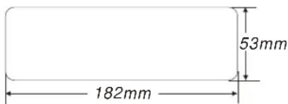
| Chassis Dimensions (W x D x H) | 178 x 165 x 50 mm |
| Maximum Output Power | 4 x 50 watts |
| Frequency Response (CD) | 40 Hz - 18 kHz |
| Signal-to-Noise Ratio (CD) | >55 dB |
| Channel Separation (CD) | >45 dB |
| Radio Frequency Coverage | 87.5 - 108 MHz |
| Intermediate Frequency | 10.7 MHz |
| Sensitivity (S/N=30dB) | 4 µV |
| Stereo Separation | >25 dB |
| Tone Controls | Bass ±10 dB at 100 Hz, Treble ±10 dB at 10 kHz |
| Current Drain (Max) | 5 Ampere |
| Supported Discs | CD, CD-R, CD-RW, MP3 (ISO9660 Level 1/2, Joliet, Romeo) |
| Additional Features | RDS, Detachable Front Panel, Auxiliary Input, Preset Equalization (FLAT, CLASSICS, POP, ROCK, DSP OFF) |
| Installation Method | DIN Front-Mount or Rear-Mount |
| Warranty | 24 months |
| Safety and Compliance | CE Type-Approval, WEEE compliant |
Frequently Asked Questions - CS FMP 400 AEG
User questions about CS FMP 400 AEG
0 question about this device. Answer the ones you know or ask your own.
Ask a new question about this device
Download the instructions for your Car stereo in PDF format for free! Find your manual CS FMP 400 - AEG and take your electronic device back in hand. On this page are published all the documents necessary for the use of your device. CS FMP 400 by AEG.
USER MANUAL CS FMP 400 AEG
natural_image
Diagram of a mechanical setup with a pointed tool and a magnified inset showing a cylindrical component (no text or symbols)Geräteeinbau
natural_image
Simple line drawing of a rectangular object with a curved cutout and an arrow indicating direction (no text or symbols)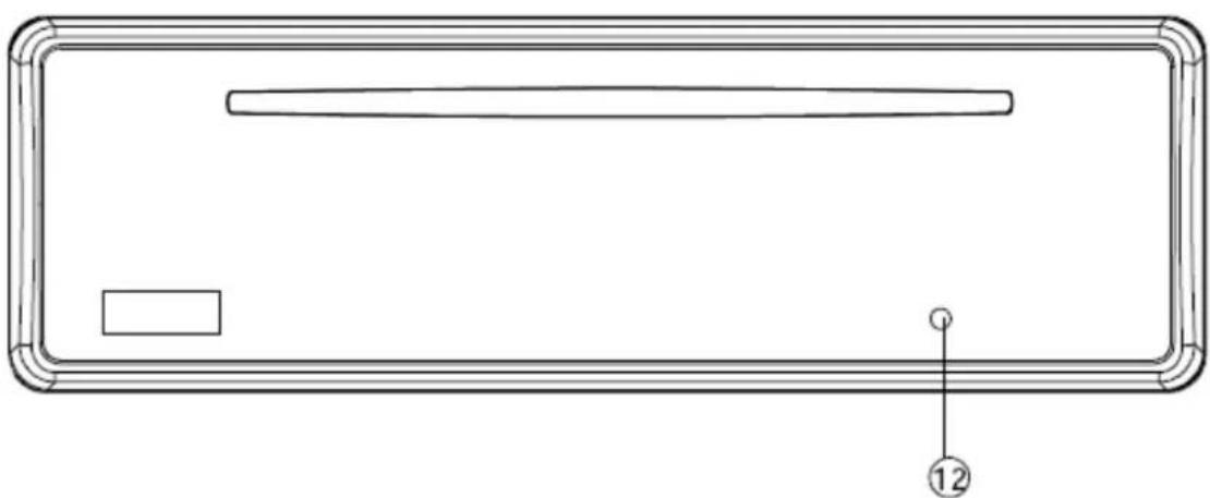
natural_image
Technical line drawing of a rectangular frame with a horizontal slot and a numbered marker (12), no text or symbols present.natural_image
Symbol of a trash bin crossed with diagonal lines, no text or labels presentCD 2, 3, 12, 15, 16, 19, 20, 21, 22, 23, 25, 26, 27, 28, 29
D
DIN- Schacht 2
Display 2, 3, 10, 12, 15, 16, 17, 19, 20, 21, 22, 24, 25
E
EJECT 12, 13, 21, 22
Frequenz 2, 14, 15, 16, 17, 27
L
Laufwerk 12, 20, 22
LED 2, 13, 16
M
Metallgehäuse 8
Metallplatten 8
MP3 3, 4, 19, 22, 23, 25, 26
mp3 26
MUTE 2
P
POWER 13
PTY 12, 15, 18, 19
R
RANDOM 3, 21, 23
RDS 2, 14, 15, 17, 20
REG 18
Reg 12, 13, 18
reg 4, 12, 13, 17, 18, 28
RESET 2, 13, 16, 28
Reset 16
RETUNE 2
Root 23, 24
S
scannen 2
Senderspeicherung 2
SOUND 2
Sound 2
U
USB 1, 9, 13
W
Wiedergabepause 2, 3
Z
Zufallswiedergabe 3
CS FMP 400
OWNER'S MANUAL
Mobile Audio System
natural_image
Technical line drawing of a device rear panel with buttons and ports (no text or symbols)• PLL Synthesizer Stereo Radio
• RDS (Radio Data System) Operation
• Digital Compact Disc Player
• Automatically Memory Storing
• Full Detachable Panel
- Preset Equalization
• Auxiliary Input Function
CONTENTS
Installation.... 3
Take out screw before installation.... 3
DIN Front-Mount (Method A) 3
Installing the unit 3
Removing the unit 4
DIN Rear-Mount (Method B) 5
Using The detachable Front Panel.... 6
Wiring Connection 7
Operation 8
Location of keys 8
Switching on/off the unit 9
Faceplate release 9
Sound adjustment 9
Loudness 10
Display 10
Equalization 10
Vacuum fluorescent display 11
Flashing LED 11
Remote sensor 11
Reset function 11
Radio operation 11
Switching to radio mode 11
Selecting the frequency band 11
Selecting station 11
Automatic memory storing &
program scanning 11
Station storing 11
RDS (Radio Data System) operation...12
operation 13
CD operation 13
Switching to CD mode 13
Selecting tracks....13
Pausing playing 13
Previewing all track 13
Repeating the same tracks 14
playing all track in random 14
Ejecting a disc 14
MP3 operation 14
Switch to CD (MP3) mode 14
Ejecting a disc 14
Selecting tracks in single step 14
Selecting directory up/down 14
Pausing playing 14
Previewing all tracks 14
Repeating the same track 14
Playing all tracks in random 14
Selecting tracks by
AMS/MP3 button 14
Display information 15
Disc notes 16
Specification 17
Trouble shooting 18
Warranty 19
CE Type-Approval Certifikate 19
Service Address 20
Retraction of old devices—20
INSTALLATION
Notes:
- Choose the mounting location where the unit will not interfere with the normal driving function of the driver.
- Before finally installing the unit, connect the wiring temporarily and make sure it is all connected up properly and the unit and the system work properly.
- Use only the parts included with the unit to ensure proper installation. The use of unauthorized parts can cause malfunctions.
- Consult with your nearest dealer if installation requires the drilling of holes or other modifications of the vehicle.
- Install the unit where it does not get in the driver's way and cannot injure the passenger if there is a sudden stop, like an emergency stop.
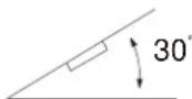
- If installation angle exceeds 30^ from horizontal, the unit might not give its optimum performance.
- Avoid installing the unit where it would be subject to high temperature, such as from direct sunlight, or from hot air, from the heater, or where it would be subject to dust, dirt or excessive vibration.
DIN FRONT/REAR-MOUNT
This unit be can properly installed either from "Front"(conventional DIN Front-mount) or "Rear"(DIN Rear-mount installation, utilizing threaded screw holes at the sides of the unit chassis). For details, refer to the following illustrated installation methods.
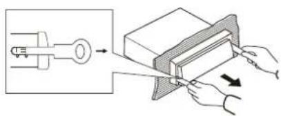
TAKE OUT SCREW BEFORE INSTALLATION
Before install the unit, please remove the two screws.
Take out screw before installation
DIN FRONT-MOUNT (Method A) Installation Opening
This unit can be installed in any dashboard having an opening as show below:
Installing the unit
Be sure you test all connections first, and then follow these steps to install the unit.
- Make sure the ignition is turned off, and then disconnect the cable from the vehicle battery's negative (-) terminal.
- Disconnect the wire harness and the antenna.
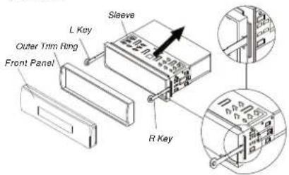
- Press the release button on the front panel and remove the control panel (see the steps of "removing the front panel").
- Lift the top of the outer trim ring then pull it out to remove it.
- The two supplied keys release tabs inside the unit's sleeve so you can remove it. Insert the keys as far as they will go (with the notches facing up) into the appropriate slots at the
INSTALLATION
middle left and right sides of the unit. Then slide the sleeve off the back of the unit.
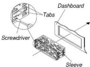
- Mount the sleeve by inserting the sleeve into the opening of the dashboard and bend open the tabs located around the sleeve with a screwdriver. Not all tabs will be able to make contact, so examine which ones will be most effective. Bending open the appropriate tabs behind the dashboard to secure the sleeve in place.
-
Reconnect the wire harness and the antenna and be careful not to pinch any wires or cables.
-
Slide the unit into the sleeve until it Locks into place.
-
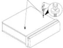
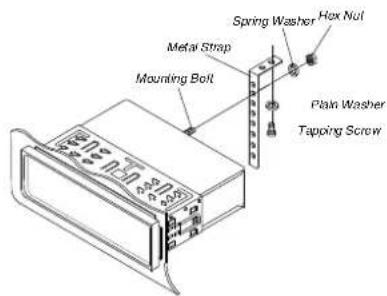
To further secure the unit, use the supplied metal strap to secure the back of the unit in place. Use the supplied hardware (Hex Nut (5mm) and Spring Washer) to attach one end of the strap to the mounting bolt on the back of the unit. If necessary, bend the metal strap to fit your vehicle's mounting area.
Then use the supplied hardware (Tapping Screw (5x25mm) and Plain Washer) to attach the other end of metal strap to a solid metal part of the vehicle under the dashboard. This strap also helps ensure proper electrical grounding of the unit.
Note to install the short threading terminal of the mounting bolt to the back of the unit and the other long threading terminal to the dashboard.
- Reconnect the cable to the vehicle battery's negative (-) terminal. Then replace the out trim ring and install the unit's front panel (see the step of "installing the front panel").
Removing the unit
-
Make sure the ignition is turned off, then disconnect the cable from the vehicle battery's negative (-) terminal.
-
Remove the metal strap attached the back of the unit (if attached).
-
Press the release button to remove the front panel.
-
Lift the top of the outer trim ring then pull it out to remove it.
-
Insert both of the supplied keys into the slots at the middle left and right sides of the unit, then pull the unit out of the dashboard.
INSTALLATION
- Align the screw holes on the bracket with the screw holes on the unit, and then tighten the screws (5x5mm) on each side.
Note: the outer trim ring, sleeve and the metal strap are not used for method B installation.
DIN REAR-MOUNT (Method B)
If your vehicle is a Nissan, Toyota, follow these mounting instructions.
Use the screw holes marked T (Toyota), N (Nissan) located on both sides of the unit to fasten the unit to the factory radio mounting brackets supplied with your vehicle.
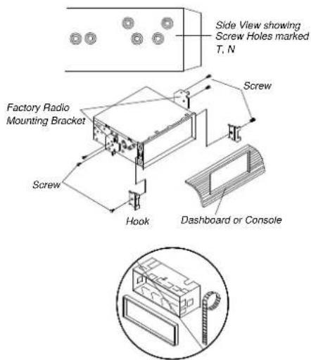
To fasten the unit to the factory radio mounting brackets.
- Use a screwdriver to loose the hook's screws on the front left and right sides of the unit and remove the hooks.
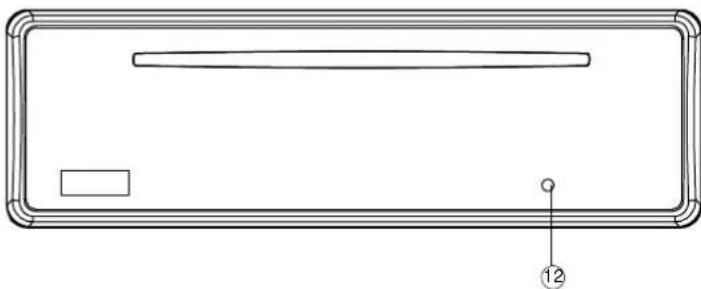
USING THE DETACHABLE FRONT PANEL
REMOVING THE FRONT PANEL
- Press the release button on the front panel and pull of the front panel.
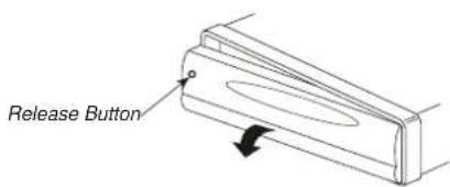
- Keep front panel into the case
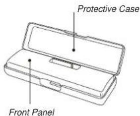
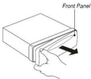
INSTALLING THE FRONT PANEL
To install the front panel, insert the panel into the housing and make sure the panel is properly installed. Otherwise, abnormality occurs on the display or some keys will not function properly.
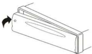
natural_image
Simple line drawing of a mechanical component with an arrow indicating rotation (no text or symbols)Precautions when handling
- Do not drop the front panel.
- Do not put pressure on the display or control buttons when removing or installing the front panel.
- Do not touch the contacts on the front panel or on the main unit body. It may result in poor electrical contact.
- If any dirt or foreign substances adhered on the contacts, they can be removed with a clean and dry cloth.
- Do not expose the front panel to high temperatures or direct sunlight in anywhere.
- Keep away any volatile agents (e.g. benzene, thinner, or insecticides) from touching the surface of the front panel
- Do not attempt to disassemble the front panel.
WIRING CONNECTION
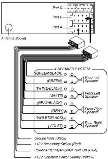
AUXILIARY CONNECTION
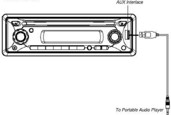
OPERATION
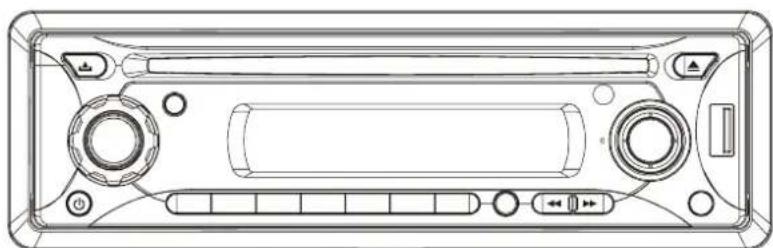
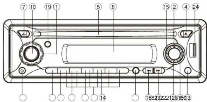
LOCATION OF KEYS
natural_image
Technical line drawing of a rectangular frame with a horizontal bar and a small rectangle on the left side, labeled with number 12 (no text or symbols beyond labels)OPERATION
SWITCHING ON/OFF THE UNIT
Switch on the unit by pressing any button [except RELEASE button (7) and EJECT button (4)]. When system is on, press POWER or PWR (9) to control the brightness of VFD. Press it for several seconds to trun off the unit.
FACEPLATE RELEASE
Press RELEASE fold down the removable faceplate.
SOUND ADJUSTMENT
Press SEL button (10) to select the desired adjustment mode. The adjustment mode will change in the following order:
By pressing the AUDIO button(11) clockwise, it is possible to adjust the desired sound quality. Press SEL button (10) for several seconds, it is activated as cyclical mode of following functions for user's selection.
flowchart
graph TD
    A["TA SEEK or ALARM"] --> B["PI SOUND or MUTE"]
    B --> C["MASK DPI or ALL RETUNE L or S"]
    C --> D["BEEP 2'nd or OFF"]
    D --> C
a) TA SEEK OR TA ALARM
- TA SEEK mode: When newly tuned station does not receive TP information for several seconds, the radio retunes to next station which has not the same station (PI) as the last station, but has the TP information. When TP information gets lost at the current station for retune time which is set by RETUNE SHORT (30 sec.) or RETUNE LONG (90 sec.), the radio start to retune to next same PI station. When same PI station does not catch in 1 cyclic search, the radio retunes to next station with TP information.
- TA ALARM mode:
When this mode is selected, any automatic retune mode is not activated. Only double beep sound (ALARM) is output. When newly tuned station does not have TP information for several seconds, beeps come out. When TP information gets lost at the current station for retune time, the beep sound is out-putted. When newly tuned station has no RDS signal, "PI SEEK" is suppressed somewhat.
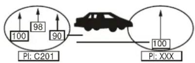
b) PI SOUND or PI MUTE
While AF switching is implemented in C201 station, AF can switch to 100 MHz, which is non genuine AF (where, different PI with same AF) in short "DIP". If a car cruises that critical area back and forth, an oscillation phenomenon can be occurred, because the different PI code can be received from 100 MHz with "XXX"PI. The car radio has special procedure to reduce even this kind of unavoidable situation however there is a limit to be escaped from this serious case perfectly. In that serious case, 2 mode is selectable as follows:
flowchart
graph TD
    A["100"] --> B["98"]
    B --> C["90"]
    D["100"] --> E["100"]
    F["PI: C201"] --> G["Car"]
    H["PI: XXX"] --> I["Car"]
- PI SOUND mode: When above different PI sound (DIP) is heard once in a while, the DIP's sound will be heard for a short time. - PI MUTE mode: Under above same situation, a mute sound will be heard for a short time.
c) RETUNE L or RETUNE S mode The initial time of automatic TA search or PI search modes is selected. When PI information is not caught for retune time, the radio starts to retune
OPERATION
to next same PI station.
When same PI station does not catch 1 cyclic search, the radio goes to last station and waits for several minutes until PI code is received.
- RETUNE L mode:
Selected as 90 seconds. - RETUNE S mode:
Selected as 30 seconds.
d) MASK DPI or MASK ALL mode
The AF frequency (which has different PI or NO RDS signal with high field strength) is masked during checking PI when the unit searches AF. The unit doesn't search this AF (DIP) for few minutes. In the case of the AF of NO RDS signal with high field strength, if the real AF is wrongly masked as DIP by some interference, the unit hesitates to search real Afs. For this reason, the unit has the user option (MASK DPI) which doesn't mask the AF of NO RDS signal with high field strength. In MASK DPI mode, the wrong sound or long mute (according to PI SOUND or PI MUTE) can be heard from the AF station which has NO RDS signal and of which the field strength is higher than that of the currently tuning AF (station). But, these phenomenons are rare and the user will hardly hear the wrong sound in whole Europe.
- MASK DPI mode:
Masked only the AF which has different PI.
- MASK ALL mode:
Masked the AF which has different PI and NO RDS signal with high field strength.
e) BEEP 2'ND, BEEP ALL, BEEP OFF mode
The situation of beep sound is selected. The 3 mode is selected a also rotating AUDIO ADJUST knob (9) lockwise or counter-clockwise.
- BEEP 2'nd mode:
The beep is only generated when
all allowed double key is pressed long (1 sec).
e.g.
When preset button (14) is pressed.
When BND/LOU button (13) is pressed.
When AS/PS button (18) is pressed.
- BEEP ALL mode:
The beep is generated when every key is pressed.
- BEEP OFF mode:
The beep is disabled.
LOUDNESS
Press BND /LOU/ENT button (13) for several seconds to reinforce the bass output. Press it for several seconds again to release this function.
DISPLAY
Press DSP button (15) to operate as the conversion of each display mode as follows:
- In case of receiving a RDS station In radio mode:
- In case of no receiving CT or PTY information, the display shows as "NO CLOCK" or "NO PTY".
- In case of receiving a non RDS station
In radio mode:
Each displaying time is several seconds, and come back to 1^st position after several seconds.
$$ \begin{array}{l} \text {- > PS - > CT - > FREQ - > PTY - >} \ \text { In CD mode: } \end{array} $$
$$ - > C D - > C T - > P S - > F R E Q - > P T Y - > $$
$$ \begin{array}{l} \text {- > " N O C L O C K" - > F R E Q - > " N O P T Y" - > } \ \text { In CD mode: } \end{array} $$
$$ \rightarrow C D \rightarrow C T \rightarrow F R E Q \rightarrow " N O P T Y" \rightarrow $$
Notes:
$$ \begin{array}{l} - C T = \text { clock time } \ - F R E Q = f r e q u e n c y \ \end{array} $$
EQUALIZATION
Press EQ button (19) to turn on equalization function and to select desired audio mode. There are five kinds of mode as below:
FLAT CLASSICS POP M ROCK M DSP OFF
VACUUM FLUORESCENT DISPLAY Exhibit current frequency and activated functions on the display (23). FLASHING LED
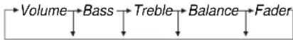
If the front panel does not install in the main unit, the LED (12) will be flashing. REMOTE SENSOR
Point the remote control handset to the remote sensor IR (24). Press the function keys on the handset to control the system.
RESET FUNCTION
RESET button (25) must be activated with either a ballpoint pen or thin metal object.
The RESET button is to be activated for the following reasons:
- Initial installation of the unit when all wiring is completed.
- All the function buttons do not operate.
- Error symbol on the display.
Note: if press RESET button (25), the unit can't work yet, please use a cotton swab soaked in isopropyl alcohol to clean the socket on the front panel.
RADIO OPERATION
• SWITCHING TO RADIO MODE
Press MD button (6) shortly to select radio mode, the radio mode appears in the display together with the memory band an frequency.
- SELECTING THE FREQUENCY BAND
At radio mode, press BND/Lation (13) shortly to select the desired band. The reception band will change in the following order:
- SELECTING STATION
Press TUN/TRK ▶ button(17) or button TUN/TRK ◀◀ (16)
shortly to activate automatic seek function. Press for several seconds until "MANUAL" appears on the display, the manual tuning mode is selected. If both buttons have not been pressed for several seconds, they will return to seek tuning mode and "AUTO" appears on the display.
• AUTOMATIC MEMORY STORING & PROGRAM SCANNING
- Automatic memory storing Press AS/PS button (18) for several seconds, the radio searches from the current frequency and checks the signal strength until one cycle search is finished. And then 6 strongest stations are stored into the corresponding preset number button.
- Program scanning Press AS/PS button (18) shortly to scan preset station, When the field strength level is more than the threshold level of stop level, the radio is holding at that preset number for several seconds with release mute, then searches again.
• STATION STORING
Press any one of the preset buttons (14) (1 to 6) to select a station, which had been stored in the memory. Press this button for several seconds (until 2ND beeps come out), current station is stored into the number button.
- Setting RDS mode Press AF button (3) and release immediately to switch on or off RDS mode. Whenever RDS is switch on, symbol "AF" appears on the display. Program name is displayed on
©
OPERATION
switched to that EON linked station, but no information could not be received because the EON linked station is located too far from that area. So the radio is switched back to current station again. In above operation, a customer listens to a wrong program or mute sound for a while.
EON TA LOCAL mode
When the filed strength level of EON linked is less than threshold level, the radio does not switch that station, and a customer can hardly listen to any disturbances.
When EON TA LOCAL mode is selected, “EON TA LO” on numeric display is indicated for a few seconds.
EON TA DISTANCE mode
EON TA switch is tried to implemented by the information of current station.
When EON TA DISTANCE mode is selected, "EON TA DX" on numeric display is indicated for a few seconds.
The RDS data used are the PI, PS, AF, TP, TA, EON and PTY data.
PI: Program Identification code Code for identifying programs
PS: Program Service Name Broadcast station name data expressed in alphanumerically characters
AF: Alternative Frequencies Frequency list of broadcasting Stations transmitting the same program
TP: Traffic Program Identification Identification data for traffic information-broadcasting station
TA: Traffic Announcement Identification Identification data
showing traffic information is being transmitted or not
EON: Enhanced Other Networks Information Broadcasting information on PI, AF, TP, TA, etc, relating to networks other than the network used for current reception
PTY: Program Type Code Contents of programs such as news, light music, sports etc.
CD OPERATION
• SWITCHING TO CD MODE
If there is no CD inserted in the driver:
Gently insert the CD with the printed side uppermost into the CD compartment until you feel some resistance,. The CD is drawn into the driver automatically, CD playback begins.
If a CD is already inserted in the driver:
Keep pressing MODE button (6) shortly until the CD mode display appears.
- SELECTING TRACKS
Press TUN/TRK ◀ button (16) or TUN/TRK ▶ button (17) to move to the previous track or the following track. Track number shows on display.
Hold TUN/TRK ◀ button (17) or TUN/TRK button ▶▶ (16) to fast reverse of fast forward, CD play starts from when you release the button.
• PAUSING PLAYING
Press PAU button (20) to pause CD player, Press it again to resume play.
• PREVIEWING ALL TRACKS
Press SCN button (21) to play first several seconds of each track on the
OPERATION
current disc, Press again to stop intro and listen to track.
• REPEATING THE SAME TRACK
Press RPT button (22) to continuously repeat the same track, Press it again to stop repeat.
- PLAYING ALL TRACKS IN RANDOM
Press SHF button (23) to play all tracks on CD in random order. Press again to cancel the function.
- EJECTING A DISC
Press ▲ button (4) to stop CD playing and eject the disc from the disc slot (5).
MP3 OPERATION
• SWITCHING TO CD (MP3) MODE
If there is no MP3 disc inserted in the driver:
Gently insert the MP3 disc with the printed side uppermost into the disc slot (5) until you feel some resistance. The MP3 disc is drawn into the driver automatically. The MP3 playback begins.
If a MP3 disc is already inserted in the driver:
Keep pressing MODE button (6) shortly until the CD (MP3) mode display appears.
- EJECTING A DISC
press ▲button (4) to stop CD playing and eject the disc from the disc slot (5).
- SEJECTING TRACKS IN SINGLE STEP
Press TUN/TRK ◀ button(16) or TUN/TRK ▶ button(17) to move to the previous track or the following track, Track number shows on display.
• PAUSING PLAYING
Press PAU button (20) to pause MP3 player, Press it again to resume play.
• PREVIEWING ALL TRACKS
Press SCN button (21) to play first several seconds of each track on the current disc. Press again to stop intro and listen to track.
• PREVIEWING THE SAME TRACK
Press SCN button (22) to continuously repeat the same track, Press it again to stop repeat
- PLAYING ALL TRACK IN RANDOM
Press SHF button (23) to play all tracks on MP3 disc in random order. Press again to cancel the function.
- SELECTING TRACK BY AMS/MP3 BUTTON
AS/PS button is assigned as Digital Audio Mode selection button in MP3 operation, When pressed, it is activated as selecting each mode of Digital Audio. "Selecting track directly" => "Searching Directory or File Name" => "Navigation" from root by TUN/TRK UP/DOWN buttons => "Navigation" from current directory by TUN/TRK UP/DOWN buttons
- Searching Track Directly
Press AS/PS button for one time. It enters into "Searching track directly" in Digital Audio CD. The unit searches the track selected by following direct numeric buttons:
M1-M6, MOD (7), MANU/SKIP DOWN(8), MANU/SKIP UP (9), DSP(0).
If selected three digits, the unit searches the tract at once. if selected one or two digits, the unit wait for ENTER (BND/LOU) button for seconds. The unit searches the track after few seconds, even if the enter button is not pressed.
OPERATION
- Searching Directory or file Name
Press AS/PS button for two times. It enters into "Searching Directory or File Name" in Digital Audio CD.
The unit searches files and directories that have the same character which is inputted by the user pressing the corresponding buttons listed on the Table 1 below. Explain as follows:
- Use the corresponding buttons to select the characters A to Z, blank, 0-9, _, -, +.
- Press SEL button to confirm entry of each characters.
- Press BND /LOU (ENTER) button to start the title search, In case the selected title is a directory name, display will show(' ') then
- Use the TUN/TRK UP/DOWN button to list all songs under this directory and select the title.
- Press BND/LOU (ENTER) button to confirm and start the play. - Repeat the above steps if the newly selected title is again a directory.
- Searching From Root Directory Press AS/PS (MP3) button for three times. The unit searches fire or directory from root by TUN/TRK UP/DOWN buttons (D-DIR icon turns on if the name is directory). Display will list all available directories and songs. Select the desired directory/songs by using
TUN/TRK UP/DOWN button and BND/LOU (ENTER) button to confirm. If the selected title is a song, it starts to play.
If the selected title is a directory name, display will show (''), then
- Use the TUN/TRK UP/DOWN buttons to list all songs under this directory and select the title.
- Press BND/LOU (ENTER) button to confirm and start the play.
- Repeat the above steps if the newly selected title is again a directory.
- Searching From Current Directory Press AS/PS button for four times. The unit searches fire or directory from current directory by TUN/TRK UP/DOWN buttons.
(D-DIR icon turns on if the name is directory). The current directory name is displayed for a second and the currently playing file name is displayed (selected). The user can select the directory or file in the directory by TUN/TRK UP/DOWN buttons. The selected] file can be played by pressing BND/LOU (ENTER) button.
"MP3" icon turns on when MP3 disc is played and blinks when it is in navigation mode.
• DISPLAY INFORMATION
Press DSP button to show the following information, such as the clock, ID3 TAG (if available: song title, directory name, artist name, other contents...) and other information.
KEY Assigned IN Searching mode (Table 1)
| AMS | Mode Select |
| BND/LOU | ENTER |
| M1 | A, B, C, 1 |
| M2 | D, E, F, 2 |
| M3 | G, H, I, 3 |
| M4 | J, K, L, 4 |
| M5 | M, N, O, 5/DirectotY DOWN |
| M6 | P, Q, R, 6/Directory UP |
| MODE | S, T, U, 7 |
| MANU/SKIP DOWN | V, W, X, 8 |
| MANU/SKIP UP | Y, Z, SPACE, 9 |
| SEL | CHARACTER SHIFT RIGHT |
| DSP | _,-,+,0 |
| AUDIO ADJUST KNOB | CHARACTER SELECT (A, B~8,9,0) |
VOLUME UP/DOWN & TUN/TRK UP/DOWN buttons:
Searching file and directory during Navigation.
DISC NOTES
A. Notes on discs:
- Attempting to use non-standard shape discs (e.g. square, start, heart) May damage the unit. Be sure to use round shape CD discs only for this unit.
- Do not stick paper or tape, etc, onto the label side or the recording side of any discs, as it may cause a malfunction.
- Dirt, dust, scratches and warping discs will cause misoperation.
B. Notes on CD-Rs (recordable CDs)/CD-RWs (rewritable CDs):
- Be sure to use discs with following marks only for the unit to play:


- The unit cannot play a CD-R and CD-RW that is not finalized. (Please refer to the manual of your CD-R/CD-RW recorder or CD-R/CD-RW software for more information on finalization process).
- Depending on the recording status, conditions of the disc and the equipment used for the recording, some CD-Rs/CD-RWs may not be played on this unit. (see *1)
*1: To have more reliable play back, please see following recommendations:
a: Use CD-RWs with speed 1x to 4x and write with speed 1x to 2x.
b. Use CD-Rs with speed 1x to 8x and write with speed 1x to 2x.
c. Do not play a CD-RW which has been written for more than 5 times.
C. Notes on MP3 files (MP3 Version Only):
- The disc must be in the ISO9660 level 1 or level 2 format, or Joliet or Romeo in the expansion format.
- When naming a MP3 file, be sure the file name extension is ".MP3".
- For a non-MP3 file, even though the file name extension is ".MP3", the unit cannot recognize it.
SPECIFICATION
GENERAL
Power Supply Requirements : DC 12 Volts, Negative Ground Chassis Dimensions : 178 (W) x 165 (D) x 50 (H)
Tone Controls
- Bass (at 100 Hz) : 10 dB
- Treble (at 10 kHz) : ±10 dB
Maximum Output Power : 4x50 watts Current Drain : 5 Ampere (max.)
CD PLAYER
Signal to Noise Ratio : More than 55 dB Channel Separation : More than 45 dB Frequency Response : 40Hz - 18 kHz
RADIO
Frequency Coverage : 87.5 to 108 Mhz I.F. : 10.7 Mhz Sensitivity (S/N=30dB) : 4μV Stereo Separation : >25 dB
TROUBLE SHOOTING
Before going through the checklist, check wiring connection. If any of the problems persist after checklist has been made, consult your nearest service dealer.
| Symptom Cause | Solution | |
| No power. The car ignition switch is If the power supply is properly not on. | supply is properly connected to the car accessory circuits, but the engine is not moving, switch the ignition key to "ACC" | |
| Disc cannot be Presence of CD disc inside Remove the disc in the player, loaded or ejected. the player. then put a new one. | ||
| No sound. Volume is in minimum. | Adjust volume to a desired level. | |
| Sound skips. | The installation angle is more than 30 degrees. | Adjust the installation angle less than 30 degrees. |
| The disc is extremely dirty or defective disc. | Clean the compact disc, or try to play a new one. | |
| The operation keys do not work. | The built-in microcomputer is not operating properly due to noise. | Press the RESET button. Front panel is not properly fix into its place. |
| The radio does not work. The radio station automatic selection does not work. | The antenna cable is not connected. | Insert the antenna cable firmly. |
| The signals are too weak. | Select a station manually. | |
Warranty
This device is covered by a 24-month warranty. The warranty starts with the date of purchase. In order to proof the date of purchase, we advise to keep the receipt. If articles are returned without receipt, repairs can only be executed on payment of additional costs. This arrangement also applies for inadequately packed articles.
Within the warranty period, all imperfections which are due to defective material or production procedures will be remedied free of charge. Within the warranty period the device will be repaired or replaced on discretion of the Service or ITM Technology AG.
Replaced parts/devices which are replaced become property of ITM Technology AG. The replacement of the device does not automatically renew or extend the warranty. The primal warranty period of the original device remains same and ends after 24 month. Damages which are due to improper use, wear, tear interference of a third party or circumstances beyond our control are not covered by the warranty. Consumables such as batteries, packing material etc. and imperfections which hardly reduce the value or serviceability of the device are not covered by the warranty. Claims for damages which are not based on a deliberate act or a grossly negligence of the producer, are exempted. Our customer service naturally remains at your disposal after the period of warranty. After expiration of the warranty or in case of damages for which we can not accept warranty you will not receive an estimate.
EC Type-Approval Certificate
Communication concerning the e1 type-approval of a type of component with regard to Directive 72/245/EEC, as last amended by Directive.

Hotline
*Hotline number: 01805 880606 (0,12€ / Minute)
*Valid for Germany only
Business hours:
Monday to Thursday from 08:00 am to 05:00 pm
Friday from 08:00 am to 04:00 pm
We offer you qualified advice, should you encounter problems during the installation or the operation of your unit.
* This hotline number is valid for the federal republic of Germany
Retraction of old devices
Waste electrical products must not be disposed of with household waste. This equipment should be taken to your local recycling centre for safe treatment.

natural_image
Symbol of a trash bin crossed with no text or labels