
STLA 828 A - Dishwasher SMEG - Free user manual and instructions
Find the device manual for free STLA 828 A SMEG in PDF.


User questions about STLA 828 A SMEG
0 question about this device. Answer the ones you know or ask your own.
Ask a new question about this device
Download the instructions for your Dishwasher in PDF format for free! Find your manual STLA 828 A - SMEG and take your electronic device back in hand. On this page are published all the documents necessary for the use of your device. STLA 828 A by SMEG.
USER MANUAL STLA 828 A SMEG
GUIDE FOR USING THE DISHWASHER AND THE WASHING PROGRAMS
- Safety and operating instructions ____ 2
- Installation and hook-up 5
- Description of the controls 9
- Operating instructions 17
- Cleaning and maintenance 32
- Troubleshooting 36
Thank you for choosing one of our products.
You are advised to read this manual carefully; it contains all the information you need about the right conditions for the proper, safe use of your dishwasher.
The individual sections are laid out to provide you with a step-by-step guide to all your appliance's functions; the texts are easy to understand and are complete with detailed illustrations.
Recommendations are given for the correct use of the baskets, spray arms, containers, filters, washing programs, and for operating the controls.
Following the cleaning instructions provided here will keep your dishwasher's performance at peak levels in the long term.
This user-friendly manual will provide answers to all your questions about use of the dishwasher.
INSTALLATION INSTRUCTIONS: these are intended for the qualified technician who must carry out the installation, hook-up and testing of the appliance.
USER INSTRUCTIONS: these consist of recommendations for using the appliance, a description of its controls and of the correct cleaning and maintenance procedures.
1. Safety and operating instructions
THIS MANUAL FORMS AN INTEGRAL PART OF THE APPLIANCE: IT MUST ALWAYS BE KEPT INTACT TOGETHER WITH THE DISHWASHER. BEFORE USING THE APPLIANCE, CAREFULLY READ ALL THE INSTRUCTIONS CONTAINED IN THIS MANUAL.
INSTALLATION MUST BE PERFORMED BY A QUALIFIED TECHNICIAN, IN COMPLIANCE WITH THE REGULATIONS IN FORCE. THIS APPLIANCE IS INTENDED FOR DOMESTIC USE, AND COMPLIES WITH THE EEC DIRECTIVES 73/23, 89/336 (INCLUDING 92/31 AND 93/68) CURRENTLY IN FORCE, INCLUDING THE PREVENTION AND ELIMINATION OF RADIO FREQUENCY INTERFERENCE.
THE APPLIANCE IS DESIGNED FOR THE FOLLOWING PURPOSE: WASHING AND DRYING OF DISHES; ANY OTHER USE SHALL BE CONSIDERED IMPROPER. THE MANUFACTURER DECLINES ALL RESPONSIBILITY FOR USES OTHER THAN THOSE DESCRIBED ABOVE.
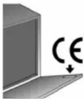
THE NAME PLATE FEATURING THE TECHNICAL DATA, SERIAL NUMBER AND MARKINGS IS VISIBLY POSITIONED ON THE INNER EDGE OF THE DOOR. THE NAME PLATE ON THE INNER EDGE OF THE DOOR MUST NEVER BE REMOVED.
DO NOT LEAVE THE DISCARDED PACKAGING MATERIALS UNSUPERVISED WITHIN THE HOME. SEPARATE THE VARIOUS MATERIALS WHICH MAKE UP THE PACKAGING AND TAKE THEM TO THE NEAREST SORTED WASTE COLLECTION CENTRE.
THE APPLIANCE MUST BE PROVIDED WITH AN EARTH CONNECTION IN ACCORDANCE WITH THE ELECTRICAL SAFETY REGULATIONS IN FORCE. THE MANUFACTURER DECLINES ALL RESPONSIBILITY FOR DAMAGE TO PERSONS OR PROPERTY RESULTING FROM THE FAILURE TO EARTH THE APPLIANCE OR FROM A DEFECTIVE EARTH CONNECTION.

IF THE APPLIANCE IS INSTALLED ON A CARPETED OR COVERED FLOOR, ENSURE THAT THE OPENINGS ON ITS UNDERSIDE ARE NOT OBSTRUCTED.
ALWAYS SWITCH OFF THE DISHWASHER AFTER EACH USE TO AVOID WASTING ELECTRICITY.

OBSOLETE APPLIANCES MUST BE RENDERED UNUSABLE. CUT OFF THE MAINS POWER CORD AFTER UNPLUGGING IT FROM THE WALL OUTLET, AND MAKE SAFE ANY COMPONENTS WHICH MIGHT BE DANGEROUS FOR CHILDREN (LOCKS, DOORS, ETC.).
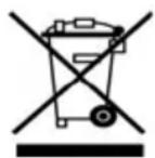
THIS APPLIANCE IS MARKED ACCORDING TO THE EUROPEAN DIRECTIVE 2002/96/EC ON WASTE ELECTRICAL AND ELECTRONIC EQUIPMENT (WEEE).
BY ENSURING THIS PRODUCT IS DISPOSED OF CORRECTLY, YOU WILL HELP PREVENT POTENTIAL NEGATIVE CONSEQUENCES FOR THE ENVIRONMENT AND HUMAN HEALTH, WHICH COULD OTHERWISE BE CAUSED BY INAPPROPRIATE WASTE HANDLING OF THIS PRODUCT.
THE SYMBOL ON THE PRODUCT, OR ON THE DOCUMENTS ACCOMPANYING THE PRODUCT, INDICATES THAT THIS APPLIANCE MAY NOT BE TREATED AS HOUSEHOLD WASTE. INSTEAD IT SHALL BE HANDED OVER TO THE APPLICABLE COLLECTION POINT FOR THE RECYCLING OF ELECTRICAL AND ELECTRONIC EQUIPMENT.
DISPOSAL MUST BE CARRIED OUT IN ACCORDANCE WITH LOCAL ENVIRONMENTAL REGULATIONS FOR WASTE DISPOSAL. FOR MORE DETAILED INFORMATION ABOUT TREATMENT, RECOVERY AND RECYCLING OF THIS PRODUCT, PLEASE CONTACT YOUR LOCAL CITY OFFICE, YOUR HOUSEHOLD WASTE DISPOSAL SERVICE OR THE SHOP WHERE YOU PURCHASED THE PRODUCT.
IN THE EVENT OF A FAULT, DISCONNECT THE DISHWASHER FROM THE ELECTRICAL POWER SUPPLY AND SHUT OFF THE WATER TAP.

DO NOT USE APPLIANCES WHICH HAVE BEEN DAMAGED DURING TRANSIT! IF IN DOUBT, CONSULT YOUR DEALER.
THE APPLIANCE MUST BE INSTALLED AND CONNECTED IN ACCORDANCE WITH THE INSTRUCTIONS PROVIDED BY THE MANUFACTURER OR BY A QUALIFIED TECHNICIAN.

THIS DISHWASHER MUST BE USED BY ADULTS.
USE BY PERSONS WITH REDUCED MENTAL AND/OR PHYSICAL CAPABILITIES IS ONLY PERMITTED UNDER THE SUPERVISION OF A PERSON RESPONSIBLE FOR THEIR SAFETY.
KEEP CHILDREN AWAY FROM DETERGENTS AND PACKAGING MATERIALS (PLASTIC BAGS, POLYSTYRENE, ETC.), AND NEVER ALLOW THEM TO APPROACH OR PLAY WITH THE DISHWASHER, SINCE IT MIGHT CONTAIN DETERGENT RESIDUES CAPABLE OF CAUSING PERMANENT DAMAGE TO THE EYES, MOUTH AND THROAT, AND EVEN LEADING TO SUFFOCATION.
DO NOT INTRODUCE SOLVENTS SUCH AS ALCOHOL OR TURPENTINE WHICH MAY CAUSE AN EXPLOSION.
DO NOT LOAD DISHES THAT ARE SOILED WITH ASH, WAX OR PAINTS.
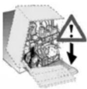
LEANING OR SITTING ON THE DISHWASHER DOOR WHEN OPEN MAY CAUSE THE APPLIANCE TO OVERTURN, PUTING PEOPLE AT RISK. NEVER LEAVE THE DISHWASHER DOOR OPEN; PEOPLE MIGHT TRIP OVER IT.

DO NOT DRINK THE WATER RESIDUES WHICH MAY BE PRESENT INSIDE THE DISHES OR DISHWASHER AT THE END OF THE WASHING PROGRAM AND BEFORE THE DRYING CYCLE.
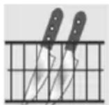
KNIVES OR OTHER SHARP-ENDED COOKING UTENSILS MUST BE PLACED IN THE CUTLERY BASKET BLADE-DOWN, OR LAID HORIZONTAL IN THE TOP BASKET. TAKE CARE NOT TO CUT YOURSELF AND ENSURE THAT THEY DO NOT PROJECT FROM THE BASKET.

AQUASTOP MODELS
THE AQUASTOP DEVICE PREVENTS FLOODING IN THE EVENT OF A WATER LEAK. WHEN THE AQUASTOP DEVICE IS TRIPPED, CALL IN A QUALIFIED TECHNICIAN TO IDENTIFY AND REPAIR THE FAULT. IN MODELS EQUIPPED WITH THE AQUASTOP DEVICE, THERE IS A SOLENOID VALVE INSIDE THE WATER INTAKE HOSE. DO NOT CUT THE HOSE AND DO NOT ALLOW THE SOLENOID VALVE TO DROP INTO WATER. IN THE EVENT OF DAMAGE TO THE WATER INTAKE HOSE, DISCONNECT THE APPLIANCE FROM THE ELECTRICAL POWER SUPPLY AND FROM THE WATER SUPPLY.
IMMEDIATELY AFTER INSTALLING THE DISHWASHER, PERFORM A QUICK TEST OF THE APPLIANCE FOLLOWING THE INSTRUCTIONS BELOW. IF THE DISHWASHER FAILS TO OPERATE CORRECTLY, DISCONNECT IT FROM THE ELECTRICAL POWER SUPPLY AND CALL THE NEAREST TECHNICAL SERVICE CENTRE. DO NOT ATTEMPT TO REPAIR THE APPLIANCE.

THE DISHWASHER MEETS ALL THE REQUIREMENTS SET OUT BY THE REGULATIONS IN FORCE CONCERNING SAFETY AND ELECTRICAL EQUIPMENT. ANY TECHNICAL CHECKS SHOULD BE CONDUCTED EXCLUSIVELY BY A TRAINED AND AUTHORISED TECHNICIAN: REPAIRS CARRIED OUT BY UNAUTHORISED PERSONS WILL INVALIDATE THE WARRANTY, AS WELL AS POSING A POTENTIAL HAZARD TO THE USER.
The manufacturer declines all responsibility for damage to persons or property resulting from failure to observe the above precautions, from tampering with even a single component of the appliance, or from the use of non original spare parts.
2. Installation and hook-up
Remove the polystyrene basket retainers.
Position the appliance in the desired place of installation. The back or sides of the dishwasher may be placed up against walls or other furniture units. If the dishwasher is installed near a heat source, fit the special insulating panel to prevent overheating and malfunction of the appliance. To ensure stability, install integrated or built-under dishwashers only under continuous worktops, and screw them to the adjacent units. To facilitate the installation procedure, the intake and drain hoses can be positioned in any direction; make sure that the hoses are not kinked, crushed or pulled too tightly. Make sure to tighten the locking ring-nut once the pipes have been placed in the direction required. A hole at least 8 cm in diameter is required to allow the power supply cable and pipes to pass.
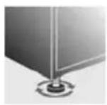
Level the appliance on the floor using its adjustable feet. This operation is essential for ensuring correct operation of the dishwasher.

Building-in a dishwasher underneath a ceramic hob is absolutely forbidden.
A dishwasher can be built-in underneath a conventional hob provided there is no break in the kitchen worktop, and the dishwasher and hob are installed and secured correctly, so that no hazards are generated.
When installing the dishwasher in a compartment next to one or more other appliances, it is essential to comply with all the recommendations provided by the appliance's manufacturer (minimum distances, installation procedures, etc.).
For free-standing models only:
- Installing a hob on top of a free-standing dishwasher is absolutely forbidden.
- If the appliance is not built-in and is therefore accessible on on side, the door hinge area must be covered for safety reasons (injury hazard). The covering fixtures are available as an accessory from specialist dealers or the After-Sales Service.
- To build in the dishwasher, the special kit must be purchased from authorised dealers or the After-Sales Service.
Some models are equipped with only one adjustable foot at the rear, which can be adjusted by turning the screw on the lower front part of the appliance.
2.1 Water supply connection
Preventing the risk of clogging or damage: if the water pipe is new or has not been used for a long time, before connecting to the water supply check that the water is clear and free of impurities, to prevent damage to the appliance.
The dishwasher must always be connected to the water system with new hoses; old or used hoses must never be reused.
CONNECTING TO THE WATER SUPPLY
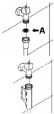
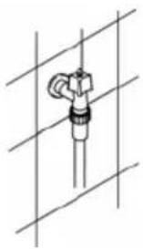
Connect the intake hose to a cold water supply with 34 " gas thread, inserting the filter A supplied with the dishwasher. Take care to screw the hose firmly into place with your hands and then complete by tightening about 14 of a turn with pliers.
In dishwashers equipped with the ACQUASTOP device, the filters is already fitted inside the threaded ring.
text_image
Technical diagram showing two mechanical assembly steps with labeled component A and directional arrowThe dishwasher can also be connected to a hot water supply not exceeding 60^ C. Supplying the appliance with hot water cuts down the washing time by approximately 20 minutes, but slightly reduces its effectiveness. Make the connection to the domestic hot water supply using the same procedure described for connecting to the cold water supply.
DRAIN CONNECTION
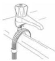
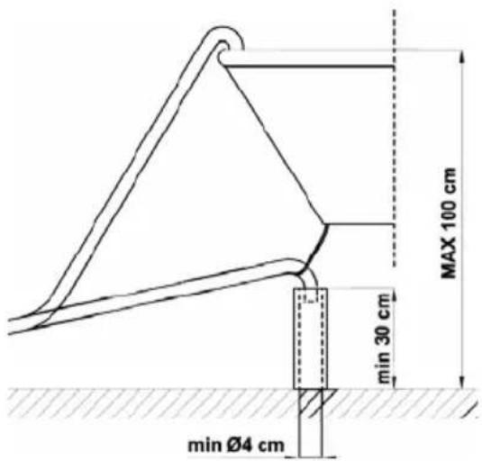
Insert the dishwasher's drain hose into a drain pipe having a diameter of at least 4 cm, or alternatively, place it inside the kitchen sink using the plastic support provided, taking care not to crush or excessively bend the hose. It is important to prevent the hose from coming loose and falling. For this purpose, the plastic support is equipped with a hole for tying it to the wall or water tap.
text_image
MAX 100 cm min 30 cm min Ø4 cmThe free end should be positioned at a height of between 30 and 100 cm, and should never be submerged in water. If a horizontal drain extension hose is used (for a maximum of 3 m) the drain hose can be placed at a maximum height of 85 cm from the ground.
2.2 Electrical connection and precautions
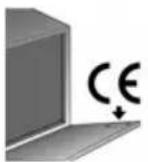
CHECK THAT THE VOLTAGE AND THE FREQUENCY OF THE MAINS MATCH THE RATINGS ON THE NAME PLATE OF THE APPLIANCE POSITIONED ON THE INNER EDGE OF THE DOOR.
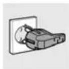
THE PLUG ON THE SUPPLY CORD AND THE CORRESPONDING SOCKET OUTLET MUST BE OF THE SAME TYPE AND MEET THE REGULATIONS IN FORCE.
THE PLUG MUST BE ACCESSIBLE AFTER INSTALLATION.
IN THE EVENT OF DAMAGE TO THE SUPPLY CORD, HAVE IT REPLACED BY THE MANUFACTURER OR AN AUTHORIZED TECHNICAL SERVICE CENTRE.
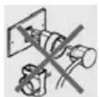
DO NOT USE ADAPTORS OR SHUNT CONNECTIONS IN ORDER TO AVOID THE POSSIBILITY OF OVERHEATING OR BURNING.
IF THE APPLIANCE IS PROVIDED WITH A PLUGLESS SUPPLY CORD:
IT IS NECESSARY TO INSTALL IN THE FIXED WIRING AN ALL-POLE DISCONNECTION DEVICE HAVING A GAP BETWEEN CONTACTS OF AT LEAST 3.5MM. AFTER INSTALLATION THE DISCONNECTION DEVICE HAS TO BE EASY TO REACH.
THE CONNECTION TO THE MAINS MUST BE CARRIED OUT BY A QUALIFIED TECHNICIAN IN ACCORDANCE TO THE SCHEME SHOWN BELOW AND THE REGULATIONS IN FORCE.
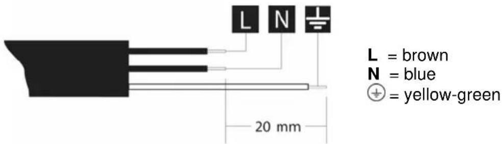
text_image
L N 20 mm L = brown N = blue ⊕ = yellow-green
In the event of damage to the supply cord, have it replaced by the manufacturer or an Authorized Technical Service Centre in order to avoid any risk.
FOR GREAT BRITAIN ONLY:

THIS APPLIANCE MUST BE EARTHED.
Fuse replacement
If the mains lead of this appliance is fitted with a BS 1363A 13amp fused plug, to change a fuse in this type of plug use an A.S.T.A. approved fuse to BS 1362 type and proceed as follows:
- Remove the fuse cover A and fuse B.
- Fit replacement 13A fuse into fuse cover.
- Refit both into plug.

text_image
Technical diagram of a mechanical switch or plug assembly with labeled parts A and B
The fuse cover must be refitted when changing a fuse and if the fuse cover is lost the plug must not be used until a correct replacement is fitted.
Correct replacement are identified by the colour insert or the colour embossed in words on the base of the plug.
Replacement fuse covers are available from your local electrical store.
3. Description of the controls
3.1 Upper panel
All the dishwasher controls are grouped on the upper panel. Switch-on, programming, switch-off etc. procedures are only possible when the door is open.

text_image
2 3 4 5 11 10 7 6 9 8 13 12 QuickTime end Auto 80-70 NFC S 1/2 QuickTime 3/1 ①| 1 | ON/OFF BUTTONPressing this button energises the appliance. |
| 2 | SELECTED PROGRAM INDICATOR LIGHTS Illumination of this light denotes the program selected and the occurrence of a fault (troubleshooting). |
| 3 | PROGRAM SELECTION BUTTONBy pressing this button in sequence it is possible to select the desired program. |
| 4 | SALT WARNING LIGHTIllumination of this light signals that salt container is empty. |
| 5 | RINSE AID WARNING LIGHTIllumination of this light signals that rinse aid dispenser is empty. |
| 6 | QUICK TIME OPTION BUTTONThis button can be pressed to reduce the duration of programs. |
| 7 | QUICK TIME OPTION LIGHTIlluminates to indicate that the function is activated. |
| 8 | “3/1” OPTION BUTTONPress this button to activate the option for use of 3/1 products. |
| 9 | “3/1” OPTION LIGHTIlluminates to indicate that the function is activated. |
| 10 | HALF LOAD BUTTONPress this button to activate the half load wash option. |
| 11 | HALF LOAD LIGHTSOne of the two light illuminates to indicate that the half load wash option in the top or bottom basket has been selected. |
| 12 | PROGRAM DELAY BUTTONPress this button to delay the start of the program by up to 9 hours. |
| 13 | INFORMATION DISPLAY |
SETTING THE WASHING PROGRAM AND SWITCHING ON
To select the most suitable program for the dishes to be washed refer to the table below, which indicates the most appropriate program according to dish type and degree of soiling.
After using the table to identify the most appropriate washing program:
- press the ON/OFF button (1) and wait for the PROGRAM INDICATOR LIGHT (2) to illuminate;
- keep pressing the PROGRAM SELECTION button (3) until the indicator light corresponding to the desired program illuminates;
- close the door; after about 2" the program will start. While it is in progress, the relative LIGHT will flash (indicating that the program is being executed).

text_image
2 3 4 5 11 10 7 6 9 8 13 12 QuickTime end Auto 60-70 °C 1/2 QuickTime 3/1 ①| PROGRAMME, NUMBER & SYMBOL | LOAD CROCKERY AND CUTLERY | PROGRAM PROGRESS | DURATION | CONSUMPTION | |||
| MINUTES (2) | WATER LITRES (1) | POWER KWh (2) | |||||
| 1 |  | SOAK | Pans and dishes awaiting completion of the load. | Cold prewash | 15' 4 0,03 | ||
| 2 |  | LIGHT | Delicate dishes with light dirt. | Wash at 45°C Cold rinse Rinse at 70°C Dry | 80' | 10 1,00 | |
| 3 |  | BIO (*) EN 50242 | Dishes with normal dirt, even with dried-on residues. | Cold prewash Wash at 50°C Cold rinse Rinse at 62°C Dry | 180' | (**) (**) | |
| 4 |  | AUTO 60-70 | Pans and dishes with normal dirt, even with dried-on residues. | Cold prewash Wash at 50°C Wash at 65°C Cold rinse Rinse at 70°C Dry | (***) | (***) (***) | |
| 5 |  | ULTRA CLEAN (****) | Very dirty pans and dishes, even with dried-on residues. | Prewash at 45°C Wash at 70°C 2 cold rinses Rinse at 70°C Dry | 140' | 18 1,72 | |
Only run the soak program with half loads.
The QUICK TIME (6), "3/1" (8), HALF LOAD WASH (10) and DELAYED START (12) options cannot be used with the soak program.
(*) Reference program as per EN 50242 standard.
(**) See energy label.
(***) When the "AUTO 60-70" program is selected, the dishwasher recognises the type of dirt and automatically adjusts the washing parameters as appropriate.
(****) The "ULTRA CLEAN" program terminates with an anti-bacteria rinse that ensures a further reduction in the bacteria level. If the temperature falls during this stage of the program (e.g. because the door is opened or due to a power blackout), the program lights (2) flash to warn that the anti-bacteria effect is not guaranteed.
(1) Average power consumption with the softener set on level 2..
(2) The cycle duration and power consumption may vary according to the water and room temperatures, and the type and amount of dishes.

The washing cycle will not take place if the dishwasher door is left open or not properly closed.
| PROGRAMME, NUMBER & SYMBOL | LOAD CROCKERY AND CUTLERY | PROGRAM PROGRESS | DURATION | CONSUMPTION | |||
| MINUTES (2) | WATER LITRES (1) | POWER KWh (2) | |||||
| 6 |  | LIGHT QUICK | Delicate dishes, with light dirt. | Wash at 45°C Cold rinse Rinse at 70°C | 60 | 10 1,00 | |
| 7 |  | BIO QUICK | Dishes with normal dirt, even with dried-on residues. | Cold prewash Wash at 55°C Cold rinse Rinse at 70°C | 80 | 15 1,45 | |
| 8 | 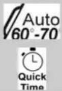 | AUTO QUICK | Pans and dishes with normal dirt, even with dried-on residues. | Cold prewash Wash at 65°C Cold rinse Rinse at 70°C | 80 | 15 1,50 | |
| 9 | 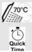 | ULTRA CLEAN QUICK (*) | Very dirty pans and dishes, even with dried-on residues. | Prewash at 45°C Wash at 70°C 2 cold rinses Rinse at 70°C | 100 | 18 1,72 | |
To run programs 6, 7, 8 or 9 the user first has to select the QUICK TIME option (6), which cuts the program duration but generates a slight increase in water and electricity consumption. The option is automatically disabled at the end of the program.
(*) The "ULTRA CLEAN QUICK" program terminates with an anti-bacteria rinse that ensures a further reduction in the bacteria level. If the temperature falls during this stage of the program (e.g. because the door is opened or due to a power blackout), the program lights (2) flash to warn that the anti-bacteria effect is not guaranteed.
(1) Average power consumption with the softener set on level 2..
(2) The cycle duration and power consumption may vary according to the water and room temperatures, and the type and amount of dishes.

The washing cycle will not take place if the dishwasher door is left open or not properly closed.
3.2 Washing programs

Before starting a washing program make sure that:
• The water supply tap is open.
- The correct amount of detergent has been added to the dispenser.
• The baskets have been correctly loaded.
- The spray arms are able to rotate freely and without obstruction.
• The dishwasher door is securely closed.
natural_image
Simple line drawing of a mechanical valve or fitting with no text or symbolsQUICK TIME (available in all programs except the soak program)
Select this option together with any washing program (except the soak program) to SHORTEN the cycle. To activate this option, press button (6) (light 7 comes on) after selecting the program required.
The option is automatically deactivated at the end of the program.

text_image
2 3 4 5 11 10 7 6 9 8 13 12 QuickTime end Auto 60°-70° 70°C 1/2 U2 QuickTime 3/1 1"3/1" OPTION BUTTON
(available in all programs except the soak program)
By pressing the button (8) you activate the "3/1" option, confirmed when the relative light comes on. This option has been studied for the use of dishwashing powder or tablets with integrated substances in place of regenerating salt or rinse-aid known on the market as "3 in 1" or "triple action" products; in this case the dishwasher will use the product in an optimal way avoiding salt and rinse-aid consumption, which could already be found in the dishwasher.
Note: When selecting the "3/1" button, it is normal that the salt and rinse-aid lights remain on, if their containers are empty.
SELECTING HALF LOAD WASH
(available in all programs except the soak program)
This function is ideal for small loads and saves water and electricity. It is controlled by the HALF LOAD (10) button, with two alternatives:
1) Press the button once to select washing in the top basket (the relative light comes on);
2) Press the button a second time to select washing in the bottom basket (the relative light comes on);
3) Press the button a third time to return to the normal full load washing mode (washing in both baskets, both lights off).

When washing in the bottom basket only, the cutlery basket can be divided so that only half is used.

text_image
2 3 4 5 11 10 7 6 9 8 13 12 QuickTime end Auto 60-70°C 3/1 ①DELAYED START
(available in all programs except the soak program)
The PROGRAM DELAY button (12) can be pressed to delay the start of the program by up to 9 hours. This means that the dishwasher can be operated at the time of day of your choice. Press the button several times in succession and the display will show the delay with which the appliance will start, beginning from 9 hours.
CANCELLING THE CURRENT PROGRAM
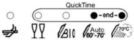
- To cancel the currently selected program, open the door and hold down the PROGRAM SELECTION (3) button for a few seconds until the indicator lights for programs 4 and 5 illuminate simultaneously (the word "end" is displayed on the window).
text_image
QuickTime - end - A10 Auto 60°-70° 70°C- Close the door.
- After approximately 1 minute the dishwasher will advance to the end of cycle.
CHANGING THE PROGRAM
To change the program in progress, simply open the door and select a new program. When the door is closed the dishwasher will automatically select the new program.

TO SAVE ON ENERGY! ... AND PROTECT THE ENVIRONMENT
• Always try to run the dishwasher fully loaded.
- Do not wash the dishes in running water.
- Use the washing program that is most appropriate for each type of load.
- Do not carry out any preliminary rinsing.
• If available, connect the dishwasher to a hot water supply up to 60°C.
TO CUT DOWN ON DETERGENT CONSUMPTION! ... AND PROTECT THE ENVIRONMENT
The phosphates contained in dishwasher detergents are harmful to the environment. To avoid using excessive amounts of detergent and to save on electricity, observe the following:
- separate the more delicate items from dishes that are more resistant to aggressive detergents and high temperatures;
• do not pour the detergent directly on the dishes.

If the door has to be opened while washing is in progress, the program will be interrupted. The relative light will keep flashing and a beeper will signal that the cycle has not been completed. You must wait about 1 minute before closing the door to restart the program. When the door is closed the program will continue from where it was interrupted. This operation should only be carried out if strictly necessary, because it might cause problems in execution of the program.

text_image
2 3 4 5 11 10 7 6 9 8 13 12 QuickTime end- Auto 70°C 3/1 ①END OF CYCLE
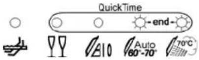
At the end of the washing cycle the dishwasher gives a short acustic signal and the program indicators nr 4 and 5 start blinking (the word "end" is displayed on the window).
text_image
QuickTime end Auto 70°C 10 60°-70°To switch off the dishwasher, open the door and press the ON/OFF button (1).
REMOVING THE DISHES
At the end of the washing program, wait at least 20 minutes before removing the dishes, to allow them to cool down. To prevent any water droplets on the upper basket from falling on the dishes in the lower basket, it is advisable to unload the lower basket first, and then the upper basket.
4. Operating instructions
Once the dishwasher has been correctly installed, prepare for use as follows:
- Adjust the water softening system;
- Add the regenerating salt;
- Add the rinse aid and detergent.

4.1 Using the water softening system
The amount of scale contained in the water (water hardness index) can cause whitish staining on the dry dishes, which tend to become dull over time. The dishwasher is equipped with an automatic softening system which uses a special regenerating salt to reduce the hardness of the water.
The dishwasher is factory set for water hardness level 3 (average hardness 41-60°dF - 24-31°dH).
text_image
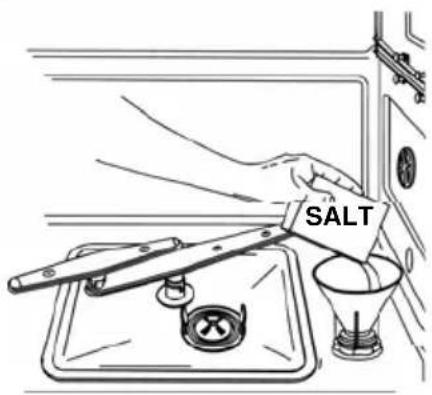
SALTWhen using water of medium hardness, the regenerating salt container should be refilled after approximately 20 washing cycles. The salt container can hold approximately 1.7 Kg of salt in grains. The container is situated at the bottom of the dishwasher. After removing the lower basket, unscrew the salt container cap by turning it anticlockwise and pour in the salt using the funnel supplied with the dishwasher. Before replacing the cap, remove any salt residues from around the opening.

- When using the dishwasher for the first time, in addition to the salt it is also necessary to add one litre of water to the container.
- Each time the salt container is refilled, make sure that the cap is securely closed. The mixture of water and detergent must never penetrate the salt container, as this would compromise the operation of the regeneration system. In the event of this occurring, the warranty will be invalidated.
- Only use regenerating salt specially formulated for domestic dishwashers. If using salt tablets, do not fill the container completely.

- Do not use table salt as it contains insoluble substances which, over time, may damage the water softening system.
- When necessary, refill the regenerating salt container before starting the washing program. In this way, the excess saline solution will be immediately removed by the water; the prolonged presence of salt water inside the tank may lead to corrosion.

Be careful not to confuse the salt and detergent packages; adding detergent to the salt container will damage the water softening system.

text_image
2 3 4 5 11 10 7 6 9 8 13 12 QuickTime end Auto 60-70 70°C S 1/5 1/2 QuickTime 3/1 ①ADJUSTING THE WATER SOFTENING SYSTEM
NOTA: for the setting below to be possible, a washing program other than the soak program must be set.
Press the PROGRAM DELAY button (12) and keep it pressed until the preset value appears followed by a full stop (normally 3.). Release the button then press it again in succession to display the value required, referring to the table.
The 6 setting levels available will appear in this order:
3., 4., 5., 0., 1., 2..
When the value required appears on the display, release the button; after 5 seconds the system automatically returns to setting of the program delay, and the setting will be made with the chosen value.
N.B.: the display shows the water hardness setting and the program delay. The dot (.) after the number indicates that the water hardness setting is being displayed. If the dot (.) does not appear, the program delay is being displayed.
WATER HARDNESS TABLE
| WATER HARDNESS | SETTING |
| German Degrees (°dH) French Degrees (°dF) | |
| 0 - 4 0 - 7 Setting N. 1 NO SALT | |
| 5 - 15 8 - 25 Setting N. 1 | |
| 16 - 23 26 - 40 Setting N. 2 | |
| 24 - 31 41 - 60 Setting N. 3 | |
| 32 - 47 61 - 80 Setting N. 4 | |
| 48 - 58 81 - 100 Setting N. 5 |
Contact your local water board for information on the hardness of your water supply.
4.2 Using the rinse aid and detergent dispensers
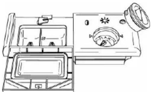
The detergent and rinse aid dispensers are situated on the inner part of the door: the detergent dispenser is on the left, and the rinse aid dispenser is on the right.
natural_image
Line drawing of a vintage-style refrigerator with front panel and side door (no text or symbols)
With the exception of the SOAK program, before every washing cycle it is necessary to add the required amount of detergent to the detergent dispenser. The rinse aid, on the other hand, should only be added as required.

ADDING THE RINSE AID
The rinse aid helps the dishes dry faster and prevents the formation of scale deposits and staining; it is automatically added to the water during the final rinse cycle, from the container situated on the inner side of the door.
natural_image
Line drawing of a mechanical component with a fan and gear (no text or symbols)To add rinse aid:
- Open the door.
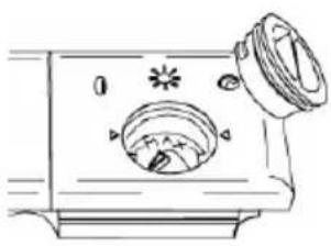
- Rotate the container cap anticlockwise by 14 of a turn and remove it.
- Add the rinse aid until the container is full (approximately 140 cc). The optical level indicator on the side of the cap should be completely obscured. Refill the rinse aid when the optical level indicator becomes clear again, or when the rinse aid warning light illuminates.
- Replace the cover and turn it in a clockwise direction.
- Use a cloth to remove any spillage of rinse aid which might lead to the formation of excess foam.
ADJUSTING THE RINSE AID DISPENSER SETTING
The dishwasher is factory set for medium water hardness. However it possible to change the setting by turning the dispenser's selector to the desired position: the amount of rinse aid dispensed is proportional to the selector position.
- To adjust the rinse aid setting, rotate the dispenser cap through a quarter turn in an anticlockwise direction and remove it.
- Then use a screwdriver to rotate the rinse aid selector to the desired position.
- Replace the cap, turning it clockwise.

- The amount of rinse aid must be increased if the washed dishes appear dull or feature circular stains.
- If, on the other hand, the dishes are sticky or have white streaks, it is necessary to reduce the rinse aid setting.
ADDING THE DETERGENT
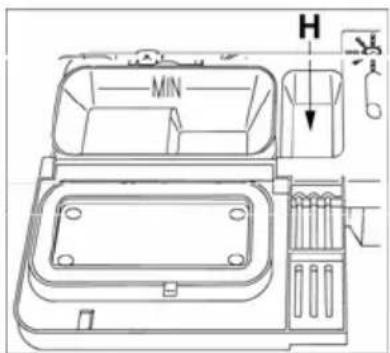
To open the detergent dispenser cap, lightly press the button P. Add the detergent and close the cap carefully.
During the washing cycle, the dispenser will be opened automatically.
text_image
MIN H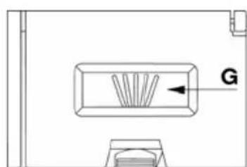
natural_image
Simple line drawing of a rectangular object with a fan-like pattern inside, labeled 'G' and an arrow pointing to it (no text or symbols beyond the label)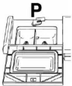
natural_image
Line drawing of a passenger airplane cabin with no visible text or symbols
- When a program with hot prewash is selected (see program table), extra detergent must be placed in the cavity G/H (depending on models).
- Use only detergents specially formulated for dishwashers. For optimal washing results it is important to use a good quality detergent.
- The detergent packs must be sealed and stored in a dry place to prevent the formation of lumps which may negatively affect washing results. Once opened the detergent packs should not be kept for too long, otherwise the detergent loses its effectiveness.
- Do not use detergents formulated for washing dishes by hand, because they produce a great deal of foam and may negatively affect the operation of the dishwasher.
- Add the correct amount of detergent. An insufficient amount of detergent will result in a partial removal of dirt from the dishes, whereas an excessive amount is wasteful and does not improve the washing results.

- The market offers liquid and powder detergents with differing chemical compositions, which may contain phosphates, or be phosphate-free but contain natural enzymes.
- Detergents containing phosphates are more effective against grease and starch at temperatures above 60°C.
- Enzyme detergents, on the other hand, are also effective at lower temperatures (from 40 to 55°C) and are more easily biodegradable. With enzyme detergents it is possible to obtain at low temperatures comparable results to those which can only be achieved at 65°C using traditional detergents.
For the safeguarding of the environment we recommend the use of phosphate- and chlorine free detergents.
- Also available are tablet detergents which state that no salt or rinse aid is required. In some cases, these detergents might not give good results, especially with short and/or low-temperature washing cycles.
If performance problems (e.g. a white coating on the tank or dishes, poor drying, dirt on dishes at the end of the wash) are noted, users are advised to return to conventional products (granular salt, powder detergent and liquid rinse aid).
However, please note that on return to the use of conventional salt, a number of cycles will be required before the system becomes fully efficient again, so traces of white coating may still be found on the tank and dishes. If the problem persists for too long, contact the After-Sales Service.
- When using detergent in tablet form (bear in mind that we recommend the use of three separate products: detergent, salt and rinse aid), place the tablets in the cutlery rack. The dispenser is designed to use powder or liquid detergent and the door does not open completely during the washing cycle. This means that a tablet is not completely dissolved (released), which may lead to the following:
- not enough detergent released during the cycle, with poor washing results;
- the detergent forms a solid block in the distributor and is released during the final rinse cycle.

The introduction of detergent into the rinse aid dispenser, even in liquid form, will damage the dishwasher.
4.3 General warnings and recommendations

Before using the dishwasher for the first time, it is advisable to read the following recommendations concerning dish types to be washed and their loading.
There are generally no constraints on the washing of domestic dishes, but in certain cases it is necessary to take their characteristics into account.
Before loading the dishes into the baskets it is necessary to:
- remove coarse food remains: e.g. bones, fish-bones, etc. which may clog the filter or damage the wash pump.
- soak any pots or pans with burnt-on food remains on the bottom to facilitate removal, then load them into the LOWER BASKET.
There is no need to pre-wash the dishes under running water before loading them into the baskets since this only wastes water.
Correct loading of the dishes helps ensure optimal washing results.
WARNING!
- Make sure that the dishes are securely in place so that they cannot tip over or obstruct the rotation of the spray arms during the washing cycle.
- Do not place very small objects in the baskets as these could fall and obstruct the spray arms or the wash pump.
- Containers such as cups, bowls, glasses and pots should always be loaded with the opening facing downwards and with any cavities at an angle, to allow the water to drain out.
- Do not stack dishes or place them in such a way that they cover one other.
- Do not place glasses too close together because they may knock against each other and break, or there might be staining at the point where they touch.
MAKE SURE that the items being washed are dishwasher-safe.

Items which are not dishwasher-safe:
- Wooden dishes, pots or pans: these may be damaged by the high washing temperatures.
- Handcrafted items: these are rarely suitable for washing in a dishwasher. The relatively high water temperatures and the detergents used may damage them.
- Plastic dishes: heat resistant plastic dishes must be washed in the upper basket.
- Dishes and objects in copper, tin, zinc or brass: these tend to stain.
- Aluminium dishes: items made from anodised aluminium may lose their colour.
• Silverware: silver items may stain. - Glass and crystal: in general, glass and crystal objects can be washed in the dishwasher. However, certain types of glass and crystal may become dull and lose their clearness after many washings. Therefore, for these items we recommend using the least aggressive program available.
- Decorated items: the decorated objects available on the market are generally able to withstand washing in the dishwasher, although the colours may fade after a great many washes. If in doubt as to the fastness of the colours, it is advisable to wash just a few items at a time for approximately one month.
4.4 Using the baskets
The dishwasher has a capacity of 14 place-settings, including serving dishes.
LOWER BASKET
The lower basket receives the full force of the lower spray arm, and should therefore be used for the “toughest” items with a heavier degree of soiling. All types and combinations of loads are permitted, provided that the dishes, pots and pans are arranged with all the soiled surfaces exposed to the water jets coming from the bottom.
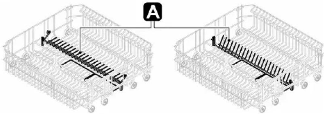
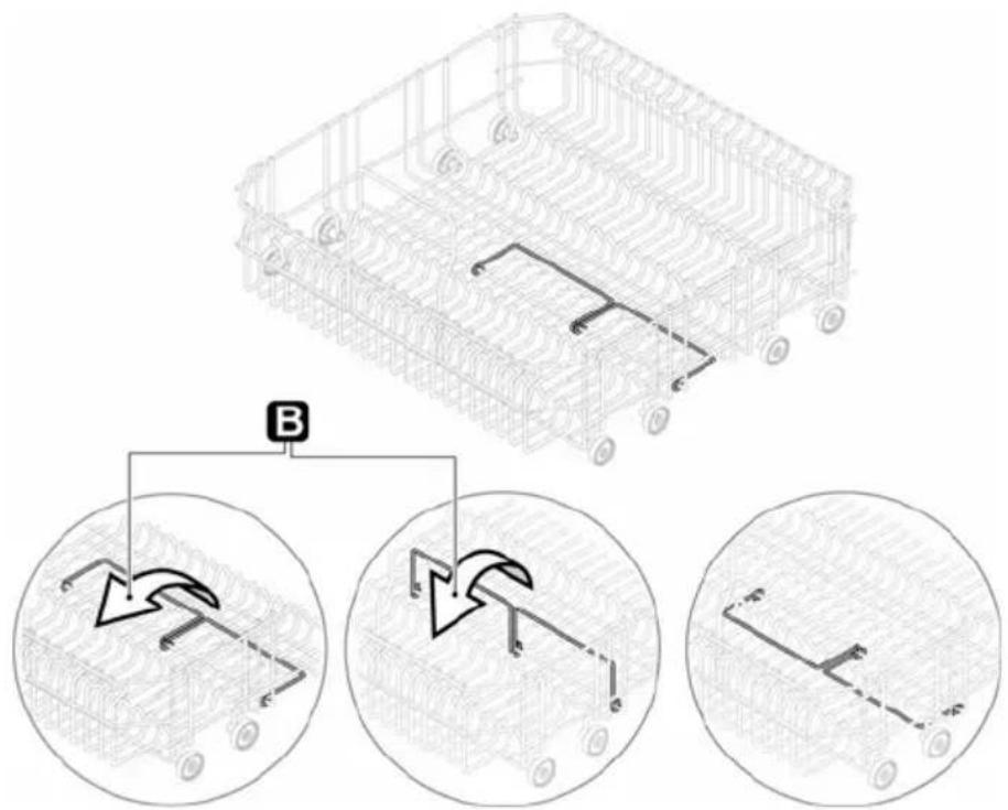
The rear of the basket is fitted with a rack to take large plates (A). To use it, simply lift it until it locks in place.
text_image
AIn the front there are one or two supports (depending on the models) for small plates (B). To use them, they have to be turned towards the front of the dishwasher.
text_image
Technical diagram showing a vehicle chassis with labeled components and three circular insets illustrating mechanical or electrical system configurations.LOADING THE LOWER BASKET
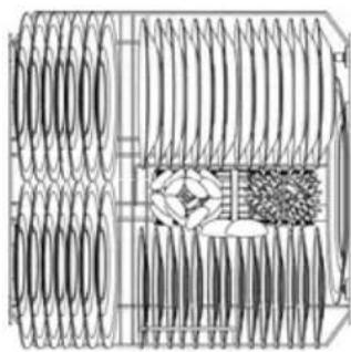
Carefully load flat plates, soup plates, dessert and serving dishes, positioning them vertically. Pots, pans and their covers must be loaded upside down. When loading soup plates and dessert bowls, be sure to leave a gap between them.
Loading examples:
natural_image
Technical line drawing of a mechanical component with coiled spring and housing (no text or symbols)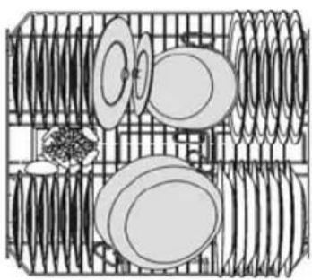
natural_image
Diagram of a mechanical or electrical component with circular components and coiled springs, no visible text or symbols.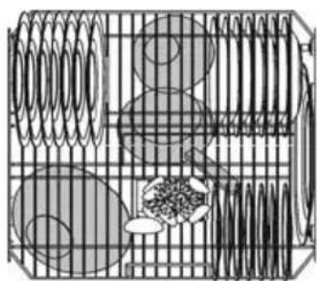
natural_image
Diagram of a mechanical or electrical component with coiled springs and circular elements, no visible text or symbols1 / 2 LOAD
CUTLERY BASKET
Cutlery must be placed with the tips facing downward.
Long items of cutlery (ladles, wooden spoons, kitchen knives, etc.), which might interfere with the upper spray arm must be placed in the upper basket, ensuring that knife tips do not project from the basket.
The cutlery basket features an exclusive system of independent sliding tip-up supports, offering a series of combinations to allow optimum use of the space available.
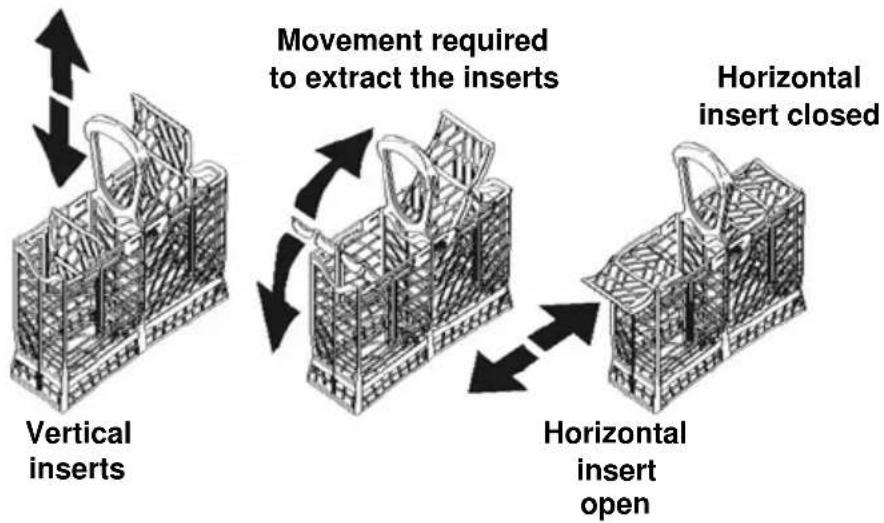
flowchart
graph TD
    A["Vertical inserts"] --> B["Movement required to extract the inserts"]
    B --> C["Horizontal insert closed"]
    C --> D["Horizontal insert open"]
It can also be separated into two parts, particularly useful when carrying out a 12 load wash (on models with this function).
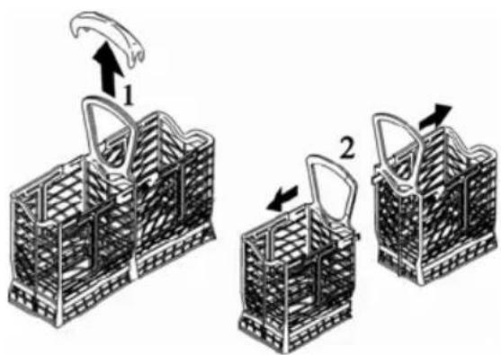
text_image
Diagram illustrating two steps of a woven basket with labeled parts and directional arrows indicating movement.UPPER BASKET
It is recommended to load the upper basket with small- or medium-sized items such as glasses, small plates, tea or coffee cups, shallow bowls and light objects made from heat resistant plastic. If the upper basket is used in the lowermost position, it can also be loaded with serving dishes, provided they are only slightly soiled.
LOADING THE UPPER BASKET
Load plates facing forward; cups, bowls etc. must always be facing downwards. The left-hand side of the basket can be loaded with two layers of cups and glasses. The centre can be filled with plates and side-plates, fitted upright into the supports provided.
Loading examples:
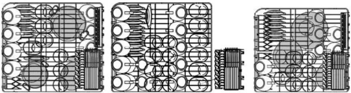
natural_image
Technical line drawings of three mechanical components with internal gear and housing (no text or symbols)12 LOAD
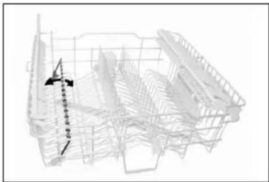
Depending on the models, the basket may be equipped with some or all of the following accessories:
- Supports for cups or long objects (ladles, spoons...), on the left; can be tipped to the vertical position when not in use.
- Long-stemmed glass holder, on the left; to use, simply lift and fix onto the hooks provided.
- Cutlery racks, on the right, designed for knives and teaspoons; for teaspoons, pull out the sliding support. The racks can be tipped to the vertical position when not in use.
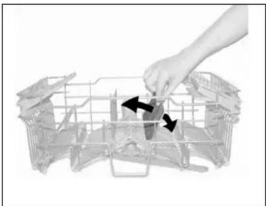
- Fixed or movable racks in the middle. The movable supports can be fixed vertical, resting on the bottom of the basket when not in use, or set in the intermediate position, as required.
natural_image
Wireframe 3D model of a building interior with structural framework and directional arrows (no text or symbols)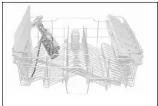
natural_image
Technical line drawing of a mechanical assembly or structural frame (no visible text or symbols)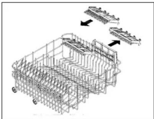
flowchart
graph TD
    A["Car Frame"] --> B["Assembly"]
    B --> C["Multi-Component Assembly"]
    C --> D["Final Assembly"]
    style A fill:#f9f,stroke:#333
    style B fill:#ccf,stroke:#333
    style C fill:#cfc,stroke:#333
    style D fill:#fcc,stroke:#333
natural_image
Hand placing a component into a wire cage with arrows indicating motion (no text or symbols)ADJUSTING THE UPPER BASKET
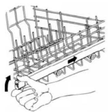
Version A: the upper basket can be adjusted in two positions, according to the user's needs and according to the height of the dishes in the lower basket. Proceed as follows:
• pull out the right-hand basket guide;
- remove the stop, first releasing it as shown in the diagram;
- push the guide to free the wheels;
- fit the upper or lower pair of wheels into the guide, depending on the setting required;
• return the stop to its original position.
natural_image
Hand holding a steel rebar structure with arrows indicating force direction (no text or symbols)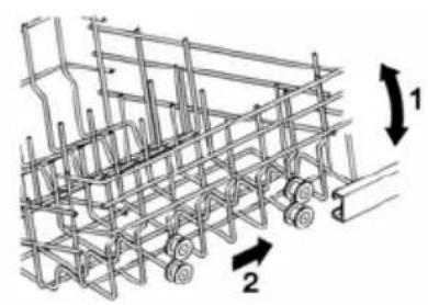
natural_image
Technical line drawing of a mechanical assembly with numbered components (1 and 2), no readable text or symbols present.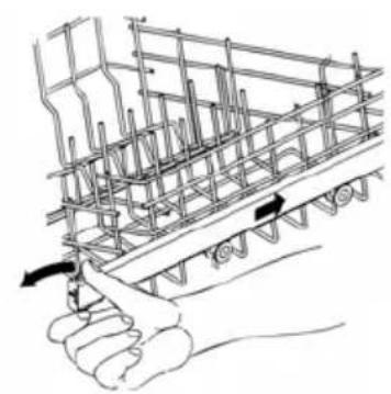
natural_image
Hand holding a structural steel frame with rebar, showing force application (no text or symbols)Version B:
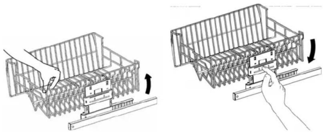
- pull out the basket to its limit position and pull the right side upwards. At this point it is possible to load larger sized plates into the lower basket.
- To return to the original position, pull out the upper basket again and press the release lever.
natural_image
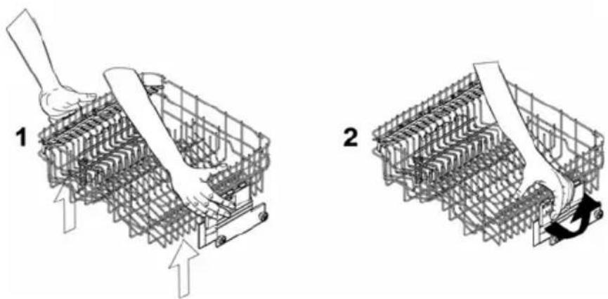
Two technical diagrams showing hand positioning of a structural frame with arrows indicating movement (no text or symbols present)Version C: the top basket can be set in three different positions on both sides. The rack must be level on both sides.
To raise the basket lift it, pulling on the front edge (1), to the first or second catch depending on the height required. To lower it, pull the release lever (2).
This is also possible with the basket loaded, but in this case when lowering the basket it should be held steady with one hand to avoid knocking the dishes.
natural_image
Two technical diagrams showing a mechanical assembly with arrows indicating motion, no text or symbols present.5. Cleaning and maintenance
Before carrying out any work, always unplug the appliance from the electrical supply or switch off the all-pole disconnection device.
5.1 General warnings and recommendations
Avoid the use of acidic or abrasive detergents.
Clean the outer surfaces and door-lining of the dishwasher regularly using a soft cloth moistened with water or with a normal detergent suitable for painted surfaces. Clean the door gaskets with a damp sponge. Periodically (once or twice a year) it is advisable to clean the tank and gaskets, using a soft cloth and water to remove any deposits.
text_image
Technical diagram showing a valve assembly with labeled component A and directional arrowCLEANING THE WATER INTAKE FILTER
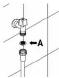
The water intake filter A located at the outlet of the water supply tap needs to be cleaned periodically.
After having closed the water supply tap, unscrew the end of the water intake hose, remove the filter A and clean it delicately under running water. Reassemble filter A in its seat and carefully screw the water intake hose back into position.
CLEANING THE SPRAY ARMS
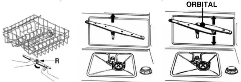
The spray arms can be easily removed for periodic cleaning of the nozzles, to prevent possible clogging. Wash them under running water and carefully replace them in their seats, checking that their rotary movement is in no way impeded.
• To remove the upper spray arm, unscrew locking ring R.
- To remove the lower spray arm, simply lift it up, pulling by the central part.
- To remove the orbital spray arm assembly, take hold of the longer arm and pull the orbital unit upward. Wash the arms under a jet of running water and return them carefully to their seat. After reassembly, check that the spray arms turn freely. Otherwise, check that they have been installed correctly.
text_image
R ORBITALCLEANING THE FILTER UNIT
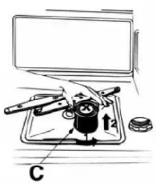
- It is advisable to periodically inspect the centre filter C and, if necessary, to clean it. To remove the filter, grip the tabs, turn them anticlockwise and lift upwards;
- push the centre filter D from the underside to remove it from the micro-filter:
- separate the two parts which make up the plastic filter by pressing the body of the filter in the zone shown by the arrows;
- remove the centre filter by lifting it upwards.
text_image
Diagram of a mechanical device with labeled parts and directional arrows, including a monitor and base plate.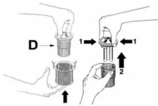
text_image
D 1 1 2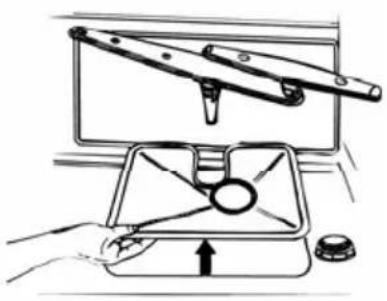
natural_image
Illustration of a hand using a tool to lift a fan inside a box, with no visible text or symbols.
GENERAL WARNINGS AND RECOMMENDATIONS FOR CORRECT MAINTENANCE:
- The filters should be cleaned under running water using a stiff brush.
- When removing the filter, take care that there are no food residues on it. If any residues fall into the washing pit they might block hydraulic components, or foul the spray arm nozzles.
- It is essential to thoroughly clean the filters according to the above instructions: the dishwasher cannot function if the filters are clogged.
- Carefully replace the filters in their seats, to avoid damaging the wash pump.
PROLONGED DISUSE:
- Run the soak program twice in succession.
• Unplug the power cord from the socket. - Leave the door slightly open, in order to prevent the formation of unpleasant odours inside the washing tank.
• Fill the rinse aid dispenser. - Shut off the water supply tap.

BEFORE STARTING THE DISHWASHER AFTER PROLONGED DISUSE:
- Check that there are no deposits of sludge or rust inside the water pipe: if there are, allow the water to run from the water supply tap for a few minutes.
• Plug the power cord back into the socket. - Reconnect the water intake hose and open the tap again.
TROUBLESHOOTING MINOR PROBLEMS
In some cases it is possible to remedy minor problems by referring to the following instructions:
If the program fails to start, check that:
• the dishwasher is connected to the electrical power supply;
• there is no power failure;
• the water tap is open;
- the dishwasher door is properly closed.
If water remains inside the dishwasher, check that:
• the drain hose is not kinked;
• the drain siphon is not obstructed;
• the dishwasher filters are not clogged.
If the dishes are not being cleaned properly, check that:
• the correct amount of detergent has been added;
• there is regenerating salt inside the special container;
• the dishes are being loaded correctly;
- the selected program is suitable for the dish types and their degree of soiling;
- all the filters are clean and positioned correctly;
- the spray arm nozzles are not obstructed;
• there is no object obstructing the rotation of the spray arms.

If the dishes fail to dry or remain dull, check that:
- there is rinse aid inside the special container;
- the rinse aid dispenser setting is correct;
- the detergent used is of good quality and has not lost its effectiveness (for example, through incorrect storage, with the box left open).
If the dishes show signs of streaking, staining, etc., check that:
- the rinse aid dispenser setting is not too high.
If there are visible traces of rust inside the tank:
- the tank is made of steel, and therefore any rust marks are due to external elements (fragments of rust from the water pipes, pots, cutlery, etc.). Special products are commercially available to remove such marks;
- check that the amount of detergent being used is correct. Certain detergents can be more corrosive than others.
- check that the cap of the salt container is securely closed, and that the water softening setting is correct.
If after following the above troubleshooting instructions the problem persists, call the nearest After-Sales Centre.
WARNING: any operations performed on the appliance by unauthorised persons are not covered by the warranty and shall be paid for by the user.
6. Troubleshooting
The dishwasher is capable of signalling a number of faults through the simultaneous illumination of several indicator lights, with the following meanings:
| FAULT | DESCRIPTION | |
| E1 |  | Acquastop failureThe anti-flooding system has been activated (for the relevant models only). The system is tripped in case of water leaks. Contact the after-sales service. |
| E2 | 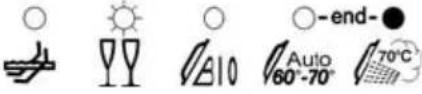 | Safety levelThe system which limits the water level inside the dishwasher has been tripped. Interrupt the program and switch off the dishwasher. Switch the dishwasher back on, program it again and start the washing cycle. If the problem persists, contact the after-sales service. |
| E3 | 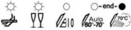 | Water heating malfunctionThe water is not heated or the heating parameters are not correct. Repeat the washing program; if the problem persists, contact the after-sales service. |
| E4 | 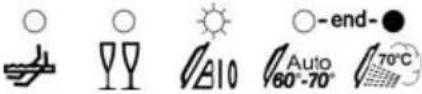 | Water temperature monitoring malfunctionInterrupt the program and switch off the dishwasher. Switch the dishwasher back on, program it again and start the washing cycle. If the problem persists, contact the after-sales service. |
| E5 | 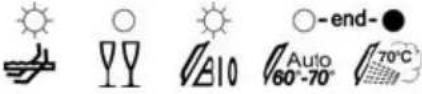 | Water intake malfunctionThe appliance does not take in water or does not do so correctly. Check that the water connections are correct, the water intake tap is turned on and the filter is not fouled. If the problem persists, contact the after-sales service. |
| E6 | 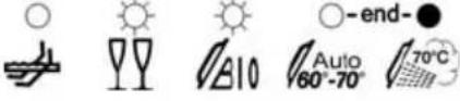 | Water pump-out malfunctionThe appliance does not pump out the water or does not do so correctly. Check that the drain hose is not kinked or crushed and that the siphon and filter are not fouled. If the problem persists, contact the after-sales service. |
| E7 | 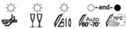 | Turbine flow-regulator malfunction(for the relevant models only)The appliance is not able to "measure" the amount of water loaded accurately. Interrupt the program and switch off the dishwasher. Switch the dishwasher back on, program it again and start the washing cycle. If the problem persists, contact the after-sales service. |
| E8 | 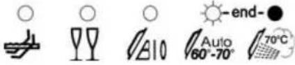 | Alternate washing system malfunctionInterrupt the program and switch off the dishwasher.Switch the dishwasher back on, program it again and start the washing cycle. If the problem persists, contact the after-sales service. |
| E9 |  | Water intake system malfunctionContact the after-sales service. |

Light off

Light on

Light flashing
If an alarm occurs the appliance interrupts the program in progress and signals a fault.
- Alarms E1, E2, E3, E4, E8 and E9 interrupt the current program immediately.
- The E5, E6 alarms interrupts the running program once the cause is resolved, it will bring bach the execution of the program.
- The alarm E7 is visualized at the end of the cycle that comes, however, brought to the end since the operation of the dishwasher is not harmed.
To "reset" an alarm is necessary:
- Open and close the door, or turn off and on the machine. At this point is possible to program the dishwasher again.

If the malfunction persists, contact your authorised Service Centre.
| TECHNICAL DATA | |
| Width | 597 ÷ 599 mm |
| Depth (depending on models) | 550-570-600 mm |
| Height (depending on models) | from 850 mm to 870 mm from 890 mm to 910 mm |
| Capacity | 14 Standard place settings |
| Water supply pressure | min. 0,05 - max. 0,9 MPa (min. 0.5 – max. 9 bar) |
| Electrical characteristics | See rating plate |
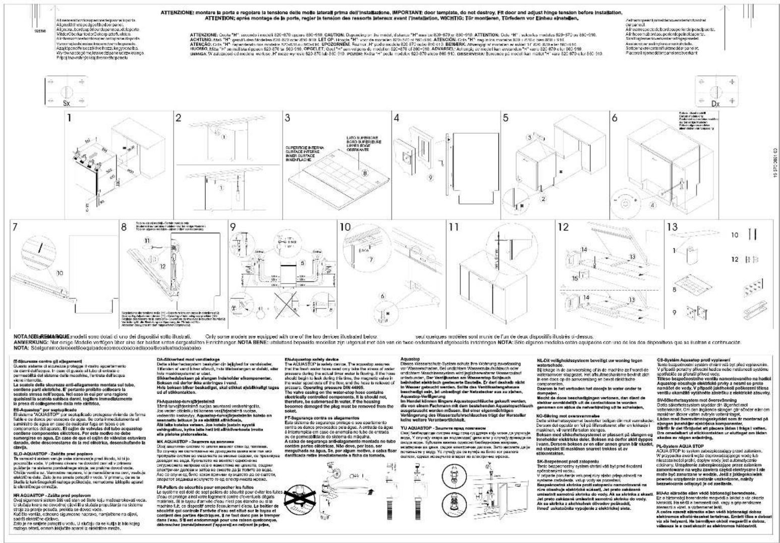
At menadełkiwarkcypentemwarkcypentem wąterba. Algozolidt eno podgosh do parneł. Algozolidt, bordup mierduperemwarkcypente. Mildončekarted o Zelcarp atort, obch. Gli-hamamtekartedom kredu warkcypentem wąterba. Vystropladshomniuska sertocu rchepań. Azajlpołnech zorszle vlaszku kegyone la. Wytwn na odogę me krawe zdrane ucluw krajce o Prpól inavodny kraj dverwopenego.
ATTENZIONE: Cada "H" secondo im media 820-870 arcu 890-910. CAUTION: Departuring the media, distance "H" may be 820-870 arcu 890-910. ATTENTION: Cada "H", selon la media 820-870 arcu 890-910. ACHTUNG: "H", general den direction 820-870 arcu 890-910. LET OP: "H". "H" may be 820-870 arcu 890-910. ATTENZION: H", reg in line of media 820-870 arcu 890-910. ATENCAO: Cada "H", dependents me media 820-870 arcu 890-910. UPOZORNEM: Razer, "H" may be 820-870 arcu 890-910. BEMERK, "H", engangly me media 820-870 arcu 890-910. ENSFERME: Cada "H", not a media 820-870 arcu 890-910. ENSFERME: Cada "H", not a media 820-870 arcu 890-910. UWAGA: W zuzhou di media, webso: H, meze wyne 820-870 arcu 890-910. POZOR: Kvaria "Poda media 820-870 arcu 890-910. OBSERVERA: Burancie pc media, kund mda" "H" may be 820-870 arcu 890-910.
Zahlreopement, namelbeterenwertenzenkred durchselt. Aftrespectrode bandouperiende penicjents. Alltheo mal bedau periode polnolaceus. Sollinglenerwerteerter ingepanelle Asistenteer andinglenerwerte. Sollteneare contentiulme dolar pares Placeral ingemddompanalenzverkant
(T-S)curems contro oil (lagement)
EN-MODELS WITH AUTOMATIC OPENING
natural_image
Exterior view of a white electronic device with two green arrows pointing to a component (no text or symbols visible)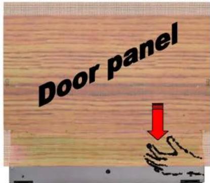
text_image
Door panel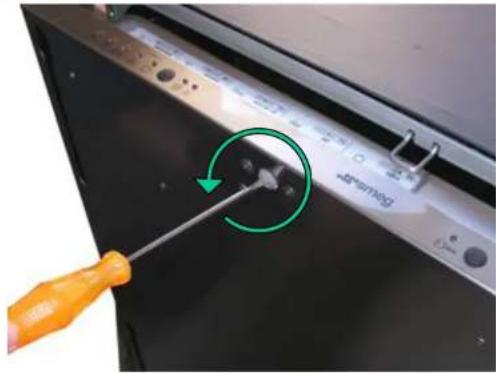
natural_image
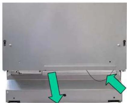
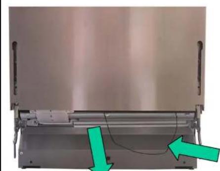
Close-up of a kitchen sink with a screwdriver inserted, showing a green circular arrow indicating rotation (no text or symbols visible)Models with automatic opening have a string (accessible from the front even when the door panel is fitted) which allows the door to be opened when the appliance is not receiving electrical power, by just pulling it down.
Before fitting the door panel, the electric opening button should be partially extracted (by turning it anticlockwise).
text_image
smec TO OPEN PRESS HERE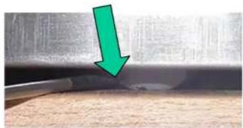
natural_image
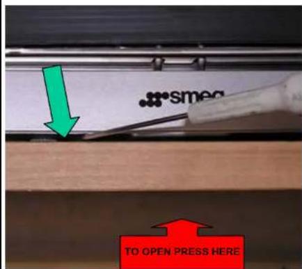
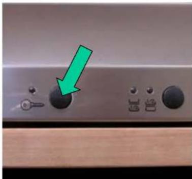
Close-up of a metallic surface with a green arrow pointing downward, showing texture and wear (no text or symbols)Fine adjustment of the button must be carried out with the door panel fitted, using a straight head screwdriver on the knurling around the edge of the button. (Anticlockwise rotation = button towards outside of door; Clockwise rotation = button towards inside of door). To open the door press the centre of the door upwards until the beep is heard, then release it. If the door fails to open, press in the point shown again until the beep is heard, then release it.
natural_image
Close-up of a kitchen control panel with switches and a green arrow pointing to the knob (no text or symbols visible)WARNING: on occasion the door may fail to open in response to light pressure; if so, press again with gradually increasing force until the beep is heard, then release.
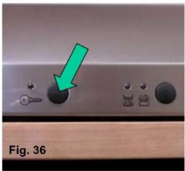
The dishwasher is fitted with a "child lock"; if this is activated, to open the door keep the door depressed until the 3rd beep is heard, then release it immediately. If the door is released before the 3rd beep, or not immediately after it, it will not open and the operation will have to be repeated.
1) Place the cardboard template on the inside of the panel and align it correctly (fig. 1, 2, 3)
2) Installation:
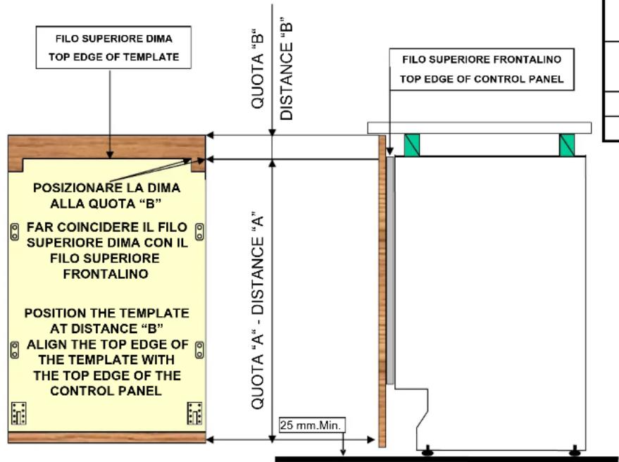
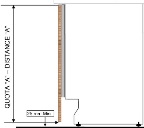
fig. 1a – standard: align the top edge of the template with the top edge of the panel (with the top edge of the door panel aligned with the top edge of the dishwasher control panel)
1b – customised: position the template at distance "B" (as shown in the diagram on the first page)
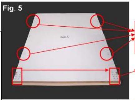
3) Check that the cardboard template is correctly positioned, then mark all the points where holes have to be drilled in the panel (fig. 4, 5, 6)
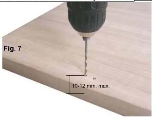
4) Make starter holes in the panel with a 2.5 mm bit, then make the holes for the bushes with a 6 mm bit, drilling to a depth of 10-12 mm MAX. (fig. 7)
5) Make starter holes in the bottom of the panel with a ∅ 1 mm bit, drilling to a depth of 10-12 mm MAX; at least two starter holes are recommended (fig. 8)
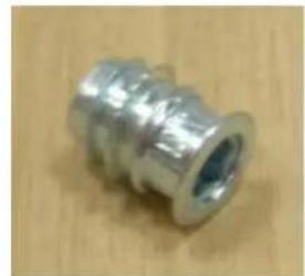
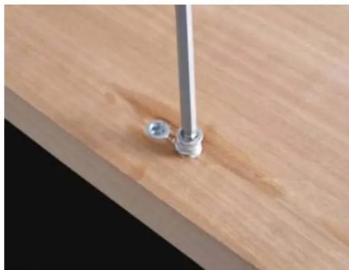
6) Fit the bushes (A) onto the panel, screwing them down until they are level with the surface of the panel itself (fig. 9, 10)
7) Fit the plastic inserts (I) into the bottom of the panel and secure them with the 8 flathead screws provided (H) (fig. 11)
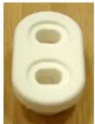
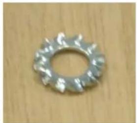
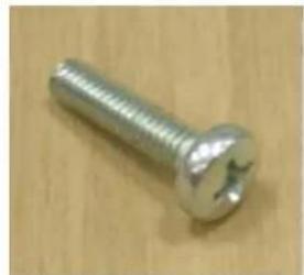
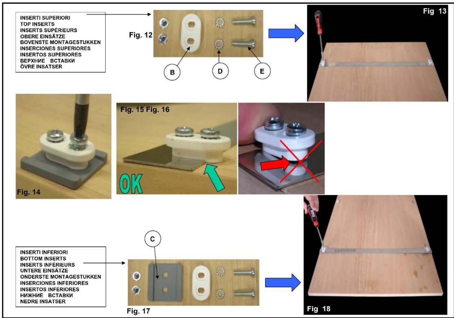
8) Fit the plastic inserts (B) using the screws (E) and the toothed washers (D), without tightening completely. Adjustment will be required before the screws are tightened completely (fig. 14)
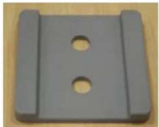
9) Place the metal template across the plastic inserts (fig. 13), aligning it so that it is centred on the panel, and push the bases of the plastic inserts into the slots in the template until they make contact (fig. 15, 16), then tighten the screws. Repeat the operation for the 2 bottom inserts (fig. 18).
WARNING!: fit the plastic spacers C (fig. 17) underneath the bottom inserts.
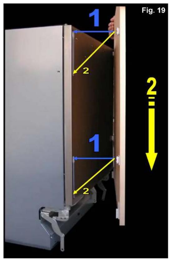
10) Connect the panel to the door of the dishwasher by inserting the plastic inserts into the slots provided on the front of the door (fig. 19, 20, 21).
WARNING: when done, check by hand that the door panel slides up and down.
11) Fit the plastic supports (G) provided onto the inserts (I) already fitted to the door panel (fig. 22)
12) Connect the arms of the hinges to the plastic supports using the screws (L) (fig. 23, 24, 25)
13) Fix the screws using the nuts (M) (fig. 26)
14) Keeping the support pressed down drill 3 starter holes with a ∅ 2.5 mm bit (fig. 27)
15) Finish fixing the door panel by tightening the screws (F) on the plastic insert, taking care to fit them into the starter holes just drilled (fig. 28)
16) ADJUSTING THE DOOR SPRING TENSION
The tension of the springs which open the door is adjusted by turning the screw accessible from the front of the dishwasher side panel, with the aid of a number 4 Allen key (fig. 29, 30)
17) MODELS WITH AUTOMATIC OPENING
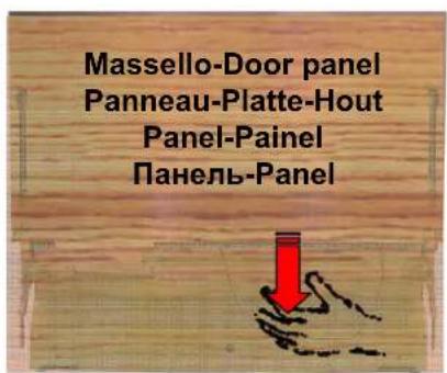
Models with automatic opening have a string (accessible from the front even when the door panel is fitted) which allows the door to be opened when the appliance is not receiving electrical power, by just pulling it down (fig. 31, 32)
18) Before fitting the door panel, the electric opening button should be partially extracted (by turning it anticlockwise) (fig. 33)
19) Fine adjustment of the button must be carried out with the door panel fitted, using a straight head screwdriver on the knurling around the edge of the button. (Anticlockwise rotation = button towards outside of door; Clockwise rotation = button towards inside of door) (fig. 34, 35).
To open the door press the centre of the door upwards until the beep is heard, then release it. If the door fails to open, press in the point shown again until the beep is heard, then release it (fig. 34)
20) The dishwasher is fitted with a "child lock"; if this is activated, to open the door keep the door depressed until the 3^rd beep is heard, then release it immediately. If the door is released before the 3rd beep, or not immediately after it, it will not open and the operation will have to be repeated (fig. 36).
SEQUENZA DI MONTAGGIO ANTA LUNGA
LONG DOOR PANEL ASSEMBLY SEQUENCE
SÉQUENCE DE MONTAGE PORTE LONGUE
natural_image
Exterior view of a beige wooden door or panel with a dark metal clip attached (no text or symbols visible)WARNING: Standard installation is recommended.
In case of customised installation (distance "B") present, lightweight door panels ( ≤ 8.5 kg) should be used.
text_image
FILO SUPERIORE DIMA TOP EDGE OF TEMPLATE QUOTA "B" DISTANCE "B" FILO SUPERIORE FRONTALINO TOP EDGE OF CONTROL PANEL POSIZIONARE LA DIMA ALLA QUOTA "B" FAR COINCIDERE IL FILO SUPERIORE DIMA CON IL FILO SUPERIORE FRONTALINO POSITION THE TEMPLATE AT DISTANCE "B" ALIGN THE TOP EDGE OF THE TEMPLATE WITH THE TOP EDGE OF THE CONTROL PANEL QUOTA "A" - DISTANCE "A" 25 mm.Min.INSTALLAZIONE PERSONALIZZATA CUSTOMISED INSTALLATION
| Quota “A” Distance “A” | ||||
| Model | Max.Min. | Molelessore Thickness | Peso Weight | |
| 2,5-938808 | ||||
| 2,5885881 | ||||
| 2,5-938808 | ||||
| 2,5885881 | ||||
| 2,5-938408 | ||||
| 2,5845841 | ||||
| 2,5-938408 | ||||
| 2,5845841 | ||||
| 2,5-938007 | ||||
| 2,5-938007 | ||||
text_image
QUOTA "A" - DISTANCE "A" 25 mm.Min.INSTALLAZIONE STANDARD STANDARD INSTALLATION
A
natural_image
Close-up of a metallic mechanical connector with flanged ends and central bore (no text or symbols visible)x 8
B
natural_image
White plastic push-button button on wooden surface (no text or symbols)x4
C
natural_image
Gray plastic mechanical component with two circular holes, placed on a wooden surface (no text or symbols visible)x 2
D
natural_image
Metal gear with serrated edge on wooden surface (no text or symbols)x8
E
natural_image
Close-up of a metallic screw with a circular head and star-shaped indentation, resting on a wooden surface (no text or symbols visible)x8
F
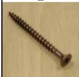
natural_image
Close-up of a wooden screw with threaded shaft and flange (no text or symbols visible)x 6
G
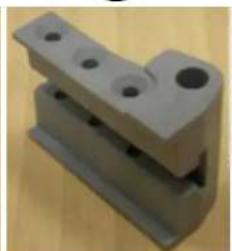
natural_image
3D rendered mechanical bracket component with mounting holes and a flat base (no text or symbols visible)x 2
H
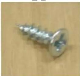
natural_image
Close-up of a metallic screw with threaded end and flange (no text or symbols visible)x 16
The Ground Truth image displays a single, solid horizontal line. According to Rule 2 (UNDERSCORE & LINE RULES), this is a stylistic or background line, not a placeholder underscore. Therefore, the OCR result must ignore it. The provided OCR content is "____", which consists of four underscores. This is an incorrect interpretation of the line as a placeholder, violating the rule that stylistic lines must be ignored. The OCR has hallucinated underscores where none should exist based on the GT's visual context. Hence, the OCR result is inconsistent with the Ground Truth.
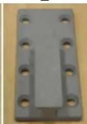
natural_image
Gray plastic mechanical part with multiple holes and a central rectangular slot (no text or symbols visible)x 2
L
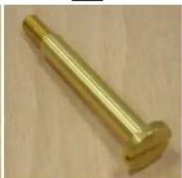
natural_image
Golden cylindrical metal bolt on a wooden surface (no text or markings visible)x 2
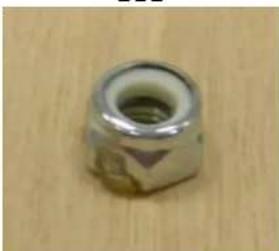
M
natural_image
Close-up of a metallic hexagonal nut with a hole, resting on a wooden surface (no text or symbols visible)x 2
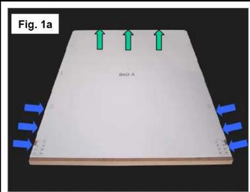
text_image
Fig. 1a B60.3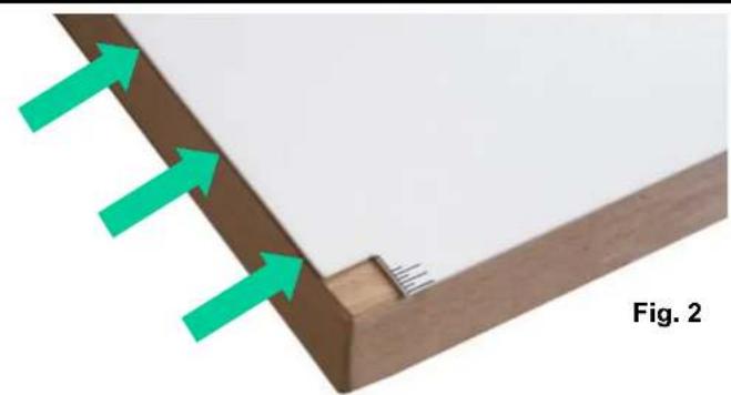
natural_image
Diagram showing green arrows pointing to a wooden panel corner with a small wooden base and small pins, labeled Fig. 2 (no text or symbols on the diagram itself)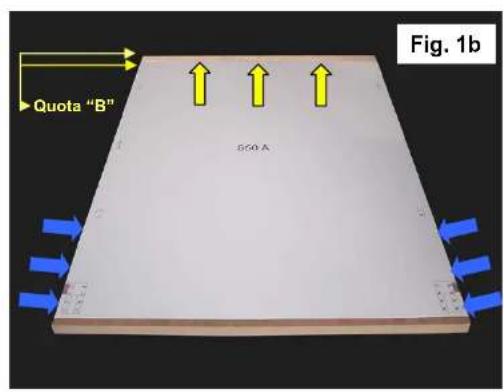
text_image
Quota "B" 500 A Fig. 1b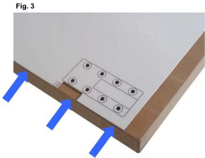
text_image
Fig. 3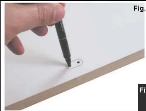
natural_image
Hand holding a pen writing on a white surface with a small circular mark, no visible text or symbolsPre-fori max. ∅ 2,5 mm-fori boccole max. ∅ 6 mm.
Starter holes max. ∅ 2.5 mm-bush holes max. ∅ 6 mm.
Pré-trous maxi. ∅ 2,5 mm-trous douilles maxi. ∅ 6 mm.
Vorbohrungen max. ∅ 2,5 mm - Löcher Hülsen max. ∅ 6 mm.
Prep.-gaten max. ∅ 2,5 mm-gaten bussen max. ∅ 6 mm.
Pre-agujeros máx. ∅ 2,5 mm agujeros casquillos máx. ∅ 6 mm
Pré-furos máx. ∅ 2,5 mm-furos para casquilhos máx. ∅ 6 mm
Предварительные отверстия макс. ∅ 2,5 mm - Отверстия втулок макс. ∅ 6 mm.
Rikthál max. diam. 2,5 mm - Hàl för bussningar max. ∅ 6 mm
Fig. 4a
text_image
Fig. 5 MGA A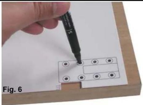
natural_image
Hand using a pen to insert or mark a small electronic component on a wooden surface (no text or symbols visible)pre-fori max. ∅ 2,5 mm. starter holes max. ∅ 2,5 mm.
pré-trous maxi. ∅ 2,5 mm. Vorbohrungen max. ∅ 2,5 mm.
prep.-gaten max. ∅ 2,5 mm. pre-agujeros máx. ∅ 2,5 mm
pré-furos máx. ∅ 2,5 mm.
предварительные отверстия макс. ∅ 2,5 mm
Rikthal max. ∅ 2,5 mm
pre-fori max. ∅ 1 mm. starter holes max. ∅ 1 mm.
pré-trous maxi. ∅ 1 mm. Vorbohrungen max. ∅ 1 mm
prep.-gaten max. ∅ 1 mm. pre-agujeros maxi. ∅ 1 mm
pré-furos max. ∅ 1 mm
предварительные отверстия макс. ∅ 1 mm
Rikthal maxi. ∅ 1 mm
text_image
Fig. 7 10-12 mm. max.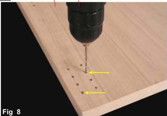
natural_image
Close-up of a drill bit on a wooden surface with two yellow arrows indicating specific points (no text or symbols present)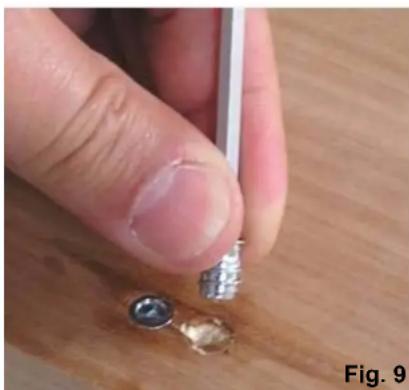
natural_image
Close-up of a finger holding a small metallic object on a wooden surface, with no visible text or symbols.Fig. 9 Fig. 10
natural_image
Close-up of a wooden table with a metal rod and two small bolts attached (no text or symbols visible)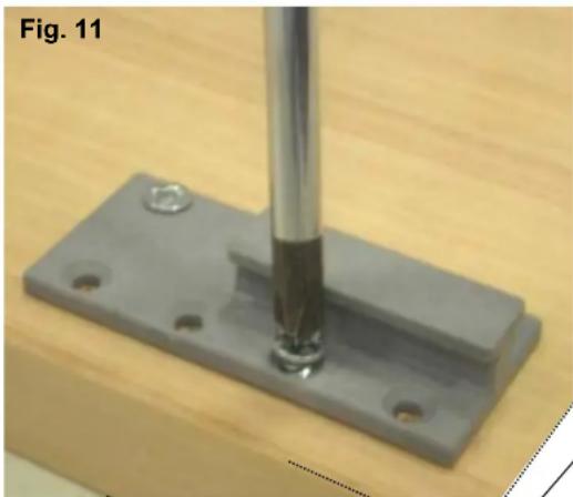
natural_image
Close-up of a mechanical component with a metallic screw and mounting base (no text or symbols visible)PARTE INFERIORE DEL PANNELLO
BOTTOM OF PANEL
PARTIE INFÉRIEURE DU PANNEAU
UNTERER TEIL DER PLATTE
ONDERSTE DEEL PANEEL
PARTE INFERIOR DEL PANEL
PARTE INFERIOR DO PAINEL
НИЖНЯЯ ЧАСТЬ ПАНЕЛИ
PANELENS NEDRE DEL
text_image
Fig. 19 1 2 1 2 2Fig. 20

natural_image
Interior view of a cabinet with a blue line and numbered label '1' pointing to the door (no text or symbols on the cabinet itself)Fig. 21

text_image
1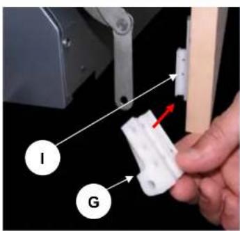
text_image
I G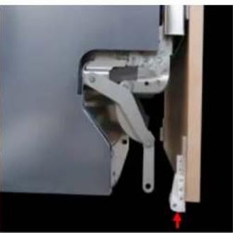
natural_image
Close-up of a mechanical assembly with metal components and a red arrow indicating direction (no visible text or symbols)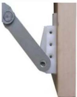
natural_image
Close-up of a mechanical lever assembly with a gray handle and mounting bracket (no text or symbols visible)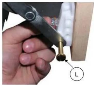
natural_image
Close-up of a hand using a tool to apply a metal component, with a labeled arrow indicating 'L' (no text or symbols on the object itself)Fig. 22 Fig. 23 Fig. 24 Fig. 25
PREMERE
A PORTA CHIUSA
PRESS
WITH DOOR CLOSED
PRESSER
AVEC LA PORTE
FERMÉE
DRÜCKEN
BEI GESCHLOSSEN
GERÄTETÜR
DRUKKEN
BIJ GESLOTEN
DEUR
PRESIONAR
CON PUERTA CERRADA
PREMIR
COM A PORTA FECHADA
НАЖАТЬ
ПРИ ЗАКРЪИТОЙ
ДВЕРЧИМЕД STÅNGD LUCKA
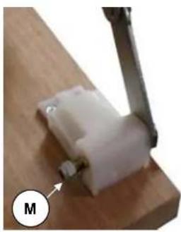
natural_image
Close-up of a mechanical clamp or bracket with a white plastic component and a metal clip, mounted on a wooden base (no visible text or symbols)Fig. 26 Fig. 27 Fig. 28
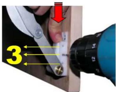
text_image
3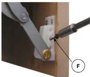
natural_image
Close-up of a mechanical clamp securing a small component with a forceps, labeled 'F' (no text or symbols on the object itself)REGOLAZIONE TENSIONE MOLLE PORTA - ADJUSTING THE DOOR SPRING TENSION
RÉGLAGE DE LA TENSION DES RESSORTS DE LA PORTE
natural_image
Close-up of a hand holding a screwdriver inside a rack-mounted device, with green circular arrows indicating clockwise rotation (no text or symbols on the diagram itself)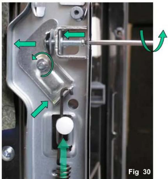
natural_image
Close-up of a mechanical latch mechanism with green arrows indicating motion or movement, labeled Fig 30 (no text or symbols on the diagram itself)MODELLI CON APERTURA AUTOMATICA-MODELS WITH AUTOMATIC OPENING
MODÈLES AVEC OUVERTURE AUTOMATIQUE-MODELLE MIT AUTOMATISCHER ÖFFNUNGSFUNKTION
MODELLEN MET AUTOMATISCHE OPENING- MODELOS CON APERTURA AUTOMÁTICA
MODELOS COM ABERTURA AUTOMÁTICA-MODELI C АВТОМАТИЧЕСКИМ ОТКРЫТИЕМ
MODELLER MED AUTOMATISK LUCKÖPPNING
natural_image
Metallic electronic device with attached circuit board and green arrows indicating connection points (no text or symbols)Fig. 31 Fig. 32
text_image
Massello-Door panel Panneau-Platte-Hout Panel-Painel Pannelb-Panel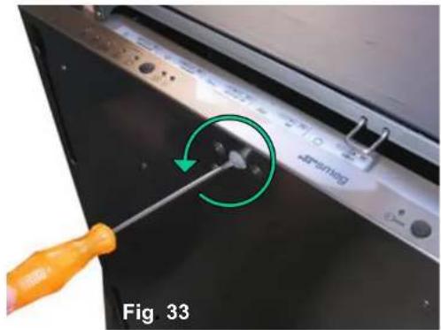
text_image
48Packing Fig 33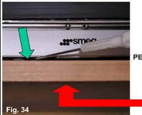
text_image
smeq PE Fig. 34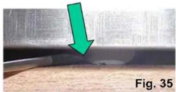
natural_image
Close-up of a metallic surface with a green arrow pointing downward, labeled Fig. 35 (no text or symbols on the main subject)PER APRIRE PREMERE QUI-TO OPEN PRESS HERE
POUR OUVRIR APPUYER ICI
ZUM ÖFFNEN HIER DRÜCKEN
OM TE OPENEN HIER DRUKKEN
PARA ABRIR PRESIONAR AQUI
PARA ABRIR PREMIR AQUI
ЧТОБЫ ОТКРЫТЬ НАЖМИТЕ ЗДЕСЬ
TRYCK HÄR FÖR ATT ÖPPNA
text_image
Fig. 36DIAGRAM FOR ESTABLISHING WHETHER THE LONG DOOR DISHWASHER (type "B") is COMPATIBLE WITH THE FITTED KITCHEN FRONTS AND LAYOUT

other
| Door Length (mm) | Base of Dishwasher (mm) | | ---------------- | ---------------------- | | 1.760 | - | | 1.765 | - | | 1.770 | - | | 1.775 | - | | 1.780 | - | | 1.785 | - | | 1.790 | - | | 1.795 | - | | 1.800 | - |INSTRUCTIONS FOR USE OF THE DIAGRAM FOR ESTABLISHING WHETHER THE LONG DOOR DISHWASHER (type "B") is COMPATIBLE WITH THE FITTED KITCHEN FRONTS H820mm: STL827B - STLA828B
STEP1: establishing the height above the floor
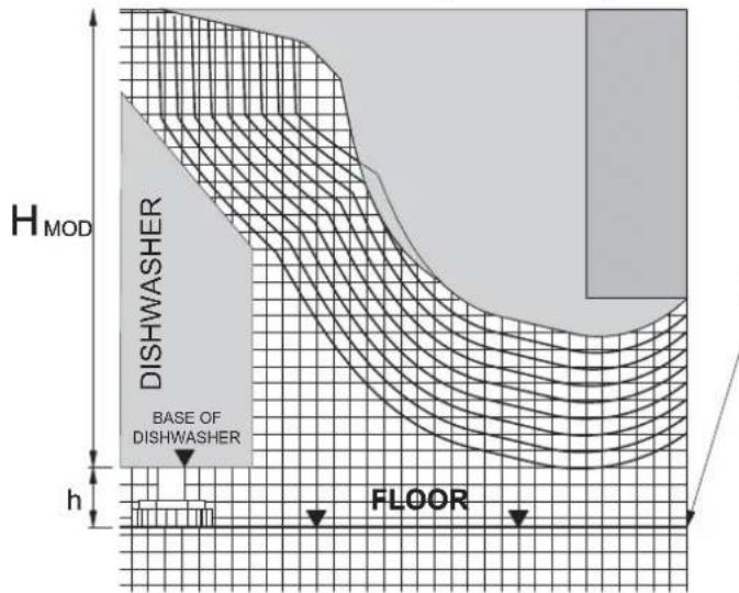
text_image
H MOD DISHWASHER BASE OF DISHWASHER h FLOORh = distance between dishwasher and floor
h = (820 mm H)HWASHER
Mark the line of the floor at the distance (h) from the "BASE OF DISHWASHER" line
STEP2: door front dimensions
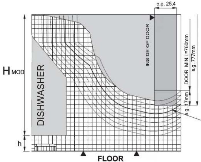
text_image
H MOD DISHWASHER INSIDE OF DOOR e.g. 25.4 17mm e.g. FOOR MIN.L=760mm e.g. 777mm h FLOORDraw the thickness of the door front starting from the mark: "INSIDE OF DOOR". Add the difference needed to reach the intended length of the door to the minimum length L_mm = 760 mm
E.g.: L077 mm.
Delta L=LDDOR777-760=17 mm.
Then choose the door front dimension line by selecting the curve closer to the outline of the door front just drawn; the whole of the door front profile must be contained within the curve chosen.
STEP3: plinth positioning

text_image
SPACE REQUIRED H_MOD DISHWASHER H_PLINTH PLINTH h FLOOR e.g. 25.4 DOOR MIN.L=760mm e.g. 777mm 17mm e.g. DISTANCE BY WHICH PLINTH IS RECESSEDMark out the space required (e.g. with a dotted line), i.e. the zone which must be left unobstructed to allow the door to move (this will be all the space above the space occupancy line).
The position of the plinth, in terms of the height of the plinth and the amount by which it must be recessed behind the kitchen front (i.e. the visible part of the door front), can be defined, taking care to avoid the identified area.
DIAGRAM FOR ESTABLISHING WHETHER THE LONG DOOR DISHWASHER (type "A") is COMPATIBLE WITH THE FITTED KITCHEN FRONTS AND LAYOUT
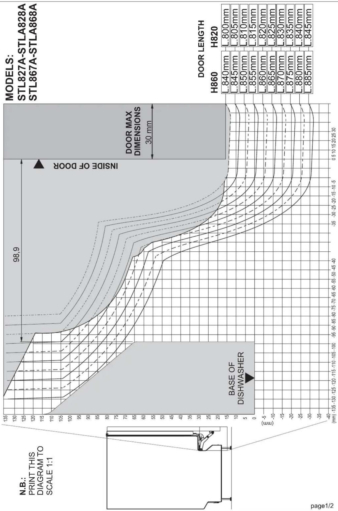
other
| DOOR Length | H860 (mm) | H820 (mm) | | --- | --- | --- | | L.840mm | L.840mm | L.840mm | | L.845mm | L.845mm | L.845mm | | L.850mm | L.850mm | L.850mm | | L.855mm | L.855mm | L.855mm | | L.860mm | L.860mm | L.860mm | | L.865mm | L.865mm | L.865mm | | L.870mm | L.870mm | L.870mm | | L.875mm | L.875mm | L.875mm | | L.880mm | L.880mm | L.880mm | | L.885mm | L.885mm | L.885mm | | L.800mm | L.800mm | L.800mm | | L.805mm | L.805mm | L.805mm | | L.810mm | L.810mm | L.810mm | | L.815mm | L.815mm | L.815mm | | L.820mm | L.820mm | L.820mm | | L.825mm | L.825mm | L.825mm | | L.830mm | L.830mm | L.830mm | | L.835mm | L.835mm | L.835mm | | L.840mm | L.840mm | L.840mm | | L.845mm | L.845mm | L.845mm | | L.850mm | L.850mm | L.850mm | | L.855mm | L.855mm | L.855mm | | L.860mm | L.660mm | L.660mm | | L.865mm | L.665mm | L.665mm | | L.870mm | L.670mm | L.670mm | | L.875mm | L.675mm | L.675mm | | L.880mm | L.680mm | L.680mm | | L.840mm | L.840mm | L.840mm | | L.845mm | L.845mm | L.845mm | | L.850mm | L.850mm | L.850mm | | L.855mm | L.855mm | L.855mm | | L.860mm | L 660mm | L 660mm | | L 665mm | L 665mm | L 665mm | | L 670mm | L 670mm | L 670mm | | L 675mm | L 675mm | L 675mm | | L 680mm | L 680mm | L 680mm | | P deg/2 deg (base of dishwasher) (lower-left) (page_number) (X-axis) (Y-axis) (Z-axis) (Y-axis) (Z-axis) (Z-axis) (Z-axis) (Z-axis) (Z-axis) (Z-axis) (Z-axis) (Z-axis) (Z-axis) (Z-axis) (Z-axis) (Z-axis) (Z-axis) (Z-axis) (Z-axis) (Z-axis) (Z-axis) (Z-axis) (Z-axis) (Z-axis) (Z-axis) (Z-axis) (Z-axis) (Z-axis) (Z-axis) (P deg/2 deg)INSTRUCTIONS FOR USE OF THE DIAGRAM FOR ESTABLISHING WHETHER THE LONG DOOR DISHWASHER (type "A") is COMPATIBLE WITH THE FITTED KITCHEN FRONTS MODELS: STL827A - STLA828A - STL867A - STLA868A
text_image
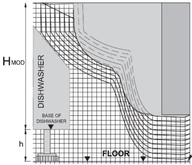
H_MOD DISHWASHER BASE OF DISHWASHER h FLOORSTEP1: establishing the height above the floor
h = distance between dishwasher and floor h = Hc4Vr(820mmx860mm)
Mark the line of the floor at the distance (h) from the "BASE OF DISHWASHER" line
text_image
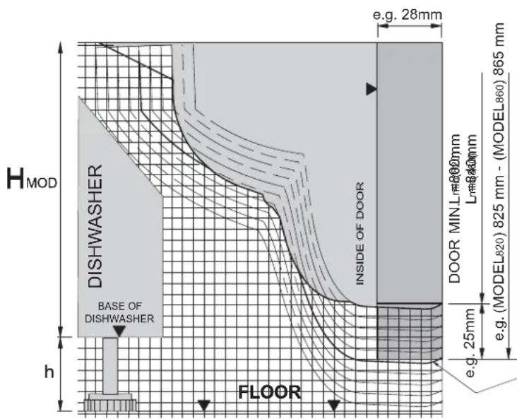
H MOD DISHWASHER BASE OF DISHWASHER INSIDE OF DOOR e.g. 28mm DOOR MIN L##@00mm L##@40mm e.g. (MODEL820) 825 mm - (MODEL860) 865 mm e.g. 25mm h FLOORSTEP2: door front dimensions
Draw the thickness of the door front starting from the mark: "INSIDE OF DOOR". Add the difference needed to reach the intended length of the door to the minimum length L 800mm = 840mm min(860=)
E.g.: L08252mm:
Delta(25)DobR=825.800=25mm
E.g.: Ld=865mm:
Delta(86)DobR7865.840=25mm
Then choose the door front dimension line by selecting the curve closer to the outline of the door front just drawn; the whole of the door front profile must be contained within the curve chosen.
text_image
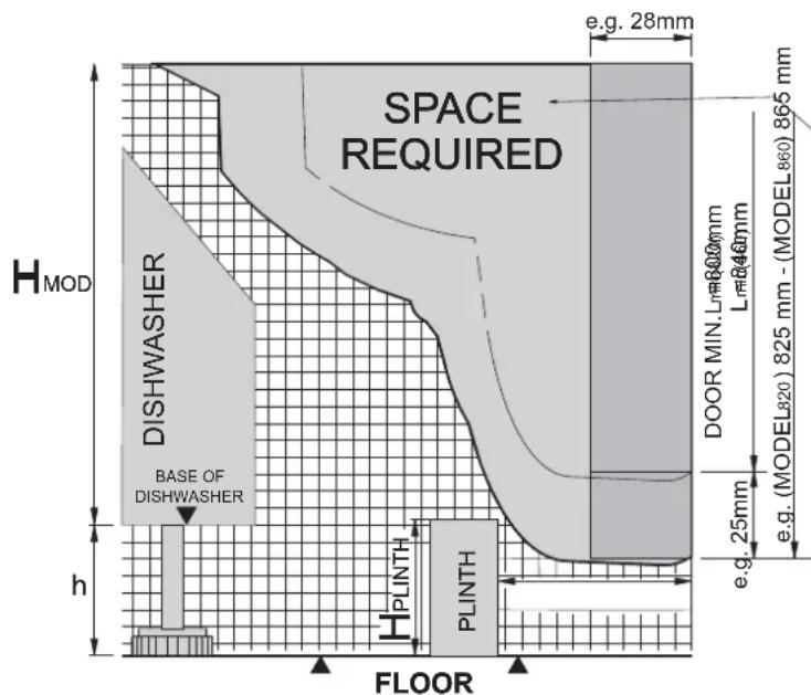
SPACE REQUIRED H_MOD DISHWASHER BASE OF DISHWASHER h e.g. 28mm DOOR MIN Lm=600mm Lm=846mm e.g. (MODEL320) 825 mm - (MODEL860) 865 mm e.g. 25mm PLINTH PLINTH FLOORSTEP3: plinth positioning
Mark out the space required (e.g. with a dotted line), i.e. the zone which must be left unobstructed to allow the door to move (this will be all the space above the space occupancy line).
The position of the plinth, in terms of the height of the plinth and the amount by which it must be recessed behind the kitchen front (i.e. the visible part of the door front), can be defined, taking care to avoid the identified area.