XTA360.4 - Car stereo Soundstream - Free user manual and instructions
Find the device manual for free XTA360.4 Soundstream in PDF.


| Product Type | Car Stereo Amplifier |
| Model | XTA360.4 |
| Brand | Soundstream |
| Dimensions (L x W x H) | 11 x 10 x 2.4 inches |
| Power Output (4 Ohm Stereo) | 4 x 45 Watts RMS |
| Power Output (2 Ohm Stereo) | 4 x 90 Watts RMS |
| Power Output (4 Ohm Bridged) | 2 x 180 Watts RMS |
| Frequency Response | 10 Hz - 30 kHz (±1 dB) |
| Signal-to-Noise Ratio | >96 dB |
| Input Sensitivity | 0.5 V - 4 V |
| Input Impedance | 10 kΩ |
| High Pass Filter (HPF) | 30 Hz - 500 Hz (variable) |
| Low Pass Filter (LPF) | 30 Hz - 500 Hz (variable) |
| Bass Boost | 0 to +18 dB at 45 Hz (switchable) |
| Crossover Type | Selectable HPF / Full / LPF |
| Power Supply | PWM MOSFET |
| Fuse Rating | 40 A (one) |
| Protection Circuits | Thermal, Short Circuit, Overload |
| Remote Turn-On | Soft Delay Remote Turn-On |
| Drive Delay | Drive Delay II (2-3 sec delay to eliminate pops) |
| Inputs | Gold plated RCA jacks |
| Speaker Outputs | Gold plated terminal strips |
| Phantom Channel | For center speaker or subwoofer |
Frequently Asked Questions - XTA360.4 Soundstream
User questions about XTA360.4 Soundstream
0 question about this device. Answer the ones you know or ask your own.
Ask a new question about this device
Download the instructions for your Car stereo in PDF format for free! Find your manual XTA360.4 - Soundstream and take your electronic device back in hand. On this page are published all the documents necessary for the use of your device. XTA360.4 by Soundstream.
USER MANUAL XTA360.4 Soundstream
T E C H N O L O G I E S
Owner's Manual and Installation Guide

natural_image
Abstract geometric logo design with intersecting lines and partial letter 's' (no text or symbols)STREAM
XTA360.4 / XTA480.4 / XTA720.4 / XTA600.5
XTA180.2 / XTA240.2
XTA360.2 / XTA480.2
XTA600.2 / XTA880.2
XTA720.4 / XTA600.5
CONGRATULATIONS!
You now own a Limited Edition XTA Amplifier, the product of an uncompromising design and engineering philosophy.
To maximize the performance of your system, we recommend that you thoroughly acquaint yourself with its capabilities and features. Please retain this manual and your sales receipt for future reference.
Soundstream amplifiers are the result of American innovation and the highest quality control standards. When properly installed, they will provide you with many years of listening pleasure. Should your amplifier ever need service or replacement due to theft, please record the following information which will help protect your investment.
Serial # ____
Dealer's Name ____
Date of Purchase ____
Installation Shop ____
Installation Date ____
CAUTION!
Prolonged listening at extremely high levels may result in hearing loss. Even though your new Soundstream Limited Edition XTA Amplifier sounds better than anything you've ever heard, exercise caution to prevent hearing damage.
TABLE OF CONTENTS
Features p 4
Specification / Power ratings / Dimensions p 5, 6
Tools / parts for installation p 6
Wiring p 7
Panel layout p 8,9
Key to callouts p 10\~12
2Ch system design #1, 2 p 13
2Ch system design #3 p 14
4Ch system design #1 p 14
4Ch system design #2 p 15
4Ch system design #3 p 16
5Ch system design #1, 2 p 17
5Ch system design #3 p 18
5Ch system design #4 p 19
Trouble shooting / Protection circuit p 20
FEATURES
* Bass EQ Control - Fully adjustable subwoofer equalization circuit providing frequency and boost("Q") adjustment for optimum subwoofer performance. A frequency tracking subsonic filter protects woofers from potentially harmful low frequency information and maximizes output in a usable range.
* Drive Delay II™ - Amplifier section powers up 2 to 3 seconds after the power supply eliminating turn-on and off pops. The turn off process is reversed: Amplifier section turns off first, followed by the power supply.
* Flexible Input Level Control - allows 500 mV to 4 V input sensitivity.
* THERMAL / SHORT / OVER LOAD PROTECTION
* 2 OHM STEREO / 4 OHM MONO
* P.W.M MOSFET POWER SUPPLY
* POWER & PROTECTION INDICATOR
* SELECTABLE X-OVER HPF / FULL / LPF
* 18 dB. BASS BOOST WITH SWITCH SUB (45Hz)
* VARIABLE HI-PASS AND LOW PASS (30Hz\~500Hz)
* GOLD PLATED TERMINAL STRIPS / RCA JACKS
* HEAVY DUTY HEAT SINK
* ADJUSTABLE INPUT SENSITIVITY
* SOFT DELAY REMOTE TURN-ON
* LOW LEVEL INPUTS
* PHANTOM CHANNEL FOR POWERING CENTER SPEAKER OR SUBWOOFER
SPECIFICATIONS
| Signal / noise Ratio | >96dB |
| Frequency Response ±1.0db | 10Hz - 30kHz |
| HPF | 50Hz - 500Hz |
| LPF | 30Hz - 500Hz |
| Adjustable Sensitivity Range | 0.5 - 4V |
| Input Impedance(Low Level) | 10K Ohms |
POWER RATINGS & FUSE
| MODEL | 4 ohm STEREO | 2 ohm STEREO | 4 ohm BRIDGED | FUSE |
| XTA180.2 | 2 x 45W | 2 x 90W | 180W | 15A |
| XTA240.2 | 2 x 60W | 2 x 120W | 240W | 25A |
| XTA360.2 | 2 x 90W | 2 x 180W | 360W | 40A |
| XTA480.2 | 2 x 120W | 2 x 240W | 480W | 25A x 2 |
| XTA600.2 | 2 x 150W | 2 x 300W | 600W | 25A x 3 |
| XTA880.2 | 2 x 220W | 2 x 440W | 880W | 30A x 3 |
| XTA360.4 | 4 x 45W | 4 x 90W | 180W x 2 | 40A |
| XTA480.4 | 4 x 60W | 4 x 120W | 240W x 2 | 25A x 2 |
| XTA720.4 | 4 x 90W | 4 x 180W | 360W x 2 | 30A x 2 |
| XTA600.5 | 4 x 45W, 1 x 120W | 4 x 90W, 1 x 240W | 2 x 180W, 1 x 240W | 30A x 2 |
DIMENSIONS
| MODEL | Length | Width | Height |
| XTA180.2 | 7 inch | 10 inch | 2.4 inch |
| XTA240.2 | 8.2 inch | 10 inch | 2.4 inch |
| XTA360.2 | 11 inch | 10 inch | 2.4 inch |
| XTA480.2 | 13.7 inch | 10 inch | 2.4 inch |
| XTA600.2 | 20 inch | 10 inch | 2.4 inch |
| XTA880.2 | 21.6 inch | 10 inch | 2.4 inch |
| XTA360.4 | 11 inch | 10 inch | 2.4 inch |
| XTA480.4 | 13.7 inch | 10 inch | 2.4 inch |
| XTA720.4 | 20 inch | 10 inch | 2.4 inch |
| XTA600.5 | 20 inch | 10 inch | 2.4 inch |
TOOLS / PARTS FOR INSTALLATION
natural_image
Mechanical assembly diagram showing a shaft and housing with no visible text or symbolsNOTE: TOOLS ARE NOT SUPPLIED
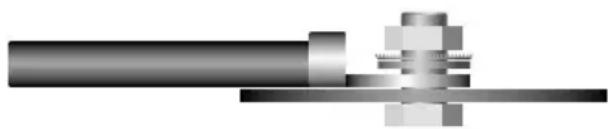
Small flat blade screwdriver Phillips screwdriver (#2 or medium sized), Wire cutters Wire strippers, - #6 round head screws, and 1 - #8 sheet metal screw (or nut, bolt, flat washer, star washer) [see detail] 2 - Ring connectors (large enough to accommodate your method of grounding) In-line fuse or circuit breaker - see fuse chart below Power and ground wire - see Power Wire Calculator on page 7 Speaker wire - 12-16 gauge Grommets (sized to work with the power wire you plan to use in your installation) Tube of silicone sealant
WIRING
Before beginning, disconnect the negative (-) terminal of the battery prior to working on the positive (+) terminal to prevent a short to ground. This is important, unless you want to spend the rest of your life with a nickname like "Sparky," or "Smokey." Reconnect the negative terminal only after all connections have been made.
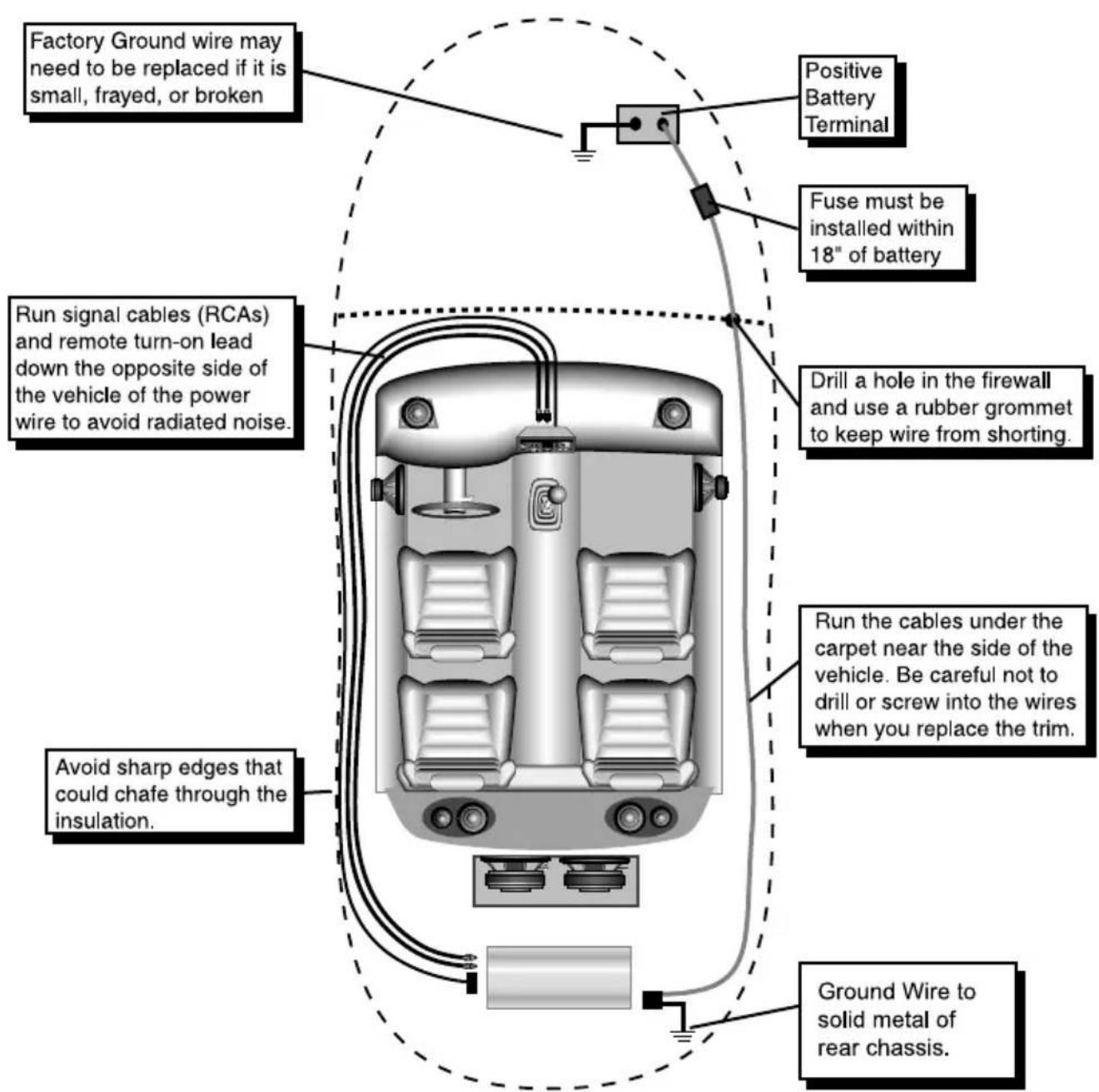
Warning! A Main Fuse must be installed within 18" of battery!
PANEL LAYOUT
XTA180.2 / XTA240.2 / XTA360.2
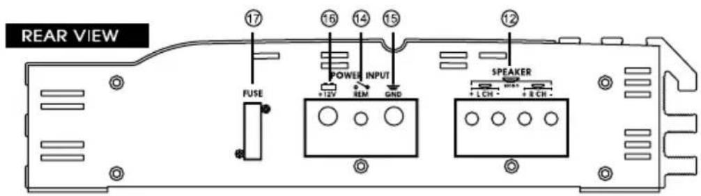
XTA480.2 / XTA600.2 / XTA880.2
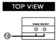
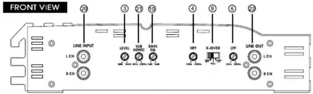
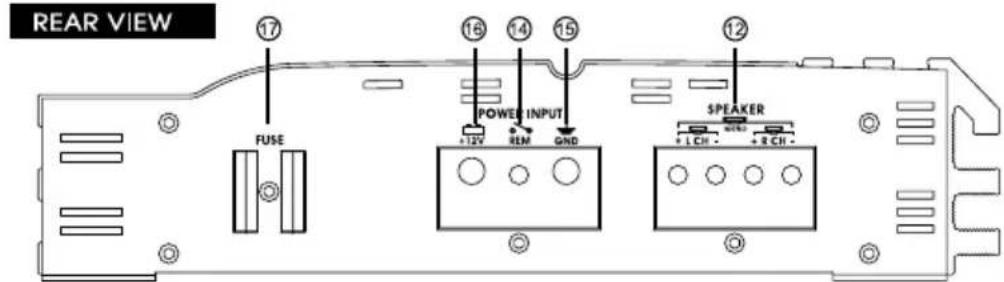
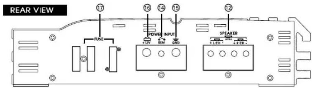
PANEL LAYOUT
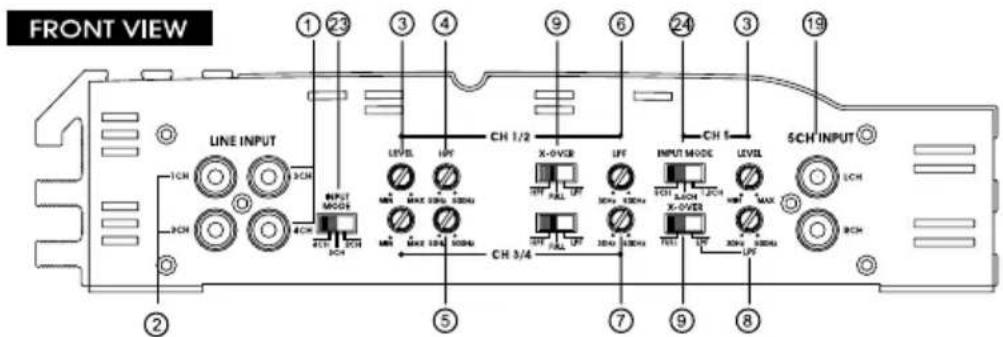
XTA360.4 / XTA480.4 / XTA720.4
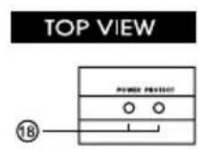
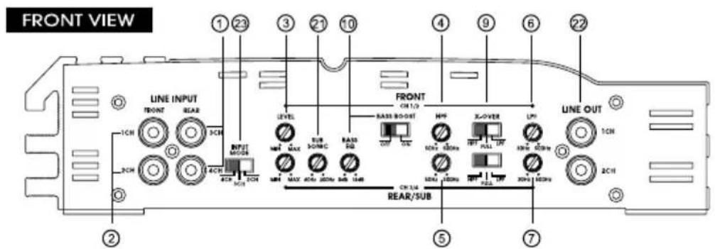
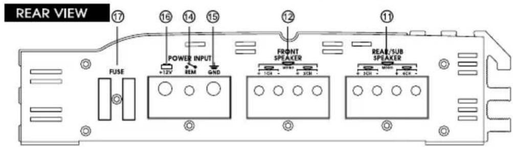
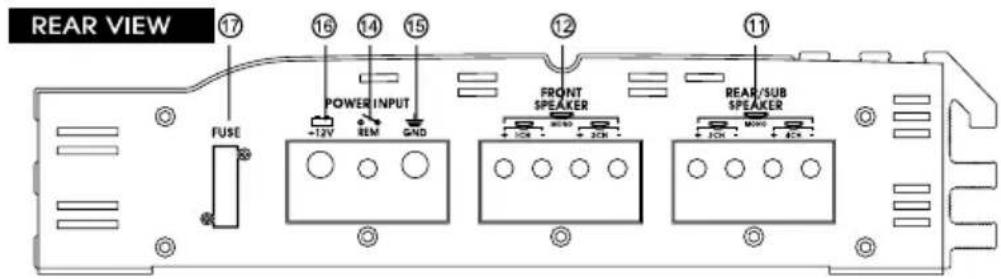
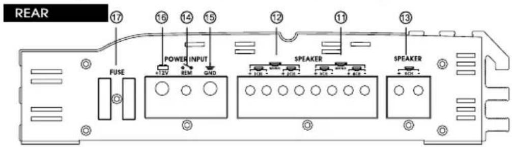
XTA600.5
KEY TO CALLOUTS
- RCA Inputs - 3 Channel and 4 Channel RCA inputs.
- RCA Inputs - 1 Channel and 2 Channel RCA inputs.
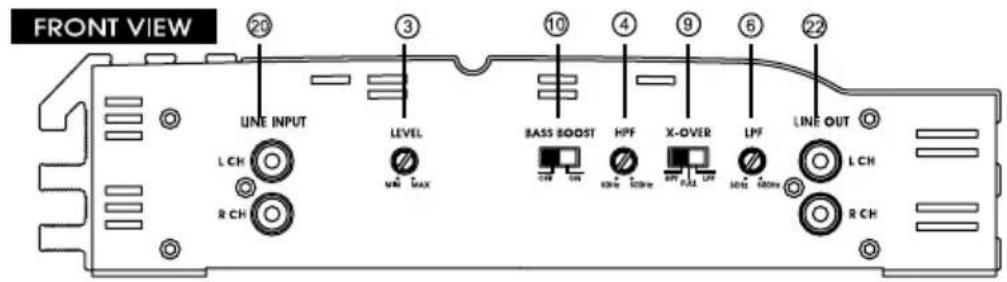
- Input Levels - Input level control variable from 500mV to 4V.
- High Pass Filter Control Adjustment- Frequency adjustment control for the High Pass Filter for satellite CH1&2(L & R).
- High Pass Filter Control Adjustment- Frequency adjustment control for the High Pass Filter for satellite CH3&4.
- Low Pass Filter Control Adjustment- Frequency adjustment control for the Low Pass Filter for CH1&2(L & R).
- Low Pass Filter Control Adjustment- Frequency adjustment control for the Low Pass Filter for CH3&4.
- Low Pass Filter Control Adjustment- Frequency adjustment control for the Low Pass Filter for CH5.
- Selectable X-Over HPF/FULL/LPF
- Bass EQ Control "Boost" Adjustment - Varies from 0 to +18 dB of boost when the Bass Control circuit is engaged.
- Speaker connection Terminal - Speaker connections for satellite CH3&4.
- Speaker connection Terminal - Speaker connections for satellite CH1&2(L & R).
- Speaker connection Terminal - Speaker connections for satellite CH5
- REMOTE - Remote turn - on input from the head unit. Accepts +12V.
- GND - Main ground connection. Bolt to a clean chassis point in the vehicle.
- +12V - Connected to a fuse or circuit breaker, then to the battery's positive terminal.
- FUSES - Satellite channels power supply fuses. Warring: Replace only with the same value fuses!
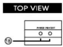
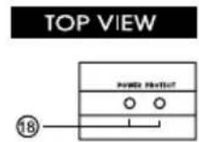
- Power LED - Indicates amplifier power.(Power:Green / Protection:Red)
- RCA Inputs - 5 Channel RCA inputs.
- RCA Inputs - R Channel and L Channel RCA inputs.
- Subsonic/Bass Control Adjustment - Frequency adjustment control for the Bass Control filter or the Sub Sonic filter.
-
AUXILIARY OUTPUT - The Aux outputs offer amplifiers easy, unlimited system expansion. Routing signal from a source unit, pre-amplifier or equalizer is a matter of routing RCA's into the RCA inputs and out through the AUX outputs to the next amplifier.
-
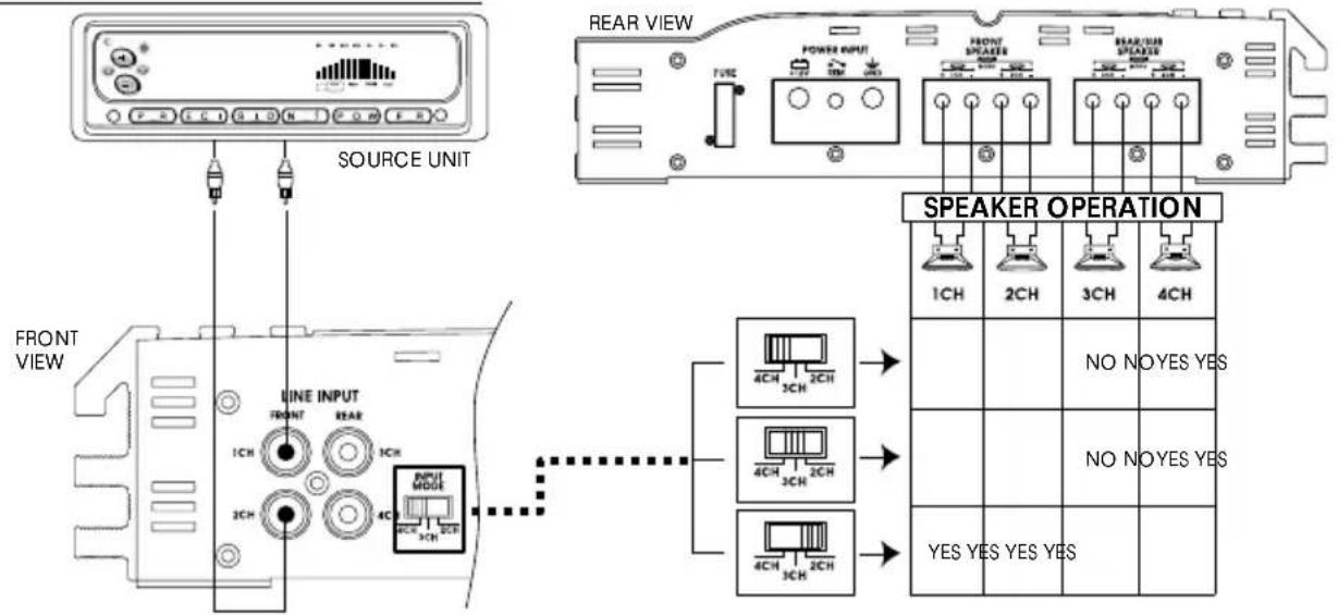
INPUT MODE - XTA360.4/XTA480.4/XTA720.4
2 CHANNEL LINE INPUT MODE
3 CHANNEL LINE INPUT MODE
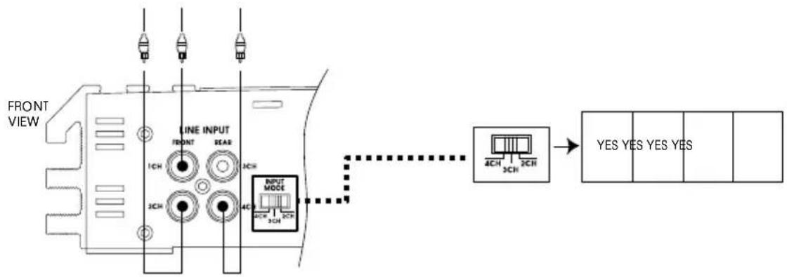
flowchart
graph TD
    A["FRONT VIEW"] --> B["LINE INPUT"]
    B --> C["1CH 3CH"]
    B --> D["2CH 3CH"]
    B --> E["4CH 3CH"]
    B --> F["INPUT MODE"]
    F --> G["4CH 3CH"]
    F --> H["2CH 3CH"]
    G --> I["→ YES YES YES"]
    H --> I
    I --> J["Output"]
4 CHANNEL LINE INPUT MODE
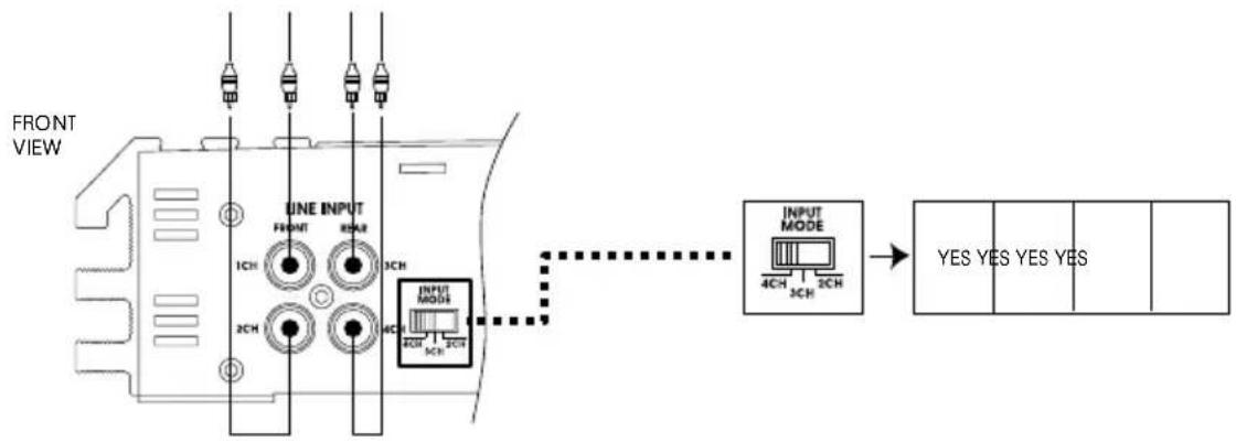
flowchart
graph TD
    A["FRONT VIEW"] --> B["LINE INPUT"]
    B --> C["INPUT MODE"]
    C --> D["YES YES YES"]
    style A fill:#f9f,stroke:#333
    style B fill:#ccf,stroke:#333
    style C fill:#cfc,stroke:#333
    style D fill:#fcc,stroke:#333
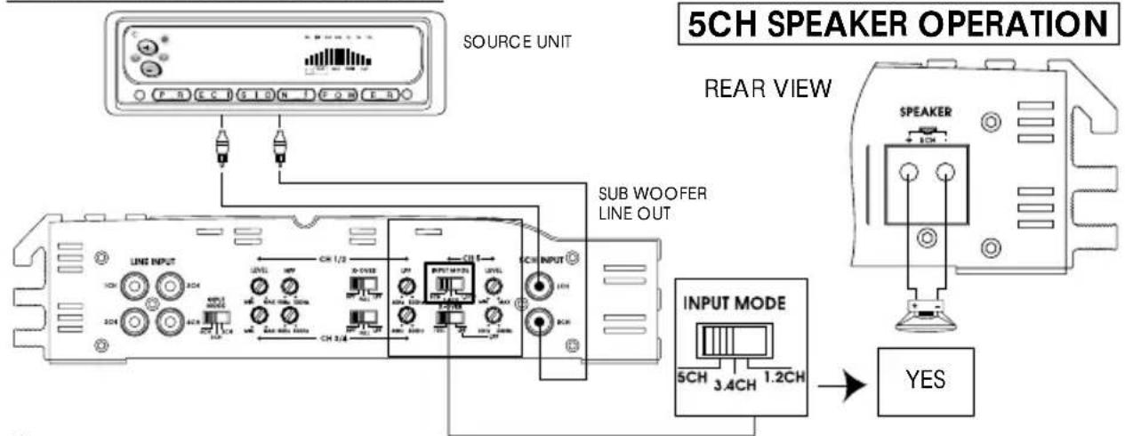
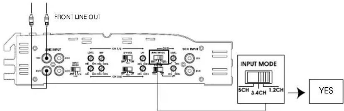
24. INPUT MODE - XTA600.5
5 CHANNEL LINE INPUT MODE
3,4 CHANNEL LINE INPUT MODE
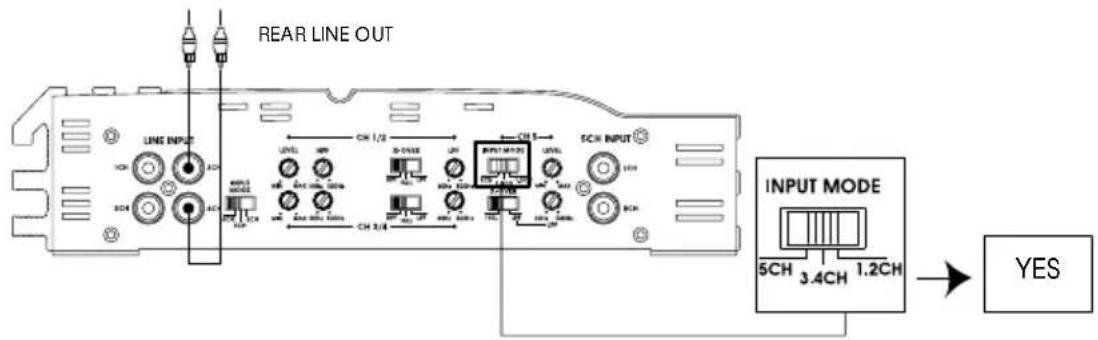
1,2 CHANNEL LINE INPUT MODE
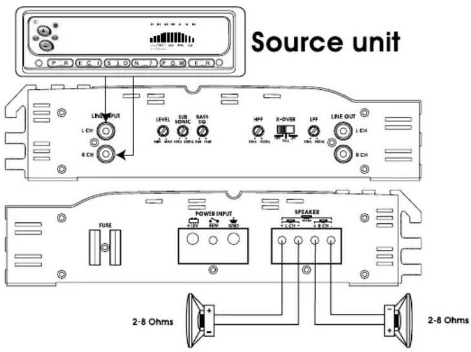
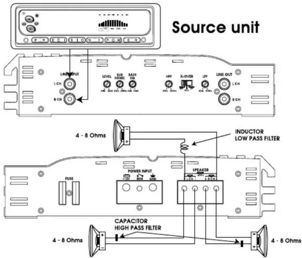
2 CHANNEL SYSTEM DESIGN #2 XTA180.2/240.2/360.2/480.2/600.2/880.2
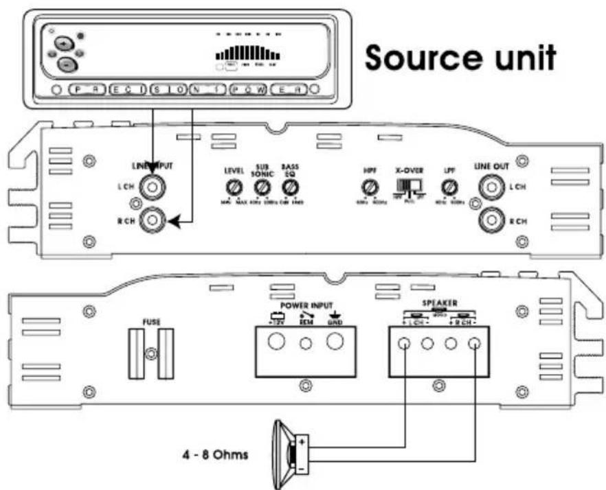
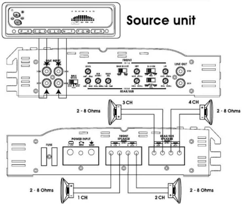
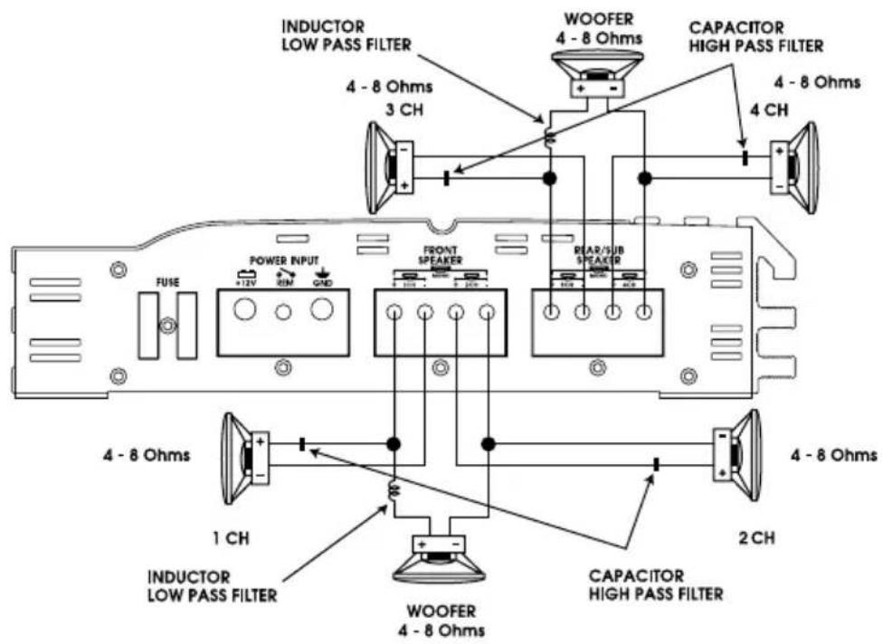
4CHANNEL SYSTEM DESIGN #1 XTA360.4/480.4/720.4
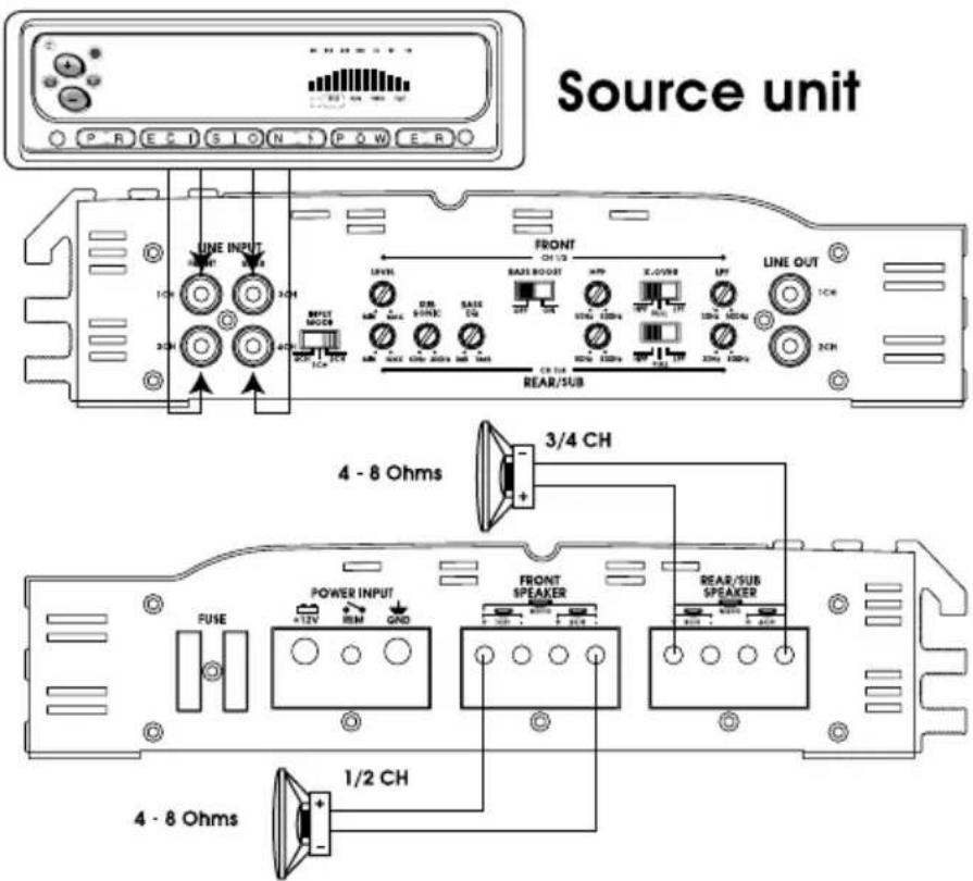
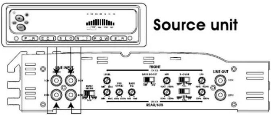
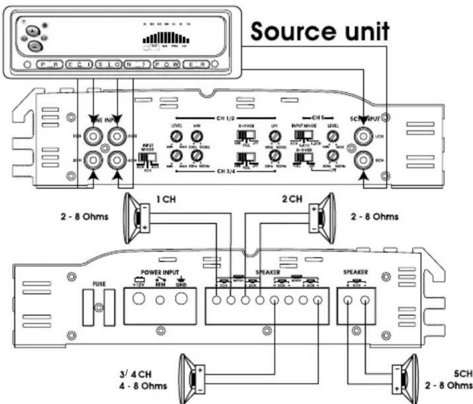
5CHANNELSYSTEM DESIGN #1 XTA600.5

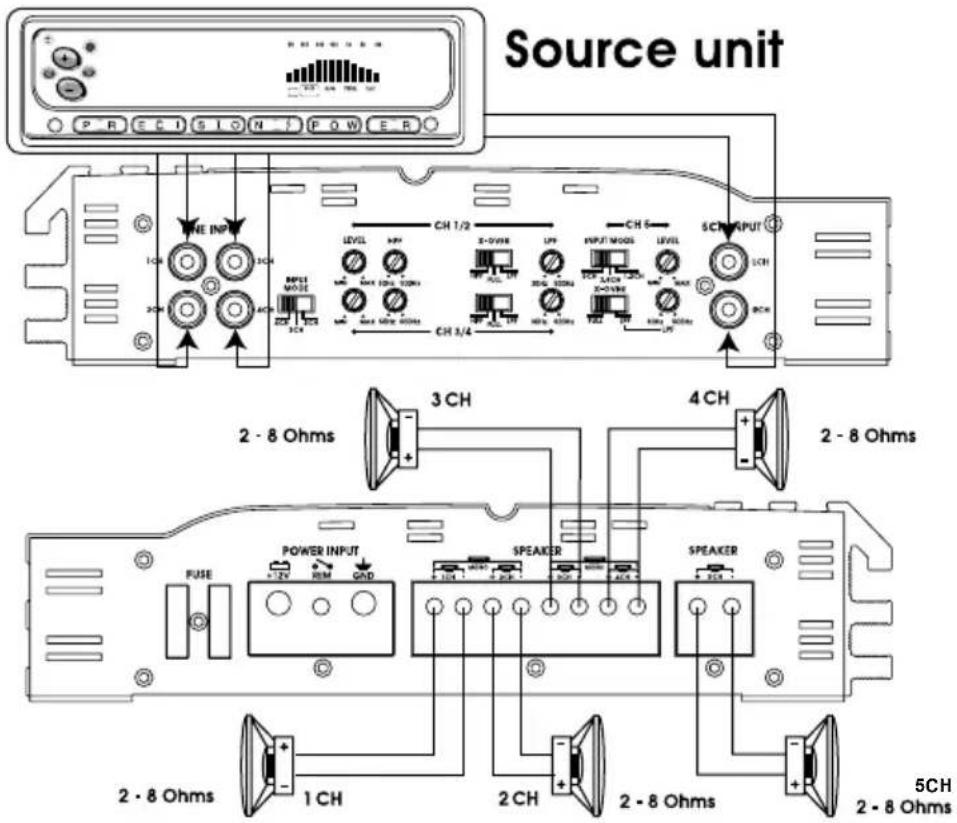
5CHANNELSYSTEM DESIGN #2 XTA600.5
5CHANNEL SYSTEM DESIGN #3 XTA600.5
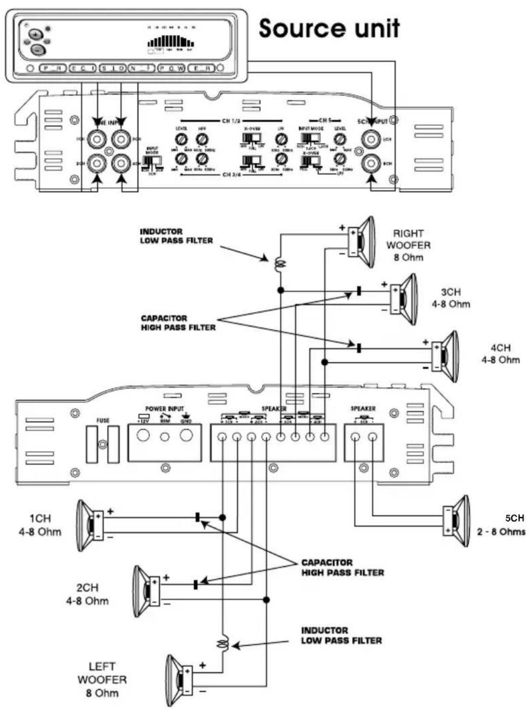
TROUBLE SHOOTING
NO SOUND
Is the LED lit?
YES
NO
Check Power and Remote turn-on wire for voltage. Make sure Ground wire is secure.
STILL NO SOUND
See your Authorized Sound Stream Dealer.
SOUND IN ONE CHANNEL ONLY
Reverse left and right speakers by unplugging the speaker connector, turning it over and plugging it back in.
SOUND IS NOW IN
OPPOSITE CHANNEL
Reverse RCA inputs
SAME CHANNEL
Problem is in the speaker or speaker wire of the silent channel
SOUND IS NOW IN
OPPOSITE CHANNEL
Reverse RCAs at head unit
SAME CHANNEL
Problem is in the Amplifier. See your local Authorized
SOUND IS NOW IN
OPPOSITE CHANNEL
Problem is in the head unit or before the amplifier
SAME CHANNEL
Problem is in the RCA cables
PROTECTION CIRCUIT
Short Circuit Protection engaged: The amplifier will turn off and try to come back on immediately. The amplifier will cycle like this indefinitely, with "blips" of sound each time. If this is the case, check your speakers and wiring for low impedance and short circuits.
Thermal Protection engaged: The amplifier will turn off and several minutes later will come back on. In this case, ensure that there is nothing blocking the normal convective airflow of the amplifier. No obstruction should be within 2" of the amplifier on all sides.
NOTE: Low battery voltage will cause the amplifier to run warmer and possibly damage the amplifier.
SOUNDSTREAM® T E C H N O L O G I E S
SOUNDSTREAM TECHNOLOGIES
1550 Maple Avenue., Montebello, CA 90640 U.S.A
Phone 323-722-3333 fax. 323-722-1122
- Owner's Manual and Installation Guide
- CONGRATULATIONS!
- CAUTION!
- TABLE OF CONTENTS
- FEATURES
- TOOLS / PARTS FOR INSTALLATION
- NOTE: TOOLS ARE NOT SUPPLIED
- WIRING
- PANEL LAYOUT
- KEY TO CALLOUTS
- INPUT MODE - XTA600.5
- 5CHANNELSYSTEM DESIGN #1 XTA600.5
- 5CHANNELSYSTEM DESIGN #2 XTA600.5
- 5CHANNEL SYSTEM DESIGN #3 XTA600.5
- TROUBLE SHOOTING
- SOUND IN ONE CHANNEL ONLY
- PROTECTION CIRCUIT
- SOUNDSTREAM® T E C H N O L O G I E S
Brand : Soundstream
Model : XTA360.4
Category : Car stereo