
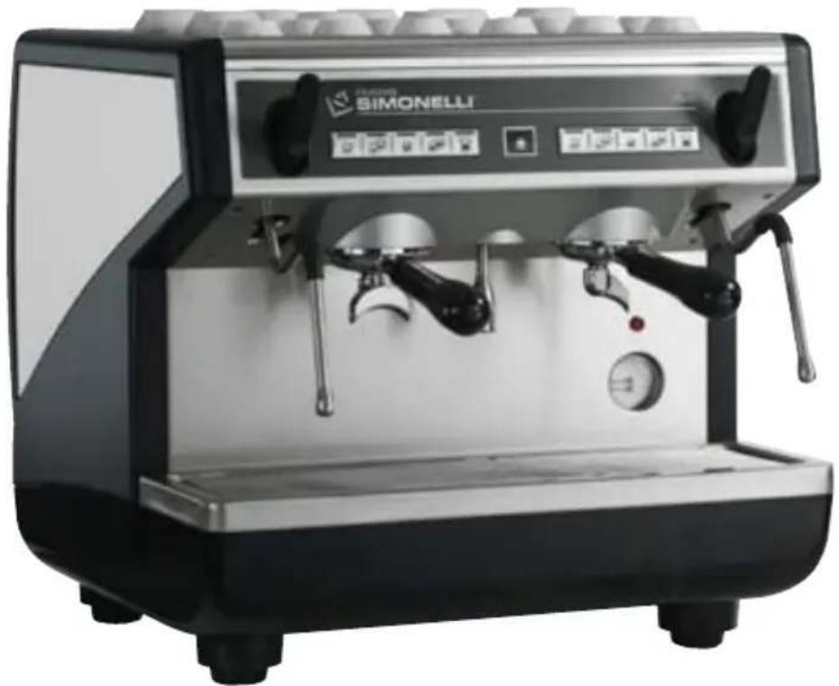
Appia Compact - Coffee maker NUOVA SIMONELLI - Free user manual and instructions
Find the device manual for free Appia Compact NUOVA SIMONELLI in PDF.


| Brand | Nuova Simonelli |
| Model | Appia Compact |
| Product Type | Professional espresso coffee machine |
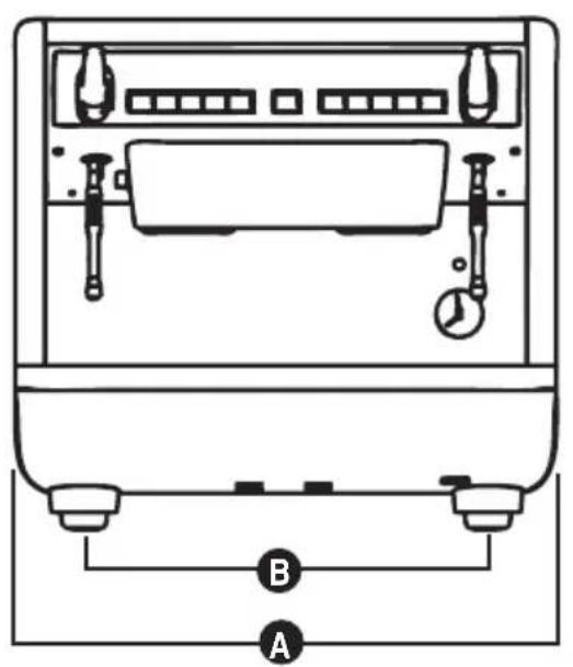
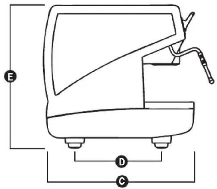
| Dimensions (A x B x C x D x E) | A 550 mm, B 460 mm, C 545 mm, D 370 mm, E 530 mm |
| Net Weight | 60 kg (133 lb) |
| Gross Weight | 65 kg (143 lb) |
| Power Supply | 220 V or 110 V (depending on version) |
| Thermal Power | 3000 W (220 V) / 1500-2200 W (110 V) |
| Water Connection | Direct water supply (3/8" tube), drain pipe Ø 25 mm |
| Boiler Pressure | Adjustable, recommended 1 - 1.4 bar |
| Pump Pressure | Adjustable, recommended 9 bar |
| Main Functions | Espresso (1 or 2 cups), long coffee (1 or 2 cups), steam, hot water, cappuccino, timed steam, autosteam (depending on version), programmable doses |
| Keypad | Volumetric keypad with select buttons, delivery buttons, steam, hot water, autosteam/timed steam keys |
| Accessories Included | Filling tube, waste pipe, 3 filter-holders, double filter, single filter, blind filter, springs, double/single delivery spouts, coffee presser |
| Cleaning and Maintenance | Daily: automatic group cleaning cycle with blind filter and powder; weekly: clean coffee-holders; periodic: regenerate water softener resins |
| Safety Features | Earth grounding required, omnipolar switch (≥3 mm contact gap), automatic shut-off in case of level error, short circuit protection |
| Spare Parts and Repairability | Only original spare parts from authorized service centers; power cord replacement must be done by qualified electrician |
| Certifications | CE declaration of conformity |
| Warranty | Refer to manufacturer's warranty conditions |
| Country of Origin | Italy (Belforte del Chienti, Macerata) |
Frequently Asked Questions - Appia Compact NUOVA SIMONELLI
User questions about Appia Compact NUOVA SIMONELLI
0 question about this device. Answer the ones you know or ask your own.
Ask a new question about this device
Download the instructions for your Coffee maker in PDF format for free! Find your manual Appia Compact - NUOVA SIMONELLI and take your electronic device back in hand. On this page are published all the documents necessary for the use of your device. Appia Compact by NUOVA SIMONELLI.
USER MANUAL Appia Compact NUOVA SIMONELLI
DICHIARAZIONE DI CONFORMITÀ CE EC DECLARATION OF CONFORMITY


Via M. D'Antegiano, 6 - €2031 Belforte del Chienti (MC)

CARATTERISTICHE TECNICHE
| 220 V 110 V | ||||
| PESO NETTO 60 kg 133 | b 60 kg 133 lb | |||
| PESO LORDO 65 kg 143 | b 65 kg 143 lb | |||
| POT. TERMICA 3000 W | 3000 W 1500/2200 W 1500/2200 W | |||
| DIMENSIONI | A 550 mm | A 21.6 | A 550 mm | A 21.6 |
| B 460 mm | B 18 | B 460 mm | B 18 | |
| C 545 mm | C 21.4 | C 545 mm | C 21.4 | |
| D 370 mm | D 14.5 | D 370 mm | D 14.5 | |
| E 530 mm | E 20.8 | E 530 mm | E 20.8 | |

INDICE
CARATTERISTICHE TECNICHE ....2
- DESCRIZIONE 4

Fig. 4



9. MESSAGGI ERRORI MACCHINA
By purchasing the Appia you have made an excellent choice.
The purchase of a professional espresso coffee-maker involves various elements of selection: the name of the manufacturing firm, the machine's specific functions, its technical reliability, the option of immediate and suitable servicing, its price. You certainly evaluated all these factors and then made your choice: the 4 Anna model.
We think you have made the best choice and after every coffee and cappuccino you will be able to assess this.
You will see how practical, convenient and efficient working with Appia is.
If this is the first time you have bought a Nuova Simonelli coffee machine, welcome to high quality coffee-making; if you are already a customer of ours, we feel flattered by the trust you have shown us.
Thanks of the preference.
With best wishes,

TECHNICAL CHARACTERISTICS
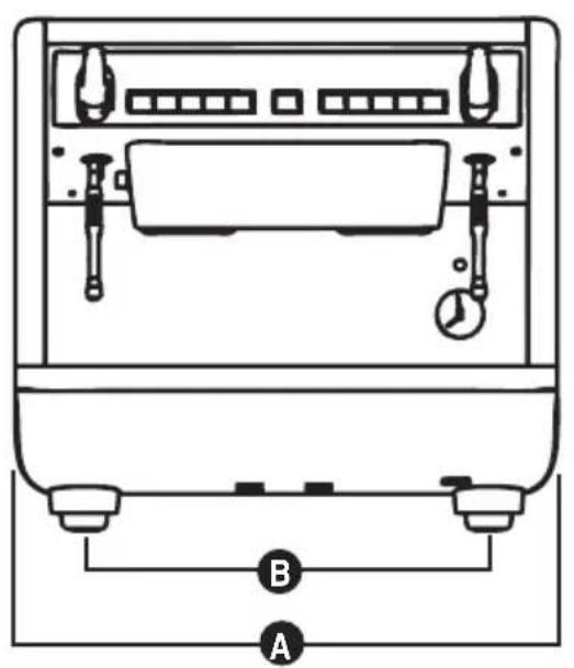
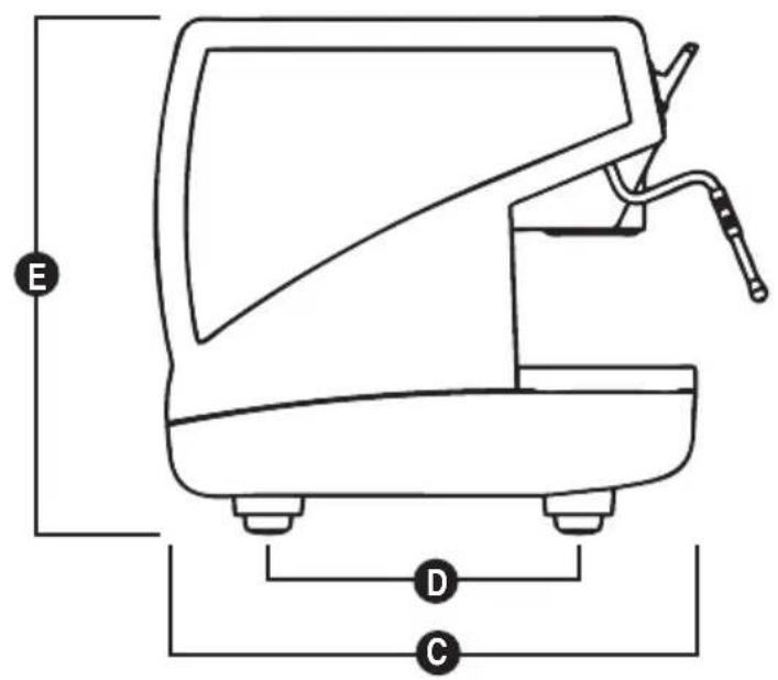
| 220 V 110 V | ||||
| NET WEIGHT 60 kg 133 lb 60 kg 133 lb | ||||
| GROS WEIGHT 65 kg 143 lb 65 kg 143 lb | ||||
| POWER 3000 W 3000 W 1500/2200 W 1500/2200 W | ||||
| DIMENSIONS | A 550 mm | A 21.6 | A 550 mm | A 21.6 |
| 460 mm 18 460 mm 18 | B | B | B | B |
| C 545 mm | C 21.4 | C 545 mm | C 21.4 | |
| 370 mm 14.5 370 mm 14.5 | D | D | D | D |
| E 530 mm | E 20.8 | E 530 mm | E 20.8 | |

INDEX
TECHNICAL CHARACTERISTICS 26
- DESCRIPTION 28
1.1 KEYPAD DESCRIPTION 29
1.2 ACCESSORIES LIST 30
-
SAFETY PRESCRIPTION .....31
-
TRANSPORT AND HANDLING ....34
3.1 MACHINE IDENTIFICATION 34
3.2 TRANSPORT 34
3.3 HANDLING 34
-
INSTALLATION AND PRELIMINARY OPERATIONS .....35
-
ADJUSTMENTS TO BE MADE BY A QUALIFIED TECHNICIAN ONLY 37
5.1 PRESSURE SWITCH ADJUSTMENT 37
5.2 SETTING THE BOILER TANK PRESSURE .. 37
5.3 SETTING THE PUMP PRESSURE 38
5.4 SETTING THE HOT WATER ECONOMISER . 39
- USE 40
6.1 SWITCHING THE MACHINE ON 40
6.2 SWITCHING THE MACHINE OFF 40
6.3 COFFEE PREPARATION....40
6.4 USING STEAM 41
6.5 MAKING CAPPUCCINO 41
6.6 HOT WATER SELECTION 41
6.7 TIMED STEAM SELECTION 41
6.8 AUTOSTEAM SELECTION 42
- PROGRAMMING 43
7.1 PROGRAMMING DOSES 43
7.2 PROGRAMMING COFFEE DOSES 43
7.3 SETTING THE TIMED STEAM FUNCTION .... 43
7.4 SETTING THE AUTOSTEAM FUNCTION ..... 43
7.5 PROGRAMMING HOT WATER 43
7.6 PROGRAMMING STANDARD DOSES 44
7.7 COPYING DOSE SETTINGS 44
7.8 PROGRAMMING OPERATING PARAMETERS 44
7.9 AUTOMATIC GROUP CLEANING CYCLE ..... 45
- CLEANING AND MAINTENANCE 46
8.1 CLEANING THE OUTSIDE OF THE MACHINE 46
8.2 CLEANING THE STAINLESS COFFEE-HOLDERS 46
8.3 CLEANING THE UNIT WITH THE AID OF THE BLIND FILTER 46
8.4 CLEANING FILTERS AND FILTER-HOLDERS 47
8.5 REGENERATING THE WATER SOFTENER RESINS 47
- MACHINE ERROR MESSAGES ....48
1. DESCRIPTION
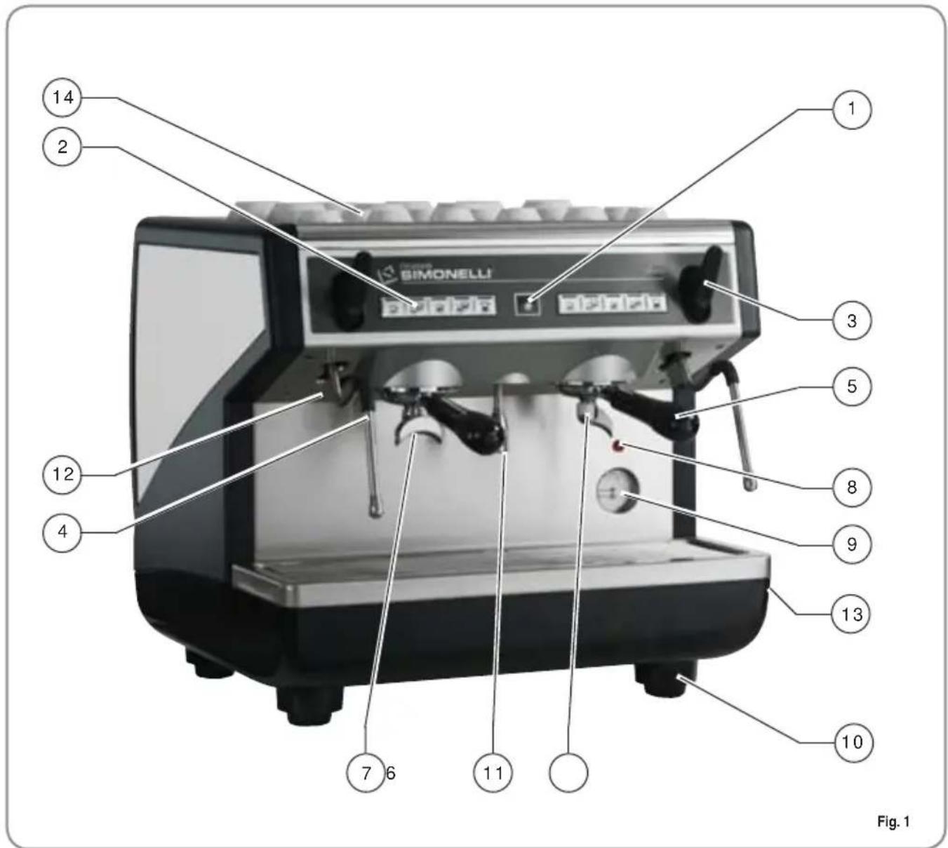
KEY
1 Select buttons
2 Delivery buttons
3 Steam knob
4 Steam nozzle
5 Filter holder
6 Single delivery spout
7 Double delivery spout
8 Optical level
9 Pressure gauge
10 Adjustable foot
11 Hot water nozzle
12 Rating plate
13 Main switch
14 Cup warmer (optional)
1.1 KEYPAD DESCRIPTION
VOLUMETRIC APPIA COMPACT
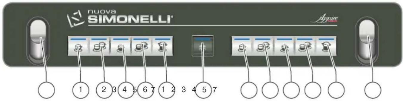
1 1 Espresso key
2 2 Espressos key
3 1 Coffee key
4 2 Coffees key
5 Continuous coffee key
6 Hot water key
7 Steam key
8 Autosteam / timed steam key
9 Coffee key
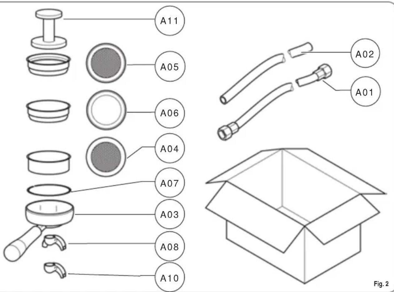
1.2 ACCESSORIES LIST
| CODE DESCRIPTION QUANTITY | ||
| A01 Filling tube | C 3\8, 1 | |
| A02 Waste pipe | ∅ 25 mm - L. 150 cm 1 | |
| A03 Filter-holder | 3 | |
| A04 Double filter | 2 | |
| A05 Single filter | 1 | |
| A06 Blind filter | 1 | |
| A07 Spring 3 | ||
| A08 Double delivery spout | 2 | |
| A09 Single delivery spout | 1 | |
| A10 Coffee presser | 1 | |
2. SAFETY PRESCRIPTION

This book is an integral and essential part of the product and must be given to the user. Read this book carefully. It provides important information concerning safety of installation, use and maintenance. Save it carefully for future reference.

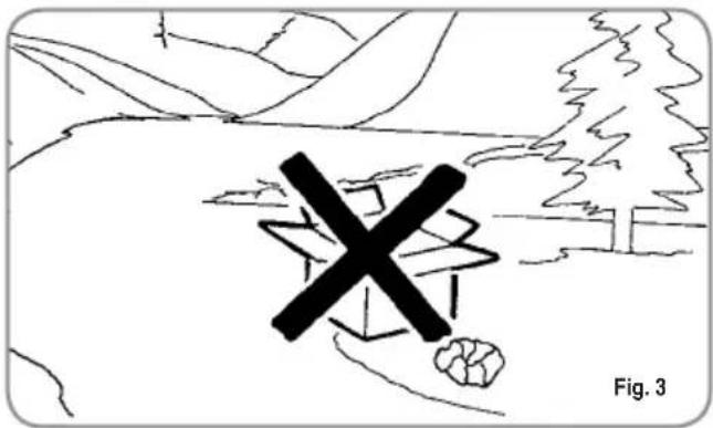
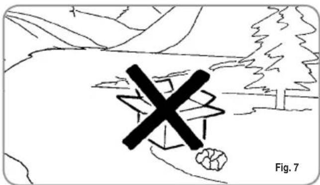
After unpacking, make sure the appliance is complete. In case of doubts, do not use the appliance, but consult a qualified technician. Packaging items which are potentially dangerous (plastic bags, polystyrene foam, nails, etc.) must be kept out of children's reach and must not be disposed of in the environment.

RISK OF POLLUTION

Before connecting the appliance make sure the rating plate data correspond with the mains. This plate is on the front panel at the top right hand side of the appliance. The appliance must be installed by qualified technicians in accordance with current standards and manufacturer's instructions.
The manufacturer is not liable for any damage caused due to failure to ground the system. For the electrical safety of the appliance, it is necessary to equip the system with the proper grounding. This must be carried out by a qualified electrician who must ensure that the electric power of the system is sufficient to absorb the maximum power input stated on the plate.

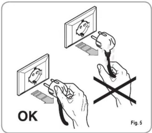
Fig. 4

In particular you must ensure that the size of the wiring cables is sufficient to absorb power input.
The use of adapters, multiple sockets or extensions is strictly forbidden. If they prove necessary, call a fully qualified electrician.

The machine must be installed according to the local standards in force with regard to plumbing systems. For this reason, the plumbing connections must be carried out by a qualified technician.

This appliance must only be used as described in this handbook. The manufacturer shall not be liable for any damage caused due to improper, incorrect and unreasonable use.

WARNING
The power cord may only be replaced by a Qualified Electrician, using an Original Replacement fitted with special earth wire, which is available from Authorised Assistance Centres.

Basic rules must be observed when using any electric appliance.
In particular:
• do not touch the appliance when hands or feet are wet;

CAUTION RISK OF ELECTRIC SHOCK
- do not use the appliance when barefoot;
• do not use extensions in bath or shower rooms;
- do not pull the supply cord out of the socket to disconnect it from the mains;
• do not leave the appliance exposed to atmospheric agents (rain, sun, etc.);
• do not let the appliance be used by children, unauthorised staff or staff who have not read and fully understood the contents of this handbook.

Before servicing the appliance, the authorised technician must first switch off the appliance and remove the plug.
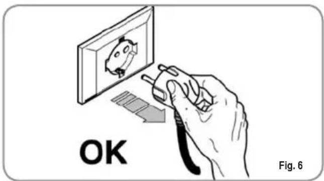

To clean the appliance, set the machine to the "0" energy level, that is, "WITH THE MACHINE SWITCHED OFF AND THE PLUG REMOVED FROM THE MAINS" and follow the instructions in this handbook.

If the appliance breaks down or fails to work properly, switch it off. Any intervention is strictly forbidden. Contact qualified experts only.
Repairs should only be made by the manu
facturer or authorized service centres. Only original spare parts must be used. Failure to observe the above, could make the appliance unsafe.

For installation, the qualified electrician must fit an omnipolar switch in accordance with the safety regulations in force and with 3 (0,12) or more mm (in) between contacts.

To avoid dangerous overheating, make sure the supply cord is fully uncoiled.

Do not obstruct the extraction and/or dissipator grids, especially of the cup warmer.

The user must not replace the appliance supply cord. If the cord is damaged, switch off the appliance and have a qualified technician change the cord.

If no longer using the appliance, we recommend making it inoperative; after removing the plug from the mains electricity, cut the power supply cable.

CAUTION RISK OF POLLUTION

Do not dispose of the machine in the environment: to dispose of the machine, use an authorised centre, or contact the manufacturer for relative information.

CAUTION RISK OF BURNS OR SCALDING

Do not dispose of the machine in the environment: to dispose of the machine, use an authorised centre, or contact the manufacturer for relative information.

CAUTION RISK OF BURNS OR SCALDING

We remind you that before carrying out any installation, maintenance, unloading or adjustment operations, the qualified operator must put on work gloves and protective footwear.
CAUTION

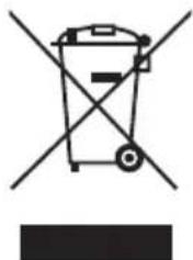
INFORMATION TO THE USERS Under the senses of art. 13 of Law Decree 25th July 2005, n. 151 "Implementation of the Directives/ Guidelines 2002/95/CE, 2002/96/CE and 2003/108/CE, concerning the reduction of the use of dangerous substances in electric and electronic equipment, as well as the disposal of wastes".
The symbol of the crossed large rubbish container that is present on the machine points out that the product at the end of its life cycle must be collected separately from the other wastes. The user for this reason will have to give the equipment that got to its life cycle to the suitable separate waste collection centres of electronic and electrotechnical wastes, or to give it back to the seller or dealer when buying a new equipment of equivalent type, in terms of one to one. The suitable separate waste collection for the following sending of the disused equipment to recycling, the dealing or handling and compatible environment disposal contributes to avoid possible negative effects on the environment and on the people's health and helps the recycling of the materials the machine is composed of. The user's illegal disposal of the product implies the application of administrative fines as stated in Law Decree n.22/1997" (article 50 and followings of the Law Decree n.22/1997).
3. TRANSPORT AND HANDLING
3.1 MACHINE IDENTIFICATION
Always quote the machine serial number in all communications to the manufacturer, Nuova Simonelli.
Fig. 9
3.2 TRANSPORT
The machine is transported on pallets which also contain other machines - all boxed and secured to the pallet with supports.
Prior to carrying out any transport or handling operation, the operator must:
- put on work gloves and protective footwear, as well as a set of overalls which must be elasticated at the wrists and ankles.
The pallet must be transported using a suitable means for lifting (e.g., forklift).
3.3 HANDLING

CAUTION RISK OF IMPACT OR CRASHING
During all handling operations, the operator must ensure that there are no persons, objects or property in the handling area.
The pallet must be slowly raised to a height of 30 cm (11,8 in) and moved to the loading area.
After first ensuring that there are no persons, objects or property, loading operations can be carried out.
Upon arrival at the destination and after ensuring that there are no persons, objects or property in the unloading area, the proper lifting equipment (e.g. forklift) should be used to lower the pallet to the ground and then to move it (at approx. 30 cm (11,8 in) from ground level), to the storage area.

CAUTION RISK OF IMPACT OR CRASHING
Before carrying out the following operation, the load must be checked to ensure that it is in the correct position and that, when the supports are cut, it will not fall.
The operator, who must first put on work gloves and protective footwear, will proceed to cut the supports and to storing the product. To carry out this operation, the technical characteristics of the product must be consulted in order to know the weight of the machine and to store it accordingly.

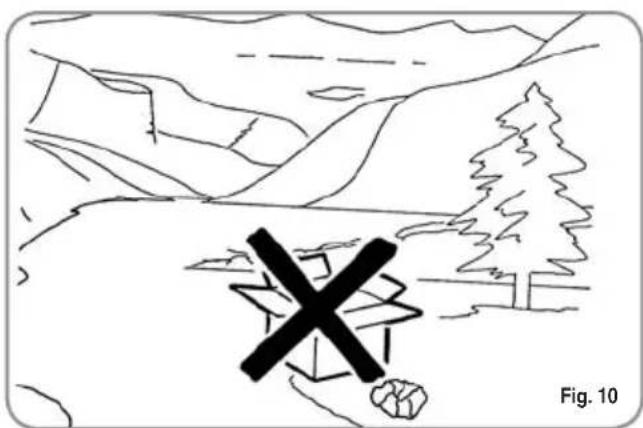
CAUTION RISK OF POLLUTION
4. INSTALLATION AND PRELIMINARY OPERATIONS
Before carrying out any installation and adjustment operations you must read and fully understand the SAFETY INSTRUCTIONS of this handbook. The company cannot be held responsible for damage to things or injury to persons caused by failure to comply with the safety instructions and installation and maintenance instructions contained in this handbook.

CAUTION
RISK OF POLLUTION
Do not dispose of packaging in the environment
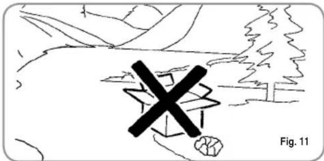
After unpacking, assess that the machine and its accessories unit are complete, then proceed as follows:
- place the machine so that it is level on a flat surface;
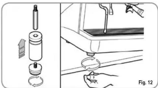
- assemble its supporting feet by inserting the insert into the cylindrical unit;
- twist the rubber foot into the screw thread inside the unit;
- screw the whole assembled unit into the allotted setting for the machine's adjustable feet;
• level the machine by regulating the adjustable feet;
NOTE: the unit grooves have to face upwards, as shown in the following illustration.
It is advisable to install a softener (1) and then a mesh filter (2) on the external part of the plumbing system, during preliminaries and after levelling the machine.
In this way impurities like sand, particles of calcium, rust etc will not damage the delicate graphite surfaces and durability will be guaranteed.
Following these operations, connect the plumbing systems as illustrated in the following figure.

WARNING
Avoid throttling in the connecting tubes.
Assess that the drain pipe (3) is able to eliminate waste.
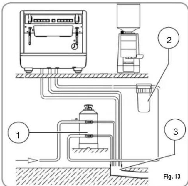
KEY
1 Softener
2 Mesh filter
3 Drain ∅ 50 mm
NOTE: For a correct functioning of the machine the water works pressure must not exceed 4 bars.
Otherwise install a pressure reducer upstream of the softener; the internal diameter of water entrance tube must not be less than 6mm (3\8").

CAUTION RISK OF SHORT CIRCUITS
The machine must always be protected by an automatic omnipolar switch of suitable power with contact openings of equal distance or more than 3mm.
Nuova Simonelli is not liable for any damage to people or objects due to not observing current security measures.
Prior to connecting the machine to the electrical mains, assess that the voltage shown on the machine's data plate corresponds with that of the mains.
5. ADJUSTMENTS TO BE MADE BY A QUALIFIED TECHNICIAN ONLY

CAUTION
The adjustments listed here below must ONLY be performed by a Specialist Technical Engineer. Nuova Simonelli cannot be held liable for any damage to persons or property arising from failure to observe the safety instructions supplied in this manual.

CAUTION ELECTRIC SHOCK HAZARD
Before performing any operation, the specialist technical engineer must first switch off the main switch off and unplug the machine.
5.1 FILLING BOILER MANUALLY
All models are equipped with a level gauge to keep the water level inside the boiler constant.
When using the machine for the first time, it is advisable to fill the boiler by hand to avoid damaging the electrical resistor and turning on the electronic protection.
If this should happen, just turn the machine off and then start it up again to complete its loading procedure (see chapter "MACHINE FUNCTIONS MESSAGE – LEVEL ERROR").
To fill the boiler manually for the first time, proceed as follows:
- remove the worktop grid;
- remove the sheet metal guard by unscrewing the four screws at the sides (A), as illustrated in the following figure;
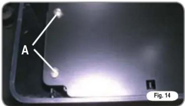
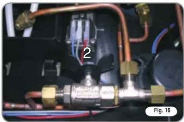
- use the manual level valve to allow water to enter the boiler tank for about 20-30 secs.;
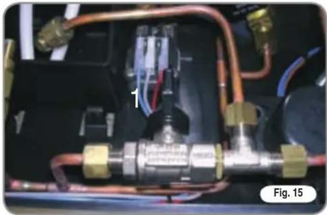
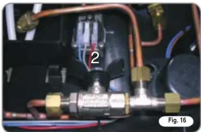
1: Operating position
2: Manual filling position
When the adjustments have been made, refit the sheet metal guard into its housing and fix it into place with the four side screws; refit the grid into the work surface.
5.2 SETTING THE BOILER TANK PRESSURE (Pressure switch adjustment)
To adjust the service pressure of the boiler, thus regulating the water temperature, according to the various functions and needs of the coffee desired, proceed as follows:
- unscrew the 4 screws on the top panel (Fig. 17);
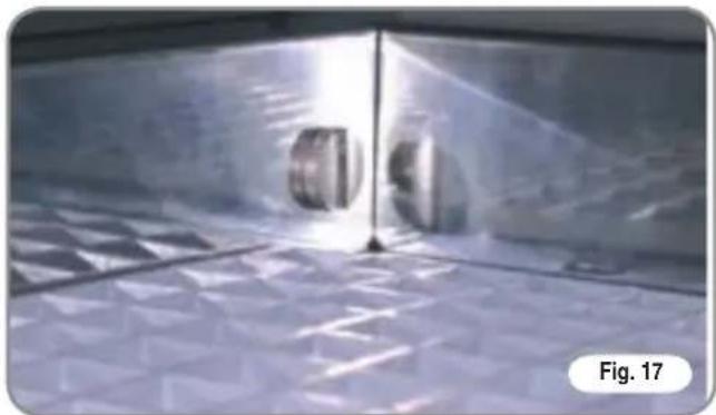
- turn the pump registration screw, turning it clockwise to INCREASE and counter clock wise to DECREASE the pressure.

Advisable pressure: 1 - 1,4 bar (according to the kind of coffee).
5.3 SETTING THE PUMP PRESSURE
To set the pressure of the pump, proceed as follows:
- remove the grid from the work surface;
- remove the sheet metal guard by unscrewing the four screws at the sides (A), as illustrated in the following figure;
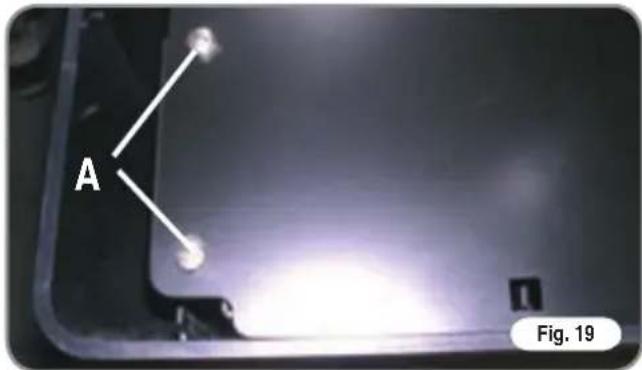
- turn the pump registration screw, turning it clock - wise to INCREASE and counter clock wise to DECREASE the pressure.
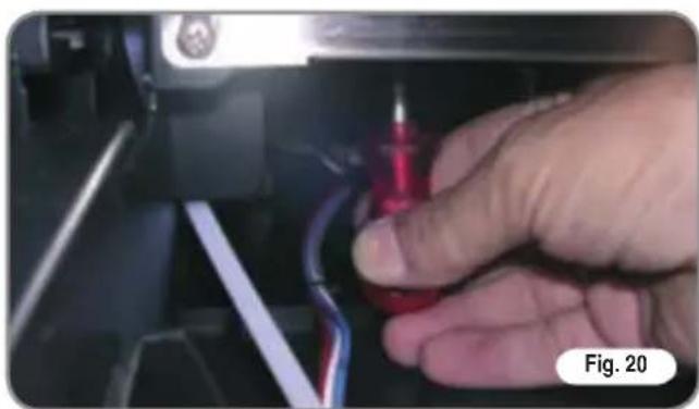
Advisable pressure: 9 bar.
- The pressure set for the pump will be shown in the bottom section of the pressure gauge when coffee is being dispensed.
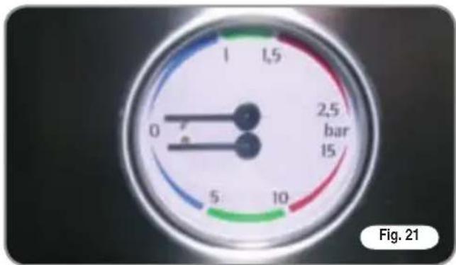
Once the adjustment operation has been completed, screw the protective metal sheet back into its setting and replace the worktop grid cover.
5.4 HOT WATER ECONOMISER ADJUSTMENT
All Appa models are fitted with a hot water mixer that can be used to adjust the delivery temperature of the water and therefore, to optimise system performance.
To adjust the hot water economiser, it is necessary to remove the top panel of the machine, proceeding as follows:
- unscrew the 4 screws on the top panel (Fig. 22);
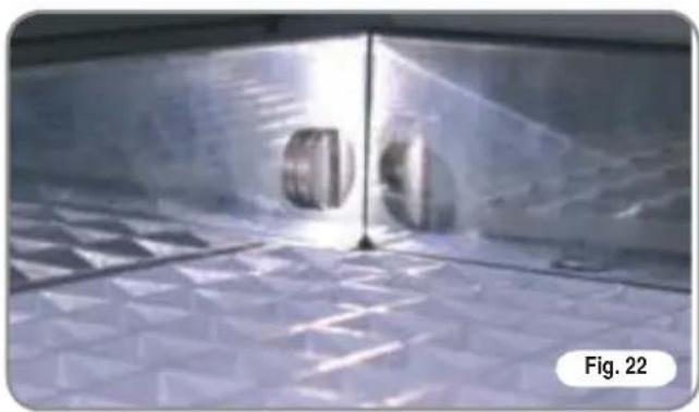
- to adjust the temperature of the hot water delivered from the nozzle, turn the register knob CLOCKWISE / ANTICLOCKWISE to INCREASE / REDUCE the temperature;
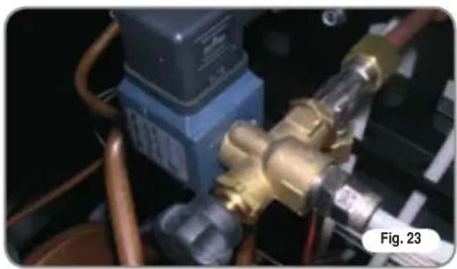
- at the end of this operation, refit the top panel on the machine.
6. USE
Before starting to use the appliance, the operator must be sure to have read and understood the safety prescriptions contained in this booklet.
6.1 SWITCHING THE MACHINE ON
- Plug the machine into the mains power socket.
- Set the main switch (n.xx, Fig 1) to "I".
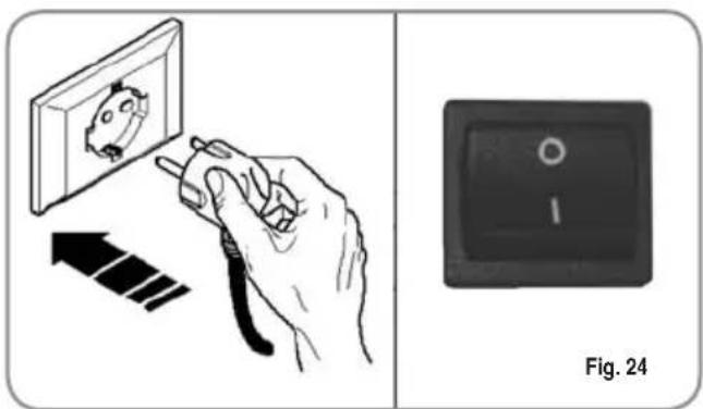
6.2 SWITCHING THE MACHINE OFF
- Set the main switch (n. 13, Fig 1) to "O".
- Unplug the machine into the mains power socket.
6.3 MAKING COFFEE
Unhitch the filter-holder and fill it with one or two doses of ground coffee depending on the filter used.
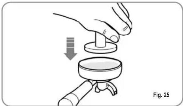
Press the coffee with the provided coffee presser, dust off any coffee residue from the rim of the filter (this way the rubber gasket will last longer).
Insert the filter in its unit.
Press the desired coffee button:
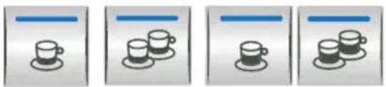
1 small coffee
2 small coffees
1 long coffee
2 long coffees
By starting up the coffee brewing procedure the unit's pump is activated and the unit's solenoid valve is opened.
By pressing it, the button will turn on and signal the operation
NOTE: when in pause, leave the filter-holder inserted in the unit so that it will keep warm. To guarantee the utmost thermic stability during use, the delivery units are thermo-compensated with complete hot water circulation.
6.4 USING STEAM

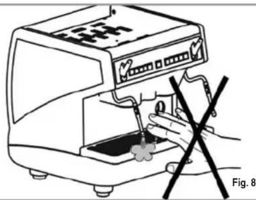
CAUTION RISK OF BURNS OR SCALDING
While using the steam nozzle, you must pay attention to not place your hands beneath it or touch just after it has been used.
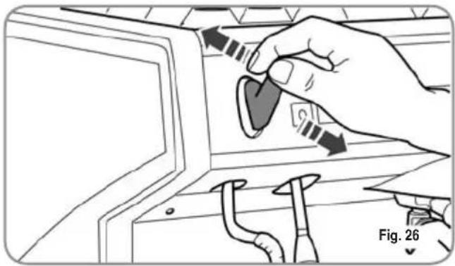
To use steam just pull or push the provided lever (Fig. 26).
By pulling it completely the lever will hold a position of maximum delivery; by pushing it, the lever will automatically give way.
The two steam nozzles are articulated to guarantee their easy use.
6.5 MAKING CAPPUCCINO
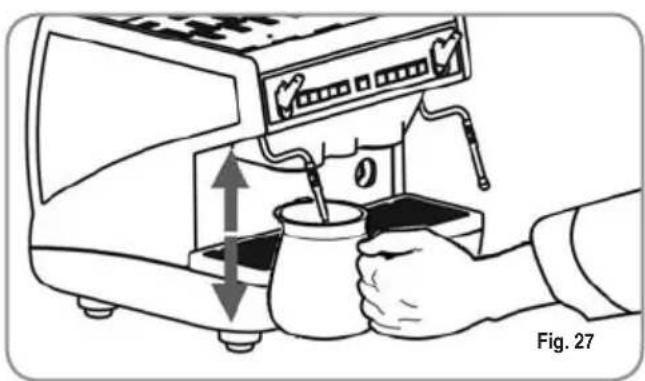
To obtain the typical cappuccino foam, immerse the nozzle all the way into a container 1/3 full of milk (preferably cone-shaped). Turn on the steam. Before the milk starts to boil, pull the nozzle slightly up and lightly move it vertically across the surface of the milk. When you have completed the procedure, clean the nozzle carefully with a soft cloth.
6.6 HOT WATER SELECTION

CAUTION RISK OF BURNS OR SCALDING
While using the hot water nozzle, pay careful attention not to place your hands beneath it or touch it just after it has been used.
This nozzle delivers hot water to make tea or herb teas.
Place a container underneath the hot water nozzle and press the hot water select button
Make sure the button lights up.
Water will be delivered from the hot water nozzle for as long as the set time indicates.
NOTE: Hot water can be delivered at the same time as coffee.
6.7 TIMED STEAM
SELECTION
(Version with timed steam nozzle without temperature probe)

WARNING DANGER OF BURNS OR SCALDS
When using the steam nozzle always take great care never to place your hands underneath it or to touch it immediately after use.
This is used to dispense steam for milk-based beverages (e.g. cappuccino or latte).
Place a container with the liquid to be heated beneath the steam nozzle and press the steam button
Make sure that the button itself lights up.
The nozzle will dispense steam for the amount of time set in the programming function.
NOTE: Steam can be dispensed at the same time as coffee.
6.8 AUTOSTEAM
SELECTION (Version with Autosteam)

WARNING DANGER OF BURNS OR SCALDS
When using the steam nozzle always take great care never to place your hands underneath it or to touch it immediately after use.
This is used to dispense steam for milk-based beverages (e.g. cappuccino or latte).
Place a container with the liquid to be heated beneath the steam nozzle and press the steam button
Make sure that the button itself lights up.
The nozzle will continue to dispense steam until the heated liquid reaches the set temperature.
NOTE: Steam can be dispensed at the same time as coffee.
7. PROGRAMMING
7.1 PROGRAMMING DOSES
To access the programming units, proceed as follows:
NOTE: the procedure can be carried out with the machine on.
- To enter the programming function for each group, it is necessary to hold down the continued delivery key for 5 seconds.
• The delivery keys will begin to flash.
- Accessing the programming mode for the first group also enables the setting mode for the machine's operating parameters.
7.2 PROGRAMMING COFFEE DOSES
To programme the amount of water for each of the delivery keys, proceed as follows:
- fill the filter holder with the right amount of coffee (the double or single filter holder can be used, according to the key to be programmed).
- Place the filter holder in the group.
- Press one of the delivery keys:
- The machine will begin to dispense and once the required quantity has been delivered, press the continued key.
- Delivery will cease and the selected dose key will switch off (the other keys will continue to flash).
- Press the continued key 📄 to exit the programming function or to continue programming other dose keys
NOTE: This procedure can be used for all groups on the machine, although it must be performed on one group at a time; the other groups will continue to operate as normal.
7.3 SETTING THE TIMED STEAM FUNCTION
(Version with timed steam nozzle without temperature probe)
- Follow the standard procedure to enter the programming function;
- Place the steam nozzle inside the liquid to be heated;
- Press the steam select key
• The nozzle will begin to dispense steam; - Press the steam key 📋 again when a sufficient amount of steam has been dispensed. The machine will store this dispensing time to memory.
- Press the continuous key to quit the programming function or to go on to program other selection keys.
7.4 SETTING THE AUTOSTEAM FUNCTION (Version with Autosteam)
- Follow the standard procedure to enter the programming function;
- Place the steam nozzle complete with temperature probe inside the liquid to be heated;
- Press the steam select key ;
• The nozzle will begin to dispense steam; - Press the steam key again when the liquid has reached the required temperature. The machine will store this temperature setting to memory;
- Press the continuous key to quit the programming function or to go on to program other selection keys.
7.5 PROGRAMMING HOT WATER
- Use the relevant procedure to enter the programming function.
- Press the hot water selection key
• Hot water delivery will begin. - Decide the required amount of hot water and then press the key again.
- Press the continued key to exit the programming function or to continue programming other selection keys.
7.6 PROGRAMMING STANDARD DOSES
- It is possible to enter pre-set values for the 4 group doses and water (steam).
PTo do this, it is necessary to press the key and hold it down for at least 10 seconds until the flashing keys switch off. The doses are:
| 1CN 2CN 1CL 2CL | ||
| 40 cc 60 cc 50 cc 85 cc |
| WATER STEAM STEAM TEMP. | ||
| 9 sec. | 0 sec. | 50°C |
NOTE: A time setting of 0 seconds for steam and water means this function will work continually.
7.7 COPIATURA DOSI
It is possible to copy the doses stored to memory for group 1 to the doses for group 2. This operation is performed by pressing the continuous key 📄 for group 2 and holding it down for at least 10 seconds until the flashing keys switch off.
7.8 PROGRAMMING OPERATING PARAMETERS

CAUTION
The adjustments listed here below must ONLY be performed by a Specialist Technical Engineer.
If you hold down the key of the second group, after first entering the programming mode for the first group, this will access the machine parameters setting mode; this is signalled by the continuous key or the second group, which will switch on
- Enabling the pump if the level is enabled.
- Enabling the software block to enter the dose programming function.
- Adjusting keypad brightness.
- Enabling the hot water pump (on machines
fitted with economiser).
- Disenabling the cup warmer
- Restoring default settings.
1. Enabling the pump during levelling.
Use the espresso key during levelling:

if the key is lit, the pump is enabled together with the level; if it is switched off, the pump is not enabled with the level function.
2. Enabling the software block to enter the dose programming function.
Use the long coffee key 📁 to enable a software block to programme doses (key lit) or to de-activate the block (key off).
3. Adjusting keypad brightness.
The 2 long coffees key of the second group is used to choose the key brightness setting from 5 pre-set levels.
Use the 📄, key, which will flash, to change the level, lowering it to minimum or returning it to maximum.
4. Enabling the hot water pump (machines fitted with economiser only).
Use the hot water key to set the pump to switch on while hot water is being delivered.
If the ☐ key is lit, the pump will switch on while hot water is being delivered; if it is switched off, the pump will not switch on.
5. Starting the pump with steam (only for machine models with timed steam or autosteam functions).
The steam key is used to set the pump to start while steam is being dispensed.
If the key is lit, the pump will start while steam is being dispensed; if the key is not switched on, then the pump will not start.
7.9 AUTOMATIC GROUP CLEANING CYCLE
To start the automatic cleaning mode, the machine must first be switched off and then back on again while holding down the hot water and one low coffee from group 2 during the initial Lamp-test.
At the end of the Flash-test, the and keys and the single long coffee key of all groups will begin to flash.
Press the key to start the washing cycle for the relevant group.
Once the washing cycle has been completed, it is possible to perform a rinse cycle for the same group by pressing the key again.
To perform the rinse cycle at a later time, switch off the machine and the card will store any cleaning cycles that need to be completed in its memory. In fact, the next time that the machine is switched on, the machine card will automatically open the group cleaning status without it being necessary to press the and keys.
Hold down the and keys for 2 seconds to exit the cleaning mode in the event that there are no cycles to be completed. For incomplete cycles, the keys of the groups that require rinsing will continue to flash.
Hold down the and keys for 2 seconds more to force exit from the cleaning mode, resetting all information about rinse cycles still to be completed.
When a cleaning cycle is complete, the key for the group will switch off.
If there are no more rinse cycles to be performed, the card will exit the cleaning mode.
8. CLEANING AND MAINTENANCE
8.1 CLEANING THE OUTSIDE OF THE MACHINE
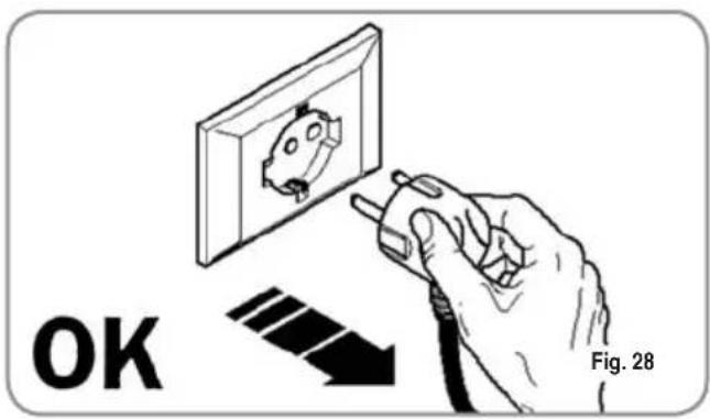
Before performing any cleaning operation, the machine must be cut off from the power supply (machine switched off and unplugged).

WARNING
Do not use solvents, chlorine-based products or abrasives.
Cleaning the work area: remove the worktop, lifting it up from the front and sliding it out. Remove the water collection dish underneath and clean everything with hot water and cleansers.
Cleaning the bottom: To clean all the chromium-plated areas, use a soft, damp cloth.
8.2 CLEANING THE STAINLESS COFFEE- HOLDERS
The stainless coffee-holders are situated under the delivery units, as shown in figure.

NOTE: To clean proceed as follows:
- Turn the screw placed in the centre of the coffee-holder.
- Slide the coffee-holder out and check that its holes are not obstructed but clean.
- If obstructed, clean as described (Paragraph "CLEANING FILTERS AND FILTER-HOLDERS")
We recommend cleaning the coffee-holder once a week.
8.3 CLEANING THE UNIT WITH THE AID OF THE BLIND FILTER
The machine is pre-set for cleaning the delivery unit with a specific washing powder.
We recommend carrying out a washing cycle at least once a day with special cleansers.

CAUTION RISK OF INTOXICATION
Once the filter-holder has been removed, repeat delivery operations a few times to eliminate any cleanser residues.
To carry out the washing procedure, proceed as follows:
1) Substitute the filter with the delivery unit blind filter.
2) Fill it with two spoonfuls of special cleanser powder and insert it into the unit filter-holder.
3) Press one of the coffee keys and halt it after 10 seconds.
4) Repeat the procedure several times.
5) Remove the filter-holder and carry our a few deliveries.
8.4 CLEANING FILTERS AND FILTER-HOLDERS
Place two spoonfuls of special cleanser in half a litre of hot water and immerse filter and filter-holder (without its handle) in it leaving them to soak for at least half an hour. Then rinse abundantly with running water.
8.5 RESIN AND SOFTENER REGENERATION
To avoid scaling deposits in the boiler and in the heating exchangers, the softener must always be kept efficient. Therefore, the ionic resins must be regularly regenerated.
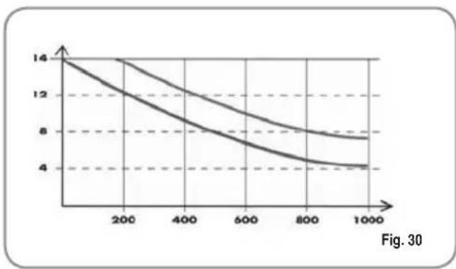
Regeneration times are established according to the quantity of coffee delivered daily and the hardness of the water utilised.
As an indication, regeneration times can be calculated on the basis diagram illustrated in Fig. 30.
Regeneration procedures are as follows:
1) 1) Turn the machine off and place a container large enough to contain at least 5 litres under tube E (Fig. 31).
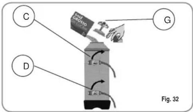
Turn levers C and D from left to right; take the cap off by unscrewing knob and fill with 1 Kg normal kitchen salt (Fig. 32).
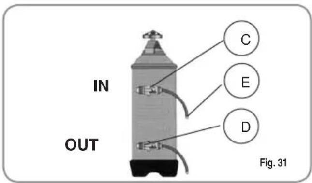
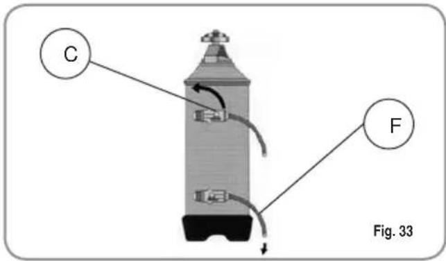
2) Put the cap back on and reposition lever C moving it towards the left (Fig. 33), and allowing tube F to discharge the salty water until it has been eliminated and the water becomes fresh again (about half and hour).
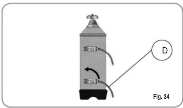
3) Reposition lever D towards the left (Fig. 34).
9. MACHINE ERROR MESSAGES
| DISPLAY AND KEY INDICATIONS | CAUSE | EFFECT | SOLUTION | NOTES |
DOSAGE ERRORContinuous key  ing and dispensinglit without flashing. ing and dispensinglit without flashing. | If the doser doesn't send out its set commands within the first three seconds from delivery onset. | If the delivery isn't manually halted, the maximum time limit (120 sec) will be blocked. | Interrupt delivery. | |
| LEVEL ERRORContinuous key [czdc] flashing on both groups. | If within 90 sec. from onset, with pump inserted during the levelling, at 180 sec., if the level has not been re-established. | The pump, the resistor and all the functions will be halted. | Turn the machine off for at least 5 sec. and then switch it on again. |
IMPIANTO ELETTRICO / ELECTRICAL SYSTEM
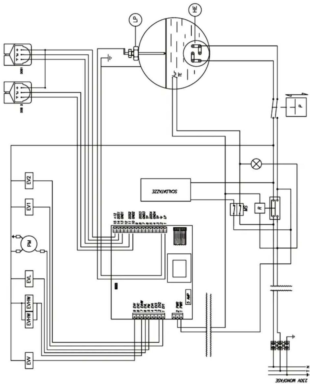
IMPIANTO ELETTRICO / ELECTRIC SYSTEM
5 Refill electrovalve
6 Flowmeter
7 Heater exchange
8 Delivery electrovalve
9 Safety valve
10 Hot water electrovalve
11 Steam tap
12 Pressostat
13 Boiler
14 Heating element
LEGENDA
espresso coffee machines
Nuova Distribution Centre
LLC 6940Salashan PKWY BLDG A 98248 Ferdale, WA
Tel. +1.360.3662226
Fax +1.3603664015
videoconf.+1.360.3188595
espresso coffee machines
Via M. d'Antegiano, 6
62020 Belforte del Chienti
Macerata Italy
Tel. +39.0733.9501
Fax +39.0733-950242


- DICHIARAZIONE DI CONFORMITÀ CE EC DECLARATION OF CONFORMITY
- CARATTERISTICHE TECNICHE
- INDICE
- CARATTERISTICHE TECNICHE ....2
- MESSAGGI ERRORI MACCHINA
- TECHNICAL CHARACTERISTICS
- INDEX
- TECHNICAL CHARACTERISTICS 26
- DESCRIPTION
- KEY
- 1.1 KEYPAD DESCRIPTION
- 1.2 ACCESSORIES LIST
- SAFETY PRESCRIPTION
- WARNING
- CAUTION RISK OF ELECTRIC SHOCK
- CAUTION RISK OF POLLUTION
- CAUTION RISK OF BURNS OR SCALDING
- CAUTION
- TRANSPORT AND HANDLING
- 3.1 MACHINE IDENTIFICATION
- 3.2 TRANSPORT
- 3.3 HANDLING
- CAUTION RISK OF IMPACT OR CRASHING
- INSTALLATION AND PRELIMINARY OPERATIONS
- CAUTION RISK OF SHORT CIRCUITS
- ADJUSTMENTS TO BE MADE BY A QUALIFIED TECHNICIAN ONLY
- CAUTION ELECTRIC SHOCK HAZARD
- 5.1 FILLING BOILER MANUALLY
- 5.2 SETTING THE BOILER TANK PRESSURE (PRESSURE SWITCH ADJUSTMENT)
- 5.3 SETTING THE PUMP PRESSURE
- 5.4 HOT WATER ECONOMISER ADJUSTMENT
- USE
- 6.1 SWITCHING THE MACHINE ON
- 6.2 SWITCHING THE MACHINE OFF
- 6.3 MAKING COFFEE
- 6.4 USING STEAM
- 6.5 MAKING CAPPUCCINO
- 6.6 HOT WATER SELECTION
- 6.7 TIMED STEAM
- WARNING DANGER OF BURNS OR SCALDS
- 6.8 AUTOSTEAM
- PROGRAMMING
- 7.1 PROGRAMMING DOSES
- 7.2 PROGRAMMING COFFEE DOSES
- 7.3 SETTING THE TIMED STEAM FUNCTION
- 7.4 SETTING THE AUTOSTEAM FUNCTION (VERSION WITH AUTOSTEAM)
- 7.5 PROGRAMMING HOT WATER
- 7.6 PROGRAMMING STANDARD DOSES
- 7.7 COPIATURA DOSI
- 7.8 PROGRAMMING OPERATING PARAMETERS
- ENABLING THE PUMP DURING LEVELLING
- ENABLING THE SOFTWARE BLOCK TO ENTER THE DOSE PROGRAMMING FUNCTION
- ADJUSTING KEYPAD BRIGHTNESS
- ENABLING THE HOT WATER PUMP (MACHINES FITTED WITH ECONOMISER ONLY)
- STARTING THE PUMP WITH STEAM (ONLY FOR MACHINE MODELS WITH TIMED STEAM OR AUTOSTEAM FUNCTIONS)
- 7.9 AUTOMATIC GROUP CLEANING CYCLE
- CLEANING AND MAINTENANCE
- 8.1 CLEANING THE OUTSIDE OF THE MACHINE
- 8.2 CLEANING THE STAINLESS COFFEE- HOLDERS
- 8.3 CLEANING THE UNIT WITH THE AID OF THE BLIND FILTER
- CAUTION RISK OF INTOXICATION
- 8.4 CLEANING FILTERS AND FILTER-HOLDERS
- 8.5 RESIN AND SOFTENER REGENERATION
- MACHINE ERROR MESSAGES
Brand : NUOVA SIMONELLI
Model : Appia Compact
Category : Coffee maker