
KEW 1012 - Multimeter Kyoritsu - Free user manual and instructions
Find the device manual for free KEW 1012 Kyoritsu in PDF.


| Product Type | High Voltage Insulation Resistance Tester |
| Brand | Kyoritsu |
| Model | KEW 1012 (based on KEW3121B/3122B) |
| Rated Voltage | 2500V (KEW3121B) / 5000V (KEW3122B) |
| Measuring Range | 0 - 2GΩ / 1 - 100GΩ (automatic change) for 2500V; 0 - 5GΩ / 2 - 200GΩ for 5000V |
| Accuracy (First Effective Range) | ±5% of indicated value at 23°C±5°C |
| Output Voltage | DC 2500V±5% (0.1 - 50GΩ) / DC 5000V±5% (0.2 - 100GΩ) |
| Overload Protection | AC720V/10 sec on insulation resistance range |
| Withstand Voltage | AC5160V (50/60Hz)/5 sec between electrical circuit and enclosure |
| Insulation Resistance | 1000MΩ or more at DC1000V |
| Dimensions | 177(L) × 226(W) × 100(D) mm |
| Weight | Approx. 1.6 kg (with batteries) |
| Power Source | DC12V LR14 (Alkaline size C) × 8 pcs |
| Battery Life | Approx. 55 hours (KEW3121B) / 40 hours (KEW3122B) under typical load |
| Operating Temperature | -10°C to +40°C, relative humidity 85% or less |
| Storage Temperature | -20°C to +60°C, relative humidity 75% or less |
| Safety Standards | IEC 61010-1,-2-030 (CAT III 600V / CAT IV 300V, Pollution Degree 2) |
| Measurement Categories | CAT III 600V, CAT IV 300V |
| Accessories Included | Line probe (MODEL 7165A), Earth cord (MODEL 7264), Guard cord (MODEL 7265), LR14 batteries ×8, Hard case (MODEL 9179), Instruction manual |
| Optional Accessories | Recorder adapter (MODEL8324), Line probe with alligator clip (3m MODEL7168A or 15m MODEL7253) |
| Cleaning | Use a damp cloth with alcohol or anti-static agent; avoid organic solvents |
| Battery Replacement | Set switch to OFF, disconnect leads, remove cover, replace all 8 batteries, ensure correct polarity |
| Disposal | Observe WEEE Directive; dispose of batteries with terminals insulated |
Frequently Asked Questions - KEW 1012 Kyoritsu
User questions about KEW 1012 Kyoritsu
0 question about this device. Answer the ones you know or ask your own.
Ask a new question about this device
Download the instructions for your Multimeter in PDF format for free! Find your manual KEW 1012 - Kyoritsu and take your electronic device back in hand. On this page are published all the documents necessary for the use of your device. KEW 1012 by Kyoritsu.
USER MANUAL KEW 1012 Kyoritsu
High voltage insulation resistance tester
KEW3121B/3122B

- Safety warnings .... 1
- Features 5
- Specification 6
- Instrument layout ...... 9
- Getting started 10
5-1 Mechanical Zero Adjustment 10
5-2 Battery Check 10 - Measurement 11
6-1 Insulation resistance measurement 11
6-2 Continuous measurement 13
6-3 Voltage characteristics at measuring terminal 13
6-4 Use of Guard terminal 14 - Battery replacement 15
- How to remove the Hard case 16
- Cleaning Meter Cover 17
- Accessories 18
10-1 Metal parts for Line Probe, and replacement 18
10-2 How to use the adaptor for recorder 19
10-3 Line probe with alligator clip(optional accessory) ..... 19 - Disposing the Product 20
1. Safety warnings
- This instrument has been designed, manufactured and tested according to IEC 61010: Safety requirements for Electronic Measuring apparatus, and delivered in the best condition after passing quality control tests. This instruction manual contains warnings and safety rules which must be observed by the user to ensure safe operation of the instrument and to maintain it in safe condition. Therefore, read through these operating instructions before using the instrument.
WARNING
- Read through and understand instructions contained in this manual before starting to use the instrument.
- Keep the manual at hand to enable quick reference whenever necessary.
- The instrument is to be used only in its intended applications.
- Understand and follow all the safety instructions contained in the manual. It is essential that the above instructions are adhered to.
Failure to follow the above instructions may cause injury, instrument damage and/or damage to equipment under test.
○ The symbol ⚠ indicated on the instrument means that the user must refer to the related parts in the manual for safe operation of the instrument. It is essential to read the instructions wherever the symbol ⚠ appears in the manual.
⚠️ DANGER is reserved for conditions and actions that are likely to cause serious or fatal injury.
⚠ WARNING is reserved for conditions and actions that can cause serious or fatal injury.
⚠️ CAUTION is reserved for conditions and actions that can cause injury or instrument damage.
⚠️ DANGER
- Do not use this instrument to test the circuits in which 300V or higher potentials exist in Measurement category IV (CAT IV) environment or 600V or higher potentials exist in CAT III environment.
- Do not attempt to make measurements in the presence of flammable gasses. Otherwise, the use of the instrument may cause sparking, which can lead to an explosion.
- Never attempt to use the instrument if its surface or your hand is wet.
- Be careful not to short-circuit the power line with the metal part of the test leads when measuring a voltage. It may cause personal injury.
- Do not exceed the maximum allowable input of any measuring ranges.
- Do not press the Test button when connecting the test leads to the instrument.
- Never open the Battery compartment cover during a measurement.
- To prevent possible electrical shock, do not touch the circuit under test during an insulation resistance measurement or right after a measurement.
⚠ WARNING
- Never attempt to make any measurements if any abnormal conditions such as broken case and exposed metal parts are noted.
- Do not rotate the Function switch with the test leads connected to the object under test.
- Do not install substitute parts or make any modifications to the instrument. Return the instrument to your local KYORITSU distributor for repair or re-calibration.
- Do not try to replace the batteries if the surface of the instrument is wet.
- Insert the plug into the terminal firmly when using test leads.
- Ensure that the instrument is switched off before opening the Battery compartment cover for battery replacement.
CAUTION
- Before starting a measurement, confirm that the Function switch is at an appropriate position.
- Set the Function switch to “OFF” position after use. Remove the batteries if the instrument is to be stored and will not be in use for a long period.
- Do not expose the instrument to direct sunlight, high temperatures and humidity or dew.
- Use a damp cloth with alcohol for cleaning the instrument and the areas around the measuring terminals.
- When this instrument is wet, please store it after it dries.
Symbols
 | Danger of possible electric shock |
 | Instrument with double or reinforced insulation |
 | User must refer to the manual |
 | DC |
 | AC |
 | Earth terminal |
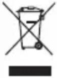 | Crossed-out wheel bin symbol (according to WEEE Directive: 2002/96/EC) indicating that this electrical product may not be treated as household waste, but that it must be collected and treated separately. |
○ Measurement categories (Over-voltage categories)
To ensure safe operation of measuring instruments, IEC 61010 establishes safety standards for various electrical environments, categorized as O to CAT IV, and called measurement categories. Higher-numbered categories correspond to electrical environments with greater momentary energy, so a measuring instrument designed for CAT III environments can endure greater momentary energy than one designed for CAT II.
O : Circuits which are not directly connected to the mains power supply.
CAT II : Electrical circuits of equipment connected to an AC electrical outlet by a power cord.
CAT III : Primary electrical circuits of the equipment connected directly to the distribution panel, and feeders from the distribution panel to outlets.
CAT IV : The circuit from the service drop to the service entrance, and to the power meter and primary overcurrent protection device (distribution panel).

2. Features
KEW3121B (2500V/100GΩ) and KEW3122B (5000V/200GΩ) are battery-operated high voltage insulation testers.
- Designed to meet the following safety standards:
IEC 61010-1,-2-030 (CAT III 600V/CAT IV 300V Pollution degree 2)
IEC 61010-031 (Requirements for hand-held probes)
- Suited for heavy duty electrical maintenance and servicing of industrial installations, cables, transformers, generators and switchgear where high voltage insulation tests are required.
- Dual scales for low and high ranges which change automatically. Colour coded scales for easy reading plus LED's that illuminate in matching colour.
- Hard carrying case furnished as standard accessory. Houses both instrument and test leads in compact form. Made of plastic, it is highly water resistant.
- Rated output voltage is maintained down to 0.1GΩ for KEW3121B, 0.2GΩ for KEW 3122B. This permits accurate measurements of low insulation resistance.
- Audible high voltage warning at insulation resistance measurement
- Optional adapter MODEL8324 is available for connection to recorder and enables cable insulation monitoring.(Option)
3. Specification
• Applicable standards
IEC 61010-1,-2-030
Measurement CAT III 600V Pollution degree2
Measurement CAT IV 300V Pollution degree2
IEC 61010-031 Standard for hand-held probes
MODEL7165A(CAT IV 600V)
MODEL7264(CAT IV 600V)
MODEL7265(CAT IV 600V)
* When KEW3121B/3122B and the test lead
are combined and used together, whichever is lower category either of them belongs to is applied.
IEC 61326-1,-2-2 EMC standard
IEC 60529 IP40
EN 50581 RoHS Directive
- Measuring range and accuracy
| Model KEW3121B KEW3122B | |||
| Rated voltage 2500V 5000V | |||
| Measuring range | 0 - 2GΩ/ 1 - 100GΩ(Automatic change) | 0 - 5GΩ/ 2 - 200GΩ(Automatic change) | |
| Temperature:23°C±5°C | First effective measuring range | 0.1 - 50GΩ 0.2 - 100GΩ | |
| Accuracy ±5% of indicated value | |||
| Second effective measuring range | Measuring ranges other than listed above, 0 and∞ | ||
| Accuracy | ±10% of indicated value or 0.5% of scale length | ||
| Temperature:-10°C to +40°C | First effective measuring range | 0.1 - 50GΩ 0.2 - 100GΩ | |
| Accuracy ±10% of indicated value | |||
| Second effective measuring range | Measuring ranges other than listed above, 0 and∞ | ||
| Accuracy ±20% of indicated value or 1.0% of scale length | |||
| Output voltage | DC 2500V±5%(0.1 - 50GΩ) | DC 5000V±5%(0.2 - 100GΩ) | |
- Altitude : 2000m or less
- Temperature & humidity range (guaranteed accuracy) : 23°C±5°C/Relative humidity 85% or less (no condensation)
- Operating temperature & humidity range : -10°C to +40°C/Relative humidity 85% or less (no condensation)
- Storage temperature & humidity range : -20°C to +60°C/Relative humidity 75% or less (no condensation)
- Overload protection : Insulation resistance range: AC720V/10sec.
- Withstand voltage : AC5160V(50/60Hz)/ 5 sec. (Between electrical circuit and enclosure)
- Insulation resistance : 1000MΩ or more/DC1000V (Between electrical circuit and enclosure)
- Dimension : 177(L)×226(W)×100(D)mm
●Weight : KEW3121B approx. 1.6kg (battery included) KEW3122B approx. 1.7kg(battery included)
●Power source : DC12V LR14(Alkaline battery size C)x 8pcs
●Current consumption (representative values at supply voltage 12V)
| Model KEW3121B KEW3122B | ||
| Rated voltage 2500V | 5000V | |
| Short-circuit current | 65mA | 82mA |
| Max. current consumption | 80mA/50MΩ | 100mA/100MΩ |
| Output at open circuit | 70mA | 85mA |
●Measurement time : 3121B:approx. 55 hours * under a load of 50MΩ on the Insulation resistance 2500V range.
3122B:approx. 40hours
*under a load of 100MΩ on the Insulation resistance 5000V range.
- Accessories : Line probe: MODEL 7165A
(Including MODEL8255 Straight type prod with molded parts)
Earth cord: MODEL 7264
Guard cord: MODEL 7265
LR14(Alkaline battery size C)x 8pcs
Instruction manual
Hard Case: MODEL 9179
Pickel Type Prod: MODEL 8019
Straight Type Prod: MODEL 8254
- Optional : Adaptor for recorder:MODEL8324
accessories 3m Line probe with alligator clip: MODEL7168A 15m Line probe with alligator clip: MODEL7253
4. Instrument layout
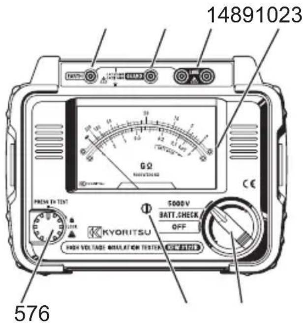
natural_image
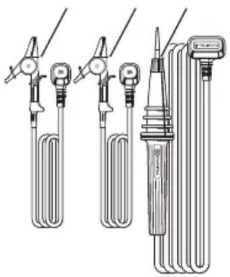
Technical line drawing of three different types of medical or industrial devices with coiled tubing and connectors (no text or symbols)1 Line terminal
2 Guard terminal
3 Earth terminal
4 LED for high & low range indication
5 PRESS TO TEST button
6 Function switch
7 Meter movement zero adjust
8 Guard cord (green)
9 Earth cord (black)
10 Line probe
5. Getting started
⚠️ DANGER
- Be careful. High voltage may present across LINE and EARTH terminals of the instrument when the PRESS TO TEST button is operated. Make sure to connect the Earth terminals of the circuit under test and of this instrument to earth. The buzzer sounds continuously while measuring insulation resistance.
5-1 Mechanical Zero Adjustment
Set the Function switch to “OFF” position. Adjust the Meter movement zero adjust located at the center of the Front panel with a screwdriver so that the pointer of the instrument reads “∞” symbol on the scale.
5-2 Battery Check
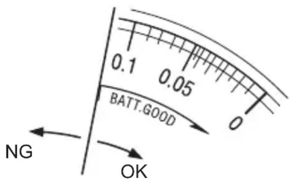
Set the Function switch to “BATT. CHECK” position and press the PRESS TO TEST button. The battery voltage is enough when the the pointer stays in BATT. GOOD area or to the right of this area.
If not, replace the batteries with new ones.
⚠️ DANGER
- Do not hold down or lock the PRESS TO TEST button when checking the battery voltage. It may lead to shorter battery life.
6. Measurement
6-1 Insulation resistance measurement
⚠️ DANGER
- Use a high voltage detector and confirm that there is no electrical charge in the circuit under test.
- Wear a pair of insulated gloves for high voltage.
- If the Function switch is at the insulation resistance range and the Test button is being pressed down, high voltages are generated and applied to the test leads and the circuit under test continuously. Do not touch the circuit or the test leads.
- The Battery compartment cover must be closed and screwed during a measurement.
- Do not make measurement when thunder rumbling.
- Connect the Earth Cord (black) to the earth terminal of the circuit under test.
This instrument measures insulation resistances and checks whether the insulations of electrical equipments or circuits are in good condition or not. So, please check the voltage that can be applied to the object under test before making a measurement.
Note:
- The insulation resistance values of the objects under test may not be stable, and the readings may be unstable.
- Bleep sound may be heard during an insulation resistance measurement, but it is not malfunction.
- It takes time to measure a capacitive load.
- At insulation resistance measurement, positive (+) voltage is outputted from the Earth terminal and negative (-) voltage is outputted from the Line terminal.
Connect the Earth cord to the Earth (ground) terminal.
It is recommended to connect the positive(+) pole to the earth side when measuring insulation resistance against the ground or when a part of the equipment under test is earthed.
With this connection, smaller measured value can be obtained comparing with other way round.
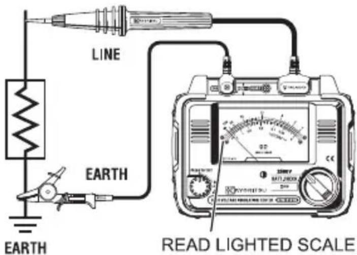
(1) Check the voltage which can be applied to the circuit under test, and set the Function switch to a desired insulation resistance range.
(2) Connect the Earth cord (black) to the Earth terminal of the circuit under test.
(3) Place the tip of the Line probe (red) to the circuit under test. Then press the “PRESS TO TEST” button. The buzzer sounds intermittently during a measurement.
(4) When the green LED illuminates, read insulation resistance on the outer scale (for high range). Use the inner scale where the red LED illuminates.
Caution
Always turn off the Breaker for the circuit under test.
(5) After a test, release the PRESS TO TEST button and wait for the same amount of time that it took for the measurement performed. Keep the Line probe and the circuit tested connected until electrical charges stored in the circuit under test are completely discharged.
⚠️ DANGER
- Do not touch the circuit under test immediately after testing. Capacitances stored in the circuit may cause electric shock.
- Leave the test leads connected to the circuit and never touch the circuit until electrical discharge completes.
(6) Set the Function switch to "OFF" position, and disconnect the test leads from the instrument.
6-2 Continuous measurement
Press and turn the Test button clockwise and lock the button to measure insulation resistances continuously. Turn the button counter-clockwise and set it to the initial position after a measurement.
⚠️ DANGER
- Be extremely careful not to get electric shock as a high voltage is present on the tip of the test leads continuously.
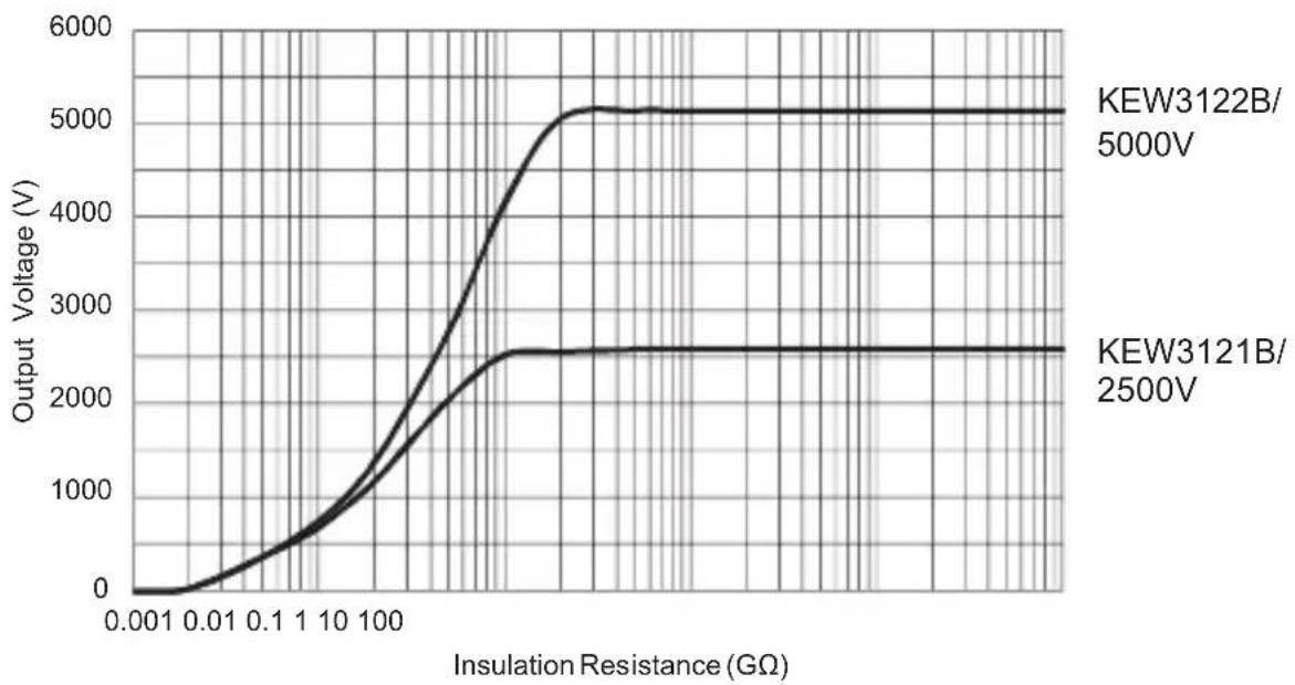
6-3 Voltage characteristics at measuring terminal
KEW3121B/ 3122B Output characteristics
line
| Insulation Resistance (GΩ) | KEW3122B/5000V Output Voltage (V) | KEW3121B/2500V Output Voltage (V) | | -------------------------- | ---------------------------------- | ---------------------------------- | | 0.001 | ~0 | ~0 | | 0.01 | ~100 | ~50 | | 0.1 | ~500 | ~200 | | 1 | ~1000 | ~800 | | 10 | ~2000 | ~1500 | | 100 | ~4000 | ~2500 | | >10 | ~5000 | ~2500 |6-4 Use of Guard terminal
When measuring the insulation resistance of a cable, leakage current flowing on the surface of cable jacket and the current flowing inside the insulator are mixed and may cause error in insulation resistance value. In order to prevent such error, wind a conductive wire around the point where leakage current flows. Then connect it to the Guard terminal. This is to move out the surface leakage resistance of the cable insulation to measure only the volume resistance of insulator. Make sure to use the Guard cord supplied with this instrument to connect the instrument to Guard terminal.
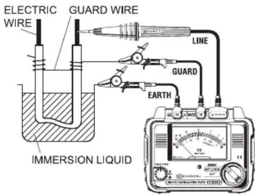
* It is possible to move out the surface leakage resistance of the insulation and measure only the volume resistance by using the Guard terminal. This is helpful when performing tests in humid air.
7. Battery replacement
DANGER
- Do not open the Battery compartment cover if the surface of the instrument is wet.
- Never open the Battery compartment cover during a measurement. To avoid electric shock, power off the instrument and disconnect the test leads from the instrument when replacing batteries.
- Always attach and close the Battery compartment cover when making a measurement.
CAUTION
- Do not mix new and old batteries or brands of batteries.
- Make sure to install batteries in correct polarity as marked inside.
(1) Set the Function switch to "OFF" position, and disconnect the test leads from the instrument.
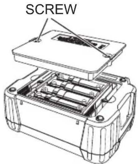
(2) Loosen the Battery compartment cover-fixing screws, and remove the Battery compartment cover. Remove all eight batteries and replace them with new ones.
(3) After replacing batteries, be sure to tighten up the screw for the Battery compartment cover.
Make sure to install batteries in correct polarity as marked inside.
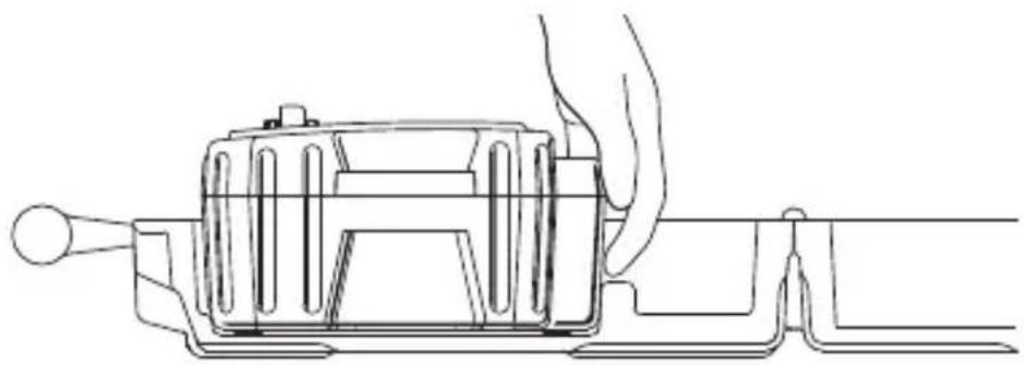
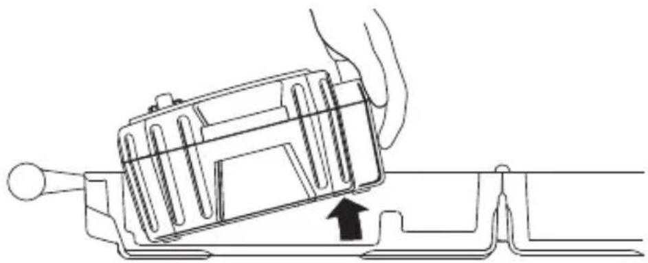
8. How to remove the Hard case
Hold the side surface of the terminal part, and gently pull the unit toward the front.
- Hold the side surface of the terminal part.
natural_image
Line drawing of a hand operating a mechanical device with no visible text or symbols- Pull the unit toward the front.
natural_image
Line drawing of a mechanical device with a hand operating it, showing internal components and a black arrow indicating motion (no text or symbols)9. Cleaning Meter Cover
This instrument is managed by our company's quality standard and is delivered in the best condition after passed the inspection. But in the dry time of winter static electricity sometimes builds up on the meter cover due to the characteristic of plastic.
When static electricity builds up on the meter cover and affects the meter reading, use a cloth dampened with off-the-shelf anti-static agent or detergent to wipe the meter cover surface.
CAUTION
- When the pointer deflects by touching the surface of this tester or zero adjustment cannot be made, do not try to make measurements.
- Anti-static agent has been applied to the surface of the Meter cover of this instrument. Clean the surface of the cover gently when it gets dirty.
- To avoid possible deforming or discoloring, do not use organic solvents.
10. Accessories
10-1 Metal parts for Line Probe, and replacement
DANGER
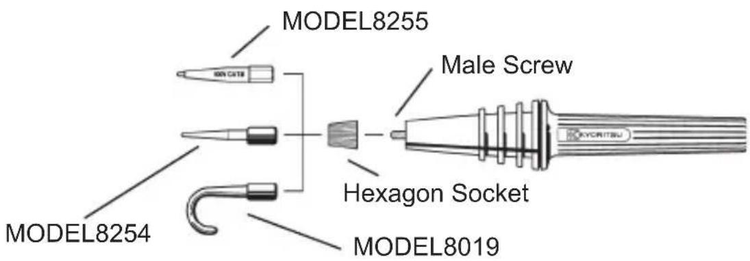
Attach MODEL8255 to the test leads to use the instrument in CAT II or higher environments. MODEL8254 and 8019 have exposed large metal parts, therefore, they may short circuit or damage the objects under test, cause fire or pose fatal or serious injuries to the users.
(1) Tip metal parts
MODEL8255: Standard Prod (straight type, with molded parts)
MODEL8254: Straight Type Prod
MODEL8019: Pickel Type Prod
To be used to hook the instrument.
(2) Replacement
Turn the Line probe counterclockwise to remove the attached tip metal. Put the tip metal you want to use to the hexagon socket and turn it clockwise together with the tip of probe, and tighten up the screws.
10-2 How to use the adaptor for recorder
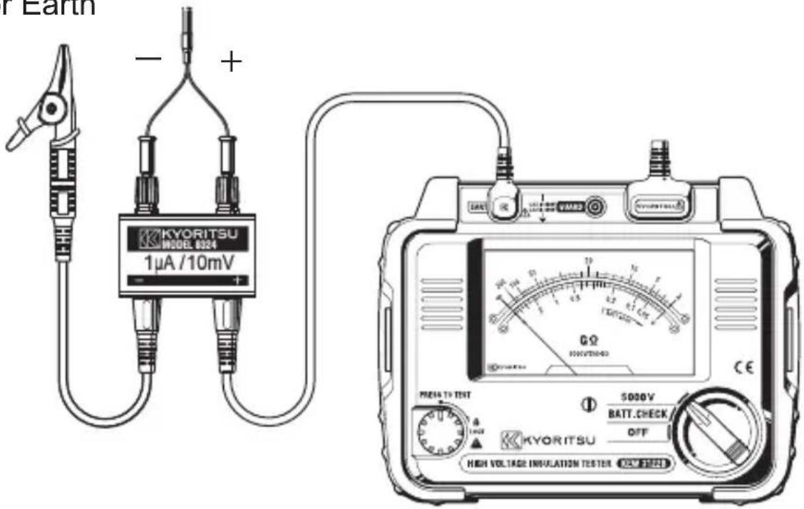
MODEL8324 is an adaptor for a recorder (option) for output current measurement. Connect it as shown in the below figure.
Output is DC10mV when current of 1 A is flowing.
To shield or Earth To recorder
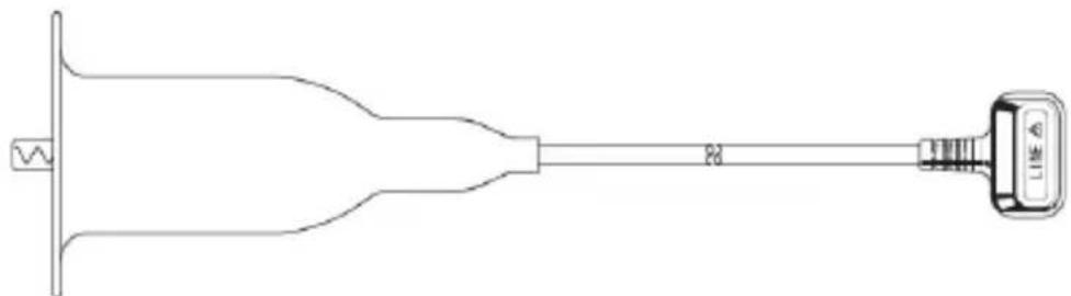
10-3 Line probe with alligator clip(optional accessory)
MODEL7168A : 3m Line probe with alligator clip MODEL7253 : 15m Line probe with alligator clip
natural_image
Pure technical line drawing of a mechanical component with no text or symbols11. Disposing the Product
Waste Electrical and Electronic Equipment (WEEE), Directive 2002/96/EC
This Product complies with the WEEE Directive (2002/96/EC) marking requirement. The affixed product label (see below) indicates that you must not discard this electrical/electronic product in domestic household waste.
Product Category
With reference to the equipment types in the WEEE directive Annex 1, this product is classified as a “Monitoring and Control instrumentation” product.

natural_image
Symbol of a trash bin crossed with two crossed lines, no text or numbers presentDisposing lead-storage batteries
When you throw away the batteries, be sure to cover their positive and negative terminals and always observe local laws and regulations.
Insufficient insulation of the terminals may cause explosion or fire because electrical energies remain in lead-storage batteries after use.
MEMO
DISTRIBUTOR
Kyoritsu reserves the rights to change specifications or designs described in this manual without notice and without obligations.

natural_image
Abstract black arrow symbol pointing left, enclosed in a rounded rectangle (no text or numbers)
- Safety warnings
- WARNING
- ⚠️ DANGER
- ⚠ WARNING
- CAUTION
- ○ Measurement categories (Over-voltage categories)
- Features
- Specification
- • Applicable standards
- Instrument layout
- Getting started
- 5-1 Mechanical Zero Adjustment
- 5-2 Battery Check
- Measurement
- 6-1 Insulation resistance measurement
- Note:
- 6-2 Continuous measurement
- 6-3 Voltage characteristics at measuring terminal
- 6-4 Use of Guard terminal
- Battery replacement
- DANGER
- How to remove the Hard case
- Cleaning Meter Cover
- Accessories
- 10-1 Metal parts for Line Probe, and replacement
- 10-2 How to use the adaptor for recorder
- 10-3 Line probe with alligator clip(optional accessory)
- Disposing the Product
- Waste Electrical and Electronic Equipment (WEEE), Directive 2002/96/EC
- Product Category
- Disposing lead-storage batteries
- MEMO
Brand : Kyoritsu
Model : KEW 1012
Category : Multimeter