
KEW2127R - Multimeter Kyoritsu - Free user manual and instructions
Find the device manual for free KEW2127R Kyoritsu in PDF.


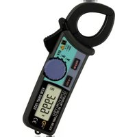
| Product Type | Clamp Multimeter |
| Brand | Kyoritsu |
| Model | KEW2127R |
| Dimensions | 204 (L) x 51 (W) x 66 (D) mm |
| Weight | Approx. 200 g (including batteries) |
| Power Supply | DC 3V, two AAA (R03/LR03) batteries |
| Display | LCD, auto-ranging |
| Measurement Functions | ACA, ACV, DCV, Resistance, Capacitance, Continuity, Diode, Frequency, PEAK hold |
| AC Current (ACA) Range | 60 A / 600 A / 1000 A (auto) ±1.5%rdg±4dgt (45-65 Hz) |
| AC Voltage (ACV) Range | 60.00 V / 600.0 V ±1.5%rdg±2dgt (40-1 kHz) |
| DC Voltage (DCV) Range | 60.00 V / 600.0 V ±1.0%rdg±3dgt |
| Resistance Range | 600.0 Ω to 40.00 MΩ ±1.0%rdg±5dgt to ±5.0%rdg±3dgt |
| Capacitance Range | 1.000 μF to 100.0 μF ±3.0%rdg±15dgt to ±3.0%rdg±10dgt |
| Frequency Range | 999.9 Hz / 9.999 kHz ±0.1%rdg±3dgt |
| Safety Rating | CAT IV 300 V / CAT III 600 V |
| Standards | IEC 61010-1, IEC 61010-2-032, IEC 61010-2-033 |
| IP Rating | IP40 (IEC 60529) |
| Sleep Function | Auto power off after approx. 10 min |
| Special Features | Data Hold, Backlight, NCV (non-contact voltage) detection, PEAK hold |
| Accessories Included | Test leads M-7066A, carrying case 9078, instruction manual, batteries |
| Maintenance | Clean with damp cloth and neutral detergent; avoid abrasives and solvents |
Frequently Asked Questions - KEW2127R Kyoritsu
User questions about KEW2127R Kyoritsu
0 question about this device. Answer the ones you know or ask your own.
Ask a new question about this device
Download the instructions for your Multimeter in PDF format for free! Find your manual KEW2127R - Kyoritsu and take your electronic device back in hand. On this page are published all the documents necessary for the use of your device. KEW2127R by Kyoritsu.
USER MANUAL KEW2127R Kyoritsu

This instrument has been designed, manufactured and tested according to IEC 61010: Safety requirements for Electronic measuring apparatus, and delivered in the best condition after passed the inspection. This instruction manual contains warnings and safety rules which must be observed by the user to ensure safe operation of the instrument and retain it in safe condition. Therefore, read through these operating instructions before using the instrument.
⚠ WARNING
- Read through and understand the instructions contained in this manual before using the instrument.
- Keep the manual at hand to enable quick reference whenever
- The instrument is to be used only in its intended applications
- The instrument is to be used only in its intended applications.
- Understand and follow all the safety instructions contained in the manual.
- It is essential that the above instructions are adhered to. Failure to follow the above instructions may impair the protection provided by the instrument and test leads, and may cause injury, instrument damage and/or damage to equipment under test.
The symbol △ indicated on the instrument means that the user must refer to the related parts in the manual for safe operation of the instrument. It is essential to read the instructions wherever the symbol △ appears in the manual.
⚠️ DANGER is reserved for conditions and actions that are likely to cause serious or fatal injury.
⚠ WARNING is reserved for conditions and actions that can cause serious or fatal injury.
⚠️ CAUTION is reserved for conditions and actions that can cause injury or instrument damage.
- Marks listed below are used on this instrument.
User must refer to the manual.
Instrument with double or reinforced insulation
Indicates that this instrument can clamp on bare conductors when measuring a voltage corresponding to the applicable measurement category, which is marked next to this symbol
\~ AC = DC 1= Ground (Earth)
This instrument is subject to WEEE Directive (2002/96/EC). Please contact our dealer near you at disposal.
Measurement Category
- Circuits which are not directly connected to the mains power supply.
CAT II Primary electrical circuits of equipment connected to an AC electrical outlet by a power cord.
CAT III Primary electrical circuits of the equipment connected directly to the distribution panel, and feeders from the distribution panel to outlets.
CAT IV The circuit from the service drop to the service entrance, and to the power meter and primary over current protection device (distribution panel).
This instrument is designed for CAT IV 300V/ CAT III 600V. Test leads M-7066A with the supplied caps are designed for CAT IV600V/ CAT III 1000V and without the caps are for CAT II 1000V.

△ DANGER
- Never make measurements under the circumstances exceed the designed measurement category and the rated voltage of the instrument and the test leads.
- Do not attempt to make measurement in the presence of flammable gasses. Otherwise, the use of the instrument may cause sparking, which can lead to an explosion.
- Never attempt to use the instrument if its surface or your hand is wet
- Do not exceed the maximum allowable input of any measuring range.
- Never open the Battery cover during a measurement.
- To avoid electrical shock by touching the equipment under test or its surroundings, he sure to wear insulated protective gear.
- Never measure current while the test leads are inserted into the input terminals.
- Test leads to be used for voltage measurements shall be rated as appropriate for Measurement Category III or IV
according to IEC 61010-031 and shall have a voltage rating of 600V or higher. - Barriers on the instrument body and the test leads provide protection to keep your fingers and hands from touching an object under test. Keep your fingers and hands behind the barriers during measurement.
⚠ WARNING
- Never attempt to make measurement if any abnormal conditions, such as broken case and exposed metal parts are found on the instrument or test leads.
- Verify proper operation on a known source before use or take action as a result of the indication of the instrument.
- Firmly attach the caps to the test leads when performing measurements in CAT III or higher test environments. When KEW2127R and the test leads are combined and used together, whichever is lower category & voltage to earth either of them belong to is applied.
- Do not rotate the Function Switch if the instrument and the equipment under test are connected.
- Do not install substitute parts or make any modification to the instrument. For repair or re-calibration, return the instrument to your local KYORITSU distributor.
CAUTION
- Use of this instrument is limited to domestic, commercial and light industry applications. Strong electromagnetic interference or strong magnetic fields, generated by large currents, may cause malfunction of the instrument.
- Connect the test leads to the terminals firmly
- This instrument isn't water proofed. Keep away from water
- Do not pull or twist the test leads to prevent the risk of damage.
- Power off the instrument after use. Remove batteries if the instrument is to be stored and will not be in use for a long period
- Do not expose the instrument to the direct sunlight, high temperature and humidity or dewfall.
- Use a cloth dipped in water or neutral detergent for cleaning the instrument. Do not use abrasives or solvents.
NOTE
- The LCD shows some digits at the ACV and the DCV ranges even while the test leads are open. In addition, the LCD shows some digits instead of 0 when short-circuiting the test leads. However, these phenomena don't affect measurement results.
- A resistance measurement takes time to settle the reading if there are high resistance or capacitance components.
2. Specification
Temperature: 23 ± 5°C, Humidity: 45 - 75%
ACA/RMS (Auto Range)
| Range Display Range Accuracy (sine wave) | |
| 60A 0.00, 0.06 – 62.99A | ±1.5 %rdg±4dgt (45-65Hz) ±2.0 %rdg±5dgt (40-1kHz) |
| 600A 57.0 – 629.9A | |
| 1000A 570 – 1049A | |
Guaranteed accuracy: 0.1A - 1000A
Input protective current: AC1200A
V ACV
| Range Display Range Accuracy (sine wave) |
| 60.00V 0.00 – 62.99V ±1.5 %rdg±4dgt (40-1kHz) |
| 600.0V 57.0 – 629.9V ±1.0%rdg±2dgt (45-65Hz) |
Guaranteed accuracy: 0.1V – 600V, 900Vpeak or less
Input protective voltage: AC/DC720V 10 sec
Hz Frequency – AC measurement
| Range Display Range Accuracy | (sine wave) | |
| 999.9Hz | 0.0 – 999.9Hz | ±0.1 %rdg±3dgt |
| 9.999kHz | 0.950 – 9.999kHz | |
Guaranteed accuracy: 20Hz – 9.9kHz
Trigger threshold: 4A or more (ACA), 2V or more (ACV)
DCV
(Auto Range)
| Range | Display Range | Accuracy |
| 60.00V 0.0 | - ±62.99V ±1.0 | %rdg±3dgt |
| 600.0V | ±57.0V - ±629.9V | ±1.2 %rdg±3dgt |
Guaranteed accuracy: 0V - ±600V
ACV/DCV Input impedance: approx. 10MΩ
Ω Resistance
(Auto Range)
| Range | Display Range | Accuracy |
| 600.0Ω | 0.0 - 629.9Ω | ±1.0 %rdg±5dgt |
| 6.000kΩ | 0.570 - 6.299kΩ | ±2.0 %rdg±3dgt |
| 60.00kΩ | 5.70 - 62.99kΩ | |
| 600.0kΩ | 57.0 - 629.9kΩ | |
| 6.000MΩ | 0.570 - 6.299MΩ | ±3.0 %rdg±3dgt |
| 40.00MΩ | 5.70 - 41.99MΩ | ±5.0 %rdg±3dgt |
Guaranteed accuracy: 0Ω - 40MΩ
Open-loop voltage: less than 3V
Measurement current: less than 1mA Input protective voltage: AC/DC600V
Input protective voltage: AC/DC000V-10sec (Resistance/ Continuity/ Capacitance/ Diode)
••) Continuity
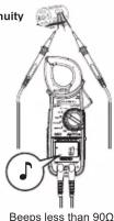
| Range | Display Range | Accuracy |
| 600.0Ω | 0.0 - 629.9Ω | Bz threshold value < 90Ω |
Open-loop voltage: less than 3V
Measurement current: less than 1mA
Capacitance
(Auto Range)
| Range | Display Range | Accuracy |
| 1.000μF | 0.000 - 1.049μF | ±3.0 %rdg±15dgt |
| 10.00μF | 0.95 - 10.49μF | ±3.0 %rdg±10dgt |
| 100.0μF | 9.5 - 104.9μF |
Guaranteed accuracy: 0μF - 100μF
Diode
| Range | Display Range | Accuracy |
| 2.000V | 0.000 - 2.099V | ±4 %rdg±5dgt |
Guaranteed accuracy: 0V - 2V, Open-loop voltage: < 3.5V
Measurement current: approx. 0.8mA (Vf = 0.6V)
●Measuring method: modulation
●Over-range indication: OL
●Measurement cycle: 2.5 times per second
- Crest factor: less than 3 (45-65Hz) Add +0.5% rdg+Edgt to above specified accuracies. Applicable
Add ±0.5% 1ug ±0.5 ugt to above specified accuracies. Applicable functions: ACA (less than 1500Apeak), ACV (900Vpeak or less)
●Applicable Standards:
IEC 61010-1/ 61010-2-032/ 61010-2-033 (instrument)
Pollution degree 2, Indoor use, Altitude up to 2000m
CAT III 600V / CAT IV 300V IFG 61010 924 (Text/loads)
IEC 61010-031(Test leads Model 7066A) w/ cans CAT IV 600V / CAT III 1000
w/o cans CAT II 1000V
w/o caps EN61326 (EMC)
In the radio-frequency electromagnetic field of 3V/m, accuracy
is within five times the rated accuracy.
●Environmental standards: EU RoHS directive compliant
- Withstand voltage: AC5160Vrms 5sec
and enclosure or circuit and
- IP rating: IP40 (IE
- Insulation resistance: >100MΩ/1000V between enclosure and electrical circuit
- Operating Temperature e
- Operating Temperature and humidity range: 0 to 40 °C 85%RH or less (no condensation)
- Storage Temperature and humidity range: -20 to 60°C 85%RH
or less (no condensation)
●Power source : DC3V R03 / LR03 (AAA) ×2
●Current consumption : < 4mA (LED for NCV OFF)
< 8mA (LED for NCV ON)
●Battery life (ACA, continuous, no load, with R03): 176 L/min (LED for NO) (255)
approx. 170 hours (LED for NCV OFF approx. 70 hours (LED for NCV ON)
approx. 70 hours (LED for NOV ON) - Dimension Weight: 204(L)x84(W)
- Dimension, weight. 204(L)×81(W)×36(D)min, approx. 230g (including batteries).
•Accessories
Test leads Model 7066A 1set /Battery R03(AAA) 2pcs /
Instruction manual 1pce /Carrying case Model 9079 1pce
3. ACA (PEAK / Frequency) Measurement
△ DANGER
- Disconnect the test leads from the instrument when performing a test.
- Do not exceed the rated voltage (600V) and the category ratings of the instrument.
- Keep your fingers and hands behind the barrier during measurement.
(1) Set the Functions switch to ACA position. For PEAK or frequency measurement, set the switch to ACA and press the SELECT key.
(2) Press the trigger to open the Current Sensor and clamp the one conductor (Dia, 33mm max.) under test.

flowchart
graph TD
    A["PEAK/Hat"] --> B["Default ACA"]
    B --> C["PEAK"]
    C --> D["Frequency"]
    D --> E["Press the SELECT key to toggle functions"]
    E --> F["Correct"]
    E --> G["Incorrect"]
NOTE
Measurement accuracy is guaranteed when the measured object is placed at the center of the Current Sensor.
4. ACV / DCV (PEAK / Frequency) Measurement
DANGER
- Before starting a measurement, ensure that the Function switch is set to the appropriate position.
- switch is set to the appropriate position. - Do not exceed the rated voltage (600V) and the category
- Keep your fingers and hands behind the barrier during measurement.
(1) Set the Function switch to ACV or DCV position. For PEAK or frequency measurement, set the switch to ACV and press the SELECT key (Frequency is ACV only).
) Firmly connect the test leads to V/Ω and COM terminals.

Press the SELECT key to toggle functions

NOTE
If the connection is reversed, the LCD indicates the “-” mark (DCV measurement)
5. Resistance / Capacitance (Continuity / Diode) Measurement
WARNING
Never use the instrument on an energized circuit. Discharge the capacitor before starting a capacitance measurement.
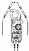
(1) Set the Function switch to Resistance or Capacitance
position. For Continuity measurement, set the switch to Resistance and press the SELECT key. For Diode measurement, set the switch to Capacitance and press the SELECT key.
(2) Firmly connect the test leads to V/Ω and COM terminals.

Resistance


NOTE
- LCD shows "OL" when the test leads are open.
(except for capacitance measurement) - The LCD shows "OL" if the test lead connection is reversed for diode measurement.
6. Other Functions

- Backlight function
Press the HOLD key 1 sec or longer to turn on the backlight. Press the HOLD key another 1 sec or longer to turn it off. The light automatically turns off in 1 min.
- Low battery indication
The LCD shows "BATT" mark when the batteries fall below the normal operating voltage.

- Sleep Function
Automatically powers off the instrument in about 10min after the last switch operation. Buzzer beeps five times one minute before entering into the Sleep mode, and also one time just before entering into the mode. To exit from the Sleep mode, rotate the Function switch or press any key. To disable the Sleep function, press the HOLD key and power on the instrument.
Confirm that the LCD shows "PDF" about 1 sec. Sleep function is disabled in the PEAK hold mode. - PEAK Hold (PEAK) function
Press the SELECT key on ACA, ACV or DCV function to start PEAK measurement. The LCD shows "PEAK" and updates the max measured value repeatedly during a measurement.
| Function | Range | Display Range | Response time |
| ACA(Auto Range) | 999.9A | 0.0, 0.6 – 999.9A | 10ms(sine wave) |
| 1500A | 1000 – 1574A | ||
| ACV | 900V | 0.0, 0.6 – 944.9V | 10ms(sine wave) |
| DCV | 600V | 0.0, 0.6 – 629.9V | 1ms |
On ACA or ACV function, the displayed value is peak value. Therefore, when measuring a sine wave, the displayed value will be 2 of the rms PEAK value.

Peak value displayed on DCV function has larger absolute value. When a negative voltage value has a larger absolute value than a positive voltage value, the negative voltage value will be displayed.

- NCV Function
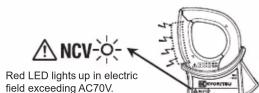
Red LED for NCV lights up at All functions except for OFF when an electric field exceeding AC70V is detected by the sensor installed in Current Sensor.
It indicates a presence of voltage in an electrical circuit or equipment without touching them.
DANGER
- The LED may not light up due to installation condition of electrical circuit or equipment. Never touch the circuit under test to avoid possible danger even if the LED for NCV doesn't light up.
- The way you hold or place the instrument or external voltages may affect NCV indication.
NCV Sensor can detect electrical field only from the direction indicated in the below figure.
Put the fixed element (left side) closer to the conductor under test.
Detection against in-wall outlet is impossible.
7. Battery Replacement
⚠ WARNING
- Replace the batteries when a Low Battery Voltage warning
"3A11" mark is indicated on the LCD. Otherwise, precise measurement cannot be made. If batteries are completely
exhausted, the LCD goes blank without showing "BATT"
- Do not try to replace the batteries if the surface of the instrument is wet
- Disconnect the test leads from the object under test and power off the instrument before opening the Battery Compartment Cover for battery replacement.
CAUTION
- Do not mix old and new batteries.
- Install batteries in correct polarity as indicated in the Battery Compartment.
(1) Set the Function Switch to "OFF" position
(2) Unscrew and remove the Battery Compartment Cover on the instrument
(3) Replace the batteries observing correct polarity. Use new
two AAA 1.5V batteries. (4) Install the Battery Compartment Cover and tighten the screw.

DISTRIBUTOR
Kyoritsu reserves the rights to change specifications or designs described in this manual without notice and without obligations.

KYORITSU ELECTRICAL INSTRUMENTS
WORKS. LTD.
2-5-20, Nakane, Meguro-ku,
Tokyo, 152-0031 Japan
Phone: +81-3-3723-0131
Fax: +81-3-3723-0152
Factory: Ehime, Japan
www.kew-ltd.co.jp
- ⚠ WARNING
- Measurement Category
- △ DANGER
- CAUTION
- NOTE
- Specification
- ACA (PEAK / Frequency) Measurement
- ACV / DCV (PEAK / Frequency) Measurement
- DANGER
- Resistance / Capacitance (Continuity / Diode) Measurement
- WARNING
- Other Functions
- Battery Replacement
- DISTRIBUTOR
- KYORITSU ELECTRICAL INSTRUMENTS
- WORKS. LTD.
- www.kew-ltd.co.jp
Brand : Kyoritsu
Model : KEW2127R
Category : Multimeter