
F1226-6 - Water pump Nibe - Free user manual and instructions
Find the device manual for free F1226-6 Nibe in PDF.


| Product Type | Ground Source Heat Pump (brine-water) |
| Model | NIBE F1226-6 |
| Power Supply | 3×400V, 50Hz, 6-8 kW |
| Rated Heat Output (at 0/35°C) | 6.2 kW |
| Max Supply Temperature | 63 °C |
| Sound Power Level | 43 dB(A) |
| Brine Flow Rate | 0.92 m³/h |
| Heating Medium Flow Rate | 0.54 m³/h |
| Refrigerant | R407C (GWP 1774) |
| Compressor Type | Scroll compressor |
| Integrated Immersion Heater | Yes, max 7 kW (switchable to 9 kW) |
| Control System | Display unit with rotary knob and buttons |
| Emergency Mode | Yes, via switch, only immersion heater active |
| Protection Class | IPX1B |
| CE Marking | Yes |
| Serial Number Location | Bottom right of front cover, type plate, menu 3.1 |
| Installation Requirements | Isolator switch, earth fault breaker recommended |
| Maintenance | Filter cleaning, pressure checks, annual service recommended |
| Spare Parts | Use only NIBE original parts |
| Environmental Note | Contains fluorinated greenhouse gas R407C; do not release into atmosphere |
Frequently Asked Questions - F1226-6 Nibe
User questions about F1226-6 Nibe
0 question about this device. Answer the ones you know or ask your own.
Ask a new question about this device
Download the instructions for your Water pump in PDF format for free! Find your manual F1226-6 - Nibe and take your electronic device back in hand. On this page are published all the documents necessary for the use of your device. F1226-6 by Nibe.
USER MANUAL F1226-6 Nibe
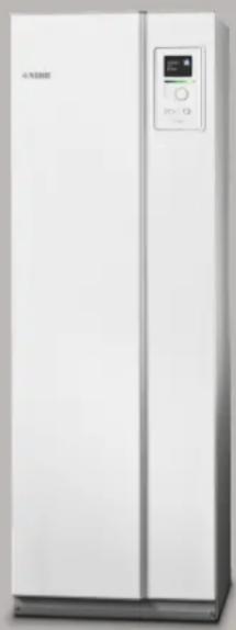
Ground source heat pump NIBE F1226
natural_image
Front view of a white industrial refrigerator with control panel and digital display (no visible text or symbols)
natural_image
Simple line drawing of a wrench and plow (no text or symbols)Quick guide
Navigation

Ok button (confirm/select)
Back button (back/undo/exit)
Control knob (move/increase/reduce)
A detailed explanation of the button functions can be found on page 31.
How to scroll through menus and make different settings is described on page 33.
Set the indoor climate

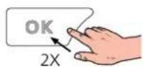

The mode for setting the indoor temperature is accessed by pressing the OK button twice, when in the st mode in the main menu.
Increase hot water volume

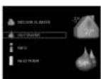


To temporarily increase the amount of hot water, rst turn the control knob to mark menu 2 (water droplet) and then press the OK button twice.
Table of Contents
41 Important information
4Safety information
4Symbols
4Marking
5Serial number
5Recovery
5Environmental information
6Inspection of the installation
72 Delivery and handling
7Transport
7Assembly
8Supplied components
8Removing the covers
9Removing parts of the insulation
103 The heat pump design
10General
12Distribution boxes
13Cooling module (EP14)
144 Pipe connections
14General
15Dimensions and pipe connections
16Brine side
16Heating medium side
17Cold and hot water
17 Installation alternative
195 Electrical connections
19General
21Connections
22Settings
24Optional connections
25Connecting accessories
266 Commissioning and adjusting
26Preparations
26Filling and venting
27Start-up an
29Setting the
317 Contrc
31Display uni
32Menu syst
358 Contrc
35Menu 1 -
35Menu 2 -
35Menu 3 -
36Menu 4 -
37Menu 5 -
419 Service
41Service act
4710 Distui
47Manage aka
47Troublesho
5011 Acces.
5112 Techr
51Dimensions
52Electrical d
53Technical s
55Energy lab
59Electrical c
69Item reg
75Contact
1 Important information
Safety information Symbols
This manual describes installation and service procedures for implementation by specialists.
The manual must be left with the customer.
This appliance can be used by children aged from 8 years and above and person with reduced physical, sensory or mental capabilities or lack of experience and knowledge if they have been given supervision or instruction concerning use of the appliance in a safe way and understand the hazards involved. Children shall not play with the appliance. Cleaning and user maintenance shall not be made by children without supervision.
Rights to make any design or technical modi cations are reserved.
©NIBE 2020.

NOTE
This symbol indicates danger to person or machine.

Caution
This symbol indicates important information about what you should consider when installing or servicing the installation.

TIP
This symbol indicates tips on how to facilitate using the product.
Marking
CE The CE mark is obligatory for most products sold in the EU, regardless of where they are made.
IPX1B Classi cation of enclosure of electro-technical equipment.
Over- Danger to person or machine.
ock- Read the User Manual.
Water may drip from the safety valve's over ow pipe. The entire length of the
ow water pipe must be routed to a suitable drain and be inclined to prevent water pockets, and must also be frost-proof. The over-
ow pipe must be at least the same size as the safety valve. The over ow pipe must be visible and its mouth must be open and not located close to electrical components.
F1226 must be installed via an isolator switch. The cable area has to be dimensioned based on the fuse rating used.
Serial number
The serial number can be found at the bottom right of the front cover, in the info menu (menu 3.1) and on the type plate (PZ1).


Caution
You need the product's (14 digit) serial number for servicing and support.
Recovery
Leave the disposal of the packaging to the installer who installed the product or to special waste stations.
Do not dispose of used products with normal household waste. It must be disposed of at a
special waste station or dealer who provides this type of service.
Improper disposal of the product by the user results in administrative penalties in accordance with current legislation.
Environmental information
F-GAS REGULATION (EU) NO. 517/2014
This unit contains a uorinated greenhouse gas that is covered by the Kyoto agreement.
The equipment contains R407C, a uorinated greenhouse gas with a GWP value (Global Warming Potential) of 1,774. Do not release R407C into the atmosphere.
Inspection of the installation
Current regulations require the heating installation to be inspected before it is commissioned. The inspection must be carried out by a suitably qualified person.
In addition, II in the page for the installation data in the User Manual.
| DateSignatureNotesD | ||||
| Brine (page 16) | ||||
| System ushed | ||||
| System vented | ||||
| Antifreeze | ||||
| Level/Expansion vessel | ||||
| Particle Iter | ||||
| Safety valve | ||||
| Shut off valves | ||||
| Circulation pump setting | ||||
| Heating medium (page 16) | ||||
| System ushed | ||||
| System vented | ||||
| Expansion vessel | ||||
| Particle Iter | ||||
| Safety valve | ||||
| Shut off valves | ||||
| Circulation pump setting | ||||
| Electricity (page 19) | ||||
| Connections | ||||
| Main voltage | ||||
| Phase voltage | ||||
| Fuses heat pump | ||||
| Fuses property | ||||
| Outside sensor | ||||
| Safety breaker | ||||
| Earth circuit-breaker | ||||
| Setting of emergency mode thermostat | ||||
2 Delivery and handling
Transport
F1226 should be transported and stored vertically in dry place. When being moved into a building, F1226 may be leant back 45°.
Ensure that F1226 has not been damaged during port.

Caution
The product can be tail heavy.
- Install with its back to an outside wall, ideally in a room where noise does not matter, in order to eliminate noise problems. If this is not possible, avoid placing it against a wall behind a bedroom or other room where noise may be a problem.
- Wherever the unit is located, walls to sound sensitive trans-rooms should be tted with sound insulation.
- Route pipes so they are not xed to an internal wall that backs on to a bedroom or living room.
INSTALLATION AREA
Remove the outer panels in order to protect them moving in con ned spaces inside buildings.

natural_image
Diagram showing a van connected to a lift truck and a cross symbol (no text or labels)Leven a free space of 800 mm in front of the product. Approx. 50 mm free space is required on each side, to allow the side panels to be removed (see image). All service on F1226 can be carried out from the front, however the right-hand panel may need to be removed. Leave free space between the heat pump and the wall behind (and any routing of supply cables and pipes), to reduce the risk of any vibrations being propagated.
EXTRACTING THE COOLING MODULE
To simplify transport and service, the heat pump can be separated by pulling the cooling module out from the cabinet.
See page 43 for instructions about the separation.
Assembly
- Place F1226 on a solid foundation indoors that can take the heat pump's weight. Use the product's adjustable feet to obtain a horizontal and stable set-up.


* A normal installation needs 300 - 400 mm (any side) for connection equipment, valves and electrical equipment.
- Because water comes from F1226, the area where the heating pump is located must be equipped with oor drainage.
Supplied componentsRemoving the covers

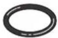
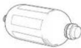
Outdoor temperat-O-rings ure sensor (BT1) _8x
1 x
Level vessel (CM2)
1 x
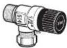

Safety valve (FL3)Particle Iter 0.3 MPa (3 bar)1 pcs 1 x

Compression ring couplings
6-8 KW
2 pcs (ø28 x G25)
2 pcs (ø22 x G20) ^2 . Lift the panel out at the bottom edge and up.
12 KW
4 × (ø28 × G25)
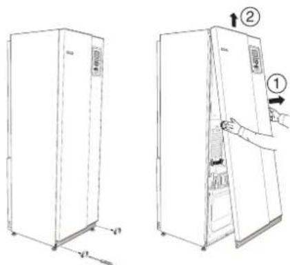
FRONT COVER
-
Remove the screws from the lower edge of the front panel.
-
Lift the panel out at the bottom edge and up.
SIDE COVERS

natural_image
Line drawing of three views of a refrigerator with handle and door, showing internal structure and mounting details (no text or symbols)LOCATION
The kit of supplied items is placed in packaging on top of the heat pump.
The side covers can be removed to facilitate the installation.
-
Remove the screws from the upper and lower edges.
-
Twist the cover slightly outward.
-
Move the hatch outwards and backwards.
-
Assembly takes place in the reverse order.
Removing parts of the insulation
Parts of the insulation can be removed to facilitate the installation.
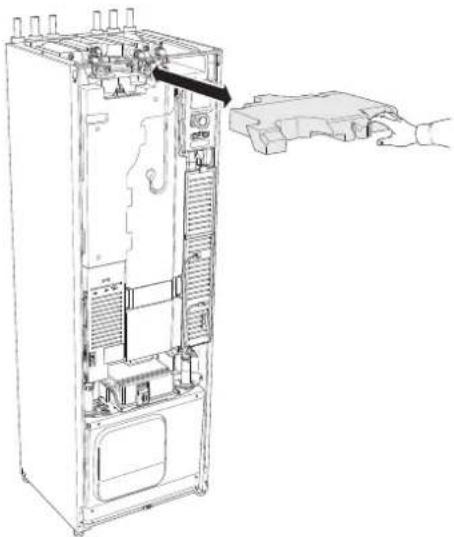
INSULATION, TOP
- Disconnect the cable from the motor and remove the motor from the shuttle valve as illustrated.

- Grip the handle and pull straight out as illustrated.
natural_image
Technical line drawing of an internal server or rack cabinet with a hand inserting a component (no text or symbols visible)Remove the cover for the junction box according to the description on page 20.
- Grip the handle and pull the insulation carefully towards you as illustrated.


NOTE
Electrical installation and service must be carried out under the supervision of a qualified electrician. Electrical installation and wiring must be carried out in accordance with the stipulations in force.
3 The heat pump design
General

VIEW FROM ABOVE
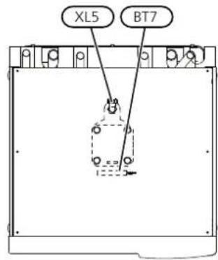
PIPE CONNECTIONS
Connection, heating medium owXL1
Connection, heating medium returnXL2
Connection, cold waterXL3
Connection, hot waterXL4
Connection, HWC*XL5
Connection, brine inXL6
Connection, brine outXL7
* Only heat pumps with stainless steel vessel.
HVAC COMPONENTS
Venting, coilQM22
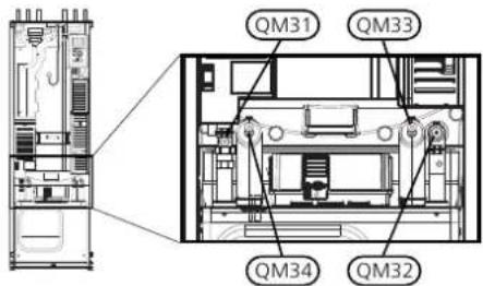
Shut-off valve, heating medium owQM31
Shut off valve, heating medium returnQM32
Shut off valve, brine outQM33
Shut-off valve, brine inQM34
Shuttle valve, climate system/water heaterQN10
SENSORS ETC.
BT1 Outdoor temperature sensor*
BT2 Temperature sensors, heating medium ow
BT6 Temperature sensor, hot water charging
BT7 Temperature sensor, hot water top
* Not illustrated
ELECTRICAL COMPONENTS
AA4 Display unit
AA4-XF3 USB socket
AA4-XF4 Service outlet (No function)
AA11 Motor module
EB1 Immersion heater
FR1 Electrical anode ^1
SF1 Switch
W130 Network cable for NIBE Uplink
1 Only heat pump with enamelled vessel.
MISCELLANEOUS
EP14 Cooling module
PZ1 Rating plate
PZ2 Identi cation plate, cooling module
UB1 Cable gland, incoming electricity
UB2 Cable gland
UB3 Cable gland, rear side, sensor
Designations according to standard EN 81346-2.
Distribution boxes
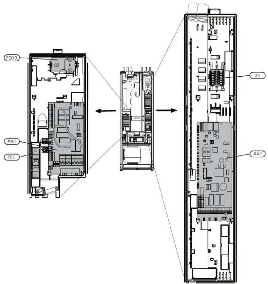
MOTOR MODULE (AA11)
3×400 V 6-8 kW
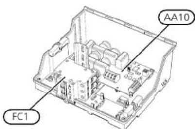
3x400V 12 kW
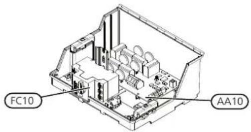
ELECTRICAL COMPONENTS
Immersion heater cardAA1
Base cardAA2
Soft-start cardAA10
Motor moduleAA11
Miniature circuit-breakerFC1
Motor cut-outFC10
Temperature limiter/Emergency mode thermostatFQ10
Terminal blockX1
Cooling module (EP14)
6 & 8 kW
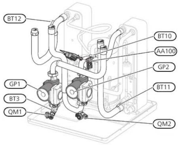
12 kW
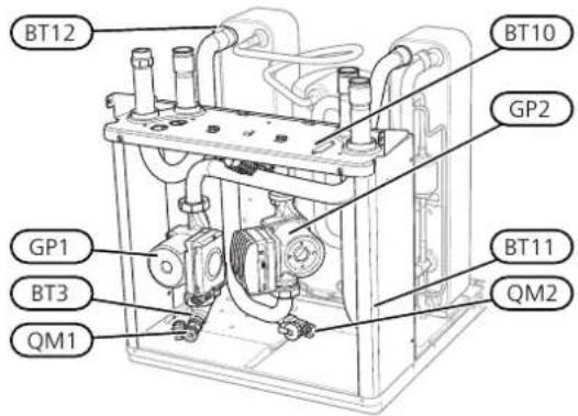
6 & 8 kW

kW

PIPE CONNECTIONS
Service connection, high pressureXL20
Service connection, low pressureXL21
HVAC COMPONENTS
Circulation pumpGP1
Brine pumpGP2
Drainage, climate systemQM1
Draining, brine sideQM2
SENSORS ETC.
High pressure pressostatBP1
Low pressure pressostatBP2
Temperature sensors, heating medium returnBT3
Temperature sensor, brine inBT10
Temperature sensor, brine outBT11
Temperature sensor, condenser supply lineBT12
Temperature sensor, hot gasBT14
Temperature sensor, uid pipeBT15
BT17 Temperature sensor, suction gas
ELECTRICAL COMPONENTS
AA100 Joint card
Compressor heaterEB10
COOLING COMPONENTS
EP1 Evaporator
EP2 Condenser
GQ10 Compressor
Drying IterHS1
QN1 Expansion valve
4 Pipe connections
General
Pipe installation must be carried out in accordance current norms and directives. F1226 can operate with a return temperature of up to 56 °C and an outgoing temperature from the heat pump of 70 (63 °C with the compressor).
F1226 is not equipped with external shut off valve these must be installed to facilitate any future serv

Caution
Ensure that incoming water is clean. When using a private well, it may be necessary to supplement with an extra water liter.

Caution
Any high points in the climate system, must be equipped with air vents.

NOTE
The pipe systems need to be ushed out before the heat pump is connected so debris cannot damage component parts.

NOTE
Water may drip from the safety valve's over-ow pipe. The entire length of the over ow water pipe must be routed to a suitable drain and be inclined to prevent water pockets, and must also be frost-proof. The over ow pipe must be at least the same size as the safety valve. The over ow pipe must be visible and its mouth must be open and not located close to electrical components.
SYMBOL KEY
| MeaningSymbol | |
| with↑ | Venting valve |
| bingX | Shut-off valve |
| h only | Non-return valve |
| Circulation pump | |
| S, [6XT2] | Expansion vessel |
| Auxiliary relay | |
| Compressor | |
| Pressure gauge | |
 | Level vessel |
| Particle Iter | |
| Safety valve | |
 | Temperature sensor |
| Trim valve | |
| [A4HT3] | Reversing valve/shunt |
| Heat exchanger |
SYSTEM DIAGRAM
F1226 consists of a heat pump, water heater, electrical module, circulation pumps and a control system. F1226 is connected to the brine and heating medium circuits.
In the heat pump evaporator, the brine (water mixed with anti-freeze, glycol or ethanol) releases its energy to the refrigerant, which is vaporised in order to be compressed in the compressor. The refrigerant, of which the temperature has now been raised, is passed to the condenser where it gives off its energy to the heating medium circuit and, if necessary, to the water heater. If there is a greater need for heating/hot water than the compressor can provide there is an integrated immersion heater.

flowchart
graph TD
    XL1 --> A["Valve"]
    XL6 --> A
    XL4 --> A
    XL3 --> A
    XL7 --> A
    XL2 --> A
    A --> B["Reactor Unit"]
    B --> C["Pressure Gauge"]
    B --> D["Flow Control Valve"]
    B --> E["Control Valve"]
    B --> F["Reactor Structure"]
    F --> G["Outlet"]
    style A fill:#f9f,stroke:#333
    style B fill:#ccf,stroke:#333
Connection, heating medium owXL1
Connection, heating medium returnXL2
Connection, cold waterXL3
Connection, hot waterXL4
Connection, brine inXL6
XL7 Connection, brine out
Dimensions and pipe Electrical 1226 Suits connections

PIPE DIMENSIONS
| Connection | (kW) | 6-8 | 12 |
| (XL6)/(XL7) Brine in/out ext ∅ | (mm) | 28 | |
| (XL1)/(XL2) Heating medium ow/return ext ∅ | (mm) | 22 | 28 |
| (XL3)/(XL4) Cold/hot water ∅ | (mm) | 22 | |
Brine side
COLLECTOR

Caution
The length of the collector hose varies depending on the rock/soil conditions, climate zone I and on the climate system (radiators or underoor heating) and the heating requirement of the building. Each installation must be sized individually.
CONNECTING THE BRINE SIDE
• Insulate all indoor brine pipes against condensation.
- The level vessel must be installed as the highest point in the brine system on the incoming pipe before the brine pump (Alt. 1).
the level vessel cannot be placed at the highest point, an expansion vessel must be used (Alt. 2).

NOTE
Note that condensation may drip from the level vessel. Position the vessel so that this does not harm other equipment.
Max. length per coil for the collector should not exceed 400 m.
In those cases where it is necessary to have several collectors, these should be connected in parallel with the possibility for adjusting the ow of the relevant For surface soil heat, the hose should be buried at a depth determined by local conditions and the distance between the hoses should be at least 1 metre.
- Details of the antifreeze used must be shown on the level vessel.
- Install the enclosed safety valve below the level vessel as illustrated.
Install shut off valves as close to the heat pump as possible.
For several bore holes, the distance between the holes must be determined according to local conditions.
• Fits the enclosed particle liter on the incoming brine.
Ensure the collector hose rises constantly towards heat pump to avoid air pockets. If this is not positive airvents should be used.

TIP
If lling connection KB25/KB32 is used, the enclosed Iterball does not need to be tted.
Because the temperature of the brine system can below 0 °C, it must be protected against freezing to -15 °C. When making the volume calculation, u litres of ready mixed brine per metre of collector (applies when using PEM-hose 40x2.4 PN 6.3) as a value.
down In the case of connection to an open groundwater sys- se 1 tem, an intermediate frost-protected circuit must be hose provided, because of the risk of dirt and freezing in the guide evaporator. This requires an extra heat exchanger.
SIDE CONNECTION
It is possible to angle the brine connections, for connection to the side instead of top connection.
To angle out a connection:
- Disconnect the pipe at the top connection.
- Angle the pipe in the desired direction.
- If necessary, cut the pipe to the desired length.
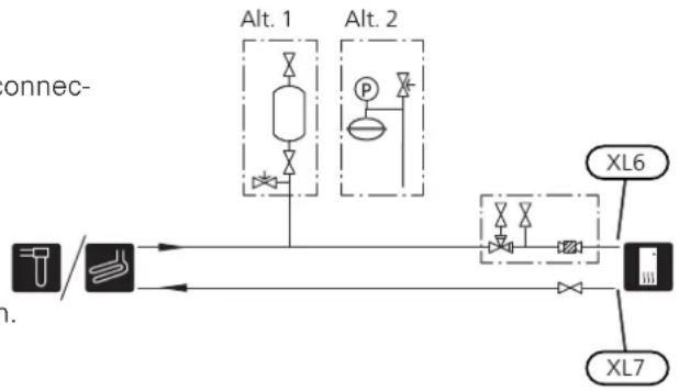
flowchart
graph LR
    A["Input"] --> B["Control Unit"]
    B --> C["Alt. 1"]
    B --> D["Alt. 2"]
    C --> E["Control Unit"]
    D --> F["Control Unit"]
    E --> G["XL6"]
    F --> H["XL7"]
Heating medium side
CONNECTING THE CLIMATE SYSTEM
A climate system is a system that regulates indoor comfort with the help of the control system in F1226 and for example radiators, under oor heating/cooling, fan convectors etc.
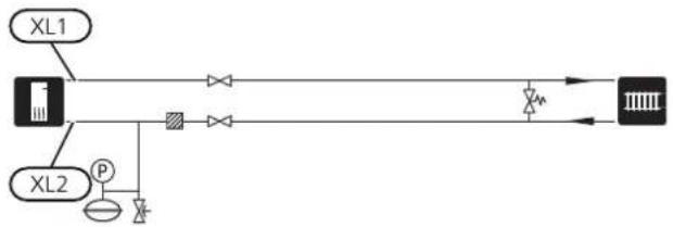
- Install all required safety devices, shut-off valves (as close to the heat pump as possible), and supplied particle liter.
• Install the safety valve as illustrated. Recommend opening pressure is 0.25 MPa (2.5 bar). For inform about max opening pressure, see technical specifications.
- When connecting to a system with thermostats radiators (or under oor heating coils), either a bypass valve must be tted or some of the thermostats be removed to ensure there is sufficient ow.
BUFFER VESSEL nation If the climate system volume is too small for the heat ca- pump output, the radiator system can be supplemented with a buffer vessel, for example NIBE UKV.

flowchart
graph LR
    A["pass must"] --> B["Device"]
    B --> C["Output"]
flowchart
graph LR
    XL1["XL1"] --> BusBar
    XL2["XL2"] --> BusBar
    BusBar --> LoadValve
    LoadValve --> BusBar
    BusBar --> LoadMixer
    BusBar --> LoadPump
    BusBar --> LoadSpike
    BusBar --> LoadSpike
    BusBar --> LoadMixer
    BusBar --> LoadPump
    BusBar --> LoadSpike
EXTRA HOT WATER HEATERS
The heat pump should be supplemented with an extra water heater, if a large bath tub or other signi cant consumer of hot water is installed.
Water heater with immersion heater
If it is possible to use a water heater with an immersion heater, connect it as illustrated below.
Cold and hot water
The settings for hot water are made in menu 5.1.1.
CONNECTING COLD AND HOT WATER
Install as follows:
- shut-off valve
- non-return valve
• pressure relief valve
The safety valve must have a maximum 1.0 MPa (RPO bar) opening pressure and be installed on the incoming domestic water line as shown.
- mixing valve
A mixer valve must also be installed, if the fact setting for hot water is changed. National regulator must be observed.

flowchart
graph TD
    A["Inlet"] --> B["Valve"]
    C["Outlet"] --> B
    B --> D["Main Tank"]
    style D fill:#ccc,stroke:#333
GROUND WATER SYSTEM
An intermediate heat exchanger is used to protect the heat pump's exchanger from dirt. The water is released into a buried ltration unit or a drilled well. This docking alternative requires the EXC 40 accessory.
this docking alternative is used, "min. brine out" in menu 5.1.7 "br pmp al set." must be changed to a suitable value to prevent freezing of the heat exchanger.

flowchart
graph LR
    XL3 --> A["Process Unit"]
    XL4 --> A
    A --> B["Control Valve"]
    B --> C["Output"]
    style XL3 fill:#f9f,stroke:#333
    style XL4 fill:#f9f,stroke:#333
Installation alternative
F1226 can be installed in several different ways, some of which are shown below.
Further option information is available at nibe.eu and in the respective assembly instructions for the accessories used. See page 50 for a list of the accessories that can be used with F1226.

flowchart
graph TD
    A["Input"] --> B["Process Unit"]
    B --> C["Output"]
    style A fill:#f9f,stroke:#333
    style B fill:#ccf,stroke:#333
    style C fill:#cfc,stroke:#333
VENTILATION RECOVERY
UNDERFLOOR HEATING SYSTEM
The installation can be supplemented with the exhaust external circulation pump is dimensioned for the air module NIBE FLM to provide ventilation recovery under poor heating system's demand.
- Pipes and other cold surfaces must be insulated. If the climate system volume is too small for the heat diffusion-proof material to prevent condensation. pump output, the under oor heating system can be
- The brine system must be supplied with a pressure expansion vessel. If there is a level vessel this should be replaced.

flowchart
graph TD
    A["Chamber"] --> B["Valve"]
    B --> C["Pressure Point P"]
    C --> D["Flow Path"]
    D --> E["Return Line"]
    style A fill:#f9f,stroke:#333
    style E fill:#bbf,stroke:#333

flowchart
graph LR
    A["Device"] --> B["Processing Unit"]
    B --> C["Server"]
    style A fill:#f9f,stroke:#333
    style B fill:#ccf,stroke:#333
    style C fill:#cfc,stroke:#333
FREE COOLING
The installation can be supplemented with fan convectors, for example, in order to allow connections for free cooling.
- Pipes and other cold surfaces must be insulated with diffusion-proof material to prevent condensation.
- Where the cooling demand is high, fan convectors with drip trays and drain connection are needed.
- The brine system must be supplied with a pressure expansion vessel. If there is a level vessel this should be replaced.

flowchart
graph TD
    A["Input Valve"] --> B["Processing Unit"]
    B --> C["Output Test Tube"]
    D["Check Valve"] --> B
    E["Feedback Loop"] --> B
5 Electrical connections
General
All electrical equipment except for the outdoor temperature sensors has been connected at the factory.
- Disconnect the heat pump before insulation testing the house wiring.
- If the building is equipped with an earth-fault b F1226 should be equipped with a separate one.
- If a miniature circuit breaker is used this should have at least motor characteristic "C". See page 52 for fuse size.
- Electrical wiring diagram for the heat pump, see page 59.
- Communication and sensor cables to external connections must not be laid close to high current cables.
- The minimum area of communication and sensor cables to external connections must be 0.5 mm ^2 up to 50 m, for example EKKX or LiYY or equivalent.
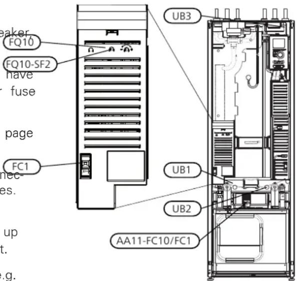
- When cable routing in F1226, cable grommets (e.g. UB1-UB3, marked in image) must be used. In UB1-UB3 the cables are inserted through the heat pump from the back to the front.

NOTE
The switch (SF1) must not be moved to ""
"⚠ until the boiler has been lled with war
Components in the product could be damag

NOTE
Electrical installation and service must be carried out under the supervision of a qualified electrician. Cut the current with the circuit breaker before carrying out any servicing.
Electrical installation and wiring must be carried out in accordance with the stipulations in force.

NOTE
Check the connections, main voltage and phase voltage before the machine is started, to prevent damage to the heat pump electronics.
aMINIATURE CIRCUIT-BREAKER
The heat pump operating circuit and some of its internal components are internally fused by a miniature circuit breaker (FC1).
TEMPERATURE LIMITER
The temperature limiter (FQ10) cuts the power to the electric additional heat if the temperature exceeds 89°C and is reset manually.
Resetting
The temperature limiter (FQ10) is accessed behind the front cover. Reset the temperature limiter by pressing the button (FQ10-SF2) using a small screwdriver.
MOTOR PROTECTION BREAKER /MINIATUREACCESSIBILITY, ELECTRICAL CONNECTION CIRCUIT BREAKER The plastic cap of the electrical boxes is opened u
The plastic cap of the electrical boxes is opened using
Motor protection breaker (AA11-FC10) / miniature circuit crewdriver.
breaker (AA11-FC1) cuts the power to the compressor
if the current is too high. It is located behind the cover and is reset manually.

NOTE
The cover for the terminal block for soft inputs is opened without a tool.

Caution
Check the miniature circuit-breaker, temperat-R ure limiter and motor protection breaker. They may have tripped during transportation.
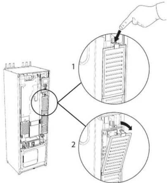
- Push the catch down.
- Angle out the cover and remove it.
Removing the cover, immersion heater circuit board

- Insert the screwdriver (A) and pry the catch carefully downwards (B).
- Angle out the cover and remove it.
Removing the cover, base board

Caution
To remove the cover for the base board, cover for the terminal block for soft inputs rst be removed.
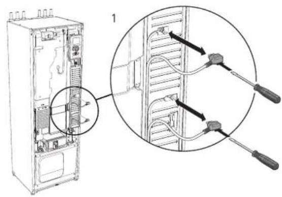

- Disconnect the switches using a screwdriver.
- Insert the screwdriver (A) and pry the catch carefully downwards (B).
- Angle out the cover and remove it.
CABLE LOCK
Use a suitable tool to release/lock cables in the heat pump terminal blocks.

Connections

NOTE
To prevent interference, unscreened communication and/or sensor to external connections cables must not be laid closer than 20 cm to high voltage cable when cable routing.
POWER CONNECTION
F1226 must be installed with a disconnection option on the supply cable. Minimum cable area must be sized according to the fuse rating used. Enclosed cable for incoming supply electricity is connected to terminal block X1 on the immersion heater board (AA1). All installations must be carried out in accordance with current norms and directives.

Connection 3x400V
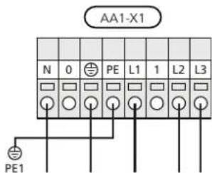

NOTE
F1226 contains scroll compressor, which means that it is important that electrical connections are made with the correct phase sequence. With the incorrect phase sequence, the compressor does not start and an alarm displayed.
If a separate supply to the compressor and electric heater is wanted, see section "External blocking of functions" on page 25.
TARIFF CONTROL
If the voltage to the immersion heater and/or the fom-conduit is used it must be sealed to prevent condens-pressor disappears during a certain period, there motion in the sensor capsule.
also be blocking via the AUX-input, see "Connection options - Possible selection for AUX inputs" page. 25
CONNECTING EXTERNAL OPERATING VOLTAGE FOR THE CONTROL SYSTEM

NOTE
Mark up any junction boxes with warnings for external voltage.
If you wish to connect external operating voltage for the control system to F1226 on the immersion heater circuit board (AA1) the edge connector at AA1:X2 must be moved to AA1:X9 (as illustrated).
Operating voltage (1x230V \~ 50Hz) is connected to AA1:X11 (as illustrated).

1x230V+N+PE operating voltage
CONNECTING SENSORS
Connect the sensor(s) to terminal block X1 according to the instructions below.
Outside sensor
Install the outdoor temperature sensor (BT1) in the shade on a wall facing north for north-west, so it is unaffected by the morning sun for example.

Connect the sensor to terminal block X1:1 and X1:2.

flowchart
graph TD
    A["External"] --> B["F1226"]
    C["BT1"] --> B
    B --> D["X1"]
    D --> E["Grid 1-5"]
    D --> F["Grid 5-3"]
    D --> G["Grid 4-2"]
    D --> H["Grid 3-1"]
Settings

ELECTRICAL ADDITION - MAXIMUM OUTPUT
The electric additional heat may be restricted depending on the selected country.
On delivery, the immersion heater is connected for a maximum of 7 kW (switchable to 9 kW).
The immersion heater's output is split into seven steps (four steps if the immersion heater is switched to maximum 9 kW), according to the table below.
Setting max electrical output
Setting maximum output in the electric additional heat is done in menu 5.1.12.
The table displays the total phase current for the immersion heater at start up. If an immersion heater has already been started and is not used for its full capacity the values in the table can be changed because the control initially uses this immersion heater.
Switching to maximum electrical output
If more than the maximum output (7 kW) for the sion heater connected on delivery is needed, the pump can be switched to maximum 9 kW.
Move the white cable from terminal block X7:23 terminal block X3:13 (the seal on the terminal block be broken) on the immersion heater card (AA1).
3x400V V (maximum electrical output, con upon delivery 7 kW)
| Max electric al addition (kW) | Max phase current L1(A) | Max phase current L2(A) | Max phase current L3(A) |
| 0 | - | - | - |
| 4.3—1 | |||
| -8.7—2 | |||
| 4.38.7—3 | |||
| 8.78.7—4 | |||
| 13.08.7—5 | |||
| 8.78.78.7 | |||
| 13.08.78.7 |
3x400V (maximum electrical output, switched 9 kW)
| Max electric al addition (kW) | Max phase current L1(A) | Max phase current L2(A) | Max phase current L3(A) |
| 0 | - | - | - |
| -8.7-2 | |||
| 8.78.7-4 | |||
| 8.78.78.76 | |||
| 15.615.68.79 |
EMERGENCY MODE
When the heat pump is set to emergency mode is set ⬆ only the most necessary functions are ated.
- The compressor is off and heating is managed immersion heater.
• Hot water is not produced.

NOTE
The switch (SF1) must not be moved to "" or "Δ until F1226 has been lled with water. Components in the product can be damaged.
Power in emergency mode
The immersion heater's output in emergency mode is set with the dipswitch (S2) on the immersion heater circuit board (AA1) according to the table below. Factory setting is 6 kW.
When installing according to current building regulations (BBR) the immersion heater's power in emergency inner-mode must be set to the maximum permitted electrical output.
3x400V (maximum electrical output, connected upon delivery 7 kW)
| kW | 1 | 2 | 3 | 4 | 5 | 6 |
| eected | off | off | off | off | off | on |
| 2 | off | off | on | off | off | off |
| 3 | off | off | on | off | off | on |
| 4 | off | off | on | off | on | off |
| 5 | on | off | on | off | off | on |
| 6 | on | off | on | off | on | off |
| 7 | on | off | on | off | on | on |
3x400V (maximum electrical output, switched to 9 kW)
| kW | 1 | 2 | 3 | 4 | 5 | 6 |
| 2 | off | off | off | off | on | off |
| 4 | off | off | on | off | on | off |
| 6 to 9 | on | off | on | off | on | off |
| on | off | on | on | on | on |
3×400V

(SE1 AA1-S2
The image shows the dip-switch (AA1-S2) in the factory setting.
by the Emergency mode thermostat
The supply temperature in emergency mode is set using a thermostat (FQ10). It can be set to 35 (pre-set, for example under oor heating) or 45 °C (for example radiators).

Optional connections
EXTERNAL CONNECTION OPTIONS
F1226 has software-controlled AUX inputs for connecting external switch function (contact has to be poten free) or sensor.
Go into menu 5.4 "soft in/outputs" on the display to lect to which AUX connection each function connects

For certain functions, accessories may be required.

TIP
Some of the following functions can also be activated via menu settings.
Selectable inputs
Selectable inputs on terminal block (X1) for these tions are:
X1:3-4AUX1
X1:5-6AUX2

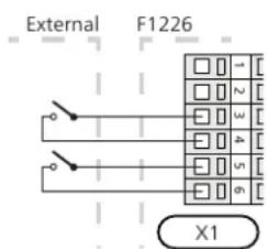
The example above uses the inputs AUX1 (X1:3-4) and AUX2 (X1:5-6) on terminal block (X1).
Possible selection for AUX inputs
Temperature sensor
Temperature sensor can be connected to F1226.
Available options are:
• room sensor (RTS 40)
- external supply line (BT25) (control of temperature the heating system)
Monitor
Available options are:
- alarm from external units. The alarm is connected to the control, which means that the malfunction is presented as an information message in the display. Potential-free signal of type NO or NC.
- level (accessory NV10)/, pressure/flow monitor for the to se-brine (NC).
• pressure switch for climate system (NC).
External activation of functions
An external switch function can be connected to F1226 to activate various functions. The function is activated during the time the switch is closed.
Possible functions that can be activated:
• forced control of brine pump
- hot water comfort mode "temporary lux"
- hot water comfort mode "economy"
- "external adjustment"
When the switch is closed, the temperature changes in °C (if the room sensor is connected and activated). If a room sensor is not connected or not activated, the desired change of "temperature" (heating curve offset) is set with the number of steps selected. The value is adjustable between -10 and +10. External adjustment of climate systems 2 to 8 requires accessories.
- climate system 1 to 8
The value for the change is set in menu 1.9.2, "external adjustment".
- activation of one of four fan speeds.
(Can be selected if ventilation accessory is activated.) The following ve options are available:
- 1-4 is normally open (NO)
- 1 is normally closed (NC)
The fan speed is activated during the time the switch is closed. Normal speed is resumed when the switch is opened again.
- +Adjust
Using +Adjust, the installation communicates with the under oor heating's control centre* and adjusts the heating curve and calculated supply temperature according to the under oor heating system's reconnection.
Activate the climate system you want +Adjust to affect by highlighting the function and pressing the OK button.
*Support for +Adjust required

Caution
This accessory may require a software update in your F1226. The version can be checked in the "Service info" menu 3.1. Visit nibeuplink.com and click on the "Soft ware" tab to download the latest software to your installation.

NOTE
Blocking entails a risk of freezing.

Caution
In systems with both under oor heating an radiators, NIBE ECS 40/41 should be used for optimum operation.
Functions that can be blocked:
• heating (blocking of heating demand)
- hot water (hot water production). Any hot water circulation (HWC) remains in operation.
- compressor
nd internally controlled additional heat
- tariff blocking (additional heat, compressor, heating and hot water are disconnected)
- SG ready

Caution
This function can only be used in mains r works that support the "SG Ready" standard
"SG Ready" requires two AUX inputs.
Connecting accessories
Instructions for connecting accessories are in the installation instructions provided for the respective accessory. See information at nibe.eu for the list of the accessories that can be used with F1226.
"SG Ready" is a smart form of tariff control where the electricity supplier can affect the indoor and hot water temperatures or simply block the additional heat and/or the compressor in the heat pump at certain times of the day (can be selected in menu 4.1.5 after the function is activated). Activate the function by connecting potential-free switch functions to two inputs selected in menu 5.4 (SG Ready A and SG Ready B).
Closed or open switch means one of the following:
- Blocking (A: Closed, B: Open)
"SG Ready" is active. The compressor in the heat pump and additional heat is blocked.
- Normal mode (A: Open, B: Open)
"SG Ready" is not active. No effect on the system.
- Low price mode (A: Open, B: Closed)
"SG Ready" is active. The system focuses on costs savings and can for example exploit a low tariff from the electricity supplier or over-capacity from any own power source (effect on the system can be adjusted in the menu 4.1.5).
— Overcapacity mode (A: Closed, B: Closed)
"SG Ready" is active. The system is permitted to run at full capacity at over capacity (very low price) with the electricity supplier (effect on the system is set-table in menu 4.1.5).
(A = SG Ready A and B = SG Ready B)
External blocking of functions
An external switch function can be connected to F1226 for blocking various functions. The switch must be potential-free and a closed switch results in blocking.
6 Commissioning and adjusting
Preparations
- Check that the switch (SF1) is in position "".
- Check for water in the hot water heater and system.

Caution
Check the miniature circuit-breaker and the motor protection breakers. They may have tripped during transportation.

NOTE
Do not start F1226 if there is a risk that water in the system has frozen.
Filling and venting

Caution
Insuf cient venting can damage internal components in F1226.
FILLING AND VENTING THE CLIMATE SYSTEM
Filling
-
Open the lling valve (external, not included in product). Fill the coil in the hot water heater a rest of the climate system with water.
-
Open the vent valve (QM22).
-
When the water that exits the vent valve (QM22) not mixed with air, close the valve. After a while pressure starts to rise.
-
Close the lling valve when the correct pressure obtained.
Venting
-
Bleed the heat pump via a vent valve (QM22) and the rest of the climate system via their relevant vent valves.
-
Keep topping up and venting until all air has been removed and the pressure is correct.

NOTE
The pipe from the coil in the container must be drained of water before air can be released. This means that the system is not necessarily bled despite the ow of water when the vent valve (QM22) is opened.
FILLING THE HOT WATER HEATER
- Open a hot water tap in the house.
- Fill the hot water heater through the cold water connection (XL3).
- When the water that comes out of the hot water tap is no longer mixed with air, the water heater is full and the tap can be closed.
FILLING AND VENTING THE BRINE SYSTEM
When Iling the brine system, mix the water with anti-freeze in an open container. The mixture should be protected against freezing down to about -15°C. The brine is topped up by connecting a Iling pump.
- Check the brine system for leakage.
- Connect the lling pump and return line on the brine system's lling connection (accessory).
- If alternative 1 is used (level vessel), close the valve
the under the level vessel.
and the 4. Close the reversing valve in the lling connection. - Open the valves on the ller connector.
- Start the lling pump.
hile File until liquid enters the return pipe. - Close the valves on the ller connector.
- is Open the reversing valve in the lling connection.
- If alternative 1 (level vessel) is used, open the valve under the level vessel (CM2).

flowchart
graph TD
    A["Valve 1"] --> B["Valve 2"]
    B --> C{Close}
    C --> D["Valve 3"]
    D --> E["Valve 4"]
    E --> F["Valve 5"]
    F --> G["Valve 6"]
    G --> H["Valve 7"]
    H --> I["Valve 8"]
    I --> J["Valve 9"]
    J --> K["Valve 10"]
    K --> L["Valve 11"]
    L --> M["Valve 12"]
    M --> N["Valve 13"]
    N --> O["Valve 14"]
    O --> P["Valve 15"]
    P --> Q["Valve 16"]
    Q --> R["Valve 17"]
    R --> S["Valve 18"]
    S --> T["Valve 19"]
    T --> U["Valve 20"]
    U --> V["Valve 21"]
    V --> W["Valve 22"]
    W --> X["Valve 23"]
    X --> Y["Valve 24"]
    Y --> Z["Valve 25"]
Start-up and inspection
START GUIDE

NOTE
There must be water in the climate system before the switch is set to "".
-
Set switch (SF1) on F1226 to position ""
-
Follow the instructions in the display's start guide. Press the OK button to skip between the pages in If the start guide does not start when you start the F1226, start it manually in menu 5.7.

TIP
See page 31 for a more in-depth introduction to the heat pump's control system (operation menus etc.).
Commissioning
The rst time the installation is started a start guide is Option / setting started. The start guide instructions state what needs make settings for the system here. to carried out at the rst start together with a run through of the installation's basic settings.
The start guide ensures that the start-up is carried out correctly and, for this reason, cannot be skipped.

Caution
As long as the start guide is active, no function in the installation will start automatically.
The start guide will appear at each restart of the installation, until it is deselected on the last page.
Operation in the start guide
A. Page
B. Name and menu number
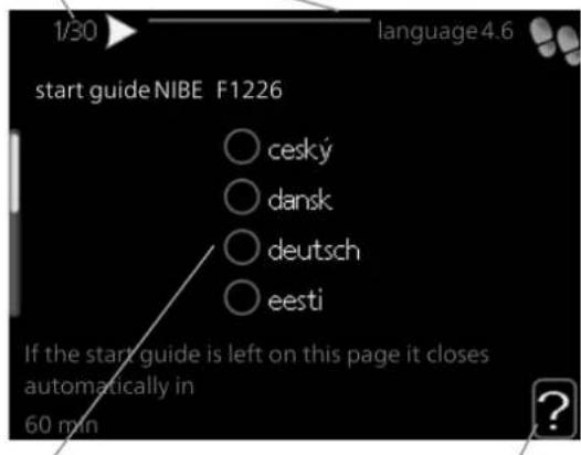
C. Option / setting
D. Help menu
A. Page
Here you can see how far you have come in the start guide.
Scroll between the pages of the start guide as follows:
- Turn the control knob until one of the arrows in the top left corner (at the page number) has been marked.
side. Press the OK button to skip between the pages in start the the start guide.
B. Name and menu number
Here, you can see which menu in the control system this page of the start guide is based on. The digits in brackets refer to the menu number in the control system.
If you want to read more about affected menus either consult the help menu or read the user manual.
Option / setting
Make settings for the system here.
n
。
-
-
广力云
。
。
[Non-Text]
[Non-Text]
-
。
。
-
。
(五)
-
。
[Non-Text]
[Non-Text]
-
。
[Non-Text]
-
-
-
[Non-Text]
[Non-Text]
(1)
-
。
-
(二)
广力云
。
-
。
[Non-Text]
。
[Non-Text]
[Non-Text]
[Non-Text]
[Non-Text]
[Non-Text]
[Non-Text]
[Non-Text]
[Non-Text]
[Non-Text]
[Non-Text]
[Non-Text]
[Non-Text]
[Non-Text]
[Non-Text]
[Non-Text]
[Non-Text]
[Non-Text]
[Non-Text]
[Non-Text]
[Non-Text]
[Non-Text]
[Non-Text]
[Non-Text]
[Non-Text]
[Non-Text]
[Non-Text]
POST ADJUSTMENT AND VENTING
Pump adjustment
Brine side, manual operation
To set the correct ow in the brine system the speed must be set for the brine pump.
Set the pump speed when the system has come balance (ideally 5 minutes after compressor start).
Adjust the ow so the temperature difference bet brine out (BT11) and brine in (BT10) is between Check these temperatures in menu 3.1 "service in and adjust the brine pump's (GP2) speed until the temperature difference is obtained. A large difference ates a low brine ow and a small difference indi high brine ow.
Read off what speed the brine pump should have the diagrams below.

Available pressure, kPa
Electrical output, W
F1226 6 kW
Available pressure, kPa
Electrical output, W

line
| Flow I/s | P40% | P60% | P80% | P100% | | -------- | ---- | ---- | ---- | ----- | | 0.05 | 25 | 35 | 75 | 65 | | 0.15 | 20 | 45 | 70 | 75 | | 0.25 | 15 | 55 | 65 | 85 | | 0.35 | 10 | 65 | 60 | 90 | | 0.45 | 5 | 75 | 55 | 95 |F1226 8 kW
Available pressure, kPa
Electrical output, W

line
| Flow I/s | P40% | P60% | P80% | P100% | P150% | | -------- | ---- | ---- | ---- | ----- | ----- | | 0.05 | 25 | 30 | 45 | 65 | 75 | | 0.10 | 20 | 25 | 40 | 70 | 70 | | 0.15 | 15 | 20 | 35 | 75 | 65 | | 0.20 | 10 | 15 | 30 | 80 | 60 | | 0.25 | 15 | 20 | 25 | 85 | 55 | | 0.30 | 20 | 25 | 20 | 90 | 50 | | 0.35 | 25 | 30 | 15 | 95 | 45 | | 0.40 | 30 | 35 | 10 | 98 | 40 | | 0.45 | 35 | 40 | 5 | 99 | 35 |F1226 12 kW
Available pressure, kPa
Electrical output, W
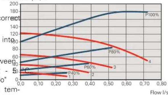
line
| Flow l/s | P100% | P80% | P60% | P40% | | -------- | ----- | ---- | ---- | ---- | | 0.0 | 120 | 60 | 40 | 20 | | 0.30 | 140 | 70 | 50 | 30 | | 0.70 | 180 | 80 | 60 | 40 |Heating medium side, manual operation To set the correct flow in the climate system the correct speed must be set for the heating medium pump in the different operating conditions.
The ow must have a suitable temperature difference for the operating case (heating operation: 5 - 10 °C, hot water generation: 5 - 9 °C) between supply temperature sensor (BT2) and return line sensor (BT3). Check these temperatures in menu 3.1 "service info" and adjust the heating medium pump (GP1) speed until the temperature difference is attained. A high difference indicates a low heating medium flow and a low difference indicates a high heating medium ow.
Set the speed of the heating medium pump in menu 5.1.11.
Read off what speed the heating medium pump should be from the diagrams below.

Available pressure, kPa
Electrical output, W
F1226 6 kW
Available pressure, kPa
Electrical output, W

line
| Flow I | P100% | P80% | P60% | P40% | P40% | | ------ | ----- | ---- | ---- | ---- | ---- | | 0.0 | 75 | 45 | 35 | 20 | 15 | | 0.15 | 70 | 40 | 30 | 18 | 12 | | 0.25 | 65 | 35 | 25 | 15 | 10 | | 0.35 | 60 | 30 | 20 | 12 | 8 | | 0.40 | 55 | 25 | 15 | 10 | 6 | | 0.45 | 50 | 20 | 10 | 8 | 4 |F1226 8 and 12 kW
Available pressure, kPa
Electrical output, W

line
| Flow I/s | P100% | P80% | P60% | P40% | | -------- | ----- | ---- | ---- | ---- | | 0.0 | 75 | 45 | 30 | 20 | | 0.10 | 70 | 40 | 35 | 25 | | 0.20 | 65 | 35 | 40 | 30 | | 0.25 | 60 | 30 | 45 | 35 | | 0.30 | 55 | 25 | 50 | 40 | | 0.35 | 50 | 20 | 55 | 45 | | 0.40 | 45 | 15 | 60 | 50 | | 0.45 | 40 | 10 | 65 | 55 |Readjusting, venting, heat medium side Air is initially released from the hot water and vent when the outdoor temperature drops/increases. A may be necessary. If gurgling sounds can be heard steeper slope means a higher supply temperature at a the heat pump or climate system, the entire system certain outdoor temperature. requires additional venting. Check the pressure in the Supply temperature pressure expansion vessel (CM1) with the pressure gauge (BP5). If the pressure drops, the system should be replenished.
Readjusting, venting, collector side
Level vessel
Check the uid level in the level vessel (CM2). If the uid level has dropped, top up the system.
-
Close the valve under the vessel.
-
Disconnect the connection on top the vessel.
-
Fill with brine until approx 2/3 of the vessel is full.
-
Reconnect the connector at the top of the vessel.
-
Open the valve under the vessel.

If the pressure in the system needs to be raised done by closing the valve on the outgoing main when the brine pump (GP2) is in operation and t vessel (CM2) is open, so that liquid is drawn down the vessel.
Expansion vessel
If a pressure expansion vessel (CM3) is used instead of a level vessel, the pressure level is checked with the pressure gauge (BP6). If the pressure drops, the system should be replenished.
Setting the heating curve
In menu Curve, heatir you can view the heating curve for your house. The task of the curve is to give an even indoor temperature, regardless of the outdoor temperature, and thereby energy-of-cient operation. Based on this curve, the F1226 determines the temperature of the water to the climate system (the supply temperature) and thus the indoor temperature.
CURVE COEFFICIENT
The slope of the heating curve indicates how many degrees the supply temperature is to be increased/reduced When the outdoor temperature drops/increases. A steeper slope means a higher supply temperature at a certain outdoor temperature. Supply temperature
(°C)

line
| Outdoor temperature (°C) | d (solid line) | d (dashed line) | | ------------------------ | -------------- | --------------- | | 0 | 25 | 25 | | 10 | 30 | 35 | | 0 | 35 | 40 | | -10 | 40 | 45 | | -20 | 45 | 50 | | -30 | 50 | 55 | | -40 | 55 | 60 |The optimum curve slope depends on the climate conditions in your location, whether the house has radiators, fan coils or under oor heating and how well insulated the house is.
The heating curve is set when the heating installation is installed, but may need adjusting later. Normally, the curve will not need further adjustment.
this is
curve OFFSET
An offset of the heating curve means that the supply temperature is changed by the same amount for all outdoor temperatures, e.g. a curve offset of +2 steps increases the supply temperature by 5 °C at all outdoor temperatures.
Supply temperature

line
| Outdoor temperature (°C) | Offset heating curve (°C) | | ------------------------ | ------------------------- | | 0 | 30 | | -20 | 55 | | -40 | 65 |SUPPLY TEMPERATURE - MAXIMUM AND MINIMUM VALUES
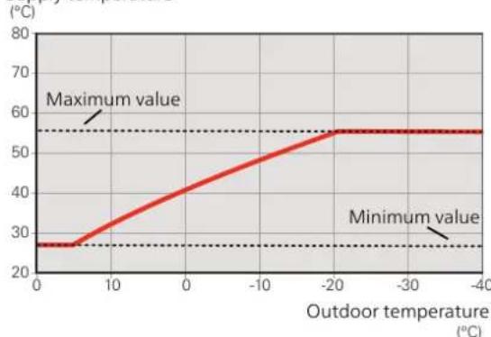
Because the flow line temperature cannot be calculated higher than the set maximum value or lower than set minimum value the heating curve attens out of these temperatures.
Supply temperature
line
| Outdoor temperature (°C) | Value | | ------------------------ | ----- | | 0 | 28 | | 10 | 30 | | 0 | 40 | | -10 | 50 | | -20 | 55 | | -30 | 55 | | -40 | 55 |
Caution
With under oor heating systems, the maximum supply temperature is normally set between 35 and 45 °C.
Check the max oor temperature with your oor supplier.
ADJUSTMENT OF CURVE

line
| Point | Temperature (°C) | Curve offset | |---|---|---| | 1 | 0 | 0 | | 2 | 0 | 0 | | 3 | 41 | 9 | | 4 | 41 | 9 | | 5 | 60 | 9 | | 6 | 60 | 9 | | 7 | 60 | 9 | | 8 | 60 | 9 | | 9 | 60 | 9 | | Max supply temperature (at) | 0 | ? | | Min supply temperature (at) | 0 | ? | | Curve coefficient: heating curve 1.9/1.1, Curve offset: Curve coefficient- Select curve slope and curve offset.

Caution
If you need to adjust "min. ow line temp." and/or "max flow line temperature", you do this in other menus.
Settings for "min. ow line temp." in menu 1.9.3.
Settings for "max ow line temperature" in menu 5.1.2.

Caution
Curve 0 means that own curve is used.
Settings for own curve are made in menu 1.9.7.
TO READ OFF A HEATING CURVE
-
Turn the control knob so that the ring on the shaft with the outdoor temperature is marked.
-
Press the OK button.
-
Follow the grey line up to the curve and out to the left to read off the value for the supply temperature at the selected outdoor temperature.
-
You can now select to take read outs for different outdoor temperatures by turning the control knob to the right or left and read off the corresponding ow temperature.
-
Press the OK or Back button to exit read off mode.
7 Control - Introduction
Display unit
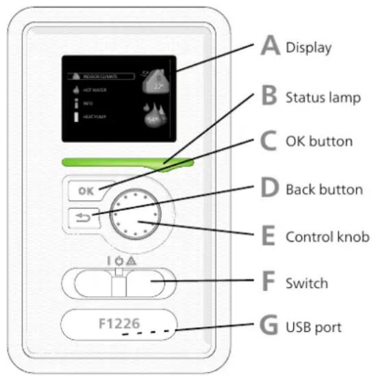
E
CONTROL KNOB
The control knob can be turned to the right or left. You can:
- scroll in menus and between options.
- increase and decrease the values.
- change page in multiple page instructions (for example help text and service info).
F
SWITCH (SF1)
The switch assumes three positions:
- On ( )
- Standby ⏻)
- Emergency mode △)
Emergency mode must only be used in the event of a fault on the heat pump. In this mode, the compressor switches off and the immersion heater engages. The heat pump display is not illuminated and the status lamp illuminates yellow.
A DISPLAY
Instructions, settings and operational information are shown on the display. You can easily navigate between the different menus and options to set the comfort or obtain the information you require.
B STATUS LAMP
The status lamp indicates the status of the heat pump. It:
- lights green during normal operation.
- lights yellow in emergency mode.
- lights red in the event of a deployed alarm.
C OK BUTTON
The OK button is used to:
- con rm selections of sub menus/options/set values/page in the start guide.
D BACK BUTTON
The back button is used to:
- go back to the previous menu.
- change a setting that has not been con rmed.
USB PORT
The USB port is hidden beneath the plastic badge with the product name on it.
The USB port is used to update the software.
Visit nibeuplink.com and click the "Software" tab to download the latest software for your installation.
Menu system

MENU 1 - INDOOR CLIMATE
Setting and scheduling the indoor climate. See information in the help menu or user manual.
MENU 2 - HOT WATER
Setting and scheduling hot water production. See information in the help menu or user manual.
MENU 3 - INFO
Display of temperature and other operating information and access to the alarm log. See information in the help menu or user manual.
MENU 4 - HEAT PUMP
Setting time, date, language, display, operating mode etc. See information in the help menu or user manual.
MENU 5 - SERVICE
Advanced settings. These settings are only intended for installers or service engineers. The menu is visible when the Back button is pressed for 7 seconds, when you are in the start menu. See page 37.

flowchart
graph LR
    A["INDOOR CLIMATE"] --> B["Marked main menu"]
    B --> C["Symbols – sub menus"]
    C --> D["Name – sub menus"]
    D --> E["Symbol – main menu"]
    E --> F["Temp: 11, 0, advanced"]
    F --> G["Status information – sub menus"]
    style A fill:#f9f,stroke:#333
    style B fill:#ccf,stroke:#333
    style C fill:#cfc,stroke:#333
    style D fill:#fcc,stroke:#333
    style E fill:#cff,stroke:#333
    style F fill:#ffc,stroke:#333
    style G fill:#fcf,stroke:#333
OPERATION
To move the cursor, turn the control knob to the left or the right. The marked position is brighter and/or has a light frame.

SELECTING MENU
To advance in the menu system select a main menu by marking it and then pressing the OK button. A new window then opens with sub menus.
Select one of the sub menus by marking it and then pressing the OK button.
SELECTING OPTIONS

In an options menu the current selected option is indicated by a green tick.

To select another option:
- Mark the applicable option. One of the options is pre-selected (white).

- Press the OK button to confirm the selected option. The selected option has a green tick.

SETTING A VALUE

To set a value:
- Mark the value you want to set using the control knob.

- Press the OK button. The background of the value becomes green, which means that you have accessed the setting mode.

- Turn the control knob to the right to increase the value and to the left to reduce the value.

- Press the OK button to confirm the value you have set. To change and return to the original value, press the Back button.

SCROLL THROUGH THE WINDOWS
A menu can consist of several windows. Turn the control knob to scroll between the windows.
Scroll through the windows in the start guide

Arrows to scroll through window in start guide
- Turn the control knob until one of the arrows in the top left corner (at the page number) has been marked.
- Press the OK button to skip between the steps in the start guide.
HELP MENU

In many menus there is a symbol that indicates that extra help is available.
To access the help text:
- Use the control knob to select the help symbol.
- Press the OK button.
The help text often consists of several windows that you can scroll between using the control knob.
8 Control - Menus
Menu 1 - INDOOR CLIMATE
1.1 - temperature1 - INDOOR CLIMATE
1.9.1.1 - heating curve1.9.1 - curve
1.9.2 - external adjustment
1.9.3 - min. ow line temp.
1.9.4 - room sensor settings
1.9.7 - own curve
1.9.8 - point offset
Menu 2 - HOT WATER
2.1 - temporary lux2 - HOT WATER
2.2 - comfort mode
2.9.1 - periodic increase2.9 - advanced
Menu 3 - INFO
3.1 - service info3 - INFO
3.2 - compressor info
3.3 - add. heat info
3.4 - alarm log
3.5 - indoor temp. log
Menu 4 - HEAT PUMP
4.2 - op. mode4 - HEAT PUMP
4.4 - time & date
4.6 - language
4.9.1 - op. prioritisation4.9 - advanced
4.9.2 - auto mode setting
4.9.3 - degree minute setting
4.9.4 - factory setting user
Menu 5 - SERVICE
OVERVIEW
5.1.1 - hot water settings5.1 - operating settings5 - SERVICE
5.1.2 - max ow line temperature
5.1.3 - max diff ow line temp.
5.1.4 - alarm actions
5.1.7 - br pmp al set.
5.1.8 - operating mode brine pump
5.1.9 - brine pump speed
5.1.10 - op. mod heat med pump
5.1.11 - pump speed heating medium
5.1.12 - internal electrical addition
5.2 - system settings
5.4 - soft in/outputs
5.5 - factory setting service
5.6 - forced control
5.7 - start guide
5.8 - quick start
5.10 - change log
5.12 - country
Go to the main menu and hold the Back button in MENU 5.1.1 - HOT WATER SETTINGS
seconds to access the Service menu.
Sub-menus
Menu SERVICE has orange text and is intended for advanced user. This menu has several sub-menus.
Status information for the relevant menu can be found on the display to the right of the menus.
operating settings Operating settings for the heat pump.
system settings System settings for the heat pump activating accessories etc.
soft in/outputs Setting software-controlled inputs and outputs on terminal block (X1).
soft in/outputs Setting software-controlled inputs and outputs on terminal block (X2).
factory setting servio Total reset of all settings (including settings available to the user) to default values.
forced contro Forced control of the different components in the heat pump.
start guide Manual start of the start guide which is run the rst time the heat pump is started.
quick start Quick starting the compressor.

NOTE
Incorrect settings in the service menus can damage the heat pump.
Operating settings can be made for the heat pump in the sub menus.
start temp. economy / normal / lux
Setting range: 5 - 70 °C
Factory setting (°C):
ind Copper
| luxurynormaleconomy | |||
| 484642F1226-6 | |||
| 464340F1226-8 | |||
| 434037F1226-12 |
Stainless
| luxurynormaleconomy | |||
| 484642F1226-6 | |||
| lud- | 464340F1226-8 | ||
| 434037F1226-12 |
stop temp. economy / normal / lux
Setting range: 5 - 70 °C
Factory setting (°C):
Copper
| luxurynon | |||
| 525046 | |||
| 504744 | |||
| 474441 |
Stainless
| luxurynon | |||
| 525046 | |||
| 504744 | |||
| 474441 |
stop temp. per. increase
Setting range: 55 - 70 °C
Factory setting: 55 °C
Here you set the start and stop temperature of water for the different comfort options in menu 2 well as the stop temperature for periodic increase menu 2.9.1.
MENU 5.1.2 - MAX FLOW LINE TEMPERATURE
climate system
Setting range: 20-80 °C
Default value: 60 °C
Set the maximum supply temperature for the climate system here.

Caution
For under oor heating systems, max ow line temperature should normally be set to between 35 and 45°C.
Check the max oor temperature with your oor supplier.
MENU 5.1.3 - MAX DIFF FLOW LINE TEM
max diff compressor
Setting range: 1 - 25 °C
Default value: 10 °C
max diff addition
Setting range: 1 - 24 °C
Default value: 7 °C
Here you set the maximum permitted difference between the calculated and actual supply temperature in the event of compressor or additional heat mode respectively. Max diff. additional heat can never exceed max diff. compressor
max diff compressor
male economy If the current supply temperature exceeds the calculated supply by set value, the degree minute value is set to 12268 The compressor in the heat pump stops if there is 12280 a heating demand.
max diff addition
If "addition" is selected and activated in menu 4.2 and male economy, the current supply temperature exceeds the calculated temperature by the set value, the additional heat is forced to stop.
122612 MENU 5.1.4 - ALARM ACTIONS
Select how you want the heat pump to alert you that there is an alarm in the display here.
The different alternatives are that the heat pump stops producing hot water (default setting) and/or reduces the room temperature.

Caution
If no alarm action is selected, it can result in higher energy consumption in the event of an alarm.
MENU 5.1.7 - BR PMP AL SET.
min. brine out
Setting range: -12 - 15 °C
Default value: -8 °C
^e max brine in
Setting range: 10 - 30 °C
Default value: 30 °C
Set the temperature at which the heat pump is to activate the alarm for low temperature in outgoing brine.
If "automatic reset" is selected, the alarm resets when the temperature has increased by 1 °C below the set value.
max brine in
Set the temperature at which the heat pump is to activate the alarm for high temperature in incoming brine.
Setting range: intermittent, continuous, 10 days continuous
Default value: intermittent
Set the operating mode of the brine pump here.
intermittent: The brine pump starts approx. 20 sec before and stops approx. 20 seconds after the compressor.
continuous: Continuous operation.
10 days continuous: Continuous operation for 10 The pump then shifts to intermittent operation.

TIP
You can use "10 days continuous" at start-up to obtain continuous circulation during a start-up time in order to make it easier to bleed system.
MENU 5.1.9 - BRINE PUMP SPEED
Setting range: 0 - 100 %
Default values: 50 %
Set the speed of the brine pump here.
MENU 5.1.10 - OP. MOD HEAT MED PU
op. mode
Setting range: auto, intermittent, continuous
Default value: auto
Set the operating mode of the heating medium here.
auto: The heating medium pump runs according current operating mode for F1226.
intermittent: The heating medium pump starts app 20 seconds before, and stops at the same time a compressor.
continuous: Continuous operation.
Set the speed at which the heat pump is to operate in the present operating mode.
"heating" means heating operating mode for the heating medium pump.
"hot water" means hot water operating mode for the cond heating medium pump.
"speed in wait mode" is the heat pump speed when neither compressor nor electric additional heat are active. days.
MÉNU 5.1.12 - INTERNAL ELECTRICAL ADDITION
max connected el. add.
Setting range: 7 / 9
the Default value: 7
set max electrical add.
Setting range: 0 - 9 kW
Factory setting: 6 kW
Here you set the max. electrical output of the internal electrical addition in F1226 and the fuse size for the installation.
MÉNU 5.4 - SOFT IN/OUTPUTS
Here, you can select which input on the terminal block (X1) the external contact function (page 24) must be connected to.
Selectable inputs on terminal block AUX 1-2 (X1:3-6).
MENU 5.5 - FACTORY SETTING SERVICE
All settings can be reset (including settings available to the user) to default values here.

Caution
is, the When resetting, the start guide is displayed the next time the heat pump is restarted.
MENU 5.6 - FORCED CONTROL
You can force control the different components in the heat pump and any connected accessories here.

NOTE
Forced control is only intended to be used for troubleshooting purposes. Using the function in any other way may cause damage to the components in your climate system.
MENU 5.7 - START GUIDE
When the heat pump is started for the rst time the start guide starts automatically. Start it manually here.
See page 27 for more information about the start guide.
MENU 5.8 - QUICK START
It is possible to start the compressor from here.

Caution
There must be a heating or hot water demand to start the compressor.

NOTE
Do not quick start the compressor too many times over a short period of time, as this could damage the compressor and its surrounding equipment.
MENU 5.10 - CHANGE LOG
Read off any previous changes to the control system here.
The date, time, ID no. (unique to particular setting) and the new set value are shown for every change.

Caution
The change log is saved at restart and remains unchanged after factory setting.
5.12 - COUNTRY
Select here the country in which the product was installed. This allows access to country-speci c settings in your product.
Language settings can be made regardless of this selection.

Caution
This option locks after 24 hours, after restarting the display and during program updating.
9 Service
Service actions

NOTE
Servicing should only be carried out by persons with the necessary expertise.
When replacing components on F1226 only replacement parts from NIBE may be used.
EMERGENCY MODE

NOTE
The switch (SF1) must not be moved to "" or
"△ until F1226 has been lled with water.
Component parts in the product can be damaged.

Emergency mode is used in event of operational inference and in conjunction with service. Hot water not produced in emergency mode.
Emergency mode is activated by setting switch (SI in mode ▲". This means that:
- The status lamp illuminates yellow.
- The display is not lit and the control computer connected.
- The temperature at the immersion heater is controlled by the thermostat (FQ10). It can be set either to 35 or 45 °C.
- The compressor and the brine system are off and the heating medium pump and the electric additional heat are active. The additional heat power in emergency mode is set in the immersion heater board (AA1). See page 23 for instructions.
The image shows an example of what a cooling section could look like.
DRAINING THE HOT WATER HEATER
The siphon principle is used to empty the hot water heater. This can be done either via the drain valve on the incoming cold water pipe or by inserting a hose into the cold water connection.
DRAINING THE CLIMATE SYSTEM
In order to carry out service on the climate system, it may be easier to drain the system first. This can be done in different ways depending on what needs doing:

NOTE
There may be some hot water when draining the heating medium side/climate system. There is a risk of scalding.
Draining the heating medium side in the cooling module
If, for example, the heating medium pump requires replacing or the cooling module requires servicing, drain the heating medium side as follows:
-
Close the shut-off valves to heating medium side (QM31) and (QM32).
-
Connect a hose to the bleed valve (QM1) and open the valve. Some liquid will run out.
-
Air must get into the system for the remaining EMPTYING THE BRINE SYSTEM
to run out. To let in air, slacken off the connection
slightly at the shut-off valve (QM32) that joins heat pump with the cooling module.
In order to service the brine system it may be easier to the drain the system first. This can be done in different ways depending on what needs doing:
When the heating medium side is empty, the required service can be carried out and/or replacement of any components carried out. Draining the brine system in the cooling module
Draining the heating medium system in the heat pump II, for example, the brine pump requires replacing of the cooling module requires servicing, drain the brine system by:
If F1226 requires servicing, drain the heating medium side as follows: Close the shut-off valves to brine system (QM33) and (QM34).
- Close the shut-off valves outside the heat pump for Connect a hose to the drain valve (QM2), place the heating medium side (return and ow line). other opening of the hose in a container and open
- Connect a hose to the bleed valve (QM1) and open the valve. A small amount of brine will ow into the valve. Some liquid will run out. container.
- Air must get into the system for the remaining liquid air must get into the system in order for the remaining brine to run out. To let in air, slacken off the connection slightly at the shut-off valve that joins the heat pump connection slightly at the shut-off valve (QM33) that with the cooling module (XL2).
When the heating medium side is empty, the required service can be carried out. When the brine system is empty, the required service can be carried out.
Draining the entire climate system
If the entire climate system requires draining, do follows:
Draining the brine system in the heat pump
If the heat pump requires servicing, drain the brine system by:
- Connect a hose to the bleed valve (QM1) and open the shut-off valve outside the heat pump for the valve. Some liquid will run out. the brine system.
- Air must get into the system for the remaining 2-liquid connect a hose to the drain valve (QM2), place the to run out. To allow air in, unscrew the bleed screw ether opening of the hose in a container and open on the highest radiator in the house. The valve. A small amount of brine will ow into the container.
When the climate system is empty, the required can be carried out.
- Air must get into the system for the remaining brine to run out. To let in air, slacken off the connection slightly at the shut-off valve that joins the brine side with the heat pump at connection (XL7).
When the brine system is empty, the required service can be carried out.
- Turn off F1226 by setting the switch (SF _0 to " ".
- Remove the front cover
- Remove the cover for the cooling module.
- Loosen the venting screw (QM5) with a screwdriver. Hold a cloth around the screwdriver blade as a small amount of water may run out.
- Insert a screwdriver and turn the pump motor around.
- Screw in the venting screw (QM5).
- Start F1226 by setting the switch (SF11) to "" and check that the circulation pump is working.
It is usually easier to start the circulation pump with PULLING OUT THE COOLING MODULE F1226 running, and with the switch (SF1) Iset to "If the circulation pump is helped to start while F1226 is running, be prepared for the screwdriver to jerk when the transport.
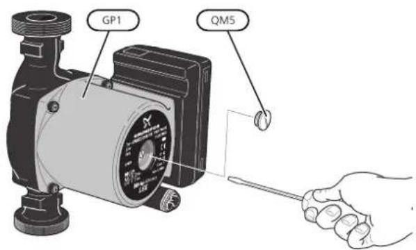
pump starts.
The image shows an example of what a circulation pump can look like.

NOTE
Switch off the heat pump and cut the power with the safety switch.

Caution
Remove the front cover according to the description on page 8.
- Close the shut-off valves (QM31), (QM32), (QM33) and (QM34).
look Drain the compressor module according to the instructions on page 41
TEMPERATURE SENSOR DATA
| Temperature (°C) (kOhm) | Voltage (VDC)Re | |
| 3.256351.0-40 | ||
| 3.240251.6-35 | ||
| 3.218182.5-30 | ||
| 3.189133.8-25 | ||
| 3.15099.22-20 | ||
| 3.10574.32-15 | ||
| 3.04756.20-10 | ||
| 2.97642.89-5 | ||
| 2.88933.020 | ||
| 2.78925.615 | ||
| 2.67320.0210 | ||
| 2.54115.7715 | ||
| 2.39912.5120 | ||
| 2.24510.0025 | ||
| 2.0838.04530 | ||
| 1.9166.51435 | ||
| 1.7525.30640 | ||
| 1.5874.34845 | ||
| 1.4263.58350 | ||
| 1.2782.96855 | ||
| 1.1362.46760 | ||
| 1.0072.06865 | ||
| 0.8911.73970 | ||
| 0.7851.46975 | ||
| 0.6911.24680 | ||
| 0.6071.06185 | ||
| 0.5330.90890 | ||
| 0.4690.77995 | ||
| 0.4140.672100 | ||
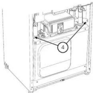
-
Pull off the lock catches.
-
Disconnect the pipe connection under the shut-off valve (QM31).

- Remove the two screws.
- Remove the connections from the base card (AA2) using a screwdriver.


NOTE
At reinstallation, the supplied O-rings must replace the existing ones at the connections to the heat pump (see image).

- Disconnect the connectors (A) and (B) from the derside of the base card cabinet.
- Disconnect the connector (C) from the electric tion PCB (AA1) using a screwdriver.
- Disconnect the switch (D) from the joint board (AA100).
- Carefully pull out the cooling module.

USB SERVICE OUTLET

The display unit is equipped with a USB socket that can be used to update the software and save logged information in F1226.


TIP
The cooling module is installed in reverse order.
When a USB memory is connected, a new menu choose another le
7) appears in the display.
Menu 7.1 - update rmware

This allows you to update the software in F1226.

NOTE
For the following functions to work the USB date, memory must contain les with software for F1226 from NIBE.
The fact box at the top of the display shows info (always in English) of the most probable update th update software has selected form the USB memo
This information states the product for which the software is intended, the software version and general formation about it. If you want a le other than the selected, the correct le can be selected through "choose another le".
start updating
Select "start updating" if you want to start the update. Setting range: 1 s - 60 min You are asked whether you really want to update the software. Respond "yes" to continue or "no" to undo. Factory setting range: 5 s
If you responded "yes" to the previous question the Here you can choose how current measurement values date starts and you can now follow the progress of the from F1226 should be saved onto a log le on the USB update on the display. When the update is complete memory.
F1226 restarts.

TIP
A software update does not reset the menu ^3 . settings in F1226.

Caution
If the update is interrupted before it is complete (for example power cut etc.), the software can be reset to the previous version if the OK button is held in during start up until the green lamp starts to illuminate (takes about 10 seconds).
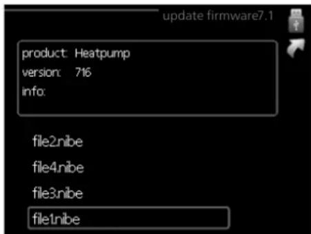
Select "choose another le" if you do not want to use the suggested software. When you scroll through the les, information about the marked software is shown in a fact box just as before. When you have selected a le with the OK button you will return to the previous page (menu 7.1) where you can choose to start the up-
Menu 7.2 - logging

date Setting range: 1 s - 60 min the Factory setting range: 5 s do.
Here you can choose how current measurement values of the F1226 should be saved onto a log le on the USB memory.
- Set the desired interval between loggings.
- Tick "activated".
- The present values from F1226 are saved in a le in the USB memory at the set interval until "activated" is unticked.

Caution
Untick "activated" before removing the USB memory.
Menu 7.3 - manage settings

Here you can manage (save as or retrieve from) all the menu settings (user and service menus) in F1226 with a USB memory.
Via "save settings" you save the menu settings to the USB memory in order to restore them later or to copy the settings to another F1226.

Caution
When you save the menu settings to the USB memory you replace any previously saved settings on the USB memory.
Via "recover settings" you reset all menu settings from the USB memory.

Caution
Reset of the menu settings from the USB memory cannot be undone.
10 Disturbances in comfort
In most cases, F1226 notes a malfunction (a malfunction mode “aid mode” is a type of emergency mode. can lead to disruption in comfort) and indicates this means that the heat pump produces heat and/or alarms, and instructions for action, in the display. hot water even though there is some kind of problem.
INFO MENU
This could mean that the heat pump's compressor is not running. In this case, the immersion heater produces
All the heat pump measurement values are gathered at and/or hot water.
under menu 3.1 in the heat pump menu system. Looking through the values in this menu can often simplify and ing the source of the fault. See help menu or user manual for more information about menu 3.1.

Caution
To select aid mode an alarm action must be selected in the menu 5.1.4.
Manage alarm


Caution
Selecting "aid mode" is not the same as correcting the problem that caused the alarm. The status lamp will therefore continue to be red.
Troubleshooting
If the operational interference is not shown in the display the following tips can be used:
In the event of an alarm, some kind of malfunction BASIC ACTIONS
occurred, which is indicated by the status lamp changing from green continuously to red continuously. In addition,
an alarm bell appears in the information window.
• The switch's (SF1) position.
- Group and main fuses of the accommodation.
ALARM
In the event of an alarm with a red status lamp a mal- The property's earth circuit breaker.
function has occurred that the heat pump cannot remedy. Heat pump's earth-fault breaker.
itself. In the display, by turning the control knob and
pressing the OK button, you can see the type of a Miniature circuit breaker for F1226 (FC1).
it is and reset it. You can also choose to set the heat
• heat Temperature limiter for F1226 (FQ10).
pump to aid mode.
info / action Here you can read what the alarm means Correctly set load monitor.
and receive tips on what you can do to correct the
problem that caused the alarm.
LOW HOT WATER TEMPERATURE OR NO HOT WATER
reset alarm In many cases, it is sufficient to select reset
alarm" for the product to revert to normal operation. Mixing valve (if there is one installed) set too low.
a green light comes on after selecting "reset alarm"
the alarm has been remedied. If the red light is still on,
and a menu called "alarm" is visible in the display. The 1226 in incorrect operating mode.
problem causing the alarm still remains.
- Enter menu 4.2. If mode "auto" is selected, select a higher value on "stop additional heat" in menu 4.9.2.
- If mode "manual" is selected, select "addition".
- Enter menu 1.1 (temperature) and reduce the offset heating curve. If the room temperature is only high in cold weather the curve slope in menu 1.9.1
• Large hot water consumption.
- Wait until the hot water has heated up. Temporarily heating curve" needs adjusting down. increased hot water capacity (temporary lux) can be activated in menu 2.1. - External switch for changing room tem
- Too low hot water setting.
- External switch for changing room temperature activated.
- Enter menu 2.2 and select a higher comfort mode.
Check any external switches.
- Too low or no operating prioritisation of hot water. UNEVEN ROOM TEMPERATURE.
- Enter menu 4.9.1 and increase the time for when incorrectly set heating curve. hot water is to be prioritised. Note that, if the time fine-tune the heating curve in menu 1.9.1 for hot water is increased, the time for heating production is reduced, which can give lower/uneven. Too high set value on "dT at DOT". room temperatures.
LOW ROOM TEMPERATURE
- Enter menu 5.1.14 (ow set. climate system) and reduce the value of "dT at DOT".
- Closed thermostats in several rooms.
- Uneven ow over the radiators.
- Set the thermostats to max, in as many rooms possible. Adjust the room temperature via menu 1.1, instead of choking the thermostats.
-asAdjust the ow distribution between the radiators.
See the "Saving tips" section in the User manual more detailed information about how to best set thermostats.
LOW SYSTEM PRESSURE
for Not enough water in the climate system. the
- Top up the water in the climate system (see page 26).
- Too low set value on the automatic heating control.
- Enter menu 1.1 "temperature" and adjust the off heating curve up. If the room temperature is on low in cold weather the curve slope in menu 1. "heating curve" needs adjusting up.
OMPRESSOR DOES NOT START
yThere is no heating requirement.
9.1 F1226 does not call on heating or hot water.
• F1226 in incorrect operating mode.
- Compressor blocked due to the temperature conditions.
- Enter menu 4.2. If mode "auto" is selected, select higher value on "stop heating" in menu 4.9.2.
^ct Wait until the temperature is within the product's working range.
- If mode "manual" is selected, select "heating". is not enough, select "addition".
If this - Minimum time between compressor starts has not been reached.
- Too low or no operating prioritisation of heat.
- Wait for at least 30 minutes and then check if the
- Enter menu 4.9.1 and increase the time for whencompressor has started.
heating is to be prioritised. Note that if the time for heating is increased the time for hot water produc- Alarm tripped.
tion is reduced, which can give smaller amounts of Follow the display instructions. hot water.
- "Additional heat only" is selected.
- External switch for changing room temperature ated.
activ- Switch to "Auto" or "Manual" in menu 4.1 - Operating mode.
- Check any external switches.
WHINING NOISE IN THE RADIATORS
• Air in the climate system.
- Closed thermostats in the rooms and incorrectly set heating curve.
- Vent the climate system (see page 26).
- Closed valves (QM31), (QM32) to the climate – Open the valves.
system Set the thermostats to max. in as many rooms as possible. Adjust the heating curve via menu 1.1, instead of choking the thermostats.
HIGH ROOM TEMPERATURE
- Too high set value on the automatic heating control.
• Circulation pump speed set too high.
- Enter menu 5.1.11 (pump speed heating medium) and reduce the speed of the circulation pump.
- Uneven ow over the radiators.
- Adjust the ow distribution between the radiators.
GURGLING SOUND
This part of the troubleshooting chapter only applies if the NIBE FLM accessory is installed.
- Not enough water in the water seal.
- Re ll the water seal with water.
- Choked water seal.
- Check and adjust the condensation water hose.
11 Accessories
Detailed information about the accessories and complete ROOM SENSORRTS 40 accessories list available at nibe.eu.
Not all accessories are available on all markets.
EXTRA RELAY CARD EXC 40
This accessory is used to obtain a more even indoor temperature.
Part no. 067 065
Extra relay board required if ground water pump and/or hot water circulation pump is to be connected to F1226.
The extra relay card is installed inside the heat pump Part no. 067 072
or BUFFER VESSEL UKV
A buffer vessel is an accumulator tank that is suitable for connection to a heat pump or another external heat source, and can have several different applications. It can also be used during external control of the heating system.
EXHAUST AIR MODULE NIBE FLM
UKV 100
UKV 200
NIBE FLM is an exhaust air module designed to combine recovery of mechanical exhaust air with ground source heating.
Part no. 088 207
Part no. 080 300
NIBE FLM
Bracket BAU 40
Part no. 067 011
Part no. 067 666
BASE EXTENSION EF 45
This accessory is used to create a larger connection area under F1226.
Part no. 067 152
AUXILIARY RELAY HR 10
Auxiliary relay HR 10 is used to control external 1 to 3 phase loads such as oil burners, immersion heaters and pumps.
Part no 067 309
LEVEL MONITOR NV 10
Level monitor for extended checks of the brine level.
Part no. 089 315
FILLING VALVE KIT KB 25
Valve kit for lling brine in the collector hose. Includes particle liter and insulation.
KB 25 (max. 12 kW)
Part no 089 368
12 Technical data
Dimensions and setting-out coordinates

* This dimension applies at 90° angle on the brine pipes (side connection). The dimension can vary approx. ±100 mm vertically as the brine pipes consist in part of exible pipes.
Electrical data
3X400 V
| F1226-6 | ||
| 400V 3N ~ 50HzRated voltage | ||
| Starting current | A_ms | 13 |
| Max operating current including 0 kW immersion heater (Recommended fuse rating). | ms | 5.3(16)A |
| Max operating current including 1 - 2 kW immersion heater (Recommended fuse rating). | ms | 13(16)A |
| Max operating current including 3 - 4 kW immersion heater (Recommended fuse rating). | ms | 13(16)A |
| Max operating current including 5 - 6 kW immersion heater (Recommended fuse rating). | ms | 17(20)A |
| Max operating current including 7 kW immersion heater, connected on delivery (Recommended fuse rating). | rating). | 17(20)A |
| Max operating current including 9 kW immersion heater, requires reconnection (Recommended fuse rating). | rating). | 20(20)A |
| 1/2/3/4/5/6/7 (switchable to 2/4/6/9)kWAdditional | ||
| 5 - 87WOutput, Brine pump | ||
| 4 - 70WOutput, Heating medium | ||
| IPX1BEnclosure class | ||
| Equipment Compliant with IEC 61000-3-12 | ||
| For Connection Design Purposes, Compliant with IEC 61000-3-3 technical requirements | ||
| F1226-8 | ||
| 400V 3N ~ 50HzRated voltage | ||
| Starting current | A_ms | 16 |
| Max operating current including 0 kW immersion heater (Recommended fuse rating). | ms | 6.4(16)A |
| Max operating current including 1 - 2 kW immersion heater (Recommended fuse rating). | ms | 14(16)A |
| Max operating current including 3 - 4 kW immersion heater (Recommended fuse rating). | ms | 14(16)A |
| Max operating current including 5 - 6 kW immersion heater (Recommended fuse rating). | ms | 18(20)A |
| Max operating current including 7 kW immersion heater, connected on delivery (Recommended fuse rating). | rating). | 18(20)A |
| Max operating current including 9 kW immersion heater, requires reconnection (Recommended fuse rating). | rating). | 21(25)A |
| 1/2/3/4/5/6/7 (switchable to 2/4/6/9)kWAdditional | ||
| 5 - 87WOutput, Brine pump | ||
| 4 - 70WOutput, Heating medium | ||
| IPX1BEnclosure class | ||
| Equipment Compliant with IEC 61000-3-12For Connection Design Purposes, Compliant with IEC 61000-3-3 technical requirements | ||
| F1226-12 | ||
| 400V 3N ~ 50HzRated voltage | ||
| Starting current | A_ms | 29 |
| Max operating current including 0 kW immersion heater (Recommended fuse rating). | ms | 9(16)A |
| Max operating current including 1 - 2 kW immersion heater (Recommended fuse rating). | ms | 18(20)A |
| Max operating current including 3 - 4 kW immersion heater (Recommended fuse rating). | ms | 18(20)A |
| Max operating current including 5 - 6 kW immersion heater (Recommended fuse rating). | ms | 18(20)A |
| Max operating current including 7 kW immersion heater, connected on delivery (Recommended fuse rating). | rating). | 23(25)A |
| Max operating current including 9 kW immersion heater, requires reconnection (Recommended fuse rating). | rating). | 24(25)A |
| 1/2/3/4/5/6/7 (switchable to 2/4/6/9)kWAdditional | ||
| 3 - 180WOutput, Brine pump | ||
| 4 - 70WOutput, Heating medium | ||
| IPX1BEnclosure class | ||
| Equipment Compliant with IEC 61000-3-12For Connection Design Purposes, Compliant with IEC 61000-3-3 technical requirements | ||
Technical speci cations
3X400 V
| F1226-12F1226-8F1226-6I | ||||
| Output data according to EN 14511 | ||||
| 0/35 nominal | ||||
| H) | 11.527.735 39kWHeating | |||
| # | 2.681.721 29kWSupplied | |||
| 4.304.484 17COP | ||||
| 0/45 nominal | ||||
| H) | 10.887.365 05kWHeating | |||
| # | 3.142.041 65kWSupplied | |||
| 3.463.623 26COP | ||||
| SCOP according to EN 14825 | ||||
| design) | 139 / 97 / 6kWRated | |||
| 4.6 / 3.64.8 / 3.84.5 / 3 | ||||
| 4.5 / 3.54.7 / 3.74.4 / 3 | ||||
| Energy rating, average climate | ||||
| The product's room heating ef ciency class 35 °C / 55 °C1 | A++ / A++ | A+++ / A++ | A++ / A++ | |
| The system's room heating ef ciency class 35 °C / 55 °C2 | A++ / A++ | A+++ / A++ | A++ / A++ | |
| Ef ciency class hot water heating / declared tap pro le3 | A / XL | A / XL | A / XL | |
| Noise | ||||
| Sound power level (LWA)EN 12102 at 0/35 | dB(A) | 42 | 43 | 44 |
| Sound pressure level (IA) calculated values according to EN ISO 11203 at 0/35 and 1 m range | dB(A) | 27 | 24 | 29 |
| Refrigerant circuit | ||||
| Type of refrigerant | R407C | |||
| GWP refrigerant | 1,774 | |||
| Fill amount | kg | 0.85 | 1.1 | 1.2 |
| 2 equivalent | ton2031.951 51 | |||
| Cut-out value pressure switch HP / LP | MPa | 2.9 (29 bar) / 0.15 (1.5 bar) | ||
| Brine circuit | ||||
| Min/max system pressure brine | MPa | 0.05 (0.5 bar) / 0.45 (4.5 bar) | ||
| Min ow | l/s 0.430.300 22 | |||
| Nominal ow | l/s 0.640.420 30 | |||
| Max external avail. press at nom ow | kPa | 49 | 39 | 57 |
| Min/Max incoming Brine temp | °C | see diagram | ||
| Min. outgoing brine temp. | °C | -10 | ||
| Heating medium circuit | ||||
| Min/Max system pressure heating medium | MPa | 0.05 (0.5 bar) / 0.45 (4.5 bar) | ||
| Min ow | l/s 0.180.120 09 | |||
| Nominal ow | l/s 0.250.160 13 | |||
| Max external avail. press at nom ow | kPa | 53 | 47 | 57 |
| Min/max HM-temp | °C | see diagram | ||
| Pipe connections | ||||
| Brine ext diam. CU pipe | mm | 28 | 28 | 28 |
| Heating medium ext diam. CU pipes | mm | 22 | 22 | 28 |
| Hot water connection external diam | mm | 22 | ||
| Cold water connection external diam | mm | 22 | ||
| Hot water and heating section | ||||
| Volume water heater (Cu / Rf4/ E) | l | 178 / 176 / - | ||
| Max pressure in water heater | MPa | 1.0 (10 bar) | ||
| Hot water heating capacity (comfort mode Normal) According to EN16147 | ||||
| Amount of hot water (40 °C) | l | 240 | 235 | 230 |
| COPDHW (load pro le XL) | 2.8 | 2.8 | 2.8 | |
| Dimensions and weight | ||||
| Width x Depth x Height | mm | 600 x 620 x 1,800 | ||
| Ceiling height5 | mm | 1,950 | ||
| Weight complete heat pump (Cu / Rf / E)4 | kg | 225 / 205 / - | 235 / 215 / - | 255 / 235 / - |
| Weight only cooling module | kg | 100 | 105 | 126 |
| Lead in brass componentsSubstances according | ||||
| Part number, 3x400 V (Cu / Rf / E) | 065 581 /065 583 / - | 065 582 /065 584 / - | 065 227 /065 230 / - | |
1 Scale for the product's ef ciency class room heating: A+++ to D.
2 Scale for the system's efficiency class room heating: A+++ to G. Reported efficiency for the system takes the product's temperature regulator into account.
3 Scale for ef ciency class hot water: A+ to F.
4 Cu: copper, Rf: stainless steel, E: enamel.
5 With feet removed, the height is approx. 1,930 mm.
WORKING RANGE HEAT PUMP, COMPRESSOR OPERATION
The compressor provides a supply temperature up to 63 °C at 0 °C incoming brine temperature.
12 kW 3x400V
Temperature, °C

line
| Incoming brine temp, °C | Flow pipe | Return pipe | | ----------------------- | --------- | ----------- | | -10 | 15 | 10 | | -5 | 20 | 58 | | 0 | 25 | 58 | | 5 | 28 | 58 | | 10 | 30 | 58 | | 15 | 32 | 57 | | 20 | 34 | 56 | | 25 | 36 | 55 | | 30 | 38 | 54 |6 - 8 kW 3x400V
Temperature, °C

line
| Incoming brine temp, °C | Flow pipe | Return pipe | | ----------------------- | --------- | ----------- | | -10 | 15 | 8 | | -5 | 20 | 10 | | 0 | 25 | 15 | | 5 | 30 | 20 | | 10 | 35 | 25 | | 15 | 40 | 30 | | 20 | 45 | 35 | | 25 | 50 | 40 | | 30 | 60 | 45 |Energy labelling
INFORMATION SHEET
| NIBE ABSupplier | ||||
| F1226-12 3x400VF1226-8 3x400VF12 | ||||
| 35 / 5535 / 5535 / 55°CTe | ||||
| Declared load pro le for water heating | XLXLXL | |||
| Seasonal space heating energy ef ciency class, average climate | A++ / A++A+++ / A++A++ | |||
| Water heating energy efficiency class, average climate | A | A | A | |
| designh, average rated heat output (P) | kW 7 / 6 | 139 / 9 | ||
| Annual energy consumption space heating, average climate | kWh | 3,102 / 3,757 | 3,978 / 4,748 | 5,986 / 7,628 |
| Annual energy consumption water heating, average climate | kWh | 1838 | 1794 | 1876 |
| Seasonal space heating energy ef ciency, average climate | % | 168 / 128 | 179 / 140 | 171 / 133 |
| Water heating energy ef ciency, average climate | % | 91 | 93 | 89 |
| Sound power level LWA indoors | dB | 43 | 43 | 45 |
| designh, cold climate rated heat output (P) | kW 7 / 6 | 139 / 9 | ||
| designh, warm climate rated heat output (P) | kW 7 / 6 | 139 / 9 | ||
| Annual energy consumption space heating, cold climate | kWh | 3,609 / 4,364 | 4,630 / 5,695 | 6,946 / 8,874 |
| Annual energy consumption water heating, cold climate | kWh | 1838 | 1794 | 1876 |
| Annual energy consumption space heating, warm climate | kWh | 2,029 / 2,470 | 2,592 / 3,167 | 3,923 / 4,972 |
| Annual energy consumption water heating, warm climate | kWh | 1838 | 1794 | 1876 |
| Seasonal space heating energy efficiency, cold climate | % | 172 / 132 | 184 / 144 | 177 / 136 |
| Water heating energy ef ciency, cold climate | % | 91 | 93 | 89 |
| Seasonal space heating energy ef ciency, warm climate | % | 166 / 126 | 178 / 137 | 169 / 132 |
| Water heating energy ef ciency, warm climate | % | 91 | 93 | 89 |
| Sound power level LWA outdoors | dB | - | - | - |
DATA FOR ENERGY EFFICIENCY OF THE PACKAGE
| F1226-12 3x400VF1226-8 3x400VF12 | ||||
| 35 / 5535 / 5535 / 55°CTe | ||||
| Controller, class | III | |||
| Controller, contribution to ef ciency | % | 1.5 | ||
| Seasonal space heating energy ef ciency of the package, average climate | % | 169/130 | 180/141 | 173/134 |
| Seasonal space heating energy ef ciency class of the package, average climate | A++/A++ | A+++/A++ | A++/A++ | |
| Seasonal space heating energy ef ciency of the package, cold climate | % | 174/134 | 185/146 | 178/138 |
| Seasonal space heating energy ef ciency of the package, warm climate | % | 167/128 | 179/139 | 171/133 |
The reported ef ciency of the package also takes the controller into account. If an external supplementary boiler or solar heating is added to the package, the overall ef ciency of the package should be recalculated.
TECHNICAL DOCUMENTATION
F1226-6 3x400VModel
| Type of heat pump | Air-water | ||||||
| Exhaust-water | |||||||
| Brine-water | |||||||
| Water-water | |||||||
| Low-temperature heat pump | Yes No | ||||||
| Integrated immersion heater for additional heat | Yes No | ||||||
| Heat pump combination heater | Yes No | ||||||
| Climate | Average Cold Warm | ||||||
| Temperature application | Average (55 °C) Low (35 °C)EN-14825 & EN-16147Applied standards | ||||||
| Seasonal space heating energy ef ciencykW6,2Prated Rated heat% 12 output | |||||||
| Declared capacity for space heating at part load and at outdoor temperature Tj | Templared coefficient of performance for space heating at part load and at out temperature Tj = -7 °C | ||||||
| Tj = +2 °CTj = +7 °CTj = +12 °CTj = bivTj = TOL | -2.91COPdTj = PdH | ||||||
| Tj = +2 °CTj = +7 °CTj = +12 °CTj = bivTj = TOL | PdH 8.44005PdTj = +2PdH 8.79005PdTj = +7PdH 4.17005PdTj = +1;Pdh 3.06005PdTj = bivPdh 2.70005PdTj = TO | ||||||
| Tj = -15 °C (if TOL < -20 °C) | Pdh | kW | Tj = -15 °C (if TOL < -20 °C) | COPd | - | ||
| Bivalent temperature | Tbiv | -5 | °C | Min. outdoor air temperature | TOL | -10 | °C |
| Cycling interval capacity | Pcych | kW | Cycling interval ef ciency | COPcyc | - | ||
| Degradation coef client | Cdh | 1.00 | - | Max supply temperature | WTOL | 63 | °C |
| Power consumption in modes other than active mode | Additional heat | ||||||
| Off mode | POFF | 0.003 | kW | Rated heat output | Psup | 1.3 | kW |
| Thermostat-off mode | TO | 0P | kW | ||||
| Standby mode | PSB | 0.007 | kW | Type of energy input | Electric | ||
| Crankcase heater mode | PCK | 0.014 | kW | ||||
| Other items | |||||||
| Capacity control | Fixed | Rated air ow (air-water) | m3/h | ||||
| Sound power level, indoors/outdoors | LWA | 43/- | dB | Nominal heating medium ow | 0.54 | m3/h | |
| Annual energy consumption | QHE | 3,757 | kWh | Brine flow brine-water or water-water heat pumps | 0.92 | m3/h | |
| For heat pump combination heater | |||||||
| Declared load pro le for water heating | XL | Water heating energy ef ciency | _wh | 91 | % | ||
| Daily energy consumption | Qec | 8.37 | kWh | Daily fuel consumption | Qfuel | kWh | |
| Annual energy consumption | AEC | 1,838 | kWh | Annual fuel consumption | AFC | GJ | |
| Contact information | NIBE Energy Systems – Box 14 – Hannabadsvägen 5 – 285 21 Markaryd – Sweden | ||||||
| Integrated immersion heater for additional heat | Yes No | ||||||
| Heat pump combination heater | Yes No | ||||||
| Climate | Average Cold Warm | ||||||
| Temperature application | Average (55 °C) Low (35 °C)EN-14825 & EN-16147Applied standards | ||||||
| Seasonal space heating energy ef ciencykW8,50Prated Rated heat 140input | |||||||
| Declared capacity for space heating at part load and at outdoor temperature Tj | Templared coefficient of performance for space heating at part load and at out temperature Tj | ||||||
| Tj = -7 °C | -3.18COPdTj = Poh | ||||||
| Tj = +2 °C | Pdh8.72COPdTj = +2 | ||||||
| Tj = +7 °C | Pdh4.08COPdTj = +7 | ||||||
| Tj = +12 °C | Pdh4.48COPdTj = +12 | ||||||
| Tj = biv | Pdh3.26COPdTj = biv | ||||||
| Tj = TOL | Pdh2.96COPdTj = TO | ||||||
| Tj = -15 °C (if TOL < -20 °C) | Pdh | kW | Tj = -15 °C (if TOL < -20 °C) | COPd | - | ||
| Bivalent temperature | Tbiv | -6 | °C | Min. outdoor air temperature | TOL | -10 | °C |
| Cycling interval capacity | Pcych | kW | Cycling interval ef ciency | COPcyc | - | ||
| Degradation coef client | Cdh | 1.00 | - | Max supply temperature | WTOL | 63 | °C |
| Power consumption in modes other than active mode | Additional heat | ||||||
| Off mode | POFF | 0.003 | kW | Rated heat output | Psup | 1.5 | kW |
| Thermostat-off mode | PTO | 0.001 | kW | ||||
| Standby mode | PSB | 0.007 | kW | Type of energy input | Electric | ||
| Crankcase heater mode | PCK | 0.014 | kW | ||||
| Other items | |||||||
| Capacity control | Fixed | Rated air ow (air-water) | m3/h | ||||
| Sound power level, indoors/outdoors | LWA | 43 / - | dB | Nominal heating medium ow | 0.77 | m3/h | |
| Annual energy consumption | QHE | 4,748 | kWh | Brine flow brine-water or water-water heat pumps | 1.40 | m3/h | |
| For heat pump combination heater | |||||||
| Declared load pro le for water heating | XL | Water heating energy ef ciency | wh | 93η | % | ||
| Daily energy consumption | Qec | 8.17 | kWh | Daily fuel consumption | Qfuel | kWh | |
| Annual energy consumption | AEC | 1,794 | kWh | Annual fuel consumption | AFC | GJ | |
| Contact information | NIBE Energy Systems – Box 14 – Hannabadsvägen 5 – 285 21 Markaryd – Sweden | ||||||
| Integrated immersion heater for additional heat | Yes No | ||||||
| Heat pump combination heater | Yes No | ||||||
| Climate | Average Cold Warm | ||||||
| Temperature application | Average (55 °C) Low (35 °C)EN-14825 & EN-16147Applied standards | ||||||
| Seasonal space heating energy ef ciencykW13,0Prated Rated heat 13 output | |||||||
| Declared capacity for space heating at part load and at outdoor temperature Tj | Templared coefficient of performance for space heating at part load and at out temperature Tj | ||||||
| Tj = -7 °C | -3.11COPdTj = -7 | ||||||
| Tj = +2 °C | -3.57COPdPdPdh +2 | ||||||
| Tj = +7 °C | -3.87COPdZPdh +7 | ||||||
| Tj = +12 °C | -4.13COPd5Pdh +1: | ||||||
| Tj = biv | -3.22COPdFdh+ biv | ||||||
| Tj = TOL | -2.98COPdFdh+ TO | ||||||
| Tj = -15 °C (if TOL < -20 °C) | Pdh | kW | Tj = -15 °C (if TOL < -20 °C) | COPd | - | ||
| Bivalent temperature | Tbiv | -5.2 | °C | Min. outdoor air temperature | TOL | -10 | °C |
| Cycling interval capacity | Pcych | kW | Cycling interval ef ciency | COPcyc | - | ||
| Degradation coef cient | Cdh | 0.99 | - | Max supply temperature | WTOL | 63 | °C |
| Power consumption in modes other than active mode | Additional heat | ||||||
| Off mode | POFF | 0.002 | kW | Rated heat output | Psup | 2.7 | kW |
| Thermostat-off mode | PTO | 0.018 | kW | ||||
| Standby mode | PSB | 0.007 | kW | Type of energy input | Electric | ||
| Crankcase heater mode | PCK | 0.030 | kW | ||||
| Other items | |||||||
| Capacity control | Fixed | Rated air ow (air-water) | m3/h | ||||
| Sound power level, indoors/outdoors | LWA | 45 / - | dB | Nominal heating medium ow | 1.11 | m3/h | |
| Annual energy consumption | QHE | 7,628 | kWh | Brine flow brine-water or water-water heat pumps | 2.04 | m3/h | |
| For heat pump combination heater | |||||||
| Declared load pro le for water heating | XL | Water heating energy ef ciency | _wh | 89 | % | ||
| Daily energy consumption | Qec | 8.54 | kWh | Daily fuel consumption | Qfuel | kWh | |
| Annual energy consumption | AEC | 1,876 | kWh | Annual fuel consumption | AFC | GJ | |
| Contact information | NIBE Energy Systems – Box 14 – Hannabadsvägen 5 – 285 21 Markaryd – Sweden | ||||||
Electrical circuit diagram
3X400V 6-8 KW
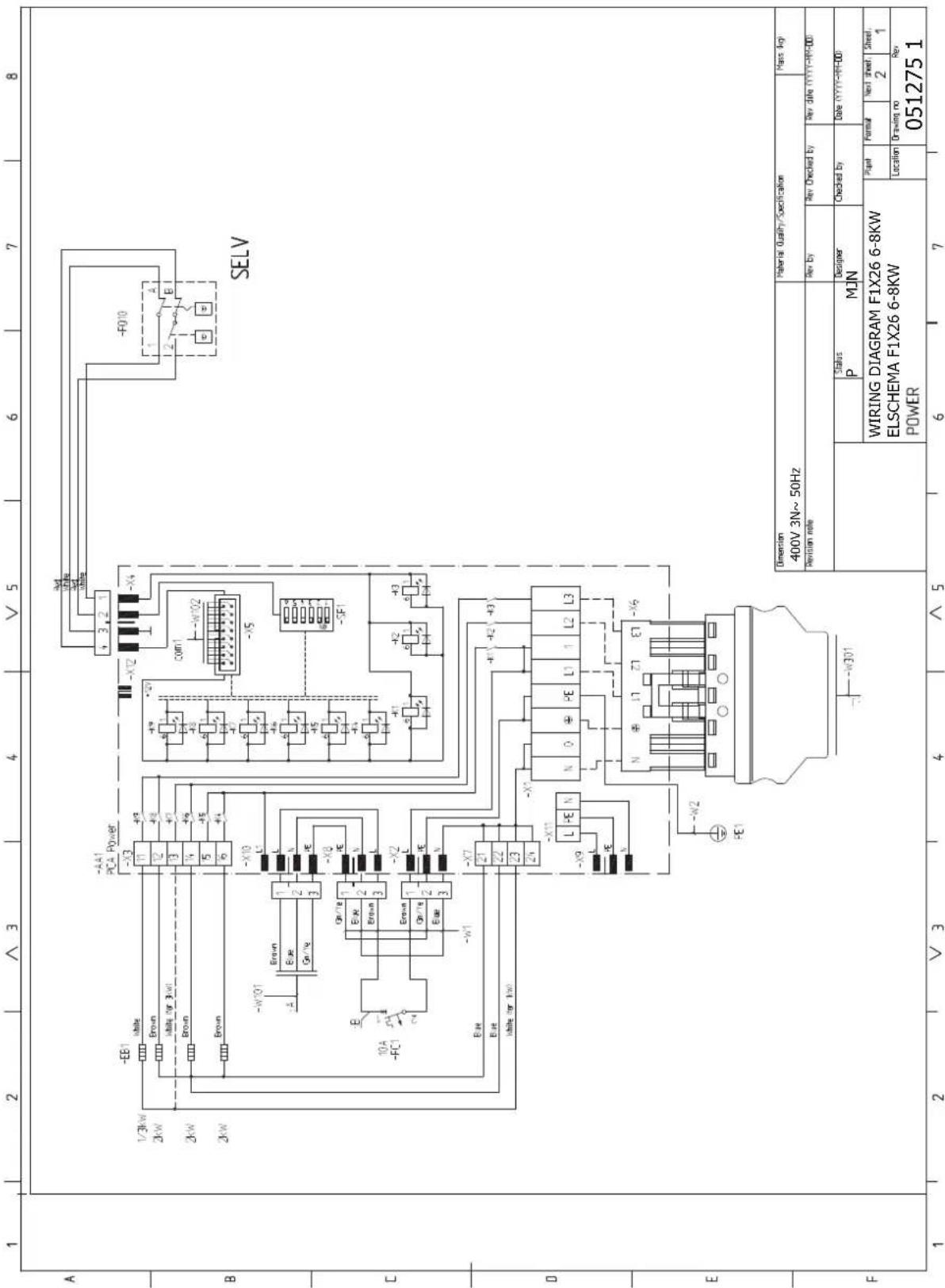
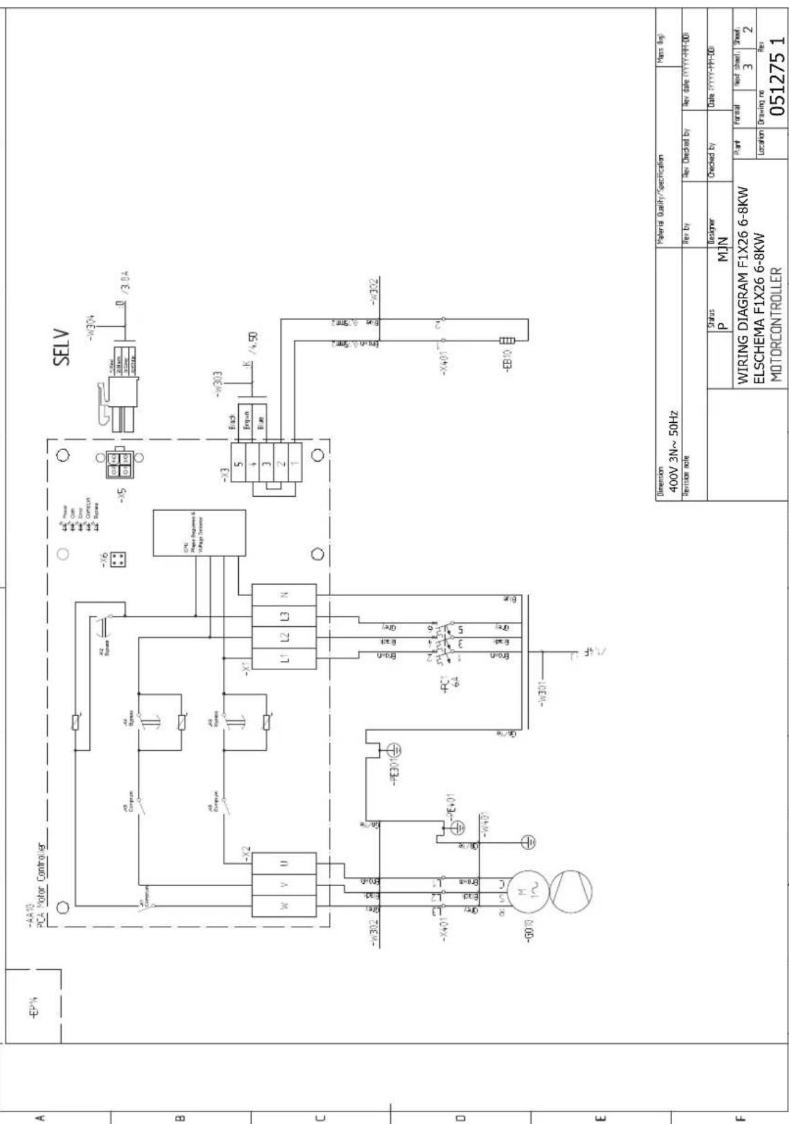


| Dimension 400V 3N~50Hz | Material Quality/Specification | Mass (kg) | |||||||
| Revision note | Rev by | Rev Checked by | Rev date YYYY-MM-DD | ||||||
| Status P | M1N | Designer | Checked by | Date YYYY-MM-DD | |||||
| WIRING DIAGRAM F1X26 6-8KW ELSCHEMA F1X26 6-8KW DISPLAY | Plant | Format | New sheet. | Sheet. | |||||
| Location | Drawing no Rev 051275 1 | ||||||||

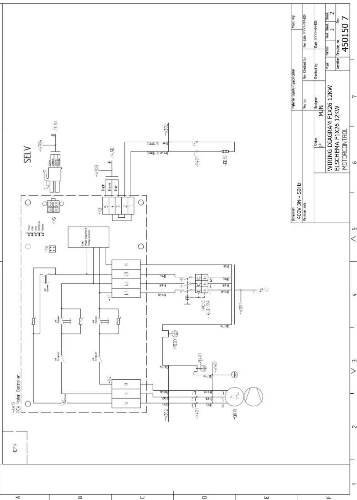


Item register
A
Accessibility, electrical connection, 20
Accessories, 50
Alarm, 47
Assembly, 7
B
Back button, 31
Brine side, 16
C
Cable lock, 21
Cold and hot water, 17
Connecting cold and hot water, 17
Commissioning and adjusting, 26
Filling and venting, 26
Post adjustment and bleeding, 28
Preparations, 26
Start guide, 27
Connecting accessories, 25
Connecting external operating voltage for the control system, 22
Connecting the climate system, 16
Connections, 21
Control, 31, 35
Control - Introduction, 31
Control - Menus, 35
Control - Introduction, 31
Display unit, 31
Menu system, 32
Control knob, 31
Control - Menus, 35
Menu 5 - SERVICE, 37
Cooling section, 13
D
Data for energy efficiency of the system, 55
Delivery and handling, 7
Assembly, 7
Drawing out the cooling module, 7
Installation area, 7
Removing parts of the insulation, 9
Removing the covers, 8
Supplied components, 8
Transport, 7
Dimensions and pipe connections, 15
Dimensions and setting-out coordinates, 51
Display, 31
Display unit, 31
Back button, 31
Control knob, 31
Display, 31
OK button, 31
Status lamp, 31
Switch, 31
Disturbances in comfort, 47
Alarm, 47
Manage alarm, 47
Troubleshooting, 47
Docking alternatives
Free cooling, 18
Ground water system, 17
Neutralization vessel, 17
Under oor heating systems, 18
Ventilation recovery, 18
Draining the climate system, 41
Draining the hot water heater, 41
Drawing out the cooling module, 7, 43
E
Electrical addition - maximum output, 22
Setting max electrical output, 22
Switching to maximum electrical output, 23
Electrical cabinets, 12
Electrical circuit diagram, 59
Electrical connections, 19
Accessibility, electrical connection, 20
Cable lock, 21
Connecting accessories, 25
Connecting external operating voltage for the control system, 22
Connections, 21
Electrical addition - maximum output, 22
General, 19
Miniature circuit-breaker, 19
Motor cut-out, 20
Optional connections, 24
Outdoor sensor, 22
Power connection, 21
Removing the cover, base board, 21
Removing the cover, immersion heater circuit board, 20
Removing the hatch, input circuit board, 20
Settings, 22
Standby mode, 23
Temperature limiter, 19
Electrical wiring diagram
3x400V 6-8 kW, 59
3×400V 12 kW, 64
Emptying the brine system, 42
Energy labelling, 55
Data for energy efficiency of the package, 55
Information sheet, 55
Technical documentation, 56
External connection options, 24
Possible selection for AUX inputs, 24
F
Filling and venting, 26
Filling and venting the brine system, 26
Filling and venting the climate system, 26
Filling the hot water heater, 26
Filling and venting the brine system, 26
Filling and venting the climate system, 26
Filling the hot water heater, 26
H
Heating medium side, 16
Connecting the climate system, 16
Helping the circulation pump to start, 42
Help menu, 34
|
Important information, 4
Recovery, 5
Information sheet, 55
Inspection of the installation, 6
Installation alternative
Water heater with immersion heater, 17
Installation area, 7
M
Manage alarm, 47
Marking, 4
Menu 5 - SERVICE, 37
Menu system, 32
Help menu, 34
Operation, 33
Scroll through the windows, 34
Selecting menu, 33
Selecting options, 33
Setting a value, 33
Miniature circuit-breaker, 19
Motor cut-out, 20
0
OK button, 31
Operation, 33
Optional connections, 24
Outdoor sensor, 22
P
Pipe connections, 14
Brine side, 16
Cold and hot water
Connecting cold and hot water, 17
Dimensions and pipe connections, 15
General, 14
Heating medium side, 16
Pipe dimensions, 15
Symbol key, 14
System diagram, 15
Pipe dimensions, 15
Possible selection for AUX inputs, 24
Post adjustment and bleeding, 28
Pump adjustment, 28
Pump capacity diagrams, collector side, 28
Readjusting, venting, heat medium side, 29
Power connection, 21
Preparations, 26
Pump adjustment, 28
Heating medium side, 28
Pump capacity diagrams, collector side, 28
R
Readjusting, venting, heat medium side, 29
Remove parts of the insulation, 9
Removing the cover, base board, 21
Removing the cover, immersion heater circuit board, 20
Removing the covers, 8
Removing the hatch, input circuit board, 20
s
Safety information
Inspection of the installation, 6
Marking, 4
Symbols, 4
Scroll through the windows, 34
Selecting menu, 33
Selecting options, 33
Service, 41
Service actions, 41
Service actions, 41
Draining the climate system, 41
Draining the hot water heater, 41
Drawing out the cooling module, 43
Emptying the brine system, 42
Helping the circulation pump to start, 42
Standby mode, 41
Temperature sensor data, 43
USB service outlet, 44
Setting a value, 33
Settings, 22
Standby mode, 41
Power in emergency mode, 23
Start guide, 27
Status lamp, 31
Supplied components, 8
Switch, 31
Symbol key, 14
Symbols, 4
System diagram, 15
T
Technical data, 51
Dimensions and setting-out coordinates, 51
Electrical circuit diagram, 59
Energy labelling, 55
Data for energy ef ciency of the system, 55
Information sheet, 55
Technical documentation, 56
Technical Data, 53
Technical Data, 53
Working range heat pump, 54
Technical documentation, 56
Temperature limiter, 19
Resetting, 19
Temperature sensor data, 43
The heat pump's design
Component list, cooling module, 13
Component location, cooling module, 13
The heat pump design, 10
Component list electrical cabinets, 12
Component location electrical cabinets, 12
Component locations, 10
List of components, 10
Transport, 7
Troubleshooting, 47
U
USB service outlet, 44
W
Working range heat pump, 54
Contact information
DENMARKCZECH REPUBLICAUSTRIA
For countries not mentioned in this list, contact NIBE Sweden or check nibe.eu for more information.
NIBE Energy Systems
Hannabadsvägen 5
Box 14
SE-285 21 Markaryd
info@nibe.se
nibe.eu
This manual is a publication from NIBE Energy Systems. All product illustrations, facts data are based on the available information at the time of the publication's approval. NIBE Energy Systems makes reservations for any factual or printing errors in this ma



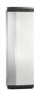
- Ground source heat pump NIBE F1226
- Quick guide
- Navigation
- Set the indoor climate
- Increase hot water volume
- Table of Contents
- Important information
- Safety information Symbols
- NOTE
- Caution
- TIP
- Marking
- Serial number
- Recovery
- Environmental information
- Inspection of the installation
- Delivery and handling
- Transport
- INSTALLATION AREA
- EXTRACTING THE COOLING MODULE
- Assembly
- Supplied componentsRemoving the covers
- LOCATION
- Removing parts of the insulation
- INSULATION, TOP
- The heat pump design
- PIPE CONNECTIONS
- HVAC COMPONENTS
- SENSORS ETC.
- ELECTRICAL COMPONENTS
- MISCELLANEOUS
- Cooling module (EP14)
- COOLING COMPONENTS
- Pipe connections
- General
- SYSTEM DIAGRAM
- Dimensions and pipe Electrical 1226 Suits connections
- Brine side
- COLLECTOR
- CONNECTING THE BRINE SIDE
- SIDE CONNECTION
- Heating medium side
- CONNECTING THE CLIMATE SYSTEM
- EXTRA HOT WATER HEATERS
- Cold and hot water
- CONNECTING COLD AND HOT WATER
- GROUND WATER SYSTEM
- Installation alternative
- VENTILATION RECOVERY
- UNDERFLOOR HEATING SYSTEM
- FREE COOLING
- Electrical connections
- aMINIATURE CIRCUIT-BREAKER
- TEMPERATURE LIMITER
- Resetting
- MOTOR PROTECTION BREAKER /MINIATUREACCESSIBILITY, ELECTRICAL CONNECTION CIRCUIT BREAKER The plastic cap of the electrical boxes is opened u
- CABLE LOCK
- Connections
- POWER CONNECTION
- TARIFF CONTROL
- CONNECTING EXTERNAL OPERATING VOLTAGE FOR THE CONTROL SYSTEM
- CONNECTING SENSORS
- Outside sensor
- Settings
- ELECTRICAL ADDITION - MAXIMUM OUTPUT
- Setting max electrical output
- EMERGENCY MODE
- Power in emergency mode
- Optional connections
- EXTERNAL CONNECTION OPTIONS
- Selectable inputs
- Possible selection for AUX inputs
- Temperature sensor
- Monitor
- External activation of functions
- Connecting accessories
- External blocking of functions
- Commissioning and adjusting
- Preparations
- Filling and venting
- FILLING AND VENTING THE CLIMATE SYSTEM
- Filling
- Venting
- FILLING THE HOT WATER HEATER
- FILLING AND VENTING THE BRINE SYSTEM
- Start-up and inspection
- Commissioning
- Operation in the start guide
- Page
- Name and menu number
- Option / setting
- POST ADJUSTMENT AND VENTING
- Pump adjustment
- Setting the heating curve
- CURVE COEFFICIENT
- SUPPLY TEMPERATURE - MAXIMUM AND MINIMUM VALUES
- TO READ OFF A HEATING CURVE
- Control - Introduction
- E
- CONTROL KNOB
- F
- SWITCH (SF1)
- A DISPLAY
- B STATUS LAMP
- C OK BUTTON
- D BACK BUTTON
- USB PORT
- Menu system
- MENU 1 - INDOOR CLIMATE
- MENU 2 - HOT WATER
- MENU 3 - INFO
- MENU 4 - HEAT PUMP
- MENU 5 - SERVICE
- OPERATION
- SELECTING MENU
- SCROLL THROUGH THE WINDOWS
- HELP MENU
- Control - Menus
- OVERVIEW
- Sub-menus
- MENU 5.1.2 - MAX FLOW LINE TEMPERATURE
- MENU 5.1.3 - MAX DIFF FLOW LINE TEM
- MENU 5.1.4 - ALARM ACTIONS
- MENU 5.1.7 - BR PMP AL SET.
- MENU 5.1.9 - BRINE PUMP SPEED
- MENU 5.1.10 - OP. MOD HEAT MED PU
- MÉNU 5.1.12 - INTERNAL ELECTRICAL ADDITION
- MÉNU 5.4 - SOFT IN/OUTPUTS
- MENU 5.5 - FACTORY SETTING SERVICE
- MENU 5.6 - FORCED CONTROL
- MENU 5.7 - START GUIDE
- MENU 5.8 - QUICK START
- MENU 5.10 - CHANGE LOG
- - COUNTRY
- Service
- Service actions
- DRAINING THE HOT WATER HEATER
- DRAINING THE CLIMATE SYSTEM
- USB SERVICE OUTLET
- Menu 7.3 - manage settings
- Disturbances in comfort
- INFO MENU
- Manage alarm
- Troubleshooting
- ALARM
- LOW HOT WATER TEMPERATURE OR NO HOT WATER
- LOW ROOM TEMPERATURE
- LOW SYSTEM PRESSURE
- OMPRESSOR DOES NOT START
- WHINING NOISE IN THE RADIATORS
- HIGH ROOM TEMPERATURE
- GURGLING SOUND
- Accessories
- BASE EXTENSION EF 45
- AUXILIARY RELAY HR 10
- LEVEL MONITOR NV 10
- FILLING VALVE KIT KB 25
- Technical data
- Electrical data
- Technical speci cations
- WORKING RANGE HEAT PUMP, COMPRESSOR OPERATION
- kW 3x400V
- - 8 kW 3x400V
- Energy labelling
- TECHNICAL DOCUMENTATION
- Electrical circuit diagram
- Item register
- A
- B
- C
- D
- H
- |
- M
- 0
- P
- R
- s
- T
- Contact information
- DENMARKCZECH REPUBLICAUSTRIA
Brand : Nibe
Model : F1226-6
Category : Water pump