
WDE002478 - Thermostat SCHNEIDER - Free user manual and instructions
Find the device manual for free WDE002478 SCHNEIDER in PDF.


| Product Type | Programmable 2-pole thermostat with touch display |
| Brand | Schneider Electric |
| Model | WDE002478 (also WDE003478, WDE004478) |
| Power Supply | 230 V AC, 50 Hz |
| Max Resistive Load | 3680 W (16 A, cos φ = 1) |
| Inductive Load | 1 A, cos φ = 0.6 |
| Display | Touch display with brightness adjustment (15% to 100%) |
| Temperature Sensors | Internal room air sensor; optional floor sensor (WDE002495) |
| Operating Modes | Room air, Floor, Dual (room + floor), PWM |
| Heating Modes | Comfort (+21°C default), Eco (+19°C default), Frost protection (+7°C default), Auto (weekly program) |
| Weekly Programs | Freely adjustable; 3 pre-programmed (Work, Family, Weekend house) |
| Setpoint Range (Room) | +5°C to +35°C |
| Setpoint Range (Floor) | +5°C to +50°C |
| Display Accuracy | 0.5°C |
| Sensor Calibration | Room: -3°C to +3°C; Floor: -9°C to +9°C |
| External Sensor Types | NTC 2 k, 10 k, 12 k, 15 k, 33 k, 47 k at 25°C |
| Protection Class | IP20 |
| Rated Surge Voltage | 4 kV |
| Operating Temperature | -10°C to +35°C |
| Power Reserve | Date/time saved for 2 days; permanent settings saved permanently |
| Valve Protection | Weekly valve exercise (4 min on Tuesdays at 10 am) |
| Relay Output | Normally open (NO) or normally closed (NC), selectable |
| Summer/Winter Time | Automatic CEST switching (optional) |
| Energy Efficiency Interval | 1, 7, or 30 days |
| Dimensions | Fits standard flush-mounted box (approx. 55mm deep) |
| Weight | Approx. 0.2 kg (estimated) |
Frequently Asked Questions - WDE002478 SCHNEIDER
User questions about WDE002478 SCHNEIDER
0 question about this device. Answer the ones you know or ask your own.
Ask a new question about this device
Download the instructions for your Thermostat in PDF format for free! Find your manual WDE002478 - SCHNEIDER and take your electronic device back in hand. On this page are published all the documents necessary for the use of your device. WDE002478 by SCHNEIDER.
USER MANUAL WDE002478 SCHNEIDER
Programmable thermostat 2-pole with touch display
Operating instructions
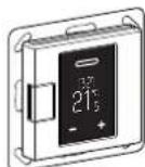
WTH-16 Art. no. WDE002478, WDE003478, WDE004478
Accessories
- WDE002495 Floor Sensor
For operating the thermostat in floor and dual mode.
For your safety

DANGER
Risk of serious damage to property and personal injury, e.g. from fire or electric shock, due to incorrect electrical installation.
Safe electrical installation can only be ensured if the person in question can prove basic knowledge in the following areas:
- Connecting to installation networks
- Connecting several electrical devices
- Laying electric cables
These skills and experience are normally only possessed by skilled professionals who are trained in the field of electrical installation technology. If these minimum requirements are not met or are disregarded in any way, you will be solely liable for any damage to property or personal injury.

DANGER
Risk of death from electric shock.
The outputs may carry an electrical current even when the device is switched off. Always disconnect the fuse in the incoming circuit from the supply before working on connected loads.
Table of Content
Function and installation
• Getting to know the thermostat
• Installing the thermostat
Operation
• Displays and operating elements
- Starting up
- Operating the thermostat
- Adjusting the basic settings
Appendix
- Behaviour during mains voltage failure and recovery / power reserve
• What should I do if there is a problem? - Technical data
Getting to know the thermostat
With the programmable thermostat 2-pole with touch display (referred to in the following as the thermostat), you can regulate the room and/or floor temperature. The unit is operated using a touch display.
The thermostat can be connected to electrical underfloor heating systems, radiators or valve drives which can be switched.
The thermostat has a weekly clock with an individually adjustable program. Alternatively, you can select one of 3 pre-programmed weekly programs. Various heating modes with individual temperature setpoints are available: comfort mode, eco mode and frost protection mode.
Operating modes
The thermostat can be operated in four different variants.
- Room air: The internal temperature sensor detects the room temperature. The thermostat controls this with the aid of the connected heat load.
- Floor: The floor sensor detects the floor temperature. The thermostat controls this with the aid of the underfloor heating.
- Dual: The internal temperature sensor monitors the room temperature and controls it with the help of the connected heating systems. At the same time, the floor sensor monitors the floor temperature and limits this to the predefined maximum temperature value ("max temp").
This variant is particularly recommended for temperature-sensitive parquet and laminate floors. - PWM: The pulse width modulator (PWM) switches the heating on and off at regular intervals. In PWM mode, you can adjust the desired temperature using the PWM value (see "Settings the PWM value").
The floor sensor does not work in this operating mode. The room temperature limits are met.
External temperature reduction
In all operating modes, you can connect an external switch or time controls for temperature reduction (TR). The internal temperature control is overwritten here.
Installing the thermostat
Installation site of thermostat and floor sensor
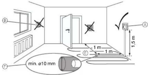
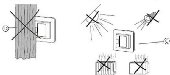
Room air mode or dual mode
To ensure reliable thermostat operation, note the following when planning the installation site:
Ⓐ Minimum installation height: 1.5 m above the floor.
⑧ Do not install too close to windows, doors or ventilation openings.
© Avoid direct sunlight or direct light from lamps.
Do not install above radiators or other heat sources.
⑭ Do not cover or install behind curtains.
Floor mode or dual mode
⑤ Position at least 1 m from walls or doors.
Install in the middle of the loops of the underfloor heating unit (see drawing).
⑤ Lay the floor sensor in a plastic tube with an inside diameter of 10 mm.
Wire the thermostat
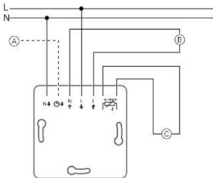
Ⓐ External switch/external time control (TR) or "PilotWire"
⑧ Heat load/valve drives
© Floor sensor
Mounting the thermostat and covers
① Install the thermostat in a flush-mounted box.
② Place the frame onto the insert.
③ Press in the snap ring until it presses against the frame.

Selecting a central plate with switches allows you to disconnect both the device and the connected load from the network at both terminals.
④ Press on the central plate until it audibly clicks into place.
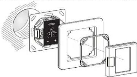
natural_image
Technical line drawing of a mechanical assembly with internal components (no text or symbols)Removing the covers
① Using a suitable screwdriver, press on the marked points to loosen the central plate.
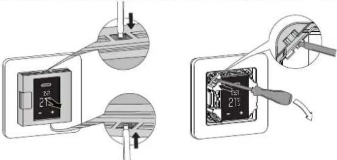
② Tilt the central plate forward and remove it.
③ Lift out the snap ring using a suitable screwdriver and remove it.
④ Remove the frame.
Displays and operating elements
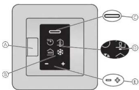
Ⓐ Push-button switch
⑧ Display
© Selection key
D Cursor
⑤ Navigation keys
• Press briefly:
change in ste
- Press and hold change continuously
Individual display elements
The following symbols are shown on the display, depending on your selections and the navigation level:
Heating mode selection / default
| A Auto modeWeekly program that is currently setB Comfort mode / +21 °C© Eco mode / +19 °CFrost protection mode / +7 °CSymbol for manual mode (with hand): setting was selected manually.Symbol for external temperature reduction (arrow): temperature is set via TR input. | 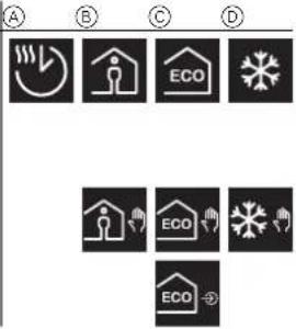 |
Basic settings 1/4 / default
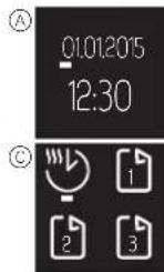
| A Date and time / 01.01.2015, 12:00B Frost protection mode (+5 °C to +21 °C) and eco mode (+5 °C to +50 °C) setpointsC "Pre-programmed weekly programs" menuD Display brightness (15% to 100%) / 30%Brightness during standard display | 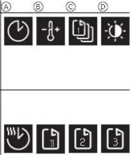 |
| "Pre-programmed weekly programs" selectionA Freely adjustable weekly programmableB WorkC FamilyD Weekend house |
Basic settings 2/4 / default
| A "Room temperature range" menu (PIN lock)B "Floor temperature range" menu (PIN lock)C "Calibrate sensor" menu (PIN lock)D "Operating modes" menu (PIN lock)Red dot on the sensor position indicates the oper-ating mode that is currently selected (here: dual). |  |
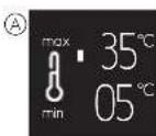
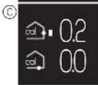
| "Temperature" settingsA Minimum and maximum room temperature (+5 °C, +35 °C) / +5 °C, +30 °CB Minimum and maximum floor temperature (+5 °C, +50 °C) / +5 °C, +40 °C C Calibrate room air sensor (-3 °C to +3 °C) and floor sensor (-9 °C to +9 °C) | 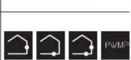 |
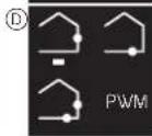
| "Operating modes" selectionA Room airOnly internal temperature sensor activeB FloorOnly floor sensor activeC DualTemperature and floor sensors activeD PWMPulse width modulator: the heating switches on and off at regular intervals. |
Basic settings 3/4 / default
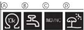
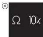
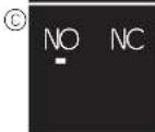
| A Floor sensor type (PIN lock)Resistance of built-in sensor in ohms at 25 °C: 2 k,10 k, 12 k, 15 k, 33 k, 47 k | 10k | MO/NC | |
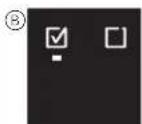
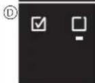
| B Valve protectiongreen: activated, white: deactivated | |||
| C Relay output (PIN lock)Normally open contact (NO=green),Normally closed contact (NC=green) | |||
| D Summer/winter time (CEST)green: activated, white: deactivated | |||
| Basic settings 4/4 / default | 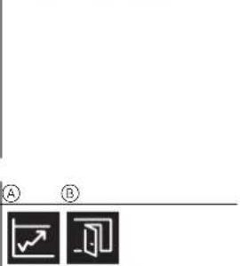 | ||
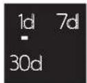
| A Energy efficiency intervalPeriod for energy efficiency calculation in days /1 d, 7 d, 30 d | |||
⑧ Exit basic settings

Basic settings for operation Ⓐ B Ⓒ
Ⓐ PIN lock
Settings require PIN entry (PIN: 5) Applies until you exit basic settings
⑧ Checkbox selected
© Checkbox deselected
Faults A


Ⓐ Internal overheating in thermostat (> +85 °C)
⑧ Room temperature sensor not detected.
© Floor temperature sensor not detected.
All "faults" symbols are yellow.


Starting up
Switching on the thermostat for the first time
If the thermostat is connected and the push-button switch is pressed in Ⓓ, the start display appears.
Setting the date and time Touch Display
① Reduce (-) or increase (+) the value marked by the cursor using the navigation keys.
Press key briefly: change value in steps Press and hold key: change value continuously
② Confirm the value and switch to the next one with the selection key.
The settings are saved once you confirm the last value.

The thermostat starts with the default settings:
- Comfort heating mode
• Room air operating mode
If a floor sensor is connected, it is detected automatically and the floor operating mode is selected. The thermostat then switches to the standard display.

Also check the following settings:
- Operating mode: Always set the dual operating mode manually. If the sensor configuration is changed later, the operating mode does not switch automatically and you also have to set this manually.
- Floor sensor type: Always select the connected floor sensor in the basic settings to ensure correct temperature regulation.
- All the default settings that are automatically selected when the device is switched on for the first time can be adjusted later on in the "Basic settings" menu.
Standard display
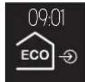
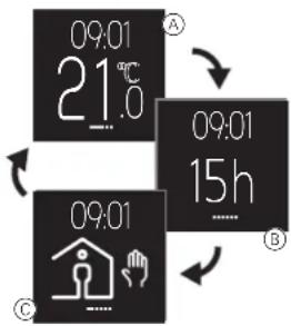
In the standard display, three different windows appear, changing in rotation every 10 seconds. The current settings and measured values are shown.
The current time is displayed at the top of each window. A red line under the display indicates that the heating is currently active.
Ⓐ Temperature
Currently measured temperature
⑧ Energy efficiency information
Number of hours of heating during the selected energy efficiency interval
© Heating mode
Mode with individual setpoint that currently applies to the heating (here: comfort mode) A hand next to the symbol indicates that the heating mode was selected manually (manual mode) and the heating is not being controlled by a weekly program. This applies until you reactivate auto mode.
flowchart
graph TD
    A["09:01 21.6°C"] --> B["09:01 15h"]
    B --> C["09:01 09:01"]
    C --> D["Home icon with hands symbol"]
    D --> E["Clock icon with hand symbol"]
    E --> F["Clock icon with hand symbol"]
    F --> G["Clock icon with hand symbol"]

To make the display last as long as possible, it moves slightly every 4 hours (screen saving function).
Operating the thermostat
Overview of operation
You can open the menus from each window of the standard display.

Ⓐ Temperature setpoint/PWM
⑧ Heating mode selection
© Weekly program
© Basic settings
Setting the temperature for comfort mode

Heating the floor or the room to the desired temperature may take several hours. You should therefore wait a while before increasing the temperature.
Setting the temperature setpoint Touch Display
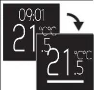
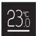
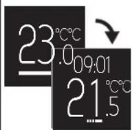
① Switch to the temperature setpoint display: Press one of the navigation keys.
The setpoint for the room or floor temperature is shown on the display with green underlining.
② Lower (-) or raise (+) the setpoint in steps of 0.5 K using the navigation keys (room air and dual operating modes from 5 °C to 35 °C, floor operating mode from 5 °C to 50 °C).
The desired setpoint for the room temperature in comfort mode is shown on the display.
③ Confirm the new setpoint with the selection key. The standard display opens. If the measured temperature is lower than the new setpoint, the heating turns on. The display shows red underlining during heating.



Settings the PWM value
The pulse width modulator (PWM) switches the heating on and off at regular intervals. In PWM mode, you can adjust the desired temperature using the PWM value. The value is displayed instead of the temperature setpoint, in the same way (see "Setting the temperature setpoint").
The PWM value specifies the percentage that the heating heats in a recurring interval of 10 minutes.
Example:
0%: heating is permanently off
50%: heating is on for 5 minutes, then off for 5 minutes
100%: heating is permanently on

The thermostat automatically returns to the standard display without saving changes if no entries are made for 15 seconds.

Selecting the heating mode
| Touch | Display | |
| 1 Open heating mode selection: Briefly press the selection key.The following four heating modes are displayed (from left to right):- Auto mode- Comfort mode- Eco mode- Frost protection modeThe green cursor marks the heating mode that is currently selected (here: auto mode with eco mode programming for the current point in time).2 Select heating mode: Use the navigation keys to move the cursor to the desired heating mode (here: comfort mode).3 Save heating mode and return to standard display: Press the selection key.A hand is displayed in addition to the comfort mode because the mode was selected manually. |


Setting a weekly program
A weekly program is the schedule for heating phases in eco and comfort modes for the entire week. Each switching time for a heating phase is defined for individual days or a group of days.
Three pre-programmed weekly programs are available (see "Possible settings/pre-programmed weekly programs") and you can change these temporarily. Your settings are only retained until you select another weekly program. In addition, you can create a freely adjustable weekly program of your own to meet your needs. During commissioning, the freely adjustable weekly program is selected but no heating phases are stored.
Navigating the weekly program Touch Display
| 1 Open "Weekly program" menu:Press and hold the selection key on the standard display.The information for a saved heating phase of the active weekly program is shown on the display (here: not heating phase stored).Information per line:A Days of the week (Mon-Sun = 1-7)green: activated, red: deactivatedB Heating mode and switching timeC Operating menu2 Select desired function:Use the navigation keys to move the cursor to the desired function.3 Activate selected function:Press the selection key.Functions:A Exit menuB Change heating phaseC Delete heating phaseD Add new heating phaseE Scroll between heating phases | >2 s | 09:0121°C C15 3 4 5 6 7A ECO 00:00B C |
| 1 2 3 4 5 6 7ECO 00:00A B C D E |
Creating a new heating phase Touch Display
| 1 Add new heating phase:Select and activate the function "Add heating phase" 1).The heating phase settings display opens.2 Make settings(see "Editing settings") |
Change heating phase Touch Display
| 1 Select heating phase:Use the “scroll” Ⓔ function to select the heating phase that you want to change (see “Navigating the weekly program”).2 Open settings for heating phase:Select and activate the function “Change heating phase” Ⓔ.The heating phase settings display opens.3 Change settings(see “Editing settings”) |
Editing settings
| 1 Activate days of the week:Deactivate (-) or activate (+) the days on which the heating phase runs (green/in bold here) or does not run (red) and confirm you entries with the selection key.The cursor moves to the next day of the week when you press a navigation key and goes to the switching time if you then confirm this with the selection key.2 Change switching time:Increase (+) or reduce (-) the hours in steps of one and the minutes in steps of ten. Confirm each entry with the selection key.After the first confirmation, the cursor moves to the minute display and after the second confirmation, it moves to the heating mode line.3 Set heating mode:Change the active heating mode (green) with the navigation keys and confirm your choice with the selection key.The settings are saved. The "Weekly program" menu appears again. |
Delete heating phase
| 1 Select heating phase:Use the "scroll" (E) function to select the heating phase that you want to delete (see "Navigating the weekly program").2 Delete heating phase:Select and activate the function "Delete heating phase" ©.The next saved heating phase is displayed. | —/+—/+— | 1 2 3 4 5 6 710:301 2 3 4 5 6 712:101 2 3 4 5 6 7ECO 22:00 |
Exit menu
| 1 Select and activate the function "Exit menu" A. The standard display opens. |

The thermostat automatically returns to the standard display without saving changes if no entries are made for one minute.
Adjusting the basic settings
Navigating in the basic settings
Selecting a possible setting Touch Display
| 1 Open basic settings:Press and hold both navigation keys together.The first of four pages is displayed. The green cursor marks the first possible "date/time" setting on the first page. | -+ + >2 s | 09:0121°C |
| 2 Select basic settings page:Starting from the bottom/right icon, open the next page with the (+) navigation key. | + | A |
| Or | ||
| Starting from the top/left icon, open the previous page with the (-) navigation key. | - | |
| Basic settings pages (possible settings from left to right):A Date/time, heating mode setpoints, pre-programmed weekly programs, display brightnessB Room temperature range, floor temperature range, calibrate sensor, operating modesC Floor sensor type, valve protection, relay output, summer/winter time (CEST)D Energy efficiency interval, exit | ||
| 3 Open possible setting:Use the navigation keys to move the cursor to the desired possible setting. Confirm your choice with the selection key. | -/+ | E |
| With PIN entry E:Some possible settings are protected by PIN entry for safety reasons. The authorisation remains valid until you exit the basic settings.Enter the PIN (5) using the navigation keys. Confirm your entry with the selection key. | -/+ | 07 °CECO 18 °CE |
| Or | ||
| Without PIN entry F:You do not have to enter a PIN for standard settings. | ||
| The setting window is displayed. |
Exit menu Touch Display
| 1 Go to the last page of the basic settings 4/4 and select the "exit" symbol with the cursor.2 Press the selection key to return to the standard display. |
Adjusting the basic settings
Depending on the possible setting, you can change values, select icons or select icons and change the corresponding values.
Changing values Touch Display
| Date/time (example)1 Reduce (-) or increase (+) a value with the navigation keys.2 Confirm the value and switch to the next one with the selection key.When you confirm the last value, the settings are saved. The display switches to the current basic settings page. |
| Selecting an icon | Touch | Display |
| Pre-programmed weekly programs (example)1 Select weekly program:Use the navigation keys to move the cursor to the desired weekly program.2 Confirm your choice with the selection key.The current page of the basic settings is displayed. |
Selecting an icon and changing the value
| Heating mode setpoints (example)The cursor marks the first symbol (here: frost protection mode).1 Change the corresponding value with the navigation keys.2 Confirm the value and switch to the next symbol (here: eco mode) with the selection key.When you confirm the last value, the settings are saved. The display switches to the current basic set- tings page. |
The thermostat automatically returns to the standard display without saving changes if no entries are made for one minute.
Setting options
Basic settings 1/4
Ⓐ Date/time
⑧ Setpoints for frost protection and eco mode
© Pre-programmed weekly programs (see "Weekly program curve")
You can choose between three default weekly programs. The default programs are useful for efficient heating with different alternative uses. They can be changed but not permanently overwritten. The next time you select them, the previous changes are discarded. In addition, you can also configure your own weekly program and select that. This is retained permanently even when you change
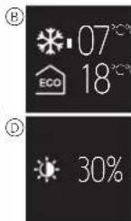
⑭ Display brightness
You can adjust the brightness of the display. When you make settings, the display always switches to its maximum brightness (100%). Changes to the brightness are active after about one minute.
Reduced brightness improves the display's service life.
Weekly program curve
The diagrams show the temperature curve over the course of a day:
Ⓐ Temperature
⑧ Time in hours or days (Monday to Sunday = 1–7)
© Temperature curve at weekend (dotted line)
© Temperature curve on workdays (solid line)
⑤ Raise temperature (optimum start)
The higher setpoint temperature is reached by the set time. Heating begins in advance. The thermostat automatically learns the time needed to heat up.
(F) Lower temperature
The temperature is reduced at the set time until it reaches the lower setpoint temperature after the cooling down time.
Freely adjustable weekly programmable:
Use the comfort and eco modes to set a temperature curve to match your needs.
Example:
The heating runs in eco mode at night and in comfort mode during the day. On workdays, the comfort setpoint temperature is reached at 6 am and is lowered again after 10 pm. At the weekend, comfort mode is used for the heating between 8 am and midnight.
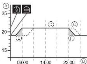
line
| Point | Value | |---|---| | A | 25 | | B | 20 | | C | 20 | | D | 20 | | E | 19 |Work weekly program:
The heating runs in eco mode at night. In the morning, the temperature is raised to the comfort mode setpoint temperature so that it is reached by 6 am (optimum start). At 8 am, the temperature is lowered to the eco mode setpoint. From 5 pm to 10 pm, the heating returns to comfort mode.
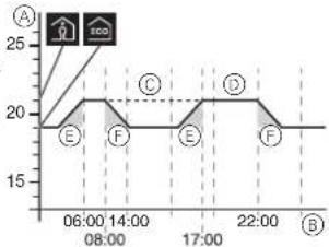
line
| Time | Value | |---|---| | 06:00 | 19 | | 08:00 | 21 | | 14:00 | 21 | | 17:00 | 21 | | 22:00 | 21 | B C D E FFamily weekly program:
The heating runs in comfort mode each day between 6 am and 10 pm and in eco mode at night.
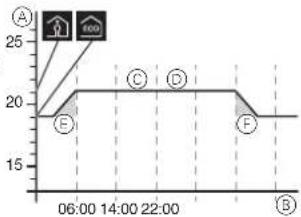
Weekend house weekly program:
At the weekend (Friday 5 pm to Sunday 10 pm), the heating runs in comfort mode and it runs in eco mode on workdays (Sunday 10 pm to Friday 5 pm).
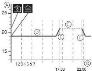
line
| Point | Value | |---|---| | A | 25 | | B | 20 | | C | 20 | | D | 20 | | E | 20 | | F | 20 | | 12:30 | 20 | | 15:67 | 20 | | 17:00 | 20 | | 22:00 | 20 |Basic settings 2/4
Ⓐ Room temperature range (PIN lock)
③ Floor temperature range (PIN lock)
© Calibrate sensor
You can correct the measured room and floor temperatures up or down.
① Operating modes (PIN lock)
After the initial automatic configuration, all changes to the operating mode have to be done manually. The dual mode and PWM operating modes always have to be set manually.

Basic settings 3/4
A Floor sensor type (PIN lock)
Select the resistance (at 25 °C) for the connected sensor. The value is displayed in the menu. An incorrectly selected sensor will not regulate the temperature properly. The actual temperature may exceed the maximum set temperature and may cause damage to the floor covering.
⑧ Valve protection (protects against valve sticking)
The valve is completely extended for 4 minutes once a week on Tuesdays at 10 am. Activate valve protection with "checkbox selected". The symbol is displayed
Change relay output (PIN lock)
Choose between a normally open (NO) or a normally closed (NC) contact.
The selection is displayed in green in the menu.
① Summer/winter time (CEST)
Activate the automatic toggling between Central European summer and winter time with "checkbox selected". The symbol is displayed in green in the menu.
Basic settings 4/4
Energy efficiency interval (monitoring period)
The hours of heating are added up for each time interval as an indication of the energy used for heating. You can choose a time interval of 1, 7 or 30 days.
Behaviour during mains voltage failure and recovery / power reserve
In the event of mains voltage failure the display goes out. The current thermostat settings are saved either permanently, temporarily for two days or not at all:
- Saved permanently: temperature setpoint in comfort mode, manual mode selection, weekly programming, all basic settings,
- Saved temporarily: date/time,
• Not saved: energy efficiency counter
After mains voltage recovery the next switching time in the weekly program is carried out first.
What should I do if there is a problem?
Connected load is not heating
- If using an external time control device, check the control voltage.
- Check power supply and connections.
- Switch thermostat off and back on again.
- Check setting for maximum temperature. The value may be too low.
Error messages
Internal overheating in thermostat (> +85 °C)
- Check load limits and connections.
Room temperature sensor not detected
- The internal sensor in the thermostat may be defective. The thermostat has to be replaced by the electrical installer.
Floor temperature sensor not detected
- Check operating mode selection.
- Check sensor installation. The floor sensor is not connected, defective or it has short-circuited. The electrical installer has to connect the sensor correctly or replace it.
Correct fault (error message disappears)
- Setting incorrect: Exit the error message by pressing any key. The standard display opens. Correct the settings in the basic settings.
- Hardware fault: contact an electrical installer.
Display blank
- Check the power supply.
- Switch thermostat off and back on again. If using a central plate without a push-button switch plate, check the state of the pressure plate under the central plate.
Technical data
| Nominal voltage: | 230 V AC, 50 Hz |
| Nominal voltage at external input (TR): | 230 V AC |
| Nominal load (ohmic): | 3680 W (~16 A) (cos φ = 1) |
| Nominal load (inductive): | 1 A, cos φ = 0.6 |
| Mode of operation: | 1 C |
| Type of housing protection: | IP 20 |
| Surge protection/overheating protection: | Electronic |
| Rated surge voltage: | 4 kV |
| Operating temperature: | -10 °C to +35 °C |
| Setting range | |
| Room temperature: | +5 °C to +35 °C |
| Floor temperature: | +5 °C to +50 °C |
| Display precision: | 0.5 °C |
| Connecting terminals: | max. 1 x 2.5 mm2 or 2 x 1.5 mm2 |
| Room sensor calibration: | -3 °C to +3 °C |
| Floor sensor calibration: | -9 °C to +9 °C |
| Operation with external sensors at 25 °C: | NTC 2 k, 10 k, 12 k, 15 k, 33 k, 47 k |
Schneider Electric Industries SAS
If you have technical questions, please contact the Customer Care Centre in your country. www.schneider-electric.com




- Programmable thermostat 2-pole with touch display
- Accessories
- For your safety
- DANGER
- Table of Content
- Function and installation
- Operation
- Appendix
- Getting to know the thermostat
- Operating modes
- External temperature reduction
- Installing the thermostat
- Room air mode or dual mode
- Floor mode or dual mode
- Mounting the thermostat and covers
- Removing the covers
- Individual display elements
- Basic settings for operation Ⓐ B Ⓒ
- Faults A
- Starting up
- Switching on the thermostat for the first time
- Setting the date and time Touch Display
- Standard display
- Operating the thermostat
- Overview of operation
- Setting the temperature for comfort mode
- Setting the temperature setpoint Touch Display
- Settings the PWM value
- Setting a weekly program
- Adjusting the basic settings
- Navigating in the basic settings
- Setting options
- Basic settings 1/4
- Weekly program curve
- Freely adjustable weekly programmable:
- Work weekly program:
- Family weekly program:
- Weekend house weekly program:
- Basic settings 2/4
- Basic settings 3/4
- Basic settings 4/4
- Behaviour during mains voltage failure and recovery / power reserve
- What should I do if there is a problem?
- Connected load is not heating
- Error messages
- Internal overheating in thermostat (> +85 °C)
- Room temperature sensor not detected
- Floor temperature sensor not detected
- Correct fault (error message disappears)
- Display blank
- Schneider Electric Industries SAS
Brand : SCHNEIDER
Model : WDE002478
Category : Thermostat