
DTH-16 - Thermostat SCHNEIDER - Free user manual and instructions
Find the device manual for free DTH-16 SCHNEIDER in PDF.


| Brand | Schneider |
| Model | DTH-16 |
| Product Type | Thermostat |
| Dimensions (W x H x D) | 80 x 80 x 25 mm |
| Weight | 150 g |
| Power Supply | 2 x AA batteries (LR6) or 24 V AC |
| Display Type | LCD |
| Temperature Range | 5 °C to 35 °C |
| Accuracy | ±0.5 °C |
| Programmable | Yes, 7-day programmable |
| Heating/Cooling Modes | Heat, Cool, Auto, Off |
| Fan Control | Auto, On |
| Backlight | Yes |
| Wireless Connectivity | None (wired/wireless only via auxiliary) |
| Mounting Type | Wall mount |
| Material | ABS plastic |
| Color | White |
| Certifications | CE, RoHS |
| Maintenance | Clean with a soft dry cloth; do not use liquids. |
| Safety Features | Overheat protection, child lock |
| Spare Parts | Batteries only user-replaceable; internal components non-serviceable. |
Frequently Asked Questions - DTH-16 SCHNEIDER
User questions about DTH-16 SCHNEIDER
0 question about this device. Answer the ones you know or ask your own.
Ask a new question about this device
Download the instructions for your Thermostat in PDF format for free! Find your manual DTH-16 - SCHNEIDER and take your electronic device back in hand. On this page are published all the documents necessary for the use of your device. DTH-16 by SCHNEIDER.
USER MANUAL DTH-16 SCHNEIDER
Termostat touchdisplay, DTH-16
Driftsinstrukser

WDE002491, WDE003491, WDE004489, WDE002891, WDE003891, WDE004889
Tilbehør
- WDE002495 gulvsensor
Trekke kabler for termostaten

Nomineil overspenning: 4 kV
Driftstemperatur.
Ministillingsomtrade Pomtoporstur: +5°C til +25°C
Gulvtemperatur: +5°C til +50 °C
The Ground Truth image displays a single, continuous horizontal line, which is a stylistic or background element (like a ruled paper line). According to Rule 2, such lines must be ignored by the OCR result. The provided OCR content is "____", which consists of underscores. Underscores are not equivalent to a solid line and are not permitted under the “Stylistic/Background Lines (Ignore)” rule. Outputting underscores for a stylistic line is incorrect because it misinterprets the line as a fill-in-the-blank placeholder. Therefore, the OCR result is inconsistent with the Ground Truth.
Operating instructions

WDE002491, WDE003491, WDE004489, WDE002891, WDE003891, WDE004889
Accessories
- WDE002495 Floor Sensor
For operating the thermostat in floor and dual mode.
For your safety

DANGER
Risk of fatal injury due to electrical current All work on the device should only be carried out by trained and skilled electricians. Observe the country-specific regulations.
Thermostat introduction
With the Touch display thermostat (referred to in the following as the thermostat), you can regulate room or floor temperature. The unit is operated using a touch display. The thermostat can be connected to floor heating systems, radiators or ambient heating systems.
Operating modes
The thermostat can be operated in three different modes:
modes:
- Ambient air mode. The internal temperature sensor detects the room temperature. The thermostat controls the load, based on the room temperature.
- Floor mode:
The floor sensor detects the floor temperature. The thermostat controls the load, based on the floor temperature.
- Dual mode:
The internal temperature sensor monitors the room temperature and controls the load, based on the room temperature. At the same time, the floor sensor monitors the floor temperature and limits this to the predefined maximum temperature value ("max Temp"). This mode is particularly recommended for parquet and laminate floors.
In all operating modes, you can connect an external time switch for temperature reduction (TR).
Installing the thermostat
Thermostat installation
In order for the thermostat to be operated in ambient air or dual mode, the thermostat must be installed in such a way that it is protected as far as possible against external influences and temperature fluctuations. This guarantees reliable detection of the room temperature.
The following should therefore be taken into account
when considering the installation site
• Minimum installation height: 1.5 m above the floor.
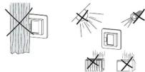
- Do not install too close to windows, doors or ventilation openings.
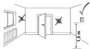
- Do not cover or install behind curtains.
- Avoid direct sunlight and light from lamps.
Floor sensor installation
In order to guarantee reliable operation in floor and dual mode, the floor sensor must be protected against external influences and temperature fluctuations.
The following should therefore be taken into account
when considering the installation site
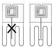
- If possible, maintain a clearance of 1.0 m from walls and doors
and doors. A small square in the middle of the loop/soo picture
- install se below).
- Place the floor sensor in a plastic tube with an inside diameter of 16 mm.
Wiring the thermostat
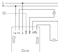
ⒶExternal time switch (TR)
⑧ Heat load/thermoelectric valve drive
©Floor sensor
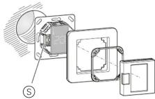
Mounting the thermostat and covers
①Install the thermostat in a flush-mounted box.
②Place the frame onto the insert.
③Press in the snap ring until it presses against the frame.
④Press on the central plate until it snaps into place.
Removing the covers
① Using a suitable screwdriver, press on the marked points to loosen the central plate.
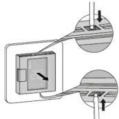
②Tilt the central plate forward and remove it.
③ Lift out the snap ring using a suitable screwdriver and remove it.
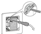
④Remove the frame.
Starting up
Switching on the thermostat for the firsttime
The thermostat can be switched on and off using the software shutdown and also using the switch.
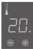
To switch off using the software shutdown,
②hold for 3 seconds,
③keep pressing when „COdE“ is demanded,
④ thermostat shuts down.
Thermostat recovers from software switch shut-
All the default settings shown when the device is switched on for the first time can be adjusted later on in the settings menu (see "Operating the thermostat").
Language pin code request
When the device is switched on for the first time, the display requests the language pin code. This ensures that the messages are displayed in the correct language.
Display Meaning Symbol
CodE Enter language pin code C0df
Press "+" until the correct language pin code is displayed.
The language pin codes are:
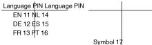
Accept your choice by pressing “+” and “-” simultaneously.
Operating mode display
The thermostat automatically detects when a floor sensor is connected and goes to the floor mode ("FLoor"). If the floor sensor is not connected, it goes to the ambient air mode ("Air").
Also other factory settings are displayed now.
If a floor sensor is connected, you can change from floor mode to dual mode at a later point (see *Operating the thermostat*).
Operating the thermostat
Setting the temperature
Heating the floor or the room to the desired temperature may take several hours. You should therefore wait a while before increasing the temperature.
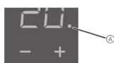
- Select the desired room temperature by pressing "+" or "-"
• The desired room temperature is shown on the display.
- The blue dot Ⓐ indicates that the heat load is warming up.
Changing the basic settings
The thermostat automatically returns to the normal display if nothing is input in the settings menu for one minute.
The settings are displayed one after another when the settings menu is selected. - Select the desired value by pressing "+" or "-". - Confirm your selection by pressing "+" and "-" simultaneously.
①Hold down "+" and "-" together for three seconds to activate the Settings menu.
②Enter the language pin code and confirm.
The language pin codes are given in the chapter "Starting up".
Display Meaning Symbol CodE Enter language pin code CodE
③ Select the desired operating mode and confirm.
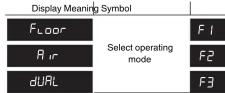
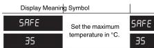
④ Set the maximum temperature and confirm.
You can set the maximum temperature in the ambient air and floor modes. In dual mode, this value limits the temperature of the floor in order to protect materials which are sensitive to extreme temperatures.
The factory setting for the maximum temperature is
• 35 °C in Air mode
• 40 °C in Floor mode and
• 27 °C in Dual mode (Floor max.)
⑤ Set the reduced temperature and confirm.
i Temperature reduction (TR) only occurs if an external timer is connected.
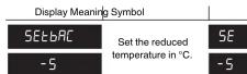
The factory setting for the temperature reduction is -4 °C.
What should I do if there is a problem?
Error outputs on the display
Display Meaning Symbo
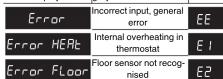
Connected load is not heating
- Observe the message on the display:
If "Error HEAt" or "Error FLOOR" are shown, load is not
connected. Investigate
- Check the power supply
- Switch the thermostat off and back on again
- Check the "SAFE"-value setting. The value may be too
low.
• Che
- If using an external time control device, check the con-
trol voltage.
Display is blank
- Check the power supply.
- Switch the thermostat off and back on again.
Technical data
Nominal voltage: 230 V AC, 50 Hz
Nominal load (ohmic): 16 A
Nominal load (inductive): 1 A, cos = 0.6
Mode of operation: 1 C
Type of housing protection. IP 20
overvoltage: Electronic overheating protection:
Rated surge voltage:
Operating temperature: -10 °C to +35°C
Setting range
Room temperature: +5°C to +35°C
Floor temperature: +5°C to +50 °C
Reduction: +/- 0...9 °C from set
temperature
Display precision
Schneider Electric Industries SAS
If you have technical questions, please contact the Cus-
tomler Care Center in your country.
www.schneider-electric.com
This product must be installed, connected and used in compliance with prevailing standards and/or installation regulations. As standards, specifications and designs develop from time to time, always ask for confirmation of the information given in this publication.



- Termostat touchdisplay, DTH-16
- Tilbehør
- Accessories
- For your safety
- Thermostat introduction
- Operating modes
- Installing the thermostat
- Thermostat installation
- Floor sensor installation
- Wiring the thermostat
- Mounting the thermostat and covers
- Removing the covers
- Starting up
- Language pin code request
- Operating mode display
- Operating the thermostat
- Setting the temperature
- Changing the basic settings
- What should I do if there is a problem?
- Display is blank
- Technical data
- Schneider Electric Industries SAS
Brand : SCHNEIDER
Model : DTH-16
Category : Thermostat