
MTN6005-0001 - Thermostat SCHNEIDER - Free user manual and instructions
Find the device manual for free MTN6005-0001 SCHNEIDER in PDF.


| Product Type | Digital Thermostat |
| Brand | Schneider |
| Model | MTN6005-0001 |
| Dimensions (W x H x D) | 80 mm x 120 mm x 30 mm |
| Weight | 0.15 kg |
| Power Supply | 230 V AC, 50 Hz |
| Standby Power Consumption | < 1 W |
| Display Type | LCD backlit |
| Temperature Control Range | 5°C to 35°C |
| Accuracy | ±0.5°C |
| Programmable Schedules | Up to 4 periods per day, 7 days |
| Frost Protection | Yes (adjustable threshold) |
| Compatible Heating Systems | Electric, Gas, Oil, Heat Pump |
| Mounting | Wall-mounted (standard backplate) |
| Wiring | 2-wire or 3-wire (voltage-free contact) |
| Maintenance & Cleaning | Wipe with a dry, soft cloth. Do not use liquids or abrasives. |
| Safety Features | Overheat protection, child lock, low battery indicator |
| Spare Parts & Repairability | Replaceable batteries (CR2032 for clock backup); no user-serviceable parts. Contact Schneider service for repairs. |
| Warranty | 2 years |
Frequently Asked Questions - MTN6005-0001 SCHNEIDER
User questions about MTN6005-0001 SCHNEIDER
0 question about this device. Answer the ones you know or ask your own.
Ask a new question about this device
Download the instructions for your Thermostat in PDF format for free! Find your manual MTN6005-0001 - SCHNEIDER and take your electronic device back in hand. On this page are published all the documents necessary for the use of your device. MTN6005-0001 by SCHNEIDER.
USER MANUAL MTN6005-0001 SCHNEIDER
KNX CO ^2 , humidity and temperature sensor (surface mounted)
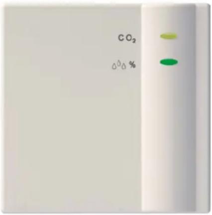
KNX CO2, humidity and temperature sensor
Order no. MTN6005-0001
Contents
KNX CO ^2 , humidity and temperature sensor (surface mounted)....1
1 Functional characteristics .... 3
1.1 Operation 3
1.2 Benefits....3
2 Technical data 4
2.1 Technical data....4
3 The application program "CO2,humidity & temperature sensor 4216/1.0"....5
3.1 Selection in the product database 5
3.2 Communication objects 6
3.2.1 Description of objects....9
3.3 Parameters....14
3.3.1 Overview 14
3.3.2 The Readings parameter page 15
3.3.3 The CO 2 threshold parameter page 16
3.3.4 The 1, 2, 3 CO 2 thresholds parameter pages ..... 17
3.3.5 The ventilation CO 2 threshold parameter page 19
3.3.6 The CO 2 scenes parameter page....20
3.3.7 The humidity threshold parameter page 21
3.3.8 The 1, 2, 3 humidity thresholds parameter pages ...... 22
3.3.9 The Humidity ventilation parameter page 24
3.3.10 The Relative humidity scenesparameter page 25
3.3.11 Temperature threshold parameter page 26
4 Appendix....28
4.1 Hysteresis 28
4.2 Switching response of thresholds for CO_2 and humidity.....28
4.3 Fan control....29
4.4 Relative humidity 29
4.5 CO _2 guide values....30
1 Functional characteristics
The device is a combined sensor for CO_2 , temperature and humidity measurement (relative humidity).
It is designed to monitor air quality in conference/meeting rooms, offices, schools/kindergartens, passive or low energy houses and living rooms without controlled ventilation.
1.1 Operation
The device does not have to be operated manually.
The LED and the push button for the physical address are accessible when cover is removed. If necessary, the push button can be reached with a thin screwdriver via the upper ventilation slot.
CAUTION: Do not drop the device!
Severe shocks reduce the accuracy of the highly sensitive CO2 sensor.
1.2 Benefits
- Combined measurement of temperature, humidity and CO2 content in one device.
• Power supply via bus connection, no mains power required.
2 Technical data
2.1 Technical data
| Power supply: | Bus voltage |
| Permissible operating temperature: | 0 °C... + 45°C |
| Power draw from bus voltage: | Max. 12 mA |
| Bus connection: | via bus terminal |
| Protection class: | III in accordance with EN 60730-1 |
| Protection rating: | IP 20 in accordance with EN 60529 |
| Dimensions of device: | LxWxH 74 x 74 x 30.8 (mm) |
Measuring ranges:
| CO_2 | 300 – 9999 ppm |
| Humidity: | 1 – 100 % |
| Temperature: | 0 – 40 °C |
Accuracy:
| CO2 | 300-1000 ppm: +/- 120 ppm |
| 1000-2000 ppm: +/- 250 ppm | |
| 2000-5000 ppm: +/- 300 ppm | |
| Humidity: | +/- 5 % |
| Temperature: | +/- 1 °C (depending on installation) |
3 The application program "CO2, humidity & temperature sensor 4216/1.0"
3.1 Selection in the product database
| Manufacturer | Schneider Electric Industries SAS |
| Product family | 2.9 Physical sensors |
| Product types | 2.9.05 Carbon doxide2.9.04 Humidity |
| Program name | KNX CO ^2 , humidity and temperature sensor |
Table 1
| Number of communication objects: | 27 |
| Number of group addresses: | 128 |
| Number of associations: | 128 |
3.2 Communication objects
Table 2: Overview
| No. | Function Object name | Type & DPT | Flags | ||||
| C | R | S | T | ||||
| 0 | Physical value CO | 2value | 2 byte 9.008 | √ | √ | √ | |
| 1 | Physical value | relative humidity | 1 byte 5.001 | √ | √ | √ | |
| 2 | Physical value | Temperature value | 2 byte 9.001 | √ | √ | √ | |
| 3 | Switching | CO2threshold 1 | 1 bit 1.001 | √ | √ | √ | |
| Valuator | 1 byte 5.001 5.010 | ||||||
| Priority | 2 bit 2.001 | ||||||
| 4 | Input Disable CO | 2threshold 1 | 1 bit 1.001 | √ | √ | √ | |
| 5 | Switching | CO2threshold 2 | 1 bit 1.001 | √ | √ | √ | |
| Valuator | 1 byte 5.001 5.010 | ||||||
| Priority | 2 bit 2.001 | ||||||
| 6 | Input Disable CO | 2threshold 2 | 1 bit 1.001 | √ | √ | √ | |
| 7 | Switching | CO2threshold 3 | 1 bit 1.001 | √ | √ | √ | |
| Valuator | 1 byte 5.001 5.010 | ||||||
| Priority | 2 bit 2.001 | ||||||
| 8 | Input Disable CO | 2threshold 3 | 1 bit 1.001 | √ | √ | √ | |
| 9 | Value for ventilation actuator | Ventilation of CO2 | 5.001 | √ | √ | √ | |
| 10 | Input Disable ventilation of CO | 2 | 1 bit 1.001 | √ | √ | √ | √ |
C R S T
Continuation:
| No. | Function Object name | Type & DPT | Flags | ||||
| C | R | S | T | ||||
| 11 | Scene control CO | 2scenes | 1 byte 18.001 | ✓ | ✓ | ✓ | |
| 12 | Input Disable CO | 2scenes | 1 bit 1.001 | ✓ | ✓ | ✓ | |
| 13 | Switching | Humidity threshold 1 | 1 bit 1.001 | ✓ | ✓ | ✓ | |
| Valuator | 1 byte 5.001 5.010 | ||||||
| Priority | 2 bit 2.001 | ||||||
| 14 | Input Disable humidity threshold | 1 | 1 bit 1.001 | ✓ | ✓ | ✓ | |
| 15 | Switching | Humidity threshold 2 | 1 bit 1.001 | ✓ | ✓ | ✓ | |
| Valuator | 1 byte 5.001 5.010 | ||||||
| Priority | 2 bit 2.001 | ||||||
| 16 | Input Disable humidity threshold | 2 | 1 bit 1.001 | ✓ | ✓ | ✓ | |
| 17 | Switching | Humidity threshold 3 | 1 bit 1.001 | ✓ | ✓ | ✓ | |
| Valuator | 1 byte 5.001 5.010 | ||||||
| Priority | 2 bit 2.001 | ||||||
| 18 | Input Disable humidity threshold | 3 | 1 bit 1.001 | ✓ | ✓ | ✓ | |
| 19 | Value for ventilation actuator | Ventilating relative humidity | 1 byte 5.001 5.010 | ✓ | ✓ | ✓ | |
| 20 | Input | Disable ventilating relative humidity | 1 bit 1.001 | ✓ | ✓ | ✓ | |
| 21 | Scene control Relative humidity | scenes | 1 byte 18.001 | ✓ | ✓ | ✓ | |
| 22 | Input | Disable relative humidity scenes | 1 bit 1.001 | ✓ | ✓ | ✓ | |
| C | R | S | T | ||||
Continuation:
| No. | Function Object name | Type & DPT | Flags | ||||
| C | R | S | T | ||||
| 23 | Switching | Temperature threshold | 1 bit 1.001 | √ | √ | √ | |
| Valuator | 1 byte 5.001 5.010 | ||||||
| Priority | 2 bit 2.001 | ||||||
| 24 | Input | Disable temperature threshold | 1 bit 1.001 | √ | √ | √ | |
| 25 | Value for ventilation actuator | highest active ventilation value | 1 byte 5.010 | √ | √ | √ | |
| 26 | Switching On/Off LEDs for CO2 | and humidity | 1 bit 1.001 | √ | √ | ||
| C | R | S | T | ||||
Table 3: Communication flags
| Flag | Name | Application |
| C | Communication | Object can communicate |
| R | Read | Object status can be viewed (ETS / display etc.) |
| S | Write | Object can receive |
| T | Transmit | Object can send |
3.2.1 Description of objects
- Object 0 "CO _2 value"
This object sends the CO_2 content measured by the sensor (if sending via configuration is permitted).
• Object 1 "relative humidity value"
This object sends the current relative humidity measured by the sensor (if sending via configuration is permitted).
- Object 2 "Temperature value"
This object sends the temperature currently being measured by the sensor (if sending via configuration is permitted).
- Object 3 "Threshold 1 CO _2 "
Output object for the first CO_2 threshold. See Overview table.
- Object 4 "Disable CO _2 threshold 1"
Disable object for the first CO_2 threshold.
- Object 5 "CO _2 threshold 2"
Output object for the second CO_2 threshold. See Overview table.
- Object 6 "Disable CO _2 threshold 2"
Disable object for the second CO_2 threshold.
- Object 7 "CO _3 threshold 2"
Output object for the third CO_2 threshold. See Overview table.
- Object 8 "Disable CO _2 threshold 3"
Disable object for the third CO_2 threshold.
• Object 9 "Ventilation of CO₂"
Actuating value for ventilation actuator (1 byte telegram).
This object is used if ventilation is only to be activated by the CO_2 content, such as in conference rooms.
Important: The configuration of the input as a percentage value or as number from 0 to 255 is irrelevant for the ventilation actuator.
- Object 10 "Disable CO _2 ventilation"
Disable object for CO_2 dependent ventilation
1 = Disable
0 = Enable
- Object 11 "CO _2 scenes"
Transmits the CO_2 dependent scene retrieval code
Table 4
| Scene no. | Retrieval code | Scene no. | Retrieval code | ||
| Hex | Dec | Hex | Dec | ||
| 1 | 00 | 0 | 33 | 20 | 32 |
| 2 | 01 | 1 | 34 | 21 | 33 |
| 3 | 02 | 2 | 35 | 22 | 34 |
| 4 | 03 | 3 | 36 | 23 | 35 |
| 5 | 04 | 4 | 37 | 24 | 36 |
| 6 | 05 | 5 | 38 | 25 | 37 |
| 7 | 06 | 6 | 39 | 26 | 38 |
| 8 | 07 | 7 | 40 | 27 | 39 |
| 9 | 08 | 8 | 41 | 28 | 40 |
| 10 | 09 | 9 | 42 | 29 | 41 |
| 11 | 0A | 10 | 43 | 2A | 42 |
| 12 | 0B | 11 | 44 | 2B | 43 |
| 13 | 0C | 12 | 45 | 2C | 44 |
| 14 | 0D | 13 | 46 | 2D | 45 |
| 15 | 0E | 14 | 47 | 2E | 46 |
| 16 | 0F | 15 | 48 | 2F | 47 |
| 17 | 10 | 16 | 49 | 30 | 48 |
| 18 | 11 | 17 | 50 | 31 | 49 |
| 19 | 12 | 18 | 51 | 32 | 50 |
| 20 | 13 | 19 | 52 | 33 | 51 |
| 21 | 14 | 20 | 53 | 34 | 52 |
| 22 | 15 | 21 | 54 | 35 | 53 |
| 23 | 16 | 22 | 55 | 36 | 54 |
| 24 | 17 | 23 | 56 | 37 | 55 |
| 25 | 18 | 24 | 57 | 38 | 56 |
| 26 | 19 | 25 | 58 | 39 | 57 |
| 27 | 1A | 26 | 59 | 3A | 58 |
| 28 | 1B | 27 | 60 | 3B | 59 |
| 29 | 1C | 28 | 61 | 3C | 60 |
| 30 | 1D | 29 | 62 | 3D | 61 |
| 31 | 1E | 30 | 63 | 3E | 62 |
| 32 | 1F | 31 | 64 | 3F | 63 |
- Object 12 "Lock CO _2 vent"
Disable object for the CO_2 scenes.
1 = Disable
0 = Enable
• Object 13 "Humidity threshold 1"
Output object for the first humidity threshold.
See Overview table.
- Object 14 "Disable humidity threshold 1"
Disable object for the first CO_2 humidity threshold.
• Object 15 "Humidity threshold 2"
Output object for the second humidity threshold.
See Overview table.
- Object 16 "Disable humidity threshold 2"
Disable object for the second CO_2 humidity threshold.
• Object 17 "Humidity threshold 3"
Output object for the third humidity threshold.
See Overview table.
- Object 18 "Disable humidity threshold 3"
Disable object for the third CO_2 humidity threshold.
• Object 19 "Vent relative humidity"
Actuating value for ventilation actuator (1 byte telegram).
This object is used if ventilation is only to be activated by the relative humidity, such as in a conservatory.
Important: The configuration of the input as a percentage value or as number from 0 to 255 is irrelevant for the ventilation actuator.
- Object 20 "Disable vent relative humidity"
Disable object for humidity dependent ventilation
1 = Disable
0 = Enable
- Object 21 "Relative humidity scenes"
Sends the humidity dependent scene retrieval code. See above, Table4.
- Object 22 "Disable relative humidity scenes"
Disable object for the humidity scenes.
1 = Disable
0 = Enable
• Object 23 "Temperature threshold"
Output object for the temperature threshold. See Overview table.
- Object 24 "Disable temperature threshold""
Disable object for humidity dependent ventilation 1 = Disable 0 = Enable
- Object 25 "Highest active vent value"
Actuating value for ventilation actuator (1 byte telegram). This object is used if ventilation is to be activated by CO_2 content and relative humidity.
The actuating values of object 9 and object 19 are monitored and the highest actuating is always sent.
Important: The configuration of the input as a percentage value or as number from 0 to 255 is irrelevant for the ventilation actuator.
- Object 26 "LEDs for CO2 and humidity"
Activates or deactivates the LEDs to display the CO_2 and humidity thresholds. This option is applied on the Readings parameter page.
0 = Switch LEDs off completely 1 = Operate LEDs.
3.3 Parameters
3.3.1 Overview
Table 5
| Name | Description |
| Measured values | Settings for sending CO2 content, relative humidity and temperature |
| CO2 thresholds | Setting the 3 CO2 thresholds |
| Thresholds 1, 2, 3 CO2 | Setting of response to exceeding or not reaching the relevant CO2 threshold. |
| Ventilating CO2 | Setting of ventilation speed depending on CO2 content |
| CO2 scenes | Setting of scene numbers to be sent depending on CO2 content |
| Humidity thresholds | Setting of the 3 humidity thresholds |
| Humidity thresholds 1, 2, 3 | Setting of response to exceeding or not reaching the relevant humidity threshold. |
| Ventilating humidity | Setting of ventilation speed depending on relative humidity |
| Humidity scenes | Setting of scene numbers to be sent depending on relative humidity |
| Temperature threshold | Setting of temperature threshold and reaction to exceeding or underrunning. |
3.3.2 The Readings parameter page
Table 6
| Designation | Values | Application |
| CO_2content sends on change in | not due to a change100 ppm200 ppm300 ppm500 ppm | only send cyclically (if enabled)Send if the value has changed since the last transmission by the selected amount |
| Send CO_2 content cyclically | do not send cyclically every minute every 2 minutes every 3 minutes...every 30 minutes every 45 minutes every 60 minutes | How often should the current measured value be resent? |
| Send humidity value in the event of a change in ... | not due to a change2 %3 %5 %10% | only send cyclically (if enabled)Send if the value has changed since the last transmission by the selected amount |
| Send humidity value cyclically | do not send cyclically every minute every 2 minutes every 3 minutes...every 30 minutes every 45 minutes every 60 minutes | How often should the current measured value be resent? |
| LEDs for CO2 and humidity | always offalways onswitchable via object 26 | The LEDs are not usedThe LEDs display the current thresholds.If necessary, the LEDs can be activated or switched off via a switching command to object 26. Typical application:Switch LEDs off overnight with a timer. |
| Transmit temperature in the event of change of | not due to a change0.5 °C, 1.0 °C1.5 °C, 2.0 °C2.5 °C | only send cyclically (if enabled)Send if the value has changed since the last transmission by the selected amount |
Continuation:
| Designation | Values | Application |
| Send temperature cyclically | Do not send cyclically every minute every 2 minutes every 3 minutes ... every 30 minutes every 45 minutes every 60 minutes | At what time interval are the cyclic telegrams to be sent again? |
| Temperature calibration in 0.1°C stages (-64..64) | manual input: - 64 .. 64 | Adjustment to temperature measurement if sent temperature deviates from actual ambient temperature.Example: Temperature = 20°C sent temperature = 21°CA adjustment value = 10 (i.e. 10 x 0.1°C) |
3.3.3 The CO_2 threshold parameter page
Essential condition for setting thresholds:
Threshold 1 must always be smaller than threshold 2 and threshold 2 smaller than threshold 3.
Table 7
| Designation | Values | Application |
| CO2threshold 1(in 10 ppm) | manual input: 10 .. 255 | Input of first CO2threshold value in 10 ppm.Example:20 is equivalent to 200 ppm |
| Hysteresis | 100 ppm200 ppm300 ppm500 ppm | The hysteresis prevents frequent switching after small changes in readings.See appendix:Hysteresis |
| CO2threshold 2(in 10 ppm) | manual input: 10 .. 255 | Input of second CO2threshold |
| Hysteresis | see above | see above |
| CO2threshold 3(in 10 ppm) | manual input: 10 .. 255 | Input of third CO2threshold |
3.3.4 The 1, 2, 3 CO₂ thresholds parameter pages
The parameters are identical for all three CO_2 thresholds.
Threshold 1 is given as an example.
Table 8
| Designation | Values | Application |
| Telegram type for CO2 threshold 1 | Switching command | The threshold sends: Switching telegrams |
| Priority | Priority telegrams | |
| Value as percentage | A percentage value Important: See appendix Fan control | |
| Value from 0 to 255 | Any desired value between 0 and 255 | |
| If CO2 threshold 1 is exceeded | no telegram send following telegram once send cyclically | Response to exceeding threshold |
| telegram | What is sent if the threshold is exceeded or underrun? The parameter values depend on the type of telegram selected: With switching command | |
| Switch-on command | With Priority | |
| Switch-off command | ||
| no priority | ||
| OFF (up) | ||
| ON (down) | ||
| 0%, 5%, 10%, 15%, 20%, 25% | ||
| 30%, 35%, 40%, 45%, 50% | ||
| 55%, 60%, 65%, 70%, 75% | ||
| 80%, 85%, 90%, 95%, 100% | ||
| manual input: 0 .. 255 | With Percentage value | |
| If CO2 threshold 1 is underrun | no telegram send following telegram once send cyclically | Response to underrunning threshold |
| telegram | see above | see above |
| Cycle time for CO2 threshold 1 (if available) | every minute, every 2 minutes every 3 minutes, every 5 minutes every 10 minutes, every 15 minutes every 20 minutes, every 30 minutes every 45 minutes, every 60 minutes | At what time interval are the cyclic telegrams to be sent again? |
Continuation:
| Designation | Values | Application |
| Behaviour when setting the lock | Ignore lockdo not sendas with underrun thresholdas with exceeded threshold | This threshold cannot be disabledThe threshold will not send as long as the disable object is setWhen setting the disable object, the threshold sends the same telegram as with threshold underrun.When setting the disable object, the threshold sends the same telegram as with exceeding the threshold. |
| Behaviour when cancelling the lock | do not sendupdate | no reactionsend current status |
3.3.5 The ventilation CO_2 threshold parameter page
Table 9
| Designation | Values | Application |
| Send given value: | (Input as number from 0 to 255)(Input as percentage) | Input format for fan control.This setting is not relevant for the actuator. |
| if CO_2 below threshold 1 | manual input 0..255 or 0..100 % | Setting of desired fan speeds depending on CO_2 content. |
| if CO_2 between threshold 1 and 2 | manual input 0..255 or 0..100 % | |
| if CO_2 between threshold 2 and 3 | manual input 0..255 or 0..100 % | |
| if CO_2 greater threshold 3 | manual input 0..255 or 0..100 % | |
| Behaviour when setting the lock | Ignore lockdo not sendsend following value | This threshold cannot be disabledThe threshold will not send as long as the disable object is setSend a value when setting disable object. |
| Value if disabled | 0%, 5%, 10%, 15%, 20%, 25%30%, 35%, 40%, 45%, 50%55%, 60%, 65%, 70%, 75%80%, 85%, 90%, 95%, 100% | Value to be sent when the disable object is set |
| Behaviour when cancelling the lock | do not sendupdate | no reaction send current fan actuating value |
3.3.6 The CO_2 scenes parameter page
Send given scene if:
Table 10:
| Designation | Values | Application |
| CO_2 below threshold 1 | Scene 1 .. scene 64 | Setting of scene numbers to be sent depending on CO_2 content. |
| CO_2 between threshold 1 and 2 | Scene 1 .. scene 64 | |
| CO_2 between threshold 2 and 3 | Scene 1 .. scene 64 | |
| CO_2 greater threshold 3 | Scene 1 .. scene 64 | |
| Behaviour when setting the lock | Ignore lockdo not sendsend scene | The scene object cannot be disabledThe scene object will not send as long as the disable object is setSend a value when setting disable object. |
| scene if disabled | Scene 1 .. scene 64 | Scene to be sent when the disable object is set |
| Behaviour when cancelling the lock | do not sendupdate | no reaction send current scene |
3.3.7 The humidity threshold parameter page
Essential condition for setting thresholds:
Threshold 1 must always be smaller than threshold 2 and threshold 2 smaller than threshold 3.
Table 11
| Designation | Values | Application |
| Relative humidity threshold 1 (in %) | Manual input 0 ..0.100 | Input of the first humidity threshold value in percent. |
| Hysteresis | 1 %, 2 %, 3 %5 %, 7 %, 10 % | The hysteresis prevents frequent switching after small changes in readings.See appendix: Hysteresis |
| Relative humidity threshold 2 (in %) | Manual input 0 ..0.100 | Input of the second humidity threshold value in percent. |
| Hysteresis | 1 %, 2 %, 3 %5 %, 7 %, 10 % | see above. |
| Relative humidity threshold 3 (in %) | Manual input 0 ..0.100 | Input of the third humidity threshold value in percent. |
| Hysteresis | 1 %, 2 %, 3 %5 %, 7 %, 10 % | see above. |
3.3.8 The 1, 2, 3 humidity thresholds parameter pages
Table 12
| Designation | Values | Application |
| Telegram type for humidity threshold 1 | Switching command | The threshold sends: Switching telegrams |
| Priority | Priority telegrams | |
| Value as percentage | A percentage value Important: See appendix Fan control | |
| Value from 0 to 255 | Any value between 0 and 255 | |
| If humidity threshold 1 is exceeded | no telegram send following telegram once send cyclically | Response to exceeding threshold |
| telegram | What is sent if the threshold is exceeded or underrun? The parameter values depend on the type of telegram selected: With switching command | |
| Switch-on command | With Priority | |
| Switch-off command | ||
| no priority | ||
| OFF (up) | ||
| ON (down) | ||
| 0%, 5%, 10%, 15%, 20%, 25% | ||
| 30%, 35%, 40%, 45%, 50% | ||
| 55%, 60%, 65%, 70%, 75% | ||
| 80%, 85%, 90%, 95%, 100% | ||
| manual input: 0 .. 255 | With Value from 0 to 255 | |
| If humidity threshold 1 is underrun | no telegram send following telegram once send cyclically | Response to underrunning threshold |
| telegram | see above | see above |
| Cycle time for humidity threshold 1 (if available) | every minute, every 2 minutes every 3 minutes, every 5 minutes every 10 minutes, every 15 minutes every 20 minutes, every 30 minutes every 45 minutes, every 60 minutes | At what time interval are the cyclic telegrams to be sent again? |
Continuation:
| Designation | Values | Application |
| Behaviour when setting the lock | Ignore lockdo not sendas with underrun thresholdas with exceeded threshold | This threshold cannot be disabledThe threshold will not send as long as the disable object is setWhen setting the disable object, the threshold sends the same telegram as with threshold underrun.When setting the disable object, the threshold sends the same telegram as with exceeding the threshold. |
| Behaviour when cancelling the lock | do not sendupdate | no reactionsend current status |
3.3.9 The Humidity ventilation parameter page
Table 13
| Designation | Values | Application |
| Send given value: | (Input as number from 0 to 255)(Input as percentage) | Input format for fan control.This setting is not relevant for the actuator. |
| if relative humidity is below threshold 1 | manual input 0..255 or 0..100 % | Ventilation speeds depending on relative humidity |
| if relative humidity between thresholds 1 and 2 | manual input 0..255 or 0..100 % | |
| if relative humidity between thresholds 2 and 3 | manual input 0..255 or 0..100 % | |
| if relative humidity is above threshold 3 | manual input 0..255 or 0..100 % | |
| Behaviour when setting the lock | Ignore lockdo not sendsend following value | This threshold cannot be disabledThe threshold will not send as long as the disable object is setSend a value when setting disable object. |
| Value if disabled | 0%, 5%, 10%, 15%, 20%, 25%30%, 35%, 40%, 45%, 50%55%, 60%, 65%, 70%, 75%80%, 85%, 90%, 95%, 100% | Value to be sent when the disable object is set |
| Behaviour when cancelling the lock | do not sendupdate | no reactionsend current fan actuating value |
3.3.10 The Relative humidity scenesparameter page
Send given scene if:
Table 14:
| Designation | Values | Application |
| relative humidity is below threshold 1 | Scene 1 .. scene 64 | Setting of scene numbers to be sent depending on relative humidity |
| relative humidity between thresholds 1 and 2 | Scene 1 .. scene 64 | |
| relative humidity between thresholds 2 and 3 | Scene 1 .. scene 64 | |
| relative humidity is greater than threshold 3 | Scene 1 .. scene 64 | |
| Behaviour when setting the lock | Ignore lockdo not sendsend scene | The scene object cannot be disabledThe scene object will not send as long as the disable object is setSend a value when setting disable object. |
| scene if disabled | Scene 1 .. scene 64 | Scene to be sent when the disable object is set |
| Behaviour when cancelling the lock | do not sendupdate | no reaction send current scene |
3.3.11 Temperature threshold parameter page
| Designation | Values | Application |
| Temperature threshold | 1 °C .. 40 °CDefault value = 15 °C | Input of desired temperature threshold in °C |
| Hysteresis | 1.0 °C, 1.5 °C2.0 °C, 2.5 °C | The hysteresis prevents frequent switching after small temperature changes.See appendix: Hysteresis |
| Telegram type for temperature threshold | Switching commandPriorityValue as percentageValue from 0 to 255 | The threshold sends:Switching telegramsPriority telegramsAny percentage valueAny value between 0 and 255 |
| If temperature threshold is underrun | no telegram send following telegram once send cyclically | Response to exceeding threshold |
| telegram | Switch-on commandSwitch-off commandno priorityOFF (up)ON (down)0%, 5%, 10%, 15%, 20%, 25%30%, 35%, 40%, 45%, 50%55%, 60%, 65%, 70%, 75%80%, 85%, 90%, 95%, 100%manual input: 0 .. 255 | What is sent if the threshold is exceeded or underrun?The parameter values depend on the type of telegram selected:With switching commandWith PriorityWith Percentage valueWith Value from 0 to 255 |
| If temperature threshold underrun | no telegram send following telegram once send cyclically | Response to underrunning threshold |
| telegram | see above | see above |
| Cycle time for temperature threshold(if available) | every minute, every 2 minutesevery 3 minutes, every 5 minutesevery 10 minutes, every 15 minutesevery 20 minutes, every 30 minutesevery 45 minutes, every 60 minutes | At what time interval are the cyclic telegrams to be sent again? |
Continuation:
| Designation | Values | Application |
| Behaviour when setting the lock | Ignore lockdo not sendas with underrun thresholdas with exceeded threshold | This threshold cannot be disabledThe threshold will not send as long as the disable object is setWhen setting the disable object, the threshold sends the same telegram as with threshold underrun.When setting the disable object, the threshold sends the same telegram as with exceeding the threshold. |
| Behaviour when cancelling the lock | do not sendupdate | no reactionsend current status |
4 Appendix
4.1 Hysteresis
The hysteresis determines the difference between switching on and off value. Here, it is completely negative.
Without hysteresis, the threshold control would switch on and off continuously provided the actual value is within the setpoint value range.
Example CO_2 threshold:
Threshold 1 = 500 ppm, hysteresis = 100 ppm.
The threshold is exceeded if the actual value rises to, or above, 500 ppm.
It is underrun if the actual value falls below the "hysteresis setpoint value"
i.e. 500 ppm - 100 ppm = 400 ppm drops.
4.2 Switching response of thresholds for CO_2 and humidity
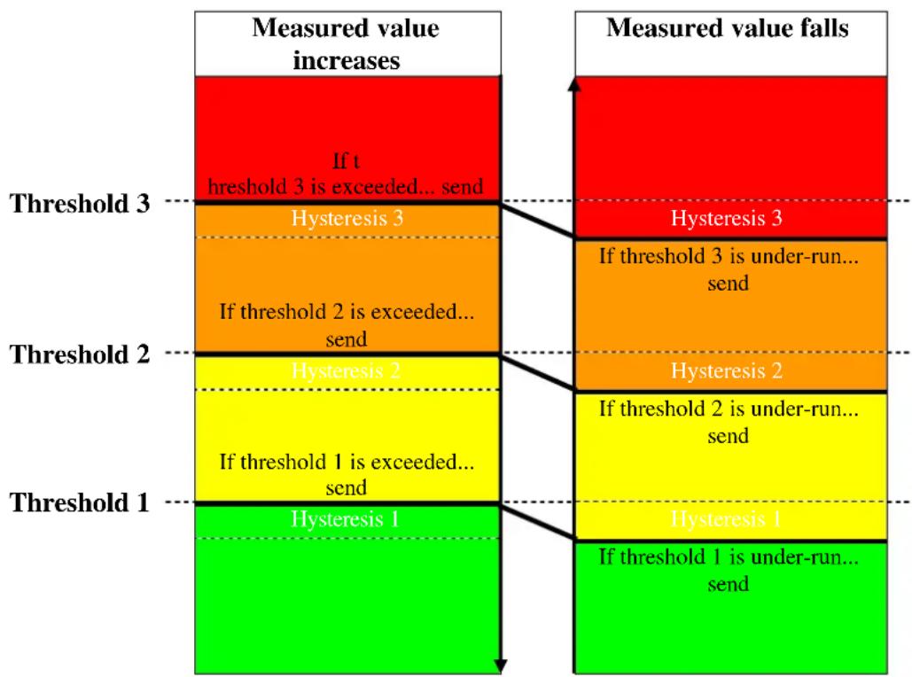
flowchart
graph TD
    A["Threshold 1"] --> B["Hysteresis 1"]
    B --> C["Threshold 2"]
    C --> D["Hysteresis 2"]
    D --> E["Threshold 3"]
    E --> F["Measured value increases"]
    F --> G["Measured value falls"]

    subgraph Threshold 1
        B
        D
    end

    subgraph Threshold 2
        C
        D
    end

    subgraph Threshold 3
        E
        F
    end

    note1["If threshold 3 is exceeded... send"]
    note2["Hysteresis 3"]
    note3["If threshold 2 is exceeded... send"]
    note4["Hysteresis 2"]
    note5["If threshold 1 is exceeded... send"]
    note6["Hysteresis 1"]
    note7["If threshold 1 is under-run... send"]
    note8["Hysteresis 3"]
    note9["If threshold 3 is under-run... send"]
    note10["Hysteresis 2"]
    note11["Hysteresis 1"]
The telegram of the last exceeded/under run threshold is sent.
If several thresholds are exceeded from one measurement cycle to the next then the telegrams are sent at an increasing value (from thresholds 1-3) whereas with cyclical sending, only the telegram for the last exceeded threshold is sent cyclically. The same applies with falling values.
4.3 Fan control
Note the following for fan control using percentage values:
The KNX sensor sends a percentage value as the control variable for each threshold.
This control variable (in accordance with the set threshold value) is transferred to the fan coil actuator as a fan stage between 0 and 3.
Important: The sent control variable should always be higher than the threshold setting of the fan coil actuator.
Example:
| Threshold value for Fan stage | Set values with KNX sensor | Recommended values for the fan coil actuator |
| 1 | 20 % | 10 % |
| 2 | 50 % | 40 % |
| 3 | 80 % | 70 % |
If fan stage 2 is selected using the button, the relevant object
(object 9 or 19) sends the control variable 50 %.
As the threshold value for stage 2 in the fan coil actuator is set at 40% , the received control variable of 50% is clearly allocated to fan stage 2 and accepted by the fan.
4.4 Relative humidity
Relative humidity is a measurement for the saturation of air with water vapour.
This is expressed as the relationship to the maximum amount absorbed at the corresponding temperature.
Example: A relative humidity of 60 % means that the air contains 60 % of the maximum absorbable amount of water vapour.
At 100 % the air is completely saturated and cannot absorb any more humidity.
Condensation or mist are produced if the volume of available water vapour exceeds this 100% threshold.
The ability of air to absorb water vapour depends on temperature.
Warm air can absorb more water vapour than cold air.
4.5 CO_2 guide values
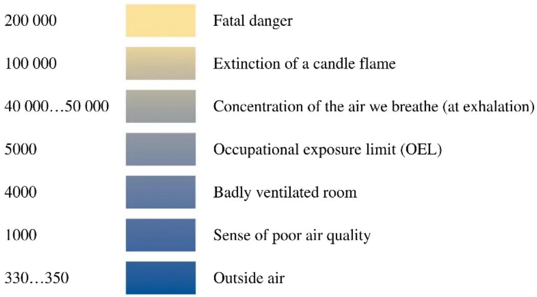
bar
| Category | Value | |---|---| | Fatal danger | 200 000 | | Extinction of a candle flame | 100 000 | | Concentration of the air we breathe (at exhalation) | 40 000...50 000 | | Occupational exposure limit (OEL) | 5000 | | Badly ventilated room | 4000 | | Sense of poor air quality | 1000 | | Outside air | 330...350 |All values in ppm (parts per million)


- KNX CO 2 , humidity and temperature sensor (surface mounted)
- Contents
- KNX CO 2 , humidity and temperature sensor (surface mounted)....1
- Functional characteristics .... 3
- Technical data 4
- The application program "CO2,humidity & temperature sensor 4216/1.0"....5
- Parameters....14
- Appendix....28
- Functional characteristics
- Operation
- CAUTION: Do not drop the device!
- Benefits
- Technical data
- Technical data
- The application program "CO2, humidity & temperature sensor 4216/1.0"
- Selection in the product database
- Communication objects
- Description of objects
- Parameters
- Overview
- The Readings parameter page
- The CO_2 threshold parameter page
- Essential condition for setting thresholds:
- The 1, 2, 3 CO₂ thresholds parameter pages
- The ventilation CO_2 threshold parameter page
- The CO_2 scenes parameter page
- The humidity threshold parameter page
- The 1, 2, 3 humidity thresholds parameter pages
- The Humidity ventilation parameter page
- The Relative humidity scenesparameter page
- Temperature threshold parameter page
- Appendix
- Hysteresis
- Example CO_2 threshold:
- Switching response of thresholds for CO_2 and humidity
- Fan control
- Relative humidity
- CO_2 guide values
Brand : SCHNEIDER
Model : MTN6005-0001
Category : Thermostat