
SFC22 - Speaker stand SANUS - Free user manual and instructions
Find the device manual for free SFC22 SANUS in PDF.


| Product Type | Center Channel Speaker Stand |
| Brand | Sanus |
| Model | SFC22 |
| Series | Steel Foundations |
| Material | Steel |
| Color | Black |
| Height Adjustment | Yes, via threaded studs (up to 1.5 inches) |
| Spiked Feet Included | Yes (for carpet) |
| Rubber Feet Included | Yes (for hard floors) |
| Isolation Pads Included | Yes (neoprene, 3 pads) |
| Weight Capacity | Approximately 30 lbs (13.6 kg) |
| Fillable Columns | Yes (can be filled with sand or shot for stability) |
| Wire Management | Optional wire guide included |
| Damping Washers | Yes (cork, self-adhesive) |
| Tools Included | Allen key |
| Assembly Required | Yes |
| Country of Origin | USA (Sanus Systems, St. Paul MN) |
| Warranty | Limited lifetime warranty |
| Maintenance | Wipe with a dry cloth; avoid harsh chemicals |
| Safety Notes | Spiked feet and studs are sharp; keep away from children |
Frequently Asked Questions - SFC22 SANUS
User questions about SFC22 SANUS
0 question about this device. Answer the ones you know or ask your own.
Ask a new question about this device
Download the instructions for your Speaker stand in PDF format for free! Find your manual SFC22 - SANUS and take your electronic device back in hand. On this page are published all the documents necessary for the use of your device. SFC22 by SANUS.
USER MANUAL SFC22 SANUS
4] The Steel Foundations center channel stand has included a pair of adjustable studs (j) and 1/4" rubber stud covers (k). These are for use if you require your speaker to angle upwards. Thread the adjustable stud through the top plate with the allen wrench to the desired height. Using a machine nut, lock the threaded stud into place. Photo
5 - Thread the rubber stud covers over the top of the adjustable stud to protect
your speaker from being scratched. Three Neoprene Isolation pads should be placed at the rear of the top plate between the top plate and the speaker to ensure the speaker does not slide off the back of the stand.
natural_image
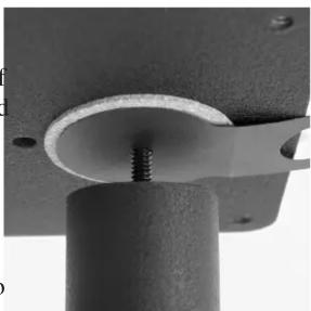
Close-up of a mechanical component with a threaded screw inserted into a circular opening (no text or symbols visible)Photo 4
*NOTE: The ends of the spiked feet and steel speaker studs are very sharp and may scratch floors or furniture. All sharp objects can be hazardous to children. For this reason large rubber feet and rubber isolation pads are provided as an option. Sanus Systems will not be liable for damage or injury.

natural_image
Close-up of a black metal table with a small protrusion and a small circular mark on the top surface (no text or symbols visible)Photo 5
Every effort has been made to ensure that your stands are perfect. If you have any questions or feel that there is a problem of any kind, please call our Customer Assistance number. We can assist with questions or damaged/
Sanus Systems 2221 Highway 36 W St. Paul MN 55113 11.22.04
800.359.5520 www.sanus.com
SANUS SYSTEMS
THE UNION OF FORM AND FUNCTION
STEEL FOUNDATIONS® SFC
INSTRUCTION MANUAL

natural_image
Black metal side table with vertical cylindrical legs and four base feet, no text or symbols visible

natural_image
Pure mechanical assembly diagram showing a tilted plate with supporting columns and mounting holes (no text or symbols)Important: This product uses two different feet for each base. Before installing, be sure to check that the feet are mounted with the (1) foot on the front left and rear right of the base, (2) front right and rear left. The designation (1) & (2) are on the bottom of each foot.
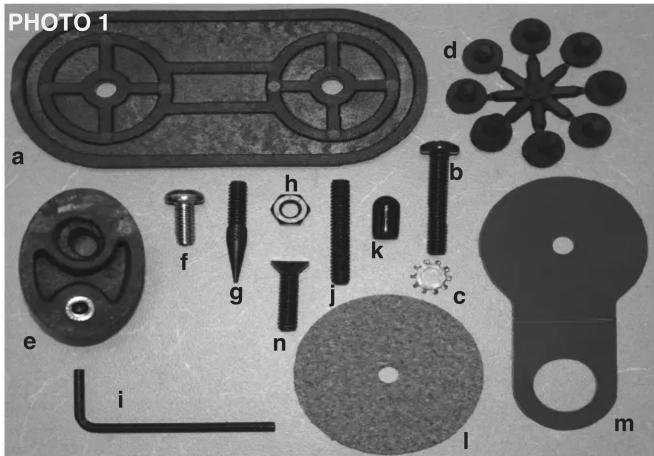
Hardware List
(PHOTO 1)
a) isolation block - 1
b) 1-1/2" pan head bolt - 2
c) lock washer - 2
d) rubber isolation pad - 8
e) plastic foot - 4
f) 5/8" pan head bolt - 4
g) carpet spike - 4
h) machine nut - 8
i) allen key - 1
j) threaded stud - 2
k) rubber stud cover - 2
I) cork damping washer - 2
m) wire guide - 2
n) flat head bolt - 2
'Take the time to find the right speaker locations for your listening room.'
1] Attach the plastic feet (e) to the corners of the base with the small pan head bolts (f). Photo 2-Group two pillars with the base. Align the holes in the base with the holes in the isolation block (a). Bolt the pillars and the base together with the isolation block between them using the large pan head bolts (b) and lock washers (c). Photo 3-Using the wire guide is optional.

natural_image
Close-up of a mechanical component with a metallic rod and two protruding pins, mounted on a dark surface (no visible text or symbols)Photo 2
2] Adhere the two inch self-adhesive damping washers (l) to the flush side of each top plate. The damping washers will be set in between the top plate and the pillars. (Optional: You may fill the pillars with sand or shot at this time.) Align the holes in the top plate with corresponding holes in the top of each pillar. Bolt the pillars and the top plate together using the flat head bolts(n). Photo 4-The wire guide (m) is optional.
3] Both spiked feet (g) and rubber feet (d) are provided for your Steel Foundations®. The spiked feet are preferable in terms of performance.
Thread a machine nut (h) over the spiked feet and thread the ends of the spiked feet into the threaded inserts in the corner feet. Adjust the spiked feet until the stand is level and then lock into place by tightening the machine nut. Use of the spiked feet is optional. The rubber feet are provided as an alternative.

natural_image
Close-up of a cylindrical mechanical component mounted on a base, with a small circular hole and a small asterisk mark (no text or symbols visible)Photo 3
Page 3 * PLEASE READ THE NOTE ON PAGE 4 OF THIS MANUAL!


Brand : SANUS
Model : SFC22
Category : Speaker stand