
70-1721 - Uncategorized Metra - Free user manual and instructions
Find the device manual for free 70-1721 Metra in PDF.


| Product Type | Receiver Wiring Adaptor |
| Brand | Metra |
| Model | 70-1721 |
| Compatibility | Aftermarket receivers and select factory harnesses |
| Number of Wires | 12 |
| Power Supply | 12V DC (Constant and Switched) |
| Illumination Wire | Orange (if receiver supports) |
| Remote Turn-On | Blue wire (Power Antenna/Amplifier Remote) |
| Speaker Channels | 4 (Front Left/Right, Rear Left/Right) |
| Ground Wire | Black |
| Connector Type | Crimp caps included |
| Installation Method | Strip, twist, crimp |
| Material | PVC wires, metal terminals |
| Wire Color Code | Standard aftermarket color coding |
| Dimensions (Approx.) | 6 x 3 x 1 inches |
| Weight (Approx.) | 0.2 lbs |
| Included Accessories | Wiring adaptor, crimp caps, user manual |
| Safety Instructions | Disconnect battery before installation |
| Maintenance | Keep dry, clean with dry cloth |
| Repairability | No user-serviceable parts; replace entire unit if defective |
Frequently Asked Questions - 70-1721 Metra
User questions about 70-1721 Metra
0 question about this device. Answer the ones you know or ask your own.
Ask a new question about this device
Download the instructions for your Uncategorized in PDF format for free! Find your manual 70-1721 - Metra and take your electronic device back in hand. On this page are published all the documents necessary for the use of your device. 70-1721 by Metra.
USER MANUAL 70-1721 Metra
Receiver Wiring Adaptor
IMPORTANT
120 70-1721
Before starting, compare items on your invoice with items received. Thoroughly check packing materials. If an item is missing, please call Crutchfield at 1-888-955-6000.
Revision 10/07/13
STEP 1 -- MATCH & CONNECT WIRES
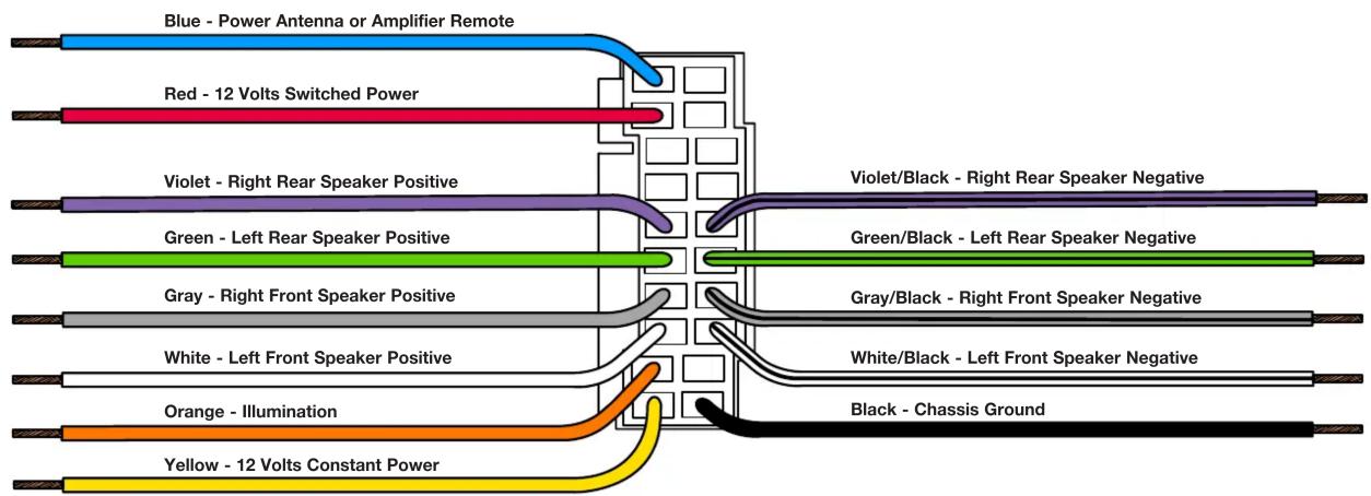
A. Match wires below to the matching function of each wire on your receiver (refer to instructions supplied with receiver). The wire colors of your new receiver may, or may not, match the wire colors of the adaptor. Match adaptor and receiver wires by function, disregarding color.
B. If your receiver does not have an Illumination wire, tape off the Orange wire.
C. Individually tape off any unused wires.
D. Make final wiring connections following instructions on the next page.
CRUTCHFIELD®
Copyright 2013 Crutchfield Corporation
*120701721*
Receiver Wiring Adaptor Connections
120 70-1721
STEP 2 -- CRIMP CONNECTIONS
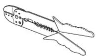
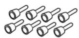
Tools & Parts Required ▶
Wire Stripper/Crimp Tool Crimp Caps
A. Strip wires back 1/2".

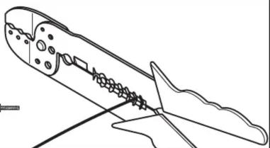
natural_image
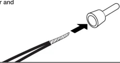
Line drawing of a mechanical component with internal components and a base, no text or symbols presentB. Twist wires together and insert in crimp cap.
natural_image
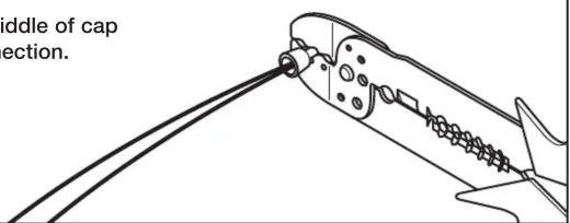
Diagram showing a cable being inserted into a plug, with an arrow indicating the process (no text or symbols present)C. Squeeze middle of cap for tight connection.
STEP 2 -- CONTINUED
D. Complete crimp connections for all necessary wires.
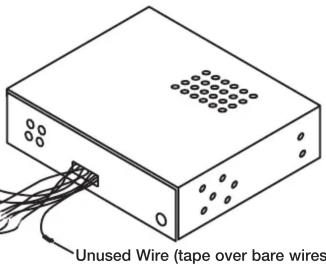
E. Be sure to wrap any wires from the Wiring Adaptor that are not necessary (wires with no match from the new receiver) with electrical tape.
Receiver Wiring Adaptor
Generic Illustration
STEP 3 -- APPLICATION
When ready to install the receiver, plug the Wiring Adaptor from the new receiver or receiver assembly into the factory radio harness(es) in the vehicle dash.
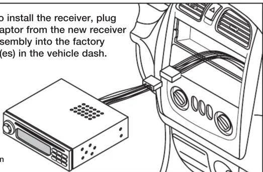
Generic Illustration
CRUTCHFIELD®
Copyright 2013 Crutchfield Corporation


Brand : Metra
Model : 70-1721
Category : Uncategorized