IP Force - Intercom 2N Telecommunications - Free user manual and instructions
Find the device manual for free IP Force 2N Telecommunications in PDF.


User questions about IP Force 2N Telecommunications
0 question about this device. Answer the ones you know or ask your own.
Ask a new question about this device
Download the instructions for your Intercom in PDF format for free! Find your manual IP Force - 2N Telecommunications and take your electronic device back in hand. On this page are published all the documents necessary for the use of your device. IP Force by 2N Telecommunications.
USER MANUAL IP Force 2N Telecommunications
Security IP Intercom
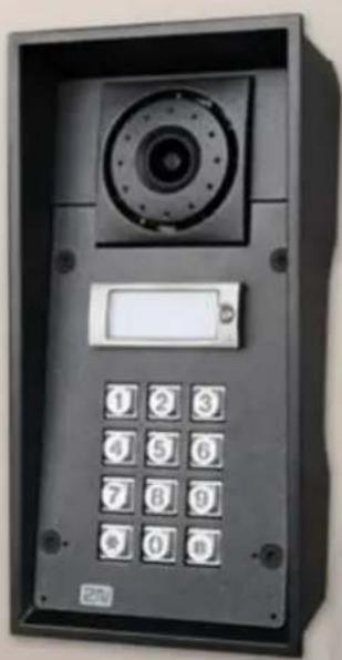
natural_image
Front view of a black rectangular electronic device with a circular dial and keypad (no visible text or symbols)Installation Manual
Version: 2.16
www.2n.cz
The 2N TELEKOMUNIKACE a.s. is a Czech manufacturer and supplier of telecommunications equipment.


The product family developed by 2N TELEKOMUNIKACE a.s. includes GSM gateways, private branch exchanges (PBX), and door and lift communicators. 2N TELEKOMUNIKACE a.s. has been ranked among the Czech top companies for years and represented a symbol of stability and prosperity on the telecommunications market for almost two decades. At present, we export our products into over 12 countries worldwide and have exclusive distributors on all continents.

2N ^ is a registered trademark of 2N TELEKOMUNIKACE a.s. Any product and/or other names mentioned herein are registered trademarks and/or trademarks or brands protected by law.

2N TELEKOMUNIKACE a.s. administers the FAQ database to help you quickly fin information and to answer your questions about 2N products and services. On www.faq.2n.cz you can find information regarding products adjustment and instructions for optimum use and procedures „What to do if...”.

2N TELEKOMUNIKACE a.s. hereby declares that the 2N product complies with all basic requirements and other relevant provisions of the 1999/5/EC directive. For the full wording of the Declaration of Conformity see the CD-ROM (if enclosed) or website at www.2n.cz.

This device complies with part 15 of the FCC Rules. Operation is subject to the following two conditions: (1) This device may not cause harmful interference, and (2) this device must accept any interference received, including interference that may cause undesired operation.

The 2N TELEKOMUNIKACE a.s. is the holder of the ISO 9001:2009 certificate. AI development, production and distribution processes of the company are managed by this standard and guarantee a high quality, technical level and professional aspect of all our products.
Content:
• 1. Product Overview
• 1.1 Components and Associated Products
• 1.2 Terms and Symbols
• 2. Description and Installation
• 2.1 Before You Start
• 2.2 Mechanical Installation
• 2.3 Electric Installation
• 2.4 Extending Module Connection
• 2.5 Button Tags
• 3. Function and Use
• 3.1 Configuration
• 3.2 Control
• 3.3 Maintenance
• 3.4 Downloads
• 4. Technical Parameters
• 4.1 General drawings
• 5. Supplementary Information
• 5.1 Troubleshooting
• 5.2 Directives, Laws and Regulations
• 5.3 General Instructions and Cautions
1. Product Overview
Here is what you can find in this section:
• 1.1 Components and Associated Products
• 1.2 Terms and Symbols
Basic Features
2N ^® IP Force is a highly resistant and reliable IP door access intercom provided with a lot of useful above-standard functions. Supporting the SIP standard and being compatible with the leading IP PBX and telephone suppliers, can make 2N IP Force use of all VoIP services. can work as a standard or emergency door 2N IP Force access intercom for buildings, entrances to premises or garages, manufacturing halls, highways and so on.
2N eRuiSpeck with two very sensitive microphones and an up to 10V loudspeaker. Thanks to an integrated acoustic echo cancelling (AEC) system, the product provides mutual audibility even of persons talking at the same time und normal conditions.
- In De-Feropped with a colour wide-angle camera, which displays the calling person on the called party's video telephone or PC monitor.
2N ^® IP Force can be provided with 1, 2 or 4 pre-programmed buttons. You can set up to three telephone numbers and time profiles for each of the buttons to increase the accessibility of the called party.
2N ^® IP Force can be equipped with a numerical keypad to be used as a code lock for lock switch activating or telephone/subscriber number dialling.
®
2N eRuiFpece with an electric lock switch. You can control the switch using a numerical keypad or, during a call, using any telephone set. An additional switch module can be installed if necessary. A wide range of settings allow for variety of applications.
®
2th Also provided with RFID card reader modules.
®
2Nv dPyFeorseto install. All you have to do is connect the system into your LAN via a network cable and feed it from a 12 V power supply or your PoE supporting LAN.
Configure using ^® your PC via any web browser. Use the2N IP Force
2N ^® Access Commander to manage extensive 2N ^® IP Force systems easily and quickly.
Advantages of Use
• Uncompromising Antivandal design
• High coverage level - up to class IP69K
- Sensitive microphone and powerful loudspeaker
- Bidirectional communication – acoustic echo cancelling
- Integrated colour camera with wide-angle lens
- Optional dial buttons including name tags and backlight
- Optional numerical keypad with backlight
- Integrated electronic lock switches with wide setting options
- Optional integrated RFID card reader module
• LAN (PoE) or external 12 V power supply
- Configuration via web interface or dedicated PC application
- SIP 2.0 support
• Up to 1999 telephone directory positions
- Up to 20 user time profiles
• Video codecs (H.263, H.263+, H.264, MPEG-4, JPEG)
• Audio codecs (G.711, G.729, G.722, L16/16kHz)
- HTTP server for configuration
• SNTP client for time synchronisation with server
• RTSP server for video streaming
- SMTP client for e-mail sending
- Variable mounting options (brick/plasterboard flush mounting, surface mounting)
- TFTP client for automatic configuration and firmware update
1.1 Components and Associated Products
2N ^® IP Force Components and Associated Products:
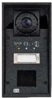
text_image
0:1 0Basic Units
| One-Button | |
2N Part No. 9151101WAxis Part No. 01336-001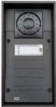 | 1 buttoncontrol of two electric locksadditional switch connection option10 W loudspeaker, IP69K |
Part No. 9151101CW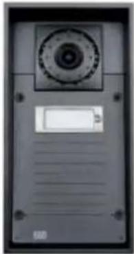 | IP69K1 buttoncamera10 W loudspeaker, IP69Kextra robust versioncontrol of two electric locksadditional switch connection option |
2N Part No. 9151101CHWAxis Part No. 01337-001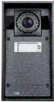 | IP69K1 buttonHD camera10 W loudspeaker, IP69Kextra robust versioncontrol of two electric locksadditional switch connection optionnight vision |
2N Part No. 9151101RPWAxis Part No. 01335-001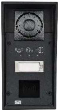 | 1 button, pictograms,possibility of connecting card readercontrol of two electric locksadditional switch connection option10 W loudspeaker, IP69K |
2N Part No.9151101CRPW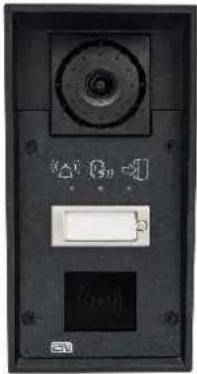 | 1 button, pictogramswith cameropp possibility of connecting card readercontrol of two electric locksadditional switch connection option10 W loudspeaker, IP69K |
2N Part No.9151101CHRPWAxis Part No. 01334-001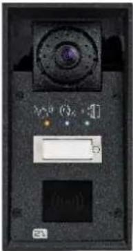 | 1 button, pictograms,with HD camera,possibility of connecting card readercontrol of two electric locksadditional switch connection option10 W loudspeaker, IP69Knight vision |
2N Part No. 9151101KWAxis Part No. 01338-001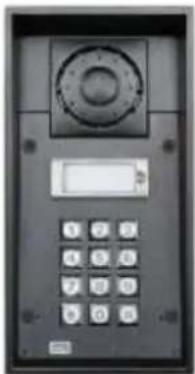 | 10 W loudspeaker, IP69K1 buttonkeypadcontrol of two electric locksadditional switch connection option |
2N Part No. 9151101CKW | 10 W loudspeaker, IP69K1 buttonkeypadcameracontrol of two electric locksadditional switch connection option |
2N Part No.9151101CHKWAxis Part No. 01339-001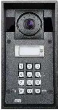 | 10 W loudspeaker, IP69K1 buttonkeypadHD cameracontrol of two electric locksadditional switch connection optionnight vision |
| Two-Button | |
2N Part No.9151102CHRWAxis Part No. 01340-001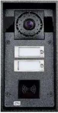 | 2 buttonsHD camerapossibility of connecting card readercontrol of two electric locksadditional switch connection option10 W loudspeaker, IP69Knight vision |
2N Part No. 9151102CRW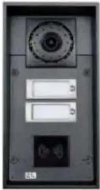 | 2 buttonscamerapossibility of connecting card readercontrol of two electric locksadditional switch connection option10 W loudspeaker, IP69K |
2N Part No. 9151102RWAxis Part No. 01341-001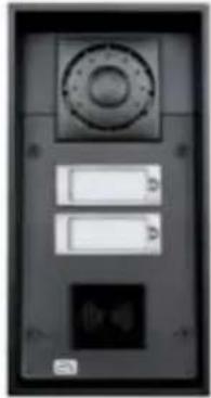 | 2 buttonscard reader connection optioncontrol of two electric locksadditional switch connection option10 W loudspeaker, IP69K |
2N Part No. 9151102-X1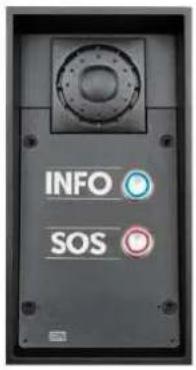 | 2 buttons10W loudspeaker, IP69K2 buttons with INFO and SOS labelsanti-vandal buttons made of stainless steelNote: customization available per request |
| Four-Button | |
2N Part No. 9151104WAxis Part No. 01342-001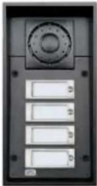 | 10 W loudspeaker, IP69K4 buttonscontrol of two electric locksadditional switch connection option |
2N Part No. 9151104CW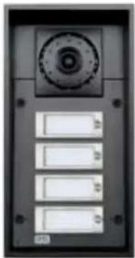 | 10 W loudspeaker, IP69K4 buttonscameracontrol of two electric lockspossibility of connecting additional switch |
2N Part No. 9151104CHWAxis Part No. 01343-001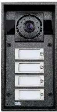 | 10 W loudspeaker, IP69K4 buttonsHD cameracontrol of two electric locksadditional switch connection optionnight vision |
®
2ND Bignode for outdoor applications and requires no additional roof. W-including Part Nos. are intended for WAP pressure cleaning and extremely noisy environments (such as highways, etc.).
®
2NitsPcaForce flush or wall mounted without requiring any additional accessories. Use the appropriate mounting box (see below) for plasterboard and hollow brick flush mounting.
Flush Mounting Box
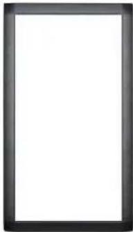 | frameincluded with basic unit |
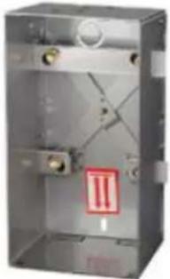
| 91510012N Part No.Axis Part No. 01348-001 | Brick flush mounting boxDimension: 132 x 223 x 83 mm |
 | |
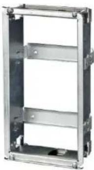
| 91510022N Part No.Axis Part No. 01349-001 | Plasterboard flush mounting boxDimension: 237 x 129 x 70 mmHole: 237 x 118 mm |
 |
Mounting Accessories
2N Part No. 9151005 Axis Part No. 01351-001
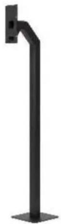
natural_image
Black metal vertical support bracket with mounting feet (no text or symbols)- Gooseneck stand - Height 120 cm (47 inch) to the intercom top
2N Part No. 9151007 Axis Part No. 01550-001

natural_image
Black vertical pole-mounted stand with adjustable arm and base (no text or symbols visible)- Gooseneck stand double - Height: 115 cm (45") and 203 cm (80")
2N Part No. 9151006Axis Part No. 01352-001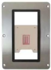 | Installation adapter (US only) |
2N Part No. 9151018Axis Part No. 01345-001 | Security screwsAn alternative safer than regular screwsTorx with a pin. Supplied with the appropriate handle. |
Internal Units and Accessories
Part Numbers:
2N Part No. 91378365
Axis Part No. 01416-001
2N Part No. 91378366
Axis Part No. 01419-001
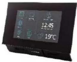
text_image
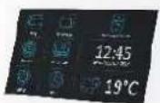
12.45 19°C- 2N ^ Indoor Touch - black
• WiFi version (latter Part No.)
- 2N ^ Indoor Touch, an elegant internal touch panel, is suitable for all intercoms. On the panel's display 2N IP not only can you find out who is at the door, but you an also start conversation with the visitor, open the lock or turn on the light in the entrance hall.
2N Part No. 91378382
Axis Part No. 01425-001
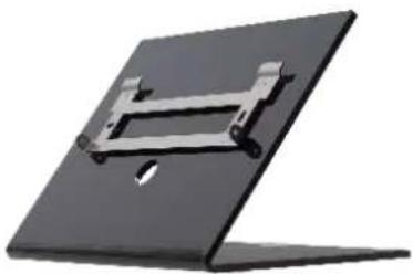
natural_image
Exterior view of a modern office building (no signage)- 2N ^ Indoor Touch desk stand black
Part Numbers:
2N Part No. 91378365WH
Axis Part No. 01417-001
2N Part No. 91378366WH
Axis Part No. 01420-001
- 2N ^ Indoor Touch - white
• WiFi version (latter Part No.)
- 2N ^ Indoor Touch, an elegant internal touch panel, is suitable for all intercoms. On the panel's display 2N IP not only can you find out who is at the door, but you can also start conversation with the visitor, open the lock or turn on the light in the entrance hall.
2N Part No. 91378382WAxis Part No. 01426-001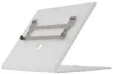 | • 2N® Indoor Touch desk stand white |
VoIP Telephones
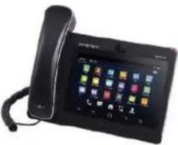
| 913783572N Part No. | Grandstream GXV3240 VoIP video telephone |
| Axis Part No. 01422-001 | GXV3240 is the successor to the popular GXV3140 model, which allows for comfortable video calls in the IP network. Touchscreen and keyboard control. |
 | |
| 913783582N Part No. | Grandstream GXV3275 VoIP telephone |
| Axis Part No. 01421-001 | GXV3275 is the successor to the popular GXV3175 model, which allows for comfortable video calls in the IP network. Touchscreen control. |
 |
Electric Locks
932071E2N Part No. 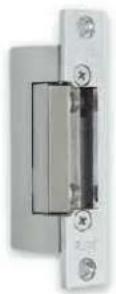 | BEFO 1121112 V / 230 mA DCLow consumption |
932081E2N Part No. 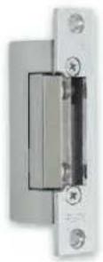 | BEFO 11221 with momentum pin12 V / 230 mA DClow consumptionA short electrical impuls is sufficient to open the lock. The lock remains open until someone closes the door. |
932091E2N F  | BEFO 11211MB with mechanical blocking12 V / 230 mA DCLow consumptionEnables to mechanically close or open the lock. Once unlocked, the lock keeps open all the time. Once closed, the lock behaves as a standard electrical lock. |
2N Part No. 932061E | BEFO 211211 door signalling, low consumption12 V / 230 mARegular lock with a built-in contact to indicate whether the door is open or closed. |
2N Part No. 932072E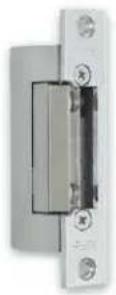 | BEFO 31211fail-safe12 V / 170 mA DCThe failsafe lock is closed when electricity is switched on.When electricity is interrupted, the lock is opened. |
2N Part No. 932062E | BEFO 321211fail-safe, door signalling12 V / 170 mAThe failsafe lock is closed when electricity is switched on.When electricity is interrupted, the lock is opened.It contains a built-in contact to indicate whether the door is open or closed. |

Tip
- FAQ: Electric locks - Difference between locks in 2N IP intercom accessories
Power Supply
Part Numbers:
2N Part No. 91378100
Axis part No. 01394-001
2N Part No. 91378100E
2N Part No. 91378100US
2N Axis part No. 01403-001
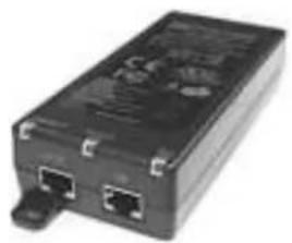
natural_image
Black rectangular electronic device with two ports and a connector (no visible text or symbols)- PoE injector - without cable
• PoE injector - with EU cable
- PoE injector - with US cable
• an Ethernet For intercom pc where no PoE switch is available.
91341481E2N Part No.

natural_image
Black and white photo of a connected power adapter with cable (no visible text or symbols)Stabilised 12 V / 2 A power supply needs to be used where no PoE is available.
9329282N Part No.
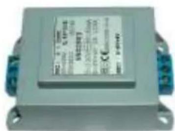
text_image
Label of an electronic component with technical specifications and certification marks• 12 V transformer
• For 230 V mains voltage.
- For external power supply of the lock with 12 V AC voltage.
Additional Modules
91510102N Part No.Axis Part No. 01350-001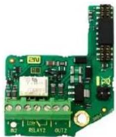 | Additional switchIncluding:relay switch - 30 V / 1 A NO/NC contactactive 12 V / 600 mA outputdigital inputtamper switch for front 2N IP Force panel opening signalling |
91510112N Part No.Axis Part No. 01344-001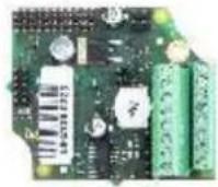  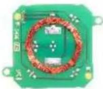 | Internal RFID card reader 125 kHz for installation in intercoms. Allows 2N IP Force the use of cards. Another two EM4xxx switches, two logical inputs and a Wiegand interface are available. It is compatible with thetwo-button and pictogram 2N IP F models.Includes a tamper switch to signal when the front panel is opened. |
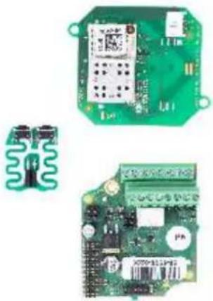
| 2N Part No. 9151031 | Internal RFID card reader 13.56 MHz NFC Ready for mounting. 2N IP ForceTwo switches, two logical inputs and a Wiegand interface are available. It is compatible with the®2NoIPForceand pictogram models.Includes a tamper switch to signal when the front panel is opened.Allows the use 13.56 MHz cards of these standards (only card serial number is read):ISO14443A (Mifare, DESFire)PicoPass (HID iClass)FeliCaST SR(IX)2N®Mobile Key |
 | |
2N Part No. 9151031SAxis Part No. 01730-001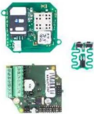 | Internal secured RFID card reader 13.56 MHz NFC Ready for mounting. 2N IP ForceTwo switches, two logical inputs and a Wiegand interface are available. It is compatible with the®2No IP Force and pictogram models.Includes a tamper switch to signal when the front panel is opened.Allows the use 13.56 MHz cards of these standards (only card serial number is read):ISO14443A (Mifare, DESFire)PicoPass (HID iClass)FeliCaST SR(IX)2N®Mobile KeyHID SE (Seos, iClass SE, Mifare SE) |
2N Part No. 9159010Axis Part No. 01386-001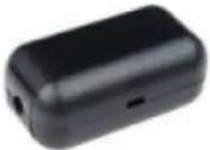 | 2N®Security RelayA handy add-on that significantly enhances door entry security as it prevents tampering with the intercom and forced opening of the lock. To be installed between intercom and lock, powered by the intercom. |
91590112N Part No.Axis Part No. 01387-001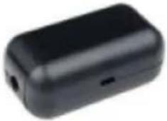 | Wiegand IsolatorThe is designed for 2N IP Wiegand Isolator galvanic isolation of two devices separately power supplied and interconnected via the Wiegand bus. The protects Wiegand Isolator the interconnected devices against communication errors and/or damage. |
9137410E2N Part No.Axis Part No. 01397-001 | External IP Relay - 1 outputStandalone IP device which can be controlled HTTP by commands sent by intercom, 2N IP which can thus control devices on unlimited distance. |
9137411E2N Part No.Axis Part No. 01398-001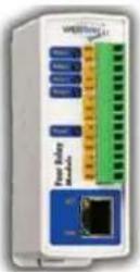 | External IP Relay - 4 outputs, PoEStandalone IP device which can be controlled HTTP by commands sent by intercom, 2N IP which can thus control devices on unlimited distance. |
9134165E2N Part NoAxis Part No. 01395-001 | RFID card, type EM4100, 125 kHz |
9134166E2N Part No.Axis Part No. 01396-001 | RFID fob, type EM4100, 125 kHz |
91341732N Part No.Axis Part No. 01384-001 | Mifare Classic 1k RFID card, 13.56 MHz |
2N Part No. 9159050Axis Part No. 01391-001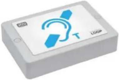 | 2N®Induction LoopAn induction loop transmits sound wirelessly from the intercom to the earphones of 2N IP people with hearing disabilities and enables them to hear and perceive sounds better. |
2N Part No. 9159052Axis Part No. 01393-001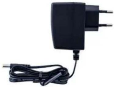 | Power supply for 2N Induction LoopExternal power supply for the induction loopInput 230 V ACOutput 12 V DC |
2N Part No. 9134174Axis Part No. 01385-001 | Mifare Classic 1k RFID fob, 13.56 MHz |
2N Part No. 9159014EU/US/UKAxis Part No. 01404-001for US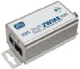 | 2N2Wire(set of 2 adaptors and power source for EU/US /UK)The con2Wire allows you to use the 2N existing wiring (2 wires) from your original doorbell or door intercom to connect any IP device. You do not have to configure anything; all you need is a unit2Wirech end of 2Nthe cable and a power source connected to at least one of these units.The unit2Wireprovides PoE power 2Nnot only to the second converter, but also to all the other connected IP end devices. |
2N Part No. 9159013 | Exit button(suitable for Internal RFID card reader or Security relay)A button for connection to a logic input for opening a door inside a building. |
2N Part No. 9159012Axis Part No. 01388-001 | Magnetic door contact(Suitable for Internal RFID card reader)Set for installation on a door, enabling the status of door opening to be ascertained. Used when the intercom is used for door protection, to detect when the door is not closed or forcibly opened. |
2N Part No. 9159030Axis Part No. 01389-001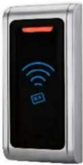 | External RFID card reader, 125 kHzSecondary reader for connection to an internal reader. Provides card entry control from both sides of the door. IP67 cover, also suitable for exteriors. Reads EM4100 and EM4102 cards. |
2N Part No. 9159031Axis Part No. 01390-001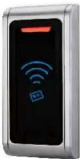 | External 13.56 MHz Mifare RFID card reader, WiegandSecondary reader for connection to an internal reader. Provides card entry control from both sides of the door. IP68 cover, also suitable for exteriors. Reads Mifare cards. |
2N Part No. 9154004Axis part No. 01479-001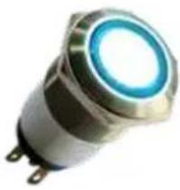 | Water-proof metal button(Suitable for Internal RFID card reader) |
9137420E2N Part NoAxis Part No. 01399-001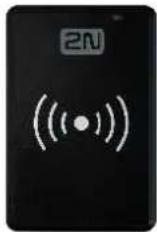 | External RFID card reader for connection to a PC using a USB interface. Suitable for system management and the addition of EM41xx cards via the PC application, 2N®AccessCommander. |
2N Part No. 9137421EAxis Part No. 01400-001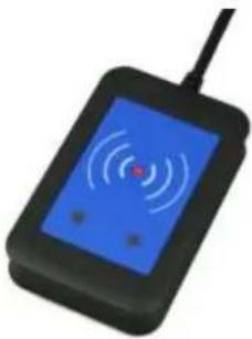 | Ext. RFID Reader 13.56 MHz, 125 kHz + NFC /HCE (USB interface)External RFID card reader for connection to PC using a USB interface. Suitable for system administration and adding 13.56 MHz, 125 kHz cards and Android platform devices supporting NFC/HCE using web interface 2N IP intercom or theapplication. It 2N Access Commander reads the same types of cards and devices as the card readers in .2N IP intercoms13.56 MHz/ISO/IEC 14443AMifare Classic 1k & 4k, DESFire EV1, Mini, Plus S&X, Ultralight, Ultralight C13.56 MHz/ISO/IEC 14443B CEPAS, HID iCLASS (CSN only)13.56 MHz/JIS X 6319 FelicaISO/IEC 18092 SmartPhone with NFC /HCE support, since Android version 4.3 (app required)2N Mobile KeyEMarine |
2N Part No. 9137424EAxis part No. 01527-001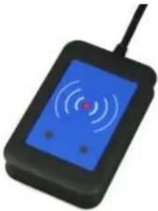 | Ext. secured RFID Reader 13.56 MHz, 125 kHz + NFC/HCE (USB interface)External secured RFID card reader for connection to PC using a USB interface. Suitable for system administration and adding 13.56 MHz, 125 kHz cards and Android platform devices supporting NFC/HCE using 2N IPweb interface or theintercom 2N Acces application. It reads the same Comm types of cards and devices as the card readers in .2N IP intercoms13.56 MHz/ISO/IEC 14443A Mifare Classic 1k & 4k, DESFire EV1, Mini, Plus S&X, Ultralight, Ultralight C13.56 MHz/ISO/IEC 14443B CEPAS, HID iCLASS (CSN or PAC ID)13.56 MHz/JIS X 6319 FelicaISO/IEC 18092SmartPhone with NFC /HCE support, since Android version 4.3 (app required)2N Mobile KeyEMarine |
2N Part No. 9159051Axis Part No. 01392-001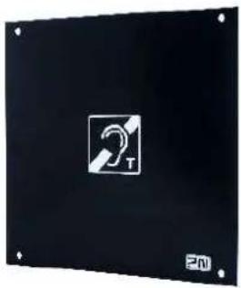 | 2N Induction loop - external antennaExternal antenna boosts the range of usability of the induction loop, so that the disabled user can receive the audio signal in a wider area. Use an external antenna with the induction loop, Part No. 9159050. A 170 cm long interconnecting cable is included. |
91605012N Part No.Axis Part No. 0820-001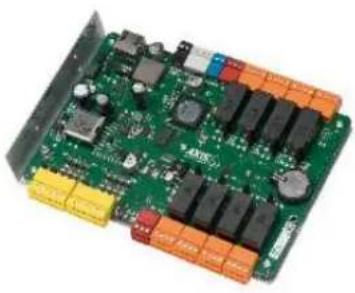 | AXIS A9188 Network I/O relay moduleLift control relay module for up to 8 floors |
License
| 2N Part No.9137905Axis Part No.01376-001 | Enhanced Audio |
| 2N Part No.9137906Axis Part No.01377-001 | Enhanced Video |
| 2N Part No.9137907Axis Part No.01378-001 | Enhanced Integration |
| 2N Part No.9137908Axis Part No.01379-001 | Enhanced Security |
| 2N Part No.9137909Axis Part No.01380-001 | Gold |
| 2N Part No.9137910Axis Part No.01381-001 | InformaCast |
| 2N9137915Axis Part No.01382-001 | NFC |
| 2N Part No.9137916 | • Lift Module |

Tip
- Refer to the Configuration Manual for 2N IP intercoms, Subs. 3.2 for details.Function Licensing

Tip
- For more accessories and particular advice please contact your local distributor of 2N products.

Tip
- FAQ: Induction loop - How to connect it with 2N IP intercoms
1.2 Terms and Symbols
The following symbols and pictograms are used in the manual:

Safety
• Always abide by this information to prevent persons from injury.

Warning
• Always abide by this information to prevent damage to the device.

Caution
- Important information for system functionality.

Tip
- Useful information for quick and efficient functionality.

Note
- Routines or advice for efficient use of the device.
2. Description and Installation
Here is what you can find in this section:
• 2.1 Before You Start
• 2.2 Mechanical Installation
• 2.3 Electric Installation
• 2.4 Extending Module Connection
• 2.5 Button Tags
2.1 Before You Start
Product Completeness Check
Before you start please check the contents of your delivery:2N IP Force
- 1x 2N ^ IP Force
• 1x frame (of the corresponding colour)
• 1x Torx 10 / Torx 20 double-ended wrench - Bushings (enclosed):
• 1x big two-hole sealed bushing with nut
- 1x spare sealing for big bushing for a thick cable, one hole
- 1x big blank with nut
• 1x small bushing with nut
- 1x bushing plug, big size
• 2x bushing plugs, small size
• 1x Installation Manual2N P Force
- 1x mounting template
• 1x A5 transparent name plate foil - 1x spare name tag
• 1x grounding connector with the screw - 4x (5 x 90) mm screws
- 4x "intelligent" (8 x 50) mm dowels
2.2 Mechanical Installation
Content
Common Mounting Principles
Flush Mounting - Classic Bricks
Flush Mounting - Thermally Insulated Wall
Flush Mounting - Plasterboard
Flush Mounting - Hollow Bricks
Wall Mounting
Use of Cable Bushings
Common Mounting Principles

Tip
- Select flush mounting where possible to make your product elegant looking, more vandal resistant and more secure.
- You can purchase the flush mounting box in advance and hire an installation professional to make the basic installation work. Moreover, the mounting box helps you align the intercom vertically (with a deviation of up to 2°).

Caution
- Make sure that the dowel holes have the required diameter. If the diameter is too large, the dowels may get loose. Use some suitable building adhesive to keep the dowels in place.
• Make sure that the hole depth is sufficient too! The dowel length is 50 mm and the screw length is 90 mm.
- Remember that dowels of poor quality may easily get loose and fall out of the wall!
- Stainless steel screws are used for the assembly. Other 2N IP Force screws than stainless steel ones corrode soon and may aesthetically deteriorate the surrounding environment!
- Having removed the front panel, make sure that no dirt gets inside the product (especially onto the sealing surface and microphone sound guides).

Caution
- The warranty does not apply to the product defects and failures arisen as a result of improper mounting (in contradiction herewith). The manufacturer is neither liable for damages caused by theft within an area that is accessible after the attached electric lock is switched. The product is not designed as a burglar protection device except when used in combination with a standard lock, which has the security function.
- When the proper mounting instructions are not met, water might get in and destroy the electronics. It is because the intercom circuits are under continuous voltage and water infiltration causes an electro-chemical reaction. The manufacturer's warranty shall be void for products damaged in this way!
Note
- The microphone sound guides are normally loose after the front panel is removed! The screw is only used as a fall-out protection during installation.
Warning
Be sure keep strictly the hole dimensions while mounting the device into classic bricks without the flush mounting box as shown in the picture with dimensions.
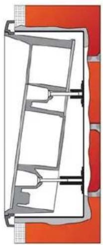
Flush Mounting - Classic Bricks
What You Need:
• The brick flush mounting box, Part No. 9151001
• Hole: (132 x 223 x 83) mm
natural_image
Cross-sectional diagram of a mechanical or architectural component with internal channels and structural elements (no text or labels)If you use the brick flush mounting box, follow the instructions below:
- Make a hole using the template.
- Suppose that all the required cables have been carried into the hole.
- Put the intercom inside and place the set onto the hole to make sure that the hole is deep enough and the uneven edge is perfectly covered with the frame.
- If the hole is perfect, wall in the flush mounting box.
- Remove the front panel from the intercom.
- Select the holes for cable supply. Insert the blanks into the other holes. Apply the cable bushings or a suitable sealant to prevent penetration of insects of water. You can also insert the small bushing in the intercom bottom hole.
- Put the frame on the intercom.
- Place the intercom into the flush mounting box while introducing the cable Leave some of the cables inside the unit as a reserve and the rest under the intercom bottom.
- Insert the supplied screws in the side mounting holes making sure that the penetrate into the flush mounting box nuts. Tighten all the screws properly. Tip: The screw tightening sequence may affect the intercom position.
- We recommend to seal the frame - wall gap with a silicone or another sealant to avoid wall dampening as a result of water leakage.
- Do not complete mounting until you have finished electrical installation.
Be sure keep strictly the hole dimensions while mounting the device into classic bricks.

Tip
- While flush mounting, pull the cables through the device back opening leaving a reserve cable length behind the device if necessary.
- If the cables cannot be cut in the wall deep enough, you can use a smaller hole on the device bottom.
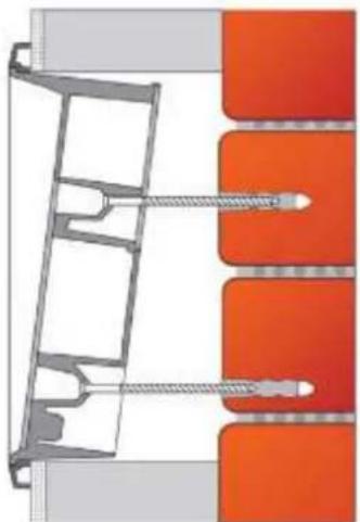
Flush Mounting - Thermally Insulated Wall
What You Need:
- Longer screws (depending on the thermal insulation thickness)
• Hole: (112 x 220 x 70) mm
Cut out the thermal insulation layer using the template (the same as for classic brick wall).
natural_image
Technical diagram of a mechanical assembly with orange components and a gray structural frame (no text or symbols)
Caution
- The hole depth depends on the insulation layer thickness. If the insulation layer is rather thick, you may need longer screws! If there are hollow bricks under the insulation, make sure that your screws pass through the whole dowel (50 mm) and fix the dowel reliably.
- Make sure that the dowel holes have the required diameter. If the diameter is too large, the dowels may get loose. Use some suitable building adhesive to keep the dowels in place.
- Make sure that the hole depth is sufficient too! The dowel length is 50 mm and the screw length is 90 mm.
Suppose that all the required cables have been carried into the drilled hole. Nov follow the instructions applicable for classic brick flush mounting. However, remember that thermally insulated walls show less strength than classic brick walls.
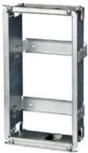
Flush Mounting - Plasterboard
Use the plasterboard flush mounting box and follow the instructions included therein.
What You Need:
- Plasterboard flush mounting box, Part No. 9151002
• Hole: 118 x 237 mm
natural_image
Metallic rectangular frame with multiple horizontal panels and mounting holes (no text or symbols visible)Flush Mounting - Hollow Bricks
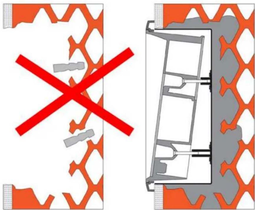
What You Need:
- Brick flush mounting box, Part No. 9151001
• Hole: (132 x 223 x 83) mm
Suppose you intend to install your unit into a wall made of hollow bricks. 2N IP Force Note that the external side of the bricks gets damaged by cutting and the dow cannot practically be fixed into the thin internal part of the bricks. Therefore, use the brick flush mounting box and follow the instructions included therein.
text_image
Diagram showing a red X-shaped prohibition symbol crossed over an orange patterned wall, with a close-up of the door mechanism inside.Wall Mounting
What You Need:
- Just your unit2N IP Force
natural_image
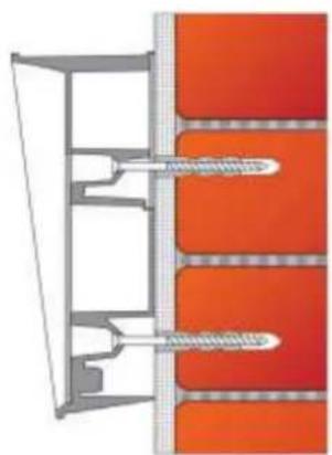
Cross-sectional diagram of a mechanical assembly with two threaded components and layered red-orange components (no text or symbols)Wall (surface) mounting is used where flush mounting is inapplicable (in concrete and steel structures, entry barrier columns, etc.). The frame is not used.

Caution
- Wall mounting may be a problem where vandals may destroy the unit (in public garages, e.g.). Therefore, use steel fixing elements instead of the dowels and screws included in the delivery.
- Be sure to insert plugs into unused bushing holes to avoid water leakage during facade cleaning, for example. Never leave the holes open for even a short time (one day delay between mounting and cable connection, e.g.).

Warning
- Eliminate the risk of accident! Wall mounting is not suitable for narrow passages or places where people's attention may be distracted. The manufacturer shall not be liable for injuries incurred as a result of unsafe mounting!
- Select position with respect to the supply cables. Where the cables are installed inside a structure or wall, use the hole at the intercom bottom.
- Drill holes of the depth of 70 mm for dowels in the wall as shown in the figure. Push or hammer the enclosed dowels into the drilled holes. Use some suitable building adhesive if the dowels are too loose. Use fixing elements of your own for steel structure surface mounting (metric screws + nuts, e.g.).
- Remove the front panel from the intercom.
- Select the holes for cable supply. Select and mount the bushings depending on the cables: 2-hole bushing or 1-hole bushing or both. Insert the blanks in the other holes.
- Put the intercom on the wall/structure while introducing cables inside. Leave some of the cables inside the unit as a reserve. Insert the plugs in the unused bushings and tighten the bushing nuts carefully.
- Do not complete mounting until you have finished electrical installation. Where cables lead along the surface, use the bushings included in the delivery.
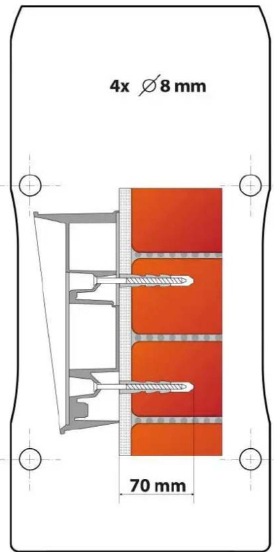
text_image
4x Ø 8 mm 70 mmStand Mounting
This mounting method is suitable for entrance installations in particular.
What you need for installation:
• Stand, Part No. 9151005
- Screws suitable for the surface – are not included in the package

Caution
- Remember to fit the stand to the base thoroughly especially if there is a risk of vandalism (public garages, etc.). Steel fitting elements are recommended.
- Connect grounding.
- Pull the cable through the stand.
- Fit the stand to the base. Refer to the Base drilling template for the dimensions of the fitting elements. The screws are not included in the package. Use screws of your own according to the type of surface.
- Use a cable bushing for the cable fee-out!2N IP Force
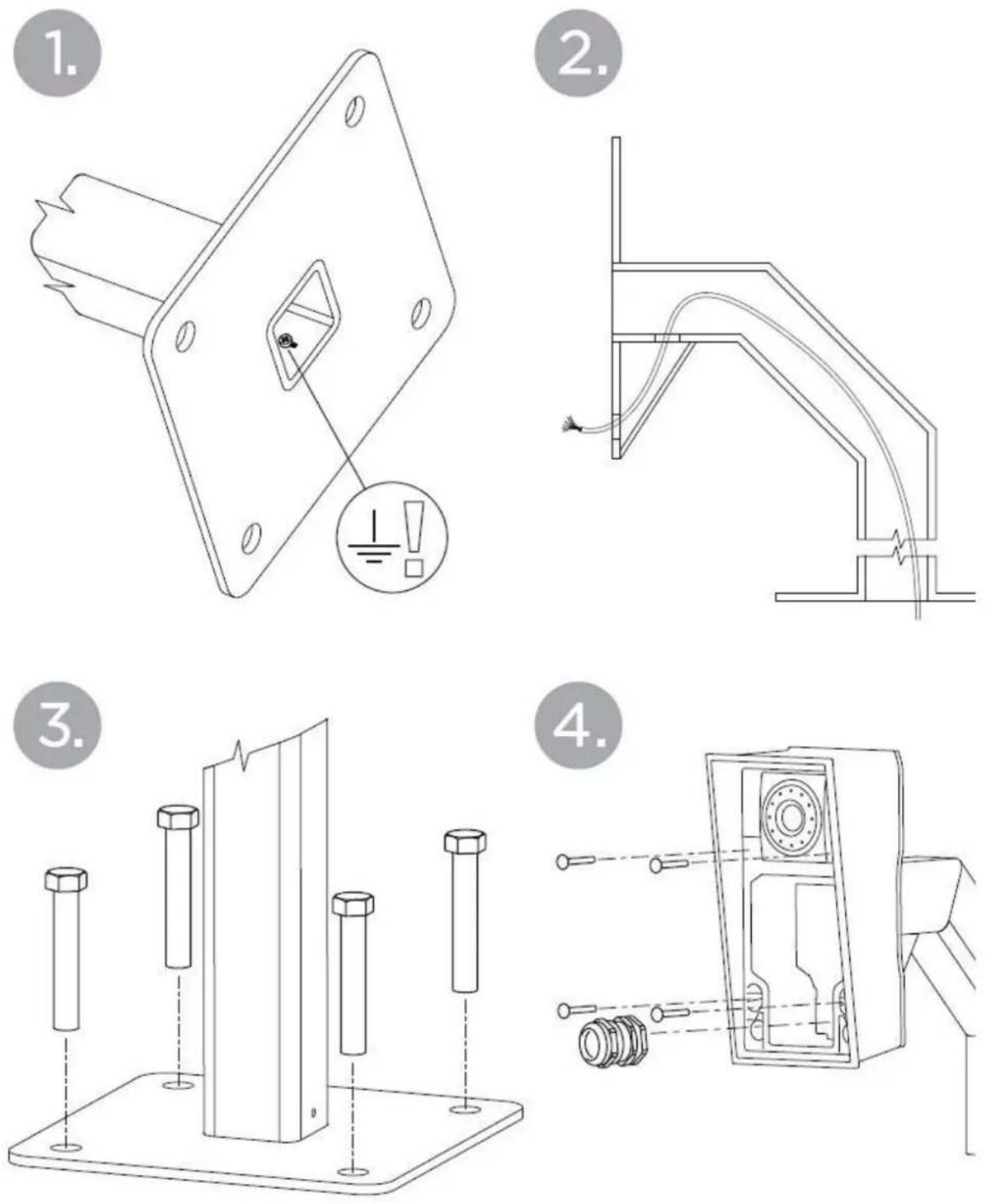
Use of Cable Bushings
The cable bushings included in the delivery are designed for the 2N IP Force following cables:
- Big bushing: for two cables of the diameter of 5-6 mm (UTP cable), or, upon insert replacement, for one thick cable/tube of the diameter of up to 14 mm.
- Small bushing: for one cable of the diameter of 5-8 mm.

Tip
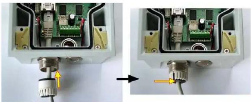
- Even a LAN cable including the RJ-45 connector can go through the big bushing. See below for instructions.
How to Pull a RJ-45 Terminated Cable through a Bushing
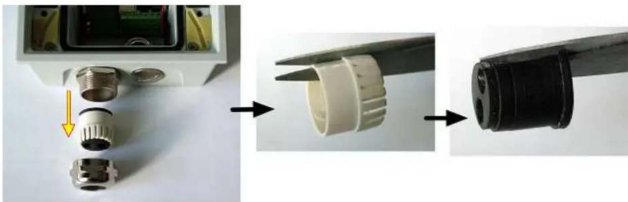
- Unscrew the big bushing nut completely.
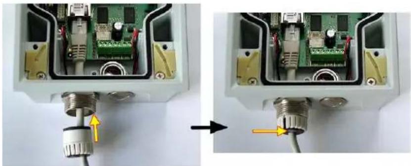
natural_image
Close-up of an electronic device showing internal components and a cable inserted into a housing (no text or symbols visible)- Remove the sealing including the cover from the bushing. Cut either of the components as shown in the figures.
natural_image
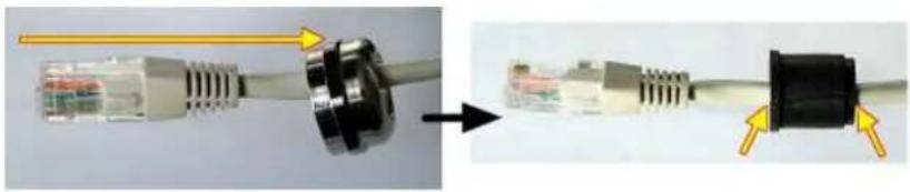
Three-step diagram showing a device with internal components and a close-up of its cable being inserted into a plug (no text or symbols present)- Put the bushing nut on the cable and insert the sealing.
natural_image
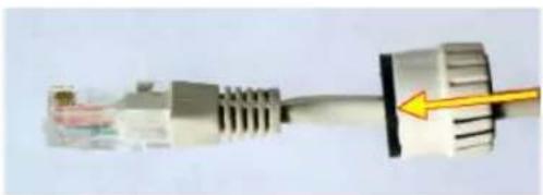
Close-up of a USB cable connector with connectors and a close-up view showing internal components (no text or symbols visible)- Replace the cover onto the sealing.
natural_image
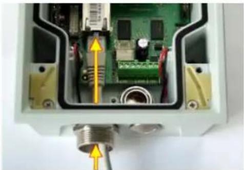
Close-up of a USB cable connector with a yellow arrow pointing to it (no text or symbols visible)- Pull the cable connector though the bushing body into the intercom and clip it into the motherboard connector.
natural_image
Interior view of an electronic device showing internal components and wiring (no visible text or symbols)- Move the sealing including the cover along the cable as far as the bushing body, or add a plug if necessary.
natural_image
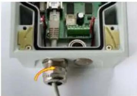
Close-up of an electronic device showing internal components and a cable inserted into a housing (no text or symbols visible)- Replace and tighten the nut.
natural_image
Interior view of an electronic device showing internal components including a green circuit board and connectors (no visible text or symbols)2.3 Electric Installation
This subsection describes how to connect into your Local Area Network 2N IP Force (LAN) and how to connect supply voltage and the electric lock.
- PCB Connectors
• LAN Connection
• External Power Supply Connection
• Electric Lock Connection
• Factory Default Resetting (PCB version 555v5)
• Factory Default Resetting (PCB version 555v3 and higher)
• Factory Default Resetting (PCB version 555v2) - Grounding
- Mounting Completion
• Available Switches

Caution
- The device must be part of the electrical system of the building.
PCB Connectors
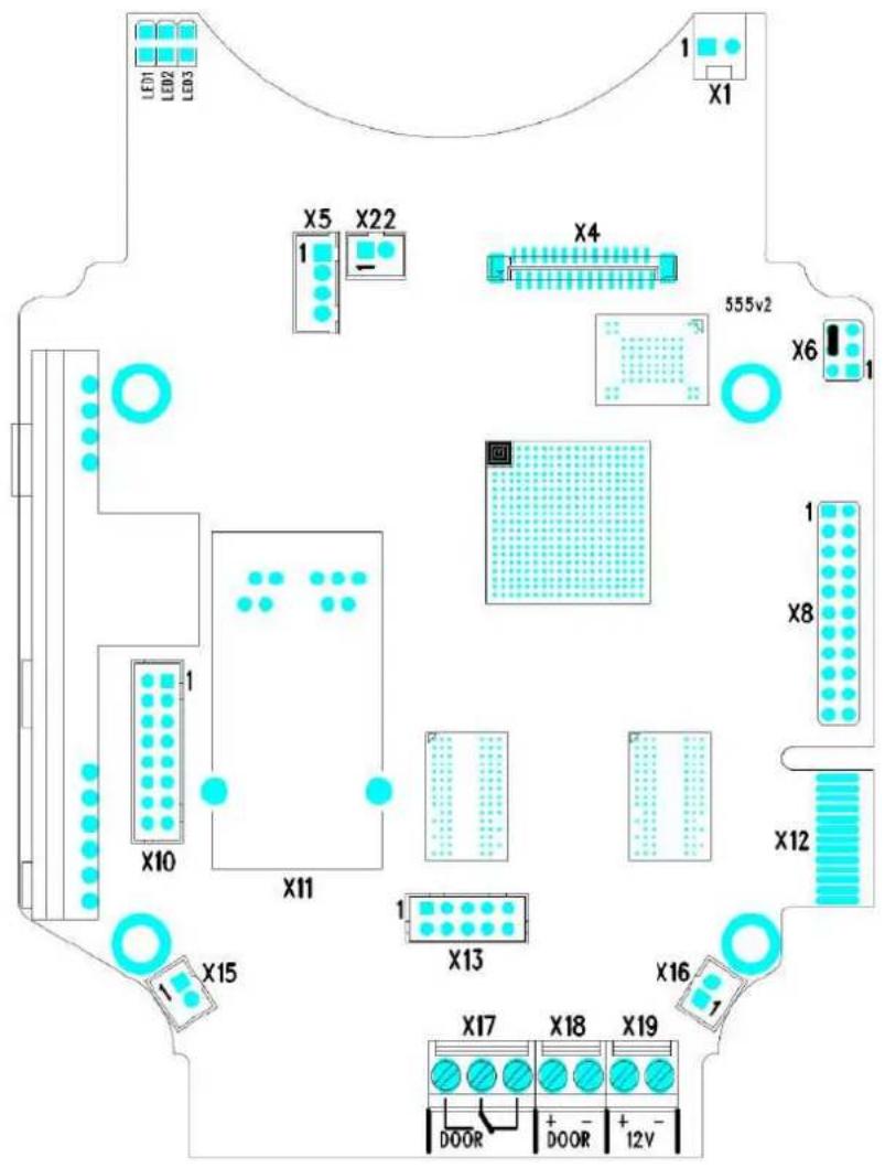
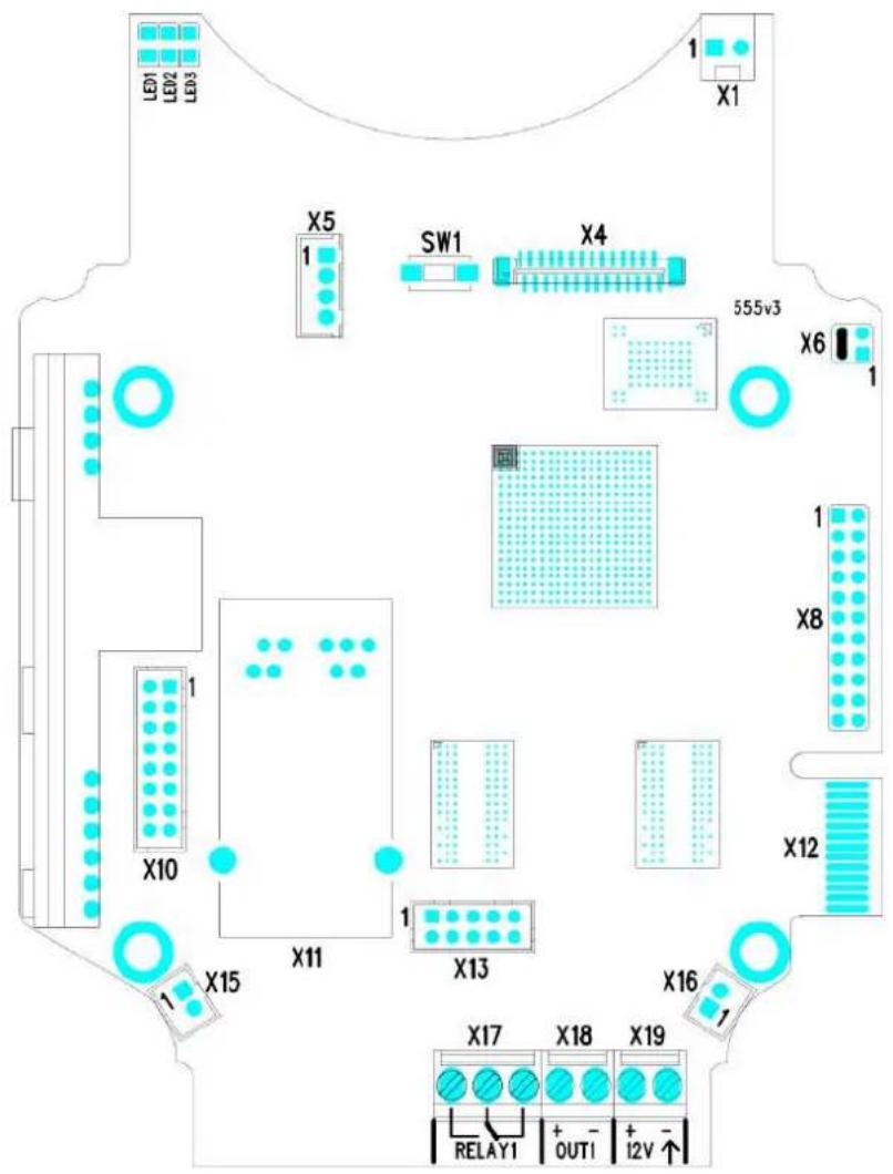
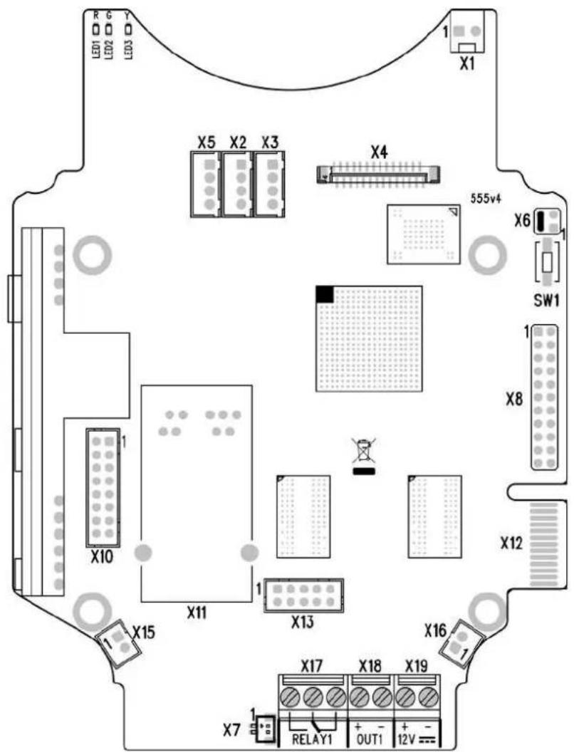
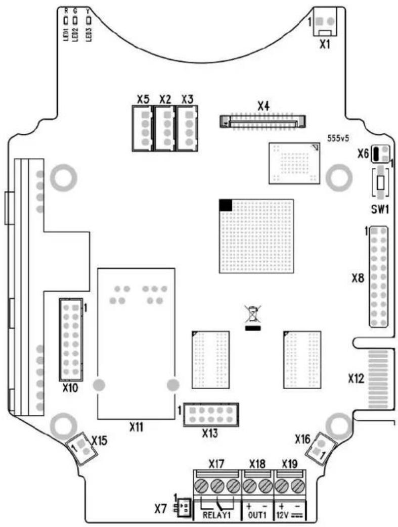
Picture shows the lay-out of connectors on the ^ printed circuit board 2N IP For (PCB). Cables, accessories and other system components are connected to connectors X1 through X22.
Connectors description:
• X1 - Loudspeaker
- X2 - Button 2
- X3 - Button 3
• X4 - Camera module
- X5 - Button 1
- SW1 - Reset button (version 555v3 and higher)
• X6 - Configuration jumpers
- X7 - Induction loop output. Connector type JST SHR-02V-S.
- X8 - Extending module (RFID card reader or additional switch)
• X10 - Buttons 1 through 4
- X11 - LAN
• X12 - Servicing connector
• X13 - Keypad module
• X15 - Left-hand microphone
• X16 - Right-hand microphone
• X17 - Relay NO and NC contact max. 30 V / 1 A AC/DC
- X18 - Switched output 9 up to 13 V DC depending on power supply (PoE: 9 V; adaptor: power supply voltage minus 1 V), max 700 mA
• X19 - Power input 12 V ±15 % / 2 A DC
• LED1/2 - System status indicators
• LED3 - LAN connection activity indicator
text_image
LED1 LED2 LED3 X1 X5 X22 X4 555v2 X6 1 1 X8 X10 X11 X12 X13 X15 X16 X17 X18 X19 DOOR DOOR 12V2N ^® IP Force Connectors, PCB Version 555v2
text_image
LED1 LED2 LED3 X1 X5 SW1 X4 555v3 X6 1 1 X8 X10 X12 X15 X11 X13 X16 X17 X18 X19 RELAY1 OUT1 + - + - 12V ↑2N ^® IP Force Connectors, PCB Version 555v3
text_image
R G Y 1 X1 X5 X2 X3 X4 555v4 X6 1 SW1 1 X8 X12 X10 X11 X13 X15 X16 X17 X18 X19 X7 RELAY1 OUT1 12V = =2N ^® IP Force Connectors, PCB Version 555v4
text_image
R G Y LEEN LEU2 LEU3 X1 X5 X2 X3 X4 555v5 X6 SW1 X8 X12 X10 X11 X13 X15 X16 X17 X18 X19 X7 RELAY1 OUT1 12V2N ^® IP Force Connectors, PCB Version 555v5

Tip
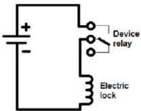
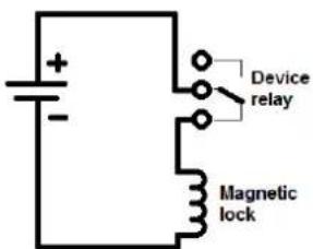
• Output wiring diagram for Relay terminals
text_image
Device relay Electric lockThe electric lock is opened by power supply connection.
text_image
Device relay Magnetic lockThe magnetic lock is opened by power supply disconnection.
LAN Connection
R
2N connected to the LAN via a RJ-45 terminated (connector X11) U/STP cable (of category Cat 5e or higher). The system is equipped with the Aut MDIX function and so both the straight and crossed cable versions can be used.

Caution
• We recommend the use of a LAN surge protection.
• We recommend the use of a shielded SSTP Ethernet cable.
External Power Supply Connection
®
2Ah beForceither from an external 12 V ±15 % / 2 A DC power supply or from the LAN equipped with the PoE 802.3af supporting network elements.
External Power Supply
An external 12 V power supply is connected to terminal block X19. Use a 12 V ± 15 % DC power source dimensioned to current intake of 2 A at least (Part No. 91341481E) to ensure a reliable function of your device.
PoE Supply
®
2NcPf401de with the PoE 802.3af (Class 0-12.95 W) technology and can be supplied directly from the LAN via compatible network elements. If your LAN in incompatible, insert the PoE injector, Part No. 91378100E/US, between
R
and the nearest network element. 2N IP Force
Electric Lock Connection
R
2NetRuiSpace with an electrically isolated relay switch with NO and NO contacts (terminal block X17, max. 30 V / 1 A AC/DC) and 9 up to 13 V DC depending on power supply (PoE: 9 V; adaptor: power supply voltage minus 1 V), max 600 mA switched output (terminal block X18), to which a standard electric lock or another compatible electrical appliance can be connected.

Note
• Devices with PCB version 555v3 and higher provides independent control of 12 V switched output (terminal block X18) and relay switch (terminal block X17). Devices with PCB version 555v2 have both outputs switched simultaneously.
Warning
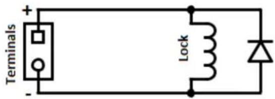
When you connect a device containing a coil, such as a relay or an electromagnetic lock, it is necessary to protect the intercom against voltage peak while switching off the induction load. For this way of protection we recommend a diode 1 A / 1000 V (e.g., 1N4007, 1N5407, 1N5408) connected antiparallel to the device.
text_image
Terminals + - Lock ΔReset Button
Located among the main unit connectors, the Reset button helps you reset the factory default values, restart the device, find the device IP address and switch the stat /dynamic mode.
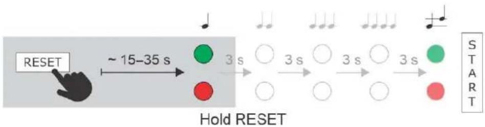
IP Address Finding
Follow the instructions below to :identify the current IP address
- Press and hold the RESET button.
- Wait until the red and green LEDs go on simultaneously on the device and the acoustic signal can be heard (approx. 15–35 s).
- Release the RESET button.
• The device automatically announces the current IP address.
flowchart
graph LR
    A["RESET"] --> B["Hold RESET"]
    B --> C["3 s"]
    C --> D["○"]
    D --> E["3 s"]
    E --> F["○"]
    F --> G["3 s"]
    G --> H["○"]
    H --> I["3 s"]
    I --> J["○"]
    J --> K["3 s"]
    K --> L["○"]
    L --> M["3 s"]
    M --> N["○"]
    N --> O["3 s"]
    O --> P["○"]
    P --> Q["3 s"]
    Q --> R["○"]
    R --> S["3 s"]
    S --> T["○"]
    T --> U["3 s"]
    U --> V["○"]
    V --> W["3 s"]
    W --> X["○"]
    X --> Y["3 s"]
    Y --> Z["○"]
    Z --> AA["3 s"]
    AA --> AB["○"]
    AB --> AC["3 s"]
    AC --> AD["○"]
    AD --> AE["3 s"]
    AE --> AF["○"]
    AF --> AG["3 s"]
    AG --> AH["○"]
    AH --> AI["3 s"]
    AI --> AJ["○"]
    AJ --> AK["3 s"]
    AK --> AL["○"]
    AL --> AM["3 s"]
    AM --> AN["○"]
    AN --> AO["3 s"]
    AO --> AP["○"]
    AP --> AQ["3 s"]
    AQ --> AR["○"]
    AR --> AS["3 s"]
    AS --> AT["○"]
    AT --> AU["3 s"]
    AU --> AV["○"]
    AV --> AW["3 s"]
    AW --> AX["○"]
    AX --> AY["3 s"]
    AY --> AZ["○"]
    AZ --> BA["3 s"]
    BA --> BB["○"]
    BB --> BC["3 s"]
    BC --> BD["○"]
    BD --> BE["3 s"]
    BE --> BF["○"]
    BF --> BG["3 s"]
    BG --> BH["○"]
    BH --> BI["3 s"]
    BI --> BJ["○"]
    BJ --> BK["3 s"]
    BK --> BL["○"]
    BL --> BM["3 s"]
    BM --> BN["○"]
    BN --> BO["3 s"]
    BO --> BP["○"]
    BP --> BQ["3 s"]
    BQ --> BR["○"]
    BR --> BS["3 s"]
    BS --> BT["○"]
    BT --> BU["3 s"]
    BU --> BV["○"]
    BV --> BW["3 s"]
    BW --> BX["○"]
    BX --> BY["3 s"]
    BY --> BZ["○"]
    BZ --> CA["3 s"]
    CA --> CB["○"]
    CB --> CC["3 s"]
    CC --> CD["○"]
    CD --> CE["3 s"]
    CE --> CF["○"]
    CF --> CG["3 s"]
    CG --> CH["○"]
    CH --> CI["3 s"]
    CI --> CJ["○"]
    CJ --> CK["3 s"]
    CK --> CR["○"]
    CR --> CS["3 s"]
    CS --> CT["○"]
    CT --> CU["3 s"]
    CU --> CV["○"]
    CV --> CW["3 s"]

Note
- The delay after pressing RESET till the first light and sound signalling is set to 15-35 s depending on the 2N IP intercom/answering unit model used.
• 24 s is the valid value for HW version 8.2N IP Force
Static IP Address Setting
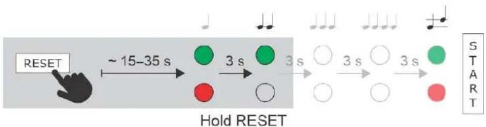
Follow the instructions below to switch on the mode (DHCP OFF):Static IP address
- Press and hold the RESET button. - Wait until the red and green LEDs go on simultaneously on the device and the acoustic signal can be heard (approx. 15–35 s).
- Wait until the red LED goes off and the acoustic signal can be heard (approx. for another 3 s). - Release the RESET button.
The following network parameters will be set after restart:
• IP address: 192.168.1.100
• Network mask: 255.255.255.0
- Default gateway: 192.168.1.1
flowchart
graph LR
    A["RESET"] --> B["Hold RESET"]
    B --> C["3 s"]
    C --> D["3 s"]
    D --> E["3 s"]
    E --> F["3 s"]
    F --> G["START"]
Dynamic IP Address Setting
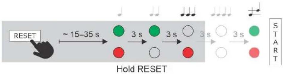
Follow the instructions below to switch on the mode (DCHP ON): Dynamic IP address
- Press and hold the RESET button. - Wait until the red and green LEDs go on simultaneously on the device and the acoustic signal can be heard (approx. 15–35 s).
- Wait until the red LED goes off and the acoustic signal can be heard (approx. for another 3 s).
- Wait until the green LED goes off and the red LED goes on again and the acoustic signal can be heard (approx. for another 3 s).
- Release the RESET button.
flowchart
graph LR
    A["RESET"] --> B["~ 15–35 s"]
    B --> C["Hold RESET"]
    C --> D["3 s"]
    D --> E["Green Circle"]
    E --> F["Red Circle"]
    F --> G["White Circle"]
    G --> H["Green Circle"]
    H --> I["Red Circle"]
    I --> J["White Circle"]
    J --> K["Green Circle"]
    K --> L["Red Circle"]
    L --> M["White Circle"]
    M --> N["Green Circle"]
    N --> O["Red Circle"]
    O --> P["White Circle"]
    P --> Q["Green Circle"]
    Q --> R["Red Circle"]
    R --> S["White Circle"]
    S --> T["Green Circle"]
    T --> U["Red Circle"]
    U --> V["White Circle"]
    V --> W["Green Circle"]
    W --> X["Red Circle"]
    X --> Y["White Circle"]
    Y --> Z["Green Circle"]
    Z --> AA["Red Circle"]
    AA --> AB["White Circle"]
    AB --> AC["Green Circle"]
    AC --> AD["Red Circle"]
    AD --> AE["White Circle"]
    AE --> AF["Green Circle"]
    AF --> AG["Red Circle"]
    AG --> AH["White Circle"]
    AH --> AI["Green Circle"]
    AI --> AJ["Red Circle"]
    AJ --> AK["White Circle"]
    AK --> AL["Green Circle"]
    AL --> AM["Red Circle"]
    AM --> AN["White Circle"]
    AN --> AO["Green Circle"]
    AO --> AP["Red Circle"]
    AP --> AQ["White Circle"]
    AQ --> AR["Green Circle"]
    AR --> AS["Red Circle"]
    AS --> AT["White Circle"]
    AT --> AU["Green Circle"]
    AU --> AV["Red Circle"]
    AV --> AW["White Circle"]
    AW --> AX["Green Circle"]
    AX --> AY["Red Circle"]
    AY --> AZ["White Circle"]
    AZ --> BA["Green Circle"]
    BA --> BB["Red Circle"]
    BB --> BC["White Circle"]
    BC --> BD["Green Circle"]
    BD --> BE["Red Circle"]
    BE --> BF["White Circle"]
    BF --> BG["Green Circle"]
    BG --> BH["Red Circle"]
    BH --> BI["White Circle"]
    BI --> BJ["Green Circle"]
    BJ --> BK["Red Circle"]
    BK --> BL["White Circle"]
    BL --> BM["Green Circle"]
    BM --> BN["Red Circle"]
    BN --> BO["White Circle"]
    BO --> BP["Green Circle"]
    BP --> BQ["Red Circle"]
    BQ --> BR["White Circle"]
    BR --> BS["Green Circle"]
    BS --> BT["Red Circle"]
    BT --> BU["White Circle"]
    BU --> BV["Green Circle"]
    BV --> BW["Red Circle"]
    BW --> BX["White Circle"]
    BX --> BY["Green Circle"]
    BY --> BZ["Red Circle"]
Factory Reset (PCB version 555v5 and higher)
Follow the instructions below to :reset the factory default values
- Press and hold the RESET button. - Wait until the red and green LEDs go on simultaneously and the acoustic signal can be heard (approx. 15–35 s).
- Wait until the red LED goes off and the acoustic signal can be heard (approx. for another 3 s).
- Wait until the green LED goes off and the red LED goes on again and the acoustic signal can be heard (approx. for another 3 s).
- Wait until the red LED goes off and the acoustic signal can be heard (approx. for another 3 s).
- Release the RESET button.
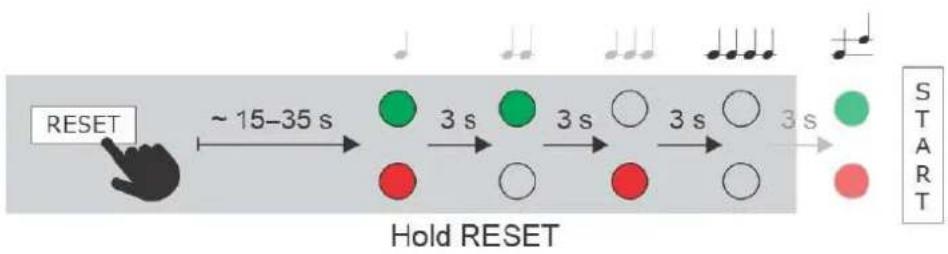
flowchart
graph LR
    A["RESET"] --> B["Hold RESET"]
    B --> C["3 s"]
    C --> D["3 s"]
    D --> E["3 s"]
    E --> F["3 s"]
    F --> G["3 s"]
    G --> H["START"]

Caution
- In case of resetting the factory default settings on a device with a version of firmware 2.18 or higher it is necessary to reprogram the using the instructions from section 22N Security Relay
Device Restart
Press the RESET button shortly (< 1 s) to restart the system without changing configuration.

Note
- The time interval between the short press of RESET and reconnection after restart is 25-50 s for depending on the HW version.2N IP Force
Factory Default Resetting (PCB version 555v3 and higher)
For resetting device to default settings press and hold SW1 button. Wait for the first sound signalization and then release the button. If you press the button for short time device will reboot only. SW1 button is available in devices with PCB version 555v3 and higher. For devices with PCB version 555v2 see procedure below.

Caution
- In case of resetting the factory default settings on a device with a version of firmware 2.18 or higher it is necessary to reprogram the using the instructions from section 22N IP Security Re
Factory Default Resetting (PCB version 555v2)
- Disconnect the device from the power supply.
- Move the short-circuit jumper on connector X6 into the position. Default setup Configuration jumpers (X6) are located in the right-hand upper corner of the PCB.
- Reconnect the power supply and wait for a start signalling sound.
- Disconnect the device from the power supply.
- Move the short-circuit jumper on connector X6 into the Normal operation position.
- Reconnect the power supply. The device will be reset to factory default.
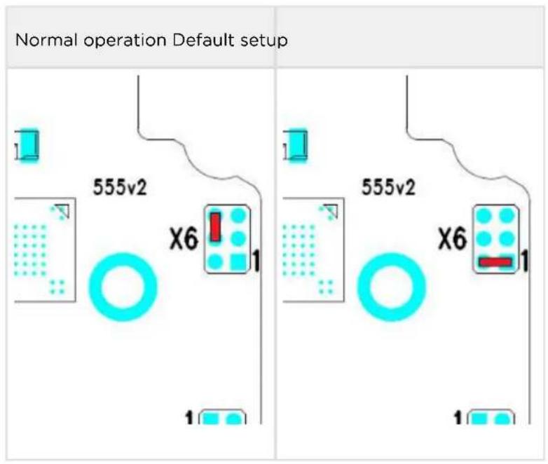
text_image
Normal operation Default setup 555v2 X6 1 1 555v2 X6 1 1Configuration jumpers X6, PCB version 555v2
Grounding
We recommend to ground the intercom in order to improve the static electricity resistance. For proper grounding you need a cable of the minimum cross-section of 4 mm2. Connect the cable to the connector in the bottom part of the intercom. T connector is enclosed to the delivery.
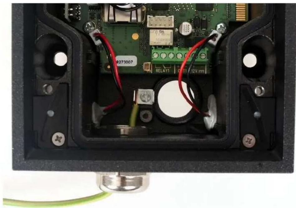
natural_image
Interior view of an electronic device showing exposed circuit board, wires, and connectors (no readable text or symbols)Mounting Completion
-
Having connected all the wires, make sure that the bushings, if used, are tightened properly and the RJ-45 connector is inserted in the PCB connector.
-
Replace the front cover carefully. Make sure that the connector is inserted correctly and the wires inside the device leave enough space for the board if you are installing a four-button board. Tighten the four screws thoroughly with the wrench enclosed (Torx 20) to make the panel fit tightly to the metal chassis.

Caution
- Properly installed intercom is waterproof. An incorrect mounting may compromise the intercom watertightness. Water leakage may damage the electronic part of the system.
- Stainless steel screws are used for the assembly. Other 2N IP Force screws than stainless steel ones corrode soon and may aesthetically deteriorate the surrounding environment!
Available Switches
| Location Name Description | ||
| Basic Unit | Relay 1 | Passive relay switch: NO and NC contacts, up to 30 V / 1 A AC /DC |
| Output 1 Active switch output: 9 up to 13 V DC depending on power supply (PoE: 9 V; adaptor: power supply voltage minus 1 V), max 600 mA | ||
| Additional Switch* (Part No. 9151010) | Relay 2 | Passive relay switch: NO and NC contacts, up to 30 V / 1 A AC /DC |
| Output 2 Active switch output 9 up to 13 V DC depending on power : supply (PoE: 9 V; adaptor: power supply voltage minus 1 V), max 600 mA | ||
| Internal RFID Card Reader 125 kHz* (Part No. 9151011) | Relay 1 (Card Reader), | Passive relay switch : NO and NC contacts, up to 30 V / 1 A AC /DC |
| Output 1 (Card Reader) | Active switch output : 9 up to 13 V DC depending on power supply (PoE: 9 V; adaptor: power supply voltage minus 1 V), max 600 mA | |
| Internal RFID Card Reader 13.56 MHz* (Part No. 9151016) | Relay 1 (Card Reader), | Passive relay switch : NO and NC contacts, up to 30 V / 1 A AC /DC |
| Output 1 (Card Reader) | Active switch output : 9 up to 13 V DC depending on power supply (PoE: 9 V; adaptor: power supply voltage minus 1 V), max 600 mA | |
Only one module marked by * can be used.
2.4 Extending Module Connection
2N ^® IP Force allows to connect following extending modules:
• Additional Switch
• Internal RFID Card Reader 125 kHz
• Internal RFID Card Reader 13.56 MHz
• Internal secured RFID Card Reader 13.56 MHz
- Security Relay
- Wiegand Isolator
- Induction Loop
Additional Switch
The (Part No. 9151010) is used for extending the number of inputsAdditional Switch /outputs. This extending module is intended for mounting into the main 2N IP Force unit and is compatible with the basic units with Part No. 915110xxxxx. If the Additional Switch is installed, it is not possible to install Internal RFID Card Reader.
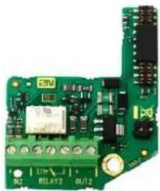
natural_image
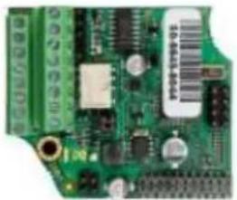
Green printed circuit board with visible components and connectors (no readable text or symbols)Function:
The Additional Switch adds two additional switches, one logical input 2N IP Force and a tamper switch to the basic unit. The purpose of the tamper switch 2N IP Force is to signal any unauthorised opening of the intercom (to prevent a theft, e.g.). It is recommended to use the tamper switch.

Tip
- FAQ: Tamper switch - How to install it into the 2N ^ IP Force
Specifications version 5:
• IN2 terminals for input in passive / active mode (-30 V to +30 V DC)
• OFF = open OR UIN > 1.5 V
• ON = closed contact OR UIN < 1.5 V
- RELAY2 terminals 30 V/1 A AC/DC NO/NC contact
• OUT2 active output: 12 V/600 mA DC
• Tamper switch input (X2): 24 V/50 mA AC/DC
Specifications version 4 a lower:
• Passive switch: NO and NC contacts, up to 30 V / 1 A AC/DC
• Active switch output: 9 V (Using PoE) or power supply voltage minus 1 V, from 9 to 13 V max. 700 mA DC
• Tamper switch: 24 V / 50 mA AC/DC
Module mounting:
- Switch off the intercom.
- Remove the front panel from the intercom.
- According to your model
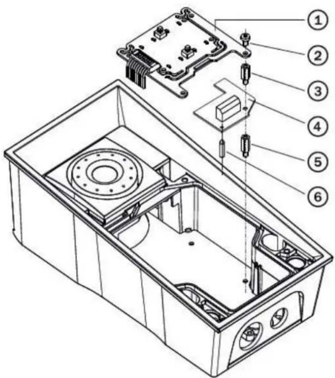
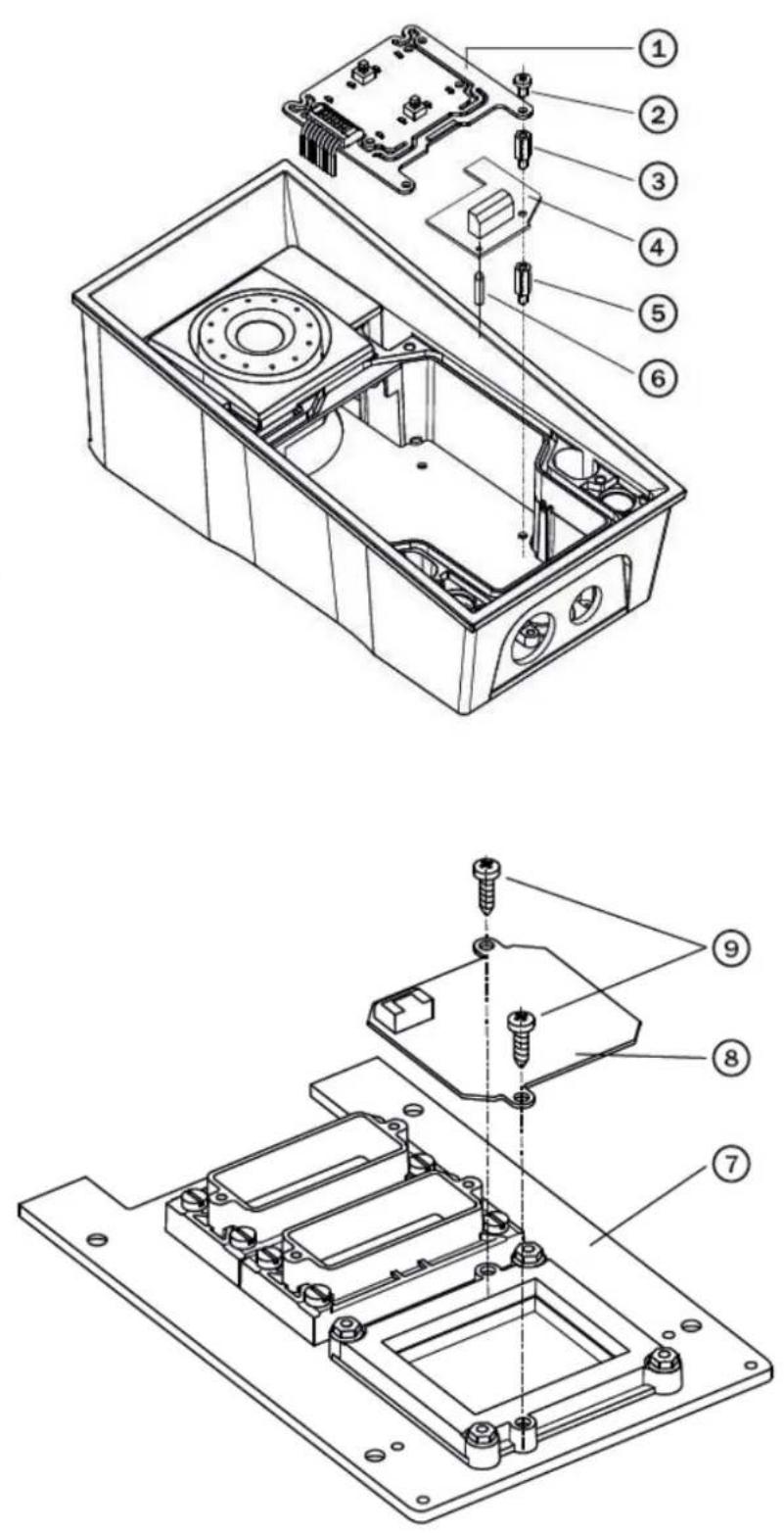
a. If you are mounting the switch into a two-nameplate model, demount the button PCB (1) and remove the right-hand bottom spacer (there are four PCB fitting spacers altogether).
b. If you are mounting the switch into a keypad model, take the keypad out of the holder. Demount the right-hand keypad holder - beam with a pin (8) - remembering its position. Demount the right-hand bottom spacer. Do not disconnect the keypad cable!
c. If you are mounting the switch into a model other than the two ones mentioned in items 3a and 3b above, remove the right-hand bottom screw from the main board.
- Now screw the enclosed 12 mm spacer (5) into the vacated main board slot.
-
Mount the enclosed plastic support (6) onto the switch board bottom side.
-
Put the switch board (4) in the main board connector making sure that the screw hole is directly above the spacer.
-
According to your model
a. If you are mounting the switch into a two-nameplate model, fit the switch board with the enclosed 10.5 mm spacer (3) and reinstall the button PCB (1).
b. If you are mounting the switch into a keypad model, reinstall the beam (8) of the keypad holder (the slot is on top). Insert the enclosed 4.5 mm washer (9) between the beam and the switch board, fitting the assembly with the 15 mm screw enclosed (7).
c. If you are mounting the switch into a model other than the two ones mentioned in items 7a and 7b, fit the switch board with the original 6 mm screw (2).
-
If you want to use the tamper switch, insert the tamper board (9) in the connector located in the right-hand bottom part of the switch board (4). As the tamper switch shares the relay output (NO and NC) terminals, you cannot use the RELAY2 output with the tamper switch together.
-
Place front panel back and tighten all four screws.
text_image
Technical diagram of an electronic device with numbered components for identification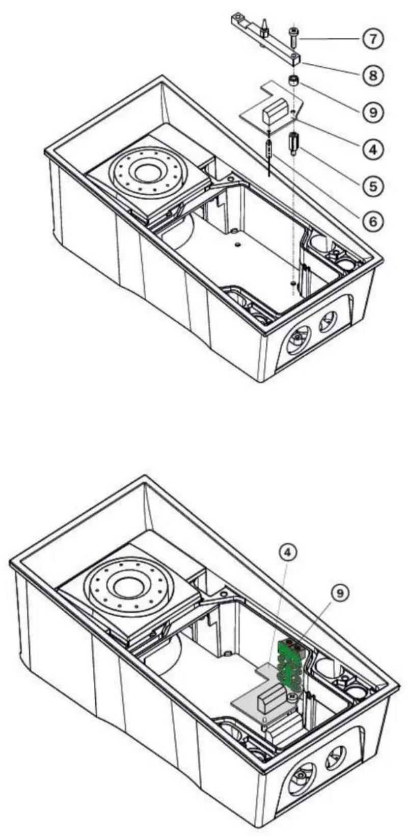
Module settings:
Refer to the Configuration Manual for details.
Connection:
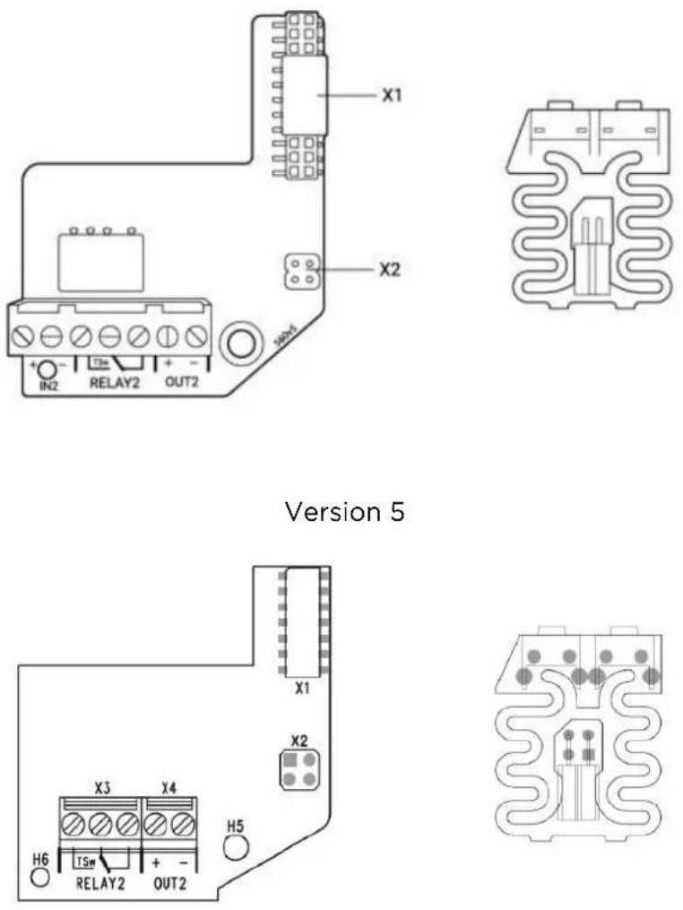
Version 4 and lower
Internal RFID Card Reader 125 kHz
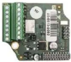
The (Part No. 9151011) is used for reading RFID card Internal RFID Card Reader 125 kHz Ids in the 125 kHz band. This module is intended for mounting into the 2N IP Force model 9151102CR, 9151102R, 9151101CRP and 9151101RP. These models have an window, which is necessary for antenna operation. If the Internal RFID Card Reader is installed, it is not possible to install the Additional Switch.
natural_image
Close-up of a green printed circuit board with various electronic components (no visible text or symbols)Function:
The Internal RFID Card Reader adds two logical inputs, two additional 2N IP Force switches and a tamper switch to the basic unit.2N IP Force
The purpose of the tamper switch is to signal any unauthorised opening of the intercom (to prevent a theft, e.g.). It is recommended to use the tamper switch.

Tip
- FAQ: Tamper switch - How to install it into the 2N ^ IP Force
Specifications:
Card reader
- Compatible with:
- EM4xxx
• Operating frequency: 125 KHz
• Minimum reading distance: 10 mm above cover2N IP Force
Relay output
- Switching contact
- 30 V / 2 A AC/DC
Active output
• 12 V / 700 mA transistor switched output
Logical inputs
Active mode - requires external voltage (JP2 jumper OFF)
- U_IN ON = min +2.5 V
- U_IN OFF = max +1.5 V
- U_IN = +48 ~V
- I_IN(U_N + 48V) = 1mA
Passive mode - requires external contact only (JP2 jumper ON)
- U_OUT = approx. 8.3 V
- I_LOOP approx. 0.5 mA
Signalling output
- Internal red LED under reader window
WIEGAND interface
- Off/Input/Output (as programmed)
Mounting guide:
- Switch off the intercom.
- Remove the front panel (7) from the intercom.
- Mount antenna board (8). Use two enclosed self tapping screws (9).
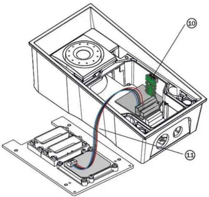
- Plug enclosed cable (11) to the antenna board connector.
- Demount a button PCB (1). Don't disconnect its cable!
-
There will stay four spacers after the switch board removal. Dismount the bottom right one.
-
There are two short metal spacers enclosed to the reader. Take a longer one (5), 12 mm long. Screw it into the free hole.
- Plug an enclosed plastic support (6) to the reader board from the bottom side.
- Put the reader board (4) in the main board connector making sure that the mounting hole is directly above the spacer.
- Screw in a remaining metal spacer (3), 10.5 mm long.
- Fit the button PCB (1) back to its position using original bolts (2).
- If you want to use the tamper switch (to detect unauthorized opening the case, as a theft protection), insert the tamper board (10) in the connector located in the right-hand bottom part of the reader board (4). As the tamper switch shares the relay output (NO and NC) terminals, you cannot use the RELAY2 output with the tamper switch at the same time.
- Plug the antenna cable (11) to its connector at the reader board (4).
- Place front panel back and tighten all four screws.
text_image
Technical diagram of an electronic device with labeled components, showing internal wiring and housing layoutModule setting:
Refer to the Configuration Manual for details of Wiegand, outputs and reader. Refer to the Automation manual for details of input, red LED and tamper function and use.
Connection:

text_image
Terminal block description X1 X2 X3 H5 JP1 JP2 X5 X4 H7 A B ↑ U W0 W1 ↑ WEGAND WEGAND WEGAND IN1 IN2 ↑ NO C NC +OUT- INPUT RELAY 2 OUT 2Internal RFID Card Reader 13.56 MHz
The (Part No. 9151031/9151017) is used for Internal RFID Card Reader 13.56 MHz reading RFID card Ids in the 13.56 MHz band, NFC supported. This module is intended for mounting into the model 9151101RPW, 9151101CRPW, 9151101CHRPW, 2N IP Force 9151102RW, 9151102CRW and 9151102CHRW. These models have an window, which is necessary for antenna operation. If the Internal RFID Card Reader is installed, it is not possible to install the Additional Switch.
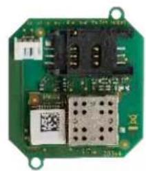
natural_image
Green printed circuit board with integrated circuits and a QR code (no readable text or symbols)9151031
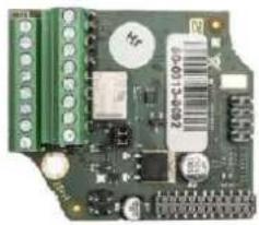
natural_image
Close-up of a green printed circuit board with various electronic components (no visible text or symbols)9151017
Function:
The Internal RFID Card Reader adds two logical inputs, two additional 2N IP Force switches and a tamper switch to the basic unit.2N IP Force
The purpose of the tamper switch is to signal any unauthorised opening of the intercom (to prevent a theft, e.g.). It is recommended to use the tamper switch.

Tip
- FAQ: Tamper switch - How to install it into the 2N ^ IP Force
Specifications:
Card reader
- Operating frequency: 13.56 MHz
• Minimum reading distance: 30 mm above cover2N IP Force - RFID Reader 9151031 is compatible with cards (only card serial number is read):
• ISO14443A (Mifare, DESFire)
- PicoPass (HID iClass)
- FeliCa
• ST SR(IX)
- 2N ^ Mobile Key
- RFID Reader 9151017 is compatible with cards (only card serial number is read):
• ISO14443A (Mifare, DESFire)
- PicoPass (HID iClass)
- FeliCa
• ST SR(IX)
- 2N ^ Mobile Key
Relay output
- Switching contact
- 30 V / 2 A AC/DC
Active output
- 9 to 12 V / 700 mA transistor switched output. Depends on power supply (PoE: 9 V or power supply voltage minus 1 V).
Logical inputs
Active mode - requires external voltage (JP2 jumper OFF)
- U_IN ON = min +2.5 V
- U_IN OFF = max +1.5 V
- U_IN = +48 ~V
• I_IN(U_IN + 48 V) = 1 mA
Passive mode - requires external contact only (JP2 jumper ON)
- U_IN = approx. 8.3 V
- U_IN2 approx. 8.3 V
- I_LOOP approx. 0.5 mA
Signalling output
- Internal red LED under reader window
PWR
• For external RFID card reader
• Out: 9 to 12 V / 350 mA depends on power supply
WIEGAND interface
- Off/Input/Output (as programmed)
Mounting guide:
- Switch off the intercom.
- Remove the front panel (7) from the intercom.
- Mount antenna board (8). Use two enclosed self tapping screws (9).
- Plug enclosed cable (11) to the antenna board connector.
- Demount a button PCB (1). Don't disconnect its cable!
- There will stay four spacers after the switch board removal. Dismount the bottom right one.
- There are two short metal spacers enclosed to the reader. Take a longer one (5), 12 mm long. Screw it into the free hole.
- Plug an enclosed plastic support (6) to the reader board from the bottom side.
- Put the reader board (4) in the main board connector making sure that the mounting hole is directly above the spacer.
- Screw in a remaining metal spacer (3), 10.5 mm long.
-
Fit the button PCB (1) back to its position using original bolts (2).
-
If you want to use the tamper switch (to detect unauthorized opening the case, as a theft protection), insert the tamper board (10) in the connector located in the right-hand bottom part of the reader board (4). As the tamper switch shares the relay output (NO and NC) terminals, you cannot use the RELAY2 output with the tamper switch at the same time.
-
Plug the antenna cable (11) to its connector at the reader board (4).
-
Place front panel back and tighten all four screws.
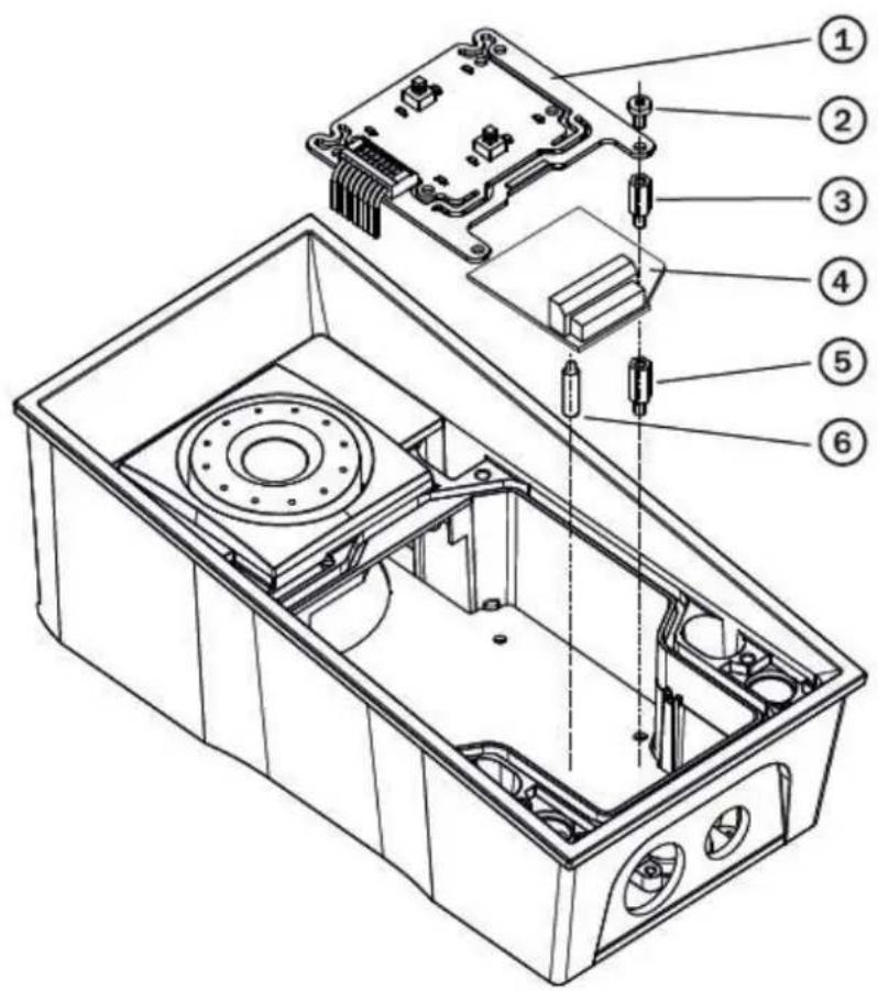
text_image
Technical diagram of an electronic device with numbered components for identification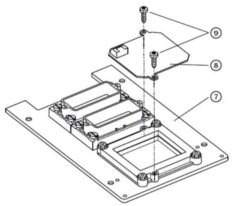
text_image
Technical diagram of a mechanical assembly with numbered parts for identification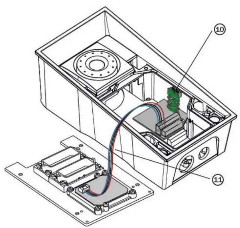
text_image
Technical diagram of an electronic device with labeled components, showing internal wiring and housing layoutModule setting:
Refer to the Configuration Manual for details of Wiegand, outputs and reader. Refer to the Automation manual for details of input, red LED and tamper function and use.
Connection:
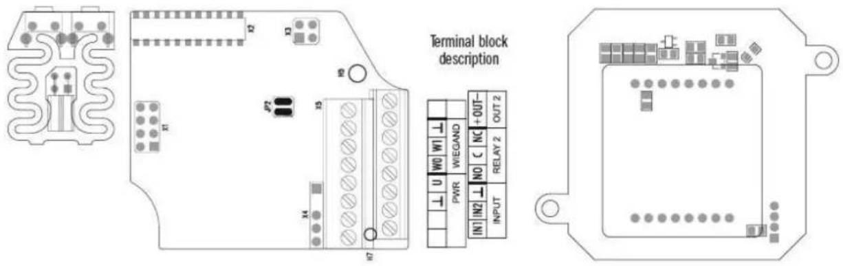
text_image
Terminal block description PWR WEGAND +OUT- IN1 IN2 NC RELAY 2 OUT 2 INPUTInternal secured RFID Card Reader 13.56 MHz
The (Part No. 9151031S/9151019) is used for Internal RFID Card Reader 13.56 MHz: reading RFID card Ids in the 13.56 MHz band, NFC supported. This module is intended for mounting into the model 9151101RPW, 9151101CRPW, 9151101CHRPW, 2N IP Force 9151102RW, 9151102CRW a 9151102CHRW. These models have an window, which is necessary for antenna operation. If the Internal RFID Card Reader is installed, it is not possible to install the Additional Switch.
natural_image
Close-up of a green printed circuit board with various electronic components (no visible text or symbols)9151019
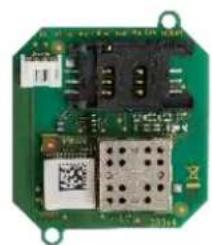
natural_image
Green printed circuit board with integrated components and a QR code (no readable text or symbols)9151031S
Function:
The Internal RFID Card Reader adds two logical inputs, two additional 2N IP Force switches and a tamper switch to the basic unit.2N IP Force
The purpose of the tamper switch is to signal any unauthorised opening of the intercom (to prevent a theft, e.g.). It is recommended to use the tamper switch.

Tip
- FAQ: Tamper switch - How to install it into the 2N ^ IP Force
Specifications:
Card reader
- Operating frequency: 13.56 MHz
• Minimum reading distance: 30 mm above cover2N IP Force - RFID card reader 9151031S is compatible with cards (optionally card serial number or PAC ID is read):
• ISO14443A (Mifare, DESFire)
- PicoPass (HID iClass)
- FeliCa
• ST SR(IX)
- 2N ^ Mobile Key
• HID SE (Seos, iClass SE, Mifare SE)
- RFID card reader 9151019 is compatible with cards (optionally card serial number or PAC ID is read):
• ISO14443A (Mifare, DESFire)
- PicoPass (HID iClass)
- FeliCa
• ST SR(IX) - 2N ^ Mobile Key
• HID SE (Seos, iClass SE, Mifare SE)
Relay output
- Switching contact
- 30 V / 2 A AC/DC
Active output
- 9 to 12 V / 700 mA transistor switched output. Depends on power supply (PoE: 9 V or power supply voltage minus 1 V).
Logical inputs
Active mode - requires external voltage (JP2 jumper OFF)
- U_IN ON = min +2.5 V
- U_IN OFF = max +1.5 V
- U_IN = +48 ~V
- I_IN(U_IN + 48 V) = 1 mA
Passive mode - requires external contact only (JP2 jumper ON)
- U_IN = approx. 8.3 V
- U_IN2 = approx. 8.3 V
- I_LOOP approx. 0.5 mA
Signalling output
- Internal red LED under reader window
PWR
- For external RFID card reader
• Out: 9 to 12 V / 350 mA depends on power supply
WIEGAND interface
- Off/Input/Output (as programmed)
Mounting guide:
- Switch off the intercom.
- Remove the front panel (7) from the intercom.
- Mount antenna board (8). Use two enclosed self tapping screws (9).
- Plug enclosed cable (11) to the antenna board connector.
- Demount a button PCB (1). Don't disconnect its cable!
- There will stay four spacers after the switch board removal. Dismount the bottom right one.
- There are two short metal spacers enclosed to the reader. Take a longer one (5), 12 mm long. Screw it into the free hole.
- Plug an enclosed plastic support (6) to the reader board from the bottom side.
- Put the reader board (4) in the main board connector making sure that the mounting hole is directly above the spacer.
- Screw in a remaining metal spacer (3), 10.5 mm long.
-
Fit the button PCB (1) back to its position using original bolts (2).
-
If you want to use the tamper switch (to detect unauthorized opening the case, as a theft protection), insert the tamper board (10) in the connector located in the right-hand bottom part of the reader board (4). As the tamper switch shares the relay output (NO and NC) terminals, you cannot use the RELAY2 output with the tamper switch at the same time.
- Plug the antenna cable (11) to its connector at the reader board (4).
- Place front panel back and tighten all four screws.
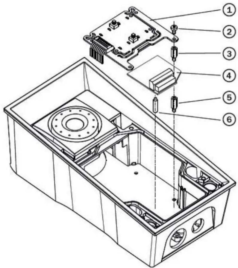
text_image
Technical diagram of an electronic device with numbered components for identification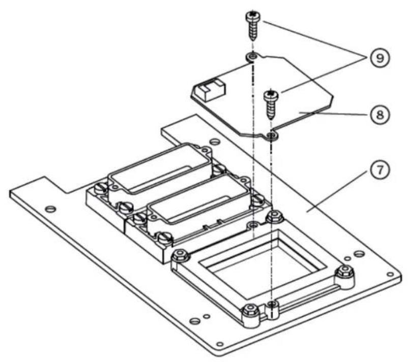
text_image
Technical diagram of a mechanical assembly with numbered parts for identification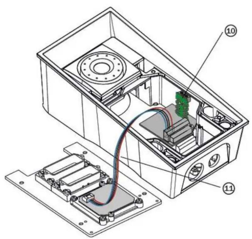
text_image
Technical diagram of an electronic device with labeled components, showing internal wiring and housing layoutModule setting:
Refer to the Configuration Manual for details of Wiegand, outputs and reader. Refer to the Automation manual for details of input, red LED and tamper function and use.
Connection:

text_image
Terminal block description* PWR IN1 | IN2 | NO | NC | OUT- INPUT W0 W1 WIEGANO + OUT- RELAY 2 OUT 2 X1 X2 X3 X4 JP2 JP7Security Relay
The (Par Security5Relay) is used for enhancing security between the 2N
intercom and the connected electric lock. The is designed for 2N IP Security Relay any intercom model with firmware versions 1.15 and higher. It significantly 2N IP enhances security of the connected electric lock as it prevents lock opening by forced intercom tampering.
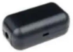
natural_image
Black rectangular electronic device with a small port and two leads (no visible text or symbols)Function:
The is ^® a device installed between an intercom (outside the secured 2N Security Relay area) and the electric lock (inside the secured area). The includes a 2N Security Relay relay that can only be activated if the valid opening code is received from the intercom.
Specifications:
Passive switch: NO and NC contacts, up to 30 V / 1 A AC/DC
Switched output:
- Where the security relay is fed from the intercom, 9 to 13 V DC is available on the output depending on the power supply (PoE: 9 V; adapter: source voltage of minus 1 V) / 400 mA DC.
- Where the security relay is fed from an external power supply, 12 V / 700 mA DC is available on the output.
Dimensions: (56 x 31 x 24) mm
Weight: 20 g
Installation:
Install the onto a two-wire cable between the intercom and the 2N Security Relay electric lock inside the area to be secured (typically behind the door). The device is powered and controlled via this two-wire cable and so can be added to an existing installation. Thanks to its compact dimensions, the device can be installed into a standard mounting box.
Connection:
Connect the to the intercom as follows:2N Security Relay
• To the intercom active output (OUT1 or OUT2), or
- To the intercom relay output with a 12 V DC serial external power supply.
Connect the electric lock to the output as follows:2N Security Relay
• To the switched output.
- To the passive output in series with the external power supply.
The device also supports a Departure button connected between the 'PB' and '-HeliosIP/IP intercom' terminals. Press the Departure button to activate the output for 5 seconds.
Status signalling:
| Green LED Red LED Status | |
| blinking off Operational mode | |
| on off Activated output | |
| blinking blinking Programming mode - waiting for initialisation | |
| on blinking Error - wrong code received |
Configuration:
- Connect the to® the properly set intercom switch output; 2N Security Relay refer to the Configuration Manual. Make sure that one LED at least on the 2N ® is on or blinking.Security Relay
- Press and hold the Reset button for 5 seconds to put the 2N Security Rela device in the programming mode (both the red and green LEDs are blinking).
- Activate the intercom switch using the keypad, telephone, etc. The first cod sent from the intercom will be stored in the memory and considered valid. After code initialisation, the will pass into the operational mode 2N Security Rela (the green LED is blinking).

Caution
- In case of resetting the factory default settings on a device with a version of firmware 2.18 or higher it is necessary to reprogram the 2N^® Security Relay using the instructions above.

Tip
- FAQ: 2N® Security Relay - what it is and how to use it with 2N IP intercom?

Tip
• Video Tutorial: Door 2N IP intercoms - Security Relay
Connection:
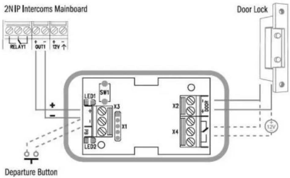
text_image
2NIP Intercoms Mainboard RELAY1 OUT1 12V ↑ + - LED1 SW1 X3 Bd X1 LED2 x2 x4 Door Lock Departure Button 12VWiegand Isolator
The (Part Wiegand 15801) tos usef for galvanic isolation of the 2N Wiegand bus.
The is ^® designed for galvanic isolation of two devices with 2N Wiegand Isolator separate power supply and interconnected via the Wiegand bus. The 2N ^® Wiegand protects the interconnected devices against communication errors and/or damage.
Connection of the intercoms Card Reader to a security system unit is a typical 2N IP example of application.
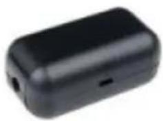
natural_image
Black rectangular electronic device with a small port and a small hole on the side (no visible text or symbols)Function:
The separates galvanically a two-wire Wiegand bus in one 2N Wiegand Isolator direction and a status LED signal in the other direction. The module is power supplied from the Wiegand bus receiver side.
Specifications:
• 2-wire WIEGAND IN
• 2-wire WIEGAND OUT
• LED IN switched against GND on WIEGAND OUT side
- Open LED OUT switched against GND on WIEGAND IN side (up to 24 V / 50 mA)
- 5 to 16 V / 10 mA power supply from Wiegand bus receiver side
• 500 V DC isolation strength
Connection:
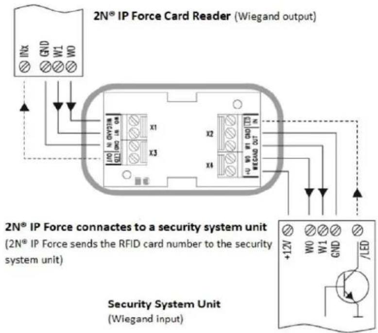
text_image
2N® IP Force Card Reader (Wiegand output) 2N® IP Force connects to a security system unit (2N® IP Force sends the RFID card number to the security system unit) Security System Unit (Wiegand input)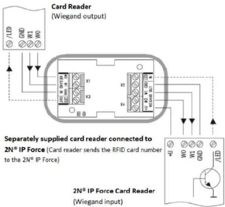
text_image
Card Reader (Wiegand output) Separately supplied card reader connected to 2N® IP Force (Card reader sends the RFID card number to the 2N® IP Force) 2N® IP Force Card Reader (Wiegand input)Induction Loop
2N ^® Induction Loop (Part No. 9159050 - Induction loop amplifier for intercom, 2N IP Part No. 9159054 - Induction loop amplifier without intercom accessory, Part 2N No. 9159051 - External induction loop for wall mounting, Part No. 9159052 - 12 V DC power adapter) is part of sound system installations for hearing impaired persons that are equipped with a special hearing aid capable of receiving reproduced sound via a magnetic field receiver. The system is defined by the IEC 60118-4 standard.
Installation:
The induction loop amplifier can be wall mounted with the use of an internal induction loop where a signal covering is requested. Outdoor use is possible thanks to the IP65 covering. A four-wire cable of the length of one meter is mounted to the suppli product for easier connection to the intercom. In the cable are two wires for 12 V DC supply and two wires for signal input, the wires are connected into interconnectic connector. If you shorten the cable, follow the colour marking.
Before wall mounting run the cable through the hole that you have prepared. The mark two mounting holes on the wall, through the amplifier front. Remove the amplifier and drill the mounting holes. Use the plugs and screws included in the delivery. Use a drill of the diameter of 6 mm. After fastening, cover the screws with the blanks supplied.
Use the supplied connectors to connect the amplifier to the intercom and power supply. The A connector is connected to the amplifier four-wire cable. Insert a special intercom-connecting cable supplied with the amplifier and 12 V power supply outlets to the B connector. Connect the special cable to the intercom and connect the power supply to the mains. You can place the mated A and B connectors into the 2N intercom cover. The connectors help you connect stripped cables. Open the connector by pushing a thin screwdriver onto the white spots at its front and close the connector by sliding the movable part through a side gap.
Finally, test the amplifier function using a suitable receiver for hearing impaired persons or magnetic field communication tester. No other settings are required.
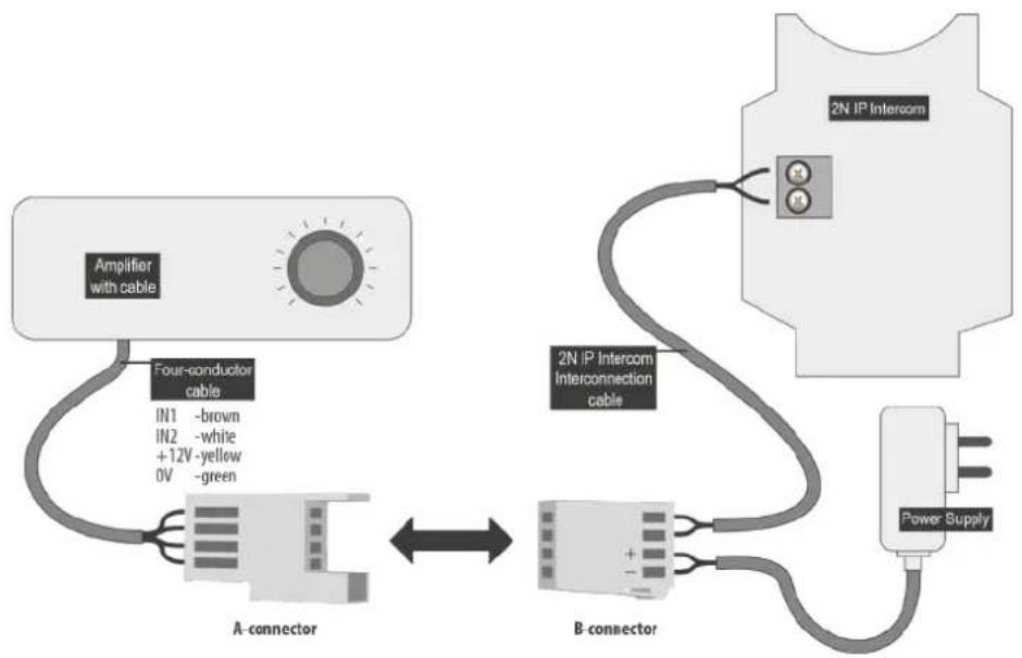
flowchart
graph LR
    A["Amplifier with cable"] -->|Four-conductor cable IN1 -brown IN2 -white +12V -yellow 0V -green| B["A-connector"]
    B --> C["B-connector"]
    C --> D["2N IP Intercom Interconnection cable"]
    D --> E["Power Supply"]
    E --> C
Specifications:
• Supply voltage: 8 18 V DC
• Supply current at 12 V supply:
• standby; up to 10 mA
• no signal; 100 mA
- 8 Ω load, half power output; 550 mA, sine wave signal; 400 mA, pink noise signal
- 1 Ω load, full power output; 1.4 A, sine wave signal; 1 A, pink noise signal
• Transition to standby w/o signal: 10 s
- Input level - basic: 100 mV - 6 V rms
- Input level - increased: 1 V - 35 V rms
- Input impedance: 2 kΩ parallel with 0.3 H
• Output current, 1 Ω load: 2.2 A rms (sine wave)
• Full power output: 1.6 A rms (pink noise)
• Output current, 8 Ω load: 730 mA rms sine wave signal
• Half power output: 520 mA rms pink noise signal
• Output short-circuit resistance: unlimited time
• Frequency characteristics: 100 Hz - 5 KHz ±3 dB
• Temperature range: -20 - +50 °C
• Covering: IP65 (with round cable of 5-10 mm diameter)
• Dimensions: 144 x 100 x 31 mm
- Weight: 0.3 kg
2.5 Button Tags
Tag Printing
- Every delivery includes a sheet of translucent foil, which can be 2N IP Force laser-printed. Cut the printed foil and insert the tags in the name plates.
- Every name plate includes a piece of foil, which can be written over manually, using a waterproof permanent marker, if necessary.

Note
- Always use waterproof foil (enclosed or other) for the tags. Never use paper or ink jet printing to avoid damage due to water leakage!

Tip
- A template for printing nametags can be downloaded from .www.2n.cz
Tag Inserting/Replacing Instructions
2N ^® IP Force provides an intuitive, easy access to the name plates. The tags are easy to insert and replace even without a manual. You need not remove the front panel and thus are not exposed to the risk of loss of components while replacing the tags.
-
Loosen the name plate screw using the wrench enclosed, for example. You can open the name plate window like a door without losing the tightened screw.
-
Remove the used or blank name tag and insert a new tag.
-
Close the name plate window and tighten the screw appropriately.
-
Check the click effect of the buttons: if the button fails to click properly when pressed (when moved by approx. 0.5 mm), the tag is too thick or thin. Make sure that the button clicks when you press it on both ends.
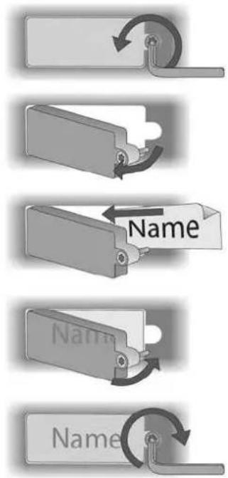
flowchart
graph TD
    A["Start"] --> B{Name}
    B -->|Yes| C["Process Step"]
    B -->|No| D["End"]
3. Function and Use
In this section we describe the basic and extending functions of the 2N ^® IP Force product.
Here is what you can find in this section:
• 3.1 Configuration
• 3.2 Control
• 3.3 Maintenance
• 3.4 Downloads
3.1 Configuration
Use a PC equipped with any web browser to configure :2N IP Force
- Launch your web browser (Internet Explorer, Firefox, etc.).
- Enter the IP address of your intercom (, e.g.).http://192.168.1.100/
- Log in using the user name and password.Admin 2n
You have to know the IP address of your device to log in to the integrated web server. By default, is ^® switched into the dynamic IP address mode, i.e. it obtains 2N IP Force the IP address automatically if a properly set DHCP server is available in your LAN. If no such DHCP server is available, you can operate 2N ^® IP Force in the static IP address mode.
If your device remains inaccessible (you have forgotten the IP address, or the LAN configuration has changed, for example), change the LAN settings using the buttons on the device.
IP Address Retrieval
Take the following steps to retrieve the 2N ^® IP Force IP address:
- Connect (or, if connected, disconnect and reconnect) 2N ^ IP Force to the power supply.
- Wait for the second sound signal
- Press the first quick dial button 5 times.
- 2N ^ IP Force will read its IP address.
- If the address is 0.0.0.0, it means that the intercom has not obtained the IP address from the DHCP server.
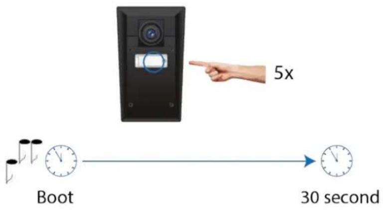
text_image
5x Boot 30 second
Note
- Be sure to press the button sequence within thirty seconds after the sound signal for security reasons. Up to 2 s intervals are allowed between the presses.
Static IP Address Setting for 4-button models
Follow the instructions below to enable the static IP address mode:
- Connect to the power supply (or, disconnect and reconnect it if 2N IP Force already connected).
- Wait for the first acoustic signal.
- Press buttons 1, 1, 1, 2, 2, 3 sequentially.
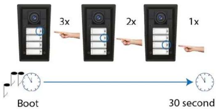
text_image
3x 2x 1x Boot 30 second• The acoustic signal indicates mode switching.
- Wait until the device is restarted automatically.

Caution
- The 1, 1, 1, 2, 2, 3 sequence must be entered within 30 seconds after the first sound signal for security reasons. The inter-digit delay may be 2 s at most.
The device will have the following network parameters after restart:
• IP address - 192.168.1.100
• Network mask - 255.255.255.0
- Default gateway - 192.168.1.1
Dynamic IP Address Setting for 4-button models
Follow the instructions below to enable automatic getting of network parameters from the DHCP server:
- Connect to the power supply (or, disconnect and reconnect it if 2N IP Force already connected).
- Wait for the first acoustic signal
- Press buttons 2, 1, 1, 2, 2, 3 sequentially.
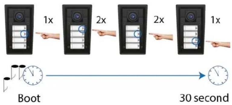
flowchart
graph LR
    A["1x"] --> B["2x"]
    B --> C["2x"]
    C --> D["1x"]
    D --> E["30 second"]
    F["Boot"] --> G["Clock with timer"]
• The acoustic signal indicates mode switching.
- Wait until the device is restarted automatically.

Caution
- The 2, 1, 1, 2, 2, 3 sequence must be entered within 30 seconds after the first sound signal for security reasons. The inter-digit delay may be 2 s at most.
2NtsPForAddress upon restart only if the DHCP server is configured properly.
Mode Switching with 1 or 2-Button Models
In case your device is equipped with 1 or 2 buttons, you can switch the 2N IP Force modes using one button only.
- Connect to the power supply (or, disconnect and reconnect it if 2N IP Force already connected).
- Wait for the first acoustic signal.
- Press the first quick dial button 15 times.
• The acoustic signal indicates mode switching. - Wait until the device is restarted automatically.
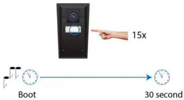
text_image
15x Boot 30 second
Caution
- The 15 times 1 sequence must be entered within 30 seconds after the first sound signal for security reasons. The inter-digit delay may be 2 s at most.
The static IP address mode will be switched into the dynamic IP address mode and vice versa upon restart.
3.2 Control
This subsection describes how to control when viewed by an external 2N IP Force user.
Speed Dial Buttons
Press the speed dial buttons on the basic unit to make quick dialling for the first 1, 2 or 4 positions (depending on the model type) in the telephone directory. Call setup is signalled by a long intermittent tone or otherwise as configured in the PBX connected.
Repeated pressing of one and the same speed dial button during call setup may initiate call termination, or call termination plus dialling the next telephone number of the called subscriber, or may be assigned no function. This behaviour can be set unit configuration.
If your model is equipped with a numerical keypad, you can also push the button anytime to terminate a call if enabled so in the parameter.Hang up with #
Calling to Telephone Directory Positions
The telephone directory can contain up to 1999 pre-programmed 2N IP Force positions. Speed dial can only be used for positions 1 to 4. The remaining positions can be retrieved via the numerical keypad if the Speed dial using digits function is enabled in configuration.
Procedure:
- Enter the position number using your numerical keypad (05, 15, 200, 1759 e.g. - two digits at least and four digits at most) and press ✕ for confirmation.
- You can also push the # button anytime to terminate a call if enabled so in the Hang up with # parameter in the unit configuration.
Calling to Telephone Number
You can dial a telephone number using your numerical keypad from 2N ^® IP Force if the Enable telephone function parameter is on.
Procedure:
- Press the ✕ button.
-
You will hear the continuous tone from the loudspeaker.
-
Enter the telephone number using the numerical keypad and repress for confirmation.
-
You can also push the button anytime to terminate a call if enabled so in the parameter; refer to the Miscellaneous subsection.Hang up with #
Answering and Rejecting Incoming Calls
If the automatic incoming call answering function is off, signals an 2N IP Force incoming call with loud ringing. Push the button to answer the call and the to reject the call. This function is available in models equipped with a numerical keypad only.
Door Opening (Switch Activation) by Code
2NedRipSpec with a door lock opening switch. Enter the valid code using your numerical keypad to activate the switch.
Procedure:
- Enter the numerical switch activating code using the numerical keypad and press for confirmation.
- A successful entering of a valid code is signalled by a continuous tone indicating unlocking (switch activation). An invalid code is signalled acoustically by
Profile Activation and Deactivation
Activate/deactivate a profile using the numerical keypad in order to define call routing to the telephone directory numbers more specifically.
Procedure:
- Enter the numerical profile activating/deactivating code and press 📧 for confirmation.
- A successful entering of a valid code is signalled acoustically by ☐ (☐ for profile) for activation, or ☐ (☐ for profile) for deactivation. An invalid code is signalled acoustically by ☐ .
3.3 Maintenance
Cleaning
If used frequently, the device surface, the keypad in particular, gets dirty. To clean it, use a piece of soft cloth moistened with clean water. We recommend you to follow these principles while cleaning:
- Never use aggressive detergents (such as abrasives or strong disinfectants).
- Use suitable cleaning agents for glass lens cleaning (cleaners for glasses, optic devices screens, etc.).
• Alcohol-based cleaners may be applied.
- Clean the device in dry weather in order to make waste water evaporate quickly.
• We recommend using cleaning wipes designed for IT / electronic items.

Warning
- Avoid peroxide-based cleaners.

Tip
- The modelsForPar01501Wnell51101Cwe 2N cleaned with WAP high pressure washers.
Future Tag Replacement, Programming Changes
For necessary steps refer to the preceding subsections. Keep the following for future changes:
- This manual
• Unused transparent foil strips for button tags

Caution
- Always use the product for the purpose it was designed and manufactured for, in compliance herewith.
- The manufacturer reserves the right to modify the product in order to improve its qualities.
- 2N ^ IP Force contains no environmentally harmful components. When the product's service life is exhausted and you would like to dispose of it please do so in accordance with applicable legal regulations.
3.4 Downloads
Templates
Nametags
Software
2N ^® IP USB driver
2N ^® IP Eye
2N ^® IP Network Scanner
4. Technical Parameters
Signalling protocol
- SIP (UDP, TCP, TLS)
Buttons
- Button design: Transparent, white backlit buttons with easily replaceable name tags
• Count of buttons: 1, 2 or 4
• Numerical keypad: optional
Audio
• Microphone: 2 integrated microphones
• Amplifier: 10 W (class D)
- Loudspeaker: 10 W
• Sound pressure level (SPL max): 78.5 dB (1 W type, for 1 kHz, distance 1 m)
• Sound pressure level (SPL max): 94 dB (10 W type, for 1 kHz, distance 1 m)
• Volume control: Adjustable with automatic adaptive mode
• Full duplex: Yes (AEC)
• Speech transmission index (STI): 0.80
Audio stream
- Protocols: RTP / RTSP
• Codecs: G.711, G.729, G.722, L16/16 kHz
Camera SD
- Sensor: 1/4" colour CMOS
• Resolution: 640 (H) × 480 (V)
• Frame rate: Up to 30 snaps/s
• Sensor sensitivity: 1.9 V/lux-sec (550 nm)
• View angle: 135^ (H), 109^ (V)
• Infrared light: Yes
• Focal length: 1.1 mm
• Focal length HD version: 2.3 mm
Camera HD
- Sensor: 1/3" colour CMOS
• JPEG resolution: Up to 1280 (H) x 960 (V)
• Video resolution: 640 (H) × 480 (V)
• Frame rate: Up to 30 snapshots/s
• Sensor sensitivity: 5.6 V/lux-sec (550 nm)
• View angle: 135^ (H), 109^ (V) - Infrared light: Yes
• Sensor sensitivity without IR light: 0,1 Lux ± 20 %
• Focal length: 2.3 mm
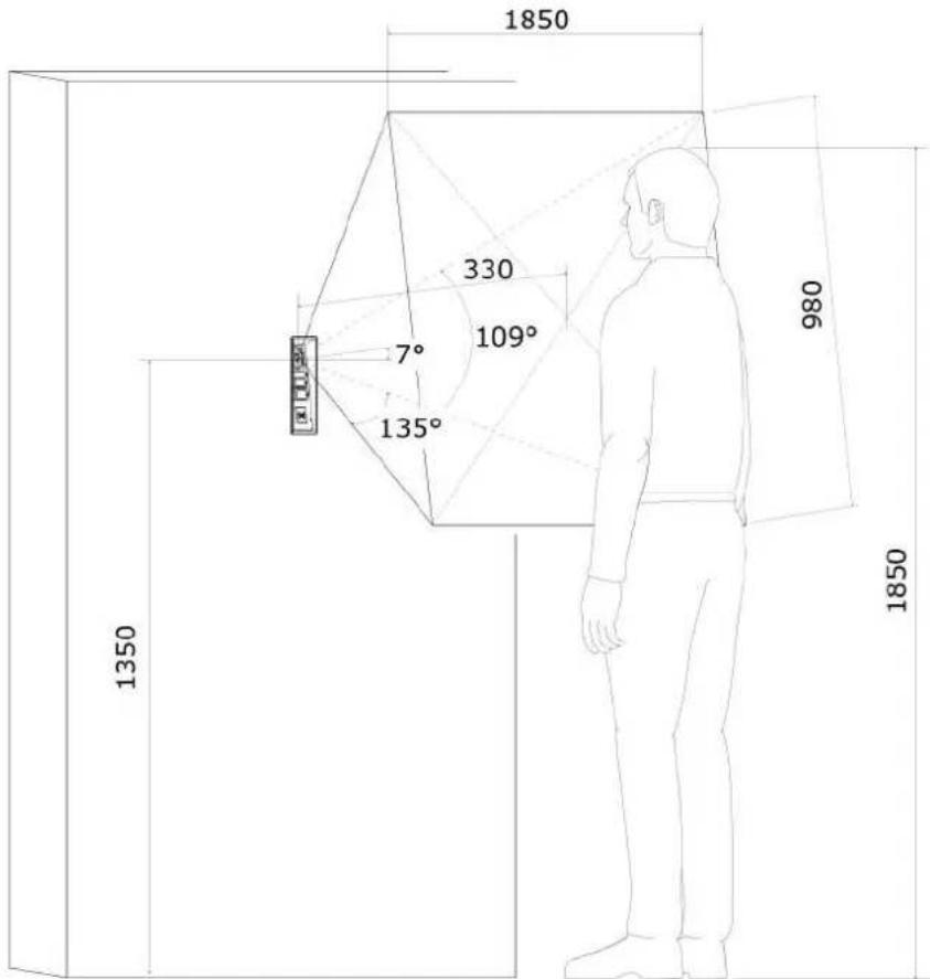
text_image
1850 330 7° 109° 135° 1350 980 1850Video stream
- Protocols: RTP / RTSP / HTTP
• Codecs: H.263, H.263+, H.264, MPEG-4, M-JPEG - IP camera function: Yes, ONVIF v2.4 profile S compatible
Bandwidth
- Audio codecs
• PCMA, PCMU - 64 kbps (with 85.6 kbps headers)
• G.729 - 16 kbps (with 29.6 kbps headers)
• G.722 - 64 kbps (with 85.6 kbps headers)
• L16 / 16 kHz - 256 kbps (with 277.6 kbps headers)
- Video codecs
Set the video codec data flows in the Services / Phone / Video menu for calls and in the Services / Streaming / RTSP menu for streaming. The set bandwidth represents the value that the codec has to approach on a long-time average. The data flows can vary depending on the scene to be scanned.
The measured data flow values correspond to the test view of a person standing in front of the intercom.
H.264
- Low quality: QVGA (320 x 240), 10 fps, 256 kbps: 181 kbps (with 190 kbps headers)
- Medium quality: VGA (640 x 480), 15 fps, 768 kbps: 600 kbps (with 661 kbps headers)
- High quality: VGA (640 x 480), 30 fps, 2048 kbps: 1319 kbps (with 13 kbps headers)
- MJPEG
- Low quality: QVGA (320 x 240), 10 fps, quality 70: 435 kbps with headers
• Medium quality: VGA (640 x 480), 15 fps, quality 85: 506 kbps
• High quality: SXGA (1280 x 960), 15 fps, quality 95: 8 Mbps
Interface
• Power supply: 12 V ±15 % / 2 A DC or PoE
• PoE: PoE 802.3af (Class 0-12.95 W)
• LAN: 10/100BASE-TX s Auto-MDIX, RJ-45
- Recommended cabling: Cat-5e or higher
- Supported protocols: SIP2.0, DHCP opt. 66, SMTP, 802.1x, RTSP, RTP, TFTP, HTTP, HTTPS, Syslog, ONVIF
• Passive relay switch: NO and NC contacts, up to 30 V / 1 A AC/DC
- Active switch output: 9 up to 13 V DC depending on power supply (PoE: 9 V adaptor: power supply voltage minus 1 V), max 600 mA
RFID card reader
- Optional
- Includes besides card reader itself: Wiegand interface, tamper switch, active output, relay, two inputs
• Supported cards on 125 kHz version, Part No. 9151011
• EM4100, EM4102
- Supported cards on 13.56 MHz version, Part No. 9151016 (only card serial number is read)
- ISO/IEC 14443A
- Mifare Classic 1k & 4k, DESFire EV1, Mini, Plus S&X, Ultralight, Ultralight C
- ISO/IEC 14443B
- CEPAS, HID iCLASS
- JIS X 6319
- Felica
- Supported cards on 13.56 MHz NFC version, Part No. 9151017 (only card serial number is read)
- ISO/IEC 14443A
- Mifare Classic 1k & 4k, DESFire EV1, Mini, Plus S&X, Ultralight, Ultralight C
- ISO/IEC 14443B
- CEPAS, HID iCLASS
- JIS X 6319
- Felica
- ISO/IEC 18092
- SmartPhone with NFC/HCE support, since Android version 4.3
- Supported cards on secured 13.56 MHz NFC version, Part No. 9151019 (optionally card serial number or PAC ID is read)
- ISO/IEC 14443A
- Mifare Classic 1k & 4k, DESFire EV1, Mini, Plus S&X, Ultralight, Ultralight C
- ISO/IEC 14443B
- CEPAS, HID iCLASS
- JIS X 6319
- Felica
- ISO/IEC 18092
- SmartPhone with NFC/HCE support, since Android version 4.3
- Wiegand Interface: Input/Output mode, located on RFID card reader module
- Active switch output: 9 up to 13 V DC depending on power supply (PoE: 9 V adaptor: power supply voltage minus 1 V), max 600 mA
• Passive relay switch: NO and NC contacts, up to 30 V / 1 A AC/DC
Additional switch
- Optional: Includes also one input, active output, relay, tamper switch
- Active switch output: 9 up to 13 V DC depending on power supply (PoE: 9 ' adaptor: power supply voltage minus 1 V), max 600 mA
• Passive relay switch: NO and NC contacts, up to 30 V / 1 A AC/DC
Mechanical properties
- Cover: Robust aluminium cast product, front panel: aluminium cast, fiberglass FR4 (91511xxxR)
• Colour: Not from RAL scheme, matching equivalent would be 9004 glossy black
• Working temperature: -40^ to 55^
• Working relative humidity: 10 % - 95 % (non-condensing)
- Storing temperature: -40^ to 70^
- Dimensions
- 217 x 109 x 83 mm
• 242 x 136 x 83 mm incl. frame
• Weight: netto max. 2 kg / brutto max. 2,5 kg
• Covering level: IP65, IP69K (91511xxxW)
• Resistance level: IK10
UL294 levels
- Attack, Security, Line Security - Level I
• Endurance - Level IV
4.1 General drawings
Surface mounting
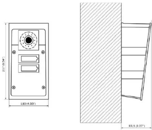
text_image
21.7 (8.54") 110 (4.33') 83.1 (3.27)Flush mounting
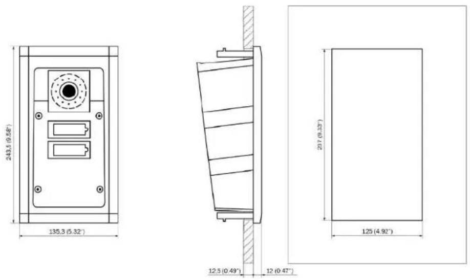
text_image
243.5 (0.58") 135.3 (5.32") 12.5 (0.49) 12 (0.47") 20 (0.33) 125 (4.92)Plasterboard mounting
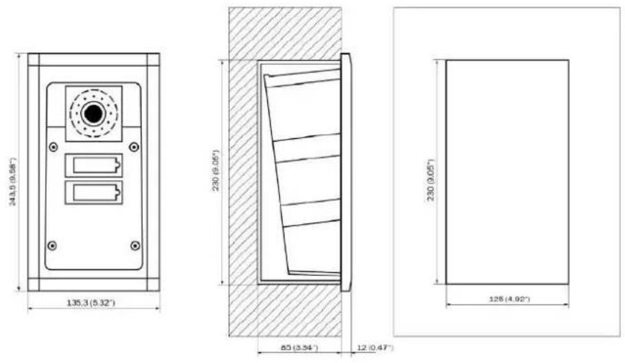
Flush mounting with box
5. Supplementary Information
Here is what you can find in this section:
• 5.1 Troubleshooting
• 5.2 Directives, Laws and Regulations
• 5.3 General Instructions and Cautions
5.1 Troubleshooting

For the most frequently asked questions refer to .faq.2n.cz
5.2 Directives, Laws and Regulations
2N ^® IP Force conforms to the following directives and regulations:
2014/35/EU on the harmonisation of the laws of the Member States relating to making available on the market of electrical equipment designed for use within certain voltage limits
2014/30/EU on the harmonisation of the laws of the Member States relating to electromagnetic compatibility
2011/65/EU on the restriction of the use of certain hazardous substances in electrical and electronic equipment
2012/19/EU on waste electrical and electronic equipment
Industry Canada
NOTE: This equipment has been tested and found to comply with the limits for a Class B digital device, pursuant to part 15 of the FCC Rules. These limits are designed to provide reasonable protection against harmful interference in a residential installation. This equipment generates, uses and can radiate radio frequency energy and, if no installed and used in accordance with the instructions, may cause harmful interference to radio communications. However, there is no guarantee that interference will not occur in a particular installation. If this equipment does cause harmful interference to radio or television reception, which can be determined by turning the equipment off and on, the user is encouraged to try to correct the interference by one or more of the following measures:
• Reorient or relocate the receiving antenna
- Increase the separation between the equipment and receiver
- Connect the equipment into an outlet on a circuit different from that to which the receiver is connected
- Consult the dealer or an experienced radio/TV technician for help.
Changes or modifications to this unit not expressly approved by the party responsible for compliance could void the user's authority to operate this equipment.
DDA compliance:
2N TELEKOMUNIKACE intercoms comply with the Disability Discrimination Act 2005 (DDA) under the following conditions:
- The intercoms are mounted so that their lower edge is between 100 and 12 centimeters above the floor.
- The intercoms use a keyboard that has a mechanical protrusion on number 5.
- The intercoms use electromagnetic loop as a hearing aid.

Caution
In order to ensure the full functioning and guaranteed outputs we strongly recommend a verification of the timeliness of version of product or facility already during the installation process. The customer takes into consideration that the product or facility can achieve the guaranteed outputs and be fully operational pursuant to the producer's instructions only by using the most recent version of product or facility, which has been tested for full interoperability and has not been determined by the producer as incompatible with certain versions of other products, only in conformity with the producer's instructions, guidelines, manual or recommendation and only in conjunction with suitable products and facilities of the other producers. The most recent versions are available on the website https://www.2n.cz/cs_CZ/, or specific facilities, depending on their technical capacity, allow updating in the configuration interface. Should the customer use any other version of product or facility than the most recent one, or the version that has been determined by the producer as incompatible with certain versions of other producers' products of facilities, or the product or facility in a way incompatible with the producer's instructions, guidelines, manual or recommendation or in conjunction with unsuitable products or facilities of the other producers, he or she is aware of all potential limitations of functionality of such a product or facility and all relating consequences. Should the customer use any other than the most recent version of the product or facility, or the version that has been that has been determined by the producer as incompatible with certain versions of other producers' products of facilities, or the product or facility in a way incompatible with the producer's instructions, guidelines, manual or recommendation or in conjunction with unsuitable products or facilities of the other producers, he or she agrees that the company 2N TELEKOMUNIKACE a.s. is not liable neither for any limitation of such a product's functionality, nor for any damage, loss or injury relating to such a potential limitation of functionality.
5.3 General Instructions and Cautions
Please read this User Manual carefully before using the product. Follow all instructions and recommendations included herein.
Any use of the product that is in contradiction with the instructions provided herein may result in malfunction, damage or destruction of the product.
The manufacturer shall not be liable and responsible for any damage incurred as a result of a use of the product other than that included herein, namely undue application and disobedience of the recommendations and warnings in contradiction herewith.
Any use or connection of the product other than those included herein shall be considered undue and the manufacturer shall not be liable for any consequences arisen as a result of such misconduct.
Moreover, the manufacturer shall not be liable for any damage or destruction of the product incurred as a result of misplacement, incompetent installation and/or undue operation and use of the product in contradiction herewith.
The manufacturer assumes no responsibility for any malfunction, damage or destruction of the product caused by incompetent replacement of parts or due to the use of reproduction parts or components.
The manufacturer shall not be liable and responsible for any loss or damage incurred as a result of a natural disaster or any other unfavourable natural condition.
The manufacturer shall not be held liable for any damage of the product arising during the shipping thereof.
The manufacturer shall not make any warrant with regard to data loss or damage.
The manufacturer shall not be liable and responsible for any direct or indirect damage incurred as a result of a use of the product in contradiction herewith or a failure of the product due to a use in contradiction herewith.
All applicable legal regulations concerning the product installation and use as well as provisions of technical standards on electric installations have to be obeyed. The manufacturer shall not be liable and responsible for damage or destruction of the product or damage incurred by the consumer in case the product is used and handled contrary to the said regulations and provisions.
The consumer shall, at its own expense, obtain software protection of the produce. The manufacturer shall not be held liable and responsible for any damage incurred as a result of the use of deficient or substandard security software.
The consumer shall, without delay, change the access password for the product after installation. The manufacturer shall not be held liable or responsible for any damage incurred by the consumer in connection with the use of the original password.
The manufacturer also assumes no responsibility for additional costs incurred by the consumer as a result of making calls using a line with an increased tariff.
Electric Waste and Used Battery Pack Handling

Do not place used electric devices and battery packs into municipal waste containers. An undue disposal thereof might impair the environment!
Deliver your expired electric appliances and battery packs removed from them to dedicated dumpsites or containers or give them back to the dealer or manufacturer for environmental-friendly disposal. The dealer or manufacturer shall take the product back free of charge and without requiring another purchase. Make sure that the devices to be disposed of are complete.
Do not throw battery packs into fire. Battery packs may not be taken into parts short-circuited either.
2N
An Axis company
2N TELEKOMUNIKACE a.s.
Modřanská 621, 143 01 Prague 4, Czech Republic
Phone: +420 261 301 500, Fax: +420 261 301 599
E-mail: sales@2n.cz
Web: www.2n.cz
v2.16