
WB21LMB - Uncategorized LG - Free user manual and instructions
Find the device manual for free WB21LMB LG in PDF.

| Product Type | Washing Machine |
| Brand | LG |
| Model | WB21LMB |
| Dimensions (H x W x D) | 850 mm x 600 mm x 600 mm |
| Weight | 68 kg |
| Power Supply | 220-240 V, 50 Hz |
| Rated Power | 2000 W |
| Drum Capacity | 8 kg |
| Maximum Spin Speed | 1400 rpm |
| Energy Class | A+++ |
| Annual Energy Consumption | 160 kWh |
| Annual Water Consumption | 10000 L |
| Noise Level (Wash/Spin) | 52 dB / 74 dB |
| Number of Programs | 14 |
| Special Programs | Cotton, Synthetics, Delicates, Quick 30, Wool, Hand Wash, Rinse+Spin, Spin Only, Drum Clean, Tub Clean |
| Control Type | Electronic with LED Display |
| Display | LED |
| Safety Features | Child Lock, Overflow Protection, Unbalanced Load Detection, Foam Detection |
| Key Functions | Delay Start, End Time, Prewash, Extra Rinse, Steam (if available) |
| Maintenance | Clean the drum and door seal regularly; clean the filter monthly; check drain hose |
| Accessories Included | Inlet hose, Drain hose, User manual, Spanner, Transit bolts |
Frequently Asked Questions - WB21LMB LG
User questions about WB21LMB LG
0 question about this device. Answer the ones you know or ask your own.
Ask a new question about this device
Download the instructions for your Uncategorized in PDF format for free! Find your manual WB21LMB - LG and take your electronic device back in hand. On this page are published all the documents necessary for the use of your device. WB21LMB by LG.
USER MANUAL WB21LMB LG
Safety and Reference
Wall Mount Bracket
Please read this manual carefully before operating your set and retain it for future reference.
WB21LMB
WB21LMC


https://youtu.be/ytLFCUqUsz0
(2112-REV04)
Printed in Korea
www.lg.com
Copyright ©2021 LG Electronics Inc. All Rights Reserved.
Accessories
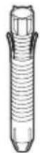
Wall mount fixing anchors 8 pcs.
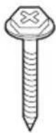
Wall mount fixing screws 8 pcs.
flowchart
graph TD
    A["Stage A"] -->|Reaction arrow| B["Stage B"]
    B -->|Reaction arrow| C["Stage B"]
    C -->|Reaction arrow| D["Stage B"]
    D -->|Reaction arrow| E["Final Stage"]
Guide paper Installation Manual
Wall mounting supporter
Assembly Guide Paper

Wall mounting supporter screw 8 EA (M5 x L6)
3-1) 13 mm (0.5 inches) (Concrete wall)
2-1) 19 mm (0.7 inches) (Wood stud)
TV protection cushion A 2 pcs.
TV fixing screws A 2 pcs.
3-2) 39 mm (1.5 inches) (Concrete wall)
2-2) 45 mm (1.7 inches) (Wood stud)
TV protection cushion B 2 pcs.
Guide Spacer Fixing Screws 2 pcs. (M6 x L45)
Guide Spacer 2 pcs.
Precautions for Safety
- Professional installers should read this manual carefully to ensure proper installation.
- Professional installers should forward this manual to customers after installation and encourage them to read and store it in a convenient place for future reference.
After reading the installation manual, keep it in a convenient place for future reference.

Warning
Ask a professional installer appointed by the store for installation of the product.
Installation by someone other than a professional installer is extremely dangerous and may result in personal injury.
Contact a professional installer appointed by the store prior to moving or replacing the product after installation.
Installation is a technical task and safety issues may arise if an individual attempts to install or move the product personally.
When installing the product on a wall, do not hang the power line or signal cables from the back of the TV.
This can damage the cords, resulting in a fire, electrical shock or malfunction of the product.
Do not install the product in an unstable site that cannot withstand its weight.
If the installation site lacks sufficient rigidity, the product may fall and cause personal injury.
Do not hang on the product or subject it to severe impact after installation.
Doing so may cause the product to fall and cause personal injury.

Caution
Install the product according to the instructions in the installation manual.
Failure to install the product according to the instructions in the installation manual can result in serious personal injury or product damage.
Be sure to have at least four people when installing the product or adjusting the product's height.
Attempting to perform installation or adjustments personally may result in personal injury or damage to the product.
Make sure a wall is available prior to proceeding with installation. Make use of the anchors and screws provided with the product.
Use of any unauthorized anchors or screws may not support the product's weight, which poses safety risks.
When drilling in the wall for installation, be sure to use drill bits and drills of the specified diameter. Follow the instructions for the hole depth.
Drilling and installing the product in ways other than specified in the installation manual may result in an unstable installation and potential safety issues.
Do not wipe the product with a wet towel or use any heating equipment or humidifier under the place where the product is installed.
Liquid water or vapor may enter the product and excessive heat may cause fire, electric shock, or malfunction.
Do not install the product near a fire sprinkler or detector, a place where vibration or shock may occur or near a high-voltage wire or power source.
Unplug the product's power cord from the wall outlet before installing.
Installing the product while the power cord is plugged in may result in electric shock or fire.
Do not install the product with bare hands. Be sure to wear work gloves.
Attempting installation without work gloves may cause personal injury.
Connect the product with the supplied cable. Use of an unauthorized cable may result in damage by friction with the wall. Make sure to use the supplied cable gender. (This may vary by model.)
Before Installation
- Do not use the product for any purpose other than installing the TV on a wall.
- Avoid product damage and safety accidents caused by careless installing or use of improper or unauthorized wall mount.
- Follow the instructions in the installation manual for a convenient installation of the wall mount.
- Immediately discontinue installation and contact the service center if you cannot fully understand the installation process.
Use a professional installer if any installation issues remain after the inquiry. -
Installation of this product on a concrete wall or wood stud is recommended. Installation on walls made of other types of plasterboard, plywood, brick, etc., is not recommended since there is a greater chance the product will fall.
-
When installing the Full Contact Wall Mount, the TV may not be contacted firmly against the wall due to some wall conditions.
• Install the product only on a vertical wall.
Do not install on a tilted wall that exceeds building standards or on the heavily titled wall or ceiling. LG is not responsible for problems caused by improper installation of the product, e.g., heavily tilted walls and ceilings. - Check the enclosed accessories before installation. We are not responsible for any lost or damaged accessories after the inner packaging is opened.
- When an infant or small child swallows the enclosed accessories, various safety accidents such as choking may occur. Keep the enclosed accessories out of the reach of infants and children.
- When tightening screws, tighten until fully snug. Avoid using excessive force when tightening the screws. Doing so may damage the wall and product or reduce the rigidity or performance of the product.
- Avoid installing a TV that exceeds the specified tensile load, and do not allow any external force to be applied to the product.
- Avoid accidents by using work tools with care during installation.
• After installing the product, ensure its use in close contact with a wall.
If the product is not positioned against a wall, the product may be unstable or damaged.
Tools for Installation
- "+" shaped screwdriver (manual or electric)
- level
- drill
- ∅ 8 mm drill bit for concrete or ∅ 4 mm drill bit for steel
How to install
- The appearance of tools may differ from the enclosed images.
• Always consult a professional when installing a wall mount.
1. Wearing gloves
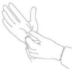
natural_image
Line drawing of a human hand with index finger extended (no text or symbols)2. Fastening Anchors and Screws
- Check that the material and thickness of the wall and finishing material comply with the installation manual. Before beginning the mounting process, you must be sure the wall is able to support the weight of the TV.
- Should use the enclosed anchors and screws on crack free concrete walls.
- If the wall is not made of concrete, the wall mount must be installed on a rigid support. Never install the product on a plasterboard or wall made of paper or medium-density fiberboard (MDF). In this case, make sure that the wall material can withstand the weight of the TV, and fix the anchor screws to the retaining wall (concrete) or wooden support behind the finishing material. Since the anchors provided with this product may not be suitable for your wall material, be sure to check with a professional before attempting installation.
- Other unspecified walls must be capable of supporting pullout loads of over 70 kgf (154.3 lbf) (686 N) and shear loads of over 100 kgf (220.4 lbf) (980 N) per fastener.
- Use an ∅ 8 mm drill bit for concrete and a hammer (impact) drill or ∅ 4 mm drill bit for wood stud to drill holes.
For installation on concrete wall
- Drill holes in anchor locations with a drill bit of ∅ 8 mm to a depth of 80 mm (3.1 inches) to 100 mm (3.9 inches).
natural_image
Abstract grayscale pattern with diagonal wavy lines on left and right edges (no text or symbols)- Clean the drilled holes.
natural_image
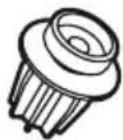
Abstract geometric shape with gray and white blocks (no text or symbols)- Insert the enclosed anchors for fixing the wall mount into the holes. (Use a hammer when inserting anchors.)
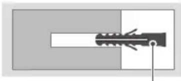
natural_image
Pure diagram of a mechanical component with no text or symbolsAnchors for fixing the wall mount
- Push the wall mount support closely toward the wall to match the hole locations.
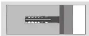
natural_image
Pure electrical circuit lines without any symbols- Tighten screws for fixing the wall mount to the holes. At this time, tighten the screws with the torque more than 45 kgf/cm (39.0 lbf/in) to 60 kgf/cm (52.0 lbf/in).
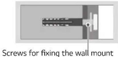
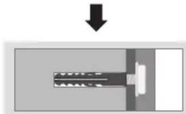
natural_image
Diagram of a mechanical component with a downward arrow indicating force or direction (no text or symbols)1. Attaching the guide paper to the wall
Attach the guide paper to the wall when determining the TV's installation site.
- Ensure the guide paper is level when attaching it to the wall.
- Attach it by referring to the outer line of the TV and the location of the TV center.
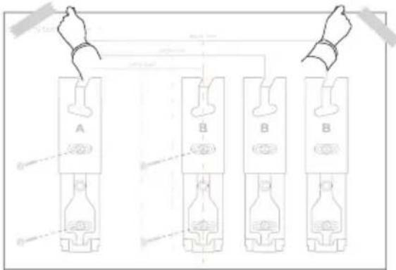
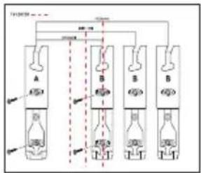
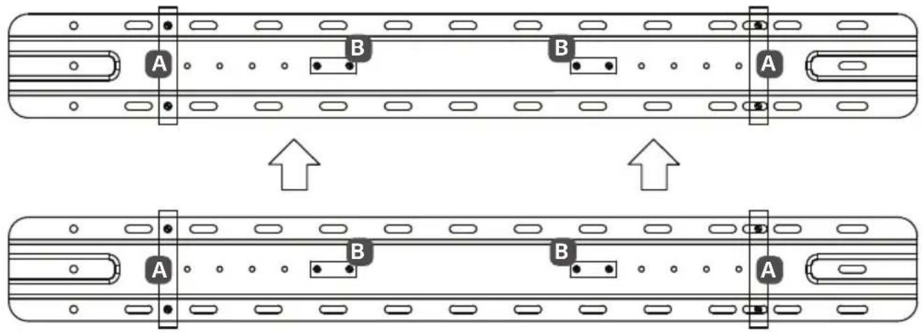
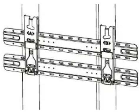
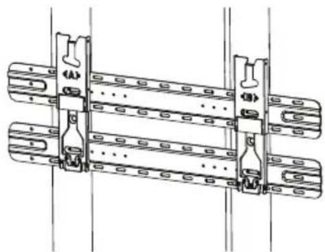
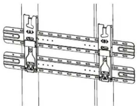
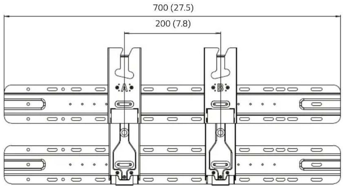
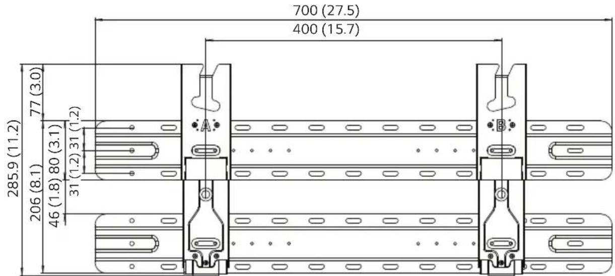
2. Installing the Wall Mount Support
- Install A on the left and B on the right according to the markings on the wall mount.
- Refer to the following picture to fix the wall mount support.
- Use a level to verify that the wall mount is positioned horizontally.
- Fix the wall mount screws: one at the top and one at the bottom.
-
Use a Phillips screwdriver (manual or powered) to tighten the screws so that the wall mount support is firmly fixed to the wall surface.
-
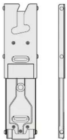
Check the shape of the wall mount in the picture.
natural_image
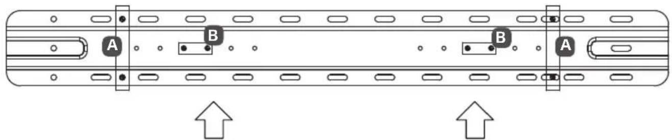
Technical line drawing of a mechanical component with two views (top and side), no text or symbols present.- Install the wall mount support at the location marked on the guide paper.
- Install after checking the VESA size for the model you purchased.
![TV CENTER [VSIA-100] [VSIA-200] A B B B](/content/2026/05/765487/images/d072ba231f7ca7eae35a9277bee8d9333220784071403104539a934a85e66316.jpg)
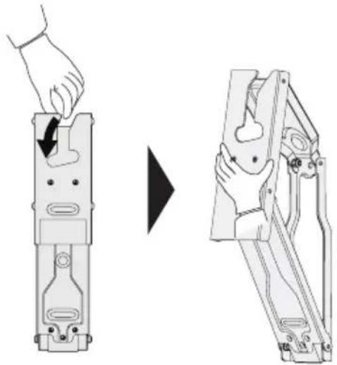
- In the order, unfold the wall mount by pulling the parts indicated in the picture.
natural_image
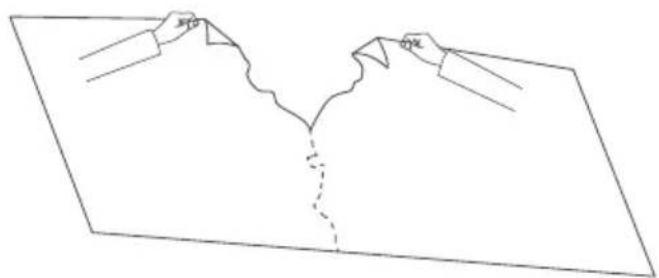
Diagram showing a hand operating a mechanical device before and after assembly, with no visible text or symbols.- Remove the guide paper.
natural_image
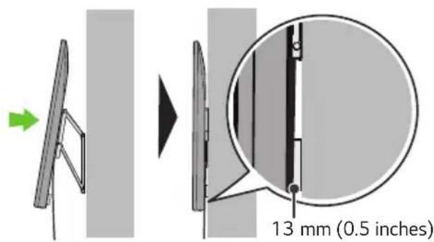
Simple line drawing of a mountain with a dashed vertical line dividing it into two sections (no text or symbols)3. Attaching the TV to the Wall Support
Depending on the model, those with horizontal terminals are recommended to follow Method 3-2 models without horizontal terminals should follow Method 3-1 and, when installing by Method 3-2, it is recommended to use the side terminal for HDMI & USB.
3-1) Separation distance between TV and wall: 13 mm (0.5 inches)
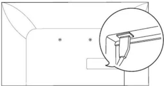
natural_image
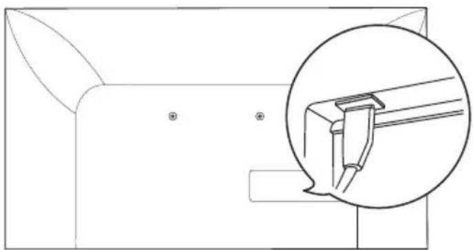
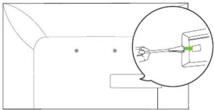
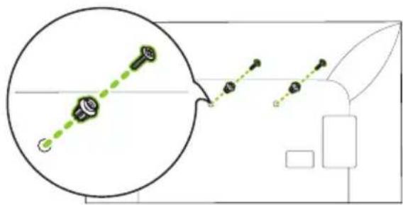
Technical line drawing of a mechanical component with an inset magnified detail (no text or symbols)- Fasten the enclosed TV fixing screws to both sides of the top of VESA on the TV.
natural_image
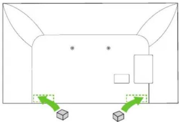
Diagram showing a magnified view of a mechanical component with green dotted lines and circular features, connected to a 3D model (no text or symbols)- Attach the enclosed TV protective cushion A to the bottom of the flat surface behind the TV. (The location may differ depending on the model.)
natural_image
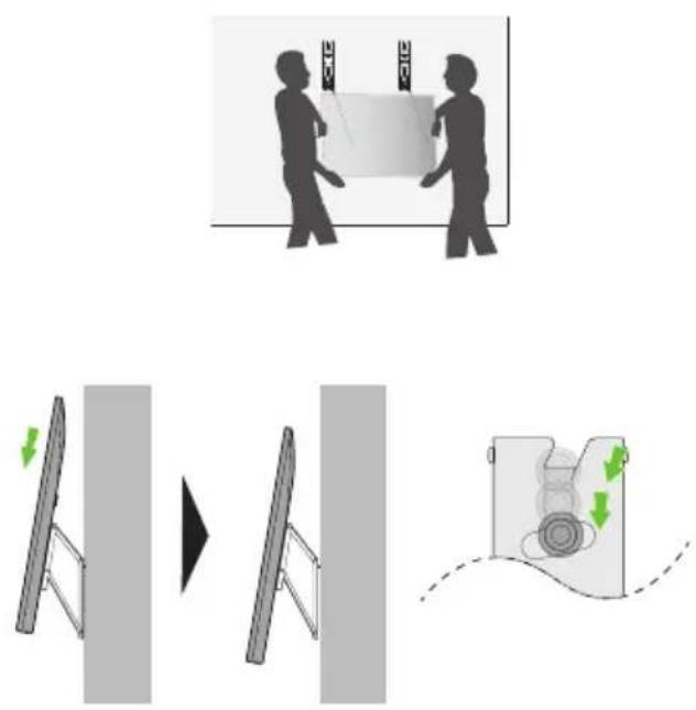
Diagram of a stylized animal face with directional arrows and blocks, no text or symbols present- After attaching the TV to the mount on the wall, fasten the screws fixed to the TV to the wall mount. Caution: Ensure two or more people work together when mounting the TV. (If the product is lifted by one person, it may fall and result in injury or damage.) Be careful not to trap the power cord between the wall mount bracket and the TV when mounting the TV. (If the power cord becomes trapped, it may result in product damage.)
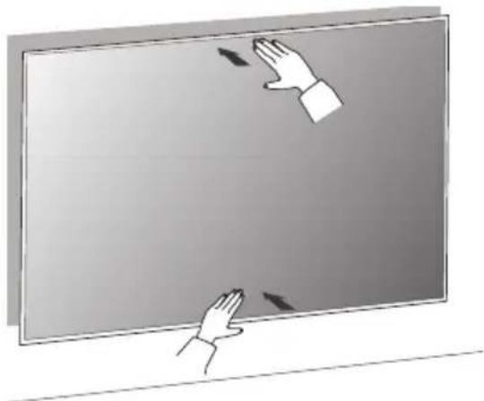
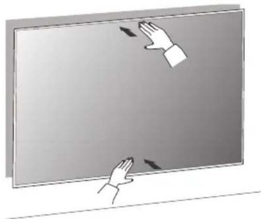
- Push the TV close to the wall. Be sure to gently push the upper and lower parts of the TV so that the pushing doesn't affect the TV. Gently push the upper center of the TV once again until it's completely pressed against the wall. Caution: Do not apply excessive force to the screen. (Doing so can damage the screen.)
natural_image
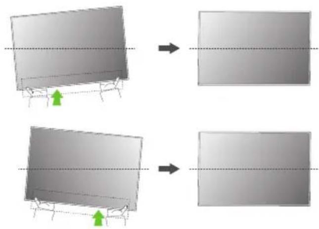
Illustration of two hands interacting with a blank screen, no text or symbols present- Adjust the product's position by hand so it's horizontal. Hold the left and right bottom sides of the TV and adjust it to the desired direction.
natural_image
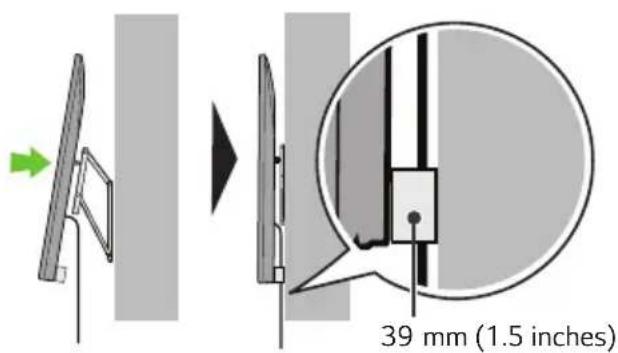
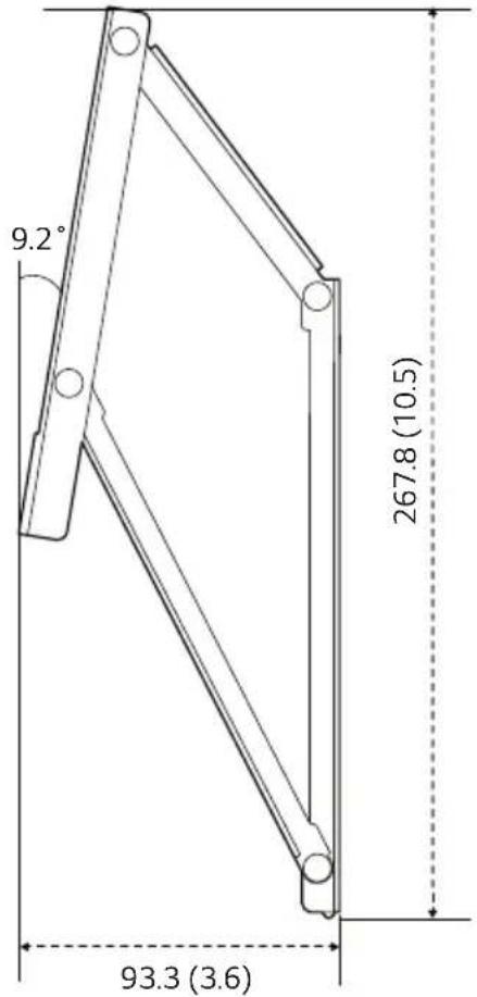
Two identical diagrams showing a 3D object being rotated, with arrows indicating transformation (no text or symbols present)3-2) Separation distance between TV and wall: 39 mm (1.5 inches)
natural_image
Technical line drawing of a mechanical component with an inset magnified view showing a green tool interacting with a component (no text or symbols present)- Fasten the enclosed TV guide spacers and guide spacer fixing screws to both sides of VESA.
- Attach the enclosed TV protective cushion B to the bottom of the flat surface behind the TV. (The location may differ depending on the model.)
natural_image
Simple line drawing of a cat's head with two green arrows pointing to the front and back (no text or symbols)- After attaching the TV to the mount on the wall, fasten the screws fixed to the TV to the wall mount. Caution: Ensure two or more people work together when mounting the TV. (If the product is lifted by one person, it may fall and result in injury or damage.)
Be careful not to trap the power cord between the wall mount bracket and the TV when mounting the TV. (If the power cord becomes trapped, it may result in product damage.)
- Push the TV close to the wall. Be sure to gently push the upper and lower parts of the TV so that the pushing doesn't affect the TV. Gently push the upper center of the TV once again until it's completely pressed against the wall. Caution: Do not apply excessive force to the screen. (Doing so can damage the screen.)
natural_image
Illustration of two hands interacting with a blank screen, no text or symbols present- Adjust the product's position by hand so it's horizontal. Hold the left and right bottom sides of the TV and adjust it to the desired direction.
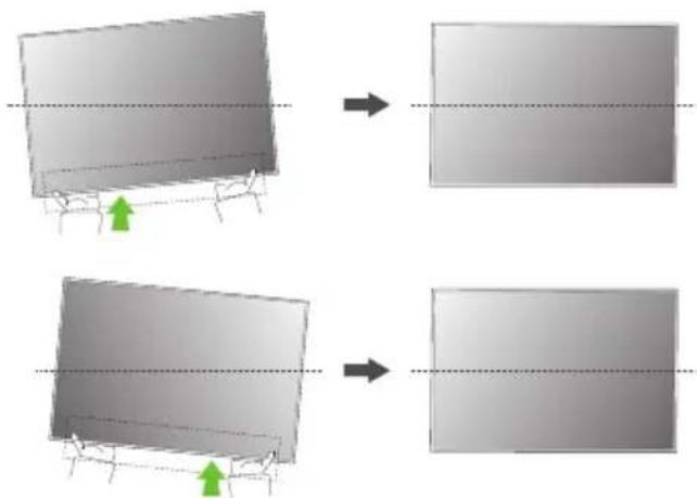
natural_image
Two identical diagrams showing a 3D object being cut off into a rectangular block, with green arrows indicating the process (no text or symbols present)4. Plugging Additional Cables in While Using the TV
- While holding the lower part of the TV, pull the upper side of the TV so it does not affect the product. Gently pull the upper and lower parts of the TV and check the position to connect the cable from the side.
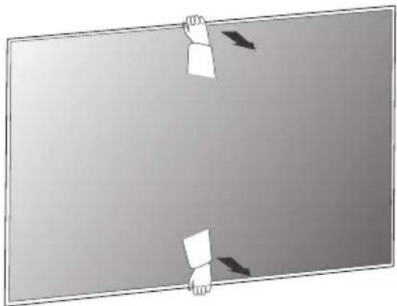
natural_image
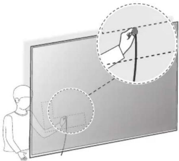
Simple diagram showing two hands holding paper clips against a gradient background (no text or symbols)- Check the position of the cable from the side and plug it into the TV. Position your body as close to the wall as possible behind the TV and organize the cables using the holder. (The location of the cable connection terminal may differ depending on the model.)
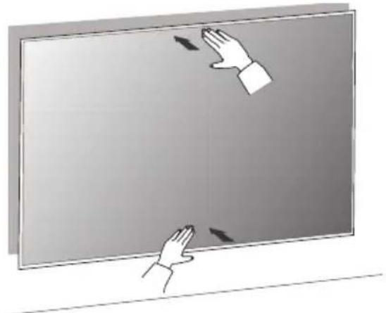
- Push the TV close to the wall. Be sure to gently push the upper and lower parts of the TV so that the pushing doesn't affect the TV. Gently push the upper center of the TV once again until it's completely pressed against the wall. Caution: Do not apply excessive force to the screen. (Doing so can damage the screen.)
natural_image
Illustration of two hands interacting with a blank screen, showing directional arrows (no text or symbols)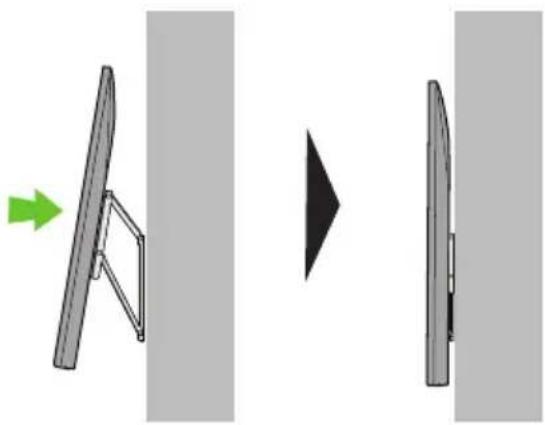
natural_image
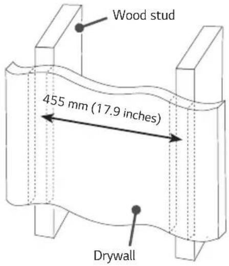
Diagram showing two views of a flat-panel device with a green arrow indicating direction (no text or symbols)For installation on wood stud
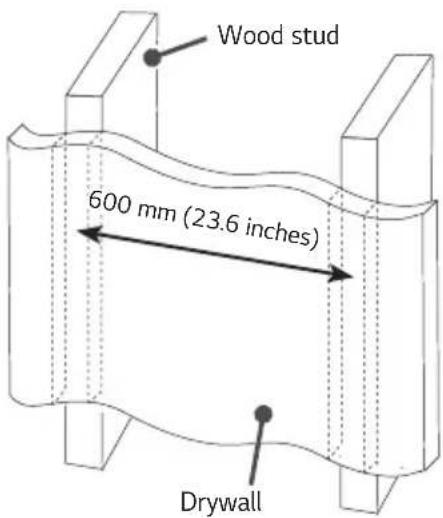
- Check the type of wall where the installation will take place.
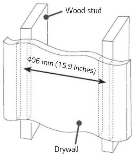
- When installing on a wooden wall, mark the left and right center positions of the wood studs.
- Assemble by referring to the assembly guide paper which is provided as an accessory.
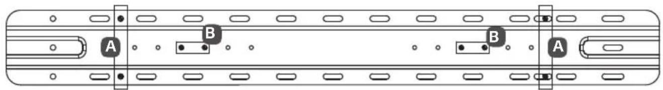
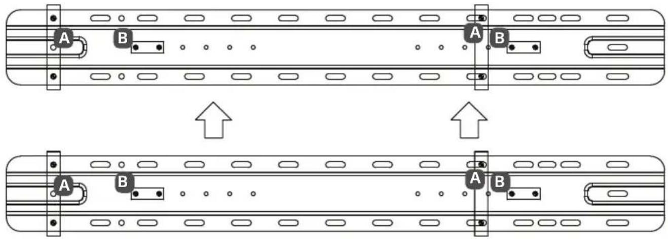
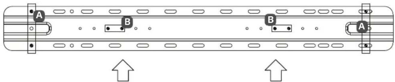
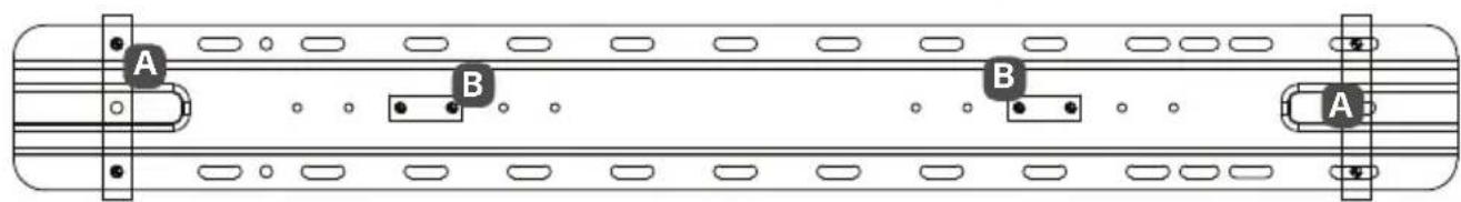
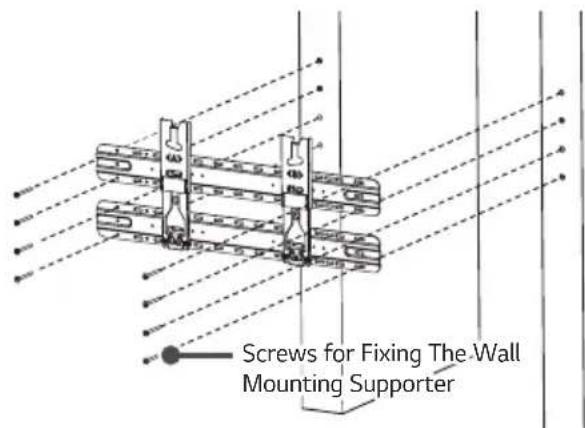
- Check the screw fixing positions by marking the Wall mounting supporter screw points indicated by the left and right centers of the wood studs.
| A | Wall Mounting Supporter Point |
| B | Wall Mounting Bracket Point |
Japan
- When installing on a wooden wall (VESA Size 200)
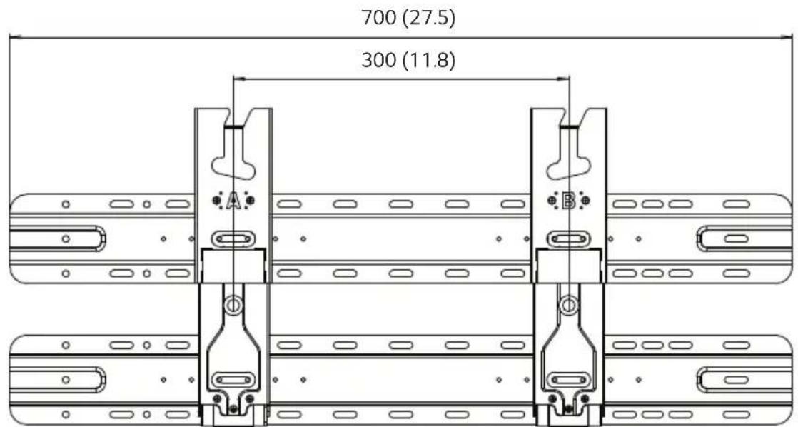
- When installing on a wooden wall (VESA Size 300)
- When installing on a wooden wall (VESA Size 400)
- When installing on a wooden wall (VESA Size 300)
- When installing on a wooden wall (VESA Size 400)
- When installing on a wooden wall (VESA Size 300)
1. How to Assemble Support
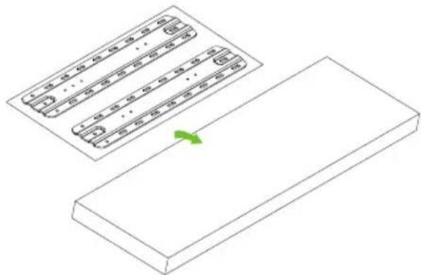
- Place the assembly guide on the box.
natural_image
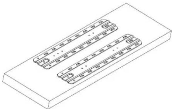
Isometric diagram of a rectangular block with internal components and a green arrow indicating direction (no text or symbols)- Align the Wall mounting supporter on the assembly guide paper with the outer line.
natural_image
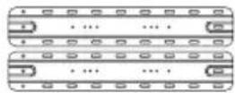
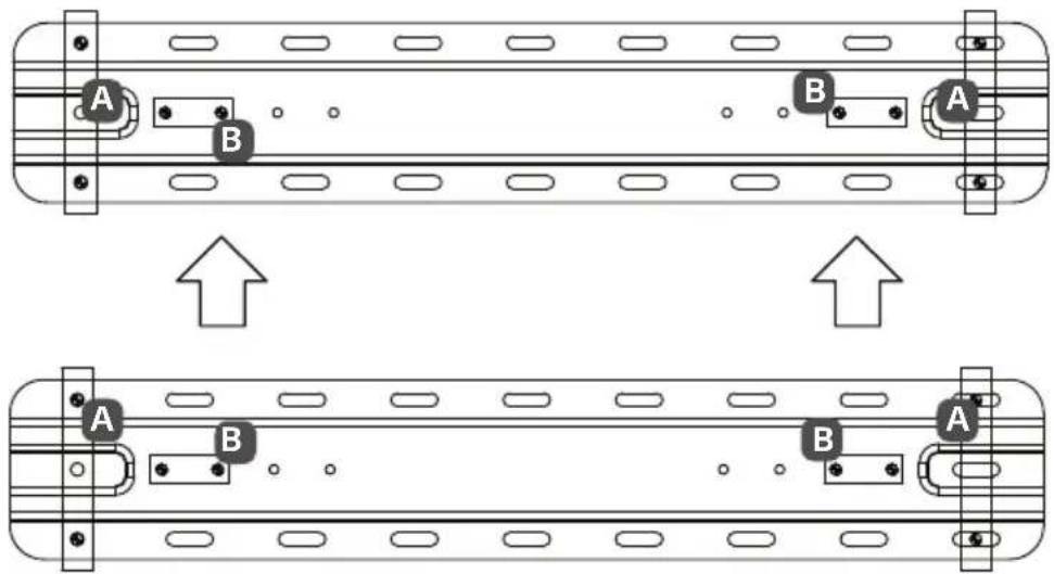
Isometric line drawing of a rectangular block with three parallel slots, no text or symbols present- Place the wall mount support on the Wall mounting supporter.
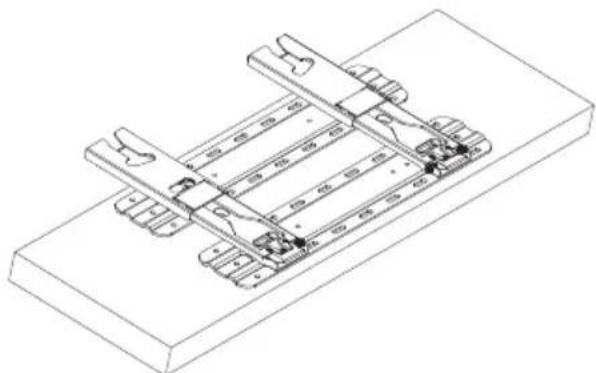
natural_image
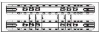
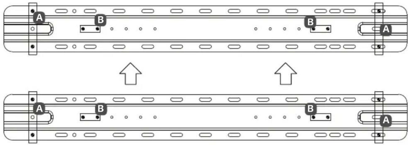
Technical line drawing of a mechanical assembly with two parallel plates and mounting brackets (no text or symbols)- Align the hole in the wall mount support with the hole in the Wall mounting supporter.
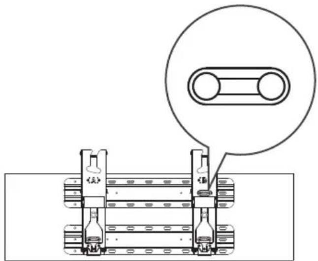
natural_image
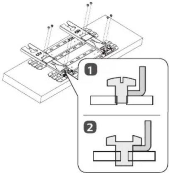
Technical diagram of a mechanical assembly with two cylindrical components and a magnified inset showing a circular detail (no text or symbols)- Insert the wall mount support screw into the hole in the wall mount support and Wall mounting supporter. (Tighten the screw while holding the wall mount support with your hand.)
1) Loosely tighten the screws, turning just 2 to 3 times before placing the wall mount.
2) Tighten until it is completely tight.
Japan
- Use the stud finder to locate and mark the center of the wall stud.
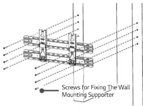
- After aligning the wall mount and Wall mounting supporter assembly (wall mount assembly) on the wall where the center of the wood stud is marked, mark the position of the screw and remove the wall mount assembly. (Use a level to make sure that the screw marks are horizontal.)
natural_image
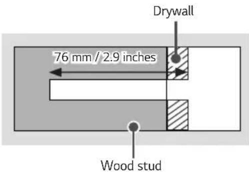
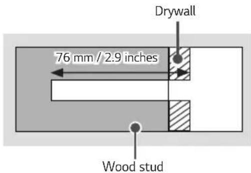
Technical line drawing of a mechanical assembly with mounting brackets and mounting holes (no text or symbols)- Using a ∅ 4 mm wood drill bit, drill a hole 76 mm (2.9 inches) or deeper into the screw locations marked on the wall for the wall mount. (Clean the drill holes)
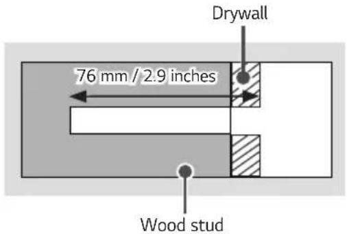
-
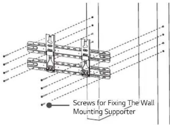
Position the wall mount assembly so that it fits over the drilled holes. Tighten the wall mount screws for the Wall mounting fixing screws into the drill holes. At this time, tighten the screws so that the wall, wall mounting assembly, and wall mount support screws are in close contact with each other.
-
Be careful, since excessive tightening can damage drywalls.
- When tightening the screws, use a Phillips head screwdriver. (manual or electric)
Australia
- Use the stud finder to locate and mark the center of the wall stud.
- After aligning the wall mount and Wall mounting supporter assembly (wall mount assembly) on the wall where the center of the wood stud is marked, mark the position of the screw and remove the wall mount assembly. (Use a level to make sure that the screw marks are horizontal.)
natural_image
Technical line drawing of a mechanical assembly with mounting flanges and bolts (no text or symbols)- Using a 4 mm wood drill bit, drill a hole 76 mm (2.9 inches) or deeper into the screw locations marked on the wall for the wall mount. (Clean the drill holes)
-
Position the wall mount assembly so that it fits over the drilled holes. Tighten the wall mount screws for the Wall mounting fixing screws into the drill holes. At this time, tighten the screws so that the wall, wall mounting assembly, and wall mount support screws are in close contact with each other.
-
Be careful, since excessive tightening can damage drywalls.
- When tightening the screws, use a Phillips head screwdriver. (manual or electric)
North America
- Use the stud finder to locate and mark the center of the wall stud.
- After aligning the wall mount and Wall mounting supporter assembly (wall mount assembly) on the wall where the center of the wood stud is marked, mark the position of the screw and remove the wall mount assembly. (Use a level to make sure that the screw marks are horizontal.)
natural_image
Technical line drawing of a mechanical assembly with mounting brackets and bolts (no text or symbols)- Using a ∅ 4 mm wood drill bit, drill a hole 76 mm (2.9 inches) or deeper into the screw locations marked on the wall for the wall mount. (Clean the drill holes)
-
Position the wall mount assembly so that it fits over the drilled holes. Tighten the wall mount screws for the Wall mounting fixing screws into the drill holes. At this time, tighten the screws so that the wall, wall mounting assembly, and wall mount support screws are in close contact with each other.
-
Be careful, since excessive tightening can damage drywalls.
- When tightening the screws, use a Phillips head screwdriver. (manual or electric)
2. Attaching the TV to the Wall Support
Depending on the model, models with horizontal terminals are recommended to follow Method 2-2 models without horizontal terminals should follow Method 2-1 and, when installing by Method 2-2, it is recommended to use the side terminal for HDMI & USB.
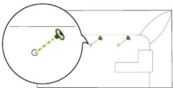
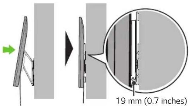
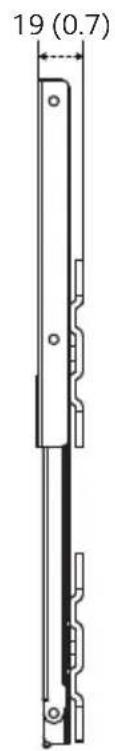
2-1) Separation distance between TV and wall: 19 mm (0.7 inches)
natural_image
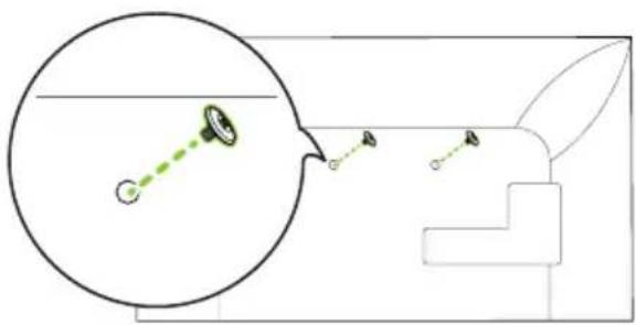
Technical line drawing of a mechanical component with an inset magnified detail (no text or symbols)- Fasten the enclosed TV fixing screws to both sides of the top of VESA on the TV.
natural_image
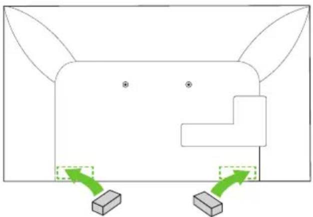
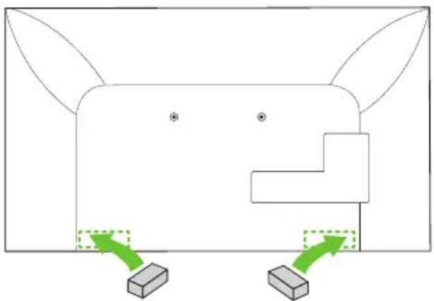
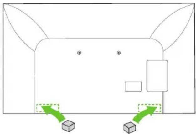
Diagram showing a magnified view of a lens interacting with a rabbit, with no text or symbols present.- Attach the enclosed TV protective cushion A to the bottom of the flat surface behind the TV. (The location may differ depending on the model.)
natural_image
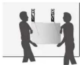
Diagram of a stylized animal face with two blocks and directional arrows indicating movement or force (no text or symbols)- After attaching the TV to the mount on the wall, fasten the screws fixed to the TV to the wall mount.
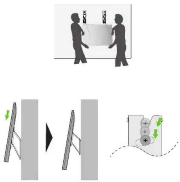
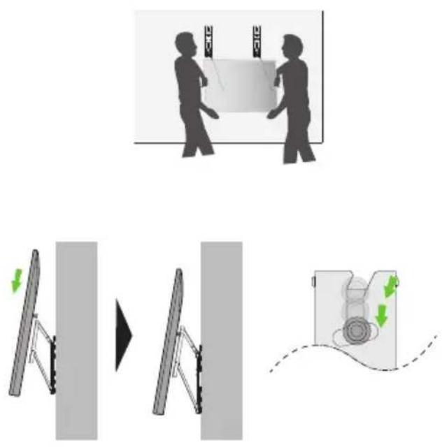
Caution: Ensure two or more people work together when mounting the TV. (If the product is lifted by one person, it may fall and result in injury or damage.)
Be careful not to trap the power cord between the wall mount bracket and the TV when mounting the TV. (If the power cord becomes trapped, it may result in product damage.)
natural_image
Silhouette of two people exchanging a rectangular object with decorative elements (no text or symbols)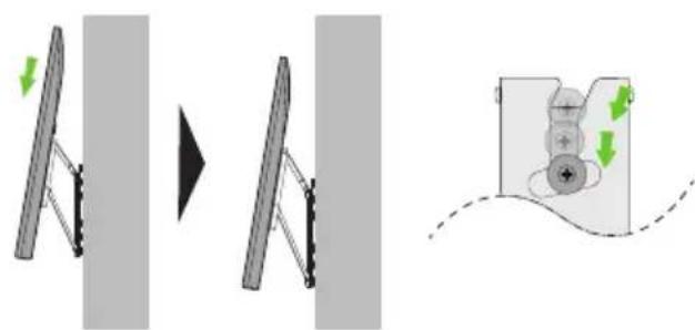
- Push the TV close to the wall. Be sure to gently push the upper and lower parts of the TV so that the pushing doesn't affect the TV. Gently push the upper center of the TV once again until it's completely pressed against the wall. Caution: Do not apply excessive force to the screen. (Doing so can damage the screen.)
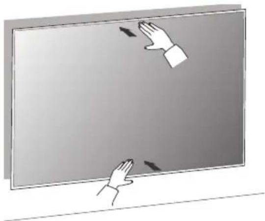
natural_image
Illustration of two hands interacting with a blank screen, no text or symbols present- Adjust the product's position by hand so it's horizontal. Hold the left and right bottom sides of the TV and adjust it to the desired direction.
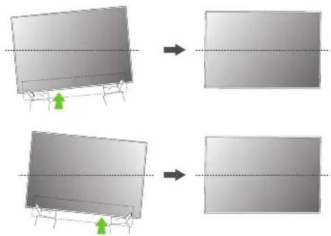
natural_image
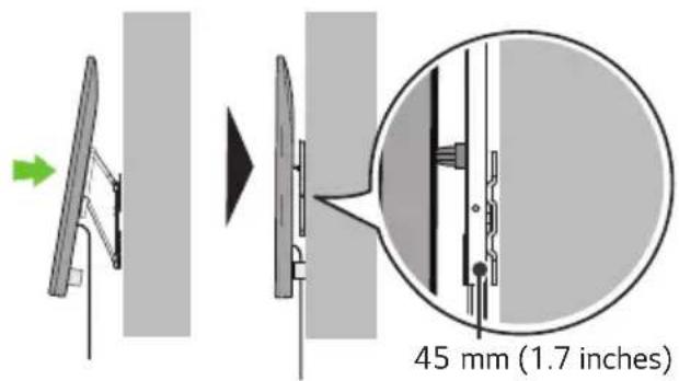
Two identical diagrams showing a 3D object being cut off into a flat surface, with green arrows indicating direction of motion (no text or symbols)2-2) Separation distance between TV and wall: 45 mm (1.7 inches)

natural_image
Technical line drawing of a mechanical component with an inset magnified view showing a green tool interacting with a component (no text or symbols present)- Fasten the enclosed TV guide spacers and guide spacer fixing screws to both sides of VESA.

natural_image
Diagram showing a magnified view of a mechanical component with green dotted lines and labeled points, no readable text or symbols present.- Attach the enclosed TV protective cushion B to the bottom of the flat surface behind the TV. (The location may differ depending on the model.)
natural_image
Simple line drawing of a cartoon animal face with two green directional arrows pointing to the lower side (no text or symbols)- After attaching the TV to the mount on the wall, fasten the screws fixed to the TV to the wall mount. Caution: Ensure two or more people work together when mounting the TV. (If the product is lifted by one person, it may fall and result in injury or damage.)
Be careful not to trap the power cord between the wall mount bracket and the TV when mounting the TV. (If the power cord becomes trapped, it may result in product damage.)
- Push the TV close to the wall. Be sure to gently push the upper and lower parts of the TV so that the pushing doesn't affect the TV. Gently push the upper center of the TV once again until it's completely pressed against the wall. Caution: Do not apply excessive force to the screen. (Doing so can damage the screen.)
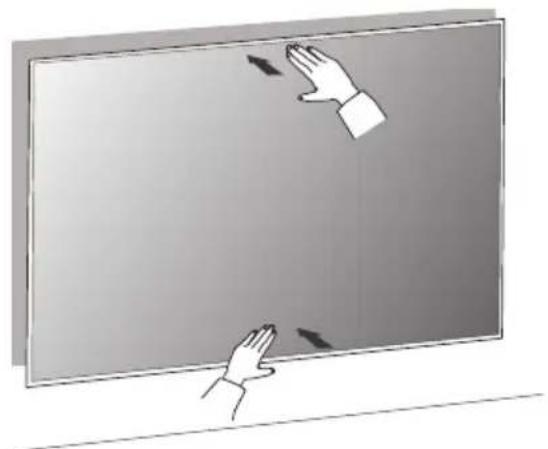
natural_image
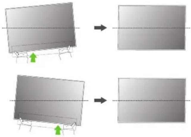
Illustration of two hands interacting with a blank screen, no text or symbols present- Adjust the product's position by hand so it's horizontal. Hold the left and right bottom sides of the TV and adjust it to the desired direction.
natural_image
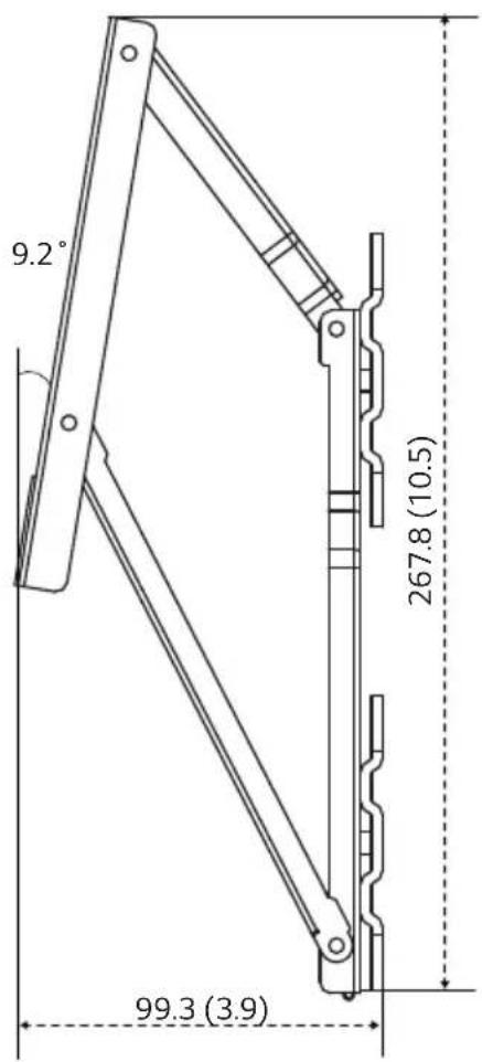
Two-step diagram showing transformation of a rectangular panel with green arrows indicating direction, no text or symbols present.Specifications
ENGLISH
[Unit: mm (inches)]
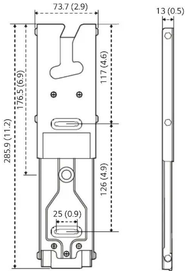
| Model Name WB21LMB | |
| Width(mm (inches)) | 73.7 (2.9) |
| Height(mm (inches)) | 285.9 (11.2) |
| Depth(mm (inches)) | 13 (0.5) |
| Product Weight(kg (lbs)) | 0.6 (1.3) x 2 |
| Screws Distance(mm) (65” ↓) | 200/300/400 |
| Max. Tensile Load(kg (lbs)) | 50 (110.2) |
Australia, Japan
When not removing the wall mount support
[VESA 200]
[VESA 300]

North America
When not removing the wall mount support
[VESA 200]
[VESA 300]
[When removing the wall mount support]
| Model Name WB21 LMB | |
| Width (mm (inches)) 73.7 (2.9) | |
| Height (mm (inches)) 285.9 (11.2) | |
| Depth (mm (inches)) 13 (0.5) | |
| Product Weight (kg (lbs)) 1.2 (2.6) | |
| Screws Distance (mm)(65” ↓) | 200/300/400 |
| Max. Tensile Load(kg (lbs)) | 50 (110.2) |
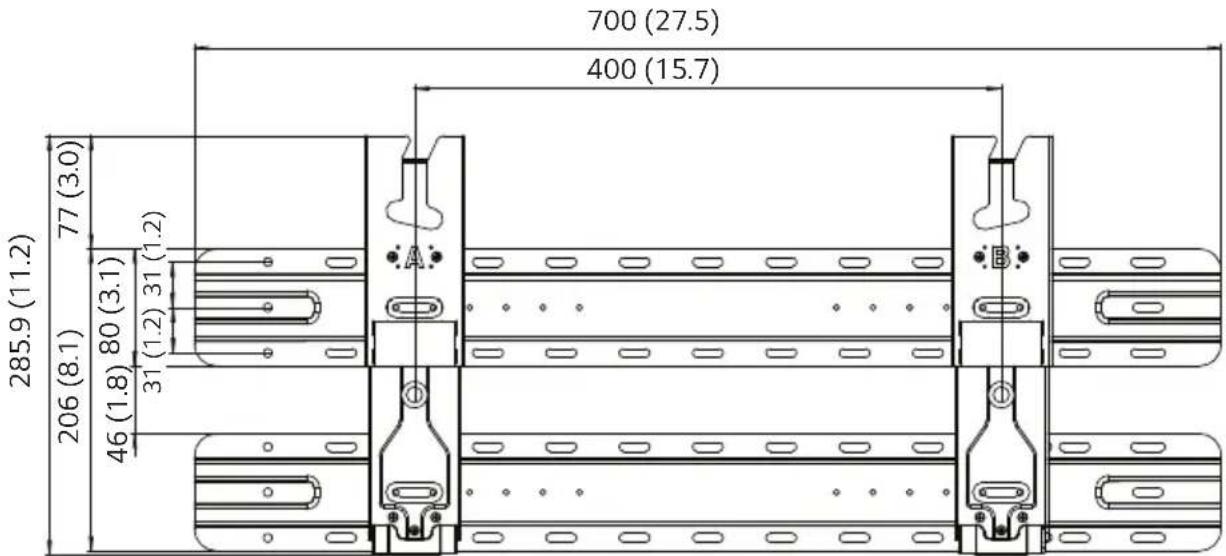
[When not removing the wall mount support]
| Model Name WB21 LMB | |
| Width (mm (inches)) 700 (27.5) | |
| Height (mm (inches)) 285.9 (11.2) | |
| Depth (mm (inches)) 19 (0.7) | |
| Product Weight (kg (lbs)) 3.6 (7.9) | |
| Screws Distance (mm)(65” ↓) | 200/300/400 |
| Max. Tensile Load(kg (lbs)) | 50 (110.2) |
< North America>
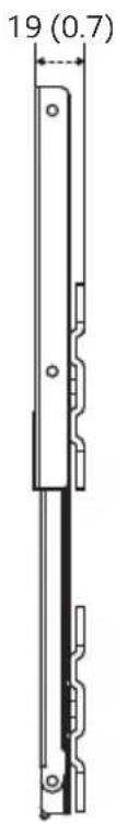
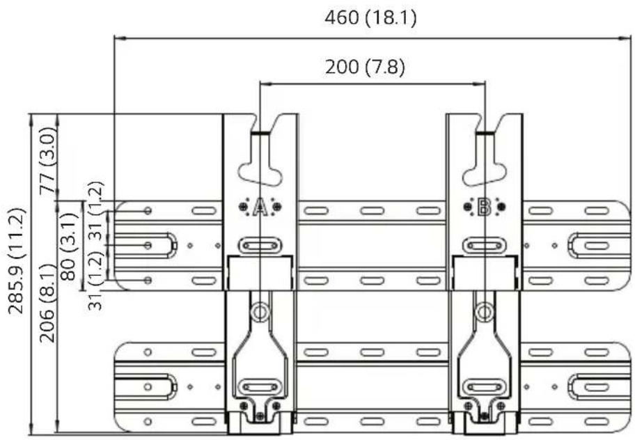
[When not removing the wall mount support]
| Model Name WB21 LMB | |
| Width (mm (inches)) 460 (18.1) | |
| Height (mm (inches)) 285.9 (11.2) | |
| Depth (mm (inches)) 19 (0.7) | |
| Product Weight (kg (lbs)) 2.8 (6.1) | |
| Screws Distance (mm)(65” ↓) | 200/300 |
| Max. Tensile Load(kg (lbs)) | 50 (110.2) |
[When not removing the wall mount support]
| Model Name WB21 LMC | |
| Width (mm (inches)) 700 (27.5) | |
| Height (mm (inches)) 285.9 (11.2) | |
| Depth (mm (inches)) 19 (0.7) | |
| Product Weight (kg (lbs)) 3.6 (7.9) | |
| Screws Distance (mm)(65”↓) | 200/300/400 |
| Max. Tensile Load(kg (lbs)) | 50 (110.2) |

LG
Life's Good

- Wall Mount Bracket
- Accessories
- Precautions for Safety
- Warning
- Caution
- Before Installation
- Tools for Installation
- How to install
- Wearing gloves
- Fastening Anchors and Screws
- For installation on concrete wall
- Attaching the guide paper to the wall
- Installing the Wall Mount Support
- Attaching the TV to the Wall Support
- 3-1) Separation distance between TV and wall: 13 mm (0.5 inches)
- 3-2) Separation distance between TV and wall: 39 mm (1.5 inches)
- Plugging Additional Cables in While Using the TV
- For installation on wood stud
- Japan
- How to Assemble Support
- Australia
- North America
- Attaching the TV to the Wall Support
- 2-1) Separation distance between TV and wall: 19 mm (0.7 inches)
- 2-2) Separation distance between TV and wall: 45 mm (1.7 inches)
- Specifications
- Australia, Japan
Brand : LG
Model : WB21LMB
Category : Uncategorized