
Quattroporte (2022) - Automotive Maserati - Free user manual and instructions
Find the device manual for free Quattroporte (2022) Maserati in PDF.


User questions about Quattroporte (2022) Maserati
0 question about this device. Answer the ones you know or ask your own.
Ask a new question about this device
Download the instructions for your Automotive in PDF format for free! Find your manual Quattroporte (2022) - Maserati and take your electronic device back in hand. On this page are published all the documents necessary for the use of your device. Quattroporte (2022) by Maserati.
USER MANUAL Quattroporte (2022) Maserati
This vehicle represents the result of Maserati's great experience in the design and production of sports, touring and racing vehicles.
The purpose of this manual and of the other documents in the two on-board documentation kits is to provide you with an understanding of the equipment, systems and controls of the vehicle and to explain how they work.
Consulting this manual you will acquaint yourself with the equipment and optional properties of your Maserati in order to take best advantage of all its potential.
The description of all the on-board safety systems and devices and the car's technical data are given in the main guide.
Before driving your vehicle for the first time, we suggest reading this manual carefully in order to quickly acquaint with commands and functions of your vehicle.
In a dedicated section of this manual you will also find instructions for basic maintenance procedures, in order to ensure steady levels of performance, quality and safe driving.
In addition, keep in mind that proper maintenance is an essential factor to help preserve the value of the vehicle over time and protect the environment.
For "Scheduled Maintenance" or any other operations, we recommend to contact the Maserati Service Network: you can trust our trained technical staff, who is constantly updated and provided with the required equipment in order to ensure that all service operations are performed properly and reliably.
All the documents contained in on-board documentation kits are integral part of the vehicle and should always be kept on board.
All documentation is also available at https://ownerdocumentation.maserati.com.
bar
| Category | Value | | :--- | :--- | | Introduction | 1 | | Understanding the Vehicle | 2 | | Before Starting | 3 | | Dashboard Instruments and Controls | 4 | | Starting and Driving | 5 | | Driver Assistance Systems | 6 | | In an Emergency | 7 | | Maintenance and Care | 8 | | Index | 9 |
1 - Introduction
On-board Documentation Kits ....6
Updating 6
Owner's Information Online 7
Consulting the manual 7
Abbreviations 8


Introduction
1
On-board Documentation Kits
On board there are various documents to provide the User with all the necessary information regarding the manufacturer's warranty, assistance request and to know all the devices supplied with the car and their functions, in order to be able to operate the vehicle using all of it's potential.
These documents are contained in two kits, one placed in the dashboard glove box and the other inside the luggage compartment.
The kit inside the dashboard glove box contains the Warranty Card, the Maserati Assistance Programme booklet (for versions/markets where provided) and Owner's Main Guide. The kit inside the luggage compartment, in addition to this manual, also contains the Maserati Intelligent Assistant™ (MIA) information booklet and Regulatory Information.
Depending on the equipment chosen, the market, etc., the kits may contain other additional documents.
NOTE:
After reviewing the manual always put the document in its case to avoid losing it.
All specifications and illustrations contained in these documents refer to the manual publishing date. Updated versions of the on-board documentation and the "Regulatory Information" are always available and can be consulted by accessing on the website https://ownerdocumentation.maserati.com In case of loss, excluding the Warranty Card, it is possible to purchase a copy of these documents by requesting it from the Service Network.
Updating
The vehicle's high quality level is guaranteed by constant improvements. Therefore, there may prove to be differences between this manual and your vehicle.
Maserati reserves the right to carry out design and functional changes and to achieve additions or improvements without incurring any obligation to update previously manufactured vehicles.
This manual illustrates and describes all versions of the current vehicle model. Therefore, some of the equipment and accessories in this publication may not appear on your vehicle; please only consider the information related to your vehicle. All specifications and illustrations contained in this manual refer to the Manual publishing date.
NOTE:
The updated version of on-board documentation can be consulted by accessing the website https://ownerdocumentation.maserati.com
Owner's Information Online
All of the on-board documents can also be consulted online in PDF format by accessing the website https://ownerdocumentation.maserati.com The website is available for most markets.
The online documents may be more up to date than those supplied with the car.
By accessing the website www.maserati.com it is possible to watch videos and find other useful information regarding your Maserati and all available services.
Consulting the manual
This manual illustrates maintenance and use information related to the following motorization models: 3.8 V8 TROFEO version, 3.0 V6 and 3.0 V6 AWD version (E) If not otherwise specified, the information is valid for all models.
For an easy identification of the topics, this manual is divided into sections and chapters: each chapter can have more paragraphs.
Meaning of Warning and Note Symbols
Within the text, important warnings and notes are also easily identifiable through icons.

WARNING!
Failure to comply with the instructions could cause HAZARDOUS SITUATIONS involving personal and vehicle safety.

ENVIRONMENTAL!
This note indicates the correct behavior when using the vehicle to protect the environment.

CAUTION!
Aimed at preventing any damage to the vehicle and thus hazards involving the safety of persons.
NOTE:
Additional information regarding the subject and/or the operation described.

In addition to these, this symbol in the text indicates a reference to the Owner's Main
Guide.
Optional Equipment and Versions/Markets Validity

In addition to the standard equipment, this manual also describes optional parts and
accessories which are identified in the title and /or text by this symbol alongside in brackets.

Optional equipment and also some functions or systems are not available in all vehicles and may only be available in markets. In these cases, the ment or the function/system will identified in the title and/or text by symbol alongside in brackets.

Introduction
1
Other General Indications
- In the images the vehicle is represented in the base version. On other versions, some part or equipment may differ from those shown in the images.
- "Left" and "right" in this manual, always refer to the driving direction.
- All indications and images in this manual refer to a vehicle with left-hand drive. On right-hand drive vehicles, some controls are ordered differently than shown in the illustrations.
- If not otherwise specified, the instrument cluster shown in the images belongs to the 3.0 V6 motorization model – however the indications given are also valid for all the other motorization models.
- If not otherwise specified, the instrument cluster shown in the images is the version with the speedometer in km/h – however the indications given are also valid for the version in mph.
Abbreviations
Some descriptions and terms with particular meanings are found in this manual in abbreviated form.
A/C Air-Conditioning system.
ABA Advanced Brake Assist.
ABS Anti-Lock Braking System.
ABSA Active Blind Spot Assist.
ACC Adaptive Cruise Control.
ADA Active Driving Assist.
ADAS Advanced Driver Assistance Systems.
AEB Autonomous Emergency Braking.
AFS Advanced Frontlighting System.
ALR Automatic Locking Retractor.
AQS Air Quality Sensor.
ATC Automatic Temperature Control.
AWD All-Wheel Drive.
BAS Brake Assist System.
BSA Blind Spot Assist.
BTO Brake Throttle Override.
CAN Controller Area Network.
CC Cruise Control.
CRS Child Restraint System.
DRL Daytime Running Lights.
EBD Electronic Brake-force Distribution.
ECU Electronic Control Unit.
EPB Electric Parking Brake.
EPS Electric Power Steering.
ESC Electronic Stability Control.
FCW Forward Collision Warning.
GPF Gasoline Particulate Filter.
HBA Hydraulic Brake Assistance.
HSA Hill Start Assist.
I.C.E. Increased Control and Efficiency.
LKA Lane Keeping Assist.
MIL Malfunction Indicator Light.
MIA Maserati Intelligent Assistant.
OBD On-Board Diagnostics.
ORC Occupant Restraint Controller.
ORS Occupants Restraint Systems.
PEB Pedestrian Emergency Braking.
RAB Ready Alert Braking.
RCP Rear Cross Path.
RHD Right-Hand Drive.
RKE Remote Keyless Entry.
RWD Rear-Wheel Drive.
Introduction

SAB Side Air Bag.
SABIC Supplemental Side Air Bag Inflatable Curtains.
SBR Seat Belt Reminder.
SRS Supplemental Restraint System.
TCS Traction Control System.
TFT Thin Film Transistor.
TPMS Tire Pressure Monitoring System.
TSA Traffic Sign Assist.
VIN Vehicle Identification Number.

Introduction
2 - Understanding the Vehicle
Main Controls Overview 12
Front Seats 15
Memorize the Driver's Seat Position 19
Rear Seats 21
Comfort Luxury Rear Seats (if equipped) . . . . . . . . . . . . . . . . . . . .
Steering Wheel Adjustment ....
Adjustable Pedals (→) 27
Rear-View Mirrors 28
External Lighting 30
Interior Lighting 36
Internal Equipment 37
Audio System 46
Cargo Area 48
HomeLink® (■) 50
Air Conditioning Distribution....


Understanding the Vehicle
Main Controls Overview
On Dashboard
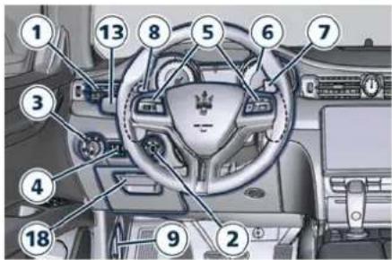
text_image
Labeled diagram of a car dashboard with numbered parts for identification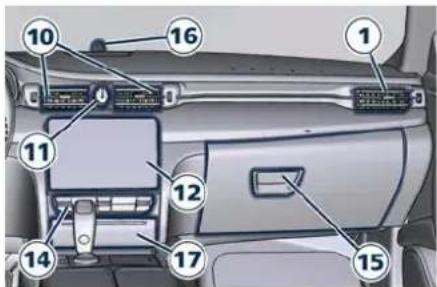
text_image
Diagram of car interior with numbered components for identification1 Adjustable side air outlets (page 56)
2 Engine START/STOP button (page 60) and (page 158)
3 Light switch (page 132)
4 Light dimmer controls (page 137)
5 Steering wheel controls (page 129)
6 Instrument cluster (page 90)
7 Right shift paddle +, if foreseen (page 172)
8 Left shift paddle -, if foreseen (page 172)
9 Hood release (page 86)
10 Adjustable central air outlets (page 56)
11 Analog clock (page 142)
12 MIA display (page 114)
13 Multifunction lever (windshield wipers, headlight selection and turn signals) (page 137)
14 Climate controls (page 146)
15 Passenger side glove box handle (page 142)
16 Vehicle security alarm light ( : chapter "Vehicle Security Alarm" in section "Safety")
17 Cover for compartment with multimedia ports (USB Type-A and Type-C) and slide phone drawer with Wireless Charger (page 41)
18 Driver side glove box handle (page 142)
On Central Console
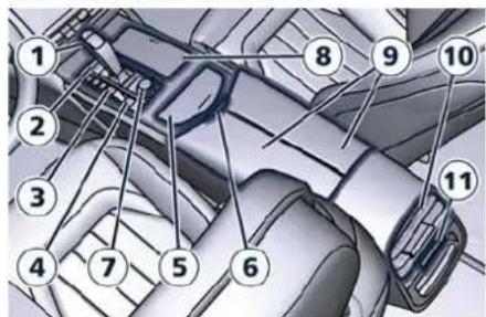
text_image
Technical diagram of a vehicle engine compartment with numbered parts labeled 1 through 11A/C Dual - zone
text_image
Technical diagram of a mechanical assembly with numbered components for identificationA/C Four - zone
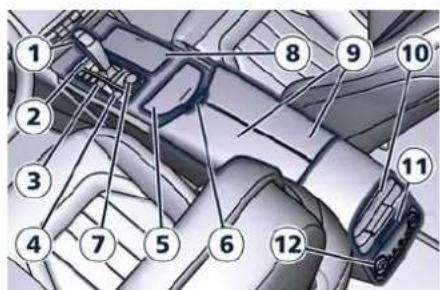
1 Automatic transmission shift lever (page 166)
2 Hazard lights switch (page 253)
3 Drive mode switches (page 175)
4 Electric Parking Brake lever (page 189)
5 Glove compartment access cover
Understanding the Vehicle

6 Unlock button for central console with cup holder and power outlet (page 39)
7 Rotary selectors and buttons for the multimedia navigation (page 114)
8 Cover for cup holder and power outlet compartment (if equipped) (page 39)
9 Central console covers with armrest function (page 39)
10 Air outlets (adjustable) (page 56)
11 Rear power sunshade (page 80) and rear seats comfort controls panel (page 22)
12 Rear climate controls panel for four-zone air conditioner (page 153)
On Front Dome Console
text_image
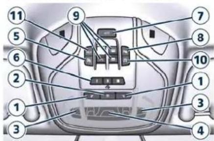
Labeled diagram of a car interior with numbered components for identification1 Reading lights control button (page 36)
2 Central light control button (page 36)
3 Reading lights (page 36)
4 Central light (page 36)
5 Passenger air bag deactivation warning light ():
paragraph "Passenger's Air bag Deactivation" in "Supplemental Restraint Systems (SRS) – Air bag" of section "Safety")
6 HomeLink controls ( ) page 50)
7 Button to release the manual boot lid (page 81) or to open fully/partially the power boot lid ( page 82)
8 Button to enable/disable front sensors of the Park Assist system (page 209)
9 Sunroof controls () (page 78)
10 Button to switch off passenger compartment lights (page 36)
11 Button to activate the HELP call (page 255) or the SOS Emergency call (page 258)
On Front Doors
text_image
Diagram showing car interior components with numbered labels and a mobile phone interfacePassenger door
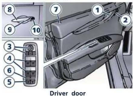
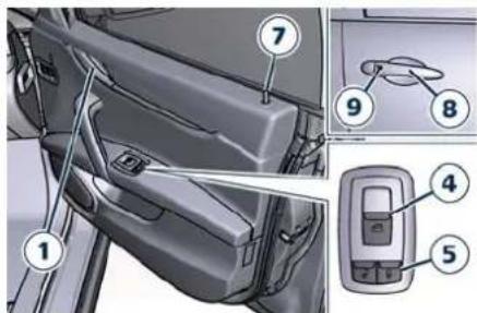
1 Internal door handle ( : chapter "Doors Security Locking" of section "Safety")
2 Driver's seat, steering wheel, adjustable pedals (if equipped) and rear mirrors memory switch (page 19)
3 Rear view mirrors switches (page 28)

Understanding the Vehicle
4 Power window switch (page 72)
5 Power door unlocks/locks ( : chapter "Doors Security Locking" of section "Safety")
6 Rear windows and sunshade lockout button (page 74)
7 Internal door lock/unlock knob (: chapter "Doors Security Locking" of section "Safety")
8 External door handle (: chapter "Doors Security Locking" of section "Safety")
9 Door lock button with "Passive Entry" function (page 68)
10 Door outboard manual opening lock (page 60)
Between the Rear Seats
text_image
Diagram of car gear shift lever with labeled parts 1 and 2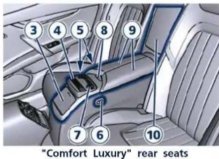
text_image
"Comfort Luxury" rear seats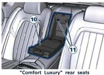
text_image
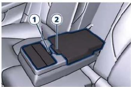
"Comfort Luxury" rear seats1 Armrest cup holder covers unlock button (page 40)
2 Armrest compartment unlock button with power outlet and USB port for charge only (page 21)
3 (*) Cup holder compartment lid (page 39)
4 (*) Rear seats comfort controls panel on rear storage compartment (page 22)
5 (*) Front and rear right seat adjustment controls (page 22)
6 (*) Left rear seat adjustment control (page 22)
7 (*) Four-zones A/C controls panel ( page 153)
8 (*) Unlock button for covers on rear central console (page 22)
9 (*) Storage covers with armrest function (page 22)
10 (*) Reclining shelf to access storage box between the rear seats (page 22)
11 (*) 12 V power outlet and USB port for charge only (page 22)
(*) For optional "Comfort Luxury" rear seats version
On Rear Dome Console
text_image
Diagram of a car interior with numbered labels pointing to different parts of the seat or seat.Understanding the Vehicle

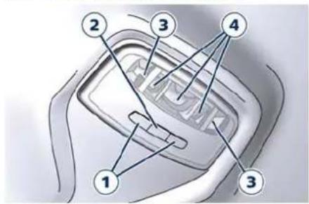
1 Reading lights control button (page 36)
2 Central light control button (page 36)
3 Reading light LED (page 36)
4 Central light LEDs (page 36)
On Rear Doors
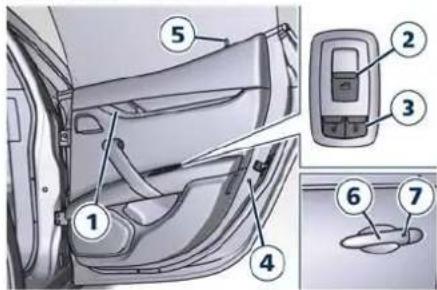
text_image
Diagram of car interior components with numbered labels indicating parts of the door and dashboard1 Internal rear door handle (: chapter "Doors Security Locking" of section "Safety")
2 Power window and sunshade (if equipped) switch (page 72)
3 Power doors lock/unlock buttons (: chapter "Doors Security Locking" of section "Safety")
4 "Child protection" door lock system ( chapter "Doors Security Locking" of section "Safety")
5 Inside door lock/unlock knob (: chapter "Doors Security Locking" of section "Safety")
6 External door handle (page 68)
7 Door lock button with "Passive Entry" function ( )page 68)
Front Seats
Seats, head restraints, and seat belts are parts of the Occupant Restraint System (ORS) of the vehicle. For further information, : chapter "Occupant Restraint System (ORS)" and "Head Restraints" in Section "Safety".

WARNING!
Be sure everyone in your vehicle is in a seat and using a seat belt properly.
Front Power Seats
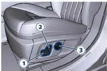
The switches of the power seats are located on the outboard side of the seat cushion.
Use the front switch 1 to move the seat up or down, forward or rearward or to recline the seat cushion.
Use the switch 2 to recline the seatback.
Use the rear switch 3 to adjust the lumbar support.

Understanding the Vehicle
2
text_image
Diagram of car interior with numbered labels pointing to a highlighted vehicle seat area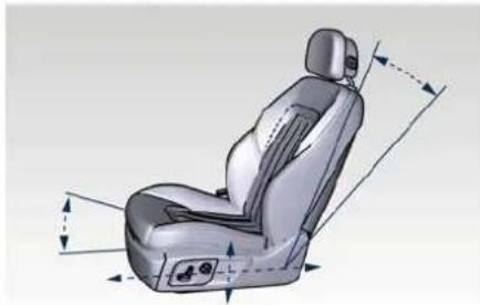
natural_image
3D rendering of a car seat with visible dimensions and control buttons (no text or symbols)Seat Forward/Rearward Adjustment
The seat can be adjusted both forward and rearward.
Push the seat switch 1 forward or rearward, the seat will move in the direction of the switch.
Release the switch 1 when the desired position is reached.
Seat Up/Down Adjustment
The height of the seat can be adjusted up- or downward.
Grip switch 1 from the back side and push it down or up. Release the switch 1 when the desired position is reached.

CAUTION!
If the seat's movement does not work, make sure that the corresponding fuse is not tripped (see chapter "If a Fuse Blows" in section "In an Emergency").
Seat Tilt Control (Up/Down)
The angle of the seat cushion can be adjusted in four directions.
Pull upward or push the front of the switch 1, to move the front cushion seat in the direction of the switch. Release the switch 1 when the desired position is reached.
Seat Back Tilt Control
The angle of the seatback can be adjusted forward or rearward.
Push the seatback switch 2 forward or rearward, the upper seatback will move in the direction of the switch. Release the switch 2 when the desired position is reached.
Power Lumbar
Push the switch 3 forward or rearward to increase or decrease the lumbar support.
Push the switch 3 upward or downward to raise or lower the lumbar support.

WARNING!
- Never adjust the seat while driving. You could lose control of the vehicle. Moving the seat could distract you or make you press a pedal unintentionally.
- Seats should be adjusted before fastening the seat belts and while the vehicle is parked.
- Do not travel with the seatback reclined so that the shoulder belt is no longer resting against your chest. In a collision you could slide under the seat belt, which could result in serious injury or death.

CAUTION!
Do not place any object under a power seat or obstruct its movement as it may cause damage to the seat controls. Seat movement may become limited if there is an obstruction in the way.
Front Heated Seats( )
The front seats are equipped with heaters in both seat cushions and seatbacks.
Understanding the Vehicle

The front seats heating is operated by the MIA system.
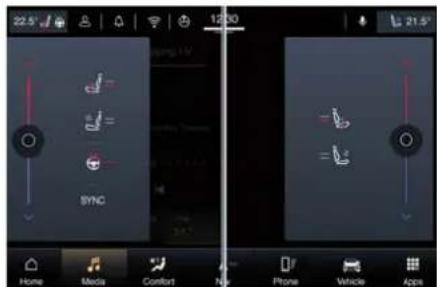
The seat comfort icons are in the upper status bar in any MIA screen configuration.
Touch the heated/vented seat icon near the temperature value to open the pop up that will allow you to activate and set the function on the driver's seat and/or on the passenger seat.
text_image
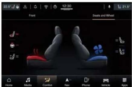
22.5° 12:30 SYNC Home Media Comfort New Phone Vehicle AppsTo activate and set the heating/ventilation functions of the front seats and the heating of the steering wheel (if available), in addition to what is indicated, it is possible to access the "Seats and Wheel" submenu of the "Comfort" page in which there are the seats and wheel icon.
text_image
22.5° Front 12:30 21.5° Seats and Wheel Home Media Comfort New Phone Vehicle AppsWARNING!
- Persons with low skin sensitivity because of advanced age, chronic illness, diabetes, spinal cord injury, medication, alcohol use, exhaustion or other physical conditions must be careful when using the seat heater. It may cause burns even at low temperatures, especially if used for long periods of time.
- Do not place anything on the seat that insulates against heat, such as a blanket or cushion. This may cause the seat heater to overheat. Sitting in a seat that has been overheated could cause serious burns due to the increased surface temperature of the seat.
Front Seats Heat Function
NOTE:
The engine must be running for the heated seats to operate.
If the function is not active (state "OFF"), the dynamic parts of the icon are grey: to activate the function operate in the following mode:
- Starting from the state "OFF", within 15 seconds touch the driver or passenger seat soft-key once to select HI-level heating displayed by the seat icon with 2 arrows and 2 red lines.
- Within 15 seconds, touch the driver or passenger seat soft-key a second time to select LO-level heating displayed by the seat icon with 1 arrow and 1 red line.
- Within 15 seconds, touch the same soft-key a third time to shut off the seat heating.
NOTE:
Once a heat setting is selected, heat will be felt within 2 to 5 minutes.
When the HI-level setting is selected, the heater will provide a boosted heat level during the first 4 minutes of operation.
Then, the heat output will drop to the normal HI-level.

Understanding the Vehicle
If the HI-level setting is selected, the system will automatically switch to LO-level after a maximum of 60 minutes of continuous operation.
At that time, the display will indicate the change from HI to LO.
The LO-level setting will turn in "OFF" state automatically after a maximum of approximately 45 minutes.
Front Ventilated Seats( )
To enhance occupants comfort by high external temperatures, both the driver and passenger seats, on request, can be ventilated.
Small fans are located in the seat cushion and seatback, they draw air from the seat surface through fine perforations in the seat cover to help keep the driver and front passenger cooler when the temperature is high. The ventilated seats are operated with the MIA system.
The seat comfort icons are in the upper status bar in any MIA screen configuration or are accessible in the "Seats and Wheel" submenu of the "Comfort" page as indicated for heated seats.
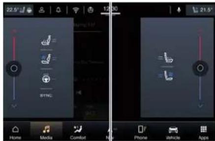
Touch the heated/vented seat icon near the temperature value to open the pop up that will allow you to activate and set the function on the driver's seat and/or on the passenger seat.
text_image
22.5° 12:30 21.5° Home Media Comfort N Phone Vehicle AppsFront Ventilated Seats Function
NOTE:
The engine must be running for the ventilated seats to operate.
If the function is not active (state "OFF"), the dynamic parts of the icon are grey: to activate the function operate in the following mode:
- Starting from the state "OFF", within 15 seconds touch the driver or passenger seat soft-key once to select HI-level ventilation displayed by the seat icon with the fan and two blue lines.
- Within 15 seconds, touch the driver or passenger seat soft-key a second time to select LO-level ventilation displayed by the seat icon with the fan and 1 blue line.
- Within 15 seconds, touch the same soft-key a third time to shut off the seat ventilation.
Understanding the Vehicle

Memorize the Driver's Seat Position
This function allows the driver to store up to two different memory profiles for easy recall through a memory switch. Each memory profile contains desired position settings for the driver seat, external side mirrors, adjustable pedals (€), power tilt and telescopic steering column and a set of programmed radio stations.
Your key fob can also be set to recall the same positions by pressing the 🔒 button.
NOTE:
- Only one key fob can be linked to each of the memory positions.
- Passive Entry door handles cannot be linked to the memory function. Use either the memory recall switch or the key fob (if linked to the memory function) to recall memory positions 1 or 2.
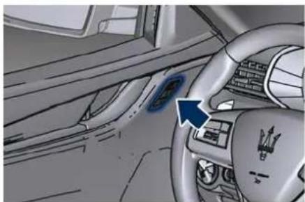
The memory seat switch is located on the driver's door trim panel. The switch consists of three buttons:
- The "S" (SET) button, which is used to activate the memory save function.
- The "1" and "2" buttons which are used to recall either of two programmed memory profiles.
natural_image
Interior view of a car dashboard with steering wheel and infotainment panel (no visible text or symbols)Memory Profiles Setting
NOTE:
Saving a new memory profile will erase an existing profile from memory. To create a new memory profile, perform the following:
- Cycle the ignition device to the ACC or RUN position.
- Adjust all memory profile settings to desired preferences (i.e., seat, side mirrors, adjustable pedals), power tilt and telescopic steering column and radio station presets).
- Press and release the "S" button on the memory switch.
- Within 5 seconds, press and release the memory button "1" or "2".
- Check on the instrument cluster for the positive response of the actions "Memory 1 (or 2) profile set".
After these steps, the profile set will be memorized in the selected position.
NOTE:
Memory profiles can be set without the vehicle in P (Park), but the vehicle must be in P (Park) to recall a memory profile.
Pairing Remote Keyless Entry Transmitter to Seats Memory
Your key fob can be programmed to recall one of two programmed memory profiles by pressing the button on the key fob.
NOTE:
This function can be enabled or disabled using the MIA System, refer to "Functions of Settings Menu on MIA" in section "Dashboard Instruments and Controls" for further information.
To programme your key fobs, perform the following actions:
- Cycle the ignition device to the RUN position.
- Move the seat and/or the other adjustable devices in the position that you wish to memorize, or recall a previously memorized profile, pressing the corresponding memory button "1" or "2".

Understanding the Vehicle
- Cycle the ignition device to the OFF position.
- Press and release the "S" button.
- Within 5 seconds, press and release the memory button "1" or "2".
- Press and release the button on key fob.
- Within 3 seconds, press and release the button on the key fob.
To check if the system has memorized the correct profile, you can move the seat and press the button: the seat will move to the memorized position.
NOTE:
Your key fobs can be unlinked to your memory settings by pressing the "S" button followed by the button on the key fob.
Memory Position Recall
NOTE:
The vehicle must be in P (Park) to recall memory positions. If a recall is attempted when the vehicle is not in P (Park), a message will display in the instrument cluster.
To recall the memory settings for driver, press memory button number "1" or "2" on the driver's door trim panel or the button on the key fob linked to memory position "1" or "2" with ignition device in the RUN position.
A recall can be cancelled by pressing any of the buttons ("S", "1", or "2") during a recall. When a recall is cancelled, the driver seat, external side mirrors, adjustable pedals and power tilt and telescopic steering column stop moving.
A delay of at least one second will occur before selecting a new recall.
Easy ENTRY/EXIT Seat
This function provides automatic driver seat positioning to enhance driver mobility when entering and exiting the vehicle.
The distance the driver seat moves depends on where you have the driver seat positioned when you place the ignition device to the OFF position.
- When you cycle the ignition to the OFF position the driver seat:
- will move about 60 mm (2.36 in) rearward if the driver seat position is greater than or equal to ca. 68 mm (2.67 in) forward of the rear stop;
- will move to a position of ca. 8 mm (0.31 in) forward of the rear stop if the driver seat position is between 23 mm (0.9 in) and 68 mm (2.67 in) forward of the rear stop.
- The seat will return to its previously set position when you place the ignition into the ACC or RUN position.
- The easy entry/easy exit function is disabled when the driver seat position is less than 23 mm (0.9 in) forward of the rear stop. In this position, there would be no benefit to the driver by moving the seat for easy exit or easy entry.
Each stored memory setting will have an associated easy entry/exit position.
NOTE:
The "Easy Entry/Easy Exit" function can be enabled or disabled using the MIA system, refer to "Functions of Settings Menu on MIA" in section "Dashboard Instruments and Controls" for further information.
Rear Seats
On standard version vehicles, rear seats can fit three passengers: side seats can be equipped with heating resistances. Seats, head restraints and seat belts are parts of the occupant restraint system of the vehicle.

WARNING!
Be sure everyone in your vehicle is in seat and using a seat belt properly.
NOTE:
- For further information chapter "Occupants Restraint Systems (ORS)" and "Head Restraints" in section "Safety".
- For vehicles equipped with "Comfort Luxury" rear seats with rear console storage compartment, refer to chapter "Comfort Luxury Rear Seats" in this section.
Rear Armrest
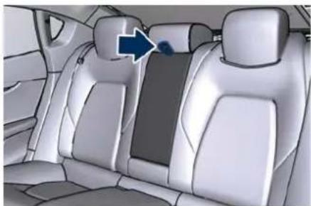
The rear armrest is mobile and can be folded up into the seat back.
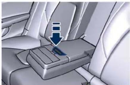
- To lower it, pull the stripe as indicated.
natural_image
Interior view of a car showing the rear seats and seat, with a blue arrow pointing to the side panel (no text or symbols visible)• aTo close it, pull it upwards then push it back into its seat.
On the front part of the armrest there are two cup holders (see "Internal Equipment" in this section). Inside the armrest there is a illuminated glove or document compartment. Pressing the opening button and lifting the cover of the armrest box you accede a 12 V power outlet and USB port: a tablet plug may be installed.
natural_image
Interior view of a car seatbelt with a blue arrow pointing to the seat (no text or symbols visible)
natural_image
Interior view of a car dashboard with three blue arrows indicating directional flow or movement (no text or symbols present)• To close the compartment, lower the cover.

CAUTION!
The armrest is not designed to support the weight of an adult or a child: please use it only to store beverages, small objects or documents.
Rear Side Heated Seats (if equipped)
The side rear seats can be equipped with heaters both in seat cushion and seatback.
Rear seats heating can be adjusted by operating control devices on the panel located on the rear side of the central console. The panel also includes command for the rear window sunshade (see "Rear Windows" in section "Before Starting") and may include four-zone climate controls

Understanding the Vehicle
(see "Air Conditioning Controls" in section "Dashboard Instruments and Controls").
2

WARNING!
- Persons with low skin sensitivity because of advanced age, chronic illness, diabetes, spinal cord injury, medication, alcohol use, exhaustion or other physical conditions must be careful when using the seat heater. It may cause burns even at low temperatures, especially if used for long periods of time.
- Do not place anything on the seat that insulates against heat, such as a blanket or cushion. This may cause the seat heater to overheat. Sitting in a seat that has been overheated could cause serious burns due to the increased surface temperature of the seat.
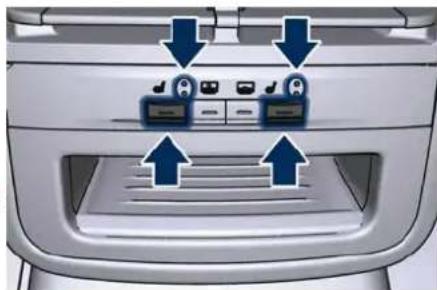
The buttons on the panel with the resistance icon activate the heating on one or both seats.
- Push the button once to select the highest heating level. The two LED beside of the icon will illuminate.
- Push the same button a second time to select the lowest level. Only the lower LED remains illuminate.
- Push the same button a third time to shut the heating elements OFF. The LED will turn off.
natural_image
Top-down view of a car rear vent with two blue arrows pointing to electronic components (no text or symbols visible)NOTE:
- Once a heat setting is selected, heat will be felt within two to five minutes.
• The engine must be running for the heated seats to operate.
By selecting the HI-level setting, the heater will provide a boosted heat level during the first four minutes of operation. Then, the heat output will drop to the normal HI-level.
By setting the HI-level, the system will automatically switch to LO-level after a maximum of 60 minutes of continuous operation. The LO-level setting will turn off automatically after a maximum of approximately 45 minutes.
Comfort Luxury Rear Seats (if equipped)
The GranLusso version can be equipped with two rear seats endowed with ventilation and a heating power regulation system (chapter "Head Restraints" in section "Safety"). In this version, the center rear seat is occupied by a central console with several functions, a compartment and a small instrument panel to control rear seats, four-zones air conditioning (if equipped) and the sunshade on the rear window.
A reclining shelf positioned centrally between both back rests enables to access power outlets and USB port.
Beside the heating regulation system designed for a better comfort at high external temperatures, as described in the previous paragraph, the rear seats can be ventilated as well. The seat cushion and seatback are equipped with small fans drawing air from the seat surface through fine perforations in the seat cover to help keep the occupant bodies cooler in case of high temperature.
Seat Setting Devices
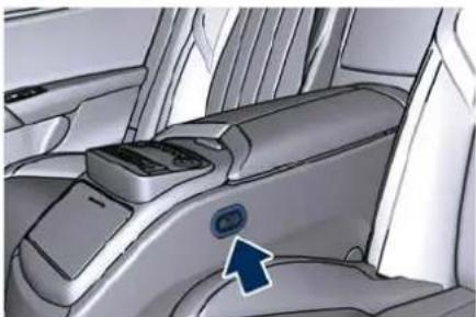
Rear seat controls operating forward and backward adjustments are
Understanding the Vehicle

positioned on both sides of the central console storage compartment. By moving the seat forward or backward, you can change the tilt of the backrest as well.
The rear passenger sitting on the side opposite to the driver can move the front passenger seat by using the rear command.
natural_image
Interior view of a car seatbelt with a blue arrow pointing to the side panel (no text or symbols visible)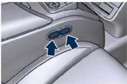
natural_image
Interior view of a car dashboard with two blue arrows pointing to the left side of the panel (no text or symbols visible)
CAUTION!
If the seat's movement does not work, make sure that the corresponding fuse is not tripped (see chapter "If a Fuse Blows" in section "In an Emergency").
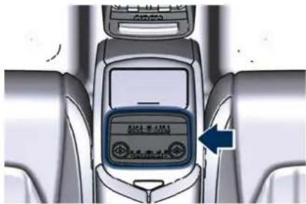
Instrument Panel on the Rear Central Console
The instrument panel on the rear central console storage compartment is divided into two areas:
- The front area with the control buttons for the rear seats comfort level and the sunshade on the rear window (see "Rear Window" in section "Before Starting").
- The rear area with the control buttons for the four-zone air conditioning system (see "Air Conditioning Controls" in section "Dashboard Instruments and Controls").
The buttons labeled with a fan- and a resistance icon are used for ventilation and/or heating control on one or on both seats.
- Push the button once to select the highest ventilation and/or heating level. The two LED beside of the icon will illuminate.
- Push the same button a second time to select the lowest ventilation
and/or heating level. Only the lower LED remains illuminate.
- Push the same button a third time to shut the ventilation and/or heating elements OFF. The LED will turn off.
text_image
SINHUA ←
text_image
Diagram of car air conditioning panel with directional indicators and labeled buttons (A/D, AUTO)NOTE:
The engine must be running for the ventilated seats to operate.
Central Console Functions
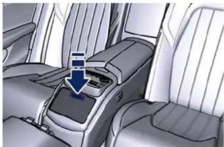
On the front part of the rear central console there is a cup holder, to open

Understanding the Vehicle
it press the cover as pointed out in the picture.
To close it, lower the cover to the console support.

natural_image
Interior view of a car seatbelt with a blue arrow indicating the down-left direction (no text or symbols present)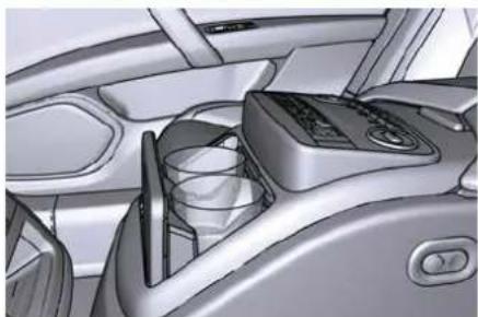
natural_image
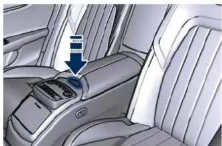
Interior view of a car dashboard and air intake unit (no visible text or symbols)By pressing the indicated button and opening the half-lids used as armrests, you can access the internal area of the storage compartment. The compartment is supplied with air-conditioned like the rest of the passenger compartment.
The illuminated area of the storage compartment includes: a 12 V power socket/cigarette lighter, a button to exclude the air-conditioning of the compartment and two holders for bottle, can or cups.
natural_image
Interior view of a car showing the seatbelt and dashboard (no text or symbols visible)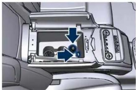
natural_image
Interior view of a camera module showing internal components and directional arrows (no text or symbols)NOTE:
For further information see "Internal Equipment" in this section.
Reclining Shelf Rear Accessories
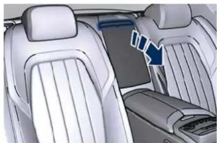
To access devices centrally between the backrests, tilt the reclining shelf downwards.
natural_image
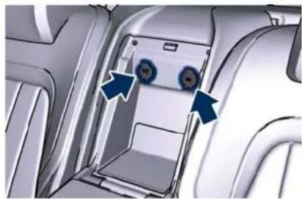
Interior view of a car showing rear seats and side seats with a blue arrow indicating a directional component (no text or symbols present)Behind the reclining shelf, you may access a power source of 12 V and a USB high capacity port for charging portable devices.
natural_image
Interior view of a car showing a vehicle's rear compartment with two blue arrows pointing to the door (no text or symbols visible)Understanding the Vehicle

NOTE:
For further information see "Internal Equipment" in this section.
Steering Wheel Adjustment
This function allows you to power tilt the steering column upward or downward or to lengthen or shorten it in order to adjust the steering wheel to an optimized position.
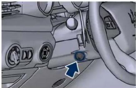
The power tilt/telescoping steering column/wheel switch is located on the lower left side of the steering column. To adjust the tilt of the steering column/wheel, move the switch up or down as desired.
natural_image
Interior view of a car dashboard with air vent, steering wheel, and dashboard (no visible text or symbols)To lengthen or shorten the steering column/wheel, pull the switch toward you or push the switch away from you as desired.
NOTE:
You can use your key fob with or the memory buttons on the driver's door
trim panel to return the tilt/telescopic steering column/wheel to programmed positions. See "Memorize the Driver's Seat Position" in this section.

WARNING!
Do not adjust the steering column/wheel while driving. Adjusting the steering column/wheel while driving could cause the driver to lose control of the vehicle. Be sure the steering column/wheel is adjusted before driving your vehicle. Failure to follow this warning may result in serious injury or death.
Heated Steering Wheel (T)
The steering wheel may contain a heating element inside the rim that helps warm driver's hands by cold weather.
The heated steering wheel has only one temperature setting. Once turned on, this function will operate for approximately 58 to 70 minutes before automatically shutting off.
The heated steering wheel can shut off early or may not turn on when the steering wheel is already warm.

Understanding the Vehicle
The heated steering wheel can be turned on and off using the MIA system.
Touch the steering wheel icon near the temperature value of driver's side to open the pop up that will allow you to activate the heating function.
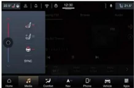
text_image
22.5° 12:30 21.5° Switching FM Browse Audio Temp Temp Temp Temp Sync Home Media Comfort Nav Phone Vehicle AppsTo activate the heating function, in addition to what is indicated, it is possible to access the "Seats and Wheel" submenu of the "Comfort" page in which there is the wheel icon.
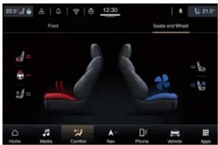
text_image
22.5° Front 12:30 21.5° Seats and Wheel Home Media Comfort Nav Phone Vehicle AppsNOTE:
The engine must be running for the heated steering wheel to operate.
If the function is not active (state "OFF"), the dynamic parts of the icon are grey: to activate the function operate in the following mode:
- Within 15 seconds, touch the heated steering wheel soft-key to turn on the function displayed by the steering wheel icon with the arrows and red line.
- Within 15 seconds, touch the heated steering wheel soft-key a second time to shut off the function: the dynamic parts of the icon turns grey.

WARNING!
- Persons who are unable to feel pain to the skin because of advanced age, chronic illness, diabetes, spinal cord injury, medication, alcohol use, exhaustion, or other physical conditions must exercise care when using the steering wheel heater. It may cause burns even at low temperatures, especially if used for long periods.
- Do not place anything on the steering wheel that insulates against heat, such as a blanket or steering
wheel covers of any type and material. This may cause the steering wheel heater to overheat.
Adjustable Pedals ( )
The adjustable pedals system is designed to allow greater range of pedals positions enabling driver comfort with regard to the steering wheel tilt and the seat position. This function allows the brake and accelerator pedals to move toward or away from the driver's feet. The switch is located on the front side of the driver's seat cushion shield.

natural_image
Interior view of a car dashboard showing the rear seat and side panel (no text or symbols visible)Press the switch downward to move the pedals forward (toward the front of the vehicle).
Lift the switch upward to move the pedals rearward (toward the driver).

WARNING!
Do not adjust the pedals position while the vehicle is moving. You could lose control and have an accident. Always adjust the pedals position while the vehicle is parked.
The following messages will be displayed if the driver is attempting to adjust the pedals when the system is locked out:
- "Adjustable Pedals Unavailable While in Reversing";
- or "Adjustable Pedals Unavailable While Cruise Engaged".
NOTE:
For vehicles equipped with driver memory seat, use your key fob or the memory buttons on the driver's door trim panel to return the adjustable pedals to programmed positions. See "Memorize the Driver's Seat Position" in this section for further information.

CAUTION!
Do not place any object under the adjustable pedals or obstruct its movement as it may cause damage to the pedal controls. Pedal movement may become limited if there is an
obstruction in the adjustable pedal's path.

Understanding the Vehicle
Rear-View Mirrors
External Mirrors
External mirrors can be adjusted electrically and are equipped with anti-mist resistors operated by the air conditioning system (see "Air Conditioning Controls" in section "Dashboard Instruments and Controls").
The mirrors can be closed electrically and will yield in both directions in case of a collision.
The external mirrors are electrochromic (E), which means, they automatically operate an anti-dazzle function by gradually shading as the light hitting the mirrors increases.
The external rear-view electrochromic mirrors work in conjunction with the internal rear-view electrochromic mirror.
NOTE:
- The mirrors can be adjusted electrically only with the ignition device in ACC and RUN position.
- When the vehicle is started, the warning light shown in the picture will momentarily illuminate in both outside rear-view mirrors to let the driver know that the BSA system()
is operational. For more details see chapter "Blind Spot Assist - BSA" or "Active Blind Spot Assist - ABSA" in section "Driver Assistance Systems".
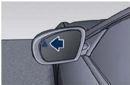
natural_image
Close-up of a car's side mirror highlighting a blue arrow symbol (no text or labels)The external of the rear-view mirror support is equipped with LEDs, lighting up when the turn signals and vehicle entry/exit lights are activated.
NOTE:
The lighting of the outside door handle and the puddle light near the front door are only available with the optional rear view mirrors (SVC).
When the surround view camera system is installed, at the external bottom side of the rear-view mirror is the side view camera (refer to "Surround View Camera System" in section "Driver Assistance Systems").
Mirrors Positioning
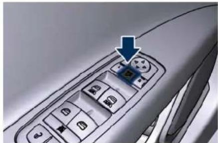
The power mirror controls are located on the driver's door trim panel.
The power mirror controls consist of mirror select buttons and a four-way mirror control switch.
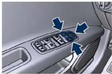
natural_image
Interior view of a car showing the dashboard with four buttons and directional arrows indicating action or movement (no text or symbols present)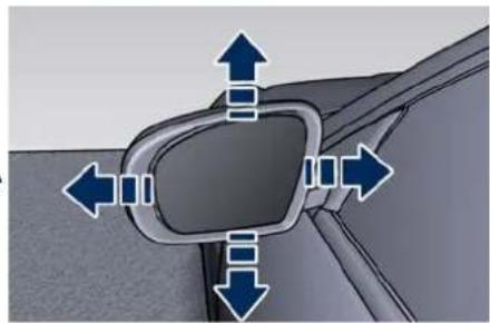
natural_image
Diagram of a car's side profile with directional arrows indicating movement (no text or symbols)To adjust a rear view mirror, press either the L (left) or R (right) button to select the mirror that you want to adjust. The spin button will illuminate indicating the rear view mirror is activated and can be adjusted.
Understanding the Vehicle

Press the mirror control switch corresponding to the arrow indicating the direction of the desired movement.
For optimal vision orientate the outside(s) mirror(s) in order to frame the adjacent lane adjacent and get a partial overlap with the visible image on the inside rear-view mirror.
Power mirror preselected positions can be reset by operating the optional memory driver seat device. Check
"Memorize the Driver's Seat Position" in this section for further information.

WARNING!
Vehicles and other objects seen in the external side convex mirror will look smaller and farther away than they really are. Relying too much on your passenger side convex mirror could cause you to collide with another vehicle or object. Use the inside mirror to judge the size or distance of a vehicle seen in the external side convex mirror.
Tilt Side Mirrors in Reverse
This function provides automatic external rear-view mirrors positioning, allowing the driver to view the ground area behind the front doors.
The external mirrors will move slightly downward from the current position when the shift lever is shifted into reverse. The external mirrors will then return to the original position when the lever is shifted out of the reverse position. Each memory set of the driver's seat (see "Memorize the Driver's Seat Position" chapter in this section) corresponds to a mirrors tilt position in reverse.
NOTE:
The mirrors tilt in reverse can be turned on and off using the MIA system, refer to "Functions of Settings Menu on MIA" in section "Dashboard Instruments and Controls".
Folding Mirrors
By selecting this function on MIA the rear-view mirrors automatically fold when the vehicle is locked by the key fob and when the power boot lid (if equipped) is closed and locked by pressing the button on the right lower parts of the lid.
When the vehicle and the boot lid will be unlocked and the ignition device is set on ACC or RUN position, the rear-view mirrors will automatically open in the position they had before the lock. The switch for the power folding mirrors is located between the power mirror switches.
natural_image
Close-up of a car's front panel with a blue arrow pointing to the button (no text or symbols visible)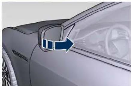
natural_image
Side view of a car's front wheel and side door, showing a blue arrow pointing to the dashboard area (no text or symbols present)Press the switch once and the mirrors will fold in; press the switch a second time to reset the mirrors to the standard position.
There is a way to make external mirrors automatically fold/unfold.
- If the function is available, it needs to be activated by MIA (refer to "Functions of Settings Menu on MIA")

Understanding the Vehicle
in section "Dashboard Instruments and Controls").
- If the mirrors are automatically folded after the last lock action, then they will automatically unfold when the ignition device is set on ACC or RUN position.
- If the mirrors were manually folded by the switch on the driver's door panel, before a lock action, they will need to be manually unfolded to reactivate the automatic function.

CAUTION!
Never retract or open the mirrors manually: it could damage the power mechanism.
Internal Rear-view Mirror
The position of internal rear-view mirror can be manually adjusted, and is endowed with an accident prevention release system operating in the event of a collision.
Internal rear-view mirror is electrochromic: this glare function is automatically deactivated in reverse to ensure maximum visibility of obstacles.

CAUTION!
To avoid damage to the mirror during cleaning, never spray any cleaning solution directly onto the mirror. Apply the solution onto a clean cloth and wipe the mirror clean.
"Mirror Dimmer" Function
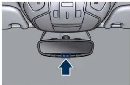
The auto-dimming function can be disabled or re-enabled by pressing the on/off button on the mirror base. Typical case is at night when the auto-dimming can be excessive (low reflectance). Disabling this function will increase the reflectance of the internal mirror, increasing visibility.
natural_image
Top-down view of a car dashboard with a blue arrow pointing to the front panel (no text or symbols visible)External Lighting
External Lights Equipment
The vehicle is equipped with lighting systems and functions that depend on the type of equipment and the target market. Some of these are completely automatic, other can be switched on and off via the light switch and the multifunction lever on the dashboard, or via "Controls" and "Settings" menu of "Vehicle" page on MIA.
This chapter only describes systems that may or may not be installed because of the various options available.
For switching the external lights on and off via the light switch and the multifunction lever behind the steering wheel, refer to the chapter "Light Controls" in section "Dashboard Instruments and Controls".
External Light Cluster
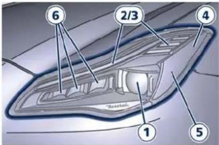
The lights of the front cluster are arranged as follows:
1 Low-beam/high-beam LED.
2 Position and DRL light LED.
3 Turn signal LED.
4 Side-marker light LED.
5 Side reflex-reflector.
6 Bending light LED.
Understanding the Vehicle

text_image
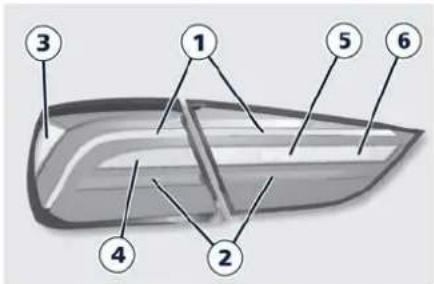
6 2/3 4 1 5The lights of the rear clusters are arranged as follows:
1 Position light guide LED.
2 Stop light LED.
3 Side reflex reflector LED.
4 Turn signal LED.
5 Reverse LED.
6 Rear fog LED.
text_image
Labeled diagram of a boat with numbered parts for identificationIntegrated External Rear View Mirror Lights
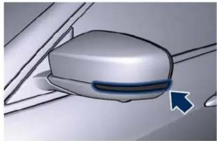
LED turn signals are integrated on the support of the external mirrors.
natural_image
Close-up of a car's side mirror with a blue arrow pointing to the side (no text or symbols visible)The LED turn signal indicators flash simultaneously with the corresponding turn signal lights in the front and rear of the vehicle. Turning on the hazard warning lights will also activate these LEDs.
On the vehicles with "Surround View Camera System", the external mirrors are equipped also with approach and courtesy LEDs, lighting up when the vehicle entry/exit lights are activated.
See "Illuminated Entry/Exit" in section "Before Starting"
SmartBeam™ System
The SmartBeam™ system provides increased forward lighting for a more comfortable and secure driving
experience without glaring other vehicles in several traffic situations.
The SmartBeam™ system uses a forward facing digital camera, located on the windshield behind the internal rear-view mirror, and an electronic headlights controller in order to dynamically adapt the front light distribution according to the traffic scenario.
The digital camera works like a human eye, it is able to see which is the traffic context while the headlight electronic controller works like a human brain, using information from the camera to command a headlight reaction that gives to the driver the "best" light distribution (best is always in reference to the specific traffic environment).
The camera gives information to the electronical headlight controller about environmental brightness, traffic participants vehicle and obstacles lights, distances and velocities. Using a proper combination of all these data the smart beam system is able to dynamically modify the light shape produced by the dipped beam and by the full beam as well, to make the driver visibility as much comfortable as possible in every condition without glaring other traffic participants.

Understanding the Vehicle
System Limitations
There are some cases in which the SmartBeam™ system could not properly work temporarily causing glaring for other vehicles especially with "Auto Dim High Beams" function activated on MIA "Settings" page (see "Functions of Settings Menu on MIA" in section "Dashboard Instruments and Controls").
These cases could be related to:
- Vehicles headlight and/or rear light (one or both of them) not visible in the field of view of the camera.
- Heavy rainy weather.
• Heavy foggy weather. - Snowing weather.
- Windshield dirt or impurities in camera lens zone.
- Camera lens obstruction or clogging. In all these cases, it will be driver's responsibility to avoid this glaring by acting manually on the system, switching off the high beam by means of steering wheel multifunction lever.
"Full-LED" Headlight with AFS
These headlamps combines the "Full-LED" technology to the AFS (Advanced Frontlighting System) adaptive functions, using a forward-facing camera located on the windshield behind the internal rear-view mirror.
"Full-LED" Technology
This technology allows having headlights with a simpler construction and a more compact size compared to those equipped with traditional or Xenon light bulbs.
Other advantages are:
- a clearer light beam, with a cool white tone that allows a better perception of the contrasts thus making the night vision more efficient and less tiring;
- a longer duration equivalent at least to that of the vehicle;
- a reduced current consumption.
These functions positively affect some vehicle management economy aspects by eliminating/reducing the light bulb replacements and the fuel consumption.
AFS Functions
The system is able to process signals of onboard systems and subsequently start up five strategic steps in the following situations:
- "motorway beam";
- "country beam";
- "town beam";
- "adverse weather beam";
- "tourist beam" (for example in countries with circulation on the opposite side). In this case this
function must be activated via the menu of MIA (refer to "Functions of Settings Menu on MIA" in section "Dashboard Instruments and Controls").
The advantages offered by the AFS system are perceived especially in case of bad weather, fog and/or insufficient road indications providing broader illumination of the side zones, which are normally left in the dark, and for motorway driving.
This surely increases driving safety as it offers less eye stress and increased orientation for the driver and better detection of other persons on the road sides (pedestrians, bicycle riders and motorcycle drivers). Furthermore, the headlamps are suitable to prevent glare, providing optimal lighting when driving the car in a country with circulation on the opposite side.
The table shows the light values (lux) and the light flux (lumen) of AFS headlights.
NOTE:
The values reported in the tables may change depending on the destination market of the car.
| Lighting(at 25 m / 27 yd) |
Understanding the Vehicle

| Low beam 55 lux | |
| High beam + Low beam | 130 lux |
| Light flux | |
| Low beam 843 lm | |
| High beam + Low beam | 1580 lm |
The system assures better visibility of the road surface when driving in a curve, steering, or in the event of road deviations, optimizing vertical light distribution according to the current drive path.
The increased lateral illumination is gained through a fixed bending light or a cornering light (depending on the market) elaborating information about the steering angle, the vehicle speed and the turn indicator.
The improved vertical illumination, in case of fast acceleration and/or fast deceleration, will assure the deeper illuminated distance from the vehicle, through a dynamical adaptation of headlight vertical attitude.
NOTE:
• Each time the adaptive headlight system is turned on, the headlights
adjustment will perform a self-regulation cycle.
- All AFS functions are available only the vehicle is moving forward.
- "Adaptive Front Light" function can be turned on or off using the MIA system, refer to "Functions of Settings Menu on MIA" in section "Dashboard Instrument and Controls" for further information.
AFS System Failure
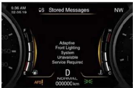
In the event of AFS system unavailable, the related warning light and message will light up on the TFT display. Take your vehicle to the nearest Center of the Service Network as soon as possible to check the system.
text_image
6:36 AM 02.05.19 Stored Messages NW Adaptive Front Lighting System Unavailable Service Required D NORMAL 000000 kmAutomatic High Beam()
The Automatic High Beam headlight control system provides increased forward lighting at night by
automating high beam control through the use of the forward-facing digital camera located behind the rear-view mirror, which is the same one used for example by the Lane Keeping Assist - LKA system on vehicles with ADAS systems.
This camera detects the environmental luminosity, the headlamps of oncoming vehicles and the tail lamps of proceeding vehicles in the front area. In these cases system automatically switches from high beams to low beams until the approaching vehicle is out of view.
Furthermore, the digital camera is able to detect the urban areas and the inhabited centers and to turn off the high beams when driving near of one of them.
The properly working for this system (if all the other conditions are met) is ensured between 40 km/h (25 mph) and 250 km/h (155 mph).
Activation Mode
To activate Automatic High Beam function:
- Shift the multifunction lever onward ED.
- Put the light switch in "AUTO" position.

Understanding the Vehicle
- Touch the "Vehicle" soft-key on the main category bar of the MIA display and open the "Settings" menu.
- Choose the "Auto Dim High Beams" function in the "Lights" submenu and insert the check mark in the box to turn on the function.
- To turn off the function delete the check mark in the box.
After these steps, the green indicator on the upper right side of the TFT display comes on.
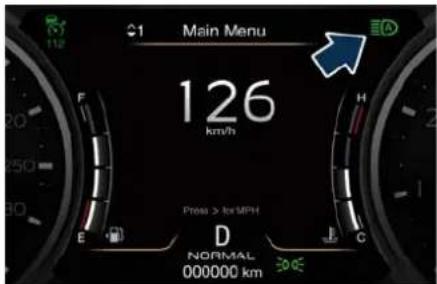
text_image
Main Menu 126 km/h Press > Ice MPH D NORMAL 000000 km 30.05NOTE:
- The function is enabled only if the brightness sensor detects the right lighting conditions and then switch to low beam on.
- Broken, muddy, or obstructed headlights and taillights of vehicles in the field of view will cause headlights to remain on longer (closer to the
vehicle). Also, dirt, film, and other obstructions on the windshield or camera lens will cause the system to function improperly.
High Beam with "Glare Free" Function
The "Glare Free" system associated with "Full-LED" headlamps assists the driver during travelling on an off-city road with not sufficient environmental illumination allowing the high beam use also with other traffic participants without glaring disturbs.
Moving the full beam light source the "Glare Free" function will create a shadow in correspondence of other vehicles present in the field of view of the camera.
The figure represents an example of the car that is travelling in the following scenarios:
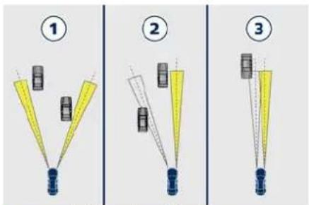
text_image
Diagram showing three stages of a device or sensor setup with labeled components and connection points1 two vehicles ahead in the same direction;
2 another vehicle that is overtaking;
3 another vehicle proceeding in the opposite direction.
The system is able to detect and react to an oncoming vehicle starting from a distance of about 400 m (400 yd), in a couple of seconds. Instead, in case of the preceding vehicles, the system is able to detect and react in few seconds starting from a distance of about 100 m (100 yd).
Activation Mode
The digital camera is the same used for the automatic high beam, and like automatic high beam also for "Glare Free" function it needs to be activated by MIA "Settings" menu of "Vehicle" page, insert the check mark on the box
Understanding the Vehicle

of the "Auto Dim High Beams" soft-key (see chapter "Functions of Settings Menu on MIA" in section "Dashboard Instruments and Controls").
The "Glare Free" function will be engaged after the following actions:
- Engine run.
• Function enabled by MIA. - Low beam on.
- Interior light switch in position "Auto".
- Multifunction lever in "High beam" activated position.
The "Glare Free" function will work if:
- The vehicle speed is equal or greater than 40 km/h (25 mph) in the engagement phase of the function.
• Environmental brightness is not sufficient for a safe and comfortable drive. - Traffic scenario out of urban context. Once the system will be active, there will be two indicators on the instrument cluster, showed in the same time: one blue and one green.
The green indicator indicates that the "Auto Dim High Beams" function is activated on MIA; the blue indicator indicates that all or only some high beam LEDs are physically on in that moment.
When instead there is the needing to switch off the whole high beam module to obtain the no glaring effect, on the instrument cluster there will be just one indicator on: the green one.
When the scenario allows the partial or full use of high beam with no glaring disturbance, the blue indicator will appear again.
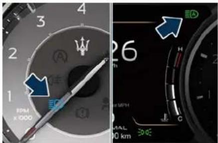
text_image
3 2 1 FPM x 000 26 MPH C H SOL 00 km 500ENOTE:
- Some unpredictable conditions, such as dirt, dust, film or any other obstruction on camera lens zone events could affect "Glare Free" function making it working improperly.
- Heavy rainy and foggy weather could affect system performance, leaving the full beam switched on for longer time than the nominal working
condition. This could cause a glaring disturbance for other vehicles, to avoid this the driver has to switch off the high beam manually.
- In phase of disengagement of the function, the minimum operating speed is 30 km/h (18 mph).
- "Glare Free" function proper operation is guaranteed if vehicle speed is less than, or at least equal to 250 km/h (155 mph).
Automatic High Beam/Glare Free High Beams Failure
In the event of a failure on high beam system (Automatic or Glare Free equipped, as well), the related amber warning light will light up on the TFT display.
Take your vehicle to the nearest Center of the Service Network as soon as possible avoiding to use this system.

Understanding the Vehicle
Interior Lighting
The interior and external approach lights turn on and off when entering/exiting the vehicle (see "Illuminated Entry/Exit" in section "Before Starting" for further information).
The brightness of the ambient lights, controls and instruments can be manually adjusted with the regulator positioned beside the light switch as described in the chapter "Light Controls" in section "Dashboard Instruments and Controls".
For backlight operation, see paragraph "Ambient Lights and Backlight Adjustment" of chapter "Illuminated Entry/Exit" in section "Before Starting"
Dome Lights
The front and rear part of the dome, include each a central and two reading lights.
The central light automatically turns on when one of the doors is opened and turns off when the door is closed (timed switching off). The light may be switched on manually by pressing the central button.
The reading lights are controlled by the respective side buttons.
If they are turned on by pressing the button, both central and reading lights will stay on for about 10 minutes after turning the engine off, and will then turn off gradually.
When the exterior lights are switched on, the two night LEDs fitted on the side of the buttons will light up to facilitate use of the transmission lever and the central console.
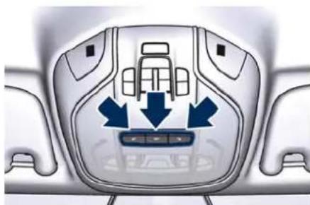
natural_image
Top-down view of a car interior showing seat, dashboard, and air vent (no text or symbols)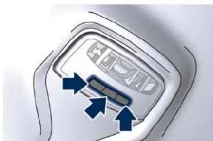
natural_image
Close-up of a device interior showing a control panel with arrows pointing to a component (no text or symbols visible)If one or more doors are opened, the front and rear dome lights will turn
on for 27 seconds. If the door is closed before this time, the lights will dim and subsequently switch off after about 3 seconds.
NOTE:
The dome lights will also turn on by pressing the ar button for centralized doors unlock and lock on the key fob. See "Illuminated Entry/Exit" section "Before Starting" for further information.
In the event of a collision causing automatic interruption of fuel supply, the dome lights switch on automatically and remain lit for approx. 15 minutes.
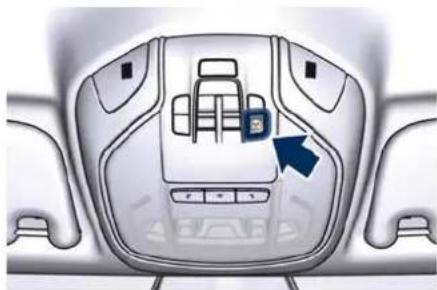
Button to Switch off Passenger Compartment Lights
In addition to specific switches to turn on and off the dome lights as previously described, on the front console there is a button that allows to turn off all these lights.
natural_image
Top-down view of a car interior showing the dashboard and seat area with a blue arrow pointing to a small device (no text or symbols visible)Interior Lights Operation
To protect the battery, the interior lights will turn off automatically 10 minutes after the ignition device has been shifted to OFF. This occurs if the interior lights were turned on manually or by opening a door. The glove box light, share the same characteristics excepting the boot light.
Courtesy Dimmable Lights
The following dimmable courtesy lights, can be set with the regulation device (see "Light Controls" in section "Dashboard Instruments and Controls"):
• instrument cluster dials and display;
- dome light (front/rear);
- internal door handle LED;
• doors and steering wheel backlight controls LED;
- front footrest light;
• front seats night lighting.
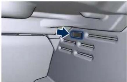
Cargo Lights
To illuminate the cargo area there are two lights inside the boot, one on each side. These lights turn on when boot lid is opened and turn off when it is closed.
natural_image
Close-up of a vehicle's interior panel with a blue arrow pointing to a small electronic device (no text or symbols visible)If boot lid is left open for a long time, lights will turn off after 30 minutes to save battery charge.
Internal Equipment
Electric Power Outlets
The vehicle is equipped with three or four 12 Volt (13 Amp) electric power outlets, one or two (if you use as power outlet the socket of the cigarette lighter) available for each front seat, one for rear seat passengers and one fitted in the boot.
In vehicles equipped with "Smoking Kit" one of the front seat electric power outlets is replaced with a cigarette lighter.
In vehicles with "Comfort Luxury" rear seats, there is an extra 12 V power outlet inside the rear console storage compartment and others in the rear of the reclining shelf between the seats. All power outlets are supplied only when the engine is started or the ignition device set on ACC or RUN.
Power outlets are protected by a fuse. Insert an accessory plug into the power outlets to ensure proper operation.
Otherwise, check the matching fuse integrity, see "If a Fuse Blows" in section "In an Emergency" for further information.

Understanding the Vehicle

CAUTION!
- Do not plug in accessories that exceed the maximum power of 160 Watts (13 Amps) at 12 Volts.
• Power outlets are designed for accessory plugs only. Do not insert any other object in the power outlets as this will damage the outlet and blow the fuse. Damages caused by improper use of the power outlet are not covered by the New Vehicle Limited Warranty.

WARNING!
To avoid serious injury or death:
- Only devices designed for use in this type of outlet should be inserted into any 12 Volt outlet.
- Replacing the fuses that protect power outlets with others of higher amperage, there is the risk of fire.
- Do not touch with wet hands.
- Close the lids when the plug is not used and while driving the vehicle.
• If this outlet is mishandled, it may cause an electric shock and failure.
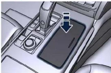
Power Outlet for Cigarette Lighter inside the Cup Holder Compartment (for Cup Holder with Cover only) To access the power outlet inside the cup holder beside the transmission lever, press the cover as indicated to open completely.
NOTE:
This outlet is specifically dedicated to power the cigarette lighter. It is not recommended to use it as an outlet charge devices: use the other power outlets for this function.

WARNING!
High power consumption items splugged into this outlet for long periods may discharge the battery and/or prevent the engine from starting.
natural_image
Interior view of a car dashboard with a hand tool and a smartphone screen, showing no visible text or symbols.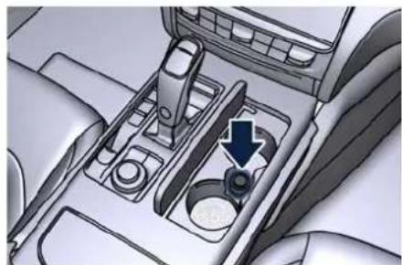
natural_image
Interior view of a car dashboard with a hand valve and gear shift (no text or symbols visible)^top Power Outlets inside the Central Console
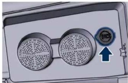
To access the power outlet located inside the glove box of the central console you need to open the half-lids as indicated in the following paragraph.
natural_image
Illustration of a dual air conditioner unit with a circular fan and a control knob (no text or symbols)Rear Power Outlets
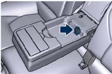
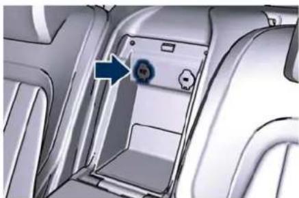
If the vehicle is equipped with bench seats, a 12 V power outlet inside the armrest between the seats, is available
for rear seat passengers (see "Rear Seats" in this section).
natural_image
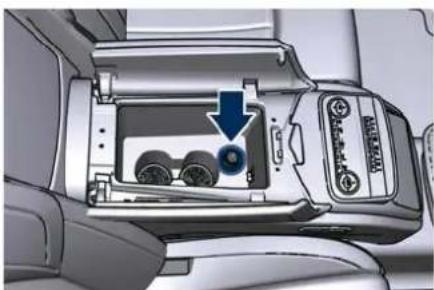
Interior view of a car dashboard with a highlighted plastic component and directional arrow (no text or symbols)A 12 V power outlet both inside the central console and in the rear of the reclining shelf, are available for rear seats passengers (see "Comfort Luxury Rear Seats" in this section).
natural_image
Interior view of a vehicle showing a battery pack with three wheels and a blue arrow indicating a component (no text or symbols visible)"Comfort Luxury" Rear Seats
natural_image
Interior view of a car showing a vehicle's door panel with a blue arrow pointing to the door (no text or symbols visible)"Comfort Luxury" Rear Seats
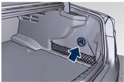
Power Outlet inside the Boot The power outlet is positioned on the right side of the boot compartment.
natural_image
Interior view of a car showing the rear door and side panel with a blue arrow pointing to a circular component (no text or symbols visible)Cup Holders The vehicle is equipped with several cup holders.

CAUTION!
- Use light and shatterproof containers.
- Do not forcefully push unsuitable containers into the cup holders to prevent damage to the containers.
- Do not store hot drinks.
Cup Holders for Front Passengers
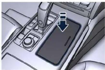
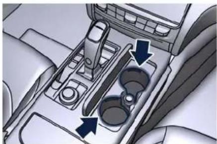
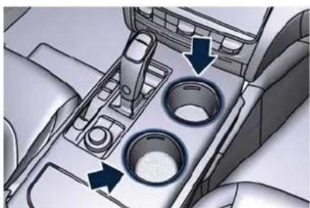
The front cup holders are located beside the transmission lever and may be with access cover or at sight (only for left-hand drive version).
To access the cup holder, push the cover as shown in the picture and it will open completely.
natural_image
Interior view of a car dashboard with a hand holding the screen and a downward arrow indicating a drop or action (no text or symbols present)Version with Cover

Understanding the Vehicle
2
natural_image
Interior view of a car showing the intake and outlet of the seat with two internal compartments (no text or symbols visible)Version with Cover
natural_image
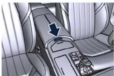
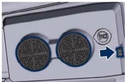
Interior view of a car dashboard with a black arrow pointing to the seat area (no text or symbols visible)The storage and passenger compartment share the same air conditioning even though you may exclude the air conditioning of the cup holder compartment by moving the indicated button.
natural_image
Interior view of a car dashboard with two circular compartments and directional arrows indicating flow or movement (no text or symbols present)At Sight Version
natural_image
Close-up of a device panel with two circular fans and a control knob, showing a blue arrow pointing to a small electronic component (no text or symbols visible)To close one or both of the half-lids, push them down to the locking position.
Pressing the indicated button on the central console, the half-lids will rise completely enabling access to the inner compartment where the two cup holders are located.
NOTE:
Vehicles equipped with the four-zone air conditioning system, are not equipped with cup holders inside the central console.
Cup Holders for Rear Passengers
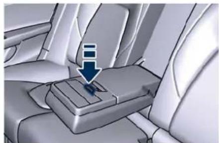
Two cup holders are available in the frontside of the rear seats central armrest, press the button as shown in the picture to access them.
natural_image
Interior view of a car seatbelt with a blue arrow pointing to the lower side of the seat (no text or symbols visible)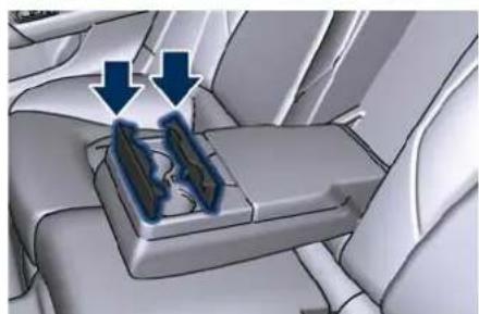
natural_image
Interior view of a car seat with two blue arrows pointing to a highlighted mechanical component (no text or symbols visible)Understanding the Vehicle

On vehicles equipped with the "Comfort Luxury" rear seats, the cup holders are located in the front and rear central storage compartment (see "Comfort Luxury Rear Seats" in this section for further information).
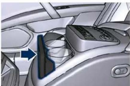
natural_image
Interior view of a car dashboard and steering wheel (no visible text or symbols)"Comfort Luxury" Rear Seats
Multimedia Port and Wireless Charger (→) Compartment
Multimedia ports and the sliding drawer for the mobile phone are located inside the dashboard compartment below the climate control panel.
This compartment, in addition to the components indicates, can be equipped with Wireless Charger that allow you to recharge your mobile phone (if it support this technology) without have to connect it to the charging port through a cable.
Wireless Charger Operation
The Wireless Charger system is designed to wirelessly charge mobile phones (maximum power available 15 W) compatible with the Q® standard. The system is activated in automatic mode when the mobile phone is placed in its drawer and the compartment door is closed. If the mobile phone is removed from the Wireless Charger compartment during the wireless charging phase, this will automatically be interrupted. The Wireless Charger system enables charging when all doors are closed properly and the ignition device is in ACC or RUN position.

CAUTION!
• Key fob must not be placed on the Wireless Charger compartment. This could cause excessive overheating and damage to the key fob. Placing the key fob near the Wireless Charger may prevent the engine from starting. In this case, a dedicated message will be shown on the MIA display to alert the driver of the need to remove the key fob from this compartment.
- Do not place any other type of metal or magnetized object (e.g. credit cards, coins, badge, etc.) inside the Wireless Charger compartment.
- Make sure that you place the mobile phone correctly (display facing upward) in the phone drawer: charging may not be enabled if it is in the wrong position.
• To avoid interference with the key fob search, the Wireless Charger system stops charging when any door is opened.
• Make sure that there are no metal objects between the mobile phone and the wireless charger system during charging. Any such objects could overheat.
NOTE:
- The wireless charger device is equipped with an NFC antenna, so the "Apple Pay Wallet" function could be activated on Iphone phones: in any case this will not involve any economic transaction or charging interruptions.
• Some smartphones, due to their specific construction characteristics (e.g. internal metal body), could show charging problems in some driving conditions. In this case, the
(Continued)

Understanding the Vehicle
(Continued)
message "Foreign Object Detection (FOD)" may appear.
- According to driving style, brief interruptions in the charging process (with the related message popup activation) generated by the movement of the smartphone within the charging area may occur. This is not an anomalous behaviour and the charging process will resume regularly as soon as driving conditions permit.
- When using smartphone cases, the wireless charging efficiency may be reduced or not possible. In this case, it will be sufficient to remove the smartphone case and verify the restoration of the correct charging conditions, keeping in mind conditions and exceptions described in the previous paragraphs.
- During the charging process, the mobile phone can overheat and stop charging because of open applications or functions used. This is not an anomalous behaviour. The charging process will resume as soon as the device's temperature drops to normal conditions.
- It is possible to deactivate the pop-ups related to the wireless charger by
removing the flag on the MIA screen (see "Wireless Status Pop-ups" in chapter "Functions of Settings Menu on MIA" in section "Dashboard and Controls").
- In all disconnection cases, to restore normal charging conditions, simply place the telephone in the drawer central position.
The charge status icon of the mobile phone housed in the Wireless Charger compartment is always visible in the MIA display on the "Home" and "Phone" screen.
This icon becomes blue if the mobile phone is charging, green if it is fully charged and blinking red for system fail or foreign object in the compartment. The blink ends after a timeout of 5 seconds and the icon becomes solid until the fail is solved.
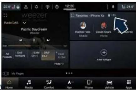
text_image
22.5° Radio DAB Pacific Daydream Weather All Presets VIRGIN SXM CH 1 DAB $4.7 Next to Set Hide My Pages Home Media Comfort Nav Phone Vehicle Apps Favorites - iPhone Xs Pacheel Haze Muscle David Sparks Home Add Widget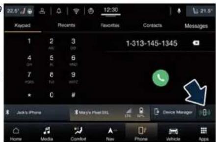
text_image
22.5 12:30 21.5 Keypad Recents Favorites Contacts Messages 1 2 3 1-313-145-1345 ABC OP 4 5 6 OR BL AMD 7 8 9 PORTS TUI AMTC 0 # Jack's iPhone May's Pixel SSL Device Manager Home Media Comfort Nav Phone Vehicle AppsYou can also drag and drop the Wireless Charger icon from the shortcut page to insert it in the upper status bar.
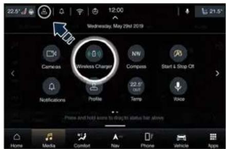
text_image
22.5° Wednesday, May 2019 Cameras Wireless Charger Compass Start & Shop Off Notifications Profile Temp Voice Press and hold issues to doing to status bar alone Home Media Comfort Nav Phone Vehicle AppsTo access the multimedia ports and Wireless Charger compartment, check that cup holder cover (if equipped) is closed, then push the door as indicated in picture: it will open completely. Gently push and release the drawer which will come out automatically of its housing and stop in the first
Understanding the Vehicle

position. In case of necessity, pull out the drawer completely.
NOTE:
• To prevent damage to the sliding mechanism, do not force the drawer into the extracted position.
- Before closing the compartment door, ensure that the drawer is fully back in its seat.
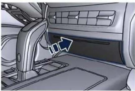
natural_image
Interior view of a car showing the dashboard and steering wheel (no text or symbols visible)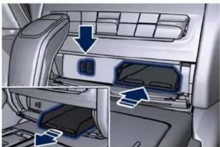
natural_image
Interior view of a car air conditioner unit showing airflow direction and component placement (no text or symbols visible)Multimedia Ports Operation
The USB ports (Type-A and Type-C) inside the Wireless Charger compartment can be used for data exchange and charge of the connected source (refer to the "Maserati Intelligent Assistant™ (MIA)" guide for further details).
Through these USB ports is possible to recharge the connected device for about an hour from when the ignition device is turned OFF ("Active Charging" function). When this function is enabled, the USB port will be backlight.
NOTE:
Just one USB at time can be used as media source: so if both have device attached just one will work as media source, the other one is not selectable from the source media and will work just as charge port.
Another USB port is present for rear seat passengers, inside the armrest between the rear seats.
To access the USB port, open the outside cover (see "Rear Seats" in this section).
This USB port allow charging the connected source.
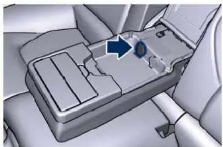
natural_image
Interior view of a car dashboard with a blue arrow pointing to the dashboard area (no text or symbols visible)Following conditions can create USB inputs damage or malfunction:
• Usage of non-original lighting cables.
- Usage of defective rechargeable devices (smartphone, tablet, mass storage devices or other generic USB devices).
- ONLY insert media devices, into your vehicle if it came from a trusted source.
• Usage of damaged or defective cables.
NOTE:
Optional "Comfort Luxury" rear seats are equipped with a USB port beneath the reclining shelf between the seats (see "Comfort Luxury Rear Seats" in this section).
iPod® Connection
An iPod ^® can be connected to the system via USB ports by means of a special cable (The MIA will then

Understanding the Vehicle
control the following functions: play, pause, fast forward, rewind, next track, previous track, random or repeat mode, selection and navigation of playlist/genre/singer/album/Podcast.

CAUTION!
Do not leave your USB device, iPod or an external audio source in the vehicle for extended period of time: extreme temperatures and humidity can occur in the vehicle.
Sun Visors
Sun visors can be folded to the front and to the side of the vehicle. To move the visor laterally, lower and release it from its catch as indicated.
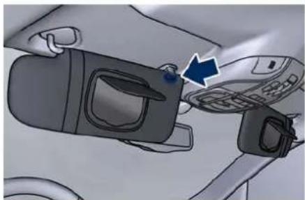
natural_image
Diagram showing a car interior with a door panel and a mobile phone, no visible text or symbols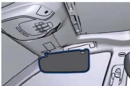
natural_image
Interior view of a car showing dashboard and steering wheel (no text or symbols visible)By lowering the visor you can access the courtesy mirror with incorporated light illuminating automatically (with the ignition device on ACC or RUN) by raising the mirror protective cover. Before raising the visor, close the mirror cover.
A paper holder is fitted inside each sun visor.
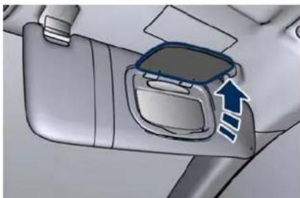
natural_image
Interior view of a car dashboard with a blue arrow indicating direction (no text or symbols)Removable Ashtray and Lighter (OPT)
The removable ashtray with cover for front seats passengers can be inserted inside the front cup holder.
The rear seat passengers can use the removable ashtray by inserting it into the rear doors pocket.
On vehicles equipped with rear seats "Comfort Luxury" smoking kit, lighter and ashtray are fitted inside the center console between the seats.
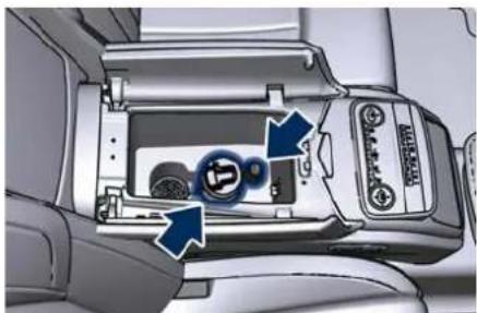
natural_image
Interior view of a car dashboard with control buttons and a central touchscreen display (no visible text or symbols)"Comfort Luxury" Rear Seats
Cigarette Lighter Use Pressing the central button activate the cigarette lighter. After about 20 seconds the button returns automatically to the initial position and stops the heating: now the cigarette lighter is ready for use.
Understanding the Vehicle


CAUTION!
After use, always make sure that the cigarette lighter is switched off.

WARNING!
• The cigarette lighter reaches high temperatures. Handle it carefully and do not allow children to use to avoid risk of fire and injury!
• The cigarette lighter may not be used as a power outlet.
Handholds and Cloth Hooks
Handholds are fitted above the doors. Once grabbed, they will lower until the block position. When released, a return spring will bring them back to the original position.
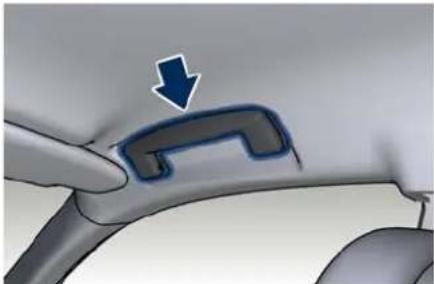
natural_image
Close-up of a car interior showing a blue arrow pointing to a curved mechanical component (no text or symbols visible)Rear handholds also include a cloth hook.
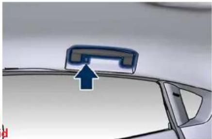
natural_image
Close-up of a car's front panel with a blue arrow pointing to the top panel (no text or symbols visible)Map Pockets
Front seats are fitted with map pockets, on the rear of the seatbacks, and accessible by rear passengers.
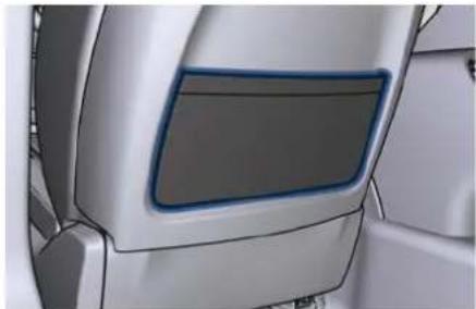
natural_image
Close-up of a car's front panel showing the dashboard and side door (no text or symbols visible)
CAUTION!
Do not put heavy or sharp objects in the map pockets.
Tables (P, not for sport seats)
Tables are fitted in the back of the front seats.
- Opening: press the upper button and lower the table until the supporting mechanism snap lock.
- Closing: lift the table until the upper button snap lock.
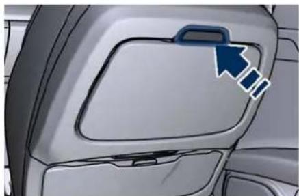
natural_image
Interior view of a car showing the backrest door and side panel, with a blue arrow pointing to the handle (no text or symbols present)
Understanding the Vehicle
2
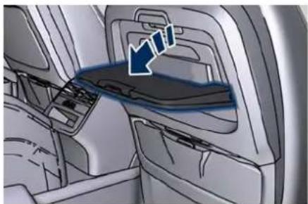
natural_image
Interior view of a vehicle showing dashboard and seat compartments with a blue arrow pointing to a specific area (no text or symbols present)
CAUTION!
As the table is not equipped with cup holders, do not place open drinks containers on the tables during the journey in order not to damage or stain the surrounding upholstery if they fall over.

WARNING!
- When the table is not used, it should be closed to prevent rear seat passengers from being hit by its edges and corners.
- When closing the table, hold it up carefully in order to avoid crushing your fingers.
iPad Holder (Genuine Accessories)
The Service Network can provide you with all information about the
"Maserati iPad Holder" mounted on the rear of the front seatbacks, available in the "Genuine Accessories" range.
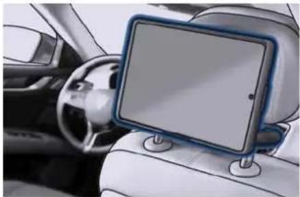
natural_image
Interior view of a car showing the front and rear seats with a tablet mounted on the steering wheel (no visible text or symbols)Audio System
The vehicle is equipped with an audio system that offers superior sound quality, higher sound pressure levels and reduced energy consumption.
The new system maximizes the amplifier and speaker technology delivering substantially higher components and system efficiency.
The standard sound system "Premium" features 10 speakers and can develop a sound output of 900 W.
The standard system includes:
- Four 165 mm (6.5 in) diameter Woofers, one on each door.
• One 80 mm (3.15 in) diameter Midrange diameter, on the top of the dashboard. - One 25 mm (1 in) diameter Tweeter, 2 on the upper edges of the dashboard and 2 on rear doors.
- One 315 x 200 mm (12.4 x 7.9 in) Subwoofer on the rear panel below the rear window.
- 12-channel amplifier in the boot. The vehicle can be equipped with an "High Premium" surround system including 15 speakers and 1280 W of sound power, available upon request. The "High Premium" system includes:
Understanding the Vehicle

- Two 165 mm (6.5 in) CFR Woofer: one on each front door.
- Two 165 mm (6.5 in) Black Kevlar Woofer: one on each rear door.
- Five 100 mm (4 in) Yellow Kevlar Midrange: one on centre dashboard, two on each front door, two on each side of the rear parcel shelf.
- Five 25 mm (1 in) MMX Tweeter: one in centre and one on the each side of the dashboard, one on each rear door.
- 315 x 200 mm (12.4 x 7.9 in)
Racetrack Sub Dual VC Subwoofer on the rear parcel shelf.
• 16-channel 1280 Watts Class-D amplifier in the boot.
The standard sound system "Premium" is supplied with a 12 channel high efficiency amplifier and is operated by a high voltage tracking power supply and drives a 7.5-channel playback architecture. This audio system offers the ability to choose Logic 7 surround sound for any audio source.
The high-efficiency speaker design ensures higher Sound Pressure Level (SPL) and exceptional dynamic sound quality. The speakers are tuned for maximum efficiency and compatible with the amplifier output stage ensuring best updated surround sound processing. Logic 7® multichannel
surround sound technology delivers an immersive, accurate sound stage throughout the passenger compartment.
This surround effect is available from any audio source - AM/FM/Satellite Radio and USB input; and is activated through the MIA system controls (see "Functions of Settings Menu on MIA" in section "Dashboard Instruments and Controls"). By selecting "Surround Sound", you can activate the Logic 7 ^ multichannel surround-sound technology in your vehicle. All information on the current operational mode are listed in the specific booklet visible on the MIA screen.
When in "Audio Surround" mode, balance is set automatically. Fader control is available in surround mode but it should be set to the center position for optimal surround performance.
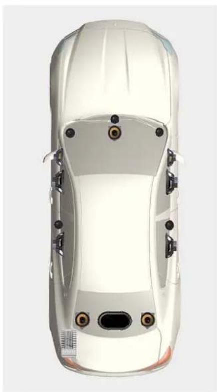
natural_image
Top-down view of a white car with visible engine compartment and sensor points (no text or symbols)
Understanding the Vehicle
Cargo Area

WARNING!
To help protect against personal injury, passengers should not be seated in the rear cargo area. The rear cargo space is intended for load carrying purposes only, not for passengers, who should sit in seats and use seat belts.
Vehicle Load Carrying Capacity
The load carrying capacity of your vehicle is shown on the vehicle homologation label positioned on the rear right hand door's ledge.
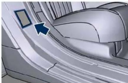
natural_image
Close-up of a car interior showing a curved seat and dashboard, with a blue arrow pointing to a specific area (no text or symbols visible)The information indicated on the label concerns passengers and luggage loading operations.
Do not exceed the specified Gross Vehicle Weight Rating (GVWR) or the
Gross Axle Weight Rating (GAWR), both front and rear. The GVWR is the total allowable weight of your vehicle. This includes driver, passengers, and cargo. The total load must be limited so that you do not exceed the GVWR indicated on the label.
Vehicle Loading

WARNING!
- Improper weight distribution can have an adverse effect on the way the vehicle steers, handles and the way the brakes operate.
- Never drive with the boot lid open. Exhaust gases can enter the passenger compartment.
- Do not arrange any luggage on cargo area cover. In said position luggage could not only impair driver's view but also, in case of collision or unexpected stop, it could cause injury to all occupants.
The boot is the most suitable place to load bulky and heavy objects onboard the vehicle. The maximum allowable load on the floor of the boot is 200 kg (440 lb).
To load your vehicle properly, store heavier items below and be sure you
distribute their weight as evenly as possible.
Stow all loose items securely before start driving as they could move during the trip.
Light objects can be stored in the net pocket on the right side of the boot compartment.
To fasten heavy and bulky luggage inside the compartment a luggage net with hooks anchored to the floor is available upon request. The hooking eyelets of the net are positioned on the floor and on the rear wall of the boot compartment.
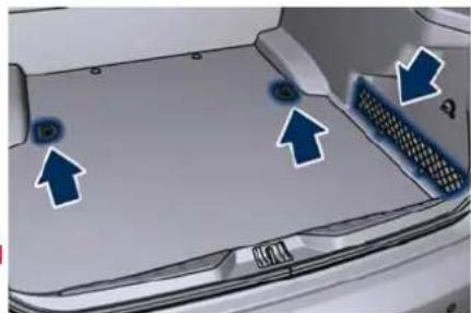
natural_image
Top-down view of a car's front bumper with blue arrows pointing to specific areas (no text or symbols visible)Understanding the Vehicle

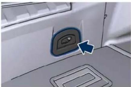
natural_image
Close-up of a car interior panel with a blue arrow pointing to the button (no text or symbols visible)NOTE:
The Maserati Service Network can provide you with information about the available "Genuine Accessories" for the boot compartment.
Loading with Rear Seatback Folded Down
The 60/40 split-folding rear seat with folding option on the shorter side (40) only, provides cargo-carrying versatility.
The seatback fold down easily by pulling tab between the seatback and the lateral support structure.
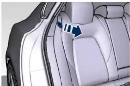
natural_image
Interior view of a car showing the side panel and seat area with a blue arrow pointing to a specific area (no text or symbols present)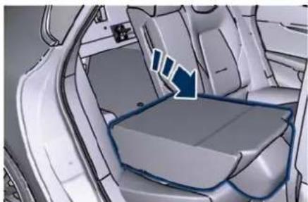
natural_image
Interior view of a car showing the rear seat and side panel, with no visible text or symbols.The seat folded down, provides a continuous nearly-flat extension of the load floor able to accommodate large sized equipment and objects (such as the "Maserati Ski and Snowboard Bag") that may not fit with the normal dimensions of the boot.
Ski and Snowboard Bag Housing
To safely store the Ski and Snowboard Bag:
- Tilt forward the short seatback side.
- Secure the rear hook of the bag to the eyelet located on the rear wall of the boot compartment.
- Wrap the belt around the seat back of the folded seat and fasten the belt buckle.
- Tighten the belt as much as necessary to prevent the bag from moving.
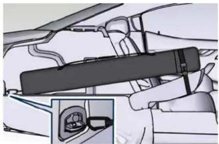
natural_image
Illustration of a car interior showing a hand holding a black rectangular object, with an inset close-up of the interior (no text or symbols visible)When the seatback is folded to the upright position, make sure it is latched by strongly pulling on the top of the seatback above the seat strap. If you follow these instructions, the bag will be securely fastened to vehicle structure and will thus remain in place also in case of collision or unexpected braking.
The Maserati approved Ski and Snowboard Bag available in the "Genuine Accessories" range, can be fastened also by folding down the seatback.

Understanding the Vehicle
NOTE:
The Maserati Service Network can provide you with information about the available "Genuine Accessories" for the boot compartment.

WARNING!
• Make sure that the seatback is securely locked into position. If the seatback is not securely locked into position, the seat will not provide the proper stability for child seats and/or passengers. An improperly latched seat could cause serious injury.
• The cargo area in the rear of the vehicle with the rear seatbacks in the folded down position should not be used as a play area by children when the vehicle is in motion. They could be seriously injured in a collision. Children should be seated and use proper restraint system.
HomeLink® (→)
HomeLink® replaces up to three hand-held transmitters operating the automatic devices that open garage doors and gates, enable/disable the lighting or security systems. The HomeLink® unit is powered by your vehicle's 12 Volt battery. The HomeLink® buttons that are located in the overhead console designate the three different HomeLink® channels. The HomeLink® warning light is located behind the buttons.
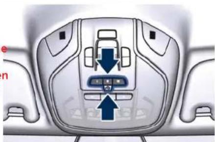
natural_image
Top-down view of a car head panel with directional arrows indicating movement or control points (no text or symbols)NOTE:
HomeLink® is disabled when the vehicle security alarm is active (chapter "Vehicle Security Alarm" in section "Safety").

WARNING!
- Your motorized door or gate will open and close while you are programming the universal transceiver. Do not program the transceiver if people, pets or other objects are in the path of the door or gate. Only use this transceiver with a garage door opener that has a "stop and reverse" function. Do not use a garage door opener without these safety functions. Call toll-free 1-800-355-3515 or, on the Internet at www.HomeLink.com for safety information or assistance.
- Vehicle exhaust contains carbon monoxide, a dangerous gas. Do not run your vehicle in the garage while programming the transceiver. Exhaust gas can cause serious injury or death.
Before You Start Programming HomeLink®
Be sure that your vehicle is parked outside of the garage before you begin programming.
For more efficient programming and accurate transmission of the radio-frequency signal it is recommended that a new battery be placed in the hand-held transmitter of the device
Understanding the Vehicle

that is being programmed to the HomeLink® system.
Before starting programming it is necessary to erase the standard codes memorized on the HomeLink® device during the production phase. To erase such codes:
- place the ignition device in the RUN position without starting the engine;
- press and hold the two outside HomeLink® buttons (I and III) until the warning light starts flashing (after approximately 20 seconds);
- release the buttons.
NOTE:
- Erasing the standard codes should only be performed when programming HomeLink® for the first time. Do not perform this operation to program additional buttons.
- If you have any problems, or require assistance, please call toll-free 1-800-355-3515 or, on the Internet at www.HomeLink.com for information or assistance.
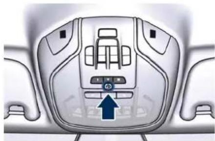
natural_image
Top-down view of a car dashboard with control buttons and a blue arrow pointing to the upper section (no text or symbols visible)System with Devices Provided with Rolling Codes
Programming the Hand-held Transmitters Manufactured after 1995
These devices can be identified by the "LEARN" or "TRAIN" setting button located where the hanging antenna is attached to the garage door/gate opener. It is NOT the button that is normally used to open and close the door.
The name and color of the button may vary by manufacturer.
- Place the ignition device to the RUN position without starting the engine.
- Place the hand-held transmitter 5 - 30 cm (1 to 3 inches) away from the HomeLink® button you wish to program.
-
Simultaneously press the Homelin® button you want to program and the hand-held transmitter button.
-
Release immediately the Homelink® button you want to program.
- Continue holding the hand-held transmitter button until the warning light starts flashing quickly; then release the button.
The quick flashing light indicates that the channel with the new frequency has been acquired and programmed correctly by the HomeLink® system.
NOTE:
The distance necessary between the portable hand-held transmitter and the HomeLink® in the vehicle depends on the system you wish to program. Probably it will be necessary to try several times. Upon every attempt, keep the setting position for at least 15 seconds before trying again.
Synchronising the Rolling Codes
At the end of the previously-described programming, if the HomeLink® has been programmed for a rolling code system, it will be necessary to synchronise it to ensure its correct operation.
- Locate the "LEARN" or "TRAINING" setting button of the opening motor. Firmly press it and then release it. On some garage door openers/devices there may be a light that blinks when

Understanding the Vehicle
the garage door opener/device is in the LEARN/TRAIN mode.
NOTE:
You have 30 seconds to initiate the next step after the setting button has been pressed.
- Return to the vehicle and press the programmed HomeLink® button for two seconds and then release it.
- Repeat this operation a second time. If the garage door opening device activates, the programming/synchronization phase is complete.
NOTE:
If the garage door opening device does not activate, press the button a third time for two seconds and then release it to complete the programming/synchronization phase.
- To program the remaining two HomeLink® buttons, repeat each step for each remaining button. DO NOT erase the channels.
Reprogramming a Single HomeLink Button
To reprogramme a channel that has been previously trained, follow these steps:
- Place the ignition device to the RUN position without starting the engine.
- Press and hold the desired HomeLink button.
- Without releasing the button proceed with "Programming the hand-held transmitters" from second step and follow all remaining steps.
System with Devices Without Rolling Code
Programming the Hand-held Transmitters Manufactured before 1995
- Turn the ignition device to the RUN position without starting the engine.
- Place the hand-held transmitter 5 to 30~cm (1 to 3 inches) away from the HomeLink® button you wish to program.
- Simultaneously press and hold both buttons until the warning light starts flashing quickly; then release both buttons.
The quick flashing light indicates that the channel with the new frequency has been acquired and programmed correctly by the HomeLink® system.
NOTE:
The distance necessary between the portable hand-held transmitter and the HomeLink® in the vehicle depends on the system you wish to program. Probably it will be necessary to try several times. Upon every attempt, keep the setting position for at least 15 seconds before trying again.
- Press and hold the programmed HomeLink® button.
If the garage door opener/device activates, programming is complete.
To program the remaining two HomeLink® buttons, repeat each step for each remaining button. Do not erase the channels.
Reprogramming a Single HomeLink Button
To reprogram a channel that has been previously trained, follow these steps:
- Place the ignition device to the RUN position without starting the engine.
- Press and hold the desired HomeLink button.
- Without releasing the button proceed with "Programming the hand-held transmitters" from second step and follow all remaining steps.
Using HomeLink®
To operate, press and release the programmed HomeLink® button. Activation will now occur for the programmed device (i.e., garage door opener, gate operator, security system, entry door lock, home/office lighting,
etc.). The hand-held transmitter of the device may also be used at any time.
Security
It is advisable to erase all channels before you sell or turn in your vehicle. To erase the channels press and hold the two outside HomeLink® buttons (I and III) until the warning light starts flashing (after approximately 20 seconds).
The HomeLink® Universal Transceiver is disabled when the vehicle security alarm is active (chapter "Vehicle security alarm" in section "Safety").
Troubleshooting Tips
If you are having trouble while programming HomeLink®, here are some of the most common solutions:
- Replace the battery in the original hand-held transmitter.
- Press the LEARN button on the garage door opener to complete the training for a rolling code.
• Did you unplug the device for programming and forgot to plug it back in?
If you have any problems, or require assistance, please call toll-free 1-800-355-3515 or, on the Internet at www.HomeLink.com for information or assistance.
Radio Frequency Transmitter - Regulatory Information
The "Regulatory Information" for all the radio frequency and radar devices can be consulted by accessing the section "Services" on the website www.maserati.com.

Understanding the Vehicle
Air Conditioning Distribution

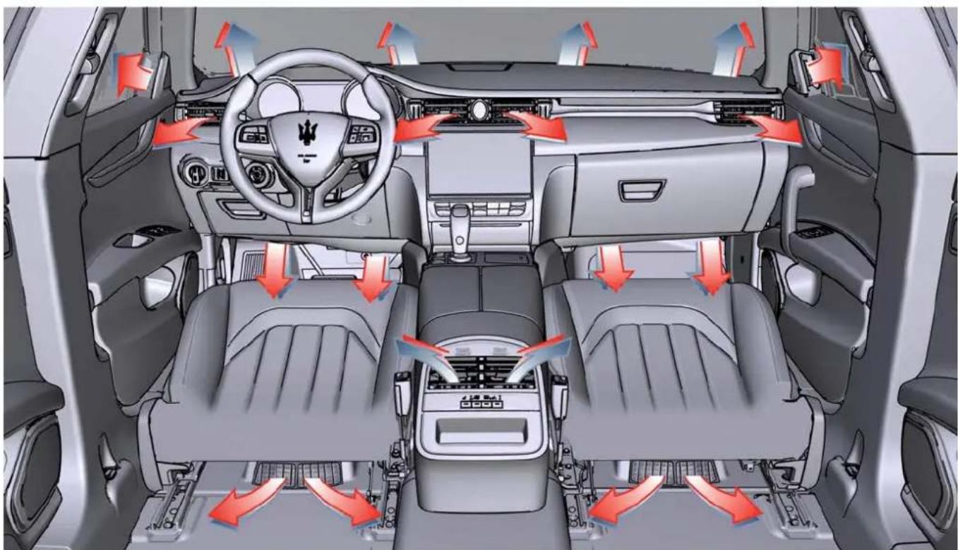
natural_image
Interior view of a car showing dashboard, steering wheel, and seat compartments with red directional arrows indicating airflow or traffic flow (no text or symbols present)A/C Dual-zone
Understanding the Vehicle

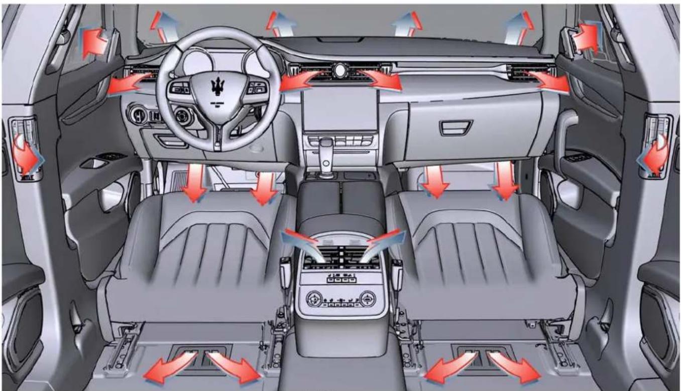
natural_image
Interior view of a car showing dashboard, steering wheel, and air intake system with red arrows indicating airflow direction (no text or symbols)A/C Four-zone

Understanding the Vehicle
Adjustable and fixed air vents allow passengers to achieve the optimal comfort conditions.
Fixed Air Vents
- The fixed vents, positioned on the upper part of the dashboard, beneath the windshield and above the front part of the front door panels are meant to guarantee the demisting and defrosting of the windshield and the side windows.
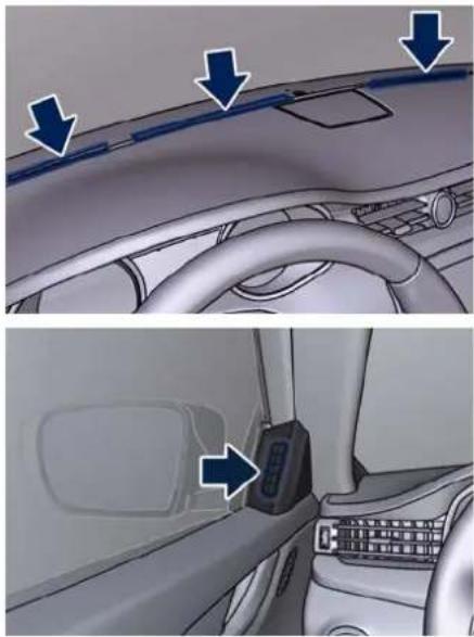
natural_image
Interior view of a car showing dashboard and steering wheel (no text or symbols visible)- The fixed vents under the dashboard are aimed at ventilating the lower part of the front passenger compartment.
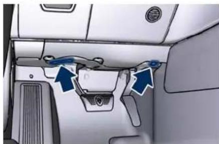
natural_image
Interior view of a car showing the dashboard and air vent (no text or symbols visible)- The ventilation of the lower part of the rear passengers compartment is made by means of fixed vents positioned under the front seats and they are specific for dual-zone and four-zone A/C system.
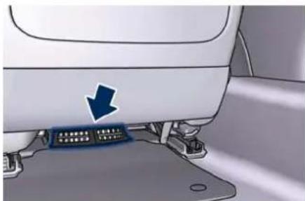
natural_image
Close-up of a car's front panel with a blue arrow pointing to a connector (no text or symbols visible)A/C Dual-zone Floor Vent
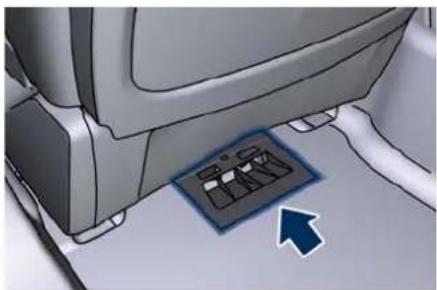
natural_image
Interior view of a car showing the roof and dashboard with a blue arrow pointing to a component (no text or symbols visible)A/C Four-zone Floor Vent
Adjustable Air Vents
- The adjustable air vents are located at the center and at the side ends of the dashboard. They have the purpose of ventilating the upper part of the passenger compartment. Two more vents, adjustable by the rear passengers, are placed at the rear end of the central console.
- Optional four-zone air conditioning provides additional adjustable vents on the side pillars between the doors. These vents can be adjusted in vertical and horizontal direction, by operating on the central paddle 1, as indicated in the following pictures. The rotor 2, located near each air vent, allows to regulate the airflow, or to close the vent. Orienting these vents it is also possible to demist the rear-door windows.
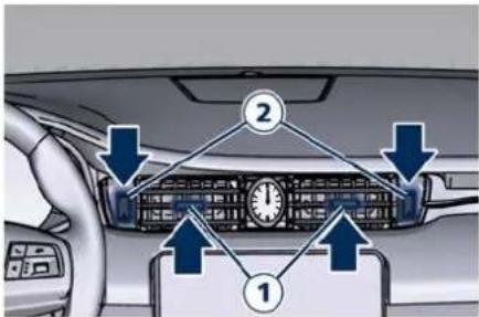
text_image
Diagram of car interior showing dashboard and steering wheel with numbered components and directional arrows indicating movement or navigation.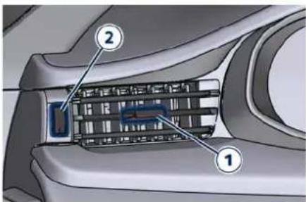
text_image
Technical diagram of a car interior with labeled components, showing numbered parts for identification.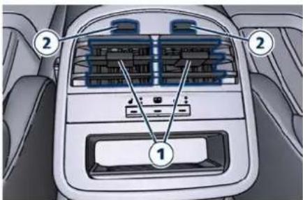
text_image
Diagram of car air intake system with labeled components including air compartments and fan compartments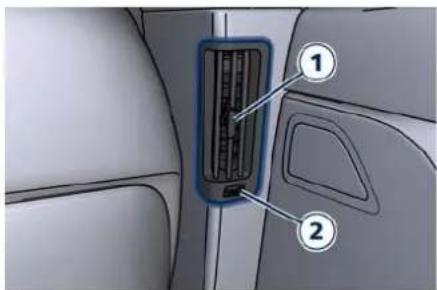
text_image
Diagram of car air intake system with labeled components, showing vent and door placementA/C Four-zone Side Pillar Vent
NOTE:
In order to avoid the obstruction of the windshield defrost vents, it is recommended not to place objects on the dashboard.

Understanding the Vehicle
3 - Before Starting
Keys 60
Illuminated Entry/Exit 62
Unlock the Vehicle with Key fob
Requiring and Setting Additional Key fobs
Passive Entry System 68
Power Windows....72
Power Sunshades on Rear Door Windows (*)
Power Sunroof with Sunshade ( ).
Rear Window 80
Open and Close the Boot Lid
Open and Close the Hood 86


Before Starting
Keys
The vehicle is equipped with a Remote Keyless Entry (RKE) transmitter and a Keyless Ignition Node (KIN), to enter, start and protect the vehicle.

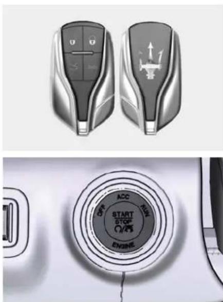
natural_image
Top: silver car key with control buttons and directional arrows; Bottom: circular dial with 'START STOP' and 'ON/OFF' labels (no readable text beyond icons)Keyless Ignition Device
The KIN allows the driver to operate the ignition device with the push of a button, as long as the RKE transmitter is inside the vehicle.
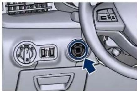
natural_image
Interior view of a car dashboard with air conditioners and a control panel (no visible text or symbols)The ignition device has three operating setups indicated on the outer ring. Pressing and releasing the middle button, you can switch from one setup to the next without starting the engine, the switched on indication will turn amber.
The engine will start by pushing the center button START/STOP with the brake pedal pressed and the device set in any of the three operating setups. In case the ignition device does not change by pushing a button, the RKE transmitter, also called the "key fob", may have a low or discharged battery. If this occurs it is necessary to replace the battery in order to operate the ignition device (see "Requiring and Setting Additional Key fobs" in this section).
It is still possible to operate the ignition device using the key fob with discharged battery by pressing
the nose side (side opposite of the emergency key) of the key fob on the START/STOP button.
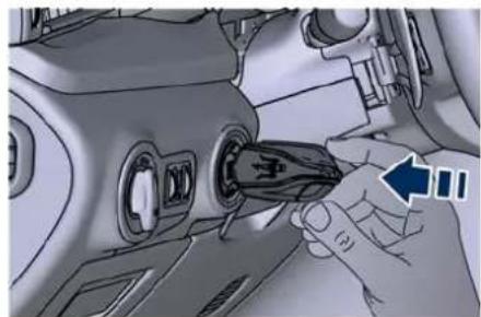
natural_image
Close-up of a hand inserting a plug into a device component (no visible text or symbols)Ignition Device Positions
The ignition device has three operating modes and is activated by pressing the central button only.
- Press and release the central button, to switch from one mode to the next without starting the engine: the active mode indication will light up on the outer ring.
- Push the central START/STOP button with brake pedal pressed and ignition device in any of the three operating modes, to start the engine (for more information, see the chapter "Normal Starting of the Engine" in section "Starting and Driving").
OFF: is the starting mode that enables centralised door locking from inside
the vehicle, provided that all doors are closed.
ACC: puts power to accessories.

CAUTION!
Do not leave the ignition device on the ACC position for a long time before a long period of inactivity to avoid further discharging of the battery.
RUN: enables all devices and controls of the vehicle.
After 30 minutes of inactivity with the ignition device in the RUN or ACC position, the transmission lever in P (Park) position and the engine off, the system turns OFF automatically in order to preserve battery life.
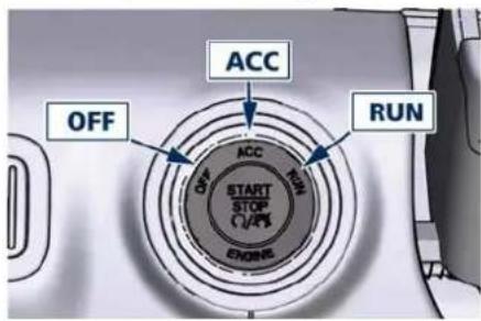
text_image
ACC OFF RUN START STOP C/4K ENGINEKey fob
The vehicle is provided with two programmed key fobs.
In addition to the RKE transmitter, the key fob also contains an emergency key.
The emergency key allows to open the vehicle by inserting into the lock of the opening handle on the driver's door, in case the battery of the vehicle or the key fob are discharged.
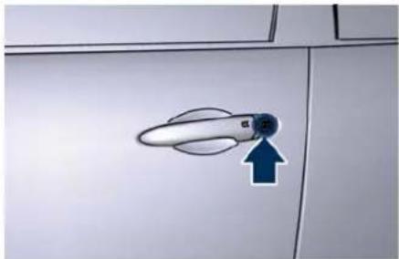
natural_image
Close-up of a door handle with a blue arrow pointing to the handle area (no text or symbols visible)You can keep the emergency key with you when using valet parking.
To remove the emergency key:
- hold the mechanical latch on the back of the key fob sideways;
- simultaneously remove the emergency key by sliding laterally towards the end of the key fob.
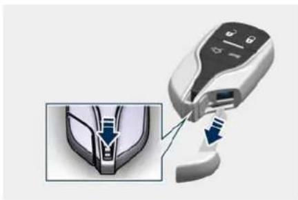
natural_image
Medical device with a close-up view of a mechanical component (no text or symbols visible)NOTE:
You can insert either side of the emergency key into the lock cylinder.
Shift Ignition Device to OFF Alert
Opening the driver's door to exit the vehicle when the ignition device is set in ACC or RUN (engine not running), a beep will remind you to cycle the ignition to OFF.
In addition to the acoustic signal a dedicated message is displayed on the instrument cluster.
If the ignition device is left in the ACC or RUN position, when vehicle is locked the system will turn off the instrument cluster and automatically set ignition device to OFF.
With the MIA System, the power window switches, radio, power sunroof (☐) and power outlets will

Before Starting
remain active for up to 10 minutes after the ignition device is cycled to the OFF position. Opening either front door will cancel this function, it is possible to set the timing of this function.
NOTE:
Refer to "Functions of Settings Menu on MIA" in section "Dashboard Instruments and Controls" for further information.

WARNING!
- When leaving the vehicle, always remove the key fob and lock your vehicle.
- Never leave children alone in a vehicle, or with access to an unlocked vehicle.
- Allowing children to be in a vehicle unattended is dangerous for a number of reasons. A child or others could be seriously or fatally injured. Children should be warned not to touch the parking brake switch, brake pedal or the shift lever.
- Do not leave the key fob in or near the vehicle, and do not leave the ignition device in the ACC or RUN mode. A child could operate power
windows, other controls, or move the vehicle.
- Do not leave children or animals inside parked vehicles in hot weather. Interior heat build-up may cause serious injury or death.
- An unlocked car is an invitation to thieves. Always remove the key fob from vehicle, cycle the ignition device to OFF and lock all doors when leaving the vehicle unattended.

WARNING!
- Do not ingest battery, chemical burn hazard. This product contains a coin/button cell battery. If the coin/button is swallowed, it can be cause severe internal burns in just 2 hours and can lead to death.
- Keep new and used batteries away from children. If the battery compartment does not close securely, stop using the product and keep it away from children. If you think batteries might have been swallowed or placed inside any part of the body, seek immediate medical attention.
Illuminated Entry/Exit
Lights will turn on and off when you enter/exit the vehicle and operate the buttons on the key fob and/or on the "Passive Entry" system as follows:
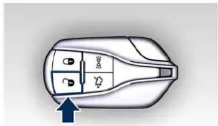
natural_image
Top-down diagram of a car interior showing dashboard, seat, and air vent (no text or symbols)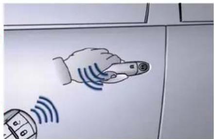
text_image
Hand-drawn diagram showing a pointing hand and a device with Wi-Fi signal waves, mounted on a cabinet surface.- If the unlock command is enabled by pressing the specific button on the key fob or by the "Passive Entry" system, the "illuminated entry" mode will activate. Courtesy & dimmable internal lighting, night front seats
Before Starting

lighting, and approach lighting will stay on for 27 seconds.
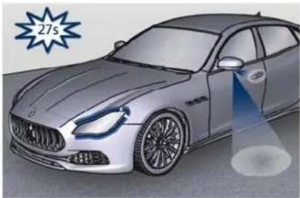
natural_image
Illustration of a Mercedes-Benz sedan with a blue light beam projecting onto the side (no text or symbols)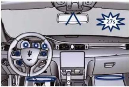
natural_image
Interior view of a car dashboard with steering wheel, dashboard, and steering wheel (no visible text or symbols)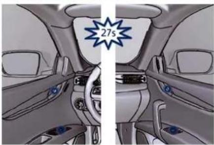
natural_image
Interior view of a car showing dashboard, steering wheel, and air vent (no text or symbols visible)- If the lock command of the car is enabled by pressing the specific 🔒 button on the key fob or by the Passive Entry system, when the key fob is out of range, all the lights will turn off within 3 seconds, if they were previously on.
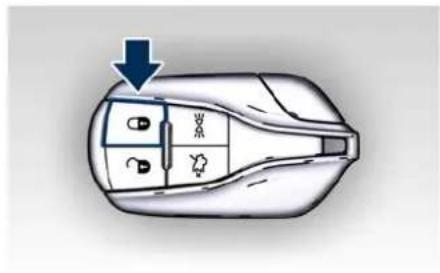
text_image
Diagram of a car interior with labeled compartments and directional arrow indicating flow or movement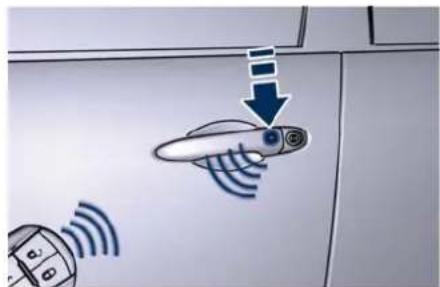
text_image
Diagram showing a device with wireless signals and a sensor icon, indicating signal flow or monitoring.- After activating the boot opening command in the possible modes (see "Open and Close the Boot Lid" in this section), the inner boot light will turn on and will stay on for 10 minutes
before turning off. The light will immediately turn off if you lock the boot lid before 10 minutes.
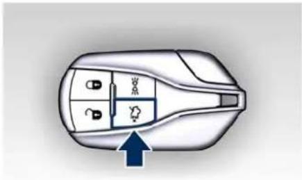
natural_image
Top-down diagram of a car interior showing dashboard and seat compartments with a blue arrow pointing to the bottom section (no text or symbols)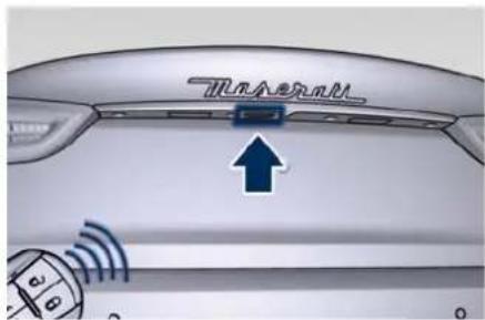
text_image
Munavalli
Before Starting
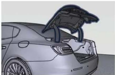
natural_image
3D rendering of a car showing the rear engine compartment with exposed internal components (no text or symbols visible)If the fob button is pressed on the key fob, the courtesy & dimmable lights and the approach lights will turn on; doors will stay locked.
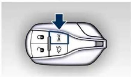
text_image
Diagram of a car interior with labeled compartments and directional arrow indicating flow or movementVehicle Lighting with Open/Closed Doors
- If one or more doors are open, the central light, front/rear domelights (main and spot light), the instrument cluster, the MIA display and the night front seats lighting and the ignition device backlight will turn on and will lit for 27 seconds.
- If the doors are closed, all lights will turn off (within 3 seconds) with the exception of the console display and the ignition device backlighting, which will turn off after 27 seconds.
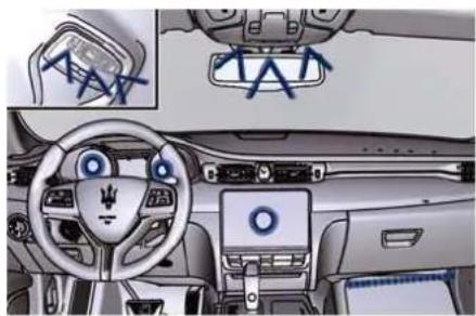
natural_image
Interior view of a car dashboard and infotainment system (no visible text or symbols)NOTE:
The lighting of the outside door handle and the puddle light near the front door are only available with the optional rear view mirrors (SVC).
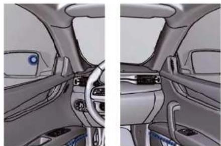
natural_image
Interior view of a car showing dashboard, steering wheel, and dashboard lift (no text or symbols visible)Courtesy Light with Logo
If equipped, a courtesy light with the Maserati logo can be provided on the bottom of the front doors. The illuminated logo will remain on until the door is closed.
NOTE:
The Maserati Service Network can provide you with any information about the Maserati approved "Courtesy Light with Logo", available in the "Genuine Accessories" range.
Use of Light Switch for Vehicle Lighting
In addiction of the key fob and the "Passive Entry" system vehicle lighting can be operated from the light switch on the left side of the dashboard. Refer to "Light Controls" in section "Dashboard Instrument and Controls" where it is indicated which external
lights turn on according to light switch positions.
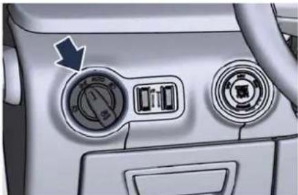
natural_image
Interior view of a car dashboard with two circular gauges and a directional arrow pointing to the left dial (no text or symbols visible)Ambient Lights and Backlight Adjustment
The ambient light and the backlight of the controls and instruments does not depend on the position of the light switch but on the detection of the ambient brightness made by the RLS solar sensor.
In "DAY" mode the backlighting of the instruments will be at 100% intensity while the backlighting of the switches will be at minimum. In "NIGHT" mode backlighting will be adjust via the left dimmer next to the light switch.
The ambient light are adjustable in the same condition which it is possible to adjust the backlight (in "NIGHT" mode only) via the left dimmer.
In all other conditions, you can activate the ambient lighting only in mode "all turned on" (Parade), turning the left dimmer upward to the second detent.
Light Dimmer Controls
The light dimmer controls are complementary to the light switch and are positioned beside the switcher itself (see "Light Controls" in section "Dashboard Instruments and Controls" for further information).
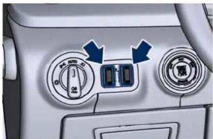
natural_image
Interior view of a car dashboard with directional controls and a central control panel (no text or symbols visible)Unlock the Vehicle with Key fob
The Remote Keyless Entry (RKE) system allows you to lock or unlock the doors and the fuel filler door, open the boot, turn the approach and courtesy lights on from a distance up to approximately 10 m (33 ft). The key fob does not need to be pointed at the vehicle to activate the system. See "Illuminated Entry/Exit" in this section for further information.
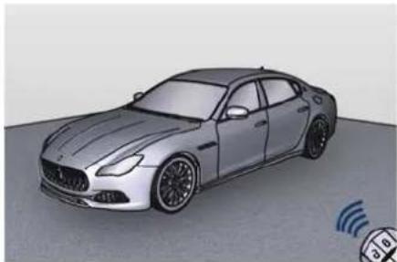
natural_image
3D rendering of a silver Mercedes-Benz sedan on a roof, with a sensor icon and antenna visible (no text or symbols)NOTE:
Driving at speeds 8 km/h (5 mph) and above disables the system from responding to all key fobs buttons.
Unlock the Doors, Fuel Filler Door and Boot
Press and release the unlock button on the key fob once to unlock the

Before Starting
driver's door or twice within five seconds to unlock all doors, the fuel filler door and the boot lid. The turn signal lights will flash for the unlock signal recognition. The illuminated entry/exit system will also turn on. See "Passive Entry System" in this section for further information.
Unlock Driver Door/All Doors with Remote Key 1 Press
This function allows you to program the system to unlock either the driver's door or all doors and the fuel filler door by the first press of the unlock button on the key fob. To change the current setting, see "Functions of Settings Menu on MIA" in section "Dashboard Instruments and Controls".
Lock/Unlock Doors Flash Lights This function will cause the flash of the turn signal lights when the doors are locked or unlocked with the key fob. This function can be turned on or turned off. To change the current setting, see "Functions of Settings Menu on MIA" in section "Dashboard Instruments and Controls".
Turn Headlights On with Key fob This function activates the headlights for up to 90 seconds when the doors are unlocked with the key fob.
The duration can be set as desired. To change the current setting, see "Functions of Settings Menu on MIA" in section "Dashboard Instruments and Controls".
Sound Horn when Locking the Doors with Key fob
With this function activate the horn will sound when the doors are locked with the key fob. This function can be enabled or disabled. To change the current setting, see "Functions of Settings Menu on MIA" in section "Dashboard Instruments and Controls".
Unlock the Boot Lid
Press the button on the key fob two times within five seconds to unlock the manual boot lid.
If the vehicle is equipped with power boot lid/Hands Free, besides unlocking the boot lid, the control will fully open it.
See chapters "Passive Entry System" and "Open and Close the Boot Lid" in this section for further information.
Requiring and Setting Additional Key fobs
In order to purchase additional key fob you need to bring with you at the Maserati Service Network:
- all key fobs in your possession;
- a personal ID;
- the identification and registration documents proving ownership of the vehicle.
Setting new key fobs or re-setting the original ones may only be performed at the Maserati Service Network.
NOTE:
The codes of any key fob that are not available when the new setting procedure is carried out will be deleted from the memory to prevent any lost or stolen key fob being used to disarm the electronic alarm system.
Key fob Battery Replacement NOTE:
A low charge level of the key fob battery will be indicated on the instrument cluster display.
The recommended replaced battery type is a: CR2032.
To replace the battery proceed as follows:
Before Starting

- Remove the emergency key as indicated in "Keys" chapter of the current section.
- Loosen the lateral screw that connects the two side covers with a torx T6 screwdriver.
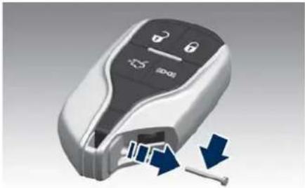
natural_image
3D rendering of a car door key with control buttons and a blue arrow indicating motion (no text or symbols)- Separate the two lateral covers from the key fob case.
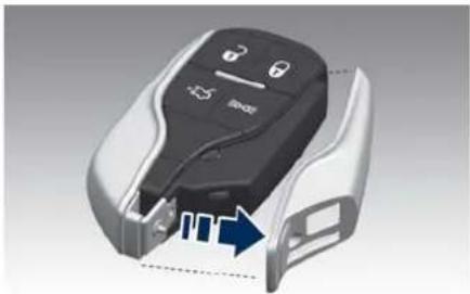
natural_image
Close-up of a car key with icons and a blue arrow indicating a motion or movement (no text or symbols)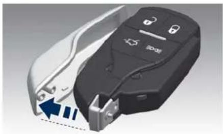
natural_image
Close-up of a car key with blue indicator lights and a lock icon, showing internal components (no text or symbols)- Separate both parts of the key fob case.
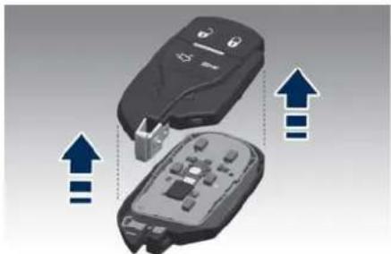
natural_image
Two electronic devices with blue arrows indicating upward motion, no text or symbols present- Remove the card with PCB (Printed Circuit Board).
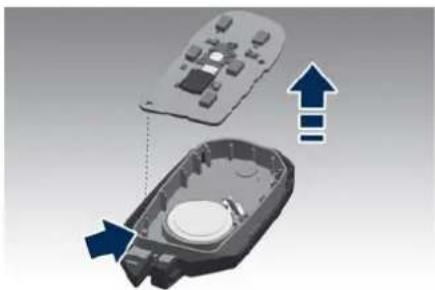
natural_image
3D diagram of a device's internal components with arrows indicating assembly or transformation (no text or symbols)- Remove the battery from its seat and replace with a new recommended type of battery.
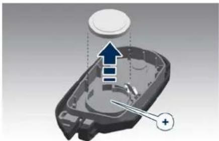
natural_image
3D diagram of a mechanical component with directional arrows and a plus sign, no readable text or symbols present.
ENVIRONMENTAL!
Batteries contain dangerous materials that could harm the environment. Please dispose of them according to local regulations or at the Service Network.
(Continued)

Before Starting
NOTE:
Avoid touching the new battery with your fingers. Skin oils may cause battery deterioration. If you touch a battery, clean with alcohol.
- Match the + sign on the battery to the + sign on the inside of the battery clip, located on the back cover.
- Replace the printed circuit board by using the indicated pin for the sealing of the two covers.
- Assemble the key fob case and reassemble the two lateral covers: a click will ensure the succeeded sealing.
- Combine the disassembled parts with clamping screw and reassemble the emergency key.
Radio Frequency RKE Transmitter - Regulatory Information
The "Regulatory Information" for all the radio frequency and radar devices can be consulted by accessing the section "Services" on the website www.maserati.com.
Passive Entry System
The "Passive Entry" system is an enhancement to the vehicle's Remote Keyless Entry (RKE) system. This function allows you to lock and unlock the vehicle's door(s) without having to press the key fob lock or unlock buttons. The "Passive Entry" system upon request can also be extended to the external opening handles of the rear doors.
NOTE:
- "Passive Entry" may be programmed to on/off; see "Functions of Settings Menu on MIA" in section "Dashboard Instruments and Controls" for further information.
- If wearing gloves, or if it has been raining on the "Passive Entry" door handle, the unlock sensitivity can be affected, resulting in a slower response time.
- Access to the vehicle using "Passive Entry" system may not work properly in case of interference caused by external sources such as metal objects, mobile phones, overhead power lines, antennas, etc. In these cases, use the buttons of the key fob to open and close the vehicle or the
emergency key, inserting it into the driver side door lock.
- The "Passive Entry" system does not lock and unlock the doors directly and immediately but with a slight delay (about 2 seconds).
Unlock Door from the Driver Side
With a valid key fob within 1 m (3.3 ft) of the driver's door handle, grip the driver's door external handle to unlock the door automatically. The interior door panel lock knob will raise when the door is unlocked.
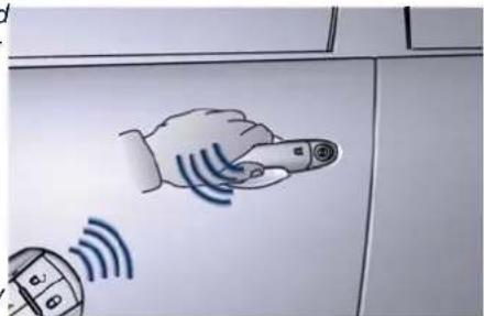
text_image
Diagram showing a hand pointing at a device with wireless signal waves, alongside a device icon and a keypad.
natural_image
Interior view of a car showing seatbelt and door panel with directional arrow (no text or symbols)NOTE:
If "1" Press of Key Fob Unlocks" is programmed all doors will unlock when you grip the front driver's door handle. To select between "Driver Door" and "All Doors", see "Functions of Settings Menu on MIA" in section "Dashboard Instruments and Controls".
Unlock Door from the Passenger Side
With a valid key fob within 1 m (3.3 ft) of the passenger door handle, grip the front passenger door handle or one of the rear door handle to unlock all four doors automatically.
The interior door panel lock knob will raise when the door is unlocked.
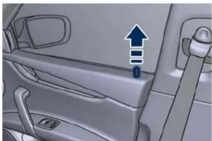
natural_image
Interior view of a car showing the door, side panel, and window (no text or symbols visible)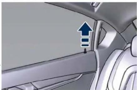
natural_image
Interior view of a car showing the side panel with an upward arrow and three horizontal bars, indicating a loading or movement (no text or symbols present)NOTE:
All doors will unlock when you grip the front passenger door handle or rear door handle regardless of the driver's door unlock preference setting ("Driver Door" or "All Doors").
Preventing Inadvertent Locking of the Key fob Inside the Vehicle
To minimize the possibility of unintentionally locking a key fob
inside your vehicle, the "Passive Entry" system is equipped with an automatic door unlock function which will function if the ignition device is in the OFF position.
If one of the vehicle doors is open and the door panel switch 🔒 used to lock the vehicle, once all open doors have been closed the system checks the inside and outside of the vehicle for any valid key fobs.
If one of the vehicle's key fobs is detected inside the vehicle, and no other valid key fobs are detected outside the vehicle, the "Passive Entry" system automatically unlocks all vehicle doors and chirps the horn fourteen times (on the fifteenth attempt ALL doors will lock and the key fob will be locked in the vehicle). This will happen even on vehicles equipped with power boot lid/Hands Free pressing RH button on its right lower part to close and lock the boot lid.
NOTE:
The vehicle automatically unlock the doors under any of the following conditions:
(Continued)

Before Starting
(Continued)
- the doors are manually locked using the door lock knob positioned on the door panel;
- there is a valid key fob inside the vehicle;
- there is a not valid key fob outside the vehicle.
- fifteen attempts are made to lock doors using the door panel switch and/or the RH button (on the vehicles equipped with power boot lid/Hands Free) and then close the doors.
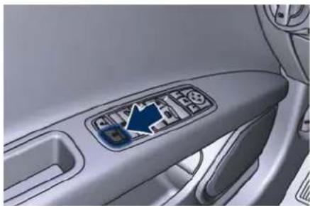
natural_image
Close-up of a car's side panel showing the front and rear door with a blue arrow pointing to a button (no text or symbols visible)NOTE:
The vehicle will not automatically unlock the doors under any of the following conditions:
- the doors are locked using the key fob;
- the doors are locked using the "Passive Entry" button on the door handles;
- there is a valid key fob outside the vehicle and within 1 m (3.3 ft) of either "Passive Entry" door handle;
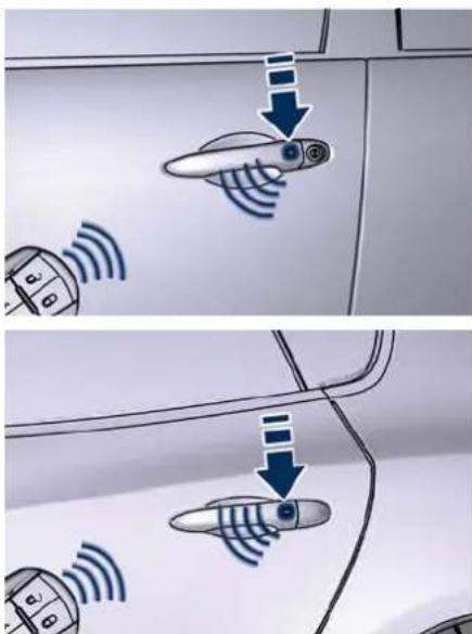
text_image
Diagram showing car door-mounted sensors with signal waves and directional arrows indicating sensor placement or navigation.
If the key fob is inside the passenger compartment and one of the doors locked only to the first detent of lock pawl (hence it is not fully closed),
then the vehicle lock function with alarm system for boot lid and doors is being activated by means of RH button
at the bottom of the boot lid, said function will be activated all the same. In this condition, any attempt to duly close the door that is partially open will cancel vehicle lock and alarm system arming thus leaving vehicle unlocked.
Since when the doors are locked, the "Passive Entry" system waits for about 16 seconds before verifying if a key fob is present inside the vehicle.
- If during this time you press the RH button which right lower part of the power boot lid/Hands Free to close the boot lid and activate the alarm, if a key fob is left in the boot, the system will close the power boot lid and will activate the alarm system. This option is recommended when you want to leave the other key fob inside the vehicle.
- By pressing the same button after 16 seconds, if a key fob is left in the boot, the power boot lid will close and will partially reopen. If the "Passive Entry" system detects no key fob inside the boot, close the power boot lid and will activate the alarm system.
Before Starting

Release the Lid and enter the Boot
For vehicles equipped with manual boot lid: with the key fob within 1 m (3.3 ft) of the lid, press the button located between the licence plate lights and lift it manually.
For vehicles equipped with power boot lid/Hands Free: with the key fob within 1 m (3.3 ft) of the lid, press the button located between the licence plate lights, the power lid will automatically open until fully home; if the same button is not pressed again to stop it (for more information, see chapter "Open and Close the Boot Lid" in this section).
If the vehicle had already been unlocked through key fob or "Passive Entry", the presence of the key fob is not required; simply use the button located between the licence plate lights to unlock the manual boot lid or to open the power boot lid/Hands Free automatically.
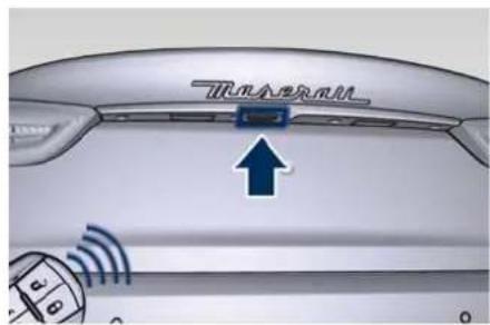
text_image
Treadmill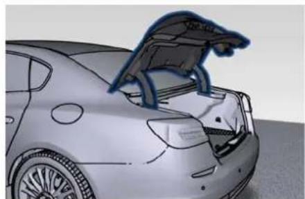
natural_image
Side view of a car trunk with a hood open, showing structural lines (no text or symbols)Manual Door Lock from Outside
With one of the vehicle's key fobs within 1 m (3.3 ft) of the driver or passenger front door handles, press the external door handle button to lock all four doors.
NOTE:
• After pressing the external door handle button, you must wait two
seconds before you can lock or unlock the doors using this door handle. By pulling the external door handle, you can check if the car remains locked, without "Passive Entry" system reacting and unlocking the doors.
- The "Passive Entry" system will not operate if the key fob battery is dead.
- If power boot lid/Hands Free (if equipped) has been left open, it will stay open when you press the button on door external handle, and the locking function will only occur after the closing of the power boot lid.
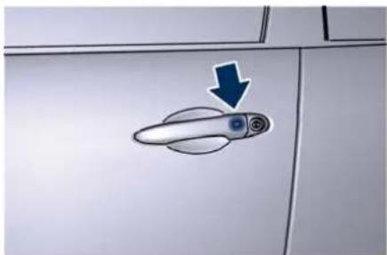
natural_image
Close-up of a door handle with a blue arrow pointing to it, mounted on a cabinet (no text or symbols visible)
Before Starting

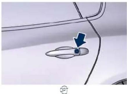
natural_image
Close-up of a car door handle with a blue arrow pointing to a small object (no text or symbols visible)The vehicle doors can also be locked by using the key fob lock button or the lock button located on the vehicle's inner door panel.
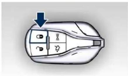
text_image
Diagram of a car interior with labeled compartments and directional arrow indicating movement or flow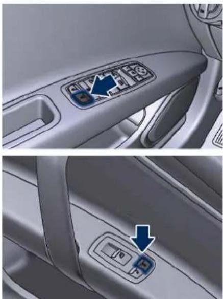
natural_image
Interior view of a car showing the dashboard and side panel with control buttons (no text or symbols visible)Radio Frequency RKE Transmitter - Regulatory Information
The "Regulatory Information" for all the radio frequency and radar devices can be consulted by accessing the section "Services" on the website www.maserati.com.
Power Windows
The window controls on the driver's door panel governs all the door windows.
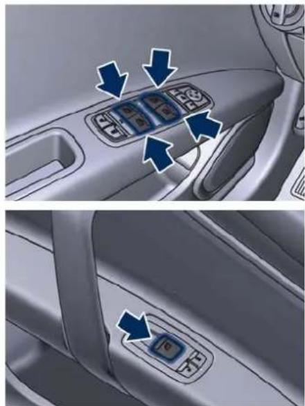
natural_image
Interior view of a car showing the dashboard and side panel with directional arrows (no text or symbols)There are single window controls on each passenger door trim panel, which operate the corresponding window. The window controls will operate only when the ignition device is in the ACC or RUN position.
NOTE:
- The power window switches will remain active for up to 10 minutes after the ignition device is turned to the OFF position. Opening either front door will cancel this function. The time lapse can be set. See "Functions of Settings Menu on MIA" in section "Dashboard Instruments and Controls" for further information.
- Frequent activations of the power windows could result in a temporary lock of their starters. In this case, was a moment before a new activation.

WARNING!
Improper use of the power windows and the sunroof (if equipped) can however be dangerous, even with the anti-pinch prevention system. Before and during activation of the power window, always check that the passengers are not exposed to the risk of injury both by the moving window and by personal objects that could be dragged or hit by it. Do not leave unattended children in a vehicle with a key fob inside. When getting out the vehicle, always remove the key fob to prevent the windows being accidentally activated, posing a risk to NOTE: passengers remaining onboard. • If th
Auto-Down Function
The driver door power window switch and some model passenger door power window switches have an auto-down function.
Press the window switch to the second detent, release, and the window will go completely down automatically. To open the window part way, press the window switch to the first detent and release it when you want the window to stop.
To stop the window from going all the way down during the auto-down operation, pull up on the switch briefly.
Auto-Up Function with Anti-Pinch Protection
Lift the window switch to the second detent, release, and the window will go all the way up automatically.
To stop the window from going all the way up during the auto-up operation, push down on the switch briefly.
To close the window part way, lift the window switch to the first detent and release it when you want the window to stop.
- If the window runs into any obstacle during auto-closure, it will reverse direction and then go back down. Remove the obstacle and use the window switch again to close the window.
- Any impact due to rough road conditions may trigger the auto reverse function unexpectedly during auto-closure. If this happens, pull the switch lightly to the first detent and hold to close the window manually.
- Frequent activations of the anti-pinch function could disable the auto-down and auto-up function of the windows. In order to re-activate this function proceed with a reset cycle as described in the next paragraph.

WARNING!
There is no anti-pinch protection when the window is almost closed. Be sure to clear all objects from the area before closing the window.
Reset Auto-Up/Down
Should the auto-up/down function stop working, the window probably needs to be reset.
To reset auto-up/down, pull the window switch up to close the window completely and push the window

Before Starting
switch down to open the window completely.
Open and Close the Windows and Sunroof with Key fob and Ignition Off
When the ignition device in is OFF position, windows and sunroof (if equipped) can be opened or closed by pressing the buttons on the key fob.
Opening:
- press the button and release it;
- press a second time the button and keep it pressed until complete opening of the windows and the sunroof, if they were closed.
Closing:
- press the button and release it;
- press a second time the button and keep it pressed until complete closure of the windows and the sunroof, if they were open.
Rear Window and Sunshade Lockout Button
The window lockout button on the driver's door trim panel allows to disable the window and sunshade control on the rear doors and the rear window sunshade control at the rear of the central console, by pressing the window lockout button (setting it in the down position).
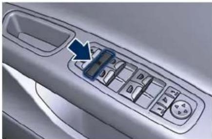
natural_image
Close-up of a car's side panel with a blue arrow pointing to a grid of buttons (no text or symbols visible)To enable the controls previously described, press the window lockout button again (setting it in the up position).
Wind Buffeting
Wind buffeting can be described as the perception of pressure or a helicopter-type sound. Your vehicle may exhibit wind buffeting with the windows down, or the sunroof in open or partially open positions. This is a normal occurrence and can be minimized. If the buffeting occurs with the rear windows open, open the front and rear windows together to minimize the buffeting. If the buffeting occurs with the sunroof open, then adjust the sunroof opening to minimize the buffeting.
Power Sunshades on Rear Door Windows ( )
NOTE:
- On vehicles provided with power sunshades on the rear windows, the window switches also operate the sunshades.
- The rear windows lock button operates as well the rear power sunshades.
- The window and sunshades controls will operate only if the ignition device is in ACC or RUN position.
Operation of the rear windows and related sunshades is done by pressing or pulling the window switch and depends on the position of the windows prior to the command operation.
As described for the opening and closing functions of the power windows (see chapter "Power Windows" in this section), the windows switch has two functioning modes: press and release the switch to the first detent to partially move the window; press and release the switch to the second detent to move the window all the way up or down.
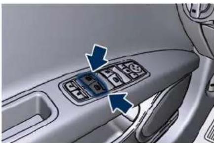
natural_image
Interior view of a car dashboard with four buttons and directional arrows indicating action buttons (no text or symbols present)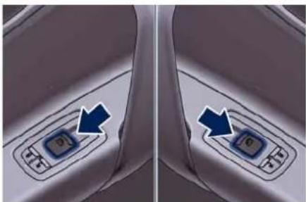
natural_image
Close-up of a car interior showing a hand valve with blue arrows pointing to the left side (no text or symbols visible)Operations

WARNING!
Rear seat passengers must be careful when operating the sunshades, since there is the risk of being pinched between the top of the sunshade and the headlining, during raising, and between the top edge of the
sunshade and the door panel, during lowering.

CAUTION!
Before activating the sunshade, make sure that no objects can interfere with its travel.
The following images and the subsequent text show the possible starting positions ("A", "B", "C" and "UP", "DOWN") and function of the window and the sunshade, to be independently activated by pressing or lifting the control switch to the first 1 or second 2 detent.
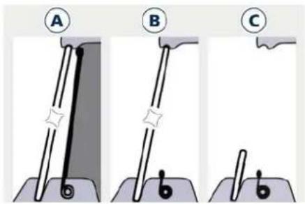
text_image
Diagram showing three stages (A, B, C) of a mechanical or electrical component with labeled parts and connection points.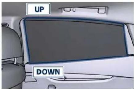
text_image
UP DOWNA. Sunshade fully unrolled ("UP" position) and Window closed ("UP" position)

text_image
A 2 1 NOP
Before Starting

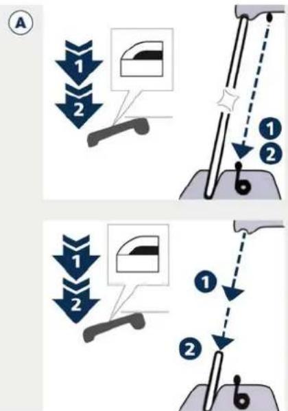
text_image
A 1 2 ① ② ① ②- Pulling the control up to 1 or 2 detent: no action ("NOP").
1.1 Pressing the control to 1 detent: the sunshade rolls down completely and the window stays closed.
1.2 Pressing the control again to 1 detent: the window opens partially until the control is released and the sunshade stays down (pressing the control to 2 detent: the window opens completely).
2.1 Pressing the control to 2 detent: the sunshade rolls down completely while the window stays closed.
2.2 Pressing the control again to 2 detent: the window opens completely.
B. Sunshade fully rolled down ("DOWN" position) and Window closed ("UP" position)
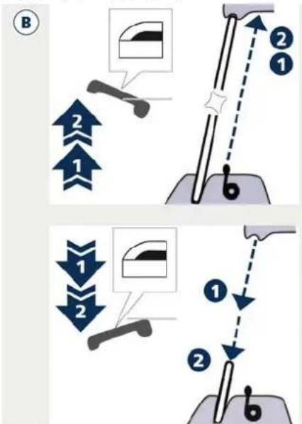
text_image
Diagram illustrating two-step mechanical assembly steps with numbered components and directional arrows indicating motion.- Pulling the control up to 1 or 2 detent: the sunshade unrolls completely and the window stay closed.
- Pressing the control to 1 or 2 detent: the window opens partially or completely and the sunshade remains rolled.
C. Sunshade fully rolled down ("DOWN" position) and Window completely open ("DOWN" position)
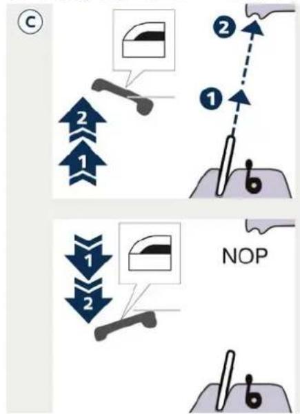
text_image
C ① ② ③ NOP ④ ⑤ ⑥ ⑦ ⑧ ⑨ ⑩ ⑪ ⑫ ⑬- Pulling the control to 1 or 2 detent: the window closes partially or completely and the sunshade remains rolled.
- Pressing the control to 1 or 2 detent: no action ("NOP").
Teach-in Cycle
After battery disconnection, the following teach-in cycle is required to store the limit positions the sunshades can reach in operation. Use the controls on the rear doors to move the sunshades.
- With glass closed, lift rear sunshade control on driver side for a few seconds. It is not necessary that the sunshade reaches its upper limit.
- Reverse the sunshade movement by pressing the control downwards. Once the lower limit is reached, press and hold the control for at least 10 seconds. This action allows setting the control unit in initialisation status.
- Release the movement command.
- Within maximum 15 seconds:
- Press once the control downwards (first or second detent indifferently). In this way the control unit stores the lower limit position. During this operation a slight click of the sunshade motor that switches to mechanical lock condition can be heard.
- Lift the control and hold it up until the sunshade completes its upstroke and reaches the car body pillar, fully home. Once the upper limit stop is reached, the sunshade will
move downwards for approx. 2-3 millimetres (0.08-0.12 inches) and the control unit will store this height as upper limit. Now the teach-in of the driver side rear sunshade is complete.
- Repeat the same operations for the passenger side rear sunshade to complete the teach-in procedure.

Before Starting
Power Sunroof with Sunshade (→)
The sunroof is power controlled and can only be operated with the ignition device in RUN position.
It can slide lengthways and be raised at the rear (tilting).
By opening the sunroof a front flap rises automatically in order to deviate the air flow.
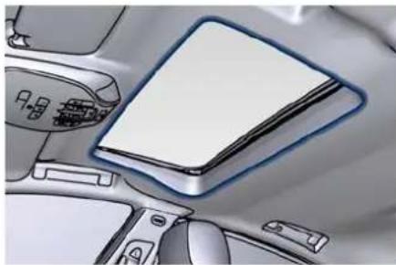
natural_image
Interior view of a car dashboard with a blank notebook and control panel (no visible text or symbols)The power sunroof controls are located between the sun visors on the overhead console.
The right two buttons controls the sunroof movement, whereas the left button controls the lifting of the sunroof for venting.
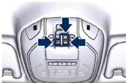
natural_image
Top-down view of a car dashboard with directional arrows indicating engine or control components (no text or symbols)The sunshade can be opened manually. However, the sunshade will open automatically as the sunroof opens.
The sunshade cannot be closed if the sunroof is open.

WARNING!
- Improper use of the sunroof can be dangerous, even if it features a finger-trap prevention system. Before and during the sunroof operation, always make sure that passengers are not exposed to the risk of injuries caused by the moving sunroof or by personal objects dragged or hit by the moving sunroof.
-
Never leave children in a vehicle with the key fob in the passenger compartment.
-
In a collision, there is a greater risk of being thrown from the vehicle if the sunroof is open. Always fasten your seat belt properly and make sure all passengers are properly secured too.
- Do not allow small children to operate the sunroof. Never insert fingers, other body parts, or any object through the roof opening.

CAUTION!
- In the event of rain, always close the sunroof to prevent water infiltrations from staining the fabric/leather upholstery.
- Do not open the sunroof if there is ice on it: risk of damage.
Slide Opening Sunroof
• Full automatic express opening
Press the right rear button for more than half second and the sunroof will open automatically regardless of any previous position. The sunroof will open fully and stop automatically. During this operation, if any sunroof button is pressed, the sunroof will stop.
• Full or partial manual opening
To open the sunroof manually press the right rear button for less than
Before Starting

half second to move step by step the sunroof panel.
Venting Sunroof
Press and release the left button, and the sunroof will open to the vent position. This is called "Express Vent", and will occur regardless of sunroof position. During this opening operation, any movement of the button will stop the sunroof.
Pinch Protect Function
This function will detect an obstruction in the opening of the sunroof during express close operation. If an obstruction is detected, the sunroof will automatically retract. If this occurs, remove the obstruction then press the right front button and release to express close.
NOTE:
If three consecutive attempts to close in express mode the sunroof result in pinch protect reversals, the fourth attempt will be manual, with pinch protect function disabled.
Pinch Protect Override
If any obstruction (ice, debris, etc.) prevents closing the sunroof, press the right front button and hold for two seconds after the reversal occurs. This allows the sunroof to move toward the closed position.
NOTE:
Pinch protection is disabled while pressing the right front button.
Closing and Opening the Power Sunroof with Key fob and Ignition Off
When the ignition device is in OFF position, if the sunroof is open, it can be closed together with the windows by pressing the button on the key fob (refer to "Power Windows" in this section).
- Press and release the button.
- Press a second time the button and keep it pressed until the sunroof is completely closed.
To open completely the sunroof from the outside, press in the same way the button on the key fob.
Wind Buffeting
Wind buffeting can be described as the perception of pressure or a helicopter-type sound. Your vehicle may exhibit wind buffeting with the windows down, or the sunroof in certain open or partially open positions. This is a normal occurrence and can be minimised. If the buffeting occurs with the rear windows open, then open the front and rear windows together to minimise the buffeting. If the buffeting occurs with the sunroof open, then adjust the sunroof opening to minimise the buffeting.
Ignition Off Operation
The power sunroof controls will remain active for up to approximately ten minutes after the ignition device is in OFF position. Opening either front door will cancel this function. The ignition system timing can be set using the MIA system (see "Functions of Settings Menu on MIA" in section "Dashboard Instruments and Controls").
Sunroof Maintenance
Use only a nonabrasive cleaner and a soft cloth to clean the glass panel.
NOTE:
To manually unlock the power sunroof (if equipped), please contact the Service Network.

Before Starting
Rear Window
Rear Window Defroster
The rear window defroster button is located on the climate control panel. See "Air Conditioning Controls" in section "Dashboard Instruments and Controls".
Power Sunshade (☐)
Your vehicle can be equipped with a power sunshade that will reduce the amount of sunlight that will enter through the rear window.
The sunshade is rolled in and stored inside the cover behind the rear seats; when activated, it rolls out upwards. The power sunshade can be operated using the MIA system.
- Touch the "Vehicle" soft-key on the main category bar of the MIA display and choose the "Controls" menu.
- Within 15 seconds, touch the "Rear Sunshade" soft-key to raise the power sunshade.
- Within 15 seconds, touch the "Rear Sunshade" soft-key a second time to lower the sunshade.
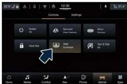
text_image
22.5° 12:30 Controls Settings Screen Off Simround View Camera Mirror Dimmar Glove Box Near Sumtrade Start & Stop Off Home Media Comfort Nav Phone Vehicle AppsIf the sunshade is in the raised position and the transmission lever is positioned in R (Reverse), the sunshade will automatically fully lower.
When the transmission lever is shifted out of R (Reverse) the sunshade will automatically return to the fully raised position after approximately five seconds.
The trigger buttons of the rear sunshade are positioned at the rear of the central console. These buttons can be operated from the rear passengers.
- Press the left button to fully raise the sunshade.
- Press the right button to fully lower the sunshade.
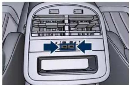
natural_image
Interior view of a car air intake console with directional arrows indicating airflow or ventilation (no text or symbols)On the vehicles equipped with the "Comfort Luxury" rear seats, the single button is located on the rear central console between the two rear seats.
- Press the button to fully raise the sunshade.
- Press the button a second time to fully lower the sunshade.
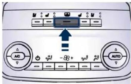
text_image
Air conditioning control panel with AC, AUTO, and directional buttons labeled in English and Chinese"Comfort Luxury" Rear Seats
NOTE:
The rear sunshade controls, power windows switches together with the sunshades on the rear windows, can be locked by pressing the window lockout button on the driver side door panel.
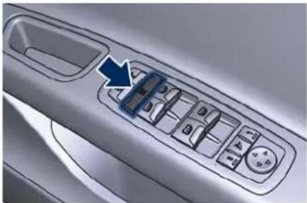
natural_image
Close-up of a car's side panel with a blue arrow pointing to the control panel (no text or symbols visible)Open and Close the Boot Lid
^b Manual Boot Lid Operation
The manual boot lid can be unlocked from inside the vehicle by pressing the button on the front dome console.
NOTE:
The shift lever must be in P (Park) before the button can operate.
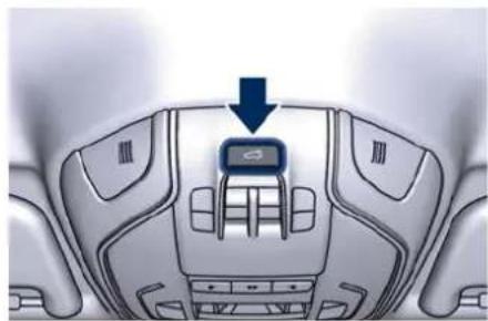
natural_image
Interior view of a car dashboard with a blue arrow pointing to the top panel (no text or symbols visible)The manual boot lid can be unlocked from outside the vehicle by pressing the button on the key fob twice within five seconds or by using the external release button located on the lower side of the boot ledge, between the license plate lights under the following conditions:
- When the car is unlocked to open the boot lid it is not necessary to keep the key fob within 1 m (3ft)
from the boot lid, with "Passive Entry" function enabled or disabled from the MIA menu.
- When the car is locked to open the boot lid:
- if the "Passive Entry" function has been enabled from the MIA menu, it is necessary to keep the key fob within 1 m (3 ft) from the boot lid; - if the "Passive Entry" function has been disabled from the MIA menu, the boot lid does not open even with the key fob within 1 m (3 ft) from the boot lid.
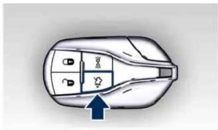
natural_image
Top-down diagram of a car interior showing dashboard and seat compartments with a blue arrow pointing to the lower portion (no text or symbols)
Before Starting
3
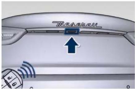
text_image
TranscollTo manually close the boot lid use the handle as indicated beside the closing device.
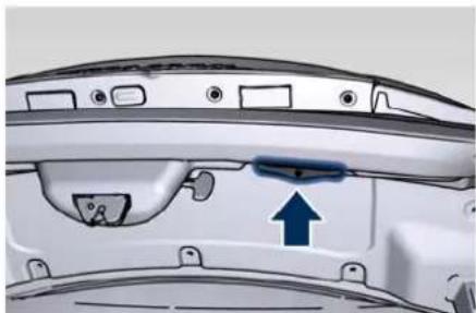
natural_image
Interior view of a car dashboard with a blue arrow pointing to a component (no text or symbols visible)With the ignition device in RUN position, the red symbol and the image of the car with the boot lid open will display on the instrument cluster. Once the boot lid is closed, both symbol and image will disappear from the display.
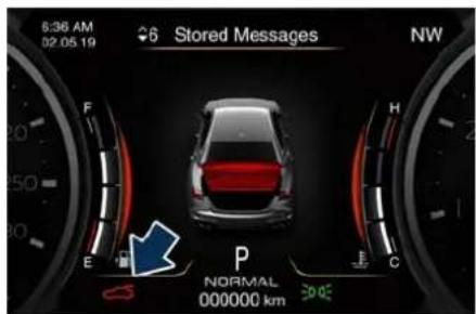
text_image
6:36 AM 02 05 19 Stored Messages NW F H E P NORMAL 000000 km 30.0°CWith the ignition device in the OFF position, the boot lid open symbol and message will display until closure. See "Passive Entry System" in this section for more information on boot lid operation with the "Passive Entry" function.
Power Boot Lid/Hands Free Operation (→)
Automatic opening and closing movement of the power boot lid/Hands Free is driven by electric actuators and a motorized latch ensuring lid locking upon closing. Power boot lid/Hands Free can be opened from outside pressing twice within five seconds the button on the key fob or from inside pressing the button on the front dome console.
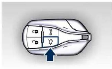
text_image
Diagram of a car interior with labeled parts and directional arrow indicating movement or flow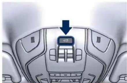
natural_image
Interior view of a car dashboard with a blue arrow pointing to the top panel (no text or symbols visible)The button on key fob and button on front dome console not only allows user to completely open the power boot lid/Hands Free, but also to stop it at any intermediate position by pressing the button again at anytime you wish to stop the opening process. In addition to these commands, it is possible to open and close the power boot lid/Hands Free by simply moving your foot under the rear bumper. In this latter case, the lid will be opened
Before Starting

and closed only if the "Passive Entry" system acknowledges the presence of the key fob within 1 m (3.3 ft) of the boot lid.
Power boot lid/Hand Free uses the button in between the license plate lights, indicated in figure, to activate the opening once the car has been unlocked by the key fob or by the "Passive Entry" function.
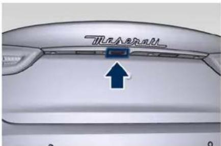
text_image
TreadmillBy pressing this button when the power boot lid/Hands Free is closed you can open it completely or by pressing the button again stop the opening process.
When the power boot lid/Hands Free is open, to move it there are two buttons positioned on its right lower part as indicated in figure.
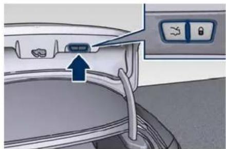
natural_image
Interior view of a car showing the seat, dashboard, and air conditioner unit (no text or symbols visible)When the power boot lid is completely open if you press and release the LH button, the power boot lid will be completely closed unless it is stopped;
- if instead the power boot lid is in an intermediate position and you press and release the LH button during the closing or opening stroke, it will be stopped; - if instead the power boot lid is stopped in an intermediate position and you press and release the LH button, it will reverse its previous movement and it will be completely opened or closed unless it is stopped again.
In any case, when you press the LH button, the doors will not be locked and the alarm system will not be armed.
When the power boot lid is completely open if you press and release the RH
button, the power boot lid will be completely closed unless it is stopped;
- if instead the power boot lid is in an intermediate position and you press and release the RH button during the closing or opening stroke, it will be stopped;
- if instead the power boot lid is stopped in an intermediate position and you press and release the RH button, it will reverse its previous movement and it will be completely opened or closed unless it is stopped again.
In any case, when you press the RH button, the doors will not be locked and the alarm system will not be armed immediately, but only when the power boot lid will have reached the totally closed position as effect of every movement commands received from every other available inputs.
NOTE:
- The order of the functions shown does not represent the sequence in which they can be performed.
- The buttons of the power boot lid/Hands Free do not work if a gear is engaged or if the vehicle speed is higher than 0 km/h (0 mph).
(Continued)

Before Starting
(Continued)
- The power boot lid/Hands Free does not work with temperatures lower than -30^ (-22^) or higher than 65^ (150^) .
- If the opening buttons or the handle are operated while the power boot lid/Hands Free is closing, the stroke of lid stops. Pressing another time the same command it reverses movement and fully open.
- If the opening buttons or the handle are operated while the power boot lid/Hands Free is opening, the motor of the lid is disabled to allow manual operation.
- If the power boot lid/Hands Free finds several obstacles during the same operating cycle, it will stop automatically and must be opened or closed manually.
- If the power boot lid/Hands Free is closing and a gear is engaged, the lid will continue closing. In this condition, it is possible that, during the closing stroke, it may find an obstacle and stop.
Since when the doors are locked, the "Passive Entry" system waits for about 16 seconds before verifying if a key fob is present inside the vehicle.
- If during this time you press the RH button on right lower part of the
power boot lid/Hands Free to close the boot lid and activate the alarm, if a key fob is left in the boot, the system will close the power boot lid and will activate the alarm system.
e This option is recommended when you want to leave the other key fob of inside the vehicle.
- By pressing the same button after 16 seconds, if a key fob is left in the boot, the power boot lid will close and will partially reopen. If the "Passive Entry" system detects no key fob inside the boot, close the power /boot lid and will activate the alarm system.
Set the Position of Maximum Power Boot Lid/Hands Free Opening
The maximum opening position of the power boot lid can be modified using the previously described buttons on its right lower side.
- Activate the power boot lid and stop it in the new maximum opening position to be set, by pressing the LH button.
- Press the LH and RH buttons at the same time and keep them pressed for 3 seconds.
- Release both buttons. Upon the following opening controls, the
power boot lid will stop in the stored position.
If you want to reset the maximum possible opening position of the power boot lid, proceed as described below starting from the previously set opening position.
- Manually push the power boot lid to the maximum possible opening position.
- Repeat the previously performed steps 2 and 3.
Power Boot Lid/Hands Free Automatic Safe Movement
Power boot lid/Hands Free safe opening and closing is ensured by a protection system able to stop its movement when an obstacle is detected along the path: when opening or closing, it stops automatically and then slightly moves back.
After the closing command, when power boot lid/Hands Free starts closing, all the indicators will blink to warn anyone within range.
When power boot lid/Hands Free edge reaches the car body, the motor locking the latch is activated automatically.
If necessary, the power boot lid/Hands Free can also be opened or closed
manually. This operation could be required when the boot lid remains open for a long period of time.

WARNING!
- Activate power boot lid/Hands Free only when vehicle is at a standstill.
• Always pay utmost attention when opening and closing power boot lid/Hands Free since the protection system might fail to respond and cause injury to anyone within range
• After the closing command, always make sure that power boot lid/Hands Free is completely closed.

CAUTION!
• Under extreme weather conditions, boot lid seal could freeze and compromise power boot lid/Hands Free automatic opening and closing.
- Before opening power boot lid/Hands Free, make sure that no objects or snow are set on boot lid or might jam or prevent its opening.
Hands Free Power Boot Release and Closing
This mode is controlled by the "Passive Entry" system (see chapter "Passive Entry System" in this section), which automatically releases and closes the
power boot lid/Hands Free when you place your foot in the area under the rear bumper.
The system will only operate if the system acknowledges the presence of the key fob within 1 m (3.3 ft) of the power boot lid/Hands Free.
The range of the sensors that detect your foot movement extends along and underneath the central portion of the rear bumper.
To activate the power boot lid/Hands Free, stand behind the vehicle, near the boot lid, and move your foot under the bumper as if to kick something. Do not place your foot too close to the bumper or touch the underbody.

WARNING!
- Pay careful attention to the exhaust tailpipes as they can reach high temperatures and, in case of contact, they can cause severe burns.
- When it is not necessary to open the power boot lid with the "Hands free" mode, make sure the key fob results outside the range of use (1 m/3.3 ft). Otherwise, the power boot lid/Hands Free can be opened
accidentally by an unintentional movement of the foot.
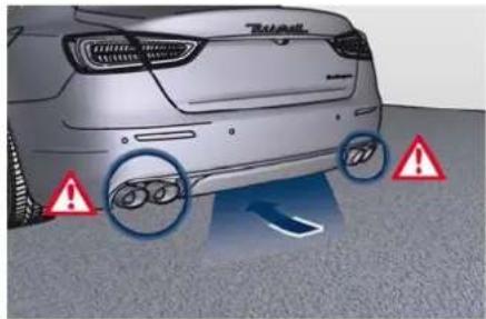
text_image
Diagram showing a car rear view with warning symbols and circular annotations highlighting accident zones.In order for the sensors to detect your foot movement, move your foot towards the vehicle rather than sideways and immediately pull it back: from this moment, the power boot lid/Hands Free will activate within two seconds.
If closed, with the foot movement the power boot lid/Hands Free will:
- unlock and completely open;
• after another kick, will stop;
• after another kick, will reverse its movement and completely close unless stopped again.
If open, with the foot movement the power boot lid/Hands Free will:
• completely close but does not lock;
- another kick before the completed closing can stop the movement;

Before Starting
- if the movement was stopped another kick operation will invert a complete opening.
NOTE:
- If your foot movement fails to activate the power boot lid/Hands Free movement, wiggling your foot under the bumper will not help. Repeat the whole kick movement.
- In particular situations, external factors affecting the sensor area may trigger the "Hands free" power boot release function. For example, when washing the vehicle, a water jet aimed at the sensor area may trigger the "Hands free" power boot release function. Keep the key fob away from the sensing range of the sensors (3 ml/10 ft) or disable the "Hand free" function from the MIA menu (see "Functions of Settings Menu on MIA" in section "Dashboard Instruments and Controls"). A key fob cated in the front seat passenger area is considered out of range of the "Hands free" boot release sensor.
- If somebody or something knocks against the power boot lid/Hands Free while it is moving, the safety system might stop lid opening or closing movement.
Boot Lid Emergency Release
To access the boot compartment from the rear seats, operate the emergency release lever pulling tab between the seatback and the bolster in order to lower the rear seat backrest (see "Cargo Area" in section "Understanding the Vehicle"). Release the boot lid from inside by pulling on the phosphorescent handle (chapter "Boot Safety" in section "Safety").
If the power release control operated by the key fob or by pressing the button on the dome console fails, the vehicle battery could be in a low condition or disconnected.
If the doors are still locked, use the emergency mechanical key inserted in the driver's door lock to enter the vehicle and open the hood. In this condition, it is possible to temporarily power the system by using the battery remote poles located inside the
engine compartment (see "Auxiliary Jump-Start Procedure" in section "In an Emergency"). Then it is possible to normally unlock and open the boot lid by using the key fob or the button on the dome console. Have the vehicle subsequently serviced by a Service Network centre in order to solve the failure.
Open and Close the Hood
Opening
Two latches must be released to open the hood.
- From inside the vehicle, pull the hood release lever located under the left lower side of the dashboard.
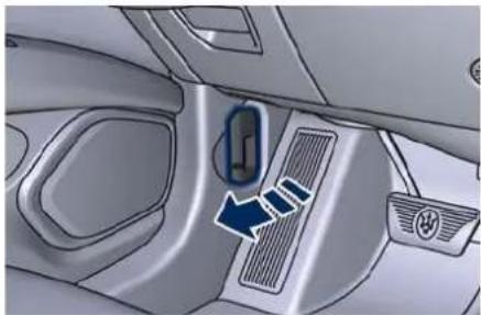
natural_image
Interior view of a car showing the air intake manifold and directional arrow (no text or symbols)- Move to the outside and stand in front of the vehicle front grille.
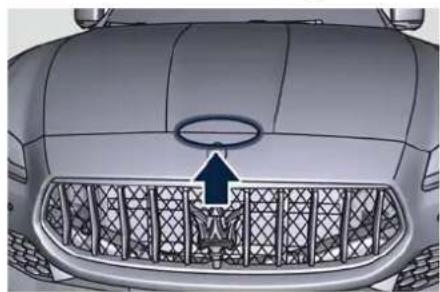
natural_image
Front view of a car grille with a logo and arrow symbol (no readable text or labels)- Slightly lift the hood and push the safety catch as indicated by the arrow. The safety catch is located in the center of the lid.
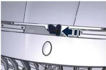
natural_image
Close-up of a car's front bumper with a blue arrow pointing to the side panel (no visible text or symbols)- Lift the hood completely: this operation is facilitated by two gas struts keeping the fully open position.
With the ignition device in RUN position, the red symbol with display on the instrument cluster with the message indicating that the hood is open.
Closing
Lower the hood and then drop it. This should secure the inclusion of both latches.

CAUTION!
To prevent possible damage, do not slam the hood to close it.

WARNING!
- Be sure the hood is fully latched before driving your vehicle. If the lid is not fully latched, it could open when the vehicle is in motion and block your vision. Failure to follow this warning could result in serious injury or death
- Gear shifting is always active and may be performed even when one or more doors, the hood or the boot lid are open. Therefore, in these conditions, take great care to avoid moving the gearshift lever and so accidentally engage gears.

Before Starting
4 - Dashboard Instruments and Controls
Instrument Cluster Overview ....
TFT Display Areas 91
TFT Display Pop up Messages.
TFT Display Setting and Menu Overview ....
TFT Display: Menu and Submenu Content .....
Warning and Indicator Lights . . . . . . . . . . . . . . . . . . . . . . . . . . . .
Maserati Intelligent Assistant™ Operation ....
Functions of Controls Menu on MIA 118
Functions of Settings Menu on MIA ....
Controls on Steering Wheel 129
Light Controls 132
Wipers and Washers Control ....
Analog Clock 142
Glove Box Compartments ....
Air Conditioning Controls 146

Dashboard Instruments and Controls
Instrument Cluster Overview
The instrument cluster is divided into three main areas.
A - Analogue speedometer. It indicates the vehicle speed and displays in its interior some of the main warning lights (see "Warning and Indicator Lights" in this section).
B - Analogue tachometer. It indicates the engine revolutions and displays in its interior some of the main warning lights (see "Warning and Indicator Lights" in this section).
C - TFT display. In this area are displayed all the other warning and indicator lights (see "Warning and Indicator Lights" in this section), information, signs and text and/or icon messages.
NOTE
The image shows the instrument cluster before starting the engine.
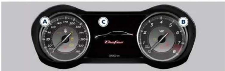
text_image
A 110 140 170 200 230 260 290 320 350 380 410 440 470 500 530 560 590 620 650 680 710 740 770 800 830 860 890 920 950 980 1010 1040 1070 1100 1130 1160 1190 1220 1250 1280 1310 1340 1370 1400 1430 1460 1490 1520 1550 1580 1610 1640 1670 1700 1730 1760 1790 1820 1850 1880 1910 1940 1970 2000 2030 2060 2090 2120 2150 2180 2210 2240 2270 2300 2330 2360 2390 2420 2450 2480 2510 2540 2570 2600 2630 2660 2690 2720 2750 2780 2810 2840 2870 2900 2930 2960 2990 3020 3050 3080 3110 3140 3170 3200 3230 3260 3290 3320 3350 3380 3410 3440 3470 3500 3530 3560 3590 3620 3650 3680 3710 3740 3770 3800 3830 3860 3890 3920 3950 3980 4010 4040 4070 4100 4130 4160 4190 4220 4250 4280 4310 4340 4370 4400 4430 4460 4490 4520 4550 4580 4610 4640 4670 47003.8 V8 TROFEO Version
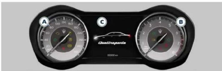
text_image
A B C Centropaste 00000 km3.0 V6 - 3.0 V6 AWD Version
Dashboard Instruments and Controls

TFT Display Areas
When operating, the TFT Display is divided into sectors including menus and sub-menus, running data, warning lights and messages represented in the example of picture.
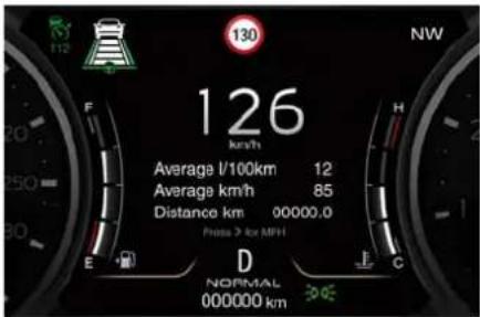
text_image
126 km/h Average l/100km 12 Average km/h 85 Distance km 00000.0 Press > for MPH D NORMAL 000000 kmThe presence of some areas depends on the type of equipment and the target market.
The different sectors of the display layout are rendered in the following picture.
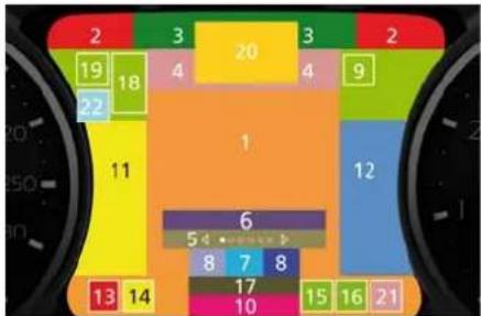
heatmap
| Value | Color | |---|---| | 1 | Orange | | 2 | Green | | 3 | Yellow | | 4 | Light Green | | 5 | Purple | | 6 | Blue | | 7 | Dark Blue | | 8 | Grey | | 9 | Light Green | | 10 | Pink | | 11 | Yellow | | 12 | Blue | | 13 | Red | | 14 | Red | | 15 | Light Pink | | 16 | Light Pink | | 17 | Dark Pink | | 18 | Light Green | | 19 | Light Green | | 20 | Yellow | | 21 | Light Pink |1 Main area.
2 Selectable information (data, time, outside temperature, compass, etc.). When setting the "Auto Dim High Beams" function, in the right portion of this area is displayed the respective indicator.
3 Main menu number and titles with scroll arrows (the number and the main menu title is always visible while scrolling the menu, and for the next five seconds).
4 Submenu titles.
5 Position within the submenus and scroll arrows (example: 1 of 5). There can be maximum 9 displayable submenu positions. When the number of submenu points exceeds 9, the points are replaced by a numerical value within the scroll arrows.
6 Menu Instruction (hideable).
7 Shift lever positions (P, R, N, D, M, 1, 2, 3...).
8 Gear shift indicator light and paddles (if equipped).
9 Hard or soft suspension and Launch Control (TROFEO version only) indicator light.
10 Complete odometer (total distance covered by the vehicle).
11 Fuel Gauge.
12 Engine Temperature Gauge.
13 Reconfigurable quadrant for red telltales
14 Reconfigurable quadrant for amber telltales.
15 Low beam headlights/position lights.
16 Speed Warning indicator (dynamic text).
17 NORMAL, I.C.E., SPORT and CORSA (TROFEO version only) modes indicator light.
18 Combined telltale of ACC, LKA and ADA status. They are displayed in the cluster when one (or more) of these systems is enabled and a different menu from "Drive Assist" is displayed in the main area.
19 CC and ACC status function.
20 Traffic Sign Assist icons: conditioned and unconditioned

Dashboard Instruments and Controls
speed limit and/or overtaking ban. See "Traffic Sign Assist - TSA" in section "Driver Assistance Systems" for further details.
21 Electric Parking Brake failure warning light.
22 BSA and ABSA status.

TFT Display Pop up Messages
The main area of the TFT displays is the one dedicated to "pop up" messages. These pop up messages fall into several categories.
The display background may change according to the type of pop up message displayed.
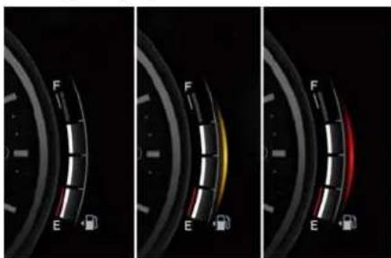
text_image
F E F E F E• No color: normal conditions.
- Yellow color: low-critical warning.
• Red color: high-critical warning.
Five-Second Stored Messages
When the appropriate conditions occur, this type of message appears on the main display area for five seconds and then returns to the previous screen. Most of the messages of this type are then stored (as long as the condition that activated them remains
active) and can be reviewed from the "Stored Messages" main menu item. Example of this message type is the one shown in the picture.
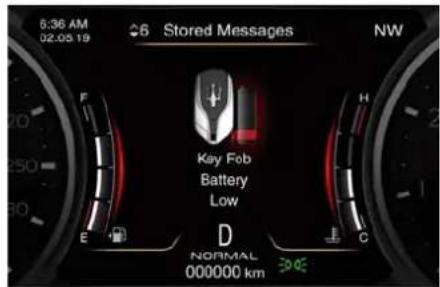
text_image
6:36 AM 02-05 19 Stored Messages NW F H Key Fob Battery Low D NORMAL 000000 kmUnstored Messages
Unstored Messages This message type is displayed until the condition that activated the message is cleared (see example in picture).
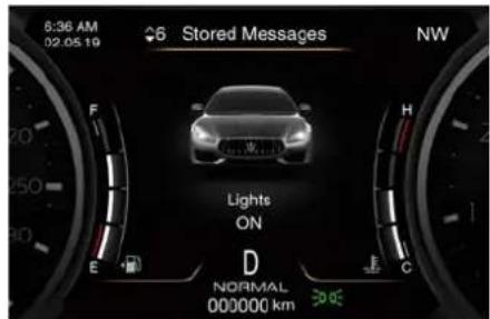
text_image
6:36 AM 02.05.19 Stored Messages NW Lights ON D NORMAL 000000 km E F H CUnstored Messages with Ignition Device in RUN
This message type is displayed until the ignition device is in RUN position. An example of this message type is the one shown in picture.
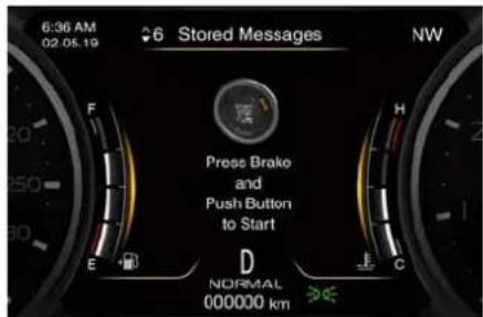
text_image
6:36 AM 02.05.19 Stored Messages NW Press Brake and Push Button to Start D NORMAL 000000 kmFive-Second Unstored Messages
When appropriate conditions occur, this type of message appears on the main display area for five seconds then returns to the previous screen.
Navigation Messages
When the navigation menu is enabled on the MIA, information pop-ups will be displayed for 5 seconds while changing direction or approaching a turning point.
On highway, the first pop up will be displayed at 3.2 km (2 miles) from the turn, on roadway, at 1.6 km (1 mile). While approaching the turn, further pop ups will be displayed starting at 400 m (437 yd) from the turning point and the countdown to 0 meters.
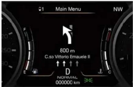
text_image
1 Main Menu NW 800 m C.so Vittorio Emauele II ↑ ↑ ↑ ↑ D NORMAL 000000 kmWhile getting closer to a turn, the sections referred to the distance already travelled will switch off while the ones referred to the distance yet to be travelled will remain on.
NOTE:
- Popup boxes might take up the spa normally used to display main menu items and relevant submenus.
- The distance indicated under the road name is expressed in the unit of measure set by the user.
TFT Display Setting and Menu Overview
Setting Controls
Operate the controls on the right side of the steering wheel to scroll, modify and program the main and submenu.
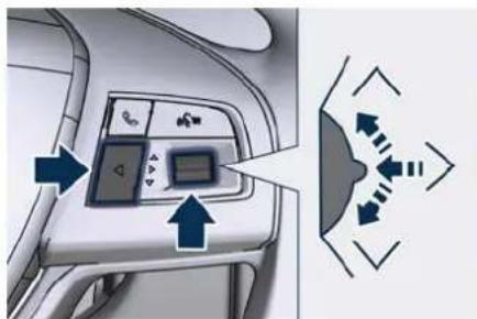
natural_image
Airplane control panel with directional arrows and icons, no visible text or symbolsPress and release the multifunction switch in the and arrow directions, corresponding to the same symbols on the TFT display, to scroll upwards and downwards the main menu titles.
The screen area in sector 1 (main area) will be updated and the selected title will be shown in sector 3 (main menu number and title).
Press and release the multifunction switch, corresponding to the same symbol and the indication "SELECT" on the TFT display, to enter the information screens or a submenu.

Dashboard Instruments and Controls
Keep the switch for 2 seconds to restore the selected/visualized functions.
The selected sub-menu title will be displayed in sector 4 (submenu titles).
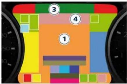
text_image
Diagram of a vehicle's front view with numbered sections and color-coded sections, likely illustrating a road or navigation system.Within a submenu, press and release the multifunction switch in the and ∨ arrow directions allow to scroll the menu.
Press the button, corresponding to the same symbol and the indication "EXIT" on the TFT display, to return to the main menu from an item of interest or from an information screen. When the driver selects a main menu page and the Traffic Sign Assist (TSA) function on "Vehicle" page of MIA is set off (see "Functions of Settings Menu on MIA" in this section), main menu title, its number and the scroll arrows will disappear after two seconds.
When driver selects a main menu, if the TSA function is set on and a sign and/or a speed limit icon is displayed in the sector 20, only the main menu number and the scroll arrows remain displayed in the sector 3 left side.
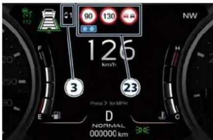
text_image
125 km/h 90 130 3 23 Press > for MPH D NORMAL 000000 km 30°C NWMenu Overview
1. MAIN MENU
• View speed in km/h or mph
2. VEHICLE INFO
- Drive Mode
- Tire Pressure
• Gauges: Transmission Temperature, Oil Temperature and Oil Pressure - Battery Voltage
- Maintenance
3. DRIVER ASSIST
• Shows a specific feedback referred only to ACC, LKA and ADA drive assist systems (for each of these
systems, see section "Driver Assistance Systems")
• LKA (LaneSense) status
4. TRIP & FUEL ECONOMY
- Trip A: Distance, Average (fuel economy), Average (speed), Elapsed time
- Trip B: Distance, Average (fuel economy), Average (speed), Elapsed time
- Fuel Economy: Current fuel economy bar graph, Range, Average (fuel economy)
5. START&STOP
- Messages relating to the Start&Stop function
6. STORED MESSAGES
7. VEHICLE SETTINGS
- Speed Warning: enables, disables or sets the speed limit represented in the dynamic icon on the TFT display
• Auto apply Off/On of the Electric Parking Brake - Passenger Air bag enable/disable
-
Screen Setup
-
Upper Left
- Upper Right
- Main Menu: Line 1
- Main Menu: Line 2
- Main Menu: Line 3
- MPH km/h Display On/Off
- Main Menu Navigation
Dashboard Instruments and Controls

- Audio: Radio, Media and Projection Mode
- Key-On Display
- Key-Off Display
- Defaults
How to Set TFT Display
To set the TFT display it is necessary to select the "Screen Setup" submenu from the "Vehicle Settings" menu, proceeding as follows.
After having entered the "Vehicle Settings" menu, press and release the multifunction switch in the √ arrow directions until "Screen Setup" is displayed.
Press and release the multifunction switch to access the available items for this submenu.
If the vehicle exceeds 8 km/h (5 mph), this function is unavailable and the main screen shows possible options in grey (not activable).
Operate this function with the vehicle stopped and transmission in P (Park) position.
In order to enter a function, press the multifunction switch.
The following directory shows the items available in this submenu:
Upper Left
- None
- Compass (only with navigation system)
- Outside Temperature (default: Upper Right)
- Date
• Time
• Time/Date (default: Upper Left) - Range to Empty
• Average L/100km or km/L (or MPG) - Current L/100km or km/L (or MPG)
- Trip A Distance
- Trip B Distance
Upper Right (example in picture)
- None
- Compass (only with navigation system)
- Outside Temperature (default: Upper Right)
- Date
• Time
• Time/Date (default: Upper Left)
- Range to Empty
• Average L/100km or km/L (or MPG)
- Current L/100km or km/L (or MPG)
- Trip A Distance
- Trip B Distance
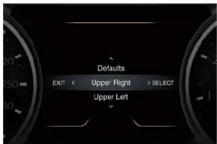
text_image
Defaults EXIT < Upper Right > SELECT Upper LeftMain Menu: Line 1 (only displays in Main Menu)
- None (default status)
- Compass (only with navigation system)
- Outside Temperature
- Date
- Time
- Time/Date
- Range to Empty
• Average L/100km or km/L (or MPG) - Current L/100km or km/L (or MPG)
- Trip A Distance
- Trip B Distance
- Audio
Main Menu: Line 2 (only displays in Main Menu)
- Same configurable options as Line 1
Main Menu: Line 3 (only displays in Main Menu)
- Same configurable options as Line 1
MPH km/h Display (instruction line)

Dashboard Instruments and Controls
• On
- Off
Main Menu Navigation
• On
- Off
Audio
• Radio: FM/AM frequencies
• Media: USB and Bluetooth® (text label only)
- Projection Mode: Apple CarPlay™ and Android Auto™ (text label only)
Key-On Display
• On
- Off
Key-Off Display
- On: Trip summary
- Off: screen with Maserati logo and trident
Defaults
- Restore
- Cancel
Scroll with the switch in the ∅ or ∨ arrow directions to view the selectable items (in the example "Time" is selected). A check mark will remain next to the previously-selected item until a new selection is made.
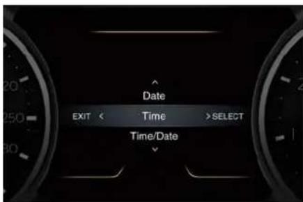
text_image
Date EXIT < Time >SELECT Time/DatePress and release the multifunction switch to select an item. The notification of setting saved appears as a popup for 2 seconds, then the display will show the last-modified item.
text_image
Settings SavedPress and release the Button to return to the "Screen Setup" submenu. "Screen Setup" submenu parameters set by the user as the ones to be displayed are also indicated in the top
part of the MIA (see example in the figures).
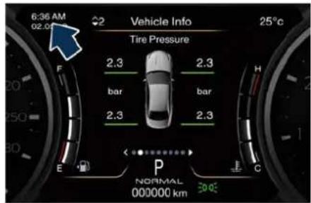
text_image
6:36 AM 02.04 Vehicle Info Tire Pressure 2.3 bar 2.3 bar 2.3 2.3 E P NORMAL 000000 km 30°C 25°C H C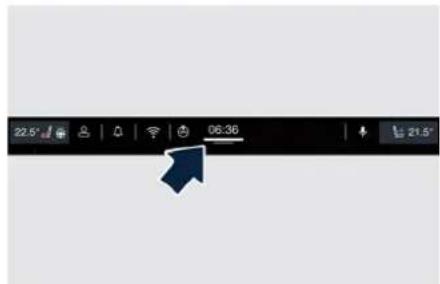
text_image
22:57 06:38 21:57As for the instruction line "MPH km/h Display", you can either select to display it in sector 6 or not ("Off" option). In the latter case, the function of changing units remains in any case active.
If the "Main Menu Navigation" is set to "On", navigation information will be displayed in the main area of the display only if a destination has been
Dashboard Instruments and Controls

set on the navigator of the MIA. If function is set to "Off", the navigation information will not be displayed.
"Key-On Display" and "Key-Off Display" items allow user to set display during vehicle key-on and off.
"Key-On Display" is normally set to "On". When entering the vehicle, after the welcome screen, the display will show the information concerning engine starting sequence. While if it is set to "Off" (example shown in figure), the display will show the information displayed before last vehicle key-off.
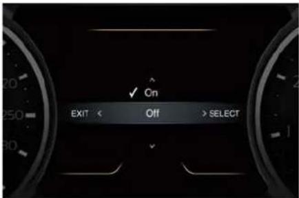
text_image
ON EXIT < Off > SELECTWhen engine is started and ignition device is pressed to stop it, it is possible to set "Key-Off Display", "On" or "Off" to obtain the following display settings:
- "On": Trip summary screen (Trip B is reset after each key-on/key-off cycle);
- "Off": screen with Maserati logo and trident.
The "Defaults" item of "Screen Setup" submenu allows restoring Maserati factory settings.
TFT Display: Menu and Submenu Content
1. MAIN MENU
Press and release the multifunction switch in the arrow directions until this menu item is displayed. Pressing and releasing the multifunction switch will toggle the unit of measure between km/h or mph.
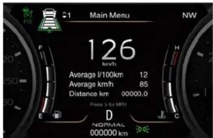
text_image
Main Menu NW 126 km/h Average l/100km 12 Average km/h 85 Distance km 00000.0 Press > for MFI D NORMAL 000000 kmFurther to speed, the main area can indicate three lines that can be set to the same options and in the top right or top left area. When these three lines are present and turn-by-turn navigation is on, main menu area will automatically show navigation information. For further details, please refer to Maserati Intelligent Assistant™ (MIA) guide.

Dashboard Instruments and Controls
Press and release the button to return to the main menu.
2. VEHICLE INFO
Press and release the multifunction switch in the k arrow directions until this menu item is displayed.
Press and release the switch to access the submenus.
Press and release the multifunction switch in the or arrow directions to scroll through the following information displays pressing and releasing the multifunction switch to display the selected information.
Drive mode
Press and release the multifunction switch in the arrow directions until this menu item is displayed. The screen graphically shows the Drive Mode: I.C.E., NORMAL, SPORT, CORSA (TROFEO version only) and (Suspension) set by the user through the relevant controls.
The display main area will show vehicle image with parameters and color-coded components affected by the selected drive mode.
The image will show the following parameters:
- torque distribution percentage indicated under the arrow in front of the wheels (on AWD version only); - selected drive mode (in the example shown: SPORT).
For any color-coded components, color depends on settings of:
• ESC: identified by wheel color.
- PowerTrain: identified by engine + transmission unit color.
- Suspension identified by the color of the four shock absorbers.
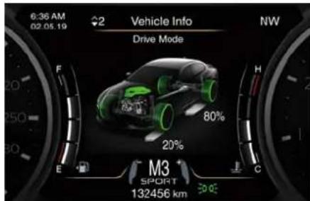
text_image
6:36 AM 02.05.19 2 Vehicle Info Drive Mode F H 20% 80% 20% M3 SPORT 132456 km C EFor every drive mode, function (ESC, PowerTrain and Suspension) and color of the components shown are matched as follows:
| Drive Mode | ESC | ||
| I.C.E. | |||
| NORMAL | |||
| SPORT | |||
| CORSA (*) | |||
| (*) TROFEO version only. | |||
NOTE:
To set drive parameters according to own needs and path, refer to chapter "Drive Mode" in section "Starting and Driving".
Press and release the button to return to the main menu.
Tire Pressure
Indicates the pressure of each single tire (see example below). For further information : chapter "Tire Pressure Monitoring System (TPMS)" in section "Safety".
Dashboard Instruments and Controls

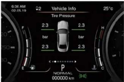
text_image
6:36 AM 02.05.19 2 Vehicle Info Tire Pressure 2.3 2.3 bar bar 2.3 2.3 E P C NORMAL 000000 km 25°CGauges
This screen shows the following parameters in bar graph form.
- Oil Pressure
Displays the current motor oil pressure level.
- Oil Temperature
Displays the current engine oil temperature level.
The gauge fill and telltale (if applicable) are highlighted in red to emphasise that the parameter is at a critical level.
NOTE:
This strategy is also applicable in the "Transmission Temperature" and "Oil Pressure" information screen.
• Transmission Temperature
Displays the current transmission temperature level.
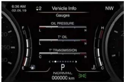
text_image
6:36 AM 02.05.19 2 Vehicle Info Gauges OIL PRESSURE L H T° OIL L H T° TRANSMISSION C H E P C NORMAL 000000 km NWBattery Voltage
Displays the current voltage of the 12V battery.

text_image
6:36 AM 02.05.19 Vehicle Info Battery Voltage 12.5 v L H E P NORMAL 000000 km 30.0° NWMaintenance
(service)
Displays mileage and days remaining to next frequency scheduled maintenance service.
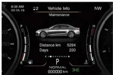
text_image
6:36 AM 02.05.19 Vehicle Info NW Maintenance Distance km 5284 Days 220 E P C NORMAL 000000 kmPress and release the button to return to the main menu.
3. DRIVER ASSIST
Press and release the multifunction switch in the arrow directions until this menu item is displayed. The screen graphically shows current status of activate driver assist systems: the figure shows an example with ACC and ADA ready and LKA engaged.
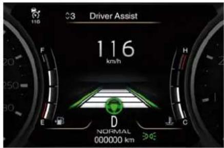
text_image
Driver Assist 116 km/h E D NORMAL 000000 km(Continued)

Dashboard Instruments and Controls
NOTE:
To set these systems, see chapters
"Adaptive Cruise Control - ACC",
"Active Driving Assist - ADA" and
"Lane Keeping Assist - LKA" in section
"Driver Assistance Systems".
Press and release the button to return to the main menu.
4. TRIP & FUEL ECONOMY
Press and release the multifunction switch in the or arrow directions until this menu item is displayed.
For each of the "Trip A" and "Trip B" sub-menus the screen will display the following:
- "Distance" traveled in km or miles. Shows the total covered distance since the last reset.
- "Average" consumption in L/100km, MPG (UK) or MPG (US). Shows the average fuel consumption since the last reset.
- "Average" speed in km/h or MPH. Shows the average speed since the last reset.
- "Elapsed Time". Shows the total time of travel since the last reset in "hours:minutes: seconds." Elapsed Time will increment when the
ignition device is in the RUN or START position.
Press the multifunction switch for 1 second and release to reset "Trip A" or "Trip B".
"Trip B" is reset after each key on/key off cycle.
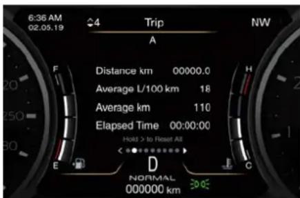
text_image
6:36 AM 02.05.19 4 Trip A Distance km 00000.0 Average L/100 km 18 Average km 110 Elapsed Time 00:00:00 Hold > to Reset All E D C NORMAL 000000 km 30.05The "Fuel Economy" screen will display the following:
Current fuel economy in L/100km, MPG (UK) or MPG (US)
Shows in bar graph form the current fuel economy. During AutoStop stage performed by the Start&Stop system (see "Normal Starting of the Engine" in section "Starting and Driving"), a dash will be displayed instead of the value.
Range in km or miles
Shows the range since the last fuel average reset.
When the fuel economy is reset, the display will read "Reset" or show dashes for two seconds.
Then, the history information will be erased, and the averaging will continue from the last fuel average reading before the reset.
Fuel economy average ("Avg.") in L/100km, MPG (UK) or MPG (US)
• Shows the average fuel economy since the last reset.
Press the multifunction switch for 1 second and release it to reset the fuel economy average.
When the fuel economy is reset, the display will read "Reset" or show dashes for two seconds.
Then, the history information will be erased, and the averaging will continue from the last fuel average reading before the reset.
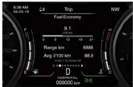
text_image
6:36 AM 02.05.19 4 Trip Fuel Economy 9.1 2100 km Range km 8888 Avg l/100 km 88.8 Hold > to Reset All E D F C NORMAL 000000 kmDashboard Instruments and Controls

Press and release the button to return to the main menu.
5. START & STOP
Press and release the multifunction switch in the or arrow directions until this menu item is displayed.
With the ignition device in RUN position, the screen will display the status of the function (see example in picture). To change the status of the function, please see chapter "Automatic Start&Stop System" of section "Starting and Driving".
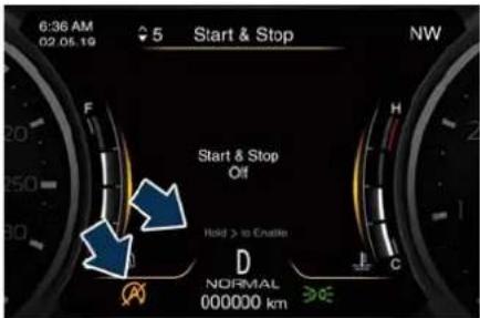
text_image
6:36 AM 02.05.19 5 Start & Stop NW Start & Stop Off Hold > to Enalte D NORMAL 000000 km ≥E6. STORED MESSAGES
Press and release the multifunction switch in the or arrow directions until this menu item is displayed.
The system will either display the number of the stored messages (if any available) or "No Stored Messages" if there are no stored messages.
Press and release the multifunction switch in the arrow directions to scroll the stored messages.
When the number of messages exceeds 9, the submenu points will be replaced by a numerical value indicating the message number. Press and release the multifunction switch > to view the selected message (see example in the picture).
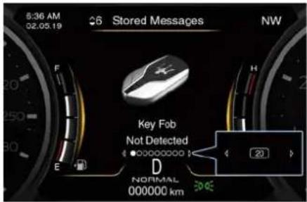
text_image
6:36 AM 02.05.19 Stored Messages NW Key Fob Not Detected D NORMAL 000000 km 20Press and release the button to return to the main menu.
7. VEHICLE SETTINGS
With ignition device in RUN position and vehicle stopped, press and release the multifunction switch in the
√ arrow directions until this menu item is displayed.
Press and release the multifunction switch to access the submenus.
Scroll with the multifunction switch in the or arrow directions to view the selectable items:
- Speed Warning: in order to set this function see example below.
- Electric Parking Brake: in order to modify the status of electric parking brake, see chapter "Parking Brake" in section "Starting and Driving".
- Passenger Air bag (if equipped): in order to modify the status of passenger air bag, : paragraph "Passenger's Air bag Deactivation" in "Supplemental Restraint Systems (SRS) – Air bag" in section "Safety".
- Screen Setup: see chapter "TFT Display Setting and Menu Overview" in this section.
Example to modify the "Speed Warning" status
NOTE:
• Minimum set speed: 30 km/h (18 mph).
• Maximum set speed: 280 km/h (174 mph).
When the vehicle is in motion (above 8 km/h - 5 mph) this function is available
(Continued)

Dashboard Instruments and Controls
(Continued)
and displayed in the list of "Vehicle Settings" menu.
Scroll with the multifunction switch in the arrow directions to view the selectable items.
Press and release the multifunction switch to select "Speed Warning".
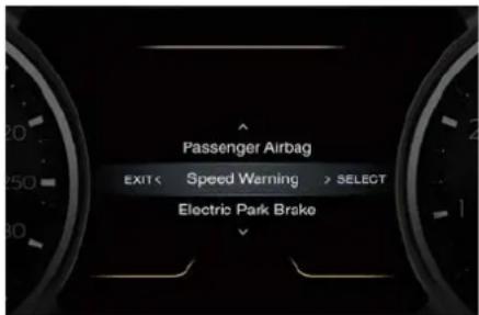
text_image
Passenger Airbag EXIT < Speed Warning > SELECT Electric Park BrakePress and release the multifunction switch once again to view the related options: "Off" is the default status.
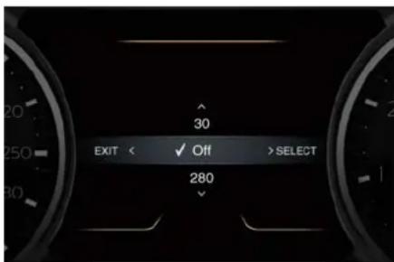
text_image
30 EXIT < ✓ Off > SELECT 280Scroll with the multifunction switch in the or arrow directions to view the selectable options.
Speed values are in loop, keeping the switch pressed in the or arrow directions will increase scroll speed in step of 5 km/h (5 mph).
Press and release the multifunction switch to select the option. A check mark will remain next to the previously-selected item until a new selection is made.
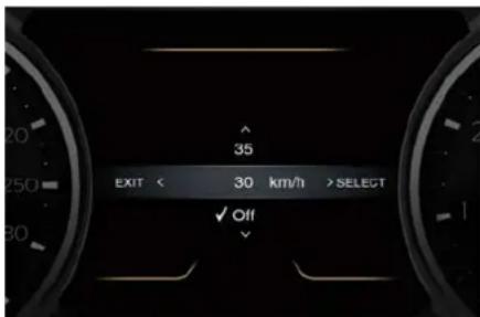
text_image
35 EXIT < 30 km/h > SELECT ✓ Off ✓A setting saved notification appears as a popup for 2 seconds and a white telltale indicating the set speed limit will appear on display.
text_image
Settings SavedThen the display will show the last modified item.
When the set speed is exceeded, the driver is alerted by an acoustic signal and the telltale indicating the speed limit becomes amber.
A pop-up message indicating that the limit has been exceeded will appear on display.
Dashboard Instruments and Controls

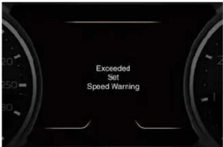
text_image
Exceeded Set Speed WarningThe pop-up message and the telltale will be displayed for 5 seconds then system will return to the previous screen.
Warning and Indicator Lights
Warning and Indicator Lights on Speedometer
Following tell tales are displayed on the speedometer, and related messages are visible for 5 seconds on the central sector of the display, unless otherwise indicated.
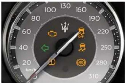
text_image
100 80 60 40 20 km/h 130 160 190 220 250 280 310Malfunction Indicator Light (MIL)

The Malfunction Indicator Light (MIL) is part of an onboard diagnostic system that monitors
engine and automatic transmission control systems.
Under normal conditions, this indicator light should switch on when the ignition device is in RUN position and switch off as soon as the engine is started.
This is a sign of the indicator light working properly. If the indicator remains lighted up or switches on while driving, there is a failure in the fuel supply/ignition and emission control systems.
The failure could cause high exhaust emissions, loss of performance, poor vehicle handling and high consumption levels.
Under these conditions you can proceed slowly without forcing the engine or driving at high speeds. The indicator light will switch off if the problem is solved.
The error will be registered by the system in any case.

CAUTION!
- When the ignition device is in the RUN position and if the indicator light does not switch on or if it switches on while driving, contact the Service Network as soon as possible.
- Prolonged driving with the MIL on could cause damage to the engine control system. It also could affect fuel economy and drivability. If the MIL is flashing, severe catalytic converter damage and power loss

Dashboard Instruments and Controls
may occur. Immediate service is required.
Left Turn Signal Indicator Light

This indicator lights up when the left turn signals or the hazard lights are turned on. The indicator light will flash
at the same frequency of the turn indicators and is controlled by the stalk switch lever.
If the vehicle electronics sense that the vehicle drives for more than 1.6 km (1 mile) with either turn signal on, a continuous sound will alert the driver to turn the signal off.
If the indicator flashes at a fast rate, check for a defective exterior light LED.
Tire Pressure Monitoring Light

This warning light is connected to the Tire Pressure Monitoring System (TPMS). Under normal
conditions, the warning light should illuminate when the ignition device is in RUN and should go off as soon as the engine is started.
If the warning light remains lit or illuminates while driving, the pressure of one or more tires is too low and a message will be displayed.
The TPMS malfunction indicator is connected to the low tire pressure monitoring light.
When the system detects a malfunction, the monitoring light and the related message will flash for approximately one minute and then remain lit.
This sequence will continue upon subsequent vehicle startups as long as the malfunction lasts.
When the malfunction indicator lights up, the system may not be able to detect or signal low tire pressure correctly.
For further information, : chapter "Tire Pressure Monitoring System (TPMS)" in section "Safety".
Anti-Lock Braking System (ABS) Malfunction Warning Light

This warning light, and its related message, indicate possible malfunctions of the
Anti-Lock Brake System (ABS).
The warning light will turn on when the ignition device is in RUN position and may stay on for 4 seconds. If the ABS warning light remains lit or turns on while driving, the Anti-Lock portion of the brake system is not functioning and requires service.
However, the conventional brake system will continue to operate
normally if the warning light is switched off. If the ABS warning light turns on while driving, or if it does not switch on when the ignition device is in RUN position, please visit as soon as possible a Service Center in order to restore the Anti-Lock brakes functions.
Electronic Stability Control (ESC) Activation/Malfunction Indicator Light

The ESC activation/malfunction indicator light on the instrument cluster will display
when the ignition device is in RUN position.
It should switch off by starting the engine.
If the light stays on with the engine running, there is a malfunction in the ESC system.
If the light still stays on after several ignition cycles, and the vehicle has been driven for several kilometers at more than 48 km/h (30 mph) speed, visit the Service Network as soon as possible to have the problem diagnosed and restored.
NOTE:
Each time the ignition device is in RUN:
- The ESC OFF indicator light and the ESC activation/malfunction
Dashboard Instruments and Controls

indicator light illuminates temporarily.
- The ESC system will be on, even if it was turned off previously. The ESC system will make buzzing or clicking sounds when active. This is normal; the sounds will stop when ESC becomes inactive by solving the problem that caused the ESC activation.
Electronic Stability Control (ESC) OFF Indicator Light

This indicator notifies that the Electronic Stability Control (ESC) is disabled; the linked
message will be displayed.
Warning and Indicator Lights on Tachometer
Following tell tales are displayed on the tachometer and related messages are visible for 5 seconds on the central sector of the display, unless otherwise indicated.
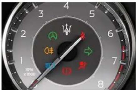
text_image
RPM x 1000Start&Stop Active Indicator Light

This indicator light indicates that the engine has been switched off automatically by
the Start&Stop system.
When the engine starts again, this indicator light will switch off. If the indicator light during an automatic engine shutdown (AutoStop) phase starts flashing, it will be necessary to restart the engine normally with the ignition device while holding down the brake pedal. See chapter "Normal Starting of the Engine" in section "Starting and Driving" for further information.
Rear Fog Indicator Light

This indicator lights up when the rear fog lights are switched on.
High Beam Indicator Light

This indicator lights up when the high beams are switched on or when blinking.
Brake Warning Light

This warning light monitors various brake functions, including brake fluid level and g brake engagement.
If the brake warning light illuminates the parking brake may be engaged, the brake fluid level mat be low or a problem with the anti-lock brake system (ABS) reservoir may have occurred.
In all the above situations, a related message will be displayed. If the warning light still illuminates when the parking brake has been disengaged, and the fluid level is at the full mark on the master cylinder reservoir, there could be a brake hydraulic system malfunction or a problem with the brake booster detected by the ABS/ESC system. If this occurs, the warning light will remain lit until the problem has been solved. If the problem concerns the brake booster, the ABS pump will run when engaging the brake and a brake pedal pulsation may be felt during each stop of the vehicle.

Dashboard Instruments and Controls
Inefficiency of one of the dual brake system cycle is indicated by the brake warning light, which will turn on when the brake fluid level in the master cylinder has dropped below a certain level.
The warning light will remain lit until the problem has been solved. If the brake warning light flashes for 10 seconds with the electric parking brake warning light and the related message on, an EPB system failure has occurred. If a brake failure occurs, visit the
Service Network as soon as possible in order to check up the brake system. In the event of an Electronic Brake Force Distribution (EBD) failure, both the brake warning light and the ABS light illuminate.
Immediate repair of the ABS system is required.
Functioning of the brake warning light can be checked by turning the ignition device from OFF to RUN position.
The warning light should illuminate for approximately 2 seconds.
The warning light should switch off unless the parking brake is engaged or a brake fault is detected. If the warning light does not illuminate, have the light system overhauled by the Service Network.
The warning light will also switch on when the parking brake is engaged with the ignition device in RUN position. This warning light only indicates the brake is engaged but not the clamping force of the parking brake to the wheels.

WARNING!
Driving a vehicle with the red brake light on can be very dangerous. Part of the brake system may have failed, resulting in increased braking distances and the risk of an accident. Have the vehicle checked as soon as possible at the Service Network.
Air bag Warning Light

This warning light will illuminate for a few seconds for a bulb check when the ignition
device is in RUN. If the warning light does not illuminate while starting the engine, stays lit, or switches on while driving, have the system checked at the Service Network as soon as possible.
In the latter case, the message will remain displayed: to hide it, press the button on the steering wheel right side.
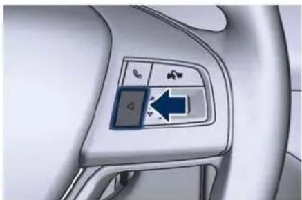
natural_image
Interior view of a car dashboard with a directional control panel and navigation icons (no text or symbols)For further information, : chapter "Supplemental Restraint System (SRS) – Air bags" in section "Safety".

WARNING!
If the warning light remains ON or if it does not illuminate or illuminates while driving, contact your Service Network as soon as possible.
Right Turn Signal Indicator Light

This indicator lights up when the right turn signals or the hazard lights are switched on.
The indicator light will flash at the same frequency of the turn indicators and is controlled by the multifunction lever behind the steering wheel. If the vehicle electronics sense that the vehicle drives for more than 1.6 km (1 mile) with either turn signal on, a
Dashboard Instruments and Controls

continuous sound will alert the driver to turn the signal off. If the indicator flashes at a fast rate, check for a defective exterior light LED.
Seat Belt Reminder Indicator Light

When the ignition device is in RUN, the seat belt reminder indicator light will light up for
a few seconds as a bulb check.
During the bulb check, you will hear an acoustic signal if one or both front seat belts are unbuckled.
After the bulb check or while driving, if driver or front passenger seat belt is unbuckled, together with the acoustic signal the seat belt reminder light will light up.
The SBR system monitors the condition of the seat belt buckled and unbuckled for all the passengers in the vehicle. The system visualizes this indicator light inside the tachometer and the state of each rear seat belt represented by the same symbol in red or green color on the upper part of the TFT.

WARNING!
Maserati urges you to use the seat belts correctly fastened and adjusted at all times. Correct use of the seat belts can help reduce the risk of serious injury in the event of an accident. Do not pass seat belts over sharp edges: they could tear. Do not pin anything to the seat belts. This could reduce their initial strength and cause them to tear in the event of a crash.
For further information, : chapter "Occupants Restraint Systems (ORS)" in section "Safety".
Warning and Indicator Lights on TFT Display
The relevant messages will be indicated within the main area for 5 seconds, unless otherwise specified. Fault messages will be stored under "Stored Messages".
Charging System Warning Light

This warning light shows the status of the electrical charging system. If the light stays on
or comes on while driving, turn off some of the vehicle's non-essential electrical devices or increase engine speed (if at idle). If the charging
system warning light remains on, it means that the vehicle is experiencing a problem with the charging system. Require IMMEDIATE service at the Service Network. If jump starting is required, refer to "Auxiliary Jump Start Procedure" in section "In an Emergency".
Transmission Temperature Warning Light

This warning light and the related message indicate that the transmission fluid
temperature is rising. If this warning light turns on, safely pull over and stop the vehicle. Then, shift the transmission into P (Park) and run the engine at idle until the temperature drops and the light switches off. If the problem persists, contact the Service Network.

CAUTION!
Continuous driving with the transmission temperature warning light illuminated will eventually cause severe transmission damage or failure.

Dashboard Instruments and Controls

WARNING!
If the transmission temperature warning light is illuminated and you continue operating the vehicle, in some circumstances you could cause the fluid to boil over, come in contact with hot engine or exhaust components and cause a fire.
Engine Temperature Warning Light

This warning light notifies when the engine is overheated. If the temperature reaches critical levels and the gauge displayed in sector 12, on the left side of the tachometer, turns red, this warning light under the engine temperature gauge indicator will illuminate in red color combined with the related message on display. When the temperature is reaching the set threshold an acoustic signal will be heard.
If the warning light switches on while driving, safely pull over and stop the vehicle. If the A/C system is on, turn it off. Also, shift the transmission into N (Neutral) and idle the vehicle. If the temperature does not return to normal, immediately turn the engine off and contact the Service Network Check "Engine Overheating" in
section "In an Emergency" for more information.
Low Oil Pressure Warning Light

Under normal conditions, the warning light illuminates when the ignition device is turned to RUN and goes off as soon as the engine is started.
If the warning light stays or turns on while driving, the engine oil pressure is too low. The warning light is combined with a displayed message and an acoustic signal that will last 4 minutes. In this case, turn the engine off immediately and carry out the necessary checks.
Do not operate the vehicle until the problem has been solved. This warning light does not indicate the oil level. The engine oil level must be checked with the dipstick located under the hood (see "Maintenance Procedures" in section "Maintenance and Care"). If the problem persists, contact the Service Network.
Engine Oil Temperature Warning Light

This light indicates that the engine oil is overheated. The warning light is combined
with the related displayed message. In this case, drive carefully until the
temperature drops back to normal level and the warning light turns off. If the problem persists, contact the Service Network.
Low Engine Oil Level Warning Light

This warning light and the related displayed message, indicate a low engine oil level.
The engine oil level must be checked with the dipstick fitted under the hood (see "Maintenance Procedures" in section "Maintenance and Care").
Electric Power Steering Failure Warning Light

This warning light, and the related message, illuminate when the electric power
steering is not operating and needs service.
If the warning light is on, steering assistance may be not available.

WARNING!
After battery disconnection event, the warning light may be on. In this case, start the engine and perform a steering wheel stroke to bottom in both senses.
If the problem persists, contact the Service Network.
Dashboard Instruments and Controls

Catalyst Over Temperature Warning Light

This warning light, and the related message, light up if the engine runs irregularly with
consequent high temperature in the exhaust system.

WARNING!
- If the warning light is accompanied by the message "Catalyst Temp Getting Hot Reduce Speed": the temperature of the catalytic converters is too high. The driver must slow down immediately until the warning light turns off.
- If the message "Catalyst Temp Hot Stop Safely Wait To Cool" appears after decelerating: the temperature in the catalytic converters has reached a dangerous level and the catalytic converters could be damaged. Drive slowly to the nearest Service Network.
- If the light turns on permanently 3 times the engine will stop. It will be possible to restart the vehicle only after a key-off / key-on cycle. Then slowly drive to the nearest Service Centre.
- Maserati declines all responsibility for whatever damage deriving from non-compliance with the above mentioned warnings.
Door Ajar Indicator Light
This indicator light illuminates on when one or more doors are ajar. The indicator light will show which door is ajar. When one or more doors are open, a related message will be displayed if the vehicle is running at a speed of 8 km/h (5 mph) or faster.
Boot Lid and Hood Ajar Indicator Lights

These indicators lights will illuminate to indicate that the boot lid and/or hood are ajar. When the boot lid or the hood is open, a related message will be displayed besides the
indicator light if the vehicle is running at speed 8 km/h (5 mph) or faster.
Traffic Sign Assist (TSA) Indicator Lights (-)

Speed limit unconditioned signs (in example: 130 Km/h), limiting condition aknoweledged (in example: snow), conditioned speed limit signs and overtaking ban are
displayed when the TSA function is active.
For further information, see "Traffic Sign Assist - TSA" in section "Driver Assistance Systems".
Seat Belt Reminder Indicator Light for Rear Passengers

At the beginning of each ignition cycle this indicator light up for 65 seconds in red to indicate the seat belts unbuckled in the rear seats, or in green to indicate those
buckled.
For further information, : chapter "Occupant Restraint Systems (ORS)" in section "Safety".
Electronic Throttle Control (ETC) Indicator Light

This indicator light indicates a failure of the Electronic Throttle Control (ETC) system. If
the indicator turns on while driving (a torque decrease is possible), have the system checked by the Service Network.
When detecting a failure, the light indicator will illuminate while the engine is running.
If the indicator remains lit with the engine running, you can still drive your

Dashboard Instruments and Controls
vehicle. However, contact the Service Network as soon as possible. If the indicator is flashing while the engine is running, immediate service is required. You may experience reduced performance, an elevated/rough idle or engine stall and your vehicle may require towing.
Speed Limit Primary Indicator (India market only)

This indicator, and the related message, illuminate when the vehicle speed exceeds 80 km/h
(50 mph) which is the speed limit established by law when traveling on the highways.
It goes off when the vehicle speed decreases by at least 5 km/h (3 mph) below the speed limit 80 km/h (50 mph).
Low Fuel Indicator Light

When the fuel level reaches approximately 16.0 litres (3.5 UK gal) this indicator light
under the fuel gauge indicator will turn on, and remain on until fuel is added together with the related message. In this condition the color indicating the quantity of fuel in the tank, inside the indicator light on display, will go from white to amber.
Refer to "Refuelling" in section "Starting and Driving" for fuel filling.
Windshield Washer Low Fluid Indicator Light

This indicator light will illuminate for 5 seconds to indicate a low level of the
windshield washer fluid. A related message will be displayed.
See "Maintenance Procedures" in section "Maintenance and Care" for fluid filling.
Headlight Aiming System Failure Warning Light

This warning light, and the related message, indicate a failure of the horizontal
levelling or electromechanical swivelling of the headlight system. Please contact the Service Network to check the system.
Advanced Frontlighting System (AFS) Failure Warning Light

This warning light and the related message light up to report a failure of the AFS
system.
Contact the Service Network as soon as possible.
Automatic High Beam Failure Warning Light

This warning light and the related message light up to report a failure of the
automatic high beam headlights.
Contact the Service Network as soon as possible.
Suspensions Failure Warning Light

This warning light and the related message turn on while driving if there is a failure of
the Skyhook suspension system.
Please contact the Service Network to check the system.
Ice Hazard Indicator Light

When the external temperature falls below 3°C (38°F), the temperature value
blinks for a few seconds, the warning light turns on, a message is displayed and an acoustic signal is triggered to warn the driver of the risk of icy roadbed.
Under such conditions, we recommend using the I.C.E. drive mode (see
"Automatic Transmission" in section
"Starting and Driving") drive carefully and slow down as the grip of the tires may be significantly reduced.
The warning light flashes for 5
seconds and switches off when the
Dashboard Instruments and Controls

temperature reaches 6^ C ( 43^ F) or higher.
Brake Pads Wear Warning Light

This warning light and the related message indicate that the brake pads have reached
their wear limit.
Please contact the Service Network to have them replaced.
Electric Parking Brake Failure Warning Light

This warning light and related message illuminate when there is an EPB system failure.
The failure could also completely or partially block the vehicle because the parking brake could remain on even after it has been automatically or manually disengaged though its controls.
If it is still possible to use the vehicle (parking brake not engaged) drive to the nearest Service Network and remember to perform each operation/command during which the electric parking brake does not work.
Start&Stop Disable Indicator Light

This indicator light illuminates when Start&Stop system is not available in the conditions
described in "Start&Stop Not Active" of the "Automatic Start&Stop System"
chapter, or the system is turned off through the hard button on the central console or through the controls on the right side of the steering wheel or the relevant soft-key on MIA.
See chapter "Automatic Start&Stop System" of section "Starting and Driving" for further information.
Start&Stop Failure Warning Light

This warning light illuminates when there is a failure in the Start&Stop system. Switch the
engine on or off using the normal procedure with the ignition device START/STOP and have the vehicle checked at a Service Network.
Scheduled Maintenance (Service) Indicator Light

This indicator light illuminates and a message flashes on the display after an acoustic signal
to indicate that the next scheduled maintenance is due or has already overdue.
Unless reset, the indicator light and message will continue to display each time you cycle the ignition device to the RUN position.
To turn off the message temporarily, press and release the button on the steering wheel. To reset the service indicator system, please visit a Service Centre.
Passenger's Air bag Deactivated Indicator Light (if equipped)

This warning light switches on when the passenger's airbag is deactivated. For
further information, : chapter
"Supplemental Restraint System (SRS) - Airbags" in section "Safety".
ADAS Status Indicator Lights

When you are not viewing the "Drive Assist" page, the indicator lights at top left-hand side of the display indicate status of individual ADAS system or the combination of
them (see examples).
For further details, refer to "Adaptive Cruise Control - ACC", "Lane Keeping Assist - LKA" and "Active Driving Assist - ADA" in section "Driver Assistance Systems".
Forward Collision Warning (FCW) Off

This warning light informs the driver that FCW is disabled. This might occur when front sensor
and/or the ACC/FCW system sensors are malfunctioning and need cleaning or servicing and when ACC/FCW system is not available due to a system error (for further details, refer to "Adaptive

Dashboard Instruments and Controls
Cruise Control - ACC" in section "Driver Assistance Systems"). This warning light will light even when the activation of another driver assistance function or drive mode (such as "ESC OFF") disables the FCW.
Forward Collision Warning (FCW) and Pedestrian Emergency Braking (PEB) Fault

This warning light informs that FCW and/or PEB is in fault state and autonomous
braking may not be available. If this occurred together with other specific messages, could mean that a system fault requiring servicing at the Service Network. It is nevertheless possible to drive the vehicle without using this function (for further details, refer to "Forward Collision Warning - FCW" in section "Driver Assistance Systems").
AWD Failure Warning Light (AWD version only)

This warning light turns on to indicate a fault of the AWD system otherwise a fault or
overheating due to excessive wheel spin. Contact the Service Network as soon as possible, and avoid using the vehicle in heavy duty conditions.
Passive Speed Limit Set

This indicator indicates the passive speed limit set via the controls on the RH side of the
steering wheel (for further details, refer to "TFT Display Settings and Menu Overview" in this section).
Passive Speed Limit Exceeded

This warning light informs the driver that the speed limit that was set has been exceeded.
Suspension Setting Indicator Light

This indicator light displays which suspensions setting (soft "S" or hard "H") is on. For
further details, refer to "Drive Mode" in section "Starting and Driving".
Drive Mode Indicator Light

Drive mode set by the driver through the controls on central console is displayed above the
transmission lever indicator (example in picture: NORMAL). For further details, refer to "Drive Mode" in section "Starting and Driving".
Cruise Control (CC) Ready or Canceled

This white indicator light will illuminate when the CC is ready to be set (with 3 dashes
below) and, once it sets, when it is temporarily canceled (set speed in
white below). For further information, check "Cruise Control - CC" in section "Driver Assistance Systems".
Cruise Control (CC) Set

This green indicator light will illuminate with the set speed when the CC is set and in driver
override. For further information, check "Cruise Control - CC" in section "Driver Assistance Systems".
Blind Spot Assist (BSA) or Active Blind Spot Assist (ABSA) Ready and Active

This white indicator light indicates that the BSA is in stand-by (ready): the same

indicator light in green color indicates that the system is active.
Active Blind Spot Assist (ABSA) Intervention

This amber indicator light indicates the intervention of the system on the steering to
avoid a potentially dangerous lane change.
For further information, see "Active Blind Spot Assistance - ABSA" in section "Driving Assistance systems".
Dashboard Instruments and Controls

Lane Keeping Assist (LKA) Fault

This warning light on indicates that the LKA system is in fault. If the warning light and the
relevant message do not go off after a few manoeuvres and eventually an ignition cycle, contact the Service Network.
Active Driving Assist (ADA) Fail

This warning light will turn on to indicate a failure of the ADA system.
Contact the Service Network as soon as possible avoiding using this system.
Adaptive Cruise Control (ACC) Ready or Canceled

This white indicator light indicates that the ACC is ready to be set (with 3 dashes below)
and, once it sets, when it is temporarily canceled (set speed in white below). For further details, refer to "Adaptive Cruise Control - ACC" in section "Driver Assistance Systems".
Adaptive Cruise Control (ACC) Set

This green indicator light with below the set speed turns on when the ACC is set (for further
details, refer to "Adaptive Cruise Control - ACC" in section "Driver
Assistance Systems") and vehicle will keep set speed.
Adaptive Cruise Control (ACC) Fault

This warning light turns on when ACC is not operating or needs servicing, For further
details, refer to "Adaptive Cruise Control - ACC" in section "Driver Assistance Systems".
Blind Spot Assist (BSA) and Active Blind Spot Assist (ABSA) Failure

This warning light and related message light on to report a failure of the BSA system. As
consequence, on vehicles equipped with ABSA also this latter will be not working or malfunctioning.
Contact the Service Network as soon as possible avoiding to use this system.
Low Beams On Indicator Light

This indicator light will illuminate when the low beams headlights are turned on.
For further details, see "External Lighting" in section "Understanding the Vehicle".
Headlight On Indicator Light

This indicator light will illuminate when the position lights or headlights are turned
on. For further details, see "External
Lighting" in section "Understanding the Vehicle".
Automatic High Beam On Indicator Light

This indicator light turn on when the "Auto Dim High Beams" function is set on MIA
(see "Functions of Settings Menu on MIA" in this section).
Gear Shift Indicator Light

This indicator lights up to indicate gear shift change in order to optimise fuel consumption.

See "Drive Mode" in section "Starting and Driving" for
further information.
Performance "Launch Control" Indicator Light (TROFEO version only)

This indicator lights up when the car is launched in the "Launch Control" performance
start procedure.
See chapter "Launch Control Mode" in section "Starting and Driving" for the activation procedure.

Dashboard Instruments and Controls
Maserati Intelligent Assistant™ Operation
General Notes
The vehicle is equipped with the infotainment Maserati Intelligent Assistant™ (MIA) system, an advanced user interface which combines innovative and exclusive technical functions integrating entertainment, user settings, air conditioning, navigation, communication functions within a single system. The MIA system features an audio system which is acoustically optimised for this specific vehicle.
Only the MIA functions related to driving and on-board comfort that the user can set are described in this manual; all other entertainment and communication functions are described in a specific guide called "Maserati Intelligent Assistant™ (MIA)". This guide also includes all warnings and precautions, which are essential for a safe use of the MIA system. Maserati advises you to read this guide carefully and thoroughly.
Manual Controls and Devices
The MIA display is positioned in the central part of the dashboard and the manual controls and devices
for multimedia and navigation and connect external sources are positioned on the central console. This manual controls are a further interface for the driver and nearby passenger, that adds to the MIA display soft-keys. Using the manual controls, the MIA display will work as a graphic display of the inputs from the controls.
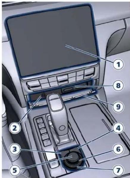
text_image
Diagram of car interior air intake system with numbered components for identification1 MIA touch display
The touch screen soft-keys allows to access to all available functions. When you touch an active area of the screen a visual feedback of active area's is linked to the touch event. It is valid for all active areas with or without long touch functionality. This feedback associated to the touching state highlight the icon or text label and apply an additional graphic shape. This strategy is valid for all the active areas of the display (soft-keys, main category bar, etc...) except the lists, the status bar and the draggable areas. To select a list item touch and release the screen or press the "BROWSE-ENTER" button in the central console.
2 Multimedia Ports
For further details, refer to "Internal Equipment" in section "Understanding the Vehicle".
3 "BROWSE/ENTER" button
In Radio/Media screen, after selecting a function using the tune/scroll knob or soft-keys on MIA display, press this button to see the detail of the items/options of the selected function. When in "Phone" page, open phonebook browse.
4 "MUTE" button
Press this button to mute the volume of the active sources.
Dashboard Instruments and Controls

5 ON/OFF button
Press this button to turn the MIA system on or off.
6 "VOLUME" control
Independently from currently shown MIA screen, turn this knob clockwise to increase the volume, counter-clockwise to decrease it.
When the volume control is adjusted through the "VOLUME" knob or the steering wheel control, a volume alert pop up will appear at the top of MIA screen. Volume alert shows the icon of the active source, the volume level bar with numerical value and the - and + soft-keys. Touch this soft-keys or press anywhere or drag the scrubber bar to decrease/increase the volume of the source highlighted.
Touching the drop down arrow on the right side of the volume alert to view and possibly change the volume level of the other sources (Media, Phone, Navigation and Voice Recognition).
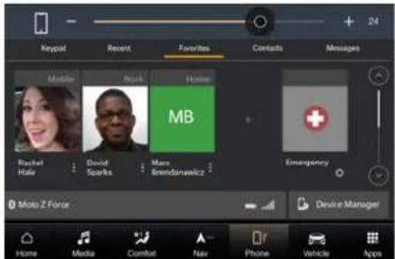
text_image
Keypial Recent Favorites Contacts Messages Mobile News Home MB Risabel Hale David Soanks Marc Brendsnawicz Emergency Moto Z Force Device Manager Home Media Comfort Nav Phone Vehicle AppsThe volume control pop up can be closed 5 seconds time out after last touch, touching anywhere outside of the pop up or touch the "X" soft-key on the upper right side.

text_image
Volume Settings MEDIA PHONE NAV WORK 40 24 38 38 Home Media Comfort New Phone Vehicle Apps7 "TUNE-SCROLL" control
When navigating a list, turn this knob clockwise to move the cursor downwards, or counter-clockwise to move it upwards. In any main screen, turn this knob to tune a Radio stations
up or down and to skip the previous or next track of Media source.
NOTE:
For more information on the other functions of these controls and devices, see "Maserati Intelligent Assistant™ (MIA)" guide included in the onboard documentation.
8 Phone drawer
Slide phone drawer.
9 Multimedia ports and phone housing door
Door for access to multimedia ports and phone housing with Wireless Charger.

Main Status Bar on MIA Display
Main status bar is set up by Maserati: some of soft-keys that make up the bar can be customised according to personal requirements, as explained in "Customising Main Status and Category Bar" in this chapter.
The composition of the main status bar is briefly indicated below. For further information, refer to the "Maserati Intelligent Assistant™ (MIA)" guide included in the on board documentation.

Dashboard Instruments and Controls
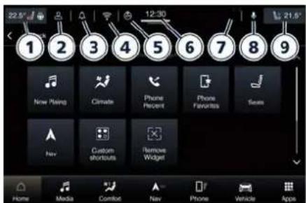
text_image
22.5% 1 2 3 4 5 6 7 8 9 New Rising Climate Phone Percent Phone Favorites Sees Hav Custom shortcuts Remove Widget Home Media Comfort Nav Phone Vehicle Apps1 Driver temperature and seat and steering wheel comfort functions (if equipped).
2 Profiles (customisable).
3 Notifications (customisable).
4 Wi-fi connection (customisable).
5 Geolocation.
6 Clock.
7 Status alert box.
8 Passenger Voice Recognition - VR (customisable).
9 Passenger temperature and seat comfort function (if equipped).
NOTE:
The images may represent a main status bar other than the one on your MIA.
Main Category Bar on MIA Display
The soft keys located on the lower part of the MIA display represent the default main categories, which are briefly indicated below. The figure shows the main menu bar of a car equipped with navigator.

text_image
12:30 Back Select A Manager New Painting Climate Phone Forward Phone Favorites Steels Box Custom shortcuts Password Widget Home Mobile Comfort New Show Window App ①②③④⑤⑥⑦Main category bar is set up by Maserati: it can be customised according to personal requirements, as explained in "Customising the Main Status and Category Bar" in this chapter.
To view the label of the soft-keys in the main category bar it is necessary to activate the "Show Main Category Labels" function in the "Display" submenu of the "Settings" screen of the "Vehicle" page.
NOTE:
The images may represent a main category bar other than the one on your MIA.
For further information on the "Home", "Media", "Nav", "Phone" and "Apps", refer to the "Maserati Intelligent Assistant™ (MIA)" guide included in the onboard documentation.
Touch one of these soft-keys to access the list of functions that the user can set.
1 "Home" soft-key
Touch this soft-key to enter the home page from which you can choose among all the available widgets the one to display the desired function.
2 "Media" soft-key
Touch this soft-key to access media sources such as: Radio, USB device and Bluetooth as long as the requested media is present.
3 "Comfort" soft-key
Touch this soft-key to access the air conditioning settings and the other comfort controls available: Heated Seats, Heated Steering Wheel and Ventilated Seats. See
Dashboard Instruments and Controls

"Air Conditioning Controls" in this section for further details.
4 "Nav" soft-key (if equipped)
Touch this soft-key to access the Navigation function.
5 "Phone" soft-key
Touch this soft-key to access the MIA Phone function that can be set or monitored via MIA.
6 "Vehicle" soft-key
Touch this soft-key to access the "Controls" and "Settings" menu from which to choose which the customer programmable functions of some driver assistance system (ADAS) to set up. Functions can be selected and adjusted or turned on/off by touching the related soft-key (see "Functions of Controls Menu on MIA" in this section).
7 "Apps" soft-key
Touch this soft-key to have access to the Apps page from which you can choose which app you want to display between "Favorites", "Recent", "Categories" and "All".
Switch Off Touch Screen Backlight If the screen backlight becomes annoying when driving, it is possible to switch it off pressing ON/OFF
button described in the "Manual Controls and Devices" of this chapter. The MIA touch screen can be turned off by touching the "Screen Off" soft-key in the "Controls" menu of the "Vehicle" page.
Touch screen Display Warnings

CAUTION!
- Do NOT attach any object to the touch screen, doing so can result in damage to the touch screen.
- Do not press the screen with any hard or sharp objects (pen, USB stick, jewelry, etc.) which could scratch the touch screen surface.
- Do not spray any liquid or caustic chemicals directly on the screen. Use a clean and dry microfibre lens cleaning cloth in order to clean the touch screen.
- If necessary, use a lint-free cloth dampened with a cleaning solution, such as isopropyl alcohol, or an isopropyl alcohol and water solution ratio of 50:50. Be sure to follow the solvent manufacturer's precautions and directions.
Customising the Main Status and Category Bar
The soft-keys for the main functions of the MIA system, indicated at the bottom of the MIA display and some of those on the main status bar can be easily customised to suit user's requirements, as follows:
- drag and drop the soft-key to move it inside the bar;
- touch the "Apps" soft-key to open applications/settings screen or access the screen with the function symbol to be inserted in the bar;
- drag and drop the icon corresponding to the selected function until it overlaps the one to be replaced on the top of the bottom bar.
Once it is set in the category bar, the new connection will be immediately operational.

Dashboard Instruments and Controls
Functions of Controls Menu on MIA
The MIA system uses a combination of keys able to access and change the customer programmable functions present in the "Controls" or "Settings" menu of the "Vehicle" screen page. A shortcut to set the customer programmable functions is available in the "Apps" screen page.
Once you enter the "Controls" screen, using the touch soft-keys or turn the "TUNE-SCROLL" knob to scroll and change settings of the customer programmable functions.
Touch the function soft-key or press the "BROWSE-ENTER" button to confirm the selection.
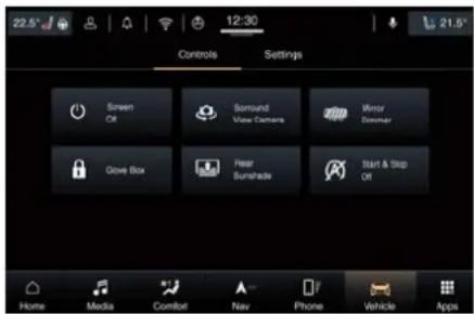
text_image
22.5° 12:30 Controls Settings Screen Off Sound View Camera Mirror Dommar Glove Box Fear Sunshade Start & Stop Off Home Media Comfort Nav Phone Vehicle AppsSome functions can be set only on or off touching the corresponding soft-key which will be highlighted with the
yellow outline (example: "Start&Stop Off").
Other functions can have one or more instruction/setting pages that are accessed by touching the corresponding soft-key (example: "Glove Box").
NOTE:
- All settings must be edited with ignition device set to RUN position.
- Some of the customer programmable functions are optional or for a specific model/version and may not be available on your vehicle.
- Only one touch screen area/soft-key may be selected at a time.
- Screen Off
This function allows you to switch off the MIA screen backlight if it becomes annoying when driving.
- Surround View Camera
Activating this function the system uses four cameras to monitor the area around the vehicle when transmission lever is shifted to P (Park), N (Neutral) or D (Drive) position.
When activation occurs by touching the "Surround View Camera" soft-key in the "Controls" screen or moving the shift lever in R (Reverse) position, the initial view will be the default view (associated with current gear state).
See "Surround View Camera System" in section "Driver Assistance Systems" for further details.
- Mirror Dimmer
The auto-dimming function can be disabled or re-enabled by touching this soft-key. See "Rear-View Mirrors" in section "Understanding the Vehicle" for further details.
- Glove Box
This function allows you to enter a 4-digit PIN code to lock and unlock the glove box in the passenger side of the dashboard.
See "Glove Box Compartment" in this section for further details.
- Rear Sunshade
This function allows you to open and close the sunshade on the rear window.
See "Rear Window" in section "Before Starting" for further details.
- Start&Stop Off
This function allows you to disable the Start&Stop when frequent stops and restarts of the engine may become annoying.
See "Automatic Start&Stop System" in section "Starting and Driving" for further details.

Dashboard Instruments and Controls

Functions of Settings Menu on MIA
The MIA system uses a combination of keys able to access and change the customer programmable functions present in the "Controls" or "Settings" menu of the "Vehicle" screen page.
A shortcut to set the customer programmable functions is available in the "Apps" screen page.
Once you enter the "Settings" screen, using the touch soft-keys or turn the "TUNE-SCROLL" knob to scroll and change settings of the customer programmable functions.
NOTE:
- All settings must be edited with ignition device set to RUN position.
- Some of the customer programmable functions are optional or for a specific model/version and may not be available on your vehicle.
- Only one touch screen area/soft-key may be selected at a time.
Modes for Setting a Function
To enter the desired function, touch the corresponding soft-key on the lateral list (the picture shown is "Display").
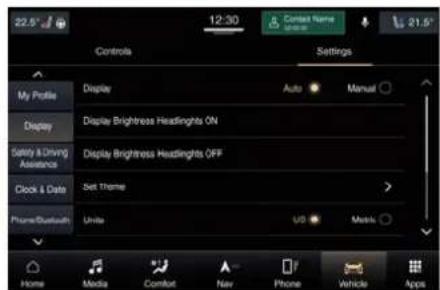
text_image
22.5° 12:30 Context Name Control Settings My Profile Display Auto Manual Display Display Brightress Headlights ON Safety & Driving Assistance Display Brightress Headlights OFF Clock & Date Set Theme Phone/Bluetooth Units US Mask Home Media Comfort Nav Phone Vehicle AppsTo scroll through the functions of the list, move the cursor up or down, or touch the arrow or until the function to be set is displayed. Touching the or soft keys and the cursor on the right side of the screen will allow you to scroll up or down through the available setting options. In this screen one or more boxes may indicate status or possible variants of the function. A check mark in a box indicates the active status of the function.
When in a setting line with many options:
- touching on the option currently not selected (no check mark in option) move the selector and change the option accordingly;
- touching on the option already selected (with selection) do not
perform action (maintain the option selection).
When in a setting line with one option only:
- if on/off setting (example: "Touchscreen Beep") touching on the option select/deselected the option (check mark appear/disappear). The same behavior is performed touching on the entire row area;
- if one-of-many option setting (example:"English" under "Language" function) touching on the option do not perform action (maintain the check mark). Also in this case, the same behavior is performed touching on the entire row area.
When in a function with +/- soft-key:
- if touch on the +/- soft-key, increase or decrease the value. Touching outside the +/- soft-key do not perform action;
- when the maximum value +/- is reached, +/- the soft-key turn grey.
Once the procedure is completed touch the back arrow to return to the previous menu or touch the upper right "X" soft-key, to close the settings screen.
In this mode the MIA system allows you to access the following programmable functions: Display,

Dashboard Instruments and Controls
Safety & Driving Assistant, Clock & Date, Phone/Bluetooth, Voice, Navigation, Camera, Mirrors & Wipers, Lights, Doors & Locks, Seats & Comfort, Key Off Options, Audio, Notifications, Radio Setup, Geolocation, Software Updates, System Information and Reset.
Display
Touch this soft-key to set the following modes.
- Language
When in this display, you can select one language for all display descriptions, including the trip functions and the navigation system (if equipped). The available languages are specific to the target markets.
- Display Mode
When in this display, you can select "Auto" or "Manual" mode.
- Display Brightness with Headlights On
When "Display Mode" function is in "Manual" mode, you can select the brightness with the headlights on (night condition). Adjust the brightness from level 0 to 10 with the "+" and "-" setting soft-keys or by selecting any point on the scale between the "+" and "-" soft-keys.
- Display Brightness with Headlights Off
When "Display Mode" is in "Manual" mode, you can select the brightness with the headlights off (day condition). Adjust the brightness as previously explained for "Headlights On" setting.
- Units
After touching the "Units" and then "Custom" soft-key on the touchscreen you may select between "Metric" and "US" units of measure. Each unit of measure can be independently displayed in the TFT Display and in the navigation system (if equipped). The following selectable units of measure are listed below:
- Speed unit: select from: "km/h" or "MPH".
- Distance unit: select from: "km" or "mi".
- Fuel Consumption unit: select from: "L/100km", "km/L", "MPG (UK)" and "MPG (US)".
- Pressure unit: select from: "kPa", "bar" or "psi".
- Temperature unit: select from: "°C" or "°F".
- Power unit:
select from: "kW", "HP (UK)" or "HP (US)".
- Torque unit: select from: "Nm" or "lb-ft".
- Touchscreen Beep
- Navigation Turn-by-Turn Displayed in Cluster
When in this display, you can turn on or shut off the sound activated by pressure of a touchscreen soft-key.
• Show Main Category Bar Labels By selecting this function, the system shows the labels on the soft-keys of the main category bar.
By selecting this function, the next turn direction will appear on the instrument cluster along a programmed route until the desired destination is reached (see picture).
- Phone Pop-ups Displayed in Cluster
When this mode is selected a pop up message will appear in case of incoming call. Information associated to call in progress are available by entering to the "Audio" menu using the buttons on the steering wheel RH side.
Dashboard Instruments and Controls

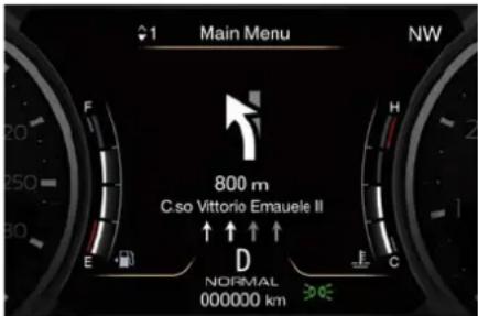
text_image
Main Menu NW 800 m C.so Vittorio Emauele II ↑ ↑ ↑ ↑ E D NORMAL 000000 kmSafety & Driving Assistant
Touch this soft-key to set the following modes.
• Forward Collision Warning / Pedestrian Emergency Braking
The FCW function primary use the front radar and the forward looking camera for sensing vehicle and pedestrian (if the car is equipped with Pedestrian Emergency Braking - PEB function) ahead, provide warnings to the driver and may perform brakings and brake jerks (if set).
FCW is always active: it is possible to set the warnings, the sensitivity and the aid of the active braking.
FCW warnings can be set in "Off", "Only Active Braking" (default mode) and "Warning + Active".
FCW sensitivity can be set to "Near", to "Med (Medium)" or to "Far".
The default status of FCW sensitivity is the "Med" setting.
FCW with active braking can be set to "On" or "Off".
See "Forward Collision Warning - FCW" in section "Driver Assistance Systems" for more details.
- Traffic Sign Assist
Activating this function the forward-facing digital camera, with the aid of maps on the navigation system, is able to detect signs (no overtaking, etc.) and speed limits. Those are displayed by the TSA system on the instrument cluster display together with a possible alert when the vehicle exceeds the speed limit.
See "Traffic Sign Assist - TSA" in section "Driver Assistance Systems" for further details.
- Lane Keeping Assist
Activating this function the LKA system will attempt to keep the vehicle in lane and can apply direct input to electric power steering system to change direction of vehicle. Driver warnings are "Visual & Haptic" (default mode).
System response can be set to "Early", "Medium" (default mode) and "Late".
System reaction force can be set to "Low", "Medium" (default mode) and "High".
See "Lane Keeping Assist - LKA" in section "Driver Assistance Systems" for more details.
- Blind Spot Alert
Activating this function the system will try to prevent collision between host vehicle and potential blind spot collision hazard.
This function can be set in "Off", "Lights" or "Lights + Chime".
See "Blind Spot Assist - BSA" in section "Driver Assistance Systems" for more details.
• Active Blind Spot Assist
Activating this function the system will try to prevent collision between host vehicle and potential blind spot collision hazard. System applies direct input to electric power steering system to change direction of vehicle to avoid collision.
Driver warnings can be only "Visual", "Visual & Acoustic" (default mode) or "Visual & Haptic".
System response can be set to "Early", "Medium" (default mode) and "Late".

Dashboard Instruments and Controls
System reaction force can be set to "Low", "Medium" (default mode) and "High".
See "Active Blind Spot Assist - ABSA" in section "Driver Assistance Systems" for more details.
- Park Assist
The park assist system will scan for objects behind and in front of the vehicle when the transmission shift lever is in R (Reverse) and the vehicle speed is less than 12 km/h (7.5 mph). The system can be enabled with "Sound Only", "Sound+Display", or turned "Off". See "Park Assist" in section "Driver Assistance Systems" for further information.
- ParkSense Front Sensors Active in Drive
If this function is active, when driver takes shift lever from P (Park) or N (Neutral) to D (Drive), front parking sensors are activated. If this function is not active, when driver takes shift lever from P (Park) or N (Neutral) to D (Drive), front parking sensors are NOT activated.
- Front ParkAssist Volume
When this function is selected, the chime volume of front park assist sensors can be set to "Low", "Medium" or "High" level. "Medium" is the default setting.
The system will retain its last known configuration state through ignition cycles.
- Rear ParkAssist Volume
When this function is selected, the chime volume of rear park assist sensors can be set to "Low", "Medium" or "High" level. "Medium" is the default setting. The system will retain its last known configuration state through ignition cycles.
Clock & Date
Time is always visible on the dashboard analog clock (see "Analog Clock" in this section) and in digital format on the instrument cluster and on the MIA display.
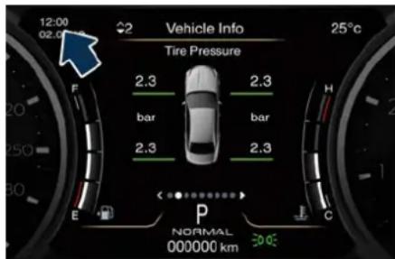
text_image
12:00 02.0 Vehicle Info 25°C Tire Pressure 2.3 bar bar 2.3 E P NORMAL 000000 km 30°C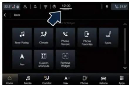
text_image
22.5° 12:00 Back Next A Widget Now Placing Climate Phone Percent Phone Favorites Sears New Custom shortcuts Remove Widget Home Media Comfort Nav Phone Vehicle AppsWith this function it is possible to view and set the following modes.
- Sync with GPS Time
Time is normally automatically synchronised with the radio signal. It is also possible to set automatic synchronisation mode using GPS signal instead.
- Set Time Hours
With "Sync with GPS Time" function unchecked and this mode selected, you can set the hours manually from 1 to 24. To select, touch the "+" or "-" soft-keys to adjust the hours.
- Set Time Minutes
With "Sync with GPS Time" function unchecked and this mode selected, you can set the minutes manually from 0 to 59. To select, touch the "+" or "-" soft-keys as done for the hours.
- Time Format
Dashboard Instruments and Controls

When in this mode, you can select the time format display. To change the current setting, touch and release the "12 Hrs" or "24 Hrs" soft-key.
• Show Time In Status Bar
This function will allow you to turn on or shut off the digital clock in the upper status bar.
- Set Date (in Cluster)
When in this mode, you can set the date manually in the upper status bar of the MIA and on the instrument cluster display. Touch the "+" or "-" soft-keys to adjust day, month and year.
Phone/Bluetooth
Touch this soft-key to select the function related to the connect phones.
- Device Manager
By selecting this function, when touch the "Phone" soft-key in the main category bar the system open the "Device Manager" page to manage the connected devices. - Do Not Disturb All
By selecting this function will block incoming texts, calls or both. - Enable Two Active Phones
By selecting this function the MIA system enable two phones connected via Bluetooth.
NOTE:
On the Maserati website, at www.maserati.com, or through the Maserati Service Network you may consult the list of telephones that are compatible with the MIA, and their level of compatibility.
- Phone Pop-ups Displayed in Cluster When this mode is selected a pop-up message will appear in case of incoming call. Information associated to call in progress are available by entering to the "Audio" menu using the buttons on the steering wheel RH side.
Voice
After touching this soft-key the following modes to give voice commands will be available.
- Voice Options
It is possible choose between "Female" or "Male" voice commands. - Wake Up Word
With the microphones in the listening mode, this function allows you to select the wake up word from the available options.
• Voice Barge-in
By selecting this function it is possible to respond to a voice response before the statement is completed.
• Show Command List
When this function is selected, it is possible to select options during a voice control session.
Navigation
Touch this soft-key to set the following modes.
• Show
- Map View
- Routing
- Sound & Alerts
- Other
Camera
Touch this soft-key to set the following modes.
- Surround View Camera Delay By selecting this function the image of surround camera is displayed on MIA screen.
- Surround View Camera Guidelines By selecting this function on the screen of the surround camera are displayed guidelines.
- ParkView Backup Camera Delay By selecting this function, when the shift lever is moved out of R (Reverse), the rear view image will be displayed for up to 10 seconds after

Dashboard Instruments and Controls
shifting unless the forward vehicle speed exceeds 12 km/h (8 mph).
- ParkView Backup Camera Active Guidelines
By selecting this function on the screen of the parkview backup camera are displayed active guidelines.
Mirrors & Wipers
Touch this soft-key to set the following modes.
- Tilt Side Mirrors In Reverse
By selecting this function the outside side-view mirrors will tilt downward when the ignition device is in RUN position and the transmission shift lever is in R (Reverse) position. The mirrors will move back to their previous position when the transmission is shifted out of R (Reverse).
• Auto Folding Side Mirrors
By selecting this function the rear-view mirrors automatically fold when the vehicle is locked by the key fob and when the power boot lid (if equipped) is closed and locked by pressing the button on the outer ledge of the left boot compartment lining. When the vehicle and the boot lid will be unlocked, the rear-view mirrors will automatically open
in the position they had before the lock.
If the mirrors were manually folded by the switch on the driver's door panel, before a lock action, they will need to be manually unfold to reactivate the automatic behave.
- Rain Sensing Auto Wipers
By selecting this function, the system will automatically activate the windshield wipers if the rain sensor senses moisture on the windshield.
• Headlights with Wipers
By selecting this function, while the headlight lever is in "AUTO" position, the headlight will turn on approximately 10 seconds after the wipers are activated. The headlight will also turn off when the wipers deactivate if they were activated in the current mode.
Lights
Press the "Lights" soft-key to set the following modes.
- Headlight Off Delay
By selecting this function, the driver can choose to have the headlight off or lit for 30, 60, or 90 seconds when the engine is shut off. To change the current headlight off delay status, touch and release the "0", "30", "60"
or "90" soft-key to select the desired time range.
- Adaptive Front Lights
By selecting this function, the driver can set the light sensor by choosing between "on" or "off".
- Headlights Illuminated on Approach By selecting this function, the driver can choose to have the headlight off or lit for 30, 60, or 90 seconds when the doors are unlocked with the key fob.
• Headlights with Wipers
By selecting this function, while the headlight lever is in "AUTO" position, the headlight will turn on approximately 10 seconds after the wipers are activated. The headlight will also turn off when the wipers deactivate if they were activated in the current mode.
• Auto Dim High Beams
By selecting this function, the high beam headlight will deactivate automatically under certain conditions. See "External Lighting" in section "Understanding the Vehicle" for further information.
- Headlight Dip (right/left-hand drive) By selecting this function, the headlights will change their light distribution when a left-hand-drive
Dashboard Instruments and Controls

vehicle enter a Country with right-hand-drive system and vice versa.
- Flash Lights with Lock By selecting this function, the headlights will flash when the doors are locked or unlocked with the key fob or when using the "Passive Entry" function.
Doors & Locks
Touch this soft-key to set the following modes.
• Auto Door Locks
When this function is selected, all doors will automatically lock when the vehicle is in motion.
• Auto Unlock on Exit
By selecting this function, all doors will unlock when the vehicle is stopped, the transmission is in P (Park) or N (Neutral) position and the driver's door is open.
- Flash Lights with Lock
By selecting this function, the headlights will flash when the doors are locked or unlocked with the key fob or when using the "Passive Entry" function.
• Sound Horn with Lock (where available)
When this function is selected, the horn will sound when the doors are
locked with the key fob. You can choose from the following options: "Off" (no sound), "1 ^st Press" (sound on the first press of the button) and "2 ^nd Press" (sound on the second press of the button).
- Sound Horn with Remote Start When this function is selected, the horn will sound when you use the key fob to start the engine. The function can be set to "On" or "Off". See "Remote Start System" in section "Starting and Driving" for further details.
- 1st Press of Key Fob Unlock By selecting this function you may set up only the driver's door or all doors mode will unlock on the first press of the key fob button. When "Driver Door" is selected, you must press the key fob button twice to unlock also the passenger's doors. When unlocking "All Doors" by first press selection mode, all doors will unlock on the first press of the key fob button.
- Passive Entry
This function allows you to lock and unlock the vehicle door(s) without having to push the key fob buttons. By selecting this function, "Passive Entry" may be set to "On"
or "Off". The default status is "On". With "Passive Entry" deactivated, also the "Pre-Short Drop" function is disabled (for further information, refer to "Bodywork Maintenance and Care" in section "Maintenance and Care").
- Personal Settings Linked to Key Fob This selected mode enables to combine the key fob to personal driver's position settings. These settings will be implemented when pressing the button on the key fob with ignition device in RUN position.
- Hands Free Power Liftgate
To prevent the accidental opening of the power boot lid with Hands Free function (with the movement of the foot, it is possible to disable this function. This operation is recommended when you have to wash the car (for further information, refer to "Open and Close the Boot Lid" in section "Before Starting").
Seat & Comfort
Press this soft-key to set the following modes.
- Easy Exit Seats
When this function is selected, the driver's seat will automatically move

Dashboard Instruments and Controls
rearward once the engine is shut off for easy exit of the vehicle.
- Auto-on Driver Heated/Vented Seat & Steering Wheel
This function allows to activate the comfort of the driving seat when starting the engine.
If equipped, the driver's heated/vented seat and/or heated steering wheel will automatically activate by temperatures below 4°C (40°F). When temperatures are above 26°C (80°F) the driver vented seat will turn on.
If the vehicle is equipped with the remote start system, you can choose from the following options: "Off", "Remote Start" (activation of this function when you use the key fob to start the engine) and "All Starts" (activation of this function when you start the engine in all modes).
Key Off Options
This function allows you to set some functions after turning off the engine.
- Easy Exit Seats
When this function is selected, the driver's seat will automatically move rearward once the engine is shut off for easy exit of the vehicle.
• Key Off Power Delay (power duration after engine shutdown)
By selecting this function, the power window switches, radio, MIA Phone System, power sunroof (if equipped), and power outlets will remain active for up to 10 minutes after turning off the engine. Opening of one front doors will cancel this function.
The switch-off delay can be cancelled (0 seconds) you can choose from 45 seconds, 5 minutes or 10 minutes.
• Headlight Off Delay
By selecting this function the headlight will stay lit for up to 90 seconds after turning off the engine.
The switch-off delay can be cancelled (0 seconds) or reduced to 60 or 30 seconds.
Audio
This function enables to view and set the available audio modes depending on the type of audio system supplied on the car.
- Audio Settings
Touch this function to open the subscreen with all the audio settings items.
The following settings refer to the "High Premium" audio system.
• Balance/Fade
Use this screen to adjust the balance and fade settings. Touch and drag the speaker icon, use the arrows to
adjust, or tap the "C" icon to readjust to the centre.
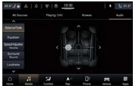
text_image
22.5° 12:30 21.5° All Sources Playing: DAE Browse Audio Balance/Fade Equalizer Speed Adjusted Volume Surround Sound Loudness Home Media Comfort Nav Phone Vehicle Apps- Equalizer
Use this screen is used to adjust the "Bass", "Mid" and "Treb" settings.
Adjust the settings with the "+" and "-" setting soft-keys or scroll and touch the slider in any point on the scale between the "+" and "-" soft-keys.
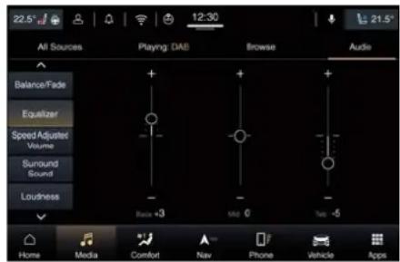
text_image
22.5° 12:30 21.5° All Sources Playing: DAB Browse Audie Balance/Fade Equalizer Speed Adjusted Volume Surround Sound Loudness Basic -3 Mid 0 Tet -5 Home Media Comfort Nav Phone Vehicle Apps• Speed Adjusted Volume
Dashboard Instruments and Controls

This function increases or decreases volume combined to vehicle speed. To change the speed adjusted volume touch the "Off", "1", "2" or "3" soft-key.
- Surround Sound
This function provides simulated surround sound mode. Available settings: "On" and "Off".
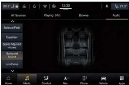
text_image
22.5° 12:30 21.5° All Sources Playing: DAB Browse Audio Balance/Fade Equalizer Speed Adjusted Volume Surround Sound Loudness Home Media Comfort New Phone Vehicle Apps- Auto Play
When a portable device is connected via Wireless Charger or USB port to MIA system, it plays automatically the songs if this function is set to "On".
- Clari-Fi
This function improves the audio quality by enhancing digitally compressed source files such as MP3 and AAC files and certain music tracks played by radio stations. In case of high-definition source files, Clari-Fi shall apply no enhancement.
Clari-Fi intervention is completely automatic.
Notification
Touch this soft-key to set the following modes.
- App Drawer Favoriting Popups By selecting this function is possible turns on and off popup for "App Favorited".
- App Drawer Unfavoriting Popups By selecting this function is possible turns on and off popup for "App Unfavorited".
- New Text Message Popups
By selecting this function is possible turns on and off receiving/storing a popup for new text messages of any connected phone.
- Missed Calls Message
By selecting this function is possible turns on and off receiving/storing a popup for missed calls of any connected phone.
- Navigation Popups
By selecting this function is possible turns on and off receiving/storing predictive Navigation popups and any other Navigation popups that can be turned off.
• Wireless Charger Status Pop-ups
Display Wireless Charger status pop-ups on the MIA screen.
- Drive Mode Transition Popups
Radio Setup
Touch this soft-key to set some listening options.
• Traffic Announcement By selecting this function the system pauses receivers and media that issue traffic reports.
- DAB Announcement (if supported) Digital radio extends the selection of stations, adding also numerous specialty channels. By selecting the DAB type of frequency you may listen to connection type announcements and announcement categories.
- DAB Announcement Categories By selecting DAB Announcements Categories (if supported) are displayed additional Categories such as: alarm, traffic announcement, etc... All these items can be set to "On" or "Off".
• Regional By selecting this function the system forces regional services enabling the automatic switching to networked stations.

Dashboard Instruments and Controls
Geolocation
Touch this soft-key to set the following modes.
- Geolocation
By selecting this function is possible disables or re-enables the GPS tracking in the vehicle.
Software Updates
Touch this soft-key to set the following modes.
- Software Downloads over Wi-Fi By selecting this function you can download the MIA software via Wi-Fi.
System Information
Touch this soft-key to set the following modes.
- Version Information
By selecting this function you can access the data page relating to the software version installed on MIA.
- License Information
Reset
Touch this soft-key to set the functions which allow you to reset data, Apps and password used by MIA system.
- Restart Radio
- Reset App Drawer to Default Order By selecting this function a popup will appear asking user to confirm
App Drawer resetting. Select "Yes" to restore, or "Cancel" and "X" to close the popup without reset the App Drawer.
- Restore Apps
By selecting this function a popup will appear asking user that the function is not available for speeds above 8 km/h (5MPH). If speed is less than 8 km/h (5MPH) or the vehicle is stationary and you want to restore all the Apps because there have been problems of use or installation, touch the "Next" soft-key and then "Yes". Otherwise touch "Cancel" or "Back" to cancel the operation.
When this function is selected, it will reset the "Clock", "Audio", and "Radio" settings to their default settings.
Run this function and a pop up will appear asking user to confirm default settings resetting. Select "Yes" to restore, or "Cancel" and "X" to exit. Once the settings are restored, a pop up appears confirming that settings have been reset to default and then the MIA will restart.
- Clear Personal Data
When this function is selected, it will remove personal data concerning settings and/or options that have
been modified compared to factory settings and will also remove from system memory Bluetooth devices, Apps and presets.
To remove personal information, select this function and a pop up will appear asking confirmation to delete all personal data. Select "Yes" to clear, or "Cancel" and "X" to exit. Once the data have been cleared, a pop up appears confirming that personal data have been cleared and then the MIA will restart.
- Reset Wi-Fi Password for Projection By selecting this function a popup will appear with the request to confirm the intention to change the Wi-Fi password. Select "Yes" and then "OK" to reset the password, or "Cancel" and "X" to close the popup without reset the Wi-Fi password.
- Factory Reset
Selecting this function a popup will appear with the request to confirm the intention to reset the MIA to the factory defaults. The "Yes" choice will cause the MIA to restart and the backup camera, the radio, SOS Call and several driving assistance functions will not available. This could take several minutes. Select "Cancel" or "X" to close the popup without reset the factory defaults.
Dashboard Instruments and Controls

Controls on Steering Wheel
ADAS Controls
The controls on the left side of the steering wheel are dedicated to ADAS systems and their presence and layout depend on the car's options.
The "Standard Configuration", in addition to the multifunction switch 1, includes the control of the Cruise Control (CC) 2 system.
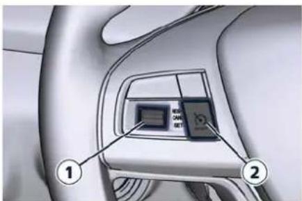
text_image
1 2Standard Configuration
The "Optional Configuration", in addition to the multifunction switch 1 includes the ON/OFF Adaptive Cruise Control (ACC) button 3, the button 4 to set the ACC time gap to the sensed vehicle ahead and can include the Active Driving Assist (ADA) ON/OFF button 5. The two ACC controls also allow the switching on and off of the CC.
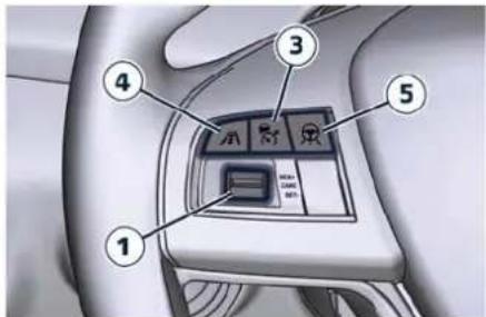
text_image
Diagram of car interior control panel with numbered labels pointing to key buttons and indicatorsOptional Configuration
For all information on the use of these commands, see the chapters on the individual ADAS systems in the section "Driver Assistance Systems".
Phone and Voice Controls
The controls on the right side of the steering wheel activate/deactivate the phone mode ( ) and the Voice Recognition ( ) functions.
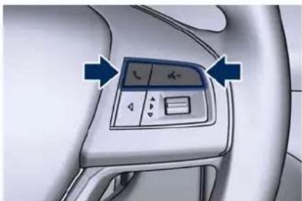
natural_image
Interior view of a car dashboard with a digital control panel and directional arrows (no text or symbols visible)These functions are only available when one or more Bluetooth® compatible mobile phones are paired with the MIA system connection.
To pair a phone and to learn all available functions refer to the "Maserati Intelligent Assistant™ (MIA)" guide.
NOTE:
On the Maserati website, at www.maserati.com, or through the Maserati Service Network you may consult the list of telephones that are compatible with the MIA, and their level of compatibility.
The voice command communication system is fully integrated with the vehicle's audio system.
The volume can be adjusted from the "VOLUME" upper knob on the central console (see "Maserati Intelligent
Assistant™ Operation" in this section)

Dashboard Instruments and Controls
or from the steering wheel audio controls described in this chapter. The system will automatically mute the radio when using the phone mode. When activating the phone mode using voice commands with speakerphone, you should talk quietly in a normal conversional tone by keeping the driving position and turning to the microphone of the voice command system located inside the internal rear-view mirror.
The ability of the system voice control to recognise the user's voice commands can be invalidated when speaking too quickly or too loudly.

WARNING!
Any voice-controlled system should be used only in safe driving conditions following all applicable regulations. Full attention should be kept on driving. Failure to do so may result in a collision causing serious injury or death.
Phone Mode Button
By using the phone button on the steering wheel it is possible to: activate the phone mode, start a call, show recent incoming and outgoing calls, show contacts list, etc.
text_image
6:36 AM 02.05.19 Main Menu NW Incoming Call: Lorem Ipsum P NORMAL 000000 kmTouching the active call soft-key on the main category bar, the "Phone" page will open (see example in picture).
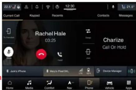
text_image
22.5° Current Call Keypad Recents 12:30 Contacts Messages Rachel Hale 03:25 Snap Charize Call On Hold Jack's iPhone May's Pixel 3XL LTE Device Manager Home Media Comfort Nav Phone Vehicle AppsWhen pressing the phone button an audible sound will invite you to impart a command.
Information on incoming call is indicated in a pop-up on instrument cluster display main area if this function is checkmarked on MIA (see "Functions of Settings Menu on MIA"
in this section). Said information will stay displayed until a control is executed (e.g.: answer, reject, etc.) for the incoming call.
The screen will only display the phone number or name of caller (if available) as long as this complies with system specifications in terms of font and number of characters.
Call details can be displayed at any time through "Audio" submenu item. "Phone: call details" using the buttons on steering wheel RH side. On display, said details shall temporarily replace the ones on media source in use.
Voice Recognition Button
The short pressure of the VR button on the steering wheel allows you to give voice commands dedicated to all the native functions of the MIA (radio, media, navigator, climate, etc.). Excluded are all functions that interact with the Apps: "Apple CarPlay", "Android Auto" and "Baidu CarLife" or those of the voice assistants: Siri, Google Voice, etc..., supported on the mobile paired via Bluetooth® to the MIA.
The voice assistant of Baidu is not available with mobile paired via Bluetooth® to the MIA because
Dashboard Instruments and Controls

Baidu CarLife™ is a projection mode application.
A long pressure of the VR Button, in addition to the native ones of the MIA, allows to give voice commands dedicated to the above mentioned Apps and voice assistants.
NOTE:
The pressure difference of the VR button (short or long) is effective only when the mobile is paired via Bluetooth® to the MIA.
On the markets where it is available, once voice recognition is activated via the VR button on the steering wheel, a "teleprompter" screen is displayed on the MIA with a list of commands specific to each active function key shown on the vertical menu bar in the left side of the screen.
The teleprompter screen shall always open at the "Suggested" menu (see example in picture). Selecting a different menu will bring up commands within that menu.
The key words to activate the dialog are white, the variable ones gray between the symbols "<>" and the alternative ones after the slash "/".
Touching voice help soft-key the help response will be reproduced. It will have the same function as
saying help. If the dialogue is paused, at the end of the help prompt the teleprompter will return to the listening status.
Touching setting soft-key the voice session will be canceled and will open the voice settings page.
At the top center of the teleprompter screen is displayed an animation representing the listening, processing and speaking state. While in the listening state, the animation will react to the microphone input: when in speaking state, will react to the prompt.
Touch the "Cancel" soft-key to end the voice dialog and close the teleprompter screen.
Touching one of the soft-key on the main category bar, the session is cancelled and displays the selected category screen.
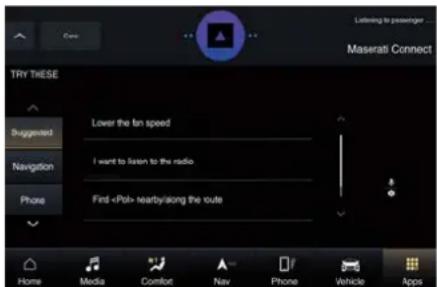
text_image
TRY THESE Suggestion Lower the fan speed Navigation I want to listen to the radio. Phone Find «Pah» nearby/along the route Home Media Comfort Nav Phone Vehicle AppsWhen pressing the VR button an acoustic signal will invite to give a voice command.
NOTE:
For further details refer to the "Maserati Intelligent Assistant™ (MIA)" guide.
Siri Smart Personal Assistant
When a compatible iPhone or iPad that supports Siri voice recognition is paired to the vehicle via Bluetooth, a long press of the VR button activates the Siri Smart Personal Assistant.
Siri requires mobile internet access and its functionality might change depending on the geographical area. Through simple voice commands, without taking your eyes off the road, it may be possible to send messages, make phone calls, create notes and reminders, etc.
Audio System Controls
The vehicle is equipped with audio controls which allows the driver to operate the audio system. These controls can be used to adjust audio volume, change radio station or mode (FM, AM, USB, etc).
These audio controls are rocker-type switches with a button in the center

Dashboard Instruments and Controls
and are located on the rear side of the steering wheel, right behind the front switches.
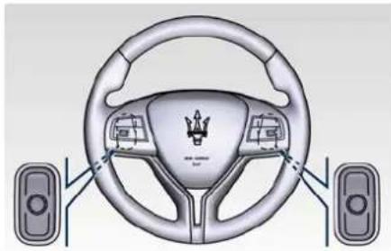
natural_image
Interior view of a car steering wheel with two side speakers and a crown on the steering wheel (no text or symbols visible)Press any button to display information on the radio station or track being listened to inside a pop-up for 2 seconds on instrument cluster. The right-hand control manages the volume.
By pressing the top of the rocker switch you can increase the volume and by pressing the bottom of the rocker switch you can lower it. Press the center button to mute the volume.
The left-hand control functions depend on the current source. To change source, press the center button.
When in "Radio" mode, pressing the top of the switch will "Seek" up for the previous listenable station and pressing the bottom of the switch
will "Seek" down for the previous listenable station.
When an external source is connected to MIA, a light press on the top of the switch will play the next track on the device connected.
Press the bottom of the switch once to go to the beginning of the current track, or to the beginning of the previous track if it is within 1 second after the current track begins to play. If you press the switch up or down twice, it plays the second track; three times, it will play the third one, etc.
Light Controls
Light Switch
The light switch located on the left side of the dashboard can be used to turn on and off the position/DRL lights, headlights, side marker, license plate lights and fog lights.
The light switch can be take the following positions:
300 Position/DRL lights, side marker and license plate light;
AUTO Automatic headlights;
D Manual headlights.
The light switch can also be pressed ( ) turn the rear fog lights on and off.

natural_image
Interior view of a car dashboard with two circular gauges and a directional arrow pointing to the left dial (no text or symbols visible)By turning the light switch in 300
ED position, the instrument cluster will display the related telltale (in example: position/DRL lights).
Dashboard Instruments and Controls

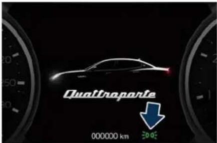
text_image
Quattroparte 000000 km 30.05When the engine is not started and the lights are switched on automatically by the twilight sensor or manually via the light switch, after about 30 minutes the lighting system turns off the lights that would otherwise remain lit and could discharge the battery.


Dashboard Instruments and Controls
The following table shows the on/off condition of external lights, according to the ignition device position, to the engine status, to the twilight sensor mode and to the light switch position.
| Ignition Device Position | Engine Status | Twilight Sensor Mode | Light Switch Position | ||
| ≥slant 00 ≤slant | AUTO | D | |||
| OFF – | – | Position lights (1), side marker and license plate lights on (4). | All lights off. Low beams, position (1), side marker and license plate lights on. | ||
| ACC Off – | Position lights (1), side marker and license plate lights on (2). | All lights off. Low beams, position (1), side marker and license plate lights on (2). | |||
| RUN Off – | Position lights (1), side marker and license plate lights on (2). | All lights off. Low beams, position (1), side marker and license plate lights on (2). | |||
| RUN On DAY | DRL (1) on. DRL (1) on. Low beams, position (1), side marker and license plate lights on. | ||||
| RUN On NIGHT | Low beams, position (1), side marker and license plate lights on (3). | Low beams, position (1), side marker and license plate lights on. | Low beams, position (1), side marker and license plate lights on. | ||
| (1) The lighting system uses the same LED for DRL and front position lights with two different levels of intensity: high for DRL and low for position lights.(2) The lights are powered up for 30 minutes to preserve the charge of the battery.(3) In some countries a message on TFT display alerts the user to use position when parking because the position lights will turn on with engine started also in low ambient light conditions or at night.(4) To preserve the charge of the battery, do not leave these lights on for a long time. | |||||
Dashboard Instruments and Controls

Position Lights and Daytime Running Lights (DRL)
The lighting system uses the same high or low intensity headlamps LED, respectively, for the DRL lights and front position lights.
With the light switch turned in 2005 the position lights will turn on when the ignition device is in any position and the engine is stopped or when the engine is running and the twilight sensor is in "NIGHT" mode.
The position lights are always on when the light switch is set in the 3D position.
DRL lights will turn on when the twilight sensor is in "DAY" mode, the engine is running and the light switch is in 30 dAUTO" position.
NOTE:
- In certain European countries, the position lights will only operate with the ignition device in OFF position, or with headlights on. Regardless of ignition device position, the position/DRL lights will remain on as long as the lights switch is 30005 position.
- If the headlights or position/DRL lights are on after the ignition device is placed in OFF position, a buzzer
will alert the driver while opening the driver's door, to exit the car. When the car is locked, the telltale on the instrument cluster will turn off.
If a turn signal is activated, the DRL LED on the same side of the vehicle will turn off for the duration of the turn signal activation. Once the turn signal is deactivated, the DRL LED will light up again.
NOTE:
Depending on your Country's regulations, DRL lights may be turned on and off.
Automatic Headlights
This system automatically turns the headlights on or off according to ambient light intensity detected by the twilight sensor positioned on the inner surface of the windshield, over the rear view mirror. To turn the system on, rotate the lights switch clockwise to "AUTO" position.
When the automatic system is activated, the headlight time delay function is activated as well. This means the headlights will stay on for up to 90 seconds after you place the ignition device into OFF position. To turn the automatic system off, move the lights switch out of "AUTO" position.
NOTE:
The engine must be running and the twilight sensor in "NIGHT" mode before the headlights turn on in automatic mode.

WARNING!
The responsibility for turning on the lights, depending on the daylight and regulations in force in the country of use, always lies with the driver. The automatic system for switching on and off the external lights is to be considered as an aid for the driver. If necessary, switch the lights including the rear fog lights on and can manually.
Headlights On with Wipers
When this function is active, the headlights will turn on in "Adverse Weather" mode approximately 10 seconds after activation of the wipers, if the lights switch is placed in the "AUTO" position. The headlights will additionally turn off by deactivation of the wipers if previously activated with this function.
(Continued)

Dashboard Instruments and Controls
NOTE:
The headlights with wipers function may be turned on and off using the MIA system, refer to "Functions of Settings Menu on MIA" in section "Dashboard Instrument and Controls".
Headlights Time Delay
This safety function provides headlight illumination for up to 90 seconds (programmable) when leaving your vehicle in an unlit area. To activate automatically the delay function with the light switch in "AUTO" position, place the ignition device in the OFF or ACC position while the headlights are still on.
The delay interval begins when the ignition device is placed in the OFF or ACC position.
To activate manually the delay function the headlights must be on before place the ignition device in the OFF or ACC position and the light switch in "AUTO" position.
If you place the ignition in RUN, the system will cancel the delay.
NOTE:
• To activate this function the light switch must be turned in "AUTO" position within 45 seconds of placing
the ignition device in the OFF or ACCD or "AUTO" position. Press the position. lights switch to turn on the rear
- Once the delay function is active, an additional shifting of the light switch will cancel the function.
- The headlight delay time is programmable using the MIA system, see "Functions of Settings Menu on MIA" in section "Dashboard Instrument and Controls".
- If the low beam LEDs are active due to "Headlights with Wipers", than the headlamps delay function will not be activated when the ignition device is set in OFF position.
Manual Headlights
Turning the light switch in position turns on the low beam together with the position lights, the side markers and the license plate lights regardless of the ignition device state and the "DAY" or "NIGHT" mode detected by the twilight sensor (see table in "Light Switch" paragraph of this chapter). The related telltale will display on the instrument cluster.
Fog Lights
The rear fog lights switch is built into the lights switch.
To activate the rear fog lights, turn the light switch to the low beam light
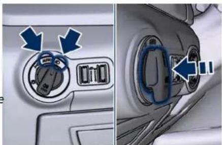
natural_image
Close-up of a car air conditioner control panel showing two buttons with blue arrows pointing to the dial (no text or symbols visible)Pressing again the lights switch 0¥ will deactivate the rear fog lights.
A dedicated telltale in the instrument cluster illuminates when the rear fog lights are turned on.
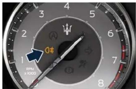
text_image
1 2 3 4 5 6 7 8 BMW x 1000Dashboard Instruments and Controls

NOTE:
After a key-off/key-on cycle, the rear fog lights will NOT activate automatically when turning on the low beam ☑ "AUTO" headlights. The rear fog lights will only turn on by operating the lights switch as previously described.
The AFS headlights, in the "Adverse Weather" mode also operate as fog system device (see paragraph "Full-LED Headlights with AFS" of chapter "External Lighting" in section "Understanding the Vehicle").
Light Dimmer Controls
The regulation devices beside the switch (see "Interior Lighting" in section "Understanding the Vehicle") can adjust the brightness of the instrument cluster lights, the doors controls rear lighting and the interior lighting.
Dimmer controls are located beside the light switch.
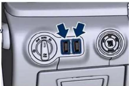
natural_image
Close-up of a car air conditioner control panel with two buttons and directional arrows indicating cooling or ventilation (no text or symbols)The regulation device rotates from position "0" upward and back downward performing stable and dimmable positions.
The left regulator switch has 4 different positions:
0 Stable position: lower level (OFF) of the internal lighting. 1 ^st Dimmable position: allows minimum to maximum brightness tuning of the in- strument cluster dials, dis- play, control switches and MIA's backlight, including all displayed messages.
2nd Stable position: allows maximum brightness set.
3 ^rd Stable position: allows to switch on the main and reading lights of the front dome light.
The right regulator has 2 different positions:
0 Stable position: front seat (OFF) lighting and front dome light LED are turned off.
1st Dimmable position: allows minimum to maximum brightness tuning of the front dome light LED and the front seats lighting.
Multifunction Lever
The multifunction lever is fitted on the left side of the steering column.
The multifunction lever controls the operation of the turn signals, headlight beam selection and overtaking lights. This lever controls also the operation of windshield wiper and washer (for this content see the chapter "Wipers and Washers Control" of this section).
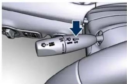
natural_image
Close-up of a hand holding a car's brake caliper with a blue arrow pointing to the caliper (no text or symbols visible)
Dashboard Instruments and Controls
Turn Signals
Move the multifunction lever all the way up or down until the stop trigger; the left or right arrow on respectively the speedometer and tachometer instrument cluster, flashes to show proper operation of the front and rear turn signal lights.
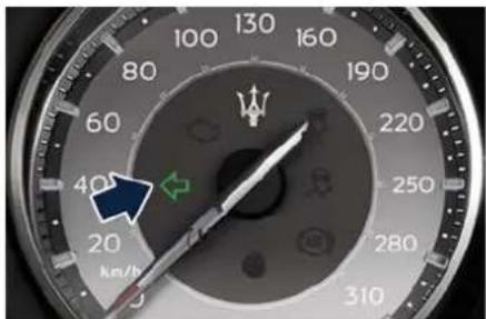
text_image
100 80 60 40 20 310 130 160 190 220 250 280 km/h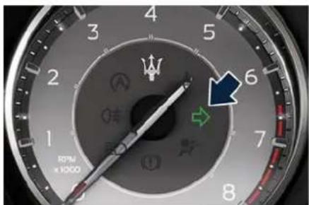
text_image
4 3 5 2 6 1 7 8 RPM ×1000To activate lane change function, tap the lever up or down once, without moving beyond the detent. The turn signals (right or left) will flash three
times then automatically turn off. This function is useful when overtaking or changing lanes.
NOTE:
- If either light remains on and does not flash, or flashes at a fast rate, check for a defective outside light. If an indicator on instrument cluster fails while moving the lever, then the turn indicator is probably defective.
- The message that a turn signal is will appear in the instrument cluster and a continuous chime will sound if the vehicle is driven more than 1 km (1 mile) with either turn signal on.
High Beams and Flashing
To switch on the high beams with the light switch in "AUTO" position, shift the multifunction lever onward.
A related telltale will illuminate on the tachometer.
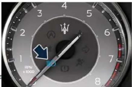
text_image
RPM ×1000By pulling the lever backward (toward or the steering wheel) you switch off the high beams and switch on the low 1.6 beams.
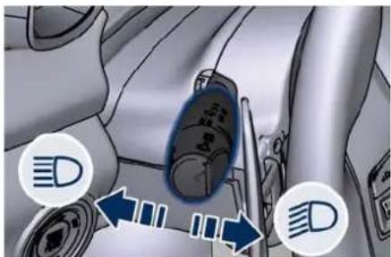
text_image
Diagram showing car interior with directional arrows and circular icons labeled 'D' pointing to a vehicle component.You can signal another vehicle with your headlights by lightly pulling the multifunction lever toward you. This will turn on the high beams headlights until the lever is released.
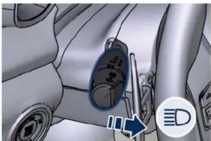
natural_image
Close-up of a car's side panel with a blue arrow pointing to a component, no visible text or symbolsFlashing occurs also with lights off if the ignition device is RUN position.

CAUTION!
The high beams can only be switched on manually by pushing the multifunction lever forward.

WARNING!
If the high beams are activated, they will turn on automatically every time the low beams are switched on either manually or automatically. We recommend therefore that you switch them off when they are no longer necessary and every time the twilight sensor deactivates the external lights.
Wipers and Washers Control
The multifunction lever is located on the left side of the steering column. The multifunction lever operates the windshield wipers and washer when the ignition device is placed in RUN or ACC position.
A windshield washer low fluid level is indicated by the warning light and by the message on the instrument cluster.
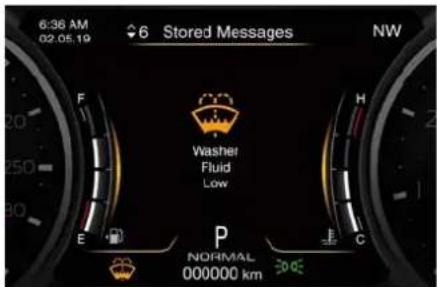
text_image
6:36 AM 02.05.19 6 Stored Messages NW F Washer Fluid Low E P NORMAL 000000 km 30 HzTo refill the fluid, see "Maintenance Procedures" in section "Maintenance and Care".

CAUTION!
- Turn the windshield wipers off when driving through an automatic car wash. The windshield wipers may be damaged if the wiper control is left in any position other than "OFF".
- In cold weather, always turn off the wiper switch and allow the wipers to return to the park position before turning off the engine. If the wiper switch is left on and the wipers freeze to the windshield, the wiper motor may be damaged when the vehicle is restarted.
- Always remove any buildup of snow that prevents the windshield wiper blades from returning to the off position. If the windshield wiper control is turned off and the blades cannot return to the off position, the wiper motor may be damaged.
Windshield Wipers
- Rotate the end of the multifunction lever to one of the four settings to activate the automatic intermittent setting (see "Rain Sensing Windshield Wipers" paragraph in this chapter).
- For low speed wiper operation (stable position "LO"): rotate the end of the multifunction control lever

Dashboard Instruments and Controls
forward to the first trigger after the intermittent setting.
- Rotate to the second trigger after the intermittent setting for high-speed (stable position HI) wiper operation.
- Rotate the end of the lever downward to the "MIST" position to activate a single wipe cycle. The wipers will continue to operate until you release the multifunction lever.
- To turn the wipers off rotate the lever to "OFF".
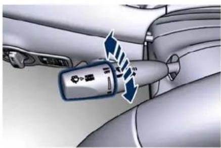
natural_image
Close-up of a hand holding a car's head panel with directional arrows indicating motion (no text or symbols)Rain Sensing Wipers
This function detects moisture on the windshield through an internal rear view mirror integrated sensor, which automatically activates the wipers. Rotate the end of the multifunction lever to one of four settings to adjust the detection system.
First wiper delay position is the least sensitive, and fourth wiper delay position is the most sensitive. Third position should be used for normal rain conditions.
The rain sense wipers will automatically change between an intermittent wipe, slow wipe and a fast wipe depending on the amount of detected moisture sensed by a particular area of the windshield. Place the wiper switch in the "OFF" position when you do not want to use the automatic intermittent system.
The rain sensing function can be turned on and off using the MIA system, see "Functions of Settings Menu on MIA" in section "Dashboard Instruments and Controls" for further information.

CAUTION!
• The rain sensing function may not function properly due to ice or dried salt water on the windshield.
- Use on the windshield of RainX® or products containing wax or silicone may reduce rain sensor performance.
The rain sensing system has protective functions for the wiper blades and arms. It will not operate under the following conditions:
- Low temperature wipe inhibit: the rain sensing function will not operate
when the ignition device is in RUN position, the vehicle is stationary and the outside temperature is below 0°C (32°F). To resume, set the automatic function on the multifunction lever, start the engine and drive or wait until the outside temperature rises above freezing.
- Wipe inhibit with transmission in N (Neutral) position: the rain sensing function will not operate when the ignition device is placed in the RUN position, the transmission shift lever is in the N (Neutral) position and the vehicle speed is less than 8 km/h (5 mph). To resume, set the multifunction lever to the automatic function or move the shift lever out of N (Neutral).
Headlights On with Wipers
When activating this function, the headlights will light up approximately 10 seconds after the wipers are turned on if the light switch is placed in "AUTO" position.
In addition, the headlights switch off when the wipers are turned off (position "OFF") if they were previously turned by using this function.
Powering on Headlights with wipers can be activated and deactivated with
Dashboard Instruments and Controls

the MIA system, see "Functions of Settings Menu on MIA" in section "Dashboard Instruments and Controls" for further information.
Wipers Blades Maintenance
When the wiper arms are in the rest position it is not possible to check or replace the blades (Service position) as they are folded under the hood. To service the blades it is necessary to shift the multifunction lever to "OFF" and the ignition device to OFF position.
Shift the control lever within 15 seconds to the "MIST" position (forward rotation of the twist switch) and release. The blades are brought in a position enabling the opening of the wiper arms and change of the blades.
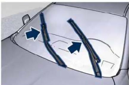
natural_image
Diagram of a car's front window with two blue arrows pointing to the sides of the window (no text or symbols present)It is possible to use the "MIST" position for a maximum of 3 times within two minutes, corresponding to different
the blades positions on the windshield. When completed bring the ignition device in RUN: the arms will reposition. If necessary move the multifunction lever to other required operating positions.
WARNING!
Operate or service the wiper blades without deactivating the wipers ("OFF" position) leaving the ignition device in RUN can be dangerous for the operator since the rain sensor may suddenly activate the wipers. Always use "Service" position for any intervention on the wiper blades.
Windshield Washers
To use the washer, push the end of the multifunction lever inward (toward the steering column) and hold it as long as washer spray is desired.
If you activate the washer while the windshield wiper control is in the automatic intermittent range, the wipers will operate for two wipe cycles after releasing the lever and then resume the previously selected intermittent interval.
If you activate the washer while the windshield wiper is turned off (OFF) the wipers will operate for three wipe cycles and then turn off.
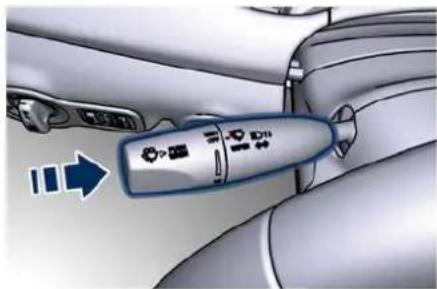
natural_image
Close-up of a car's steering wheel with a blue control knob and directional arrow (no text or symbols)WARNING!
- Do not start the windscreen washer during the cold months until the windscreen has warmed up. If it has not warmed up, the liquid could freeze on the glass and block your view.
- Sudden loss of visibility through the windshield could lead to a collision. You might not see other vehicles or other obstacles. To avoid sudden icing of the windshield during freezing weather, warm the windshield with the defroster before and during windshield washer use.
Head Windshield Washer Nozzles()
To avoid fluid freezing inside at low external temperatures, the fluid supply

Dashboard Instruments and Controls
nozzles can be heated by internal resistors.
Analog Clock
To adjust the analog clock located on the center of the dashboard between the air outlets, use the MIA system (see "Functions of Settings Menu on MIA" in this section).
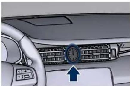
natural_image
Interior view of a car dashboard with air conditioner and directional indicator (no text or symbols)The time can be visualized also on the MIA upper status bar and on the instrument cluster display (see "Functions of Settings Menu on MIA" in this section).
Clock lighting works in the same way as instrument and controls backlighting (refer to "Interior Lighting" in section "Understanding the Vehicle").
Glove Box Compartments
The two glove box compartments on the dashboard may be used to store devices, small items or documents.

WARNING!
Do not operate the vehicle with the lid of glove box compartment in the open position. Store objects or devices in this compartment or in any other vehicle compartments, to ensure they will not move during the trip and prevent them from hitting any person on board.

CAUTION!
Do not place objects weighing over 10 kg (22 lb) in the glove box compartment.
Glove Box Driver Side
To open the glove box on the driver side, pull the handle as indicated.
Dashboard Instruments and Controls

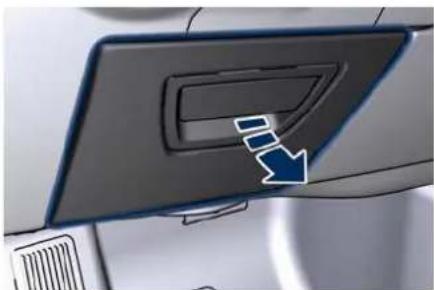
natural_image
Close-up of a car's front panel with a blue arrow pointing to the button (no text or symbols visible)The compartment is ca. 15 cm (6 in) deep and is lit by a courtesy light when open (the light automatically switches off when the compartment is closed).
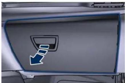
natural_image
Close-up of a car's side panel with a blue arrow pointing to the left side (no text or symbols visible)The compartment is divided into two parts: in the lower part you can find one of the two on-board documentation kits, while in the upper part you can fit small items.
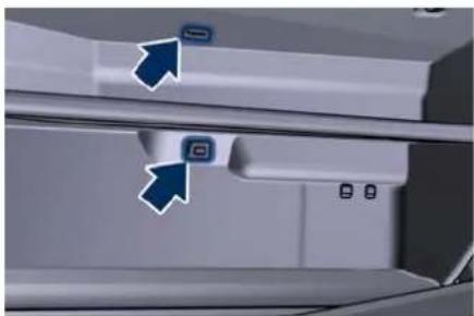
natural_image
Close-up of a white electronic device with two blue arrows pointing to ports, no visible text or symbols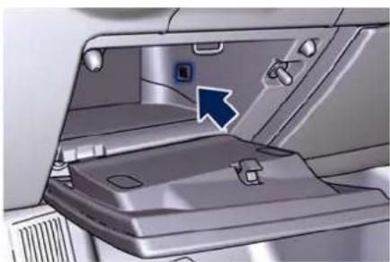
natural_image
Interior view of a vehicle showing the rear compartment with a blue arrow pointing to a keyhole (no text or symbols visible)Glove Box Passenger Side
To open the glove box, pull the handle as shown in the picture.
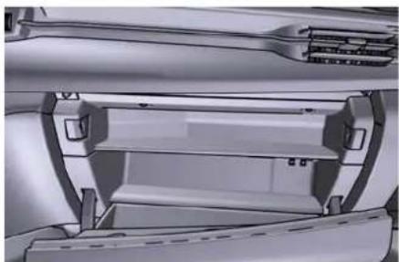
natural_image
Close-up of a mechanical component with no visible text or symbolsThe compartment is illuminated by a courtesy lights when open (the light will automatically switch off when the compartment is closed).
Privacy Lock Functions( )
The glove box compartment in the passenger side can be equipped with an opening/closing electric actuator that can be locked and unlocked via the MIA, by entering a 4-digit PIN code. These functions are useful for example when you have to leave the vehicle to another driver (for example, valet parking).
"Glove Box" function allow you to only lock the glove box and is available in the "Controls" menu of the "Vehicle" page and in the "Apps" page.
"Valet Mode" function is only available in the "Profiles" page and, in addition to lock the glove box, allows you to lock all the driver profiles for listening and guidance.
It is important to memorise and take note of the PIN since if it is lost, you

Dashboard Instruments and Controls
must contact the Maserati Service Network that will reset this function.
NOTE:
- "Glove Box Mode" and "Valet Mode can not be activated at the same time.
- "Glove Box Mode" and "Valet Mode lock functions must be activated when the glove box is already closed. If you activated one of these lock functions when the glove box is opened, the glove box will not close properly and will not lock.
Glove Box Activation Procedure
- Open "Controls" screen and touch "Privacy Lock" soft-key.
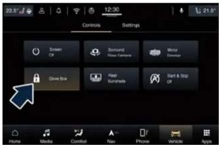
text_image
22.5° 12:30 Controls Settings Screen Off Sound Wave Camera Mirror Window Drive Box Fear Sunshade Start & Stop Off Home Media Comfort New Phone Vehicle Apps- Touch "Yes" soft-key in the function described screen to activate the function.
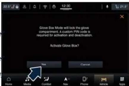
text_image
Glove Box Mode will lock the glove compartment. A custom PIN code is required for activation and deactivation. Activate Glove Box? Yes Cancel Home Media Comfort Nav Phone Vehicle Apps- Using the keypad, enter the four digits of the PIN and touch "OK". The system prompts you re-enter the PIN code to confirm it.
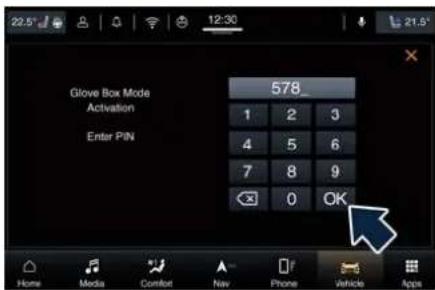
text_image
Glove Box Mode Activation Enter PIN 578_ 1 2 3 4 5 6 7 8 9 OK Home Media Comfort Nav Phone Vehicle AppsNOTE:
• To activate and deactivate the function, the user has 10 attempts to type a 4 digit PIN before system cancels the deactivation. The user can try again in 30 minutes.
- If you do not enter all PIN digits, a prompt will indicate that you should do so.
- In case of incoming call while entering the PIN, the MIA system will temporarily stop the release function. As soon as the call is over, the keypad screen will be displayed again so that you can enter the PIN.
- When the next page shown in figure appears, touch "OK".
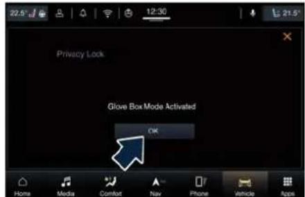
text_image
22.5° 12:30 21.5° Privacy Lock: Glove Box Mode Activated OK Home Media Comfort Nav Phone Vehicle AppsGlove box is now locked and the MIA will go back to "Controls" page. In this condition, system operation is reduced and only "Climate", "Controls" and "Settings" functions are active.
Glove Box Deactivation Procedure To unlock the glove box which has been locked with PIN code, touch
Dashboard Instruments and Controls

"Vehicle" category soft-key and open the "Controls" menu.
- Touch the "Glove Box" soft-key to enter this page.
- Unlock glove box by entered the lock code as previously specified.
- Touch "OK" to deactivate the function.
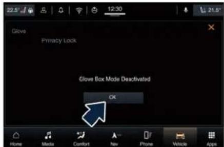
text_image
Glove Privacy Lock Glove Box Mode Deactivated OKGlove Box Manual Unlock
If battery is flat, it is necessary to manually unlock the actuator on the LH side of the glove box in order to open the glove box that has been locked using the PIN code.
To perform this operation you need to remove the lower dashboard moulding to access the actuator unlocking cable. Considering the complexity of this operation, we recommend you to contact the Service Network.
Valet Mode Activation Procedure
- Open "Profiles" screen and touch "Valet mode" soft-key.
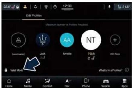
text_image
Edit Profiles Maximum number of Profiles reached. [Username] Jack 2 d/ AMELE Nick 2 NT Add Now Select Mode What's In a Profiles? Home Media Comfort Nav Phone Vehicle Apps- Touch "Yes" soft-key in the function described screen to activate the function.
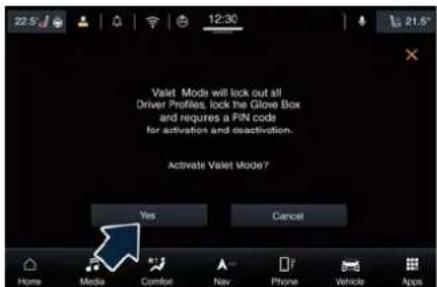
text_image
Vallet Modes will lock out all Driver Profiles, lock the Glove Box and requires a PIN coda for activations and deactivation. Activate Valet Mode? Yes Cancel Home Media Comfort Nav Phone Vehicle Apps- Using the keypad, enter the four digits of the PIN and touch "GO".
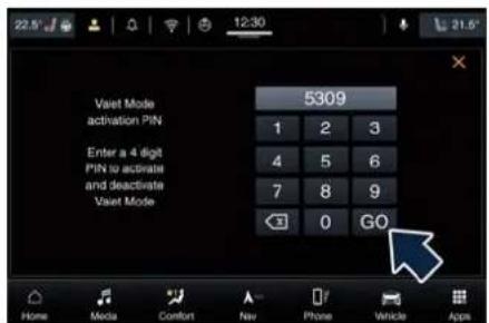
text_image
22.5° 12:30 21.6° Vaset Mode activation PIN Enter a 4 digit PIN to activate and deactivate Vaset Mode 5309 1 2 3 4 5 6 7 8 9 ←3 0 GO Home Media Comfort Nav Phone Vehicle AppsNOTE:
• To activate and deactivate the function, the user have 10 attempts to type a 4 digit PIN before system cancels the deactivation. The user can try again in 30 minutes.
- If you do not enter all PIN digits, a prompt will indicate that you should do so.
- In case of incoming call while entering the PIN, the MIA system will temporarily stop the release function. As soon as the call is over, the keypad screen will be displayed again so that you can enter the PIN.
"Valet Mode" activated will be indicated in the main status bar with a lock symbol combined with the Profile icon. In this condition if user touch the Profile icon in the main status bar a popup will indicate that


Dashboard Instruments and Controls
the function is not available in Valet Mode.
To Exit Valet Mode Function
To exit Valet Mode function touch the "Exit Valet Mode" soft-key in the "Welcome" pop-up at key on. Deactivate the function by entering the lock PIN code as previously specified.
NOTE:
Valet Mode function cannot be deactivated while the vehicle is in motion.
Air Conditioning Controls
The vehicle is equipped with an automatic dual-zone air conditioning system that allows to adjust separately the temperature and the airflow distribution in the left and in the right zone of the passenger compartment, according to the requests of the driver and the front passenger.
A humidity sensor, positioned on the inner surface of the windshield, over the rear view mirror, allows the A/C system to prevent/eliminate fogging of the windshield and side windows.
The best efficacy in preventing fogging is obtained by selecting the "AUTO" function, described later. A dual zone solar sensor helps to achieve the best comfort in presence of solar radiation.
Upon request, the vehicle can be equipped with an additional automatic dual-zone air conditioning system installed in the central console, between the front seats. The additional dual-zone module, can be operated by the rear passengers (see "Four-zone Climate Control" in this chapter), by means of the control panel at the end of central console, but also by the front passengers entering the "Comfort" category on MIA display.
Dual-Zone Climate Controls
This system can be operated by using the controls of the climate control panel on the dashboard, or the soft-keys on the MIA display when "Comfort" mode is selected.
To monitor the comfort parameters on board, you can also access the widget page from the "Home" screen and choose the "Climate" widget (see example in picture).
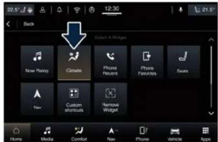
text_image
22.5° 12:30 Back Select A Widgets New Painting Climate Phone History Phone Favorites Sees New Custom shortcuts Remove Widget Home Media Comfort Nav Phone Vehicle AppsTo navigate the MIA screen, it is possible use the "TUNE-SCROLL" lower rotary knob on the central console to scroll through the soft-key of each function: the cursor will appear in grey outline on the first available function. Press "BROWSE/ENTER" button to enter the selected
Dashboard Instruments and Controls

function and to adjust it through the "BROWSE/ENTER" knob.
In the "Climate" screen of the MIA, the front seats and steering wheel comfort setting soft-keys may be present (optional equipments). The "OFF" state of the front seats comfort setting is shown on their soft-key. The front seats and steering wheel comfort setting soft-keys may be present in the upper status bar if the car is equipped with these devices. When these are active, the related icon is colored red or blue: when they are not active, it is grey (see "Front Seats" and/or "Steering Wheel Adjustment" in section "Understanding the Vehicle" for further details).
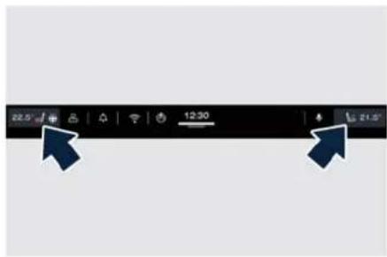
text_image
Screenshot of a mobile device status bar with time and navigation icons, showing two arrows pointing to specific time values.Front seats and steering wheel comfort setting soft-keys are present even when the A/C is off.
When the MIA system is in any category other than "Comfort" ("Home", "Media", "Phone", etc.) the driver and passenger temperature is always visible on the upper status bar together with the front seats and steering wheel comfort functions (if equipped).
Description of Controls
All described functions can be set and modified using the controls on the climate control panel or the soft-keys on the MIA display.
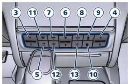
text_image
Diagram of car interior panel with numbered labels pointing to internal compartments or switches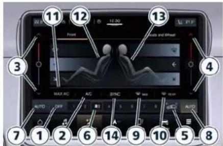
text_image
Labeled diagram of a car dashboard with numbered parts for navigation and tracking functionsPress any of controls on the climate control panel to display "Comfort" screen.
To adjust driver and passenger side temperature and blower speed, climate control panel features rocker switches that can be pushed up to increase temperature/speed, or down to decrease them.
When MIA is in any category other than "Comfort", pressing an air distribution or blower hard control on the climate control panel a small pop-up will appear for 3 seconds above the "Comfort" icon on the main category bar (see example in picture).


Dashboard Instruments and Controls
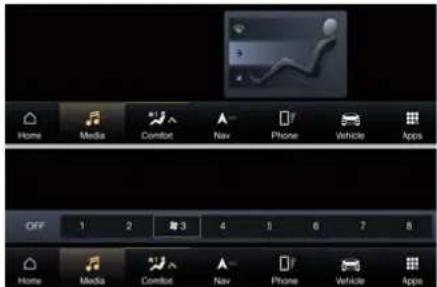
text_image
Home Media Comfort Nav Phone Vehicle Apps OFF 1 2 3 4 5 6 7 8 Home Media Comfort Nav Phone Vehicle Apps1. Climate control on/off
Once you enter the screen "Climate", touch the "ON" soft-key to switch the climate control on/off.
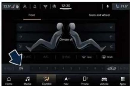
text_image
22.5° Font 12:30 Seats and Wheel Climate off ON Media Comfort Nav Phone Vehicle AppsThe "OFF" soft-key will appear in place of "ON" when the A/C is on. If the A/C system has been turned off, temperature values in the upper status bar will be obscured in all MIA modes.
NOTE:
For vehicles equipped with Remote Start, the Air Conditioning System will not function during Remote Start operation if the climate control is left in "OFF".
2. A/C
Touch the A/C soft-key to change the current air conditioning setting; the soft-key illuminates when the A/C is on. Operating this function will cause the automatic function to switch into manual mode and the "AUTO" LED on the buttons and MIA soft-key will turn off.
3. Driver temperature control
Provides the driver with independent temperature control. Touch the blue √ soft-key for cooler temperature.
Touch the red soft-key for warmer temperature. The driver's temperature setting will be displayed on the upper status bar, left side.
The temperature can also be adjusted by touching and sliding the bar towards soft-key /to increase temperature, or towards soft-key √ to decrease it.
During this phase, the corresponding temperature will be displayed on the upper status bar.
It is possible to adjust the temperature on the driver and passenger side even when you are outside the "Comfort" screen by simply touching the temperature indication on the upper status bar. A pop up will appear below with the bar and Xarrows to change the temperature and the "SYNC" soft-key to synchronise the driver's side temperature with which of the passenger side (see example in picture).
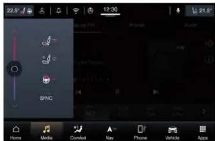
text_image
22.5° 12:30 21.5° SYNC Home Media Comfort Nav Phone Vehicle AppsYou can also increase or decrease the temperature using the rocker switch on the climate control panel.
NOTE:
In "SYNC" mode, this control will also automatically and simultaneously adjust the passenger temperature.
Dashboard Instruments and Controls

- Passenger temperature control Provides the passenger with independent temperature control. Touch the soft-key for cooler temperature. Touch the soft-key for warmer temperature. The passenger's temperature setting will be displayed on the upper status bar. The temperature can also be adjusted by touching and sliding the bar towards soft-key /to increase temperature, or towards soft-key √ to decrease it. During this phase, the corresponding temperature will be displayed on the upper status bar as for the driver's side. You can increase or decrease the temperature using the rocker switch on the climate control panel.
NOTE:
Pressing the 4 button/soft-key while "SYNC" mode will automatically exit "SYNC".
5. Recirculation
Press to change the current setting, the LED indicator on the button and the relevant soft-key illuminates to indicate which recirculation function is activated. For further details, see paragraph "Dual zone Climate Control Functions" in this chapter.
6. Blower control
Blower control is used to adjust the amount of air forced through the climate system. Eight levels of blower speed can be selected. Adjusting the blower will cause automatic mode to switch to manual.
On the climate control panel, push the rocker switch up to increase blower speed. Push the rocker switch down to decrease blower speed. Pushing down the rocker switch when set blower is at the first speed, causes the A/C system shutdown (OFF condition).
On the MIA display, touch the number of the corresponding to the blower speed you want to set.
When the MIA is displayed in any category other than "Climate", the blower speed is indicated by the number in the "Comfort" soft key of the main category bar.
7 - 8. AUTO
This function automatically controls the interior temperature by adjusting the air flow rate and the air distribution respectively on the driver and on the passenger zone. Press "AUTO" to switch the ATC between manual and automatic mode. The LED on the button and the "AUTO" soft-key illuminates when the automatic function is activated. See "Automatic Temperature Control (ATC)" in this chapter for more information.
9. MAX defrosting/demisting
Press the button or the MIA soft-key to switch the airflow setting to the windshield and the front side windows to get quick defrosting/defogging. The LED on the button and the MIA soft-key illuminates when this function is activated. Operating this function will cause the ATC to switch into manual mode: so the "AUTO" LED on the button and the MIA soft-key will turn off. With engine off, the blower will run at minimum speed (level 1) and can be increased manually: with engine on, the blower speed will gradually increase to the higher speed (level 8). MAX defrosting/demisting shall also involve REAR defrosting/demisting function. If this function is turned off the climate system will return to the previous setting, switching on the A/C ("A/C" LED on the button and the MIA soft-key illuminated).
10. REAR defrosting/demisting
Press the button or the MIA soft-key to turn on the rear window defroster and the heated outside mirrors. The LED on the button and the MIA soft-key will illuminate when the rear window defroster and the

Dashboard Instruments and Controls
heated external mirrors are on. The rear window defroster and the heated external mirrors automatically turn off after 10 minutes.
For any subsequent request after the first one (in the current ignition cycle), the system activates the function for 5 minutes. The timing described above is automatically reset and the defrost/demisting function is deactivated at each key-off.

CAUTION!
Failure to observe the following cautions may cause damage to the rear windows defroster:
- Use care when washing the inside of the rear window. Do not use abrasive window cleaners on the interior surface of the window. Use a soft cloth and a mild washing solution, wiping parallel to the heating elements. Labels can be peeled off after soaking with warm water.
- Do not use scrapers, sharp instruments, or abrasive window cleaners on the interior surface of the window.
- Keep all objects inside the vehicle at a safe distance from the window.
11. MAX A/C
By pressing the "MAX A/C" button or the MIA soft-key, the system automatically switches to get the maximum cold air flow in both zones.
12 - 13. Air flow distribution modes The airflow distribution mode, respectively on the driver and on the passenger zone, can be adjusted so air comes from the dashboard vents, vents under the dashboard in direction of the floor, demist/defrost vents and vents under the front seats and adjustable vents at the rear end of the central console for the rear passengers only.
The climate control panel features a single button for each zone: press it several times to select and set the required airflow distribution mode.
The airflow mode combinations will cycle in this order: "Dashboard" → "Bi-Level" → "Floor" → "Mix" → "Defrost" → "Hi-Level" → "Tri-Level". When MIA are out of the "Comfort" page, each time the button is pressed, a pop up will appear with the airflow mode activated.
When in the "Comfort" category, the MIA displays the relevant soft-keys to set these modes individually for each zone.
The arrow on the symbol soft-key in white indicates active status, in grey indicates inactive status. Available settings are as follows:
- "Dashboard" mode Air for each zone flows from four adjustable vents of the dashboard and two positioned at the rear end of the central console. Each of these vents can be singly adjusted. The air grids or vanes of the vents can be moved to adjust air flow direction. A setting wheel, placed near each vent, allows to regulate or close the airflow.
- "Bi-Level" mode Air for each zone flows from the dashboard and central console adjustable vents and from the fixed floor vents described in "Floor" mode. A small portion of the airflow is directed through the defrost/demist vents to prevent windows fogging.
NOTE:
Bi-Level mode is designed to let cooler air come in the dashboard and rear part of the central console vents and warmer air from the floor vents.
- "Floor" mode Air for each zone flows from the fixed front vents, located under the
Dashboard Instruments and Controls

dashboard, and under the front seats for the rear passengers. A small portion of the airflow is directed through the defrost/demist vents to prevent windows fogging.
- "Mix"


Air for each zone flows from the defrost/demist vent, the fixed vent under the dashboard and which from floor vent described in "Floor" mode. This mode is recommended for cold climates, to improve comfort and prevent windows fogging.
• "Defro


Air for each zone flows from the dashboard defrost/demist vents to prevent windows fogging.
• "Hi-Le


Air for each zone flows from the dashboard defrost/demist vents, from the dashboard and central console adjustable vents and from the fixed floor vents described in "Floor" mode.
• "Tri-Le


Air for each zone flows from all the adjustable/fixed and defrost/demist vents.
14. "SYNC" mode
Touch the "SYNC" soft-key on the MIA to switch the Sync function on/off. The "SYNC" soft-key illuminates when
this function is selected. This function is used to synchronise the passenger temperature setting with the driver temperature setting. It is possible to activate this function even when MIA is in any category other than "Comfort" through the pop up window that opens when you touch the driver's temperature soft-key on the upper status bar. Changing the passenger temperature setting while in "SYNC" will automatically exit this function.
Dual-Zone Climate Control Functions
Air Conditioning (A/C)
The "A/C" soft-key allows to manually activate or deactivate the air conditioning system. When the air conditioning system is turned on, cool dehumidified air will flow through the vents into the cabin. For improved fuel economy, touch the "A/C" soft-key to turn off the air conditioning and manually adjust the blower and airflow mode settings.
When the A/C and automatic functions are switched off it is not possible to have air at a lower temperature than the outside.
Recirculation and Air Quality Sensor (AQS)
When outside air contains smoke, odours, or high humidity, or if rapid cooling is desired, you may wish to recirculate interior air by pressing the recirculation control button or the relevant soft-key button to activate the two different functionalities.
The recirculation function, that allows to open/close the A/C air inlet by operating the button on the climate control panel or the MIA soft key, is integrated with the Air Quality Sensor.
This sensor, positioned upstream of the A/C filter, in front of the air intake of the A/C system, detects the presence of polluting substances and submits an electric signal to the A/C control unit, that closes the intake of the external air by activating the air recirculation.
The button or the MIA soft-key can therefore enable three operating modes, switchable in sequence: "Auto", "Manual" and "Open".
Starting from the outside air condition ("Open" mode) with LED on the button off and MIA soft-key not highlighted, in which the external air is aspirated by the A/C system and treated to be introduced into the passenger compartment, subsequent

Dashboard Instruments and Controls
actuations of the button or the MIA soft-key change the state as follows.
- First press - "Auto" mode: the A/C system activates the automatic recirculation control by using the signal transmitted from the AQS. The symbol "A" on the button lights up and the MIA soft-key with the symbol "A" in white lights up.
- Second press - "Manual" mode: the A/C system activates the recirculation, the LED on the button light up and the MIA soft-key with the symbol "A" in white lights up. The A/C system will stay this way up to a new actuation, or until the increased humidity could lead to windshield fogging: in this case the recirculation automatically switches to external air.
- Third press - "Open" mode: the A/C system switches back to external air (default operating mode).
The next press of the button or the MIA soft-key restarts the operating cycle just described.
NOTE:
To avoid the risk of fogging, the AQS is disabled when the external temperature falls below Z (35F) or rises above 26C (79F).
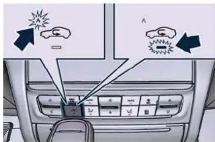
text_image
Diagram showing car interior control panel with warning icons and directional arrows indicating shock or damage points."Manual" Mode
"Auto" Mode
text_image
30 91° NC MAX REAR 5 6 T 8 AUTO Phone Vehicle App
text_image
Screenshot of a car navigation interface showing a 3D model with UI elements and a 'AUTO' button highlighted.NOTE:
In cold weather, use of recirculation mode may lead to window fogging. Select the MIX mode and increase the blower speed to prevent fogging.
MAX A/C
Activating this function, the system switches to exit automatic mode and enter A/C and recirculation functions. The minimum temperature (LO) in both zones, the maximum blower
speed and the "Dashboard" air distribution mode are also selected.
The blower speed can be adjusted and the air distribution can be modified without exiting "MAX A/C". To exit "MAX A/C" touch the relevant MIA soft-key or exit A/C or recirculation functions.
Selecting "AUTO", or "OFF", will also exit "MAX A/C".
Automatic Temperature Control (ATC)
Automatic operation
The system activates automatic mode in the following ways:
- Press the "AUTO" soft-key of driver and/or passenger zone on the climate control panel or the relevant soft-key button on the MIA screen. The text "Auto" and the fan in white will appear inside the area usually occupied by the blower speeds.
Dashboard Instruments and Controls

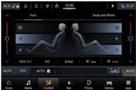
text_image
22.5° Front 12:30 Seats and Wheel MAX A/C A/C SYNC MAX AUTO OFF AUTO Auto Home Media Comfort New Phone Vehicle Apps- Set the desired temperature adjusting the driver and/or passenger temperature control buttons or soft-keys. The system automatically work to maintain the best comfort level inside the passengers compartment. - When the system is set up for your comfort level, it is not necessary to change the settings anymore, simply allow the system to function automatically.

text_image
Diagram of car interior air conditioner panel with directional arrows indicating airflow or movement- To provide you with maximum comfort in the automatic mode, during cold start-ups the blower speed will remain low until the engine warms up. - AUTO mode can be deactivated by operating any airflow or blower controls and by pressing "AUTO", "A/C", "MAX AC", "MAX" or "OFF" button or the same MIA soft-key.
Manual operation
The system allows manual selection of blower speed, air distribution mode, A/C status and recirculation control. The blower fan speed can be set to any fixed speed by using the blower control. In this case the blower will operate at a fixed speed until a different speed is selected. This allows the front occupants to control the volume of air circulated in the vehicle exiting the automatic mode.
The user can also choose the direction of the airflow by selecting one of the available mode settings. A/C operation, recirculation control and SYNC mode can also be manually selected.
Four-Zone Climate Controls (f)
Air conditioning controls that allow rear passengers to adjust the temperature in the left and right rear part of the passenger compartment are located at the rear end of the central console underneath the adjustable air outlets or on the rear console storage compartment between the rear seats, if the vehicle is equipped with "Comfort Luxury" seats.
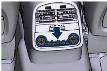
natural_image
Interior view of a car's backrest with the Seat Top Control Panel and Air Condition Indicator (no text or symbols on the panel itself)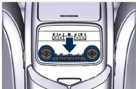
text_image
Diagram of car interior with directional control panel and speedometer display showing down arrow and circular indicators"Comfort Luxury" Rear Seats
Description of Controls
The following functions can be operated/adjusted by using the rear

Dashboard Instruments and Controls
climate control panel (represented on the "Comfort Luxury" rear seats version).
- Rear climate control on/off Press the button to switch the rear climate control on/off. The LED on the button turns on when the rear A/C is on.
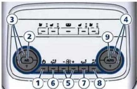
text_image
3 2 9 1 6 5 7 8 AUTO-
A/C Press to change the current air conditioning (A/C) setting, the "A/C" symbol on the button illuminates when the A/C is on. This will cause the automatic operation to switch into manual mode and the "AUTO" indicator will turn off.
-
Left side temperature control Provides the rear passengers with independent temperature control. Push the button for cooler temperature settings or the button for warmer temperature. The set
temperature value will be displayed in the area above the buttons.
- Right side temperature control Provides the rear seats passengers with independent temperature control.
Push the button for cooler temperature settings or the button for warmer temperature. The set temperature value will be displayed in the area above the buttons.
5. Blower control
Blower control is used to regulate the airflow of the rear climate system.
There are seven blower speeds available. Adjusting the blower will cause the automatic mode to switch to manual.
Press the "+" button to increase blower speed.
Press the "-" button for lower speed.
Airflow distribution modes
The airflow distribution can be adjusted to let air come in from the adjustable and fixed central console vents and floor vents. The set mode is recognisable through the lighting of the soft-key or the LED on the button of the climate control panel.
6. "Bi-Level" mode
Air comes from the adjustable vents on the rear central console and on the side pillars between the doors, and from the fixed vents on the floor.
NOTE:
The Bi-Level mode is designed to provide comfort by sending cooler air out of the central console and side pillars vents and warmer air from the floor vents.
7. "Floor" mode
Air comes from the floor vents under the front seats.
8. "Torso" mode
Air comes from the adjustable vents on the central console and the ones on the pillars between the doors. Each of these vents can be singly adjusted.
The air grids of the vents can be moved up/down and right/left to adjust the airflow direction. A setting wheel, placed near each vent, allows to regulate the airflow or to close the vent.
9. AUTO
This function automatically controls the interior temperature by adjusting the air flow rate and the air distribution.
- Press the "AUTO" button: the automatic rear climate control switches from manual to automatic mode and vice-versa. The "AUTO"
Dashboard Instruments and Controls

symbol on the button illuminates when this function is activated.
- Adjust then the temperature you wish to maintain by regulating the left and/or right side temperature control buttons. Once the desired temperature is set, the system will achieve and automatically maintain that comfort level.
- When the system is set up for your comfort level, it is not necessary to change the settings anymore: simply allow the system to function automatically.
To provide you with maximum comfort in the automatic mode, during cold start-ups the blower speed will remain low until the engine warms up.
Four-Zone Climate Control by the Driver
When the car is equipped with the additional dual-zone module in the "Comfort" screen are present 3 soft-keys to set the "Front" climate, the "Seats and Wheel" functions (if equipped) and the "Rear" climate. To set the rear climate zones touch "Rear" soft-key or select it with the manual controls on the central console.
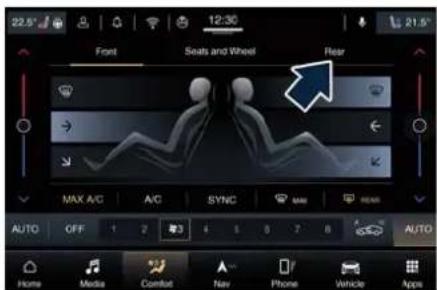
text_image
22.5° Font Seats and Wheel Rear MAX A/C A/C SYNC MAX REACH AUTO OFF 1 2 3 4 5 6 7 8 9 AUTO Home Media Comfort New Phone Vehicle AppsOnce you have entered the rear climate screen, by touching the following soft-keys, the driver is able to:
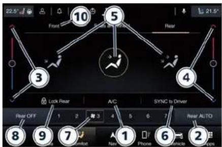
text_image
22.5° Front 10 5 Rear 3 4 Lock Rear A/C SYNC to Driver Rear OFF 1 2 驿 3 4 5 6 7 Near AUTO 8 9 7 1 Phone Vehicle Next
text_image
22.5° Front Seats and Wheel Rear Rear Climate Off Lock Rear A/C SYNC to Driver Rear ON 1 2 3 4 5 6 7 Media Comfort Nav Phone Vehicle Apps1 Turn on the A/C compressor.
2 The system switch the ATC between manual and automatic mode by controlling the interior temperature (controls 3, 4) by adjusting the air flow rate and the air distribution (controls 5) of the rear passengers.
3 Adjust the temperature in the left rear zone in the indicated mode for the front zones.
4 Adjust the temperature in the right rear zone in the indicated mode for the front zones.
5 Set the airflow distribution in "Torso", "Bi-Level" or "Floor" mode.
6 Synchronise the two rear passenger temperature setting. If the driver adjust the temperature while SYNC mode is on, this will affect the rear passenger


Dashboard Instruments and Controls
temperature. If the front or rear passengers adjust the temperature setting the system automatically break the function and turn it off.
7 Set the blower speed through seven speed levels.
8 Turn off the rear climate option.
9 Block the settings of the rear climate.
10 Return to the front climate control screen.
11 Re-activate the rear climate setting.
Operating Tips
- Continuous use of the air recirculation in winter, in rainy weather or humid climate is not recommended because it may cause window fogging.
- Interior fogging on the windshield can be quickly removed by fast defrosting/demisting. The "Mix" mode can be used to maintain a clear windshield and provide sufficient heating. If side window fogging becomes a problem increase blower speed.
NOTE:
- Recirculation mode without A/C should not be used for long periods of time, as fogging may occur.
- If inside the passenger compartment there are conditions of high temperature and humidity, when the A/C compressor is switched on ("A/C" soft-key illuminated on MIA display or LED on climate control panel "A/C" button ON) there may be some cold steam at ventilation port outlet: this situation is normal and does not indicate air conditioning system malfunction.
- Automatic Temperature Controls (ATC) will automatically adjust the climate control settings to prevent or eliminate window fogging on the front windshield.
- Make sure the external air intake grille, located directly in front of the windshield, is free of obstructions such as leaves or other objects. Leaves collected in the air intake may reduce airflow, and if they enter the plenum, they could plug the water drains. In winter make sure the air intake is clear of ice, slush, and snow.
- The temperature can be displayed in Metric or US units by selecting the "Units" customer programmable
function. See "Functions of Settings Menu on MIA" in this section.
- Any time you store your vehicle or keep it stationary (i.e., during vacation) for two weeks or more, run the air conditioning system at idle for about five minutes in the fresh air by high blower setting. This will ensure adequate system lubrication and minimize the possibility of the compressor damage when the system is started again.
A/C Filter
The climate control system filters outside air containing dust, pollen and some odours. Strong odours cannot be totally removed by A/C filter at the entrance of the air climate system. See "Maintenance Procedures" in section "Maintenance and Care" for filter replacement instructions.
5 - Starting and Driving
Normal Starting of the Engine ....
Remote Start System (E) 160
Automatic Start&Stop System 162
Automatic Transmission 165
All-Wheel Drive (AWD version only) 174
Drive Mode....175
Launch Control Mode (TROFEO version only) ....
Parking Brake 189
Parking 193
Using the Brakes 195
Use of the Engine 196
Refuelling 198
Driving Conditions 200


Starting and Driving
Normal Starting of the Engine

WARNING!
It is dangerous to run the engine in a enclosed area. The engine consumes oxygen and discharges carbon dioxide, carbon monoxide and other toxic gases in the atmosphere.
When doors are opened, the instrument cluster displays the model logo in the center and the complete odometer plus the open doors indicator in the lower part of the cluster.
text_image
Quattroporte 000000 kmBefore starting the engine, close the doors, adjust your seat, the inside and outside mirrors, fasten your seat belt and instruct all other occupants to buckle their seat belts.
The shift lever must be in P (Park) or N (Neutral) position before you can start the engine. Apply the brakes before shifting into any driving gear (see "Automatic Transmission" in this section).

CAUTION!
- Before starting the engine, switch off the electrical devices with a high power consumption (air-conditioning and heating system, heated rear window, headlights, etc.).
- Do not start the engine if the fuel level in the tank is low.
The keyless ignition allows the driver to operate the ignition device by pushing the center button, as long as the key fob is within the passenger compartment (check "Keys" in section "Before Starting" for further information).
By pressing the brake pedal and pushing the START/STOP button the engine starts. Instrument cluster displays the initial sequence with warning light and analog instruments test routine and switch-on of the engine temperature indicators and fuel level. This happens if option "Key-On Display" was set in "Screen Setup" submenu for display switch-on (see
chapter "TFT Display Setting and Menu Overview" in section "Dashboard Instruments and Controls").
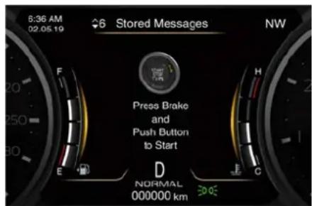
text_image
6:36 AM 02.05.19 Stored Messages NW Press Brake and Push Button to Start D NORMAL 000000 kmThe current display subsequently sets up with the latest screenshot.
If the engine fails to start, the starter will disengage automatically after 10 seconds. If you wish to stop the cranking of the engine prior to starting it, press the button again.
NOTE:
Normal starting of either a cold or a warm engine is obtained without pumping or pressing the accelerator pedal.
If the driver only pushes the START/STOP button but does not press the brake pedal, the ignition device cycles to the ACC position (see "Keys" in section "Before Starting") and the
Starting and Driving

instrument cluster displays the latest screenshot.
At the third press of the START/STOP button the ignition device returns to OFF position and the display powers down.
At the fourth press of the START/STOP button the screen will display the message that invites you to press the brake pedal and push the START/STOP button to start the engine.
NOTE:
If the ignition device is left in the AC or RUN (engine not running) position and the transmission is in P (Park), the system will automatically time out after 30 minutes of inactivity and the ignition device will switch to the OFF position.
After starting the engine, the idle speed is controlled automatically and will decrease as the engine warms up.
Engine Start Failure

CAUTION!
- Do not attempt to push or tow your vehicle to get it started. Vehicles equipped with an automatic transmission cannot be started this way. Moreover, unburned fuel could
enter the catalytic converter and once the engine has started, ignite and damage the converter and vehicle.
- If the vehicle has a discharged battery, booster cables may be used to obtain a start from a booster battery or the battery in another vehicle. This type of start can be dangerous if done improperly. See "Auxiliary Jump Start Procedure" in section "In an Emergency" for further information.
Flooded Engine Clearing
df the engine fails to start after you have followed the described procedures, it may be flooded. To clear any excess fuel, move the shift lever in P (Park) position. Press and hold the brake pedal, push the accelerator all the way to the floor and hold it, then press and release the START/STOP button once. The starter will engage automatically, run for 10 seconds, and then disengage. Once this occurs, release the accelerator pedal and the brake pedal, wait 10 to 15 seconds, then repeat the normal starting of the engine procedure.
Driving with Cold Engine
Start-off slowly, avoiding sudden acceleration and rev the engine up at low medium speeds. High performance driving should be avoided until the engine temperature reaches 65-70°C (149-158°F).
Engine Turn Off
- With the shift lever in P (Park), D (Drive) or R (Reverse) positions (see "Automatic Transmission" in this section) and vehicle standstill, press and release the START/STOP button to switch off the engine. A burst on the accelerator pedal before turning off the engine has no purpose and increases fuel consumption.
- If the shift lever is in N (Neutral) and the START/STOP button is pressed once, the instrument cluster will display a "Vehicle Not in Park" message and the engine will remain running.

WARNING!
Never leave a vehicle out of the P (Park) position, as it could move.
NOTE:
If the ignition device is left in the ACC or RUN (engine not running) position and the transmission is in P (Park), the system will automatically time out after 30 minutes of inactivity and (Continued)

Starting and Driving
(Continued)
the ignition device will switch to OFF position.
Engine Turn Off when in Automatic Start&Stop
When the engine has been turned off by the Start&Stop system, press and release the START/STOP button. The ignition device will return to the OFF position and the vehicle is off.
"Panic Stop" Strategy
In panic conditions, if driver stops engine in any non-standard manner while driving at a speed over 8 km/h (5 mph), the "Panic Stop" strategy can manage the situation by checking gearchange condition upon engine cutting, driver's action on brakes, road condition (flat or slope) so as to set gearchange to the most suitable condition.
Remote Start System()
This system enables the key fob to start the engine conveniently from outside the vehicle while still maintaining security. The system has a range of approximately 91 m (300 ft). Obstructions between the vehicle and the key fob may reduce this range.
How to use Remote Start
All of the following conditions must be met before the engine will remote start:
- System not disabled from previous remote start event.
- Vehicle theft alarm not active.
- Doors closed.
- Hood closed.
- Boot lid closed.
- Hazard lights switched off.
- Brake pedal not pressed by any passenger remained in the vehicle.
- Battery at an acceptable charge level.
- The shift lever is in P (Park) position.
- The vehicle transmission is in automatic mode.
- The remote start has not been activated yet two consecutive times. If EPB (Electric Parking Brake) is not inserted, at key-off in some conditions the remote start system may not allow engine to start. We suggest to set
"Auto Apply On" function through the switch on the right-side of the steering wheel (refer to "Parking Brake" in this section).

WARNING!
- Do not start or run an engine in a closed garage or confined area. Exhaust gas contains Carbon Monoxide (CO) which is odourless and colourless.
- Keep key fobs away from children. Operation of the Remote Start System, windows, door locks or other controls could cause serious injury or death.
Engine Remote Start Abort
Message on Instrument Cluster
The following messages will display on the instrument cluster if the vehicle fails to remote start or exits remote start prematurely:
- "Remote Start Cancelled Door Open".
- "Remote Start Cancelled Boot Open".
- "Remote Start Cancelled Fuel Low".
- "Remote Start Cancelled Time Expired".
- "Remote Start Disabled Start Vehicle to Reset".
The message on the instrument cluster stays active as long as the ignition device is in RUN position.
To enter Remote Start Mode
NOTE:
On the key fob of vehicles with this function, the approach lights button is replaced by the remote start button
Press and release the button @ the key fob twice within five seconds. The vehicle doors will lock, position lights will flash and the horn will ring twice (if the "Sound Horn with Remote Start" function of the "Doors & Locks" submenu is activate using the MIA system, refer to "Functions of Settings Menu on MIA" in section "Dashboard Instruments and Controls"). Then, the engine will start and the vehicle will remain in the "Remote Start" mode for a 15-minute cycle.
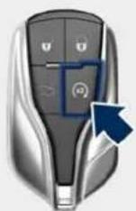
NOTE:
- In case of an engine fault or low f level, the vehicle will start and then shut down in 10 seconds.
- The position lights will turn on and remain lit during "Remote Start" mode.
- For security reasons, power window and power sunroof operation (if equipped) are disabled when the vehicle is in the "Remote Start" mode.
- The engine can be started two consecutive times (two 15-minute cycles) with the key fob. However, the ignition device must be cycled to the RUN position before you can repeat the start sequence for a third cycle.
To exit Remote Start Mode without Driving the Vehicle
Press and release the button one time or allow the engine to run for the entire 15 minute cycle.
NOTE:
To avoid unintentional shutdowns, the system will disable the one time press of the button for two seconds after receiving a valid "Remote Start" request.
To exit Remote Start Mode and Drive the Vehicle
Before the end of 15 minute cycle, press and release the button on the key fob to unlock the doors and disarm the vehicle security alarm. Then, prior to the end of the 15 minute cycle, press and release the START/STOP button.
NOTE:
The message "Remote Start Active Push Start Button" will display in the instrument cluster until you push the START/STOP button.
Driver's Seat Comfort with Remote Start
The driver's heated and ventilated seat and the heated steering wheel (if foreseen) can be programmed to

Starting and Driving
come on during a remote start. Refer to "With Vehicle Start" function of the "Seats & Comfort" submenu in the "Settings" page (see chapter "Functions of Settings Menu on MIA" of section "Dashboard Instruments and Controls" for further information).
Radio Frequency RKE Transmitter - Regulatory Information
The "Regulatory Information" for all the radio frequency and radar devices can be consulted by accessing the section "Services" on the website www.maserati.com.
Automatic Start&Stop System
The Maserati Start&Stop system allows the engine to automatically switch off when the vehicle stops and to restart when the driver intends to drive. This function helps reduce fuel consumption. During the "Stop (AutoStop)" phase the ignition is still on and all security functions are available.
In order for the Start&Stop to activate, the vehicle must be stationary and the brake pedal adequately pressed.
NOTE:
If the brake pedal is not sufficiently pressed the Start&Stop may not function even if the vehicle is stopped
When the Start&Stop switches off the engine, the related light Ⓐ illuminates on the instrument cluster. As soon as the brake pedal is released, the engine turns on.
While the vehicle is stopped, the transmission can be placed in P (Park) pressing the "P" button on the shift lever
In this case it is possible to release the brake pedal and the vehicle will remain in "AutoStop" with engine off. Pressing the brake pedal and shifting transmission into D (Drive) or R (Reverse) will deactivate the "AutoStop" condition and restart the engine.
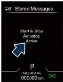
text_image
6 Stored Messages Start & Stop Autostop Active P NORMAL 000000 km 300E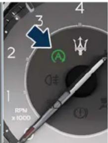
text_image
3 A RPM x1000Start&Stop Deactivated
Start&Stop function is deactivated, under the following conditions:
- When SPORT drive mode is activated.
- When (ESC Off) drive mode is activated.
- If it has been disabled through the main menu item "Start&Stop", via the controls located on the right side of the steering wheel, or through the Start & Stop hard button on the central console (see chapter "Drive Mode" in this section) or via the MIA in the "Controls" page (see "Functions of Controls Menu on MIA" in section "Dashboard Instruments and Controls").
Starting and Driving

Start&Stop Not Active
For keeping driving safety, interior comfort and a correct functioning of engine and vehicle, the Start&Stop function does not activate under the following conditions:
- When the driver's seat belt is unbuckled (see example).
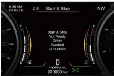
text_image
6:36 AM 02 05 19 5 Start & Stop NW Start & Stop Not Ready Driver Seabelt Unbuckled E F D NORMAL 000000 km C- When the driver door is open.
- When the fuel level is too low.
- When the vehicle is stopped on a very steep road.
- When the vehicle is stopped with steered wheels (over 135^ of steering wheel angle for each part).
- When the vehicle is manoeuvring: shift lever in R (Reverse).
- When the temperature conditions inside the vehicle do not correspond to the air conditioning setting.
-
When the front and rear "defroster" function is activated.
-
When the engine coolant and the engine oil temperature is not on proper functioning level.
- When the external temperature is too cold.
- When the battery charge is below safety value.
- When the previous stop had just happened (few seconds) and the minimum speed has not yet been achieved.
- Shortly after R (Reverse) has been set or when driving under a certain speed level.
- When the hood is open.
- The sensors managing the Start&Stop have been damaged.
- Start&Stop system faults are present.
- When Adaptive Cruise Control (ACC) and/or Active Driving Assist (ADA) system are engaged.
Automatic Restarting of the Engine
The engine may automatically restart, before the brake pedal has been released, when one of the following conditions occurs:
- The SPORT drive mode or ESC Off) drive mode is being activated.
- If the Start&Stop function has been disabled through the Start&Stop hard button on the central console
(see chapter "Drive Mode" in this section) or via MIA in the "Control" page (see "Functions of Controls Menu on MIA" in section "Dashboard Instruments and Controls").
- If shift lever is moved to R (Reverse).
- If the steering wheel is moved to steer the wheels.
- When the temperature conditions inside the vehicle do not correspond to the air conditioning setting.
- When changing the temperature setting on the air conditioning.
- When the defroster function is being activated.
- When the battery charge is below safety value.
- When the accelerator pedal is being pressed (together with the brake pedal).
- If a long time has passed since the last automatic stop of the engine.
Occupants Safety Function
To enhance occupants safety, the Start&Stop system monitors if the driver is present and does not allow automatic restarting of the engine if one of the following manoeuvres is being performed while in "AutoStop" condition:
• The driver unbuckles his/her seat belt and releases the brake pedal.

Starting and Driving
- The driver opens the door and releases the brake pedal.
- The driver unbuckles the seat belt and opens the door.
• The driver opens the hood.
All the above-mentioned conditions deactive the Start&Stop function (the "AutoStart" is deactivated and the engine remains off) and the transmission shifts automatically in P (Park).
The tentale will flash to indicate the Start&Stop function disabling. To restart the engine it is necessary to press the brake pedal and push the START/STOP button.
Move the shift lever to D (Drive) to drive away.

WARNING!
- Even when the vehicle is stopped in the "Stop (AutoStop)" phase, the driver is responsible for the vehicle and the occupants and shall take care of what happens inside and outside the vehicle.
- Even when the vehicle is stopped within the "Stop (AutoStop)" phase, the vehicle driver is responsible for the vehicle, the vehicle's occupants and the vehicle's surrounding area.
Never leave the vehicle unattended with the engine running; doing so poses a risk of danger. It is a good practice to always ensure to set the parking brake and place the transmission gear selector lever into the P (Park) position, thereby ensuring the vehicle will not move, when performing any vehicle checks, maintenance and/or service procedures on the vehicle.
Start & Stop Function Disabling
Start & Stop enabled is the default status.
Under certain driving conditions, when frequent stops and restarts of the engine may become annoying, it is possible to disable the Start & Stop function in different ways.
- Press the Start&Stop hard button on the central console to the disable the function (see instructions in chapter "Drive Mode" in this section).
- Use the controls located on the right side of the steering wheel (see instructions in chapter "TFT Display Setting and Menu Overview" in section "Dashboard Instruments and Controls") and hold the multifunction switch as indicated in the screenshot to change the status of the function.
When the Start & Stop function is disabled, in addition to the related message the amber indicator on the TFT display indicated in the picture and the same symbol on MIA upper status bar will turn on.
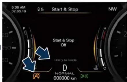
text_image
6:36 AM 02.05.19 5 Start & Stop NW Start & Stop Off Hold > to Enable D NORMAL 000000 km 30.02Other ways to disable the Start & Stop are via the MIA entering the "Vehicle" or "Apps" menu.
- Entering the "Vehicle" page and touch the "Controls" soft-key.
- Touch the "Start & Stop Off" soft-key to disable the function.
- Touch a second time the same soft-key to re-enable the function.
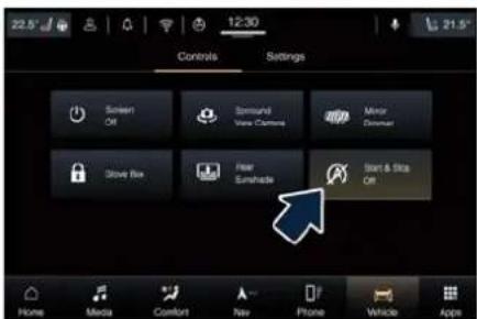
text_image
22.5° 12:30 Controls Settings Screen Off Bsquare View Cartone Mirror Dishman Show Box Fear Sunshine Start & Stop Off Home Media Comfort New Phone Vehicle AppnNOTE:
The highlighted and yellow soft-key indicates the disabled status of Start Stop system and vice versa.
- Touch the "Apps" soft-key on the main category bar or open the shortcuts page (shown in picture).
- Touch the "Start & Stop Off" soft-key to disable the function.
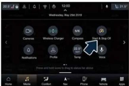
text_image
22.5° Wednesday, May 29st 2019 Cameras Wireless Charger NWN Compass Start & Stop Off 22.5° 000 Notifications Profile Temp Voice Press and hold issues to bring to status bar above Home Media Comfort New Phone Vehicle AppsTo quickly disable the Start&Stop function, you can insert it in the main status or category bar of
the MIA display (see "Maserati Intelligent Assistant™ Operation" in section "Dashboard Instruments and Controls"). Once it is set in the bar, the new menu will be immediately operational.
If the driving conditions allow it, the user can re-enable the Start&Stop function at any time using one of previous ways.
NOTE:
After user intervention, the Start&Stop &system will automatically update the status of the function in all contexts where it can be modified.
Start&Stop System Failure
When the warning light and the related message illuminate on the TFT display (see chapter "Warning and Indicator Lights" in section "Dashboard Instruments and Controls") there is a malfunction in the Start&Stop system and the engine cannot be switched off and restarted automatically. To switch off or restart the engine it is necessary to push the START/STOP. Have the vehicle checked at the Service Network.
Automatic Transmission
The vehicle is equipped with an electronically controlled 8-speed automatic transmission, which automatically changes gear according to the vehicle's instantaneous usage parameters (vehicle speed, road gradient and accelerator pedal position).
It is possible to change gear manually thanks to the "M +/-" (Manual) position for the shift lever.
The electronic shift lever replaces the conventional mechanical lever and has no mechanical connection to the transmission. The transmission is operated by electrical actuators on the hydraulic system and all commands to the control system are transmitted by the CAN network. The lever itself represents a mere user interface. Gear positions are simulated by solenoids inside the lever body, which are computer-controlled and enable or disable certain positions of the lever. The solenoids inside the shift lever prevent the movement of the lever towards invalid positions.
The electronically-controlled transmission provides a precise shift schedule. The transmission electronics are self-calibrating, therefore the

Starting and Driving
gearshift behaviour could become perfect as expected after few hundreds of km.

CAUTION!
In order to properly use the automatic transmission, it is essential that you read through the whole chapter, so that you can understand right from the start what the correct and granted operations are.
Damage to the transmission may occur if the following precautions are not observed:
- Shift into P (Park) only after the vehicle has come to a complete stop: this is the default position of the lever. After engaged P (Park) it is possible set the ignition device to OFF.
- Shift into or out of R (Reverse) only after the vehicle has come to a complete stop and the engine is at idle speed.
- Do not shift between P (Park), R (Reverse), N (Neutral) or D (Drive) when the engine is above idle speed.
- To effect any change from vehicle stop to R (Reverse), D (Drive), 1^st or 2^nd gear, it is necessary to keep the brake pedal fully depressed.

WARNING!
- It is dangerous to move the shift lever out of P (Park) or N (Neutral) if the engine speed is higher than idle speed. If your foot is not firmly pressing on the brake pedal, the vehicle could accelerate quickly forward or in reverse. You could lose control of the vehicle and hit someone or something. Only shift into gear when the engine is idling normally and when your foot is firmly pressing on the brake pedal.
- Unintended movement of a vehicle could injure those in or near the vehicle. As with all vehicles, you should never exit a vehicle while the engine is running. Before exiting a vehicle, always apply the electronic parking brake, shift the transmission into P (Park), and turn the engine o
-
Never leave children alone in a vehicle, or with access to an unlocked vehicle. Allowing children to be in a vehicle unattended is dangerous for a number of reasons. A child or others could be seriously or fatally injured. Children should be warned not to touch the parking brake, brake pedal or the shift lever.
-
When leaving the vehicle, always remove the key fob and lock your vehicle.
- Do not leave the key fob in or near the vehicle. A child could operate power windows, other controls, or move the vehicle.
This vehicle is equipped with a function which requires the transmission to be placed in P (Park) before the engine can be turned off.
This prevents the driver from inadvertently leaving the vehicle without having placed the transmission in P (Park). This system also locks the transmission in P (Park) whenever the ignition device is in the OFF position.
Automatic Transmission Lever
Automatic transmission is operated by a shift lever with unlock button, located on the central console, which can have the following operating positions:
• P (Park): button control;
- R (Reverse);
- N (Neutral);
• D (Drive) automatic forward speed;
- M -/+ (Manual): "+" shifting to higher gear or "-" shifting to lower gear in
Starting and Driving

manual mode (see "Drive Mode" in this section).
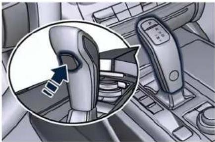
natural_image
Interior view of a car dashboard with a highlighted device component (no text or symbols visible)Transmission status is visible on the lever and on the lower part of the instrument cluster display.
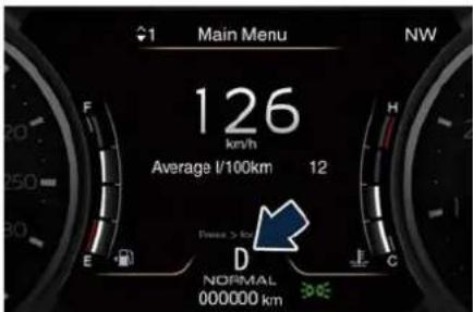
text_image
1 Main Menu NW 126 km/h Average l/100km 12 Free > By D NORMAL 000000 kmShift Lever Movements
Shift lever has two main positions with a single step selection (backward/forward): two unstable position (2) and (3) and two stable position (1) and (4).
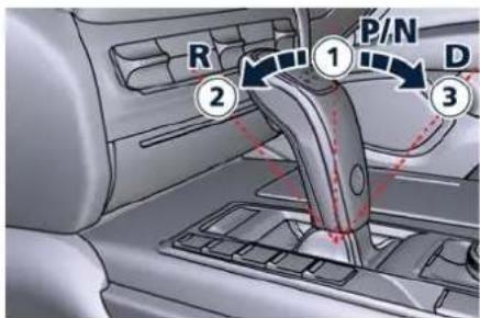
text_image
R P/N D ① ② ③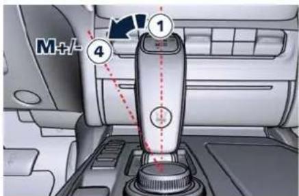
text_image
M+/+ ① ④• Automatic lane ("R", "N", "D") as main central position.
- Manual lane ("M +/-") on left position: move forward for "-" and backward for "+".
- "P" is a button on the top of the lever.
Shift Lever Backlit
- White backlit for "P", "R", "N", "D" and "M +/-": brighter when selected and dimmer when not selected.
- When P (Park) mode is selected, the letter "P" becomes brighter and "P" appears brighter near "N". Backlit on the shift lever depends on the status of the ignition device.
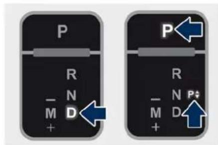
text_image
P R N M D + P R N P# M D +To Engage a Mode (briefly)
To select one of the operating modes, move the lever as previously indicated and press the brake pedal at the same time.
To engage "P" mode, driver must press the "P" button.
In order to engage "R" or "D" mode, driver have to move the shift lever by pressing the unlock button. If the unlock button is not pressed, the instrument cluster shows the popup message shows in picture.


Starting and Driving
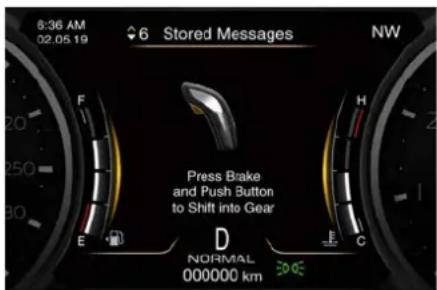
text_image
8:36 AM 02.05.19 6 Stored Messages NW Press Brake and Push Button to Shift into Gear E D NORMAL 000000 kmThe lever functions like a joystick, so releasing it after giving the command, it automatically returns to the two stable positions (vertical in line with "R", "N" and "D" or in line with "-" and "+" when in "M +/-" mode).
- To engage the N (Neutral) mode from R (Reverse) or D (Drive) mode, the driver has to move the shift lever and press the brake pedal only.
- Normally, to engage R (Reverse) mode, press the brake pedal and the unlock button together.
- To pass from P (Park) mode directly to D (Drive) mode, in addition to pressing the brake pedal, it is also necessary to press the unlock button.
-
Normally, to pass from R (Reverse) mode directly to D (Drive) mode and vice versa, in addition to pressing the brake pedal, it is necessary to press the unlock button.
-
The P (Park) mode can be automatically enabled by pressing the "P" button: if the shift lever was in "M +/-" position, will go to central stable position automatically.
- To exit P (Park) mode, or to pass from N (Neutral) to D (Drive) or R (Reverse) position when the car is stopped or is moving at a low speed, press the brake pedal and the unlock button.
- If using the shift lever in M +/- (Manual) mode, you can activate it by moving the lever from D (Drive) to the left and then forward towards the "-" symbol or back towards the "+" symbol and the gear is shifted.

CAUTION!
- DO NOT accelerate while shifting from P (Park) or N (Neutral) to another mode.
• After selecting a transmission mode, wait a few seconds before accelerating. This precaution is particularly important with a cold engine.
Transmission Status on the Instrument Cluster Display
By pressing the unlock button on the lever, the gear change positions field is displayed: if you release the button without moving the lever, the
field disappears after 2 seconds. By operating instead the lever, the new range will be indicated in the field and in the lower part of the display.
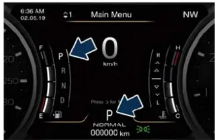
text_image
6:36 AM 02.05.19 Main Menu NW F P R N D E O km/h Press > for P NORMAL 000000 km H L C E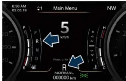
text_image
6:36 AM 02.05.19 Main Menu NW 5 km/h Press > for R NORMAL 000000 km 30 0EIf the vehicle is in D (Drive) status, in M +/- (Manual) or temporarily in manual drive mode, the gear position is indicated beside the lever status ("D" or "M"), on the lower part of the display.
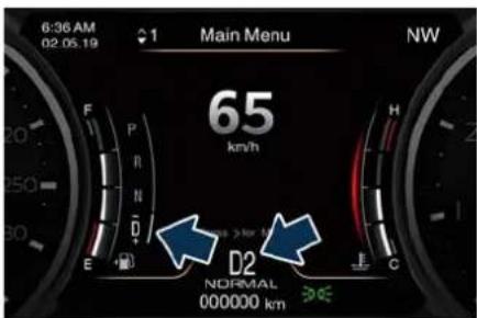
text_image
6:36 AM 02.05.19 Main Menu NW 65 km/h D2 NORMAL 000000 km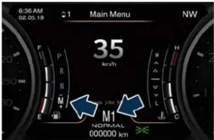
text_image
6:36 AM 02.05.19 1 Main Menu NW 35 km/h M1 NORMAL 000000 km E F P R N M H L CService Shift Lever
In the event of a shift lever malfunction, a message on the instrument cluster will invite to stop the car safety and turn off the engine. In this way the system moves the transmission in P (Park) position.
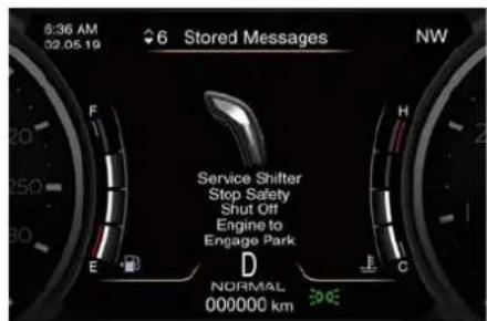
text_image
8:36 AM 02.05.19 6 Stored Messages NW Service Shifter Stop Safety Shut Off Engine to Engage Park D NORMAL 000000 kmAutomatic Transmission Range P (Park)
Use this position to park the vehicle. The transmission can be shifted from "P" position only with the brake pedal and the unlock button pressed: then move the shift lever. To move the shift lever from "P" position to any other position, the engine must be switched on. The engine can be regularly started in P (Park) range. Never attempt to use P (Park) while the vehicle is in motion. When parking on a level surface, you may press the "P" button first, and then apply the electronic parking brake by pulling the trigger upwards.
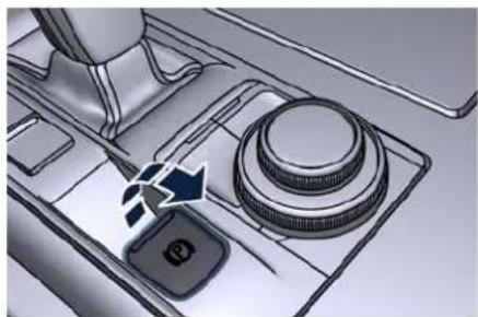
natural_image
Diagram of a mechanical device's internal components, showing a knob and lever mechanism (no text or symbols)The Instrument cluster will display the related light indicator and the message for 5 seconds.
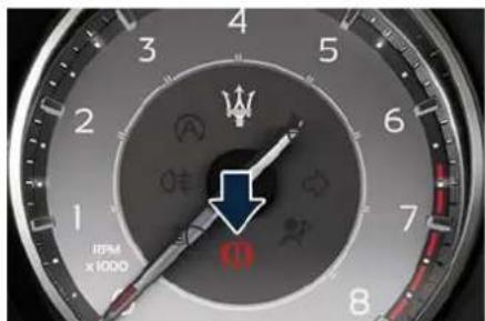
text_image
4 3 5 2 6 1 7 8 IFM x1000When parking on a hill, apply the parking brake before pressing the "P" button.
For enhanced security, turn the front wheels toward the kerb on a downhill and away from the kerb on an uphill grade.

Starting and Driving

WARNING!
- Never use the P (Park) mode as a substitute for the electric parking brake. Always apply the parking brake fully when parked to prevent vehicle movement and possible injury or damage.
- Make sure the transmission is in P (Park) before leaving the vehicle.

CAUTION!
DO NOT race the engine when shifting from P (Park) or N (Neutral) into another gear range, as this can damage the drivetrain.
The following indicators should be used to ensure that you have engaged the shift lever into the "P" position:
- when shifting into P (Park), push the "P" button on the shift lever.
- with the brake pedal released, verify that "P" position is illuminated on the shift lever and in the instrument cluster display.
R (Reverse)
This range is used to move the vehicle backward.
Switching to R (Reverse) starting from N (Neutral) is only possible if the vehicle is moving backwards. We
recommend to shift into R (Reverse) only after the vehicle has come to a complete stop.
- Vehicle stationary: switching between R (Reverse) and D (Drive), passing from N (Neutral), in addition to the action on the shift lever this requires applying the brake pedal and the unlock button being pressed.
- Vehicle moving: the driver can switch from R (Reverse) to N (Neutral) acting on the shift lever without pressing the unlock button and the brake pedal.
N (Neutral)
- Vehicle stationary and engine started: switching from N (Neutral) to P (Park) requires "P" button pressed only. Switching from N (Neutral) to R (Reverse) and/or D (Drive) requires brake pedal and unlock button pressed and the action on the shift lever.
- Vehicle moving: switching from N (Neutral) to R (Reverse) and/or D (Drive) requires pressing the unlock button and the action on the shift lever. Switching to R (Reverse) starting from N (Neutral) is only possible if the vehicle is moving backwards, while switching to D (Drive) starting from N (Neutral) is
only possible if the vehicle is moving forwards.
Set the parking brake and shift the transmission into P (Park) mode if you must leave the vehicle.
NOTE:
To move the car into tunnel washers, or to generally move with engine off, if foreseen use the "Car Wash" mode (see "Bodywork Maintenance and Cure" chapter in section "Maintenance and Care").

WARNING!
Do not switch to N (Neutral) and/or never turn off the ignition to coast downhill. These are unsafe practices that limit driver's response to changing traffic or road conditions. It is possible to lose control of the vehicle and have a collision.

CAUTION!
Towing the vehicle, coasting, or driving for any other reason with the transmission in N (Neutral) can result in transmission damage. See "Towing a Disabled Vehicle" in section "In an Emergency" for further information.
Starting and Driving

D (Drive)
This range should be used for most city and highway driving. It provides the smoothest upshifts and downshifts and the best fuel economy. The transmission automatically shifts up and down through all gears. The D (Drive) mode provides optimum driving characteristics under all normal operating conditions of the vehicle.
- Vehicle stationary: to switch from D (Drive) to R (Reverse) requires brake pedal and unlock button pressed and the action on the shift lever: to reach N (Neutral) starting from D (Drive) is possible by only acting on the shift lever.
- To enable special operations while the car is moving at a low speed, such as getting out of marsh or snow, it is possible to run quickly from D (Drive) to R (Reverse), and vice versa, by pressing the unlock button and acting on the shift lever passing from N (Neutral).
- Vehicle moving: switching to N (Neutral) from D (Drive) it is not necessary to press brake pedal.
- From D (Drive) selected mode it is always possible to switch to M +/- (Manual) mode, by move the shift lever to the left (see following paragraph); to return to "D"
position, move the shift lever to the right. It is possible to shift from D (Drive) mode to M +/- (Manual) mode regardless of car speed.
- When in D (Drive) mode, using the paddles behind the steering wheel (if equipped), will cause the system to enter a temporary function and enable the manual shift mode. This range is indicated with the symbols "+/-" above and below "D" letter on the gear range field of the display. The system will then switch back to automatic mode according to time elapsed in "temporary" mode and driving conditions.
At extremely cold temperatures (-30°C / -23°F or below), transmission may be affected by the low temperature of the engine and transmission. Normal operation will resume once the transmission temperature has risen to a normal level.
M +/- (Manual)
This mode is obtained by moving the shift lever to the left in "M +/-" position.
In this mode, the transmission interacts with the driver in order to allow manual shift and ensure increased control of the vehicle. The current mode allows the transmission system to optimise the engine brake action,
remove undesired shifting into higher and lower gears and improve the overall performance of the vehicle.
This mode allows you to move the shift lever step by step forward "-" or backward "+" without pressing the unlock button. The current transmission gear is displayed on the instrument cluster beside "M".
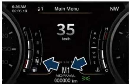
text_image
6:36 AM 02.05.19 1 Main Menu NW 35 km/h M1 NORMAL 000000 km DOEManual mode can be activated at any time, with no need to release the brake pedal.
In M +/- (Manual) mode, the transmission will shift up or down (+/-) if manually selected by the driver by using the shift lever, or shift paddles on the steering wheel (if foreseen). The transmission remains in the engaged gear until the driver shifts into another higher or lower gear, except in the following cases.


Starting and Driving
- Lack of accelerator pedal activity will cause the transmission to revert to automatic operation. The transmission will also upshift automatically once maximum engine speed is reached.
- If in SPORT mode, the transmission will remain in the selected gear even when maximum engine speed is reached. The transmission will upshift only if enabled by the driver. Manual upshift or downshift will be maintained as long as SPORT mode is selected, even by full stroke pedal press.
- If in "M +/-" or in SPORT mode, the transmission will automatically downshift as the vehicle slows to halt (to prevent engine lugging) and the current gear will display on the instrument cluster. Shifting the shift lever backward "+" or moving the right shift paddle "+" towards the steering wheel when stationary, will cause the vehicle to start in second gear. If the vehicle speed is too low, the system will ignore further upshifts. Avoid using speed control when the M +/- (Manual) mode is engaged.
When the car stops in M +/- (Manual) mode, the transmission automatically moves the shift lever and inserts P (Park).
If you enter the I.C.E. drive mode when the gearshift is in "M +/-" position, the system activates the automatic return of the shift lever in D (Drive) mode.
Shift Paddles (if equipped)
The driver can change gears with the shift paddles behind the steering wheel when in D (Drive) and M +/- (Manual) mode.
Using the shift paddles, the corresponding icon will display on the instrument cluster beside the "M" indication and current shifted gear.
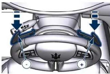
text_image
Technical diagram of a car's seat assembly with labeled components and directional arrows indicating movement or force.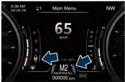
text_image
6:36 AM 02.05.19 ↑1 Main Menu NW 65 km/h M2 NORMAL 000000 km > for MPH 30 °CPull the right shift paddle "+" towards the steering wheel and release it to enter the higher gear; do the same operation with the left shift paddle "-" to enter the lower gear.
- When in D (Drive) mode, by pressing "-" paddle the transmission shifts to "D1 - D2" temporary mode (or the "Launch Control" on the TROFEO version).
- Pull simultaneously both paddles to deactivate the D (Drive) temporary mode (or the "Launch Control" on the TROFEO version)..
Gear Shift Indicator (GSI)
In order to improve fuel economy, we recommend that you shift gears when the GSI system prompts you to do so. This will help reduce fuel consumption without significantly affecting vehicle performance.
Starting and Driving

When in "M +/-" (Manual) mode, GSI indicates when a gear shift is needed in two different ways, depending on whether you use the paddles or the transmission lever to change gear.
- When using the paddles, GSI indicates when a gear shift is needed by coloring the correspondent paddle in white: up (right side) or down (left side) and displaying "SHIFT" reinforced by an up/down arrow according to the side.
text_image
M2 NORMAL 000000 km
text_image
E M3 NORMAL 000000 km SHIFT C- When using the transmission lever to shift, GSI indicates when a gear shift is needed by displaying just "SHIFT" on the corresponding side reinforced by an up/down arrow according to the side.
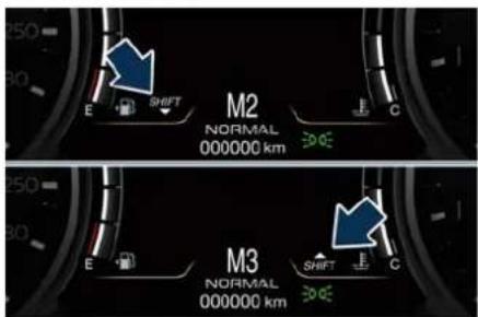
text_image
M2 NORMAL 000000 km M3 NORMAL 000000 kmWhen the new gear is engaged, the GSI turns off. If the shift runs late or is not performed at all, the GSI remains lit for a few seconds then turns off. As soon as new conditions requiring further gear change occur, the GSI light will illuminate again.
NOTE:
The GSI system will only work when the transmission is set in M +/- (Manual) mode.
Transmission Malfunction and Overheating Conditions
Transmission Emergency Control Transmission function is electronically monitored to detect abnormal conditions. If a condition that could result in transmission damage is detected, "Transmission Limp Home Mode" will be activated. In this situation, the transmission may
operate only in certain gears, or may not shift at all. Vehicle performance may be severely degraded and the engine may stall. In some situations, the transmission system may not re-engage if the engine is turned off and restarted.
A message in the instrument cluster will inform the driver about the more serious transmission conditions, and indicate what actions may be necessary.
Transmission Oil Over Temperature If the transmission oil temperature exceeds the operating limit, the red warning light illuminates on the instrument cluster.
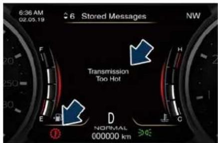
text_image
6:36 AM 02.05.19 6 Stored Messages NW Transmission Too Hot E D NORMAL 000000 km F H CIn this case, slow down until temperature returns to normal level (the light will turn off).
If this is not sufficient, we recommend to stop the vehicle, shift the lever to

Starting and Driving
position P (Park) or N (Neutral) and keep the engine idle until the red temperature warning light turns off and the message disappears from the display. Resume driving without demanding high engine performance. If the red warning light and the related message turns on again, it is advisable to stop the vehicle, turn off the engine and wait for the engine/transmission assembly to fully cool down.
If the instrument cluster message indicates that the transmission may not re-engage after engine shutdown, perform the following procedure preferably at a Service Center.
In the event of a momentary problem, the transmission can be reset to regain all forward gears by performing the following steps.
- Stop the vehicle.
- Shift the transmission into P (Park), if possible.
- Turn the engine off.
- Wait approximately 30 seconds.
- Restart the engine.
- Shift the transmission into D (Drive) and then into the desired gear range. If the problem is no longer detected, the transmission will return to normal operation.
NOTE:
Even if the transmission can be reset, we recommend that you visit the Service Network at your earliest possible convenience, which has diagnostic equipment to determine if the problem could recur.
Transmission Manual Release of P (Park) Position
See chapter "Transmission Manual Release of P (Park) Position" in section "In an Emergency".
All-Wheel Drive (AWD version only)
The active on-demand All-Wheel Drive (AWD) system provides available optimum traction for a wide variety of road surface and driving conditions. The system minimizes wheel slip by automatically redirecting torque to the front and rear wheels as necessary. To maximise fuel economy, the AWD system automatically disengages torque distribution on front axle when road and environmental conditions are such that wheel slip is unlikely to occur. When specific road and environmental conditions require increased levels of road traction, the AWD system automatically distributes the torque between front and rear axle in order to grant the best driving experience. Torque distribution is displayed on the TFT in the "Drive Mode" main menu. Refer to "TFT Display: Menu and Submenu Content" in section "Dashboard Instruments and Controls" for further information.

WARNING!
There may be a slight delay for AWD engagement after a wheel slip condition occurs.
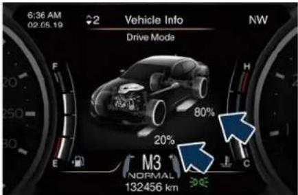
text_image
6:36 AM 02.05.19 2 Vehicle Info NW Drive Mode F H 20% 80% 20% M3 NORMAL 132456 km CNOTE:
If the AWD system service warning message appears after engine start up, or during driving, it means that the AWD system is not functioning properly or is in recovery mode due to overheating caused by the excessive wheel spin. In this condition the vehicle can continue driving but only rear wheel drive is working. If the warning message is often activated, it is recommended to have the vehicle serviced at the Service Network.
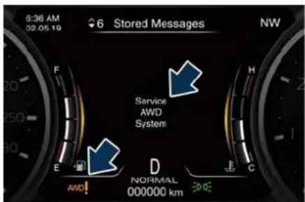
text_image
6:36 AM 02.05.19 6 Stored Messages NW Service AWD System E D AWD! NORMAL 000000 km 30.00Drive Mode
Controls Preview
Drive modes can be set using the buttons on central console.

CAUTION!
"NORMAL" is the default drive mode, optimised for the best balance between performances, fuel consumptions and emissions in the standard conditions use of the car.
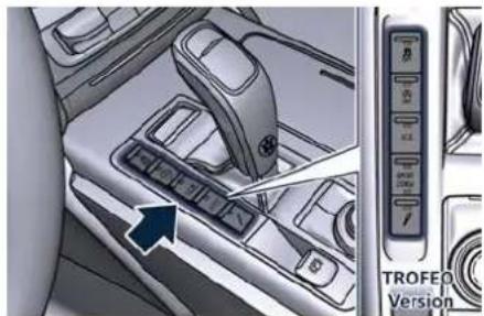
natural_image
Interior view of a car gear shift lever with control panel and TROFEO Version indicator (no text or symbols on the main components)Buttons on the central console have the following functions:
- (ESC Off): to exclude/reactivate the ESC system.
- (Start&Stop Off): to deactivate/reactivate the Start&Stop system.
- I.C.E: to activate/deactivate the drive mode to ensure increased control on slippery surfaces as well as higher

Starting and Driving
energy efficiency (see "Monitoring Settings on Display" in this chapter.
- SPORT (NOT for TROFEO version): to activate/deactivate a sportier drive mode. In this mode, the vehicle has a faster throttle response and ESC sport calibration (not recommended on wet/slippery surfaces). Activating this drive mode, will also change the EPS setting.
- SPORT and CORSA (TROFEO version only): to activate/deactivate the sportier and the race drive mode. When in "SPORT" drive mode, the vehicle has a faster throttle response and ESC sport calibration (not recommended on wet/slippery surfaces). Activating this drive mode, will also change the EPS setting. When in "CORSA" drive mode, in addition to what indicated for the sposts mode, the transmission use a specific gear shift pattern and the traction is shifted more on the rear wheels with increased oversteering behavior. Traction control with dedicated calibration to maximize traction vs stability and "Launch Control" start mode.
- (Suspension): to switch between the two suspensions setting modes: soft (LED light off and "S" in the telltale on the TFT display) and hard
(LED light on and "H" in the telltale on the TFT display). Activating this drive mode, will also change the EPS setting.
By selecting one of these drive modes, the yellow or white LED on the button illuminates and, for some of these, the vehicle configuration obtained is graphically displayed on instrument cluster. The same screen is also obtained when selecting the "Drive mode" menu using the buttons on steering wheel.
Setting the Drive Mode
Drive modes can be set using the buttons on central console.
Keys (buttons) only have two statuses: OFF and ON. The OFF status (button released) is the standard function mode. The ON status is activated by pressing the button, the dedicated LED will illuminate. It is necessary to press the ESC Off button for at least 3 seconds.
At each key on the car starts always in NORMAL drive mode (all LEDs are OFF) and driver can select different drive mode according to following table.
| Button | ON – Button pressed (LED ON) |
 | Electronic Stability Control ESC partially deactivated. |
 | Start&Stop function deactivated. |
 | Increased Control and Efficiency mode ON (*). |
S  | Sportier drive mode (SPORT) ON. |
| SPORT CORSA (TRO-FEO version only) | • Button pressed the first time (upper LED ON): sportier drive mode (SPORT) ON.• Button pressed the second time (upper and lower LED ON): race drive mode (CORSA) ON, ESC partially deactivated (ON) and hard/stiff suspension setting ("S").• When button is pressed third time, it returns to OFF-button release. |
 | Soft/Hard suspension setting. |
PORT
CORSA
(TRO-
FEO
version
only)
| Button | ON – Button pressed(LED ON) |
| (*) I.C.E. (Increased Control and Efficiency) operates on engine supply in order to reduce fuel consumption, exhausts, noisiness (efficiency) by dampening vehicle reactions (control). The current mode is also useful for low-grip surfaces. | |
The tables below summarise the adjustment of transmission and engine parameters according to set drive mode/s. (ESC Off) is the only mode that does not depend on the activation or deactivation of the other modes. The tables show the two configurations with:
- (ESC Off) button NOT pressed;
- ESC Off) button pressed.

Starting and Driving
(ESC Off) Button NOT pressed (NOT for TROFEO Version)
| ■ Buttonpressed: LED ON□ Button notpressed: LED OFF | □ □ □ □ □ I.C.E.□ SPORT□ | □ □ □ □ □ I.C.E.□ SPORT□ | □ □ □ □ □ I.C.E.□ SPORT□ | □ □ □ □ □ I.C.E.□ SPORT□ | □ □ □ □ □ I.C.E.□ SPORT□ |
| Setup | NORMAL + Auto+ S&S enabled +Soft suspensions | NORMAL + Auto+ S&S disabled +Soft suspensions | I.C.E. + Auto +S&S enabled +Soft suspensions | SPORT + Auto +S&S disabled +Soft suspensions | NORMAL + Auto+ S&S disabled +Hard suspensions |
| Stability control Active Active Active Active Active Active Active Active Active Active Active Active Active Active Active Active Active Active Active Active Active Active Active Active Active Active Active Active Active Active Active Active Active Active Active Active Active Active Active Active Active Active Active Active Active Active Active Active Active Active Active Active Active Active Active Active Active Active Active Active Active Active Active Active Active Active Active Active Active Active Active Active Active Active Active Active Active Active Active Active Active Active Active Active Active Active Active Active Active Active Active Active Active Active Active Active Active Active Active Active | |||||
| Electric PowerSteering (EPS) | Normal Normal Normal | Normal Sport Sport | |||
| Suspensions setup Normal | Normal Normal Normal | Normal Hard | |||
| Engine control Normal | Normal Normal Comfort | Performance Performance | |||
| Engine boost Normal | Boost Overboost Low | Low boost Overboost Overboost | |||
| Exhaust sound Low (Rev.Threshold) | Low (Rev.Threshold) | Low | Always High | Always High | |
| Gear shifting point | Normal | - | Comfort | Performance | Performance |
| Kick down | Yes | Yes | Yes - Soft | Yes - Strong | Yes - Strong |
| Upshift rev. limiter | Yes | Yes | Yes | Yes (No, when inM+/-) | Yes (No, when inM+/-) |
| Automatic down-shift | Normal Anti - Stall | Comfort Performance | (Anti - Stall, whenin M+/-) | Performance(Anti - Stall, whenin M+/-) | |
Starting and Driving

| ■ Buttonpressed: LED ON□ Button notpressed: LED OFF | □ □ □ □ □ I.C.E.□ SPORT□ ↗ | □ □ □ □ □ I.C.E.□ SPORT□ ↗ | □ □ □ □ □ I.C.E.□ SPORT□ ↗ | □ □ □ □ □ I.C.E.□ SPORT□ ↗ | □ □ □ □ □ I.C.E.□ SPORT□ ↗ |
| Shifting timing Normal | Rapid - Normal | Comfort Sport (Rapid | - | Sport, when in M +/-) | Sport (Rapid - Sport, when in M +/-) |
| (*) In low- and medium-grip conditions (e.g., rain, snow, ice, sand, etc.) it is advisable not to activate SPORT mode, even with the ESC system active (button ESC OFF) not pressed). | |||||
(ESC Off) Button pressed (NOT for TROFEO Version)
| ■ Buttonpressed: LED ON□ Button notpressed: LED OFF | |||||
| I.C.E.SPORT | I.C.E.SPORT | I.C.E.SPORT | |||
| Setup | NORMAL + Auto+ S&S disabled +Soft suspensions | NORMAL + Auto+ S&S disabled +Soft suspensions | I.C.E. + Auto +S&S disabled +Soft suspensions | SPORT + Auto +S&S disabled +Soft suspensions | NORMAL + Auto+ S&S disabled +Hard suspensions |
| Stability control OFF | OFF OFF OFF OFF | ||||
| Electric PowerSteering (EPS) | Normal Normal Normal | Normal Sport Sport | |||
| Suspensions setup Normal | Normal Normal Normal | Normal Hard | |||
| Engine control Normal | Normal Comfort | Performance Performance | |||
| Engine boost | Normal boost | Overboost | Low boost | Overboost | Overboost |


Starting and Driving
| ■ Buttonpressed: LED ON□ Button notpressed: LED OFF | |||||
| AOFFI.C.E.SPORT | AOFFI.C.E.SPORT | AOFFI.C.E.SPORT | AOFFI.C.E.SPORT | AOFFI.C.E.SPORT | |
| Exhaust sound Low (Rev.Threshold) | Low (Rev.Threshold) | Low Always High Always High | |||
| Gear shifting point | Normal - Comfort | Performance Performance | |||
| Kick down Yes Yes | Yes - Soft Yes - Strong | g Yes - Strong | |||
| Upshift rev. limiter | Yes Yes Yes Yes (No, | when in | M+/-) | Yes (No, when in M+/-) | |
| Automatic down-shift | Normal Anti - Stall | Comfort Performance | (Anti - Stall, when in M+/-) | Performance (Anti - Stall, when in M+/-) | |
| Shifting timing | Normal Rapid - Normal | Comfort Sport (Rapid - | Sport, when in M+/-) | Sport (Rapid - Sport, when in M+/-) | |

WARNING!
On TROFEO version, when CORSA drive mode is activated, the ⚙ (ESC OFF) indicator light on the instrument cluster is on because the intervention of the Electronic Stability Control (ESC) system is lower than the other modes, but still present to allow a more sporty drive.
You can always press 📋 (ESC OFF) button to fully deactivate ESC system. Due to high power output of the engine can be potentially dangerous to drive the car on wet or slippery roads with ESC off and CORSA drive mode set.

(ESC OFF) Button NOT pressed (TROFEO Version only)
| ■ Buttonpressed: LED ON□ Buttonnot pressed:LED OFF | □ □ □ □ □ I.C.E.□ SPORT□ CORSA□ J | □ □ □ □ □ I.C.E.□ SPORT□ CORSA□ J | □ □ □ □ □ I.C.E.□ SPORT□ CORSA□ J | □ □ □ □ □ I.C.E.□ SPORT□ CORSA□ J | □ □ □ □ □ I.C.E.□ SPORT□ CORSA□ J | □ □ □ □ □ I.C.E.□ Sport□ CORSA□ J | □ □ □ □ □ I.C.E.□ SPORT□ CORSA□ J |
| Setup | NORMAL + Auto + S&S enabled + Soft suspensions | NORMAL + Auto + S&S disabled + Soft suspensions | I.C.E. + Auto + S&S enabled + Soft suspensions | SPORT + Auto + S&S disabled + Soft suspensions | CORSA + Auto + S&S disabled + Manual + Corsa suspensions | NORMAL + Auto +S&S disabled + Corsa suspensions | |
| Stability control | Active Active Active Active-Sport (*) Active-Corsa | (*) | Active-Sport (*) | ||||
| Electric Power Steering (EPS) | Normal Normal Normal Sport Corsa Sport | ||||||
| Suspensions setup | Normal Normal Normal Normal Hard Hard | ||||||
| Engine control | Normal Normal Comfort Performance Performance | ||||||
| Engine boost | Normal boost Overboost Low boost Overboost Overboost | ||||||
| Exhaust sound | Low (Rev. Threshold) | Low (Rev. Threshold) | Low Always High | Always High | Always High | ||
| Gear shifting point | Normal | - | Comfort | - | Performance | Performance | |
| Kick down | Yes | Yes | Yes - Soft | Yes - Strong | Not | Yes - Strong | |
| Upshift rev. limiter | Yes | Yes | Yes | Yes (No, when in M+/-) | Not | Yes (No, when in M+/-) | |

Starting and Driving
| ■ Buttonpressed: LED ON□ Buttonnot pressed:LED OFF | □ □ AOFF□ I.C.E.□ SPORT□ CORSA□ ∅ | □ □ AOFF□ I.C.E.□ SPORT□ CORSA□ ∅ | □ □ AOFF□ I.C.E.□ SPORT□ CORSA□ ∅ | □ □ AOFF□ I.C.E.□ SPORT□ CORSA□ ∅ | □ □ AOFF□ I.C.E.□ SPORT□ CORSA□ ∅ | □ □ AOFF□ I.C.E.□ SPORT□ CORSA□ ∅ |
| Automaticdownshift | Normal Anti - Stall Comfort Performance | (Anti - Stall,when in M+/-) | Anti - Stall Performance(Anti - Stall,when in M+/-) | |||
| Shifting timing | Normal Rapid - Normal Comfort Sport (Rapid -Sport, when inM+/-) | Quick - Corsa Sport (Rapid -Sport, when inM+/-) | ||||
| (*) In low- and medium-grip conditions (e.g., rain, snow, ice, sand, etc.) it is advisable not to activate SPORT or CORSA mode, even with the ESC system active (button,ESC OFF) not pressed). | ||||||
(ESC OFF) Button pressed (TROFEO version only)
| ■ Buttonpressed: LED ON□ Buttonpressed: LED OFF | ■ □ □ □ I.C.E.□ SPORT□ CORSA□ □ | ■ □ □ □ I.C.E.□ SPORT□ CORSA□ □ | ■ □ □ □ I.C.E.□ SPORT□ CORSA□ □ | ■ □ □ □ I.C.E.□ SPORT□ CORSA□ □ | ■ □ □ □ I.C.E.□ SPORT□ CORSA□ □ | ■ □ □ □ I.C.E.□ SPORT□ CORSA□ ▢ | ■ □ □ □ I.C.E.□ SPORT□ CORSA□ ▢ |
| Setup | NORMAL + Auto + S&Sdisabled + Soft suspensions | NORMAL + Auto + S&Sdisabled + Soft suspensions | I.C.E. + Auto + S&S disabled + Soft suspensions | SPORT + Auto + S&S disabled + Soft suspensions | CORSA + Auto + S&S disabled + Manual + Corsa suspensions | NORMAL + Auto + S&S dis-abled + Corsa suspensions | |
| ■ Buttonpressed: LEDON□ Buttonpressed: LEDOFF | ■ □ (A) OFF□ I.C.E.□ SPORT□ CORSA□ ∅ | ■ □ (A) OFF□ I.C.E.□ SPORT□ CORSA□ ∅ | ■ □ (A) OFF□ I.C.E.□ SPORT□ CORSA□ ∅ | ■ □ (A) OFF□ I.C.E.□ SPORT□ CORSA□ ∅ | ■ □ (A) OFF□ I.C.E.□ SPORT□ CORSA□ ∅ | ■ □ (A) OFF□ I.C.E.□ SPORT □ CORSA□ ∅ | ■ □ (A) OFF□ I.C.E.□ SPORT□ CORSA□ ∅ |
| Stability con-trol | OFF OFF OFF OFF | OFF OFF | |||||
| Electric Power Steering (EPS) | Normal Normal | Normal Sport Corsa | Sport | ||||
| Suspensions setup | Normal Normal | Normal Normal | Hard Hard | ||||
| Engine control | Normal Normal | Comfort Performance | Performance Performance | ||||
| Engine boost | Normal boost Overboost | Overboost Low boost | Overboost Overboost | ||||
| Exhaust sound | Low (Rev. Threshold) | Low (Rev. Threshold) | Low Always High | Always High Always High | |||
| Gear shifting point | Normal - | Comfort | Performance Performance | ||||
| Kick down | Yes | Yes | Yes - Soft | Yes - Strong | Not | Yes - Strong | |
| Upshift rev. limiter | Yes | Yes | Yes | Yes (No, when in M+/-) | Not | Yes (No, when in M+/-) | |
| Automaticdownshift | Normal Anti - Stall | Comfort Performance | (Anti - Stall, when in M+/-) | Anti - Stall Performance | (Anti - Stall, when in M+/-) | ||
| Shifting timing | Normal Rapid - Normal | Comfort | Sport (Rapid - Sport, when in M+/-) | Quick - Corsa | Sport (Rapid - Sport, when in M+/-) | ||

Starting and Driving
NOTE:
A different drive mode can be set even with engine running and vehicle in motion.
To activate a drive mode, press briefly the corresponding button as indicated below. The LED on the button will light up and set drive mode screen will be displayed (example in the figure: NORMAL) for 5 seconds.
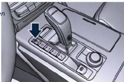
natural_image
Interior view of a car showing a hand shift lever with a blue arrow pointing to the left side (no text or symbols visible)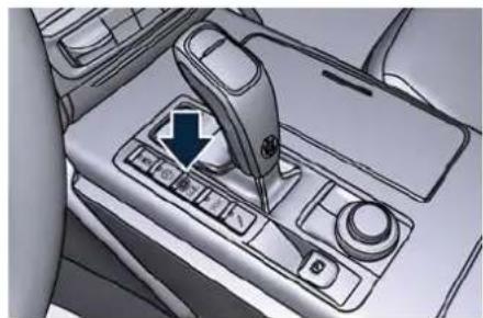
natural_image
Interior view of a car gear shift control panel with a blue arrow indicating the direction (no text or symbols visible)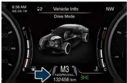
text_image
6:36 AM 02.05.19 2 Vehicle Info Drive Mode NW M3 NORMAL 132456 kmActivate/Deactivate (ESC OFF) Drive Mode
To activate (ESC OFF) drive mode press the corresponding button for at least 3 seconds: the yellow LED on the button will turn on.
To deactivate the drive mode, briefly press the same button again: the LED will turn off and the display will show the message indicating that ESC OFF) drive mode is off and ESC system is active.
Deactivate/Reactivate (Start&Stop Off) Drive Mode
To deactivate the Start&Stop function normally active, briefly press the corresponding button once: the yellow LED on the button will turn on. To reactivate the Start&Stop function, briefly press the same button again: the LED will turn off.
Activate/Deactivate I.C.E. and SPORT Drive Mode
To activate one of these drive mode, briefly press the corresponding button once: the white LED on the button will turn on.
To disable the drive mode activated, briefly press the same button again: the LED will turn off.
If you deactivate the SPORT mode by briefly pressing the related button when is activate (LED lit) it also deactivates the (Suspension) mode if it was activate (LED lit).
Activate/Deactivate SPORT and CORSA Drive Mode (TROFEO Version only)
To activate SPORT drive mode, briefly press the corresponding button once: the upper white LED on the button will turn on. CORSA drive mode can be active by pressing again the same button for more than a second (about 1.2 seconds): also the lower LED on the button will turn on. To return in SPORT drive mode, briefly press the SPORT/CORSA button again.
When in CORSA drive mode, (Suspension) hard drive mode can not
Starting and Driving

be set and you can run the "Launch Control" start procedure (see "Launch Control Mode" in this section).
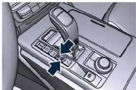
natural_image
Interior view of a car showing a car gear shift lever with directional arrows indicating motion (no text or symbols visible)To disable the SPORT mode without activating the CORSA mode, briefly press the same button once again: the two LED will turn off.
Activate/Deactivate Hard Suspension Drive Mode
Briefly press "7" (Suspension) button on the central console to activate the hard suspension setting recognizable by the green color of the 4 shock absorbers, when in NORMAL, I.C.E. or SPORT drive mode. When exiting the drive mode screen, the setting is always visible through the icon with "S" (Soft) or "H" (Hard) beside on the upper right side of the TFT display (area 9).
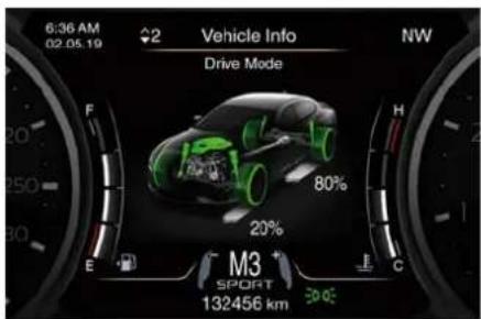
text_image
6:36 AM 02.05.19 Vehicle Info NW Drive Mode 80% 20% M3 SPORT 132456 km 30.00Monitoring Settings on Display
By gaining access to "Drive mode" menu through the buttons on steering wheel right-hand side, it is possible to monitor the settings for driving.
The list and figure show vehicle parameters referred to each drive mode. Driving mode and its parameters are identified by a different color (example in the figure: SPORT).
A Powertrain.
B Drive Mode/ESC.
C Torque distribution (AWD version only).
D Suspension stiffness.
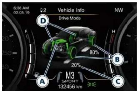
text_image
6:36 AM 02.05.19 2 Vehicle Info NW Drive Mode D F H B 80% 20% A C M3 SPORT 132456 kmSPORT


Starting and Driving
The table below specifies the default settings for each drive mode.
| Drive Mode Default Condition | |||
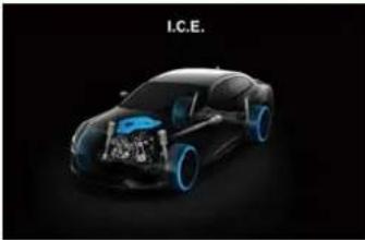 | ESC I.C.E. | ||
| [ZYH] | Normal | ||
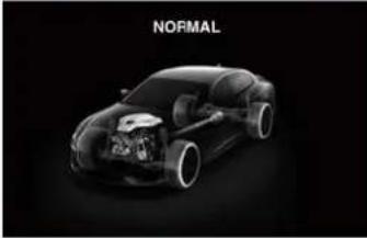 | ESC Normal | ||
 | Normal | ||
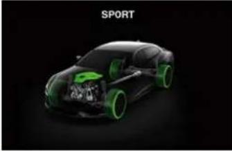 | ESC Sport | ||
| [CTGT] | Normal | ||
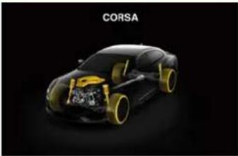 | ESC Corsa | ||
 | Corsa | ||
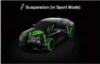 | ESC Sport | ||
| [04KH] | Sport | ||

Starting and Driving
I.C.E. Mode excluding ESC
To release the vehicle in low grip conditions (e.g.: heaps of snow, mud, sand, etc), it is possible to shift the transmission function in the specific driving mode as required for these situations, by pressing the I.C.E. button and to exclude completely the yaw and spinning control system, by pressing the button for at last three seconds (ESC OFF).
Launch Control Mode (TROFEO version only)
"Launch Control" mode is a performance start procedure. By activating this procedure you get the best possible acceleration from standstill of the car.
This mode allows you to ground the torque necessary to prevent the wheels from slipping during acceleration performance.
To make a performance start in "Launch Control" mode, the following conditions must be met:
• Water and transmission temperature in proper range.
- No engine and on board systems faults.
- The vehicle mileage must be higher than 700 km (440 mi).
- "CORSA" drive mode on.
- Shift lever in "D" or "M +/-" position.
- The vehicle must be stationary on a level road surface.
- The driver door closed and the safety belt fastened.
Launch Control Sequence
NOTE:
- All the above mentioned conditions must be verified in order to activate
"Launch Control" performance start procedure.
- During "Launch Control" ACC, FCW and ADA (if equipped) are temporarily disabled.
• Each step displayed on the instrument cluster has a time out approximately of 5 seconds. - "Launch Control" maneuver requires to use both feet, left foot to brake and right foot to accelerate at the same time.
- With engine on, parking brake disengaged, brake pedal pressed and steering wheel straight, pull "-" left paddle. The instrument cluster shows the "Launch Control" engaged page.
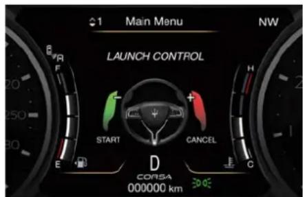
text_image
Main Menu NEW LAUNCH CONTROL START CANCEL D CORSA 000000 km- To confirm the procedure, pull again the "-" paddle. To abort the procedure, pull "+" right paddle.
- To confirm the "Launch Control" sequence, press full the brake pedal as indicated in the message on the instrument cluster.
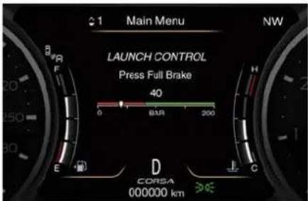
text_image
Main Menu NEW LAUNCH CONTROL Press Full Brake 40 6 BAR 200 D COREA 000000 km ≥0E- With brake pedal pressed full with left foot, fully press the accelerator pedal (with right foot) as indicated in the message on the instrument cluster.
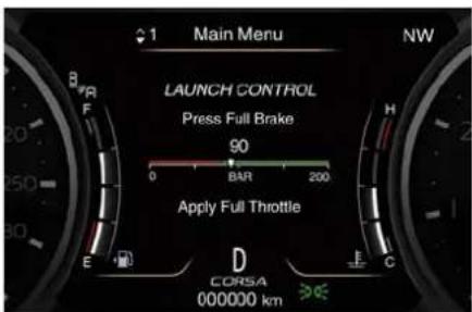
text_image
1 Main Menu NW LAUNCH CONTROL Press Full Brake 90 0 BAR 200 Apply Full Throttle D CORSA 000000 km E F G H C- Release brake pedal. The launch of the vehicle starts with ESC that manages the maximum performance
and engine torque calibrated to maximize performance. Maximum performance is achieved if driver let the engine rpm stall above 2300 rpm before releasing brake pedal.
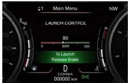
text_image
Main Menu NW LAUNCH CONTROL 90 0 BAR 200 To Launch Release Brake D CORSA 000000 kmDuring the acceleration phase the "Launch Control" symbol appears at the top right of the TFT display.
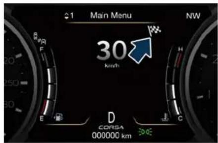
text_image
Main Menu NW 30 km/h D CORSA 000000 kmParking Brake
The vehicle is equipped with an electric automatic parking brake, also called EPB (Electric Parking Brake). The EPB braking action on model with "Base" braking system (equipped with rear floating caliper) is ensured by a power actuator directly working on the brake pad inside each caliper of the rear brake system.
All other braking system ("Performance Dual Cast" and "Dual Cast") are equipped with a dedicated caliper which acts on each rear brake disc.
It can be automatically engaged when the engine is turned off and disengaged with engine running, driver seatbelt latched and driver door closed, while pressing the brake pedal and operating the shift lever. Furthermore, EPB can be automatically engaged above a slope threshold with transmission in parking to avoid damage to the vehicle. EPB can be disengaged before to turn off the vehicle.
When the parking brake is applied, the warning light lights up on the tachometer display and the related message is displayed on the instrument cluster for 5 seconds (see

Starting and Driving
"Warning and Indicators Lights" in section "Dashboard Instruments and Controls").
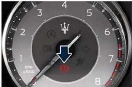
text_image
10PM x1000During engagement and disengagement procedures, the warning light flashes until the parking brake has reached its maximum activation force and is respectively fully released. In the above-mentioned conditions, the automatic engagement function can be deactivated/activated by selecting the menu item "Vehicle settings" on the main menu (refer to paragraph "Deactivating Automatic Operation" in this chapter).
Manual Engagement/Disengagement
The parking brake can also be manually engaged or disengaged when the engine is running or the ignition device is in the RUN position, by pressing the brake pedal and raising the lever located behind the shift lever.
When the parking brake is applied, the warning light lights up on the tachometer and the related message will be displayed for 5 seconds on the instrument cluster.
If you attempt to engage/disengage the parking brake without having pressed the brake pedal, a message will be displayed, warning you to proceed.
If the engine was turned off when the automatic engagement device was deactivated (see "Deactivating Automatic Operation" in this chapter) it is possible to shift the parking brake simply by pulling the lever upward within 3 minutes after turning off.
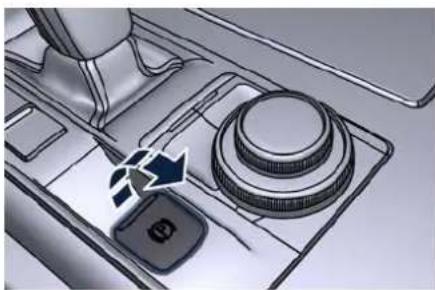
natural_image
Diagram of a mechanical device with a lever and control knob (no text or symbols)
CAUTION!
The main function of the EPB is to allow safe parking of the vehicle, therefore it must only be applied when the vehicle is already stationary. If the EPB is used while the vehicle is moving and decelerating until a speed lower of 5 km/h (3 mph) and, in particular, until complete stop (typically in a sudden brake), it is necessary to have the EPB system checked by the Service Network.

WARNING!
• Always hold the brake pedal pressed during engagement or disengagement of the parking brake.
- The EPB command activation while running generates a deceleration of the vehicle with strong deceleration (Dynamic Braking). It is therefore recommended to use this function only in case of emergency. The stability of the car is guaranteed by the action of the activated ESC system.
- It is advisable to keep the "Auto Apply" function always active (On) so that the vehicle is properly secured with electric parking brake.
Deactivating Automatic Operation
The automatic engagement function can be deactivated/reactivated by selecting the menu item "Vehicle settings" through the switch on the right-side of the steering wheel (refer to "TFT Display Setting and Menu Overview" in section "Dashboard Instruments and Controls".)
Press and release the multifunction switch toward the arrow to select "Electric Park Brake".
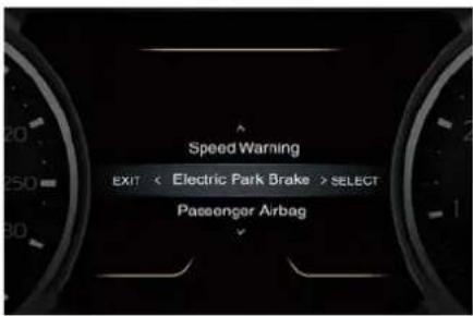
text_image
Speed Warning EXIT < Electric Park Brake > SELECT Passenger AirbagPress and release the switch once again toward the arrow to visualize the options connected to this function.
- Auto Apply On (recommended setting);
- Auto Apply Off.

WARNING!
It is advisable to keep the "Auto Apply" function always active (On) so that the vehicle is properly secured with electric parking brake.
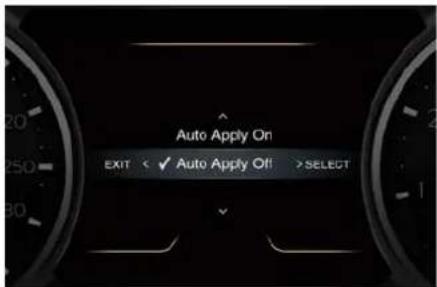
text_image
Auto Apply On EXIT < ✓ Auto Apply Off >SELECTScroll with the multifunction switch toward the arrow or through the programmable options.
Press and release the multifunction switch toward the arrow to set the selected option. A check mark will remain next to the previously-selected item until a new selection is made.
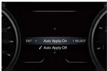
text_image
EXIT < Auto Apply On > SELECT ✓ Auto Apply Off"Setting Saved" Selection notification appears as a popup for 2 seconds then the display will show again the modified function.
text_image
Settings SavedIn order to disable the automatic operation follow the same procedures and select the other option.

Starting and Driving

CAUTION!
- Under certain conditions when the battery voltage is low, the electric automatic parking brake system may temporarily be deactivated for safety reasons. Therefore, typically upon starting the engine, when the battery voltage drops, a message may temporarily be displayed, indicating that automatic operation is temporarily disabled.
- In case of repetitive requests to reset the EPB through the messages shown on the TFT display, please contact the Service Network.
Failure Indication
In the event of electric parking brake system failure, the warning light (P)! on the display will light up for 10 seconds and the related message will show as long as the failure is present. In addition, the warning light (M) flash for 10 seconds.

WARNING!
In the event of an EPB failure, take your vehicle to the nearest Service Network Center as soon as possible.
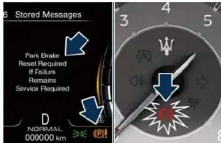
text_image
Stored Messages Park Brake Reset Required If Failure Remains Service Required D NORMAL 000000 kmInitialize the EPB System after Re-connecting the Vehicle Battery
After the detachment and the subsequent connection of the battery, on the instrument cluster display the warning light VAI be illuminated.
To initialize the EPB system, lift, release and lift again the lever located behind the shift lever.
After having initialized the EPB system, the error messages regarding the unavailability of the radar functions shown in the pictures will be displayed on the instrument cluster. In the next key cycle, the messages will no longer be present.
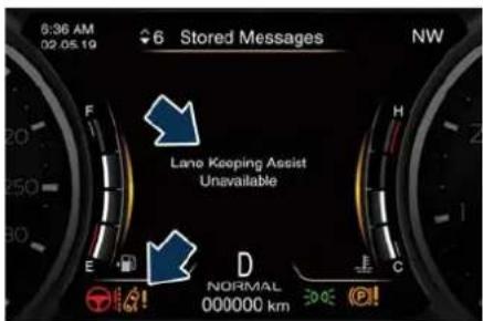
text_image
6:36 AM 02.05.19 6 Stored Messages NW Lane Keeping Assist Unavailable E D NORMAL 000000 km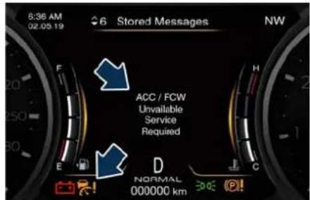
text_image
6:36 AM 02.05 19 Stored Messages NW ACC / FCW Unavailable Service Required D NORMAL 000000 kmEmergency Disengagement
In case of brake lock with complete electrical system failure, is necessary to act on the electric actuator to undo the pressure on the pads of rear brake calipers (see "Emergency Release of the Parking Brake" chapter in section "In an Emergency").
EPB Operation with Overheated Brakes
Driving on mountain roads with steep slopes or a sports use of the vehicle could overheat the brake system components. In these conditions, parking brake must not be used since the push of the power actuator might not be sufficient to ensure vehicle braking, especially on a slope.
Drive normally without braking to allow the brakes to cool down a few minutes before stopping. In this way, the automatic or manual activation of the parking brake will ensure vehicle braking.
Parking
Before leaving the vehicle, make sure that the parking brake is fully applied in automatic or manual and place the transmission lever in the P (Park) position by pressing the "P" button.

WARNING!
• Always check that the vehicle is locked before leaving it.
- Never leave children unattended in the vehicle.
- Do not park the vehicle on paper, grass, dry leaves or other flammable materials. They could catch fire if they come into contact with hot parts of the exhaust system.
- Do not leave the engine running while the vehicle is unattended.
only the parking brake could be not sufficient to stop the vehicle.
When parking on hill roads, it is important to turn the front wheels toward the curb on a downhill grade and away from the curb on an uphill grade.
Apply the parking brake before placing the shift lever in P (Park), otherwise the load on the transmission locking mechanism may make it difficult to move the shift lever out of P (Park).
In certain conditions, it is however advisable to disengage the parking brake manually and slightly apply the service brake for starting off. This is advisable when there are obstacles very close to the vehicle in the direction in which you intend to move.

CAUTION!
When you need to park the vehicle on a steep slope, both with the engine on and off, it is recommended not only to engage the parking brake, but also to shift the transmission lever to P (Park) before leaving the vehicle. A warning message on the instrument cluster could appear when parking on a steep slope to remember that

Starting and Driving
"Drive Away Inhibit" strategy
In order to avoid a dangerous condition resulting from leaving the vehicle "not braked" with running engine and without driver on board, "Drive Away Inhibit" strategy alerts the driver with messages on the instrument cluster display and sounding chimes, then puts the transmission in P (Park).
The table shows the vehicle condition and the action that the system runs to exit the dangerous condition.
| Vehicle condition Action of the driver | ▶ | ▶ | The system puts the transmission in P (Park) position. | |
| Engine running and speed lower than 3 km/h (1.8 mph).Transmission in any position other P (Park).Driver safety belt unlocked.Driver door opened.Brake pedal pressed. | The driver releases the brake pedal to get out of the vehicle. | |||
| Warnings Warnings | ||||
| Slow continuous chime.The condition of the vehicle not in P (Park) position will be signalled by a message on the display. | Fast chime.A message which invites to engage the parking brake to prevent vehicle movement will be displayed on the display. |
Using the Brakes

CAUTION!
To obtain a good performance by brake pads and discs, avoid sudden braking during the first 300 km (190 mi).
The pad wear limit is indicated by the illumination of the warning light ☐, on the instrument cluster. In this event, please contact the Service Network.
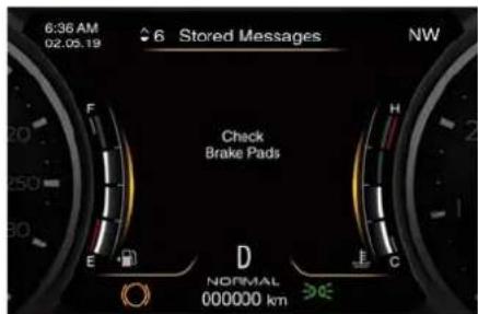
text_image
6:36 AM 02.05.19 6 Stored Messages NW Check Brake Pads E F H D NORMAL 000000 km E C
WARNING!
Riding the brakes can lead to brake failure and possibly an accident. Driving with your foot resting or riding on the brake pedal can result abnormally high brake temperatures, excessive lining wear, and possible brake damage. In an emergency full braking capacity may be impaired.
Brake Pads and Brake Discs
Wear on the brake pads and brake discs depends to a great extent on the driving style and the conditions of use and therefore cannot be expressed in actual kilometres driven on the road.
The brake system is designed for optimal braking effect at all speeds and temperatures.
Certain speeds, braking forces and ambient conditions (e.g. temperature, humidity and long outdoor stopping periods) can therefore cause the brakes to "squeal". This is normal and will cease after a few brakings.
New Brake Pads and/or Brake Discs
New brake pads have to be "bed in", and therefore only attain optimal friction to the brake disc when the vehicle has covered several hundred km.
During this first period, the slightly reduced braking ability must be compensated for by pressing the brake pedal harder. This applies whenever the brake pads and/or brake discs are replaced.
Brake Overheating
Driving on mountain roads with steep slopes or a sports use of the vehicle could overheat the brake system components. In these conditions, parking brake must not be used since the push of the power actuator might not be sufficient to ensure vehicle braking, especially on a slope.
Drive normally without braking to allow the brakes to cool down a few minutes before stopping. In this way, the automatic or manual activation of the parking brake will ensure vehicle braking.
Brake overheating could also cause "squeals" and "vibrations".

Starting and Driving
Use of the Engine
Breaking-In
Today's most modern production methods are designed to provide extremely precise construction and assembly of components. However, moving parts do undergo a settling process, basically in the first hours of vehicle operation.
Do not drive keeping at a constant high speed rate for a prolonged time. While cruising, brief full-throttle acceleration within the limits of local traffic laws contributes to a good break-in. Wide-open throttle acceleration in low gear can be detrimental and should be avoided.
The engine oil installed in the engine at the factory is a high-quality energy conserving type lubricant. Oil changes should be consistent with anticipated climate conditions under which vehicle operations will occur. For the recommended viscosity and quality grades, see "Refillings Table" in section "Maintenance and Care".
A new engine may consume some oil during its first few thousand kilometers of operation. This should be considered as a normal part of the break-in and not interpreted as an indication of malfunction.
Avoid exceeding 5000 rpm for the first 1000 trip km (620 mi). After starting the vehicle, do not exceed 4000 rpm until the engine has warmed up sufficiently (coolant temperature: 65-70°C /149-158°F).
While Driving
Never travel with the tachometer indicator approaching the peak rpm, not even downhill. When the tachometer indicator is approaching the peak rpm (red colored zone), take precautions to avoid exceeding that limit.
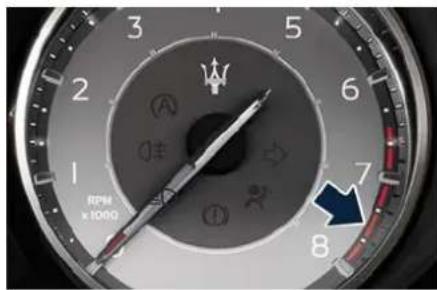
text_image
RPM x 1000Ensure proper operation of different devices checking their respective control telltales.

CAUTION!
- Under normal conditions, all red warning lights on the instrument cluster display should be off. When they come on, they indicate a malfunction. Refer to "Warning and Indicator Lights" in section "Dashboard Instruments and Controls".
• Continuing to drive when a red warning light is on could cause serious damage to the vehicle and affect its performance.

WARNING!
Do not travel downhill with the engine off, as the servo brake will no longer function due to the vacuum decrease and thus after a few braking attempts, the system becomes totally inefficient. The Electric Power Steering will not provide assistance.
On-Board Diagnostics (OBD)
Your vehicle is equipped with a sophisticated on-board diagnostic system. This system monitors the performance of the emissions, engine, and automatic transmission control systems. When these systems are operating properly, your vehicle will
Starting and Driving

provide excellent performance and fuel economy, as well as engine emissions well within current local regulations of various countries. If any of these systems require service, the system will turn on the Malfunction Indicator Light (MIL). It will also store diagnostic codes and other information to assist which your Service Center will use to service your vehicle. Although the vehicle will still be driveable and not need towing, contact the Service Network for service as soon as possible.
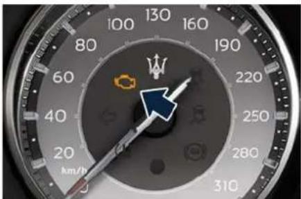
text_image
130 100 80 60 40 20 km/h 160 190 220 250 280 310
CAUTION!
- Prolonged driving with the Malfunction Indicator Light (MIL) on could cause further damage to the emissions control system. It could also affect fuel economy and driveability.
The vehicle must be serviced before any emissions tests can be performed.
- If the Malfunction Indicator Light (MIL) is flashing while the engine is running, severe catalytic converter damage and power loss could occur. Immediate service is required at the Service Network. - After the problem has been solved, the Service Network personnel will perform specific tests on the test bench for a complete check of the system and, if necessary, also road tests, even on long distances.
Gasoline Particulate Filter - GPF (E→)
To reduce the emissions of particulate matter, the exhaust system is equipped with a particulate filter optimized for the back pressure and with a high filtration efficiency.
This filter is maintenance-free and self-regulating and therefore does not require a regeneration procedure when using the car. This performance made possible by the improvement of the filtering support between engine and silencer.
Spare Parts
Use of genuine parts for normal or scheduled maintenance and repairs
is highly recommended to ensure excellent performance.
Damage or failures caused by non-genuine spare parts used for maintenance and repairs will not be covered by the manufacturer's warranty.

Starting and Driving
Refuelling
Fuel Filler Neck Access
To access the fuel filler neck, the filler door must be unlocked. From outside the vehicle, this can only be done by pressing the unlock ☑ the lock 🔒 button on the key fob, in the same way as if opening or closing the doors. If any of the door lock controls is pressed from inside the vehicle, the filler door will still remain open to allow refuelling.
- Press the indicated area on the filler door, which is located on the rear left side of the vehicle: the filler door will open completely.
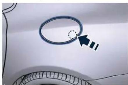
natural_image
Close-up of a car's side panel with a circular ring and arrow pointing to a dotted circle (no text or symbols)NOTE:
In order to guarantee an easy fuel filler door opening, it has to be pressed in the lower right side; if pressed in any other position, it could Refill the Tank remain locked. The fuel filler is sea
To help the user in the choice of fuel compatible for the car, inside the fuel filler door is present a label shown in the picture.
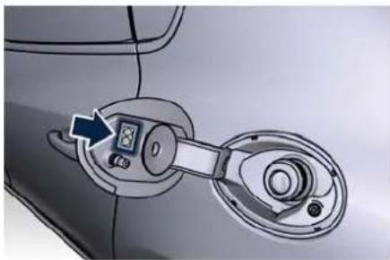
natural_image
Diagram of a car's door panel with a digital display and lock mechanism (no text or symbols)The label includes one or two graphic symbols that identifies the type of fuel to be used compliant to EN16942 and reported in the following table.
| E5 | Unleaded fuel containing up to 2,7% (m/m) oxygen and a maximum ethanol content of 5,0% (V/V) EN228 compliant fuel |
| E10 | Unleaded fuel containing up to 3,7% (m/m) oxygen and a maximum ethanol content of 10,0% (V/V) EN228 compliant fuel |
The fuel filler is sealed by an internal closing tab, which is opened by the fuel nozzle of the service station when refueling.
Only a nozzle of the suitable size can open the closing tab.
- Insert the fuel nozzle fully into the filler.
NOTE:
Only with a correct size nozzle you can refuel.

WARNING!
• To avoid the risk of fire, do not approach the filler with open flames or cigarettes!
• To avoid the risk of inhaling noxious fumes, do not breathe close to the fuel filler door, when opened.
- Never have any smoking materials lit in or near the vehicle when the fuel filler door is open or the tank is being filled.
- Never add fuel when the engine is running. This violates most fire-prevention regulations and may cause the Malfunction Indicator
Light (MIL) to turn on (see "Warning and Indicator Lights" in
section "Dashboard Instruments and Controls").
- Fill the vehicle with fuel. Fuel tank capacity is indicated in the "Refillings Table" in section "Maintenance and Care". When the fuel nozzle "clicks" or shuts off, the fuel tank is basically full: it is possible to further ensure refueling by enabling the fuel nozzle additional fuel supply until twofold clicks. After the two additional clicks, the amount of fuel allowed by the system is very low, we recommend therefore not to persist further.
- Wait approximately 10 seconds before removing the fuel nozzle in order to ensure completed supply of residual fuel and restrict the risk of fouling the fuel filler door area.
- Remove the fuel nozzle.
- Close the fuel filler door.

CAUTION!
To avoid fuel spillage and overfilling, do not "top off" the fuel tank after filling.
Emergency Refueling Funnel
A funnel is provided in the tool box container (represented in the picture a tool kit with compact spare wheel) for emergency refuelling with a gas can
(see chapter "Tool Kit" in section "In a Emergency").
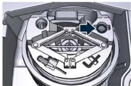
natural_image
Cross-sectional diagram of a mechanical device showing internal components and a directional arrow (no text or symbols)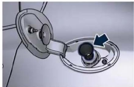
natural_image
Close-up of a mechanical component with a blue arrow indicating a specific part (no text or symbols visible)
WARNING!
A fire may result if fuel is pumped into a portable container that is inside of a vehicle. You could be burned. Always place gas containers outside the vehicle while filling.
Emergency Fuel Filler Door Release
If you are unable to unlock the fuel filler door using the key fob, use the fuel filler door emergency release fitted in the boot.
- Open the boot lid (see "Open and Close the Boot Lid" in section "Before Starting").
- Lift the access cover on the left side of the boot compartment.
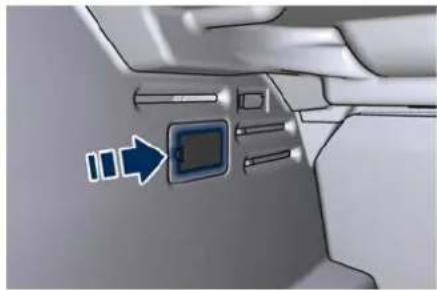
natural_image
Interior view of a vehicle showing a directional indicator with arrows pointing to a digital display (no text or symbols present)- Pull the release cable moderately to avoid its possible break. It's not possible to feel or hear the unlocking of the fuel filler door actuator.

Starting and Driving

natural_image
Close-up of a mechanical component with a blue arrow pointing to a component (no visible text or symbols)- Then open normally the fuel filler door.
Driving Conditions
Before the Trip
Check the following at regular intervals and always before long trips:
- tire pressure and condition;
• levels of fluids and lubricants; - conditions of the windshield wiper blades;
- clean the glass on the external lights and all other glass surfaces;
• proper operation of the warning lights and of the external lights.

CAUTION!
It is however advisable to perform these checks at least every 1000 km (600 mi) and always following the maintenance schedule reported in section "Maintenance and Care".
Before you drive:
- adjust seat position, steering wheel, adjustable pedals (if equipped with) and rear-view mirrors in order to have the best driving position;
- ensure that nothing (mat covers, etc.) is obstructing the pedals movement;
- carefully arrange and secure any objects in the boot, to prevent them to move forward in case of sudden stops;
- avoid heavy meals before a trip. A light snack helps keep your reflexes sharp. In particular, avoid drinking alcohol.

WARNING!
Beyond being prohibited by law, it is extremely dangerous to ride inside the boot or on the front lid. In the event of an accident, passengers sitting here are more exposed to the risk of serious injury. Passengers must only travel seated in the vehicle seats, with the seat belts fastened. Always check that the driver and all passengers have the seat belts correctly fastened.
Safe Driving
Although the vehicle is equipped with active and passive safety devices, the driver's conduct is always a decisive factor for road safety.
Some simple rules for travelling safely in different conditions are listed below. Some of them will probably already sound familiar but, in any case, it would be useful to read them carefully.
Driving at Night
The main guidelines to follow when driving at night are set out below.
Starting and Driving

- Drive drive carefully. Night conditions demand more focus and attention.
- Reduce your speed, especially on roads with no streetlights.
- Stop at early signs of drowsiness. Continuing to drive would be a risk for yourself and for others. Have a rest before continuing your trip.
- Keep the vehicle at a greater distance from vehicles in front of you than you would during the day: it is difficult to assess the speed of other vehicles when you only see the lights.
- Use the high beams only outside of densely-populated areas and when you are sure that they will not disturb other drivers.
- When another vehicle is approaching, switch from high beams (if on) to low beams.
- Keep lights and headlights clean.
• Outside of densely-populated areas, beware of animals crossing the road.
Driving in the Rain
Rain and wet roads are dangerous. On a wet road all manoeuvres are more difficult since wheel grip on the asphalt is significantly reduced. This means that the braking distances increase considerably and the road grip decreases.
Some recommendations for driving in the rain are listed below.
- Reduce your speed and keep a greater safety distance from the vehicles in front of you. High speed may result in a loss of vehicle control.
- When driving on wet or slushy roads, it is possible for a wedge of water to build up between the tire and road surface. This is known as aquaplaning and may cause partial or complete loss of vehicle control and stopping ability. To reduce this possibility: slow down if the road has standing water or puddles.
- Heavy rain substantially reduces visibility. In these circumstances, even during the day, turn on the low beams, to be more visible to other drivers.
- Set the air conditioning and heating system controls on the demisting function, in order to avoid any visibility problem.
• Periodically check the conditions of the windshield wiper blades. - In low grip conditions use "I.C.E." driving mode (see chapters "Drive Mode" in this section).
- Avoid driving with ESC OFF as this could possibly cause a loss of control of the vehicle.
Driving in Fog
If the fog is dense, avoid travelling if possible.
When driving in mist, blanket fog or when there is the possibility of banks of fog, please consider some advices listed below.
- Keep a moderate speed.
• Even in daytime, turn on the low beams and rear fog lights. Do not use the high beams. - Remember that fog creates dampness on the asphalt and thus any type of manoeuvre is more difficult and braking distances are extended.
- Keep a safe distance from the vehicle in front of you.
- Avoid sudden changes in speed as much as possible.
- Whenever possible, avoid overtaking.
- If you are forced to stop the vehicle (breakdowns, impossibility of proceeding due to poor visibility, etc.), first of all, try to stop off of the travel lane. Then turn on the hazard warning lights and, if possible, the low beams.
• Sound the horn rhythmically if you hear another vehicle approaching.


Starting and Driving

CAUTION!
Be aware that rear fog lights can bother the drivers following your vehicle: when visibility is back to normal, turn off these lights.
Driving in the Mountains
Mountain roads usually have many narrow turns and curves, tunnels and steep uphill or downhill slopes: please consider some advices listed below.
- Drive at a moderate speed, avoid "cutting" corners.
- When driving inside a tunnel in daylight turn on the low beams in advance; avoid high beams and be aware of the rapid brightness change. Avoid abrupt manoeuvres that could be dangerous for the following vehicle.
- Never coast downhill with the engine off or in neutral.
- Remember that passing other vehicles when driving uphill is slower and thus requires more free distance on the road. If you are being overtaken on a hill, slow down and allow the other vehicle to pass.
Driving on Snow or Ice
Please consider some general advice for driving in these conditions, listed below.
- Maintain a very moderate speed.
-
Fit snow chains or specific tires if the road is covered with snow,
chapter "Tires Information" in section "Safety". -
We recommend you to activate the "I.C.E." mode (see chapters "Drive Mode" in this section).
- During the winter season, even apparently dry roads can have icy sections. Be careful when crossing bridges, viaducts and roads that have little exposure to the sun and are bordered by trees and rocks. They may be icy.
- Keep an ample safe distance from the vehicles in front of you.
- Avoid sharp braking, sharp changes in direction and rapid acceleration. Rapid acceleration on snow covered or icy surfaces may cause the driving wheels to pull erratically to the right or left. This phenomenon occurs when there is a difference in the surface traction under the rear (driving) wheels.

WARNING!
Rapid acceleration on slippery surfaces is dangerous. Unequal traction can cause sudden pulling of the rear driving wheels. You could lose control of the vehicle and possibly have a collision. Accelerate slowly and carefully whenever there is likely to be poor traction (ice, snow, wet mud, loose sand, etc.).
Driving through Flooded Sections
Driving through more than a centimeters deep shallow standing water section will require extra caution to ensure passenger safety and prevent damage to your vehicle.

WARNING!
Do not drive on or across a road or path where water is flowing and/or rising (as in storm run-off). Flowing water can wear away the road or path surface and cause your vehicle to sink into deeper water. Furthermore, flowing and/or rising water can carry your vehicle away swiftly. Failure to follow this warning may result in injuries that are serious or fatal
to you, your passengers, and others around you.
Although your vehicle is capable of driving through shallow standing water, consider the following Caution and Warning before doing so.

CAUTION!
• Always check the depth of the standing water before driving through it. Never drive through standing water that is deeper than 150 mm (6 in).
- Determine the condition of the road or the path that is under water and if there are any obstacles in the way before driving through the standing water.
- Do not exceed 8 km/h (5 mph) when driving through standing water. This will minimize wave effects.
- Driving through standing water may cause damage to your vehicle drivetrain components. After driving through standing water, do not drive if you are not sure about drivetrain condition. Such damage is not covered by the New Vehicle Warranty.
• Getting water inside your vehicle engine can cause it to lock up and
stall out, and cause serious internal damage to the engine. Such damage is not covered by the New Vehicle Warranty.
• After driving through standing water always have the fluids (engine oil, transmission oil, etc) checked for contaminations at a Service Center.

WARNING!
- Driving through standing water limits your vehicle traction capabilities. Do not exceed 8 km/h (5 mph) when driving through standing water.
- Driving through standing water limits your vehicle braking capabilities, which increases stopping distances. Therefore, after driving through standing water, drive slowly and lightly press on the brake pedal several times to progressively dry the brakes discs and pads.
• Getting water inside your vehicle engine can cause it to lock up and stall out. - Failure to follow these warnings may result in injuries that are serious or fatal to you, your passengers, and others around you.

Starting and Driving
6 - Driver Assistance Systems
General Notes 206
Park Assist 206
Rear Parking Camera 211
Surround View Camera System (1)
Cruise Control - CC 215
Adaptive Cruise Control - ACC (with FCW only) .....
Forward Collision Warning - FCW (7)
Lane Keeping Assist - LKA (with ACC only) 231
Blind Spot Assist - BSA (→) 235
Active Blind Spot Assist - ABSA (with ACC only) . . . . . . . . . . . . . .
Active Driving Assist - ADA (with ACC only) .....
Traffic Sign Assist – TSA (→) 248


Driver Assistance Systems
General Notes
This section lists all the parking assistance systems and all the Advanced Driver Assistance Systems, sintetically called ADAS, available for this car.
Some ADAS are standard, others are optional and may vary depending on the equipment of the car and the target market.
Some of these systems activate or deactivate automatically, others can be activated or deactivated and set using the buttons on the steering wheel L/H side or via the "Controls" and "Settings" menu on the "Vehicle" page or the "Apps" page of MIA display. For further information see "Functions of Controls Menu on MIA" and "Functions of Settings Menu on MIA" in section "Dashboard Instruments and Controls".
Park Assist
The Park Assist (also called "ParkSense") system provides visual and audible indications of the distance between the rear and/or front bumper and a detected obstacle when backing up or moving forward, e.g. during a parking manoeuvre.
Besides the use of the sensors available on the bumpers and of the rear parking camera, the vehicle may be equipped with surround view cameras (if to assist the driver during manoeuvres on dead-ends/roads and on intersections. For more details on this option, see chapter "Surround View Camera System" in this section.
Refer to "Park Assist System Usage Precautions" in this chapter for limitations of this system and recommendations. Park Assist system will retain the last system state (enabled or disabled) from the last ignition cycle when the ignition device is changed to the RUN position.
Park Assist system can be active only when the shift lever is in R (Reverse) or D (Drive).
If Park Assist is enabled at one of these shift lever positions, the system will remain active until the vehicle speed is increased to approximately 12 km/h (7.5 mph) or above. The system will become active again if the vehicle speed is decreased to speeds less than approximately 10 km/h (6.2 mph).
Park Assist Sensors
The four Park Assist sensors, located in the rear bumper, monitor the area behind the vehicle that is within the sensor's field of view. The sensors can detect obstacles up to approximately 200 cm (78 in) from the rear bumper in the horizontal direction, depending on the location, type and orientation of the obstacle.
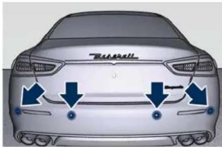
text_image
BaseballThe six Park Assist sensors, located in the front bumper, monitor the area in front of the vehicle that is within the sensor's field of view.
The sensors can detect obstacles up to a distance of approximately 120 cm (50 in) from the front bumper in the horizontal direction, depending on the
Driver Assistance Systems

location, type and orientation of the obstacle.
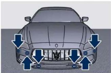
natural_image
Top-down view of a car with blue arrows pointing to the front grille and side seats (no text or symbols)Park Assist Warning Messages Display
The Park Assist warning screen will only be displayed if "Sound + Display" is selected from the MIA system.
Refer to "Functions of Settings Menu on MIA" in section "Dashboard Instruments and Controls" for further information. The Park Assist warning screen is located on the instrument cluster display.
It provides visual warnings to indicate the distance between the rear bumper and/or front bumper and the detected obstacle.
The warning display will turn on indicating the system status (ready or off) when the vehicle is in R (Reverse)
or in D (Drive) and an obstacle has been detected.
The detection area in front of the vehicle is divided into two parts with four arcs while the two detection areas behind the car into five arcs.
The system will indicate a detected obstacle by displaying arcs with fixed or flashing light and a characteristic sound according to the obstacle distance. The colour indicates the distance and the arc indicates the position of the detected obstacle. The green colour of the outer arc indicates the maximum distance, the amber colour of the middle arcs indicates the medium distance, while the red colour of the nearest arc indicates the minimum distance.
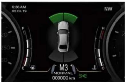
text_image
6:36 AM 02.05.19 NW M3 NORMAL 000000 km 30.0E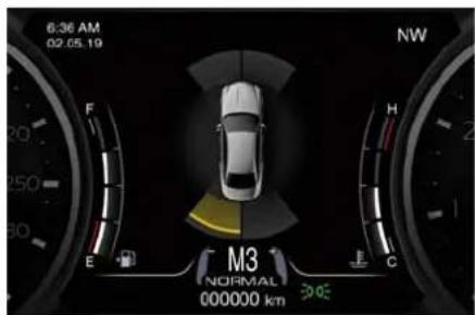
text_image
6:36 AM 02.05.19 NW M3 NORMAL 000000 km F E H C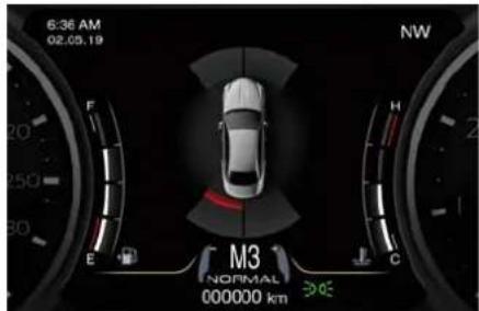
text_image
6:36 AM 02.05.19 NW M3 NORMAL 000000 km E F H CAs the vehicle moves closer to the object the instrument cluster will display the arc moving towards the vehicle and the sound tone will change from single to slow, to fast and to continuous.
The vehicle is close to the obstacle when the instrument cluster displays one flashing red arc only, combined with a continuous sound.

Driver Assistance Systems
The following charts show the warning alert visualization when the system is detecting an obstacle.
| Front Sensors - Warning Alerts | ||||||
| Front distance | More than 120 cm (50 in) | 120-101 cm (50-40 in) | 100-61 cm (40-24 in) | 60-31 cm (23.6-12.2 in) | Less than 30 cm (12 in) | |
| Audible Alert None | None Slow (5 Hz) Fast | (8 Hz) Continuous | ||||
| Arc in left and right areas | None 4 | ^th | 3^rd | 2^nd | 1^st (inner most) | |
| Type light None Solid | Solid Flash Flash | |||||
| Arc colour – Green | Amber | Amber Red | ||||
| Radio sound | Active | Active | Mute | Mute | Mute | |
| Rear Sensors - Warning Alerts | ||||||
| Rear distance | More than 200 cm (78 in) | 200-151 cm (78-59.4 in) | 150-101 cm (60-40 in) | 100-61 cm (40-24 in) | 60-31 cm (23.6-12.2 in) | Less than 30 cm (12 in) |
| Audible Alert | None | Single | Slow (2 Hz) | Slow (5 Hz) | Fast (8 Hz) | Continuous |
| Arc in left and right areas | None 5 | ^th | 4^th | 3^rd | 2^nd | 1^st (inner most) |
| Type light | None | Solid | Solid | Solid | Flash | Flash |
| Arc colour | – | Green | Amber | Amber | Amber | Red |
| Radio sound | Active | Mute | Mute | Mute | Mute | Mute |
Driver Assistance Systems

NOTE:
Park Assist will turn off the front park assist audible alert (chime) after approximately 4 seconds when an obstacle has been detected, the vehicle is stationary, and brake pedal applied.
Enabling and Disabling Park Assist
By accessing the submenu "Safety & Driving Assistant" from MIA system, the "Park Assist" can be disabled (option "Off"). The available options regarding the warning alerts are: "Sound" or "Sound + Display".
Refer to "Functions of Setting Menu on MIA" in section "Dashboard Instruments and Controls" for further information.
The front sensors can be enabled or disabled at any time by pressing the button on the front dome console.
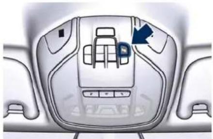
natural_image
Top-down view of a car interior showing the dashboard and seat area with a blue arrow pointing to a specific seat (no text or symbols present)After pressing the button the instrument cluster will display the state of front parking sensors for approximately five seconds. The button LED will be on when the front sensors are disabled. The button LED will be off when the front sensors are enabled. If the button is pressed and the system requires service, the LED will blink momentarily, and then the LED will be on.
When the shift lever is moved to R (Reverse) or to D (Drive) at a speed of 11 km/h (7 mph) or below and the system is disabled, the instrument cluster will display the "PARK ASSIST Off" message for 5 seconds until the shift lever remains in R (Reverse) or when the shift lever is moved in D (Drive).
Service the Park Assist System
In case of malfunction of the Park Assist system, the instrument cluster will actuate a single sound, once per ignition cycle. The instrument cluster will display a message when any of the rear or front sensor(s) are blocked by snow, mud, or ice and the vehicle is shifted into R (Reverse) or D (Drive).
The instrument cluster will display a message when any of the rear or
front sensors are damaged and require service.
When the shift lever is moved to R (Reverse) or D (Drive) and the system has detected a faulted condition, the instrument cluster will display the corresponding message for the time lapse the vehicle is in R (Reverse) or D (Drive) at speeds less than 11 km/h (7 mph). Under this condition Park Assist will not operate. See "Warning and Indicator Lights" in section "Dashboard Instruments and Controls" for further information.
If the instrument cluster displays a message prompting you to clean the sensors, make sure the outer surface and the underside of the rear bumper and/or front bumper is clean and clear of snow, ice, mud, dirt or other obstruction and then cycle the ignition device. If the message continues to appear contact the Service Network.

Driver Assistance Systems
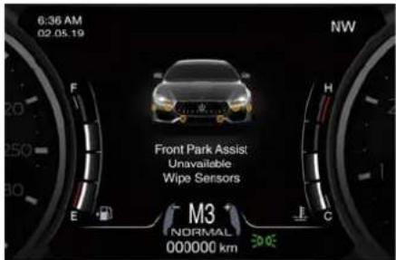
text_image
6:36 AM 02.05.19 F 20 50 30 E NW Front Park Assist Unavailable Wipe Sensors M3 NORMAL 000000 km 30.00If a failure message is displayed on the instrument cluster, contact the Service Network.
Cleaning the Park Assist Sensors
When cleaning the sensors, take special care not to scratch or damage them; therefore, do not use dry, rough or hard cloths.
The sensors must be washed with clean water, possibly adding car shampoo. Should you need to repaint the bumper or in case of paint touch-ups in the sensor area, please contact exclusively the Service Network. Incorrect paint application could affect the parking sensors operation.
Park Assist System Usage Precautions
NOTE:
- Jackhammers, large trucks, and other vibrations could affect the performance of Park Assist.
- Objects such as bicycle carriers, trail hitches, etc., must not be placed within 30 cm (12 in) from the rear bumper while driving the vehicle. Failure to do so can result in the system misinterpreting a close object as a sensor problem, causing the service Park Assist message to be displayed in the instrument cluster.

CAUTION!
- Park Assist is only a parking aid and it is unable to recognise every obstacle, including small obstacles. Parking curbs might only be temporarily detected or not detected at all. Obstacles located above or below the sensors will not be detected when they are in close proximity.
• The vehicle must be driven slowly when using Park Assist in order to be able to stop in time when an obstacle is detected. When backing up, it is recommended that the driver looks
over his/her shoulder when using Park Assist.

WARNING!
Drivers must be careful when backing up even when using the Park Assist system. Always check carefully behind your vehicle, look behind you, and be sure to check for pedestrians, animals, other vehicles, obstructions, and blind spots before backing up. You are responsible for safety and must continue to pay attention to your surroundings. Failure to do so can result in serious injury or death.
Park Assist Volume
The volume of the acoustic signal emitted by the front and rear parking sensors is set to the medium level. Three different level of volume can be selected the submenu "Safety & Driving Assistant" of the "Settings" page on MIA.
Low level is useful in certain conditions when the parking sensor acoustic signal keeps coming on although there is no actual collision hazard. This may typically occur when driving in a queue or when the vehicle is overtaken by motorcycles or other vehicles on one or both sides in a queue of traffic. When
Driver Assistance Systems

you set the volume, only the parking sensor acoustic signal will be affected. The radio or any other devices connected to the vehicle sound system will not be affected. Refer to chapter "Functions of Menu on Settings MIA" in section "Dashboard Instruments and Controls" for further information.
Rear Parking Camera
Your vehicle is equipped with a rear parking camera that allows you to see an image on the MIA screen of the rear surroundings of your vehicle whenever the shift lever is put into R (Reverse).
When "Parkview Backup Camera Delay" mode is enabled, the rear view image shall be displayed for up to 10 seconds after shifting out of R (Reverse).
To assist the driver during manoeuvres on dead-ends/roads and on intersections, the vehicle may be equipped with an optional surround view camera system. In this case, the rear parking camera is integrated into the surround view camera system. In both configurations (rear parking camera only or surround view camera system), you can always monitor the rear view. For more details on this option, see chapter "Surround View Camera System" in this section.
The image will be displayed along with a caution note to "Check Entire Surroundings" across the top of the screen. After five seconds this note will disappear.
The rear parking camera is located on the rear of the vehicle above the rear licence plate.
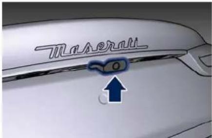
text_image
Transmit OWhen the shift lever is shifted out of R (Reverse), the rear camera mode is exited and the navigation or audio screen appears again.
When displayed, dynamic grid lines (if the function is set to MIA through the "Settings" menu of the "Vehicle" page) will illustrate the width of the vehicle to assist with parking or aligning to a hitch/receiver. The dynamic grid lines will show separate zones in different colour that will help indicate the distance to the rear of the vehicle.
The following table shows the approximate distances for each zone and colour:

Driver Assistance Systems
| Zone | Distance to the rear of the vehicle |
| Red 28 - | 30 cm (11 - 12 in) |
| Yellow 30 | cm - 2 m (12 - 78 in) |
| Green 2 - | 4 m (78 - 157 in) |
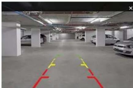
natural_image
Interior view of a parking garage with parked cars and yellow/red directional arrows indicating lanes (no text or symbols visible)WARNING!
Drivers must be careful when reversing even when using the rear view camera. Always check carefully behind your vehicle, and be sure to check for pedestrians, animals, other vehicles, obstructions, or blind spots before reversing. You are responsible for the safety of your surroundings and must continue to be careful while reversing. Failure to do so can result in serious injury or death.

CAUTION!
• To avoid vehicle damage, the rear camera should only be used as a parking aid, as the rear camera is unable to view every obstacle or object in your drive path.
• To avoid vehicle damage, the vehicle must be driven slowly when using the rear camera to be able to stop in time when an obstacle is seen. It is recommended that the driver looks frequently over his/her shoulder when using the rear camera.
NOTE:
If snow, ice, mud, or any other substance builds up on the camera lens, clean the lens, rinse with water, and dry with a soft cloth. Do not cover the lens.
Surround View Camera System (DPT)
System components
The system uses four cameras to monitor the area around the vehicle, placed on the front grid, under the side rear-view mirrors and on the boot lid, between the number plate lights.
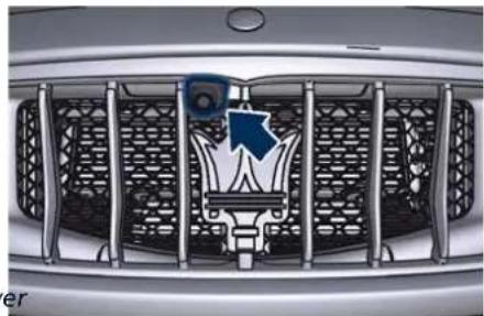
natural_image
Front view of a car grille with a decorative emblem and blue arrow symbol (no readable text or numbers)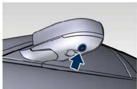
natural_image
Illustration of a computer mouse with a blue eye and an arrow pointing to the lens (no text or symbols present)Driver Assistance Systems

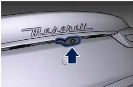
text_image
TaurusWhen the shift lever is shifted to R (Reverse) position, the top view and rear view of the surrounding scenario will be automatically displayed on MIA display.
Image will be displayed with active guidelines while in that gear as long as vehicle speed remains lower than 12 km/h (8 mph).
When vehicle is shifted into a different gear, the image will remain displayed for 10 seconds, or vehicle is shifted in P (Park), or until vehicle speed exceeds 12 km/h (8 mph), at which point it will immediately cancel and return to the last-viewed screen.
Instead, when the shift lever is shifted to P (Park), N (Neutral) or D (Drive) position, it is possible to activate/deactivate the system by touching "Surround View Camera" soft-key in
"Controls" menu of the "Vehicle" page.

text_image
22.5° 12:30 Controls Settings Bumpen Of Grossword View Camera Mirror Dimmer Glow Box Fear Curtailbox Start & Stop On Home Media Comfort New Phone Vehicle AppsOnce the "Surround View Camera" screen is displayed, it is possible to choose which images to display according to 4 possible settings.
Rear view and top view
Rear cross path view
Front cross path view
Front view and top view
In any shift lever condition, when "Surround View Camera" screen is displayed, a pop-up message will appear in the upper part for 5 seconds to advise the driver to check the surrounding scenario before any manoeuvre.
With transmission in P (Park), N (Neutral) or D (Drive), the upper right corner of the screen will show the "X" key: touch it to go back to the previous screen of MIA display, before entering in "Controls".
The deactivation of the rear visualization via "X" soft-key is not possible when the transmission is in R (Reverse) position.
Choose the most suitable setting for the situation and the manoeuvre you are performing or going to perform, by touching the relevant button present under the images: the edges of the pressed button will highlight. The button will highlight and the type of selected view will appear on each image.
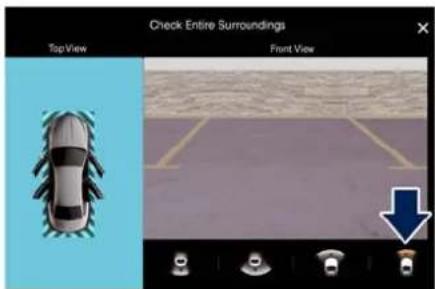
text_image
Check Entire Surroundings Top View Front ViewIn the top view, the vehicle is represented as it is during the manoeuvre (see example in the

Driver Assistance Systems
figure), therefore any open doors will be visible in the image. To display also the dynamic lines of the trajectory you are setting, it is necessary to set this function by accessing the "Settings" menu on "Vehicle" page of MIA, at "Safety & Driving Assistant" item, by using the dynamic gridlines activation menu. Once this menu is displayed, it is also possible to set the function that delays the exit from this screen in special situations when the transmission lever is in D (Drive), N (Neutral) and P (Park) position by using the surround view camera delay menu. For further information, see "Functions of Settings Menu on MIA" in section "Dashboard Instruments and Controls".
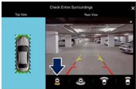
text_image
Check Entire Surroundings Top View Rear View
WARNING!
Failure to follow the precautions below might result in serious injury or even death.
- Drivers must be careful during maneuvers also when using the camera system with surround view.
• Always check carefully the areas around your vehicle, before proceeding forward or backward. - Be sure to always check for any pedestrians, animals, other vehicles, obstructions, or blind spots.
• The driver must use the utmost caution while using the system to avoid damage to property or personal injury.
• The camera system with surround view is designed for use during the day or under good lighting conditions. Do not use and rely on the system under poor lighting conditions. - Distance lines and trajectory lines must be used only as a reference and only when vehicle is on a flat ground. The distance shown on MIA display must be interpreted as a reference and might be different from the distance actually present
between the vehicle and any displayed objects.
- Any obstacles present above the cameras cannot be detected.

CAUTION!
- To avoid vehicle damage, the camera system with surround view should only be used as a parking aid, as the cameras are unable to view every obstacle or object in your drive path.
• To avoid vehicle damage, the vehicle must be driven slowly when using the camera system with surround view, to be able to stop in time when an obstacle is seen. It is recommended that the driver looks frequently over his/her shoulder when using this system.
NOTE:
If snow, ice, mud, or any other substance builds up on the camera lens, clean the lens, rinse with water, and dry with a soft cloth. Do not cover the lens.
Cruise Control - CC
The electronic Cruise Control (CC) enables the driver to maintain the desired vehicle speed without pressing the accelerator pedal, reducing driving fatigue on highways, especially long trips, as the set speed is automatically maintained. A firm press on the accelerator pedal or the braking pedal will temporarily deactivate the cruise control function.

CAUTION!
The device can only be switched on at speeds exceeding 30 km/h (18 mph) and it switches off automatically when the brake pedal or the accelerator pedal is pressed.

WARNING!
The Cruise Control function must only be activated when traffic and the route permit a constant speed to be maintained safely for a sufficiently long distance.
Controls
The Cruise Control controls are located on the left side of the steering wheel.
Control configuration depends on which driver assist systems are installed to the vehicle.
In the standard configuration there is a specific button to enable and disable the CC.
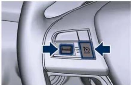
natural_image
Interior view of a car dashboard with a central control panel and directional arrows indicating movement (no text or symbols)Standard Configuration
In the optional configuration, there is no specific button to enable and disable the CC, since driver uses the ACC control buttons.
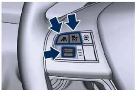
text_image
Car interior control panel with icons and directional arrows indicating movement or navigationOptional Configuration
Control buttons have the following functions:
Standard Configuration

ON/OFF button to en- gage/disengage CC system.
Optional Configuration

Press ACC time gap button and hold it down for 2 seconds to enable the CC system.

Press ACC button to disable the CC system.
Shared by All Configurations
RES+ CANC SET-
Multifunction switch:
- Press up (indication RES +): increase speed, set current speed or resume previously set speed when system is in "cancelled" status;
- Pushed (indication CANC): deletes the set speed;
- Press down (indication SET -): set speed/decrease speed.
NOTE:
- The figures only show the Standard Configuration.
• In order to ensure proper operation, the CC system has been designed
(Continued)

Driver Assistance Systems
(Continued)
to shut down if multiple systems are operated at the same time (example: ACC and FCW). When conditions so allow, the CC system can be reactivated by pushing the CC "ON/OFF" button or the ACC time gap button (in the Optional Configuration) and resetting the desired vehicle set speed.
Displayed Information
Apart from the pop-up messages at the centre of the display, CC system status is represented by icons at the top left of the TFT display, in the dedicated area. See "TFT Display Areas" in section "Dashboard Instrument and Controls".
Displayed information depends on system status: ready, set, temporarily cancelled or override.
Activation
To turn the system on, push the ON/OFF button or the ACC time gap button for 2 seconds (in the Optional Configuration). The white light with below 3 dashes on the TFT display will illuminate.
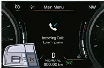
text_image
Main Menu Incoming Call: Lorem Ipsum D NORMAL 000000 kmTo turn the system off, push the ON/OFF button a second time or the ACC button (in the Optional Configuration). The white light will turn off.
NOTE:
The CC system must be turned off when not in use.

WARNING!
Never leave the Cruise Control system on when not in use. You could accidentally set the system or cause it to go faster than you want. Always leave the system off when you are not using it.
Speed Range of Use
| Speed km/h (mph) | |
| Minimum 30 (20) |
| Speed km/h (mph) | |
| Engaged/activated 30 (20) | |
| Maximum 210 (130) | |
Setting Desired Speed
Turn on the CC function. When the vehicle has reached the desired speed (in the example: 100 km/h), push downward the multifunction switch (SET -) and release.
The green light with below the desired speed will illuminate on the TFT display.
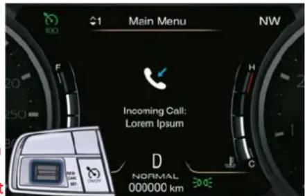
text_image
Main Menu NW Incoming Call: Lorem Ipsum D NORMAL 000000 kmRelease the accelerator and the vehicle will operate at the selected speed.
NOTE:
The vehicle should be travelling at a steady speed and on level ground before pushing the switch downward.
Driver Assistance Systems

Pressing the "ON/OFF" button or the ACC time gap button for 2 seconds (in the Optional Configuration) or moving the ignition device in OFF position erases the set speed memory.
Changing Speed Setting
Pushing the multifunction switch upward (RES +) or downward (SET -) once, or by holding it down, will enable to increase or decrease the set speed by one unit (1 km/h or 1 mph). If the car is equipped with ADAS Systems, the single press of the multifunction switch will increase or decrease the set speed of 1 km/h or 1 mph; a continuous pressure of the same will increase or decrease the set speed of 10 km/h or 5 mph.
Release the switch when the desired speed is reached, and the new set speed will be visualized below the green light.
Each subsequent tap of the multifunction switch will increase or decrease the speed by 1 km/h or 1 mph.
Temporary Deactivation
A soft tap on the brake pedal, pressing the multifunction switch (CANC), or normal brake pressure while slowing the vehicle will temporarily deactivate
the CC without erasing the set speed memory. The white light with below the set speed will appear on the TFT display.
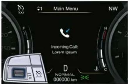
text_image
100 Main Menu NW F 20 250 20 Incoming Call: Lorem Ipsum D NORMAL 000000 km 30.0Driver Override
If the driver presses the accelerator pedal while the CC is on, such as to overtake another vehicle, and exceeds the set speed limit, the system will temporarily deactivate the CC. During the event, the speed indication below the green light will be blinking.
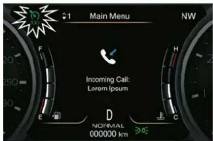
text_image
Main Menu Incoming Call: Lorem Ipsum NORMAL 000000 kmWhen the accelerator pedal is released, the vehicle will return to the set speed and the green light with below the set speed with steady light will be displayed.
Resume Speed
To resume a previously set speed, push upward the multifunction switch (RES +) and release. The green light with below the set speed will illuminate on the TFT display. Resume can be used at any speed above 30 km/h (18 mph).
Using Cruise Control on Hillsides
The transmission may be downshifted on hills to maintain the vehicle set speed. The CC system maintains set speed up and down hills. A slight speed change on moderate hills is normal. On steep slopes, a greater

Driver Assistance Systems
speed loss or gain may occur so we recommend to drive without CC.

WARNING!
Cruise Control (CC) can be dangerous where the system cannot maintain a constant speed. Your vehicle could go too fast for the conditions, and you could lose control and have an accident. Do not use CC in heavy traffic or on winding, icy, snow-covered or slippery roads.
Adaptive Cruise Control - ACC (ET, with FCW only)
The Adaptive Cruise Control (ACC) is part of ADAS equipments and can only be present on cars equipped with Front Collision Warning (FCW).
NOTE:
LKA and ABSA and all the other ADAS systems are described in the relevant chapters of this section.
Warnings and Cautions
The ACC further increases the drive comfort ensured by the Cruise Control (CC). ACC can work in any type of road: however, its use it is not recommended in urban scenario.
Always consider that ACC is not a safety system and is not designed to prevent accidents.
The ACC allows driver to keep CC active in limited or moderate traffic conditions with no need to constantly restore the CC.
The ACC uses a radar sensor, located on the front grille behind the trident, and the camera behind the internal rear-view mirror to detect the presence of a vehicle ahead at a close distance and moving in the same direction.
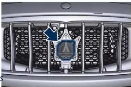
natural_image
Front view of a car grille with a logo featuring a stylized human figure and a blue arrow symbol (no readable text or symbols)This vehicle, in this chapter, will be indicated as "target vehicle" or "vehicle ahead".
NOTE:
- If the sensor detects no vehicle ahead, the ACC system will maintain set steady speed.
- At the time instant the ACC sensors detect a target vehicle, the system keeps the time gap selected by the driver. In the same way, the ACC adapts the vehicle speed according to both time gap and set speed selected by the driver.

WARNING!
• The Adaptive Cruise Control (ACC) is designed to increase vehicle driving comfort. It must not be considered as a means replacing the required attention of the driver. The driver is
Driver Assistance Systems

always required to drive carefully. The driver is always required to pay utmost attention to driving conditions (road, traffic, weather) and style (speed, distance from sensed vehicle ahead, brake use). Driver has the full responsibility of the vehicle therefore his attention is crucial to keeping vehicle control in particular when approaching curves, rounds and situations with heavy traffic. Failure to follow these warnings can result in a collision and death or serious personal injury.
• In some driving scenarios, the ACC could have detection problems. In such cases, the ACC could kick in late or unexpectedly. The driver must be careful since his/her intervention could be necessary.
- It is always driver responsibility to obey to speed limits and to keep minimum legal distance to the preceding vehicle foreseen for the specific country.
- ACC system can decelerate only with limited braking, it cannot execute emergency braking.
The ACC system:
- Does not activate/react in the presence of pedestrians, bicycle and not licensable vehicle in general,
incoming traffic from opposite direction and steady objects such as a vehicle stuck in a traffic jam or for a fault.
• Is meant for the use on highways and well-build roads, not for city traffic or mountain roads.
- May not have enough time to react and/or decelerate sufficiently on vehicles when lane is changed too fast or the relative speed is too high. In such cases the driver has to react appropriately also without any acoustic/visual warning.
- Cannot consider road, traffic and weather conditions and might prove be limited when visibility is poor.
- Does not always fully recognise complex driving conditions and this could cause wrong assessment of the required safety distance.
It is recommended to disable the ACC system in the following instances:
- When driving in the fog, heavy rain, heavy snow, slush, heavy traffic and similar complex situations such as for instance highway sections where there are men at work.
- When entering a junction lane or a slip road to leave the highway; when driving on narrow, icy, snowy, slippery roads, or on steep up and downhill roads.
- When circumstances do not allow to drive safely at constant speed.
Displayed Information
ACC condition, as well as the LKA and HAS status, is displayed on TFT display after selecting "Driver Assist" menu (see "TFT Display: Menu and Submenu Content" in section "Dashboard Instruments and Controls").
Displayed information depends on system status: ready, set, temporarily cancelled or override.
Apart from the image at the centre of the display, ADAS systems status is represented by icons at the top left and right of the TFT display. These icons remain displayed even when you exiting the "Driver Assist" screen.
The vehicle(s) and horizontal bars represent the ACC status as ready (white) or with sensed vehicle ahead (green); the white, grey or yellow lines represent the LKA and ADA systems.
The ACC screen can be displayed any time driver changes system status or settings. After 5 seconds of ACC inactivity, the display goes back to last screen.

Driver Assistance Systems
System Controls and Activation Conditions
The buttons on steering wheel RH side control ACC operation and the other functions/driver assist systems installed to this vehicle.
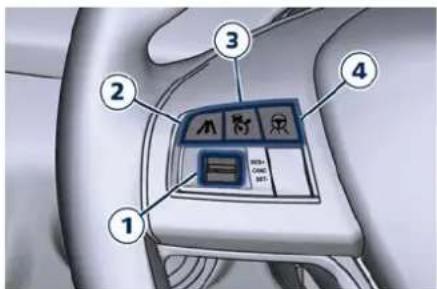
text_image
Diagram of a car interior control panel with numbered labels pointing to function keys and buttons- Multifunction control shared by all driver assist functions/systems:
- Press up (indication "RES +"): increase speed, set current speed or resume previously set speed when system is in "cancelled" status.
- Pushed (indication "CANC"): cancel the function if it was in "set" status, going in a ready condition but remembering the previous set speed.
- Press down (indication "SET -"): set speed/decrease speed.
- Two functions button with ACC activated:
- ACC time gap: pressed and released; set the distance to sensed vehicle ahead as horizontal bars (setting cycle starts to 3 bars).
- CC On: pressed for 2 seconds activates the CC system. See chapter "Cruise Control - CC" in this section for further details.
- Press it to switch from CC to ACC.
-
ACC ON/OFF button. If enabled, pressing this button will disable CC.
-
ADA ON/OFF button with ACC set only. See "Active Driving Assist - ADA" in this section for further details.
NOTE:
Any change made to tire dimensions affects performance of Adaptive Cruise Control and Front Collision Warning.
The ACC is not activated in the following conditions:
- When braking.
- When parking brake is activated.
- When automatic transmission is in P (Park), R (Reverse) or N (Neutral).
- When vehicle speed is out of preset speed range.
- When brakes are overheated.
- When driver door is open.
- When the driver's seat belt is unbuckled.
- When the road is particularly steep (both uphill and downhill) at low speed.
- When drive mode (ESC OFF) is selected.
- When the door is opened at low speed.
- When there has been an ESC event in the last 5 seconds, or is still active.
- When there is an object too close in front of the vehicle.
It is possible that more than one system is active at the same time such as ACC and ABSA just to mention some.
While activation of ACC and CC at the same time is impossible.
Speed Range of Use
| Speed km/h (mph) | |
| Minimum 0 | |
| Engaged/activated 30 (20) | |
| Maximum 210 (130) | |
Activation/Deactivation
NOTE:
Pictures show status of ACC and LKA systems.
Driver Assistance Systems

Press and release ON/OFF button to activate the ACC and enter the "Driver Assist" page. The display will show in the top left corner the white symbol with below 3 dashes will illuminate indicating that system is ready to be set.
In the main area the symbology of the other ADAS system set will be displayed.
When exiting the "Drive Assist" page, only the ADAS symbology will remain on the top left corner.
text_image
Driver Assist 116 km/h D NORMAL 000000 kmIf a vehicle is detected as being too close, the display will show a message for 5 seconds and trigger a buzzer to warn the driver that current conditions do not allow enabling of the ACC. At any rate, system will remain in the ready status.
text_image
Driver Assist ACC Not Set Vehicle Too Near D NORMAL 000000 kmPush the ON/OFF button a second time and release to turn the system off. A pop-up message is displayed for 2 seconds to indicate that ACC was disabled.
text_image
Driver Assist Adaptive Cruise Control (ACC) and LaneSense Off D NORMAL 000000 kmWARNING!
Leaving the Adaptive Cruise Control (ACC) system on when not in use is dangerous. You could accidentally activate the system or cause it to go faster than you want. Always leave the system off when you are not using it.
Setting the Speed
When vehicle reaches required speed, press down and release the multifunction control (SET -). The display will show set speed corresponding to vehicle current one. Speed value will be indicated below the green symbol and above the distance bars, in the center of the display.
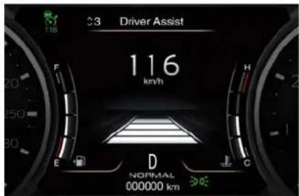
text_image
3 Driver Assist 116 km/h E F H D NORMAL 000000 km CRemove foot from accelerator pedal and vehicle will continue at set speed.

Driver Assistance Systems
Driver Override
If driver accelerates beyond the set speed or faster than the car would do autonomously, the set speed below the green light will be blinking and the time gap bars will vanish to remember that in this condition the system cannot control the distance between vehicle and sensed vehicle ahead. Vehicle speed will be determined only by the accelerator pedal position.
Changing Speed Setting
Once speed is set, driver can increase or decrease it by respectively pressing multifunction control up (RES +) or down (SET -). Speed can be increased or decreased in two ways:
- Pressing control once, set speed will increase or decrease by one unit corresponding to 1 km/h (1 mph).
- Hold the control to increase or decrease set speed by 10 km/h (5 mph) at a time.
NOTE:
- When pressing the multifunction control up (RES +) or down (SET -), the new set speed will be the current speed of the vehicle.
- When using (SET -) control to decelerate, if the engine braking
power does not slow down the vehicle sufficiently to reach the set speed, the brake system will automatically slow down the vehicle.
- The ACC system applies the brake down to a full stop when following a target vehicle. If an ACC host vehicle follows a target vehicle to a standstill, after two seconds the system will not be able to resume driving the car autonomously. As this point it is necessary the intervention of the driver on the multifunction control (press SET- or RES+) or press the accelerator pedal (see "ACC Operation Before and During Stop" in this chapter).
- The ACC system maintains set speed when driving up hill and down hill. However, a slight speed change on moderate hills is normal. In addition, downshifting may occur while climbing uphill or descending downhill. This is normal operation and necessary to maintain set speed. When driving uphill and downhill, the ACC system will cancel if the braking temperature exceeds normal range.
Temporary Deactivation
A soft tap on the brake pedal, pushing the multifunction control (CANC), or normal brake pressure while slowing the vehicle will temporarily deactivate the ACC without erasing the set speed memory. The white light will appear on the TFT display with below the set speed.
Conditions for Disabling and Deactivation
Besides the cases specified in the previous paragraph, the following conditions will disable the system:
- Anti-Lock Brake (ABS) kicks in.
- Transmission lever is not in D (Drive).
- The Electronic Stability Control and the Traction Control System (ESC/TCS) activate.
- Vehicle parking brake is operated.
- The driver safety belt is unbuckled at low speed.
- The driver door is ajar at low speed.
- The driver disabled the ESC using the (ESC Off) button on central console.
- The road is too steep both uphill and downhill at low speed.
The system is deactivated and set speed is deleted from system memory, if the ACC ON/OFF button is pressed or if ignition device is turned to OFF.
Driver Assistance Systems

Resuming Speed
If a speed setting is stored in system memory, press the multifunction control (RES +) up and take foot off the accelerator pedal. The last set speed will be displayed.

WARNING!
The resume function should be used only when road and traffic conditions allow it. Resuming too a high or too low speed for current traffic and road conditions could cause a harsh vehicle acceleration or deceleration which could jeopardise driving safety and risk to cause severe accidents.
Setting the Time Gap
The specified time gap has four different settings, identified by 4 horizontal bars that represent 4 different time gaps:
• Maximum (longest) time: 4 bars.
- Long time: 3 bars (default time).
• Medium time: 2 bars.
- Short time: 1 bar.
Based on both time gap, selected by the driver, and the actual vehicle speed, ACC calculates the distance to keep from the vehicle ahead.
If another information covering ADAS visualization in the main area (textual
pop ups, NAVI information, phone call, etc...) are displayed, the ACC time gap symbol shall be displayed in the top left corner for the time the ADAS in the main area is covered (see detail in picture).
If system does not detect the presence of any vehicles ahead, only the bars referred to set time gap will be displayed.
When system detects the presence of a vehicle ahead, it is displayed in front of the bars (see example in the figure).
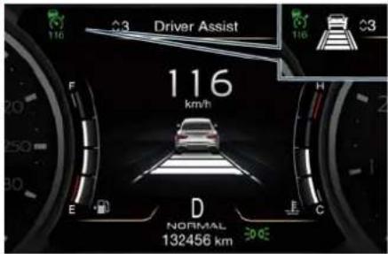
text_image
Driver Assist 116 km/h E F 20 250 30 D NORMAL 132456 km 30.0ETo increase or decrease the number of bars, corresponding to the time gap from vehicle ahead, press and release the related setting button.
natural_image
Interior view of a car dashboard with control panel and directional arrow (no text or symbols)Each press and release of the button changes the time gap starting from 3 bars (default time) and moving in a sequential way towards the minimum time: 3 2 1 4 3 2 1 4 and so on. If there is no vehicle ahead, the vehicle will maintain the set speed. If a slower moving vehicle is detected in the same lane, the system displays the target vehicle icon before the bars.
From that moment, the system adjusts vehicle speed automatically to maintain the time gap setting, regardless of the set speed.
The vehicle will then maintain the set time gap until:
• The vehicle ahead accelerates to a speed above the set speed.
- The vehicle ahead moves out of your lane or view of the sensor.
• The time gap setting is changed.
• The driver disables the system.

Driver Assistance Systems
The maximum braking applied by ACC is limited; however, the driver can always apply the brakes manually, if necessary. Any time the ACC system automatically operates the brakes, the stop lights will turn on as if the driver was braking.
A Proximity Warning on display will alert the driver if ACC predicts that its maximum braking level is not sufficient to maintain the set time gap. If this occurs, a visual alert will flash on the display and a chime will sound while ACC continues to apply its maximum braking capacity.
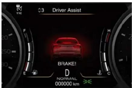
text_image
Driver Assist BRAKE! D NORMAL 000000 kmNOTE:
The displayed warning is a warning for the driver to take action and does not necessarily mean that the Forward Collision Warning system is applying the brakes autonomously.
Overtake Aid
When driving with ACC engaged and following a target vehicle, the system will provide an additional acceleration to assist in passing vehicles in front.
This additional acceleration is triggered when the driver utilises the left turn signal to start overtaking. In locations with left hand drive traffic, overtake aid is active only when passing on the left hand side of the target vehicle.
When a vehicle goes from a location with left hand drive traffic to a location with right hand drive traffic, the ACC system will automatically detect traffic direction. In this condition, overtake aid is active only when passing on the right side of the target vehicle. This additional acceleration is triggered when the driver utilises the right turn signal to start overtaking. In this condition the ACC system will no longer provide
Overtake Aid on the left side until it determines that the vehicle has moved back to a location with left hand drive.
System Operation Before and During Stop
If an ACC host vehicle follows a target vehicle to a standstill, after two seconds the system will not be able to resume.
In this condition, TFT displays an instruction message pop up for 5 seconds and the driver has to press the accelerator pedal or resume the ACC speed by acting on the multifunction control (RES + or SET -).
While ACC with Stop is holding your vehicle at a standstill, if the driver unbuckles the seatbelt or opens the door, the ESC system will activate the EPB. During standstill, ACC system monitors the occupant detection signals: if the driver's seatbelt becomes unbuckled, the ACC system shall be cancelled when the EPB is applied.

WARNING!
- When the Adaptive Cruise Control (ACC) system is resumed, the driver must ensure that there are no pedestrians, vehicles or objects in the path of the vehicle. Failure to follow these warnings can result in a collision and death or serious personal injury.
- During the automatic stopping behind a vehicle in some rare cases it may happen that the system does not recognize the rearmost point of
Driver Assistance Systems

the vehicle ahead but a target under ACC and FCW systems will recover the vehicle ahead (e.g. the back axle operation after the vehicle has left of a truck with a high loading edge or a bumper of a vehicle although overhanging load is hanging over the vehicle's rear). In these cases the system cannot guarantee the appropriate stopping distance leading to collision in the worst case. For this reason the driver has to be attentive and ready to brake during automatic stops.
Display Warnings and Maintenance of ACC and FCW Systems
Wipe Front Radar Sensor Warning This warning will display and also a chime will indicate when conditions temporarily limit system performance due to sensor poor or failed signal reception. This most often occurs at times of poor visibility, such as in snow or heavy rain. The ACC and FCW systems may also become temporarily blinded due to obstructions, such as mud, dirt or ice on the radar sensor. In these cases, the system will be disabled.
This message can sometimes be displayed while driving in highly reflective areas (i.e. tunnels with reflective tiles, or ice and snow). The To keep the ACC System operating properly, it is important to note the following maintenance items:
• Always keep the sensor clean.
Carefully wipe the sensor lens with a soft cloth. Be cautious not to damage it.
- Do not remove any screws from the sensor. Doing so could cause an ACC system malfunction or failure and require a sensor realignment.
- If the sensor or front end of the vehicle is damaged due to a collision, see your authorised dealer for service.
- Do not attach or install any accessories near the sensor, including transparent material or aftermarket grilles. Doing so could cause an ACC system failure or malfunction. When the condition that deactivated the
system is no longer present, the system will return to the "Adaptive Cruise Control Off" state and will resume function by simply reactivating it.
NOTE:
If the radar sensor wipe warning message occurs frequently (e.g. more than once on every trip) without any snow, rain, mud, or other obstruction, have the radar sensor realigned at the Service Network.
Clean Front Windshield Warning
This warning will display and also a chime will indicate when conditions temporarily limit system performance due to camera poor or failed signal reception. This most often occurs at times of poor visibility, such as in snow or heavy rain and fog. The ACC and FCW systems may also become temporarily blinded due to obstructions, such as mud, dirt, or ice on windshield and fog on the inside of glass or when driving in bad weather. In these cases, the system will have degraded performance.
The ACC and FCW systems will recover operation after the vehicle has left these areas. Under rare conditions, when the camera is not tracking any

Driver Assistance Systems
vehicles or objects in its path this warning may temporarily occur. If weather conditions are not a factor, the driver should examine the windshield and the camera. They may require cleaning or removal of an obstruction.
When the condition that created limited functionality is no longer present, the ACC and FCW systems will return to full functionality.
NOTE:
If the windshield wiper warning message occurs frequently (e.g. more than once on every trip) without any snow, rain, mud, or other obstruction, have the windshield and forward-facing camera inspected at the Service Network.
Service ACC/FCW Warning
If the ACC and FCW systems turn off, and the system displays a service warning, there may be an internal system fault or a temporary malfunction that limits functionality. Although the vehicle is still driveable under normal conditions, ACC and FCW will be temporarily unavailable. If this occurs, try activating ACC and FCW again later, following an ignition cycle. If the problem persists, contact the Service Network.
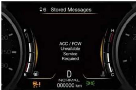
text_image
6 Stored Messages ACC / FCW Unavailable Service Required D NORMAL 000000 kmPrecautions while Driving with ACC
Offset Driving
ACC may not detect a vehicle in the same lane that is offset from your direct line of travel, or a vehicle merging in from a side lane. There may not be sufficient distance to the vehicle ahead. The offset vehicle may move in and out of the line of travel, which can cause your vehicle to brake or accelerate unexpectedly.
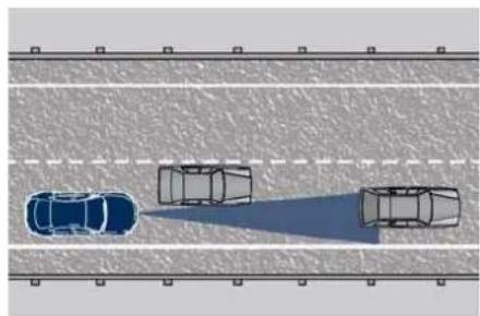
natural_image
Top-down view of three cars on a road with lane markings (no text or symbols)Turns and Bends
When driving on a curve with ACC engaged, the system may decrease the vehicle speed and acceleration for stability reasons, with no target vehicle detected. Once the vehicle is out of the curve the system will resume your original set speed. This is a part of normal ACC system functionality. Moreover, the radar sensor might detect a vehicle on a nearby lane or no longer detect the target vehicle.

natural_image
Top-down diagram of a multi-lane road intersection with vehicles and a truck, no text or symbols presentDriver Assistance Systems

Using ACC on Hills
When driving on steep hills, ACC may not detect a vehicle in your lane when vehicle reaches the crest. Depending on the speed, vehicle load, traffic conditions, and the steepness of the hills, ACC performance may be limited.
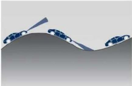
natural_image
Illustration of three cars on a curved surface with an arrow indicating motion (no text or symbols)Lane Changing
ACC may not detect a vehicle until it is completely in the lane in which you are travelling.
In the illustration shown, ACC has not yet detected the vehicle changing lane and it may not detect the vehicle until it is too late for the driver to take action. ACC may not detect a vehicle until it is completely in the lane. There may not be sufficient distance to the lane changing vehicle.
Always be attentive and ready to apply the brakes if necessary.
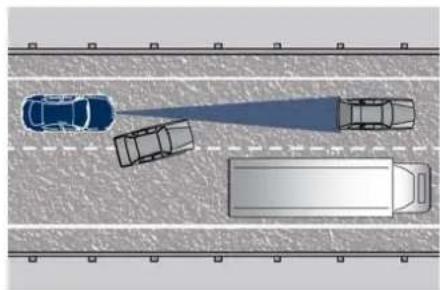
natural_image
Top-down view of a multi-lane road with cars and a truck, no visible text or symbolsNarrow Vehicles
Some narrow vehicles (like motorcycles) travelling near the outer edges of the lane or edging into the lane are not detected until they have moved fully into the lane. There may not be sufficient distance to the vehicle ahead.
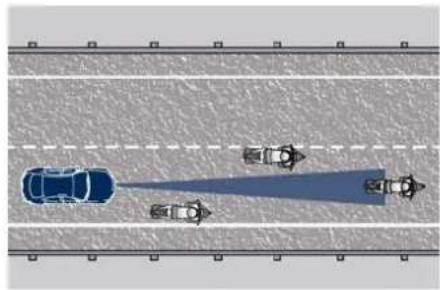
natural_image
Top-down view of a multi-lane road with cars and a speedboat, no visible text or symbolsStationary Objects and Vehicles
ACC does not react to stationary objects and stationary vehicles. For example, ACC will not react in
situations where the vehicle you are following exits your lane and the vehicle ahead is stopped in your lane. Always be attentive and ready to apply the brakes if necessary.
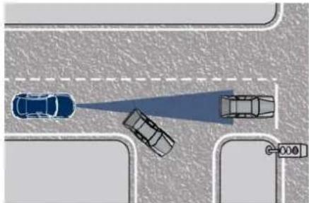
natural_image
Top-down view of a road intersection with cars and a traffic light (no text or symbols)Radar Device - Regulatory Information
The "Regulatory Information" for all the radio frequency and radar devices can be consulted by accessing the section "Services" on the website www.maserati.com.

Driver Assistance Systems
Forward Collision Warning - FCW ( )
The Forward Collision Warning (FCW) system with braking action uses the same parts already described for Adaptive Cruise Control (ACC) for sensing vehicle ahead (hereinafter "target vehicle") as well as part of the warnings/messages on system condition and activation status. Full performance can be reached only when both the sensing parts have detected a vehicle or, if the car is equipped with Pedestrian Emergency Braking (PEB) system, also a pedestrian.
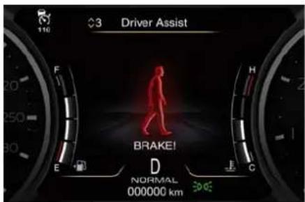
text_image
Driver Assist F 3 H 20 250 300 E BRAKE! D NORMAL 000000 km 300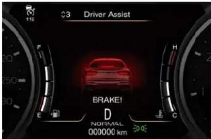
text_image
Driver Assist BRAKE! D NORMAL 000000 kmThe difference between full and reduced performance is not visible for the driver.
Pedestrian Emergency Braking (PEB) System (if equipped)
PEB is a sub-system of FCW and it provides the driver with audible warnings, visual warnings on the instrument cluster display, and may apply automatic braking when it detect a potential frontal collision with a pedestrian.
NOTE:
The PEB function is only active up to 60 km/h (37 mph).

WARNING!
Pedestrian Emergency Braking (PEB) is not intended to avoid a collision on its own, nor can PEB detect every type of potential collision with pedestrian. The driver has the responsibility to avoid a collision by controlling the vehicle via braking and steering. Failure to follow this warning could lead to serious injury or death.
PEB System Limitations
PEB may be impaired or may not function in the following situations:
- If there is poor visibility, e.g. due to insufficient illumination of the road, if there are highly variable shade conditions or in rain, snow or fog.
- If there is glare, e.g. from oncoming traffic, direct sunlight or reflections from other vehicles.
- If the windshield in the area of the camera is dirty, or if the camera is fogged up, damaged or covered.
System Operation
The FCW provides audible and visual warnings when a potential collision is detected. Brake jerk and limited braking may also be applied depending on the specific scenario. FCW monitors the information from the forward looking radar sensor as
well as the Electronic Brake Controller (EBC), to calculate the probability of a forward collision. When the system determines that a forward collision is probable, the driver will be provided with audible and visual warnings and may provide a warning brake jerk. If the driver does not take action based upon these progressive warnings, then the system will provide a limited level of active braking to help slow down the vehicle and mitigate the potential forward collision. If the driver reacts to the warnings by braking and the system determines that the driver intends to avoid the collision by braking but has not applied sufficient brake force, the system will compensate and provide additional brake force as required. When the system determines a collision with the vehicle in front of you is no longer probable, the warning messages will be deactivated.
NOTE:
- Bad weather conditions, like strong rain, snow, etc., can lead to reduced system performance. Under these conditions relevant objects will not be detected or detected late by the system.
- FCW is designed to react in specific situations in typical traffic scenarios with objects in the same lane driving in the same direction, but under certain conditions it can also react on stationary objects in the same lane. It is not designed to react to oncoming traffic or crossing traffic.
- The FCW alerts may be triggered on objects other than vehicles such as guard rails or sign posts based on the course prediction. This can occur but it is not part of normal FC activation and functionality.
- It is unsafe to test the FCW system. prevent such misuse of the system, after four Active Braking events within an ignition cycle, the Active Braking portion of FCW will be deactivated until the next ignition cycle. The limit of four events applies to the brake jerk too.
- FCW will automatically deactivated when ESC Off) button is pressed (LED light up).
WARNING!
- Forward Collision Warning (FCW) is not intended to avoid a collision on its own, nor can FCW detect every type of potential collision. The driver has the responsibility to avoid a collision by controlling the vehicle via braking and steering. Failure to follow this warning could lead to serious injury or death. The driver is always in charge to safely drive and to avoid critical situations not relying on the support of the system. Driver has to keep in mind that the system and therefore its intervention is always subject to the prevailing physical limits.
• FCW is not intended either to warn or to apply any brake aid/brake intervention in case of collisions with pedestrians (if not equipped with Pedestrian Emergency Braking PEB sub-system), bicycles and smaller vehicles in general.
Speed Range of Use
| Speed km/h (mph) | |
| Minimum 0 | |
| Engaged/activated 2 (1.24) | |
| Maximum 250 (155) | |

Driver Assistance Systems
When the speed is outside the specified limits, the system automatically disables without turning on the corresponding warning light on the instrument cluster.
System Status
The driver can adjust FCW sensitivity or enable/disable the brake jerk with the other emergency brakings by touching "Forward Collision Warning" soft-key on the Apps page or in the "Settings" list of the "Vehicle" page.
Setting options are described in the following paragraph.
When FCW status for some reason changes in off, the corresponding amber warning light on instrument cluster will light on.

text_image
126 km/h FM 94.70 Press > for MPH D NORMAL 000000 kmThis warning light informs the driver that FCW is disabled. This warning light will light even when the activation of another driver assistance
function or drive mode (example: ESC Off) disables the FCW.
NOTE:
The FCW system setting chosen by the User is kept in memory only for the current ignition cycle.
System Setting
FCW warning can be set in "Active Braking" (default mode), "Warning" or "Warning & Active Braking".
The default status of FCW sensitivity is the "Med (Medium)" setting. When also the active braking function ("Forward Collision Warning Active Braking") setting is on, the system warns you of a possible collision with the vehicle in front of you when you are farther away and it applies limited braking. This gives you the most reaction time to avoid a possible collision.
Changing the sensitivity status to the "Near" setting, allows the system to warn you of a possible collision with the vehicle in front of you when you are much closer. This setting provides less reaction time than the "Warning & Active Braking" sensitivity setting, which allows for a more dynamic driving experience.
"Med" is the intermediate status between the two described above.
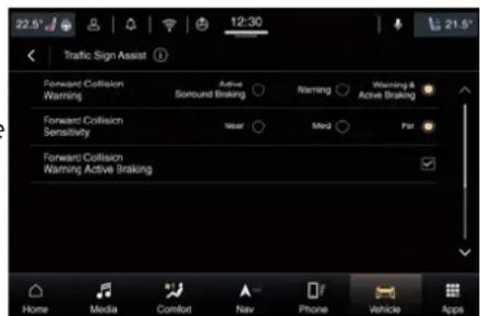
text_image
22.5° 12:30 Traffic Sign Assist Forward Collision Warning Actual Sound Braking Warning Warning & Active Braking Forward Collision Sensitivity Year Med Par Forward Collision Warning Active Braking Home Media Comfort Nav Phone Vehicle AppsNOTE:
- The default values shall appear at every new ignition cycle: Sensitivity = "Med" and "Active Braking" = on.
- FCW may not react to irrelevant objects such as objects not in the path of the car, stationary objects that are far away, oncoming traffic, on cross traffic vehicles, or leading vehicles with the same or higher rate of speed.
- The active braking (autonomous braking/braking aid) will not engage in case of potential collision with static object such as guard rails, walls, etc..
- FCW will be disabled like ACC (refer to chapter "Adaptive Cruise Control - ACC" in this section.
Changing the active braking status to "Off" prevents the system from providing limited autonomous braking
or additional brake support if the driver is not braking adequately in the event of a potential frontal collision. In this state the system disables the brake jerk.
Limited Operation and Service Warning
The messages indicating on display the limited functionality or service at Service Network required are the same as for the ACC system. For further details, refer to "Adaptive Cruise Control - ACC" in this section.
NOTE:
- The adjustment of the sensor could be affected by strong shocks or light collisions. This could affect the system by reducing the systems performance or could increase the false positive rate. The adjustment of the radar system has to be proved or a new adjustment has to be performed by a Service Network.
- The radar system requires specific function to detect objects. The detection could be disturbed/reduced by environment influences, for example by electrical field or the object itself. Object with small radar reflection properties could not be detected or detected late.
- When in "CORSA" mode (TROFEO version only), the FCW function is deactivated.
Radar Device - Regulatory Information
The "Regulatory Information" for all the radio frequency and radar devices can be consulted by accessing the section "Services" on the website www.maserati.com.
Lane Keeping Assist - LKA (with ACC only)
This system was designed especially for highway or freeway driving, to reduce the risk that the vehicle, under particular circumstances, accidentally departs from the lane in use. When this happens, graphic instructions on instrument cluster display together with steering torque application and steering wheel vibration (depending on the distance to the line and the setting that the driver has chosen from the "Settings" menu on MIA as described in "Customised Settings" of this chapter) warn the driver that the vehicle is going out of the lane initiates a steering manoeuvre to try to prevent the lane exit.
To detect lane lines, the system uses the forward-facing camera behind of the rear-view mirror, which is the same one used also by the lighting system to manage automatic high beam. The logic core is in the front radar. LKA system remembers the condition it was in before turning off the vehicle. Refer to "Functions of Controls Menu on MIA" in section "Dashboard Instruments and Controls" for further information.

Driver Assistance Systems
NOTE:
In case of wet road or raining conditions the function could be disabled by the system in order to minimize the risks.
Speed Range of Use
| Speed km/h (mph) | |
| Minimum 60 (37) | |
| Engaged/activated 60 (37) | |
| Maximum 180 (112) |
Customised Settings
LKA is configurable by the customer in order to maximize its efficiency based on the driver driving style and his expectation of the system, reducing at the same time the possible invasiveness.
Entering "Settings" menu of the "Vehicle" page on MIA display the driver can see the current setting beside the "Lane Keeping Assist" soft-key.
Touching "Lane Keeping Assist" soft-key to enter the setting page.
Driver warnings are "Visual & Haptic" (default mode).
System response can be set to "Early", "Medium" (default mode) or "Late". System reaction force can be set to "Low", "Medium" (default mode) or "High".
Meanings of Settings
"Visual & Haptic": the system will apply steering torque when lane departure is detected showing at the same time the proper cluster indication, adding to this steering vibration when the departure is very imminent.
When "Visual & Haptic" is selected and of course LKA is enabled then two following menu will be used by the system.
- "LKA Sensitivity": it tunes the distance to the lane boundary interested where the system will start to apply steering torque.
- "LKA Strength": it tunes the steering torque and speed value increasing or decreasing it to have a stronger or weaker trajectory correction/deviation.

WARNING!
In rare cases, Lane Keeping Assist (LKA) may make an inappropriate steering torque application. LKA may be interrupted at any time by counter steering. Lack of attention may lead to serious injury or death.
System Availability
The ADAS systems help the driver while driving. These systems can be set and monitored simultaneously on the display, after opening "Driver Assist" menu (see "TFT Display: Menu and Submenu Content" in section "Dashboard Instruments and Controls").
When you are not in the "Driver Assist" page, the system status is indicated by a telltale at the top left of the TFT display.
LKA is designed for an attentive driver therefore the system is available only when his/her hands are on the steering wheel or with hands off for a very limited amount of time. When the system is enabled it will trigger cluster warning in case at least one hand is not detected on the steering wheel.
The torque application as well as the vibration are suppressed/inhibited in case of: high driver torque in the steering wheel, high lateral acceleration, trailer connected to the proper control module, hands not on the steering wheel detected for more than a certain time.
Driver Assistance Systems

High dynamic behaviours, driving on the lane boundary, off course will prevent the function from working. FCW braking and stability system interventions (ESC, ABS) will also prevent the system from operating.
Changing lane results in system inhibition for a certain time. In addition, the road must respect some characteristics such as minimummaximum width, lane clearly defined by two lane boundaries and only in limited cases for a limited time at least one.
The LKA system is active both in the case of both lines visible and available for the system, and in case of the only line available on the road.
Each LKA intervention is notified to the driver with the relative graphics which is shown for the entire duration of the system intervention and for a minimum time of 1 second.
Multiple interventions are allowed both in terms of visual and acoustic signals and in terms of steering torque.
If more then three consecutive interventions are required within a period of 180 seconds, starting from the second intervention the acoustic signal will last 10 seconds longer the previous one.
Starting from the third acoustic signal the system will emit a continuous sound and a message on TFT display will indicate to keep the center line.
NOTE:
• In case of wet road or raining conditions the function could be disabled by the system in order to minimize any risks.
- The system is developed to work on the lines painted on the road surfaces, but it may happen that shadows, traces of old lines, road edges, etc. are also interpreted as such.
Being this function used to prevent unintentional lane change/lane drift, it will be temporary suppressed/inhibited by a turn indicator activation, therefore, graphic warning, steering torque application and vibration will be terminated. In these conditions the graphics turn gray.
Function Description and Operating Mode
The function intent is to prevent the lane departure by warning the driver through indication on the cluster and if set applying steering torque and vibration. The graphic intent is to represent at the glance the system knowledge of the lane in front of the car, the system suppression status and warning.
For this a simple colour code has been adopted for each line (of the two presented):
- Both grey lines means system enable, not able to operate (suppression condition present or lane detection system not able to estimate properly the lane);
- Left/right grey line: the lane detection system is not able to detect that specific lane boundary;
- Yellow line: there is a steering torque intervention in progress that tries to prevent a departure on that side, in this situation the warning should increase the driver attention requiring him to properly handle the situation;
- Yellow flashing line: the graphic is shown whenever the system detects a very imminent lane departure, at this can be added torque and steering vibration if configured by the customer.
The white lines (one or both) indicates that the corresponding lane boundary is detected and the system is capable to intervene on it.
Whenever the system is enabled there will be graphic on the dedicated screen of the "Driver Assist" page. This

Driver Assistance Systems
graphic will be available in the form of symbols (see detail in figure) in the top left corner of the cluster screen.
An example of this screen, with only LKA system activated and with LKA and ACC systems activated, can be found in the following figures.
In the first, only LKA system is activated, steering torque in progress to correct the trajectory towards the lane center.
In the second LKA and ACC systems are activated, car is crossing the lane boundary, steering torque and vibration if configured are in progress when this graphic is shown.
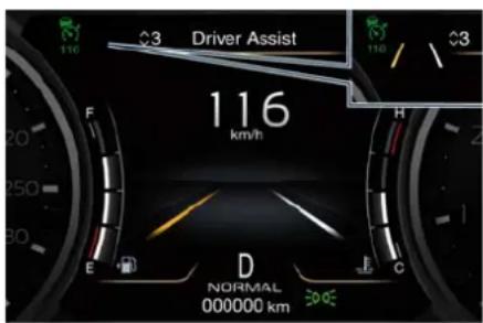
text_image
Driver Assist 116 km/h E F 20 250 30 D NORMAL 000000 km F C H 116 / 3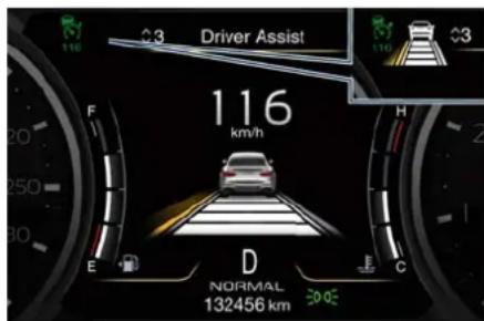
text_image
Driver Assist 116 km/h E F H D NORMAL 132456 km C E F H C 110 3 110 3The icons that represent the status of the ADAS systems remain displayed even when you exit the "Driver Assist" screen.
System Limitations
Because of physical limits the system to properly operate needs good visibility (it might not work or not properly operate in case of heavy rain, snow, wet roads, fog, direct sun on the camera, etc.).
NOTE:
The sensors are not able to detect the presence of the hands on the steering wheel areas covered in wood, plastic bezels or carbon inserts (where present).
Sharp turns, slopes and change in slopes, poor lane boundaries, as well as construction areas and all the scenario described in this paragraph may challenge the system, therefore be always ready to prevent any unexpected behaviour of the car.
Damaged front bumper, windshield replaced without proper technical intervention may also lead to system malfunction or system unavailability.
Other conditions such as fault, but not explicitly indicated here may also prevent/interrupt the system intervention.

WARNING!
If the driver fail to adapt his/her driving style, Lane Keeping Assist (LKA) can neither reduce the risk of an accident nor override the laws of physics. It cannot take into account road, weather or traffic conditions. Active LKA is only an aid. Driver is always responsible for the distance to the vehicle in front, for vehicle speed, for braking in good time and for staying in lane.
System in Faulty
When the LKA cannot properly operate due to a fault of its components or because the windshield in front of the forward facing camera is dirty, the amber light and/or the
corresponding message will be displayed.
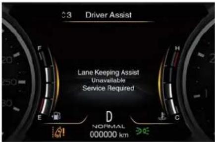
text_image
Driver Assist Lane Keeping Assist Unavailable Service Required NORMAL 000000 kmIf message suggestion does not allow fixing the fault, avoid using the system and have the vehicle inspected at the Service Network.
Radar Device - Regulatory Information
The "Regulatory Information" for all the radio frequency and radar devices can be consulted by accessing the section "Services" on the website www.maserati.com.
Blind Spot Assist - BSA (
System Operation
The Blind Spot Assist (BSA) system uses two radar-based sensors, located inside the rear bumper fascia, to detect highway licensable vehicles (cars, lorries, motorbikes, etc.) that enter the blind spot zones from the rear/front/side of the vehicle in adjacent lines.
The example shown in the figure highlights the blind spots on either side of the vehicle when overtaking traffic is approaching from behind.
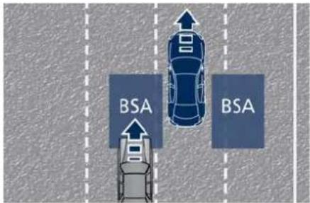
text_image
BSA BSAWhen the vehicle is started, the BSA warning light will momentarily illuminate in both outside rear view mirrors to let the driver know that the system is operational and on. The BSA system sensors operate when the vehicle is in any forward gear
) and enters standby mode when the transmission is in (P) Park.
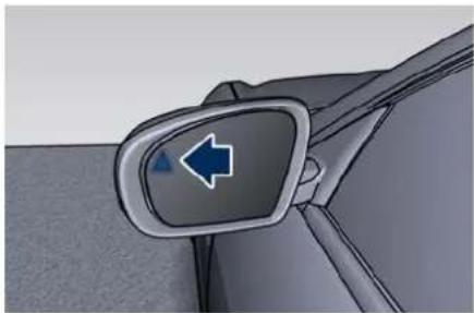
natural_image
Close-up of a car's side mirror with a blue arrow pointing left (no text or symbols)The BSA detection zone shown in figure covers approximately one lane on both sides of the vehicle (approximately 3.3 m or 11 ft).
The blind spot area extends from immediately behind the exterior rear-view mirrors up to about 7 m (23 ft) behind the rear bumper.
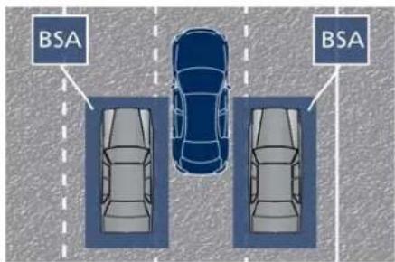
text_image
BSA BSAThe BSA system monitors the detection zones on both sides of the vehicle

Driver Assistance Systems
to detect the presence of vehicles and begins to warn the driver by flashing the warning light in the rear view when the vehicle speed reaches approximately 6 km/h (4 mph) or higher.

WARNING!
- The Blind Spot Assist (BSA) system does NOT alert the driver about rapidly approaching vehicles that are outside the detection zones.
• The BSA might alert the driver too late especially in case of rapidly approaching vehicles.

WARNING!
Risk of accident despite Blind Spot Assist (BSA).
BSA does not detect/react to the following:
- Overtaking vehicles close on the side, placing them in the blind spot area. As a result, BSA may neither give warnings nor intervene in such situations.
• Always pay attention to the traffic situation and maintain a safe distance at the side of the vehicle.
NOTE:
If your vehicle has experienced any damage in the area where the sensor is located, even if the fascia is not damaged, the sensor may have become misaligned. Take your vehicle at the Service Network to verify sens alignment. Having a sensor that is misaligned will result in the BSA not operating to specification.
The area on the rear bumper fascia where the radar sensors are located must remain free of snow, ice, and dirt/road contamination so that the BSA system can function properly. Do not cover or block the area of the rear bumper fascia where the radar sensors are located with foreign objects (bumper stickers, spoilers, bicycle racks, etc.).
The BSA system notifies the driver of vehicles or objects in the detection zones by illuminating the BSA warning light located in the outside mirrors in addition to sounding an audible (chime) alert and reducing the radio volume (if the radio is on). Refer to "BSA and RCP Setting" in this chapter for further information.
The BSA system monitors the detection zone from three different entry points (side, rear, overtaking traffic) while
driving to see if an alert is necessary. The BSA system will issue an alert whenever a vehicle enters any one detection zone as outlined below.
Speed Range of Use
| Speed km/h (mph) | |
| Minimum 10 (6) | |
| Engaged/activated 10 (6) | |
| Maximum – |
Entering from the Side
Vehicles that move into your adjacent lanes from either side of the vehicle.
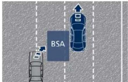
text_image
BSAEntering from the Rear
The alert will turn on when the vehicles that come up from behind your vehicle on either side and enter the rear detection zone with a relative speed of more than 43 km/h (27 mph).
Driver Assistance Systems

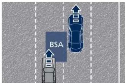
text_image
BSAOvertaking Traffic
The figures show the vehicle approaching (A) and passing (O) another vehicle in the overtaking lane. If you pass another vehicle slowly, the vehicle remains in the blind spot for approximately 2 seconds, the BSA warning light in the outside mirror will illuminate after 1.5 seconds.
If the difference in speed between the two vehicles is greater, the warning light will not illuminate.
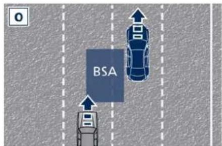
text_image
BSAOther Cases
The BSA system is not designed to issue an alert on stationary objects such as guardrails, posts, walls, foliage heaps, berms, etc. However, occasionally the system may alert on such objects. This is normal operation and your vehicle does not require service.
opposite direction of the vehicle in adjacent lanes.
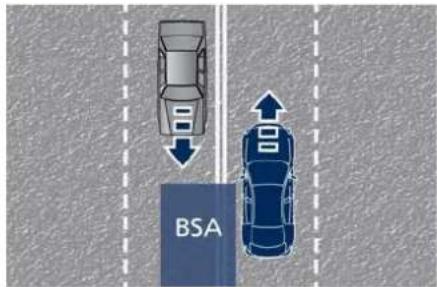
text_image
BSA
WARNING!
- The Blind Spot Assist (BSA) system is only an aid to help detect vehicles in the blind spot zones.
• The BSA system is not designed to detect pedestrians, cyclists, or animals. - Even if your vehicle is equipped with the BSA system, always check your vehicle's outside and rear-view mirrors for any vehicles approaching from behind or overtaking.
- Use your turn signal before changing lanes.
System Monitoring on TFT Display
Whenever the BSA system is enabled by the user, an specific indicator is
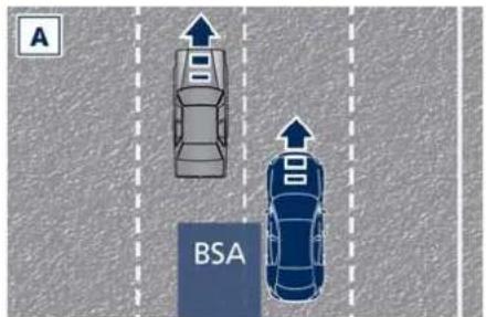
text_image
A BSA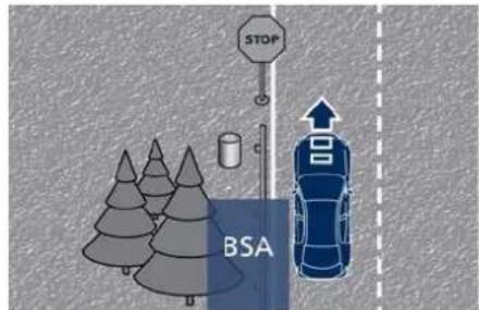
text_image
STOP BSAThe BSA system will not alert you of objects that are travelling in the

Driver Assistance Systems
displayed in the left upper corner of the TFT display (area 22). This indicator can take on different colors depending on the system status:
stand by status (white icon);
active status (green icon).
RCP - Rear Cross Path()
The Rear Cross Path (RCP) function is intended to aid the drivers when gear in reverse of parking spaces where their vision of oncoming vehicles may be blocked.
The RCP system monitors the rear detection zones on both sides of the vehicle. Using sensors located on either side of the rear bumper, it detects vehicles or objects that are moving toward the side of the vehicle with a minimum speed of approximately 1 km/h to 3 km/h (1 to 2 mph) to a maximum of approximately 16 km/h (10 mph), such as in parking lot situations.
NOTE:
In a parking lot situation, oncoming vehicles can be obscured by vehicles parked on either side. If the sensors are blocked by other structures or vehicles, the system will not be able alert the driver.
Proceed slowly and cautiously out of the parking space until the rear end of the vehicle is moderately exposed. The RCP system will then have a clear view of the cross traffic. If an oncoming vehicle is detected, the RCP system will alert the driver using both the visual and audible alarms. If the radio is on, it will also reduce the radio volume.
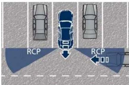
text_image
RCP RCP
WARNING!
Rear Cross Path (RCP) is not a Back Up Aid system. More specifically, it is intended to be used to help a driver detect an oncoming vehicle in parking lot situation. Drivers must be careful when backing up, even when torsing RCP. Always check carefully behind your vehicle, look behind you, and be sure to check for pedestrians, animals, other vehicles, obstructions, and blind spots before backing up. Failure to do so can result in serious injury or death.
BSA and RCP Setting
Setting modes can be selected from the MIA system.
Touch "Settings" soft-key on "Vehicle" page and then select "Blind Spot Assist" soft-key to enter the setting page.
Refer to chapter "Functions of Controls Menu on MIA" in section "Dashboard Instruments and Controls" for further information.
BSA in Visual Mode
When operating in "Visual" mode, the BSA system will provide a visual alert in the appropriate side view mirror when it detects a vehicle or an object in the detection areas monitored by its sensors: depending on the status of the relative turn indicator, the warning light can be fixed or flashing. However, when the system is operating in RCP mode, it will respond with both visual and audible alerts when an oncoming vehicle or an
Driver Assistance Systems

object approaching the rear end side of the vehicle is detected. Whenever an audible alert is requested, the radio is muted (if the radio is on).
BSA in Visual and Acoustic Mode When operating in "Visual & Acoustic" mode, the BSA system will provide a visual alert in the appropriate side view mirror based on a detected vehicle or object.
If the turn signal is then activated, and it corresponds to an alert present on that side of the vehicle, an audible chime will also be sounded: in the same moment the warning light will start flashing.
Whenever a turn signal and detected vehicle or object are present on the same side at the same time, both the visual and audio alerts will be issued. In addition to the audible alert, the radio volume will be reduced (if the radio is on).
NOTE:
If the hazard flashers are on, the BSA system will issue the appropriate visual alert only.
When the system is in RCP mode, the system shall respond with both visual and audible alerts when a detected vehicle or object is present. Whenever an audible alert is requested, the radio (if on) is also muted. Right/left turn/hazard signal status is ignored; the RCP status always requests the chime when needed.
Blind Spot Assist Off
When this function is turned off from the MIA, there will be no visual or audible alerts from either the BSA or RCP subsystems.
NOTE:
The BSA system will store the current operating mode when the vehicle is shut off. Each time the vehicle is started, the previously-stored mode will be recalled and used.
System Temporarily Unavailable
The blind spot system will become temporarily unavailable and the instrument cluster display will show the message "Blind Spot Alert Temporarily Unavailable" when the vehicle enters a radio quite zone (example the areas around radio telescopes).
The warning light on the outside rearview mirrors will be lit up and stay lit until the vehicle exits the zone.
System in Faulty
The BSA system cannot properly operate due to a fault of its
components, or because the area on the rear bumper fascia where the radar sensors are located is dirty. In these cases the amber warning light and the related message will be displayed on the instrument cluster.
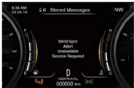
text_image
6:36 AM 02.05.19 6 Stored Messages NW Blind Spot Allert Unavailable Service Required E D NORMAL 000000 km CIn these cases avoid using the system and have the vehicle inspected at the Service Network.
Radar Device - Regulatory Information
The "Regulatory Information" for all the radio frequency and radar devices can be consulted by accessing the section "Services" on the website www.maserati.com.

Driver Assistance Systems
Active Blind Spot Assist - ABSA (→, with ACC only)
ABSA system represents an addition to the BSA previously described (see chapter "Blind Spot Assist - BSA" of this section).
ABSA adds to the BSA the possibility in certain circumstances to avoid and or mitigate side collisions with vehicles proceeding in the adjacent lanes by changing the car trajectory in order to try to keep it inside the detected/estimated lane. A steering wheel vibration is used as further feedback to warn the driver that the lane change is not safe.
The main logic core is the front radar, whereas the sense inputs are the radars on the rear bumper fascia used for sensing the presence of vehicle in the blind spot areas and the forward facing camera placed behind the internal rear-view mirror that instead is used for lane detection and estimation.
ABSA is designed to avoid and/or mitigate a collision. Torque and vibration application is however available in the 60 - 180 km/h (37 - 112 mph) speed interval. All the speed thresholds related to the BSA remain still valid, since ABSA as mentioned is BSA extension.
ABSA is intended as a "hands-on" function meaning that the driver is required to stay engaged in the driving all the time with his/her hands on the steering wheel, in case hands are not on the steering wheel for a certain time there cannot be any steering torque application vibration included (see "System Monitoring on TFT Display" in this chapter).
System Availability
ABSA is designed for an attentive driver therefore the system is available only when his/her hands are on the steering wheel or with hands off for a very limited amount of time. When the system is enabled, it will trigger cluster warning in case at least one hand is not detected on the steering wheel. The torque application as well as the vibration are suppressed/inhibited in case of: high driver torque in the steering wheel, high lateral acceleration, trailer connected to the proper control module, hands not on the steering wheel detected for more than a certain time.
Highly dynamic behaviours, driving on the lane boundary, off course will prevent the function from working. FCW braking and stability system interventions (ESC, ABS) will also prevent the system from operating. Changing lane results in system inhibition for a certain time.
In addition the road must respect some characteristics such as minimum-maximum width, lane clearly defined by two lane boundaries and only in limited case for a limited time at least one.
Each steering of the ABSA system is always notified to the driver with acoustic and visual feedback and each signaling has the same duration as the steering intervention, with a minimum of 1 seconds.
Multiple steering interventions are only allowed if both line lines are available for the system.
Multiple interventions are allowed both in terms of visual and acoustic signals and in terms of steering torque.
If more then three consecutive interventions are required within a period of 180 seconds, starting from the second intervention the acoustic signal will last 10 seconds longer the previous one.
Starting from the third acoustic signal the system will emit a continuous
Driver Assistance Systems

sound and a message on TFT display will indicate to keep the center line. If there is only one line on the road, when it is correctly detected by the ABSA system, only one trajectory correction with relative acoustic signal will be possible. Until two lines are displayed again, there will be no trajectory correction but only acoustic and visual signals.
Furthermore in case of a single and very wide lane line, if the system intervenes by steering in the opposite direction to the line, this could force the car to remain slightly misaligned from the center of the lane, towards the only available line. This behavior serves to prevent the intervention that has just taken place the car off the road from the side where the lane is not available.
NOTE:
• In case of wet road or raining conditions the function could be disabled by the system in order to minimize risks.
- The system is developed to work on the lines painted on the road surfaces, but it may happen that shadows, traces of old lines, road edges, etc. are also interpreted as such.
Speed Range of Use
| Speed km/h (mph) | |
| Minimum 60 (37) | |
| Engaged/activated 60 (37) | |
| Maximum 180 (112) |
System Limitation
Because of physical limits the system to properly operate needs good visibility (it might not work or not properly operate in case of heavy rain, snow, wet roads, fog, direct sun on the camera, dirty windshield, low illumination etc.)
Sharp turns, slopes and change in slopes, poor lane boundaries, as well as construction areas and all the scenarios described in this paragraph may challenge the system, therefore be always ready to prevent any unexpected behaviour of the car.
Damaged front bumper, windshield replaced without proper technical intervention may also lead to system malfunction or system unavailability.
Other conditions such as faults, but not explicitly indicated here may also prevent/interrupt the system intervention.
System Setting
ABSA is configurable by the customer in order to maximize its efficiency based on the driver driving style and his/her expectation of the system, reducing at the same time the possible invasiveness.
Setting modes can be selected from the MIA system (see "Functions of Controls Menu on MIA" in section "Dashboard Instruments and Controls" for further information).
Touch "Settings" soft-key on "Vehicle" page and select "Active Blind Spot Assist" function to enter the setting page.
Driver warnings can be only "Visual", "Visual & Acoustic" (default mode) or "Visual & Haptic". When "haptic" feedback is selected, every time a steering force is applied there will always also an acoustic signal to the driver.
System sensitivity can be set to "Early", "Medium" (default mode) or "Late". System strength can be set to "Low", "Medium" (default mode) or "High".
NOTE:
The ABSA system will store the current operating mode when the vehicle is shut off. Each time the vehicle is (Continued)

Driver Assistance Systems
(Continued)
started, the previously-stored mode will be recalled and used.
Meanings of Settings
When "Visual & Haptic" is selected and of course ABSA is enabled, then two following menus will be used by the system.
- ABSA "Sensitivity": it tunes the distance to the lane boundary concerned where the system will start to apply steering torque.
- ABSA "Strength": it tunes the steering torque value increasing or decreasing it to have a stronger or weaker trajectory correction/ deviation.
System in "Visual & Haptic" Mode
When the system is on and configured "Visual & Haptic" then the real ABSA is enabled because to the conventional visual warnings is added the steering torque and vibration.
When operating in this mode, the system will provide a visual alert in the appropriate outside rear-view mirror when it detects a vehicle or an object in the detection areas monitored by its sensors. In case of turn indicator activation on the appropriate side, the system will react with a torque on the steering wheel to try to prevent the lane change and therefore to avoid/mitigate the collision. The torque on the steering is applied when the car is very close to the lane boundary as a further feedback to warn the driver of the unsafe manoeuvre.
NOTE:
The steering torque is not supplied if the system is not able to estimate a lane and if the turn indicator from the appropriate side is not inserted.

WARNING!
- Risk of accident despite steering torque application of Active Blind Spot Assist (ABSA).
- A course-correcting steering torque application cannot always prevent a collision.
• The driver is always required to steer, brake or accelerate himself, especially if ABSA warns or makes a course correcting steer intervention.
• Always maintain a safe distance at the sides.
• In rare cases, the system may make an inappropriate steering torque application. This application may be interrupted at any time by counter steering.
- Lack of attention may lead to serious injury or death.
System Monitoring on TFT Display
Whenever the ABSA system is enabled by the user, an specific indicator is displayed in the left upper corner of the TFT display (area 24). This indicator can take on different colors depending on the system status:
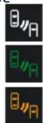
stand by status (white icon);
active status (green icon);
intervention (amber icon).
In Case of Intervention
ABAS shall apply a torque on the steering wheel when a vehicle is detected in blind spot. If driver's hands are off the steering wheel, a graphic pop up shall appear on TFT display to invite you to keep your hands on the steering wheel. In this case, a single audible chime is repeated until he/she will take the control of the vehicle again.
Driver Assistance Systems

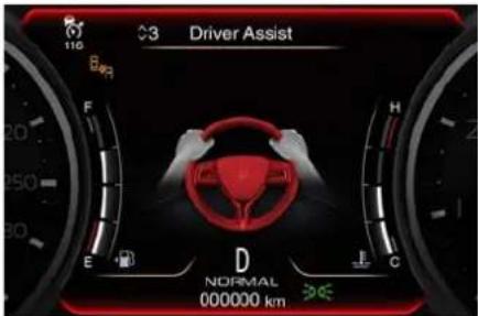
text_image
3 Driver Assist E D C NORMAL 000000 kmRCP - Rear Cross Path Operation
RCP operation (if equipped) is the same as described in chapter "Blind Spot Assist - BSA".
The visual or audible alerts from RCP subsystem will also be present when ABSA is turned off from MIA "Settings" menu of the "Vehicle" page.
When ABSA is turned on with any setting, RCP subsystem shall respond with both visual and audible alerts when a detected vehicle or object is present. Whenever an audible alert is requested, the radio (if on) is also muted.
Right/left turn/hazard signal status is ignored; the RCP status always requests the chime.
System Temporarily Unavailable
The blind spot system will become temporarily unavailable and the instrument cluster display will show the message "Blind Spot Alert Temporarily Unavailable" when the vehicle enters a radio quite zone (example the areas around radio telescopes).
The warning light on the outside rear-view mirrors will be lit up and stay lit until the vehicle exits the zone.
System in Faulty
The ABSA system cannot properly operate due to a fault of its components, or because the area on windshield where the forward-facing camera is located or on the rear bumper fascia where the radar sensors are located is dirty. In these cases the amber warning light and the related message will be displayed on the instrument cluster.
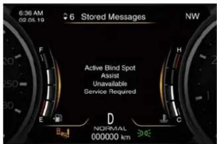
text_image
6:36 AM 02.05.19 6 Stored Messages NW Active Blind Spot Assist Unavailable Service Required E F H D NORMAL 000000 km CIn these cases avoid using the system and have the vehicle inspected at the Service Network.
Radar Device - Regulatory Information
The "Regulatory Information" for all the radio frequency and radar devices can be consulted by accessing the section "Services" on the website www.maserati.com.

Driver Assistance Systems
Active Driving Assist - ADA (ET, with ACC only)
The Active Driving Assist (ADA) is a level 2 autonomy system (in reference to SAE standards) that is designed to aid the driver in the steering, acceleration, and braking functions of the vehicle.
ADA can work in any type of road. However, its use it is not recommended in urban scenarios. ADA centres the vehicle by controlling the EPS system based off of lane line information from the forward-facing camera and data from the front radar sensor.
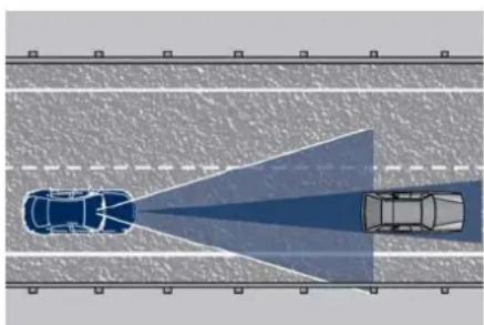
natural_image
Top-down view of a road with two cars ahead, showing a blue light beam and a white car silhouette (no text or symbols)ADA combines ACC and LKA to manage the steering and speed of the vehicle under specific conditions. The conditions to engage ADA are listed in the next paragraph. If a lane line cross is imminent, the steering wheel will vibrate and a graphic will display on the instrument cluster.
WARNING!
- In case the vehicle approaches a curve that is too tight in relation to the current speed the system will disengage, therefore the driver must be prepared to take over control of the vehicle immediately at any time. To avoid this situation it is important that the vehicle speed is not set higher than the current speed limit of the road.
• Active Driving Assist (ADA) is a hands-on function! You must keep your hands on the steering wheel at all times. The ADA system will disengage and ACC will cancel if your hands are removed from the steering wheels for a set amount of time. - ADA is intended for use only on highways or limited access freeways, freeways, etc. with a fully attentive driver. When using ADA, hold the steering wheel and be aware of surrounding traffic and road conditions. Always be prepared to immediately take over control of the
vehicle from the ADA system. Failure to follow these instructions could result in serious injury or death.
- The following list does not fully represent all situations in which ADA may not function as intended. Do NOT solely rely on the ADA system to control the vehicle. It is the driver's responsibility to stay alert and safely control the vehicle at all times.
- If the windshield is replaced, you must have the forward-facing camera remounted and aligned by a centre of the Service Network.
Many factors can impact the performance of ADA causing the system to be unable to function as intended. These include (but are not limited to):
- Narrow, winding or curvy roads.
- Poor visibility (due to heavy rain, snow, fog, etc.).
- Bright light (oncoming headlights or direct sunlight) or shadows.
- Damage or obstruction caused by mud, ice, snow, etc.
- A damaged or misaligned bumper.
- Interference from other equipment that generates electromagnetic waves.
Driver Assistance Systems

- Wet roads, roads covered or partially covered by snow.
- Construction zones.
System Operation
With ACC set (see "Adaptive Cruise Control – ACC" in this section), ADA system activates by simply pressing the button on the steering wheel. Once the conditions are met, ADA will engage.

WARNING!
The Active Driving Assist (ADA) system may take up to 5 seconds to engage once all conditions are met.
The conditions for ADA to engage are as follows:
- ADA must be turned on or enabled.
NOTE:
In case of wet road or raining conditions the function could be disabled by the system in order to minimize the risks.
- The vehicle must be on the highway or limited access freeway, or on the extra urban roads.
- ACC must be engaged.
• Left and right visible lane lines. -
Vehicle speed must be between 0 and 145 ~km / h (0 to 90 mph ).
-
No faults in the forward facing camera, radar, EPS, or MIA.
- Lane width between 2.8 and 4.2m (3 to 4.6 yd).
- Turn signal not activated.
- No faults related to this system.
Speed Range of Use
| Speed km/h (mph) | |
| Minimum 0 | |
| Engaged/activated(with ACC engaged) | 0 |
| Engaged/activated(with ACC not en-gaged) | 30 (20) |
| Maximum 145 (90) |
- If set above the maximum speed, ADA will not function after the vehicle speed will reach the maximum speed.
- If set below the maximum speed and the ACC target speed is increased, ADA will function up to the maximum speed and then the system will turn off automatically.
- When the ACC target speed is reduce and speed is lower than the maximum speed, the system will start automatically.
- If the ACC target speed is set under the maximum speed, ADA is active
and vehicle speed increases above the maximum speed due to slope, ADA will continue to function.
Monitoring on TFT Display
ADA and the other ADAS systems conditions can be monitored on TFT display by accessing the "Driver Assist" page with the buttons on the steering wheel (see "TFT Display Setting and Menu Overview" in section "Dashboard Instruments and Controls").
The symbol in grey indicates that the ADA system is active, but not engaged and is shown at the centre of the TFT display when the "Driver Assist" page is displayed.
The ACC and ADA information are shown with a telltale on the left top corner of the TFT display when other information (textual pop ups, NAVI information, phone call, etc...) cover the ADA's ones (see detail in picture). In telltale ADA uses steering wheel icon and corner lines to indicated its status.
When exiting the "Driver Assist" page, on TFT display top left corner, the ⏱ grey symbol will appear in the multiple light of active ADAS systems.

Driver Assistance Systems
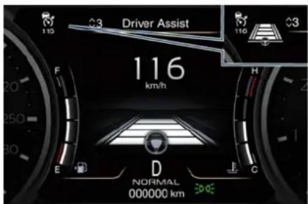
text_image
Driver Assist 116 km/h E F 20 250 30 D NORMAL 000000 km H C 110 110 3In addition to these symbols, on the TFT top and bottom edge a coloured glow may appear (further referred to as "attention level colour"). Attention level colour together with the outline of the symbol represent a further indication of the system status.
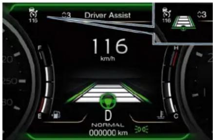
text_image
Driver Assist 116 km/h E F 20 250 300 D NORMAL 000000 km E F C 116 3When exiting the "Driver Assist" page, the attention level colour will always be displayed until the system is disabled by pressing the button on the steering wheel.
The ADA system uses sensors in the steering wheel outer crown to detect if the driver's hands are on the steering wheel. If the driver's hands are not detected on the steering wheel, the instrument cluster will display a series of warnings to alert the driver to return their hands to the steering wheel. There will also be audible chimes. After a set amount of time, ADA will cancel if the driver's hands are not returned to the steering wheel.
When the system does not sense the hands on the steering wheel for a few seconds (3 – 5 seconds) or more (up to 10 seconds), it tries to draw the attention of the driver by showing, even when the display is not in the "Driver Assist" page, the symbol with the figure of the hands in the centre of the display. According to such time frames, the system will change the attention level colour, silence the audio in the vehicle (if it is active) and emit audible chimes to notify the driver to take the control of the vehicle again. This is the only way to reengage the system.
Hands Detection on Steering Wheel
The sensors in the steering wheel outer crown are able to detect the presence of the hands on the steering wheel.
In order to be able to use the ADA system, place your hands around the steering wheel outer crown.
NOTE:
The sensors are not able to detect the presence of the hands on the steering wheel areas covered in wood, plastic bezels or carbon inserts (where present).
ADA is deactivated if the steering wheel is no longer being touched.
System Statuses
The active status of the ADA system is indicated by the green attention level colour which is maintained even if the driver releases his/her grip from the steering wheel up to 3 seconds.
The graphic information changes as soon as (max 1 second) the driver releases the steering wheel:
- glow color: green;
- lines: green;
- car: centered;
• steering wheel: yellow small in the center (see picture).
Driver Assistance Systems


text_image
Driver Assist 116 km/h E D C NORMAL 000000 kmThe yellow attention level colour appears when the driver removes his/her hands from the steering wheel for 3 to 5 seconds and the symbol with the figure of the hands will occupy the whole central area of the TFT display.
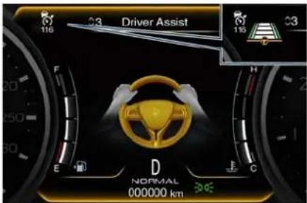
text_image
Driver Assist 116 F 20 250 30 E D NORMAL 000000 km C H 115 3The red attention level colour appears when the driver releases his/her grip from the steering wheel for 5 and up to 10 seconds: in this case a single audible chime is repeated until he/she will take the control of the vehicle again.
The red attention level colour and the chime remains even when the steering wheel is released for more than 8 to 10 seconds.
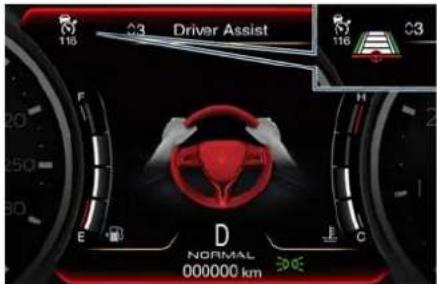
text_image
Driver Assist 116 3 116 3 20 250 300 E D NORMAL 000000 km 300EWhen the system disengage the ADA, a sequences of 3 audible chimes will be emitted and a message invites him/her to grip the steering wheel again. Then the symbol on TFT display will become grey.
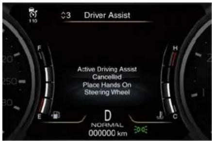
text_image
Driver Assist Active Driving Assist Cancelled Place Hands On Steering Wheel NORMAL 000000 kmIf the driver keeps his/her hands away from the steering wheel (for more than 8 to 10 seconds), also the ACC system is deactivated (white ACC symbol on the display) and will have to be reset. The aid of LKA system will be disabled as well. In these cases the display will not show the attention level colour anymore and the vehicle will be controlled by the driver only.
System Disengage
To disengage ADA you can do any of the following actions:
- Press the ADA enable button on the steering wheel.
- Begin steering manually.
- Press brake pedal.
- Turn off ACC.
- Unbuckle the driver's seat belt.
- Press ACC time gap button for two seconds to enable CC system.
- Shift out of the (D) Drive gear.
- Enter an Autonomous Emergency Braking (AEB) event (See chapter "Forward Collision Warning - FCW" in this section).
- Turn signal activated.
System Cancellation
The ADA system will cancel (without driver intervention) if either of the following actions occur:

Driver Assistance Systems
- Curve that is too tight.
- When removing the hands from the steering wheel.
- Lane line markers are not detected by the forward facing camera.
- The lane intersection or roundabout (traffic circle).
- Any ADAS system faults.
- ACC cancellation.
- Vehicle speed exceeds the maximum limit.
- Lateral accelerations exceeds the limits.
NOTE:
When ADA cancels, the symbol will turn red then grey.
System Limitations
ADA is unable to guide the vehicle when the following conditions occur.
- Lane markings are not clear or visibility is poor (i.e. heavy rain, snow, fog, etc.).
- Obstructed, covered or damaged forward-facing camera or sensor.
- When driving on hills or sharp curves.
- When approaching toll booths.
- When the highway entrance or exit is wider than 6 meters (20 ft).
- Bright light (ex. direct sunlight or glare) facing the forward camera.

WARNING!
Many unforeseen conditions can occur that can affect the performance of Active Driving Assist (ADA). Always keep this in mind and drive attentively. Be prepared to take over control of the vehicle immediately at any time.
Radar Device - Regulatory Information
The "Regulatory Information" for all the radio frequency and radar devices can be consulted by accessing the section "Services" on the website www.maserati.com.
Traffic Sign Assist – TSA (→)
TSA detects traffic signs through the use of a forward-facing digital camera mounted on windshield, behind the rear-view mirror and assists the driver by displaying detected speed limits and overtaking restrictions in the instrument cluster. The camera also detects traffic signs with a restriction indicated by an additional sign (e.g. in snow conditions). TSA also uses the data of the navigation system, in order to provide information to the driver in all cases in which the camera is not able to detect the traffic signs that are present on the road where the car is travelling.
Some examples of these are: due to low visibility, light reflection, damaged traffic signs, traffic signs in wrong position like rotated or fallen poles.
NOTE:
- Overtaking restriction sign will be displayed only in markets where this is allowed.
- TSA provides a visual warning to the driver when he/she unintentionally reaches the maximum speed limit
Driver Assistance Systems

allowed or when it exceeds the set "Sensitivity" value.
- The performance of TSA depends on the update degree of navigation system's maps.
Customised Settings
TSA is configurable by the customer regarding the display mode on the instrument cluster and the warning sensitivity.
Entering "Vehicle" page on MIA display and select the "Traffic Sign Assist" soft-key of the "Settings" menu to enter the setting page.
The check mark on the "Warning Mode" box indicates that the warning function is active.
The display of the traffic signs can be blinking or static.
The system can be set to display the traffic signs when the speed of the vehicle is equal to the speed limit allowed, or when it is higher than 5 or 10 km/h (5 or 10 mph).
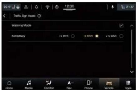
text_image
22.5° 12:30 21.5° Traffic Sign Asset Warning Mode Sensitivity +0 km/h -0 km/h +10 km/h Home Media Comfort Nav Phone Vehicle AppsSigns Monitoring on Instrument Cluster
If TSA function is set and a sign or a speed limit is detected, the related icons are displayed in the upper area of the instrument cluster beside of the main menu number and scroll arrows. The display area is divided in three different sectors:
1 Conditioned speed limit area.
2 Unconditioned speed limit area.
3 Overtaking restriction area.
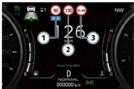
text_image
1 90 130 26 1 kWh 3 F E D Normal 000000 km Press > for MPH NWNOTE:
Overtaking restriction sign will be displayed only in markets where this is allowed.
If "Blinking On" warning mode is set, when the visual warning is provided only the unconditioned speed limit (in sector 2) will start blinking when the vehicle speed exceeds to the detected unconditioned speed limit ("+0 km/h" or "+0 mph" option) or when it exceeds the set sensitivity value ("+5 km/h" - "+5 mph" or "+10 km/h" - "+10 mph" options). If the vehicle speed stays above the unconditioned speed limit for several seconds the unconditioned speed limit sign will stop blinking because the manoeuvre is evaluated as intentional. If the TSA is not able to determine any kind of valid speed limit neither from camera

Driver Assistance Systems
nor from digital maps the following image will be shown in sector 2.
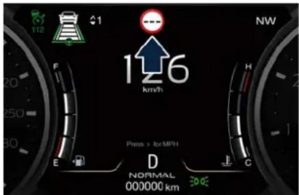
text_image
126 km/h Press > for MPH D NORMAL 000000 km NW E F G H CSince TSA also uses the data provided by the navigation system, it can update the sector 2 of the display in the following situations without detecting traffic signs:
- When the vehicle changes road.
• Highway enter/exit. - Urban area stored in the digital map enter/exit.
System Limitations
TSA may be impaired or may not function in the following situations:
- If there is poor visibility, e.g. due to insufficient illumination of the road, if there are highly variable shade conditions or in rain, snow or fog.
-
If there is glare, e.g. from oncoming traffic, direct sunlight or reflections from other vehicles.
-
If the windshield in the area of the camera is dirty, or if the camera is fogged up, damaged or covered.
- If the traffic signs are hard to detect, e.g. due to dirt or snow, or because they are covered or because of insufficient lighting.
- If the information in the navigation system's digital map is incorrect or out-of-date.
- If the signs are ambiguous, e.g. traffic signs on construction sites or in adjacent lanes.
- When passing buses or trucks with a speed sticker.
7 - In an Emergency
Tool Kit 252
Hazard Warning Flashers 253
In the Event of an Accident 254
Help and Assist Call (→) 255
SOS-Emergency Call Function (Russian market only) .....
Engine Overheating 261
In case of a Punctured Tire 261
If a Fuse Blows 266
In Case of External Lights Fault Signal 272
Emergency Release of the Parking Brake ....
Transmission Manual Release of P (Park) Position . . . . . . . . . . . . . . . .
Freeing the Stuck Vehicle 275
Auxiliary Jump-Start Procedure ....
Towing a Disabled Vehicle 278

In an Emergency
Tool Kit
The tools and other first aid equipment are located in the boot inside a preformed container and are available by lifting the ground coverage.
The tools layout in the container depends on the boot configuration of the vehicle, depending on the destination markets and on customer requirements.
A Configuration with tire repair kit.
B Configuration with compact spare wheel.
The tools inserted in the boot container are the following:
| Ref. | Description Layout | |
| 1 | Double torx + cross-head screwdriver A, B | |
| 2 | 8 mm Allen wrench A, B | |
| 3 | Electric compressor complete with pressure gauge for inflating the compact spare wheel B | |
| 4 | Spanner for unscrewing/tightening the wheel nuts and for operating the jack B | |
| 5 | Chock to be positioned in front of or behind the wheel B | |
| 6 | Tow hook A, B | |
| 7 | Funnel for emergency supply A, B | |
| 8 | First Aid Kit 📋 | A |
| 9 | Tire repair kit | A |
| 10 | Jack | B |
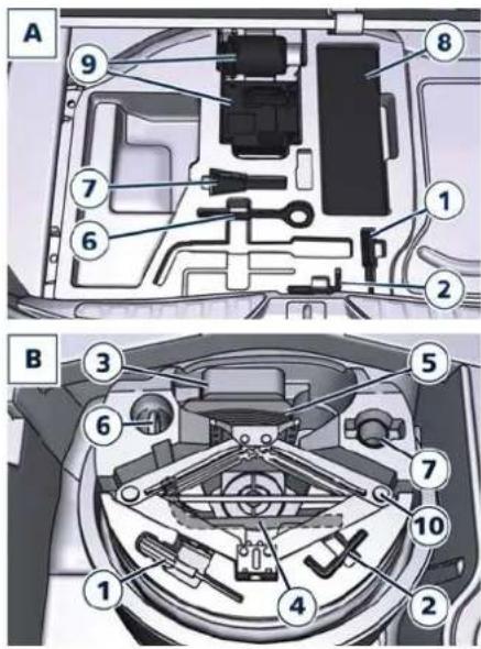
text_image
A 9 8 7 1 6 2 B 3 5 6 7 10 4 2Hazard Warning Flashers
The hazard warning flashers switch is located in the central console in front of the transmission lever.
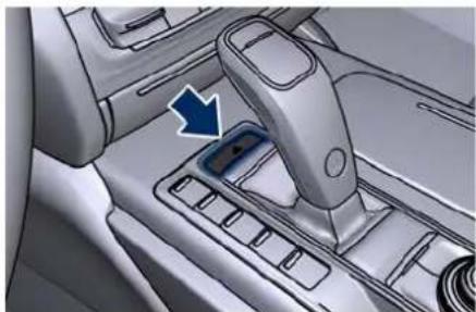
natural_image
Interior view of a car gear shift lever with a blue arrow indicating the direction (no text or symbols visible)Press the switch to turn on the hazard warning flashers to warn oncoming traffic of an emergency. When these lights illuminate, the turn signals, the related warning lights on the instrument cluster and the button start flashing.
Press the switch a second time to turn off the hazard warning flashers.
This is an emergency warning system and it should not be used when the vehicle is in motion. Use it when your vehicle is disabled and it is creating a safety hazard for other motorists.
When you must leave the vehicle to seek assistance, the hazard warning flashers will continue to operate even
though the ignition is placed in the OFF position.

CAUTION!
- When the hazard warning flashers are activated, the turn signals control is disabled.
• The extended use of the hazard warning flashers may wear down your battery.

In an Emergency
In the Event of an Accident
It is important always to keep calm.
- If not directly involved, stop at a safe distance of at least ten meters away from the accident area.
- If on a motorway, stop without obstructing the emergency lane and be especially careful if you need to exit the vehicle.
- Turn off the engine and switch on the hazard warning flashers.
- At night, illuminate the accident area with the headlights.
- Always act with caution to avoid the risk of being crashed into by other drivers.
- Indicate that an accident has occurred by placing the emergency triangle (if equipped) in a well visible position and at the prescribed distance.
- Call the emergency services, providing as much information as possible. On the motor way, use the special call boxes.
- Remove the ignition key (if present) from the vehicles involved.
-
If fuel or other chemical products can be smelled, do not smoke and ask people around you to put their cigarettes out.
-
To extinguish fires, even small ones, use a fire extinguisher, blankets, sand or earth. Never use water.
- In multiple accidents occurred on motorways, particularly where visibility is poor, there is a high risk of being involved in other collisions. Leave the vehicle immediately and move away from the area.
In case of Injured Persons
- Never leave the injured person alone. Persons not directly involved in the accident are also required to give assistance.
- Do not crowd around injured persons.
- Reassure the injured person that help is on the way and stay close to them to assist them to avoid possible panic attacks.
- Release or cut the seat belts restraining the injured persons.
- Do not give the injured persons anything to drink.
- Never move an injured person.
- Remove the injured person from the vehicle only in emergency situation, e.g. if there is a risk of fire, sinking in water or falling down into a pit.
- When removing an injured person, do not pull his/her limbs, never bend his/her head and, as far as possible,
keep his/her body in a horizontal position.
Emergency Kit (→)
The Emergency Kit provides first aid in case of a car breakdown or any other situation. The kit comes in a case on the left side of the boot compartment. The kit includes the following elements:
• emergency triangle;
• reflective emergency vest;
- luminescent pipes providing chemical lights;
- dynamo torch;
- First Aid Kit;
- gloves;
- ice scraper.
NOTE:
The items inside the kit could change according to different countries' regulations.
First Aid Kit( )
The First Aid Kit is available in the boot compartment inside the Emergency Kit case (if foreseen) or in the following positions:
- on the vehicles with tire repair kit configuration (see "Tool Kit" in this section) this kit is placed in the tools container;
- on the vehicles with compact spare wheel this kit is placed in the right side of the boot compartment.
This kit contains following:
• sterile gauze to cover and clean the wounds;
• bandages of various sizes;
• treated adhesive bandages of various sizes; - an adhesive bandage strip;
- a pair of rounded-end scissors;
- gloves;
- rescue blanket.
Help and Assist Call()
The car is equipped with on-board assistance functions designed to provide support in the event of an accident and/or emergency (Help Call) or vehicle malfunction (Assist Call).
NOTE:
For Help and Assist Call functions, location (GPS) must always be active: any deactivation would make these services unavailable.
Help Call
The Help Call is sent to a private response center (this service is not equivalent to the e-call service envisaged by the applicable legislation for new type-approved vehicles).
The call is powered by its own rechargeable battery to ensure operation even when the vehicle battery is low or disconnected.
When the call system battery goes low, the instrument cluster display will show a message and send a notification via mobile App.
NOTE:
Failure to replace the call system battery or to ignore system warnings may impair or completely exclude the operation of the services.
In an Emergency
Regardless of the state of charge, the call system battery must be replaced every 5 years at the Service Network. The Help Call is only to be used when there is a concern for the health of individuals. In this case, the operator of the emergency center verifies the status of the vehicle's safety systems and defines with the driver the type of emergency support needed (ambulance, fire brigade, etc.). The Help Call is automatically forwarded in the event of an accident with air bag deployment providing that the ignition device is in RUN position and air bags are working (malfunction warning light off).
The Help Call can be activated manually by the user in 3 different ways:
• via the button on the dome console;
- via "HELP call" soft-key on the "Apps" page of the MIA screen;
• using the MIA smartphone application (applicable only in European countries).
Via the Button on the Dome Console
Press and hold for a few seconds the Help Call button on the dome console; the green LED on the button will

In an Emergency
blink and then become a fixed light indicating that a call has been placed.
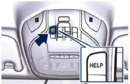
text_image
HELPThe manual Help Call is possible when the ignition device is in the RUN or ACC position and in OFF position until its backlight stays on, which is a convenient way to get in contact with an operator to request help. When the connection between the vehicle and a safety operator is made, your vehicle will automatically transmit location and vehicle information to the service operator.
NOTE:
- In case the Help Call button is accidentally pushed, there is a 10 second delay before the call is placed. The system will verbally alert you that a call is about to be made. To cancel the call connection, press the button on the dome console again.
- The Help Call function may not be available in the first minute after starting the car.
The Help Call has priority over other audio sources, which will be muted. If you have a phone connected via Bluetooth®, it will be disconnected and reconnected again at the end of the call. Voice prompts will guide you during the Help Call.
If a connection is made between a service operator and your vehicle, you understand and agree that operators may, like any other Help Call, record conversations and sounds in and near your vehicle upon connection.
Only a safety operator can remotely end the Help Call and, if necessary, call back the vehicle eCall system. After the call, you can still call the emergency service operator to indicate additional information by pressing the button again.
In an Emergency, the connection and the call to the operator of the Help center will immediately be activated and the following screen will be displayed on the MIA App.
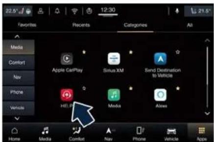
text_image
22.5° Favorites Recents Categories All Media Comfort Apple CarPlay Sirius XM Send Destination to Vehicle Helix Media Alexes Home Media Comfort Nav Phone Vehicle App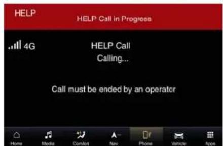
text_image
HELP HELP Call in Progress .4G HELP Call Calling... Call must be ended by an operatorDuring the Help Call, if the user opens another page and exits the screen, the Help Call status bar will be shown on all the other screens too, displaying "HELP Call in Progress" in writing and the call time, if available.
For further information, see the "Maserati Intelligent Assistant™ (MIA)" guide.
Help Call Not Available Messages The Help Call is not available in the following cases:
• during a system update process;
- system error (generic fault, sim fault, antenna, USB connection, etc..);
- the subscription to the service is not active or has expired. In these cases, the Help Call can be temporarily unavailable.
NOTE:
If a customer has not subscribed to Maserati Connected Services, the Help Call will not be available. For more details, see the official Maserati website.
Assist Call
The Assist Call service is available only where the user has an active assistance coverage.
Assist Call requires the ignition device to be in RUN or ACC position with a properly functioning electrical system. Owners have the ability to activate to types of Assist Call:
•Roadside Assistance Call
Road Assistance provides 24 hours / 7 days of assistance in case of vehicle-related problems (towing, flat tire, etc..) and dispatches roadside assistance to the vehicle's location. Enter the "Assist Call" menu of the "Apps" and touch the "Road Assistance" soft-key.
NOTE:
When the user selects the "Road Assistance" soft-key, the vehicle location will be sent through to the call center.
- Customer Service Call
Customer Service provides assistance and support on general enquiries. Enter the "Assist Call" menu of the "Apps" and touch the "Customer Service" soft-key.
NOTE:
- When the user selects the "Customer Service" soft-key, the vehicle location will be sent through to them.
- If a customer has not subscribed to Maserati Connected Services, the Assist Call will not be available. For more details, see the official Maserati website.
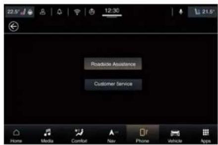
text_image
Roadside Assistance Customer ServiceIn an Emergency
NOTE:
• Roadside Assistance Call or Customer Service Call may not be available in the first minute after starting the car.
• In case the Roadside Assistance Call or Customer Service Call soft-key are inadvertently touched on the MIA screen, the call can be interrupted by touching the end call soft-key.
- If there is an active Help Call, neither a Roadside Assistance or Customer Service Call can be triggered.
For further information, see the "Maserati Intelligent Assistant™ (MIA)" guide.
Assist Call Not Available Messages The Assist calls are not available in the following cases:
i• the subscription to the service is not active or has expired;
- there are problems connecting to the network. In these cases, the user will be warned that the call cannot be made on the TFT display.

In an Emergency
SOS-Emergency Call Function (Russian market only)

WARNING!
SOS Emergency call function is available only for Eurasian Customs Union and works only with an enabled network operator. Your vehicle has on-board assistance functions that are automatically activated by the air bag intervention or activated by the button located on the dome console designed to provide support in case of accident and emergency.
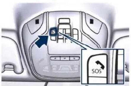
text_image
Diagram of car interior with labeled door panel and SOS switch, showing directional arrow and control buttonsDescription
SOS Emergency Call is a function that, at the push of a button, can contact emergency services providing that the SOS Emergency Call system is working, and the ignition device is in RUN or ACC position.
The manual Emergency Call is possible also when the ignition device is in OFF position until its backlight stays on. It is a convenient way to get in contact with an operator in the event of an emergency.
When the connection between the vehicle and a public safety operator is made, your vehicle will automatically transmit location and vehicle information to the emergency service operator.
The SOS Emergency Call is automatically forwarded in the event of an accident with air bag intervention providing that the ignition device is in RUN position and air bags are working (malfunction warning light off).
Only a public safety operator can remotely end the SOS Emergency Call and, if necessary, call back the vehicle's eCall system.
After the call, you can still call the emergency service operator to indicate additional information by pressing the button again.
How It Works
Press and hold for a few seconds the SOS Emergency Call button on the dome console; the green LED on the button will blink and then become a fixed light indicating a call has been placed.
NOTE:
In case the SOS Emergency Call button is accidentally pushed, there is a 10 second delay before the call is placed. The system will verbally alert you that a call is about to be made.
To cancel the call connection, push the SOS Emergency Call button on the dome console. Once a connection between the vehicle and an emergency service operator is made, the SOS Emergency Call system will transmit the following important vehicle information to the operator:
- indication that the occupant placed an SOS Emergency Call;
• the Vehicle Identification Number (VIN); - the last known GPS coordinates of the vehicle.
You should be able to speak with the emergency service operator to determine if additional help is needed. The SOS Emergency Call has priority over other audio sources, which will be
muted. If you have a phone connected via Bluetooth ^® , it is disconnected and reconnected at the end of the SOS Emergency Call.
Voice prompts will guide you during the SOS Emergency Call.
If a connection is made between an emergency service operator and your vehicle, you understand and agree that operators may, like any other emergency call, record conversations and sounds in and near your vehicle upon connection.
System Limitations
When the driver switches the ignition device to the RUN position, the system runs a check routine. During this stage, the red indicator will illuminate for about 3 seconds: this signal must not be confused with a fault warning, remember that in such an event the red indicator would remain on.
If the SOS Emergency Call system detects a malfunction, any of the following may occur at the time the malfunction is detected:
- The LED on the dome console button will continuously be illuminated red.
- The system is powered by its own rechargeable battery to ensure operation even when the vehicle battery is flat or disconnected. When
the system battery goes flat, the instrument panel display will show a special message, different than any other message referred to other types of faults. In this case, the system works only if powered by the battery of the vehicle.
- The instrument cluster will display a message alerting you to contact the Service Network together with the failure warning light. Even if the SOS Emergency call system is fully functional, external or uncontrolled factors may prevent or stop the SOS Emergency Call operation from taking place.
These include, but are not limited to, the following factors:
- The key fob has been removed from the vehicle and the delayed accessories mode is active.
- The ignition device is in OFF position.
- The vehicle's electrical systems are not intact.
- The SOS Emergency Call system software and/or hardware is damaged during a vehicle crash.
- There are network problems that could limit or impair service operation (e.g., error by operator, busy network, bad weather, etc.). If a vehicle battery connection fails due to a collision or accident, the system
can support an SOS Emergency Call for a limited period of time.
If the battery is disconnected for service, the system turns off. In this case, it will be possible to make an SOS Emergency Call only when the battery is reconnected to the vehicle's electrical system.
Requirements
NOTE:
This function is available only on vehicles sold in the Eurasian Customs Union.
- Vehicle must have an operable connection to ERA-Glonass enabled mobile network operator.
- A vehicle must be powered with a properly functioning electrical system.
- The ignition device must be in the RUN or ACC position and in OFF position until its backlight stays on.

WARNING!
- Never place anything on or near the vehicle's 3G (data) and GPS aerials. You could prevent 3G (data) and GPS signal reception, which can prevent your vehicle from placing an emergency call. An operable 3G

In an Emergency
(data) network connection and a GPS signal is required for the SOS Emergency Call system to function properly.
- Do not add any aftermarket electrical equipment to the vehicle's electrical system. This may prevent your vehicle from sending a signal to initiate an emergency call. To avoid interference that can cause the SOS Emergency Call system to fail, never add aftermarket equipment (e.g., two-way mobile radio, CB radio, data recorder, etc.) to your vehicle's electrical system or modify the antennas on your vehicle. IF YOUR VEHICLE LOSES BATTERY POWER FOR ANY REASON (INCLUDING DURING OR AFTER AN ACCIDENT) THE MASERATI CONNECT FUNCTIONS, APPS AND SERVICES AMONG OTHERS WILL NOT OPERATE.
- The Occupant Restraint Controller (ORC) turns on the air bag warning light on the instrument cluster if a malfunction in any part of the air bag system is detected. If the air bag warning light is illuminated, the air bag system may not be working properly, and the SOS Emergency Call system may not be able to send a signal to an emergency service
operator. If the air bag warning light is illuminated, contact the Service Network to have the air bag system checked immediately.
In an Emergency
- Ignoring the LED on the dome console button could mean you will not have the emergency call services if needed. If the LED on the dome console button is illuminated red, contact the Service Network to have the emergency call system checked immediately.
- If anyone in the vehicle could be in danger (e.g., fire or smoke is visible, dangerous road conditions or location), do not wait for voice contact from an emergency service operator. All occupants should exit the vehicle immediately and move to a safe location.
- Failure to perform scheduled maintenance and regularly inspect your vehicle may result in vehicle damage, accident or injury.
FAQs
What Happens if I Accidentally Push the SOS Emergency Call Button on the Dome Console?
You have 10 seconds after pushing the emergency button to cancel the
call. To cancel the call push the button again.
What type of information is sent when I call the Emergency Service Operator from my vehicle?
Certain vehicle information, such as VIN of the model, is transmitted along with the last known GPS location. Also note that emergency service operators may record conversations and sounds within your vehicle once a connection is made, and that by using the service you consent to having this information shared.
When should I use the SOS Emergency Call Button?
You can use the emergency button to make a call if you or someone else needs emergency assistance.
Engine Overheating
To reduce potentially overheating of the engine in city traffic, while stationary, place the transmission in N (Neutral), but do not increase the engine idle speed.
NOTE:
There are steps that you can take to slow down an impending overheat condition:
- If your air conditioner (A/C) is on, turn it off. The A/C system adds heat to the engine cooling system and turning the A/C off can help remove this heat
- You can also turn the temperature control to maximum heat, the mode control to floor and the blower control to high. This allows the heater core to act as a supplement to the radiator and aids in removing heat from the engine cooling system.
red warning light comes on, pull over and stop the vehicle. Idle the vehicle with the air conditioner turned off until the temperature gauge drops back into the normal range. If the temperature gauge remains on the red zone "H" and the red warning light stays on, turn the engine off immediately and contact the Service Network.
WARNING!
You or others can be badly burned by hot engine coolant (antifreeze) or steam from your radiator. If you see or hear steam coming from under the hood, do not open it until the radiator has had time to cool. Never try to open a coolant bottle pressure cap (refer to "Maintenance Procedures" in section "Maintenance and Care") when the radiator is overheated.
In case of a Punctured Tire
The vehicle can be equipped with a tire repair kit or with a compact spare wheel, depending on the destination markets and on customer requirements.
Using Tire Repair Kit
Small punctures up to 6 mm (1/4") in the tire tread can be sealed using the tire repair kit, fitted beneath the ground coverage of the boot compartment.
The kit consists of two parts:
- an electric compressor with pressure gauge and power cable; - a bottle containing sealant with hose to be connected to the punctured tire.
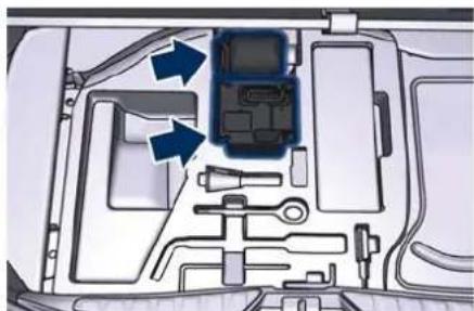
natural_image
Interior view of a vehicle showing internal components and airflow arrows (no text or symbols)(Continued)

CAUTION!
Driving with a hot cooling system could damage the engine. If the temperature gauge is positioned on the red zone "H" (refer to "TFT Display Areas" in section "Dashboard Instruments and Controls") and the

In an Emergency
NOTE:
For the tire repair procedures with tire repair kit see instructions included in the kit.
This kit will provide a temporary tire seal, allowing you to drive your vehicle up to 10 km (6 miles) with a maximum speed of 80 km/h (50 mph).

CAUTION!
- Intruding objects (e.g., screws or nails) should not be removed from the tire, which could compromise the repair with the tire repair kit.
- Do not use the tire repair kit if the tire shows lateral damages and/or the rim is damaged by driving with flat tire.
- Tire repair kit can be used in outside temperatures down to approximately -20°C (-4°F).
- Replace the tire repair kit sealant bottle prior to the expiration date (printed on the bottle label) to assure optimum operation of the system.
NOTE:
- The compressor power plug can be inserted either in the 12 V power outlet housed in the boot or inside the passenger compartment (see
"Internal Equipment" in section "Understanding the Vehicle").
- When having the tire serviced, advise the Maserati dealer or service center that the tire has been sealed using the tire repair kit.
Using the Compact Spare Wheel
NOTE:
The compact spare wheel is supplied in aluminium or steel: the pictures show the one in aluminium.
The compact spare wheel is stored in the boot and is supplied deflated in order to limit the amount of space occupied. An electric compressor is also provided for inflating. In the event of a tire puncture, proceed as follows.
- Stop the vehicle in a place that does not constitute a danger to traffic and where the wheel can be changed safely.
- Select the P (Park) mode and then engage manually the electric parking brake and move the ignition device to OFF position.
- If necessary, turn the hazard warning lights on and place the warning triangle at the required distance.

WARNING!
The vehicle must be level and on firm ground during the vehicle lifting operations. The use of chock contained in the tool kit is always mandatory. In case of slight slope (less than 10%), place the chock in front of (downhill) or behind (uphill) the wheel diagonally opposite the one to be replaced. In case of higher slope (more than 10%), call the Assistance Service and avoid any operation.
• The jack should be used on level firm ground wherever possible.
- It is recommended that the wheels of the vehicle be chocked, and that no person should remain in a vehicle that is being jacked.
- Never start or run the engine with the vehicle on a jack.
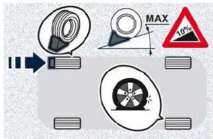
text_image
MAX 10%In an Emergency

- Before placing the chock, it is necessary to open it like a book as shown in the picture.
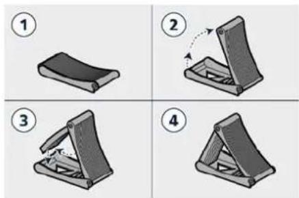
- Lift the ground coverage of the boot compartment.
• Take the tools indicated in picture for changing the wheel from the container.
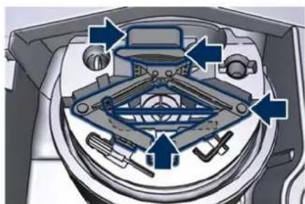
natural_image
Mechanical assembly diagram showing internal components with arrows indicating motion or force directions (no text or labels)- Loosen and remove the spare wheel locking knob.
• Take the tool box container and the compact spare wheel out of the boot.
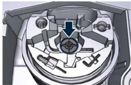
natural_image
Cross-sectional diagram of a mechanical device showing internal components and a central hub (no text or labels)- Using the kit spanner, loosen anticlockwise by approximately one turn the five bolts on the wheel to be changed. In case a "Wheel Security Stud Bolt" is installed, it can only be loosened and removed by using the specific fitting spanner insert provided with the "Wheel Security Stud Bolt Kit", available in the "Genuine Accessories" range. In this case, the insert must be installed on the kit spanner.
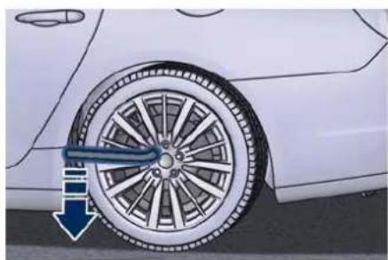
natural_image
Close-up of a car wheel rim with a blue arrow pointing to the wheel rim (no text or symbols visible)- Place the jack near the wheel to be changed as illustrated. Make sure that the head of the jack is correctly inserted in one of the slots 1 or 2 under the longitudinal member.
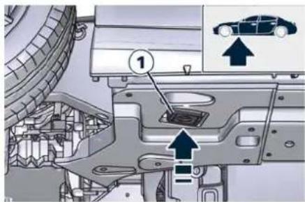
text_image
Technical diagram showing car engine compartment with labeled parts and directional arrows indicating movement or assembly.

In an Emergency
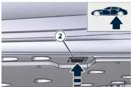
text_image
Diagram showing a car with an upward arrow and numbered annotation, likely illustrating vehicle safety or installation steps.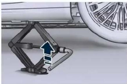
natural_image
Mechanical assembly diagram showing a clamping mechanism with a blue arrow indicating direction (no text or symbols present)
WARNING!
- Never position yourself under a jacked vehicle.
- Jack wrong positioning can cause vehicle accidental fall, with consequent severe risk for operator's safety and damages to vehicle body
- Never use the jack to carry out maintenance or repairs under the vehicle.
-
Insert the kit spanner on the hexagonal end of the jack and turn it clockwise until the jack bracket is firmly inserted in the slot under the longitudinal member.
-
Turn the jack lever until the wheel is raised a few centimeters off the ground.
- Completely unscrew the five bolts and remove the wheel.
- Make sure that the contact surfaces between spare wheel and hub are clean and free of impurities.
- Fit the compact spare wheel with the valve stem side out and secure it with the five bolts previously removed, without tightening them.
- Remove from the compressor case the inflation hose and the cable with a plug for the power outlet.
- Unscrew the valve cap of the compact spare wheel and screw the fitting of the inflation hose onto the valve.
- Insert the plug inside one of the available power outlets fitted in the boot or passenger compartment.
-
Set the ignition device on ACC or RUN position.
-
Turn the compressor on by pressing the switch.
- Stop the compressor pressing switch again, when the pressure indicated by the gauge reaches the recommended level of 350 kPa - 3,5 bar - 51 psi (chapter "Tire Inflation Pressure" in section "Technical Specifications") and screw the cap on the compact spare wheel valve.
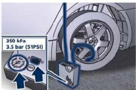
text_image
350 kPa 3.5 bar (51PSI)
CAUTION!
- In order to obtain a more accurate reading, the compressor should be switched off when checking the tire pressure of the compact spare wheel on the pressure gauge.
- Do not run the compressor for more than 20 minutes: there is a risk it could overheat. Also, prolonged
power absorption may discharge the battery, subsequently preventing the engine from starting.
- The compressor has been designed exclusively to inflate compact spare wheels; do not use it to inflate air mattresses, dinghies etc.
- With the kit spanner, turn anticlockwise the hexagonal end of the jack to lower the vehicle and remove the jack.
- Fully tighten clockwise the bolts, alternately tightening diametrically opposite.

WARNING!
• FOR ALUMINIUM SPARE WHEEL
Observe the tightening torque for the bolts securing the spare wheel (98 ± 10 Nm/ 72 ± 7 lbf·ft).
• FOR STEEL SPARE WHEEL Observe the tightening torque for the bolts securing the spare wheel (86 ± 10 Nm/ 63 ± 7 lbf·ft).
- Bolts must be tightened only after vehicle is back to ground, so as to prevent it from falling down due to the force exerted for bolt tightening. Failure to comply with this recommendation can cause operator injuries.
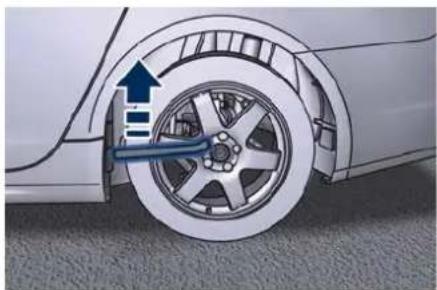
natural_image
Diagram of a car wheel with a blue brake lever and upward arrow indicating motion (no text or symbols)
WARNING!
- The compact spare wheel is narrow than standard wheels and must only be used to travel the distance required to reach a service station, where the punctured tire can be repaired or replaced.
- Do not exceed a maximum speed of 80 km/h (50 mph) when using the compact spare wheel; when this limit is exceeded, the stability, road holding and braking of the vehicle will be compromised. Avoid accelerating to full speed, heavy braking and fast cornering.
-
The compact spare wheel must be inflated to the recommended tire pressure (chapter "Tire Inflation Pressure" in section "Technical Specifications").
-
For safety reasons, it is absolutely forbidden to drive with more than one compact spare wheel fitted on the vehicle.
- Snow chains cannot be fitted on the compact spare wheel.
• The compact spare wheel can travel a maximum of 3000 km (1800 mi). - For Trofeo Version, in case of tire/rim/valve replacement, it is necessary to use a new valve and sensor with same technical features.
To Refit the Standard Wheel with Repaired or Replaced Tire
- Following the procedure and the caution described above, raise the vehicle and remove the compact spare wheel reusing the supplied spanner.
- Fit the standard wheel with repaired or replaced tire.
- Tighten the original bolts on the wheel.
- Lower the vehicle and remove the jack.
- Fully tighten the bolts, alternately tightening diametrically opposite.

In an Emergency
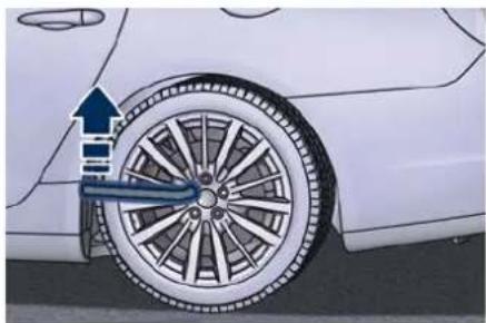
natural_image
Side view of a car tire with a blue arrow indicating motion direction (no text or symbols)Reposition of the Compact Spare Wheel and Tools

WARNING!
Observe the tightening torque for the bolts securing the wheels (98 ± 10 Nr / 72 ± 7 lbf·ft).
- Completely deflate the compact spare wheel by pressing on the valve with the overhang of the valve cap.
- Place the compact spare wheel and tool container in the boot.
- Fix everything in place with the locking knob.
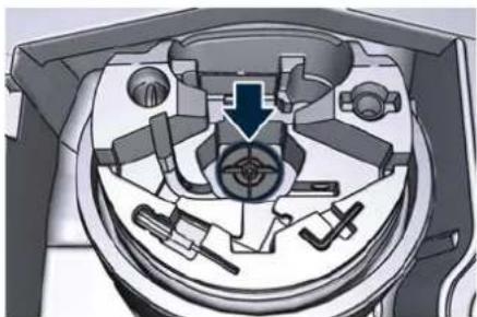
natural_image
Cross-sectional diagram of a mechanical assembly with no visible text or symbols- Wrap the power cable and the inflation hose inside the compressor case.
- Place the compressor, the spanner and the jack in the container above the compact spare wheel.
Remove the chock located in front of or behind the wheel and place it inside the container.
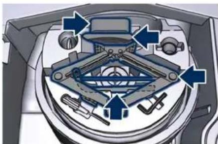
natural_image
Diagram of a mechanical device with labeled parts and directional arrows indicating motion (no text or symbols present)- Lower the ground coverage at the bottom of the boot compartment.
If a Fuse Blows
Used Fuses Characteristics
When an electrical device is not functioning, check that the corresponding fuse is in proper working order (intact).
A Fuse intact
B Fuse blown
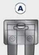
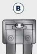
On the vehicle are mainly used with mini-and maxi-fuses with blade engagement.
Besides these there are other types of the fuse provided with holes for fixing to the cable connection terminals. For the replacement of these fuses contact the Service Network.
Replace the faulty fuse with a new one featuring the same rating, by using appropriate forceps added in the integrated power module and

inside the cover of the rear power distribution center.
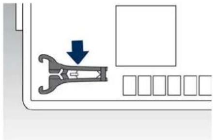
natural_image
Diagram showing a wrench inside a door with a blue arrow indicating downward motion, alongside a grid of empty compartments (no text or symbols)The colour identifies the value of the fuses in amperes which is also reported on them.
The table shows the match between colour and amperage of mini and maxi fuses.
| Type | |
| Mini Fuse Maxi Fuse | |
| Beige - 5 Yellow - 20 | |
| Brown - 7,5 Green - 30 | |
| Red - 10 Orange - 40 | |
| Blue - 15 Red - 50 | |
| Yellow - 20 Blue - 60 | |
| White - 25 | |
| Green - 30 | |

CAUTION!
- Never replace a blown fuse with anything other than a new and suitable fuse (same rating).
• After replacing a fuse, if the fault recurs, contact the Service Network.
Position of Fuses
The fuses are located in three parts of the vehicle, namely:
• inside the integrated power module, on the right hand side of the engine compartment;
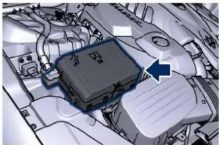
natural_image
Close-up of an automotive engine bay with a highlighted component and blue arrow indicating direction (no text or symbols)• inside the rear power distribution center, behind the battery, on the right hand side of the boot compartment;
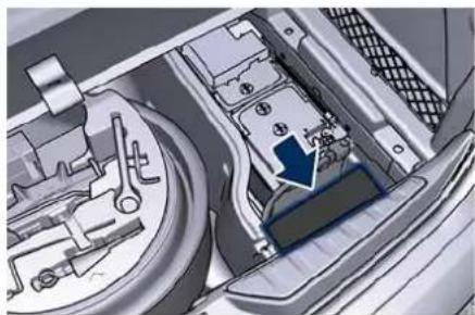
natural_image
Interior view of a vehicle engine bay with mechanical components and a blue arrow indicating a component (no visible text or symbols)- on the fuse and relay box located in a covered area, behind the glove compartment on the dashboard left side.
Integrated Power Module
- To access the module it is necessary to lift the hood (see "Open and Close the Hood" in section "Before Starting").
- To access the fuses remove the module cover unhooking the lateral locks as shown in the picture. To recognize the reference number of the fuses in the table below, see the diagram inside the cover just removed.

In an Emergency
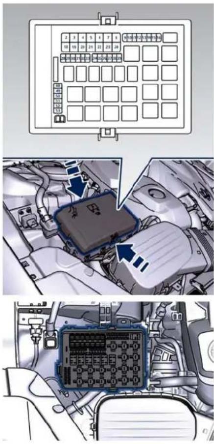
The table points out the position as featured in the cover, the type and function of the fuses included in the integrated power module.

CAUTION!
• After replacement, refit the protective cover of the module.
- If you need to wash the engine compartment, do not direct the water for too long directly on the module.
| Ref. | Type Function | |
| 2 Maxi – 50A | Secondary air pump relay input (3.8 V8 - Engine only) | |
| 4 Maxi – 30A | Starter motor relay input and starter solenoid supply | |
| 5 Maxi – 40A | ABS-ESP pump feed | |
| 6 Maxi – 30A | AWD module (AWD version only) | |
| 8 Maxi – 40A | ABS-ESP valve feed | |
| Ref. | Type Function | |
| 11 | Mini – 20A | Horn relay input |
| 12 | Mini – 10A | AC compressor feed relay input |
| 14 | Mini – 7,5A Alarm siren | |
| 15 | Mini – 10A | Washer heated nozzles relay input |
| 16 | Maxi – 10A | Enable cooling fan relay input and enable cooling oil pump relay input |
| 20 | Maxi – 30A | Wiper ON/OFF relay output and wiper LOW/HI |
| 28 | Mini – 7,5A | Drive Assist System Module (DASM) |
| 29 | Mini – 10A | PCM module - Starter solenoid relay coil - Voltage Body & Dash, PTC relay coil |
| 30 | Mini – 5A | ORC- Air bag module |
| 31 | Mini – 5A | ABS-ESP module |
| 32 | Mini – 5A | SSCU, AWD module (AWD version only), EPS and AQS |
| 33 | Mini – 10A | HDLP Head-lights - AFLS |
| 34 | Mini – 15A | Primary load to engine harness LH side |
| 35 | Mini – 15A | Primary load to engine harness RH side |
| 36 | Mini – 30A | PCM module primary load |
| 37 | Mini – 15A | Engine secondary load |
| 38 | Mini – 15A Lambda sensor | |
| 39 | Mini – 7,5A | Flow meters, tank lackage, canister, ex-haust by-pass valve relay coil and air shutter |
| Ref. | Type Function | |
| 49 | Mini – 10A | Pedal brake switch - TCM module |
| 50 | Mini – 15A | +30 PCM module |
| 51 | Mini – 30A | Fuel pump high speed relay input |
| 52 | Mini – 5A | Starter solenoid signal for PCM and voltage stabilizer |
| 53 | Mini – 10A | AWD module (AWD version only) |
Rear Power Distribution Center
- To access the center it is necessary to lift the ground coverage of the boot compartment and remove the access cover (refer "Battery Status and Maintenance" in section "Maintenance and Care").
- To access the fuses release the cover latch shown in picture.
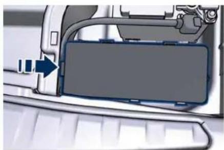
natural_image
Close-up of a car interior panel with a blue arrow pointing to a component (no visible text or symbols)- Press the release latch and lift the lid from this side.
- Push the lid toward the right side to release the indicated latches on the unit. To recognize the reference number of the fuses in the table below, see the diagram inside the cover just removed.

In an Emergency
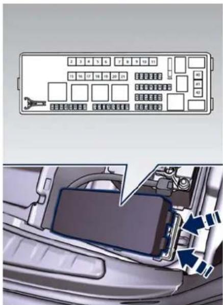
text_image
Diagram showing car interior layout with numbered vehicle keys and a close-up of the dashboard compartment with directional arrows.The table points out the position as featured in the cover, the type and function of the fuses on the rear area distribution control unit.
| Ref. | Type Function |
| 2 Maxi – 40A BCM module | |
| 3 Maxi – 40A BCM module | |
| 4 Maxi – 30A BCM module | |
| 5 Maxi – 30A BCM module | |
| Ref. | Type Function | |
| 6 Maxi – 20A | Sunroof module | |
| 7 Maxi – 30A | Driver door module | |
| 8 Maxi – 30A | Passenger door module | |
| 9 Maxi – 40A | Start&Stop: voltage stabilizer, dashboard | |
| 10 Maxi – 40A | Start&Stop: voltage stabilizer, body | |
| 11 | Maxi – 40A | "High Premium" stereo amplifier unit |
| Maxi – 20A | "Premium" stereo amplifier unit (1) | |
| 15 Maxi – 40A | HVAC front blower relay coil | |
| 16 Maxi – 40A | Rear window defrost relay coil (HVAC module) | |
| Ref. | Type Function | |
| 17 | Maxi – 30A | Rear LH door module |
| 18 | Maxi – 30A | Rear RH door module |
| 20 | Maxi – 20A | "Premium" stereo amplifier unit (2) |
| 21 | Maxi – 40A | Fuel Pump (3.8 V8 - Engine only) |
| 22 | Mini – 7,5A | Rear HVAC module |
| 23 | Mini – 10A | Fuel door relay and RF Hub module |
| 24 | Mini – 10A | ITM module, ceiling light unit (front and rear), rain/lights sensor |
| 25 | Mini – 20A Inverter | |
| 27 | Mini – 20A | LH rear seat movement |
| 31 | Mini – 25A | LH front seat movement |
| 33 | Mini – 20A | RH rear seat movement |
| 34 | Mini – 20A | Soft Door Close latch |
| 35 | Mini – 20A | Rear doors sunshade |
| 36 | Mini – 10A | Transmission lever, Navtrak, ASBM control suspension and Hands Free access module |
| 37 | Mini – 25A | Power lift-gate/boot lid module |
| 38 | Mini – 25A | RH front seat movement, passenger front seat movement from rear |
| 40 | Maxi – 20A | Boot power outlet |
| 43 | Mini – 20A | Seat passenger heater module |
| 46 | Mini – 5A Rear camera | |
| 47 | Mini – 5A Navtrak | |
| Ref. | Type Function | |
| 48 | Mini – 5A Surround view | |
| 49 | Mini – 10A | Internal temperature sensor, internal mirror and HALF |
| 51 | Mini – 25A | Rear seat and steering wheel heater module |
| 53 | Mini – 25A | Rear seat vented module |
| 54 | Mini – 7,5A | Blind Spot module |
| 56 | Mini – 7,5A | Blower front HVAC coil relay |
| 57 | Mini – 7,5A | Blower rear HVAC coil relay |
| 59 | Mini – 10A | SDC module, transmission lever, ASBM, rear tunnel stack switch |
| 60 | Mini – 10A SDC | module |
| 61 | Mini – 25A | Front console power outlet and cigar lighter |
| Ref. | Type Function | |
| 62 | Mini – 7,5A | Front HVAC module |
| 63 | Mini – 20A | Blower rear HVAC |
| 64 | Mini – 10A | Wi-fi, rear HVAC module |
| 65 | Mini – 10A | Intelligent battery sensor |
| 66 | Mini – 10A Wi-fi | |
| 67 | Mini – 7,5A | USB charge outlet, sunroof |
| 68 | Mini – 20A | Rear sunshade module |
| 69 | Mini – 25A | Rear console power outlet and cigar lighter |
| 70 | Mini – 10A | Front HVAC module, Park-ing Aid Module (PAM) |
Fuse Box under the Dashboard
This box is located in an internal area that can be accessed only by removing the glove compartment on the dashboard left side. Considering the complexity of this operation, we

In an Emergency
recommend having the fuses replaced by the Service Network.
The table points out the position as featured in the figure, the type and function of the fuses in the box under the dashboard.

natural_image
Interior view of a car dashboard and infotainment system (no visible text or symbols)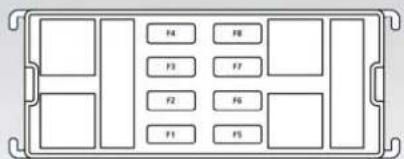
text_image
F4 F5 F3 F7 F2 F6 F1 F5| Ref. | Type Function | |
| 1 Mini – 7,5A | Cluster module, CSS, SGW and DSRC (Japan version only) | |
| 2 Mini – 15A | Cluster module, clock | |
| 3 Mini – 10A | DSRC and DTV system (Japan version only) | |
| 4 Mini – 5A E-call | ||
| 5 Mini – 7,5A | Security Gateway | |
| 6 Mini – 25A Radio | ||
| 7 Mini – 10A | Column software module, CSS, USB auxiliary port | |
| 8 Mini – 10A | Start & Stop switch, diagnostic outlet | |
In Case of External Lights Fault Signal
The signal failure of an external light is communicated to the instrument cluster that displays on the TFT screen in a graphical form and with a text message which light is faulty (see example in the figure).
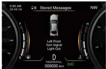
text_image
6:36 AM 02.05.19 6 Stored Messages NW F H Left Front Turn Signal Light Out E D C NORMAL 000000 km 30.02Replacement of LED Lights

CAUTION!
The front and rear light clusters are equipped with LEDs.
It is not possible replace a single LED of the cluster, we recommend that you contact the Service Network for the replacement of the entire cluster.
Most of the bulbs of the other devices are LED powered and cannot be
replaced by the owner. Contact the Service Network to replace them.
Emergency Release of the Parking Brake
In the event the electric parking brake locks due to a total system failure (see "Parking Brake" in section "Starting and Driving"), it is not possible to move the vehicle, since the thrust action of the power actuator that operates on the brake pad inside each rear caliper will lock the rear wheels. After verifying that the battery is sufficiently charged (otherwise use an external power source connected to the vehicle electric system to operate the EPB control lever and try to unlock the parking brake), for moving the vehicle it is necessary to act on the power actuator or caliper in order to release the pressure on the pads of the rear brake calipers.
Contact the Service Network to carry out this operation.

CAUTION!
If the parking brake has been activated in manual or automatic mode and it is not possible to release it by operating on the lever of the central console, do not move the vehicle since rear brake calipers might
be damaged. To move the vehicle, load it on a rescue vehicle, avoiding to move it. In case of AWD vehicle, avoid moving it with only the rear axle lifted, since the torque converter of AWD system might be seriously damaged. For more information on vehicle towing, see "Towing a Disabled Vehicle" chapter in this section.

In an Emergency
Transmission Manual Release of P (Park) Position
The manual disengagement of the shift from P (Park) has the purpose to allow pushing or towing the vehicle if not normally possible using the shift lever (such as in the event of a battery failure with inability to start the engine).
The current procedure is exclusively intended for emergency situations, but not for frequent use.

WARNING!
Before performing the manual release of P (Park) position, if possible, always secure your vehicle by fully applying the parking brake. Performing this operation will allow your vehicle to roll away if it is not secured by the parking brake. Performing the manual release of P (Park) position on an unsecured vehicle could lead to serious injury or death for those in or around the vehicle.
The cover that allows the emergency manual park release is located on the left part of the driver's foot well.
- Lift the mat on the driver side to access the lace.
- Slip the cover from its seat.
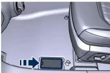
natural_image
Interior view of a car showing the dashboard and side panel with directional arrows (no text or symbols)• Take strap out of its seat.
- With the tip of a screwdriver press the clip shown in the picture box and lift the lace up to release the transmission from the P (Park) position. The new position will allow vehicle moving and towing.
- Release the parking brake only when the vehicle is securely connected to a tow vehicle.
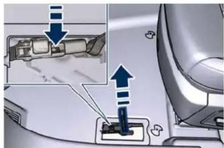
text_image
Diagram showing car interior and door switch mechanism with blue arrows indicating movement or force directionFreeing the Stuck Vehicle
If your vehicle is stuck in mud, sand, or snow, it can probably be moved backward and forward by a simple rocking motion.
Steer the wheel right and left to clear the area around the front wheels. Shift then between D (Drive) or M +/- (Manual) and R (Reverse) (see chapter
"Automatic Transmission" in section "Starting and Driving"). Shifting to M +/- (Manual), try to free the car starting in second gear.
At low speed motion of the vehicle, you can switch quickly from D (Drive) to R (Reverse), and vice versa, just by pressing the release button on the shift lever.
For more effectiveness press lightly on the accelerator pedal in order to avoid wheel slippage.
If unable to release the vehicle in one of the previously described ways, enter the low-grip driving mode, by pressing the "I.C.E." button, and completely exclude the yaw and slip control system, by pressing the button
for at least 3 seconds. Moving the shift lever between D (Drive) and R (Reverse) to start.
Notes for AWD Vehicle Version On these vehicles slippage produced by low grip conditions, automatically activates the AWD mode. Using the shifting mode M +/- (Manual), the insertion of AWD will happen immediately when engaging a forward gear.

CAUTION!
Racing the engine or spinning the drive wheels may lead to transmission overheating and failure. Allow the engine to idle with the shift lever in N (Neutral) for at least one minute after every five rocking-motion cycles. This will minimise overheating and reduce the risk of transmission failure during prolonged efforts to free a stuck vehicle.

WARNING!
Fast spinning tires can be dangerous. Forces generated by excessive drive wheel speeds may cause damage, or even failure, of the drivetrain and tires. A tire could explode and injure someone. Do not spin your vehicle's wheels continuously without stopping when you are stuck and do not let
anyone near a spinning wheel, no matter what the speed.

In an Emergency
Auxiliary Jump-Start Procedure
If your vehicle has a discharged battery it can be jump-started using a set of jumper cables and a battery of another vehicle or by using a portable battery booster. It is necessary to have proper jumper cables in order to connect the booster battery to the remote posts of the discharged battery. Booster cables have usually positive and negative terminal clamps and are identified by a different from the sheath color (red = positive, black = negative). Maserati provides on request jumper cables created for its models and content in a practical case.
NOTE:
The Maserati Service Network can provide you with information about the "Maserati Jumper Cables Kit", available in the "Genuine Accessories" range.
Jump-starting can be dangerous if done improperly so please follow the procedures in this section carefully.
NOTE:
When using a portable battery booster pack, follow the battery
manufacturer's operating instructions and precautions.

CAUTION!
- To jump start a vehicle do not use a portable battery, a booster pack or any other booster source with a system voltage greater than 14 Volts or damage to the battery, starter motor, alternator or electrical system of the vehicle with the discharged battery may occur.
- Do not use a battery charger for emergency starting under any circumstances. You could damage the electronic systems, particularly the control units managing the ignition and fuel supply functions.
- If the battery is completely discharged when the windows are fully raised, open the door with the utmost care; do not close the door again until it is possible to lower the window.

WARNING!
- Using booster packs that have not been checked, which could therefore release a too high charging voltage (higher than 14 V), in extreme environmental conditions (for example: closed areas or without proper ventilation and temperatures higher than 50°C/122°F or lower than -20°C/-4°F) create the right conditions for ignition which could then cause the battery to explode. Therefore you shall always perform jump-starting operations using the adequate tools and in the best environmental conditions, taking all necessary precautions.
- Do not attempt jump-starting if the discharged battery is frozen. It could rupture or explode during jump start and cause personal injury.
- Do not carry out this procedure if you have not done it before: incorrect manoeuvres can originate high electrical discharges and even cause the battery to explode.
• To avoid the risk of explosion or fire, do not approach the battery with open flames or cigarettes that could generate sparks.
NOTE:
If you need to disconnect the battery from the vehicle electrical system, see "Battery Status and Maintenance" in section "Maintenance and Care").
Battery Remote Posts Position
For easier operation, remote battery posts for jumpstarting are located in the engine compartment while the battery is stored in the boot. Open the hood (see "Open and Close the Hood" in section "Before Starting") the positive remote post (+) and the negative remote post (−) are easily recognizable by the icons labeled on the integrated power module.
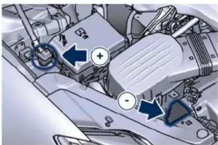
natural_image
Interior view of a car engine bay with blue directional arrows indicating traffic flow (no text or symbols)Jump-Start Procedure

WARNING!
- Stay clear of the radiator cooling fan whenever the hood is raised. It can start anytime the ignition device
start anytime the ignition device is on. You can be injured by the moving fan blades.
- Remove any metal jewelry such as watch bands or bracelets that might make an inadvertent electrical contact. You could be seriously injured.
- Do not allow the vehicles involved the jumpstarting operation to touch each other as this could establish a ground connection and cause personal injury.
- Turn off the heater, radio, and all unnecessary electrical accessories.
- Set the parking brake, shift the automatic transmission into P (Park) and set the ignition device to OFF.
- If using another vehicle to jumpstart the battery, park the vehicle within the jumper cables reach and set the parking brake and make sure the ignition is off.
- Connect one terminal clamp of the positive jumper cable to the positive (+) remote post of the vehicle with the discharged battery after lifting
the protection cap of the cable indicated on the external side of the integrated power module.
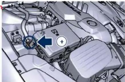
natural_image
Close-up of an automotive engine bay with a blue arrow pointing to a component (no visible text or symbols)Connect the opposite terminal clamp of the positive (+) jumper cable to the positive (+) post of the booster battery.
- Connect one terminal clamp of the negative jumper cable to the negative (−) post of the booster battery.
- Connect the opposite terminal clamp of the negative (−) jumper cable to the remote negative (−) post of the vehicle with the discharged battery as rendered.

In an Emergency
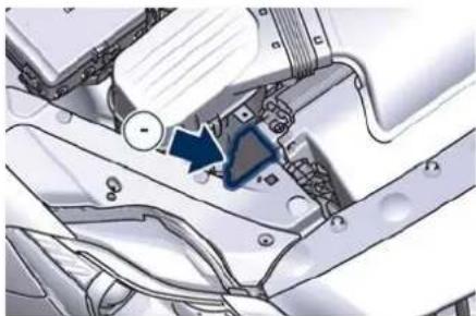
natural_image
Mechanical assembly diagram showing a component with a blue arrow indicating direction (no text or symbols present)- Start the engine in the vehicle that has the booster battery, let the engine idle a few minutes, and then start the engine in the vehicle with the discharged battery. If using a portable battery booster, wait a few seconds after connecting the cables, before starting the booster vehicle.
Once the engine is started, remove the jumper cables in the reverse sequence.
- Disconnect the terminal clamp of the negative (−) jumper cable from the remote negative (−) post of the vehicle with the discharged battery.
- Disconnect the opposite terminal clamp of the negative jumper cable from the negative (−) post of the booster battery.
- Disconnect the terminal clamp of the positive (+) jumper cable from the positive (+) post of the booster battery.
- Disconnect the terminal clamp of the positive jumper cable from the remote positive (+) post of the discharged vehicle.
NOTE:
If frequent jump-starting is required to start your vehicle you should have the battery and charging system inspected at a Service Network center.
Towing a Disabled Vehicle
Proper towing or lifting equipment is required to prevent damage to your vehicle. Use only towing bars and other equipment designed for the purpose, following equipment manufacturer's instructions.
Safety chains are mandatory.
Except for the front threaded seat to fix the supplied hook (see "Tool Kit" chapter in this section), the vehicle is not equipped with other connection points for towing operations with tow truck.

CAUTION!
Any improper manoeuvre and use of unsuitable equipment for recovering vehicle in an emergency from off road location could seriously damage the vehicle. Contact the Service Network or anyone having suitable equipment and the required expertise to safely and properly carry out any required operations.
Make sure you comply with local towing regulations.
- If the vehicle's battery is discharged, refer to the following paragraph on how to shift the automatic transmission out of the P (Park)

position and release the parking brake.
- If the vehicle battery is still charged turn off the engine and disengage the parking brake manually (if automatically engaged) by using the command behind the shift lever (see "Parking Brake" chapter in section "Starting and Driving"). Shift then manually the transmission out of P (Park) as described in "Transmission Manual Release of P (Park) Position" chapter of this section. If you need to use the accessories (wipers, defrosters, etc.) while being towed, the ignition device must be in RUN position, do not use the ACC position.
Manual Release of
Transmission with Low Battery
In order to push or tow the vehicle if unable to shift the transmission out of P (Park) (such as a discharged battery), a manual park release is available. In this case it is necessary to manually release the shift lever and release the parking brake if inserted (see "Emergency Release of the Parking Brake" in this section). Follow the steps as indicated in "Transmission Manual Release of P (Park) Position" in this section to manually disengage the transmission.
Vehicle Towing Conditions
Maserati only allows vehicle towing either on a flatbed or with all four wheels off the ground.
Towing an RWD Vehicle
If flatbed equipment is not available, and the transmission is still operable, a RWD vehicle may be flat towed (with all four wheels on the ground) under the following conditions.
• The shift lever must be in N (Neutral).
- The distance to be traveled must not exceed 50 km (30 mi).
- The towing speed must not exceed 50 km/h (30 mph).

CAUTION!
If you have to tow the RWD vehicle with 2 wheels raised, ensure that the ignition device is in the OFF position. If this is not observed, when the ESC is active, the ECU will store a malfunction and the relative warning light will illuminate on the instrument cluster display. This requires the intervention of the Service Network to reset the system.

CAUTION!
It is forbidden to tow any other type of vehicle with this car.
Towing an AWD Vehicle

WARNING!
- Single axle towing or use of a tow dolly is not allowed since it will severely damage components of an AWD vehicle.
- Use of a tow dolly on front wheels is strictly forbidden since front wheels may still receive a residual amount of torque and disengage the vehicle from the tow dolly and affect safety of both rescuers and other road users.
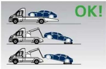
text_image
OK!
In an Emergency
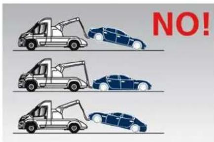
text_image
NO!Use the Tow Hook Included in the Tool Kit

CAUTION!
The tow hook should only be used for towing the car on flat roads. Do not use the tow hook to remove the car that is stuck on off-road stretches.
The tow hook can also be used to tow the vehicle on the platform of a tow truck.
It is necessary to inform the operators of the rescue vehicle about the vehicle minimum height to avoid, during its loading, any contact of the lower ends of the front or rear bumper with the tow truck loading ramp.
The tow hook is contained in the tool kit (see "Tool Kit" in this section) and must be screwed in its seat accessible behind the front grille, right-hand
side, after removing the protective cap.
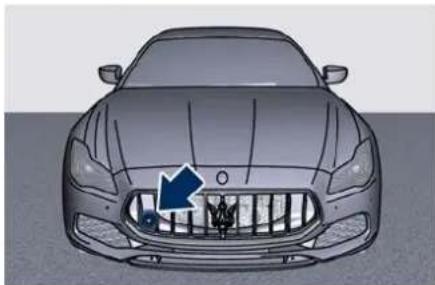
natural_image
Front view of a car with a blue arrow pointing to the grille (no text or symbols visible)- Carefully clean the threaded seat before screwing the hook.
- Screw the tow hook into its seat for at least 11 turns.
NOTE:
Maximum work angle of towing cable or bar: 15
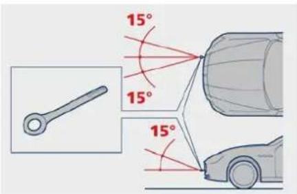
text_image
15° 15° 15°8 - Maintenance and Care
Scheduled Maintenance Service ....
Scheduled Service Plan 283
Maintenance Service Components 28
Maintenance Procedures 291
Battery Status and Maintenance 298
A/C System Maintenance .... 303
Wheels Maintenance 304
Bodywork Maintenance and Care ....
Interior Maintenance and Care ....
Vehicle Stored for Long Periods ..... 31
Restarting the Vehicle after a Long Inactivity ....
Refillings Table 313


Maintenance and Care
Scheduled Maintenance Service
Correct maintenance is clearly the best way to guarantee vehicle performance and safety functions, ensure respect for the environment and low operating costs.
NOTE:
Also remember that the scrupulous observance of the maintenance procedures is essential for keeping your vehicle operating properly. Not adhering to the "Scheduled Service Plan" can impact your vehicle's warranty.
Interval Running Coupons
Maserati has therefore provided for a series of checks and maintenance operations involving the 1 ^st service and subsequent when the vehicle reaches mileage/years reported on the "Scheduled Service Plan" in this section.
After the last service, maintenance must be restarted with the operations scheduled for the 1 ^st , 2 ^nd and 3 ^rd service.

CAUTION!
The Scheduled Maintenance services are prescribed by the Manufacturer. Failure to have the services carried out can affect your warranty.
The Scheduled Maintenance service is provided by the whole Service Network. In the event that, when a service is performed, further replacements or repairs are found to be necessary in addition to the scheduled operations, these can be carried out only with the specific consent of the Customer.

CAUTION!
You are advised to notify the Service Network of any minor operating problem, without waiting for the next scheduled service.
NOTE:
- Change your engine oil more often you drive your vehicle off-road for an extended period of time or short trips without reaching operation temperature. Even the use of the vehicle with extremely hot or cold ambient temperature may make
necessary change engine oil more often.
- Under no circumstances should oil change intervals exceed mileagelyears reported on the "Scheduled Service Plan" in this section.

CAUTION!
Failure to perform the required maintenance items may result in damage to the vehicle.
Scheduled Maintenance (Service) Indicator
The service indicator system will remind you the deadline for the maintenance program.
The indicator light on the instrument cluster flashes for approx. 5 seconds displaying the message backed by a beeping sound, indicating that the next scheduled maintenance is due or has already overdue.
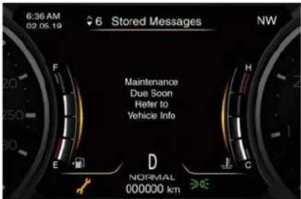
text_image
6:36 AM 02.05.19 6 Stored Messages NW Maintenance Due Soon Refer to Vehicle Info E D NORMAL 000000 kmWhen the scheduled maintenance has overdue, the indicator light ⚙ and message will be displayed on the instrument cluster.
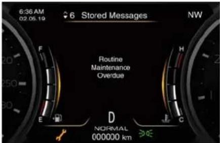
text_image
6:36 AM 02.05.19 6 Stored Messages NW Routine Maintenance Overdue E D NORMAL 000000 km E CThe service indicator and message will illuminate approximately from 1000 km (620 mi) or 30 days to the next scheduled maintenance.
Have your vehicle serviced as soon as possible.
NOTE:
The service indicator will not monitor the time elapsed from the last scheduled maintenance.
To check the km/mi and the days that remain at the inspiration of the next scheduled maintenance, consult the "Maintenance" submenu of "Vehicle Info" main menu (see "TFT Display Menu and Submenu Content" in section "Dashboard Instruments and Controls" for more details).
The Service Network will reset the service indicator message after completing the scheduled maintenance operations.
Scheduled Service Plan
The Scheduled Maintenance services listed in this chapter must be done at the times or mileages specified to protect your vehicle warranty and ensure the best vehicle performance and reliability.
More frequent maintenance may be needed for vehicles in severe operating conditions, such as dusty areas, extremely hot or cold ambient temperature and very short trip driving.
Inspection and service should also be done anytime a malfunction is suspected.
Maserati recommends that these maintenance intervals be performed at the Service Network. The technicians at your dealership know your vehicle best, and have access to factory-approved information, genuine Maserati parts, and specially designed electronic and mechanical tools that can help prevent future costly repairs.

Maintenance and Care
Main Operations/Service Coupons (NOT valid for Japan market)
| Service coupons | 1° | 2° | 3° | 4° | 5° | 6° |
| Main operations | Interval running coupons: every 20000 km (12500 mi) or 2 years (*) | |||||
| Vehicle road test III | ||||||
| Check with Maserati Diagnosi I I I I I I | ||||||
| Engine oil and filter R R R R R R | ||||||
| Engine coolant level | I I I I I I | |||||
| Replace every 10 years or 240000 km (150000 mi) | ||||||
| Engine check for leaks I I I I I I | ||||||
| Cooling system connections and lines (check for leaks) I I I | ||||||
| Air filter R R R | ||||||
| Belt for alternator, water pump and air conditioning compressor (3.8 V8 Engine) | I I I R I I | |||||
| Replace every time the part is removed | ||||||
| Belt for alternator and belt for water pump and air conditioning compressor (3.0 V6 Engines) | I I I R I I | |||||
| Replace every time the part is removed | ||||||
| Spark plugs | R | R | ||||
| Intercooler check for leaks | I I I I I I | |||||
| Brake fluid | I I I I I I | |||||
| Replace every 2 years | ||||||
| Brake system (lines, calipers, connections) - Instrument cluster warning light efficiency - Parking brake operation | I I I I I I | |||||
| Tire wear, tire and spare tire (if equipped) pressure check | I I I I I I | |||||
| Joints, rods for front and rear suspensions, front and rear under-chassis | I I I | |||||
| Main operations | Interval running coupons: every 20000 km (12500 mi) of years (*) | |||||
| Correct operation and reliability of the seats and seat belts I | I I I I I | |||||
| Pollen filter R R R R R R | ||||||
| Windshield fluid level - Windshield washer cleaner I I I I I I | ||||||
| Headlight leveling I I I I I I | ||||||
| E- Call module (●) battery change (1) | ||||||
| Controls and adjustment systems in general, hinges, doors, engine compartment lid and luggage compartment | III | |||||
| Condition of the leather interiors III | ||||||
| (*) Interval running coupons for India, Australia, New Zealand, Morocco, Lebanon and Jordania markets are every 20000 km (12500 mi) or 1 year, and for Chile, Argentina, Brazil, Mexico, Colombia, Guatemala, Dominican Republic, Uruguay, Costa Rica, Panama, Peru and Ecuador markets are every 10000 km (6213 mi) or 1 year.I = Inspect and carry out any other necessary operationR = Replace(1) The E-call module's battery must be replaced every 5 years. | ||||||

Maintenance and Care
Main Operations/Service Coupons (Valid for Japan market)
| Service coupons | 1° | 2° | 3° | 4° | 5° | 6° |
| Main operations | Interval running coupons: every 20000 km (12500 mi) or 1 year | |||||
| Vehicle road test III | ||||||
| Check with Maserati Diagnosi I I I I I I | ||||||
| Engine oil and filter R R R R R R | ||||||
| Engine coolant level | I I I I I I | |||||
| Replace every 10 years or 240000 km (150000 mi) | ||||||
| Engine check for leaks I I I I I I | ||||||
| Cooling system connections and lines (check for leaks) I I I I I I | ||||||
| Air filter R R R | ||||||
| Belt for alternator, water pump and air conditioning compressor (3.8 V8 Engine) | I I I R I I | |||||
| Replace every time the part is removed | ||||||
| Belt for alternator and belt for water pump and air conditioning compressor (3.0 V6 Engines) | I I I R I I | |||||
| Replace every time the part is removed | ||||||
| Spark plugs | R | R | ||||
| Intercooler check for leaks | I I I I I I | |||||
| Brake fluid | I I I I I I | |||||
| Replace every 2 years | ||||||
| Brake system (lines, calipers, connections) - Instrument cluster warning light efficiency - Parking brake operation | I I I I I I | |||||
| Tire wear, tire and spare tire (if equipped) pressure check | I I I I I I | |||||
| Joints, rods for front and rear suspensions, front and rear under-chassis | I I I | |||||
| Main operations | Interval running coupons: every 20000 km (12500 mi) of year | |||||
| Correct operation and reliability of the seats and seat belts I | I | I | I | |||
| Pollen filter R R R | ||||||
| Windshield fluid level - Windshield washer cleaner I | I | I | I | |||
| Headlight leveling I | I | I | I | |||
| Controls and adjustment systems in general, hinges, doors, engine compartment lid and luggage compartment | I | I | I | |||
| Condition of the leather interiors I | I | I | I | |||
| I = Inspect and carry out any other necessary operationR = Replace | ||||||

Maintenance and Care
Periodic Maintenance
Every 1000 km (600 mi) or before long journeys
Check:
- engine coolant;
- brake fluid;
• windshield washer fluid level; - tire inflation pressure and condition;
• operation of lighting system (headlights, turn signals, hazard warning lights, etc.); - operation of windshield washer/wiper system and wear of windshield wiper blades.
Every 3000 km (1900 mi)
Check and top up, if required, the engine oil level.
Heavy-Duty Vehicle Use
If the car is mainly used under one of the following conditions:
- off-road;
- short, repeated journeys (less than 7-8 km /4-5 mi) at sub-zero outside temperatures;
• engine often idling or driving long distances at low speeds or long periods of idleness;
you should perform the following inspections more frequently than recommended on the "Scheduled Service Plan":
- check front disc brake pad conditions and wear;
- check cleanliness of hood and trunk locks, cleanliness and lubrication of linkage;
- visually inspect conditions of: engine, transmission, pipes and hoses (exhaust - fuel system - brakes) and rubber elements (boots - sleeves - bushes - etc.);
- check battery charge;
- visually inspect condition of the accessory drive belts;
- check and, if necessary, change engine oil and replace oil filter;
- check and, if necessary, replace pollen filter of the A/C system;
- check and, if necessary, replace air cleaner filter.

CAUTION!
All maintenance operations for the vehicle must be carried out by the Service Network. For routine and minor maintenance operations which you can carry out yourself, make sure that you have the necessary experience and always use suitable equipment, original Maserati spare parts (or equivalent) and the prescribed fluids. Shall this not be the case, do not carry
out any operation on your own and contact a Service Center.
On-Board Diagnostics (OBD)
Your vehicle is equipped with an on-board diagnostic system that monitors the performance of the emissions, engine, and automatic transmission control systems. See "Use of the Engine" in section "Starting and Driving" for further details.
If any of these systems require service, the system will turn on the Malfunction Indicator Light (MIL) 📄 on the instrument cluster display (refer to "Warning and Indicator Lights" in section "Dashboard Instruments and Controls").
Spare Parts
Use of genuine parts for normal or scheduled maintenance and repairs is highly recommended to ensure excellent performance.
Damage or failures caused by non-genuine spare parts used for maintenance and repairs will not be covered by the manufacturer's warranty.
Maintenance Service Components
The following images show the position of all components involved in the maintenance service.
3.8 V8 - Engine
- Engine oil dipstick.
- Engine oil filler neck.
- Air cleaner filters.
- Engine coolant expansion reservoir cap.
- Coolant reservoir cap for transmission cooling system.
- Washer fluid reservoir cap.
- Brake fluid reservoir access cover.
- A/C pollen filter access cover.
- Integrated power module (fuses).
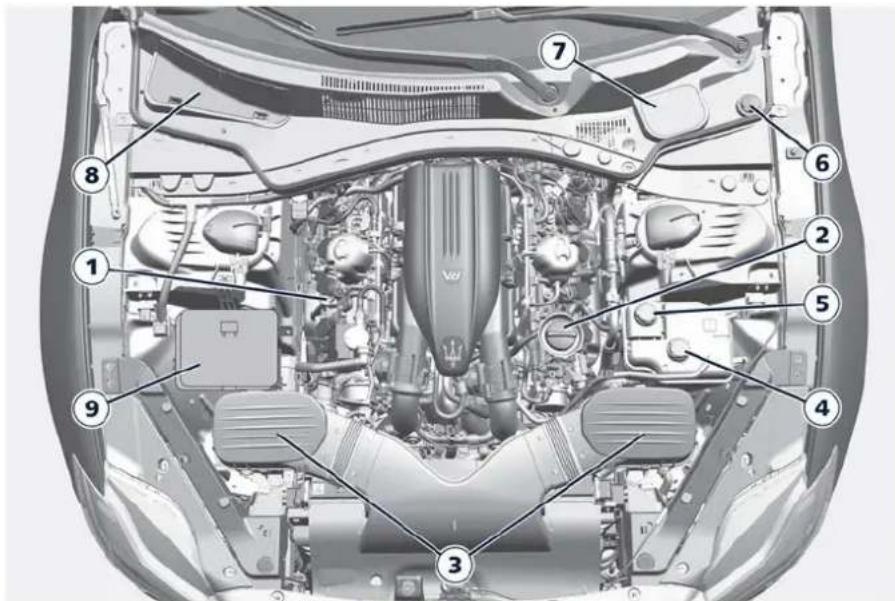
text_image
Technical diagram of a car engine with numbered components for identification3.8 V8 - Engine

Maintenance and Care
3.0 V6 - Engines
- Engine oil dipstick.
- Engine oil filler neck.
- Air cleaner filters.
- Engine coolant expansion reservoir cap.
- Coolant reservoir cap for transmission cooling system.
- Washer fluid reservoir cap.
- Brake fluid reservoir access cover.
- A/C pollen filter access cover.
- Integrated power module (fuses).
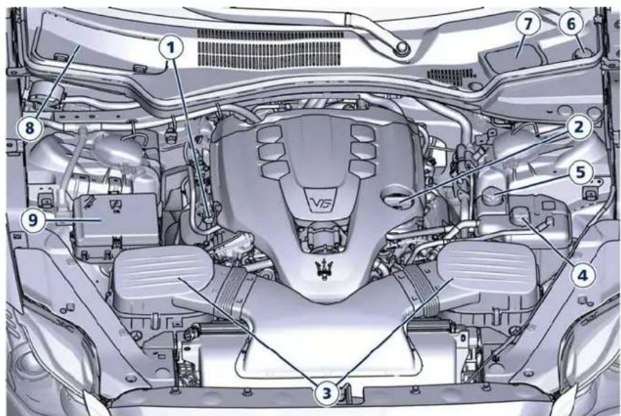
text_image
Technical diagram of a car engine bay with numbered components for identification3.0 V6 - Engines
Maintenance Procedures
The following pages contain the "required" maintenance standards determined by Maserati engineers. Besides those maintenance items specified in the "Scheduled Service Plan", there are other components which may require service or replacement in the future. To perform most of the services, it is necessary to open the hood (see "Open and Close the Hood" in section "Before Starting").

CAUTION!
- Failure to properly maintain your vehicle or perform repairs and service when necessary could result in more costly repairs, damage to other components or negatively impact vehicle performance. Immediately have potential malfunctions address to the Service Network: please be advised that Maserati recommends to address to the Official Service Network.
- Your vehicle has been equipped with improved fluids that protect the performance and durability of your vehicle and also allow extended
maintenance intervals. Do not use chemical flushes for washing as the chemicals can damage your engine, transmission, electric power steering or air conditioning. Such damages are not covered by the New Vehicle Limited Warranty. If a flush is needed because of component malfunction, use only a specific product for the flushing procedure.
Level Checks

ENVIRONMENTAL!
• The engine oils and fluids used contain substances that are dangerous for the environment. For replacement you are advised to contact the Service Network, where all the necessary equipment is available to dispose of the used oil and fluids in compliance with the regulations in force and in an environment-friendly manner.
- All equipment used for fluids replacement (gloves, cloths, containers, etc) must be disposed of in compliance with the regulations in force.
Engine Coolant Level Check
Your vehicle has been equipped with an improved engine coolant
(antifreeze) that offers high protection against corrosion, freezing and allows extended maintenance intervals. To prevent reducing extended maintenance periods, it is important to use original engine coolant (antifreeze) when adding coolant throughout the life of your vehicle. When adding engine coolant (antifreeze) use pure water only such as distilled or deionized water when mixing the water/engine coolant (antifreeze) solution. The use of impure water will reduce the amount of corrosion protection in the engine cooling system.
- Mix a minimum solution of 50% engine coolant (antifreeze) and distilled water. Use higher concentrations (do not exceed 70%) if temperatures below -37°C (-35°F) are forecasted.
Please note that it is the owner's responsibility to maintain the proper level of protection against freezing according to the temperatures occurring in the circulation area of the vehicle.
The coolant reservoir provides a quick visual method to determine that the coolant level is adequate. As long as the engine operating temperature is satisfactory, the coolant reservoir only

Maintenance and Care
needs to be checked once a month. With the engine off and cold, the level of the coolant in the reservoir should be between the ranges indicated on the reservoir and inside the filler neck.
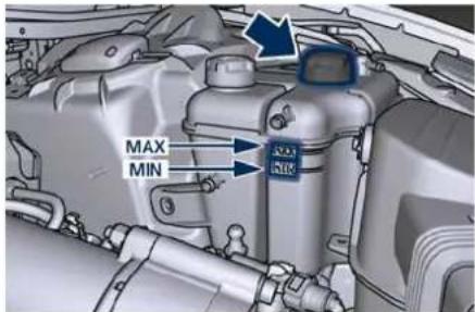
text_image
MAX MIN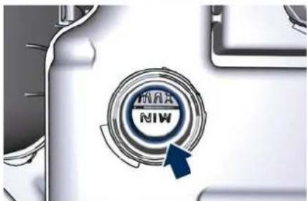
natural_image
Close-up of a car's front grille with 'INRA' and 'MIW' branding, no readable text or symbols beyond the logo design- When additional engine coolant (antifreeze) is needed to maintain the proper level, it should be added to the coolant reservoir after removing the cap. Do not overfill.
-
Once the desired level is reached, firmly close cap of the reservoir.
-
If frequent engine coolant (antifreeze) additions are required, or if the level in the coolant recovery reservoir does not drop when the engine cools, the cooling system should be pressure tested for leaks by a Service Center.
- Keep the front of the radiator and the condenser clean.

WARNING!
- Never add engine coolant (antifreeze) when the engine is hot. Do not loosen or remove the cap of the engine coolant reservoir to cool hot engine. Heat causes pressure to build up in the cooling system. To prevent scalding or injury, do not remove the pressure cap while the system is hot or under pressure.
- When adding coolant do not use a pressure cap other than the one specified for your vehicle. Personal injury or engine damage may result.
Brake Fluid Level Check
Check the fluid level immediately if the brake system warning light ⏻ and the related message turn on indicating a low level of brake fluid.
- Remove the brakes fluid reservoir access cover.
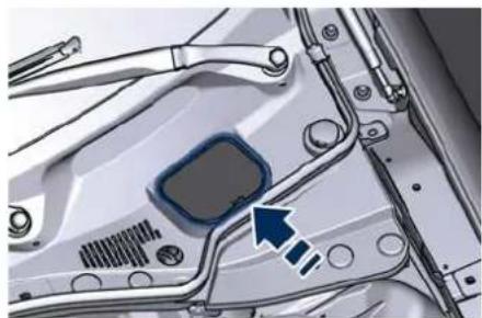
natural_image
Close-up of a mechanical component with a blue arrow pointing to a highlighted section (no text or symbols visible)- Clean the top of the master cylinder area before removing the cap.
- Add fluid to bring the level up to the "MAX" mark on the side of the master cylinder reservoir. Use only manufacturer's recommended brake fluid (see "Refillings Table" in this section).
- Once the correct level is reached, firmly close the cap.
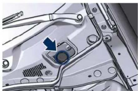
natural_image
Mechanical component diagram showing a highlighted circular feature with an arrow, no visible text or symbolsThe brake pads wear could cause the fluid level to fall. However, low fluid
level may be caused by a leak and a requires accurate checkup of the braking system.

CAUTION!
The symbol 📄 the tank cap identifies the synthetic type of brake fluid, distinguishing it from the mineral type. Using mineral fluids damages the special rubber linings of the brake system irreparably.

WARNING!
• To avoid contamination from foreign materials or moisture, use only new brake fluid or fluid that has been in a tightly closed container. Keep the master cylinder reservoir cap secured at all times. Brake fluid in an open container absorbs moisture from the air resulting in a lower boiling point. This may cause it to boil unexpectedly during hard or prolonged braking, resulting in sudden brake failure. This could result in an accident.
• Overfilling the brake fluid reservoir can result in spilling brake fluid on hot engine parts, causing the brake fluid to catch fire. Brake fluid can also damage painted and vinyl
surfaces, make sure it does not spill over these surfaces.
- Do not allow petroleum based fluid to contaminate the brake fluid. Brake seal components could be damaged, causing partial or complete brake failure. This could result in an accident.
Adding Windshield Washer Fluid
The reservoir on the left side of the engine compartment contains the fluid to wash the windshield.
During scheduled services or when the message of low level of the washer fluid appears together with the related telltale add more fluid as soon as possible.
The fluid reservoir may contain nearly 3,5 litres (0.77 UK gal) of washer fluid.
- Remove the reservoir cap in the engine compartment and lift the filler neck.
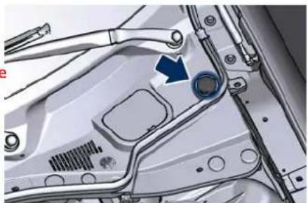
natural_image
Mechanical assembly diagram showing a component with a blue arrow pointing to a circular feature (no text or symbols present)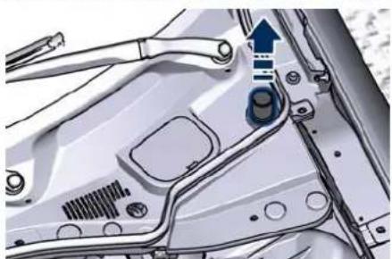
natural_image
Mechanical assembly diagram showing a valve mechanism with no visible text or symbols- Fill the reservoir with windshield washer solvent (refer to "Refillings Table" in this section) and operate the system for a few seconds to flush out the residual water. - When refilling the washer fluid reservoir, apply some washer fluid to a cloth or towel and wipe the wiper blades clean. This will help blade performance.
To prevent freeze-up of your windshield washer system in cold

Maintenance and Care
weather, select a solution or mixture that meets or exceeds the temperature range of your climate.
This rating information can be found on most washer fluid containers.
NOTE:
The Service Network can provide you with information about the "Maserati recommended Windshield Washer Fluid", available in the "Genuine Accessories" range.

WARNING!
• Commercially available windshield washer solvents are flammable. They could ignite and burn you. Care must be exercised when filling or when working around the windshield washer system.
- Do not drive with the windshield washer reservoir empty: the action of the washer is essential for improving visibility when driving.
Engine Oil Level Check
To assure proper lubrication of your vehicle's engine, the engine oil must be maintained at the correct level. If the warning light illuminates and the related message of low oil level displays, or during scheduled services (see "Scheduled Maintenance Service" in this section) it is necessary to check the engine oil level.
The best time to check the engine oil level is about five minutes after a fully warmed up engine is shut off or before starting the engine after it has sat overnight. In both cases the vehicle should be parked on level ground to improve the accuracy of the oil level readings.

CAUTION!
- Do not top up with oil with different characteristics than the engine one (refer to "Refillings Table" in this section).
• Overfilling or underfilling the sump will cause aeration or loss of oil pressure. This could damage your engine. - Do not add any supplemental materials to the engine oil, other than leak detection dyes. Engine oil is an engineered product, and its performance may be impaired by supplemental additives.
- Remove the dipstick and clean it with a dry and clean cloth (the figure represent a 3.0 V6 engine).
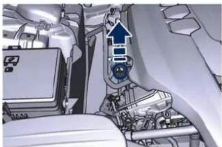
natural_image
Interior view of a vehicle showing engine, dashboard, and gear assembly (no visible text or symbols)- Re-insert the dipstick completely and remove: the oil level should maintain between the MIN and MAX reference ranges (SAFE range).
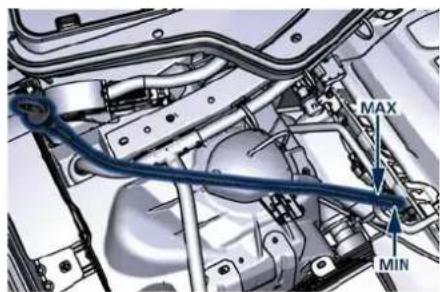
text_image
MAX MIN- If a refilling is necessary: unscrew the filler neck cap.
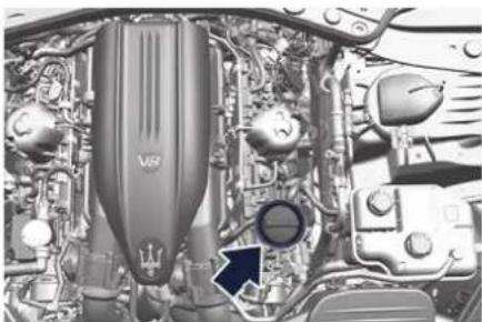
natural_image
Engine bay with visible components and a black arrow pointing to a specific part (no text or symbols present)3.8 V8 Engine
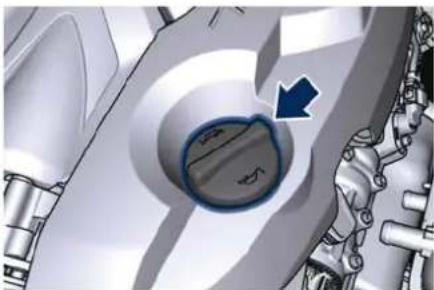
natural_image
Mechanical component with a highlighted circular feature and arrow indicator (no text or symbols)3.0 V6 Engines
- Adding 1.4 Litres/0.30 UK gal (3.8 V8 Engine) or 1 Litre/0.22 UK gal (3.0 V6 Engines) of oil when it is at the minimum level.
- Return the cap and dipstick to their position and wait for a few minutes to allow the oil to reach the sump.
- Check the level again.
Engine Oil Filter Replacement
The engine oil filter should be replaced with a new filter at every oil change.
Contact the Service Network to perform this service.
Automatic Transmission Oil Check
Contact the Service Network for the oil level check.
Fluid Level Check for Transmission Cooling System
The coolant contained in the reservoir of this system is equal to the one used for the cooling system of the engine. For the preparation of the mixture of water and antifreeze and for the control of the level, proceed as shown in the "Engine Coolant Level Check" of this chapter.
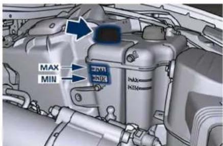
text_image
MAX MINEngine Air Filters Replacement
Contact the Service Network to have the air filters replaced.
A/C Air Filter Replacement
This filter performs mechanic/electrostatic air filtering, provided that windows and doors are perfectly closed.
The filter is located under the hood in the external A/C system air inlet, on the passenger side of the vehicle, next to the windshield wipers.
To replace the filter during the scheduled maintenance services or after the vehicle has been heavily used on dusty roads, proceed as follows:
- Remove the access door in the cowl screen by pressing the retaining clips indicated.
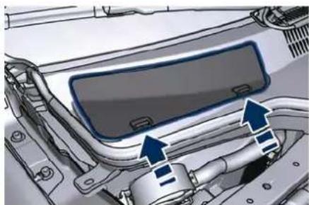
natural_image
Close-up of a car hood with visible engine and pipe components (no text or symbols)- Unsnap both ends and lift the filter access cover.

Maintenance and Care
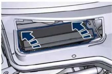
natural_image
Diagram of a car interior showing airflow or airflow direction arrows (no text or symbols)- Remove the used filter slipping it off from within the air intake.
• Install the new filter with arrows pointing in the direction of airflow, which is toward the rear of the vehicle (text and arrows on the filter will indicate this).
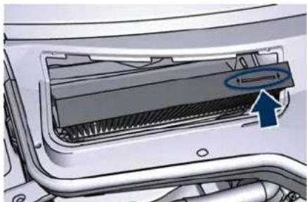
natural_image
Interior view of a car air conditioner unit showing airflow path and ventilation cover (no text or symbols)- Close the filter access cover and reinstall the access door.

CAUTION!
Failure to replace the filter may considerably reduce the air conditioning and heating system efficiency.
Windshield Wiper Maintenance and Blades Replacement
When the wiper arms are in rest position it is not possible to check or replace the blades as they remain under the hood. To service the blades it is necessary to move the wiper arms in "Service" position (see chapter "Wipers and Washers Control" in section "Dashboard Instruments and Controls").
In this way it is possible to turn and lift the arms for the desired intervention.

WARNING!
It is dangerous to operate or service the wiper blades with the wipers in active position (different than "OFF") and with the ignition device in the RUN position. The rain sensors may suddenly activate the wipers. Always use the "Service" position for any intervention on the wipers blades.
Windshield Wiper Maintenance
Life expectancy of wiper blades varies depending on the geographical area's weather conditions where the car is used and frequency of use. Poor performance of blades may be present with chattering, marks, water lines or wet spots. If any of these conditions are present, clean the wiper blades or replace if necessary.
Clean the rubber edges of the wiper blades and the windshield periodically with a sponge or soft cloth and a mild nonabrasive cleaner. This will remove accumulations of salt or road film.
Operation of the wipers on dry glass for long periods may cause deterioration of the wiper blades.
Always use washer fluid when using the wipers to remove salt or dirt from a dry windshield.
Avoid using the wiper blades to remove frost or ice from the windshield. Keep the blade rubber out of contact with petroleum products such as engine oil, gasoline, etc.
Spray nozzles
If the jet does not work, first check that there is fluid in the pan (see paragraph "Level checks" in this section) then check that the nozzles are not clogged.
Blades Replacement
- Move the wiper arms into "Service" position (see chapter "Wipers and Washers Control" in section "Dashboard Instruments and Controls") and lift them.
- Press the indicated button, slip off the blade support from the arm and replace it.
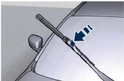
natural_image
Diagram of a car's steering wheel with a blue arrow indicating the angle (no text or symbols present)- Return the blade to its original position on the windscreen.
- Turn the multifunction lever to one of the automatic settings (see chapter "Wipers and Washers Control" in section "Dashboard Instruments and Controls") and move the ignition device to the RUN position: the wiper arms will return to the resting position.
NOTE:
Apply a small amount of high quality
Due to the difficulty of this operation, lubricant directly on the bolt. we recommend that you contact the Service Network for replacement of the blades.
Body Lubrication
Locks and all body pivot points, including such items as seat tracks, door hinge pivot points and rollers, boot lid and hood, sliding parts of power sunroof (if foreseen) and hood hinges, should be lubricated periodically with a lithium-based grease. This action is essential to preserve the original operation of these components and to protect them against rust and wear.
Prior to the application of any lubricant, the parts concerned should be wiped clean to remove dust and grit; after lubricating excess oil and grease should be removed. Particular attention should also be given to hood latching components to ensure proper function. When performing maintenance in the engine compartment, the hood latch, release mechanism and safety catch should be cleaned and lubricated. The coupling pin of the lock on the rear driver pillar should be lubricated at least twice a year, preferably in the Fall and Spring.

Maintenance and Care
Battery Status and Maintenance
This vehicle is equipped with a sealed type maintenance-free battery. You will never have to add water, nor is periodic maintenance required.

WARNING!
- Battery fluid is a corrosive acid solution and can burn or damage the eyes. Do not allow battery fluid to contact your eyes, skin, or clothing. Do not lean with the face over a battery. If acid splashes in eyes or on skin, flush the area immediately with large amounts of water.
- Battery gas is flammable and explosive. Keep flame or sparks away from the battery. Do not use a booster battery or any other booster source with an output greater than 12 Volts. Do not allow cable clamps to touch each other.
- Battery posts, terminals, and related accessories contain lead and lead compounds. Wash hands after handling the battery.
• The battery in this vehicle has a vent hose that should not be disconnected and should only be
replaced with a component of the same type (vented).
NOTE:
Remote battery terminals for start are located in the engine compartment for jump starting to be used with an auxiliary battery or a battery from another vehicle (see "Auxiliary Jump-Start Procedure" chapter in section "In an Emergency").
Battery State of Charge
To avoid problems with ignition and/or the electrical system in general when you are driving, the battery charge status is constantly maintained and guaranteed by the vehicle's recharge circuit; the main component of which is the alternator. This circuit is only able to supply voltage to the battery when the vehicle is travelling.
The warning light on the instrument cluster, will indicate any malfunctions in the recharge circuit or an insufficient battery charge status (shown in figure).
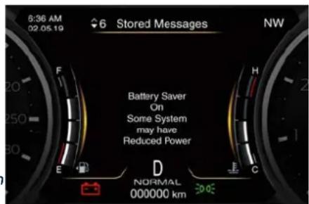
text_image
6:36 AM 02.05.19 6 Stored Messages NW Battery Saver On Some System may have Reduced Power D NORMAL 000000 kmThe vehicle is fitted with advanced electronic systems, such as, for example, the alarm system and various electronic control modules, which consume power even when the ignition device is in the OFF position and the vehicle is not being used. Therefore, it is fundamental that the battery is properly charged to ensure that the engine starts properly and that all the electrical/electronic systems in the vehicle work efficiently.
To Disconnect the Battery
The battery is fitted on the inner right side of the boot compartment.
To access the battery it is necessary to lift the ground coverage of the boot compartment and remove the access cover as indicated.
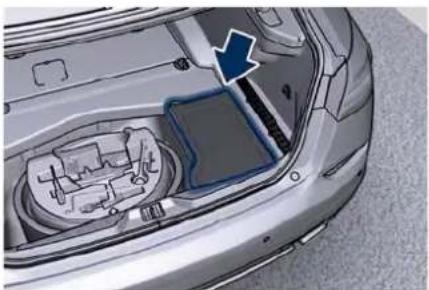
natural_image
Interior view of a car showing engine compartment and battery cover (no text or symbols visible)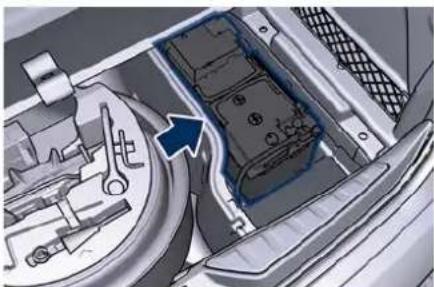
natural_image
Interior view of a vehicle showing engine compartment with tool handle and gear mechanism (no text or symbols visible)
CAUTION!
- Before disconnecting the battery, open the boot lid and lower the windows a few centimeters, to avoid damaging the seal and the glass when opening and closing the door. When the battery is connected, this operation is performed automatically when the door is opened and closed. The boot lid must remain open
and the windows lowered until the charged battery is reconnected.
- Never disconnect the battery from the electrical system when the engine is running.
- To temporarily disconnect the vehicle electrical system from the battery, simply remove the cable end with quick coupling from to the negative post (-) of the battery.
- If the battery needs to be removed from its compartment, you must first detach the terminal clamp to the negative post (−) and then the other terminal clamp to the positive post (+), after removing the protective cover. Battery posts are marked positive (+) and negative (−) and are identified on the battery case.
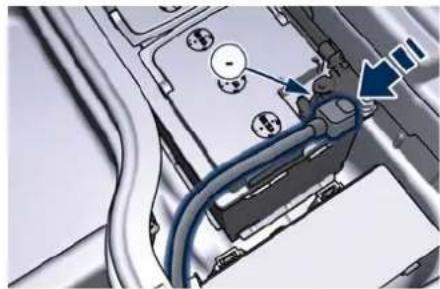
natural_image
Close-up of a mechanical component with blue cables and a blue arrow pointing to a detail (no visible text or symbols)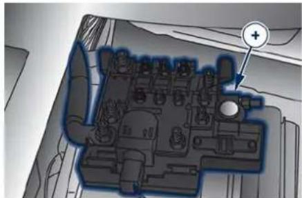
natural_image
Top-down schematic of a vehicle or engine bay with no visible text or symbolsTo Reconnect the Battery
NOTE:
When the battery cables have been disconnected and the boot lid has been locked, it is necessary to pull the emergency release lever in order to re-open it. To access the boot and operate the emergency release fold the rear seatback (see "Cargo Area" chapter in section "Understanding the Vehicle").

CAUTION!
- It is essential when reconnecting the cables on the battery that the positive cable is precisely attached to the positive post (+) and the negative cable is attached to the negative post (-).

Maintenance and Care
- Cable clamps should be tight on the terminal posts and free of corrosion.
After the battery has been disconnected and re-connected and before starting the engine it is necessary to proceed as follows:
- Unlock and lock the doors using the key fob.
- Close manually the boot lid, unlock it with the key fob and then lock it manually on more time. If the vehicle is equipped with power boot lid/Hand Free, manually perform the complete closure. Then move the lid automatically, using the buttons on the lid itself, performing a complete cycle of opening and closing. If the limit of maximum power boot lid opening has been set, it is necessary to reset it (see "Open and Close the Boot Lid" in section "Before Starting").
- Initialise the climate control system by activating the system and pressing the "AUTO" control as described in chapter "Air Conditioning Controls" in section "Dashboard Instruments and Controls".
- Turn on the MIA and set the date and time (see "TFT Display Settings and Menu Overview" in section
"Dashboard Instruments and Controls").
- Lift, release and lift again the lever located behind the shift lever to inizialize the electric parking brake. Following this operation, at the next key cycle, the warning light on the instrument cluster will turn off and the error messages regarding the unavailability of the radar functions will also no longer be present.
- For correct activation of the approach lights on the external mirrors, press at least once the tilt button on the driver's door panel so that the door mode recognizes the mirrors position.
- If the car is equipped with power sunshades on rear door windows, carry out the teach-in cycle described on chapter "Open and Close Power Sunshades on Rear Door Windows" in section "Before Starting".
- Start the engine and perform the end-stop learning of EPS, steering fully to the left and then to the right. The EPS failure warning light and message should disappear on the TFT display

CAUTION!
- Every time the battery is reconnected, wait at least 30 seconds with the ignition device turned to RUN before starting the engine, in order to allow the electronic system that manages the motor-driven throttles to run a self-learning cycle. At the same time, you can run the date and time set up procedure for the MIA.
- Every time the battery is reconnected the warning lights and flash for about 10 seconds then go off.
Useful Advice to Extend Battery Life
When parking the vehicle, make sure that the doors, front, rear lids and flaps are properly closed. All interior lights should be off.
When the engine is turned off, do not keep the connected devices switched on for a long time (such as radio, hazard warning lights, fan, etc.).

CAUTION!
If the battery charge remains below 50% for a long period of time, it will be damaged due to sulfation; its performance and starting power will be reduced and it will be more subject to freezing (this can happen even at -10°C/14°F).
We recommend you to have the battery charge condition checked, preferably at the beginning of the cold season, to prevent the electrolyte from freezing.
This check should be carried out more frequently if the vehicle is used mainly for short trips or if it is equipped with power absorbing devices that remain permanently on even when the ignition device is off. This applies above all if these devices have been retrofitted ("Aftermarket" services). If the vehicle is not used for long periods of time, please see "Vehicle Stored for Long Periods" in this section
Battery Recharge

WARNING!
The process of charging or recharging the battery produces hydrogen, a flammable gas that can explode and cause serious injuries. When charging or recharging the battery, follow the recommended precautions at all times.
- Before using a charger device always check that this tool is suitable for the installed battery, with constant voltage (lower than 14.8 V) and low amperage (maximum limit 15 A).
- Recharge the battery in a well-ventilated environment.
- Never charge or recharge a frozen battery: it can explode due to hydrogen trapped inside the ice crystals.
- Ensure that any sparks or open flames are kept well away from the battery while it is charging.
- Before using a charger to charge or maintain the battery charge status, carefully follow the instructions provided to ensure the charger is connected to the battery safely and correctly.
Is possible to recharge the battery without disconnecting the cables of the vehicle electrical system.
- To access the battery lift the ground coverage of the boot compartment and remove the battery access cover (see paragraph "To Disconnect the Battery" in this chapter).
- Remove the protection cover and connect the terminal clamp of the charger positive cable (typically in red) to the positive post (+) of the battery.
- Connect the terminal clamp of the charger negative cable (typically in black) to the nut located by the negative post (-) on the battery, indicated in the picture.
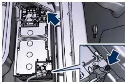
natural_image
Mechanical assembly diagram showing internal components with arrows indicating movement or force (no text or symbols present)The vehicle is equipped with a IBS (Intelligent Battery Sensor) sensor able to measure charging and discharging currents and to calculate the state of charge and state of health of the battery. This sensor is located in

Maintenance and Care
correspondence with the negative post (-) of the battery.
For a successful charge/recharge operation, the charging current must flow through the IBS sensor as shown in the picture.
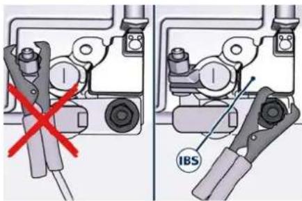
text_image
Technical diagram showing mechanical assembly with red X mark and IBS label, likely illustrating a valve or clamp mechanism.- Turn the charger on and follow the instructions on its user manual to completely recharge the battery.
- When the battery is recharged, turn off the battery charger before disconnecting it from the battery.
- Disconnect first the terminal clamp of the charger black cable from the battery and then the terminal clamp of the red cable.
- Reassemble the protection cover on the battery positive post and the access cover on the battery room.
Maintaining Battery Charge
If you perform short daily trips (approximately 16 km/10 miles), which correspond to an annual total of 6000 km/4000 miles, or when the vehicle is not going to be used for one week or more, Maserati recommends connecting the vehicle to a battery charger, to save you the trouble of having to recharge the battery. The battery charger will keep the battery charged properly and at the correct voltage levels required by the systems and devices in the vehicle.
Before using the battery charger, carefully follow the instructions provided.
If you do not use a battery charger to prevent the battery from going flat when you are not going to use the vehicle for long periods of time, you need to check and recharge the battery at least once every three weeks. Make this check if you perform short daily trips (approximately 16 km/10 mi) which correspond to an annual total of 6000 km/4000 miles.
Please note that allowing the battery to go flat repeatedly can cause premature wear on the internal cells and greatly reduce their life, leading to problems with the ignition system and other electrical/electronic systems.
The Service Network is available to advise you on how to recharge your battery correctly and give you useful information on battery care and maintenance.
NOTE:
The Maserati Service Network can provide you with any information about the Maserati approved "Battery Charger and Conditioner", available in the "Genuine Accessories" range.

WARNING!
The process of charging or recharging the battery produces hydrogen, a dangerous gas that can explode and cause serious injuries. When charging or recharging the battery, follow the recommended precautions at all times:
• always charge or recharge the battery in a well-ventilated environment;
- never charge or recharge a battery that has frozen: it can explode due to hydrogen trapped inside the ice crystals;
- ensure that any sparks or open flames are nowhere near the battery while it is charging;
- before using a charger to charge or maintain the battery charge status,
carefully follow the instructions provided to ensure the charger is connected to the battery safely and correctly.
A/C System Maintenance
For best performances, the air conditioning system should be checked and serviced by the Service Network at the beginning of the warm season.
This service should include cleaning of the condenser fins and a performance test. Drive belt tension should also be checked at this time.
During the winter, the air conditioning system should be operated at least once a month for about 10 minutes.

CAUTION!
Do not use chemical flushes in your air conditioning system as the chemicals can damage your air conditioning components. Such damage is not covered by the New Vehicle Limited Warranty.

WARNING!
- Use only refrigerants and compressor lubricants approved by the manufacturer for your air conditioning system. Some refrigerants are flammable and can explode, causing injuries. Other unapproved refrigerants or
lubricants can cause the system to fail, requiring costly repairs.
- The air conditioning system contains refrigerant under high pressure. To avoid risk of personal injury or damage to the system, adding refrigerant or any repair requiring lines to be disconnected should be done by an experienced technician.
Periodically remove any leaves and insects that may build up and obstruct the inlet of external air in the air conditioning system through the grille present underneath the rear part of the hood.
To access the grille, lift the hood as described in "Open and Close the Hood" in section "Before Starting".

Maintenance and Care
Wheels Maintenance
Tires Maintenance

CAUTION!
To obtain the best performances and the longest mileage from the tires, take following precautions during the first 500 km (310 mi):
- do not drive at the vehicle's maximum speed;
• drive at low speed on curves; - avoid sudden steering;
- avoid sudden braking;
- avoid sudden acceleration;
- do not drive at high speeds for too long.
The tires inflation pressure must correspond to the prescribed values (chapter "Tire Inflation Pressure" in section "Technical Specifications") and should be checked only when the tires have cooled down. In fact, the pressure increases as the tire temperature progressively increases. Never reduce the pressure if tires are hot (chapter "Tires Information" chapter in section "Safety").
Insufficient tire inflating pressure can cause tire overheating and possible internal damage, which may even lead to the tire destruction.

CAUTION!
After inspecting or adjusting the tire pressure, always reinstall the valve stem cap. This will prevent moisture and dirt from entering the valve stem, which could damage it.
Impacts with curbs, holes, and obstacles in the road, and prolonged trips on rough roads can cause tire damage which may not be visible to the naked eye.
Check your tires regularly for any signs of damage (e.g. scratches, cuts, cracks, bulges, etc.). If sharp objects penetrate the tires, they can cause structural damage which is only visible when the tire is removed.
In any case, any possible damage must be inspected by an experienced tire fitter, as it may seriously reduce the tire life.
Remember that tires deteriorate with time, even if used little or not at all. Cracks in the tire tread and sides, alongside possible bulging, are a sign of deterioration.

WARNING!
- Check the inflating pressure of the tires when cold, at least every two weeks and before long trips.
- Have the old tires inspected by an experienced technician, to make sure they can still be used safely. If the same tire has been on your vehicle for 4 or 5 years, have it inspected anyway by an experienced technician.
- Never fit tires of uncertain origin.
- "Directional" tires have an arrow on their side showing the rolling direction. To keep the best performance when replacing a tire, make sure that the rolling direction corresponds to the one shown by the arrow.
- During the tire life, the rolling direction used for the first fitting shall always be observed, also in case of "nondirectional" tires.
- Check the depth of the tire tread at regular intervals. The minimum allowed value is 1.6 mm (0.06 in) or 4 mm (0.16 in) for winter, all-season and snow tires, at that point the wear indicators on the tire will be visible (chapter "Tires
Information" in section "Safety"). The thinner is the tread, the greater is the risk of skidding.
- Drive carefully on wet roads to decrease the risk of aquaplaning.
Winter Tires
These tires are specially designed for driving on snow and ice and are fitted to replace the ones supplied with the vehicle.
The functions of these tires are significantly reduced in winter when tread depth is less than 4 mm (0.157 in). In this case, they should be replaced.
The specific functions of the winter tires lead to lower performance under normal environmental conditions or on long highway trips, compared to the standard tires.
Therefore, their use should be limited to the situations and performance for which they have been type-approved.
The Service Network can provide all necessary information about fitting winter tires on the vehicle.
NOTE:
- We recommend fitting winter tires on the vehicle at temperatures ^ (45°F) since the driving performance of summer tires is reduced at low
temperatures. Summer tires may be permanently damaged at extremely low temperatures.
- Comply with all state and local laws governing snow tire and tread depth requirements.
Wheel Rims Maintenance
All wheel rims should be cleaned regularly with a mild soap and water. To remove heavy soil and/or excessive brake dust, use a nonabrasive, non-acidic cleaner.
Do not use scouring pads, steel wool, a bristle brush, or metal polishes. Do not use oven cleaner that may involve and damage the brake calipers.
Avoid automatic car washes that use acidic solutions or harsh brushes that may damage the wheel rim protective finish.
Bodywork Maintenance and Care
Protection from Atmospheric Agents
The main causes of corrosion are:
• atmospheric pollution;
• salinity and humidity in the atmosphere (marine areas or a damp climate);
• seasonal environmental conditions;
- salt scattered on the roadbed to melt ice and snow.
The abrasive action of wind-carried atmospheric dust and sand, mud and stones should not be underestimated. On this vehicle, Maserati has adopted the best technological solutions to protect the bodywork from corrosion.
The main measures are:
- paint products and systems that give the vehicle particular resistance to corrosion and abrasion;
- use of galvanized (or pre-treated) metal sheets which are highly resistant to corrosion in the most exposed parts;
- spraying of the underbody, engine compartment, insides of wheel housings, and other structures with wax products having high protective power;

Maintenance and Care
- spraying of plastic materials, with a protective function, in the most exposed points: underneath the doors, inside part of the mud guards, edges, etc.;
- use of ventilated box sections, coated with protective wax products, to avoid condensation and trapped water which could encourage the formation of internal rust.
Useful Advice to Keep the Bodywork in Good Condition Paint
The paintwork does not only have an aesthetic function but also protects the underlying metal sheets. In the event of abrasions or deep scratches, we recommend to have the necessary touch-ups made immediately, to avoid any rust formation. Touch-ups do not function particular difficulties, even on metallic and matte finishes.
For all paint touch-ups, use only original products indicated on the plate applied on the lower left side of the hood.
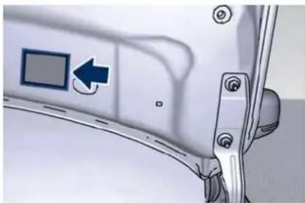
natural_image
Close-up of a car door panel with a blue square button and arrow indicator (no text or symbols)Normal paint maintenance consists in washing, the frequency of which depends on the conditions of use and of the environment. For example, if driving the vehicle in areas where there is high atmospheric pollution or the roads are spread with anti-freeze salt, it is advisable to wash the vehicle more frequently.

ENVIRONMENTAL!
Detergents pollute water. Therefore the vehicle should be washed in areas equipped for the collection and purification of the fluids used for washing.
NOTE:
The use of alcohol-based products for cleaning the metal plates in the engine compartment and/or the boot may deteriorate the painted surface. It is recommended to use water-based products and neutral surfactants.
Car Wash
For correct washing:
- wet the bodywork with a low pressure water jet;
• pass a sponge with a light detergent solution over the bodywork, frequently rinsing the sponge; - rinse well with water and dry with an air jet or chamois leather.
When drying, take particular care with the parts that are less visible, such as the door and lid bays, headlight edges, in which water can be trapped more easily.
You are recommended not to take the vehicle immediately into an enclosed environment, but leave it in the open air so as to allow the water to evaporate.
Do not wash the vehicle after it has been left in the sun or when the hood is hot: the paint gloss could be affected.
External plastic parts must be cleaned with the same procedure followed for the normal washing of the bodywork.
Avoid, as far as possible, parking the vehicle under trees; the resinous substances that very often drop
Maintenance and Care

from the trees give the paint a dull appearance and increase the possibility of originating corrosive processes. It is important that the drain holes in the lower sides of the doors, rocker panels, and trunk bottom be kept clear and open.

CAUTION!
- Bird droppings must be washed off immediately and thoroughly, since their acidity is particularly corrosive.
• To provide better protection for the paint, polish the vehicle at intervals with a suitable product leaving a protective film on the paint. - If the vehicle is washed using high-pressure water jets or cleaners, it is important that the nozzle of the jet be kept at a distance of at least 40 cm (16 in) from the bodywork to avoid damaging it.
Washing Vehicles with Matte Finish Paint
- It is recommended to hand wash vehicles with matte-finish paint.
-
Before washing, first remove from the bodywork dust and other particles that could damage the paint. Preferably use an air pressure jet.
-
When grease spots and fingerprints are present, it is recommended using a special cleaner for matte finish paint. Apply the product using a microfiber cloth. To avoid damaging the paint surface, do not use too much pressure.
- Wet the bodywork with plenty of water and clean it using a soft sponge and a neutral wax-free shampoo, starting from the top and working down. Dry the bodywork using an air pressure jet.
- Rinse all the parts of the vehicle thoroughly with plenty of water. Keep the sponge or the washing mitt in use always wet and clean.
- At last, using a different sponge or washing mitt, clean the wheels, the door sill plates and the other parts that are less visible.

CAUTION!
-
It is recommended not to wash the vehicle in direct sunlight. The little drops of water, acting as small focal lenses, could damage the paint.
• Always and only wash the vehicle by hand. Avoid using abrasive sponges or mitts that could damage the matte finish paint. -
Never polish and never use polishing agents on the vehicle with matte finish paint or on parts of it.
- Hard water (over 30 °C) could leave limestone residues.
Glass Surfaces
All glass surfaces should be cleaned on a regular basis with any commercial household-type glass cleaner.
Never use an abrasive type cleaner.
Use caution when cleaning the inside rear window equipped with electric defrosters. Do not use scrapers or other sharp instrument that may scratch the elements.
When cleaning the rear view mirror, spray cleaner on the towel or rag that you are using. Do not spray cleaner directly on the mirror.
Labels can be peeled off after soaking with warm water.
Keep all objects a safe distance from the window.
Cleaning Headlights
Your vehicle has plastic headlights that are lighter and less susceptible to stone breakage than glass headlights. Plastic is not as scratch resistant as glass and therefore different lens cleaning procedures must be followed.

Maintenance and Care
To minimize the possibility of scratching the lenses and reducing light output, avoid wiping with a dry cloth. To remove road dirt, wash with a mild soap solution followed by rinsing.
Do not use abrasive cleaning components, solvents, steel wool or other aggressive material to clean the lenses.
Condensation and Fogging on the Light Clusters
With cold or humid climate, after a driving rain or after cleaning the car, the surface of the front and rear light clusters could fog and/or form condensate drops on the inside. This is a natural phenomenon due to the temperature and humidity difference between the lens internal and external surface, which nevertheless does not indicate a fault and does not compromise the regular operation of the lights. The fogging/condensate disappear when switching on the lights, starting from the centre of the diffuser and going gradually to the edges.
Mouldings and Aluminium Trim
- For cleaning mouldings and aluminium trim, avoid the use of acidic or alkaniline cleaning agents
that can destroy the protecting surface treatment.
- After washing aluminium trim with warm water, apply the cleaning agent with a clean tissue or a soft sponge on the surface. Do not use any other equipment such as brushes, steel wool, abrasives or any other equipment for cleaning.
• After cleaning, please rinse the aluminium trim with a lot of clear water. - While cleaning in the car wash please make sure that the mouldings and aluminium trim only gets contact with soft brushes or textiles.
Engine Compartment
At the end of each winter season, carefully wash the engine compartment, remembering to avoid directing the jet of water for too long on the electric parts.
To perform this operation, you must contact the Service Network.
"Car Wash" Mode (if equipped)
To move the vehicle in tunnel washers, or generally move with engine off, you can use the following mode.
- Vehicle must be on level ground, stationary or moving up to 1 km/h (0.6 mph).
- If enabled, disable the automatic engagement function of electric parking brake (see "Parking Brake" in section "Starting and Driving").
- Shift the gearshift lever to N (Neutral).
- The brake pedal can be pressed or not pressed.
- Turn the engine off by pressing the START/STOP button for 5 seconds.
Through these steps, the driver's door must be closed. This condition will persist for about 25 minutes, the shift lever will switch to P (Park) once time has expired.
In case of low-battery voltage the shift lever can be placed in P (Park) before this time has expired.
NOTE:
It is also appropriate to disable the "Passive Entry" function from the MIA System so that the "Pre-Short Drop" function will not be activated. This can prevent water from entering in the passenger compartment during car washing.

WARNING!
- Performed this procedure the vehicle will stay in N (Neutral), rather without any brake. To avoid accidental movement, always check that the movement of the vehicle take place only on a flat surface.
- DO NOT USE this mode to haul the vehicle because after a period of time the shift lever will be placed automatically in P (Park) position. If this occurs when the vehicle is moving the transmission can be damaged. To haul the vehicle use the emergency manual park release (see "Transmission Manual Release of P (Park) Position" in section "In an Emergency").
Pre-Short Drop Function
When in a car washing, if the driver keeps the key fob in his/her pocket, or in any place outside the vehicle within 1 m (3.3 ft) distance, the front windows will perform a pre-short drop. This is a shorter drop compared to the normal short drop performed by the "Passive Entry" function when you grab the door handle to enter the vehicle.
In order to prevent water from entering the vehicle between the
upper edge of the glass window and the door outline on the bodywork, while the car is being washed, it is advisable to disable the "Passive Entry" from the MIA system, for further information refer to chapter "Functions of Settings Menu on MIA" in section "Dashboard Instruments and controls". When deactivating the "Passive Entry", also the "Pre-Short Drop" function will be disabled.
Interior Maintenance and Care
Interior trim should be cleaned starting with a damp cloth. Do not use harsh cleaners.
The leather upholstery can be best preserved by regular cleaning with a damp soft cloth. Small particles of dirt can act as an abrasive and damage the leather upholstery and should be removed promptly with a damp cloth. Stubborn soils stains can be removed easily with a soft cloth and appropriate products. Avoid soaking the leather upholstery with any liquid. Please do not use polishes, oils, cleaning fluids, solvents, detergents, or ammonia-based cleaners to clean your leather upholstery.
Application of a leather conditioner is not required to maintain the original condition.
Check at regular intervals that there is no water trapped under the mats (due to drips off shoes, umbrellas etc.) which may cause the metal parts to oxidize.

Maintenance and Care

CAUTION!
Do not use alcohol, petrol or solvents to clean the instrument cluster's transparent dome, the MIA display, the analogue clock and the leather upholstery. We recommended the use of "Car Care" products approved by Maserati for the maintenance and care of the interior.
Leather Upholstery Treatment
Have the leather upholstery only treated, as provided in the Scheduled Service Plan, by the Service Network which has the required specific products.
Parts in Premium Quality Wood
Remove any dirt with a buckskin leather or damp cloth.
NOTE:
The Service Network can provide you with any information about the Maserati approved "Car Care" products, available in the "Genuine Accessories" range.
Maserati Intelligent Assistant™ Touch Screen
- Do NOT attach any object to the touch screen, doing so can result in damage to the touch screen.
- Do not touch the screen with any hard or sharp objects (pen, USB stick, jewelry, etc.) which could scratch the touch screen surface. - Do not spray any liquid or caustic chemicals directly on the screen! Use a clean and dry micro fibre lens cleaning cloth in order to clean the touch screen. If necessary, use a lint-free cloth dampened with a cleaning solution, such as isopropyl alcohol, or an isopropyl alcohol and water solution ratio of 50:50. Be sure to follow the solvent manufacturer's precautions and directions.
NOTE:
The Maserati Service Network can provide you with any information about the Maserati approved "Microfiber Cloth", available in the "Genuine Accessories" range.
Car Cleaning and Sanitizing
According to what is prescribed by the health authorities in each country, after using the car it is necessary to clean all surfaces that may have been touched by other people (example: steering wheel, transmission lever, air vents, seat belts, keys, handles, etc.). To carry out this operation safely and correctly, trying to avoid possible damage to the internal surfaces of the car, here are some useful tips:
• perform the operation if possible outdoors or in any case in a sufficiently ventilated area;
- wear all personal safety devices: gloves, mask and goggles using new or sanitized devices;
- clean the surfaces with a microfibre cloth moistened with an alcoholic sanitizing solution, avoiding to apply or spray said solution directly on the surface. The use of hydrogen peroxide, bleach and amuchin is not recommended as they can develop too aggressive action on leather and plastic;
- check the air conditioning filter and sanitize the vents that circulate the air in the passenger compartment;
• vacuum the dust from the upholstery and the mats, or wash them with the appropriate detergent products.
A good habit to take, is to always have clean hands, both before and after driving, as it will help to keep the steering wheel and other surfaces more frequently touched inside cleaner car.
Vehicle Stored for Long Periods
If the vehicle is going to be stored for long period of time, you need to check first the battery charge status. After this check follow the below precautions:
- Wash and dry the vehicle thoroughly.
- Store the vehicle in a covered, dry and, if possible, ventilated area.
- Select P (Park) and turn off the engine.
- Check that the parking brake is NOT engaged.
- Disconnect the battery or connect a battery charger (refer to paragraph "Maintaining Battery Charge" of chapter "Battery Status and Maintenance" in this section).
- During parking, battery charge status must be carried out every three weeks. Recharge the battery if the open circuit voltage is lower than 12.2 V.
- Do not empty the engine cooling system
- Clean and protect the painted parts applying protective wax.
- Clean and protect polished metal parts with special products available on the market.
- Talc the windshield wiper blades and raise them from the windshield.
- Cover the vehicle with a long cloth in breathable fabric (available from the Service Network). Do not use thick plastic sheets, which do not allow the humidity on the vehicle surface to evaporate.
- Inflate the tires up to a pressure which must be 1 bar (14.5 psi) higher than the normally prescribed one, and check it at regular intervals.
NOTE:
The Service Network can provide you with any information about the available "Indoor and Outdoor Car Covers", available in the "Genuine Accessories" range.

WARNING!
The tire pressure must be brought back to the prescribed value before reusing the vehicle 📊 chapter "Tire Inflation Pressure" in section "Technical Specifications").
Restarting the Vehicle after a Long Inactivity
Before restarting the vehicle after a long period of inactivity, we recommend that you carry out the following operations.
- Check the tires for pressure and for any damages, cuts or cracks. If this is the case, have them replaced.
- Do not dry-rub the external surface of the vehicle.
- Visually inspect if there are any fluid leaks (oil, brake and clutch fluid, engine coolant etc.).
- Have the engine oil and filter replaced.
- Check the fluid levels in the brake system, as well as the engine coolant level.
- Check the air filter and have them replaced if necessary.
- Reconnect the battery after checking the charge status (refer to "Battery Status and Maintenance" in this section) and perform the initializing procedure if applicable.
- With the gearshift in N (Neutral), let the engine idle for several minutes.

Maintenance and Care

WARNING!
The engine idle must be performed outdoors. Exhaust gases contain carbon monoxide which is strongly toxic and potentially lethal.
Refillings Table
NOTE:
Maserati reserves the right to change or revise specifications without prior notification.

CAUTION!
To guarantee vehicle's integrity and maintain performance level Maserati recommends to use Maserati genuine products.
Refillings and Recommended Products
| Parts to be refilled Quantity Product specifications | ||
| Fuel tank | 80 litres/17.5 UK gal (including 16 litres/3.5 UK gal of reserve) | Premium unleaded fuel with no less than 95 RON/85 MON (91 CLC or AKI). |
| Engine (3.8 V8): oil capacity including filter cartridge | 8,3 litres/1.82 UK gal (max)(MIN - MAX difference: 1,4 litres/0.31 UK gal) | Synthetic multigrade lubricants SAE 5W-40 that meet API SL/CF and ACEA A3, B3, B4 specifications.Recommended oil: SHELL Helix Ultra Maserati 5W-40 (1). |
| Engine (3.0 V6): oil capacity including filter cartridge | 7,3 litres/1.61 UK gal (max)(MIN - MAX difference: 1 litre/0.22 UK gal) | Synthetic multigrade lubricants SAE 10W-60 that meet API SN/CF and ACEA A3, B3, B4 specifications. Recommended oil: SHELL Helix Ultra Maserati 10W-60 (2). |
| Engine (3.0 V6 AWD version): oil capacity including filter cartridge | 8,3 litres/1.82 UK gal (max)(MIN - MAX difference: 1 litre/0.22 UK gal) | |

Maintenance and Care
| Parts to be refilled Quantity Product specifications | ||
| Windshield washer fluid tank | 3,5 litres/0.77 UK gal | Mix of water and detergent fluid, in the proportions indicated on the product package. If the temperature is below -20°C (-4°F), use pure detergent fluid.Detergent fluid: Mix of CUNA NC 956-II surfactants and alcohols. Recommended fluid: WUERTH Windshield Washer Fluid with antifreeze or AREXONS DP1. |
| Engine cooling circuit (3.8 V8) | 14,2 litres/3.13 UK gal (for dual-zone air conditioning system)15 litres/3.3 UK gal (for four-zone air conditioning system) | Mixture of water and coolant, proportionally 50/50%.Coolant: protective, antifreeze action and ethylene glycol-based with organic inhibitors compatible with regulations:ASTM D 3306, ASTM D 2570ASTM D 4340, ASTM D 2809SAE J 1034CUNA NC 956/16.Recommended fluid: PETRONAS Paraflu UP (1681). |
| Engine cooling circuit (3.0 V6 and 3.0 V6 AWD version) | 9,2 litres/2.03 UK gal (for dual-zone air conditioning system)10 litres/2.2 UK gal (for four-zone air conditioning system) | |
| Automatic transmission cooling circuit | 2,5 litres/0.55 UK gal | |
| (3) Automatic transmission | 7,6 litres/1.67 UK gal | First equipment oil: SHELL ATF L- 12108 or ZF Lifeguard 8. |
| (3) Differential | 1,3 litres/0.28 UK gal | Synthetic Axle Lubricant SAE 75W-90 – FE Hypoid Gear Lubricant. |
| (3) Front differential (3.0 V6 AWD version) | 0,45 litres/0.10 UK gal | First equipment oil: SHELL TF 0951B. |
| (3) Transfer case (3.0 V6 AWD version) | 0,62 litres/0.14 UK gal | First equipment oil: SHELL TF 0870. |
| Braking system | 0,88 litres/0.19 UK gal +/-4% | Synthetic fluid: FMVSS 116 DOT 4, ISO 4925 Class 4, ENSAYOS INTA-UNE 26-109-88, SAE J1703, SAE J1704, CUNA NC 956-01. Recommended fluid: PETRONAS Tutela TOP 4/S.CAUTION!For each oil refilling and/or replacement, please contact the Service Network. |
| Air conditioning system | dual-zone: 620 g +/-20 g1.367 lb +/-0.044 lb (r1234yf);680 g +/-20 g1.5 lb +/-0.044 lb (r134a)four-zone: 780 g +/-20 g1.72 lb +/-0.044 lb (r1234yf);870 g +/-20 g1.92 lb +/-0.044 lb (r134a) | Coolant: r1234yf (for the European market).r134a (for the other markets). |
| 180 ml / 6.33 oz First equipment oil: Daphne Hermetic Oil PS-D1 (3) | ||
| (1) In countries where it is not available, recommended oil "SHELL Helix Ultra 5W-40".(2) In countries where it is not available, recommended oil "SHELL Helix Ultra 10W-60".(3) No change and/or topping up expected in scheduled maintenance. | ||

Maintenance and Care
Index

Index
Abbreviations 8
Active Blind Spot Assist - ABSA .. 240
Radar Device - Regulatory
Information 243
RCP - Rear Cross Path
Operation 243
Speed Range of Use ..... 241
System Availability 240
System in Faulty 243
System Limitation 241
System Monitoring on TFT
Display 242
System Setting 241
System Temporarily
Unavailable 243
Active Driving Assist - ADA ..... 244
Hands Detection on Steering
Wheel 246
Monitoring on TFT Display . . . 245
Radar Device - Regulatory
Information 248
Speed Range of Use ..... 245
System Cancellation ..... 247
System Disengage ..... 247
System Limitations ..... 248
System Operation 245
System Statuses 246
Adaptive Cruise Control - ACC .. 218
Activation/Deactivation ..... 220
Changing Speed Setting ..... 222
Conditions for Disabling and
Deactivation 222
Display Warnings and
Maintenance 225
Displayed Information ..... 219
Driver Override 222
Overtake Aid 224
Precautions while Driving with
ACC 226
Radar Device - Regulatory
Information 227
Resuming Speed 223
Setting the Speed 221
Setting the Time Gap ..... 223
Speed Range of Use ..... 220
System Controls and Activation
Conditions.... 220
System Operation Before and
During Stop 224
Temporary Deactivation ..... 222
Warnings and Cautions ..... 218
Adjustable Pedals 27
Air Conditioning Control
Dual-zone Controls ..... 146
Air Conditioning Controls ..... 146
A/C Filter 156
Automatic Temperature
Control (ATC) 152
Dual-Zone Climate Control
Functions 151
Four-zone Controls ..... 153
Operating Tips.... 156
Air Conditioning Distribution .... 54
Adjustable Air Vents 56
Fixed Air Vents 56
Air Conditioning System
Maintenance 303
All-Wheel Drive 174
Analog Clock 142
Audio System 46
Automatic Headlights ..... 135
Automatic Start&Stop System...162
Automatic Restarting of the
Engine 163
Occupant Safety Function .... 163
Start&Stop Deactivated ..... 162
Start&Stop Function Disabling
Indicator 164
Start&Stop Not Active ..... 163
Start&Stop System Failure....165
Automatic Transmission ..... 165
Automatic Transmission
Lever 166
Automatic Transmission
Range 169
Service Shift Lever 169
Transmission Malfunction and
Overheating Conditions ..... 173
Auxiliary Jump-Start Procedure .. 276
Battery Remote Posts
Position. 277
Jump Start Procedure ..... 277
Battery Status and Maintenance 298
Battery Recharge ..... 301

Index
Battery State of Charge ..... 298
Maintaining Battery
Charge 302
To Disconnect the Battery . . . . 298
To Reconnect the Battery . . . . 299
Useful Advice to Extend
Battery Life 300
Blind Spot Assist - BSA 235
BSA and RCP Setting ..... 238
Radar Device - Regulatory
Information 239
RCP - Rear Cross Path ..... 238
System Monitoring on TFT
Display 237
System Operation 235
Bodywork Maintenance and Care 305
Pre-Short Drop Function ..... 309
Protection from Atmospheric
Agents 305
Useful Advice to Keep
the Bodywork in Good
Condition 306
Boot Compartment
Open and Close the Boot Lid .. 81
Cargo Area 48
Loading with Rear Seatback
Down 49
Vehicle Load Carrying
Capacity 48
Vehicle Loading 48
Comfort Luxury Rear Seats ..... 22
Central Console Functions .... 23
Instrument Panel on the Rear
Central Console 23
Reclining Shelf Rear
Accessories 24
Seat Setting Devices ..... 22
Consulting the manual 7
Controls on Steering Wheel . . . . 129
Audio System Controls ..... 131
Phone and Voice Controls .... 129
Cruise Control - CC 215
Activation 216
Changing Speed Setting ..... 217
Controls 215
Displayed Information ..... 216
Driver Override 217
Resume Speed 217
Setting Desired Speed ..... 216
Speed Range of Use ..... 216
Temporary Deactivation ..... 217
Using Cruise Control on
Hillsides.... 217
Drive Away Inhibit strategy .... 194
Drive Mode 175
Controls Preview 175
I.C.E. Mode excluding ESC .... 188
Setting the Drive Mode ..... 176
Driving Conditions 200
Before the Trip 200
Safe Driving 200
Sections.... 202
Emergency Release of the
Parking Brake 273
Engine Overheating 261
Example to modify the "Speed
Warning" status 101
External Light Cluster 30
External Lighting 30
Automatic High Beam ..... 33
External Lights Equipment .... 30
Full-LED Headlight with AFS . . . 32
High Beam with "Glare Free"
Function 34
SmartBeam System.... 31
Fog Lights 136
Forward Collision Warning - FCW
Limited Operation and Service
Warning 231
Radar Device - Regulatory
Information 231
Speed Range of Use ..... 229
System Operation 228
System Setting 230
System Status 230
Forward Collision Warning FCW.228
Pedestrian Emergency Braking
(PEB) System 228
Freeing the Stuck Vehicle ..... 275
Front Seats 15
Front Heated Seats.... 16
Front Power Seats 15
Front Ventilated Seats ..... 18
Index

Functions of Controls Menu on MIA 118
Functions of Settings Menu on
MIA 119
Audio 126
Camera 123
Clock & Date 122
Display 120
Doors & Locks 125
Geolocation.... 128
Key Off Options 126
Lights 124
Mirrors & Wipers 124
Navigation 123
Notification 127
Phone/Bluetooth 123
Radio Setup 127
Reset.... 128
Safety and Driving
Assistance 121
Seat & Comfort 125
Software Updates 128
System Information ..... 128
Voice 123
Glove Box Compartments ..... 142 Privacy Lock Functions ..... 143
Hazard Warning Flashers ..... 253
Headlight Time Delay ..... 136
Headlights On with Wipers ..... 135
Help and Assist Call 255
HomeLink ^® 50
Before You Start Programming HomeLink ^® 50
Radio Frequency Transmitter - Regulatory Information ..... 53
Security 53
System with Devices Provided with Rolling Codes .... 51
System with Devices Without Rolling Code 52
Troubleshooting Tips ..... 53
Using HomeLink 52
If a Fuse Blows 266
Fuse Box under the
Dashboard.... 271
Integrated Power Module . . . 267
Position of Fuses 267
Rear Power Distribution
Center 269
Used Fuses Characteristics . . . . 266
Illuminated Entry/Exit Light Dimmer Controls ..... 65 Use of Light Switch for Vehicle Lighting ..... 64
In case of a Punctured Tire ..... 261
Using the Compact Spare Wheel 262
Using Tire Repair Kit ..... 261
In Case of External Lights Fault Signal 272
In the Event of an Accident .... 254 Emergency Kit .... 254
First Aid Kit 254
In case of Injured Persons . . . . 254
Instrument Cluster Overview .... 90
Integrated External Rear View Mirror Lights 31
Interior Lighting 36
Cargo Lights 37
Dome Lights 36
Interior Maintenance and Care .. 309 Car Cleaning and
Sanitizing 310
Leather Upholstery Treatment 310
Maserati Intelligent Assistant™
Touch Screen 310
Parts in Premium Quality Wood 310
Internal Equipment 37
Cup Holders.... 39
Electric Power Outlets ..... 37
Handholds and Cloth Hooks . . . 45
iPad Holder (Genuine Accessories) 46
iPod ^® Connection 43
Map Pockets 45
Multimedia Port and Wireless Charger Compartment ..... 41
Removable Ashtray and Lighter (OPT) 44
Sun Visors 44
Tables (OPT, not for sport seats) 45

Index
Keys 60
Key fob 61
Keyless Ignition Device ..... 60
Shift Ignition Device to OFF Alert 61
Lane Keeping Assist - LKA
Customised Settings ..... 232
Function Description and Operating Mode 233
Radar Device - Regulatory Information 235
Speed Range of Use 232
System Availability 232
System in Faulty 234
System Limitations 234
Lane Keeping Assist-LKA ..... 231
Launch Control Mode (TROFEO version only) 188
Lights Controls.... 132 Light Switch.... 132
Position Lights and Daytime Running Lights (DRL) ..... 135
Main Controls Overview ..... 12
Between the Rear Seats ..... 14
On Central Console 12
On Dashboard 12
On Front Dome Console ..... 13
On Front Doors 13
On Rear Dome Console ..... 14
On Rear Doors 15
Maintenance Procedures ..... 291
A/C System Air Filter Replacement 295
Engine Air Filters Replacement 295
Level Checks 291
Windshield Wiper Maintenance and Blades Replacement .... 296
Maintenance Service Components 289
Manual Headlights 136
Maserati Intelligent Assistant™
Operation 114 Customising the Main Status and Category Bar 117
Main Category Bar on MIA Display 116
Main Status Bar on MIA Display 115
Manual Controls and Devices 114
Memorize the Driver's Seat Position 19 Easy Entry/Exit Seats ..... 20
Memory Position Recall ..... 20 Memory Profiles Setting ..... 19
Pairing Remote Keyless Entry Transmitter to Seats Memory 19
Menu Overview 94
Normal Starting of the Engine .. 158
"Panic Stop" Strategy ..... 160
Engine Start Failure ..... 159
Engine Turn Off.... 159
On-board Documentation Kits . . . . 6
Open and Close the Boot Lid Boot Lid Emergency Release . . . 86 Power Boot Lid/Hands Free Operation . . . . . . . . . . . . . . . . . . . . . . . . . . . . . . . . . . . . . . . . . . . 82
Open and Close the Hood ..... 86
Owner's Information Online ..... 7
Park Assist 206
Cleaning the Park Assist Sensors 210
Enabling and Disabling Park Assist 209
Park Assist Sensors ..... 206
Park Assist System Usage Precautions 210
Park Assist Volume ..... 210
Park Assist Warning Messages Display 207
Service the Park Assist System 209
Parking 193
Parking Brake 189
Deactivating Automatic Operation 191
EPB Operation with
Overheated Brakes.... 193
Failure Indication ..... 192
Manual Engagement/ Disengagement ..... 190
Index

Passive Entry System.... 68
Manual Door Lock from Outside 71
Preventing Inadvertent Locking of key fob Inside the Vehicle . . 69
Radio Frequency RKE Transmitter - Regulatory Information 72
Release the Lid and enter the Boot 71
Unlock Door from the Driver Side 68 Unlock Door from the Passenger Side 69
Phone Mode Button 130
Power Sunroof with Sunshade . . . 78 Closing and Opening the Power Sunroof with Key fob and Ignition Off . . . . . . . . . . . . . . . . . . . . . . . . . . . . . . . . . . . . . . . . . . . . . . . . 79
Ignition Off Operation ..... 79 Pinch Protect Function ..... 79
Slide Opening Sunroof ..... 78 Sunroof Maintenance..... 79
Venting Sunroof 79 Wind Buffeting 79
Power Sunshade on Rear Door Windows 74
Power Windows....72 Auto Down Function....73
Auto-Up Function with Anti-Pinch Protection 73
Open and Close the Windows and Sunroof with Key fob and Ignition Off 74
Rear Window and Sunshade Lockout Button 74
Reset Auto-Up/Down ..... 73
Wind Buffeting 74
Rear Parking Camera 211
Rear Seats 21 Rear Armrest 21
Rear Side Heated Seats ..... 21
Rear View Mirrors 28
Rear Window 80 Power Sunshade 80 Rear Window Defroster 80
Rear-View Mirrors External Mirrors.... 28 Internal Rear-View Mirror.... 30
Refillings Table 313 Refillings and Recommended
Products 313
Refuelling 198 Emergency Fuel Filler Door
Release 199
Fuel Filler Neck Access ..... 198
Refill the Tank 198
Remote Start System ..... 160 Requiring and setting Additional
Key Fobs 66 Key Fob Battery
Replacement 66
Radio Frequency RKE Transmitter 68
Restarting the Vehicle after a Long Inactivity 311
Scheduled Maintenance Service . 282 Interval Running Coupons . . . 282 Scheduled Maintenance (Service) Indicator ..... 282
Scheduled Service Plan ..... 283 Heavy-Duty Vehicle Use ..... 288
Main Operations/Service Coupons (NOT valid for Japan market).... 284
Main Operations/Service Coupons (Valid for Japan market) 286
On-Board Diagnostics (OBD) 288
Periodic Maintenance ..... 288 Spare Parts ..... 288
Siri Smart Personal Assistant .... 131
SOS-Emergency Call Function (Russian market only) ..... 258
Spare Parts 197
Steering Wheel Adjustment ..... 25 Heated Steering Wheel ..... 25
Surround View Camera System 212
TFT Display Areas 91
TFT Display Pop up Messages .... 92

Index
TFT Display Setting and Menu Overview 93
TFT Display: Menu and Submenu Content 97
Tool Kit 252
Towing a Disabled Vehicle ..... 278 Manual Release of Transmission ..... 279 Use the Tow Hook Included in the Tool Kit ..... 280 Vehicle Towing Conditions ... 279
Traffic Sign Assist - TSA ..... 248
Traffic Sign Assist – TSA Customised Settings ..... 249 Signs Monitoring on Instrument Cluster ..... 249 System Limitations ..... 250
Transmission Manual Release of P (Park) Position 274
Unlock the Vehicle with Key Fob . 65 Unlock the Boot Lid ..... 66 Unlock the Doors, Fuel Filler Door and Boot..... 65
Updating 6
Use of the Engine 196
Breaking-In 196
Gasoline Particulate Filter - GPF 197
On-Board Diagnostics (OBD) 196
While Driving 196
Using the Brakes 195 Brake Overheating 195 Brake Pads and Brake Discs 195 New Brake Pads and/or Brake Discs 195
Vehicle Stored for Long Periods ..... 311 Voice Recognition Button ..... 130
Warning and Indicator Lights . . 103 Warning and Indicator Lights on Speedometer . . . . . . . . . . . . . . . . . . . . . . . . . . . . . . . . . . . . . . . . . . . . . . . . . . . . . . . . . . . . . . . . . . . . . . . . . . Warning and Indicator Lights on Tachometer . . . . . . . . . . . . . . . . . . . . . . . . . . . . . . . . . . . . . . . . . . . Warning and Indicator Lights on TFT Display. . . . . . . . . . . . . . . . . . . . . . . . . . . . . . . . . . 107 Wheels Maintenance. 304 Tires Maintenance. 304 Wheel Rims Maintenance. 305
Wipers and Washers Headlight On with Wipers . . . 140 Wipers and Washers Control . . . . 139 Rain Sensing Wipers . . . . . . . . 140 Windshield Washers . . . . . . . . 141 Windshield Wipers . . . . . . . . 139 Wipers Blades Maintenance . . . . . . . . . . . 141

Because of the evolutions of the MASERATI products, which are continually developed and perfected, MASERATI S.p.A. reserves the right to make modifications to this manual as well as to the technical contents, functions and equipment of the vehicles delivered.
Therefore, the user is not entitled to any claims based on the contents (texts, data, illustrations, explanations and regulations) in this manual, which are based on the data known at the time of going to print.
Publication no. 910043521 - 1st Edition - 05/2021
This document may not be reproduced, printed or translated, even partially, without the written consent of MASERATI S.p.A.


Maserati
WWW.MASERATI.COM
MASERATI SPA · VIALE CIRO MENOTTI, 322 · I-41121 MODENA