
EWE361KX-DWB5 - Chauffe-eau et ballon d'eau chaude ELECTROLUX - Free user manual and instructions
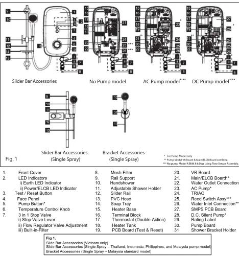
Find the device manual for free EWE361KX-DWB5 ELECTROLUX in PDF.

| Product Type | Instantaneous Electric Water Heater |
| Brand | Electrolux |
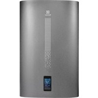
| Model | EWE361KX-DWB5 |
| Dimensions (W x H x D) | 220 x 401 x 90 mm |
| Net Weight | 1.5 kg (No Pump), 2.0 kg (DC Pump), 2.5 kg (AC Pump) |
| Power Supply | 220-240 V AC, 50/60 Hz |
| Power Rating | 2.4 kW to 6.0 kW (depending on model) |
| Minimum Water Flow Rate | 2.0 L/min (2.2 L/min for 4.8 kW, 2.5 L/min for 6.0 kW) |
| Maximum Water Pressure | 6.0 bar (0.6 MPa) |
| Water Connection | 1/2" BSP single point |
| Safety Features | Built-in ELCB (Earth Leakage Circuit Breaker), Double-action thermostat, Automatic cut-off at over 15 mA leakage, Dry burn protection |
| Handshower Spray Patterns | 5 patterns: Standard, Jumbo, Soothe, Mix, Marriage |
| Pump Type | AC pump or DC pump (model dependent); also available without pump |
| Installation Requirements | Minimum 1.5 m above floor; hardwired via double-pole switch; earth connection mandatory |
| Maintenance | Test ELCB monthly; clean mesh filter regularly; clean handshower holes weekly |
| Included Accessories | Handshower, Slider rail, Shower holder, Soap tray, PVC hose, 3-in-1 stop valve |
Frequently Asked Questions - EWE361KX-DWB5 ELECTROLUX
User questions about EWE361KX-DWB5 ELECTROLUX
0 question about this device. Answer the ones you know or ask your own.
Ask a new question about this device
Download the instructions for your Chauffe-eau et ballon d'eau chaude in PDF format for free! Find your manual EWE361KX-DWB5 - ELECTROLUX and take your electronic device back in hand. On this page are published all the documents necessary for the use of your device. EWE361KX-DWB5 by ELECTROLUX.
USER MANUAL EWE361KX-DWB5 ELECTROLUX
3.1 Select a suitable position in the bathroom.
3.2 Remove the screw (A) at the bottom of the Electric Water Heater. (Fig. 2)
3.3 Remove the Front Cover from the bottom and then lift up the front cover.
3.4 Mark 3 Screw points of the Heater Base on the wall. The Electric Water Heater position should be 1.5m above the bathroom floor. (Fig. 2)
3.5. Slider Bar Accessories: Mark 2 screw points of the Slider Rail beside the Electric Water Heater.
It is recommended that the top of the portion is in level with the top of Electric Water Heater. (Fig. 3 & 3a)
Bracket Accessories: Open the Shower Holder cover, mark 2 screw point of the Shower Holder beside the Electric Water Heater. It is recommended that the top of the portion is in level the top Electric
Water Heater. After screw the Shower Holder, put back the shower holder cover. (Fig. 3b)
3.6 Use 6mm diameter drill and make the wall plug holes in depth of 34mm, for mount the Electric Water Heater.
3.7 Insert the wall plugs and mount the Electric Water Heater firmly in position with the screws provided
3.8 Insert the Shower Holder and Soap Tray into the Slider Rail
3.9 Insert the Rail Bracket to both end of the Slider Rail Bar
3.10 Remove the cap from the Rail Bracket and screw the Bracket to marked position.
Replace the cap. (Fig. 3)
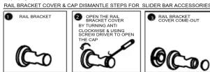
Fig. 3C
- PARTS IDENTIFICATION
-
PLUMBING PROCEDURE
4.1 Connect the 3 in 1 Stop Valve to the Water Inlet with washer. Use correct tools to tighten and be careful not to over tighten and damage the plastic nut.
4.2 Connect the incoming water piping to the 3 in
1 Stop Valve (1/2" BSP).
Make sure to put the Mesh Filter between 3 in 1 Stop Valve and incoming water piping.
4.3 If in any case, the 3 in 1 Stop Valve is not use c
omitted, make sure to put the Mesh Filter between the Electric Water Heater inlet pipe
between the Electric Water Heater inlet pipe and incoming water pipe.
4.4 Turn on the water mains to drain out all plumb
dirts before connecting the water supply to the Electric Water Heater, the water supply to the
Electric Water Heater, the water supply to the Electric Water Heater must be free from mud a
dirt.
WARNING!
5.1 This Electric Water Heater must be earthed. Improper grounding could cause
cattered, improper grounding could cause electrical shock.
5.2 Remember to SWITCH OFF the power supply before carrying out any electrical work
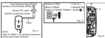
supply before carrying out any electrical work. 5.3 Refer to TABLE 1 for the correct cable size.
5.4 Use double insulation cable of over 2.5mm ^2 for 2.4kW, 2.5kW, 2.8kW, 4.5kW, 4.8kW models
for 2.4kW, 3.5kW 3.8kW, 4.5kW 4.6kW models and 4mm² for 3.6kW and 6.0kW model.
5.5 Lead the power cable from MCB to a
"ON/OFF" double pole Linked Switch having a contact separation of at least 3mm in all poles.
outside the bathroom, then lead a cable to the
terminal block inside the Electric Water Heater. (Fig. 4)
FIG. 4 PROCEDURE
5.6 Insert the wall embedded cable through
Side Entry 'A' by cutting a hole at the source cord rubber holder and lead the cable to
Cable Bracket 'B'. (Fig. 6)
Always KEEP the water supply to the Electric Water
Heater free from mud and dirt at all time during usage
IMPORTANT
THE HEATER TANK MUST BE FILLED UP WITH
WATER BEFORE TURNING ON THE POWER SUPPLY TO PREVENT ANY DRY PURNT DAMAC
SOPPLE TO PREVENT ANY DRY BORNT DAMAS TO THE HEATING ELEMENT.
4.5 Connect the Hose and Handshower to the
outlet of Electric Water Heater, be sure to put in the
Washer in between the connection. (Fig. 2)
4.6 Hook the Handshower to the Slider Rail
Shower Holder and adjust to your ideal position 4.7 Check if www.waterlookers
4.7 Check if any water leakage 4.8 Do not use sealing tape du
No. 20 not and sealing tape during piping installation.
WARNING!
4.9 THE WATER INLET AND OUTLET MUST BE
INSTALLED CORRECTLY, OTHERWISE ELECTRIC WATER HEATER WILL NOT FUNCTION
4.10. DO NOT APPLY PLUMBING CEMENT ON
4.10 DO NOT APPLET PLUMBING CEMENT ON CONNECTION WHENEVER NECESSARY USE
ONNECTION. WHENEVER NEEDS ONLY THREAD OR SEALING TAPE.
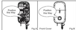
5.7 Connect the cable as following: (Fig. 5)
BROWN OF RED --LIVE (L) BLUE or BLACK --NEUTRAL (N)
GREEN or GREEN/YELLOW --EARTH (⊕)
5.8 Clamp the cable to the correct position
Technician need to confirm the wire before installation.
CHECK IF THE WIRING CONNECT CORRECT and replace the cover
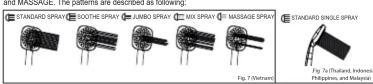
5.9 When putting back the Front Cover
please take note of the procedure shown below
-Ensure the position is correct, turn the Temperature Control Knob Insert to OFI
position as shown in Fig.A (At the Heater Base)
Install the Front Cover, turn the Temperature Control Knob to OFF position to align with the
VR shaft as shown in Fig.B (At the Front Cover)
5.10 Fix the Temperature Control Knob and screw 'A' (Fig. 2). -
ELECTRICAL INSTALLATION
1
2. SAFETY INFORMATION
WARNING!
2.1 Products manufactured by Electrolux are safe provided they are installed, used and maintained in good working order in accordance with our instructions and recommendations. Always refer to this manual if you have any doubt.
2.2 The Electric Water Heater must be earthed. Improper grounding could cause electrical shock
2.3 If any of the following conditions occur as shown below, immediately switch off the power supply and contact the Electrolux Consumer Care Center. Never attempt to repair the Electric Water Heater yourself:
. If the Electric Water Heater begins to make an odd noise, smell or smoke. . If ELCB trips and Electric Water Heater Indicator does not light up.
- Water temperature cannot be controlled. - If the Electric Water Heater shows signs of a distinct change in performance.
- If water leaks from inside. 2.4 If the Red (POWER) Indicator does not go off when you turn off the water, switch OFF the mains supply and contact Electrolux Consumer Care Centre for repair service. Special skill is
required for repairing
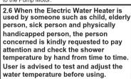
NEVER try to repair the unit by yourself. 2.5 For Pump Model, it is highly recommended to connect the Water Inlet Connection to tank storage supply, otherwise it may cause damage to the Pump Motor.
2.7 During lightning/thunder, switch off the power supply to the Electric Water Heater in advance to protect the Electric Water Heater against possible damage.
2.8 The earth continuity conductor of the electrical installation must be effectively connected to all exposed metal parts of other appliances and services in the room, which in the Electric Water Heater is to be installed to conform to local regulations and ensure proper earthing/grounding for ELCB to be effective.
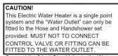
2.9 WARNING: Metallic / chromed hose and conductive control valve shall not be used.
NOTE: When removing the Electric Water Heater from package, a small amount of water may be found inside. This is normal as the Electric Water Heater is tested during manufacturing process.
CAUTION
2.10 Installation must be carried out by a qualified personnel and in compliance local authority regulations.
2.11 This Electric Water Heater must be permanently connected to the direct main line supply. A plug and socket is not recommended to be used.
2.12 For the correct size of wire conductor corresponding to different electrical loadings, please refer to Table 1.
2.13 This Electric Water Heater operates at a minimum water flow rate of 2.0 litre/min (2.2 €/Min for 4.8kW & 2.5 €/min for 6.0kW model only) and maximum working pressure of 6 bars. For direct connection from the water tank, the Electric Water Heater must have an installation minimum 1.0mbelow the water tank.
2.14 The Electric Water Heater will not function if there is insufficient water flow (min 2.0 litre/min / 2.2 €/Min for 4.8kW & 2.5 €/min for 6.0kW model only) to trigger the flow switch.
2.15 The built-in ELCB will automatically cut off the power supply in case there is a current leakage over 15mA.
2.16 The thermostat will automatically cut off the power supply if it has sensed an abnormal rise in water temperature.
2
- ELECTRICAL INSTALLATION (CONT'D)
METHOD OF ALIGNMENT WHEN REPLACING FRONT COVER
6. TABLE 1 - CABLE SIZE TABLE
| Voltage (AC) | Power (kW) | Current (A) | Conductor Size (csa) | On/ Off Switch (A) | Fuse / MCB (A) | ||
| mm3 | Conduit Cable | Flexible Cable | |||||
| 220V ~ 50/60 Hz | 2.4 | 10.9 | 2.5 | 7 / 0.87mm | 50 / 0.25 mm | 20 | 20 |
| 3.5 | 15.9 | 2.5 | 7 / 0.87mm | 50 / 0.25 mm | 20 | 20 | |
| 3.8 | 17.3 | 2.5 | 7 / 0.87mm | 50 / 0.25 mm | 20 | 20 | |
| 4.5 | 20.5 | 2.5 | 7 / 0.87mm | 50 / 0.25 mm | 32 | 32 | |
| 4.8 | 21.8 | 2.5 | 7 / 0.87mm | 50 / 0.25 mm | 32 | 32 | |
| 6.0 | 27.3 | 4.0 | 7 / 0.85mm | 56 / 0.30 mm | 32 | 32 | |
| 240V ~ 50/60 Hz (Malaysia Model) | 3.6 | 15.0 | 4.0 | 7 / 0.85mm | 56 / 0.30 mm | 20 | 20 |
4
5
7. TEST RUN
7.1 Tum on the water supply and 3 in 1 Stop Valve, the water will flow through the Handshower.
7.2 Switch on the power supply. The 3 LED Indicator light shall run ON/OFF 3 times in sequences to indicate the set are self checking.
If the Electric Water Heater is not earthed properly, the Earth Led indicator light will OFF, during usage or standby. Earth Led indicator light also OFF if Live & Neutral reverse connection.
7.3 Turn the Temperature Control Knob to 'ON', the Red indicator light (HEATER POWER) will turn on, (ELCB/Power Led indication are combine Led indicator light- ELCB is GREEN & Power is RED) hot water will flow out within a few seconds. The more Temperature Control Knob being turned in clockwise direction, the hotter is the water.
7.4 The Electric Water Heater might not be hot enough even at the 'MAX' position if incoming water supply from the mains is too cold or the pressure of water is too high. In this case, you may adjust the 3 in 1 Stop Valve to reduce the water inflow in order to get the desired showering temperature.
(Recommended flow rate of below 6 litre/min) 7.5 Check the Buill-in ELCB as following: - Press the "TEST" Button, the Buill-in ELCB should trip and cut off the power supply, ELCB and Power Indicators should light off. -Press the "RESET" Button, the 3 LED Indicator light shall run ON/OFF 3 times in sequences to indicate self checking as in 7.2 above and the Electric Water Heater should resume normal function, the Green LED Indicator should light on. If procedures stated above prevailed, the ELCB is functioning in normal condition.
7.6 The height and direction of Shower Holder are adjustable by releasing the shower holder knob clockwise and anticlockwise.
7.7 Move the Handshower to the desired angle. A ratchet mechanism in the Shower Holder will hold the Handshower in selected position.
7.8 It is unnecessary to turn the Temperature Control Knob to "OFF" position when the Instant Hot Shower is not in use.
7.9 Switch OFF the power supply after shower.
7.10 For Pump model: The pump will auto ON when power and 3 in 1 stop valve open (and there is water supply) 7.11 Booster Pump Function: After incoming power supply is ON, and water supply flow through 3 in 1 stop valve while open position but the water flow rate is not sufficient to activate the flow sensor. Booster Pump function can be useful to increase the incoming water flow rate. Press the pump button to activate the booster pump function. The booster pump function will be ON to increase the incoming water flow rate. While the Booster Pump Function is working and the incoming water flow rate can be maintained above flow sensor activation level, the Electric Water Heater will be resumed working continuously as normally. If the incoming flow rate can not be maintained above flow sensor activation level, the Booster Pump Function will be auto OFF and the Electric Water Heater will not be able to function normally due to increasing flow rate is too low. (Adriable to avoid applying Booster Pump Function to increase the incoming water flow rate more than 3 times of each showering).
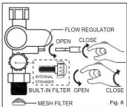
8. HANDSHOWER SPRAY
This Innovative adjustable Handshower has 5 different spray patterns (STANDARD, JUMBO, SOOTHE, MIX and MARRAGE). The pattern are described as following:
Clean the Handshower Head holes by using the soft brush from time to time. (Recommended once a week) Note: Take care not to damage the holes of the Handshower Head during cleaning.
9.MAINTENANCE
Read the section ' SAFETY INFORMATION' first. 9.1 TEST THE 'ELCB' REGULARLY (This procedure is highly recommended test at least once a month) Turn on the power supply and water supply, both Red (HEATER) and Green (ELCB) Indicators will light up if the Temperature Control Knob is in 'ON' position. Press the ELCB Test Button, both HEATER and ELCB Indicators should go off. Press the Reset Button to resume the power supply.
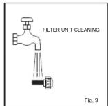
9.2 CLEAN THE FILTER REGULARLY Clean the Mesh Filter regularly to prevent blockage (Fig. 8). Remove the Built-in Filter by turning its cap anticlockwise. Whenever need
flush the internal stainer with water to remove any trapped sediments. Whenever fixing back the Built-In Filter, beware of the alignment of Internal Strainer. Use the protruded guideline within Stop Valve to position the Internal
Strainer. WARNING! 9.3 If the Red (POWER) Indicator does not go off when you press the ELCB Test Button, switch OFF the mains supply and contact Electrolux Consumer Care Centre for repair service. Special skill is required for repairing. NEVER try to repair the unit by yourself. 9.4 CLEANING PRECAUTION! Do not use thinner, alcohol, petrol or any other organic solutions to clean the set. Use only damped cloth with mild detergent.
6
10. WIRING DIAGRAM (CON'D)
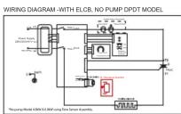
* Thermostat Manual Reset (90° C Thermostat) For Models rated 4.8kW and below, thermostat is manually resetable. For models rated 6.0kW and above, thermostat needed to be replaced once permanently tripped.
11. ELECTRICAL SPECIFICATION
| ELECTRONIC POWER CONTROLTYPE | |
| ELECTRICAL LOADING | 2.4kW TO 6.0kW 220V-240V a.c. 50/60Hz3.6kW 240V a.c. 50/60Hz (Malaysia Model Only) |
| Min. WATER FLOW RATE | 2 L/min / min (2.2 L/min for 4.8kW & 2.5 l/min for 6.0kW model only) |
| Min. INLET WATER PRESSURE | 0.1 Bar (10 kPa ; 1.45 psi) |
| Max. INLET WATER PRESSURE | 6.0 Bar (0.6 MPa ; 87.02 psi) |
| WATER CONNECTION | 1/2" BSP SINGLE POINT SYSTEM |
| DIMENSIONS | 220 (W) X 401 (H) X 90 (T) mm |
| NET WEIGHT | 2.5 kg AC Pump Model2.0 kg DC Pump Model1.5 kg No Pump Model / 1.7 kg No Pump Model (6kW) |
Note : The specification, actual product's cosmetic design and accessories parts shown are correct at the time of printing and may be subjected to change without prior notice.
WE'RE THINKING OF YOU
Thank you for purchasing an Electrolux appliance. You've chosen a product that brings with it decades of professional experience and innovation. In genious and stylish, it has been designed with you in mind. So whenever you use it, you can be safe in knowledge that you'll get great results every time. Welcome to Electrolux.
Visit our website to:
Get usage advice, brochures, trouble shooter, service information:
www.electrolux.com
Register your product for better service:
www.registerelectrolux.com
Buy Accessories, Consumables and Original spare parts for your appliance: www.electrical.com/shop
CONSUMER CARE AND SERVICE
We recommend the use of original spare parts.
When contacting Service, ensure that you have the following data available. The information can be found on the rating plate. Model, PNC, Serial Number. (Right side of unit).
Warning/ Caution-Safety information.
i General information and tips
Environmental information
Subject to change without notice.
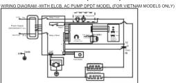
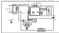
10. WIRING DIAGRAM
WIRING DIAGRAM -WITH ELCB, AC PUMP DPDT MODEL
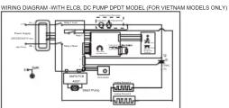
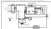
WIRING DIAGRAM - WITH ELCB, DC PUMP DPDT MODEL
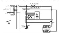
WIRING DIAGRAM -WITH ELCB, NO PUMP DPDT MODEL (FOR VIETNAM MODELS ONLY)
7
CONSUMER CARE
Indonesia
Hotline service: 08041119999
PT. Electrolux Indonesia
Electrolux Building
JI.Abdul Muis No.34, Petojo Selatan, Gambir Jakarta Pusat 10160
Email:customercare@electrolux.co.id SMS & WA : 0812.8088.8863
[Non-Text]
Malaysia
Consumer Care Center Tel: 1300-88-11-22
Electrolux Home Appliances Sdn. Bhd
Electrolux Home Appliances Sun. Blvd.
Corporate Office Address: Unit T2-7, 7th Floor, Tower 2
Jaya33 Hyperoffice, No. 3, Jalan Semangat, Seksyen 13,
46100 Petaling Jaya, Selangor Office Tel : (+60 3) 7843 5999
Office Fax : (+60 3) 7955 5511
Consumer Care Center Address: Lot C6, No. 28, John 45/22, Tower Parindustrie Tleng Nom
Jalan 15/22, Taman Perindustrain Hong Nam, 40200 Shah Alam, Selangor
Consumer Care Center Fax : (+60 3) 5524 2521
Email : malaysia.customercare@electrolux.com
Philippines
Consumer Care Center Toll Free : 1-800-10-845-CARE 2273
Consumer Care Hotline : (+63 2) 845 CARE 2273 Electrolux Philippines, Inc.
10th Floor. W5th Avenue Building
5th Avenue Corner 32nd Street Bonifacio Global City
Beninakis Global City, Taquig Philippines 1634
Trunkline: +63 2 737-47
Website : www.electrolux.com.pe
Email : wecare@electrolux.com
(No text)
Singapore
Consumer Care Center Tel: (+65) 6727 3600
Consumer Care Center Tel. (+65) 0727 3699
Electrolux S.E.A. Pte Ltd.
1 Fusionopolis Place,
07-10 Galaxis, West Lobby Singapore 138522.
Office Fax : (+65) 6727 3611
Email: customer-care.sin@electrolux.com
Thailand Consumer Care Tel : (+66 2) 725 9000 Electrolux Thailand Co., Ltd. Electrolux Building 14th Floor 1910 New Phetchaburi Road, Bangkapi, Huai Khwang, Bangkok 10310 Office Tel : (+66 2) 7259100 Office Fax : (+66 2) 7259299 Email : customercarethai@electrolux.com
Electrolux Vietnam Ltd. Floor 9th A&R Tower
76 Le Lai street - Ben Thanh Ward - District 1
Ho Chi Minh City • Vietnam
Office Tel : (+84 8) 3910 5465 Office Fax : (+84 8) 3910 5470
Email: vncare@electrolux.com
“
Hongkong Tel: (+852) 8203 0298
Dah Chong Hong, Ltd. - Service Centre
8/F., Yee Lim Godown Block C 3-28 Kwai Lok Street, Kwai Chung, N.T.
2-20 Kwai Lok Street, Kwai Chung, N.T.
9
10
8


Brand : ELECTROLUX
Model : EWE361KX-DWB5
Category : Chauffe-eau et ballon d'eau chaude