a3004 FC - Multimeter FLUKE - Free user manual and instructions
Find the device manual for free a3004 FC FLUKE in PDF.


User questions about a3004 FC FLUKE
0 question about this device. Answer the ones you know or ask your own.
Ask a new question about this device
Download the instructions for your Multimeter in PDF format for free! Find your manual a3004 FC - FLUKE and take your electronic device back in hand. On this page are published all the documents necessary for the use of your device. a3004 FC by FLUKE.
USER MANUAL a3004 FC FLUKE
Each Fluke product is warranted to be free from defects in material and workmanship under normal use and service. The warranty period is one year and begins on the date of shipment. Parts, product repairs, and services are warranted for 90 days. This warranty extends only to the original buyer or end-user customer of a Fluke authorized reseller, and does not apply to fuses, disposable batteries, or to any product which, in Fluke's opinion, has been misused, altered, neglected, contaminated, or damaged by accident or abnormal conditions of operation or handling. Fluke warrants that software will operate substantially in accordance with its functional specifications for 90 days and that it has been properly recorded on non-defective media. Fluke does not warrant that software will be error free or operate without interruption.
Fluke authorized resellers shall extend this warranty on new and unused products to end-user customers only but have no authority to extend a greater or different warranty on behalf of Fluke. Warranty support is available only if product is purchased through a Fluke authorized sales outlet or Buyer has paid the applicable international price. Fluke reserves the right to invoice Buyer for importation costs of repair/replacement parts when product purchased in one country is submitted for repair in another country.
Fluke's warranty obligation is limited, at Fluke's option, to refund of the purchase price, free of charge repair, or replacement of a defective product which is returned to a Fluke authorized service center within the warranty period.
To obtain warranty service, contact your nearest Fluke authorized service center to obtain return authorization information, then send the product to that service center, with a description of the difficulty, postage and insurance prepaid (FOB Destination). Fluke assumes no risk for damage in transit. Following warranty repair, the product will be returned to Buyer, transportation prepaid (FOB Destination). If Fluke determines that failure was caused by neglect, misuse, contamination, alteration, accident, or abnormal condition of operation or handling, including overvoltage failures caused by use outside the product's specified rating, or normal wear and tear of mechanical components, Fluke will provide an estimate of repair costs and obtain authorization before commencing the work. Following repair, the product will be returned to the Buyer transportation prepaid and the Buyer will be billed for the repair and return transportation charges (FOB Shipping Point).
THIS WARRANTY IS BUYER'S SOLE AND EXCLUSIVE REMEDY AND IS IN LIEU OF ALL OTHER WARRANTIES, EXPRESS OR IMPLIED, INCLUDING BUT NOT LIMITED TO ANY IMPLIED WARRANTY OF MERCHANTABILITY OR FITNESS FOR A PARTICULAR PURPOSE. FLUKE SHALL NOT BE LIABLE FOR ANY SPECIAL, INDIRECT, INCIDENTAL, OR CONSEQUENTIAL DAMAGES OR LOSSES, INCLUDING LOSS OF DATA, ARISING FROM ANY CAUSE OR THEORY.
Since some countries or states do not allow limitation of the term of an implied warranty, or exclusion or limitation of incidental or consequential damages, the limitations and exclusions of this warranty may not apply to every buyer. If any provision of this Warranty is held invalid or unenforceable by a court or other decision-maker of competent jurisdiction, such holding will not affect the validity or enforceability of any other provision.
Fluke Corporation
P.O. Box 9090
Everett, WA 98206-9090
U.S.A.
Fluke Europe B.V.
P.O. Box 1186
5602 BD Eindhoven
The Netherlands
Table of Contents
Title Page
Introduction....1
Contact Fluke 1
Safety Information 2
Specifications 5
Required Equipment....6
Maintenance Mode 7
Start Maintenance Mode 7
Enter the Password 7
Change the Password 7
Restore the Default Password 9
Performance Tests....10
Test the Display ....10
Test the Backlight 10
Clamp Input and Keypad Test ....10
DC Voltage Verification ....11
4-20 mA Clamp Performance Test 12
2000 A Clamp Performance Test ....13
2000 mA Clamp Balance Test 15
Calibration 15
Meter Calibration Adjustment ....15
4-20 mA Clamp Calibration Adjustment 16
2000 mA Clamp Calibration Adjustment 18
Maintenance....19
Clean the Product 19
Battery Replacement 19
Replaceable Parts 20
Introduction
⚠ Warning
Read all safety information before you use the Product.
This manual provides all the information necessary to perform maintenance and make calibration adjustments for the a3003 FC and a3004 FC DC Meters (the Meter) and the associated clamps. The Product measures up to 2000 A dc current (a3003 FC) or 100 mA dc current (a3004 FC) using a detachable clamp.
For complete operating instructions, see www.fluke.com.
Contact Fluke
To contact Fluke, use one of these telephone numbers:
• Technical Support USA: 1-800-44-FLUKE (1-800-443-5853)
• Calibration/Repair USA: 1-888-99-FLUKE (1-888-993-5853)
• Canada: 1-800-36-FLUKE (1-800-363-5853)
• Europe: +31 402-675-200
• Japan: +81-3-6714-3114
• Singapore: +65-6799-5566
• China: +86-400-810-3435
• "Brazil: +55-11-3530-8901
• Anywhere in the world: +1-425-446-5500
Or, visit Fluke's website at www.fluke.com.
To register your product, visit http://register.fluke.com.
To view, print, or download the latest manual supplement, visit http://us.fluke.com/usen/support/manuals.
Safety Information
A Warning identifies hazardous conditions and procedures that are dangerous to the user. A Caution identifies conditions and procedures that can cause damage to the Product or the equipment under test.
Warning
To prevent possible electrical shock, fire, or personal injury:
• Carefully read all instructions.
- Use the Product only as specified, or the protection supplied by the Product can be compromised.
- Limit operation to the specified measurement category, voltage, or amperage ratings.
- Do not touch voltages >30 V ac rms, 42 V ac peak, or 60 V dc.
- Do not use the Product around explosive gas, vapor, or in damp or wet environments.
- Do not use the Product if it is altered or damaged.
• Disable the Product if it is damaged.
- Do not use the Product if it operates incorrectly.
- The battery door must be closed and locked before you operate the Product.
- Replace the batteries when the low battery indicator shows to prevent incorrect measurements.
• Have an approved technician repair the Product.
• Use only specified replacement parts.
- Comply with local and national safety codes. Use personal protective equipment (approved rubber gloves, face protection, and flame-resistant clothes) to prevent shock and arc blast injury where hazardous live conductors are exposed.
- Do not work alone.
- Before each use, examine the Product. Look for cracks or missing pieces of the clamp housing or output cable insulation. Also look for loose or weakened components. Carefully examine the insulation around the jaws.
- De-energize the circuit or wear personal protective equipment in compliance with local requirements before you apply or remove the clamp.
- Do not operate the Product with covers removed or the case open. Hazardous voltage exposure is possible.
- Remove the input signals before you clean the Product.
• Use only the correct measurement category (CAT) for measurement.
- Do not measure current if the wear indicator of cable shows.
- Hold the clamp behind the tactile barrier.
- Do not use the Product to measure ac current.
- Do not use the Product to measure dc mA in circuits carrying more than 300 V CAT II
- Do not use the Product near strong magnetic fields.
For safe operation and maintenance of the Product:
- Remove batteries to prevent battery leakage and damage to the Product if it is not used for an extended period.
• Repair the Product before use if the battery leaks. - Be sure that the battery polarity is correct to prevent battery leakage.
- Batteries contain hazardous chemicals that can cause burns or explode. If exposure to chemicals occurs, clean with water and get medical aid.
Caution
To prevent possible damage to the Product or to equipment under test:
• Use the correct terminals, function, and range for measurements.
- Clean the case and accessories with a damp cloth and mild detergent only. Do not use abrasives or solvents.
Note
The Measurement Category (CAT) and voltage rating of any combination of test probe, test probe accessory, current clamp accessory, and the Product is the LOWEST rating of any individual component.
The symbols in Table 1 are used on the Product or in this manual.
Table 1. Symbols
| Symbol Description | |
 | Consult user documentation. |
 | WARNING. RISK OF DANGER. |
 | WARNING. HAZARDOUS VOLTAGE. Risk of electric shock. |
 | Do not apply around or remove from uninsulated hazardous live conductors without taking additional protective measures. |
 | Application around and removal from uninsulated hazardous live conductors is permitted. |
 | Double Insulated |
 | Battery |
 | DC (Direct Current) |
 | Conforms to relevant Australian EMC standards. |
| [7S25] | Certified by CSA Group to North American safety standards. |
 | Conforms to European Union directives. |
 | Measurement Category III is applicable to test and measuring circuits connected to the distribution part of the building's low-voltage MAINS installation. |
 | Measurement Category IV is applicable to test and measuring circuits connected at the source of the building's low-voltage MAINS installation. |
 | This product complies with the WEEE Directive marking requirements. The affixed label indicates that you must not discard this electrical/electronic product in domestic household waste. Product Category: With reference to the equipment types in the WEEE Directive Annex I, this product is classed as category 9 “Monitoring and Control Instrumentation” product. Do not dispose of this product as unsorted municipal waste. |
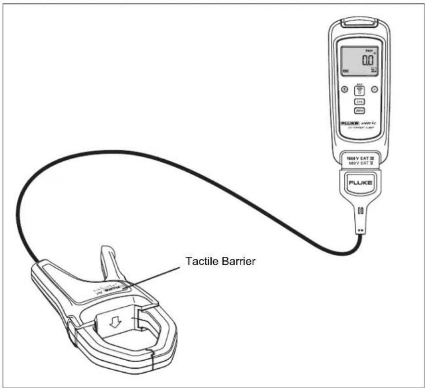
text_image
Tactile Barrier FLUKE 1000 V CAT III MD V CAT IVFigure 1. a3003 FC Wireless DC Clamp
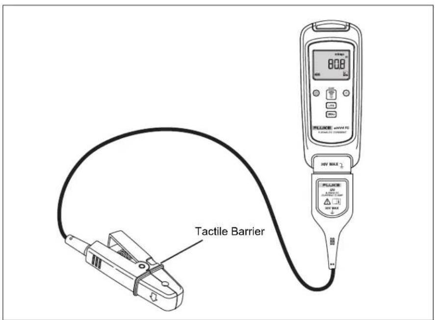
text_image
Tactile Barrier 80.8 PLAUXE 43V/5 FC PLAUXE 30V MAX 30V MAXFigure 2. a3004 FC Wireless DC Clamp
Specifications
Maximum Voltage between Terminals and
Earth Ground 30 V
Range
a3003 FC 1.0 A to 999.9 A dc, 1000 A to 2000 A dc (with Fluke i2000 Current Clamp)
a3004 FC 0.05 mA to 20.99 mA dc, 21.0 mA to 99.9 mA dc (with Fluke i20 Current Clamp)
Resolution
a3003 FC 0.1 A, 1 A
a3004 FC 0.01 mA, 0.1 A
Accuracy
a3003 FC 2% ±5 digits, 2.5% ±5 digits
a3003 FC LCD with backlight 3 digits
a3004 FC 0.2 % ± 5 digits, 1.0 % ± 5 digits
a3004 FC LCD with backlight 3 1/2 digits
Log rate/interval 1 sec minimum (adjustable by PC or front panel)
Battery..... Two AA, IEC LR6
Battery life
a3003 FC 120 hours
a3004 FC 45 hours
Memory up to 65 000 readings
Temperature
Operating Temperature....-10 °C +50 °C
Storage Temperature....-40 °C +60 °C
Temperature coefficient....Add 0.1 X (specified accuracy)/°C (<18 °C or >28 °C
Operating Relative Humidity 90 % at 35 °C
(75 % at 40 °C)
(45 % at 50 °C)
Altitude
Operating 2000 meters
Storage 12000 meters
Ingress Protection....IEC 60529: IP42 (non operating)
Jaw opening
a3003 FC 64 mm
a3004 FC 4.5 mm
Size (HxWD)
a3003 FC 16.5 cm x 6.35 cm x 1.4 cm (6.5 in x 2.5 in x 1.4 in)
a3004 FC 16.5 cm x 6.35 cm x 1.4 cm (6.5 in x 2.5 in x 1.4 in)
Weight
a3003 FC 65 kg (1.75 lb)
a3004 FC 0.299 kg (0.8 lb)
RF communication 2.4 GHz ISM Band
RF communication range....Open air, unobstructed (up to 20 m)
Obstructed, Sheetrock wall (up to 6.5 m)
Obstructed, concrete wall or steel electrical enclosure (up to 3.5 m)
Safety
a3003 FC ....IEC 61010-1, Pollution Degree 2
IEC 61010-2-032: CAT III 1000V / CAT IV 600V
a3004 FC ....IEC 61010-1, Pollution Degree 2
Electromagnetic Compatibility (EMC)
International ....IEC 61326-1: Portable, Electromagnetic Environment, IEC 61326-2-1, CISPR 11: Group 1, Class A
Group 1: Equipment has intentionally generated and/or uses conductively-coupled radio frequency energy that is necessary for the internal function of the equipment itself.
Class A: Equipment is suitable for use in all establishments other than domestic and those directly connected to a low-voltage power supply network that supplies buildings used for domestic purposes. There may be potential difficulties in ensuring electromagnetic compatibility in other environments due to conducted and radiated disturbances.
Caution: This equipment is not intended for use in residential environments and may not provide adequate protection to radio reception in such environments.
Emissions that exceed the levels required by CISPR 11 can occur when the equipment is connected to a test object.
Korea (KCC) ......Class A Equipment (Industrial Broadcasting & Communication Equipment.
Class A: Equipment meets requirements for industrial electromagnetic wave equipment and the seller or user should take notice of it. This equipment is intended for use in business environments and not to be used in homes.
USA (FCC) 47 CFR 15 subpart B. This product is considered an exempt device per clause 15.103.
Required Equipment
The equipment in Table 2 is necessary for performance tests and calibration adjustment.
Table 2. Required Equipment
| Equipment Required | Characteristics Recommended Model | |
| Calibrator | ≥5.0-digit resolutionDC Voltage Accuracy:-600 mV to 600 mV ±0.01 % | Fluke 5522A |
| Clamp 2000 A Clamp (PN: 4628781) Only for a3003 DC Meter | ||
| Clamp 20 mA Clamp (PN: 4628796) Only for a3004 DC Meter | ||
| Cable | CABLE ASSEMBLY,1000V, 914MILLIMETER,SILICON,BLACK,A3003FC (PN: 4632023) | |
| For 2000 A Clamp Calibration | ||
| Transconductance Amplifier -- | Fluke 52120A | |
| Coil -- | Fluke 52120 3 kA | |
| Coil 50 turn 1 kA -- | ||
| For 4-20 mA Clamp Calibration | ||
| Calibrated Meter | -- A3004 FC DC Meter (Calibrated) | |
| Wired Coil | 1 loop insulated copper wire, diameter ≤4 m | -- |
Maintenance Mode
Use Maintenance mode to set parameters on the Meter. Some options require a password. Maintenance mode options are:
- Full-screen mode
- Revision information (rxxx, where xxx is the revision)
• P o f f
• L o f f
FC
• CAL (Calibration mode)
• JC (Jaw Calibration) - TEST (Verification mode)
Start Maintenance Mode
To enter Maintenance mode:
- With the Meter off, push and hold LOG.
- Push Ⓙ while you keep LOG pushed until all of the display segments are shown.
- Release LOG and ①, to enter the maintenance mode.
- Push LOG until the appropriate option shows on the display.
Enter the Password
The CAL and JC options require a password.
To enter the password:
- Push Ⓞ.
The Meter shows the CAL counts, for example n002.
- Push ⓞ to show ????.
The first digit flashes
- Push LOG and enter the first digit of the password. (Default is 1234).
- Push LOG and enter the next digit of the password, until all digits are entered.
- Push Ⓞ to confirm the input.
When the correct password is entered the Meter shows C-01. When the incorrect password is entered ???? shows and you must re-enter the password.
Change the Password
Note
If you forget the password after you change it, you can reset it to 1234. See Restore the Default Password.
To change the password:
- Do steps 1 through 4 in the Enter the Password section.
Do not confirm the entry. - Push 📋 to show ---- on the display. The first digit flashes.
- Push LOG and enter the first digit of the new password.
- Push Ⓞ to accept the first digit, then enter the next digit, continue until all digits are entered.
- Push ⓞ to confirm the changes.
If the Meter has been calibrated, the Meter goes to normal measurement mode. Otherwise, the Meter shows donE.

Static Awareness

Semiconductors and integrated circuits can be damaged by electrostatic discharge during handling. This notice explains how to minimize damage to these components.
- Understand the problem.
- Learn the guidelines for proper handling.
- Use the proper procedures, packaging, and bench techniques.
Follow these practices to minimize damage to static sensitive parts.
⚠ Warning
To prevent electric shock or personal injury. De-energize the product and all active circuits before opening a product enclosure, touching or handling any PCBs or components.

- Minimize handling
- Handle static-sensitive parts by non-conductive edges.
- Do not slide static-sensitive components over any surface.
- When removing plug-in assemblies, handle only by non-conductive edges.
- Never touch open-edge connectors except at a static-free work station.
- Keep parts in the original containers until ready for use.
- Use static shielding containers for handling and transport.
- Avoid plastic, vinyl, and Styrofoam® in the work area.

natural_image
Pure electrical circuit symbol for a lamp, no text or labels present- Handle static-sensitive parts only at a static-free work station.
- Put shorting strips on the edge of the connector to help protect installed static-sensitive parts.
- Use anti-static type solder extraction tools only.
- Use grounded-tip soldering irons only.
Restore the Default Password
If you do not have the calibration password, you can restore the default password (1234).
Warning
To prevent possible electrical shock, fire, or personal injury, remove all input signals, before you open the Meter.
To restore the default password:
- Remove the battery door of the Meter. See Battery Replacement.
-
Use a Phillips screwdriver to remove the bottom case screws. (Two of the screws are inside the battery door.)
-
Keep the PCA in the top case.
-
Apply 3.0 V across the battery contacts on the PCA.
Note the polarity that is shown in Figure 3.
-
Push ① on the Meter.
-
Short across the calibration key pads on the PCA. See Figure 3.
The default password is now restored.
- Remove the 3.0 V supply and replace the bottom case, batteries, and battery door.
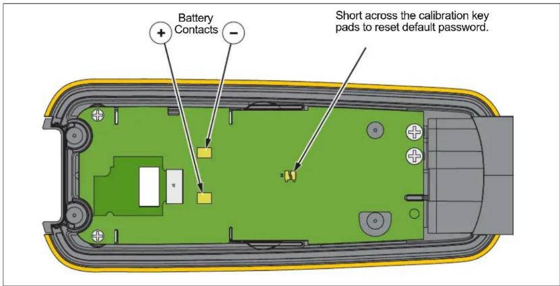
text_image
Battery Contacts Short across the calibration key pads to reset default password.Figure 3. Calibration Password Rest
Performance Tests
Performance tests make sure that the Product operates within the published specifications. Do the performance tests periodically and after service or repair. If the Product fails any part of the verification test, repair and/or calibration adjustments are required. See Calibration.
In this section the Meter is called the UUT (Unit Under Test). Use these verification performance tests to make sure the values indicated on the UUT correspond, as closely as possible, with the actual values being measured.
Test the Display
To verify that all segments of the display function:
- With the Meter off, push and hold LOG.
- Push ① while you keep LOG pushed until all of the display segments are shown. See Figure 4.
If segments of the display are missing, contact Fluke for repair. See Contact Fluke.
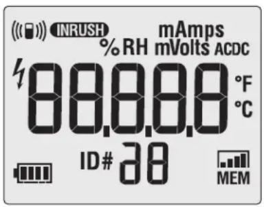
text_image
INRUSH % RH mAmps mVolts ACDC 88.8.8.8 °F °C ID# 38 MEMFigure 4. Display Segments
Test the Backlight
To verify the backlight: With the Meter on, push Ⓞ.
If the backlight does not come on, contact Fluke for repair. See Contact Fluke.
Clamp Input and Keypad Test
To verify the clamp input and keypad functions:
- With the Meter off, push Ⓐ.
The display shows ----.
- Plug the clamp into the Meter:
• 2000 A dc clamp into the a3003 FC DC Meter.
• 4-20 mA clamp into the a3004 FC DC Meter.
The display shows the name of the Meter.
- Start the dc current test.
- Push each button separately to verify the keypad functions.
Each button push turns on a display function and Ⓧ turns on the backlight. If there is no response from the buttons, contact Fluke for repair. See Contact Fluke.
DC Voltage Verification
Before you do the dc voltage verification:
- Make sure you have the necessary equipment. See Table 2.
- Make sure the Meter battery is good and replace it if necessary. See Battery Replacement.
- Warm up the Calibrator as necessary. Refer to the specifications for the Calibrator.
- Let the temperature of the UUT become stable to room temperature.
Start the dc voltage verification.
- Follow the instructions to enter Maintenance mode (see Start Maintenance Mode) and then:
a. Push LOG until TEST shows on the display.
b. Push Ⓤ. The Meter is in verification mode.
- Connect the Calibrator to test leads and three of the six leads in the cable, as shown in Figure 5. (The white lead connects to the NORMAL Hi terminal of the 5522A. The yellow and black leads connect to the NORMAL LO terminals.)
- Apply the input level for each value shown in Table 3 and compare the UUT indication on the display with the UUT reading limits.
If the display indication falls outside of the range shown in Table 3, calibration adjustment or repair is necessary. See Calibration.
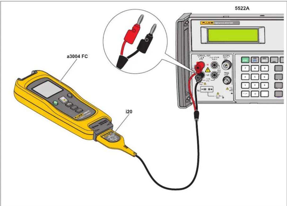
Figure 5. Performance Verification Connections for Simulated Voltages
Table 3. a3003 and a3004 DC Meter Performance Verification
| Test Connection Calibrator Output Resolution Specification | UUT Reading Limits | a3003 a3004 | |||||
| 1 Year Lower Limit | 1 Year Upper Limit | ||||||
| Single-turn Loop -100.0 mA 0.1 1.0 % ±5 digits -101.5 -98.5 | • | ||||||
| Single-turn Loop -20.00 mA 0.01 0.2 % ±5 digits -20.09 -19.91 | • | ||||||
| Single-turn Loop -2.00 mA 0.01 0.2 % ±5 digits -2.05 | -1.95 | • | |||||
| Single-turn Loop 2.00 mA 0.01 0.2 % ±5 digits 1.95 | 2.05 | • | |||||
| Single-turn Loop 20.00 mA 0.01 0.2 % ±5 digits 19.91 | 20.09 | • | |||||
| Single-turn Loop 100.0 mA 0.1 1.0 % ±5 digits 98.5 | 101.5 | • | |||||
| 25-turn Coil | -80 mA (-2000 A) | 1 | 2.5 % ±5 digits | -2055 | -1945 | • | |
| 25-turn Coil | -38 mA (-950.0 A) | 0.1 2.0 % ±5 digits -969.5 -930.5 | • | ||||
| 25-turn Coil | -2 mA (-50.0 A) | 0.1 | 2.0 % ±5 digits | -51.5 | -48.5 | • | |
| 25-turn Coil | 2 mA (50.0 A) | 0.1 | 2.0 % ±5 digits | 48.5 | 51.5 | • | |
| 25-turn Coil | 38 mA (950.0 A) | 0.1 | 2.0 % ±5 digits | 930.5 | 969.5 | • | |
| 25-turn Coil | 80 mA (2000 A) | 1 | 2.5 % ±5 digits | 1945 | 2055 | • | |
| Simulate | -550 mV | 1 | 1.0 % ±5 digits | -2533 | -2467 | • | • |
| Simulate | -190 mV | 0.1 1.0 % ±5 digits -964.5 -935.5 | • | ||||
| Simulate | -100 mV | 0.1 0.2 % ±5 digits -501.0 -499.0 | • | ||||
| Simulate | -10 mV | 0.1 | 0.2 % ±5 digits | -50.6 | -49.4 | • | • |
| Simulate | 0 mV | 0.1 | 0.2 % ±5 digits | -0.5 | 0.5 | • | • |
| Simulate | 10 mV | 0.1 | 0.2 % ±5 digits | 49.4 | 50.6 | • | • |
| Simulate | 100 mV | 0.1 | 0.2 % ±5 digits | 499.0 | 501.0 | • | |
| Simulate | 190 mV | 0.1 | 1.0 % ±5 digits | 935.5 | 964.5 | • | |
| Simulate | 550 mV | 1 | 1.0 % ±5 digits | 2467 | 2533 | • | • |
4-20 mA Clamp Performance Test
Do the performance test periodically and after calibration.
The performance test requires a calibrator with a current loop from the AUX terminal to the LO terminal. See Table 2. To short the two terminals, use a conductor with 2 banana jacks at both ends. To ensure the clamp closes properly, the diameter of the conductor should be no more than 4 mm. The Meter must be factory-calibrated to calibrate the clamp.
To make the calibration adjustment:
- Make sure you have the necessary equipment, see Table 2.
- Allow the Meter and the 4-20 mA clamp to stabilize to room temperature.
- Connect the 4-20 mA clamp to a calibrated Meter.
- Use 1 loop insulated copper wire to short circuit the calibrator current output AUX and LO terminals, see Figure 8.
- Clamp the 4-20 mA current clamp around the insulated copper wire. Current flow should be in the direction of the arrow on the current clamp.
- For each value in Table 4.
a. Zero the Meter.
b. Apply the Calibrator Output value to the Meter.
c. Wait 4 seconds for the signal to stabilize.
d. Record the reading.
All readings must meet 100 % of specification, see Table 4. If the Product fails any part of the performance test, calibration adjustments are required. See Calibration. If the Product continues to fail, contact Fluke for repair. See Contact Fluke.
Table 4. Performance Specifications for the 4-20 mA Clamp
| Test (Function) | Calibrator Outputs | Meter Response | |
| Lower Limit Upper | Limit | ||
| mA dc | 90 mA 88.6 91.4 | ||
| 20 mA 19.91 20.09 | |||
| 4 mA 3.94 4.06 | |||
| -4 mA -4.06 -3.94 | |||
| -20 mA -20.09 -19.91 | |||
| -90 mA | -91.4 -88.6 | ||
2000 A Clamp Performance Test
Do the performance test periodically and after calibration and the balance test.
To do the performance test:
- Make sure you have the required equipment. See Table 2.
- Connect the equipment. See Figure 6.
- Power on all the equipment and set the parameters:
• On the 5522A, put in the Standby state with 0 A output.
• On the 52120A put in the Current Mode, with the 120 A range. Put in the Local Control mode.
-
Push ① on the Meter.
-
For each value in Table 5:
a. Zero the Meter.
b. Apply the Calibrator Output value to the Meter.
c. Wait 4 seconds for the signal to stabilize.
d. Record the reading.
All readings must meet 100 % of the specification.
Table 5. Performance Specifications for the 2000 A Clamp
| Test (Function) | List | Calibrator Output (mA) From 5522A | Meter Response (mA) | |
| Lower Limit | Upper Limit | |||
| Adc | 1.0 0.04 | 0.48 | 1.52 | |
| 50.0 2.0 | 48.5 | 51.5 | ||
| 300.0 | 12.0 | 293.5 | 306.5 | |
| 950.0 | 38.0 | 930.5 | 969.5 | |
| 1050 | 42.0 | 1019 | 1081 | |
| 1500 | 60.0 | 1458 | 1543 | |
| 2000 | 80.0 | 1945 | 2055 | |
| -A dc | -1.0 -0.04 | -2.0 | 0.0 | |
| -50.0 -2.0 | -52 | -49 | ||
| -300.0 | -12.0 | -307.0 | -294 | |
| -950.0 | -38.0 | -970 | -931 | |
| -1050 | -42.0 | -1081 | -1019 | |
| -1500 | -60.0 | -1543 | -1458 | |
| -2000 | -80.0 | -2055 | -1945 | |
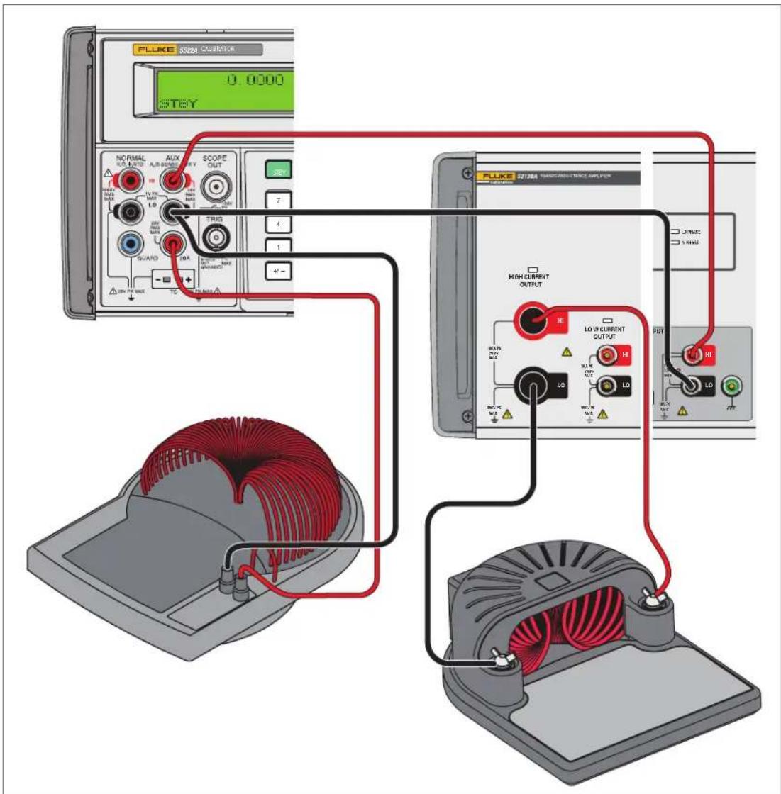
text_image
FLUKE 3028A CUBRATOR 0.0000 STET NORMAL AUX SCOPE 1.5V A,B-SENSO B-V 7 6 4 1 4- TIGS GUARD 10A 10A 10A 10A 10A 10A 10A 10A 10A 10A 10A 10A 10A FLUKE 3028A TRANSFERENTABLE AMP LUX HIGH CURRENT OUTPUT LO W CURRENT OUTPUT LO LO LO LO LO LO LO LO LO LO LO LO LO LO LO LO LO LO LO LO LO LO LO LO LO LO LO LO LO LO LO LO LO LO LO LO LO LO LO LO LO LO LO LO LO LO LO LO LO LO LIF PWRK TC MRSFigure 6. Calibration Connections for 2000 A Clamp
2000 mA Clamp Balance Test
Do the balance test after calibration. The balance test evaluates the clamp measurement error when the clamp is in different positions. If any position fails the balance test, a balance adjustment is required. See 2000 mA Clamp Calibration Adjustment.
To do the balance test:
- Make sure you have the required equipment. See Table 2.
- Connect the equipment. See Figure 6.
- Power on all the equipment.
- On the 5522A, set the 9.0 A dc output to the 50-turn 1 kA coil and place the clamp on it.
- Push ⓧ until b-UP shows, then move the jaw and locate the coil center in the top area of the jaw. Hold for 5 seconds.
- Push Ⓧ until b-do shows, then move the jaw and locate the coil center in the bottom area of the jaw. Hold for 5 seconds.
- Record the reading.
The reading difference between the top and bottom position must be below 1.0 A (10 digits.)
Calibration
Use the calibration procedures to adjust the Product so that the values shown on the Meter correspond as closely as possible with the actual measured values. The Product measures the applied reference source, calculates correction factors, and stores the correction factors in nonvolatile memory.
Should the Product fail any of the performance tests, do the calibration adjustment procedure.
Note
The first calibration of the Product is available from the Fluke factory only.
Meter Calibration Adjustment
Before you can adjust the Meter calibration, you must enter your password in the Maintenance Mode.
- Follow the instructions to enter Maintenance mode (see Start Maintenance Mode) and then:
a. Push LOG until CAL shows on the display.
b. Follow the steps in Enter the Password until C-01 shows on the display.
- For each value in Table 6:
a. Apply the Calibrator Output value to the Meter.
b. Push Ⓤ to confirm the calibration step.
If the input signal does not satisfy the calibration requirement, the Meter shows Err. If the signal is not stable, you must push Ⓧ several times to confirm the calibration.
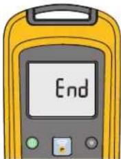
After you confirm the calibration, the Meter goes to the subsequent calibration step. When the last calibration point is recorded, End shows on the display. See Figure 7.
Note
After you push Ⓤ wait for the calibration step number to advance before you change the calibrator source. Some adjustment steps can take several seconds to complete before the Meter goes to the subsequent step. Set the Calibrator to Standby after you complete adjustment of each function.
Note
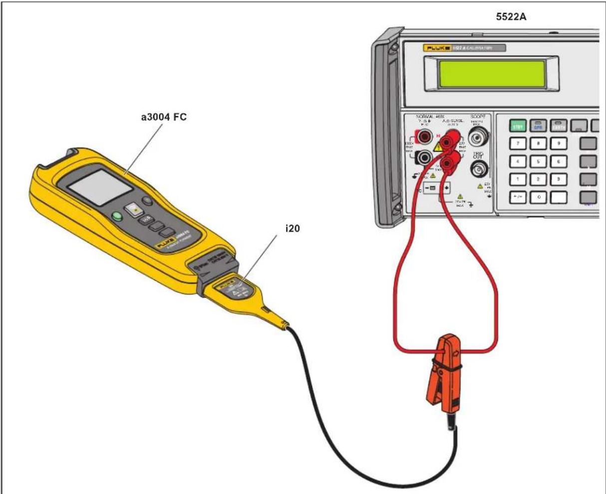
While the calibration adjustment points are shown in Table 6, the Meter shows the necessary inputs. For each step, push LOC to see the necessary dc reference signal amplitude. Use the connections shown in Figure 8.
text_image
EndFigure 7. End
Table 6. Calibration Steps for the Meter
| Calibration Step | Calibrator Output (mV) | A3303 A3304 | |
| C-01 -200 | ● | ● | |
| C-02 -20 ● | ● | ||
| C-03 20.0 ● | ● | ||
| C-04 200 ● | ● | ||
4-20 mA Clamp Calibration Adjustment
The calibration adjustment requires a calibrator with a current loop from the AUX terminal to the LO terminal. See Table 2. To short the two terminals, use a conductor with 2 banana jacks at both ends. To ensure the clamp closes properly, the diameter of the conductor should be ≤4 mm. The Meter must be factory-calibrated to calibrate the clamp.
During the calibration adjustment the temperature must be controlled to 23 °C ±5 °C.
To make the calibration adjustment:
- Allow the Meter and the 4-20 mA clamp to stabilize to room temperature.
- Connect the 4-20 mA clamp to a calibrated Meter.
- Use 1 loop insulated copper wire to short circuit the calibrator current output AUX and LO terminals, see Figure 8.
- Clamp the 4-20 mA current clamp around the insulated copper wire. Current flow should be in the direction of the arrow on the current clamp.
- Follow the instructions to enter Maintenance mode (see Start Maintenance Mode) and then:
a. Wait 20 seconds for the Meter to warm up.
b. Push LOG until JC shows on the display.
c. Follow the steps in Enter the Password until PoS shows on the display.
- For each value in Table 7:
a. Apply the Calibrator Output value to the Meter.
b. Wait 4 seconds for the signal to stabilize.
c. Push Ⓤ to confirm the calibration step.
- When you have completed the calibration, push Ⓤ once to enter normal measurement.
text_image
a3004 FC i20 5522A PLUKC 102 & CALIPATOR NORMAL AUX AVOC AVOC AVOC AVOC AVOC AVOC AVOC AVOC AVOC AVOC AVOC AVOC AVOC AVOC AVOC AVOC AVOC AVOC AVOC AVOC AVOC AVOC AVOC AVOC AVOC AVOC AVOC AVOC AVOC AVOC AVOC AVOC AVOC AVOCFigure 8. Calibration Connections for the 4-20 mA Clamp
Table 7. Calibration Steps for the 4-20 mA Clamp
| Function Step Display Calibrator Output | |||
| mA DC | 1 POS | 20 mA,0 Hz | |
| 2 0A 0 | mA | ||
| 3 | C-01 | -20 mA,0 Hz | |
| 4 0A 0 | mA | ||
| 5 C-02 | 20 mA,0 Hz | ||
| 6 0A 0 | mA | ||
| 7 | C-03 | -100 mA,0 Hz | |
| 8 0A 0 | mA | ||
| 9 C-04 | 100 mA,0 Hz | ||
2000 mA Clamp Calibration Adjustment
Do the balance adjustment and then do the calibration adjustment.
To do the balance adjustment:
- Follow the instructions to enter Maintenance mode (see Start Maintenance Mode) and then:
a. Wait 20 seconds for the Meter to warm up.
b. Push LOG until JC shows on the display.
c. Follow the steps in Enter the Password until b-UP shows on the display.
- For each value in Table 7:
a. Apply the Calibrator Output value to the Meter.
b. Wait 4 seconds for the signal to stabilize.
c. Push Ⓞ to confirm the calibration step.
- On the 5522A, set the 12 A dc output to the 50-turn 1 kA coil and place the clamp on it.
- Push Ⓤ, until b-UP shows, then move the jaw and locate the coil center in the top area of the jaw.
- Push Ⓤ, until b-do shows, then move the jaw and locate the coil center in the bottom area of the jaw.
- Repeat the previous two steps until 0 A shows.
When 0 A shows on the display the balance adjustment passes. Continue with the calibration.
To do the calibration adjustment:
- Move the jaw to the 3 kA coil.
- Power on all the equipment and set the parameters:
• On the 5522A, put in the Standby state with 0 μA output.
- On the 52120A put in Current Mode input, with the 120 A range. Put the 52120A in Local Control mode.
- Push ① on the Meter.
- For each value in Table 8:
a. Apply the Calibrator Output value to the Meter.
b. Wait 4 seconds for the signal to stabilize.
c. Push Ⓞ to confirm the calibration step.
If Err shows on the Meter when you push Ⓧ, the internal measurement is working and the result is not ready. Wait for 1 minute.
If out shows on the Meter, the internal measurement is out of range. Check the input signal and correct it.
Table 8. Calibration Specifications 2000 A Clamp
| Display Output to 3KA | coil | From 5522A[1] |
| 0A 0 A 0 mA | ||
| C-01 10 A 0.4 mA | ||
| C-02 1000 A 40 mA | ||
| C-03 2000 A 80 mA | ||
| H-0A 0 A 0 mA | ||
| C-04 -10 A -0.4 mA | ||
| C-05 -1000 A -40 mA | ||
| C-06 -2000 A -80 mA | ||
| [1]: Manually adjust the current signal from the 5522A to drive the high current from 52120A. | ||
Maintenance
Clean the Product
Caution
To prevent possible damage to the Product or to equipment under test, do not use abrasive cleaners. They will damage the case.
To clean the Product, use a cloth with a mild cleaning solution.
Battery Replacement
Warning
To prevent possible electrical shock, fire, or personal injury, replace the batteries when the low-battery indicator (☐) shows to prevent incorrect measurements.
Caution
To prevent possible damage to the Product or to equipment under test:
- Remove batteries to prevent battery leakage and damage to the Product if it is not used for an extended period.
- Be sure that the battery polarity is correct to prevent battery leakage.
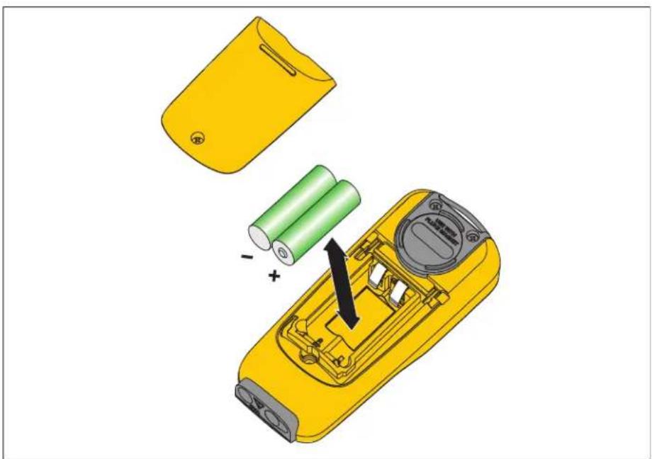
To change the batteries, see Figure 9:
- Make sure the Meter is OFF.
- Turn over the Meter to access the battery compartment door.
- Remove the screw.
- Use a flat-head screwdriver to loosen the battery compartment door.
- Replace the two AA batteries.
Make sure to use the correct polarity when you replace the batteries. - Reattach the battery compartment door.
- Tighten the battery compartment door screw.
natural_image
Illustration of a yellow handheld device with battery pack and internal components, showing battery assembly (no text or symbols)Figure 9. Battery Replacement
Replaceable Parts
User-replaceable parts and accessories are shown in Table 9.
Table 9. User-Replaceable Parts
| Description Fluke Part Number | |
| Battery Door 4583058 | |
| Batteries 376756 |