
EWE361MB-DST1 - Chauffe-eau et ballon d'eau chaude ELECTROLUX - Free user manual and instructions
Find the device manual for free EWE361MB-DST1 ELECTROLUX in PDF.

| Product Type | Electric Water Heater |
| Brand | Electrolux |
| Model | EWE361MB-DST1 |
| Capacity | 50 gallons (190 liters) |
| Dimensions (H x W x D) | 48 x 22 x 22 inches (122 x 56 x 56 cm) |
| Weight | 45 kg (99 lbs) |
| Power Supply | 240V, 60Hz, Single Phase |
| Wattage | 4500W (dual elements) |
| First Hour Rating | 62 gallons (235 liters) |
| Energy Factor | 0.92 |
| Thermostat | Adjustable, surface-mounted |
| Insulation | 2-inch foam (R-Value 16) |
| Anode Rod | Powered anode rod for corrosion protection |
| Safety Features | T&P relief valve, auto shutoff |
| Maintenance | Annual tank flushing, inspect anode rod |
| Parts & Repair | Replaceable heating elements, thermostats, anode rod |
| Warranty | 6 years tank, 2 years parts |
| Certification | UL, Energy Star |
Frequently Asked Questions - EWE361MB-DST1 ELECTROLUX
User questions about EWE361MB-DST1 ELECTROLUX
0 question about this device. Answer the ones you know or ask your own.
Ask a new question about this device
Download the instructions for your Chauffe-eau et ballon d'eau chaude in PDF format for free! Find your manual EWE361MB-DST1 - ELECTROLUX and take your electronic device back in hand. On this page are published all the documents necessary for the use of your device. EWE361MB-DST1 by ELECTROLUX.
USER MANUAL EWE361MB-DST1 ELECTROLUX
-
Front Cover
-
Main Display
(*LED Display Main PCB)
- 3 in 1 Stop Valve
(i) Stop Val
ii) Flow Regulator Valve iii) Built-in Filters
4 Mesh Filter
-
Rail Support
-
Handshower
-
Adjustable Shower Holder
-
PVC Hose
-
Soap Tray
-
2013.11.7
Slider Rail
Terminal Block
Thermostat (Double-Action)
Hostor Tank
PCB Board (Text & Read)
ELCB Board
Water Outlet Connection
SMPS PCB Board* DC Buret*
DCT Pump Heater Base
Triac
Flow Sensor Winter Joint Connection
Water that Connaclia Rating Label
Test & Reset Button
Logo Light
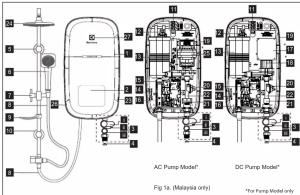
- PARTS IDENTIFICATION (RAIN SHOWER MODEL)
1
- Main Display
(*LED Display Main PCB
Board behind front cover)
- 3 IN 1 Stop Valve (1) Stop Valve
ii) Flow Regula
iii) Built-in-Filter
-
Mesh Filter
-
Rail Support
-
Handshower
-
Adjustable Shower Holder
-
PVC Hose
-
Soap Tray
[Non-Text]
[Non-Text]
10.
-
Terminal Block
-
Thermostat (Double-Action)
-
Heater Task
-
Trelaxi Tank
-
PCB Board (Test & Resc)
-
PCB Board (Test & Review)
-
ELCB Board
-
Water Outlet Connection
-
SMPS PCB Board ^™ 18. DC Power
-
DC Pump
-
Heater Base
-
Triac
-
Flow Sensor
-
Water Inlet Connection
-
Rating Lissel
-
Rain Shower Head
-
AG Pump*
-
Test & Reset Button
-
Logo Light
-
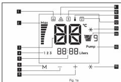
DESCRIPTION OF LCD DISPLAY AND CONTROL PANEL
1.
2.
3.
4.
5,
0.7
8.
[Non-Text]
[Non-Text]
[Non-Text]
[Non-Text]
[Non-Text]
ctas:
3405.
Merr
Butto
2.1.1.
The di
9.
10.
11.
12. 13.
1.5. 44.
14. 15.
16.
[Non-Text]
[Non-Text]
[Non-Text]
[Non-Text]
[Non-Text]
[Non-Text]
[Non-Text]
[Non-Text]
s are dc
广力云
here is a
out the
[Non-Text]
[Non-Text]
[Non-Text]
[Non-Text]
[Non-Text]
[Non-Text]
[Non-Text]
[Non-Text]
[Non-Text]
[Non-Text]
[Non-Text]
- SAFETY INFORMATION
WARNING
3.1 Product
6.1.1 Provides manufactured by Electricals are sold provided they are installed, used and maintained in
good working order in accordance with our
instructions and recommendations. Always refer to this removal if you have no doubt.
to this manual if you have any boost. 3.2. EARTHING:
A) The Earthing
accordance with the local Wiring Regulations.
B) The Electric Water Heater must be earthed.
Improper grounding such as Earth conductor not grounded (floating) or having high resistance to
ground could cause malfunction to ELCB and
ground well based mechanical test and electrical shock. Never use water heater if there is
doubt on Earthin
3.3 If any of the following conditions occur as shown below, immediately switch off the mains and
shown below, immobiliary switch of the mains and contact the Electrolux Customer Service Call Centre
Never attempt to repair the unit yourself :
- If the Electric Water Heater begins to make an
odd noise, smell or smoke.
- If ELCB trips and LCD display does not light up
- Water temperature cannot be controlled. - If the Electric Water Heater shows signs of a
- The exercise Water Health shown light of a distinct change in performance
- If water leaks from inside.
3.4 If the Red (POWER) Indicator does not go
when you turn a
mains supply and contact Electrolux Consumer
Care Centre for repair service. Special skill is required for repairing
REQUIRED for repairing. NEVER by to repair the unit by yourself
NEVER Syl to repair the unit by yourself.
3.5 For Pump Model, it is highly recommended
to connect the V
water tank, otherwise it may cause damage to the
built in Pump Motor inside.
3.6 When the Shower is used by someone such
as child, elderly person, sick person and physically handicapped person, the person appeared is
handicapped pension, the pension concerned to kindly requested to pay attention and check the
shower temperature by hand from time to time.
User is advised to test and adjust the water
temperature be
3.7 During taking shower, once stop for a while
for washing with soap or shampoo and resuming the shower again by turning on 3 in 1 stop valve.
the shower again by turning off in 1 stop valve or water tap. It is normal that the instant water
Temperature output from the water heater will be
higher than the set temperature. To avoid the risk
of scalding, it is advisable to avoid shower with water outst in that period, at ind the water flow.
Water output in that period, or let the water flow for few seconds before continuing bathing.
3.8. During Isotope/hyder switch off the clast
5.3 During lighting/shand, switch on the electric supply to the shower unit in advance to protect the
supply to the shower unit in advance to protect the shower unit against possible damage.
• • •
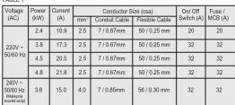
- ELECTRICAL LOADING TABLE
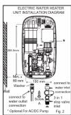
- ELECTRIC WATER HEATER UNIT INSTALLATION
5.1 Select a suitable position in the bathroom.
5.2 Remove the screw (A) at the bottom of the unit. (Fig. 2)
5.3 Remove the Front Cover by lifting up the front cover from the bottom and be careful not to over pull the wire connected between the users interface and main control PCB. Next step is disconnect wire from main PCB.
5.4 Mark 3 Screw points of the Heater Base on the wall. The Heater Base position should 1.5m above the bathroom floor and the left side should be at least 80mm from side wall. The purpose for user easily to press Test & Reset button by themselves regularly. (Fig.2)
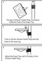
5.5 Select a suitable position for the Shower Set then mark 4 screws point (2 on top and 2 on bottom). The gap of 2 screw hole was 38mm . It is recommended that the top of the portion is in level with the top of Electric Water Heater. (Fig. 3)
5.6 Use 6mm diameter drill and make the wall plug holes in depth of 34mm.
5.7 Insert the wall plugs and mount the Electric Water Heater firmly in position with the screws
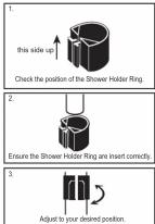
provided. 5.3 Insert the Sharray Holdre and Scam Trow into the Slider Rail
5.9 Insert the Shower Holder and Soap Tray
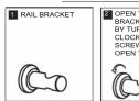
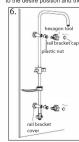
5.10 Remove the cap from the Rail Bracket (Fig. 3A) and screw the Bracket to marked
position. Replace the cap. (Fig. 3)
(1) 2017年1月1日
NORMAL SHOWER INSTALLATION

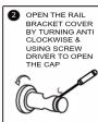
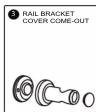
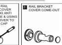
RAIL BRACKET COVER & CAP DISMANTLE STEPS
(THAILAND, INDONESIA, PHILLIPINES & VIETNAM MODELS)
Method of install the soap tray (straight bar type)
- RAIN SHOWER SET INSTALLATION PROCEDURES (MALAYSIA ONLY)
RAIL BRACKET COVER & CAP DISMANTLE STEPS
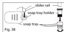
- Insert Soap Tray Holder into Soap Tray hole. (Fig. 3B)
- Then insert soap tray (with Soap Tray Holder) into Slider Rail.
- Soap Tray shall be insert to the Slider Rail after Shower Holder.
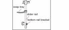
STEP 1
Insert the Top Rail Bracket, Adjustable Shower Holder
Soap Tray & Bottom Rail Bracket to the Slider Rail.

STEP 2
Connect the Selector Valve to the bottom of Slide
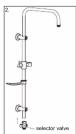
selector valve
STEP 3
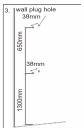
Select a suitable position for the Rain Shower Set then mark 4 screws point (2 on top and 2 on bottom). The gap of 2 screw hole was 38mm. It is recommended that the Top Rail Bracket position at height of 1950mm to the floor and Bottom Rail Bracket 1300mm to the floor.
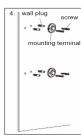
STEP 4
Use 6mm diameter drill and make the wall plug holes in depth of 34mm. Insert the wall plugs and mounting terminal firmly in position with the screw provided.
STEP 5
Mount the Slider Rail (connected with Rail Bracket, Adjustable Shower Holder and Selector Valve) to the mounting terminal by tums the terminal cover

STEP 6
Remove the cover and cap from the Rail Bracket (Fig. 21) and removes the rail headset by turning the cover
(Fig. 3A) and screw the hall bracket by turning the cover clockwise. Using hexagon tool to tighten the plastic nut
to the desire position and then replace the cover.
STEP 8
Recommended Height for Rain Shower Set.
[Non-Text]

1
E _0^2
|| E | 11_ 2
F10
|| E | ||
120
[Non-Text]
[Non-Text]
IMPORTA
For Pump
Connect water that connection is storage supply tank, otherwise it may cause damage
the Pump Motor.
7.6 THE HEATER TANK MUST BE FILLED UP WITU HATER BEFORE TURNING ON TUE
WITH WATER BEFORE TURNING ON THE ELECTRICITY SUPPLY TO PREVENT ANY DRY
BURNT DAMAGE TO THE HEATING ELEMENT.
7.7 Hook the Handshower to the Slider Rail
shower Holder and adjust to your ideal position.
7.9 Do not use white tape during piping installation.
WARNING
7.10 THE WATER INLET AND OUTLET MUST BE
INSTALLED IN CORRECT DIRECTION, OTHERWISE HEATER UNIT WILL NOT FUNCTION
7.11 DO NOT APPLY PLUMBING CEMENT ON
CONNECTION. WHENEVER NECESSARY, USE
ONLY THREAD OR SEALING TAPE AT 3 IN 1 STOP VALVE INLET ONLY. (FIG 2)
7.12 Must use 3 in 1 Stop Valve accessories
provided with the electric water heater
- ELECTRICAL INSTALLATION
WARNINGS
8.1 FARTHING
A) The Earthing installation should be
carried out in accordance with the local
Wiring Regulations.
B) The Electric Water Heater must be
earthed. Improper grounding such as E
conductor not grounded (including) or having high resistance to ground could cause BLUE or BLACK --NEUTRAL (N)
malfunction to ELCB and electrical shock. GREEN or GREEN/YELLOW --EARTH (④)
Never use water heater if there is doubt on 8.8 Connect the LCD display cable from front
Earthing installation. cover to the Main Control PCB. Clamp the cable to the correct position. CHECK IF THE WIRING
8.2. Remember to SWITCH OFF the CONNECTION IS CORRECT and replace the
0.2 Remember to switch off the mains before carrying out any electrical cover. (Fig. 6a)
work. B
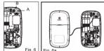
8.9 Example of wrong wiring connection to the
6.5 Example of wrong Electric Water Heater
Fig. A correct wiring co
Fig. 11 Correct wiring connection FICR15mA
L L
①
图 1-3
Ground
⊕
Fig. B wrong wir
earth reversed)
L L ELOC TSMW
_N N
图 1
Ground
⑧
Fig. C wrong wiring connection live connected
to neutral , neutral connected to earth)
ELCB T5mM
L L
N
Ground
Ground
for safety and warning details.
[Non-Text]
[Non-Text]
[Non-Text]
[Non-Text]
[Non-Text]
[Non-Text]
[Non-Text]
[Non-Text]
[Non-Text]
[Non-Text]
[Non-Text]
[Non-Text]

[Non-Text]
[Non-Text]
[Non-Text]
[Non-Text]
[Non-Text]
[Non-Text]
[Non-Text]
[Non-Text]
[Non-Text]
9. TEST OPERATION
9.1 TEST RUN
Before switch ON electricity supply, please check the electrical wiring connection properly to the
(1) Electric Water
10
| |
| |
M - + R
SafeReady
- The icons will blink 2 times (earth harvesting, electrical fan) and
overheating, electrical thermistor) after switch
(附) 7.5.1.1
70.
: ∫0
12.4 BB:BB times
M - + +
- When 3 in 1 stop valve is turns off
Electric Water Heater goes to pre-standby minutes will go to standby mode. (50% light dimmer)
9.2 MANUHY
The temperature can be gradually controlled by
40
70
38
142 BB BB free
(1)
Brass (a) button
- Degree goes up.
- Power display bar lev
accordingly to reach the desired temperature.
2.1.1.3.
The Ground Truth image displays a single, solid horizontal line. According to Rule 2 (UNDERSCORE & LINE RULES), this is a stylistic or background line, not a placeholder underscore. Therefore, the OCR result must ignore it and output nothing or only meaningful text. The provided OCR content is "____", which consists of four underscores. This is an incorrect interpretation of the line as a placeholder, violating the rule that stylistic lines must be ignored. The OCR has hallucinated placeholder underscores where none exist in the GT. Hence, the OCR result is inconsistent with the Ground Truth.
(10)
38*
: JU 5
1.2.0 80 80 mm
M + x
Press (-) button
- Degree goes down. - Power display bar, kg
accordingly to reach the desired
temperature e.
button one more time will trigger the cold water function.
does. The memory indicator will appear in the event that the manual selection for the temperature dotor pump (*) value combination which is same as stored memory. The memory indicator will lights up
(2) pump ( ) 102
9.3 COLD SHOWER SHORTCUT
Cold shower function
(1) 四个区1号
(1)
189
- 30 Pons
-
BB:BB
-
65.65M
M = 十 全
water heater is running - Liser presses the cold sh
- User presses the cold shower button
- After Pressed display changed
to 8.3 (ii).
[Non-Text]
[Non-Text]
e check the electrical wiring
图 4-1 图 4-2
1) 20.
: 30
1.2.3 00:00
M
when the 3 is 1 step
- Last used setting will be activate if the
3 in 1 stop valve is turns on.
(No text)
i)
|
|
M = 1 + 2
- If the 3 in 1 stop valve not ON, after 5
minutes will go to standby mode. (50% light) dimmer.
after 15 minutes, the light
v pressing either UP or DC
1) (probing order of 3 or 24)
720.
:コロ書9
1st BB88.htm
H
Press and hold (+) but
- Temperature digits rises at faster spe
up to the maximum 45 degree.
- Power display bar adjustment according to - If actual temperature cannot reach the
temperature, the "MAX" will show & b
the actual temperature reaches SET "MAX" will disapprove.
Press and hold DOWN button for 2
- Temperature digits falls at faster speed down to 32
degree and stop autoscroll.
- Power display bar adjust accordingly - If the setting reached 32 degree, pres
button one more time will trigger the cold water function.
vent that the manual select
e as stored memory, the memory indicator will lights up
[Non-Text]
(五) 通过网络投票
- via shortcut button: -
□ △ △ ▼
-
| 曹9
1.2.0 88:88
H = 十 元
Cold setting activated
- Electric Water Heater turn off the heating element
- Temperature digits changes to two lines.
- The cold setting (美) icon lights up on the display.
[Non-Text]
Cold setting deactivated
Presses the cold shower button
hen display will go back to
previous setting.
[Non-Text]
[Non-Text]
FOR PUMP MODEL
The pump will ON whe
The Ground Truth image displays a single, solid horizontal line. According to Rule 2 (UNDERSCORE & LINE RULES), if the GT contains lines used for stylistic emphasis or as background elements (like ruled paper), the OCR result must ignore them. The provided OCR content is "____", which consists of four underscores. This is an incorrect interpretation of the line as a placeholder symbol, violating the rule that stylistic lines must be ignored. Therefore, the OCR output hallucinated symbols where none should exist.
[ICON] [ICON] [ICON]
70°
70
: 20
123 BB:BB Liters
M
M - +
Notes: 1. If actual temperature cannot reach the set temperature, full power bar will be shown and
'MAX' display will blink.
It might due to flow rate too high or incoming water temperature too low.
Adjust the 3 in 1 stop valve to reduce water flow.
- It is recommended not to operate the pump for more than 30 minutes.
1.5 MEMORY SETTING
This Electric Water Heater allows user to store up to 3 desired settings (M1/ M2/ M3) for easy access:
[ICON] [ICON] [ICON]
10
J0
108 88:88
M - + +
Memory function
- Press M button for 3 seconds, Memory 1, 2
and 3 will appear.
- Press in button to select the memory selected memory number will blink.
- Press the Temperature (+) or (-) to
desire temperature and leave for 3 seconds.
- Once beep to indicate the setting has been stored.
- 投资投入量
70^
18
1 30
- 30.00.02
M - + * Deactivate the memory function
- Press any button except your cure
selected memory (1, 2 & 3) and
EcoShower button to exit your selected
memory.
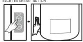
9.6 ELCB TESTING
This procedure is highly recommended to test at least once a month:
ELCR TEST/RESET BUTTON
(2) 100%
(ii)
1738w9
Pump
17 du-deu
Press RESET button
- The Electric Water Heater recover, the
icons (earth, overheating, electrical leak
and thermistor) will blink 2 times & back to previous display.
previous display.
(6) 项目图
(4) 70*
!30w9
1.4.8 88:88 Litter
(1) _2O_2
Memory selection
- User may selects a desired stored setting
by pressing M button
[Non-Text]
[Non-Text]
[Non-Text]
[Non-Text]
(No text)
(N)
1738 ^+
: 30
1.6.7 BB=BB Units
H - + *
- The memory indicator will appear in
the event that the selected temperature
value are the same as stored memory, the memory indicator will lights up.
the memory address
[Non-Text]
[Non-Text]
( once a month:-
a) ELCR ok:
□ (i)
(b)
1
1
1
Press TEST but
- The E1 display
and auto turn
b) ELCB failure: -
(i)
10
C
NEW
M
Press TEST/RESET button
- The E4 display blink & beep
and auto cut off, cannot be reset and
please contact Electrolux customer service call centre.
service can continue.
[Non-Text]
9.7 LOW WATER PRESSURE
This Electric Water Heater can :
10
1
|
|
N = + -
Low water pressure
- Low water pressure
appeared on screen when water pressure is lower than activation flow rate.
(Low water pressure indicator will be
occasional disappeared if water pressure is
too low below 0.8 Litre/min, the display will be become to the are steadily open and
be become to the pre-stuary screen and we can not activate any button on the disk
we can not reserve any button on the display of Electric Water Heater).
- Pump button always lights up if the 3 in 1
stop valve open during pre-standby mode (for model with pump function only)
- During the standby mode, when turn on the
3 in 1 stop valve, if the water flow rate still
cannot activate the Electric Water Heater, to
low pressure indicator will be applied.
[Non-Text]
[Non-Text]
EcoShower is to calculate water consumption by bucket (1 bucket = 20 Liters) and have Eco friendly
environment benefits for user notification of water consumption on each shower. EcoShower will stay
whenever 3 in 1 stop valve being turns on.
Normal usage
(1)
720
: 30
149 00000
M - + *
- Normal display when 3 in 1
stop valve being turn
图 1 图 2
80
: 30w
1.2.0 88:88 Umm
M = N + O - S
- The EcoShower of
- The EcoShower by
accent 1 bucket each time the - If the user continue shower within 15 minutes
EcoShower liters counter reach 20 liters.
- The Ecoholder liters counter will be reset (Present display 3 bucket & 5 liters meaning to reach 20 liters) to 0 each time when reach 20 liters (liters water consumption).
(Present display 1 bucket & 0 liters
meaning to 20 liters water consumption) the counter will reset to zero.
[Non-Text]
[Non-Text]
[Non-Text]
[Non-Text]
[Non-Text]
[Non-Text]
[Non-Text]
[Non-Text]
[Non-Text]
[Non-Text]
[EMPTY]
14 ELECTRICAL SPECIFICATION
| TYPE | ELECTRONIC POWER CONTROL |
| ELECTRICAL LOADING | 2.4kW 220V a.c. 10.9A 50Hz and 60Hz3.8kW 220V a.c. 17.3A 50Hz and 60Hz4.5kW 220V a.c. 20.5A 50Hz and 60Hz4.8kW 220V a.c. 21.8A 50Hz and 60Hz3.6kW 240V a.c. 15.0A 50Hz and 60Hz |
| Min. WATER FLOW RATE | 2 Litre / min |
| Min. INLET WATER PRESSURE | 0.1 Bar (10 kPa; 1:45 psi) |
| Max. INLET WATER PRESSURE | 6.0 Bar (0.6 MPa; 87.02 psi) |
| WATER CONNECTION | 1/2" BSP SINGLE POINT SYSTEM |
| DIMENSIONS | 220 (W) X 401 (H) X 80 (T) mm |
| GROSS WEIGHT | 3.5 kg - ELCB, DPDT, NO PUMP4.5 kg - ELCB, DPDT, AC PJMP3.8 kg - ELCB, DPDT, DC PJMP |
Note: The specification, actual product's cosmetic design and accessories parts shown are
correct at the time of printing and may be subjected to change without prior notice.
[Non-Text]
WE'RE THINKING OF YOU
Thank you for purchasing an Electrolux appliance. You've chosen a product that brings with
it decades of professional experience and innovation. In genious and stylish, it has been
designed with you in mind. So whenever you use it, you can be safe in knowledge that
you'll get great results every time.
17.4.2.3 2.4.2.4
Visit our website to:
Get usage advice, brochures, trouble shooter, service information:
www.electrolux.com
Register your product for better service
www.registerelectrolux.com
- Buy Accessories, Consumables and Original open parts for using appliances
Buy Accessories, Consumat www.electrolux.com/shop
We recommend the use of original spare parts.
When contacting Service, ensure that you have the following data available.
The information can be found on the rating plate. Model, PNC, Serial Number
(Right side of unit).
[Non-Text]
(1) _1 (2) _2 (3) _3 (4)
Warning/ Caution-Safety information.
■ General information and tips.
■ Environmental Information.


Brand : ELECTROLUX
Model : EWE361MB-DST1
Category : Chauffe-eau et ballon d'eau chaude