
MV8-OP1 - Uncategorized ROLAND - Free user manual and instructions
Find the device manual for free MV8-OP1 ROLAND in PDF.


| Product Type | Audio Mixer / Recorder |
| Brand | Roland |
| Model | MV8-OP1 |
| Dimensions (W x D x H) | 320 x 210 x 70 mm |
| Weight | 2.1 kg |
| Power Supply | AC adapter 9V DC, 1.5A (included) |
| Input Channels | 8 mono (XLR/TRS combo), 1 stereo (RCA) |
| Outputs | 2 main XLR, 2 monitor TRS, 1 headphone (1/4") |
| Built-in Effects | 24-bit digital reverb, delay, chorus |
| EQ | 3-band per channel (Hi, Mid, Low) |
| Recording | Direct to USB drive (WAV 16-bit/44.1kHz) |
| Phantom Power | +48V switchable per pair |
| Display | 2.8" color TFT LCD |
| Connectivity | USB B (to computer), USB A (to flash), MIDI I/O |
| Construction | Metal chassis with ABS side panels |
| Maintenance | Clean with soft dry cloth; avoid liquids |
| Safety | Do not expose to rain or moisture; use only supplied adapter |
| Spare Parts Availability | Contact Roland authorized service centers for replacement parts |
| Repairability | Designed for professional repair; user-replaceable fuses |
| General Information | Ideal for live sound and studio recording; firmware updateable via USB |
Frequently Asked Questions - MV8-OP1 ROLAND
User questions about MV8-OP1 ROLAND
0 question about this device. Answer the ones you know or ask your own.
Ask a new question about this device
Download the instructions for your Uncategorized in PDF format for free! Find your manual MV8-OP1 - ROLAND and take your electronic device back in hand. On this page are published all the documents necessary for the use of your device. MV8-OP1 by ROLAND.
USER MANUAL MV8-OP1 ROLAND
Installing the MV8-OP1....4
Installation de la MV8-OP1
(French language for Canadian Safety Standard) 6
Using the MV8-OP1.... 8
Outputting analog audio from analog multi output.... 8
Inputting audio via a digital connection (coaxial/optical) ..... 8
Transferring digital audio via R-BUS....9
Connections and settings for R-BUS devices 12
Copyright © 2006 ROLAND CORPORATION
All rights reserved. No part of this publication may be reproduced in any form without the written permission of ROLAND CORPORATION.
About the MV8-OP1
The MV8-OP1 AUDIO I/O EXPANSION (sold separately) is an expansion board that adds six analog multi-outputs, digital inputs (coaxial type and optical type), and an R-BUS connector to the MV-8800.
Installing the MV8-OP1 adds the following functionality.
- You can digitally connect a digital audio device (CD player, MD player, DAT recorder) and sample without impairing the audio quality.
- You can input digital audio of a variety of sampling frequencies.
* Since the MV8-OP1 contains a sampling rate converter, there is no limitation on the sampling frequencies that can be input. All signals will be converted to 44.1 kHz. - You can connect devices that have an R-BUS connector, such as the Roland VS-2480CD or XV-5080, for digital audio input/output via R-BUS (2-channel input / 8-channel output).
- You can individually output the audio signals of the MV-8800 to its multi outputs. This is convenient when you are using the MV-8800 with an external mixer. (Analog output and R-BUS output are all available.)
- When used with the DIF-AT24 (sold separately), an additional MIDI IN and OUT (16 channels) is added.
* Don't connect the R-BUS connector to an RMDB connector, SCSI connector, RS-232C connector, or parallel connector. Doing so will cause malfunctions.
* Don't connect or disconnect the R-BUS connector while the power is turned on. Doing so will cause malfunctions.
Panel Descriptions
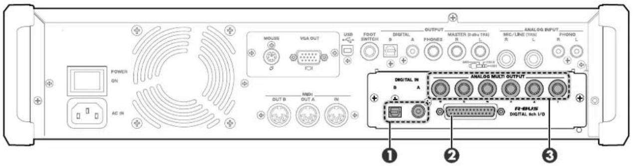
The illustration shows the MV-8800 rear panel when the separately sold MV8-OP1 option is installed.
The jacks shown in items 1–3 are available if the MV8-OP1 AUDIO I/O EXPANSION (separately sold) is installed. You can make output settings from the INSTRUMENTS screen (Screen Guide; p. 114) and the PARTIAL EDIT screen (Screen Guide; p. 125).
1 DIGITAL IN Connectors
These are digital audio input connectors. "A" is a coaxial type connector, and "B" is an optical type connector.
② R-BUS Connector
This is a digital 2-channel input/8-channel output connector. You can also set the input select setting to receive audio input from R-BUS channels 1 and 2, or use the R-BUS channels 1–8 to output the audio from the MULTI OUTPUT bus.
③ ANALOG MULTI OUTPUT Connectors
These jacks output the audio from the MULTI OUTPUT bus.
Precautions for expanding option
 | Always turn the unit off and unplug the AC plug before attempting installation of the MV8-OP1. |
 | Install only the specified option. Remove only the specified screws. |
- To avoid the risk of damage to internal components that can be caused by static electricity, please carefully observe the following whenever you handle the board.
Before you touch the board, always first grasp a metal object (such as a water pipe), so you are sure that any static electricity you might have been carrying has been discharged.
When handling the board, grasp it only by its edges. Avoid touching any of the electronic components.
Save the bag in which the board was originally shipped, and put the board back into it whenever you need to store or transport it. - Do not touch any of the printed circuit pathways.
- Never use excessive force when installing a circuit board. If it doesn't fit properly on the first attempt, remove the board and try again.
- When circuit board installation is complete, double-check your work.
- When turning the unit upside-down, get a bunch of newspapers or magazines, and place them under the four corners or at both ends to prevent damage to the buttons and controls. Also, you should try to orient the unit so no buttons or controls get damaged.
- When turning the unit upside-down, handle with care to avoid dropping it, or allowing it to fall or tip over.
- Use a Philips screwdriver of the appropriate size to avoid damaging the screw heads (a number of 2 screwdriver). If an unsuitable screwdriver is used, the head of the screw may be stripped.
- Turn the screwdriver counter-clockwise to loosen the screws-turn it clockwise to tighten them.

tightenloosen
- Be careful not to let the screws drop inside the MV-8800's body.
- Do not leave the option slot cover removed. After installation of the MV8-OP1 is complete, be sure to replace the cover.
- Be careful not to cut your hand on the edge of the cover or the opening edge while removing the cover.
MV8-OP1 installation procedure

- Be careful not to cut your hand on any sharp edges of the installation slot, cover, or circuit board.
- Turn off the power of the MV-8800 and the connected devices, and disconnect all cables from the MV-8800.
- Turn the MV-8800 upside down, and lay it on its face supported by objects at each corner so that the panel buttons and knobs are not damaged.

- When you lay the MV-8800 on its face, make stacks of magazines or newspapers to support each of the four corners so that the weight of the unit does not damage the buttons and knobs. Make sure that no pressure is being applied to any button or knob.
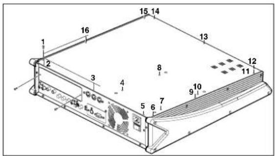
- Remove sixteen screws from the bottom panel and two screws from the MV8-OP1 slot cover at the locations shown in the illustration, and detach the bottom cover and the slot cover.
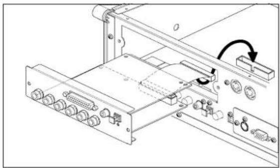
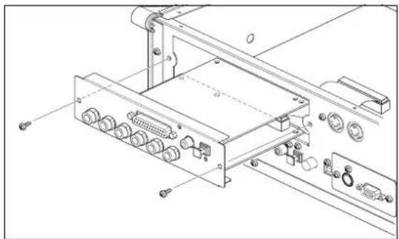
- Insert the MV8-OP1 into the slot in the orientation shown by the illustration.
natural_image
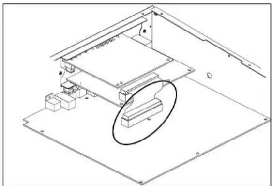
Technical line drawing of a computer rack with connectors and a switch (no text or symbols)- Plug the flat cable extending from the MV8-OP1 firmly into the connector on the main board of the MV-8800.
natural_image
Technical line drawing of an electronic device with a highlighted component (no text or symbols)- Use the two screws to fasten the MV8-OP1.
natural_image
Technical line drawing of an electronic device chassis with connectors and ports (no text or symbols)- Use the sixteen screws to fasten the bottom cover as it was originally.
Precautions concernant l'extension de la options

natural_image
Technical line drawing of a computer rack with connectors and a switch (no text or symbols)natural_image
Technical line drawing of a mechanical assembly with no visible text or symbolsnatural_image
Technical line drawing of an electronic device chassis with ports and connectors (no text or symbols)Outputting analog audio from analog multi output
- Connect the MV-8800 with your output destination device.
- Press [MIXER].
The MIXER (AUDIO TRACK) screen (Screen Guide; p. 235) will appear.
- Set the Output parameter to MLT1-8 or M1/2-7/8.
Set the Output parameter of the part whose signal you want to send to the multi outputs. The signal sent to each output will be output via the analog multi output.
| Value | Destination bus Analog multi output | |
| MLT1 | Multi output 1 1 | |
| ... | ||
| MLT6 Multi output 6 | 6 | |
| MLT7 Multi output 7 | Not output | |
| MLT8 Multi output 8 | Not output | |
| M1/2 Multi output 1/2 | 1 and 2 | |
| M3/4 Multi output 3/4 | 3 and 4 | |
| M5/6 Multi output 5/6 | 5 and 6 | |
| M7/8 Multi output 7/8 | Not output |

● The audio signal of multi output 7 and 8 cannot be output via analog multi output.
Inputting audio via a digital connection (coaxial/optical)
The MV-8800 has both coaxial and optical type digital input connectors. You must choose either one or the other type. You cannot use both simultaneously.
- Connect your digital audio device to the MV-8800.
- Press [SYSTEM].
The SYSTEM MENU screen (Screen Guide; p. 172) will appear.
- With the cursor located in the upper row of icons, press F1. Alternatively, select the GLOBAL icon and press [ENTER].
The GLOBAL screen (Screen Guide; p. 173) will appear.
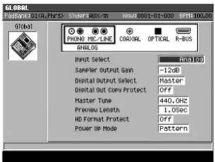
- Set the Input Select parameter to either "Coaxial" or "Optical."
Select "Coaxial" if you want to input from the coaxial connector (DIGITAL IN A), or select "Optical" if you want to input from the optical connector (DIGITAL IN B). When you change the setting, the illustration of the input connector in the GLOBAL screen will also change.
Transferring digital audio via R-BUS
If the MV-8800 is connected to another device that has an R-BUS connector, you can use two channels of digital audio input and eight channels of digital audio output.
Caution when connecting an R-BUS device
- You may connect only another R-BUS device to the R-BUS connector. Even if the connector has the same shape, you must never attempt to connect a SCSI, RS-232C, or parallel interface. Doing so will cause malfunctions.
Use an R-BUS cable (RBC-1 or RBC-3: each sold separately) to make connections to an R-BUS connector.
Before connecting or disconnecting the R-BUS cable, you must turn off the power of the MV-8800 and the other R-BUS device. If you make connections while the power is on, the system may fail to operate correctly, and malfunctions may also occur.
R-BUS is the same specification as “RMDB2” and “RMDB II.” It can be used without any problems with devices marked “RMDB2” or “RMDB II.”
R-BUS is not compatible with "RMDB".
The RBC-5 (5 meter R-BUS cable: no longer available) cannot be used with the MV-8800. Please use the RBC-1 (1 meter R-BUS cable) or RBC-3 (3 meter R-BUS cable).
Making word clock settings
Here's how to specify whether the word clock master device (the device that produces the synchronization signal that regulates transmission and reception of digital audio signals) will be the MV-8800 itself or the external device connected to the R-BUS connector.

- For details on word clock, refer to "Digital Connection with the Word Clock" (p. 10).
1. Press [SYSTEM].
The SYSTEM MENU screen (Screen Guide; p. 172) will appear.
2. With the cursor located in the upper row of icons, press [F2](R-BUS). Alternatively, select the R-BUS icon and press [ENTER].
The R-BUS screen (Screen Guide; p. 183) will appear.
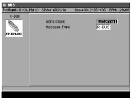
3. Set the Word Clock parameter.
Normally, you should use the "External" setting.
| Value | Explanation |
| External | The word clock will be received from an externally connected R-BUS device. In this case, the sampling rate of the signal sent from the MV8-OP1's R-BUS connector will match the sampling rate of the external R-BUS device. |
| Internal The word clock (44.1 kHz) will be generated inside the MV-8800, and transmitted via the R-BUS connector. Set the external R-BUS device connected to the R-BUS connector to operate as the Slave. | |

The signal transmitted from the MV-8800's OUTPUT DIGITAL and the internal processing of the sampling functionality and the like is always 44.1 kHz.
Digital Connection with the Word Clock
Ordinarily, word clock is generated within, and output by the device transmitting digital signals (the master). Meanwhile, the receiving device (the slave) receives the word clock and adjusts its operation (synchronizes) to that clock. This means that the operation of the transmitting and receiving devices is based on the same sampling rate. With some devices, however, the sampling rate used may differ.
The digital circuitry of the MV8-OP1 (optional), which can be combined with the MV-8800, features a built-in sampling rate converter. This enables reception of digital signals, even when the sampling rate of the received signals differs. The digital signals transmitted from the R-BUS are matched to the received sampling rate.
Also, with some R-BUS devices, you could encounter situations such as the following:
- No word clock can be generated (only slave operation is available)
Due to circumstances with the connection, the device needs to be set to receive word clock (slave).
In such situations, you can make the MV-8800 the word clock master by setting it to "Internal." However, the sampling rate of the digital signals output from the R-BUS will be fixed at 44.1 kHz.
Inputting digital audio into R-BUS
- Connect the MV-8800 with your R-BUS device.
- Press [SYSTEM].
The SYSTEM MENU screen (Screen Guide; p. 172) will appear.
- With the cursor located in the upper row of icons, press F1. Alternatively, select the GLOBAL icon and press [ENTER].
The GLOBAL screen (Screen Guide; p. 173) will appear.
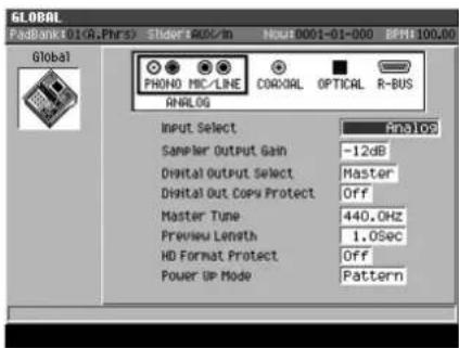
- Set the Input Select parameter to "R-BUS."
Audio can now be input via R-BUS channels 1 and 2. When you switch the setting, the illustration of the input connectors shown in the GLOBAL screen will also change.

- You cannot use R-BUS channels 3–8 to input audio into the MV-8800.
- Since the MV8-OP1 contains a sampling rate converter, there is no restriction on the sampling rates that can be input. All signals will be converted to 44.1 kHz.
Outputting digital audio from R-BUS
You can output the audio from the MV-8800's multi outputs via the R-BUS connector (digital) on MV8-OP1.
-
Connect the MV-8800 with your output destination device.
-
Press [MIXER].
The MIXER (AUDIO TRACK) screen (Screen Guide; p. 235) will appear.
- Set the Output parameter to MLT1-8 or M1/2-7/8.
Set the Output parameter of the part whose signal you want to send to the multi output bus. The signal sent to each bus will be output via R-BUS.
| Value | Destination bus R-BUS output channel | |
| MLT1 | Multi output 1 1 | |
| ... | ||
| MLT6 Multi output 6 6 | ||
| MLT7 Multi output 7 7 | ||
| MLT8 Multi output 8 8 | ||
| M1/2 Multi output 1/2 1 and 2 | ||
| M3/4 Multi output 3/4 3 and 4 | ||
| M5/6 Multi output 5/6 5 and 6 | ||
| M7/8 Multi output 7/8 7 and 8 |

● The identically-numbered R-BUS and analog multi output will output the same audio.
Connections and settings for R-BUS devices
Using the DIF-AT24 to add MIDI connectors
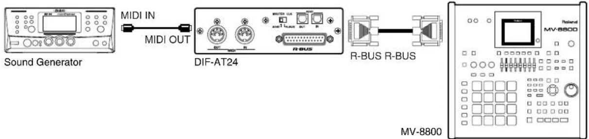
You can add MIDI IN and OUT connectors by connecting the DIF-AT24 (sold separately). You can use the MIDI IN/OUT connectors of the DIF-AT24 to input/output MIDI data.
■ Transmitting MIDI data via the DIF-AT24's MIDI OUT
1. Connect the DIF-AT24 (sold separately) to the R-BUS connector.
flowchart
graph LR
    A["Sound Generator"] -->|MIDI IN| B["DIF-AT24"]
    B -->|MIDI OUT| A
    B --> C["R-BUS"]
    C --> D["R-BUS R-BUS"]
    D --> E["MV-8800"]
2. Power-on the MV-8800.
3. Press [SONG].
The SONG screen (Screen Guide; p. 8) will appear.
4. Use CURSOR [A] to select the MIDI track that contains the performance data you want to output.
The track you select will be the current track.
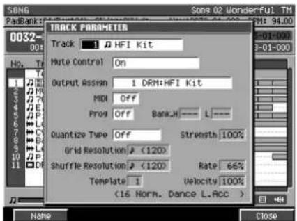
5. Press [F1](Track Param).
The TRACK PARAMETER popup (for a MIDI track) (Screen Guide; p. 11) will appear.
6. Set the Output MIDI parameter.
Select the MIDI connector and channel on which you want to transmit the performance data. If you want to transmit MIDI data via the DIF-AT24, select R1–R16.
| Value | Output destination Channel | |
| A-1 | MIDI OUT A 1 | |
| : | : | |
| A-16 | 16 | |
| B-1 | MIDI OUT B 1 | |
| : | : | |
| B-16 | 16 | |
| R-1 | R-BUS (use MV8-OP1 and DIF-AT24) 1 | |
| : | : | |
| R-16 | 16 |
■ Receiving MIDI data via the DIF-AT24's MIDI IN
The MIDI IN connector added by the DIF-AT24 has the very same functionality as the MV-8800's own MIDI IN connector. The MIDI data from each connector is internally mixed by the MV-8800.
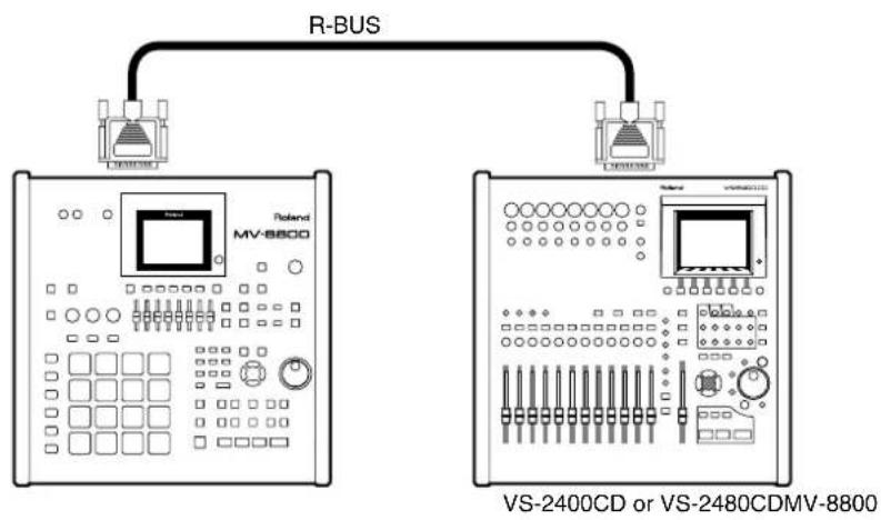
Connecting the VS-2480CD/2400CD
flowchart
graph TD
    A["Power Supply"] --> B["R-BUS"]
    C["Power Supply"] --> D["Power Supply"]
    B --> E["VS-2400CD or VS-2480CDMV-8800"]
■ Required equipment
MV-8800 (with MV8-OP1 [sold separately] installed)
VS-2480CD or VS-2400CD
● RBC-1 (1 meter R-BUS cable) or RBC-3 (3 meter R-BUS cable)
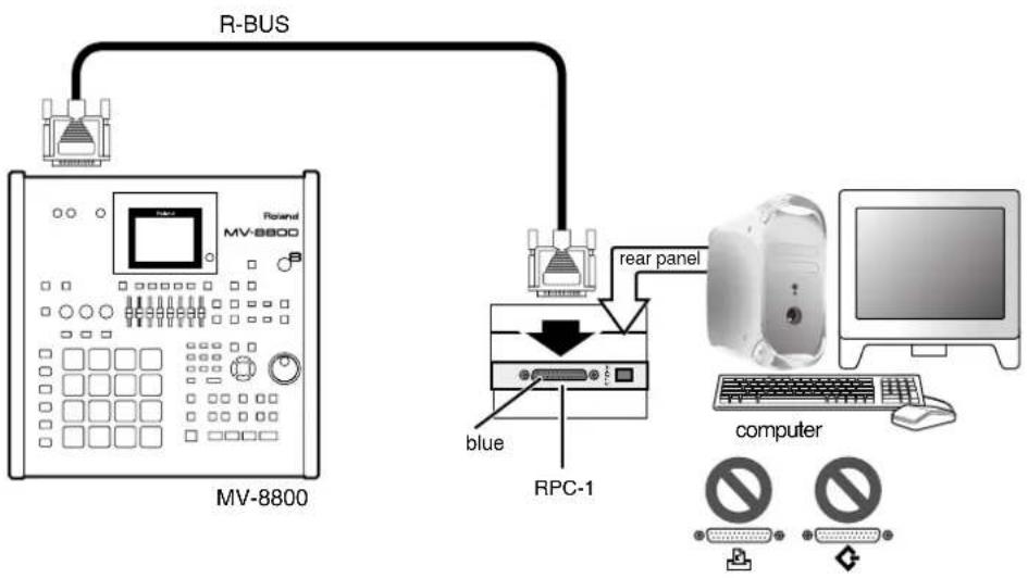
Connecting the RPC-1
flowchart
graph TD
    A["RV-8800"] -->|R-BUS| B["Rear Panel"]
    B --> C["RPC-1"]
    C --> D["blue"]
    C --> E["computer"]
    style A fill:#f9f,stroke:#333
    style B fill:#ccf,stroke:#333
    style C fill:#cfc,stroke:#333
    style D fill:#fcc,stroke:#333
    style E fill:#cff,stroke:#333
■ Required equipment
● MV-8800 (with MV8-OP1 [sold separately] installed)
• Computer with PCI bus (5 volts)
RPC-1
● RBC-1 (1 meter R-BUS cable) or RBC-3 (3 meter R-BUS cable)
Connecting the VM-7000/C7000 series device
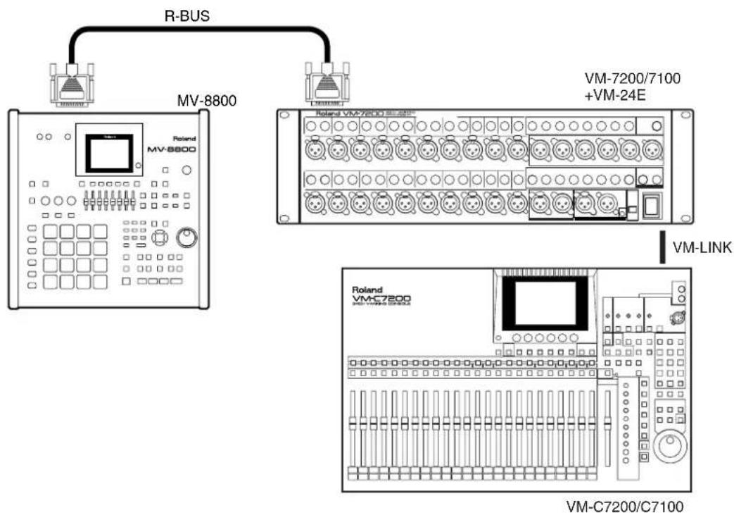
■ Required equipment
● MV-8800 (with MV8-OP1 [sold separately] installed)
● VM-7200/7100 (with VM-24E [sold separately] installed)
VM-C7200/7100
● RBC-1 (1 meter R-BUS cable) or RBC-3 (3 meter R-BUS cable)
VM-LINK cable
Settings for each device
■ Transferring audio
| Model | Master (output device) Slave | |
| MV-8800 | MIXER (INSTRUMENT PART) screen (Screen Guide; p. 236)Output parameter of the part you want to send to R-BUS: MLT1–8, M1/2–M7/8R-BUS screen (Screen Guide; p. 183)R-BUS Word Clock parameter: Internal | GLOBAL screen (Screen Guide; p. 173)Input Select parameter: R-BUSR-BUS screen (Screen Guide; p. 183)R-BUS Word Clock parameter: External |
| VS-2480CD/VS-2400CD | PROJECT PARAMETER screenMASTER CLOCK parameter: INTOUTPUT ASSIGN screenConnect the bus you want to output via R-BUS to R-BUS (1/2–7/8) | PROJECT PARAMETER screenMASTER CLOCK parameter: R-BUSPATCH BAY screenConnect R-BUS 1 or 2 to the INPUT MIXER.You must first load a 44.1 kHz project or create a new one. |
| RPC-1 | MASTER CLOCK parameter: Int. Clock MASTER CLOCK parameter: Ext. Clock | |
| VM-7000 series | SYS DIGITAL screenWORD CLOCK SOURCE parameter: INTERNALEZ ROUTING - MULTI IN screenIn the patch bay, connect the signal from R-BUS to the multi in mixer. | SYS DIGITAL screenWORD CLOCK SOURCE parameter: MULTI 1-8 / MULTI 9-16 / MULTI 17-24EZ ROUTING - MULTI IN screenIn the patch bay, connect the signal from R-BUS to the multi in mixer. |
■ Remote control using MMC
| Model | Master (controlling device) Slave (controlled device) | |
| MV-8800 | SYNC screen (Screen Guide; p. 81) orPATTERN SYNC screen (Screen Guide; p. 94)MMC Mode parameter: MasterMMC R-BUS parameter: On | SYNC screen (Screen Guide; p. 81) orPATTERN SYNC screen (Screen Guide; p. 94)MMC Mode parameter: Slave (R-BUS) |
| VS-2480CD/VS-2400CD | MIDI PARAMETER screenMMC MODE parameter: Master | MIDI PARAMETER screenMMC MODE parameter: SLAVEMMC SOURCE: R-BUS |
| RPC-1 | In your sequencer software, set the MMC parameter to Master.In your sequencer software, specify the RPC-1 as the device that will transmit MMC. | In your sequencer software, set the MMC parameter to Slave.In your sequencer software, specify the RPC-1 as the device that will receive MMC. |
| VM-7000 series | SYS SYNC/MMC screenMMC CONTROL parameter: ONMMC MASTER parameter: INTSYS MIDI screenTx PARAM parameter: ON | SYS SYNC/MMC screenMMC CONTROL parameter: ONMMC MASTER parameter: MULTI 1-8 / MULTI 9-16 / MULTI 17-24SYS MIDI screenRx PARAM parameter: ON |
- About the MV8-OP1
- Panel Descriptions
- DIGITAL IN Connectors
- ② R-BUS Connector
- ③ ANALOG MULTI OUTPUT Connectors
- Precautions for expanding option
- MV8-OP1 installation procedure
- Precautions concernant l'extension de la options
- Outputting analog audio from analog multi output
- Inputting audio via a digital connection (coaxial/optical)
- Transferring digital audio via R-BUS
- Caution when connecting an R-BUS device
- Making word clock settings
- Press [SYSTEM].
- With the cursor located in the upper row of icons, press [F2](R-BUS). Alternatively, select the R-BUS icon and press [ENTER].
- Set the Word Clock parameter.
- Digital Connection with the Word Clock
- Inputting digital audio into R-BUS
- Outputting digital audio from R-BUS
- Connections and settings for R-BUS devices
- Using the DIF-AT24 to add MIDI connectors
- ■ Transmitting MIDI data via the DIF-AT24's MIDI OUT
- Connect the DIF-AT24 (sold separately) to the R-BUS connector.
- Power-on the MV-8800.
- Press [SONG].
- Use CURSOR [A] to select the MIDI track that contains the performance data you want to output.
- Press [F1](Track Param).
- Set the Output MIDI parameter.
- ■ Receiving MIDI data via the DIF-AT24's MIDI IN
- ■ Required equipment
- Settings for each device
Brand : ROLAND
Model : MV8-OP1
Category : Uncategorized