
IDS-TP40-04L - Detector Hikvision - Free user manual and instructions
Find the device manual for free IDS-TP40-04L Hikvision in PDF.


| Product Type | Traffic Incident Detection Server |
| Model | iDS-TP40-04L |
| Number of IP Camera Channels | 4 (up to 3 MP each) |
| Video Input | 4 IP cameras via network |
| Network Interfaces | 4x 10/100M self-adaptive Ethernet, 1x 100/1000M G2/G1, 1x optical interface |
| Serial Ports | 1x RS-232, 1x RS-485 |
| Alarm Input/Output | 4 alarm inputs, 4 alarm outputs |
| USB Interfaces | 2x USB 2.0 |
| Video Output | 1x HDMI |
| Power Supply | 100-240 VAC or 12 VDC (SELV/LPS) |
| Hard Drive Support | Up to 4 HDDs (SATA) |
| Operating System Compatibility | Windows 7/8/10 (32/64-bit), IE8+ / Firefox 30-52 / Chrome 31-45 |
| Key Functions | Traffic violation detection, traffic data collection, incident recording, image collage, 24/7 video recording |
| Supported Traffic Violations | Wrong-way driving, reverse, lane line violation, illegal lane change, illegal U-turn, illegal parking, red light running, overspeed, etc. |
| Network Protocols | TCP/IP, RTSP, HTTP, HTTPS, DHCP, NTP, FTP, SSH, EHome, SDK, Private Protocol |
| Security | Strong password policy, HTTPS, SSH, user hierarchy (admin, operator, user) |
| Maintenance | HDD initialization, S.M.A.R.T., bad sector detection, database repair, config export/import, remote upgrade |
| Backup Methods | USB backup, web backup (to FTP or remote host) |
| Environment | Indoor use, rack-mountable, requires proper grounding |
Frequently Asked Questions - IDS-TP40-04L Hikvision
User questions about IDS-TP40-04L Hikvision
0 question about this device. Answer the ones you know or ask your own.
Ask a new question about this device
Download the instructions for your Detector in PDF format for free! Find your manual IDS-TP40-04L - Hikvision and take your electronic device back in hand. On this page are published all the documents necessary for the use of your device. IDS-TP40-04L by Hikvision.
USER MANUAL IDS-TP40-04L Hikvision
iDS-TP40-04L Traffic Incident Detection Server
User Manual
User Manual
COPYRIGHT © 2018 Hangzhou Hikvision Digital Technology Co., Ltd.
ALL RIGHTS RESERVED.
Any and all informaon, including, among others, wordings, pictures, graphs are the properes of Hangzhou Hikvision Digital Technology Co., Ltd. or its subsidiaries (hereinaer referred to be "Hikvision"). This user manual (hereinaer referred to be "the Manual") cannot be reproduced, changed, translated, or distributed, parally or wholly, by any means, without the prior written permission of Hikvision. Unless otherwise spulated, Hikvision does not make any warranties, guarantees or representaons, express or implied, regarding to the Manual.
About this Manual
This Manual is applicable to iDS-TP40-04L Trac Incident Detecon Server.
The Manual includes instrucons for using and managing the product. Pictures, charts, images and all other informaon hereinaer are for descripon and explanaon only. The informaon contained in the Manual is subject to change, without noce, due to rmware updates or other reasons. Please nd the latest version in the company website
(hp://overseas.hikvision.com/en/).
Please use this user manual under the guidance of professionals.
Trademarks Acknowledgement
HIKVISION and other Hikvision's trademarks and logos are the properes of Hikvision in various jurisdicons. Other trademarks and logos menoned below are the properes of their respective owners.
Legal Disclaimer
TO THE MAXIMUM EXTENT PERMITTED BY APPLICABLE LAW, THE PRODUCT DESCRIBED, WITH ITS HARDWARE, SOFTWARE AND FIRMWARE, IS PROVIDED "AS IS", WITH ALL FAULTS AND ERRORS, AND HIKVISION MAKES NO WARRANTIES, EXPRESS OR IMPLIED, INCLUDING WITHOUT LIMITATION, MERCHANTABILITY, SATISFACTORY QUALITY, FITNESS FOR A PARTICULAR PURPOSE, AND NON-INFRINGEMENT OF THIRD PARTY. IN NO EVENT WILL HIKVISION, ITS DIRECTORS, OFFICERS, EMPLOYEES, OR AGENTS BE LIABLE TO YOU FOR ANY SPECIAL, CONSEQUENTIAL, INCIDENTAL, OR INDIRECT DAMAGES, INCLUDING, AMONG OTHERS, DAMAGES FOR LOSS OF BUSINESS PROFITS, BUSINESS INTERRUPTION, OR LOSS OF DATA OR DOCUMENTATION, IN CONNECTION WITH THE USE OF THIS PRODUCT, EVEN IF HIKVISION HAS BEEN ADVISED OF THE POSSIBILITY OF SUCH DAMAGES.
REGARDING TO THE PRODUCT WITH INTERNET ACCESS, THE USE OF PRODUCT SHALL BE WHOLLY AT YOUR OWN RISKS. HIKVISION SHALL NOT TAKE ANY RESPONSIBILITES FOR ABNORMAL OPERATION, PRIVACY LEAKAGE OR OTHER DAMAGES RESULTING FROM CYBER ATTACK, HACKER ATTACK, VIRUS INSPECTION, OR OTHER INTERNET SECURITY RISKS; HOWEVER, HIKVISION WILL PROVIDE TIMELY TECHNICAL SUPPORT IF REQUIRED.
SURVEILLANCE LAWS VARY BY JURISDICTION. PLEASE CHECK ALL RELEVANT LAWS IN YOUR JURISDICTION BEFORE USING THIS PRODUCT IN ORDER TO ENSURE THAT YOUR USE CONFORMS THE APPLICABLE LAW. HIKVISION SHALL NOT BE LIABLE IN THE EVENT THAT THIS PRODUCT IS USED WITH ILLEGITIMATE PURPOSES.
IN THE EVENT OF ANY CONFLICTS BETWEEN THIS MANUAL AND THE APPLICABLE LAW, THE LATER PREVAILS.
Applicable Models
This manual is applicable to iDS-TP40-04L.
Symbol Conventions
The symbols that may be found in this document are dened as follows.
| Symbol | Description |
 NOTE NOTE | Provides additional informaon to emphasize or supplement important points of the main text. |
 WARNING WARNING | Indicates a potentially hazardous situaon, which if not avoided, could result in equipment damage, data loss, performance degradaon, or unexpected results. |
 DANGER DANGER | Indicates a hazard with a high level of risk, which if not avoided, will result in death or serious injury. |
Safety Instructions
- Proper conguraon of all passwords and other security sengs is the responsibility of the installer and/or end-user.
- In the use of the product, you must be in strict compliance with the electrical safety regulaons of the naon and region. Please refer to technical specicaons for detailed informaon.
- Enter voltage should meet both the SELV (Safety Extra Low Voltage) and the Limited Power Source with 100 to 240 VAC or 12 VDC according to the IEC60950-1 standard. Please refer to technical speciaons for detailed informaon.
- Do not connect several devices to one power adapter as adapter overload may cause over-heang or a re hazard.
- Please make sure that the plug is rmly connected to the power socket.
- If smoke, odor or noise rise from the device, turn off the power at once and unplug the power cable, and then please contact the service center.
Preventive and Cautionary Tips
Before connecng and operang your device, please be advised of the following ps:
- Ensure environmental conditions meet factory specicaons.
- Ensure unit is properly secured to a rack or shelf. Major shocks or jolts to the unit as a result of dropping it may cause damage to the sensitive electronics within the unit.
- Use the device in conjuncon with an UPS if possible.
● Power down the unit before connecng and disconnectg accessories and peripherals.
● A factory recommended HDD should be used for this device. - Improper use or replacement of the baery may result in hazard of explosion. Replace with the same or equivalent type only. Dispose of used baeries according to the instrucons provided by the baery manufacturer.
Table of Contents
Chapter 1 Key Features....7
Chapter 2 Introducon and Interfaces....8
Chapter 3 Geng Started....9
3.1 Starng Up and Shung Down....9
3.1.1 Start Up 9
3.1.2 Shut Down....9
3.1.3 Reboot....9
3.2 Environment Requirement....9
3.3 Set the Admin Password ....10
Chapter 4 Network Setngs....12
4.1 External Network Setngs....12
4.2 Internal Network Setngs 12
4.3 More Settings....13
4.3.1 Port Sengs....13
4.3.2 Remote Access Conguraon 14
4.3.3 HTTPS Conguraon 14
4.3.4 Stac Router....16
Chapter 5 Device Parameters....18
5.1 Device Informaon....18
5.2 Time Setngs....18
5.3 DST Setngs....19
5.4 Other Trac Sengs....20
Chapter 6 Camera Management ......23
Chapter 7 Camera Sengs....25
7.1 Display Setngs 25
7.2 Text Overlay....25
7.3 Image Collage Parameters....26
7.4 Collaged Picture Text Overlay....27
7.5 Interacon Conguraon....27
7.6 Alarm Output 28
7.7 Scene Patrol....29
7.7.1 Congure Preset Scene 29
7.7.2 Congure Scene Patrol Schedule 29
Chapter 8 Trac Incident Detecon....31
8.1 Event Monitoring Conguraon 31
8.1.1 Monitoring Spot Informaon Setngs 31
8.1.2 Intelligent Analysis Parameters....32
8.1.3 Congure Preset Scene 33
8.1.4 Capture Illegal Parking Vehicle....34
8.1.5 Trac Violaon Capture 34
8.1.6 Trafc Parameters Collecon 35
8.1.7 Congure Trac Stascs Parameters ...... 36
8.1.8 Set Trafc Incident Rule 36
8.1.9 Set Lane Line 37
8.1.10 Congure Flow Stasc Rules 38
8.2 Trac Incident Search....38
8.2.1 Search Trac Data....38
8.2.2 Search Trac Flow Stascs 39
8.2.3 Search Real-Time Data 39
Chapter 9 Record and Capture Sengs....40
9.1 HDD Inializaon 40
9.2 Picture Quota 40
9.3 HDD Detecon 41
9.3.1 S.M.A.R.T Sengs 41
9.3.2 Bad Sector Detecon 41
9.4 Video Parameter Sengs 42
9.5 Holiday Sengs....43
9.6 Record Schedule Sengs 44
9.7 Alarm Input Recording Setngs 46
Chapter 10 Serial Port Sengs ....49
10.1 RS-232 Serial Port 49
10.2 RS-485 Serial Port 49
Chapter 11 Backup Conguraon ....51
11.1 USB Backup Setngs....51
11.2 Web Backup Setngs....52
Chapter 12 Uploading Data....54
12.1 Host Sengs 54
12.2 FTP Sengs....55
12.3 Data Uploading Conguraon....57
Chapter 13 Status Informaon....59
13.1 Server Status ....59
13.2 Camera Status ....59
Chapter 14 Other Sengs ......61
14.1 User Management....61
14.1.1 Adding a User 61
14.1.2 Modifying a User 62
14.1.3 Deleng a User 63
14.2 Excepon....63
14.3 Maintenance 64
14.3.1 Reboong the Device....65
14.3.2 Default Sengs....65
14.3.3 Repairing Database 66
14.3.4 Exporng/Imporng Conguraon File....66
14.3.5 Remote Upgrade 66
14.4 Audio Linkage Alarm Conguraon 67
Chapter 1 Key Features
● 4 IP cameras, with resoluon up to 3 MP, are connectable.
- Detect trafc violaon including wrong-way driving, reverse, driving on the lane line, illegal lane change, and illegal U-turn capture.
- Collect trac data including trac ow, trac speed, vehicle distance, trac status, etc.
- Record trac incident videos, including incident alarm video and trac violaon video.
- Collage violaon pictures in to on picture.
- Search traffic data according to specied me, camera, incident type, violaon type, etc. And play linked videos.
● Record all-day video for connected cameras.
Chapter 2 Introduction and Interfaces
Purpose:
iDS-TP40-04L as a trac dedicated trac incident detecon server provides mulply features, including video management, trac data management, video and audio decoding, picture processing, network transmission, etc. It integrates 4 network ports and 1 ber ports, eecvely meets the demands of distributed storage and accessing to surveillance management plaorm. Owing to the above features, iDS-TP40-04L series is widely applied in checkpoint, E-police, trac surveillance system, etc.
The front panel view is shown below:
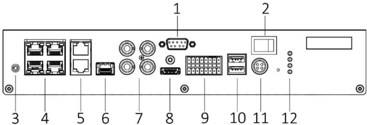
Figure 2-1 Front Panel View
Table 2-1 Descripon of Front Panel
| No. | Name | No. | Name |
| 1 | RS-232 serial interface | 9 | RS-485 serial interface |
| 2 | Power switch | RS-232 serial interface | |
| 3 | GND | Alarm input | |
| 4 | 10/100M self-adapve Ethernet interfaces | Alarm output | |
| 5 | 100/1000M self-adapve G2/G1 Ethernet interface | 10 | USB 2.0 interfaces |
| 6 | Opcal interface | 11 | 12 VDC power input |
| 7 | Video inputs | 12 | Status indicators |
| 8 | HDMI interface |
Chapter 3 Getting Started
3.1 Starting Up and Shutting Down
Purpose:
Proper startup and shutdown procedures are crucial to expanding the life of the device.
3.1.1 Start Up
Before you start:
- Fix the device in an equipment cabinet.
- Ensure the device is properly grounded.
- Plug the network cable
Step 1 Plug the power supply to start up.

Make sure the power supply is plugged into an electrical outlet. It is HIGHLY recommended that an Uninterruptible Power Supply (UPS) be used in conjunction with the device.
3.1.2 Shut Down
Unplug the power supply to shut down.
3.1.3 Reboot
For detailed steps, please refer to 14.3.1 Reboong the Device.
3.2 Environment Requirement
Purpose:
Requirements on web browser and operaon system are as follows:
- Web Browser: Internet Explorer 8.0 and above version/Mozilla Firefox 30-52 version/Google Chrome 31.0-45.0.2454.85.
● Operang System: Windows 7/Windows 8/Windows 10 (32-bit or 64-bit).

For Windows 10 operaon system, to access the server via Internet Explorer 10, you need to Run IE10 as an Administrator.
3.3 Set the Admin Password
Purpose:
For the rst-me access, you need to acvate the device by seng an admin password. No operaon is allowed before acvaon. You can also acvate the device via Web Browser, SADP or Client Soware.
Before you start:
Set the IP address of your computer. Make sure the device is in the same network segment with your computer.

● The default IP address for G1 network interface is 192.0.0.64.
● The default IP address for G2 network interface is 192.168.1.64.
Step 1 Enter device IP address in address bar of the browser and press Enter. Thus the acvaon interface pops up.
Step 2 Enter the Admin Password and Conrm Password.
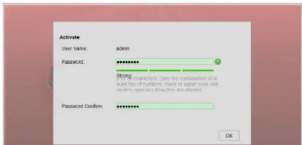
Figure 3-1 Seng Admin Password

WARNING
STRONG PASSWORD RECOMMENDED— We highly recommend you create a strong password of your own choosing (using a minimum of 8 characters, including upper case leers, lower case leers, numbers, and special characters) in order to increase the security of your product. And we recommend you reset your password regularly, especially in the high security system, reseng the password monthly or weekly can beer protect your product.
Step 3 Click OK to set the admin password.
Step 4 Aer successful login, follow the prompt to install the plug-in.
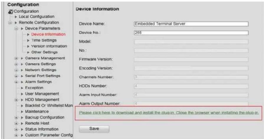
Figure 3-2 Installing Plug-in
Chapter 4 Network Settings
Purpose:
Guarantee the network conncon between your computer and the device is correct, thus you can control the device remotely.
4.1 External Network Settings
Step 1 Go to Conguraon > Remote Conguraon > Network Sengs > External Network Sengs.
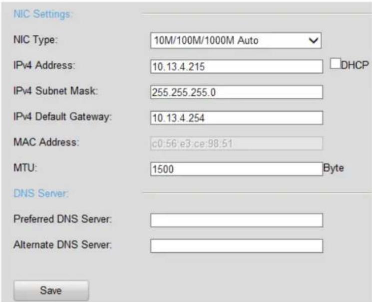
Figure 4-1 Basic Network Sengs
Step 2 Set the NIC Sengs.
1) Select the NIC Type in the dropdown list.
2) Enter IPv4 Address, IPv4 Subnet Mask, IPv4 Default Gateway. Or you can select DHCP (Dynamic Host Conguraon Protocol) to obtain IPv4 address dynamically.
Step 3 Set the DNS Server.
Enter the Preferred DNS Server and Alternate DNS Server.
Step 4 Click Save to save the above sengs.
4.2 Internal Network Settings
Purpose:
You can congregate the IP address for the network interfaces. The default IP address is 192.0.0.64.
Step 1 Go to Conguraon > Remote Conguraon > Network Sengs > Internal Network Sengs.
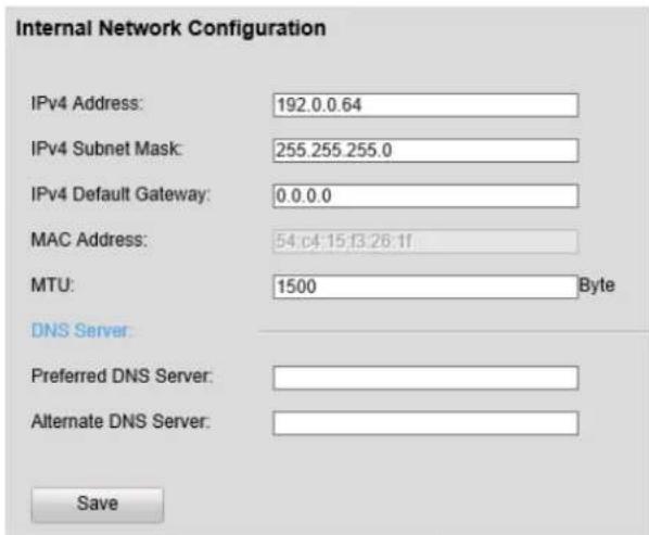
Figure 4-2 Basic Network Sengs
Step 2 Set the NIC Sengs.
1) Select the NIC Type in the dropdown list.
2) Enter IPv4 Address, IPv4 Subnet Mask, IPv4 Default Gateway. Or you can select DHCP (Dynamic Host Conguraon Protocol) to obtain IPv4 address dynamically.
Step 3 Set the DNS Server.
Enter the Preferred DNS Server and Alternate DNS Server.
Step 4 Click Save to save the above sengs.
4.3 More Settings
Purpose:
Oponally, you can congregate the device network ports. And SSH (Secure Shell) funcon is provided. SSH is an encrypted network protocol to ensure the remote visit security.
4.3.1 Port Settings
Step 1 Go to Conguraon > Remote Conguraon > Network Sengs > Network Port Sengs.
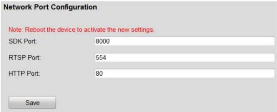
Figure 4-3 Network Port Conguraon
Step 2 Edit the SDK Port, RTSP Port and HTTP Port.
- SDK Port: Port for plaorm to communicate with the device.
● RTSP Port: Port for geng stream from IP camera. - HTTP Port: Port for browser to access the device.
Step 3 Click Save to save the sengs.

Restart the device to acvate the new sengs.
4.3.2 Remote Access Configuration
Purpose:
SSH (Secure Shell) as a security protocol ensures network security for the remote accessing and other network service. It prevents informaon leakage issues during remote management.
Step 1 Go to Conguraon > Remote Conguraon > Network Sengs > Remote Access Conguraon.
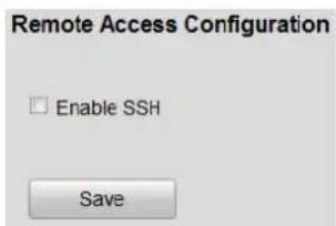
Figure 4-4 Remote Access Conguraon
Step 2 Check the checkbox of SSH.
Step 3 Click Save to enable it.
4.3.3 HTTPS Configuration
Purpose:
HTTPS provides authencaon of the web site and associated web server that one is communicang with, which protects against Man-in-the-middle aacks. Perform the following steps to set the port number of hps.
Example:
If you set the port number as 443 and the IP address is 192.168.1.64, you may access the device by inpung hps://192.168.1.64:443 via the web browser.
Step 1 Go to Conguraon > Remote Conguraon > Network Sengs > HTTPS.
Step 2 Create the self-signed cercate or authorized cercate.
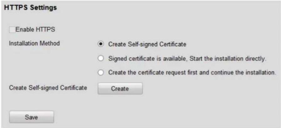
Figure 4-5 HTTPS Sengs
- Opon 1: Create the self-signed cercate
1) Select the radio of Create Self-Signed Cercate.
2) Click the Create buon to pop up the following dialog box.
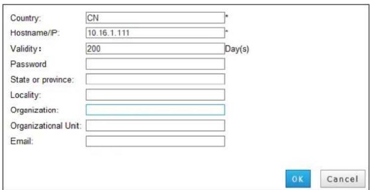
Figure 4-6 Create Self-signed Cercate
3) Enter the Country, Hostname/IP, Validity, and other informaon.
4) Click OK to create the cercate.
- Opon 2: Install available cercate
1) Select the radio of Signed cercate is available, Start the installaon direcon.
2) Click Browse and import the cercate to the device and install it.
- Opon 3: Create the authorized cercate
1) Select the radio of Create the cercate request rst and connue the installaon.
2) Click the Create buon to create the cercate request.
3) Download the cercate request and submit it to the trusted cercate authority for signature.
4) Aer receiving the signed valid cercate, import the cercate to the device and install it.
Step 3 There will be the cercate informaon aer you successfully create and install the cercate.
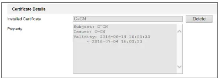
Figure 4-7 Installed Cercate Property
Step 4 Check the checkbox to enable the HTTPS funcon.
Step 5 Click the Save buon to save the sengs.
4.3.4 Static Router
Purpose:
To access dierent local networks via G1 and G2 network interface, you need to congregate stac router. If you do not specify a router, the device will visit network via the default G1 gateway.
Step 1 Go to Conguraon > Remote Conguraon > Network Sengs > Static Router.
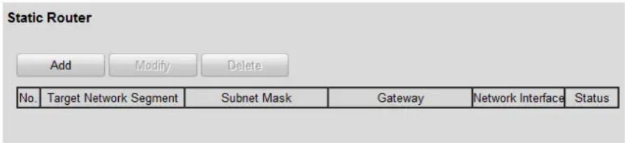
Figure 4-8 Stac Router
Step 2 Click the Add buon.
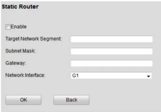
Figure 4-9 Add
Step 3 Check Enable checkbox.
Step 4 Enter Target Network Segment, Subnet Mask, and Gateway.
● Target Network Segment: The network segment of target server.
- Subnet Mask: subnet mask of target network segment.
● Gateway: gateway for the selected network interface.
Step 5 Select Network Interface.
Step 6 Click OK to save the sengs.
Chapter 5 Device Parameters
5.1 Device Information
Purpose:
You can enter Device Informaon interface to view the basic informaon of device.
Step 1 Go to Conguraon > Remote Conguraon > Device Parameters > Device Informaon.
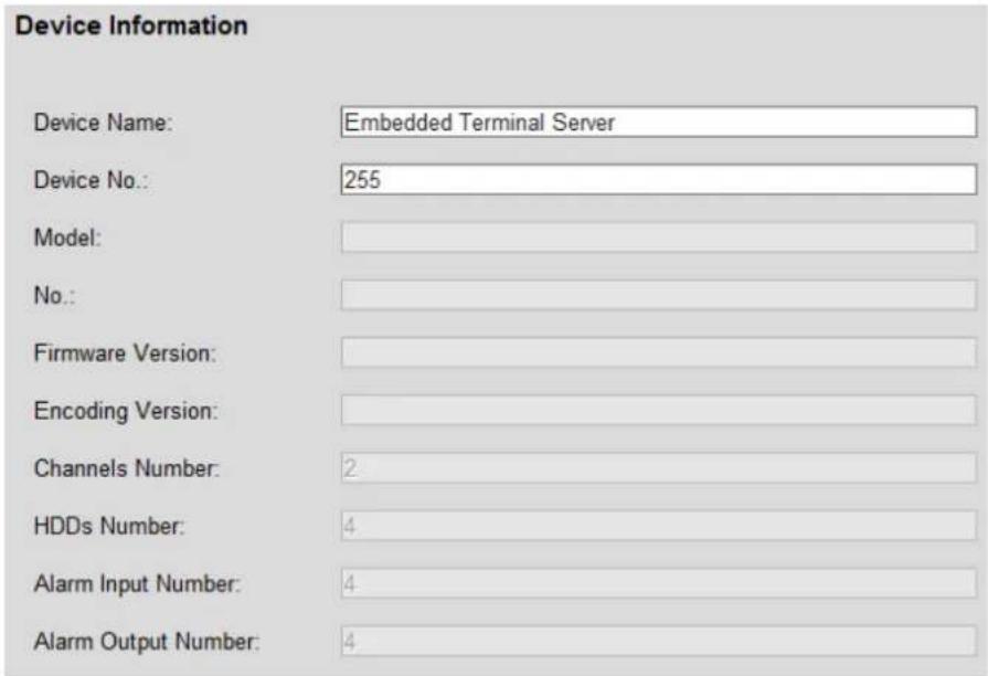
Figure 5-1 Device Informaon
5.2 Time Settings
Purpose:
You can synchronize the date and me of the device manually or automacally.
Step 1 Go to Conguraon > Remote Conguraon > Device Parameters > Time Sengs.
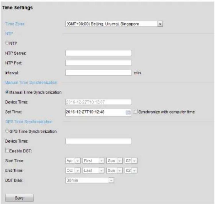
Figure 5-2 Time Sengs
Step 2 Select Time Zone from the dropdown list.
Step 3 Select the clock synchronizaon mode as NTP, Manual Time Synchronizaon or GPS Time Synchronizaon.
NTP
Enter NTP Server, NTP Port and Interval me.
● Manual Time Synchronizaon
Enter the me and date in Set Time. Or you can select Synchronize with computer me.
5.3 DST Settings
Purpose:
DST (Daylight Saving Time) is the pracce of advancing clocks during summer months by specied hours so that evening daylight lasts specied hours longer while sacrificing normal sunrise mes.
Step 1 Go to Conguraon > Remote Conguraon > Device Parameters > Time Sengs.
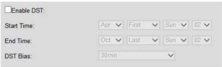
Figure 5-3 DST Sengs Interface
Step 2 Check the checkbox of Enable DST.
Step 3 Set Start Time, End Time, and DST Bias.
Step 4 Or you can manually check the Enable DST checkbox, and then you choose the date of the DST period.
5.4 Other Traffic Settings
Purpose:
Congure other trac sengs for device.
Step 1 Go to Conguraon > Remote Conguraon > Device Parameters > Other Sengs.
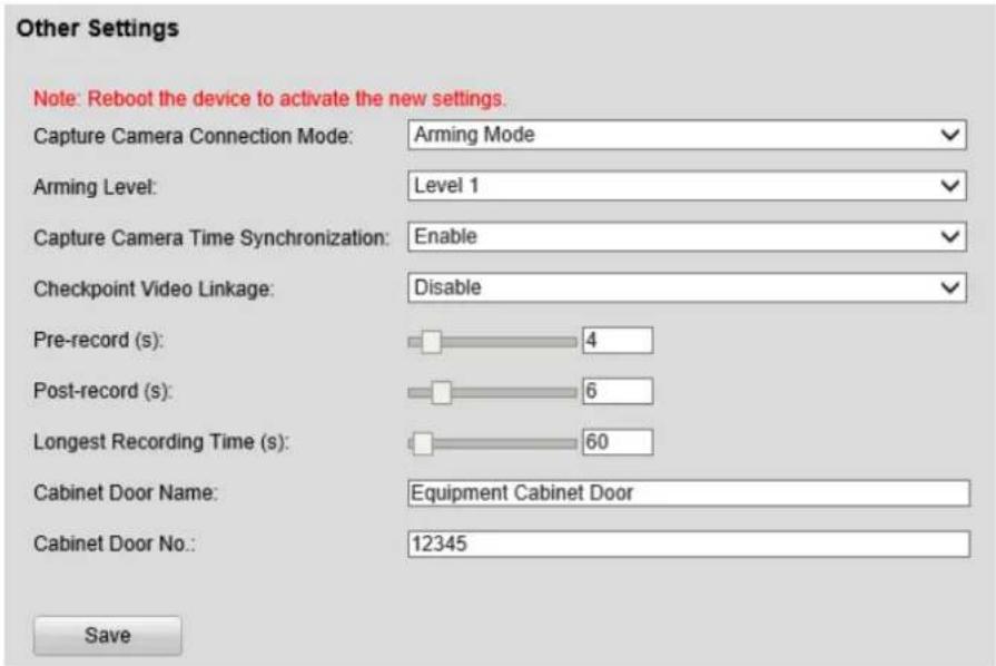
Figure 5-4 Other Sengs
Step 2 Congure following parameters according to your needs.
● Trac Camera Connecon Mode:
Arming Mode: Link between server and trac cameras is a long-period link. server takes pictures from trac cameras. Server is the acve device.
Listening Mode: Link between server and trac cameras is a short-period link. Trac cameras upload pictures to server. Server is the passive device.
● Arming Level (only available for Arming Mode):
Level 1: The server has the highest priority to receive pictures from connected trac cameras. Ensures no picture loss.
Level 2: Two servers can receive pictures from one trac camera. They are equal to cameras.
Level 3: Three servers can receive pictures from one trac camera. They are equal to cameras.
- Checkpoint Video Linkage:
Enable: When searching trac data in Trac interface, you can play and export checkpoint linked video.
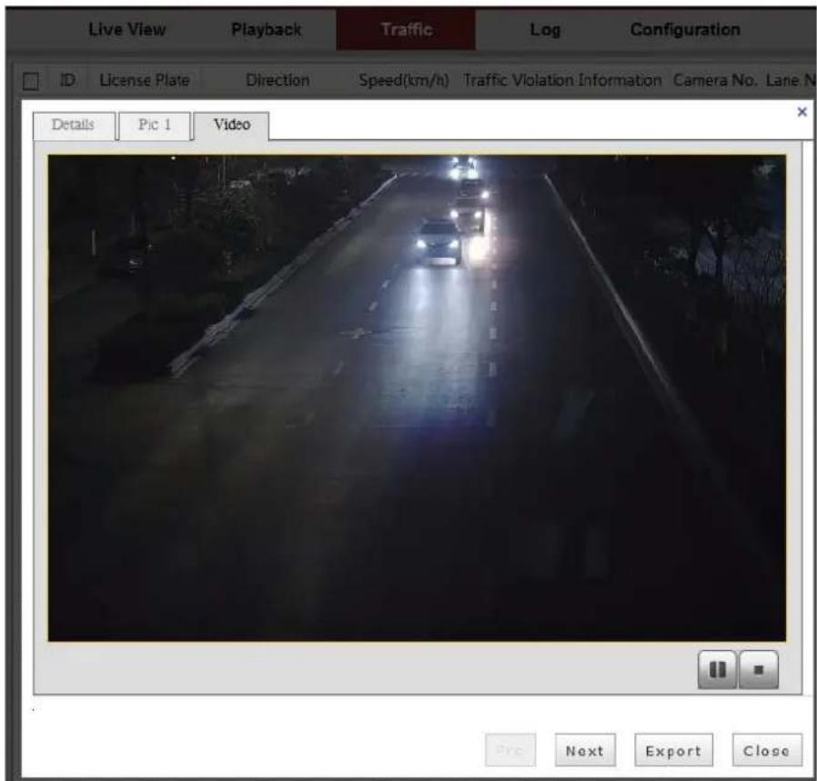
Figure 5-5 Linked Video
● Trac Camera Time Synchronizaon:
Enable: Server synchronizes the connected trac cameras' me.
● Pre-record (s): The me you set to record before the violaon. For example, when a violaon occurs at 10:00, if you set the pre-record me as 4 seconds, the camera records it at 9:59:56.
● Post-record (s): The me you set to record aer the violaon. For example, when a violaon ends at 11:00, if you set the post-record me as 6 seconds, it records ll 11:00:06.
● Longest Recording Time (s): The longest me for a violaon video.

When you search the violaon pictures, you can view the violaon video as while. In order to keep the violaon video completeness, set the all-day record schedule for cameras.
- Mark Picture with: Add Time Synchronizaon Mark or add Security Code to pictures. The two items are written in binary code and they are invisible.
Step 3 Enter Cabinet Door Name and Cabinet Door No. according to actual installaon.
Step 4 Click Save to save the sengs.
Chapter 6 Camera Management
Purpose:
Up to 4 smart IP cameras can be add to the device.
Step 1 Go to Conguraon > Remote Conguraon > Camera Management > IP Camera.
Step 2 Add IP cameras. Manual add and quick-scan are provided.
- Opon 1: Manual Add
1) Click the Add buon.
2) Select Registraon Mode as IP or Normal Domain.
3) Enter IP Address / Domain.
4) Select Protocol.
5) Enter Management Port, Channel No., User Name, Admin Password and Password Conrm.
6) Click OK to add it.

All the input parameter above should be the same with the IP camera itself.
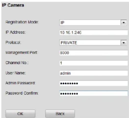
Figure 6-1 Manually Add IP Camera
- Opon 2: Quick-Scan
1) Click the Quick-Scan buon. The online IP cameras will be listed.
2) Select the IP cameras you want to add.
3) Click OK to add them.

IP cameras have the same password with the device can be connected successfully.
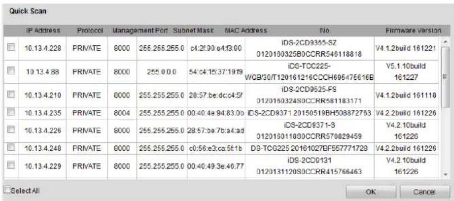
Figure 6-2 Quick-Scan
Step 3 Oponally, you can click to select an added IP camera, and click Modify, Delete or Reboot to perform corresponding acons.
Chapter 7 Camera Settings
7.1 Display Settings
Purpose:
You can congure parameters of OSD (On Screen Display) menu.
Step 1 Go to Conguraon > Remote Conguraon > Camera Sengs > Display Sengs.
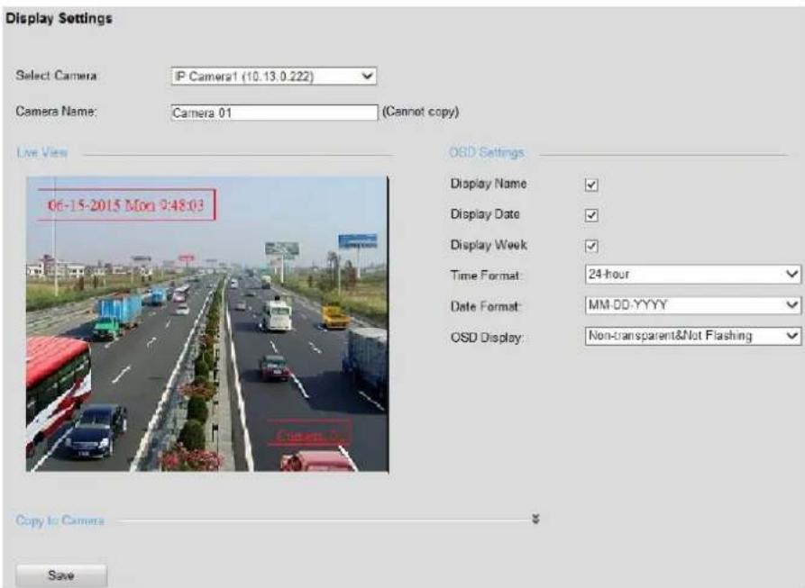
Figure 7-1 Display Sengs
Step 2 Select camera to congure.
Step 3 Congure parameters according to your need, including Camera Name, Display Name, Display Date, Display Week, Time Format, Date Format and OSD Display.
Step 4 Oponally, you can click and select cameras you want to copy above sengs to.
Step 5 Click OK to save the sengs.
7.2 Text Overlay
Purpose:
You can overlay four text contents onto the video.
Step 1 Go to Conguraon > Remote Conguraon > Camera Sengs > Text Overlay.
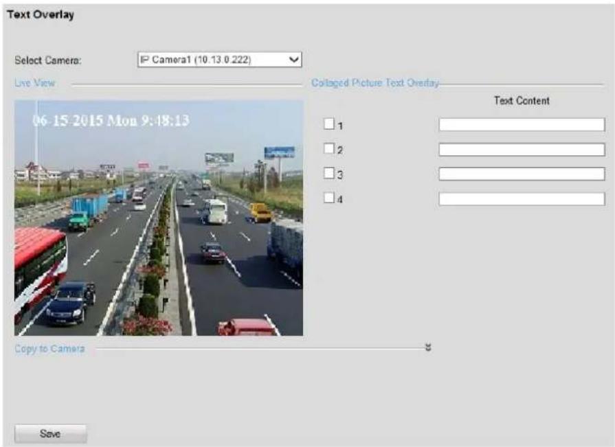
Figure 7-2 Text Overlay Sengs
Step 2 Select camera to congure in Select Camera dropdown list.
Step 3 Enter contents in the four Text Contents.
Step 4 Check the checkbox of text content you want to display.
Step 5 Click Save to show the contents.
7.3 Image Collage Parameters
Purpose:
Congure image collage layout and other parameters.
Step 1 Go to Conguraon > Remote Conguraon > Camera Sengs > Image Collage Parameters.
Step 2 Select camera to congure.
Step 3 Set Image Collaging as Enable.
Step 4 Select layout for 2 Captured Pictures and 3 Captured Pictures.
Step 5 Congure Maximum Size of Picture (KB) and Original Picture Zoom Mulple.
● Maximum Size of Picture (KB): The maximum size of collaged pictures.
● Original Picture Zoom Mulple: The zoom in times for pictures to collage.
Step 6 Click Save.
7.4 Collaged Picture Text Overlay
Purpose:
Overlay text on collaged pictures.
Step 1 Go to Conguraon > Remote Conguraon > Camera Sengs > Collaged Picture Text Overlay.
Step 2 Select camera to congure.
Step 3 Select Text Overlay Posion.
Step 4 Select Text Overlay Type.
Step 5 Set text parameters including Inial Top Margin, Initial Le Margin, Character Size, Character Color, Background Color, Space, and Posion Percentage of Line Break.
- Inial Top Margin: Text posion from top margin.
- Inial Le Margin: Text posion from le margin.
- Posion Percentage of Line Break: Text will switch to next line when the percentage between text length and picture width reaches the set value.
Step 6 Click Save.
7.5 Interaction Configuration
Purpose:
Congure the Interacon Mode between server and trac cameras.
Step 1 Go to Conguraon > Remote Conguraon > Camera Sengs > Interacon Conguraon.
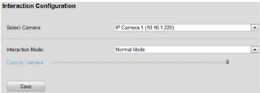
Figure 7-3 Interacon Conguraon
Step 2 Select camera to conjure in Select Camera dropdown list.
Step 3 Select Interacon Mode as Normal Mode or Data Receiving Mode. The default one is Normal Mode.
● Normal Mode: Device can record videos, live view, and receive pictures from the selected camera.
● Data Receiving Mode: Device can only receive pictures from the selected camera. Recording videos and live view are not supported.
Step 4 Click ⚪ and select camera(s). Thus to congregate the same parameters to selected camera(s).
Step 5 Click Save to save the sengs.
7.6 Alarm Output
Purpose:
You can congregate the delay me, arming me, and alarm output name.
Step 1 Go to Conguraon > Remote Conguraon > Alarm Sengs > Alarm Output.
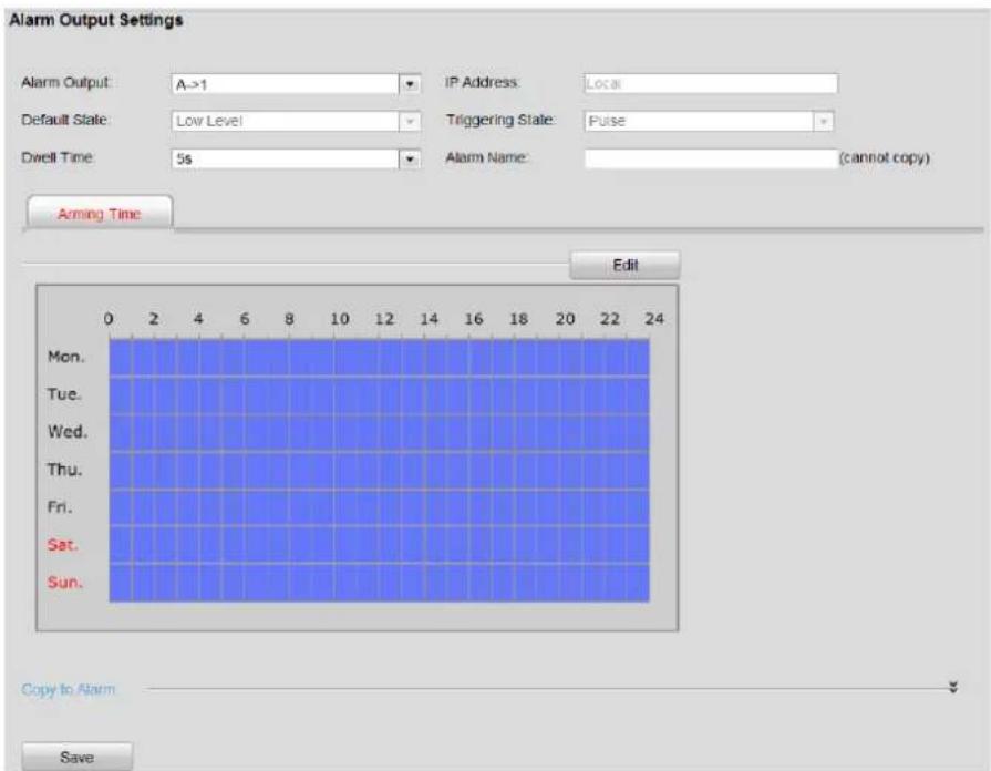
Figure 7-4 Alarm Output
Step 2 Select Alarm Output No. in the dropdown list.
Step 3 Select the Dwell Time. Thus the device sends out alarm output signal for the set me.
Step 4 Enter Alarm Name.
Step 5 Click the buon to conjure the arming me. The alarm output signal is only available in arming me.
For detailed steps, turn to step 5 to 8 in 9.7 Alarm Input Recording Sengs.
Step 6 Click Save to save the sengs.
7.7 Scene Patrol
Purpose:
Camera will automatically rotate to specied scenes and stay there for the set dwell me before moving on to the next scene.
7.7.1 Configure Preset Scene
Purpose:
Preset the scenes to monitor.
Step 1 Go to Conguraon > Remote Conguraon > Camera Conguraon > Preset Scene Parameters.
Step 2 Select camera to congure.
Step 3 Rotate the camera to a scene to monitor by operang the le PTZ panel.
Step 4 Enter Scene Name and Scene No. and select Direcon and Scene Mode according to actuality.
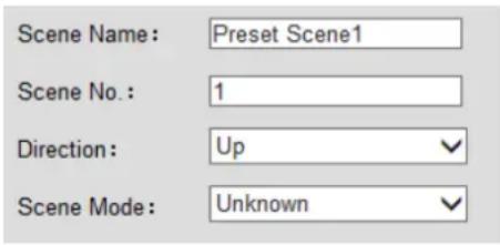
Figure 7-5 Scene Parameters
Step 5 Repeat above steps to preset more scenes.
Step 6 Save the sengs.
7.7.2 Configure Scene Patrol Schedule
Purpose:
Congure scene patrol schedule. Camera will automatically patrol according to the set schedule.
Step 1 Go to Conguraon > Remote Conguraon > Camera Conguraon > Scene Patrol Schedule.
Step 2 Select camera to congure.
Step 3 Check Enable Schedule.
Step 4 Select a date congure the schedule and congure scene rules the day.
4) Select a me period to set the Start Time and End Time.
5) Click Conguraon to congure linked scenes.
| Auto-Switch Scene Configuration | ||||
| Auto- Switch Sequence | Scene | Dwell Time | ||
| - | 1 | Scene 1 √ | 0 Hour 5 Minute | |
| - | 2 | Scene 2 √ | 0 Hour 10 Minute | |
| - | 3 | Scene 3 √ | 0 Hour 15 Minute | ↑↓ |
| + Add New Rule | ||||
Figure 7-6 Scene Conguraon
6) Click Add New Rule.
7) For each rule, select Scene to patrol and set Dwell Time.
8) Repeat above steps to congregate rules for other me periods.
Step 5 Oponally, copy the conguraon to other days and other cameras.
Step 6 Save the sengs.
Chapter 8 Traffic Incident Detection
8.1 Event Monitoring Configuration
8.1.1 Monitoring Spot Information Settings
Purpose:
Congure monitoring spot parameters before conging trac violaon capture, trac stascs, picture capture, etc.
Step 1 Go to Conguraon > Remote Conguraon > Camera Sengs > Monitoring Spot Informaon.
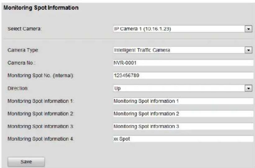
Figure 8-1 Monitoring Spot Informaon
Step 2 Select camera to congregate in Select Camera dropdown list.
Step 3 Select Camera Type as Video Surveillance Camera or Intelligent Trac Camera. The default Camera Type is Video Surveillance Camera.
- Video Surveillance Camera: Server stores camera video les. Camera picture les won't be stored.
● Intelligent Trac Camera: Server stores both camera video les and picture les.
● Video Analysis: Server analyzes stream received from the camera and generates trace incident and evidence data. The camera resolution must be lower than 3 MP.
Step 4 Enter Camera No. and Monitoring Spot No. (Internal).
- Camera No.: Used to disguish trac cameras from each other. Enter an exclusive No. for each camera. It only supports leer and number in 30 bytes.
● Monitor Spot No. (internal): Used to disguish trafc cameras in dierent checkpoints. Enter an exclusive No. for each camera. It only supports number no bigger than 4,294,967,295.
Step 5 Select Direcon according to actual installaon.
Step 6 Enter detailed informaon for monitoring spots in the four text contents, including Monitoring Spot Informaon 1, Monitoring Spot Informaon 2, Monitoring Spot Informaon 3, and Monitoring Spot Informaon 4.
i NOTE
- Valid Monitoring Spot Informaon 1: No more than 120 characters.
- Valid Monitoring Spot Informaon 2: No more than 40 characters.
- Valid Monitoring Spot Informaon 3: No more than 30 characters.
- Valid Monitoring Spot Informaon 4: No more than 24 characters.
Step 7 Click Save to save the sengs.
8.1.2 Intelligent Analysis Parameters
Purpose:
Enable intelligent analysis to obtain violaon vehicle informaon.
Step 1 Go to Conguraon > Remote Conguraon > Camera Conguraon > Intelligent Analysis Parameters.
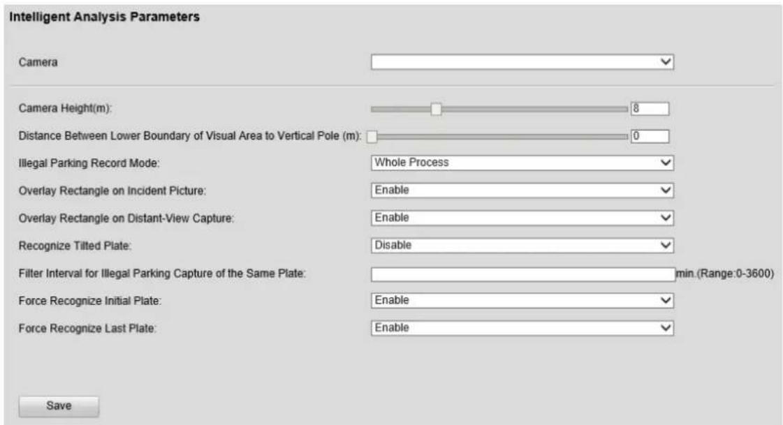
Figure 8-2 Intelligent Analysis Parameters
Step 2 Select camera to congure.
Step 3 Congure intelligent analysis parameters.
- Overlay Rectangle on Incident Picture: If enabled, in the picture of trac incident search result, the violaon vehicle will be marked by a red rectangle frame.
- Overlay Rectangle on Distant-View Capture: If enabled, in the picture of evidence data search result, the violaon vehicle will be marked by a red rectangle frame.
● Force Recognize Inial Plate/Force Recognize Last Plate: Force recognize the initial/last picture of evidence data picture.
Step 4 Save the sengs.
8.1.3 Configure Preset Scene
Purpose:
Congure preset scene parameters before collecng trac informaon, capture illegal parking violaon, and capture trac violaon.
Step 1 Go to Conguraon > Remote Conguraon > Camera Conguraon > Preset Scene Parameters.
Step 2 Select Camera to congure.
Step 3 Select Scene to congure.
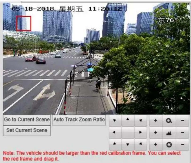
Figure 8-3 PTZ Panel
● Auto Track Zoom Rao: Click the buon to adjust the ratio of target object in the picture. The camera will track target object by the set rao.

You need to congregate the zoom rao when the auto-tracking speed dome is connected.
- Set Current Scene: Rotate the camera to a posion to monitor by operang the PTZ panel and click the buon to save the posion as a scene.
- Go to Current Scene: Click the buon to rotate the camera to the saved scene.
Step 4 Select direcon and scene mode according to your needs.
Step 5 Save the sengs.
8.1.4 Capture Illegal Parking Vehicle
Purpose:
Set the illegal parking enforcement parameters to detect illegal parking vehicles. Only speed dome supports illegal parking enforcement.
Step 1 Go to Conguraon > Remote Conguraon > Camera Conguraon > Preset Scene Parameters.
Step 2 Click Lock to lock the preset scene.
Step 3 Congure Scene Name, Scene No., and Direcon according to your needs.
Step 4 Check Capture Violaon Evidence and Capture No Plate Vehicle.

Uncheck Capture No Plate Vehicle and set Plate Matching Rao when you need to improve eecveness of illegal parking capture.
Step 5 Set Number of Captured Picture(s).
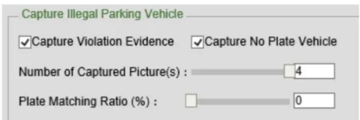
Figure 8-4 Capture Illegal Parking Vehicle
Step 6 Oponally, click Picture Conguraon to set details about captured pictures.
Step 7 Save the sengs.
8.1.5 Traffic Violation Capture
Purpose:
Follow the steps to detect trac violaon including wrong-way driving, reverse, driving on the lane line, illegal lane change, and illegal U-turn capture.
Step 1 Go to Conguraon > Remote Conguraon > Camera Conguraon > Preset Scene Parameters.
Step 2 Click Lock to lock the preset scene.
Step 3 Congure Scene Name, Scene No., and Direcon according to your needs.
Step 4 Check Capture Violaon Evidence.
Step 5 Select Capture Mode according to your needs.
Step 6 Set Number of Captured Picture(s).
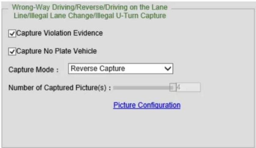
Figure 8-5 Trac Violaon Capture
Step 7 Oponally, click Picture Conguraon to set details about captured pictures.
Step 8 Go to Trac Incident Rule tab, check incidents in Incident Rule secon frame and check Select All in Lange Linkage for selected incidents in Incident Parameters secon frame.
Step 9 Congure lane line parameters. For details, refer to 8.1.9 Set Lane Line.
Step 10 Save the sengs.
8.1.6 Traffic Parameters Collection
Purpose:
Congure trac parameters collecon to count trac ow during a period.
Step 1 Go to Conguraon > Remote Conguraon > Device Parameters > Trac Stascs.
Step 2 Enable Trac Parameters Stascs.
Step 3 Congure Trac Parameters Stascs Period, Smooth Threshold, and Blocked Threshold according to your needs.
Step 4 Go to Trac Incident Rule tab, check incidents in Incident Rule secon frame and check Select All in Lange Linkage for selected incidents in Incident Parameters secon frame.
Congure lane line parameters. For details, refer to 8.1.9 Set Lane Line.
Step 5 Save the sengs.
8.1.7 Configure Traffic Statistics Parameters
Purpose:
Enable trac ow stascs feature.
Step 1 Go to Conguraon > Remote Conguraon > Device Parameters > Trac Stascs.
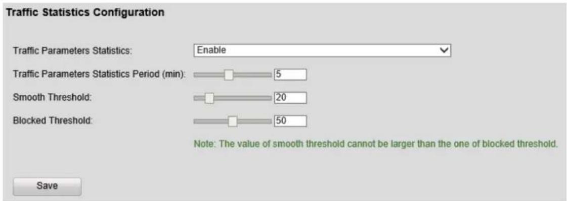
Figure 8-6 Trac Stascs
Step 2 Select Trac Parameters Stascs as Enable.
Step 3 Adjust Trac Parameters Stascs Period, Smooth Threshold, and Blocked Threshold.
● Trac Parameters Stascs Period: The smaller than value is, the faster the trafc stascs counts.
● Smooth Threshold and Blocked Threshold: You are recommended to use the default value.
Step 4 Save the sengs.
Step 5 Go to Conguraon > Remote Conguraon > Camera Conguraon > Preset Scene Parameters.
Step 6 In Basic Parameter tab, check Trac Parameters Collecon.
Step 7 Go to Trac Incident Rule tab, check Flow incident.
Step 8 Go to Lane Conguraon tab, congure ow trigger line and lane line.
Step 9 Save the sengs
8.1.8 Set Traffic Incident Rule
Purpose:
Set trac incident rules to automacally track vehicle in preset scene.
Step 1 Go to Conguraon > Remote Conguraon > Camera Conguraon > Preset Scene Parameters.
Step 2 Select Camera and Scene to congure.
Step 3 Go to Trac Incident Rule tab.
Step 4 Check incidents according to your needs.
Step 5 Congure incident parameters according to your needs.
Step 6 Check Lane Linkage.
Step 7 Save the sengs.
8.1.9 Set Lane Line
Purpose:
Set lane line when trac parameters stascs is enabled. Set a lane line for each real lane line. Up to 6 lane lines can be set for each scene.

- Lane line direcon is required.
- Adjacent lanes cannot be overlapped.
Step 1 Go to Conguraon > Remote Conguraon > Camera Conguraon > Preset Scene Parameters.
Step 2 Select Camera and Scene to congure.
Step 3 Go to Lane Conguraon tab.
Step 4 Select Lane Number according to actual situaon.
Step 5 Click Draw Lane Line and draw a lane line. Repeat the step to draw more lane lines.
Step 6 Click Set Lane Informaon and congure lane informaon according to actual situaon.

Figure 8-7 Lane Informaon
Step 7 Save the sengs.
8.1.10 Configure Flow Statistic Rules
Purpose:
Congure trac ow stasc rules.
Step 1 Go to Conguraon > Remote Conguraon > Camera Conguraon > Preset Scene Parameters.
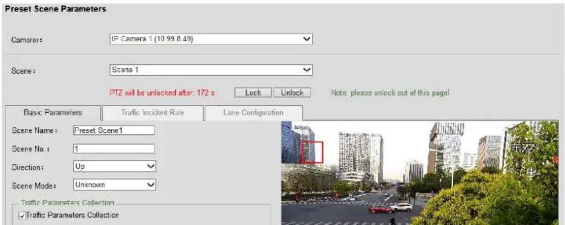
Figure 8-8 Preset Scene Parameters
Step 2 Select Camera to congure.
Step 3 In Basic Parameter tab, check Trac Parameters Collecon.
Step 4 Go to Trac Incident Rule tab, check Flow incident and check Select All in Lange Linkage of Flow Incident Parameters.
Step 5 Oponally, to analyze Run on Road Shoulder and Run on Non-motor Vehicle Lane events, you need to check Vehicle Passing Capture.

Figure 8-9 Flow Incident Parameters
Step 6 Congure lane line parameters. For details, refer to 8.1.9 Set Lane Line.
Step 7 Save the sengs.
8.2 Traffic Incident Search
8.2.1 Search Traffic Data
Purpose:
View trac data of a camera.
Step 1 Go to Trac > Trac Data Search.
Step 2 Select Camera No.
Step 3 Set search conditions.

Time range must be within 7 days.
Step 4 Click Search.
Step 5 Click Details to show detailed informaon, picture, and videos.
Step 6 Oponally, click Export to export the data to a local path.

Add the camera IP address as trusted site before exporng.
8.2.2 Search Traffic Flow Statistics
Purpose:
Search trac ow stascs.
Step 1 Go to Trac > Trac Flow Stascs.
Step 2 Select Graph Format as desired.
Step 3 Select Camera No.
Step 4 Select Stascs Format.
Step 5 Set Start Time and End Time.
Step 6 Click Stascs.
8.2.3 Search Real-Time Data
Purpose:
Capture trac violaon vehicle in real me and recognize vehicle type, license plate number, violaon type, etc.
Step 1 Go to Real-Time Data. You can view the violaon vehicle informaon.
Step 2 Select a violaon vehicle to view captured picture.
Chapter 9 Record and Capture Settings
9.1 HDD Initialization
Purpose:
Initialize the HDD before you use it.

HDD amount varies according to dierent models. You can refer to specicaon for details.
Step 1 Go to Conguraon > Remote Conguraon > HDD Management > Basic Sengs.
Step 2 Check the checkbox of HDD to inialize.
Step 3 Click Init to initiate it.
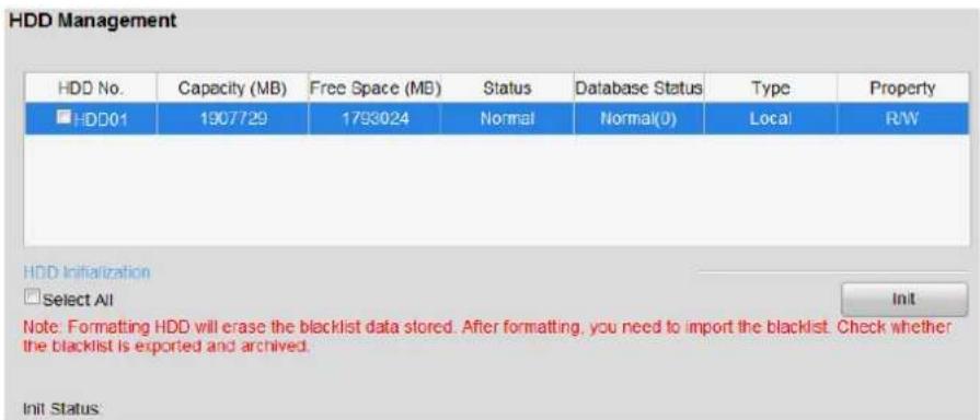
Figure 9-1 HDD Management
9.2 Picture Quota
Purpose:
You can set the maximum capacity for saving picture.
Step 1 Go to Conguraon > Remote Conguraon > HDD Management > Picture Quota.
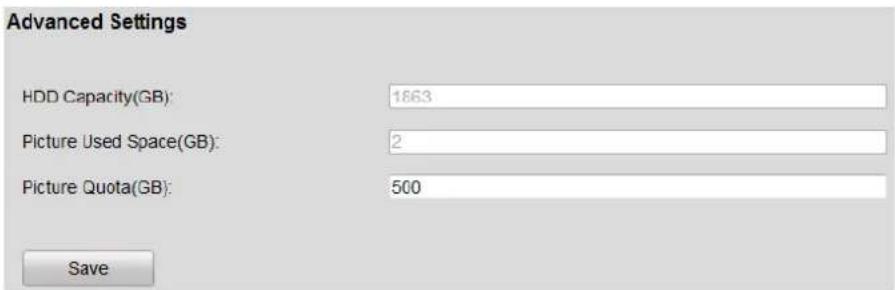
Figure 9-2 Advanced Sengs
Step 2 Enter the Picture Quota in the text eld. The other HDD capacity is for video les.
Step 3 Click OK to save the sengs.
9.3 HDD Detection
Purpose:
The device provides the HDD detecon funcon such as the adopng of the S.M.A.R.T and the Bad Sector Detecon technique. The S.M.A.R.T (Self-Monitoring, Analysis and Reporng Technology) is a monitoring system for HDD to detect and report on various indicators of reliability in the hopes of ancipang failures.
9.3.1 S.M.A.R.T Settings
Step 1 Go to Conguraon > Remote Conguraon > HDD Management > S.M.A.R.T..
Step 2 Select the HDD to view its S.M.A.R.T informaon.
The related informaon of the S.M.A.R.T. is shown on the interface.
Step 3 Choose the Self-Test Type as Short Test, Expanded Test or the Conveyance Test.
Step 4 Click the Start buon to start the S.M.A.R.T. HDD self-evaluaon.
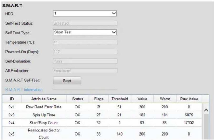
Figure 9-3 S.M.A.R.T Sengs Interface
9.3.2 Bad Sector Detection
Step 1 Go to Conguraon > Remote Conguraon > HDD Management > S.M.A.R.T..
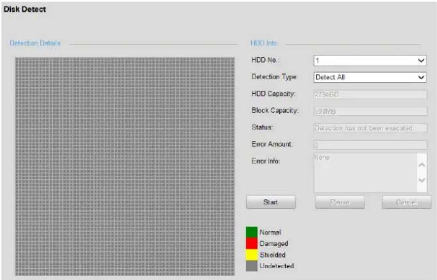
Figure 9-4 Bad Sector Detecon
Step 2 Select the HDD No. in the drop-down.
Step 3 Choose Detecon Type as Detect All or Key Area Detecon.
Step 4 Click the Start buon to start the detecon. You can pause or cancel the detecon.
9.4 Video Parameter Settings
Purpose:
You can denote the parameters that act the image quality, such as the transmission stream type, the resolution and so on.
Step 1 Go to Conguraon > Remote Conguraon > Camera Sengs > Video Seings.
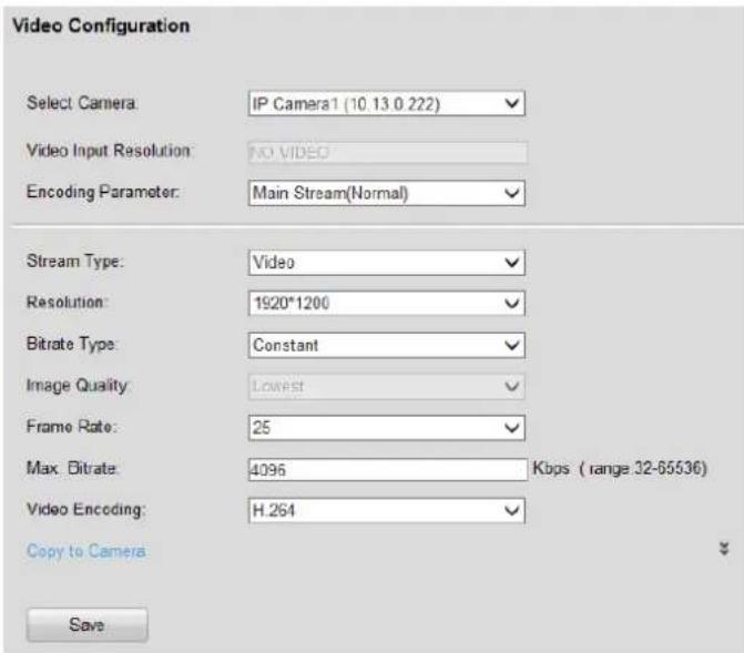
Figure 9-5 Video Sengs
Step 2 Select the camera to congure from the Select Camera dropdown list.
Step 3 Select stream to congregate as Main Stream (Normal), Sub-stream, or Main Stream (Event).
● Main Stream (Normal): Stream for normal recording.
- Sub-stream: Stream for network transmission.
● Main Stream (Event): Stream for event recording.
Step 4 Congure Encoding Parameters. You can congregate the stream type, resolution, and other parameters on your demand.
Step 5 Oponally, click and select cameras to copy the above parameters to.

Only analog cameras can copy parameters to each other.
Step 6 Click OK to save the sengs.
9.5 Holiday Settings
Purpose:
You may want to have dierent recording schedule on holiday or special days. Follow the steps to specify holiday date.
Step 1 Go to Conguraon > Remote Conguraon > Camera Sengs > Holiday Sengs.
| Serial No. | Holiday Name | Status | Start Date | End Date | Edit |
| 1 | Holiday1 | Disable | 1.Jan. | 1.Jan. | |
| 2 | Holiday2 | Disable | 1.Jan. | 1.Jan. | |
| 3 | Holiday3 | Disable | 1.Jan. | 1.Jan. | |
| 4 | Holiday4 | Disable | 1.Jan. | 1.Jan. | |
| 5 | Holiday5 | Disable | 1.Jan. | 1.Jan. | |
| 6 | Holiday6 | Disable | 1.Jan. | 1.Jan. | |
| 7 | Holiday7 | Disable | 1.Jan. | 1.Jan. | |
| 8 | Holiday8 | Disable | 1.Jan. | 1.Jan. | |
| 9 | Holiday9 | Disable | 1.Jan. | 1.Jan. | |
| 10 | Holiday10 | Disable | 1.Jan. | 1.Jan. | |
| 11 | Holiday11 | Disable | 1.Jan. | 1.Jan. | |
| 12 | Holiday12 | Disable | 1.Jan. | 1.Jan. | |
| 13 | Holiday13 | Disable | 1.Jan. | 1.Jan. | |
| 14 | Holiday14 | Disable | 1.Jan. | 1.Jan. | |
| 15 | Holiday15 | Disable | 1.Jan. | 1.Jan. |
Figure 9-6 Holiday Sengs
Step 2 Click the icon aer a holiday to enter Edit Holiday interface.

Up to 32 holidays can be congured.
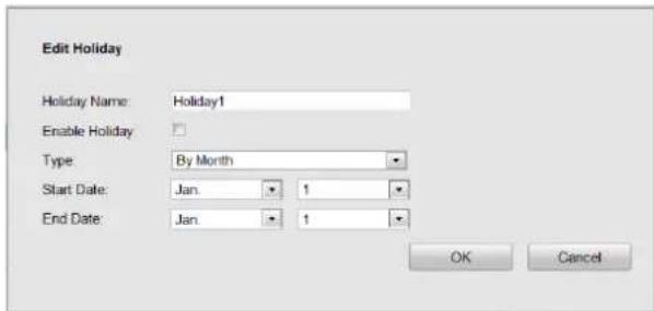
Figure 9-7 Edit Holiday
Step 3 Edit Holiday Name.
Step 4 Check the Enable Holiday checkbox.
Step 5 Select holiday Type as By Date, By Week, or By Month.
Step 6 Enter Start Date and End Date.
Step 7 Click OK to save the holiday and go back to upper menu.
9.6 Record Schedule Settings
Purpose:
Set the record schedule as connuous recording or alarm triggered recording, and then the camera automacally starts/stops recording according to the congured schedule.
Step 1 Go to Conguraon > Remote Conguraon > Camera Sengs > Record Schedule.
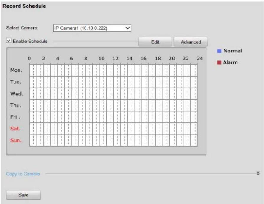
Figure 9-8 Record Schedule
Step 2 Select camera to congure in the Select Camera dropdown list.
Step 3 Check the checkbox of Enable Schedule.
Step 4 Click to congure record schedule.
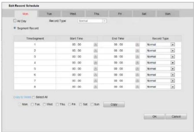
Figure 9-9 Edit Record Schedule
Step 5 Select a day in a week to congure.
Step 6 Check All Day record schedule or Segment Record schedule checkbox.
● All Day: Device records video for the whole day in the selected record type. Select Record Type as Normal or Alarm.
● Normal: Connuous recording.
● Alarm: Alarm triggered recording.
- Segment Record: Up to 8 me segments can be set in a day. Device records only in set me segments.
1) Set the Start Time, End Time, and Record Type for a me segment.
2) Oponally, repeat step 1) to congure more me segments.
Step 7 Select day(s) in Copy to Week and click Copy, thus to copy the schedule to other days. Or repeat the step 5 and 6 to conjure.
Step 8 Click OK to go back to previous menu.
Step 9 Oponally, click Advanced to set Advanced Sengs.
- Pre-Record: The me you set to record before the scheduled me or event. For example, when an alarm triggered the recording at 10:00, if you set the pre-record me as 5 seconds, the camera records it at 9:59:55.
- Post-Record: The me you set to record aer the scheduled me or the event. For example, when an alarm triggered the recording ends at 11:00, if you set the post-record me as 5 seconds, it records ll 11:00:05.
- Redundant Record: Enabling redundant record or capture means you save the record and captured picture in the redundant HDD.
- Record Audio: Check the checkbox to enable or disable audio recording.
- Expired Time: The expired me is the longest me for a record le to be kept in the HDD, if the deadline is reached, the le will be deleted. You can set the expired me to 0, and then the le will not be deleted. The actual keeping me for the le should be determined by the capacity of the HDD.
Step 10 Click Save to save the sengs.
9.7 Alarm Input Recording Settings
Purpose:
Follow the steps to congregate the alarm input recording schedule and alarm responding acons.
Step 1 Go to Conguraon > Remote Conguraon > Alarm Sengs > Alarm Input.
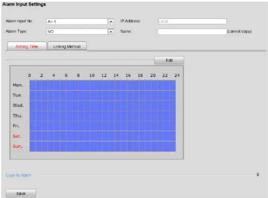
Figure 9-10 Alarm Input Sengs
Step 2 Select Alarm Input No. in the dropdown list.
Step 3 Select Alarm Type as NO (normally open) or NC (normally closed) for alarm type.
i NOTE
- NO: Alarm linking method and alarm recording are triggered when the alarm input is closed.
- NC: Alarm linking method and alarm recording are triggered when the alarm input is opened.
Step 4 Enter alarm input Name in the text eld.
Step 5 Click to congure arming me. Linking method is only available in the arming me.
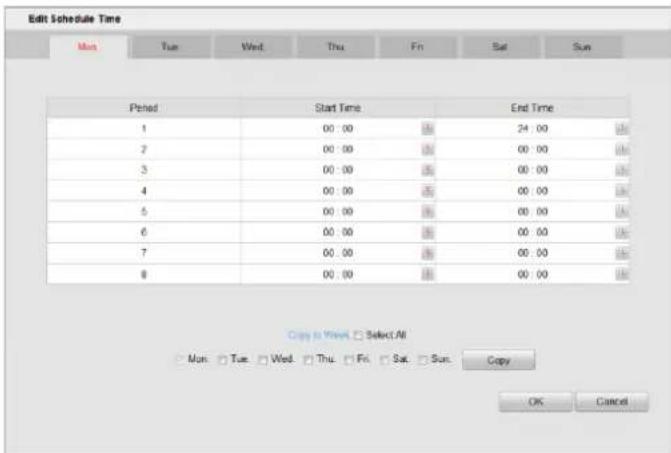
Figure 9-11 Arming Time
1) Select a day in a week to congure.
2) Up to 8 me segments are provided. Set the Start Time and End Time for one or more me segments.
3) Select day(s) in Copy to Week and click Copy, thus to copy the schedule to other days. Or repeat the step 1) and 2) to conjure arming me for other days.
Step 6 Click to congure linking method.
Step 7 Set Alarm Linking, Trigger Alarm Output, Alarm Linked Recording, and PTZ Linking according to your needs. Once an alarm occurs, the selected linking method will be triggered.
Step 8 Congure the alarm record schedule. For detailed steps, please refer to 9.4 Video Parameter Sengs.
Step 9 Click Save to save the sengs.
Chapter 10 Serial Port Settings
Purpose:
Congure RS-232 serial port and RS-485 serial port.
10.1 RS-232 Serial Port
Purpose:
Connect the RS-232 serial interface in device rear panel with the one on computer. Thus device can communicate with computer.
Step 1 Go to Conguraon > Remote Conguraon > Serial Port Sengs > RS-232 Serial Port.
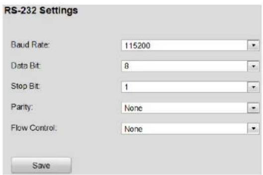
Figure 10-1 RS-232 Sengs
Step 2 Congure the parameter, including Baud Rate, Data Bit, Stop Bit, Parity and Flow Control.

Make sure the parameters are exactly the same with the computer parameters.
Step 3 Click Save to save the sengs.
10.2 RS-485 Serial Port
Step 1 Go to Conguraon > Remote Conguraon > Serial Port Sengs > RS-485 Serial Port.
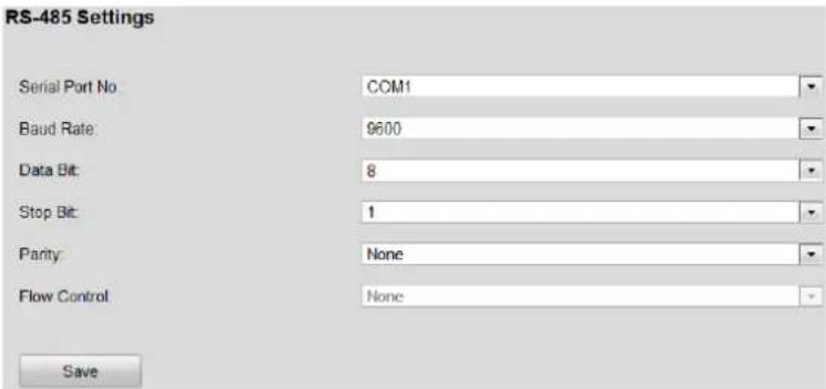
Figure 10-2 RS-485 Sengs
Step 2 Select Serial Port No., Baud Rate, Data Bit, Stop Bit, Parity and Flow Control.

Make sure the parameters are exactly the same with the connected device.
Step 3 Click Save to save the sengs.
Chapter 11 Backup Configuration
11.1 USB Backup Settings
Purpose:
You can export data to USB backup device.
Before you start:
Insert a USB backup device into the USB interface in rear panel.
Step 1 Go to Conguraon > Remote Conguraon > Backup Configuraon > USB Backup Sengs.
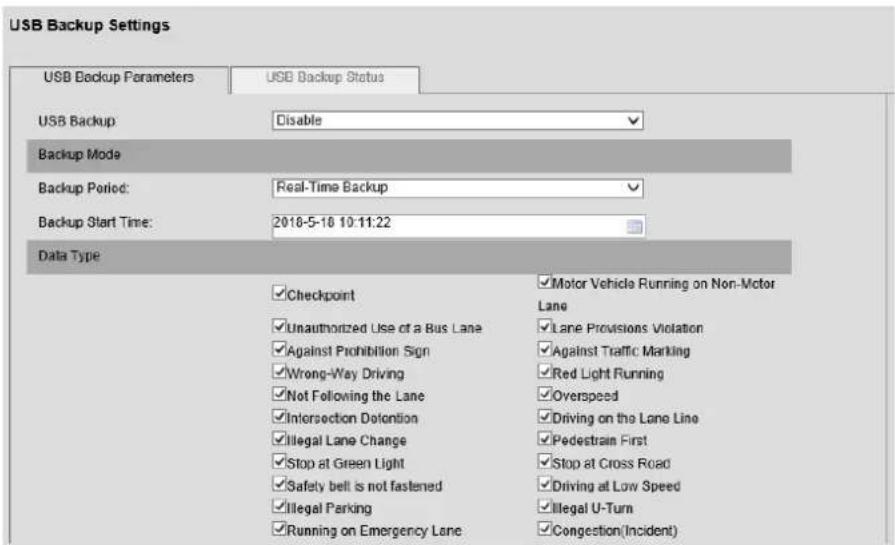
Figure 11-1 USB Backup Sengs
Step 2 Select USB Backup as Enable.
Step 3 Set Backup Mode.
1) Select Backup Period as Real-Time Backup or Backup Every Day. The recommend one is Real-me Backup.
● Real-Time Backup: Export pictures and video les immediately to USB backup device, once server receives any data.
● Backup Every Day: Export pictures and video les of last day in every 0 a.m.
2) Set Backup Start Time to export historical les.
Step 4 Select the Data Type to backup.
Step 5 Set Saving Path and File Name. We take seng the le name and directory for backing up license plate picture as an example.
3) Click the text eld aer the License Plate Picture Name. The following menu pops up.
![[YYYY][MM][DD]_HH][FF][SS][SSS]_CDBH]_CPHM]_plate.jpg Year(YYYY) Year(YY) Month Day Hour Minute Second Millisecond Device No. Device Name Monitoring Spot No. Monitoring Spot Name Monitoring Spot Direction Channel No. Camera No. Camera IP Address Lane No. Vehicle Speed License Plate Number Monitoring Spot Information 1 Monitoring Spot Information 2 Monitoring Spot Information 3 Random Number(6) Picture No. Pictures Plate coordinates Speed Limit Value Data Type Path separator 7 OK Cancel](/content/2026/05/763369/images/dd4e6ee24416b96111dbb7c4296fc55bab55ad1ba7ec3e2005a7f29c17643b79.jpg)
Figure 11-2 License Plate Picture Name
4) Click to select contents. The selected contents are list in the text led. And the text led is the license plate picture name.
i NOTE
If you want to add other contents that is not provided in the list, you can input the contents in the text eld.
5) Oponally, click Backspace in keyboard to delete contents.
6) Click OK to save the contents and go back to upper level.
Step 6 Click Save to save the sengs.
11.2 Web Backup Settings
Purpose:
In Trac interface, you can export trac informaon. And you can set the le name and directory for the backup les, including pictures and videos of license plate, trac violaon, event, and evidence. Event le conguraon is only available for trafc incident detecon server. Evidence le is only available for enforcement speed dome.
We take seng the le name and directory for backing up license plate picture as an example.
Step 1 Go to Conguraon > Remote Conguraon > Backup Configuraon > Web Backup Sengs.
| License Plate Picture Name: | [YYYY][MM][DD][HH][FF][SS][SSS][CDBH][CPHM]_plate. |
| Checkpoint Picture Name: | [YYYY][MM][DD][HH][FF][SS][SSS][CDBH][CPHM]_P(TP) |
| Checkpoint Picture Saving Path: | [XJIP]/[SJLX]/[YYYY][MM][DD]/[HH]/ |
| Checkpoint Video Name: | [YYYY][MM][DD][HH][FF][SS][SSS][CDBH][CPHM].mp4 |
| Checkpoint Video Saving Path: | [XJIP]/[SJLX]/[YYYY][MM][DD]/[HH]/ |
| Traffic Violation Picture Name: | [YYYY][MM][DD][HH][FF][SS][SSS][CDBH][CPHM]_P(TP) |
| Traffic Violation Picture Saving Path: | [XJIP]/[SJLX]/[YYYY][MM][DD]/[HH]/ |
| Traffic Violation Video Name: | [YYYY][MM][DD][HH][FF][SS][SSS][CDBH][CPHM].mp4 |
| Traffic Violation Video Saving Path: | [XJIP]/[SJLX]/[YYYY][MM][DD]/[HH]/ |
| Incident Picture Name: | [YYYY][MM][DD][HH][FF][SS][SSS][CDBH][CPHM]_P(TP) |
| Incident Picture Saving Path: | [XJIP]/[SJLX]/[YYYY][MM][DD]/[HH]/ |
| Incident Video Name: | [YYYY][MM][DD][HH][FF][SS][SSS][CDBH][CPHM].mp4 |
Figure 11-3 Web Backup
Step 2 Click the text eld aer the License Plate Picture Name. The following menu pops up.
![[YYYY][MM][DD]_[HH][FF][SS][SSS]_[CDBH]_[CPHM]_plate.jpg Year Month Day Hour Minute Second Millisecond Lane No. Vehicle Speed(3Bits) License Plate Number Picture No. Number of Picture Camera IP Address Camera No. Monitoring Spot No. Monitoring Spot Name Channel No. Direction No. Direction Information Monitoring Spot Information 1 Monitoring Spot Information 2 Monitoring Spot Information 3 Data Type Random Number Underline_ Path Separator/'' OK Cancel](/content/2026/05/763369/images/35fac6304962e948189d26c31a265caca2c18a4576f80a5107ecd851fb415665.jpg)
Figure 11-4 License Plate Picture Name
Step 3 Edit the saving path and le name. We can turn to Step 5 in 11.1 USB Backup Sengs for reference.
Step 4 Click Save to save the sengs.
Chapter 12 Uploading Data
12.1 Host Settings
Purpose:
Congure the Remote Host sengs to upload data to Remote Host, including iVMS-8600 and third-party plaorms.
Step 1 Go to Conguraon > Remote Conguraon > Remote Host > Host Sengs.
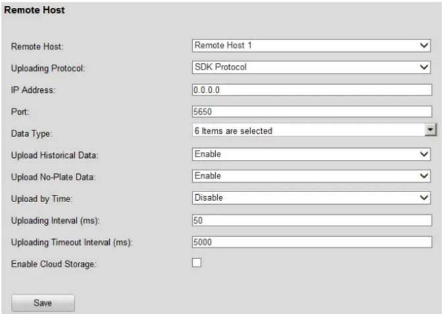
Figure 12-1 Host Sengs
Step 2 Select Remote Host as Remote Host 1 or Remote Host 2 in Select dropdown list.

You can congregate both the two Remote Hosts. Files can be uploaded to the two Remote Hosts.
Step 3 Select Upload Protocol as SDK Protocol, Private Protocol, or EHome protocol. The default Upload Protocol is SDK Protocol.
- iVMS-8600 whose version is V2.3 or above supports both SDK Protocol and Private Protocol. Other versions only support Private Protocol.
- If set Upload Protocol as EHome Protocol, you need to register the device in Ehome plaorm rst.
Step 4 Enter selected Remote Host IP Address and Port.
The default Port for SDK Protocol and Private Protocol are 5650 and 5682 separated.
Step 5 Select Data Type to upload in the dropdown list.
Step 6 You can select Upload Historical Data and Upload No-Plate Data as Enable to upload historical data and No-plate data.
Upload Historical Data: Upload historical data in HDD.
Step 7 Enable the Upload by Time and set the Uploading Start Time and Uploading End Time. Up to 2 periods can be set. Device only uploads data during the start me and end me.
Step 8 Enter Upload Interval (ms) and Upload Timeout Interval (ms).
Step 9 Oponally, set the Enable Cloud Storage sengs. Thus the data are saved in Cloud Storage device.
1) Check Enable Cloud Storage checkbox.
2) Enter cloud storage Management Server IP Address, Command Port, User Name, and Password.
3) Enter Normal Vehicle Picture and Record File Pool ID and Trac Violaon Picture and Record File Pool ID.
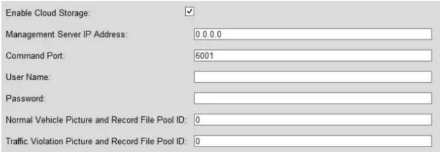
Figure 12-2 Cloud Storage
Step 10 Click Save to save the sengs.
12.2 FTP Settings
Purpose:
Device provides two FTP servers. Congure the parameters, thus to upload data to the two FTP servers.
Step 1 Go to Conguraon > Remote Conguraon > Custom Sengs.
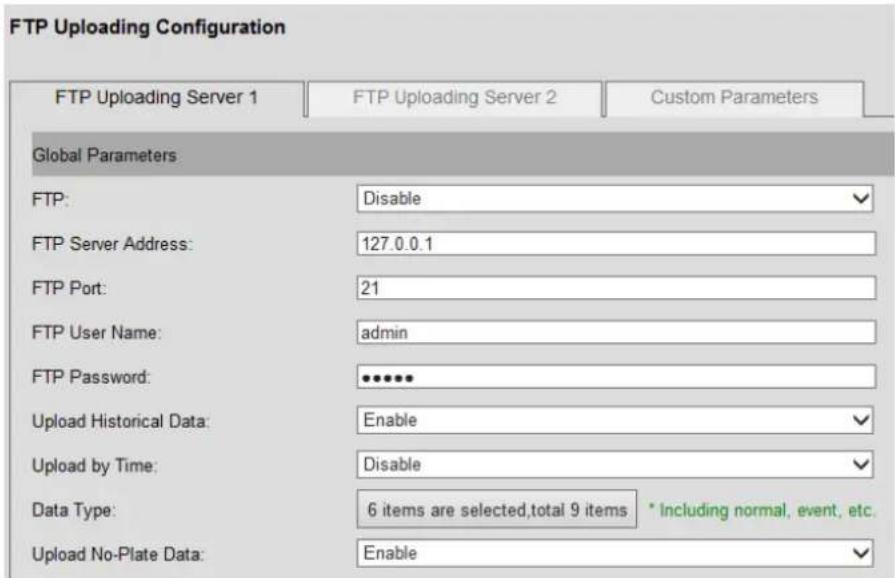
Figure 12-3 Custom Sengs
Step 2 Select FTP Server 1 tab or FTP Server 2 tab. You can enable both of them or one of them. The Custom Parameters interface is reserved.
Step 3 Select Enable in FTP dropdown list.
Step 4 Enter FTP Server Address, FTP Port, FTP User Name, and FTP Password.
Step 5 You can select Upload Historical Data and Upload No-Plate Data as Enable to upload historical data and No-plate data.
Step 6 Enable the Upload by Time and set the Uploading Start Time and Uploading End Time. Up to 2 periods can be set.
Step 7 Select Data Type.
1) Click 6 items are selected total 9 items to pop up Data Type items.
2) Check the checkbox (es) of item (s) to upload.
3) Click OK to save the sengs and go back to upper level.
Step 8 Edit uploading le name and saving path. For detailed steps, please refer to step 5 of 11.1 USB Backup Sengs.
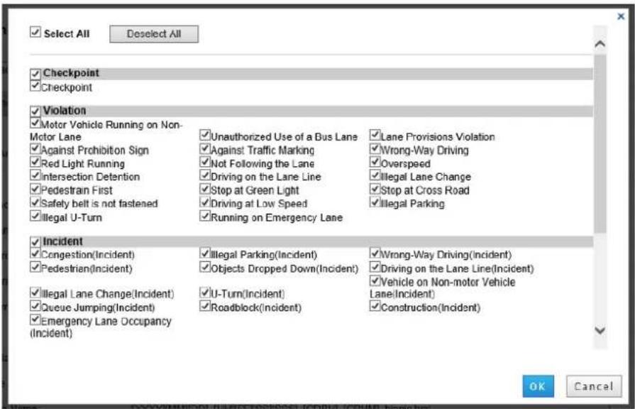
Figure 12-4 Data Type Items
Step 9 Click OK to save the sengs.
12.3 Data Uploading Configuration
Purpose:
Set parameters for uploading historical les and re-uploading les to Remote Host.
Before you start:
- To upload data to remote host, enable the Upload Historical Data funcon in Host settings rst. For details, refer to Step 6 of 12.1 Host Sengs.
- To upload data to FTP server, enable the Upload Historical Data funcon in FTP sengs rst. For details, refer to Step 5 of 12.2 FTP Sengs.
Step 1 Go to Conguraon > Remote Conguraon > Remote Host > Data Uploading Conguraon.
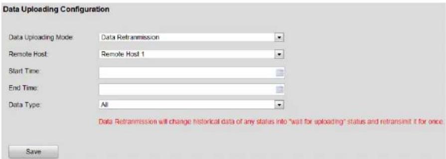
Figure 12-5 Data Retransmission
Step 2 Select Data Uploading Mode as Data Retransmission, Upload Historical Data First, or Disable.
● Data Retransmission: Resends les to Remote Host.
- Upload Historical Data First: Sends historical les rst. Otherwise server sends historical les when free.
- Disable: Server won't upload historical data when free.
Step 3 Select uploading Remote Host as Remote Host 1, Remote Host 2, FTP Uploading Host 1, or FTP Uploading Host 2.

Congure the four host's parameters before selecng Remote Host as any of them. For detailed steps, please refer to 12.1 Host Sengs and 12.2 FTP Sengs.
Step 4 Enter Start Time and End Time, thus to specify the start me and end me of uploaded le.
Step 5 Select uploading Data Type in dropdown list.
Step 6 Click Save to save the sengs.
Chapter 13 Status Information
13.1 Server Status
Purpose:
You can view the network status, server working status, network uploading status, and wireless network status.
Step 1 Go to Conguraon > Remote Conguraon > Status Informaon > Server Status.
| Network Status | Working Status | Network Uploading Status | Wireless Network Status | ||
| No. | Status Info | IP Address | MAC Address | Upstream Traffic | Downstream Traffic |
| 1 | Disconnected | 0 0 0 0 | 00:00:00:00:00:00 | 0 KB | 0 KB |
| 2 | Disconnected | 0 0 0 0 | 00:00:00:00:00:00 | 0 KB | 0 KB |
| 3 | Disconnected | 0 0 0 0 | 00:00:00:00:00:00 | 0 KB | 0 KB |
| 4 | Disconnected | 0 0 0 0 | 00:00:00:00:00:00 | 0 KB | 0 KB |
| 5 | Disconnected | 0 0 0 0 | 00:00:00:00:00:00 | 0 KB | 0 KB |
Figure 13-1 Status
Step 2 Click Network Status, Working Status, Network Uploading Status, and Wireless Network Status to view system status.
● Network Status: Shows all network interfaces status.
● Working Status: Displays the system working status.
● Network Uploading Status: Shows the four uploading hosts status.
● Wireless Network Status: Shows the dialing status.
13.2 Camera Status
Purpose:
You can view the Trac Flow Stasc informaon, Front-end Device Status, and Camera Status. The funcon is only available when the connected camera supports trac ow stascs.
Before you start:
Select the Camera Type as Intelligent Trac Camera. For details, please refer to 8.1.1 Monitoring Spot Informaon Sengs.
Step 1 Go to Conguraon > Remote Conguraon > Status Informaon > Camera Status.
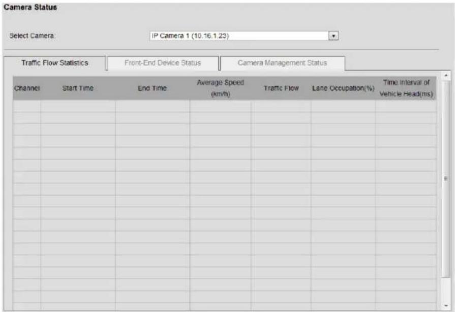
Figure 13-2 Camera Status
Step 2 Select camera to view status in Select Camera dropdown list.
Step 3 Select the Front-End Device Status, or Camera Management Status to view camera status.
● Front-End Device Status: Shows the camera, vehicle detector, or signal lamp detector working status.
● Camera Management Status: Shows the Camera Version, Camera Serial No., Login Status, and Arming Status.
Chapter 14 Other Settings
14.1 User Management
Purpose:
You can add, edit, and delete users.
Step 1 Go to Conguraon > Remote Conguraon > User Management.
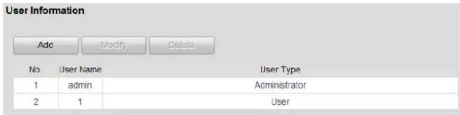
Figure 14-1 User Management
14.1.1 Adding a User
Step 1 Click Add to enter the Add user interface.
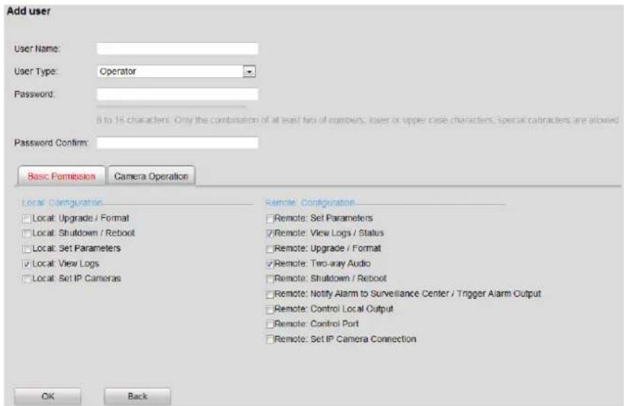
Figure 14-2 Add User
Step 2 Enter the User Name and Password, and conrm the password.

WARNING
STRONG PASSWORD RECOMMENDED— We highly recommend you create a strong password of your own choosing (using a minimum of 8 characters, including upper case leers, lower case leers, numbers, and special characters) in order to increase the security of your product. And we recommend you reset your password regularly, especially in the high security system, reseng the password monthly or weekly can beer protect your product.
Step 3 Select the Level to Operator or User.
- Operator: The Operator user level has permission of Local Log Search in Local Conguraon, Remote Log Search and Two-way Audio in Remote Conguraon and all operang permission in Camera Conguraon.
- User: The Guest user has permission of Local Log Search in Local Conguraon, Remote Log Search in Remote Conguraon and only has the local/remote playback in the Camera Conguraon.
Step 4 Congure the user permissions for the created user account, including the Basic Permission and Camera Operaon.
Step 5 Click OK to add the user.
14.1.2 Modifying a User

NOTE
You need the admin password to modify the admin user.
Step 1 Select a user account from the list on the User Informaon interface to be modified.
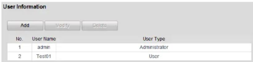
Figure 14-3 Select a User
Step 2 Click Modify to enter the seng interface.

Figure 14-4 Modify a User
Step 3 Modify the User Name, Password, and then select User Type.

WARNING
STRONG PASSWORD RECOMMENDED— We highly recommend you create a strong password of your own choosing (using a minimum of 8 characters, including upper case leers, lower case leers, numbers, and special characters) in order to increase the security of your product. And we recommend you reset your password regularly, especially in the high security system, reseng the password monthly or weekly can beer protect your product.
Step 4 Congure the user permission for the user, including the Basic Permission and Camera Operaon.
Step 5 Click OK to nish the user modicaon.
14.1.3 Deleting a User
Step 1 Select a user account from the list on the User Informaon interface to be deleted.
Step 2 Click Delete, and an informaon box will pop up.
Step 3 Click OK to delete the selected user account.
14.2 Exception
Purpose:
You can specify the linkage acon and triggered alarm output for nine excepon types.
● HDD Full: The HDD is full.
- HDD Error: Wring HDD error or unformaed HDD.
● Network Disconnected: Disconnected network cable.
● IP Conicted: Duplicated IP address.
- Illegal Access: Incorrect user ID or password.
● Video Standard Mismatch: I/O video standards do not match.
● Video Signal Excepon: Unstable video signal.
● Record/Capture Excepon: Unable to recording or capture.
Step 1 Go to Conguraon > Remote Conguraon > Excepon.
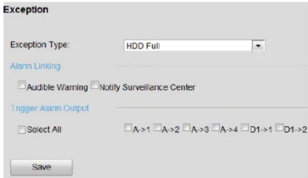
Figure 14-5 Excepon
Step 2 Select the Excepon Type in the dropdown list.
Step 3 Select Alarm Linking and Trigger Alarm Output.
Step 4 Click Save to save the sengs.
14.3 Maintenance
Purpose:
You can restart, restore default, repair database index, export/import conguraon le, and upgrade device.
Step 1 Go to Conguraon > Remote Conguraon > Maintenance.
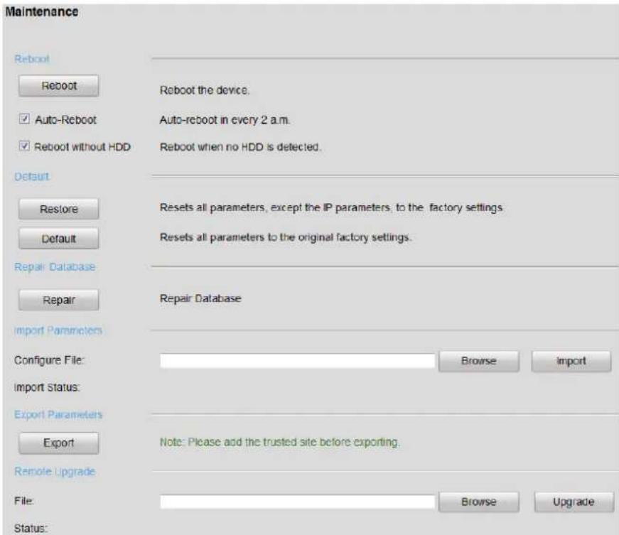
Figure 14-6 Maintenance
14.3.1 Rebooting the Device
- Click Reboot to reboot the device.
- Oponally, check Auto-Reboot checkbox. Then the device reboots automacally 2 a.m. every day.
- Oponally, check Reboot without HDD checkbox. Then the device reboots automacally when no HDD is detected.
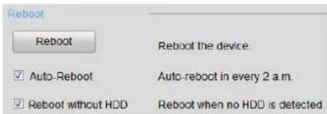
Figure 14-7 Restart
14.3.2 Default Settings
Step 1 Select the restoring type as Restore or Default.
- Restore: Restore all parameters, except the network (including IP address, subnet mask, gateway, MTU, NIC working mode, default route, server port, etc.) and user account parameters, to the factory default sengs.
- Default: Restore all parameters to the factory default settings.

Figure 14-8 Default
14.3.3 Repairing Database
Purpose:
When errors happen, such as searching data failed, uploading data failed, etc., repairing database funcon is one of the method to recover the errors.
Step 1 Click Repair to repair database.
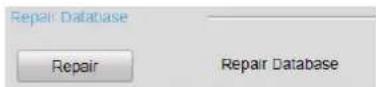
Figure 14-9 Repairing Database Index
14.3.4 Exporting/Importing Configuration File
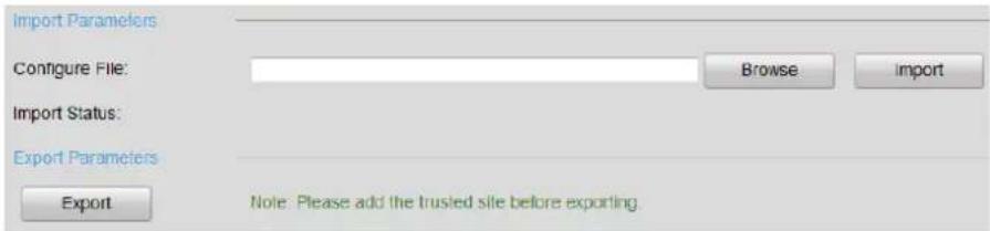
Figure 14-10 Impomg/Exporng Conguraon File
- Import conguraon le.
1) Click Browser.
2) Select conguraon le path.
3) Click Import to import the selected le.
- Export conguraon le.
1) Click Export.
2) Select exporng path.
3) Click Save to save the conguraon le.
14.3.5 Remote Upgrade
Step 1 Click Browse.
Step 2 Select upgrade le.
Step 3 Click Upgrade to upgrade.

Figure 14-11 Remote Upgrade
- Sub System No. 1/2 Status: The status of analysis modules. You can only upgrade device when the status is normal.
14.4 Audio Linkage Alarm Configuration
Purpose:
You can customize the alarm sound for each trac violaons. When a trac violaon occurs, device will send out corresponding alarm sound.
Step 1 Go to Conguraon > Remote Conguraon > Alarm Conguraon > Audio Linkage Alarm Conguraon.
Step 2 Edit Audio File Name and click Import to select a local audio le. Up to 10 audio les are conguraon.
Step 3 Select Camera to congure.
Step 4 Select audio for each trac violaon.
Step 5 Click Save.

See Far, Go Further

- User Manual
- ALL RIGHTS RESERVED.
- About this Manual
- Trademarks Acknowledgement
- Legal Disclaimer
- Applicable Models
- Symbol Conventions
- Safety Instructions
- Preventive and Cautionary Tips
- Table of Contents
- Chapter 1 Key Features....7
- Chapter 2 Introducon and Interfaces....8
- Chapter 3 Geng Started....9
- Chapter 4 Network Setngs....12
- Chapter 5 Device Parameters....18
- Chapter 6 Camera Management ......23
- Chapter 7 Camera Sengs....25
- Chapter 8 Trac Incident Detecon....31
- Chapter 9 Record and Capture Sengs....40
- Chapter 10 Serial Port Sengs ....49
- Chapter 11 Backup Conguraon ....51
- Chapter 12 Uploading Data....54
- Chapter 13 Status Informaon....59
- Chapter 14 Other Sengs ......61
- Chapter 1 Key Features
- Chapter 2 Introduction and Interfaces
- Purpose:
- Chapter 3 Getting Started
- Starting Up and Shutting Down
- Start Up
- Before you start:
- Shut Down
- Reboot
- Environment Requirement
- Set the Admin Password
- WARNING
- Chapter 4 Network Settings
- External Network Settings
- Internal Network Settings
- More Settings
- Port Settings
- Remote Access Configuration
- HTTPS Configuration
- Example:
- - Opon 3: Create the authorized cercate
- Static Router
- Chapter 5 Device Parameters
- Device Information
- Time Settings
- DST Settings
- Other Traffic Settings
- - Checkpoint Video Linkage:
- ● Trac Camera Time Synchronizaon:
- Chapter 6 Camera Management
- Chapter 7 Camera Settings
- Display Settings
- Text Overlay
- Image Collage Parameters
- Collaged Picture Text Overlay
- Interaction Configuration
- Alarm Output
- Scene Patrol
- Configure Preset Scene
- Configure Scene Patrol Schedule
- Chapter 8 Traffic Incident Detection
- Event Monitoring Configuration
- Monitoring Spot Information Settings
- i NOTE
- Intelligent Analysis Parameters
- Configure Preset Scene
- Capture Illegal Parking Vehicle
- Traffic Violation Capture
- Traffic Parameters Collection
- Configure Traffic Statistics Parameters
- Set Traffic Incident Rule
- Set Lane Line
- Configure Flow Statistic Rules
- Traffic Incident Search
- Search Traffic Data
- Search Traffic Flow Statistics
- Search Real-Time Data
- Chapter 9 Record and Capture Settings
- HDD Initialization
- Picture Quota
- HDD Detection
- S.M.A.R.T Settings
- Bad Sector Detection
- Video Parameter Settings
- Holiday Settings
- Record Schedule Settings
- Alarm Input Recording Settings
- Chapter 10 Serial Port Settings
- RS-232 Serial Port
- RS-485 Serial Port
- Chapter 11 Backup Configuration
- USB Backup Settings
- Web Backup Settings
- Chapter 12 Uploading Data
- Host Settings
- FTP Settings
- Data Uploading Configuration
- Chapter 13 Status Information
- Server Status
- Camera Status
- Chapter 14 Other Settings
- User Management
- Adding a User
- Modifying a User
- NOTE
- Deleting a User
- Exception
- Maintenance
- Rebooting the Device
- Default Settings
- Repairing Database
- Exporting/Importing Configuration File
- Remote Upgrade
- Audio Linkage Alarm Configuration
Brand : Hikvision
Model : IDS-TP40-04L
Category : Detector