
OptiPlex 5055 - Desktop computer DELL - Free user manual and instructions
Find the device manual for free OptiPlex 5055 DELL in PDF.


User questions about OptiPlex 5055 DELL
0 question about this device. Answer the ones you know or ask your own.
Ask a new question about this device
Download the instructions for your Desktop computer in PDF format for free! Find your manual OptiPlex 5055 - DELL and take your electronic device back in hand. On this page are published all the documents necessary for the use of your device. OptiPlex 5055 by DELL.
USER MANUAL OptiPlex 5055 DELL
Dell OptiPlex 5055 Small Form Factor
Owner's Manual
Notes, cautions, and warnings
NOTE: A NOTE indicates important information that helps you make better use of your product.
CAUTION: A CAUTION indicates either potential damage to hardware or loss of data and tells you how to avoid the problem.
WARNING: A WARNING indicates a potential for property damage, personal injury, or death.
© 2018 Dell Inc. or its subsidiaries. All rights reserved. Dell, EMC, and other trademarks are trademarks of Dell Inc. or its subsidiaries. Other trademarks may be trademarks of their respective owners.
Contents
1 Working on your computer....6
Safety instructions....6
Turning off your computer....6
Turning off your — Windows....6
Before working inside your computer....7
After working inside your computer....7
2 Chassis....8
Front chassis view....8
Back chassis view 9
3 Field service information.... 10
Screw size list....10
Recommended tools....10
Critical callouts....10
Trusted Platform Module....11
System Board Configuration 11
Enabling data wipe option in BIOS 13
System board jumper setting 14
LED error code after replacing coin cell battery 14
Working on your computer....15
Safety instructions....15
Turning off your computer....15
Before working inside your computer....16
After working inside your computer....16
Safety precautions....16
Electrostatic discharge—ESD protection....17
ESD field service kit ....17
Transporting sensitive components....18
Disassembly and reassembly....19
Back cover....19
Front Bezel....20
Storage device....21
Expansion card....24
Cooling shroud....26
Coin-cell battery....28
Optical drive....29
M.2 PCIe SSD....32
Heat sink assembly....33
Processor....35
Intrusion switch....36
Memory modules....37
VGA Daughterboard....38
SD card....39
Power supply unit....40
Power switch....43
Speaker 45
System board....46
4 Technology and components.... 53
Systems management features....53
In-Band Systems Management – Dell Client Command Suite....53
Out-of-Band Systems Management – DASH....54
AMD APUs, AMD Ryzen CPUs and APUs....54
AMD Advanced Processing Unit - APU....54
AMD Ryzen....54
AMD Ryzen APUs....55
AMD PT B350....55
AMD B350....55
Specification....55
AMD Radeon R7 M450....55
Key Specifications....56
AMD Radeon R5 M430....56
Key Specifications....56
USB features....56
USB 3.1 Gen 1 (SuperSpeed USB)....57
Speed....57
Applications....58
Compatibility....58
DDR4....59
DDR4 Details....59
Memory Errors....60
Active State Power Management....60
6 System setup....61
Boot menu....61
System Setup options....61
Updating the BIOS in Windows 67
Updating BIOS on systems with BitLocker enabled....68
Updating your system BIOS using a USB flash drive....68
Updating the Dell BIOS in Linux and Ubuntu environments....68
Flashing the BIOS from the F12 One-Time boot menu....69
6 System setup....73
Boot menu....73
System Setup options....73
Updating the BIOS in Windows 79
Updating BIOS on systems with BitLocker enabled....80
Updating your system BIOS using a USB flash drive....80
Updating the Dell BIOS in Linux and Ubuntu environments....80
Flashing the BIOS from the F12 One-Time boot menu....81
Technical Specifications....84
Processor....85
Memory....85
Video....85
Audio....86
Network 86
Expansion bus 86
Wireless....86
Drives....87
External connectors....87
Controls and lights 87
Power 88
Physical dimension....88
Environmental....89
7 Getting help....90
Contacting Dell....90
Working on your computer
Safety instructions
Use the following safety guidelines to protect your computer from potential damage and to ensure your personal safety. Unless otherwise noted, each procedure included in this document assumes that the following conditions exist:
- You have read the safety information that shipped with your computer.
• A component can be replaced or, if purchased separately, installed by performing the removal procedure in reverse order.
WARNING: Disconnect all power sources before opening the computer cover or panels. After you finish working inside the computer, replace all covers, panels, and screws before connecting to the power source.
WARNING: Before working inside your computer, read the safety information that shipped with your computer. For additional safety best practices information, see the Regulatory Compliance Homepage at www.Dell.com/regulatory_compliance
CAUTION: Many repairs may only be done by a certified service technician. You should only perform troubleshooting and simple repairs as authorized in your product documentation, or as directed by the online or telephone service and support team. Damage due to servicing that is not authorized by Dell is not covered by your warranty. Read and follow the safety instructions that came with the product.
CAUTION: To avoid electrostatic discharge, ground yourself by using a wrist grounding strap or by periodically touching an unpainted metal surface at the same time as touching a connector on the back of the computer.
CAUTION: Handle components and cards with care. Do not touch the components or contacts on a card. Hold a card by its edges or by its metal mounting bracket. Hold a component such as a processor by its edges, not by its pins.
CAUTION: When you disconnect a cable, pull on its connector or on its pull-tab, not on the cable itself. Some cables have connectors with locking tabs; if you are disconnecting this type of cable, press in on the locking tabs before you disconnect the cable. As you pull connectors apart, keep them evenly aligned to avoid bending any connector pins. Also, before you connect a cable, ensure that both connectors are correctly oriented and aligned.
NOTE: The color of your computer and certain components may appear differently than shown in this document.
Turning off your computer
Turning off your — Windows
CAUTION: To avoid losing data, save and close all open files and exit all open programs before you turn off your computer.
1 Click or tap

2 Click or tap and then click or tap Shut down.
NOTE: Ensure that the computer and all attached devices are turned off. If your computer and attached devices did not automatically turn off when you shut down your operating system, press and hold the power button for about 6 seconds to turn them off.
Before working inside your computer
To avoid damaging your computer, perform the following steps before you begin working inside the computer.
1 Ensure that you follow the Safety Instruction.
2 Ensure that your work surface is flat and clean to prevent the computer cover from being scratched.
3 Turn off your computer.
4 Disconnect all network cables from the computer.
CAUTION: To disconnect a network cable, first unplug the cable from your computer and then unplug the cable from the network device.
5 Disconnect your computer and all attached devices from their electrical outlets.
6 Press and hold the power button while the computer is unplugged to ground the system board.
NOTE: To avoid electrostatic discharge, ground yourself by using a wrist grounding strap or by periodically touching an unpainted metal surface at the same time as touching a connector on the back of the computer.
After working inside your computer
After you complete any replacement procedure, ensure that you connect any external devices, cards, and cables before turning on your computer.
1 Connect any telephone or network cables to your computer.
CAUTION: To connect a network cable, first plug the cable into the network device and then plug it into the computer.
2 Connect your computer and all attached devices to their electrical outlets.
3 Turn on your computer.
4 If required, verify that the computer works correctly by running ePSA diagnostics.
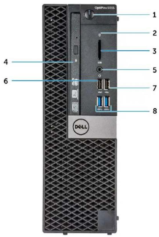
Front chassis view
text_image
OptiPlex 5055 1 2 3 4 5 6 7 8 DCLL1 Power button and power light 2 Hard drive activity light
3 Memory card reader (optional) 4 Optical drive (optional)
5 Headset port 6 USB 2.0 port with PowerShare
7 USB 2.0 port 8 USB 3.1 Gen1 port
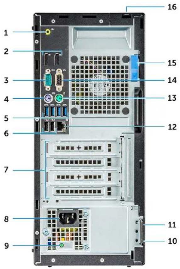
Back chassis view
text_image
1 2 3 4 5 6 7 8 9 10 11 12 13 14 15 161 Line-out port 2 DisplayPort
3 Serial port 4 PS/2 keyboard port
5 USB 3.1 Gen1 port 6 USB 2.0 ports (supports Smart Power On)
7 Expansion card slots 8 Power connector port
9 Power supply diagnostic light 10 Padlock ring
11 Kensington security cable slot 12 Network port
13 PS/2 mouse port 14 VGA connector port (optional)
15 Release latch 16 Cable cover lock slot
Field service information
This chapter details the safety precautions that must be taken before disassembling the systems. It also lists the detailed disassembly and assembly instructions along with related information such as screw list and tool requirements.
Topics:
- Screw size list
- Recommended tools
• Critical callouts - Working on your computer
• Disassembly and reassembly
Screw size list
Table 1. OptiPlex 5055
| Component Secured to Screw type Quantity Image | ||||
| System board System chassis #6.32X1.4 8 |  | |||
| PSU 3 | ||||
| SD card module System chassis #6.32x3.6L 1 |  |
Recommended tools
The procedures in this document require the following tools:
- Small flat blade screwdriver
- Phillips # 1 screwdriver
- Small plastic scribe
Critical callouts
Key disassembly instructions along with important replacement instructions are called out to ensure the field technicians take into account this information before removing or replacing any components.
Trusted Platform Module
Trusted Platform Module (TPM) is a dedicated cryptoprocessor designed to secure hardware by integrating cryptographic keys into devices. A software can use a Trusted Platform Module to authenticate hardware devices. As each TPM chip has a unique and secret RSA key burned in as it is produced, it can perform the platform authentication.

NOTE: Trusted Platform Module (TPM) is part of the system board. In an event of system board replacement, the encryption needs to be suspended in the OS and re-enabled on new system board's BIOS prior to resuming the encryption.

CAUTION: Attempt to replace the system board without prior suspending the encryption, will cause operating system corruption and may eventually lead to No-Boot scenario.
System Board Configuration

NOTE: After replacing the system board, please follow these instructions carefully to ensure the new system board is configured correctly
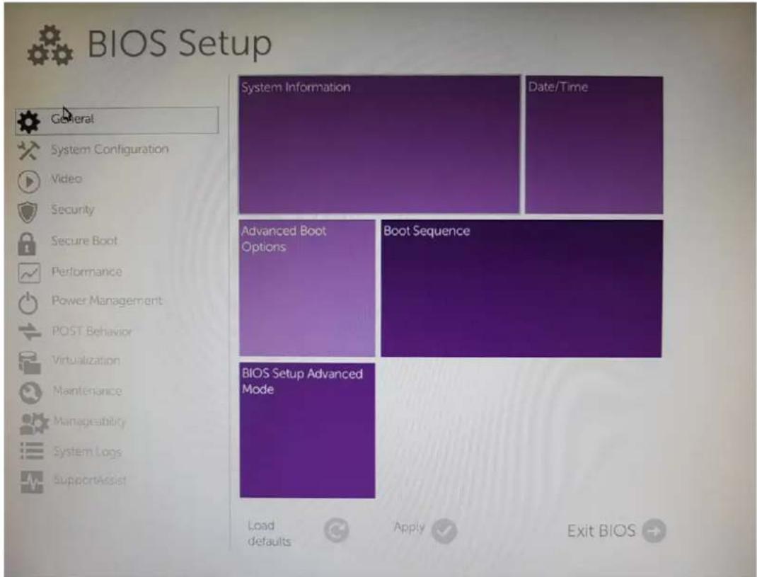
1 Press F12 to get one time boot menu and select BIOS set up.
text_image
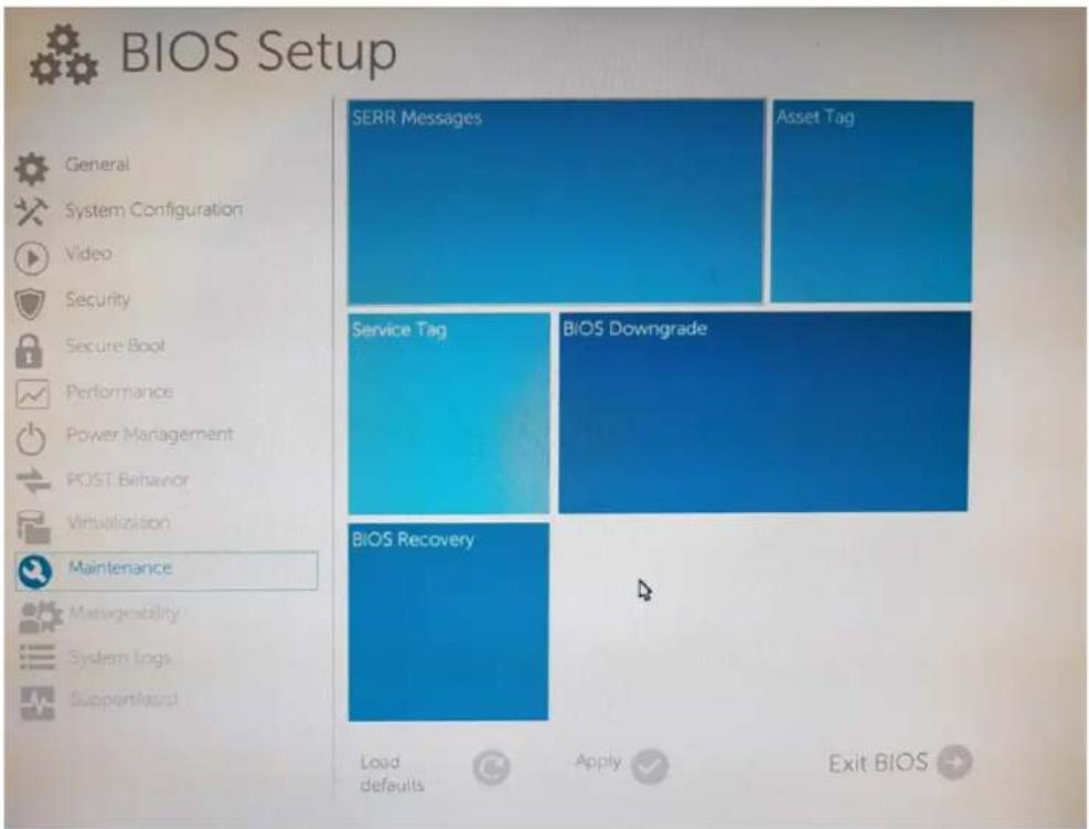
BIOS Setup General System Configuration Video Security Secure Boot Performance Power Management POST Behavior Virtualization Maintenance Manageability System Logs SupportAssist System Information Date/Time Advanced Boot Options Boot Sequence BIOS Setup Advanced Mode Load defaults Apply Exit BIOS →2 Click on Maintenance tab.
text_image
BIOS Setup General System Configuration Video Security Secure Boot Performance Power Management POST Behavior Virtualization Maintenance Managementability System Logs SupportAssist SERR Messages Asset Tag Service Tag BIOS Downgrade BIOS Recovery Load defaults Apply Exit BIOS3 Click the service tag.
4 Enter the service tag and press enter.
NOTE: Once you exit setup and save changes you will not be allowed to modify the Service Tag.
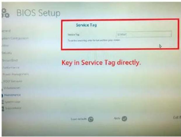
text_image
BIOS Setup Service Tag Service Tag Start the Service Tag after the end of the next session. Key in Service Tag directly. Load defaults Apply Exit5 Select the option Yes to save the changes.
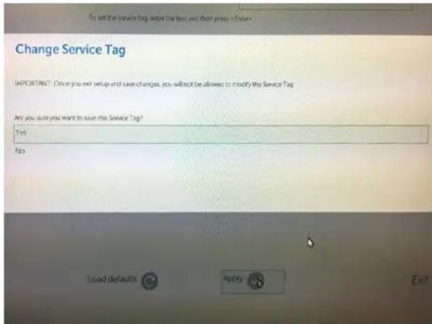
text_image
To sell the service tag enter the text and then press < Finish> Change Service Tag IMPORTANT: Once you exit setup and save changes, you will not be allowed to modify the Service Tag Any you sure you want to save the Service Tag? Yes No Load defaults Apply Exit6 Click on maintenance to verify Service Tag on the machine.
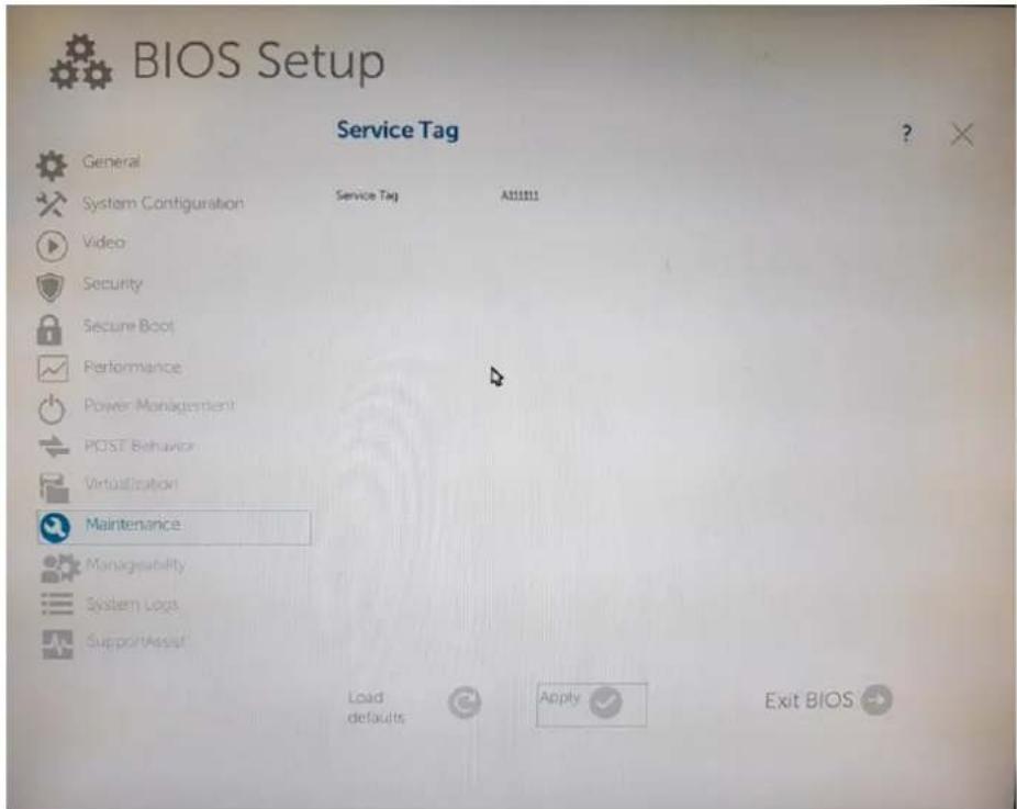
text_image
BIOS Setup Service Tag General System Configuration Video Security Secure Boot Performance Power Management POST Behavior Virtualization Maintenance Manageability System Logs SupportAssuit Service Tag Alt111111 Load defaults Apply Exit BIOS
CAUTION: Technicians must input the correct Service Tag and configurations on the first and only attempt. If the Service Tag or any of the configurations are incorrectly entered, then another system board will need to be dispatched and replaced.
Enabling data wipe option in BIOS
After replacing the system board and successfully setting the service tag, the system will reboot. If the technician enters the BIOS at this point, the Data Wipe option will not be available. To re-enable Data Wipe, simply power down the system, then power it back up (cold boot). The Data Wipe option is now available.
System board jumper setting
The service system board jumper must be set to PW_CLR to function normally. Jumper will be parked at "PW_CLR" for both production and service motherboard by the default. The issue of cycling reboot will occurred if the technician or customers did not place the jumper back to "PW_CLR" after clearing CMOS.
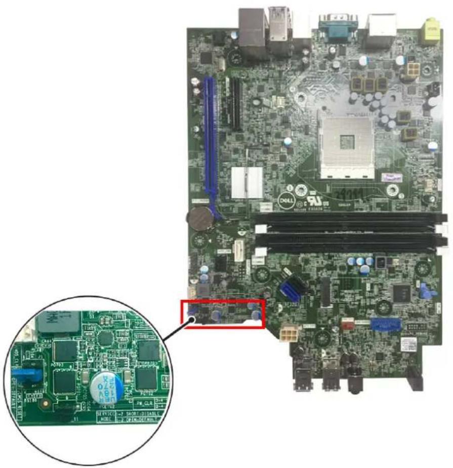
natural_image
Close-up of a computer motherboard with visible CPU socket, RAM slots, and circuit board (no text or symbols)Table 2. System board jumper details
PW_CLR 3-4 Short: Default
SERVICE_MODE 1-2 Short: Disable
CMOS_CLR 5-6 Short: CMOS Reset
3-4 Open: Password: Reset
1-2 Open: Default
5-6 Open: Default
LED error code after replacing coin cell battery
After replacing the coin-cell battery, the system will not power on and the LED blinks 2-2 in amber. This is a known behavior when the super I/O is reset to default. Press and hold the power button until the system powers on.
Working on your computer
Safety instructions
Use the following safety guidelines to protect your computer from potential damage and to ensure your personal safety. Unless otherwise noted, each procedure included in this document assumes that the following conditions exist:
- You have read the safety information that shipped with your computer.
• A component can be replaced or, if purchased separately, installed by performing the removal procedure in reverse order.
WARNING: Disconnect all power sources before opening the computer cover or panels. After you finish working inside the computer, replace all covers, panels, and screws before connecting to the power source.
WARNING: Before working inside your computer, read the safety information that shipped with your computer. For additional safety best practices information, see the Regulatory Compliance Homepage at www.Dell.com/regulatory_compliance
CAUTION: Many repairs may only be done by a certified service technician. You should only perform troubleshooting and simple repairs as authorized in your product documentation, or as directed by the online or telephone service and support team. Damage due to servicing that is not authorized by Dell is not covered by your warranty. Read and follow the safety instructions that came with the product.
CAUTION: To avoid electrostatic discharge, ground yourself by using a wrist grounding strap or by periodically touching an unpainted metal surface at the same time as touching a connector on the back of the computer.
CAUTION: Handle components and cards with care. Do not touch the components or contacts on a card. Hold a card by its edges or by its metal mounting bracket. Hold a component such as a processor by its edges, not by its pins.
CAUTION: When you disconnect a cable, pull on its connector or on its pull-tab, not on the cable itself. Some cables have connectors with locking tabs; if you are disconnecting this type of cable, press in on the locking tabs before you disconnect the cable. As you pull connectors apart, keep them evenly aligned to avoid bending any connector pins. Also, before you connect a cable, ensure that both connectors are correctly oriented and aligned.
NOTE: The color of your computer and certain components may appear differently than shown in this document.
Turning off your computer
Turning off your — Windows
CAUTION: To avoid losing data, save and close all open files and exit all open programs before you turn off your computer.
1 Click or tap

2 Click or tap and then click or tap Shut down.
NOTE: Ensure that the computer and all attached devices are turned off. If your computer and attached devices did not automatically turn off when you shut down your operating system, press and hold the power button for about 6 seconds to turn them off.
Before working inside your computer
To avoid damaging your computer, perform the following steps before you begin working inside the computer.
1 Ensure that you follow the Safety Instruction.
2 Ensure that your work surface is flat and clean to prevent the computer cover from being scratched.
3 Turn off your computer.
4 Disconnect all network cables from the computer.
CAUTION: To disconnect a network cable, first unplug the cable from your computer and then unplug the cable from the network device.
5 Disconnect your computer and all attached devices from their electrical outlets.
6 Press and hold the power button while the computer is unplugged to ground the system board.
NOTE: To avoid electrostatic discharge, ground yourself by using a wrist grounding strap or by periodically touching an unpainted metal surface at the same time as touching a connector on the back of the computer.
After working inside your computer
After you complete any replacement procedure, ensure that you connect any external devices, cards, and cables before turning on your computer.
1 Connect any telephone or network cables to your computer.
CAUTION: To connect a network cable, first plug the cable into the network device and then plug it into the computer.
2 Connect your computer and all attached devices to their electrical outlets.
3 Turn on your computer.
4 If required, verify that the computer works correctly by running ePSA diagnostics.
Safety precautions
The safety precautions chapter details the primary steps to be taken before performing any disassembly instructions.
Observe the following safety precautions before you perform any installation or break/fix procedures involving disassembly or reassembly:
- Turn off the system and all attached peripherals.
- Disconnect the system and all attached peripherals from AC power.
- Disconnect all network cables, telephone, and telecommunications lines from the system.
• Use an ESD field service kit when working inside any desktop to avoid electrostatic discharge (ESD) damage. - After removing any system component, carefully place the removed component on an anti-static mat.
- Wear shoes with non-conductive rubber soles to reduce the chance of getting electrocuted.
Standby power
Dell products with standby power must be unplugged before you open the case. Systems that incorporate standby power are essentially powered while turned off. The internal power enables the system to be remotely turned on (wake on LAN) and suspended into a sleep mode and has other advanced power management features.
Unplugging, pressing and holding the power button for 15 seconds should discharge residual power in the system board, desktops.
Bonding
Bonding is a method for connecting two or more grounding conductors to the same electrical potential. This is done through the use of a field service electrostatic discharge (ESD) kit. When connecting a bonding wire, ensure that it is connected to bare metal and never to a painted or non-metal surface. The wrist strap should be secure and in full contact with your skin, and ensure that you remove all jewelry such as watches, bracelets, or rings prior to bonding yourself and the equipment.
Electrostatic discharge—ESD protection
ESD is a major concern when you handle electronic components, especially sensitive components such as expansion cards, processors, memory DIMMs, and system boards. Very slight charges can damage circuits in ways that may not be obvious, such as intermittent problems or a shortened product life span. As the industry pushes for lower power requirements and increased density, ESD protection is an increasing concern.
Due to the increased density of semiconductors used in recent Dell products, the sensitivity to static damage is now higher than in previous Dell products. For this reason, some previously approved methods of handling parts are no longer applicable.
Two recognized types of ESD damage are catastrophic and intermittent failures.
- Catastrophic – Catastrophic failures represent approximately 20 percent of ESD-related failures. The damage causes an immediate and complete loss of device functionality. An example of catastrophic failure is a memory DIMM that has received a static shock and immediately generates a "No POST/No Video" symptom with a beep code emitted for missing or nonfunctional memory.
- Intermittent – Intermittent failures represent approximately 80 percent of ESD-related failures. The high rate of intermittent failures means that most of the time when damage occurs, it is not immediately recognizable. The DIMM receives a static shock, but the tracing is merely weakened and does not immediately produce outward symptoms related to the damage. The weakened trace may take weeks or months to melt, and in the meantime may cause degradation of memory integrity, intermittent memory errors, etc.
The more difficult type of damage to recognize and troubleshoot is the intermittent (also called latent or "walking wounded") failure.
Perform the following steps to prevent ESD damage:
- Use a wired ESD wrist strap that is properly grounded. The use of wireless anti-static straps is no longer allowed; they do not provide adequate protection. Touching the chassis before handling parts does not ensure adequate ESD protection on parts with increased sensitivity to ESD damage.
- Handle all static-sensitive components in a static-safe area. If possible, use anti-static floor pads and workbench pads.
- When unpacking a static-sensitive component from its shipping carton, do not remove the component from the anti-static packing material until you are ready to install the component. Before unwrapping the anti-static packaging, ensure that you discharge static electricity from your body.
- Before transporting a static-sensitive component, place it in an anti-static container or packaging.
ESD field service kit
The unmonitored Field Service kit is the most commonly used service kit. Each Field Service kit includes three main components: anti-static mat, wrist strap, and bonding wire.
Components of an ESD field service kit
The components of an ESD field service kit are:
- Anti-Static Mat – The anti-static mat is dissipative and parts can be placed on it during service procedures. When using an anti-static mat, your wrist strap should be snug and the bonding wire should be connected to the mat and to any bare metal on the system being worked on. Once deployed properly, service parts can be removed from the ESD bag and placed directly on the mat. ESD-sensitive items are safe in your hand, on the ESD mat, in the system, or inside a bag.
- Wrist Strap and Bonding Wire – The wrist strap and bonding wire can be either directly connected between your wrist and bare metal on the hardware if the ESD mat is not required, or connected to the anti-static mat to protect hardware that is temporarily placed on the mat. The physical connection of the wrist strap and bonding wire between your skin, the ESD mat, and the hardware is known as
bonding. Use only Field Service kits with a wrist strap, mat, and bonding wire. Never use wireless wrist straps. Always be aware that the internal wires of a wrist strap are prone to damage from normal wear and tear, and must be checked regularly with a wrist strap tester in order to avoid accidental ESD hardware damage. It is recommended to test the wrist strap and bonding wire at least once per week.
- ESD Wrist Strap Tester – The wires inside of an ESD strap are prone to damage over time. When using an unmonitored kit, it is a best practice to regularly test the strap prior to each service call, and at a minimum, test once per week. A wrist strap tester is the best method for doing this test. If you do not have your own wrist strap tester, check with your regional office to find out if they have one. To perform the test, plug the wrist-strap's bonding-wire into the tester while it is strapped to your wrist and push the button to test. A green LED is lit if the test is successful; a red LED is lit and an alarm sounds if the test fails.
- Insulator Elements – It is critical to keep ESD sensitive devices, such as plastic heat sink casings, away from internal parts that are insulators and often highly charged.
- Working Environment – Before deploying the ESD Field Service kit, assess the situation at the customer location. For example, deploying the kit for a server environment is different than for a desktop or portable environment. Servers are typically installed in a rack within a data center; desktops or portables are typically placed on office desks or cubicles. Always look for a large open flat work area that is free of clutter and large enough to deploy the ESD kit with additional space to accommodate the type of system that is being repaired. The workspace should also be free of insulators that can cause an ESD event. On the work area, insulators such as Styrofoam and other plastics should always be moved at least 12 inches or 30 centimeters away from sensitive parts before physically handling any hardware components
- ESD Packaging – All ESD-sensitive devices must be shipped and received in static-safe packaging. Metal, static-shielded bags are preferred. However, you should always return the damaged part using the same ESD bag and packaging that the new part arrived in. The ESD bag should be folded over and taped shut and all the same foam packing material should be used in the original box that the new part arrived in. ESD-sensitive devices should be removed from packaging only at an ESD-protected work surface, and parts should never be placed on top of the ESD bag because only the inside of the bag is shielded. Always place parts in your hand, on the ESD mat, in the system, or inside an anti-static bag.
- Transporting Sensitive Components – When transporting ESD sensitive components such as replacement parts or parts to be returned to Dell, it is critical to place these parts in anti-static bags for safe transport.
ESD protection summary
It is recommended that all field service technicians use the traditional wired ESD grounding wrist strap and protective anti-static mat at all times when servicing Dell products. In addition, it is critical that technicians keep sensitive parts separate from all insulator parts while performing service and that they use anti-static bags for transporting sensitive components.
Transporting sensitive components
When transporting ESD sensitive components such as replacement parts or parts to be returned to Dell, it is critical to place these parts in anti-static bags for safe transport.
Lifting equipment
Adhere to the following guidelines when lifting heavy weight equipment:
CAUTION: Do not lift greater than 50 pounds. Always obtain additional resources or use a mechanical lifting device.
1 Get a firm balanced footing. Keep your feet apart for a stable base, and point your toes out.
2 Tighten stomach muscles. Abdominal muscles support your spine when you lift, offsetting the force of the load.
3 Lift with your legs, not your back.
4 Keep the load close. The closer it is to your spine, the less force it exerts on your back.
5 Keep your back upright, whether lifting or setting down the load. Do not add the weight of your body to the load. Avoid twisting your body and back.
6 Follow the same techniques in reverse to set the load down.
Disassembly and reassembly
Back cover
Removing cover
1 Follow the procedure in Before working inside your computer.
2 To release cover:
a Slide the blue retention tab to the right to unlock the cover [1]. b Slide the cover toward the back of the computer [2].
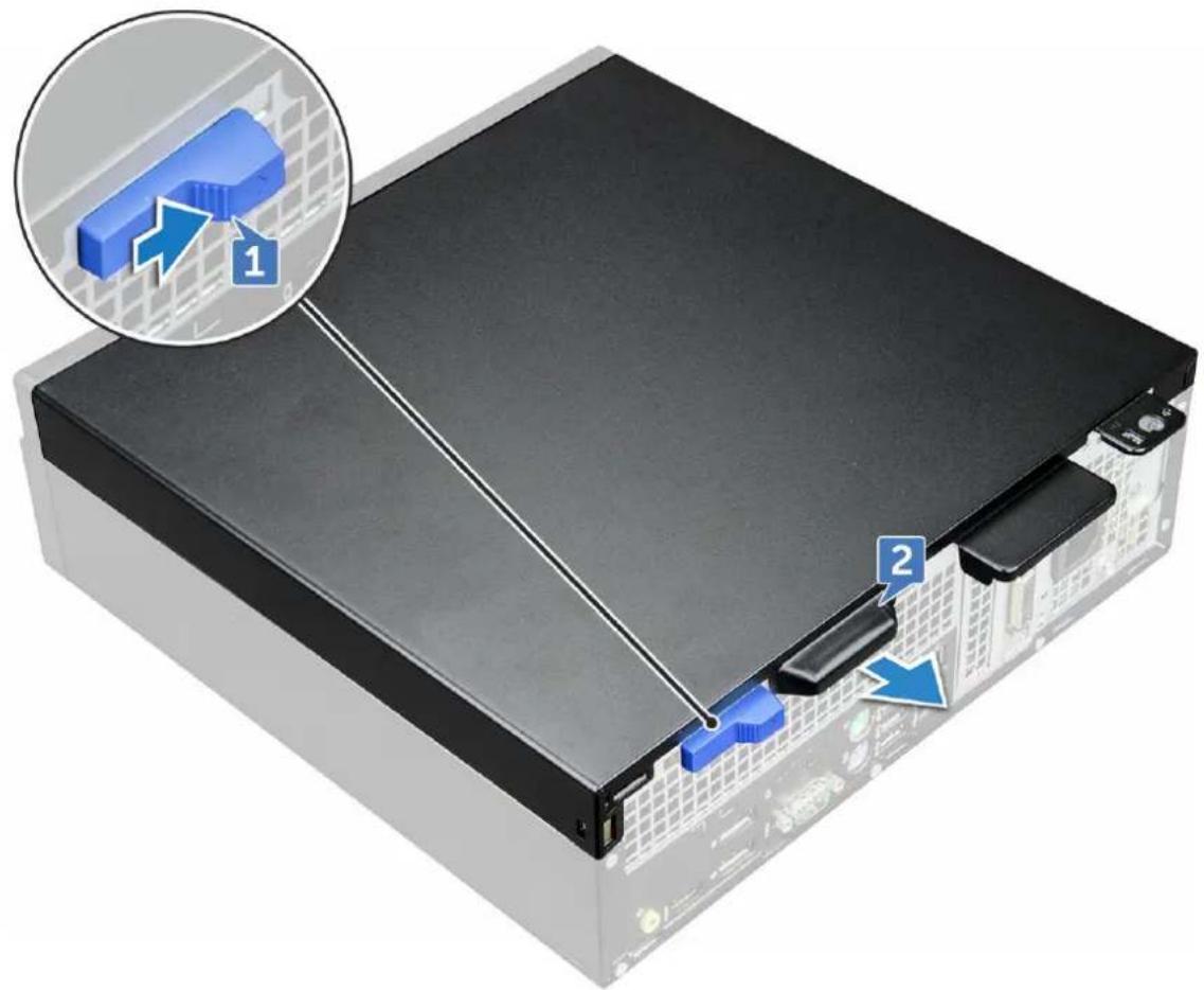
text_image
Diagram of a computer drive with labeled components and a magnified view showing component 1 and component 2.3 Lift the cover to remove it from the computer.
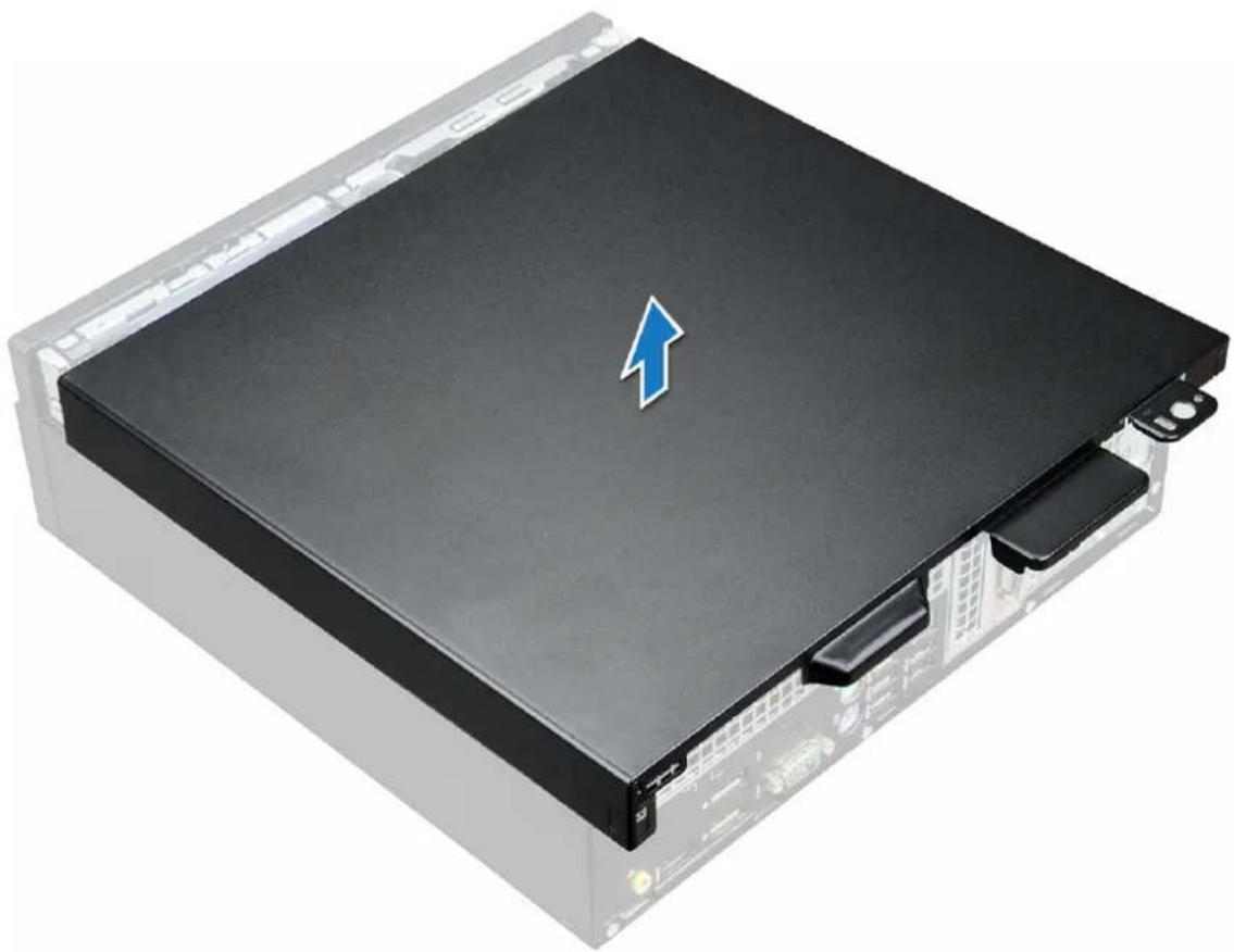
natural_image
3D rendering of a black server rack with a blue upward arrow on top (no text or symbols)Installing cover
1 Place the cover on the computer and slide the cover forward until it clicks into place.
2 Follow the procedure in After working inside your computer.
Front Bezel
Removing the front bezel
1 Follow the procedure in Before working inside your computer.
2 Remove the cover.
3 To remove front bezel:
a Lift the tabs to release the bezel from the chassis [1]. b Remove the front bezel from the computer [2].
NOTE: Please ensure that the tabs at the bottom of the bezel is also released before lifting the bezel.
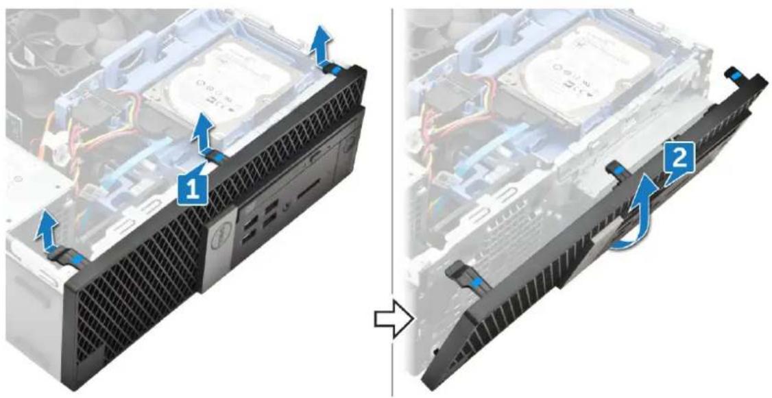
text_image
Diagram showing component assembly of a computer drive, with numbered parts and blue arrows indicating motion direction.Installing front bezel
1 Insert the tabs of the bezel into the slots on the chassis.
2 Press the bezel until the tabs click into place.
3 Install the cover.
4 Follow the procedure in After working inside your computer.
Storage device
Removing 2.5-inch hard drive assembly
1 Follow the procedure in Before working inside your computer.
2 Remove the cover.
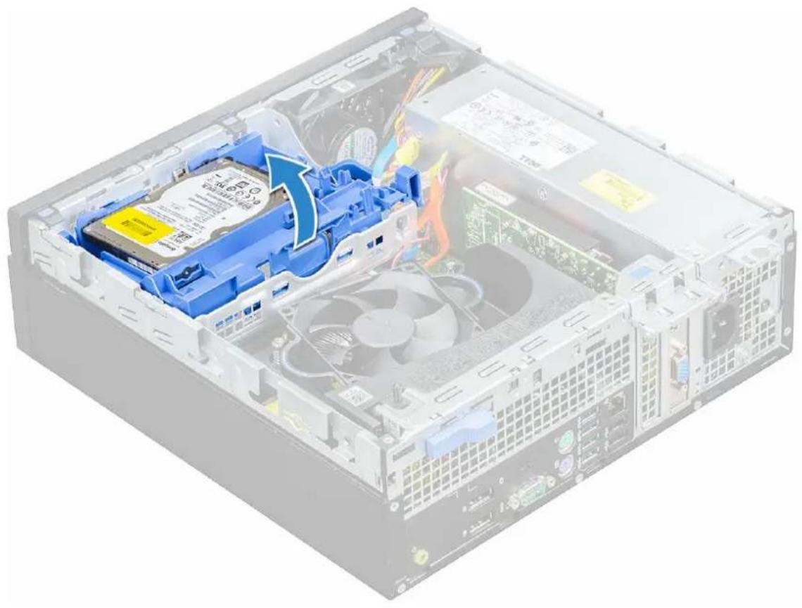
3 To remove the 2.5-inch drive assembly:
a Disconnect the SATA cable and power cable from the drive [1].
b Push the tab to release drive assembly from the chassis [2].
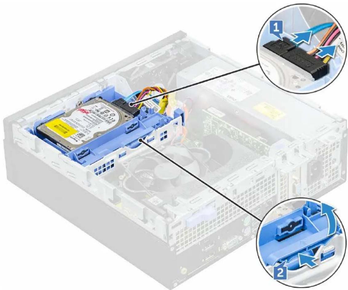
text_image
Diagram of an internal hard drive assembly with labeled components and zoomed-in views showing cable routing and component insertion.4 Slide and lift the hard drive assembly from the computer.
natural_image
3D cutaway view of an internal computer drive showing internal components like CPU, fan, and drive bays (no text or symbols visible)Removing 2.5-inch hard drive from the hard drive bracket
1 Follow the procedure in Before working inside your computer.
2 Remove the:
a cover
b 2.5 inch hard drive assembly
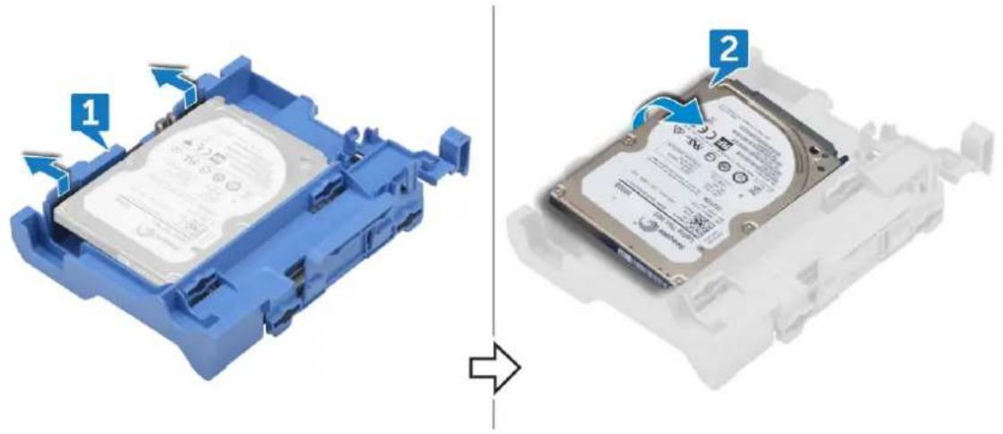
3 To remove hard drive bracket:
a Pull one side of the hard drive bracket to disengage the pins on the bracket from the slots on the hard drive [1].
b Lift the drive out of the 2.5-inch drive bracket [2].
text_image
Diagram showing two views of a blue hard disk device with labeled parts, indicating assembly or disassembly.Installing 2.5-inch hard drive into the hard drive bracket
1 Flex the side of the hard drive bracket, to align and insert the pins on the bracket into the hard drive.
2 Insert the hard drive into the hard drive bracket until it clicks into place.
3 Install the:
a 2.5 inch hard drive assembly
b cover
4 Follow the procedure in After working inside your computer.
Installing 2.5-inch hard drive assembly
1 Insert the drive assembly into the slot on the computer until it clicks into place.
2 Connect the SATA cable and the power cable to the connectors on the hard drive.
3 Install the cover.
4 Follow the procedure in After working inside your computer.
Expansion card
Removing PCIe expansion card
1 Follow the procedure in Before working inside your computer.
2 Remove the:
a cover
b front bezel
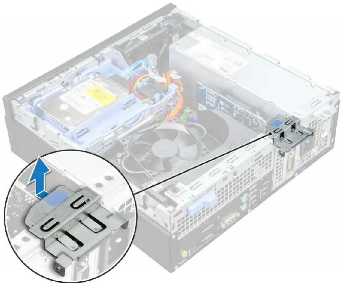
3 Pull the metal tab to open the expansion card latch.
natural_image
Interior view of a computer tower with visible CPU socket and drive, showing internal components and a close-up of the internal component (no text or symbols)4 To remove the PCIe expansion card:
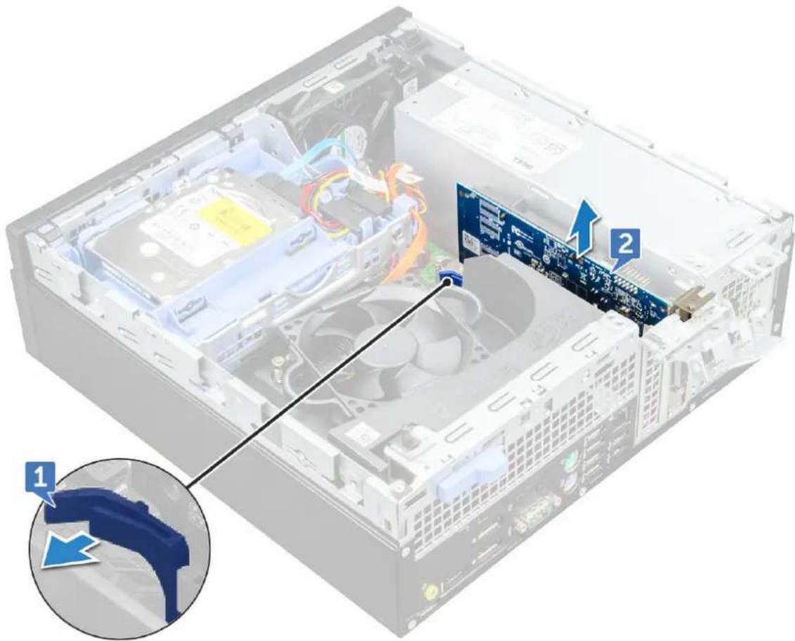
a Pull the release latch to unlock the PCIe expansion card [1].
b Push the release tab [2] and lift the PCIe expansion card out of the computer [3].
NOTE: The release tab is at the base of the expansion card.
text_image
Diagram of a computer tower internal structure with labeled components and an inset showing a blue component detail.5 Repeat the steps to remove any additional PCIe expansion cards.
Installing PCIe expansion card
1 Insert the expansion card into the connector on the system board.
2 Press the expansion card until it clicks into place.
3 Close the expansion card latch and press it until it clicks into place.
4 Install the:
a front bezel
b cover
5 Follow the procedure in After working inside your computer.
Cooling shroud
Removing the cooling shroud
NOTE: Cooling shroud is encompasses the processor assembly and it must be removed to access the processor.
1 Follow the procedure in Before working inside your computer.
2 Remove the cover.
3 To remove cooling shroud:
a Holding the touch points, pull the fan duct bracker outwards to release the cooling shroud.
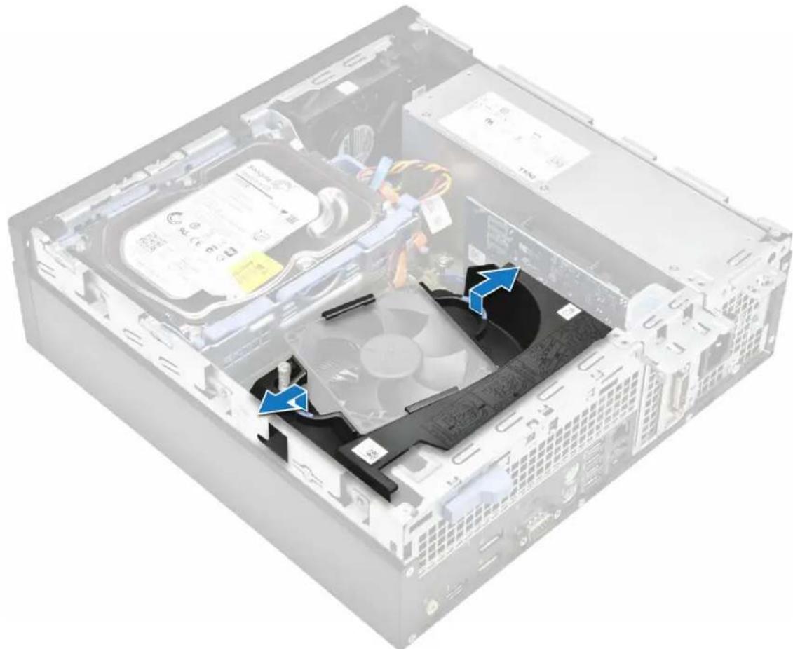
natural_image
Internal view of a computer drive chassis showing fan, drive, and internal components (no text or symbols visible)NOTE: Illustration on how to remove the shroud is also given on the shroud. b Lift the cooling shroud away from the chassis.
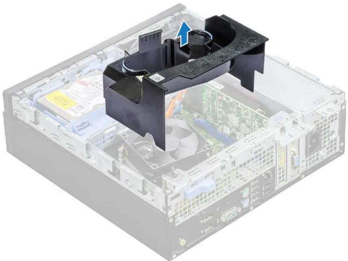
natural_image
3D cutaway view of a computer tower with visible CPU socket and motherboard (no text or symbols)Installing cooling shroud

NOTE When inserting the shroud on the processor assembly, please ensure that the data and power cables of the optical drive do not get caught inside the shroud.
1 Align the slots on the cooling shroud, with the screws on the heat sink.
2 Insert the cooling shroud over the processor assembly.
3 Install the cover.
4 Follow the procedure in After working inside your computer.
Coin-cell battery
Removing coin cell battery
1 Follow the procedure in Before working inside your computer.
2 Remove the:
a cover
b cooling shroud
c expansion card
3 To remove the coin cell battery:
a Using a plastic scribe press the release latch until the coin cell battery pops out [1].
b Remove the coin cell battery from the connector on the system board [2].
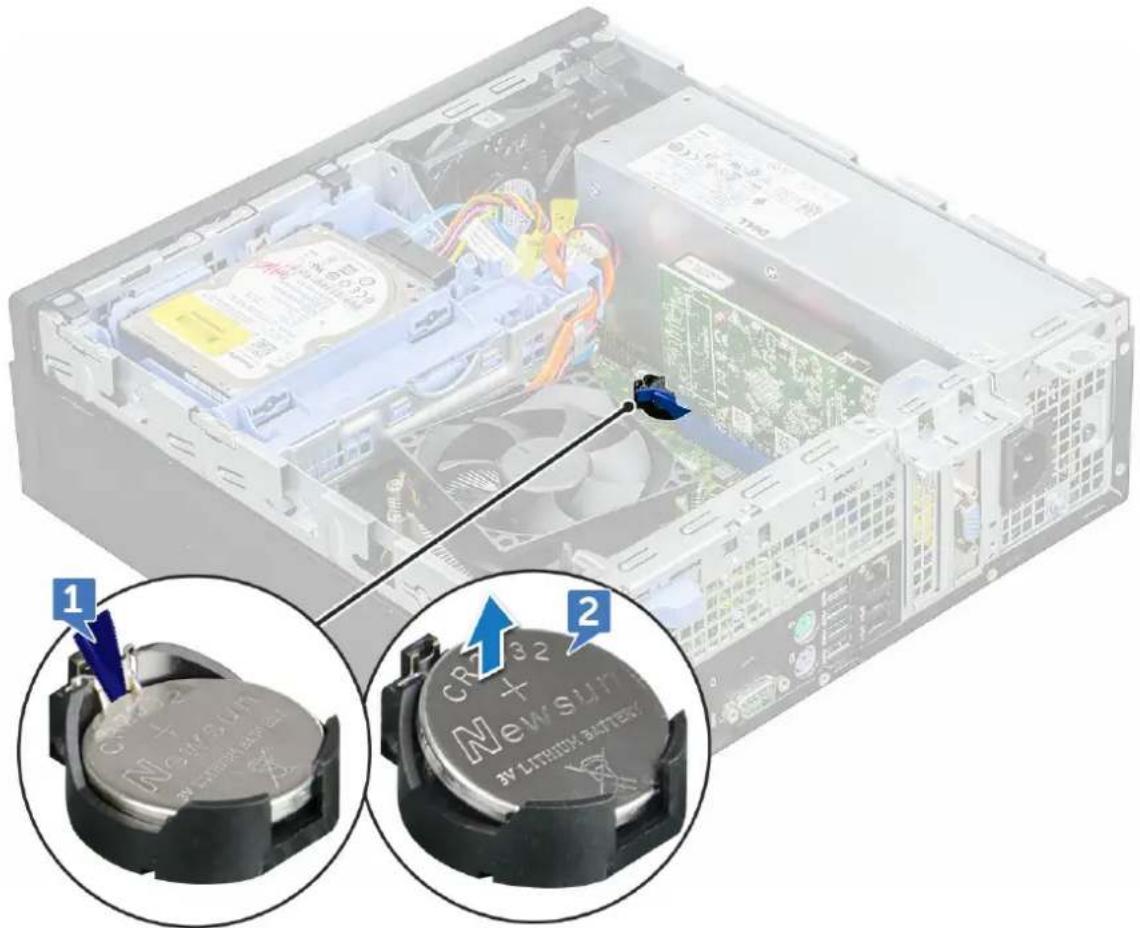
text_image
Technical diagram showing internal components of a computer drive with labeled parts and close-ups of battery modulesInstalling coin cell battery
1 Hold the coin cell battery with the "+" sign facing up and slide it under the securing tabs at the positive side of the connector.
2 Press the battery into the connector until it locks into place.
3 Install the:
a expansion card
b cooling shroud
c cover
4 Follow the procedure in After working Inside your computer.
Optical drive
Removing optical drive
1 Follow the procedure in Before working inside your computer.
2 Remove the:
a cover
b front bezel
c cooling shroud
d 2.5 inch hard drive assembly
3 To remove optical drive:
a Release the cables from the retention clip [1].
b Slide the blue tab to unlock the optical drive assembly [2].
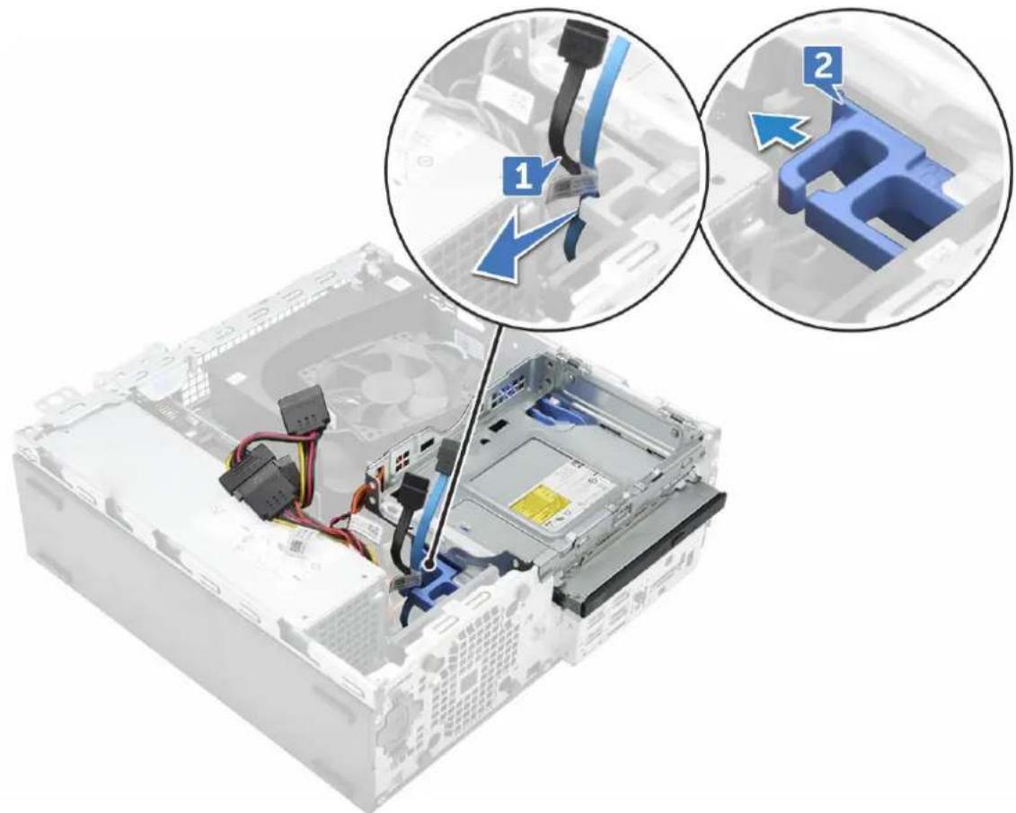
text_image
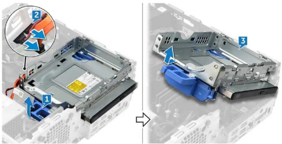
Diagram showing cable installation steps on a computer drive, with numbered annotations highlighting key components.4 To remove the optical drive assembly:
a Pull the tab upward to release the assembly [1].
b Holding the tab, disconnect the optical drive cables [2].
c Slide and lift the optical drive assembly away from the computer [3].
text_image
Diagram showing device rear panel assembly with labeled parts and a magnified view of cable connectionsNOTE: After releasing the Optical drive, you can also flip the drive assembly for easy access to the drive cables.
NOTE: The Optical drive cables are available on side of the drive assembly.
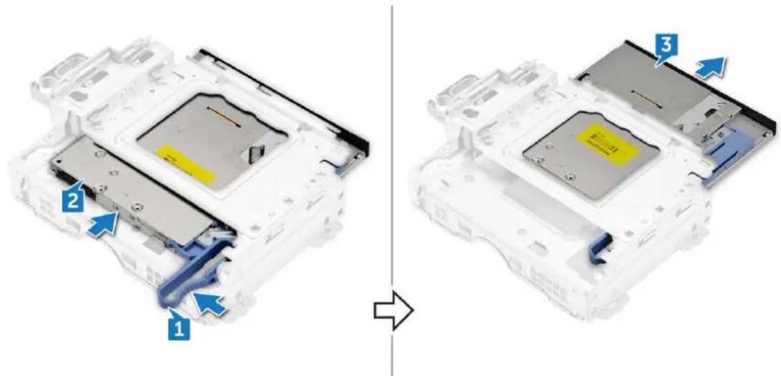
5 To remove the optical drive:
a Slide the tab to release the optical drive [1].
b Push the optical drive away from the assembly [2][3].
text_image
Diagram showing device components with numbered annotations indicating assembly or transformation stepsInstalling optical drive
1 Slide the optical drive into the optical drive assembly.
2 Align the tabs on the optical assembly with the slots on the computer.
3 Lower the optical drive assembly into the computer.
4 Lock the latch to secure the optical drive to the computer.
5 Connect the data and the power cables to the optical drive.
6 Install the:
a 2.5 inch hard drive assembly
b cooling shroud
c front bezel
d cover
7 Follow the procedure in After working inside your computer.
M.2 PCIe SSD
Removing M.2 PCIe SSD
1 Follow the procedure in Before working inside your computer.
2 Remove the:
a cover
b front bezel
c 2.5 inch hard drive assembly
d cooling shroud
e optical drive
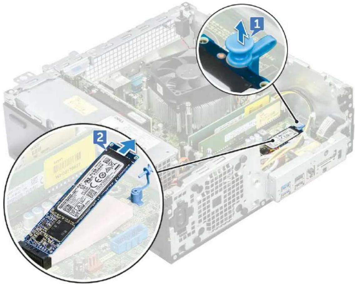
3 To remove the M.2 PCIe SSD:
a Pull the blue plastic pin that secures the M.2 PCIe SSD to the system board [1].
b Disconnect the M.2 PCIe SSD from the connector on the system board [2].
text_image
Diagram showing a computer motherboard with labeled components and a close-up of the chip, highlighting two key steps (1 and 2) for assembly or maintenance.Installing M.2 PCIe SSD
1 Insert the M.2 PCIe SSD to the connector
2 Press the blue plastic tab to secure the M.2 PCIe SSD.
3 Install the:
a optical drive
b cooling shroud
c 2.5 inch hard drive assembly
d front bezel
e cover
4 Follow the procedure in After working inside your computer.
Heat sink assembly
Removing heat sink assembly
1 Follow the procedure in Before working inside your computer.
2 Remove the:
a cover
b front bezel
c 2.5 inch hard drive assembly
d cooling shroud
e optical drive
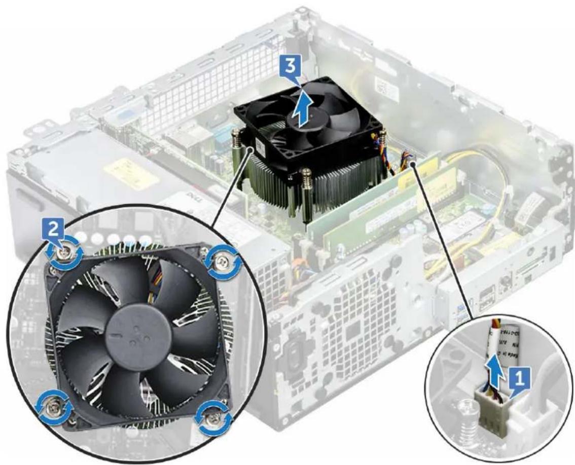
3 To remove the heat sink assembly:
a Disconnect the heat sink assembly cable from the connector on the system board [1].
b Loosen the captive screws(6 lbs) that secure the heat sink assembly to the system board [2].
NOTE: Loosen the screws based on the numbers available on the system board.
c Lift the heat sink assembly away from the computer [3].
text_image
Diagram showing CPU cooling system with labeled components and fan assembly, including numbered parts for each component.Installing heat sink assembly
1 Align the screws of the heat sink assembly with the holders on the system board.
2 Place the heat sink assembly on the processor.
3 Replace the captive screws (6 lbs) to secure the heat sink assembly to the system board.

NOTE: Tighten the screws based on the order given in the system board.
4 Connect the heat sink assembly cable to the connector on the system board.
5 Install the:
a optical drive
b cooling shroud
c 2.5 inch hard drive assembly
d front bezel
e cover
6 Follow the procedure in After working inside your computer.
Processor
Removing the processor
1 Follow the procedure in Before working inside your computer.
2 Remove the:
a cover
b front bezel
c 2.5 hard drive assembly
d cooling shroud
e optical drive
f heat sink assembly
3 To remove the processor:
a Release the socket lever by pushing the lever down and out from under the tab on the processor shield [1].
b Lift the lever upward and lift the processor shield [2].
c Lift the processor out of the socket [3].

CAUTION: Do not touch the processor socket pins, they are fragile and can be permanently damaged. Be careful not to bend the pins in the processor socket when removing the processor out of the socket.
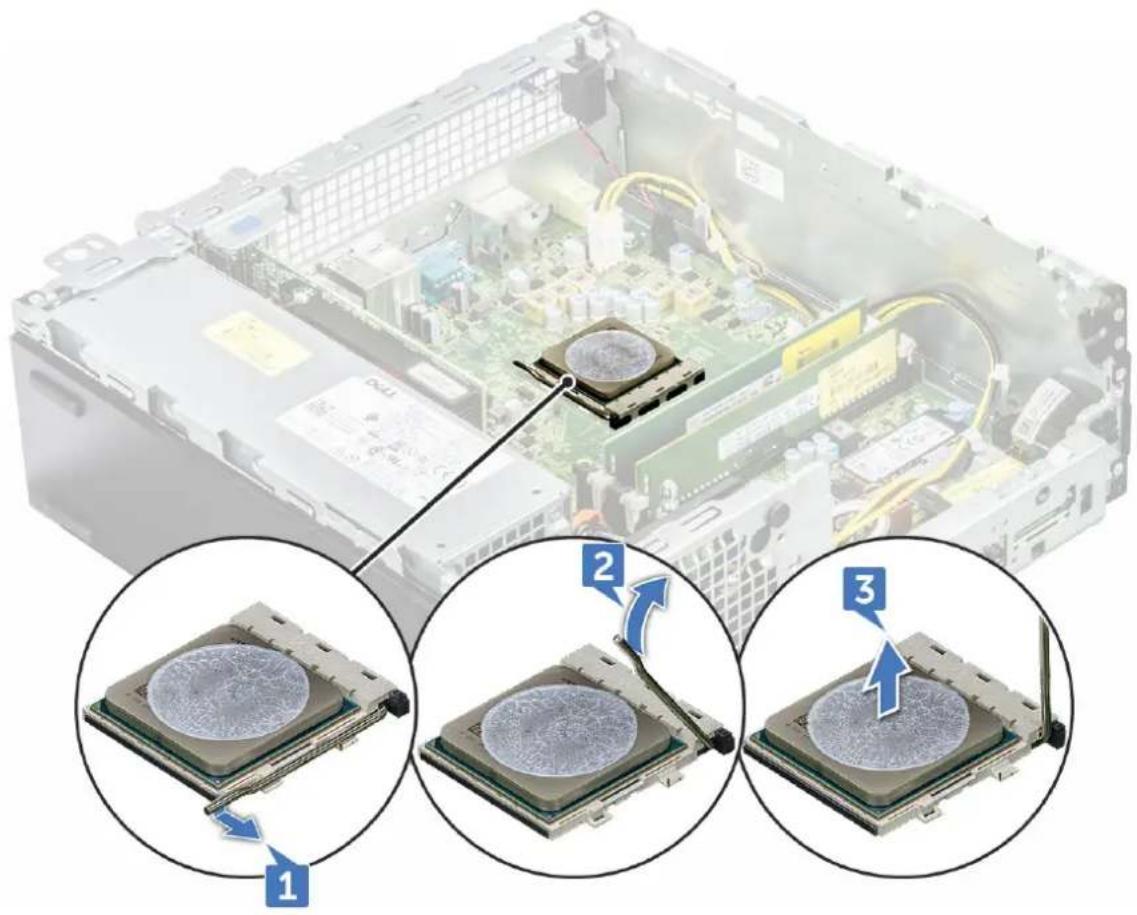
text_image
Diagram showing three steps of CPU disk disc installation on an electronic device, with labeled components and directional arrows.Installing the processor
1 Align the processor with the socket keys.

CAUTION: Do not use force to seat the processor. When the processor is positioned correctly, it engages easily into the socket.
2 Align the pin-1 indicator of the processor with the triangle on the socket.
3 Place the processor on the socket such that the slots on the processor align with the socket keys.
4 Close the processor shield by sliding it under the retention screw.
5 Lower the socket lever and push it under the tab to lock it.
6 Install the:
a heat sink assembly
b optical drive
c cooling shroud
d 2.5 hard drive assembly
e front bezel
f cover
7 Follow the procedure in After working inside your computer.
Intrusion switch
Removing intrusion switch
1 Follow the procedure in Before working inside your computer.
2 Remove the:
a cover
b front bezel
c cooling shroud
3 To the intrusion switch:
a Disconnect the intrusion switch cable from the connector on the system board [1].
b Slide the intrusion switch and push it to remove from the chassis [2].
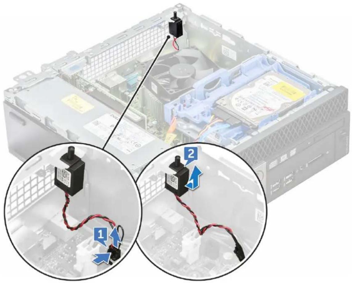
text_image
Diagram showing two views of a computer motherboard with labeled components and wiring, highlighting parts numbered 1 and 2.Installing intrusion switch
1 Insert the intrusion switch into the slot on the computer.
2 Connect the intrusion switch cable to the connector on the system board.
3 Install the:
a cooling shroud
b front bezel
c cover
4 Follow the procedure in After working inside your computer.
Memory modules
Removing memory module
1 Follow the procedure in Before working inside your computer.
2 Remove the:
a cover
b front bezel
c 2.5 inch hard drive assembly
d cooling shroud
e optical drive
3 To remove the memory module:
a Push the tabs on both sides of the memory module.
b Lift the memory module from the connector on the system board.
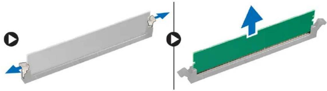
natural_image
Diagram showing two mechanical components with directional arrows, one gray and one green, both without any text or symbols.Installing memory module
1 Align the notch on the memory module with the tab on the memory module connector.
2 Insert the memory module into the memory module socket.
3 Press the memory module until the memory module retention tabs click into place.
4 Close the front panel door.
5 Install the:
a optical drive
b cooling shroud
c 2.5 inch hard drive assembly
d front bezel
e cover
6 Follow the procedure in After working inside your computer.
VGA Daughterboard
Removing the VGA daughter board
1 Follow the procedure in Before Working Inside Your Computer.
2 Remove the:
a Back Cover
b Bezel
3 Open the Front Bezel Door
4 To remove the VGA daughter board:
a Remove the screws that secure the VGA connector to the computer [1].
b Slide the VGA connector to release it from the computer [2].
c Remove the screw that secures the VGA daughter board to the computer [3].
d Lift the VGA daughter board using the handle to remove it from the computer [4].
Installing the VGA daughter board
1 Align the VGA daughter board with the screw holder on the system board.
2 Tighten the screw to secure the VGA daughter board to the system board.
3 Insert the VGA connector into the slot at the back of the computer.
4 Tighten the screws to secure the VGA connector to the computer.
5 Install the:
a Bezel
b Cover
6 Follow the procedure in After Working Inside Your Computer.
SD card
Removing SD card reader
1 Follow the procedure in Before working inside your computer.
2 Remove the:
a cover
b front bezel
c 2.5 inch hard drive assembly
d cooling shroud
e optical drive
f M.2 PCIe SSD
3 To remove the SD card reader:
a Release the power cables from the retention clips on the SD card reader enclosure [1].
b Remove the screws(6lbs) that secure the SD card reader [2].
c Lift the SD card reader away from the computer [3].
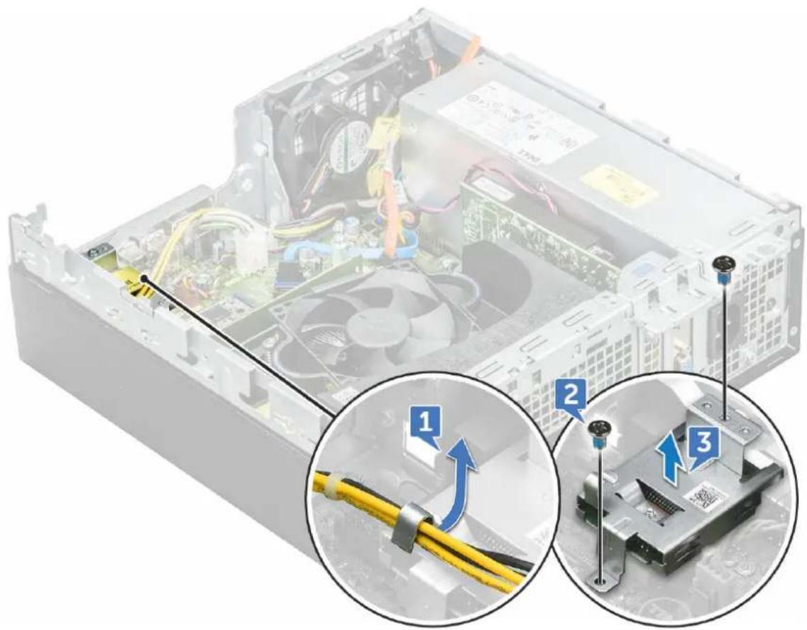
text_image
Diagram showing computer hardware components with numbered annotations highlighting cable installation stepsInstalling SD card reader
1 Place the SD card in the slot on the system board.
2 Tighten the screw(6 lbs) to secure the SD card reader to the front panel door.
3 Install the:
a M.2 PCIe SSD
b optical drive
c cooling shroud
d 2.5 inch hard drive assembly
e front bezel
f cover
4 Follow the procedure in After working inside your computer.
Power supply unit
Removing power supply unit — PSU
1 Follow the procedure in Before working inside your computer.
2 Remove the:
a cover
b front bezel
c 2.5 inch hard drive assembly
d cooling shroud
e optical drive
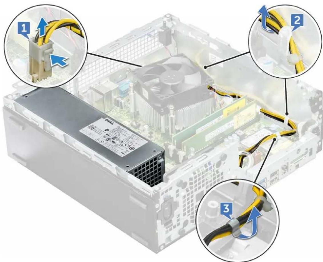
3 To release the PSU:
a Disconnect the PSU cables from the connectors on the system board [1].
b Unroute the PSU cables from the retention clips [2, 3].
text_image
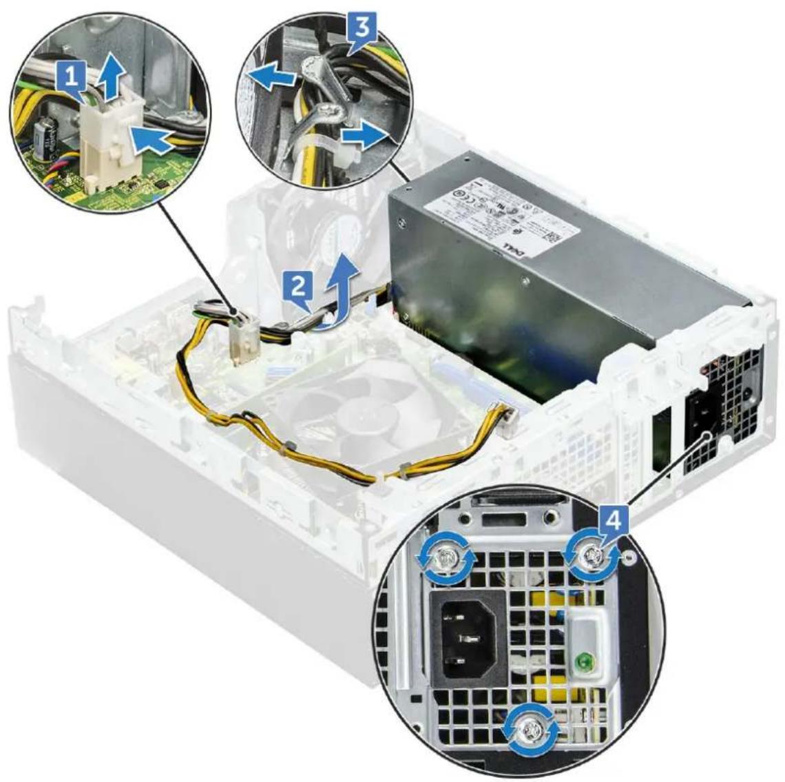
Diagram showing three cable connection steps in a computer motherboard: pin-up, cable insertion, and cable disassembly.4 To disconnect the cables:
a Disconnect the power cable from the system board [1] [2].
b Lift the cables away from the computer [3, 4].
c Remove the screws(6lbs) that secure the PSU to the computer [5].
text_image
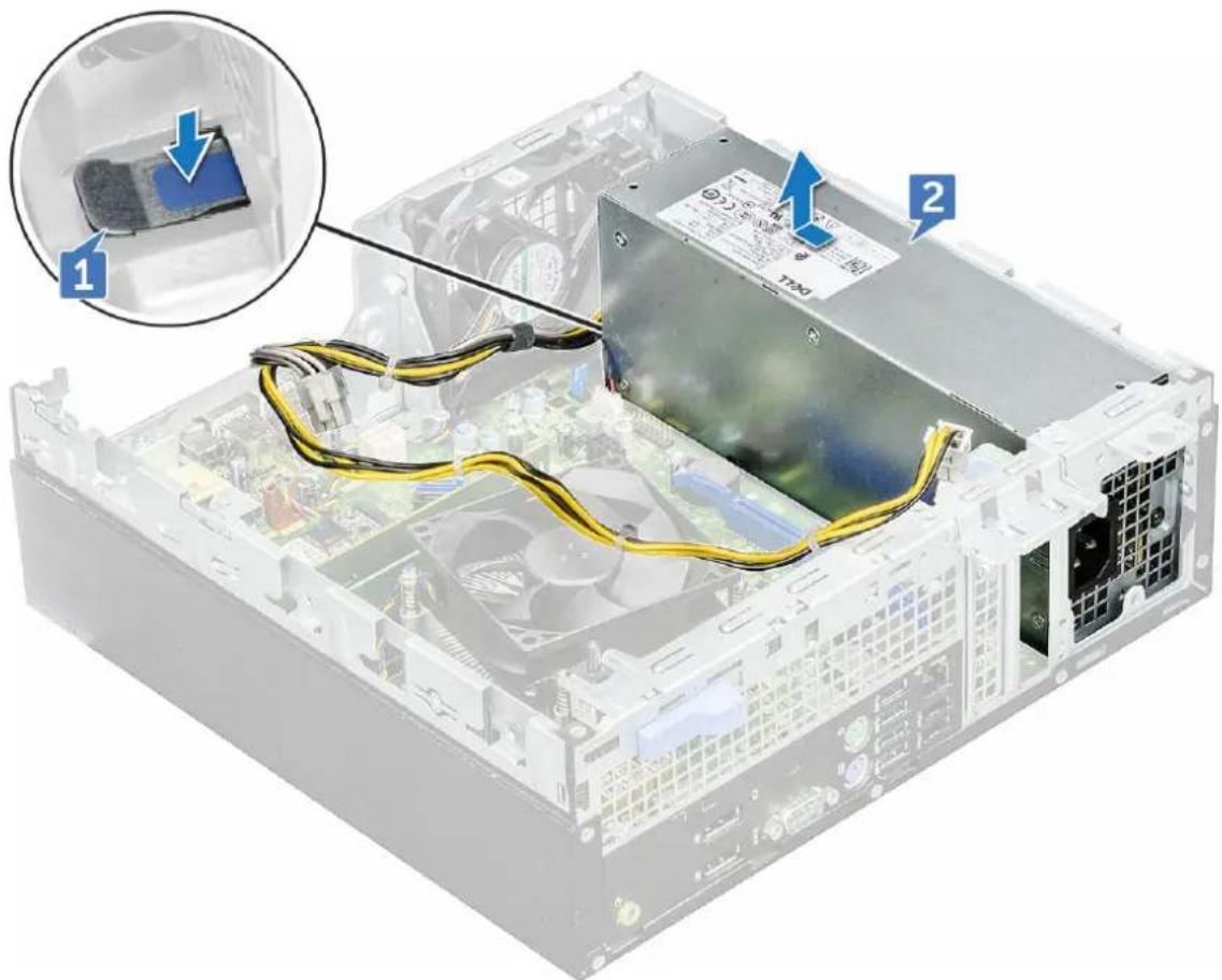
Diagram of a computer power supply unit with labeled components and wiring, showing connections to circuit boards and a monitor.5 To remove the PSU:
a Press the blue release tab [1]
b Slide the PSU and lift it away from the computer [2].
natural_image
Interior view of a computer drive bay with cable and power supply components, showing a close-up inset of a component (no text or symbols visible)Installing power supply unit — PSU
1 Insert the PSU into the slot.
2 Slide the PSU towards the back of the computer until it clicks into place.
3 Replace the screws( 6lbs) to secure the PSU to the computer.
4 Route the PSU cables through the retention clips.
5 Connect the PSU cables to the connectors on the system board.
6 Install the:
a optical drive
b cooling shroud
c 2.5 inch hard drive assembly
d front bezel
e cover
7 Follow the procedure in After working inside your computer.
Power switch
Removing power switch
1 Follow the procedure in Before working inside your computer.
2 Remove the:
a cover
b front bezel
c 2.5 inch hard drive assembly
d cooling shroud
e optical drive
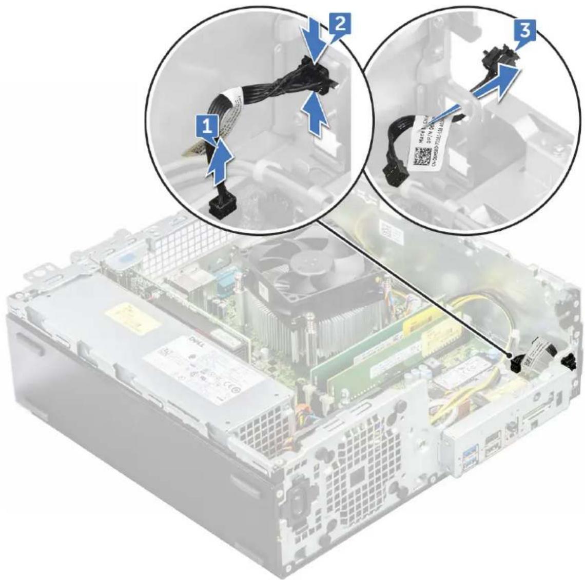
3 To release the power switch:
a Disconnect the power switch cable from the system board [1].
b Press the power switch retention tabs and pull out from the computer [2, 3].
text_image
Diagram showing three steps of inserting a cable into a computer motherboard, with labeled components and a QR code tag.Installing power switch
1 Slide the power switch module into the slot on the chassis until it clicks into place.
2 Connect the power switch cable to the connector on the system board.
3 Install the:
a optical drive
b cooling shroud
c 2.5 inch hard drive assembly
d front bezel
e cover
4 Follow the procedure in After working inside your computer.
Speaker
Removing speaker
1 Follow the procedure in Before working inside your computer.
2 Remove the:
a cover
b front bezel
c 2.5 inch hard drive assembly
d cooling shroud
e optical drive
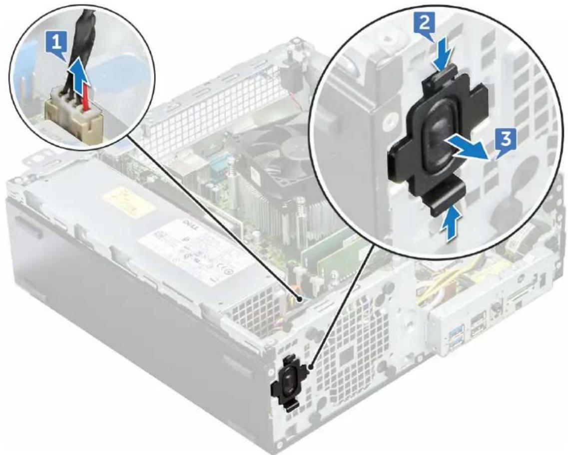
3 To remove the speaker:
a Disconnect the speaker cable from the connector on the system board [1].
b Press the release tabs [2], and slide the speaker module [3] out of the slot.
text_image
Diagram showing three views of a computer tower with labeled components and directional arrows indicating assembly or operation.Installing speaker
1 Insert the speaker into the slot and press it until it clicks into place.
2 Connect the speaker cable to the connector on the system board.
3 Install the:
a optical drive
b cooling shroud
c 2.5 inch hard drive assembly
d front bezel
e cover
4 Follow the procedure in After working inside your computer.
System board
Removing the system board
1 Follow the procedure in Before working inside your computer.
2 Remove the:
a cover
b front bezel
c 2.5 inch hard drive assembly
d cooling shroud
e optical drive
f M.2 PCIe SSD
g heat sink assembly
h memory module
i processor
j expansion card
k SD card
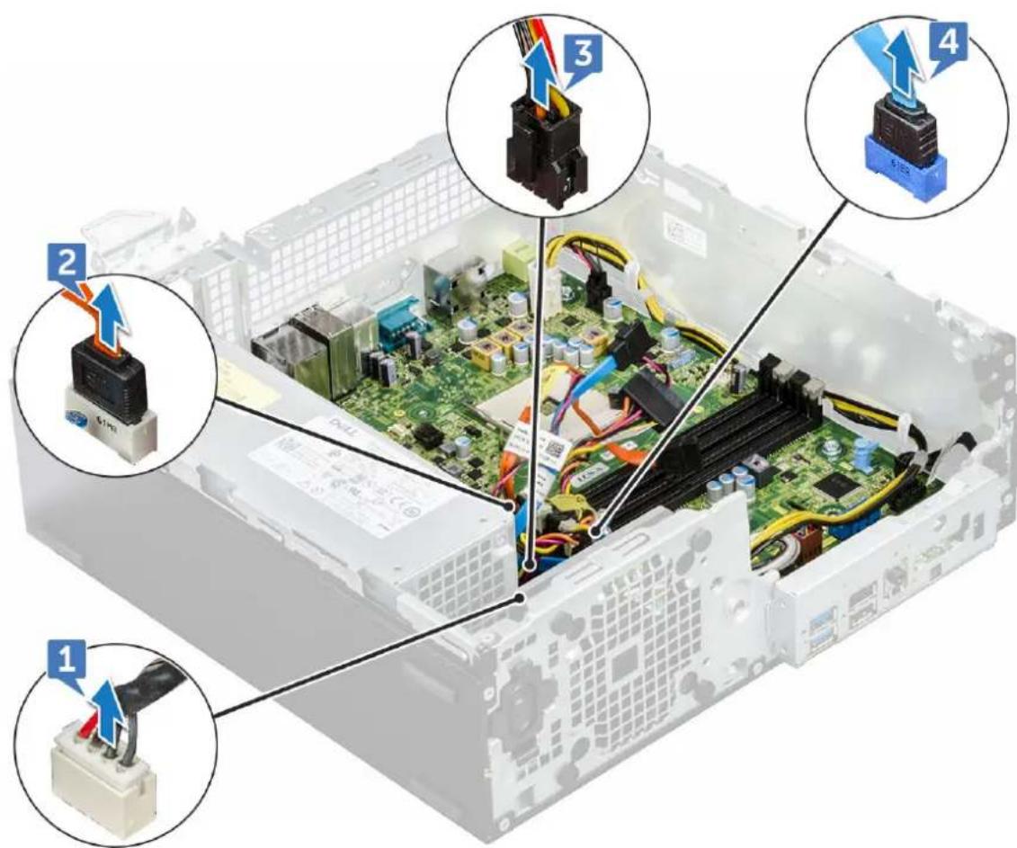
3 Disconnect the following cables from the system board:
a speaker [1]
b 2.5-inch drive [2]
c optical drive [3]
d data cable [4]
text_image
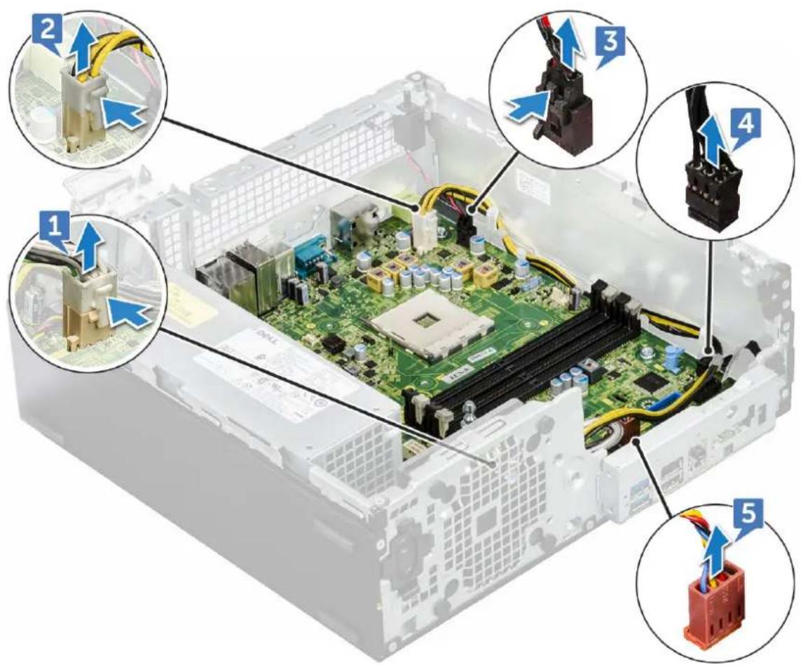
Diagram of an internal computer motherboard with labeled components and wiring, showing connections between ports 1, 2, 3, and 4.4 Disconnect the following cables and screw from the system board:
a PSU [1]
b hard drive and optical drive caddy stand off screw [2]
c PSU [3]
d power switch [4]
e intrusion switch [5]
text_image
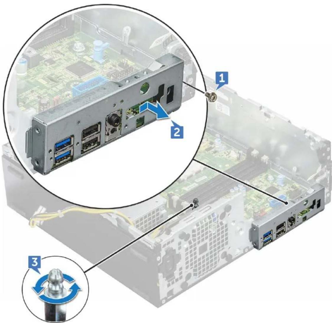
Diagram of computer motherboard with labeled components and wiring connections, showing numbered parts for assembly or maintenance.5 To remove the I/O panel plate:
a Remove the screw (6 lbs) that secures the I/O panel [1].
b Slide and push toward the front from the computer [2].
text_image
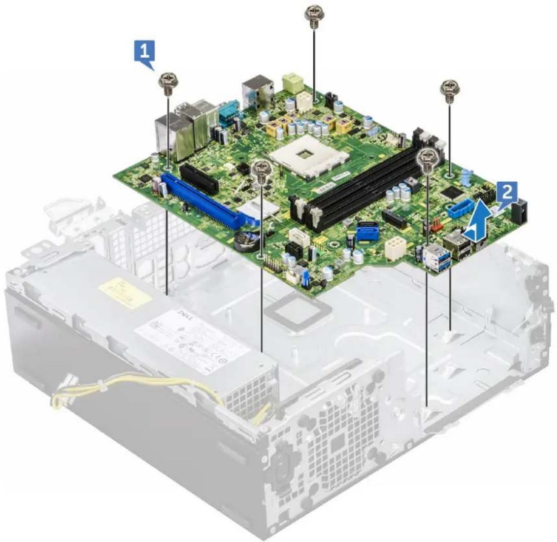
Diagram of a computer drive showing internal components and labeled parts, including ports, connectors, and a close-up view of the internal chassis.6 To remove the system board:
a Remove the screws (12 lbs) that secure the system board to the computer
b Slide and lift the system board away from the computer [2].
text_image
Diagram of an electronic circuit board with labeled components and a blue arrow indicating a specific area.Installing the system board
1 Hold the system board by its edges and align it toward the back of the computer.
2 Lower the system board into the chassis until the connectors at the back of the system board.
3 Align with the slots on the chassis, and the screw holes on the system board align with the standoffs on the computer.
4 Replace the screws (12 lbs) to secure the system board to the computer.
5 Route all the cables through the routing clips.
6 Align the cables with the pins on connectors on the system board and connect the following cables to the system board:
a intrusion switch
b optical drive
c hard drive
d PSU
e power switch
f power distribution for optical drive and hard drive
7 Install the:
a expansion card
b memory module
c heat sink assembly
d SD card
e M.2 PCIe SSD
f processor
g cooling shroud
h optical drive
i 2.5 inch hard drive assembly
j front bezel
k cover
8 Follow the procedure in After working inside your computer.
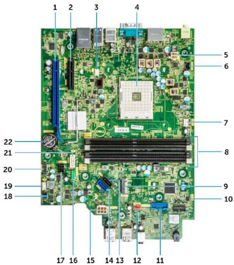
System board layout
This chapter explains about the motherboard's layout with name and location of its connectors.
text_image
1 2 3 4 5 6 7 8 9 10 11 12 13 14 15 16 17 18 19 20 21 22 DCI-CCN-CCN-CCN-CCN-CCN-CCN-CCN-CCN-CCN-CCN-CCN-CCN-CCN-CCN-CCN-CCN-CCN-CCN-CCN-CCN-CCN-CCN-CCN-CCN-CCN-CCN-CCN-CCN-CCN-CCN-CCN-CCN-CCN-CCN DCI-CCN-CCN-CCN-CCN-CCN-CCN-CCN-CCN-CCN-CCN-CCN-CCN-CCN-CCN-CCN-CCN-CCN-CCN-CCN-CCN-CCN-CCN-CCN1 PCI-e x16 Connector (SLOT2) 2 PCI-e x4 Connector (SLOT1) - open ended X4 to support X16
3 VGA Daughter Board Connector (VGA) 4 Processor Socket (CPU)
5 CPU Power Connector (ATX_CPU) 6 Intrusion Switch Connector (INTRUDER)
7 CPU fan Connector (FAN_CPU) 8 Memory Slots (DIMM1, DIMM2, DIMM3, DIMM4)
9 M.2 Slot 3 Connector (M.2_SSD) 10 Power Switch Connector (PWR_SW)
11 Media Card Reader Connector (CARD_READER)
12 System fan Connector (FAN_SYS)
13 SATA2 Connector Black Color (SATA2)
14 SATA0 Connector Blue Color (SATA0)
15 ATX Power Connector (ATX_SYS) 16 Front USB2.0 Connector (Front_USB)
17 HDD&ODD Power Cable Connector (SATA_PWR) 18 Clear CMOS Jumper (CMOS_CLR); Clear Password Jumper
(PASSWORD_CLR); Clear Password ; Jumper
(PASSWORD_CLR); Service Mode Jumper
(SERVICE_MODE)
19 Internal Speaker Connector (INT_SPKR) 20 Internal USB Connector (WF_BT_USB)
21 SATA 1 Connector White Color (SATA1) 22 Battery Connector (BATTERY)
Technology and components
This chapter details the technology and components available in the system.
Topics:
- Systems management features
- In-Band Systems Management – Dell Client Command Suite
- Out-of-Band Systems Management – DASH
- AMD APUs, AMD Ryzen CPUs and APUs
- AMD PT B350
- AMD Radeon R7 M450
• AMD Radeon R5 M430 - USB features
• DDR4
• Active State Power Management
Systems management features
Overview: Dell commercial systems come with a number of systems management options that are include by default for In-Band management with our Dell Client Command Suite. In-Band management meaning that the Operating System is functional and the device is connected to a network so that it can be managed. The Dell Client Command Suite of tools can be leveraged individually or with a systems management console like SCCM, LANDESK, KACE, etc.
We also offer Out-of-Band management as an option. Out-of-Band management is when the system does not have a functional operating system or is turned off and you still want to be able to manage the system in that state.
In-Band Systems Management – Dell Client Command Suite
The Dell Client Command Suite of tools is free to download at http://dell.com/command and can be used with all OptiPlex desktops. It contains the following components that can be used individually, or in the case of SCCM in conjunction with our integration for SCCM.
Dell Command | Deploy Driver Packs - Bundles of system specific drivers (web hosted on dell.com/command) that have been extracted and reduced to an OS consumable state for use with any OS deployment tool. Here is a link to Dell TechCenter where you can find the driver packs for each commercial client system: http://en.community.dell.com/techcenter/enterprise-client/w/wiki/2065.dell-command-deploy-driver-packs-forenterprise-client-os-deployment
Dell Command | Configure - A GUI based IT administrator tool for configuring and deploying hardware settings in either a pre-OS or post-OS environment. Example configurations include enabling TPM, restricting access to USB ports, locking the BIOS with BIOS passwords, disabling wireless/Bluetooth.
Dell Command | Monitor - A WMI (Windows Management Instrumentation) agent that provides deep hardware inventory and health monitoring along with command line and scripting capabilities that allow IT administrators to configure their hardware remotely.
Dell Command | Update - a factory-installed application that end-users, with administrative rights, may utilize to individually manage their own Dell updates. This tool leverages the Updates Catalog for scheduling and installing Dell updates (drivers, BIOS, firmware).
Dell Command | Update Catalog - Provides searchable metadata that is leveraged with Dell Command | Update and enables management consoles Dell KACE Appliances, LANDesk Management Systems and Microsoft System Center to retrieve the latest system specific updates (driver, firmware, or BIOS) for any Dell commercial client to be delivered seamlessly to end-users.
Dell Command | PowerShell Provider - Furthers the ability to standardize on this industry-leading scripting preference by enabling IT administrators to dynamically query and modify hardware settings with native PowerShell commands.
Dell Command | Power Manager - factory installed on all end-point devices with a battery (laptops, tablets) that enables modifications beyond the power options provided by the operating system.
Dell Command | Integration Suite for System Center 2012 - This suite integrates all the key components of the Client Command Suite into Microsoft System Center Configuration Manager 2012 and later.
Out-of-Band Systems Management – DASH
DMTF's Desktop and mobile Architecture for System Hardware (DASH) Standard is a suite of specifications that takes full advantage of DMTF's Web Services for Management (WS-Management) specification – delivering standards-based web services management for desktop and mobile client systems. Through DASH, DMTF provides the next generation of standards for secure out-of-band and remote management of desktop and mobile systems.
OptiPlex 5055 with DASH 1.2 on BCM5762 supports the following features such as remote power command, OOO Firmware Update.
To learn more about DMTF's DASH, visit DMTF's website at: https://www.dmtf.org/standards/dash
AMD APUs, AMD Ryzen CPUs and APUs
This topic explains about the AMD's APUs, Ryzen series of CPUs and Ryzen series of APUs.
OptiPlex 5055 is offered with either of the three variants of AMD's A-Series APUs, Ryzen CPUs or APUs.
• Optiplex 5055 A-Series: Offered with AMD Ryzen 7 Pro 1700, Ryzen 5 Pro 1500 and Ryzen 3 Pro 1300.
• Optiplex 5055 Ryzen CPU: Offered with AMD PRO A12-9800, A10-9700, A8-9600, and A6-9500.
• OptiPlex 5055 Ryzen APU: Offered with Ryzen 3 Pro 2200G, Ryzen 5 Pro 2400G and Athlon Pro 200GE.
AMD Advanced Processing Unit - APU
This topic explains AMD's Advanced processing Unit (APU)
The AMD Accelerated Processing Units (APU) are a series of 64-bit microprocessors designed aesthetically by AMD combining the capabilities of Central Processing Unit (CPU) and Graphical Processing Unit (GPU) on a single die(chip).
Features:
- Heterogeneous System Architecture (HSA): An open-source, cross vendor set of specification allowing the integration of CPU and GPU on the same bus as CPU cores with coherent memory.
- Power Management: CPU and GPU share same power resources optimizing performance and availability.
- System Architecture Integration: Allows the GPU to be context switched, providing a multitasking environment with smart utilization of hardware resources across workloads.
- Open CL, C++: Support for Open CL and C++ language extensions.
AMD Ryzen
This topic explains about the AMD's Ryzen series of processors.
AMD's Ryzen is a series of CPUs and APUs based on Zen micro architecture. Zen System On Chip(SoC) design allows the PCIe, SATA, and USB controllers reside on same chip as CPU's cores.
Features:
- Performance: Simultaneous multithreading (SMT) to allow execution of two threads per core, increasing the Instruction Per Cycle(IPC) thus enhancing the processing throughput.
• Power: AMD's Sense MI technology employs sensors across the chip to dynamically scaling the frequency and voltage automatically defined in processor itself allowing better use of available resources.
• Security and Virtualization: Ryzen offers Secure Memory Encryption(SME) and Secure Encrypted Vitalization(SEV) for real time memory encryption securing the system from cold boot attacks.
AMD Ryzen APUs
This topic explains AMD's Ryzen series of APUs.
Ryzen APUs are series of APU (CPU+GPU) offered with Vega 8/11 graphics processors. Ryzen APUs are performance enhancements over the predecessor Ryzen CPUs incorporating the GPU on same chip as CPU cores.
AMD PT B350
AMD B350
- Chipset is perfect for power-users who value flexibility and overclocking control, but don't need the maximum PCIe bandwidth required by multi-GPU configurations.
- AMD Socket AM4 represents the company's new future-proof platform targeting the fastest DDR4 memory.
- With processor-direct SATA and USB connectivity, configurable for real-world flexibility, the new AM4 platform takes advantage of the leading-edge features
Specification
Table 3. Specification
SpecificationDetails
PCI Express Gen3 Graphics 1x16(AMD Ryzen™)1x8 (A-Series/AMD Athlon™)
USB 3.1 G2 + 3.1 G1 + 2.0 2+6+6
SATA + NVMe 4 + x2 NVMe (or 2 SATA 1 x4 NVMe on AMD Ryzen™ Processor).
SATA Express* (SATA & GPP PCIe G3*) 1
PCI Express® GP x6 Gen2 (plus x2 PCIe Gen3 when no x4 NVMe)
SATA RAID 0,1,10
Dual PCI Express® slots No
Over-clocking Unlocked
AMD Radeon R7 M450
- The first graph shows the relative performance of the video card compared to the 10 other common video cards in terms of PassMark G3D Mark.
Key Specifications
The following table contains the key specifications of the AMD Radeon R7 M450:
Table 4. Key Specifications
SpecificationAMD Radeon R7 M450
| Product Line AMD |
| API Supported DirectX 12 , OpenCL 1.2 , OpenGL 4.3 |
| Clock Speed 925 MHz |
| Bus Width 128-bit |
| Memory Clock Speed 1.125 GHz |
| Technology DDR3 SDRAM |
| Max External Resolution 1920 x 1080 |
| Interface Type PCI Express 3.0 x16 |
AMD Radeon R5 M430
The AMD Radeon R5 M430 is an entry level graphics card for laptops. It is based on the older Radeon R5 M330 / M335 or R7 M340.
Key Specifications
The following table contains the key specifications of the AMD Radeon R5 M430:
Table 5. KeySpecifications
SpecificationAMD Radeon R5 M430
| Radeon R5 M400 Series Radeon R5 M430 | |
| Codename Sun XT | |
| Architecture GCN | |
| Pipelines 320 - unified | |
| Memory Bus Width | 64 Bit |
| Shared Memory | No |
| Technology 28 nm | |
| DirectX | DirectX 12 |
USB features
Universal Serial Bus, or USB, was introduced in 1996. It dramatically simplified the connection between host computers and peripheral devices like mice, keyboards, external drivers, and printers.
Let's take a quick look on the USB evolution referencing to the table below.
Table 6. USB evolution
Type Data Transfer Rate Category Introduction Year
USB 3.0/USB 3.1 Gen 2 5 Gbps Super Speed 2010
USB 2.0 480 Mbps High Speed 2000
USB 3.1 Gen 1 (SuperSpeed USB)
For years, the USB 2.0 has been firmly entrenched as the de facto interface standard in the PC world with about 6 billion devices sold, and yet the need for more speed grows by ever faster computing hardware and ever greater bandwidth demands. The USB 3.1 Gen 1 finally has the answer to the consumers' demands with a theoretically 10 times faster than its predecessor. In a nutshell, USB 3.1 Gen 1 features are as follows:
• Higher transfer rates (up to 5 Gbps)
- Increased maximum bus power and increased device current draw to better accommodate power-hungry devices
- New power management features
• Full-duplex data transfers and support for new transfer types
- Backward USB 2.0 compatibility
- New connectors and cable
The topics below cover some of the most commonly asked questions regarding USB 3.1 Gen 1.

Speed
Currently, there are 3 speed modes defined by the latest USB 3.1 Gen 1 specification. They are Super-Speed, Hi-Speed and Full-Speed. The new SuperSpeed mode has a transfer rate of 4.8Gbps. While the specification retains Hi-Speed, and Full-Speed USB mode, commonly known as USB 2.0 and 1.1 respectively, the slower modes still operate at 480Mbps and 12Mbps respectively and are kept to maintain backward compatibility.
USB 3.1 Gen 1 achieves the much higher performance by the technical changes below:
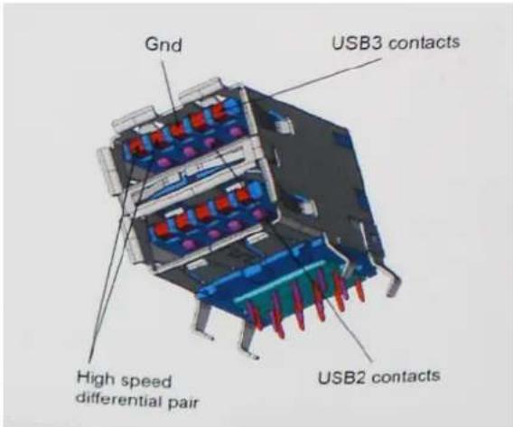
- An additional physical bus that is added in parallel with the existing USB 2.0 bus (refer to the picture below).
- USB 2.0 previously had four wires (power, ground, and a pair for differential data); USB 3.1 Gen 1 adds four more for two pairs of differential signals (receive and transmit) for a combined total of eight connections in the connectors and cabling.
- USB 3.1 Gen 1 utilizes the bidirectional data interface, rather than USB 2.0's half-duplex arrangement. This gives a 10-fold increase in theoretical bandwidth.
text_image
Gnd USB3 contacts High speed differential pair USB2 contactsWith today's ever increasing demands placed on data transfers with high-definition video content, terabyte storage devices, high megapixel count digital cameras etc., USB 2.0 may not be fast enough. Furthermore, no USB 2.0 connection could ever come close to the 480Mbps theoretical maximum throughput, making data transfer at around 320Mbps (40MB/s) — the actual real-world maximum. Similarly, USB 3.1 Gen 1 connections will never achieve 4.8Gbps. We will likely see a real-world maximum rate of 400MB/s with overheads. At this speed, USB 3.1 Gen 1 is a 10x improvement over USB 2.0.
Applications
USB 3.1 Gen 1 opens up the laneways and provides more headroom for devices to deliver a better overall experience. Where USB video was barely tolerable previously (both from a maximum resolution, latency, and video compression perspective), it's easy to imagine that with 5-10 times the bandwidth available, USB video solutions should work that much better. Single-link DVI requires almost 2Gbps throughput. Where 480Mbps was limiting, 5Gbps is more than promising. With its promised 4.8Gbps speed, the standard will find its way into some products that previously weren't USB territory, like external RAID storage systems.
Listed below are some of the available SuperSpeed USB 3.1 Gen 1 products:
- External Desktop USB 3.1 Gen 1 Hard Drives
- Portable USB 3.1 Gen 1 Hard Drives
• USB 3.1 Gen 1 Drive Docks & Adapters
• USB 3.1 Gen 1 Flash Drives & Readers
• USB 3.1 Gen 1 Solid-state Drives - USB 3.1 Gen 1 RAIDs
• Optical Media Drives - Multimedia Devices
- Networking
• USB 3.1 Gen 1 Adapter Cards & Hubs
Compatibility
The good news is that USB 3.1 Gen 1 has been carefully planned from the start to peacefully co-exist with USB 2.0. First of all, while USB 3.1 Gen 1 specifies new physical connections and thus new cables to take advantage of the higher speed capability of the new protocol, the connector itself remains the same rectangular shape with the four USB 2.0 contacts in the exact same location as before. Five new connections to carry receive and transmitted data independently are present on USB 3.1 Gen 1 cables and only come into contact when connected to a proper SuperSpeed USB connection.
Windows 8/10 will be bringing native support for USB 3.1 Gen 1 controllers. This is in contrast to previous versions of Windows, which continue to require separate drivers for USB 3.1 Gen 1 controllers.
Microsoft announced that Windows 7 would have USB 3.1 Gen 1 support, perhaps not on its immediate release, but in a subsequent Service Pack or update. It is not out of the question to think that following a successful release of USB 3.1 Gen 1 support in Windows 7, SuperSpeed support would trickle down to Vista. Microsoft has confirmed this by stating that most of their partners share the opinion that Vista should also support USB 3.1 Gen 1.
Super-Speed support for Windows XP is unknown at this point. Given that XP is a seven-year-old operating system, the likelihood of this happening is remote.
DDR4
DDR4 (double data rate fourth generation) memory is a higher-speed successor to the DDR2 and DDR3 technologies and allows up to 512 GB in capacity, compared to the DDR3's maximum of 128 GB per DIMM. DDR4 synchronous dynamic random-access memory is keyed differently from both SDRAM and DDR to prevent the user from installing the wrong type of memory into the system.
DDR4 needs 20 percent less or just 1.2 volts, compared to DDR3 which requires 1.5 volts of electrical power to operate. DDR4 also supports a new, deep power-down mode that allows the host device to go into standby without needing to refresh its memory. Deep power-down mode is expected to reduce standby power consumption by 40 to 50 percent.
DDR4 Details
There are subtle differences between DDR3 and DDR4 memory modules, as listed below.
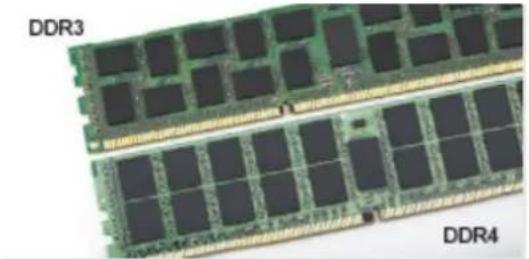
Key notch difference
The key notch on a DDR4 module is in a different location from the key notch on a DDR3 module. Both notches are on the insertion edge but the notch location on the DDR4 is slightly different, to prevent the module from being installed into an incompatible board or platform.
natural_image
Two views of a DDR3 and DDR4 integrated circuit chips (no text or symbols on the chips themselves)Figure 1. Notch difference
Increased thickness
DDR4 modules are slightly thicker than DDR3, to accommodate more signal layers.
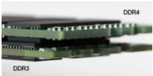
natural_image
Close-up of electronic components labeled DDR3 and DDR4, showing layered circuitry (no text beyond labels)Figure 2. Thickness difference
Curved edge
DDR4 modules feature a curved edge to help with insertion and alleviate stress on the PCB during memory installation.
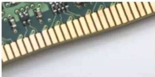
natural_image
Close-up of a green printed circuit board with gold traces, showing solder pads and components (no text or symbols visible)Figure 3. Curved edge
Memory Errors
Memory errors on the system display the new ON-FLASH-FLASH or ON-FLASH-ON failure code. If all memory fails, the LCD does not turn on. Troubleshoot for possible memory failure by trying known good memory modules in the memory connectors on the bottom of the system or under the keyboard, as in some portable systems.
Active State Power Management
This section describes about the Active State Power Management (ASPM).
ASPM is the power management capability of hardware to effectively reduce usage of power by placing the PCI Express(PCIe) based serial link devices to low-power state when not in use.
ASPM is controlled by BIOS or the power management component of the operating system in two configurations.
- Disabled: PCIe devices operate on high-performance mode.
- L1 Mode: Bi-directional setting of the serially linked PCIe device to low-power state.
NOTE: This mode provides with higher power saving at expense of latency when re-establishing the connection.
The PCIe bus must be woken up from low-power mode to re-establish the connection with the device. This accounts for the latency, which is also referred to as ASPM exit latency.
System setup
System setup enables you to manage your desktop hardware and specify BIOS level options. From the System setup, you can:
- Change the NVRAM settings after you add or remove hardware
• View the system hardware configuration - Enable or disable integrated devices
- Set performance and power management thresholds
- Manage your computer security
Topics:
- Boot menu
- System Setup options
- Updating the BIOS in Windows
- Updating the Dell BIOS in Linux and Ubuntu environments
- Flashing the BIOS from the F12 One-Time boot menu
Boot menu
Press
The options are:
- Legacy Boot:
- Internal HDD
- Onboard NIC
- UEFI Boot:
- Windows Boot Manager
- Other Options:
- BIOS Setup
- BIOS Flash Update
– Diagnostics - Change Boot Mode Settings
System Setup options
NOTE: Depending on the computer and its installed devices, the items listed in this section may or may not appear.
Table 7. General
Option Description
System Information Displays the following information:
| System Information: Displays BIOS Version, Service Tag, Asset Tag, Ownership Tag, Ownership Date, Manufacture Date, Express Service Code and the Singed Firmware Update.Memory Information: Displays Memory Installed, Memory Available, Memory Speed, Memory Channel Mode, Memory Technology, DIMM 1 Size, DIMM 2 Size, DIMM 3 Size and DIMM 4 Size.PCI Information: Displays SLOT1_M.2, SLOT2_M.2Processor Information: Displays Processor Type, Core Count, Current Clock Speed, Minimum Clock Speed, Maximum Clock Speed, Processor L2 Cache, Processor L3 Cache, HT Capable, and 64-Bit Technology.Device Information: Displays LOM MAC Address, Video Controller, Audio Controller. | |
| Boot Sequence | Boot ModeBoot List option:- Legacy- UEFI (Default)Enable Boot DevicesBoot Sequence- Add Boot Option- Remove Boot Option- View Boot Option |
| Advanced Boot Options Allows you to select the Enable Legacy Option ROMs option. By default, this option is selected.Enabled(selected by default)Disabled | |
| BIOS Setup Advanced Mode Allows you to select BIOS Setup Advanced Mode. By default, this option is selected.Enabled(selected by default)Disabled | |
| Date/Time | Allows you to set the date and time settings. Changes to the system date and time take effect immediately. |
Table 8. System Configuration
Option Description
| Integrated NIC Allows you to control the on-board LAN controller. The option 'Enable UEFI Network Stack' is not selected by default. The options are: | |
| DisabledEnabledEnabled w/PXE (default) | |
| NOTE: Depending on the computer and its installed devices, the items listed in this section may or may not appear. | |
| Serial Port The options are: | |
| COM1 (Enabled by default)COM2 (Disabled by default)COM3 (Disabled by default)COM4 (Disabled by default) | |
| SATA Operation | Allows you to configure the operating mode of the integrated hard drive controller. |
| Disabled = The SATA controllers are hidden | |
Option Description
| · AHCI (Enabled by default) · RAID ON = SATA is configured to support RAID mode (Disabled by default) | |
| Drives Allows you to enable or disable the various drives on-board: | |
| · SATA-0 (enabled by default) · SATA-1 · SATA-2 · SATA-3 · M.2 PCIe SSD-0 | |
| Smart Reporting | This field controls whether hard drive errors for integrated drives are reported during system startup. The Enable Smart Reporting option is disabled by default. |
| USB Configuration | Allows you to enable or disable the integrated USB controller for: · Enable Boot Support · Enable Front USB Ports · Enable Rear USB Ports All the options are enabled by default. |
| USB PowerShare This option allows you to charge the external devices, such as mobile phones, music player. This option is disabled by default. | |
| Audio | Allows you to enable or disable the integrated audio controller. The option Enable Audio is selected by default. · Enable Microphone · Enable Audio · Enable Internal Speaker The options are selected by default. |
| Miscellaneous Devices Allows you to enable or disable the Miscellaneous Devices. The option are · Enable Secure Digital (SD) Card (Enabled by default) · Secure Digital (SD) Card Read-Only mode | |
Table 9. Video
Option Description
| Multi-Display The option is selected by default. |
| Primary Display Allows you to select the primary display when multiple controllers are available in the system. |
| · Auto (default) · Integrated Graphics |
Table 10. Security
Option Description
Admin Password Allows you to set, change, and delete the admin password.
System Password Allows you to set, change, and delete the system password.
Option Description
| Internal HDD-0 Password Allows you to set, change, and delete the computer's internal HDD. | |
| Internal HDD-1 Password Allows you to set, change, and delete the computer's internal HDD. | |
| Internal HDD-2 Password Allows you to set, change, and delete the computer's internal HDD. | |
| Strong Password This option lets you enable or disable strong passwords for the system. | |
| Password Configuration | Allows you to control the minimum and maximum number of characters allowed for a administrative password and the system password. The range of characters is between 4 and 32. |
| Password Change This option lets you determine whether changes to the System and Hard Disk passwords are permitted when an administrator password is set.Allow Non-Admin Password Changes - This option is enabled by default. | |
| UEFI Capsule Firmware Updates | This option controls whether this system allows BIOS updates via UEFI capsule update packages. This option is selected by default. Disabling this option will block BIOS updates from services such as Microsoft Windows Update and Linux Vendor Firmware Service (LVFS) |
| TPM 2.0 Security Allows you to control whether the Trusted Platform Module (TPM) is visible to the operating system. | |
| • TPM On (default)– PPI Bypass for Enable Commands– PPI Bypass for Disable Commands– PPI Bypass for Clear Commands– Attestation Enable (default)– Key Storage Enable (default)– SHA-256 (default)• Clear• TPM State– Disable– Enable (default) | |
| Computrace | This field lets you Activate or Disable the BIOS module interface of the optional Computrace Service from Absolute Software. Enables or disables the optional Computrace service designed for asset management.• Deactivate - This option is selected by default.• Disable• Activate |
| Chassis Intrusion The options are: | |
| • Disable (default)• Enable• On-Silent | |
| Admin Setup Lockout | Allows you to enable or disable the option to enter Setup when an Administrative password is set. This option is not set by default. |
Table 11. Secure Boot
| Option | Description |
| Secure Boot Enable | Allows you to enable or disable Secure Boot feature· Disable (selected by default) |
- Enable
Expert key Management Allows you to manipulate the security key databases only if the system is in Custom Mode. The
Enable Custom Mode option is disabled by default. The options are:
- PK (default)
· KEK - db
- dbx
If you enable the Custom Mode, the relevant options for PK, KEK, db, and dbx appear. The options are:
- Save to File- Saves the key to a user-selected file
- Replace from File- Replaces the current key with a key from a user-selected file
- Append from File- Adds a key to the current database from a user-selected file
- Delete- Deletes the selected key
- Reset All Keys- Resets to default setting
- Delete All Keys- Deletes all the keys

NOTE: If you disable the Custom Mode, all the changes made will be erased and the keys will restore to default settings.
Table 12. Performance
Option Description
C States Control Allows you to enable or disable additional processor sleep states.
This option is enabled by default.
AMD TurboCore Technology This options is disable by default.
Table 13. Power Management
Option Description
AC Recovery Determines how the system responds when AC power is re-applied after a power loss. You can set the AC Recovery to:
- Power Off
- Power On
- Last Power State
This option is Power Off by default.
Auto On Time Sets time to automatically turn on the computer. Time is kept in standard 12-hour format
(hour:minutes:seconds). Change the startup time by typing the values in the time and AM/PM fields.

NOTE: This feature does not work if you turn off your computer using the switch on a power strip or surge protector or if Auto Power is set to disabled.
Deep Sleep Control Allows you to define the controls when Deep Sleep is enabled.
- Disabled
- Enabled in S5 only
- Enabled in S4 and S5
This option is Enabled in S4 and S5 by default.
Option Description
| Fan Control Override Allows you to determine the speed of the system fan. When this option is enabled, the system fan runs at the maximum speed. This option is disabled by default. | |
| USB Wake Support Allows you to enable the USB devices to wake the computer from standby mode. The option "Enable USB Wake Support" is selected by default | |
| Wake on LAN/WWAN | This option allows the computer to power up from the off state when triggered by a special LAN signal. This feature only works when the computer is connected to AC power supply.·Disabled- Does not allows the system to power on by special LAN signals when it receives a wake-up signal from the LAN or wireless LAN.·LAN- Allows the system to be powered on by special LAN signals.·WLAN Only- Allows the system to be powered on by special WLAN signals.·LAN or WLAN- Allows the system to be powered on by special LAN signals or WLAN signals.·LAN with PXE Boot- A wakeup packet sent to the system in either the S4 or S5 state, that will cause the system to wake-up and immediately boot to PXE.This option is Disabled by default. |
| Block Sleep Allows you to block entering to sleep (S3 state) in OS environment. This option is disabled by default. | |
Table 14. POST Behavior
Option Description
| Numlock LED Allows you to enable or disable the Numlock feature when your computer starts. This option is enabled by default. |
| Keyboard Errors Allows you to enable or disable the keyboard error reporting when the computer starts. This option is enabled by default. |
| Warnings and Errors This option can speed up the boot process by bypassing some compatibility steps: |
| · Prompt on Warnings and Errors (enabled by default) |
| · Continue on Warnings |
| · Continue on Warnings and Errors |
| Extend BIOS POST Time The options are: |
| · 0 seconds (default) |
| · 5 seconds |
| · 10 seconds |
| Full Screen Logo This options is disabled by default. |
Table 15. Virtualization Support
Option Description
| AMD-V Technology This option is enabled by default. |
| AMD-VI Technology This option is enabled by default. |
Table 16. Maintenance
Option Description
| Service Tag Displays the Service Tag of your computer. | |
| Asset Tag | Allows you to create a system asset tag if an asset tag is not already set. This option is set by default. |
Option Description
SERR Messages Controls the SERR message mechanism. This option is set by default. Some graphics cards require that the SERR message mechanism be disabled.
Dell Development Configuration This options is disabled by default.
BIOS Downgrade Allows you to control flashing of the system firmware to the previous versions. This option is enabled by default.

NOTE: If this option is not selected, the flashing of the system firmware to the previous versions is blocked.
Data Wipe Allows you to securely erase the data from all the available internal storages, such as HDD, SSD, mSATA, and eMMC. The option Wipe on Next Boot is disabled by default.
BIOS recovery Allows you to recover the corrupted BIOS conditions from the recovery files on the primary hard drive. The option BIOS Recovery from Hard Drive is selected by default
Table 17. System Logs
Option Description
BIOS Events Displays the system event log and allows you to:
- Clear Log
- Mark all Entries
Table 18. SupportAssist System Resolution
Option Description
Auto OS Recovery Threshold Options are: OFF, 1, 2 (default), 3.
Updating the BIOS in Windows
It is recommended to update your BIOS (System Setup), when you replace the system board or if an update is available.

NOTE If BitLocker is enabled, it must be suspended prior to updating the system BIOS, and then re-enabled after the BIOS update is completed.
1 Restart the computer.
2 Go to Dell.com/support.
- Enter the Service Tag or Express Service Code and click Submit.
- Click Detect Product and follow the instructions on screen.
3 If you are unable to detect or find the Service Tag, click Choose from all products.
4 Choose the Products category from the list.

NOTE: Choose the appropriate category to reach the product page
5 Select your computer model and the Product Support page of your computer appears.
6 Click Get drivers and click Drivers and Downloads.
The Drivers and Downloads section opens.
7 Click Find it myself.
8 Click BIOS to view the BIOS versions.
9 Identify the latest BIOS file and click Download.
10 Select your preferred download method in the Please select your download method below window, click Download File.
The File Download window appears.
11 Click Save to save the file on your computer.
12 Click Run to install the updated BIOS settings on your computer.
Follow the instructions on the screen.
Updating BIOS on systems with BitLocker enabled

CAUTION: If BitLocker is not suspended before updating the BIOS, the next time you reboot the system it will not recognize the BitLocker key. You will then be prompted to enter the recovery key to progress and the system will ask for this on each reboot. If the recovery key is not known this can result in data loss or an unnecessary operating system re-install. For more information on this subject, see Knowledge Article: http://www.dell.com/support/article/sln153694
Updating your system BIOS using a USB flash drive
If the system cannot load into Windows but there is still a need to update the BIOS, download the BIOS file using another system and save it to a bootable USB Flash Drive.

NOTE: You will need to use a bootable USB Flash drive. Please refer to the following article for further details: http://www.dell.com/support/article/sln143196
1 Download the BIOS update .EXE file to another system.
2 Copy the file e.g. O9010A12.EXE onto the bootable USB Flash drive.
3 Insert the USB Flash drive into the system that requires the BIOS update.
4 Restart the system and press F12 when the Dell Splash logo appears to display the One Time Boot Menu.
5 Using arrow keys, select USB Storage Device and click Return.
6 The system will boot to a Diag C:> prompt.
7 Run the file by typing the full filename e.g. O9010A12.exe and press Return.
8 The BIOS Update Utility will load, follow the instructions on screen.
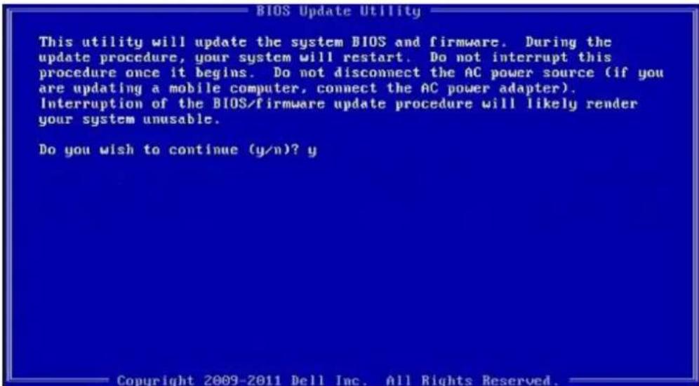
text_image
BIOS Update Utility This utility will update the system BIOS and firmware. During the update procedure, your system will restart. Do not interrupt this procedure once it begins. Do not disconnect the AC power source (if you are updating a mobile computer, connect the AC power adapter). Interruption of the BIOS/firmware update procedure will likely render your system unusable. Do you wish to continue (y/n)? y Copyright 2009-2011 Dell Inc. All Rights Reserved.Figure 4. DOS BIOS Update Screen
Updating the Dell BIOS in Linux and Ubuntu environments
If you want to update the system BIOS in a Linux environment such as Ubuntu, see http://www.dell.com/support/article/sln171755.
Flashing the BIOS from the F12 One-Time boot menu
Updating your system BIOS using a BIOS update .exe file copied to a FAT32 USB key and booting from the F12 one time boot menu. BIOS Update
You can run the BIOS update file from Windows using a bootable USB key or you can also update the BIOS from the F12 One-Time boot menu on the system.
Most Dell systems built after 2012 have this capability and you can confirm by booting your system to the F12 One-Time Boot Menu to see if BIOS FLASH UPDATE is listed as a boot option for your system. If the option is listed, then the BIOS supports this BIOS update option.
NOTE: Only systems with BIOS Flash Update option in the F12 One-Time Boot Menu can use this function.
Updating from the One-Time Boot Menu
To update your BIOS from the F12 One-Time boot menu, you will need:
- USB key formatted to the FAT32 file system (key does not have to be bootable)
• BIOS executable file that you downloaded from the Dell Support website and copied to the root of the USB key - AC power adapter connected to the system
• Functional system battery to flash the BIOS
Perform the following steps to execute the BIOS update flash process from the F12 menu:
CAUTION: Do not power off the system during the BIOS update process. Powering off the system could make the system fail to boot.
1 From a power off state, insert the USB key where you copied the flash into a USB port of the system.
2 Power on the system and press the F12 key to access the One-Time Boot Menu, Highlight BIOS Flash Update using the arrow keys then press Enter.
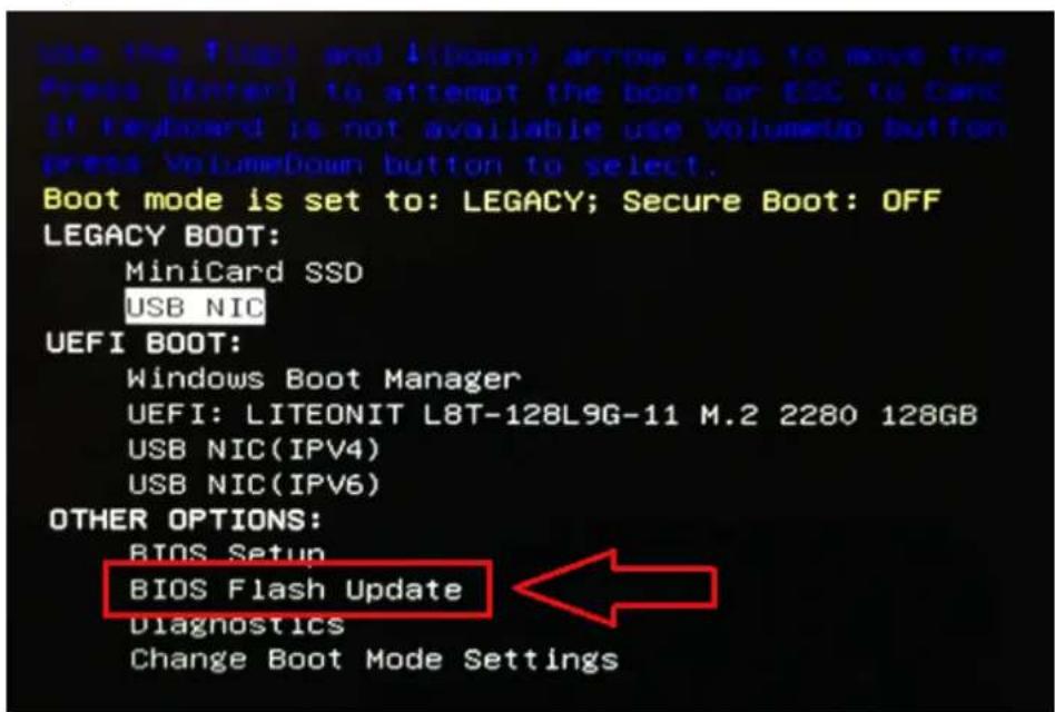
text_image
use the 1/4bit and 1(down) arrow keys to move the Press [Enter] to attempt the boot or ESC to Card. If keyboard is not available use VolumeUp button press VolumeDown button to select. Boot mode is set to: LEGACY; Secure Boot: OFF LEGACY BOOT: MiniCard SSD USB NIC UEFI BOOT: Windows Boot Manager UEFI: LITEONIT L8T-128L9G-11 M.2 2280 128GB USB NIC(IPV4) USB NIC(IPV6) OTHER OPTIONS: BIOS Setup BIOS Flash Update Diagnostics Change Boot Mode Settings3 The Bios flash menu will open then click the browse button.
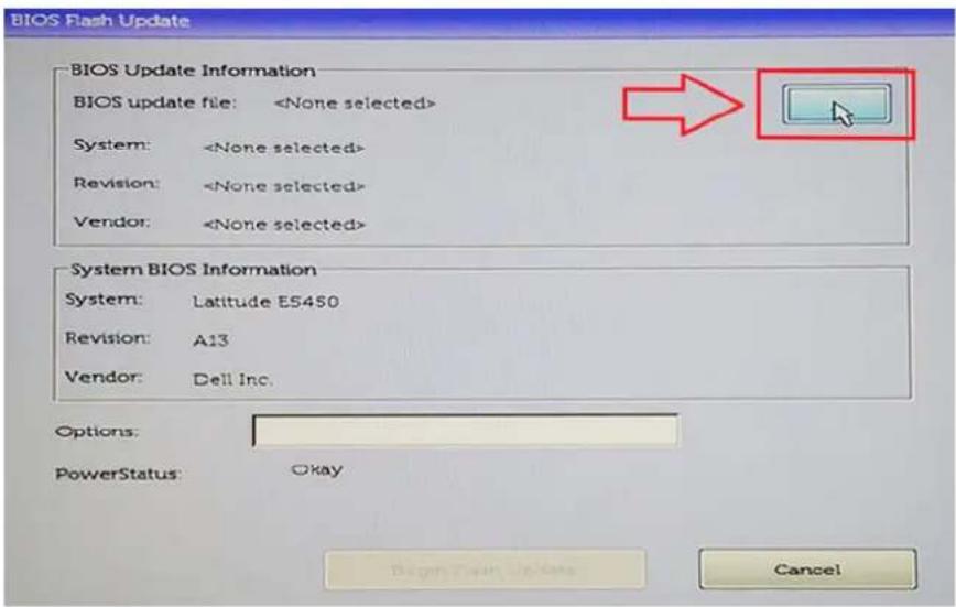
text_image
BIOS Flash Update BIOS Update Information BIOS update file:4 The E5450A14.exe file is shown as an example in the following screenshot. The actual file name may vary.
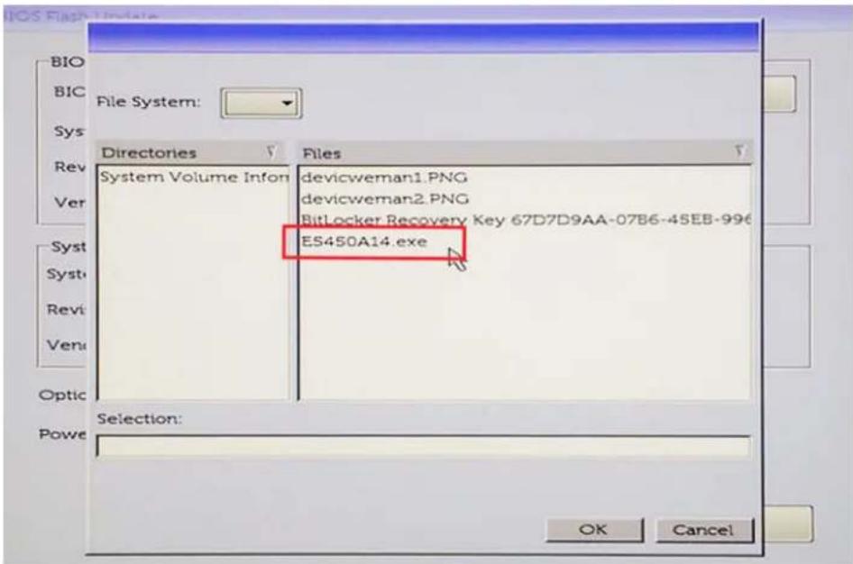
text_image
BIO BIC Sys Rev Ver System Volume Infon devicweman1.PNG devicweman2.PNG BitLocker Recovery Key 67D7D9AA-07B6-45EB-996 ES450A14.exe Selection: OK Cancel5 Once the file is selected, it will show in the file selection box and you can click the OK button to continue.
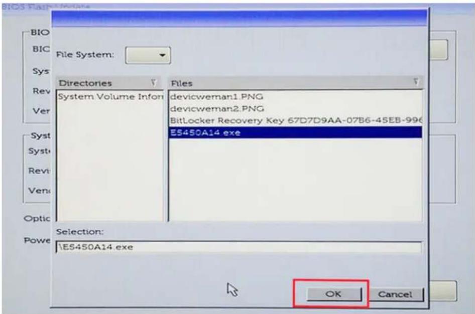
text_image
File System: Directories Systems Volume Infon Files devicweman1.PNG devicweman2.PNG BitLocker Recovery Key 67D7D9AA-07B6-45EB-996 ES450A14.exe Selection: ES450A14.exe OK Cancel6 Click the Begin Flash Update button.
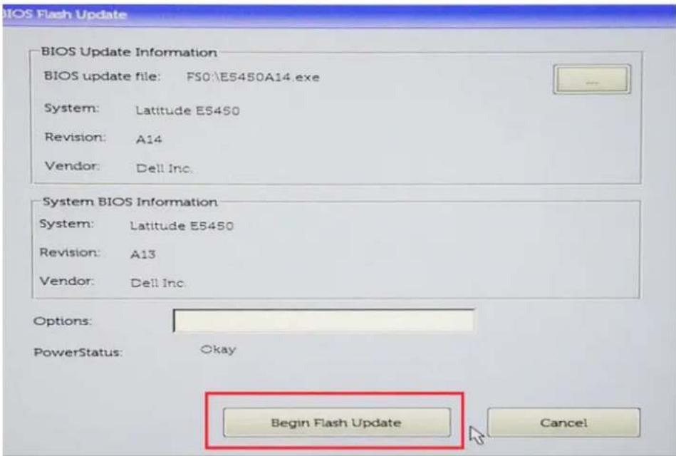
text_image
BIOS Flash Update BIOS Update Information BIOS update file: FS0:\E5450A14.exe System: Latitude E5450 Revision: A14 Vendor: Dell Inc. System BIOS Information System: Latitude E5450 Revision: A13 Vendor: Dell Inc. Options: PowerStatus: Okay Begin Flash Update Cancel7 A warning box is displayed asking you if you want to proceed. Click the Yes button to begin the flash.
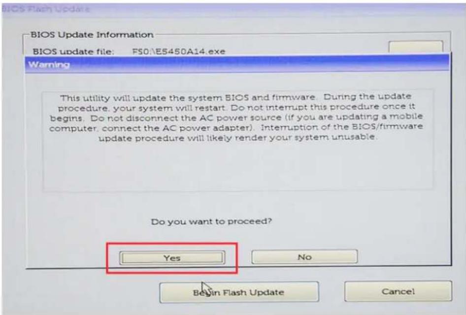
text_image
BIOS Update Information BIOS update file: FS0E5450A14.exe Warning This utility will update the system BIOS and firmware. During the update procedure, your system will restart. Do not interrupt this procedure once it begins. Do not disconnect the AC power source (if you are updating a mobile computer, connect the AC power adapter). Interruption of the BIOS/firmware update procedure will likely render your system unusable. Do you want to proceed? Yes No Begin Flash Update Cancel!8 At this point the BIOS flash will execute, the system will reboot and then the BIOS flash will start and a progress bar will show the progress of the flash. Depending on the changes included in the update, the progress bar may go from zero to 100 multiple times and the flash process could take as long as 10 minutes. Generally this process takes two to three minutes.
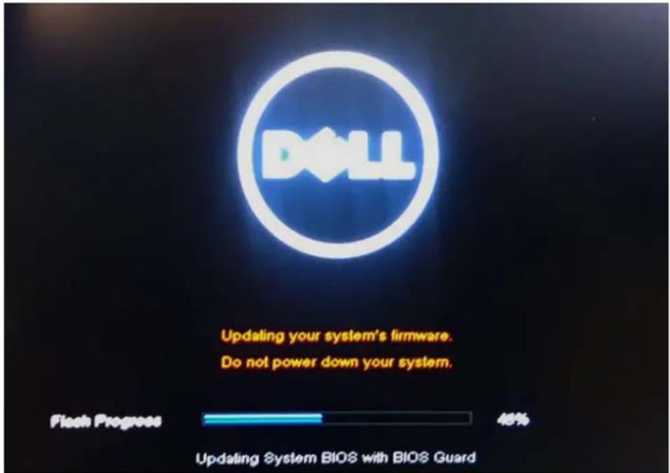
text_image
DLL Updating your system's firmware. Do not power down your system. Flash Progress 48% Updating System BIOS with BIOS Guard9 Once complete, the system will reboot and the BIOS update process is completed.
System setup
System setup enables you to manage your desktop hardware and specify BIOS level options. From the System setup, you can:
- Change the NVRAM settings after you add or remove hardware
• View the system hardware configuration - Enable or disable integrated devices
- Set performance and power management thresholds
- Manage your computer security
Topics:
- Boot menu
- System Setup options
- Updating the BIOS in Windows
- Updating the Dell BIOS in Linux and Ubuntu environments
- Flashing the BIOS from the F12 One-Time boot menu
• Technical Specifications
Boot menu
Press
The options are:
- Legacy Boot:
- Internal HDD
- Onboard NIC
- UEFI Boot:
- Windows Boot Manager
- Other Options:
- BIOS Setup
- BIOS Flash Update
– Diagnostics - Change Boot Mode Settings
System Setup options

NOTE: Depending on the computer and its installed devices, the items listed in this section may or may not appear.
Table 19. General
Option Description
| System Information Displays the following information: | |
| · System Information: Displays BIOS Version, Service Tag, Asset Tag, Ownership Tag, Ownership Date, Manufacture Date, Express Service Code and the Singed Firmware Update.· Memory Information: Displays Memory Installed, Memory Available, Memory Speed, Memory Channel Mode, Memory Technology, DIMM 1 Size, DIMM 2 Size, DIMM 3 Size and DIMM 4 Size.· PCI Information: Displays SLOT1_M.2, SLOT2_M.2· Processor Information: Displays Processor Type, Core Count, Current Clock Speed, Minimum Clock Speed, Maximum Clock Speed, Processor L2 Cache, Processor L3 Cache, HT Capable, and 64-Bit Technology.· Device Information: Displays LOM MAC Address, Video Controller, Audio Controller. | |
| Boot Sequence | · Boot Mode· Boot List option:- Legacy- UEFI (Default)· Enable Boot Devices· Boot Sequence- Add Boot Option- Remove Boot Option- View Boot Option |
| Advanced Boot Options Allows you to select the Enable Legacy Option ROMs option. By default, this option is selected. | |
| · Enabled(selected by default)· Disabled | |
| BIOS Setup Advanced Mode Allows you to select BIOS Setup Advanced Mode. By default, this option is selected. | |
| · Enabled(selected by default)· Disabled | |
| Date/Time | Allows you to set the date and time settings. Changes to the system date and time take effect immediately. |
Table 20. System Configuration
Option Description
| Integrated NIC Allows you to control the on-board LAN controller. The option 'Enable UEFI Network Stack' is not selected by default. The options are: | |
| Disabled | |
| Enabled | |
| Enabled w/PXE (default) | |
| NOTE: Depending on the computer and its installed devices, the items listed in this section may or may not appear. | |
| Serial Port The options are: | |
| COM1 (Enabled by default) | |
| COM2 (Disabled by default) | |
| COM3 (Disabled by default) | |
Option Description
| ·COM4 (Disabled by default) | |
| SATA Operation | Allows you to configure the operating mode of the integrated hard drive controller.·Disabled = The SATA controllers are hidden·AHCI (Enabled by default)·RAID ON = SATA is configured to support RAID mode (Disabled by default) |
| Drives Allows you to enable or disable the various drives on-board: | |
| ·SATA-0 (enabled by default)·SATA-1·SATA-2·SATA-3·M.2 PCIe SSD-0 | |
| Smart Reporting | This field controls whether hard drive errors for integrated drives are reported during system startup.TheEnable Smart Reporting optionis disabled by default. |
| USB Configuration | Allows you to enable or disable the integrated USB controller for:·Enable Boot Support·Enable Front USB Ports·Enable Rear USB PortsAll the options are enabled by default. |
| USB PowerShare This option allows you to charge the external devices, such as mobile phones, music player. This option is disabled by default. | |
| Audio | Allows you to enable or disable the integrated audio controller. The optionEnable Audiois selected by default.·Enable Microphone·Enable Audio·Enable Internal SpeakerThe options are selected by default. |
| Miscellaneous Devices Allows you to enable or disable the Miscellaneous Devices. The option are | |
| ·Enable Secure Digital (SD) Card (Enabled by default)·Secure Digital (SD) Card Read-Only mode | |
Table 21. Video
Option Description
| Multi-Display The option is selected by default. |
| Primary Display Allows you to select the primary display when multiple controllers are available in the system. |
| · Auto (default) |
| · Integrated Graphics |
Table 22. Security
Option Description
| Admin Password Allows you to set, change, and delete the admin password. | |
| System Password Allows you to set, change, and delete the system password. | |
| Internal HDD-0 Password Allows you to set, change, and delete the computer's internal HDD. | |
| Internal HDD-1 Password Allows you to set, change, and delete the computer's internal HDD. | |
| Internal HDD-2 Password Allows you to set, change, and delete the computer's internal HDD. | |
| Strong Password This option lets you enable or disable strong passwords for the system. | |
| Password Configuration | Allows you to control the minimum and maximum number of characters allowed for a administrative password and the system password. The range of characters is between 4 and 32. |
| Password Change This option lets you determine whether changes to the System and Hard Disk passwords are permitted when an administrator password is set.Allow Non-Admin Password Changes - This option is enabled by default. | |
| UEFI Capsule Firmware Updates | This option controls whether this system allows BIOS updates via UEFI capsule update packages. This option is selected by default. Disabling this option will block BIOS updates from services such as Microsoft Windows Update and Linux Vendor Firmware Service (LVFS) |
| TPM 2.0 Security Allows you to control whether the Trusted Platform Module (TPM) is visible to the operating system. | |
| · TPM On (default)– PPI Bypass for Enable Commands– PPI Bypass for Disable Commands– PPI Bypass for Clear Commands– Attestation Enable (default)– Key Storage Enable (default)– SHA-256 (default)· Clear· TPM State– Disable– Enable (default) | |
| Computrace | This field lets you Activate or Disable the BIOS module interface of the optional Computrace Service from Absolute Software. Enables or disables the optional Computrace service designed for asset management.· Deactivate - This option is selected by default.· Disable· Activate |
| Chassis Intrusion | The options are:· Disable (default)· Enable· On-Silent |
| Admin Setup Lockout | Allows you to enable or disable the option to enter Setup when an Administrative password is set. This option is not set by default. |
Table 23. Secure Boot
| Option | Description |
| Secure Boot Enable | Allows you to enable or disable Secure Boot feature |
- Disable (selected by default)
- Enable
Expert key Management Allows you to manipulate the security key databases only if the system is in Custom Mode. The
Enable Custom Mode option is disabled by default. The options are:
- PK (default)
• KEK
· db - dbx
If you enable the Custom Mode, the relevant options for PK, KEK, db, and dbx appear. The options are:
- Save to File- Saves the key to a user-selected file
- Replace from File- Replaces the current key with a key from a user-selected file
- Append from File- Adds a key to the current database from a user-selected file
- Delete- Deletes the selected key
- Reset All Keys- Resets to default setting
- Delete All Keys- Deletes all the keys

NOTE: If you disable the Custom Mode, all the changes made will be erased and the keys will restore to default settings.
Table 24. Performance
Option Description
C States Control Allows you to enable or disable additional processor sleep states.
This option is enabled by default.
AMD TurboCore Technology This options is disable by default.
Table 25. Power Management
Option Description
AC Recovery Determines how the system responds when AC power is re-applied after a power loss. You can set the AC Recovery to:
- Power Off
• Power On - Last Power State
This option is Power Off by default.
Auto On Time Sets time to automatically turn on the computer. Time is kept in standard 12-hour format
(hour:minutes:seconds). Change the startup time by typing the values in the time and AM/PM fields.

NOTE: This feature does not work if you turn off your computer using the switch on a power strip or surge protector or if Auto Power is set to disabled.
Deep Sleep Control Allows you to define the controls when Deep Sleep is enabled.
- Disabled
- Enabled in S5 only
- Enabled in S4 and S5
This option is Enabled in S4 and S5 by default.
Option Description
| Fan Control Override Allows you to determine the speed of the system fan. When this option is enabled, the system fan runs at the maximum speed. This option is disabled by default. | |
| USB Wake Support Allows you to enable the USB devices to wake the computer from standby mode. The option "Enable USB Wake Support" is selected by default | |
| Wake on LAN/WWAN | This option allows the computer to power up from the off state when triggered by a special LAN signal. This feature only works when the computer is connected to AC power supply.·Disabled- Does not allows the system to power on by special LAN signals when it receives a wake-up signal from the LAN or wireless LAN.·LAN- Allows the system to be powered on by special LAN signals.·WLAN Only- Allows the system to be powered on by special WLAN signals.·LAN or WLAN- Allows the system to be powered on by special LAN signals or WLAN signals.·LAN with PXE Boot- A wakeup packet sent to the system in either the S4 or S5 state, that will cause the system to wake-up and immediately boot to PXE.This option is Disabled by default. |
| Block Sleep Allows you to block entering to sleep (S3 state) in OS environment. This option is disabled by default. | |
Table 26. POST Behavior
Option Description
| Numlock LED Allows you to enable or disable the Numlock feature when your computer starts. This option is enabled by default. |
| Keyboard Errors Allows you to enable or disable the keyboard error reporting when the computer starts. This option is enabled by default. |
| Warnings and Errors This option can speed up the boot process by bypassing some compatibility steps: |
| · Prompt on Warnings and Errors (enabled by default) |
| · Continue on Warnings |
| · Continue on Warnings and Errors |
| Extend BIOS POST Time The options are: |
| · 0 seconds (default) |
| · 5 seconds |
| · 10 seconds |
| Full Screen Logo This options is disabled by default. |
Table 27. Virtualization Support
Option Description
| AMD-V Technology This option is enabled by default. |
| AMD-VI Technology This option is enabled by default. |
Table 28. Maintenance
Option Description
| Service Tag Displays the Service Tag of your computer. | |
| Asset Tag | Allows you to create a system asset tag if an asset tag is not already set. This option is set by default. |
Option Description
SERR Messages Controls the SERR message mechanism. This option is set by default. Some graphics cards require that the SERR message mechanism be disabled.
Dell Development Configuration This options is disabled by default.
BIOS Downgrade Allows you to control flashing of the system firmware to the previous versions. This option is enabled by default.

NOTE: If this option is not selected, the flashing of the system firmware to the previous versions is blocked.
Data Wipe Allows you to securely erase the data from all the available internal storages, such as HDD, SSD, mSATA, and eMMC. The option Wipe on Next Boot is disabled by default.
BIOS recovery Allows you to recover the corrupted BIOS conditions from the recovery files on the primary hard drive. The option BIOS Recovery from Hard Drive is selected by default
Table 29. System Logs
Option Description
BIOS Events Displays the system event log and allows you to:
- Clear Log
- Mark all Entries
Table 30. SupportAssist System Resolution
Option Description
Auto OS Recovery Threshold Options are: OFF, 1, 2 (default), 3.
Updating the BIOS in Windows
It is recommended to update your BIOS (System Setup), when you replace the system board or if an update is available.

NOTE If BitLocker is enabled, it must be suspended prior to updating the system BIOS, and then re-enabled after the BIOS update is completed.
1 Restart the computer.
2 Go to Dell.com/support.
- Enter the Service Tag or Express Service Code and click Submit.
- Click Detect Product and follow the instructions on screen.
3 If you are unable to detect or find the Service Tag, click Choose from all products.
4 Choose the Products category from the list.

NOTE: Choose the appropriate category to reach the product page
5 Select your computer model and the Product Support page of your computer appears.
6 Click Get drivers and click Drivers and Downloads.
The Drivers and Downloads section opens.
7 Click Find it myself.
8 Click BIOS to view the BIOS versions.
9 Identify the latest BIOS file and click Download.
10 Select your preferred download method in the Please select your download method below window, click Download File.
The File Download window appears.
11 Click Save to save the file on your computer.
12 Click Run to install the updated BIOS settings on your computer.
Follow the instructions on the screen.
Updating BIOS on systems with BitLocker enabled

CAUTION: If BitLocker is not suspended before updating the BIOS, the next time you reboot the system it will not recognize the BitLocker key. You will then be prompted to enter the recovery key to progress and the system will ask for this on each reboot. If the recovery key is not known this can result in data loss or an unnecessary operating system re-install. For more information on this subject, see Knowledge Article: http://www.dell.com/support/article/sln153694
Updating your system BIOS using a USB flash drive
If the system cannot load into Windows but there is still a need to update the BIOS, download the BIOS file using another system and save it to a bootable USB Flash Drive.

NOTE: You will need to use a bootable USB Flash drive. Please refer to the following article for further details: http://www.dell.com/support/article/sln143196
1 Download the BIOS update .EXE file to another system.
2 Copy the file e.g. O9010A12.EXE onto the bootable USB Flash drive.
3 Insert the USB Flash drive into the system that requires the BIOS update.
4 Restart the system and press F12 when the Dell Splash logo appears to display the One Time Boot Menu.
5 Using arrow keys, select USB Storage Device and click Return.
6 The system will boot to a Diag C:> prompt.
7 Run the file by typing the full filename e.g. O9010A12.exe and press Return.
8 The BIOS Update Utility will load, follow the instructions on screen.
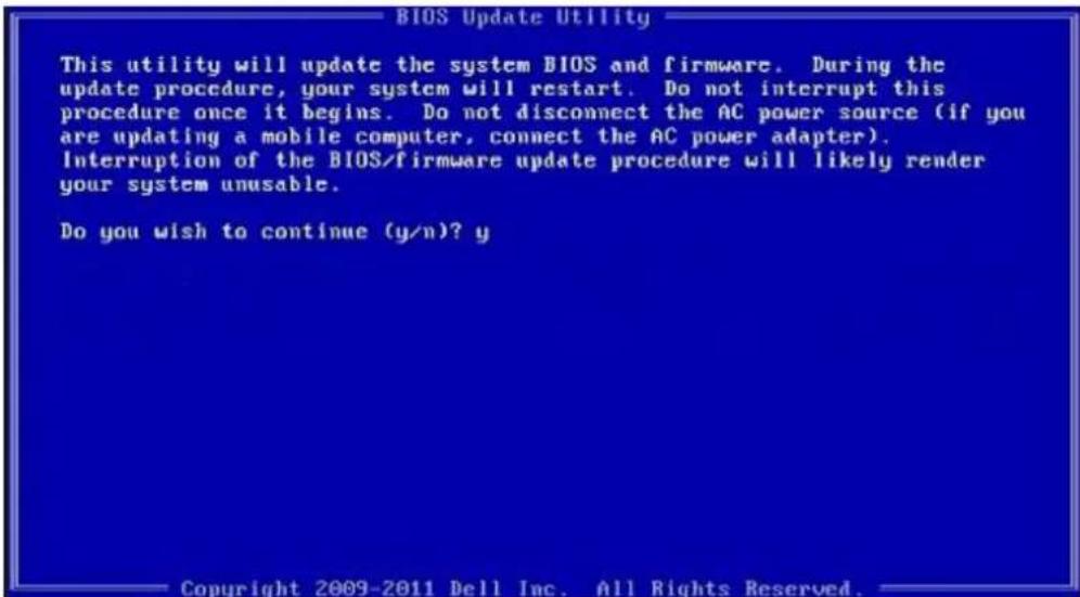
text_image
BIOS Update Utility This utility will update the system BIOS and firmware. During the update procedure, your system will restart. Do not interrupt this procedure once it begins. Do not disconnect the AC power source (if you are updating a mobile computer, connect the AC power adapter). Interruption of the BIOS/firmware update procedure will likely render your system unusable. Do you wish to continue (y/n)? y Copyright 2009-2011 Dell Inc. All Rights Reserved.Figure 5. DOS BIOS Update Screen
Updating the Dell BIOS in Linux and Ubuntu environments
If you want to update the system BIOS in a Linux environment such as Ubuntu, see http://www.dell.com/support/article/sln171755.
Flashing the BIOS from the F12 One-Time boot menu
Updating your system BIOS using a BIOS update .exe file copied to a FAT32 USB key and booting from the F12 one time boot menu. BIOS Update
You can run the BIOS update file from Windows using a bootable USB key or you can also update the BIOS from the F12 One-Time boot menu on the system.
Most Dell systems built after 2012 have this capability and you can confirm by booting your system to the F12 One-Time Boot Menu to see if BIOS FLASH UPDATE is listed as a boot option for your system. If the option is listed, then the BIOS supports this BIOS update option.
NOTE: Only systems with BIOS Flash Update option in the F12 One-Time Boot Menu can use this function.
Updating from the One-Time Boot Menu
To update your BIOS from the F12 One-Time boot menu, you will need:
- USB key formatted to the FAT32 file system (key does not have to be bootable)
• BIOS executable file that you downloaded from the Dell Support website and copied to the root of the USB key - AC power adapter connected to the system
• Functional system battery to flash the BIOS
Perform the following steps to execute the BIOS update flash process from the F12 menu:
CAUTION: Do not power off the system during the BIOS update process. Powering off the system could make the system fail to boot.
1 From a power off state, insert the USB key where you copied the flash into a USB port of the system.
2 Power on the system and press the F12 key to access the One-Time Boot Menu, Highlight BIOS Flash Update using the arrow keys then press Enter.
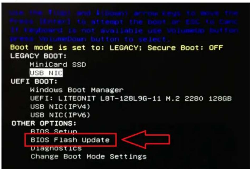
text_image
use the 1/4bit and 1/4down) arrow keys to move the Press [Enter] to attempt the boot or ESC to Card. If keyboard is not available use VolumeUp button press VolumeDown button to select. Boot mode is set to: LEGACY; Secure Boot: OFF LEGACY BOOT: MiniCard SSD USB NIC UEFI BOOT: Windows Boot Manager UEFI: LITEONIT L8T-128L9G-11 M.2 2280 128GB USB NIC(IPV4) USB NIC(IPV6) OTHER OPTIONS: BIOS Setup BIOS Flash Update Diagnostics Change Boot Mode Settings3 The Bios flash menu will open then click the browse button.
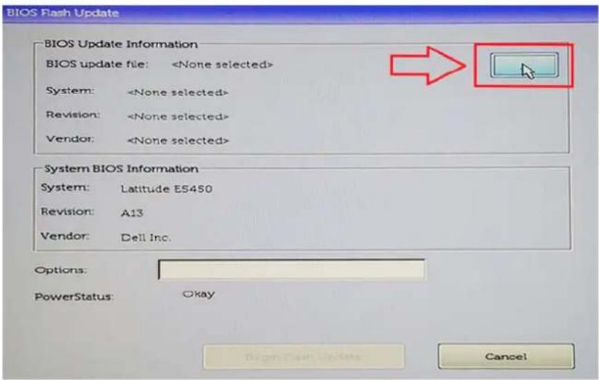
text_image
BIOS Flash Update BIOS Update Information BIOS update file:4 The E5450A14.exe file is shown as an example in the following screenshot. The actual file name may vary.
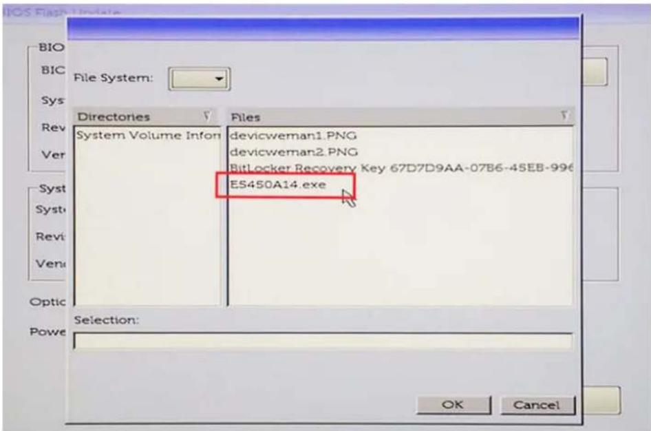
text_image
BIO BIC Sys Rev Ver System Volume Infon devicweman1.PNG devicweman2.PNG BitLocker Recovery Key 67D7D9AA-07B6-45EB-996 ES450A14.exe Selection: OK Cancel5 Once the file is selected, it will show in the file selection box and you can click the OK button to continue.
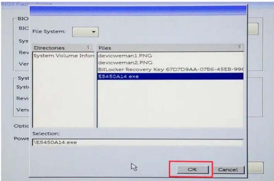
text_image
File System: Directories Systems Volume Infon Files devicweman1.PNG devicweman2.PNG BitLocker Recovery Key 67D7D9AA-07B6-45EB-996 ES450A14.exe Selection: ES450A14.exe OK Cancel6 Click the Begin Flash Update button.
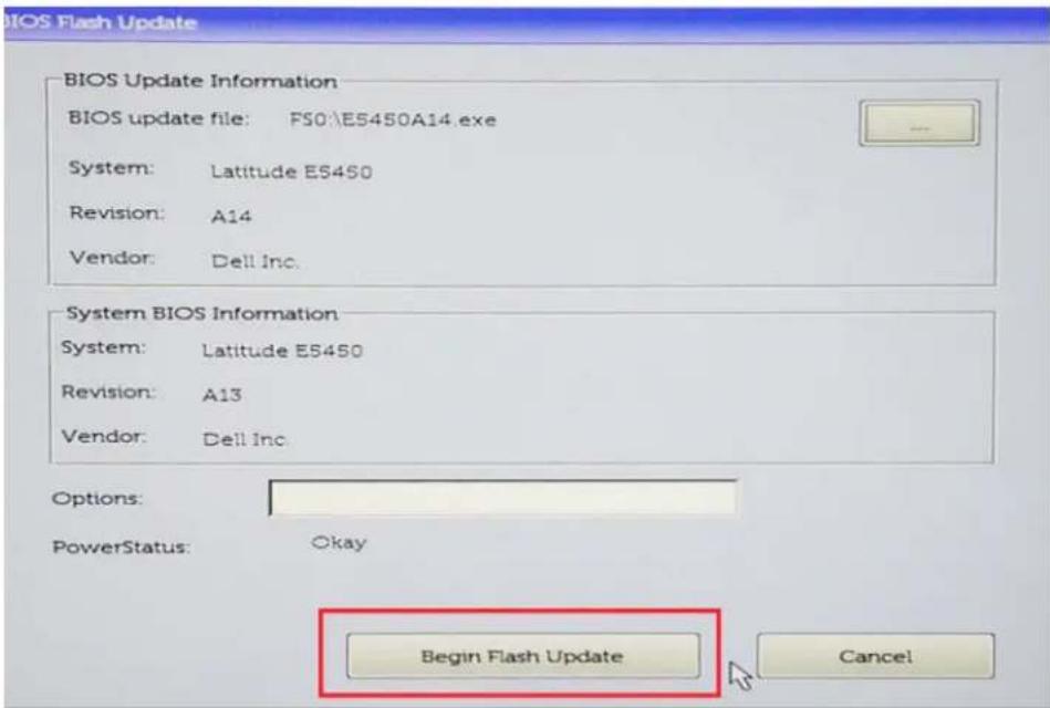
text_image
BIOS Flash Update BIOS Update Information BIOS update file: FS0:\E5450A14.exe System: Latitude E5450 Revision: A14 Vendor: Dell Inc. System BIOS Information System: Latitude E5450 Revision: A13 Vendor: Dell Inc. Options: PowerStatus: Okay Begin Flash Update Cancel7 A warning box is displayed asking you if you want to proceed. Click the Yes button to begin the flash.
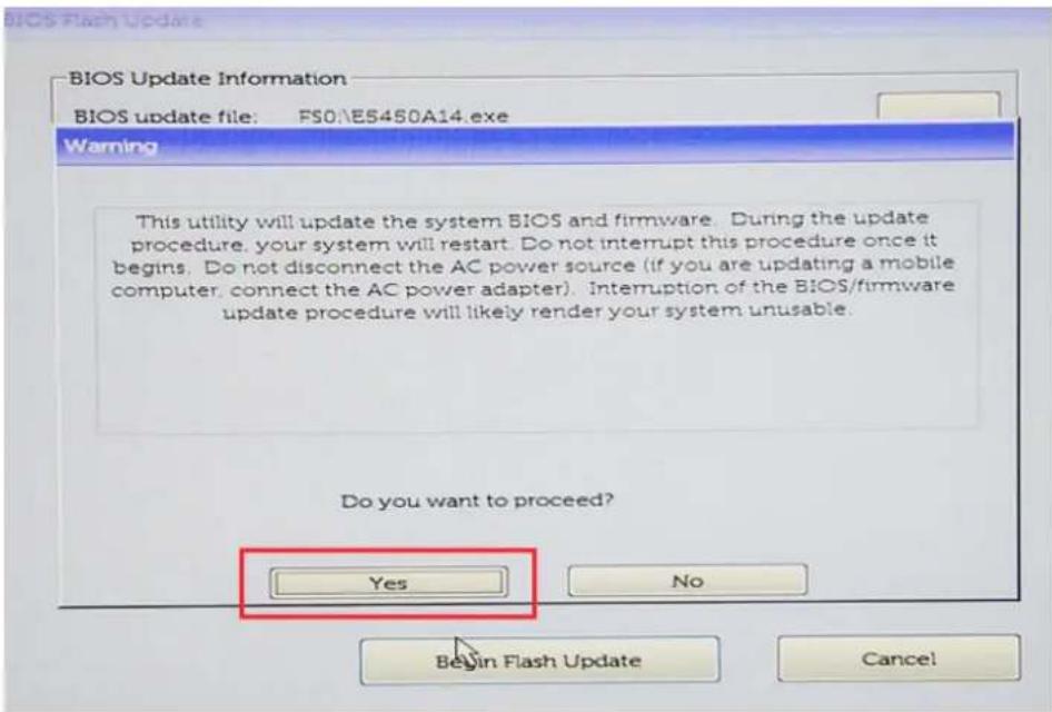
text_image
BIOS Update Information BIOS update file: FS0E5450A14.exe Warning This utility will update the system BIOS and firmware. During the update procedure, your system will restart. Do not interrupt this procedure once it begins. Do not disconnect the AC power source (if you are updating a mobile computer, connect the AC power adapter). Interruption of the BIOS/firmware update procedure will likely render your system unusable. Do you want to proceed? Yes No Begin Flash Update Cancel!8 At this point the BIOS flash will execute, the system will reboot and then the BIOS flash will start and a progress bar will show the progress of the flash. Depending on the changes included in the update, the progress bar may go from zero to 100 multiple times and the flash process could take as long as 10 minutes. Generally this process takes two to three minutes.
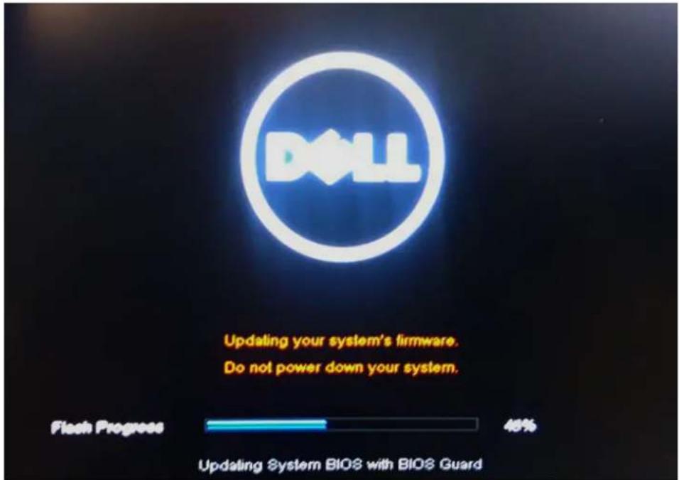
text_image
DLL Updating your system's firmware. Do not power down your system. Flash Progress 48% Updating System BIOS with BIOS Guard9 Once complete, the system will reboot and the BIOS update process is completed.
Technical Specifications
NOTE: Offerings may vary by region. For more information regarding the configuration of your computer in:
- Windows 10, click or tap Start > Settings > System > About.
Table 31. Chipset Specifications
Feature Specification
Chipset AMD B350 Chipset
Processor
Table 32. Processor Specifications
Feature Specification
| Processor type | • AMD Ryzen 3 Pro 2200G (QC/ L2 Cache: 2 MB/3.5 Ghz/65 W) |
| • AMD Ryzen 5 Pro 2400G (QC/L2 Cache: 2 MB/3.9 Ghz/65 W) | |
| • AMD Athlon PRO 200GE (DC/L2 Cache: 2 MB/3.2 Ghz/35 W) |
Total L2 cache Up to 4MB
NOTE: Extended Frequency (XFR) in GHz are not supported on OptiPlex 5055.
Memory
Table 33. MemorySpecifications
Feature Specification
| Memory type DDR4 |
| Memory speed Up to 2400 MHz |
| Memory connectors Four DIMM slots |
| Memory capacity Up to 64 GB |
| Minimum memory 4 GB (2 GB for Linux based OS only) |
| Maximum memory 64 GB |
Video
Table 34. Video Specifications
Feature Specification
| Integrated AMD Radeon Vega Graphics Processor [with AMD Ryzen 3 2200G- Vega8, AMD Ryzen 5 Pro 2400G- Vega11, AMD Athlon PRO 200GE-Vega 3] | |
| Optional | • 1 GB AMD Radeon R5 430 |
| • 2 GB AMD Radeon R5 430 | |
| • 4 GB AMD Radeon R7 450 | |
Audio
Table 35. Audio Specifications
Feature Specification
Integrated Realtek HDA Codec ALC3234
Network
Table 36. Network Specifications
Feature Specification
Integrated BCM5762B0KMLG Broadcom ethernet controller
Expansion bus
Table 37. Expansion Bus Specifications
Feature Specification
Bus type USB 2.0, USB 3.1 Gen 1, SATA 3, and PCIe up to Gen 3
Bus speed
- USB 2.0 - 480 Mbps
• USB 3.1 Gen 1 – 5 Gbps - SATA 3.0 – 6 Gbps
- PCIe - 8 Gbps
Wireless
Table 38. Wireless Cards
Feature Specification
WLAN card
• Intel Wireless-AC 8265 2x2
• Intel Wireless-AC 3165 1x1
- Bluetooth 4.1

NOTE: For optimal performance, it is recommended to use the wireless display feature with an access point that supports 5 GHz standard.
Drives
Table 39. Drives
Feature Specification
| Internally accessible | • 2.5-inch SATA drive bay |
| • 3.5-inch SATA drive bay | |
| • M.2 SATA and NVMe SSD |
External connectors
Table 40. External Connectors Specifications
| Feature Specification | |
| Audio | |
| Front panel | ·Universal headset |
| Rear panel | ·Line out connector |
| Network adapter RJ-45 connector | |
| Serial PS2 and serial connector | |
| USB 2.0 | ·Front - 2 |
| ·Back - 2 | |
| ·Internal -2 | |
| USB 3.1 Gen 1 | ·Front - 2 |
| ·Back - 4 | |
| ·Internal -0 | |
| Video | ·15-pin VGA connector (one optional VGA connector only supports A-Series APU and Ryzen APUs) |
| ·Two DisplayPort 1.2 (DP only supported with A-Series APU and Ryzen APUs) | |
NOTE: Available video connectors may vary based on the optional graphic board selected.
Controls and lights
Table 41. Controls and lights
Feature Specification
Front of the computer
Power button light White light — Solid white light indicates power-on state; slow blinking white light indicates sleep state of the computer.
Feature Specification
| Drive activity light White light — Slow blinking white light indicates that the computer is reading data from or writing data to the hard drive. | |
| Back of the computer | |
| Link integrity light on integrated network adapter Green — A 10 Mbps connection exists between the network and the computer. | |
| Green — A 100 Mbps connection exists between the network and the computer. | |
| Orange — A 1000 Mbps connection exists between the network and the computer. | |
| Off (no light) — The computer is not detecting a physical connection to the network. | |
| Network activity light on integrated network adapter | Yellow light — A breathing yellow light indicates that network activity is present. |
| Power supply diagnostic light Green light — The power supply is turned On and is functional. The power cable must be connected to the power connector (at the back of the computer) and the electrical outlet. | |
Power
Table 42. Power Specifications
Feature Specification
| Wattage 240 W | |
| AC input voltage range 90 – 264 Vac | |
| AC input current (low ac range / high ac range) | 4 A/ 2 A |
| AC input frequency 47 Hz/ 63 Hz | |
| Coin cell battery 3 V CR2032 lithium-coin-cell | |
Physical dimension
Table 43. Physical dimensions
Physical Tower
| Height 35 cm (13.8 inches) | |
| Width 15.4 cm(6.1 inches) | |
| Depth 27.4 cm (10.8 inches) | |
| Weight | 7.93 kg (17.49 lbs) |
Environmental
Table 44. Environmental Specifications
Feature Specification
| Temperature range | |
| Operating 5 °C to 35 °C (41 °F to 95 °F) | |
| Non-Operating -40 °C to 65 °C (-40°F to 149 °F) | |
| Relative humidity (maximum) | |
| Operating 20 % to 80 % (non condensing) | |
| Non-Operating 5 % to 95 % (non condensing) | |
| Maximum vibration | |
| Operating 0.66 Grms | |
| Non-Operating 1.37 Grms | |
| Maximum shock | |
| Operating 40 G | |
| Non-Operating 105 G | |
| Altitude | |
| Operating -15.2 m to 3048 m (-50 to 10,000 ft) | |
| Non-Operating -15.20 m to 10,668 m (-50 ft to 35,000 ft) | |
| Airborne contaminant level | G1 or lower as defined by ANSI/ISA-S71.04-1985 |
Getting help
Contacting Dell

NOTE: If you do not have an active Internet connection, you can find contact information on your purchase invoice, packing slip, bill, or Dell product catalog.
Dell provides several online and telephone-based support and service options. Availability varies by country and product, and some services may not be available in your area. To contact Dell for sales, technical support, or customer service issues:
1 Go to Dell.com/support.
2 Select your support category.
3 Verify your country or region in the Choose a Country/Region drop-down list at the bottom of the page.
4 Select the appropriate service or support link based on your need.