
TL-SC3230 - Security Camera TP-LINK - Free user manual and instructions
Find the device manual for free TL-SC3230 TP-LINK in PDF.

| Product Type | IP Security Camera |
| Brand | TP-Link |
| Model | TL-SC3230 |
| Image Sensor | 1/4" Progressive CMOS |
| Maximum Resolution | 1920 x 1080 (Full HD) |
| Lens | Fixed focal length, 4mm |
| Field of View | 60° horizontal |
| Video Compression | H.264, MJPEG |
| Audio | Two-way audio support |
| Network Interface | 10/100 Mbps Ethernet, RJ-45 |
| Supported Protocols | TCP/IP, HTTP, RTSP, FTP, SMTP, DHCP, DDNS |
| Power Supply | 12V DC or PoE (Power over Ethernet) |
| Power Consumption | Max 5W |
| Dimensions (W x D x H) | 130 x 130 x 120 mm |
| Weight | Approx. 400 g |
| Operating Temperature | 0°C to 40°C |
| Mounting | Ceiling or wall mount (bracket included) |
| Main Features | Motion detection, schedule recording, PTZ control, alarm notification, E-Map support |
| Storage | Local recording to PC via Surveillance Manager software |
| Maintenance | Clean lens with a soft, dry cloth; avoid direct sunlight and moisture |
| Safety | Indoor use only; keep away from water and extreme temperatures |
| Spare Parts / Repairability | No user-serviceable parts; contact support for repairs |
Frequently Asked Questions - TL-SC3230 TP-LINK
User questions about TL-SC3230 TP-LINK
0 question about this device. Answer the ones you know or ask your own.
Ask a new question about this device
Download the instructions for your Security Camera in PDF format for free! Find your manual TL-SC3230 - TP-LINK and take your electronic device back in hand. On this page are published all the documents necessary for the use of your device. TL-SC3230 by TP-LINK.
USER MANUAL TL-SC3230 TP-LINK
Chapter 2 Installation....2
2.1 Before Install the Software 2
2.2 Starting tinstallation....2
Chapter 3 Quick Start....5
3.1 Install IP Camera(s)....5
3.2 Add IP er6am....5
3.3 Configuration of schedule recording....9
3.4 Playback....14
Chapter 4 Main-console....17
4.1 System status....17
4.2 Screen Division....19
4.3 Operation with sub-screen: 20
4.3.1 Define display camera(s) sequence 20
4.3.2 Digital Zoom at sub-screen 20
4.3.3 Switch to Full screen 20
4.3.4 Snapshot of sub-screen....21
4.3.5 Restore division default 21
4.4 System setup 21
4.4.1 System setup....22
4.4.2 Camera....24
4.4.3 User 27
4.4.4 Address Book 28
4.4.5 Notification....29
4.4.6 Muti-Monitor....31
4.4.7 Joystick 32
4.5 Alarm Segtin....34
4.6 Server Setup....39
4.7 Log Viewer....40
4.8 Import / Export Setting 44
4.9 Schedule setup....44
4.9.1 Schedule Setup 44
4.9.2 Record Setup....47
4.10 Start & Stop Monitor 49
4.11 E-Map....50
4.12 Two wayAudio....51
Chapter 5 Playback....53
5.1 Search history recorded.file(s)....54
5.2 Playback control button(s)....56
5.3 Convert tollAile....57
5.4 Switch audio play mode....59
5.5 Playback tsreg 59
5.6 Snapshot dialog ....59
5.7 Backup hirstole(s)....61
5.8 Playback status....62
5.9 Operation with sub-screen....62
5.9.1 Define display camera(s) sequence 62
5.9.2 Digital Zoom at sub-screen 63
5.9.3 Switch to Full screen 63
5.9.4 Snapshot of sub-screen....63
5.9.5 Motion Search 64
5.9.6 Sequential Search....65
Chapter 1 System Requirement
| FPS (QVGA) | ~120 | 120~360 | 360~540 | 540~960 | 960~ |
| CPU | Intel P4 2.4GHz | Intel P4 3.2GHz | Intel Pentium D 950 3.4GHz | Intel core 2 Duo E8600 3.3GHz | Intel core I7 2600K 3.8GHz |
| RAM 512MB | 512MB | 1GB 2GB | 4GB | ||
| Display | Support1024x768 resolution or aboveSupport DirectX 9.0c or aboveIntel 945G or Intel 965G or above | ||||
| OS | Windows XP , Vista*, Win 7 (32bits or 64bits) | ||||
| Hard disk | 60GB | ||||
| Ethernet | 100Mbps | 1Gbps | |||
| Chipset | Intel 945 or Intel 965 or above | ||||
*If you install the Surveillance Manager with the Vista, you should install more physical memory into system.
QVGA = 320 x 240 pixel
CIF ≡ QVGA, D1 ≡ VGA at mapping table below.
| Image resolution mapping table | |
| Resolution Compared with QVGA | |
| QQVGA QQVGA = QVGA | /4 |
| VGA | VGA = QVGA x 4 |
| SXGA | SXGA = QVGA x 16 |
| FULL HD | FHD = QVGA X 24 |
Chapter 2 Installation
2.1 Before Installing the Software
Run Surveillancee_Manager6_0_3_495.exe, which is included on the Resource CD.
2.2 Starting the Installation
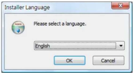
Step1: The Installation Wizard will start. Select your preferred language for the Surveillance Manager.
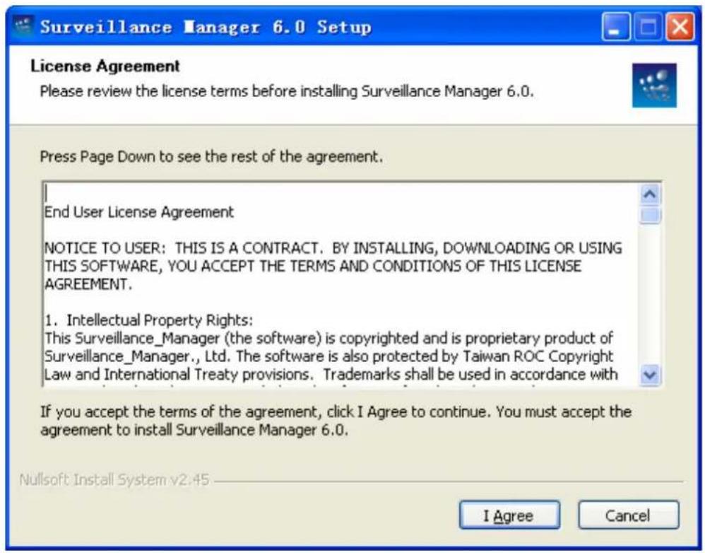
Step2: The License Agreement window will be listed as below. Click I Agree to continue if you want to install this software.
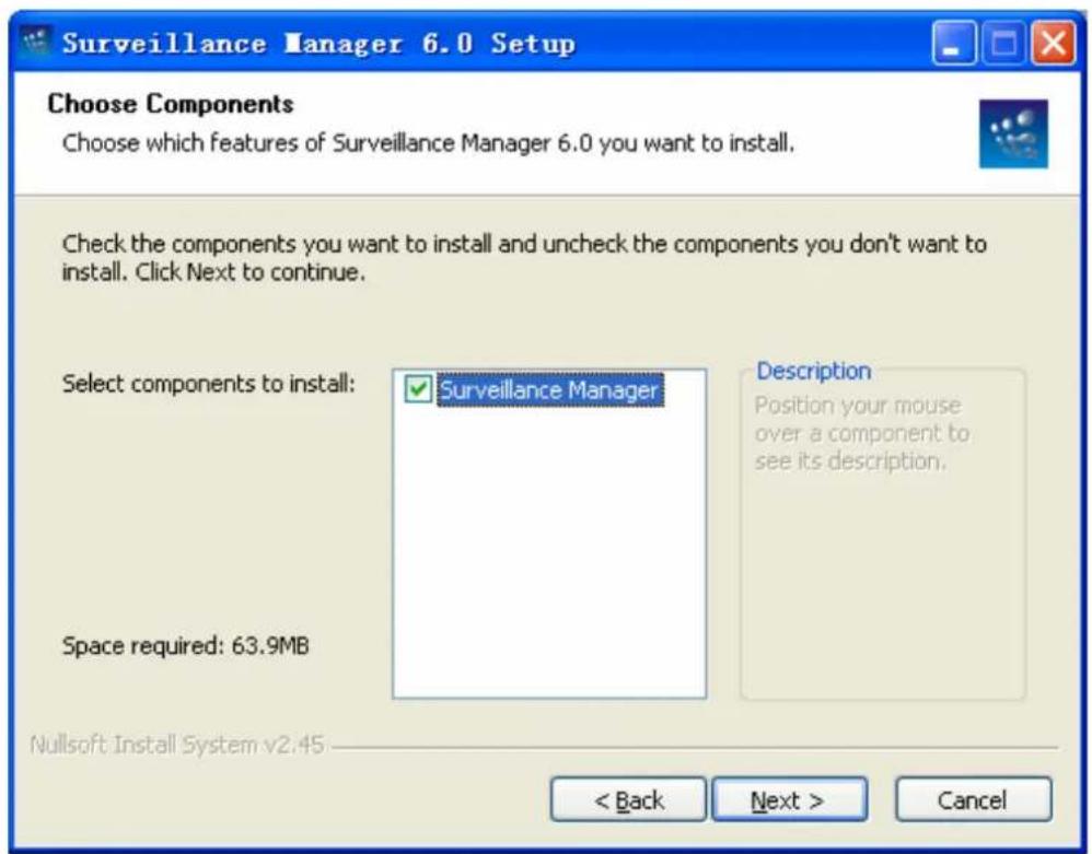
Step3: Select Surveillancee Manager, then click Next button.
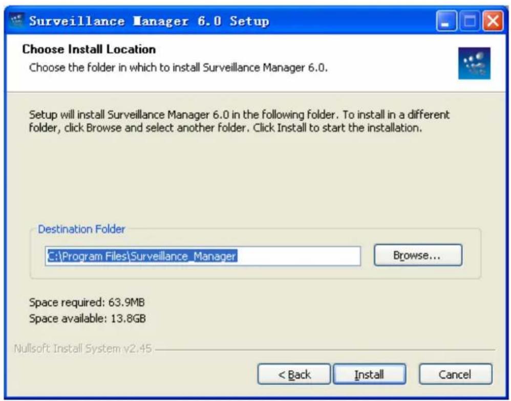
Step4: The Choose Install Location window will open. Select the folder which you wish to install Surveillance Manager to, and then click on Install button to continue.
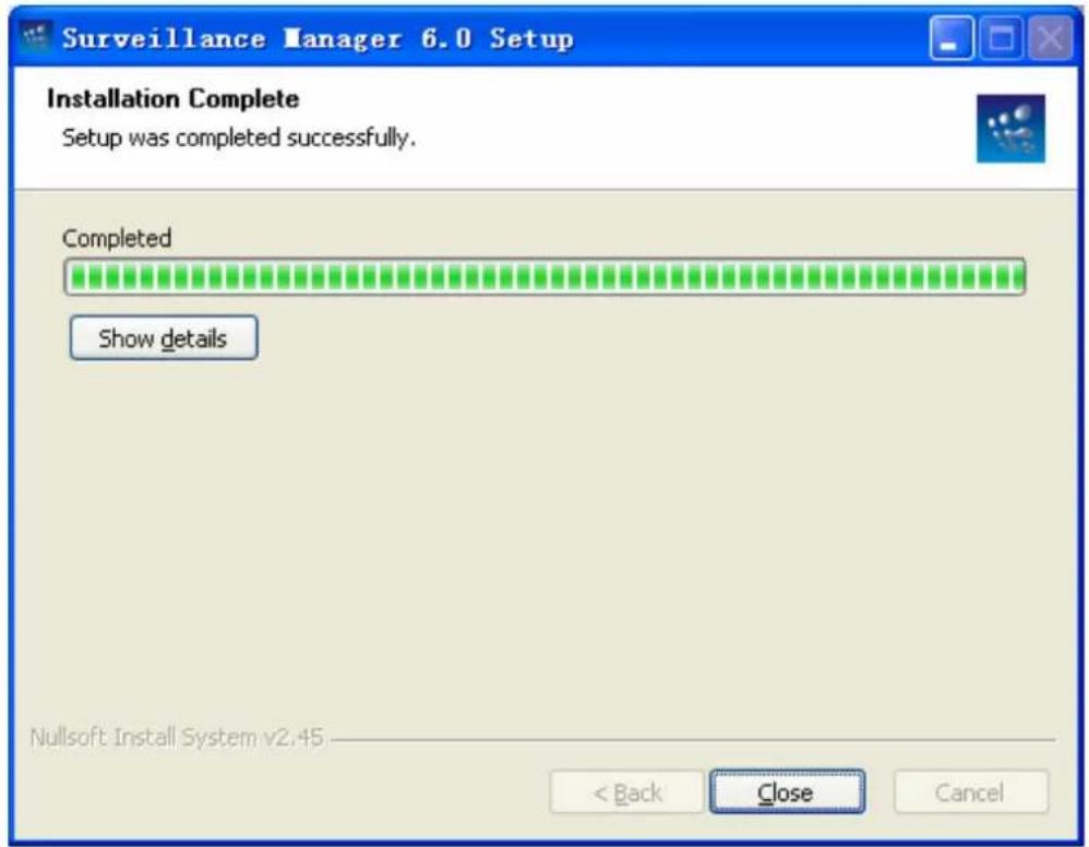
Step5: The Installation Complete window will open next. Click on Close button to complete the installation.
Chapter 3 Quick Start
3.1 Install IP Camera(s)
Step1: Set up the IP camera(s) by following the instruction manual provided by the manufacturer.
Step2: Check the network between the IP camera(s) and the system.
Step3: Add the IP camera(s) to the system by following the steps below .
3.2 Add IP Camera(s)
Step1: Click Start → All Programs → Surveillancee_Manager → Surveillancee_Manager.
Step2: Enter the user name and password to login Surveillance Manager (Both the default of user name and password are admin)
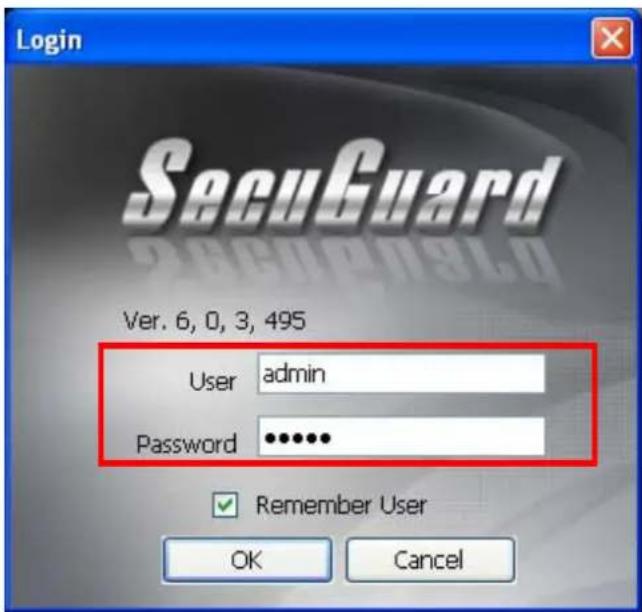
Check the Remember User to remember the account user name and password you enter this time.
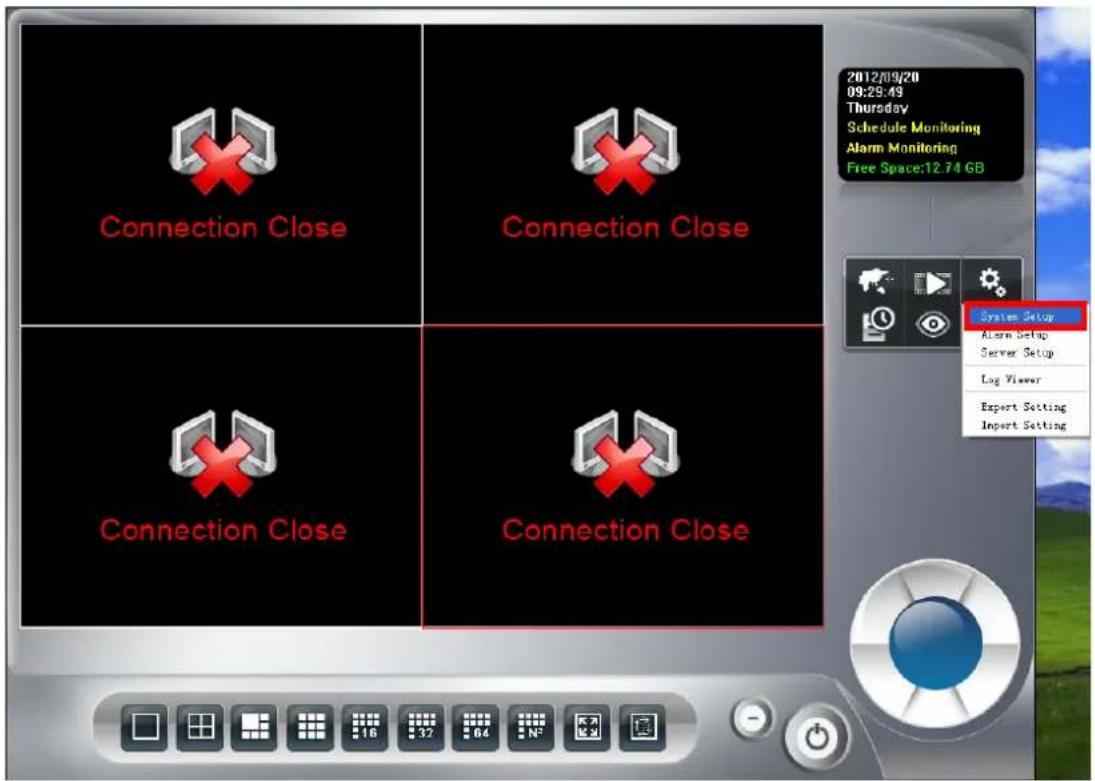
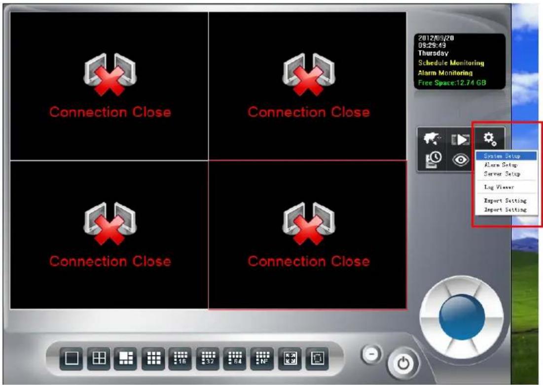
Step3: Click the system setup 🎨 icon and select System setup.
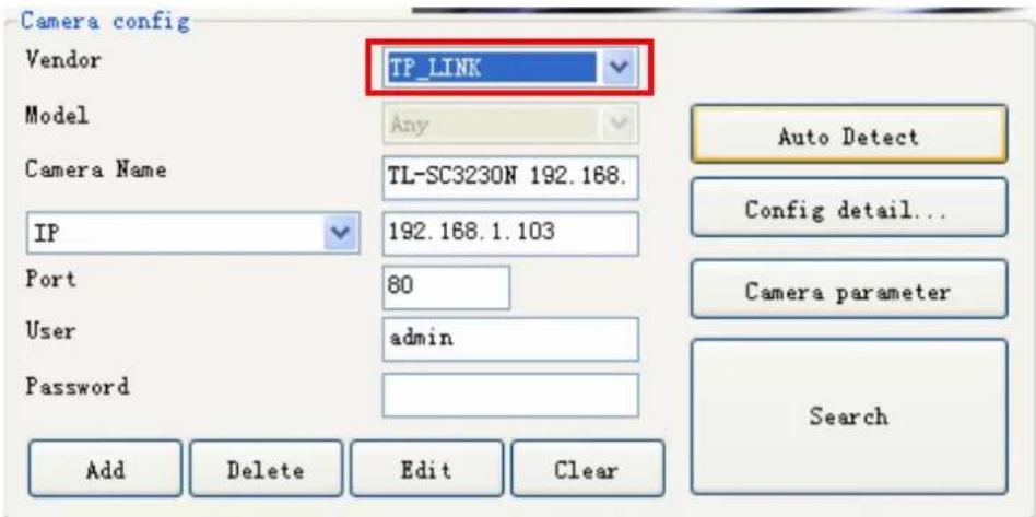
Step4: Select "Camera", enter the camera's configuration, and then click Add.
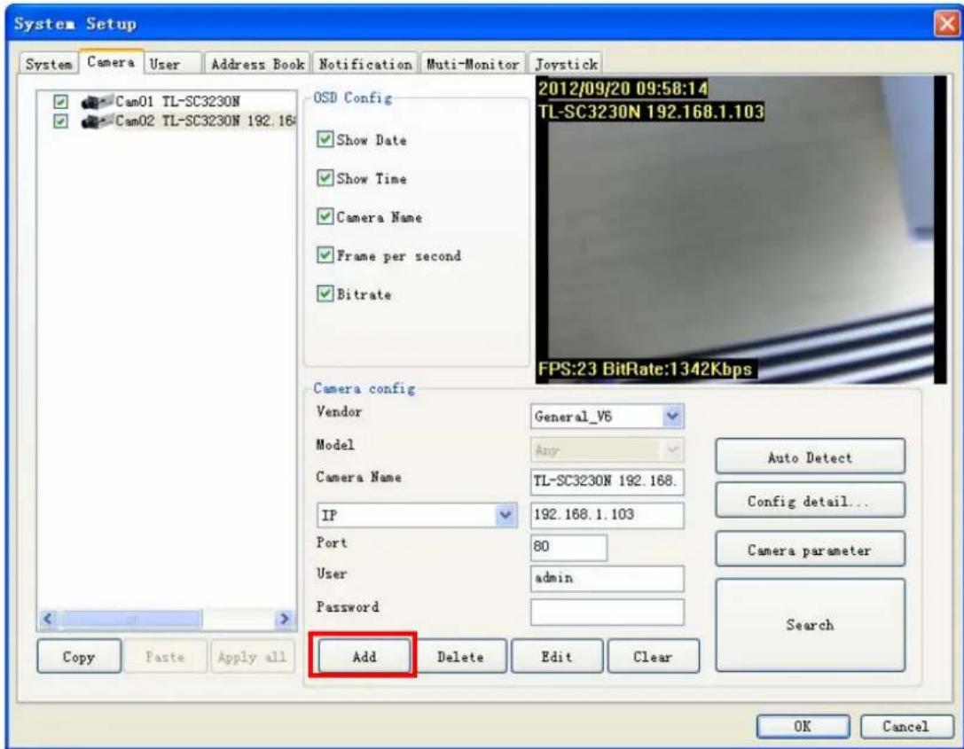
Auto Detect: Click Auto Detect button to detect camera and the system will check and set model automatically. Please confirm the Vendor and Model setting is matched to the camera, or may cause malfunction.
Camera parameter: If you need to change the camera parameters, click button.
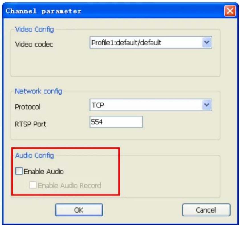
- Select the Video codec, protocol, and RSTP port for the current connection.
- Check Enable Audio if you need to receive audio streaming. If you need to record audio into file, you must check both Enable Audio and Enable Audio Record.
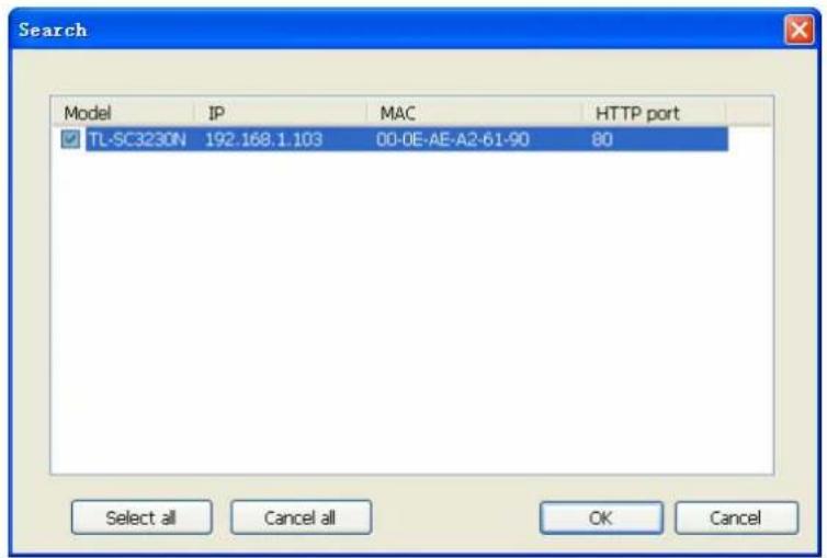
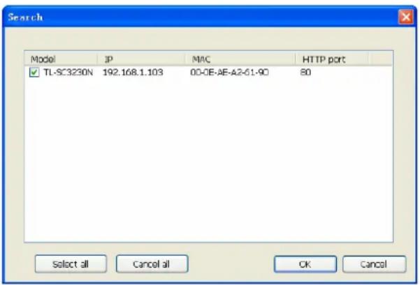
Search: Click the Search button to search the camera(s) installed in LAN, wait for searching complete, select the cameras as your need, and then click OK to finish this job.
Step5: Confirm all added camera's setting parameters.
Step6: Click OK button.
Step7: Now you can preview live stream at main page.
3.3 Configuration of schedule recording
Step1: Click the Schedule Setup
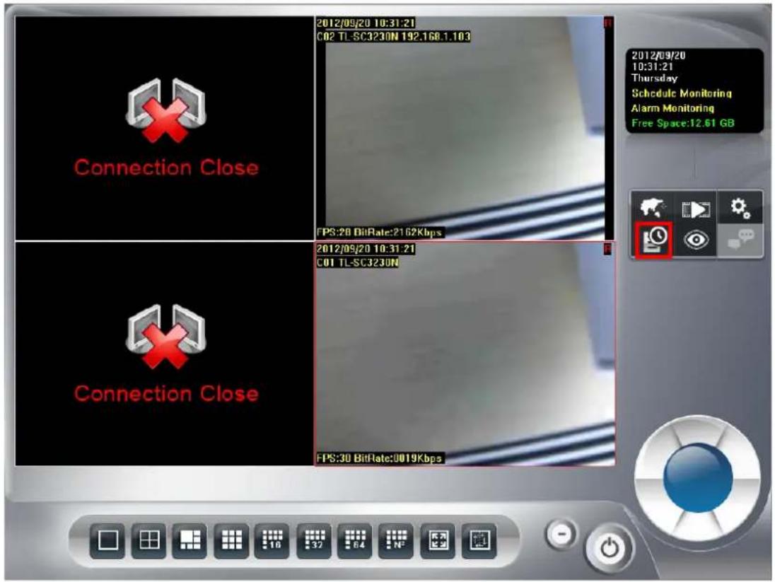
Step2: Select the schedule type that you need.
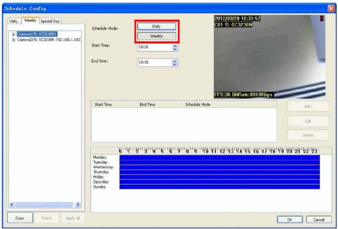
Daily mode: configure each camera's recording time and type on every day.
Weekly mode: configure each camera's recording time and type in each weekday.
Special day mode: configure each camera's recording time and type on specified day.
Note:
If the Special day schedule was set, when the system time matched the Special day setting, system will execute this special day setting immediately as top priority, even system has the same time period setting of daily or weekly schedule setup.
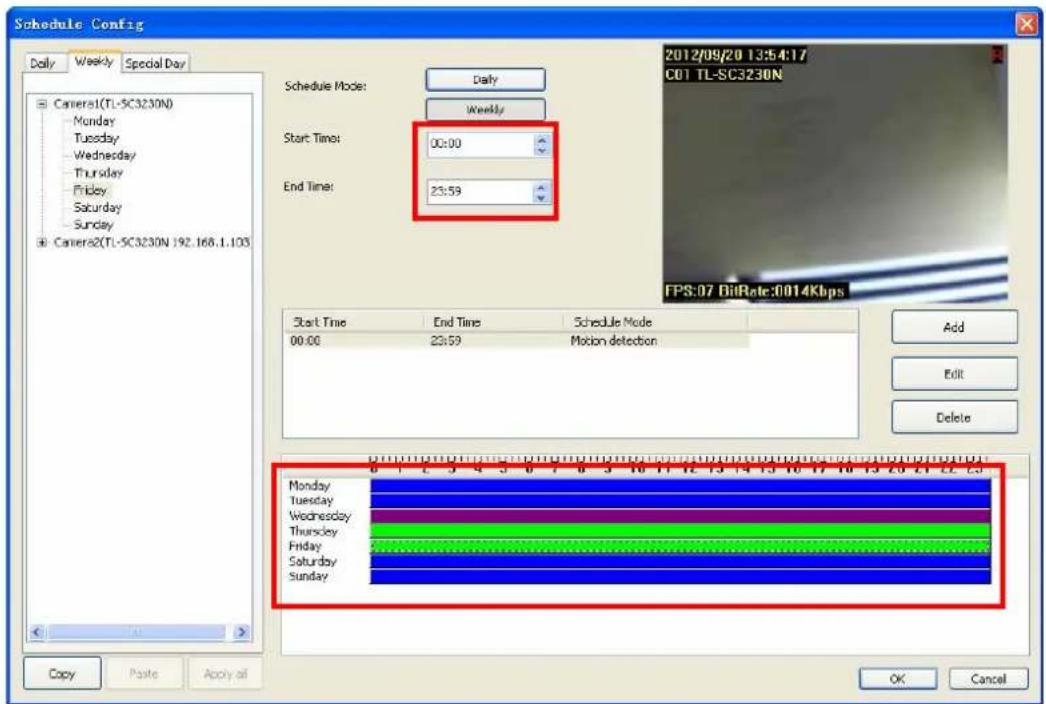
Step3: Select one camera for schedule configuration and select one of weekday for schedule setup (weekly mode)
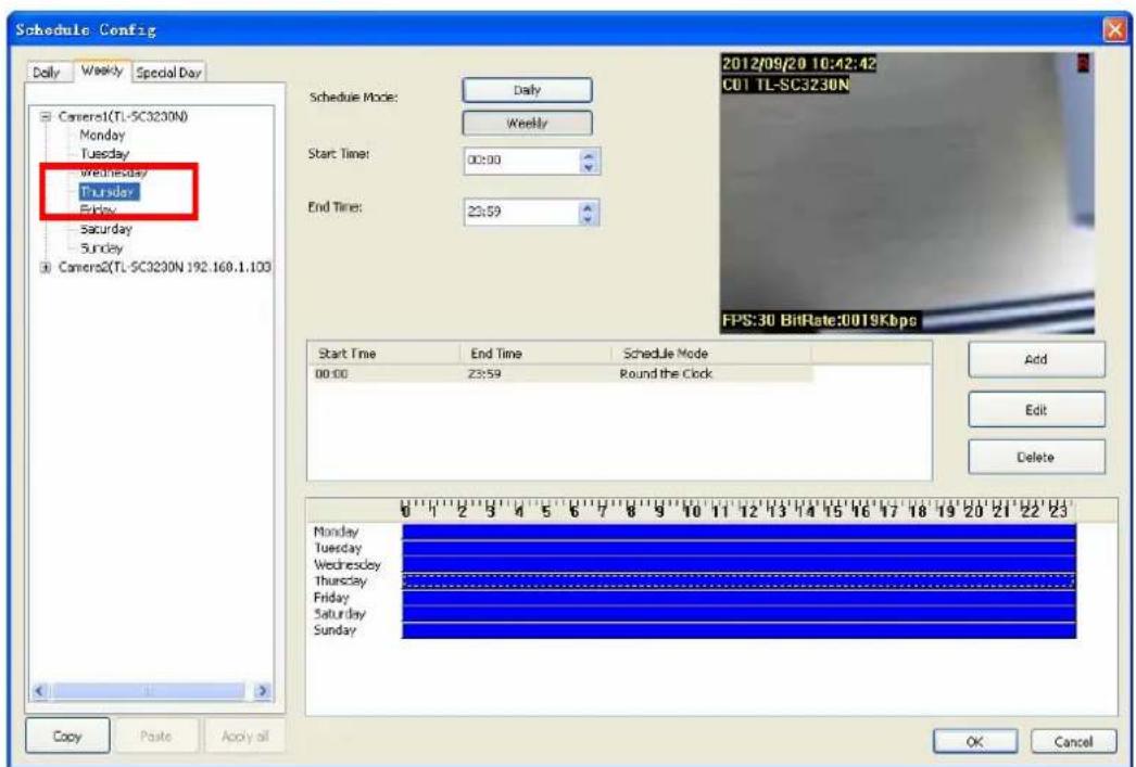
Step4: If you want to modify a specified schedule period, Select the period first from time period list or time period bar, or skip this step.
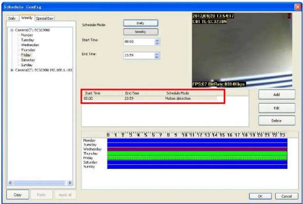
Step5: Modify the time period from time-select control or drag the period bar below.
Step6: After setting with time period, if you want to add a new schedule, click Add, or you want to modify a selected schedule, click Edit.
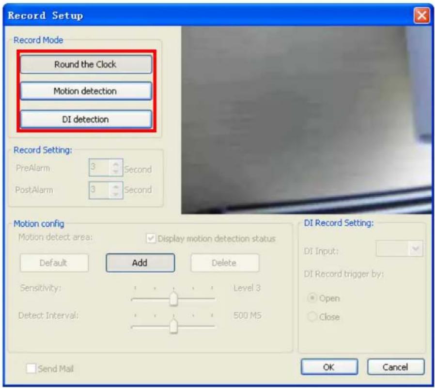
Step7: Choose Round-the-clock or Motion detection or DI detection record mode.
Motion detection mode: if you select the Motion detection mode, you have to configure the detection area, or use default setting.
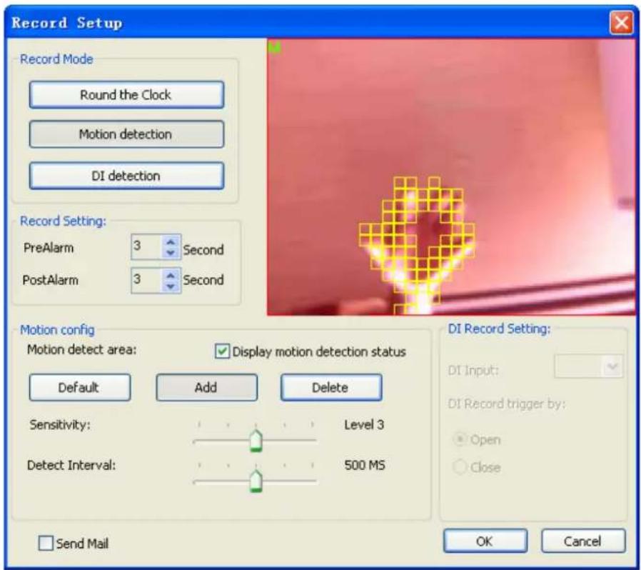
- Add detection area: Click Add, then drag a rectangle window on the preview image.
- Remove detection area: Click Delete button, then drag a rectangle window on
the preview image.
● Recover to default area: Click the Default button.
Note:
The red transparent window is the monitored area while the rest of the window will not be monitored.
DI Record Mode:
- Select trigger recording and specify the DI input source.
- Set trigger recording depend on whether status of DI is open or close.
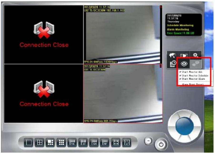
Step8: Start schedule monitor. Click the monitor button and select Start Monitor all or Start Monitor Schedule.
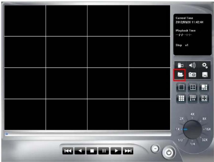
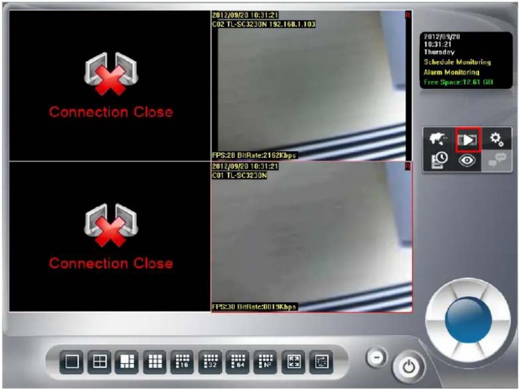
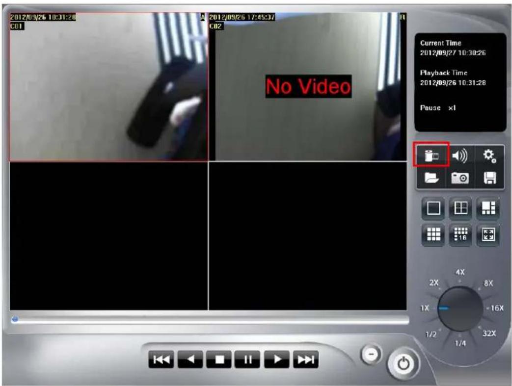
3.4 Playback
Step1: Click the playback button to launch playback panel.

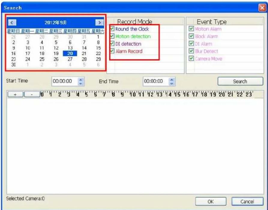
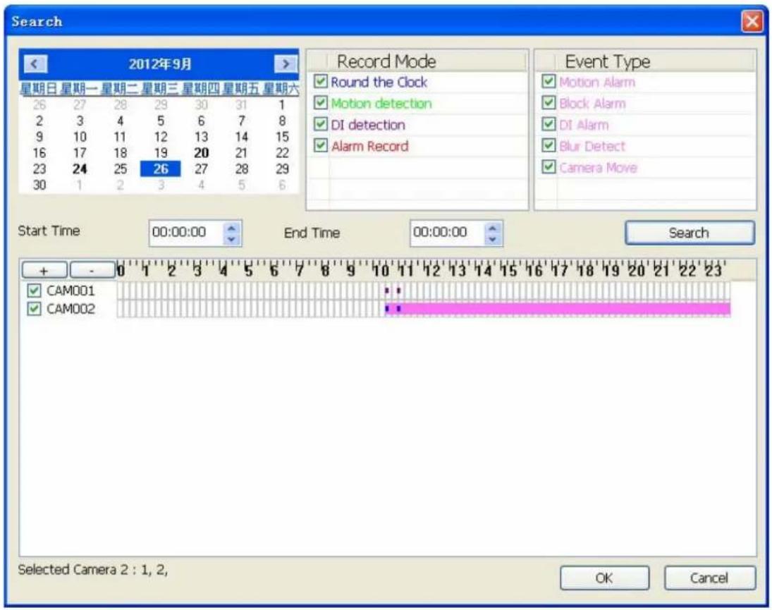
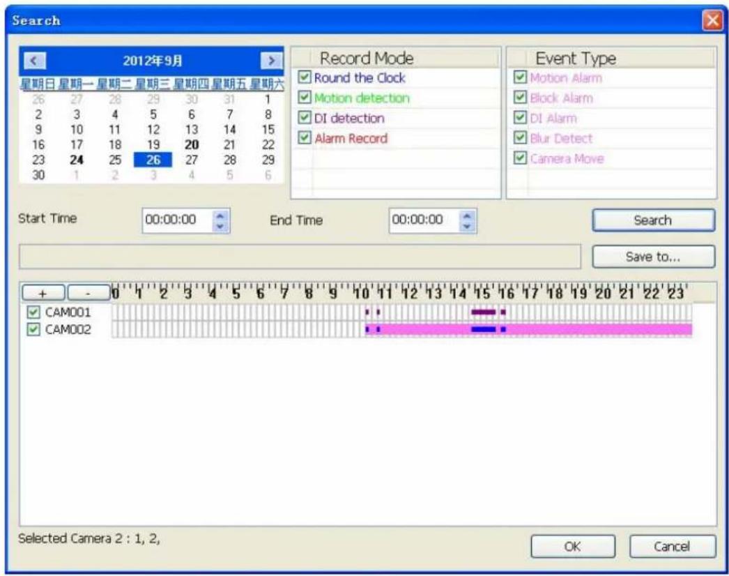
Step2: Click the search button to approach search dialog.
Step3: Click on the date that you want to search recorded files. Choose Record mode(s) that you need (Round the clock, Motion detection, DI detection, Alarm) and click Search.
Step4: System will display recorded file(s) status in control list below.
Blue: Round the clock recorded file.
Green: Motion detection recorded file.
Red: DI triggered recorded file.
Step5: Drag mouse cursor on the list control to select playback time period. Select the camera(s) to playback recorded file(s). System allows maximum 16 cameras playback at once.
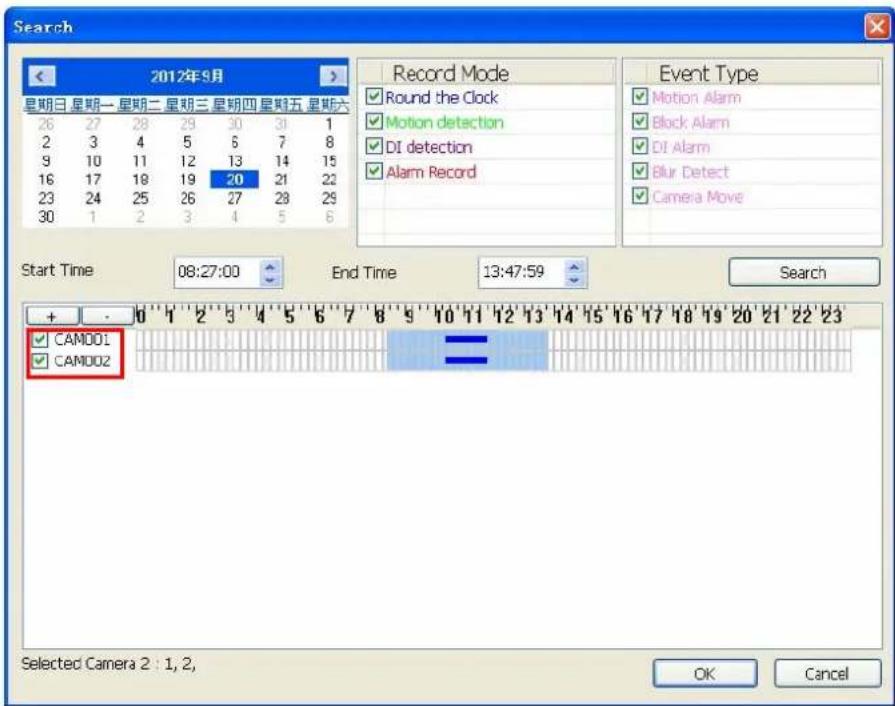
Step6: Click OK to finish search recorded files for playback job.
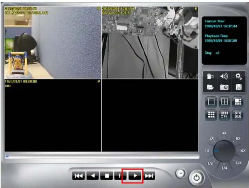
Step7: Click the play button to start playback procedure.
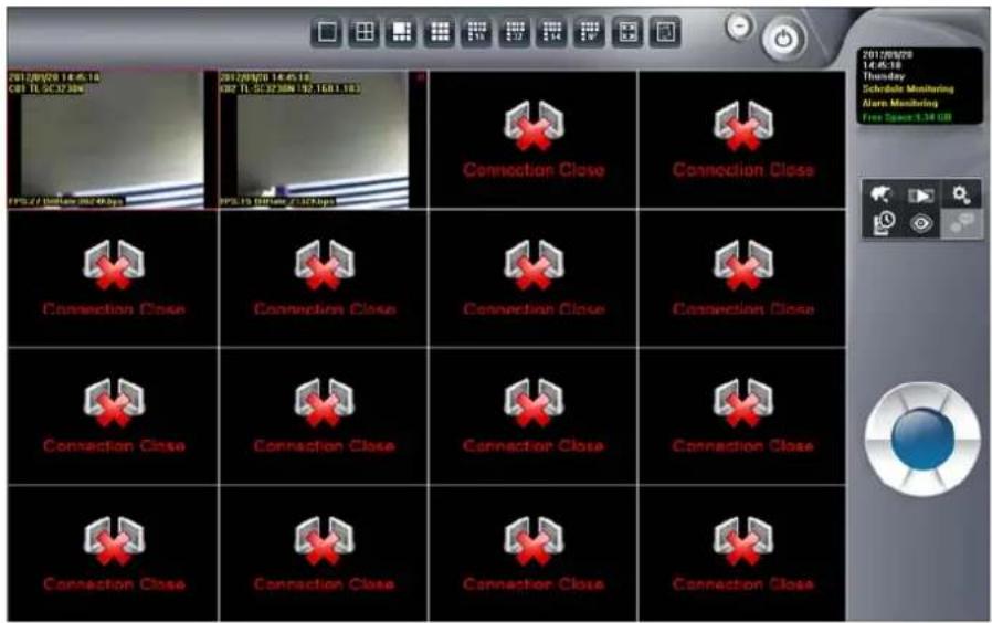
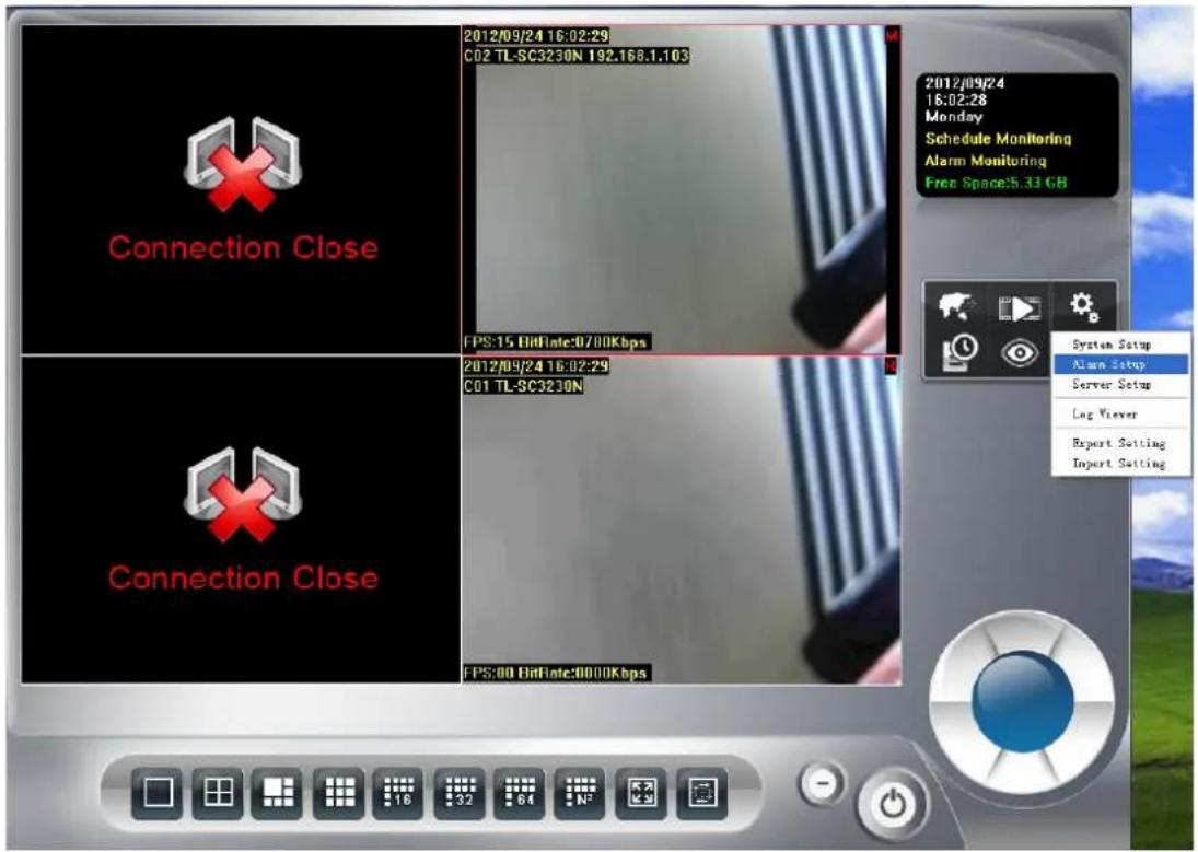
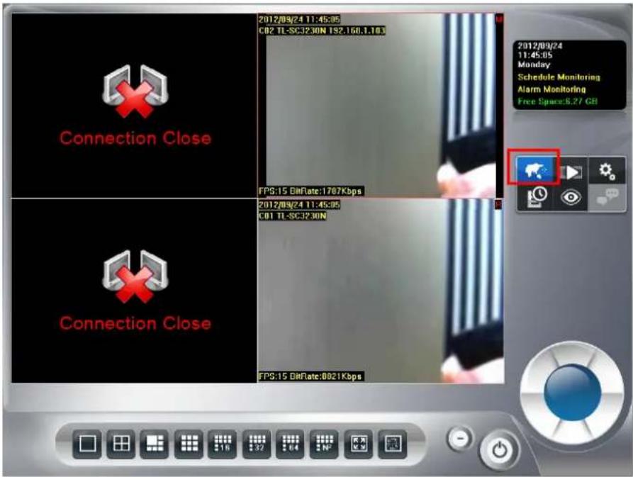
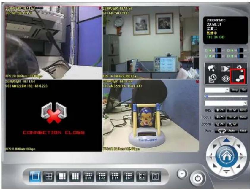
Chapter 4 Main-console
This is the main console of the system, providing live stream preview, system setup, E-Map, schedule setup, playback, start or stop monitor, PTZ controls, and so on.
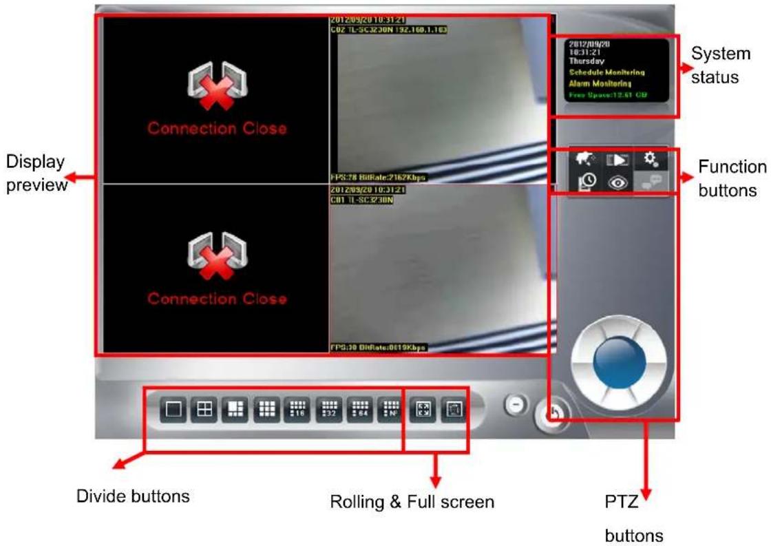
4.1 System status
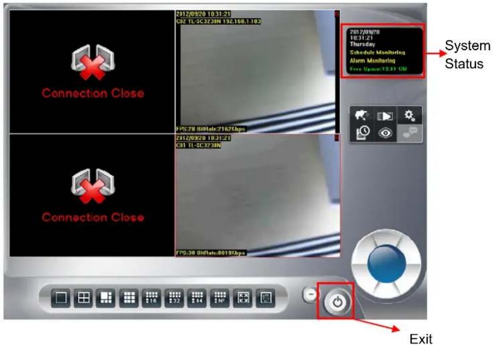
Click the exit

button and you will see the following options.
| Logout |
| Minimize |
| Maximize |
| Restore |
| Exit |
| Ver. 6, 0, 3, 495 |
- Logout: Log out current user.
Minimize: Minimize the main console to taskbar.
Maximize: Switch display mode to Maximize mode. When switching to Maximize mode, system will auto fit out whole screen, and set maximize display area, all buttons function just the same as normal mode.
Restore: Switch display mode to normal.
Exit: Shut down Surveillance Manager.
▶ Version: Display version number.
System status:
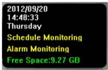
- System Date
- System Time
- Weekly day
- Schedule and Alarm Monitor status. If monitor stop, it will show nothing
- Hard disk available free size
The system status can configure at system setting. Please refer to "Setup page".
Hard Disk available free size has three color types, they mean:
Green: normal
Yellow: recycle job executing
Red: system can't found available free space any more.
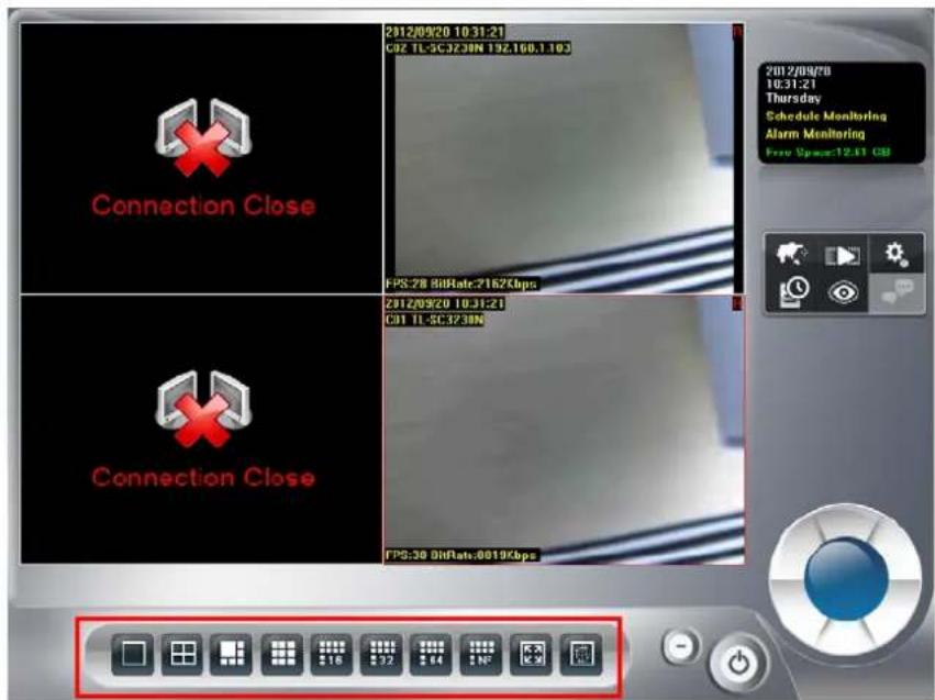
4.2 Screen Division
Assign the preview screen to preferred layout division by clicking these buttons.
To switch to single camera display, just double click on a particular sub-screen. Double click on the screen again to restore previous screen division layout.

Divide to 1 Screen

Divide to 4 Screen(s)

Divide to 6 Screen
Divide to 9 Screen(s)

Divide to 16 Screen(s)
Divide to 32 Screen(s)
Divide to 64 Screen(s)

Divide to NxN Screen(s)
Switch to Full screen mode
Start Rotate sub-screen(s)

Stop Rotate sub-screen(s)
4.3 Operation with sub-screen:
4.3.1 Define display camera(s) sequence
- To switch display sequence in sub-screen(s), press and hold mouse left button on source sub-screen, then drag to target sub-screen and release mouse left button.
- To switch current sub-window to another camera, click mouse right button on the sub-screen, then choose the live camera you needed.
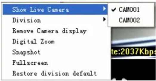
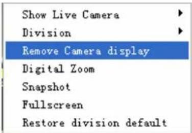
- To remove camera display, click the mouse right button and click Remove Camera display on popup menu.
4.3.2 Digital Zoom at sub-screen
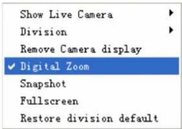
- Click mouse right button on sub-screen, and check Digital Zoom.
-
Move mouse cursor to the position that you want to zoom-in.
-
Roll mouse wheel forward to zoom-in.
-
Roll mouse wheel backward to zoom-out.
-
Press and hold mouse left button to drag the image at sub-screen onto the position in which you prefer.
-
To cancel digital zoom mode, click mouse right button and un-check Digital Zoom.
4.3.3 Switch to Full screen
- Click mouse right button and check Full screen on popup menu to switch Full screen mode.
- Click Esc key on your keyboard or un-check Full screen on popup menu to return to normal display mode.
4.3.4 Snapshot of sub-screen
- Click mouse right button and choose Snapshot on popup menu.
- Configure with the image by Snapshot dialog as below.
- Click Save button and choose the folder that you want to save to.
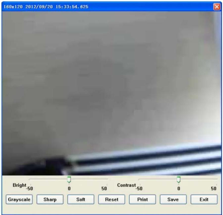
Bright: 50 = Maximum brightness, -50 = Maximum dark
Contrast: 50 = Maximum strong with Contrast, -50 = Minimum value of Contrast.
Grayscale: Click to switch image to grayscale mode.
Sharp: Click Sharp button to increase image sharp level.
Soft: Click Soft button to increase image soft level.
Reset: Click Reset button to restore image to original image.
➢ Print: Click Print button to print out image to printer.
Save: Click "Save" button and then choose folder and file name to save the snapshot.
Exit: Click "Exit" button to close the Snapshot dialog.
4.3.5 Restore division default
Reset division setting to default.
4.4 System setup
Click system setup button and select System Setup to approach System setup dialog.
4.4.1 System setup
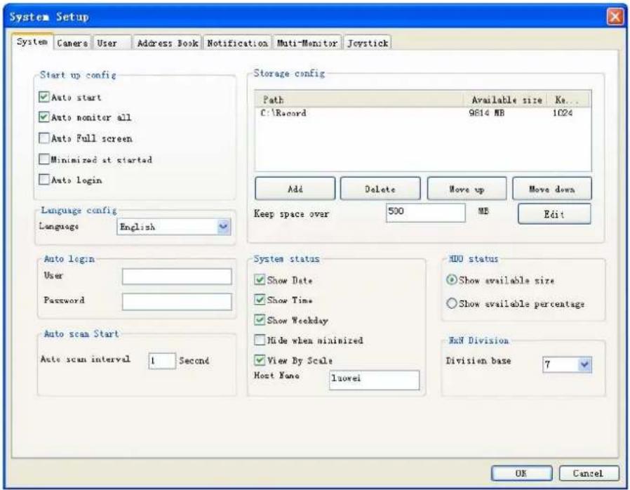
Start up config:
● Auto start: Auto start main console while system boots up.
● Auto monitor all: Auto monitors all cameras when main console starts up
● Auto Full Screen: Auto configure as full screen when main console starts up.
● Minimized at started: Auto minimize main console when system boots up.
- Auto login: Auto login main console when system boots up. It must configure "Auto login" information.
Language config:
- Language: Click on the combo box of language, and select the language that you prefer. The system will change language immediately.
Auto scan start:
● Auto scan interval: Set the screen rotation interval by seconds.
Storage config:
- Add: Click Add to select a new folder for recording work.
- Delete: Click Delete to remove selected folder from list.
- Move up/Move down: Click Move up and Move down to change priority of recording folders. Top of list is the first priority of recording work.
- Keep space over: Set Keep space over in MB, which means when the hard disk free space is less than the setting number, the system will recycle to kill the oldest recorded files. Please note that you should click Edit after you modified Keep space over value.
System status:
● Show Date/Show Time/Show Weekday: Select status item(s) for display on system status window. Check means this status will be displayed on main console status window. Otherwise, it will display nothing.
- Hide when minimized: If "Hide when minimized" is check, when the main console is minimized, the icon will move to system tray at right-down corner. Click the 📷 icon at system tray to restore main console.
- Host Name: define this Surveillance Manager system's name for the other integration system.
> HDD status:
● Show available size: The main console will display free space of hard disk(s) by choosing Show available size.
● Show available percentage: The main console will display percentage of free space by choosing Show available percentage.
NxN Division:
- Division base: Set the N of NxN division. When user click NxN division button, main console will divide the sub-screen(s) by this value.
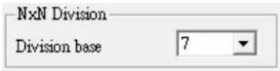
For examples:
If this value is set to 1, the divided sub-screen(s) is one sub-screen, If this value is set to 2, the divided sub-screen(s) is four sub-screens.
If this value is set to 3, the divided sub-screen(s) is nine sub-screens.
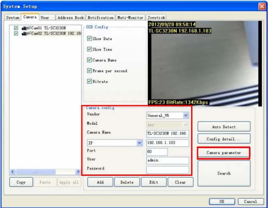
4.4.2 Camera
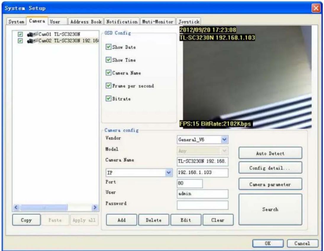
Camera list: List all camera(s) installed at system. It is listed by camera index. Check each camera to enable them. If you need to disable some of these camera(s), please un-check them by clicking checkbox.
Clone Camera setting:
- Select one camera and click Copy, or click mouse right button and select Copy on pop-up menu.
- Copy only camera's configuration, camera's parameter or both of them.
- Select a target camera and click Paste to update the settings. (Or click mouse right button on target camera, and select Paste on pop-up menu)
- Click Apply all button will toggle update all cameras setting with the copied setting.
OSD Config: System could show some information on the sub-screen. Check the checkbox before the information to display the corresponding information. The information will display on the preview screen at left-upper corner.
● Show Date: Displays system date.
● Show Time: Displays system time.
● Camera Name: Displays this Camera name
● Frame per second: Displays the frame per second of this channel.
- Bitrate: Displays the bit-rate per second of this channel.
▶ Camera Config:
● Vendor: Select Vendor name of this camera. If the selected Vender is not identical to the
camera, this channel may not work correctly. General: For all supported IP cameras. NVR: For backup streaming from another Surveillance Manager NVR.
- Model: Select Model name of this camera. If the selected Model is not identical to the camera, this channel may not work correctly.
- Camera name: Set this channel's camera name to identify this camera in system.
- IP: Set this camera's IP.
- Port: Set this camera's HTTP port.
- User: Set the User name for this camera. This User name must have the authority to login the specified camera.
- Password: Set the Password for this camera. This system will use the User name and Password to login specified camera.
- Add: Click Add to insert camera configuration to system.
- Delete: Click Delete to remove camera configuration from system.
- Edit: Click Edit to modify the configuration from system.
● Clear: Click Clear to clear all field for a new setting. - Search: Click Search to search the cameras at LAN. The system will pop up a dialog and display all found cameras in the list. Wait for search completed and check the cameras which you need. Click Select all to auto check all cameras in the list. Click Cancel all to auto un-check all cameras in the list. Click OK to confirm all selected camera and close this page. Click Cancel to cancel all actions and close this page.
- Configure detail button: Click Config detail to access web page of the selected camera.
- Camera parameter button: Click Camera parameter to approach channel parameter page.
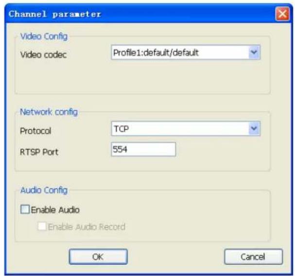
Video codec: Select the Video codec which system will receive from camera. Note that the codec capability depends on the camera.
Protocol: Select the protocol via which the system connects to the camera.
RTSP Port: Specify RTSP port for connecting to camera.
Enable Audio: Set Audio enabled to receive audio streaming form camera. If you need to listen live audio, this function must be enabled.
Enable Audio Record: Check this box to save audio data into recorded file.

Note:
The Audio Record must Enabled with "Enable Audio" value both.
Click OK to save the connection configuration and return to the previous page. Click Cancel to cancel the configuration on this page and return to the previous page.
- Channel parameter Page(NVR):
Channel: Select which channel for backup.
Network config: Set RTSP connection port.
Enable Audio: Set Audio enabled to receive audio streaming form NVR. If you need to listen live audio, this function must be enabled.
Enable Audio Record: Check this box to save audio data into recorded file.
4.4.3 User
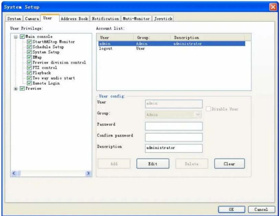
User Privilege: The user Privilege tree is to define user's privilege of each function of system. Check box means the user can use this function and un-check means the user can't use it.
- Main console: It controls the main functions of the system. The user must have some of these privileges at least or the user can not do anything with system.
- Start and Stop Monitor: This function means the user can start or stop system monitor work (schedule recording).
- Schedule Setup: The privilege of the user can access schedule setup page.
- System Setup: The privilege of the user can access system setup page.
● EMap: The privilege of the user can use E-Map function. - Preview Quad control: The privilege of the user can change division of sub-screen.
- PTZ control: The privilege of the user can control Pan, Tilt, and Zoom functions of camera.
● Playback: The privilege of the user can playback recorded files. - Two way audio start: The privilege of the user can enable two-way audio with camera.
- Remote Login: This user could login remote service or not.
- Preview: The privilege of the user can preview live streaming. The user can preview the live streaming of check cameras.
Account list: Display all users' information of system. If you want to modify user's configuration or delete user account, please click on the user name in the list first. When you
have modified user's information (add, edit or delete), please confirm the data appears in the list.
- Admin account: This user will own privilege of system administrator.
- Logout account: This is a special account when system is under logout status.
User config:
- User: User name.
- Group: Select the group of the user. The admin group has all privilege of system by default and the user group only has main console privilege by default.
- Password: The password of the user for login system.
- Confirm password: Retype the password.
● Description: The user can specify some description for this account.
● Disable User: Check this box to disable the user account. - Add: Enter user's information and check user's privilege first, then click "Add" button to add new user to the list.
- Edit: Click on the user name of the list first, and then modify the data of this account. After modified data, you must click the "Edit" button to confirm it.
- Delete: Click on the user name of the list, and then click "Delete" button to remove the user account from list.
- Clear: Click the "Clear" button to clear all settings.
4.4.4 Address Book
Setting address book for sending event mail or query phone from here.
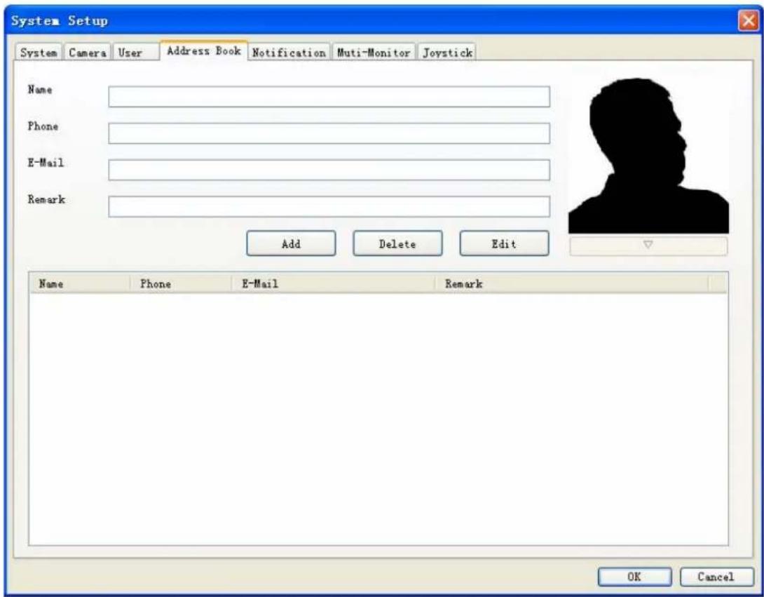
Add address book record: Enter the contact information, and then click Add.
➢ Delete address book record: Click on the contact list which you want to delete, then click Delete.
Edit address book record: Select the record which you want to modify. Modify the information, and then click Edit.
Change photo of contact: Click the "▽" button below the photo, and then select a picture to replace it.
4.4.5 Notification
Configure the Notification information for event notice.
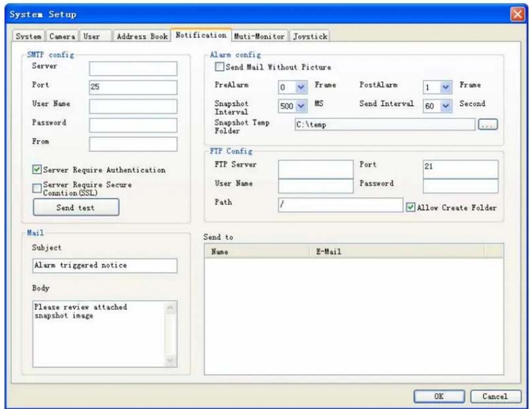
SMTP Setting: Enter the SMTP server connection information for sending event notice mail.
● Server: SMTP provider IP address or DNS.
- Port: Mail Server's SMTP port.
- User Name: Login SMTP server's user account.
- Password: Login SMTP server's password.
- From: The "From" field of E-Mail.
- Account Authentication: Check this box for the SMTP server which needs authentication
- Secure Connection (SSL): Connect to SMTP with SSL authentication.
- Send Test: Click Send test to send a test mail.
Mail Content: Set the "Subject" and "Body" of event notice mail.
➢ Alarm Setting: Configure the attached snapshot picture rule of event notice mail.
- Pre-Alarm: Set for how many snapshot pictures should be captured before event is triggered.
- Post-Alarm: Set for how many snapshot images should be captured after event is triggered.
- Snapshot interval: Set the interval between of each snapshot.
- Send Interval: Set the interval between of each send-out notice mail.
● Picture Temp Folder: Select a folder for store snapshot pictures, these pictures will be deleted when system is shutdown.
FTP Config:
- FTP Server: Set the FTP site's IP for system upload image when event is triggered.
- Port: The FTP server's port.
- User Name: The account to login FTP server.
- Password: The password to login FTP server.
● Path: the system will upload images to defined folder. - Allow Create Folder: If check this field, system will create folder automatically for new event's upload process. If un-check this field, system will only upload image to define folder.
➢ Send to Config: Select the mail accounts for send schedule record notification mail.
4.4.6 Muti-Monitor
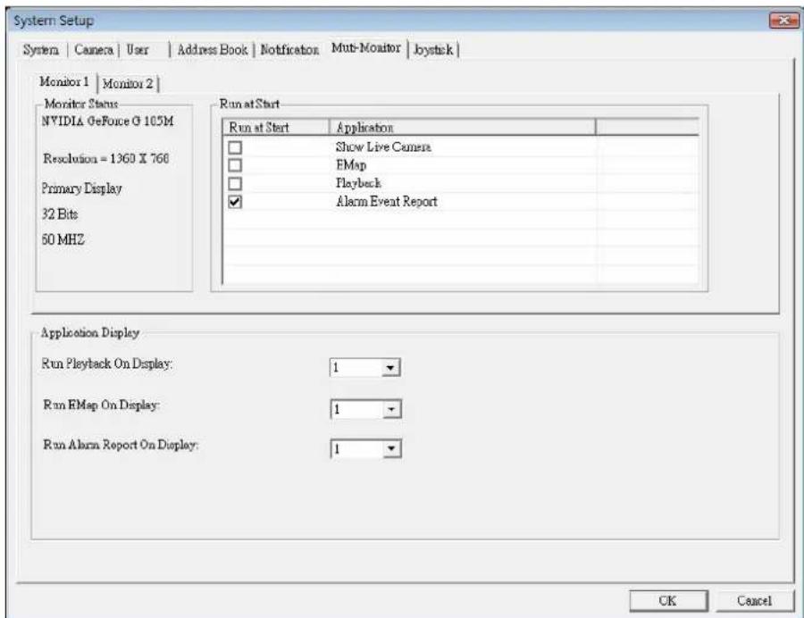
Monitor list tab-control: Select which monitor to be configuration.
Monitor Status: Displays monitor information.
➢ Run at Start: Check the functions which will be run at selected monitor on system start.
● Show Live Camera: Displays extra live preview window on selected monitor.
● EMap: Displays E-Map on selected monitor.
- Playback: Execute Playback on selected monitor.
● Alarm-Report: Displays Alarm status report on selected monitor.
- Application Display: Definition when the user click application buttons on Main-console, the application will display on which monitor.
Note:
The system will auto-detect monitor connect status, If you can't find out extra-monitor, please check monitor connect status and re-open setup page.
4.4.7 Joystick
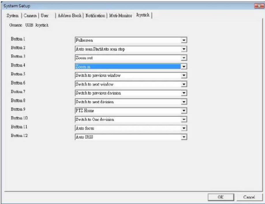
This page displays the joystick was found at system, and you could define each button's function with drop-down list.
Surveillance Manager support all kinds of joystick by Microsoft Direct-Input, please confirm install joystick driver first.
Button's function list:
- Full-Screen:
Switch current display mode to full-screen or normal.
- PTZ Up/Down/Left/Right/Up-Left/Up-Right/Down-Left/Down-Right/Home:
Move Pan-Tilt camera direction.
- Switch to next division / Switch to previous division / Switch to One division:
Change sub-screen division.
- Switch to next window / Switch to previous window
Change focus camera window.
- Auto Scan Start / Auto Scan Stop
Start auto scan or stop.
- Auto Focus:
Trigger focus camera auto focus function.
- Zoom in / Zoom out
Trigger focus camera zoom-in or zoom-out.
- Auto IRIS:
Trigger focus camera auto-IRIS function.
9. Preset 1\~16
Change focus camera direction to preset position.
Note:
How many buttons will display on setting page depends on joystick driver, each button can define one function in the list above.
System will auto-detect joystick connect status, If you can't find out your joystick, please check the joystick connect status and re-open setup page.
4.5 Alarm Setting
Click system setup

button and select Alarm Setup to approach Alarm setup dialog.
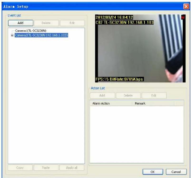
Event Setting / Add Event:
-
Select the camera which you want to add event.
-
Click Add to approach Alarm Event Selection dialog.
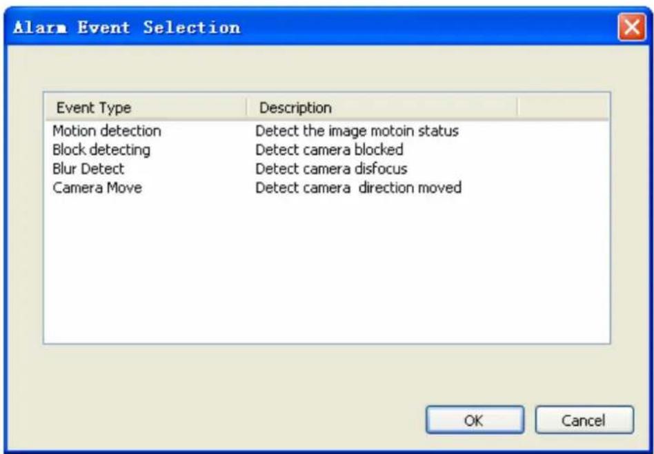
- Select the Event that you want to add, and then click OK, or double-click on the Event to add it.
- The selected Event will be added into the specified camera.
Event Setting / Delete Event: Select an event which you want to delete, and then click Delete to delete this event.
Event Setting / Edit Event:
- Select the Event which you want to modify.
- Click the Edit button or double-click the Event which was selected.
- Configure the event setting, then click OK to save setting, or click Cancel to cancel edit job.
Please refer the items below to check detail information of event setting.
Event Setting/ Edit Event / Basic Setting: Select the event which you want to modify. Click the Edit button or double-click the Event which was selected to display the Alarm Setup dialog.

● Auto Stop Type: Alarm Stop by Manual: Once event was triggered, it would keep alarm until the user cancels it from Event Report dialog. Alarm Stop after Second: Once event was triggered, it would automatically stop alarm after setting seconds.
- Event Detect Period: Always Detect: When Alarm Monitor is activated, the detection job will always execute. Detect by Schedule: The detection job will execute when Alarm Monitor is activated and match the schedule setting.
Note:
The System accepts maximum 10 detection schedule settings.
Event Setting/ Edit Event / Advance Setting/ Motion:
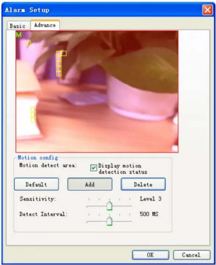
- Define motion detection area: Click Default to select all images for motion detection. Select Add and use mouse to specify a rectangle window to add a detection area. Select Delete and use mouse to specify a rectangle window to remove a detection area. The area covered by transparent red color is motion detection area.
- Set motion detection sensitivity: Set the motion detection sensitivity level between 1 and 5. Level 5 means the highest motion detection sensitivity.
- Set detection interval: Set this value to define the interval of motion detection. If set longer value, means system will use less CPU computing power to check motion detection.
- Adjust parameter by detection result: When motion detection event is triggered, system will display "M" at left-up corner and you can adjust these two parameters by checking detection result to get best settings.
Event Setting/ Edit Event / Advance Setting/ Block Detect:
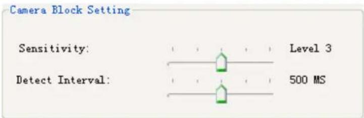
- Block detection could detect camera is blocked by something, detect area is set to full image.
- Set Sensitivity with higher level to trigger block alarm easier, otherwise set lower level to
prevent false alarm.
Event Setting/ Edit Event / Advance Setting/ Blur Detect:

- Blur detection could detect image lost focus (blur), detect area is set to full image.
- Set Sensitivity with higher level to trigger blur alarm easier, otherwise set lower level to prevent false alarm.
Event Setting/ Edit Event / Advance Setting/ Camera Move Detect:
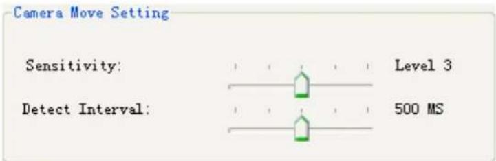
- Camera move detection could detect camera direction is moved, detect area is set to full image.
- Set Sensitivity with higher level to trigger camera move alarm easier, otherwise set lower level to prevent false alarm.
Event Setting/ Edit Action: Select an action from the Action list then click Edit or double-click on the action to enter action setting dialog.
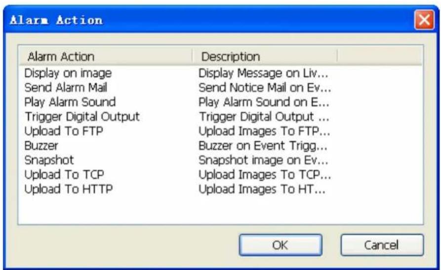
- Display on image: Select the channels which you want to display alarm message when event is triggered. The default selected channel is the event detection channel.
-
Send Alarm Mail: Select the mail accounts which you want to send a notice mail when event is triggered. Mail account list is set by system / address book page.
● Play Alarm sound: Select a Wav file to play once event was triggered. -
Trigger Digital Output: Select a digital output which you want to take an action once event was triggered.
- Upload To FTP: When event is triggered, system will upload images by setting in system setup page.
Event Setting / Delete Action: Select an action which you want to delete, and then click Delete to remove this action.
Event Setting / Clone Event setting: Select an event and click Copy or pop-up menu, and then select the camera you need clone the settings to, click Paste to paste on target.
You can apply copied setting to all cameras by click Apply all.
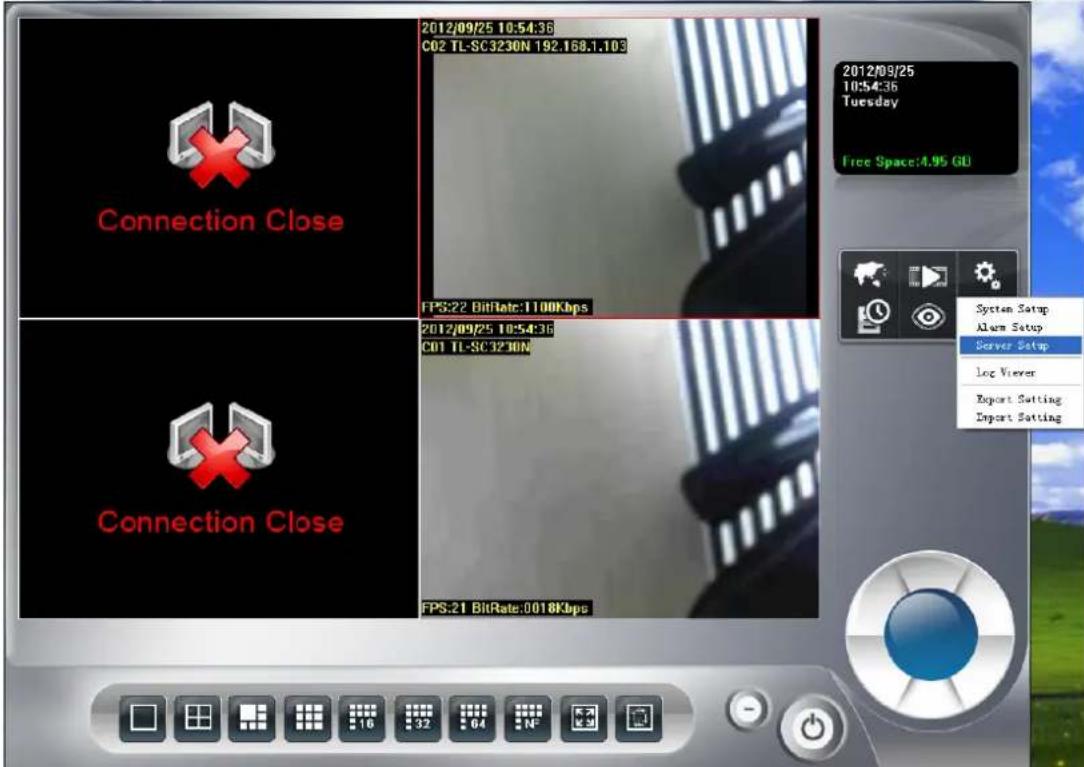
4.6 Server Setup
Click system setup button and select Server Setup to approach server setup dialog.
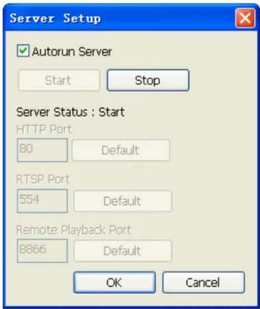
➢ Autorun Server: Once Autorun Server is checked, the remote service will start automatically while Surveillance Manager is running.
Start Server: Click Start to start the remote service which the HTTP and RTSP service will start working.
Stop Server: Click Stop to stop the remote service which the HTTP and RTSP service will stop working.
HTTP Port: In case you need to change HTTP port, please stop remote service first and then enter new port value. The default HTTP port is 80.
RTSP Port: If you need to change RTSP port, please stop remote service first and then enter new port value. The default RTSP port is 554.
Remote Playback Port: If you need to change Remote playback port, please stop remote service first and then enter new port value.
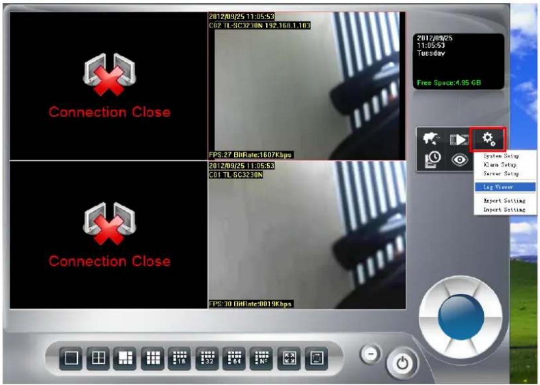
4.7 Log Viewer
Click system setup 📋 button and select Log Viewer to approach Log Viewer dialog.
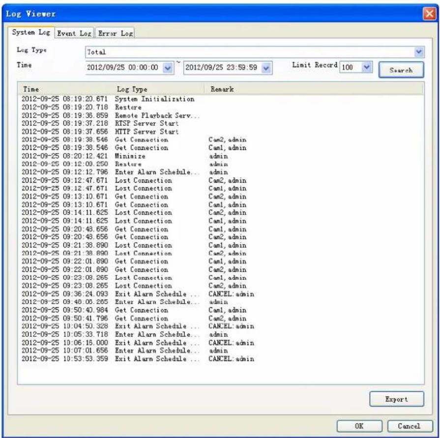
System Log page:
- Select Log Type
-
Select Log time period.
-
Click Search to list Logs.
- Click Export to export search result to TXT file.
Event Log page:
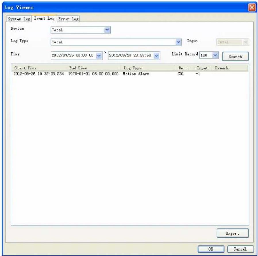
- Select the device to display the event triggered or list all.
- Select event type or list all.
- Select the input source that triggered the event (Digital Input Event).
- Specify search time period.
- Click Search to list event logs.
- Click Export to export search result to TXT file.
- Double click on the event log record, the system will bring up a playback window, and playback 10 second record video (pre-alarm 5 second, post-alarm 5 second). Please note that playback job must wait for record file closed.
Error Log page:
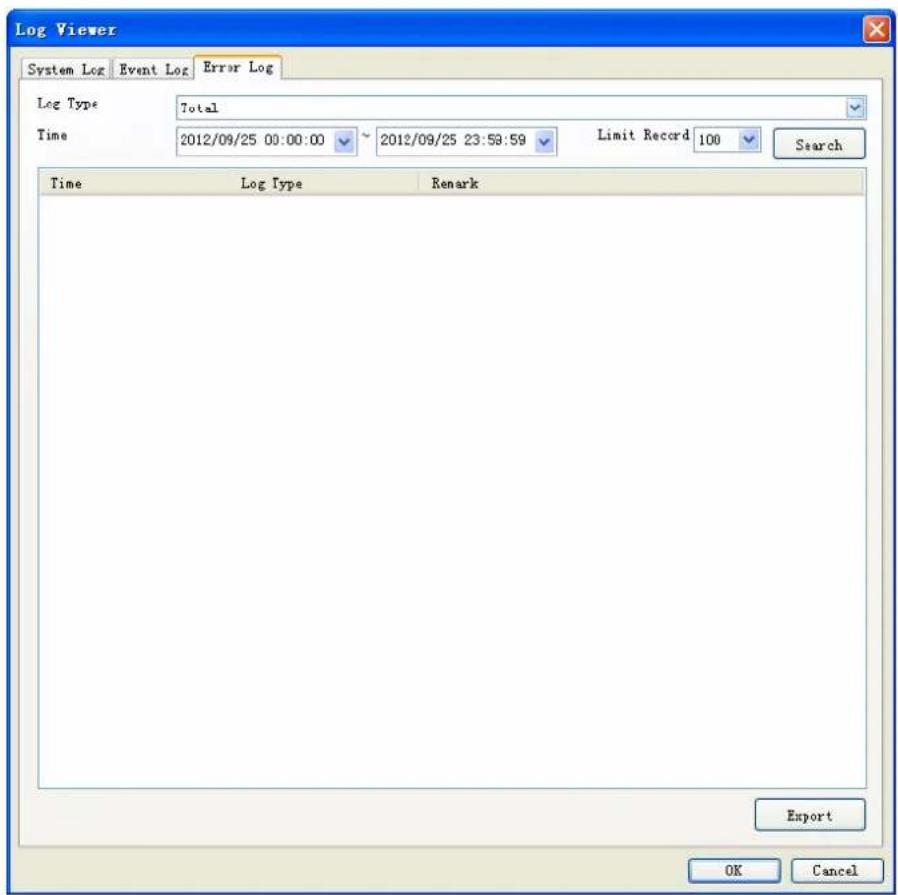
- Select Log Type.
- Specify Log time period.
- Click Search to list Logs.
- Click Export to export search result to TXT file.
4.8 Import / Export Setting
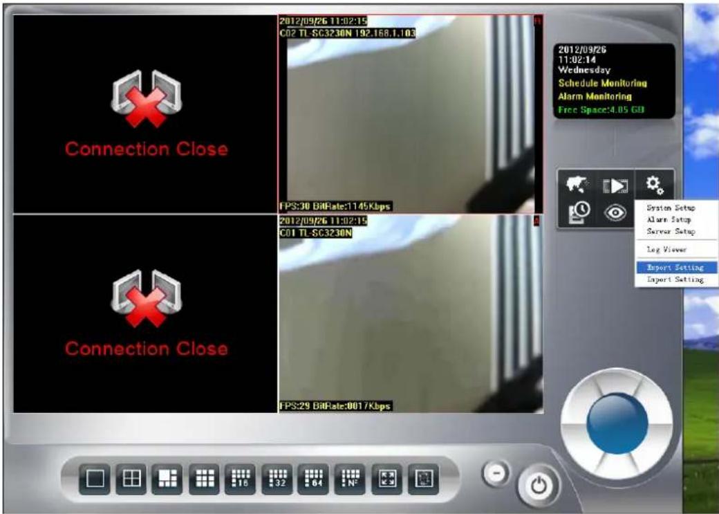
- Import Setting: Select a history export setting file by open file dialog and click OK, and the system will restore setting by selected file.
- Export Setting: Select a file from save file dialog and click OK, the system will create a setting file to destination folder.
4.9 Schedule setup
4.9.1 Schedule Setup
Click schedule setup button to approach Schedule setup dialog.
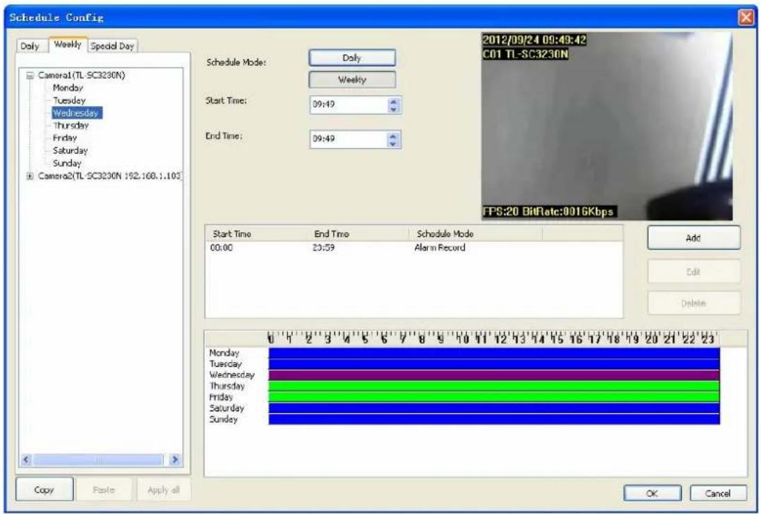
Schedule mode: Select the schedule mode of system. The Daily and Weekly mode is exclusive to each other. Daily mode: Set schedule time slice by day. Weekly mode: Set schedule time slice by weekday.
Select camera of Daily mode: When you choose Daily mode or click on "Daily" tab of camera list tree, the list tree will display all installed cameras of system. Click on the camera name which you want to modify. The schedule configuration of this camera will display at left of dialog. System defaults the schedule from 00:00 to 23:59 round the clock recording mode. The user could modify it for your own schedule.
Clone setting:
- Select one camera and click Copy to copy camera's schedule setting.
- Select a camera and click Paste to update schedule setting with copied data.
- Click Apply all to update all cameras with copied setting.
Note:
You can right-click on camera to bring up pop-up menu, and clone settings as above.
Select weekday of Weekly mode: When you choose Weekly mode or click on "Weekly" tab of camera list tree, the list tree will display all installed cameras of system. Click on the camera name which you want to modify. The schedule configuration of this camera will display at left of dialog. System defaults the schedule from 00:00 to 23:59 round the clock recording setting. The user could modify it for your own schedule
Clone Setting (copy setting from a camera):
- Select a camera and click Copy to copy selected all weekday schedule setting.
- Click Paste and select Paste will update selected camera all weekday's schedule setting.
- Click Paste and select Paste on Monday to Friday will update selected camera's Monday to Friday schedule setting as same as copied Monday to Friday setting.
- Click Paste and select Paste on Saturday to Sunday will update selected camera's Saturday and Sunday setting as same as copied Saturday and Sunday setting.
- If select a weekday, and Click Paste, then select Paste to all camera on Selected Weekday will update all camera's selected weekday setting as same as copied camera weekday.
- Click Apply all to update all camera's setting as same as copied camera.
Clone Setting (copy setting from a weekday):
- Select a weekday of one camera and click Copy to copy selected weekday schedule setting.
- Select a camera and click Paste, select Paste on pop-up menu will update same weekday's setting of selected camera.
- Select a weekday of camera, click Paste and select Paste on pop-up menu will update selected weekday's setting from copied data.
- Click Paste and select Paste on Monday to Friday will update selected camera's Monday to Friday schedule setting as same as copied Weekday setting.
- Click Paste and select Paste on Saturday to Sunday will update selected camera's Saturday and Sunday setting as same as copied Weekday setting.
- If select a weekday, and Click Paste, then select Paste to all camera on Selected Weekday will update all camera's selected weekday setting as same as copied camera weekday.
- Click Apply all to update all camera's all weekday settings as same as copied Weekday.
Select camera of special day mode: When you choose "Special Day mode" or click "Special Day" tab of camera list tree, the list tree will display all installed cameras of system. Click on the camera name which you want to modify. The schedule configuration of this camera will display at left of dialog. System defaults the schedule from 00:00 to 23:59 round the clock recording setting. The user could modify it for your own schedule
Clone Setting:
- Select one date or camera and click Copy.
- If you want to copy setting from a date, click Paste will update all cameras of selected target date by copied setting.
- If you want to copy setting from a camera of some special date, click Paste with selected a date to update the camera schedule setting.
- Copy a camera schedule setting and paste to another camera by click Paste with selected a camera.
- Add or remove special day: If you want to add a new special day into system, choose a day from date-time picker control, then click Add. If you want to remove a special day from system, click the special day on the tree control at right of dialog, then click Delete.
Add schedule time slice: You can define a time slice as below:
- Select Start time and End time from date-time picker control: Click on the hour section or
minute section, then key in the time value, or click the “▲” or “▼” to increase or decrease the time value.
- Drag time slice bar from time table: Move mouse cursor to the empty zone on time table in which you want to add. Press and hold mouse left button, drag cursor to right until touch the End time which you need, then release the left button of mouse.
- After drag action, a new gray bar is show on the time table. The left end of the time bar means this slice's Begin time and right end means End time. Note that the mouse cursor must drag on empty zone, or this action will be not successful.
- After time slice define is completed, the system will pop up the "Record Setup" dialog. Please refer to "Record Setup Page" as below.
Modify schedule time slice:
- Selected the Camera's name (daily mode) or weekday (weekly mode) from the tree control at left of dialog.
- Click on the slice in the list which you want to modify. The other way, you can click on the slice bar on the time bar control.
- Click on the hour section or minute section on the date-time picker control, then enter the time value, or click the "▲" or "▼" to increase or decrease the time value. Or you can move mouse cursor to edge of slice bar on time bar control, then the cursor will become
to “↑↑”, and drag the edge to the position where you need.
- After complete the time slice, click Edit to approach "Record Setup" dialog.
Remove schedule time slice:
- Select the Camera's name (daily mode) or weekday (weekly mode) from the tree control at left of dialog.
- Click on the time slice in the list which you want to modify. The other way, you can click on the time slice bar on the time bar control
- Click the "Delete" button at right of dialog.
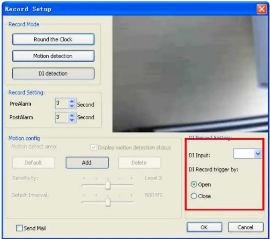
4.9.2 Record Setup
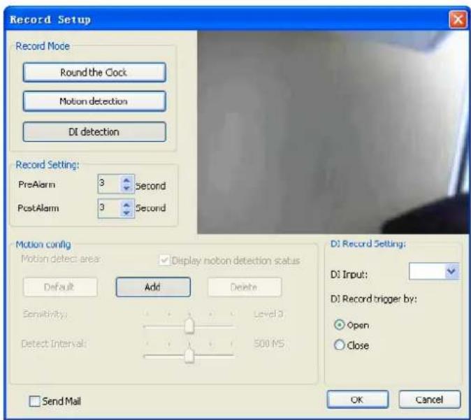
Record Mode:
- Round the Clock: When system time reach the schedule begin time, system will start recording work immediately and continually until the system time reach the end time.
● Motion detection: When system time reach the schedule begin time and motion alarm is triggered, system will start recording work immediately and continually until the system time is over the post-alarm seconds.
- DI Detection: When system time reach the schedule begin time and DI alarm is triggered system will start recording work immediately and continually until the system time is over the post-alarm seconds. If the pre-alarm seconds is set, when motion detection has been triggered, the recorded file will include pre-alarm seconds by setting.
Record Setting:
- PreAlarm: When set to Motion detection or DI detection record mode, the user can set the Pre-Alarm second(s) which the recorded file will keep a slice of image defined as the setting second(s) before event was triggered.
- PostAlarm: Set the Post-Alarm second(s) which the recorded file will keep a slice of image defined as the setting second(s) after the event was triggered.
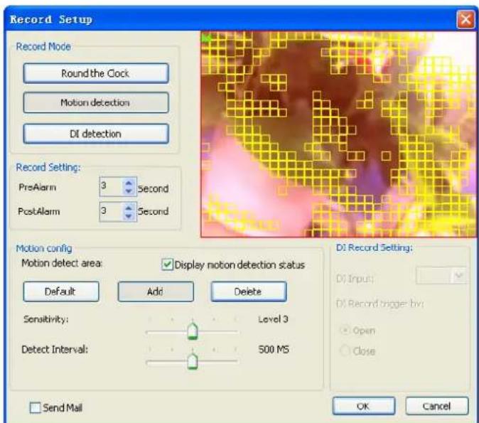
Motion Config:
● Default: Select the full image for motion detection.
- Add: Define a rectangle area on the image first, and then click Add to add a new region.
- Delete: Define a rectangle area on the image first, and then click Delete to remove the region that was defined.
- Sensitivity: Set sensitivity level of motion detection. Level 5 means the highest motion detection sensitivity. On the contrary, level 1 is the lowest level of sensitivity.
- Motion Interval: Set this value to define the interval of motion detection. If set longer value, means system will use less CPU computing power to check motion detection.
- Display Motion detection status: Check the check box to display the area(s) where motion detection is triggered.
- Preview window: Red area is the motion detection area. The other areas are non-motion detection region. The yellow rectangles are triggered regions of motion detection areas.
DI Record Setting: When you set the DI record mode, select the DI input from the combo box,
and select the DI as open or close to trigger recording.
To finish configuration job of schedule setting, click OK to confirm. If you want to abort this setting, please click Cancel instead.
When you set the DI record mode, select the DI input from the combo box, and select the DI as open or close to trigger recording.
4.10 Start & Stop Monitor
Click Start & Stop Monitor button to control system monitor job.
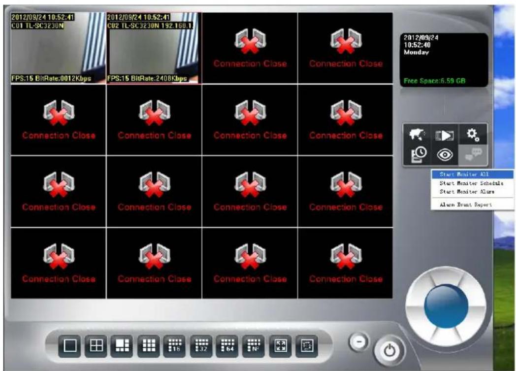
➢ Start Monitor All: Check it to start all type of monitor job.
Start Monitor Schedule: Check it to start the schedule monitor job.
Start Monitor Alarm: Check it to start the Alarm monitor job.
Note:
If Start Monitor All is check, system will execute all monitor jobs automatically.
➢ Alarm Event Report: Alarm Event Report dialog displays all triggered events and those were not stopped or canceled events.
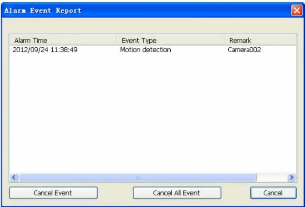
● Alarm time: The triggered time of this event.
● Event Type: The trigger type of this event.
● Remark: The description of this event.
- Cancel Event: Select the events and click Cancel Event to stop alarm actions, and reset event status.
- Cancel All Event: Stop all event action and reset all event status.
4.11 E-Map
Click E-MAP button to approach E-MAP dialog.
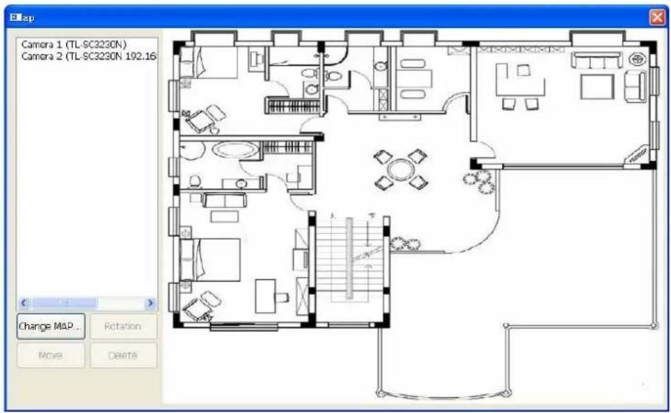
➢ Camera list: List all installed camera(s) in system by camera index and name.
Add camera to Map: Drag a camera name from camera list onto the Map. If the dragging camera has already existed in Map, the cursor will become to and will not allow you to add this camera.
Make camera as a focus camera: Double click on the camera icon which you want this camera be focused. When the camera is focused, the system will pop up a window to display live preview of this camera.
Move camera on Map: You can move the camera position by two ways as below.
- Select the camera icon which you want to move, and then drag it onto the position where you prefer.
- Double click on the camera, make it as a focus camera, and then click Move. Move the mouse cursor to the new position and click the left button of the mouse.
Rotate camera on Map: You can rotate camera direction by two ways as below.
- Right-click on the camera icon, then rotate the camera icon until you prefer.
- Make camera as a focus camera, then click Rotation until you prefer.
➢ Delete camera on Map: Make the camera as a focus camera, then click Delete.
Change Map: Click Change Map, and then select a new picture to replace the old one.
4.12 Two way Audio
Click Two way Audio button to switch Two-way Audio status.
When Two-way audio is on, system will transmit local microphone's voice to remote camera.

Start Two way Audio.

Stop Two way Audio.
Two-way Audio function depends on camera's capability. This button is only enabled when the focused camera is with two-way audio capability.
If the channel's two way audio was enabled by remote service, system will reject enable this channel's two way audio job until remote's two way audio job stop.
Chapter 5 Playback
Playback is to search, playback, backup, and converts file format on history recorded file(s).
The user could find out the critical image in minutes by playback tools, and back up these images to the user assigned storage by selected period and length.
Click the playback button to launch playback panel.

Click exit button to leave playback application.
5.1 Search history recorded file(s)
Click the search button on Playback page and the Search history file(s) dialog will display.

Select the time period and camera(s) within the search dialog.
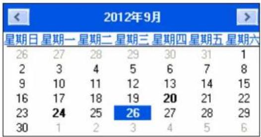
Select a day to search history file(s):
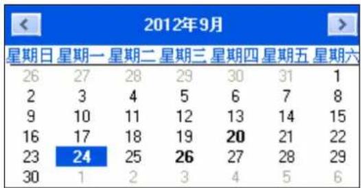
- Click , buttons to select the month which you want to search history file(s).
- Click on the date to choose a day to search.
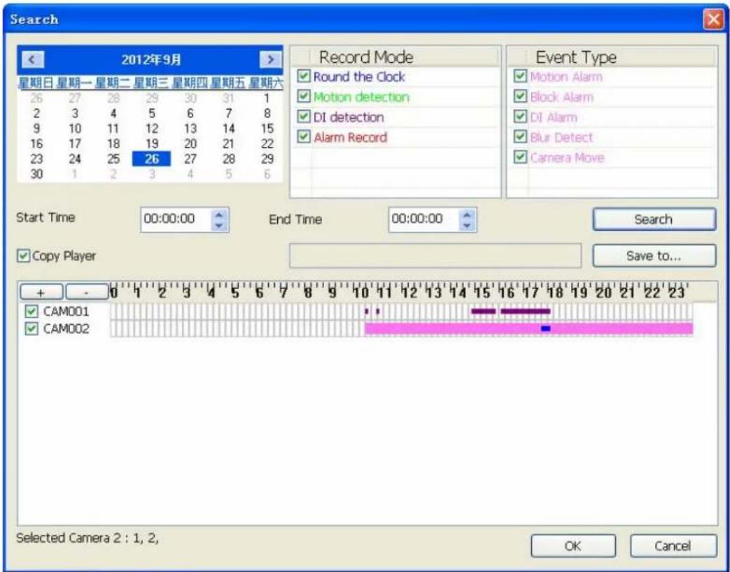
Select record mode(s) / Event Type:
- Check the modes which you want to search. System will search recorded files within these modes only.
- Check Event types which you want to display, system will display event triggered time on list.
You could define display color for each record modes and events by color select dialog. Click button to approach color select dialog.
➢ Start search: Click Search to start search procedure. Please wait a moment for the search result which will appear on the list control.
➢ Review history record file(s) in search period: The list control will display the result of search procedure.

● Blue section: Round the clock recorded file(s).
● Green section: Motion detection recorded file(s).
● Red section: Alarm recorded file(s).
➢ Assign time period of search result:
- You can drag mouse cursor on the list control to assign a time period to playback.
- Choose a time period by the start time and end time picker control manually.
The selected time period will display as blue section on the list control.
Select the camera(s) to playback: Select the camera(s) which you want to playback. The system can select maximum 16 camera(s) to playback at once.
Click OK to finish search procedure and start playback, or click Cancel to abort this job and return to Playback main page.
5.2 Playback control button(s)
These buttons are used to control playback start, pause, backward play and the other operations. The user can control playback functions by these buttons.
➢ Play button : Click play button to play the selected history file(s).
➢ Pause button : Click pause button to pause playback stream. Some operations must enter pause mode first.
➢ Backward play button: Click backward play button to playback stream direction to backward mode.
➢ Stop button : Click stop button to stop playback stream and return to the beginning position of stream.
➢ Next frame button: When playback is in the pause mode, click the next frame button to seek next frame.
Previous frame button: When playback is in the pause mode, click the previous frame button to seek previous frame.
Playback speed control : Turn the speed button to select playback speed.
1X: Normal speed.
2X: Double of normal speed
4X: 4X normal speed.
8X: 8X normal speed.
16X: 16X normal speed.
32X: 32X normal speed.
1/2X: Half of normal speed.
1/4X: Quarter of normal speed.
Division control buttons:

Divide to 1 screen.

Divide to 4 screen(s).
Divide to 6 screen(s).

Divide to 9 screen(s).

Divide to 16 Screen(s)
Full screen mode.
5.3 Convert to AVI file
Click Convert file button

proach Covert file dialog.
Select time slice and camera to convert to AVI file by the convert file dialog. The AVI file can play on most PC with current codec installed.
Select a day to covert history file(s):
- Click < , > buttons to select the month that you want to convert history file(s).
- Click on the date to choose a day to convert file(s).
Assign time slice to convert job: Choose a time slice by the Start time and End time picker control, or drag mouse cursor on record list to define convert period.
Select cameras to convert job: Check camera's IDs from list to convert job.
Select a folder to save converted file: Click the brows button to select a folder which will save the converted file.
Start converting job: Click OK to start convert job. When convert job is finished, the system will generate a file into assigned folder. Click Cancel to abort convert job.
The name rule of converted file is as below:
CHXXXYYYYMMDDHHmmssnnn.avi
XXX: camera ID.
YYYY: Execute convert year.
MM: Execute convert month.
DD: Execute convert day.
HH: Execute convert hour.
mm: Execute convert minute.
ss: Execute convert second.
nnn: Execute convert million-second.
For example:
CH00220090914140253150.avi
5.4 Switch audio play mode
Click audio mode button

to pop up the menu of audio mode.
Mute
√ Live Audio Playback Audio
Select the audio mode from the popup menu. The check item means the current mode of audio playback now.
Mute: No audio data will play.
Live Audio: Play the live audio stream.
▶ Playback Audio: Play the playback audio stream.
5.5 Playback setting
Click the Setting button

to pop up the menu of playback setting.
√ Show Date
√ Show Time
√ Camera Name
√ Subtitle
Select Playback Path
Check the item(s) to change OSD status on the image while the recorded file is playing back.
➢ Display Date: Display the date of recorded file on the image.
➢ Display Time: Display the time of recorded file on the image.
➢ Display camera name: Display the camera name on the image.
5.6 Snapshot dialog
Click the snapshot button

o approach snapshot dialog. This function is used to take a
snapshot of the playing history file.
The snapshot all dialog will display all snapshot images on the dialog. You can choose which image will be saved and assign the file format and folder.
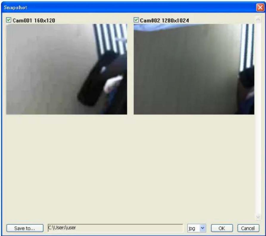
Select snapshot image: The dialog displays all snapshot images with the camera ID, resolution, and camera name. Check the check box if you want to save this image.
Select snapshot folder: Click the Save to button to select a folder to save snapshot images.
Select file format: Select the image file format in the combo box.
Save snapshot images: Click OK to save all selected images or click Cancel to abort this snapshot job.
▶ Saved image file name:
The name rule of saved file is as below:
CamXXX_NNNNNN_YYYYMMDDHHmmssnnn.jpg
XXX: camera ID.
NNNN: camera name.
YYYY: The image's year of date.
MM: The image's month of date.
DD: The image's day of date.
HH: The image's hour of time.
mm: The image's minute of time.
ss: The image's second of time.
nnn: The image's million-second of time.
For example:
Cam000_AM3220 192.168.0.143_20090908111559901.jpg
5.7 Backup history file(s)
Click the backup button to approach backup dialog to select backup file(s).
Select date and time of backup slice: The select procedure is the same as selecting date and time of playback slice.
Select backup camera(s) and backup time period: The select procedure is the same as selecting camera and time of playback slice.
Select output directory: Click the Save to button to select the output directory. Click OK to start backup job or click Cancel to abort this backup job.
Playback backup files: All related files and information are saved in backup folder. You can execute the Player.exe in backup directory. The operation procedure is the same as playback job.
Note:
The backup files must place in the same directory or the playback job will be failed.
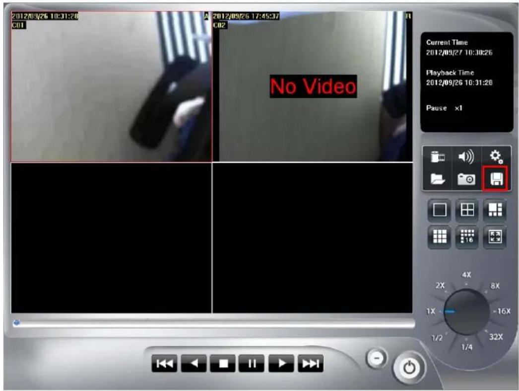
5.8 Playback status
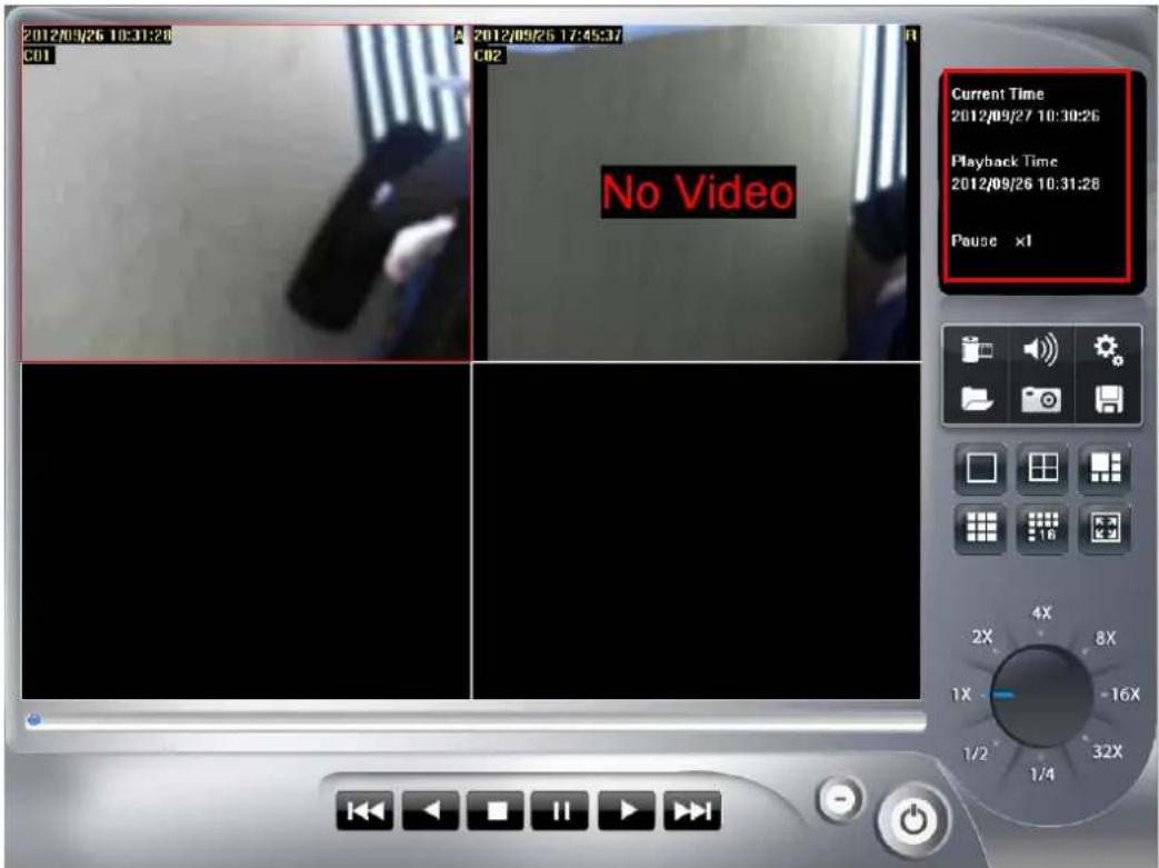
Current Time: The system current time.
▶ Playback Time: The playing video time.
▶ Playback status: Displays playback status and speed.
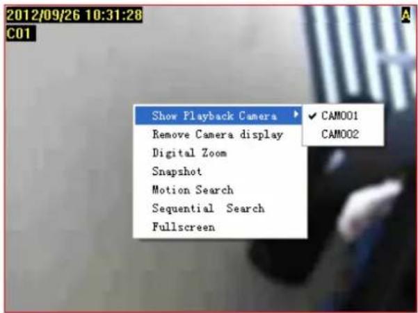
5.9 Operation with sub-screen
5.9.1 Define display camera(s) sequence
-
To switch display sequence in sub-screen(s), press and hold mouse left button on source sub-screen, and then drag to target sub-screen and release mouse left button.
-
To switch current sub-window to another camera, right-click on the sub-screen, and then choose the preferred playback camera.
5.9.2 Digital Zoom at sub-screen
- Right-click on sub-screen, and then check Digital Zoom.
- Move mouse cursor to the position where you want to do digital zoom.
- Move mouse wheel forward to zoom in the image.
- Move mouse wheel backward to zoom out the image.
- Press and click to drag the image at sub-screen to the position where you needed.
- To cancel digital zoom mode, click mouse right button and un-check the Digital Zoom.
5.9.3 Switch to Full screen
- Right-click and check Full screen on popup menu to switch Full screen mode.
- Click "Esc" button or un-check "Full screen" on popup menu to return normal display mode.
5.9.4 Snapshot of sub-screen
- Right-click and choose Snapshot on popup menu.
- Configure the image by Snapshot dialog.
- Click Save button and choose the folder which you want to save the snapshot.
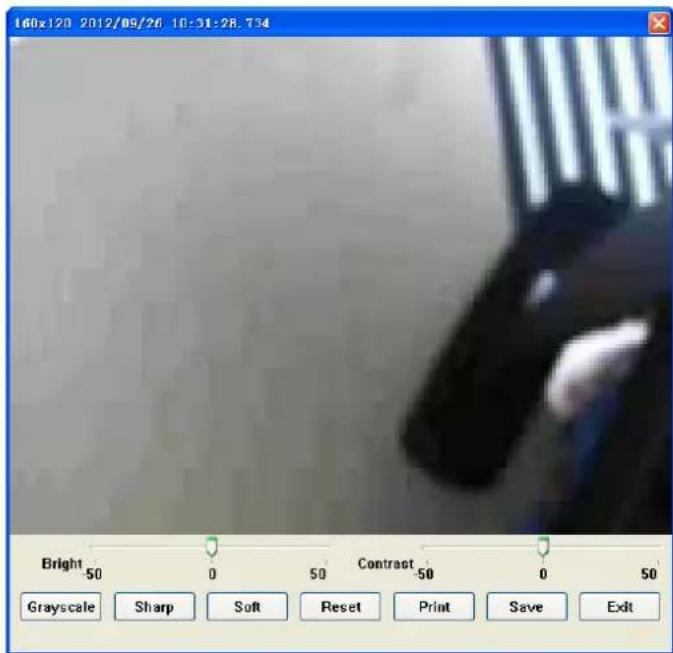
● Bright: 50 = Maximum brightness, -50 = Maximum dark
- Contrast: 50 = Maximum strong with Contrast, -50 = Minimum value of Contrast.
● Grayscale: Click to switch image to grayscale mode.
● Sharp: Click Sharp to increase image sharp level.
- Soft: Click Soft to increase image soft level.
- Reset: Click Reset to restore image to original image.
● Print: Click Print to print out image to printer.
- Save: Click Save and then choose folder and file name to save the snapshot.
- Exit: Close Snapshot dialog.
5.9.5 Motion Search
Right-click on the channel which you want to do motion search, and then select Motion Search from the popup menu.
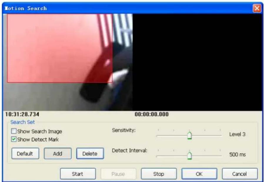
Add: Click Add and drag a rectangle area where you want to check. The search area will overlay a transparent red mask.
➢ Delete: Click Delete and drag a rectangle area where you want to remove the region.
Default: Click Default to select full image for motion detection.
Show Search Image: Check Show Search Image to display the searching video sequence or un-check this box to only show the image once the event found.
Show Detect Mark: Check Show Detect Mark to display the detect result on the image by pink rectangles.
➢ Sensitivity: Select Sensitivity to define the sensitivity of detection. The higher value means the event will be triggered easier.
➢ Detect Interval: Select Detect Interval to define the interval of motion detection. If set longer value, it means the system will use less CPU computing power to check motion detection.
Start / Continue: When the event has been triggered, the window on the right side will display the triggered image. If the event is not matched your expectation, click the "Continue" button to search next event.
OK: If you found the matched event, click OK to return to the playback panel, and all playing channels will be synchronized to the same timestamp of the event.
Cancel: Click Cancel to abort this motion search job.
5.9.6 Sequential Search
Click mouse right button on the channel which you want to do sequential search, and then select Sequential Search from the popup menu.
Sequential Search Window:
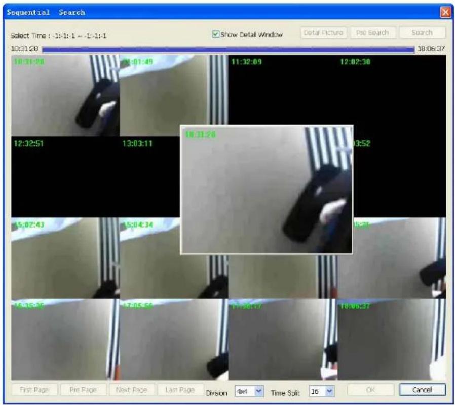
Quick start with sequential search:
- Choose sequential search channel and time period.
- Select two images from these sequential pictures by clicking on the images, and then click Search.
- Repeat this procedure until time period into one second resolution.
- Click Detail picture to approach snapshot images dialog.
- Select these snapshot images, and save them to assigned folder.
Define search time period: We need to define time period for the sequential search task. We could define time period by two ways and the selected time period will display on the upper left corner.
-
Select two images from these sequential pictures to define search time period. Click on the image to select it and click it again to un-select it.
-
Or drag on the time line to define search time period directly.

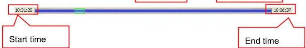
flowchart
graph LR
    A["Start time"] --> B["10:31:29"]
    B --> C["End time"]
    C --> D["18:06:37"]
● Blue bar: The time period of selected images for sequential search.
● Green transparent bar: New time period to be searched.
Start search and rollback: After defined search time period, and then click Search to display next search result. Click Pre search for rollback to previous search result.
Detail window for snapshots: The dialog will display small snapshot images by search result. In case you need bigger image of snapshots, you could enable "Show Detail Window" to get a resizable window for display the detail snapshot. You could move the detail window and resize it to get bigger preview image size.
Preview mode of search result: You could define the preview mode of search result by these parameters below.

- Time Split: Define the number to divide the search time period equally, and take a snapshot at beginning of each part.
● Division: Select the display division mode of search result. - Switch page buttons: In case the search result couldn't display within one page, then these buttons will be enabled. Click these buttons to switch the pages of snapshot.