ADM-30.1 - Receiver Integra - Free user manual and instructions
Find the device manual for free ADM-30.1 Integra in PDF.


User questions about ADM-30.1 Integra
0 question about this device. Answer the ones you know or ask your own.
Ask a new question about this device
Download the instructions for your Receiver in PDF format for free! Find your manual ADM-30.1 - Integra and take your electronic device back in hand. On this page are published all the documents necessary for the use of your device. ADM-30.1 by Integra.
USER MANUAL ADM-30.1 Integra
TO REDUCE THE RISK OF FIRE OR ELECTRIC SHOCK, DO NOT EXPOSE THIS APPARATUS TO RAIN OR MOISTURE.
CAUTION:
TO REDUCE THE RISK OF ELECTRIC SHOCK, DO NOT REMOVE COVER (OR BACK). NO USER-SERVICEABLE PARTS INSIDE. REFER SERVICING TO QUALIFIED SERVICE PERSONNEL.

WARNING
RISK OF ELECTRIC SHOCK DO NOT OPEN


The lightning flash with arrowhead symbol, within an equilateral triangle, is intended to alert the user to the presence of uninsulated “dangerous voltage” within the product’s enclosure that may be of sufficient magnitude to constitute a risk of electric shock to persons.

The exclamation point within an equilateral triangle is intended to alert the user to the presence of important operating and maintenance (servicing) instructions in the literature accompanying the appliance.
Important Safety Instructions
- Read these instructions.
- Keep these instructions.
- Heed all warnings.
- Follow all instructions.
- Do not use this apparatus near water.
- Clean only with dry cloth.
- Do not block any ventilation openings. Install in accordance with the manufacturer's instructions.
- Do not install near any heat sources such as radiators, heat registers, stoves, or other apparatus (including amplifiers) that produce heat.
- Do not defeat the safety purpose of the polarized or grounding-type plug. A polarized plug has two blades with one wider than the other. A grounding type plug has two blades and a third grounding prong. The wide blade or the third prong are provided for your safety. If the provided plug does not fit into your outlet, consult an electrician for replacement of the obsolete outlet.
- Protect the power cord from being walked on or pinched particularly at plugs, convenience receptacles, and the point where they exit from the apparatus.
-
Only use attachments/accessories specified by the manufacturer.
-
Use only with the cart, stand, tripod, bracket, or table specified by the manufacturer, or sold with the apparatus. When a cart is used, use caution when moving the cart/ apparatus combination to avoid injury from tip-over.
PORTABLE CART WARNING

natural_image
Symbolic icon of a person pushing a large object through a circular background, with no readable text or symbols.-
Unplug this apparatus during lightning storms or when unused for long periods of time.
-
Refer all servicing to qualified service personnel. Servicing is required when the apparatus has been damaged in any way, such as power-supply cord or plug is damaged, liquid has been spilled or objects have fallen into the apparatus, the apparatus has been exposed to rain or moisture, does not operate normally, or has been dropped.
-
Damage Requiring Service
Unplug the apparatus from the wall outlet and refer servicing to qualified service personnel under the following conditions:
A. When the power-supply cord or plug is damaged,
B. If liquid has been spilled, or objects have fallen into the apparatus,
C. If the apparatus has been exposed to rain or water,
D. If the apparatus does not operate normally by following the operating instructions. Adjust only those controls that are covered by the operating instructions as an improper adjustment of other controls may result in damage and will often require extensive work by a qualified technician to restore the apparatus to its normal operation,
E. If the apparatus has been dropped or damaged in any way, and
F. When the apparatus exhibits a distinct change in performance this indicates a need for service.
- Object and Liquid Entry
Never push objects of any kind into the apparatus through openings as they may touch dangerous voltage points or short-out parts that could result in a fire or electric shock.
The apparatus shall not be exposed to dripping or splashing and no objects filled with liquids, such as vases shall be placed on the apparatus.
Don't put candles or other burning objects on top of this unit.
- Batteries
Always consider the environmental issues and follow local regulations when disposing of batteries.
- If you install the apparatus in a built-in installation, such as a bookcase or rack, ensure that there is adequate ventilation.
Leave 20 cm (8") of free space at the top and sides and 10 cm (4") at the rear. The rear edge of the shelf or board above the apparatus shall be set 10 cm (4") away from the rear panel or wall, creating a flue-like gap for warm air to escape.
- Recording Copyright—Unless it's for personal use only, recording copyrighted material is illegal without the permission of the copyright holder.
- AC Fuse—The AC fuse inside the unit is not user serviceable. If you cannot turn on the unit, contact the dealer from whom you purchased this unit.
- Care—Occasionally you should dust the unit all over with a soft cloth. For stubborn stains, use a soft cloth dampened with a weak solution of mild detergent and water. Dry the unit immediately afterwards with a clean cloth. Don't use abrasive cloths, thinners, alcohol, or other chemical solvents, because they may damage the finish or remove the panel lettering.
4. Power
WARNING
BEFORE PLUGGING IN THE UNIT FOR THE FIRST TIME, READ THE FOLLOWING SECTION CAREFULLY.
AC outlet voltages vary from country to country. Make sure that the voltage in your area meets the voltage requirements printed on the unit's rear panel (e.g., AC 120 V, 60 Hz or AC 220-240 V, 50/60 Hz).
The power cord plug is used to disconnect this unit from the AC power source. Make sure that the plug is readily operable (easily accessible) at all times. Pressing the [POWER] button to select OFF mode does not fully shutdown the unit. If you do not intend to use the unit for an extended period, remove the power cord from the AC outlet.
- Never Touch this Unit with Wet Hands—Never handle this unit or its power cord while your hands are wet or damp. If water or any other liquid gets inside this unit, have it checked by the dealer from whom you purchased this unit.
6. Handling Notes
- If you need to transport this unit, use the original packaging to pack it how it was when you originally bought it.
- Do not leave rubber or plastic items on this unit for a long time, because they may leave marks on the case.
- This unit's top and rear panels may get warm after prolonged use. This is normal.
- If you do not use this unit for a long time, it may not work properly the next time you turn it on, so be sure to use it occasionally.
For British models
Replacement and mounting of an AC plug on the power supply cord of this unit should be performed only by qualified service personnel.
IMPORTANT
The wires in the mains lead are coloured in accordance with the following code:
Blue:Neutral
Brown:Live
As the colours of the wires in the mains lead of this apparatus may not correspond with the coloured markings identifying the terminals in your plug, proceed as follows: The wire which is coloured blue must be connected to the terminal which is marked with the letter N or coloured black.
The wire which is coloured brown must be connected to the terminal which is marked with the letter L or coloured red.
IMPORTANT
The plug is fitted with an appropriate fuse. If the fuse needs to be replaced, the replacement fuse must approved by ASTA or BSI to BS1362 and have the same ampere rating as that indicated on the plug. Check for the ASTA mark or the BSI mark on the body of the fuse.
If the power cord's plug is not suitable for your socket outlets, cut it off and fit a suitable plug. Fit a suitable fuse in the plug.
For European Models
Declaration of Conformity
We, ONKYO EUROPE
ELECTRONICS GmbH LIEGNITZERSTRASSE 6, 82194 GROEBENZELL, GERMANY

declare in own responsibility, that the ONKYO product described in this instruction manual is in compliance with the corresponding technical standards such as EN60065, EN55013, EN55020 and EN61000-3-2, -3-3.
GROEBENZELL, GERMANY
ONKYO EUROPE ELECTRONICS GmbH
Thank you for purchasing the Integra 2 Channel Amplifier.
Please read this manual thoroughly before making connections and plugging in the unit.
Following the instructions in this manual will enable you to obtain optimum performance and listening enjoyment from your new 2 Channel Amplifier.
Please retain this manual for future reference.
Contents
Before using
Important Safety Instructions ...... 2
Precautions 3
Features 4
Supplied accessory 4
Facilities and connections
Front panel facilities and connections.... 5
Rear panel facilities and connections.... 6
AUTO ON Function 8
Connection diagram 9
Operations 10
Appendix
Troubleshooting guide.... 10
Specifications 11
Features
- Exclusive Onkyo VL Technology
- Separate Transformers for L/R Channels
- New Custom-Designed, Audio-Tuned Reference Capacitors
- Perfect for Second Zone and Distributed Audio Applications
- Low-Impedance Copper Bus Plates for Perfect Ground Potential
- Hi-Rigidity, Anti-Resonant Flat Chassis (1.6 mm Thick)
- 19mm-Pitch Audio Terminals for High-Grade Cable
- North American model: 40 W 8 ohm 2 ch Driven 1 kHz 0.8 %THD (FTC) 100 W 2 ohm 2 ch Driven 1 kHz 0.8 %THD (FTC) Other models: 40 W 8 ohm 2 ch Driven 1 kHz 0.8 %THD (IEC) 80 W 4 ohm 2 ch Driven 1 kHz 0.8 %THD (IEC)
- Input Level Adjustment
- Audio Sensing Level Control (-6 dB-0 dB) and On / Off Switch
- 1 Audio Input and 1 Output
- 12V Trigger In / Out and 12V Remote On / Off Switch
- Auto on Function (On/Off Control for Audio Sense and 12V Trigger)
- Gold-Plated, Banana Plug-Compatible Transparent Speaker Posts
- Heavy-Duty Inlet Power Cord
- Aluminum Front Panel
Supplied accessory
Check that the following accessory is supplied with the ADM-30.1.

natural_image
Coiled electrical cable with two terminal connectors (no text or symbols)Power cord
North American model :1.8m (5.9ft) ...... [1]
Australian/European models :1.8m (5.9ft) ..... [1]
2m (6.5ft) ..... [1]
(Use a power cord designed for use in your region.)
In catalogs and on packaging, the letter at the end of the product name indicates the color.
Specifications and operations are the same regardless of color.
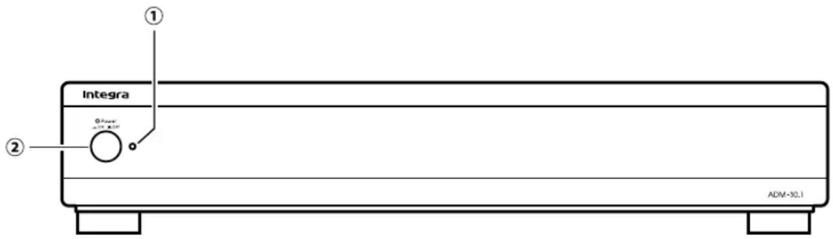
Front panel facilities and connections
text_image
Integra ① ② #Power +/- 25% 100% ADM-30.1① Power indicator
The Power indicator lights green when the ADM-30.1 is turned on and the amplifier circuit is activated, and lights red when the ADM-30.1 is in the Ready state. The indicator goes off when the ADM-30.1 is turned off.
② Power switch
This switch is used to turn the main power on/off. The power state depends on the settings of the AUDIO SENSE and 12V TRIGGER switches on the rear panel. (See p.8)
| POWER indicator | POWER switch | Amplifier circuit | Audio output | Status | |
| OUTPUT jacks | SPEAKERS | ||||
| Off No circuits are active. | |||||
| Red | √ | √ | The buffer amplifier between the INPUT and OUTPUT jacks is functioning, which allows the signal input at the INPUT jacks to be directly output from the OUTPUT jacks.The AUDIO SENSE circuit is active. | ||
| Green | √√√√ | All circuits are active. | |||

Notes
- When the Power switch is set to Off, you cannot control the on/off of the amplifier circuit from the connected devices. If you want the amplifier circuit to be turned on/off by turning on/off the connected devices, press the Power switch to the On position to put the ADM-30.1 in the Ready state.
- When the AUDIO SENSE switch is ON and the 12V TRIGGER switch is OFF, pressing the Power switch to the On position turns on the ADM-30.1 and the Power indicator lights green. If no audio signal is received for about 10 minutes, the ADM-30.1 enters the Ready state and the Power indicator lights red.
Rear panel facilities and connections
Caution:
- Be sure to always refer to the instructions that came with the component that you are connecting.
- Do not plug in the power cord until all connections have been made.
- Do not make connections to input or output jacks while the ADM-30.1 is turned on.
- Always turn the volume of the control amplifier or preamplifier down before turning on the ADM-30.1.
- For input and output jacks, red connectors (marked R) are used for the right channel and white connectors (marked L) are used for the left channel.

text_image
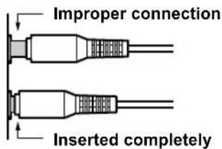
Left(white) Right(red)- Insert all plugs and connectors securely. Improper connections can result in noise, poor performance, or damage to the equipment.
text_image
Improper connection Inserted completely- Do not bind audio connection cables with power cords and speaker cables. Doing so may adversely affect the sound quality.
text_image
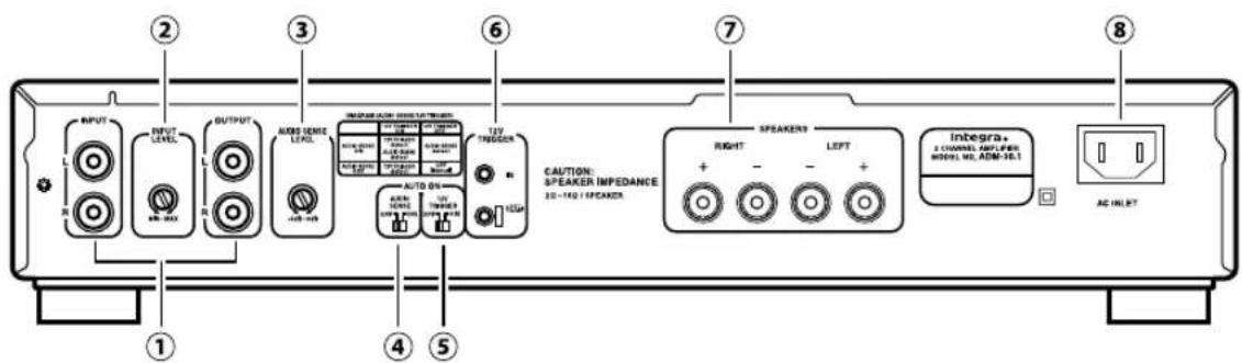
INPUT OUTPUT MODE SENSIE LEAF AUTO ON SPEAKER IMPEDANCE 20-140 / SPEAKER CAUTION: SPEAKER IMPEDANCE SPEAKERS RIGHT LEFT Integra. 2 CHANNEL AMPLIFIER MODEL NO. ADM-38.1 AC INLET① INPUT/OUTPUT
These are the analog audio inputs and outputs. Use an RCA-type audio connection cable to connect the output jacks of the device to the INPUT jacks on the ADM-30.1. When connecting a control amplifier or preamplifier, connect the PRE OUT jacks to the INPUT jacks.
If you connect the OUTPUT jacks of the ADM-30.1 to the INPUT jacks of another ADM-30.1, the signal input at the INPUT jacks of the ADM-30.1 is also output from the OUTPUT jacks (Input/Output Link Function).
If you set the AUDIO SENSE switch to ON, the amplifier circuit of the connected ADM-30.1 turns on automatically when an audio signal is supplied to the INPUT jacks (Amplifier Circuit Auto On/Off Function).
② INPUT LEVEL
Turn this INPUT LEVEL control to adjust the input level of the signal from the INPUT jacks. Normally, set to MAX.

Notes
When a CD player is connected to the ADM-30.1, be sure to adjust the INPUT LEVEL control.
③ AUDIO SENSE LEVEL
If you activate/deactivate the amplifier circuit by turning on/off the device connected to the INPUT jacks, use this AUDIO SENSE LEVEL to set the sensitivity of the input signal (-6dB to 0dB). The level is factory set to 0dB.
④ AUDIO SENSE
With this switch set to ON, the amplifier circuit will be activated/deactivated when the device connected to the INPUT jacks is turned on/off.
The sensitivity of the input signal from the device can be set with the AUDIO SENSE LEVEL.
Notes
The Power switch of the ADM-30.1 needs to be set to On in advance. If no audio signal is received for about 10 minutes, the ADM-30.1 enters the Ready state and the Power indicator lights red.
⑤ 12V TRIGGER
With this switch set to ON, the amplifier circuit will be activated/deactivated when the device connected to the 12V TRIGGER IN jack is turned on/off.
Notes
The Power switch of the ADM-30.1 needs to be set to On in advance.
⑥ 12V TRIGGER IN/OUT
Connect the 12V TRIGGER IN jack to an AV Receiver that has a 12V TRIGGER output jack. This jack works on between 5 to 12 volts DC. With the Power switch of the ADM-30.1 set to On, you can control the amplifier circuit using the controls of the AV Receiver.
If you want another component to be activated/deactivated by turning on/off the AV receiver connected to the 12V TRIGGER IN jack of the ADM-30.1, connect the 12V TRIGGER input jack of that component to the 12V TRIGGER OUT jack of the ADM-30.1. In this state, the 12V TRIGGER is output when the ADM-30.1 is turned on. Devices can be connected in series using these jacks.
Use 1/8-inch (3.5mm) monaural-type mini-jack connectors or the supplied stereo mini-plug cable. The tip polarity of the connector is positive.
⑦ SPEAKERS
Connect the jacks on the speakers to the SPEAKERS terminals using the speaker cables. These terminals are compatible with banana plug connections.
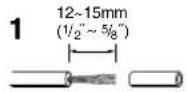
1 Strip away 12 \~ 15 mm (1/2" \~ 5/8") of wire insulation.
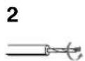
2 Twist wire ends very tight.
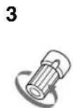
3 Unscrew.
4 Insert wire.
5 Screw.
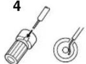
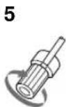
- Do not connect any devices other than speakers to these terminals.
- Be sure not to mistake the positive and negative outputs or the left and right speakers. Doing so will result in an unnatural sound space.
- North American model: Make sure to use speakers with an impedance of 2 to 16 Ohms.
If a speaker with an impedance of less than 2 ohms is connected, it may damage the ADM-30.1.
Other models:
Make sure to use speakers with an impedance of 4 to 16 Ohms.
If a speaker with an impedance of less than 4
ohms is connected, it may damage the ADM-30.1.
- When you are using only one speaker or when you wish to listen to monaural (mono) sound, a single speaker should never be connected in parallel to both the right and left channel terminals simultaneously.
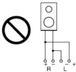
text_image
No R - L +- To prevent damage to circuitry, never short-circuit the positive (+) and negative (−) speaker wire.
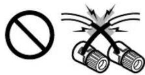
text_image
Safety warning symbol and hazard illustration showing no prohibition and flashlight hazard⑧ AC INLET
Plug the supplied power cord into this AC INLET and then into the power outlet on the wall.
- Do not use a power cord other than the one supplied with the ADM-30.1. The power cord supplied is designed for use with the ADM-30.1 and should not be used with any other device.
- Never disconnect the power cord from the ADM-30.1 while the other end is plugged into the wall outlet. Doing so may cause an electric shock. Always connect by plugging into the wall outlet last and disconnect by unplugging from the wall outlet first.
Set the AUDIO SENSE and 12V TRIGGER switches in accordance with the intended use.
| For Manual operation/When not using AUTO ON Function | Set both the AUDIO SENSE and 12V TRIGGER switches to OFF. The ADM-30.1 can be turned ON/OFF using the POWER switch on the front panel. | 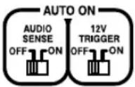 |
| When using only the AUDIO SENSE | Set the AUDIO SENSE switch to ON and the 12V TRIGGER switch to OFF. Pressing the POWER switch powers the ADM-30.1 up. However, if there is no signal for 10 minutes, the circuit turns off to put the ADM-30.1 in the Ready state.Then the circuit automatically turns on when an incoming Audio signal is received. The ADM-30.1 switches between the On and Ready states depending on the signal. | 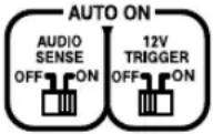 |
| When using only the 12V TRIGGER | Set the AUDIO SENSE switch to OFF and the 12V TRIGGER switch to ON.When you press the POWER switch, the ADM-30.1 goes into the Ready state waiting for a 12V TRIGGER signal.Then the circuit automatically turns on when the 12V TRIGGER signal is detected. The ADM-30.1 switches between the On and Ready states depending on the signal. | 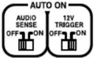 |
| When using both the AUDIO SENSE and 12V TRIGGER | Set the AUDIO SENSE switch to ON and the 12V TRIGGER switch to ON.When you press the POWER switch, the ADM-30.1 goes into the Ready state waiting for a 12V TRIGGER signal.Then the circuit automatically turns on when the 12V TRIGGER signal is detected.In this setting, even if the Audio signal has been input, the ADM-30.1 goes into the Ready state unless the 12V TRIGGER signal is input.On the contrary, even if the 12V TRIGGER signal has been input, the ADM-30.1 goes into the Ready state if there is no Audio signal for 10 minutes.For the ADM-30.1 to go from the Ready state to the On state, both the 12V TRIGGER and Audio signals need to be input. | 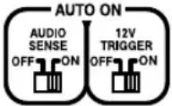 |
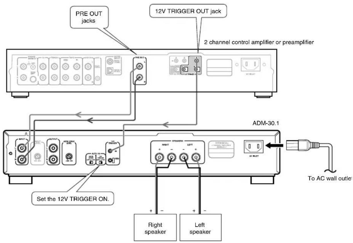
Here is an explanation of how to connect the ADM-30.1 to 2 channel control amplifier or preamplifier.
When connecting the ADM-30.1 to 2 channel control amplifier or preamplifier, connect the INPUT jacks of the ADM-30.1 to the PRE OUT jacks of the control amplifier or preamplifier, and connect the front speakers to the SPEAKERS terminals of the ADM-30.1.
text_image
PRE OUT jacks 12V TRIGGER OUT jack 2 channel control amplifier or preamplifier ADM-30.1 Set the 12V TRIGGER ON. Right speaker Left speaker To AC wall outletOperations
To listen to music or view your favorite movies, follow the operations below.
The procedures given below assume that the other system components are already connected. (For example, that the source components are already connected to the control amplifier or the preamplifier.)
1 Lower the volume at the control amplifier or preamplifier.
Lower the volume of the control amplifier or preamplifier to the minimum so that when the ADM-30.1 is turned on, you do not hear loud unwanted sounds.
2 Turn on the ADM-30.1 and select the input on the control amplifier or preamplifier.
Select the proper input on the control amplifier or preamplifier.
3 Slowly increase the volume of the control amplifier or preamplifier.
Now all that remains is to control the control amplifier or preamplifier and the other connected system components to enjoy your music or movies.
Troubleshooting guide
The Power indicator stays lit red (does not light green).
- The setting of the 12V TRIGGER switch or AUDIO SENSE switch is wrong.
→ Set the 12V TRIGGER switch or AUDIO SENSE switch to the appropriate position.
- With the 12V TRIGGER switch or AUDIO SENSE switch set to a position other than OFF, the Power switch is pressed again immediately after turning the power off.
→ Be sure to leave more than 5 seconds before turning the power on again.
- No device is connected to the 12V TRIGGER jack but the 12V TRIGGER switch is set to ON.
→ Set the 12V TRIGGER switch to OFF.
The Standby/On indicator does not light when the Power switch is pressed.
- Bad connections or wiring.
→ Check if the power cord is properly connected. If the indicator still does not light, turn off the ADM-30.1, disconnect the power cord, and contact the dealer from whom you purchased this unit.
The Standby/On indicator flashes red for more than 7 seconds when the Power switch is pressed.
- The protection circuitry has been activated.
→ The protection circuitry may have been activated. Disconnect the power cord from the electrical outlet and contact the dealer from whom you purchased this unit.
The Power indicator lights green, but no sound comes from the speaker or the volume is very low.
- Bad connections or wiring.
→ Check connections, speaker cables, etc.
- The INPUT LEVEL control is set to MIN.
→ Turn the INPUT LEVEL control to adjust the input level.
- The settings on the control amplifier or preamplifier are wrong.
→ Check the settings on the control amplifier or pre-amplifier.
The left and right sounds are unbalanced or reversed.
- Bad connections or wiring.
→ Check connections, RCA-type audio connection cable, etc.
- The polarity of the speaker cable is wrong.
→ Check the polarity of the speaker cable.
AMPLIFIER SECTION
| Rated output Power : North America | |
| 40 W 8 ohm 2 ch Driven 1 kHz 0.8 %THD (FTC) | |
| 100 W 2 ohm 2 ch Driven 1 kHz 0.8 %THD (FTC) | |
| Others | |
| 40 W 8 ohm 2 ch Driven 1 kHz 0.8 %THD (IEC) | |
| 80 W 4 ohm 2 ch Driven 1 kHz 0.8 %THD (IEC) | |
| Dynamic Power : 115 W at 3 Ω | |
| 90 W at 4 Ω | |
| 45 W at 8 Ω | |
| Total Harmonic Distortion : 0.08% | |
| (1 kHz, 8 Ω, 1 W Output) | |
Damping Factor : 60 (1 kHz, 8 Ω)
Input Sensitivity and Impedance : LINE 200 mV/20 kΩ
Output Level and Impedance : 200 mV/220 Ω
Frequency Response : 5 Hz - 60 kHz (+1, -3 dB, LINE)
Signal-to-Noise Ratio : 100 dB (LINE, IHF-A),
Speaker Impedance : North America
2 16
Others
4 16
GENERAL
| Power Supply : North America | |
| AC 120 V, 60 HzOthers | |
| AC 220-240 V, 50/60 Hz | |
| Power Consumption : North America | |
| 110 WOthers | |
| 70 W | |
Dimensions (W x H x D) : 435 x 80 x 324 mm
17-1/8"×3-1/8"×12-3/4"
Weight : 9.6 kg (21.2 lbs)
Specifications and features are subject to change without notice.
Integra Division of
18 park Way, Upper Saddle River, N.J. 07458, U.S.A.
Tel: 201-818-9200 Fax: 201-785-2650 http://www.integrahometheater.com
Integra Division of
ONKYO CORPORATION
Sales & Product Planning Div.: 2-1, Nisshin-cho, Neyagawa-shi, OSAKA 572-8540, JAPAN
Tel: 072-831-8023 Fax: 072-831-8163
SN 29400051
(C) Copyright 2009 ONKYO CORPORATION Japan. All rights reserved.

W0907-1
* 2 9 4 0 0 0 5 1 *