
TL-NC450 - Security Camera TP-LINK - Free user manual and instructions
Find the device manual for free TL-NC450 TP-LINK in PDF.

| Product Type | Indoor HD Pan/Tilt Wi-Fi Security Camera |
| Dimensions | Approx. 100 x 100 x 120 mm (3.9 x 3.9 x 4.7 in) |
| Weight | Approx. 250 g (8.8 oz) |
| Power Supply | DC 5V/1.5A (provided adapter) |
| Resolution | HD 1280x720 at 15 fps |
| Lens | Focal length: 3.6 mm, Aperture: F2.0 |
| Pan/Tilt Range | Pan: 350°, Tilt: 120° |
| Night Vision | Up to 10 m (33 ft) with IR LEDs |
| Audio | Built-in microphone and speaker for 2-way audio |
| Storage | Micro SD card slot (up to 128 GB, not included) |
| Connectivity | Wi-Fi 802.11b/g/n (2.4 GHz) and 10/100 Ethernet port |
| Wireless Security | WEP/WPA/WPA2-PSK |
| Supported Protocols | TCP/IP, DHCP, HTTP, NTP, Bonjour |
| Detection Features | Motion detection, sound detection |
| Notifications | Email and app push notifications with snapshots |
| Cloud Service | TP-Link Cloud for remote viewing via app or web |
| Operating Temperature | 0°C to 40°C (32°F to 104°F) indoor use only |
| Mounting | Tabletop, wall, or ceiling mount (hardware included) |
| LED Indicators | System LED (red/green) and WPS LED (green) |
| Button | WPS/Reset button (press 2s for WPS, 5s for reset) |
Frequently Asked Questions - TL-NC450 TP-LINK
User questions about TL-NC450 TP-LINK
0 question about this device. Answer the ones you know or ask your own.
Ask a new question about this device
Download the instructions for your Security Camera in PDF format for free! Find your manual TL-NC450 - TP-LINK and take your electronic device back in hand. On this page are published all the documents necessary for the use of your device. TL-NC450 by TP-LINK.
USER MANUAL TL-NC450 TP-LINK
Chapter 1 About This Guide.... 1
1.1 Conventions ...... 1
1.2 Overview of This Guide.... 1
1.3 More Info 2
Chapter 2 Get to Know Your Camera.... 3
2.1 Product Overview....3
2.2 Panel Appearance....3
2.2.1 Front Panel....3
2.2.2 Rear Panel 4
Chapter 3 Set Up Your Camera 6
3.1 Set up the Camera with the tpCamera app 6
3.2 Position Your Camera 8
Chapter 4 Configure Your Camera....11
4.1 Log in to Your Camera 11
4.2 Live View 13
4.3 Basic....15
4.3.1 Basic > Status 15
4.3.2 Basic > Network 16
4.3.3 Basic > Wireless Connection 17
4.3.4 Basic > Cloud Setting....20
4.3.5 Basic > LED 21
4.4 Advanced 22
4.4.1 Advanced > Status 22
4.4.2 Advanced > Network 22
4.4.3 Advanced > Wireless Connection 26
4.4.4 Advanced > Cloud Setting 27
4.4.5 Advanced > Video 27
4.4.6 Advanced > Sound Detection 29
4.4.7 Advanced > Motion Detection 30
4.4.8 Advanced > SD Card 31
4.4.9 Advanced > Notification Delivery 33
4.4.10 Advanced >LED 36
4.5 System 37
4.5.1 Account....37
4.5.2 Date/Time 39
4.5.3 Management 41
4.5.4 System Log 43
Chapter 1 About This Guide
This guide is a complement to Quick Installation Guide. The Quick Installation Guide instructs you on quick setup, and this guide provides details of each function and shows you the way to configure these functions appropriate to your needs.
When using this guide, please notice that features of the TP-Link Camera may vary slightly depending on the model and software version you have, and on your location, and language. All images, parameters and descriptions documented in this guide are used for demonstration only.
1.1 Conventions
In this Guide, the following conventions are used:
| Convention Description | |
| Teal Underlined | Hyperlinks are teal underlined. You can click to redirect to a website or a specific section. |
| Teal | Contents to be emphasized and texts on the web page are in teal, including the menus, items, buttons, etc. |
| Note | Ignoring this type of note might result in a malfunction or damage to the device. |
1.2 Overview of This Guide
| Chapter | Introduction |
| Chapter 1 About This Guide | Introduces the guide structure and conventions. |
| Chapter 2 Get to Know Your Camera | Introduces the features, application and appearance of the camera. |
| Chapter 3 Set Up Your Camera | Introduces how to quickly set up the camera using the tpCamera app and how to position your camera. |
| Chapter 4 Configure Your Camera | Introduces how to configure the camera using the built-in web management page. |
1.3 More Info
Specifications can be found on the product page at http://www.tp-link.com.
Our Technical Support contact information can be found at the Contact Technical Support page at http://www.tp-link.com/support.
The latest software, management app and utility can be found at Download Center at http://www.tp-link.com/support.
A Technical Support Forum is provided for you to discuss our products at http://forum.tp-link.com.
Chapter 2 Get to Know Your Camera
2.1 Product Overview
TP-Link NC450 HD Pan/Tilt Wi-Fi Camera is a cloud-based Wi-Fi video monitoring device with live streaming and remote viewing, which makes it easy to stay connected with what you care most.
• Easy to install with tpCamera app
• Remote monitoring via TP-Link Cloud website or tpCamera app
• Support 24-hour recording and motion tracking
• Get notifications when motion or sound is detected, and view alerts history
• View clearer images with HD resolution
• View clearly in the dark with night vision
• Stay in touch with 2-way audio
• Save the images and videos in the Micro SD card
• Patrol a large area with pan and tilt
2.2 Panel Appearance
2.2.1 Front Panel
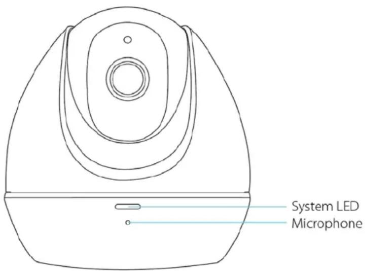
Front Panel
System LED:
| Status | Indication |
| Flashing Red | The camera is starting up. |
| Solid Red | The camera has started up, but not connected to any network. |
| Flashing Green | The camera is in firmware upgrade procedure. |
| The camera is connecting to a network. | |
| Solid Green | The camera is connected to a network. |
| The camera is transferring data. |
Microphone: The camera has a built-in internal microphone. This microphone is hidden in the pinhole located on the front panel.
2.2.2 Rear Panel
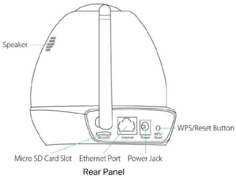
Speaker: For audio output.
Micro SD Card Slot: For holding the micro SD card.
Internet Port: For connecting the camera to your router via an Ethernet cable.
Power Jack: For connecting the camera to a power socket via the provided power adapter.
WPS/Reset Button: The switch for the WPS and Reset function. To use the WPS function, press it for about 2 seconds. To use the Reset function, press and hold for more than 5 seconds.
• Used as the WPS button:
If your wireless router supports WPS (Wi-Fi Protected Setup), you can connect the camera to your Wi-Fi network using WPS. Press the WPS or QSS button on your router. Within 2 minutes, press the WPS/Reset button on the camera for about 2 seconds, then the LED above this button will start flashing quickly. When this LED becomes solid on, the WPS is successful.
• Used as the Reset button:
With the camera powered on, press and hold the WPS/Reset button (for more than 5 seconds) until the System LED turns off. Then release the button and wait the camera to reset to its factory default settings.
WPS LED:
| Status | Indication |
| Flashing Green | The camera starts booting up. |
| The camera is connecting to a network by WPS function. | |
| Off | The camera has boot up. |
| The camera failed to be added to a network by WPS function. | |
| Solid Green | The camera has been successfully added to a network by WPS function. This process will last in the first two minutes. |
Chapter 3 Set Up Your Camera
3.1 Set up the Camera with the tpCamera app
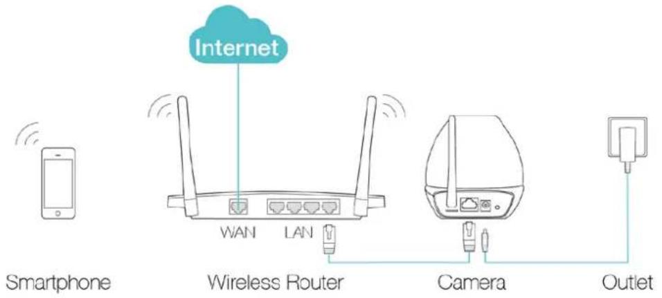
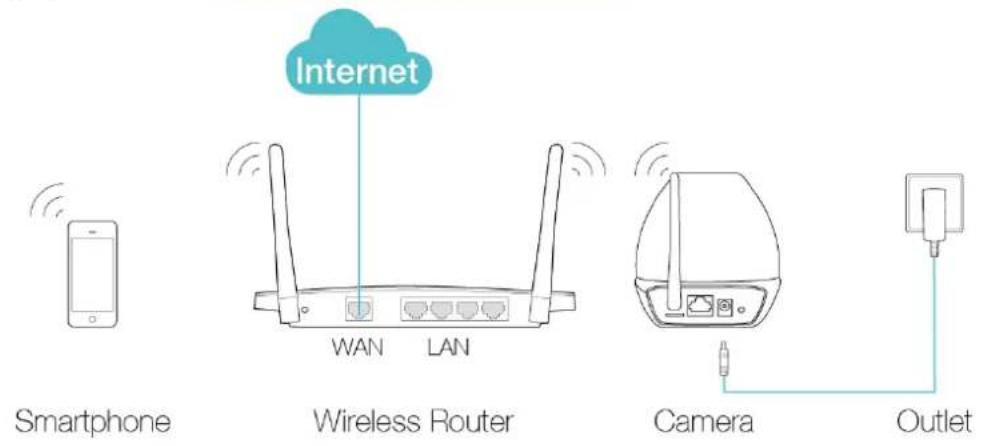
Step 1. Connect the camera to the network your smartphone is on.
1) Power on the camera using the provided power adapter as shown.
2) Connect a smartphone to the router as shown.
3) Connect the camera to the router via wired or wireless connection, and then wait till the camera's system LED become solid green.
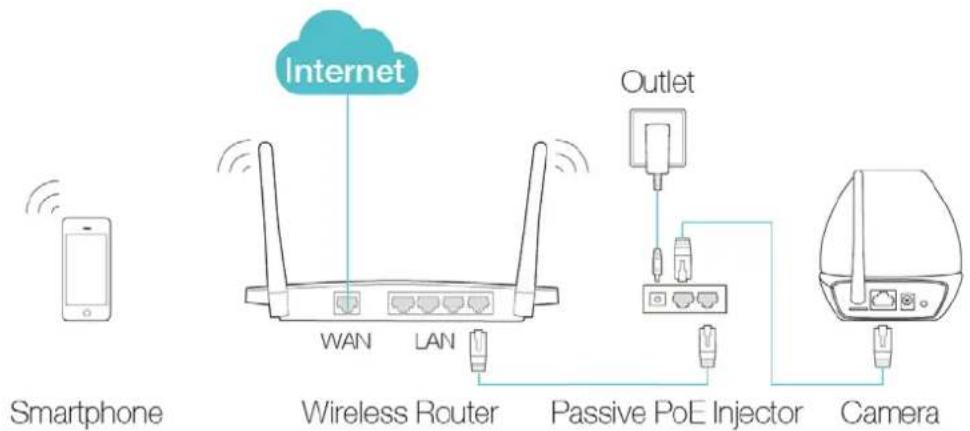
Wired: Connect the camera to the router's LAN port via an Ethernet cable or the provided passive PoE injector.
Via an Ethernet cable
Via the provided passive PoE injector
flowchart
graph LR
    A["Smartphone"] -->|Wireless Router| B["Internet"]
    B -->|WAN LAN| C["Passive PoE Injector"]
    C --> D["Camera"]
    B --> E["Outlet"]
    E --> F["Mobile Device"]
Wireless:
Via web management page
You can set the wireless connection using the basic settings on the web management page. (Refer to 4.3.3 Basic > Wireless Connection).
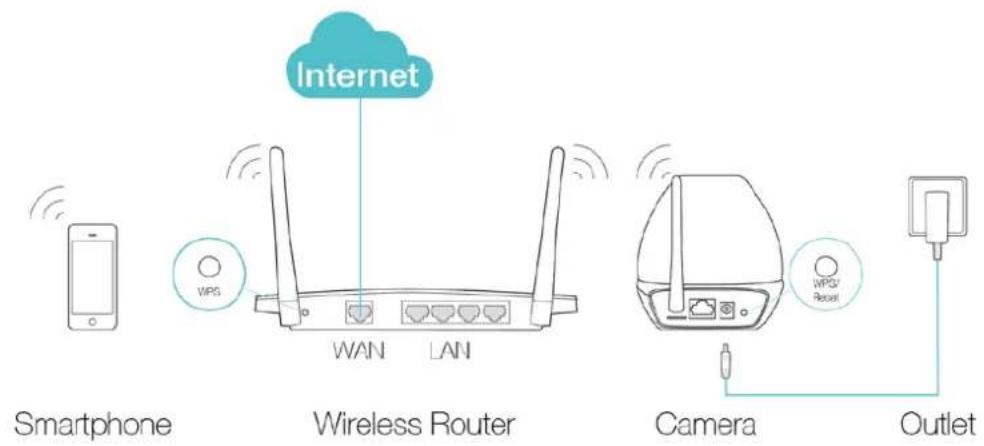
Via WPS/QSS button
If your wireless router supports WPS, you can connect the camera to your Wi-Fi network using WPS. Press the WPS or QSS button on your router. Within 2 minutes, press the WPS/Reset button on the back of the camera for about 2 seconds, then the LED above this button will start flashing quickly. When this LED becomes solid on, the WPS is successful and the camera is connected to the router wirelessly.
Step 2. Download and install the tpCamera app.
You can download the free tpCamera app from the App Store or Google play. You can also scan the QR code below to download the tpCamera app.

OR

→

natural_image
Stylized icon of a stylized eye inside a cloud shape, set against a blue background (no text or symbols)Step 3. Add the camera to your TP-Link ID.
Launch the tpCamera app, log in with your TP-Link ID or create one if you do not have a TP-Link ID. Then follow the app instructions to add your new camera to your TP-Link ID.
When you reach the My Cam screen, you have successfully added your camera and can start to use your camera.
Note:
You can enable Email and App notification in the app, which will inform you immediately of any detected movement or sound by sending the snapshots. The time interval between each Email notification alert is 10 minutes while the time interval for App notification is 3 minutes.
3.2 Position Your Camera
Before positioning your camera, please keep these safety guidelines in mind:
- Keep your camera out of reach of children and pets.
- Use your camera only indoors, and keep it out of direct sunlight. Make sure its operating temperature is in the range of 0-40°C (32-104°F).
• Pick a location which is close enough to a wall outlet.
• Use only the power adapter that comes with this camera in the package.
You can place your camera to your desired location. Just unplug and replug it without having to go through the app's setup again. Place the camera within the coverage of your wireless network. You can place the camera in various ways:
- Place it on a flat surface.
• Mount it on the wall or ceiling with the provided screws and base.
Detailed instructions on mounting your camera to a wall or ceiling are shown as follows.
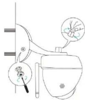
Wall Mounting
Get the provided accessories for camera's wall mounting ready, and follow the instructions below to mount the camera. After relocating your camera, remember to power on it.

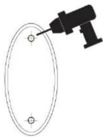
a) Place the paper drill guide where you want the camera. Check the alignment using a level.
b) Using a 0.24 inch (6mm) drill bit, drill holes through the two circles on the guide. Remove the paper.
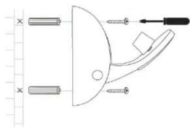
c) Insert the two anchors into the holes and place the camera mount over the anchor.
d) Attach the camera and use the screws to secure it.
1 Drill Holes
natural_image
Simple line drawing of a drill bit hitting a circular target (no text or symbols)2 Mount Base
natural_image
Pure mechanical diagram showing a lever and screwdriver with no text or symbols3 Secure Camera
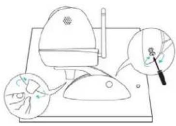
Ceiling Mounting
Get the provided accessories for camera's wall mounting ready, and follow the instructions below to mount the camera. After relocating your camera, remember to power on it.
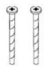
screws
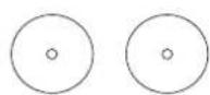
wing nuts washers

a) Place the paper drill guide where you want the camera*.
*Camera placement can affect viewing angle. For best results, place the camera near a wall or corner.
b) Using a 0.24 inch (6mm) drill bit, drill holes through the two circles on the guide. Remove the paper.
c) Attach the camera mount using the screws, washers, and wingnuts.
d) Attach the camera and use the screws to secure it.
1 Drill Holes
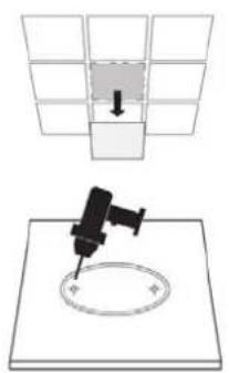
2 Mount Base
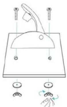
3 Secure Camera
When you finish positioning your camera, use the tpCamera app to check that your camera can see what you want to keep an eye on. Adjust its position if needed.
Chapter 4 Configure Your Camera
This chapter shows how to use the camera's web management page to configure the camera locally. In addition to the web management page, you can use the tpCamera app and TP-Link Cloud (http://www.tplinkcloud.com) to view and manage your camera remotely.
4.1 Log in to Your Camera
- Connect a computer to the router that your camera is connected to. You can connect the computer to the router using an Ethernet cable or via the wireless connection.
- Find the management IP address of the camera from the web management page of the connected router. Here we use the web management page of TP-Link router for demonstration.
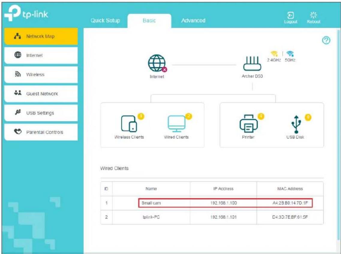
- On a computer that connects to the same router as the camera does, open a web browser, type in the camera's IP address in the address field, and press Enter. Here we use http://192.168.1.100 for demonstration.

- Enter the default username and password (admin/admin). Click Login.
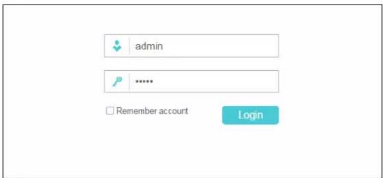
- Create a new password for your camera to enhance security. Click OK.
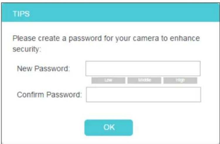
Note:
For the administrator, the default password is admin. For subsequent logins, use your password you have created.
If you log in to the camera as an administrator, you can perform all the settings provided by the camera. After logging as administrator, you can add up to five user accounts in the Account menu (Go to System > Account).
If you log in to the camera as a common user, you can only view the Live View.
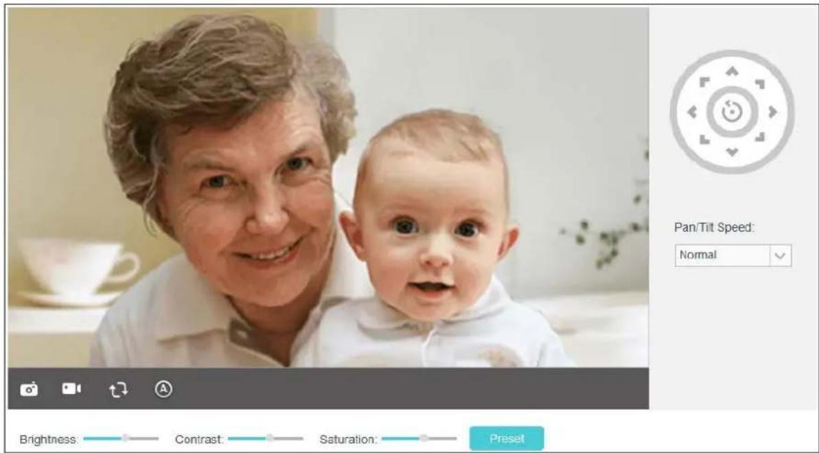
4.2 Live View
The Live View screen shows you the live video feed from your camera. On this screen, you can capture a picture.
| Symbols Meaning Note | ||
 | Click to capture a still image shot by the camera. | The image file will be automatically saved to your computer. |
| [3D76] | Click to record a video by the camera. | The video file will be automatically saved to your computer. |
 | Click to rotate the current image. | If the view of the camera is upside down, Rotate settings should be checked. |
Ima  Rotate Rotate  | ||

   | Click to select the Auto/Day/Night mode. | Auto: This mode will automatically switch between Day and Night modes based on the amount of available lighting.Day: This sets the camera to always be in the Day mode.Night: This sets the camera to always be in the Night mode. |
 | Click to set the camera's position. | Click on the directional arrows on the pan/tilt wheel to manually control the pan and tilt functions of the camera. At any time, you can click the Return button in the center of the wheel to return the camera to its initial position. |
| Pan/Tilt Speed:Normal | Set the speed of the camera's movement for each press of a pan or tilt arrow on the pan/tilt wheel. | Select the pan/tilt speed from the drop-down list:Fast, Normal, Slow. |
Note:
Use the camera's pan and tilt controls via the web management page or tpCamera app instead of rotating the camera forcibly, which may cause damage to the camera.
Brightness: Drag the Brightness: slider to adjust the brightness level of camera. Large value will brighten the current displayed screen.
Contrast: Drag the Contrast: slider to adjust the contrast level of the camera. Large value will contrast the current displayed screen heavily.
Saturation: Drag the Saturation: slider to adjust the saturation level of the camera. Large value will saturate the current displayed screen to be more colorful.
Preset: Click the Preset button to restore to factory image settings.
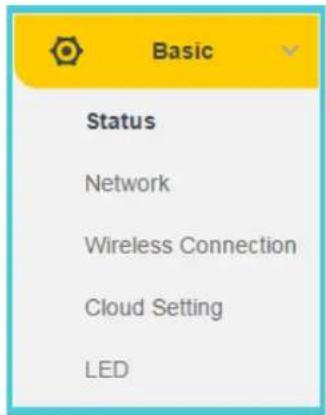
4.3 Basic
Click the Basic menu to display the submenus including Status, Network, Wireless Connection, Cloud Setting, and LED.
4.3.1 Basic > Status
The Status page displays the current configuration information of the camera. All the information is read-only.
| Basic | |
| Camera Name: | NC450 2.0 |
| Model: | NC450 2.0 |
| Firmware: | 1.3.3 Build 170906 Rel.F31B04 |
| Current Viewers: | 1 |
| Cloud Server | |
| Connection Status: | Not registered |
| Username: | - |
| Wireless | |
| Connection Status: | Connected but not in use (Unplug the camera's Ethernet cable to use the wireless connection.) |
| Wireless Network Name: | - |
| Channel: | - |
| Rate/Signal Strength: | - |
| Security: | - |
| Network | |
| Connection Type: | Dynamic IP |
| MAC Address: | 00-0C-43-76-20-81 |
| LAN IP Address: | 192.168.0.101 |
| Subnet Mask: | 255.255.255.0 |
| Default Gateway: | 192.168.0.55 |
| Primary DNS Server: | 192.168.0.55 |
| Secondary DNS Server: | 0.0.0.0 |
| Video Profile 1 | |
| Resolution: | 1280*720 |
| Frame Rate: | 15 |
| Image Quality: | High |
| Light Frequency: | Auto |
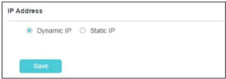
4.3.2 Basic > Network
On this page, you can configure your camera's IP address which is used to access and configure the camera.
Dynamic IP: Select this option when a DHCP server is installed on the network to issue IP address assignment. With this setting, the IP address of the camera is assigned automatically.
Static IP: Select this option when a static or fixed IP address is obtained for the camera. A static IP address will ease your access to the camera in the future. Add your camera's static IP information to your router to avoid IP conflicts.
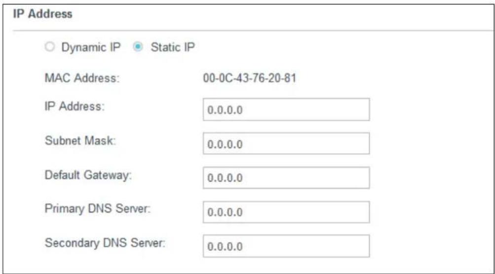
- MAC Address: Displays the Ethernet MAC address of the camera. The MAC address is read-only.
• IP Address: Enter a fixed IP address for the camera in dotted-decimal notation. - Subnet Mask: Enter the subnet mask in dotted-decimal notation. The default value is "0.0.0.0."
- Default Gateway: Enter the default gateway in dotted-decimal notation.
• Primary DNS Server: Enter a DNS address in dotted-decimal notation.
• Secondary DNS Server: Enter a DNS address in dotted-decimal notation.
Click Save to save and enable the settings.
4.3.3 Basic > Wireless Connection
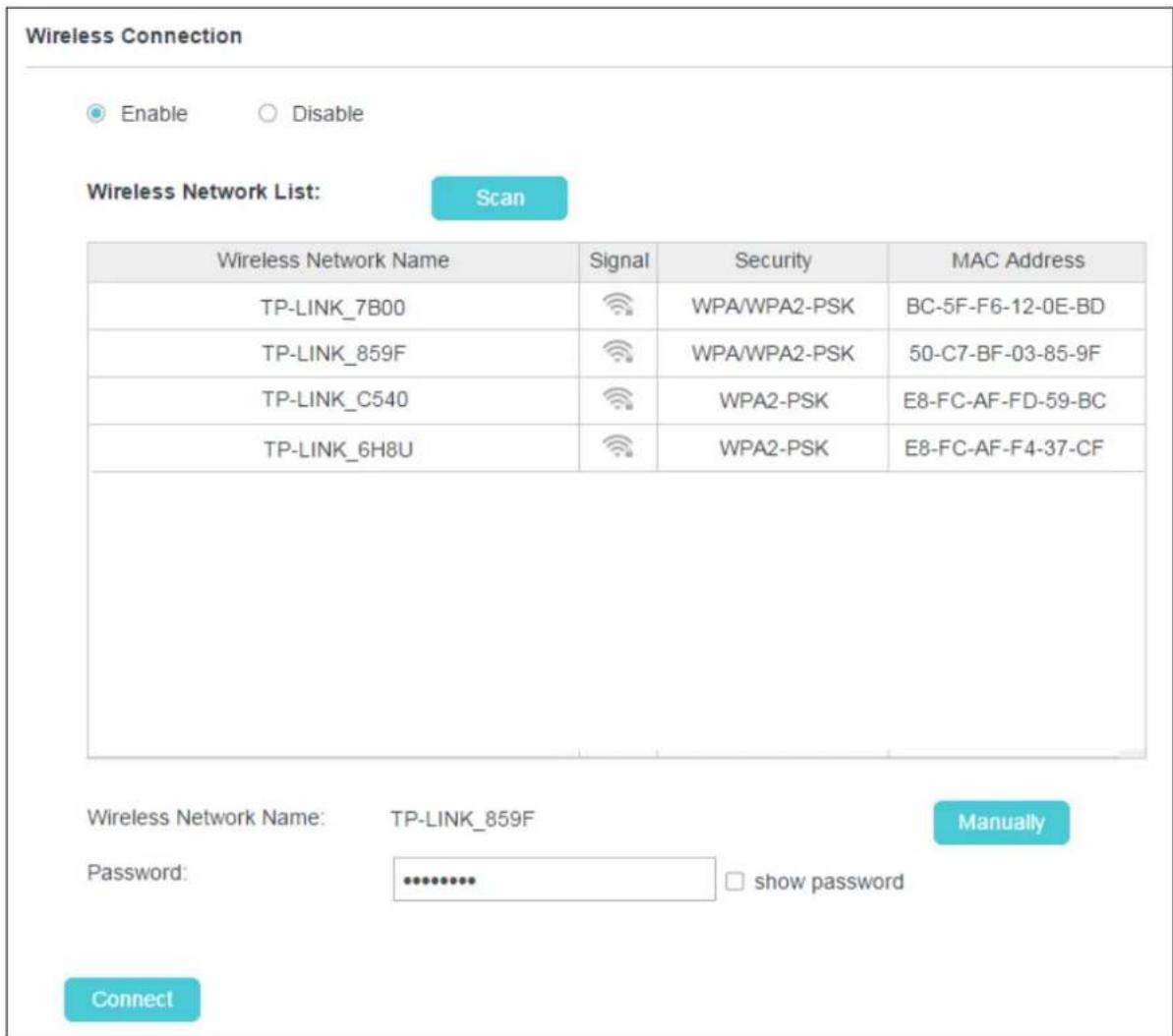
The camera's wireless function is enabled by default. This function helps to connect your camera to a wireless network wirelessly. If you don't want to use this function, just select the Disable option.
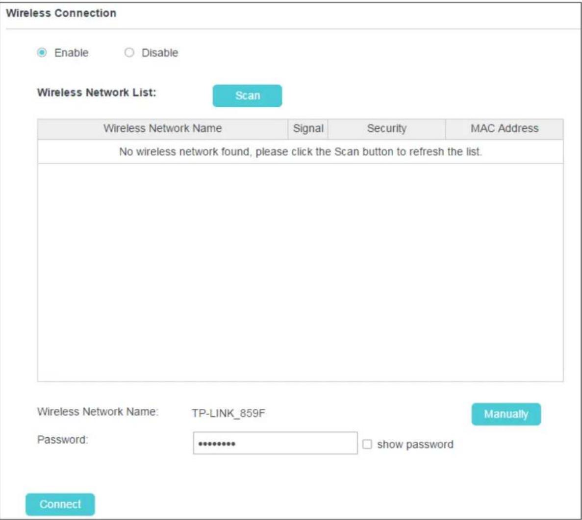
Scan: Click to scan the available wireless network. You will get or refresh the Wireless Network List as shown below.
Wireless Connection

Enable

Disable
Wireless Network List:
Scan
Wireless Network Name: Displays the wireless network's name. Make sure the camera and your PC connect to the same wireless network; otherwise your PC can't access the camera.
Signal: Displays the strength of the wireless signal.
Security: Displays the wireless network's security mode.
MAC Address: Displays the MAC address of the router.
To connect your camera to a wireless network, follow the steps below:
- Click Scan to get and refresh the Wireless Network List.
- Select a wireless network from the wireless network list.
-
If the wireless network's security mode is None, simply click Connect. If the security mode requires a password, enter the wireless network's password and then click Connect. You can select show password to display what you've entered.
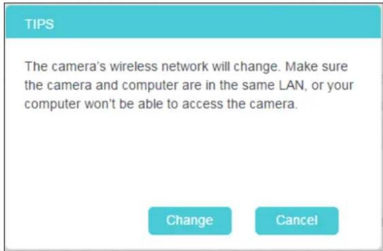
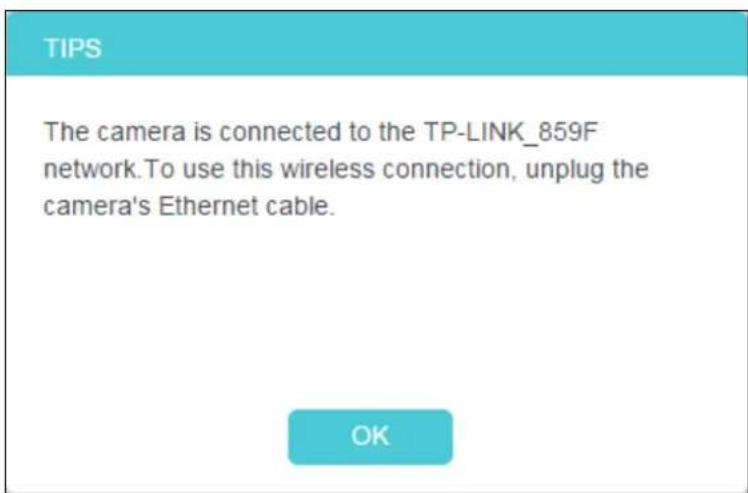
-
A pop-up screen will prompt you for the wireless network modification. Click Change, and then click OK on the next pop-up screen. The camera will connect to the wireless network that you have selected.
- To log in to the web management page of the camera, you need to connect your computer to the router that your camera is connected to. Refer to 4.1 Log in to Your Camera to find the IP address of your camera and log in to the camera again.
4.3.4 Basic > Cloud Setting
A Cloud Camera can be viewed anytime and anywhere over the internet with TP-Link Cloud service. On this page, you can add the camera to your TP-Link ID.
Note:
-
You can register a TP-Link ID in the tpCamera app. If you do not get the tpCamera app, please refer to the Step 2 Download and install the tpCamera app in 3.1 Set up the Camera with the tpCamera app to register a TP-Link ID.
-
To add a camera to your TP-Link ID, make sure that the camera is connected to the internet.
Add Your Camera to TP-Link ID
If you already have a TP-Link ID, in order to add your camera to your account, just enter the TP-Link ID and password, and then click Register.
Cloud Setting
Add your camera to Cloud account
Please enter your Cloud account and password:
Account:
E-mail/Username
Password:
Camera Name:
NC450 2.0
With Cloud service, you can view your cloud cameras anytime and anywhere over the Internet. Go to www.tplinkcloud.com
Register
Account: Enter your TP-Link ID. Either E-mail address or username is allowed.
Password: Enter your TP-Link ID's password.
Camera Name: The default value is the camera model. You can change it to an easy-to-remember one. Camera name can contain up to 31 characters. It cannot contain the following characters: \ / := & ' " < > {}.
After your camera is registered successfully, you can go to http://www.tplinkcloud.com to view it.
4.3.5 Basic > LED
The camera's LED is on by default. If you want to turn it off, select Off and click Save.

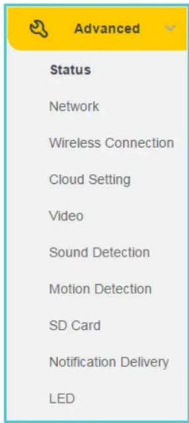
4.4 Advanced
Click the Advanced menu to display the submenus including Status, Network, Wireless Connection, Cloud Setting, Video, Sound Detection, Motion Detection, SD Card, Notification Delivery and LED.
4.4.1 Advanced > Status
Refer to 4.3.1 Basic > Status.
4.4.2 Advanced > Network
On this page, you can configure the network settings of the camera.
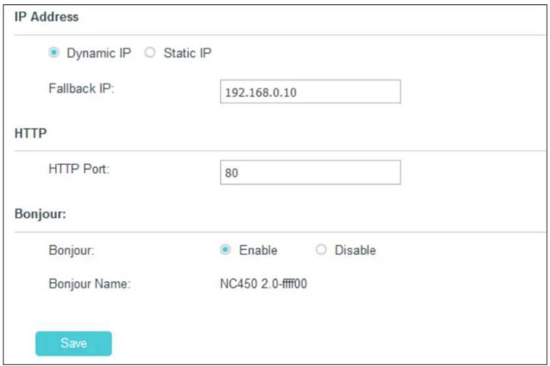
IP Address
On this section, you can configure your camera's IP address which is used to access and configure the camera.
Dynamic IP: Select this option when a DHCP server is installed on the network to issue IP address assignment. With this setting, the IP address of the camera is assigned automatically.
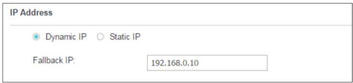
- Fallback IP: If the camera cannot get a dynamic IP address from a DHCP server within limited tries, the camera will assign a default IP address, 192.168.0.10, by itself as the Fallback IP address.
Static IP: Select this option when a static or fixed IP address is obtained for the camera. A static IP address will ease your access to the camera in the future. Add your camera's static IP information to your router to avoid IP conflicts.
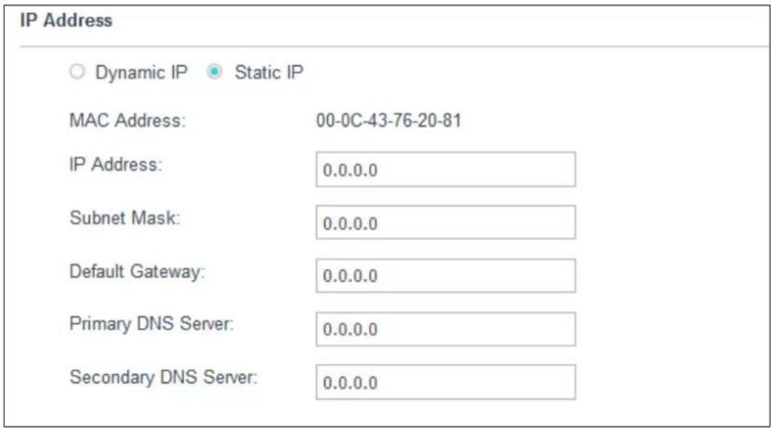
- MAC Address: Displays the Ethernet MAC address of the camera. The MAC address is read-only.
• IP Address: Enter a fixed IP address for the camera in dotted-decimal notation. - Subnet Mask: Enter the subnet mask in dotted-decimal notation. The default value is "0.0.0.0".
- Default Gateway: Enter the default gateway in dotted-decimal notation.
• Primary DNS Server: Enter a DNS address in dotted-decimal notation.
• Secondary DNS Server: Enter a DNS address in dotted-decimal notation. - Fallback IP: If the camera cannot get a valid static IP address, the camera will assign a default IP address, 192.168.0.10, by itself as the Fallback IP address.
HTTP (Hypertext Transfer Protocol)
This feature allows you to access and manage your camera via its IP address. Web browser access normally uses the standard HTTP service port 80. The camera uses HTTP port 80 by default. For greater security, you can change the port to a custom one.
When HTTP port is set to 80, you can access the camera by typing its IP address (for example, http://192.168.1.100) on a web browser. When HTTP port is set to another value (for example, 2000), you need to enter http://192.168.1.100:2000 instead.
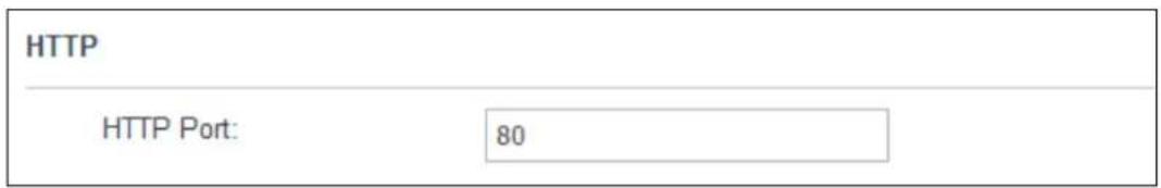
HTTP Port: The default value is 80. If you want to use a port number other than 80, enter a port number between 1 and 65535.
Bonjour
Bonjour, also known as zero-configuration networking, enables automatic discovery of computers, devices, and services on IP networks. Bonjour uses industry standard IP protocols to allow devices to automatically discover each other without the need to enter IP addresses or configure DNS servers.
Bonjour Name: Displays the Bonjour name. By default, it is a combination of device name and the last six characters of the camera's MAC address.
Click Save to save and enable the settings.
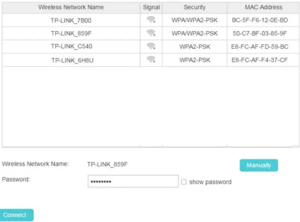
4.4.3 Advanced > Wireless Connection
You can set the wireless connection manually besides the basic settings for wireless connection (Refer to 4.3.3 Basic > Wireless Connection).
For example, a hidden wireless network does not broadcast its SSID, and you cannot find it from the Wireless Network List. If you want to connect the camera to a hidden wireless network, you need to make it manually. Click the Manually button. Then enter the wireless network name, select the security type and encryption type of the wireless network, enter the password if needed, and click Connect.
Wireless Connection

Enable

Disable
Wireless Network List:
Scan
| Wireless Network Name | Signal | Security | MAC Address |
| TP-LINK_7B00 | WPA/WPA2-PSK | BC-5F-F6-12-0E-BD | |
| TP-LINK_859F | WPA/WPA2-PSK | 50-C7-BF-03-85-9F | |
| TP-LINK_C540 | WPA2-PSK | E8-FC-AF-FD-59-BC | |
| TP-LINK_6H8U | WPA2-PSK | E8-FC-AF-F4-37-CF |
Wireless Network Name:
TP-LINK_50FB
Auto
Security:
WPA2-PSK

Encryption:
AES

Password:
●●●●●●●
□ show password
Connect
4.4.4 Advanced > Cloud Setting
Refer to 4.3.4 Basic > Cloud Setting.
4.4.5 Advanced > Video
On this page, you can configure the video settings for your camera.
Video
Video Profile 1:
| Coding Format | Resolution | Frame Rate | Mode | Image Quality | ||
| H.264 | 1280*720 | 15FPS | √ | VBR | High | √ |
Backlight Compensation:
○ Enable
Disable
Light Frequency:
Time Stamp&On-Screen
○ Enable
Disable
Display (OSD):
Save
Coding Format: Displays the video coding format of the camera.
Resolution: Displays the video resolution of the camera. Higher resolution offers better quality, but will require more bandwidth to stream.
Frame Rate: Select the frame rate to use for the video stream from the drop-down list. Higher settings offer smoother video streams, but will require more bandwidth.
Mode: Displays the bit rate mode of the camera. This camera uses the VBR (variable bit rate) mode. In this mode, the bit rate varies to keep consistent video quality. It allows a higher bit rate (and therefore requires more bandwidth) to be allocated to dynamic scenes while less bit rate to be allocated to static scenes.
Image Quality: Select the image quality from the drop-down list: High and Low. High settings offer better quality, but it may require more bandwidth to stream.
Backlight Compensation: If enabled, this feature will compensate for bright backgrounds so foreground objects aren't silhouetted.
Enabled

natural_image
Portrait of an elderly woman and a baby smiling, both looking at each other (no text or symbols visible)Disabled

natural_image
Black-and-white photo of an adult and a baby standing together, no visible text or symbolsLight Frequency: Select the frequency used by your lighting and power to help reduce image flicker. The default setting is Auto, which is recommended.
Time Stamp&On-Screen Display (OSD): If enabled, the current time of your camera, which can be set on the System > Date/Time page, will be displayed on the Live View screen. Meanwhile, you can set the OSD text to be displayed with the time stamp. We use NC450 as the OSD text for demonstration here.

Enabled

natural_image
Portrait of an elderly woman and a baby smiling together (no visible text or symbols)Disabled

natural_image
Portrait of an elderly woman and a baby smiling together (no visible text or symbols)Click Save to save and enable the settings.
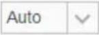
4.4.6 Advanced > Sound Detection
Sound detection allows your camera to detect a loud sound, which can be used to trigger snapshots. Refer to 4.4.9 Advanced > Notification Delivery for more details.
Sound Detection
area
| Sound Condition | Value | | ------------------- | ----- | | Lawn mower | 0 | | Noisy office | 0 | | Hair dryer | 0 | | Quiet home | 0 | | Whisper | 0 | | Silence | 0 |Sound Detection: To enable or disable the sound detection function.
Sensitivity: Specify the level of difference between current sound and the threshold you set. Select one of the three levels of sensitivity from the drop-down list: High, Medium, and Low.
Click Save to save and enable the settings.
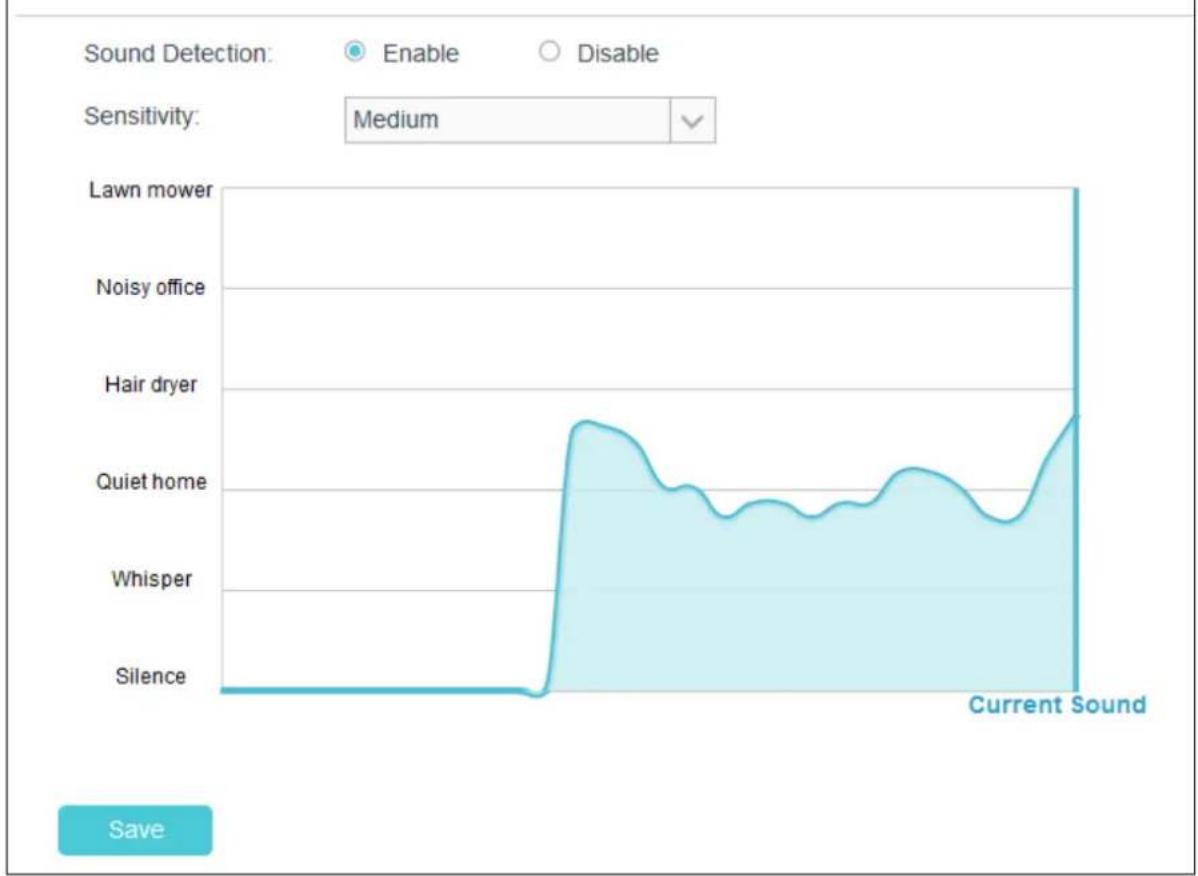
4.4.7 Advanced > Motion Detection
Motion detection allows you to specify areas and sensitivity of your camera's video to monitor for motion, which can be used to trigger snapshots. Refer to 4.4.9 Advanced > Notification Delivery for more details.
Motion Detection
Save
Motion Detection: To enable or disable the motion detection function. The area with blue mask indicates that it is the area with motion detection on. All areas are selected by default. You can drag your mouse to draw specific areas that you want to monitor.
Sensitivity: Select one of the three levels of sensitivity from the drop-down list: High, Medium, and Low. Snapshots will be triggered and saved to SD card when the motion meets the level of sensitivity. And notification messages will be sent to the tpCamera app in your smartphone.
Click Save to save and enable the settings.
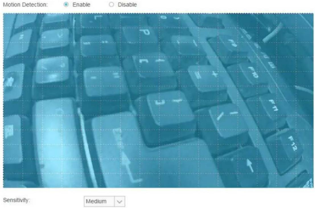
4.4.8 Advanced > SD Card
SD Card function allows you to save snapshots and videos in your SD card. The SD card is not provided, and you need to insert a micro SD card into the SD card slot on the back of the camera.
SD Card
Please Insert SD Card
After inserting a micro SD card, go to Advanced > Sound Detection or Advanced > Motion Detection to set the detections according to your needs. Then when an event occurs, the corresponding snapshot and video will be saved in the micro SD card automatically.
Note:
If the micro SD card capacity is insufficient, it will overwrite the oldest data saved by your camera.
Back: Click to go back to the previous path of the folder.
Type: Displays the type of the file or folder, such as the photo, video, and file.
Name: Displays the name of the file or folder.
Size: Displays the size of the file.
Total Items: Displays the number of the files in the folder.
Date: Displays the recording time of the file or folder.
The micro SD card capacity is displayed at the bottom of the table.
Note:
The Wi-Fi camera supports 24-hour recording. If you enable the 24-hour Recording function, remember to save your previous recordings in your SD card to avoid them being overwritten. If the 24-hour Recording function is disabled, the SD card recording triggered by motion detection or sound detection will last from 15s to 60s (depending on how long the motion or sound lasts). If the event continues beyond 60s, the camera will start a new recording.
4.4.9 Advanced > Notification Delivery
Notification Delivery settings are available only after the motion detection or sound detection function is enabled. It is used to inform you immediately by sending the snapshots triggered by a detected motion or sound to the specified FTP server and email addresses.
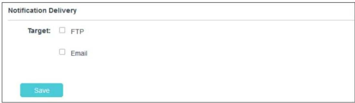
FTP
Select FTP, and you can configure your camera to send snapshots to a specified FTP server on the following screen:
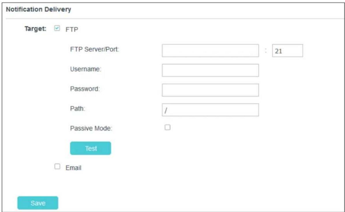
FTP Server/Port: Enter the IP or the domain (IP/domain without prefix ftp://) and the port of the FTP server that you will be connecting to. The port is 21 by default.
Note:
The FTP server you set and the camera should be in the same LAN.
Username: Enter the username that is used to log in to your FTP server.
Password: Enter the password that is used to log in to your FTP server.
Path: Enter the path to the destination on the FTP server.
Passive Mode: Enabling passive mode may help you reach your FTP server if your camera is behind a router protected by a firewall.
To set up a FTP to receive notification, follow the steps below:
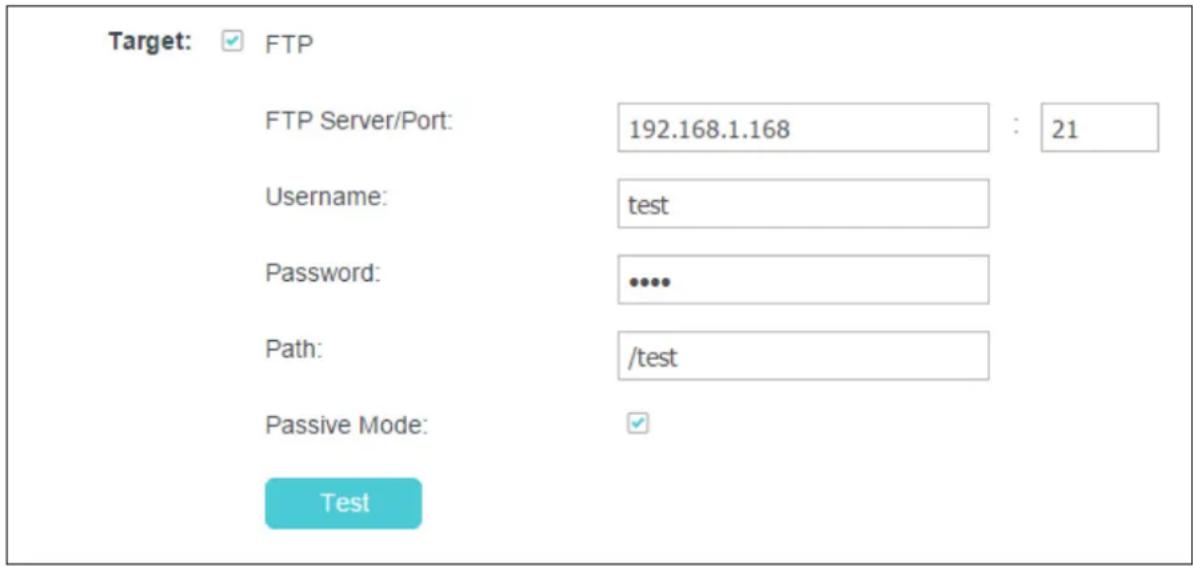
- Enter an IP address or domain of your FTP server, e.g. 192.168.1.168
- Remain the FTP port number as the default value: 21.
- Enter your username to log in to the FTP server, e.g. test.
- Enter your password to log in to the FTP server.
- Enter the path to the destination on the FTP server, e.g. /test
- Enable Passive Mode.
- Click Save to save and enable the settings.
Click Test, and a test JPEG snapshot will be sent to the specified FTP server to check whether your settings are correct.
If the settings are tested correct, click OK.
If the settings are tested incorrect, check your network and FTP settings and try again later.
Select Email, and you can configure your camera to send snapshots to specified email addresses on the following screen:
Notification Delivery
Target: □ FTP
Recipient E-mail Address

Sender E-mail Address:

Password:

SMTP Server/Port

SSL Encryption:

Sending Interval
Test
Note If you want to set Hotmail as sender E-mail Address, you need to set SMTP Server/Port as smtp-mail outlook com 25 (Or 567), and SSL Encryption as STARTTLS. If you want to set Gmail as sender E-mail Address, please refer to this link http://www.tp-lmk.com/en/faq-900.html
Save
Recipient E-mail Address: Enter the receiver's E-mail address that the notification E-mail will be sent to. Click Add recipient to add receiver's E-mail addresses. You can specify up to four recipient E-mail addresses.
Sender E-mail Address: Enter the sender's E-mail address that is used to send the notification E-mail.
Password: Enter your password if the SMTP server uses authentication.
SMTP Server/Port: Enter the domain name or IP address and the port of your external E-mail server. The port is 25 by default.
SSL Encryption: Select TLS or STARTTLS as the SSL encryption; select Close to disable SSL encryption.
If TLS is selected, SMTP server port should be 465; if STARTTLS is selected, SMTP server port should be 25 or 587.
Sending Interval: Set the limit for how frequently E-mail notifications will be sent. Select one interval from the drop-down list.
Note:
For example, if you want to use Gmail with TLS for E-mail notifications, follow the steps below:

Recipient E-mail Address:
test@tp-link.com
Add recipient
Sender E-mail Address:
test@gmail.com
Password:
SMTP Server/Port:
smtp.gmail.com
: 465
SSL Encryption:
TLS

Sending Interval:
1m

Test
- Enter the receiver's E-mail address in Recipient E-mail Address, e.g. test@tp-link.com.
- Enter your E-mail address in Sender E-mail Address, e.g. test@gmail.com.
- Enter the password required to access the SMTP server.
- Enter smtp.gmail.com in SMTP server.
- Select TLS as the SSL encryption and the SMPT server port number will be changed to 465 automatically.
- Set the Sending Interval, e.g. 1m.
- Click Save to save and enable the settings.
Click Test, and a test JPEG snapshot will be sent to the recipient E-mail address to check whether your settings are correct.
If the settings are tested correct, click OK.
If the settings are tested incorrect, check your network and E-mail settings and try again later.
4.4.10 Advanced > LED
Refer to 4.3.5 Basic > LED.
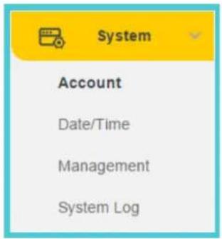
4.5 System
Click the System menu to display the submenus including Account, Date/Time, Management, and System Log.
4.5.1 Account
On this page, you can change the administrator's password and manage the user account(s) that are allowed to access to your camera.
Account
| User Name | User Group |
| admin | admin |
| test | user |
User Name: Displays the name of the user account.
User Group: Displays the group that the user account is in. Different user group has different limits of authority.
- admin: This group has all authority of configuration. It can only have one account: admin.
- user: This group can only view the Live View. It can have up to five accounts.
Add a New User Account
You can create a new user account to provide viewing access for your camera's video. User accounts will only be able to access the Live View section of the web management page, but cannot access any other parts or change any settings.
To add a new user account, follow the steps below:
- Click Add, and you will see the following screen.
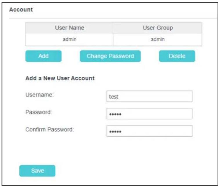
- Enter a username for your new account.
- Enter a password for your new account. The password should contain 5 to 20 characters.
- Enter the password again to confirm it.
- Click Save to save and enable the settings.
Change Password
You can change the password of all the accounts here.

Note:
The default account and password are both admin. Everyone who knows the camera's IP address can access the device with all configuration authority. It is necessary to change the default password if the device is intended to be accessed only by administrator.
To change password, follow the steps below:
- Select a user account in the list whose password you want to change
- Click Change Password, and you will see the following screen.
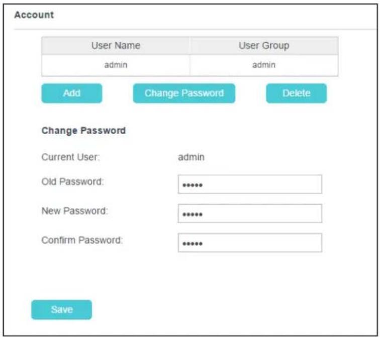
- Enter the current password in the Old Password textbox.
- Enter a new password.
- Enter the new password again to confirm it.
- Click Save to save and enable the settings.
Delete a User Account
You can delete a user account except admin here. Click a user entry in the list and click Delete.
4.5.2 Date/Time
On this page, you can configure the settings of the internal system clocks for your camera.
Date/Time
Time Configuration:
Current Time:
2017-09-29
04:46:53
Time Zone:
(GMT) Greenwich Mean Time: Dublin, Edinburgh, Lisbon, London

Automatic Time Configuration:
Synchronize With NTP Server
NTP Service
0.pool.ntp.org
0.pool.ntp.org
○ Set NTP Server from Dynamic IP
Set Date And Time Manually:
○ Set Date And Time Manually:
Save
Current Time: Displays the current date and time of the camera.
Time Zone: Select the time zone for the region where the camera is installed from the drop-down list.
Synchronize With NTP Server: Select this option to specify the NTP server name to synchronize the date and time of the camera with those of the time server, known as the NTP (Network Time Protocol) server.
- NTP Service: You can either enter a domain name of the NTP server or select one which will be filled in automatically from the drop-down list.
- Set NTP Server from Dynamic IP: You can use the NTP server applied in the DHCP server on the network.
Set Date and Time Manually: Select this option to set the date and time of the camera manually. If enabled, you will see the following screen:
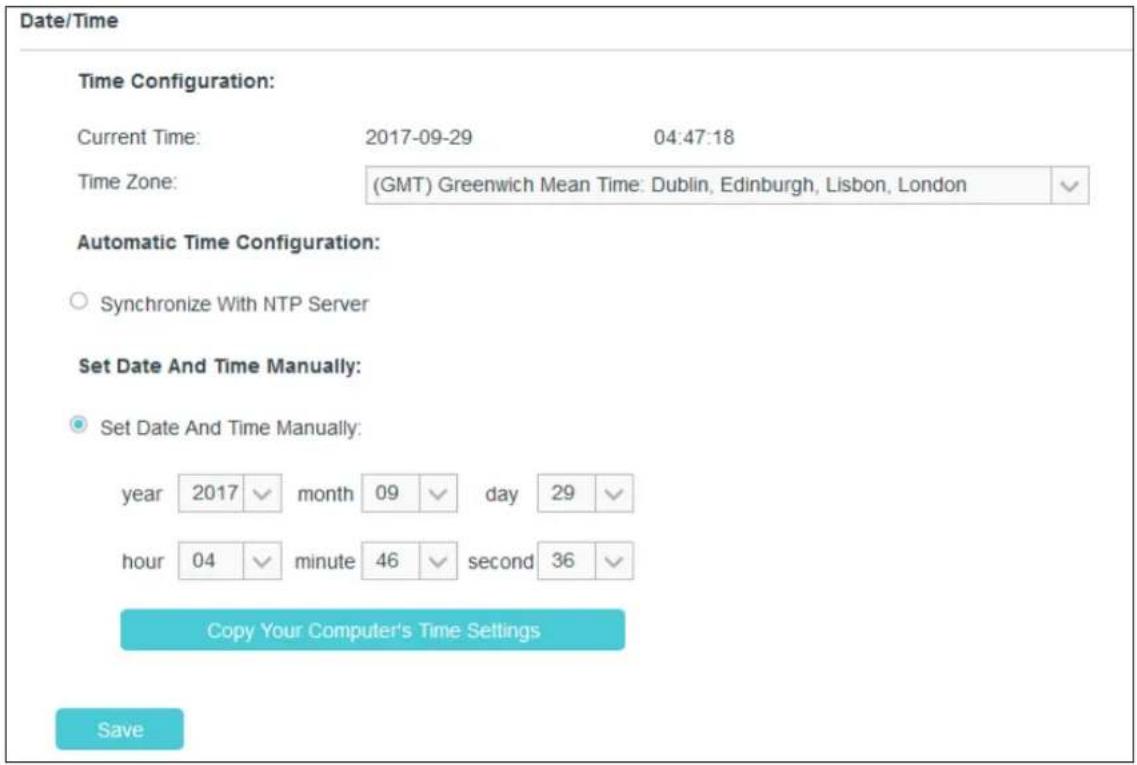
- Copy Your Computer's Time Settings: Click this button to copy your computer's current time settings.
Click Save to save and enable the settings.
4.5.3 Management
On this page, you can reboot the camera, backup and restore the camera's current settings, reset factory settings, and update the camera's software.
Reboot
Reboot your camera:
Reboot
Backup and Restore
Back up current settings:
Backup
Restore settings from a backup file:
Browse
Restore
Restore factory default settings:
Reset
Update
Upgrade from a file on your hard disk:
Browse
Upgrade
Reboot: Click Reboot and then click Reboot on the pop-up screen to confirm. The reboot will not change the camera's setting. After rebooting, you need to log in to this page again.
Backup: Click Backup and follow the instructions on the browser to save the setting data file to your specified location.
Browse: Click Browse to locate the saved backup file.
Restore: Click Restore, and then the camera will start rebooting. The settings will be restored to the previous configuration.
Reset: Click Reset to restore the camera to its factory defaults. Don't turn off the camera while resetting. After resetting, you need to add the camera to your TP-Link ID again, find out the IP address of your camera (refer to 4.1 Log in to Your Camera), and then use the default username and password (admin/admin) to log in to this web management page.
Browse: Click Browse to locate the saved upgrade file.
Update: Before the update, download the latest firmware from the product page at http://www.tp-link.com, and then extract the file. Click Browse and select the downloaded firmware upgrade file. Then click Upgrade to update the camera's software to the latest version. Wait for the upgrading process to complete, and the camera will reboot automatically.
Note:
The firmware upgrade procedure must not be interrupted, or the camera may be damaged. When upgrading firmware, do not unplug the camera or your computer, or close the web management page until the process is complete.
4.5.4 System Log
On this page, you can review any changes and events happened to your camera. The system starts logging automatically after startup.
System Log
| Time | Module | Level | Content | |||
| 2017-09-29/02:45:38 | NetSwitch | INFO | LAN gateway: 192.168.0.55 | |||
| 2017-09-29/02:45:30 | NetSwitch | INFO | LAN gateway: 192.168.0.1 | |||
| 2017-09-29/02:45:30 | NetSwitch | NOTICE | LAN IP: 192.168.0.101 | |||
| 2017-09-29/02:45:28 | NetSwitch | NOTICE | Link status: wired | |||
| 2017-09-29/02:45:24 | NetSwitch | NOTICE | Link status: wireless | |||
| 2017-09-29/02:45:24 | Wireless | INFO | receive wlan connected mesaage, type is 0. | |||
| 2017-09-29/02:45:22 | NetSwitch | NOTICE | Link status: wireless | |||
| 2017-09-29/02:45:21 | NetSwitch | NOTICE | LAN IP: 192.168.0.10 | |||
| level | ALL | √ | module | ALL | √ | |
Refresh
Save Log
Clear
Log Control
Time: Displays the time when the log event occurs. The log can get the correct time after you configure on the Date/Time page (Go to Advanced > Date/Time).
Module: Displays the module to which the log information belongs. You can specify the module by selecting one from the Module drop-down list at the bottom.
Level: Displays the severity level of the log information. You can specify the level by selecting one from the Level drop-down list at the bottom.
Content: Displays the details of the log information.
Refresh: Click Refresh to refresh the log information.
Save Log: You may be asked to use this function when contacting our technical support for troubleshooting.
Clear: Click Clear to clear all the log information.
Log Control: You may be asked to use this function when contacting our technical support for troubleshooting.
COPYRIGHT & TRADEMARKS
Specifications are subject to change without notice. TP-Link is a registered trademark of TP-Link Technologies Co., Ltd. Other brands and product names are trademarks or registered trademarks of their respective holders.
No part of the specifications may be reproduced in any form or by any means or used to make any derivative such as translation, transformation, or adaptation without permission from TP-Link Technologies Co., Ltd. Copyright © 2017 TP-Link Technologies Co., Ltd. All rights reserved.
http://www.tp-link.com
FCC STATEMENT
FC
This equipment has been tested and found to comply with the limits for a Class B digital device, pursuant to part 15 of the FCC Rules. These limits are designed to pro-vide reasonable protection against harmful interference in a residential installation. This equipment generates, uses and can radiate radio frequency energy and, if not in-stalled and used in accordance with the instructions, may cause harmful interference to radio communications. However, there is no guarantee that interference will not occur in a particular installation. If this equipment does cause harmful interference to radio or television reception, which can be determined by turning the equipment off and on, the user is encouraged to try to correct the interference by one or more of the following measures:
• Reorient or relocate the receiving antenna.
- Increase the separation between the equipment and receiver.
- Connect the equipment into an outlet on a circuit different from that to which the receiver is connected.
- Consult the dealer or an experienced radio/ TV technician for help.
This device complies with part 15 of the FCC Rules. Operation is subject to the following two conditions:
1) This device may not cause harmful interference.
2) This device must accept any interference received, including interference that may cause undesired operation.
Any changes or modifications not expressly approved by the party responsible for compliance could void the user's authority to operate the equipment.
Note: The manufacturer is not responsible for any radio or TV interference caused by unauthorized modifications to this equipment. Such modifications could void the user's authority to operate the equipment.
FCC RF Radiation Exposure Statement:
This equipment complies with FCC RF radiation exposure limits set forth for an uncontrolled environment. This device and its antenna must not be co-located or operating in conjunction with any other antenna or transmitter.
"To comply with FCC RF exposure compliance requirements, this grant is applicable to only Mobile Configurations. The antennas used for this transmitter must be installed to provide a separation distance of at least 20 cm from all persons and must not be co-located or operating in conjunction with any other antenna or transmitter."
CE Mark Warning
CE
This is a class B product. In a domestic environment, this product may cause radio interference, in which case the user may be required to take adequate measures.
OPERATING FREQUENCY (the maximum transmitted power)
No restrictions exist in the use of radio frequencies or frequency bands in all EU member states and EFTA countries.
EU declaration of conformity
TP-Link hereby declares that the device is in compliance with the essential requirements and other relevant provisions of directives 2014/53/EU, 2009/125/EC and 2011/65/EU.
The original EU declaration of conformity may be found at http://www.tp-link.com/en/ce
RF Exposure Information
This device meets the EU requirements (2014/53/EU Article 3.1a) on the limitation of exposure of the general public to electromagnetic fields by way of health protection.
The device complies with RF specifications when the device used at 20 cm from your body.
Canadian Compliance Statement
This device complies with Industry Canada license-exempt RSSs. Operation is subject to the following two conditions:
1) This device may not cause interference, and
2) This device must accept any interference, including interference that may cause undesired operation of the device.
This radio transmitter (IC: 8853A-NC450/ Model: NC450) has been approved by Industry Canada to operate with the antenna types listed below with the maximum permissible gain indicated. Antenna types not included in this list (Appendix A), having a gain greater than the maximum gain indicated for that type, are strictly prohibited for use with this device.
Radiation Exposure Statement:
This equipment complies with IC radiation exposure limits set forth for an uncontrolled environment. This equipment should be installed and operated with minimum distance 20cm between the radiator & your body.
Industry Canada Statement
CAN ICES-3 (B)/NMB-3(B)
Korea Warning Statements:
- Keep the device away from water, fire, humidity or hot environments.
- Do not attempt to disassemble, repair, or modify the device.
- Do not use damaged charger or USB cable to charge the device.
• Do not use any other chargers than those recommended - Do not use the device where wireless devices are not allowed.
- Adapter shall be installed near the equipment and shall be easily accessible.

Use only power supplies which are provided by manufacturer and in the original of this product. If you have any questions, please don't hesitate to contact us.
Please read and follow the above safety information when operating the device. We cannot guarantee that no accidents or damage will occur due to improper use of the device. Please use this product with care and operate at your own risk.
Explanation of the symbols on the product label
| Symbol | Explanation |
 | DC voltage |
 | Indoor use only |

RECYCLING
This product bears the selective sorting symbol for Waste electrical and electronic equipment (WEEE). This means that this product must be handled pursuant to European directive 2012/19/EU in order to be recycled or dismantled to minimize its impact on the environment.
User has the choice to give his product to a competent recycling organization or to the retailer when he buys a new electrical or electronic equipment.

- Chapter 1 About This Guide.... 1
- Chapter 2 Get to Know Your Camera.... 3
- Chapter 3 Set Up Your Camera 6
- Chapter 4 Configure Your Camera....11
- Chapter 1 About This Guide
- Conventions
- Overview of This Guide
- More Info
- Chapter 2 Get to Know Your Camera
- Product Overview
- Panel Appearance
- Front Panel
- Rear Panel
- • Used as the WPS button:
- • Used as the Reset button:
- WPS LED:
- Chapter 3 Set Up Your Camera
- Set up the Camera with the tpCamera app
- Step 1. Connect the camera to the network your smartphone is on.
- Wireless:
- Via web management page
- Via WPS/QSS button
- Step 2. Download and install the tpCamera app.
- Step 3. Add the camera to your TP-Link ID.
- Note:
- Position Your Camera
- Wall Mounting
- Ceiling Mounting
- Drill Holes
- Mount Base
- Secure Camera
- Chapter 4 Configure Your Camera
- Log in to Your Camera
- Live View
- Basic
- Basic > Status
- Basic > Network
- Basic > Wireless Connection
- Wireless Connection
- Wireless Network List:
- Basic > Cloud Setting
- Cloud Setting
- Register
- Basic > LED
- Advanced
- Advanced > Status
- Advanced > Network
- IP Address
- HTTP (Hypertext Transfer Protocol)
- Bonjour
- Advanced > Wireless Connection
- Advanced > Cloud Setting
- Advanced > Video
- Video
- Save
- Advanced > Sound Detection
- Advanced > Motion Detection
- Motion Detection
- Advanced > SD Card
- SD Card
- Advanced > Notification Delivery
- FTP
- Notification Delivery
- Test
- Advanced > LED
- System
- Account
- Add a New User Account
- Change Password
- To change password, follow the steps below:
- Date/Time
- Date/Time
- Time Configuration:
- Automatic Time Configuration:
- Set Date And Time Manually:
- Management
- Reboot
- Backup and Restore
- Update
- System Log
- Refresh
- Save Log
- Clear
- Log Control
- COPYRIGHT & TRADEMARKS
- FCC STATEMENT
- FC
- FCC RF Radiation Exposure Statement:
- CE Mark Warning
- CE
- OPERATING FREQUENCY (the maximum transmitted power)
- EU declaration of conformity
- RF Exposure Information
- Canadian Compliance Statement
- Radiation Exposure Statement:
- Industry Canada Statement
- Korea Warning Statements:
- Explanation of the symbols on the product label
- RECYCLING
Brand : TP-LINK
Model : TL-NC450
Category : Security Camera