
ST 4851 AE - Snow blower STIGA - Free user manual and instructions
Find the device manual for free ST 4851 AE STIGA in PDF.

| Product Type | Snow Blower |
| Brand | Stiga |
| Model | ST 4851 AE |
| Engine Type | Gasoline, 4-stroke |
| Clearing Width | 51 cm (20 in) |
| Intake Height | 30 cm (12 in) |
| Maximum Throwing Distance | 10 m (33 ft) |
| Chute Control | Remote, 180° rotation |
| Drive Type | Self-propelled, multiple speeds |
| Starting System | Electric start with recoil backup |
| Fuel Tank Capacity | 1.2 L (0.32 gal) |
| Weight | 50 kg (110 lb) |
| Dimensions (L x W x H) | 85 x 55 x 60 cm (33 x 22 x 24 in) |
| Wheel Size | 13 in pneumatic |
| Maintenance | Check oil, spark plug, and auger shear pins regularly |
| Safety Features | Dead man's switch, safety key, Auger brake |
| Spare Parts Availability | Shear pins, belts, spark plugs, oil filters |
| Repairability | Modular design, user-serviceable with manual |
Frequently Asked Questions - ST 4851 AE STIGA
User questions about ST 4851 AE STIGA
0 question about this device. Answer the ones you know or ask your own.
Ask a new question about this device
Download the instructions for your Snow blower in PDF format for free! Find your manual ST 4851 AE - STIGA and take your electronic device back in hand. On this page are published all the documents necessary for the use of your device. ST 4851 AE by STIGA.
USER MANUAL ST 4851 AE STIGA
natural_image
Exterior view of a snowman lawn mower (no text or symbols visible)ST 4851 AE ST 8051 AE
Type ST 515 Li ST 615 Li
BATTERY SNOW THROWER INSTRUCTION MANUAL...... EN
СНЕГОРИН УПЪТВАНЕ ЗА УПОТРЕБА...... BG
ČISTAČ SNIJEGA PRIRUČNIK S UPUTAMA.... BS
SNĚHOVÁ FRÉZA INSTRUKTIONSMANUAL.... CS
SNESLYNGE
PRIRUČNIK SA UPUTSTVIM.... SR
BRUKSANVISNING OCH UNDERHÅLL...... SV
ENGLISH - Translation of the original instruction ...... EN
БЪЛГАРСКИ - Инструкция за експлоатация ...... BG
BOSANSKI - Prijevod originalnih uputa BS
ČESKY - Překlad původního návodu k používání ...... CS
DANSK - Oversættelse af den originale brugsanvisning DA
DEUTSCH - Übersetzung der Originalbetriebsanleitung ...... DE
ESPAÑOL - Traducción del Manual Original
EESTI - Algupärase kasutusjuhendi tõlge ET
SUOMI - Alkuperäisten ohjeiden käännös FI
FRANÇAIS - Traduction de la notice originale .... FR
HRVATSKI - Prijevod originalnih uputa .... HR
MAGYAR - Eredeti használati utasítás fordítása ...... HU
ITALIANO - Istruzioni Originali IT
LIETUVIŠKAI - Originalių instrukcijų vertimas ....LT
LATVIEŠU - Instrukciju tulkojums no origināl valodas ...... LV
МАКЕДОНСКИ - Превод на оригиналните упатства ...... MK
NEDERLANDS - Vertaling van de oorspronkelijke gebruiksaanwijzing ....NL
NORSK - Oversettelse av den originale bruksanvisningen ...... NO
POLSKI - Tłumaczenie instrukcji oryginalnej PL
ROMÂN - Traducerea manualului fabricantului ...... RO
РУССКИЙ - Перевод оригинальных инструкций ...... RU
SLOVENSKY - Preklad pôvodného návodu na použitie ...... SK
SLOVENŠČINA - Prevod izvirnih navodil SL
SRPSKI - Prevod originalnih uputstva SR
SVENSKA - Översättning av bruksanvisning i original SV
2
natural_image
Technical line drawing of a mechanical device with labeled dimension B (no text or symbols beyond label)A
natural_image
Technical line drawing of a snowman lawn mower with labeled dimensions (no text or symbols present)3
4
5
natural_image
Line drawing of a robot riding a three-wheeled vehicle with a hand holding a tool, no text or symbols present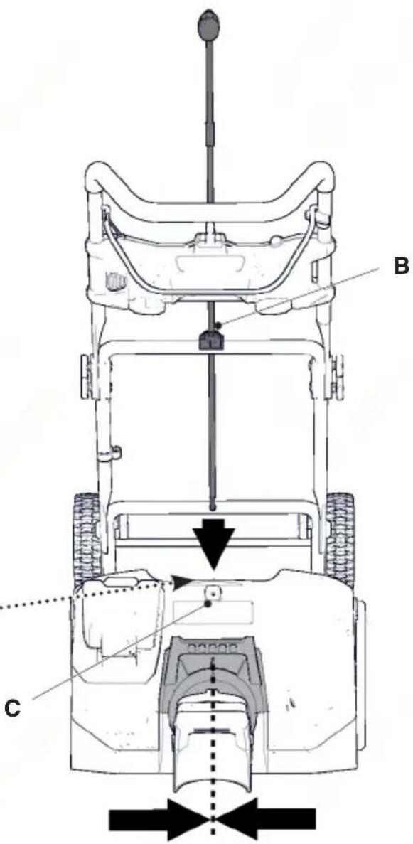
| [1] | TECHNICAL DATA | type ST 515 Li ST 615 Li | ||
| model ST 4851 AE ST 8051 AE | ||||
| [2] | Power voltage V 48 80 | |||
| [3] | Motor rotations rpm 2000 ± 10% 1900 ± 10% | |||
| [4] | Working width cm 50,8 50,8 | |||
| [5] | Weight kg 15,6 15,5 | |||
| [6] | Maximum launch distance | m | 5,5 | 6 |
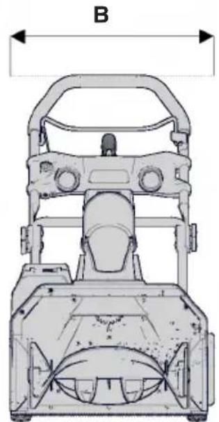
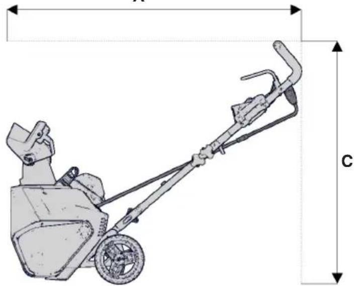
| [7] | Dimensions | Fig. 2 | ||
| [8] | A = Length | mm | 1130 | 1135 |
| [9] | B = Height | mm 950 | 940 | |
| [10] | C = Width | mm | 590 | 525 |
| [11] | Measured acoustic power level | dB(A) | 81 79 | |
| [12] | Uncertainty | dB(A) | 3 | 3 |
| [13] | Guaranteed acoustic power level | dB(A) | 84 | 82 |
| [14] | Sound pressure level | dB(A) | 68 68 | |
| [15] | Uncertainty | dB(A) | 3 | 3 |
| [16] | Operator position vibration value | m/s^2 | 2,5 | 2,5 |
| [17] | Uncertainty | m/s^2 | 1,5 | 1,5 |
| [18] | Batteries | mod | BT 48 Li 4,0BT 48 Li 5,0 | BT 80 Li 2,5BT 80 Li 4,0BT 80 Li 5,0 |
| [1] BG - ТЕХНИЧЕСКИ ДАННИ[2] Напрежение и честота на захранване[3] Обороти на двигателя[4] Работна ширина[5] Маса[6] Максимално разстояние на изхвърляне[7] Максимални размери[8] А = Дължина[9] В = Височина[10] С = Ширина[11] Измерено ниво на звукова мощност[12] Несигурност[13] Гарантирано ниво на звукова мощност[14] Ниво на звуково налягане[15] Несигурност[16] Стойност на вибрации в мястото за управление[17] Несигурност[18] Акумулатори | [1] BS - TEHNIČKI PODACI[2] Napon i frekvencija napajanja[3] Okretaji motora[4] Radna širina[5] Masa[6] Maksimalna udaljenost bacanja[7] Dimenzije[8] А = Dužina[9] В = Visina[10] С = Širina[11] Izmjerena razina zvučne snage[12] Nesigurnost[13] Garantirana razina zvučne snage[14] Razina zvučnog pritiska[15] Nesigurnost[16] Razina vibracija na mjestu vozača[17] Nesigurnost[18] Baterije | [1] CS - TECHNICKÉ PARAMETRY[2] Napájeci napětí a frekvence[3] Otáčky motoru[4] Pracovni záběr[5] Hmotnost[6] Maximální vzdálenost vyhazování[7] Vnější rozměry[8] А = Délka[9] В = Výška[10] С = Šířka[11] Naměřená úroveň akustického výkonu[12] Nepřesnost měření[13] Zaručená úroveň akustického výkonu[14] Úroveň akustického tlaku[15] Nepřesnost měření[16] Hodnota vibraci na místě řidiče[17] Nepřesnost měření[18] Akumulátor |
| [1] DA - TEKNISKE DATA[2] Forsyningsspænding og frekvens[3] Motoromdrejninger[4] Arbejdsbredde[5] Vægt[6] Maks. slyngningsafstand[7] Maskinmál[8] A = Længde[9] B = Høde[10] C = Bredde[11] Målt lydeffektniveau[12] Usikkerhed[13] Garanteret lydeffektniveau[14] Lydtryksniveau[15] Usikkerhed[16] Vibrationsniveau på førersædet[17] Usikkerhed[18] Batterier | [1] DE - TECHNISCHE DATEN[2] Versorgungsspannung und -frequenz[3] Motordrehzahl[4] Arbeitsbreite[5] Gewicht[6] Maximaler Wurfabstand[7] Abmessungen des Platzbedarfs[8] A = Länge[9] B = Höhe[10] C = Breite[11] Gemessener Schallleistungspegel[12] Messungenauigkeit[13] Garantierter Schallleistungspegel[14] Schalldruckpegel[15] Messungenauigkeit[16] Vibrationswert am Fahrerplatz[17] Messungenauigkeit[18] Akkus | [1] ES - DATOS TÉCNICOS[2] Tensión y frecuencia de alimentación[3] Revoluciones motor[4] Ancho de trabajo[5] Masa[6] Distancia de lanzamiento máxima[7] Dimensiones totales[8] A = Longitud[9] B = Altura[10] C = Anchura[11] Nivel de potencia sonora medido[12] Incertidumbre[13] Nivel de potencia sonora garantizado[14] Nivel de presión sonora[15] Incertidumbre[16] Valor de las vibraciones en el puesto de conducción[17] Incertidumbre[18] Batterias |
| [1] ET - TEHNILISED ANDMED[2] Toltepinge ja -sagedus[3] Mootoripoörded[4] Tóölaius[5] Mass[6] Maksimaalne heitekaugus[7] Möötmed[8] A = Pikkus[9] B = Körgus[10] C = Laius[11] Möödetud mūravõimsuse tase[12] Ebakindlus[13] Garanteeritud mūravõimsuse tase[14] Helirõhu tase[15] Ebakindlus[16] Vibratsiooni suurus juhikohal[17] Ebakindlus[18] Aku | [1] FI - TEKNISET TIEDOT[2] Syöttöjännite ja -taajuus[3] Moottorin kierrosluku[4] Työstöleveys[5] Massa[6] Maksimi linkoamisetäisyys[7] Mitat[8] A = Pituus[9] B = Korkeus[10] C = Leveys[11] Mitattu äänitehotaso[12] Epätarkkuus[13] Taattu äänitehotaso[14] Äänenpaineen taso[15] Epätarkkuus[16] Tārinārvo kuljetajan paikalla[17] Epätarkkuus[18] Akut | [1] FR - CARACTÉRISTIQUES TECHNIQUES[2] Tension et fréquence d'alimentation[3] Tours du moteur[4] Largeur de travail[5] Masse[6] Distance de projection maximale[7] Dimensions d'encombrement[8] A = Longueur[9] B = Hauteur[10] C = Largeur[11] Niveau de puissance sonore mesuré[12] Incertitude[13] Niveau de puissance sonore garanti[14] Niveau de pression sonore[15] Incertitude[16] Valeur des vibrations au poste de conduite[17] Incertitude[18] Batteries |
| [1] HR - TEHNIČKI PODACI[2] Napon i frekvencija napajanja[3] Broj okretaja motora[4] Radna širina[5] Masa[6] Maksimalna udaljenost izbacivanja[7] Gabaritne dimenzije[8] A = Dužina[9] B = Visina[10] C = Širina[11] Izmjerena razina zvučne snage[12] Mjerna nesigurnost[13] Zajamčena razina zvučne snage[14] Razina zvučnog tlaka[15] Mjerna nesigurnost[16] Vrijednost vibracija na vozačkom mjestu[17] Mjerna nesigurnost[18] Akumulatori | [1] HU - MŰSZAKI ADATOK[2] Tápfeszültseg és -frekvencia[3] Motor fordulatszáma[4] Munkavégzési szélesség[5] Tőmeg[6] Max. kidobási távolság[7] Befoglaló méretek[8] A = Hosszúság[9] B = Magasság[10] C = Szélesség[11] Mért zajteljesítmény szint[12] Mérési bizonytalanság[13] Garantált zajteljesítmény szint[14] Hangnyomásszint[15] Mérési bizonytalanság[16] A vezetőállásnál mért vibrációszint[17] Mérési bizonytalanság[18] Akkumulátorok | [1] IT - DATI TECNICI[2] Tensione di alimentazione[3] Giri motore[4] Larghezza di lavoro[5] Massa[6] Distanza di lancio massima[7] Dimensioni di ingombro[8] A = Lunghezza[9] B = Altezza[10] C = Larghezza[11] Livello di potenza sonora misurato[12] Incertezza[13] Livello di potenza sonora garantito[14] Livello di pressione sonoră[15] Incertezza[16] Valore delle vibrazioni al posto di guida[17] Incertezza[18] Batterie |
| [1] LT - TECHNINIAI DUOMENYS[2] Maitinimo įtampa ir dažnis[3] Variklio apsukos[4] Darbo plotis[5] Svoris[6] Maksimalus metimo tolis[7] Matmenys[8] A = Ilgis[9] B = Aukštis[10] C = Plotis[11] Išmatuotas garso galios lygis[12] Paklaida[13] Garantuotas garso galios lygis[14] Garso slógio lygis[15] Paklaida[16] Vibraciju lygis, sédyné[17] Paklaida[18] Akumuliatoriai | [1] LV - TEHNISKIE DATI[2] Barošanas spriegums un frekvence[3] Dziněja apgrieżeni[4] Darba platums[5] Masa[6] Maksimálais izmešanas attálums[7] Gabaritli[8] A = Garums[9] B = Augstums[10] C = Platums[11] Izměritais skaņas intensitātes līmenis[12] Kļūda[13] Garantētais skaņas intensitātes līmenis[14] Skaņas spiediena līmenis[15] Kļūda[16] Vibraciju līmenis vaditāja vietä[17] Kļūda[18] Akumulatori | [1] MK - ТЕХНИЧКИ ПОДАТОЦИ[2] Волтажа и вид на напојување[3] Вртежи на моторот[4] Ширина на работа[8] Тежина[6] Далечина за максимально отфрлање[7] Димензии на пречка[8] A = Должина[9] Б = Висина[10] В = Ширина[11] Измерено ниво на бучава[12] Отстапување[13] Гарантирано ниво на бучава[14] Ниво на звучен притисок[15] Отстапување[16] Вредност на вибрации на местото на управување[17] Отстапување[18] Батерии |
| [1] NL - TECHNISCHE GEGEVENS[2] Spanning en frequentie voeding[3] Toeren motor[4] Werkbreedte[5] Massa[6] Maximale schietafstand[7] Afmetingen[8] A = Lengte[9] B = Hoogte[10] C = Breedte[11] Gemeten akoestisch vermogen[12] Onzekerheid[13] Gewaarborgd akoestisch vermogen[14] Niveau geluidsdruk[15] Onzekerheid[16] Niveau trillingen op de bestuurdersplaats[17] Onzekerheid[18] Batterijen | [1] NO - TEKNISKE DATA[2] Matespenning og -frekvens[3] Motoromdreininger[4] Arbeidsbredde[5] Vekt[6] Maks. rekkevidde for utkast[7] Totale mål[8] A = Lengde[9] B = Høyde[10] C = Bredde[11] Målt lydeffektnivå[12] Usikkerhet[13] Garantert lydeffektnivå[14] Lydtrykknivå[15] Usikkerhet[16] Vibrasjonsnivå ved førerplassen[17] Usikkerhet[18] Batterier | [1] PL - DANE TECHNICZNE[2] Napięcie i częstotliwość zasilania[3] Obroty silnika[4] Zasięg prac[5] Masa[6] Odległość maksymalna odrzutu[7] Wymiary ogólne[8] A = Długość[9] B = Wysokość[10] C = Szerokość[11] Pomiar poziomu mocy akustycznej[12] Niepewność pomiaru[13] Gwarantowany poziom mocy akustycznej[14] Poziom ciśnienia akustycznego[15] Niepewność pomiaru[16] Poziom drgań na stanowisku kierowcy[17] Niepewność pomiaru[18] Akumulatory |
| [1] RO - DATE TEHNICE[2] Tensiunea și frecvența de alimentare[3] Turații motor[4] Lățime de lucru[5] Masă[6] Distanță maximă de lansare[7] Dimensiuni de gabarit[8] A = Lungime[9] B = Inălțime[10] C = Lățime[11] Nivel de putere sonoră măsurat[12] Nesiguranță[13] Nivel de putere sonoră garantat[14] Nivel de presiune sonoră[15] Nesiguranță[16] Valoarea vibrațiilor la locul conducătorului[17] Nesiguranță[18] Baterii | [1] RU - ТЕХНИЧЕСКИЕ ХАРАНТЕРИСТИКИ[2] Напряжение и частота питания[3] Число оборотов двигателя[4] Ширина рабочей зоны[5] Масса[6] Дальность отброса снега[7] Габаритные размеры[8] A = Длина[9] B = Высота[10] C = Ширина[11] Измеренный уровень звуковой мощности[12] Погрешность[13] Гарантируемый уровень звуковой мощности[14] Уровень звукового давления[15] Погрешность[16] Уровень вибрации на месте водителя[17] Погрешность[18] Батареи | [1] SK - TECHNICKÉ PARAMETRE[2] Napăjeci napěti a frekvence[3] Otáčky motoru[4] Pracovni záběr[5] Hmotnost[6] Maximální vzdálenost vyhazování[7] Vnější rozměry[8] A = Délka[9] B = Výška[10] C = Šiřka[11] Naměřená úroveň akustického výkonu[12] Nepřesnost měření[13] Zaručená úroveň akustického výkonu[14] Úroveň akustického tlaku[15] Nepřesnost měření[16] Hodnota vibrací na místě řidiče[17] Nepřesnost měření[18] Akumulátory |
| [1] SL - TEHNIČNI PODATKI[2] Napetost in frekvenca električnega napajanja[3] Vrtljaji motorja[4] Delovna širina[5] Masa[6] Maksimalna dolžina izmeta[7] Dimenzije[8] A = Dolžina[9] B = Višina[10] C = Širina[11] Izmerjena raven zvočne moči[12] Negotovost[13] Zajamčena raven zvočne moči[14] Raven zvočnega tlaka[15] Negotovost[16] Stopnja vibracij na upravljavčevem mestu[17] Negotovost[18] Baterije | [1] SR - TEHNIČKI PODACI[2] Napon i frekvencija napajanja[3] Obrtaji motora[4] Radna širina[5] Masa[6] Maksimalna udaljnost bacanja[7] Dimenzije[8] A = Dužina[9] B = Višina[10] C = Širina[11] Izmereni nivo zvučne snage[12] Nesigurnost[13] Garantovani nivo zvučne snage[14] Nivo zvučnog pritiska[15] Nesigurnost[16] Vrednost vibracija na mestu vozača[17] Nesigurnost[18] Baterije | [1] SV - TEKNISKA DATA[2] Drivspänning och frekvens[3] Motorvarvtal[4] Arbetsbredd[5] Vikt[6] Maximal kastlängd[7] Mått[8] A = längd[9] B = höjd[10] C =bredd[11] Uppmätt ljudeffektnivå[12] Osäkerhet[13] Garanterad ljudeffektnivå[14] Ljudtrycksnivå[15] Osäkerhet[16] Vibrationsnivå på manöverhandtag[17] Osäkerhet[18] Batterier |
INDEX
- GENERAL INFORMATION......1
- SAFETY REGULATIONS....2
- GETTING TO KNOW THE MACHINE......5
3.1 Description of the machine and planned use....5
3.2 Safety signs 6
3.3 Identification label 6 - ASSEMBLY....7
- CONTROLS....8
5.2 Starter lever....8
5.3 Starter lever lock 8
5.4 Discharge chute adjustment handle ..... 8
5.5 Deflector adjustment....8
5.6 Led lights switch....8 - USING THE MACHINE....8
6.1 Preparation 8
6.2 Safety checks....8
6.3 Start-Up / Operation....9
6.4 Stop 9
6.5 Advice for operation 9
6.6 After operation 9 - BATTERY RECHARGING AND MANAGEMENT....9
- MAINTENANCE 10
8.1 General information....10
3.2 Cleaning....10 - STORAGE 11
- ASSISTANCE AND REPAIRS......11
11.WARRANTY COVERAGE 11 - MAINTENANCETABLE....12
13.PROBLEM IDENTIFICATION 12
1. GENERAL INFORMATION
1.1 HOW TO READ THE MANUAL
Some paragraphs in the manual contain important information regarding safety and operation and are emphasized in this manner:
NOTE or IMPORTANT these give details or further information on what has already been said, and aim to prevent damage to the machine.
The symbol highlights danger. Non-compliance with the warning could lead to personal or third party injury and/or damage.
The paragraphs highlighted in a square with grey spots indicate the optional characteristics not on all models documented in this manual. Check if the characteristic is on this model.
Whenever reference is made to a position on the machine "front", "back", "left" or "right" hand side, this is determined from where the operator is driving.
1.2 REFERENCES
1.2.1 Figures
The figures in these instructions for use are numbered 1, 2, 3, etc.
Components shown in the figures are marked A, B, C, etc.
A reference to component C in figure 2 is written: "See fig. 2.C" or simply "(Fig. 2.C)".
The figures are given as a guide only. The actual parts may vary from those shown.
1.2.2 Titles
The manual is divided into chapters and paragraphs. The title of paragraph "2.1 Training" is a sub-title of "2. Safety regulations". References to titles or paragraphs are marked with the abbreviation chap. or par. and the relevant number. Example: "chap. 2" o "par. 2.1".
2. SAFETY REGULATIONS
2.1 TRAINING
⚠️ Read these instructions carefully before using the machine.
⚠️ Become acquainted with the controls and the proper use of the machine. Learn how to stop the motor quickly. Failure to follow the warnings and instructions may result in fire and/or serious injury. Save all warnings and instructions for future reference.
- Never allow children or persons unfamiliar with these instructions to use the machine. Local regulations may restrict the age of the operator.
- This appliance can be used by children aged from 8 years and above and persons with reduced physical, sensory or mental capabilities or lack of experience and knowledge if they have been given supervision or instructions concerning use of the appliance in a safe way and understand the hazards involved. Children shall not play with the appliance. Cleaning and user maintenance shall not be made by children without supervision.
- Never use the machine if the user is tired or unwell, or has taken medicine, drugs, alcohol or any substances which may slow his reflexes and compromise his judgement.
Bear in mind that the operator or user is responsible for accidents or unexpected events occurring to other people or their property. It is the user's responsibility to assess the potential risk of the area where work is to be carried out, and to take all the necessary precautions to ensure his own safety and that of others, particularly on slopes or rough, slippery and unstable ground.
2.2 PREPARATION
Individual Protection Devices (IPD)
- Do not use the snow thrower without wearing adequate clothing.
- Wear footwear that enables good grip on slippery surfaces.
• Always wear protective goggles or a visor during use, maintenance or repairs. The operation of any powered machine can result in foreign objects being thrown into the eyes.
• Always use noise-proof hearing protectors.
Work area/Machine
- Check the area to clean well and remove any obvious foreign bodies. E.g. all doormats, sleds, boards, wires, etc.
- Before starting the motor, check you have disconnected all the commands.
- Let engine and the snow thrower adjust to outdoor temperatures before starting to clear snow.
Battery power supply
- Read the safety precautions contained in the battery manual.
- Check the mains voltage corresponds to the power supply voltage.
⚠️ Permanent connection of any electrical device to the building mains must be carried out by a qualified electrician, in compliance with the standards in force. Improper connection can cause serious personal harm, including death.
2.3 DURING OPERATION
Work Area
- Do not use the machine in environments at risk of explosion, in the presence of flammable liquids, gas or powder. Electrical contacts and mechanical friction can generate sparks that can ignite the powder or vapours.
• Work only in daylight or with good artificial light in good visibility conditions. - Keep persons, children and animals away from the working area. Get another adult to keep the children under supervision.
• Exercise extreme caution when operating on or crossing gravel drives, walks or roads. Stay alert for hidden hazards. - Look out for traffic when using the machine near the road.
Behaviour
- Do not place the discharge chute against the wind, or at people, animals, vehicles, houses and anything else
that could be damaged by the snow or by objects hidden in the snow. Never allow anyone in front of the unit.
- Never use the snow thrower near fences, cars, windows, glass enclosures, etc. without having first adjusted the deflector on the discharge chute.
- Keep hands and feet away from rotating parts. Always keep your distance from the snow discharge chute. Keep clear the discharge opening at all times.
- Keep hands and feet away from rotating parts. Always keep your distance from the snow discharge chute.
- If the snow thrower strikes foreign bodies or displays anomalous vibrations, remove the battery and carefully inspect the machine to check there is no damage. Vibrations are normally synonymous with a problem. Repair any damage before re-using the machine
- Before leaving the machine, disconnect all the commands and remove the battery.
- Before cleaning, repairs or inspections, always check the rotating units have stopped, controls are disengaged and the battery is removed.
- Never operate the snow thrower at high transport speeds on slippery surfaces. Use care when reversing. Look behind you to make sure there are no obstacles before and during operations in reverse gear.
- Disengage power to the auger when snow thrower is transported or not in use.
• Always be sure of your footing, and keep a firm hold on the handle. Walk, never run!
Use limitations
- Do not use the machine sideways on a slope. Always move from top to bottom, then from bottom to top. Exercise caution when changing direction on a slope. Avoid steep slopes.
- Do not use the machine if the guards are insufficient or if the safety devices are not correctly positioned.
- Never disengage or tamper with the safety systems.
- Do not overload the machine by driving it too fast.
- Do not place hands inside the chute or the auger without firstly removing the battery.
2.4 MAINTENANCE, STORAGE AND TRANSPORT
Ensure regular maintenance and correct storage to maintain machine safety.
⚠️ Before cleaning or doing maintenance work, remove the battery and read the relevant instructions. Wear proper clothing and protective gloves whenever your hands are at risk.
⚠️ Faulty or worn-out parts must always be replaced and never repaired. Only use original spare parts: the use of non-original and/or incorrectly fitted parts will compromise the safety
of the machine, may cause accidents or personal injuries for which the Manufacturer is under no circumstance liable or responsible.
Maintenance
- The battery, if damaged, must be replaced with a genuine part only, by your dealer or an authorised assistance centre.
Storage
- Run the machine a few minutes after throwing snow to prevent freeze-up of the collector/impeller
- Let the motor cool down before storing the snow thrower indoors.
- Always refer to owner's guide instructions for important details if the snowthrower is to be stored for an extended period.
Transport
Each time you have to move, lift, transport or tilt the machine:
- Wear heavy work gloves.
- Hold the machine in the points offering a safe grip, taking into account the weight and its division.
- Use an adequate number of people for the weight of the machine and the characteristics of the transport vehicle.
2.5 ENVIRONMENTAL PROTECTION
Safeguarding the environment must be a relevant and priority aspect of machine use, of benefit to the community and the environment we live in.
- Avoid being a disturbance to the neighbourhood.
- Adhere strictly to the local regulations governing the disposal of packaging, oil, fuel, filters, damaged parts or any other element which may have an impact on the environment; this waste should not be disposed of along with standard household waste, but must be disposed of separately and sent to special waste disposal facilities for handling and recycling.
- When the machine is withdrawn from service, do not dump it in the environment, but take it to a waste disposal facility in accordance with the local regulations in force.
Li-ion
At the end of their working life, dispose of batteries paying due attention to the environment. Batteries in material classified as tardous for you and the onment. They must beived and disposed of rately at a facility that lots lithium-ion batteries.

Separate waste collection of the products and packaging used allows the materials to be recycled and reused. Reuse of recycled materials help to prevent environmental pollution and reduces the demand for raw materials.
3. GETTING TO KNOW THE MACHINE
2.6 RECYCLING
Do not throw electrical equipment away with domestic waste. According to the European Directive 2012/19/EC on electrical and electronic equipment waste and its implementation in compliance with national standards, old electrical equipment must be collected separately, for eco-compatible recycling. If electrical equipment is disposed of in a landfill or in the ground, the harmful substances can reach the aquifer and enter the food chain, damaging your health and wellbeing. For further information on disposing of this product, contact the competent authority for the disposal of domestic waste or your dealer.
3.1 DESCRIPTION OF THE MACHINE AND PLANNED USE
This machine is a snow thrower.
The machine is electrically powered. It is equipped with a 48V / 80V rechargeable battery pack. It should be recharged with a 230 V c.a. current socket using a specific battery charger (see the specific manual). The electrical motor is activated by a starter lever on the handle, activating the clearing auger. The operator can drive the machine by holding it by the handle where the starter lever is located, always standing upright behind the machine.
3.1.1 Intended use
This machine has been designed and built to remove and clear away snow from pavements, gardens, drives and other ground-level surfaces. The snow thrower must only be used to remove snow.
3.1.2 Improper use
Any other usage not in keeping with the above-mentioned ones may be hazardous and harm persons and/or damage things. Examples of improper use may include, but are not limited to:
- use of the machine on surfaces above ground level, such as roofs on houses, garages, porticoes or other structures or buildings.
- Activate the auger in the presence of materials other than snow (e.g. soil, grass, pebbles, etc.),
- Pulling or pushing loads.
- Do not carry passengers.
IMPORTANT Improper use of the machine will invalidate the warranty, relieve the Manufacturer from all liabilities, and the user will consequently be liable for all and any damage or injury to himself or others.
3.1.3 User types
This machine is intended for use by consumers, i.e. non-professional operators. The machine is intended for “DIY” use only.
IMPORTANT The machine must
be used by one operator.
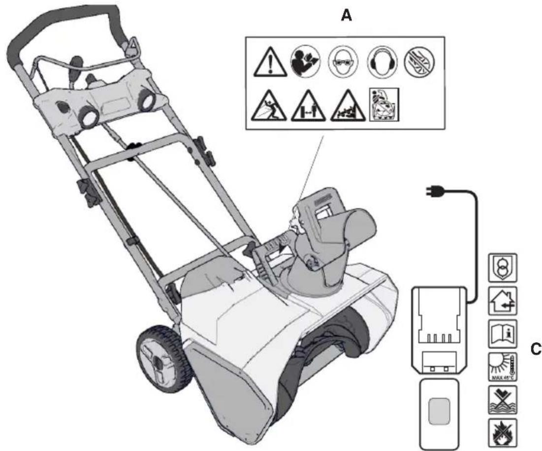
3.2 SAFETY SIGNS
The machine has various symbols on it (fig. 3). They are used to remind the operator of the behaviour to follow to use it with the necessary attention and caution. Meaning of symbols:

DOUBLE INSULATED - Class II: Device in which protection against electric shocks is not based exclusively on the main insulation, but also on additional safety measures such as double or reinforced insulation. These measures do not include earthing devices and do not depend on the installation conditions

WARNING! In the event of non-compliance with regulations, the risk of death and/or damage to people or property exists.

WARNING! Read the instructions before operating the machine.

DANGER! Thrown objects. Do not turn the discharge chute towards onlookers or animals.

DANGER! Keep people, children and animals away from the work area.

DANGER! Rotor turning. Always keep away from the snow discharge opening..

DANGER! Keep hands and feet away from rotating parts.

DANGER! Never put your hands inside the discharge chute when the auger is in motion. Stop the engine before unclogging the discharge chute.

DANGER! Always use hearing protectors

DANGER! Wear eye protection.

DANGER! Before carrying out maintenance on the machine, remove the battery pack from the machine..

WARNING! Battery charger is equipped with a safety transformer.

DANGER! Use only in dry surroundings.

WARNING! Read the instruction manual before using.

WARNING! Do not expose the accumulator when the temperature is higher than 45^ C.

DANGER! Do not immerse the accumulator in water and do not expose it to humidity.

DANGER! Do not throw batteries into a fire. EXPLOSION RISK!
IMPORTANT Any damaged or illegible decals must be replaced. Order replacement decals from an authorised assistance centre.
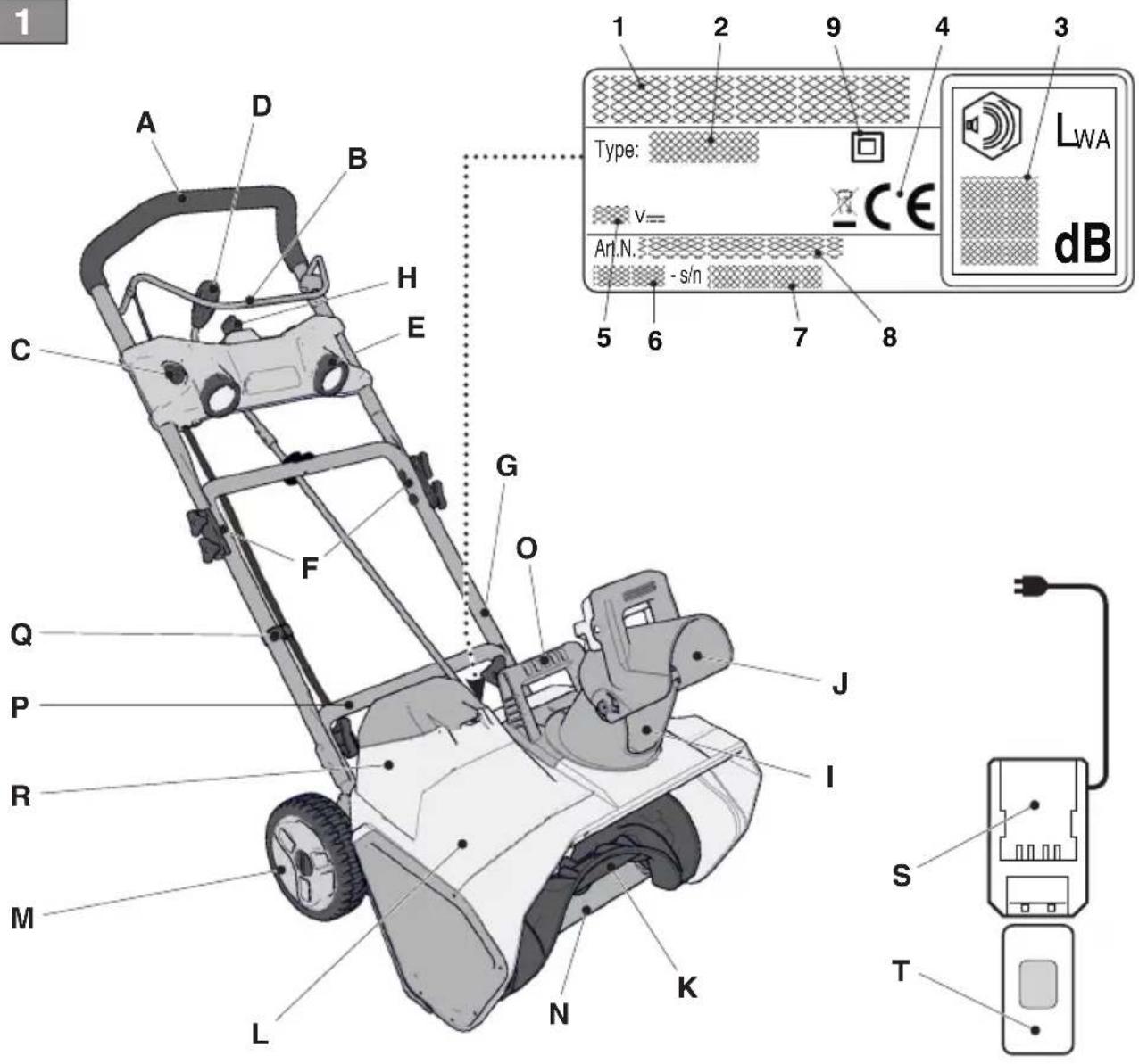
3.3 IDENTIFICATION LABEL
The identification label holds the following data (fig. 1)
- Manufacturer's address
- Type of machine
- Sound power level
- CE conformity marking
- Power voltage
- Month /Year of manufacture
- Serial number
- Article code
- Electrical protection rating
Write the identification data of the machine in the specific space on the label on the back of the cover page.
IMPORTANT Use the identification names on the identification label of the product.
IMPORTANT Use these means of identification whenever you contact an authorized service workshop.
- IMPORTANT The example of the Declaration of Conformity is provided on the last pages of the manual.
3.4 MAIN COMPONENTS
The machine is made up of the following main components (fig. 1):
A. Handle
B. Starter lever
C. Starter lever release
D. Chute adjustment handle
E. Led lights
F. Handle pivot closure
G. Central handle
H. Ignition key
I. Exhaust chute
J. Deflector
K. Auger
L Auger compartment
M. Wheel
N. Lower blade
O. Transport handle
P. Lower part of handle
Q. Cable gland
R. Battery compartment
S. Battery charger (supplied separately)
T. Battery (supplied separately)
4. ASSEMBLY
For storage and transport purposes, some components of the machine are not installed in the factory and have to be assembled after unpacking. Follow the instructions below.
4.1 ASSEMBLY COMPONENTS
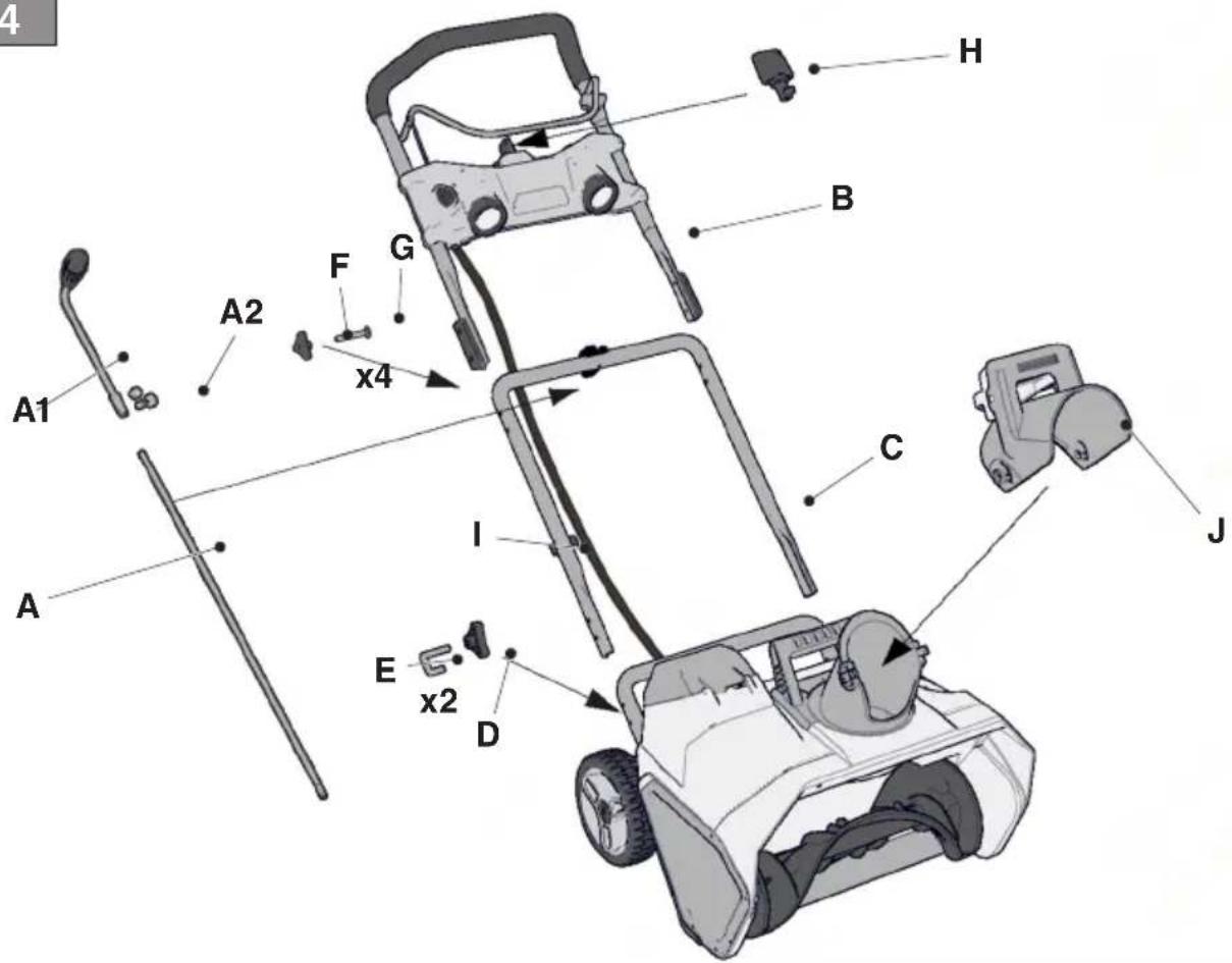
The packaging holds the components needed for assembly (fig. 4) listed in the following table:
| Component | Fig. | N. |
| Snow thrower | 4 | 1 |
| Discharge chute adjustment handle | 4.A, 4.A1, 4.A2 | 1 |
| Handle | 4.B | 1 |
| Handle fitting | 4.C | 1 |
| Component | Fig. | N. |
| Spacers and screws for securing the handle in place | 4.D, 4.E | 2 |
| Spacers and screws for securing the handle in place | 4.F, 4.G | 4 |
| Ignition key | 4.H | 1 |
| Cable gland to handle | 4.I | 1 |
| Deflector | 4.J | 1 |
| Instructions | - | 1 |
4.2 UNPACKING
- Cautiously open the packaging, paying attention not to lose components.
- Consult the documentation in the box, including these instructions.
- Remove all the unassembled parts from the box.
- Lift the snow thrower from the box.
- Dispose of the box and packaging in compliance with local regulations.
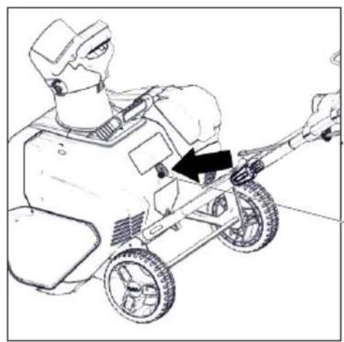
4.3 HANDLE ASSEMBLY
- Assemble the central part of the handle (fig. 4.C) on the snow thrower (lower part of handle), fastening it with screws (fig. 4.D, 4.E) on both sides.
- Position the upper handle (fig. 4.B) on the central one and fasten it with the specific screws and fastenings (fig. 4.G, 4.F).
- Fasten the electrical cable in place with the specific cable gland (fig. 4.1).
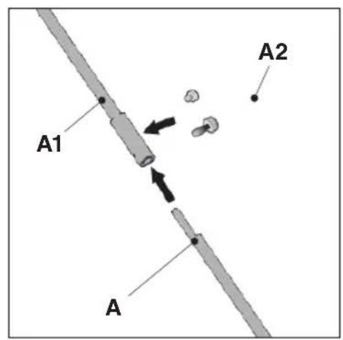
4.4 DISCHARGE CHUTE ADJUSTMENT HANDLE ASSEMBLY
- Assemble the handle (fig. 5.A1) using the specific extension shaft (fig. 5.A), fastening it in place with the 2 screws (fig. 5.A2). Make sure the holes of the shaft (fig. 5.A) and joint (fig. 5.A1) are aligned.
- Insert the 2 screws in the holes and fix.
- Pass the handle obtained in the specific lower handle support (fig. 5.B).
- Insert the end of the handle in the specific coupling hole on the chute, keeping it straight and with the grip upwards (fig. 5.C).
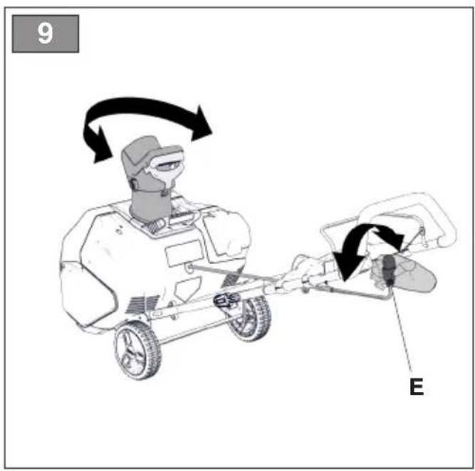
- Check the discharge chute by turning it entirely in both directions. The chute must freely rotate (fig. 9).
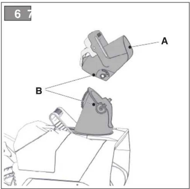
4.5 DEFLECTOR ASSEMBLY
- Insert the deflector on the discharge duct in the upright position (fig. 6.A).
-
Fit the tabs on both sides in the rotation eyelets (fig. 6.B).
-
Push until the pins fit into the specific holes ON: lights on with a click. O = OFF: lights off
4.6 CABLE GLAND ASSEMBLY
Insert the cable in the cable gland (fig. 4.1) and fit it on the intermediate handle.
5. CONTROLS
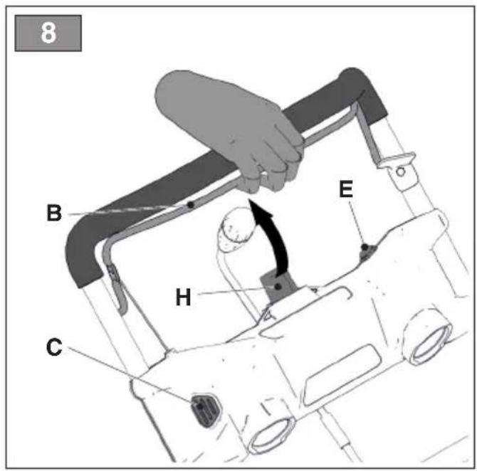
5.1 IGNITION KEY
Used to start and stop the motor. The ignition key has two positions (fig. 8.H):
- Key removed - OFF - the motor stops cannot be restarted.
- Key inserted - ON - the motor can start and run.
5.2 STARTER LEVER
Used to start and stop the motor.
- Start: Press the lock button (fig. 8.C) and pull the starter lever (fig. 8.B).
- Stop: release the starter lever (fig. 8.B).
5.3 STARTER LEVER LOCK
It prevents accidental activation of the starter lever. Press the button (fig. 8.C) to release the starter lever.
5.4 DISCHARGE CHUTE ADJUSTMENT HANDLE
This controls rotation of the discharge chute so that snow discharge can be aimed in the required direction. Turn the handle (fig. 9.E) clockwise/anti-clockwise to adjust the chute.
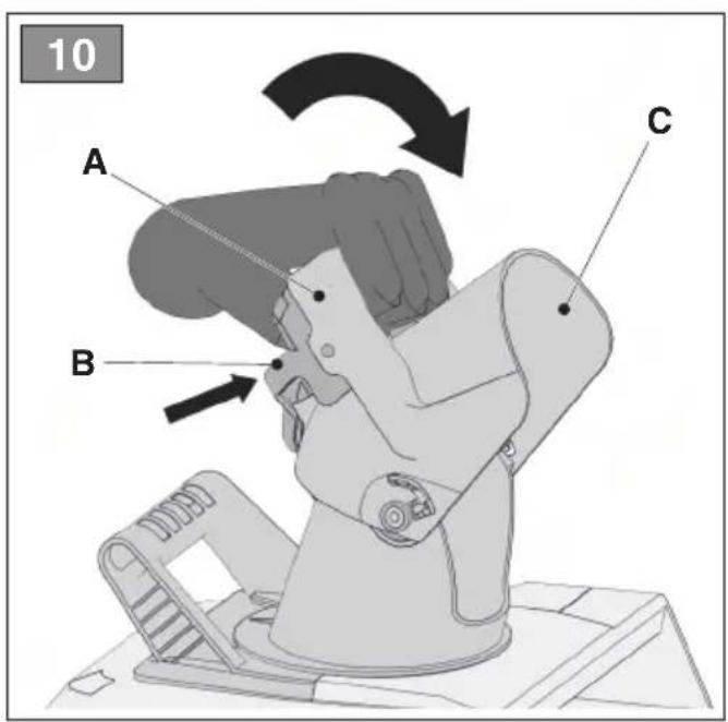
5.5 DEFLECTOR ADJUSTMENT
Hold the handle (fig. 10.A) and press it to release the deflector lock (fig. 10.B) to enable deflector regulation (fig. 10.C). Move the handle forward/back to lower/lift the deflector, pulling the handle. Once the deflector is brought to the desired position, releasing your grip blocks the deflector (click).
5.6 LED LIGHTS SWITCH
To turn the headlamps on, push the switch (fig. 8.E) forward.
6. USING THE MACHINE
IMPORTANT The safety regulations to follow during machine use are described in chap. 2. Strictly comply with these instructions to avoid serious risks or hazards.
The machine is supplied without the battery. Purchase the battery with the capacity that most suits your operational requirements and fully charge it according to the instructions in the battery booklet. The list of approved batteries for this machine and found in the “Technical Data” table.
6.1 PREPARATION
- Check the auger has not already taken in snow in the start position.
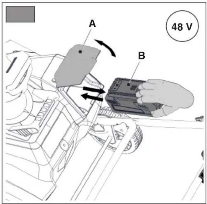
- Insert the battery in the specific compartment (fig. 7)
NOTE Before starting to clear the snow, silicone spray should be applied to the auger to avoid ice formation on the rotating units.
6.2 SAFETY CHECKS
After start-up and before using the machine, it is essential to run the following safety tests. Check the results of the safety checks correspond to those in the table.
Always carry out the safety checks before use.
6.2.1 General safety and auger functionality check
| Object Result | |
| Press the release button (fig. 8.C).Press the starter lever. | The motor starts and the auger starts to rotate. |
| Test driving No abnormal v | brations.No abnormal sound. |
| Release the starter lever. The motor and auger stop immediately. | |
⚠️ If any of the results fails to match the indications provided in the following table, do not use the machine! Take it to a service centre to be checked and repaired if necessary.
The auger starts to rotate when the snow thrower starts. Keep people a safe distance away and check the auger is not touching stones or objects that could be launched.
6.3.1 Departure
- Tilt the snow thrower slightly back and lift the auger slightly off the ground.
- Press and keep the starter lever release pressed (fig. 8.C).
- To start, pull the starter lever (fig. 8.B).
- Release the starter lever.
⚠️ If the auger is blocked, do not attempt to operate the motor.
The machine is equipped with an automatic "Motor save" protection when inserted, wait a few minutes before re-starting the machine.
6.3.2 Operation
Lower the auger towards the ground and start to remove snow.
Always stop the motor before proceeding with release operations.
6.4 STOP
To stop the machine, release the starter lever (fig. 8.B).
IMPORTANT If you have to leave the machine, remove the battery.
- Snow is removed more easily when it is still fresh. Pass back over the already cleared zones to remove snow residue.
- If possible, clear the snow in the direction of the wind. Check the distance and the direction of the removed snow jet.
- In strong winds, lower the deflector to direct the discharged snow towards the ground, reducing the likelihood of the wind transporting the snow to the wrong areas.
- Once you have finished work, leave the machine running for a few minutes to prevent ice from forming in the discharge chute.
6.5.1 Dry and normal snow
Snow up to 20 cm can be quickly removed by proceeding to evenly clear it away. For deeper or built up snow, reduce the speed and let the machine work at its own rhythm.
6.5.2 Wet or compact snow
Slowly move forward. Avoid using the lower blade to remove compact snow and ice.
IMPORTANT Heavy use of the machine with wet or compact snow can cause faults to the auger compartment.
6.6 AFTER OPERATION
- Open the battery housing hatch (fig. 7).
Battery 48 V
- Press the retainer tab in the battery and remove it from the compartment (Fig. 7).
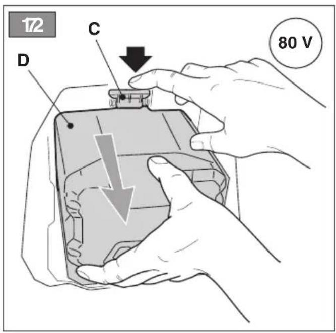
Battery 80 V
- Press the retainer tab in the battery compartment and remove the battery (Fig. 7).
- Clean the remaining snow on the machine with a brush (par. 8.2).
- Move all the controls forward and back a few times.
- Tighten any nuts and bolts that are loosened during operation.
- Check there are no loose or damaged components. If necessary, replace the damaged components.
Do not cover the machine when the motor is still warm.
7. BATTERY RECHARGING AND MANAGEMENT
- The battery must be stored in places with temperatures between 7°C and 40°C. If the machine is stored in places that could exceed these threshold, it is recommended to remove the battery and store it in a more suitable location.
- During use, the battery is protected against total drainage with a protective device that switches off the machine and stops it from working.
- The battery is equipped with a guard that inhibits recharging if the environmental temperature is not between 0 and +45 °C.
- The battery can be recharged at any time, even partially, with no risk of damaging it.
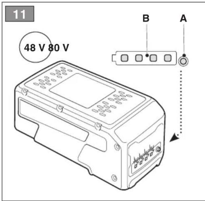
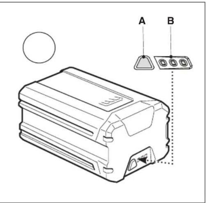
Check the battery charge status
To check the condition of the battery charge status, press the small button (fig.
11.A) which activates 3 or 4 LED lights (fig.11.B) which indicate the following:
| LED Battery power reserve | ||
| 48 V 80 V | ||
| 4 GREEN | 100% - | |
| 3 GREEN | 70% 100% | |
| 2 GREEN | 45% 70% | |
| 1 GREEN | 10% - Recharge needed | 30% - Recharge needed |
| None The battery has less than 10% power reserve and needs recharging immediately. If at least one LED does not come on after 30 minutes charging, the battery is faulty and needs replacing. | ||
Battery charging lasts from 1.5 - 3.5 hours, depending on the battery capacity and its residual charge. The battery charger (5) is the diagnostic type fitted with a LED that provides information on the battery and charge status, based on the following chart:
| LED (5a) Meaning | |
| GREEN(Flashing) | Battery charging |
| GREEN Fully charged battery | |
| RED Battery overheated: remove the battery and leave it to cool for at least 30 minutes | |
| Off No battery or battery inserted incorrectly | |
| RED (Flashing) Charge anomaly and possible faulty battery; in this case remove the battery and replace it with hours: if the LED indicates charging status, this means that the battery is in good condition and the charging can proceed as normal. Otherwise:- disconnect the battery charger, wait a few minutes, and reconnect it to the mains again;- remove the battery from the charger, wait a few minutes, and replace it again.If, after all these attempts, the LED (5b) does not indicate the charge status and continues to flash, this means that the battery is faulty and needs replacing. | |
8. MAINTENANCE
8.1 GENERAL INFORMATION
IMPORTANT The safety regulations to follow during machine use are described in par. 2.4. Strictly comply with these instructions to avoid serious risks or hazards.
All service and all maintenance checks must be carried out on a stationary machine with the motor switched off. Before any maintenance operation, switch off the motor and remove the key from the compartment.
⚠ Wear adequate clothing, gloves and goggles before carrying out any maintenance.
- The frequency and types of maintenance are summarised in the "Maintenance Table". The table will help you maintain your machine's safety and performance. It summarises the main interventions to be made and the frequency applicable to each of them. Carry out the relevant intervention according to the first deadline.
- The use of non-genuine spare parts and accessories could adversely affect machine operation and safety. The manufacturer shall decline all liability in the event of injuries or damages caused by such parts.
• Genuine spare parts are supplied by authorized assistance workshops and dealers.
IMPORTANT All the maintenance and adjustment operations not described herein must be carried out by your dealer or Authorised Service Centre.
8.2 CLEANING
⚠️ Carry out cleaning operations with the machine switched off Do not try to remove snow from the discharge without firstly:
- Releasing the auger control.
- Removing the ignition key
- Removing the battery
Always clean the machine after use. To clean the machine adhere to the instructions provided below:
- Stop the motor
- Remove the battery from its compartment.
- Cool the snow thrower.
- Clean the snow thrower internally and externally with an adequate brush and/or compressed air.
⚠️ Never wash the snow thrower with water, otherwise the electric device will be damaged causing the risk of electrocution.
9. STORAGE
If you intend to put your machine away for more than 30 days:
- Clean the snow thrower thoroughly.
- Check for any damage. If necessary, see to the necessary repairs.
- If the paintwork is damaged, touch it up to prevent rust.
- Protect any exposed metal surfaces from rust.
10. ASSISTANCE AND REPAIRS
This manual provides all the necessary information to run the machine and for correct basic maintenance operations which can be performed by the user. Any regulations and maintenance operations not described herein must be carried out by your Dealer or Authorized Service Centre, which have the necessary knowledge and equipment to ensure that the work is carried out correctly, maintaining the correct degree of safety and the original operating conditions of the machine. Any operations performed in unauthorized centres or by unqualified persons will totally invalidate the Warranty and all obligations and responsibilities of the Manufacturer.
- Only authorized service workshops can carry out guaranteed repairs and maintenance.
- The authorized service workshops only use genuine spare parts. Genuine
spare parts and accessories have been designed specifically for machines.
- Non-genuine spare parts and accessories are not approved. Use of non-genuine spare parts and accessories cause the warranty to expire.
- It is advisable to send your machine once a year to an authorized service workshop for servicing, assistance and safety device inspection.
11. WARRANTY COVERAGE
The warranty covers all material and manufacturing defects. The user must follow all the instructions provided in the accompanying documentation.
The warranty does not cover damages caused by:
- Failure to become familiar with the documentation accompanying the machine.
- Carelessness.
- Incorrect or prohibited use or assembly.
- Use of non-genuine spare parts.
- Use of accessories not supplied or approved by the manufacturer.
The warranty does not cover:
- Normal wear and tear of consumables, such as drive belts, drills, headlights, wheels, bolts and wires.
• Normal wear and tear. - Motors. Motors are covered by the warranty provided by the relative manufacturer in compliance with the specified terms and conditions.
The purchaser is protected by his own national legislation. The purchaser's rights envisaged by the national laws in his own country are not in any way restricted by this warranty.
- MAINTENANCE TABLE
| Intervention Frequency Paragraph | ||
| Safety checks/check controls Before each use 6.2 | ||
| Always check the electric devices are intact and working properly Before each use 6.2 | ||
| Check the auger rotates freely Before each use 6.2.1 | ||
| Apply silicone spray on the auger, to avoid ice formation Before each use 6.3 | ||
| Check all the screw connections are tight. Tighten, if necessary. | Before and after each use | 4 |
| Check the starter lever is only activated on release of the disengaged starter lever | Before each use 5.3 | |
| General cleaning and inspection | At the end of each operation | 8.2 |
13. PROBLEM IDENTIFICATION
| PROBLEM PROBABLE CAUSE REMEDY | ||
| 1. No start | Battery is not inserted or is inserted incorrectly | Check that the battery is correctly inserted |
| Overload protection activated Wait a few seconds for automatic reset. | ||
| The auger is on and the motor cannot start. | Immediately release the start control and remove the obstacle.Try and switch on again. | |
| 2. The motor barely rotates | Auger or discharge chute obstructed, blocked by obstacles or damaged. | Clean the auger and chute. Remove any dirt or foreign bodies. Replace if damaged. |
| The capacitor is faulty. Call assistance or the dealer. | ||
| 3. The motor stops suddenly | Electric part malfunction Call assistance or the dealer. | |
| Overload protection activated Wait 10 minutes and try again. | ||
| 4. Excessive vibrations | Loose parts or auger or rotor damaged. Tighten all the fastening devices.Replace the damaged parts in the authorised assistance centre. | |
| Handle not correctly positioned. Ensure the handle is fastened in its position. | ||
| 5. Loss or slowing of thrown snow | Blocked discharge chute. Clean the discharge chute. | |
| Auger blocked. | Remove any dirt or foreign bodies from the auger. | |
| 6. The snow thrower leaves a light layer of snow on the ground | Auger blade worn | Contact the authorised assistance centre. |
| 7. Battery power reserve is low | Severe working conditions requiring greater current absorption | Optimise operations (chap. 7) |
| Battery is insufficient for operating requirements | Use a second battery or an extended battery | |
| 8. The battery charger is not recharging the battery (red led on or flashing) | Battery is not correctly inserted in the battery charger | Check it is correctly inserted |
| Unsuitable environmental conditions | Recharge the battery in places with suitable temperatures (chap. 7) | |
| Dirty contacts | Clean the contacts | |
| 9. The battery charger is not recharging the battery (no led on) | The battery charger is not energised | Check it is plugged in and the power socket is energised |
| Faulty battery charger | Replace with an original spare part | |
If problems persist after having performed the above operations, contact your dealer.
D. Lgs. 262/2002, ANNEX V (Italy)
• EMCD: 2014/30/EU
• RoHS II: 2011/65/EU

- ST 4851 AE ST 8051 AE
- INDEX
- GENERAL INFORMATION
- HOW TO READ THE MANUAL
- REFERENCES
- Figures
- Titles
- SAFETY REGULATIONS
- TRAINING
- PREPARATION
- Individual Protection Devices (IPD)
- Work area/Machine
- Battery power supply
- DURING OPERATION
- Work Area
- Behaviour
- Use limitations
- MAINTENANCE, STORAGE AND TRANSPORT
- Maintenance
- Storage
- Transport
- ENVIRONMENTAL PROTECTION
- GETTING TO KNOW THE MACHINE
- RECYCLING
- DESCRIPTION OF THE MACHINE AND PLANNED USE
- This machine is a snow thrower.
- Intended use
- Improper use
- User types
- SAFETY SIGNS
- IDENTIFICATION LABEL
- MAIN COMPONENTS
- ASSEMBLY
- ASSEMBLY COMPONENTS
- UNPACKING
- HANDLE ASSEMBLY
- DISCHARGE CHUTE ADJUSTMENT HANDLE ASSEMBLY
- DEFLECTOR ASSEMBLY
- CABLE GLAND ASSEMBLY
- CONTROLS
- IGNITION KEY
- STARTER LEVER
- STARTER LEVER LOCK
- DISCHARGE CHUTE ADJUSTMENT HANDLE
- DEFLECTOR ADJUSTMENT
- LED LIGHTS SWITCH
- USING THE MACHINE
- PREPARATION
- SAFETY CHECKS
- Departure
- Operation
- STOP
- Dry and normal snow
- Wet or compact snow
- AFTER OPERATION
- Battery 48 V
- Battery 80 V
- BATTERY RECHARGING AND MANAGEMENT
- Check the battery charge status
- MAINTENANCE
- GENERAL INFORMATION
- CLEANING
- STORAGE
- ASSISTANCE AND REPAIRS
- WARRANTY COVERAGE
- PROBLEM IDENTIFICATION
Brand : STIGA
Model : ST 4851 AE
Category : Snow blower