
OptiPlex 3280 - Desktop computer DELL - Free user manual and instructions
Find the device manual for free OptiPlex 3280 DELL in PDF.


User questions about OptiPlex 3280 DELL
0 question about this device. Answer the ones you know or ask your own.
Ask a new question about this device
Download the instructions for your Desktop computer in PDF format for free! Find your manual OptiPlex 3280 - DELL and take your electronic device back in hand. On this page are published all the documents necessary for the use of your device. OptiPlex 3280 by DELL.
USER MANUAL OptiPlex 3280 DELL
OptiPlex 3280 All-in-One
Service Manual
Notes, cautions, and warnings
NOTE: A NOTE indicates important information that helps you make better use of your product.
CAUTION: A CAUTION indicates either potential damage to hardware or loss of data and tells you how to avoid the problem.
WARNING: A WARNING indicates a potential for property damage, personal injury, or death.
Contents
Chapter 1: Safety instructions....6
Before working inside your computer....6
Before you begin 7
Electrostatic discharge—ESD protection....7
ESD field service kit 8
Transporting sensitive components....9
After working inside your computer....9
Chapter 2: Removing and installing components....10
Recommended tools....10
Screw list....10
Stand....12
Removing the fixed stand....12
Installing the fixed stand....13
Removing the articulating stand....14
Installing the articulating stand....16
Removing the height adjustable stand....17
Installing the height adjustable stand....18
Cable cover—optional....19
Removing the cable cover....19
Installing the cable cover....21
Back cover....22
Removing the back cover....22
Installing the back cover....24
Hard drive....25
Removing the hard drive.... 25
Installing the hard drive....26
Memory modules....26
Removing the memory modules....26
Installing the memory modules....27
System-board shield....28
Removing the system-board shield....28
Installing the system-board shield....29
Solid-state drive....30
Removing the M.2 2230 solid-state drive....30
Installing the M.2 2230 solid-state drive....31
Removing the M.2 2280 solid-state drive/Intel Optane memory module....32
Installing the M.2 2280 solid-state drive/Intel Optane memory module....33
System fan....34
Removing the fan....34
Installing the fan....35
Coin-cell battery....36
Removing the coin-cell battery....36
Installing the coin-cell battery....37
Wireless card....38
Removing the wireless card....38
Installing the wireless card....39
Camera assembly....41
Removing the camera assembly....41
Installing the camera assembly....42
Bottom cover....43
Removing the bottom cover....43
Installing the bottom cover....44
Heat sink....45
Removing the heat sink 45
Installing the heat sink....46
Processor....47
Removing the processor....47
Installing the processor....48
Rear-I/O bracket....49
Removing the rear-I/O bracket 49
Installing the rear-I/O bracket 50
System board....52
Removing the system board....52
Installing the system board....55
Speakers....57
Removing the speakers....57
Installing the speakers....58
Power-button board....60
Removing the power-button board....60
Installing the power-button board....60
Microphones....61
Removing the microphones....61
Installing the microphones....62
Side I/O-board....63
Removing the side-I/O board....63
Installing the side-I/O board....65
Audio board....66
Removing the audio board....66
Installing the audio board....67
Antenna modules....67
Removing the antenna modules....67
Installing the antenna modules....70
Display panel....71
Removing the display panel....71
Installing the display panel....73
Middle frame....75
Removing the middle frame....75
Installing the middle frame....77
Chapter 3: Software....80
Operating system....80
Downloading the drivers....80
Chapter 4: System setup....81
BIOS overview....81
Entering BIOS setup program....81
Navigation keys....81
Boot Sequence....82
System setup options....82
Updating the BIOS....88
Updating the BIOS in Windows....88
Updating the BIOS in Linux and Ubuntu....89
Updating the BIOS using the USB drive in Windows....89
Updating the BIOS from the F12 One-Time boot menu....89
System and setup password....90
Assigning a system setup password....90
Deleting or changing an existing system setup password....91
Chapter 5: Troubleshooting....92
SupportAssist diagnostics....92
Display built-in self test....92
System-diagnostic lights....93
Recovering the operating system....93
Updating the BIOS in Windows....93
Updating the BIOS using the USB drive in Windows....94
Backup media and recovery options....94
Wi-Fi power cycle....94
Drain residual flea power (perform hard reset)....95
Chapter 6: Getting help and contacting Dell....96
Safety instructions
Use the following safety guidelines to protect your computer from potential damage and to ensure your personal safety. Unless otherwise noted, each procedure included in this document assumes that you have read the safety information that shipped with your computer.
WARNING: Before working inside your computer, read the safety information that is shipped with your computer. For more safety best practices, see the Regulatory Compliance home page at www.dell.com/regulatory_compliance.
WARNING: Disconnect your computer from all power sources before opening the computer cover or panels. After you finish working inside the computer, replace all covers, panels, and screws before connecting your computer to an electrical outlet.
CAUTION: To avoid damaging the computer, ensure that the work surface is flat, dry, and clean.
CAUTION: To avoid damaging the components and cards, handle them by their edges, and avoid touching the pins and the contacts.
CAUTION: You should only perform troubleshooting and repairs as authorized or directed by the Dell technical assistance team. Damage due to servicing that is not authorized by Dell is not covered by your warranty. See the safety instructions that is shipped with the product or at www.dell.com/regulatory_compliance.
CAUTION: Before touching anything inside your computer, ground yourself by touching an unpainted metal surface, such as the metal at the back of the computer. While you work, periodically touch an unpainted metal surface to dissipate static electricity which could harm internal components.
CAUTION: When you disconnect a cable, pull it by its connector or its pull tab, not the cable itself. Some cables have connectors with locking tabs or thumbscrews that you must disengage before disconnecting the cable. When disconnecting cables, keep them evenly aligned to avoid bending the connector pins. When connecting cables, ensure that the ports and the connectors are correctly oriented and aligned.
CAUTION: Press and eject any installed card from the media-card reader.
CAUTION: Exercise caution when handling Lithium-ion batteries in laptops. Swollen batteries should not be used and should be replaced and disposed properly.
NOTE: The color of your computer and certain components may appear differently than shown in this document.
Topics:
•Before working inside your computer
•Electrostatic discharge—ESD protection
- ESD field service kit
- Transporting sensitive components
•After working inside your computer
Before working inside your computer
NOTE: The images in this document may differ from your computer depending on the configuration you ordered.
Before you begin
Steps
-
Save and close all open files and exit all open applications.
-
Shut down your computer. Click Start > ⏻ Power > Shut down.

NOTE: If you are using a different operating system, see the documentation of your operating system for shut-down instructions.
-
Disconnect your computer and all attached devices from their electrical outlets.
-
Disconnect all attached network devices and peripherals, such as keyboard, mouse, and monitor from your computer.
-
Remove any media card and optical disc from your computer, if applicable.
-
After the computer is unplugged, press and hold the power button for 5 seconds to ground the system board.

CAUTION: Place the computer on a flat, soft, and clean surface to avoid scratches on the display.
- Place the computer face down.
Electrostatic discharge—ESD protection
ESD is a major concern when you handle electronic components, especially sensitive components such as expansion cards, processors, memory DIMMs, and system boards. Very slight charges can damage circuits in ways that may not be obvious, such as intermittent problems or a shortened product life span. As the industry pushes for lower power requirements and increased density, ESD protection is an increasing concern.
Due to the increased density of semiconductors used in recent Dell products, the sensitivity to static damage is now higher than in previous Dell products. For this reason, some previously approved methods of handling parts are no longer applicable.
Two recognized types of ESD damage are catastrophic and intermittent failures.
- Catastrophic – Catastrophic failures represent approximately 20 percent of ESD-related failures. The damage causes an immediate and complete loss of device functionality. An example of catastrophic failure is a memory DIMM that has received a static shock and immediately generates a "No POST/No Video" symptom with a beep code emitted for missing or nonfunctional memory.
- Intermittent – Intermittent failures represent approximately 80 percent of ESD-related failures. The high rate of intermittent failures means that most of the time when damage occurs, it is not immediately recognizable. The DIMM receives a static shock, but the tracing is merely weakened and does not immediately produce outward symptoms related to the damage. The weakened trace may take weeks or months to melt, and in the meantime may cause degradation of memory integrity, intermittent memory errors, etc.
The more difficult type of damage to recognize and troubleshoot is the intermittent (also called latent or "walking wounded") failure.
Perform the following steps to prevent ESD damage:
- Use a wired ESD wrist strap that is properly grounded. The use of wireless anti-static straps is no longer allowed; they do not provide adequate protection. Touching the chassis before handling parts does not ensure adequate ESD protection on parts with increased sensitivity to ESD damage.
- Handle all static-sensitive components in a static-safe area. If possible, use anti-static floor pads and workbench pads.
- When unpacking a static-sensitive component from its shipping carton, do not remove the component from the anti-static packing material until you are ready to install the component. Before unwrapping the anti-static packaging, ensure that you discharge static electricity from your body.
- Before transporting a static-sensitive component, place it in an anti-static container or packaging.
ESD field service kit
The unmonitored Field Service kit is the most commonly used service kit. Each Field Service kit includes three main components: anti-static mat, wrist strap, and bonding wire.
Components of an ESD field service kit
The components of an ESD field service kit are:
- Anti-Static Mat – The anti-static mat is dissipative and parts can be placed on it during service procedures. When using an anti-static mat, your wrist strap should be snug and the bonding wire should be connected to the mat and to any bare metal on the system being worked on. Once deployed properly, service parts can be removed from the ESD bag and placed directly on the mat. ESD-sensitive items are safe in your hand, on the ESD mat, in the system, or inside a bag.
- Wrist Strap and Bonding Wire – The wrist strap and bonding wire can be either directly connected between your wrist and bare metal on the hardware if the ESD mat is not required, or connected to the anti-static mat to protect hardware that is temporarily placed on the mat. The physical connection of the wrist strap and bonding wire between your skin, the ESD mat, and the hardware is known as bonding. Use only Field Service kits with a wrist strap, mat, and bonding wire. Never use wireless wrist straps. Always be aware that the internal wires of a wrist strap are prone to damage from normal wear and tear, and must be checked regularly with a wrist strap tester in order to avoid accidental ESD hardware damage. It is recommended to test the wrist strap and bonding wire at least once per week.
- ESD Wrist Strap Tester – The wires inside of an ESD strap are prone to damage over time. When using an unmonitored kit, it is a best practice to regularly test the strap prior to each service call, and at a minimum, test once per week. A wrist strap tester is the best method for doing this test. If you do not have your own wrist strap tester, check with your regional office to find out if they have one. To perform the test, plug the wrist-strap's bonding-wire into the tester while it is strapped to your wrist and push the button to test. A green LED is lit if the test is successful; a red LED is lit and an alarm sounds if the test fails.
- Insulator Elements – It is critical to keep ESD sensitive devices, such as plastic heat sink casings, away from internal parts that are insulators and often highly charged.
- Working Environment – Before deploying the ESD Field Service kit, assess the situation at the customer location. For example, deploying the kit for a server environment is different than for a desktop or portable environment. Servers are typically installed in a rack within a data center; desktops or portables are typically placed on office desks or cubicles. Always look for a large open flat work area that is free of clutter and large enough to deploy the ESD kit with additional space to accommodate the type of system that is being repaired. The workspace should also be free of insulators that can cause an ESD event. On the work area, insulators such as Styrofoam and other plastics should always be moved at least 12 inches or 30 centimeters away from sensitive parts before physically handling any hardware components.
- ESD Packaging – All ESD-sensitive devices must be shipped and received in static-safe packaging. Metal, static-shielded bags are preferred. However, you should always return the damaged part using the same ESD bag and packaging that the new part arrived in. The ESD bag should be folded over and taped shut and all the same foam packing material should be used in the original box that the new part arrived in. ESD-sensitive devices should be removed from packaging only at an ESD-protected work surface, and parts should never be placed on top of the ESD bag because only the inside of the bag is shielded. Always place parts in your hand, on the ESD mat, in the system, or inside an anti-static bag.
- Transporting Sensitive Components – When transporting ESD sensitive components such as replacement parts or parts to be returned to Dell, it is critical to place these parts in anti-static bags for safe transport.
ESD protection summary
It is recommended that all field service technicians use the traditional wired ESD grounding wrist strap and protective anti-static mat at all times when servicing Dell products. In addition, it is critical that technicians keep sensitive parts separate from all insulator parts while performing service and that they use anti-static bags for transporting sensitive components.
Transporting sensitive components
When transporting ESD sensitive components such as replacement parts or parts to be returned to Dell, it is critical to place these parts in anti-static bags for safe transport.
Lifting equipment
Adhere to the following guidelines when lifting heavy weight equipment:

CAUTION: Do not lift greater than 50 pounds. Always obtain additional resources or use a mechanical lifting device.
- Get a firm balanced footing. Keep your feet apart for a stable base, and point your toes out.
- Tighten stomach muscles. Abdominal muscles support your spine when you lift, offsetting the force of the load.
- Lift with your legs, not your back.
- Keep the load close. The closer it is to your spine, the less force it exerts on your back.
- Keep your back upright, whether lifting or setting down the load. Do not add the weight of your body to the load. Avoid twisting your body and back.
- Follow the same techniques in reverse to set the load down.
After working inside your computer
About this task

CAUTION: Leaving stray or loose screws inside your computer may severely damage your computer.
Steps
- Replace all screws and ensure that no stray screws remain inside your computer.
- Connect any external devices, peripherals, or cables you removed before working on your computer.
- Replace any media cards, discs, or any other parts that you removed before working on your computer.
- Connect your computer and all attached devices to their electrical outlets.
- Turn on your computer.
Removing and installing components
NOTE: The images in this document may differ from your computer depending on the configuration you ordered.
Topics:
•Recommended tools
- Screw list
•Stand
•Cable cover—optional
- Back cover
- Hard drive
- Memory modules
•System-board shield
- Solid-state drive
•System fan
- Coin-cell battery
- Wireless card
- Camera assembly
- Bottom cover
- Heat sink
- Processor
•Rear-I/O bracket
- System board
- Speakers
•Power-button board
- Microphones
- Side I/O-board
•Audio board
- Antenna modules
- Display panel
- Middle frame
Recommended tools
The procedures in this document may require the following tools:
- Phillips screwdriver #1
- Plastic scribe
Screw list
NOTE: When removing screws from a component, it is recommended to note the screw type, the quantity of screws, and then place them in a screw storage box. This is to ensure that the correct number of screws and correct screw type is restored when the component is replaced.
NOTE: Some systems have magnetic surfaces. Ensure that the screws are not left attached to such surface when replacing a component.
NOTE: Screw color may vary with the configuration ordered.
Table 1. OptiPlex 3280 All-in-One screw list
| Component Screw type Quantity Screw image | |||
| Cable cover—optional M3x9 1 |  | ||
| System-board shield M3x5 5 |  | ||
| Bottom cover M3x5 4 |  | ||
| M.2 2230 solid-state drive M2x2.5 1 |  | ||
| M.2 2280 solid-state drive/Intel Optane memory | M2x2.5 1 |  | |
| System fan M3x5 3 |  | ||
| Wireless-card shield M2x2.5 2 |  | ||
| Wireless card M2x2.5 1 |  | ||
| Camera assembly M3x5 2 |  | ||
| Camera door M3x5 2 |  | ||
| Heat sink—UMA Captive screws | 5 | ||
| Rear-I/O bracket | M3x5 4 |  | |
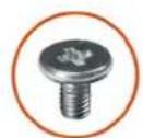
| System board M3x5 7 |  | ||
| Speakers | M3 4+7.1xZN | 4 | 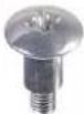 |
| Power-button board M3x5 1 |  | ||
| Microphones M2x2.5 2 |  | ||
| Side I/O-board shield | M3x5 2 |  | |
| Side-I/O board | M2.5x3.5 | 2 |  |
| Component Screw type Quantity Screw image | |||
| Antennas M2x2.5 2 |  | ||
| Display panel M3x5 8 |  | ||
| Middle frame M3x5 11 |  | ||
| Audio board M3x5 1 |  | ||
Stand
Removing the fixed stand
Prerequisites
- Follow the procedure in Before working inside your computer.

NOTE: When servicing the system, place it on an elevated, clean, and flat surface. Dell recommends removing the stand to avoid accidental damage to the system display during servicing.
About this task
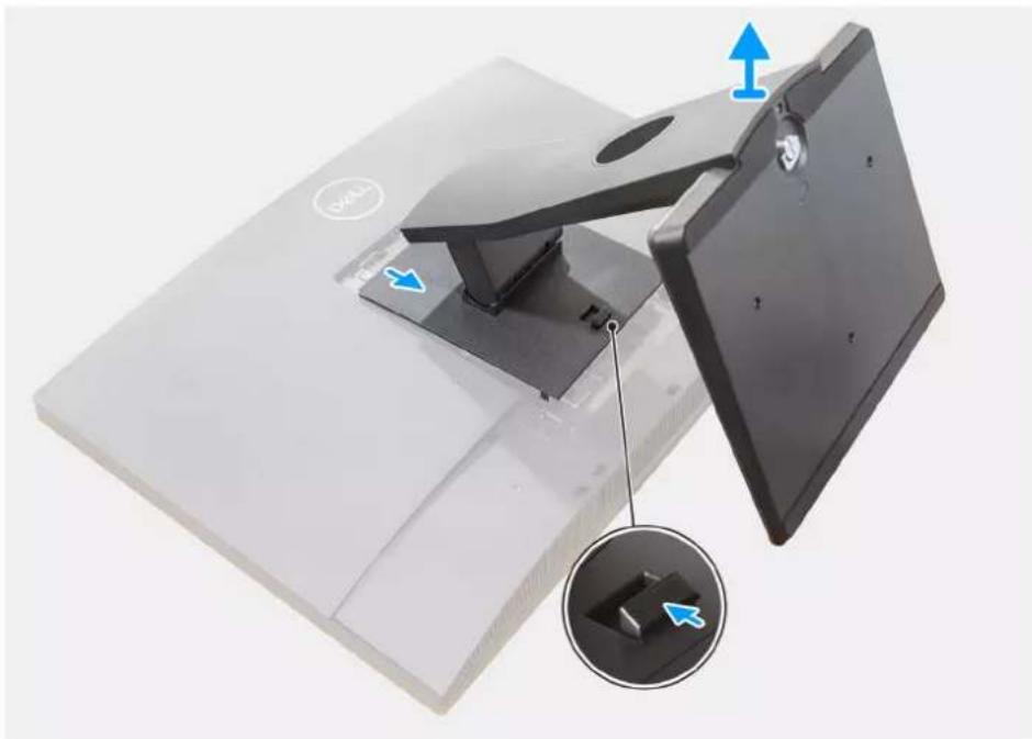
The following image provides a visual representation of the fixed stand removal procedure.
natural_image
3D model of a computer monitor with an inset close-up showing a small component (no text or symbols visible)Steps
- Press and slide the release button up.
- Hold the button in the release position and lift the stand upward.
- Slide the stand downward, to lift the stand off the back cover.
Installing the fixed stand
Prerequisites
If you are replacing a component, remove the existing component before performing the installation procedure.
About this task
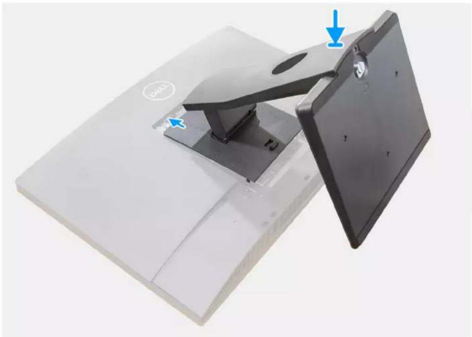
The following image provides a visual representation of the fixed stand installation procedure.
natural_image
Close-up of a black electronic device with a flat top and a stand, showing blue arrows indicating motion or assembly (no text or symbols visible)Steps
- Align the tabs on the stand with the slots on the back cover.
- Snap the stand until it clicks into place.
Next steps
- Follow the procedure in After working inside your computer.
Removing the articulating stand
Prerequisites
- Follow the procedure in Before working inside your computer.

CAUTION: When servicing the system, place it on an elevated, clean, and flat surface. Dell recommends removing the stand to avoid accidental damage to the system display during servicing.
About this task
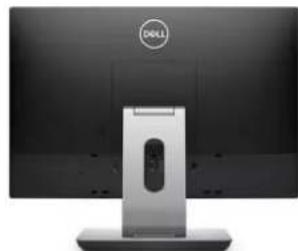
The following image indicates the articulating stand and provides a visual representation of the removal procedure.
natural_image
Front view of a Dell computer monitor with a silver stand and a circular logo on top (no visible text or symbols on the device body)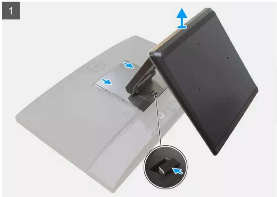
natural_image
Close-up of a black electronic device with a slide and a close-up inset showing a blue arrow pointing to a component (no text or symbols visible)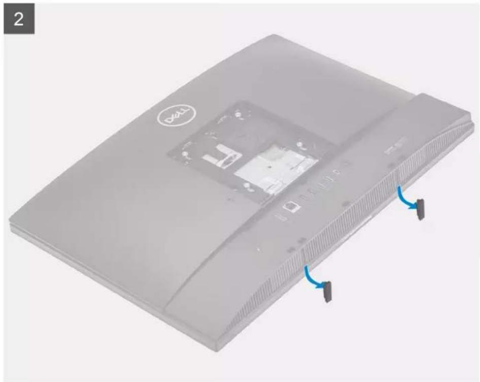
natural_image
3D rendering of a gray electronic device casing with ventilation slots and a DZ11 logo, showing internal components and blue directional arrows indicating rotation (no text or symbols on the device itself)Steps
-
Press and slide the release button up.
-
Hold the button in the release position, and lift the stand upward.
- Slide the stand downward, to lift the stand off the back cover.
- Pry the rubber feet from the bottom cover and pull it out.
Installing the articulating stand
Prerequisites
If you are replacing a component, remove the existing component before performing the installation procedure.
About this task
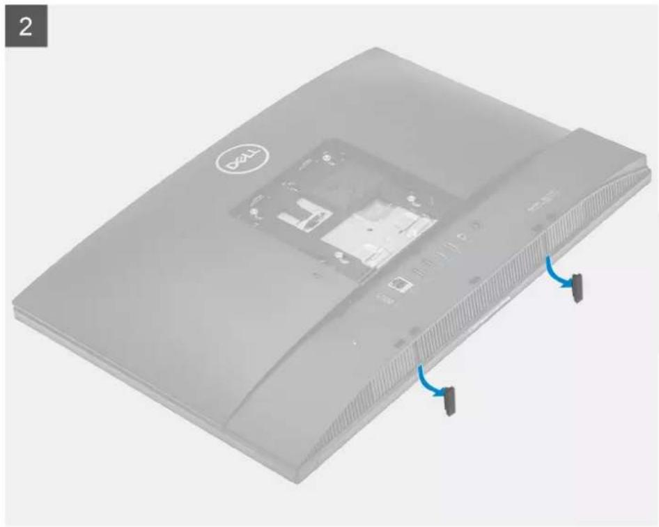
The following image indicates the articulating stand and provides a visual representation of the installation procedure.
natural_image
3D rendering of a Dell computer case with ventilation slots and a CD drive (no text or symbols visible)
natural_image
Front view of a Dell computer monitor with a stand (no visible text or symbols)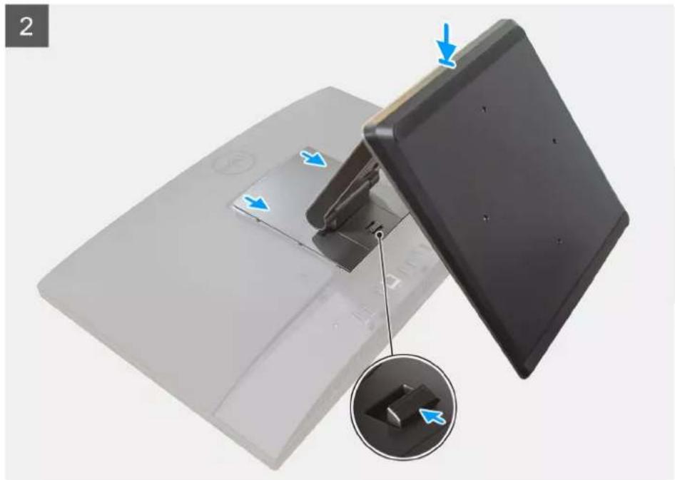
natural_image
Close-up of a black electronic device with a clip and a close-up inset showing a component (no text or symbols visible)Steps
- Align the rubber feet with the slots on the bottom cover and push it firmly in place.
- Align the tabs on the stand with the slots on the back cover.
- Snap the stand until it clicks into place.
Next steps
- Follow the procedure in After working inside your computer.
Removing the height adjustable stand
Prerequisites
NOTE: Follow the same procedure to remove the Height Adjustable Stand with Optical Disk Drive.
- Follow the procedure in Before working inside your computer.
CAUTION: When servicing the system, place it on an elevated, clean, and flat surface. Dell recommends removing the stand to avoid accidental damage to the system display during servicing.
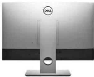
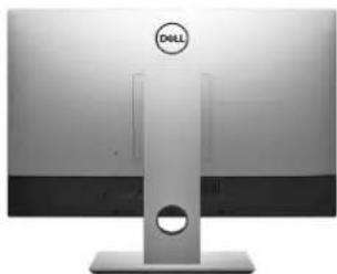
About this task
The following image provides a visual representation of the height adjustable stand removal procedure.
natural_image
Front view of a Dell computer monitor with a stand and circular lens (no visible text or symbols on the screen)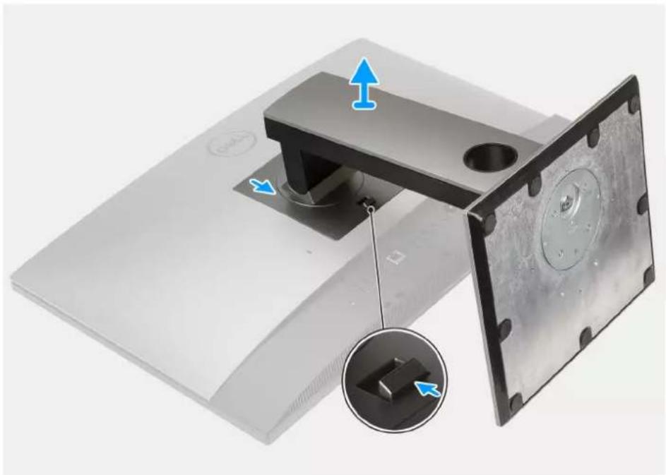
natural_image
3D rendering of a mechanical device with a mounting bracket and internal components, showing directional arrows and a close-up inset (no text or symbols)Steps
- Press and slide the release button up.
- Hold the button in the release position, and lift the stand upward.
- Slide the stand downward, to lift the stand off the back cover.
Installing the height adjustable stand
Prerequisites
If you are replacing a component, remove the existing component before performing the installation procedure.

NOTE: Follow the same procedure to install the Height Adjustable Stand with Optical Disk Drive.
About this task
The following image provides a visual representation of the height adjustable stand installation procedure.
natural_image
Front view of a Dell computer monitor with a stand and circular lens (no visible text or symbols)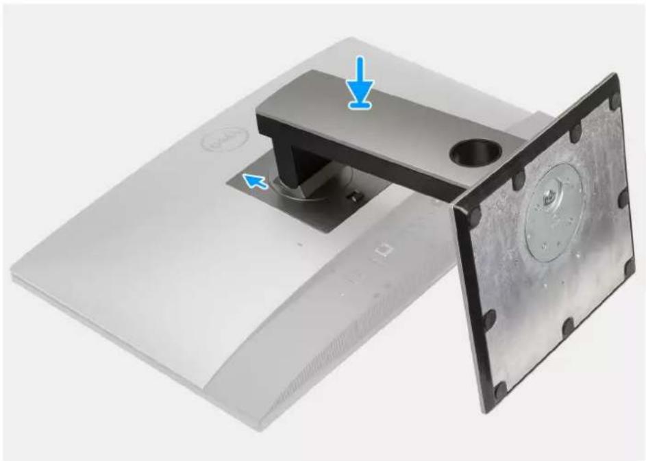
natural_image
3D rendering of a mechanical device with a black bracket and mounting plate, showing blue arrows indicating direction (no text or symbols)Steps
- Align the tabs on the stand with the slots on the back cover.
- Snap the stand until it clicks into place.
Next steps
- Follow the procedure in After working inside your computer.
Cable cover—optional
Removing the cable cover
Prerequisites
- Follow the procedure in Before working inside your computer.

CAUTION: When servicing the system, place it on an elevated, clean, and flat surface. It is recommended to remove the stand to avoid accidental damage to the system display during servicing.
- Remove the stand.
About this task
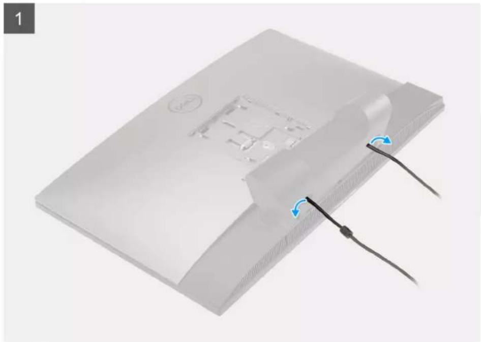
The following image provides a visual representation of the cable cover removal procedure.
1x
M3×9
natural_image
Exterior view of a modern office building (no signage)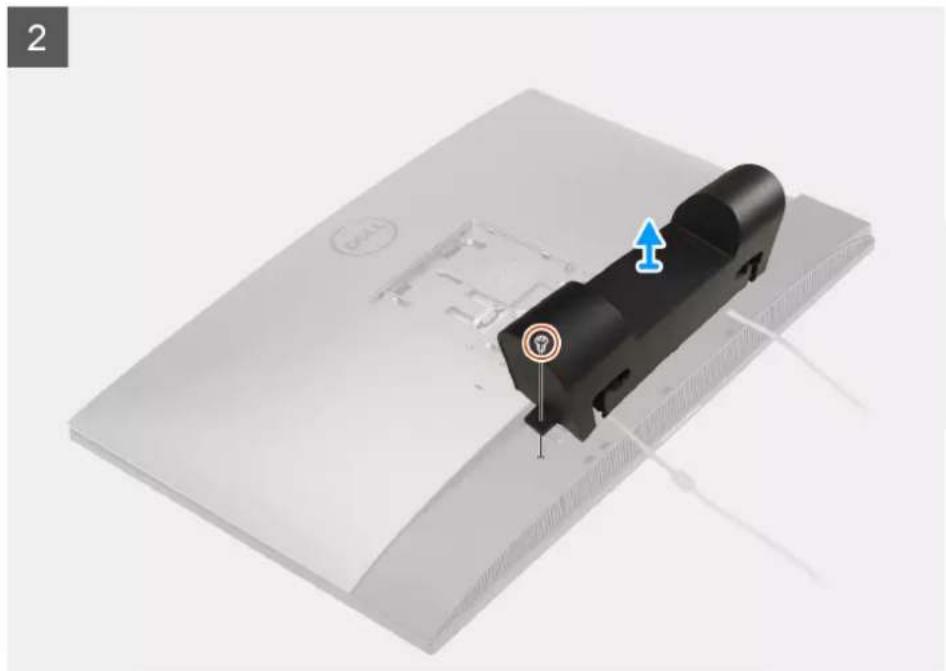
natural_image
3D rendering of a black mechanical component mounted on a white base, with no visible text or symbols.Steps
- Unroute the power cable from the slots on the cable cover.
- Remove the screw (M3x9) that secures the cable cover to the bottom cover.
- Lift the cable cover from the bottom cover.
Installing the cable cover
Prerequisites
If you are replacing a component, remove the existing component before performing the installation procedure.
About this task
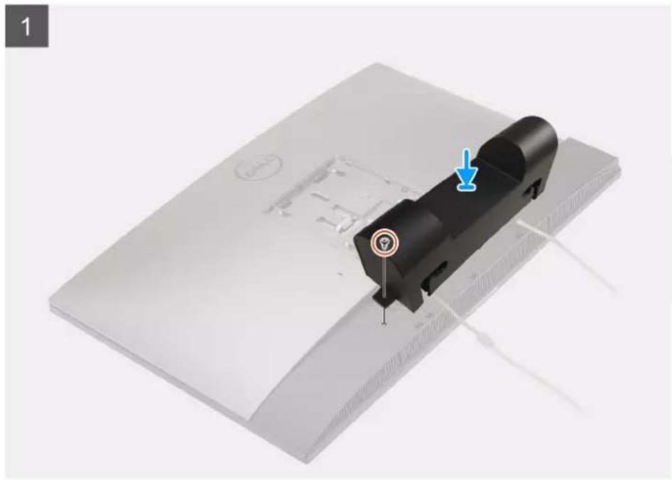
The following image provides a visual representation of the cable cover installation procedure.
1x
M3×9
natural_image
3D rendering of a black mechanical component with a blue arrow indicating a feature, placed on a white surface (no text or symbols visible)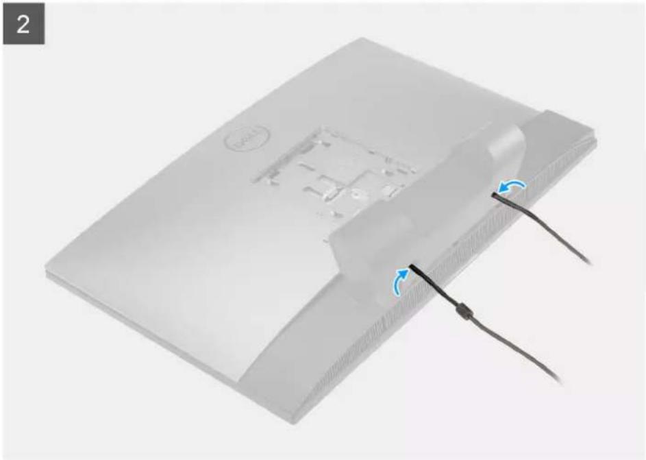
natural_image
3D rendering of a flat-screen electronic device with a cable and cable connector, showing internal components and blue directional arrows (no text or symbols)Steps
- Route the power cable through the slots on the cable cover.
- Align the screw hole on the cable cover with the screw hole on the bottom cover.
- Replace the screw (M3x9) to secure the cable cover to the bottom cover.
Next steps
- Install the stand.
- Follow the procedure in After working inside your computer.
Back cover
Removing the back cover
Prerequisites
- Follow the procedure in Before working inside your computer.

CAUTION: When servicing the system, place it on an elevated, clean, and flat surface. Dell recommends removing the stand to avoid accidental damage to the system display during servicing.
- Remove the stand.
- Remove the cable cover (optional).
About this task
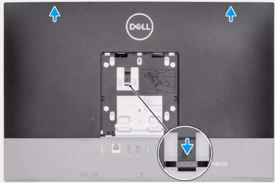
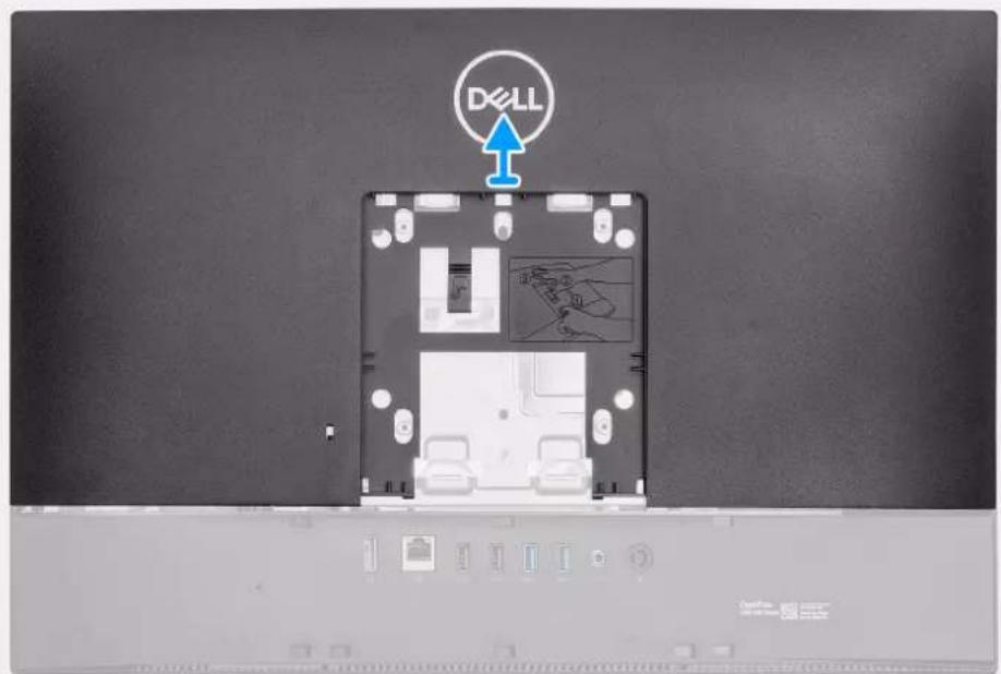
The following image provides a visual representation of the back cover removal procedure.
1
text_image
DX-LL2
text_image
D\LLSteps
- Press and hold the release tab on the back cover to release it from the latch on the system-board shield.
- Slide the back cover up to release the tabs on the cover from the slots on the middle frame.
- Lift the back cover up and remove it from the system.
Installing the back cover
Prerequisites
If you are replacing a component, remove the existing component before performing the installation procedure.
About this task
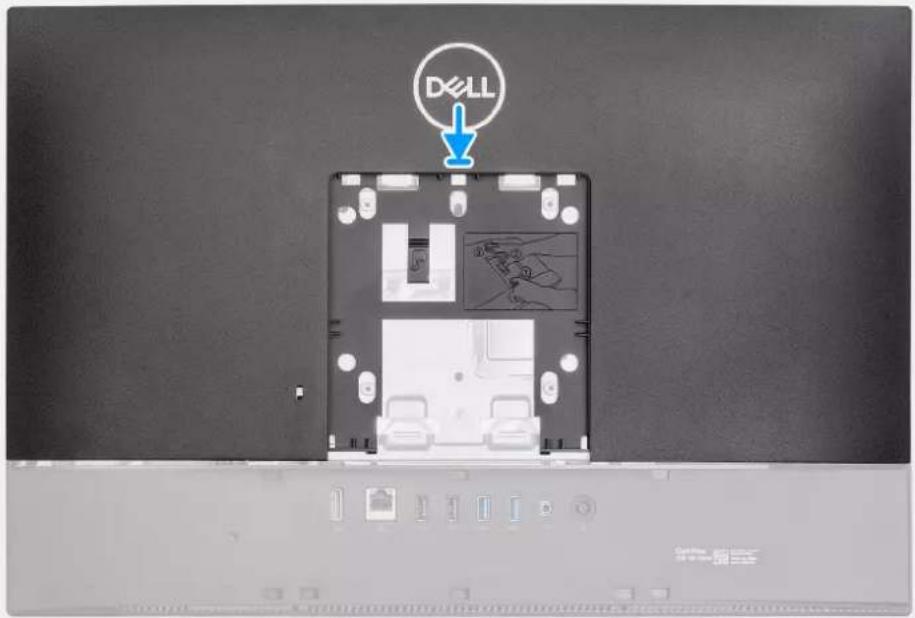
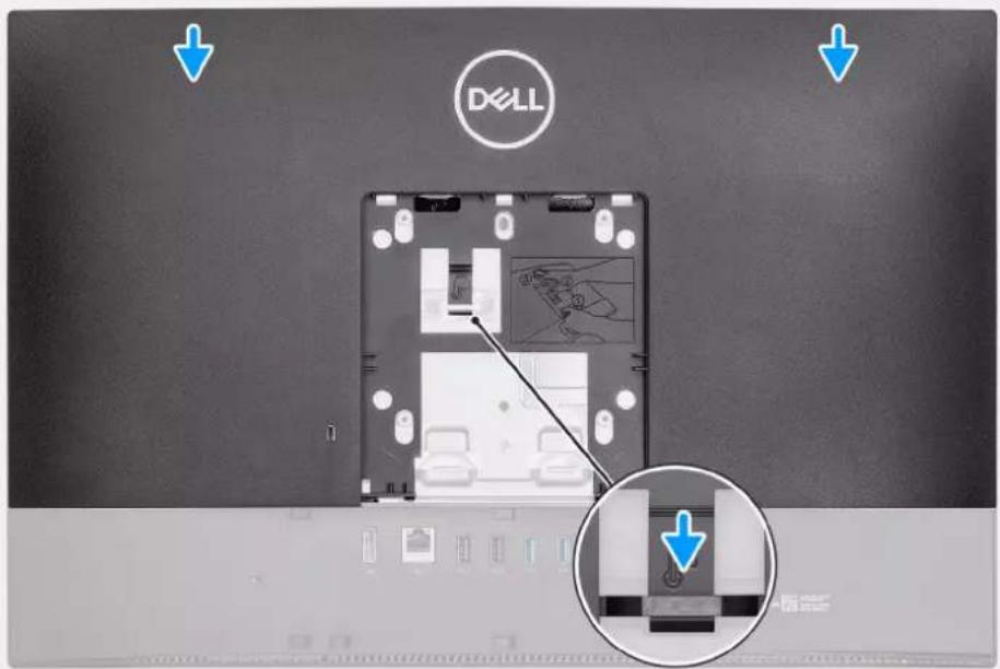
The following image provides a visual representation of the back cover installation procedure.
1
text_image
D&LL2
text_image
Dell ↓ ↓Steps
- Place the back cover on the middle frame and system-board shield and align the tabs on the back cover with the slots on the middle frame.
- Slide the back cover to lock the release tab under the latch on the system-board shield.
Next steps
- Install the cable cover (optional).
- Install the stand.
- Follow the procedure in After working inside your computer.
Hard drive
Removing the hard drive
Prerequisites
- Follow the procedure in Before working inside your computer.
- Remove the stand.
- Remove the cable cover (optional).
- Remove the back cover.
About this task
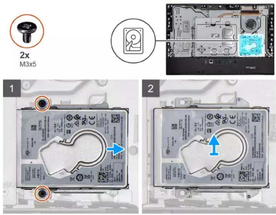
The following image indicates the location of the hard drive and provides a visual representation of the removal procedure.
Steps
- Remove the two screws (M3x5) that secure the hard-drive assembly to the display-assembly base.
- Slide the hard-drive assembly away from the hard-drive slot on the display-assembly base.
Installing the hard drive
Prerequisites
If you are replacing a component, remove the existing component before performing the installation procedure.
About this task
The following image indicates the location of the hard drive and provides a visual representation of the installation procedure.
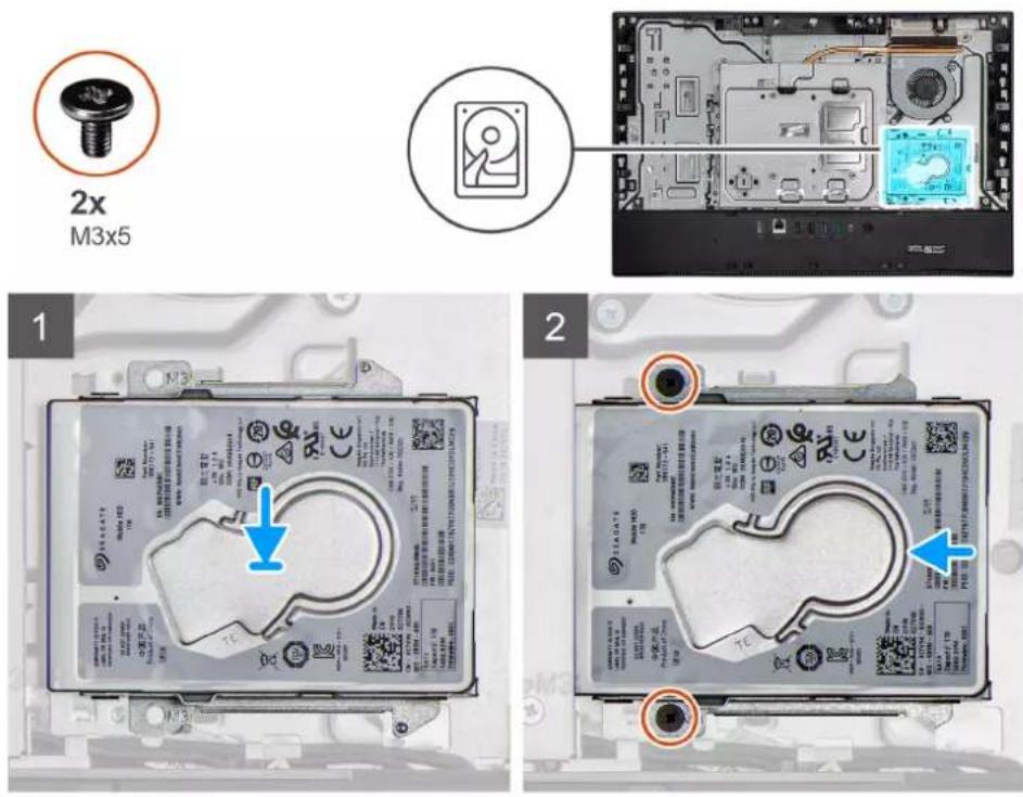
Steps
- Slide the hard-drive assembly into the slot on the display-assembly base.
- Replace the two screws (M3x5) that secures the hard-drive assembly to the display-assembly base.
Next steps
- Install the cable cover (optional).
- Install the back cover.
- Install the stand.
- Follow the procedure in After working inside your computer.
Memory modules
Removing the memory modules
Prerequisites
- Follow the procedure in Before working inside your computer.
- Remove the stand.
- Remove the cable cover (optional).
- Remove the back cover.
About this task
The following image indicates the location of the memory modules and provides a visual representation of the removal procedure.
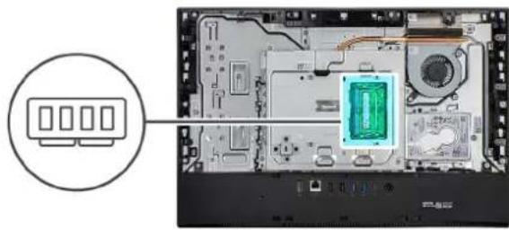
natural_image
Interior view of a computer motherboard showing a green-labeled component and a circular icon pointing to four ports (no text or symbols visible)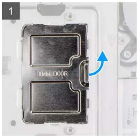
text_image
DIMM DOOR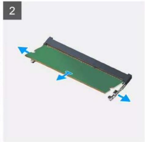
natural_image
3D diagram of a green electronic component with blue directional arrows indicating movement or force (no text or symbols)Steps
- Pry and remove the DIMM door from the system-board shield
- Using your fingertips, spread apart the securing clips on the memory-module slot until the memory module pops up.
- Slide and remove the memory module from the memory-module slot.

NOTE: Repeat step 2 and 3 if there are two memory modules.
Installing the memory modules
Prerequisites
If you are replacing a component, remove the existing component before performing the installation procedure.
About this task
The following image indicates the location of the memory module and provides a visual representation of the installation procedure.
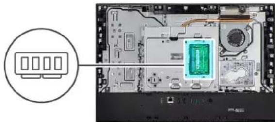
natural_image
Interior view of a computer motherboard showing a green-labeled component and a circular icon pointing to four ports (no text or symbols visible)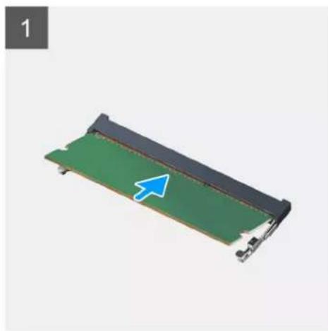
natural_image
3D rendering of a green electronic component with a blue arrow pointing to its edge (no text or symbols visible)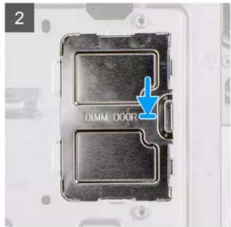
text_image
2 DIMM DOORSteps
- Align the notch on the memory module with the tab on the memory-module slot.
- Slide the memory module firmly into the slot at an angle and press the memory module down until it clicks into place.
NOTE: If you do not hear the click, remove the memory module and reinstall it.
NOTE: Repeat step 1 and 2 if there are two memory modules.
- Align the tabs on the DIMM door with the slots on the system-board shield and snap it into place.
NOTE: Repeat step 1 and 2 if there are two memory modules.
Next steps
- Install the back cover
- Install the cable cover (optional).
- Install the stand.
- Follow the procedure in After working inside your computer.
System-board shield
Removing the system-board shield
Prerequisites
- Follow the procedure in Before working inside your computer.
- Remove the stand.
- Remove the cable cover (optional).
- Remove the back cover.
About this task
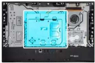
The following image indicates the location of the system-board shield and provides a visual representation of the removal procedure.
5x
M3x5
natural_image
Interior view of a computer motherboard showing CPU socket, drive bays, and monitor (no visible text or labels)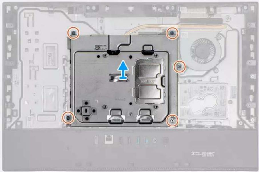
natural_image
Top-down view of a computer motherboard showing a CPU socket and drive bays with mounting holes (no text or symbols visible)Steps
- Remove the five screws (M3x5) that secure the system-board shield to the display-assembly base.
- Lift the system-board shield off the display-assembly base.
Installing the system-board shield
Prerequisites
If you are replacing a component, remove the existing component before performing the installation procedure.
About this task
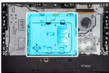
The following image indicates the location of the system-board shield and provides a visual representation of the installation procedure.
5x
M3x5
natural_image
Interior view of a computer motherboard showing a blue-lit integrated circuit board with no visible text or symbols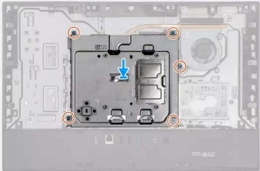
natural_image
Top-down view of a computer motherboard showing a CPU socket with mounting holes and a blue arrow indicating a component (no text or symbols present)Steps
- Align the screw holes on the system-board shield with the screw holes on the display-assembly base.
- Replace the five screws (M3x5) to secure the system-board shield to the display-assembly base.
Next steps
- Install the back cover
- Install the cable cover (optional).
- Install the stand.
- Follow the procedure in After working inside your computer.
Solid-state drive
Removing the M.2 2230 solid-state drive
Prerequisites
- Follow the procedure in Before working inside your computer.
- Remove the stand.
- Remove the cable cover (optional).
- Remove the back cover.
- Remove the system-board shield.
About this task
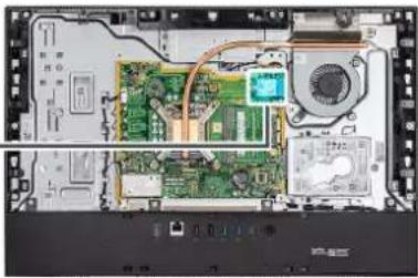
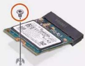
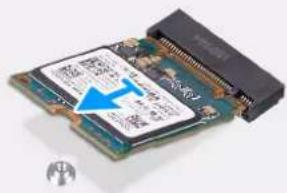
The following image indicates the location of the solid-state drive and provides a visual representation of the removal procedure.
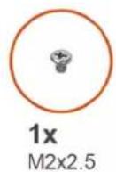
1x M2x2.5
natural_image
Interior view of a computer motherboard showing CPU socket, motherboard, and drive unit (no text or symbols visible)1
text_image
Diagram showing a microprocessor with an LED indicator and printed circuit board, likely illustrating a microprocessor or memory layout.2
natural_image
Close-up of an Intel 3.22 microprocessor with visible internal components and a blue arrow pointing to its edge (no text or symbols on the chip itself)Steps
- Remove the screw (M2x2.5) that secures the solid-state drive to the system board.
- Slide and remove the solid-state drive from the M.2 card slot on the system board.
Installing the M.2 2230 solid-state drive
Prerequisites

CAUTION: Solid-state drives are fragile. Exercise care when handling the solid-state drive.
If you are replacing a component, remove the existing component before performing the installation procedure.
About this task
The following image indicates the location of the solid-state drive and provides a visual representation of the installation procedure.
natural_image
Exploded view of a computer motherboard showing CPU socket, circuit board, and drive components (no text or labels visible)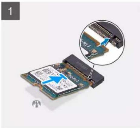
natural_image
Close-up of a microchip with an inset showing a close-up of its internal structure (no text or symbols visible)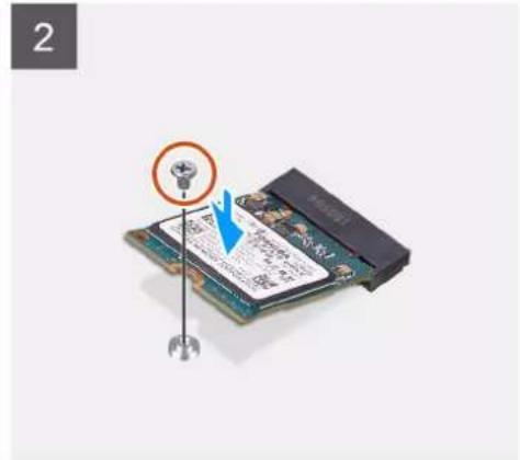
text_image
2Steps
- Align the notch on the solid-state drive with the tab on the M.2 card slot.
- Slide the solid-state drive into the M.2 card slot on the system board.
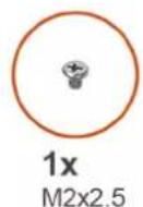
- Replace the screw (M2x2.5) to secure the solid-state drive to the system board.
Next steps
- Install the system-board shield.
- Install the back cover
- Install the cable cover (optional).
- Install the stand.
- Follow the procedure in After working inside your computer.
Removing the M.2 2280 solid-state drive/Intel Optane memory module
Prerequisites
- Follow the procedure in Before working inside your computer.
- Remove the stand.
- Remove the cable cover (optional).
- Remove the back cover.
- Remove the system-board shield.
About this task
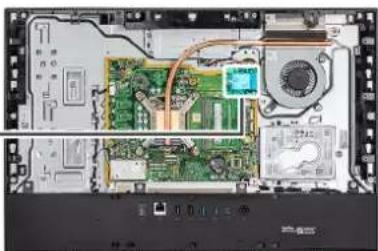
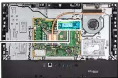
The following image indicates the location of the solid-state drive and provides a visual representation of the removal procedure.
natural_image
Interior view of an electronic device showing circuit board, CPU socket, and fan (no text or symbols visible)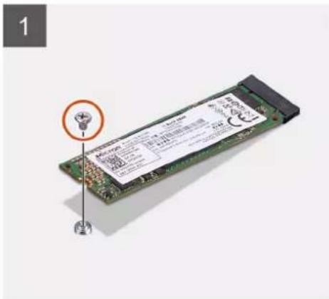
text_image
1 LEDRAM LEDRAM LEDRAM LEDRAM LEDRAM LEDRAM LEDRAM LEDRAM LEDRAM LEDRAM LEDRAM LEDRAM LEDRAM LEDRAM LEDRAM LEDRAM LEDRAM LEDRAM LEDRAM LEDRAM LEDRAM LEDRAM LEDRAM LEDRAM LEDRAM LEDRAM LEDRAM LEDRAM LEDRAM LEDRAM LEDRAM LEDRAM LEDRAM LEDRAM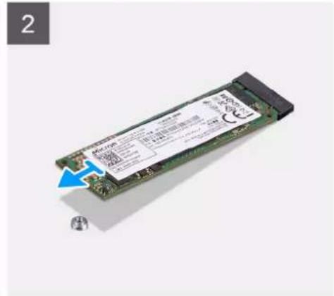
text_image
2 RAM/CMOS 1.0 1.0 1.0 1.0 1.0 1.0 1.0 1.0 1.0 1.0 1.0 1.0 1.0 1.0 1.0 1.0 1.0 1.0 1.0 1.0 1.0 1.0 1.0 1.0 1.0 1.5 1.5 1.5 1.5 1.5 1.5 1.5 1.5 1.5 1.5 1.5 1.5 1.5 1.5 1.5 1.5 1.5 1.5 1.5 1.5 1.5 1.5 1.5 1.5 1.5Steps
- Remove the screw (M2x2.5) that secures the solid-state drive to the system board.
- Slide and remove the solid-state drive from the M.2 card slot on the system board.
Installing the M.2 2280 solid-state drive/Intel Optane memory module
Prerequisites
CAUTION: Solid-state drives are fragile. Exercise care when handling the solid-state drive.
If you are replacing a component, remove the existing component before performing the installation procedure.
About this task
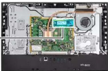
The following image indicates the location of the solid-state drive and provides a visual representation of the installation procedure.
natural_image
Interior view of an electronic device showing circuit board, CPU socket, and fan (no visible text or symbols)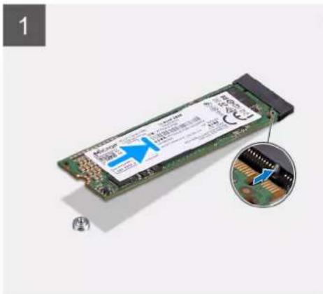
text_image
1 Microsoft 3.2G RAM Microsoft 3.2G RAM Microsoft 3.2G RAM Microsoft 3.2G RAM Microsoft 3.2G RAM Microsoft 3.2G RAM Microsoft 3.2G RAM Microsoft 3.2G RAM Microsoft 3.2G RAM Microsoft 3.2G RAM Microsoft 3.2G RAM Microsoft 3.2G RAM Microsoft 3.2G RAM Microsoft Microsoft 3.2G RAM Microsoft 3.2G RAM Microsoft 3.2G RAM Microsoft 3.2G RAM Microsoft 3.2G RAM Microsoft 3.2G RAM Microsoft 3.2G RAM Microsoft 3.2G RAM Microsoft 3.2G RAM Microsoft 3.2G RAM Microsoft 3.2G RAM Microsoft 3.2G RAM Microsoft 01-01-01-01-01-01-01-01-01-01-01-01-01-01-01-01-01-01-01-01-01-01-01-01-01-01-01-01-01-01-01-01-01-01-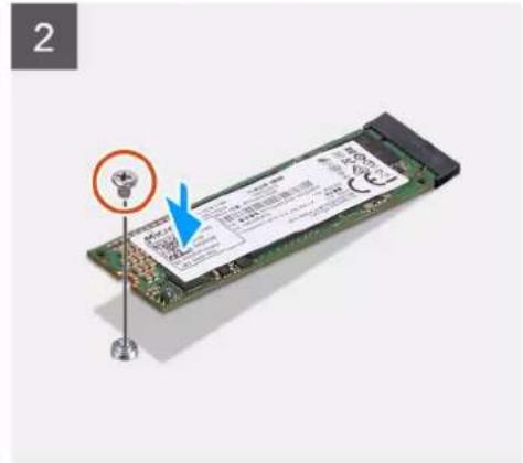
text_image
2Steps
- Align the notch on the solid-state drive with the tab on the M.2 card slot.
- Slide the solid-state drive into the M.2 card slot on the system board.
- Replace the screw (M2x2.5) to secure the solid-state drive to the system board.
Next steps
- Install the system-board shield.
- Install the back cover
- Install the cable cover (optional).
- Install the stand.
- Follow the procedure in After working inside your computer.
System fan
Removing the fan
Prerequisites
- Follow the procedure in Before working inside your computer.
- Remove the stand.
- Remove the cable cover (optional).
- Remove the back cover.
- Remove the system-board shield.
About this task
The following image indicates the location of the fan and provides a visual representation of the removal procedure.

natural_image
Exploded view of an electronic device showing internal circuitry, fan, and components (no readable text or symbols)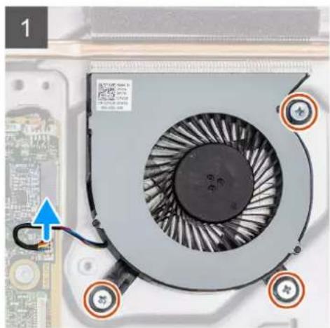
natural_image
Close-up of a computer fan with visible cooling effect and mounting points (no text or symbols)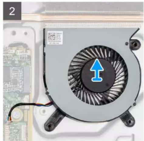
natural_image
Close-up of a CPU fan with an upward arrow indicator, placed on a circuit board background (no readable text or symbols)Steps
- Disconnect the system-fan cable from the system board.
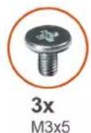
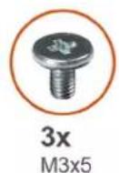
- Remove the three screws (M3x5) that secure the system-fan to the display-assembly base.
- Lift the system-fan, along with its cable, off the display-assembly base.
Installing the fan
Prerequisites
If you are replacing a component, remove the existing component before performing the installation procedure.
About this task
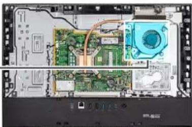
The following image indicates the location of the fan and provides a visual representation of the installation procedure.
natural_image
Interior view of a computer motherboard showing CPU socket, motherboard, and drive casing (no text or labels visible)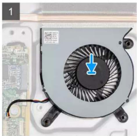
natural_image
Close-up of a CPU fan with a blue downward arrow indicating cooling or discharging (no text or symbols on the fan itself)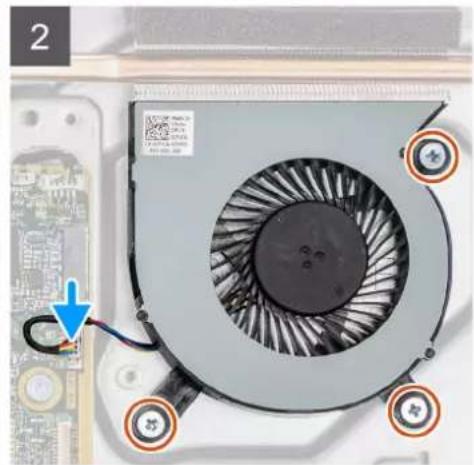
natural_image
Close-up of a computer fan with visible cooling effect and mounting points (no text or symbols)Steps
- Align the screw holes on the system-fan with the screw holes on the display-assembly base.
- Replace the three screws (M3x5) to secure the system-fan to the display-assembly base.
- Connect the system-fan cable to the connector on the system board.
Next steps
- Install the system-board shield.
- Install the back cover
- Install the cable cover (optional).
- Install the stand.
- Follow the procedure in After working inside your computer.
Coin-cell battery
Removing the coin-cell battery
Prerequisites
- Follow the procedure in Before working inside your computer.
- Remove the stand.
- Remove the cable cover (optional).
- Remove the back cover.
- Remove the system-board shield.

NOTE: Removing the coin-cell battery resets the CMOS and BIOS settings to default and results in data lose. It is recommended that you note the CMOS and BIOS settings before removing the coin-cell battery.
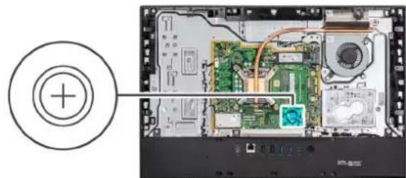
About this task
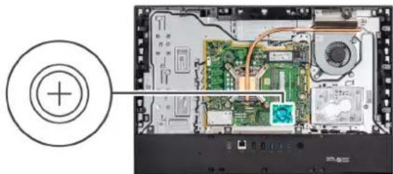
The following image indicates the location of the coin-cell battery and provides a visual representation of the removal procedure.
natural_image
Interior view of a computer motherboard showing CPU socket, circuit board, and drive casing (no text or symbols visible)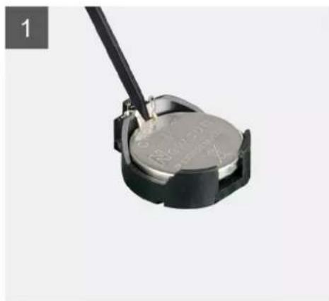
natural_image
Close-up of a small electronic component with a metallic body and black handle, no visible text or symbols.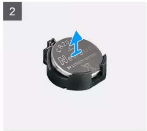
natural_image
Close-up of a cylindrical electronic component with 'CR20 Neusun' label and blue arrow pointing to it (no additional text or symbols visible)Steps
- Using your fingertip or plastic scribe, press on the metal clip to release the coin-cell battery from the coin-cell battery holder.
- Lift the coin-cell battery from the coin-cell battery holder.
Installing the coin-cell battery
Prerequisites
If you are replacing a component, remove the existing component before performing the installation procedure.
About this task
The following image indicates the location of the coin-cell battery and provides a visual representation of the installation procedure.
natural_image
Interior view of a computer motherboard showing circuit boards, connectors, and a central hub (no text or symbols visible)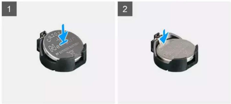
text_image
1 CR203- Meison WALPHEN ELECTRIC 2Steps
With the positive-side facing up, insert the coin-cell battery into the battery holder on the system board and gently press the battery until it snaps into place.
Next steps
- Install the system-board shield.
- Install the back cover
- Install the cable cover (optional).
- Install the stand.
- Follow the procedure in After working inside your computer.
Wireless card
Removing the wireless card
Prerequisites
- Follow the procedure in Before working inside your computer.
- Remove the stand.
- Remove the cable cover (optional).
- Remove the back cover.
- Remove the system-board shield.
About this task
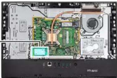
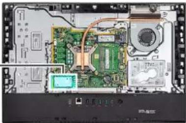
The following image indicates the location of the wireless card and provides a visual representation of the removal procedure.
natural_image
Interior view of a computer motherboard showing CPU socket, circuit board, and drive unit (no text or symbols visible)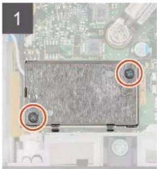
natural_image
Top-down view of a computer monitor on a circuit board (no visible text or symbols)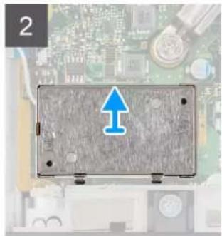
natural_image
Electronic component with a blue upward arrow on its surface, placed on a circuit board background (no text or symbols visible)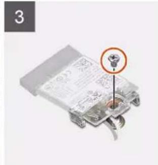
text_image
3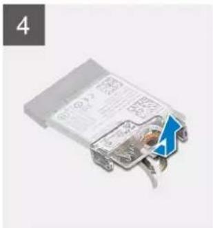
natural_image
Close-up of a metallic electrical connector with visible internal components and mounting brackets (no text or symbols)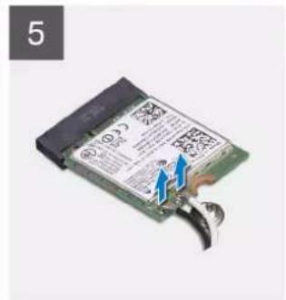
text_image
5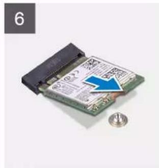
natural_image
Close-up of a green printed circuit board with a blue arrow pointing to it, next to a coin for scale (no visible text or symbols)Steps
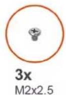
- Remove the two screws (M2x4) that secure the wireless-card shield to the system board.
- Unroute the antenna cables from the routing guides on the display-assembly base.
- Lift the wireless-card shield out of the system.
- Remove the screw (M2x4) that secures the wireless-card bracket to the wireless card.
- Slide and remove the wireless-card bracket off the wireless card.
- Disconnect the antenna cables from the wireless card.
- Slide and remove the wireless card from the wireless-card slot.
Installing the wireless card
Prerequisites
If you are replacing a component, remove the existing component before performing the installation procedure.

NOTE: To avoid damage to the wireless card, route the antenna cables accurately.
About this task
The following image indicates the location of the wireless card and provides a visual representation of the installation procedure.
natural_image
Interior view of a computer motherboard showing CPU socket, motherboard, and drive unit (no text or symbols visible)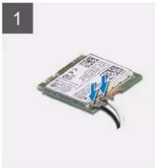
text_image
1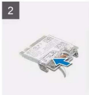
text_image
2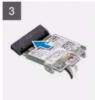
natural_image
Close-up of a circuit board with a blue arrow pointing to a component, no visible text or symbols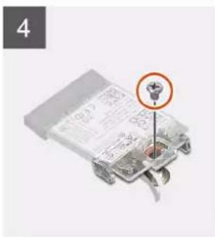
text_image
4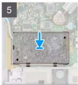
natural_image
Close-up of a damaged electronic component on a circuit board (no visible text or symbols)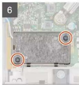
natural_image
Close-up of a computer motherboard with two orange circular annotations highlighting specific components (no readable text or symbols)Steps
- Connect the antenna cables to the wireless card.
The following table provides the antenna-cable color scheme:
Table 2. Antenna-cable color scheme
| Connectors on the wireless card Antenna-cable color | |
| Main (white triangle) White | |
| Auxiliary (black triangle) Black |
- Place the wireless-card bracket on the wireless card.
- Align the notch on the wireless card with the tab on the wireless-card slot.
- Slide the wireless card at an angle into the wireless-card slot.
- Replace the screw (M2x4) to secure the wireless-card bracket to the wireless card.
- Align and place the wireless-card shield on the system board and wireless card.
- Route the antenna cables through the routing guides on the display-assembly base.
- Replace the two screws (M2x4) to secure the wireless-card shield to the system board.
Next steps
- Install the system-board shield.
- Install the back cover
- Install the cable cover (optional).
- Install the stand.
- Follow the procedure in After working inside your computer.
Camera assembly
Removing the camera assembly
Prerequisites
- Follow the procedure in Before working inside your computer.
- Remove the stand.
- Remove the cable cover (optional).
- Remove the back cover.
- Remove the system-board shield.
About this task
The following image indicates the location of the camera assembly and provides a visual representation of the removal procedure.
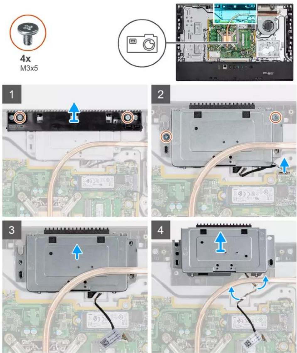
Steps
- Remove the two screws (M3x5) that secure the camera assembly door to the display-assembly base.
-
Disconnect the camera cable from the connector on the system board.
-
Unroute the camera cable from the routing guides on the display-assembly base.
- Remove the two screws (M3x5) that secure the camera assembly to the middle frame.
- Slide and remove the camera assembly from the middle frame.
Installing the camera assembly
Prerequisites
If you are replacing a component, remove the existing component before performing the installation procedure.
About this task
The following image indicates the location of the camera and provides a visual representation of the installation procedure.
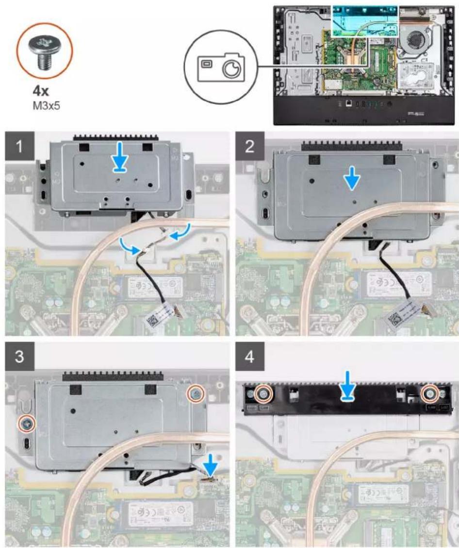
Steps
- Slide the camera assembly on the middle frame, and align the screw holes on the camera assembly with the screw holes on the middle frame.
- Replace the two screws (M3x5) to secure the camera assembly to the middle frame.
- Route the camera cable through the routing guides on the display-assembly base.
-
Connect the camera cable to the system board.
-
Align the screw holes on the camera door with the screw holes on the display-assembly base.
- Replace the two screws (M3x5) to secure the camera assembly door to the display-assembly base.
Next steps
- Install the system-board shield.
- Install the back cover
- Install the cable cover (optional).
- Install the stand.
- Follow the procedure in After working inside your computer.
Bottom cover
Removing the bottom cover
Prerequisites
- Follow the procedure in Before working inside your computer.
- Remove the stand.
- Remove the cable cover (optional).
- Remove the back cover.
- Remove the system-board shield
About this task
The following image indicates the location of the bottom cover and provides a visual representation of the removal procedure.
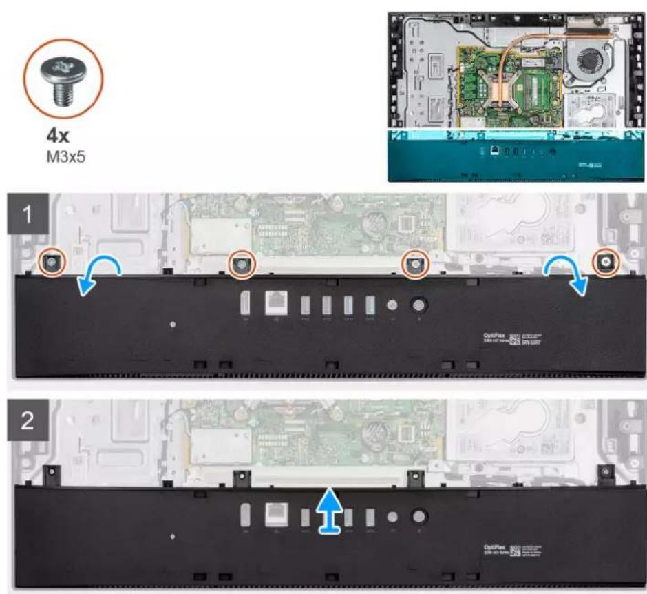
Steps
- Remove the four screws (M3x5) that secure the bottom cover to the display-assembly base.
- Lift the bottom cover off the display-assembly base.
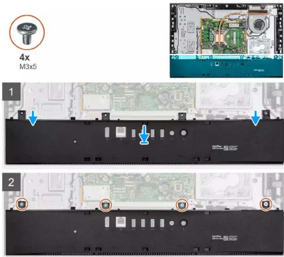
Installing the bottom cover
Prerequisites
If you are replacing a component, remove the existing component before performing the installation procedure.
About this task
The following image indicates the location of the bottom cover and provides a visual representation of the installation procedure.
text_image
4x M3x5 1 2Steps
- Align the screw holes on the bottom cover with the screw holes on the display-assembly base.
- Replace the four screws (M3x5) to secure the bottom cover to the display-assembly base.
Next steps
- Install the system-board shield.
- Install the back cover.
- Install the cable cover (optional).
- Install the stand.
- Follow the procedure in After working inside your computer.
Heat sink
Removing the heat sink
Prerequisites
- Follow the procedure in Before working inside your computer.
- Remove the stand.
- Remove the cable cover (optional).
- Remove the back cover.
- Remove the system-board shield.
- Remove the system fan.
About this task
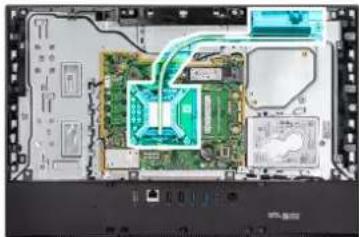
The following image indicates the location of the heat sink and provides a visual representation of the removal procedure.
natural_image
Interior view of a computer motherboard showing circuit boards, connectors, and memory drives (no text or symbols visible)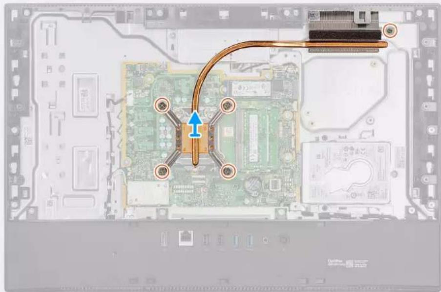
natural_image
Interior view of a computer motherboard showing CPU socket, thermal insulation, and heat sink (no text or symbols)Steps
- In reverse sequential order (as indicated on the heat sink), loosen the five captive screws that secure the heat sink to the system board and the display-assembly base.
- Slide and lift the heat sink off the system board and display-assembly base.
Installing the heat sink
Prerequisites
If you are replacing a component, remove the existing component before performing the installation procedure.

NOTE: If either the system board or the heat sink is replaced, use the thermal pad/paste provided in the kit to ensure that thermal conductivity is achieved.
About this task
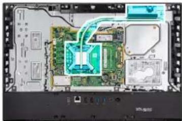
The following image indicates the location of the heat sink and provides a visual representation of the installation procedure.
natural_image
Interior view of an electronic device showing internal circuitry and components (no visible text or symbols)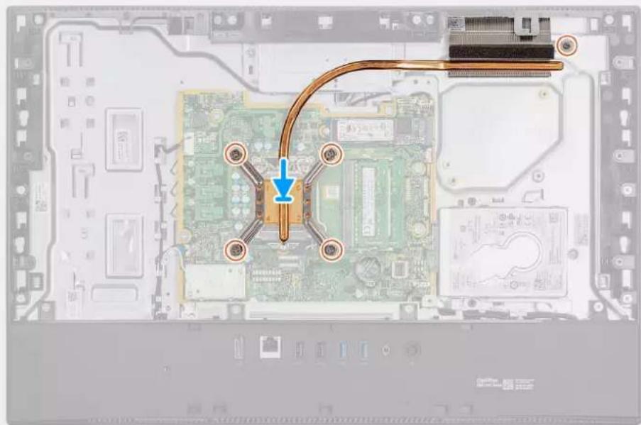
natural_image
Interior view of a computer motherboard showing CPU socket, thermal insulation, and cable routing (no text or symbols visible)Steps
- Align the screw holes on the heat sink with the screw holes on the system board and the display-assembly base.
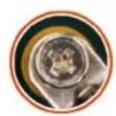
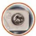
- In sequential order (as indicated on the heat sink), tighten the five captive screws that secure the heat sink to the system board and display-assembly base.
Next steps
- Install the system fan.
- Install the system-board shield.
- Install the back cover
- Install the cable cover (optional).
- Install the stand.
- Follow the procedure in After working inside your computer.
Processor
Removing the processor
Prerequisites
- Follow the procedure in Before working inside your computer.
- Remove the stand.
- Remove the cable cover (optional).
- Remove the back cover.
- Remove the system-board shield.
- Remove the system fan.
- Remove the heat sink.
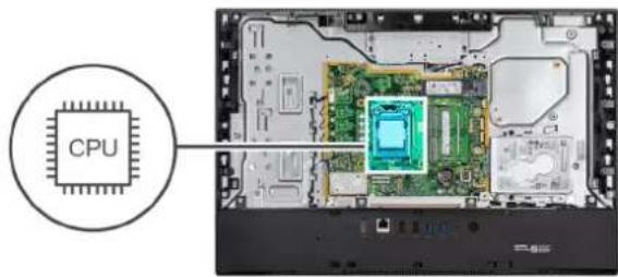
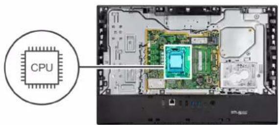
About this task
The following image indicates the location of the processor and provides a visual representation of the removal procedure.
text_image
CPU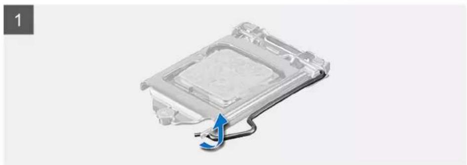
natural_image
3D rendering of a mechanical component with a blue arrow indicating a cable or connection (no text or symbols)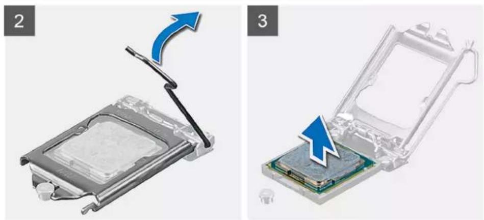
natural_image
Two-step diagram showing a computer processor being inserted into an open circuit board, with no visible text or symbols.Steps
- Press the release lever down and then push it away from the processor to release it from the securing tab.
- Extend the release lever completely, and open the processor cover.

CAUTION: When removing the processor, do not touch any of the pins inside the socket or allow any objects to fall on the pins in the socket.
- Gently lift the processor from the processor socket.
Installing the processor
Prerequisites
If you are replacing a component, remove the existing component before performing the installation procedure.
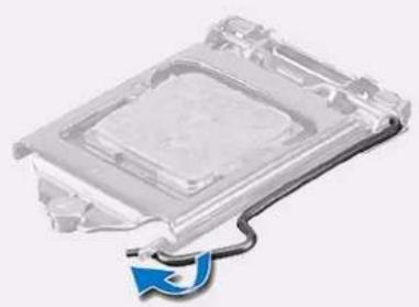
About this task
The following image indicates the location of the processor and provides a visual representation of the installation procedure.
text_image
CPU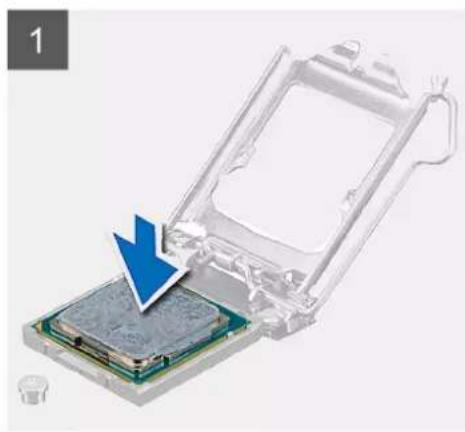
natural_image
3D rendering of a computer processor with an arrow pointing to its internal structure (no text or symbols visible)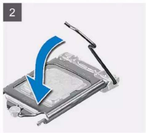
natural_image
Illustration of a computer monitor with a blue arrow indicating compression or disassembly (no text or symbols)
natural_image
Transparent plastic electronic component with a black cable and blue arrow symbol (no text or labels)Steps
- Ensure that the release lever on the processor socket is fully extended in the open position.

NOTE: The pin-1 corner of the processor has a triangle that aligns with the triangle on the pin-1 corner on the processor socket. When the processor is properly seated, all four corners are aligned at the same height. If one or more corners of the processor are higher than the others, the processor is not seated properly.
- Align the notches on the processor with the tabs on the processor socket and place the processor in the processor socket.

CAUTION: Ensure that the processor-cover notch is positioned underneath the alignment post.
- When the processor is fully seated in the socket, pivot the release-lever down and place it under the tab on the processor cover.
Next steps
- Install the heat sink.
- Install the system fan.
- Install the system-board shield.
- Install the back cover
- Install the cable cover (optional).
- Install the stand.
- Follow the procedure in After working inside your computer.
Rear-I/O bracket
Removing the rear-I/O bracket
Prerequisites
- Follow the procedure in Before working inside your computer.
- Remove the stand.
- Remove the cable cover (optional).
- Remove the back cover.
- Remove the system-board shield.
- Remove the bottom cover
About this task
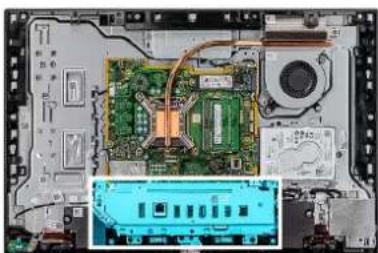
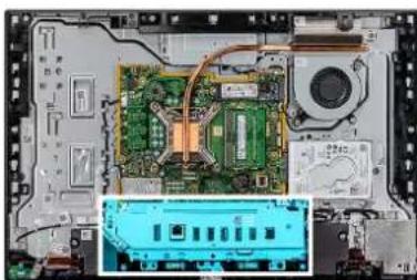
The following image indicates the location of the rear-I/O bracket and provides a visual representation of the removal procedure.
natural_image
Interior view of a computer motherboard showing CPU socket, circuit board, and drive casing (no text or symbols visible)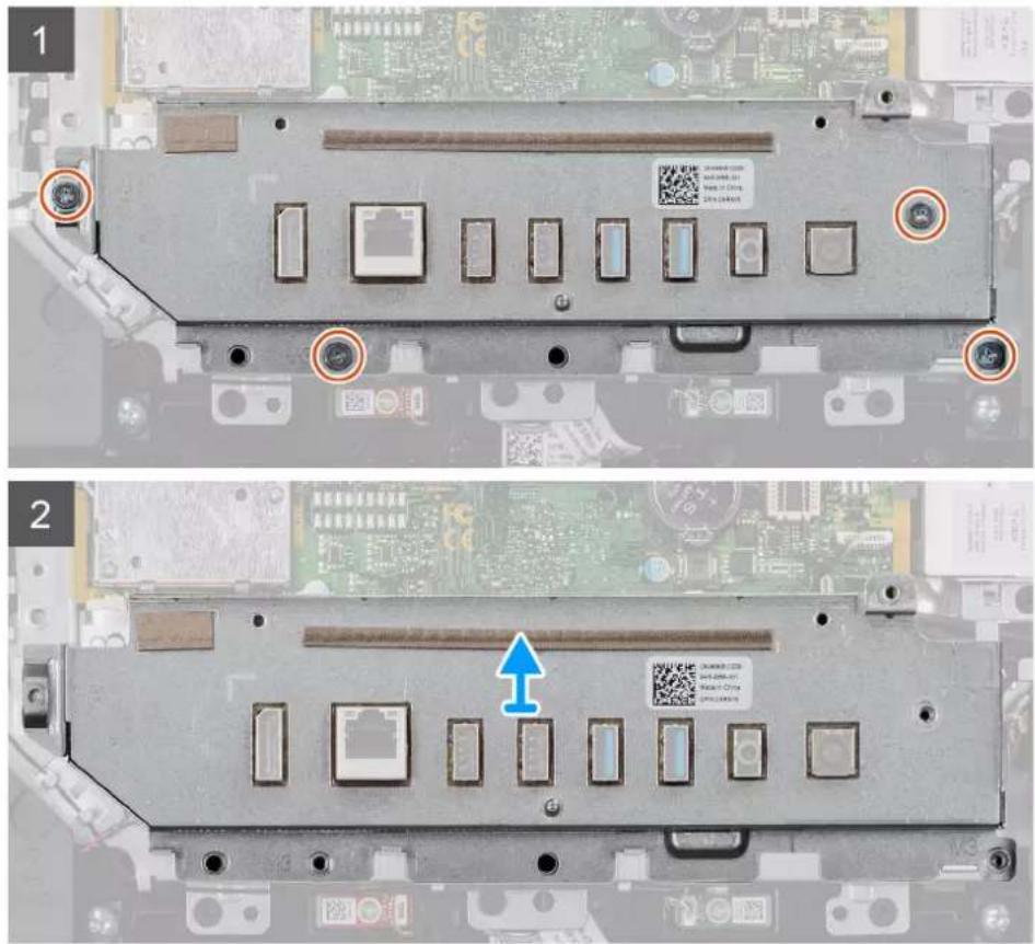
text_image
Technical diagram showing two views of a computer motherboard with labeled components and annotations in ChineseSteps
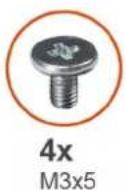
- Remove the four screws (M3x5) that secure the rear-I/O bracket to the display-assembly base.
- Lift the rear-I/O bracket off the display-assembly base.
Installing the rear-I/O bracket
Prerequisites
If you are replacing a component, remove the existing component before performing the installation procedure.
About this task
The following image indicates the location of the rear-I/O bracket and provides a visual representation of the installation procedure.
4x
M3x5
natural_image
Interior view of an electronic device showing a circuit board, CPU socket, and motherboard (no visible text or symbols)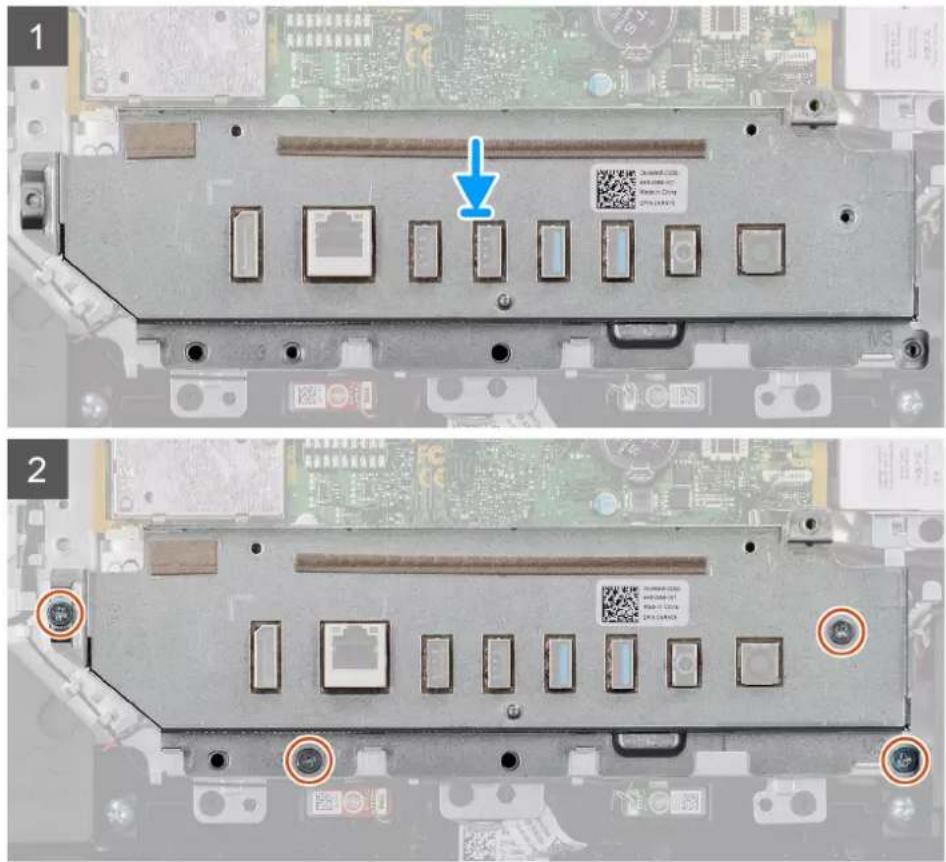
text_image
Laptop CPU rear panel with labeled ports and a QR code, showing two views (1 and 2) with annotations and a blue arrow pointing to a component.Steps
- Align the screw holes on the rear-I/O bracket with the screw holes on the display-assembly base.
- Replace the four screws (M3x5) that secure the rear-I/O bracket to the display-assembly base.
Next steps
- Install the bottom cover.
- Install the system-board shield.
- Install the back cover
- Install the cable cover (optional).
- Install the stand.
- Follow the procedure in After working inside your computer.
System board
Removing the system board
Prerequisites
- Follow the procedure in Before working inside your computer.
NOTE: Your computer's Service Tag is stored in the system board. You must enter the Service Tag in the BIOS setup program after you replace the system board.
NOTE: Replacing the system board removes any changes you have made to the BIOS using the BIOS setup program. You must make the appropriate changes again after you replace the system board.
NOTE: Before disconnecting the cables from the system board, note the location of the connectors so that you can reconnect the cables correctly after you replace the system board.
- Remove the stand.
- Remove the cable cover (optional).
- Remove the back cover.
- Remove the system-board shield.
- Remove the memory module.
- Remove the wireless card.
- Remove the hard drive.
- Remove the M.2 2230 solid-state drive.
- Remove the M.2 2280 solid-state drive/Intel Optane.
- Remove the heat sink.
- Remove the processor.
- Remove the coin-cell.
- Remove the bottom cover.
- Remove the rear-I/O bracket.
About this task
The following image indicates the connectors on your system board.
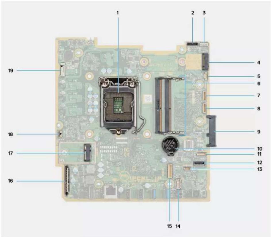
text_image
1 2 3 4 5 6 7 8 9 10 11 12 13 14 15 16 17 18 19- Processor 2. Camera cable connector
- Touch-screen cable connector 4. M.2 2230/2280 solid-state drive/Intel Optane PCIe connector
- System-fan cable connector 6. Memory module
- eSPI Debug Card cable connector 8. EC debug connector
- Hard-drive connector 10. Coin-cell battery
- Microphone-module cable connector 12. SIO-signal cable connector
- Speaker cable connector 14. Audio-board cable connector
- SIO-power cable connector 16. Display cable connector
- M.2 WLAN connector
-
Display back-light cable connector
-
Power-button cable connector
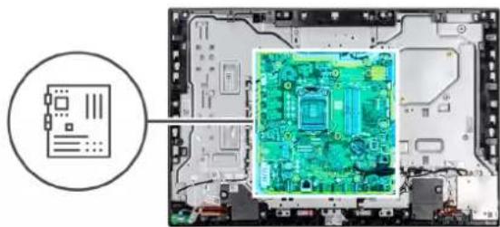
The following image indicates the location of system board and provides a visual representation of the removal procedure.

7x
M3x5
natural_image
Diagram showing a computer motherboard with an inset close-up of a green circuit board (no text or symbols visible)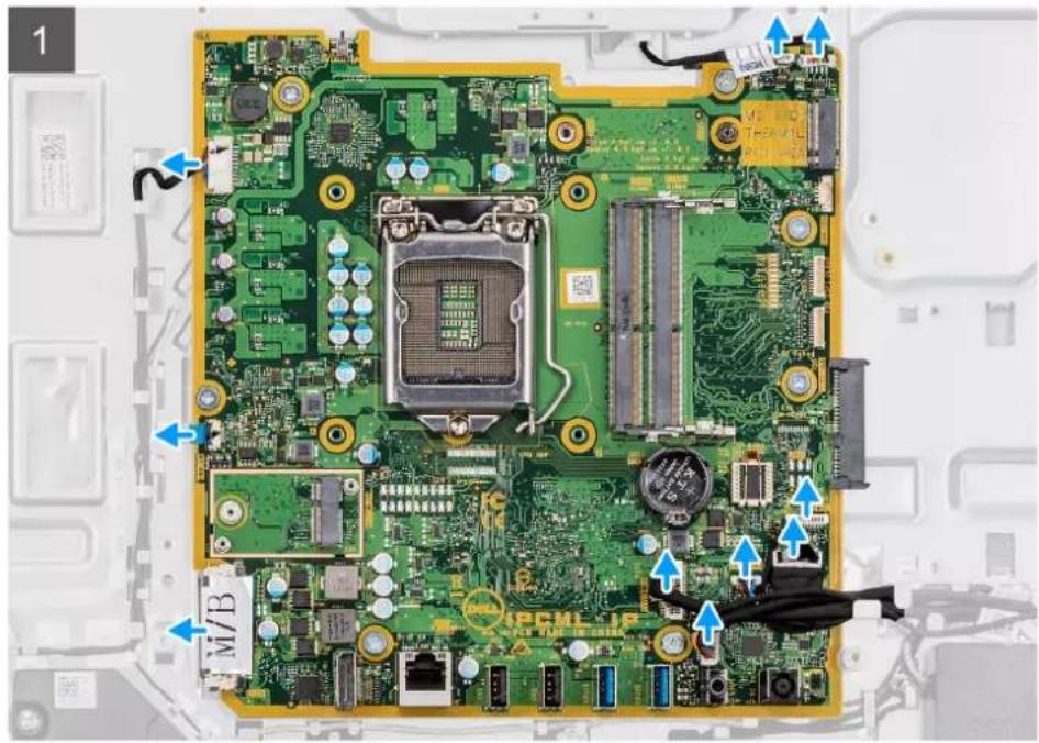
text_image
1 M/B M / C T / E / V / L M / C M / B M / C M / B M / C M / B M / C M / B M / C M / B M / C M / B M / C M / B M / C M / B M / C M / B M / C M / B M / C M / B M / C M / B M / C M / B M /C M /B M /C M /B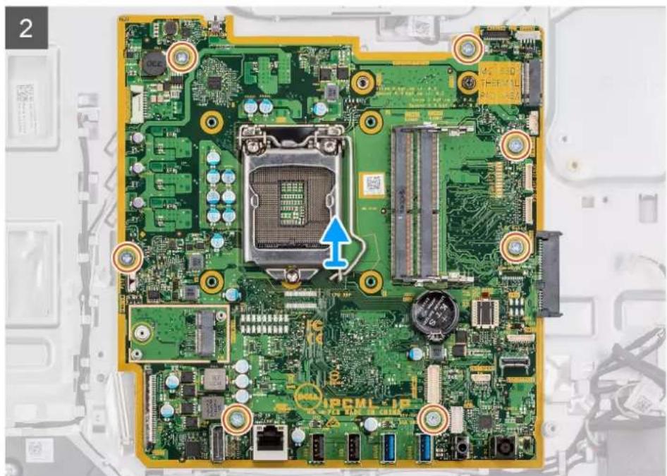
natural_image
Close-up of a green printed circuit board with visible components and a blue arrow pointing to a central processor (no readable text or symbols)Steps
- Disconnect the camera cable from the connector on the system board.
- Disconnect the touchscreen cable from the connector on the system board.
-
Disconnect the system fan cable from the connector on the system board.
-
Disconnect the microphone-module cable from the connector on the system board.
- Disconnect the SIO-signal cable from the connector on the system board.
- Disconnect the speaker cable from the connector on the system board.
- Disconnect the audio-board cable from the connector on the system board.
- Disconnect the SIO-power cable from the connector on the system board.
- Disconnect the display cable from the connector on the system board.
- Open the latch and disconnect the power-button board cable from the connector on the system board.
- Disconnect the display back-light cable from the connector on the system board.
- Remove the seven screws (M3x5) that secure the system board to the display-assembly base.
- Lift and remove the system board from the display-assembly base.
Installing the system board
Prerequisites
If you are replacing a component, remove the existing component before performing the installation procedure.
About this task
The following image indicates the connectors on your system board.
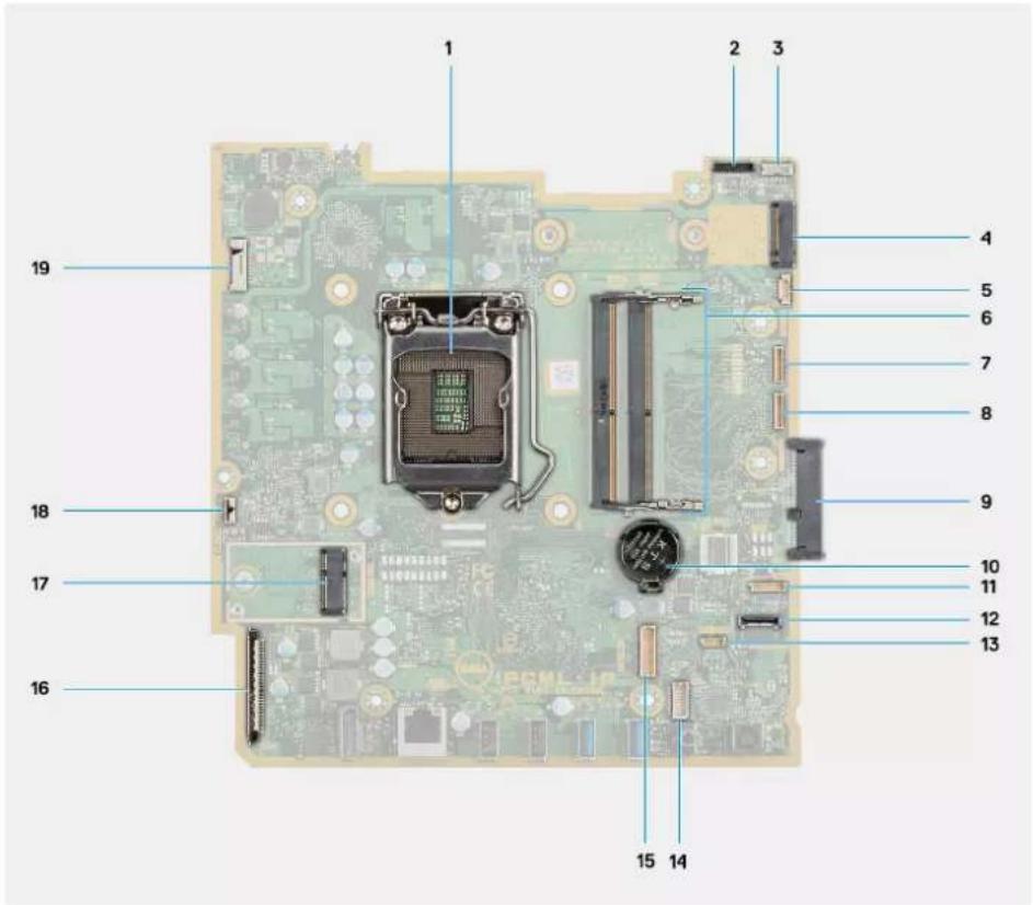
text_image
1 2 3 4 5 6 7 8 9 10 11 12 13 14 15 16 17 18 19- Processor 2. Camera cable connector
- Touch-screen cable connector 4. M.2 2230/2280 solid-state drive/Intel Optane PCIe connector
- System-fan cable connector 6. Memory module
- eSPI Debug Card cable connector 8. EC debug connector
- Hard-drive connector 10. Coin-cell battery
- Microphone-module cable connector 12. SIO-signal cable connector
- Speaker cable connector 14. Audio-board cable connector
-
SIO-power cable connector
-
Display cable connector
-
M.2 WLAN connector 18. Power-button cable connector
- Display back-light cable connector
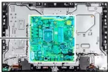
The following image indicates the location of system board and provides a visual representation of the installation procedure.
7x
M3x5
natural_image
Interior view of an electronic circuit board with a highlighted green PCB component (no text or symbols visible)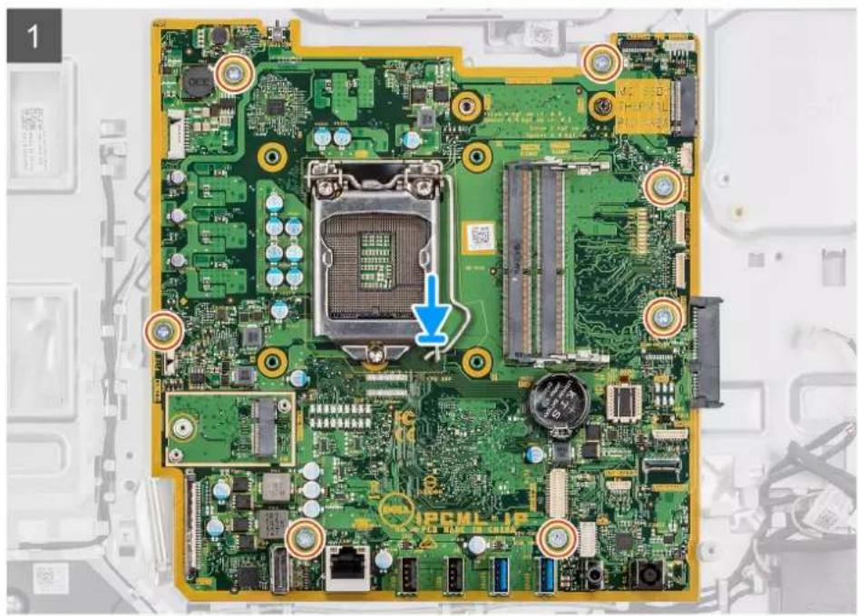
natural_image
Close-up of a green printed circuit board with visible components and a blue arrow pointing to a central processor (no text or symbols on the circuit itself)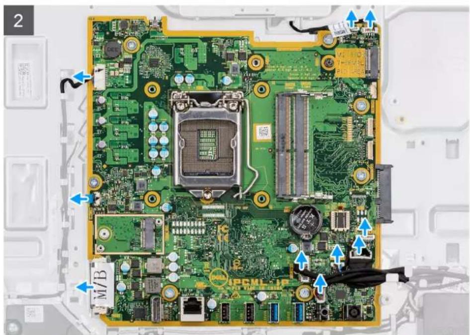
text_image
Labeled diagram of a computer motherboard showing CPU socket, memory card, and connectors with blue arrows indicating assembly or component.Steps
- Align the screw holes on the system board with the screw holes on the display-assembly base.
- Replace the seven screws (M3x5) to secure the system board to the display-assembly base.
- Connect the camera cable to the connector on the system board.
- Connect the touchscreen cable to the connector on the system board.
- Connect the system fan cable to the connector on the system board.
- Connect the microphone-module cable to the connector on the system board.
- Connect the SIO-signal cable to the connector on the system board.
- Connect the speaker cable to the connector on the system board.
- Connect the audio-board cable to the connector on the system board.
- Connect the SIO-power cable to the connector on the system board.
- Connect the display cable to the connector on the system board.
- Connect the power-button board cable to the system board and close the latch to secure the cable.
- Connect the display back-light cable to the connector on the system board.
Next steps
- Install the rear-I/O bracket.
- Install the bottom cover.
- Install the coin-cell.
- Install the processor.
- Install the heat-sink.
- Install the M.2 2230 solid-state drive/Intel Optane.
- Install the M.2 2230 solid-state drive.
- Install the hard drive.
- Install the wireless card.
- Install the memory module.
- Install the system-board shield.
- Install the back cover
- Install the cable cover (optional).
-
Install the stand.
-
Follow the procedure in After working inside your computer.
NOTE: Your computer's Service Tag is stored in the system board. You must enter the Service Tag in the BIOS setup program after you replace the system board.
NOTE: Replacing the system board removes any changes you have made to the BIOS using the BIOS setup program. You must make the appropriate changes again after you replace the system board.
Speakers
Removing the speakers
Prerequisites
- Follow the procedure in Before working inside your computer.
- Remove the stand.
- Remove the cable cover (optional).
- Remove the back cover.
- Remove the system-board shield.
- Remove the bottom cover.
- Remove the rear-I/O bracket.
About this task
The following image indicates the location of the speakers and provides a visual representation of the removal procedure.
4x
M3 4+7.1xZN
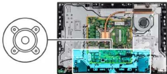
natural_image
Interior view of a computer motherboard showing circuit boards, CPU socket, and drive casing (no text or symbols visible)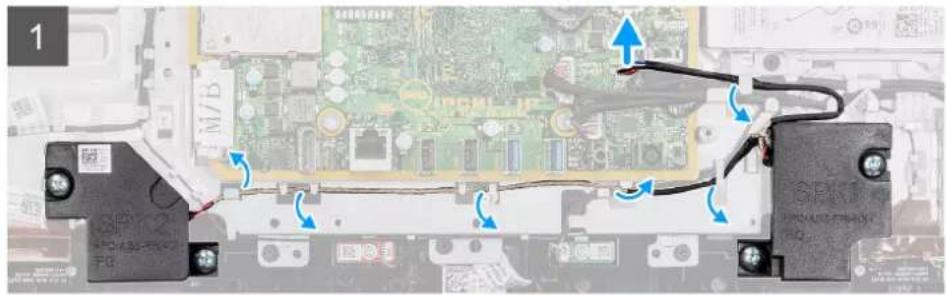
text_image
Circuit board diagram with labeled components and wiring, showing connections between components like M/B and PCB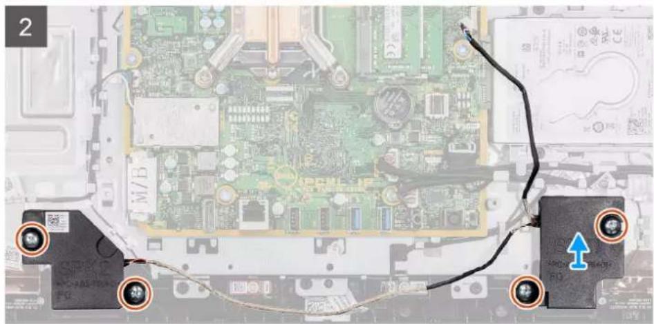
natural_image
Close-up of a computer motherboard with visible circuitry and connectors (no readable text or symbols)Steps
- Disconnect the speaker cable from the connector on the system board.
- Remove the four screws (M3 4+7.1xZN) that secure the speakers to the display-assembly base.
- Unroute the speaker cable from the routing guides on the display-assembly base.
- Lift the speakers along with the cable off the display-assembly base.
Installing the speakers
Prerequisites
If you are replacing a component, remove the existing component before performing the installation procedure.
About this task
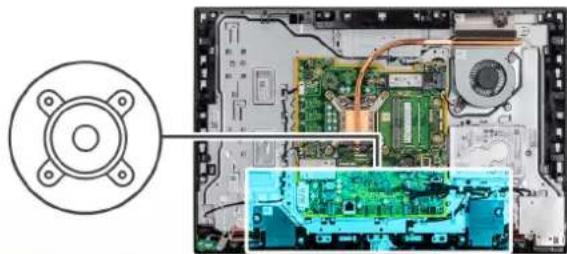
The following image indicates the location of the speakers and provides a visual representation of the installation procedure.
4x
M3 4+7.1xZN
natural_image
Interior view of a computer motherboard showing CPU socket, circuit board, and drive casing (no text or symbols visible)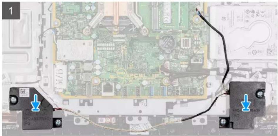
natural_image
Close-up of a computer motherboard with two connectors and cable, showing circuitry and wiring (no readable text or symbols)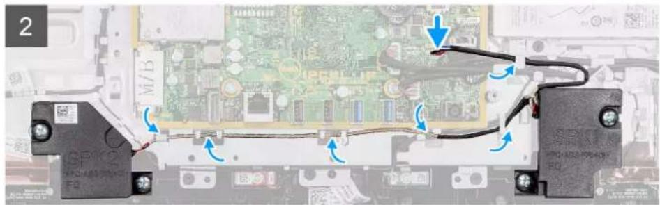
natural_image
Close-up of a computer motherboard with visible circuit board and cable connections (no readable text or symbols)Steps
- Align the screw holes on the speakers with the screw holes on the display-assembly base.
- Replace the four screws (M3 4+7.1xZN) to secure the speakers to the display-assembly base.
- Route the speaker cable through the routing guide on display-assembly base and connect the speaker cable to the system board.
Next steps
- Install the rear-I/O bracket.
- Install the bottom cover.
- Install the system-board shield.
- Install the back cover
- Install the cable cover (optional).
- Install the stand.
- Follow the procedure in After working inside your computer.
Power-button board
Removing the power-button board
Prerequisites
- Follow the procedure in Before working inside your computer.
- Remove the stand.
- Remove the cable cover (optional).
- Remove the back cover.
- Remove the system-board shield.
- Remove the rear-I/O bracket.
- Remove the speakers.
About this task
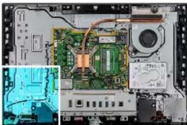
The following image indicates the location of the power-button board and provides a visual representation of the removal procedure.
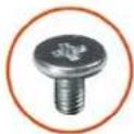
1x
M3x5
natural_image
Interior view of a computer motherboard showing CPU socket, circuit board, and drive casing (no visible text or labels)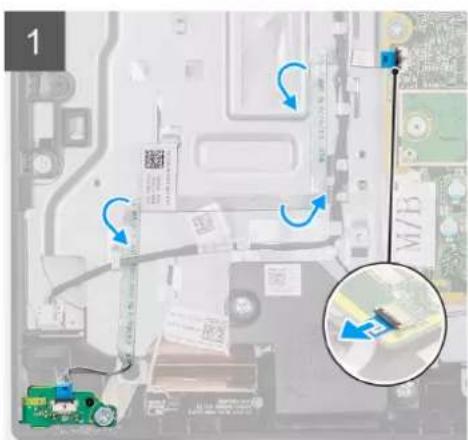
text_image
Diagram showing a computer motherboard with labeled components and directional arrows, including a magnified inset highlighting a component.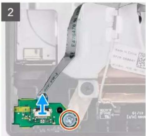
text_image
2 10/19 0.000-1 ↑ 5000V 0.000-1 10/19 0.000-1 [4V 30V]Steps
- Open the latch, and disconnect the power-button board cable from the connector on the system board.
- Unroute the power-button board cable from the display-assembly base.
- Remove the screw (M3x5) that secures the power-button board to the middle frame.
- Lift and remove the power-button board with the cable off the middle frame.
Installing the power-button board
Prerequisites
If you are replacing a component, remove the existing component before performing the installation procedure.
About this task
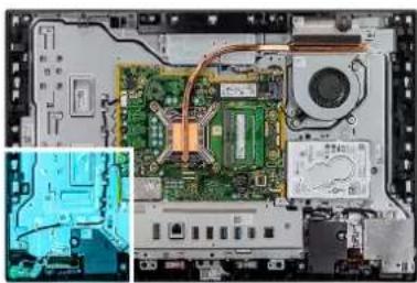
The following image indicates the location of the power-button board and provides a visual representation of the installation procedure.
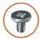
1x
M3x5
natural_image
Interior view of a computer motherboard showing CPU socket, circuit board, and drive unit (no text or symbols visible)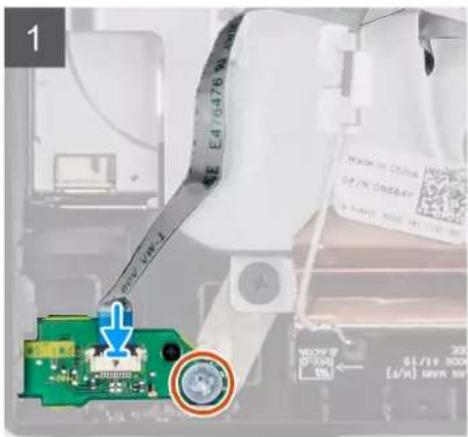
text_image
1 E4/6476 90 MAD IN CHINA OF IN ONER SAMS 2000 001133 50 300 [0/10] [0/10] 300 [0/10]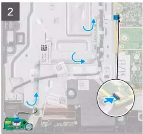
text_image
Diagram showing a computer motherboard with annotations and a magnified view highlighting a location near the keyboardSteps
- Align and place the power-button board in the slot on the middle frame.
- Replace the screw (M3x5) to secure the power-button board to the middle frame.
- Route the power-button board cable through the display-assembly base.
- Connect the power-button board cable to the connector on the system board and close the latch to secure the cable.
Next steps
- Install the speakers.
- Install the rear-I/O bracket.
- Install the bottom cover.
- Install the system-board shield.
- Install the back cover
- Install the cable cover (optional).
- Install the stand.
- Follow the procedure in After working inside your computer.
Microphones
Removing the microphones
Prerequisites
- Follow the procedure in Before working inside your computer.
- Remove the stand.
- Remove the cable cover (optional).
- Remove the back cover.
-
Remove the system-board shield.
-
Remove the bottom cover.
- Remove the rear-I/O bracket.
- Remove the speaker
About this task
The following image indicates the location of the microphones and provides a visual representation of the removal procedure.
2x M2x2.5
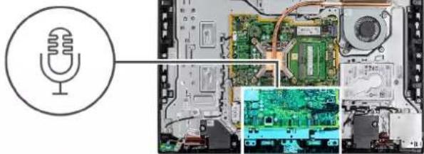
natural_image
Diagram showing a microphone icon pointing to an open circuit board with various components (no text or symbols present)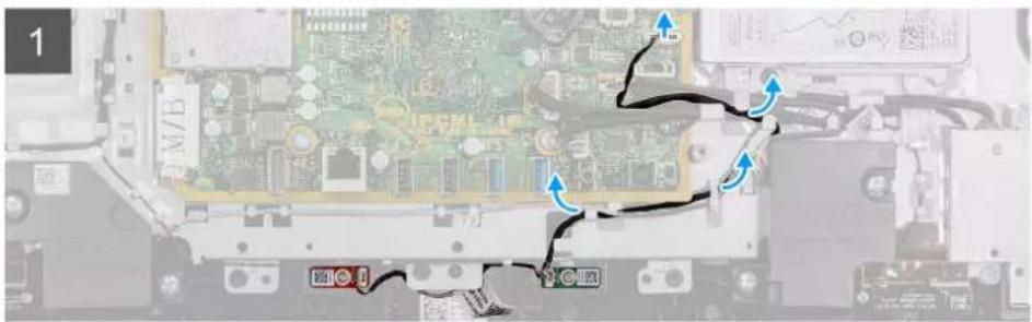
natural_image
Close-up of an electronic circuit board with visible traces and connectors (no readable text or symbols)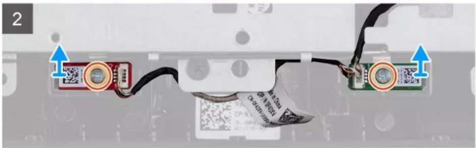
natural_image
Close-up of a computer monitor cable with two connected components and a QR code tag, no visible text or symbolsSteps
- Disconnect the microphone cable from the system board, and unroute it from the routing guides on the display-assembly base.
- Remove the two screws (M2x2.5) that secure the microphone module (2) to the middle frame.
- Lift the microphone module (2) off the slots on the middle frame.
Installing the microphones
Prerequisites
If you are replacing a component, remove the existing component before performing the installation procedure.
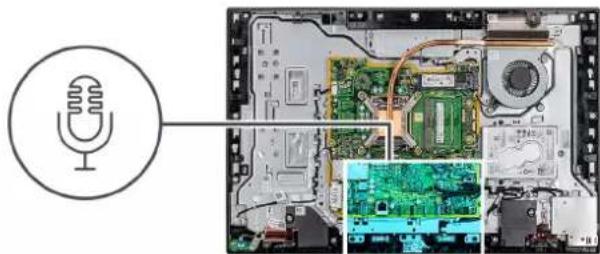
About this task
The following image indicates the location of the microphones and provides a visual representation of the installation procedure.
2x
M2x2.5
natural_image
Interior view of an electronic device showing internal circuit boards and a microphone icon (no text or symbols)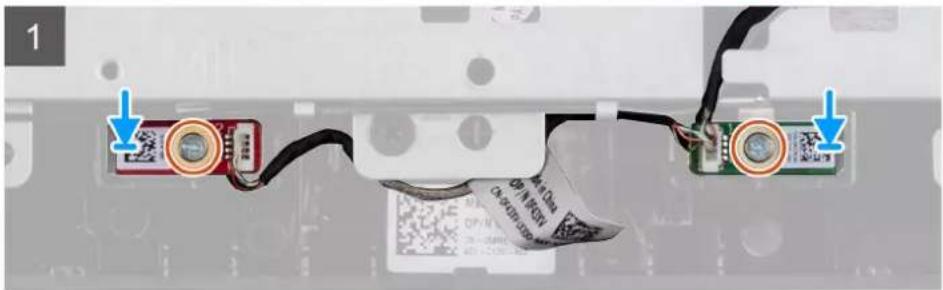
natural_image
Close-up of a computer monitor cable with two connected components and a QR code on the cover (no readable text or symbols)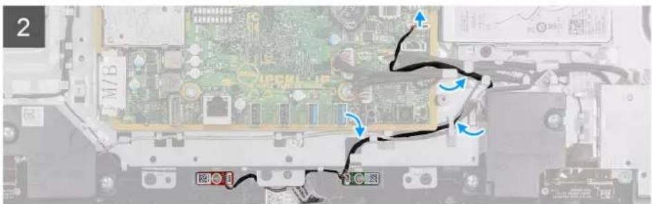
text_image
Laptop keyboard interface with visible circuit board and annotated arrows indicating movement or navigationSteps
- Align the screw holes on the microphone modules with the screw holes on the middle frame.
- Replace the two screws (M2x2.5) that secure the microphone modules to the middle frame.
- Route the microphone cable through the routing guides on the display-assembly base and connect the microphone cable to the system board.
Next steps
- Install the speaker.
- Install the rear-I/O bracket.
- Install the bottom cover.
- Install the back cover
- Install the cable cover (optional).
- Install the stand.
- Follow the procedure in After working inside your computer.
Side I/O-board
Removing the side-I/O board
Prerequisites
- Follow the procedure in Before working inside your computer.
- Remove the stand.
- Remove the cable cover (optional).
- Remove the back cover.
-
Remove the hard drive.
-
Remove the system-board shield.
- Remove the bottom cover.
- Remove the rear-I/O bracket.
About this task
The following image indicates the location of the side-I/O board and provides a visual representation of the removal procedure.
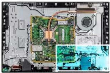
natural_image
Interior view of a computer motherboard showing CPU socket, circuit board, and drive unit (no text or symbols visible)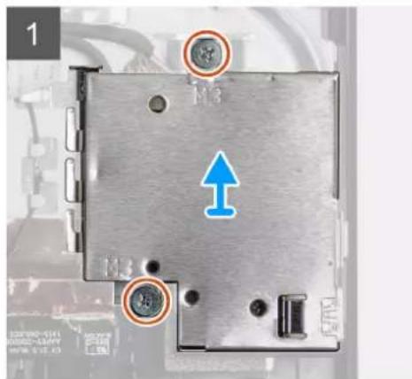
text_image
1 M3 M3 ↑ ←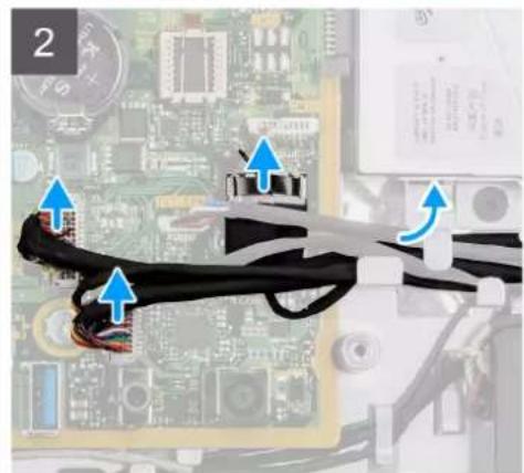
natural_image
Close-up of a computer motherboard with visible wiring and connectors (no text or symbols)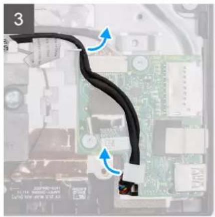
natural_image
Close-up of a black cable with blue directional arrows pointing to components on a computer motherboard (no text or symbols visible)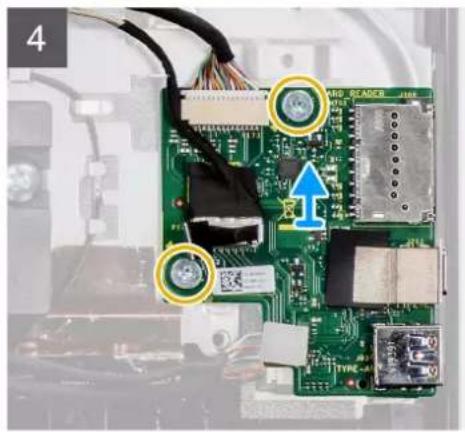
natural_image
Close-up of a green printed circuit board with connectors and labeled components (no readable text or symbols)Steps
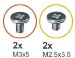
- Remove the two screws (M3x5) that secure the side-I/O board shield to the display-assembly base.
- Lift and remove the side I/O-board shield off the side-I/O board.
- Disconnect the SIO-signal cable, SIO-power cable, and audio-board cable from the connector on the system board.
- Remove the SIO-signal cable, SIO-power cable, and audio-board cable from the routing guides on the display-assembly base.
- Remove the two screws (M2.5x3.5) that secure the side-I/O board to the display-assembly base.
- Lift and remove the side-I/O board with the cables off the display-assembly base.
Installing the side-I/O board
Prerequisites
If you are replacing a component, remove the existing component before performing the installation procedure.
About this task
The following image indicates the location of the side-I/O board and provides a visual representation of the installation procedure.
2x
M3x5
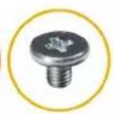
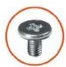
2x
M2.5×3.5
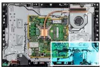
natural_image
Interior view of an electronic device showing a circuit board, fan, and motherboard (no visible text or symbols)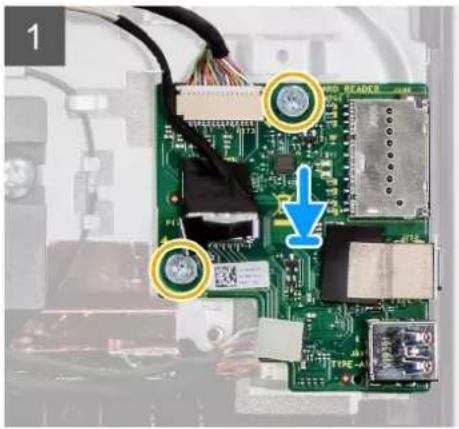
natural_image
Close-up of a green printed circuit board with visible components and connectors, no readable text or symbols present.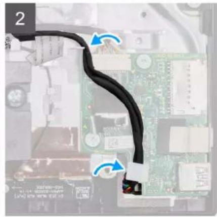
natural_image
Close-up of a black cable inserted into a computer motherboard, showing circuit board and connectors (no text or symbols visible)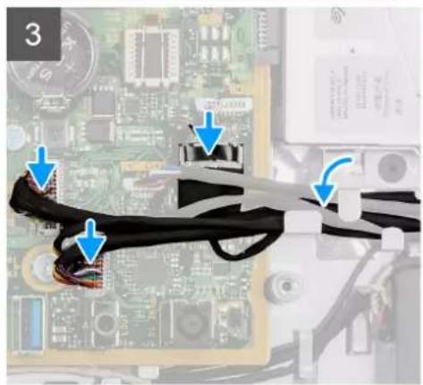
natural_image
Close-up of a computer motherboard with visible traces and connectors (no text or symbols)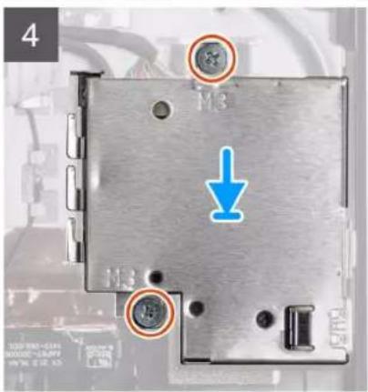
text_image
4 M3 ↓Steps
- Align the screw holes on the side-I/O board with the screw holes on the display-assembly base.
- Replace the two screws (M2.5x3.5) to secure the side-I/O board to the display-assembly base.
- Route the SIO-signal cable, SIO-power cable, and audio-board cable through the routing guides on the display-assembly base.
- Connect the SIO-signal cable, SIO-power cable, and audio-board cable to the system board.
- Align the screw holes on the side I/O-board shield with the screw holes on the display-assembly base.
- Replace the two screws (M3x5) to secure the side I/O-board shield to the display-assembly base.
Next steps
- Install the rear-I/O bracket.
- Install the bottom cover.
- Install the system-board shield.
- Install the back cover.
- Install the cable cover (optional).
- Install the stand.
- Follow the procedure in After working inside your computer.
Audio board
Removing the audio board
Prerequisites
- Follow the procedure in Before working inside your computer.
- Remove the stand.
- Remove the cable cover (optional).
- Remove the back cover.
- Remove the system-board shield.
- Remove the bottom cover.
- Remove the rear-I/O bracket.
- Remove the side-I/O bracket.
About this task
The following image indicates the location of the audio board and provides a visual representation of the removal procedure.
1x
M3x5
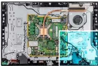
natural_image
Interior view of a computer motherboard showing CPU socket, circuit board, and ventilation unit (no text or symbols visible)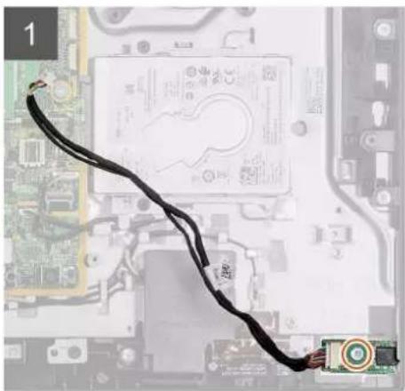
natural_image
Close-up of a computer motherboard with visible circuit board and cable (no text or symbols)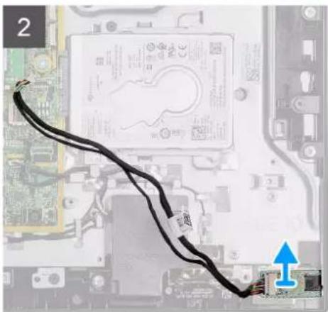
natural_image
Close-up of an electronic circuit board with a black cable and connector, showing no readable text or symbols.Steps
- Disconnect the audio-board cable from the connector on the system board.
- Remove the screw (M3x5) that secure the audio board to the display-assembly base.
- Lift and remove the audio board with the cable off the display-assembly base.
Installing the audio board
Prerequisites
If you are replacing a component, remove the existing component before performing the installation procedure.
About this task
The following image indicates the location of the audio board and provides a visual representation of the installation procedure.
1x
M3x5
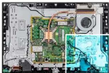
natural_image
Interior view of a computer motherboard showing CPU socket, circuit board, and electronic components (no visible text or labels)
natural_image
Close-up of a computer motherboard with a black cable and connector, showing no readable text or symbols.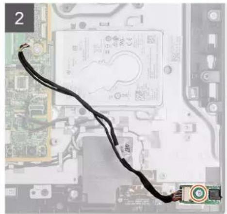
natural_image
Close-up of a computer motherboard with visible circuit traces and connectors (no readable text or symbols)Steps
- Align the screw hole on the audio board with the screw hole on the display-assembly base.
- Replace the screw (M3x5) to secure the audio board to the display-assembly base.
- Connect the audio-board cable to the system board.
Next steps
- Install the rear-I/O bracket.
- Install the bottom cover.
- Install the system-board shield.
- Install the back cover.
- Install the cable cover (optional).
- Install the stand.
- Follow the procedure in After working inside your computer.
Antenna modules
Removing the antenna modules
Prerequisites
- Follow the procedure in Before working inside your computer.
-
Remove the stand.
-
Remove the cable cover (optional).
- Remove the back cover.
- Remove the system-board shield.
- Remove the hard-drive.
- Remove the wireless card.
- Remove the system board.
- Remove the bottom cover.
- Remove the rear-I/O bracket.
- Remove the speakers.
- Remove the side-I/O board.
About this task
The following image provides a visual representation of the antenna modules removal procedure.
2x
M2x2.5
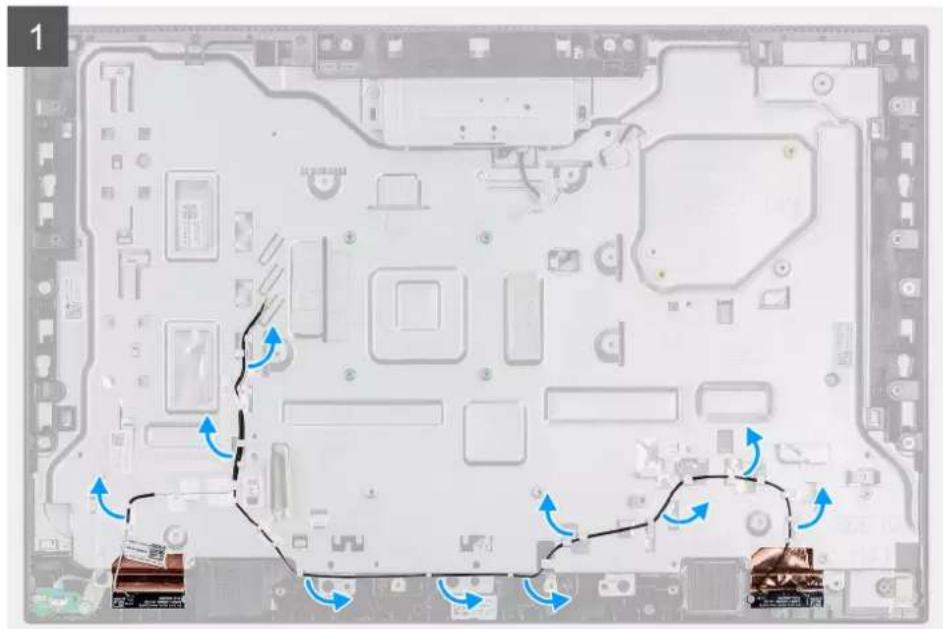
natural_image
Top-down view of a computer motherboard with visible circuitry and directional arrows indicating movement (no text or symbols)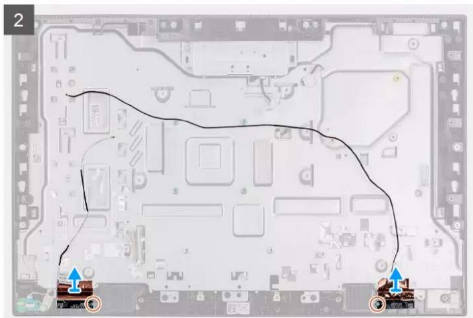
natural_image
Interior view of a computer motherboard with visible CPU socket and track indicators (no text or symbols)Steps
- Remove the antenna cables from the routing guides on the display-assembly base.
- Remove the two screws (M2x2.5) that secure the antenna modules to the middle frame.
- Carefully peel the copper foil that secures the antenna cables to the middle frame.
- Lift the antenna modules off the middle frame.
Installing the antenna modules
Prerequisites
If you are replacing a component, remove the existing component before performing the installation procedure.
About this task
The following image provides a visual representation of the antenna modules installation procedure.
2x
M2x2.5
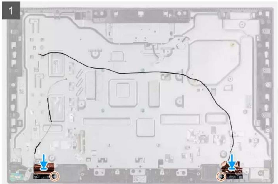
natural_image
Interior view of a computer motherboard with visible circuitry and two blue arrows pointing to specific components (no text or symbols)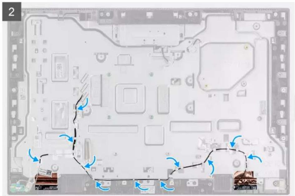
natural_image
Top-down view of a computer motherboard with blue arrows indicating movement paths (no text or symbols)Steps
- Align and place the antenna modules in the slots on the middle frame.
- Adhere the copper foil that secures the antenna cables to the middle frame.
- Replace the two screws (M2x2.5) to secure the antenna modules to the middle frame.
- Route the antenna cables through the routing guides on the display-assembly base.
Next steps
- Install the speakers.
- Install the rear-I/O bracket.
- Install the system board.
- Install the bottom cover.
- Install the wireless card.
- Install the hard-drive.
- Install the system-board shield.
- Install the back cover.
- Install the cable cover (optional).
- Install the stand.
- Follow the procedure in After working inside your computer.
Display panel
Removing the display panel
Prerequisites
- Follow the procedure in Before working inside your computer.
- Remove the stand.
- Remove the cable cover (optional).
- Remove the back cover.
- Remove the system-board shield.
- Remove the hard drive.
- Remove the bottom cover.
- Remove the rear-I/O bracket.
- Remove the speakers.
- Remove the camera assembly.
- Remove the system board.
About this task
The following image indicates the location of display panel and provides a visual representation of the removal procedure.
8x
M3x5
natural_image
Dark screen with a white header and 'DLL' label at the bottom (no other text or symbols visible)1
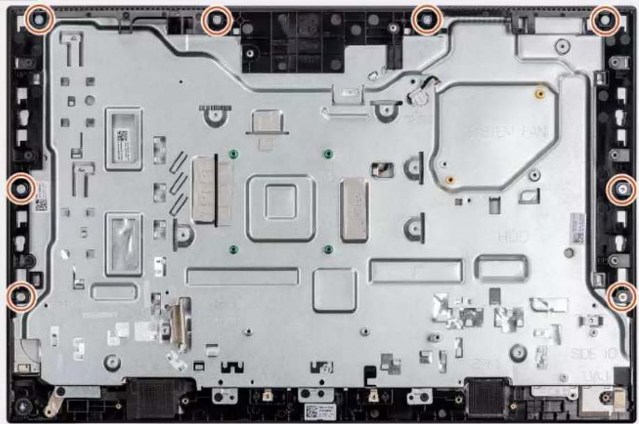
natural_image
Top-down view of a computer motherboard showing labeled components and mounting points (no readable text or symbols)2
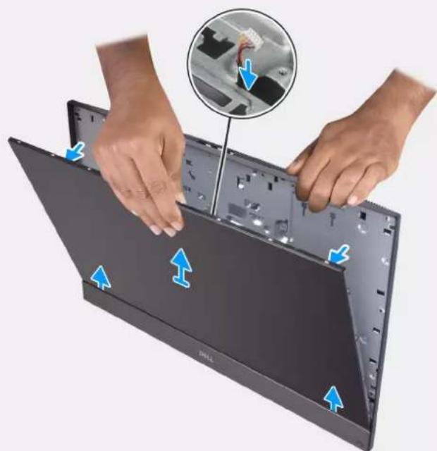
natural_image
Close-up of hands installing or adjusting a black Dell laptop into a plastic case, with an inset showing a close-up of the internal components (no text or symbols visible)Steps
- Remove the 8 screws (M3x5) that secure the middle frame and display-assembly base to the display panel.
- Place the system in an upright position.
-
Holding the top corner, release the display panel away from the middle frame and display-assembly base.
-
Route the display back-light, touch screen and display cable through the slots on the display assembly base.
- Lift the display panel up from the middle frame and display-assembly base.
Installing the display panel
Prerequisites
If you are replacing a component, remove the existing component before performing the installation procedure.
About this task
The following image indicates the location of display panel and provides a visual representation of the installation procedure.
8x
M3x5
natural_image
Front view of a black screen with 'DALL' branding at the bottom (no other text or symbols visible)1
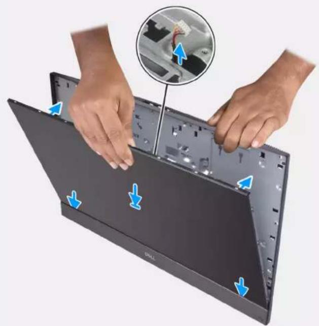
natural_image
Close-up of hands installing or adjusting a laptop panel with blue directional arrows indicating component movement (no text or symbols visible)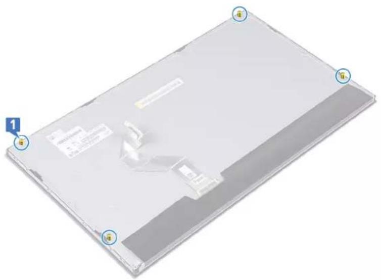
natural_image
3D CAD model of a rectangular electronic device with labeled points (1 and 2) and no visible text or symbols on the body itself.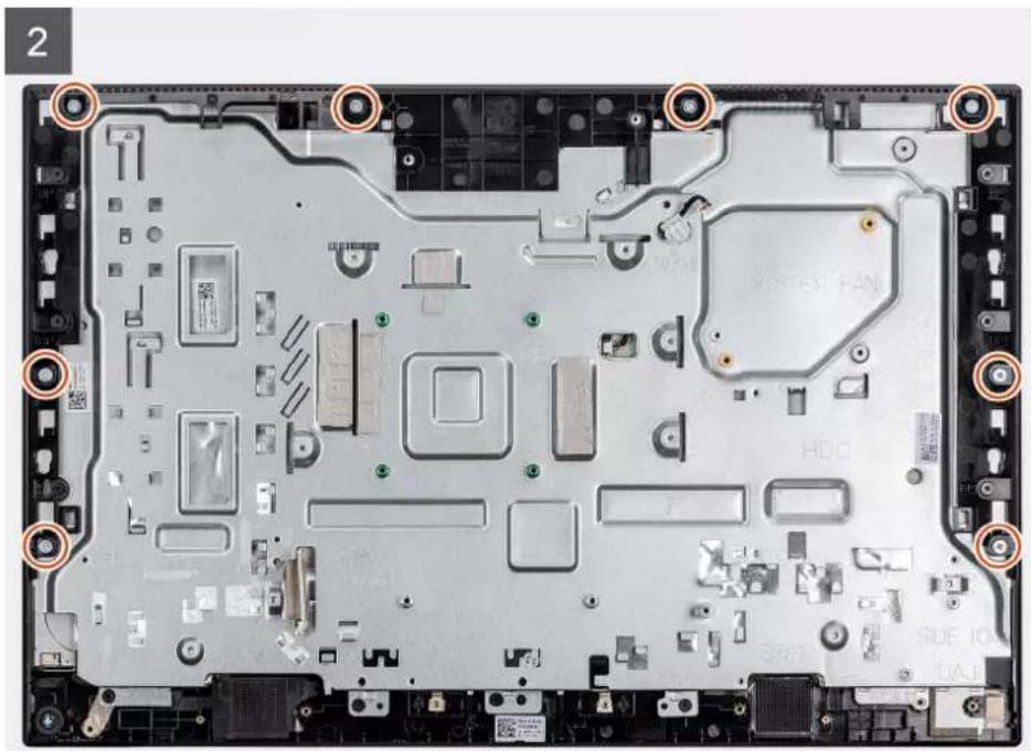
natural_image
Top-down view of a computer motherboard showing multiple slots, connectors, and ventilation (no readable text or symbols)Steps
- Place the system in an upright position, and slide the display panel on the slots of the display-assembly base.
- Route the display-backlight, touch screen, and display cable through the slots on the display-assembly base.
- Place the display-assembly base on a clean and flat surface with the display panel facing down.
- Replace the four screws (M3x5) to secure the display panel to the middle frame and display-assembly base.
- Remove the four jig screws from the display panel.
- Replace the four screw (M3x5) to secure the display panel to the middle frame and display assembly base.
- Route the display cable in the routing guides on the display-assembly base.
Next steps
- Install the system board.
- Install the camera assembly.
- Install the speakers.
- Install the rear-I/O bracket.
-
Install the bottom cover.
-
Install the heat sink.
- Install the system-board shield.
- Install the back cover
- Install the cable cover (optional).
- Install the stand.
- Follow the procedure in After working inside your computer.
Middle frame
Removing the middle frame
Prerequisites
- Follow the procedure in Before working inside your computer.
- Remove the stand.
- Remove the cable cover (optional).
- Remove the back cover.
- Remove the system-board shield.
- Remove the hard-drive.
- Remove the wireless card.
- Remove the bottom cover.
- Remove the rear-I/O bracket.
- Remove the speakers.
- Remove the camera assembly.
- Remove the system board.
- Remove the power-button board.
- Remove the microphones.
- Remove the side-I/O board.
- Remove the antenna module.
- Remove the display panel.
About this task
The following image indicates the location of the middle frame and provides a visual representation of the removal procedure.
11x
M3x5

natural_image
Top-down view of a computer motherboard showing circuitry and components (no text or symbols visible)1
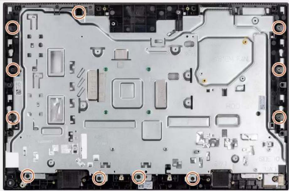
natural_image
Top-down view of a computer motherboard showing multiple slots, connectors, and labeled components (no readable text or symbols)2
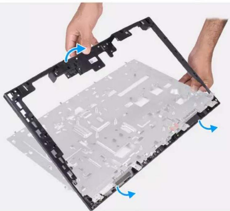
natural_image
Close-up of hands installing or adjusting a black plastic electronic device casing with visible internal components and blue directional arrows indicating rotation (no text or symbols)Steps
- Remove the 11 screws (M3x5) that secure the middle frame to the display-assembly base.
- Remove the middle frame and lift the middle frame off the display-assembly base.
Installing the middle frame
Prerequisites
If you are replacing a component, remove the existing component before performing the installation procedure.
About this task
The following image indicates the location of the middle frame and provides a visual representation of the installation procedure.
11x
M3x5
natural_image
Top-down view of a computer motherboard showing circuit boards and components (no text or symbols visible)1
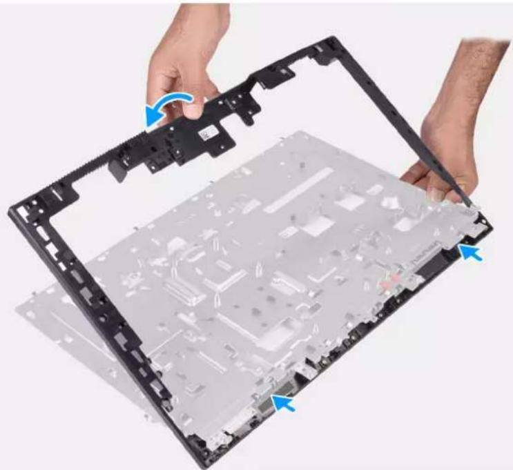
natural_image
Close-up of hands installing or adjusting a black plastic electronic device casing with visible internal components and blue directional arrows indicating assembly (no text or symbols)2
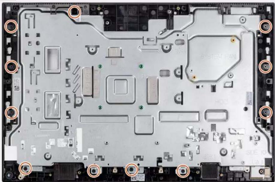
natural_image
Top-down view of a computer motherboard with visible slots, connectors, and mounting points (no readable text or symbols)Steps
- Slide and align the middle frame to the slots on the display-assembly base, then snap the middle frame into place on the display-assembly base.
- Replace the 11 screws (M3x5) to secure the middle frame to the display-assembly base.
Next steps
- Install the display panel.
- Install the antenna module.
- Install the side-I/O board.
- Install the microphones.
- Install the power-button board.
- Install the system board.
- Install the camera assembly.
- Install the speakers.
- Install the rear-I/O bracket.
- Install the bottom cover.
- Install the wireless card.
- Install the hard-drive.
- Install the system-board shield.
- Install the back cover
- Install the cable cover (optional).
- Install the stand.
- Follow the procedure in After working inside your computer.
This chapter details the supported operating systems along with instructions on how to install the drivers.
Topics:
- Operating system
- Downloading the drivers
Operating system
Your Dell Optiplex 3280 All-in-One supports the following operating systems:
●Windows 10 Home (64-bit)
●Windows 10 IoT Enterprise 2019 LTSC (OEM Only)
●Windows 10 Professional (64-bit)
●Windows 10 Pro Education (64-bit)
- NeoKylin 7.0 (China only)
- Ubuntu 18.04 (64-bit)
Downloading the drivers
Steps
- Turn on your computer.
- Go to www.dell.com/support.
- Enter the Service Tag of your computer, and then click Submit.
NOTE: If you do not have the Service Tag, use the auto-detect feature or manually browse for your computer model.
- Click Drivers & downloads.
- Click the Detect Drivers button.
- Review and agree to the Terms and Conditions to use SupportAssist, then click Continue.
- If necessary, your computer starts to download and install SupportAssist.
NOTE: Review on-screen instructions for browser-specific instructions.
-
Click View Drivers for My System.
-
Click Download and Install to download and install all driver updates detected for your computer.
- Select a location to save the files.
- If prompted, approve requests from User Account Control to make changes on the system.
- The application installs all drivers and updates identified.
NOTE: Not all files can be installed automatically. Review the installation summary to identify if manual installation is necessary.
- For manual download and installation, click Category.
- From the drop-down list, select the preferred driver.
- Click Download to download the driver for your computer.
- After the download is complete, navigate to the folder where you saved the driver file.
- Double-click the driver file icon and follow the instructions on the screen to install the driver.
System setup

CAUTION: Unless you are an expert computer user, do not change the settings in the BIOS Setup program. Certain changes can make your computer work incorrectly.

NOTE: Before you change BIOS Setup program, it is recommended that you write down the BIOS Setup program screen information for future reference.
Use the BIOS Setup program for the following purposes:
- Get information about the hardware installed in your computer, such as the amount of RAM and the size of the hard drive.
- Change the system configuration information.
- Set or change a user-selectable option, such as the user password, type of hard drive installed, and enabling or disabling base devices.
Topics:
•BIOS overview
- Entering BIOS setup program
- Navigation keys
- Boot Sequence
- System setup options
- Updating the BIOS
•System and setup password
BIOS overview
The BIOS manages data flow between the computer's operating system and attached devices such as hard disk, video adapter, keyboard, mouse, and printer.
Entering BIOS setup program
About this task
Turn on (or restart) your computer and press F2 immediately.
Navigation keys

NOTE: For most of the System Setup options, changes that you make are recorded but do not take effect until you restart the system.
Keys Navigation
Up arrow Moves to the previous field.
Down arrow Moves to the next field.
Enter Selects a value in the selected field (if applicable) or follow the link in the field.
Spacebar Expands or collapses a drop-down list, if applicable.
Tab Moves to the next focus area.
Esc
Moves to the previous page until you view the main screen. Pressing Esc in the main screen displays a message that prompts you to save any unsaved changes and restarts the system.
Boot Sequence
Boot Sequence allows you to bypass the System Setup-defined boot device order and boot directly to a specific device (for example: optical drive or hard drive). During the Power-on Self-Test (POST), when the Dell logo appears, you can:
- Access System Setup by pressing F2 key
●Bring up the one-time boot menu by pressing F12 key.
The one-time boot menu displays the devices that you can boot from including the diagnostic option. The boot menu options are:
-UEFI BOOT
- Windows Boot Manager
○Onboard NIC (IPV4)
○Onboard NIC (IPV6)
- OTHER OPTIONS
oBIOS Setup
○Device Configuration
- BIOS Flash Update
o Diagnostics
oSupportAssist OS Recovery
○Change Boot Mode Settings
- Exit Boot Menu and continue
System setup options

NOTE: Depending on this computer and its installed devices, the items listed in this section may or may not appear.
Table 3. System setup options—System information menu
| General-System Information | |
| System Information | |
| BIOS Version Displays the BIOS version number. | |
| Service Tag Displays the Service Tag of the computer. | |
| Asset Tag Displays the Asset Tag of the computer. | |
| Ownership Tag Displays the Ownership Tag of the computer. | |
| Manufacture Date Displays the manufacture date of the computer. | |
| Ownership Date Displays the ownership date of the computer. | |
| Express Service Code Displays the express service code of the computer. | |
| Signed Firmware Update is enabled Displays whether the Signed Firmware Update is enabled on your computer. | |
| Memory Information | |
| Memory Installed Displays the total computer memory installed. | |
| Memory Available Displays the total computer memory available. | |
| Memory Speed Displays the memory speed. | |
| Memory Channel Mode Displays single or dual channel mode. | |
| Memory Technology Displays the technology used for the memory. | |
| DIMM 1 Size Displays the DIMM A memory size. | |
| DIMM 2 Size Displays the DIMM B memory size. | |
| PCI Information | |
| SLOT1 | Displays the M.2 slot1 information. |
| SLOT2_M.2 Displays the M.2 slot2 information. | |
| Processor Information | |
| Processor Type Displays the processor type. | |
| Core Count Displays the number of cores on the processor. | |
| Processor ID Displays the processor identification code. | |
| Current Clock Speed Displays the current processor clock speed. | |
| Minimum Clock Speed Displays the minimum processor clock speed. | |
| Maximum Clock Speed Displays the maximum processor clock speed. | |
| Processor L2 Cache Displays the processor L2 Cache size. | |
| Processor L3 Cache Displays the processor L3 Cache size. | |
| HT Capable Displays whether the processor is HyperThreading (HT) capable. | |
| 64-Bit Technology Displays whether 64-bit technology is used. | |
| Device Information | |
| SATA-0 Displays the SATA-0 device information of the computer. | |
| M.2 PCIe SSD-0 Displays the M.2 PCIe SSD information of the computer. | |
| LOM MAC Address Displays the LAN On Motherboard (LOM) MAC address of the computer. | |
| Video Controller Displays the video controller type of the computer. | |
| Video BIOS Version Displays the video BIOS version of the computer. | |
| Video Memory | Displays the video memory information of the computer. |
| Panel Type | Displays the Panel Type of the computer. |
| Native Resolution | Displays the native resolution of the computer. |
| Audio Controller Displays the audio controller information of the computer. | |
| Wi-Fi Device | Displays the wireless device information of the computer. |
| Bluetooth Device | Displays the bluetooth device information of the computer. |
| Boot Sequence | |
| Boot Sequence | Displays the boot sequence. |
| Boot List Option Displays the available boot options. | |
| UEFI Boot Path Security | Displays the UEFI Boot options. |
| By default, the Always Except Internal HDD option is enabled. | |
| Date/Time | Displays the current date in MM/DD/YY format and current time in HH:MM:SS AM/PM format. |
Table 4. System setup options—System Configuration menu
| System Configuration | |
| Integrated NIC Controls the on-board LAN controller. | |
| Enable UEFI Network Stack | Enable or disable UEFI Network Stack.By default, the Enable UEFI Network Stack and Enabled w/PXE options are enabled. |
| SATA Operation | Configure operating mode of the integrated SATA hard drive controller.By default, the RAID On option is enabled. |
Table 4. System setup options—System Configuration menu (continued)
| System Configuration |
| Drives Enable or disable various drives on board. |
| By default, all the options are enabled. |
| SMART Reporting Enable or disable Self-Monitoring, Analysis, and Reporting Technology (SMART) during system startup. |
| By default, theEnable SMART Reportingoption is not enabled. |
| USB Configuration |
| Enable USB Boot Support Enable or disable booting from USB mass storage devices such as external hard drive, optical drive, and USB drive. |
| By default, theEnable USB Boot Supportoption is enabled. |
| Enable Rear USB Ports Enable or disable booting from USB mass storage devices connected to rear USB port. |
| By default, theEnable Rear USB Portsoption is enabled. |
| Enable Side USB Ports Enable or disable booting from USB mass storage devices connected to side USB port. |
| By default, theEnable side USB Portsoption is enabled. |
| Rear USB Configuration Enable or disable rear USB configuration. |
| By default, all the options are enabled. |
| Side USB Configuration Enable or disable rear USB configuration. |
| By default, all the options are enabled. |
| USB PowerShare Enable or Disable USB PowerShare |
| By default, theEnable USB PowerShareoption is not enabled. |
| Audio Enable or disable the integrated audio controller. |
| By default, all the options are enabled. |
| OSD Button Management |
| Disable OSD button Enable or disable OSD button. |
| By default, theDisable OSD Buttonsoption is not enabled. |
| Touchscreen |
| Touchscreen Enable or disable touchscreen (only for touchscreen computers). |
| By default, theTouchscreenoption is enabled. |
| Miscellaneous Devices Enable or disable various onboard devices. |
| Enable Camera Enable or disable the camera. |
| By default, theEnable Cameraoption is enabled. |
| Enable Secure Digital (SD) Card Enable or disable the SD card. |
| By default, theEnable Secure Digital (SD) Cardoption is enabled. |
| Secure Digital (SD) Card Boot Enable or disable the SD card read-only boot. |
| By default, theSecure Digital (SD) Card Bootoption is not enabled. |
| Secure Digital (SD) Card Read-Only Mode Enable or disable the SD card read-only mode. |
| By default, theSecure Digital (SD) Card Read-Only Modeoption is not enabled. |
Table 5. System setup options—Security menu
| Security |
| Admin Password Set, change, or delete the administrator password. |
| System Password Set, change, or delete the system password. |
| Internal HDD-0 Password Set, change, or delete the system's internal HDD password. |
| Password Configuration Control the minimum and maximum number of characters allowed for the Admin and System passwords. |
| Password Bypass Bypass the System (Boot) Password and the internal HDD password prompts during a system restart. |
| By default, the Disabled option is enabled. |
| Password Change Enable or disable changes to the System and Hard Disk passwords when an administrator password is set. |
| By default, the Allow Non-Admin Password Changes option is enabled. |
| UEFI Capsule Firmware Updates Enable or disable BIOS updates through UEFI capsule update packages. |
| By default, the option is enabled. |
| TPM 2.0 Security Enable or disable TPM 2.0 security options. |
| Absolute Enable or disable the BIOS module interface of the optional Absolute Persistence Module service from Absolute Software. |
| By default, the option is enabled. |
| Chassis Intrusion Enable or disable the chassis intrusion feature. |
| By default, the option is not enabled. |
| OROM Keyboard Access Enable or disable OROM keyboard access. |
| By default, the option is enabled. |
| Admin Setup Lockout Enable to prevent users from entering Setup when an Admin Password is set. |
| By default, the option is not enabled. |
| Master Password Lockout Enable to prevent users from entering Setup when a Master Password is set. |
| By default, the option is not enabled. |
| SMM Security Mitigation Enable or disable SMM Security Mitigation. |
| By default, the option is enabled. |
Table 6. System setup options—Secure Boot menu
| Secure Boot | |
| Secure Boot Enable Enable or disable the secure boot feature. | |
| By default, the option is not enabled. | |
| Secure Boot Menu | Enable or disable to change the secure boot mode options. |
| By default, the Deployed Mode is enabled. | |
| Expert Key Management | |
| Enable Custom Mode | Enable or disable custom mode. |
| Expert Key Management | Enable or disable Expert Key Management. |
| Custom Mode Key Management | Select the custom values for expert key management. |
Table 7. System setup options—Intel Software Guard Extensions menu
Intel Software Guard Extensions
Intel SGX Enable Enable or disable Intel Software Guard Extensions.
By default, the Software Controlled option is enabled.
Enclave Memory Size Set the Intel Software Guard Extensions Enclave Reserve Memory Size.
By default, the 128 MB option is enabled.
Table 8. System setup options—Performance menu
| Performance | |
| Multi Core Support Enable multiple cores. | By default, the option is enabled. |
| Intel SpeedStep Enable or disable Intel SpeedStep Technology. | By default, the option is enabled. |
| C-States Control Enable or disable additional processor sleep states. | i|NOTE: If enabled, the processor clock speed and core voltage are adjusted dynamically based on the processor load. |
| Intel TurboBoost Enable or disable Intel TurboBoost mode of the processor. | By default, the option is enabled. |
| HyperThread Control Enable or disable HyperThreading in the processor. | By default, the option is enabled. |
Table 9. System setup options—Power Management menu
| Power Management | |
| AC Recovery Enables the system to turn on au | automatically, when AC is inserted. |
| By default, the Power Off option is enabled. | |
| Enable Intel Speed Shift technology Enable/dis | able Intel Speed Shift Technology support . Setting this option to enable to allows the operating system to select the appropriate processor performance automatically. |
| By default, the option is enabled. | |
| Auto On Time Enable to set the computer to tu | turn on automatically every day or on a preselected date and time. This option can be configured only if the Auto On Time is set to Everyday, Weekdays, or Selected Days. |
| By default, the option is disabled. | |
| Deep Sleep Control | Enable or disable the Deep Sleep mode support. |
| By default, the Enabled in S4 and S5 option is enabled. | |
| Fan Control Override Enable or disable the fan | control override feature. |
| By default, the option is disabled. | |
| USB Wake Support Enable the USB devices to | wake the computer from Standby. |
| By default, the option is enabled. | |
| Wake on LAN/WLAN | Enable or disable the computer to be powered on by special LAN signals. |
| By default, the option is disabled. | |
| Block Sleep Enable or disable block sleep. | By default, the option is disabled. |
Table 10. System setup options—POST Behavior menu
| POST Behavior | |
| Numlock LED Enable or disable Numlock LED. | By default, theEnable Numlock LEDoption is enabled. |
| Keyboard Error Enable or disable the keyboard | error detection. |
| By default, the option is enabled. | |
| Fastboot Enable to set the speed of the boot process. | By default, theThoroughoption is enabled. |
| Extend BIOS POST Time Set the BIOS POST time. | |
| Full Screen Logo Enable or disable full screen logo. | By default, the option is not enabled. |
| Warning and Errors Enable or disable the action to be done when a warning or error is encountered. | By default, thePrompt on Warnings and Errorsoption is enabled. |
Table 11. System setup options—Manageability menu
| Manageability | |
| Intel AMT Capability Enable or disable the Intel | AMT capability.By default, theRestrict MEBx Accessoption is enabled. |
| USB Provision Enable or disable USB provision. | By default, the option is disabled. |
| MEBx Hotkey Enable or disable the MEBx hotkey feature. | By default, the option is disabled. |
Table 12. System setup options—Virtualization Support menu
| Virtualization Support |
| Virtualization Specify whether a Virtual Machine Monitor (VMM) can utilize the additionalhardware capabilities provided by Intel Virtualization Technology.By default, the option is enabled. |
| VT for Direct I/O Specify whether a Virtual Machine Monitor (VMM) can utilize the additionalhardware capabilities provided by Intel Virtualization Technology for Direct I/O.By default, the option is enabled. |
Table 13. System setup options—Wireless menu
| Wireless |
| Wireless Device Enable Enable or disable internal wireless devices.By default, all the options are enabled. |
Table 14. System setup options—Maintenance menu
| Maintenance |
| Service Tag Display the system's Service Tag. |
| Asset Tag Create a system Asset Tag. |
| SERR Messages Enable or disable SERR messages. |
| BIOS Downgrade Control flashing of the system firmware to previous revisions. |
| Data Wipe Enable to securely erase data from all internal storage devices. |
| BIOS Recovery Enable the user to recover from certain corrupted BIOS conditions from a recovery file on the user primary hard drive or an external USB key. |
| First Power On Date Set the ownership date. |
Table 15. System setup options—System Logs menu
| System Logs |
| BIOS Events Display BIOS events. |
Table 16. System setup options—Advanced configurations menu
| Advanced configurations |
| ASPM Enable or disable the Active State Power Management (ASPM) level.By default, theAutooption is enabled. |
Table 17. System setup options—SupportAssist System Resolution menu
| SupportAssist System Resolution |
| Auto OS Recovery Threshold Control the automatic boot flow for SupportAssist System Resolution Console and for the Dell OS Recovery tool. |
| SupportAssist OS Recovery Enable or disable the boot flow for the SupportAssist OS Recovery tool when certain system errors.By default, the option is enabled. |
| BIOSConnect Enable or disable the cloud service OS upon absence of local OS recovery.By default, the option is enabled. |
Updating the BIOS
Updating the BIOS in Windows
About this task

CAUTION: If BitLocker is not suspended before updating the BIOS, the next time you reboot the computer it will not recognize the BitLocker key. You will then be prompted to enter the recovery key to progress and the system will ask for this on each reboot. If the recovery key is not known this can result in data loss or an unnecessary operating system re-install. For more information on this subject, search in the Knowledge Base Resource at www.dell.com/support.
Steps
- Go to www.dell.com/support.
- Click Product support. In the Search support box, enter the Service Tag of your computer, and then click Search.

NOTE: If you do not have the Service Tag, use the SupportAssist feature to automatically identify your computer. You can also use the product ID or manually browse for your computer model.
- Click Drivers & Downloads. Expand Find drivers.
- Select the operating system installed on your computer.
- In the Category drop-down list, select BIOS.
- Select the latest version of BIOS, and click Download to download the BIOS file for your computer.
- After the download is complete, browse the folder where you saved the BIOS update file.
- Double-click the BIOS update file icon and follow the on-screen instructions.
For more information, search in the Knowledge Base Resource at www.dell.com/support.
Updating the BIOS in Linux and Ubuntu
To update the system BIOS on a computer that is installed with Linux or Ubuntu, see the knowledge base article 000131486 at www.dell.com/support.
Updating the BIOS using the USB drive in Windows
About this task

CAUTION: If BitLocker is not suspended before updating the BIOS, the next time you reboot the system it will not recognize the BitLocker key. You will then be prompted to enter the recovery key to progress and the system will ask for this on each reboot. If the recovery key is not known this can result in data loss or an unnecessary operating system re-install. For more information on this subject, search in the Knowledge Base Resource at www.dell.com/support.
Steps
- Follow the procedure from step 1 to step 6 in Updating the BIOS in Windows to download the latest BIOS setup program file.
- Create a bootable USB drive. For more information, search in the Knowledge Base Resource at www.dell.com/support.
- Copy the BIOS setup program file to the bootable USB drive.
- Connect the bootable USB drive to the computer that needs the BIOS update.
- Restart the computer and press F12.
- Select the USB drive from the One Time Boot Menu.
- Type the BIOS setup program filename and press Enter. The BIOS Update Utility appears.
- Follow the on-screen instructions to complete the BIOS update.
Updating the BIOS from the F12 One-Time boot menu
Update your computer BIOS using the BIOS update.exe file that is copied to a FAT32 USB drive and booting from the F12 One-Time boot menu.
About this task

CAUTION: If BitLocker is not suspended before updating the BIOS, the next time you reboot the computer it will not recognize the BitLocker key. You will then be prompted to enter the recovery key to progress and the computer will ask for this on each reboot. If the recovery key is not known this can result in data loss or an unnecessary operating system re-install. For more information on this subject, search in the Knowledge Base Resource at www.dell.com/support.
BIOS Update
You can run the BIOS update file from Windows using a bootable USB drive or you can also update the BIOS from the F12 One-Time boot menu on the computer.
Most of the Dell computers built after 2012 have this capability, and you can confirm by booting your computer to the F12 One-Time Boot Menu to see if BIOS FLASH UPDATE is listed as a boot option for your computer. If the option is listed, then the BIOS supports this BIOS update option.
NOTE: Only computers with BIOS Flash Update option in the F12 One-Time boot menu can use this function.
Updating from the One-Time boot menu
To update your BIOS from the F12 One-Time boot menu, you need the following:
- USB drive formatted to the FAT32 file system (key does not have to be bootable)
- BIOS executable file that you downloaded from the Dell Support website and copied to the root of the USB drive
●AC power adapter that is connected to the computer
●Functional computer battery to flash the BIOS
Perform the following steps to perform the BIOS update flash process from the F12 menu:

CAUTION: Do not turn off the computer during the BIOS update process. The computer may not boot if you turn off your computer.
Steps
- From a turn off state, insert the USB drive where you copied the flash into a USB port of the computer.
- Turn on the computer and press F12 to access the One-Time Boot Menu, select BIOS Update using the mouse or arrow keys then press Enter.
The flash BIOS menu is displayed. - Click Flash from file.
- Select external USB device.
- Select the file and double-click the flash target file, and then click Submit.
- Click Update BIOS. The computer restarts to flash the BIOS.
- The computer will restart after the BIOS update is completed.
System and setup password
Table 18. System and setup password
| Password type Description | |
| System password Password that you must enter to log on to your system. | |
| Setup password Password that you must enter to access and make changes to the BIOS settings of your computer. | |
You can create a system password and a setup password to secure your computer.

CAUTION: The password features provide a basic level of security for the data on your computer.

CAUTION: Anyone can access the data stored on your computer if it is not locked and left unattended.

NOTE: System and setup password feature is disabled.
Assigning a system setup password
Prerequisites
You can assign a new System or Admin Password only when the status is in Not Set.
About this task
To enter the system setup, press F2 immediately after a power-on or reboot.
Steps
- In the System BIOS or System Setup screen, select Security and press Enter. The Security screen is displayed.
- Select System/Admin Password and create a password in the Enter the new password field. Use the following guidelines to assign the system password:
●A password can have up to 32 characters.
- The password can contain the numbers 0 through 9.
- Only lower case letters are valid, upper case letters are not allowed.
- Only the following special characters are allowed: space, ("), (+), (,), (-), (.), (/), (;), ([), (), (]), (^).
-
Type the system password that you entered earlier in the Confirm new password field and click OK.
-
Press Esc and a message prompts you to save the changes.
- Press Y to save the changes. The computer reboots.
Deleting or changing an existing system setup password
Prerequisites
Ensure that the Password Status is Unlocked (in the System Setup) before attempting to delete or change the existing System and Setup password. You cannot delete or change an existing System or Setup password, if the Password Status is Locked.
About this task
To enter the System Setup, press F2 immediately after a power-on or reboot.
Steps
- In the System BIOS or System Setup screen, select System Security and press Enter. The System Security screen is displayed.
- In the System Security screen, verify that Password Status is Unlocked.
- Select System Password, alter or delete the existing system password and press Enter or Tab.
- Select Setup Password, alter or delete the existing setup password and press Enter or Tab.

NOTE: If you change the System and/or Setup password, re enter the new password when prompted. If you delete the System and Setup password, confirm the deletion when prompted.
- Press Esc and a message prompts you to save the changes.
- Press Y to save the changes and exit from System Setup. The computer restarts.
Troubleshooting
Topics:
•SupportAssist diagnostics
• Display built-in self test
•System-diagnostic lights
•Recovering the operating system
- Updating the BIOS in Windows
- Updating the BIOS using the USB drive in Windows
• Backup media and recovery options
•Wi-Fi power cycle
- Drain residual flea power (perform hard reset)
SupportAssist diagnostics
About this task
The SupportAssist diagnostics (previously known as ePSA diagnostics) performs a complete check of your hardware. The SupportAssist diagnostics is embedded in the BIOS and is launched by it internally. The SupportAssist diagnostics provides a set of options for particular devices or device groups. It allows you to:
- Run tests automatically or in an interactive mode.
- Repeat tests
- Display or save test results
- Run thorough tests to introduce additional test options and provide extra information about the failed device(s)
- View status messages that indicate if the tests are completed successfully
- View error messages that indicate if problems were encountered during the test

NOTE: Some tests are meant for specific devices and require user interaction. Ensure that you are present in front of the computer when the diagnostic tests are performed.
For more information, see SupportAssist Pre-Boot System Performance Check.
Display built-in self test
The following procedure provides the instructions on how to run the built-in self test for the display:
- Turn off your computer.
- Press and hold the display built-in self test button.
- Press and hold the power button.
- Release the power button.
- Hold the display built-in self test button until the test starts.
Alternatively, boot into SupportAssist diagnostics (previously known as ePSA diagnostics) menu which has the built-in self test for the display. The built-in self test for the display mode gives 2 cycles of color bar patterns that can be observed.
System-diagnostic lights
Table 19. Diagnostic LED behavior
| Blinking pattern | Problem descriptionAmber White | |
| 1 2 Unrecoverable SPI Flash Failure | ||
| 2 1 CPU failure | ||
| 2 2 System board failure (included BIOS | corruption or ROM error) | |
| 2 3 No memory/RAM detected | ||
| 2 4 Memory/RAM failure | ||
| 2 5 Invalid memory installed | ||
| 2 6 System board / Chipset Error / Clock | failure / Gate A20 failure / Super I/O failure / Keyboard controller failure | |
| 3 1 CMOS battery failure | ||
| 3 2 PCI or Video card/chip failure | ||
| 3 3 BIOS Recovery image not found | ||
| 3 4 BIOS Recovery image found but invalid | ||
| 3 5 | Power rail failure | |
| 3 6 | SBIOS Flash corruption | |
| 3 7 | Intel ME (Management Engine) Error | |
| 4 2 | CPU Power Cable Connection Issue | |
Recovering the operating system
When your computer is unable to boot to the operating system even after repeated attempts, it automatically starts Dell SupportAssist OS Recovery.
Dell SupportAssist OS Recovery is a standalone tool that is preinstalled in all Dell computers installed with Windows operating system. It consists of tools to diagnose and troubleshoot issues that may occur before your computer boots to the operating system. It enables you to diagnose hardware issues, repair your computer, back up your files, or restore your computer to its factory state.
You can also download it from the Dell Support website to troubleshoot and fix your computer when it fails to boot into their primary operating system due to software or hardware failures.
For more information about the Dell SupportAssist OS Recovery, see Dell SupportAssist OS Recovery User's Guide at www.dell.com/serviceabilitytools. Click SupportAssist and then, click SupportAssist OS Recovery.
Updating the BIOS in Windows
Steps
- Go to www.dell.com/support.
- Click Product support. In the Search support box, enter the Service Tag of your computer, and then click Search.

NOTE: If you do not have the Service Tag, use the SupportAssist feature to automatically identify your computer. You can also use the product ID or manually browse for your computer model.
- Click Drivers & Downloads. Expand Find drivers.
- Select the operating system installed on your computer.
- In the Category drop-down list, select BIOS.
- Select the latest version of BIOS, and click Download to download the BIOS file for your computer.
- After the download is complete, browse the folder where you saved the BIOS update file.
- Double-click the BIOS update file icon and follow the on-screen instructions.
For more information about how to update the system BIOS, search in the Knowledge Base Resource at www.dell.com/support.
Updating the BIOS using the USB drive in Windows
Steps
- Follow the procedure from step 1 to step 6 in Updating the BIOS in Windows to download the latest BIOS setup program file.
- Create a bootable USB drive. For more information, search the Knowledge Base Resource at www.dell.com/support.
- Copy the BIOS setup program file to the bootable USB drive.
- Connect the bootable USB drive to the computer that needs the BIOS update.
- Restart the computer and press F12.
- Select the USB drive from the One Time Boot Menu.
- Type the BIOS setup program filename and press Enter. The BIOS Update Utility appears.
- Follow the on-screen instructions to complete the BIOS update.
Backup media and recovery options
It is recommended to create a recovery drive to troubleshoot and fix problems that may occur with Windows. Dell proposes multiple options for recovering Windows operating system on your Dell PC. For more information, see Dell Windows Backup Media and Recovery Options.
Wi-Fi power cycle
About this task
If your computer is unable to access the Internet due to Wi-Fi connectivity issues a Wi-Fi power cycle procedure may be performed. The following procedure provides the instructions on how to conduct a Wi-Fi power cycle:
NOTE: Some ISPs (Internet Service Providers) provide a modem/router combo device.
Steps
- Turn off your computer.
- Turn off the modem.
- Turn off the wireless router.
- Wait for 30 seconds.
- Turn on the wireless router.
- Turn on the modem.
- Turn on your computer.
Drain residual flea power (perform hard reset)
About this task
Flea power is the residual static electricity that remains in the computer even after it has been powered off and the battery is removed.
For your safety, and to protect the sensitive electronic components in your computer, you are requested to drain residual flea power before removing or replacing any components in your computer.
Draining residual flea power, also known as a performing a "hard reset", is also a common troubleshooting step if your computer does not power on or boot into the operating system.
To drain residual flea power (perform a hard reset)
Steps
- Turn off your computer.
- Disconnect the power adapter from your computer.
- Remove the base cover.
- Remove the battery.
- Press and hold the power button for 20 seconds to drain the flea power.
- Install the battery.
- Install the base cover.
- Connect the power adapter to your computer.
- Turn on your computer.

NOTE: For more information about performing a hard reset, search in the Knowledge Base Resource at www.dell.com/support.
Getting help and contacting Dell
Self-help resources
You can get information and help on Dell products and services using these self-help resources:
Table 20. Self-help resources
| Self-help resources Resource location | |
| Information about Dell products and services www.dell.com | |
| Tips |  |
| Contact Support In Windows search, type Contact Support, and press Enter. | |
| Online help for operating system www.dell.com/support/windows | www.dell.com/support/linux |
| Troubleshooting information, user manuals, setup instructions, product specifications, technical help blogs, drivers, software updates, and so on. | www.dell.com/support |
| Dell knowledge base articles for a variety of computer concerns. | 1. Go to www.dell.com/support/home/?app=knowledgebase.2. Type the subject or keyword in the Search box.3. Click Search to retrieve the related articles. |
Contacting Dell
To contact Dell for sales, technical support, or customer service issues, see www.dell.com/contactdell.
NOTE: Availability varies by country and product, and some services may not be available in your country.
NOTE: If you do not have an active internet connection, you can find contact information on your purchase invoice, packing slip, bill, or Dell product catalog.