
VWH560481BU - Range hood VIKING - Free user manual and instructions
Find the device manual for free VWH560481BU VIKING in PDF.

| Product Type | Wall-Mounted Range Hood |
| Brand | Viking |
| Model | VWH560481BU |
| Width | 59-7/8" (152.1 cm) |
| Depth | 24" (61.0 cm) |
| Height | 18" (45.7 cm) |
| Number of Lights | 4 |
| Number of Filters | 4 (baffle grease filters) |
| Heat Lamps | 3 |
| Duct Size | 10" (25.4 cm) round |
| Electrical | 120 V / 60 Hz, hardwired, 2-wire with ground; maximum 10.8 A (with ventilator) |
| Ventilator Requirement | Must be used with Viking ventilator kit (interior VINV1200 or exterior DEV1200/DEV1500, sold separately) |
| Maximum CFM | 1200 CFM (with compatible ventilator) |
| Material | Stainless steel |
| Control Type | Variable speed control (integrated with ventilator) |
| Installation Type | Wall mount, indoor use only (outdoor models available separately) |
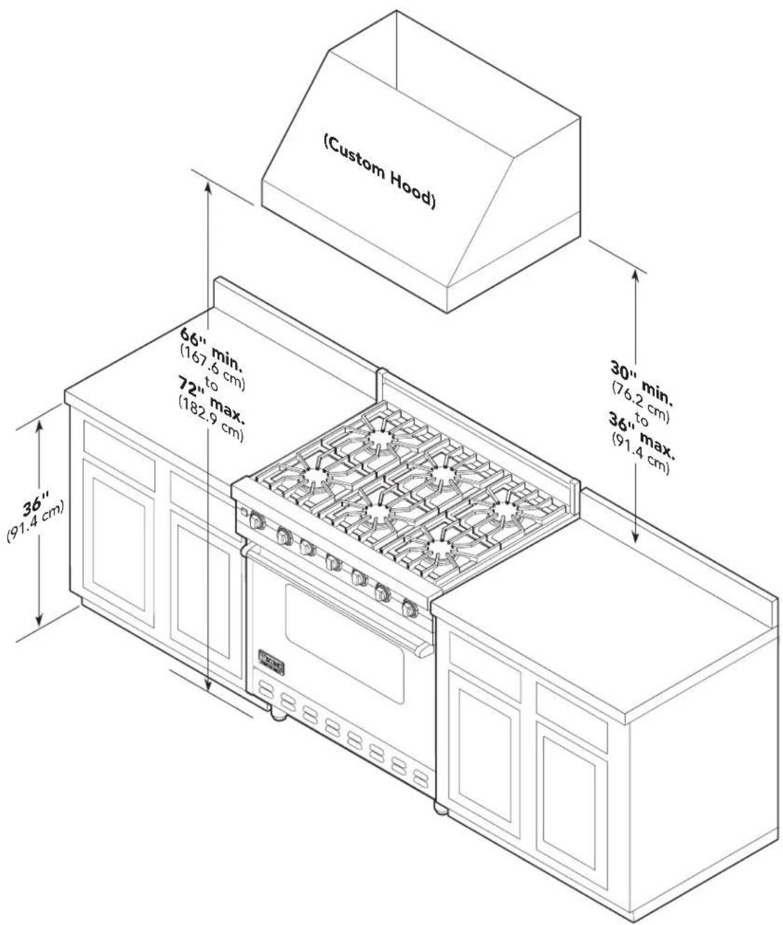
| Mounting Height | 30" (76.2 cm) to 36" (91.4 cm) above cooking surface |
| Duct Cover | Optional, 12" (30.5 cm) depth, 12" height (sold separately) |
| Warranty | Contact Viking Range, LLC; refer to warranty card |
| User Manual | Included (40 pages, PDF available online) |
Frequently Asked Questions - VWH560481BU VIKING
User questions about VWH560481BU VIKING
0 question about this device. Answer the ones you know or ask your own.
Ask a new question about this device
Download the instructions for your Range hood in PDF format for free! Find your manual VWH560481BU - VIKING and take your electronic device back in hand. On this page are published all the documents necessary for the use of your device. VWH560481BU by VIKING.
USER MANUAL VWH560481BU VIKING
natural_image
Exterior view of a white stainless steel air duct HVAC unit (no text or symbols visible)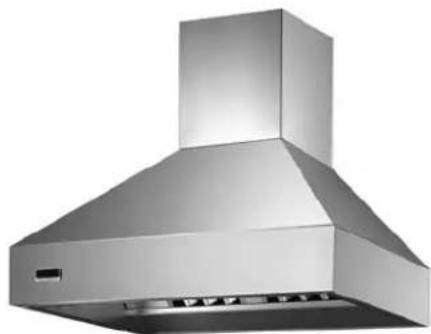
natural_image
Exterior view of a stainless steel kitchen range hood (no text or symbols visible)5 SERIES
Professional Indoor & Outdoor Hoods
VWH53012 / CVWH53012 / VWH53612 / CVWH53612
VWH53048 / CVWH53048 / VWH53648 / CVWH53648 / VWH54248 / CVWH54248 /
VWH54848 / CVWH54848 / VWH56048 / CVWH56048
VCWH53048 / CVCWH53048 / VCWH53648 / CVCWH53648 / VCWH54248 / CVCWH54248 /
VCWH54848 / CVCWH54848 / VCWH56048 / CVCWH56048
VCIH53608 / CVCIH53608 / VCIH54208 / CVCIH54208 / VCIH55408 / CVCIH55408 / VCIH56608 / CVCIH56608
VBCV53638 / CVBCV53638 / VBCV54238 / CVBCV54238 / VBCV54838 / CVBCV54838 / VBCV56038 / VBCV56038
VWHO3678 / VWHO4878 / VWHO6078 (Canadian Outdoor models not applicable)
Table of Contents
Warnings & Important Information 3-4
VWH/CVWH 10" H/12"H. Wall Hoods w/Standard Ventilator 30", & 36" Dimensions & Specifications ____ 5 Clearance Dimensions ____ 6 Interior Ventilator Dimensions ____ 7
VWH/CVWH 18"H. 24"Deep Wall Hoods 30", 36", 42", 48", & 60" Dimensions & Specifications 8 Clearance Dimensions 9 Interior Ventilator Dimensions 10 Exterior Ventilator Dimensions 11
VWHO/CVWHO 18"H. Outdoor Wall Hoods 36", 48", & 60" Dimensions & Specifications ____ 12 Clearance Dimensions ____ 13
VCWH/CVCWH Chimney Wall Hoods 30", 36", 42", 48", & 60" Dimensions & Specifications ____ 14 Clearance Dimensions ____ 15 Interior Ventilator Dimensions ____ 16 Exterior Ventilator Dimensions ____ 17
VCIH/CVCIH Chimney Island Hoods 36", 42", 54", & 66" Dimensions & Specifications ____ 18 Clearance Dimensions ____ 19 Interior Ventilator Dimensions ____ 20 Exterior Ventilator Dimensions ____ 21
VBCV/CVBCV Wall Custom Ventilator System Dimensions & Specifications 22 Installing Hood Canopy 23 Clearance Dimensions 24 VBCV Ventilator Dimensions 25
Planning Information 27 Installation Procedures Installation (VWH/CVWH 10"H./12"H. Wall Hoods w/Standard Ventilator) 28
Duct Cover Option (VWH/CVWH 12"H. Wall Hoods w/Standard Ventilator) ____ 30
Installation (VWH/CVWH 12"H. Wall Hoods w/Recirculating Kit) ____ 30
Installation (VWH/CVWH 18"H. Wall & VCWH Chimney Wall Hoods) ____ 33
Duct Cover Option (VWH/CVWH 18"H. Wall Hoods) 34
Duct Cover Option (VCWH/CVCWH Chimney Wall Hoods) 35 Installation (VCIH Island Hoods) 36
Service & Registration 38
Wiring Diagram 39
IMPORTANT—Please Read and Follow!
NOTE: If installing hood with warming shelf panel, install warming shelf panel first.
IMPORTANT – PLEASE READ AND FOLLOW
- Before beginning, please read these instructions completely and carefully.
- Do not remove permanently affixed labels, warnings, or plates from the product. This may void the warranty.
- Please observe all local and national codes and ordinances. If no local codes are applicable, wire in accordance with the National Electrical Code, ANSI/NFPA 70-latest edition.
- Damp environment approved models should be installed in a covered non-enclosed area and should be protected from the elements as much as possible.
- The installer should leave these instructions with the consumer who should retain for local inspector's use and for future reference.
- Check with a qualified and trained installer or local codes for makeup air requirement, if any.
This hood is for residential installation only and is not designed for installation over a commercial product. Make sure power is off at the main circuit breaker or fuse box before making connections. To avoid risk of fire, electric shock, or injury to persons, turn off the electricity to the hood from the power supply before servicing or cleaning. Viking hoods are equipped with variable speed control blowers. These units will not function with a single speed ventilator. All Viking Range ventilator kits are designed specifically for use with Viking Range hoods. Use of any non-Viking Range ventilator kit will void the hood warranty.
Viking hoods are equipped with the variable speed controls for blowers. These units will not function with a single speed ventilator. All Viking ventilator kits are designed specifically for use with Viking hoods. Use of any non-Viking ventilator kit will void the hood warranty.
READ AND SAVE THESE INSTRUCTIONS
WARNING
To reduce the risk of fire, electric shock, or injury to persons, observe the following:
- Use this unit only in the manner intended by the manufacturer. If you have any questions, contact the manufacturer.
- Before servicing or cleaning unit, switch power off at service panel and lock service panel to prevent power from being switched on accidentally. When the service disconnecting means cannot be locked, securely fasten a prominent warning device, such as a tag, to the service panel.
WARNING
TO REDUCE THE RISK OF FIRE, ELECTRICAL SHOCK, OR INJURY TO PERSONS, OBSERVE THE FOLLOWING:
- Installation work and electrical wiring must be done by qualified person(s) in accordance with all applicable codes and standards, including fire-rated construction.
- Sufficient air is needed for proper combustion and exhausting of gases through the flute (chimney) of fuel burning equipment to prevent back drafting. Follow the heating equipment manufacturer's guideline and safety standards such as those published by the National Fire Protection Association (NFPA), and the American Society for Heating, Refrigeration and Air Conditioning Engineers (ASHRAE), and the local code authorities.
- When cutting of drilling into wall or ceiling, do not damage electrical wiring and other hidden utilities.
- Ducted fans must always be vented to the outdoors.
- WARNING!: To reduce risk of fire, use only metal ductwork
- CAUTION!: To reduce risk of fire and to properly exhaust air, be sure to duct air outside. Do not vent exhaust air into spaces within walls or ceilings, or into attics, crawl spaces, or garages.
- CAUTION!: To Reduce the Risk of Fire and Electric Shock, Install this rangehood only with remote blower models manufactured by Viking, model numbers – DEV900/DEV1200, VEV900, VIL1200, OR DEV1500 or integral blowers manufactured by Viking, model numbers – VINV300/600/1200, or DIL1200. NOTE – Please refer inside for specific canopy/blower combinations.
IMPORTANT—Please Read and Follow!
WARNING
To reduce the risk of injury to persons in the event of a rangetop grease fire, observe the following. (Based on "Kitchen Firesafety Tips," published by NFPA.)
- SMOTHER FLAMES with a close fitted lid, cookie sheet, or metal tray, then turn off the burner. BE CAREFUL TO PREVENT BURNS. If the flames do not go out immediately, EVACUATE AND CALL THE FIRE DEPARTMENT.
- NEVER PICK UP A FLAMING PAN. You may be burned.
- DO NOT USE WATER, including wet dishcloths or towels a violent steam explosion will result.
-
Use an extinguisher ONLY if
-
You know it is a Class ABC extinguisher, and you already know how to operate it.
- The fire is small and contained in the area where it started.
• The fire department is being called. - You can fight the fire with your back to an exit.
CAUTION
For general ventilating use only. Do not use to exhaust hazardous or explosive materials and vapors.
WARNING
TO REDUCE THE RISK OF FIRE, ELECTRICAL SHOCK, OR INJURY TO PERSONS
Rangehoods must be installed with the ventilators that are specified on their carton indicating suitability with
this model. Other ventilators cannot be substituted.
WARNING
This appliance is not to be used by persons (including children) with reduced physical, sensory or mental capabilities, or lack of experience and knowledge, unless they have been given supervision or instruction concerning the use of the appliance by a person responsible for their safety. Children should be supervised to ensure that they do not play with the appliance.
Dimensions & Specifications
(VWH 10"H./12"H. Wall Hoods w/Standard Ventilator 30", & 36")
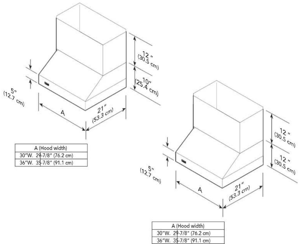
NOTE: Optional duct cover sold separately.
| VWH/CVWH 10"H./12"H. Wall Hoods w/Standard Ventilator | ||
| Description 30" 36" | ||
| Duct cover width | 29-7/8" (75.9 cm) 35-7/8" | (91.1 cm) |
| Duct cover depth | 12" (30.5 cm) | |
| Duct cover height | 12" (30.5 cm) | |
| Number of lights | 2 | |
| Number of filters | 2 | |
| Heat lamps | N/A | |
| Interior ventilator kit | 460 CFM Standard | |
| Interior duct size* | 7" (17.8 cm) | |
| Interior—Maximum amps | 5.6 A | |
* Disregard when using recirculating kits.
460 CFM blower is shipped with hood.
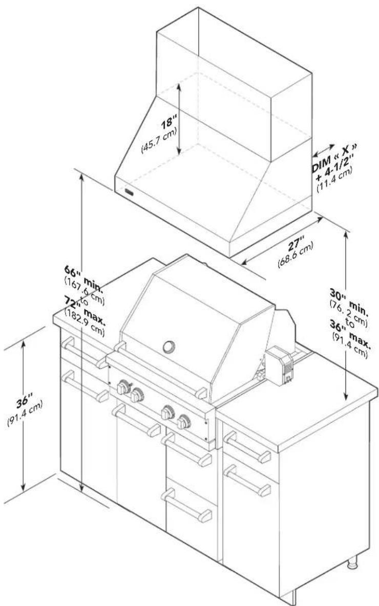
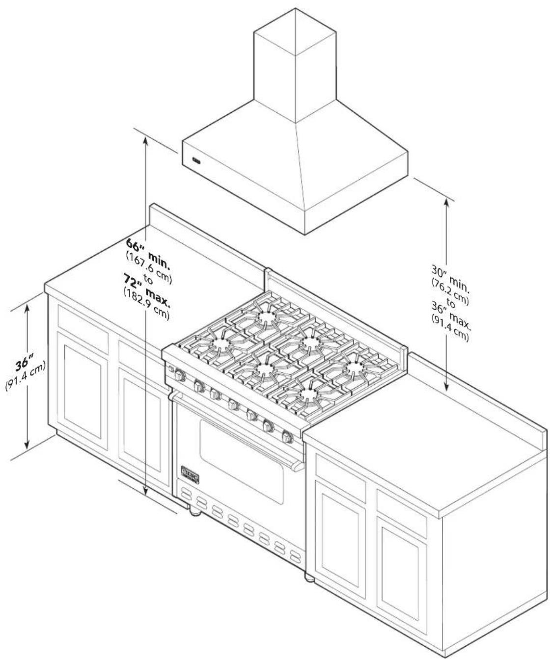
Clearance Dimensions
(VWH/CVWH 10"H./12"H. Wall Hoods w/Standard Ventilator)
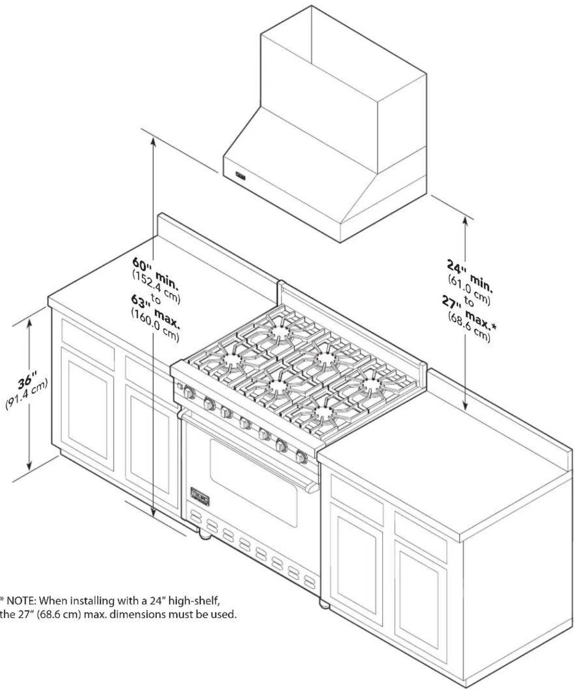
* NOTE: When installing with a 24" high-shelf, the 27" (68.6 cm) max. dimensions must be used.
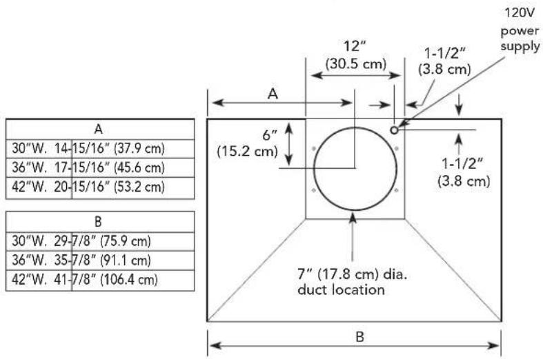
Interior Ventilator Dimensions
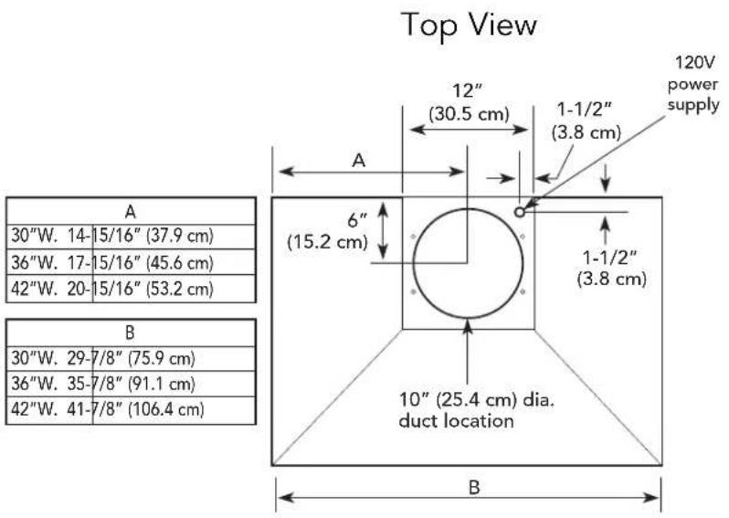
(VWH/CVWH 10"H./12"H. Wall Hoods w/Standard Ventilator)
Top View
| A |
| 24"W. 23-7/8" (60.6 cm) |
| 30"W. 29-7/8" (75.9 cm) |
| 36"W. 35-7/8" (91.1 cm) |
| B |
| 24"W. 5-1/4" (13.3 cm) |
| 30"W. 8-1/4" (20.9 cm) |
| 36"W. 11-1/4" (28.6 cm) |
| C | |
| 24"W. 11- | 5/16" (30.3 cm) |
| 30"W. 14- | 5/16" (37.9 cm) |
| 36"W. 17- | 5/16" (45.6 cm) |
| D |
| 24"W. 5/8" (1.6 cm) |
| 30"W. 3-5/8" (9.2 cm) |
| 36"W. 6-5/8" (16.8 cm) |
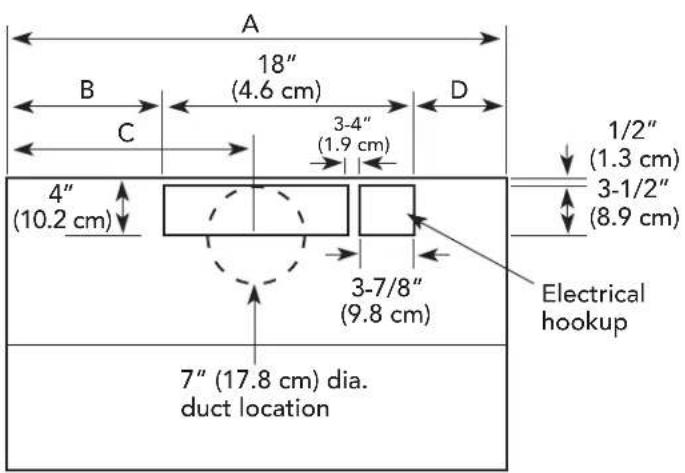
460 CFM Interior Ventilator Installation
Dimensions & Specifications
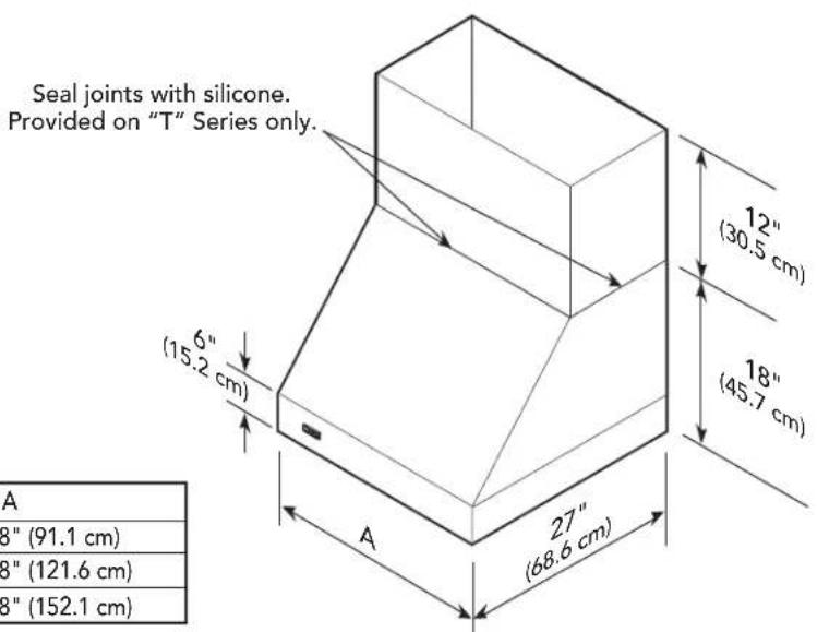
(VWH/CVWH 18"H. 24" Deep Wall Hoods 30", 36", 42", 48", & 60")
| A |
| 30" W 29-7/8" (76.2 cm) |
| 36" W 35-7/8" (91.1 cm) |
| 42" W 41-7/8" (106.4 cm) |
| 48" W 47-7/8" (121.6 cm) |
| 60" W 59-7/8" (152.1 cm) |
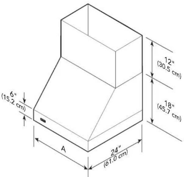
NOTE: Optional duct cover sold separately.
| VWH/CVWH 18"H. Wall Hoods | |||||
| Description 30" 36" 42" 48" 60" | |||||
| Duct cover width | 29-7/8"(75.9 cm) | 35-7/8"(91.1 cm) | 41-7/8"(106.4 cm) | 47-7/8"(121.6 cm) | 59-7/8"(152.1 cm) |
| Duct cover depth | 12" (30.5 cm) | ||||
| Duct cover height | 12" (30.5 cm) | ||||
| Number of lights | 2 2 2 3 4 | ||||
| Number of filters | 2 2 2 3 4 | ||||
| Heat lamps | 1 1 1 2 3 | ||||
| Interior ventilator kits | VINV300/600/1200 | VINV300/600/1200 | VINV600/1200 | VINV1200* V | NV1200* |
| Exterior ventilator kits | DEV900/1200* | DEV900/1200* | DEV900/1200* | DEV1200*/1500** | DEV1200*/1500** |
| In-line ventilator kits | DIL1200 DIL1200 DIL1200 DIL1200 | ||||
| Interior duct size | 7"/10"(17.8/25.4 cm) | 7"/10"(17.8/25.4 cm) | 7"/10"(17.8/25.4 cm) | 10"(25.4 cm) | 10"(25.4 cm) |
| Exterior duct size | 10" (24.5 cm) | ||||
| Interior—Maximum amps | 4.2/5.2/8.2 4.2 | 5.2/8.2 5.2/8.2 | 10.8 10.8 | ||
| Exterior—Maximum amps | 8.0/5.3 8.0/5 | 3 8.0/5.3 7.8/8.5 | 7.8/8.5 | ||
| In-Line—Maximum amps | 5.3/7.2 5.3/7 | 2 5.3/7.2 | 9.6 | 10.0 | |
| Total Watts | 47 Watts | ||||
* A 1,200 CFM interior- or exterior-power ventilator should be used when installed over range/rangetop with gas char-grill. Max duct run is 50 ft.
** It is recommended that the 1,500 CFM ventilator be used with longer duct runs. Max duct run is 75 ft.
NOTE: Maximum amp rating for hoods includes recommended ventilator kit rating; All products must be hard wired with 2-wire with ground. An interior- or exterior-power ventilator kit must be purchased for installation with all 18"H. hoods.
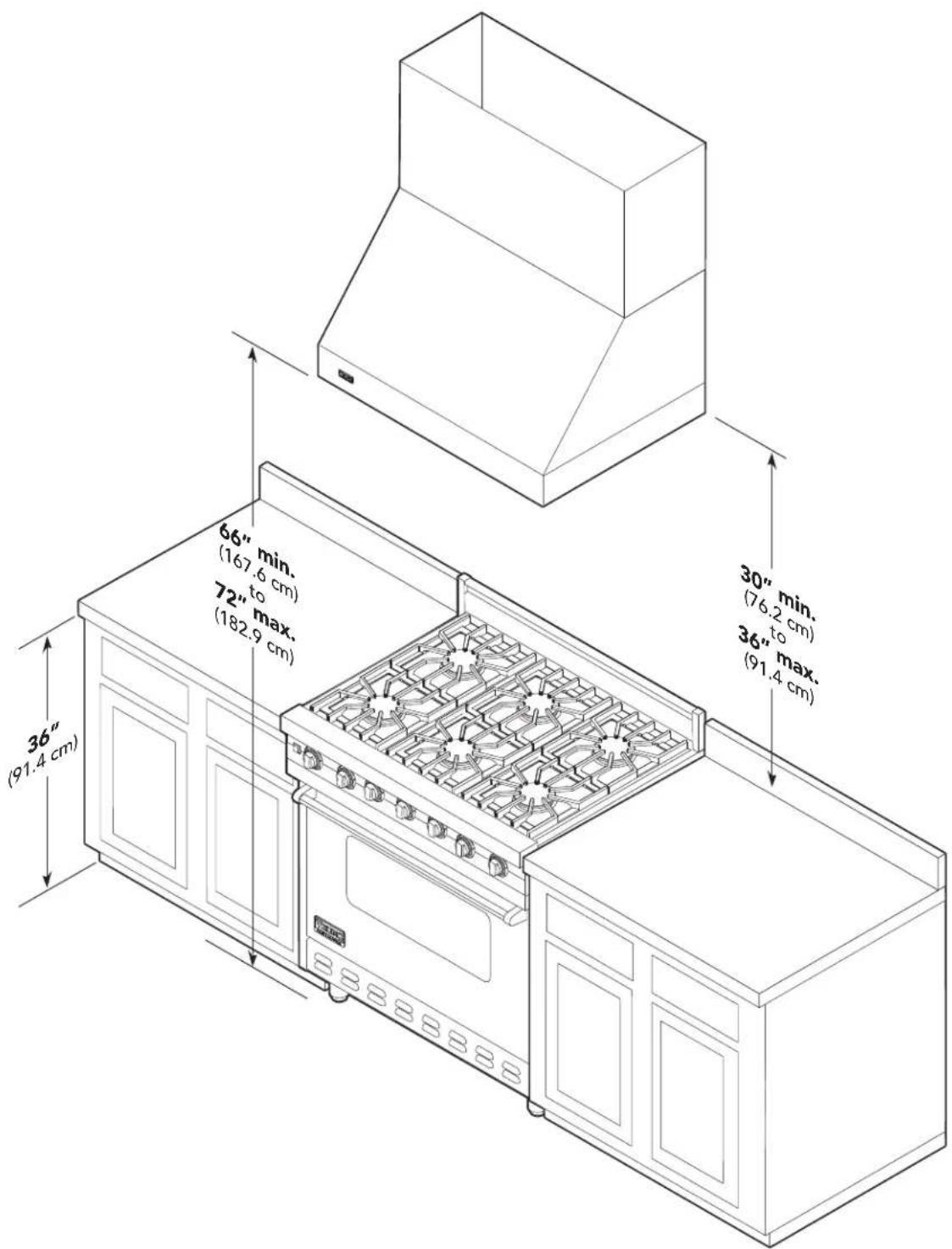
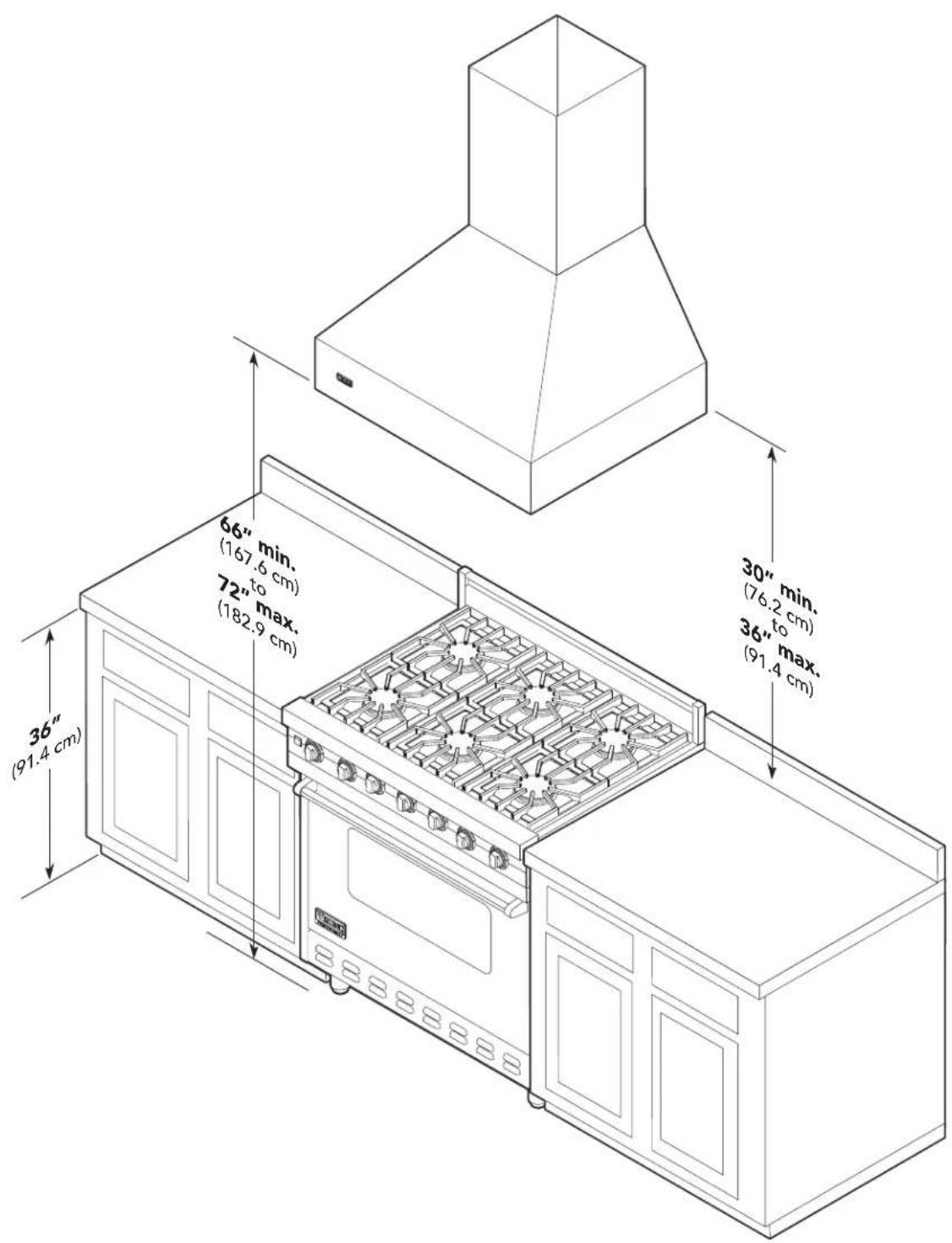
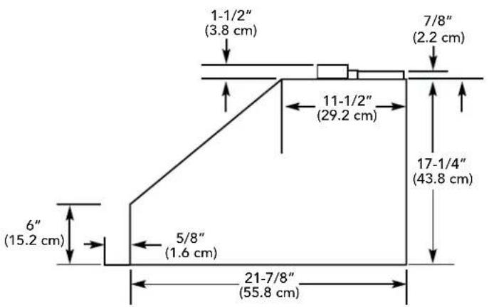
Clearance Dimensions
(VWH/CVWH 18"H. Wall Hoods)
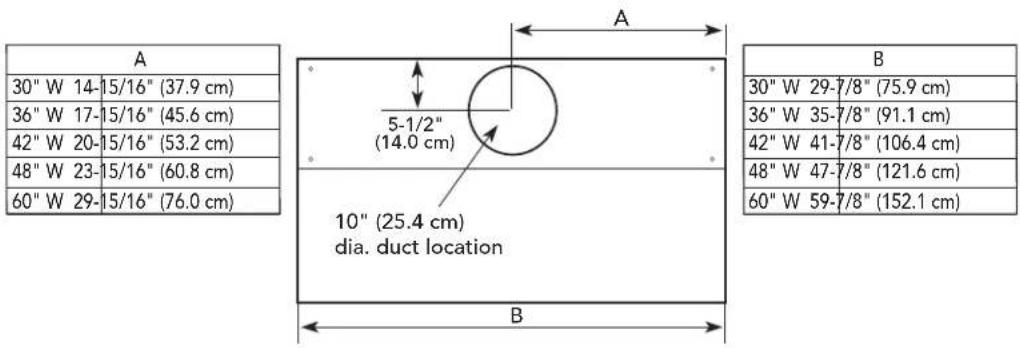
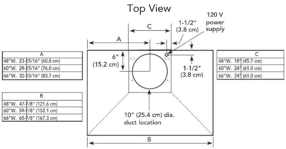
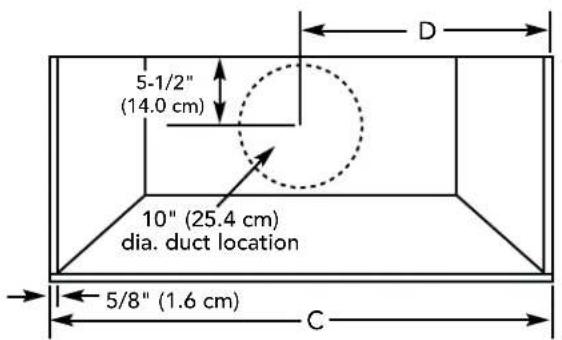
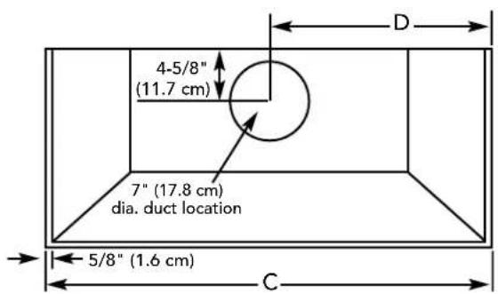
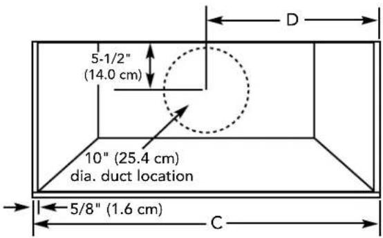
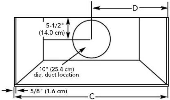
Interior Ventilator Dimensions
(VWH/CVWH 18"H. Wall Hoods)
Top View
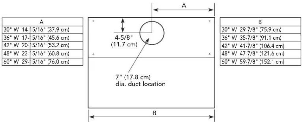
300 or 600 CFM Interior Ventilator Installation for all Wall Hoods
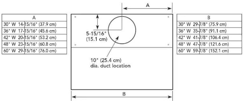
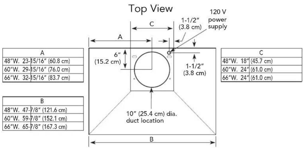
Top View
1200 CFM Interior Ventilator Installation for all Wall Hoods
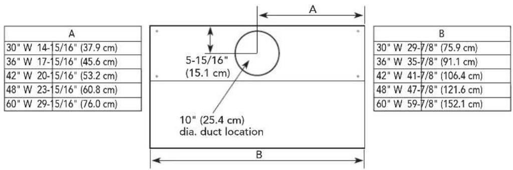
Exterior Ventilator Dimensions
(VWH/CVWH 18"H. Wall Hoods)
Top View
900 or 1200 CFM Exterior or In-Line Ventilator Installation for all Wall Hoods
Top View
1200 or 1500 CFM Exterior or In-Line Ventilator Installation for all Wall Hoods
Dimensions & Specifications
(VWHO/CWWHO 18"H. Outdoor Wall Hoods 36", 48", & 60")
| A |
| 36" W 35-7/8" (91.1 cm) |
| 48" W 47-7/8" (121.6 cm) |
| 60" W 59-7/8" (152.1 cm) |
NOTE: Optional duct cover sold separately.
| VWHO/CVWHO 18"H. Outdoor Wall Hoods | |||
| Description 36" 48" 60" | |||
| Duct cover width | 35-7/8" (91.1 cm) 47-7/8" (121.6 cm) 59-7/8" (152.1 cm) | ||
| Duct cover depth | 12" (30.5 cm) | ||
| Duct cover height | 12" (30.5 cm) | ||
| Number of lights | 2 3 4 | ||
| Number of filters | 2 3 4 | ||
| Interior ventilator kits | VINV1200* VINV1200* VINV1200* | ||
| Exterior ventilator kits | DEV1200*/1500** DEV1200*/1500** | ||
| In-line ventilator kits | DIL1200 DIL1200 | DIL1200 | |
| Interior duct size | 10" (25.4 cm) | ||
| Exterior duct size | 10" (25.4 cm) | ||
| Interior—Maximum amps | 9.0 | 11.4 11.8 | |
| Exterior—Maximum amps | 6.1/6.8 | 8.4/9.1 | 8.8/9.5 |
| In-Line—Maximum amps | 7.9 | 10.2 | 10.6 |
| Total watts | 47 Watts | ||
* A 1,200 CFM interior- or exterior-power ventilator should be used with all outdoor models and when indoor models are installed over range/rangetop with gas char-grill. Max duct run is 50 ft.
** It is recommended that the 1,500 CFM ventilator be used with longer duct runs. Max duct run is 75 ft.
NOTE: Maximum amp rating for hoods includes recommended ventilator kit rating; All products must be hard wired with 2-wire with ground. An interior- or exterior-power ventilator kit must be purchased for installation with all 18"H. hoods.
Clearance Dimensions
(VWHO/CVWHO 18"H. Outdoor Wall Hoods)
Note: Outdoor Models must be installed in a covered, non-enclosed area, and should be protected from the elements as much as possible.
The bottom of the hood should be 30" (76.2 cm) to 36" (91.4 cm) above the grill surface. The hood should be installed 4-1/2" (11.4 cm) plus the distance between the back trim and surface from the back wall. (Note: There is a 3" minimum clearance from the back trim to non-combustible surfaces, and a 24" minimum to combustible surfaces.) This will require building the hood out from the wall. Any combustible material used for this purpose must be covered with locally-supplied stainless steel. Viking also recommends using a backsplash.
Dimensions & Specifications
(VCWH/CVCWH
Chimney Wall Hoods 30", 36", 42", 48", 54", & 60")
| A (Duct width) |
| 30"W. 12" (30.5 cm) |
| 36"W. 12" (30.5 cm) |
| 42"W. 12" (30.5 cm) |
| 48"W. 18" (45.7 cm) |
| 60"W. 24" (61.0 cm) |
| 66"W. 24" (61.0 cm) |
| B (Hood width) |
| 30"W. 29-7/8" (76.2 cm) |
| 36"W. 35-7/8" (91.1 cm) |
| 42"W. 41-7/8" (106.4 cm) |
| 48"W. 47-7/8" (121.6 cm) |
| 60"W. 59-7/8" (152.1 cm) |
| 66"W. 65-7/8" (167.3 cm) |

NOTE: Optional duct cover sold separately.
VCWH Chimney Wall Hoods
| Description 30" 36" 42" 48" 60" | |||||
| Duct cover width | 12" (30.5 cm) 12" (30.5 cm) 12" | (30.5 cm) 18" | (45.7 cm) 24" | (61.0 cm) | |
| Duct cover depth | 12" (30.5 cm) | ||||
| Duct cover height | 12" (30.5 cm) to 24" (61.0 cm) | ||||
| Number of lights | 2 2 2 3 4 | ||||
| Number of filters | 2 2 2 2 3 | ||||
| Heat lamps | 1 1 1 2 3 | ||||
| Interior ventilator kits | VINV300/600 VINV300/600 VINV600 VINV1200* VINV1200* | ||||
| Exterior ventilator kits | DEV900/1200* | DEV900/1200* | DEV900/1200* | DEV1200*/1500** | DEV1200*/1500** |
| In-line ventilator kits | DIL1200 | DIL1200 | DIL1200 | DIL1200 | DIL1200 |
| Interior duct size | 7" (17.8 cm) | 7" (17.8 cm) | 7" (17.8 cm) | 10" (25.4 cm) | 10" (25.4 cm) |
| Exterior duct size | 10" (25.4 cm) | ||||
| Interior—Maximum amps | 4.2/5.2 | 4.2/5.2 | 5.2 | 10.8 | 10.8 |
| Exterior—Maximum amps | 8.0/5.3 | 8.0/5.3 | 8.0/5.3 | 7.8/8.5 | 7.8/8.5 |
| In-Line—Maximum amps | 5.3/7.2 | 5.3/7.2 | 5.3/7.2 | 9.6 | 10.0 |
| Total Watts | 47Watts | ||||
* A 1,200 CFM interior- or exterior-power ventilator should be used when installed over range/rangetop with gas char-grill. Max duct run is 50 ft.
** It is recommended that the 1,500 CFM ventilator be used with longer duct runs. Max duct run is 75 ft. NOTE: Maximum amp rating for hoods includes recommended ventilator kit rating; All products must be hard wired with 2-wire with ground. An interior- or exterior-power ventilator kit must be purchased for installation with all 18"H. hoods.
Clearance Dimensions
(VCWH/CVCWH Chimney Wall Hoods)
Interior Ventilator Dimensions
(VCWH/CVCWH Chimney Wall Hoods)
Top View
300 or 600 CFM Interior Ventilator Installation for 30", 36", & 42" models
1200 CFM Interior Ventilator Installation for 48", & 60" models
Exterior Ventilator Dimensions
(VCWH/CVCWH Chimney Wall Hoods)
900 or 1200 CFM Exterior or In-Line Ventilator Installation for 30", 36", & 42" models
900, 1200 or 1500 CFM Exterior or In-Line Ventilator Installation for 48", & 60" models
Dimensions & Specifications
(VCIH/CVCIH Chimney Island Hoods 36", 42", 54", & 66")
| A | |
| 36" W 12" | (30.5 cm) |
| 42" W 12" | (30.5 cm) |
| 54" W 18" | (45.7 cm) |
| 66" W 24" | (70.0 cm) |
| B | |
| 36" W. | 12" (30.5 cm)or |
| 42" W. | |
| 54" W. | 24" (61.0 cm)or |
| 66" W. | 36" (91.4 cm) |
| C |
| 36" W 35-7/8" (91.1 cm) |
| 42" W 41-7/8" (106.4 cm) |
| 54" W 53-7/8" (136.8 cm) |
| 66" W 65-7/8" (167.3 cm) |
NOTE: Optional duct cover sold separately.
| VCIH/CVCIH Chimney Island Hoods | ||||
| Description 36" 42" 54" 66" | ||||
| Duct cover width | 12" (30.5 cm) 12" (30.5 cm) 18" (45.7 cm) 24" (70.0 cm) | |||
| Duct cover depth | 12" (30.5 cm) | |||
| Duct cover height | 12" (30.5 cm) or 24" (61.0 cm) or 36" (91.4 cm) | |||
| Number of lights | 4 4 6 8 | |||
| Number of filters | 4 4 6 8 | |||
| Heat lamps | N/A | |||
| Interior ventilator kits | VINV600 VINV600 | VINV1200* VINV1200* | ||
| Exterior ventilator kits | DEV900/1200* | DEV900/1200*/1500** | DEV1200*/1500** | DEV1200*/1500** |
| In-line ventilator kits | DIL1200 DIL1200 | DIL1200 | DIL1200 | |
| Interior duct size | 7" (17.8 cm) | 7" (17.8 cm) | 10" (25.4 cm) 10" (25.4 cm) | |
| Exterior duct size | 10" (25.4 cm) | |||
| Interior—Maximum amps | 4.2/5.2/8.2 | 5.2/8.2 | 8.9 | 9.3 |
| Exterior—Maximum amps | 7.4/4.7 | 7.4/4.7/5.5 | 5.6/6.4 | 6.4/7.4 |
| In-Line—Maximum amps | 4.7/6.5 | 3.9/5.7 | 7.4 | 7.4 |
| total Watts | 47 Watts | |||
* A 1,200 CFM interior- or exterior-power ventilator should be used when installed over range/rangetop with gas char-grill. Max duct run is 50 ft.
** It is recommended that the 1,500 CFM ventilator be used with longer duct runs. Max duct run is 75 ft.
NOTE: Maximum amp rating for hoods includes recommended ventilator kit rating; All products must be hard wired with 2-wire with ground. An interior or exterior-power ventilator kit must be purchased for installation with all 18"H. hoods.
Clearance Dimensions
(VCIH /CVCIHChimney Island Hoods)
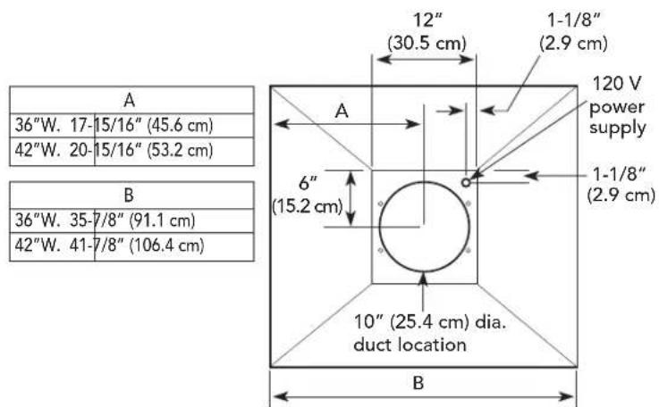
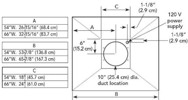
Interior Ventilator Dimensions
(VCIH/CVCIH Chimney Island Hoods)
Top View
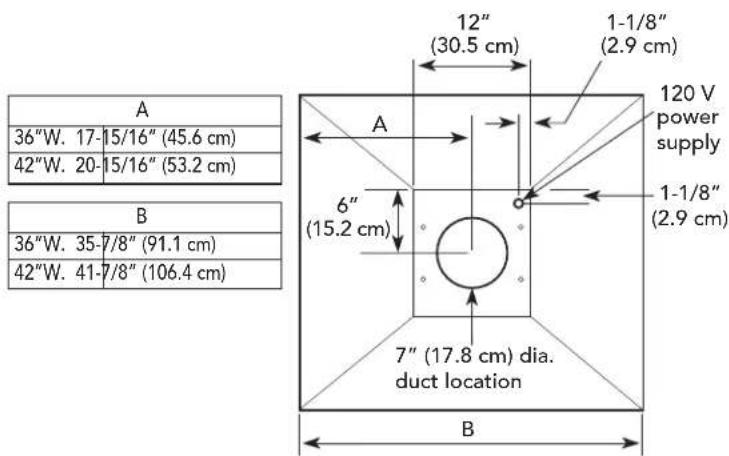
600 CFM Interior Ventilator Installation for all Chimney Island Hoods
Top View
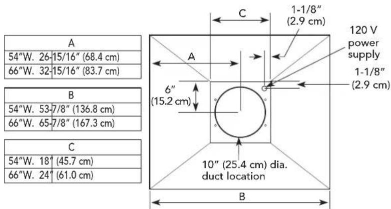
1200 CFM Interior Ventilator Installation for all Chimney Island Hoods
Exterior Ventilator Dimensions
(VCIH/CVCIH Chimney Island Hoods)
Top View
900 or 1200 CFM Exterior or In-Line Ventilator Installation for all Chimney Island Hoods
Top View
900, 1200 or 1500 CFM Exterior or In-Line Ventilator Installation for all Chimney Island Hoods
Dimensions & Specifications
(VBCV Wall Custom Ventilator System 36", 42", 48", & 60")
*For best results, center the unit over the burners of the cooking product (front to back; right to left).
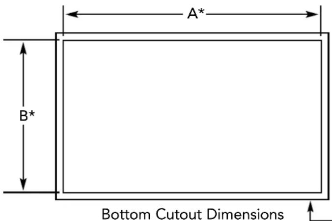
Make sure the back wall of the custom hood canopy is flush with the cutout so the ventilator system may be mounted as shown on page 25.
| Wall Hoods | |
| Description A (Hood Width) B (Hood Depth) | |
| 36" W. 33-7/16" (84.9 cm) 21-7/16" (54.5 cm) | |
| 42" W. 39-7/16" (100.2 cm) 21-7/16" (54.5 cm) | |
| 48" W. 45-7/16" (115.4 cm) 21-7/16" (54.5 cm) | |
| 60" W. 57-7/16" (145.9 cm) 21-7/16" (54.5 cm) |
| VBCV Wall Custom Ventilator System | ||||
| Description 36" 42" 48" 60" | ||||
| Number of lights | 2 2 3 4 | |||
| Number of filters | 2 2 3 4 | |||
| Heat lamps | 1 1 2 3 | |||
| Interior ventilator kits | VINV300/600/1200* | VINV600/1200* | VINV1200* | VINV1200* |
| Exterior ventilator kits | DEV900/1200* | DEV900/1200* | DEV1200*/1500** | DEV1200*/1500** |
| In-line ventilator kits | DIL1200 DIL | 900/1200 DIL1 | 200 DIL1200 | |
| Interior duct size | 7"/10"(17.8/25.4 cm) | 7"/10"(17.8/25.4 cm) | 10"(25.4 cm) | 10"(25.4 cm) |
| Exterior duct size | 10" (25.4 | |||
| Interior—Maximum amps | 4.2/5.2 | 10.8 10.8 | 10.8 | |
| Exterior—Maximum amps | 8.0/5.3 | 8.0/5.3 | 7.8/8.5 | 7.8/8.5 |
| In-Line—Maximum amps | 5.3/7.2 | 5.3/7.2 | 9.6 | 10.0 |
| Total Watts | 47 Watts | |||
* A 1,200 CFM interior- or exterior-power ventilator should be used when installed over range/rangetop with gas char-grill. Max duct run is 50 ft.
** It is recommended that the 1,500 CFM ventilator be used with longer duct runs. Max duct run is 75 ft.
NOTE: Maximum amp rating for hoods includes recommended ventilator kit rating; All products must be hard wired with 2-wire with ground. An interior- or exterior-power ventilator kit must be purchased for installation with all 18"H. hoods.
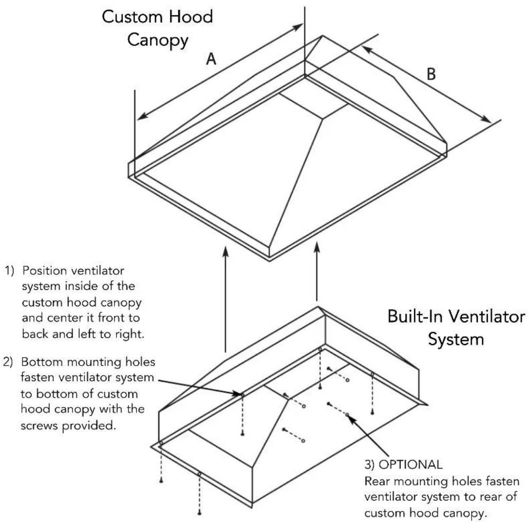
Installing Hood Canopy
(Custom Hood Canopy Cutouts)
Clearance Dimensions
(VBCV/CVBCV Wall Custom Ventilator System)
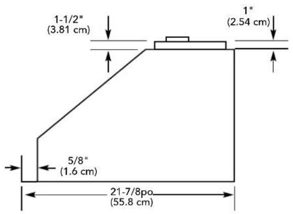
Built-In Wall Custom Ventilator System Dimensions (VBCV Models)
For 900, 1200 or 1500 CFM Exterior or In-Line Ventilator Installation
For 300, 600 or 1200 CFM Interior Ventilator Installation
900 or 1200 CFM Exterior or In-Line Ventilator Installation 36", 42" W. Models
300 or 600 CFM Interior Ventilator Installation 36", 42" W. Models
| C |
| 36" W. 34-1/4" (87.0 cm) |
| 42" W. 40-1/4" (102.2 cm) |
| D | |
| 36” W. 17-1 | /8” (43.5 cm) |
| 42” W. 20-1 | /8” (51.1 cm) |
Built-In Wall Custom Ventilator System Dimensions (VBCV/CVBCV Models)
1200 or 1500 CFM Exterior or In-Line Ventilator Installation 48", 60" W. Models
1200 CFM Interior Ventilator Installation 36", 42", 48", 60" W. Models
| C |
| 36" W. 34-1/4" (87.0 cm) |
| 42" W. 40-1/4" (102.2 cm) |
| 48" W. 46-1/4" (117.5 cm) |
| 60" W. 58-1/4" (148.0 cm) |
| D |
| 36" W. 17-1/8" (43.5 cm) |
| 42" W. 20-1/8" (51.1 cm) |
| 48" W. 23-1/8" (58.7 cm) |
| 60" W. 29-1/8" (74.0 cm) |
Planning Information
Proper installation of ducting is extremely important to ensure maximum performance from any ventilation product.
- All CFMs are based on tests at 0.1 static pressure: without applying static pressure, CFM would be greatly overstated.
- Straight runs and gradual turns are best; for example, each 90^ elbow is equivalent to 5-10 feet (1.52-3.05 cm) of straight run.
- Never use flexible duct; it creates back pressure/air turbulence and greatly reduces performance.
- Proper performance is dependent on proper ducting; make sure that a qualified and trained installer is used.
- Check with a qualified and trained installer or local codes for makeup air requirement, if any.
- Max. amp rating for hoods includes recommended ventilator kit rating; all products must be hard wired direct with 2-wire with ground.
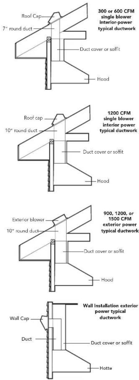
Plan where the duct work will be located. Install proper-sized duct work, and roof or wall cap for the type of blower you are using. Recommended hood locations for the most common installations are shown. Adjust your measurements for various heights of ceilings, soffits, cabinets, or ranges/rangetops.
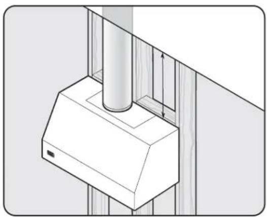
Check Framing
natural_image
Technical line drawing of a ceiling-mounted device mounted on a wall, showing structural components and height measurement (no text or symbols)NOTE: Because of the weight of the hood make sure that the mounting screws are driven into the framing and not just the drywall. It may be necessary to drill additional holes in the canopy for proper alignment.
NOTE: Wall exhaust must be a minimum of 24" (61.0 cm) from ground. This may vary depending on local codes and geographic location.
Installation (VWH/CVWH 10"H./12"H. Wall Hoods w/Standard Ventilator)
Check damper for unrestricted movement, adjust if necessary.
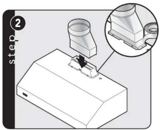
Attach transition to damper. Seal with aluminum tape.
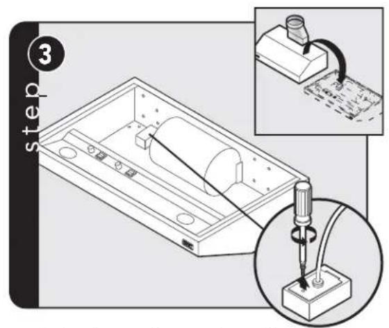
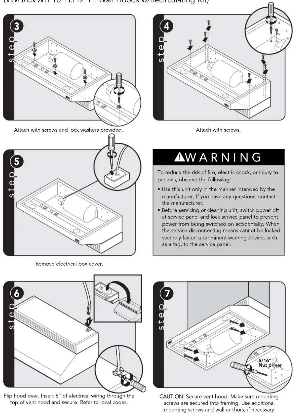
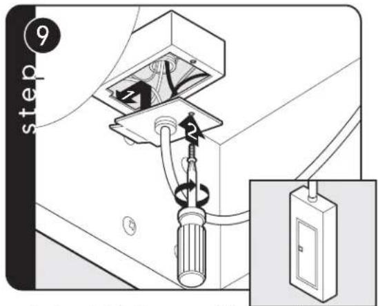
Flip hood over and remove electrical box cover.
WARNING
To reduce the risk of fire, electric shock, or injury to persons, observe the following:
- Use this unit only in the manner intended by the manufacturer. If you have any questions, contact the manufacturer.
- Before servicing or cleaning unit, switch power off at service panel and lock service panel to prevent power from being switched on accidentally. When the service disconnecting means cannot be locked, securely fasten a prominent warning device, such as a tag, to the service panel.
Insert 6" of electrical wiring through the top of vent hood and secure using wiring restrain. Refer to local codes.
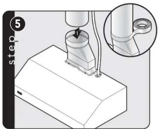
Slide duct over transition and tape around joint.
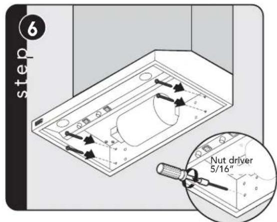
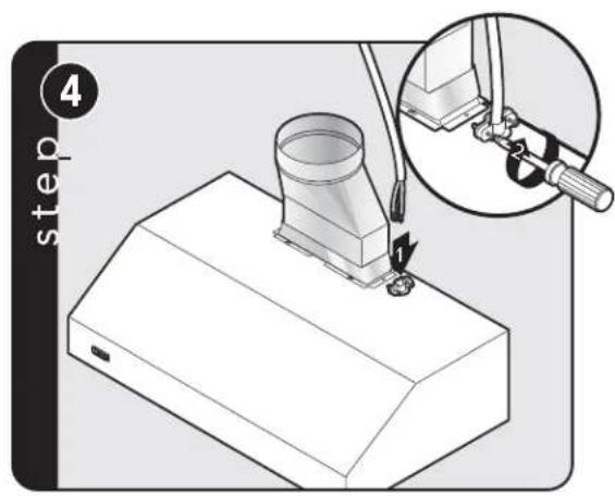
CAUTION: Secure vent hood to wall using screws provided. Use additional mounting screws and wall anchors, if necessary.
CAUTION: If not using a duct cover, using screws provided, make sure top mounting screws are secured into soffit or cabinet framing. Use additional mounting screws, if necessary.
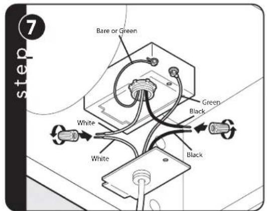
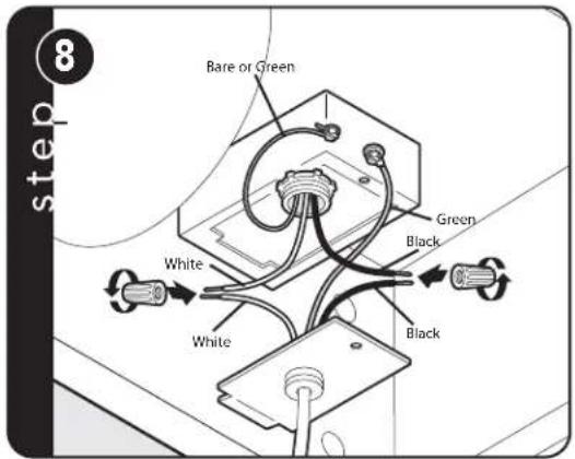
Connect black to black, white to white, and the green/bare wire under the green screw. NOTE: Housing wiring must be properly installed for wiring to be correct when wiring unit.
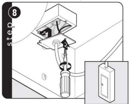
Replace electrical box cover. Make connection to breaker box.
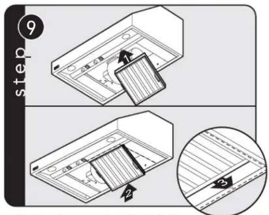
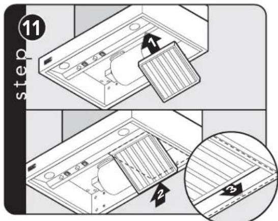
Slide filter front over front lip. Push filter rear up, then slide back over rear lip.
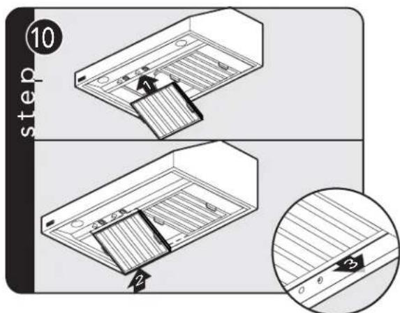
Slide filter front over front lip. Push filter rear up, then slide back over rear lip.
Duct Cover Option
(VWH/CVWH 10"H./12"H. Wall Hoods w/Standard Ventilator)
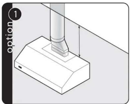
Measure distance from ceiling to canopy.
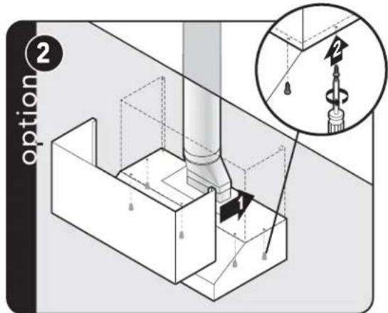
Slide the duct cover in place and fasten from inside canopy using the sheet metal screws provided.
Installation
(VWH/CVWH 10"H./12"H. Wall Hoods w/Recirculating Kit)
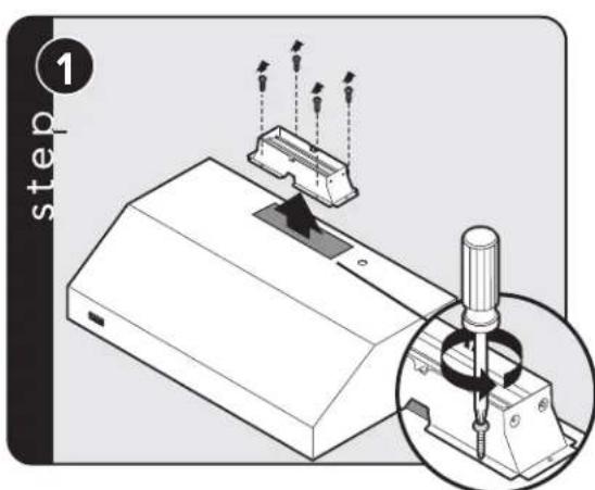
Remove damper and discard with transition.
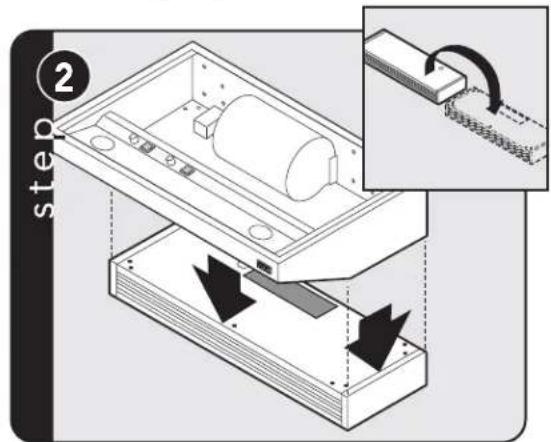
Turn recirculating unit upside down. Place vent hood upside down on recirculating unit.
Installation
(VWH/CVWH 10"H./12"H. Wall Hoods w/Recirculating Kit)
⚠ WARNING
To reduce the risk of fire, electric shock, or injury to persons, observe the following:
- Use this unit only in the manner intended by the manufacturer. If you have any questions, contact the manufacturer.
- Before servicing or cleaning unit, switch power off at service panel and lock service panel to prevent power from being switched on accidentally. When the service disconnecting means cannot be locked, securely fasten a prominent warning device, such as a tag, to the service panel.
Installation (con't)
(VWH/CVWH 10"H./12"H. Wall Hoods w/Recirculating Kit)
Connect black to black, white to white, and the green/bare wire under the green screw. NOTE: Housing wiring must be properly installed for wiring to be correct when wiring unit.
Replace electrical box cover. Make connection to breaker box.
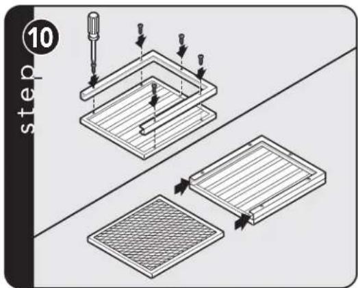
Assemble brackets to baffles and insert charcoal filters.
Slide filter front over front lip. Push filter rear up, then slide back over rear lip.
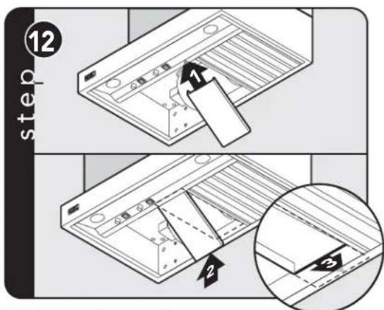
Slide spacer front over front lip. Push spacer rear up, then slide back over rear lip.
Slide filter front over front lip. Push filter rear up, then slide back over rear lip.
Installation
(VWH/CVWH 18"H. Wall & VCWH Chimney Wall Hoods)*For VCWH hoods, begin with Step 3. The VCWH hoods do not require the wood strip
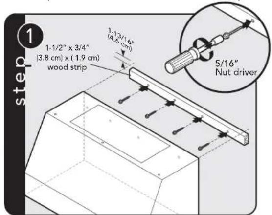
VWH/CVWH only! Measure down 1-13/16 (4.6 cm) from desired height of hood and secure 1-1/2" x 3/4" wood strip (provided locally) to wall using screws provided.
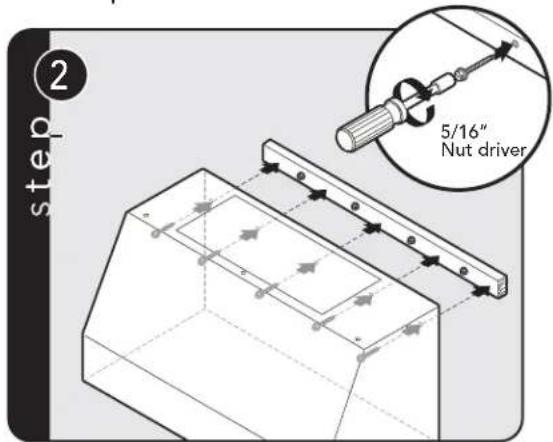
VWH/CVWH only! Use additional mounting screws to secure hood to wood strip.
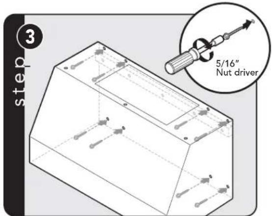
CAUTION: Secure vent hood to wall using screws provided. Use additional mounting screws and wall anchors, if necessary.
CAUTION: If not using a duct cover, using screws provided, make sure top mounting screws are secured into soffit or cabinet framing use additional mounting screws, if necessary.
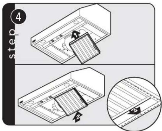
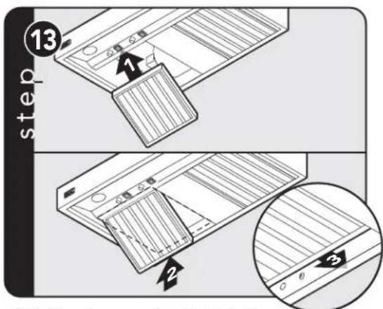
Slide filter front over front lip. Push filter rear up, then slide back over rear lip.
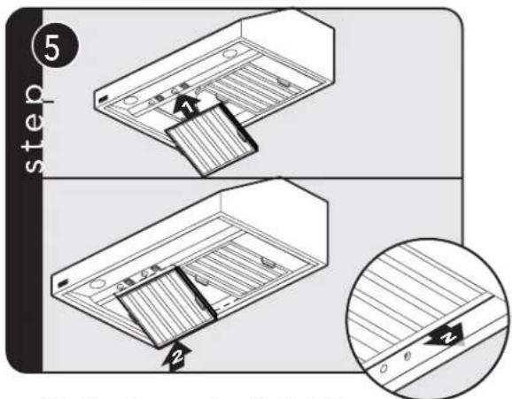
Slide filter front over front lip. Push filter rear up, then slide back over rear lip.
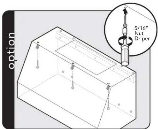
Duct Cover Option (VWH/CVWH 18"H. Wall Hoods)
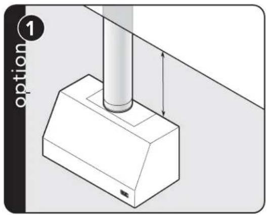
Measure distance from ceiling to canopy.
Slide the duct cover in place and fasten from inside canopy using the sheet metal screws provided.
To install ventilation kit refer to ventilation kit installation instructions.
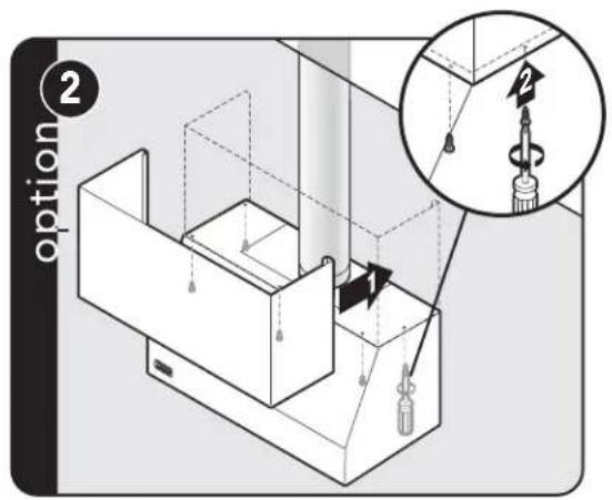
Duct Cover Option (VCWH/CVCWH Chimney Wall Hoods)
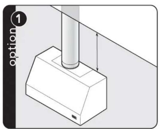
Measure distance from ceiling to canopy.
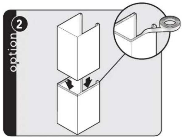
Tape to avoid scratching.
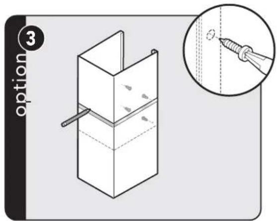
Place duct cover top inside duct cover base and lower until desired height is found. Mark height. Use the retaining nuts and bolts to fasten in place and remove tape.
Slide the duct cover in place and fasten from inside canopy using the sheet metal screws provided.
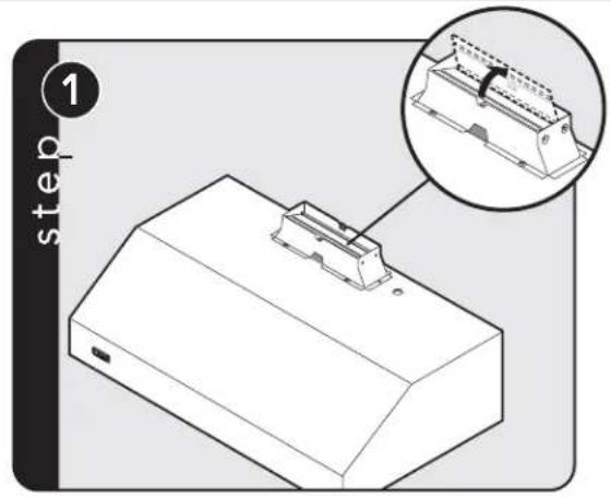
Installation (VCIH/CVCIH Island Hoods)
natural_image
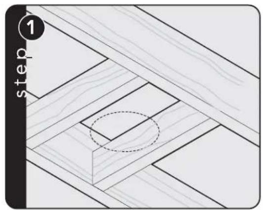
Diagram showing a wooden floor with diagonal lines and a circular cutout, labeled 'step 1' (no text or symbols within the diagram itself)Check framing where cutout will be. NOTE: 200 lb. limit.
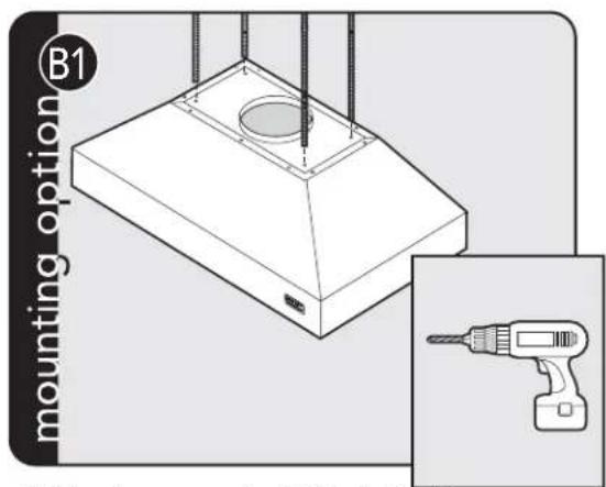
natural_image
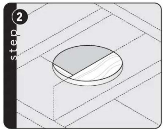
Diagram showing a circular object with a shaded cross-section, set on a grid background with dashed lines (no text or symbols)Cut appropriate size hole in ceiling. Either 7" or 10" depending on your specific unit and ventilator kit.
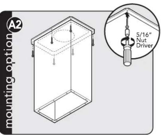
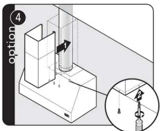
Attach duct cover to ceiling. The ceiling bracket can be hidden by using a locally supplied trim.
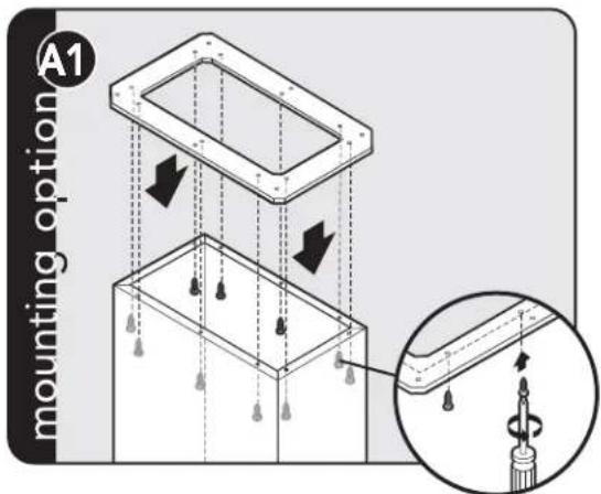
Attach duct cover to optional ceiling mounting bracket.
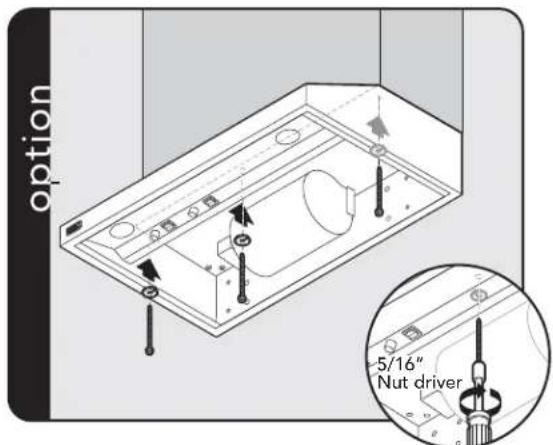
Additional support option. Drill holes in all four corners for threaded rod and run rods from hood to ceiling.
Installation (VCIH/CVCIH Island Hoods)
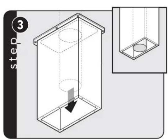
Run duct work down to bottom edge of duct cover/soffit and secure in place. Make sure the duct does not stick down past the cover.
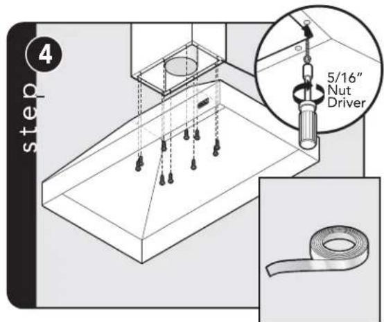
Attach canopy to duct cover/soffit. Seal top of hood to duct with aluminum tape.
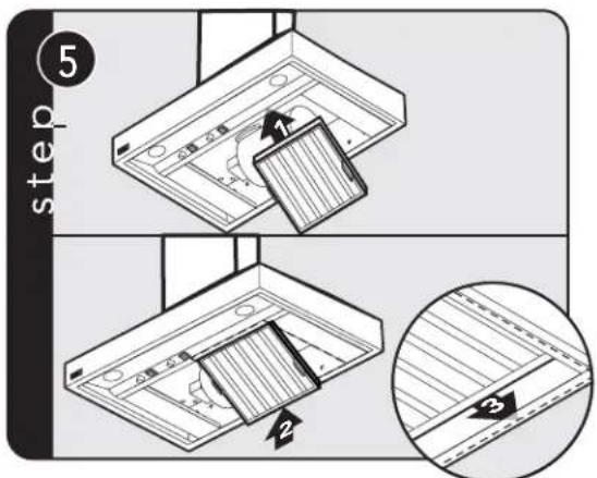
Slide filter front over front lip. Push filter rear up, then slide back over rear lip.
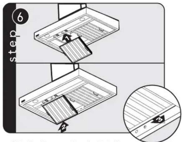
Slide filter front over front lip. Push filter rear up, then slide back over rear lip.
To install ventilation kit refer to ventilation kit installation instructions.
Service & Registration
If service is required, call your dealer or authorized service agency.
The name of the authorized service agency can be obtained from the dealer or distributor in your area.
Have the following information readily available.
- Model number
- Serial number
- Date purchased
• Name of dealer from whom purchased
Clearly describe the problem that you are having. If you are unable to obtain the name of an authorized service agency, or if you continue to have service problems, contact Viking Range, LLC at 1-888-(845-4641), or write to:
VIKING RANGE, LLC
PREFERRED SERVICE
111 Front Street
Greenwood, Mississippi 38930 USA
Record the information indicated below. You will need it if service is ever required. The model and serial number for your hood is located behind the baffle filter on the left side panel in the lower right corner.
Model no. ____ Serial no. ____
Date of purchase ____ Date installed ____
Dealer's name ____
Address ____
If service requires installation of parts, use only authorized parts to ensure protection under the warranty.
THIS MANUAL SHOULD REMAIN WITH THE HOOD FOR FUTURE REFERENCE.
Viking Range, LLC
111 Front Street
Greenwood, Mississippi 38930 USA
(662) 455-1200
For product information,
call 1-888-(845-4641)
or visit our web site at vikingrange.com in the US
brigade.ca in Canada


- SERIES
- Table of Contents
- IMPORTANT—Please Read and Follow!
- IMPORTANT – PLEASE READ AND FOLLOW
- READ AND SAVE THESE INSTRUCTIONS
- WARNING
- TO REDUCE THE RISK OF FIRE, ELECTRICAL SHOCK, OR INJURY TO PERSONS, OBSERVE THE FOLLOWING:
- CAUTION
- Dimensions & Specifications
- Clearance Dimensions
- Interior Ventilator Dimensions
- Exterior Ventilator Dimensions
- Installing Hood Canopy
- Built-In Wall Custom Ventilator System Dimensions (VBCV Models)
- Built-In Wall Custom Ventilator System Dimensions (VBCV/CVBCV Models)
- Planning Information
- Installation (VWH/CVWH 10"H./12"H. Wall Hoods w/Standard Ventilator)
- Duct Cover Option
- Installation
- ⚠ WARNING
- Installation (con't)
- Duct Cover Option (VWH/CVWH 18"H. Wall Hoods)
- Duct Cover Option (VCWH/CVCWH Chimney Wall Hoods)
- Installation (VCIH/CVCIH Island Hoods)
- Service & Registration
Brand : VIKING
Model : VWH560481BU
Category : Range hood