
OptiPlex 5070 SFF - Desktop computer DELL - Free user manual and instructions
Find the device manual for free OptiPlex 5070 SFF DELL in PDF.


User questions about OptiPlex 5070 SFF DELL
0 question about this device. Answer the ones you know or ask your own.
Ask a new question about this device
Download the instructions for your Desktop computer in PDF format for free! Find your manual OptiPlex 5070 SFF - DELL and take your electronic device back in hand. On this page are published all the documents necessary for the use of your device. OptiPlex 5070 SFF by DELL.
USER MANUAL OptiPlex 5070 SFF DELL
Dell OptiPlex 5070 Tower
Setup and Specifications
Notes, cautions, and warnings
NOTE: A NOTE indicates important information that helps you make better use of your product.
CAUTION: A CAUTION indicates either potential damage to hardware or loss of data and tells you how to avoid the problem.
WARNING: A WARNING indicates a potential for property damage, personal injury, or death.
© 2019 Dell Inc. or its subsidiaries. All rights reserved. Dell, EMC, and other trademarks are trademarks of Dell Inc. or its subsidiaries. Other trademarks may be trademarks of their respective owners.
Contents
1 Set up your computer....5
2 Chassis....7
Front view....7
3 System specifications....8
Chipset....8
Processor....8
Memory....11
Intel Optane Memory....11
Operating system....12
Storage....13
System board connectors....14
External ports and connectors....14
Graphics and Video Controller....15
Communications—Wireless....16
Audio and speakers....16
Input devices....17
Regulatory and environmental compliance....17
4 System setup....19
Boot menu....19
Navigation keys....19
System setup options....20
General options....20
System information....21
Video screen options....22
Security....22
Secure boot options....23
Intel Software Guard Extensions options....24
Performance....25
Power management....25
Post behavior....26
Manageability....27
Virtualization support....27
Wireless options....28
Maintenance....28
System logs....28
Advanced configuration....29
Updating the BIOS in Windows 29
Updating BIOS on systems with BitLocker enabled....29
Updating your system BIOS using a USB flash drive....30
Updating the Dell BIOS in Linux and Ubuntu environments....30
Flashing the BIOS from the F12 One-Time boot menu....30
System and setup password....33
Assigning a system setup password....34
Deleting or changing an existing system setup password....34
5 Software....35
Downloading drivers....35
System device drivers....35
Serial IO driver....35
Security drivers....35
USB drivers....36
Network adapter drivers....36
Realtek Audio....36
Storage controller 36
6 Getting help....37
Contacting Dell....37
Set up your computer
1 Connect the keyboard and mouse.
2 Connect to your network using a cable, or connect to a wireless network.
3 Connect the display.
NOTE: If you ordered your computer with a discrete graphics card, the HDMI and the display ports on the back panel of your computer are covered. Connect the display to the discrete graphics card.
4 Connect the power cable.
5 Press the power button.
6 Follow the instructions on the screen to finish Windows setup:
a Connect to a network.
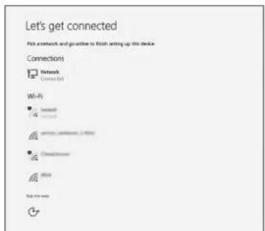
text_image
Let's get connected Pick a network and go to finish setting up this device. Connections Network Connected Wi-Fi Microsoft www.ewisense.com Microsoft 2019 Add to newb Sign-in to your Microsoft account or create a new account.
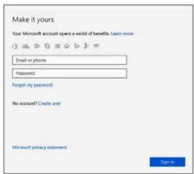
text_image
Make it yours Your Microsoft account opens a world of benefits. Learn more Email or phone Password Forgot my password No account? Create one! Microsoft privacy statement Sign in7 Locate Dell apps.
Table 1. Locate Dell apps

Register your computer

Dell Help & Support

text_image
Get Help a Support Overview Supervices Manuals FEATURES/HELP ARTICLE A new look for settings HELP CATEGORIES Getting About Mailman ID Connecting to Webber and Announces Setting as Account and Personalization Getting to Know Your Device and Software Keeping Your System Inserts Find Accessories of the user
SupportAssist — Check and update your computer
This chapter illustrates the multiple chassis views along with the ports and connectors and also explains the FN hot key combinations.
Front view
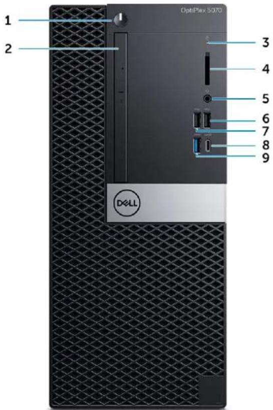
text_image
1 2 3 4 5 6 7 8 9 OptiPlex 5070 Dell1 Power button and power light
2 Optical drive (optional)
3 Hard drive activity light
4 Memory card reader (optional)
5 Headset/Universal audio jack port
6 USB 2.0 port with PowerShare
7 USB 2.0 port
8 USB 3.1 Gen 2 Type-C port with PowerShare
9 USB 3.1 Gen 1 port
System specifications

NOTE: Offerings may vary by region. The following specifications are only those required by law to ship with your computer. For more information about the configuration of your computer, go to Help and Support in your Windows operating system and select the option to view information about your computer.
Topics:
- Chipset
- Memory
- Intel Optane Memory
- Operating system
- Storage
- System board connectors
- External ports and connectors
• Graphics and Video Controller
• Communications—Wireless
• Audio and speakers - Input devices
• Regulatory and environmental compliance
Chipset
Table 2. Chipset
Tower/ Small form factor/ Micro
| Chipset Intel Q370 Chipset | |
| Non-volatile memory on chipset | |
| BIOS Configuration Serial Peripheral Interface (SPI) | 256 Mbit (32 MB) located at SPI_FLASH on chipset |
| Trusted Platform Module (TPM) 2.0 Security Device (Discrete TPM Enabled) | 24 KB located at TPM 2.0 on chipset |
| Firmware-TPM (Discrete TPM disabled) | By default the Platform Trust Technology feature is visible to the OS |
| NIC EEPROM | LOM configuration contained within LOM e-fuse – no dedicated LOM EEPROM |
Processor

NOTE Global Standard Products (GSP) are a subset of Dell's relationship products that are managed for availability and synchronized transitions on a worldwide basis. They ensure the same platform is available for purchase globally. This allows customers to reduce the number of configurations managed on a worldwide basis, thereby reducing their costs. They also enable companies to implement global IT standards by locking in specific product configurations worldwide.
Device Guard (DG) and Credential Guard (CG) are the new security features that are only available on Windows 10 Enterprise today.
Device Guard is a combination of enterprise-related hardware and software security features that, when configured together, will lock a device down so that it can only run trusted applications. If it is not a trusted application, it cannot run.
Credential Guard uses virtualization-based security to isolate secrets (credentials) so that only privileged system software can access them. Unauthorized access to these secrets can lead to credential theft attacks. Credential Guard prevents these attacks by protecting NTLM password hashes and Kerberos Ticket Granting Tickets

NOTE: Processor numbers are not a measure of performance. Processor availability subject to change and may vary by region/country.

NOTE: These are available offline only.
Table 3. Processor
| Intel Core Processors 9th Gen Core CPUs Tower/Small Form Factor | Micro GSP DG/CG Ready | ||
| Intel® Pentium G5420 (2 Cores/4MB/4T/3.8GHz/65W); supports Windows 10/Linux | x | x | |
| Intel® Pentium G5420T (2 Cores/4MB/4T/3.2GHz/35W); supports Windows 10/Linux | x | ||
| Intel® Pentium G5600 (2 Cores/4MB/4T/3.9GHz/65W); supports Windows 10/Linux | x | x | |
| Intel® Pentium G5600T (2 Cores/4MB/4T/3.3GHz/35W); supports Windows 10/Linux | x | ||
| Intel® CoreTM i3-9100 (4 Cores/6MB/4T/3.6GHz to 4.2GHz/65W); supports Windows 10/Linux | x | x | |
| Intel® CoreTM i3-9100T (4 Cores/6MB/4T/3.1GHz to 3.7GHz/35W); supports Windows 10/Linux | x | x | |
| Intel® CoreTM i3-9300 (4 Cores/8MB/4T/3.7GHz to 4.3GHz/65W); supports Windows 10/Linux | x | x | |
| Intel® CoreTM i3-9300T (4 Cores/8MB/4T/3.2GHz to 3.8GHz/35W); supports Windows 10/Linux | x | x | |
| Intel® CoreTM i5-9400 (6 Cores/9MB/6T/2.9GHz to 4.1GHz/65W); supports Windows 10/Linux | xxxx | ||
| Intel® CoreTM i5-9400T (6 Cores/9MB/6T/1.8GHz to 3.4GHz/35W); supports Windows 10/Linux | xxxx | ||
| Intel® CoreTM i5-9500 (6 Cores/9MB/6T/3.0GHz to 4.4GHz/65W); supports Windows 10/Linux | xxxx | ||
| Intel® CoreTM i5-9500T (6 Cores/9MB/6T/2.2GHz to 3.7GHz/35W); supports Windows 10/Linux | xxxx | ||
Intel Core Processors 9th Gen Core CPUs Tower/ Micro GSP DG/CG Ready Small Form Factor
| Intel® CoreTM i5-9600 (6 Cores/9MB/6T/3.1GHz to 4.6GHz/65W); supports Windows 10/Linux | x x x | |
| Intel® CoreTM i5-9600T (6 Cores/9MB/6T/2.3GHz to 3.9GHz/35W); supports Windows 10/Linux | x x x | |
| Intel® CoreTM i7-9700 (8 Cores/12MB/8T/3.0GHz to 4.8GHz/65W); supports Windows 10/Linux | x x x | |
| Intel® CoreTM i7-9700T (8 Cores/12MB/8T/2.0GHz to 4.3GHz/35W); supports Windows 10/Linux | x x x |
Table 4. Processor
| Intel Core Processors 8th Gen Core CPUs Tower Small Form | Factor | Micro GSP DG/CG | Ready | |||
| Intel Core i7-8700 (6 Cores/12 MB/12T/up to 4.6 GHz/65 W); supports Windows 10/Linux | Yes Yes No GSP | Yes | ||||
| Intel Core i5-8500 (6 Cores/9 MB/6T/up to 4.1 GHz/65 W); supports Windows 10/Linux | Yes Yes No GSP | Yes | ||||
| Intel Core i5-8400 (6 Cores/9 MB/6T/up to 4.0 GHz/65 W); supports Windows 10/Linux | Yes Yes No GSP | Yes | ||||
| Intel Core i3-8300 (4 Cores/8 MB/4T/3.7 GHz/65 W); supports Windows 10/Linux | Yes Yes No | Yes | ||||
| Intel Core i3-8100 (4 Cores/6 MB/4T/3.6 GHz/65 W); supports Windows 10/Linux | Yes Yes No | Yes | ||||
| Intel Pentium Gold G5500 (2 Cores/4 MB/4T/3.8 GHz/65 W); supports Windows 10/Linux | Yes Yes No | Yes | ||||
| Intel Pentium Gold G5400 (2 Cores/4 MB/4T/3.7 GHz/65 W); supports Windows 10/Linux | Yes Yes No | Yes | ||||
| Intel Celeron G4900 (2 Cores/2 MB/2T/up to 3.1 GHz/65 W); supports Windows 10/Linux | Yes Yes No | Yes | ||||
| Intel Core i7-8700T (6 Cores/12 MB/12T/up to 4.0 GHz/35 W); supports Windows 10/Linux | No No | Yes | GSP | Yes | ||
| Intel Core i5-8500T (6 Cores/9 MB/6T/up to 3.5 GHz/35 W); supports Windows 10/Linux | No No | Yes | GSP | Yes | ||
| Intel Core i5-8400T (6 Cores/9 MB/6T/up to 3.3 GHz/35 W); supports Windows 10/Linux | No No | Yes | GSP | Yes | ||
| Intel Core i3-8300T (4 Cores/8 MB/4T/3.2 GHz/35 W); supports Windows 10/Linux | No No | Yes Yes | ||||
| Intel Core i3-8100T (4 Cores/6 MB/4T/3.1 GHz/35 W); supports Windows 10/Linux | No No | Yes Yes | ||||
| Intel Core Processors 8th Gen Core CPUs Tower Small Form | Factor | Micro GSP DG/CG | Ready | |
| Intel Pentium Gold G5500T (2 Cores/4 MB/4T/3.2 GHz/35 W); supports Windows 10/Linux | No No Yes | |||
| Intel Pentium Gold G5400T (2 Cores/4 MB/4T/3.1 GHz/35 W); supports Windows 10/Linux | No No Yes | |||
| Intel Celeron G4900T (2 Cores/2 MB/2T/2.9 GHz/35 W); supports Windows 10/Linux | No No Yes | |||
Memory
NOTE: Memory modules should be installed in pairs of matched memory size, speed, and technology. If the memory modules are not installed in matched pairs, the computer will continue to operate, but with a slight reduction in performance. The entire memory range is available to 64-bit operating systems.
Table 5. Memory
| Tower Small Form Factor Micro | |||
| Type: DDR4 DRAM Non-ECC Memory | 2666 MHz on i5 and i7 processors (performs at 2400 MHz on Celeron, Pentium and i3 processors) | ||
| DIMM Slots 4 4 2 (SoDIMM)s | |||
| DIMM Capacities Up to 64 GB Up to 64 GB | Up to 32 GB | ||
| Minimum Memory | 4 GB | 4 GB | 4 GB |
| Maximum System Memory | 64 GB 64 GB | 32 GB | |
| DIMMs/Channel | 2 2 1 | ||
| UDIMM support | Yes | Yes | No |
| Memory configurations: | |||
| 4 GB = 1 x 4 GB | Yes | Yes | Yes |
| 8 GB = 2 x 4 GB and 1 x 8 GB | Yes | Yes | Yes |
| 16 GB = 2 x 8 GB and 1 x 16 GB | Yes | Yes | Yes |
| 32 GB = 4 x 8 GB | Yes | Yes | No |
| 32 GB = 2 x 16 GB | Yes | Yes | Yes |
| 64 GB = 4 x 16 GB | Yes | Yes | No |
Intel Optane Memory
NOTE Intel Optane memory cannot replace DRAM entirely. However, these two memory technologies complement each other within the PC.
Table 6. M.2 16 GB Intel Optane
| Tower/Small form factor/Micro | |
| Capacity (TB) | 16 GB |
| Dimensions (inches) (W x D x H) | 22 x 80 x 2.38 |
Tower/Small form factor/Micro
| Interface type and Maximum speed | PCIe Gen2 |
| MTBF 1.6 M hours | |
| Logical Blocks 28,181,328 | |
| Power Source: | |
| Power Consumption (reference only) | Idle 900 mW to 1.2 W, Active 3.5 W |
Environmental Operating Conditions (Non-Condensing):
Temperature Range 0°C to 70°C
Relative Humidity Range 10 to 90%
Op Shock (@2 ms) 1,000G
Environmental Non-Operating Conditions (Non-Condensing):
Temperature Range -10°C to 70°C
Relative Humidity Range 5 to 95%
Operating system
This topic lists the operating system supported by
Table 7. Operating system
Operating system Tower/ Small Form Factor/ Micro
| Windows operating system | Microsoft Windows 10 Home (64-bit) |
| Microsoft Windows 10 Pro (64-bit) | |
| Microsoft Windows 10 Pro National Academic (64-bit) | |
| Microsoft Windows 10 Home National Academic (64-bit) | |
| Other | Ubuntu 18.04 SP1 LTS (64-bit) |
| Neokylin v6.0 SP4 (China only) | |
| OS Media Support | Optional |
Commercial Platform Windows 10 N-2 and 5 year OS Supportability
All newly introduced 2019 and later commercial platforms (Latitude, OptiPlex, and Precision) will qualify and ship with the most current factory installed Semi-Annual Channel Windows 10 version (N) and qualify (but not ship) the previous two versions (N-1, N-2). This device platform OptiPlex 5070 will RTS with Windows 10 version v19H1 at time of launch, and this version will determine the N-2 versions that are initially qualified for this platform.
For future versions of Windows 10, Dell will continue to test the commercial platform with coming Windows 10 releases during device production and
for five years post-production, including both fall and spring releases from Microsoft.
Please reference the Dell Windows as a Service (WaaS) website for additional information on N-2 and 5 year Windows OS supportability. Website can be found at this link:
Platforms qualified on specific versions of Windows 10
This website also includes a matrix of other platforms qualified on specific versions of Windows 10.
Storage
Table 8. Storage
Tower Small Form Factor Micro
Bays:
Optical Drives Supported 1 Slim 1 Slim 0
Hard Drive Bay Supported (Internal) 1 x 3.5"/2 x 2 .5" 1 x 3.5" or 2 x 2.5" 1 x 2.5"
Hard Drives Supported 3.5"/2.5" (maximum) 1/2 1/2 0/1
Interface:
| SATA 2.0 1 | 1 | 0 | ||
| SATA 3.0 | 3 | 2 | 1 (HDD) | |
| M.2 Socket 3 (for SATA / NVMe SSD) | 1 | 1 | 1 | |
| M.2 Socket 1 (for WiFi/BT card) | 1 | 1 | 1 |
3.5" Drives:
| 3.5 inch 500 GB 7200 RPM Hard Disk Drive | Y | Y | N/A |
| 3.5 inch 1 TB SATA 7200 RPM Hard Disk Drive | Y | Y | N/A |
| 3.5 inch 2 TB SATA 7200 RPM Hard Disk Drive | Y | Y | N/A |
2.5" Drives:
| 2.5 inch 500 GB SATA 5400 RPM Hard Disk Drive | Y | Y | Y |
| 2.5 inch 500 GB SATA 7200 RPM Hard Disk Drive | Y | Y | Y |
| 2.5 inch 500GB 7200 RPM FIPS Self Encrypting Opal 2.0 Hard Disk Drive | Y | Y | Y |
| 2.5 inch 1 TB SATA 7200 RPM Hard Disk Drive | Y | Y | Y |
| 2.5 inch 2 TB 5400 RPM SATA Hard Disk Drive | Y | Y | Y |
| 2.5 inch 256 GB SATA Class 20 Solid State Drive^1 | Y | Y | Y |
| 2.5 inch 512 GB SATA Class 20 Solid State Drive^1 | Y | Y | Y |
| 2.5 inch 1 TB SATA Class 20 Solid State Drive^1 | Y | Y | Y |
M.2 SSD:
M.2 1 TB PCIe Class 40 Solid State Drive Y Y Y
M.2 256 GB PCIe NVMe Class 40 Solid State Drive Y Y Y
M.2 512 GB PCIe NVMe Class 40 Self Encrypting Opal 2.0 Solid Y Y Y State Drive
M.2 512 GB PCIe NVMe Class 40 Solid State Drive Y Y Y
M.2 128 GB PCIe NVMe Class 35 Solid State Drive Y Y Y
M.2 256 GB PCIe NVMe Class 35 Solid State Drive Y Y Y
M.2 512 GB PCIe NVMe Class 35 Solid State Drive Y Y Y
^12.5 Inch Solid State Drives are only available as a secondary storage option and can only be paired with a M.2 Solid State Drive as the Primary Storage Device.
System board connectors

NOTE: See Detailed Engineering Specifications for maximum card dimensions.
Table 9. System board connectors
| Tower Small Form Factor Micro | ||
| PCIe x16 Slot(s)1 | 110 | |
| PCIe x16 (wired x4) Slot(s)2 | 11x4 open ended 0 | |
| PCIe x1 Slot(s)2 | 20 | 0 |
| Serial ATA (SATA)3 | 43 | 1 |
| M.2 Socket 34(for SSD) | 1 - 2280/2230 | 1 - 2280/2230 |
| M.2 Socket 15(for WiFi/BT card) | 1 - 2230 | 1 - 2230 |
^1 PCIe x16 Slots (Support Standard Rev 3.0)
^2 PCIe x16 (wired x 4), PCIe x1 Slots, M.2 Slot (Support Standard Rev 3.0)
^3 Serial ATA (Tower/Small Form Factor support one Gen2 port for ODD and the rest of the ports support Gen3)
^4 M.2 Socket3: Support SATA & PCIe interface
^5 M.2 Socket1: Support Intel CNVi or USB2.0/PCIe
External ports and connectors

NOTE: Tower supports Full Height (FH) cards and Small Form Factor supports Low Profile (LP) cards. See chassis diagrams section for port/connector locations.
Table 10. External ports and connectors
| Tower | Small Form Factor | Micro | |
| USB 2.0 (SmartPower On) | 2 Rear 2 Rear 0 | ||
| USB 3.1 Gen 1 (Front/Rear/Internal) | 1/4/0 | 1/4/0 | 0/3/0 |
| USB 3.1 Gen 1 (SmartPower On) | 0 | 0 | 1 Rear |
USB 3.1 Gen 1 PowerShare 0 0 1 Front
USB 2.0 port 1 Front 1 Front 0
USB 2.0 PowerShare (2A max) 1 Front 1 Front 0
USB 3.1 Gen 2 Type C with PowerShare 1 Front 1 Front 1 Front
Serial port Optional Optional 2 Options: #1 - Serial port in option
| port, #2 Serial & PS/2 via fan out cable | ||
| Network Connector (10/100/1000 RJ-45) 1 Rear | 1 Rear | 1 Rear |
| PS/2 | Optional Optional Optional | |
Video:
| DisplayPort 1.2 | 2 Rear (3rd optional video out: HDMI 2.0, DP, VGA, USB Type C (with DP Alt Mode)) | 2 Rear (3rd optional video out: HDMI 2.0, DP, VGA, USB Type C (with DP Alt Mode)) | 2 Rear (3rd optional video out: HDMI 2.0, DP, VGA, USB Type C (with DP Alt Mode)) |
| Support for Dual 50 W Graphics | Yes | N/A | N/A |
| Support for Dual 25 W Graphics | N/A | Yes | N/A |
Audio:
| Rear panel Mic-in/Line-in, Line-out | 1 x Line-out | 1 x Line-out | N/A |
| Universal Audio Jack | 1 x UAJ | 1 x UAJ | 1 x UAJ and 1 x Line-out |
Graphics and Video Controller

NOTE: Tower supports Full Height (FH) cards and Small Form Factor supports low profile (LP) cards.
Table 11. Graphics and Video Controller
| Tower | Small Form Factor | Micro | |
| Intel UHD 630 Graphics [with 9th Generation Core i3/i5/i7 CPU-GPU combo] | Integrated on CPU | Integrated on CPU | Integrated on CPU |
| Intel UHD 610 Graphics [with 9th Generation Pentium CPU-GPU combo] | Integrated on CPU | Integrated on CPU | Integrated on CPU |
| Enhanced Graphic/ Video Options | |||
| 2 GB AMD Radeon R5 430 | Optional | Optional | Not available |
| 2 GB NVIDIA GeForce GT 730 | Optional | Optional | Not available |
| 4 GB AMD Radeon RX 550 | Optional | Optional | Not available |
| 2 GB Dual AMD Radeon R5 430 | Optional | Optional | Not available |
| 4 GB Dual AMD Radeon RX 550 | Optional | Not available | Not available |
Communications—Wireless
Table 12. Communications—Wireless
| Tower/Small Form Factor/Micro | |
| Qualcomm QCA9377 Dual-band 1x1 802.11ac Wireless with MU-MIMO + Bluetooth 4.1 | Yes |
| Qualcomm QCA61x4A Dual-band 2x2 802.11ac Wireless with MU-MIMO + Bluetooth 4.2 | Yes |
| Intel Wireless-AC 9560, Dual-band 2x2 802.11ac Wi-Fi with MU-MIMO + Bluetooth 5 | Yes |
| Internal Wireless Antennas Yes | |
| External Wireless Connectors and Antenna Yes | |
| Support for 802.11n and 802.11ac wireless NIC Yes via M.2 | |
| Energy-Efficient Ethernet capability" as specified in IEEE 802.3az-2010. | Yes |
Audio and speakers
Table 13. Audio and speakers
| Tower/Small Form Factor/Micro | |
| Realtek ALC3234 High Definition Audio Codec (supports multiple streaming) | Integrated |
| Audio enhancement software Wave MaxxAudioPro (Standard) | |
| Internal speaker (mono) Integrated | |
| Speaker Performance, Speech Grade & Electrical Grade Grade D | |
| Dell 2.0 Speaker System - AE215 Optional | |
| Dell 2.1 Speaker System - AE415 Optional | |
| Dell AX210 USB Stereo speakers Optional | |
| Dell Wireless 360 Speaker System - AE715 Optional | |
| AC511 Sound Bar Optional | |
| Dell Professional Sound Bar - AE515 Optional | |
| Dell Stereo Soundbar - AX510 | Optional |
| Dell Performance USB Headset - AE2 | Optional |
| Dell Pro Stereo Headsets - UC150/UC350 | Optional |
Table 14. Input devices
Tower/ Small Form Factor/ Micro
| Dell Business Multimedia Keyboard KB522 Optional |
| Dell Multimedia Keyboard KB216 Optional |
| Dell Smartcard Keyboard KB813 Optional |
| Dell Wireless Mouse WM326 Optional |
| Dell Wireless Keyboard and Mouse KM636 Optional |
| Dell Premier Wireless Keyboard WK717 Optional |
| Dell Premier Wireless Keyboard and Mouse KM717 Optional |
| Dell Premier Wireless Mouse WM527 Optional |
| Dell Laser Scroll USB 6-Buttons Silver and Black Mouse Optional |
| Dell Optical Mouse MS116 Optional |
| Dell Palm Rest for KB216 and KM636 Optional |
Regulatory and environmental compliance
Product related conformity assessment and regulatory authorizations including Product Safety, Electromagnetic Compatibility (EMC), Ergonomics, and Communication Devices relevant to this product may be viewed at www.dell.com/regulatory_compliance. The Regulatory Datasheet for this product is located at http://www.dell.com/regulatory_compliance.
Details of Dell's environmental stewardship program to conserve product energy consumption, reduce or eliminate materials for disposal, prolong product life span and provide effective and convenient equipment recovery solutions may be viewed at www.dell.com/environment. Product related conformity assessment, regulatory authorizations, and information encompassing Environmental, Energy Consumption, Noise Emissions, Product Materials Information, Packaging, Batteries, and Recycling relevant to this product may be viewed by clicking the Design for Environment link on the webpage.
Table 15. Regulatory/EnvironmentalCertifications
| Tower SFF Micro | |||
| Energy Star 7.0/7.1 Compliant (Windows & Ubuntu) | Yes | Yes | Yes |
| EPEAT 2018 Bronze Rated Configurations | Yes | Yes | Yes |
| NFPA 99 Leakage Current Spec (Dell ENG0011750) | Yes | Yes | Yes |
| TCO 8.0 | Yes | Yes | Yes |
| BFR / PVC Free: (aka Halogen Free) : The system shall comply with the limits defined in Dell specification ENV0199 - BFR/CFR/PVC-Free Specification | No | No | Yes |
| California Energy Commission (CEC) MEPs - Internal PSU Requirements | Yes | Yes | No |
| Br/CL Reduction: | Yes | Yes | Yes |
Plastic parts above 25 grams shall not contain greater than 1000 ppm chlorine or greater than 1000 ppm bromine at the homogenous level.
Following can be excluded:
- Printed circuit boards, cable and wiring, fans, and electronic components
Anticipated Required Criteria for EPEAT Revision Effective 1H 2018
Minimum 2% Post-Consumer Recycled (PCR) plastics as standard in product.
Anticipated Required Criteria for EPEAT Revision Effective 1H 2018
Higher level % Post-Consumer Recycled (PCR) plastics in product:
* DT, Workstations, Thin Clients - 10%
* Integrated Desktop Computers (AIO) 15%
(Anticipated 1 Optional point in the EPEAT Revision for higher level PCR)
Yes No No
Yes No No
System setup
System setup enables you to manage your hardware and specify BIOS level options. From the System setup, you can:
- Change the NVRAM settings after you add or remove hardware
• View the system hardware configuration - Enable or disable integrated devices
- Set performance and power management thresholds
- Manage your computer security
Topics:
- Boot menu
- Navigation keys
- System setup options
- Updating the BIOS in Windows
- System and setup password
Boot menu
Press
The options are:
- UEFI Boot:
- Windows Boot Manager
- Other Options:
- BIOS Setup
- BIOS Flash Update
– Diagnostics - Change Boot Mode Settings
Navigation keys

NOTE For most of the System Setup options, changes that you make are recorded but do not take effect until you restart the system.
Keys Navigation
Up arrow Moves to the previous field.
Down arrow Moves to the next field.
Enter
Selects a value in the selected field (if applicable) or follow the link in the field.
Keys Navigation
Spacebar Expands or collapses a drop-down list, if applicable.
Tab Moves to the next focus area.
Esc
Moves to the previous page until you view the main screen. Pressing Esc in the main screen displays a message that prompts you to save any unsaved changes and restarts the system.
System setup options
NOTE: Depending on the and its installed devices, the items listed in this section may or may not appear.
General options
Table 16. General
| Option Description | |
| System Information Displays the following information: · System Information: Displays BIOS Version, Service Tag, Asset Tag, Ownership Tag, Ownership Date, Manufacture Date, and the Express Service Code. · Memory Information: Displays Memory Installed, Memory Available, Memory Speed, Memory Channel Mode, Memory Technology, DIMM 1 Size, DIMM 2 Size. · PCI Information: Displays SLOT1, SLOT 2, SLOT1_M.2, SLOT2_M.2 · Processor Information: Displays Processor Type, Core Count, Processor ID, Current Clock Speed, Minimum Clock Speed, Maximum Clock Speed, Processor L2 Cache, Processor L3 Cache, HT Capable, and 64-Bit Technology. · Device Information: Displays SATA-0, SATA 4, M.2 PCIe SSD-0, LOM MAC Address, Video Controller, Audio Controller, Wi-Fi Device, and Bluetooth Device. | |
| Boot Sequence | Allows you to specify the order in which the computer attempts to find an operating system from the devices specified in this list. · Windows Boot Manager · ONboard NIC (IPV4) · Onboard NIC (IPV6) |
| Advanced Boot Options Allows you to select the Enable Legacy Option ROMs option, when in UEFI boot mode. By default, this option is selected. · Enable Legacy Option ROMs—Default · Enable Attempt Legacy Boot | |
| UEFI Boot Path Security This option controls whether or not the system will prompt the user to enter the Admin password when booting a UEFI boot path from the F12 Boot Menu. · Always, Except Internal HDD—Default · Always, Except Internal HDD and PXE · Always · Never | |
| Date/Time | Allows you to set the date and time settings. Changes to the system date and time take effect immediately. |
System information
Table 17. System Configuration
| Option Description | |
| Integrated NIC Allows you to control | the on-board LAN controller. The option 'Enable UEFI Network Stack' is not selected by default. The options are:DisabledEnabledEnabled w/PXE (default)NOTE: Depending on the computer and its installed devices, the items listed in this section may or may not appear. |
| SATA Operation | Allows you to configure the operating mode of the integrated hard drive controller disabled = The SATA controllers are hiddenAHCI = SATA is configured for AHCI modeRAID ON = SATA is configured to support RAID mode (selected by default) |
| Drives Allows you to enable or disable | the various drives on-board:SATA-0SATA-4M.2 PCIe SSD-0 |
| Smart Reporting | This field controls whether hard drive errors for integrated drives are reported during system startup.The Enable Smart Reporting option is disabled by default. |
| USB Configuration | Allows you to enable or disable the integrated USB controller for:Enable USB Boot SupportEnable Front USB PortsEnable Rear USB PortsAll the options are enabled by default. |
| Front USB Configuration | Allows you to enable or disable the front USB ports. All the ports are enabled by default. |
| Rear USB Configuration | Allows you to enable or disable the rear USB ports. All the ports are enabled by default. |
| USB PowerShare This option allows | you to charge the external devices, such as mobile phones, music player. This option is enabled by default. |
| Audio | Allows you to enable or disable the integrated audio controller. The option Enable Audio is selected by default.Enable MicrophoneEnable Internal SpeakerBoth the options are selected by default. |
| Dust Filter Maintenance | Allows you to enable or disable BIOS messages for maintaining the optional dust filter installed in your computer. BIOS will generate a pre-boot reminder to clean or replace the dust filter based on the interval set Cooperative (default)15 days30 days60 days90 days120 days150 days180 days |
Video screen options
Table 18. Video
| Option Description | |
| Primary Display Allows you to select the primary display when multiple controllers are available in the system.·Auto (default)·Intel HD Graphicsi|NOTE:If you do not select Auto, the on-board graphics device will be present and enabled. | |
Security
Table 19. Security
| Option Description | |
| Strong Password This option lets you enable or disable strong passwords for the system. The option is disabled by default. | |
| Password Configuration | Allows you to control the minimum and maximum number of characters allowed for a administrative password and the system password. The range of characters is between 4 and 32. |
| Password Bypass This option lets you bypass the System (Boot) Password and the internal HDD password prompts during a system restart.·Disabled— Always prompt for the system and internal HDD password when they are set. This option is enabled by default.·Reboot Bypass — Bypass the password prompts on Restarts (warm boots).i|NOTE:The system will always prompt for the system and internal HDD passwords when powered on from the off state (a cold boot). Also, the system will always prompt for passwords on any module bay HDDs that may be present. | |
| Password Change This option lets you determine whether changes to the System and Hard Disk passwords are permitted when an administrator password is set.Allow Non-Admin Password Changes - This option is enabled by default. | |
| UEFI Capsule Firmware Updates | This option controls whether this system allows BIOS updates via UEFI capsule update packages. This option is selected by default. Disabling this option will block BIOS updates from services such as Microsoft Windows Update and Linux Vendor Firmware Service (LVFS) |
| TPM 2.0 Security Allows you to control whether the Trusted Platform Module (TPM) is visible to the operating system. | |
| TPM On (default)ClearPPI Bypass for Enable CommandsPPI Bypass for Disable CommandsPPI Bypass for Clear CommandsAttestation Enable (default)Key Storage Enable (default)SHA-256 (default)Choose any one option:DisabledEnabled (default) | |
| Absolute | This field lets you Enable, Disable or Permanently Disable the BIOS module interface of the optional Absolute Persistence Module service from Absolute Software.Enabled (default)DisabledPermanently Disabled |
| Chassis Intrusion This field controls | the chassis intrusion feature.Choose any one of the option:Disabled (default)EnabledOn-Silent |
| OROM Keyboard Access | DisabledEnabled (default)One Time Enable |
| Admin Setup Lockout Allows you to | prevent users from entering Setup when Admin password is set. This option is not set by default. |
| SMM Security Mitigation | Allows you to enable or disable additional UEFI SMM Security Mitigation protections. This option is not set by default. |
Secure boot options
Table 20. Secure Boot
| Option Description | |
| Secure Boot Enable Allows you to enable or disable Secure Boot feature· Secure Boot EnableThis option is not selected by default. | |
| Secure Boot Mode Allows you to modify the behavior of Secure Boot to allow evaluation or enforcement of UEFI driver signatures.· Deployed Mode (default) | |
| · Audit Mode | |
| Expert key Management Allows you to manipulate the security key databases only if the system is in Custom Mode. The Enable Custom Mode option is disabled by default. The options are:PK (default)KEKdbdbxIf you enable theCustom Mode, the relevant options for PK, KEK, db, and dbxappear. The options are:Save to File- Saves the key to a user-selected fileReplace from File- Replaces the current key with a key from a user-selected fileAppend from File- Adds a key to the current database from a user-selected fileDelete- Deletes the selected keyReset All Keys- Resets to default settingDelete All Keys- Deletes all the keysNOTE: If you disable the Custom Mode, all the changes made will be erased and the keys will restore to default settings. | |
Intel Software Guard Extensions options
Table 21. Intel Software Guard Extensions
| Option Description | |
| Intel SGX Enable | This field specifies you to provide a secured environment for running code/storing sensitive information in the context of the main OS.Click one of the following options:DisabledEnabledSoftware controlled—Default |
| Enclave Memory Size | This option sets SGX Enclave Reserve Memory SizeClick one of the following options:32 MB64 MB128 MB—Default |
Performance
Table 22. Performance
| Option Description | |
| Multi Core Support | This field specifies whether the process has one or all cores enabled. The performance of some applications improves with the additional cores. · All—Default · 1 · 2 · 3 |
| Intel SpeedStep | Allows you to enable or disable the Intel SpeedStep mode of processor. · Enable Intel SpeedStepThis option is set by default. |
| C-States Control | Allows you to enable or disable the additional processor sleep states. · C statesThis option is set by default. |
| Intel TurboBoost | Allows you to enable or disable the Intel TurboBoost mode of the processor. · Enable Intel TurboBoostThis option is set by default. |
| Hyper-Thread Control | Allows you to enable or disable the HyperThreading in the processor. · Disabled · Enabled—Default |
Power management
Table 23. Power Management
| Option Description | |
| AC Recovery Determines how the system responds when AC power is re-applied after a power loss. You can set the AC Recovery to:Power OffPower OnLast Power State | This option is set toPower Offby default. |
| Enable Intel Speed Shift Technology | Allows you to enable or disable Intel Speed Shift Technology support. The optionEnable Intel Speed Shift Technologyis set by default. |
| Auto On Time Sets time to automatically turn on the computer. Time is kept in standard 12-hour format(hour:minutes:seconds). Change the startup time by typing the values in the time and AM/PM fields. i NOTE: This feature does not work if you turn off your computer using the switch on a power strip or surge protector or if Auto Power is set to disabled. | |
| Deep Sleep Control Allows you to define the controls when Deep Sleep is enabled.· Disabled (default)· Enabled in S5 only· Enabled in S4 and S5 | |
| Fan Control Override The option is not set by default | |
| USB Wake Support | Allows you to enable the USB devices to wake the computer from standby mode. The option "Enable USB Wake Support" is selected by default |
| Wake on LAN/WWAN | This option allows the computer to power up from the off state when triggered by a special LAN signal. This feature only works when the computer is connected to AC power supply.·Disabled- Does not allows the system to power on by special LAN signals when it receives a wake-up signal from the LAN or wireless LAN.·LAN or WLAN- Allows the system to be powered on by special LAN or wireless LAN signals.·LAN Only- Allows the system to be powered on by special LAN signals.·LAN with PXE Boot- A wakeup packet sent to the system in either the S4 or S5 state, that will cause the system to wake-up and immediately boot to PXE.·WLAN Only- Allows the system to be powered on by special WLAN signals.This option is set toDisabledby default. |
| Block Sleep Allows you to block entering to sleep (S3 state) in OS environment. This option is disabled by default. | |
Post behavior
Table 24. POST Behavior
| Option Description | |
| Numlock LED Allows you to enable | or disable the Numlock feature when your computer starts. This option is enabled by default. |
| Keyboard Errors Allows you to enable | or disable the keyboard error reporting when the computer starts. The optionEnable Keyboard Error Detectionis enabled by default. |
| Fast Boot This option can speed up | the boot process by bypassing some compatibility steps: Minimal — The system boots quickly, unless the BIOS has been updated, memory changed, or the previous POST did not complete.Thorough — The system does not skip any steps in the boot process.Auto — This allows the operating system to control this setting (this works only when the operating system supports Simple Boot Flag).This option is set toThoroughby default. |
| Extend BIOS POST Time This option | creates an additional pre-boot delay.0 seconds (default)5 seconds10 seconds |
| Full Screen Logo | This option will display full screen logo if your image match screen resolution. The option Enable Full Screen Logo is not set by default. |
| Warnings and Errors This option causes the boot process to only pause when warning or errors are detected. Choose any one of the option:Prompt on Warnings and Errors (default)Continue on WarningsContinue on Warnings and Errors | |
Manageability
Table 25. Manageability
| Option Description | |
| USB provision This option is not selected by default. | |
| MEBx Hotkey This option is selected by default. | |
Virtualization support
Table 26. Virtualization Support
| Option Description | |
| Virtualization | This option specifies whether a Virtual Machine Monitor (VMM) can utilize the additional hardware capabilities provided by the Intel Virtualization technology. |
| · Enable Intel Virtualization Technology | |
| This option is set by default. | |
| VT for Direct I/O | Enables or disables the Virtual Machine Monitor (VMM) from utilizing the additional hardware capabilities provided by the Intel Virtualization technology for direct I/O. |
| · Enable VT for Direct I/O | |
| This option is set by default. | |
| Trusted Execution | This option specifies whether a Measured Virtual Machine Monitor (MVMM) can utilize the additional hardware capabilities provided by Intel Trusted Execution Technology. |
| · Trusted Execution | |
| This option is not set by default. | |
Wireless options
Table 27. Wireless
Option Description
| Wireless Device Enable | Allows you to enable or disable the internal wireless devices. |
| The options are: | |
| ·WLAN/WiGig | |
| ·Bluetooth | |
| All the options are enabled by default. |
Maintenance
Table 28. Maintenance
| Option Description | |
| Service Tag | Displays the service tag of your computer. |
| Asset Tag | Allows you to create a system asset tag if an asset tag is not already set.This option is not set by default. |
| SERR Messages Controls the | SERR message mechanism. This option is set by default. Some graphics cards require that the SERR message mechanism be disabled. |
| BIOS Downgrade | Allows you to flash previous revisions of the system firmware.• Allow BIOS DowngradeThis option is set by default. |
| Bios Recovery | BIOS Recovery from Hard Drive—This option is set by default. Allows you to recover the corrupted BIOS from a recovery file on the HDD or an external USB key.BIOS Auto-Recovery— Allows you to recover the BIOS automatically. |
| First Power On Date | Allows you the set Ownership date. The option Set Ownership Date is not set by default. |
System logs
Table 29. System Logs
| Option Description | |
| BIOS events | Allows you to view and clear the System Setup (BIOS) POST events. |
Advanced configuration
Table 30. Advanced configuration
| Option Description | |
| ASPM Allows you to set the ASPM | level.· Auto (default) - There is handshaking between the device and PCI Express hub to determine the best ASPM mode supported by the device· Disabled - ASPM power management is turned off at all time· L1 Only - ASPM power management is set to use L1 |
Updating the BIOS in Windows
It is recommended to update your BIOS (System Setup), when you replace the system board or if an update is available.

NOTE: If BitLocker is enabled, it must be suspended prior to updating the system BIOS, and then re-enabled after the BIOS update is completed.
1 Restart the computer.
2 Go to Dell.com/support.
- Enter the Service Tag or Express Service Code and click Submit.
- Click Detect Product and follow the instructions on screen.
3 If you are unable to detect or find the Service Tag, click Choose from all products.
4 Choose the Products category from the list.

NOTE: Choose the appropriate category to reach the product page
5 Select your computer model and the Product Support page of your computer appears.
6 Click Get drivers and click Drivers and Downloads.
The Drivers and Downloads section opens.
7 Click Find it myself.
8 Click BIOS to view the BIOS versions.
9 Identify the latest BIOS file and click Download.
10 Select your preferred download method in the Please select your download method below window, click Download File.
The File Download window appears.
11 Click Save to save the file on your computer.
12 Click Run to install the updated BIOS settings on your computer.
Follow the instructions on the screen.
Updating BIOS on systems with BitLocker enabled

CAUTION: If BitLocker is not suspended before updating the BIOS, the next time you reboot the system it will not recognize the BitLocker key. You will then be prompted to enter the recovery key to progress and the system will ask for this on each reboot. If the recovery key is not known this can result in data loss or an unnecessary operating system re-install. For more information on this subject, see Knowledge Article: https://www.dell.com/support/article/sln153694
Updating your system BIOS using a USB flash drive
If the system cannot load into Windows but there is still a need to update the BIOS, download the BIOS file using another system and save it to a bootable USB Flash Drive.

NOTE: You will need to use a bootable USB Flash drive. Please refer to the following article for further details: https://www.dell.com/support/article/us/en/19/sln143196/
1 Download the BIOS update .EXE file to another system.
2 Copy the file e.g. O9010A12.EXE onto the bootable USB Flash drive.
3 Insert the USB Flash drive into the system that requires the BIOS update.
4 Restart the system and press F12 when the Dell Splash logo appears to display the One Time Boot Menu.
5 Using arrow keys, select USB Storage Device and click Return.
6 The system will boot to a Diag C:> prompt.
7 Run the file by typing the full filename e.g. O9010A12.exe and press Return.
8 The BIOS Update Utility will load, follow the instructions on screen.
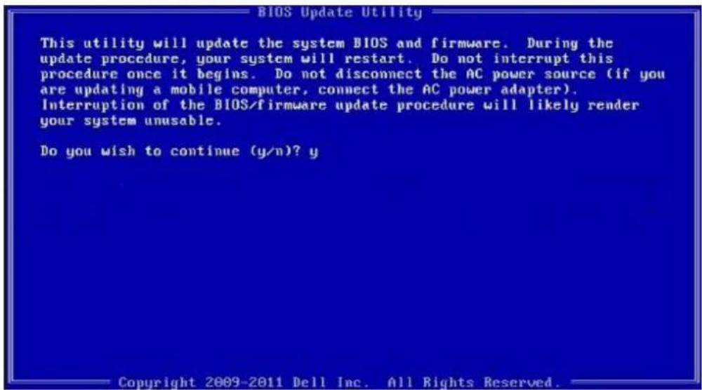
text_image
BIOS Update Utility This utility will update the system BIOS and firmware. During the update procedure, your system will restart. Do not interrupt this procedure once it begins. Do not disconnect the AC power source (if you are updating a mobile computer, connect the AC power adapter). Interruption of the BIOS/firmware update procedure will likely render your system unusable. Do you wish to continue (y/n)? y Copyright 2009-2011 Dell Inc. All Rights Reserved.Figure 1. DOS BIOS Update Screen
Updating the Dell BIOS in Linux and Ubuntu environments
If you want to update the system BIOS in a Linux environment such as Ubuntu, see https://www.dell.com/support/article/us/en/19/sln171755/.
Flashing the BIOS from the F12 One-Time boot menu
Updating your system BIOS using a BIOS update .exe file copied to a FAT32 USB key and booting from the F12 one time boot menu. BIOS Update
You can run the BIOS update file from Windows using a bootable USB key or you can also update the BIOS from the F12 One-Time boot menu on the system.
Most Dell systems built after 2012 have this capability and you can confirm by booting your system to the F12 One-Time Boot Menu to see if BIOS FLASH UPDATE is listed as a boot option for your system. If the option is listed, then the BIOS supports this BIOS update option.
NOTE: Only systems with BIOS Flash Update option in the F12 One-Time Boot Menu can use this function.
Updating from the One-Time Boot Menu
To update your BIOS from the F12 One-Time boot menu, you will need:
- USB key formatted to the FAT32 file system (key does not have to be bootable)
• BIOS executable file that you downloaded from the Dell Support website and copied to the root of the USB key - AC power adapter connected to the system
• Functional system battery to flash the BIOS
Perform the following steps to execute the BIOS update flash process from the F12 menu:
CAUTION: Do not power off the system during the BIOS update process. Powering off the system could make the system fail to boot.
1 From a power off state, insert the USB key where you copied the flash into a USB port of the system.
2 Power on the system and press the F12 key to access the One-Time Boot Menu, Highlight BIOS Update using the mouse or arrow keys then press Enter.
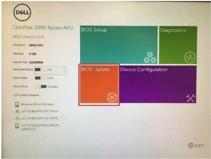
text_image
OptiPlex 5055 Ryzen APU BIOS Version 1.1.0 Processor: AMD CPU Memory: 4 GB Service Tag: GL3FR9W Advanced Setup ON Boot mode UEFI Secure Boot Disabled UEFI Boot Devices Windows Boot Manager: UEFI ONBOARD NIC (IPV4) UEFI ONBOARD NIC (IPV6) UEFI ST500DM002-1SB10A 2990051Q BIOS Setup Diagnostics BIOS Update Device Configuration EXIT3 The Bios flash menu will open then click the Flash from file.
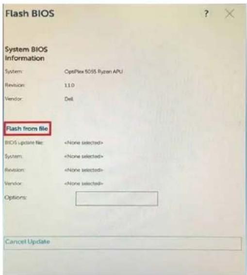
text_image
Flash BIOS System BIOS Information System: OptiFlex 5055 Ryzen APU Revision: 11.0 Vendor: Dell Flash from file BIOS update file:4 Select external USB device
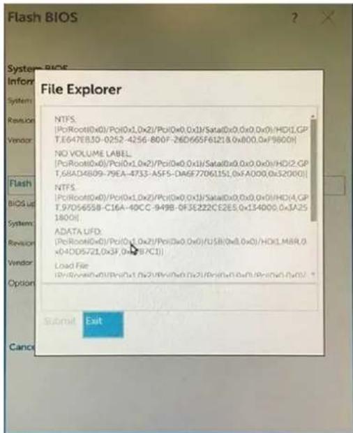
text_image
File Explorer NTFS. (PoRoot(0x0)/Po(0x1,0x2)/Po(0x0,0x1)/Sata(0x0,0x0,0x0)/HD1,GP T.6647EB30-0252-4256-800F-26D665F61218,0x800,0xF9600) NO VOLUME LABEL (PoRoot(0x0)/Po(0x1,0x2)/Po(0x0,0x1)/Sata(0x0,0x0,0x0)/HD1,GP T.68AD4809-79EA-4733-ASFS-DAGF77061151,0x5A000,0x52000) NTFS. (PoRoot(0x0)/Po(0x1,0x2)/Po(0x0,0x1)/Sata(0x0,0x0,0x0)/HD1,GP T.97D5655B-C16A-40CC-949B-DF3E222CE2ES,0x134000,0x3A25- 1800) ADATA UFD. (PoRoot(0x0)/Po(0x1,0x2)/Po(0x0,0x0)/U5B(0x8,0x0)/HD1,M8R,O x0-4DD5721,0x3F,0x4B/C1) Load File (PoRoot(0x0)/Po(0x1,0x2)/Po(0x0,0x1),Pc(0x1,0x2)/Po(0x1,0x2/Pr(0x1,0x1/Pr(0x1,0x2)) Submit Exit5 Once the file is selected, Double click the flash target file, then press submit.
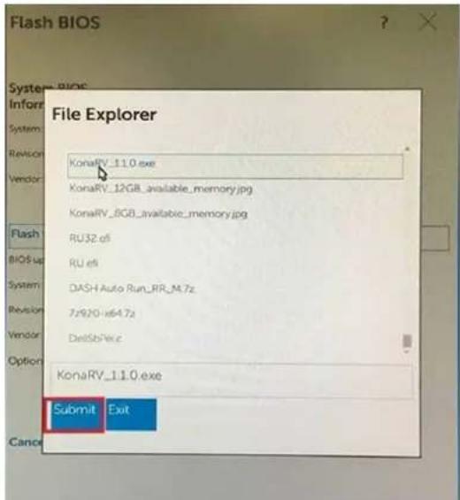
text_image
Flash BIOS System BIOS InfoR System Revision Vendor Flash BIOS us System Revision Vendor Option KonaRV_11.0.exe KonaRV_12GB_available_memory.jpg KonaRV_8GB_available_memory.jpg RU32 ef5 RU ef6 DASH Auto Run_RR_M.7z 7x920-x64.7z DelSbVdc KonaRV_11.0.exe Submit Exit6 Click the Update BIOS then system will reboot to flash the BIOS.
text_image
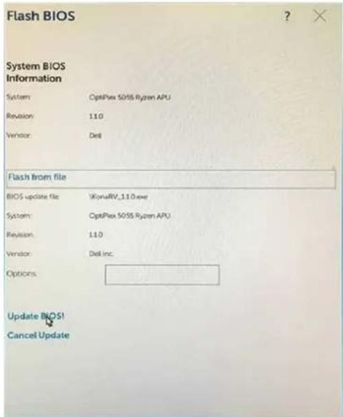
Flash BIOS System BIOS Information System: OptiFlex 5055 Ryzen APU Revision: 11.0 Vendor: Dell Flash from file BIOS update file: VkorRV_11.0.exe System: OptiFlex 5055 Ryzen APU Revision: 11.0 Vendor: Dell Inc. Options: Update BIOS! Cancel Update7 Once complete, the system will reboot and the BIOS update process is completed.
System and setup password
Table 31. System and setup password
Password type Description
System password Password that you must enter to log on to your system.
Setup password Password that you must enter to access and make changes to the
BIOS settings of your computer.
You can create a system password and a setup password to secure your computer.

CAUTION: The password features provide a basic level of security for the data on your computer.
CAUTION: Anyone can access the data stored on your computer if it is not locked and left unattended.
NOTE: System and setup password feature is disabled.
Assigning a system setup password
You can assign a new System or Admin Password only when the status is in Not Set.
To enter the system setup, press F2 immediately after a power-on or re-boot.
1 In the System BIOS or System Setup screen, select Security and press Enter.
The Security screen is displayed.
2 Select System/Admin Password and create a password in the Enter the new password field.
Use the following guidelines to assign the system password:
- A password can have up to 32 characters.
- The password can contain the numbers 0 through 9.
- Only lower case letters are valid, upper case letters are not allowed.
- Only the following special characters are allowed: space, ("), (+), (,), (-), (.), (/), (:), ([), (), (]), (^).
3 Type the system password that you entered earlier in the Confirm new password field and click OK.
4 Press Esc and a message prompts you to save the changes.
5 Press Y to save the changes.
The computer reboots.
Deleting or changing an existing system setup password
Ensure that the Password Status is Unlocked (in the System Setup) before attempting to delete or change the existing System and/or Setup password. You cannot delete or change an existing System or Setup password, if the Password Status is Locked. To enter the System Setup, press F2 immediately after a power-on or reboot.
1 In the System BIOS or System Setup screen, select System Security and press Enter. The System Security screen is displayed.
2 In the System Security screen, verify that Password Status is Unlocked.
3 Select System Password, alter or delete the existing system password and press Enter or Tab.
4 Select Setup Password, alter or delete the existing setup password and press Enter or Tab.
NOTE: If you change the System and/or Setup password, re-enter the new password when prompted. If you delete the System and/or Setup password, confirm the deletion when prompted.
5 Press Esc and a message prompts you to save the changes.
6 Press Y to save the changes and exit from System Setup. The computer reboot.
This chapter details the supported operating systems along with instructions on how to install the drivers.
Downloading drivers
1 Turn on the.
2 Go to Dell.com/support.
3 Click Product Support, enter the Service Tag of your, and then click Submit.
NOTE: If you do not have the Service Tag, use the auto detect feature or manually browse for your model.
4 Click Drivers and Downloads.
5 Select the operating system installed on your .
6 Scroll down the page and select the driver to install.
7 Click Download File to download the driver for your.
8 After the download is complete, navigate to the folder where you saved the driver file.
9 Double-click the driver file icon and follow the instructions on the screen.
System device drivers
Verify if the system device drivers are already installed in the system.
Serial IO driver
Verify if the drivers for Touchpad, IR camera, and keyboard and are installed.

text_image
✓ Human Interface Devices USB Input Device USB Input Device ✓ Keyboards HID Keyboard Device ✓ Mice and other pointing devices HID-compliant mouseFigure 2. Serial IO driver
Security drivers
Verify if the security drivers are already installed in the system.


Security devices
Trusted Platform Module 2.0
USB drivers
Verify if the USB drivers are already installed in the computer.


Universal Serial Bus controllers
Intel(R) USB 3.1 eXtensible Host Controller - 1.10 (Microsoft)
USB Root Hub (USB 3.0)
Network adapter drivers
Verify if the Network adapter drivers are already installed in the system.
Realtek Audio
Verify if audio drivers are already installed in the computer.


Sound, video and game controllers
Intel(R) Display Audio
Realtek Audio
Storage controller
Verify if the storage control drivers are already installed in the system.
Getting help
Contacting Dell
NOTE: If you do not have an active Internet connection, you can find contact information on your purchase invoice, packing slip, bill, or Dell product catalog.
Dell provides several online and telephone-based support and service options. Availability varies by country and product, and some services may not be available in your area. To contact Dell for sales, technical support, or customer service issues:
1 Go to Dell.com/support.
2 Select your support category.
3 Verify your country or region in the Choose a Country/Region drop-down list at the bottom of the page.
4 Select the appropriate service or support link based on your need.