Vigor 2927ac - Router Draytek - Free user manual and instructions
Find the device manual for free Vigor 2927ac Draytek in PDF.


User questions about Vigor 2927ac Draytek
0 question about this device. Answer the ones you know or ask your own.
Ask a new question about this device
Download the instructions for your Router in PDF format for free! Find your manual Vigor 2927ac - Draytek and take your electronic device back in hand. On this page are published all the documents necessary for the use of your device. Vigor 2927ac by Draytek.
USER MANUAL Vigor 2927ac Draytek
(For future update, please visit DrayTek web site)
Date: May 29 2025
Copyrights
© All rights reserved. This publication contains information that is protected by copyright. No part may be reproduced, transmitted, transcribed, stored in a retrieval system, or translated into any language without written permission from the copyright holders.
Trademarks
The following trademarks are used in this document:
● Microsoft is a registered trademark of Microsoft Corp.
● Windows, Windows 7, 8, 10, 11 and Explorer are trademarks of Microsoft Corp.
● Apple and Mac OS are registered trademarks of Apple Inc.
● Other products may be trademarks or registered trademarks of their respective manufacturers.
Safety Instructions
- Read the installation guide thoroughly before you set up the router.
- The router is a complicated electronic unit that may be repaired only be authorized and qualified personnel. Do not try to open or repair the router yourself.
- Do not place the router in a damp or humid place, e.g. a bathroom.
● The router should be used in a sheltered area, within a temperature range of +5 to +40 Celsius. - Do not expose the router to direct sunlight or other heat sources. The housing and electronic components may be damaged by direct sunlight or heat sources.
- Do not deploy the cable for LAN connection outdoor to prevent electronic shock hazards.
- Do not power off the router when saving configurations or firmware upgrades. It may damage the data in a flash. Please disconnect the Internet connection on the router before powering it off when a TR069/ ACS server manages the router.
- Keep the package out of reach of children.
- When you want to dispose of the router, please follow local regulations on conservation of the environment.
Warranty
We warrant to the original end user (purchaser) that the router will be free from any defects in workmanship or materials for a period of two (2) years from the date of purchase from the dealer. Please keep your purchase receipt in a safe place as it serves as proof of date of purchase. During the warranty period, and upon proof of purchase, should the product have indications of failure due to faulty workmanship and/or materials, we will, at our discretion, repair or replace the defective products or components, without charge for either parts or labor, to whatever extent we deem necessary tore-store the product to proper operating condition. Any replacement will consist of a new or re-manufactured functionally equivalent product of equal value, and will be offered solely at our discretion. This warranty will not apply if the product is modified, misused, tampered with, damaged by an act of God, or subjected to abnormal working conditions. The warranty does not cover the bundled or licensed software of other vendors. Defects which do not significantly affect the usability of the product will not be covered by the warranty. We reserve the right to revise the manual and online documentation and to make changes from time to time in the contents hereof without obligation to notify any person of such revision or changes.
Be a Registered Owner
- Web registration is preferred. You can register your Vigor router via https://myvigor.draytek.com.
Firmware & Tools Updates
- Due to the continuous evolution of DrayTek technology, all routers will be regularly upgraded. Please consult the DrayTek web site for more information on newest firmware, tools and documents.
https://www.draytek.com
Table of Contents
Part I Installation....i
I-1 Introduction ...... 1
I-1-1 Indicators and Connectors 2
I-1-1-1 Vigor2927 2
I-1-1-2 Vigor2927L 4
I-1-1-3 Vigor2927ac / Vigor2927ax / Vigor2927Lac....6
I-1-1-4 Vigor2927Vac 10
I-1-1-5 Vigor2927L-5G / Vigor2927Lax-5G.... 12
I-1-2 Notes for Antenna Installation (for "L" model) 15
I-2 Hardware Installation 18
I-2-1 Installing Vigor Router 18
I-2-2 Wall-Mounted Installation 19
I-2-3 Installing USB Printer to Vigor Router 20
I-3 Accessing Web Page 27
I-4 Dashboard....29
I-4-1 Virtual Panel 30
I-4-2 Name with a Link 31
I-4-3 Status for LTE 31
I-4-4 Quick Access for Common Used Menu 32
I-4-5 GUI Map 33
I-4-6 Web Console 34
I-4-7 Config Backup 35
I-4-8 Manual Download....35
I-4-9 Logout.... 35
I-4-10 Online Status 36
I-4-10-1 Physical Connection.... 36
I-4-10-2 Virtual WAN 38
I-5 Quick Start Wizard 39
I-5-1 For WAN1/WAN2 (Ethernet) 40
I-5-2 For WAN3/WAN4 (Wireless 2.4G/Wireless 5G).... 49
I-5-3 For WAN5/WAN6 (USB).... 55
I-6 Service Activation Wizard 57
I-7 Registering Vigor Router....59
Part II Connectivity 63
II-1 WAN 64
Web User Interface 66
II-1-1 General Setup 66
II-1-1-1 WAN1/ WAN2 (Ethernet).... 69
II-1-1-2 WAN3/WAN4 (Wireless 2.4G or 5G) 71
II-1-1-3 WAN5 / WAN6 (USB) or LTE or 5G-NR....72
II-1-2 Internet Access....74
II-1-2-1 Details Page for PPPoE in WAN1/ WAN2 (Physical Mode: Ethernet)....77
II-1-2-2 Details Page for Static or Dynamic IP in WAN1/WAN2 (Physical Mode: Ethernet)
80
II-1-2-3 Details Page for PPTP/L2TP in WAN1/WAN2 (Physical Mode: Ethernet)..... 84
II-1-2-4 Details Page for WAN3/WAN4 (Physical Mode: Wireless 2.4G/Wireless 5G) . 87
II-1-2-5 Details Page for 3G/4G USB Modem (PPP mode) in WAN5 / WAN6 ...... 89
II-1-2-6 Details Page for 3G/4G USB Modem (DHCP mode) in WAN5 / WAN6 ...... 91
II-1-2-7 Details Page for 3G/4G USB Modem (DHCP mode) in LTE WAN 94
II-1-2-8 Details Page for 3G/4G/5G Modem (DHCP mode) in 5G-NR WAN....98
II-1-2-9 Details Page for IPv6 - Offline in WAN1/ WAN2/ WAN5/ WAN6.... 104
II-1-2-10 Details Page for IPv6 - PPP in WAN1/ WAN2.... 104
II-1-2-11 Details Page for IPv6 - TSPC in WAN1/ WAN2/ WAN5/ WAN6 105
II-1-2-12 Details Page for IPv6 - AICCU in WAN1/ WAN2/ WAN5/ WAN6.... 107
II-1-2-13 Details Page for IPv6 - DHCPv6 Client in WAN1/WAN2.... 108
II-1-2-14 Details Page for IPv6 - Static IPv6 in WAN1/WAN2 110
II-1-2-15 Details Page for IPv6 - 6in4 Static Tunnel in WAN1/ WAN2.... 111
II-1-2-16 Details Page for IPv6 - 6rd in WAN1/WAN2.... 113
II-1-3 Multi-VLAN 115
II-1-4 WAN Budget.... 120
II-1-4-1 General Setup 120
II-1-4-2 Status 124
II-2 LAN 125
Web User Interface 127
II-2-1 General Setup 127
II-2-1-1 Details Page for LAN1 - Ethernet TCP/IP and DHCP Setup.... 129
II-2-1-2 Details Page for LAN2 \~ LAN8 and DMZ 133
II-2-1-3 Details Page for IP Routed Subnet 135
II-2-1-4 Details Page for LAN IPv6 Setup 137
II-2-1-5 DHCP Server Options.... 140
II-2-2 VLAN 142
II-2-3 Bind IP to MAC 146
II-2-4 LAN Port Mirror.... 149
II-2-5 Wired 802.1x 150
II-2-6 Link Aggregation.... 151
II-3 Hardware Acceleration.... 152
II-4 NAT 154
Web User Interface 155
II-4-1 Port Redirection.... 155
II-4-2 DMZ Host 159
II-4-3 Open Ports 162
II-4-4 Port Triggering....164
II-4-5 Port Knocking 166
II-4-6 ALG....169
II-5 Applications 170
Web User Interface 172
II-5-1 Dynamic DNS 172
II-5-2 LAN DNS / DNS Forwarding 178
II-5-3 DNS Security 181
II-5-3-1 General Setup 181
II-5-3-2 Domain Diagnose 182
II-5-4 Schedule....183
II-5-5 RADIUS/TACACS+ 186
II-5-5-1 External RADIUS.... 186
II-5-5-2 Internal RADIUS 188
II-5-5-3 External TACACS+.... 191
II-5-6 Active Directory/LDAP 192
II-5-6-1 General Setup 192
II-5-6-2 Active Directory / LDAP Profiles.... 193
II-5-7 UPnP 195
II-5-8 IGMP....196
II-5-8-1 General Setting.... 196
II-5-8-2 Working Status 197
II-5-9 Wake on LAN/WAN 198
II-5-10 SMS / Mail Alert Service.... 200
II-5-10-1 SMS Alert 200
II-5-10-2 Mail Alert 201
II-5-11 Bonjour 202
II-5-12 High Availability 205
II-5-12-1 General Setup 206
II-5-12-2 Config Sync 208
II-5-13 Local 802.1X General Setup 210
Application Notes 212
A-1 How to use DrayDDNS? 212
A-2 How to Configure Customized DDNS? 217
II-6 Routing....221
Web User Interface 222
II-6-1 Static Route 222
II-6-2 Load-Balance /Route Policy 227
Diagnose for Route Policy 233
II-6-3 BGP 237
II-6-3-1 Basic Settings.... 237
II-6-3-2 Static Network.... 238
Application Notes 239
A-1 How to set up Address Mapping with Route Policy? 239
A-2 How to use destination domain name in a route policy? 241
A-3 Introduction to Load Balance/Route Policy 243
II-7 LTE / 5G-NR....245
Web User Interface 246
II-7-1 General Settings 246
II-7-1-1 SMS Quota 246
II-7-1-2 SMS Inbox/Outbox 247
II-7-1-3 Signal Quality Display 247
II-7-2 SMS Inbox 248
II-7-3 Send SMS 251
II-7-4 SMS Gateway 252
II-7-5 Router Commands 256
II-7-6 Status....259
II-7-7 RSRP Graph.... 261
Part III Wireless LAN....263
III-1 Wireless LAN (2.4GHz/5GHz) 264
Web User Interface 267
III-1-1 Wireless Wizard....267
III-1-2 General Setup 271
III-1-3 Security 273
III-1-4 Access Control 275
III-1-5 WPS....277
III-1-6 WDS (for 5GHz) 280
III-1-7 Advanced Setting 282
III-1-8 Station Control 286
III-1-9 Bandwidth Management 287
III-1-10 AP Discovery 288
III-1-11 Airtime Fairness....289
III-1-12 Band Steering (2.4 GHz) 291
III-1-13 Roaming 295
III-1-14 Station List....296
III-2 Mesh Network 298
III-2-1 Mesh Wizard.... 299
III-2-2 Mesh Setup 303
III-2-3 Mesh Status.... 305
III-2-4 Mesh Discovery 306
III-2-5 Basic/Advanced Config Sync 307
III-2-6 Support List 309
Part IV VoIP....311
IV-1 VoIP 312
Web User Interface 314
IV-1-1 VoIP Wizard 314
IV-1-2 General Settings 316
IV-1-3 SIP Accounts 319
IV-1-3-1 Alias List 322
IV-1-4 DialPlan 325
IV-1-4-1 Phone Book 325
IV-1-4-2 Digit Map 326
IV-1-4-3 Call Barring 329
IV-1-4-4 Regional 331
IV-1-5 Phone Settings.... 333
IV-1-6 Status 337
IV-1-7 Diagnostics.... 339
IV-1-7-1 Caller ID 339
IV-1-7-2 Tone 339
Part V VPN....341
V-1 VPN and Remote Access 342
Web User Interface 343
V-1-1 VPN Client Wizard 343
V-1-2 VPN Server Wizard 350
V-1-3 Remote Access Control 360
V-1-3-1 Remote Access Control Setup 360
V-1-3-2 Bind to WAN 361
V-1-4 PPP General Setup 362
V-1-5 SSL General Setup 364
V-1-6 IPsec General Setup 366
V-1-7 IPsec Peer Identity 369
V-1-8 VPN Matcher Setup 371
V-1-9 OpenVPN 373
V-1-9-1 OpenVPN Server Setup 373
V-1-9-2 Client Config.... 375
V-1-9-3 Import Certificate 376
V-1-10 WireGuard 377
V-1-11 Remote Dial-in User 378
V-1-11 LAN to LAN 384
V-1-12 VPN Trunk Management.... 395
V-1-13 Connection Management 401
V-2 Certificate Management.... 403
Web User Interface 404
V-2-1 Local Certificate 404
V-2-2 Trusted CA Certificate 409
V-2-3 Certificate Backup 413
V-2-4 Self-Signed Certificate 414
V-2-5 Local Services List 415
Part VI Security 417
VI-1 Firewall 418
Web User Interface 420
VI-1-1 General Setup 420
VI-1-2 Filter Setup 425
VI-1-3 Defense Setup 435
VI-1-3-1 DoS Defense 435
VI-1-3-2 Spoofing Defense 438
VI-1-3-3 Brute Force Protection 439
VI-1-4 Diagnose 440
VI-2 Central Security Management (CSM).... 443
Web User Interface 444
VI-2-1 APP Enforcement Profile 444
VI-2-2 URL Content Filter Profile 446
VI-2-4 Web Content Filter Profile 450
VI-2-5 DNS Filter Profile 453
Application Notes 456
A-1 How to Create an Account for MyVigor 456
A-2 How to Block Facebook Service Accessed by the Users via Web Content Filter / URL
Content Filter 461
Part VII Management....467
VII-1 System Maintenance 468
Web User Interface 469
VII-1-1 System Status 469
VII-1-2 TR-069 471
VII-1-2-1 ACS and CPE Settings 471
VII-1-2-2 Reporting Configuration.... 473
VII-1-2-3 Export Parameters 473
VII-1-3 NetFlow 474
VII-1-4 Administrator Password 475
VII-1-5 User Password 479
VII-1-6 Login Page Greeting 482
VII-1-7 Configuration Backup.... 484
VII-1-8 Webhook 487
VII-1-9 Syslog/Mail Alert 488
VII-1-10 Time and Date.... 491
VII-1-11 SNMP 492
VII-1-11 Management 494
VII-1-12 Panel Control 500
VII-1-13 Self-Signed Certificate 505
VII-1-14 Reboot System....507
VII-1-15 Firmware Upgrade 508
VII-1-16 Firmware Backup 509
VII-1-17 Internal Service User List.... 510
VII-1-18 Dashboard Control 511
VII-2 Bandwidth Management....512
Web User Interface 513
VII-2-1 Sessions Limit 513
VII-2-2 Bandwidth Limit....515
VII-2-3 Quality of Service 517
VII-2-4 APP QoS 523
VII-3 User Management 524
Web User Interface 525
VII-3-1 General Setup 525
VII-3-2 User Profile 526
VII-3-3 User Group.... 530
VII-3-4 User Online Status 531
Application Notes 533
A-1 How to authenticate clients via User Management 533
A-2 How to use Landing Page Feature.... 542
VII-4 Hotspot Web Portal....546
Web User Interface 546
VII-4-1 Profile Setup.... 546
VII-4-1-1 Login Method....547
VII-4-1-2 Steps for Configuring a Web Portal Profile.... 548
VII-4-2 User Information....567
VII-4-2-1 User Info 567
VII-4-2-2 Database Setup 568
VII-4-3 Quota Management 570
VII-4-4 PIN Generator 573
VII-4-4-1 PIN Status.... 573
VII-4-4-2 PIN Generator 574
VII-4-4-3 JSON PIN Generator 575
VII-4-4-4 PIN Voucher 576
Application Notes 578
A-1 How to create Facebook APP for Web Portal Authentication? 578
A-2 How to create Google APP for Web Portal Authentication?...... 584
VII-5 Central Management (VPN) 586
Web User Interface 587
VII-5-1 General Setup 587
VII-5-1-1 General Settings.... 587
VII-5-1-2 IPsec VPN Settings.... 588
VII-5-2 CPE Management.... 589
VII-5-2-1 Managed Device List 589
VII-5-2-2 CPE Maintenance 592
VII-5-2-3 Google Map.... 594
VII-5-3 VPN Management 596
VII-5-4 Log & Alert 597
Application Notes 598
A-1 CVM Application - How to manage the CPE (router) through Vigor2927 series? . 598
A-2 CVM Application - How to upgrade CPE firmware through Vigor2927 series? .... 602
VII-6 Central Management (AP)....605
Web User Interface 606
VII-6-1 Dashboard.... 606
VII-6-2 Status 607
VII-6-3 WLAN Profile.... 608
VII-6-4 AP Maintenance 614
VII-6-5 Traffic Graph 615
VII-6-6 Event Log 616
VII-6-7 Total Traffic 617
VII-6-8 Station Number 617
VII-6-9 Load Balance 618
VII-7 Central Management (Switch) 620
Web User Interface 621
VII-7-1 Status 621
VII-7-1-1 Switch Status....621
VII-7-1-2 Switch Hierarchy 623
VII-7-1-3 Detailed Info 624
VII-7-1-4 TR069 Setting 625
VII-7-2 Profile 627
VII-7-3 Group 630
VII-7-4 Maintenance....632
VII-7-5 Alert and Log 633
VII-7-5-1 Alert Setup 633
VII-7-5-2 Switch and Port Setup 634
VII-7-5-3 Alert Logs....635
VII-7-6 Database Setup 636
VII-7-7 Support List 637
VII-8 Central Management (External Devices) 638
Part VIII Others....641
VIII-1 Objects Settings....642
Web User Interface 643
VIII-1-1 IP Object 643
VIII-1-2 IP Group 646
VIII-1-3 IPv6 Object.... 648
VIII-1-4 IPv6 Group 650
VIII-1-5 Service Type Object....652
VIII-1-6 Service Type Group 654
VIII-1-7 Keyword Object 656
VIII-1-8 Keyword Group 658
VIII-1-9 File Extension Object 659
VIII-1-10 SMS/Mail Service Object 661
VIII-1-11 Notification Object 666
VIII-1-12 String Object 668
VIII-1-13 Country Object 669
VIII-1-14 Objects Backup/Restore 671
Application Notes 672
A-1 How to Send a Notification to Specified Phone Number via SMS Service in WAN Disconnection 672
VIII-2 USB Application 676
Web User Interface 677
VIII-2-1 USB General Settings....677
VIII-2-2 USB User Management 678
VIII-2-3 File Explorer 680
VIII-2-4 USB Device Status....681
VIII-2-5 Temperature Sensor 682
VIII-2-6 Modem Support List 685
VIII-2-7 SMB Client Support List 686
Application Notes 687
A-1 How can I get the files from USB storage device connecting to Vigor router? ... 687
Part IX Troubleshooting 691
IX-1 Diagnostics 692
Web User Interface 693
IX-1-1 Dial-out Triggering....693
IX-1-2 Routing Table 694
IX-1-3 ARP Cache Table 695
IX-1-4 IPv6 Neighbour Table 696
IX-1-5 DHCP Table 697
IX-1-6 NAT Sessions Table 698
IX-1-7 DNS Cache Table 699
IX-1-8 Ping Diagnosis 700
IX-1-9 Data Flow Monitor 701
IX-1-10 Traffic Graph 704
IX-1-11 VPN Graph 705
IX-1-12 Trace Route 706
IX-1-13 Syslog Explorer 707
IX-1-14 IPv6 TSPC Status 708
IX-1-15 High Availability Status 708
IX-1-16 Authentication Information 710
IX-1-17 DoS Flood Table 712
IX-1-18 Route Policy Diagnosis 713
IX-2 Checking If the Hardware Status Is OK or Not.... 715
IX-3 Checking If the Network Connection Settings on Your Computer Is OK or Not.... 716
IX-4 Pinging the Router from Your Computer 719
IX-5 Checking If the ISP Settings are OK or Not.... 721
IX-6 Problems for 3G/4G Network Connection....722
IX-7 Backing to Factory Default Setting If Necessary 723
IX-8 Contacting DrayTek 724
Part X Telnet Commands....725
Accessing Telnet of Vigor2927 726
Part I Installation

Installation
This part will introduce Vigor router and guide to install the device in hardware and software.
I-1 Introduction
This is a generic International version of the user guide. Specification, compatibility and feature vary by region. For specific user guides suitable for your region or product, please contact local distributor.
Vigor2927 series integrates IP layer QoS, NAT session/bandwidth management to help users control works well with large bandwidth.
By adopting hardware-based VPN platform and hardware encryption of AES/ DES/ 3DES, the router increases the performance of VPN greatly, and offers several protocols (such as IPsec/ PPTP/ L2TP) with VPN tunnels.
The object-based design used in SPI (Stateful Packet Inspection) firewall allows users to set firewall policy with ease. CSM (Content Security Management) provides users control and management in IM (Instant Messenger) and P2P (Peer to Peer) more efficiency than before. By the way, DoS/ DDoS prevention and URL/ Web content filter strengthen the security outside and control inside. Object-based firewall is flexible and allows your network be safe.
User Management implemented on your router firmware can allow you to prevent any computer from accessing your Internet connection without a username or password. You can also allocate time budgets to your employees within office network.
With the 4-port Gigabit switch on the LAN side provides extremely high speed connectivity for the highest speed local data transfer of any server or local PCs. The tagged VLANs (IEEE802.1Q) can mark data with a VLAN identifier. This identifier can be carried through an onward Ethernet switch to specific ports. The specific VLAN clients can also pick up this identifier as it is just passed to the LAN. You can set the priorities for LAN-side QoS. You can assign each of VLANs to each of the different IP subnets that the router may also be operating, to provide even more isolation. The said functionality is tag-based Multi-subnet (Multiple-Private LAN Subnets).
On the Wireless-equipped models (e.g., Vigor2927Iac) each of the wireless SSIDs can also be grouped within one of the VLANs.
In addition, Vigor2927 series supports USB interface for connecting USB printer to share printing function or 3G USB modem for network connection.
Vigor2927 series provides two-level management to simplify the configuration of network connection. The user mode allows user accessing into WEB interface via simple configuration. However, if users want to have advanced configurations, they can access into WEB interface through admin mode.
I-1-1 Indicators and Connectors
Before you use the Vigor router, please get acquainted with the LED indicators and connectors first.
I-1-1-1 Vigor2927

text_image
DrayTek Vigor2927 Dual-WAN Security Router Factory Reset ACT WAN2 USB1 DMZ WAN1 USB2 QoS VPN WCF USB WAN1 WAN2 / PS P1 P2 P3 P4 P5| LED | Status | Explanation |
| ACT | Off | The router is powered off. |
| Blinking | The router is powered on and running normally. | |
| WAN2/ WAN1 | On | Internet connection is ready. |
| Off | Internet connection is not ready. | |
| Blinking | The data is transmitting. | |
| USB1/ USB2 | On | USB device is connected and ready for use. |
| Off | No USB device is connected. | |
| Blinking | The data is transmitting. | |
| DMZ | On | The DMZ function is enabled. |
| Off | The DMZ function is disabled. | |
| Blinking | The data is transmitting. | |
| QoS | On | The QoS function is active. |
| Off | The QoS function is inactive. | |
| VPN | On | The VPN tunnel is active. |
| Off | VPN services are disabled | |
| Blinking | Traffic is passing through VPN tunnel. | |
| WCF | On | The Web Content Filter is active. (It is enabled from Firewall >> General Setup). |
| Off | WCF is disabled. |
WAN1, WAN2 / P6
| Left LED | On | The port is connected. |
| Off | The port is disconnected. | |
| Blinking | The data is transmitting. | |
| Right LED | On | The port is connected with 1000Mbps. |
| Off | The port is connected with 10/100Mbps. |
LAN P1-P5
| Left LED | On | The port is connected. |
| Off | The port is disconnected. | |
| Blinking | The data is transmitting. | |
| Right LED | On | The port is connected with 1000Mbps. |
| Off | The port is connected with 10/100Mbps |
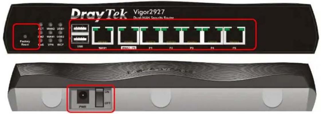
text_image
DrayTek Vigor2927 Dual-WAN Security Router Factory Reset CT WAN2 USB1 CMZ WAN1 USB2 COS VPN WCP USB WAN1 WAN2 PS P1 P2 P3 P4 PS PWR ON OFF| Interface | Description |
| Factory Reset | Restore the default settings. Usage: Turn on the router (ACT LED is blinking). Press the hole and keep for more than 5 seconds. When you see the ACT LED begins to blink rapidly than usual, release the button. Then the router will restart with the factory default configuration. |
| USB | Connector for a USB device (for 3G/4G USB Modem or printer or thermometer). |
| WAN1 Connector | for a modem for accessing Internet. |
| WAN2 / P6 | Connector for local network devices or modem for accessing Internet.It is a switchable port. It can be used for LAN connection or WAN connection according to the settings configured in WUI. |
| LAN P1-P5 | Connecters for local network devices. |
| PWR Connector | for a power adapter. |
| ON/OFF Power Switch. | |
I-1-1-2 Vigor2927L

text_image
DrayTek Vigor2927L Dual-WAN Security Router Factory Reset ACT WAN2 LTE DWZ WAN1 USB QoS VPN WCF USB WAN1 WAN2 / PS P1 P2 P3 P4 P5| LED | Status | Explanation |
| ACT | Off | The router is powered off. |
| Blinking | The router is powered on and running normally. | |
| WAN2/ WAN1 | On | Internet connection is ready. |
| Off | Internet connection is not ready. | |
| Blinking | The data is transmitting. | |
| LTE | On | LTE device is connected and ready for use. |
| Off | LTE device is not detected, or has serious problem (e.g., no SIM card, SIM pin error, SIM deactivated, and etc.). | |
| Blinking | Slowly: LTE device is in dialing up. Quickly: The data is transmitting. | |
| DMZ | On | The DMZ function is enabled. |
| Off | The DMZ function is disabled. | |
| Blinking | The data is transmitting. | |
| USB | On | USB device is connected and ready for use. |
| Off | No USB device is connected. | |
| Blinking | The data is transmitting. | |
| QoS | On | The QoS function is active. |
| Off | The QoS function is inactive. | |
| VPN | On | The VPN tunnel is active. |
| Off | VPN services are disabled | |
| Blinking | Traffic is passing through VPN tunnel. | |
| WCF | On | The Web Content Filter is active. (It is enabled from Firewall >> General Setup). |
| Off | WCF is disabled. | |
| WAN1, WAN2 / P6 | ||
| Left LED | On | The port is connected. |
| Off | The port is disconnected. | |
| Blinking | The data is transmitting. | |
| Right LED | On | The port is connected with 1000Mbps. |
| Off | The port is connected with 10/ 100Mbps. | |
| LAN P1-P5 | ||
| Left LED | On | The port is connected. |
| Off | The port is disconnected. | |
| Blinking | The data is transmitting. | |
| Right LED | On | The port is connected with 1000Mbps. |
| Off | The port is connected with 10/ 100Mbps | |

text_image
DrayTek Vigor2927L Dual-WAN Security Router Factory Reset ACT WAN2 LTE DMZ WAN1 USB GoS VPN WCF USB WAN1 WAN2 / PE P1 P2 P3 P4 P5
text_image
PWR ON OFF LTE LTE Sail Card Off| Interface | Description |
| Factory Reset | Restore the default settings. Usage: Turn on the router (ACT LED is blinking). Press the hole and keep for more than 5 seconds. When you see the ACT LED begins to blink rapidly than usual, release the button. Then the router will restart with the factory default configuration. |
| USB | Connector for a USB device (for 3G/ 4G USB Modem or printer or thermometer). |
| WAN1 Connector | for a modem for accessing Internet. |
| WAN2 / P6 | Connector for local network devices or modem for accessing Internet. It is a switchable port. It can be used for LAN connection or WAN connection according to the settings configured in WUI. |
| LAN P1-P5 | Connecters for local network devices. |
| PWR Connector for a power adapter. | |
| ON/OFF Power Switch. | |
 | Connector for installing LTE antennas. |
| SIM 2/1 | Slots for installing SIM card(s). |
I-1-1-3 Vigor2927ac / Vigor2927ax / Vigor2927Lac
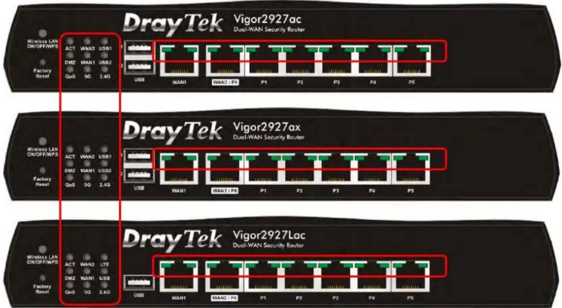
text_image
DrayTek Vigor2927ac Dual-WAN Security Router Wireless LAN ON/OFF/WPS ACT WAN2 USB1 DMZ WAN1 USB2 QoS 5G 2.4G Factory Reset USB WAN1 WAN2 / PE P1 P2 P3 P4 P5 DrayTek Vigor2927ax Dual-WAN Security Router Wireless LAN ON/OFF/WPS ACT WAN2 USB1 DMZ WAN1 USB2 QoS 5G 2.4G Factory Reset USB WAN1 WAN2 / PE P1 P2 P3 P4 P5 DrayTek Vigor2927Lac Dual-WAN Security Router Wireless LAN ON/OFF/WPS ACT WAN2 LTE DMZ WAN1 USB QoS 5G 2.4G Factory Reset USB WAN1 WAN2 / PE P1 P2 P3 P4 P5| LED | Status | Explanation |
| ACT | Off The router is powered off. | |
| Blinking | The router is powered on and running normally. | |
| WAN2/ WAN1 | On Internet connection is ready. | |
| Off Internet connection is not ready. | ||
| Blinking The data is transmitting. | ||
| USB1/ USB2 | On USB device is connected and ready for use. | |
| Off No USB device is connected. | ||
| Blinking The data is transmitting. | ||
| LTE | On | LTE device is connected and ready for use. |
| Off | LTE device is not detected, or has serious problem (e.g., no SIM card, SIM pin error, SIM deactivated, and etc.). | |
| Blinking | Slowly: LTE device is in dialing up. Quickly: The data is transmitting. | |
| DMZ | On The DMZ function is enabled. | |
| Off The DMZ function is disabled. | ||
| Blinking The data is transmitting. | ||
| QoS | On | The QoS function is active. |
| Off | The QoS function is inactive. | |
| 5G / 2.4G | On | 5G/ 2.4G: Wireless access point with bandwidth of 5GHz/ 2.4GHz is ready. WLAN: Wireless access point is ready. |
| Off Wireless function is disabled. | ||
| Blinking | It will blink slowly while wireless traffic goes through. ACT and WLAN LEDs blink quickly and simultaneously when WPS is working, and will return to normal condition after two minutes. (You need to setup WPS within 2minutes.) | |
| WAN1,WAN2 / P6 | ||
| Left LED | On | The port is connected. |
| Off | The port is disconnected. | |
| Blinking | The data is transmitting. | |
| Right LED | On | The port is connected with 1000Mbps. |
| Off | The port is connected with 10/ 100Mbps. | |
| LAN P1-P5 | ||
| Left LED | On | The port is connected. |
| Off | The port is disconnected. | |
| Blinking | The data is transmitting. | |
| Right LED | On | The port is connected with 1000Mbps. |
| Off | The port is connected with 10/ 100Mbps | |
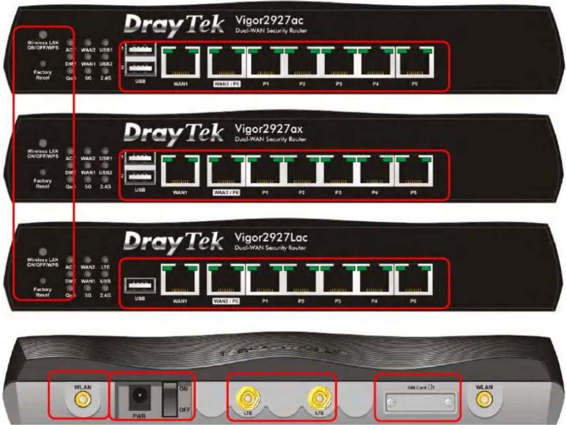
text_image
DrayTek Vigor2927ac Dual-WAN Security Router Wireless LAN ON/OFF/WPS AC WAN2 USB1 DM WAN1 USB2 Factory Reset Qo 5G 2.4G USB WAN1 WAN2 / PE P1 P2 P3 P4 P5 DrayTek Vigor2927ax Dual-WAN Security Router Wireless LAN ON/OFF/WPS AC WAN2 USB1 DM WAN1 USB2 Factory Reset Qo 5G 2.4G USB WAN1 WAN2 / PE P1 P2 P3 P4 P5 DrayTek Vigor2927Lac Dual-WAN Security Router Wireless LAN ON/OFF/WPS AC WAN2 LTE DM WAN1 USB Factory Reset Qo 5G 2.4G USB WAN1 WAN2 / PE P1 P2 P3 P4 P5 WLAN ON OFF LTE LTE LTE SIM Card WLAN| Interface | Description |
| Wireless LAN ON/ OFF/ WPS | Wireless band will be switched / changed according to the button pressed and released. For example,2.4G (On) and 5G (On) - in default.2.4G (Off) and 5G (On) - pressed and released the button once.2.4G (On) and 5G (Off) - pressed and released the button twice.2.4G (Off) and 5G (Off) - pressed and released the button three times.When WPS function is enabled by web user interface, press this button for more than 2 seconds to wait for client's device making network connection through WPS. |
| Factory Reset | Restore the default settings. Usage: Turn on the router (ACT LED is blinking). Press the hole and keep for more than 5 seconds. When you see the ACT LED begins to blink rapidly than usual, release the button. Then the router will restart with the factory default configuration. |
| USB1~2 / USB | Connector for a USB device (for 3G/ 4G USB Modem or printer or thermometer). |
| WAN1 Connector | for a modem for accessing Internet. |
| WAN2 / P6 | Connector for local network devices or modem for accessing Internet.It is a switchable port. It can be used for LAN connection or WAN connection according to the settings configured in WUI. |
| LAN P1-P5 | Connecters for local network devices. |
| Connector for installing WLAN antennas.(For ac model) | |
| PWR Connector for a power adapter. | |
| ON/ OFF Power Switch. | |
| Connector for installing LTE antennas.(For L model). | |
| SIM 2/1 | Slots for installing SIM card(s).(For L model). |
I-1-1-4 Vigor2927Vac

text_image
DrayTek Vigor2927Vac Dual-WAN Security Router Wireless LAN ORIOFF/WPS ACT WAN2 QoS USB WAN1 Phone1 Factory Reset 2.4G SQ Phone2 USB WAN1 WAN2 / P6 P1 P2 P3 P4 P5 Phone2 Phone1| LED | Status | Explanation |
| ACT | Off The router is powered off. | |
| Blinking | The router is powered on and running normally. | |
| WAN2/WAN1 | On Internet connection is ready. | |
| Off Internet connection is not ready. | ||
| Blinking The data is transmitting. | ||
| QoS | On | The QoS function is active. |
| Off | The QoS function is inactive. | |
| USB | On USB device is connected and ready for use. | |
| Off No USB device is connected. | ||
| Blinking The data is transmitting. | ||
| Phone1/Phone2 | On | The phone connected to this port is off-hook. |
| Off | The phone connected to this port is on-hook. | |
| Blinking | A phone call comes. | |
| 2.4G/5G | On | 5G/2.4G: Wireless access point with bandwidth of 5GHz/2.4GHz is ready.WLAN: Wireless access point is ready. |
| Off Wireless function is disabled. | ||
| Blinking | It will blink slowly while wireless traffic goes through.ACT and WLAN LEDs blink quickly and simultaneously when WPS is working, and will return to normal condition after two minutes. (You need to setup WPS within 2 minutes.) | |
| WAN1,WAN2/P6 | ||
| Left LED | On | The port is connected. |
| Off | The port is disconnected. | |
| Blinking | The data is transmitting. | |
| Right LED | On | The port is connected with 1000Mbps. |
| Off | The port is connected with 10/100Mbps. | |
| LAN P1-P5 | ||
| Left LED | On | The port is connected. |
| Off | The port is disconnected. | |
| Blinking | The data is transmitting. | |
| Right LED | On | The port is connected with 1000Mbps. |
| Off | The port is connected with 10/100Mbps | |

text_image
DrayTek Vigor2927Vac Dual-WAN Security Router Wireless LAN ON/OFF/WPS ACT WAN2 QoS USB WAN1 Phone1 Factory Reset 2.4G 5G Phone2 USB WAN1 WAN2 / P6 P1 P2 P3 P4 P5 Phone2 Phone1
text_image
PWR ON OFF| Interface | Description |
| Wireless LAN ON/ OFF/ WPS | Wireless band will be switched / changed according to the button pressed and released. For example,2.4G (On) and 5G (On) - in default.2.4G (Off) and 5G (On) - pressed and released the button once.2.4G (On) and 5G (Off) - pressed and released the button twice.2.4G (Off) and 5G (Off) - pressed and released the button three times.When WPS function is enabled by web user interface, press this button for more than 2 seconds to wait for client's device making network connection through WPS. |
| Factory Reset | Restore the default settings. Usage: Turn on the router (ACT LED is blinking). Press the hole and keep for more than 5 seconds. When you see the ACT LED begins to blink rapidly than usual, release the button. Then the router will restart with the factory default configuration. |
| USB1~2 / USB | Connector for a USB device (for 3G/ 4G USB Modem or printer or thermometer). |
| WAN1 Connector | for a modem for accessing Internet. |
| WAN2 / P6 | Connector for local network devices or modem for accessing Internet.It is a switchable port. It can be used for LAN connection or WAN connection according to the settings configured in WUI. |
| LAN P1-P5 | Connecters for local network devices. |
 | Connector for installing WLAN antennas.(For ac model) |
| PWR Connector for a power adapter. | |
| ON/ OFF Power Switch. | |
I-1-1-5 Vigor2927L-5G / Vigor2927Lax-5G

text_image
DrayTek Vigor2927L-5G Dual-WAN Security Router Factory Reset ACT WAN2 5G-NR DMZ WAN1 USB QoS VPN WCF USB WAN1 WAN2 / P6 P1 P2 P3 P4 P5
text_image
DrayTek Vigor2927Lax-5G Dual-WAN Security Router Wireless LAN DNOFF/WPS ACT WAN2 5G-NR DMZ WAN1 USB QoS SG 2.4G Factory Reset USB WAN1 WAN2 / P6 P1 P2 P3 P4 P5| LED | Status | Explanation |
| ACT | Off | The router is powered off. |
| Blinking | The router is powered on and running normally. | |
| WAN2~WAN1 | On | Internet connection is ready. |
| Off | Internet connection is not ready. | |
| Blinking | The data is transmitting. | |
| 5G-NR | On | 5G-NR device is connected and ready for use. |
| Off | 5G-NR device is not detected, or has serious problem (e.g., no SIM card, SIM pin error, SIM deactivated, and etc.). | |
| Blinking | Slowly: 5G-NR device is in dialing up. Quickly: The data is transmitting. | |
| DMZ | On | The DMZ function is enabled. |
| Off | The DMZ function is disabled. | |
| Blinking | The data is transmitting. | |
| USB | On | USB device is connected and ready for use. |
| Off | No USB device is connected. | |
| Blinking | The data is transmitting. | |
| QoS | On | The QoS function is active. |
| Off | The QoS function is inactive. | |
| VPN | On | The VPN tunnel is active. |
| Off | VPN services are disabled. | |
| Blinking | Traffic is passing through VPN tunnel. | |
| WCF | On | The Web Content Filter is active. (It is enabled from Firewall >> General Setup). |
| Off | WCF is disabled. | |
| 2.4G/5G | On | 2.4G/5G: Wireless access point with bandwidth of 2.4GHz/5GHz is ready. WLAN: Wireless access point is ready. |
| Off | Wireless function is disabled. | |
| Blinking | It will blink slowly while wireless traffic goes through. ACT and WLAN LEDs blink quickly and simultaneously when WPS is working, and will return to normal condition after two minutes. (You need to setup WPS within 2 minutes.) | |
| WAN1,WAN2 / P6 | ||
| Left LED | On | The port is connected. |
| Off | The port is disconnected. | |
| Blinking | The data is transmitting. | |
| Right LED | On | The port is connected with 1000Mbps. |
| Off | The port is connected with 10/ 100Mbps. | |
| LAN P1-P5 | ||
| Left LED | On | The port is connected. |
| Off | The port is disconnected. | |
| Blinking | The data is transmitting. | |
| Right LED | On | The port is connected with 1000Mbps. |
| Off | The port is connected with 10/ 100Mbps | |

text_image
DrayTek Vigor2927L-5G Dual-WAN Security Router Factory Reset CT WAN2 SG-NR CMZ WAN1 USB OS VPN WCF USB WAN1 WAN2 PS P1 P2 P3 P4 P5
text_image
DrayTek Vigor2927Lax-5G Dual-WAN Security Router Wireless LAN ON/OFF/WPS HCT WAN2 5G-4R JNZ WAN1 USB Factory Reset GS 5G 2.4G USB WAN1 WAN2 / PS P1 P2 P3 P4 P5
text_image
WLAN PWR ON OFF LTE LTE LTE LTE SIM Card □1 WLAN| Interface | Description |
| Wireless LAN ON/ OFF/ WPS | Wireless band will be switched / changed according to the button pressed and released. For example,2.4G (On) and 5G (On) - in default.2.4G (Off) and 5G (On) - pressed and released the button once.2.4G (On) and 5G (Off) - pressed and released the button twice.2.4G (Off) and 5G (Off) - pressed and released the button three times.When WPS function is enabled by web user interface, press this button for more than 2 seconds to wait for client's device making network connection through WPS. |
| Factory Reset | Restore the default settings. Usage: Turn on the router (ACT LED is blinking). Press the hole and keep for more than 5 seconds. When you see the ACT LED begins to blink rapidly than usual, release the button. Then the router will restart with the factory default configuration. |
| USB | Connector for a USB device (for 3G/ 4G USB Modem or printer or thermometer). |
| WAN1 | Connector for local network devices or modem for accessing Internet. |
| WAN2 / P6 | Connector for local network devices or modem for accessing Internet.The port “ WAN2 / P6” is switchable. It can be used for LAN connection or WAN connection according to the settings configured in WUI. |
| LAN P1-P5 | Connecters for local network devices. |
 | Connector for installing WLAN antennas.(For ac/ ax model). |
| PWR | Connector for a power adapter. |
| ON/ OFF | Power Switch. |
 | Connector for installing LTE antennas. |
| SIM Card | Slots for installing SIM card(s).(For L model). |
I-1-2 Notes for Antenna Installation (for "L" model)
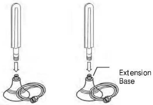
Antenna must be installed on the extension base before connecting to Vigor router.
text_image
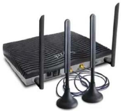
Extension BaseThe number of antenna used for LTE and 5G-NR models are different.
LTE Model
2 sets (Antenna + Extension Base)
5G-NR Model
4 sets (Antenna + Extension Base)
natural_image
Black wireless router with two external antennas and two connected coaxial cables (no visible text or symbols)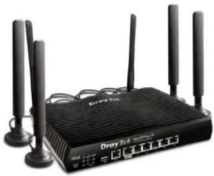
natural_image
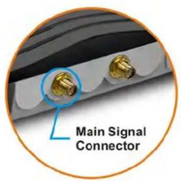
Black DroyTel network device with multiple Ethernet ports and antennas (no visible text or symbols on body)The antenna with an extension base on the Vigor router must be installed correctly. If only one antenna shall be installed, please use the connector (main signal connector) near the power switch.
LTE Model 5G-NR Model
text_image
Main Signal Connector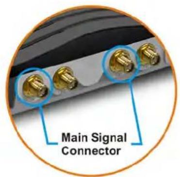
text_image
Main Signal ConnectorFor installing the SIM card into the card slot, here, we take Vigor2927Lac as an example.
-
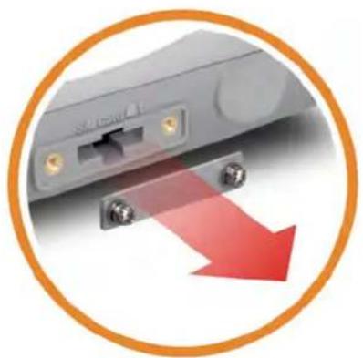
While installing the SIM card into the card slot, note that the back plate of the SIM card slot must be removed first.
-
Assemble the SIM1 and SIM2 with the SIM tray. Then insert the SIM tray into the SIM card slot of the router.
natural_image
Close-up of a gray network switch with red arrow indicating downward motion (no text or symbols)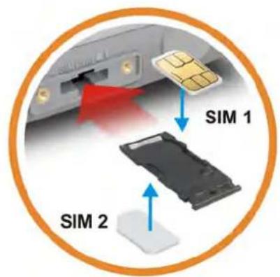
text_image
SIM 1 SIM 2Note
If you need to remove SIM1 or SIM2, carefully take them out of the card slot without bending the SIM tray.

natural_image
Abstract diagram of two hands holding a device with a red circle containing an 'X' symbol (no text or labels)Warning
There are two types of antennas provided for Vigor2927Lac, which must be installed in different locations carefully and correctly. Wrong installation might cause bad signal of wireless connection. Therefore, pay attention to the installation of antennas by referring to the following illustration.

text_image
SMA jack for LTE Antenna (with extension base) SMA jack for WLAN AntennaI-2 Hardware Installation
I-2-1 Installing Vigor Router
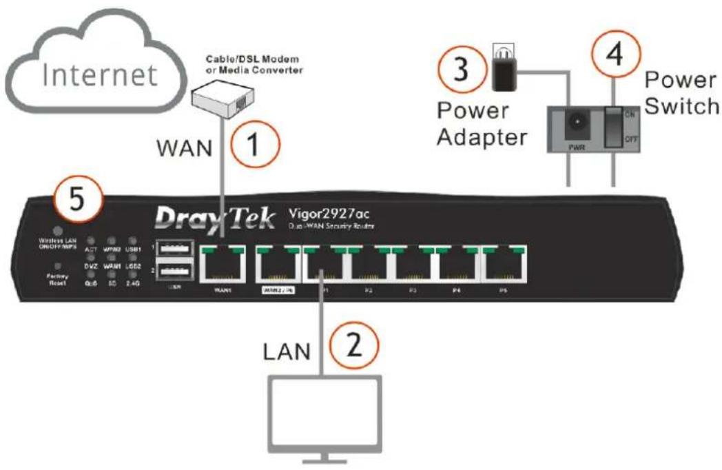
Before starting to configure the router, you have to connect your devices correctly. (For the hardware connection, we take "ac" model as an example.)
- Connect the DSL interface to the land line jack with a DSL line cable.
Connect the cable Modem/ DSL Modem/ Media Converter to the WAN port of router with Ethernet cable (RJ-45). - Connect one end of an Ethernet cable (RJ-45) to one of the LAN ports of the router and the other end of the cable (RJ-45) into the Ethernet port on your computer.
- Connect one end of the power adapter to the router's power port on the rear panel, and the other side into a wall outlet.
- Power on the device by pressing down the power switch on the rear panel.
- The system starts to initiate. After completing the system test, the ACT LED will light up and start blinking.
(For the hardware connection, we take "ac" model as an example.)
text_image
Internet Cable/DSL Modem or Media Converter 1 WAN 3 Power Adapter 4 Power Switch 5 DrayTek Vigor2927ac Dual-WAN Security Router LAN 2I-2-2 Wall-Mounted Installation
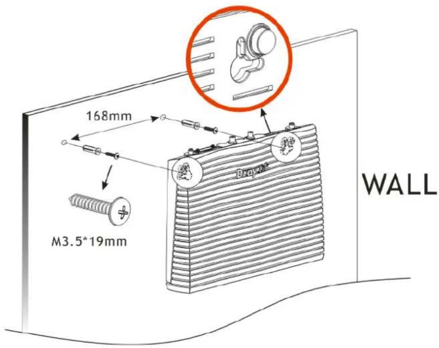
Vigor router has keyhole type mounting slots on the underside.
-
Drill two holes on the wall. The distance between the holes shall be 168mm.
-
Fit screws into the wall using the appropriate type of wall plug.
text_image
168mm M3.5*19mm DRAGON WALL
Info
The recommended drill diameter shall be 6.5mm (1/4").
- When you finished about procedure, the router has been mounted on the wall firmly.
I-2-3 Installing USB Printer to Vigor Router
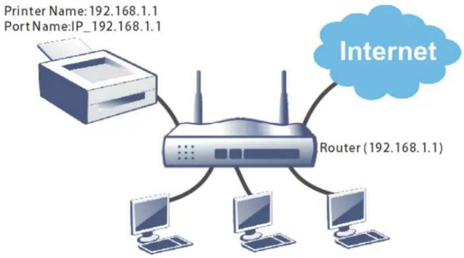
You can install a printer onto the router for sharing printing. All the PCs connected this router can print documents via the router. The example provided here is made based on Windows 7. For other Windows system, please visit www.DrayTek.com.
flowchart
graph TD
    A["Printer Name: 192.168.1.1\nPort Name: IP_192.168.1.1"] --> B["Router (192.168.1.1)"]
    B --> C["Computer 1"]
    B --> D["Computer 2"]
    B --> E["Computer 3"]
    B --> F["Computer 4"]
    B --> G["Internet"]
Before using it, please follow the steps below to configure settings for connected computers (or wireless clients).
- Connect the printer with the router through USB/parallel port.
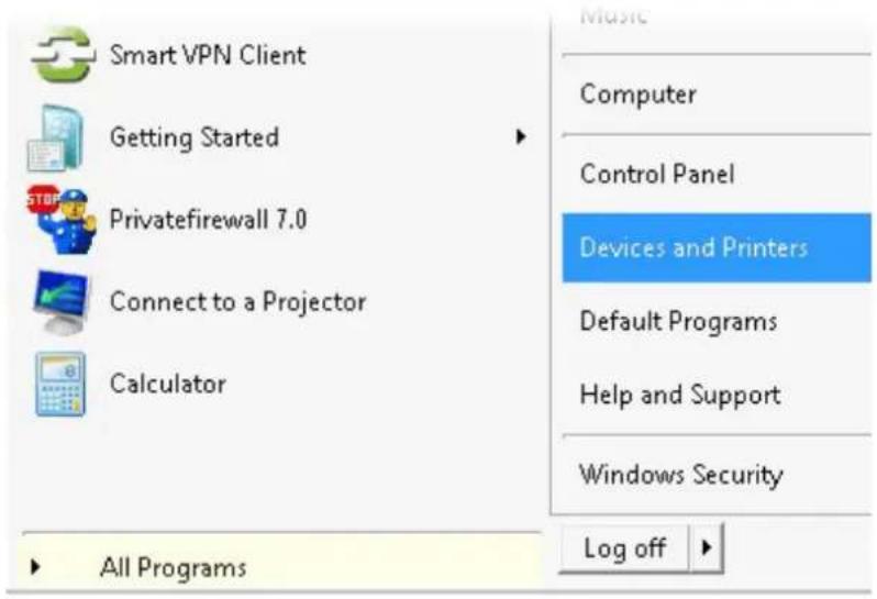
- Open All Programs>>Getting Started>>Devices and Printers.
text_image
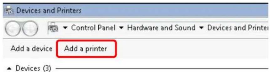
Smart VPN Client Getting Started Privatefirewall 7.0 Connect to a Projector Calculator All Programs Music Computer Control Panel Devices and Printers Default Programs Help and Support Windows Security Log off- Click Add a printer.
text_image
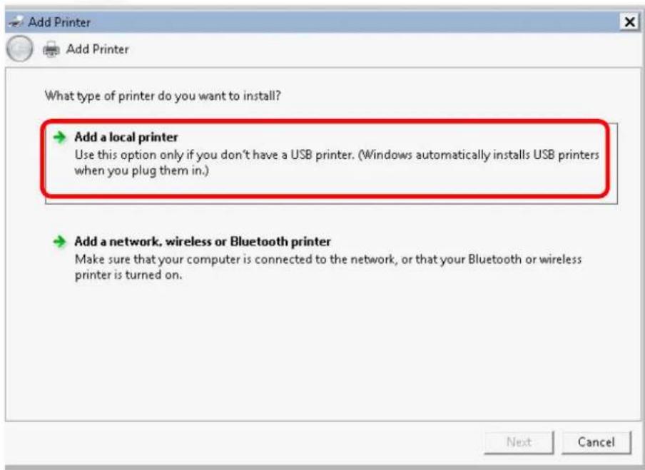
Devices and Printers Control Panel ▼ Hardware and Sound ▼ Devices and Printer Add a device Add a printer ▲ Devices (3)- A dialog will appear. Click Add a local printer and click Next.
text_image
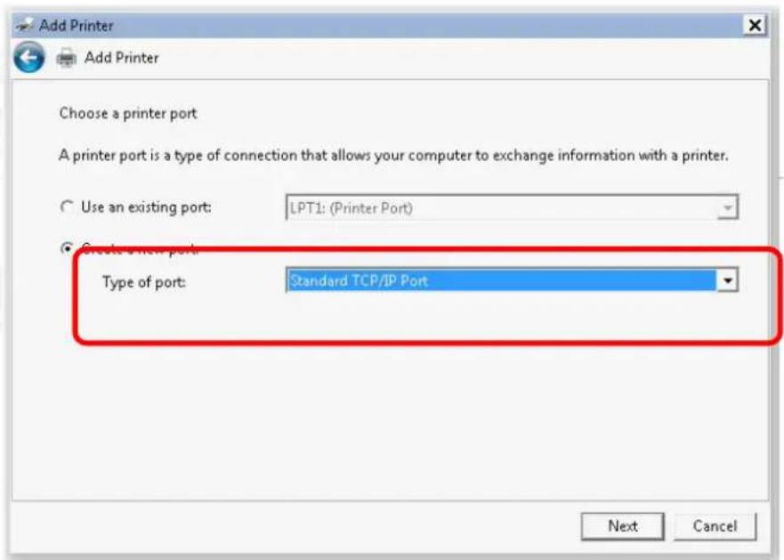
Add Printer What type of printer do you want to install? → Add a local printer Use this option only if you don't have a USB printer. (Windows automatically installs USB printers when you plug them in.) → Add a network, wireless or Bluetooth printer Make sure that your computer is connected to the network, or that your Bluetooth or wireless printer is turned on. Next Cancel- In this dialog, choose Create a new port. In the field of Type of port, use the drop down list to select Standard TCP/IP Port. Then, click Next.
text_image
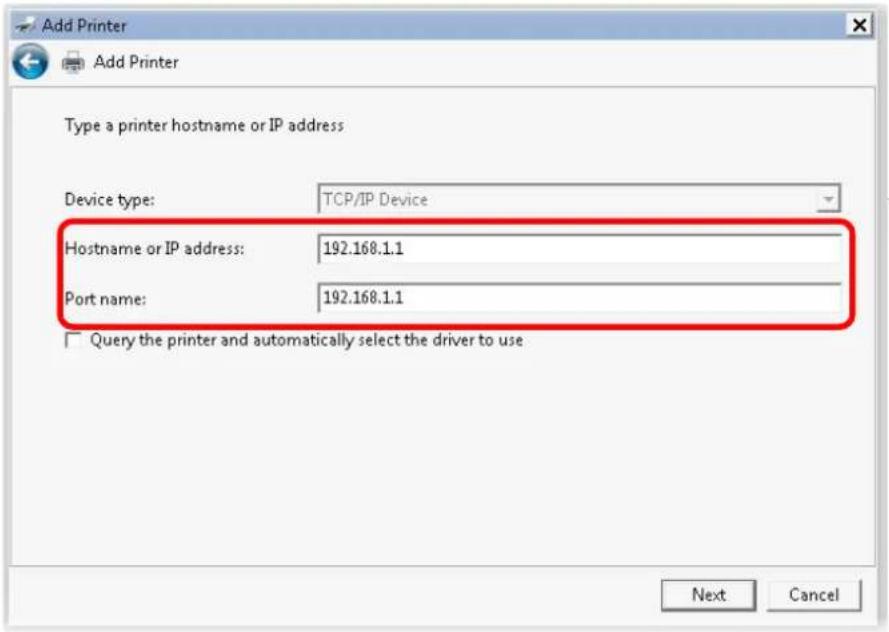
Add Printer Add Printer Choose a printer port A printer port is a type of connection that allows your computer to exchange information with a printer. Use an existing port: LPT1: (Printer Port) Create a new port Type of port: Standard TCP/IP Port Next Cancel- In the following dialog, type 192.168.1.1 (router's LAN IP) in the field of Hostname or IP Address and type 192.168.1.1 as the Port name. Then, click Next.
text_image
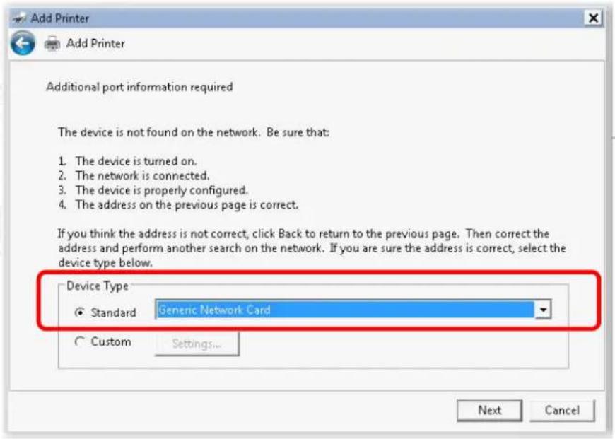
Add Printer Add Printer Type a printer hostname or IP address Device type: TCP/IP Device Hostname or IP address: 192.168.1.1 Port name: 192.168.1.1 □ Query the printer and automatically select the driver to use Next Cancel- Click Standard and choose Generic Network Card.
text_image
Add Printer Add Printer Additional port information required The device is not found on the network. Be sure that: 1. The device is turned on. 2. The network is connected. 3. The device is properly configured. 4. The address on the previous page is correct. If you think the address is not correct, click Back to return to the previous page. Then correct the address and perform another search on the network. If you are sure the address is correct, select the device type below. Device Type Standard Generic Network Card Custom Settings... Next Cancel- Now, your system will ask you to choose right name of the printer that you installed onto the router. Such step can make correct driver loaded onto your PC. When you finish the selection, click Next.
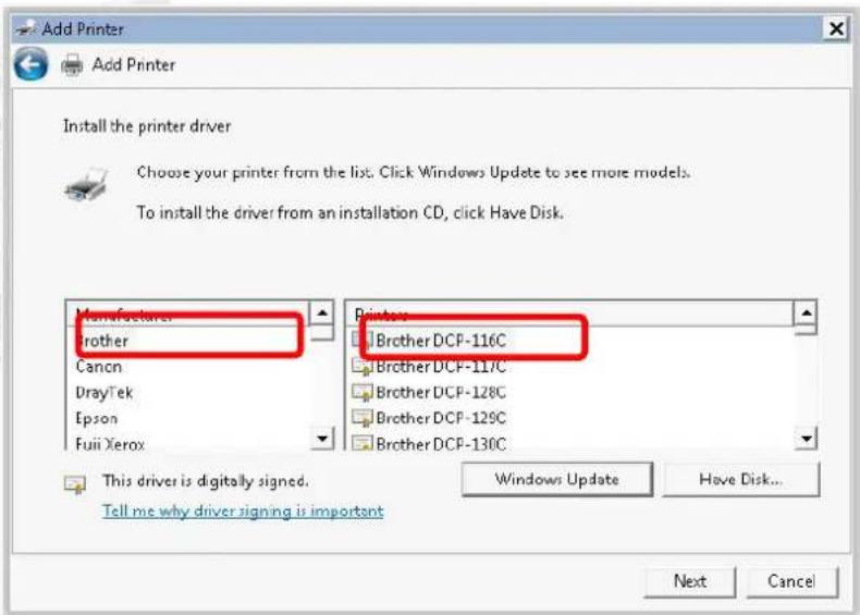
text_image
Add Printer Add Printer Install the printer driver Choose your printer from the list. Click Windows Update to see more models. To install the driver from an installation CD, click Have Disk. Manufacturer Brother Canon DrayTek Epson Fuii Xerox Printers Brother DCP-116C Brother DCP-117C Brother DCP-128C Brother DCP-129C Brother DCP-130C This driver is digitally signed. Tell me why driver signing is important Windows Update Have Disk... Next Cancel- Type a name for the chosen printer. Click Next.
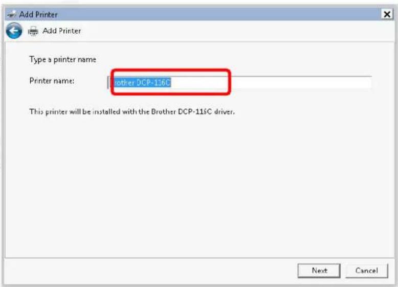
text_image
Add Printer Add Printer Type a printer name Printer name: other DCP-116C This printer will be installed with the Brother DCP-116C driver. Next Cancel- Choose Do not share this printer and click Next.
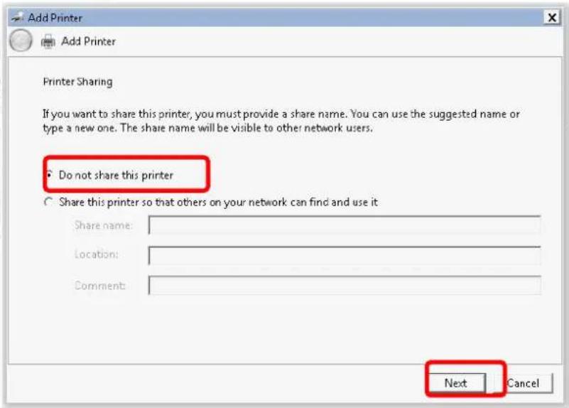
text_image
Add Printer Add Printer Printer Sharing If you want to share this printer, you must provide a share name. You can use the suggested name or type a new one. The share name will be visible to other network users. Do not share this printer Share this printer so that others on your network can find and use it Share name: Location: Comment: Next Cancel- Then, in the following dialog, click Finish.
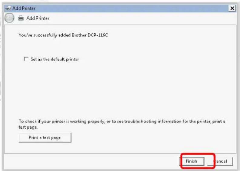
text_image
Add Printer Add Printer You've successfully added Brother DCP-116C □ Set as the default printer To check if your printer is working properly, or to see troubleshooting information for the printer, print a test page. Print a test page Finish Cancel- The new printer has been added and displayed under Printers and Faxes. Click the new printer icon and click Printer server properties.
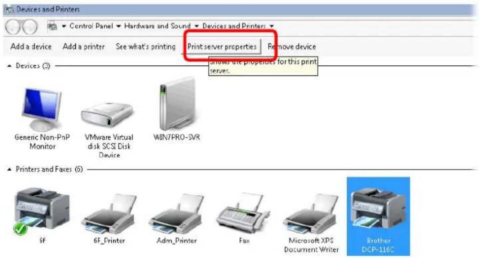
text_image
Add a device Add a printer See what's printing Print server properties Remove device ▲ Devices (3) shows the properties for this print server. Genetic Non-PnP Monitor VMware Virtual disk SCSI Device WIN/PRO-SVR ▲ Printers and Faxes (6) 6F 6F_Printer Adm_Printer Fax Microsoft XP$ Document Writer Brother DCP-116C- Edit the property of the new printer you have added by clicking Configure Port.
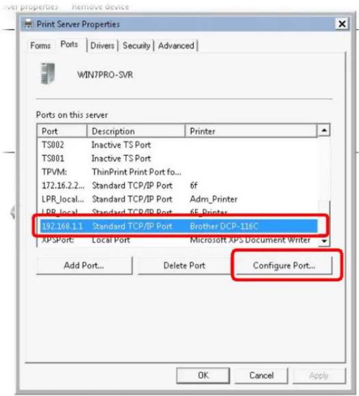
text_image
Print Server Properties Forms | Ports | Drivers | Security | Advanced | WIN7PRO-SVR Ports on this server Port Description Printer TS002 Inactive TS Port TS001 Inactive TS Port TPVM: ThinPrint Print Port fo... 172.16.2.2... Standard TCP/IP Port 6f LPR_local... Standard TCP/IP Port Adm_Printer LPR_local... Standard TCP/IP Port 6F_Printer 192.168.1.1 Standard TCP/IP Port Brother DCP-116C XPSPort: Local Port Microsoft XPS Document Writer Add Port... Delete Port Configure Port... OK Cancel Apply- Select "LPR" on Protocol, type p1 (number 1) as Queue Name. Then click OK. Next please refer to the red rectangle for choosing the correct protocol and LPR name.
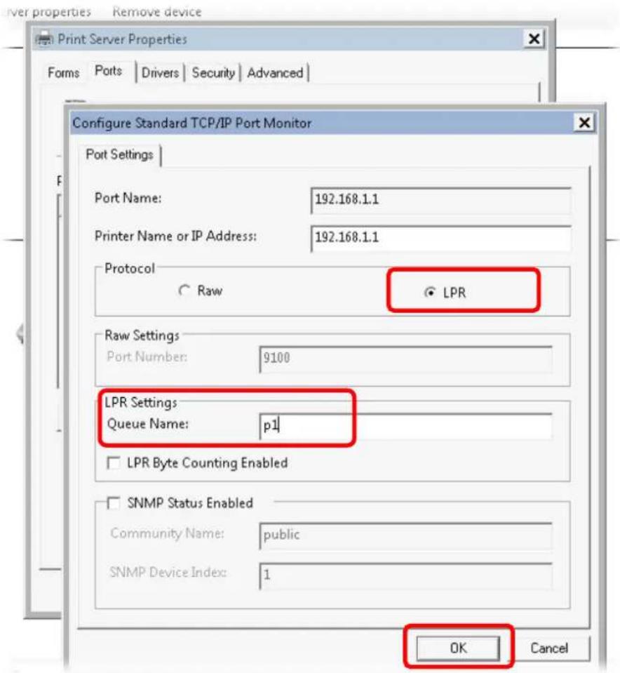
text_image
Printer properties Remove device Print Server Properties Forms Ports Drivers Security Advanced Configure Standard TCP/IP Port Monitor Port Settings Port Name: 192.168.1.1 Printer Name or IP Address: 192.168.1.1 Protocol Raw LPR Raw Settings Port Number: 9100 LPR Settings: Queue Name: p1 LPR Byte Counting Enabled SNMP Status Enabled Community Name: public SNMP Device Index: 1 OK CancelThe printer can be used for printing now. Most of the printers with different manufacturers are compatible with vigor router.

Info
Some printers with the fax/scanning or other additional functions are not supported.
Vigor router supports printing request from computers via LAN ports but not WAN port.
I-3 Accessing Web Page
- Make sure your PC connects to the router correctly.
You may either simply set up your computer to get IP dynamically from the router or set up the IP address of the computer to be the same subnet as the default IP address of Vigor router 192.168.1.1. For the detailed information, please refer to the later section - Trouble Shooting of the guide.
- Open a web browser on your PC and type http://192.168.1.1. The following window will be open to ask for username and password.
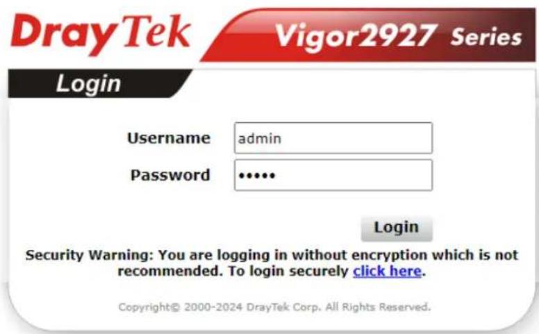
text_image
DrayTek Vigor2927 Series Login Username admin Password ••••• Login Security Warning: You are logging in without encryption which is not recommended. To login securely click here. Copyright© 2000-2024 DrayTek Corp. All Rights Reserved.-
Please type "admin/admin" as the Username/Password and click Login.
-
Next, the following page will appear. You must change the login password before accessing the web user interface. Please set a password with the highest level of strength for network security.
For security reason, you must change the password before proceeding to the router webpage
New Password
| Password | ********** |
| Confirm Password | ********** |
Password Strength:
Strong password requirements:
- Minimal length is 8 characters.
- Must use at least 1 Upper and 1 lower character.
- Must use at least 1 numeric or special character.
- The Password cannot contain only the character "z".
OK

Info
If you fail to access to the web configuration, please go to "Trouble Shooting" for detecting and solving your problem.
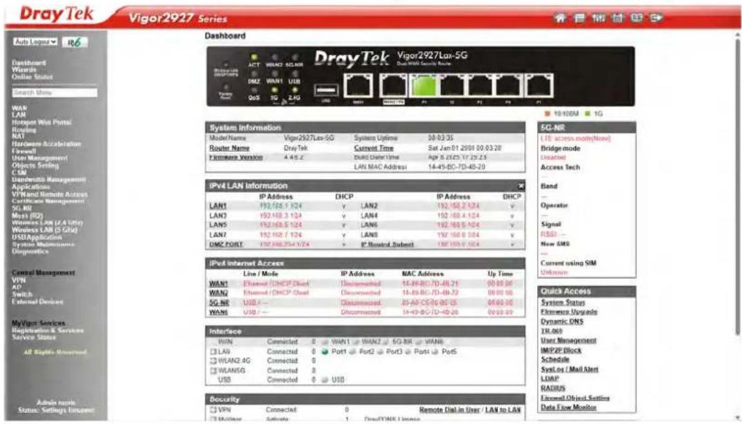
- Now, the Main Screen will appear. Take Vigor2927Lax-5G as an example.
text_image
DrayTek Vigor2927 Las-5G DrayTek Vigor2927 Las-5G System Information Model Name Vignr2927 Las-5G System Update 30-03:35 Router Name Dray Tek Current Time Sat Jun 01 2001 00 03:28 Firmware Version 4.45.2 Disk Diver User Date Age 8.2625.17.25.23 LAN MAC Address 14-45-BC-TD-40-20 IPV4 LAN Information IP Address DHCP IP Address DHCP LAN1 192.168.1 1/24 v LAN2 192.168.2 1/24 v LAN3 192.168.3 1/24 v LAN4 192.168.4 1/24 v LAN5 192.168.5 1/24 v LAN6 192.168.6 1/24 v LAN7 192.168.7 1/24 v LAN8 192.168.8 1/24 v DMZ FORT 192.168.9 1/24 v IP Hosted Submit 192.168.0 1/24 v IPV4 Internet Access Line / Mode IP Address MAC Address Up Time WAN1 Ethernet / DHCP Client Disconnected 14-49-BC-TD-49.71 00:00:00 WAN2 Ethernet / DHCP Chat Disconnected 18-85-BC-TD-49.72 00:00:00 5G NR USB / Disconnected 03-AF-CS-5G-05 35 06:00:00 WAN6 USB / Disconnected 14-43-BC-TD-43.26 00:00:00 Interface WIN Connected 0 WAN1 WAN2 5G-NR WAN6 □ LAN Connected 0 Port1 Port2 Port3 Port4 Port5 □ WLAN2.4G Connected 0 □ WLAN5G Connected 0 USB Connected 0 USD Bocurity □ VPN Connected 0 Remote Dial in User / LAN to LAN Monitoring Admate 1 DashTONE License SG-NR LTE access mode[None] Bridge mode Circuit Access Tech Band Operator Signal RSSI - New SMS Current using SIM Unknown Quick Access System Status Firmware Upgrade Dynamic DNS TR.065 User Management IMP/P/Dlock Schedule SysLog / Mail Alert LDAP RADUS Forward Object Settings Data Flow Monitor
Info
The home page will be different slightly in accordance with the type of the router you have.
- The web page can be logged out according to the chosen condition. The default setting is Auto Logout, which means the web configuration system will logout after 5 minutes without any operation. Change the setting for your necessity.

text_image
Auto Logout Auto Logout Off 1 min 3 min 5 min 10 minI-4 Dashboard
Dashboard shows the connection status including System Information, IPv4 Internet Access, IPv6 Internet Access, Interface (physical connection), Security and Quick Access.
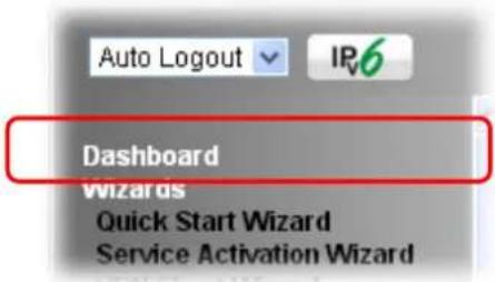
Click Dashboard from the main menu on the left side of the main page.
text_image
Auto Logout IP6 Dashboard Wizards Quick Start Wizard Service Activation WizardA web page with default selections will be displayed on the screen. Refer to the following figure:
Dashboard

text_image
DrayTek Vigor2927Lax-5G Dual-WAN Security Router Windows LAN ON/OCT TYPE ACT WAN2 5G-NR DMZ WAN1 USB CoS 5G 2.4G Factory Reset USB WAN1 WAN2 IPG P1 P2 P3 P4 P5System Information
| Model Name | Vigor2927Lax-5G | System Uptime | 00 52:15 |
| Router Name | DrayTek | Current Time | Sat Jan 01 2000 00 52:07 |
| Firmware Version | 4.4.6.2 | Build Data/Time | Apr 8 2025 17:25:23 |
| LAN MAC Address | 14-49-BC-7D-4B-20 |
IPv4 LAN Information
| IP Address | DHCP | IP Address | DHCP | ||
| LAN1 | 192.168.1 1/24 | v | LAN2 | 192.168.2 1/24 | v |
| LAN3 | 192.168.3 1/24 | v | LAN4 | 192.168.4 1/24 | v |
| LAN5 | 192.168.5 1/24 | v | LAN6 | 192.168.6 1/24 | v |
| LAN7 | 192.168.7 1/24 | v | LAN8 | 192.168.8 1/24 | v |
| DMZ PORT | 192.168.264 1/24 | v | IP Routed Subnet | 192.168.0 1/24 | v |
IPv4 Internet Access
| Line / Mode | IP Address | MAC Address | Up Time | |
| WAN1 | Ethernet / DHCP Client | Disconnected | 14-49-BC-7D-4B-21 | 00:00:00 |
| WAN2 | Ethernet / DHCP Client | Disconnected | 14-49-BC-7D-4B-22 | 00:00:00 |
| 5G-NR | USB / — | Disconnected | 00-A0-C6-00-00-55 | 00:00:00 |
| WAN6 | USB / — | Disconnected | 14-49-BC-7D-4B-26 | 00:00:00 |
Interface
| WAN | Connected | 0 | WAN1 | WAN2 | 5G-NR | WAN6 |
| LAN | Connected | 0 | Port1 | Port2 | Port3 | Port4 |
| WLAN2.4G | Connected | 0 | ||||
| WLAN5G | Connected | 0 | ||||
| USB | Connected | 0 | USB |
Security
| VPN | Connected | 0 | Remote Dial in User / LAN to LAN |
| MyVincor | Activate | 1 | DravDDNS License |
10/100M 1G
5G-NR
LTE access mode[None]
Bridge mode
Disabled
Access Tech
LTE
Band
Operator
单位:元
Signal
RSSI:
RSRP: -122 dBm (Poor)
RSRO:
New SMS
Current using SIM
Unknown
Quick Access
System Status
Firmware Upgrade
Dynamic DNS
TR-069
User Management
IM/P2P Block
Schedule
SysLog / Mail Alert
LDAP
RADIUS
Firewall Object Setting
I-4-1 Virtual Panel
On the top of the Dashboard, a virtual panel (simulating the physical panel of the router) displays the physical interface connection. It will be refreshed every five seconds. When you move and click the mouse cursor on LEDs (except ACT), USB ports, WAN2/P6, or LAN1-LAN5 (P1\~P5), related web setting page will be open for you to configure if required.

text_image
DrayTek Vigor2927Lac Dual-WAN Security Router Wireless LAN ON/OFF/WPS ACT WAN2 LTE DMZ WAN1 USB QoS 5G 2.4G Factory Reset USB WAN1 WAN2 / PS P1 P2 P3 P4 P5| Port Color | Description | |
| WAN2/ P6 | Black | WAN2 port is disconnected. |
| Green WAN2 | port is connected at 1 Gbps. | |
| Orange | WAN2 port is connected at 10/ 100 Mbps. | |
| P1 ~ P5 | Black | LAN port is disconnected. |
| Green LAN port is connected at 1 Gbps. | ||
| Orange | LAN port is connected at 10/ 100 Mbps. | |
For detailed information about the LED display, refer to I-1-1 LED Indicators and Connectors.
I-4-2 Name with a Link
A name with a link (e.g., Router Name, Current Time, WAN1\~6 and etc.) below means you can click it to open the configuration page for modification.
| System Information | |||
| Model Name | Vigor2927Lax-5G | System Optime | 00:52:15 |
| Router Name | DrayTek | Current Time | Sat Jan 01 2000 00:52:07 |
| Firmware Version | 4.4.6.2 | Build Date/Time | Apr 8 2025 17:25:23 |
| LAN MAC Address | 14-49-BC-7D-4B-20 | ||
| IPv4 LAN Information | |||||
| IP Address | DHCP | IP Address | DHCP | ||
| LAN1 | 192.168.1.1/24 | v | LAN2 | 192.168.2.1/24 | v |
| LAN3 | 192.168.3.1/24 | v | LAN4 | 192.168.4.1/24 | v |
| LAN5 | 192.168.5.1/24 | v | LAN6 | 192.168.6.1/24 | v |
| LAN7 | 192.168.7.1/24 | v | LAN8 | 192.168.8.1/24 | v |
| DMZ PORT | 192.168.254.1/24 | v | IP Routed Subnet | 192.168.0.1/24 | v |
| IPv4 Internet Access | ||||
| Line / Mode | IP Address | MAC Address | Up Time | |
| WAN1 | Ethernet / DHCP Client | Disconnected | 14-49-BC-7D-4B-21 | 00:00:00 |
| WAN2 | Ethernet / DHCP Client | Disconnected | 14-49-BC-7D-4B-22 | 00:00:00 |
| 5G-NR | USB / --- | Disconnected | 00-A0-C6-00-00-55 | 00:00:00 |
| WAN6 | USB / --- | Disconnected | 14-49-BC-7D-4B-26 | 00:00:00 |
I-4-3 Status for LTE
It is a short table which displays current status for
Vigor2927L/ Vigor2927Lac/ V2927L-5G/ V2927Lax-5G including access mode used, access tech adopted, band usage, operator, strength of signal and notification of new SMS received.
| 5G-NR |
| LTE access mode[None] |
| Bridge mode |
| Disabled |
| Access Tech |
| LTE |
| Band |
| LTE |
| Operator |
| ... |
| Signal |
| RSSI: --- |
| New SMS |
| ... |
| Current using SIM |
| Unknown |
I-4-4 Quick Access for Common Used Menu
All the menu items can be accessed and arranged orderly on the left side of the main page for your request. However, some important and common used menu items which can be accessed in a quick way just for convenience.
Look at the right side of the Dashboard. You will find a group of common used functions grouped under Quick Access.
| Quick Access |
| System Status |
| Firmware Upgrade |
| Dynamic DNS |
| TR-069 |
| User Management |
| IM/P2P Block |
| Schedule |
| SysLog / Mail Alert |
| LDAP |
| RADIUS |
| Firewall Object Setting |
| Data Flow Monitor |
The function links of System Status, Dynamic DDNS, TR-069, User Management, IM/ P2P Block, Schedule, Syslog/ Mail Alert, LDAP, RADIUS, Firewall Object Setting and Data Flow Monitor are displayed here. Move your mouse cursor on any one of the links and click on it. The corresponding setting page will be open immediately.
In addition, quick access for VPN security settings such as Remote Dial-in User and LAN to LAN are located on the bottom of this page. Scroll down the page to find them and use them if required.
| IPv4 LAN Information | |||||
| IP Address | DHCP | IP Address | DHCP | ||
| LAN1 | 192.168.1.1/24 | v | LAN2 | 192.168.2 1/24 | v |
| LAN3 | 192.168.3.1/24 | v | LAN4 | 192.168.4 1/24 | v |
| LAN5 | 192.168.5.1/24 | v | LAN6 | 192.168.6 1/24 | v |
| LAN7 | 192.168.7.1/24 | v | LAN8 | 192.168.8 1/24 | v |
| DMZ PORT | 192.168.254.1/24 | v | IP_Routed_Subnet | 192.168.0 1/24 | v |
| IPv4 Internet Access | ||||
| Line / Mode | IP Address | MAC Address | Up Time | |
| WAN1 | Ethernet / DHCP Client | Disconnected | 14-49-BC-6D-C3-09 | 00:00:00 |
| WAN2 | Ethernet / DHCP Client | Disconnected | 14-49-BC-6D-C3-0A | 00:00:00 |
| 5G-NR | USB / --- | Disconnected | 00-A0-C6-00-00-55 | 00:00:00 |
| WAN6 | USB / --- | Disconnected | 14-49-BC-6D-C3-0E | 00:00:00 |
| Interface | |||||||
| WAN | Connected | 0 | WAN1 | WAN2 | 5G-NR | WAN6 | |
| LAN | Connected | 0 | Port1 | Port2 | Port3 | Port4 | Port5 |
| WLAN2.4G | Connected | 0 | |||||
| WLAN5G | Connected | 0 | |||||
| USB | Connected | 0 | USB | ||||
| Security | ||
| VPN | Connected: | 0 Remote Dial-in User / LAN to LAN |
| MyVigor | Activate: | 0 |
| DoS | Attack Detected: | |
| RootCA | ||
| System Resource | |
| CPU Usage | 2% |
| Memory Usage | 88% |
Note that there is a plus ( ) icon located on the left side of VPN/LAN. Click it to review the VPN connection(s) used presently.

text_image
Interface WAN Connected 0 WAN1 WAN2 5G-NR WAN6 + LAN Connected 0 Port1 Port2 Port3 Port4 Port5 WLAN2-4G Connected 0 + WLAN5G Connected 0 USB Connected 0 USBHost connected physically to the router via LAN port(s) will be displayed with green circles in the field of Connected.
All of the hosts (including wireless clients) displayed with Host ID, IP Address and MAC address indicates that the traffic would be transmitted through LAN port(s) and then the WAN port. The purpose is to perform the traffic monitor of the host(s).
I-4-5 GUI Map
text_image
GUI MapAll the functions the router supports are listed with table clearly in this page. Users can click the function link to access into the setting page of the function for detailed configuration. Click the icon on the top of the main screen to display all the functions.
GUI Map
| Dashboard | 5G-NR | ||
| Wizards | General Settings | ||
| Quick Start Wizard | SMS Inbox | ||
| Service Activation Wizard | Send SMS | ||
| VPN Client Wizard | SMS Gateway | ||
| VPN Server Wizard | Router Commands | ||
| Wireless Wizard | Status | ||
| Mesh Wizard | RSRP Graph | ||
| Online Status | Mesh (R2) | ||
| Physical Connection | Mesh Setup | ||
| Virtual WAN | Mesh Status | ||
| Mesh Discovery | |||
| WAN | Basic Config Sync | ||
| General Setup | Advanced Config Sync | ||
| Internet Access | Support List | ||
| Multi-VLAN | Wireless LAN (2.4 GHz) | ||
| WAN Budget | General Setup | ||
| LAN | Security | ||
| General Setup | Access Control | ||
| VLAN | WPS | ||
| Bind IP to MAC | Advanced Setting | ||
| LAN Port Mirror | Station Control | ||
| Wired 802.1X | Bandwidth Management | ||
| Link Aggregation | AP Discovery | ||
| Hotspot Web Portal | Airtime Fairness | ||
| Profile Setup | Band Steering | ||
| Users Information | Roaming | ||
I-4-6 Web Console
text_image
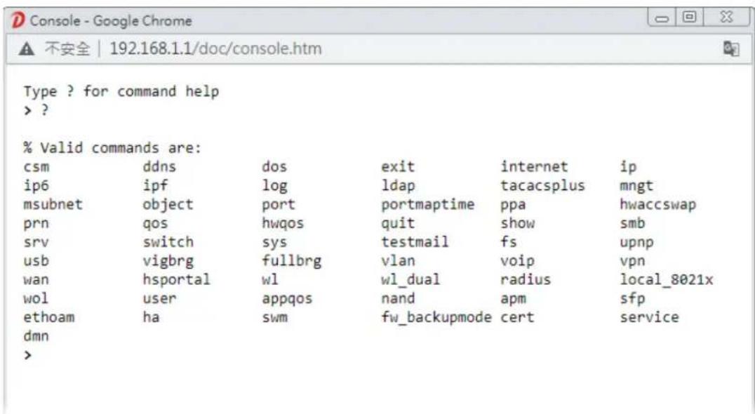
Web ConsoleIt is not necessary to use the telnet command via DOS prompt. The changes made by using web console have the same effects as modified through web user interface. The functions/ settings modified under Web Console also can be reviewed on the web user interface.
Click the Web Console icon on the top of the main screen to open the following screen.
text_image
% Valid commands are: csm ddns dos exit internet ip ip6 ipf log ldap tacacsplus mngt msubnet object port portmaptime ppa hwaccswap prn qos hwqos quit show smb srv switch sys testmail fs upnp usb vigbrg fullbrg vlan voip vpn wan hsportal wl wl_dual radius local_8021x wol user appqos nand apm sfp ethoam ha swm fw_backupmode cert service dmn >I-4-7 Config Backup
text_image
Config BackupThere is one way to store current used settings quickly by clicking the Config Backup icon. It allows you to backup current settings as a file. Such configuration file can be restored by using System Maintenance>>Configuration Backup.
I-4-8 Manual Download

text_image
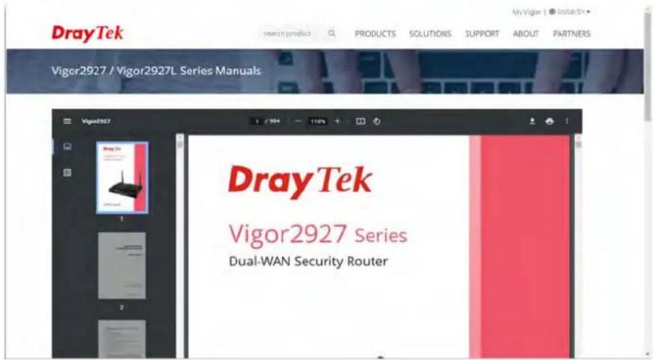
Manual DownloadClick this icon to open online user's guide of Vigor router. This document offers detailed information for the settings on web user interface.
text_image
DrayTek MyVigor | Search Product PRODUCTS SOLUTIONS SUPPORT ABOUT PARTNERS Vigor2927 / Vigor2927L Series Manuals Vigor2927 DrayTek Vigor2927 Series Dual-WAN Security RouterI-4-9 Logout
text_image
LogoutClick this icon to exit the web user interface.
I-4-10 Online Status
Online Status
Physical Connection
Virtual WAN
I-4-10-1 Physical Connection
Such page displays the physical connection status such as LAN connection status, WAN connection status, and so on.
Physical Connection for IPv4 Protocol
Online Status
| Physical Connection System Uptime: 4days 23:49:54 | ||||||
| IPv4 | IPv6 | |||||
| LAN Status | ||||||
| IP Address | TX Packets | RX Packets | Router Primary DNS: | Router Secondary DNS: | ||
| 192.168.1.1 | 289,820 | 206,065 | 8.8.8.8 | 8.8.4.4 | ||
| WAN 1 Status >> Renew | ||||||
| Enable | Line | Name | Mode | Up Time | ||
| Yes | Ethernet | DHCP Client | 00:00:00 | |||
| IP | GW IP | TX Bytes | TX Rate(bps) | RX Bytes | RX Rate(bps) | |
| --- | --- | 0 (B) | 0 | 0 (B) | 0 | |
| WAN 2 Status >> Renew | ||||||
| Enable | Line | Name | Mode | Up Time | ||
| Yes | Ethernet | DHCP Client | 00:00:00 | |||
| IP | GW IP | TX Bytes | TX Rate(bps) | RX Bytes | RX Rate(bps) | |
| --- | --- | 0 (B) | 0 | 0 (B) | 0 | |
| WAN 3 Status | ||||||
| Enable | Line | Name | Mode | Up Time | ||
| No | Wireless 2.4G | --- | 00:00:00 | |||
| IP | GW IP | TX Bytes | TX Rate(bps) | RX Bytes | RX Rate(bps) | |
| --- | --- | 0 (B) | 0 | 0 (B) | 0 | |
| SSID Channel Security PHY Mode Rate Signal Strength 6 Disable --- 0% | ||||||
| WAN 4 Status | ||||||
| Enable | Line | Name | Mode | Up Time | ||
| No | Wireless 5G | --- | 00:00:00 | |||
| IP | GW IP | TX Bytes | TX Rate(bps) | RX Bytes | RX Rate(bps) | |
| --- | --- | 0 | 0 | 0 | 0 | |
| SSID Channel Security PHY Mode Rate Signal Strength 36 Disable --- 0% | ||||||
| LTE Status | ||||||
| Enable | Line | Name | Mode | Up Time | Signal | |
| Yes | USB | --- | 00:00:00 | |||
| IP | GW IP | TX Bytes | TX Rate(bps) | RX Bytes | RX Rate(bps) | |
| --- | --- | 0 | 0 | 0 | 0 | |
| WAN 6 Status | ||||||
| Enable | Line | Name | Mode | Up Time | Signal | |
| Yes | USB | --- | 00:00:00 | |||
| IP | GW IP | TX Bytes | TX Rate(bps) | RX Bytes | RX Rate(bps) | |
Physical Connection for IPv6 Protocol
| Physical Connection System Uptime: 4days 23:50:56 | |||
| IPv4 | IPv6 | ||
| LAN Status | |||
| IP Address | |||
| FE80::1649:BCFF:FE02:37E8/64 (Link) | |||
| TX Packets | RX Packets | TX Bytes | RX Bytes |
| 1,888 | 2,716 | 147,336 | 372,789 |
| WAN1 IPv6 Status | |||
| Enable | Mode | Up Time | |
| No | Offline | --- | |
| IP | Gateway IP | ||
| --- | --- | ||
| WAN2 IPv6 Status | |||
| Enable | Mode | Up Time | |
| No | Offline | --- | |
| IP | Gateway IP | ||
| --- | --- | ||
| WAN3 IPv6 Status | |||
| Enable | Mode | Up Time | |
| No | Offline | --- | |
| IP | Gateway IP | ||
| --- | --- | ||
| WAN4 IPv6 Status | |||
| Enable | Mode | Up Time | |
| No | Offline | --- | |
| IP | Gateway IP | ||
| --- | --- | ||
| LTE IPv6 Status | |||
| Enable | Mode | Up Time | |
| No | Offline | --- | |
| IP | Gateway IP | ||
| --- | --- | ||
| WAN6 IPv6 Status | |||
| Enable | Mode | Up Time | |
| No | Offline | --- | |
| IP | Gateway IP | ||
| --- | --- | ||
Detailed explanation (for IPv4) is shown below:
| Item Description | |
| LAN Status | Primary DNS-Displays the primary DNS server address for WAN interface.Secondary DNS -Displays the secondary DNS server address for WAN interface.IP Address-Displays the IP address of the LAN interface.TX Packets-Displays the total transmitted packets at the LAN interface.RX Packets-Displays the total received packets at the LAN interface. |
| WAN1/WAN2/WAN3/WAN4/WAN5/WAN6 Status | Enable - Yes in red means such interface is available but not enabled. Yes in green means such interface is enabled.Mode - Displays the type of WAN connection (e.g., PPPoE).Up Time - Displays the total uptime of the interface.IP - Displays the IP address of the WAN interface.GW IP - Displays the IP address of the default gateway.TX Packets - Displays the total transmitted packets at theWAN interface.TX Rate - Displays the speed of transmitted octets at the WAN interface.RX Packets - Displays the total number of received packets at the WAN interface.RX Rate - Displays the speed of received octets at the WAN interface. |
Detailed explanation (for IPv6) is shown below:
| Item Description | |
| LAN Status | IP Address- Displays the IPv6 address of the LAN interface..TX Packets-Displays the total transmitted packets at the LAN interface.RX Packets-Displays the total received packets at the LAN interface.TX Bytes - Displays the speed of transmitted octets at the LAN interface.RX Bytes - Displays the speed of received octets at the LAN interface. |
| WAN IPv6 Status | Enable - No in red means such interface is available but not enabled. Yes in green means such interface is enabled. No in red means such interface is not available.Mode - Displays the type of WAN connection (e.g., TSPC).Up Time - Displays the total uptime of the interface.IP - Displays the IP address of the WAN interface.Gateway IP - Displays the IP address of the default gateway. |

Info
The words in green mean that the WAN connection of that interface is ready for accessing Internet; the words in red mean that the WAN connection of that interface is not ready for accessing Internet.
I-4-10-2 Virtual WAN
Such page displays the virtual WAN connection information.
Virtual WAN are used by TR-069 management, VoIP service and so on.
The field of Application will list the purpose of such WAN connection.
I-5 Quick Start Wizard
Quick Start Wizard can help you to deploy and use the router easily and quickly.
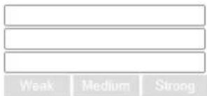
Go to Wizards>>Quick Start Wizard. The first screen of Quick Start Wizard is entering login password. After typing the password, please click Next.
Wizards >> Quick Start Wizard
Enter login password
Please enter an alpha-numeric string as your Password (Max 83 characters)
Old Password
New Password
Confirm Password
Password Strength:
text_image
Weak Medium StrongPassword Requirements:
-
Must be a minimum of 8 characters.
-
Contain at least three of the following for a strong password:
uppercase letters
lowercase letters
numbers
symbols
Hint: If you want to keep the password unchanged, leave the password blank and press "Next" button to skip this process.

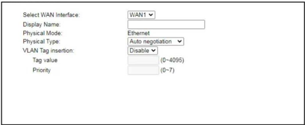
On the next page as shown below, please select the WAN interface that you use. If Ethernet interface is used, please choose WAN1/WAN2; if 3G USB modem is used, please choose WAN3 or WAN4. Then click Next for next step.
Wizards >> Quick Start Wizard
Select WAN Interface
Select WAN Interface:
Display Name:
Physical Mode:
Physical Type:
VLAN Tag insertion:
Tag value
Priority
WAN1

Ethernet
Auto negotiation
Disable
(0\~4095)
(0\~7)

Note: The available WAN interfaces (WAN#, 5G-NR, LTE) will vary according to the model you have.
WAN1, WAN2, WAN3, WAN4, WAN5 and WAN6 will bring up different configuration page. Refer to the following for detailed information.
I-5-1 For WAN1/WAN2 (Ethernet)
WAN1/ WAN2 can be configured for physical mode of Ethernet.
Wizards >> Quick Start Wizard
Select WAN Interface
text_image
Select WAN Interface: Display Name: Physical Mode: Physical Type: VLAN Tag insertion: Tag value Priority WAN1 Ethernet Auto negotiation Disable (0~4095) (0~7)< Back Next > Finish Cancel
Available settings are explained as follows:
| Item Description | |
| Display Name | Enter a name for the router. |
| Physical Type | This setting is available when Ethernet is selected as Physical Mode. In general, Auto negotiation is suggested. |
| VLAN Tag insertion | The settings configured in this field are available when Ethernet is selected as Physical Mode. Disable - Disable the function of VLAN with tag. Enable - Enable the function of VLAN with tag. The router will add specific VLAN number to all packets on the WAN while sending them out. Please Enter the tag value and specify the priority for the packets sending by WAN. Tag value - Enter the value as the VLAN ID number. The range is form 0 to 4095. Priority - Enter the packet priority number for such VLAN. The range is from 0 to 7. |
On the next page as shown below, please select the appropriate Internet access type according to the information from your ISP. For example, you should select PPPoE mode if the ISP provides you PPPoE interface. Then click Next for next step.
Ethernet WAN1/2 - PPPoE
- Choose WAN1 as the WAN Interface and choose Ethernet as the Physical Mode. Click the Next button. The following page will be open for you to specify Internet Access Type.
Quick Start Wizard
Connect to Internet

text_image
WAN 1 Select one of the following Internet Access types provided by your ISP. ● PPPoE ○ PPTP ○ L2TP ○ Static IP ○ DHCP < Back Next > Finish Cancel- Click PPPoE as the Internet Access Type. Then click Next to continue.
Quick Start Wizard
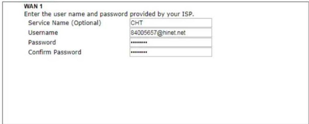
PPPoE Client Mode
text_image
WAN 1 Enter the user name and password provided by your ISP. Service Name (Optional) CHT Username 84005657@hinet.net Password .......... Confirm Password ..........
Available settings are explained as follows:
| Item Description | |
| Service Name(Optional) | Enter the description of the specific network service. |
| Username | Assign a specific valid user name provided by the ISP.Note:The maximum length of the user name you can set is 63 characters. |
| Password | Assign a valid password provided by the ISP.Note:The maximum length of the password you can set is 62 characters. |
| Confirm Password | Re-enter the password. |
| Back | Click it to return to previous setting page. |
| Next | Click it to get into the next setting page. |
| Cancel | Click it to give up the quick start wizard. |
- Please manually enter the Username/ Password provided by your ISP. Click Next for viewing summary of such connection.
Wizards >> Quick Start Wizard
Please confirm your settings:
WAN Interface:
WAN1
Physical Mode:
Ethernet
Physical Type:
Auto negotiation
Internet Access:
PPPoE
Click Back to modify changes if necessary. Otherwise, click Finish to save the current settings and restart the Vigor router.

- Click Finish. A page of Quick Start Wizard Setup OK!!! will appear. Then, the system status of this protocol will be shown.
Quick Start Wizard Setup OK!
- Now, you can enjoy surfing on the Internet.
Ethernet WAN1/2 - PPTP/L2TP
- Choose WAN1 as the WAN Interface and choose Ethernet as the Physical Mode. Click the Next button. The following page will be open for you to specify Internet Access Type.
Quick Start Wizard
Connect to Internet
WAN 1 Select one of the following Internet Access types provided by your ISP.
- Click PPTP/L2TP as the Internet Access Type. Then click Next to continue.
Quick Start Wizard
PPTP Client Mode
WAN 1
Enter the username, password, WAN IP configuration and PPTP server IP provided by your ISP.
Username
Password
Confirm Password
WAN IP Configuration
Obtain an IP address automatically
○ Specify an IP address
IP Address
Subnet Mask
Gateway
Primary DNS
Second DNS
PPTP Server
192.168.124.14
255.255.255.0
192.168.124.1
8.8.8.8
8.8.4.4

Available settings are explained as follows:
| Item Description | |
| Username | Assign a specific valid user name provided by the ISP.Note: The maximum length of the user name you can set is 63 characters. |
| Password | Assign a valid password provided by the ISP.Note: The maximum length of the password you can set is 62 characters. |
| Confirm Password | ReEnter the password. |
| WAN IP Configuration | Obtain an IP address automatically - The router will get an IP address automatically from DHCP server.Specify an IP address - You have to type relational settings manually.IP Address - Enter the IP address.Subnet Mask - Enter the subnet mask.Gateway - Enter the IP address of the gateway.Primary DNS - Enter the primary IP address for the router.Second DNS - Enter secondary IP address for necessity in the future. |
| PPTP Server / L2TP Server | Enter the IP address of the server. |
| Back | Click it to return to previous setting page. |
| Next | Click it to get into the next setting page. |
| Cancel | Click it to give up the quick start wizard. |
- Please Enter the IP address/ mask/ gateway information originally provided by your ISP. Then click Next for viewing summary of such connection.
Wizards >> Quick Start Wizard
Please confirm your settings:
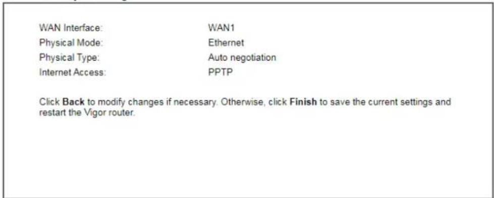
text_image
WAN Interface: WAN1 Physical Mode: Ethernet Physical Type: Auto negotiation Internet Access: PPTP Click Back to modify changes if necessary. Otherwise, click Finish to save the current settings and restart the Vigor router.
- Click Finish. A page of Quick Start Wizard Setup OK!!! will appear. Then, the system status of this protocol will be shown.
Quick Start Wizard Setup OK!
- Now, you can enjoy surfing on the Internet.
Ethernet WAN1/2 - Static IP
- Choose WAN1 as the WAN Interface and choose Ethernet as the Physical Mode. Click the Next button. The following page will be open for you to specify Internet Access Type.
Quick Start Wizard
Connect to Internet
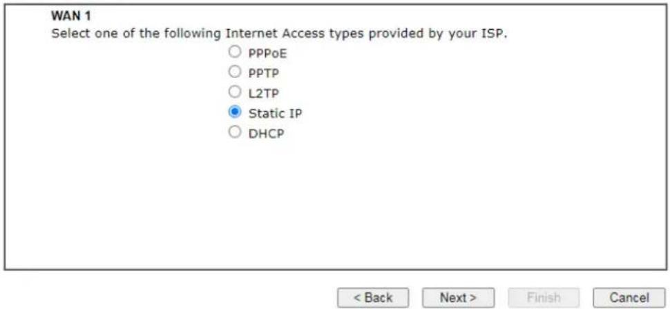
text_image
WAN 1 Select one of the following Internet Access types provided by your ISP. ○ PPPoE ○ PPTP ○ L2TP ● Static IP ○ DHCP < Back Next > Finish Cancel- Click Static IP as the Internet Access type. Simply click Next to continue.
Quick Start Wizard
Static IP Client Mode
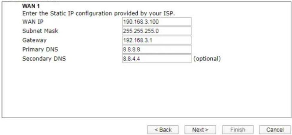
text_image
WAN 1 Enter the Static IP configuration provided by your ISP. WAN IP 190.168.3.100 Subnet Mask 255.255.255.0 Gateway 192.168.3.1 Primary DNS 8.8.8.8 Secondary DNS 8.8.4.4 (optional) < Back Next > Finish CancelAvailable settings are explained as follows:
| Item Description | |
| WAN IP | Enter the IP address. |
| Subnet Mask | Enter the subnet mask. |
| Gateway | Enter the IP address of gateway. |
| Primary DNS | Enter the primary IP address for the router. |
| Secondary DNS | Enter the secondary IP address for necessity in the future. |
| Back | Click it to return to previous setting page. |
| Next | Click it to get into the next setting page. |
| Cancel | Click it to give up the quick start wizard. |
- Please Enter the IP address information originally provided by your ISP. Then click Next for next step.
Wizards >> Quick Start Wizard
Please confirm your settings:
WAN Interface:
WAN1
Physical Mode:
Ethernet
Physical Type
Auto negotiation
Internet Access:
Static IP
Click Back to modify changes if necessary. Otherwise, click Finish to save the current settings and restart the Vigor router.

- Click Finish. A page of Quick Start Wizard Setup OK!!! will appear. Then, the system status of this protocol will be shown.
Quick Start Wizard Setup OK!
- Now, you can enjoy surfing on the Internet.
Ethernet WAN1/2 - DHCP
- Choose WAN1 as the WAN Interface and choose Ethernet as the Physical Mode. Click the Next button. The following page will be open for you to specify Internet Access Type.
Quick Start Wizard
Connect to Internet
WAN 1 Select one of the following Internet Access types provided by your ISP.
- Click DHCP as the Internet Access type. Simply click Next to continue.
Quick Start Wizard
DHCP Client Mode
WAN 1 If your ISP requires you to enter a specific host name or specific MAC address, please enter it in.


Available settings are explained as follows:
| Item Description | |
| Host Name | Enter the name of the host.Note: The maximum length of the host name you can set is 39 characters. |
| MAC | Some Cable service providers specify a specific MAC address for access authentication. In such cases you need to enter the MAC address. |
| Back | Click it to return to previous setting page. |
| Next | Click it to get into the next setting page. |
| Cancel | Click it to give up the quick start wizard. |
- After finished the settings above, click Next for viewing summary of such connection.
Wizards >> Quick Start Wizard
Please confirm your settings:
WAN Interface:
WAN1
Physical Mode:
Ethernet
Physical Type:
Auto negotiation
Internet Access:
DHCP
Click Back to modify changes if necessary. Otherwise, click Finish to save the current settings and restart the Vigor router.

- Click Finish. A page of Quick Start Wizard Setup OK!!! will appear. Then, the system status of this protocol will be shown.
Quick Start Wizard Setup OK!
- Now, you can enjoy surfing on the Internet.
I-5-2 For WAN3/WAN4 (Wireless 2.4G/Wireless 5G)
WAN3/ WAN4 shall be used for wireless (2.4G or 5G) connection.
Wireless WAN3/WAN4 - Static IP
- Choose WAN3/WAN4 as WAN Interface and choose Wireless 2.4G or Wireless 5G as the physical mode.
Quick Start Wizard
Select WAN Interface
Select WAN Interface:
Display Name:
Physical Mode:
Physical Type:
WAN3
Wireless 2.4G
Auto negotiation

or
Quick Start Wizard
Select WAN Interface
Select WAN Interface:
Display Name:
Physical Mode:
Physical Type:
WAN4
Wireless 5G
Auto negotiation

- Then, click Next for getting the following page.
Quick Start Wizard
Connect to Internet
WAN 3
Select one of the following Internet Access types.
Static IP
○ DHCP

- After click Static IP as the Internet Access type, you will get the following page. Enter the required information and click Next to continue.
Quick Start Wizard
Static IP Client Mode
WAN 3
Enter the Static IP configuration.
WAN IP
172.16.3.8
Subnet Mask
255.255.255.0
Gateway
172.16.3.7

Available settings are explained as follows:
| Item Description | |
| WAN IP | Enter the IP address. |
| Subnet Mask | Enter the subnet mask. |
| Gateway | Enter the IP address of gateway. |
| Back | Click it to return to previous setting page. |
| Next | Click it to get into the next setting page. |
| Cancel | Click it to give up the quick start wizard. |
- From the following page, enter the SSID of an existed AP as the wireless connection server for this WAN. Or click AP Discovery to find an access point as the server for this WAN interface. Click Next to continue.
Wizards >> Quick Start Wizard
Connect to Internet
WAN 3
Enter the AP configuration that router wants to connect.
SSID
MAC Address (Optional)
Channel
Security Mode
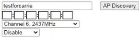
text_image
testforcarrie Channel 6, 2437MHz Disable AP Discovery
- Then, a summary of the connection will be shown on the screen.
Quick Start Wizard
Please confirm your settings:
WAN Interface:
WAN3
Physical Mode:
Wireless 2.4G
Internet Access:
Static IP
Click Back to modify changes if necessary. Otherwise, click Finish to save the current settings and restart the Vigor router.

- Click Finish. A page of Quick Start Wizard Setup OK!!! will appear. Then, the system status of this protocol will be shown.
Quick Start Wizard Setup OK!
- Now, you can enjoy surfing on the Internet.
Wireless WAN3/WAN4 - DHCP
- Choose WAN3/WAN4 as WAN Interface and choose Wireless 2.4G or Wireless 5G as the physical mode.
Quick Start Wizard
Select WAN Interface
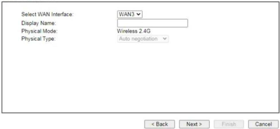
text_image
Select WAN Interface: Display Name: Physical Mode: Physical Type: WAN3 Wireless 2.4G Auto negotiation < Back Next > Finish Cancelor
Quick Start Wizard
Select WAN Interface

text_image
Select WAN Interface: Display Name: Physical Mode: Physical Type: WAN4 Wireless 5G Auto negotiation
- Then, click Next for getting the following page.
Quick Start Wizard
Connect to Internet
WAN 3
Select one of the following Internet Access types.
○ Static IP
DHCP

- After click DHCP as the Internet Access type, you will get the following page. Eenter the SSID of an existed AP as the wireless connection server for this WAN. Or click AP Discovery to find an access point as the server for this WAN interface. Click Next to continue.
Quick Start Wizard
Connect to Internet
WAN 3
Enter the AP configuration that router wants to connect.
SSID
MAC Address (Optional)
Channel :
Security Mode
Encryption Mode
Pass Phrase
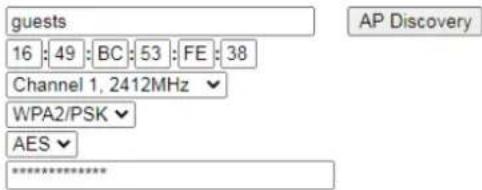
text_image
guests 16 : 49 : BC : 53 : FE : 38 Channel 1, 2412MHz WPA2/PSK AES **************************
Available settings are explained as follows:
| Item Description | |
| SSID | Enter the SSID of an existed AP. Or click AP Discovery to find an access point as the server for this WAN interface. |
| MAC Address | Enter the MAC address of an existed AP. |
| Channel | Choose a channel of frequency of the Wireless AP. |
| Securithy Mode | The Router connects to the wireless AP as a WEP, WPA or WPA2 client.Select a mode to connect to the Wireless AP. |
| Encryption Mode WPA/Pass Phrase | PSK uses TKIP as Encryption Mode. WPA2/ PSK uses AES as Encryption Mode.It is available when WPA/ PSK or WPA2/ PSK is enabled. |
| WEP Keys | It is available when WEP is enabled. |
| Back | Click it to return to previous setting page. |
| Next | Click it to get into the next setting page. |
| Cancel | Click it to give up the quick start wizard. |
- Then, a summary of the connection will be shown on the screen.
Quick Start Wizard
Please confirm your settings:
WAN Interface:
WAN3
Physical Mode:
Wireless 2.4G
Internet Access:
DHCP
Click Back to modify changes if necessary. Otherwise, click Finish to save the current settings and restart the Vigor router.

- Click Finish. A page of Quick Start Wizard Setup OK!!! will appear. Then, the system status of this protocol will be shown.
Quick Start Wizard Setup OK!
- Now, you can enjoy surfing on the Internet.
I-5-3 For WAN5/WAN6 (USB)
WAN3/ WAN4 is dedicated to physical mode in USB.
- Choose WAN5/WAN6 as WAN Interface. For "L" model, the WAN5 will be changed as LTE.
Quick Start Wizard
WAN Interface
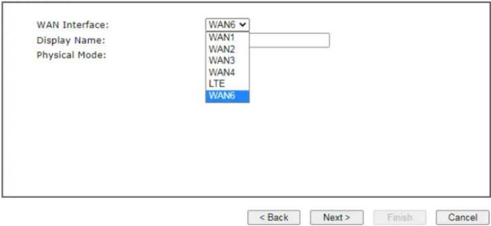
text_image
WAN Interface: Display Name: Physical Mode: WAN6 WAN1 WAN2 WAN3 WAN4 LTE WAN6 < Back Next > Finish Cancel- Then, click Next for getting the following page.
Quick Start Wizard
Connect to Internet
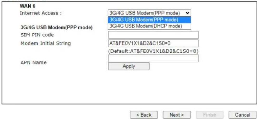
text_image
WAN 6 Internet Access : 3G/4G USB Modem(PPP mode) 3G/4G USB Modem(PPP mode) 3G/4G USB Modem(PPP mode) 3G/4G USB Modem(DHCP mode) SIM PIN code Modem Initial String AT&FE0V1X1&D2&C1S0=0 (Default:AT&FE0V1X1&D2&C1S0=0) APN Name Apply < Back Next > Finish CancelAvailable settings are explained as follows:
| Item Description | |
| Internet Access | Choose one of the selections as the protocol of accessing the internet. |
| 3G/4G USB Modem (PPP mode) | SIM Pin code -Type PIN code of the SIM card that will be used to access Internet. The maximum length of the pin code you can set is 15 characters.Modem Initial String - Such value is used to initialize USB modem. Please use the default value. If you have any question, please contact to your ISP. The maximum length of the string you can set is 47 characters.APN Name - APN means Access Point Name which is provided and required by some ISPs. Enter the name and click Apply. |
| 3G/4G USB Modem (DHCP mode) | SIM Pin code - Type PIN code of the SIM card that will be used to access Internet.Network Mode - Force Vigor router to connect Internet with the mode specified here. If you choose 4G/ 3G/ 2G as network mode, the router will choose a suitable one according to the actual wireless signal automatically.APN Name - APN means Access Point Name which is provided and required by some ISPs. |
| Back | Click it to return to previous setting page. |
| Next | Click it to get into the next setting page. |
| Cancel | Click it to give up the quick start wizard. |
- Then, click Next for viewing summary of such connection.
Wizards >> Quick Start Wizard
Please confirm your settings:
WAN Interface:
WAN6
Physical Mode:
USB
Internet Access:
PPP
Click Back to modify changes if necessary. Otherwise, click Finish to save the current settings and restart the Vigor router.

- Click Finish. A page of Quick Start Wizard Setup OK!!! will appear. Then, the system status of this protocol will be shown.
Quick Start Wizard Setup OK!
- Now, you can enjoy surfing on the Internet.
I-6 Service Activation Wizard
Service Activation Wizard can guide you to activate WCF service (Web Content Filter) with a quick and easy way. For the Service Activation Wizard is only available for admin operation, therefore, please type "admin/admin" on Username/Password while Logging into the web user interface.
Service Activation Wizard is a tool which allows you to use trial version of WCF directly without accessing into the server (MyVigor) located on http://myvigor.draytek.com. For using Web Content Filter Profile, please refer to later section Web Content Filter Profile for detailed information.
Now, follow the steps listed below to activate WCF feature for your router.

Info
Such function is available only for Admin Mode.
- Open Wizards>>Service Activation Wizard.
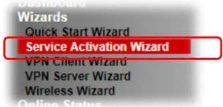
text_image
Wizards Quick Start Wizard Service Activation Wizard VPN Client Wizard VPN Server Wizard Wireless Wizard Online Status- The screen of Service Activation Wizard will be shown as follows. You can activate the Web content filter services and/or APPE enforcement service and/or DDNS service at the same time or individually. When you finish the selection, please click Next.
Service Activation Wizard
Select the service type that you want to activate
text_image
Web Content Filter(WCF) Service : □ Epjm License Agreement This is a web content filter that is provided by the German government. It is a free service without any guarantee and will expire one year after activation. You may re-activate the service after expiry. ☑ Cyren 30-Days Free Trial License Agreement This is a worldwide web content filter service. The free trail license can only be used once. At the end of the free trail period you may purchase the official one-year Cyren Web Content Filter from an authorized DrayTek reseller. APP Enforcement(APPE) Service : ☑ DT-APPE License Agreement Upgrade APPE Signature automatically. Dynamic DNS(DDNS) Service : ☑ DT-DDNS License Agreement This is a Dynamic Domain Name Service that is provided by DrayTek company. It is a free service will expire 1 year after activation. You may re-active the service after expiry. Domain Name : 2018042313200201 drayddns.com ☑ I have read and accept the above Agreement. (Please check this box).

Info
- BPjM is web content filter (WCF) for German Speaking users. It is ideal for your family to provide more Internet security for youngsters.
● Cryan 30-day trial is WCF which offers 30-day trial period.
● DT-APPE, developed by DrayTek, offers a mechanism to upgrade APPE signature automatically. -
DT-DDNS, developed by DrayTek, offers one year free charge service of dynamic DNS service for internal use.
-
Setting confirmation page will be displayed as follows, please click Activate.
Service Activation Wizard
Please confirm your settings
Sevice Type : Trial version
Sevice Activated : Web Content Filter (Cyren / Commtouch)
APP Enforcement (DT-APPE)
Dynamic DNS (2018042313200201.drayddns.com)
Please click Back to re-select service type you to activate.


Info
The service will be activated and applied as the default rule configured in Firewall>>General Setup.
- Now, the web page will display the service that you have activated according to your selection(s).
Service Activation Wizard
Please confirm your settings
Sevice Type : Trial version
Sevice Activated : Web Content Filter (Cyren / Commtouch)
APP Enforcement (DT-APPE)
Dynamic DNS (2018042313200201.drayddns.com)
Please click Back to re-select service type you to activate.

I-7 Registering Vigor Router
You have finished the configuration of Quick Start Wizard and you can surf the Internet at any time. Now it is the time to register your Vigor router to MyVigor website for getting more service. Please follow the steps below to finish the router registration.
1 Please login the web configuration interface of Vigor router by typing "admin/admin" as User Name / Password.
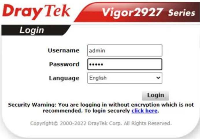
text_image
DrayTek Vigor2927 Series Login Username admin Password ••••• Language English Login Security Warning: You are logging in without encryption which is not recommended. To login securely click here. Copyright© 2000-2022 DrayTek Corp. All Rights Reserved.2 Click MyVigor Services>>Production Registration from the home page.
MyVigor Services Product Registration Service Status
3 A Login page will be shown on the screen. Please Enter the account and password that you created previously. And click Login.
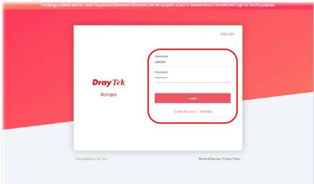
text_image
The MayLige website does not request any personal identifiable information with the exception of your ID. Address which is recorded either login for security purposes. DRayTek MyVigor ENGLISH Username camtesi Password: ****** Login Create Account / Get Help Copyright@DrayTek Our Terms of Service / Privacy PolicyInfo
If you haven't an accessing account, please refer to section Creating an Account for MyVigor to create your own one. Please read the articles on the Agreement regarding user rights carefully while creating a user account.
4 The following page will be displayed after you logging in MyVigor. Type a nickname for the router, then click Submit.
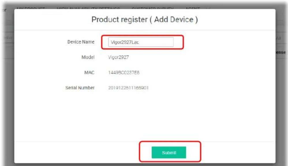
text_image
Product register ( Add Device ) Device Name Vigor2927Lac Model Vigor2927 MAC 1449BC0237E8 Serial Number 2019122511165901 Submit!5 When the following page appears, your router information has been added to the database. Your router has been registered to myvigor website successfully.
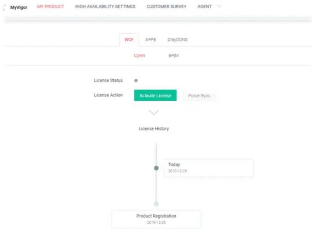
flowchart
graph TD
    A["License Status"] --> B["License Action"]
    B --> C["Activate License"]
    C --> D["Force Sync"]
    D --> E["License History"]
    E --> F["Today 2019-12-26"]
    F --> G["Product Registration 2019-12-26"]
6 Clicking MYPRODUCT for viewing the general information of the registered router on MyVigor website.
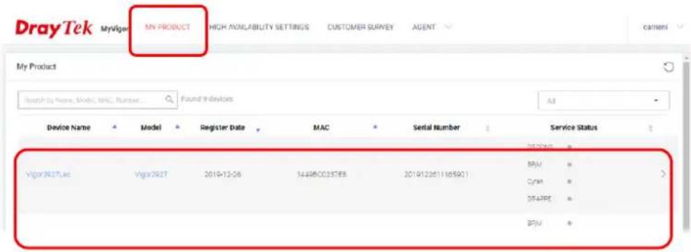
text_image
DrayTek My Product HIGH AVNABILITY SETTINGS CUSTOMER SURVEY AGENT My Product Search by Name, Model, MAC, Number Found 9 devices All Device Name Model Register Date MAC Serial Number Service Status Vigor2627Lac Vigor2627 2019-12-26 1448BC025763 2019123611165901 BPM CFPA DTAPE BPMThis page is left blank.
Part II Connectivity

WAN

LAN

NAT

Applications

Routing
It means wide area network. Public IP will be used in WAN.
It means local area network. Private IP will be used in LAN. Local Area Network (LAN) is a group of subnets regulated and ruled by router. The design of network structure is related to what type of public IP addresses coming from your ISP.
When the data flow passing through, the Network Address Translation (NAT) function of the router will dedicate to translate public/private addresses, and the packets will be delivered to the correct host PC in the local area network.
DNS, LAN DNS, LDAP, UPnP, IGMP, Wake on LAN/WAN, RADIUS/TACACS+, SMS/ Mail Alert, Bonjour, High Availability, Local 802.1x
Static Route, Load-Balance/ Route Policy, BGP
It allows users to access Internet.
Basics of Internet Protocol (IP) Network
IP means Internet Protocol. Every device in an IP-based Network including routers, print server, and host PCs, needs an IP address to identify its location on the network. To avoid address conflicts, IP addresses are publicly registered with the Network Information Centre (NIC). Having a unique IP address is mandatory for those devices participated in the public network but not in the private TCP/IP local area networks (LANs), such as host PCs under the management of a router since they do not need to be accessed by the public. Hence, the NIC has reserved certain addresses that will never be registered publicly. These are known as private IP addresses, and are listed in the following ranges:
From 10.0.0.0 to 10.255.255.255
From 172.16.0.0 to 172.31.255.255
From 192.168.0.0 to 192.168.255.255
What are Public IP Address and Private IP Address
As the router plays a role to manage and further protect its LAN, it interconnects groups of host PCs. Each of them has a private IP address assigned by the built-in DHCP server of the Vigor router. The router itself will also use the default private IP address: 192.168.1.1 to communicate with the local hosts. Meanwhile, Vigor router will communicate with other network devices through a public IP address. When the data flow passing through, the Network Address Translation (NAT) function of the router will dedicate to translate public/private addresses, and the packets will be delivered to the correct host PC in the local area network. Thus, all the host PCs can share a common Internet connection.
Get Your Public IP Address from ISP
In ADSL deployment, the PPP (Point to Point)-style authentication and authorization is required for bridging customer premises equipment (CPE). Point to Point Protocol over Ethernet (PPPoE) connects a network of hosts via an access device to a remote access concentrator or aggregation concentrator. This implementation provides users with significant ease of use. Meanwhile it provides access control, billing, and type of service according to user requirement.
When a router begins to connect to your ISP, a serial of discovery process will occur to ask for a connection. Then a session will be created. Your user ID and password is authenticated via PAP or CHAP with RADIUS authentication system. And your IP address, DNS server, and other related information will usually be assigned by your ISP.
Network Connection by 3G/4G USB Modem
For 3G/4G mobile communication through Access Point is popular more and more, Vigor2927 adds the function of 3G/4G network connection for such purpose. By connecting 3G/4G USB Modem to the USB port of Vigor2927, it can support LTE/HSDPA/UMTS/EDGE/GPRS/GSM and the future 3G/4G standard (HSUPA, etc). Vigor2927n with 3G/4G USB Modem allows you to receive 3G/4G signals at any place such as your car or certain location holding outdoor activity and share the bandwidth for using by more people. Users can use LAN ports on the router to access Internet. Also, they can access Internet via 802.11(a/b/g/n/ac) wireless standard, and enjoy the powerful firewall, bandwidth management, and VPN features of Vigor2927n series.
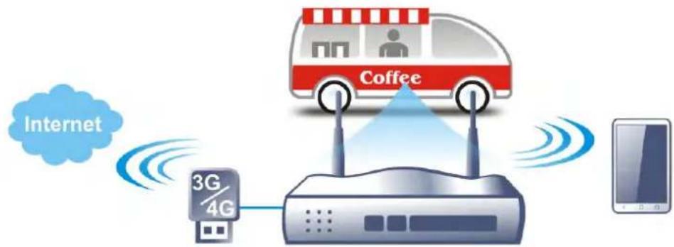
flowchart
graph TD
    A["Coffee Bus"] -->|Wireless Signal| B["3G/4G Router"]
    B --> C["Internet"]
    C -->|Wireless Signal| A
    D["Smartphone"] -->|Wireless Signal| B
After connecting into the router, 3G/4G USB Modem will be regarded as the WAN3/WAN4 port. However, the original WAN1 and WAN2 still can be used and Load-Balance can be done in the router. Besides, 3G/4G USB Modem in WAN3/WAN4 also can be used as backup device. Therefore, when WAN1 and WAN2 are not available, the router will use 3.5G for supporting automatically. The supported 3G/4G USB Modem will be listed on DrayTek web site. Please visit www.draytek.com for more detailed information.
Web User Interface
WAN
General Setup
Internet Access
Multi-VLAN
WAN Budget
II-1-1 General Setup
This section will introduce some general settings of Internet and explain the connection modes for WAN1, WAN2, WAN3, WAN4, WAN5/LTE and WAN6 in details.
This router supports multiple-WAN function. It allows users to access Internet and combine the bandwidth of the multiple WANs to speed up the transmission through the network. Each WAN port can connect to different ISPs, even if the ISPs use different technology to provide telecommunication service (such as DSL, Cable modem, etc.). If any connection problem occurred on one of the ISP connections, all the traffic will be guided and switched to the normal communication port for proper operation. Please configure WAN1, WAN2, WAN3, WAN4, WAN5/LTE and WAN6 settings.
This webpage allows you to set general setup for WAN1, WAN2, WAN3, WAN4, WAN5/LTE and WAN6 respectively.
WAN >> General Setup
General Setup
| Index | Enable | Physical Mode/Type | Bandwidth(Kbps) DownLink/Uplink | Latency | Jitter | Pkt.Loss | Active Mode | Load Balance |
| WAN1 | √ | Ethernet/Auto negotiation | - / - | - | - | - | Always On | √ |
| WAN2 | √ | Ethernet/Auto negotiation | - / - | - | - | - | Always On | √ |
| WAN3 | √ | Wireless 2.4G/- | - / - | - | - | - | Always On | √ |
| WAN4 | □ | Wireless SG/- | - / - | - | - | - | Always On | √ |
| LTE | √ | USB/- | - / - | - | - | - | Always On | √ |
| WAN6 | √ | USB/- | - / - | - | - | - | Always On | √ |
Load Balance Setup Advance
| Mode | IP Based |
| Line Speed | Auto Detect |
| Load Balance Weights | Bandwidth-Based |
Note:
-
Latency, jitter, and packet-loss require setting Link Condition Detection in each WAN setting page.
-
When WAN2 is not Ethernet, P6 port will be used as LAN.
OK Cancel
Or
WAN >> General Setup
| Index | Enable | Physical Modo/Type | Bandwidth(Kbps) DownLink/UpLink | Latency | Jitter | PktLoss | Active Mode | Load Balance |
| WAN1 | √ | Ethernet/Auto negotiation | - / - | - | - | - | Always On | √ |
| WAN2 | √ | Ethernet/Auto negotiation | - / - | - | - | - | Always On | √ |
| 5G NR | √ | USB/- | - / - | - | - | - | Always On | √ |
| WAN6 | √ | USB/- | - / - | - | - | - | Always On | √ |
Load Balance Setup Advanced
| Mode | IP Based |
| Line Speed | Auto Detect |
| Load Balance Weights | Bandwidth-Based |
Note
-
Latency, jitter, and packet-loss require setting Link Condition Detection in each WAN setting page
-
When Physical Mode/Type of WAN2 is not Ethernet or WAN2 is disabled, P6 port will be used as LAN
OK Cancel
Available settings are explained as follows:
| Item Description | |
| Index | Click the WAN interface link under Index to access into the WAN configuration page. |
| Enable | V means such WAN interface is enabled and ready to be used. |
| Physical Mode / Type | Display the physical mode and physical type of such WAN interface. |
| Bandwidth(Kbps)DownLink/UpLink | Display the downstream and upstream rate of such WAN interface. |
| Active Mode | Display whether such WAN interface is Active device or backup device.Backup (WAN#) - Display the backup WAN interface for such WAN when it is disabled. |
| Load Balance | Select to enable the load balance function. |
| Load Balance Setup | Advance - Load Balance for the traffic of STUN, google STUN, and SIP are disabled in default to prevent from conflict. The following dialog allows you to define protocol, port and name for the traffic not to be applied with load balance. That is, when an item is enabled (checked), it might not be affected by load balance.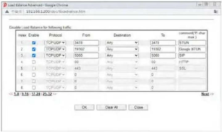 |
| Mode | IP Based - The same source / destination IP pair will select the same WAN interface as policy. It is the default setting.Session Based- All of the WAN interfaces will be used (as out-going WAN) for passing through new sessions to get better transmission speed. Though good speed test result for throughput might be reached; however, some web site may not open smoothly, especially the site need authentication, e.g., FTP.If you have no strong demand about speed test result, keep default settings as IP based. |
| Line Speed | This option is available for multiple-WAN for getting enough bandwidth for each WAN port. If you know the practical bandwidth for your WAN interface, please choose the setting of According to Line Speed. Otherwise, please choose Auto Detect to let the router reach the best load balance. |
| Load Balance Weights | There are four weight types for choosing to meet your request.Custom - You can distribute the usage ratio for each WAN interface by setting weights for bandwidth, latency, jitter, |
and packet loss respectively.
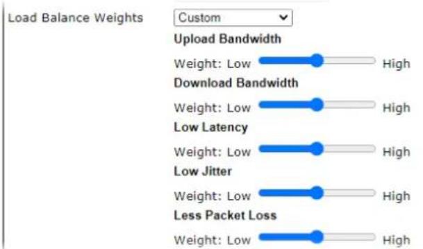
text_image
Load Balance Weights Custom Upload Bandwidth Weight: Low High Download Bandwidth Weight: Low High Low Latency Weight: Low High Low Jitter Weight: Low High Less Packet Loss Weight: Low High- Upload / Download Bandwidth - The higher the weight is, the WAN interface with higher bandwidth will get higher usage.
- Low Latency - It defines the time taken by Vigor router when sending the packets to the IP set in Link Condition Detection. The higher the weight is, the WAN interface with lower latency will get higher usage.
- Low Jitter - It defines the change rate of latency. For stable session, small jitter value will be better. The higher the weight is, the WAN interface with lower jitter will get higher usage.
● Less Packet Loss - It defines the proportion that packets will be discarded before arriving at the IP set in Link Condition Detection. The higher the weight is, the WAN interface with lower packet loss will get higher usage.
Bandwidth-Based - The load balance weight for each WAN will be executed according to line speed setting (DownLink/ UpLink Rate). This is default setting.
Quality-Based - The load balance weight for each WAN will be executed according to the transmission rate, latency time and the jitter time.
Reliabilitiy-Based - The load balance weight for each WAN will be executed according to line speed and packet loss value. Usually, the WAN interface with low packet loss will have the higher ratio to be used.

Info
Some router (e.g., Vigor2927 or Vigor2927Lax-5G) does not support WAN3 and WAN4.
After finished the above settings, click OK to save the settings.
II-1-1-1 WAN1/WAN2 (Ethernet)
WAN1/ WAN2 can be configured for physical mode of Ethernet.
WAN >> General Setup
WAN 1
| Enable: | Yes✓ | |
| Display Name: | ||
| Physical Mode: | Ethernet | |
| Physical Type (Ethernet): | Auto negotiation✓ | |
| Line Speed(Kbps): | ||
| DownLink | 0 | |
| UpLink | 0 | |
| Link Condition Detection | ||
| Mode | Ping Detect✓ | |
| Primary Ping IP | 8.8.8.8 | |
| Secondary Ping IP | 8.8.4.4 | |
| Ping Interval | 1 Seconds(s) | |
| Active Mode: | Backup✓ | |
| WAN 1 | ||
| WAN 2 | ||
| WAN 3 | ||
| WAN 4 | ||
| LTE | ||
| WAN 6 | ||
| Active When | Any✓ of the WAN selected above | |
| Fails to connect: | ||
| Meet Any✓ of the following conditions: | ||
| Upload traffic reaches 0 Kbps | ||
| Download traffic reaches 0 Kbps | ||
| Latency over 0 ms | ||
| Jitter over 0 ms | ||
| Packet loss over 0 % | ||
| VLAN Tag insertion | Customer (TPID 0x8100) | Service (TPID 0x8100) |
| Disable✓ Tag value Priority 0 0 (0~4095) (0~7) | Disable✓ Tag value Priority 0 0 (0~4095) (0~7) |
Available settings are explained as follows:
After finished the above settings, click OK to save the settings.
| Item Description | |
| Enable | Choose Yes to invoke the settings for this WAN interface.Choose No to disable the settings for this WAN interface. |
| Display Name | Enter the description for such WAN interface. |
| Physical Mode | Display the physical mode (Ethernet) of the interface. |
| Physical Type | You can change the physical type for WAN1/2 or choose Auto negotiation for determined by the system. |
| Line Speed (Kbps) | If your choose According to Line Speed as the Line Speed on WAN>>General Setup, please enter the line speed for downloading and uploading for such WAN interface. The unit is kbps. |
| Link Condition Detection | In order for the system to detect the latency, jitter, and packet-loss status for each WAN interface, you have to specify the IP transmitting data through the interface.Mode - Choose Ping Detect, Http Detect, or Disable as detection mode. If Ping Detect or Http Detect is selected,you have to configure the following option.● Primary Ping IP - Enter an IP address.● Secondary Ping IP - Enter an IP address.● Ping Interval - Set a time interval (unit:second) for the system to ping the IP address specified above. |
| Active Mode | Always On - WAN is always enabled.Backup - WAN is enabled only when other WAN ports specified in Backup For (see below), have lost connection.● Backup For - Select the WANs for which this WAN is intended to serve as a backup.● Active When - Set the condition for backup connection.- Any - The selected WAN(s) will be activated when any master WAN interface disconnects.- All - All of the backup WANs will be activated only when all master WAN interface disconnects.- Fails to connect - When the active WAN failed, the WAN selected above will be activated as the main network connection.- Meet All/Any of the following conditions - When the upload traffic, download traffic, latency, jitter and/or packet loss of active WAN reaches the traffic threshold (specified here), the backup WAN will be enabled automatically to share the overloaded data traffic. |
| VLAN Tag insertion | Such feature is offered to the user with the environment supporting IEEE_802.1ad. In which, service is used for outer tag; customer is used for inner tag.It is available only when Ethernet is selected as Physical Mode.Disable - Disable the function of VLAN with tag.Enable -Enable the function of VLAN with tag.The router will add specific VLAN number to all packets on the WAN while sending them out.Please Enter the tag value and specify the priority for the packets sending by WAN1.● Tag value - Enter the value as the VLAN ID number. The range is form 0 to 4095.● Priority - Enter the packet priority number for such VLAN. The range is from 0 to 7. |
II-1-1-2 WAN3/WAN4 (Wireless 2.4G or 5G)
WAN3/ WAN4 can be configured for physical mode of Wireless 2.4G or Wireless 5G.
WAN >> General Setup
WAN 3
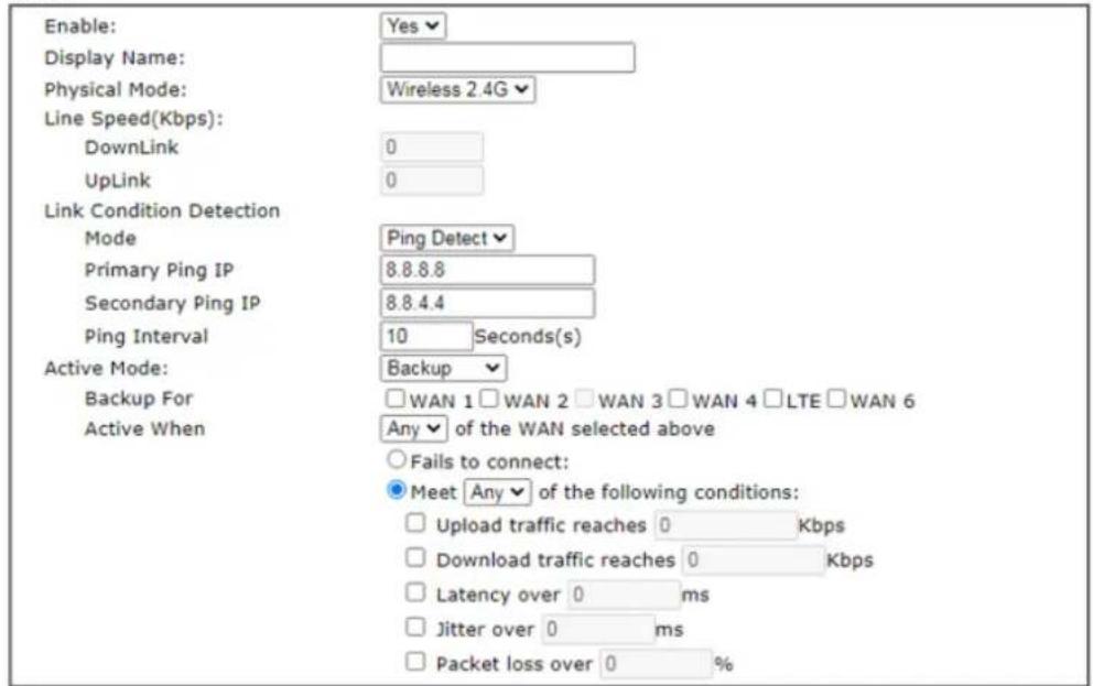
text_image
Enable: Display Name: Physical Mode: Line Speed(Kbps): DownLink UpLink Link Condition Detection Mode Primary Ping IP Secondary Ping IP Ping Interval Active Mode: Backup For Active When Yes Wireless 2.4G 0 0 Ping Detect 8.8.8.8 8.8.4.4 10 Seconds(s) Backup WAN 1 WAN 2 WAN 3 WAN 4 LTE WAN 6 Any of the WAN selected above Fails to connect: Meet Any of the following conditions: Upload traffic reaches 0 Kbps Download traffic reaches 0 Kbps Latency over 0 ms Jitter over 0 ms Packet loss over 0 %Note:
The line speed setting of WAN interface is available only when According to Line Speed is selected as the Load Balance Mode.
OK
Cancel
Available settings are explained as follows:
| Item Description | |
| Enable | Choose Yes to invoke the settings for this WAN interface.Choose No to disable the settings for this WAN interface. |
| Display Name | Enter the description for such WAN interface. |
| Physical Mode | Choose the physical mode (Wireless 2.4G / Wireless 5G) of the interface. |
| Line Speed (Kbps) | If your choose According to Line Speed as the Line Speed on WAN>>General Setup, please enter the line speed for downloading and uploading for such WAN interface. The unit is kbps. |
| Link Condition Detection | In order for the system to detect the latency, jitter, and packet-loss status for each WAN interface, you have to specify the IP transmitting data through the interface.Mode - Choose Ping Detect, Http Detect, or Disable as detection mode. If Ping Detect or Http Detect is selected, you have to configure the following option.Primary Ping IP - Enter an IP address.Secondary Ping IP - Enter an IP address.Ping Interval - Set a time interval (unit:second) for the system to ping the IP address specified above. |
| Active Mode | Always On - WAN is always enabled.Backup - WAN is enabled only when other WAN portsspecified in Backup For (see below), have lost connection.● Backup For - Select the WANs for which this WAN is intended to serve as a backup.● Active When - Set the condition for backup connection.- Any - The selected WAN(s) will be activated when any master WAN interface disconnects.- All - All of the backup WANs will be activated only when all master WAN interface disconnects.- Fails to connect - When the active WAN failed, the WAN selected above will be activated as the main network connection.- Meet All/Any of the following conditions - When the upload traffic, download traffic, latency, jitter and/or packet loss of active WAN reaches the traffic threshold (specified here), the backup WAN will be enabled automatically to share the overloaded data traffic. |
After finished the above settings, click OK to save the settings.
II-1-1-3 WAN5 / WAN6 (USB) or LTE or 5G-NR
To use 3G/4G network connection through 3G/4G USB Modem, please configure WAN5 or LTE / WAN6 interface.
WAN >> General Setup
WAN 6
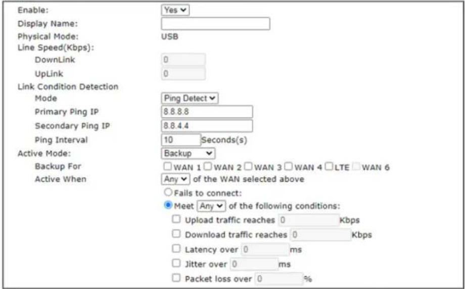
text_image
Enable: Display Name: Physical Mode: USB Line Speed(Kbps): DownLink UpLink Link Condition Detection Mode Primary Ping IP Secondary Ping IP Ping Interval Active Mode: Backup For Active When Ping Detect 8.8.8.8 8.8.4.4 10 Seconds(s) Backup WAN 1 WAN 2 WAN 3 WAN 4 LTE WAN 6 Any of the WAN selected above Fails to connect: Meet Any of the following conditions: Upload traffic reaches 0 Kbps Download traffic reaches 0 Kbps Latency over 0 ms Jitter over 0 ms Packet loss over 0 %Note:
The line speed setting of WAN interface is available only when According to Line Speed is selected as the Load Balance Mode.

Available settings are explained as follows:
After finished the above settings, click OK to save the settings.
| Item Description | |
| Enable | Choose Yes to invoke the settings for this WAN interface.Choose No to disable the settings for this WAN interface. |
| Display Name | Enter the description for such WAN interface. |
| Physical Mode | Display the physical mode of such WAN interface. |
| Line Speed (Kbps) | If your choose According to Line Speed as the Line Speed on WAN>>General Setup, please enter the line speed for downloading and uploading for such WAN interface. The unit is kbps. |
| Link Condition Detection | In order for the system to detect the latency, jitter, and packet-loss status for each WAN interface, you have to specify the IP transmitting data through the interface.Mode - Choose Ping Detect, Http Detect, or Disable as detection mode. If Ping Detect or Http Detect is selected, you have to configure the following option.Primary Ping IP - Enter an IP address.Secondary Ping IP - Enter an IP address.Ping Interval - Set a time interval (unit:second) for the system to ping the IP address specified above. |
| Active Mode | Always On - WAN is always enabled.Backup - WAN is enabled only when other WAN ports specified in Backup For (see below), have lost connection.Backup For - Select the WANs for which this WAN is intended to serve as a backup.Active When - Set the condition for backup connection.Any - The selected WAN(s) will be activated when any master WAN interface disconnects.All - All of the backup WANs will be activated only when all master WAN interface disconnects.Fails to connect - When the active WAN failed, the WAN selected above will be activated as the main network connection.Meet All/Any of the following conditions - When the upload traffic, download traffic, latency, jitter and/or packet loss of active WAN reaches the traffic threshold (specified here), the backup WAN will be enabled automatically to share the overloaded data traffic. |
II-1-2 Internet Access
For the router supports multi-WAN function, the users can set different WAN settings for Internet Access. Due to different Physical Mode for WAN interface, the Access Mode for these connections also varies. Refer to the following figures for examples.
Access Mode for Etherenet,
WAN >> Internet Access
Internet Access
| Index | Display Name | Physical Mode | Access Mode | ||
| WAN1 | Ethernet | Static or Dynamic IP | Details Page | IPv6 | |
| WAN2 | Ethernet | Static or Dynamic IP | Details Page | IPv6 | |
| WAN3 | Wireless 2.4G | None PPPoE | Details Page | IPv6 | |
| WAN4 | Wireless 5G | Static or Dynamic IP | Details Page | IPv6 | |
| WAN5 | USB | PPTP/L2TP None | Details Page | IPv6 | |
| WAN6 | USB | None | Details Page | IPv6 | |
Note:
-
Device on USB port 1 applies WAN5 configuration.
-
Device on USB port 2 applies WAN6 configuration.
DHCP Client Option
Access Mode for Wireless 2.4G/5G,
WAN >> Internet Access
Internet Access
| Index | Display Name | Physical Mode | Access Mode | ||
| WAN1 | Ethernet | Static or Dynamic IP | Details Page | IPv6 | |
| WAN2 | Ethernet | Static or Dynamic IP | Details Page | IPv6 | |
| WAN3 | Wireless 2.4G | None | Details Page | IPv6 | |
| WAN4 | Wireless 5G | None | Details Page | IPv6 | |
| LTE | USB | Static or Dynamic IP | Details Page | IPv6 | |
| WAN6 | USB | None | Details Page | IPv6 | |
Note:
- Device on USB port 2 applies WAN6 configuration.
DHCP Client Option
Access Mode for 5G-NR
WAN >> Internet Access
Internet Access
| Index | Display Name | Physical Mode | Access Mode | ||
| WAN1 | Ethernet | Static or Dynamic IP | Details Page | IPv6 | |
| WAN2 | Ethernet | Static or Dynamic IP | Details Page | IPv6 | |
| 5G-NR | USB | 3G/4G/5G Modem(DHCP mode) | Details Page | IPv6 | |
| WAN6 | USB | None3G/4G/5G Modem(DHCP mode) | Details Page | IPv6 | |
Note:
- Device on USB port 2 applies WAN6 configuration.
DHCP Client Option
Access Mode for USB,
WAN >> Internet Access
Internet Access
| Index | Display Name | Physical Mode | Access Mode | ||
| WAN1 | Ethernet | Static or Dynamic IP | Details Page | IPv6 | |
| WAN2 | Ethernet | Static or Dynamic IP | Details Page | IPv6 | |
| WAN3 | Wireless 2.4G | None | Details Page | IPv6 | |
| WAN4 | Wireless 5G | None | Details Page | IPv6 | |
| WAN5 | USB | None | Details Page | IPv6 | |
| WAN6 | USB | None | Details Page | IPv6 | |
Note:
1.Device on USB port 1 applies WAN5 configuration
2.Device on USB port 2 applies WAN6 configuration.
DHCP Client Option
None
3G/4G USB Modem(PPP mode)
3G/4G USB Modem(DHCP mode)
Available settings are explained as follows:
| Item Description | |
| Index Display the WAN interface. | |
| Display Name | It shows the name of the WAN1/ WAN2/ WAN3/ WAN4/ WAN5 or LTE/ WAN6 or 5G-NR that entered in general setup. |
| Physical Mode | It shows the physical connection for WAN interfaces according to the real network connection. |
| Access Mode | Use the drop down list to choose a proper access mode. The details page of that mode will be popped up. If not, click Details Page for accessing the page to configure the settings. |
| Details Page | This button will open different web page (based on IPv4) according to the access mode that you choose in WAN interface.Note that Details Page will be changed slightly based on physical mode specified on WAN>>General Setup. |
| IPv6 | This button will open different web page (based on Physical Mode) to setup IPv6 Internet Access Mode for WAN interface. |
| DHCP Client Option | This button allows you to configure DHCP client options. DHCP packets can be processed by adding option number and data information when such function is enabled and configured. |
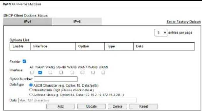
text_image
WAN >> Internet Access DHCP Client Options Status IPv4 IPv6 Set to Factory Default 5 entries per page Options List Enable Interface Option Type Data Enable: Interface: All WAN1 WAN2 SQ-NR, WAN6 WAN7 WAN8 WAN9 Option Number: DataType ASCII Character (e.g. Option:10, Data:/path) Hexadecimal Digit (Please check note 4 ) Address List (e.g. Option 44, Data 172.16.2.10,172.16.2.20...) Data: Max: 127 characters Add Update Delete ResetNote:
- Option 12 is reserved. You cannot configure it here, but you can configure it in "Router Name" field of "WAN >> internet Access >> Details Page".
2 Option 55 is reserved and configured with value 1, 3, 6, 15 and 212, also 33 and 121 for some models. - Configuring option 61 here will override the setting in "WAN >> Internet Access" page's DHCP Client Identifier field.
- Hexadecimal Digit: Input the hexadecimal representation of ASCII Character data. e.g. Option 16, Data:2f70617468 (/path)
-
Address List: Data column supports maximum 339 characters or 15 IP addresses
-
Address LLC Data Column supports maximum 239 characters of 15 IP addresses

Enable/Disable - Enable/Disable the function of DHCP Option. Each DHCP option is composed by an option number with data. For example,
Option number:100
Data: abcd
When such function is enabled, the specified values for DHCP option will be seen in DHCP reply packets.
Interface - Specify the WAN interface(s) that will be overwritten by such function. WAN7 \~ WAN9 can be located under WAN>>Multi-PVC/VLAN.
Option Number - Type a number for such function.
DataType - Choose the type (ASCII or Hex) for the data to be stored.
Data - Enter the content of the data to be processed by the function of DHCP option.

Info
If you choose to configure option 61 here, the detailed settings in WAN>>Interface Access will be overwritten.
II-1-2-1 Details Page for PPPoE in WAN1/WAN2 (Physical Mode: Ethernet)
To choose PPPoE as the accessing protocol of the Internet, please select PPPoE from the WAN>>Internet Access >>WAN1/2 page. The following web page will be shown.
WAN >> Internet Access
WAN 1
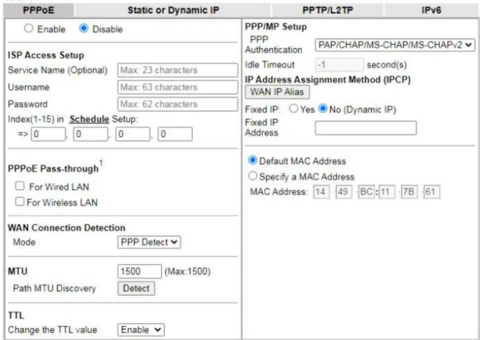
text_image
PPPoE Static or Dynamic IP PPTP/L2TP IPv6 Enable Disable ISP Access Setup Service Name (Optional) Max: 23 characters Username Max: 63 characters Password Max: 62 characters Index(1-15) in Schedule Setup: => 0 0 0 0 PPPoE Pass-through¹ □ For Wired LAN □ For Wireless LAN WAN Connection Detection Mode PPP Detect ▼ MTU 1500 (Max:1500) Path MTU Discovery Detect TTL Change the TTL value Enable ▼ PPP/MP Setup PPP Authentication PAP/CHAP/MS-CHAP/MS-CHAPv2 ▼ Idle Timeout -1 second(s) IP Address Assignment Method (IPCP) WAN IP Alias Fixed IP: Yes ▼ No (Dynamic IP) Fixed IP Address ▼ Default MAC Address Specify a MAC Address MAC Address: 14 49 BC: 11 7B 61Note:
- (Optional) Required for some ISPs. Leave blank if in doubt because the connection request might be denied if "Service Name" is incorrect.
- VPN feature may be affected when the value of MTU is changed, please also check your value of VPN MSS in "VPN and Remote Access >> PPP General Setup" or "VPN and Remote Access >> IPsec General Setup" page.
We recommend to put the same decreased value on VPN MSS. For example, reducing the MTU from 1500 -> 1400, then it will need to reduct 100 from MSS value.

Available settings are explained as follows:
| Item Description | |
| Enable/Disable | Click Enable for activating this function. If you click Disable, this function will be closed and all the settings that you adjusted in this page will be invalid. |
| ISP Access Setup | Enter your allocated username, password and authentication parameters according to the information provided by your ISP.Service Name (Optional) - Enter the description of the specific network service.Usage - Enter the username provided by ISP in this field.The maximum length of the user name you can set is 63 characters.Password - Enter the password provided by ISP in this field.The maximum length of the password you can set is 62 characters.Index (1-15) in Schedule Setup - You can Enter four sets of time schedule for your request. All the schedules can be set previously in Applications >> Schedule web page and youcan use the number that you have set in that web page. |
| PPPoE Pass-through | The router offers PPPoE dial-up connection. Besides, you also can establish the PPPoE connection directly from local clients to your ISP via the Vigor router. When PPPoA protocol is selected, the PPPoE package transmitted by PC will be transformed into PPPoA package and sent to WAN server. Thus, the PC can access Internet through such direction.For Wired LAN - If you check this box, PCs on the same network can use another set of PPPoE session (different with the Host PC) to access into Internet.For Wireless LAN - It is available for n model. If you check this box, PCs on the same wireless network can use another set of PPPoE session (different with the Host PC) to access into Internet.Note: To have PPPoA Pass-through, please choose PPPoA protocol and check the box(es) here. The router will behave like a modem which only serves the PPPoE client on the LAN. That's, the router will offer PPPoA dial-up connection. |
| WAN Connection Detection | Such function allows you to verify whether network connection is alive or not through PPP Detect or Ping Detect.Mode - Choose PPP Detect or Ping Detect for the system to execute for WAN detection. If you choose Ping Detect as the detection mode, you have to type required settings for the following items.Primary/Secondary Ping IP - If you choose Ping Detect as detection mode, you have to type Primary or Secondary IP address in this field for pinging.Ping Gateway IP - If you choose Ping Detect as detection mode, you also can enable this setting to use current WAN gateway IP address for pinging.With the IP address(es) pinging, Vigor router can check if the WAN connection is on or off.TTL (Time to Live) - Set TTL value of PING operation.Ping Interval - Enter the interval for the system to execute the PING operation.Ping Retry - Enter the number of times that the system is allowed to execute the PING operation before WAN disconnection is judged. |
| MTU | It means Max Transmit Unit for packet.Path MTU Discovery - It is used to detect the maximum MTU size of a packet not to be segmented in specific transmit path.Click Detect to open the following dialog.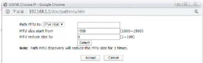 Path MTU to - Enter the IP address as the specific transmit path.MTU size start from - Determine the starting point value of the packet. Default setting is 1500.MTU reduce size by - It determines the decreasing sizeof MTU value. For example, the number specified in this field is “8”. The maximum MTU size is “1500”. After clicking the “detect” button, the system will calculate and get the suitable MTU value such as 1500, 1492, 1484 and etc., automatically.Detect- Click it to detect a suitable MTU valueAccept- After clicking it, the detected value will be displayed in the field of MTU. Path MTU to - Enter the IP address as the specific transmit path.MTU size start from - Determine the starting point value of the packet. Default setting is 1500.MTU reduce size by - It determines the decreasing sizeof MTU value. For example, the number specified in this field is “8”. The maximum MTU size is “1500”. After clicking the “detect” button, the system will calculate and get the suitable MTU value such as 1500, 1492, 1484 and etc., automatically.Detect- Click it to detect a suitable MTU valueAccept- After clicking it, the detected value will be displayed in the field of MTU. |
| TTL | Change the TTL value - Enable or disable the TTL (Time to Live) for a packet transmitted through Vigor router.En able - TTL value will be reduced (-1) when it passes through Vigor router. It will cause the client, accessing Internet through Vigor router, be blocked by certain ISP when TTL value becomes “0”.Disable - TTL value will not be reduced. Then, when a packet passes through Vigor router, it will not be cancelled. That is, the client who sends out the packet will not be blocked by ISP. |
| PPP/MP Setup | PPP Authentication - Select PAP only or PAP / CHAP / MS-CHAP / MS-CHAPv2 for PPP.Idle Timeout - Set the timeout for breaking down the Internet after passing through the time without any action.IP Address Assignment Method (IPCP)- Usually ISP dynamically assigns IP address to you each time you connect to it and request. In some case, your ISP provides service to always assign you the same IP address whenever you request. In this case, you can fill in this IP address in the Fixed IP field. Please contact your ISP before you want to use this function.WAN IP Alias - If you have multiple public IP addresses and would like to utilize them on the WAN interface, please use WAN IP Alias. You can set up to 32 public IP addresses other than the current one you are using. Enter the additional WAN IP address and check the Enable box. Then click OK to exit the dialog.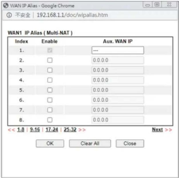 Fixed IP Address - Enter a fixed IP address.Default MAC Address - Enter MAC address for the router. Youcan use Default MAC Address or specify another MAC address for your necessity.Specify a MAC Address – Enter the MAC address for the router manually. Fixed IP Address - Enter a fixed IP address.Default MAC Address - Enter MAC address for the router. Youcan use Default MAC Address or specify another MAC address for your necessity.Specify a MAC Address – Enter the MAC address for the router manually. |
After finishing all the settings here, please click OK to activate them.
II-1-2-2 Details Page for Static or Dynamic IP in WAN1/WAN2 (Physical Mode: Ethernet)
For static IP mode, you usually receive a fixed public IP address or a public subnet, namely multiple public IP addresses from your DSL or Cable ISP service providers. In most cases, a Cable service provider will offer a fixed public IP, while a DSL service provider will offer a public subnet. If you have a public subnet, you could assign an IP address or many IP address to the WAN interface.
To use Static or Dynamic IP as the accessing protocol of the internet, please click the Static or Dynamic IP tab. The following web page will be shown.
WAN >> Internet Access
WAN 1
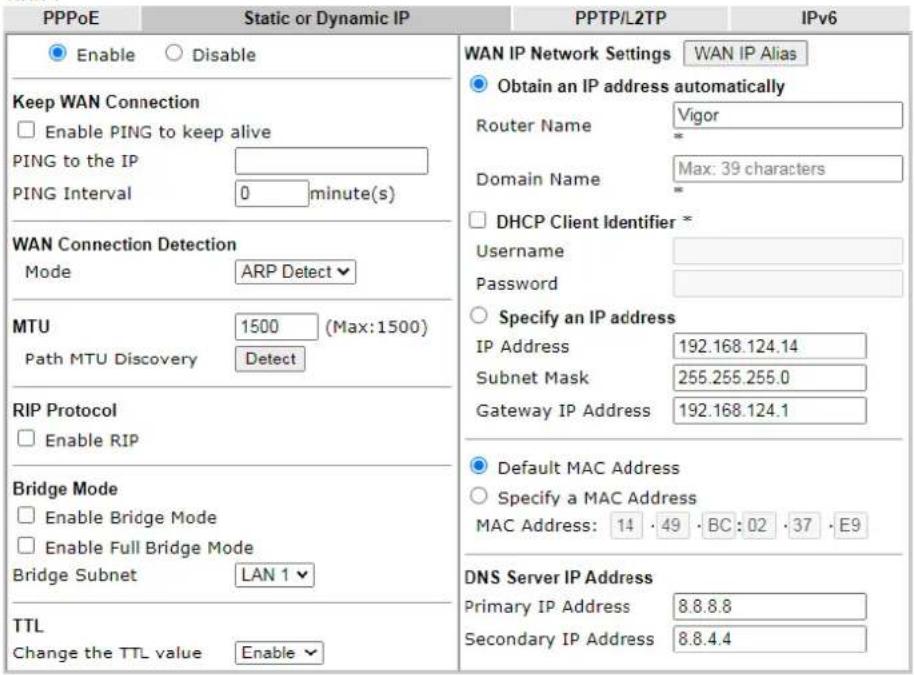
text_image
PPPoE Static or Dynamic IP PPTP/L2TP IPv6 Enable Disable Keep WAN Connection Enable PING to keep alive PING to the IP PING Interval 0 minute(s) WAN Connection Detection Mode ARP Detect MTU 1500 (Max:1500) Path MTU Discovery Detect RIP Protocol Enable RIP Bridge Mode Enable Bridge Mode Enable Full Bridge Mode Bridge Subnet LAN 1 TTL Change the TTL value Enable WAN IP Network Settings WAN IP Alias Obtain an IP address automatically Router Name Vigor * Domain Name Max: 39 characters DHCP Client Identifier * Username Password Specify an IP address IP Address 192.168.124.14 Subnet Mask 255.255.255.0 Gateway IP Address 192.168.124.1 Default MAC Address Specify a MAC Address MAC Address: 14 · 49 · BC : 02 · 37 · E9 DNS Server IP Address Primary IP Address 8.8.8.8 Secondary IP Address 8.8.4.4*: Required for some ISPs
Note:
- If enable firewall in bridge mode, IPv6 connection type would be change to DHCPv6 mode.
- Bridge Subnet cannot be selected by Multi-WAN Interface at the same time.
- If both Bridge Mode and Firewall are enabled, the settings under User Management will be ignored.
- Full Bridge Mode supports forwarding packets with VLAN tags.
- Full Bridge Mode doesn't support wireless LAN.
OK Cancel
Available settings are explained as follows:
| Item Description | |
| Enable / Disable | Click Enable for activating this function. If you click Disable, this function will be closed and all the settings that you adjusted in this page will be invalid. |
| Keep WAN Connection | Normally, this function is designed for Dynamic IP environments because some ISPs will drop connections ifthere is no traffic within certain periods of time. Check Enable PING to keep alive box to activate this function.PING to the IP - If you enable the PING function, please specify the IP address for the system to PING it for keeping alive.PING Interval - Enter the interval for the system to execute the PING operation. |
| WAN Connection Detection | Such function allows you to verify whether network connection is alive or not through ARP Detect or Ping Detect.Mode - Choose ARP Detect, Ping Detect or Always On for the system to execute for WAN detection. If you choose Ping Detect as the detection mode, you have to type required settings for the following items.Primary/Secondary Ping IP - If you choose Ping Detect as detection mode, you have to type Primary or Secondary IP address in this field for pinging.Ping Gateway IP - If you choose Ping Detect as detection mode, you also can enable this setting to use current WAN gateway IP address for pinging.With the IP address(es) pinging, Vigor router can check if the WAN connection is on or off.TTL (Time to Live) - Set TTL value of PING operation.Ping Interval - Enter the interval for the system to execute the PING operation.Ping Retry - Enter the number of times that the system is allowed to execute the PING operation before WAN disconnection is judged. |
| MTU | It means Max Transmit Unit for packet.Path MTU Discovery - It is used to detect the maximum MTU size of a packet not to be segmented in specific transmit path.Click Detect to open the following dialog.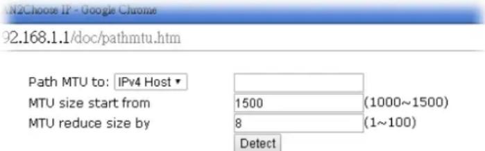 Note: Path MTU discovery will reduce the MTU size for 3 times.Accept CancelPath MTU to - Enter the IP address as the specific transmit path.MTU size start from - Determine the starting point value of the packet. Default setting is 1500.MTU reduce size by - It determines the decreasing size of MTU value. For example, the number specified in this field is “8”. The maximum MTU size is “1500”. After clicking the “detect” button, the system will calculate and get the suitable MTU value such as 1500, 1492, 1484 and etc., automatically.Detect - Click it to detect a suitable MTU valueAccept - After clicking it, the detected value will bedisplayed in the field of MTU. Note: Path MTU discovery will reduce the MTU size for 3 times.Accept CancelPath MTU to - Enter the IP address as the specific transmit path.MTU size start from - Determine the starting point value of the packet. Default setting is 1500.MTU reduce size by - It determines the decreasing size of MTU value. For example, the number specified in this field is “8”. The maximum MTU size is “1500”. After clicking the “detect” button, the system will calculate and get the suitable MTU value such as 1500, 1492, 1484 and etc., automatically.Detect - Click it to detect a suitable MTU valueAccept - After clicking it, the detected value will bedisplayed in the field of MTU. |
| RIP Protocol | Routing Information Protocol is abbreviated as RIP (RFC1058)specifying how routers exchange routing tables information.Click Enable RIP for activating this function. |
| Bridge Mode | Enable Full Bridge Mode - If the function is enabled, the router will work as a bridge modem which is able to forward incoming packets with VLAN tags.Enable Bridge Mode - If the function is enabled, the router will work as a bridge modem. Yet, the incoming packets with VLAN tags will be discarded.Enable Firewall - It is available when Bridge Mode is enabled. When both Bridge Mode and Firewall check boxes are enabled, the settings configured (user profiles) under User Management will be ignored. And all of the filter rules defined and enabled in Firewall menu will be activated.Bridge Subnet - Make a bridge between the selected LAN subnet and such WAN interface. |
| TTL | Change the TTL value - Enable or disable the TTL (Time to Live) for a packet transmitted through Vigor router.I f enabled - TTL value will be reduced (-1) when it passes through Vigor router. It will cause the client, accessing Internet through Vigor router, be blocked by certain ISP when TTL value becomes “0”.I f disabled - TTL value will not be reduced. Then, when a packet passes through Vigor router, it will not be cancelled. That is, the client who sends out the packet will not be blocked by ISP. |
| WAN IP Network Settings | This group allows you to obtain an IP address automatically and allows you Enter IP address manually.WAN IP Alias - If you have multiple public IP addresses and would like to utilize them on the WAN interface, please use WAN IP Alias. You can set up to 32 public IP addresses other than the current one you are using.Obtain an IP address automatically - Click this button to obtain the IP address automatically if you want to use Dynamic IP mode.Router Name: Enter the router name provided by ISP.Domain Name: Enter the domain name that you have assigned.DHCP Client Identifier: Check the box to specify username and password as the DHCP client identifier for some ISP.Usage: Type a name as username. The maximum length of the user name you can set is 63 characters.Password: Type a password. The maximum length of the password you can set is 62 characters.Specify an IP address - Click this radio button to specify some data if you want to use Static IP mode.IP Address: Enter the IP address.Subnet Mask: Enter the subnet mask.Gateway IP Address: Enter the gateway IP address.Default MAC Address: Click this radio button to use default MAC address for the router.Specify a MAC Address: Some Cable service providers specify a specific MAC address for access authentication. Insuch cases you need to click the Specify a MAC Address and enter the MAC address in the MAC Address field. |
| DNS Server IP Address | Enter the primary IP address for the router if you want to use Static IP mode. If necessary, Enter secondary IP address for necessity in the future. |
After finishing all the settings here, please click OK to activate them.
II-1-2-3 Details Page for PPTP/L2TP in WAN1/WAN2 (Physical Mode: Ethernet)
To use PPTP/L2TP as the accessing protocol of the internet, please click the PPTP/L2TP tab. The following web page will be shown.
WAN >> Internet Access
WAN 1
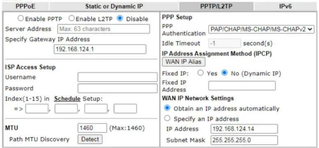
text_image
PPPoE Static or Dynamic IP PPTP/L2TP IPv6 Enable PPTP Enable L2TP Disable Server Address Max: 63 characters Specify Gateway IP Address 192.168.124.1 ISP Access Setup Username Password Index(1-15) in Schedule Setup: => , , , , , MTU 1460 (Max:1460) Path MTU Discovery Detect PPP Setup PPP PAP/CHAP/MS-CHAP/MS-CHAPv2 Authentication Idle Timeout -1 second(s) IP Address Assignment Method (IPCP) WAN IP Alias Fixed IP: Yes No (Dynamic IP) Fixed IP Address WAN IP Network Settings Obtain an IP address automatically Specify an IP address IP Address 192.168.124.14 Subnet Mask 255.255.255.0OK
Cancel
Available settings are explained as follows:
| Item Description | |
| PPTP/L2TP | Enable PPTP - Click this radio button to enable a PPTP client to establish a tunnel to a DSL modem on the WAN interface.Enable L2TP - Click this radio button to enable a L2TP client to establish a tunnel to a DSL modem on the WAN interface.Disable - Click this radio button to close the connection through PPTP or L2TP.Server Address - Specify the IP address of the PPTP/ L2TP server if you enable PPTP/ L2TP client mode.Specify Gateway IP Address - Specify the gateway IP address for DHCP server. |
| ISP Access Setup | Username - Enter the username provided by ISP in this field.The maximum length of the user name you can set is 63 characters.Password -Enter the password provided by ISP in this field.The maximum length of the password you can set is 62 characters.Index(1-15) in Schedule Setup - You can Enter four sets of time schedule for your request. All the schedules can be set previously in Applications >> Schedule web page and you can use the number that you have set in that web page. |
| MTU | It means Max Transmit Unit for packet.Path MTU Discovery - It is used to detect the maximum MTU size of a packet not to be segmented in specific transmit path.Click Detect to open the following dialog. |
 92.168.1.1/doc/pathmtu.htmPath MTU to: IPv4 Host•MTU size start from 92.168.1.1/doc/pathmtu.htmPath MTU to: IPv4 Host•MTU size start from  MTU reduce size by MTU reduce size by  Note: Path MTU discovery will reduce the MTU size for 3 times.Accept CancelPath MTU to - Enter the IP address as the specific transmit path.MTU size start from - Determine the starting point value of the packet. Default setting is 1500.MTU reduce size by- It determines the decreasing size of MTU value. For example, the number specified in this field is “8”. The maximum MTU size is “1500”. After clicking the “detect” button, the system will calculate and get the suitable MTU value such as 1500, 1492, 1484 and etc., automatically.Detect - Click it to detect a suitable MTU valueAccept - After clicking it, the detected value will be displayed in the field of MTU. Note: Path MTU discovery will reduce the MTU size for 3 times.Accept CancelPath MTU to - Enter the IP address as the specific transmit path.MTU size start from - Determine the starting point value of the packet. Default setting is 1500.MTU reduce size by- It determines the decreasing size of MTU value. For example, the number specified in this field is “8”. The maximum MTU size is “1500”. After clicking the “detect” button, the system will calculate and get the suitable MTU value such as 1500, 1492, 1484 and etc., automatically.Detect - Click it to detect a suitable MTU valueAccept - After clicking it, the detected value will be displayed in the field of MTU. | |
| PPP/MP Setup | PPP Authentication - Select PAP only or PAP / CHAP / MS-CHAP / MS-CHAPv2 for PPP.Idle Timeout - Set the timeout for breaking down the Internet after passing through the time without any action.IP Address Assignment Method (IPCP)- Usually ISP dynamically assigns IP address to you each time you connect to it and request. In some case, your ISP provides service to always assign you the same IP address whenever you request. In this case, you can fill in this IP address in the Fixed IP field. Please contact your ISP before you want to use this function.WAN IP Alias - If you have multiple public IP addresses and would like to utilize them on the WAN interface, please use WAN IP Alias. You can set up to 32 public IP addresses other than the current one you are using. Enter the additional WAN IP address and check the Enable box. Then click OK to exit the dialog.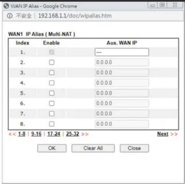 Fixed IP Address - Enter a fixed IP address. Fixed IP Address - Enter a fixed IP address. |
| WAN IP Network Settings | Obtain an IP address automatically - Click this button to obtain the IP address automatically.Specify an IP address - Click this radio button to specify some data.IP Address - Enter the IP address.Subnet Mask - Enter the subnet mask. |
92.168.1.1/doc/pathmtu.htm
After finishing all the settings here, please click OK to activate them.
II-1-2-4 Details Page for WAN3/WAN4 (Physical Mode: Wireless 2.4G/ Wireless 5G)
When Wireless 2.4G is selected as Physical Mode, WAN uses wireless station mode to access Internet. The Router acts as a 2.4GHz wireless station and connects to the specific Wireless AP.

Info
WAN3/ WAN4 (Wireless WAN) is not available for "ax" model.
Open WAN>>Internet Access>>WAN3/4 page. The following web page will be shown.
WAN >> Internet Access
WAN 3
Static or Dynamic IP
Enable
○ Disable
Obtain an IP address automatically
○ Specify an IP address
IP Address
Subnet Mask
Gateway IP Address
192.168.98.46
255.255.255.0
192.168.98.1
WAN Connection Detection
Mode
ARP Detect
MTU
1500 (Max:1500)
Universal Repeater Parameters
SSID
MAC Address (Optional)
Channel :
Security Mode
Encryption Mode
Pre-Shared Key(PSK)
guests
16:49:BC:53:FE:38
Channel 1, 2412MHz
WPA2/PSK
AES
•••••••••
AP Discovery
Note: If Channel is modified, the Channel setting of wireless 2.4G would be also modified.
OK
Cancel
Available settings are explained as follows:
| Item Description | |
| Enable/Disable | Click Enable for activating this function. If you click Disable, this function will be closed and all the settings that you adjusted in this page will be invalid. |
| Obtain an IP address automatically | Click this radio button to obtain the IP address automatically if you want to use Dynamic IP mode. |
| Specify an IP address | Click this radio button to specify dome data if you want to use Static IP mode.IP address - Enter the IP address.Subnet Mask - Enter the subnet mask.Gateway IP Address - Enter the gateway IP address. |
| WAN Connection Detection | Such function allows you to verify whether network connection is alive or not through ARP Detect or Ping Detect.Mode - Choose ARP Detect, Ping Detect or Always On for the system to execute for WAN detection. If you choose Ping Detect as the detection mode, you have to type required settings for the following items.Ping IP - If you choose Ping Detect as detection mode, you also can enable this setting to use current WAN gateway IP address for pinging.With the IP address(es) pinging, Vigor router can check if the WAN connection is on or off.TTL (Time to Live) - Set TTL value of PING operation. |
| MTU | It means Max Transmit Unit for packet. |
| Universal Repeater Parameters | AP Discovery - Click this button to open the Access Point Discovery window. Let wireless 2.4GHz do AP discovery and choose the Wireless AP you want to connect to.Wireless LAN >> Access Point DiscoveryAccess Point ListIndex BSSID Channel RSSI SSID Authentication1 02:1D:λλ:9T:E9:48 11 70% DreyTek-LAN-B Mixed(UPA+UPA2)/PSK2 00:1D:λλ:9T:E9:48 11 78% AP800-alctime UPA2/PSK3 02:1D:λλ:90:20:80 11 26% ap902_2_4G_114_2 UPA2/PSK4 00:1P:λλ:90:20:80 11 26% ap902_Wift_114_1 UPA2/PSK5 02:50:7F:22:33:08 11 23% AP900_110_Bondette... UPA2/PSK6 00:50:7F:22:33:08 11 23% AP900_110_2_4G-1 UPA2/PSK7 02:1D:λλ:7E:41:80 11 13% TestRoaming2_4G-5 Mixed(UPA+UPA2)/PSK8 00:1P:λλ:7E:41:80 11 18% TestRoaming2_4G-A Mixed(UPA+UPA2)/PSK9 00:1P:λλ:DP:75:00 11 63% v2860_lts_1 Mixed(UPA+UPA2)/PSK ScanAP's MAC address □:□:□:□:□:□Add to □ Universal RepeaterNote:1. During the scanning process (~5 seconds), no station is allowed to connect with the router.2. AP Discovery can only support up to 32 APs displayed on the screen.SSID - The identification of the Wireless AP.MAC Address (Optional)- The MAC Address of the Wireless AP.Channel - The channel of frequency of the Wireless AP.Security Mode - The mode to connect to the Wireless AP.Disable - The Router connects to the wireless AP without any encryption mechanism.WEP - The Router connects to the wireless AP as a WEP client and the encryption key should be entered in WEP Key.- 64-Bit - For 64 bits WEP key, either 5 ASCII characters, such as 12345 (or 10 hexadecimal digitals leading by 0x, such as 0x4142434445.)- 128-Bit - For 128 bits WEP key, either 13 ASCII characters, such as ABCDEFGHIJKLM (or 26 hexadecimal digits leading by 0x, such as 0x4142434445464748494A4B4C4D).- WEP keys - Four keys can be entered here, but only one key can be selected at a time. The keys can be entered in ASCII or Hexadecimal. Check the key you wish to use.WPA/PSK - The Router connects to the wireless AP as a WPA client and the encryption key should be entered in PSK.WPA2/PSK - The Router connects to the wireless AP as a WPA2 client and the encryption key should be entered in PSK.- Encryption Mode - WPA/ PSK uses TKIP asEncryption Mode. WPA2/ PSK uses AES as Encryption Mode.- Pre-Shared Key (PSK) - The PSK. Either 8~63 ASCII characters, such as 012345678..(or 64 Hexadecimal digits leading by 0x, such as "0x321253abcde..."). |
After finishing all the settings here, please click OK to activate them.
II-1-2-5 Details Page for 3G/4G USB Modem (PPP mode) in WAN5 / WAN6
To use 3G/4G USB Modem (PPP mode) as the accessing protocol of the internet, please choose Internet Access from WAN menu. Then, select 3G/4G USB Modem (PPP mode) for WAN5/WAN6. The following web page will be shown.
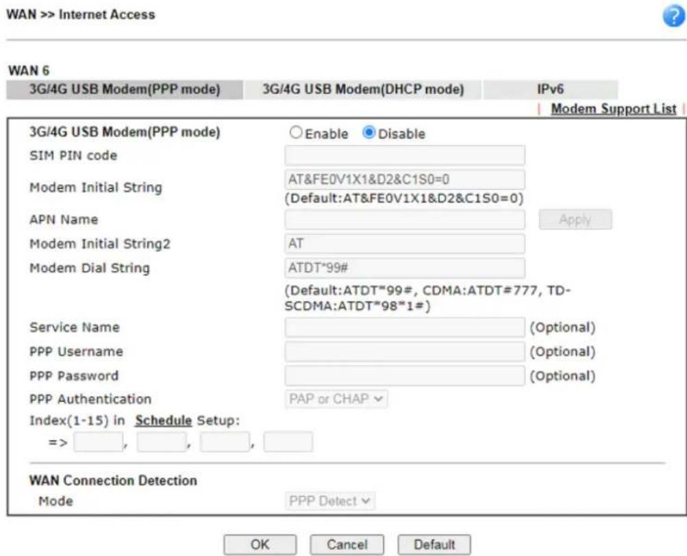
text_image
WAN >> Internet Access 3G/4G USB Modem(PPP mode) 3G/4G USB Modem(DHCP mode) IPv6 Modem Support List 3G/4G USB Modem(PPP mode) Enable Disable SIM PIN code Modem Initial String AT&FE0V1X1&D2&C1S0=0 (Default:AT&FE0V1X1&D2&C1S0=0) APN Name Apply Modem Initial String2 AT Modem Dial String ATDT*99# (Default:ATDT*99#, CDMA:ATDT#777, TD- SCDMA:ATDT*98*1#) Service Name (Optional) PPP Username (Optional) PPP Password (Optional) PPP Authentication PAP or CHAP Index(1-15) in Schedule Setup: => , , , , WAN Connection Detection Mode PPP Detect OK Cancel DefaultAvailable settings are explained as follows:
| Item Description | |
| Modem Support List | It lists all of the modems supported by such router.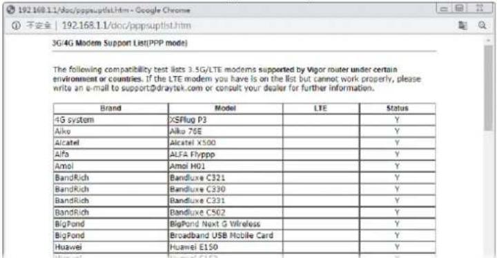 |
| 3G /4G USB Modem (PPP)mode) | Click Enable for activating this function. If you click Disable,this function will be closed and all the settings that you adjusted in this page will be invalid. |
| SIM PIN code | Type PIN code of the SIM card that will be used to access Internet.The maximum length of the PIN code you can set is 15 characters. |
| Modem Initial String | Such value is used to initialize USB modem. Please use the default value. If you have any question, please contact to your ISP.The maximum length of the string you can set is 47 characters. |
| APN Name | APN means Access Point Name which is provided and required by some ISPs. Enter the name and clickApply.The maximum length of the name you can set is 43 characters. |
| Modem Initial String2 | The initial string 1 is shared with APN.In some cases, user may need another initial AT command to restrict 3G band or do any special settings.The maximum length of the string you can set is 47 characters. |
| Modem Dial String | Such value is used to dial through USB mode. Please use the default value. If you have any question, please contact to your ISP.The maximum length of the string you can set is 31 characters. |
| Service Name | Enter the description of the specific network service. |
| PPP Username | Enter the PPP username (optional). The maximum length of the name you can set is 63 characters. |
| PPP Password | Enter the PPP password (optional). The maximum length of the password you can set is 62 characters. |
| PPP Authentication | Select PAP only or PAP or CHAP for PPP. |
| Index (1-15) in Schedule Setup | Set the wireless LAN to work at certain time interval only.You may choose up to 4 schedules out of the 15 schedules pre-defined inApplications >> Schedule setup. The default setting of this field is blank and the function will always work. |
| WAN Connection Detection | Such function allows you to verify whether network connection is alive or not through PPP Detect or Ping Detect.Mode - Choose PPP Detect or Ping Detect for the system to execute for WAN detection. If you choose Ping Detect as the detection mode, you have to type required settings for the following items.Primary/Secondary Ping IP - If you choose Ping Detect as detection mode, you have to type Primary or Secondary IP address in this field for pinging.Ping Gateway IP - If you choose Ping Detect as detection mode, you also can enable this setting to use current WAN gateway IP address for pinging.With the IP address(es) pinging, Vigor router can check if the WAN connection is on or off.TTL (Time to Live) - Set TTL value of PING operation.● Ping Interval - Enter the interval for the system to execute the PING operation. ● Ping Retry - Enter the number of times that the system is allowed to execute the PING operation before WAN disconnection is judged. |
After finishing all the settings here, please click OK to activate them.
II-1-2-6 Details Page for 3G/4G USB Modem (DHCP mode) in WAN5 / WAN6
To use 3G/4G USB Modem (DHCP mode) as the accessing protocol of the internet, please choose Internet Access from WAN menu. Then, select 3G/4G USB Modem (DHCP mode) for WAN5/WAN6. The following web page will be shown.
WAN >> Internet Access

WAN 5
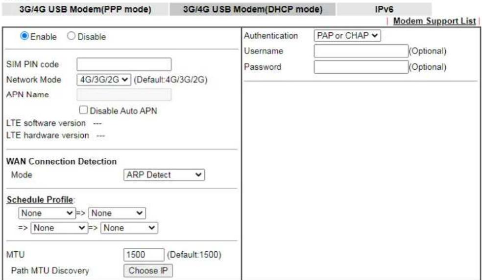
text_image
3G/4G USB Modem(PPP mode) 3G/4G USB Modem(DHCP mode) IPv6 Modem Support List Enable Disable SIM PIN code Network Mode 4G/3G/2G (Default:4G/3G/2G) APN Name Disable Auto APN LTE software version --- LTE hardware version --- WAN Connection Detection Mode ARP Detect Schedule Profile: None => None => None => None MTU 1500 (Default:1500) Path MTU Discovery Choose IP Authentication PAP or CHAP Username (Optional) Password (Optional)Note:
-
Please note that in some case USB port connection will be terminated temporarily to activate the new configuration.
-
VPN feature may be affected when the value of MTU is changed, please also check your value of VPN MSS in "VPN and Remote Access >> PPP General Setup" or "VPN and Remote Access >> IPsec General Setup" page. We recommend to put the same decreased value on VPN MSS. For example, reducing the MTU from 1500 -> 1400, then will need to reduct 100 from MSS value.

The following compatibility test lists 3.5G/LTE modems supported by Vigor router under certain environment or countries. If the LTE modem you have is on the list but cannot work properly, please write an e-mail to support@dravtek.com or consult your dealer for further information.
Available settings are explained as follows:
| Item Description | |
| Modem Support List | It lists all of the modems supported by such router. 3G4G Modem Support List(DHCP mode)The following compatibility test lists 3.5G/LTE modems supported by Vigor router under certain environment or countries. If the LTE modem you have is on the list but cannot work properly, please write an e-mail to support@draytek.com or consult your dealer for further information. 3G4G Modem Support List(DHCP mode)The following compatibility test lists 3.5G/LTE modems supported by Vigor router under certain environment or countries. If the LTE modem you have is on the list but cannot work properly, please write an e-mail to support@draytek.com or consult your dealer for further information.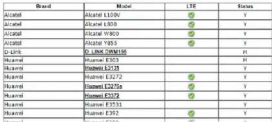 |
| Enable / Disable | Click Enable for activating this function. If you click Disable, this function will be closed and all the settings that you adjusted in this page will be invalid. |
| SIM PIN code | Type PIN code of the SIM card that will be used to access Internet.The maximum length of the PIN code you can set is 19 characters. |
| Network Mode | Force Vigor router to connect Internet with the mode specified here. If you choose 4G/ 3G/ 2G as network mode, the router will choose a suitable one according to the actual wireless signal automatically. |
| APN Name | APN means Access Point Name which is provided and required by some ISPs. Enter the name and click Apply.The maximum length of the name you can set is 47 characters.Disable Auto APN - In default, the APN name will be given automatically (through pre-configured APN profile list) by Vigor router system. To specify an APN name, check this box and enter the APN name manually in the field of APN Name. |
| WAN Connection Detection | Such function allows you to verify whether network connection is alive or not through ARP Detect, Strict ARP Detect or Ping Detect.Mode - Choose ARP Detect, Strict ARP Detect or Ping Detect for the system to execute for WAN detection. If you choose Ping Detect as the detection mode, you have to type required settings for the following items.Primary/Secondary Ping IP - If you choose Ping Detect as detection mode, you have to type Primary or Secondary IP address in this field for pinging.Ping Gateway IP - If you choose Ping Detect as detection mode, you also can enable this setting to use current WAN gateway IP address for pinging.With the IP address(es) pinging, Vigor router can check if the WAN connection is on or off.TTL (Time to Live) - Set TTL value of PING operation.Ping Interval - Enter the interval for the system to execute the PING operation.Ping Retry - Enter the number of times that the system is allowed to execute the PING operation before WAN disconnection is judged. |
| Schedule Profiles | Set the wireless LAN to work at certain time interval only.You may choose up to 4 schedules out of the 15 schedules pre-defined inApplications >> Schedulesetup. The default setting of this field is blank and the function will always work. |
| MTU | It means Max Transmit Unit for packet.Path MTU Discovery- It is used to detect the maximum MTU size of a packet not to be segmented in specific transmit path.Click Choose IP to open the following dialog.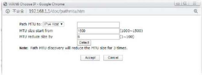 Path MTU to - Enter the IP address as the specific transmit path.MTU size start from - Determine the starting point value of the packet. Default setting is 1500.MTU reduce size by- It determines the decreasing size of MTU value. For example, the number specified in this field is “8”. The maximum MTU size is “1500”. After clicking the “detect” button, the system will calculate and get the suitable MTU value such as 1500, 1492, 1484 and etc., automatically.Detect - Click it to detect a suitable MTU valueAccept - After clicking it, the detected value will be displayed in the field of MTU. Path MTU to - Enter the IP address as the specific transmit path.MTU size start from - Determine the starting point value of the packet. Default setting is 1500.MTU reduce size by- It determines the decreasing size of MTU value. For example, the number specified in this field is “8”. The maximum MTU size is “1500”. After clicking the “detect” button, the system will calculate and get the suitable MTU value such as 1500, 1492, 1484 and etc., automatically.Detect - Click it to detect a suitable MTU valueAccept - After clicking it, the detected value will be displayed in the field of MTU. |
| Authentication | SelectPAP onlyorPAP or CHAPfor PPP authentication.Usage - Enter the username for authentication (optional).Password - Enter the password for authentication (optional). |
After finishing all the settings here, please click OK to activate them.
II-1-2-7 Details Page for 3G/4G USB Modem (DHCP mode) in LTE WAN
It is available for "L" model only. LTE WAN uses the embedded LTE module to access internet.
To use 3G/4G USB Modem (DHCP mode) as the accessing protocol of the internet, please choose Internet Access from WAN menu. Then, select 3G/4G USB Modem (DHCP mode) for LTE. The following web page will be shown.
WAN >> Internet Access

LTE
3G/4G LTE Modem(DHCP mode) IPv6
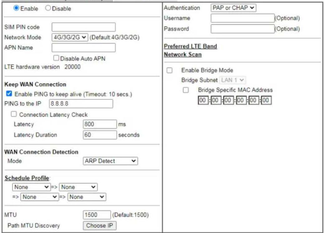
text_image
Enable Disable SIM PIN code Network Mode 4G/3G/2G (Default:4G/3G/2G) APN Name Disable Auto APN LTE hardware version 20000 Keep WAN Connection Enable PING to keep alive (Timeout: 10 secs.) PING to the IP 8.8.8.8 Connection Latency Check Latency 800 ms Latency Duration 60 seconds WAN Connection Detection Mode ARP Detect Schedule Profile: None => None => None => None MTU 1500 (Default:1500) Path MTU Discovery Choose IP Authentication PAP or CHAP Username (Optional) Password (Optional) Preferred LTE Band Network Scan Enable Bridge Mode Bridge Subnet LAN 1 Bridge Specific MAC Address 00:00:00:00:00:00Note:
- Please note that in some case USB port connection will be terminated temporarily to activate the new configuration.
- Preferred LTE band setting will take effect until next LTE connection.
- VPN feature may be affected when the value of MTU is changed, please also check your value of VPN mss by using "VPN mss set" command.
We recommend to put the same decreased value on VPN mss. For example, reducing the MTU from 1500 -> 1400, then it will need to reduct 100 from mss value.

Available settings are explained as follows:
| Item Description | |
| Enable | Click Enable for activating this function. If you click Disable, this function will be closed and all the settings that you adjusted in this page will be invalid. |
| SIM PIN code | Enter PIN code of the SIM card that will be used to access Internet.The maximum length of the PIN code you can set is 15 characters. |
| Network Mode | Force Vigor router to connect Internet with the mode specified here. If you choose 4G/3G/2G as network mode, the router will choose a suitable one according to the actual wireless signal automatically. |
| APN Name | APN means Access Point Name which is provided and required by some ISPs. Enter the name and clickApply.The maximum length of the name you can set is 47 characters.Disable Auto APN - In default, the APN name will be given automatically (through pre-configured APN profile list) by Vigor router system. To specify an APN name, check this box and enter the APN name manually in the field of APN Name. |
| LTE hardware version | The hardware version of the embedded LTE module. |
| Keep WAN Connection | Normally, this function is designed for Dynamic IP environments because some ISPs will drop connections if there is no traffic within certain periods of time. CheckEnable PING to keep alive box to activate this function.Enable PING to Keep alive - If you enable the PING function, please specify an IP address for the system to PING it for keeping alive. Vigor system will send a packet per second to the specified IP address. If the system does not receive any reply from that IP within 10 seconds, Vigor system will reboot LTE module until successfully set LTE connection.PING to the IP - Enter an IP address.Connection Latency Check - Enable the latency time setting for packet reply. If it is enabled (checked), Vigor system will wait for the packet reply from the specified IP address.When the time of waiting packet reply reaches the time threshold (defined in Latency) and continues for a period of time (defined in Latency Duration), Vigor system will reboot LTE module until successfully set LTE connection.Latency - Set a time threshold for packet reply. Default value is 800 (unit: micro-second).Latency Duration - Set a time period. Default value is 60 (unit: second). |
| WAN Connection Detection | Such function allows you to verify whether network connection is alive or not through ARP Detect or Ping Detect.Mode - Choose ARP Detect or Ping Detect for the system to execute for WAN detection. If you choose Ping Detect as the detection mode, you have to type required settings for the following items.Primary/Secondary Ping IP - If you choose Ping Detect as detection mode, you have to type Primary or Secondary IP address in this field for pinging.Ping Gateway IP - If you choose Ping Detect as detection mode, you also can enable this setting to use current WAN gateway IP address for pinging.With the IP address(es) pinging, Vigor router can check if the WAN connection is on or off.TTL (Time to Live) - Set TTL value of PING operation.Ping Interval - Enter the interval for the system to execute the PING operation.Ping Retry - Enter the number of times that the system is allowed to execute the PING operation before WAN disconnection is judged. |
| Schedule Profile | Set the LTE WAN to work at certain time interval only.Specify up to 4 time schedule entries to enable or disable the WAN. All the schedules can be set previously inApplications>> Schedule web page and you can use the number that youhave set in that web page. |
| MTU | Maximum Transmission Unit, the size of the largest packet, in bytes, that can be transmitted to the WAN. The maximum value is 1500.Path MTU Discovery- Use this feature to determine the optimal MTU size for the WAN.Click Choose IP to open the following dialog.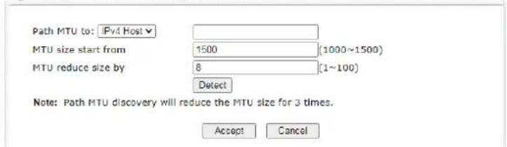 Path MTU to - Select Host / IP, for an IPv4 address or Host / IPv6, for an IPv6 address, and then enter the IP address in the textbox.MTU size start from - Determine the starting point value of the packet.MTU reduce size by - Number of octets by which to decrease the 1500-byte MTU. Start with a 0 value for the reduce size and click the Detect button. If the message Fail is returned, increase the MTU reduce size and try again. Repeat until you see the message Success, indicating that the optimal MTU size has been reached.Detect - Click it to detect a suitable MTU valueAccept - After clicking it, the detected value will be displayed in the field of MTU. Path MTU to - Select Host / IP, for an IPv4 address or Host / IPv6, for an IPv6 address, and then enter the IP address in the textbox.MTU size start from - Determine the starting point value of the packet.MTU reduce size by - Number of octets by which to decrease the 1500-byte MTU. Start with a 0 value for the reduce size and click the Detect button. If the message Fail is returned, increase the MTU reduce size and try again. Repeat until you see the message Success, indicating that the optimal MTU size has been reached.Detect - Click it to detect a suitable MTU valueAccept - After clicking it, the detected value will be displayed in the field of MTU. |
| Authentication The protocol used for PPP authentication.PAP only - Only PAP (Password Authentication Protocol) is used.PAP or CHAP - Both PAP and CHAP (Challenge-Handshake Authentication Protocol) can be used for PPP authentication. Router negotiates with the PPTP or L2TP server to determine which protocol to use.Usage -Username provided by the ISP for authentication (optional).Password -Password provided by the ISP for authentication (optional). | |
| Preferred LTE Band | Click the link to specify the preferred LTE band. A dialog will be open and list available LTE bands supported by the LTE module for the user to choose for establishing the network connection. |
| Network Scan | Click it to search the nearby ISP for LTE connection.The following dialog lists available ISP services detected by Vigor router.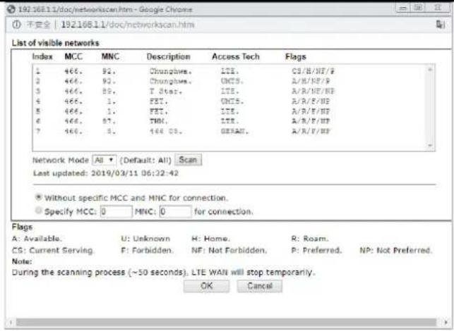 |
| Enable Bridge Mode | If the function is enabled, the router will work as a LTE bridge modem.Bridge Specific MAC Address - Enter the MAC address of the device (e.g., a computer, router or a WiFi router) which needs to be connected to the Internet through the LTE modem. |
After finishing all the settings here, please click OK to activate them.
II-1-2-8 Details Page for 3G/4G/5G Modem (DHCP mode) in 5G-NR WAN
It is available for "5G-NR" model only.
To use 3G/4G/5G Modem (DHCP mode) as the accessing protocol of the internet, please choose Internet Access from WAN menu. Then, select 3G/4G/5G Modem (DHCP mode) for 5G-NR. The following web page will be shown.
WAN >> Internet Access
5G-NR
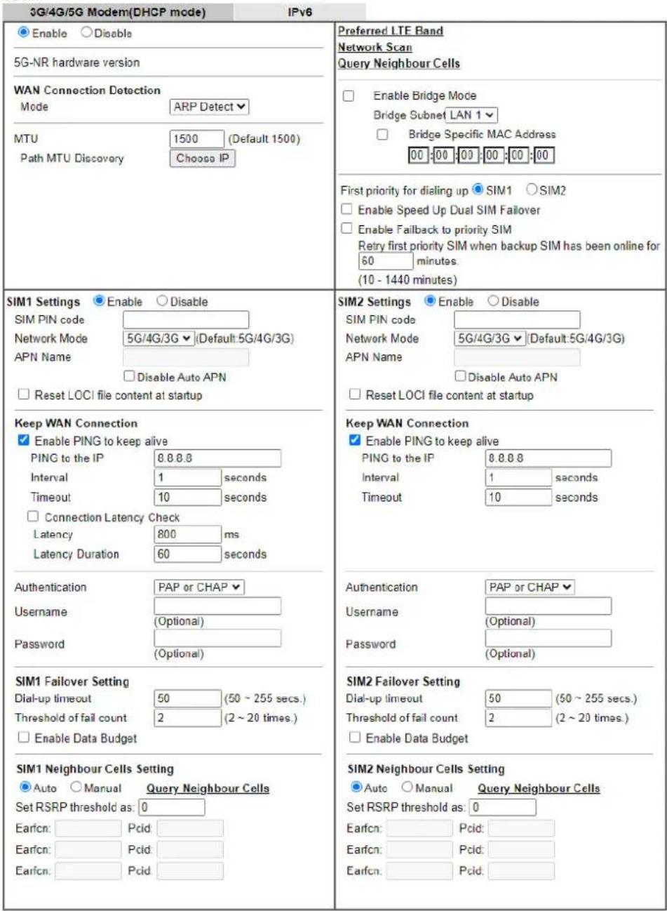
text_image
3G/4G/5G Modem(DHCP mode) IPv6 Enable Disable 5G-NR hardware version WAN Connection Detection Mode ARP Detect MTU 1500 (Default 1500) Path MTU Discovery Choose IP First priority for dialing up SIM1 SIM2 Enable Speed Up Dual SIM Failover Enable Failback to priority SIM Retry first priority SIM when backup SIM has been online for 60 minutes. (10 - 1440 minutes) SIM1 Settings Enable Disable SIM PIN code Network Mode 5G/4G/3G (Default:5G/4G/3G) APN Name Disable Auto APN Reset LOCI file content at startup Keep WAN Connection Enable PING to keep alive PING to the IP 8.8.8.8 Interval 1 seconds Timeout 10 seconds Connection Latency Check Latency 800 ms Latency Duration 60 seconds Authentication PAP or CHAP Username (Optional) Password (Optional) SIM1 Failover Setting Dial-up timeout 50 (50 ~ 255 secs.) Threshold of fail count 2 (2 ~ 20 times.) Enable Data Budget SIM1 Neighbour Cells Setting Auto Manual Query Neighbour Cells Set RSRP threshold as: 0 Earfcn: Pcid: Earfcn: Pcid: Earfcn: Pcid: Preferred LTE Band Network Scan Query Neighbour Cells Enable Bridge Mode Bridge Subnet LAN 1 Bridge Specific MAC Address 00:00:00:00:00:00 First priority for dialing up SIM1 SIM2 Enable Speed Up Dual SIM Failover Enable Failback to priority SIM Retry first priority SIM when backup SIM has been online for 60 minutes. (10 - 1440 minutes) SIM2 Settings Enable Disable SIM PIN code Network Mode 5G/4G/3G (Default:5G/4G/3G) APN Name Disable Auto APN Reset LOCI file content at startup Keep WAN Connection Enable PING to keep alive PING to the IP 8.8.8.8 Interval 1 seconds Timeout 10 seconds Authentication PAP or CHAP Username (Optional) Password (Optional) SIM2 Failover Setting Dial-up timeout 50 (50 ~ 255 secs.) Threshold of fail count 2 (2 ~ 20 times.) Enable Data Budget SIM2 Neighbour Cells Setting Auto Manual Query Neighbour Cells Set RSRP threshold as: 0 Earfcn: Pcid: Earfcn: Pcid: Earfcn: Pcid:Note:
- Only one SIM will be used at the same time.
SIM1 (the lower SIM slot) has a higher priority by default. - Preferred LTE band setting will take effect until next LTE connection.
- Enabling failback to priority SIM option will drop backup SIM 5G-NR connection when doing the retry.

Available settings are explained as follows:
| Item Description | |
| Enable | Click Enable for activating this function. If you click Disable, this function will be closed and all the settings that you adjusted in this page will be invalid. |
| WAN Connection Detection | Such function allows you to verify whether network connection is alive or not through ARP Detect or Ping Detect.Mode - Choose ARP Detect or Ping Detect for the system to execute for WAN detection. If you choose Ping Detect as the detection mode, you have to type required settings for the following items.Primary/Secondary Ping IP - If you choose Ping Detect as detection mode, you have to type Primary or Secondary IP address in this field for pinging.Ping Gateway IP - If you choose Ping Detect as detection mode, you also can enable this setting to use current WAN gateway IP address for pinging.With the IP address(es) pinging, Vigor router can check if the WAN connection is on or off.TTL (Time to Live) - Set TTL value of PING operation.Ping Interval - Enter the interval for the system to execute the PING operation.Ping Retry - Enter the number of times that the system is allowed to execute the PING operation before WAN disconnection is judged. |
| MTU | Maximum Transmission Unit, the size of the largest packet, in bytes, that can be transmitted to the WAN. The maximum value is 1500.Path MTU Discovery - Use this feature to determine the optimal MTU size for the WAN.Click Choose IP to open the following dialog.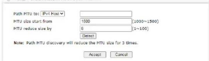 Path MTU to - Select Host / IP, for an IPv4 address or Host / IPv6, for an IPv6 address, and then enter the IP address in the textbox.MTU size start from - Determine the starting point value of the packet.MTU reduce size by - Number of octets by which to decrease the 1500-byte MTU. Start with a 0 value for the reduce size and click the Detect button. If the message Fail is returned, increase the MTU reduce size and try again. Repeat until you see the message Success, indicating that the optimal MTU size has been reached.Detect - Click it to detect a suitable MTU valueAccept - After clicking it, the detected value will be displayed in the field of MTU. Path MTU to - Select Host / IP, for an IPv4 address or Host / IPv6, for an IPv6 address, and then enter the IP address in the textbox.MTU size start from - Determine the starting point value of the packet.MTU reduce size by - Number of octets by which to decrease the 1500-byte MTU. Start with a 0 value for the reduce size and click the Detect button. If the message Fail is returned, increase the MTU reduce size and try again. Repeat until you see the message Success, indicating that the optimal MTU size has been reached.Detect - Click it to detect a suitable MTU valueAccept - After clicking it, the detected value will be displayed in the field of MTU. |
| Preferred LTE Band | Click the link to specify the preferred LTE band. A dialog willbe open and list available LTE bands supported by the LTE module for the user to choose for establishing the network connection.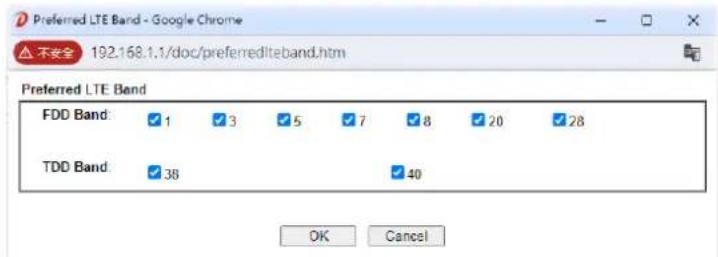 |
| Network Scan | Click it to search the nearby ISP forLTEconnection.The following dialog lists available ISP services detected by Vigor router.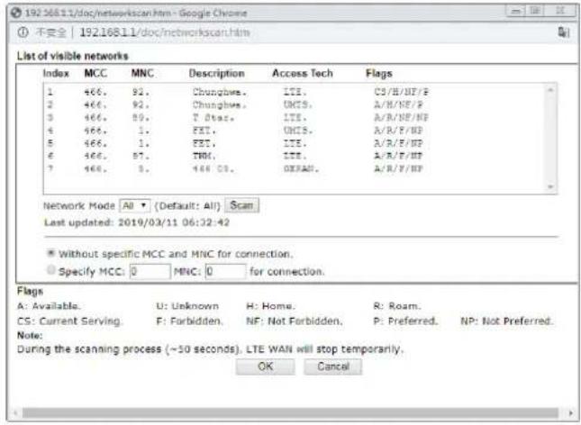 |
| Query Neighbour Cells | Vigor system will scan automatically to locate the neighboring access points and display corresponding information.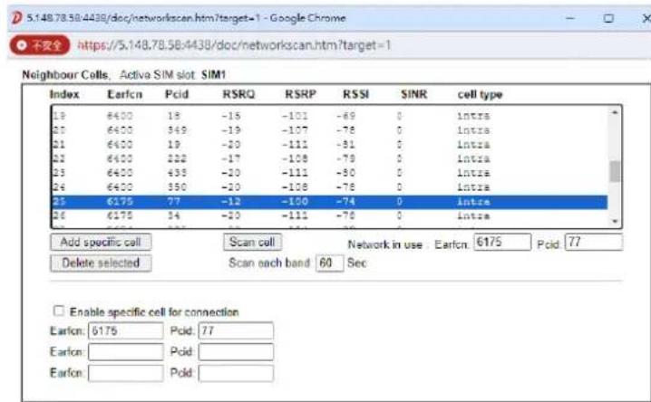 Note:If set wrong cell, LTE WAN cannot connect to networkOK CancelAdd specific cell- Select one of the entries from the Neighbour Cells list and click Add specific cell to add it for connection.Scaning / Scan- If “Scanning” appears, it means that the Vigor system is searching the APs to display information related to the neighboring APs. If “Scan” appears, the Vigor router is ready to perform the searching job.Network in use- Displays current used Earfcn and Pcidvalues.Delete selected- Remove the access point which has been added to the specific cell for connection.Enable specific cell for connection- If selected, Vigor router will only connect to the access points specified in this area.Earfcn (E-UTRA Absolute Radio Frequency Channel Number) / Pcid(Physical cell ID) - Both values are used for identifying the access point. Enter the values for specific access point by referring to the values displayed on the Neighbour Cells list. Note:If set wrong cell, LTE WAN cannot connect to networkOK CancelAdd specific cell- Select one of the entries from the Neighbour Cells list and click Add specific cell to add it for connection.Scaning / Scan- If “Scanning” appears, it means that the Vigor system is searching the APs to display information related to the neighboring APs. If “Scan” appears, the Vigor router is ready to perform the searching job.Network in use- Displays current used Earfcn and Pcidvalues.Delete selected- Remove the access point which has been added to the specific cell for connection.Enable specific cell for connection- If selected, Vigor router will only connect to the access points specified in this area.Earfcn (E-UTRA Absolute Radio Frequency Channel Number) / Pcid(Physical cell ID) - Both values are used for identifying the access point. Enter the values for specific access point by referring to the values displayed on the Neighbour Cells list. |
| Enable Bridge Mode | Enable Bridge Mode- If the function is enabled, the router will work as a LTE bridge modem.Bridge Subnet- Select an interface.Bridge Specific MAC Address- Enter the MAC address of the device (e.g., a computer, router or a WiFi router) which needs to be connected to the Internet through the LTE modem. |
| First priority for dialing up | SIM1/SIM2- Select SIM1 or SIM2 as the first priority for dialing up. The default setting is SIM1.Enable Speed Up Dual SIM Failover- If selected, Vigor router will speed up the SIM failover procedure to prevent disconnection.Enable Failback to priority SIM- If selected, the Vigor router will return to use the priority SIM for network connection after the time interval set below.Retry first priority SIM when backup SIM has been online for XXX minutes- Set the time interval. |
| SIM1 Settings / SIM2 Settings | |
| SIM PIN code | Enter PIN code of the SIM card that will be used to access Internet. |
| Network Mode | Force Vigor router to connect Internet with the mode specified here. If you choose 4G/3G/5G as network mode, the router will choose a suitable one according to the actual wireless signal automatically. |
| APN Name | APN means Access Point Name which is provided and required by some ISPs. Enter the name.Disable Auto APN- In default, the APN name will be given automatically (through pre-configured APN profile list) by Vigor router system. To specify an APN name, check this box and enter the APN name manually in the field of APN Name. |
| Reset LOCI file content at startup | Clean the LOCI file (e.g., information of RPLMN, FPLNM stored in SIM card) before accessing Internet with SIM card again. |
| Keep WAN Connection | Normally, this function is designed for Dynamic IP environments because some ISPs will drop connections if there is no traffic within certain periods of time.Enable PING to Keep alive- If you enable the PING function, please specify an IP address for the system to PING it for keeping alive.PING to the IP- Enter an IP address.Interval- Set the time interval to send out the keepalive packet.Timeout- Vigor system will send a packet per secondto the specified IP address. If the system does not receive any reply from that IP within 10 seconds, Vigor system will reboot LTE module until successfully set LTE connection.Connection Latency Check - Enable the latency time setting for packet reply. If it is enabled (checked), Vigor system will wait for the packet reply from the specified IP address. When the time of waiting packet reply reaches the time threshold (defined in Latency) and continues for a period of time (defined in Latency Duration), Vigor system will reboot LTE module until successfully set LTE connection.Latency- Set a time threshold for packet reply. Default value is 800 (unit: micro-second).Latency Duration- Set a time period. Default value is 60 (unit: second). |
| Authentication The protocol used for PPP authentication.PAP only- Only PAP (Password Authentication Protocol) is used.PAP or CHAP- Both PAP and CHAP (Challenge-Handshake Authentication Protocol) can be used for PPP authentication. Router negotiates with the PPTP or L2TP server to determine which protocol to use.Usage-Username provided by the ISP for authentication (optional).Password-Password provided by the ISP for authentication (optional). | |
SIM1/SIM2 Failover Setting
| Dial-up timeout | Set the time out interval (50 to 255 seconds). |
| Threshold of fail count | Set the maximum times (2 to 20) of failed dial-ups. After that, the system will stop dial-up and use another SIM card for dial-up instead. |
| Enable Data Budget | When selected, WAN Budget is enabled for this WAN.Quota Limit- Enter the data traffic quota allowed for such WAN interface. There are two unit (MB and GB) offered for you to specify.When quota exceeded: Shutdown WAN interface- All the outgoing traffics through the WAN interface will be terminated.When quota exceeded: Send alert SMS to- The system will send out a warning message to a specified mail address when the quota is running out. However, the connection charges will be calculated continuously.Monthly- Some ISP might apply for the network limitation based on the traffic limit per month. This setting is to offer a mechanism of resetting the traffic record every month.MonthlyCustomSelect the day of a month when your (cellular) data resets.Data quota resets on day1▼at00:00▼Data quota resets on day...-Some ISP might apply for the network limitation based on the traffic limit per month. This setting is to offer a mechanism for resetting the trafficrecord every month. You can determine the starting day in one month.Custom- This setting allows the user to define the billing cycle according to his request. The WAN budget will be reset with an interval of billing cycle.Monthly is default setting. If long period or a short period is required, useCustom. The period of cycle duration is between 1 day and 60 days. You can determine the cycle duration by specifying the days and the hours. In addition, you can specify which day of today is in a cycle.Use Cycle in hours - Monthly CustomUse Cycle in hoursUse Cycle in daysUsage counter resets at the beginning of each cycle.Cycle duration: 1 days and 0 hoursToday is day 1 in the cycle.Cycle duration: Specify the days and hours to reset the traffic record. For example, 7 means the whole cycle is 7 days; 20 means the whole cycle is 20 days. When the time is up, the router will reset the traffic record automatically.Today is day - Specify the day in the cycle as the starting point which Vigor router will reset the traffic record. For example, “3” means the third day of the cycle duration.Use Cycle in days - Monthly CustomUse Cycle in hoursUse Cycle in daysUsage counter resets at the beginning of each cycle.Cycle duration: 1 days.Today is day 1 in the cycle and data quota resets at 00:00Cycle duration: Specify the days to reset the traffic record. For example, 7 means the whole cycle is 7 days; 20 means the whole cycle is 20 days. When the time is up, the router will reset the traffic record automatically.Today is day - Specify the day and time for data quota rest in the cycle as the starting point which Vigor router will reset the traffic record. For example, “3” means the third day of the cycle duration. |
SIM1/SIM2 Neighbour Cells Settings
| Auto | Vigor router will automatically scan and select the access points with values larger than the RSRP threshold for connection.Set RSRP threshold as - Set the value. |
| Manual | Vigor router will connect to the access point(s) with the values (Earfcn and Pcid) set below.Earfcn / Pcid - Click the Query Neighbour Cells link to display the access point. Enter the value based on the neighbor cell (access point) of the one you want the Vigorrouter to connect. |
After finishing all the settings here, please click OK to activate them.
II-1-2-9 Details Page for IPv6 – Offline in WAN1/WAN2/WAN5/WAN6
When Offline is selected, the IPv6 connection will be disabled.
| WAN >> Internet Access |
WAN 1
| PPPoE | Static or Dynamic IP | PPTP/L2TP | IPv6 |
| Internet Access Mode Connection Type | Offline | ||

II-1-2-10 Details Page for IPv6 – PPP in WAN1/WAN2
| WAN >> Internet Access | ? |
WAN 1
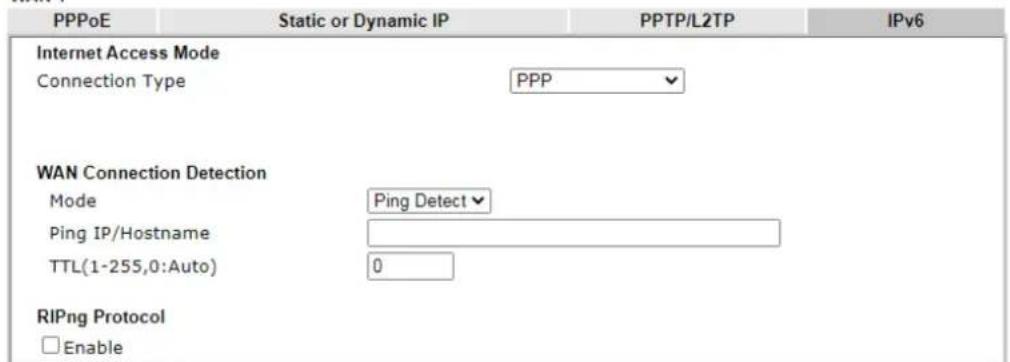
text_image
PPPoE Static or Dynamic IP PPTP/L2TP IPv6 Internet Access Mode Connection Type PPP WAN Connection Detection Mode Ping Detect Ping IP/Hostname TTL(1-255,0:Auto) 0 RIPng Protocol EnableNote:
IPv4 WAN setting should be PPPoE / PPPoA client.

Available settings are explained as follows:
| Item Description | |
| WAN Connection Detection | Such function allows you to verify whether network connection is alive or not through Ping Detect. Mode - Choose Always On or Ping Detect for the system to execute for WAN detection. Always On means no detection will be executed. The network connection will be on always.● Ping IP/Hostname - If you choose Ping Detect as detection mode, you have to type IP address in this field for pinging.● TTL (Time to Live) -If you choose Ping Detect as detection mode, you have to type TTL value. |
| RIPng Protocol RIPng (RIP next generation) offers the same functions and benefits as IPv4 RIP v2. | |
Below shows an example for successful IPv6 connection based on PPP mode.
Online Status
| Physical Connection | System Uptime: 0:2:32 | |||
| IPv4 | IPv6 | |||
| LAN Status | ||||
| IP Address | ||||
| 2001:B010:7300:201:21D:AAFF:FEA6:2568/64 (Global) | ||||
| FE80::21D:AAFF:FEA6:2568/64 (Link) | ||||
| TX Packets | RX Packets | TX Bytes | RX Bytes | |
| 7 | 4 | 690 | 328 | |
| WAN2 IPv6 Status | >> Drop PPP | |||
| Enable | Mode | Up Time | ||
| Yes | PPP | 0:02:08 | ||
| IP | Gateway IP | |||
| 2001:B010:7300:201:21D:AAFF:FEA6:256A/128 (Global) | FE80::90;1A00:242:AD52 | |||
| FE80::1D:AAFF:FEA6:256A/128 (Link) | ||||
| DNS IP | ||||
| 2001:B000:168::1 | ||||
| 2001:B000:168::2 | ||||
| TX Packets | RX Packets | TX Bytes | RX Bytes | |
| 7 | 9 | 544 | 1126 | |

Info
At present, the IPv6 prefix can be acquired via the PPPoE mode connection which is available for the areas such as Taiwan (hinet), the Netherlands, Australia and UK.
II-1-2-11 Details Page for IPv6 – TSPC in WAN1/WAN2/WAN5/WAN6
Tunnel setup protocol client (TSPC) is an application which could help you to connect to IPv6 network easily.
Please make sure your IPv4 WAN connection is OK and apply one free account from hexago (http://gogonet.gogo6.com/page/freenet6-account) before you try to use TSPC for network connection. TSPC would connect to tunnel broker and requests a tunnel according to the specifications inside the configuration file. It gets a public IPv6 IP address and an IPv6 prefix from the tunnel broker and then monitors the state of the tunnel in background.
After getting the IPv6 prefix and starting router advertisement daemon (RADVD), the PC behind this router can directly connect to IPv6 the Internet.
WAN 1
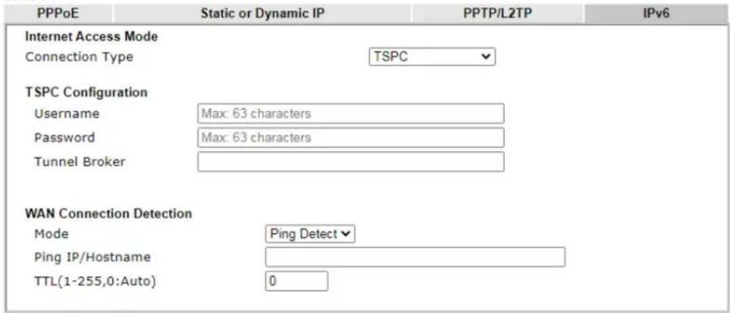
text_image
PPPoE Static or Dynamic IP PPTP/L2TP IPv6 Internet Access Mode Connection Type TSPC TSPC Configuration Username Max: 63 characters Password Max: 63 characters Tunnel Broker WAN Connection Detection Mode Ping Detect Ping IP/Hostname TTL(1-255,0:Auto) 0
Available settings are explained as follows:
| Item Description | |
| Username | It is suggested for you to apply another username and password for http://gogonet.gogo6.com/page/freenet6-account.The maximum length of the name you can set is 63 characters. |
| Password | Enter the password assigned with the user name.The maximum length of the name you can set is 19 characters. |
| Tunnel Broker | Enter the address for the tunnel broker IP, FQDN or an optional port number. |
| WAN Connection Detection | Such function allows you to verify whether network connection is alive or not through Ping Detect.Mode - Choose Always On or Ping Detect for the system to execute for WAN detection. Always On means no detection will be executed. The network connection will be on always.Ping IP/Hostname - If you choose Ping Detect as detection mode, you have to type IP address in this field for pinging.TTL (Time to Live) -If you choose Ping Detect as detection mode, you have to type TTL value. |
After finished the above settings, click OK to save the settings.
II-1-2-12 Details Page for IPv6 – AICCU in WAN1/WAN2/WAN5/WAN6
WAN >> Internet Access

WAN 1
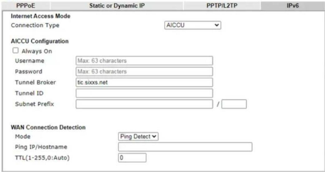
text_image
PPPoE Static or Dynamic IP PPTP/L2TP IPv6 Internet Access Mode Connection Type AICCU AICCU Configuration □ Always On Username Max: 63 characters Password Max: 63 characters Tunnel Broker tic.sixxs.net Tunnel ID Subnet Prefix / WAN Connection Detection Mode Ping Detect▼ Ping IP/Hostname TTL(1-255,0:Auto) 0Note:
If "Always On" is not enabled, AICCU connection would only retry three times.
OK
Cancel
Available settings are explained as follows:
| Item Description | |
| Always On | Check this box to keep the network connection always. |
| Username | Enter the name obtained from the broker. Please apply new account at http://www.sixxs.net/. It is suggested for you to apply another username and password.The maximum length of the name you can set is 19 characters. |
| Password | Enter the password assigned with the user name.The maximum length of the password you can set is 19 characters. |
| Tunnel Broker | It means a server of AICCU. The server can provide IPv6 tunnels to sites or end users over IPv4.Enter the address for the tunnel broker IP, FQDN or an optional port number. |
| Tunnel ID | One user account may have several tunnels. And, each tunnel shall have one specified tunnel ID (e.g., T115394).Enter the ID offered by Tunnel Broker. |
| Subnet Prefix | Enter the subnet prefix address obtained from service provider.The maximum length of the prefix you can set is 128 characters. |
| WAN Connection Detection | Such function allows you to verify whether network connection is alive or not through Ping Detect.Mode - Choose Always On or Ping Detect for the system toexecute for WAN detection.● Ping IP/Hostname – If you choose Ping Detect as detection mode, you have to type IP address in this field for pinging.● TTL (Time to Live) -If you choose Ping Detect as detection mode, you have to type TTL value. |
After finished the above settings, click OK to save the settings.
II-1-2-13 Details Page for IPv6 – DHCPv6 Client in WAN1/WAN2
DHCPv6 client mode would use DHCPv6 protocol to obtain IPv6 address from server.
WAN >> Internet Access

WAN 1
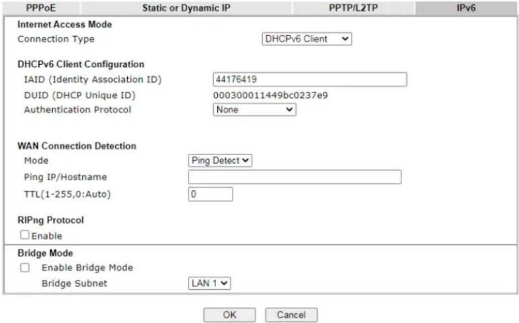
text_image
PPPoE Static or Dynamic IP PPTP/L2TP IPv6 Internet Access Mode Connection Type DHCPv6 Client DHCPv6 Client Configuration IAID (Identity Association ID) 44176419 DUID (DHCP Unique ID) 000300011449bc0237e9 Authentication Protocol None WAN Connection Detection Mode Ping Detect Ping IP/Hostname TTL(1-255,0:Auto) 0 RIPng Protocol □ Enable Bridge Mode □ Enable Bridge Mode Bridge Subnet LAN 1 OK CancelAvailable settings are explained as follows:
After finished the above settings, click OK to save the settings.
| Item Description | |
| DHCPv6 ClientConfiguration | IAID - Type a number as IAID.DUID - Display the DHCP unique ID used by such WAN interface.Authentication Protocol - Such protocol will be used for the client to be authenticated by DHCPv6 server before accessing into Internet. There are three types can be specified,Reconfigure Key, Delayed and None. In general, the default setting is None.Reconfigure Key - During the connection process, DHCPv6 server will authenticate the client automatically.Delayed - During the connection process, DHCPv6 server will authenticate and identify the client based on the key ID, realm and secret information specified in these fields.Key ID - Type a value (range from 1 to 65535) which willbe used to generate HMAC-MD5 value.Realm - The name (1 to 31 characters) typed here will identify the key which generates HMAC-MD5 value.Secret - Type a text (1 to 31 characters) as s a unique identifier for each client on each DHCP server. |
| WAN Connection Detection | Such function allows you to verify whether network connection is alive or not through NS Detect or Ping Detect.Mode - Choose Always On, Ping Detect or NS Detect for the system to execute for WAN detection. With NS Detect mode, the system will check if network connection is established or not, like IPv4 ARP Detect. Always On means no detection will be executed. The network connection will be on always.Ping IP/Hostname - If you choose Ping Detect as detection mode, you have to type IP address in this field for pinging.TTL (Time to Live) -If you choose Ping Detect as detection mode, you have to type TTL value. |
| RIPng Protocol RIPng (RIP next generation) offers the same functions and benefits as IPv4 RIP v2. | |
| Bridge Mode | Enable Bridge Mode - If the function is enabled, the router will work as a bridge modem.Enable Firewall - It is available when Bridge Mode is enabled. When both Bridge Mode and Firewall check boxes are enabled, the settings configured (user profiles) under User Management will be ignored. And all of the filter rules defined and enabled in Firewall menu will be activated.Bridge Subnet - Make a bridge between the selected LAN subnet and such WAN interface. |
II-1-2-14 Details Page for IPv6 – Static IPv6 in WAN1/WAN2
This type allows you to setup static IPv6 address for WAN interface.
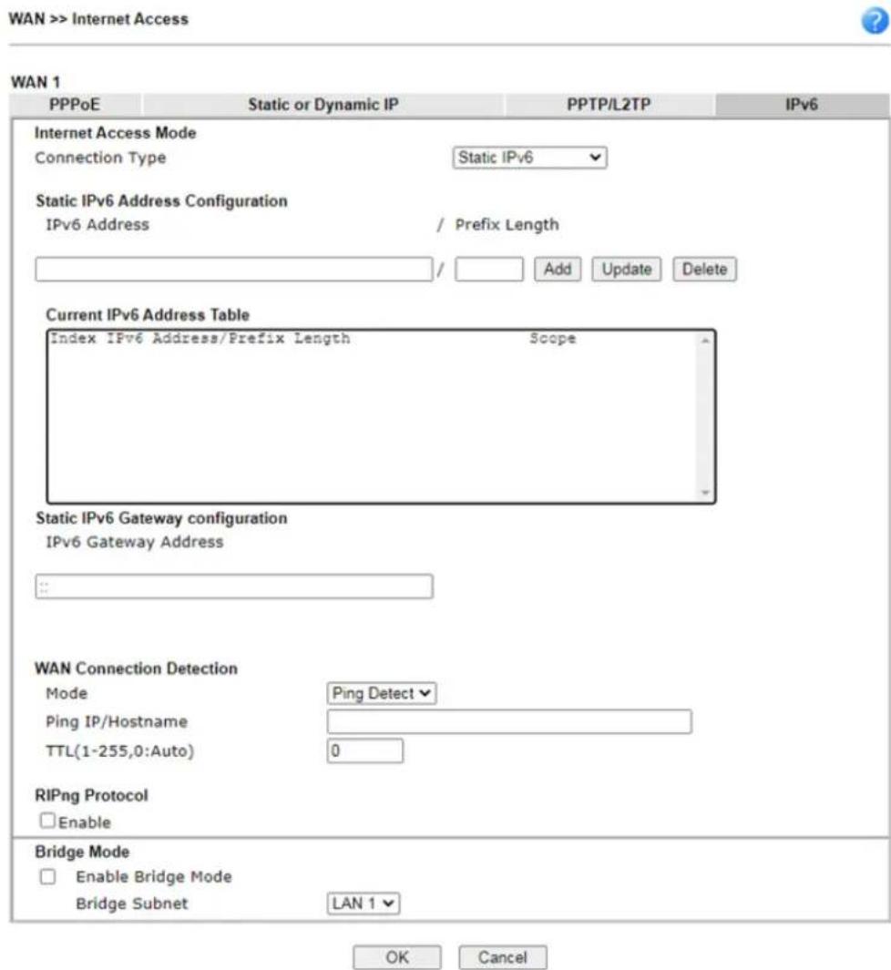
text_image
WAN >> Internet Access WAN 1 PPPoE Static or Dynamic IP PPTP/L2TP IPv6 Internet Access Mode Connection Type Static IPv6 Static IPv6 Address Configuration IPv6 Address / Prefix Length / Add Update Delete Current IPv6 Address Table Index IPv6 Address/Prefix Length Scope Static IPv6 Gateway configuration IPv6 Gateway Address ... WAN Connection Detection Mode Ping Detect Ping IP/Hostname TTL(1-255,0:Auto) 0 RIPng Protocol Enable Bridge Mode Enable Bridge Mode Bridge Subnet LAN 1 OK CancelAvailable settings are explained as follows:
| Item Description | |
| Static IPv6 Address Configuration | IPv6 Address - Enter the IPv6 Static IP AddressPrefix Length - Enter the fixed value for prefix length.Add - Click it to add a new entry.Update - Click it to modify an existed entry.Delete - Click it to remove an existed entry. |
| Current IPv6 Address Table | Display current interface IPv6 address. |
| Static IPv6 Gateway Configuration | IPv6 Gateway Address - Type your IPv6 gateway address here. |
| WAN Connection Detection | Such function allows you to verify whether network connection is alive or not through Ping Detect.Mode - Choose Always On or Ping Detect for the system to execute for WAN detection. Always On means no detection will be executed. The network connection will be on always.● Ping IP/Hostname - If you choose Ping Detect as detection mode, you have to type IP address in this field for pinging. ●TTL (Time to Live) -If you choose Ping Detect as detection mode, you have to type TTL value. |
| RIPng Protocol RIPng (RIP next generation) offers the same functions and benefits as IPv4 RIP v2. | |
| Bridge Mode | Enable Bridge Mode - If the function is enabled, the router will work as a bridge modem. Enable Firewall - It is available when Bridge Mode is enabled. When both Bridge Mode and Firewall check boxes are enabled, the settings configured (user profiles) under User Management will be ignored. And all of the filter rules defined and enabled in Firewall menu will be activated. Bridge Subnet - Make a bridge between the selected LAN subnet and such WAN interface. |
After finished the above settings, click OK to save the settings.
II-1-2-15 Details Page for IPv6-6in4 Static Tunnel in WAN1/WAN2
This type allows you to setup 6in4 Static Tunnel for WAN interface.
Such mode allows the router to access IPv6 network through IPv4 network.
However, 6in4 offers a prefix outside of 2002::0/16. So, you can use a fixed endpoint rather than anycast endpoint. The mode has more reliability.

text_image
WAN >> Internet Access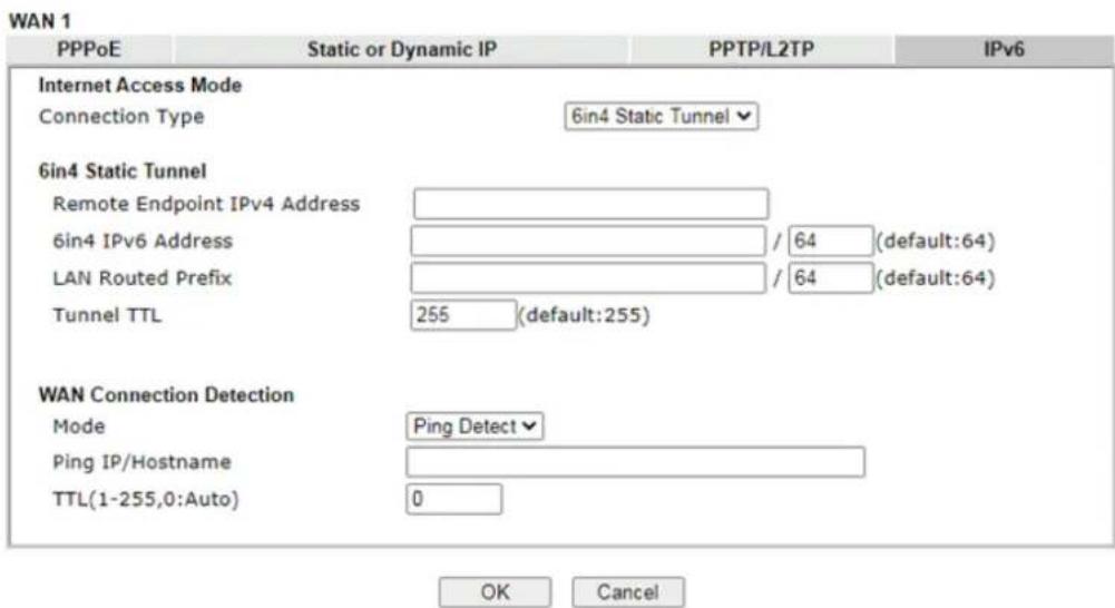
text_image
WAN 1 PPPoE Static or Dynamic IP PPTP/L2TP IPv6 Internet Access Mode Connection Type 6in4 Static Tunnel 6in4 Static Tunnel Remote Endpoint IPv4 Address 6in4 IPv6 Address / 64 (default:64) LAN Routed Prefix / 64 (default:64) Tunnel TTL 255 (default:255) WAN Connection Detection Mode Ping Detect Ping IP/Hostname TTL(1-255,0:Auto) 0 OK CancelAvailable settings are explained as follows:
| Item Description | |
| 6in4 Static Tunnel | Remote Endpoint IPv4 Address - Enter the static IPv4 address for the remote server.6in4 IPv6 Address - Enter the static IPv6 address for IPv4 tunnel with the value for prefix length.LAN Routed Prefix - Enter the static IPv6 address for LAN routing with the value for prefix length.Tunnel TTL - Enter the number for the data lifetime in tunnel. |
| WAN Connection Detection | Such function allows you to verify whether network connection is alive or not through Ping Detect.Mode - Choose Always On or Ping Detect for the system to execute for WAN detection. Always On means no detection will be executed. The network connection will be on always.Ping IP/Hostname - If you choose Ping Detect as detection mode, you have to type IP address in this field for pinging.TTL (Time to Live) -If you choose Ping Detect as detection mode, you have to type TTL value. |
After finished the above settings, click OK to save the settings.
Below shows an example for successful IPv6 connection based on 6in4 Static Tunnel mode.
Online Status
| Physical Connection | System Uptime: 0day 0:4:16 | |||
| IPv4 | IPv6 | |||
| LAN Status | ||||
| IP Address | ||||
| 2001:4DD0:FF00:83E4:21D:AAFF:FE83:11B4/64 (Global) | ||||
| FE80::21D:AAFF:FE83:11B4/64 (Link) | ||||
| TX Packets | RX Packets | TX Bytes | RX Bytes | |
| 14 | 80 | 1244 | 6815 | |
| WAN1 IPv6 Status | ||||
| Enable | Mode | Up Time | ||
| Yes | 6in4 Static Tunnel | 0:04:07 | ||
| IP | Gateway IP | |||
| 2001:4DD0:FF10:83E4::2131/64 (Global) | --- | |||
| FE80::C0A8:651D/128 (Link) | ||||
| TX Packets | RX Packets | TX Bytes | RX Bytes | |
| 3 | 26 | 211 | 2302 | |
II-1-2-16 Details Page for IPv6 - 6rd in WAN1/WAN2
This type allows you to setup 6rd for WAN interface.
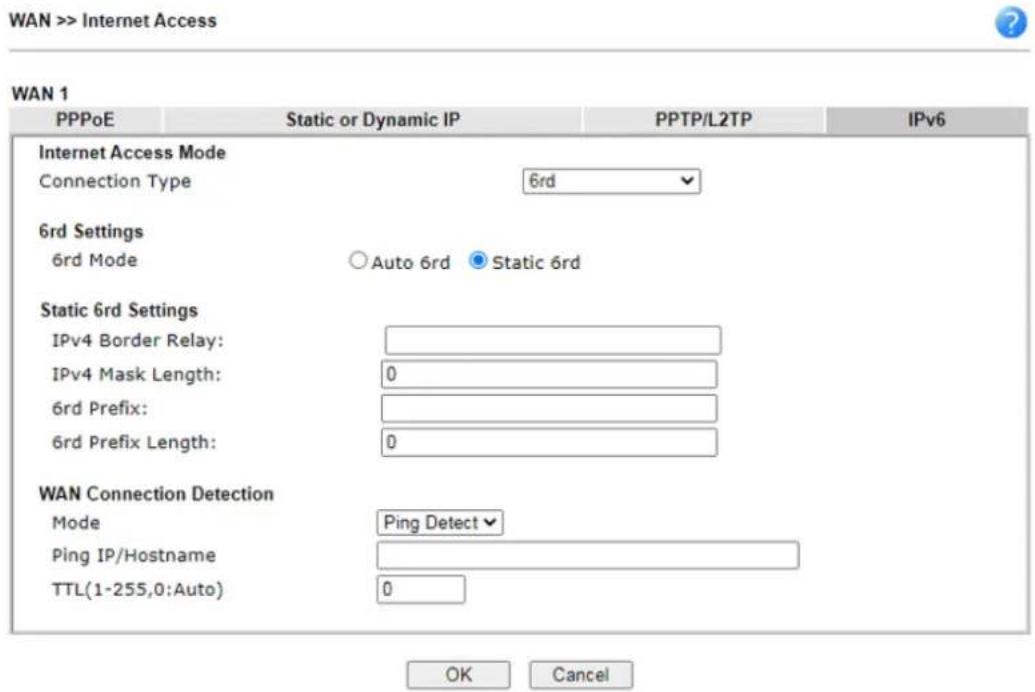
text_image
WAN >> Internet Access WAN 1 PPPoE Static or Dynamic IP PPTP/L2TP IPv6 Internet Access Mode Connection Type 6rd 6rd Settings 6rd Mode ○ Auto 6rd ● Static 6rd Static 6rd Settings IPv4 Border Relay: IPv4 Mask Length: 0 6rd Prefix: 6rd Prefix Length: 0 WAN Connection Detection Mode Ping Detect▼ Ping IP/Hostname TTL(1-255,0:Auto) 0 OK CancelAvailable settings are explained as follows:
| Item Description | |
| 6rd Mode | Auto 6rd - Retrieve 6rd prefix automatically from 6rd service provider. The IPv4 WAN must be set as "DHCP". Static 6rd - Set 6rd options manually. |
| IPv4 Border Relay | Enter the IPv4 addresses of the 6rd Border Relay for a given 6rd domain. |
| IPv4 Mask Length | Type a number of high-order bits that are identical across all CE IPv4 addresses within a given 6rd domain.It may be any value between 0 and 32. |
| 6rd Prefix | Enter the 6rd IPv6 address. |
| 6rd Prefix Length | Enter the IPv6 prefix length for the 6rd IPv6 prefix in number of bits. |
| WAN Connection Detection | Such function allows you to verify whether network connection is alive or not through Ping Detect.Mode - Choose Always On or Ping Detect for the system to execute for WAN detection. Always On means no detection will be executed. The network connection will be on always.Ping IP/Hostname - If you choose Ping Detect as detection mode, you have to type IP address in this field for pinging.TTL (Time to Live) -If you choose Ping Detect as detection mode, you have to type TTL value. |
After finished the above settings, click OK to save the settings.
Below shows an example for successful IPv6 connection based on 6rd mode.
| Physical Connection | System Uptime: 0day 0:9:15 | |||
| IPv4 | IPv6 | |||
| LAN Status | ||||
| IP Address | ||||
| 2001:E41:A865:1D00:21D:AAFF:FE83:11B4/64 (Global) | ||||
| FE80::21D:AAFF:FE83:11B4/64 (Link) | ||||
| TX Packets | RX Packets | TX Bytes | RX Bytes | |
| 15 | 113 | 1354 | 18040 | |
| WAN1 IPv6 Status | ||||
| Enable | Mode | Up Time | ||
| Yes | 6rd | 0:09:06 | ||
| IP | Gateway IP | |||
| 2001:E41:A865:1D01:21D:AAFF:FE83:11B5/128(Global) | --- | |||
| FE80::C0A8:651D/128 (Link) | ||||
| TX Packets | RX Packets | TX Bytes | RX Bytes | |
| 13 | 29 | 967 | 2620 | |
II-1-3 Multi-VLAN
Multi-VLAN allows users to create profiles for specific WAN interface and bridge connections for user applications that require very high network throughput. Simply go to WAN and select Multi-VLAN.
● Channel 1/2: Ethernet on WAN1/WAN2.
● Channel 3: Wireless 2.4GHz on WAN3.
● Channel 4: Wireless 5GHz on WAN4.
● Channel 5/6: USB1/USB2 (WAN5/WAN6).
Channels 7 through 16 can be bridged to one or more of the 4 LAN ports P2 through P5. In addition, Channels 7 through 9 can be configured as virtual WANs (WAN7 through WAN9).
General
WAN >> Multi-VLAN

Multi-VLAN
| General | ||||||||||||||||
| Channel | Enable | WAN Type | VLAN Tag | Port-based Bridge | Wireless LAN(2.4GHz) | Wireless LAN(5GHz) | ||||||||||
| 1 | Ethernet(WAN1) | None | ||||||||||||||
| 2 | Ethernet(WAN2) | None | ||||||||||||||
| 7, WAN7 | Ethernet(WAN1) | None | Enable | P1 | P2 | P3 | P4 | P6 | SSID1 | SSID2 | SSID3 | SSID4 | SSID1 | SSID2 | SSID3 | |
| 8, WAN8 | Ethernet(WAN1) | None | Enable | P1 | P2 | P3 | P4 | P5 | SSID1 | SSID2 | SSID3 | SSID4 | SSID1 | SSID2 | SSID3 | |
| 9, WAN9 | Ethernet(WAN1) | None | Enable | P1 | P2 | P3 | P4 | P5 | SSID1 | SSID2 | SSID3 | SSID4 | SSID1 | SSID2 | SSID3 | |
| 10 | Ethernet(WAN1) | None | Enable | P1 | P2 | P3 | P4 | P5 | SSID1 | SSID2 | SSID3 | SSID4 | SSID1 | SSID2 | SSID3 | |
| 11 | Ethernet(WAN1) | None | Enable | P1 | P2 | P3 | P4 | P5 | SSID1 | SSID2 | SSID3 | SSID4 | SSID1 | SSID2 | SSID3 | |
| 12 | Ethernet(WAN1) | None | Enable | P1 | P2 | P3 | P4 | P5 | SSID1 | SSID2 | SSID3 | SSID4 | SSID1 | SSID2 | SSID3 | |
| 13 | Ethernet(WAN1) | None | Enable | P1 | P2 | P3 | P4 | P5 | SSID1 | SSID2 | SSID3 | SSID4 | SSID1 | SSID2 | SSID3 | |
| 14 | Ethernet(WAN1) | None | Enable | P1 | P2 | P3 | P4 | P5 | SSID1 | SSID2 | SSID3 | SSID4 | SSID1 | SSID2 | SSID3 | |
| 15 | Ethernet(WAN1) | None | Enable | P1 | P2 | P3 | P4 | P5 | SSID1 | SSID2 | SSID3 | SSID4 | SSID1 | SSID2 | SSID3 | |
| 16 | Ethernet(WAN1) | None | Enable | P1 | P2 | P3 | P4 | P5 | SSID1 | SSID2 | SSID3 | SSID4 | SSID1 | SSID2 | SSID3 | |
Note:
1 Greyed out or hidden WANs are reserved
2. Ports configured for bridge mode cannot be selected in LAN >> VLAN Configuration.

Available settings are explained as follows:
| Item Description | |
| Channel | Display the number of each channel.Channels 7 ~ 16 are configurable. |
| Enable | Display whether the settings in this channel are enabled (Yes) or not (No). |
| WAN Type | Displays the physical medium that the channel will use. |
| VLAN Tag | Displays the VLAN tag value that will be used for the packets traveling on this channel. |
| Port-based Bridge | The network traffic flowing on each channel will be identified by the system via their VLAN Tags. Channels using the same WAN type may not configure the same VLAN tag value.Enable - Check this box to enable the port-based bridge function on this channel.P1 ~ P5 - Check the box(es) to build bridge connection on LAN. |
To configure a PVC channel, click its channel number.
WAN links for Channel 7, 8 and 9 are provided for router-borne application such as TR-069. The settings must be applied and obtained from your ISP. For your special request, please contact with your ISP and then click WAN link of Channel 7, 8 and 9 to configure your router.
Internet Access >> Multi-VLAN >> Channel 7
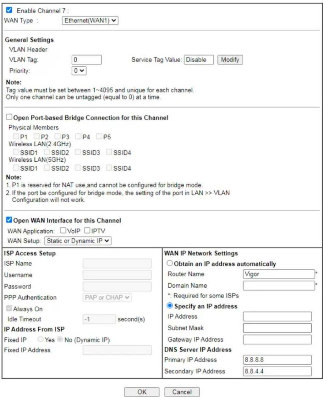
text_image
Enable Channel 7 : WAN Type : Ethernet(WAN1) General Settings VLAN Header VLAN Tag: 0 Service Tag Value: Disable Modify Priority: 0 Note: Tag value must be set between 1~4095 and unique for each channel. Only one channel can be untagged (equal to 0) at a time. □ Open Port-based Bridge Connection for this Channel Physical Members □ P1 □ P2 □ P3 □ P4 □ P5 Wireless LAN(2.4GHz) □ SSID1 □ SSID2 □ SSID3 □ SSID4 Wireless LAN(5GHz) □ SSID1 □ SSID2 □ SSID3 □ SSID4 Note: 1. P1 is reserved for NAT use,and cannot be configured for bridge mode. 2. If the port be configured for bridge mode, the setting of the port in LAN >> VLAN Configuration will not work. □ Open WAN Interface for this Channel WAN Application: □ VoIP □ IPTV WAN Setup: Static or Dynamic IP √ ISP Access Setup ISP Name Username Password PPP Authentication PAP or CHAP √ □ Always On Idle Timeout -1 second(s) IP Address From ISP Fixed IP ○ Yes ● No (Dynamic IP) Fixed IP Address WAN IP Network Settings ○ Obtain an IP address automatically Router Name Vigor* Domain Name * *: Required for some ISPs ● Specify an IP address IP Address Subnet Mask Gateway IP Address DNS Server IP Address Primary IP Address 8.8.8.8 Secondary IP Address 8.8.4.4 OK CancelAvailable settings are explained as follows:
| Item Description | |
| Enable Channel 7/8/9 | Check it to enable this channel. |
| WAN Type | Specify a WAN type of the VLAN.Ethernet (WAN1/2) - A VLAN will be created on WAN1/2. |
| General Settings | VLAN Tag - Enter the value as the VLAN ID number. Valid settings are in the range from 1 to 4095. The network traffic flowing on each channel will be identified by the system via their VLAN Tags. Channels using the same WAN type may notconfigure the same VLAN tag value.Priority- Choose the number to determine the packet priority for such VLAN. The range is from 0 to 7.Service Tag Value- Such value varies depending on the setting configured in WAN>>General Setup. If required, click Modify to open WAN>>General Setup. Then, enable VLAN Tag insertion for service (outer tag) and specify the value as the VLAN ID number. Or, disable it. |
| Open Port-based Bridge Connection for this Channel | The settings here will create a bridge between the LAN ports selected and the WAN. The WAN interface of the bridge connection will be built upon the WAN type selected using the VLAN tag configured.Physical Members- Group the physical ports by checking the corresponding check box(es) for applying the port-based bridge connection.Wireless LAN (2GHz/5GHz)- Group the SSIDs by checking the corresponding check box(es) for applying the port-based bridge connection.Note: LAN port P1 is reserved for NAT use and cannot be selected for bridging. |
| Open WAN Interface for this Channel | Check the box to enable relating function.WAN Application- The intended usage of this channel.IPTV- IGMP packets can be sent to IPTV servers on this channel.WAN Setup-(Available when WAN type is VDSL or Ethernet(WAN2)) The WAN access method of this channel. Available options are PPPoE/ PPPoA and Static or Dynamic IP.PPPoE/ PPPoA- When PPPoE/ PPPoA is selected, the ISP Access Setup and IP Address From ISP settings are available for configuration, and will be used to establish the WAN connection.Static or Dynamic IP- When Static or Dynamic IP is selected, the WAN IP Network Settings and DNS Server IP Address settings are available for configuration, and will be used to establish the WAN connection. |
| ISP Access Setup | Enter your allocated username, password and authentication parameters according to the information provided by your ISP.ISP Name- PPP Service Name. Enter if your ISP requires this setting; otherwise leave blank.Usage- Name provided by the ISP for PPPoE/ PPPoA authentication. Maximum length is 62 characters.Password- Password provided by the ISP for PPPoE/ PPPoA authentication. Maximum length is 62 characters.PPP Authentication-The protocol used for PPP authentication.PAP only- Only PAP (Password Authentication Protocol) is used.PAP or CHAP- Both PAP and CHAP(Challenge-Handshake Authentication Protocol) can be used for PPP authentication. Router negotiates with the PPTP or L2TP server to determine which protocol to use.Always On- If selected, the router will maintain thePPPoE/ PPPoA connection.Idle Timeout- Maximum length of time, in seconds, of idling allowed (no traffic) before the connection is dropped.IP Address From ISP - Specifies how the WAN IP address of the channel configured.Fixed IPYes- IP address entered in the Fixed IP Address field will be used as the IP address of the virtual WAN.No- Virtual WAN IP address will be assigned by the ISP's PPPoE/ PPPoA server. |
| WAN IP Network Settings | Obtain an IP address automatically- Select this option if the router is to receive IP configuration information from a DHCP server.Router Name- Sets the value of DHCP Option 12, which is used by some ISPs.Domain Name- Sets the value of DHCP Option 15, which is used by some ISPs.Specify an IP address- Select this option to manually enter the IP address.IP Address- Type in the IP address.Subnet Mask- Type in the subnet mask.Gateway IP Address- Type in gateway IP address.DNS Server IP Address- Type in the primary IP address for the router if you want to use Static IP mode. If necessary, type in secondary IP address for necessity in the future. |
After finished the above settings, click OK to save the settings and return to previous page.
Click any index (10\~16) to get the following web page:
Internet Access >> Multi-VLAN >> Channel 10
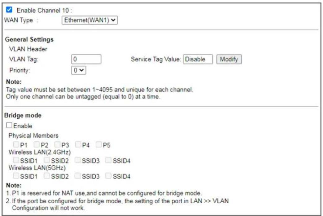
text_image
Enable Channel 10 : WAN Type : Ethernet(WAN1) General Settings VLAN Header VLAN Tag: 0 Service Tag Value: Disable Modify Priority: 0 Note: Tag value must be set between 1~4095 and unique for each channel. Only one channel can be untagged (equal to 0) at a time. Bridge mode □ Enable Physical Members □ P1 □ P2 □ P3 □ P4 □ P5 Wireless LAN(2.4GHz) □ SSID1 □ SSID2 □ SSID3 □ SSID4 Wireless LAN(5GHz) □ SSID1 □ SSID2 □ SSID3 □ SSID4 Note: 1. P1 is reserved for NAT use, and cannot be configured for bridge mode. 2. If the port be configured for bridge mode, the setting of the port in LAN >> VLAN Configuration will not work.
Available settings are explained as follows:
| Item Description | |
| Enable Channel 10~16 | Click it to enable the configuration of this channel. |
| WAN Type | The connections and interfaces created in every channel may select a specific WAN type to be built upon. In the Multi-VLAN application, only the Ethernet WAN type is available. The user will be able to select the physical WAN interface the channel shall use here. |
| General Settings | VLAN Tag - Enter the value as the VLAN ID number. Valid settings are in the range from 1 to 4095. The network traffic flowing on each channel will be identified by the system via their VLAN Tags. Channels using the same WAN type may not configure the same VLAN tag value.Priority - Choose the number to determine the packet priority for such VLAN. The range is from 0 to 7. |
| Bridge mode | Enable - Click it to enable Bridge mode for such channel.Physical Members - Group the physical ports by checking the corresponding check box(es) for applying the bridge connection.Wireless LAN (2GHz/5GHz) - Group the SSIDs by checking the corresponding check box(es) for applying the bridge connection.Note: LAN port P1 is reserved for NAT use and cannot be selected for bridging. |
After finished the above settings, click OK to save the settings.
II-1-4 WAN Budget
This function is used to determine the data traffic volume for each WAN interface respectively to prevent from overcharges for data transmission by the ISP. Please note that the Quota Limit and Billing cycle day of month settings will need to be configured correctly first in order for some period calculations to be performed correctly.
II-1-4-1 General Setup
WAN >> WAN Budget

| General Setup | Status | ||||
| Index | Enable | Quota | When quota exceeded | Time cycle | Duration |
| WAN1 | 0MB/0MB | 0/00/00 00:00~0/00/00 00:00 | |||
| WAN2 | 0MB/0MB | 0/00/00 00:00~0/00/00 00:00 | |||
| WAN3 | 0MB/0MB | 0/00/00 00:00~0/00/00 00:00 | |||
| WAN4 | 0MB/0MB | 0/00/00 00:00~0/00/00 00:00 | |||
| WAN5 | 0MB/0MB | 0/00/00 00:00~0/00/00 00:00 | |||
| WAN6 | 0MB/0MB | 0/00/00 00:00~0/00/00 00:00 | |||
Note:
- The budget traffic information provided here is for reference only, please consult your ISP for the actual traffic usage and charges.
- When hardware acceleration function is used, the monitored WAN traffic of Ethernet WAN interfaces may be slightly inaccurate.

or
WAN >> WAN Budget

| General Setup | Status | ||||
| Index | Enable | Quota | When quota exceeded | Time cycle | Duration |
| WAN1 | ☐ | 0MB/0MB | 0/00/00 00:00~0/00/00 00:00 | ||
| WAN2 | ☐ | 0MB/0MB | 0/00/00 00:00~0/00/00 00:00 | ||
| WAN3 | ☐ | 0MB/0MB | 0/00/00 00:00~0/00/00 00:00 | ||
| WAN4 | ☐ | 0MB/0MB | 0/00/00 00:00~0/00/00 00:00 | ||
| LTE | ☐ | 0MB/0MB | 0/00/00 00:00~0/00/00 00:00 | ||
| WAN6 | ☐ | 0MB/0MB | 0/00/00 00:00~0/00/00 00:00 | ||
Note:
- The budget traffic information provided here is for reference only, please consult your ISP for the actual traffic usage and charges.
- When hardware acceleration function is used, the monitored WAN traffic of Ethernet WAN interfaces may be slightly inaccurate.

or
| General Setup | Status | Set to Factory Default | |||
| Index | Enable | Quota | When quota exceeded | Time cycle | Duration |
| WAN1 | 0MB/0MB | 0/00/00 00:00~0/00/00 00:00 | |||
| WAN2 | 0MB/0MB | 0/00/00 00:00~0/00/00 00:00 | |||
| 5G-NR | 0MB/0MB | 0/00/00 00:00~0/00/00 00:00 | |||
| WAN6 | 0MB/0MB | 0/00/00 00:00~0/00/00 00:00 | |||
Note:
- The budget traffic information provided here is for reference only, please consult your ISP for the actual traffic usage and charges.
- When hardware acceleration function is used, the monitored WAN traffic of Ethernet WAN interfaces may be slightly inaccurate.
OK Cancel
| Item Description | |
| Index The WAN port. | Click to configure WAN Budget for a particular WAN. |
| Enable | v - WAN Budget is enabled on this WAN.x - WAN Budget is disabled on this WAN. |
| Quota | The current cycle's Internet usage is expressed as x/y where x is the cumulative usage and y is the upper limit. For example, 100MB/200MB means the usage thus far in this cycle is 100MB, and the upper limit is 200MB. |
| When quota exceeded | Actions to be taken once the quota is reached.Shutdown - WAN will be disabled.Mail Alert - Email will be sent to the administrator. |
| Time cycle | Reset frequency of the usage data.Monthly - The Monthly option in the Criterion and Action tab was used to set up the usage quota.User Defined: The User Defined option in the Criterion and Action tab was used to set up the usage qota. |
| Duration | Start and end timestamps of the current cycle. |
Click WAN1 (to WAN6) or LTE link to open the following web page.
WAN 1
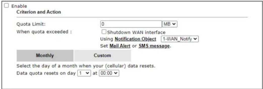
text_image
Enable Criterion and Action Quota Limit: 0 MB When quota exceeded : Shutdown WAN interface Using Notification Object 1-WAN_Notify Set Mail Alert or SMS message. Monthly Custom Select the day of a month when your (cellular) data resets. Data quota resets on day 1 at 00:00Note:
- Please make sure the Time and Date of the router is configured.
- SMS message and mail will be sent when the usage reaches 95% and 100% of quota.

Available settings are explained as follows:
| Item Description | |
| Enable | Check the box to enable such function. |
| Quota Limit | Enter the data traffic quota allowed for such WAN interface.There are two unit (MB and GB) offered for you to specify. |
| When quota exceeded | Check the box(es) as the condition(s) for the system to perform when the traffic has exceeded the budget limit.Shutdown WAN interface- All the outgoing traffic through such WAN interface will be terminated.Using Notification Object- The system will send out a notification based on the content of the notification object.Set Mail Alert- The system will send out a warning message to the administrator when the quota is running out. However, the connection charges will be calculated continuously.Set SMS message- The system will send out SMS message to the administrator when the quota is running out. |
| Monthly | Some ISP might apply for the network limitation based on the traffic limit per month. This setting is to offer a mechanism of resetting the traffic record every month.MonthlyCustomSelect the day of a month when your (cellular) data resets.Data quota resets on day 1▼ at 00:00▼Data quota resets on day ... - You can determine the starting day in one month. |
| Custom This setting allows the user to define the billing cycle according to his request. The WAN budget will be reset with an interval of billing cycle.Monthly is default setting. If long period or a short period is required, use Custom. The period of cycle duration is between 1 day and 60 days. You can determine the cycle duration by specifying the days and the hours. In addition, | |
you can specify which day of today is in a cycle.
Use Cycle in hours -
WAN1
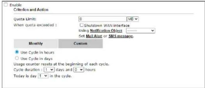
text_image
Enable Criterion and Action Quota Limits: 0 MB When quota exceeded : Shutdown WAN interface Using Notification Object Set Mail Alert or SMS message. Monthly Custom Use Cycle in hours Use Cycle in days Usage counter resets at the beginning of each cycle. Cycle duration : 1 days and 0 hours Today is day 1 in the cycle.Note:
1. Please make sure the Time and Date of the router is configured.
2. SMS message and mail will be sent when the usage reaches 95% and 100% of quota.
- Cycle duration: Specify the days and hours to reset the traffic record. For example, 7 means the whole cycle is 7 days; 20 means the whole cycle is 20 days. When the time is up, the router will reset the traffic record automatically.
- Today is day - Specify the day in the cycle as the starting point which Vigor router will reset the traffic record. For example, "3" means the third day of the cycle duration.
Use Cycle in days -
WAN >> WAN Budget
WAN 1
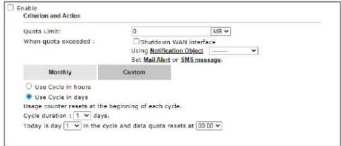
text_image
Enable Criterion and Action Quota Limit: 0 MB When quota exceeded : Shutdown WAN Interface Using Notification Object ———— Set Mail Alert or SMS message. Monthly Custom Use Cycle in hours Use Cycle in days Usage counter resets at the beginning of each cycle. Cycle duration : 1 days. Today is day 1 in the cycle and data quota resets at 00:00- Cycle duration: Specify the days to reset the traffic record. For example, 7 means the whole cycle is 7 days; 20 means the whole cycle is 20 days. When the time is up, the router will reset the traffic record automatically.
- Today is day - Specify the day and time for data quota rest in the cycle as the starting point which Vigor router will reset the traffic record. For example, "3" means the third day of the cycle duration.
After finished the above settings, click OK to save the settings.
II-1-4-2 Status
The status page displays the status WAN budget, including the duration and the usage.
WAN >> WAN Budget

text_image
General Setup Status Refresh Min(s) : 1 | Refresh | Interface: WAN2 Duration: 2014/07/19 11:00~2014/08/07 11:00 OMB 0% 1000MBIf the WAN budget is exhausted, a lock will be displayed on the page if Shutdown WAN interface is selected. Which means no data transmission will be carried out. Moreover, the system will send out a warning message to the administrator if Mail Alert is selected. Or, the system will send out SMS message to the administrator if SMS message is selected.
WAN >> WAN Budget
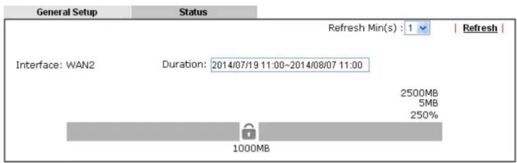
text_image
General Setup Status Refresh Min(s) : 1 | Refresh | Interface: WAN2 Duration: 2014/07/19 11:00~2014/08/07 11:00 2500MB 5MB 250% 1000MBII-2 LAN
Local Area Network (LAN) is a group of subnets regulated and ruled by router. The design of network structure is related to what type of public IP addresses coming from your ISP.
The most generic function of Vigor router is NAT. It creates a private subnet of your own. As mentioned previously, the router will talk to other public hosts on the Internet by using public IP address and talking to local hosts by using its private IP address. What NAT does is to translate the packets from public IP address to private IP address to forward the right packets to the right host and vice versa. Besides, Vigor router has a built-in DHCP server that assigns private IP address to each local host. See the following diagram for a briefly understanding.
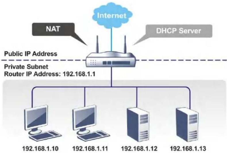
flowchart
graph TD
    A["Internet"] --> B["NAT"]
    A --> C["DHCP Server"]
    B --> D["Public IP Address"]
    C --> E["Private Subnet Router IP Address: 192.168.1.1"]
    D --> F["Computer 192.168.1.10"]
    D --> G["Computer 192.168.1.11"]
    D --> H["Computer 192.168.1.12"]
    D --> I["Computer 192.168.1.13"]
In some special case, you may have a public IP subnet from your ISP such as 220.135.240.0/24. This means that you can set up a public subnet or call second subnet that each host is equipped with a public IP address. As a part of the public subnet, the Vigor router will serve for IP routing to help hosts in the public subnet to communicate with other public hosts or servers outside. Therefore, the router should be set as the gateway for public hosts.
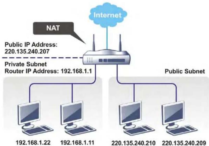
flowchart
graph TD
    A["Internet"] --> B["NAT"]
    B --> C["Router"]
    C --> D["Public Subnet"]
    C --> E["Computer 192.168.1.22"]
    C --> F["Computer 192.168.1.11"]
    C --> G["Computer 220.135.240.210"]
    C --> H["Computer 220.135.240.209"]
    C --> I["Public Subnet"]
    style A fill:#cce5ff,stroke:#333
    style B fill:#ffcccc,stroke:#333
    style C fill:#e6f7ff,stroke:#333
    style D fill:#e6f7ff,stroke:#333
    style E fill:#e6f7ff,stroke:#333
    style F fill:#e6f7ff,stroke:#333
    style G fill:#e6f7ff,stroke:#333
    style H fill:#e6f7ff,stroke:#333
    style I fill:#e6f7ff,stroke:#333
What is Routing Information Protocol (RIP)
Vigor router will exchange routing information with neighboring routers using the RIP to accomplish IP routing. This allows users to change the information of the router such as IP address and the routers will automatically inform for each other.
What is Static Route
When you have several subnets in your LAN, sometimes a more effective and quicker way for connection is the Static routes function rather than other method. You may simply set rules to forward data from one specified subnet to another specified subnet without the presence of RIP.
What are Virtual LANs and Rate Control
You can group local hosts by physical ports and create up to 8 virtual LANs. To manage the communication between different groups, please set up rules in Virtual LAN (VLAN) function and the rate of each.
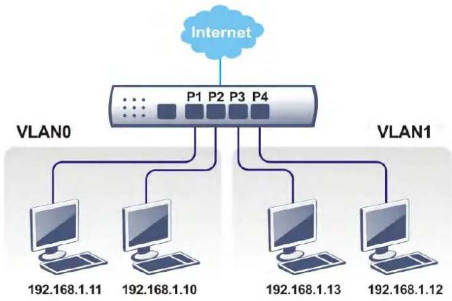
flowchart
graph TD
    A["Internet"] --> B["VLAN0"]
    A --> C["VLAN1"]
    B --> D["192.168.1.11"]
    B --> E["192.168.1.10"]
    C --> F["192.168.1.13"]
    C --> G["192.168.1.12"]
Web User Interface
A LAN comprises a collection of LAN clients, which are networked devices on your premises. A LAN client can be a computer, a printer, a Voice-over-IP (VoIP) phone, a mobile phone, a gaming console, an Internet Protocol Television (IPTV), etc, and can have either a wired (using Ethernet cabling) or wireless (using Wi-Fi) network connection.
LAN clients within the same LAN are normally able to communicate with one another directly, as they are peers to one another, unless measures, such as firewalls or VLANs, have been put in place to restrict such access. Nowadays the most common LAN firewalls are implemented on the LAN client itself. For example, Microsoft Windows since Windows XP and Apple OS X have built-in firewalls that can be configured to restrict traffic coming in and going out of the computer. VLANs, on the other hand, are usually set up using network switches or routers, such as the Vigor2927.
To communicate with the hosts outside of the LAN, LAN clients have to go through a network gateway, which in most cases is a router (such as the Vigor 2862) that sits between the LAN and the ISP network, which is the WAN. The router acts as a director to ensure traffic between the LAN and the WAN reach their intended destinations.
LAN
General Setup
VLAN
Bind IP to MAC
LAN Port Mirror
Wired 802.1X
Link Aggregation
II-2-1 General Setup
This page provides you the general settings for LAN. Click LAN to open the LAN settings page and choose General Setup.
There are eight subnets provided by the router which allow users to divide groups into different subnets (LAN1 - LAN8). In addition, different subnets can link for each other by configuring Inter-LAN Routing. At present, LAN1 setting is fixed with NAT mode only. LAN2 - LAN8 can be operated under NAT or Route mode. IP Routed Subnet can be operated under Route mode.
General Setup
| Index | Enable | DHCP | DHCPv6 | IP Address | ||
| LAN 1 | V | V | V | 192.168.1.1 | Details Page | IPv6 |
| LAN 2 | 192.168.2.1 | Details Page | IPv6 | |||
| LAN 3 | 192.168.3.1 | Details Page | IPv6 | |||
| LAN 4 | 192.168.4.1 | Details Page | IPv6 | |||
| LAN 5 | 192.168.5.1 | Details Page | IPv6 | |||
| LAN 6 | 192.168.6.1 | Details Page | IPv6 | |||
| LAN 7 | 192.168.7.1 | Details Page | IPv6 | |||
| LAN 8 | 192.168.8.1 | Details Page | IPv6 | |||
| DMZ Port | 192.168.254.1 | Details Page | IPv6 | |||
| IP Routed Subnet | 192.168.0.1 | Details Page |
DHCP Server Option
Note:
Please enable LAN 2 - 8 on LAN >> VLAN page before configure them.
Enable DMZ port will make the LAN Port 5 neglect the setting on VLAN page, LAN Port 5 will become the DMZ Port.
☐ Force router to use "DNS server IP address" settings specified in LAN1
Inter-LAN Routing
| Subnet | LAN 1 | LAN 2 | LAN 3 | LAN 4 | LAN 5 | LAN 6 | LAN 7 | LAN 8 | DMZ Port |
| LAN 1 | |||||||||
| LAN 2 | |||||||||
| LAN 3 | |||||||||
| LAN 4 | |||||||||
| LAN 5 | |||||||||
| LAN 6 | |||||||||
| LAN 7 | |||||||||
| LAN 8 | |||||||||
| DMZ Port |
OK
Available settings are explained as follows:
| Item Description | |
| General Setup | Allow to configure settings for each subnet respectively. Index - Display all of the LAN items. Enable- Basically, LAN1 status is enabled in default. LAN2 -LAN8 and IP Routed Subnet can be observed by checking the box of Enable. DHCP/DHCPv6- LAN1 is configured with DHCP/ DHCPv6 in default. If required, please check the DHCP box for each LAN. IP Address - Display the IP address for each LAN item. Such information is set in default and you can not modify it. Details Page - Click it to access into the setting page. Each LAN will have different LAN configuration page. Each LAN must be configured in different subnet. IPv6 - Click it to access into the settings page of IPv6. |
| DHCP Server Option | DHCP packets can be processed by adding option number and data information when such function is enabled. For detailed information, refer to later section. |
| Force router to use “DNS server IP address .....” | Force Vigor router to use DNS servers configured in LAN1/ LAN2/ LAN3/ LAN4/ LAN5/ LAN6/ LAN7/ LAN8/ DMZ Port instead of DNS servers given by the Internet Access server (PPPoE, PPTP, L2TP or DHCP server). |
| Inter-LAN Routing | Check the box to link two or more different subnets (LAN and LAN).Inter-LAN Routing allows different LAN subnets to be interconnected or isolated.It is only available when the VLAN functionality is enabled.Refer to section II-2-2 VLAN on how to set up VLANs.In the Inter-LAN Routing matrix, a selected checkbox means that the 2 intersecting LANs can communicate with each other. |
When you finish the configuration, please click OK to save and exit this page.

Info
To configure a subnet, select its Detials Page button to bring up the LAN Details Page.
II-2-1-1 Details Page for LAN1 – Ethernet TCP/IP and DHCP Setup
There are two configuration pages for LAN1, Ethernet TCP/IP and DHCP Setup (based on IPv4) and IPv6 Setup. Click the tab for each type and refer to the following explanations for detailed information.
LAN >> General Setup
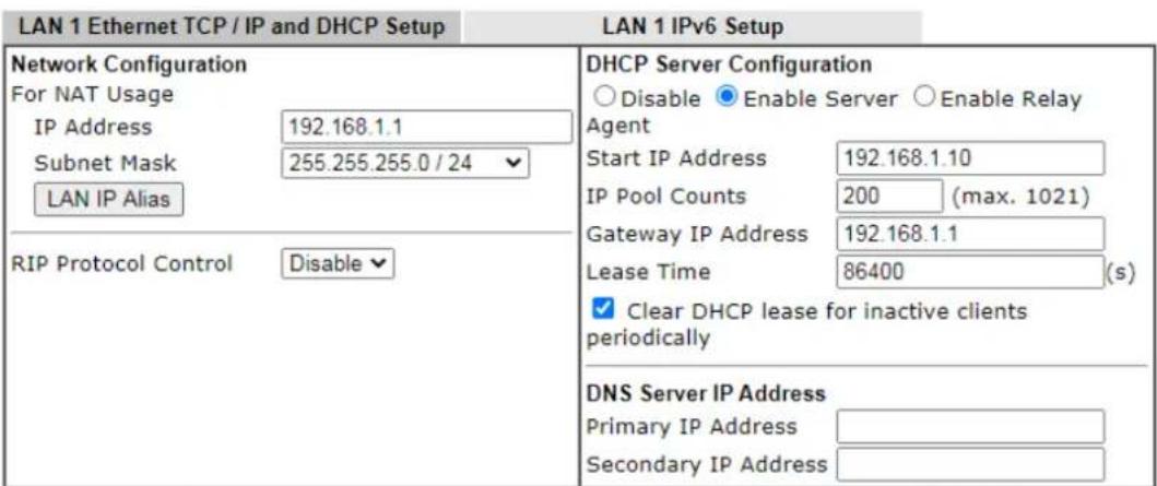
text_image
LAN 1 Ethernet TCP / IP and DHCP Setup LAN 1 IPv6 Setup Network Configuration For NAT Usage IP Address 192.168.1.1 Subnet Mask 255.255.255.0 / 24 LAN IP Alias RIP Protocol Control Disable DHCP Server Configuration ○ Disable ● Enable Server ○ Enable Relay Agent Start IP Address 192.168.1.10 IP Pool Counts 200 (max. 1021) Gateway IP Address 192.168.1.1 Lease Time 86400 (s) ✓ Clear DHCP lease for inactive clients periodically DNS Server IP Address Primary IP Address Secondary IP AddressNote: Change IP Address or Subnet Mask in Network Configuration will also change HA LAN1 Virtual IP to the same domain IP.
OK
Available settings are explained as follows:
| Item Description | |
| Network Configuration For | NAT Usage,IP Address - This is the IP address of the router. (Default: 192.168.1.1).Subnet Mask - The subnet mask, together with the IP Addressfield, indicates the maximum number of clients allowed on the subnet. (Default: 255.255.255.0/ 24).LAN IP Alias-Such feature allows specifying multiple gateways (under a switch) with different WAN interfaces for accessing the Internet via the Vigor router. LAN 1 IP Alias LAN 1 IP Alias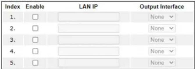 Note:1. LAN IP Alias only applies to muti-gateway usage. When a LAN host set its gateway as LAN IP Alias, Vigor Router will route the host's packets through the specified Output Interface.2. Route Policy has a higher priority than the LAN IP Alias Output Interface setting.OK Clear All CancelRIP Protocol Control,Enable - When Enabled, the router will attempt to exchange routing information with neighbouring routers using the Routing Information Protocol. Note:1. LAN IP Alias only applies to muti-gateway usage. When a LAN host set its gateway as LAN IP Alias, Vigor Router will route the host's packets through the specified Output Interface.2. Route Policy has a higher priority than the LAN IP Alias Output Interface setting.OK Clear All CancelRIP Protocol Control,Enable - When Enabled, the router will attempt to exchange routing information with neighbouring routers using the Routing Information Protocol. |
| DHCP ServerConfiguration | DHCP stands for Dynamic Host Configuration Protocol. The router by factory default acts a DHCP server for your network so it automatically dispatches related IP settings to any local user configured as a DHCP client. It is highly recommended that you leave the router enabled as a DHCP server if you do not have a DHCP server for your network.If you want to use another DHCP server in the network other than the Vigor Router's, you can let Relay Agent help you to redirect the DHCP request to the specified location.Disable - Let you manually assign IP address to every host in the LAN.Enable Server - Let the router assign IP address to every host in the LAN.Start IP Address - The beginning LAN IP address that is given out to LAN DHCP clients.IP Pool Counts - The maximum number of IP addresses to be handed out by DHCP. The default value is 200. Valid range is between 1 and 1021. The actual number of IP addresses available for assignment is the IP Pool Counts, or 1021 minus the last octet of the Start IP Address, whichever is smaller.Gateway IP Address - The IP address of the gateway, which is the host on the LAN that relays all traffic coming into and going out of the LAN. The gateway is normally the router, and therefore the Gateway IPAddress should be identical to the IP Address in the Network Configuration section above.Lease Time - The maximum duration DHCP-issued IP addresses can be used before they have to be renewed.Clear DHCP lease for inactive clients periodically - If selected, the router sends ARP requests recycles IP addresses previously assigned to inactive DHCP clients to prevent exhaustion of the IP address pool.Note: When Clear DHCP lease for inactive clients periodically is enabled, router will do the following:Check activities of DHCP clients by ARP requests every minute when the available DHCP IP addresses are less than 30Clear DHCP lease when the client is not responding ARP replies.Enable Relay Agent - When selected, all DHCP requests are forwarded to a DHCP server outside of the LAN subnet, and whose address is specified in the DHCP Server IP Address field.DHCP Server IP Address - It is available when Enable Relay Agent is checked. Set the IP address of the DHCP server you are going to use so the Relay Agent can help to forward the DHCP request to the DHCP server. |
| DNS Server IP Address | DNS stands for Domain Name System. Every Internet host must have a unique IP address, also they may have a human-friendly, easy to remember name such as www.yahoo.com. The DNS server converts the user-friendly name into its equivalent IP address.Primary IP Address -You must specify a DNS server IP address here because your ISP should provide you with usually more than one DNS Server.Secondary IP Address - You can specify secondary DNS server IP address here because your ISP often provides you more than one DNS Server.The default DNS Server IP address can be found via Online Status:Online Status If both the Primary IP and Secondary IP Address fields are left empty, the router will assign DNS servers obtained from WAN interface to local users as a DNS proxy server and maintain a DNS cache. If there is no DNS servers available, router will use its own IP address instead.If the IP address of a domain name is already in the DNS cache, the router will resolve the domain name immediately. Otherwise, the router forwards the DNS query packet to the external DNS server by establishing a WAN (e.g. DSL/ Cable) connection. If both the Primary IP and Secondary IP Address fields are left empty, the router will assign DNS servers obtained from WAN interface to local users as a DNS proxy server and maintain a DNS cache. If there is no DNS servers available, router will use its own IP address instead.If the IP address of a domain name is already in the DNS cache, the router will resolve the domain name immediately. Otherwise, the router forwards the DNS query packet to the external DNS server by establishing a WAN (e.g. DSL/ Cable) connection. |
When you finish the configuration, please click OK to save and exit this page.
Private IP addresses can be assigned automatically to LAN clients using Dynamic Host Configuration Protocol (DHCP), or manually assigned. The DHCP server can either be the
router (the most common case), or a separate server, that hands out IP addresses to DHCP clients.
Alternatively, static IP addresses can be manually configured on LAN clients as part of their network settings. No matter how IP addresses are configured, it is important that no two devices get the same IP address. If both DHCP and static assignment are used on a network, it is important to exclude the static IP addresses from the DHCP IP pool. For example, if your LAN uses the 192.168.1.x subnet and you have 20 DHCP clients and 20 static IP clients, you could configure 192.168.1.10 as the Start IP Address, 50 as the IP Pool Counts (enough for the current number of DHCP clients, plus room for future expansion), and use addresses greater than 192.168.1.100 for static assignment.
II-2-1-2 Details Page for LAN2 \~ LAN8 and DMZ
LAN >> General Setup
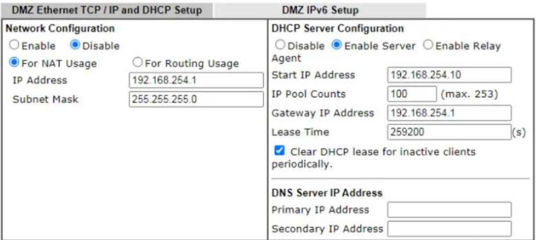
text_image
DMZ Ethernet TCP / IP and DHCP Setup DMZ IPv6 Setup Network Configuration ○ Enable ○ Disable ● For NAT Usage ○ For Routing Usage IP Address 192.168.254.1 Subnet Mask 255.255.255.0 DHCP Server Configuration ○ Disable ○ Enable Server ○ Enable Relay Agent Start IP Address 192.168.254.10 IP Pool Counts 100 (max. 253) Gateway IP Address 192.168.254.1 Lease Time 259200 (s) ✓ Clear DHCP lease for inactive clients periodically. DNS Server IP Address Primary IP Address Secondary IP AddressNote: Change IP Address or Subnet Mask in Network Configuration will also change HA DMZ Virtual IP to the same domain IP.
OK
Available settings are explained as follows:
| Item Description | |
| Network Configuration | Enable/Disable - Click Enable to enable such configuration; click Disable to disable such configuration.For NAT Usage - Click this radio button to invoke NAT function.For Routing Usage - Click this radio button to invoke this function.IP Address - This is the IP address of the router. (Default: 192.168.1.1).Subnet Mask - The subnet mask, together with the IP Address field, indicates the maximum number of clients allowed on the subnet. (Default: 255.255.255.0/ 24). |
| DHCP Server Configuration | Disable - Let you manually assign IP address to every host in the LAN.Enable Server - Let the router assign IP address to every host in the LAN.Start IP Address - The beginning LAN IP address that is given out to LAN DHCP clients.IP Pool Counts - The maximum number of IP addresses to be handed out by DHCP. The default value is 100. Valid range is between 1 and 1021. The actual number of IP addresses available for assignment is the IP Pool Counts, or 1021 minus the last octet of the Start IP Address, whichever is smaller.Gateway IP Address - The IP address of the gateway, which is the host on the LAN that relays all traffic coming into and going out of the LAN. The gateway is normally the router, and therefore the Gateway IP Address should be identical to the IP Address in the Network Configuration section above.Lease Time - The maximum duration DHCP-issued IP addresses can be used before they have to be renewed.Clear DHCP lease for inactive clients periodically - If selected, the router sends ARP requests recycles IP addresses previously assigned to inactive DHCP clients to prevent exhaustion of the IP address pool.Note: When Clear DHCP lease for inactive clients periodically is enabled, router will do the following:- Check activities of DHCP clients by ARP requests every minute when the available DHCP IP addresses are less than 30- Clear DHCP lease when the client is not responding ARP replies.Enable Relay Agent - When selected, all DHCP requests are forwarded to a DHCP server outside of the LAN subnet, and whose address is specified in the DHCP Server IP Address field.DHCP Server IP Address - It is available when Enable Relay Agent is checked. Set the IP address of the DHCP server you are going to use so the Relay Agent can help to forward the DHCP request to the DHCP server. |
| DNS Server IP Address | DNS stands for Domain Name System. Every Internet host must have a unique IP address, also they may have a human-friendly, easy to remember name such as www.yahoo.com. The DNS server converts the user-friendly name into its equivalent IP address.Primary IP Address -You must specify a DNS server IP address here because your ISP should provide you with usually more than one DNS Server.Secondary IP Address - You can specify secondary DNS server IP address here because your ISP often provides you more than one DNS Server.The default DNS Server IP address can be found via Online Status:Online StatusPhysical Connection System Uptime: 22:22:45IPv4 IPv6LAN Status Primary DNS: 8.8.8.8 Secondary DNS: 8.8.4.4IP Address TX Packets RX Packets192 168.1.1 0 41533If both the Primary IP and Secondary IP Address fields are left empty, the router will assign its own IP address to local users as a DNS proxy server and maintain a DNS cache.If the IP address of a domain name is already in the DNS cache, the router will resolve the domain name immediately. Otherwise, the router forwards the DNS query packet to the external DNS server by establishing a WAN (e.g. DSL/ Cable) connection. |
When you finish the configuration, please click OK to save and exit this page.
II-2-1-3 Details Page for IP Routed Subnet
LAN >> General Setup
TCP/IP and DHCP Setup for IP Routed Subnet
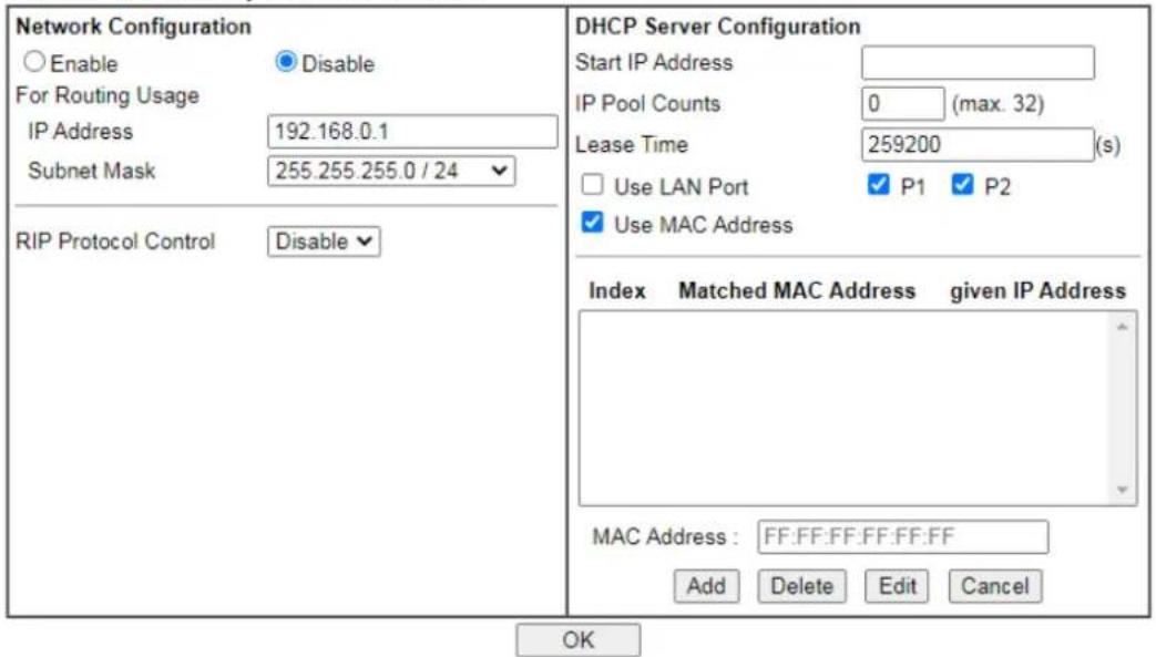
text_image
Network Configuration Enable Disable For Routing Usage IP Address 192.168.0.1 Subnet Mask 255.255.255.0 / 24 RIP Protocol Control Disable DHCP Server Configuration Start IP Address IP Pool Counts 0 (max. 32) Lease Time 259200 (s) Use LAN Port P1 P2 Use MAC Address Index Matched MAC Address given IP Address MAC Address: FF:FF:FF:FF:FF:FF Add Delete Edit Cancel OKAvailable settings are explained as follows:
| Item Description | |
| Network Configuration | Enable/Disable - Click Enable to enable such configuration; click Disable to disable such configuration.For Routing Usage,IP Address - This is the IP address of the router. (Default: 192.168.1.1).Subnet Mask - The subnet mask, together with the IP Address field, indicates the maximum number of clients allowed on the subnet. (Default: 255.255.255.0/ 24).RIP Protocol Control,Enable - When Enabled, the router will attempt to exchange routing information with neighbouring routers using the Routing Information Protocol. |
| DHCP Server Configuration | DHCP stands for Dynamic Host Configuration Protocol. The router by factory default acts a DHCP server for your network so it automatically dispatch related IP settings to any local user configured as a DHCP client. It is highly recommended that you leave the router enabled as a DHCP server if you do not have a DHCP server for your network.Start IP Address - Enter a value of the IP address pool for the DHCP server to start with when issuing IP addresses. If the 1st IP address of your router is 192.168.1.1, the starting IP address must be 192.168.1.2 or greater, but smaller than 192.168.1.254.IP Pool Counts - Enter the maximum number of PCs that you want the DHCP server to assign IP addresses to. The default is 50 and the maximum is 253.Lease Time - Enter the time to determine how long the IPaddress assigned by DHCP server can be used.Use LAN Port - Specify an IP for IP Route Subnet. If it is enabled, DHCP server will assign IP address automatically for the clients coming from P1 and/ or P2. Please check the box of P1 and P2.Use MAC Address - Check such box to specify MAC address.MAC Address - Enter the MAC Address of the host one by one and click Add to create a list of hosts which can be assigned, deleted or edited from above pool. Set a list of MAC Address for 2^nd DHCP server will help router to assign the correct IP address of the correct subnet to the correct host. So those hosts in 2^nd subnet won’t get an IP address belonging to 1^st subnet.Add - Enter the MAC address in the boxes and click this button to add.Delete - Click it to delete the selected MAC address.Edit - Click it to edit the selected MAC address.Cancel - Click it to cancel the job of adding, deleting and editing. |
When you finish the configuration, please click OK to save and exit this page.
II-2-1-4 Details Page for LAN IPv6 Setup
There are two configuration pages for LAN1/ LAN2/ LAN3/ LAN4/ LAN5/ LAN6/ LAN7/ LAN8/ DMZ Port, Ethernet TCP/ IP and DHCP Setup (based on IPv4) and IPv6 Setup. Click the tab for each type and refer to the following explanations for detailed information. Below shows the settings page for IPv6.
LAN >> General Setup
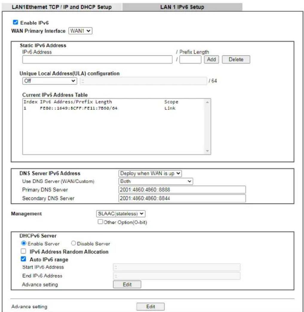
text_image
LAN1Ethernet TCP / IP and DHCP Setup LAN 1 IPv6 Setup Enable IPv6 WAN Primary Interface WAN1 Static IPv6 Address IPv6 Address / Prefix Length Add Delete Unique Local Address(ULA) configuration Off / 64 Current IPv6 Address Table Index IPv6 Address/Prefix Length Scope 1 FE80::1649:BCFF:FE11:7B50/64 Link DNS Server IPv6 Address Deploy when WAN is up Use DNS Server (WAN/Custom) Both Primary DNS Server 2001:4860:4860:8888 Secondary DNS Server 2001:4860:4860:8844 Management SLAAC(stateless) Other Option(O-bit) DHCPv6 Server Enable Server Disable Server IPv6 Address Random Allocation Auto IPv6 range Start IPv6 Address End IPv6 Address Advance setting Edit Advance setting Edit
It provides 2 daemons for LAN side IPv6 address configuration. One is SLAAC(stateless) and the other is DHCPv6 (Stateful) server.
Available settings are explained as follows:
| Item Description | |
| Enable | Check the box to enable the configuration of LAN 1 IPv6 Setup. |
| WAN Primary Interface | Use the drop down list to specify a WAN interface for IPv6. |
| Static IPv6 Address configuration | IPv6 Address -Type static IPv6 address for LANPREFIX Length - Enter the fixed value for prefix length.Add - Click it to add a new entry.Delete - Click it to remove an existed entry. |
| Unique Local Address (ULA) configuration | Unique Local Addresses (ULAs) are private IPv6 addresses assigned to LAN clients.Off - ULA is disabled.Manually ULA Prefix - LAN clients will be assigned ULAs generated based on the prefix manually entered.Auto ULA Prefix - LAN clients will be assigned ULAs using an automatically-determined prefix. |
| Current IPv6 Address Table | Display current used IPv6 addresses. |
| DNS Server IPv6 Address | Deploy when WAN is up - The RA (router advertisement) packets will be sent to LAN PC with DNS server information only when network connection by any one of WAN interfaces is up.Enable - The RA (router advertisement) packets will be sent to LAN PC with DNS server information no matter WAN connection is up or not.Use DNS Server (WAN/Custom) - Determines the DNS server for sending the packets through WAN DNS Server, Customized DNS Server or both servers. The default setting is Both.If WAN DNS Server is selected, LAN client can visit the Internet through the dynamic DNS server offered by the ISP for data transmission. However,if Customized DNS Server is selected, LAN client can visit the Internet via the primary/ secondary DNS server. Please specify settings for primary/ secondary DNS server or use the default values.Whe Both is chosen, LAN client can visit the Internet either via the dynamic DNS server or the customized DNS servers.Primary DNS Sever - Enter the IPv6 address for Primary DNS server.Secondary DNS Server - Enter another IPv6 address for DNS server if required.Disable - DNS server will not be used. |
| Management | Configures the Managed Address Configuration flag (M-bit) in Route Advertisements.Off - No configuration information is sent using Route Advertisements.SLAAC(stateless) - M-bit is unset.DHCPv6(stateful) - M-bit is set, which indicates to LAN clients that they should acquire all IPv6 configuration information from a DHCPv6 server. The DHCPv6 server can either be the one built into the Vigor2927, or a separate DHCPv6 server.Other Option (O-bit) - Check this box to enable the O-bit for obtaining additional information (e.g., DNS) from DHCPv6. |
| DHCPv6 Server | Enable Server -Click it to enable DHCPv6 server. DHCPv6 Server could assign IPv6 address to PC according to the Start/ End IPv6 address configuration.Disable Server -Click it to disable DHCPv6 server.Auto IPv6 range - After check the box, Vigor router will assign the IPv6 range automatically.Start IPv6 Address / End IPv6 Address -Enter the start andend address for IPv6 server.Advancesetting- Click the Edit button to configure advanced IPv6 settings for DHCPv6 server.LAN >> General Setup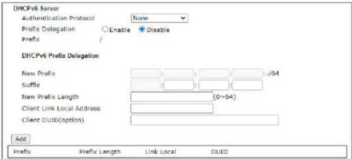 OK Cancel OK Cancel |
| Advance setting | The Advanced Settings page has additional settings for Router Advertisement and enabling multiple WANs for IPv6 traffic.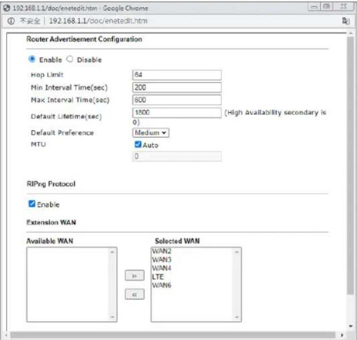 Router Advertisement Configuration- Click Enable to enable router advertisement server. The router advertisement daemon sends Router Advertisement messages, specified by RFC 2461, to a local Ethernet LAN periodically and when requested by a node sending a Router Solicitation message. These messages are required for IPv6 stateless auto-configuration.Disable- Click it to disable router advertisement server.Hop Limt- The value is required for the device behind the router when IPv6 is in use.Min/Max Interval Time (sec) - It defines the interval (between minimum time and maximum time) for sending RA (Router Advertisement) packets.Default Lifetime (sec)-Within such period of time, Vigor router can be treated as the default gateway.Default Preference- It determines the priority of the hostbehind the router when RA (Router Advertisement) packets are transmitted.MTU - It means Max Transmit Unit for packet. IfAutois selected, the router will determine the MTU value for LAN.RIPng Protocol -RIPng (RIP next generation) offers the same functions and benefits as IPv4 RIP v2.Extension WAN - In addition to the default WAN used for IPv6 traffic specified in the WAN Primary Interface in the LAN IPv6 Setup page, additional WANs can be selected to carry IPv6 traffic by enabling them in the Extension WAN section.Available WAN - Additional WANs available but not currently selected to carry IPv6 traffic.Selected WAN - Additional WANs selected to carry IPv6 traffic. Router Advertisement Configuration- Click Enable to enable router advertisement server. The router advertisement daemon sends Router Advertisement messages, specified by RFC 2461, to a local Ethernet LAN periodically and when requested by a node sending a Router Solicitation message. These messages are required for IPv6 stateless auto-configuration.Disable- Click it to disable router advertisement server.Hop Limt- The value is required for the device behind the router when IPv6 is in use.Min/Max Interval Time (sec) - It defines the interval (between minimum time and maximum time) for sending RA (Router Advertisement) packets.Default Lifetime (sec)-Within such period of time, Vigor router can be treated as the default gateway.Default Preference- It determines the priority of the hostbehind the router when RA (Router Advertisement) packets are transmitted.MTU - It means Max Transmit Unit for packet. IfAutois selected, the router will determine the MTU value for LAN.RIPng Protocol -RIPng (RIP next generation) offers the same functions and benefits as IPv4 RIP v2.Extension WAN - In addition to the default WAN used for IPv6 traffic specified in the WAN Primary Interface in the LAN IPv6 Setup page, additional WANs can be selected to carry IPv6 traffic by enabling them in the Extension WAN section.Available WAN - Additional WANs available but not currently selected to carry IPv6 traffic.Selected WAN - Additional WANs selected to carry IPv6 traffic. |
After making changes on the Advance setting page, click the OK button to retain the changes and return to the LAN IPv6 Setup page. Be sure to click OK on the LAN IPv6 Setup page or else changes made on the Advance setting page will not be saved.
II-2-1-5 DHCP Server Options
DHCP Options can be configured by clicking the DHCP Server Option button on the LAN>> General Setup screen.
LAN >> General Setup
DHCP Server Customized Status
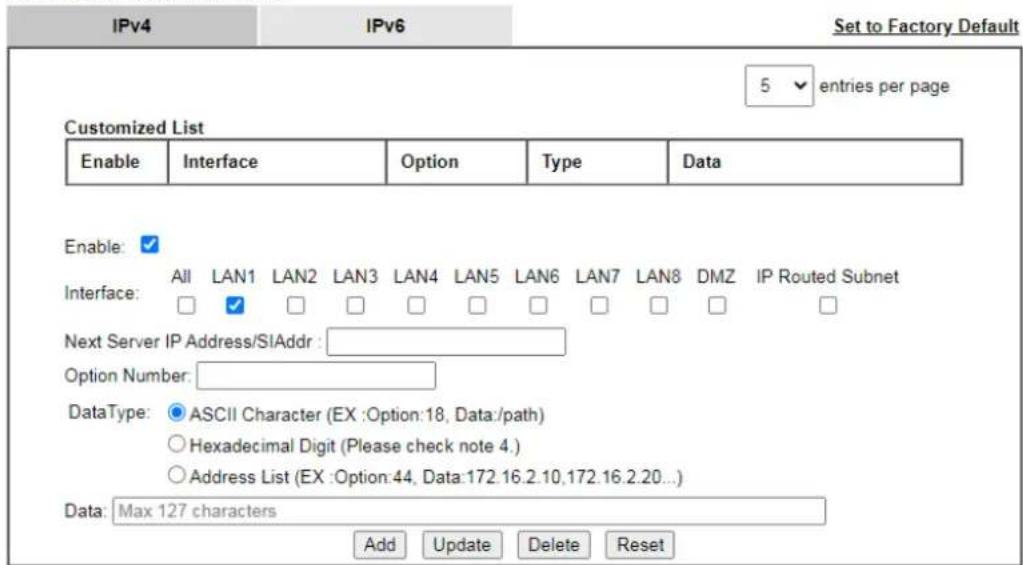
text_image
IPv4 IPv6 Set to Factory Default 5 entries per page Customized List Enable Interface Option Type Data Enable: ✓ Interface: All LAN1 LAN2 LAN3 LAN4 LAN5 LAN6 LAN7 LAN8 DMZ IP Routed Subnet Next Server IP Address/SIAddr :_ Option Number: DataType: ⬤ ASCII Character (EX :Option:18, Data:/path) ○Hexadecimal Digit (Please check note 4.) ○Address List (EX :Option:44, Data:172.16.2.10,172.16.2.20...) Data: Max 127 characters Add Update Delete ResetNote:
1. Configuring options 44, 46 or 66 here will overwrite the settings by telnet command msubnet.
2. Configuring option 3 here will overwrite the setting in "LAN >> General Setup" Details Page's "Gateway IP Address" field.
3. Configuring option 15 here will overwrite the setting in "WAN >> Internet Access >> Static or Dynamic IP" Detail Page's "Domain Name" field.
4. Hexadecimal Digit: Input the hexadecimal representation of ASCII Character data. EX: Option:18, Data:2f70617468 (/path)
OK
Available settings are explained as follows:
| Item Description | |
| Customized List | Shows all the DHCP options that have been configured in the system. |
| Enable | If selected, DHCP option entry is enabled.If unselected, DHCP option entry is disabled. |
| Interface | LAN interface(s) to which this entry is applicable. |
| Next Server IP Address/SIAddr | Overrides the DHCP Next Server IP address (DHCP Option 66) supplied by the DHCP server. |
| Option Number | DHCP option number (e.g., 100). |
| DataType | Type of data in the Data field:ASCII Character - A text string. Example: / path.Hexadecimal Digit - A hexadecimal string. Valid characters are from 0 to 9 and from a to f. Example: 2f70617468.Address List - One or more IPv4 addresses, delimited by commas. |
| Data Data of this DHCP option. | |
To add a DHCP option entry from scratch, clear the data entry fields (Enable, Interface, Option Number, DataType and Data) by clicking Reset. After filling in the values, click Add to create the new entry.
To add a DHCP option entry modeled after an existing entry, click the model entry in Customized List. The data entry fields will be populated with values from the model entry. After making all necessary changes for the new entry, click Add to create it.
To modify an existing DHCP option entry, click on it in Customized List. The data entry fields will be populated with the current values from the entry. After making all necessary changes, click Update to save the changes.
To delete a DHCP option entry, click on it in Customized List, and then click Delete.
II-2-2 VLAN
Virtual Local Area Networks (VLANs) allow you to subdivide your LAN to facilitate management or to improve network security.
Select LAN>>VLAN from the menu bar of the Web UI to bring up the VLAN Configuration page.
Tagged VLAN
The tagged VLANs (802.1q) can mark data with a VLAN identifier. This identifier can be carried through an onward Ethernet switch to specific ports. The specific VLAN clients can also pick up this identifier as it is just passed to the LAN. You can set the priorities for LAN-side QoS. You can assign each of VLANs to each of the different IP subnets that the router may also be operating, to provide even more isolation. The said functionality is tag-based multi-subnet.
Port-Based VLAN
Relative to tag-based VLAN which groups clients with an identifier, port-based VLAN uses physical ports (P1 \~ P4) to separate the clients into different VLAN group.
Virtual LAN function provides you a very convenient way to manage hosts by grouping them based on the physical port. The multi-subnet can let a small businesses have much better isolation for multi-occupancy applications. Go to LAN page and select VLAN. The following page will appear. Click Enable to invoke VLAN function.
Below is an example page in Vigor2927ac:
LAN >> VLAN Configuration

VLAN Configuration
√ Permit untagged device in P1 to access router
Note:
1. For each VLAN row, selecting Enable VLAN Tag will apply the associated VID to the selected wired LAN port.
2. Wireless LAN traffic is always untagged, but the SSID is still a member of the selected VLAN (group).
3. Each VID must be unique.

Available settings are explained as follows:
| Item Description | |
| Enable | Click it to enable VLAN configuration. |
| LAN | P1 - P5 - Check the LAN port(s) to group them under the selected VLAN. |
| Wireless LAN (2.4GHz) | SSID1 - SSID4 - Check the SSID boxes to group them under the selected VLAN. |
| Wireless LAN (5GHz) | SSID1 - SSID4 - Check the SSID boxes to group them under the selected VLAN. |
| Subnet Choose one of them | to make the selected VLAN mapping to the specified subnet only. For example, LAN1 is specified for VLAN0. It means that PCs grouped under VLAN0 can get the IP address(es) that specified by the subnet. |
| VLAN Tag | Enable - Check the box to enable the function of VLAN with tag.The router will add specific VLAN number to all packets on the LAN while sending them out.Please Enter the tag value and specify the priority for the packets sending by LAN.VID - Enter the value as the VLAN ID number. The range is form 0 to 4095. VIDs must be unique.Priority - Valid values are from 0 to 7, where 1 has the lowest priority, followed by 0, and finally from 2 to 7 in increasing order of priority. |
| Permit untagged device in P1 to access router | Select to allow untagged hosts connected to LAN port P1 to access the router. In case you have incorrectly configured VLAN functionality, you will still be able to access the router via the Web UI, and telnet and SSH shells to adjust the configuration. |
Inter-LAN Routing
The Vigor router supports up to 15 VLANs. Each VLAN can be set up to use one or more of the Ethernet ports and wireless LAN Service Set Identifiers (SSIDs). Within the grid of VLANs (horizontal rows) and LAN interfaces (vertical columns),
● all hosts within the same VLAN (horizontal row) are visible to one another
● all hosts connected to the same LAN or WLAN interface (vertical column) are visible to one another if
- they belong to the same VLAN, or
- they belong to different VLANs, and inter-LAN routing (LAN>>General Setup) between them is enabled (see below).
Inter-LAN Routing
| Subnet | LAN 1 | LAN 2 | LAN 3 | LAN 4 | LAN 5 | LAN 6 | LAN 7 | LAN 8 | DMZ Port |
| LAN 1 | |||||||||
| LAN 2 | |||||||||
| LAN 3 | |||||||||
| LAN 4 | |||||||||
| LAN 5 | |||||||||
| LAN 6 | |||||||||
| LAN 7 | |||||||||
| LAN 8 | |||||||||
| DMZ Port |
Inter-LAN Routing allows different LAN subnets to be interconnected or isolated. It is only available when the VLAN functionality is enabled. In the Inter-LAN Routing matrix, a selected checkbox means that the 2 intersecting LANs can communicate with each other.
Vigor2927 series features a hugely flexible VLAN system. In its simplest form, each of the Gigabit LAN ports can be isolated from each other, for example to feed different companies or departments but keeping their local traffic completely separated.
Configuring port-based VLAN for wireless and non-wireless clients
-
All the wire network clients are categorized to group VLAN0 in subnet 192.168.1.0/24 (LAN1).
-
All the wireless network clients are categorized to group VLAN1 in subnet 192.168.2.0/24 (LAN2).
-
Open LAN>>VLAN Configuration. Check the boxes according to the statement in step 1 and Step 2.
LAN >> VLAN Configuration

VLAN Configuration
-
Click OK.
-
Open LAN>>General Setup. If you want to let the clients in both groups communicate with each other, simply activate Inter-LAN Routing by checking the box between LAN1 and LAN2.
LAN >> General Setup
General Setup
| Index | Enable | DHCP | DHCPv6 | IP Address | ||
| LAN 1 | V | V | V | 192.168.27.1 | Details Page | IPv6 |
| LAN 2 | √ | √ | √ | 192.168.20.1 | Details Page | IPv6 |
| LAN 3 | ☐ | ☑ | ☑ | 192.168.3.1 | Details Page | IPv6 |
| LAN 4 | ☐ | ☑ | ☑ | 192.168.4.1 | Details Page | IPv6 |
| LAN 5 | ☐ | ☑ | ☑ | 192.168.5.1 | Details Page | IPv6 |
| LAN 6 | ☐ | ☑ | ☑ | 192.168.6.1 | Details Page | IPv6 |
| LAN 7 | ☐ | ☑ | ☑ | 192.168.7.1 | Details Page | IPv6 |
| LAN 8 | ☐ | ☑ | ☑ | 192.168.8.1 | Details Page | IPv6 |
| DMZ Port | ☐ | √ | √ | 192.168.254.1 | Details Page | IPv6 |
| IP Routed Subnet | ☐ | ☑ | 192.168.0.1 | Details Page |
DHCP Server Option
Note
- Please enable LAN 2 - 8 on LAN >> VLAN page before configure them.
- Enable DMZ port will make the LAN Port 5 neglect the setting on VLAN page. LAN Port 5 will become the DMZ Port.
☐ Force router to use "DNS server IP address" settings specified in LAN1
Inter-LAN Routing
Vigor router supports up to six private IP subnets on LAN. Each can be independent (isolated) or common (able to communicate with each other). This is ideal for departmental or multi-occupancy applications.
II-2-3 Bind IP to MAC
This function is used to bind the IP and MAC address in LAN to have a strengthening control in network. With the Bind IP to MAC feature you can reserve LAN IP addresses for LAN clients. Each reserved IP address is associated with a Media Access Control (MAC) address.
Click LAN and click Bind IP to MAC to open the setup page.
LAN >> Bind IP to MAC
Bind IP to MAC
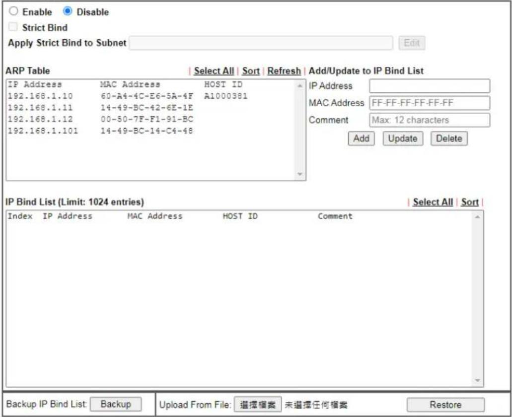
text_image
Enable Disable Strict Bind Apply Strict Bind to Subnet Edit ARP Table | Select All | Sort | Refresh | Add/Update to IP Bind List IP Address MAC Address HOST ID 192.168.1.10 60-A4-4C-E6-5A-4F A1000381 192.168.1.11 14-49-BC-42-6E-1E 192.168.1.12 00-50-7F-F1-91-BC 192.168.1.101 14-49-BC-14-C4-48 IP Address MAC Address FF-FF-FF-FF-FF-FF Comment Max: 12 characters Add Update Delete IP Bind List (Limit: 1024 entries) | Select All | Sort | Index IP Address MAC Address HOST ID Comment Backup IP Bind List: Backup Upload From File: 選擇檔案 未選擇任何檔案 RestoreNote:
- IP-MAC binding presets DHCP Allocations.
- If Strict Bind is enabled, unspecified LAN clients in the selected subnets cannot access the Internet.
- Comment can not contain characters " and ".
- MAC address can be seperated by : or - . E.g., FF:FF:FF:FF:FF:FF or FF-FF-FF-FF-FF-FF
OK
Available settings are explained as follows:
| Item Description | |
| Enable | Click this radio button to invoke this function. However, IP/ MAC which is not listed in IP Bind List also can connect to Internet. |
| Disable | Click this radio button to disable this function. All the settings on this page will be invalid. |
| Strict Bind | Check the box to block the connection of the IP/ MAC which is not listed in IP Bind List.LAN clients will be assigned IP addresses according to theMAC-to-IP address associations on this page. LAN client whose MAC address has not been bound to an IP address will be denied network access.Note: Before selecting Strict Bind, make sure at least one valid MAC address has been bound to an IP address. Otherwise no LAN clients will have network access, and it will not be possible to connect to the router to make changes to its configuration.Apply Strict Bind to Subnet - Choose the subnet(s) for applying the rules of Bind IP to MAC.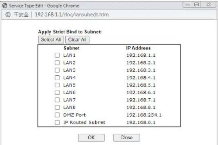 |
| ARP Table | This table is the LAN ARP table of this router. The information for IP and MAC will be displayed in this field. Each pair of IP and MAC address listed in ARP table can be selected and added to IP Bind List by clicking Add below. |
| Select All | Select all entries in the ARP Table for manipulation. |
| Sort | Reorder the entry based on the IP address. |
| Refresh | Refresh the ARP table listed below to obtain the newest ARP table information. |
| Add or Update to IP Bind List | IP Address - Enter the IP address to be associated with a MAC address.Mac Address - Enter the MAC address of the LAN client's network interface.Comment - Type a brief description for the entry. |
| Add | It allows you to add the one you choose from the ARP table or the IP/ MAC address typed in Add and Edit to the table of IP Bind List. |
| Update | It allows you to edit and modify the selected IP address and MAC address that you create before. |
| Delete | You can remove any item listed in IP Bind List. Simply click and select the one, and click Delete. The selected item will be removed from the IP Bind List. |
| IP Bind List | It displays a list for the IP bind to MAC information. |
| Backup IP Bind List | Click Backup and enter a filename to back up IP Bind List to a file. |
| Upload From File | Click Browse... to select an IP Bind List backup file. ClickRestore to restore the backup and overwrite the existing list. |

Info
Before you select Strict Bind, you have to bind one set of IP/MAC address for one PC. If not, no one of the PCs can access into Internet. And the web user interface of the router might not be accessed.
When you finish the configuration, click OK to save the settings.
II-2-4 LAN Port Mirror
The LAN Port Mirror function allows network traffic of select LAN ports to be forwarded to another LAN port for analysis. This is useful for enforcing policies, detecting unauthorized access, monitoring network performance, etc.
Select LAN>>LAN Port Mirror from the menu bar of the Web UI to bring up the LAN Port Mirror configuration page.
LAN >> LAN Port Mirror
LAN Port Mirror
| Port Mirror: ○ Enable ● Disable | |||||||
| Port1 | Port2 | Port3 | Port4 | Port5 | WAN1 | WAN2 | |
| Mirror Port | ○ | ○ | ○ | ○ | |||
| Mirrored Tx Port | □ | □ | □ | □ | □ | □ | □ |
| Mirrored Rx Port | □ | □ | □ | □ | □ | □ | □ |
Note:
- The mirrored WAN1 is a software mirror, it will lead to a substantial decline in performance.
OK
Available settings are explained as follows:
| Item Description | |
| Port Mirror | Enables or disables LAN Port Mirroring. |
| Mirror Port | One and only one port is selected as the mirror port, to which traffic is to be forwarded. |
| Mirrored Tx Port | Port(s) whose outbound traffic will be forwarded to the mirror port. |
| Mirrored Rx Port | Port(s) whose inbound traffic will be forwarded to the mirror port. |
After finishing all the settings here, please click OK to save the configuration.
II-2-5 Wired 802.1x
Wired 802.1X provides authentication for clients wishing to connect to the LAN by Ethernet. Only one client can be authenticated on each LAN port.
Select LAN>>Wired 802.1X from the menu bar of the Web UI to bring up the Wired 802.1X configuration page.
LAN >> Wired 802.1X
Wired 802.1X
LAN 802.1X:
□ Enable
Authentication Type:
External RADIUS
802.1X ports:
P1
P2
P3
P4
P5
Note:
- 802.1X enabled LAN ports only support a single attached device using EAPOL authentication. To authenticate multiple devices through a LAN port you need an 802.1X-capable switch. Then configure 802.1X on the attached switch instead.
- Please configure External RADIUS or Local 802.1X for authentication.
- Authentication by External RADIUS supports PEAP, EAP-TLS and EAP-TTLS.
OK
Available settings are explained as follows:
| Item Description | |
| Enable | Check the box to enable LAN 802.1x function. |
| Authentication Type | External RADIUS - An external RADIUS server is to be used for 802.1X authentication. Go to Applications >> RADIUS / TACACS+>>External RADIUS to specify the RADIUS server.Local 802.1X - Use the user database on the router to authenticate clients. Go to User Management >> User Profile to set up users by entering user names, passwords and ensure that Local 802.1X service is enabled for the profiles. |
| 802.1X ports | 802.1X authentication will be available for the selected LAN ports. |
After finishing all the settings here, please click OK to save the configuration.
II-2-6 Link Aggregation
LAG means Link Aggregation Group which groups some physical ports together to make a single high-bandwidth data path. Thus it can implement traffic load sharing among the member ports in a group to enhance the connection reliability.
LAN >> Link Aggregation
Link Aggregation
| Aggregation Ports | Link Status | |||||
| Enable | P2 | P3 | P4 | P5 | ||
| LAG1 | □ | □ | □ | |||
Notes:
- Only Support Static (Balance-xor) mode
- Ports in LAG can not be mirror port
- LAG uses Hash Algorithm to decide the port, and the calculated port might be the same. When LAG doesn't work as expected, please change the device IP for a try.
OK
Available settings are explained as follows:
| Item Description | |
| Enable | Check the box to enable LAN 802.1x function. |
| Aggregation Ports | Select the port number (at least two ports) to make a high-bandwidth data path.At present, the available ports to be selected include P2 and P3. |
| Link Status | Green light means the LAG port is connected by Ethernet cable(s). |
After finishing all the settings here, please click OK to save the configuration.
II-3 Hardware Acceleration
Hardware Acceleration is also called PPA in DrayTek for it is based on Protocol Processing Engine (PPE) of Infineon. It can only support 4096 sessions for network traffic (IN & OUT).
When the data traffic is heavy and data transmission is getting slowly and slowly, you can configure this page to accelerate the data streaming by hardware itself. Open Hardware Acceleration to access into the following page:
Hardware Acceleration
Acceleration: Enable ▼
NAT
Protocol: √ TCP √ UDP
Option: √ Wireless LAN Client
5G WAN
IPsec
Protocol: √ TCP √ UDP
□ Exception List
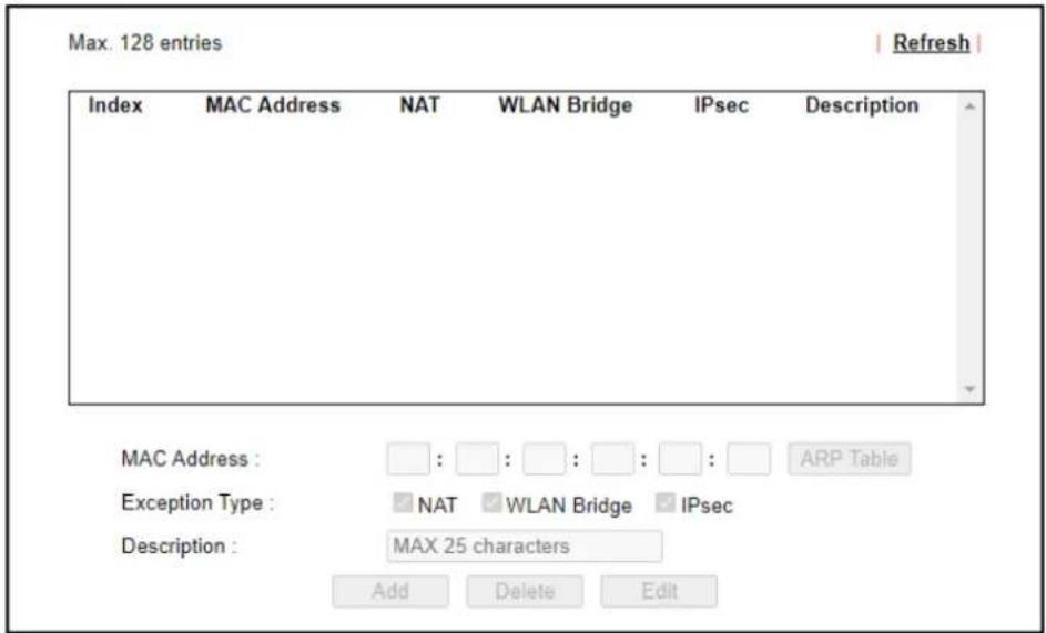
text_image
Max. 128 entries Index MAC Address NAT WLAN Bridge IPsec Description MAC Address : □ : □ : □ : □ : □ : ARP Table Exception Type : NAT WLAN Bridge IPsec Description : MAX 25 characters Add Delete EditNote:
- When the wireless bandwidth limit is enable, wireless sessions will not add hardware acceleration.
- Hardware Acceleration does not support PPTP/L2TP.
- The exception type "WLAN Bridge" means hardware acceleration between wireless lan client and physical lan client.
OK
Clear
Available settings are explained as follows:
| Item Description | |
| Acceleration | Disable - The default setting.Enable - Choose to enable the hardware acceleration function. |
| NAT | Select TCP and/ or UDP. |
| IPsec Select TCP and/ or UDP. | |
| Exception List | If you want to restrict some users/ clients from transmittingdata through the router by using the hardware acceleration function, check this box to create an exclusion list.MAC Address - Enter the MAC address of the client.ARP Table - Click to select the client listed on the ARP table. Then, the MAC address of the selected client will be shown on the MAC Address field.Exception Type - Select NAT and / or IPsec.Description - Enter a brief explanation for the selected client. |
Checking the PPA status
For checking whether the rule of PPA is working or not, a user can login to Vigor2927 series by using telnet. User can view how many sessions are transferring in each direction of PPA table after entering "ppa -v".
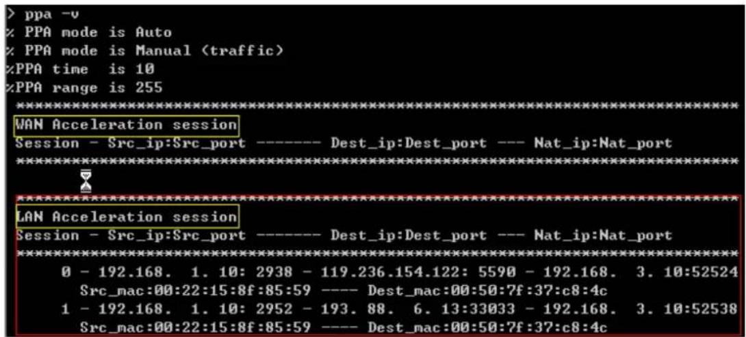
text_image
> ppa -v % PPA mode is Auto % PPA mode is Manual (traffic) %PPA time is 10 %PPA range is 255 ********************************************************************** WAN Acceleration session Session - Src_ip:Src_port ---- Dest_ip:Dest_port --- Nat_ip:Nat_port ********************************************************************** LAN Acceleration session Session - Src_ip:Src_port ---- Dest_ip:Dest_port --- Nat_ip:Nat_port ********************************************************************** 0 - 192.168. 1. 10: 2938 - 119.236.154.122: 5590 - 192.168. 3. 10:52524 Src_mac:00:22:15:8f:85:59 ---- Dest_mac:00:50:7f:37:c8:4c 1 - 192.168. 1. 10: 2952 - 193. 88. 6. 13:33033 - 192.168. 3. 10:52538 Src_mac:00:22:15:8f:85:59 ---- Dest_mac:00:50:7f:37:c8:4cII-4 NAT
Usually, the router serves as an NAT (Network Address Translation) router. NAT is a mechanism that one or more private IP addresses can be mapped into a single public one. Public IP address is usually assigned by your ISP, for which you may get charged. Private IP addresses are recognized only among internal hosts.
When the outgoing packets destined to some public server on the Internet reach the NAT router, the router will change its source address into the public IP address of the router, select the available public port, and then forward it. At the same time, the router shall list an entry in a table to memorize this address/ port-mapping relationship. When the public server response, the incoming traffic, of course, is destined to the router's public IP address and the router will do the inversion based on its table. Therefore, the internal host can communicate with external host smoothly.
The benefit of the NAT includes:
- Save cost on applying public IP address and apply efficient usage of IP address. NAT allows the internal IP addresses of local hosts to be translated into one public IP address, thus you can have only one IP address on behalf of the entire internal hosts.
● Enhance security of the internal network by obscuring the IP address. There are many attacks aiming victims based on the IP address. Since the attacker cannot be aware of any private IP addresses, the NAT function can protect the internal network.

Info
On NAT page, you will see the private IP address defined in RFC-1918. Usually we use the 192.168.1.0/24 subnet for the router. As stated before, the NAT facility can map one or more IP addresses and/or service ports into different specified services. In other words, the NAT function can be achieved by using port mapping methods.
Web User Interface
NAT
Port Redirection
DMZ Host
Open Ports
Port Triggering
ALG
II-4-1 Port Redirection
Port Redirection is usually set up for server related service inside the local network (LAN), such as web servers, FTP servers, E-mail servers etc. Most of the case, you need a public IP address for each server and this public IP address/ domain name are recognized by all users. Since the server is actually located inside the LAN, the network well protected by NAT of the router, and identified by its private IP address/ port, the goal of Port Redirection function is to forward all access request with public IP address from external users to the mapping private IP address/ port of the server.
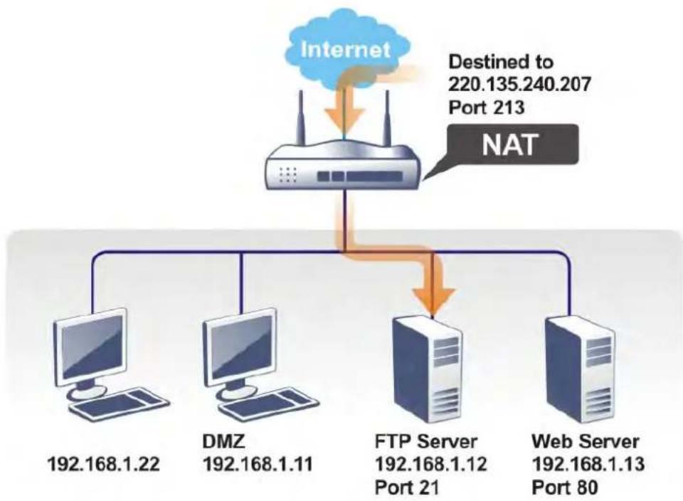
flowchart
graph TD
    A["Internet"] --> B["NAT"]
    B --> C["DMZ 192.168.1.22"]
    B --> D["DMZ 192.168.1.11"]
    B --> E["FTP Server 192.168.1.12 Port 21"]
    B --> F["Web Server 192.168.1.13 Port 80"]
    G["Destined to 220.135.240.207 Port 213"] --> A
The port redirection can only apply to incoming traffic.
To use this function, please go to NAT page and choose Port Redirection web page. The Port Redirection Table provides 40 port-mapping entries for the internal hosts.
NAT >> Port Redirection
| Index Enable Service Name WAN Interface Protocol Public Port Source IP Private IP | ||||||
| 1. | ☐ | All | Any | |||
| 2. | ☐ | All | Any | |||
| 3. | ☐ | All | Any | |||
| 4. | ☐ | All | Any | |||
| 5. | ☐ | All | Any | |||
| 6. | ☐ | All | Any | |||
| 7. | ☐ | All | Any | |||
| 8. | ☐ | All | Any | |||
| 9. | ☐ | All | Any | |||
Note:
The port number values set in this page might be invalid due to the same values configured for Management Port Setup in System Maintenance>>Management, Open VPN and SSL VPN.
Each item is explained as follows:
| Item Description | |
| Index | Display the number of the profile. |
| Enable | Check the box to enable the port redirection profile. |
| Service Name | Display the description of the specific network service. |
| WAN Interface | Display the WAN IP address used by the profile. |
| Protocol | Display the transport layer protocol (TCP or UDP). |
| Public Port | Display the port number which will be redirected to the specified Private IP and Port of the internal host. |
| Source IP | Display the IP object of the source IP. |
| Private IP | Display the IP address of the internal host providing the service. |
| Backup | Click it to backup the configuration of port redirection settings. |
| Restore | Click it to restore the configuration of port redirection settings. Before clicking, make sure upload the configuration file onto Vigor router. |
Press any number under Index to access into next page for configuring port redirection.
Index No. 1
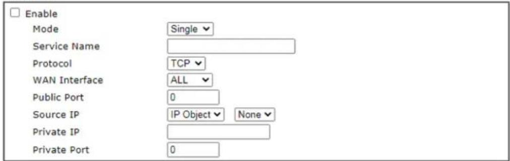
text_image
Enable Mode Single Service Name Protocol TCP WAN Interface ALL Public Port 0 Source IP IP Object None Private IP Private Port 0Note:
In "Range" Mode the End IP will be calculated automatically once the Public Port and Start IP have been entered.

Available settings are explained as follows:
| Item Description | |
| Enable | Check this box to enable such port redirection setting. |
| Mode | Two options (Single and Range) are provided here for you to choose. To set a range for the specific service, selectRange.In Range mode, if the public port (start port and end port) and the starting IP of private IP had been entered, the system will calculate and display the ending IP of private IP automatically. |
| Service Name | Enter the description of the specific network service. |
| Protocol | Select the transport layer protocol (TCP or UDP). |
| WAN Interface | Select the WAN interface used for port redirection. There are eight WAN IP alias that can be selected and used for port redirection. The default setting isAllwhich means all the incoming data from any port will be redirected to specified range of IP address and port. |
| Public Port | Specify which port can be redirected to the specifiedPrivateIP and Portof the internal host. If you chooseRangeas the port redirection mode, you will see two boxes on this field.Enter the required number on the first box (as the starting port) and the second box (as the ending port). |
| Source IP | IP Object- Use the drop down list to specify an IP object profile.IP Group- Use the drop down list to specify an IP group profile. |
| Private IP | Specify the private IP address of the internal host providing the service. If you chooseRangeas the port redirection mode, you will see two boxes on this field. Type a complete IP address in the first box (as the starting point). The second one will be assigned automatically later. |
| Private Port | Specify the private port number of the service offered by the internal host. |
After finishing all the settings here, please click OK to save the configuration.
Note that the router has its own built-in services (servers) such as Telnet, HTTP and FTP etc. Since the common port numbers of these services (servers) are all the same, you may need to reset the router in order to avoid confliction.
For example, the built-in web user interface in the router is with default port 80, which may conflict with the web server in the local network, http://192.168.1.13:80. Therefore, you need to change the router's http port to any one other than the default port 80 to avoid conflict, such as 8080. This can be set in the System Maintenance >>Management Setup. You then will access the admin screen of by suffixing the IP address with 8080, e.g., http://192.168.1.1:8080 instead of port 80.
System Maintenance >> Management

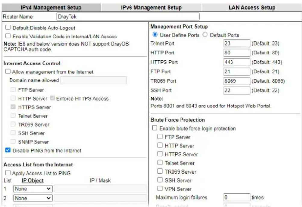
text_image
IPv4 Management Setup IPv6 Management Setup LAN Access Setup Router Name DrayTek □ Default:Disable Auto-Logout □ Enable Validation Code in Internet/LAN Access Note: IE8 and below version does NOT support DrayOS CAPTCHA auth code. Internet Access Control □ Allow management from the Internet Domain name allowed □ FTP Server □ HTTP Server □ Enforce HTTPS Access □ HTTPS Server □ Telnet Server □ TR069 Server □ SSH Server □ SNMP Server ✓ Disable PING from the Internet Access List from the Internet □ Apply Access List to PING List IP Object IP / Mask 1 None 2 None Management Port Setup ● User Define Ports ○ Default Ports Telnet Port 23 (Default: 23) HTTP Port 80 (Default: 80) HTTPS Port 443 (Default: 443) FTP Port 21 (Default: 21) TR069 Port 8069 (Default: 8069) SSH Port 22 (Default: 22) Note: Ports 8001 and 8043 are used for Hotspot Web Portal. Brute Force Protection □ Enable brute force login protection □ FTP Server □ HTTP Server □ HTTPS Server □ Telnet Server □ TR069 Server □ SSH Server □ VPN Server Maximum login failures 0 times Result posted 0 secondsII-4-2 DMZ Host
As mentioned above, Port Redirection can redirect incoming TCP/UDP or other traffic on particular ports to the specific private IP address/port of host in the LAN. However, other IP protocols, for example Protocols 50 (ESP) and 51 (AH), do not travel on a fixed port. Vigor router provides a facility DMZ Host that maps ALL unsolicited data on any protocol to a single host in the LAN. Regular web surfing and other such Internet activities from other clients will continue to work without inappropriate interruption. DMZ Host allows a defined internal user to be totally exposed to the Internet, which usually helps some special applications such as Netmeeting or Internet Games etc.
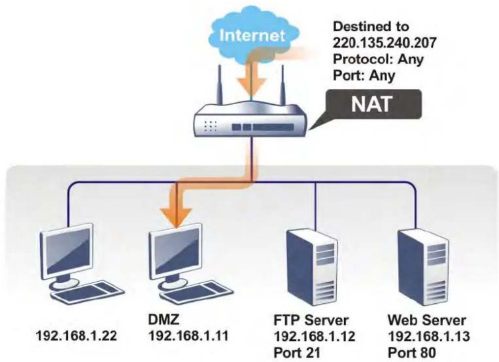
flowchart
graph TD
    A["Internet"] --> B["NAT"]
    B --> C["DMZ 192.168.1.22"]
    B --> D["DMZ 192.168.1.11"]
    B --> E["FTP Server 192.168.1.12 Port 21"]
    B --> F["Web Server 192.168.1.13 Port 80"]
    G["Destined to 220.135.240.207\nProtocol: Any\nPort: Any"] --> A
The security properties of NAT are somewhat bypassed if you set up DMZ host. We suggest you to add additional filter rules or a secondary firewall.
Click DMZ Host to open the following page. You can set different DMZ host for each WAN interface. Click the WAN tab to switch into the configuration page for that WAN.
NAT >> DMZ Host Setup

text_image
DMZ Host Setup WAN1 WAN2 WAN3 WAN4 LTE WAN6 WAN 1 None Private IP Choose IP
Available settings are explained as follows:
| Item Description | |
| WAN 1 | Choose Private IP or None first. |
| Private IP | Enter the private IP address of the DMZ host, or click Choose PC to select one. |
| Choose IP Click this button | and then a window will automatically pop up, as depicted below. The window consists of a list of private IP addresses of all hosts in your LAN network. Select one private IP address in the list to be the DMZ host.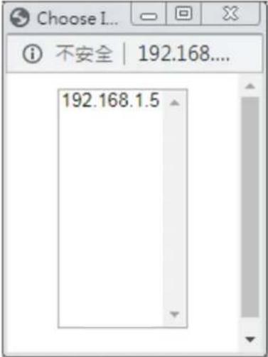 When you have selected one private IP from the above dialog, the IP address will be shown on the following screen. Click OK to save the setting.NAT >> DMZ Host SetupDMZ Host SetupWAN1 WAN2 WAN3 WAN4 WAN5 WAN6WAN 1Private IPPrivate IP 192 160 1.5 Choose IPOK When you have selected one private IP from the above dialog, the IP address will be shown on the following screen. Click OK to save the setting.NAT >> DMZ Host SetupDMZ Host SetupWAN1 WAN2 WAN3 WAN4 WAN5 WAN6WAN 1Private IPPrivate IP 192 160 1.5 Choose IPOK |
DMZ Host for WAN2, WAN3, LTE or WAN4 is slightly different with WAN1. Active True IP selection is available for WAN1 only.
See the following figure.
NAT >> DMZ Host Setup
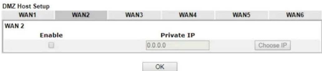
text_image
DMZ Host Setup WAN1 WAN2 WAN3 WAN4 WAN5 WAN6 WAN 2 Enable Private IP 0.0.0.0 Choose IP OKIf you previously have set up WAN Alias for PPPoE or Static or Dynamic IP mode in WAN2 interface, you will find them in Aux. WAN IP for your selection.
NAT >> DMZ Host Setup
| DMZ Host Setup | |||||
| WAN1 | WAN2 | WAN3 | WAN4 | WAN5 | WAN6 |
| WAN 2 | |||||
| Index Enable | Aux. WAN IP | Private IP | |||
| 1. ☐ | 10.39.0.10 | 0.0.0.0 | Choose IP | ||
| 2. ☐ | 10.39.0.150 | 0.0.0.0 | Choose IP | ||
Available settings are explained as follows:
| Item Description | |
| Enable | Check to enable the DMZ Host function. |
| Private IP | Enter the private IP address of the DMZ host, or click Choose PC to select one. |
| Choose IP | Click this button and then a window will automatically pop up, as depicted below. The window consists of a list of private IP addresses of all hosts in your LAN network. Select one private IP address in the list to be the DMZ host.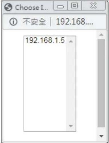 When you have selected one private IP from the above dialog, the IP address will be shown on the screen. Click OK to save the setting. When you have selected one private IP from the above dialog, the IP address will be shown on the screen. Click OK to save the setting. |
After finishing all the settings here, please click OK to save the configuration.
II-4-3 Open Ports
Open Ports allows you to open a range of ports for the traffic of special applications.
Common application of Open Ports includes P2P application (e.g., BT, KaZaA, Gnutella, WinMX, eMule and others), Internet Camera etc. Ensure that you keep the application involved up-to-date to avoid falling victim to any security exploits.
Click Open Ports to open the following page:
NAT >> Open Ports
Open Ports Setup
Set to Factory Default
| Index | Enable | Comment | WAN Interface | Source IP | Local IP Address |
| 1. | Any | ||||
| 2. | Any | ||||
| 3. | Any | ||||
| 4. | Any | ||||
| 5. | Any | ||||
| 6. | Any | ||||
| 7. | Any | ||||
| 8. | Any | ||||
| 38. | Any | ||||
| 39. | Any | ||||
| 40. | Any |
OK
Cancel
The port number values set in this page might be invalid due to the same values configured for Management Port Setup in System Maintenance>>Management, Open VPN and SSL VPN.
Available settings are explained as follows:
| Item Description | |
| Index | Indicate the relative number for the particular entry that you want to offer service in a local host. You should click the appropriate index number to edit or clear the corresponding entry. |
| Enable | Check the box to enable the open port profile. |
| Comment | Specify the name for the defined network service. |
| WAN Interface | Display the WAN interface used by such index. |
| Aux. WAN IP | Display the IP alias setting used by such index.If no IP alias setting exists, such field will not appear. |
| Source IP Display the name of the IP object. | |
| Local IP Address | Display the private IP address of the local host offering the service. |
| Backup | Click it to backup the configuration of open ports settings. |
| Restore | Click it to restore the configuration of open ports settings.Before clicking, make sure upload the configuration file ontoVigor router. |
To add or edit port settings, click one index number on the page. The index entry setup page will pop up. In each index entry, you can specify 10 port ranges for diverse services.
NAT >> Open Ports >> Edit Open Ports
Index No. 1
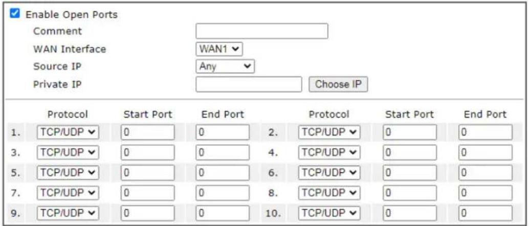
text_image
Enable Open Ports Comment WAN Interface Source IP Any Choose IP Private IP Protocol Start Port End Port Protocol Start Port End Port 1. TCP/UDP ▼ 0 0 2. TCP/UDP ▼ 0 0 3. TCP/UDP ▼ 0 0 4. TCP/UDP ▼ 0 0 5. TCP/UDP ▼ 0 0 6. TCP/UDP ▼ 0 0 7. TCP/UDP ▼ 0 0 8. TCP/UDP ▼ 0 0 9. TCP/UDP ▼ 0 0 10. TCP/UDP ▼ 0 0
Available settings are explained as follows:
| Item Description | |
| Enable Open Ports | Check to enable this entry. |
| Comment | Make a name for the defined network application/ service. |
| WAN Interface | Specify the WAN interface that will be used for this entry. |
| Source IP Any - Any IP can be used as the source IP.IP Object- Use the drop down list to specify an IP object profile.IP Group- Use the drop down list to specify an IP group profile. | |
| WAN IP | Specify the WAN IP address that will be used for this entry.This setting is available when WAN IP Alias is configured. |
| Private IP | Enter the private IP address of the local host or click Choose PC to select one.Choose IP - Click this button and, subsequently, a window having a list of private IP addresses of local hosts will automatically pop up. Select the appropriate IP address of the local host in the list. |
| Protocol | Specify the transport layer protocol. It could be TCP, UDP, or ---- (none) for selection. |
| Start Port | Specify the starting port number of the service offered by the local host. |
| End Port | Specify the ending port number of the service offered by the local host. |
After finishing all the settings here, please click OK to save the configuration.
NAT >> Open Ports
| Open Ports Setup | Set to Factory Default | |||||
| Index | Enable | Comment | WAN Interface | Aux. WAN IP | Source IP | Local IP Address |
| 1. | √ | first | WAN3 | Any | 192.168.1.13 | |
| 2. | □ | Any | ||||
| 3. | □ | Any | ||||
II-4-4 Port Triggering
Port Triggering is a variation of open ports function.
The key difference between "open port" and "port triggering" is:
- Once the OK button is clicked and the configuration has taken effect, "open port" keeps the ports opened forever.
- Once the OK button is clicked and the configuration has taken effect, "port triggering" will only attempt to open the ports once the triggering conditions are met.
- The duration that these ports are opened depends on the type of protocol used. The "default" durations are shown below and these duration values can be modified via telnet commands.
TCP: 86400 sec.
UDP: 180 sec.
IGMP: 10 sec.
TCP WWW: 60 sec.
TCP SYN: 60 sec.
NAT >> Port Triggering
| Port Triggering | Set to Factory Default | ||||||
| Index | Enable | Comment | Triggering Protocol | Source IP | Triggering Port | Incoming Protocol | Incoming Port |
| 1. | Any | ||||||
| 2. | Any | ||||||
| 3. | Any | ||||||
| 4. | Any | ||||||
| 5. | Any | ||||||
| 6. | Any | ||||||
| 7. | Any | ||||||
| 8. | Any | ||||||
| 9. | Any | ||||||
| 10. | Any | ||||||

Available settings are explained as follows:
| Item Description | |
| Index | Indicate the relative number for the port triggering profile. You should click the appropriate index number to edit orclear the corresponding entry. |
| Enable | Check the box to enable the Port Triggering profile. |
| Comment | Display the text which memorizes the application of this rule. |
| Triggering Protocol | Display the protocol of the triggering packets. |
| Source IP Display the name of the IP object. | |
| Triggering Port | Display the port of the triggering packets. |
| Incoming Protocol Display the protocol for the incoming data of such triggering profile. | |
| Incoming Port Display the port for the incoming data of such triggering profile. | |
Click the index number link to open the configuration page.
NAT >> Port Triggering
No. 1

Enable
Service
Comment
Source IP
Triggering Protocol
Triggering Port
Incoming Protocol
Incoming Port
Note:
The Triggering Port and Incoming Port should be input like this : 123-456,777-789 (legal),123-456,789 (legal), but 123-456-789 (illegal).
OK
Clear
Cancel
Available settings are explained as follows:
| Item Description | |
| Enable Check to enable this entry. | |
| Service | Choose the service type to apply for such trigger profile. |
| Comment | Enter the text to memorize the application of this rule. |
| Source IP Any - Any IP can be used as the source IP.IP Object - Use the drop down list to specify an IP object profile.IP Group - Use the drop down list to specify an IP group profile. | |
| Triggering Protocol | Select the protocol (TCP, UDP or TCP/UDP) for such triggering profile. |
| Triggering Port | Enter the port or port range for such triggering profile. |
| Incoming Protocol | When the triggering packets received, it is expected the incoming packets will use the selected protocol. Select the protocol (TCP, UDP or TCP/UDP) for the incoming data of such triggering profile. |
| Incoming Port | Enter the port or port range for the incoming packets. |
II-4-5 Port Knocking
Port Redirection is one of the typical ways to allow the internal servers to be accessible from the Internet. However, the port might be exposed to the Internet and might be scanned by the malware if it open.
Therefore, a technology which can add an extra layer of protection to the internal servers and protect network services from unauthorized access, Port Knocking.
Port knocking is a technology that can add an extra layer of protection to the internal servers. Its basic idea is that only open ports are at risk of being attacked, so it allows all ports to be closed at the beginning. Do not open them, and then set a password based on the port combination. Only those who know the password can open the ports and connect.
Typical NAT Port Redirection

flowchart
graph LR
    A["Internet"] --> B["TCP Port 8080 is always open."]
    B --> C["Server"]
    C --> D["Warning Icon"]
NAT Port Knocking
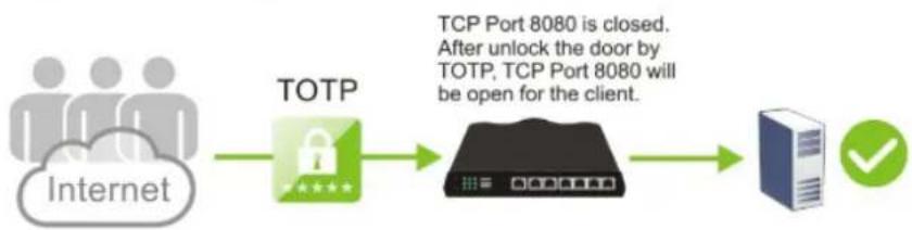
flowchart
graph LR
    A["Internet"] --> B["TOTP"]
    B --> C["TOP Port 8080 is closed. After unlock the door by TOTP, TCP Port 8080 will be open for the client."]
    C --> D["Server"]
    D --> E["✓"]
This page offers up to 16 profiles to configure the server's public IP, first port knock port and 6 digit validation code. Later, the client's computer can establish the network connection securely via a Port Knock tool. After passing the authentication, the client can access the specified server.
NAT >> Port Knocking
| Port Knocking | Set to Factory Default | Status Table | |||||
| Index | Enable | Service Name | WAN | Protocol | Initial Knock | Public Port | Private Node |
| 1. | ALL | - | - | - | - | ||
| 2. | ALL | - | - | - | - | ||
| 3. | ALL | - | - | - | - | ||
| 4. | ALL | - | - | - | - | ||
| 5. | ALL | - | - | - | - | ||
| 6. | ALL | - | - | - | - | ||
| 7. | ALL | - | - | - | - | ||
| 8. | ALL | - | - | - | - | ||
| 9. | ALL | - | - | - | - | ||
| 10. | ALL | - | - | - | - | ||
| 11. | ALL | - | - | - | - | ||
| 12. | ALL | - | - | - | - | ||
| 13. | ALL | - | - | - | - | ||
| 14. | ALL | - | - | - | - | ||
| 15. | ALL | - | - | - | - | ||
| 16. | ALL | - | - | - | - | ||

Available settings are explained as follows:
| Item Description | |
| Index | Profile number. Click to view or modify the profile settings. |
| Enable | Select to enable the profile.Only the open ports will be at risk of being attacked. So all ports are disabled (closed) in default. |
| Service Name | Display the name of the profile. |
| WAN | Display the interface used for accessing Vigor router. |
| Protocol Display the protocol for accessing Vigor router. | |
| Initial Knock Display the initial knock port number. | |
| Public Port | Display the port number used for the selected protocol. |
| Private Node | Display the IP address of the server. |
Click the index number link to open the configuration page.
Index No. 1
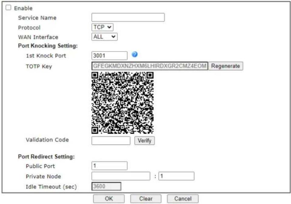
text_image
Enable Service Name Protocol TCP WAN Interface ALL Port Knocking Setting: 1st Knock Port 3001 TOTP Key GFEGKMDXNZHXM6LHIRDXGR2CMZ4EOM Regenerate Validation Code Verify Port Redirect Setting: Public Port 1 Private Node : 1 Idle Timeout (sec) 3600 OK Clear CancelAvailable settings are explained as follows:
| Item Description | |
| Enable | Select to enable the profile. |
| Service Name | Set a profile name. |
| Protocol Select TCP or UDP. | |
| WAN Interfac | It allows the user accessing the server by Vigor router's WAN IP. |
| Port Knocking Setting 1 | ^st Knock Port- Enter a value. Use the default value if you have no idea to enter a new value. Or click the ? mark to have more information.TOTP Key- Use the default value.The key will be used for generate a number for two-factor authentication via an Authenticator App.Regenerate- If required, click this button to regenerate a new TOTP Key.Validation Code- Scan the QR code by a mobile with the App, Google Authenticator. Later, enter the six digit code from the mobile to this field.Verify- Click to verify the validation code to the left. |
| Port Redirect Setting | Public Port- Set a port number for the protocol TCP or UDP.Private Node- Enter an IPv4 address with a port number of a server.Idle Timeout- The default value (usually one hour). After no traffic within this period, the profile will lock, and you need to do port knock again to use it. |
After finishing all the settings here, please click OK to save the configuration.
II-4-6 ALG
ALG means Application Layer Gateway. There are two methods provided by Vigor router, RTSP (Real Time Streaming Protocol) ALG and SIP (Session Initiation Protocol) ALG, for processing the packets of voice and video.
RTSP ALG makes RTSP message, RTCP message, and RTP packets of voice and video be transmitted and received correctly via NAT by Vigor router.
However, SIP ALG makes SIP message and RTP packets of voice be transmitted and received correctly via NAT by Vigor router.
NAT >> ALG
ALG (Application Layer Gateway)
Set to Factory Default
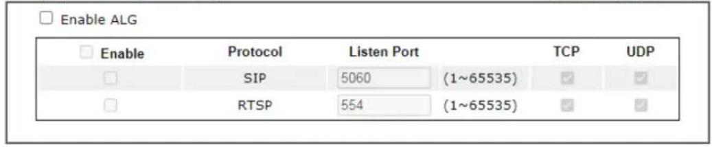
text_image
Enable ALG Enable Protocol Listen Port TCP UDP SIP 5060 (1~65535) RTSP 554 (1~65535)OK
Available settings are explained as follows:
| Item Description | |
| Enable ALG | Check to enable such function. |
| Listen Port | Type a port number for SIP or RTSP protocol. |
| TCP | Check the box to make correspond protocol message packet from TCP transmit and receive via NAT. |
| UDP | Check the box to make correspond protocol message packet from UDP transmit and receive via NAT. |
II-5 Applications
Dynamic DNS
Most ISPs assigns dynamic WAN IP addresses to their customers. Dynamic IP addresses presents challenges to users who would like to accept remote connections to their LANs from the Internet, as service could be disrupted due to the IP address changing without notice. By setting up service with a Dynamic DNS (DDNS) provider, and configuring Dynamic DNS updates on the Vigor router, you can have reliable access to your network by means of an easy-to-remember domain address that resolves to the most current WAN IP address.
The Vigor router supports a wide range of DDNS providers, such as DynDNS, No-IP.com, DtDNS, and ChangeIP. Please contact the DDNS provider of your choice to set up service before configuring DDNS on the router.
LAN DNS / DNS Forwarding
LAN DNS allows the network administrator to override standard DNS resolutions for selecting domain addresses. The router will respond to queries on matched domain addresses with custom IP addresses.
DNS Forwarding allows the network administrator to forward DNS queries to different DNS servers based on the domain name.
LAN DNS and DNS Forwarding only affect DNS queries that are sent to the WAN through the router. DNS queries that are directed to a DNS server on the LAN will not be intercepted by the router.
Schedule
The Vigor router has a built-in clock which can update itself manually or automatically by means of Network Time Protocols (NTP). As a result, you can not only schedule the router to dialup to the Internet at a specified time, but also restrict Internet access to certain hours so that users can connect to the Internet only during certain hours, say, business hours. The schedule is also applicable to other functions.
RADIUS/TACACS+
Remote Authentication Dial-In User Service (RADIUS) is a security authentication client/server protocol that supports authentication, authorization and accounting, which is widely used by Internet service providers. It is the most common method of authenticating and authorizing dial-up and tunneled network users.
The built-in RADIUS client feature enables the router to assist the remote dial-in user or a wireless station and the RADIUS server in performing mutual authentication. It enables centralized remote access authentication for network management.
LDAP /Active Directory Setup
Lightweight Directory Access Protocol (LDAP) is a communication protocol for using in TCP/IP network. It defines the methods to access distributing directory server by clients, work on directory and share the information in the directory by clients. The LDAP standard is established by the work team of Internet Engineering Task Force (IETF).
As the name described, LDAP is designed as an effect way to access directory service without the complexity of other directory service protocols. For LDAP is defined to perform, inquire and modify the information within the directory, and acquire the data in the directory
securely, therefore users can apply LDAP to search or list the directory object, inquire or manage the active directory.
UPnP
The Vigor supports UPnP (Universal Plug and Play), which is a suite of network protocols that simplifies network configuration. Applications and network devices on the LAN, that support UPnP, may request the router to modify its settings to allow NAT Traversal, so that WAN hosts can connect to them directly.
Examples of applications and devices that support UPnP include file-sharing applications such as uTorrent, Vuze and eMule, gaming consoles such as the Sony PlayStations 3 and 4 Xbox 360 and Xbox One, media streaming applications such as Plex and XBMC, and messaging and calling applications such as Skype. To find out if a certain application or network device supports or requires UPnP, please consult its user manual or check with its vendor.
Wake on LAN
Using the Wake on LAN (WoL) feature, LAN clients that support WoL can be powered on or resume from sleep over the network, without the need for physical access to the device.
In order for LAN clients to be able to woken from sleep or off states, the network interface card must be configured to monitor Wake-on-LAN messages. Consult the documentation of the LAN client for details on setting up its network interface for Wake on LAN.
Web User Interface
Applications
Dynamic DNS
LAN DNS / DNS Forwarding
DNS Security
Schedule
RADIUS/TACACS+
Active Directory / LDAP
UPnP
IGMP
Wake on LAN/WAN
SMS/Mail Alert Service
Bonjour
High Availability
Local 802.1X General Setup
II-5-1 Dynamic DNS
Enable the Function and Add a Dynamic DNS Account
To begin configuring Dynamic DNS, from the main menu, navigate to Applications, and select Dynamic DNS. The Dynamic DNS main configuration screen appears:
Applications >> Dynamic DNS Setup
Dynamic DNS Setup
Set to Factory Default
| □ Enable Dynamic DNS SetupAuto-Update interval 14400 Min(s) (180~14400) | |||
| Accounts: | |||
| Index | Enable | WAN Interface | Domain Name |
| 1. | □ | WAN1 First | |
| 2. | □ | WAN1 First | |
| 3. | □ | WAN1 First | |
| 4. | □ | WAN1 First | |
| 5. | □ | WAN1 First | |
| 6. | □ | WAN1 First | |
OK
Clear All
Available settings are explained as follows:
| Item Description | |
| Enable Dynamic DNS Setup | Select to enable DDNS function. |
| Set to Factory Default | Click to clear all profiles to factory settings. |
| View Log | Select to display the most recent DDNS update messages. |
| Force Update | Click to connect immediately to DDNS servers to update IP address information. |
| Auto-Update interval | The frequency, in minutes, at which the router connects to DDNS servers to update IP address information. |
| Index | Click to bring up the configuration page of the DDNS profile. |
| Enable | Check the box to enable such account. |
| WAN Interface | Shows the WAN interface associated with the DDNS profile. |
| Domain Name | Shows the domain name with which the profile is associated. |
After clicking on the index number, the detail configuration screen for the DDNS profile appears:
Applications >> Dynamic DNS Setup >> Dynamic DNS Account Setup
Index : 1
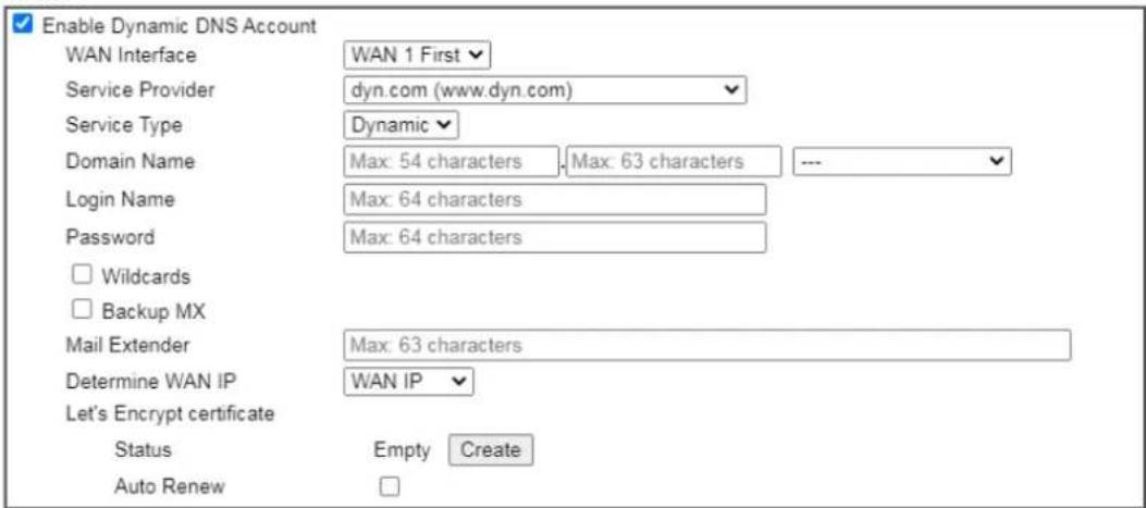
text_image
Enable Dynamic DNS Account WAN Interface Service Provider Service Type Domain Name Login Name Password □ Wildcards □ Backup MX Mail Extender Determine WAN IP Let's Encrypt certificate Status Empty Create Auto RenewNote:
- The Create function of Let's Encrypt certificate works only when the current profile has been stored.
- WAN IP must be public IP when create Let's Encrypt certificate.
OK Clear Cancel
If User-Defined is specified as the service provider, the web page will be changed slightly as follows:
Applications >> Dynamic DNS Setup >> Dynamic DNS Account Setup
Index : 1
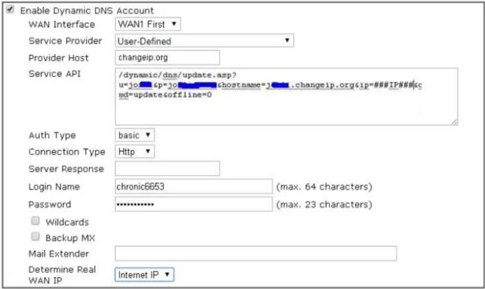
text_image
Enable Dynamic DNS Account WAN Interface WAN1 First ▼ Service Provider User-Defined ▼ Provider Host changeip.org Service API /dynamic/dns/update.asp? u=jo#&p=jo#h#s#@hostname=j#.changeip.org&ip=#####IP### md=update&offline=0 Auth Type basic ▼ Connection Type Http ▼ Server Response Login Name chronic6653 (max. 64 characters) Password ******** (max. 23 characters) □ Wildcards □ Backup MX Mail Extender Determine Real Internet IP ▼ WAN IP
Available settings are explained as follows:
| Item Description | |
| Enable Dynamic DNS Account | Select to enable this DDNS profile. |
| WAN Interface | Select the WAN interface to monitor for IP address changes.WANx First - The specified WAN interface will be examined first. If it is online, its IP address will be used in the DDNS update.WANx Only - Only the specified WAN interface will be examined. If the WAN interface is online, its IP address will be used in the DDNS update. Otherwise no update will be performed for this DDNS profile. |
| Service Provider | Select the DDNS provider. If your DDNS provider is not listed, select User-Defined and manually configure the profile.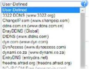 Provider Host - Enter the IP address or the domain name of the host which provides related service.Note that such option is available when Customized is selected as Service Provider.Service API - Enter the API information obtained from DDNS server.Note that such option is available when Customized isselected as Service Provider.(e.g:/dynamic/ dns/ update.asp?u=j0***&p=j0*******&hostname=j****.changeip.org&ip=###IP###&cmd=update&offline=0)Auth Type- Two types can be used for authentication.Basic-Username and password defined later can be shown from the packets captured.URL-Username and password defined later can be shown in URL.(e.g., http://ns1.vigorddns.com/ddns.php?username=xxxx&password=xxxx&domain=xxxx.vigorddns.com)Note that such option is available when Customized is selected as Service Provider.Connection Type- There are two connection types (HTTP and HTTPS) to be specified. Note that such option is available when Customized is selected as Service Provider.Server Response- Type any text that you want to receive from the DDNS server.Note that such option is available when Customized is selected as Service Provider.If other service provider is selected, you have to configure Service Type, Domain Name, Login Name and Password.Service Type- Select the service type that matches that of your DynDNS account. If you are unsure which service type to select, try Dynamic first. This options is applicable to DynDNS only.Domain Name- The domain and subdomain to be updated. Provider Host - Enter the IP address or the domain name of the host which provides related service.Note that such option is available when Customized is selected as Service Provider.Service API - Enter the API information obtained from DDNS server.Note that such option is available when Customized isselected as Service Provider.(e.g:/dynamic/ dns/ update.asp?u=j0***&p=j0*******&hostname=j****.changeip.org&ip=###IP###&cmd=update&offline=0)Auth Type- Two types can be used for authentication.Basic-Username and password defined later can be shown from the packets captured.URL-Username and password defined later can be shown in URL.(e.g., http://ns1.vigorddns.com/ddns.php?username=xxxx&password=xxxx&domain=xxxx.vigorddns.com)Note that such option is available when Customized is selected as Service Provider.Connection Type- There are two connection types (HTTP and HTTPS) to be specified. Note that such option is available when Customized is selected as Service Provider.Server Response- Type any text that you want to receive from the DDNS server.Note that such option is available when Customized is selected as Service Provider.If other service provider is selected, you have to configure Service Type, Domain Name, Login Name and Password.Service Type- Select the service type that matches that of your DynDNS account. If you are unsure which service type to select, try Dynamic first. This options is applicable to DynDNS only.Domain Name- The domain and subdomain to be updated. |
| Login Name The login name | of the DDNS account. |
| Password | The password of the DDNS account. |
| Wildcard and Backup MX | The Wildcard and Backup MX (Mail Exchange) features are not supported for all Dynamic DNS providers. You could get more detailed information from their websites. |
| Mail Extender | If the mail server is defined with another name, please enter the name in this area. Such mail server will be used as backup mail exchange. |
| Determine WAN IP | If a Vigor router is installed behind any NAT router, you can enable such function to locate the real WAN IP.When the WAN IP used by Vigor router is private IP, this function can detect the public IP used by the NAT router and use the detected IP address for DDNS update.There are two methods offered for you to choose:WAN IP- The IP address of the router's WAN interface will be used.Internet IP- The real public IP address will be used.Select this option if the IP address assigned to the router's WAN interface is not the actual external IP address. |
Click OK to save changes, Clear to clear all settings, or Cancel to discard changes and return to the main DDNS screen.
DrayDDNS Settings
DrayDDNS, a new DDNS service developed by DrayTek, can record multiple WAN IP (IPv4) on single domain name. It is convenient for users to use and easily to set up. Each Vigor Router is available to register one domain name.
Choose DrayDDNS (Global) as the service provider, the web page will be displayed as follows:
Applications >> Dynamic DNS Setup >> Dynamic DNS Account Setup
Index : 1
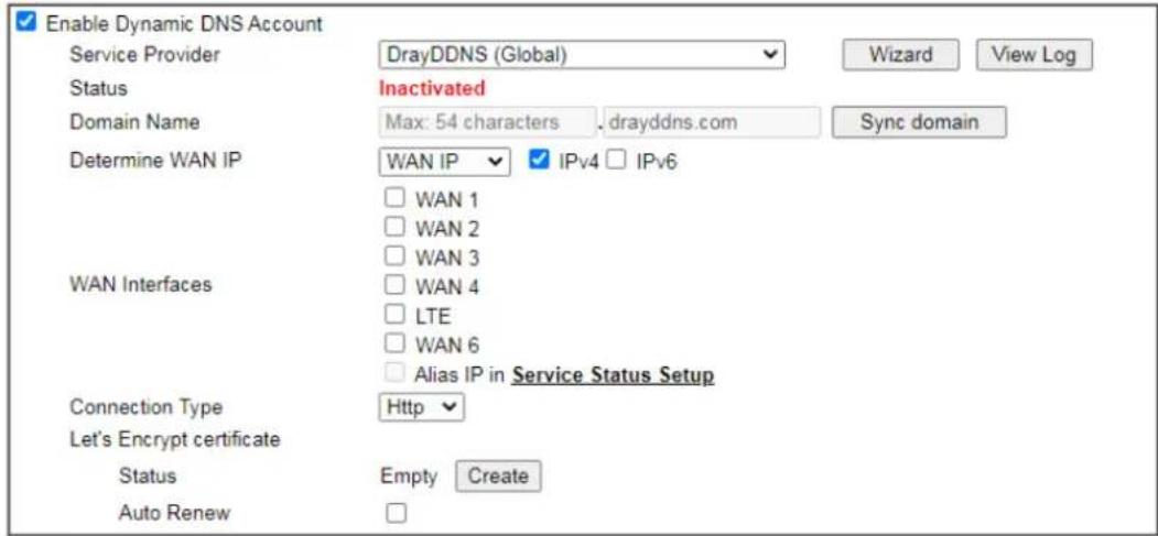
text_image
Enable Dynamic DNS Account Service Provider DrayDDNS (Global) Wizard View Log Status Inactivated Domain Name Max: 54 characters drayddns.com Sync domain Determine WAN IP WAN IP IPv4 IPv6 WAN Interfaces WAN 1 WAN 2 WAN 3 WAN 4 LTE WAN 6 Alias IP in Service Status Setup Connection Type Http Let's Encrypt certificate Status Empty Create Auto RenewNote:
- The Create function of Let's Encrypt certificate works only when the current profile has been stored.

Available settings are explained as follows:
| Item Description | |
| Enable Dynamic DNS Account | Check this box to enable the current account. If you did check the box, you will see a check mark appeared on the Active column of the previous web page in step 2). |
| Service Provider | Choose DrayDDNS (Global) as the service provider.Wizard - This button is available when DrayTek Global is selected as Service Provider. To activate the DrayTek's DDNS service, click it to enable license issued by DrayTek through Wizards>>Service Activation Wizard.Refer to secon A-1 How to use DrayDDNS? for detailed information. |
| Status | Display if the license is activtaed or not. |
| Determine WAN IP | If a Vigor router is installed behind any NAT router, you can enable such function to locate the real WAN IP.When the WAN IP used by Vigor router is private IP, this function can detect the public IP used by the NAT router and use the detected IP address for DDNS update.There are two methods offered for you to choose:WAN IP - If it is selected and the WAN IP of Vigor router is private, DDNS update will take place right away.Internet IP - If it is selected and the WAN IP of Vigor router is private, it will be converted to public IP before DDNS update takes place. |
| WAN Interfaces | WANx - While connecting, the router will use WANx as the channel for such account. |
| Let's Encrypt certificate | Create - Click it to generate a certificate issued by Let's Encrypt for applying to such DDNS account.Auto Update - Check the box to make the system update the certificate automatically. |
Disable the Function and Clear all Dynamic DNS Accounts
Uncheck Enable Dynamic DNS Setup, and click Clear All button to disable the function and clear all accounts from the router.
Delete a Dynamic DNS Account
Click the Index number you want to delete and then click Clear All button to delete the account.
DDNS updates take place when:
● The router is powered on or rebooted.
● The public IP address of any WAN interface changes.
● The online status of a WAN interface changes (going from online to offline or vice versa).
● The DDNS function is changed from disabled to enabled.
● A DDNS entry is modified and enabled.
● The Auto-Update Interval has elapsed.
Procedures for Setting up a Dynamic DNS Entry
- Contact the dynamic DNS provider of your choice and have service set up. Most DDNS providers accept signups on their websites. Service could be provided free of charge or for a fee.
- Create a DDNS entry on the router by selecting the appropriate DDNS provider and enter the account information.
- Make sure that both the DDNS entry and the DDNS feature are enabled on the router.
- Click the View Log button on the DDNS main page to bring up the update log.
- Examine the update log to make sure the update was successful.
- If the update was not successful, verify the DDNS entry to make sure the settings are entered correctly.
II-5-2 LAN DNS / DNS Forwarding
LAN DNS lets the network administrators host servers with privacy and security. When the network administrators of your office set up FTP, Mail or Web server inside LAN, you can specify specific private IP address (es) to correspondent servers. Thus, even the remote PC is adopting public DNS as the DNS server, the LAN DNS resolution on Vigor2927 series will respond the specified private IP address.
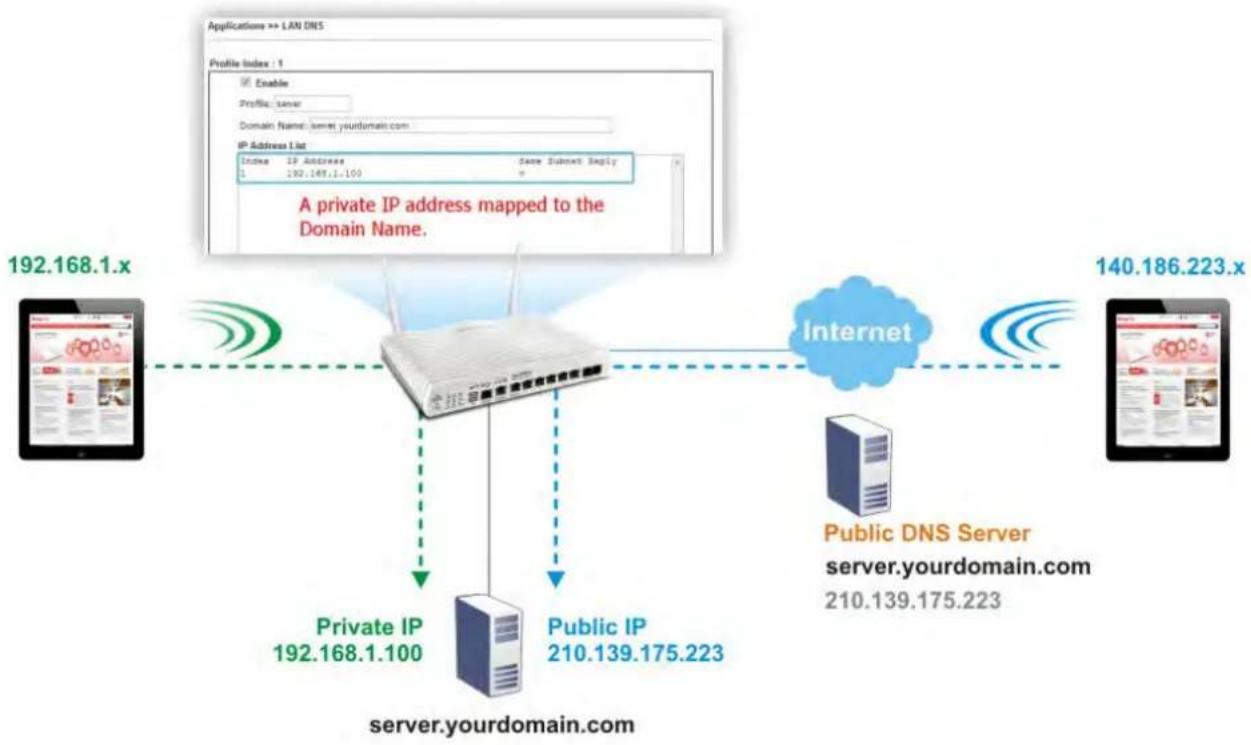
flowchart
graph TD
    A["server.yourdomain.com"] -->|Private IP 192.168.1.100| B["Internet"]
    A -->|Public IP 210.139.175.223| B
    B --> C["Public DNS Server server.yourdomain.com"]
    D["192.168.1.x"] -->|A private IP address mapped to the Domain Name.| E["IP Address List"]
    F["140.186.223.x"] -->|Data transfer| G["Internet"]
    H["Enable Profile: server"] --> I["Profile Index: 1"]
    J["Domain Name: kernel.yourdomain.com"] --> K["IP Address List"]
    L["IP Address List: Index: IP Address = 192.168.1.100"] --> M["IP Address List: Same Subset Reply"]
To start configuring LAN DNS or DNS Forwarding, from the main menu, click Applications, followed by LAN DNS / DNS Forwarding.
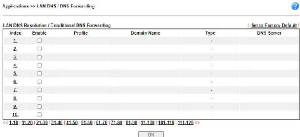
text_image
Applications >> LAN DNS / DNS Forwarding LAN DNS Resolution / Conditional DNS Forwarding | Set to Factory Default | Index Enable Profile Domain Name Type DNS Server 1. □ 2. □ 3. □ 4. □ 5. □ 6. □ 7. □ 8. □ 9. □ 10. □ << 1-10 11-20 21-30 31-40 41-50 51-60 61-70 71-80 81-90 91-100 101-110 111-120 >> OKEach item is explained as follows:
| Item Description | |
| Set to Factory Default | Click to clear all profiles to factory settings. |
| Index | Click to bring up the configuration page for the profile. |
| Enable | Select to enable this profile. |
| Profile | Shows the name of the profile. |
| Domain Name | Shows the domain name configured for the profile. |
| Type | Display the type (LAN DNS or DNS Forwarding) of the profile. |
| DNS Server | DNS server to which DNS queries for the specified domain name will be forwarded. |
To configure a LAN DNS profile, click on its index to bring up the configuration page.
Applications >> LAN DNS / DNS Forwarding
Profile Index : 1
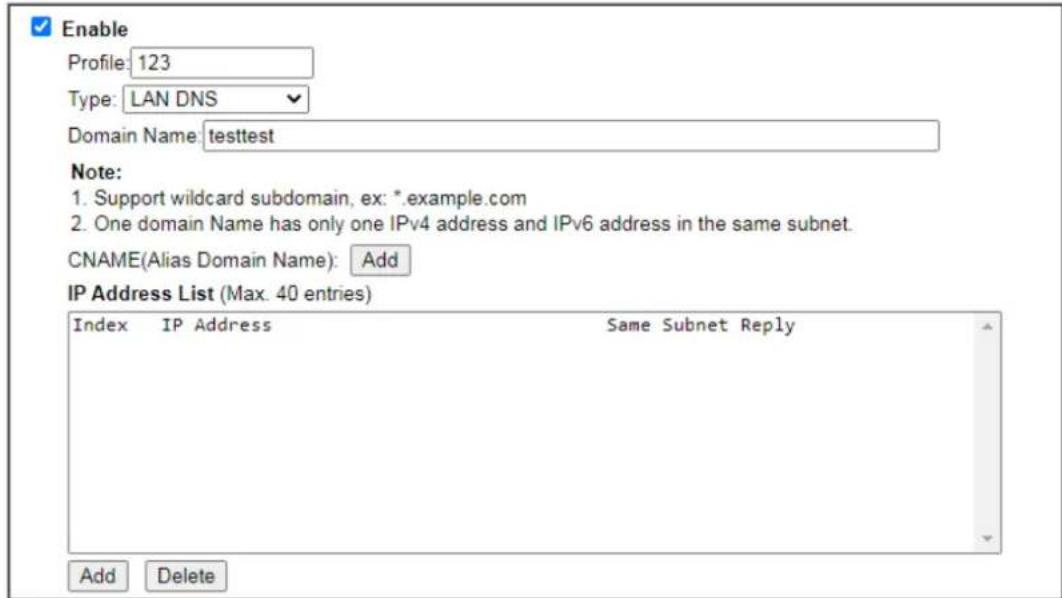
text_image
Enable Profile: 123 Type: LAN DNS Domain Name: testtest Note: 1. Support wildcard subdomain, ex: *.example.com 2. One domain Name has only one IPv4 address and IPv6 address in the same subnet. CNAME(Alias Domain Name): Add IP Address List (Max. 40 entries) Index IP Address Same Subnet Reply Add Delete
Available settings are explained as follows:
| Item Description | |
| Enable | Select to enable this profile. |
| Profile | Enter a name to identify this profile.Note: If you type a name here for LAN DNS and click OK to save the configuration, the name also will be applied to conditional DNS forwarding automatically. |
| Type Choose LAN DNS or LAN Forwarding. | |
| If LAN DNS is selected | Domain Name - Enter the domain name for the router to look for in DNS queries to intercept and reply to. Wildcards in the form of asterisks (*) can be used to match a domain level. For example, *.draytek.com will match domain names such as www.draytek.com and ftp.draytek.com, whereas www.draytek.* will match domain names such as www.draytek.com and www.draytek.co.uk.CNAME - Click Add to add an domain name alias for the domain name. Click Delete next to an alias entry to delete it.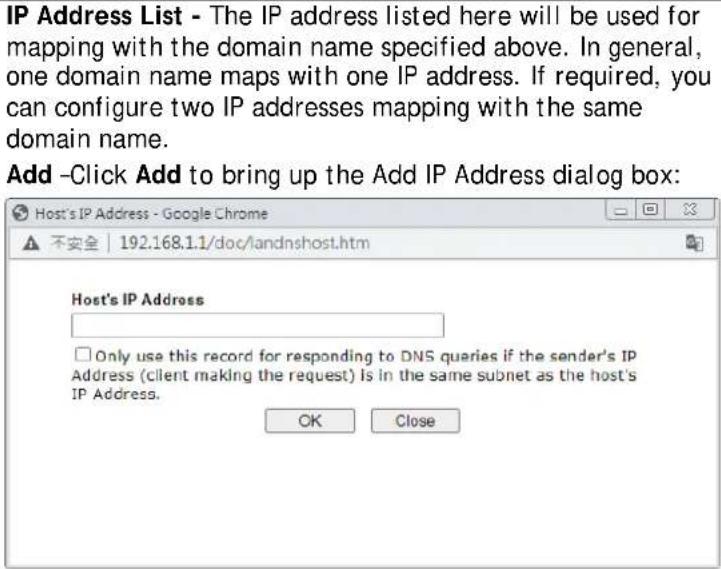 |
| Host's IP Address - Enter the IP address to be returned in response to a DNS query for the configured domain names and aliases.Only responds to the DNS.... - Select to use this IP address only if the IP address of the source of the DNS query belongs to the same subnet as the host IP address entered above.After changes have been made, click OK to save and dismiss the dialog box, or Close to discard the changes and dismiss the dialog box.Delete-To delete an IP address, click on it and then click Delete. | |
| If DNS Forwarding is selected | Domain Name - Enter the domain name for the router to look for in DNS queries to intercept and reply to. Wildcards in the form of asterisks (*) can be used to match a domain level. For example, *.draytek.com will match domain names such as www.draytek.com and ftp.draytek.com, whereas www.draytek.* will match domain names such as www.draytek.com and www.draytek.co.uk.DNS Server IP/Host Name - Enter the IP address of the DNS server you want to use for DNS forwarding. |
To save changes made to the LAN DNS profile, click OK. To clear the profile and restore the factory default blank values, click Clear.
II-5-3 DNS Security
Domain Name System Security Extensions (DNSSEC) protects against DNS-based attacks by authenticating DNS responses from DNS resolvers.
The DNS servers must support DNS security validation for the feature to function properly. To configure DNS security, from the main menu, click Applications, followed by DNS Security.
II-5-3-1 General Setup
All of WAN interfaces of Vigor router can be configured with DNS Security enabled respectively.
Application >> DNS Security

DNS Security
| General Setup | Domain Diagnosis | Refresh | ||
| Interface | Enable | Primary DNS | Secondary DNS | Bogus DNS Reply |
| WAN1 | □ | --- | --- | Pass▼ |
| WAN2 | □ | --- | --- | Pass▼ |
| WAN3 | □ | --- | --- | Pass▼ |
| WAN4 | □ | --- | --- | Pass▼ |
| LTE | □ | --- | --- | Pass▼ |
| WAN6 | □ | --- | --- | Pass▼ |
Note:

The DNS server supports DNSSEC

The DNS server does not support DNSSEC, function may not work as expected even if it is enabled
OK
Available settings are explained as follows:
| Item Description | |
| Interface | The WAN interface name for which DNS security is to be configured. |
| Enable | Select to enable DNS security for this WAN Interface. |
| Primary DNS | Shows the primary DNS server IP address in effect for this WAN. |
| Secondary DNS | Shows the secondary DNS server IP address in effect for this WAN. |
| Bogus DNS Reply | Show action to be taken for DNS responses that fail authentication. Choose Pass or Drop.Pass - Pass DNS result.Drop - Do not pass DNS result. |
Press OK to save changes.
II-5-3-2 Domain Diagnose
While using the Domain Diagnose feature, you can check to see if the router's DNS security function is working properly, or whether a given domain is secured by DNS security. Note that DNS Security has to be first enabled or the test results would not be meaningful.
Application >> DNS Security

DNS Security
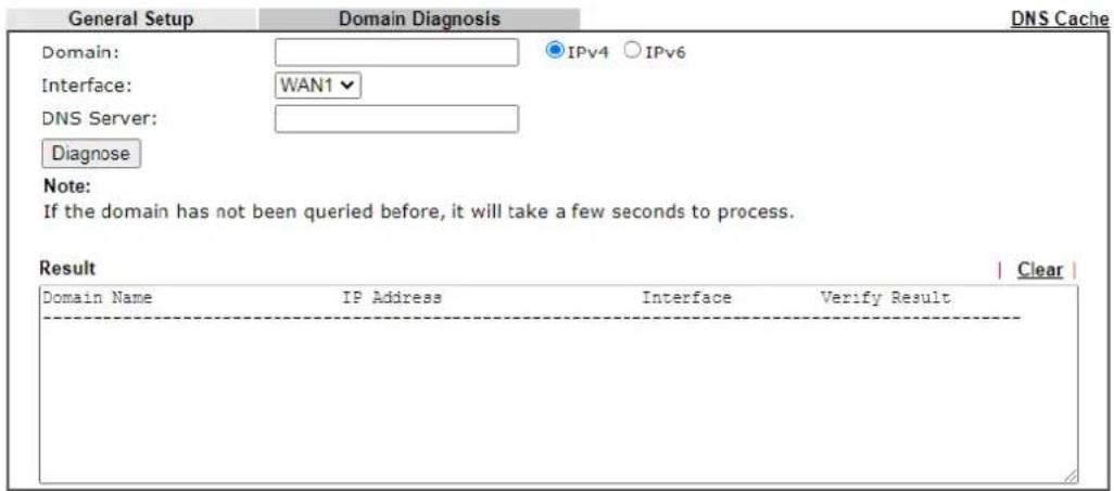
text_image
General Setup Domain Diagnosis Domain: IPv4 IPv6 Interface: WAN1 DNS Server: Diagnose Note: If the domain has not been queried before, it will take a few seconds to process. Result Clear Domain Name IP Address Interface Verify Result -Available settings are explained as follows:
| Item Description | |
| Domain | Enter domain address to be diagnosed.Select the type of IP address to be looked up.IPv4 - looks up A records.IPv6 - looks up AAAA records. |
| Interface | Select the WAN port to be used for the lookup. |
| DNS Server | Enter the IPv4 address of the DNS server to be used for the lookup. |
| Diagnose Click to begin DNS | lookup. |
| Result | The history of domain diagnosis is shown in the Result panel. |
II-5-4 Schedule
Time schedules can be created and used with router features that support them, so that those features can be turned on and off automatically at preconfigured times.
Applications >> Schedule
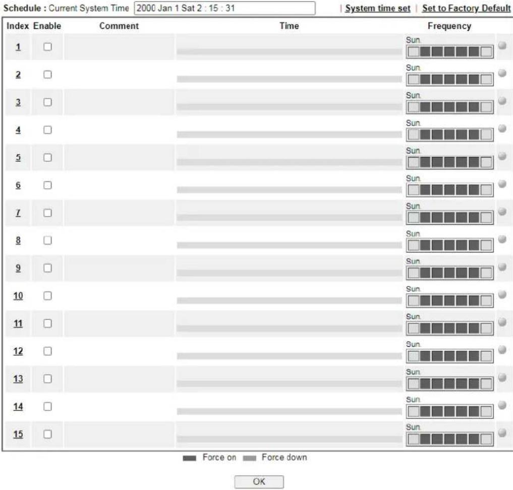
bar
| Index | Enable | Comment | Time | Frequency | | :--- | :--- | :--- | :--- | :--- | | 1 | □ | | Sun | ● | | 2 | □ | | Sun | ● | | 3 | □ | | Sun | ● | | 4 | □ | | Sun | ● | | 5 | □ | | Sun | ● | | 6 | □ | | Sun | ● | | 7 | □ | | Sun | ● | | 8 | □ | | Sun | ● | | 9 | □ | | Sun | ● | | 10 | □ | | Sun | ● | | 11 | □ | | Sun | ● | | 12 | □ | | Sun | ● | | 13 | □ | | Sun | ● | | 14 | □ | | Sun | ● | | 15 | □ | | Sun | ● | OKAvailable settings are explained as follows:
| Item Description | |
| Current System Time | Shows the current time of the router. |
| System time set | Click to navigate to System Maintenance >> Time and Date to set the system time and date. |
| Set to Factory Default | Reset all schedules to factory default values. |
| Index | Shows the index number of the schedule entry. |
| Enable | Select to enable the schedule; clear to disable it. |
| Comment | Shows the name given to the schedule. |
| Time | Shows the start and end times of the schedule. The time interval of the schedule is indicated in dark grey. |
| Frequency | Shows the days of the week configured for the schedule. Selected days are shown in dark grey. - If it lights in green, it means such schedule is active. |
To configure a schedule, click on its index to bring up the settings page.
Applications >> Schedule
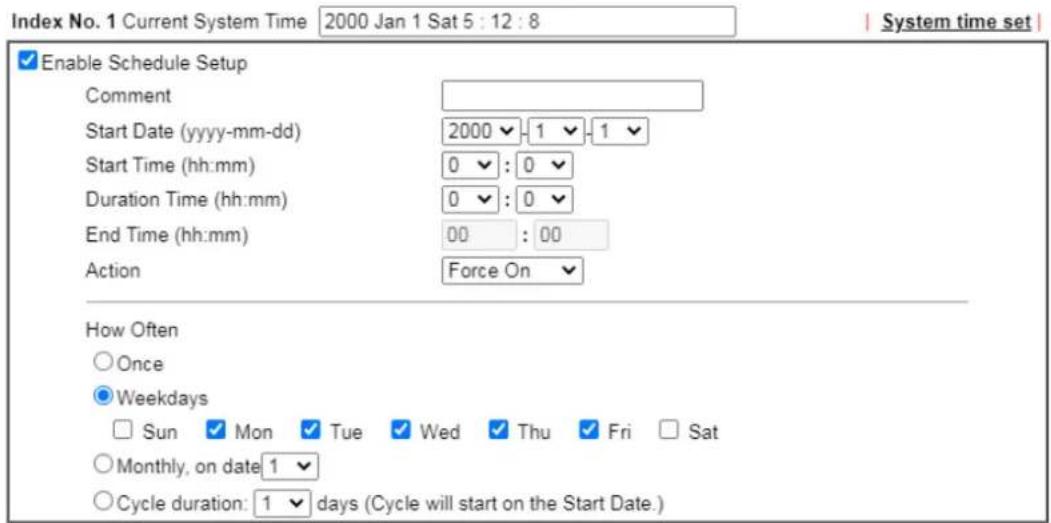
text_image
Index No. 1 Current System Time 2000 Jan 1 Sat 5 : 12 : 8 System time set Enable Schedule Setup Comment Start Date (yyyy-mm-dd) 2000 -1 -1 Start Time (hh:mm) 0 : 0 Duration Time (hh:mm) 0 : 0 End Time (hh:mm) 00 : 00 Action Force On How Often Once Weekdays Sun Mon Tue Wed Thu Fri Sat Monthly, on date 1 Cycle duration: 1 days (Cycle will start on the Start Date.)Note:
Comment can not contain characters \~ ! @ # \$ % ^ & * ( ) " { } |;

Available settings are explained as follows:
| Item Description | |
| Enable Schedule Setup | Select to enable the schedule; clear to disable it. |
| Comment | Name to identify this schedule entry. |
| Start Date (yyyy-mm-dd) | The date when the entry comes into effect. |
| Start Time (hh:mm) | The time when the schedule is triggered. See the How Often setting below for details. |
| Duration Time (hh:mm) | How long the action lasts when the scheduled is triggered. |
| End Time (hh:mm) | It will be calculated automatically when Start Time and Duration Time are configured well. |
| Action Action to take when the schedule is triggered. | |
| How Often | How frequently the schedule is triggered.● Once - The schedule is triggered once, on the Start Date at the Start Time, for the Duration Time.● Weekdays - The schedule will be triggered repeatedly, starting on the Start Date at the Start Time, on the selected days of the week, at the Start Time, for the Duration Time.● Monthly, on date - The router will only execute the action applied such schedule on the date (1 to 28) of a month. ● Cycle duration - Type a number as cycle duration. Then, any action applied such schedule will be executed per several days. For example, “3” is selected as cycle duration. That means, the action applied such schedule will be executed every three days since the date defined on the Start Date. |
To save changes made to the Schedule, click OK. To clear the schedule and restore the factory default blank values, click Clear. To cancel the changes and return to the main Schedule page, click Cancel.
Example
Suppose you want to control the PPPoE Internet access connection to be always on (Force On) from 9:00 to 18:00 for whole week. Other time the Internet access connection should be disconnected (Force Down).
Office
Hour:
(Force On)

Mon - Sun
9:00 am
to

6:00 pm
- Make sure the PPPoE connection and Time Setup is working properly.
- Configure the PPPoE always on from 9:00 to 18:00 for whole week.
- Configure the Force Down from 18:00 to next day 9:00 for whole week.
- Assign these two profiles to the PPPoE Internet access profile. Now, the PPPoE Internet connection will follow the schedule order to perform Force On or Force Down action according to the time plan that has been pre-defined in the schedule profiles.
II-5-5 RADIUS/TACACS+
Remote Authentication Dial-In User Service (RADIUS) is a security authentication client/server protocol that supports authentication, authorization and accounting, which is widely used by Internet service providers. It is the most common method of authenticating and authorizing dial-up and tunneled network users.
The router supports external TACACS+ and internal and external RADIUS servers for user authentication. Services that require user authentication include WLAN and VPN.
To configure RADIUS or TACACS+ servers, from the Main Menu select Applications >> RADIUS/TACACS+.
II-5-5-1 External RADIUS
The built-in RADIUS client feature enables the router to assist the remote dial-in user or a wireless station and the RADIUS server in performing mutual authentication. It enables centralized remote access authentication for network management.
Vigor router can be operated as a RADIUS client. This web page is used to configure settings for external RADIUS server. Then LAN users of Vigor router will be authenticated and accounted by such server for network application.
Select External RADIUS to configure the router to use an external RADIUS server for user authentication.
Applications >> RADIUS/TACACS+
External RADIUS
Internal RADIUS
External TACACS+
Enable
Enable Accounting
Comments: Max: 23 characters
RADIUS Request Interval 2 sec (2\~30)
Primary Server
| Primary Server | Max: 63 characters | |
| Secret | Max: 63 characters | |
| Authentication Port | 1812 | |
| Accounting Port | 1813 | |
| Disconnect Message Port | 3799 | |
| Interim Update Interval | 10 | min(s)(10~1440) |
| Retry | 2 | times(1~3) |
Secondary Server
| Secondary Server | Max: 63 characters | |
| Secret | Max: 63 characters | |
| Authentication Port | 1812 | |
| Accounting Port | 1813 | |
| Disconnect Message Port | 3799 | |
| Interim Update Interval | 10 | min(s)(10~1440) |
| Retry | 2 | times(1~3) |
Note:
If RADIUS server has specified Interim Update Interval value(Acct-Interim-Interval), Vigor Router will follow the interval that the RADIUS server provides and ignore the Interim Update Interval setting here.
OK
Clear
Cancel
RADIUS Server Status Log
| Refresh | Clear | |
| _ |
Available settings are explained as follows:
| Item Description | |
| Enable | Check to enable RADIUS client profile.Comments - Enter a brief description for this profile.RADIUS Request Interval - Set a timeout value for the router waiting for a response from the RADIUS server. If no response, Vigor router will send the authentication request again.Enable Accounting - RADIUS Accounting is a network customer billing mechanism for RADIUS server.If enabled, Vigor router will deliver accounting request (e.g., IP address, traffic from the client) to the specified RADIUS server periodically.Accounting Port - Set the UDP port number (1813 in default) as the accounting port.Disconnect Message Port - Set a UDP port number (3799 in default) for receiving thedisconnected-request packets from the AAA server. Note that these packets have been accepted by the RADIUS server before being disconnected by the AAA server.● Interim Update Interval - Set a value (10 minutes in default). It indicates the time between each transmittal of an interim update for a specific session. |
| Primary Server | Primary Server - Enter the IP address of RADIUS server.Secret - The RADIUS server and client share a secret that is used to authenticate the messages sent between them. Both sides must be configured to use the same shared secret. The maximum length of the shared secret you can set is 36 characters.Authentication Port - The UDP port number that the RADIUS server is using. The default value is 1812, based on RFC 2138.Retry - Set the number of attempts to perform reconnection with RADIUS server. If the connection (with the Primary Server) still fails, stop the connection attempt and begin to make connection with the secondary server. |
| Secondary Server | Secondary Server - Enter the IP address of RADIUS server.Secret - The RADIUS server and client share a secret that is used to authenticate the messages sent between them. Both sides must be configured to use the same shared secret. The maximum length of the shared secret you can set is 36 characters.Authentication Port - The UDP port number that the RADIUS server is using. The default value is 1812, based on RFC 2138.Retry - Set the number of attempts to perform reconnection. If the connection (with the Secondary Server) still fails, stop the connection attempt. The client authentication would be determined as "failed". |
| RADIUS Server Status Log | Display the record of current status of RADIUS server. |
To save changes on the page, click OK. To discard changes, click Cancel. To reset all settings to blank, click Clear.
II-5-5-2 Internal RADIUS
Except for being a built-in RADIUS client, Vigor router also can be operated as a RADIUS server which performs security authentication by itself. This page is used to configure settings for internal RADIUS server. Then LAN user of Vigor router will be authenticated by Vigor router directly.
Select Internal RADIUS to configure the router's built-in RADIUS server.
Applications >> RADIUS/TACACS+
External RADIUS Internal RADIUS External TACACS+
Enable
Authentication Port
1812
RADIUS Client Access List
| Index Enable Shared Secret | IP Address | IP Mask | IPv6 Address | IPv6 Length | ||
| 1 | ☐ | Max: 31 character | 0.0.0.0 | 0.0.0.0 | :: | 0 |
| 2 | ☐ | Max: 31 character | 0.0.0.0 | 0.0.0.0 | :: | 0 |
| 3 | ☐ | Max: 31 character | 0.0.0.0 | 0.0.0.0 | :: | 0 |
| 4 | ☐ | Max: 31 character | 0.0.0.0 | 0.0.0.0 | :: | 0 |
| 5 | ☐ | Max: 31 character | 0.0.0.0 | 0.0.0.0 | :: | 0 |
| 6 | ☐ | Max: 31 character | 0.0.0.0 | 0.0.0.0 | :: | 0 |
| 7 | ☐ | Max: 31 character | 0.0.0.0 | 0.0.0.0 | :: | 0 |
| 8 | ☐ | Max: 31 character | 0.0.0.0 | 0.0.0.0 | :: | 0 |
| 9 | ☐ | Max: 31 character | 0.0.0.0 | 0.0.0.0 | :: | 0 |
| 10 | ☐ | Max: 31 character | 0.0.0.0 | 0.0.0.0 | :: | 0 |
Authentication
| Method |
| PAP Only |
| 802.1X Method |
| Support 802.1X MethodEAP_TTLS/PAPEAP_TTLS/MSCHAPEAP_TTLS/MSCHAPv2EAP_PEAP/MSCHAPv2CertificateDefault Certificate |
User Profile
| Select All | Clear All |
| Available List | Authentication List |
| Synchronize Internal RADIUS user list to Local 802.1X user list. |
Note:
1 Only the user profiles which is enabled in User Management >> User Profile will be listed here, and it shows in the System Maintenance >> Internal Service User List
2.RADIUS Client Access List is first match.

Available settings are explained as follows:
| Item Description | |
| Enable | Select to enable the router’s internal RADIUS server. |
| Authentication Port | The UDP port for authentication messages. |
| RADIUS Client Access List | Only clients that meet the criteria configured in the access list are allowed to access the RADIUS server.Enable - Select to enable this client entry.Shared Secret - A text string that is known to both the router’s RADIUS server and the RADIUS client that is used to authenticate messages sent between them. Maximum length is 36 characters.IP Address - Base address of the IP block.IP Mask - Enter the IP mask to configure the size of the IPblock.IPv6 Address - Base address of the IPv6 block.IPv6 Length - The prefix length of the IPv6 block. |
| Authentication Configures the authentication settings.Specify the way to authenticate the wireless client.PAP - Only the Password Authentication Protocol will be used to validate users.PAP/CHAP/MS-CHAP/MS-CHAPv2 - PAP, CHAP(Challenge-Handshake Authentication Protocol), and Microsoft versions of CHAP can be used to validate users.Support 802.1X Method - The built in RADIUS server offered by Vigor router can act as the AAA server. Select to enable 802.1X support. | |
| User Profile | During the process of security authentication, user account and user password will be required for identity authentication. Before configuring such page, create at least one user profile in User Management>>User Profile first.Select All - Click to move all user profiles under the Available List to the Authentication List.Clear All - Click to remove all user profiles from the Authentication List.Available List - The user profiles without RADIUS server enabled in User Management >> User Profile will be listed in this field.Authentication List -The user profiles with RADIUS server enabled in User Management >> User Profile will be listed in this field. |
| Synchronize Internal RADIUS user list to Local 802.1X user list | Users can be authenticated by RADIUS server and local 802.1X to get certain network service. It is not necessary to create new user profiles (containing user accounts and user passwords) for RADIUS and local 802.1X respectively.Simply select to update the 802.1X authentication list to match the RADIUS authentication list. |
To add a User Profile to the RADIUS server, select it under Available List, then click the >> button. To remove a User Profile from the RADIUS server, select it under Selected Authentication List, then click the << button.
To save changes on the page, click OK. To discard changes, click Cancel. To reset all settings to blank, click Clear.
II-5-5-3 External TACACS+
It means Terminal Access Controller Access-Control System Plus. It works like RADIUS does. Click the External TACACS+ to open the following page:
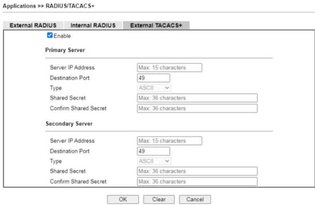
text_image
Applications >> RADIUS/TACACS+ External RADIUS Internal RADIUS External TACACS+ Enable Primary Server Server IP Address Max: 15 characters Destination Port 49 Type ASCII Shared Secret Max: 36 characters Confirm Shared Secret Max: 36 characters Secondary Server Server IP Address Max: 15 characters Destination Port 49 Type ASCII Shared Secret Max: 36 characters Confirm Shared Secret Max: 36 characters OK Clear CancelAvailable settings are explained as follows:
| Item Description | |
| Enable | Select to enable the use of an external TACACS+ server. |
| Primary Server / Secondary Server | Two external TACACS+ servers are allowed to set in this page.The secondary TACACS+ server will be used as a backup server when the primary TACACS+ server is down. |
| Server IP Address | The IP address of the TACACS+ server. |
| Destination Port The port used by the TACACS+ server. Port 49 is most common. | |
| Shared Secret | A text string that is known to both the TACACS+ server and client (the router) that is used to authenticate messages sent between them. Maximum length is 36 characters. |
| Confirm Shared Secret | Enter the shared secret again for verification. |
To save changes on the page, click OK. To discard changes, click Cancel. To reset all settings to blank, click Clear.
II-5-6 Active Directory/LDAP
Lightweight Directory Access Protocol (LDAP) is an industry-standard protocol for maintaining and accessing directory information on a network. When used in conjunction with a Vigor router, LDAP can be used to authenticate VPN connection attempts.
Active Directory (AD) is a directory service from Microsoft that supports LDAP queries.
To configure Active Directory or LDAP settings, from the Main Menu select Applications >> Active Directory /LDAP.
II-5-6-1 General Setup
To configure the settings for the LDAP server, select General Setup.
Applications >> Active Directory / LDAP
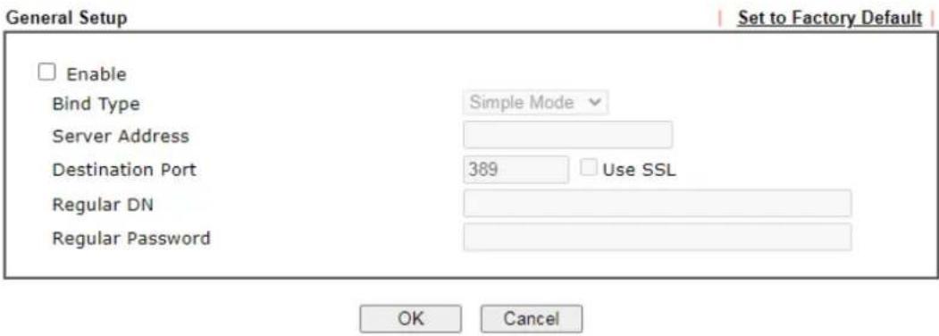
text_image
General Setup Enable Bind Type Simple Mode Server Address Destination Port 389 Use SSL Regular DN Regular Password OK Cancel Set to Factory DefaultActive Directory / LDAP Profiles
| Index | Name | Distinguished Name |
| 1. | ||
| 2. | ||
| 3. | ||
| 4. | ||
| 5. | ||
| 6. | ||
| 7. | ||
| 8. |
Available settings are explained as follows:
| Item Description | |
| Enable | Select to enable LDAP client.If enabled, the LDAP profiles will be available for configuration. |
| Bind Type | Select from one of 3 bind types:Simple Mode - Initiate bind operation (authentication) without performing user search. This mode can be used when all users belong to the same branch in the LDAP structure.Anonymous - Bind anonymously, without supplying thedistinguished name (DN) and password, and perform user search. This mode can be used when not all users belong to the same branch and the server allows anonymous searches.● Regular Mode - Same as Anonymous mode, except that the DN and password are sent to the server. This mode can be used when not all users belong to the same branch and the server does not allow anonymous searches.For the regular mode, you’ll need to Enter the Regular DN and Regular Password. |
| Server Address | The network address of the LDAP server. |
| Destination Port The network | work port that the LDAP server listens on. The default ports are 389 for unsecured connections and 636 for LDAPS (LDAP over SSL) connections. |
| Use SSL | Select to use Secure Sockets Layer (SSL) for LDAP traffic. |
| Regular DN | Enter the LDAP Distinguished Name for authentication if Bind Type is set to Regular Mode. |
| Regular Password | Enter the LDAP Password for authentication if Bind Type is set to Regular Mode. |
| Active Directory / LDAP Profiles | Up to 8 LDAP profiles can be created. These profiles would be used with User Management for different purposes in management. |
To save changes on the page, select OK; to discard changes, select Cancel.
II-5-6-2 Active Directory / LDAP Profiles
To configure an LDAP profile, click on its index to show the following settings page.
Applications >> Active Directory /LDAP>>Server Profiles
Index No. 1
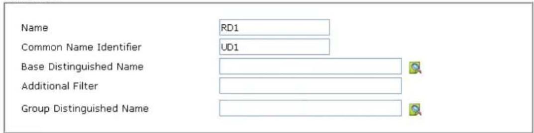
text_image
Name RD1 Common Name Identifier UD1 Base Distinguished Name Additional Filter Group Distinguished NameNote:
Please type in your additional filter for BaseDN search request. For example, "gidNumber=500" for OpenLDAP, and "msNPAIowDialin=TRUE" for AD.

Available settings are explained as follows:
To save changes on the page, select OK; to discard changes, select Cancel.
| Item Description | |
| Name | Name that identifies this profile. Maximum length is 19 characters. |
| Common Name Identifier | The common name attribute, which is typically “cn” in most LDAP configurations. |
| Base Distinguished Name | The starting point of user search in the LDAP directory, forexample, dc=draytek,dc=com. - click this icon to display a list of valid DNs in the LDAP directory. |
| Additional Filter | Additional filter to be applied to the search request to identify eligible users.For example,- “OpenLDAP: (gidNumber=500)”Here group ID 500 is the group of dial-in users.- “ActiveDirectory: (msNPAIlowDialin=TRUE)”The msNPAIlowDialin attribute indicates that the user has permission to dial in remotely. |
| Group Distinguished Name | The base DN of the tree in the LDAP directory that contains groups, for example, ou=groups,dc=draytek,dc=com. - click this icon to display a list of valid DNs in the LDAP directory. |
II-5-7 UPnP
To configure UPnP settings, from the Main Menu select Applications >> UPnP.
Applications >> UPnP
UPnP
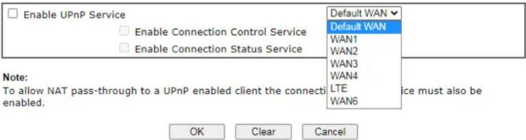
text_image
Enable UPnP Service Enable Connection Control Service Enable Connection Status Service Default WAN Default WAN WAN1 WAN2 WAN3 WAN4 LTE WAN6 Note: To allow NAT pass-through to a UPnP enabled client the connecti enabled. OK Clear CancelAvailable settings are explained as follows:
| Item Description | |
| Enable UPNP Service | Select to enable UPnP. |
| Default WAN | Select the WAN port on which ports will be opened in response to UPnP commands. |
| Enable Connection Control Service | Select to enable the connection control service. |
| Enable Connection Status Service | Select to enable the connection status service. |
To save changes on the page, select OK; to discard changes, select Cancel; to revert all settings to the factory default, select Clear.
The reminder as regards concern about Firewall and UPnP:
Can't work with Firewall Software
Enabling firewall applications on your PC may cause the UPnP function not working properly. This is because these applications will block the accessing ability of some network ports.
Security Considerations
Activating UPnP allows any application or network devices to open ports on the WAN side to allow connections to the LAN, which could compromise network security. Also if UPnP applications or network devices malfunction or terminate abnormally, the opened ports may remain open indefinitely, and thus increasing the chance of it getting exploited by malicious parties.
If you do not have applications or network devices which requires UPnP, you are advised to disable UPnP.

Info
UPnP is required for some applications such as PPS, Skype, eMule...and etc. If you are not familiar with UPnP, it is suggested to turn off this function for security.
II-5-8 IGMP
Internet Group Management Protocol (IGMP) is an IPv4 communication protocol for establishing multicast group memberships.
To configure IGMP settings, from the Main Menu select Applications >> IGMP.
II-5-8-1 General Setting
Applications >> IGMP
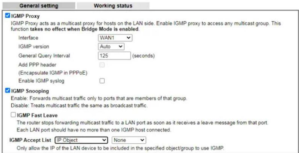
text_image
General setting Working status IGMP Proxy IGMP Proxy acts as a multicast proxy for hosts on the LAN side. Enable IGMP proxy to access any multicast group. This function takes no effect when Bridge Mode is enabled. Interface WAN1 IGMP version Auto General Query Interval 125 (seconds) Add PPP header (Encapsulate IGMP in PPPoE) Enable IGMP syslog IGMP Snooping Enable: Forwards multicast traffic only to ports that are members of that group. Disable: Treats multicast traffic the same as broadcast traffic. IGMP Fast Leave The router stops forwarding multicast traffic to a LAN port as soon as it receives a leave message from that port. Each LAN port should have no more than one IGMP host connected. IGMP Accept List IP Object None Only allow the IP of the LAN device to be included in the specified object/group to use IGMP.
Available settings are explained as follows:
| Item Description | |
| IGMP Proxy | Check this box to enable this function. The application of multicast will be executed through WAN / PVC/ VLAN port.In addition, such function is available in NAT mode.Interface- Specify an interface for packets passing through.IGMP version- At present, two versions (v2 and v3) are supported by Vigor router. Choose the correct version based on the IPTV service you subscribe.General Query Interval- Vigor router will periodically check which IP obtaining IPTV service by sending query. It might cause inconvenience for client. Therefore, set a suitable time (unit: second) as the query interval to limit the frequency of query sent by Vigor router.Add PPP header- Check this box if the interface type for IGMP is PVC/ VLAN. It depends on the specifications regulated by each ISP. If you have no idea to enable or disable, simply contact your ISP providers.Enable IGMP syslog- Check the box to store the IGMP status onto Syslog. |
| IGMP Snooping | Select to enable IGMP Snooping so that multicast traffic are forwarded to IGMP clients that have joined a multicast group. |
| IGMP Fast Leave | This option is shown only when IGMP Snooping is enabled.Select to enable IGMP Fast Leave.Normally when the router receives a “leave” message from an IGMP host, it will send a last member query message to see if there are still members within the multicast group.When Fast Leave is enabled, multicast for a group is immediately terminated when the last host in that group sends a “leave” message. |
| IGMP Accept List | Select IP Object or IP Group.Only the IP of the LAN device within the IP object / IP group will be allowed to use IGMP. |
To save changes on the page, select OK; to discard changes, select Cancel.
II-5-8-2 Working Status
Displays a list of active multicast groups.
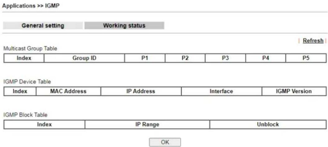
text_image
Applications >> IGMP General setting Working status Multicast Group Table Index Group ID P1 P2 P3 P4 P5 IGMP Device Table Index MAC Address IP Address Interface IGMP Version IGMP Block Table Index IP Range Unblock OKAvailable settings are explained as follows:
| Item Description | |
| Refresh | Click to reload the Multicast Group Table with the latest information. |
| Index | Index number of the multicast group. |
| Group ID | ID port of the multicast group, which is within the IP range reserved for IGMP, 224.0.0.0 through 239.255.255.254. |
| P1 to P5 LAN ports that have IGMP hosts joined to this multicast group. | |
II-5-9 Wake on LAN/WAN
II-5-9-1 Wake on LAN
Using the Wake on LAN (WoL) feature, LAN clients that support WoL can be powered on or resume from sleep over the network, without the need for physical access to the device.
In order for LAN clients to be able to wake from sleep or off states, the network interface card must be configured to monitor Wake-on-LAN messages. Consult the documentation of the LAN client for details on setting up its network interface for Wake on LAN.
If you wish to be able to select the IP address of the Wake-on-LAN client, its MAC address must first be bound to a static IP address using the Bind IP to MAC function.
To configure Wake on LAN settings, from the Main Menu select Applications >> Wake on LAN.
Applications >> Wake on LAN/WAN
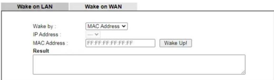
text_image
Wake on LAN Wake on WAN Wake by : MAC Address IP Address : --- MAC Address : FF:FF:FF:FF:FF:FF Wake Up! ResultNote:
Wake on LAN integrates with Bind IP to MAC function; only bound PCs can wake up through IP.
Available settings are explained as follows:
| Item Description | |
| Wake by | Two types provide for you to wake up the binded IP.If you choose Wake by MAC Address, you have to Enter the correct MAC address of the host in MAC Address boxes.If you choose Wake by IP Address, you have to choose the correct IP address. |
| IP Address The IP addresses that have been configured in Firewall>>Bind IP to MAC will be shown in this drop down list. Choose the IP address from the drop down list that you want to wake up. | |
| MAC Address | Type any one of the MAC address of the bound PCs. |
| Wake Up | Click this button to wake up the selected IP. See the following figure. The result will be shown on the box. |
| Result | Result of the transmission of the Wake-on-LAN message. |
II-5-9-2 Wake on WAN
To configure Wake on WAN settings, from the Main Menu select Applications >> Wake on LAN and select the tab of Wake on WAN.
Applications >> Wake on LAN/WAN
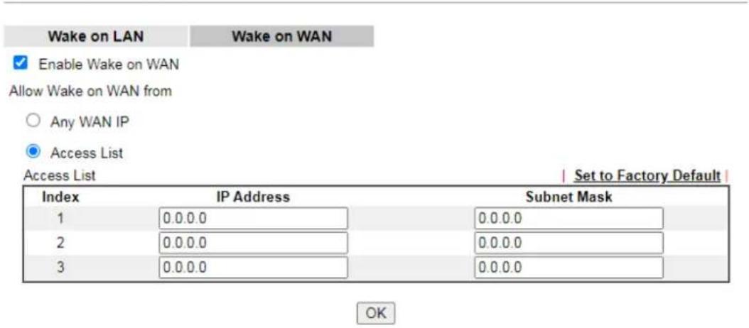
text_image
Wake on LAN Wake on WAN Enable Wake on WAN Allow Wake on WAN from Any WAN IP Access List Access List | Set to Factory Default | Index IP Address Subnet Mask 1 0.0.0.0 0.0.0.0 2 0.0.0.0 0.0.0.0 3 0.0.0.0 0.0.0.0 OKAvailable settings are explained as follows:
| Item Description | |
| Enable Wake on WAN | Select to enable the function. |
| Allow Wake on WAN from Set the path for the boot packet (sent by a mobile phone) to deliver to the remote device.Any WAN IP - Any WAN IP can be used as a path for waking the remote device.Access List - Enter the WAN IP address with the subnet mask. Later, use your mobile phone (installing an APP for sending the boot packets first) to connect to the Vigor router network. The boot packets will be transferred to the remote device via any WAN IP or the IP listed on Access List. | |
II-5-10 SMS / Mail Alert Service
The function of SMS (Short Message Service)/ Mail Alert is that Vigor router sends a message to user's mobile or e-mail box through specified service provider to assist the user knowing the real-time abnormal situations.
Vigor router allows you to set up to 10 SMS profiles which will be sent out according to different conditions.
II-5-10-1 SMS Alert
This page allows you to specify SMS provider, who will get the SMS, what the content is and when the SMS will be sent.
Applications >> SMS/Mail Alert Service
| SMS Alert | Mail Alert | Set to Factory Default | ||||||
| Index | Enable | SMS Provider | Recipient Number | Notify Profile | Schedule(1-15) | |||
| 1 | 1 - ??? | 1 - ??? | None | √ | None | √ | ||
| 2 | 1 - ??? | 1 - ??? | None | √ | None | √ | ||
| 3 | 1 - ??? | 1 - ??? | None | √ | None | √ | ||
| 4 | 1 - ??? | 1 - ??? | None | √ | None | √ | ||
| 5 | 1 - ??? | 1 - ??? | None | √ | None | √ | ||
| 6 | 1 - ??? | 1 - ??? | None | √ | None | √ | ||
| 7 | 1 - ??? | 1 - ??? | None | √ | None | √ | ||
| 8 | 1 - ??? | 1 - ??? | None | √ | None | √ | ||
| 9 | 1 - ??? | 1 - ??? | None | √ | None | √ | ||
| 10 | 1 - ??? | 1 - ??? | None | √ | None | √ | ||
Note:
-
All the SMS Alert profiles share the same "Sending Interval" setting if they use the same SMS Provider.
-
If SMS Provider is "LTE Modem", the "Quota" is controlled by LTE >> SMS Quota Limit and the "Sending Interval" is 3 seconds.

Available settings are explained as follows:
| Item Description | |
| Enable | Check the box to enable or disable the profile. |
| SMS Provider | Use the drop down list to choose SMS service provider.You can click SMS Provider link to define the SMS server. |
| Recipient Number | Enter the phone number of the one who will receive the SMS. |
| Notify Profile | Use the drop down list to choose a message profile. The recipient will get the content stated in the message profile.You can click the Notify Profile link to define the content of the SMS. |
| Schedule (1-15) | Enter the schedule number that the SMS will be sent out.You can click the Schedule(1-15) link to define the schedule. |
After finishing all the settings here, please click OK to save the configuration.
II-5-10-2 Mail Alert
This page allows you to specify Mail Server profile, who will get the notification e-mail, what the content is and when the message will be sent.
Application >> SMS / Mail Alert Service
| SMS Alert | Mail Alert | Set to Factory Default | ||||
| Index | Enable | Mail Service | Mail Address | Notify Profile | Schedule(1-15) | |
| 1 | □ | 1 - ??? √ | 1 - ??? √ | None √ | None √ | |
| 2 | □ | 1 - ??? √ | 1 - ??? √ | None √ | None √ | |
| 3 | □ | 1 - ??? √ | 1 - ??? √ | None √ | None √ | |
| 4 | □ | 1 - ??? √ | 1 - ??? √ | None √ | None √ | |
| 5 | □ | 1 - ??? √ | 1 - ??? √ | None √ | None √ | |
| 6 | □ | 1 - ??? √ | 1 - ??? √ | None √ | None √ | |
| 7 | □ | 1 - ??? √ | 1 - ??? √ | None √ | None √ | |
| 8 | □ | 1 - ??? √ | 1 - ??? √ | None √ | None √ | |
| 9 | □ | 1 - ??? √ | 1 - ??? √ | None √ | None √ | |
| 10 | □ | 1 - ??? √ | 1 - ??? √ | None √ | None √ | |
Note:
All the Mail Alert profiles share the same "Sending Interval" setting if they use the same Mail Server.
OK
Cancel
Available settings are explained as follows:
| Item Description | |
| Enable | Check the box to enable / disable this profile. |
| Mail Service | Use the drop down list to choose mail service object. All of the available objects are created in Object Settings>>SMS/ Mail Service Object. If there is no object listed, click Mail Service link to define a new one with specified service provider. |
| Mail Address | Enter the e-mail address of the one who will receive the notification message. |
| Notify Profile | Use the drop down list to choose a message profile. The recipient will get the content stated in the message profile. You can click the Notify Profile link to define the content of the mail message. |
| Schedule (1-15) | Enter the schedule number that the notification will be sent out.You can click the Schedule(1-15) link to define the schedule. |
After finishing all the settings here, please click OK to save the configuration.
II-5-11 Bonjour
Bonjour is a service discovery protocol which is a built-in service in Mac OS X; for Windows or Linux platform, there is correspondent software to enable this function for free.
Usually, users have to configure the router or personal computers to use above services. Sometimes, the configuration (e.g., IP settings, port number) is complicated and not easy to complete. The purpose of Bonjour is to decrease the settings configuration (e.g., IP setting). If the host and user's computer have the plug-in bonjour driver install, they can utilize the service offered by the router by clicking the router name icon. In short, what the Clients/ users need to know is the name of the router only.
To enable the Bonjour service, click Application>>Bonjour to open the following page. Check the box(es) of the server service(s) that you want to share to the LAN clients.
Available settings are explained as follows:
| Item Description | |
| Enable Bonjour Service | Select to enable the Bonjour service on the router. The rest of the checkboxes will be enabled for selection when this checkbox has been selected. |
| HTTP Server | Select to allow the router's HTTP server to be discovered via Bonjour. |
| Telnet Server | Select to allow the router's telnet server to be discovered via Bonjour. |
| FTP Server | Select to allow the router's FTP server to be discovered via Bonjour. |
| SSH Server | Select to allow the router's SSH server to be discovered via Bonjour. |
| LPR Print Server | Select to allow the router's LPR server to be discovered via Bonjour. This allows printers attached to the router's USB ports to be discovered. |
Below shows an example for applying the bonjour feature that Vigor router can be used as the FTP server.
- Here, we use Firefox and DNSSD to discover the service in such case. Therefore, just ensure the Bonjour client program and DNSSD for Firefox have been installed on the computer.

text_image
Browser - Mozilla Firefox File Edit View History Bookmarks Tools Help Mozilla Firefox Start Page □ Browser □ Browser □ Browser chrome://dnssd/content/browser.html- Open the web browse, Firefox. If Bonjour and DNSSD have been installed, you can open the web page (DNSSD) and see the following results.

text_image
chrome://dnssd/content/browser.htm - GoogleDNSSD for Firefox
| Interface | Name | Type | Domain | Service Info |
| 2 | DS1010Plus | _http_tcp. | local | Select a service on the left to view further details. |
| 2 | DS1010Plus(WebDAV) | _http_tcp. | local | |
| 2 | HP LaserJet 1300 | _1pp_tcp. | local | |
| 2 | tctseng-virtual-machine | _udisks-ssh_tcp. | local | |
| 2 | tctseng-virtual-machine [00:0c:29:78 bc:24] | _workstation_tcp. | local | |
| 2 | tomikao-desktop [00:0c:29:26:09:5d] | _workstation_tcp. | local |
- Open System Maintenance>>Management. Type a name as the Router Name and click OK.
System Maintenance >> Management
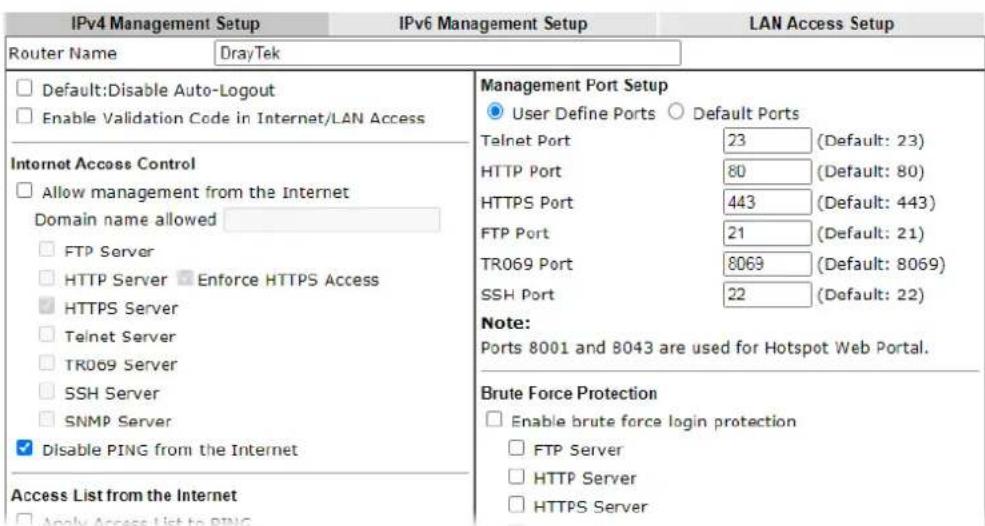
text_image
IPv4 Management Setup IPv6 Management Setup LAN Access Setup Router Name DrayTek □ Default:Disable Auto-Logout □ Enable Validation Code in Internet/LAN Access Internet Access Control □ Allow management from the Internet Domain name allowed □ FTP Server □ HTTP Server □ Enforce HTTPS Access □ HTTPS Server □ Telnet Server □ TR069 Server □ SSH Server □ SNMP Server ✓ Disable PING from the Internet Access List from the Internet □ Apply Access List to PING Management Port Setup ● User Define Ports ○ Default Ports Telnet Port 23 (Default: 23) HTTP Port 80 (Default: 80) HTTPS Port 443 (Default: 443) FTP Port 21 (Default: 21) TR069 Port 8069 (Default: 8069) SSH Port 22 (Default: 22) Note: Ports 8001 and 8043 are used for Hotspot Web Portal. Brute Force Protection □ Enable brute force login protection □ FTP Server □ HTTP Server □ HTTPS Server- Next, open Applications>>Bonjour. Check the service that you want to use via Bonjour.
Bonjour Setup

text_image
Enable Bonjour Service HTTP Server Telnet Server FTP Server SSH Server LPR Printer Server
- Open the DNSSD page again. The available items will be changed as the follows. It means the Vigor router (based on Bonjour protocol) is ready to be used as a printer server, FTP server, SSH Server, Telnet Server, and HTTP Server.

text_image
chrome://dnssd/content/browser.html GoogleDNSSD for Firefox
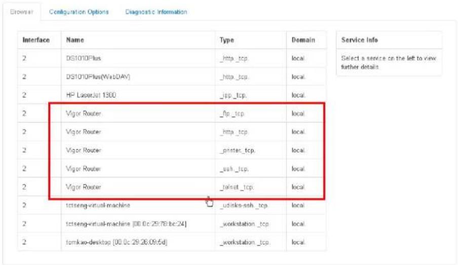
text_image
Interface Name Type Domain Service Info 2 DS1010Plus _http_tcp. local Select a service on the left to view further details 2 DS1010Plus(WebDAY) _http_tcp. local 2 HP LaserJet 1300 _jpp_tcp. local 2 Vigor Router _fip_tcp local 2 Vigor Router _http_tcp. local 2 Vigor Router _printer_tcp. local 2 Vigor Router _ssh_tcp. local 2 Vigor Router _fset_tcp. local 2 tctseng-virtual-machine _udisks-ssh_tcp. local 2 tctseng-virtual-machine [00.0c 29:78:bc:24] _workstation_tcp. local 2 tomkao-desktop [00.0c 29:26:09:5d] _workstation_tcp. local- Now, any page or document can be printed out through Vigor router (installed with a printer).
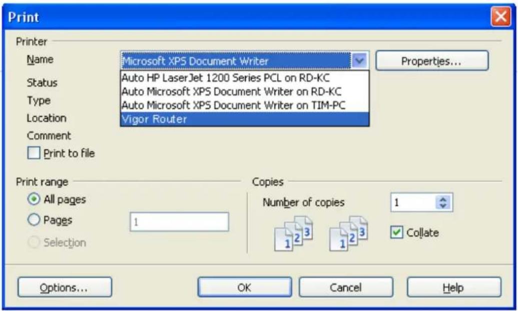
text_image
Print Printer Name Microsoft XPS Document Writer Status Auto HP LaserJet 1200 Series PCL on RD-KC Auto Microsoft XPS Document Writer on RD-KC Location Auto Microsoft XPS Document Writer on TIM-PC Vigor Router Comment Print to file Print range All pages Pages 1 Selection Copies Number of copies 1 Collate Options... OK Cancel HelpII-5-12 High Availability
The High Availability (HA) feature of the router provides redundancy of network resources, and reduces downtime in case of component failure. The level of sophistication of HA is determined by availability requirements and tolerance of system interruptions. Systems that provide near full-time availability typically have redundant hardware and software.
The HA of the Vigor2927 Series is designed to avoid single points-of-failure. When failures occur, the failover process transfers the network load handled by the failed component (the primary router) to the backup component (the secondary router), and the availability of network resources are preserved and partially failed transactions are recovered. In a matter of seconds the system returns to normal operation.
In order to set up High Availability, at least 2 DrayTek routers have to be configured in the following manner:
● Enable High Availability on both the primary and secondary routers.
- Set a high priority ID on the primary router, and a lower priority ID on the secondary router.
- Configure identical redundancy methods, group IDs, and authentication keys on both routers.
- Set the management interface of both routers to the same subnet.
- Enable virtual IP on both routers for each subnet in use. Make sure the virtual IPs are identical on both routers.
II-5-12-1 General Setup
Open Applications>>High Availability to bring up the configuration page to configure High Availability.
Applications >> High Availability

□Enable High Availability
Redundancy Method Active-Standby
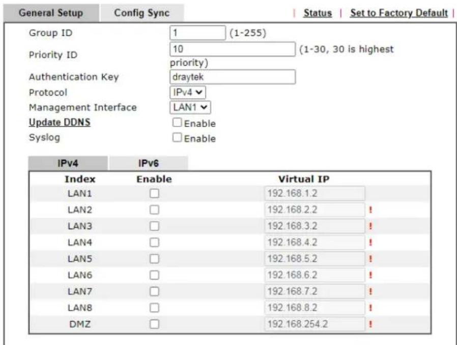
text_image
General Setup Config Sync STATUS Set to Factory Default Group ID 1_(1-255) Priority ID 10_(1-30, 30 is highest priority) Authentication Key draytek Protocol IPv4 Management Interface LAN1 Update DDNS Enable Syslog Enable IPv4 IPv6 Index Enable Virtual IP LAN1 □ 192.168.1.2 LAN2 □ 192.168.2.2 LAN3 □ 192.168.3.2 LAN4 □ 192.168.4.2 LAN5 □ 192.168.5.2 LAN6 □ 192.168.6.2 LAN7 □ 192.168.7.2 LAN8 □ 192.168.8.2 DMZ □ 192.168.254.2Note:
To configure High Availability on at least two DrayTek routers:
- Enable High Availability on the Primary and Secondary routers.
- Set a high Priority ID number on the Primary router and lower numbers for the Secondary router(s).
- Set the same Redundancy Method / Group ID / Authentication Key on the Primary and
Secondary routers. - Set the Management Interface to the same subnet for the Primary and Secondary routers.
- Enable Virtual IP on the Primary and Secondary routers for each subnet in use and set the same Virtual IP on each router.
OK
Cancel
Available settings are explained as follows:
| Item Description | |
| Enable High Abailability | Check this box to enable HA function. |
| Redundancy Method | Select the redundancy method for high availability.Hot-Standby -This method is suitable when there is only one ISP account.When this method is selected,● Du ring normal operation the secondary router will be idling. When the primary router fails to operate normally, the secondary router(s) will take over.● WAN settings of the primary and secondary routers are identical.Note: When Hot-Standby is used, the wireless LAN function on secondary router will be “disabled” directly. Clients can not connect to the secondary router any more. |
| Active-Standby -This method is suitable when there are multiple simultaneously active ISP connections. When this method is selected,A II WANs on the secondary routers can be up at the same time. LANs that are not configured under high availability can be routed to secondary routers.WAN settings of primary and secondary routers are independently configured.Config Sync may be enabled to synchronize most configuration settings between the primary and secondary routers.All routers must be set to the same redundancy method. | |
| Group ID Enter a value (1~255). | |
| Priority ID | Enter a value (1~30).Different routers must be configured with different IDs.All routers within a group must be assigned a priority ID.Within a group, the router with the largest priority ID (i.e., the highest priority) will be the primary router. When multiple routers in a group are assigned the same priority ID,routers with lower LAN IP addresses (configured on the LAN >> General Setup page) have higher priority. |
| Authentication Key | Enter an authentication key up to 31 characters long. This is used to encrypt the DARP (DrayTek Address Redundancy Protocol) traffic to guard against malicious attacks. |
| Protocol Select the IP protocol to be used for DARP. | |
| Management Interface | Select the interface to be used for DARP negotiation between routers. Only interfaces which are enabled in LAN>>General Setup are available for selection.However, LAN1 is always enabled. |
| Update DDNS | Enable - Check the box to update the DDNS server for the secondary device when the primary router fails.If the primary device fails, and the secondary device must take over the job of data transmitting and receiving. Then the system will update the DDNS server to make the user connect to the specified domain name. |
| Syslog | Enable - Check the box to record required information on Syslog. |
| LAN1 ~ LAN8, DMZ | Enable - Check the box to enable the interface.Virtual IP - Enter the IP address of the router plays the role of Primary device. |
When you finish the configuration, please click OK to save and exit this page.
II-5-12-2 Config Sync
This page is used to specify the synchronization time for such Vigor router.
Applications >> High Availability

□ Enable High Availability
Redundancy Method Active-Standby
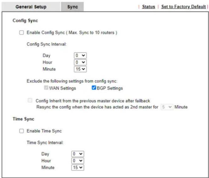
text_image
General Setup Sync Status | Set to Factory Default | Config Sync Enable Config Sync ( Max. Sync to 10 routers ) Config Sync Interval: Day 0 Hour 0 Minute 15 Exclude the following settings from config sync: WAN Settings BGP Settings Config Inherit from the previous master device after failback Resync the config when the device has acted as 2nd master for 5 Minute Time Sync Enable Time Sync Time Sync Interval: Day 0 Hour 0 Minute 15Note:
- These features require that both routers are the same series, and the High Availability must be enabled for Config Sync / Time Sync to operate.
- When enabling Time Sync, router will sync time when becoming backup router.

Available settings are explained as follows:
| Item Description | |
| Enable Config Sync (Max. Sync to 10 routers) | Check this box to enable configuration synchronization.To sync configuration from primary to secondary router,both primary and seconday routers need to enable “ config sync”. Note that config sync can be enabled byHot-Standbyredundancy method only. |
| Config Sync Interval | Day / Hour / Minute- The primary router will synchronize its configuration with secondary routers at every specified time interval. |
| Exclude the following settings from config sync | This setting is available when the Redundancy Method is set toHot Standby.Select the configuration settings to be excluded fromsynchronization. |
| Config Inherit from the previous master device after failback | The configuration inherits will be executed only when the device (router) plays the role of the master device.Once another device with the priority ID higher than this device is ready to take over the management as the master device, after acting as the primary master for a while, this device will sync the configuration to all members in the same group and return to the role of the backup device (secondary master).Config Inherit... for ( ) minute - Enter a value. |
When you finish the configuration, please click OK to save and exit this page.
When the configuration method is set to "Hot Standby", the following settings will not be synchronized:
- WAN (user selectable)
• LAN
• LAN IPv6 - router name
- admin and user passwords
Example:
In the following example, the first Vigor2927 is configured as the primary device, and the other Vigor2927 is the secondary device. When the primary Vigor2927 breaks down, the secondary device assumes the role of the primary device by taking over all responsibilities as soon as possible. However, when the primary device recovers, the secondary device will once again be the standby device.
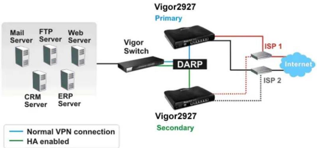
flowchart
graph TD
    A["Mail Server"] --> B["Vigor Switch"]
    C["FTP Server"] --> B
    D["Web Server"] --> B
    E["CRM Server"] --> B
    F["ERP Server"] --> B
    B --> G["DARP"]
    G --> H["Vigor2927 Primary"]
    G --> I["Vigor2927 Secondary"]
    H --> J["ISP 1"]
    I --> K["ISP 2"]
    J --> L["Internet"]
    K --> L
    style A fill:#f9f,stroke:#333
    style C fill:#f9f,stroke:#333
    style D fill:#f9f,stroke:#333
    style E fill:#f9f,stroke:#333
    style F fill:#f9f,stroke:#333
    style G fill:#ccf,stroke:#333
    style H fill:#ccf,stroke:#333
    style I fill:#ccf,stroke:#333
    style J fill:#dfd,stroke:#333
    style K fill:#dfd,stroke:#333
    style L fill:#dfd,stroke:#333
II-5-13 Local 802.1X General Setup
Such page allows you to configure general settings for Local 802.1X server built in Vigor router. The local 802.X server can be used to authenticate wired and wireless LAN clients.
Applications >> Local 802.1X General Setup
Local 802.1X General Setup
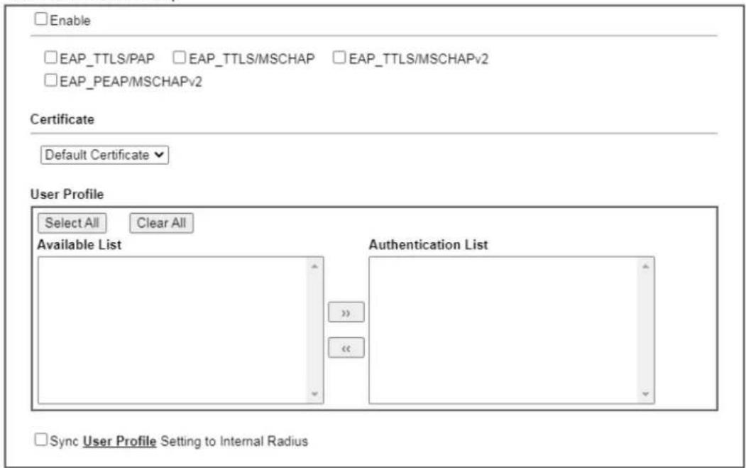
text_image
Enable EAP_TTLS/PAP EAP_TTLS/MSCHAP EAP_TTLS/MSCHAPv2 EAP_PEAP/MSCHAPv2 Certificate Default Certificate User Profile Select All Clear All Available List Authentication List Sync User Profile Setting to Internal RadiusNote:
- Only the user profiles which is enabled in User Management >> User Profile will be listed here.
- Wireless LAN(2.4G). Wireless LAN(5G) and Wired 802.1X used the same User Profile as its identity and password.

Available settings are explained as follows:
| Item Description | |
| Enable | Click it to enable the built-in 802.1X server.At present, such feature can be used for wireless and wired 802.1x authentication. |
| Certificate | Select a certificate for the user profiles. Usually, the self-signed certificate will be used as the default certificate.If there are many local / trusted certificates, select one of the certificates if required. |
| User Profile | Select All - Click to add all User Profiles to the 802.1X server.All profiles will appear under the Authentication List.Clear All - Remove all user profiles from the 802.1X server.All profiles will appear under Available List . |
| Sync User Profile .... | Make the enabling/ disabling setting for both Internal RADIUS and Local 802.1X synchronize for all of the user profiles (User Management>>User Profile).For example, if Local 802.1x is configured as Enabled (checked), the Internal RADIUS will be configured as Enabledtoo. |
| 3. Internal ServicesInternal RADIUSLocal 802.1XNote:Internal Services means the account and password of this user profile can be used by other application.OKRefreshClearCancelIf Local 802.1X is configured as Disabled (unchecked), the Internal RADIUS will be changed as Disabled too, even if it is enabled previously. | |
| 3. Internal ServicesInternal RADIUSLocal 802.1XNote:Internal Services means the account and password of this user profile can be used by other application.OKRefreshClearCancel | |
| OK | Click it to save the settings. |
| Cancel | Click it to give up all settings configuration. |
When you finish the configuration, please click OK to save and exit this page.
Application Notes
A-1 How to use DrayDDNS?
Vigor router supports various DDNS service providers, user can set up user-defined profile to update the DDNS even the service provider is not on the list. Now, DrayTek starts to support our own DDNS service - DrayDDNS. We will provide a domain name for each Vigor Router, this single domain name can record IP addresses of all WAN.
Activate DrayDDNS License
- Go to Wizards >> Service Activation Wizard, wait for the router to connect to MyVigor server, then tick DT-DDNS and I have read and accept the above Agreement, click Next.
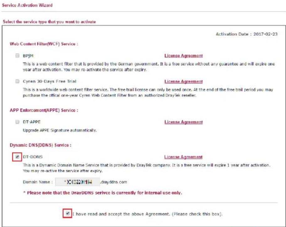
text_image
Service Activation Wizard Select the service type that you want to activate Activation Date : 2017-02-23 Web Content Filter(WCF) Service : BPJM License Agreement This is a web content filter that is provided by the German government. It is a free service without any guarantee and will expire one year after activation. You may re-activate the service after expiry. Cyren 30-Days Free Trial License Agreement This is a worldwide web content filter service. The free trail license can only be used once. At the end of the free trail period you may purchase the official one-year Cyren Web Content Filter from an authorized DrayTek reseller. APP Enforcoment(APPE) Service : DT-APPE License Agreement Upgrade APPE Signature automatically. Dynamic DNS(DDNS) Service : DT-DONS License Agreement This is a Dynamic Domain Name Service that is provided by DrayTek company. It is a free service will expire 1 year after activation. You may re-active the service after expiry. Domain Name : X(02)154 ,drayddns.com * Please note that the DrayDDNS service is currently for internal use only. I have read and accept the above Agreement. (Please check this box).
- Confirm the information, then click Activate.
Please confirm your settings
Sevice Type : Trial version
Sevice Activated : Dynamic DNS ( L3=002511.drayddns.com )
Please click Back to re-select service type you to activate.
< Back
Activate
Cancel
- MyVigor server will reply with the service activation information.
DrayTek Service Activation
| Service Name | Start Date | Expire Date | Status |
| Web Content filter | --- | --- | Not Activated |
| APP Enforcement | --- | --- | Not Activated |
| DDNS | 2017-02-23 | 2018-02-23 | DT-DDNS |
Please check if the license fits with the service provider of your signature. To ensure normal operation for your router, update your signature again is recommended.
Configure DDNS Profile
- Go to Applications >> Dynamic DNS Setup,
a. Tick Enable Dynamic DNS Setup
b. Click an available profile index
c. Tick Enable Dynamic DNS Account
d. Select DrayDDNS Global (www.drayddns.com) as Service Provider
e. Select the WAN you would like to upload the IP to DDNS server
f. Click Get domain
g. Click OK on the pop up notification window
Applications >> Dynamic DNS Setup
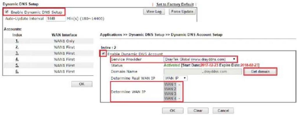
text_image
Dynamic DNS Setup Enable Dynamic DNS Setup Auto-Update Interval 1440 Min(s) (180~14400) Set to Factory Default View Log Force Update Accounts: Index WAN Interface 1 WAN1 Only 2 WAN1 First 3 WAN1 First 4 WAN1 First 5 WAN1 First 6 WAN1 First OK Applications >> Dynamic DNS Setup >> Dynamic DNS Account Setup Index : 2 Enable Dynamic DNS Account Service Provider DrayTek Global (www.drayddns.com) Status Activated [Start Date:2017-02-23 Expire Date:2018-02-23] Domain Name drayddns.com Get domain Determine Real WAN IP WAN IP Determine WAN IP WAN 1 - WAN 2 WAN 3 WAN 4 - OK Clear Cancel192.168.193.10 says:
Note: Router will automatically get the domain name from MyVigor server. Please kindly wait for a while, then check the config again.
☐ Prevent this page from creating additional dialogs.
OK
- Wait few seconds for router to get the domain name, then, we can click the profile to check the information of license and domain name.
Applications >> Dynamic DNS Setup
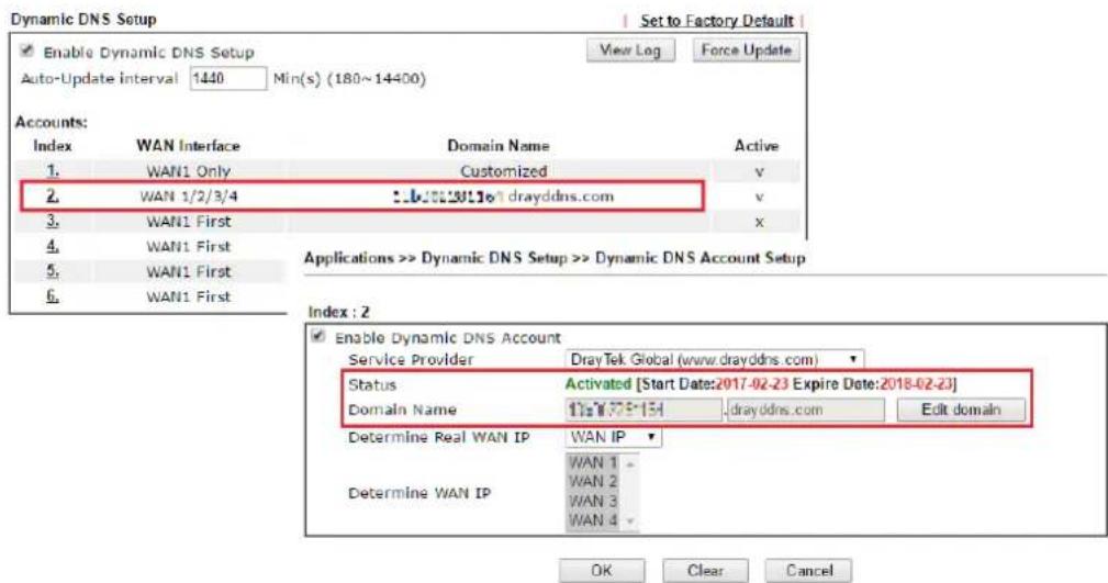
text_image
Dynamic DNS Setup Enable Dynamic DNS Setup Auto-Update interval 1440 Min(s) (180~14400) Set to Factory Default View Log Force Update Accounts: Index WAN Interface Domain Name Active 1. WAN1 Only Customized v 2. WAN 1/2/3/4 ..b:2023/16" drayddns.com v 3. WAN1 First x 4. WAN1 First 5. WAN1 First 6. WAN1 First Applications >> Dynamic DNS Setup >> Dynamic DNS Account Setup Index : 2 Enable Dynamic DNS Account Service Provider DrayTek Global (www.drayddns.com) Status Activated [Start Date:2017-02-23 Expire Date:2018-02-23] Domain Name 1751779-154 drayddns.com Edit domain Determine Real WAN IP WAN IP WAN 1 - WAN 2 - WAN 3 - WAN 4 - Determine WAN IP OK Clear CancelModify Domain Name
Currently, only the domain name is allowed to be modified MyVigor website. We will need to register the router to MyVigor server, and log in to MyVigor website to modify it.
- Please visit https://myvigor.draytek.com/ or go to Applications >> Dynamic DNS Setup >> DrayDDNS profile and click Edit domain.
Applications >> Dynamic DNS Setup >> Dynamic DNS Account Setup
Index : 2
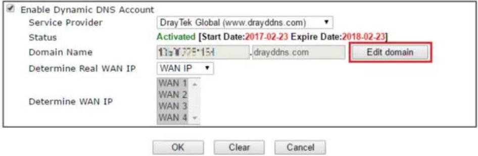
text_image
Enable Dynamic DNS Account Service Provider DrayTek Global (www.drayddns.com) Status Activated [Start Date:2017-02-23 Expire Date:2018-02-23] Domain Name 13=1.775*154 drayddns.com Edit domain Determine Real WAN IP WAN IP WAN 1 WAN 2 WAN 3 WAN 4 Determine WAN IP OK Clear Cancel- Log in to MyVigor Website, choose the profile, then click Edit DDNS settings.
My Information - My Products
Device Information
Device Name: 141790
Serial Number: 1348720114
Model: Vigor2925 Series

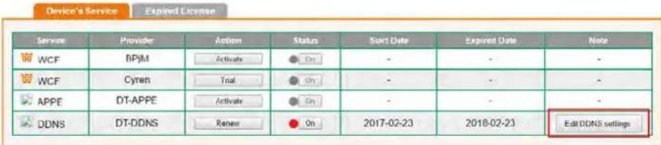
text_image
Device's Service Expired License Service Provider Action Status Start Date Expired Date None WCF BPJM Activate ● On - - - WCF Cyren Trial ● On - - - APPE DT-APPE Activate ● On - - - DDNS DT-DDNS Renew ● On 2017-02-23 2018-02-23 Edit DDNS settings- Input the desired Domain name (e.g., XXXX25) and click Update.
Edit DDNS Settings
Please note that the DrayDONS service is currently for internal use only.
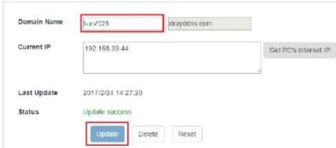
text_image
Domain Name 1:41:425 drayddas.com Current IP 192.168.39.44 Get PC's Internet IP Last Update 2017/2/24 14:27:20 Status Update success Update Delete Reset- Vigor router will get the modified domain name when the it performs next DDNS updating. We can click Sync domain to accelerate this process.
Index : 2
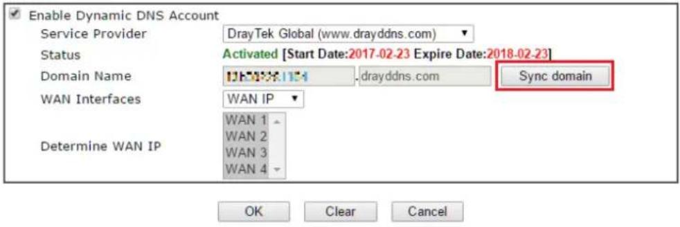
text_image
Enable Dynamic DNS Account Service Provider DrayTek Global (www.drayddns.com) Status Activated [Start Date:2017-02-23 Expire Date:2018-02-23] Domain Name drayddns.com Sync domain WAN Interfaces WAN IP Determine WAN IP WAN 1 WAN 2 WAN 3 WAN 4 OK Clear CancelAfter few seconds, the router will get the new domain name and print it on the profiles list.
Applications >> Dynamic DNS Setup
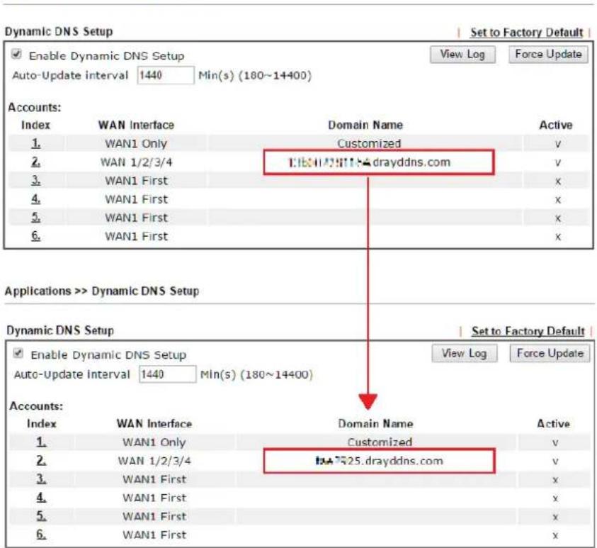
text_image
Dynamic DNS Setup Enable Dynamic DNS Setup Auto-Update interval 1440 Min(s) (180~14400) View Log Force Update Accounts: Index WAN Interface Domain Name Active 1. WAN1 Only Customized v 2. WAN 1/2/3/4 drayddns.com v 3. WAN1 First x 4. WAN1 First x 5. WAN1 First x 6. WAN1 First x Applications >> Dynamic DNS Setup Dynamic DNS Setup Set to Factory Default Enable Dynamic DNS Setup View Log Force Update Auto-Update Interval 1440 Min(s) (180~14400) Accounts: Index WAN Interface Domain Name Active 1. WAN1 Only Customized v 2. WAN 1/2/3/4 drayddns.com v 3. WAN1 First x 4. WAN1 First x 5. WAN1 First x 6. WAN1 First xA-2 How to Configure Customized DDNS?
This article describes how to configure customized DDNS on Vigor routers to update your IP to the DDNS server. We will take "Changeip.org" and "3322.net" as example. Before setting, please make sure that the WAN connection is up.
Part A: Changeip.org
| Physical Connection | System Uptime: 0day 2:25:59 | ||||
| IPv4 | IPv6 | ||||
| LAN Status | Primary DNS: 168.95.192.1 | Secondary DNS: 168.95.1.1 | |||
| IP Address | TX Packets | RX Packets | |||
| 10.1.7.1 | 2069 | 1036 | |||
| WAN 1 Status | >> Drop PPPoE | ||||
| Enable | Line | Name | Mode | Up Time | |
| Yes | Ethernet | iwiz | PPPoE | 2:25:53 | |
| IP | GW IP | TX Packets | TX Rate(Bps) | RX Packets | RX Rate(Bps) |
| 1.169.185.242 | 168.95.98.254 | 14851 | 9506 | 11281 | 912 |
Note that,
Username: jo***
Password: jo*****
Host name: j*****.changeip.org
WAN IP address: 1.169.185.242
Following is the screenshot of editing the HTML script on the browser to update your IP to the DDNS server.
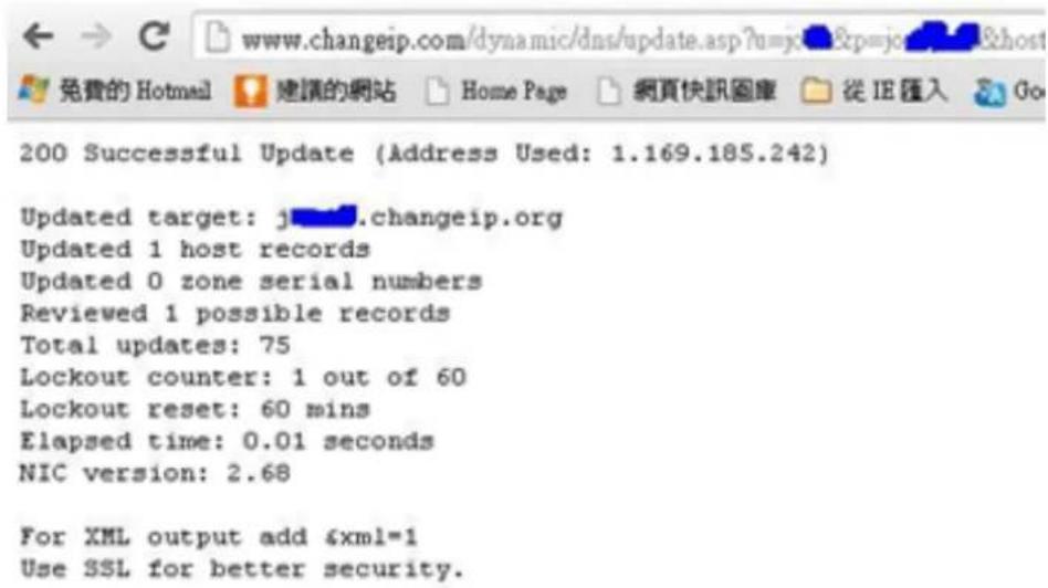
text_image
200 Successful Update (Address Used: 1.169.185.242) Updated target: j...changeip.org Updated 1 host records Updated 0 zone serial numbers Reviewed 1 possible records Total updates: 75 Lockout counter: 1 out of 60 Lockout reset: 60 mins Elapsed time: 0.01 seconds NIC version: 2.68 For XML output add 6xml=1 Use SSL for better security.Now we have to configure the router so it can do the same job for us automatically.
- Please go to Applications >> Dynamic DNS to create a profile for customized DDNS client.
Applications >> Dynamic DNS Setup >> Dynamic DNS Account Setup
Index : 1
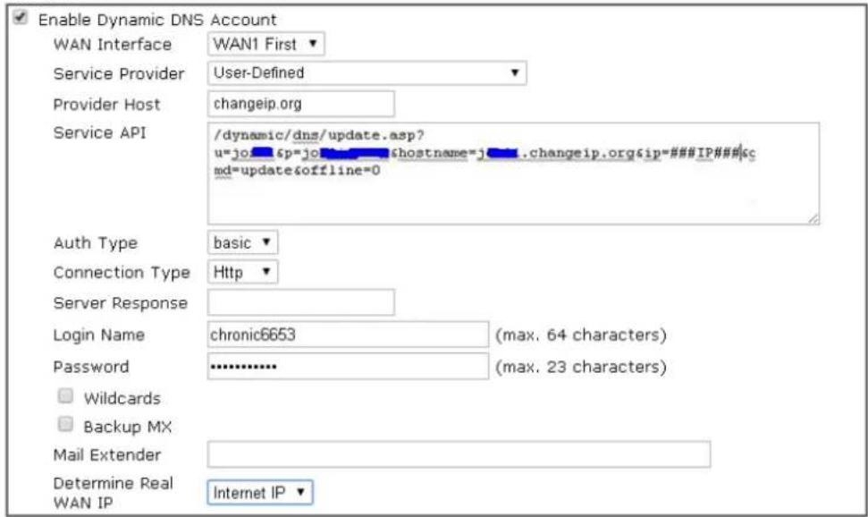
text_image
Enable Dynamic DNS Account WAN Interface WAN1 First Service Provider User-Defined Provider Host changeip.org Service API /dynamic/dns/update.asp? u=jo_6p=jo_6p@hostname=j_.changeip.org&ip=#####IP#####&c md=update&offline=0 Auth Type basic Connection Type Http Server Response Login Name chronic6653 (max. 64 characters) Password ******** (max. 23 characters) Wildcards Backup MX Mail Extender Determine Real Internet IP WAN IP
-
Set the Service Provider as User-Defined.
-
Set the Service API as: / dynamic/ dns/ update.asp?u=j0***&p=j0*******&hostname=j****.changeip.org&ip=###IP #### &cmd=update&offline=0
In which, ####IP### is a value which will be replaced with the current interface IP address automatically when DDNS service is running. In this case the IP will be 1.169.185.242.
- After setting, the Customized DDNS service will be up, and our IP will be updated to the DDNS server.
Part B : 3322.net
| WAN 1 | |
| Link Status | : Connected |
| MAC Address | : 00-50-7F-C8-C6-A1 |
| Connection | : PPPoE |
| IP Address | : 111.243.178.53 |
| Default Gateway | : 168.95.98.254 |
| Primary DNS | : 168.95.192.1 |
| Secondary DNS | : 168.95.1.1 |
Username: bi*****
Password: 88********
Host name: bi*****.3322.org
WAN IP address: 111.243.178.53
To update the IP to the DDNS server via editing the HTML script, we can Enter the following script on the browser:

text_image
members.3322.net/dyndns/update members.3322.net/dyndns/update?hostname=b40000.3322.org&my/p=#####/wildcard=OFF&mx=mail.exchanger.ext&backmx=NO&offline=NO HTTP/1.1And the result will be :

text_image
members.3322.net/dyndns/update?hostname=148888.3322.org&myip=PKZ3K23IPKZ3K23&wildcard=OFF&mx=mail.exchanger.ext&backmx=NO&offline=NOS20HTP/1.1 members.3322.net/dyndns/update?hostname=148888.3322.org&myip=PKZ3K23IPKZ3K23&wildcard=OFF&mx=mail.exchanger.ext&backmx=NO&offline=NOS20HTP/1.1 digital... Mac OS... Bonjour... WBDC... History Files.doc... 6PC 95... pic.dle... 201212... Lockad... 新闻api... DrayTe... good 111.243.178.53"good 111.243.178.53" means our IP has been updated to the server successfully.
Now we have to configure the router so it can do the same job for us automatically.
- Please go to Applications >> Dynamic DNS to create a profile for Customized DDNS client.
Applications >> Dynamic DNS Setup >> Dynamic DNS Account Setup
Index : 1
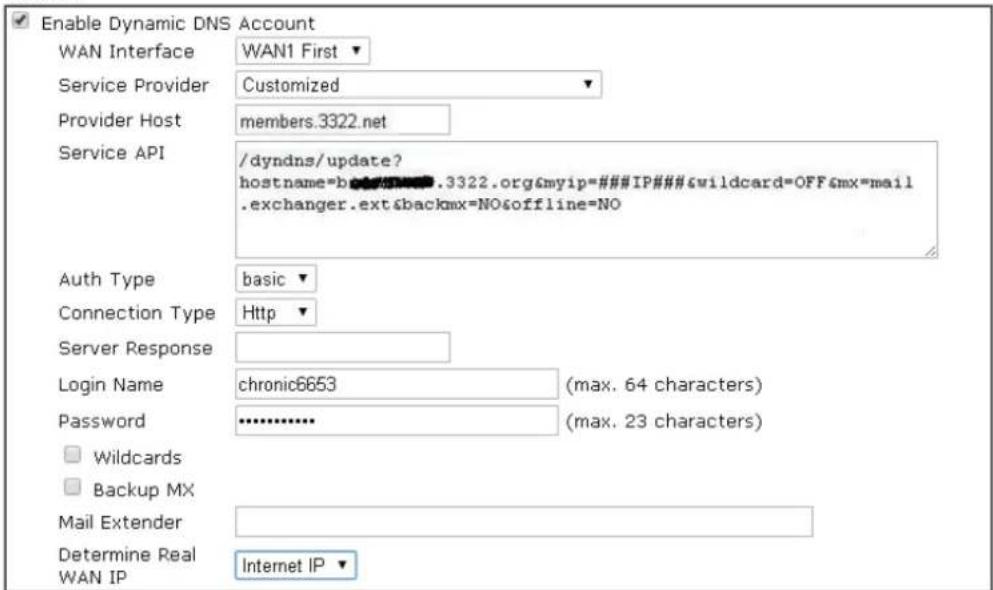
text_image
Enable Dynamic DNS Account WAN Interface WAN1 First Service Provider Customized Provider Host members.3322.net Service API /dyndns/update? hostname=b########.3322.org&myip=###IP###&wildcard=OFF&mx=mail .exchanger.ext&backmx=NO&offline=NO Auth Type basic Connection Type Http Server Response Login Name chronic6653 (max. 64 characters) Password ******** (max. 23 characters) Wildcards Backup MX Mail Extender Determine Real Internet IP WAN IP
- Set the Service Provider as User-Defined.
- Set the Provider Host as member.3322.net.
- Set the Service API as: /dyndns/ update?hostname=yourhost.3322.org&myip=###IP###&wildcard=OFF&mx=mail .exchanger.ext&backmx=NO&offline=NO
- Enter your account and password.
- After the setting, the Customized DDNS service will be up, and our IP will be updated to the DDNS server automatically.
Part C : Extend Note
The customized Service Provider is also eligible with the ClouDNS.net.

text_image
ipv4.cloudns.net/api/dynamicURL/?q=MTUzMTE3OJEONTA1MzA6MDAyODE3MDIIZGQ3ZJNiZmE2 ipv4.cloudns.net/api/dynamicURL/?q=MTUzMTE3OJEONTA1MzA6MDAyODE3MDIIZGQ3ZJNiZmE2 swm.draytek.com/track... 2012120610000265 - draytek_sum: DrayTek - DrayTek Vigor2920OK
Applications >> Dynamic DNS Setup >> Dynamic DNS Account Setup
Index : 1
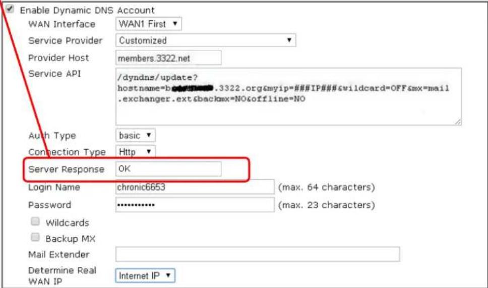
text_image
Enable Dynamic DNS Account WAN Interface WAN1 First Service Provider Customized Provider Host members.3322.net Service API /dyndns/update? hostname=b########.3322.org&myip=###IP###&wildcard=OFF&mx=mail .exchanger.ext&backmx=NO&offline=NO Auth Type basic Connection Type Http Server Response OK Login Name chronic6653 (max. 64 characters) Password ******** (max. 23 characters) Wildcards Backup MX Mail Extender Determine Real Internet IP WAN IP
II-6 Routing
Route Policy (also well known as PBR, policy-based routing) is a feature where you may need to get a strategy for routing. The packets will be directed to the specified interface if they match one of the policies. You can setup route policies in various reasons such as load balance, security, routing decision, and etc.
Through protocol, IP address, port number and interface configuration, Route Policy can be used to configure any routing rules to fit actual request. In general, Route Policy can easily reach the following purposes:
Load Balance
You may manually create policies to balance the traffic across network interface.
Specify Interface
Through dedicated interface (WAN/LAN/VPN), the data can be sent from the source IP to the destination IP.
Address Mapping
Allows you specify the outgoing WAN IP address (es) for an internal private IP address or a range of internal private IP addresses.
Priority
The router will determine which policy will be adopted for transmitting the packet according to the priority of Static Route and Route Policy.
Failover to/Failback
Packets will be sent through another Interface or follow another Policy when the original interface goes down (Failover to). Once the original interface resumes service (Failback), the packets will be returned to it immediately.
Other routing
Specify routing policy to determine the direction of the data transmission.

Info
For more detailed information about using policy route, refer to Support >>FAQ/Application Note on www.draytek.com.
Web User Interface
Routing
Static Route
Load-Balance/Route Policy
BGP
II-6-1 Static Route
Go to Routing >> Static Route. The router offers IPv4 and IPv6 for you to configure the static route. Both protocols bring different web pages.
Static Route for IPv4
Routing >> Static Route Setup
| IPv4 | IPv6 | Set to Factory Default | View Routing Table | ||
| Index | Enable | Destination Address | Mask | Gateway | Interface |
| 1. | |||||
| 2. | |||||
| 3. | |||||
| 4. | |||||
| 5. | |||||
| 6. | |||||
| 7. | |||||
| 8. | |||||
| 9. | |||||
| 10. | |||||
| 11. | |||||
| 31. | |||||
| 38. | |||||
| 39. | |||||
| 40. | |||||

Available settings are explained as follows:
| Item Description | |
| Index | The number (1 to 40) under Index allows you to open next page to set up static route. |
| Enable | Check the box to enable the static route profile. |
| Destination Address | Displays the destination address of the static route. |
| Set to Factory Default | Clear all of the settings and return to factory default settings. |
| Viewing Routing Table | Displays the routing table for your reference.Diagnostics >> View Routing Table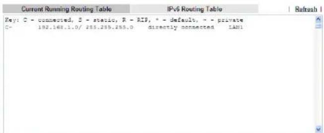 |
| Backup | Click it to backup the configuration of static route settings. |
| Restore | Click it to restore the configuration of static route settings.Before clicking, make sure upload the configuration file ontoVigor router. |
Add Static Routes to Private and Public Networks
Here is an example (based on IPv4) of setting Static Route in Main Router so that user A and B locating in different subnet can talk to each other via the router. Assuming the Internet access has been configured and the router works properly:
● use the Main Router to surf the Internet.
● create a private subnet 192.168.10.0 using an internal Router A (192.168.1.2)
● create a public subnet 211.100.88.0 via an internal Router B (192.168.1.3).
● have set Main Router 192.168.1.1 as the default gateway for the Router A 192.168.1.2.
Before setting Static Route, user A cannot talk to user B for Router A can only forward recognized packets to its default gateway Main Router.
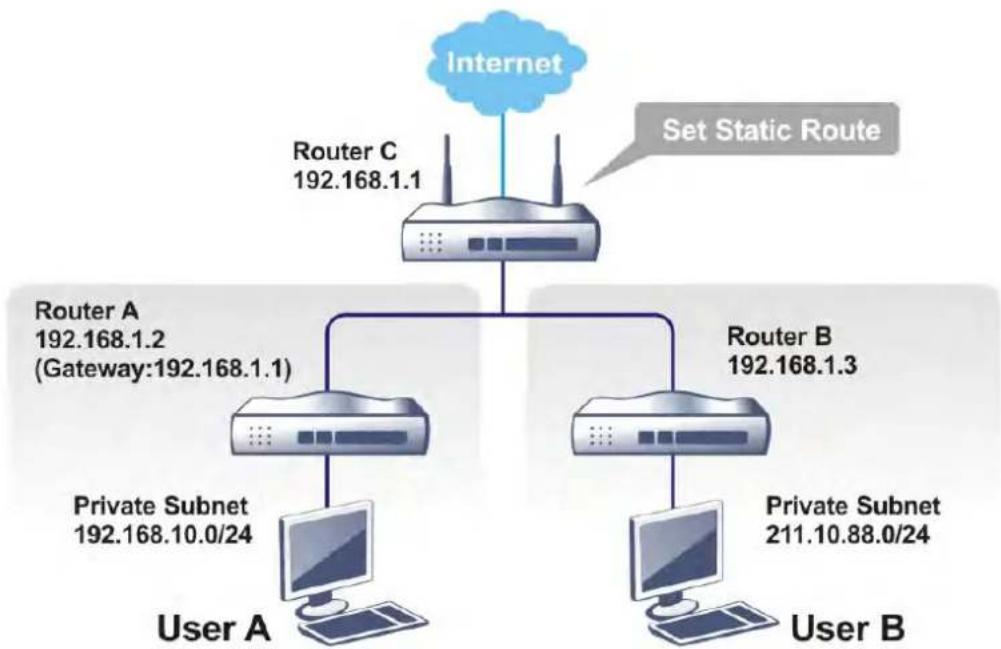
flowchart
graph TD
    A["Internet"] --> B["Router C 192.168.1.1"]
    B --> C["Set Static Route"]
    C --> D["Router A 192.168.1.2 (Gateway:192.168.1.1)"]
    C --> E["Router B 192.168.1.3"]
    D --> F["Private Subnet 192.168.10.0/24"]
    E --> G["Private Subnet 211.10.88.0/24"]
    F --> H["User A"]
    G --> I["User B"]
- Go to LAN page and click General Setup, select 1st Subnet as the RIP Protocol Control. Then click the OK button.

Info
There are two reasons that we have to apply RIP Protocol Control on 1st Subnet. The first is that the LAN interface can exchange RIP packets with the neighboring routers via the 1st subnet (192.168.1.0/24). The second is that those hosts on the internal private subnets (ex. 192.168.10.0/24) can access the Internet via the router, and continuously exchange of IP routing information with different subnets.
- Click the Routing >> Static Route and click on the Index Number 1. Check the Enable box. Please add a static route as shown below, which regulates all packets destined to 192.168.10.0 will be forwarded to 192.168.1.2. Click OK.
Routing >> Static Route Setup
Index No. 1

text_image
Enable Destination IP Address 192.168.10.0 Subnet Mask 255.255.255.255 / 32 Gateway IP Address 192.168.1.2 Network Interface LAN1Note:
WAN7, WAN8, WAN9 are PVCs or VLANs that can be configured on the Multi-PVC/VLAN page.

Available settings are explained as follows:
| Item Description | |
| Enable | Click it to enable this profile. |
| Destination IP Address | Enter an IP address as the destination of such static route. |
| Subnet Mask | Enter the subnet mask for such static route. |
| Gateway IP Address | Enter the IP address of the gateway. |
| Network Interface | Use the drop down list to specify an interface for such static route. |
- Return to Static Route Setup page. Click on another Index Number to add another static route as show below, which regulates all packets destined to 211.100.88.0 will be forwarded to 192.168.1.3. Click OK.
Routing >> Static Route Setup
Index No. 2

text_image
Enable Destination IP Address 211.100.88.0 Subnet Mask 255.255.255.255 / 32 Gateway IP Address 192.168.1.3 Network Interface LAN1Note:
WAN7, WAN8, WAN9 are PVCs or VLANs that can be configured on the Multi-PVC/VLAN page.

- Go to Diagnostics and choose Routing Table to verify current routing table.
Diagnostics >> View Routing Table
| Current Running Routing Table | IPv6 Routing Table | | Refresh | | ||
| Key: C - connected, S - static, R - RIP, * - default, ~ - private | ||||
| S~ | 192.168.10.0/ 255.255.255.0 | via 192.168.1.2 | LAN1 | |
| C~ | 192.168.1.0/ 255.255.255.0 | directly connected | LAN1 | |
| S~ | 211.100.88.0/ 255.255.255.0 | via 192.168.1.3 | LAN1 | |
Static Route for IPv6
You can set up to 40 profiles for IPv6 static route. Click the IPv6 tab to open the following page:
Routing >> Static Route Setup
| IPv4 | IPv6 | Set to Factory Default | View IPv6 Routing Table | |
| Index | Enable | Destination Address | Gateway | Interface |
| 1. | ||||
| 2. | ||||
| 3. | ||||
| 4. | ||||
| 5. | ||||
| 6. | ||||
| 7. | ||||
| 8. | ||||
Available settings are explained as follows:
| Item Description | |
| Index | The number (1 to 40) under Index allows you to open next page to set up static route. |
| Enable | Check the box to enable the static route profile. |
| Destination Address | Displays the destination address of the static route. |
| Gateway | Displays the IP address of the gateway. |
| Interface | Displays the interface used for this static route. |
| Set to Factory Default | Clear all of the settings and return to factory default settings. |
| Viewing IPv6 Routing Table | Displays the routing table for your reference. |
| Backup | Click it to backup the configuration of static route settings. |
| Restore | Click it to restore the configuration of static route settings.Before clicking, make sure upload the configuration file onto Vigor router. |
Click any underline of index number to get the following page.
Routing >> Static Route Setup
Index No. 1

text_image
Enable Destination IPv6 Address / Prefix Len 0 Gateway IPv6 Address Network Interface LAN1
Available settings are explained as follows:
| Item Description | |
| Enable | Click it to enable this profile. |
| Destination IPv6 Address / Prefix Len | Enter the IP address with the prefix length for this entry. |
| Gateway IPv6 Address | Enter the gateway address for this entry. |
| Network Interface | Use the drop down list to specify an interface for this static route. |
When you finish the configuration, please click OK to save and exit this page.
II-6-2 Load-Balance /Route Policy
It allows network administrator to manage the outbound traffic more specifically. The policy set in Load-Balance/ Route Policy always has higher priority than Default Route and Auto Load Balance set in WAN >> Internet Access, and always has lower priority than the Firewall Rules. Administrator may also define a priority to this policy.
This page lists all the policies and shows whether the policy is enabled/ disabled, what are the criteria to match, and through which the interface should the traffic to go if the criteria are matched, and also its priority.
Routing >> Load-Balance/Route Policy

| Index | Enable | Comment | Protocol | Interface | Priority | Source | Destination | Dest Port | Move Up | Move Down |
| 1 | □ | Any | WAN1 | 200 | Any | Any | Any | Down | ||
| 2 | □ | Any | WAN1 | 200 | Any | Any | Any | UP | Down | |
| 3 | □ | Any | WAN1 | 200 | Any | Any | Any | UP | Down | |
| 4 | □ | Any | WAN1 | 200 | Any | Any | Any | UP | Down | |
| 5 | □ | Any | WAN1 | 200 | Any | Any | Any | UP | Down | |
| 6 | □ | Any | WAN1 | 200 | Any | Any | Any | UP | Down | |
| 7 | □ | Any | WAN1 | 200 | Any | Any | Any | UP | Down | |
| 8 | □ | Any | WAN1 | 200 | Any | Any | Any | UP | Down | |
| 9 | □ | Any | WAN1 | 200 | Any | Any | Any | UP | Down | |
| 10 | □ | Any | WAN1 | 200 | Any | Any | Any | UP | Down |


○ Wizard Mode: most frequently used settings in three pages
Advance Mode: all settings in one page
Note:
The policies in blue are SD-WAN related, and can only be edited via ACS.

Available settings are explained as follows:
| Item Description | |
| Index | Click the number of index to access into the configuration web page. |
| Enable | Check this box to enable this policy. |
| Protocol Display the protocol used for this policy. | |
| Interface | Display the interface to send packets to once the policy is matched. |
| Priority | Display the priority value for such route policy profile. |
| Source | Display the content of source IP, subnet, object or group. |
| Destination | Display the content of destination IP, subnet, object or group. |
| Dest Port | Display the content of the destination port. |
| Move UP/Move Down | Use Up or Down link to move the order of the policy. |
| Wizard Mode | Allow to configure frequently used (simple and basic) settings of route policy via three setting pages. |
| Advance Mode | Allow to configure detailed settings of route policy. |
To use Wizard Mode, simple do the following steps:
- Click the Wizard Mode radio button.
- Click Index 1. The setting page will appear as follows:
Routing >> Load-Balance/Route Policy
Index: 1 Criteria
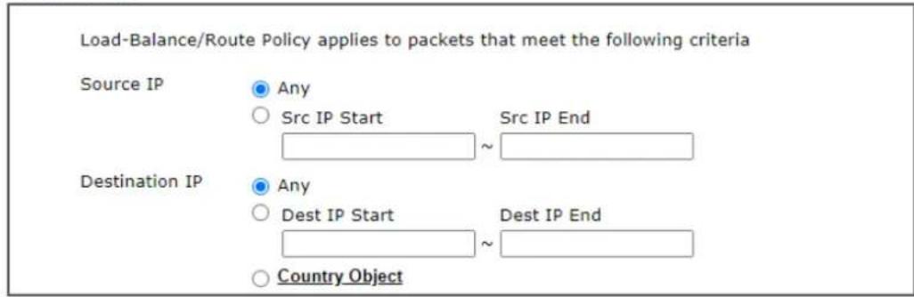
text_image
Load-Balance/Route Policy applies to packets that meet the following criteria Source IP Any ○ Src IP Start Src IP End Destination IP Any ○ Dest IP Start Dest IP End ○ Country Object
Available settings are explained as follows:
| Item Description | |
| Source IP Any - Any IP can be treated as the source IP. Src IP Start - Enter the source IP start for the specified WAN interface. Src IP End - Enter the source IP end for the specified WAN interface. If this field is blank, it means that all the source IPs inside the LAN will be passed through the WAN interface. | |
| Destination IP | Any - Any IP can be treated as the destination IP. Dest IP Start- Enter the destination IP start for the specified WAN interface. Dest IP End - Enter the destination IP end for the specified WAN interface. If this field is blank, it means that all the destination IPs will be passed through the WAN interface. Country Object - Specify a country object. All the IPs coming from the country (countries) specified in the object will be passed through the WAN interface. |
- Click Next to get the following page.
Routing >> Load-Balance/Route Policy
Index: 1 Interface
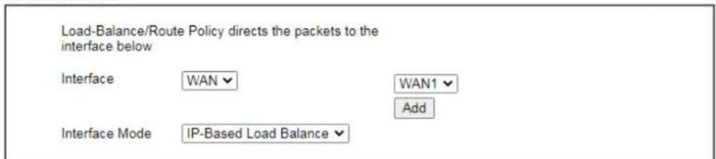
text_image
Load-Balance/Route Policy directs the packets to the interface below Interface WAN Interface Mode IP-Based Load Balance WAN1 Add
Available settings are explained as follows:
| Item Description | |
| Interface | You can select an interface from one of the following: WAN, LAN, VPN, IP Routed Subnet, and DMZ Subnet. Packets match with the above criteria will be transferred to the interface chosen here. Select an interface from the list. |
| Interace Mode | Select IP-Based Load Balance or Session-Based Load Balance if WAN is specified as the Interface. |
- Specify an interface and click Next. The following page will appear only if you choose WAN1 \~WAN9 as Interface.
Routing >> Load-Balance/Route Policy
Index: 1 NAT or Routing

text_image
Based on the settings in the previous pages, we guess you want to have: Force NAT The current setting is: ● Force NAT ○ Force Routing
Available settings are explained as follows:
| Item Description | |
| Force NAT /Force Routing | It determines which mechanism that the router will use to forward the packet to WAN. |
- After choosing the mechanism, click Next to get the summary page for reference.
Routing >> Load-Balance/Route Policy
Index: 1 Configuration Summary
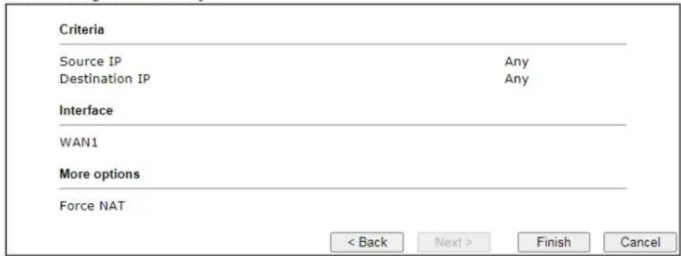
text_image
Criteria Source IP Any Destination IP Any Interface WAN1 More options Force NAT < Back Next > Finish Cancel- If there is no error, click Finish to complete wizard setting.
To use Advance Mode, do the following steps:
- Click the Advance Mode radio button.
- Click Index 1 to access into the following page.
Routing >> Route Policy
Index: 1
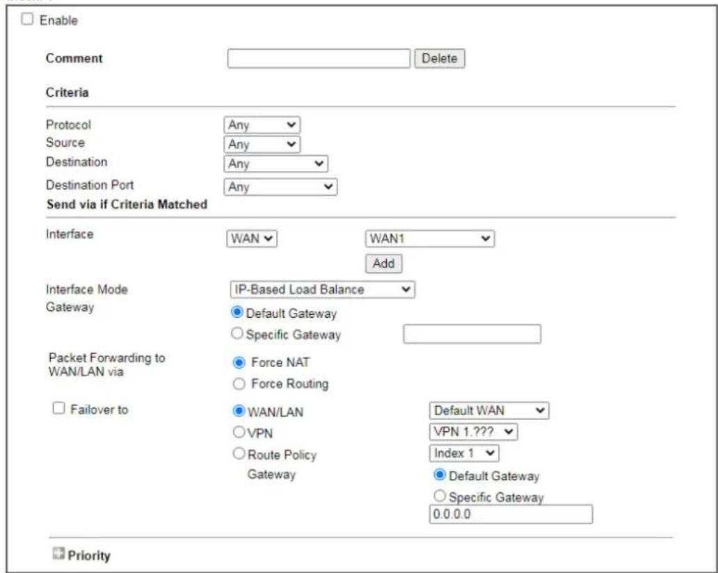
text_image
Enable Comment Delete Criteria Protocol Any Source Any Destination Any Destination Port Any Send via if Criteria Matched Interface WAN WAN1 Add Interface Mode IP-Based Load Balance Gateway Default Gateway Specific Gateway Packet Forwarding to Force NAT WAN/LAN Force Routing Failover to WAN/LAN Default WAN VPN VPN 1.??? Route Policy Index 1 Gateway Default Gateway Specific Gateway 0.0.0.0 Priority
Note:
Force NAT(Routing): NAT(Routing) will be performed on outgoing packets, regardless of which type of subnet (NAT or IP Routing) they originate from.
Available settings are explained as follows:
| Item Description | |
| Enable | Check this box to enable this policy. |
| Comment | Type a brief explanation for such profile. |
| Criteria | Router examines outgoing LAN traffic to find the first rule whose criteria are satisfied.Protocol- Use the drop-down menu to choose a proper protocol for the WAN interface.Source- Source IP addresses to which this rule is to be applied.Any- This rule applies to all source IP addresses.IP Range-This rule applies to the specified range of source IP addresses.- Start- Enter an address as the starting IP forsuch profile.- End - Enter an address as the ending IP for such profile.● IP Subnet - This rule applies to source IP addresses defined by the specified network IP address and subnet mask.- Network - Enter an IP address here.- Mask - Use the drop down list to choose a suitable mask for the network.● IP Object / IP Group - Use the drop down list to choose a preconfigured IP object/ group.Destination - Destination IP addresses to which this rule is to be applied.● Any - This rule applies to all source IP addresses.● IP Range -This rule applies to the specified range of destination IP addresses.- Start - Enter an address as the starting IP for such profile.- End - Enter an address as the ending IP for such profile.● IP Subnet - This rule applies to destination IP addresses defined by the specified network IP address and subnet mask.- Network - Enter an IP address here.- Mask - Use the drop down list to choose a suitable mask for the network.● Domain Name - Specify a domain name as the destination.- Select - Click it to choose an existing domain name defined in Objects Setting>>String Object.- Delete - Remove current used domain name.- Add - Create a new domain name as the destination.● IP Object / IP Group - Use the drop down list to choose a preconfigured IP object/ group.● Country Object - Use the drop dwon list to choose a preconfigured object. Then all IPs within that country will be treated as the destination IP.Destination Port - Destination port numbers to which this rule is to be applied. As only TCP and UDP protocols use port numbers, this setting does not apply to the ICMP protocol.● Any - This rule applies to all destination ports.● Dest Port Range - This rule applies to the specified range of destination ports.- Start - Enter the destination port start for the destination IP.- End - Enter the destination port end for the destination IP. If this field is blank, it means that all the destination ports will be passed through the WAN interface. |
| Send to if criteria matched | If criteria are matched, the traffic will be sent to the designated interface and gateway.Interface - Packets match with the above criteria will be |
transferred to the interface chosen here. Select an interface from the list (WAN/ LAN: A WAN or LAN interface; VPN: A Virtual Private Network; PVC).
Interface Mode - It is available if WAN is selected as the Interface.
- IP Based Load Balance - The same source / destination IP pair will select the same WAN interface as policy. It is the default setting.
- Session Based Load Balance - All of the WAN interfaces will be used (as out-going WAN) for passing through new sessions to get better transmission speed. Though good speed test result for throughput might be reached; however, some web site may not open smoothly, especially the site need authentication, e.g., FTP.
If you have no strong demand about speed test result, keep default settings as IP based.
Gateway - Select a gateway.
- Default Gateway - Traffic will be sent to the default gateway address of the specified interface.
- Specific Gateway - Traffic will be sent to the specified gateway address instead of the default gateway address.
Packet Forwarding to WAN/LAN via - When you choose LAN/WAN (e.g., WAN1) as the Interface for packet transmission, you have to specify the way the packet forwarded to.
● Force NAT - The source IP address will not be used to connect to the remote destination. Network Address Translation (NAT) will be used, where a common IP address will be used.
● Force Routing - The source IP address will be preserved when connecting to the remote destination.
Failover to - If the interface specified above loses connection, traffic can be forwarded to an alternate interface or be scrutinized by an alternate route policy.
- WAN/LAN - Use the drop down list to choose an interface as an auto failover interface.
- VPN - Use the drop down list to choose a VPN tunnel as a failover tunnel.
- Route Policy – Use the drop down list to choose an existed route policy profile.
- Gateway - The failed-over traffic can be sent to the Default Gateway of the alternate interface/route policy, or a Specific Gateway at the specified IP address.
Failback- When Failover to option is enabled, Administrator could also enable Failback to clear the existing session on Failover interface and return to the original interface immediately once the original interface resume its service. When Failback is not enabled, the router will only stop sending packets via the Failover interface when the existing sessions are cleared, and this might take a long time because some application will keep
| sending packet once a while. Therefore, Failback option is recommended if Administrator wants the traffic to go via the primary interface as soon as possible. | |
| Priority | Specifies the priority of the rule in relation to other rules. Lowering the priority value increases the priority of the rule, and vice versa. Routes in the routing table have a priority value of 150, whereas the default routes have a priority value of 250.The default priority value of Load Balance/ Route Policy rules is 200. To change the priority, move the slider or enter a value. |
- When you finish the configuration, please click OK to save and exit this page.
Diagnose for Route Policy
The button of Diagnose located below the Load-Balance / Route Policy profile is used to trace possible path of the packets sent out of the router.
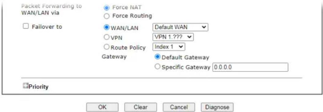
text_image
Packet Forwarding to WAN/LAN via □ Failover to ● Force NAT ○ Force Routing ● WAN/LAN Default WAN ○ VPN VPN 1.??? ○ Route Policy Index 1 Gateway Default Gateway ○ Specific Gateway 0.0.0.0 Priority OK Clear Cancel DiagnoseClick Diagnose.
Analyze a single packet
Select this mode to make Vigor router analyze how a single packet will be sent by a route policy.
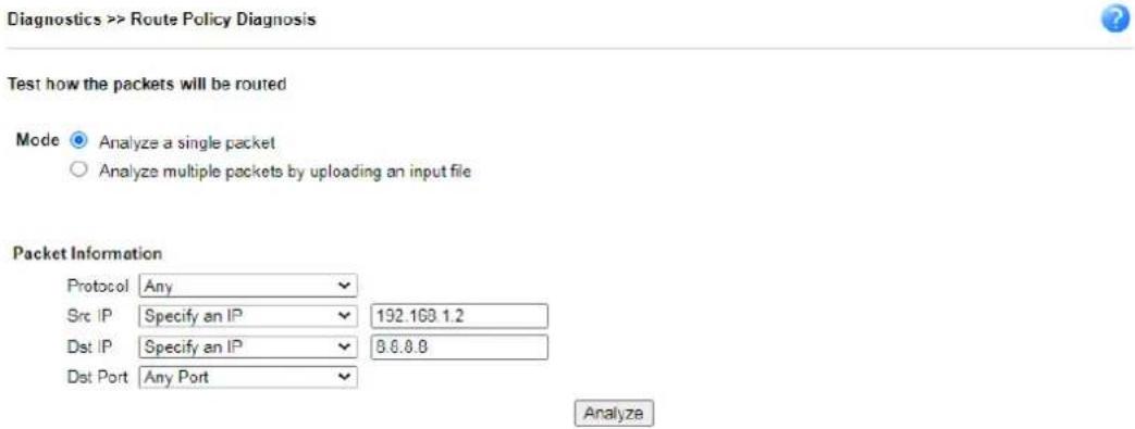
text_image
Diagnostics >> Route Policy Diagnosis Test how the packets will be routed Mode Analyze a single packet Analyze multiple packets by uploading an input file Packet Information Protocol Any Src IP Specify an IP 192.168.1.2 Dst IP Specify an IP 8.6.8.8 Dst Port Any Port AnalyzeAvailable settings are explained as follows:
| Item Description | |
| Packet Information Specify | the nature of the packets to be analyzed by Vigor router.Protocol - Specify a protocol for diagnosis. |
Src IP - IP address of host where the traffic originates.
- Specify an IP - One source IP address.
- Any IP- Source IP address is not specified. Any IP from LAN 1/ LAN 2/ LAN 3/ LAN 4/ LAN 5/ LAN 6/ LAN7/ LAN8/ DMZ/ IP Routed Subnet.
- Subnet/IP Routed Subnet - Any source IP address on the specified subnet.
Dst IP - IP address of the destination host.
- Specify an IP - One destination IP address.
● Any IP - Destination IP address is not specified.
Dst Port - Number of port to which the traffic is sent. This setting is only applicable to UDP and TCP protocols. Use the drop down list to specify the destination port.
Analyze - Click to analyze and display routes, route policies and load balance rules with matching criteria. If required, click export analysis to export the result as a file.
The following shows an analysis example. The packet matched the criteria of one route policy.
Diagnostics >> Route Policy Diagnosis

Test how the packets will be routed
Mode ● Analyze a single packet
○ Analyze multiple packets by uploading an input file
Packet Information
| Protocol | Any | ▼ |
| Src IP | Specify an IP | ▼ 192.163.1.2 |
| Dst IP | Specify an IP | ▼ 8.8.8.8 |
| Dst Port | Any Port | ▼ |
Analyze
Analysis
the packet

LAN
Vigor2927
Matched Route
| Matched | Priority |
| N/A | N/A |
The packet was dropped because the matched policy "policy 1" failed to failover
Matched Policy
| Matched | Priority | failovered |
| Route Policy 1 | 200 | Yes |
Close
Analyze multiple packets by uploading an input file
Test how the packets will be routed
Mode
Analyze a single packet
Analyze multiple packets by uploading an input file
Input File

( download an example input file)

Available settings are explained as follows:
| Item Description | |
| Input File | Browse- Click to browse folder structure and select an input file.Download and example input file- Click to download a sample input file (blank “.csv” file). Then, click the Browse button to select that blank “.csv” file for saving the result of analysis.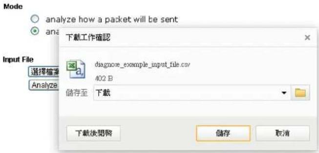 Analyze-After selecting input file, click to start the analysis process. Click the export button to export the result as a file.Note that the analysis was based on the current "load-balance/ route policy" settings, we do not guarantee it will be 100% the same as the real case. Analyze-After selecting input file, click to start the analysis process. Click the export button to export the result as a file.Note that the analysis was based on the current "load-balance/ route policy" settings, we do not guarantee it will be 100% the same as the real case. |
The following shows the analysis of the sample input file. The matched routes and policies are highlighted in green. The Final Result column shows the outcome.
Mode
○ analyze how a packet will be sent
analyze how multiple packets as specified in the input file will be sent
Input File
选择档案 未选择档案
( download an example input file)
Analyze
Analysis
export analysis
| Input Packet Information | Matched Route | Matched Policy | Final Result | ||||||||
| Profile | Proto | Src IP | Dst IP | Dst Port | Route | Priority | Policy | Priority | failovered | Interface | Reason |
| LA-branch | ICMP | 192.168.1.10 | 10.10.10.10 | N/A | No Match | N/A | No Match | N/A | N/A | N/A | The packet was dropped because neither "route" or "policy" was matched |
| NY-branch | TCP | 192.168.1.20 | 20.20.20.20 | 5050 | No Match | N/A | No Match | N/A | N/A | N/A | The packet was dropped because neither "route" or "policy" was matched |
| The packet was dropped because | |||||||||||
II-6-3 BGP
Border Gateway Protocol (BGP) is a standardized protocol designed to exchange routing and reachability information among autonomous systems (AS) on the Internet.
II-6-3-1 Basic Settings
Set general settings for for local router and neighboring routers.
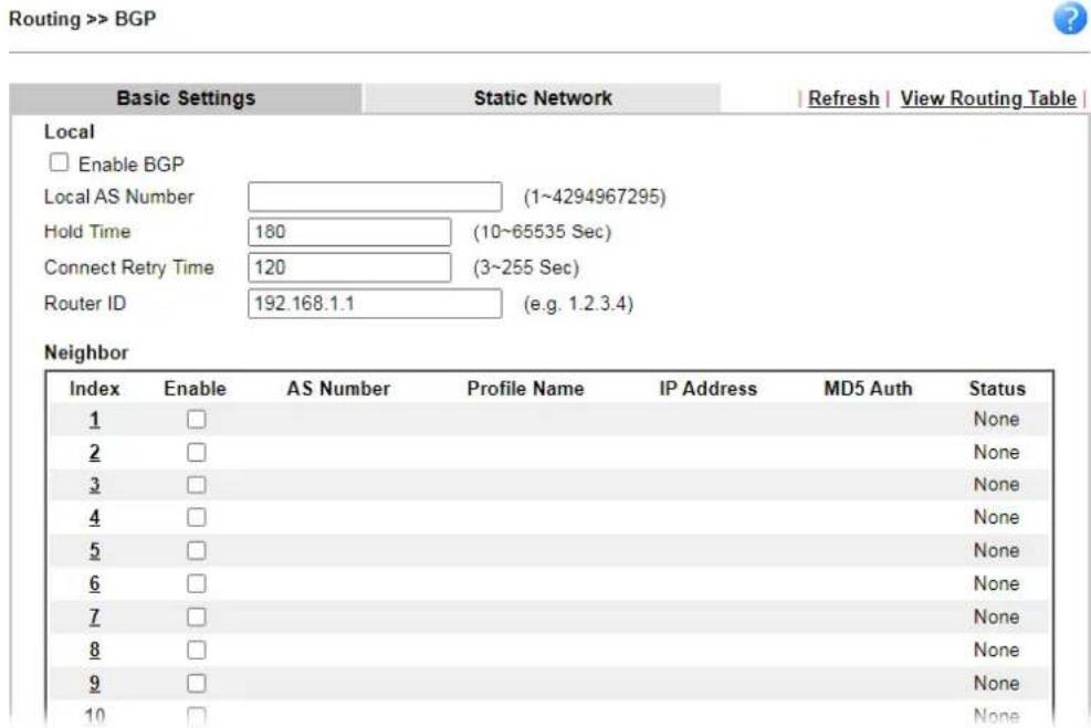
text_image
Routing >> BGP Basic Settings Static Network Refresh View Routing Table Local □ Enable BGP Local AS Number (1~4294967295) Hold Time 180 (10~65535 Sec) Connect Retry Time 120 (3~255 Sec) Router ID 192.168.1.1 (e.g. 1.2.3.4) Neighbor Index Enable AS Number Profile Name IP Address MD5 Auth Status 1 □ None 2 □ None 3 □ None 4 □ None 5 □ None 6 □ None 7 □ None 8 □ None 9 □ None 10 □ NoneAvailable settings are explained as follows:
| Item Description | |
| Local | |
| Enable BGP | Check the box to enable basic BGP function for local router. |
| Local AS Number | Set the AS number for local router. |
| Hold Time | Set the time interval (in seconds) to determine the peer is dead when the router is unable to receive any keepalive message from the peer within the time. |
| Connect Retry Time If the router fails to connect to neighboring router, it requires a period of time to reconnect.Set the time interval to do reconnection. | |
| Router ID | Specify the LAN subnet for the router. |
| Neighbor | |
| Index | Click the index number link to configure neighbor profile. |
| Enable | Check the box to enable the basic BGP function for neighboring router. |
| AS Number | Display the AS Number for neighboring router. |
| Profile Name | Display the name of the neighboring profile. |
| IP Address | Display the IP address specified for the neighboring profile. |
| MD5 Auth | Display the status (enabled or disabled) of MD5 authentication. |
| Status | Display the connection status for local router and neighboring router. |
II-6-3-2 Static Network
This page allows you to configure up to eight neighboring routers for exchanging the routing information with the local router.
Routing >> BGP

| Basic Settings | Static Network | | View Routing Table | | |
| Select | Index | IP Address | Subnet Mask |
| □ | 1 | 255.255.255.255 / 32 ▼ | |
| □ | 2 | 255.255.255.255 / 32 ▼ | |
| □ | 3 | 255.255.255.255 / 32 ▼ | |
| □ | 4 | 255.255.255.255 / 32 ▼ | |
| □ | 5 | 255.255.255.255 / 32 ▼ | |
| □ | 6 | 255.255.255.255 / 32 ▼ | |
| □ | 7 | 255.255.255.255 / 32 ▼ | |
| □ | 8 | 255.255.255.255 / 32 ▼ | |
| □ | 9 | 255.255.255.255 / 32 ▼ | |
| □ | 10 | 255.255.255.255 / 32 ▼ | |
| □ | 11 | 255.255.255.255 / 32 ▼ | |
| □ | 12 | 255.255.255.255 / 32 ▼ | |
| □ | 13 | 255.255.255.255 / 32 ▼ | |
| □ | 14 | 255.255.255.255 / 32 ▼ | |
| □ | 15 | 255.255.255.255 / 32 ▼ | |
| □ | 16 | 255.255.255.255 / 32 ▼ | |
Available settings are explained as follows:
| Item Description | |
| Select | Check the box to enable the configuration for the selected index entry. |
| IP Address | Enter the IP address for a router. |
| Subnet Mask | Use the drop down list to specify a subnet mask for the IP address. |
Application Notes
A-1 How to set up Address Mapping with Route Policy?
Address Mapping is used to map a specified private IP or a range of private IPs of NAT subnet into a specified WAN IP (or WAN IP alias IP). Refer to the following figure.
This document introduces how to set up address mapping with Route Policy. When a WAN interface has multiple public IP addresses, Administrator may specify the outgoing IP for certain internal IP address by a Route Policy.
- Set up WAN IP Alias. Go to WAN >> Internet Access >> Details Page, and click on WAN IP Alias button.
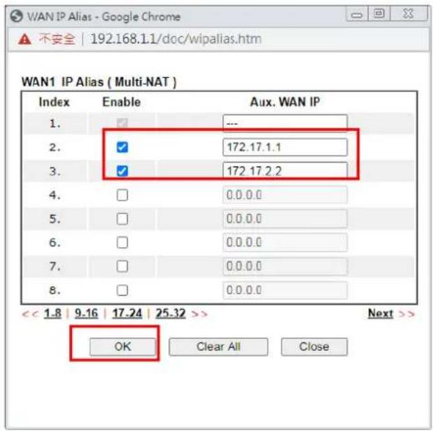
text_image
WAN IP Alias - Google Chrome A 不安全 | 192.168.1.1/doc/wipalias.htm WAN1 IP Alias ( Multi-NAT ) Index Enable Aux. WAN IP 1. ✓ --- 2. ✓ 172.17.1.1 3. ✓ 172.17.2.2 4. □ 0.0.0.0 5. □ 0.0.0.0 6. □ 0.0.0.0 7. □ 0.0.0.0 8. □ 0.0.0.0 << 1.8 | 9.16 | 17.24 | 25.32 >> OK Clear All Close Next >>- Check Enable.
- Enter the WAN IP address.
- Click OK to save.
After setting up the WAN IP Alias, the IP addresses will be shown in the drop-down list of Interface in Route Policy setting.
- Go to Routing>> Load Balance/Route policy. Create a Route Policy for specific IP address to send from specific WAN IP Address.
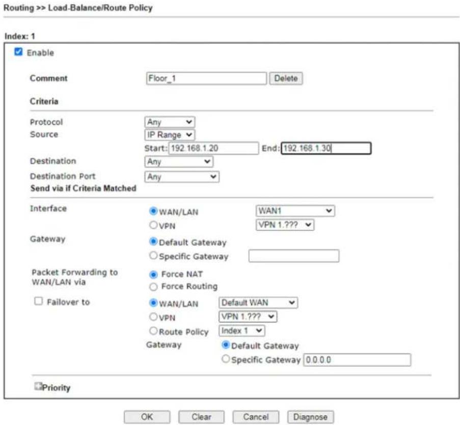
text_image
Routing >> Load-Balance/Route Policy Index: 1 Enable Comment Floor_1 Delete Criteria Protocol Any Source IP Range Start: 192.168.1.20 End: 192.168.1.30 Destination Any Destination Port Any Send via if Criteria Matched Interface WAN/LAN WAN1 VPN VPN 1.??? Gateway Default Gateway Specific Gateway Packet Forwarding to Force NAT WAN/LAN Default WAN VPN VPN 1.??? Failover to Route Policy Index 1 Gateway Default Gateway Specific Gateway 0.0.0.0 Priority OK Clear Cancel DiagnoseNote:
Force NAT(Routing): NAT(Routing) will be performed on outgoing packets, regardless of which type of subnet (NAT or IP Routing) they originate from.
- Enable this policy.
● Enter Source IP as the range of private IP address. - Leave the Destination IP and Port as Any.
- Select Interface as WAN, and then select Interface address from the drop-down list. (The List can be edited in WAN IP Alias setting.)
- Enable Failover to other WAN so the traffic will be sent via other Interface when the path fails. But do not enable this option if you want the traffic only to use a designated IP address.
-
Click OK to save.
-
After the above configuration, packet source from the range between 192.168.1.20 and 192.168.1.30 sent to the Internet will use the public IP 172.17.1.1.
A-2 How to use destination domain name in a route policy?
Route Policy supports using a domain name as destination criteria. It provides a more direct way to set up route polices if the network administrator is trying to specify the gateway for the traffic that destined for a certain website.
To use a destination domain name as criteria, just select Domain Name as Destination in Criteria, and enter the domain name in the empty field.
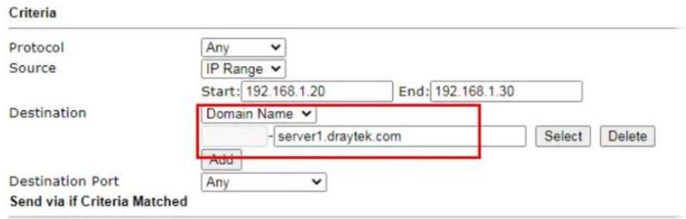
text_image
Criteria Protocol Any Source IP Range Start: 192.168.1.20 End: 192.168.1.30 Destination Domain Name server1.draytek.com Add Destination Port Any Send via if Criteria MatchedOr you may click Select, and use a string that is pre-defined in Objects Settings >> String Object as the domain name.
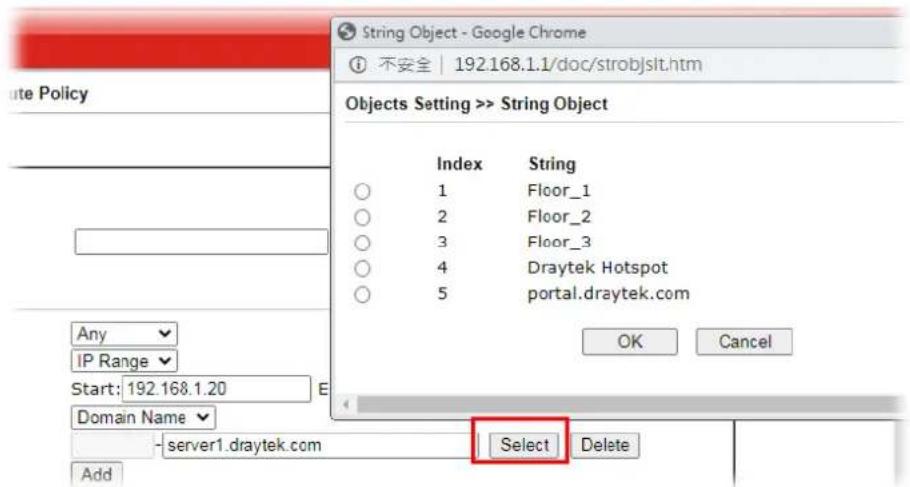
text_image
String Object - Google Chrome ① 不安全 | 192.168.1.1/doc/strobjslt.htm Objects Setting >> String Object Index String ○ 1 Floor_1 ○ 2 Floor_2 ○ 3 Floor_3 ○ 4 Draytek Hotspot ○ 5 portal.draytek.com OK Cancel Any IP Range Start: 192.168.1.20 Domain Name server1.draytek.com Select Delete AddClick Add too add more domain names, we can set up to 5 domain names in one route policy.
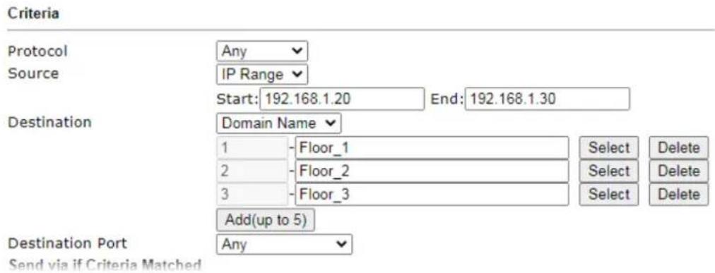
text_image
Criteria Protocol Any Source IP Range Start: 192.168.1.20 End: 192.168.1.30 Destination Domain Name 1 - Floor_1 Select Delete 2 - Floor_2 Select Delete 3 - Floor_3 Select Delete Add(up to 5) Destination Port Any Send via if Criteria MatchedAuto-create String Objects
If you manually enter the domain name in a route policy, after clicking OK to apply the route policy, those domain names will be given a number.
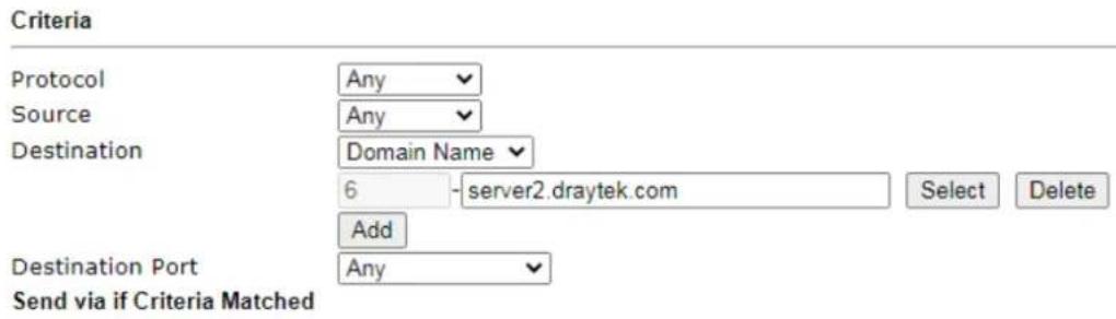
text_image
Criteria Protocol Any Source Any Destination Domain Name 6 -server2.draytek.com Select Delete Add Destination Port Any Send via if Criteria MatchedThat means the router has automatically created string objects for those domain names, so that they can be used in other route policies or other functions.
Objects Setting >> String Object
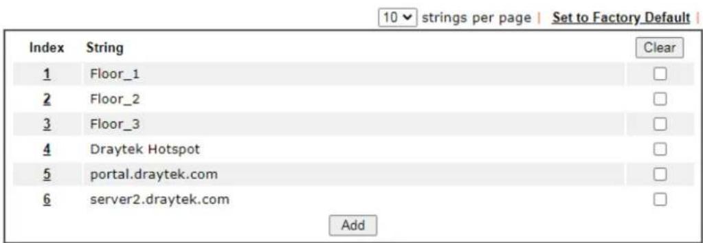
text_image
10 strings per page | Set to Factory Default | Index String Clear 1 Floor_1 2 Floor_2 3 Floor_3 4 Draytek Hotspot 5 portal.draytek.com 6 server2.draytek.com AddA-3 Introduction to Load Balance/Route Policy
This document introduces the Load-Balance/ Route Policy. This feature allows network administrator to manage the outbound traffic more specifically.
The Policy set in Load-Balance/ Route Policy always has higher priority than Default Route and Auto Load Balance set in WAN >> General Setup, and always has lower priority than the Firewall Rules. Administrator may also define a priority to this policy.
To configure Route Policy, go to Routing>>Load-Balance/Route Policy. The following image is a screen-shot of Load-Balance/Route policy page. It lists all the policies and shows whether the policy is enabled, what are the criteria to match, and through which the interface should the traffic to go if the criteria are matched, and also its priority.
Routing >> Load-Balance/Route Policy

| Index | Enable | Comment | Protocol | Interface | Priority | Source | Destination | Dest Port | Move Up | Move Down |
| 1 | ✓ | Any | WAN1 | 200 | Any | Domain Name | Any | Down | ||
| 2 | ☐ | Any | WAN1 | 200 | Any | Any | Any | UP | Down | |
| 3 | ☐ | Any | WAN1 | 200 | Any | Any | Any | UP | Down | |
| 4 | ☐ | Any | WAN1 | 200 | Any | Any | Any | UP | Down | |
| 5 | ☐ | Any | WAN1 | 200 | Any | Any | Any | UP | Down | |
| 6 | ☐ | Any | WAN1 | 200 | Any | Any | Any | UP | Down | |
| 7 | ☐ | Any | WAN1 | 200 | Any | Any | Any | UP | Down | |
| 8 | ☐ | Any | WAN1 | 200 | Any | Any | Any | UP | Down | |
| 9 | ☐ | Any | WAN1 | 200 | Any | Any | Any | UP | Down | |
| 10 | ☐ | Any | WAN1 | 200 | Any | Any | Any | UP | Down |
○ Wizard Mode: most frequently used settings in three pages
Advance Mode: all settings in one page
Note:
The policies in blue are SD-WAN related, and can only be edited via ACS.

To set up a Route Policy, just click on an Index number. At the bottom of the page, there are two configuration modes could be choose: the Wizard Mode provides a simple and basic configuration; while Advance Mode allows more options.
- First, set the criteria of the packets to apply this policy.
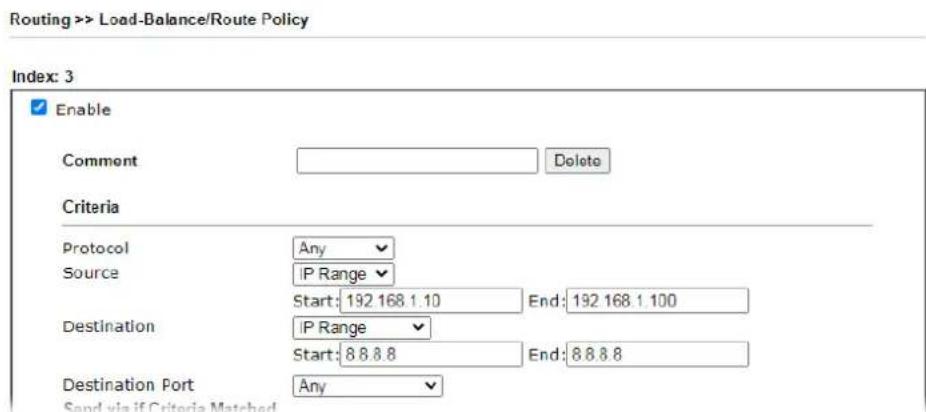
text_image
Routing >> Load-Balance/Route Policy Index: 3 Enable Comment Delete Criteria Protocol Any Source IP Range Start: 192.168.1.10 End: 192.168.1.100 Destination IP Range Start: 8.8.8.8 End: 8.8.8.8 Destination Port Any Send via if Criteria Matcheda. Select a Protocol.
b. Enter the Source IP address range, the Source IP could be a single address if the Start and End are the same.
c. Enter the Destination IP address range.
d. Select the Destination Port.
The above configuration is an example that if a packet is sent
from192.168.1.10\~192.168.1.100 to 8.8.8.8, no matter what the protocol or destination port is, it will follow this route policy.
- Next, we select an interface and gateway through which should the packet be sent if it matches the criteria.
Send via if Criteria Matched
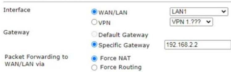
text_image
Network interface configuration settings showing WAN/LAN, VPN, Gateway, and packet forwarding options with LAN1 and VPN 1.??? Default Gateway Specific Gatewaya. Select an Interface.
b. Select a Gateway IP. Note that if Interface is chosen to be a LAN, it is necessary to designate a specific gateway.
The above configuration is an example that if a packet matches the criteria of this Route Policy, it will be sent to the default gateway then the destination through VPN1.
- In Advance Mode, if the Interface is selected as WAN or VPN, there are some more options:
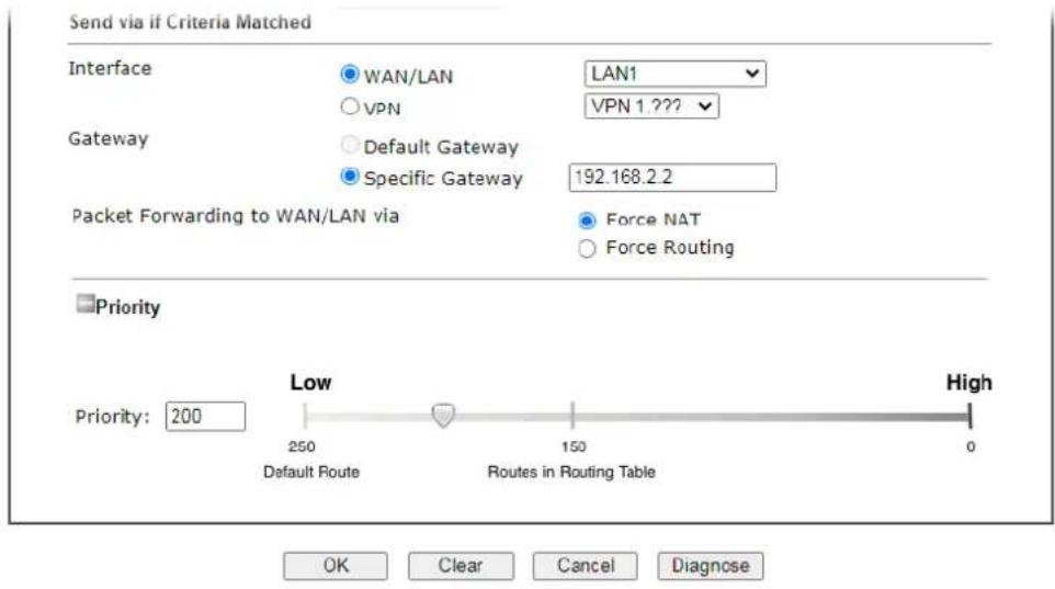
text_image
Send via if Criteria Matched Interface WAN/LAN LAN1 VPN VPN 1.222 Gateway Default Gateway 192.168.2.2 Specific Gateway Packet Forwarding to WAN/LAN via Force NAT Force Routing Priority Priority: 200 Low High 250 Default Route 150 Routes in Routing Table 0 OK Clear Cancel Diagnose- Priority: Administrator may set priority between 1 and 249 for this Route policy, where smaller number indicates higher priority. When two policies are having the same priority, the first (according to the policy index order) matched policy will be implemented.
II-7 LTE / 5G-NR
LTE WAN with SIM card can provide convenient Internet access for Vigor router. However, we can't stop thinking about what can Vigor router utilize this SIM card to provide more useful functions for user? Now, we have developed some useful functions for user, such as sending SMS from a router to report router status, rebooting router remotely via SMS with taking security into consideration, and so on.
This section can guide you to use the SIM card in LTE WAN to perform SMS related operations.

Info
This function is used for "L" models only.
Service Network
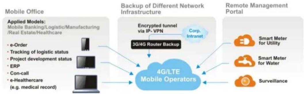
flowchart
graph TD
    A["Applied Models: Mobile Banking/Logistic/Manufacturing /Real Estate/Healthcare"] --> B["• e-Order"]
    A --> C["• Tracking of logistic status"]
    A --> D["• Project development status"]
    A --> E["• ERP"]
    A --> F["• Con-call"]
    A --> G["• e-Healthcare (e.g. medical record)"]
    H["Mobile Office"] --> I["Backup of Different Network Infrastructure"]
    I --> J["3G/4G Router Backup"]
    J --> K["4G/LTE Mobile Operators"]
    K --> L["Encrypted tunnel via IP-VPN"]
    L --> M["Corp. Intranet"]
    M --> N["Remote Management Portal"]
    N --> O["Smart Meter for Utility"]
    N --> P["Smart Meter for Water"]
    N --> Q["Surveillance"]
Web User Interface
LTE
General Settings
SMS Inbox
Send SMS
SMS Gateway
Router Commands
Status
5G-NR
General Settings
SMS Inbox
Send SMS
SMS Gateway
Router Commands
Status
II-7-1 General Settings
This page allows you to configure general settings for LTE/5G-NR. When SMS Quota Limit is enabled, you can specify the number of SMS quota, actions to perform when quota exceeded, and the period of resetting SMS quota used.
II-7-1-1 SMS Quota
5G-NR >> General Settings
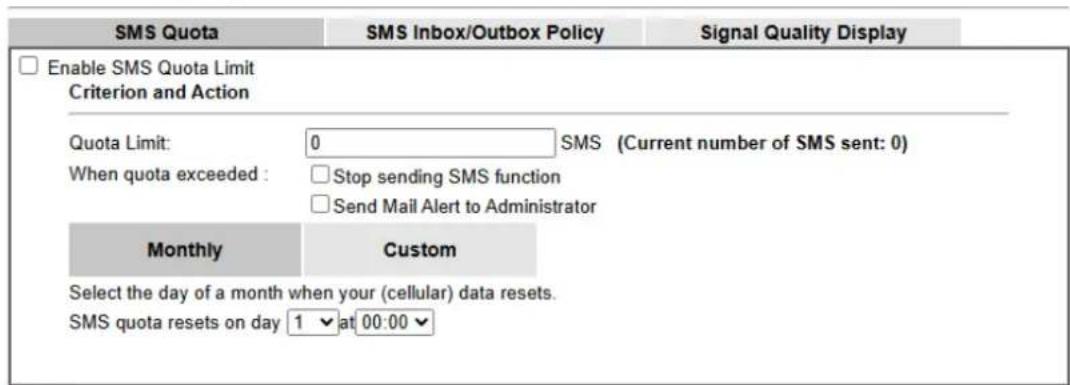
text_image
SMS Quota SMS Inbox/Outbox Policy Signal Quality Display Enable SMS Quota Limit Criterion and Action Quota Limit: 0 SMS (Current number of SMS sent: 0) When quota exceeded : □ Stop sending SMS function □ Send Mail Alert to Administrator Monthly Custom Select the day of a month when your (cellular) data resets. SMS quota resets on day 1 at 00:00Note
- Please make sure the Time and Date of the router is configured.
- When quota exceeded, user can choose to stop sending sms or send e-mail to administrator.
- After clicking OK, the counter used will be reset.
- Set up System Maintenance >> SysLog / Mail Alert Setup in order to send the e-mail alerts.
OK
Cancel
Available settings are explained as follows:
| Item Description | |
| Enable SMS Quota Limit | Check the box to enable such feature. |
| Quota Limit | Specify the maximum number of sending SMS for LTE/ 5G-NR. |
| When quota exceeded | There are two actions to be performed when the quota limit is expired.Stop sending SMS - If it is checked, no SMS for LTE/ 5G-NR will be sent after the quota limit is expired.Send Mail Alert to Administrator - If it is checked, a mail alert will be sent to the administrator when the quota limit is expired. |
| Monthly This setting is to offer a mechanism of resetting the number | |
| of SMS sent record every month.SMS quota resets on day XX at XX ... -You can determine the starting day in one month. The number of SMS sent will be reset. | |
| Custom This setting allows the user to define the billing cycle according to his request.The number of SMS sent will be reset with an interval of cycle duration.Custom - Monthly is default setting. If long period or a short period is required, use Custom. The period of reset is between 1 day and 60 days. You can determine the cycle duration by specifying the days and the hours.Cycle duration: Specify the days to reset the number of SMS sent. For example, 7 means the whole cycle is 7 days; 20 means the whole cycle is 20 days. When the time is up, the router will reset the number of SMS sent automatically.Today is day XX in the cycle -Specify the day in the cycle duration as the starting point which Vigor router will reset the number of SMS sent. For example, 3 means the third day of the duration cycle. | |
II-7-1-2 SMS Inbox/Outbox
Such page allows you to determine which policy shall be used for SMS inbox/outbox.
5G-NR >> General Settings
| SMS Quota | SMS Inbox/Outbox Policy | Signal Quality Display |
| SMS Inbox Policy | ||
| If SMS inbox is full, send e-mail alert to Administrator If SMS inbox is full, delete the oldest read SMS Forward new SMS via e-mail to Administrator If new SMS is received, mark SMS as read | ||
| SMS Outbox Policy | ||
| Store SMS outbox cache in USB disk | ||
Note:
- Set up System Maintenance >> SysLog / Mail Alert Setup in order to send the e-mail alerts

II-7 -1-3 Signal Quality Display
This page allows you to configure the thresholds for RSSI.
5G-NR >> General Settings
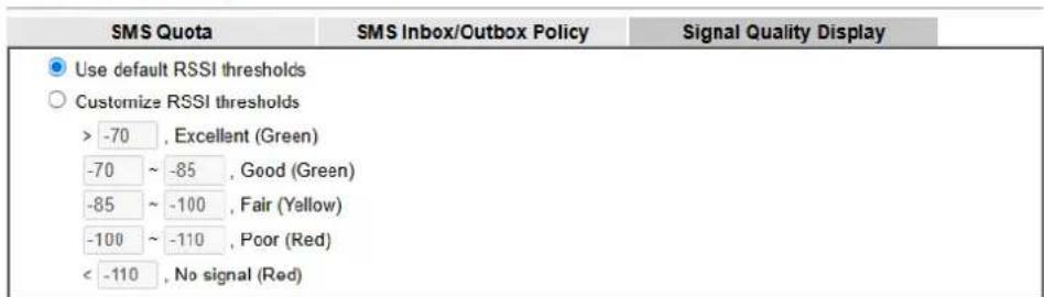
text_image
SMS Quota SMS Inbox/Outbox Policy Signal Quality Display Use default RSSI thresholds Customize RSSI thresholds > -70 , Excellent (Green) -70 ~ -85 , Good (Green) -85 ~ -100 , Fair (Yellow) -100 ~ -110 , Poor (Red) < -110 , No signal (Red)
II-7-2 SMS Inbox
This page will list the received SMS messages in the LTE SIM card. The SMS Inbox table shows the received date, the phone number or sender ID where this message was from, and the beginning of the message content.
Since the data size of one SMS is limited, a long message will be sent by multiple SMS. For the convenience of users, we provide two modes. Simple Mode lists SMS messages in order for received time. Advanced Mode lists SMS in order for real index in the SIM card. Different SIM cards have different capacities. In general, it's around 30 to 40 SMS. Please note that the SIM card can not receive new SMS when all SMS indexes are occupied.
Click the Simple Mode link or the Advanced Mode link below to switch between these two modes.
II-7-2-1 Simple Mode
LTE >> SMS Inbox
LTE SMS Inbox
| Details | Mark as Read | Delete | Date | From | Message |
| View | 2021/08/20 18:51:54 | 988 | |||
| View | 2021/08/08 10:40:21 | 0906180674 | |||
| View | 2020/10/21 11:30:55 | 0982174999 | |||
| View | 2020/10/19 12:04:04 | 777 | |||
| View | 2020/10/15 10:30:35 | 0982174999 | |||
| View | 2020/10/15 10:22:29 | 0965219549 | |||
| View | 2020/10/08 11:23:25 | 0906180674 | |||
| View | 2020/10/08 09:28:06 | 0972218658 | 2020/10/08 09:28 | ||
| View | 2020/10/07 07:57:27 | 923 | |||
| View | 2020/09/21 18:33:28 | 988 | |||
| View | 2020/09/21 13:45:04 | 988 | |||
| View | 2020/09/08 11:23:31 | 0906180674 | |||
| View | 2020/08/20 15:42:04 | 988 | |||
| View | 2020/08/20 11:47:41 | 0907914272 | 2020/08/20 11:47 | ||
| View | 2020/08/17 13:28:41 | 0963954022 | 2020/08/17 13:28 | ||
| View | 2020/08/14 09:55:46 | 0982347365 | |||
| View | 2020/08/08 11:00:02 | 0906180674 | |||
| View | 2020/07/31 10:58:27 | 0961238382 | |||
| View | 2020/07/22 14:08:35 | 988 | |||
| View | 2020/07/08 11:18:45 | 0906180674 |
Next >>
Simple Mode: Show SMS messages in order of received dates. Advanced Mode: Show SMS in order of indexes in SIM card.

Available settings are explained as follows:
| Item Description | |
| Mark as Read | Those messages in "unread" state are showed in bold text. If you want to change messages into "read" state, select them and click the OK button. Checking the checkbox in title will select all "unread" messages in this page. |
| Delete | If you want to delete messages, select them and click the OK button. Checking the checkbox in title will select all messages in this page. |
| Details | If you want to read the full content of the message, click the View link of that message to open the following page. It will change the message into "read" state.LTE >> SMS Inbox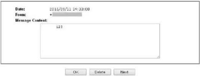 Message Content - Display the full content of the message.OK - Return to previous page.Delete - Click it to delete this message and return to previous page.Next - Click it to see the content of next message. Message Content - Display the full content of the message.OK - Return to previous page.Delete - Click it to delete this message and return to previous page.Next - Click it to see the content of next message. |
II-7-2-1 Advanced Mode
LTE >> SMS Inbox
LTE SMS Inbox
| Index | Mark as Read | Delete | Date | From | Message |
| 1. | 2020/08/08 11:00:02 | 0906180674 | |||
| 2. | 2020/08/08 11:00:02 | 0906180674 | |||
| 3. | 2020/05/05 16:39:38 | 0903447001 | |||
| 4. | 2020/03/08 11:38:35 | 0906180674 | |||
| 5. | 2020/03/08 11:38:35 | 0906180674 | |||
| 6. | 2020/03/08 11:38:35 | 0906180674 | |||
| 7. | 2020/07/08 11:18:45 | 0906180674 | |||
| 8. | 2020/07/08 11:18:45 | 0906180674 | |||
| 9. | 2020/07/22 14:08:35 | 988 |
Available settings are explained as follows:
| Item Description | |
| Mark as Read | Those SMS in "unread" state are shown in bold text. If you want to change SMS into "read" state, select them and click the OK button. Checking the checkbox in title will select all "unread" SMS in this page. |
| Delete | If you want to delete SMS, select them and click the OK button. Checking the checkbox in title will select all SMS in this page. |
| Index | If you want to read the full content of the message of the |
SMS, click the index link of that SMS to open the following page. It will change all SMS of the message into "read" state.
LTE >> SMS Inbox
Index No.17
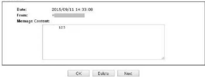
text_image
Date: 2015/09/11 14:33:08 From: Message Content: 123 OK Delete NextMessage Content - Display the full content of the message.
OK - Return to previous page.
Delete - Click it to delete all SMS of this message and return to previous page.
Next - Click it to see the content of next SMS index.
II-7-3 Send SMS
This page is used to send SMS messages by the LTE SIM card. It also displays the number of SMS required to send the message.
LTE >> Send SMS
Send SMS Message
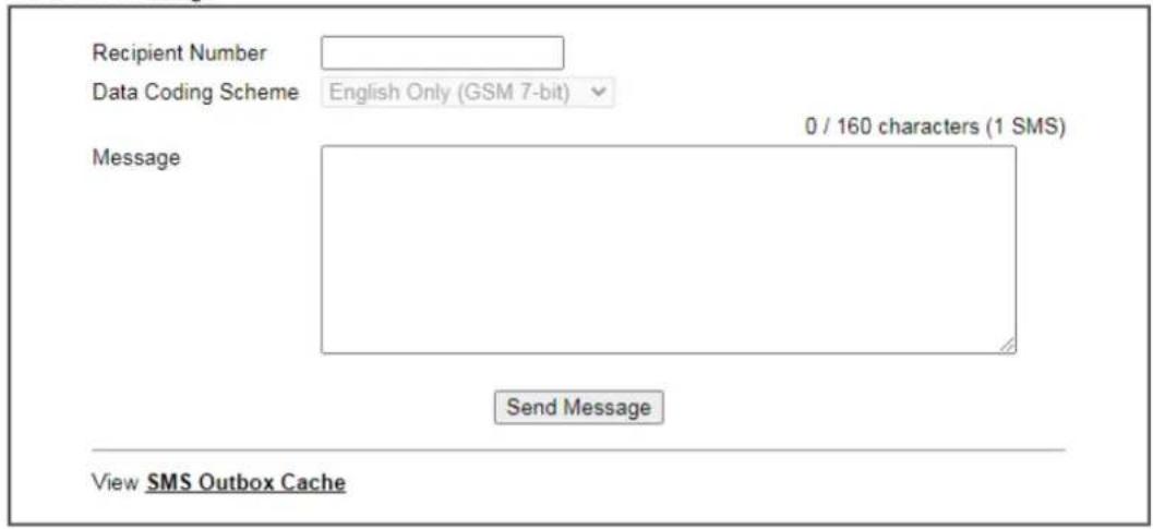
text_image
Recipient Number Data Coding Scheme English Only (GSM 7-bit) Message 0 / 160 characters (1 SMS) Send Message View SMS Outbox CacheAvailable settings are explained as follows:
| Item Description | |
| Recipient Number | Enter the phone number of the recipient.The format can be an international phone number(+8869123455678) or a general phone number(0912345678). |
| Data Coding Scheme | The router will automatically select a suitable Data Coding Scheme according to the current content in Message. GSM 7-bit and UCS-2 are supported. |
| Message | Enter the message content to send.The total number of characters that you can Enter this field is 1024. |
| Send Message | Click it to send this SMS message to the recipient immediately. |
| ViewSMS Outbox Cache | Display the record of SMS messages sent from the Router.LTE >> SMS Outbox CacheLTF SMS Outbox CacheDetailsDeleteDateToMessageView2015/10/05 03:12:061234567890555555555555555555View2015/10/05 03:12:011234567890444444444444444View2015/10/05 03:11:56123456789033333333333333333View2015/10/05 03:11:511234567890322222222222View2015/10/05 03:11:461234567890111111View2015/10/05 03:07:551234567890居易科技於1997年成立,View2015/10/05 03:04:381234567890Test Test Nancy 123Note: Records in Outbox Cache are NOT preserved after replacement of newer records or Router reboot.OK |
II-7-4 SMS Gateway
Vigor router can serve as an SMS Gateway for sending alerts via SMS to mobile phones.
Take a look at the following two pictures.
The IP cameras connect to Router A and Router B via LAN. Where there is something wrong with IP camera, Router A can only send the SMS with alerts/warning message via a specified service provider on Internet.
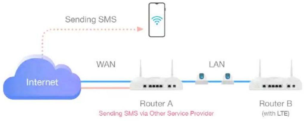
flowchart
graph LR
    A["Internet"] -->|WAN| B["Router A"]
    B -->|LAN| C["Router B (with LTE)"]
    D["Sending SMS"] -->|dotted arrow| E["Mobile Device"]
    style A fill:#800000,stroke:#333
    style B fill:#fff,stroke:#333
    style C fill:#fff,stroke:#333
    style D fill:#fff,stroke:#333
    style E fill:#fff,stroke:#333
With the feature of SMS Gateway on Router B, even Router A is offline, router B could serve as an SMS Gateway that can send SMS (related to alerts or other events) to mobile phones directly.
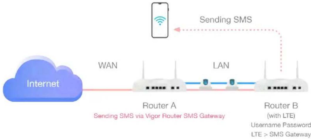
flowchart
graph LR
    A["Internet"] -->|WAN| B["Router A"]
    B -->|LAN| C["Router B (with LTE)"]
    C -->|Sending SMS| D["Mobile Phone"]
    style A fill:#99CCFF,stroke:#333
    style B fill:#99CCFF,stroke:#333
    style C fill:#99CCFF,stroke:#333
    style D fill:#FF9900,stroke:#333
For router B, simply open LTE>>SMS Gateway and set a pair of username and password.
SMS Gateway Setting
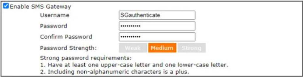
text_image
Enable SMS Gateway Username SGauthenticate Password .......... Confirm Password .......... Password Strength: Weak Medium Strong Strong password requirements: 1. Have at least one upper-case letter and one lower-case letter. 2. Including non-alphanumeric characters is a plus.Note:
- Password can contain a-z A-Z 0-9, ; : . " < > * + = | ? @ # ^ ! ( )
- Password can't be all asterisks(∞). For example, '∞' or '∞∞∞' is illegal, but '123∞' or '∞45' is OK.
- Please enable HTTP or HTTPS server to allow SMS Gateway to work Remotely on System Maintenance >> Management page.
OK
Available settings are explained as follows:
| Item Description | |
| Enable SMS Gateway | Check the box to enable SMS gateway of this router. |
| Username Define a username. | |
| Password Define a password. | |
| Confirm Passowrd | Enter the password again. |
Below shows the settings configured on Router A and Router B.
- Connect Router A and Router B (with LTE module).
- On Router B, set a pair of username (e.g., SGauthenticate) and password on LTE>>SMS Gateway.
LTE >> SMS Gateway
SMS Gateway Setting
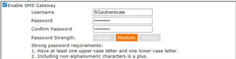
text_image
Enable SMS Gateway Username: SGauthenticate Password: ********** Confirm Password: ********** Password Strength: Weak Medium Strong Strong password requirements: 1. Have at least one upper-case letter and one lower-case letter. 2. Including non-alphanumeric characters is a plus.Note:
- Password can contain a-z A-Z 0-9, ; : , " < > " + = | ? @ # ^ ! ( )
- Password can't be all asterisks(*). For example, '*' or '***' is illegal, but '123*' or '45' is OK.
- Please enable HTTP or HTTPS server to allow SMS Gateway to work Remotely on System Maintenance >> Management page.
OK
- On Router A, open Object Settings >> SMS/ Mail Service Object >> Service Provider. Click any index number (e.g., #1 in this case) to open the following page. Select Vigor Router SMS Gateway as the service provider. Set the WAN IP or LAN IP of this router in IP field.
Objects Setting >> SMS / Mail Service Object
Profile Index: 1
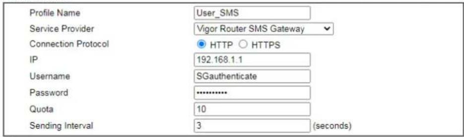
text_image
Profile Name User_SMS Service Provider Vigor Router SMS Gateway Connection Protocol HTTP HTTPS IP 192.168.1.1 Username SGauthenticate Password .......... Quota 10 Sending Interval 3 (seconds)Note:
- Only one message can be sent during the "Sending Interval" time.
- If the "Sending Interval" was set to 0, there will be no limitation.

As for username and password, please enter the same values as configured in Step 2.
- Next, go to Objects Setting >> Notification Object. Select disconnection or connection of WAN, VPN tunnel and click OK to save the setting on Router A.
Objects Setting >> Notification Object
Profile Index: 1
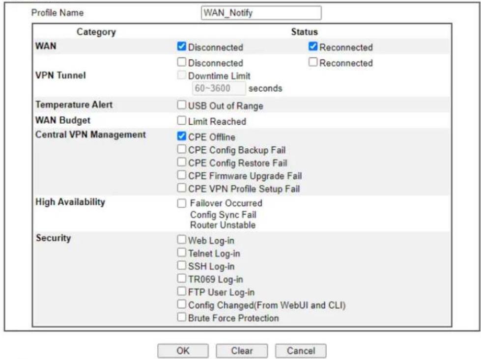
text_image
Profile Name WAN_Notify Category Status WAN ✓ Disconnected ✓ Reconnected □ Disconnected □ Reconnected VPN Tunnel □ Downtime Limit 60~3600 seconds Temperature Alert □ USB Out of Range WAN Budget □ Limit Reached Central VPN Management ✓ CPE Offline □ CPE Config Backup Fail □ CPE Config Restore Fail □ CPE Firmware Upgrade Fail □ CPE VPN Profile Setup Fail High Availability □ Failover Occurred Config Sync Fail Router Unstable Security □ Web Log-in □ Telnet Log-in □ SSH Log-in □ TR069 Log-in □ FTP User Log-in □ Config Changed(From WebUI and CLI) □ Brute Force Protection OK Clear CancelNote:
- When High Availability is enabled, "Sending Interval" of SMS Provider profile should set to 0.
-
When the VPN Downtime limit is enabled, Vigor Router will not send the VPN Down alert immediately. It will send the Alert after the Downtime limit period if the VPN still doesn't go up.
-
Once the router A encounters the condition set above, router B (as an SMS gateway) will send out an SMS to the recipient.
For a user who owns a non-DrayTek LTE router, there is one way to send the SMS to mobile phones through the non-DrayTek LTE router and DrayTek router.
-
Make sure the DrayTek router and the non-DrayTek LTE router are connected via LAN.
-
Obtain the exact URL string from non-DrayTek LTE router.
-
On DrayTek router, open Objects Setting>>SMS/Mail Service Object and click the number link #9 or #10 to customize SMS service object.
Objects Setting >> SMS / Mail Service Object
Profile Index: 9
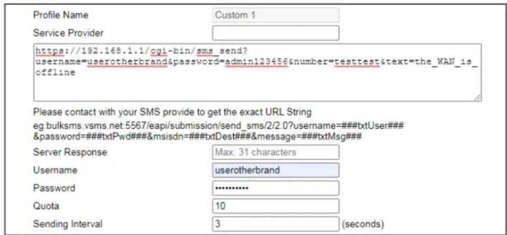
text_image
Profile Name Custom 1 Service Provider https://192.168.1.1/cgi-bin/sms_send? username=userotherbrand&password=admin123456&number=testtest&text=the_WAN_is_offline Please contact with your SMS provide to get the exact URL String eg:bulksms.vsms.net:5567/eapi/submission/send_sms/2/2.0?username=###txtUser### &password=###txtPwd###&msisdn=###txtDest###&message=###txtMsg### Server Response Max: 31 characters Username Taiwan userotherbrand Password ****** Quota 10 Sending Interval 3 (seconds)Note:
- Only one message can be sent during the "Sending Interval" time.
- If the "Sending Interval" was set to 0, there will be no limitation.

Enter the data coming from the non-DrayTek LTE router, e.g., the URL string, the username, password, and warning message on the entry box.
- Click OK to save the settings.
II-7-5 Router Commands
This page allows the user to set function to reboot Vigor router remotely and get the router status via SMS.
Get Router Status or Reboot Router via SMS Message
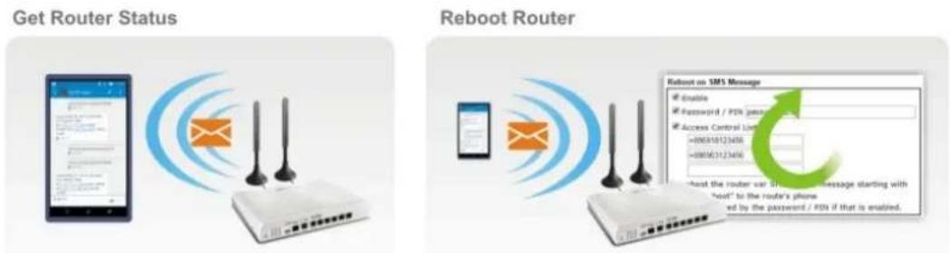
text_image
Get Router Status Reboot Router Enable Password / PSN please Access Control List -08056123456 -08056123456 Reboot the router var. the router's message starting with "host" to the router's phone ed by the password / PSN if that is enabled.Go to LTE>>Router Commands / 5G-NR Router Commands to get the following page.
LTE >> Router Commands
Reboot on SMS Message
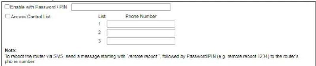
text_image
Enable with Password / PIN Access Control List List Phone Number 1 2 3 Note: To reboot the router via SMS, send a message starting with "remote reboot", followed by Password/PIN (e.g. remote reboot 1234) to the router's phone number.Reply with Router Status Message
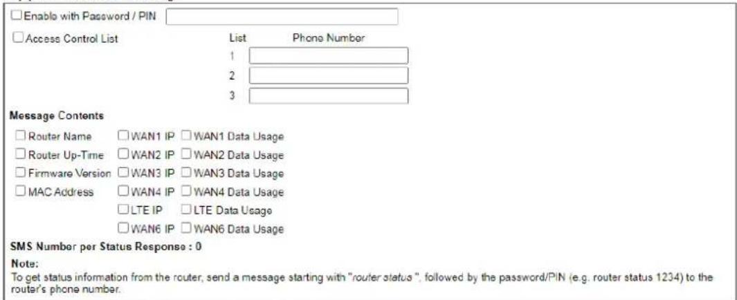
text_image
Enable with Password / PIN Access Control List List Phone Number 1 2 3 Message Contents Router Name WAN1 IP WAN1 Data Usage Router Up-Time WAN2 IP WAN2 Data Usage Firmware Version WAN3 IP WAN3 Data Usage MAC Address WAN4 IP WAN4 Data Usage LTE IP LTE Data Usage WAN6 IP WAN6 Data Usage SMS Number per Status Response : 0 Note: To get status information from the router, send a message starting with "router status", followed by the password/PIN (e.g. router status 1234) to the router's phone number.Note: Phone numbers in the Access Control List should be in international format (e.g., +886123456789).
OK
Or
Command on SMS Message
□ Enable with Password / PIN
□Access Control List
| List | Phone Number |
| 1 | |
| 2 | |
| 3 |
Note:
- Command list
"remote reboot": reboot the router
"remote default": reboot the router using factory default configuration
"tr069 set" set TR069 parameter
"tr069 gef": get TR069 parameter - Send a message starting with "Command", followed by Password/PIN (e.g. remote default 1234) to the router's phone number.
Reply with Router Status Message
□ Enable with Password / PIN
□Access Control List
| List | Phone Number |
| 1 | |
| 2 | |
| 3 |
Message Contents
□Router Name
□ WAN1 IP □ WAN1 Data Usage
□Router Up-Time
□ WAN2 IP □ WAN2 Data Usage
□ Firmware Version
□ MAC Address
□ 5G-NR IP □ 5G-NR Data Usage
□WAN6 IP □WAN6 Data Usage
SMS Number per Status Response : 0
Note
- To get status information from the router, send a message starting with "router status", followed by the password/PIN (e.g. router status 1234) to the router's phone number
Note.
- Phone numbers in the Access Control List should be in international format (e.g., +886123456789).
Available settings are explained as follows:
| Item Description | |
| Reboot on SMS Message | |
| Enable with Password / PIN | To reboot Vigor router remotely via SMS, please check such box and Enter the password/ PIN number (treated as authentication for any mobile phone).The password shall be composed by letters, numbers and baseline. |
| Access Control List | Check the box to type or modify (up to 3) phone numbers.The phone number specified here is capable of sending SMS to reboot such Vigor router remotely.Note: If such option is enabled, only mobile phones specified here are allowed to send SMS to reboot Vigor router if correct password is given. That is, if it isdisabled(unchecked), any mobile phone can send SMS to reboot such Vigor router if correct password is given. |
| Reply with Router Status Message | |
| Enable with Password / PIN | Users can get the WAN data usage and basic information about Vigor router (e.g., IP address, MAC address) through the mobile phone by entering the password/ PIN specified in this field.The password shall be composed by letters, numbers and baseline. |
| Access Control List | Check the box to type or modify (up to 3) phone numbers.The phone number specified here is capable of getting related information about Vigor router remotely.Note: If such option is enabled, only mobile phones specified here are allowed to obtain related information about Vigor router if correct password is given. That is, if it isdisabled (unchecked), any mobile phone can get the data of Vigor router if correct password is given. |
| Message Contents | There are several types of message contents for you to select. Choose and check the required item, then Vigor router will offer the status response about that item via SMS. |
| SMS messages per status response | Display the total number of the type for status response. Display the total number of SMS required to send the status message which contains the current selected Message Contents. |
II-7-6 Status
Vigor router with LTE/5G-NR function is capable of accessing into Internet and able to send SMS to specified mobile phone. In addition, it can be treated as a LTE modem.
This page will display basic information about the embedded LTE module and the current LTE connection.
LTE >> Status
Refresh
| LTE Modem | |
| Status: | Operational |
| IMEI: | 861107031196273 |
| IMSI: | 466924102353176 |
| ICCID: | 89886920041023531764 |
| Access Tech: | LTE |
| Band: | E-UTRA Op Band 8 |
| Operator: | 46692 |
| Mobile Country Code: | 466 |
| Mobile Network Code: | 92 |
| Location Area Code: | 65534 |
| Cell ID: | 80439842 |
| RSRP Signal: | -99 dBm (Good) |
| RSSI Signal: | -61 dBm (Excellent) |
| Active Channel: | 3650 |
| Max Channel TX Rate: | 50 Mbps |
| Max Channel RX Rate: | 150 Mbps |
| LTE Bridge | |
| LTE Bridge mode: | Disabled |
| LTE Bridge specific MAC: | YES |
| LTE Bridged MAC: | 00:1D:AA:11:22:33 |
| LTE Bridged IP: | 0.0.0.0 |
| LTE Bridged Gateway IP: | 0.0.0.0 |
| LTE SMS | |
| SMS Centre Number: | +886932400851 |
| SMS Service Status: | Ready |
| SMS Loading: | Not ready |
| New SMS: | --- |
Each item is explained as follows:
| Item Description | |
| LTE Modem | |
| Status LTE WAN status. | |
| IMEI International Mobile Equipment Identity of the embedded LTE module. | |
| IMSI | International Mobile Subscriber Identity of the LTE SIM card. |
| Access Tech Type of LTE connection(CDMA/ GSM/ WCDMA/ LTE/ TD-SCDMA). | |
| Band Band of LTE connection. | |
| Operator | ISP name of LTE connection. |
| Mobile Country Code / Mobile Network Code / Location Area Code / Cell ID : | Base station information. |
| Signal | Signal strength of LTE connection. |
| Active Channel | Frequency of LTE connection. |
| Interference with 2.4GHz WLAN | Whether the current LTE frequency causes interference with 2.4G wireless. If Yes, the interfered 2.4G wireless channels will be indicated. |
| Max Channel TX Rate / Max Channel RX Rate | Maximum TX/ RX link rate of LTE connection. |
| LTE SMS | |
| SMS Centre Number | The phone number for SMS service of the LTE SIM card. |
| SMS Service status | Whether the SMS service of the LTE SIM card is ready. |
| SMS Loading | Whether the received SMS messages in the LTE SIM card have been loaded to the Router. |
| New SMS | The number of unread SMS in SMS Inbox. |
II-7-7 RSRP Graph
Click RSRP Graph to open the web page.
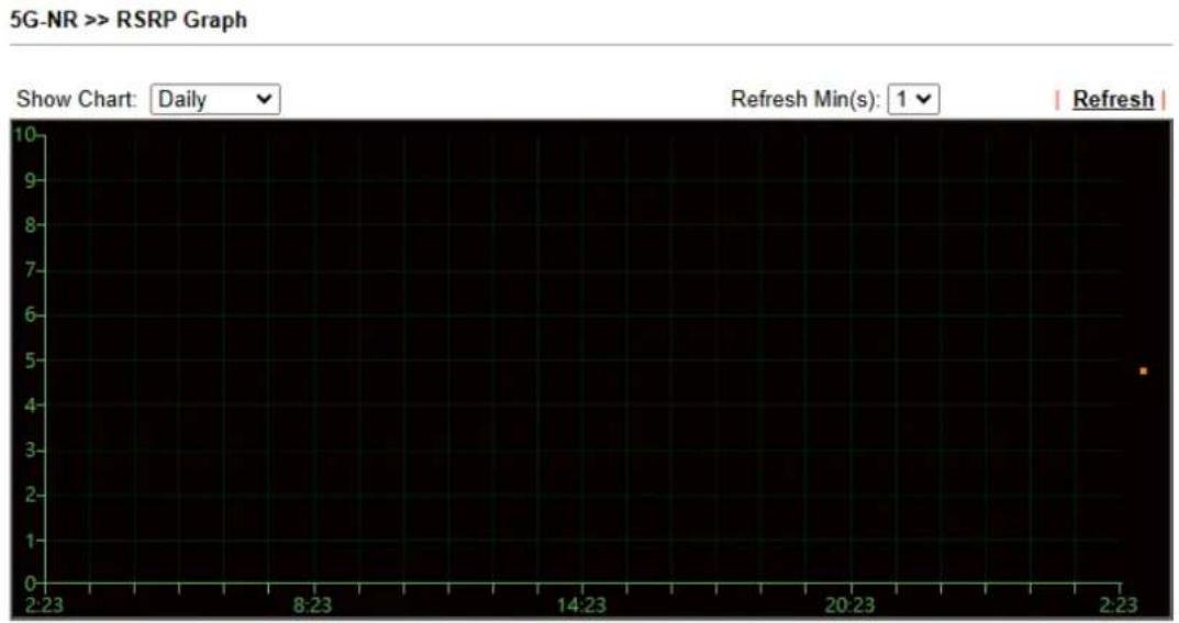
line
| Time | Value | |--------|-------| | 2:23 | 4.8 |Choose daily, weekly, 3 hours, 6 hours or 12 hours for viewing data transmission chart. Click Refresh to renew the graph at any time.
This page is left blank.
Part III Wireless LAN

Wireless
Wireless LAN enables high mobility so WLAN users can simultaneously access all LAN facilities just like on a wired LAN as well as Internet access.
III-1 Wireless LAN (2.4GHz/5GHz)
This function is available on wireless models only (models with -ax or -ac suffixes).
In recent years, the market for wireless communications has enjoyed tremendous growth. Wireless technology now reaches virtually every location on earth. Billions of people exchange information daily with wireless communication products. The Vigor2927 series of wireless routers (with “n”, “n-plus”, or “ac” in the model name), designed with maximum flexibility and efficiency in mind, is ideal for use in a small office or home. In a business environment, any authorized personnel can bring a WLAN-equipped tablet, PDA or notebook into a meeting room and connect to the network without drilling holes through walls or tearing up flooring to lay a clot of LAN cabling. Wireless networking enables high mobility so WLAN users can access all LAN resources in the same manner just as they would on a wired LAN, but without the cables.
All Vigor2927 wireless routers support 2.4 GHz. ac models add support for 5 GHz frequencies. Channel operations of 20 and 40 MHz are possible on the 2.4 GHz spectrum, and 20, 40 and 80 MHz are supported on the 5 GHz spectrum. “ac” models (2865ac) support data rates of up to 1.3 Gbps on 802.11ac 80 MHz channels, whereas “n” models support data rates of up to 300 Mbps on 802.11n 40 MHz channels.

Info
The actual data throughput will vary according to the network conditions and environmental factors, including volume of network traffic, network overhead and building materials.
In an Infrastructure Mode of wireless network, Vigor wireless router plays a role as an Access Point (AP) connecting to lots of wireless clients or Stations (STA). All the STAs will share the same Internet connection via Vigor wireless router. The wireless network settings, such as SSID, channels, encryption protocol, can be configured in General Settings.
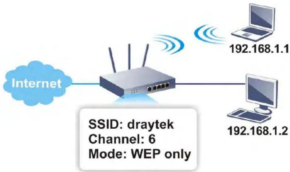
flowchart
graph LR
    A["Internet"] --> B["Router"]
    B --> C["192.168.1.1"]
    B --> D["192.168.1.2"]
    style B fill:#f9f,stroke:#333
    note right of B: SSID: draytek
    note right of C: Channel: 6
    note right of D: Mode: WEP only
Multiple SSIDs
Vigor wireless routers support up to four SSIDs (Service Set Identifiers) per band for wireless connections. A service set is a group of wireless network clients that have the same
networking parameters. Each service set can be configured to have a unique name (SSID) and specific download and upload rates, and can be used by different categories of users.
Real-time Hardware Encryption
Vigor wireless routers are equipped with a hardware AES encryption engine to provide the most effective and efficient protection of wireless traffic, without sacrificing user experience.
Complete Security Standard Selection
To ensure the security and privacy of your wireless communication, we provide several prevailing standards on market.
WEP (Wired Equivalent Privacy) is a legacy method to encrypt each frame transmitted via radio using either a 64-bit or 128-bit key. Usually access point will preset a set of four keys and it will communicate with each station using only one out of the four keys.
WPA (Wi-Fi Protected Access), the most dominating security mechanism in industry, is separated into two categories: WPA-personal or called WPA Pre-Share Key (WPA/PSK), and WPA-Enterprise or called WPA/802.1x.
In WPA-Personal, a pre-defined key (PSK) is used to encrypt traffic during data transmission. WPA uses the Temporal Key Integrity Protocol (TKIP) for data encryption whereas WPA2 applies AES (Advanced Encryption Standard). A major advantage of WPA-Enterprise is that it supports not only encryption but also authentication.
You should select the appropriate security mechanism according to your needs. Because WEP has proven to be vulnerable to attacks, you should consider using WPA instead for the most secure connection. No matter which security suite you select, they all will enhance the over-the-air data protection and/or privacy on your wireless network. The Vigor wireless router is very flexible and can support multiple secure connections with both WEP and WPA at the same time.

Info
The default password (PSK) is listed on a label attached to the bottom of the router. Since anyone who has physical access to the router can discover the default password, you are strongly advised to change it.
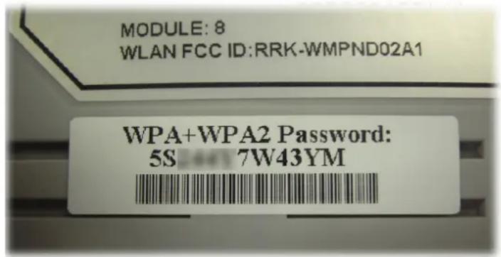
text_image
MODULE: 8 WLAN FCC ID:RRK-WMPND02A1 WPA+WPA2 Password: 5S 7W43YMSeparate the Wireless and the Wired LAN-WLAN Isolation
WLAN Isolation allows you to separate wireless LAN clients from wired ones, either for the purpose of quarantining certain users, or restricting their access to LAN resources. When WLAN isolation is enabled on an SSID, its users will only be able to connect to the WAN (i.e., internet). This is ideal for providing visitors Internet access while keeping the wired network secure.
For the highest degree of security, you may consider adding firewall rules to filter access by MAC address.
Manage Wireless Stations - Station List
All stations on the wireless network and their connection status is shown here.
DFS Restrictions
In certain parts of the world, there are radar systems that are primary users of the 5 GHz band. WLAN equipment on the 5 GHz band is considered secondary users and must not cause interference to the primary users. By utilizing a feature called Dynamic Frequency Selection, the wireless router detects the presence of radar signals and relocates the wireless network to a clear channel. DFS channels vary by region, and we must obtain certification from the authorities before making them available for use on the Vigor router. We are working on DFS certification in Europe and will open up those channels by releasing new firmware once we pass certification. In Europe, these DFS channels will be made available 52, 56, 60, 64, 100, 104, 108, 112, 116, 120, 124, 128, 132, 136 and 140.
At this time, we have no plans to pursue DFS certification in the USA, so DFS channels will not be available in the foreseeable future. The U.S. DFS channels 52, 56, 60, 64, 100, 104, 108, 112, 116, 120, 124, 128, 132, 136 and 140 will not be available on routers sold in the United States.
In the rest of world, there are restrictions on DFS channels as well. Uncertified DFS channels will be unavailable for selection depending on the country code programmed in the router.
WPS
WPS (Wi-Fi Protected Setup) makes connecting wireless clients to wireless access points and routers a simple process.
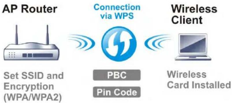
flowchart
graph LR
    A["AP Router"] -->|Set SSID and Encryption (WPA/WPA2)| B["Connection via WPS"]
    B -->|PBC Pin Code| C["Wireless Client"]
    C -->|Wireless Card Installed| D["Computer"]
Web User Interface
Wizards
Quick Start Wizard
Service Activation Wizard
VPN Client Wizard
VPN Server Wizard
Wireless Wizard
Mesh Wizard
Online Status
Wireless LAN (2.4 GHz)
General Setup
Security
Access Control
WPS
Advanced Setting
Station Control
Bandwidth Management
AP Discovery
Airtime Fairness
Band Steering
Roaming
Station List
Wireless LAN (5 GHz)
General Setup
Security
Access Control
WPS
WDS
Advanced Setting
Station Control
Bandwidth Management
AP Discovery
Airtime Fairness
Roaming
Station List
III-1-1 Wireless Wizard
On Wi-Fi-equipped models, you can configure the wireless access point (AP) using the Wireless Wizard. The Host AP Configuration sets up SSID 1 for use by internal users, who are allowed to access both the LAN and the WAN (Internet), whereas the Guest AP Configuration sets up SSID 2 for use by visitors, who are allowed only WAN access and whose access speeds can optionally be throttled.
The Wireless Wizard allows you to quickly configure a host SSID (for internal use, such as in a home or business environment), and optionally a guest SSID (for wireless clients that are restricted to Internet access only, typically used by visitors).
Follow the steps listed below:
-
On the menu bar, click on Wizards, and then Wireless Wizard.
-
The Host AP Configuration page appears. This page sets up SSID 1 for use by internal users. SSID 1 configured using the wizard will have no access speed throttling (by means of the Rate Control feature), and both the LAN and the WAN will be accessible.
Wireless Wizard
Host AP Configuration
Wireless 2.4GHz Settings
Name:
Mode:
Channel:
Security Key:
DrayTek
Mixed(11b+11g+11n)
Channel 6, 2437MHz
[Non-Text]
Wireless 5GHz Settings
□ Use the same SSID and Security Key as above
Name:
Mode:
Channel:
Security Key:
DrayTek_5G
Mixed (11a+11n+11ac)
Channel 36, 5180MHz
......
Note:
The host AP configured here will be used for home or internal company use.
< Back Next > Finish Cancel
Available settings are explained as follows:
| User-configurabeltem | Description |
| Wireless 2.4GHz Settings | |
| Name | Service Set Identification (SSID), which shows up as the AP identifier. Maximum length is 32 characters. |
| Mode | Allowed Wi-Fi modes.802.11b is the original Wi-Fi mode on the 2.4 GHz band and supports raw data rates up to 11 Mbit/s.802.11g allows for enhanced throughput up to 54 Mbit/s.802.11n provides throughput up to 300 MHz.Available selections are• 11b Only• 11g Only• 11n Only (2.4 GHz)• Mixed(11b+11g)• Mixed(11g+11n)• Mixed(11b+11g+11n)• Mixed(11b+11g+11n+11ax)The selections labeled “Mixed” enable multiple simultaneously-active modes. |
| Channel | Wi-Fi channel used for this SSID. If set to Auto, the router uses the best available channel. |
| Security Key | The Pre-shared Key (PSK) used by WPA2/ PSK (Wireless Protected Access 2/ Pre-shared Key) to encrypt wireless traffic. The key is composed of 8 to 63 ASCII characters. You may also specify the key using 64 hexadecimal digits, prefixed with the sequence 0x (“0x321253abcde...”). |
| Wireless 5GHz Settings | |
| Use the same SSID and Security Key as above | If selected, the SSID Name and Security Key from the 2.4 GHz section will be used. |
| Name | Service Set Identification (SSID), which shows up as the AP identifier. Maximum length is 32 characters. |
| Mode | Allowed Wi-Fi modes.802.11a is the original Wi-Fi mode on the 5 GHz band and supports raw data rates up to 11 Mbit/s.802.11n enhances the throughput and provides up to 300 MHz.802.11ac, can achieve 1.3 Gbit/s of data throughput on the 5 GHz band.Available selections are• 11a Only• 11n Only (5GHz)• Mixed(11a+11n)• Mixed(11a+11n+11ac)• Mixed(11a+11n+11ac+11ax)The selections labeled “Mixed” enable multiple simultaneously-active modes. |
| Channel | Wi-Fi channel used for this SSID. If set to Auto, the router uses the best available channel. |
| Security Key | The Pre-shared Key (PSK) used by WPA2/ PSK (Wireless Protected Access 2/ Pre-shared Key) to encrypt wireless traffic. The key is composed of 8 to 63 ASCII characters. You may also specify the key using 64 hexadecimal digits, prefixed with the sequence 0x (“0x321253abcde...”). |
| Next | Click it to get into the next setting page. |
| Cancel | Exit the wireless wizard without saving any changes. |
- Click Next to proceed to the Guest AP Configuration page. The Guest AP Configuration page appears. This page sets up SSID 2 for use by guest users. SSID 2 configured using the wizard can optionally be set up with access speed throttling (by means of the Rate Control feature), and only the WAN (the Internet) will be accessible.
SSID 2 shares the same Mode and Channel settings as SSID 1 configured on the previous page.
Wireless Wizard
Guest AP Configuration
Wireless 2.4GHz Settings
○ Enable
Disable
SSID:
DrayTek_Guest
Security Key:
[Non-Text]
Bandwidth Limit:
Enable Total Upload 30000
kbps Total Download 30000 kbps
Wireless 5GHz Settings
○ Enable
Disable
□ Use the same SSID and Security Key as above
SSID:
DrayTek_5G_Guest
Security Key:
[Non-Text]
Note:
The configured guest AP will not be able to access the LAN network, VPN connections, or communicate with wireless devices connecting to the router's other APs. This AP interface shall be used for Internet access only.

Available settings are explained as follows:
| User-configurable Item | Description |
| Wireless 2.4GHz Settings | |
| Enable/Disable | Enable or disable the SSID for guest use. |
| SSID | Service Set Identification (SSID), which shows up as the AP identifier. Maximum length is 32 characters. |
| Security Key | The Pre-shared Key (PSK) used by WPA2/ PSK (Wireless Protected Access 2/ Pre-shared Key) to encrypt wireless traffic. The key is composed of 8 to 63 ASCII characters. You may also specify the key using 64 hexadecimal digits, prefixed with the sequence 0x (“0x321253abcde...”). |
| Bandwidth Limit | Enable - Check the box to set the bandwidth limit for data transmission in upload and download.It controls the data transmission rate through wireless connection.Total Upload - Check Enable and Enter the transmitting ratefor data upload. Default value is 30,000 kbps.Total Download - Enter the transmitting rate for data download. Default value is 30,000 kbps. |
| Wireless 5GHz Settings | |
| Enable/Disable | Click it to enable or disable settings in this page. |
| Use the same SSID and Security Key as above | If selected, the SSID Name and Security Key from the 2.4 GHz section will be used. |
| SSID | Service Set Identification (SSID), which shows up as the AP identifier. Maximum length is 32 characters. |
| Security Key | The Pre-shared Key (PSK) used by WPA2/ PSK (Wireless Protected Access 2/ Pre-shared Key) to encrypt wireless traffic. The key is composed of 8 to 63 ASCII characters. You may also specify the key using 64 hexadecimal digits, prefixed with the sequence 0x (“0x321253abcde...”). |
| Next | Click it to get into the next setting page. |
| Cancel | Exit the wireless wizard without saving any changes. |
- Click Next to proceed to the Configuration Summary page.
Wireless Wizard
Configuration Summary
| Wireless 2.4GHz Settings | |
| Wireless 5GHz Settings | |
| Mode:Mixed(11b=11g+11n)Channel:Channel 6, 2437MHz | Mode:Mixed (11a+11n+11ac)Channel:Channel 36, 5180MHz |
| Host APSSID Name:DrayTekSecurity Key:00000000000000 | Host APSSID Name:DrayTek_5GSecurity Key:00000000000000 |
| Guest APStatus:EnabledSSID Name:DrayTek_GuestSecurityKey:0x0000000000000000000000000000000000000000000000000000000000000000000000000000000000000000000000000000 | Guest APStatus:EnabledSSID Name:DrayTek_5G_GuestSecurityKey:0x00000000000000000000000000000000000000000000000000000000000000000000000000000000000000000000 |
| Bandwidth Limit:Disabled | |

- The Configuration Summary page displays all the settings you have entered. Click Finish to save the settings, Back to make changes, or Cancel to exit the wizard without saving the settings.
III-1-2 General Setup
The Wireless LAN>>Genera Setup section lets you configure the most basic settings of your wireless network, including the SSIDs, WLAN channels and bandwidth control.
Wireless LAN (2.4 GHz) >> General Setup
General Setting ( IEEE 802.11 )
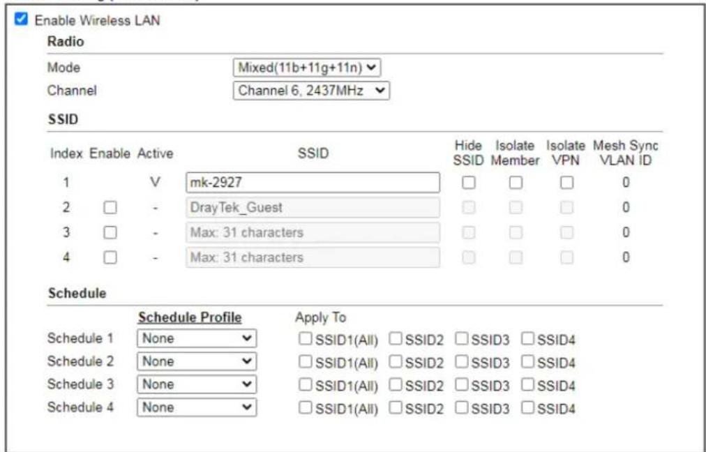
text_image
Enable Wireless LAN Radio Mode Mixed(11b+11g+11n) Channel Channel 6, 2437MHz SSID Index Enable Active SSID Hide Isolate Isolate Mesh Sync SSID SSID Member VPN VLAN ID 1 V mk-2927 □ □ □ 0 2 □ - DrayTek_Guest □ □ □ 0 3 □ - Max: 31 characters □ □ □ 0 4 □ - Max: 31 characters □ □ □ 0 Schedule Schedule Profile Apply To Schedule 1 None □ SSID1(All) □ SSID2 □ SSID3 □ SSID4 Schedule 2 None □ SSID1(All) □ SSID2 □ SSID3 □ SSID4 Schedule 3 None □ SSID1(All) □ SSID2 □ SSID3 □ SSID4 Schedule 4 None □ SSID1(All) □ SSID2 □ SSID3 □ SSID4Note:
- Channel setting should not be changed while Wireless 2.4G WAN mode is in use.
- Isolate Member: Prevent the clients associated with this SSID from accessing each other.
- Isolate VPN: Block the wireless clients from accessing the VPN network and prevent wireless traffic being sent to VPN connections.
- Only the action "Force Down" in the Schedule Profile will be applied to WLAN, other actions will be ignored.
- When the router is in High Availability Hot-Standby method and it's the Secondary Router, the wireless function will be disabled.

Available settings are explained as follows:
To save changes on the General Settings page, select OK; to discard changes, select Cancel.
| Item Description | |
| Enable Wireless LAN | Check the box to enable wireless function. |
| Radio | |
| Mode | Select the 802.11 mode allowed on the band.On the 2.4 GHz band, the following wireless mode options are available:11b Only11g Only11n Only (2.4 GHz)Mixed (11b+11g)Mixed (11g+11n)Mixed (11b+11g+11n)Mixed (11b+11g+11n+11ax)On the 5 GHz band on ac models (e.g., 2927ac or 2927Lax-5G), the following options are available:11a Only11n Only (5 GHz)Mixed (11a+11n)Mixed (11a+11n+11ac)Mixed (11a+11n+11ac+11ax) |
| Channel | Allows you to specify a particular wireless channel to use, or let the system determine the optimal channel by selecting “Auto”. The list of available channels varies depending on the locale for which the router is intended. |
| SSID | |
| SSID | Service Set Identification (SSID), which shows up as the AP identifier. Maximum length is 32 characters. |
| Hide SSID | Select to keep SSIDs from showing up when scans are performed by wireless clients, which makes it harder for unauthorized clients or STAs to join your wireless LAN. Depending on the wireless client and software used, the user may see only an AP listed without the SSID, or the AP might not even show up. |
| Isolate | Member - Check this box to disallow communication between wireless clients (stations) on the same SSID.VPN - Check this box to block wireless clients (stations) from accessing VPN clients. |
| Mesh Sync VLAN ID | Display the VLAN ID, which will synchronize copy to the mesh node using the same SSID. |
| Schedule | |
| Schedule Profile | Set the wireless LAN to be disabled at certain time intervals. You may choose up to 4 schedules out of the 15 schedules defined inApplications >> Schedule. Only “Force Down” schedule profiles take effect, and the wireless function will be turned off for the duration of the profile. The default setting is blank for all schedules, meaning wireless function will always work. |
| Apply To | Selected SSID (2 / 3 / 4) will be forced up / down based on the schedule profile used.ScheduleSchedule ProfileApply ToSchedule 1 None✓SSID1(All) ✓SSID2 ✓SSID3 ✓SSID4Schedule 2 None✓SSID1(All) ✓SSID2 ✓SSID3 ✓SSID4Schedule 3 None✓SSID1(All) ✓SSID2 ✓SSID3 ✓SSID4Schedule 4 None✓SSID1(All) ✓SSID2 ✓SSID3 ✓SSID4 |
III-1-3 Security
Every router has a default wireless password (PSK) which is provided on a label attached to the bottom of the router. For the wireless client who wants to access into Internet through such router, please input the default PSK value for connection.
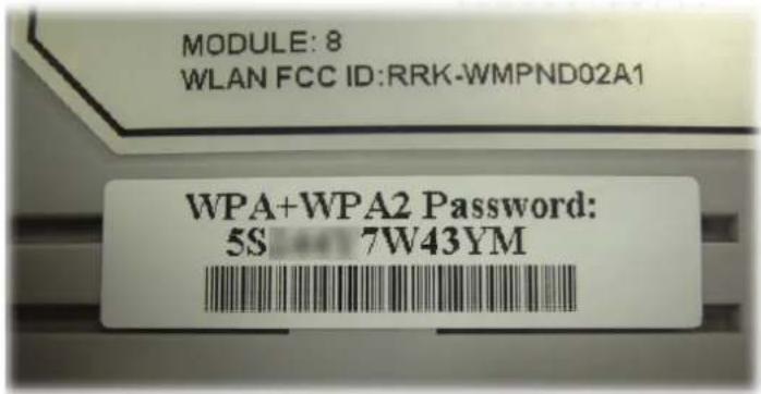
text_image
MODULE: 8 WLAN FCC ID:RRK-WMPND02A1 WPA+WPA2 Password: 5S 7W43YMFor extra security you can set your own wireless password by clicking the Wireless LAN>>Security Settings entry on the Web User Interface. Each of the 4 SSIDs can be configured independently using their own tab page.
Wireless LAN(2.4GHz) >> Security Settings
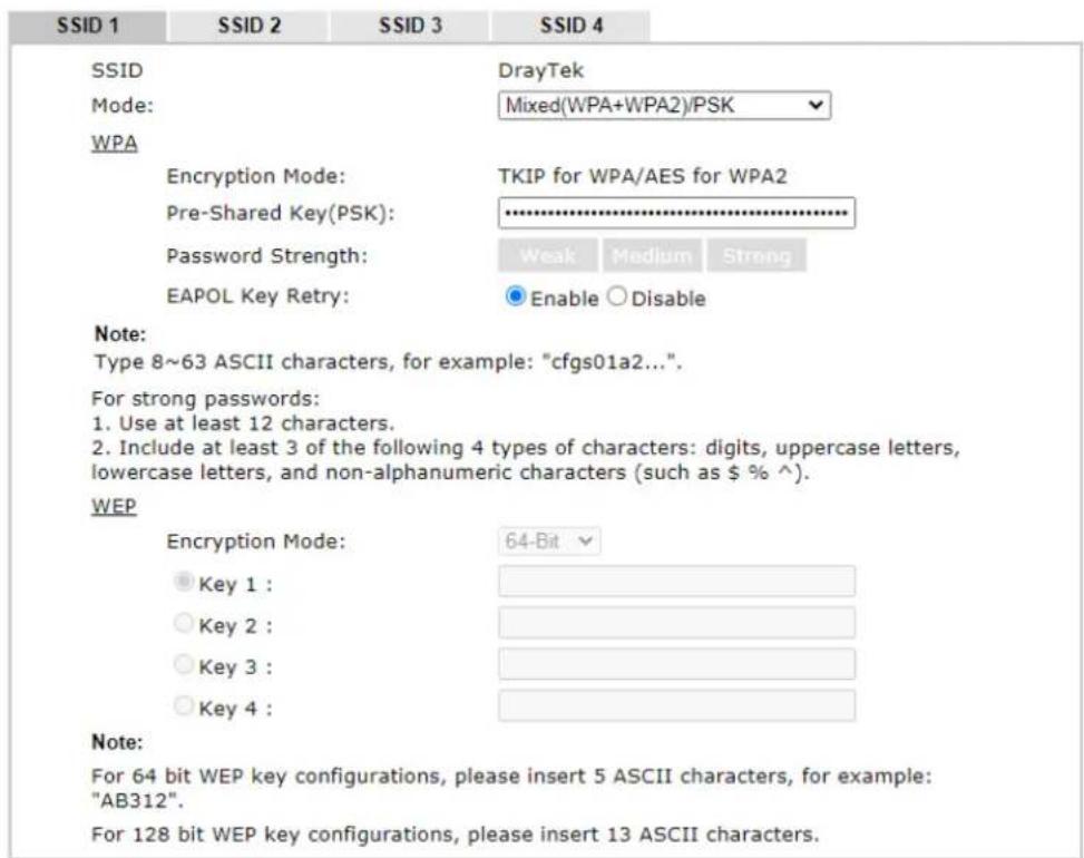
text_image
SSID 1 SSID 2 SSID 3 SSID 4 SSID DrayTek Mode: Mixed(WPA+WPA2)/PSK WPA Encryption Mode: TKIP for WPA/AES for WPA2 Pre-Shared Key(PSK): ********** Password Strength: Weak Medium Strong EAPOL Key Retry: Enable Disable Note: Type 8~63 ASCII characters, for example: "cfgs01a2...". For strong passwords: 1. Use at least 12 characters. 2. Include at least 3 of the following 4 types of characters: digits, uppercase letters, lowercase letters, and non-alphanumeric characters (such as $ % ^). WEP Encryption Mode: 64-Bit Key 1 : Key 2 : Key 3 : Key 4 : Note: For 64 bit WEP key configurations, please insert 5 ASCII characters, for example: "AB312". For 128 bit WEP key configurations, please insert 13 ASCII characters.
Available settings are explained as follows:
| Item Description | |
| Mode | This dialog box lists all available security modes. |
| Info You should also set Wireless LAN(2.4GHz)802.1X Setting simultaneously if 802.1x mode is selected.Disable - Encryption mechanism is disabled.WEP - Allow only connections from WEP clients. Encryption key should be entered in the WEP Key section.WEP/802.1x Only - Accepts only WEP clients and the encryption key is obtained dynamically from RADIUS server with 802.1X protocol.Allow only connections from WEP clients. Encryption key is obtained from a RADIUS server using the 802.1X protocol.WPA/802.1x Only - Allow only connections from WPA clients. Encryption key is obtained from a RADIUS server using the 802.1X protocol.WPA2/802.1x Only- Allow only connections from WPA2 clients. Encryption key is obtained from a RADIUS server using the 802.1X protocol.Mixed (WPA+WPA2/802.1x only) - Allow connections from both WPA and WPA2 clients. Encryption key is obtained from a RADIUS server using the 802.1X protocol.WPA/PSK - Allow connections only from WPA clients.Encryption key should be entered in the PSK field.WPA2/PSK - Allow connections only from WPA2 clients.Encryption key should be entered in the PSK field.Mixed (WPA+ WPA2)/PSK - Allow connections from both WPA and WPA2 clients. Encryption key should be entered in the PSK field.WPA3/SAE - Allow connections only from WPA3 clients.Encryption key should be entered in the PSK field.Mixed (WPA2+ WPA3)/SAE - Allow connections from both WPA2 and WPA3 clients. Encryption key should be entered in the PSK field.OWE - WPA3 also introduces a new open and secure connection mode; "Opportunistic Wireless Encryption" (OWE). It allows the clients to connect without a password, ideal for hotspot networks, but the connection between each individual client is uniquely encrypted behind the scenes. | |
| WPA | WPA encrypts each frame transmitted from the radio using the key, which is either entered in the PSK (Pre-Shared Key) field, or or automatically negotiated via 802.1x authentication from a RADIUS server.Pre-Shared Key (PSK) - Enter 8~63 ASCII characters, for example, “012345678..”, or 64 hexadecimal digits with a leading “0x”, for example, "0x321253abcde...".Password Strength - The system will display the strength of the password, indicated by the words “weak”, “medium” or “strong”.EAPOL Key Retry - The default setting is "Enable". It can make sure that the key will be installed and used once in order to prevent key reinstallation attack. |
| WEP | WEP keys can either be 64-bit or 128-bit.64-Bit - Either 5 ASCII characters, for example “12345”, or 10 hexadecimal digitals with a leading “0x”, such as“0x4142434445”.128-Bit - Either 13 ASCII characters, for example “ABCDEFGHIJKLM”, or 26 hexadecimal digits with a leading “0x”, for example “0x4142434445464748494A4B4C4D”.Up to four keys can be entered here, but only one key can be selected at any time. The keys can be entered in ASCII or Hexadecimal.All wireless devices intending to connect to the same SSID must support the same WEP encryption bit size and have the same key. |
To save changes on this page, select OK; to discard changes, select Cancel.
III-1-4 Access Control
In the Access Control, the router may restrict wireless access to certain wireless clients only by referencing a MAC address black or white list. The user may block wireless clients by inserting their MAC addresses into a black list, or only allow certain wireless clients to connect by inserting their MAC addresses into a white list.
In the Access Control web page, users may configure the white/black list modes used by each SSID and the MAC addresses applied to their lists.
Wireless LAN (2.4 GHz) >> Access Control
Access Control
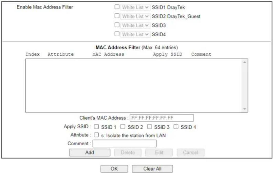
text_image
Enable Mac Address Filter White List ▼ SSID1 DrayTek White List ▼ SSID2 DrayTek_Guest White List ▼ SSID3 White List ▼ SSID4 MAC Address Filter (Max. 64 entries) Index Attribute MAC Address Apply SSID Comment Client's MAC Address: FF:FF:FF:FF:FF:FF Apply SSID: □ SSID 1 □ SSID 2 □ SSID 3 □ SSID 4 Attribute: □ s: Isolate the station from LAN Comment: Add Delete Edit Cancel OK Clear All
Note:
Support AP ACL configuration file restoration.
Available settings are explained as follows:
To save changes on this page, select OK.
| Item Description | |
| Enable Mac Address Filter | Select the SSIDs that you would like to have MAC Address filter enabled. Select White List or Black List in the combo box next to each enabled SSIDs.White List - Only allow wireless clients whose MAC addresses are listed in the MAC Address Filter list.Black List - Only allow wireless clients whose MAC addresses are not listed in the MAC Address Filter list. |
| MAC Address Filter | Displays all MAC addresses in the filter list. |
| Client's MAC Address | Manually enter the MAC address of wireless client. |
| Apply SSID | Select the SSIDs to which the above MAC address filter will be applied. |
| Attribute | s: Isolate the station from LAN - select to isolate the wireless client from LAN. |
| Comment | Enter a brief description for the specified client's MAC address. |
| Add | Add a new filter entry to the MAC Address filter list using the information entered above. |
| Delete | Delete the selected MAC address from the list. |
| Edit Update the selected MAC address in the list using the information entered above. | |
| Cancel | Clear the contents of all the above fields. This will discard all changes without saving to the MAC Address Filter list. |
| OK | Click to save the MAC Address Filter list. |
| Clear All | Remove all entries from the MAC Address Filter list. |
| Backup Access Control Settings on this web page can be saved as a file which can be restored in the future by this device or other device. | |
| Upload From File | Restore wireless access control settings and applied onto this device. |
III-1-5 WPS
WPS (Wi-Fi Protected Setup) provides an easy way to connect wireless to wireless access points and routers with WPA or WPA2 encryption.
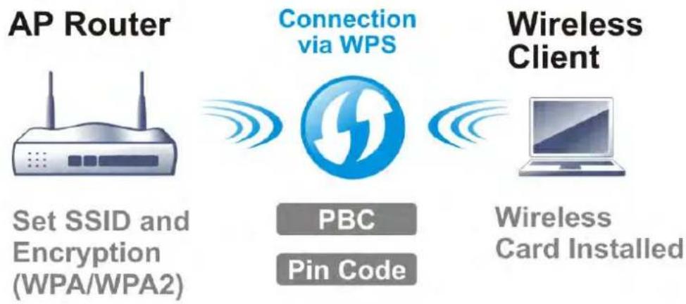
flowchart
graph LR
    A["AP Router"] --> B["Connection via WPS"]
    B --> C["Wireless Client"]
    D["Set SSID and Encryption (WPA/WPA2)"] --> B
    E["PBC"] --> B
    F["Pin Code"] --> B
    G["Wireless Card Installed"] --> B

Info
WPS works with wireless stations with WPS or WPS2 support. It does not work with WEP.
It is the simplest way to build connection between wireless network clients and vigor router. Users do not need to select any encryption mode and type any long encryption passphrase to setup a wireless client every time. He/she only needs to press a button on wireless client, and WPS will connect for client and router automatically.
There are two methods to do network connection through WPS between AP and Stations: pressing the Start PBC button or using PIN Code.
Using the PBC button
On the Vigor router, press and hold the WPS button on the front panel for 2 seconds, or click the Start PBC button on the Wireless LAN>>WPS page in the Web User Interface. On the wireless station (for example, a laptop computer), press the WPS/Start PBC button on the network card.
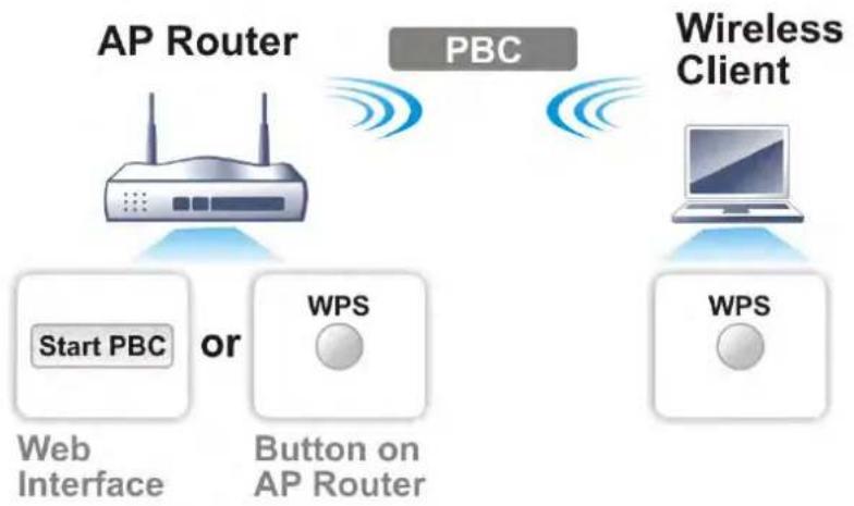
flowchart
graph TD
    A["AP Router"] -->|Start PBC or| B["Web Interface"]
    A -->|Start PBC or| C["Button on AP Router"]
    D["Wireless Client"] -->|WPS| E["WPS"]
    D -->|WPS| F["Computer"]
    style A fill:#f9f,stroke:#333
    style D fill:#ccf,stroke:#333
Using a PIN code
You may establish a wireless connection by entering a PIN code generated by a wireless client that supports WPS.
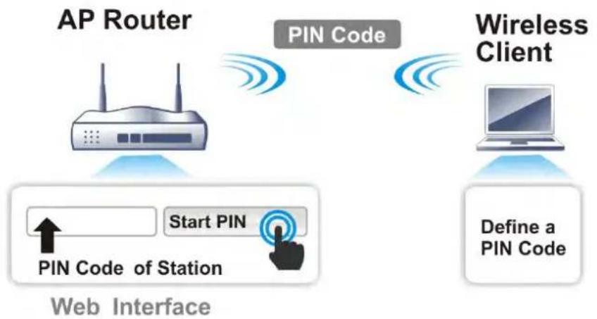
flowchart
graph TD
    A["AP Router"] -->|Start PIN| B["PIN Code of Station"]
    B --> C["Web Interface"]
    D["Wireless Client"] -->|Define a PIN Code| E["Laptop"]
    style A fill:#f9f,stroke:#333
    style D fill:#ccf,stroke:#333
    style B fill:#cfc,stroke:#333
    style E fill:#fcc,stroke:#333
WPS is only supported when the encryption protocol is set to WPA-PSK or WPA2-PSK. If other protocols (such as WEP) have been selected in Wireless LAN>>Security, you will see the following message box:
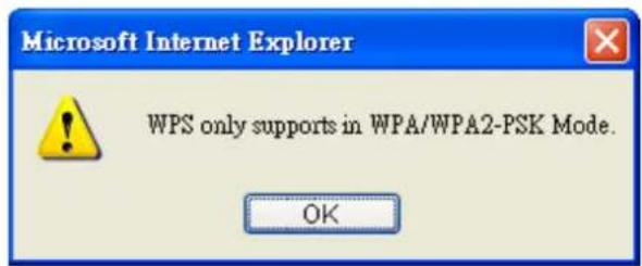
text_image
Microsoft Internet Explorer WPS only supports in WPA/WPA2-PSK Mode. OKPlease click OK to dismiss dialog box, return to Wireless LAN>>Security and select WPA-PSK or WPA2-PSK mode before attempting to enable WPS again.
Below shows Wireless LAN>>WPS web page:
Wireless LAN (2.4 GHz) >> WPS
Enable WPS
Wi-Fi Protected Setup Information
| WPS Status | Configured |
| SSID | DrayTek |
| Authentication Mode | Mixed(WPA2+WPA3)/SAE |
Device Configure
| Configure via Push Button | Start PBC | |
| Configure via Client PinCode | Start PIN | |
Status: The Authentication Mode is NOT WPA2 PSK!!
Note:
WPS can help your wireless client automatically connect to the Access point.
: WPS is Disabled.
Q: WPS is Enabled.
: Waiting for WPS requests from wireless clients.
Available settings are explained as follows:
| Item Description | |
| Enable WPS | Check this box to enable WPS setting. |
| WPS Status | Displays system information related to WPS. The message “Configured” means that the wireless security (encryption) function of the router is properly configured and functioning properly. |
| SSID | Displays the SSID1. WPS is supported on SSID1 only. |
| Authentication Mode | Displays the current authentication mode of the router. |
| Configure via Push Button | Click Start PBC to invoke Push-Button style WPS setup procedure. The router will wait for about 2 minutes for WPS connection requests from wireless clients. The WPS LED on the router will blink fast when WPS is in progress, and will return to normal condition after two minutes. |
| Configure via Client PinCode | Enter a PIN code, and click the Start PIN button. The WPS LED on the router will blink rapidly when WPS is in progress, for up to 2 minutes or until a successful WPS connection from a wireless client has been established. |
III-1-6 WDS (for 5GHz)
Wireless Distribution System (WDS) is a protocol for linking access points (AP) wirelessly. WDS supports two modes:
• Bridge mode, which bridges traffic between two LANs wirelessly.
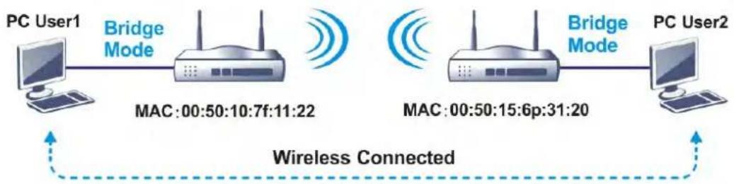
flowchart
graph LR
    PC1["PC User1"] -->|Bridge Mode| Mac1["MAC:00:50:10:7f:11:22"]
    Mac1 -->|Wireless Signal| Mac2["MAC:00:50:15:6p:31:20"]
    Mac2 -->|Bridge Mode| PC2["PC User2"]
    PC1 -.->|Wireless Connected| PC2
• Repeater mode, which extends the coverage range of a WLAN.
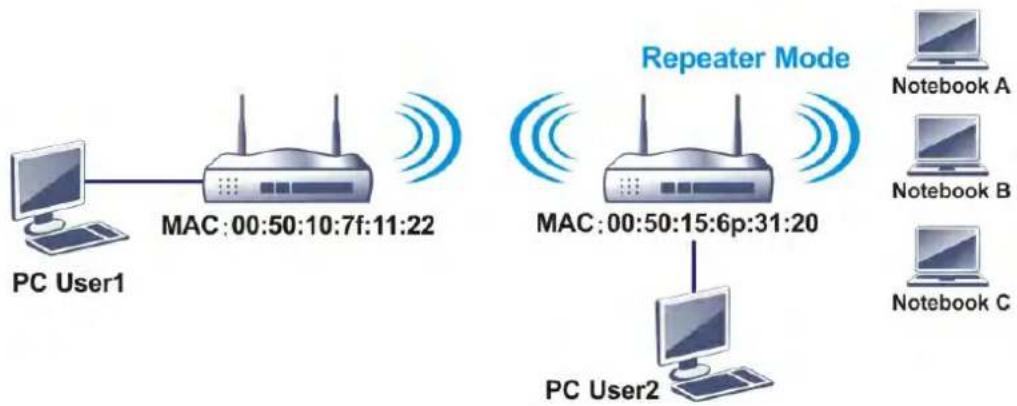
flowchart
graph TD
    PCUser1["PC User1"] --> MAC1["MAC:00:50:10:7f:11:22"]
    MAC1 --> MAC2["Repeater Mode"]
    MAC2 --> PCUser2["PC User2"]
    PCUser2 --> NoteBookA["Notebook A"]
    PCUser2 --> NoteBookB["Notebook B"]
    PCUser2 --> NoteBookC["Notebook C"]
The main difference between these two modes is that, in Repeater mode, the packets received from one peer AP can be repeated to another peer AP through WDS links, whereas in Bridge mode, packets received from a WDS link will only be forwarded to local wired or wireless hosts. In other words, only Repeater mode can do WDS-to-WDS packet forwarding.
In the following example, hosts connected to Bridge 1 or 3 can communicate with hosts connected to Bridge 2 through WDS links. However, hosts connected to Bridge 1 cannot communicate with hosts connected to Bridge 3 through Bridge 2.
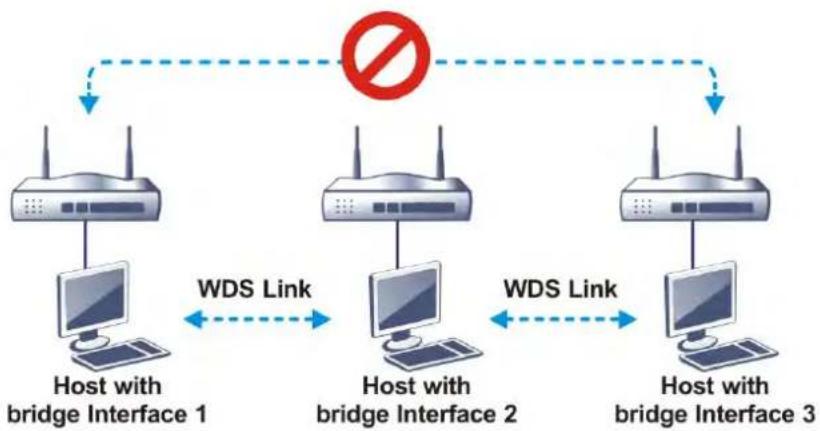
flowchart
graph TD
    A["Host with bridge Interface 1"] --> B["Host with bridge Interface 2"]
    B --> C["Host with bridge Interface 3"]
    D["Router Symbol"] -->|No| E["Router Symbol"]
    style A fill:#f9f,stroke:#333
    style B fill:#f9f,stroke:#333
    style C fill:#f9f,stroke:#333
    linkStyle 0 stroke:#ff0000,stroke-width:2px
    linkStyle 1 stroke:#ff0000,stroke-width:2px
    linkStyle 2 stroke:#ff0000,stroke-width:2px
    linkStyle 3 stroke:#ff0000,stroke-width:2px
    linkStyle 4 stroke:#ff0000,stroke-width:2px
    linkStyle 5 stroke:#ff0000,stroke-width:2px
Click WDS from Wireless LAN menu. The following page will be shown.
Wireless LAN (5 GHz) >> WDS Settings
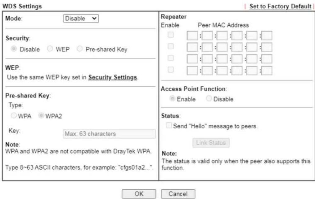
text_image
WDS Settings Mode: Disable Security: ● Disable ○ WEP ○ Pre-shared Key WEP: Use the same WEP key set in Security Settings. Pre-shared Key: Type: ○ WPA ● WPA2 Key: Max: 63 characters Note: WPA and WPA2 are not compatible with DrayTek WPA. Type 8~63 ASCII characters, for example: "cfgs01a2..." Repeater Enable Peer MAC Address □ : □ : □ : □ : □ : □ □ : □ : □ : □ : □ : □ □ : □ : □ : □ : □ : □ □ : □ : □ : □ : □ : □ Access Point Function: ● Enable ○ Disable Status: □ Send "Hello" message to peers. Link Status Note: The status is valid only when the peer also supports this function. OK CancelAvailable settings are explained as follows:
| Item Description | |
| Mode Choose the WDS mode. | Disable - WDS is disabled.Repeater - WDS is enabled in Repeater mode. |
| Security | Choose one of the types for the router. The setting you choose here will make the following WEP or Pre-shared key field valid or not.Disable - Security is disabled.WEP - Security is enabled.Pre-shared key - Security is enabled. |
| Pre-shared Key | Type - Select either WPA or WPA2 as the encryption protocol.Key - Enter 8 ~ 63 ASCII characters or 64 hexadecimal digits with a leading “0x”. |
| Repeater | If Repeater was selected as the WDS mode, enter the peer MAC addresses in these fields. Up to four peer MAC addresses may be entered in this page. Select the checkbox in front of a MAC address to enable it. |
| Access Point Function | Select Enable to make this router serve as an access point;select Disable to disable access point function. |
| Status | Click to send a “hello” message to peers. This only works if the peer also supports this function. |
To save changes on this page, select OK; to discard changes, select Cancel.
III-1-7 Advanced Setting
On this page you can configure advanced settings such as operation mode, channel bandwidth, guard interval, and aggregation MSDU for wireless data transmission.
If the Vigor router supports dual-band WLAN, you will see separate Advanced Setting sections for 2.4GHz and 5GHz.
2.4 GHz Advanced Setting page
Wireless LAN(2.4GHz) >> Advanced Setting
HT Physical Mode
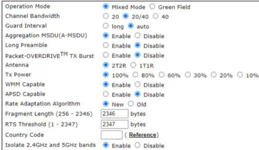
other
Operation Mode ● Mixed Mode ○ Green Field Channel Bandwidth ○ 20 ● 20/40 ○ 40 Guard Interval ○ long ● auto Aggregation MSDU(A-MSDU) ● Enable ○ Disable Long Preamble ○ Enable ● Disable Packet-OVERDRIVE™ TX Burst ○ Enable ● Disable Antenna ● 2T2R ○ 1T1R Tx Power ● 100% ○ 80% ○ 60% ○ 30% ○ 20% ○ 10% WMM Capable ● Enable ○ Disable APSD Capable ○ Enable ● Disable Rate Adaptation Algorithm ● New ○ Old Fragment Length (256 - 2346) 2346 bytes RTS Threshold (1 - 2347) 2347 bytes Country Code ( Reference ) Isolate 2.4GHz and 5GHz bands ● Enable ○ DisableOK
5 GHz Advanced Setting page:
Wireless LAN (5 GHz) >> Advanced Setting
Physical Mode
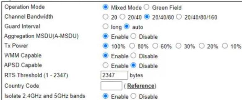
text_image
Operation Mode Channel Bandwidth Guard Interval Aggregation MSDU(A-MSDU) Tx Power WMM Capable APSD Capable RTS Threshold (1 - 2347) Country Code Isolate 2.4GHz and 5GHz bands ● Mixed Mode ○ Green Field ○ 20 ○ 20/40 ● 20/40/80 ○ 20/40/80/160 ○ long ● auto ● Enable ○ Disable ● 100% ○ 80% ○ 60% ○ 30% ○ 20% ○ 10% ● Enable ○ Disable ○ Enable ● Disable 2347 bytes ( Reference ) ● Enable ○ DisableOK
Available settings are explained as follows:
After finishing all the settings here, please click OK to save the configuration.
| Item Description | ||
| Operation Mode | Mixed Mode - The router can transmit data using all protocols supported by 802.11a/ b/ g and 802.11n standards. However, all wireless transmissions will be slowed down when any 802.11g or 802.11b wireless client is connected.Green Field - Select this mode to achieve the highest throughput. This mode supports data transmission between 802.11n systems only. In addition, it does not have protection mechanism to prevent conflicts with neighboring 802.11a/ b/ g devices. | |
| Channel Bandwidth | The available options will be changed according to the model you have.20 -Vigor Router will utilize 20 MHz channels for data transmission and reception between the AP and wireless stations.40 -Vigor Router will utilize 40 MHz for data transmission and reception between the AP and wireless stations.20/40 - Vigor Router will utilize either 20 MHz or 40 MHz for data transmission and reception depending on the number of nearby wireless APs. 20MHz will be used when there are more than 10 wireless APs; otherwise 40MHz will be used. Selecting this setting ensures the best performance for data transit on networks with both 20 MHz and 40 MHz clients. | |
| Guard Interval | Enabling this setting ensures the integrity of wireless traffic by inserting guard intervals between symbols to reduce the adverse effects of propagation delays, and signal multipath or reflections. If you choose auto as guard interval, the router will choose short guard interval (which increases wireless performance) or long guard interval for data transmit depending on the station capability. | |
| Aggregation MSDU (A-MSDU) | Aggregation MSDU can combine frames of different sizes to improve performance at the MAC layer for clients from certain manufacturers. The default setting is Enable. | |
| Long Preamble | This option determines the length of the sync field in an 802.11 packet. Most modern wireless network uses short preamble with 56 bit sync fields which yield better transmission speeds. However, some older 802.11b wireless devices only support long preamble which uses 128-bit sync fields. Click Enable to use Long Preamble to maintain compatibility with these devices. | |
| Packet-OVERDRIVE | This feature can enhance the performance in data transmission about 40%* (by checking Tx Burst). It is active only when both the Access Point and Station (in wireless client) support and invoke this function at the same time.Note: Vigor N61 wireless adapter supports this function. Therefore, you can install it on your PC to take advantage of Packet-OVERDRIVE (Refer to the following picture of Vigor N61 wireless utility window: choose Enable for TxBURST on the Option tab). | |
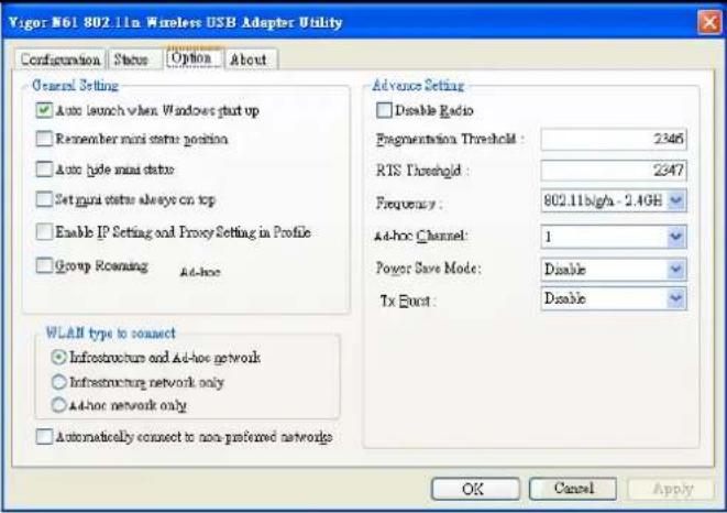 | ||
Tx Burst:  | ||
| [TCAD] | ||
| Info * Real transmission rate depends on the environment of the network. | ||
| Antenna Vigor router can be | attached with two antennas to have good data transmission via wireless connection. However, if you have only one antenna attached, please choose 1T1R. | |
| TX Power | Sets the power percentage of the access point's transmission signal. The greater the TX Power value, the higher intensity of the signal will be. | |
| WMM Capable | WMM stands for Wi-Fi Multimedia. It provides basic Quality of Service (QoS) by prioritizing traffic based on four access categories defined in the IEEE 802.11e standard. The access categories are AC_VO, AC_VI, AC_BE and AC_BK, which corresponds to traffic types of voice, video, best effort and low priority (background) data, respectively.To apply WMM parameters to wireless data transmission, click the Enable radio button. | |
| APSD Capable | APSD (Automatic Power-Save Delivery) is an enhancement over the power-saving mechanisms supported by Wi-Fi networks. It allows access points to buffer traffic before transmitting it to wireless devices, thus allowing wireless devices to enter into power saving mode which reduces power consumption. Not all wireless clients support APSD properly, and the only way to find out if APSD is appropriate for your network is to experiment.The default setting is Disable. | |
| Rate Adaptation Algorithm | Sets the way the Wireless transmission rate is adjusted dynamically. In most cases, selecting “New” will result in better performance than “Old”. | |
| Fragment Length(256 - 2346) | Set the Fragment threshold. You are advised to leave the default value, 2346, untouched. | |
| RTS Threshold (1 - 2347) | Minimize the collision (unit is bytes) between hidden stations to improve wireless performance.Set the RTS threshold. Do not modify default value if you | |
| don't know what it is, default value is 2347.Adjusts the 802.11 maximum transmit frame size, which might reduce chances of collision with hidden stations. You are advised to leave the default value, 2347, untouched. | ||
| Country Code Vigor router broadcasts country codes according to the 802.11d standard. However, some wireless stations will detect/ scan access points looking for country codes to determine which country it is in, and utilize channels appropriate to the country. The wireless client might get confused if there are multiple access points in the vicinity broadcasting different country codes. In such cases, it might be necessary to change the country code of the access point to ensure these clients can successfully establish a wireless connection. | ||
| Isolate 2.4GHz and 5GHz bands | The default setting is “Enable”. It means that the wireless client using 2.4GHz band is unable to connect to the wireless client with 5GHz band, and vice versa.For WLAN 2.4GHz and 5GHz set with the same SSID name:No matter such function is enabled or disabled, clients using WLAN 2.4GHz and 5GHz can communicate for each other if Isolate Member (in Wireless LAN>>General Setup) is NOT enabled for such SSID.Yet, if the function of Isolate Member (in Wireless LAN>>General Setup) is enabled for such SSID, clients using WLAN 2.4GHz and 5GHz will be unable to communicate with each other. | |
III-1-8 Station Control
Station Control is used to specify the duration that the wireless client can connect to the Vigor router. If this function is disabled, wireless clients can connect to the router as long as the router is powered on and the wireless feature is enabled.
This feature is especially useful for free WiFi service. For example, a coffee shop may offer free Wi-Fi service to its guests for one hour every day. In this scenario, the connection time can be set to "1 hour" and reconnection time set to "1 day". In this way, every guest can surf the net for at most one hour, thus freeing up resources for other guests.
Wireless LAN(2.4GHz) >> Station Control
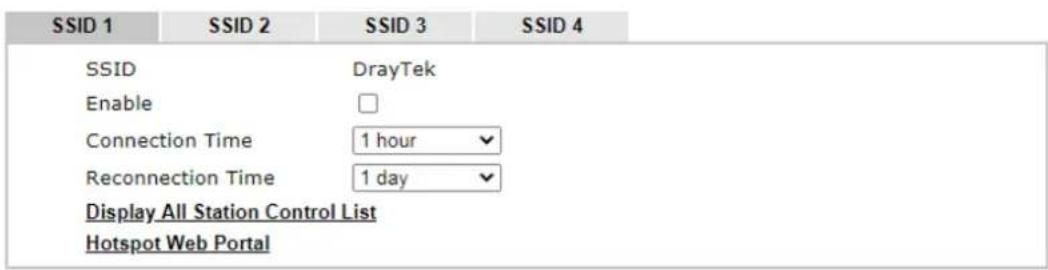
text_image
SSID 1 SSID 2 SSID 3 SSID 4 SSID DrayTek Enable Connection Time 1 hour Reconnection Time 1 day Display All Station Control List Hotspot Web PortalNote:
Once the feature is enabled, the connection time quota will apply to each wireless client (identified by MAC address).
OK Cancel
Available settings are explained as follows:
| Item Description | |
| SSID | Display the selected SSID. |
| Enable | Select to enable station control function for this SSID. |
| Connection Time / Reconnection Time | In the Connection Time dropdown box, select the maximum amount of time that a wireless client is allowed to connect within the period of time selected in the Reconnection Time dropdown box. Select User defined to manually enter the time in days, hours and minutes. |
| Display All Station Control List | Click to display all wireless clients that are under Station Control. |
| Hotspot Web Portal | Click to jump to the Hotspot Web Portal page. |
To save changes on this page, select OK; to discard changes, select Cancel.
III-1-9 Bandwidth Management
The downstream or upstream from FTP, HTTP or some P2P applications will occupy large of bandwidth and affect the applications for other programs. Please use Bandwidth Management to make the bandwidth usage more efficient.
Wireless LAN(2.4GHz) >> Bandwidth Management
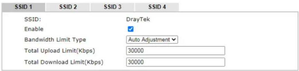
text_image
SSID 1 SSID 2 SSID 3 SSID 4 SSID: DrayTek Enable ✓ Bandwidth Limit Type Auto Adjustment ✓ Total Upload Limit(Kbps) 30000 Total Download Limit(Kbps) 30000Note:
- Download: Traffic going to any station. Upload: Traffic being sent from a wireless station.
- Allow auto adjustment could make the best utilization of available bandwidth.
OK Cancel
Available settings are explained as follows:
| Item Description | |
| SSID | Display the specific SSID name. |
| Enable Check this box to enable the bandwidth management for clients. | |
| Bandwidth Limit Type | Auto Adjustment - Bandwidth limit is determined by the system automatically.Per Station Limit - Bandwidth limit is determined according to the limitation of the wireless client. |
| Total Upload Limit | It is available when Auto Adjustment is selected.Type a value to define the maximum data traffic (uploading) for all of the wireless clients connecting to Vigor2927. |
| Total Download Limit | It is available when Auto Adjustment is selected.Type a value to define the maximum data client(stations) connecting to Vigor2927. |
| Upload Limit | It is available when Per Station Limit is selected.Type a value to define the maximum data traffic (uploading) for each wireless client connecting to Vigor2927. |
| Download Limit | It is available when Per Station Limit is selectedType a value to define the maximum data traffic (downloading) for each wireless client connecting to Vigor2927. |
To save changes on this page, select OK; to discard changes, select Cancel.
III-1-10 AP Discovery
Vigor router can scan all regulatory channels to find working APs in the neighborhood. The scanning result can be used to determine the most desirable channel to use, or to locate an AP for establishing a WDS link. Note that during the scanning process (about 5 seconds), no client is allowed to connect to the Vigor. Only APs operating on the same band as the Vigor can be discovered.
Click the Scan button to start the AP discovery process.
Wireless LAN(2.4GHz) >> Access Point Discovery
Access Point List
| Index | BSSID | Channel | RSSI | SSID | Authentication |
| 1 | 02:1D:AA:94:ED:E0 | 11 | 10% | DrayTek-LAN-B | Mixed (WPA+WPA2) / PSK |
| 2 | 00:1D:AA:94:ED:E0 | 11 | 10% | DrayTek-LAN-A | Mixed (WPA+WPA2) / PSK |
| 3 | 1A:49:BC:42:4B:B0 | 11 | 5% | VigorAP920c-1 | WPA2/PSK |
| 4 | 00:1D:AA:80:06:C4 | 11 | 0% | DrayTek | WPA2/PSK |
| 5 | 14:49:BC:42:4B:B0 | 11 | 5% | VigorAP920c | WPA2/PSK |
| 6 | 14:49:BC:0C:59:E4 | 11 | 10% | Vigor2865-PQC-Tang -2 | None |
| 7 | 14:49:BC:0C:59:E2 | 11 | 10% | Vigor2865-PQC-Tang -1 | WPA2/PSK |
| 8 | 1E:49:BC:42:4B:B0 | 11 | 5% | VigorAP920c-2 | WPA2/PSK |
| 9 | 00:1D:AA:80:06:B8 | 5 | 0% | 910C RD8 Mickey | WPA/PSK |
Note:
- During the scanning process (\~5 seconds), no station is allowed to connect with the router.
- AP Discovery can only support up to 32 APs displayed on the screen.
Available settings are explained as follows:
| Item Description | |
| Scan | Click to start the AP discovery process. The results will be shown on the box above this button. |
| Statistics | Shows channel usage by the neighboring APs.Wireless LAN >> Site Survey Statistics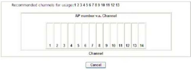 |
| Add to WDS Settings | This field is available for WLAN (5GHz). |
| Add to | To establish a WDS link to an AP that was found in an AP scan, click its entry in the Access Point List window, and its MAC address will be copied to the AP's MAC address field. Select the WDS mode you wish to use and click Add to. The AP will be configured in Wireless LAN >> WDS Settings. |
III-1-11 Airtime Fairness
Airtime fairness is essential in wireless networks that must support critical enterprise applications.
Most of the applications are either symmetric or require more downlink than uplink capacity; telephony and email send the same amount of data in each direction, while video streaming and web surfing involve more traffic sent from access points to clients than the other way around. This is essential for ensuring predictable performance and quality-of-service, as well as allowing 802.11n and legacy clients to coexist on the same network. Without airtime fairness, offices using mixed mode networks risk having legacy clients slow down the entire network or letting the fastest client(s) crowd out other users.
With airtime fairness, every client at a given quality-of-service level has equal access to the network's airtime.
The wireless channel can be accessed by only one wireless station at the same time.
The principle behind the IEEE802.11 channel access mechanisms is that each station has equal probability to access the channel. When wireless stations have similar data rate, this principle leads to a fair result. In this case, stations get similar channel access time which is called airtime.
However, when stations have various data rate (e.g., 11g, 11n), the result is not fair. The slow stations (11g) work in their slow data rate and occupy too much airtime, whereas the fast stations (11n) become much slower.
Take the following figure as an example, there are 2 wireless stations on the wireless network, Station A (11g) and Station B (11n), both of which transmit data packets to the Vigor router. Even though they have equal opportunity to access the wireless channel, Station B (11n) gets only a little airtime and waits too much because Station A (11g) takes longer to send one packet. In other words, transmission from Station B (fast rate) is effectively being throttled by Station A (slow rate).
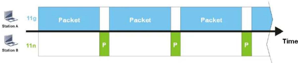
flowchart
graph LR
    A["Station A"] -->|11g| B["Packet"]
    B --> C["11n"]
    C --> D["P"]
    D --> E["Packet"]
    E --> F["P"]
    F --> G["Packet"]
    G --> H["P"]
    H --> I["Time"]
To alleviate this problem, Airtime Fairness tries to assign similar airtime to each station (A and B) by controlling TX traffic. In the following figure, Station B (11n) has higher opportunities to send data packets than Station A (11g). In this way, Station B (fast rate) gets its fair share of airtime and its speed is not limited by Station A (slow rate).
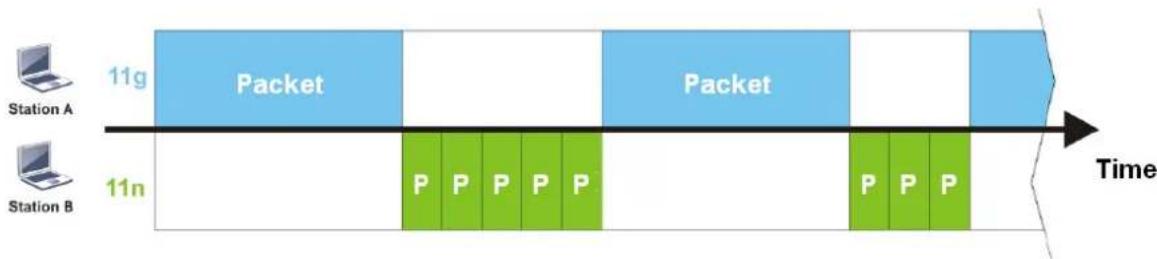
flowchart
graph LR
    A["Station A"] --> B["11g Packet"]
    C["Station B"] --> D["11n P P P P P"]
    B --> E["Time"]
    D --> F["Time"]
This is similar to automatic Bandwidth Limit, where the dynamic bandwidth limit of each station depends on instant active station number and airtime assignment. Please note that Airtime Fairness of 2.4 GHz and 5 GHz bands are independent, but stations connected to different SSIDs on the same band are prioritized as a group, because they all use the same wireless channel. Under certain environments, this function can reduce the adverse effects of slow wireless devices and improve the overall wireless performance.
Environments that can benefit by applying airtime fairness:
(1) Many wireless stations.
(2) All stations mainly use download traffic.
(3) The performance bottleneck is wireless connection.
Wireless LAN(2.4GHz) >> Airtime Fairness

text_image
Enable Airtime Fairness Triggering Client Number 2 (2 ~ 64) (Default: 2)Note:
Please enable or disable this function according to the real situation and user experience. It is NOT suitable for all environments.

Available settings are explained as follows:
| Item Description | |
| Enable Airtime Fairness | Try to assign similar airtime to each wireless station by controlling TX traffic.Airtime Fairness - Click the link to display the following explanation of airtime fairness note.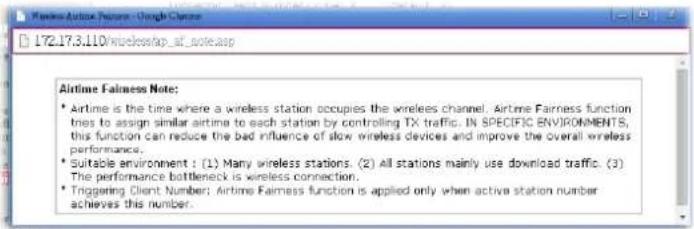 Triggering Client Number - Airtime Fairness function is applied only when there are at least this many active wireless stations. Triggering Client Number - Airtime Fairness function is applied only when there are at least this many active wireless stations. |
To save changes on this page, select OK; to discard changes, select Cancel.

Info
Airtime Fairness function and Bandwidth Limit function should be mutually exclusive. So their webs have extra actions to ensure these two functions are not enabled simultaneously.
III-1-12 Band Steering (2.4 GHz)
Band Steering detects if the wireless clients are capable of 5GHz operation, and steers them to that frequency. It helps to keep the 2.4 GHz band clear for legacy clients, and improves users' experience by reducing 2.4 GHz channel utilization.
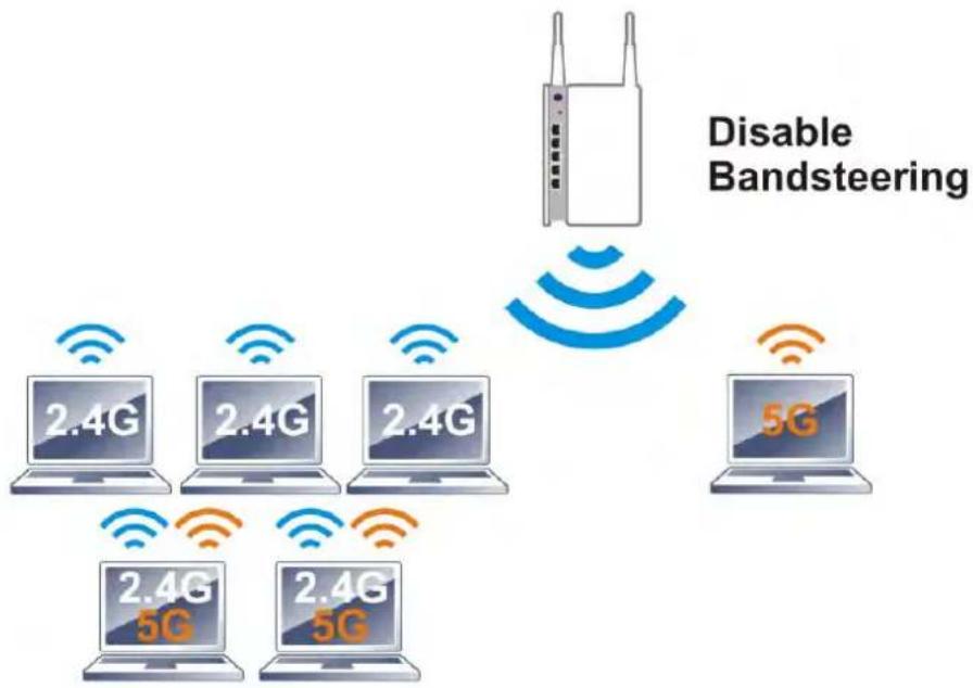
flowchart
graph TD
    A["Disassembled Router"] --> B["5G"]
    A --> C["2.4G"]
    A --> D["2.4G"]
    A --> E["2.4G"]
    A --> F["5G"]
    G["Disable Bandsteering"] --> A
    style A fill:#f9f,stroke:#333
    style B fill:#ccf,stroke:#333
    style C fill:#ccf,stroke:#333
    style D fill:#ccf,stroke:#333
    style E fill:#ccf,stroke:#333
    style F fill:#ccf,stroke:#333
If a dual-band client is detected, the AP will let the wireless client connect to the less congested wireless band, such as the 5GHz band, to reduce network congestion.
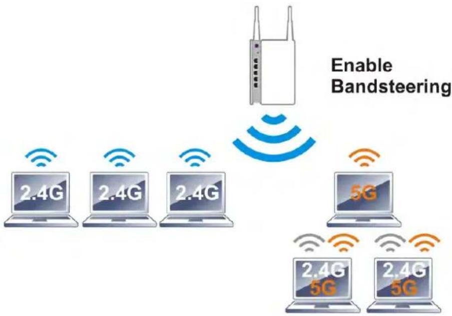
text_image
Enable Bandsteering 2.4G 2.4G 2.4G 5G 2.4G 5G 2.4G 5G
Info
For Band Steering to work properly, the same SSID and security settings must be configured on both 2.4 GHz and 5 GHz bands.
To configure Band Steering, go to the Wireless LAN (2.4GHz)>>Band Steering page:
Wireless LAN (2.4 GHz) >> Band Steering

text_image
Enable Band Steering Check Time for WLAN Client 5G Capability 15 second(s) (1 ~ 60) (Default: 15) 5GHz Minimum RSSI -78 dBm (29 %) (Default: -78)Note:
- Please setup at least one pair of 2.4GHz and 5GHz Wireless LAN with the same SSID and security.

Available settings are explained as follows:
| Item Description | |
| Enable Band Steering | When enabled, the router will detect if wireless clients are capable of dual-band or not within the time limit.Check Time.... - When a wireless client attempts to connect, the router will block attempts to connect to the 2.4 GHz band for the specified period of time (default is 30 seconds), which hopefully will entice the client to connect to the 5 GHz band. If the client fails to connect to the 5 GHz band within the specified interval, it will then be able to connect to the 2.4 GHz band. |
To save changes on this page, select OK; to discard changes, select Cancel.
The following diagram shows how Band Steering works.
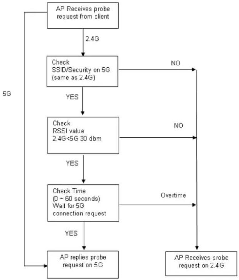
flowchart
graph TD
    A["AP Receives probe request from client"] -->|2.4G| B["Check SSID/Security on 5G (same as 2.4G)"]
    B -->|YES| C["Check RSSI value 2.4G<5G 30 dbm"]
    B -->|NO| D["AP Receives probe request on 2.4G"]
    C -->|YES| E["Check Time (0 ~ 60 seconds) Wait for 5G connection request"]
    C -->|NO| F["AP Receives probe request on 2.4G"]
    E -->|YES| G["AP replies probe request on 5G"]
    E -->|Overtime| F
Example: How to Use Band Steering?
-
Open Wireless LAN(2.4GHz)>>Band Steering.
-
Check the box of Enable Band Steering and use the default value (15) for check time setting.
Wireless LAN (2.4 GHz) >> Band Steering

text_image
Enable Band Steering Check Time for WLAN Client 5G Capability 15 second(s) (1 ~ 60) (Default: 15) □ 5GHz Minimum RSSI -78 dBm (29 %) (Default: -78)Note:
- Please setup at least one pair of 2.4GHz and 5GHz Wireless LAN with the same SSID and security.

-
Click OK to save the settings.
-
Open Wireless LAN (2.4GHz)>>General Setup and Wireless LAN (5GHz)>> General Setup. Configure SSID as DrayTek2927_BandSteering for both pages. Click OK to save the settings.
Same settings for 2.4GHz and 5GHz
Wireless LAN (2.4 GHz) >> General Setup
General Setting (IEEE 802.11)
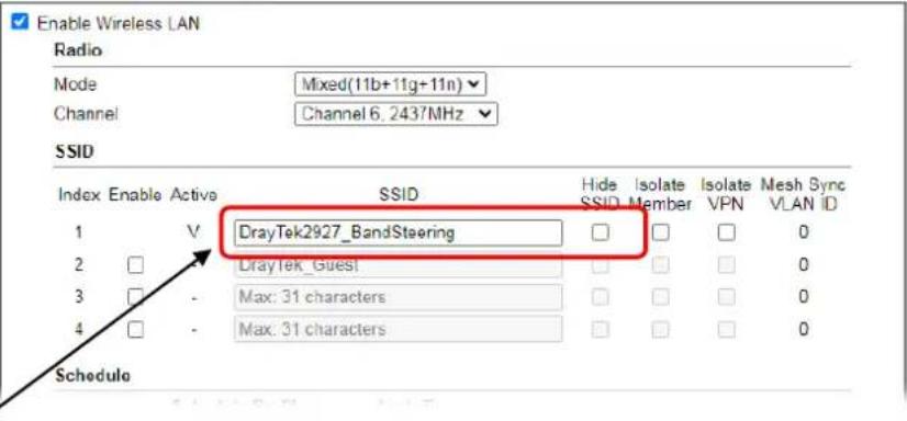
text_image
Enable Wireless LAN Radio Mode Mixed(11b+11g+11n) Channel Channel 6, 2437MHz SSID Index Enable Active SSID Hide Isolate Isolate Mesh Sync SSID SSID Member VPN VLAN ID 1 V DrayTek2927_BandSteering 0 2 DrayTek_Guest 0 3 - Max: 31 characters 0 4 - Max: 31 characters 0 ScheduleWireless LAN (5 GHz) >> General Setup
General Setting ( IEEE 802.11 )
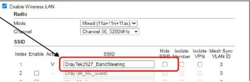
text_image
Enable Wireless LAN Radio Mode Mixed (11a+11n+11ac) Channel Channel 56, 5260MHz SSID Index Enable Active SSID Hide Isolate Isolate Mesh Sync SSID SSID Member VPN VLAN ID 1 V DrayTek2927_BandSteering 0 2 - DrayTek_BG_Guest 0 3 - 0- Open Wireless LAN (2.4GHz)>>Security and Wireless LAN (5GHz)>>Security. Configure Security as 12345678 for both pages. Click OK to save the settings.
Wireless LAN(2.4GHz) >> Security Settings
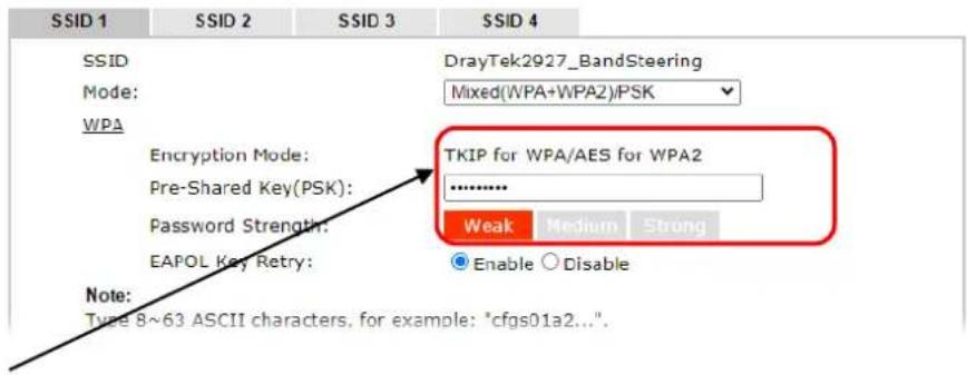
text_image
SSID 1 SSID 2 SSID 3 SSID 4 SSID DrayTek2927_BandSteering Mode: Mixed(WPA+WPA2)PSK WPA Encryption Mode: TKIP for WPA/AES for WPA2 Pre-Shared Key(PSK): .......... Password Strength: EAPOL Key Retry: Weak Medium Strong Enable Disable Note: Type 8~63 ASCII characters. for example: "cfgs01a2...".Same value for 2.4GHz and 5GHz
Wireless LAN (5 GHz) >> Security Settings
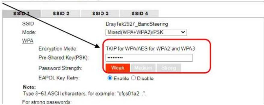
text_image
SSID-1 SSID 2 SSID 3 SSID 4 SSID DrayTek2927_BandSteering Mode: Mixed(WPA+WPA2)/PSK WPA Encryption Mode: TKIP for WPA/AES for WPA2 and WPA3 Pre-Shared Key(PSK): .......... Password Strength: Weak Medium Strong EAPOL Key Retry: Enable Disable Note: Type 8~63 ASCII characters, for example: "cfgs01a2...". For strong passwords:- The Vigor will now steer wireless clients to the less congested wireless band, such as 5GHz to reduce network congestion.
III-1-13 Roaming
WiFi roaming allows wireless stations to switch connections between access points within an area to achieve better coverage and signal quality. It usually is up to the wireless station to switch to another access point with stronger signal strength while it is already connected, but Vigor wireless routers have an AP-assisted client roaming feature that could facilitate roaming on wireless stations. Depending on the roaming configuration, the Vigor monitors the Received Signal Strength Indicator (RSSI) of wireless stations and disconnect stations whose RSSI falls below a certain (configurable) threshold, thus forcing stations to seek out other WiFi hosts to connect to.
To configure wireless roaming settings, go to Wireless LAN >> Roaming.
Wireless LAN(2.4GHz) >> Roaming
Router-assisted Client Roaming Parameters
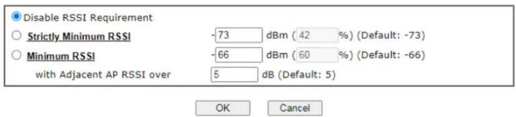
text_image
Disable RSSI Requirement Strictly Minimum RSSI -73 dBm (42 %) (Default: -73) Minimum RSSI -66 dBm (60 %) (Default: -66) with Adjacent AP RSSI over 5 dB (Default: 5) OK CancelAvailable settings are explained as follows:
| Item Description | |
| Disable RSSI Requirement | The Vigor router does not pay attention to the RSSI level of wireless stations. Selecting this option means the Vigor router will not interfere with the roaming behavior of wireless stations. |
| Strictly Minimum RSSI | The Vigor router will immediately disconnect the wireless station if its RSSI falls below the configured value. |
| Minimum RSSI | Minimum RSSI - The Vigor router will disconnect wireless clients whose RSSI falls below the minimum threshold only if there is also a neighboring wireless host (router or AP) that has an RSSI value (defined in the field of With Adjacent AP RSSI over) higher than a certain threshold.In order for this option to work, other wireless hosts connected to the same LAN subnet need to support the exchange of RSSI information with peer wireless hosts via Ethernet.With Adjacent AP RSSI over - Specify a value as a threshold. |
To save changes on this page, select OK; to discard changes, select Cancel.
III-1-14 Station List
Station List provides an overview of all currently connected wireless clients and their status. As an added convenience, you may choose to add a particular wireless client to the Access Control by double clicking its entry in the list to populate the MAC address field, followed by clicking the Add button.
There are 3 tabs on the Station List screen: General, Advanced and Neighbor. Both General and Advanced show wireless stations connected to the Vigor router, whereas Neighbor shows nearby wireless stations connected to other access points that are detected by the Vigor router.
Wireless LAN (2.4 GHz) >> Station List
Station List
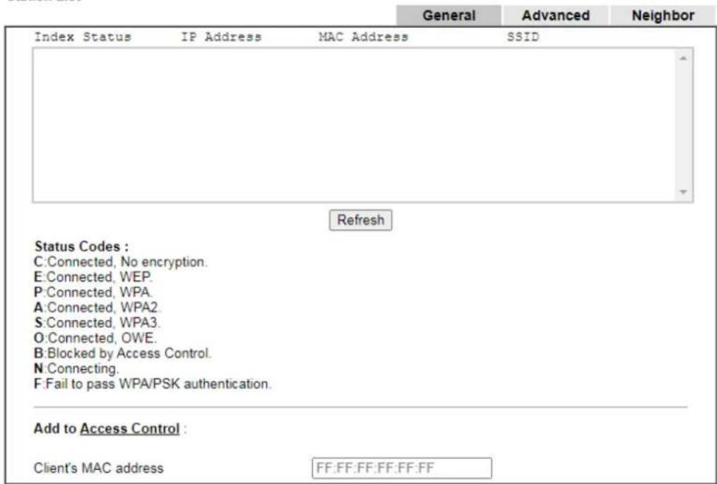
text_image
Index Status IP Address MAC Address SSID Refresh Status Codes : C:Connected, No encryption. E:Connected, WEP. P:Connected, WPA. A:Connected, WPA2. S:Connected, WPA3. O:Connected, OWE. B:Blocked by Access Control. N:Connecting. F:Fail to pass WPA/PSK authentication. Add to Access Control : Client's MAC address FF:FF:FF:FF:FF:FFNote:
After a station connects to the router successfully, it may be turned off without notice. In that case, it will still be on the list until the connection expires.
Add
Available settings are explained as follows:
| Item Description | |
| Refresh | Click to refresh the station list. |
| Add | Click to add the address in the Client’s MAC address field to Access Control. |
Below shows the Advanced tab, which lists the same clients as the General tab, but with more detailed information.
Wireless LAN (2.4 GHz) >> Station List
Station List
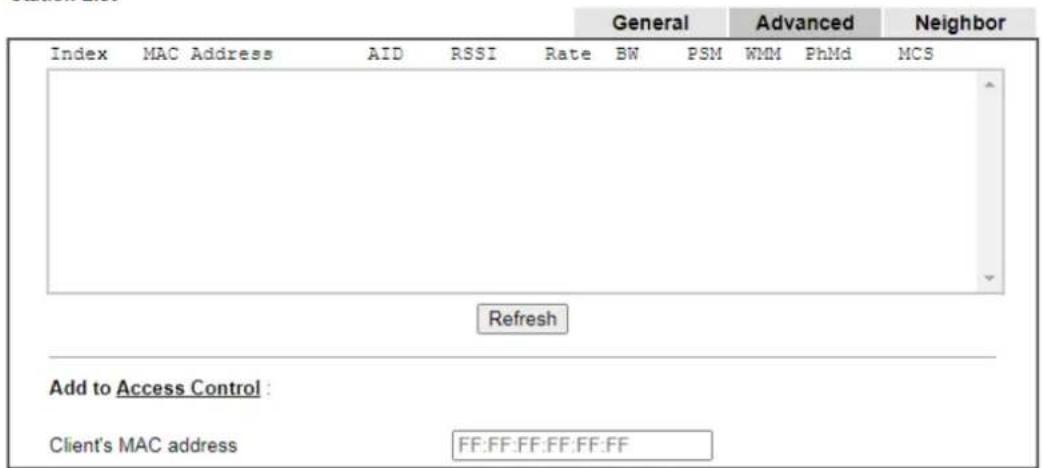
text_image
General Advanced Neighbor Index MAC Address AID RSSI Rate BW PSM WMM PhMd MCS Refresh Add to Access Control : Client's MAC address FF:FF:FF:FF:FF:FFNote:
After a station connects to the router successfully, it may be turned off without notice. In that case, it will still be on the list until the connection expires.
Add
Below shows the Neighbor tab, which lists wireless clients seen by the router but are not connected to the router's built-in access point.
Wireless LAN (2.4 GHz) >> Station List
Station List
| Index | MAC Address | Vendor | RSSI | Approx. Distance | SSID | Visit Time |
| 1 | 02:00:00:00:00:00 | 29% (-78dBm) | 44.67m | none | 0d:0h:4m:56s | |
| 2 | 5A:DF:43:39:5B:B4 | 26% (-79dBm) | 50.12m | none | 0d:0h:0m:0s | |
| 3 | B8:27:EB:CD:7C:D0 | Raspberr | 1% (-94dBm) | 281.84m | none | 0d:0h:6m:0s |
| 4 | AE:5B:D2:DC:F9:1F | 1% (-99dBm) | 501.19m | none | 0d:0h:0m:0s | |
| 5 | 5A:F8:3F:C4:F2:8B | 1% (-94dBm) | 281.84m | none | 0d:0h:0m:0s | |
| 6 | F2:02:B8:72:3E:21 | 1% (-99dBm) | 501.19m | none | 0d:0h:0m:0s | |
| 7 | 86:91:01:D6:D7:30 | 0% (-90dBm) | 177.83m | none | 0d:0h:0m:0s | |
| 8 | CE:69:2F:E9:2C:7E | 1% (-91dBm) | 199.53m | none | 0d:0h:0m:0s | |
| 9 | B6:16:25:F8:48:0F | 1% (-99dBm) | 501.19m | none | 0d:0h:0m:0s | |
| 10 | 3A:61:A8:DE:13:04 | 1% (-99dBm) | 501.19m | none | 0d:0h:0m:0s | |
Note:
- Approx. Distance is calculated by actual signal strength of device detected. Inaccuracy might occur based on barrier encountered.
- Due to the differences in signal strength for different devices, the calculated value of approximate distance also might be different.
- Trademarks and brand names are the properties of their respective owners.
Add
III-2 Mesh Network
Vigor router plays a role of Mesh root in a VigorMesh network. To configure the mesh network, please use the Mesh Wizard or open the Mesh menu to configure detailed settings.
Wizards
Quick Start Wizard
Service Activation Wizard
VPN Client Wizard
VPN Server Wizard
Wireless Wizard
Mesh Wizard
Mesh (R2)
Mesh Setup
Mesh Status
Mesh Discovery
Basic Config Sync
Advanced Config Sync
Support List
Please note that, within VigorMesh network,
● the total number allowed for mesh nodes is 8 (including the mesh root)
• the maximum number of hop is 3
Refer to the following figure:
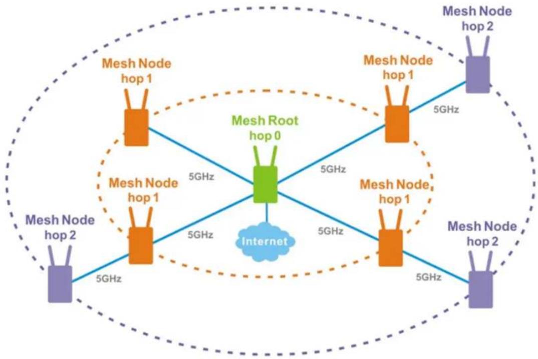
flowchart
graph TD
    A["Mesh Node hop 1"] -->|5GHz| B["Mesh Root hop 0"]
    C["Mesh Node hop 1"] -->|5GHz| B
    D["Mesh Node hop 1"] -->|5GHz| B
    E["Mesh Node hop 2"] -->|5GHz| B
    F["Mesh Node hop 2"] -->|5GHz| B
    B -->|5GHz| G["Internet"]
    style B fill:#99ccff,stroke:#333
For the mesh group set within VigorMesh network,
- It must be composed by "1" Mesh Root and "0\~7" mesh nodes
● (Roaming) Normally members in a mesh group use the same Wireless SSID/ security - (Add) Only the mesh root can add a new mesh node into the mesh group
● (Recover) A disconnected mesh node will automatically try to connect to another connected mesh node of the same group
Mesh Root
Mesh Root indicates that Vigor router would be other AP's uplink connection. As a Mesh Root, Vigor router must connect to internet through WANs to have an internet connection.
The following figure shows how Vigor router runs as MESH ROOT:
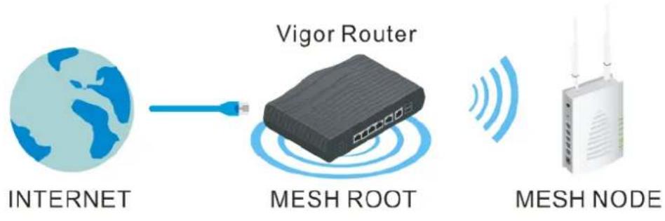
flowchart
graph LR
    A["INTERNET"] -->|Wireless Signal| B["MESH ROOT"]
    B --> C["MESH NODE"]
    B -->|Signal Transmission| D["RF"]
III-2-1 Mesh Wizard
Mesh wizard offers a quick way to configure mesh network.
- Go to Wizards>Mesh Wizard.
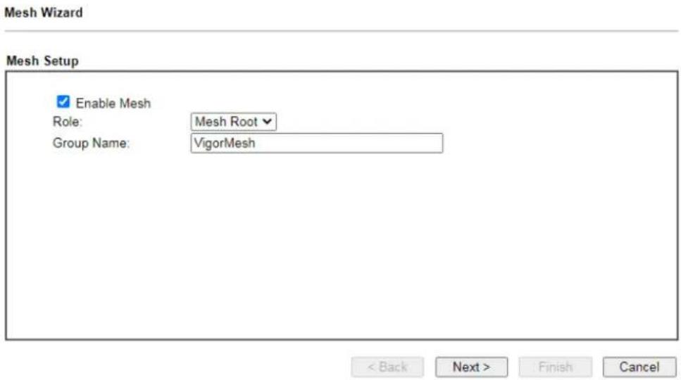
text_image
Mesh Wizard Mesh Setup Enable Mesh Role: Mesh Root Group Name: VigorMesh < Back Next > Finish Cancel- Check the Enable Mesh box. Click Next to get the following page.
Mesh Wizard
Wifi Setup
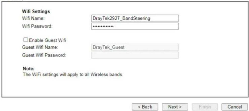
text_image
Wifi Settings Wifi Name: DrayTek2927_BandSteering Wifi Password: ******** Enable Guest Wifi Guest Wifi Name: DrayTek_Guest Guest Wifi Password: Note: The WiFi settings will apply to all Wireless bands. < Back Next > Finish Cancel- Set the Wifi Name and password; click Next to get the following page.
Mesh Wizard
Enter login password
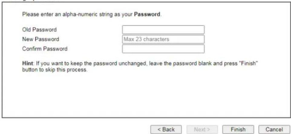
text_image
Please enter an alpha-numeric string as your Password. Old Password New Password Max 23 characters Confirm Password Hint: If you want to keep the password unchanged, leave the password blank and press "Finish" button to skip this process. < Back Next > Finish Cancel- Set the password, if required. Then, click Finish. The system starts to search available APs.
Mesh Wizard
Mesh Node Setup
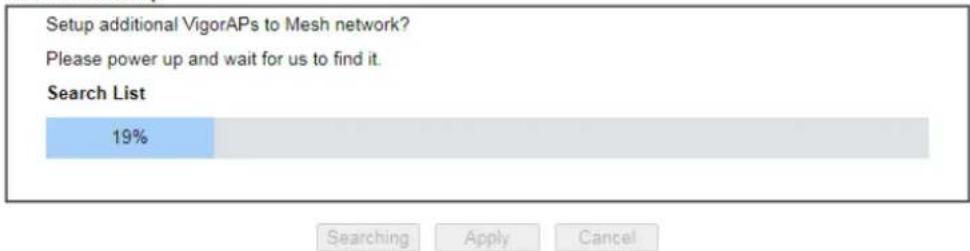
text_image
Setup additional VigorAPs to Mesh network? Please power up and wait for us to find it. Search List 19% Searching Apply Cancel- Wait for a few minutes. Later, APs around Vigor router will be shown below.
Mesh Wizard
Mesh Node Setup
Setup additional VigorAPs to Mesh network?
Please power up and wait for us to find it.
Search List
| Select | Model | MAC | Device Name |
| ✓ | VigorAP903 | 00:50:7F:F1:91:BC | AP903 |

- Select the one (e.g., VigorAP903 in this case) you want to group under Vigor router. Then, click Apply.
Mesh Wizard
Mesh Node Setup
Setup additional VigorAPs to Mesh network?
Please power up and wait for us to find it.
Search List
4%

- When the mesh node setup is finished, click Finish.
Mesh Wizard
Mesh Node Setup Finished
Setup Mesh Root and Mesh Node completed.

- After "Mesh Wizard Setup OK!" appears, go to Mesh>>Mesh Satus. The mesh node (AP903) has been grouped under the Vigor router.
Mesh Wizard
Mesh Wizard Setup OK!
Mesh >> Mesh Status
| Local Status | Refresh | ||
| Device Name | DrayTek | ||
| MAC Address | 14:49 BC:15:1F:00 | ||
| Model | Vigor2865 | ||
| Operation Mode | MeshRoot | ||
| Wireless Downlink Band | Auto | ||
| Group Name | VigorMesh | ||
| Link Status | Connected | ||
| Hop | 0 | ||
| Downlink Number | 1 | ||
| Downlink | 00:50:7F:F1:7F:1D (VigorAP903) | Wireless 5GHz (Ch36) (-58dBm / 81%) | |
| Devices | Total Number of Clients: 36 | ||||||||
| Index | Status | Device Name | IP Address | MAC Address (Model) | Hop | Uplink | Uptime | Clients | Action |
| 1 | ● Root | DrayTek | 172.16.21.64 | 14:49:BC:15:1F:00 (Vigor2865) | 0 | 3d12:06:49 | 14 | Reselect | |
| 2 | ● Online | MK_AP903 | 172.16.21.58 | 00:50:7F:F1:91:BC (VigorAP903) | 1 | 14:49:BC:17:70:08 Wireless 5GHz (Ch36) (-60dBm / 76%) | 3d12:05:44 | 6 | Disconnect |
Online(sync ready) Online Offline
III-2-2 Mesh Setup
This page can modify settings related to Mesh. You can search and specify mesh nodes as members under current mesh group.
Mesh >> Mesh Setup
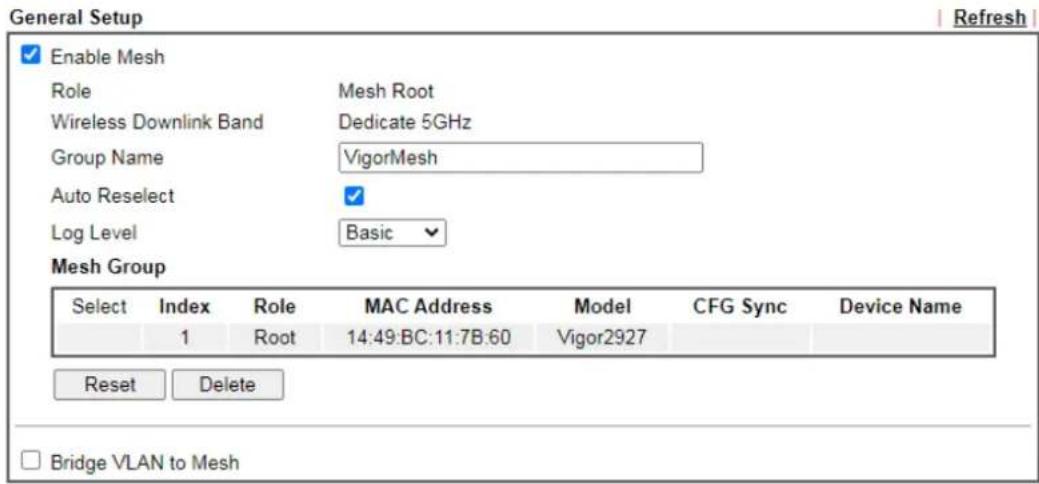
text_image
General Setup Enable Mesh Role Mesh Root Wireless Downlink Band Dedicate 5GHz Group Name VigorMesh Auto Reselect Log Level Basic Mesh Group Select/Index Role MAC Address Model CFG Sync Device Name 1 Root 14:49:BC:11:7B:60 Vigor2927 Reset Delete Bridge VLAN to Mesh
Add Mesh Node

text_image
Press Search button below to find and adopt the new node into Mesh Group. Search Search List Select MAC Address Model Operation Mode Device Name RSSI ApplyAfter enabling the Mesh function, all the settings on Wireless LAN (5 GHz)>>WDS will be invalid.
Available settings are explained as follows:
| Item Description | |
| General Setup | |
| Enable Mesh Check to enable the mesh function. | |
| Role Displays the role of Vigor router. Vigor router is a mesh root to provide internet access for Mesh Network. | |
| Wireless Downlink Band | At present, only 5GHz is dedicated as the downlink band for connecting with an uplinked mesh node. |
| Group Name | Displays the name of the current mesh group. |
| Auto Reselect | It is selected in default. To perform the auto reselect, make sure the process for CFG Sync and CFG Check for mesh nodes are successful. If enabled, after changing the environment of mesh network (e.g., offline, disconnection), the root device will perform auto reselect to reconstruct the mesh network. |
| Log Level | Choose Basic or Detailed. Related information will be shown on the Diagnostics>>Syslog Explorer. |
| Mesh Group The basic information including role, MAC address, and model name of the mesh root and node (up to 8 entries, one mesh root and seven mesh nodes) will be shown on this field. Reset - Click it to clear the Mesh Group information. Delete - Click it to remove the selected entry. | |
| Bridge VLAN to Mesh | Select to enable the function. |
| Add Mesh Node - It is available only if the Mesh function is enabled. | |
| Search | Click to scan available APs around this Vigor router.Add Mesh Node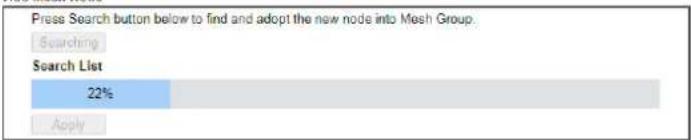  Note: After enabling the Mesh function, all the settings on Wireless LAN (5 GHz)>>WDS will be invalidThe detected APs will be shown on the Search List.Add Mesh Node Note: After enabling the Mesh function, all the settings on Wireless LAN (5 GHz)>>WDS will be invalidThe detected APs will be shown on the Search List.Add Mesh Node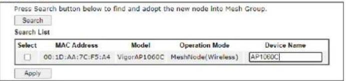  |
Apply Select the mesh node you want and click this button. The new mesh node will be shown on Mesh Group.Mesh >> Mesh Setup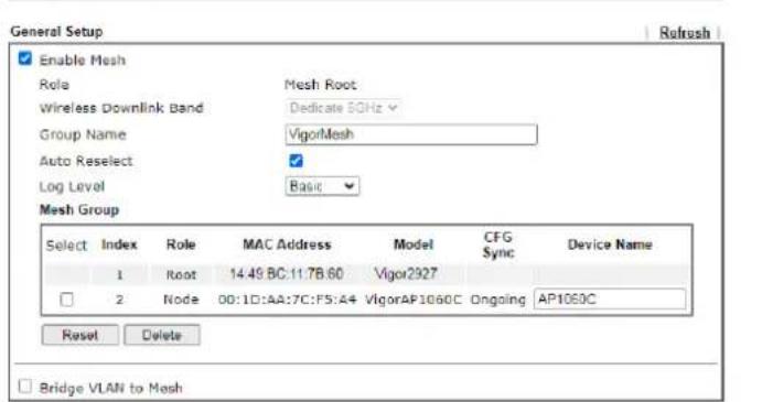 OK Cancel OK Cancel | |
| Backup Mesh Config | Backup - Click the button to save the configuration as a file. |
| Select/Restore | Click the Upload button to specify a configuration file. Then click Restore to apply the configuration.When the MAC address of the Vigor router is not the mesh root of the mesh group, the restore operation will not succeed. |
III-2-3 Mesh Status
This page shows the mesh network status.
One Mesh Group can contain up to 8 devices. In the following figure, the device with hop 0 is one special Ethernet Backhaul. It means this node will use Ethernet cable to join the mesh group while others use the wireless link.
Mesh >> Mesh Status
| Local Status | Refresh | ||
| Device Name | DrayTek | ||
| MAC Address | 14:49:BC:15:1F:00 | ||
| Model | Vigor2927 | ||
| Operation Mode | MeshRoot | ||
| Wireless Downlink Band | Auto | ||
| Group Name | VigorMesh | ||
| Link Status | Connected | ||
| Hop | 0 | ||
| Downlink Number | 1 | ||
| Downlink | 00:50:7F:F1:7F:1D (VigorAP903) | Wireless 5GHz (Ch36) (-58dBm / 81%) | |
| Index | Status | Device Name | IP Address | MAC Address(Model) | Hop | Uplink | Uptime | Clients | Action |
| 1 | ● Root | DrayTek | 172.16.21.64 | 14:49:BC:15:1F:00(Vigor2927) | 0 | 3d12:06:49 | 14 | Reselect | |
| 2 | ● Online | MK_AP903 | 172.16.21.58 | 00:50:7F:F1:7F:1D(VigorAP903) | 1 | 14:49:BC:17:70:08Wireless 5GHz (Ch36)(-60dBm / 76%) | 3d12:05:44 | 6 | Disconnect |
| 3 | ● Online | HR_AP903 | 172.16.21.62 | 00:50:7F:67:29:0C(VigorAP903) | 2 | 00:50:7F:F1:7F:1DWireless 5GHz (Ch36)(-64dBm / 65%) | 3d12:05:22 | 10 | Disconnect |
| 4 | ● Online | TB_AP1000 | 172.16.21.57 | 00:1D:AA:04:F0:DC(VigorAP1000C) | 3 | 00:50:7F:67:29:0CWireless 5GHz (Ch36)(-68dBm / 55%) | 3d12:05:00 | 6 | Disconnect |

Available settings are explained as follows:
| Item Description | |
| Local Status | Display general information for this device. |
| Devices | Display detailed information for this device (as mesh root) and mesh node(s) in the group. Index - Display the number of the device within a mesh group. Status - Display the role and connect status of the device. Device Name - Display the name of the device (for identification). IP Address - Display the IP address of the device. MAC Address - Display the MAC address of the device. Hop - Diplay the level of the device in Mesh Network. "0" means the device is connected to Internet by using Ethernet cable (wired). "1" to "3" means how many wireless links the device has to go through to reach a Hop 0 device. Uplink - Display the MAC address of the device that the AP connects to. |
| Total number of Clients | Display the station list of all mesh devices. |
| Station List of All Devices | ||||||||
| Index | MAC Address | Hostname | Vendor | SSID | Channel | RSSI | TxRate(Kbps) | RxRate(Kbps) |
| 1 | 00:50:7F:FD:CS:72 | TA001029 | DrayTek | staffs_4F | 6 | 68%(~63dBm) | 0 | 0 |
| 2 | 00:30:7F:FD:11:1D | ta002171 | DrayTek | staffs_4F | 6 | 41%(~72dBm) | 0 | 0 |
| 3 | 5C:57:F3:D3:D5:F7 | Tze-Pingde... | Apple | staffs_4F | 6 | 100%(-49dBm) | 0 | 0 |
| 4 | 40:58:AD:5B:F2:52 | Tyronetki... | Apple | staffs | 6 | 55%(~68dBm) | 0 | 0 |
| 5 | 00:30:7F:37:6D:E5 | N/A | DrayTek | staffs_4F | 6 | 52%(~69dBm) | 0 | 0 |
| 6 | 00:30:7F:37:67:E6 | N/A | DrayTek | staffs_4F | 6 | 55%(~68dBm) | 0 | 0 |
| 7 | 30:F7:C5:1D:3D:11 | N/A | Apple | guests | 6 | 83%(~57dBm) | 30 | 12 |
| 8 | 40:P0:2F:22:E8:A0 | N/A | LiteonTe | staffs | 6 | 34%(~76dBm) | 22 | 4 |
| 9 | 18:65:90:DE:D4:E5 | N/A | Apple | staffs_4F | 6 | 100%(-44dBm) | 0 | 0 |
| 10 | 60:45:CB:57:1F:36 | N/A | N/A | staffs_4F | 6 | 15%(~84dBm) | 0 | 0 |
| 11 | AC:3F:3E:42:E6:0D | N/A | Samsung | staffs_4F | 6 | 81%(~58dBm) | 0 | 0 |
| 12 | 50:8C:96:60:00:11 | N/A | Apple | staffs | 6 | 71%(~62dBm) | 0 | 0 |
| 13 | 04:B1:67:52:48:90 | RedmiS-mys... | N/A | staffs_4F | 6 | 45%(~72dBm) | 0 | 0 |
| 14 | 04:C2:3E:3F:CB:78 | android-ac... | HTC | staffs_4F | 6 | 55%(~68dBm) | 0 | 0 |
| 15 | 0C:8B:FD:31:08:78 | N/A | Intel | staffs_4F | 6 | 89%(~55dBm) | 2 | 2 |
| 16 | 38:48:22:FB:78:62 | endroid-3F... | Sony | staffs_4F | 6 | 52%(~68dBm) | 0 | 0 |
| 17 | CC:3F:7A:63:11:27 | N/A | N/A | staffs_4FS... | 36 | 52%(~99dBm) | 0 | 0 |
| 18 | 20:47:DA:38:17:79 | RedmiNotes... | N/A | staffs_4FS... | 36 | 50%(~70dBm) | 0 | 0 |
| 19 | 70:81:EB:65:80:E5 | cheng | Apple | staffs_4FS... | 36 | 87%(~56dBm) | 0 | 0 |
| 20 | BC:85:90:64:FE:A4 | N/A | Apple | staffs_4FS... | 36 | 36%(~75dBm) | 0 | 0 |
III-2-4 Mesh Discovery
Before a Mesh Node is connected, it is unable to check the device status from Mesh Root. This page can help to discover all Mesh devices around and offer the Link Status and Operation Mode of each Mesh device.
For obtaining the list of devices around this Vigor router, click Scan. Later, surrounding Mesh device(s) will be displayed on this page.
Mesh >> Mesh Discovery
Device list
| Index | MAC Address | Model | Operation Mode | Link Status | RSSI |
| 1 | 14:49:BC:0A:8A:B8 | Vigor2135 | MeshRoot | Connected | -61dBm(good) |
| 2 | 14:49:BC:02:37:40 | Vigor2927ax | MeshRoot | Connected | -88dBm(weak) |
| 3 | 00:1D:AA:04:F0:6C | VigorAP1000C | AP | Connected | -80dBm(fair) |
| 4 | 00:1D:AA:80:FE:D4 | VigorAP1060C | MeshRoot | Connected | -80dBm(fair) |
| 5 | 14:49:BC:42:4B:B0 | VigorAP920C | MeshNode(Wireless) | Connected | -59dBm(good) |
| 6 | 14:49:BC:42:4B:94 | VigorAP920C | MeshRoot | Connected | -60dBm(good) |
| 7 | 00:1D:AA:62:0F:A8 | Vigor2862 | MeshRoot | Connected | -67dBm(good) |
| 8 | 00:50:7F:F1:7F:1D | VigorAP903 | MeshNode(Wireless) | Connected | -58dBm(good) |
| 9 | 14:49:BC:42:6E:1E | VigorAP960C | MeshNode(Wireless) | New | -59dBm(good) |
| 10 | 00:1D:AA:7C:F5:BC | VigorAP1060C | MeshNode(Wireless) | Disconnected | -85dBm(weak) |
| 11 | 00:1D:AA:3F:4F:86 | VigorAP912C | AP | Connected | -69dBm(good) |
Scan
Note:
During the scanning process (about 10 seconds), no station is allowed to connect with the Router and Mesh Network may disconnect.
Only the device with the Link Status of "New" can be selected and grouped under this router.
III-2-5 Basic/Advanced Config Sync
If you add one Mesh Node in a mesh group, the Mesh Root will send the basic configuration to the device. This page could help you to change the Mesh Root settings and deliver the new configuration of the Mesh Root to all "connected" Mesh Nodes.
Mesh >> Basic Configuration Sync
□ System Maintenance
| Index | Name | Value |
| 1 | X_00507F_System.Management.SkipQuickStartWizard | Enable |
| 2 | X_00507F_System.TR069Setting.CPEEnable | 0 |
| 3 | ManagementServer.URL | |
| 4 | ManagementServer.Usage | |
| 5 | ManagementServer.Password | ***** |
| 6 | ManagementServer.ConnectionRequestUsername | vigor |
| 7 | ManagementServer.ConnectionRequestPassword | ***** |
| 8 | X_00507F_System.AdminmodePassword.Admin | admin |
| 9 | X_00507F_System.AdminmodePassword.Password | ***** |
| 10 | X_00507F_System.SyslogMail.SysLogAccess.SysLogEnable | 0 |
| 11 | X_00507F_System.SyslogMail.SysLogAccess.LogServerIP | |
| 12 | X_00507F_System.SyslogMail.SysLogAccess.LogServerPort | 514 |
| 13 | X_00507F_System.SyslogMail.MailAlert.MailAlertEnable | 0 |
| 14 | X_00507F_System.SyslogMail.MailAlert.SMTPServer | |
| 15 | X_00507F_System.SyslogMail.MailAlert.MailTo | |
| 16 | X_00507F_System.SyslogMail.MailAlert.Usage | |
| 17 | X_00507F_System.SyslogMail.MailAlert.Password | ***** |
| 18 | X_00507F_System.SyslogMail.MailAlert.UseTLS | 0 |
| 19 | X_00507F_System.SyslogMail.MailAlert.SMTPServerPort | 25 |
| 20 | X_00507F_System.PasswordEncryption.AdminPassword | ***** |
| 21 | X_00507F_System.PasswordEncryption.AdminSalt | ***** |
□ Wireless LAN (2.4GHz)
| Index | Name | Value |
| 1 | X_00507F_WirelessLAN_AP.General.EnableWLAN | 1 |
| 2 | X_00507F_WirelessLAN_AP.General.SSID.1.ESSID | DrayTek |
Available settings are explained as follows:
| Item Description | |
| System Maintenance / Wireless LAN (2.4Hz) / Wireless LAN (5GHz) | Check the item(s) you want to make configuration sync. |
| Sync | This button is available only when any mesh node in the mesh network is online and ready to sync.Click it to apply the settings configured by this router to all connected mesh node. |
Tips for Mesh network setup
- Set up TWO mesh devices with uplink RSSI larger than -65dBm.
- Upgrade the firmware version of Mesh devices through Mesh link, starting from the mesh device with less hop number. For example, upgrade the firmware from the root, hop1 Mesh Node then hop2 Mesh Node, and so on.
- VigorMesh network supports up to 3 hops of mesh devices. However, it is suggested to connect the mesh group with less than or equals to 2 hops.
For your reference, we make a real mesh environment test and get the following record. (Use VigorAP APP to do internet speed test with different hops mesh node.)
Internet Download Speed (for root and hop1 \~ hop3):
iPad connects to Root : 80Mbps
iPad connects to hop1 Node : 49Mbps (Uplink RSSI : -55dBm)
iPad connects to hop2 Node : 41Mbps (Uplink RSSI : hop2 -64dBm / hop1 -55dBm)
iPad connects to hop3 Node : 26Mbps (Uplink RSSI : hop3 -62dBm / hop2 -68dBm / hop1 -55dBm)
- It is not suggested to use a wireless Mesh Node with Ethernet cable connected to a Mesh Root.
-
If resetting a Mesh Root,
-
All "connected" Mesh Nodes will be informed to reset.
- Group List and Group Key will be reset, too.
- For those Mesh Nodes unable to reset, reset them manually. Reset the Group List by web or factory default.
- If resetting a Mesh Node,
- Group List and Group Key will be cleared.
- Link Status will become "New".
- If Mesh Search / Apply / Discover is worked too fast or is done with empty result, your request may be rejected. Please try again.
- Troubleshooting:
- Check the firmware version. Please make sure all APs within the mesh group are in the newest firmware version.
- Check the OP (operation) Mode. Make sure new Mesh Node doesn't accidentally get DHCP IP and becomes AP mode.
- Check the country code and channels. For example, it is impossible for connecting a VigorAP 912C Mesh Root with 5G channel 36 to VigorAP920R Wireless Mesh Node in EU country code.
- Check the channel load. Make sure it is not over 70%.
CHANNEL LOAD

pie
| Category | Value (%) | |---|---| | Heavy | 75 | | Light | 15 |- Collect some Mesh logs and send the result to DrayTek for analyzing.
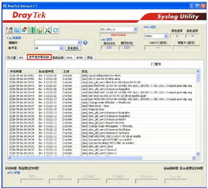
text_image
DrayTek Syslog 4.5.7 Syslog Utility Log 通道器 端脚字: 套用至: AI 页面更新 防火墙 VPN 使用者存取纪录 速缓纪录 WAN IIPBX 其他 192.168.1.1 Vpp0298SLAC LAN 财误 接收时间: 3:250 2:325 WAN 财讯 WAN1 0 0 WAN IP (固定) ... ... WAN IP (固定) ... 暂停 系统时间 路由端时间 主帧 抓总 2020-09-16 14:34:52 Jan 1 00x21:30 DrayTek [dm] SaveConfiguration by Mesh. 2020-09-16 14:34:51 Jan 1 00x21:29 DrayTek [dm] 00:1D-AA+44:33:88 is alive. 2020-09-16 14:34:51 Jan 1 00x21:29 DrayTek [dm] dim_plt_send Alive from 00:1d:aa+44:33:88 2020-09-16 14:34:49 Jan 1 00x21:27 DrayTek Local User (MAC=05-1D-AA+44-33-88): 192.168.1.10 DNS -> 192.168.1.1 Inquire pool.rtp.org 2020-09-16 14:34:48 Jan 1 00x21:26 DrayTek [dm] dim_plt_send Announce-Kespalve 2020-09-16 14:34:44 Jan 1 00x21:22 DrayTek Local User (MAC=05-1D-AA+44-33-88): 192.168.1.10 DNS -> 192.168.1.1 Inquire pool.rtp.org 2020-09-16 14:34:44 Jan 1 00x21:22 DrayTek [dm] Sec WDS key 00:1D-AA+44:33:88 on mesho aqan 2020-09-16 14:34:39 Jan 1 00x21:17 DrayTek Local User (MAC=05-1D-AA+44-33-88): 192.168.1.10 DNS -> 192.168.1.1 Inquire pool.rtp.org 2020-09-16 14:34:37 Jan 1 00x21:15 DrayTek [dm] Change state NR/Ask -> Meshloc. 2020-09-16 14:34:37 Jan 1 00x21:19 DrayTek [dm] Mesh Root - Alive 2020-09-16 14:34:37 Jan 1 00x21:18 DrayTek [dm] Register stop. 2020-09-16 14:34:36 Jan 1 00x21:14 DrayTek [dm] dim_plt_send Announce-Kespalve 2020-09-16 14:34:35 Jan 1 00x21:13 DrayTek [dm] dim_plt_send Announce-Kespalve 2020-09-16 14:34:35 Jan 1 00x21:13 DrayTek [dm] dim_plt_send Announce-Mooby 2020-09-16 14:34:35 Jan 1 00x21:13 DrayTek [dm] dim_plt_send Report-Recover 2020-09-16 14:34:34 Jan 1 00x21:12 DrayTek [dm] Change state NR/Ask -> NR/Ask. 2020-09-16 14:34:34 Jan 1 00x21:12 DrayTek [dm] dim_plt_send Announce-Ast#Status 2020-09-16 14:34:34 Jan 1 00x21:12 DrayTek [dm] dim_plt_send Announce-SetName 2020-09-16 14:34:34 Jan 1 00x21:12 DrayTek [dm] Add WDS MAC 00:LD-AA+44:33:88 on mesho 2020-09-16 14:34:34 Jan 1 00x21:12 DrayTek [dm] Succeed to add WDS MAC on mesho 2020-09-16 14:34:34 Jan 1 00x21:12 DrayTek [dm] Succeed to delete WDS MAC on mesho 2020-09-16 14:34:35 Jan 1 00x21:11 DrayTek [dm] dim_plt_send Clone 2020-09-16 14:34:35 Jan 1 00x21:11 DrayTek [dm] dim_plt_send Clone-v2 2020-09-16 14:34:35 Jan 1 00x21:11 DrayTek [dm] dim_plt_send Clone-v2 系统时间:电信标记的时间 ADSL 状态 路由器时间:路由器标记的时间 路由器时间:路由器标记的时间III-2-6 Support List
Mesh >> Support List
The following compatibility test lists DrayTek AP models supported by Vigor router Mesh.
| Model | Status | Firmware Version |
| VigorAP 906 | Y | 1.4.5 |
| VigorAP 1062C | Y | 1.5.3 |
| VigorAP 962C | Y | 1.5.3 |
| VigorAP 805 | Y | 1.5.3 |
This page is left blank.
Part IV VoIP

VoIP
Voice over IP network (VoIP) enables you to use your broadband Internet connection to make toll quality voice calls over the Internet.
IV-1 VoIP
Voice over IP network (VoIP) enables you to use your broadband Internet connection to make toll quality voice calls over the Internet.
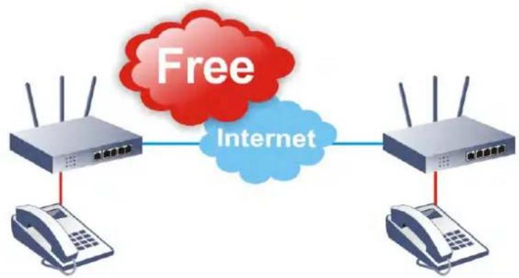
flowchart
graph LR
    A["电信设备"] -->|Free Internet| B["电信设备"]
    A --> C["电话机"]
    B --> D["电话机"]

Info
This function is used for "V" models.
There are many different call signaling protocols, methods by which VoIP devices can talk to each other. The most popular protocols are SIP, MGCP, Megaco and H.323. These protocols are not all compatible with each other (except via a soft-switch server).
The Vigor V models support the SIP protocol as this is an ideal and convenient deployment for the ITSP (Internet Telephony Service Provider) and softphone and is widely supported. SIP is an end-to-end, signaling protocol that establishes user presence and mobility in VoIP structure. Every one who wants to talk using his/her SIP Uniform Resource Identifier, "SIP Address". The standard format of SIP URI is
sip: user:password @ host: port
Some fields may be optional in different use. In general, "host" refers to a domain. The "userinfo" includes the user field, the password field and the @ sign following them. This is very similar to a URL so some may call it "SIP URL". SIP supports peer-to-peer direct calling and also calling via a SIP proxy server (a role similar to the gatekeeper in H.323 networks), while the MGCP protocol uses client-server architecture, the calling scenario being very similar to the current PSTN network.
After a call is setup, the voice streams transmit via RTP (Real-Time Transport Protocol). Different codecs (methods to compress and encode the voice) can be embedded into RTP packets. Vigor V models provide various codecs, including G.711 A/ -law, G.723, G.726 and G.729 A & B. Each codec uses a different bandwidth and hence provides different levels of voice quality. The more bandwidth a codec uses the better the voice quality, however the codec used must be appropriate for your Internet bandwidth.
Calling via SIP Servers
First, the Vigor V models of yours will have to register to a SIP Registrar by sending registration messages to validate. Then, both parties' SIP proxies will forward the sequence of messages to caller to establish the session.
If you both register to the same SIP Registrar, then it will be illustrated as below:
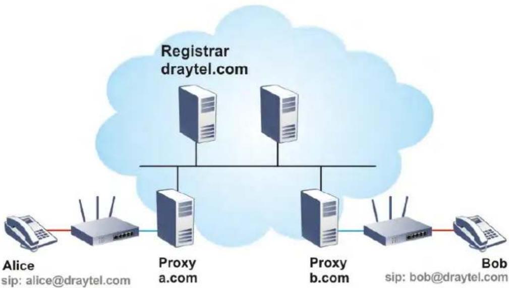
flowchart
graph TD
    A["Alice"] --> B["Proxy a.com"]
    C["Bob"] --> D["Proxy b.com"]
    B --> E["Registrar draytel.com"]
    D --> E
    E --> F["Cloud Cloud"]
The major benefit of this mode is that you don't have to memorize your friend's IP address, which might change very frequently if it's dynamic. Instead of that, you will only have to using dial plan or directly dial your friend's account name if you are with the same SIP Registrar.
Peer-to-Peer
Before calling, you have to know your friend's IP Address. The Vigor VoIP Routers will build connection between each other.
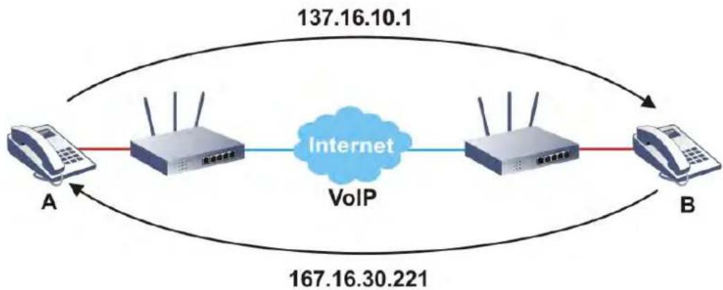
flowchart
graph LR
    A["Phone A"] -->|137.16.10.1| VoIP["Internet VoIP"]
    VoIP --> B["Phone B"]
    VoIP --> A
    VoIP --> B
    VoIP --> A
    VoIP --> B
    VoIP --> A
    VoIP --> B
    VoIP --> A
    VoIP --> B
    VoIP --> A
    VoIP --> B
    VoIP --> A
    VoIP --> B
    VoIP --> A
    VoIP --> B
    VoIP --> A
    VoIP --> B
    VoIP --> A
    VoIP --> B
    VoIP -.-> A
    VoIP -.-> B
Vigor V models firstly apply efficient codecs designed to make the best use of available bandwidth, but Vigor V models also equip with automatic QoS assurance. QoS Assurance assists to assign high priority to voice traffic via Internet. You will always have the required inbound and outbound bandwidth that is prioritized exclusively for Voice traffic over Internet but you just get your data a little slower and it is tolerable for data traffic.
Our Vigor V models firstly apply efficient codecs designed to make the best use of available bandwidth, but Vigor V models also equip with automatic QoS assurance. QoS Assurance assists to assign high priority to voice traffic via Internet. You will always have the required inbound and outbound bandwidth that is prioritized exclusively for Voice traffic over Internet but you just get your data a little slower and it is tolerable for data traffic.
Web User Interface
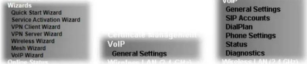
text_image
Wizards Quick Start Wizard Service Activation Wizard VPN Client Wizard VPN Server Wizard Wireless Wizard Mesh Wizard VoIP Wizard Online Status Certificate management VoIP General Settings VoIP General Settings SIP Accounts DialPlan Phone Settings Status Diagnostics Wireless LAN (2.4 GHz)IV-1-1 VoIP Wizard
Vigor router offers a quick method to configure settings for VoIP application. Follow the steps listed below.

Info
This wizard is available for "V" model only.
- Open Wizards>>VoIP Wizard.
- The screen of VoIP Wizard will be shown as follows.
VoIP Wizard
Set VoIP service provider domain
VoIP service provider
user define


(63 char max).
SIP Port
5060
5060
Set Account quickly
Phone 1 (default mapping to Account 1)
Account Number/Name


Password


Phone 2 (default mapping to Account 2)
√ use the same Account as phone1
Account Number/Name


Password


Available settings are explained as follows:
| Item Description | |
| Set VoIP service provider domain | VoIP service provider - Use the drop down list to choose the ISP which offers the VoIP service for your router.SIP Port - Use the default setting (5060). |
| Set Account quickly | Account Number/Name - Enter the account number/ name registered to your ISP.Password - Enter the password for the account registered to your ISP.Use the same Account as phone 1 – If you don’t need to configure Phone 2 settings, simply check this box. |
| Next | Click it to get into the next setting page. |
| Cancel | Click it to give up the VoIP wizard. |
- After finished the settings above, click Next for viewing summary of such connection.
VoIP Wizard
Please confirm your settings:
| VoIP Service Provider | draytel.org |
| SIP Port | 5060 |
| Phone 1 Account | 5633s |
| Phone 2 Account | 5633s |

- Click Finish. A page of VoIP Wizard Setup OK!!! will appear.
VoIP Wizard Setup OK!
IV-1-2 General Settings
Open VoIP>>General Settings. The following page will appear. Check the box of Enable VoIP and click OK to open the configuration page. If not, no settings will be displayed.
VoIP >> General Settings
Enable VoIP
Note:
If VoIP is disabled, there will be no power supplied to the FXS ports.
OK
After checking the box and click OK, the menu items under VoIP will be shown as follows.
VoIP
General Settings
SIP Accounts
DialPlan
Phone Settings
Status
Diagnostics
Wireless LAN/2.4 GHz
Again, open VoIP>>General Settings. The following page appears for you to configure secure phone, IP call; and set NAT Traversal Setting, RTP for the VoIP function.
VoIP >> General Settings
Enable VoIP
Note:
If VoIP is disabled, the FXS ports will connect to the line port.
Secure Phone
√ Enable Secure Phone (ZRTP+SRTP)
√ Enable SAS Voice Prompt
NAT Traversal Setting
STUN Server
External IP
SIP PING Interval
text_image
150 secRTP
□ Symmetric RTP
Dynamic RTP Port Start
Dynamic RTP Port End
RTP TOS
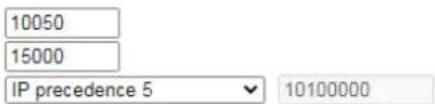
text_image
10050 15000 IP precedence 5 10100000IP Call
□ Enable IP Call
OK
Available settings are explained as follows:
| Item Description | |
| Secure Phone | Enable Secure Phone - It allows users to have encrypted RTP stream with the peer side using the same protocol (ZRTP+SRTP). Check this box to have secure call.Enable SAS Voice Prompt - If it is enabled, SAS prompt will be heard for both ends every time. If it is disabled, no SAS prompt will be heard any more. |
| NAT Traversal Setting | STUN Server - Type in the IP address or domain of the STUN server.External IP - Type in the gateway IP address.SIP PING interval - The default value is 150 (sec). It is useful for a Nortel server NAT Traversal Support. |
| RTP | Symmetric RTP - Check this box to invoke the function. To make the data transmission going through on both ends of local router and remote router not misleading due to IP lost (for example, sending data from the public IP of remote router to the private IP of local router), you can check this box to solve this problem.Dynamic RTP Port Start - Specifies the start port for RTP stream. The default value is 10050.Dynamic RTP Port End - Specifies the end port for RTP stream. The default value is 15000.RTP TOS - It decides the level of VoIP package. Use the drop down list to choose any one of them.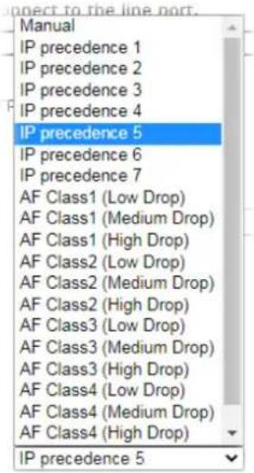 |
| IP Call | Enable IP Call - It allows that a user could dial outgoing IP Calls; and Vigor router could receive the incoming IP Calls. |
Application for Secure Phone
Enable SAS Voice Prompt, for ex: if vigor router A calls vigor router B with checking Enable Secure Phone and Enable SAS Voice Prompt, then:
- After the connection established, vigor router A will send SAS voice prompt to A and vigor router B will send the SAS voice prompt to B.
-
Then the RTP traffic is secured until the call ends.
-
If vigor router A wants to call vigor router B again next time, both A and B will not hear any voice prompt again even checking Enable SAS Voice Prompt on web UI. It means only the first call between them will have voice prompt.
Enable SAS Voice Prompt, for ex: if vigor router A calls vigor router B with checking Enable Secure Phone but not Enable SAS Voice Prompt, then:
-
After the connection established, vigor router A will NOT send SAS voice prompt to vigor router A and vigor router B will NOT send the SAS voice prompt to vigor router B.
-
Even no voice prompt, but the RTP traffic is still secured until the call ends.

Info
If the incoming or outgoing calls do not match any entry on the phonebook, the router will try to make the call "being protected". But, if the call ends up "unprotected"(e.g. peer side does not support ZRTP+SRTP), the router will not play out a warning message.
IV-1-3 SIP Accounts
In this section, you set up your own SIP settings. When you apply for an account, your SIP service provider will give you an Account Name or user name, SIP Registrar, Proxy, and Domain name. (The last three might be the same in some case). Then you can tell your folks your SIP Address as in Account Name@ Domain name
As Vigor VoIP Router is turned on, it will first register with Registrar using AuthorizationUser@Domain/Realm. After that, your call will be bypassed by SIP Proxy to the destination using AccountName@Domain/Realm as identity.

Info
Selection items for Ring Port will differ according to the router you have.
VoIP >> SiP Accounts

SIP Accounts List
Refresh
| Index | Profile | Domain/Realm | Proxy | Account Name | Codec | Ring Port | Status |
| 1 | --- | G.729A/B | □Phone1 □Phone2 | - | |||
| 2 | --- | G.729A/B | □Phone1 □Phone2 | - | |||
| 3 | --- | G.729A/B | □Phone1 □Phone2 | - | |||
| 4 | --- | G.729A/B | □Phone1 □Phone2 | - | |||
| 5 | --- | G.729A/B | □Phone1 □Phone2 | - | |||
| 6 | --- | G.729A/B | □Phone1 □Phone2 | - | |||
| 7 | --- | G.729A/B | □Phone1 □Phone2 | - | |||
| 8 | --- | G.729A/B | □Phone1 □Phone2 | - | |||
| 9 | --- | G.729A/B | □Phone1 □Phone2 | - | |||
| 10 | --- | G.729A/B | □Phone1 □Phone2 | - | |||
| 11 | --- | G.729A/B | □Phone1 □Phone2 | - | |||
| 12 | --- | G.729A/B | □Phone1 □Phone2 | - |
R: success registered on SIP server
-: fail to register on SIP server
Alias List
OK
Available settings are explained as follows:
| Item Description | |
| Index | Click this link to access into next page for setting SIP account. |
| Profile | Display the profile name of the account. |
| Domain/Realm | Display the domain name or IP address of the SIP registrar server. |
| Proxy Display the domain name or IP address of the SIP proxy server. | |
| Account Name | Display the account name of SIP address before @. |
| Codec | Display the codec type for the account. |
| Ring Port | Specify which port will ring when receiving a phone call. |
| Status | Show the status for the corresponding SIP account. R means such account is registered on SIP server successfully. - means the account is failed to register on SIP server. |
| Alias List | Allows you to set multiple SIP alias names. |
Click any index link to access into the following page for configuring SIP account.
VoIP >> SIP Accounts
SIP Account Index No. 1
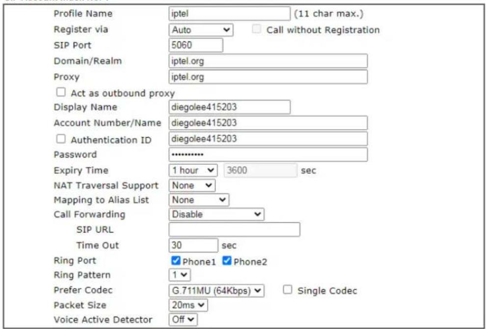
text_image
Profile Name Register via SIP Port Domain/Realm Proxy Act as outbound proxy Display Name Account Number/Name Authentication ID Password Expiry Time NAT Traversal Support Mapping to Alias List Call Forwarding SIP URL Time Out Ring Port Ring Pattern Prefer Codec Packet Size Voice Active Detector iptel (11 char max.) Auto Call without Registration 5060 iptel.org iptel.org diegolee415203 diegolee415203 diegolee415203 ********** 1 hour 3600 sec None None Disable 30 sec Phone1 Phone2 1 G.711MU (64Kbps) Single Codec 20ms Off
Available settings are explained as follows:
| Item Description | |
| Profile Name | Assign a name for this profile for identifying. You can type similar name with the domain. For example, if the domain name is draytel.org, then you might set draytel-1 in this field. |
| Register via | If you want to make VoIP call without register personal information, please choose None and check the box to achieve the goal. Some SIP server allows user to use VoIP function without registering. For such server, please check the box of Call without Registration. Choosing Auto is recommended. The system will select a proper way for your VoIP call. |
| SIP Port | Set the port number for sending/ receiving SIP message for building a session. The default value is 5060. Your peer must set the same value in his/her Registrar. |
| Domain/Realm | Set the domain name or IP address of the SIP Registrar server. |
| Proxy | Set domain name or IP address of SIP proxy server. By the time you can type :port number after the domain name to specify that port as the destination of data transmission(e.g., nat.draytel.org:5065) |
| Act as Outbound Proxy | Check this box to make the proxy acting as outbound proxy. |
| Display Name | The caller-ID that you want to be displayed on your friend's screen. |
| Account Number/Name | Enter your account name of SIP Address, e.g. every text before @. |
| Authentication ID | Check the box to invoke this function and enter the name or number used for SIP Authorization with SIP Registrar. If this setting value is the same as Account Name, it is not necessary for you to check the box and set any value in this field. |
| Password | The password provided to you when you registered with a SIP service. |
| Expiry Time | The time duration that your SIP Registrar server keeps your registration record. Before the time expires, the router will send another register request to SIP Registrar again. |
| NAT Traversal Support | If the router (e.g., broadband router) you use connects to internet by other device, you have to set this function for your necessity.None - Disable this function.Stun - Choose this option if there is Stun server provided for your router.Manual - Choose this option if you want to specify an external IP address as the NAT transversal support.Nortel - If the soft-switch that you use supports Nortel solution, you can choose this option. |
| Mapping to Alias List | Select one of the alias profiles. |
| Call Forwarding | There are four options for you to choose.Disableis to close call forwarding function.Alwaysmeans all the incoming calls will be forwarded into SIP URL without any reason.Busymeans the incoming calls will be forwarded into SIP URL only when the local system is busy.No Answermeans if the incoming calls do not receive any response, they will be forwarded to the SIP URL by the time out.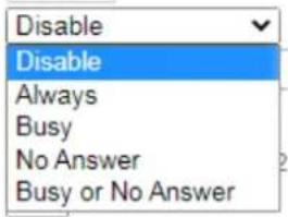 SIP URL - Type in the SIP URL (e.g., aaa@draytel.org or abc@iptel.org) as the site for call forwarded.Time Out- Set the time out for the call forwarding. The default setting is 30 sec. SIP URL - Type in the SIP URL (e.g., aaa@draytel.org or abc@iptel.org) as the site for call forwarded.Time Out- Set the time out for the call forwarding. The default setting is 30 sec. |
| Ring Port Set Phone 1 and/or | Phone 2 as the default ring port(s) for this SIP account. |
| Ring Pattern | Choose a ring tone type for the VoIP phone call.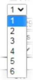 |
| Prefer Codec | Select one of five codecs as the default for your VoIP calls. The codec used for each call will be negotiated with the peer party before each session, and so may not be your default choice. The default codec is G.729A/B; it occupies little bandwidth while maintaining good voice quality.If your upstream speed is only 64Kbps, do not use G.711 codec. It is better for you to have at least 256Kbps upstream if you would like to use G.711.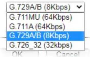 Single Codec - If the box is checked, only the selected Codec will be applied. Single Codec - If the box is checked, only the selected Codec will be applied. |
| Packet Size | The amount of data contained in a single packet. The default value is 20 ms, which means the data packet will contain 20 ms voice information.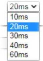 |
| Voice Active Detector | This function can detect if the voice on both sides is active or not. If not, the router will do something to save the bandwidth for other using. Click On to invoke this function; click Off to close the function. |
After finishing all the settings here, please click OK to save the configuration.
IV-1-3-1 Alias List
This page lists all SIP alias profiles.
A SIP alias is just like an extension number in that people can dial it to reach a specific person directly. Normally, when you have a user account for one ITSP, the ITSP will provide you one SIP account. However, with this feature, you can own multiple SIP alias over one SIP account. When you register with a regular user account, the alias is registered as well as the main SIP account. Then, when somebody dials the alias, the SIP URI bound to the alias will ring.
Click the Alias List link to access the configuration page as shown below.
VoIP >> Alias
Alias List
| Index | Profile Name | Number | Active | Account |
| 1. | No | |||
| 2. | No | |||
| 3. | No | |||
| 4. | No | |||
| 5. | No | |||
| 6. | No | |||
| 7. | No | |||
| 8. | No | |||
| 9. | No | |||
| 10. | No |
<< 1-10 | 11-20 | 21-30 >> Next >>
Available settings are explained as follows:
| Item Description | |
| Index | Click the number link for each profile. |
| Profile Name | Display the alias name for such sub account. |
| Number Display the phone number of such account. | |
| Active | Display current activation status for such account, enabled or disabled. |
| Account | Display the SIP account number for such sub account attached. |
You can set 30 profiles as alias. Click the number under Index to set detailed configuration.
VoIP >> Alias
Alias 1.
| Active | ● Enable ○ Disable |
| Alias Name | 522293 |
| Alias Number | 522293 |
| Alias of SIP account | 1 - diegolee415203 ▼ |
OK Clear Cancel
Available settings are explained as follows:
| Item Description | |
| Active | Click Enable to activate this entry. Or, click Disable to inactive this entry. |
| Alias Name | Specify a name for an alias number. |
| Alias Number | Enter an alias number.The alias numbers are obtained from your ITSP. |
| Alias of SIP account | Choose one of the items listed in SIP account list for this alias profile. |
After finishing all the settings here, please click OK to save the configuration.
Alias List
| Index | Profile Name | Number | Active | Account |
| 1. | 522293 | 522293 | Yes | diegolee415203 |
| 2. | No | |||
| 3. | No | |||
| 4. | No | |||
| 5. | No | |||
| 6. | No | |||
| 7. | No | |||
| 8. | No | |||
| 9. | No | |||
| 10. | No |
<< 1-10 | 11-20 | 21-30 >>
Next >>
IV-1-4 DialPlan
This page allows you to set phone book, digit map, call barring, and regional settings for the VoIP function. Click the links on this page to access into next pages for detailed settings.
IV-1-4-1 Phone Book
In this section, you can set your VoIP contacts in the "phonebook". It can help you to make calls quickly and easily by using "speed-dial" Phone Number. There are total 60 index entries in the phonebook for you to store all your friends and family members' SIP addresses. Loop through and Backup Phone Number will be displayed if you are using Vigor2927 series for setting the phone book.
VoIP >> DialPlan Setup
| Phone Book | Digit Map | Call Barring | Regional | |||
| Index | Phone Number | Display Name | SIP URL | Dial Out Account | Secure Phone | Status |
| 1. | Default | None | x | |||
| 2. | Default | None | x | |||
| 3. | Default | None | x | |||
| 4. | Default | None | x | |||
| 5. | Default | None | x | |||
| 6. | Default | None | x | |||
| 7. | Default | None | x | |||
| 8. | Default | None | x | |||
| 9. | Default | None | x | |||
| 10. | Default | None | x | |||
| 11. | Default | None | x | |||
| 12. | Default | None | x | |||
| 13. | Default | None | x | |||
| 14. | Default | None | x | |||
| 15. | Default | None | x | |||
| 16. | Default | None | x | |||
| 17. | Default | None | x | |||
| 18. | Default | None | x | |||
| 19. | Default | None | x | |||
| 20. | Default | None | x | |||


Click any index number to display the dial plan setup page.
VoIP >> DialPlan Setup
Phone Book Index No. 1
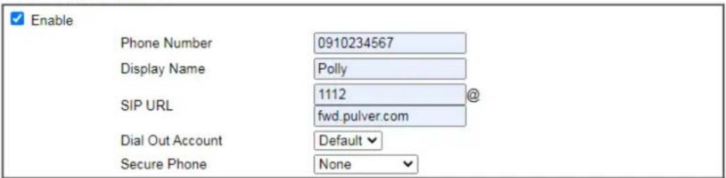
text_image
Enable Phone Number 0910234567 Display Name Polly SIP URL 1112@ fwd.pulver.com Dial Out Account Default Secure Phone None
Available settings are explained as follows:
| Item Description | |
| Enable | Click this to enable this entry. |
| Phone Number | The speed-dial number of this index. This can be any number you choose, using digits 0-9 and *. |
| Display Name | The Caller-ID that you want to be displayed on your friend's screen. This let your friend can easily know who's calling without memorizing lots of SIP URL Address. |
| SIP URL | Enter your friend's SIP Address. |
| Dial Out Account | Choose one of the SIP accounts for this profile to dial out. It is useful for both sides (caller and callee) that registered to different SIP Registrar servers. If caller and callee do not use the same SIP server, sometimes, the VoIP phone call connection may not succeed. By using the specified dial out account, the successful connection can be assured. |
| Secure Phone | ZRTP+SRTP - It allows users to have encrypted RTP stream with the peer side using the same protocol (ZRTP+SRTP). Check this box to have secure call. |
| Cancel Return to previous web page. | |
After finishing all the settings here, please click OK to save the configuration.

Info
If the incoming or outgoing calls do not match any entry on the phonebook, the router will try to make the call "being protected". But, if the call ends up "unprotected"(e.g. peer side does not support ZRTP+SRTP), the router will not play out a warning message.
IV-1-4-2 Digit Map
For the convenience of user, this page allows users to edit prefix number for the SIP account with adding number, stripping number or replacing number. It is used to help user have a quick and easy way to dial out through VoIP interface.
| Phone Book | Digit Map | Call Barring | Regional | |||||||
| # | Enable | Match Prefix | Mode | OP Number | Min Len | Max Len | Route | Move Up | Move Down | |
| 1 | 03 | Replace | 8863 | 7 | 8 | VoIP1 | Down | |||
| 2 | 886 | Strip | 886 | 9 | 10 | VoIP2 | UP | Down | ||
| 3 | None | 0 | 0 | None | UP | Down | ||||
| 4 | None | 0 | 0 | None | UP | Down | ||||
| 5 | None | 0 | 0 | None | UP | Down | ||||
| 6 | None | 0 | 0 | None | UP | Down | ||||
| 7 | None | 0 | 0 | None | UP | Down | ||||
| 8 | None | 0 | 0 | None | UP | Down | ||||
| 9 | None | 0 | 0 | None | UP | Down | ||||
| 10 | None | 0 | 0 | None | UP | Down | ||||
| 11 | None | 0 | 0 | None | UP | Down | ||||
| 12 | None | 0 | 0 | None | UP | Down | ||||
| 13 | None | 0 | 0 | None | UP | Down | ||||
| 14 | None | 0 | 0 | None | UP | Down | ||||
| 15 | None | 0 | 0 | None | UP | Down | ||||
| 16 | None | 0 | 0 | None | UP | Down | ||||
| 17 | None | 0 | 0 | None | UP | Down | ||||
| 18 | None | 0 | 0 | None | UP | Down | ||||
| 19 | None | 0 | 0 | None | UP | Down | ||||
| 20 | None | 0 | 0 | None | UP | |||||
Note:
1. The length for Min Len and Max Len fields should be between 0\~25.
2. Wildcard '?' is supported.

Available settings are explained as follows:
| Item Description | |
| Enable | Check this box to invoke this setting. |
| Match Prefix | It is used to match with the number you dialed and may be modified by the action (add, strip or replace) with the OP Number. |
| Mode None - No action. | Add - When you choose this mode, the OP number will be added before the match prefix number for calling out through the specific route.Strip - When you choose this mode, the partial or whole match prefix number will be deleted according to the OP number. Take the above picture (Prefix Table Setup web page) as an example, the OP number of 886 will be deleted completely for the match prefix number is set with 886.Replace - When you choose this mode, the OP number will be replaced by the prefix number for calling out through the specific VoIP interface. Take the above picture (Prefix Table Setup web page) as an example, the prefix number of 03 will be replaced by 8863. For example: dial number of “031111111” will be changed to “88631111111” and sent to SIP server. |
| OP Number | The front number you type here is the first part of the account number that you want to execute special function (according to the chosen mode) by using the prefix number. |
| Min Len | Set the minimal length of the dial number for applying the prefix number settings. Take the above picture (Prefix Table Setup web page) as an example, if the dial number is between 7 and 9, that number can apply the prefix number settings here. |
| Max Len | Set the maximum length of the dial number for applying the prefix number settings. |
| Route Choose the one that you want to enable the prefix number settings from the saved SIP accounts. Please set up one SIP account first to make this interface available. This item will be changed according to the port settings configured in VoIP>> Phone Settings. | |
| Move UP /Move Down | Click the link to move the selected entry up or down. |
After finishing all the settings here, please click OK to save the configuration.
IV-1-4-3 Call Barring
Call barring is used to block phone calls coming from the one that is not welcomed.
VoIP >> DialPlan Setup

| Phone Book | Digit Map | Call Barring | Regional | ||||
| Set to Factory Default | |||||||
| Index | Call Direction | Barring Type | Barring Number/URL/URI | Route | Schedule | Status | |
| 1. | Wizard1 | x | |||||
| 2. | Wizard1 | x | |||||
| 3. | Wizard1 | x | |||||
| 4. | Wizard1 | x | |||||
| 5. | Wizard1 | x | |||||
| 6. | Wizard1 | x | |||||
| 7. | Wizard1 | x | |||||
| 8. | Wizard1 | x | |||||
| 9. | Wizard1 | x | |||||
| 10. | Wizard1 | x | |||||


Block Anonymous
Route

Phone1

Phone2
Index(1-15) in Schedule Setup


Note:
Block the incoming calls which do not have the caller ID.
Block Unknown Domain
Route

Phone1

Phone2
Index(1-15) in Schedule Setup


Note:
If the domain of the incoming call is different from the domain found in SIP accounts, the call should be blocked.
Block IP Address
Route

Phone1

Phone2
Index(1-15) in Schedule Setup


Note:
The incoming calls by means of IP dialing (e.g.#192*168*1*1#) should be blocked.

Additionally, you can set advanced settings for call barring such as Block Anonymous, Block Unknown Domain or Block IP Address.
For Block Anonymous - this function can block the incoming calls without caller ID on the interface (Phone port) specified in the following window. Such control also can be done based on preconfigured schedules.
For Block Unknown Domain - this function can block incoming calls (through Phone port) from unrecognized domain that is not specified in SIP accounts. Such control also can be done based on preconfigured schedules.
For Block IP Address - this function can block incoming calls (through Phone port) coming from IP address. Such control also can be done based on preconfigured schedules.
Click any index number to display the call barring setup page.
VoIP >> DialPlan Setup
Call Barring Index No. 1
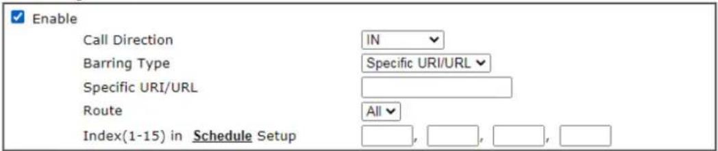
text_image
Enable Call Direction IN Barring Type Specific URI/URL Specific URI/URL Route All Index(1-15) in Schedule SetupNote:
Wildcard '?' is supported.

Available settings are explained as follows:
| Item Description | |
| Enable | Check it to enable this entry. |
| Call Direction | Determine the direction for the phone call, IN - incoming call, OUT-outgoing call, IN & OUT - both incoming and outgoing calls. |
| Barring Type | Determine the type of the VoIP phone call, URI/ URL or number.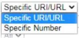 |
| Specific URI/URL or Specific Number | This field will be changed based on the type you selected for barring Type. |
| Route | All means all the phone calls will be blocked with such mechanism. |
| Index (1-15) in Schedule | Enter the index of schedule profiles to control the call barring according to the preconfigured schedules. Refer to section Applications>>Schedule for detailed configuration. |
IV-1-4-4 Regional
This page allows you to process incoming or outgoing phone calls by regional. Default values (common used in most areas) will be shown on this web page. You can change the number based on the region that the router is placed.
VoIP >> DialPlan Setup
| Phone Book | Digit Map | Call Barring | Regional |
| Enable Regional | Set to Factory Default | ||
| Last Call Return [Miss]: | *69 | ||
| Last Call Return [In]: | *12 | Last Call Return [Out]: | *14 |
| Call Forward [All] [Act]: | *72 | +number+# Call Forward [Deact]: | *73+# |
| Call Forward [Busy] [Act]: | *90 | +number+# Call Forward [No Ans] [Act]: | *92 +number+# |
| Do Not Disturb [Act]: | *78 | +# Do Not Disturb [Deact]: | *79+# |
| Hide caller ID [Act]: | *67 | +# Hide caller ID [Deact]: | *68+# |
| Call Waiting [Act]: | *56 | +# Call Waiting [Deact]: | *57+# |
| Block Anonymous [Act]: | *77 | +# Block Anonymous [Deact]: | *87+# |
| Block Unknow Domain [Act]: | *40 | +# Block Unknow Domain [Deact]: | *04+# |
| Block IP Calls [Act]: | *50 | +# Block IP Calls [Deact]: | *05+# |
| Block Last Calls [Act]: | *60 | +# | |

Available settings are explained as follows:
After finishing all the settings here, please click OK to save the configuration.
| Item Description | |
| Enable Regional | Check this box to enable this function. |
| Last Call Return [Miss] | Sometimes, people might miss some phone calls. Please dial number typed in this field to know where the last phone call comes from and call back to that one. |
| Last Call Return [In] | You have finished an incoming phone call, however you want to call back again for some reason. Please dial number typed in this field to call back to that one. |
| Last Call Return [Out] | Dial the number typed in this field to call the previous outgoing phone call again. |
| Call Forward [All][Act] | Dial the number typed in this field to forward all the incoming calls to the specified place. |
| Call Forward [Deact] | Dial the number typed in this field to release the call forward function. |
| Call Forward [Busy][Act] | Dial the number typed in this field to forward all the incoming calls to the specified place while the phone is busy. |
| Call Forward [No Ans][Act] | Dial the number typed in this field to forward all the incoming calls to the specified place while there is no answer of the connected phone. |
| Do Not Disturb [Act] | Dial the number typed in this field to invoke the function of DND. |
| Do Not Distrub [Deact] | Dial the number typed in this field to release the DND function. |
| Hide caller ID [Act] | Dial the number typed in this field to make your phone number (ID) not displayed on the display panel of remote end. |
| Hide caller ID [Deact] | Dial the number typed in this field to release this function. |
| Call Waiting [Act] | Dial the number typed in this field to make all the incoming calls waiting for your answer. |
| Call Waiting [Deact] | Dial the number typed in this field to release this function. |
| Block Anonymous[Act] Dial | the number typed in this field to block all the incoming calls with unknown ID. |
| Block Anonymous[Deact] | Dial the number typed in this field to release this function. |
| Block Unknown Domain [Act] | Dial the number typed in this field to block all the incoming calls from unknown domain. |
| Block Unknown Domain [Deact] | Dial the number typed in this field to release this function. |
| Block IP Calls [Act] | Dial the number typed in this filed to block all the incoming calls from IP address. |
| Block IP Calls [Deact] | Dial the number typed in this field to release this function. |
| Block Last Calls [Act] | Dial the number typed in this field to block the last incoming phone call. |
IV-1-5 Phone Settings
This page allows user to set phone settings for Phone 1 and Phone 2 respectively. However, it changes slightly according to different model you have.
VoIP >> Phone Settings
Phone Setting
| Index | Port | Call Feature | Tone | Gain (Mic/Speaker) | Default SIP Account | DTMF Relay |
| 1 | Phone1 | CW,CT, | Taiwan | 5/5 | OutBand | |
| 2 | Phone2 | CW,CT, | Taiwan | 5/5 | OutBand |
Available settings are explained as follows:
| Item Description | |
| Phone Setting | Index - there are two phone ports provided here for you to configure.Port - Display phone1 and phone2.Call Feature - A brief description for call feature will be shown in this field for your reference.Tone - Display the tone settings that configured in the advanced settings page of Phone Index.Gain - Display the volume gain settings for Mic/ Speaker that configured in the advanced settings page of Phone Index.Default SIP Account - “draytel_1” is the default SIP account. You can click the number below the Index field to change SIP account for each phone port.DTMF Relay - Display DTMF mode that configured in the advanced settings page of Phone Index. |
After finishing all the settings here, please click OK to save the configuration.
Detailed Settings for Phone Port
Click the index number link for Phone port, you can access into the following page for configuring Phone settings.
VoIP >> Phone Settings
Phone1
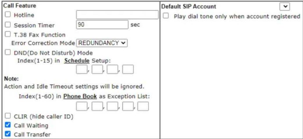
text_image
Call Feature □ Hotline □ Session Timer 90 sec □ T.38 Fax Function Error Correction Mode REDUNDANCY □ DND(Do Not Disturb) Mode Index(1-15) in Schedule Setup: □, □, □, □ Note: Action and Idle Timeout settings will be ignored. Index(1-60) in Phone Book as Exception List: □, □, □, □, □ □ CLIR (hide caller ID) ✓ Call Waiting ✓ Call Transfer
Available settings are explained as follows:
| Item Description | |
| Hotline Check the box to enable it. Type in the SIP URL in the field for dialing automatically when you pick up the phone set. | |
| Session Timer | Check the box to enable the function. In the limited time that you set in this field, if there is no response, the connecting call will be closed automatically. |
| T.38 Fax Function | Check the box to enable T.38 fax function.Error Correction Mode - choose a mode for error correction. |
| DND (Do Not Disturb) mode | Set a period of peace time without disturbing by VoIP phone call. During the period, the one who dial in will listen busy tone, yet the local user will not listen any ring tone.Index (1-15) in Schedule - Enter the index of schedule profiles to control when the phone will ring and when will not according to the preconfigured schedules. Refer to section Application >>Schedule for detailed configuration.Index (1-60) in Phone Book - Enter the index of phone book profiles. Refer to section DialPlan - Phone Book for detailed configuration. |
| CLIR (hide caller ID) | Check this box to hide the caller ID on the display panel of the phone set. |
| Call Waiting | Check this box to invoke this function. A notice sound will appear to tell the user new phone call is waiting for your response. Click hook flash to pick up the waiting phone call. |
| Call Transfer | Check this box to invoke this function. Click hook flash to initiate another phone call. When the phone call connection succeeds, hang up the phone. The other two sides can communicate, then. |
| Default SIP Account | You can set SIP accounts (up to six groups) on SIP Account page. Use the drop down list to choose one of the profile names for the accounts as the default one for this phone setting.Play dial tone only when account registered - Check this box to invoke the function. |
In addition, you can press the Advanced button to configure tone settings, volume gain, MISC and DTMF mode. Advanced setting is provided for fitting the telecommunication custom for the local area of the router installed. Wrong tone settings might cause inconvenience for users. To set the sound pattern of the phone set, simply choose a proper region to let the system find out the preset tone settings and caller ID type automatically. Or you can adjust tone settings manually if you choose User Defined. TOn1, TOff1, TOn2 and TOff2 mean the cadence of the tone pattern. TOn1 and TOn2 represent sound-on; TOff1 and TOff2 represent the sound-off.
VoIP >> Phone Settings
Advance Settings >> Phone 1
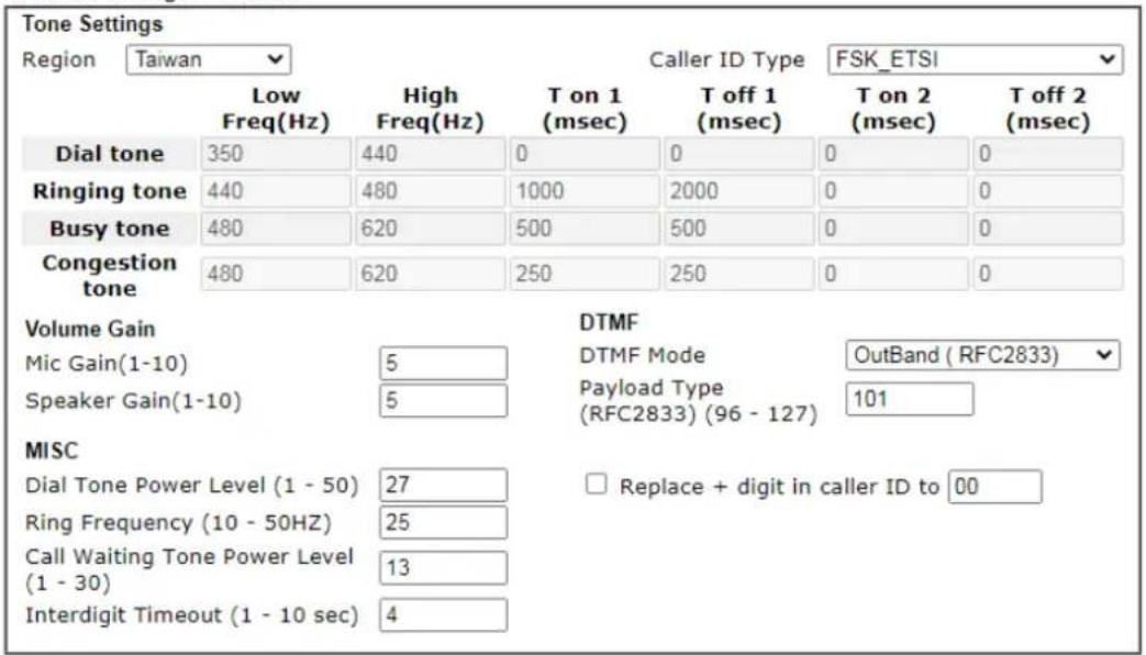
text_image
Tone Settings Region Taiwan Low Freq(Hz) High Freq(Hz) T on 1 (msec) T off 1 (msec) T on 2 (msec) T off 2 (msec) Dial tone 350 440 0 0 0 0 Ringing tone 440 480 1000 2000 0 0 Busy tone 480 620 500 500 0 0 Congestion tone 480 620 250 250 0 0 Volume Gain Mic Gain(1-10) 5 Speaker Gain(1-10) 5 DTMF DTMF Mode OutBand (RFC2833) Payload Type 101 (RFC2833) (96 - 127) MISC Dial Tone Power Level (1 - 50) 27 Ring Frequency (10 - 50HZ) 25 Call Waiting Tone Power Level (1 - 30) 13 Interdigit Timeout (1 - 10 sec) 4 Replace + digit in caller ID to 00
Available settings are explained as follows:
| Item Description | |
| Region | Select the proper region which you are located. The common settings of Caller ID Type, Dial tone, Ringing tone, Busy tone and Congestion tone will be shown automatically on the page. If you cannot find out a suitable one, please choose User Defined and fill out the corresponding values for dial tone, ringing tone, busy tone, congestion tone by yourself for VoIP phone.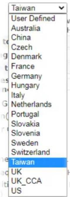 Also, you can specify each field for your necessity. It is recommended for you to use the default settings for VoIP communication. Also, you can specify each field for your necessity. It is recommended for you to use the default settings for VoIP communication. |
| Volume Gain | Mic Gain (1-10)/Speaker Gain (1-10) - Adjust the volume of microphone and speaker by entering number from 1- 10. The larger of the number, the louder the volume is. |
| MISC | Dial Tone Power Level - This setting is used to adjust the loudness of the dial tone. The smaller the number is, the louder the dial tone is. It is recommended for you to use the default setting.Ring Frequency - This setting is used to drive the frequency of the ring tone. It is recommended for you to use the default setting.Call Waiting Tone Power Level - This setting is used to adjust the loudness of the call waiting tone. The smaller the number is, the louder the tone is. It is recommended for you to use the default setting.Interdigit Timeout -Type a value in this field to specify time limit for interdigit. |
| DTMF | DTMF Mode - There are four DTMF modes for you to choose.InBand - Choose this one then the Vigor will send the DTMF tone as audio directly when you press the keypad on the phone.OutBand - Choose this one then the Vigor will capture the keypad number you pressed and transform it to digital form then send to the other side; the receiver will generate the tone according to the digital form it receive. This function is very useful when the network traffic congestion occurs and it still can remain the accuracy of DTMF tone.SIP INFO- Choose this one then the Vigor will capture the DTMF tone and transfer it into SIP form. Then it will be sent to the remote end with SIP message.Payload Type (rfc2833) - Type a number from 96 to 127, the default value was 101. This setting is available for the OutBand (RFC2833) mode.Replace + digit in caller ID to - For international phone call, the phone number could add a '+' sign, for example, +8865972727. However, the caller ID (DTMF type especially) can not display '+' at all.Therefore, this function can be enabled to give another number to replace the plus sign, for example, “+” can be replaced by “00”. Then the above phone number will become 008865972727. When the callee receives such number, he can use re-dial function to dial back to the caller. |
IV-1-6 Status
From this page, you can find codec, connection and other important call status for each port.
VoIP >> Status
| Port | Status | Codec | PeerID | Elapse(hh:mm:ss) | TxPkts | RxPkts | RxLosts | RxJitter(ms) | InCalls | OutCalls | MissCalls | SpeakerGain |
| Phone1 | IDLE | 00:00:00 | 0 | 0 | 0 | 0 | 0 | 0 | 0 | 5 | ||
| Phone2 | IDLE | 00:00:00 | 0 | 0 | 0 | 0 | 0 | 0 | 0 | 5 |
| Date(mm-dd-yyyy) | Time(hh:mm:ss) | Duration(hh:mm:ss) | In/Out/Miss | Account ID | Peer ID | |
| 00-00- | 0 | 00:00:00 | 00:00:00 | - | - | |
| 00-00- | 0 | 00:00:00 | 00:00:00 | - | - | |
| 00-00- | 0 | 00:00:00 | 00:00:00 | - | - | |
| 00-00- | 0 | 00:00:00 | 00:00:00 | - | ||
| 00-00- | 0 | 00:00:00 | 00:00:00 | - | - | |
| 00-00- | 0 | 00:00:00 | 00:00:00 | - | - | |
| 00-00- | 0 | 00:00:00 | 00:00:00 | 00:00:00 | - | - |
| 00-00- | 0 | 00:00:00 | 00:00:00 | - | - | |
| 00-00- | 0 | 00:00:00 | 00:00:00 | - | - | |
| 00-00- | 0 | 00:00:00 | 00:00:00 | - | ||
| 00-00- | 0 | 00:00:00 | 00:00:00 | - | - | |
xxxxxxxxx : VoIP is encrypted. xxxxxxxxx : VoIP isn't encrypted.
Available settings are explained as follows:
| Item Description | |
| Refresh Seconds | Specify the interval (5, 10 or 30) of refresh time to obtain the latest VoIP calling information. The information will update immediately when the Refresh button is clicked. |
| Port It shows current connection status for Phone(s) ports. | |
| StatusCodec | It shows the VoIP connection status.IDLE - Indicates that the VoIP function is idle.HANG_UP - Indicates that the connection is not established (busy tone).CONNECTING - Indicates that the user is calling out.WAIT_ANS - Indicates that a connection is launched and waiting for remote user's answer.ALERTING - Indicates that a call is coming.ACTIVE-Indicates that the VoIP connection is launched.Indicates the voice codec employed by present channel. |
| PeerID | The present in-call or out-call peer ID (the format may be IP or Domain). |
| Elapse(hh:mm:ss) | The format is represented as hours:minutes:seconds. |
| Tx Pkts | Total number of transmitted voice packets during this connection session. |
| Rx Pkts | Total number of received voice packets during this connection session. |
| Rx Losts | Total number of lost packets during this connection session. |
| Rx Jitter | The jitter of received voice packets. |
| In Calls | Accumulation for the times of in call. |
| Out Calls | Accumulation for the times of out call. |
| Miss Calls | Accumulation for the times of missing call. |
| Speaker Gain | The volume of present call. |
| Log | Display logs of VoIP calls. |
IV-1-7 Diagnostics
VoIP Diagnostics is used for diagnosing if VoIP phone failure is caused by different tone or caller ID.
VoIP >> Diagnostics
VoIP Diagnostics
| Caller IDTone |
IV-1-7-1 Caller ID
VoIP >> VOIP Diagnostics
Send Caller ID
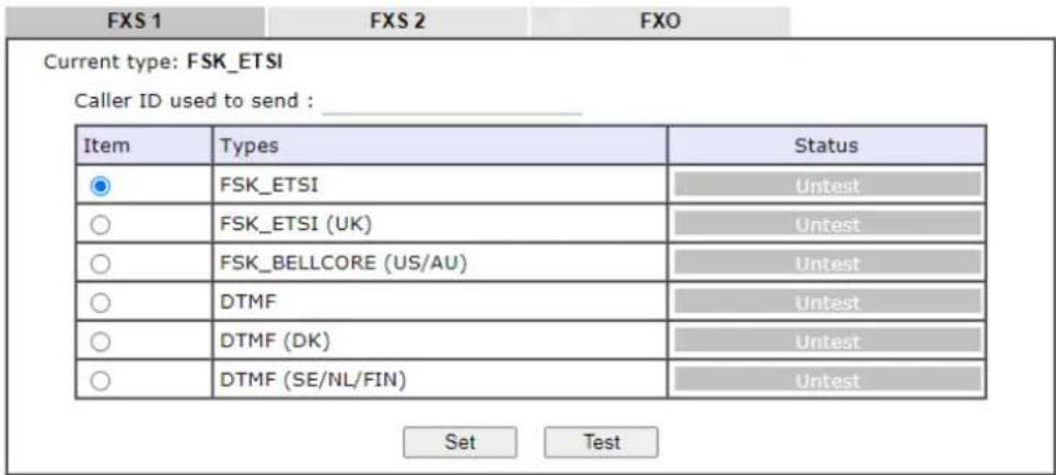
text_image
FXS 1 FXS 2 FXO Current type: FSK_ETSI Caller ID used to send : ____ Item Types Status ● FSK_ETSI Untest ○ FSK_ETSI (UK) Untest ○ FSK_BELLCORE (US/AU) Untest ○ DTMF Untest ○ DTMF (DK) Untest ○ DTMF (SE/NL/FIN) Untest Set TestIV-1-7-2 Tone
VoIP >> VOIP Diagnostics
Send Tone
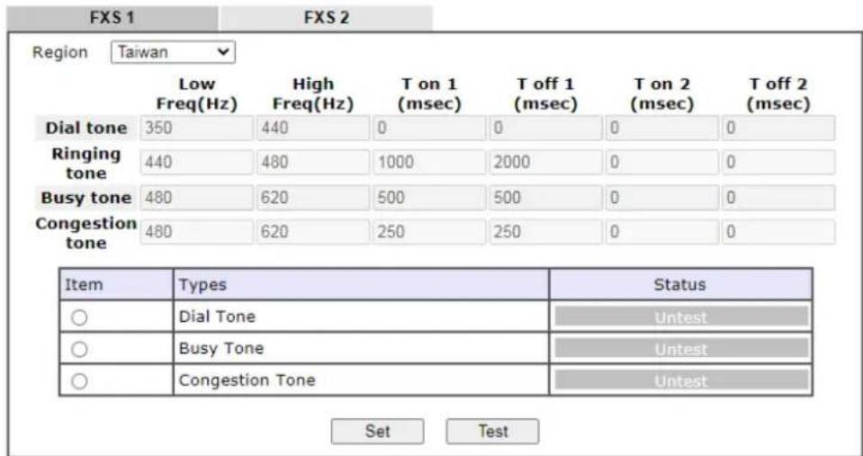
text_image
FXS 1 Region Taiwan Low Freq(Hz) High Freq(Hz) T on 1 (msec) T off 1 (msec) T on 2 (msec) T off 2 (msec) Dial tone 350 440 0 0 0 0 Ringing tone 440 480 1000 2000 0 0 Busy tone 480 620 500 500 0 0 Congestion tone 480 620 250 250 0 0 Item Types Status ○ Dial Tone Untest ○ Busy Tone Untest ○ Congestion Tone Untest Set TestThis page is left blank.
Part V VPN

VPN

Certificate Management
A Virtual Private Network (VPN) is the extension of a private network that encompasses links across shared or public networks like the Internet. In short, by VPN technology, you can send data between two computers across a shared or public network in a manner that emulates the properties of a point-to-point private link.
A digital certificate works as an electronic ID, which is issued by a certification authority (CA). It contains information such as your name, a serial number, expiration dates etc., and the digital signature of the certificate-issuing authority so that a recipient can verify that the certificate is real. Here Vigor router support digital certificates conforming to standard X.509.
V-1 VPN and Remote Access
A Virtual Private Network (VPN) is an extension of a private network that allows users to access network resources that available on the private network across shared or public networks such as the Internet, as if users are directly connected to the private network.
Here are some uses of VPNs:
● Communication between home office and customer.
- Secure connection between Teleworker, staff on business trip and main office.
● Exchange data between remote office and main office.
● POS between chain store and headquarters.
● Circumvention of Internet censorship that filters websites or contents.
- Circumvention of geolocation techniques employed by service providers or vendors to block or restrict services to users.
- Secure communications over public access points
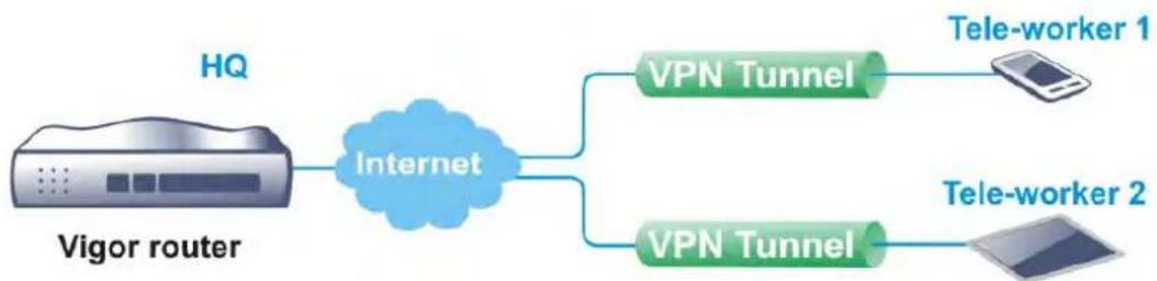
flowchart
graph LR
    A["HQ"] --> B["Internet"]
    B --> C["VPN Tunnel"]
    B --> D["VPN Tunnel"]
    C --> E["Tele-worker 1"]
    D --> F["Tele-worker 2"]
Web User Interface
Wizards
Quick Start Wizard
Service Activation Wizard
VPN Client Wizard
VPN Server Wizard
Wireless Wizard
VPN and Remote Access
Remote Access Control
PPP General Setup
SSL General Setup
IPsec General Setup
IPsec Peer Identity
VPN Matcher Setup
OpenVPN
WireGuard
Remote Dial-in User
LAN to LAN
VPN TRUNK Management
Connection Management
V-1-1 VPN Client Wizard
The VPN Client Wizard will configure the router as a client to connect to a remote VPN server using a LAN-to-LAN VPN tunnel. The wizard will guide you through the setup process.
- On the menu bar, click on Wizards, and then VPN Client Wizard.
VPN Client Wizard
Choose VPN Establishment Environment
Please choose a LAN-to-LAN Profile:
1 x ???
< Back
Next>
Finish
Cancel
Available settings are explained as follows:
| Item Description | |
| Please choose a LAN-to-LAN Profile | The profile used to store this tunnel configuration.Selecting an index that has already been setup previously will result in the existing setup getting overwritten by the wizard. |
- When you finish the mode and profile selection, please click Next to open the following page.
VPN Client Wizard
VPN Connection Setting
| Security Ranking: | Throughput Ranking: |
| Very High | Very High |
| IPsec XAuth | L2TP / PPTP (None Encryption) |
| IPsec IKEv2 EAP (only for NAT Mode) | |
| L2TP over IPSec | High |
| OpenVPN (AES256) | IPSec IKEv2/EAP/IKEv1/XAuth OpenVPN (UDP None Encryption) |
| High | |
| IPSec IKEv1/IKEv2 | Medium |
| SSL | L2TP over IPSec / PPTP (Encryption) |
| OpenVPN (AES128) | OpenVPN (UDP) OpenVPN (TCP None Encryption) |
| Medium | |
| PPTP (Encryption) | Low SSL/OpenVPN (TCP) |
| Low | |
| L2TP / PPTP (None Encryption) | |
| OpenVPN (None Encryption) | |
| LAN-to-LAN VPN Client Mode Selection: | Route Mode▼ |
| Select VPN Type: | PPTP (Encryption)▼ |
| Note: 1. Please use Route Mode for typical LAN-to-LAN tunnels. 2. If the remote network is only expecting a single client or IP and is not configured to route the subnet then select NAT Mode. 3. If you are unsure of your configuration select Route Mode. | |

Available settings are explained as follows:
| Item Description | |
| LAN-to-LAN Client Mode Selection | Route Mode - All traffic between the local network and the remote network bear the originating IP addresses. Select this if the VPN server can establish routes to handle inter-LAN traffic routing.NAT Mode - The VPN client (local router) uses a single IP address assigned by the VPN server (remote router) and uses NAT to keep track of the connections. Select this if the VPN server expects only one IP address on the local network to communicate with the remote network. |
| Select VPN Type | Select a VPN protocol for the LAN-to-LAN tunnel. Different VPN protocols offer different levels or security and performance. |

Info
The following descriptions for VPN Type are based on the Route Mode specified in LAN-to-LAN Client Mode Selection.
If you have selected PPTP (None Encryption) or PPTP (Encryption), the following configuration screen appears.
VPN Client Wizard
VPN Client PPTP Encryption Settings
| Profile Name | ??? |
| VPN Dial-Out Through | WAN1 First |
| □ Always on | |
| Server IP/Host Name for VPN(e.g. draytek.com or 123.45.67.89) | |
| Username | ??? |
| Password | |
| Remote Network IP | 0.0.0.0 |
| Remote Network Mask | 255.255.255.0 / 24 |
| Local Network IP | 192.168.1.1 |
| Local Network Mask | 255.255.255.0 / 24 |
If you have selected IPsec, the following configuration screen appears.
VPN Client Wizard
VPN Client IPsec Settings
| Profile Name | ??? |
| VPN Dial-Out Through | WAN1 First |
| □ Always on | |
| Server IP/Host Name for VPN(e.g. draytek.com or 123.45.67.89) | |
| IKE Authentication Method | |
| ● Pre-Shared Key | |
| Confirm Pre-Shared Key | |
| ○ Digital Signature (X.509) | |
| Peer ID | None |
| Local ID | |
| ● Alternative Subject Name First | |
| ○ Subject Name First | |
| Local Certificate | None |
| IPsec Security Method | |
| ○ Medium (AH) | |
| ● High (ESP) | AES with Authentication |
| Remote Network IP | 0.0.0.0 |
| Remote Network Mask | 255.255.255.0 / 24 |
| Local Network IP | 192.168.1.1 |
| Local Network Mask | 255.255.255.0 / 24 |

If you have selected SSL/L2TP, the following configuration screen appears.
VPN Client Wizard
VPN Client L2TP Settings
| Profile Name | ??? |
| VPN Dial-Out Through | WAN1 First |
| □ Always on | |
| Server IP/Host Name for VPN(e.g. draytek.com or 123.45.67.89) | |
| Username | ??? |
| Password | |
| Remote Network IP | 0.0.0.0 |
| Remote Network Mask | 255.255.255.0 / 24 |
| Local Network IP | 192.168.1.1 |
| Local Network Mask | 255.255.255.0 / 24 |

If you have selected L2TP over IPsec (Nice to Have) or L2TP over IPsec (Must), the following configuration screen appears.
VPN Client Wizard
VPN Client L2TP over IPsec (Nice to Have) Settings
| Profile Name | ??? |
| VPN Dial-Out Through | WAN1 First |
| □ Always on | |
| Server IP/Host Name for VPN(e.g. draytek.com or 123.45.67.89) | |
| IKE Authentication Method | |
| ● Pre-Shared Key | |
| Confirm Pre-Shared Key | |
| ○ Digital Signature (X.509) | |
| Peer ID | None |
| Local ID | |
| ● Alternative Subject Name First | |
| ○ Subject Name First | |
| Local Certificate | None |
| IPsec Security Method | |
| ○ Medium (AH) | |
| ● High (ESP) | AES with Authentication |
| Username | ??? |
| Password | |
| Remote Network IP | 0.0.0.0 |
| Remote Network Mask | 255.255.255.0 / 24 |
| Local Network IP | 192.168.1.1 |
| Local Network Mask | 255.255.255.0 / 24 |

If you have selected OpenVPN, the following configuration screen appears.
VPN Client OpenVPN Encryption Settings
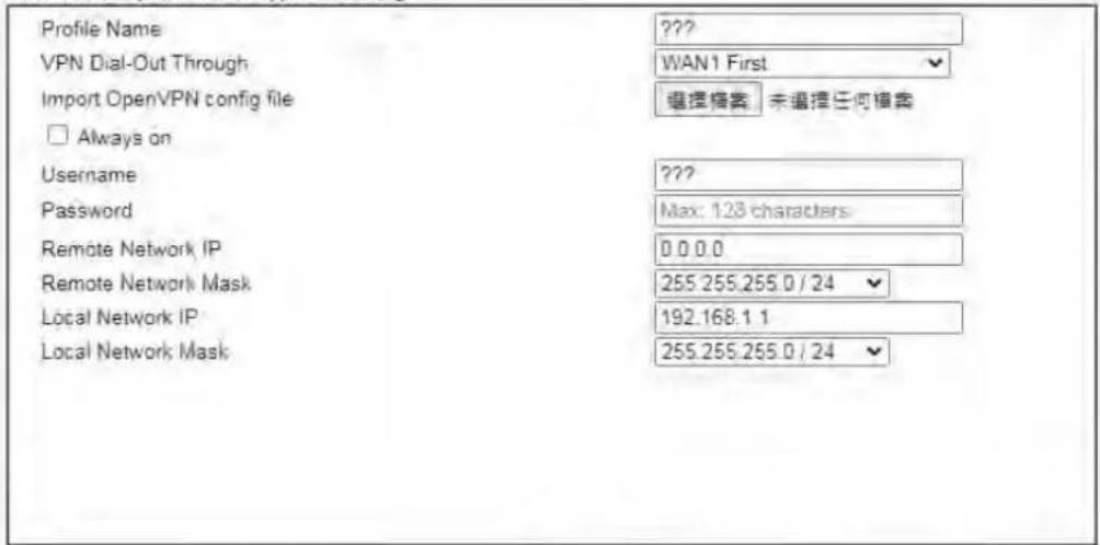
text_image
Profile Name ??? VPN Dial-Out Through WAN1 First Import OpenVPN config file 選擇檔案 未選擇任何檔案 □ Always on Username ??? Password Max: 128 characters Remote Network IP 0.0.0.0 Remote Network Mask 255.255.255.0 / 24 Local Network IP 192.168.1 1 Local Network Mask 255.255.255.0 / 24
Available settings are explained as follows:
| Item Description | |
| Profile Name | Name that identifies this profile. The maximum length of the Profile Name is 10 characters. |
| VPN Dial-Out Through | The WAN interface to be used for dialing out to establish the VPN tunnel.WANx First (or LTE First) - The Router first attempts to establish the VPN tunnel using this WAN interface. When that is unsuccessful, it will attempt to use other WAN interfaces.WANx Only (or LTE Only) - The Router will establish the VPN tunnel using this WAN interface only.WANx Only: Only establish VPN if WANy down - The Router will establish the VPN tunnel using this WAN interface if the other WAN interface is offline. |
| Always On | If selected, the router will maintain the VPN connection. |
| Server IP/Host Name for VPN | Enter the IP address or hostname of the server of the remote VPN server. |
| IKE Authentication Method | IKE Authentication Method to be used. Choose between Pre-shared Key and Digital Signature (X.509).Pre-shared KeyPre-Shared Key- Specify a key for IKE authentication.Confirm Pre-Shared Key-Confirm the pre-shared key.Digital Signature (X.509)Peer ID - Select Peer ID from the dropdown list. Peer IDs are managed using VPN and Remote Access >> IPsec Peer Identity.Local ID - Select Alternative Subject Name First or Subject Name First.Local Certificate - Select a certificate from the dropdown list. Local certificates are managed usingCertificate Management >> Local Certificate. |
| IPsec Security Method | Medium - Authentication Header (AH) means data will be authenticated, but not be encrypted. By default, this option is active.High - Encapsulating Security Payload (ESP) means payload (data) will be encrypted and authenticated. You may select encryption algorithm from Data Encryption Standard (DES), Triple DES (3DES), and AES. |
| Import OpenVPN config file | Select to import an OpenVPN configuration file from a specified OpenVPN server (e.g., Vigor router, PC, other VPN provider and etc.) onto to Vigor router.Later, as a VPN client, this router can access into VPN server via the username and password. |
| Username | This field is used to authenticate for connection when you select PPTP or L2TP with or without IPsec policy above.The length of the user name is limited to 11 characters. |
| Password | This field is used to authenticate for connection when you select PPTP or L2TP with or without IPsec policy above.The length of the password is limited to 11 characters. |
| Remote Network IP | Please enter one LAN IP address (according to the real location of the remote host) for building VPN connection. |
| Remote Network Mask | Please enter the network mask (according to the real location of the remote host) for building VPN connection. |
| Local Network IP | Enter the local network IP for TCP / IP configuration. |
| Local Network Mask | Enter the local network mask for TCP / IP configuration. |
- After you have entered all the required information, click Next to proceed to the confirmation page. The confirmation page shows a summary of all the settings. If you need to make adjustments to the settings, click Back to return to the previous page. Otherwise, select one of the following actions and click Finish to save the changes to the LAN-to-LAN VPN profile.
VPN Client Wizard
Please confirm your settings
| LAN-to-LAN Index: | 1 |
| Profile Name: | ??? |
| VPN Connection Type: | L2TP over IPsec (Nice to Have) |
| VPN Dial-Out Through: | WAN1 First |
| Always on: | Yes |
| Server IP/Host Name: | 172.16.3.8 |
| IKE Authentication Method: | Pre-Shared Key |
| IPsec Security Method: | AES with Authentication |
| Remote Network IP: | 172.16.3.89 |
| Remote Network Mask: | 255.255.255.0 |
| Local Network IP: | 192.168.1.15 |
| Local Network Mask: | 255.255.255.0 |

Available settings are explained as follows:
| Item Description | |
| Go to the VPN Connection Management | Proceed to VPN and Remote Access>>Connection Management to manage VPN sessions. |
| Do another VPN Client Wizard Setup | Rerun the VPN Client Wizard to configure another LAN-to-LAN VPN profile. |
| View more detailed configuration | Open this profile in VPN and Remote Access>>LAN to LAN to make additional configuration changes. |
V-1-2 VPN Server Wizard
The VPN Server Wizard can be used to set the router up as a server that accepts inbound VPN connections from a VPN server using a LAN-to-LAN VPN tunnel.
Site-to-Site (LAN-to-LAN)
● A connection between two router's LAN networks.
- Allows employees in branch offices and head office to share the same network resources.

flowchart
graph LR
    A["Local Network 192.168.1.0/24"] --> B["Network"]
    B --> C["Internet"]
    C --> D["Remote Network 172.16.2.0/24"]
    B --> E["VPN Tunnel"]
    E --> F["Network"]
Remote Access (Remote Dial-in)
- A connection between the remote host and router's LAN network. The host will use an IP address in the local subnet.
- Allows employees to access the company's internal resources when they are traveling.

flowchart
graph LR
    A["Local Network 192.168.1.0/24"] --> B["Network"]
    B --> C["Internet VPN Tunnel"]
    C --> D["Remote Host 192.168.1.100"]
The wizard will guide you step by step through the setup process.
- On the menu bar, click on Wizards, and then VPN Server Wizard.
VPN Server Wizard
Choose VPN Establishment Environment

text_image
VPN Server Mode Selection: Site to Site VPN (LAN-to-LAN) Please choose a LAN-to-LAN Profile: [Index] [Status] [Name] Please choose a Dial-in User Accounts: [Index] [Status] [Name] Allowed Dial-in Type: □ PPTP □ IPsec □ IPsec XAuth □ L2TP with IPsec Policy None □ SSL Tunnel □ OpenVPN Tunnel
Available settings are explained as follows:
| Item Description | |
| VPN Server Mode Selection | Type of VPN Server to be configured.Site to Site VPN (LAN-to-LAN) - Configures the VPN server for inbound connections from other routers.Remote Dial-in User (Teleworker) - Configures VPN server for inbound connections from remote users. |
| Please choose a LAN-to-LAN Profile | If the VPN Server Mode selected was Site to Site VPN (LAN-to-LAN), choose a LAN-to-LAN profile to store this configuration. |
| Please choose a Dial-in User Accounts | If the VPN Server Mode selected was Remote Dial-in User (Teleworker), choose a Dial-in user profile to store this configuration. |
| Allowed Dial-in Type | Select all VPN protocols that are allowed for this LAN-to-LAN Profile or Dial-in User Account.Different Dial-in Type will lead to different configuration page. In addition, adjustable items for each dial-in type will be changed according to the VPN Server Mode (Site to Site VPN and Remote Dial-in User) selected. |
- After making the choices for the server profile, please click Next.
- The following dialog box appears, reminding you to not configure IPsec fields if the remote location has a dynamic IP address.
192.168.1.1
If you are using IPsec Main mode and the remote VPN gateway has a dynamic IP address, please don't setup "PeerIP" or "Peer ID" fields, and don't tick "IPsec Authentication". Instead, please go to the VPN and Remote Access >> IPsec General Setup page to setup a common preshared key.
确定
Click OK to dismiss the dialog box and proceed to the next page.
If you have chosen to configure a LAN-to-LAN VPN profile, proceed to step 4.
If you have chosen to configure a Remote Dial-in User VPN profile, proceed to step 5.
- The Site to Site VPN (LAN-to-LAN) configuration page appears as follows if you have selected PPTP/SSL.
VPN Server Wizard
VPN Authentication Setting
| Profile Name | ??? |
| PPTP / SSL Tunnel Authentication | |
| Username | ??? |
| Password | |
| Peer IP/VPN Client IP | |
| Site to Site Information | |
| Remote Network IP | 0.0.0.0 |
| Remote Network Mask | 255.255.255.0/24 |
| Local Network IP | 192.168.1.1 |
| Local Network Mask | 255.255.255.0/24 |

If you have selected PPTP & IPsec & L2TP (three types) or PPTP & IPsec (two types) or L2TP with Policy (Nice to Have/Must), the following configuration screen appears.
VPN Server Wizard
VPN Authentication Setting
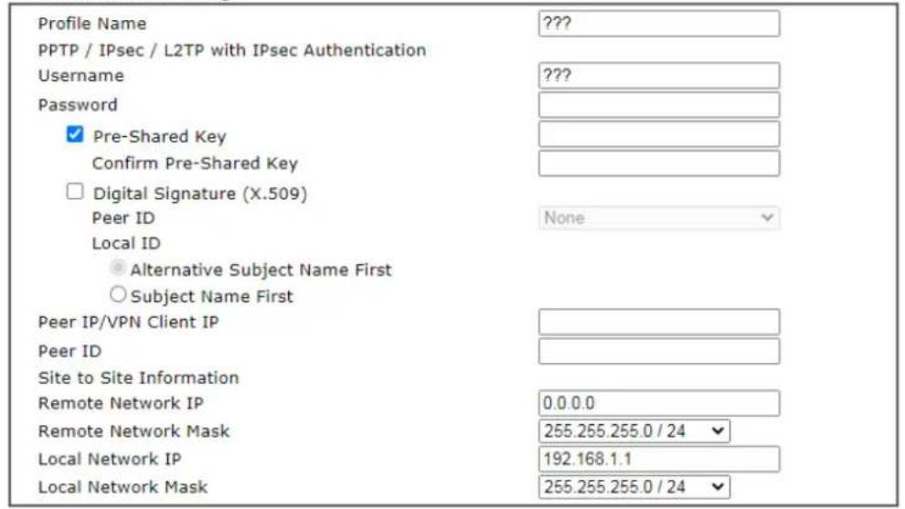
text_image
Profile Name PPTP / IPsec / L2TP with IPsec Authentication Username Password ✓ Pre-Shared Key Confirm Pre-Shared Key □ Digital Signature (X.509) Peer ID Local ID ● Alternative Subject Name First ○ Subject Name First Peer IP/VPN Client IP Peer ID Site to Site Information Remote Network IP Remote Network Mask Local Network IP Local Network Mask ???? None 0.0.0.0 255.255.255.0 / 24 192.168.1.1 255.255.255.0 / 24
If you have selected IPsec, the following configuration screen appears.
VPN Server Wizard
VPN Authentication Setting
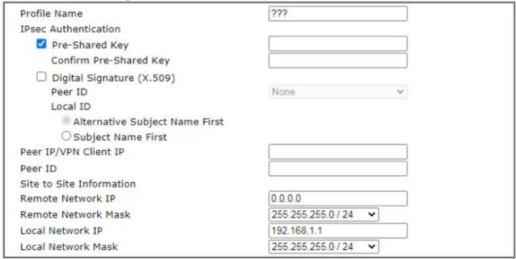
text_image
Profile Name IPsec Authentication ✓ Pre-Shared Key Confirm Pre-Shared Key □ Digital Signature (X.509) Peer ID Local ID ● Alternative Subject Name First ○ Subject Name First Peer IP/VPN Client IP Peer ID Site to Site Information Remote Network IP Remote Network Mask Local Network IP Local Network Mask ???? None 0.0.0.0 255.255.255.0 / 24 192.168.1.1 255.255.255.0 / 24
If you have selected OpenVPN, the following configuration screen appears.
VPN Authentication Setting
| Profile Name | ??? |
| OpenVPN Tunnel Authentication | |
| Username | ??? |
| Password | Max: 128 characters |
| Peer IP/VPN Client IP | |
| Site to Site Information | |
| Remote Network IP | 0.0.0.0 |
| Remote Network Mask | 255.255.255.0 / 24 |
| Local Network IP | 192.168.1.1 |
| Local Network Mask | 255.255.255.0 / 24 |
OpenVPN General Setup
| Certificates Setup | ||
| Generated certificates | Root Certificate: | None |
| Server Certificate: | None | |
| Client Certificate: | None | |
| Trust Certificate: | None | |
| Generate | ||
| Note:OpenVPN authentication is based on certificates.You may either generate new (by clicking "Generate" button) or upload existing certificates to the following path:1. Upload Server Certificate to Certificate Management >> Local Certificate2. Upload Trusted Certificate to Certificate Management >> Trusted CA Certificate | ||

Available settings are explained as follows:
| Item Description | |
| Profile Name Name to identify this VPN profile. | |
| User Name | Used by the remote LAN to establish a VPN connection.The length of the user name is limited to 11 characters. |
| Password | Used by the remote LAN to establish a VPN connection.The length of the password is limited to 11 characters. |
| IPsec / IPsec XAuth / L2TP with IPsec / SSL Tunnel Authentication | |
| Pre-Shared Key | For PPTP / IPsec / IPsec XAuth / L2TP with IPsec / SSL Tunnel authentication, you have to configure a pre-shared key and/or digital signature.Note that, if the remote client has a dynamic IP address, do not enable any of the settings (PSK / Digital Signature) in this section. Instead, configure the global IPsec settings by using VPN and Remote Access>>IPsec General Setup.Pre-Shared Key - Select to enter an IPsec Pre-shared Key specific to this profile. The length of the PSK is limited to 64 characters.Confirm Pre-Shared Key - Re-enter the Pre-shared Key again to confirm. |
| Digital Signature (X.509) | Digital Signature (X.509) - Select to enable X.509 digital signature.Peer ID - Select a predefined X.509 digital signature as the Peer ID. Peer IDs must be configured first using VPN and Remote Access>>IPsec Peer Identity.Local ID - Specifies whether the Subject Name or the Alternative Subject Name of the X.509 Peer ID is to be checked first. Select either Alternative Subject Name First or Subject Name First. |
| Peer IP/VPN Client IP | Enter the WAN IP address or VPN client IP address for the remote client.If values are specified, only connections coming from the specified IP address and/or having the specified Peer ID will be accepted. |
| Peer ID | Enter the ID name for the remote client.The maximum length of the peer ID is 47 characters.If the values are specified, only connections coming from the specified IP address and/or having the specified Peer ID will be accepted. |
| Site to Site Information | |
| Remote Network IP | Enter the IP address of the remote network. |
| Remote Network Mask | Enter the subnet mask of the remote network. |
| Local Network IP | Enter the local network IP for TCP / IP configuration. |
| Local Network Mask | Enter the local network mask for TCP / IP configuration. |
| OpenVPN General Setup | Generate - Click to generate certificate for OpenVPN authentication. Or upload an existing certificate from Local Certificate or Trusted CA Certificate page. |
- The Remote Dial-in User (Teleworker) VPN configuration page appears as follows if you have selected PPTP/SSL.
VPN Server Wizard
VPN Authentication Setting
PPTP / SSL Tunnel Authentication
Username
Password
Peer IP/VPN Client IP
Subnet

If you have selected IPsec XAuth/L2TP with IPsec Policy (None), the following configuration screen appears.
VPN Server Wizard
VPN Authentication Setting
IPsec XAuth / L2TP with IPsec Authentication
Username
Password
Pre-Shared Key
Confirm Pre-Shared Key
Peer IP/VPN Client IP
Peer ID
Subnet
text_image
??? Max: 128 characters LAN 1 ▼
If you have selected IPsec XAuth/L2TP with IPsec Policy (Nice to Have)/L2TP with IPsec Policy (Must), the following configuration screen appears.
VPN Server Wizard
VPN Authentication Setting
IPsec XAuth / L2TP with IPsec Authentication
Username
Password
Pre-Shared Key
Confirm Pre-Shared Key
Digital Signature (X.509)
Peer ID
Peer IP/VPN Client IP
Peer ID
Subnet
???
Max: 128 characters
None
LAN 1

If you have selected OpenVPN Tunnel, the following configuration screen appears.
VPN Server Wizard
VPN Authentication Setting
OpenVPN Tunnel Authentication
Username
Password
Peer IP/VPN Client IP
Subnet
???
Max: 128 characters
LAN 1
OpenVPN General Setup
Certificates Setup
Generated certificates
Root Certificate: None
Server Certificate: None
Client Certificate: None
Trust Certificate: None
Generate
Note:
OpenVPN authentication is based on certificates.
You may either generate new (by clicking "Generate" button) or upload existing certificates to the following path:
-
Upload Server Certificate to Certificate Management >> Local Certificate.
-
Upload Trusted Certificate to Certificate Management >> Trusted CA Certificate
< Back Next > Finish Cancel
Available settings are explained as follows:
| Item Description | |
| User Name | Used by the remote LAN to establish a VPN connection.The length of the user name is limited to 11 characters. |
| Password | Used by the remote LAN to establish a VPN connection.The length of the password is limited to 11 characters. |
| IKEv1/IKEv2 / IPsec XAuth / L2TP with IPsec /SSL Tunnel Authentication | |
| Pre-Shared Key | For IKEv1/ IKEv2 / IPsec / IPsec XAuth / L2TP with IPsec / SSL Tunnel authentication, you have to configure a pre-shared key and/or digital signature.Note that, if the remote client has a dynamic IP address, do not enable any of the settings (PSK / Digital Signature) in this section. Instead, configure the global IPsec settings by using VPN and Remote Access>>IPsec General Setup.Pre-Shared Key - Select to enter an IPsec Pre-shared Key specific to this profile. The length of the PSK is limited to 64characters. Confirm Pre-Shared Key - Re-enter the Pre-shared Key again to confirm. |
| Digital Signature (X.509) | Digital Signature (X.509) - Select to enable X.509 digital signature. Peer ID - Select a predefined X.509 digital signature as the Peer ID. Peer IDs must be configured first using VPN and Remote Access>>IPsec Peer Identity. |
| Peer IP/VPN Client IP | Enter the WAN IP address or VPN client IP address for the remote client. If values are specified, only connections coming from the specified IP address and/or having the specified Peer ID will be accepted. |
| Peer ID | Enter the ID name for the remote client. The maximum length of the peer ID is 47 characters. If the values are specified, only connections coming from the specified IP address and/or having the specified Peer ID will be accepted. |
| Subnet Select an interface. | |
| OpenVPN General Setup | Generate - Click to generate certificate for OpenVPN authentication. Or upload existing certificates from Local Certificate or Trusted CA Certificate page. |
- After finishing the configuration, click Next to proceed to the confirmation page.
VPN Server Wizard
Please Confirm Your Settings
| VPN Environment: | Site to Site VPN (LAN-to-LAN) |
| Index: | 1 |
| Profile Name: | test |
| Username: | ppendss |
| Allowed Service: | IPsec XAuth+L2TP+L2TP with IPsec Policy |
| Peer IP/VPN Client IP: | 172.16.3.99 |
| Peer ID: | testfor |
| Remote Network IP: | 172.16.3.190 |
| Remote Network Mask: | 255.255.255.0 |
| Local Network IP: | 192.168.1.1 |
| Local Network Mask: | 255.255.255.0 |

Available settings are explained as follows:
| Item Description | |
| Go to the VPN ConnectionManagement | Proceed to VPN and Remote Access>>Connection Management to manage VPN sessions. |
| Do another VPN Server Wizard Setup | Rerun the VPN Server Wizard to configure another LAN-to-LAN VPN profile. |
| View more detailed configuration | Open this profile in VPN and Remote Access>>LAN to LAN to make additional configuration changes. |
- Click Finish to save the profile, or Back to make changes, or Cancel to exit the wizard without saving.
V-1-3 Remote Access Control
The Vigor router supports several protocols for VPNs, all of which can be enabled or disabled independently of one another.
If you intend to run a VPN server inside your LAN, you should disable the VPN service of Vigor Router to allow VPN tunnel pass through, as well as the appropriate NAT settings, such as DMZ or open port. Open VPN and Remote Access>>Remote Access Control.
V-1-3-1 Remote Access Control Setup
VPN and Remote Access >> Remote Access Control
| Remote Access Control Setup | Bind to WAN |
| Enable PPTP VPN ServiceEnable IPsec VPN ServiceEnable L2TP VPN ServiceEnable SSL VPN ServiceEnable OpenVPN ServiceEnable WireGuard VPN Service |
Note:
- To allow VPN pass-through to a separate VPN server on the LAN, disable the services listed above that use the same protocol and ensure that NAT Open Ports or Port Redirection is well-configured.
- Disable unused VPN services, enable Brute Force Protection, and block unknown IP access to the used VPN services to reduce Cyberattacks.
OK Clear Cancel
| Item Description | |
| Enable PPTP VPN Service | This is the one of the earliest VPN protocols and is natively supported by all Microsoft Windows versions since Windows 95, all Android devices, iOS devices before version 10, and Mac OS X before version 10.12. It is easy to set up, has low overhead, and moderately secure. |
| Enable IPSec VPN Service | This is a network protocol that encrypts traffic between two network locations. Windows, by means of Windows Firewall, natively supports IPsec tunnels between endpoints with static IP addresses. For computers with dynamically-assigned IP addresses, DrayTek provides the SmartVPN client . |
| Enable L2TP VPN Service | This is a tunneling protocol used in VPNs. It does not encrypt network traffic unless used in conjunction with IPsec. |
| Enable SSL VPN Service | This type of VPN uses Secure Sockets Layer (SSL) and Transport Layer Security (TLS), which are also used to encrypt traffic to and from websites. Since SSL and TLS work on top of TCP and UDP, which are the most common internet protocols, they are less likely to be have issues with firewalls and gateways. |
| Enable OpenVPN Service | This type of VPN offers a convenient way for users to build VPN between local end and remote end. |
| Enable WireGuard VPN Service | WireGuard is a secure, fast, and modern open-source VPN Protocol. This type of VPN connection is made by exchanging public keys and intends to be considerably more performant than OpenVPN. |
To save changes on the page, select OK; to discard changes, select Cancel; to clear settings on this page and revert to default settings, select Clear.
V-1-3-2 Bind to WAN
Select the WAN interfaces to accept PPTP VPN, IPsec VPN, L2TP VPN, inbound SSL VPN, OpenVPN and WireGuard connections.
VPN and Remote Access >> Remote Access Control
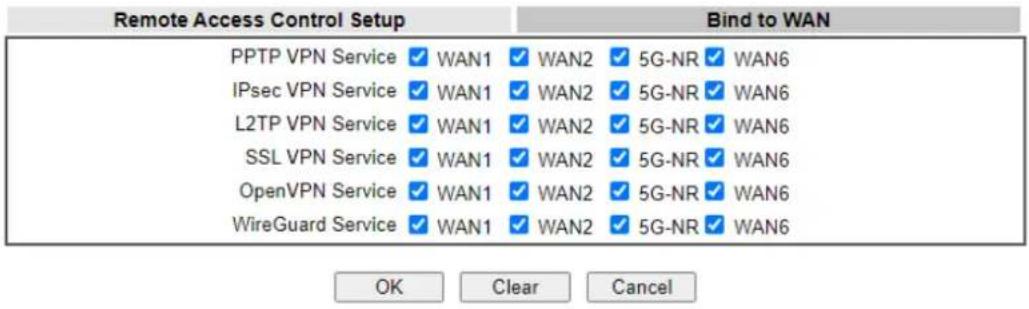
text_image
Remote Access Control Setup PPTP VPN Service ✓ WAN1 ✓ WAN2 ✓ 5G-NR ✓ WAN6 IPsec VPN Service ✓ WAN1 ✓ WAN2 ✓ 5G-NR ✓ WAN6 L2TP VPN Service ✓ WAN1 ✓ WAN2 ✓ 5G-NR ✓ WAN6 SSL VPN Service ✓ WAN1 ✓ WAN2 ✓ 5G-NR ✓ WAN6 OpenVPN Service ✓ WAN1 ✓ WAN2 ✓ 5G-NR ✓ WAN6 WireGuard Service ✓ WAN1 ✓ WAN2 ✓ 5G-NR ✓ WAN6 Bind to WAN OK Clear CancelV-1-4 PPP General Setup
This page allows configuration of Point-to-Point Protocol (PPP) used by PPTP and L2TP VPN connections. From the Main Menu select VPN and Remote Access >> PPP General Setup to bring up the following configuration page.
VPN and Remote Access >> PPP General Setup
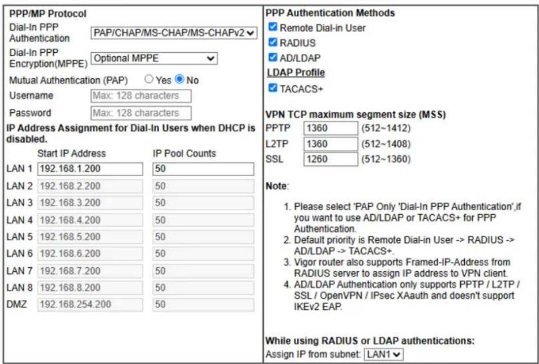
text_image
PPP/MP Protocol Dial-In PPP Authentication PAP/CHAP/MS-CHAP/MS-CHAPv2 Dial-In PPP Encryption(MPPE) Optional MPPE Mutual Authentication (PAP) ○ Yes ● No Username Max: 128 characters Password Max: 128 characters IP Address Assignment for Dial-In Users when DHCP is disabled. Start IP Address IP Pool Counts LAN 1 192.168.1.200 50 LAN 2 192.168.2.200 50 LAN 3 192.168.3.200 50 LAN 4 192.168.4.200 50 LAN 5 192.168.5.200 50 LAN 6 192.168.6.200 50 LAN 7 192.168.7.200 50 LAN 8 192.168.8.200 50 DMZ 192.168.254.200 50 PPP Authentication Methods ✓ Remote Dial-in User ✓ RADIUS ✓ AD/LDAP LDAP Profile ✓ TACACS+ VPN TCP maximum segment size (MSS) PPTP 1360 (512~1412) L2TP 1360 (512~1408) SSL 1260 (512~1360) Note: 1. Please select 'PAP Only 'Dial-In PPP Authentication',if you want to use AD/LDAP or TACACS+ for PPP Authentication. 2. Default priority is Remote Dial-in User -> RADIUS -> AD/LDAP -> TACACS+. 3. Vigor router also supports Framed-IP-Address from RADIUS server to assign IP address to VPN client. 4. AD/LDAP Authentication only supports PPTP / L2TP / SSL / OpenVPN / IPsec XAuth and doesn't support IKEv2 EAP. While using RADIUS or LDAP authentications: Assign IP from subnet: LAN1▼OK
Available settings are explained as follows:
To save changes on the page, select OK.
| Item Description | |
| Dial-In PPP Authentication | PAP Only - Authenticate dial-in users using the PAP protocol only.PAP/CHAP/MS-CHAP/MS-CHAPv2 - Attempt to authenticate dial-in users using various CHAP protocols, and if the remote VPN client fails to authenticate, fall back to PAP. |
| Dial-In PPP Encryption (MPPE) | Specifies if PPP encryption (MPPE) is to be used for dial-in VPN connections.Optional MPPE - MPPE is optional. If the VPN client supports MPPE, PPP data will be encrypted.Require MPPE (40/128bits) - Require PPP encryption for dial-in VPN connections. Both 40- and 128-bit encryption schemes are allowed. The remote dial-in user will use 40-bit to perform encryption prior to using 128-bit for encryption. In other words, if 128-bit MPPE encryption method is not available, then 40-bit encryption scheme will be applied to encrypt the data.Maximum MPPE - Require 128-bit PPP encryption for all dial-in VPN connections. |
| Mutual Authentication | Specifies if mutual authentication is to be used. Some VPN |
| (PAP) | peers (e.g., certain Cisco routers) require bi-directional authentication used for providing stronger security.When mutual authentication is enabled, Username and Password fields should also be populated using values from the VPN peer. The maximum lengths of these fields are 23 and 19 characters, respectively.Yes- Enable mutual authentication.No- Disable mutual authentication. |
| IP Address Assignment for Dial-In Users when DHCP is disabled | LAN1- When the router's DHCP server is disabled, the router will assign IP addresses to dial-in VPN users starting with the IP address specified in Start IP Address. The total number of dial-in VPN IP addresses to be given out is specified in IP Pool Counts.LAN2 ~ LAN8 and DMZ will be available if it is enabled. Refer to LAN>>General Setup for enabling the LAN interface. |
| PPP Authentication Methods | The credentials to be used for PPP authentication will be obtained from the selected sources, in the following order:Remote Dial-in User- The usernames and passwords in VPN and Remote Access >> Remote Dial-in User section will be used.RADIUS- An external RADIUS server is to be used for authentication. Please be sure to set up the RADIUS server in Applications >> RADIUS/ TACACS+ section.AD/LDAP- An Active Directory/ LDAP server is to be used for authentication. Please be sure to configure AD and LDAP settings in Applications >> Active Directory/ LDAP.TACACS+ - A TACACS+ server is to be used for authentication. Please be sure to set up the RADIUS server in Applications >> RADIUS/ TACACS+ section. |
| PPTP LDAP Profile | Configured LDAP profiles will be listed under such item.Simply check the one you want to enable the PPP authentication by LDAP server profiles.However, if there is no profile listed, simply click the link of PPTP LDAP Profile to create/ add some new LDAP profiles you want. |
| VPN TCP maximum segment size (MSS) | Set the maximum segment size (MSS) for different VPN types.Please specify the MSS values for each type to avoid packets cut by MTU during the data transmission period via the IPsec VPN connection. |
| While using Radius or LDAP Authentication | When the dial-in VPN user is authenticated using credentials from the Remote Dial-in User section, an IP address from the LAN specified in the user profile will be assigned. When the user is authenticated using credentials from other sources (RADIUS, AD, TACACS+), the assigned IP address will be drawn from the address pool of the LAN specified here. |
V-1-5 SSL General Setup
SSL VPN (Secure Sockets Layer virtual private network) is a form of VPN that encrypts traffic using SSL, which is the same technology used on secured websites. Because of SSL's prominence as an encryption protocol on the Internet, most networks have few restrictions on SSL traffic, and as a result SSL VPN is more likely to work when other VPN technologies experience difficulties due to obstacles such as firewalls and Network Address Translation (NAT).
In short,
- It is not necessary for users to preinstall VPN client software for executing SSL VPN connection.
- There are less restrictions for the data encrypted through SSL VPN in comparing with traditional VPN.
This page determines the general configuration for SSL VPN Server and SSL Tunnel.
VPN and Remote Access >> SSL General Setup
SSL General Setup
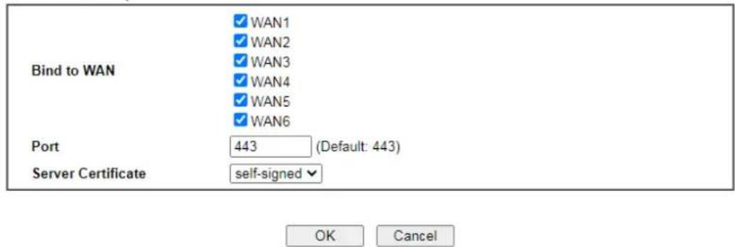
text_image
Bind to WAN WAN1 WAN2 WAN3 WAN4 WAN5 WAN6 Port 443 (Default: 443) Server Certificate self-signed ✓ OK Cancelor
VPN and Remote Access >> SSL General Setup
SSL General Setup
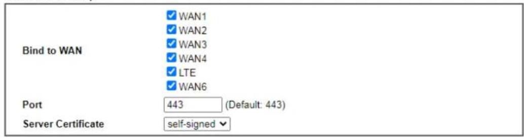
text_image
Bind to WAN WAN1 WAN2 WAN3 WAN4 LTE WAN6 Port 443 (Default: 443) Server Certificate self-signedOK Cancel
or
VPN and Remote Access >> SSL General Setup
SSL General Setup
| Bind to WAN | WAN1WAN25G-NRWAN6 |
| Port | 443 (Default: 443) |
| Server Certificate | Default Certificate |
Note:
- Server Certificate follow the Default Certificate now. Default Certificate can be configured at Certificate >> Local Services List.

Or
VPN and Remote Access >> SSL General Setup
SSL General Setup
| Bind to WAN | WAN1WAN2WAN5WAN6 |
| Port | 443 (Default: 443) |
| Server Certificate | self-signed |

Available settings are explained as follows:
| Item Description | |
| Bind to WAN Select the WAN interfaces to accept inbound SSL VPN connections. | |
| Port The port to be used for SSL VPN server. This is separate from the management port (HTTPS Port) which is configured in System Maintenance>>Management. The default setting is 443. | |
| Server Certificate | Specify the certificate to be used for SSL connections. Select a certificate from imported or generated certificates on the router, or choose Self-signed to use the router's built-in default certificate. The selected certificate can be used in SSL VPN server and HTTPS Web Proxy. |
To save changes on this page, select OK; to discard changes, select Cancel.
V-1-6 IPsec General Setup
In IPsec General Setup, there are two major parts of configuration.
There are two phases of IPsec.
- Phase 1: negotiation of IKE parameters including encryption, hash, Diffie-Hellman parameter values, and lifetime to protect the following IKE exchange, authentication of both peers using either a Pre-Shared Key or Digital Signature (x.509). The peer that starts the negotiation proposes all its policies to the remote peer and then remote peer tries to find a highest-priority match with its policies. Eventually to set up a secure tunnel for IKE Phase 2.
- Phase 2: negotiation IPsec security methods including Authentication Header (AH) or Encapsulating Security Payload (ESP) for the following IKE exchange and mutual examination of the secure tunnel establishment.
There are two encapsulation methods used in IPsec, Transport and Tunnel. The Transport mode will add the AH/ ESP payload and use original IP header to encapsulate the data payload only. It can just apply to local packet, e.g., L2TP over IPsec. The Tunnel mode will not only add the AH/ ESP payload but also use a new IP header (Tunneled IP header) to encapsulate the whole original IP packet.
AH (Authentication Header) provides data authentication and integrity for IP packets passed between VPN peers. This is achieved by a keyed one-way hash function to the packet to create a message digest. This digest will be put in the AH and transmitted along with packets. On the receiving side, the peer will perform the same one-way hash on the packet and compare the value with the one in the AH it receives.
ESP (Encapsulating Security Payload) is a security protocol that provides data confidentiality and protection with optional authentication and replay detection service.
VPN IKE/IPsec General Setup
(Dial-in settings for Remote Dial-In users and LAN-to-LAN VPN Client with Dynamic IP.)
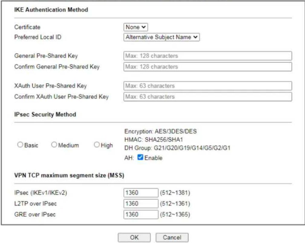
text_image
IKE Authentication Method Certificate None Preferred Local ID Alternative Subject Name General Pre-Shared Key Max: 128 characters Confirm General Pre-Shared Key Max: 128 characters XAuth User Pre-Shared Key Max: 63 characters Confirm XAuth User Pre-Shared Key Max: 63 characters IPsec Security Method Basic Medium High Encryption: AES/3DES/DES HMAC: SHA256/SHA1 DH Group: G21/G20/G19/G14/G5/G2/G1 AH: Enable VPN TCP maximum segment size (MSS) IPsec (IKEv1/IKEv2) 1360 (512~1381) L2TP over IPsec 1360 (512~1361) GRE over IPsec 1360 (512~1365) OK CancelAvailable settings are explained as follows:
| Item Description | |
| IKE Authentication Method | This usually applies to those are remote dial-in user or node (LAN-to-LAN) which uses dynamic IP address and IPsec-related VPN connections such as L2TP over IPsec and IPsec tunnel. There are two methods offered by Vigor router for you to authenticate the incoming data coming from remote dial-in user, Certificate (X.509) and Pre-Shared Key.Certificate - X.509 certificates can be used for IKE authentication. To set up certificates on the router, go to the Certificate Management section.Preferred Local ID - Specify the preferred local ID information (Alternative Subject Name First or Subject Name First) for IPsec authentication while the client is using the general setting (without a specific Peer IP or ID in the VPN profile).General Pre-Shared Key- Define the PSK key for general authentication.Confirm General Pre-Shared Key- Re-enter the characters to confirm the pre-shared key.XAuth User Pre-Shared Key - Define the PSK key for IPsec XAuth authentication.Confirm XAuth User Pre-Shared Key- Re-enter the characters to confirm the pre-shared key for IPsec XAuthauthentication.Note: Any packets from the remote dial-in user which does not match the rule defined in VPN and Remote Access>>Remote Dial-In User will be applied with the method specified here. |
| IPsec Security Method | Available methods include Basic, Medium and High. Each method offers different encryption, HMAC and DH Group.Basic - Authentication Header (AH) means data will be authenticated, but not be encrypted. By default, this option is active.Medium - When this option is selected, the Authentication Header (AH) protocol can be used to provide authentication to IPsec traffic.High - When this option is selected, the Encapsulating Security Payload (ESP) protocol can be used to provide authentication and encryption to IPsec traffic. Three encryption standards are supported for ESP: DES, 3DES and AES, in ascending order of security. |
| VPN TCP maximum segment size (MSS) | Set the maximum segment size (MSS) for different VPN types. Please specify the MSS values for each type to avoid packets cut by MTU during the data transmission period via the IPsec VPN connection. |
To save changes on the page, select OK; to discard changes, select Cancel.
V-1-7 IPsec Peer Identity
This screen allows creating profiles of subject alternative names (SANs) and distinguished names/ subject names that can be used for IPsec peer authentication in LAN-to-LAN or remote user dial-in VPN connections.
VPN and Remote Access >> IPsec Peer Identity
| Index | Enable | Name | Index | Enable | Name |
| 1. | □ | ??? | 17. | □ | ??? |
| 2. | □ | ??? | 18. | □ | ??? |
| 3. | □ | ??? | 19. | □ | ??? |
| 4. | □ | ??? | 20. | □ | ??? |
| 5. | □ | ??? | 21. | □ | ??? |
| 6. | □ | ??? | 22. | □ | ??? |
| 7. | □ | ??? | 23. | □ | ??? |
| 8. | □ | ??? | 24. | □ | ??? |
| 9. | □ | ??? | 25. | □ | ??? |
| 10. | □ | ??? | 26. | □ | ??? |
| 11. | □ | ??? | 27. | □ | ??? |
| 12. | □ | ??? | 28. | □ | ??? |
| 13. | □ | ??? | 29. | □ | ??? |
| 14. | □ | ??? | 30. | □ | ??? |
| 15. | □ | ??? | 31. | □ | ??? |
| 16. | □ | ??? | 32. | □ | ??? |
Available settings are explained as follows:
| Item Description | |
| Set to Factory Default | Click it to clear all indexes. |
| Index | Click the index number of the profile the view or edit its settings. |
| Enable | Check to enable the profile. |
| Name | User-entered name that identifies the profile. |
The following setup screen is shown after a profile index has been clicked.
VPN and Remote Access >> IPsec Peer Identity
Profile Index : 1
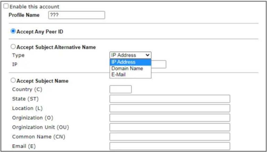
text_image
Enable this account Profile Name ??? Accept Any Peer ID Accept Subject Alternative Name Type IP Address IP IP Address Domain Name E-Mail Accept Subject Name Country (C) State (ST) Location (L) Organization (O) Organization Unit (OU) Common Name (CN) Email (E)
Available settings are explained as follows:
| Item Description | |
| Enable this account | Check to enable such account profile. |
| Profile Name | A name that allows you to identify this profile. The maximum length of the name you can set is 32 characters. |
| Accept Any Peer ID | When this option is selected, the router accepts any subject alternative name or subject name as valid, regardless of the type and value. |
| Accept Subject Alternative Name | When this option is selected, the router accepts the type and value of the specified subject alternative name as valid authentication. Supported subject alternative types are IP Address, Domain Name and E-Mail. |
| Accept Subject Name | When this option is selected, the router performs peer authentication by matching the values of the different subject name fields. These fields include Country (C), State (ST), Location (L), Organization (O), Organization Unit (OU), Common Name (CN), and Email (E). |
To save changes on the page, select OK; to discard changes, select Cancel; to clear settings on this page and revert to default settings, select Clear.
V-1-8 VPN Matcher Setup
Normally, to establish VPN connection, at least one peer must have a public IP address. The VPN Matcher server can help two Draytek routers behind NAT establish a secure VPN tunnel for data transmission between each other. Refer to the following figure.
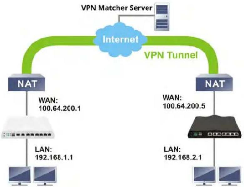
flowchart
graph TD
    A["Internet"] --> B["NAT"]
    A --> C["NAT"]
    B --> D["LAN: 192.168.1.1"]
    C --> E["LAN: 192.168.2.1"]
    F["VPN Matcher Server"] --> A
    G["VPN Tunnel"] --> A
    H["WAN: 100.64.200.1"] --> B
    I["WAN: 100.64.200.5"] --> C
There is one limitation for the VPN connection. Both routers must be behind a cone NAT, but not symmetric NAT.
Go to VPN and Remote Access>>VPN Matcher Setup to open the following page.
VPN and Remote Access >> VPN Matcher Setup
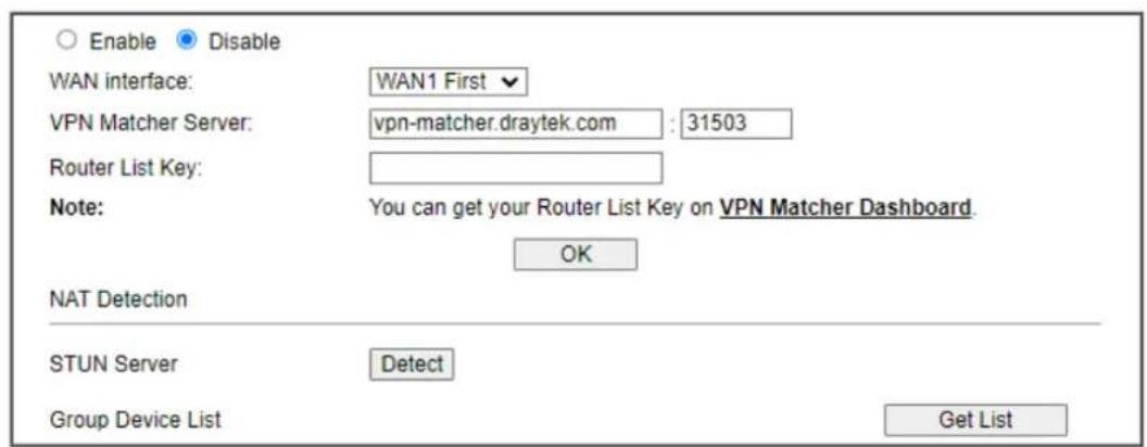
text_image
Enable Disable WAN interface: WAN1 First VPN Matcher Server: vpn-matcher.draytek.com : 31503 Router List Key: Note: You can get your Router List Key on VPN Matcher Dashboard. OK NAT Detection STUN Server Detect Group Device List Get ListAvailable settings are explained as follows:
| Item Description | |
| Enable / Disable | Click to enable / disable the function of VPN Matcher Setup. |
| WAN Interface | The WAN interface to be used for dialing out to establish the VPN connection.WANx First -The Router first attempts to establish the VPN tunnel using this WAN interface. When that is unsuccessful,it will attempt to use other WAN interfaces.WANx Only -The Router will establish the VPN tunnel using this WAN interface only. |
| VPN Matcher Server | The IP address of the DrayTek VPN Matcher server is defined as "vpn-matcher.draytek.com" with the port number "31503". |
| Router List Key | Enter the authentication key for finding a Vigor router with the same group of this device from the VPN matcher server. Then set a VPN link between Vigor routers on both ends via VPN wizard. |
| OK | Click to save the settings. |
| STUN Server | Detect - Click to check if the NAT used by Vigor router is core NAT or not. If not, no VPN can be established. |
| Group Device List | Get List - After entering the Authkey above, click to get available Vigor router which is within the same group as this device. |
V-1-9 OpenVPN
The OpenVPN protocol utilizes public keys, certificates, and usernames and passwords to authenticate the client. Traffic is carried over secure channels built upon industry-standard SSL/ TLS encryption protocols.
With integrating of OpenVPN, Vigor router can help users to achieve more robust, reliable and secure private connections for business needs.
OpenVPN offers a convenient way for users to build a VPN between the local end and the remote end. There are two advantages of OpenVPN:
- It can be operated on different systems such as Windows, Linux, and MacOS.
- Based on the standard protocol of SSL encryption, OpenVPN can provide you with a scalable client/server mode, permitting multi-client to connect to a single OpenVPN Server process over a single TCP or UDP port.
In terms of credentials, the administrator can choose to let the router generate the certificates, or import certificates issued by third-party certificate authorities (CAs). When the router generates the certificates, it acts as the root CA to issue the trusted CA certificates (stored under Certificate Management >> Trusted CA Certificate), which are used to generate the server and client certificates used by OpenVPN (stored under Certificate Management >> Local Certificate). If, however, a certificate issued by a third-party CA is used, both the CA's certificate and the issued certificate need to be imported to the router in the Trusted CA Certificate and Local Certificate sections, respectively.
V-1-9-1 OpenVPN Server Setup
OpenVPN requires the use of certificates. Before establishing OpenVPN connection, general settings for OpenVPN service shall be configured first.
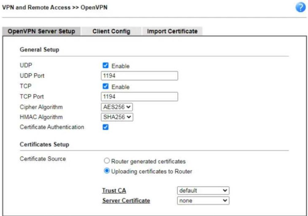
text_image
VPN and Remote Access >> OpenVPN OpenVPN Server Setup Client Config Import Certificate General Setup UDP Enable UDP Port 1194 TCP Enable TCP Port 1194 Cipher Algorithm AES256 HMAC Algorithm SHA256 Certificate Authentication Certificates Setup Certificate Source Router generated certificates Uploading certificates to Router Trust CA default Server Certificate noneNote: OpenVPN on Vigor Router only support TUN device interface currently. So please setup corresponding configurations on the client side.
OK
Available settings are explained as follows:
| Item Description | |
| General Setup | |
| UDP | Enable - Select checkbox to enable UDP protocol for OpenVPN connections.UDP Port - Enter the UDP port number. |
| TCP | Enable - Select checkbox to enable TCP protocol for OpenVPN connections.TCP Port - Enter the TCP port number. |
| Cipher Algorithm | Select the desired cipher algorithm. Two encryption algorithms are supported: AES128 and AES256. AES256 is more secure than AES128 but may result in lower performance because it incurs higher computational overhead. |
| HMAC Algorithm | HMAC stands for Hash-based Message Authentication Code. It is used to validate the data integrity and authenticity of the VPN data.Select the desired HMAC hash algorithm. Two hash algorithms, SHA1 and SHA256, are supported. SHA256 is preferred as it is more robust and reliable than SHA1. |
| Certificate Authentication | Select this checkbox if you would like to validate that the client certificate was issued by a trusted CA. |
| Certificate Setup | |
| Certificate Source | Select a source for the certificate to be used for OpenVPN.Router generated certificates - Router-generated certificates that will be used for OpenVPN.GENERATE - Click to generate a certificate.Delete all certificates - Click to remove all certificates generated by the router. Uploading certificates to Router - Third-party certificates will be used for OpenVPN.Trust CA - Use the dropdown list to select a trusted CA certificate that has already been uploaded to the router. To upload Trusted CA certificates to the router, click the Trust CA link and you will be taken to the Certificate Management >> Trusted CA Certificate page to perform the operation.Server Certificate - Use the dropdown list to select a server certificate that has already been uploaded to the router. To upload server certificates to the router, click the Server Certificate link and you will be taken to the Certificate Management >> Local Certificate page to perform the operation. |
After finishing all the settings here, please click OK to save the configuration.
V-1-9-2 Client Config
On this page, you can create and export the configuration required for a remote OpenVPN client to connect to the router.
VPN and Remote Access >> OpenVPN

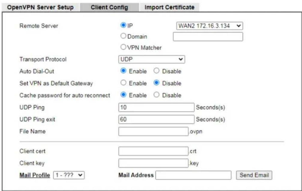
text_image
OpenVPN Server Setup Client Config Import Certificate Remote Server IP WAN2 172.16.3.134 Domain VPN Matcher Transport Protocol UDP Auto Dial-Out Enable Disable Set VPN as Default Gateway Enable Disable Cache password for auto reconnect Enable Disable UDP Ping 10 Seconds(s) UDP Ping exit 60 Seconds(s) File Name .ovpn Client cert .crt Client key .key Mail Profile 1 - ??? Mail Address Send EmailNote:
1. Please make sure the Client cert and the Client key are located in the same folder with .ovpn file.
2. Please make sure that WAN can be used as OpenVPN server.
3. Cache password for auto reconnect.
Enabled: Cache password in virtual memory for re-authentication to keep VPN always connected. Disabled: Type password manually when re-authentication needed. VPN may disconnect during re-authentication.
Export
Available settings are explained as follows:
| Item Description | |
| Remote Server | The OpenVPN client will use the IP address or domain name to connect to the router. Select either IP or Domain.IP - The OpenVPN configuration file will use the numeric IP address as the server address.Domain - The OpenVPN configuration file will use the domain as the server address. You need to ensure that the domain resolves to the IP address of a router WAN port.VPN matcher - The OpenVPN configuration file will use the VPN matcher as the server address. |
| Transport Protocol Select UDP or TCP for the protocol to be used by the OpenVPN client to connect to the router. | |
| Auto Dial-Out | Enable - If selected, the remote client can auto-dial to this Vigor router to build an OpenVPN tunnel.Disable - Select to disable the function. |
| Set VPN as Default Gateway | Enable - If selected, the Vigor router will be treated as a "default" gateway for OpenVPN clients. The OpenVPN client will redirect all the traffic to the Vigor router via theOpenVPN tunnel. Disable - Select to disable the function. |
| Cache password for auto reconnect | Enable - OpenVPN will reconnect per hour. While reconnecting, the password is required. If the function is enabled, the password for OpenVPN connection will be kept and used by the Vigor system for reconnection every time. Disable - Select to disable the function. |
| UDP Ping | Ping remote device over the UDP control channel, if no packets have been sent for the number of seconds configured here. |
| UDP Ping exit | Let OpenVPN exit after the seconds set here if no reception of a ping or other packet from the remote device. |
| File Name | Enter the filename of the configuration file to be downloaded from the router. |
| Client cert | Enter the filename of the client certificate obtained from 3rd party provider. |
| Client key | Enter the filename of the private key obtained from the 3rd party provider. |
| Mail Profile | Use the drop down list to specify a mail profile.Mail Address - Enter the mail address to receive the notification mail.Send Email - Click to send out the mail. |
| Export | Click this button to download the settings on this page as a file, which can be imported into a VPN client to establish OpenVPN connections. |
V-1-9-3 Import Certificate
On this page, you can import the certificate from other places for a remote OpenVPN client to connect to the router.
VPN and Remote Access >> OpenVPN

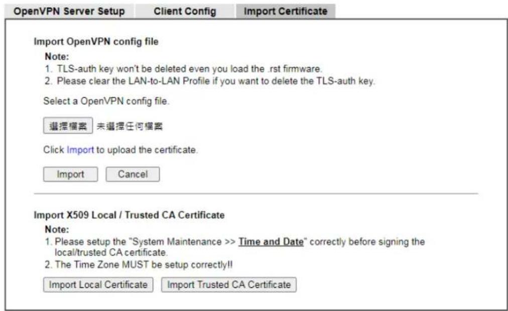
text_image
OpenVPN Server Setup Client Config Import Certificate Import OpenVPN config file Note: 1. TLS-auth key won't be deleted even you load the .rst firmware. 2. Please clear the LAN-to-LAN Profile if you want to delete the TLS-auth key. Select a OpenVPN config file. 選擇檔案 未選擇任何檔案 Click Import to upload the certificate. Import Cancel Import X509 Local / Trusted CA Certificate Note: 1. Please setup the "System Maintenance >> Time and Date" correctly before signing the local/trusted CA certificate. 2. The Time Zone MUST be setup correctly!! Import Local Certificate Import Trusted CA CertificateAvailable settings are explained as follows:
| Item Description | |
| Import OpenVPN config | |
| Select an OpenVPN config file | Browse - Click to select a file.Import - Click to import a configuration file. |
| Import X509 Local/Trusted CA Certificate | |
| Import Local Certificate | Click to access into Local Certificate page for importing a certificate. |
| Import Trusted CA Certificate | Click to access into Trusted CA Certificate page for importing a certificate. |
V-1-10 WireGuard
WireGuard is a secure, fast, simple, and modern open-source VPN Protocol. By using state-of-the-art cryptography, WireGuard can build a VPN by exchanging private and public keys between VPN servers (e.g., Vigor router) and VPN clients (e.g., WireGuard VPN Client).
VPN and Remote Access >> WireGuard

text_image
Server Private Key gDV2NkL7ti6Fexu=7j1s+uPXXp+P23hXffacpCrTrEI- Generate a Key Pair Server Public Key ESYx7f8ny3NbQRhQbPIVqMR/6+4KQEQVD50FtRdOh= Copy to Clipboard WireGuard Interface IP 192.168.1.1 Server Listen port 51820 OKAvailable settings are explained as follows:
| Item Description | |
| Server Private Key | Displays the private key generated.Generate a Key Pair - Generate keys for the VPN server. |
| Server Public Key | It is required to be configured in the WireGuard VPN client router.After clicking Generate a Key Pair, the public key and a QR code representing the public key will be shown on this page.Copy to Clipboard - Click to save the keys as a text file. |
| WireGuard Interface IP | Enter an IP address. Vigor router's LAN IP can be used as the WireGuard interface IP. |
| Server Listen Port | Enter a port number for WireGuard VPN server.The default number is 51820. |
To save changes on the page, select OK; to discard changes, select Cancel.
V-1-11 Remote Dial-in User
You can manage remote access by maintaining a table of remote user profiles, so that users can be authenticated via VPN connection.
Remote dial-in user profiles can be set up on this screen.
VPN and Remote Access >> Remote Dial-in User

| Index | Enable | User | Status | Index | Enable | User | Status |
| 1. | ??? | --- | 17. | ??? | --- | ||
| 2. | ??? | --- | 18. | ??? | --- | ||
| 3. | ??? | --- | 19. | ??? | --- | ||
| 4. | ??? | --- | 20. | ??? | --- | ||
| 5. | ??? | --- | 21. | ??? | --- | ||
| 6. | ??? | --- | 22. | ??? | --- | ||
| 7. | ??? | --- | 23. | ??? | --- | ||
| 8. | ??? | --- | 24. | ??? | --- | ||
| 9. | ??? | --- | 25. | ??? | --- | ||
| 10. | ??? | --- | 26. | ??? | --- | ||
| 11. | ??? | --- | 27. | ??? | --- | ||
| 12. | ??? | --- | 28. | ??? | --- | ||
| 13. | ??? | --- | 29. | ??? | --- | ||
| 14. | ??? | --- | 30. | ??? | --- | ||
| 15. | ??? | --- | 31. | ??? | --- | ||
| 16. | ??? | --- | 32. | ??? | --- |


Note:
User Accounts need to be added into User Group to enable SSL Portal Login.

| Backup setting to file: Backup | Restore From File:選擇檔案未選擇任何檔案Restore |
Available settings are explained as follows:
| Item Description | |
| Set to Factory Default | Click to clear all remote-dial-in user profiles. |
| Index | Click the index number of the profile the view or edit its settings. |
| Enable | Check to enable the user profile. |
| User | Display the username for the specific dial-in user of the LAN-to-LAN profile. The symbol ??? represents that the profile is empty. |
| Status | Shows the LAN subnet and IP address assignment method. Example: LAN1-DHCP means that the IP address of the VPN connection will be drawn from the DHCP pool of the LAN1subnet.The color of the status indicates the current state of the profile:Green - Profile is being used by a dial-in VPN connection.Red - Profile is not being used.Black - Profile is disabled. |
| Backup | Click Backup to save the configuration. |
| Restore | Click Select to choose a configuration file. Then click Restore to apply the file. |
To save changes on the page, select OK; to discard changes, select Cancel.
The following setup screen is shown after a profile index has been clicked.
VPN and Remote Access >> Remote Dial-in User
Index No. 1
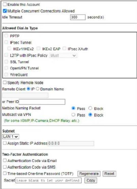
text_image
Enable this Account Multiple Concurrent Connections Allowed Idle Timeout 300 second(s) Allowed Dial-In Type PPTP IPsec Tunnel IKEv1/IKEv2 IKEv2 EAP IPsec XAuth L2TP with IPsec Policy Must SSL Tunnel OpenVPN Tunnel WireGuard Specify Remote Node Remote Client IP Domain Name or Peer ID Netbios Naming Packet Pass Block Multicast via VPN Pass Block (for some IGMP,IP-Camera,DHCP Relay...etc.) Subnet LAN 1 Assign Static IP Address 0.0.0.0 Two-Factor Authentication Authentication Code via Email Authentication Code via SMS Time-based One-time Password (TOTF) Regenerate Reset Secret Leave blank to let user defined Copy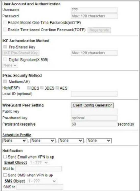
text_image
User Account and Authentication Username ???? Password Max: 128 characters Enable Mobile One-Time Passwords(mOTP) Enable Time-based One-time Password(TOTP) Regenerate IKE Authentication Method Pre-Shared Key IKE Pre-Shared Key Max: 128 characters Digital Signature(X.509) None IPsec Security Method Medium(AH) High(ESP) DES 3DES AES Local ID (optional) WireGuard Peer Setting Client Config Generator Public key Pre-shared key optional Persistent keepalive 60 second(s) Schedule Profile None None None None Notification Send Email when VPN is up Email Object 1-???_ Mail to Send SMS when VPN is up SMS Object 1-???_ SMS toNote:
- WireGuard VPN Protocol doesn't support passing Netbios or Multicast packets.

Available settings are explained as follows:
| Item Description | ||
| Enable this account | Select to enable this profile to be used by remote dial-in users. | |
| Multiple Concurrent Connections Allowed | Select to make multiple VPN clients connecting to Vigor device with the same username/ password.Idle Timeout - Allowed idle time before the router disconnects the VPN connection. Default timeout value is 300 seconds. | |
| Allowed Dial-In Type | Select all VPN protocols allowed for this profile. | |
| For L2TP, specify how IPsec should be applied. Options are:None-IPsec cannot be used with L2TP connections.Nice to Have-IPsec is preferred but not mandatory for L2TP connections.Must-IPsec is required when establish L2TP connections.Specify Remote Node- The IP address of the remote VPN client (Remote Client IP) or the Peer ID (used in IKE aggressive mode) can be optionally specified. The router will reject the connection if either of these values are entered in the profile but the remote client does not pass the value, or passes the wrong value.Netbios Naming Packet-Specifies whether to allow NetBIOS naming packets to traverse through the VPN tunnel.Pass-Click it to have an inquiry for data transmission between the hosts located on both sides of VPN Tunnel while connecting.Block-When there is conflict occurred between the hosts on both sides of VPN Tunnel in connecting, such function can block data transmission of Netbios Naming Packet inside the tunnel.Multicast via VPN-Specifies whether to allow multicast packets to traverse through the VPN tunnel.Pass-Click this button to let multicast packets pass through the router.Block-This is default setting. Click this button to let multicast packets be blocked by the router. | ||
| SubnetThe VPN client will receive an IP address from the DHCP poolor IP address range specified in IP Address Assignment for Dial-In Users for the selected LAN subnet.Assign Static IP Address - Alternatively, a static IP address can be set by selecting the Assign Static IP Address checkbox. | ||
| Two-Factor Authentication | When a remote dal-in user tries to log in Vigor router from the VPN, he/she has to pass the two-factor authentication.Send Authentication Code via Email-Select to send the authentication code via an e-mail. The e-mail address can be specified in the field of Mail to under the Notification area.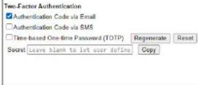 | 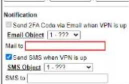 |
| Send Authentication Code via SMS-Select to send the authentication code via an SMS. The telephone number can be specified in the field of SMS to under the Notification area. | ||
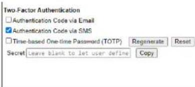 | 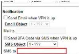 | |
| Time-based One-time Password (TOTP)-Select to display a secret generated by Vigor router. | ||
Regenerate- Click to regenerate a new secret and corresponding QR code.Reset- Click to clear the secret.Secret- Displays a 32 digit-secret number generated by Vigor router. Correspondign code also will be shown in this area. Copy- Click to copy the secret. Copy- Click to copy the secret. | ||
| User Account and Authentication | User Name- Used for PPTP, L2TP or SSL Tunnel dial-in type. The length of the name is limited to 23 characters.Password- Used for PPTP, L2TP or SSL Tunnel dial-in type. The length of the password is limited to 19 characters.Enable Mobile One-Time Passwords (mOTP)- Select to enable one-time passwords (Mobile-OTP). Enter the PIN Code and Secret. DrayTek's SmartVPN client has built-in support for mOTP. Third-party mOTP clients can be used to generate passwords when using other VPN clients. For more information on mOTP, visit Mobile-OTP's homepage.PIN Code- Enter the code for authentication (e.g., 1234).Secret- Use the 32 digit-secret number generated by mOTP in the mobile phone (e.g., e759bb6f0e94c7ab4fe6).Enable Time-based One-time Password (TOTP)- Please make sure the time zone of your router is correct. Then, install Google Authenticator APP on your cell phone. Open the APP to scan the QR code on this page. A one-time password will be shown on your phone.Enable Advanced Authentication method when login from "WAN"Time-based One-time Password (TOTPSecret: ISQUJCEGNLMIVSDNFAUQYZOMFKUZZLMFTOZZTLNBRTOMLKJSFOSGTFJU4OEZYValidation CodeVerifyIn the filed of Validation Code, enter the one-time password and click Verify.Enable Advanced Authentication method when login from "WAN"Time-based One-time Password (TOTPSecret: JZXGCY3SN5ZDKISTMPJLUG4RQKAYXCSCBNUFSSKCGJXSTDFKNLHGLUOFIEGNSJValidation Code30794dVerifyVerify successfully. You can save the config now.Mobile one-Time Passwords(mOTP)Now, the configuration is finished. You will be asked to enter the 2FA code on the after passing the username andpassword authentication.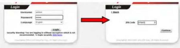 | |
| IKE Authentication Method | Pre-Shared Key - This checkbox is available when Remote Client IP or Peer ID is specified. Check the checkbox and click IKE Pre-shared Key to enter an IKE PSK (1~63 characters) that will be used only for this profile.Digital Signature (X.509) - To enable authentication using X.509 Peer IDs, check the checkbox then select an X.509 profile. X.509 profiles can be configured inVPN and Remote Access >> IPsec Peer Identity. | |
| IPsec Security Method | Select all the IPsec protocols that are allowed to be used for this profile.Medium-Authentication Header (AH) means data will be authenticated, but not be encrypted. By default, this option is invoked. You can uncheck it to disable it.High (ESP) - High-Encapsulating Security Payload (ESP) means payload (data) will be encrypted and authenticated. You may select encryption algorithm from Data Encryption Standard (DES), Triple DES (3DES), and AES.Local ID (Optional)- Specify a local ID to be used when establishing a LAN-to-LAN VPN connection using IKE aggressive mode. | |
| WireGuard Peer Setting | It is available when WireGuard is selected as the Allowed Dial-In Type. Configure the settings for VPN client (peer).Client Config Generator - Click to pop-up the configuration window.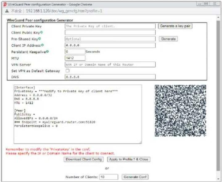 Client Private Key / Client Public Key - Click the Generate a key pair button to generate the private and public keys. The keys will be shown on the corresponding fields.Pre-Shared Key - Displays the value generated byclicking the Generate button.Client IP Address - Enter the static IP address assigned to the client.Persistent Keepalive - Default is 60 seconds. If the peer is behind a NAT or a firewall, use the default setting.MTU - Enter the value. The default is 1412.VPN Server - Enter the public IP address or domain name of Vigor router.Set VPN as Default Gateway - If required, select the box to configure this VPN as the default gateway.DNS - Enter the IP address (e.g., 8.8.8.8) of the DNS server.A QR code will be generated according to the settings configured in this pop-up window. Then, download the x.conf file by clicking Download Client Config and Apply to Profiles & Close.Public Key - Displays the value generated by clicking Client Config Generator.Pre-shared Key - Displays the value generated by clicking Client Config Generator.Persistent Keepalive - Default is 60 seconds. If the peer is behind a NAT or a firewall, use the default setting. Client Private Key / Client Public Key - Click the Generate a key pair button to generate the private and public keys. The keys will be shown on the corresponding fields.Pre-Shared Key - Displays the value generated byclicking the Generate button.Client IP Address - Enter the static IP address assigned to the client.Persistent Keepalive - Default is 60 seconds. If the peer is behind a NAT or a firewall, use the default setting.MTU - Enter the value. The default is 1412.VPN Server - Enter the public IP address or domain name of Vigor router.Set VPN as Default Gateway - If required, select the box to configure this VPN as the default gateway.DNS - Enter the IP address (e.g., 8.8.8.8) of the DNS server.A QR code will be generated according to the settings configured in this pop-up window. Then, download the x.conf file by clicking Download Client Config and Apply to Profiles & Close.Public Key - Displays the value generated by clicking Client Config Generator.Pre-shared Key - Displays the value generated by clicking Client Config Generator.Persistent Keepalive - Default is 60 seconds. If the peer is behind a NAT or a firewall, use the default setting. | |
| Schedule Profile | Up to four schedule profiles can be set. | |
| Notification | Send Email when VPN is up - An e-mail will be sent to the user defined in Email Object when VPN is connected and up.Mail to - Enter an email address.Send SMS when VPN is up - An SMS will be sent to the user defined in SMS Object when VPN is connected and up.SMS to - Enter a phone number. | |
To save changes on the page, select OK; to discard changes, select Cancel; to clear settings on this page and revert to default settings, select Clear.
V-1-11 LAN to LAN
This section allows you to configure up to 64 LAN-to-LAN VPN connections. LAN-to-LAN connections can be configured to allow dial-in only, dial-out only, or both dial-in and dial-out.
The following figure shows the summary table according to the item (All/ Trunk) selected for View.
VPN and Remote Access >> LAN to LAN

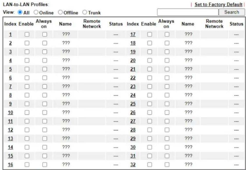
text_image
LAN-to-LAN Profiles: View: All Online Offline Trunk Index Enable Always on Name Remote Network Status Index Enable Always on Name Remote Network Status 1 □ □ ??? --- 17 □ □ ??? --- 2 □ □ ??? --- 18 □ □ ??? --- 3 □ □ ??? --- 19 □ □ ??? --- 4 □ □ ??? --- 20 □ □ ??? --- 5 □ □ ??? --- 21 □ □ ??? --- 6 □ □ ??? --- 22 □ □ ??? --- 7 □ □ ??? --- 23 □ □ ??? --- 8 □ □ ??? --- 24 □ □ ??? --- 9 □ □ ??? --- 25 □ □ ??? --- 10 □ □ ??? --- 26 □ □ ??? --- 11 □ □ ??? --- 27 □ □ ??? --- 12 □ □ ??? --- 28 □ □ ??? --- 13 □ □ ??? --- 29 □ □ ??? --- 14 □ □ ??? --- 30 □ □ ??? --- 15 □ □ ??? --- 31 □ □ ??? --- 16 □ □ ??? --- 32 □ □ ??? ---
text_image
<< 1-32 | 33-64 >> Next >> Change default route to None Pass packets from LAN in Routing mode to VPN ✓ Pass Packets to WAN when VPN disconnects
Available settings are explained as follows:
| Item Description | |
| Set to Factory Default Click | to clear all indexes. |
| View | All - Shows all LAN-to-LAN VPN profiles.Trunk - Shows all Trunk profiles (see VPN and Remote Access >> VPN TRUNK Management). |
| Index | Click the index number of the profile to view or edit its settings. |
| Enable | Check to enable the LAN-to-LAN VPN profile. |
| Always on | Check the box to enable the LAN-to-LAN VPN Dial-Outprofile. |
| Name | Display the name of the LAN-to-LAN profile. The symbol ??? represents that the profile is empty. |
| Remote Network | Display the name of the remote network. |
| Status | Shows the status of the profile.Online - LAN-to-LAN VPN is connected.Offline - LAN-to-LAN VPN is disconnected.---- Profile is disabled. |
| Change default route to | Change the default route to the selected VPN tunnel. |
| Pass packets from LAN in Routing mode to VPN | If enabled, the packets from routing LAN will pass through the VPN tunnel. |
| Pass Packets to WAN when VPN disconnects | If enabled, the packets can pass through via WAN when the VPN disconnects. |
| Backup | Click Backup to save the configuration. |
| Restore | Click Select to choose a configuration file. Then click Restore to apply the file. |
The following figure shows profiles joined into VPN Load Balance and VPN Backup mechanism.
VPN and Remote Access >> LAN to LAN
LAN-to-LAN Profiles:
View: ○ All ● Trunk
| Name | Activate | Members | Status |
| Loadbalan1 | v | VPN-2 | Offline |
| Connection | Offline |
[XXXXXXX:This Dial-out profile has already joined for VPN Load Balance Mechanism] [XXXXXXX:This Dial-out profile has already joined for VPN Backup Mechanism]
If there is no profile joined yet, this page will be shown as follows:
VPN and Remote Access >> LAN to LAN
LAN-to-LAN Profiles:
View: ○ All ● Trunk

text_image
Name Activate Members Status OK Cancel[XXXXXX:This Dial-out profile has already joined for VPN Load Balance Mechanism]
[XXXXXX:This Dial-out profile has already joined for VPN Backup Mechanism]
To edit each profile, click each index to edit each profile.
- The setup screen is shown after a profile index has been clicked. There are 6 sections: Common Settings, Dial-Out Settings, Dial-In Settings, Tunnel Settings, 6in4 Settings and TCP/IP Network Settings.
Profile Index : 1
Common Settings

text_image
Enable this profile Profile Name ???? Call Direction ● Both ○ Dial-Out ○ Dial-In ○ GRE Tunnel Dial-Out Through WAN1 First Always on □ Enable Idle Timeout 300 second(s) Quality Monitoring/Keep Alive □ Enable Netbios Naming Packet ● Pass ○ Block Multicast via VPN ○ Pass ● Block (for some IGMP,IP-Camera,DHCP Relay.etc.)Dial-Out Settings
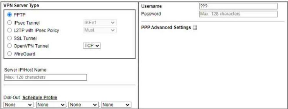
text_image
VPN Server Type PPTP IPsec Tunnel IKEv1 L2TP with IPsec Policy Must SSL Tunnel OpenVPN Tunnel TCP WireGuard Server IP/Host Name Max: 128 characters Dial-Out Schedule Profile None None None None Username ???? Password Max: 128 characters PPP Advanced SettingsDial-In Settings
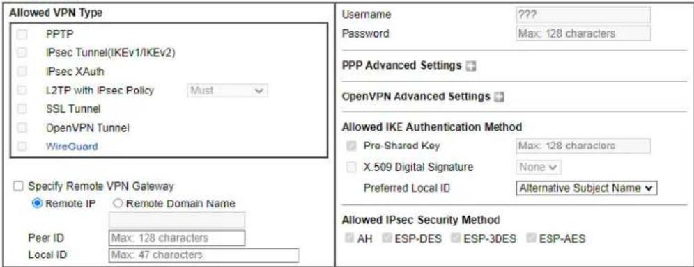
text_image
Allowed VPN Type □ PPTP □ IPsec Tunnel(IKEv1/IKEv2) □ IPsec XAuth □ L2TP with IPsec Policy Must □ SSL Tunnel □ OpenVPN Tunnel □ WireGuard □ Specify Remote VPN Gateway ● Remote IP ○ Remote Domain Name Peer ID Max: 128 characters Local ID Max: 47 characters Username ???? Password Max: 128 characters PPP Advanced Settings OpenVPN Advanced Settings Allowed IKE Authentication Method □ Pre-Shared Key Max: 128 characters □ X.509 Digital Signature None Preferred Local ID Alternative Subject Name Allowed IPsec Security Method □ AH ESP-DES ESP-3DES ESP-AESTunnel Settings

text_image
Enable IPsec Dial-Out function GRE over IPsec Tunnel Local IP Logical Traffic Tunnel Remote IP6in4 Settings

text_image
Enable 6in4 over PPTP LAN Interface LAN1 Remote LAN IP 0.0.0.0 LAN IPv6 Prefix : / 64 Remote IPv6 Prefix : / 64 Tunnel TTL 255TCP/IP Network Settings

text_image
Local Network IP 192.168.1.1 / Mask 255.255.255.0 / 24 Remote Network IP 0.0.0.0 / Mask 255.255.255.0 / 24 More Remote Subnet Mode Routing RIP via VPN Disable Translate Local Network Enable Change Default Route to this VPN tunnel (This only works if there is only one WAN online)OK Clear Cancel
Available settings are explained as follows:
| Item Description | |
| Common Settings | |
| Enable this profile | Select to enable the profile.Profile Name- Specify a name that allows you to identify this profile.Call Direction - Specify the allowed call direction of this LAN-to-LAN profile. Four choices are available for connection mode:Both- Profile is to be used to initiate (dial out) or accept (dial in) connections.Dial-Out- Profile is to be used to initiate outgoing connections.Dial-In- Profile is to be used to accept incoming connections.GRE Tunnel- Connection is by means of a GRE tunnel.Dial-Out Through- Select the WAN connection for connections made using this profile. This setting is useful for dial-out only.WANx First- While connecting, the router will use WANx or LTE as the first channel for VPN connection. If WANx or LTE fails, the router will use another WAN interface instead.WANx Only or LTE Only- While connecting, the router will use WANx or LTE as the only channel for VPN connection.WAN1 Only: Only establish VPN if WAN2 down- If WAN2 failed, the router will use WAN1 for VPN connection.WAN2 Only: Only establish VPN if WAN1 down- If WAN1 failed, the router will use WAN2 for VPN connection.Always On- Select this option to maintain an always on dial-out connection.Idle Timeout- The router will close connection if no activity is observed in the VPN connection for this many seconds. Default value is 300 seconds.Quality Monitoring/Keep Alive- Select this option to keep the VPN connection for the feature of SD-WAN quality monitoring.Netbios Naming Packet- Specifies whether to allow NetBIOS naming packets to traverse through the VPN tunnel.Pass- click it to have an inquiry for data transmission between the hosts located on both sides of VPN Tunnel while connecting.Block- When there is conflict occurred between the hosts on both sides of VPN Tunnel in connecting, such function can block data transmission of Netbios Naming Packet inside the tunnel.Multicast via VPN- Specifies whether to allow multicast packets to traverse through the VPN tunnel.Pass- Click this button to let multicast packets pass through the router.Block- This is default setting. Click this button to let multicast packets be blocked by the router. |
| Dial-Out Settings | |
| VPN Server Type | Select the VPN protocol to be used. |
| Server IP/Host Name | IP address or DNS host name of remote VPN host. |
| Dial-Out Schedule Profile | Connect and disconnect according to schedule profiles. The default setting of this field is blank and the function will always work. |
| User Name | Enter a username for establishing VPN connection. |
| Password | Enter the password for establishing VPN connection. |
| If PPTP /L2TP with IPsec Policy /SSL Tunnel /is selected as VPN Server Type | PPP Advanced Settings - Click it to expand the advanced settings for PPP.PPP Authentication -PAP Only - Authenticate dial-in users using the PAP protocol only. PAP/ CHAP/ MS-CHAP/ MS-CHAPv2 -Attempt to authenticate dial-in users using various CHAP protocols, and if the remote VPN client fails to authenticate, fall back to PAP.VJ compression - Specifies whether to enable Van Jacobson (VJ) header compression, which improves throughput on slow connections.Request IP Address - Enter the IP address. |
| If IPsec/ L2TP with IPsec Policy is is selected as VPN Server Type | IKE Phase 1 Settings - Select from Main mode and Aggressive mode. The ultimate outcome is to exchange security proposals to create a protected secure channel.Main mode is more secure than Aggressive mode since more exchanges are done in a secure channel to set up the IPsec session. However, the Aggressive mode is faster. The default value in Vigor router is Main mode.Authentication - Digital Signature(X.509)- Peer ID - Select one of the predefined Profiles set in VPN and Remote Access >>IPsec Peer Identity.- Local ID - Use Alternative Subject Name or Subject Name of local certificate as local ID.- Local Certificate - Select one of the profiles set in Certificate Management>>Local Certificate.Authentication - Pre-Shared Key- Pre-Shared Key - Input 1-128 characters as pre-shared key.- Local ID - Enter local IKE identity to send in the exchange to establish IPsec connection.proposal Encryption - Use Auto/ AES/ 3DES/ DES for packet encryption.proposal ECDH Group - Specify a group if Auto is not selected as proposal Encryption.proposal Authentication - Select SHA256 or SHA1 for packet authentication.Force UDP Encapsulation - Select to make UDP encapsulation forcefully. All IPsec packets will be encapsulated with UDP header.IKE Phase 2 Settings - Specify the security protocol, proposal encryption and proposal authentication.Security Protocol - AH (Medium) means data will be authenticated, but not be encrypted. By default, this option is active. ESP (High) means payload (data) will be encrypted and authenticated.Proposal Encryption - Use AES/ 3DES encryptionalgorithm and apply MD5 or SHA-1 authentication algorithm.Proposal Authentication - Select All, SHA or None.IKE Advanced Settings - Specify the key life of each IKE phase, network ID, etc.IKE phase 1 key lifetime- For security reason, the lifetime of key should be defined. The default value is 28800 seconds. You may specify a value in between 900 and 86400 seconds.IKE phase 2 key lifetime- For security reason, the lifetime of key should be defined. The default value is 3600 seconds. You may specify a value in between 600 and 86400 seconds.Phase 2 Network ID - This is optional. Change the source IP address of VPN traffic to the specified IP address for NAT mode selected on TCP/IP Network Settings field.Enable Perfect Forward Secret (PFS) - The IKE Phase 1 key will be reused to avoid the computation complexity in phase 2. The default value is inactive this function.Ping to Keep Alive - Select to enable the function of PING to keep alive.PING Target IP - Enter the IP address to keep alive. |
| If OpenVPN Tunnel with IPsec Policy is is selected as VPN Server Type | OpenVPN Advanced Settings - Click to set the advanced settings for OpenVPN.Cipher Algorithm - Select an algorithm for encrypting the packets via OpenVPN.HMAC Algorithm - Select an algorithm for authenticating the packets via OpenVPN.Client Certificate - Select a client certificate or self-signed a new certificate or DrayDDNS certificate.Trust CA - Select a trust CA certificate.Compress - Select a method to compress the packets to reduce the bandwidth usage while transferring the compressed packets.TLS - auth - Select On to use the TLS authentication method. Related key information can be checked by clicking View.Import OpenVPN config file - An OpenVPN config file from other Vigor router can be imported and apply to this router.Select File - Select a file from your hard disk.Import - Click to upload the selected config file to this Vigor router. |
| If WireGuard with is selected as VPN Server | Click WireGuard to set the advanced settings.[Interface] - Configure the settings for Vigor router.Generate a Key Pair - Click to generate a key pair (including private key and public key).Copy to Clipboard - Click to copy the key pair to clipboard.Address - Enter an IP address that Vigor should use to access the remote VPN network.[Peer] - Configure the settings for the client (peer).Public Key - Enter the Public key of the Peer VPNserver.● Pre-Shared Key - Click Generate to generate the pre-shared key.● Keepalive - Default is 60 seconds. |
| Dial-In Settings | |
| Allowed VPN Type | Select permissible VPN protocols for dial-in connections.● PPTP - Allow the remote dial-in user to make a PPTP VPN connection through the Internet. You should set the User Name and Password of remote dial-in user below.● IPsec Tunnel(IKEv1/IKEv2)- Allow the remote dial-in user to trigger an IPsec VPN connection through Internet.● IPsec XAuth● L2TP with IPsec Policy - Allow the remote dial-in user to make a L2TP VPN connection through the Internet. You can select to use L2TP alone or with IPsec. Select from below:- None - Do not apply the IPsec policy. Accordingly, the VPN connection employed the L2TP without IPsec policy can be viewed as one pure L2TP connection.- Nice to Have - Apply the IPsec policy first, if it is applicable during negotiation. Otherwise, the dial-in VPN connection becomes one pure L2TP connection.- Must - Specify the IPsec policy to be definitely applied on the L2TP connection.● SSL Tunnel- Allow the remote dial-in user to trigger an SSL VPN connection through Internet.● OpenVPN Tunnel- Allow the remote dial-in user to trigger an OpenVPN connection through Internet.● WireGuard - A pop-up window with detailed settings will be shown on the screen. Enter the values if required. |
| Specify Remote VPN Gateway | You can specify the IP address of the remote dial-in user or peer ID (should be the same with the ID setting in dial-in type) by checking the box. Also, you should further specify the corresponding security methods on the right side.If you uncheck the checkbox, the connection type you select above will apply the authentication methods and security methods in the general settings.Remote IP - Enter the IP address of the peer.Peer ID - Enter the ID name for the remote client.Local ID - Specify a local ID to be used when establishing a LAN-to-LAN VPN connection.Usage - This field is applicable when you select PPTP or L2TP with or without IPsec policy above. The length of the name is limited to 11 characters.Password - This field is applicable when you select PPTP or L2TP with or without IPsec policy above. The length of the password is limited to 11 characters. |
| PPP Advanced | Click it to expand the advanced settings for PPP. |
| Settings | VJ Compression - Specifies whether to enable Van Jacobson header compression, which improves throughput on slow connections.Assign Peer IP Address - Enter the IP address of the peer. |
| OpenVPN Advanced Settings | Cipher Algorithm - Select an algorithm for encrypting the packets via OpenVPN.HMAC Algorithm - Select an algorithm for authenticating the packets via OpenVPN. |
| Allowed IKE Authentication Method | This section is available when IPsec tunnel is selected as the dial-out protocol. Available options are IKE Pre-shared key and X.509 digital signature.Pre-Shared Key - To use a pre-shared key, select this radio-button and then click the IKE Pre-Shared Key button to enter the PSK.X.509 Digital Signature - To use an X.509 digital signature, select this radio button and then select an X.509 IPsec Peer Identity profile. To enable authentication using X.509 Peer IDs. X.509 profiles can be configured in VPN and Remote Access >> IPsec Peer Identity.Local ID - Select whether to first match Subject Alternative Name or Subject Name during authentication.-Alternative Subject Name - The alternative subject name (configured in Certificate Management>>Local Certificate) will be inspected first.-Subject Name - The subject name (configured in Certificate Management>>Local Certificate) will be inspected first. |
| Allowed IPsec Security Method | This setting is available when IPsec Tunnel is selected as the dial-out protocol.AH- Authentication Header (AH) means data will be authenticated, but not be encrypted. Select to use Authentication Header protocol. By default, this option is active.ESP-DES/ESP-3DES/ESP-AES - Encapsulating Security Payload (ESP) means payload (data) will be encrypted and authenticated. You may select encryption algorithm from Data Encryption Standard (DES), Triple DES (3DES), and AES. |
| If WireGuard with is selected as VPN Server | Click WireGuard to set the advanced settings.[Interface] - Configure the settings for Vigor router.Generate a Key Pair - Click to generate a key pair (including private key and public key).Copy to Clipboard - Click to copy the key pair to clipboard.Address - Enter a Static IP address that the peer should use to access the local network.[Peer] - Configure the settings for the client (peer).Public Key - Enter the public key of the Peer VPN client.Pre-Shared Key - Click Generate to generate the pre-shared key.Keepalive - Default is 60 seconds. |
| Tunnel Settings | |
| Enable IPsec Dial-Out function GRE over IPsec | Check this box to verify data and transmit data in encryption with GRE over IPsec packet after configuring IPsec Dial-Out setting. Both ends must match for each other by setting same virtual IP address for communication. |
| Logical Traffic | Such technique comes from RFC2890. Define logical traffic for data transmission between both sides of VPN tunnel by using the characteristic of GRE. Even hacker can decipher IPsec encryption, he/she still cannot ask LAN site to do data transmission with any information. Such function can ensure the data transmitted on VPN tunnel is really sent out from both sides. This is an optional function. However, if one side wants to use it, the peer must enable it, too. |
| Tunnel Local IP | Enter the virtual IP for router itself for verified by peer. |
| Tunnel Remote IP | Enter the virtual IP of peer host for verified by router. |
| 6in4 Settings | |
| Enable 6in4 over PPTP | Transmit the IPv6 packets from the local site to the remote site via IPv4 VPN tunnel with the encapsulation technology, 6in4.Check to enable the function. The IPv6 packets can pass through WAN PPTP VPN tunnel to the remote site. |
| LAN Interface | Specify a LAN interface for transmitting the packets. |
| Remote LAN IP | Specify the IP address of the remote site. |
| LAN IPv6 Prefix | Specify the prefix (with length) of the local site. |
| Remote IPv6 Prefix | Specify the prefix (with length) of the remote site. |
| Tunnel TTL Enter a value. | |
| TCP/IP Network Settings | |
| Local Network | The default value is 0.0.0.0, which means the Vigor router will get a PPP IP address from the remote router during the IPCP negotiation phase. If the PPP IP address is fixed by remote side, specify the fixed IP address here. Do not change the default value if you do not select PPTP or L2TP.IP / Mask - Display the local network IP and mask for TCP / IP configuration. You can modify the settings if required. |
| Remote Network | The default value is 0.0.0.0, which means the Vigor router will get a remote Gateway PPP IP address from the remote router during the IPCP negotiation phase. If the PPP IP address is fixed by remote side, specify the fixed IP address here. Do not change the default value if you do not select PPTP or L2TP.IP/ Mask - Add a static route to direct all traffic destined to this Remote Network IP Address/ Remote Network Mask through the VPN connection. For IPsec, this is the destination clients IDs of phase 2 quick mode. |
| More Remote Subnet | Click to bring up a dialog box to enter additional static routes for subnets destined for the remote network.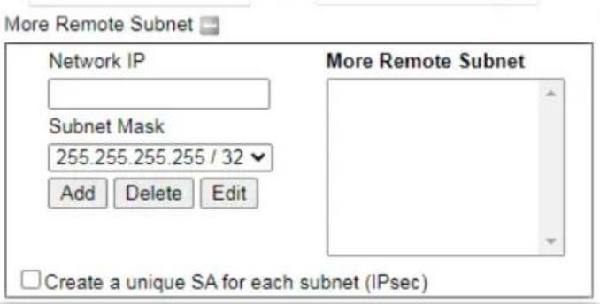 |
| Mode | If the remote network only allows one IP address for the local network, select NAT; otherwise, select Route. |
| When the Mode is set to Routing | WhenRoutingis selected, the available fields in the TCP/IP Network Settings section will be shown as:Translate Local Network- Check the box to enable the function. Add a static route to direct all traffic destined to more Remote Network IP Addresses/ Remote Network Mask through the VPN connection. This is usually used when you find there are several subnets behind the remote VPN router.Type- There are two types (Translate Whole Subnet, Translate Specific IP) for you to choose.WhenTranslate Whole Subnetis selected asType, available settings are listed as below: More Local Subnet More Local Subnet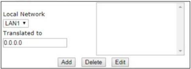 -Local Subnet- Select the LAN whose IP addresses are to be translated.-Translated IP - Specify an IP address.-More Local Subnet- Click it to add more subnets.WhenTranslate Specific IPis selected asType, available settings are listed as below: -Local Subnet- Select the LAN whose IP addresses are to be translated.-Translated IP - Specify an IP address.-More Local Subnet- Click it to add more subnets.WhenTranslate Specific IPis selected asType, available settings are listed as below: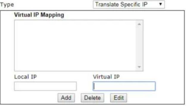 - Virtual IP Mapping - A pop up dialog will appear for you to specify the local IP address and the mapping virtual IP address. - Virtual IP Mapping - A pop up dialog will appear for you to specify the local IP address and the mapping virtual IP address. |
| When the Mode is set to NAT | When NAT is selected, the available fields in the TCP/IP Network Settings section will be shown as:RIP via VPN - Specifies the direction of Routing Information Protocol (RIP) packets. Available options are:TX/RX Both - can transmit or receive RIP packetsTX Only - can only transmit but not receive RIP packetsRX Only - can only receive but not transmit RIP packetsDisable - RIP is disabled.Change Default Route to this VPN tunnel - Select this option to direct all traffic that is not LAN-bound to this VPN tunnel.This option is functional when there is only one active WAN. |
- To save changes on the LAN to LAN profile page, select OK; to reset the entire page to blank, select Clear; to discard changes, select Cancel.
V-1-12 VPN Trunk Management
A VPN Trunk combines TWO LAN-to-LAN VPN tunnels to provide VPN Backup or VPN Load Balance functionalities.
VPN Backup
VPN Backup provides redundant, uninterrupted VPN connectivity by constantly monitoring the health of a VPN tunnel, and fails over to the secondary VPN tunnel when the primary tunnel fails.
In a Backup VPN Trunk, only one of the two LAN-to-LAN VPN tunnels is connected at any given time. When one tunnel fails, the router will automatically start up and direct all VPN traffic destined for the trunk to the other tunnel.
VPN Load Balance
VPN Load Balance increases the bandwidth of a LAN-to-LAN connection by combining and load balancing two tunnels, with the option to direct traffic to specific tunnels by originating address, destination address or port.
In a Load Balance VPN Trunk, both LAN-to-LAN VPN tunnels are simultaneously connected. The router first attempts to match the traffic to a load balance policy rule and send it down the tunnel specified in the matching rule. Traffic not matched to any policy will be load balanced in a round-robin fashion, and the traffic ratio between the two tunnels is either determined automatically by the router or specified by the user.
In order to set up a VPN Trunk, 2 LAN-to-LAN VPN profiles must have been configured first. For details on the configuration of LAN-to-LAN VPN tunnels, see section V-1-10 LAN to LAN. When the 2 LAN-to-LAN VPN profiles are ready, follow the steps below to set up a VPN Trunk.
Creating a VPN Trunk
To create a new VPN Trunk, configure the General Setup section first.
VPN and Remote Access >> VPN TRUNK Management

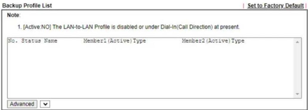
text_image
Backup Profile List Set to Factory Default Note: 1. [Active:NO] The LAN-to-LAN Profile is disabled or under Dial-In(Call Direction) at present. No. Status Name Member1 (Active) Type Member2 (Active) Type Advanced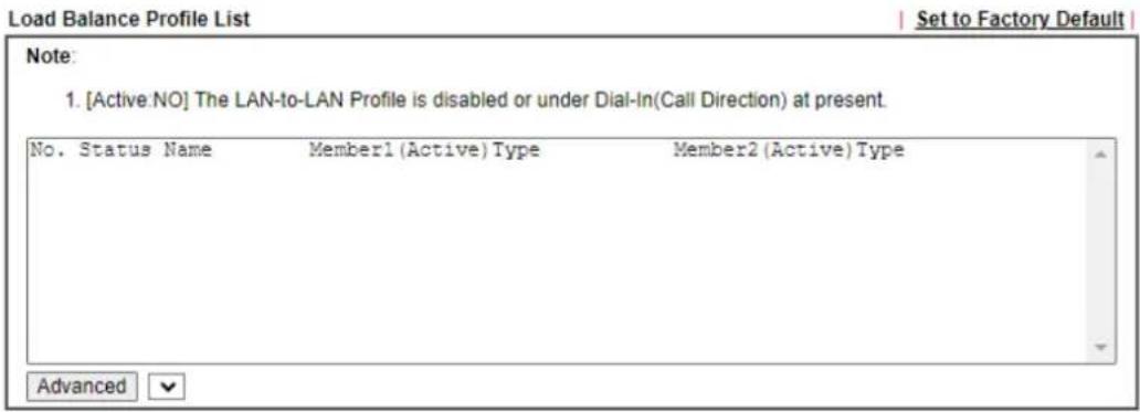
text_image
Load Balance Profile List Set to Factory Default Note: 1. [Active:NO] The LAN-to-LAN Profile is disabled or under Dial-In(Call Direction) at present. No. Status Name Member1 (Active) Type Member2 (Active) Type Advanced
text_image
General Setup Status Enable ○ Disable Profile Name Member1 Please select a LAN-to-LAN Dial-Out profile. Member2 Please select a LAN-to-LAN Dial-Out profile. Active Mode Backup Mode ○ Load Balance Mode
Available settings are explained as follows:
| Item Description | |
| General Setup | Status - Enable or disable the VPN Trunk.● Enable - Select this to enable this VPN trunk.● Disable - Select this to disable this VPN trunk.Profile Name - Enter a name to identify this VPN Trunk profile.Member 1/Member2 - Select LAN-to-LAN VPN profiles to be the first and second members of this VPN Trunk.Active Mode - Select the operation mode of the VPN Trunk.Backup Mode / Load Balance Mode - Select this to set up a Backup / Load Balance VPN Trunk.Add - Select it to add a VPN Trunk Profile using the entered information.Update - Select it to save the changes to the Status (Enableor Disable), profile name, member1 or member2. Delete - Select it to delete the selected VPN TRUNK profile. The corresponding members (LAN-to-LAN profiles) grouped in the deleted VPN TRUNK profile will be released and that profiles in LAN-to-LAN will be displayed in black. |
Configuring, Modifying or Deleting a VPN Trunk
To configure or modify a VPN Trunk, go to the Profile List section that corresponds to the type of the VPN trunk (Backup or Load Balance).
VPN and Remote Access >> VPN TRUNK Management

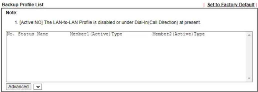
text_image
Backup Profile List Set to Factory Default Note: 1. [Active:NO] The LAN-to-LAN Profile is disabled or under Dial-In(Call Direction) at present. No. Status Name Member1 (Active) Type Member2 (Active) Type Advanced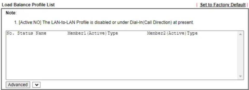
text_image
Load Balance Profile List Set to Factory Default Note: 1. [Active:NO] The LAN-to-LAN Profile is disabled or under Dial-In(Call Direction) at present. No. Status Name Member1 (Active) Type Member2 (Active) Type Advanced
text_image
General Setup Status Enable ○ Disable Profile Name Member1 Please select a LAN-to-LAN Dial-Out profile. Member2 Please select a LAN-to-LAN Dial-Out profile. Active Mode Backup Mode ○ Load Balance Mode
Available settings are explained as follows:
| Item Description | |
| Backup Profile List and Load Balance Profile List | Set to Factory Default - Removes all VPN Trunk profiles in the Profile List.No. - The index number of VPN profile.Status - Shows whether the VPN Trunk is enabled or disabled.v - VPN Trunk is enabled.x - VPN Trunk is disabled.Name - The user-entered name that identifies the trunkprofile.Member1 (Active) Type / Member2 (Active) Type - Shows the profile index, whether it is enabled or disabled, and the VPN protocol of the 2 LAN-to-LAN VPN profiles.Example: 1(YES)PPTP - the trunk member is set to use the first profile which is currently enabled and uses the PPTP protocol.Advanced- To configure advanced settings of a VPN Trunk profile, select its name from the dropdown list and click Advanced. |
| Advanced for Backup Profile List | If a Backup Profile was selected, the following Advanced Settings screen appears:VPN Backup Advance Settings Profile Name- User-defined name that identifies this profile.ERD Mode- Sets the Environment Recovery Detection (ERD) mode.Normal- Both VPN tunnels have equivalent priority.Resume- Member 1 and Member 2 VPN tunnels are primary and secondary connections, respectively. The router will always attempt to use Member 1 first, and only fail over to Member 2 if Member 1 is down.Detail Information- Provides a detailed explanation of the ERD mode.To save Advanced Settings for the profile, select OK; to close without saving changes, select Close. Profile Name- User-defined name that identifies this profile.ERD Mode- Sets the Environment Recovery Detection (ERD) mode.Normal- Both VPN tunnels have equivalent priority.Resume- Member 1 and Member 2 VPN tunnels are primary and secondary connections, respectively. The router will always attempt to use Member 1 first, and only fail over to Member 2 if Member 1 is down.Detail Information- Provides a detailed explanation of the ERD mode.To save Advanced Settings for the profile, select OK; to close without saving changes, select Close. |
| Advanced for Load Balance Profile List | If a Load Balance Profile was selected, the following Advanced Settings screen appears: |
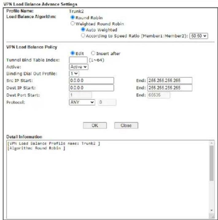
text_image
VPN Load Balance Advance Settings Profile Name: Trunk2 Load Balance Algorithm: Round Robin Weighted Round Robin Auto Weighted According to Speed Ratio [Member1:Member2]: 60.50 VPN Load Balance Policy Edit Insert after Tunnel Bind Table Index: (1~64) Active Active Binding Dial Out Profile: 1 Src IP Start: 0.0.0.0 End: 266.266.266.266 Dest IP Start: 0.0.0.0 End: 266.266.266.266 Dest Port Start: 1 End: 66635 Protocol: ANY 0 OK Close Detail Information [VPN Load Balance Profile name: Trunk2 ] [Algorithm: Round Robin ]Profile Name - User-defined name that identifies this profile.
Load Balance Algorithm - Configures how load balancing is performed.
- Round Robin – All outgoing connections that do not match to any load balance policy are evenly distributed between the tunnels.
- Weighted Round Robin -- All outgoing connections that do not match to any load balance policy are distributed between the tunnels based on a ratio that is either automatically determined by the router (Auto Weighted), or specified by the user (According to Speed Ratio).
VPN Load Balance Policy - This section allows the modification or addition of load balance policy profiles.
Edit / Insert After - Select Edit to modify the existing load balance profile with index specified in Tunnel Bind Table Index, or Insert After to insert a new load balance profile immediately after the index position specified in Tunnel Bind Table Index.
Tunnel Bind Table Index- 64 Binding tunnel tables are provided by this device. In Edit mode, the profile that matches this index will be updated.
In Insert After mode, a new profile will be inserted immediately after the policy having this index.
Active - Includes Active and Clear. In which,
● Active - All information will be saved into a load balance profile.
- Clear - The profile with index matching Tunnel Bind Table Index will be deleted.
Binding Dial Out Profile - The LAN-to-LAN VPN tunnel to which traffic matching this policy will be sent.
Scr IP Start /End- Specify source IP addresses as starting
| point and ending point.Dest IP Start/End - Specify the target IP addresses as starting point and ending point.Dest Port Start /End- Specify the target port range if the protocol is TCP or UDP.Protocol - Specify the protocol of the traffic.Detail Information - Shows all the information about the Load Balance profile.To save Advanced Settings for the profile, select OK; to close without saving changes, select Close. | |
| Add | Select it to add a VPN Trunk Profile using the entered information. |
| Update Make modifications | as necessary in the General Setup section.Select it to save the changes to the Status (Enable or Disable), profile name, member1 or member2. |
| Delete | Select it to remove the VPN TRUNK profile.The corresponding members (LAN-to-LAN profiles) grouped in the deleted VPN TRUNK profile will be released and that profiles in LAN-to-LAN will be displayed in black. |
V-1-13 Connection Management
You can initiate outbound LAN-to-LAN VPN sessions, and view and disconnect all current LAN-to-LAN and dial-up VPN sessions.
VPN and Remote Access >> Connection Management

text_image
Dial-out Tool General Mode: (toEdge_VN) 27.71.238.25 Backup Mode: Load Balance Mode: Dial Dial Refresh| VPN Connection Status | ||||||||
| All VPN Status | LAN-to-LAN VPN Status | Remote Dial-in User Status | ||||||
| VPN | Type | Remote IP | Virtual Network | Tx Pkts | Tx Rate(bps) | Rx Pkts | Rx Rate(bps) | UpTime |
| 1 [toEdge_VN] | IKEv2 IPsec Tunnel PSK AES128-CBC-SHA1 Auth | via WAN3 | 192.158.100.0/24 | 0 | 0 | 0 | 0 | 1 day 17:49:00 Drop |
| 2 (KDS) | IKEv2 IPsec Tunnel PSK AES256-CBC-SHA256 Auth | via WAN3 | 172.17.5.0/24 | 173 | 0 | 495 | 72 | 00:31:21 Drop |
□ No subpaging □ No auto refreshing
\~\~\~\~: Data is encrypted. \~\~\~\~: Data isn't encrypted. \~\~\~\~: Waiting Client 2FA.
Available settings are explained as follows:
| Item Description | |
| Refresh | Click to manually reload the page to refresh VPN connection information. |
| Dial-out Tool | The Dial-out Tool section can be used to initiate outgoing LAN-to-LAN VPN sessions.General Mode- It lists all LAN-to-LAN VPN profiles that do not belong to enabled VPN Trunk profiles.To manually dial a LAN-to-LAN VPN profile, select it from the combo box, and click theDialbutton to the right. The VPN connection built by General Mode does not support VPN backup function.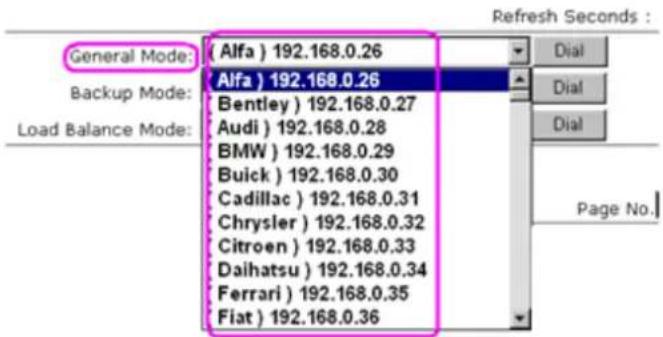 Backup Mode- It lists all Backup VPN Trunk profiles. To manually dial a Backup VPN Trunk profile, select it from the combo box, and click theDialbutton to the right. The VPN connection built by Backup Mode supports VPN backup function.General Mode: (Alfa) 192.168.0.26DalBackup Mode: (VpnBackup) 192.168.2.103DalLoad Balance Mode: (VpnBackup) 192.168.2.103DalLoad Balance Mode- It lists all Load Balance VPN Trunkprofiles. To manually dial a Load Balance VPN Trunk profile, select it from the combo box, and click the Dial button to the right.Dial - Click this button to execute dial out function. If the connect is successfully made, it will show up in the VPN Connection Status section below. Backup Mode- It lists all Backup VPN Trunk profiles. To manually dial a Backup VPN Trunk profile, select it from the combo box, and click theDialbutton to the right. The VPN connection built by Backup Mode supports VPN backup function.General Mode: (Alfa) 192.168.0.26DalBackup Mode: (VpnBackup) 192.168.2.103DalLoad Balance Mode: (VpnBackup) 192.168.2.103DalLoad Balance Mode- It lists all Load Balance VPN Trunkprofiles. To manually dial a Load Balance VPN Trunk profile, select it from the combo box, and click the Dial button to the right.Dial - Click this button to execute dial out function. If the connect is successfully made, it will show up in the VPN Connection Status section below. |
| VPN Connection Status | VPN - Displays the VPN profile number and the profile name.Type - Displays the VPN protocol used for the connectionRemote IP - Displays the remote IP address of the VPN connection.Virtual Network - Displays the IP subnet used by the VPN connection.Tx Pkts - Displays the number of packets that have been transmitted through the VPN connection.Tx Rate(Bps) - Displays the current upstream speed of the VPN connection.Rx Pkts - Displays the number of packets that have been received through the VPN connection.Rx Rate(Bps) - Displays the current downstream speed of the VPN connection.UpTime - Displays the elapsed time of the VPN connection.Drop - Click this button to disconnect this VPN connection. |
V-2 Certificate Management
A digital certificate is an electronic document issued by a certification authority (CA) to an entity to prove ownership of a public key. It contains identifying information including the issued-to-party's name, a serial number, expiration dates etc., and the digital signature of the certificate-issuing authority so that a recipient can verify that the certificate is real. Vigor router supports digital certificates that conform to the X.509 standard.
In this section, you can generate and manage local digital certificates, and import trusted CA certificates. Be sure that the system time is correct on the router so that certificates will not be erroneously considered to be invalid because of an incorrect system time falling outside of the certificate's valid time period. The easiest way to accomplish this is by periodically synchronizing the system time to a Network Time Protocol (NTP) server.
The image below shows the menu items for Certificate Management.
Web User Interface
Certificate Management
Local Certificate
Trusted CA Certificate
Certificate Backup
Self-Signed Certificate
Local Services List
附表四
V-2-1 Local Certificate
You can generate, import or view local certificates on this page.
Certificate Management >> Local Certificate
X509 Local Certificate Configuration
| Name | Subject | Status | CA | Modify |
| GENERATE | IMPORT |
Storage for Certificate
| Storage Usage: | 4% |
Note:
- Please setup the "System Maintenance >> Time and Date" correctly before signing the local certificate.
- The Time Zone MUST be setup correctly!!
- Local Certificate and Trusted CA Certificate share a storage space.
- CA field means the certificate issuer has been imported to router.
REFRESH
Certificate Management >> Local Certificate
X509 Local Certificate Configuration
| Name | Subject | Status | CA | Modify |
| DrayDDNS (Global) | CN = fae2927lax-5g.drayddns.com | ● Not Valid Yet | View Delete | |
| openvpn client | C = TW, ST = HsinChu, L = Hu... | ● Not Valid Yet | View Delete | |
| openvpn server | C = TW, ST = HsinChu, L = Hu... | ● Not Valid Yet | View Delete | |
| GENERATE IMPORT | ||||
Storage for Certificate
| Storage Usage: | 20% |
Note:
- Ensure Time Zone is correctly set up in "System Maintenance >> Time and Date" before signing the local certificate.
- Certificate files will be deleted when downgrading router firmware from version 4.4.0 to an older version.
- Local Certificate and Trusted CA Certificate share a storage space.
- CA field means the certificate issuer has been imported to router.
REFRESH
Available settings are explained as follows:
Item Description
| Name | Displays the Name that identifies the certificate. |
| Subject | Displays the Subject Name entries of the certificate. |
| Status | Displays the status of the certificate. |
| Modify | View - Click to view details about the certificate. A screen that looks like the following will be displayed, showing the Subject Name, Subject Alternative Name, and the certificate content.Delete - Click to remove the selected name.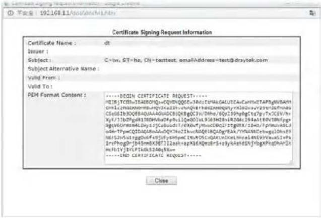 Delete - Click to remove the certificate. Delete - Click to remove the certificate. |
| Generate | Click to fill out details about a certificate, and start the generation process. |
| Storage for Certificate | Display the percentage of the storage usage. |
| Refresh | Click this button to refresh the information on this page. |
GENERATE
Use this screen to submit a request to your root CA to generate a certificate.
Generate Certificate Signing Request
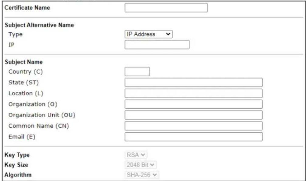
text_image
Certificate Name Subject Alternative Name Type IP Address IP Subject Name Country (C) State (ST) Location (L) Organization (O) Organization Unit (OU) Common Name (CN) Email (E) Key Type RSA Key Size 2048 Bit Algorithm SHA-256Generate
Available settings are explained as follows:
| Item Description | |
| Certificate Name | Name that identifies the certificate. |
| Type | Select the type (IP address, Domain name, E-mail or None) of Subject Alternative Name and enter its value. |
| Country (C) Country in which your organization is located. | |
| State (ST) | State or province where your organization is located. |
| Location (L) City where your organization is located. | |
| Organization (O) Legal name of your organization. | |
| Organization Unit (OU) | Department within your organization that you wish to be associated with this certificate. |
| Common Name (CN) | Fully-qualified domain name / WAN IP that will be used to reach your server. |
| Email (E) | Email address of the entry. |
| Key Type | Key type is hard set to RSA. |
| Key Size | Choose between 1024 and 2048 bit. |
| Algorithm | Choose between SHA-1 and SHA-256. |
| Generate | Click to submit generate request to the CA server. |
After clicking the Generate button, you will be taken back to the main Local Certificate screen, showing the certificate request in progress:
X509 Local Certificate Configuration
| Name | Subject | Status | CA | Modify | |
| server | C = TW, ST = HS, L = SF, O = ... | Requesting | View | Delete | |
| GENERATE | IMPORT | ||||
Storage for Certificate

bar
Storage Usage: 8%Note:
- Please setup the "System Maintenance >> Time and Date" correctly before signing the local certificate.
- The Time Zone MUST be setup correctly!!
- Local Certificate and Trusted CA Certificate share a storage space.
- CA field means the certificate issuer has been imported to router.
REFRESH
IMPORT
Vigor router allows you to generate a certificate request and submit it the CA server, then import it as "Local Certificate". If you have already gotten a certificate from a third party, you may import it directly. The supported types are PKCS12 Certificate and Certificate with a private key.
Click this button to import a saved file as the certification information. There are three types of local certificate supported by Vigor router.
Certificate Management >> Local Certificate
Import X509 Local Certificate
Upload Local Certificate
Select a local certificate file.
Certificate file: Browse.
Click Import to upload the local certificate.
Import Cancel
Upload PKCS12 Certificate
Select a PKCS12 file.
PKCS12 file: Browse..
Password:
Click Import to upload the PKCS12 file.
Import Cancel
Upload Certificate and Private Key
Select a certificate file and a matchable Private Key.
Certificate file: Browse.
Key file: Browse..
Password:
Click Import to upload the local certificate and private key.
Import Cancel
Available settings are explained as follows:
| Item Description | |
| Upload Local Certificate | Certificate file - Click Browse to select a local certificate file.Import - Click to import selected certificate file to router.Cancel - Click to return to the main Local Certificate screen. If you have done well in certificate generation, the Status of the certificate will be shown as “OK”.Import X509 Local Certificate X509 Local Certificate Conflouration X509 Local Certificate Conflouration GENERATE IMPORT REFRESH GENERATE IMPORT REFRESH |
| Upload PKCS12 Certificate | It allows users to import the certificate whose extensions are usually .pfx or .p12. And these certificates usually need passwords.Note that PKCS12 is a standard for storing private keys and certificates securely. It is used in (among other things) Netscape and Microsoft Internet Explorer with their import and export options.PKCS12 file - Click Browse to select a PKCS12 certificate file.Password - Enter the password associated with the certificate and key files.Import - Click to import selected certificate file to router.Cancel - Click to return to the main Local Certificate screen. |
| Upload Certificate and Private Key | It is useful when users have separated certificates and private keys. And the password is needed if the private key is encrypted.Certificate file - Click Browse to select a local certificate file.Key file - Click Browse to select a key file.Password - Enter the password associated with the certificate and key files.Import - Click to import selected certificate file to router.Cancel - Click to return to the main Local Certificate screen. |
V-2-2 Trusted CA Certificate
The user can build RootCA certificates (up to three) if required.
When the local client and remote client are required to make certificate authentication (e.g., IPsec X.509) for data passing through SSL tunnel and avoiding the attack of MITM, a trusted root certificate authority (Root CA) will be used to authenticate the digital certificates offered by both ends.
However, the procedure of applying digital certificate from a trusted root certificate authority is complicated and time-consuming. Therefore, Vigor router offers a mechanism which allows you to generate root CA to save time and provide convenience for general user. Later, such root CA generated by DrayTek server can perform the issuing of local certificate.

Info
Root CA can be deleted but not edited. If you want to modify the settings for a Root CA, please delete the one and create another one by clicking Create Root CA.
Create, import or export, view root the trusted certificate authority certificates on this page. No Root CA Existed
Certificate Management >> Trusted CA Certificate
X509 Trusted CA Certificate Configuration
| Name | Subject | Status | Modify |
| --- | --- | Create Root CA | |
| IMPORT |
Storage for Certificate

Note:
- Please setup the "System Maintenance >> Time and Date" correctly before you try to generate a RootCA!!
- The Time Zone MUST be setup correctly!!
- Local Certificate and Trusted CA Certificate share a storage space.
REFRESH
A Root CA Existed
Certificate Management >> Trusted CA Certificate
X509 Trusted CA Certificate Configuration
| Name | Subject | Status | Modify | ||
| Root CA | C = TW, ST = HS, L = SF, O = DrayTe... | Not Valid Yet | Export | View | Delete |
| IMPORT | |||||
Storage for Certificate

- Please setup the "System Maintenance >> Time and Date" correctly before you try to generate a RootCA!!
- The Time Zone MUST be setup correctly!!
- Local Certificate and Trusted CA Certificate share a storage space.
REFRESH
Available settings are explained as follows:
| Item Description | |
| Create Root CA | Click to create a new root CA. |
| Name | Name that identifies the certificate. |
| Subject | Shows the Subject Name of the certificate. |
| Status | Displays the status of the certificate. |
| Modify When none root CA | existed:Create Root CA - Click to fill out details about a certificate, and start the generation process.When a root CA existed:Export - Click to export the certificate as a file.View - Click to view details of the certificate. |
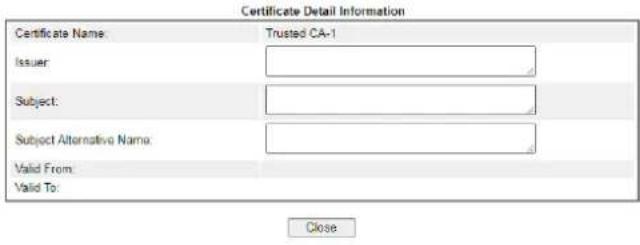 Delete - Click to delete the certificate. Delete - Click to delete the certificate. | |
| Import | Click to import an existing certificate. |
| Refresh | Click to refresh the page to display the latest certificate information. |
Creating a Root CA
Click Create Root CA to open the following page.
Generate Root CA
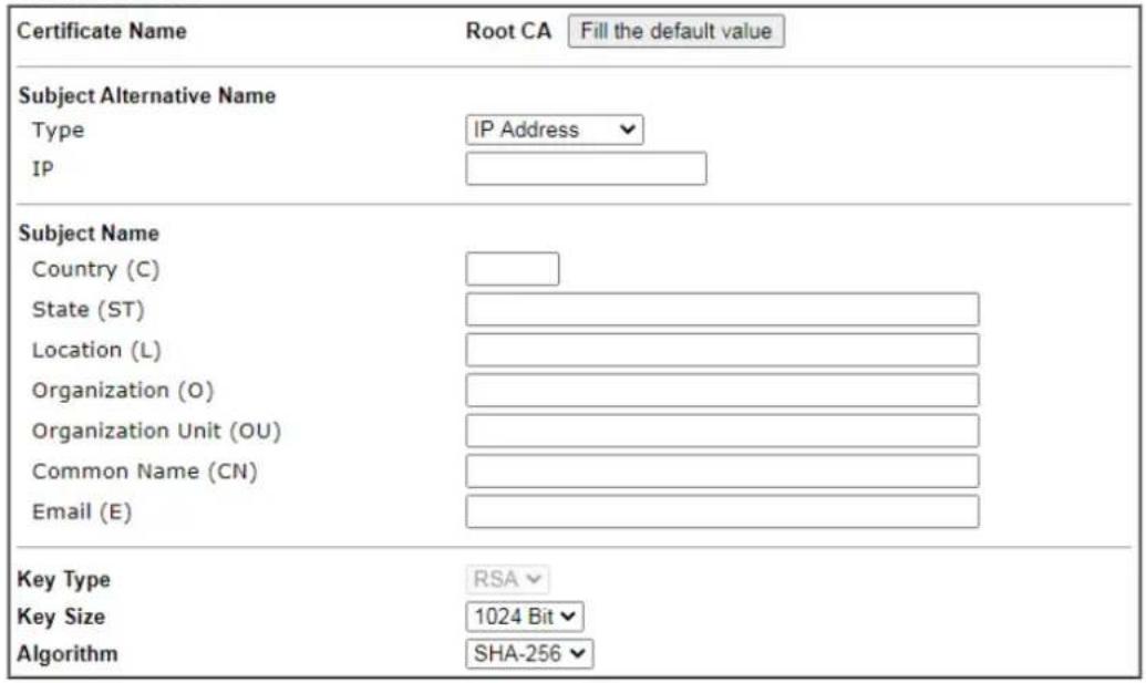
text_image
Certificate Name Root CA Fill the default value Subject Alternative Name Type IP Address Subject Name Country (C) State (ST) Location (L) Organization (O) Organization Unit (OU) Common Name (CN) Email (E) Key Type RSA Key Size 1024 Bit Algorithm SHA-256Generate
Available settings are explained as follows:
| Item Description | |
| Certificate Name | Display the name of root CA.Fill the default value - Click to enter the default value for this Root CA. |
| Type | Select the type of Subject Alternative Name and enter its value. |
| Country (C) Country in which your organization is located. | |
| State (ST) | State or province where your organization is located. |
| Location (L) City where your organization is located. | |
| Organization (O) Legal name of your organization. | |
| Organization Unit (OU) | Department within your organization that you wish to be associated with this certificate. |
| Common Name (CN) | Fully-qualified domain name / WAN IP that will be used to reach your server. |
| Email (E) | Email address of the entry. |
| Key Type | Key type is hard set to RSA. |
| Key Size | Choose between 1024 and 2048 bit. |
| Algorithm | Choose between SHA-1 and SHA-256. |
| Generate | Click to submit generate request to the CA server. |
Importing a Trusted CA
To import a pre-saved trusted CA certificate, please click IMPORT to open the following window.
Import X509 Trusted CA Certificate
Select a trusted CA certificate file.

Click Import to upload the certification.
Import Cancel
Available settings are explained as follows:
| Item Description | |
| Browse | Click Browse to select a CA certificate file. |
| Import | Click to import selected certificate file to router. The one you imported will be listed on the Trusted CA Certificate window. |
| Cancel | Click to return to the main Trusted CA Certificate screen. |
V-2-3 Certificate Backup
You can back up Local and Trusted CA certificates on the router to a file.
Certificate Management >> Certificate Backup
Certificate Backup / Restoration
Backup

text_image
Encrypt password: Max: 23 characters Confirm password: Click Backup to download certificates to your local PC as a file.Restoration
Select a backup file to restore.
選擇檔案 未選擇任何檔案

Available settings are explained as follows:
| Item Description | |
| Backup | |
| Encrypt password/Confirm password | Enter the password with which you wish to encrypt the certificate. |
| Backup | Click to download the certificate. |
| Restoration | |
| Select a backup file to restore | Click Browse to select the backup file you wish to restore. |
| Decrypt password | Enter the password that was used to encrypt the certificates. |
| Restore | Click to retrieve the certificate. |
V-2-4 Self-Signed Certificate
A self-signed certificate is a unique identification for the device (e.g., Vigor router) which generates the certificate by itself to ensure the router security. Such self-signed certificate is signed with its own private key.
The self-signed certificate will be applied in SSL VPN, HTTPS, and so on. In addition, it can be created for free by using a wide variety of tools.
Certificate Management >> Self-Signed Certificate
Self-Signed Certificate Information
| Certificate Name : | self-signed |
| Issuer : | C=TW, ST=HsinChu, L=HuKou, O=DrayTek Corp., OU=DrayTek Support, CN=Vigor Router |
| Subject : | C=TW, ST=HsinChu, L=HuKou, O=DrayTek Corp., OU=DrayTek Support, CN=Vigor Router |
| Subject Alternative Name : | DNS:www.draytek.com |
| Valid From : | Jul 7 11:50:06 2020 GMT |
| Valid To : | Jul 7 11:50:06 2022 GMT |
| PEM Format Content : |
Note:
- Please setup the System Maintenance >> Time and Date correctly before you try to regenerate a self-signed certificate!!
- The Time Zone MUST be setup correctly!!
Regenerate
Click Regenerate to open the Regenerate Self-Signed Certificate window. Enter all requested information including certificate name (used to differentiate different certificates), subject alternative name type and relational settings for subject name. Then click GENERATE.
V-2-5 Local Services List
This page shows certificate used by local services. Users can click to create self-signed certificate..
Certificate Management >> Local Services List
Default Certificate self-signed
| Certificate Name | Local Services |
| Router Management -- Web Access from LAN or WAN | |
| Router Management -- SSH | |
| VPN and Remote Access >> LAN to LAN -- SSL VPN | |
| VPN and Remote Access >> Remote Dial-in User -- SSL VPN | |
| VPN and Remote Access >> OpenVPN -- OpenVPN | |
| Default Certificate | Hotspot Web Portal |
| Applications >> Internal RADIUS | |
| Applications >> Local 802.1X General Setup | |
| Applications >> High Availability | |
| CSM >> DNS Filter -- block page | |
| USB Application >> USB User Management | |
| None | VPN and Remote Access >> IPsec General Setup |
OK
This page is left blank.
Part VI Security

Firewall
While the broadband users demand more bandwidth for multimedia, interactive applications, or distance learning, security has been always the most concerned. The firewall of the Vigor router helps to protect your local network against attack from unauthorized outsiders. It also restricts users in the local network from accessing the Internet.

CSM
CSM is an abbreviation of Central Security Management which is used to control IM/ P2P usage, filter the web content and URL content to reach a goal of security management.
VI-1 Firewall
Basic
A network firewall monitors traffic travelling between networks, with the ability to selectively allow or block traffic using a predefined set of security rules. This helps to maintain the integrity of networks by stopping unauthorized access and the exchange of sensitive information.
Firewall Facilities
LAN users are provided with secured protection by the following firewall facilities:
- User-configurable IP filter (Data Filter).
● Stateful Packet Inspection (SPI): tracks packets and denies unsolicited incoming data - Selectable Denial of Service (DoS) / Distributed DoS (DDoS) attacks protection
Data Filter
All traffic, both incoming and outgoing, that does not trigger a PPP connection attempt (either because a PPP connection is not necessary, or the required PPP connection has already been established) is checked against the Data Filter, and will be allowed or blocked according to the rules configured within.
The following flowcharts show how the router treats incoming traffic and outgoing traffic respectively.
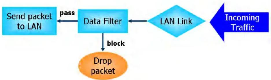
flowchart
graph TD
    A["Send packet to LAN"] -->|pass| B["Data Filter"]
    B -->|block| C["Drop packet"]
    C --> D["LAN Link"]
    D --> E["Incoming Traffic"]
Stateful Packet Inspection (SPI)
Stateful inspection is a firewall architecture that works at the network layer. Unlike legacy static packet filtering, which examines a packet based on the information in its header, stateful inspection builds up a state machine to track each connection traversing all interfaces of the firewall and makes sure they are valid. The stateful firewall of Vigor router not only examines the header information also monitors the state of the connection.
Denial of Service (DoS) Defense
DoS attacks are categorized into two types: flooding-type attacks and vulnerability attacks. Flooding-type attacks attempts to exhaust system resources while vulnerability attacks attempts to paralyze the system by exploiting vulnerabilities of protocols or operation systems.
Vigor's DoS Defense functionality detects DoS attacks and mitigates their damage by inspecting every incoming packet, and malicious packets will be blocked. If Syslog is enabled, alert messages will also be sent. Abnormal traffic flow such as flood and port scan attacks that exceed allowable thresholds are also blocked.
The below shows the attack types that DoS/ DDoS defense function can detect:
- SYN flood attack
- UDP flood attack
- ICMP flood attack
- Port Scan attack
- IP options
- Land attack
- Smurf attack
- Trace route
- SYN fragment
- Fraggle attack
- TCP flag scan
- Tear drop attack
- Ping of Death attack
- ICMP fragment
- Unassigned Numbers
Web User Interface
Below shows the menu items for Firewall.
Firewall
General Setup
Filter Setup
DoS Defense
Diagnose
VI-1-1 General Setup
General Setup Page
Such page allows you to enable / disable Data Filter, determine general rule for filtering the incoming and outgoing data.
Firewall >> General Setup
General Setup
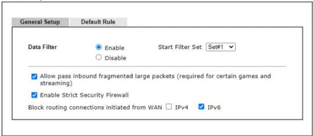
text_image
General Setup Default Rule Data Filter Enable Start Filter Set Set#1 Disable ✓ Allow pass inbound fragmented large packets (required for certain games and streaming) ✓ Enable Strict Security Firewall Block routing connections initiated from WAN □ IPv4 ✓ IPv6Note:
Packets are filtered by firewall functions in the following order:
- Data Filter Sets and Rules 2. Block routing connections initiated from WAN 3. Default Rule

This will not backup the detail setting of Quality of Service and Schedule.
Available settings are explained as follows:
| Item Description | |
| Data Filter | Select Enable to activate the Data Filter function, and then choose a Start Filter Set. |
| Always pass inboundfragmented large packets | Certain games and video streaming service use fragmented UDP packets to transfer data. Enabling this option allows these applications to function properly.If this option is not enabled, the router will attempt to reassemble fragmented packets up to a certain value (e.g., 15xx~2102) kilobytes long. Packets larger than the certain value will be discarded.If this option is enabled, the router always passes fragmented packets without reassembling them, regardless of the size of the packet. |
| Enable Strict Security Firewall | If this option and the Web Content Filter (WCF) are both enabled, web traffic will be blocked if the WCF server fails to respond to lookup requests. |
| Block routing connections initiated from WAN | IPv6 - IPv6 does not make use of Network Address Translation (NAT), so all LAN hosts receive public IPv6 IP addresses that are exposed to the WAN. Enable this option to block WAN hosts from connecting to LAN hosts using IPv6.IPv4 - For LAN hosts receiving WAN IPv4 addresses using the IP routed subnet, enable this option to prevent WAN hosts from connecting to LAN hosts. This option has no effect on LAN hosts on private LAN subnets. |
| Backup Firewall | Click Backup to save the firewall configuration. |
| Restore Firewall | Click Select to choose a firewall configuration file. Then click Restore to apply the file. |
To save changes on the page, click OK. To discard changes, click Cancel.
Traffic is filtered by firewall functions in the following order:
- Data Filter Sets and Rules
- Block connections initiated from WAN
- Default Rule
Default Rule Page
Such page allows you to choose filtering profiles including QoS, Load-Balance policy, WCF, APP Enforcement, URL Content Filter, for data transmission via Vigor router.
The default rule applies to all traffic that is not constrained by other filters or rules.
Firewall >> General Setup
General Setup
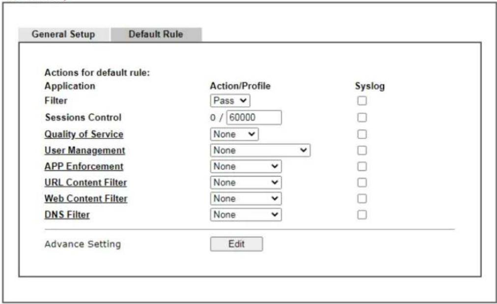
text_image
General Setup Default Rule Actions for default rule: Application Action/Profile Syslog Filter Pass □ Sessions Control 0 / 60000 □ Quality of Service None □ User Management None □ APP Enforcement None □ URL Content Filter None □ Web Content Filter None □ DNS Filter None □ Advance Setting Edit
Note:
This will not backup the detail setting of Quality of Service and Schedule.
Available settings are explained as follows:
| Item Description | |
| Filter | Select Pass or Block for the packets that do not match with the filter rules. When the setting is Block, all other fields on the page are disabled because they are not applicable. |
| Sessions Control The current | number of sessions is shown before the slash,followed by the maximum number of concurrent sessions allowed, which is configurable. The default maximum is 60000, which is also the upper limit of the value. |
| Quality of Service | Choose one of the QoS rules to be applied as firewall rule.For detailed information of setting QoS, please refer to the related section later. |
| User Management | This setting is only available when Rule-Based is selected in User Management>>General Setup. The default firewall rule will be applied to the selected user or user group. Refer to the chapter on User Management for more details on the feature.● None:User Management does not apply to the defaultrule.User Object: The default rule only applies to the selected user.[Create New User]: Select this to create a new user.User Group: The default rule only applies to the selected User Group.[Create New Group]: Select this to create a new user group.ALL: The default rule applies to all defined users.Create New User or Create New Group item will appear for you to click to create a new one if there is no user profile or group profile existed.Syslog - Select to allow User Management to log messages in Syslog. |
| APP Enforcement | Select an APP Enforcement profile for application blocking, or None to disable APP Enforcement for the Default Rule.Select [Create New] from the dropdown list to create a new profile. Refer to the chapter on APP Enforcement for more details on the feature.Syslog - Select to allow APP Enforcement to log messages in Syslog. |
| URL Content Filter Select a | URL Content Filter profile to be used, or None to disable URL Content Filter for the Default Rule. Select [Create New] from the dropdown list to create a new profile. Refer to the chapter on URL Content Filter for more details on the feature.Syslog - Select to allow URL Content Filter to log messages in Syslog. Logging action is configured at the profile level in CSM>>URL Content Filter Profile, Log. |
| Web Content Filter Select a | Web Content Filter profile to be used, or None to disable Web Content Filter for the Default Rule. Select [Create New] from the dropdown list to create a new profile.Syslog - Select to allow Web Content Filter to log messages in Syslog. Logging action is configured at the profile level in the Web Content Filter Profile Table section in CSM>>Web Content Filter Profile, Log. |
| DNS Filter | Select the DNS Filter profile to be used, or None to disable DNS Filter for the Default Rule. Select [Create New] from the dropdown list to create a new profile.Syslog - Select to allow DNS Filter to log messages in Syslog. Logging action is configured at the profile level in the DNS Filter Profile Table section in CSM>>DNS Filter Profile, SysLog. |
| Advance Setting | Click Edit to open the configuration window for Advanced Settings. However, it is recommended to use the default settings. |
Firewall >> General Setup
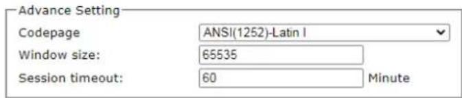
text_image
Advance Setting Codepage ANSI(1252)-Latin I Window size: 65535 Session timeout: 60 MinuteOK
Close
Codepage - Sets the codepage used by the URL content filter to match URLs against keywords in profiles. Choosing the appropriate codepage can increase the accuracy of the URL Content Filter. The default value is ANSI 1252 Latin I. If the setting is None, no decoding of URL will be performed.
If you are unsure of which codepage to use, please start the Syslog application, and the recommended codepage will be shown in the Codepage Information tab in the Setup dialog box.
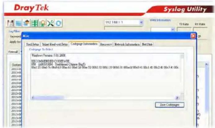
text_image
DrayTek Syslog Utility 192 168.1.1 WAN Information TX Rate RX Rate Log Fiber Keyword Apply to Formal Misc Tool Setup | Insert Read-out Setup | Codepage Information | Recovery | Network Information | Net Date Codepage To Select Windows Version: 501 2600& RECOMMENDED-CODEP AOE USB (ARBIOM: Traditional Chinese Big5) 0x1 21 0x6 7x 0x9 6:3 00x6:41 00x24 00x6:41 00x1 41 00x240 00x3:41 00x Save CodepagesWindow size - Sets the TCP window size as described in RFC 1323. Valid values are from 0 to 65535. The more the value is, the better the performance will be. However, if the network is not stable, small value will be proper.
Session timeout - Sets the timeout sessions are allowed to idle before they are removed from the system.
| Backup Firewall | Click Backup to save the firewall configuration. |
| Restore Firewall | Click Select to choose a firewall configuration file. Then click Restore to apply the file. |
After finishing all the settings here, please click OK to save the configuration.
VI-1-2 Filter Setup
Click Firewall and click Filter Setup to bring up the setup page.
Firewall >> Filter Setup

Filter Setup
Set to Factory Default
| Set | Comments | Set | Comments |
| 1. | Default Data Filter | 7. | |
| 2. | 8. | ||
| 3. | 9. | ||
| 4. | 10. | ||
| 5. | 11. | ||
| 6. | 12. |
To edit a filter set, click on its set number. The following Filter Set page will be shown. Each filter set contains up to 7 rules.
Firewall >> Filter Setup >> Edit Filter Set
Filter Set 1
Comments : Default Data Filter
| Rule | Enable | Comments | Direction | Src IP | Dst IP | Service Type | Action | CSM | Move Up | Move Down |
| 1 | xNetBios -> DNS | LAN/DMZ/RT/VPN-> WAN | Any | Any | TCP/UDP, Port: from 137~139 to 53 | Block Immediately | Down | |||
| 2 | LAN/DMZ/RT/VPN-> WAN | Any | Any | Any | Pass Immediately | UP | Down | |||
| 3 | LAN/DMZ/RT/VPN-> WAN | Any | Any | Any | Pass Immediately | UP | Down | |||
| 4 | LAN/DMZ/RT/VPN-> WAN | Any | Any | Any | Pass Immediately | UP | Down | |||
| 5 | LAN/DMZ/RT/VPN-> WAN | Any | Any | Any | Pass Immediately | UP | Down | |||
| 6 | LAN/DMZ/RT/VPN-> WAN | Any | Any | Any | Pass Immediately | UP | Down | |||
| 7 | LAN/DMZ/RT/VPN-> WAN | Any | Any | Any | Pass Immediately | UP |
Filter Set 1 2 3 4 5 6 7 8 9 10 11 12
Next Filter Set None
○ Wizard Mode: most frequently used settings in three pages
Advance Mode: all settings in one page

Available settings are explained as follows:
| Item Description | |
| Filter Rule | To edit the filter rule, click the filter rule number to bring up the Edit Filter Rule page. See the following section for details on the Edit Filter Rule page. |
| Enable | Select to enable the filter rule. |
| Comments | Optional comment entered in the settings page to identify the rule. |
| Direction | Displays the direction of packet. |
| Src IP / Dst IP | Displays the IP address of source / destination. |
| Service Type | Displays the type and port number of the packet. |
| Action | Displays the packets to be passed / blocked. |
| CSM | Displays the content security managed |
| Move Up/Down | Use Up or Down link to change the order of the filter rules. |
| Next Filter Set | Select the filter set for the firewall to process after the current filter set, or None if the current filter set is the last one to be processed. Be careful not to create a loop when setting next filter sets. |
| Wizard Mode | Allow to configure frequently used settings for filter rule via several setting pages. |
| Advance Mode | Allow to configure detailed settings of filter rule. |
To use Wizard Mode, simple do the following steps:
-
Click the Wizard Mode radio button.
-
Click Index 1. The setting page will appear as follows:
Firewall >> Edit Filter Set >> Edit Filter Rule Wizard
Filter Set 1 Rule 1
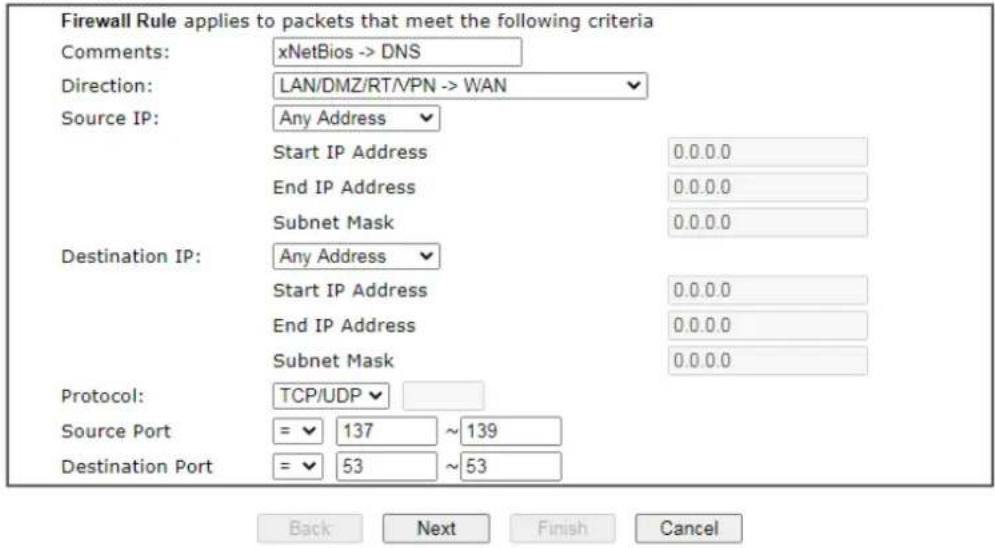
text_image
Firewall Rule applies to packets that meet the following criteria Comments: xNetBios -> DNS Direction: LAN/DMZ/RT/PN -> WAN Source IP: Any Address Start IP Address 0.0.0.0 End IP Address 0.0.0.0 Subnet Mask 0.0.0.0 Destination IP: Any Address Start IP Address 0.0.0.0 End IP Address 0.0.0.0 Subnet Mask 0.0.0.0 Protocol: TCP/UDP Source Port = 137 ~ 139 Destination Port = 53 ~ 53 Back Next Finish CancelAvailable settings are explained as follows:
| Item Description | |
| Comments | Enter filter set comments/ description. Maximum length is 14- character long. |
| Direction | Set the direction of packet flow.Note: RT means routing domain for 2nd subnet or other LAN. |
| Source/Destination IP | To set the IP address manually, please choose Any Address/Single Address/Range Address/Subnet Address as the Address Type and Enter them in this dialog. |
| Protocol | Specify the protocol(s) which this filter rule will apply to. |
| Source Port / Destination Port | (=) - when the first and last value are the same, it indicates one port; when the first and last values are different, it indicates a range for the port and available for this service type.(!=) - when the first and last value are the same, it indicates all the ports except the port defined here; when the first and last values are different, it indicates that all the ports except the range defined here are available for this service type.(>) - the port number greater than this value is available.(<) - the port number less than this value is available for this profile. |
3. Click Next to get the following page.
Firewall >> Edit Filter Set >> Edit Filter Rule Wizard
Filter Set 1 Rule 1
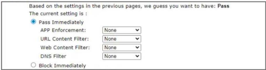
text_image
Based on the settings in the previous pages, we guess you want to have: Pass The current setting is : ● Pass Immediately APP Enforcement: None ✓ URL Content Filter: None ✓ Web Content Filter: None ✓ DNS Filter None ✓ ○ Block Immediately
Available settings are explained as follows:
| Item Description | |
| Pass Immediately | Packets matching the rule will be passed immediately.APP Enforcement - Select an APP Enforcement profile for application blocking, or None to disable APP Enforcement for the Default Rule. Select [Create New] from the dropdown list to create a new profile. Refer to the chapter on APP Enforcement for more details on the feature.URL Content Filter - Select a URL Content Filter profile to be used, or None to disable URL Content Filter for the Default Rule. Select [Create New] from the dropdown list to create a new profile. Refer to the chapter on URL Content Filter for more details on the feature.Web Content Filter - Select a Web Content Filter profile to be used, or None to disable Web Content Filter for the Default Rule. Select [Create New] from the dropdown list to create a new profile.DNS Filter - Select the DNS Filter profile to be used, or None to disable DNS Filter for the Default Rule. Select [Create New] from the dropdown list to create a new profile. |
| Block Immediately | Packets matching the rule will be dropped immediately. |
- After choosing the mechanism, click Next to get the summary page for reference.
Filter Set 1 Rule 1 Configuration Summary
Comments : xNetBios -> DNS
Direction
LAN/DMZ/RT/VPN -> WAN
Criteria
Source IP Any
Destination IP Any
Protocol TCP/UDP, Port: from 137 ~ 139 to 53
More options
Pass Immediately
APP Enforcement : None
URL Content Filter : None
Web Content Filter : None
DNS Filter : None

- If there is no error, click Finish to complete wizard setting.
To use Advance Mode, do the following steps:
- Click the Advance Mode radio button.
- Click Index 1 to access into the following page.
Firewall >> Edit Filter Set >> Edit Filter Rule
Filter Set 1 Rule 1
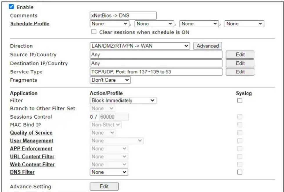
text_image
Enable Comments xNetBios -> DNS Schedule Profile None None None None Clear sessions when schedule is ON Direction LAN/DMZ/RT/PN -> WAN Advanced Source IP/Country Any Edit Destination IP/Country Any Edit Service Type TCP/UDP, Port. from 137~139 to 53 Edit Fragments Don't Care Application Action/Profile Syslog Filter Block Immediately Branch to Other Filter Set None Sessions Control 0 / 60000 MAC Bind IP Non-Strict Quality of Service None User Management None APP Enforcement None URL Content Filter None Web Content Filter None DNS Filter None Advance Setting Edit
Available settings are explained as follows:
| Item Description | |
| Enable | Check this box to enable the filter rule. |
| Comments | Enter filter set comments/ description. Maximum length is 14- character long. |
| Schedule Profile | Select Schedule indexes to allow the rule to be enabled at specific times. You may choose up to 4 out of the 15 schedules in Applications >> Schedule. The rule is always enabled when no indexes have been selected. |
| Clear sessions when schedule ON | Select this option to clear existing sessions when the rule is changes is enabled by a schedule profile. All connections will be reset. |
| Direction | Specify the direction of traffic flow to which this filter rule applies.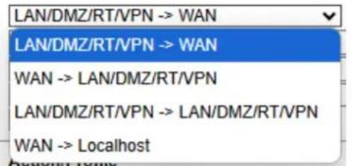 Note: RT stands for the routing domain for 2nd subnet orother LAN.Advanced- After choosing the direction, click the Advanced button to specify interfaces for traffic flow. Note: RT stands for the routing domain for 2nd subnet orother LAN.Advanced- After choosing the direction, click the Advanced button to specify interfaces for traffic flow.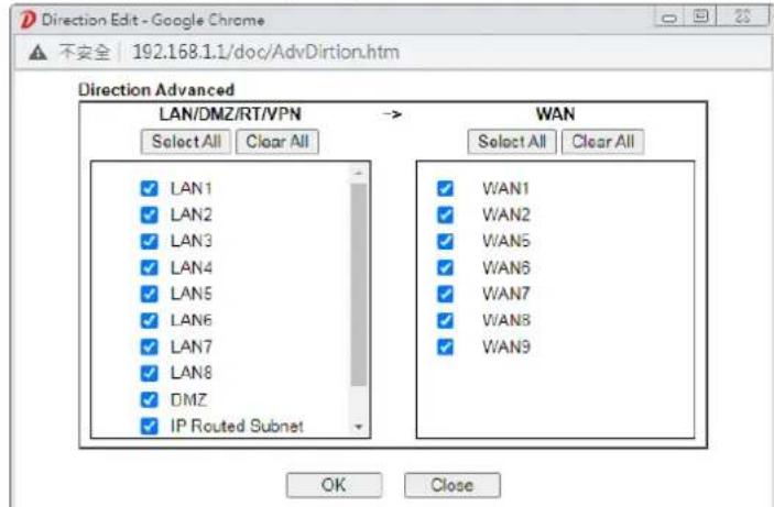 |
| Source IP/ Country and Destination IP / Country | Click Edit to bring up the following dialog box to configure the source and destination IP addresses or country objects. To set the IP address manually, please choose an Address Type and enter required information.Address Type- Select from one of the following:Any Address- All IP addressesSingle Address- Enter one IP address in Start IP addressRange Address- Enter the Start and End IP AddressesSubnet Address- Enter the Start IP Address and the Subnet Mask. Example: Start IP Address 192.168.1.1 and Subnet Mask 255.255.255.128 means is the same as having the Start IP Address as 192.168.1.1 and the End IP Address as 192.168.1.127.Group and Objects- Allows selection of predefined IP Groups and IP Objects. For details on IP Groups and Objects, see the chapter on Objects Setting.Country Object- Allows selection of predefined country objects. To set the IP address manually, please choose an Address Type and enter required information.Address Type- Select from one of the following:Any Address- All IP addressesSingle Address- Enter one IP address in Start IP addressRange Address- Enter the Start and End IP AddressesSubnet Address- Enter the Start IP Address and the Subnet Mask. Example: Start IP Address 192.168.1.1 and Subnet Mask 255.255.255.128 means is the same as having the Start IP Address as 192.168.1.1 and the End IP Address as 192.168.1.127.Group and Objects- Allows selection of predefined IP Groups and IP Objects. For details on IP Groups and Objects, see the chapter on Objects Setting.Country Object- Allows selection of predefined country objects. |
| Service Type | Click Edit to bring up the following dialog box to configure the Service Type.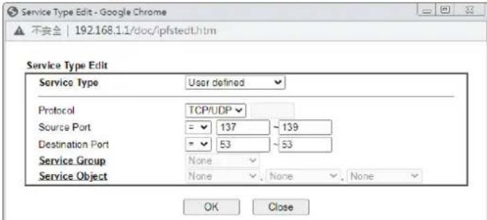 |
| Service Type - To set the service type manually, please choose User defined as the Service Type.User defined - Configure the protocol, source and destination ports manually.Group and Objects - Select preconfigured Service Groups or Objects.Protocol - Specify the protocol(s) which this filter rule will apply to.Source/Destination Port -(=)- any port that falls within the specified range(!=)- any port that falls outside of the specified range(>) - a port whose number is greater than the specified value(<)- a port whose number is smaller than the specified valueService Group/Object - Use the drop down list to select the desired Service Groups or Objects. | |
| Fragments | Action to be taken for fragmented packets. This option is valid for Data Filter rules only.Don't care-No action will be taken towards fragmented packets.Unfragmented -Apply the rule to unfragmented packets.Fragmented - Apply the rule to fragmented packets.Too Short - Apply the rule only to packets that are too short to contain a complete header. |
| Filter | Action to be taken when packets match the rule.Block Immediately - Packets matching the rule will be dropped immediately.Pass Immediately - Packets matching the rule will be passed immediately.Block If No Further Match - Block the packet if this the last matching rule for this packet in the filter.Pass If No Further Match - Pass the packet if this is the last matching rule for this packet in the filter. |
| Branch to other Filter | If the packet matches the filter rule, and the Filter action is |
| Set | Block If No Further Match or Pass If No Further Match, you can specify the next filter set to be applied, thus skipping the rest of the rules in the current filter set. |
| Sessions Control The current number of sessions is shown before the slash, followed by the maximum number of concurrent sessions allowed, which is configurable. The default maximum is 60000, which is also the upper limit of the value. | |
| MAC Bind IP | Strict – Ensure that both the MAC address and the IP address of the source and/or destination clients.Non-Strict – Do not check the IP address when processing IP Objects that specify MAC addresses. |
| Quality of Service | Choose one of the QoS rules to be applied as firewall rule. For detailed information of setting QoS, please refer to the related section later. |
| User Management | This setting is only available when Rule-Based is selected in User Management>>General Setup. The default firewall rule will be applied to the selected user or user group.Refer to the chapter on User Management for more details on the feature.None:User Management does not apply to the default rule.User Object:The default rule only applies to the selected user.[Create New User]: Select this to create a new user.User Group: The default rule only applies to the selected User Group.[Create New Group]: Select this to create a new user group.ALL:The default rule applies to all defined users.Create New User or Create New Group item will appear for you to click to create a new one if there is no user profile or group profile existed.Syslog - Select to allow User Management to log messages in Syslog. |
| APP Enforcement | Select an APP Enforcement profile for application blocking, or None to disable APP Enforcement for the Default Rule.Select [Create New] from the dropdown list to create a new profile. Refer to the chapter on APP Enforcement for more details on the feature.Syslog - Select to allow APP Enforcement to log messages in Syslog. |
| URL Content Filter Select a URL Content Filter profile to be used, or None to disable URL Content Filter for the Default Rule. Select [Create New] from the dropdown list to create a new profile. Refer to the chapter on URL Content Filter for more details on the feature.Syslog - Select to allow URL Content Filter to log messages in Syslog. Logging action is configured at the profile level in CSM>>URL Content Filter Profile, Log. | |
| Web Content Filter | Select a Web Content Filter profile to be used, or None to disable Web Content Filter for the Default Rule. Select [Create New] from the dropdown list to create a new profile.Syslog - Select to allow Web Content Filter to log messagesin Syslog. Logging action is configured at the profile level in the Web Content Filter Profile Table section in CSM>>Web Content Filter Profile, Log. |
| DNS Filter | Select the DNS Filter profile to be used, or None to disable DNS Filter for the Default Rule. Select [Create New] from the dropdown list to create a new profile.Syslog - Select to allow DNS Filter to log messages in Syslog. Logging action is configured at the profile level in the DNS Filter Profile Table section in CSM>>DNS Filter Profile, SysLog. |
| Advance Setting | Click Edit to open the configuration window for Advanced Settings. However, it is recommended to use the default settings.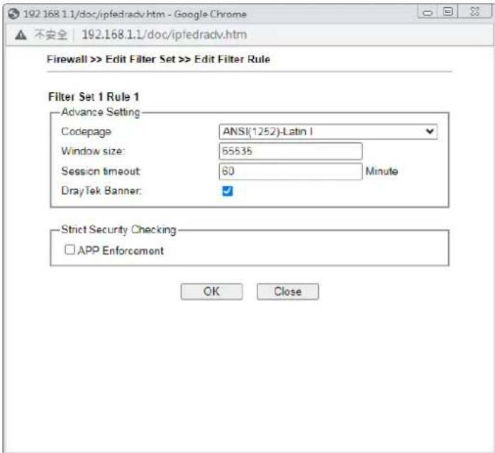 Codepage - Sets the codepage used by the URL content filter to match URLs against keywords in profiles. Choosing the appropriate codepage can increase the accuracy of the URL Content Filter. The default value is ANSI 1252 Latin I. If the setting is None, no decoding of URL will be performed. If you are unsure of which codepage to use, please start the Syslog application, and the recommended codepage will be shown in the Codepage Information tab in the Setup dialog box. Codepage - Sets the codepage used by the URL content filter to match URLs against keywords in profiles. Choosing the appropriate codepage can increase the accuracy of the URL Content Filter. The default value is ANSI 1252 Latin I. If the setting is None, no decoding of URL will be performed. If you are unsure of which codepage to use, please start the Syslog application, and the recommended codepage will be shown in the Codepage Information tab in the Setup dialog box.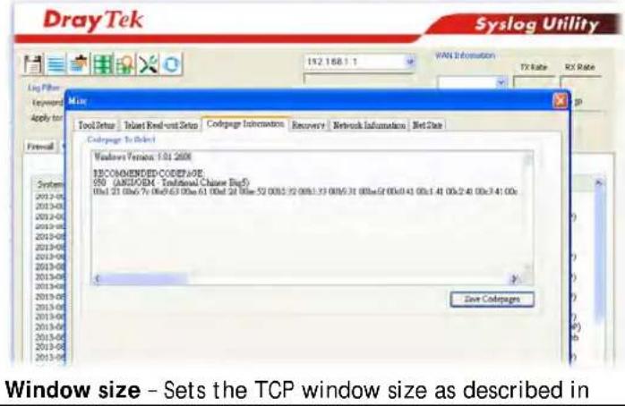 RFC 1323. Valid values are from 0 to 65535. The more the value is, the better the performance will be. However, if the network is not stable, small value will be proper.Session timeout- Sets the timeout sessions are allowed to idle before they are removed from the system.DrayTek Banner- Select to display the following screen for web pages that are blocked by the Firewall. The default setting is Enabled.The requested Web page has been blocked by Web Content Filter.Please contact your system administrator for further information.[Powered by Draytek] RFC 1323. Valid values are from 0 to 65535. The more the value is, the better the performance will be. However, if the network is not stable, small value will be proper.Session timeout- Sets the timeout sessions are allowed to idle before they are removed from the system.DrayTek Banner- Select to display the following screen for web pages that are blocked by the Firewall. The default setting is Enabled.The requested Web page has been blocked by Web Content Filter.Please contact your system administrator for further information.[Powered by Draytek] |
| Strict Security CheckingAPP Enforcement- If this option is selected, when the router cannot identify the application that generated the outbound traffic due to limited system resources, the session will be blocked; if this option is not selected, the session will be allowed. | |
- When you finish the configuration, please click OK to save and exit this page.
VI-1-3 Defense Setup
As a sub-functionality of IP Filter/ Firewall, there are 15 types of detect/ defense function in the DoS Defense setup. The DoS Defense functionality is disabled for default.
VI-1-3-1 DoS Defense
To configure DoS Defense, select DoS Defense under the Firewall menu item on the Web UI menu bar.
Firewall >> Defense Setup
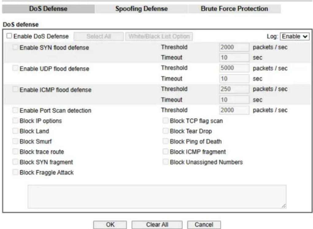
text_image
DoS Defense Spoofing Defense Brute Force Protection DoS defense Enable DoS Defense Select All White/Black List Option Log: Enable Enable SYN flood defense Threshold 2000 packets / sec Timeout 10 sec Enable UDP flood defense Threshold 5000 packets / sec Timeout 10 sec Enable ICMP flood defense Threshold 250 packets / sec Timeout 10 sec Enable Port Scan detection Threshold 2000 packets / sec Block IP options Block TCP flag scan Block Land Block Tear Drop Block Smurf Block Ping of Death Block trace route Block ICMP fragment Block SYN fragment Block Unassigned Numbers Block Fraggle Attack OK Clear All CancelNote:
- Enabling the UDP Flood Defense option may affect UDP services, like NAT-T VPN, DNS, and VoIP service. When you have UDP servers running, please increase the UDP threshold according to the Internet speed, or add the server IP into the White List. The suggested threshold value are as follows:
20M Bandwidth: 2,000 (packets/sec)
60M Bandwidth: 5,000 (packets/sec)
100M Bandwidth: 8.000 (packets/sec)
300M Bandwidth: 25,000 (packets/sec) - Packets that have been accelerated by Hardware Acceleration will not be checked by the DoS Defense function.
Available settings are explained as follows:
| Item Description | |
| Enable Dos Defense | Select to enable DoS Defense.Select All - Click to select all DoS Defense options.White/Black List Option - Set white/ black list of IPv4/ IPv6 address. |
| Enable SYN flood defense | Select to enable SYN flood defense. When the arrival rate of SYN packets exceeds the Threshold value, the router will start to randomly discard TCP SYN packets for a period of time as defined in Timeout. This is to prevent TCP SYN packets from exhausting router resources.The default values of threshold and timeout are 2000 packets per second and 10 seconds, respectively. |
| Enable UDP flood defense | Select to enable UDP flood defense. When the arrival rate of UDP packets exceeds the Threshold value, the router will start to randomly discard TCP SYN packets for a period of time as defined in Timeout.The default values of threshold and timeout are 2000 packets per second and 10 seconds, respectively. |
| Enable ICMP flood defense | Select to enable ICMP flood defense. When the arrival rate of ICMP packets exceeds the Threshold value, the router will start to randomly discard TCP SYN packets for a period of time as defined in Timeout.The default values of threshold and timeout are 250 packets per second and 10 seconds, respectively. |
| Enable Port Scan detection | Select to enable Port Scan detection. Port Scans attack your network by sending packets to a range of ports in an attempt to find services that would respond. When Port Scan detection is enabled, the router sends warning messages when it detects port scanning activities that exceed the Threshold rate.The default threshold is 2000 packets per second. |
| Block IP options Select to enable Block IP options. The Vigor router will ignore IP packets with IP option field set in the datagram header. IP options are rarely used and could be abused by attackers as they carry information about the private network otherwise not available to the external network, such as security, TCC (closed user group) parameters, a series of Internet addresses, routing messages, etc, which external eavesdroppers can use to discover details about the private network. | |
| Block Land | Select to Block LAND attacks. LAND attacks happen when an attacker sends spoofed SYN packets with both source and destination addresses set to that of the target system, which causes the target to reply to itself continuously. |
| Block Smurf | Select to Block Smurf attacks. The router will ignore any broadcasting ICMP echo request. |
| Block trace route | Select to Block traceroutes. The router will not forward traceroute packets. |
| Block SYN fragment | Select to Block SYN packet fragments. The router will drop any packets having both the SYN and more-fragments bits set. |
| Block Fraggle Attack | Select to Block Fraggle Attacks. Broadcast UDP packets received from the Internet are blocked.Activating this feature might block some legitimate packets. Since all broadcast UDP packets coming from the Internet are blocked, RIP packets from the Internet could also be dropped. |
| Block TCP flag scan | Select to Block TCP Flag Scans. TCP packets with abnormal flag settings will be dropped. TCP flag scanning activities that are blocked include no flag scan, FIN without ACK scan, SYN FIN scan, Xmas scan and full Xmas scan. |
| Block Tear Drop | Select to Block Tear Drop attacks. Some clients may crash when they receive ICMP datagrams (packets) that exceedthe maximum length. The router discards any fragmented ICMP packets having lengths greater than 1024 octets. |
| Block Ping of Death Select to | Block Ping of Death, where fragmented ping packets are sent to target hosts so that those hosts could crash as they reassemble the malformed ping packets. |
| Block ICMP Fragment | Select to Block ICMP Fragments. ICMP packets with the more-fragments bit set are dropped. |
| Block Unassigned Numbers | Select to Block Unassigned Protocol Numbers, and the router will block packets having unassigned protocol numbers. Individual IP packet has a protocol field in the datagram header to indicate the protocol type running over the upper layer. However, the protocol types greater than 100 are reserved and undefined at this time. Therefore, the router should have ability to detect and reject this kind of packets. |
| Warning Messages | We provide Syslog function for user to retrieve message from Vigor router. The user, as a Syslog Server, shall receive the report sending from Vigor router which is a Syslog Client.All the warning messages related to DoS Defense will be sent to user and user can review it through Syslog daemon. Look for the keyword DoS in the message, followed by a name to indicate what kind of attacks is detected. |
System Maintenance => SysLog / MailAlert Setup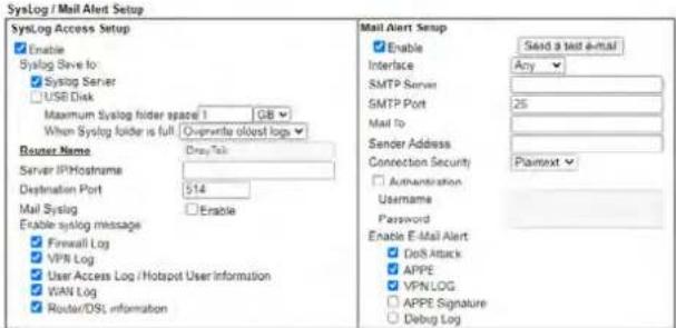 Note:1 USB Syslog space is available from 256-1024 MB or 1-16 GB2. Mail Syslog cannot be activated unless USB Disk is ticked for "Syslog Save to"3. Mail Syslog feature will send the Syslog when it is tall:OK Clear Note:1 USB Syslog space is available from 256-1024 MB or 1-16 GB2. Mail Syslog cannot be activated unless USB Disk is ticked for "Syslog Save to"3. Mail Syslog feature will send the Syslog when it is tall:OK Clear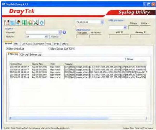 | |
After finishing all the settings here, please click OK to save the configuration.
VI-1-3-2 Spoofing Defense
Click the Spoofing Defense tab to open the setup page.
Firewall >> Defense Setup
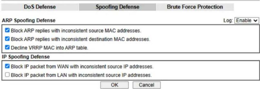
text_image
DoS Defense Spoofing Defense Brute Force Protection ARP Spoofing Defense Log: Enable ▼ ✓ Block ARP replies with inconsistent source MAC addresses. ✓ Block ARP replies with inconsistent destination MAC addresses. ✓ Decline VRRP MAC into ARP table. IP Spoofing Defense ✓ Block IP packet from WAN with inconsistent source IP addresses. □ Block IP packet from LAN with inconsistent source IP addresses. OK CancelVI-1-3-3 Brute Force Protection
A security mechanism that offers an extra protection beyond a username and password, making it more difficult for unauthorized users to gain access.
Any client trying to access into Internet via Vigor router will be asked for passing through user authentication. It can prevent Vigor router from attacks when a hacker tries every possible combination of letters, numbers and symbols until find out the correct combination of password.
Firewall >> Defense Setup
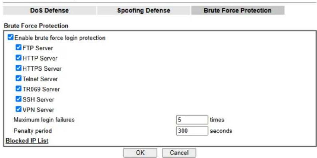
text_image
DoS Defense Spoofing Defense Brute Force Protection Enable brute force login protection FTP Server HTTP Server HTTPS Server Telnet Server TR069 Server SSH Server VPN Server Maximum login failures 5 times Penalty period 300 seconds Blocked IP List OK CancelAvailable settings are explained as follows:
| Item Description | |
| Enable brute force login protection | Enable the protection mechanism.Select All - Click this button to select all the items listed below. |
| Maximum Login Attempts | Specify the maximum number of failed login attempts.The users who fail to log in multiple times by reaching the maximum login attempts will be penalized a period not to login Vigor system. |
| Penalty Period | Set the period for penalty delay.During this period, the user is unable to log in or access Vigor's system.The purpose of this setting is to obstruct outside automated attacks (attempting to speculate passwords, authentication codes or others through repeated trials). |
| Blocked IP List | Open another web page which displays current blocked IPs. |
VI-1-4 Diagnose
The purpose of this function is to test when the router receiving incoming packet, which firewall rule will be applied to that packet. The test result, including firewall rule profile, IP address translation in packet transmission, state of the firewall functions and etc., also will be shown on this page.

Info
The result obtained by using Diagnose is offered for RD debug. It will be different according to actual state such as network connection, LAN/WAN settings and so on.
Firewall >> Diagnose
Mode
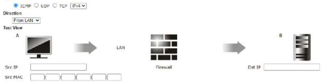
flowchart
graph LR
    A["Source IP"] --> B["Firewall"]
    C["Source MAC"] --> B
    B --> D["Dst IP"]
Packet & Payload
| Packet | Enable | Direction | Protocol |
| 1 | ✓ | A->B | ICMP:Customize |
| 2 | A->B | ICMP:Customize |
Note:
This is firewall live test which need setup WAN and plug cable in.
Analyze
Available settings are explained as follows:
| Item Description | |
| Mode | To have a firewall rule test, specify the service type (ICMP, UDP, TCP) of the packet and type of the IP address (IPv4/ IPv6). |
| Direction | Set the way (from WAN or from LAN) that Vigor router receives the first packet for test. Different way means the firewall will process the connection initiated from LAN or from WAN. |
| Test View | This is a dynamic display page.According to the direction specified, test view will display the figure to guide you typing IP address, port number, and MAC address.Later, after clicking the Analyze button, the information for the firewall rule profile and address translation will be shown on this page. |
| Src IP | Enter the IPv4/ IPv6 address of the packet's source. |
| Src Port | Enter the port number of the packet's source. |
| Src MAC | Enter the MAC address of the packet's source. |
| Dst IP | Enter the IPv4/ IPv6 address of the packet's destination. |
| Dst Port | Enter the port number of the packet's destination. |
| Packet & Payload | In firewall diagnose, two packets belong to one connection.In general, two packets are enough for Vigor router to perform this test.Enable - Check the box to send out the test packet.Direction - The first packet of the firewall test will follow the direction specified above. However, the direction for the second packet might be different. Simply choose the direction (from Computer A to B or from the B to A) for the second packet.Protocol - It displays the mode selected above and the state. If required, click the mode link to configure advanced setting. The common service type (Customize, Ping, Trace Route / Customize, DNS, Trace Route / Customize, Http(GET) related to that mode (ICMP / UDP / TCP) will be shown on the following dialog box.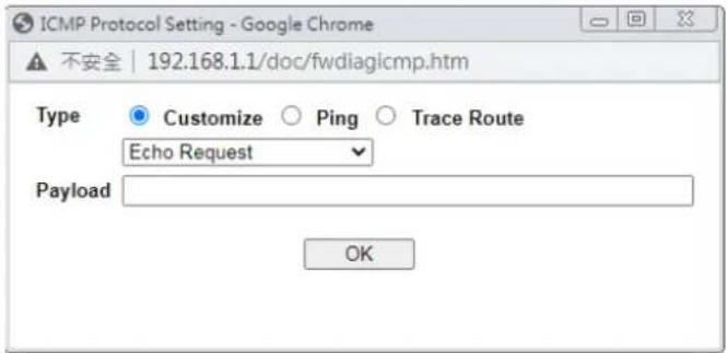 Type - Choose Customize, Ping, Trace Route / Customize, DNS, Trace Route / Customize, Http (GET).Payload - It is available when Customize is selected. Simply type 16 HEX characters which represent certain packet (e.g., DNS packet) if you want to set the data transferred with protocol (ICMP/UDP/TCP) which is different to Type setting. Type - Choose Customize, Ping, Trace Route / Customize, DNS, Trace Route / Customize, Http (GET).Payload - It is available when Customize is selected. Simply type 16 HEX characters which represent certain packet (e.g., DNS packet) if you want to set the data transferred with protocol (ICMP/UDP/TCP) which is different to Type setting. |
| Analyze | Execute the test and analyze the result. |
The following figure shows the test result after clicking Analyze. Processing state for the fuctions (MAC Filter, QoS, User management, etc.,) related to the firewall will be displayed by green or red LED.
Firewall >> Diagnose
Mode

Direction

Test View
A

192.168.1.111:22222
-7.7.7.7:51348

LAN

WAN1

Firewall
7.7.7.751348 172.16.2.234:62094

| Status | Packet | Set | Rule | UCF/WCF |
| Pass | 2 | default | default | n/a |
Packet & Payload
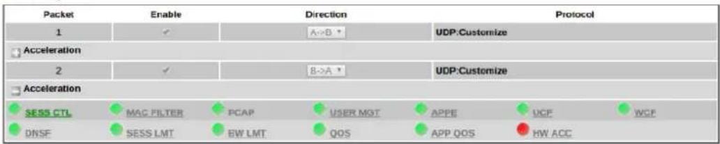
text_image
Packet Enable Direction Protocol 1 ✓ A→B * UDP:Customize Acceleration 2 ✓ B→A * UDP:Customize Acceleration SESS CTL MAG FILTER PCAP USER MGT APPE UCF WCP DNSE SESS LMT BW LMT QOS APP.QOS HW ACCAPP: The APP need to check.
APP:The APP doesn't need to check.
The APP is completed.
The APP is processing.
Note:
PCAP is "ip pcap" in telnet command.
<<Back Reset
VI-2 Central Security Management (CSM)
Content Security Management (CSM) allows the network administrator to restrict Internet traffic based on the content type, thus ensuring appropriate use of network resources and also reducing the likelihood of threats from malicious network content.
APP Enforcement Filter
The APP Enforcement Filter can be used to prevent users from using undesirable or inappropriate network applications such as online chat and peer-to-peer programs. The filter works by detecting and blocking network traffic of applications by means of traffic patterns.
URL Content Filter
The URL Content Filter scans URL strings in HTTP requests for predefined keywords to restrict browsing activities.
Web Content Filter
Users can also be prevented from browsing certain types of websites by using the Web Content Filter. This filter classifies website domain names into different categories, which can be selectively blocked.
Filter profiles must first be created before these CSM Filters can be enabled. Once profiles have been configured, they can be applied to the Default Rule under Firewall>>General Setup, or Filter Rules in Filter Sets under Firewall>>Filter Setup.

Info
The priority of URL Content Filter is higher than Web Content Filter.
Web User Interface
CSM
APP Enforcement Profile
URL Content Filter Profile
Web Content Filter Profile
DNS Filter Profile
VI-2-1 APP Enforcement Profile
Up to 32 policy profiles for APP Enforcement can be configured.
CSM >> APP Enforcement Profile
APP Enforcement Profile Table:
Set to Factory Default
Available settings are explained as follows:
| Item Description | |
| Set to Factory Default | Clear all profile settings. |
| Profile Index of the profile. | Click to bring up the configuration page of the profile. |
| Name Name of the profile. |
To configure a profile, click on its profile number, and the following profile configuration page will appear:
CSM >> APP Enforcement Profile
Profile Index : 1
Profile Name:
Clone Profile
| For Firewall For Route Policy | |||
| Category | Application | ||
| Instant Message | AIM Login BaiduHi Fetion iSpQ LinkedIn Qnext Snapchat UC WhatsApp Call | AllWW Discord GaduGadu Protocol KC Paltalk Signal Telegram WeblM URLs Zalo | Ares Facebook/Instagram ICQ LINE PocoCall Slack Tencent QQ WhatsApp |
| Select All | |||
| Clear All | |||
| VoIP Select All Clear All | RC Voice TelTel | Skype/Teams WeChat | TeamSpeak Zoom |
| P2P Select All Clear All | Ares eDonkey Huntmine OpenNap Vagaa | BitTorrent FastTrack Kuwo Pando Xunlei(Thunder) | ClubBox Gnutella OpenFT SoulSeek |
Available settings are explained as follows:
| Item Description | |
| Profile Name | Name that identifies this profile. Maximum length is 15 characters. |
| Category | Apps are classified into several categories. Each category contains several apps to be blocked. |
| Clone Profile | Click it to clone settings configured by an existed profile. |
| Select All | Click to select all of the items on this page. |
| Clear All | Click to deselect all selected items. |
| Select this checkbox to block the app. |
To save changes on the page, click OK. To discard changes, click Cancel.
VI-2-2 URL Content Filter Profile
To set up URL Content Filter Profiles, click CSM on the Main Menu bar, and then click URL Content Filter Profile to open the profile setting page.
CSM >> URL Content Filter Profile

URL Content Filter Profile Table:
Set to Factory Default
| Profile | Name | Profile | Name |
| 1. | 5. | ||
| 2. | 6. | ||
| 3. | 7. | ||
| 4. | 8. |
Note:
To make URL Content Filter profile effective, please go to Firewall >> Filter Setup page to create a firewall rule and select the desired profile.
Administration Message (Max 255 characters)
Default Message
The requested Web page has been blocked by URL Content Filter.
Please contact your system administrator for further information.
OK
Each item is explained as follows:
| Item Description | |
| Set to Factory Default | Clear all profile settings. |
| Profile | Index number of the profile. |
| Name | Name that identifies the profile. |
| Administration Message | The message to be displayed in the browser when access to a URL has been blocked. A custom message can be entered with HTML formatting in the text box.Default Message - Click to reset the administration message to the factory default. |
To set up a profile, click the profile number under Index column to bring up the configuration page.
CSM >> URL Content Filter Profile
Profile Index: 1
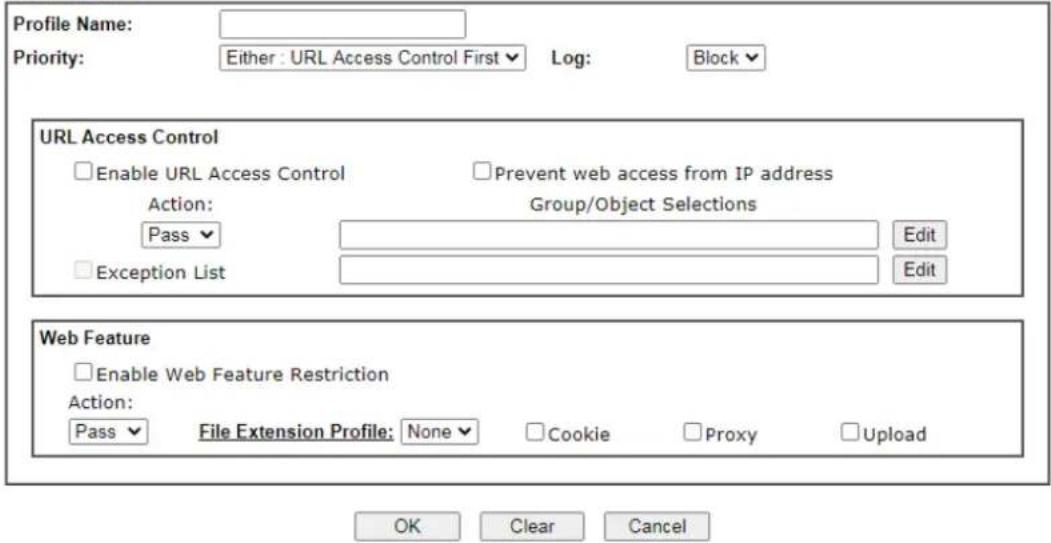
text_image
Profile Name: Priority: Either : URL Access Control First Log: Block URL Access Control Enable URL Access Control Prevent web access from IP address Action: Group/Object Selections Pass Exception List Edit Edit Web Feature Enable Web Feature Restriction Action: Pass File Extension Profile: None Cookie Proxy Upload OK Clear CancelAvailable settings are explained as follows:
| Item Description | |
| Profile Name | Name that identifies the URL Content Filter profile. The maximum length of the Profile Name is 15 characters. |
| Priority | The order of evaluation of URL Access Control and Web Feature below:Both: Pass – Router will allow access only to web resources that match conditions specified in both URL Access Control and Web Feature. The Action setting of both URL Access Control and Web Feature will be disabled and the values set to Pass.Both:Block – Router will block access to web resources that match conditions specified in both URL Access Control and Web Feature. The Action setting of both URL Access Control and Web Feature will be disabled and the values set to Block.Either: URL Access Control First – Router will block or allow access to web resources that match conditions specified in either URL Access Control or Web Feature. URL Access Control is applied first, followed by Web Feature.Either: Web Feature First – Router will block or allow access to web resources that match conditions specified in either URL Access Control or Web Feature. Web Feature is applied first, followed by URL Access Control. |
| Log None – No log file will be created for this profile.Pass – Only passed access attempts will be recorded in Syslog.Block – Only blocked access attempts will be recorded in Syslog.All – Both passed and blocked access attempts will be recorded in Syslog. | |
| URL Access Control | Enable URL Access Control - Select to activate URL AccessControl.Prevent web access from IP address- URLs containing IP addresses (e.g., 192.168.1.1) will be blocked. Only URLs with domain addresses (e.g., www.draytek.com) will be allowed. This is to prevent users from circumventing URL Access Control.Action- This setting is enabled only when Priority is set to Either: URL Access Control First or Either: Web Feature First.Pass- Allows access to web pages with URLs containing keywords that are in the selected keyword groups or objects. Access to other URLs is blocked.Block- Blocks access to web pages with URLs containing keywords that are in the selected keyword groups or objects. Access to other URLs is allowed.Exception List- Specify the object profile(s) as the exception list which will be processed in an opposite manner to the action selected above.Group/Object Selections- Shows the Keyword Groups and/ or Objects selected for this URL Content Filter Profile. To add or remove Keyword Groups and Objects to the selection, click the Edit button to bring up the following screen. |
| Group/Object EditKeyword Object None▼or Keyword Object None▼or Keyword Object None▼or Keyword Object None▼or Keyword Object None▼or Keyword Object None▼or Keyword Object None▼or Keyword Group None▼or Keyword Group None▼or Keyword Group None▼or Keyword Group None▼or Keyword Group None▼or Keyword Group None▼or Keyword Group None▼or Keyword Group None▼or Keyword Group None▼or Keyword Group None▼or Keyword Group None▼or Keyword Group None▼or Keyword Group None▼or Keyword Group None▼or Keyword Group None▼or Keyword Group None▼or Keyword Group None▼or Keyword Group None▼or Keyword Group None▼or Keyword Group None▼or Keyword group | |
| OK Close | |
| Up to 8 Keyword Objects and 8 Keyword Groups can be selected. To add, remove or modify Groups or Objects, click the Keyword Object or Keyword Group hyperlinks to bring up the Objects Setting >> Keyword Object or Objects Setting >> Keyword Group pages. | |
| Web Feature | Enable Restrict Web Feature- Check to enable the web feature restriction.Action- This setting is enabled only when Priority is set to Either: URL Access Control First or Either: Web FeatureFirst.● Pass - Allows access to web pages with URLs containing keywords that are in the selected keyword groups or objects. Access to other URLs is blocked.● Block - Blocks access to web pages with URLs containing keywords that are in the selected keyword groups or objects. Access to other URLs is allowed.File Extension Profile - Choose one of the profiles that you configured in Object Setting>> File Extension Objects previously for passing or blocking the file downloading.Cookie - Select to block cookies from Internet websites.Proxy - Select to block web proxy servers that relay HTTP traffic.Upload - Select to block HTTP uploads from the LAN to the Internet. |
To save changes on the page, click OK. To discard changes, click Cancel. To clear all settings, click Clear.
VI-2-4 Web Content Filter Profile
Trial WCF service can be activated using the Service Activation Wizard.
If you wish to continue using WCF beyond the trial period, you can obtain a full WCF subscription by contacting your local DrayTek channel partner or dealer. WCF subscriptions can be activated using the Activate link on CSM >> Web Content Filter Profile (described in this section) or System Maintenance.
From the main menu, click CSM, followed by Web Content Filter Profile to load the profile configuration page.

Info 1
Web Content Filter (WCF) is not a built-in service of Vigor router but a service powered by Commtouch. If you want to use such service (trial or formal edition), you have to perform the procedure of activation first. For the service of formal edition, please contact with your dealer/distributor for detailed information.
Info 2
Commtouch is merged by Cyren, and GlobalView services will be continued to deliver powerful cloud-based information security solutions! Refer to: http://www.prnewswire.com/news-releases/commtouch-is-now-cyren-239025151.html
CSM >> Web Content Filter Profile

Web-Filter License
[Status: Inactivated]
Activate
| Setup Query Server | auto-selected | Find more |
| Setup Test Server | auto-selected | Find more |
Web Content Filter Profile Table:
Cache : L1 + L2 Cache ▼ | Set to Factory Default
| Profile | Name | Profile | Name |
| 1. | Default | 5. | |
| 2. | 6. | ||
| 3. | 7. | ||
| 4. | 8. |
Note:
To make Web Content Filter profile effective, please go to Firewall >> Filter Setup page to create a firewall rule and select the desired profile.
| Administration Message (Max 255 characters) | Default Message |
Legend:
% SIP% - Source IP, % DIP% - Destination IP, % URL% - URL % CL% - Category, % RNAME% - Router Name
OK
Available settings are explained as follows:
| Item Description | |
| Activate | Click to visit the MyVigor website to activate WCF service. You will need to log in to your MyVigor account to proceed with the activation process. If you do not already have a MyVigor account, you can create one at this time. |
| Setup Query Server | Specify a WCF query server by typing address of the server. Click the Find more for a list of query servers. When the default value auto-selected is used, the server is determined automatically by looking up the geolocation of the WAN IP address.It is recommended that the default setting auto-selected be used. |
| Setup Test Server | Specify a WCF test server by typing address of the server. Click the Find more for a list of test servers. When the default value auto-selected is used, the server is determined automatically by looking up the geolocation of the WAN IP address.It is recommended that the default setting auto-selected be used. |
| Cache | None - The router verifies every HTTP URL requested by communicating with the WCF server on the Internet. This mode provides the most precise URL matching but has the lowest performance.L1 - The router caches the HTTP URLs that have been checked against the WCF server. URLs will be looked up in the L1 cache before reaching out to the WCF server. When the cache is full, the oldest entry will be deleted to accommodate new URLs.L2 - After a URL has been checked and found to pass WCF, the source and destination IPs are cached for about 1 second in the L2 cache. This is to allow a webpage to be loaded without further verifying the same URLs against the L1 cache or the WCF server.L1+L2 Cache - The router will utilize both L1 and L2 caches. |
| Set to Factory Default | Clear all profile settings. |
| Profile | Index number of the profile. |
| Name | Name that identifies the profile. |
| Administration Message | The message to be displayed in the browser when access to a website has been blocked. A custom message can be entered with HTML formatting in the text box.You can embed the following variables in the message:%SIP% - The source IP address that attempted the HTTP access.%DIP% - The destination IP address to which access was attempted.%URL% - The URL of the destination website.%CL% - The category to which the URL belongs.%RNAME% - The name of the router.Default Message - Click to reset the administration message to the factory default. |
Up to 8 WCF profiles can be set up. To configure a profile, click its profile number to bring up its configuration page. Filter profile settings are specific to WCF providers. If you already
have an active WCF subscription, activating a WCF subscription to a provider different from your current provider will clear all existing profile configurations.
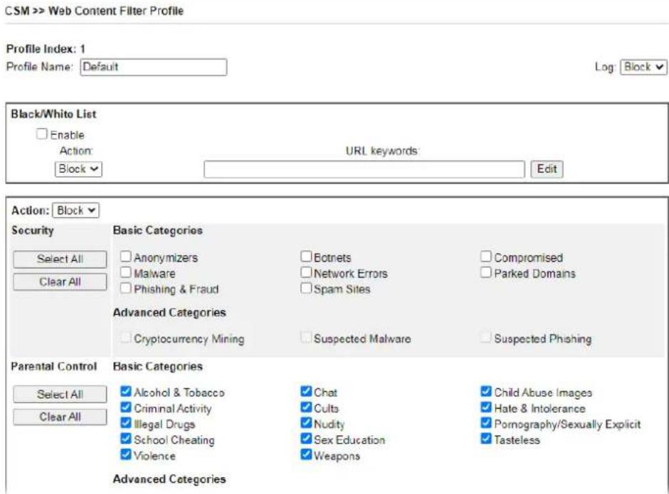
text_image
CSM >> Web Content Filter Profile Profile Index: 1 Profile Name: Default Log: Block Black/White List Enable Action: Block URL keywords: Edit Action: Block Security Select All Clear All Basic Categories Anonymizers Malware Phishing & Fraud Botnets Network Errors Spam Sites Compromised Parked Domains Advanced Categories Cryptocurrency Mining Suspected Malware Suspected Phishing Parental Control Basic Categories Select All Clear All ✓ Alcohol & Tobacco ✓ Criminal Activity ✓ Illegal Drugs ✓ School Cheating ✓ Violence ✓ Chat ✓ Cults ✓ Nudity ✓ Sex Education ✓ Weapons ✓ Child Abuse Images ✓ Hate & Intolerance ✓ Pornography/Sexually Explicit ✓ Tasteless Advanced CategoriesAvailable settings are explained as follows:
| Item Description | |
| Profile Name | Name that identifies the WCF profile. The maximum length of the Profile Name is 15 characters. |
| Log | Pass - Only passed access attempts will be recorded in Syslog.Block - Only blocked access attempts will be recorded in Syslog.All - Both passed and blocked access attempts will be recorded in Syslog. |
| Black/White List | Keyword objects and groups can be applied to the URL to override WCF category filtering.Enable - Select to enable blacklisting or whitelisting.Action - Action to take when a URL matches keyword group and object selections.Pass - Allow access to the URL.Block - Disallow access to the URL.URL Keywords - Displays selected keyword group and objects. Click the Edit button to modify keyword selections. |
| Groups and Categories | Select categories to be included in the filter.Action - Action to take when a URL matches keyword group and object selections.Pass - allow access to the URL.Block - disallow access to the URL.Select All - Click to select all categories within the group.Clear All - Click to deselect all categories within the group. |
To save changes on the page, click OK. To discard changes, click Cancel.
VI-2-5 DNS Filter Profile
DNS Filter blocks or allows traffic to the WAN by intercepting DNS queries, and applying UCF and WCF rules to hostnames. DNS filtering is especially useful when you wish to restrict access of protocols other than HTTP, such as HTTPS. Note that a WCF license must have already been activated before WCF rules could be used.
To configure DNS Filter Profiles, select CSM >> Web Content Filter Profile from the main menu.
CSM >> DNS Filter Profile
DNS Filter Profile Table
Set to Factory Default
| Profile | Name | Profile | Name |
| 1. | 5. | ||
| 2. | 6. | ||
| 3. | 7. | ||
| 4. | 8. |
Note:
- To make DNS Filter profile effective, please go to Firewall >> Filter Setup page to create a firewall rule and select the desired profile.
DNS Filter Local Setting
DNS Filter
Web Content Filter
URL Content Filter
Syslog
Black/White List
□ Enable
None
None ▼
None
Enable
Address Type
Start IP Address
End IP Address
Subnet Mask
IP Group
or IP Group
or IP Object
or IP Object
Blacklist
Any Address
0.0.0.0
0.0.0.0
0.0.0.0
None
None ▼
None
None
√ Enable Administration Message (Max 255 characters)
Preview | Default Message
The requested Web page
from %SIP%
to %URL%
that is categorized with %CL%
has been blocked by %RNAME% DNS Filter.
Please contact your system administrator for further information.
Legend:
% SIP% - Source IP, %URL% - URL
%CL% - Category, %RNAME% - Router Name
Note:
- If you Enable Block Page, the 80/443 port will turn on for the Block Page despite the management ports change.
Available settings are explained as follows:
To save changes on the page, click OK. To discard changes, click Cancel.
| Item Description | |
| DNS Filter Profile Table | DNS Filter Profiles take effect when DNS servers on the WAN are used for DNS queries. The router intercepts all outgoing DNS queries on UDP port 53 and applies WCF and UCF rules on the domain names before passing the queries to the DNSservers. IP addresses of the domains are then blocked or allowed as per applicable WCF and UCF rules.DNS Filter Profiles can be applied by selecting from Firewall filter rules.Profile - Index number of the profile. Click to bring up the configuration page for the profile entry.Name - Name that identifies the profile. |
| Set to Factory Default | Clear all DNS Filter profile settings. |
| DNS Filter Local Setting | By setting the IP address of the DNS lookup server to the router's address, the router serves as a DNS lookup proxy server. When DNS Filter Local Setting is enabled, all DNS queries sent to the router will have WCF and UCF rules applied to the hostnames, and access to the resolved IP addresses will be allowed or blocked as configured in the rules.DNS Filter - Select to enable DNS Filter Local Setting.Web Content Filter - Select a WCF profile.URL Content Filter - Select a UCF profile.Syslog - The filtering result can be recorded according to the setting selected for Syslog.None - No log file will be created for this profile.Pass Only - Only passed access attempts will be recorded in Syslog.Block Only- Only blocked access attempts will be recorded in Syslog.Both - Both passed and blocked access attempts will be recorded in Syslog.Black/White List - Specify IP address, subnet mask, IP object, or IP group as a black list or white list for DNS packets passing through or blocked by Vigor router. |
| Administration Message | The message to be displayed in the browser when access to a website has been blocked. A custom message can be entered with HTML formatting in the text box.You can embed the following variables in the message:%SIP% - The source IP address that attempted the HTTP access.%DIP% - The destination IP address to which access was attempted.%URL% - The URL of the destination website.%CL% - The category to which the URL belongs.%RNAME% - The name of the router.Default Message - Click to reset the administration message to the factory default. |
You can set up to eight DNS filter profiles. Click any one of the index numbers (1 to 8) to open the following page.
CSM >> DNS Filter
Index No. 1

text_image
Profile Name Web Content Filter None URL Content Filter None Syslog Block OnlyAdvanced Setting
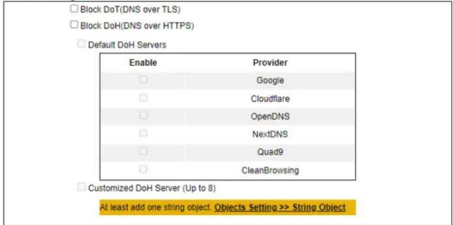
text_image
Block DoT(DNS over TLS) Block DoH(DNS over HTTPS) Default DoH Servers Enable Provider □ Google □ Cloudflare □/OpenDNS □ NextDNS □ Quad9 □ CleanBrowsing □ Customized DoH Server (Up to 8) At least add one string object. Objects Setting >> String ObjectNote:
- DNS Filter does not work in DoH/DoT environment.
- You can block DoH/DoT to force end-user to use standard DNS.

Available settings are explained as follows:
| Item Description | |
| Index No.#DNS Filter Profiles can be applied by selecting from Firewall filter rules.Profile Name- Enter the name of the profile.Web Content Filter- Select a WCF profile.URL Content Filter- Select a UCF profile.Syslog- The filtering result can be recorded according to the setting selected for Syslog.Pass Only- Only passed access attempts will be recorded in Syslog.Block Only- Only blocked access attempts will be recorded in Syslog.Both- Both passed and blocked access attempts will be recorded in Syslog. | |
| Advanced Setting | Block DoT- Select to block the DNS inquiry (plain text) encrypted through TLS (security protocol).Block DoH- Select to block the DNS inquiry (plain text) encrypted through HTTPS (security protocol).Default DoHServers- Check the box to select the service provider(s) for the DoH server.Customized DoHServer (Up to 8)- Check the box to select the service provider(defined in String Object) for the DoH server. |
Application Notes
A-1 How to Create an Account for MyVigor
The website of MyVigor (a server located on http://myvigor.draytek.com) provides several useful services (such as Anti-Spam, Web Content Filter, Anti-Intrusion, and etc.) to filtering the web pages for the sake of protecting your system.
To access into MyVigor for getting more information, please create an account for MyVigor.
Create an Account via Vigor Router
- Click CSM>> Web Content Filter Profile. The following page will appear.
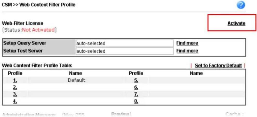
text_image
CSM >> Web Content Filter Profile Web-Filter License [Status: Not Activated] Activate Setup Query Server auto-selected Find more Setup Test Server auto-selected Find more Web Content Filter Profile Table: | Set to Factory Default | Profile Name Profile Name 1. Default 5. 2. 6. 3. 7. 4. 8.- Click the Activate link. A login page for MyVigor web site will pop up automatically.
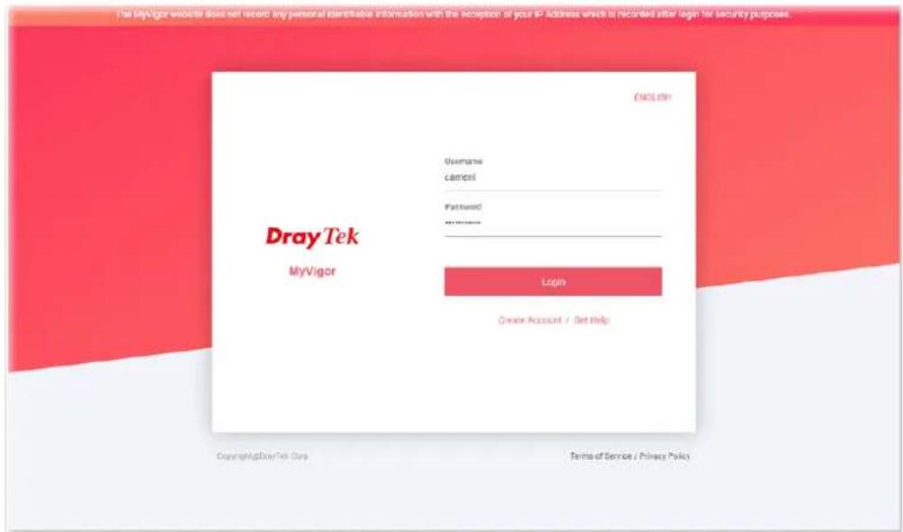
text_image
The MyVigor website does not receive any personal identifiable information with the exception of your IP Address which is recorded after login for security purposes. DrayTek MyVigor Username campos Password: ****** Login Create Account / Get Help Copyright@DrayTek Corp. Terms of Service / Privacy Policy.- Click the link of Create Account.
- The system will ask if you are 16 years old or over.
■ If yes, click I am 16 or over.
Terms of Service / Privacy Policy
Agreement
DrayTek provides MyVigor (myvigor.draytek.com) service according to this agreement. When you use MyVigor service, it means that you have read, understood and agreed to accept the items listed in this agreement. DrayTek reserves the right to update the Terms of Use at any time without notice you. It is suggested for you to notice the modifications or changes at any time. If you still use MyVigor service after knowing the modifications and changes of this service, it means you have read, understood and agreed to accept the modifications and changes. If you do not agree the contents of this agreement, please stop using MyVigor service.
Registration
To use this service, you have to agree the following conditions:
About Us
DrayTek Corporation
Address: No. 26, Fushing Rd., Hukou, Hsinchu Industrial Park, Hsinchu, 303, Taiwan
Tel: +8863 5972727
Fax: -88635972121
Personal Data Related Issue: privacy@draytek.com
Data Protection Officer: dpo@draytek.com
DrayTek Corp.
Version: V3.5
Date: 21 May, 2018
I am under 16 years old
I am 16 or over
If not, click I am under 16 years old to get the following page. Then, click I and my legal guardian agree.
this section d.
About Us
DrayTek Corporation
Address: No. 26, Fushing Rd., Hukou, Hsinchu Industrial Park, Hsinchu, 303, Taiwan
Tel: +88635972727
Fax: +8863 5972121
Personal Data Related Issue: privacy@draytex.com
Data Protection Officer: cpo@draytek.com
DrayTek Corp.
Version: V3.5
Date: 21 May, 2018
I and my legal guardian agree
Disagree
- After reading the terms of service/privacy policy, click Agree.
(四) 2016年1月1日
About Us
DrayTek Corporation
Address: No. 26, Fushing Rd., Hukou, Hsinchu Industrial Park, Hsinchu 303, Taiwan
Tel: +8863 5972727
Fax: +88635972121
Personal Data Related Issue: privacy@draytek.com
Data Protection Officer: dpo@idraytek.com
DrayTek Corp.
Version: V3.5
Date: 21 May, 2018
Agree
Disagree
- In the following page, enter your personal information in this page and then click Continue.
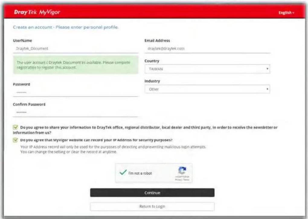
text_image
DrayTek MyVigor Create an account - Please enter personal profile. Username Draytek_Document The user account ( Draytek Document ) is available. Please complete registrations to register this account. Password ****** Confirm Password ****** Email Address draytek@draytek.com Country TA/WAN Industry Other ✓ Do you agree to share your information to DrayTek office, regional distributor, local dealer and third party, in order to receive the newsletter or information from us? ✓ Do you agree that MyVigor website can record your IP Address for security purposes? Your IP Address record will only be used for the purposes of detecting and preventing malicious login attempts. You can change the setting or clear the record at anytime. ✓ I'm not a robot Continue Return to Login- Choose proper selection for your computer and click Continue.
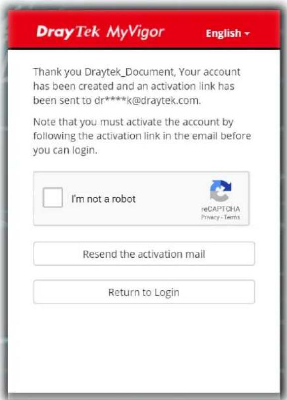
text_image
DrayTek MyVigor English Thank you Draytek_Document, Your account has been created and an activation link has been sent to dr****k@draytek.com. Note that you must activate the account by following the activation link in the email before you can login. I'm not a robot reCAPTCHA Privacy - Terms Resend the activation mail Return to Login- Now you have created an account successfully.
- Check to see the confirmation email with the title of New Account Confirmation Letter from myvigor.draytek.com.
***** This is an automated message from myvigor.draytek.com. *****
Thank you (Mary) for creating an account.
Please click on the activation link below to activate your account
Link : Activate my Account
- Click the Activate my Account link to enable the account that you created. The following screen will be shown to verify the register process is finished. Please click Login.

text_image
Register Search for this site GO Register ConfirmThank for your register in VigorPro Web Site The Register process is completed
Close
Login
- When you see the following page, please Enter the account and password (that you just created) in the fields of Username and Password.
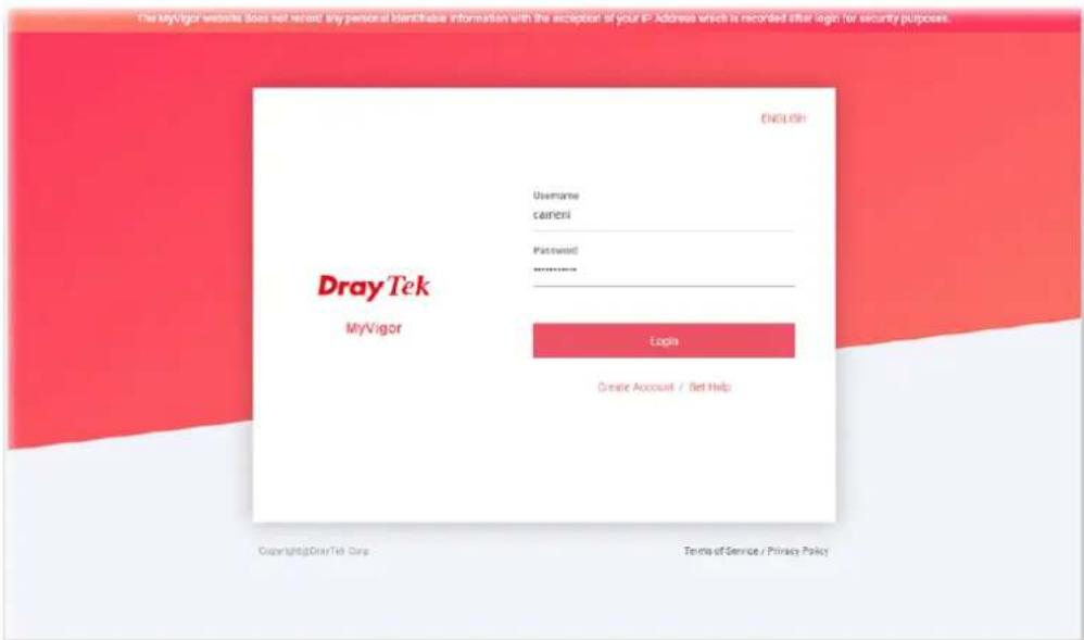
text_image
The MyVigor website does not recall any personal identities information with the exception of your IP-Address which is recorded after login for security purposes. English Username carriers Password: ****** Login Creative Account / Net Help Dray Tek MyVigor Copyright@DrayTek Corp. Terms of Service / Privacy Policy- Now, click Login. Your account has been activated. You can access into MyVigor server to activate the service (e.g., WCF) that you want.
A-2 How to Block Facebook Service Accessed by the Users via Web Content Filter / URL Content Filter
There are two ways to block the facebook service, Web Content Filter and URL Content Filter.
Web Content Filter,
Benefits: Easily and quickly implement the category/website that you want to block.
Note: License is required.
URL Content Filter,
Benefits: Free, flexible for customize webpage.
Note: Manual setting (e.g., one keyword for one website.)
I. Via Web Content Filter
1. Make sure the Web Content Filter license is valid.