
PM3953D - Cooker SMEG - Free user manual and instructions
Find the device manual for free PM3953D SMEG in PDF.


User questions about PM3953D SMEG
0 question about this device. Answer the ones you know or ask your own.
Ask a new question about this device
Download the instructions for your Cooker in PDF format for free! Find your manual PM3953D - SMEG and take your electronic device back in hand. On this page are published all the documents necessary for the use of your device. PM3953D by SMEG.
USER MANUAL PM3953D SMEG
General safety instructions 33
Installation 37
Appliance purpose 38
This user manual 38
Manufacturer's liability 39
Identification plate 39
Disposal 39
Energy efficiency information 39
To save energy 39
How to read the user manual 39
DESCRIPTION 40
General description 40
Accessories 41
USE 41
| Precautions | 41 |
| Preliminary operations | 42 |
| Using the accessories | 42 |
Basic functions 43
Using the hob 44
Special functions 46
User menu 49
Error notifications 51
CLEANING AND MAINTENANCE 51
| Cleaning the hob | 51 |
| Cleaning the glass ceramic hob | 51 |
| What to do if... | 52 |
INSTALLATION 52
| Gas connection | 52 |
| Gas types and Countries | 56 |
| Burner and nozzle specifications tables | 56 |
| Section cut from the countertop | 57 |
| Mounting | 59 |
| Fixing to the built-in cabinet | 59 |
| Electrical connection | 60 |
| Instructions for the installer | 61 |
We advise you to read this manual carefully, which contains all the instructions for maintaining the appliance's aesthetic and functional qualities. For further information on the product: www.smeg.com
These instructions apply only to the destination countries listed on the appliance's data plate.
This is a class 3 built-in hob.
PRECAUTIONS
General safety instructions
Risk of personal injury
- During use the appliance and its accessible parts become very hot. Keep children well away from the appliance.
- Protect hands with heat resistant gloves during use.
- Never try to put out a fire or flames with water: Turn off the appliance and smother the flames with a fire blanket or other appropriate cover.
- This appliance may only be used by children aged 8 years and over, and by people of
reduced physical, sensory or mental capacity, or lacking in experience in the use of electrical appliances, provided that they are supervised or have been given instructions on the safe use of the appliance and of the hazards associated with it.
• Children must not play with the appliance.
- Keep children under the age of eight at a safe distance unless they are constantly supervised.
- Keep children under the age of 8 away from the appliance when it is in use.
- Cleaning and maintenance must not be carried out by unsupervised children.
- Make sure that the flame-spreader crowns are correctly positioned in their housings with their respective burner caps.
- Be aware of how rapidly the cooking zones heat up. Do not place empty pans on the heat. Danger of overheating.
- Activate the controls lock when you have children or pets which could reach the hob.
- Do not touch or clean the hob surface during operation or when the residual heat indicator lights are still on.
• After use, switch off the plates. Never rely solely on the cookware detector. - Supervise children carefully as they cannot readily see the residual heat indication. After use the cooking zones remain hot for a certain period of time even if they have been turned off. Keep children away from the cooking zones.
- The cooking process must always kept under control. A short cooking process must be continuously monitored.
- WARNING: Cooking foods containing fat and/or oil without monitoring them can be dangerous and can cause a fire.
• Fats and oils can catch fire if
they overheat. Do not leave the appliance unattended while preparing foods containing oils or fats. If fats or oils catch fire, never put water on them. Place the lid on the pan and turn off the relevant cooking zone.
- Do not use the Booster and/or the Double Booster functions (if present) to heat fats or oils. Fire hazard.
- Do not place metal objects, such as dishes or cutlery, on the surface of the hob during cooking as they may overheat.
- WARNING: leaving food unattended when cooking using fat or oil can be dangerous and can cause a fire. DO NOT attempt to extinguish a fire with water. Turn off the appliance and smother the flames, for example with a lid or a blanket.
- Do not cook foods in closed tins or containers or plastic containers.
- Do not use magnetic tins.
- Do not use trivets or other items between the bottom of the pan and the glass ceramic surface. Danger of burns.
- Do not insert pointed metal objects (cutlery or utensils) into the slots in the appliance.
- Do not use or store flammable materials near the appliance or directly underneath the hob.
- Switch off the appliance
immediately after use.
- Do not pull the cable to unplug the appliance (if present).
• D O N O T U S E A E R O THE VICINITY OF THIS APPLIANCE WHILST IT IS IN USE.
• DO NOT MODIFY THIS APPLIANCE.
• Always wear personal protective equipment (PPE) before carrying out any work on the appliance (installation, maintenance, positioning or moving). - Do not clean the appliance if it is still hot or in operation.
• After use the cooking zones remain hot for a certain period of time after they have been turned off. Do not touch the hob surfaces. - Before performing any work on the appliance, switch off the power supply.
- Do not try to repair the appliance yourself or without the assistance of a qualified technician.
- If the power cable becomes damaged, contact technical support immediately to arrange for it to be replaced in order to avoid possible hazards.
- If cracks or fissures form, or if the glass ceramic cooking surface breaks, turn off the appliance immediately. Disconnect the power supply
and call Technical Support.
• People who have pacemakers or other similar devices fitted
O must make sure that the operation of these devices is not affected by the induction field, the frequency range of which is between 20 and 50 kHz.
- In conformity with the provisions regarding electromagnetic compatibility, the electromagnetic induction cooking hob comes under group 2 and class B (EN 55011).
- WARNING: A gas cooking appliance produces heat, humidity and combustion products in the room where it is installed. Make sure there is good ventilation, especially when the appliance is in use: keep the natural ventilation openings open or install a mechanical ventilation device.
- Intensive and prolonged use of the appliance may require additional ventilation, for example opening a window or more effective ventilation; for example by increasing the power of any mechanical suction devices.
Risk of damaging the appliance
- Do not use abrasive or corrosive detergents (e.g. scouring powders, stain
removers and metallic sponges) on glass parts.
- Use wooden or plastic utensils.
- Do not sit on the appliance.
- Do not use the glass ceramic cooking surface as a support surface.
- Do not use the appliance as a support surface.
- Do not obstruct ventilation openings and heat dispersal slots.
- Do not use the hob if the pyrolytic cycle is taking place inside any oven installed below.
- Do not use steam jets to clean the appliance.
- Never leave the appliance unattended during cooking operations where fats or oils could be released, as these could then heat up and catch fire. Be very careful.
- Fire hazard: Never leave objects on the cooking surfaces.
• DO NOT FOR ANY REASON USE THE APPLIANCE AS A SPACE HEATER.
- Cooking vessels or griddle plates should be placed inside the perimeter of the hob.
- All pans must have smooth, flat bottoms.
- If any liquid does boil over or spill, remove the excess from the hob.
• Take care not to spill acid
substances such as lemon juice or vinegar on the hob.
- Do not spill sugar or sweet mixtures on the hob during cooking.
- Do not place materials or substances that could melt or catch fire (paper, plastic or aluminium foil) on the appliance while it is in use.
- Place the cookware directly on the glass ceramic surface and on the burners.
- Do not put empty pans or frying pans cooking zones or burners that are switched on.
- Do not use rough or abrasive materials or sharp metal scrapers.
- The glass ceramic surface is highly resistant to impact. However, prevent hard, solid objects from falling on the cooking surface as they may cause it to break.
- Do not use cleaning products containing chlorine, ammonia or bleach on parts made of steel or that have metallic surface finishes (e.g. anodizing, nickel- or chromium-plating).
- Do not wash removable parts such as the hob pan support grids, flame-spreader crowns and burner caps in the dishwasher.
- This appliance is not designed to operate with external timers or with remote-control systems.
Installation
- THIS APPLIANCE MUST NOT BE INSTALLED IN BOATS OR CARAVANS.
- This appliance must not be installed on a dishwasher.
- Position the appliance into the cabinet cut-out with the help of a second person.
- Before installation, make sure that the local distribution conditions (type and pressure of the gas) and the regulation of the appliance are compatible.
- This appliance is not connected to a system for extracting combustion products. It should be installed and connected in compliance with current installation regulations. Pay particular attention to the requirements regarding ventilation.
- The settings for this appliance are shown on the gas settings label.
- Have the gas connection performed by authorised personnel.
- Have the electrical connection performed by authorised technical personnel.
-
Installation using a hose must be carried out so that the length of the hose does not exceed 2 metres when fully extended for steel hoses and 1.5 metres for rubber hoses.
-
The gas connection hoses must not come into contact with moving parts of the built-in module (for example a drawer) and must not be routed through a space that could cause it to be pinched.
- If required, use a pressure regulator that complies with current regulations.
• After carrying out any operation, check that the tightening torque of gas connections is between 10 Nm and 15 Nm. - At the end of the installation, check for any leaks with a soapy solution, never with a flame.
- Check that the carcase has the required openings.
- Check that the carcase material is heat resistant.
• Installation and servicing should be carried out by qualified personnel in accordance with current standards. - The appliance must be connected to earth in compliance with electrical system safety standards.
- Use cables that can withstand temperatures of at least 90^ C .
- Run the power cable in the rear part of the unit. Make sure that it does not come into contact with the lower part of the hob or a built-in oven below it.
- Be careful when connecting
additional electrical appliances. Connection cables must not come into contact with hot cooking zones.
- The tightening torque of the screws of the terminal supply wires must be 1.5 - 2 Nm.
- The power cable must only be installed or replaced by a qualified technician.
- If the power cable becomes damaged, contact technical support immediately to arrange for it to be replaced in order to avoid possible hazards.
- Always use any necessary/ required personal protective equipment (PPE) before performing any work on the appliance (installation, maintenance, positioning or movement).
- Before performing any work on the appliance, switch off the power supply.
- Allow the appliance to be disconnected after installation, via an accessible plug or a switch in the case of a fixed connection.
- Fit the power line with an all-pole circuit breaker with a contact separation distance sufficient to provide complete disconnection in category III overvoltage conditions, pursuant to installation regulations.
- You should make sure that the
appliance is working correctly (rotation of knobs, positioning of the pan supports etc.) only once it has been installed and secured to the unit.
- This appliance can be used up to a maximum altitude of 2,000 metres above sea level.
For this appliance
- The induction cooking zones are independent from the gas burners. The gas burners can be used while the induction zones are switched off and vice versa.
Appliance purpose
This appliance is intended for cooking food in the home environment. Every other use is considered inappropriate. It cannot be used:
- in employee kitchens, shops, offices and other working environments.
- in farms/farmhouses.
- by guests in hotels, motels and residential environments.
• In bed and breakfast accommodation.
This user manual
- This user manual is an integral part of the appliance and must therefore be kept in its entirety and within the user's reach for the whole working life of the appliance.
- Read this user manual carefully before using the appliance.
- The explanations in this manual include images, which describe all that regularly appears on the display. However, it should be kept in mind that the appliance may be equipped with an updated version of the
system, and as such, all that appears on the display may differ from those in the manual.
Manufacturer's liability
The manufacturer declines all liability for damage to persons or property caused by:
- use of the appliance other than that specified;
- failure to comply with the instructions in the user manual;
• tampering with any part of the appliance;
• use of non-original spare parts.
Identification plate
The identification plate bears the technical data, serial number and brand name of the appliance. Do not remove the identification plate for any reason.
Disposal

This appliance conforms to the WEEE European directive (2012/19/EU) and must be disposed of separately from waste at the end of its service life.
The appliance does not contain substances in quantities sufficient to be considered hazardous to health and the environment, in accordance with current European directives.

Power voltage Danger of electrocution
- Disconnect the mains power supply.
- Unplug the appliance.
To dispose of the appliance:
- Cut the power cable and remove it.
- Deliver the appliance to the appropriate recycling centre for electrical and electronic equipment waste, or return it to the retailer when purchasing an equivalent product, on a one for one basis.
Our appliances are packaged in non-polluting and recyclable materials.
- Deliver the packing materials to the appropriate recycling centre.

Plastic packaging Danger of suffocation
- Do not leave the packaging or any part of it unattended.
- Do not let children play with the plastic bags.
Energy efficiency information
The information according to the European ecodesign directive can be found in a separate document together with the product instructions.
This information can be found in the "Product information sheet" that can be downloaded from the page for the specific product on the website.
To save energy
- The diameter of the base of the pan must not extend beyond the lines printed on the glass ceramic surface.
- Pans must not be placed outside the perimeter of the hob or on the display.
- When buying a pan, check whether the diameter indicated is that of the base or the top of the pan, as the top is almost always larger than the base.
- When preparing dishes with long cooking times, you can save time and energy by using a pressure cooker, which also helps to retain vitamins contained in the food.
- Make sure that the pressure cooker contains enough liquid as, if there is not enough and it overheats, this may cause damage to both the pressure cooker and the cooking zone.
- If possible, always cover pans with a suitable lid.
- Choose a pan suitable for the quantity of food to be cooked. A large, half-empty saucepan leads to a waste of energy.

Under certain circumstances, if the hob and the oven are used at the same time, the maximum power limit of the electrical system might be exceeded.
How to read the user manual
This user manual uses the following reading conventions:

Warning/Caution

Information/Advice
General description
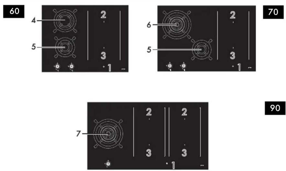
- Control panel
- Rear hot plate
- Front hot plate
- Rapid burner (R)
- Auxiliary burner (AUX)
- Ultra-rapid burner (UR)
- Ultra-rapid burner* (UR*)

Rear cooking zone

Front cooking zone
List of symbols

On/Off button: turns the hob on or off.
II Pause button: pauses cooking.
Controls lock button: prevents accidental operation of controls.
Grill function button: activates the Grill function
Warming function button: activates the keep warm function.
P Scroll bar: increases or decreases the power level of a cooking zone.
| Zone | Dimensions H x L (mm) | Max. power draw (W)* | Power draw in booster function (W)* | Power draw in Double Booster function (W)* |
Single zones 180 x 240 2100 2500 3000
Multizone 360 x 240 3000 3700 -
*Power levels are approximate and may vary according to the pan used or the settings made.
Burner knobs
For lighting and adjusting the hob burners. Press and turn the knobs anti-clockwise to order to light the relative burners. Turn the knobs to the zone between the maximum and minimum setting to adjust the flame. Return
the knobs to the position © turn off the burners.
Advantages of induction cooking

The appliance is equipped with an induction generator for each cooking zone. Each generator located under the glass ceramic cooking surface creates an electromagnetic field which induces a thermal current in the base of the pan. This means the heat is no longer transmitted from the hob to the pan but created directly inside the pan by the inductive current.
• Energy saving thanks to the direct transmission of energy to the pan (suitable magnetisable cookware is required) compared to traditional electric cooking.
- Improved safety as the energy is only transmitted to the pan placed on the hob.
- High level of energy transmitted from the induction cooking zone to the base of the pan.
- Rapid heating speed.
- Reduced danger of burns as the cooking surface is only heated under the base of the pan; foods which overflow do not stick.
Power control
The hob is fitted with a power control module that optimises/limits consumption. If the overall set power level exceeds the maximum limit permitted, the electronic circuit board will automatically manage the power supplied by the hot plates. The module tries to maintain the maximum deliverable power levels. Levels set by the automatic control will appear on the display.
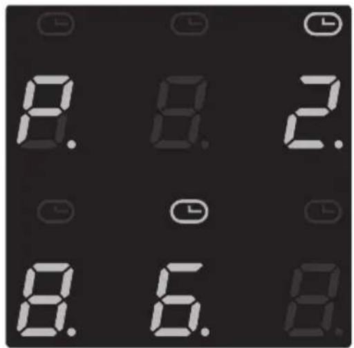
Priority is given to the last zone set.

The power control module does not affect the total power consumption of the appliance.
Accessories
- Not all accessories are available on some models.
- The accessories intended to come into contact with food are made of materials that comply with the provisions of current legislation.
- Original supplied and optional accessories can be requested to Authorised Assistance Centres. Use only original accessories supplied by the manufacturer.
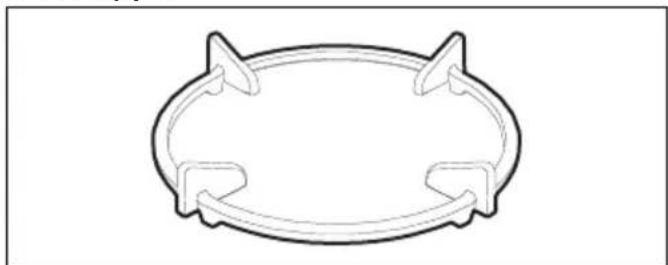
Wok support
natural_image
Simple line drawing of a circular object with two side protrusions and two central slots (no text or symbols)Useful when using a wok.
USE
Precautions

See General safety instructions.
A gas leak can cause an explosion.
If you smell gas or there are faults in the gas system:
- Immediately turn off the gas supply or close the valve on the gas cylinder.
- Extinguish all naked flames and cigarettes.
- Do not turn on power switches or
appliances and do not remove plugs from power sockets. Do not use phones or mobile phones inside the building.
- Open the window in order to ventilate the room.
- Call customer assistance services or your gas supplier.
Malfunctions
Any of the following indicate a malfunction and you should contact a service centre.
• The burners do not ignite properly.
- It is difficult to keep the burners lit.
- The burners go out when the appliance is in use.
- It is difficult to turn the gas cocks.
Preliminary operations

See General safety instructions.
- Remove any protective film from the outside or inside of the appliance, including any accessories (if present).
- Remove any labels (apart from the technical data plate).
Using the accessories
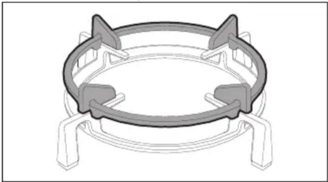
Trivet
The trivets and reduction pan supports must be placed on the hob pan supports. Make sure they are placed properly.
The trivet should only be used on the UR burner.
natural_image
Technical line drawing of a mechanical component with four circular features and mounting brackets (no text or symbols)Cookware suitable for use in induction cooking
Cookware used on the induction cooking surface must be made of metal, with magnetic properties and a sufficiently large base.
Suitable cookware:
- Enamelled steel cookware with thick bases.
- Cast iron cookware with an enamelled base.
- Cookware in multilayer stainless steel, ferritic stainless steel and aluminium with a special base.
Unsuitable cookware:
- Copper, stainless steel, aluminium, fireproof glass, wood, ceramic and terracotta cookware.
Cookware diameters
To ensure that the appliance detects the containers correctly and for best results, use the pan sizes indicated in the following table.
| Cooking zones | Minimum diameter (mm) | Maximum diameter (mm) |
Single zones 110 180
Multizone* 180 220
Bear in mind the following:
- Pans should not extend beyond the lines marked on the surface of the appliance.
- Do not place pans near to the edges of the glass ceramic surface or close to the control panel.
- If you use a griddle, it must have a maximum size of 36x24 cm.
*Values valid when using a single pan; if using two pans refer to the values for the single hob configuration.
Practical tips for using the hob
For better burner efficiency and to minimise gas consumption, use pans with lids and of suitable size for the burner, so that the flames do not reach up the sides of the pan. Once the contents come to the boil, turn down the flame far enough to ensure that the liquid does not boil over.
| Burner Pan diameter (cm) |
| AUX 8 - 18 |
| R 20 - 26 |
| UR 20 - 30 |
| UR* 20 - 30 |
Summary table of power levels
The power can be adjusted to various levels. The table below shows the levels suitable for
various types of cooking.
Power level Suitable for:
| 0 OFF setting | |
| 1 to 2 | Cooking small quantities of food (minimum power) |
| 3 to 4 Cooking | |
| 5 to 6 | Cooking large quantities of food, roasting larger portions |
| 7 to 8 Roasting, slow frying with flour | |
| 9 Roasting | |
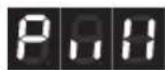
Bringing large quantities of water to a boil (maximum power, see "Booster function")
Limiting the cooking duration

See General safety instructions.
The appliance has an automatic device which limits the duration of use.
If the cooking zone settings of the pan are not changed, the maximum duration of operation depends on the power level selected.
When the device for limiting the duration of use is activated, the cooking zone turns off, a short
alert sounds and, if the zone is hot, the symbol is displayed.

| Power level | Maximum cooking duration (hours) |
| 1 | 6 |
| 2 | 6 |
| 3 | 5 |
| 4 | 5 |
| 5 | 4 |
| 6 | 1.5 |
| 7 | 1.5 |
| 8 | 1.5 |
| 9 | 1.5 |
Protection from overheating
If the hob is used on full power for a long period, the electronics will have trouble cooling down if the room temperature is high.
When certain safety thresholds are reached, one or more cooking zones are switched off. At least, if the internal temperature is very high, the
appliance is switched off automatically and "ER21" is displayed (see "error codes")
Correct positioning of the flame-spreader crowns and burner caps
text_image
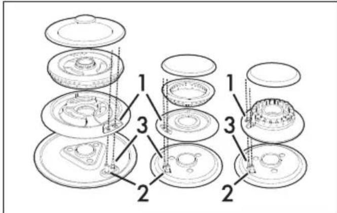
Technical diagram showing exploded view of mechanical components with numbered parts labeled 1, 2, and 3.Before lighting the hob burners, make sure that the flame-spreader crowns are correctly positioned in their housings with their respective burner caps. Make sure that the holes 1 in the flame-spreader crowns are aligned with the igniters 3 and thermocouples 2. Also ensure that the flame-spreader crowns are correctly engaged in the burner holes.
Correct positioning of the pan supports
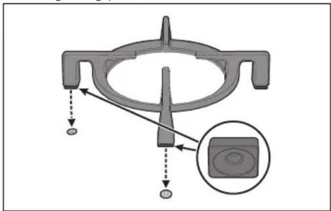
Under the pan supports there are silicone rests with a hole that must be centred onto the matching fixing pins on the surface.
text_image
Technical diagram of a mechanical component with labeled parts and an inset showing a circular feature.Make sure that the pan supports are simply centred on their respective burners, without forcing them to be raised or tilted. If they are, repeat the positioning procedure.
If you find that a pan is particularly unstable, make sure that the grids have not been positioned incorrectly.
Basic functions
First power connection
When connected to the power supply for the first time, or after power has been switched back on after a power failure, an automatic check is carried out that control turns on the
indicator lights and the displays for a few seconds. Afterwards, the appliance can be used normally.
Using the hob
Switching on and off
When the appliance is used for the first time, after having been connected to the mains the flashing symbol displays. It is used to access the appliance technical menu and is intended only for Technical Support personnel.

During the first connection to the power mains an automatic control is performed that turns on all indicator lights for a few seconds.
To switch the device on, press and hold the button for at least one second. To switch the device off, press the button until an acoustic signal is emitted. After switching on, the device will be automatically switched off after about 10 seconds of inactivity.
Switching on the cooking zone automatically After switching on the hob:
- Position a pan (suitable for induction cooking and not empty) on the cooking zone you wish to use.
- The button corresponding to the zone on which the container has been placed turns on automatically and displays the first segment of the scroll bar will light up.
- Select the cooking zone by pressing the corresponding button (see "Cooking zone setting area").
- Once a zone has been selected, a dot appears in the lower right corner of the digit field: the power level shown is
Switching the cooking zones on

The appliance is provided with an automatic pan sensing system.
After switching on the device:
- Position a pan (suitable for induction cooking and not empty) on the cooking zone you wish to use.
- The display corresponding to the zone on which the container has been placed turns on in automatically and displays
Adjusting the cooking zones
After placing a pan and ensuring that the zone has been activated:
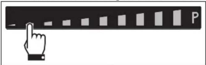
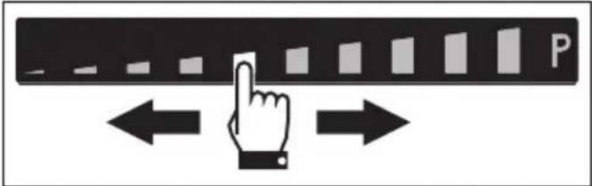
- Place a finger on the left-hand side of the scroll bar of the cooking zone to be used.
text_image
Icon showing a hand pointing at a bar labeled 'P' with a minus sign, likely indicating a status or progress indicator.The power level is now
- Move your finger to the left or right to select the power level from 1 to 9, or activate the Booster or the Double Booster functions (see dedicated chapters).
text_image
PThe display of the zone being used will indicate the selected power level.
Switching the cooking zones off
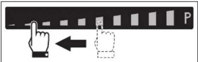
- Move your finger all the way to the left on the scroll bar of the cooking zone you wish to turn off.
text_image
Diagram showing a hand cursor clicking a button labeled 'P' with an arrow pointing to it, alongside a dashed icon.- The display of the selected zone indicates

To switch off more than one cooking zone at the same time, simply switch the appliance off using the key
Quick selection
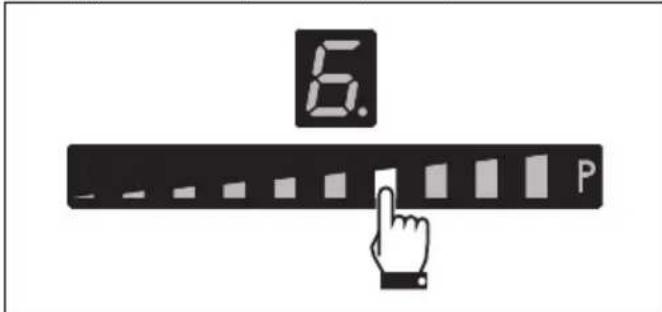
After switching on the hob and having selected a cooking zone:
- Place a finger on the scroll bar at approximately the required power level.
text_image
6. P- Move your finger to the left or right to select the required cooking power.
Booster function

See General safety instructions.
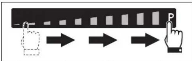
The booster function allows a pan to be heated to maximum capacity for a limited time. Useful for bringing large quantities of water to the boil in a short time.
After switching on the hob and having selected a zone:
- Slide your finger from the left end to the right end of the scroll bar.
flowchart
graph LR
    A["Start"] --> B["Step 1"]
    B --> C["Step 2"]
    C --> D["Step 3"]
    D --> E["Step 4"]
    E --> F["Step 5"]
    F --> G["Step 6"]
    G --> H["Step 7"]
    H --> I["Step 8"]
    I --> J["Step 9"]
    J --> K["Step 10"]
    K --> L["End"]
- The Booster function will be activated and
the symbol appears on the cooking zone display.
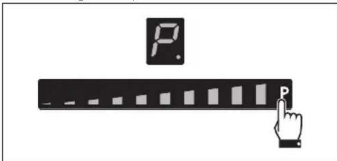
The Booster function can be activated quickly:
• After switching on the hob, place your finger at the far right of the scroll bar of the cooking zone you wish to use.
text_image
Diagram showing a hand pressing a bar labeled 'P' with an icon above it, likely illustrating a process or control interface.
The booster function is available for a maximum of 5 minutes, after which the power level in the zone returns to 9.
Double Booster Function

See General safety instructions.
The Double Booster function allows more power to be supplied compared to the Booster function.
After having activated the Booster function for a cooking zone, press the far right of the scroll bar
again. The symbols, P and displayed in sequence to indicate that the Double Booster function is on.
To deactivate the function, simply select any other power level or switch off the appliance.
Multizone function

This function allows you to operate two cooking zones (front and rear) at the same time when using pans such as fish kettles or rectangular containers.
After switching on the hob:
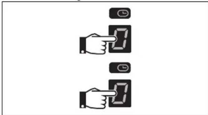
- Place a finger simultaneously on the buttons of two cooking zones one above the other.
text_image
Diagram showing two hand gestures pointing at a digital display with clock icons above themAfter a short beep, the symbol will display next to the button of the rear zone. The Multizone function is now active.
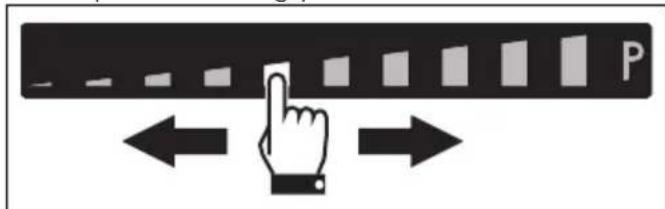
- Use the left-hand scroll bar to set the required cooking power.
text_image
PThe same parameters are set on both cooking zones.

It is not possible to activate the Double Booster function for the cooking zones on which the Multizone is active.

It is only possible to activate the Multizone function between cooking zones that are vertically connected (2 and 3).
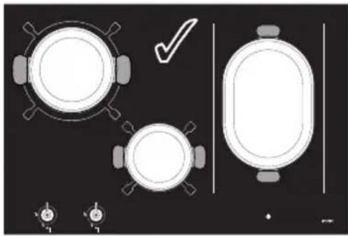
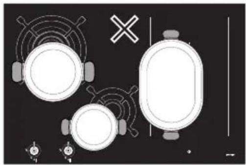
If a large, oval or oblong pan is being used, make sure that it is placed in the centre of the cooking zone.
natural_image
Top-down diagram of a kitchen appliance layout with circular and oval shapes, no text or symbols presentCorrect pan position
natural_image
Top-down schematic of a vehicle's front view showing three circular components with headsets and a cross symbol (no text or labels)INCORRECT pan position
To deactivate the Multizone function:
Simultaneously press the buttons of the cooking zones on which the Multizone function is active.
The Symbol disappears and the two zones can be regulated separately.
Cooking guidelines
The table below shows the power values which can be set, together with the corresponding type of food. Settings may vary depending on
the amount of food and consumer taste.
Power level Suitable for:
| 1 - 2 | Reheating food, keeping small amounts of water on the boil, and whipping up sauces with egg yolk or butter. |
| 3 - 4 | Cooking solid and liquid food, keeping water on the boil, defrosting deep-frozen food, cooking 2- or 3-egg omelettes, fruit and vegetable dishes, various cooking processes. |
| 5 - 7 | Stewing meat, fish and vegetables, simmering food, making jams etc. |
| 8 - 9 | Cooking or frying meat, fish, steaks and liver; browning meat, fish, eggs, etc. |
| P | Deep-frying potatoes, etc., or bringing water to the boil rapidly. |
Residual heat
If the cooking zone is still hot after being switched off, the symbol will be displayed on the display. The symbol clears once the temperature drops below 60°C.
Special functions
Warming Function

This function allows you to keep cooked food warm or to keep water on the boil.
To activate the Warming function, first turn on the hob, then:
- Place a pan on a cooking zone.
- Press the option to activate the function.
The symbol appears on the display of the selected cooking zone and the icon will appear next to the scroll bar.
To turn off the Warming function, simply press the button of the relative zone again.
Grill Function

This function is used to activate the Bridge function automatically for the right zones only. It is used when using a griddle or cooking with long pans.
To activate the Grill function:
-
Place a griddle or a long pan on the right zones.
-
Press the on . The LED above it will flash.
The symbol appears on the front zone display and the symbol appears on the rear zone display. The electronics will automatically set the power level to 9 (preheating phase).

natural_image
Abstract pattern of gray rectangular blocks on a black background (no text or symbols)After 3 minutes of operation, the power will be lowered to level 7 and the LED above the Grill function button becomes steady.
Use the scroll bar to modify the power level at any time.
Press the button to deactivate the Grill function.
Auto-Vent 2.0 function (on some models only)

- This function allows you to control the speed of the hood extractor fan via a wireless connection.
- The hood must be designed to use the Auto-Vent 2.0 function.
- The connection is always one way, from the hob to the hood. It is not possible to control the hob via the hood.
The Auto-Vent 2.0 function is disabled by default, but can be enabled from the user menu. This function has an automatic and a manual mode:
- Automatic mode adjusts the hood extractor fan speed according to the total power of the appliance (see "User menu - option U2).
- Manual mode allows you to adjust the extractor fan speed by pressing the button.
After switching on the hob, to activate manual mode:
-
Press the button.
-
Each subsequent press of the button increases the hood fan speed according to a cyclic sequence with 5 levels of adjustment, from 0 (off) to 4 (maximum speed).
To go back to automatic mode, the appliance has to be switched off and on again.

Refer to the hood manual for more detailed information.
Pause function

This function pauses the operation of all the cooking zones.
To activate the Pause function:
-
Switch on at least one cooking zone.
-
Hold down the pause button . The symbol displays on all the cooking zones.
To deactivate the Pause function:
-
Hold down the button . The pause symbol, which has just been pressed, starts to flash.
-
Press any button apart from the Pause button.
-
The pause function has now been deactivated and the previously set functions are restored.

The cooking time limitation, the residual heat indicators and the control lock function remain enabled during the Pause function.

When the power comes back on after a power failure, the pause function will be deactivated.

The pause function can be maintained for a maximum of 10 minutes, after which the appliance switches off.
Rapid heating function

This function is not available for power level 9, Booster and Double booster
The rapid heating function heats one cooking zone at maximum power for a limited time, after which it continues cooking at the set power level.

After selecting a cooking zone:
- Press and hold (1 to 8) power levels for at least 3 seconds.
• appears on the display of the cooking zone.
• After the heating time has elapsed, the cooking zone reverts to the previously selected power level. - This function can be deactivated by pressing and holding the set power level for
• 3 seconds, or by selecting a lower one.
Minute minder timer
After having switched on the hob, without having activated any cooking zone:
- Simultaneously press the buttons inside the timer setting area.
- Use the require

buttons to select the
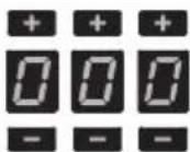
- The first digit on the left is used to select the hours, the middle one to set the tens of minutes and the one on the right the minutes.
- After 10 seconds, the timer will start the countdown.
- When the time elapses, a series of beeps will sound. Press any button to deactivate them.

A maximum of 9 hours and 59 minutes can be set.

Using the minute minder does not stop the operation of the cooking zones but rather informs the user when the set minutes have run out.
Modifying or deactivating the timer
To modify or deactivate the minute minder during the countdown:
- Press the On/Off key

activate the hob (if it was on standby).
- The timer setting area will indicate the minutes that were set.
- Use the buttons the

to change
minute minder time or reset it to zero.
3. After 10 seconds the timer will start the new countdown or will be deactivated.
Timed cooking
The timed cooking function can be activated when at least one cooking zone is switched on:
- Select the power level.
- Touch the inside of the timer setting area.
• The flashing symbol will appear above the cooking zone display.
- Use the and buttons to select the required time.
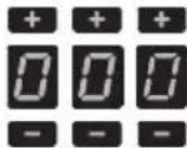
- Timed cooking will start a few seconds after the last selection.
At the end of the set time, a buzzer warns the user.
5. Press any button to deactivate the buzzer.

A maximum of 9 hours and 59 minutes can be set.

This function can be activated on multiple cooking zones at the same time. The flashing LED and time indicator refer to the next cooking zone to be switched off.
Modifying or deactivating timed cooking
To modify timed cooking during the countdown:
- Press the On/Off key

activate the hob (if it was on standby).
- Press the display button of the timed cooking zone.
- The timer setting area will indicate the minutes that were set.
- Use the buttons the

to change
minute minder time or reset it to zero.
- After 10 seconds, the timer will start the new countdown or will be deactivated.
Recall Function

This is used to restore some functions that have already been started after the appliance has been switched off unintentionally.
If the appliance is switched off unintentionally, carry out the following procedure within 6 seconds:
- Switch on the appliance.
• The button starts to flash.
- Press the pause button immediately restore the functions that were previously active.

This function restores the cooking zones, timer and rapid heating functions; no other functions will be restored.
Controls lock

This feature is designed to lock all the hob controls.
It is always active when the hob is switched on. It locks all buttons apart from this one
and the ON/OFF button.
This is useful when cleaning the appliance and to prevent functions being modified by mistake. To activate the controls lock function, at least one cooking zone has to be active:
-
Press the button for at least one second.
-
The LED on the display lights up for 2 seconds to indicate that the function has been activated.
To disable the Controls lock, press the button for at least one second.


It is always lit when the hob is activated.
User menu
The user menu allows you to modify the operating characteristics of the appliance. Seven options are available and each option is marked on the timer display with the letter "U"
followed by a sequential number.
| Option Description | |
| UO | Maximum total power (kW) |
| U1 | Option not selectable |
| U2 | Button volume |
| U3 | Buzzer volume |
| U4 | Display brightness |
| U5 | Timer animation |
| U6 | Automatic pan detection |
| U7 | Timer alarm duration |
Accessing the user menu
- If the hob is off, switch it on using the button

- Press again within 3 seconds to switch it off; the neon starts flashing.
Press and hold the button.
- The following will be shown on the cooking zones display (only for 90 cm models):
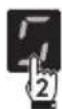
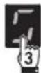
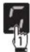
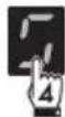
- Press all the buttons of the cooking zones in sequence in a clockwise direction starting from the front left. Every effective touch will be confirmed by a beep.
65 to 75 cm models:
First press the front cooking zone button and
then the one of the rear zone.
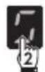
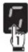

If the sequence of the buttons is selected incorrectly, the hob will be deactivated and the procedure for accessing the menu will have to be repeated.
5. Release the button.
The user menu is active and the symbol
alternating with the number - Option UO - Eco-Logic-Advance Function) will be shown at the top of the cooking zones display.
The Eco-Logic Advance function allows the total power of the appliance to be increased and decreased in steps of 0.1 kW. The timer display on the other hand will indicate the default power setting (according to the model - see "Power draws table"):
For 90 cm models:


For 65 cm and 75 cm models:


Press on the timer setting area to enable the power change; then press the left half of the scroll bar to decrease the power, and the right half to increase it.
Table of power draws
Model
Min. power (kW)
Max. power (kW)
90 cm 2.47.4
65 cm - 75 cm 2.4 3.7
- Press the symbol to go back to selecting the options.
- Press the segments of the scroll bar to select an option.

Each segment of the scroll bar corresponds to an item in the user menu, except for the second segment from the left (U1), which is deactivated.
Option U2 modifies the volume of the button sounds; 4 sound levels can be selected using the scroll bar.

According to the adjustment range of each option, the scroll bar will show only those segments that correspond to the adjustments available for each option.
- Value "O": minimum volume.
- Value "3": maximum volume.

The sound associated with the ① button and the sounds associated with error messages cannot be deactivated.
Option U3 modifies the volume of the signals (for example the sound of the alarm when the minute minder has elapsed). Four levels can be selected.
- Value "O": minimum volume.
- Value "3": maximum volume.
Option U4 modifies the brightness of the display. Ten levels can be selected.
- Value "O": maximum brightness.
• Value "9": minimum brightness.
Option U5 allows you to display the countdown of the minute minder timer and timed cooking in seconds, from 59 to 0 seconds.

The seconds count is displayed when the timer is set for less than 10 minutes.
- Value "O": animation off.
- Value "1": animation on.
Option U6 allows you to activate or deactivate the automatic pan detection function. (see "Switching on the cooking zone automatically").
- Value "O": automatic detection off.
- Value "1": automatic detection on.

If automatic pan detection is disabled, the area must be switched on manually when a pan is placed on the hob.
Option U7 allows you to set the length of the alarm when the minute minder has elapsed. Three levels can be selected:
• Value "0": alarm duration 120 seconds.
- Value "1": alarm duration 10 seconds.
• Value "2": alarm disabled.
Exiting the user menu
There are two ways to exit from the user menu:
- Press the button. Any modifications will be discarded and the hob will be switched off.
Or
- Press and hold the On/Off button for at least 2 seconds. The modifications will be saved and the hob will be switched off.
Error notifications
If the appliance malfunctions or operates incorrectly, the associated error code appears on the display.
The error codes always begin with the letter "E"
or "Er" followed by a series of digits (e.g. "Er47-30").
Errors coded as:
• "E02"
• " E 2 "
• "Er21"
Indicate that the appliance or part of it is overheating. If this occurs, you should switch off the appliance immediately, remove all pans and let it cool down.
If these errors persist or if other errors appear, make a note of the code and contact Technical Support.
CLEANING AND MAINTENANCE
Cleaning the hob
Cooking hob pan support grids
Remove the pan support grids and clean them in lukewarm water and non-abrasive detergent. Make sure to remove any encrustations. Dry them thoroughly and return them to the hob.

The continuous contact between the pan supports and the flame can cause modifications to the enamel over time in those parts exposed to heat. This is a completely natural phenomenon which has no effect on the operation of this component.
Flame-spreader crown and burner caps
For easier cleaning, the flame-spreader crowns and the burner caps can be removed. Wash them in hot water and non-abrasive detergent. Carefully remove any encrustation, then wait until they are perfectly dry. Replace the flame-spreader crowns, making sure that they are correctly positioned in their housings with their respective burner caps.
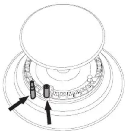
Igniters and thermocouples
For correct operation the igniters and thermocouples must always be perfectly clean. Check them frequently and clean them with a damp cloth if necessary. Remove any dry
residues with a wooden toothpick or a needle.
natural_image
Diagram of a mechanical assembly with concentric rings and two labeled components (no text or symbols)Cleaning the glass ceramic hob

See General safety instructions.
Cleaning the surfaces
To keep the surfaces in good condition, they should be cleaned regularly after use. Let them cool first.
Ordinary daily cleaning
Always and only use specific products that do not contain abrasives or chlorine-based acids. Pour the product onto a damp cloth and wipe the surface, rinse thoroughly and dry with a soft cloth or a microfibre cloth.

In case of stubborn dirt, clean when cold using a damp kitchen sponge and neutral detergent; then dry with a microfibre cloth.
Weekly cleaning
Clean and maintain the hob once a week using an ordinary glass ceramic cleaning product. Always follow the manufacturer's instructions. The silicon in these products creates a protective, water-repellent membrane which also resists dirt. All marks stay on the membrane and can therefore be removed easily. After cleaning, dry the surface with a clean cloth. Make sure that there is no detergent left on the cooking surface as it might undergo an aggressive reaction when heated up and could modify the structure of the cooking surface.
Food stains or residues
Light coloured marks from pans with aluminium bases can be easily cleaned off with a cloth moistened in vinegar. Remove any burnt-on residues after cooking; then rinse with water and dry thoroughly with a clean cloth. Dirt, which may have fallen on the hob while cleaning lettuce or potatoes, can scratch the hob when moving pans. Consequently, remove any dirt from the cooking surface immediately. Changes in colour do not affect the operation and stability of the glass. These are not alterations to the material of the hob but just residues which have not been removed and have then carbonised. Shiny surfaces can form due to the bases of pans, especially aluminium ones, rubbing on the surface, and due to the use of unsuitable detergents. They are difficult to remove using conventional cleaning products. It may be necessary to repeat the cleaning process several times. Use of corrosive detergents or rubbing of pan bases can wear away the decoration on the hob over time and contribute to the formation of stains.

We recommend the use of cleaning products distributed by the manufacturer.
INSTALLATION

The appliance must be installed by a qualified technician and according to the regulations in force.

After cleaning, dry the appliance thoroughly to prevent any water or detergent from interfering with its operation or creating unsightly marks.
What to do if...
The hob does not work:
- Make sure that the hob is connected and that the main switch is turned on.
- Make sure that there is no power failure.
- Make sure that the fuse has not blown. In this case replace the fuse.
- Make sure that the circuit breaker of the residential electrical system has not tripped. In this case, reset the circuit breaker.
The cooking results are unsatisfactory:
- Make sure that the cooking temperature is not too high or too low.
- Make sure that the hob is properly ventilated and that the air inlets are unobstructed.
- Use cookware that is certified and tested for induction cooking.
The hob smokes:
- Let the hob cool down and clean it once cooking is complete.
- Make sure that the food has not spilled out of the pan and use a larger cooking vessel, if needed.
The fuses blow or the circuit breaker of the residential electrical system trips repeatedly.
- Call Technical Support or an electrician.
There are cracks or fissures in the hob:
- Turn off the appliance immediately, disconnect the power supply and contact Technical Support.
Gas connection

See General safety instructions.
Connection to the gas mains can be made using a continuous wall steel hose in compliance with the guidelines established by the standards in force. To use other types of gas, see the chapter
"Adaptation to different types of gas". The appliance's gas connector has a 12 " external thread (ISO 228-1).
Connection with a steel hose
Make the connection to the gas mains using a continuous wall steel hose whose specifications comply with the applicable standard.
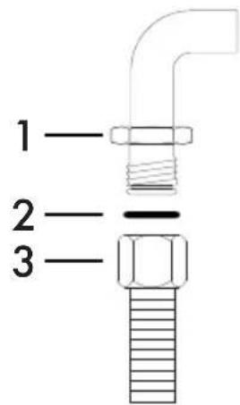
text_image
1 2 3Carefully screw the connector 3 to the gas connector 1 of the appliance, placing the seal 2 between them.
Connection with a steel hose with conical fitting
Make the connection to the gas mains using a continuous wall steel hose whose specifications comply with the applicable standard.
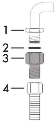
text_image
1 2 3 4Carefully screw the hose connector 3 to the appliance's gas connector 1 ( 12 " thread ISO 228-1), placing the seal 2, provided, between them. Apply insulating material to the thread of connector 3 and then screw the steel hose 4 onto the connector 3.
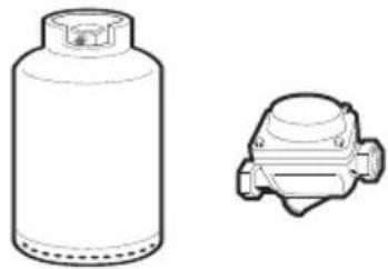
Connection to LPG
natural_image
Line drawing of a gas cylinder and a mechanical component (no text or symbols)Use a pressure regulator and make the connection on the gas cylinder following the guidelines set out in the standards in force.
The supply pressure must comply with the values indicated in the "Burner and nozzle characteristics table".
Room ventilation
The appliance should be installed in rooms that have a permanent air supply in accordance with the standards in force. The room where the appliance is installed must have enough air flow for the regular combustion of gas and the necessary air change in the room itself. The air vents, protected by grilles, must be the right size to comply with current regulations and positioned so that no part of them is obstructed, not even partially.
The room must be kept adequately ventilated in order to eliminate the heat and humidity produced by cooking: In particular, after prolonged use, you are recommended to open a window or to increase the speed of any fans.
Extraction of the combustion products
The combustion products may be extracted by means of hoods connected to a natural draught chimney whose efficiency is certain or via forced extraction. An efficient extraction system requires precision planning by a specialist qualified in this area and must comply with the positions and clearances indicated by the applicable standards.
When the job is complete, the installer must
issue a certificate of conformity.

flowchart
graph TD
    A["1A"] --> B["Receiving Air"]
    C["1B"] --> D["Receiving Air"]
    E["2C"] --> F["Receiving Air"]
    G["2D"] --> H["Receiving Air"]
1 Extraction using a hood
2 Extraction without a hood
A Extraction with a single natural draught chimney
B Extraction with a single chimney with extractor fan
C Extraction directly outdoors with wall- or window-mounted extractor fan
D Extraction directly outdoors through wall

Air

Combustion products

Extractor fan
Adaptation to different types of gas
If other types of gas are to be used, the nozzles must be replaced and the primary air must be adjusted. The top of the hob has to be removed in order to replace the nozzles and adjust the burners.

In order to be able to replace the nozzles, the appliance must be removed from the built-in unit.
Removing the hob top
-
Pull the knobs and the knob bezels (where present) upwards to remove them.
-
Remove the grids from the hob top.
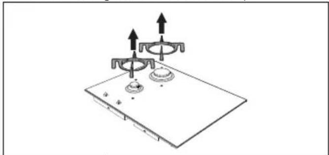
natural_image
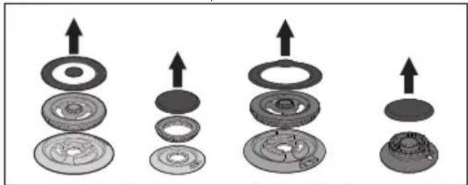
Diagram of a gas stove with two upright fans and a base, showing upward arrows indicating motion (no text or symbols)- Remove the flame-spreader crowns and relative burner caps.
natural_image
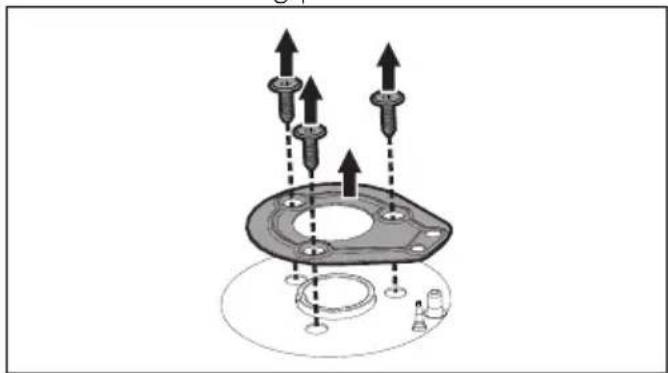
Four mechanical components with upward arrows indicating assembly or transformation (no text or symbols present)- Unscrew the screws under each burner to remove the fixing plate.
natural_image
Mechanical assembly diagram showing bolted components and motion arrows (no text or labels)
If there is an ultra-rapid burner, the nut that secures the thermocouple to the hob should be unscrewed (CH8).

Underneath the plates there may be some gaskets at the igniter and thermocouple. Pay attention.
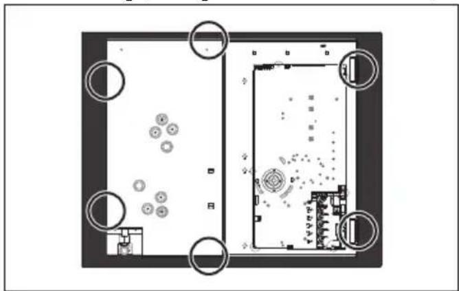
- Loosen the screws securing the glass shelf to the casing (see figures below for location):
natural_image
Top-down architectural floor plan showing room layout with circular elements and furniture placement (no text or labels)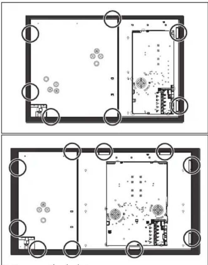
natural_image
Top-down architectural floor plan showing room layouts and surrounding structures (no text or labels)- Remove the hob top.
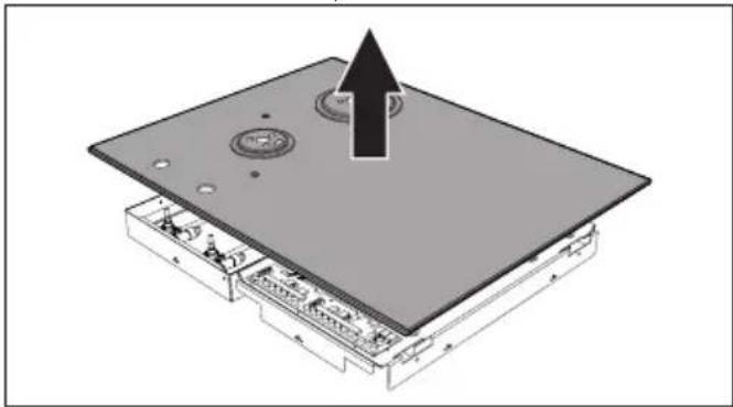
natural_image
3D diagram of an electronic device with a highlighted top component and an upward arrow indicating motion (no text or symbols)Replacing nozzles
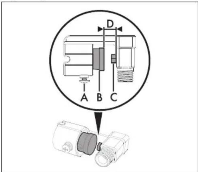
text_image
A B C D-
Loosen the screw A and push the air regulator B as far as it will go.
-
Use a spanner to remove the nozzles C and install the new ones for the required gas supply, following the indications given in the relevant table (see "Gas types and countries" or "Burner and nozzle characteristics tables").

The nozzle tightening torque must be no more than 3 Nm.
- Adjust the air flow by moving the air regulator B to obtain the distance D given in the corresponding table (see "Gas types and countries" or "Burner and nozzle characteristics tables").
- After adjusting each burner, reassemble the appliance correctly.
Adjusting the minimum setting for natural or town gas
- Light the burner and turn it to the minimum position.
- Remove the gas tap knob and turn the adjustment screw next to the gas cock spindle (depending on the model) until the correct minimum flame is achieved.
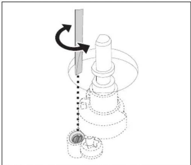
natural_image
Mechanical assembly diagram showing a rotating shaft and base with dashed lines indicating motion (no text or symbols)- Refit the knob and verify that the burner flame is stable.
- Turn the knob rapidly from the maximum to the minimum setting: The flame should not go out.
- Repeat the operation on all the gas taps.
Adjusting the minimum setting for LPG
Tighten the screw located at the side of the cock
spindle clockwise all the way.

Following adjustment to a gas other than the one originally set in the factory, replace the gas setting label on the appliance with the one corresponding to the new gas. The label is inserted inside the nozzle pack (where present).
Gas types and Countries
| Gas types IT | GB IE | FR BE | ES PT RU | SE DK | FI NO | PL HU | |||
| 1 Natural Gas G20 | |||||||||
| G20 | 20 mbar | ● | ● | ● | ● | ● | ● | ● | |
| G20/25 | 20/25 mbar | ● | |||||||
| 2 Natural Gas G20 | |||||||||
| G20 | 25 mbar | ● | |||||||
| 3 Natural Gas G25.1 | |||||||||
| G25.1 | 25 mbar | ● | |||||||
| 4 Natural Gas G2.350 | |||||||||
| G2.350 | 13 mbar | ● | |||||||
| 5 LPG G30/31 | |||||||||
| G30/31 | 28-30/37 mbar | ● | ● | ● | ● | ● | ● | ||
| G30/31 | 30/30 mbar | ● | ● | ● | |||||
| 6 LPG G30/31 | |||||||||
| G30/31 | 37 mbar | ● | |||||||
| 7 Town Gas G110 | |||||||||
| G110 | 8 mbar | ● | ● | ||||||
It is possible to identify the available gas types based on the country the appliance is to be installed in. Refer to the heading number to identify the correct values in the "Burner and nozzle characteristics tables".
Lubricating the gas cocks
Over time the gas cocks may become difficult to turn and get blocked. Clean them internally and
replace the lubrication grease.
Lubrication of the gas cocks should be performed by a specialised technician.
Burner and nozzle specifications tables
| 1 Natural Gas G20 - 20 mbar | AUX | R | UR | UR* |
| Rated heating capacity (kW) | 1 | . | 1 | 3 |
| Nozzle diameter (1/100 mm) | 73 126 | 130 | 175 | |
| Reduced flow rate (W) | 400 | 900 | 1600 | 1800 |
| Primary air (mm) | 1 | 1.5 | 0.5 | 1.5 |
| 2 Natural Gas G20 - 25 mbar | AUX | SR | R | UR2 int. |
| Rated heating capacity (kW) | 1 | . | 1 | 3 |
| Nozzle diameter (1/100 mm) | 73 120 | 123 | 160 | |
| Reduced flow rate (W) | 400 | 900 | 1400 | 1800 |
| Primary air (mm) | 1 | 1 | 1 | 1 |
| 3 | Natural Gas G25.1 - 25 mbar | AUX | SR | R | UR2 int. |
| Rated heating capacity (kW) | 1.1 3.1 | 3.3 5.9 | |||
| Nozzle diameter (1/100 mm) | 76 135 | 140 190 | |||
| Reduced flow rate (W) | 400 900 | 1400 1800 | |||
| Primary air (mm) | 0 | . | 5 | 1 | |
| 4 | Natural Gas G2.350 - 13 mbar | AUX | SR | R | UR2 int. |
| Rated heating capacity (kW) | 1.1 3.1 | 3.3 6.0 | |||
| Nozzle diameter (1/100 mm) | 100 175 | 180 280 | |||
| Reduced flow rate (W) | 400 900 | 1400 1800 | |||
| Primary air (mm) | 1 | 1 | 1 | 3 | |
| 5 | LPG G30/31 - 30/37 mbar | AUX | SR | R | UR2 int. |
| Rated heating capacity (kW) | 1.0 3.1 | 3.3 6.0 | |||
| Nozzle diameter (1/100 mm) | 48 | 85 | 87 115 | ||
| Reduced flow rate (W) | 400 1100 | 1800 1800 | |||
| Primary air (mm) | 1.5 | 2 | 1.5 | 12 | |
| Rated flow rate G30 (g/h) | 73 225 | 240 436 | |||
| Rated flow rate G31 (g/h) | 71 221 | 236 429 | |||
| 6 | LPG G30/31 - 37 mbar | AUX | SR | R | UR2 int. |
| Rated heating capacity (kW) | 1.1 3.1 | 3.3 6.0 | |||
| Nozzle diameter (1/100 mm) | 48 | 80 | 85 110 | ||
| Reduced flow rate (W) | 450 1100 | 1800 1800 | |||
| Primary air (mm) | 1 | 1 | . | 1 | |
| Rated flow rate G30 (g/h) | 80 225 | 240 436 | |||
| Rated flow rate G31 (g/h) | 79 221 | 236 429 | |||
| 7 | Town gas G110 - 8 mbar | AUX | SR | R | UR2 int. |
| Rated heating capacity (kW) | 1.1 3.0 | 3.1 3.8 | |||
| Nozzle diameter (1/100 mm) | 132 250 | 250 310 | |||
| Reduced flow rate (W) | 400 900 | 1400 1400 | |||
| Primary air (mm) | 1 | 1 | 1 | 1 |
The nozzles not provided are available at Authorised Service Centres.
Section cut from the countertop
Safety instructions for positioning and installation

See General safety instructions.
- Installation can be carried out on various materials such as masonry, metal, solid wood or plastic laminated wood as long as they are heat resistant ( >90^ ).
- Veneers, adhesives or plastic coatings on adjacent furniture should be temperature-
resistant ( >90^ ), otherwise they might warp over time.
- If the piece of furniture does not have the required recess opening, either it will have to be cut or masonry work carried out by a competent technician.
- The minimum clearance between exhaust hoods and the cooking surface must be at least the distance indicated in the exhaust hood installation instructions.
- The minimum clearances must also be respected for the edges of the hob on the back as indicated in the assembly
instructions.
- If the appliance is to be installed above an oven, the oven must be fitted with a cooling fan.
Appliance dimensions (mm)
Position of gas and electrical connections.
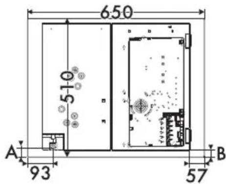
text_image
650 510 A 93 57 B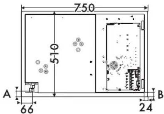
text_image
750 510 A 66 24 B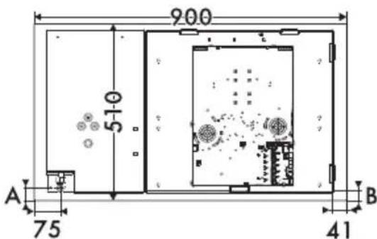
text_image
900 510 A 75 41 BA 35
B 28
Appliance overall dimensions (mm)
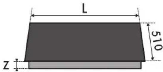
text_image
L 510 ZL Z
650 50
750 50
900 46
After laying the adhesive seal (A) on the glass surface and after positioning and securing the hob, fill the edges with insulating silicone (B) and wipe away any excess.
Built-in cabinet dimensions (mm)
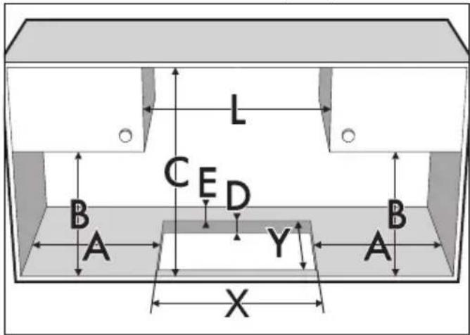
text_image
L CED B A Y A B XL (mm) X (mm) Y (mm)
650 560 - 564 482 - 486
750 720 - 724 482 - 486
900 844 - 848 482 - 486
A (mm) B (mm) C (mm)* D (mm) E (mm)
min 200 min 460 min 750 40÷60 min 65
*If there is a piece of furniture above the hob. In the case of a hood refer to to the dimensions indicated in the relevant manual.
Hob seal
To prevent leakage of liquid between the frame of the hob and the countertop, place the adhesive seal provided along the entire outer
edge of the hob before assembly.
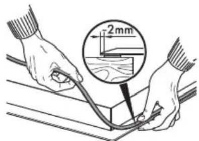
text_image
2mm
Do not use silicone to secure the hob. This would make it impossible to remove the hob without damaging it.
Mounting
On top of oven built-in unit
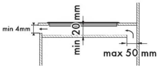
The clearance between the hob and the kitchen furniture or other installed appliances must be enough to ensure sufficient ventilation and air discharge. If installed above an oven, a space must be left between the bottom of the hob and the top of the appliance installed below.
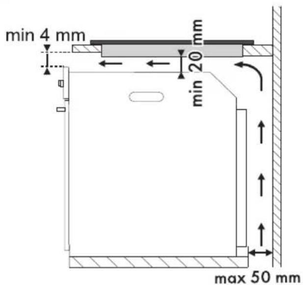
text_image
min 4 mm mm 20 min max 50 mmOn top of empty kitchen unit or drawers
If there are other pieces of furniture (lateral walls,
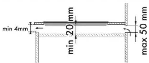
drawers, etc.), dishwashers or fridges under the hob, a double-layer wooden base must be installed at least 20 mm from the bottom of the hob to avoid any accidental contact. It must only be possible to remove the double-layer
base using suitable equipment.
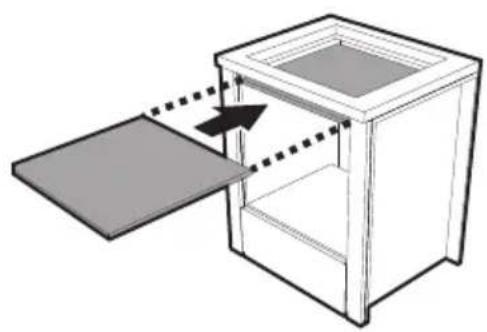
natural_image
Diagram of a cabinet with an open lid and internal compartments, showing directional arrows (no text or symbols)opens on bottom:
text_image
min 4mm 20 mm min 20 mm max 50 mmopens on rear:
text_image
min 4mm 20 mm min max 50 mm
Failure to install the double-layer wooden base exposes the user to possible accidental contact with sharp or hot parts.

If installed on top of an oven, the latter must be equipped with a cooling fan.
Fixing to the built-in cabinet
To ensure the hob is fixed and centred as accurately as possible, the clips provided must be positioned as described below:
- Fit the clips by gently pressing them horizontally into the appropriate space.
- Then turn them upwards to fix them in place.
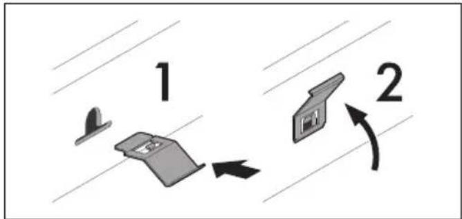
flowchart
graph TD
    A["Step 1: Top View"] --> B["Step 2: Bottom View"]
    B --> C["Arrow 1: Directional Arrow"]
    C --> D["Arrow 2: Directional Arrow"]
Position of slot for clips
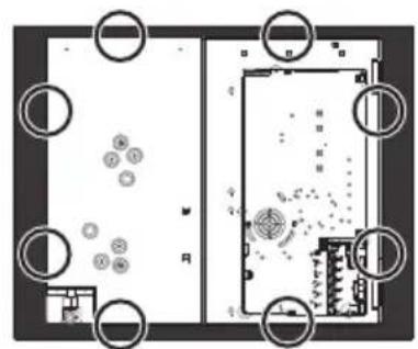
natural_image
Top-down architectural floor plan showing room layout with circular elements and furniture placement (no text or labels)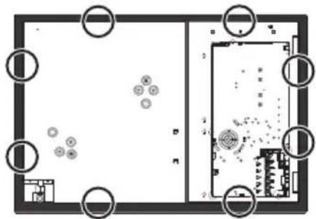
natural_image
Floor plan layout with room layouts and circular annotations (no text or symbols)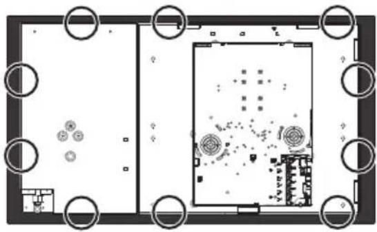
natural_image
Top-down architectural floor plan showing room layout with circular elements and central building (no text or labels)Electrical connection

See General safety instructions.
General information
Check the mains characteristics against the data indicated on the plate.
The identification plate bearing the technical data, serial number and brand name is visibly positioned on the appliance.
Do not remove this plate for any reason.
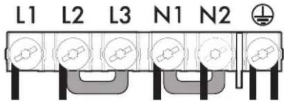
The appliance must be connected to ground using a wire that is at least 20 mm longer than the other wires.
The appliance can work in the following modes:
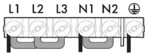
65 - 75 cm models:
- 220 - 240 V 1N\~
text_image
L1 L2 L3 N1 N23 × 1.5 mm² three-core cable.
90 cm models:
- 220 - 240 V 1N\~
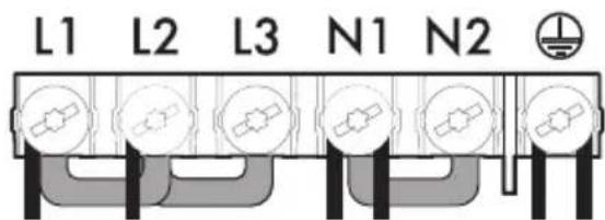
text_image
L1 L2 L3 N1 N26 × 1.5 mm² six-core cable.
- 380 - 415 V 2N\~
text_image
L1 L2 L3 N1 N26 × 1.5 mm² six-core cable.

The values indicated refer to the cross-section of the internal lead.
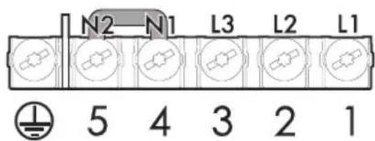
The diagram below illustrates the power supply terminal from below, with no cables connected. Terminals 4 and 5 must be connected at all times.
text_image
N2-N1 L3 L2 L1 5 4 3 2 1Fixed connection
Fit the power line with an all-pole circuit breaker with a contact separation distance sufficient to provide complete disconnection in category III overvoltage conditions, pursuant to installation regulations.
For the Australian/New Zealand market:
The circuit breaker incorporated in the fixed connection must comply with AS/NZS 3000.
Connection with plug and socket
Make sure that the plug and socket are of the same type.
Avoid using adapters, gang sockets or shunts as these could cause overheating and a risk of burns.
Instructions for the installer
- If you use a plug to connect to the power supply, the plug must be accessible after installation.
- Do not bend or trap the power cable.
- The appliance must be installed according to the installation diagrams.
- Do not try to unscrew or force the threaded elbow of the fitting. You may damage this part of the appliance, which may void the manufacturer's warranty.
- Use soap and water to check for gas leaks on all connections. DO NOT use naked flames to search for leaks.
- Turn on all the burners separately and at then all together to make sure that the gas valve, burner and ignition are working properly.
- Turn the burner knobs to the minimum position and check that the flame is stable for each individual burner and all the burners together.
- If the appliance does not work correctly after having carried out all the checks, contact your local Authorised Service Centre.
- Once the appliance has been installed, please explain to the user how to use it correctly.