
AX-330PLUS - Detector OPTEX - Free user manual and instructions
Find the device manual for free AX-330PLUS OPTEX in PDF.


| Product Type | Infrared Photoelectric Beam Detector |
| Brand | OPTEX |
| Model | AX-330PLUS |
| Detection Range | 100 m / 330 ft |
| Maximum Arrival Distance | 1000 m / 3300 ft |
| Beam Characteristics | Pulsed Infrared |
| Beam Interruption Period | 50 to 500 ms (selectable) |
| Power Supply | 10.5 to 28 VDC |
| Current Consumption (TX+RX, Normal) | 46 mA max |
| Alarm Period | 2 sec (±1) nominal |
| Alarm Output | Form C relay (28 VDC, 0.2 A max) |
| Tamper Switch | N.C., opens when cover removed (receiver only) |
| Operating Temperature | -25°C to +55°C (-13°F to +131°F) |
| Environment Humidity | 95% max |
| Alignment Angle | Vertical: ±5°, Horizontal: ±90° |
| Installation | Wall or pole mounting |
| Weight (Transmitter + Receiver) | 1040 g (36.7 oz) |
| LED Alignment Indicator | Yes, for beam alignment level |
| Fine Angle Adjustment | Dial for vertical and horizontal |
| Anti-Frost Structure | Front cover prevents fog and condensation |
| Monitor Jack | For alignment voltage check |
| Optional Accessories | Heating unit (HU-2), Back cover (BC-2) |
| Cleaning Instructions | Use dry soft cloth or mild soap and water; avoid oil/alcohol solvents |
Frequently Asked Questions - AX-330PLUS OPTEX
User questions about AX-330PLUS OPTEX
0 question about this device. Answer the ones you know or ask your own.
Ask a new question about this device
Download the instructions for your Detector in PDF format for free! Find your manual AX-330PLUS - OPTEX and take your electronic device back in hand. On this page are published all the documents necessary for the use of your device. AX-330PLUS by OPTEX.
USER MANUAL AX-330PLUS OPTEX
| Model | Detection range |
| AX-330PLUS | 100 m / 330 ft. |
FEATURES
• LED indicator for beam alignment level:
Accurate and reliable alignment can be easily achieved by using LED indicator located on the receiver.
The alarm indicating lamp is located in the front end of the inner housing and in viewfinder.
• Aligned fine angle adjustment:
By turning the dial, you can achieve vertical and horizontal optical adjustments.
- Form C relay:
Suitable for various applications.
- Anti-frost structure:
The front cover prevents fog and condensation from blocking the beams.
- Beam interruption time adjustment:
This feature allows you to select suitable beam interruption time for any environment.
- Alignment-level monitor jack
- Optional accessories (not included):
Heating unit (HU-2), Back cover (BC-2)
1 INTRODUCTION
- Read this instruction manual carefully prior to installation.
• After reading, store this manual carefully in an easily accessible place for reference. - This manual uses the following warning indications for correct use of the product, harm to you or other people and damage to your assets, which are described below. Be sure to understand the description before reading the rest of this manual.
| Warning | Failure to follow the instructions provided with this indication and improper handling may cause death or serious injury. |
| Caution | Failure to follow the instructions provided with this indication and improper handling may cause injury and/or property damage. |

This symbol indicates prohibition. The specific prohibited action is provided in and/or around the figure.

This symbol requires an action or gives an instruction.
| Warning | Do not use the product for purposes other than the detection of moving objects such as people and vehicles. Do not use the product to activate a shutter, etc., which may cause an accident. | [WY06] |
| Do not touch the unit base or power terminals of the product with a wet hand (do not touch when the product is wet with rain, etc.). It may cause electric shock. |  | |
| Never attempt to disassemble or repair the product. It may cause fire or damage to the devices. |  | |
| Do not exceed the voltage or current rating specified for any of the terminals during installation, doing so may cause fire or damage to the devices. | [H057] | |
| Caution | Do not pour water over the product with a bucket, hose, etc. The water may enter, which may cause damage to the devices. |  |
| Clean and check the product periodically for safe use. If any problem is found, do not attempt to use the product as it is and have the product repaired by a professional engineer or electrician. | [5Y82] |
1-2 PRECAUTIONS
Do not install the unit on an unstable surface.
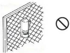
natural_image
Simple line drawing of a wall-mounted device with a grid pattern and a prohibition symbol (no text or labels)The mounting pole should have a solid basis with little movement at the top of the pole.
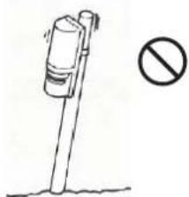
natural_image
Simple line drawing of a streetlamp with a prohibition symbol (no text or labels)Do not install the unit in a location where trees, leaves, or other objects that may swing in the wind and block the beam.
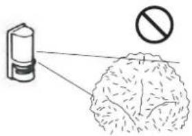
Avoid aerial wiring.
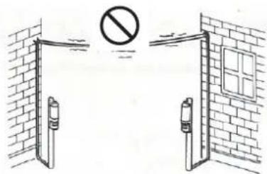

This symbol indicates prohibition.
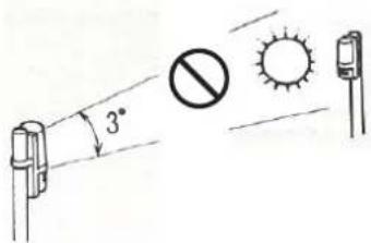
Do not install the receiver in a location where it is exposed to direct sunlight.
√ For indoor application, the wiring installation is similar to that of telephone wirings or the Internet.
√ For outdoor application, use wire conduit as far as possible. Some places require shielded wires or underground wiring.
s symbol indicates recommendation.
1-3 PARTS IDENTIFICATION
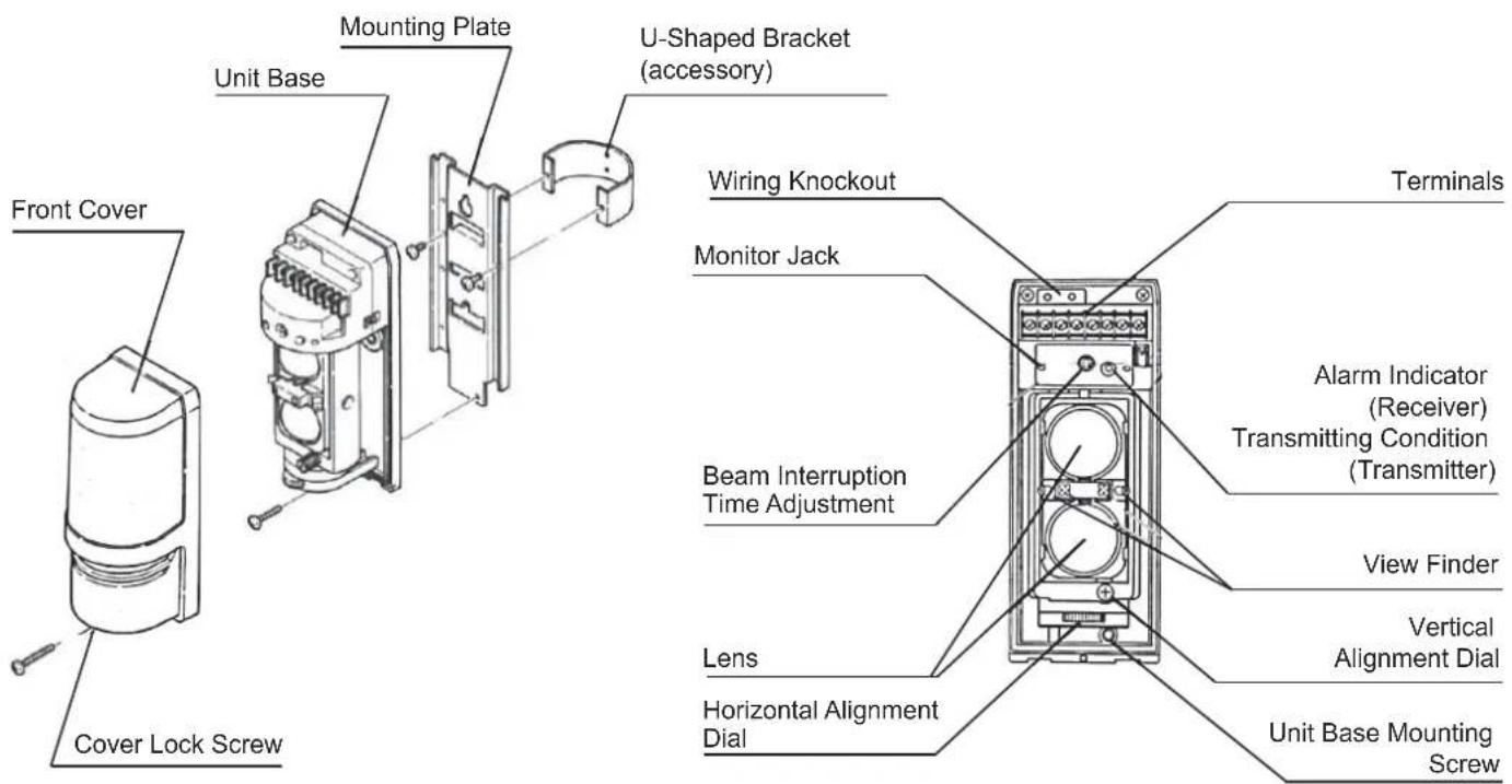
ACCESSORIES >>
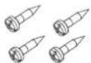
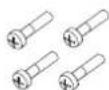
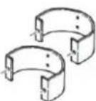
U-Shaped brackets x 24×20 self tapping x 4 M4×14 screws x 4
2 INSTALLATION
2-1 Normal installation
1 Range/ height/ angle
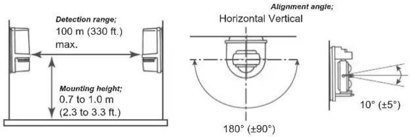
2
Pole installation
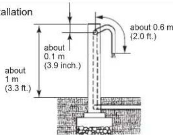
* Mounting pole; φ43\~48 mm (1 11/16"\~1 7/8") (Standard U.S. 1 1/2"pipe)
* The length of wiring cable out of the pole; within 0.6 m (2.0 ft.)
* After finishing the pole installation,
align the transmitter and receiver with each other.
2-2 Installing method
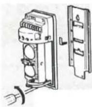
1 Separating
Loosen the cover lock screw and remove the front cover.
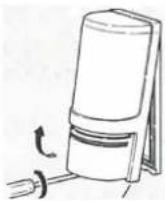
Loosen the unit base mounting screw and slide the mounting plate downwards relative to the unit base to remove it.
natural_image
Technical line drawing of an electrical switch assembly with no visible text or symbols2 Mounting
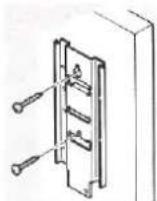
Wall mounting
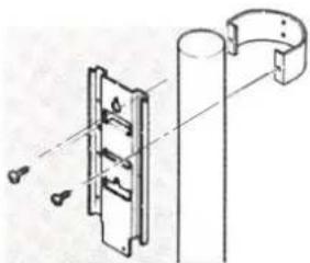
Pole mounting
natural_image
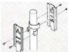
Technical line drawing of a mechanical assembly with a bracket and mounting bracket (no text or symbols)Two unit mounting
(back to back)
natural_image
Technical diagram of a mechanical assembly with three vertical components and mounting holes (no text or labels)Pull out wires through the wiring hole on the mounting plate and fix the mounting plate on the wall with screws.
Place the U-shaped bracket on the mounting pole, and pull out wires through the wiring hole on the mounting plate and fix the mounting plate on the U-shaped bracket with screws.
Fix two U-shaped brackets in layers on a pole, two units can be mounted back-to-back on a pole at the same height.
3 Wires and fixing
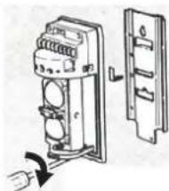
Pull the wires through the wiring holes of the unit base. Connect the unit base to the mounting plate through the hook on the top of the unit base. Push the unit base until it is fully engaged with the mounting plate. Tighten the mounting screws on the bottom of the unit base.
natural_image
Technical line drawing of an electrical switch assembly with a fuse and socket (no text or symbols)4 Connecting
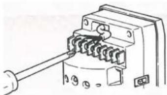
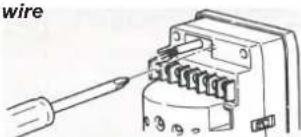
Connect wires to the terminals. (refer to Terminal and wiring in Section 2-3).
natural_image
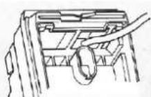
Technical line drawing of a mechanical component with no visible text or symbolsKnockout for the second wire
Dig out a hole on the right side of the rubber bushing marked with Ⓐ, when it is need for the second wire.
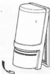
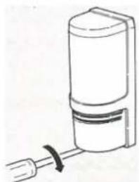
5 Place the front cover
Place the front cover after the optical alignment and the walk test. ( Refer to optical alignment in Section 4).
natural_image
Simple line drawing of a cylindrical object with a curved arrow indicating rotation (no text or symbols)Tighten the cover lock screw.
natural_image
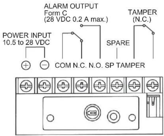
Simple line drawing of a mechanical device with a cylindrical component and a rod (no text or symbols)2-3 Terminal and wiring
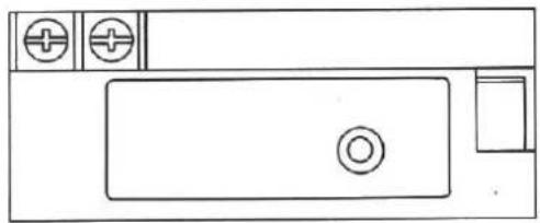
1 Receiver
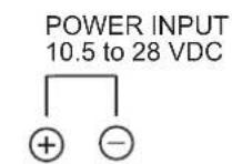
2 Transmitter
natural_image
Simple line drawing of a kitchen sink with faucet and three circular fixtures (no text or symbols)3 Wiring distance
- When using two or more units on one wire, the maximum length is obtained by dividing the maximum wire length listed right by the number of units. (a detector = a receiver or a transmitter.)
- The power wire should not exceed that.
m (ft.)
| Wire size | 12 VDC | 24 VDC |
| AWG 22(0.33 mm ^2 ) | 500(1 600) | 2 500(8 100) |
| AWG 20(0.52 mm ^2 ) | 800(2 600) | 4 000(13 000) |
| AWG 18(0.83 mm ^2 ) | 1 200(4 000) | 6 000(19 500) |
| AWG 16(1.31 mm ^2 ) | 2 000(6 500) | 10 000(32 500) |
3 Beam interruption time adjustment
Beam interruption time adjustment is on the receiver unit. This function allows you to adjust the sensitivity of the device to fit to surroundings. A slower setting means less sensitivity.
| Time adjustment (Receiver) | 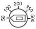 | 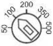 | 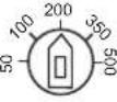 | 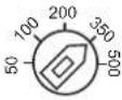 | 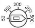 |
| Typical interruption time setting | Running Jogging Walk fast (50 msec) (100 msec) (200 msec) | Walk slow (350 msec) | Slow movement (500 msec) | ||
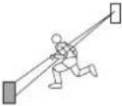 | 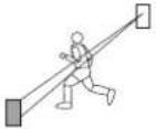 | 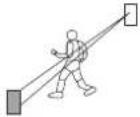 | 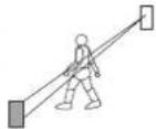 | 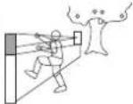 | |
| Caution | The speed shown above is the maximum detectable speed for each setting.Faster speed will not be detected. For cases where birds, newspapers, or suspended matters may accidentally interrupt the beam, adjust the set value to a slower speed (longer interruption time). |
4 Optical alignment
The reliability of photoelectric detector depends on the level of optical alignment.
Use the following method to ensure that the maximum voltage can be obtained from the monitor jack by means of a voltmeter.
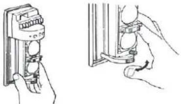
4-1 Horizontal and vertical alignment
Observe the viewfinder of the transmitter and the receiver. Adjust the lens from horizontal and vertical directions, so that the other unit is in the center of the viewfinder.
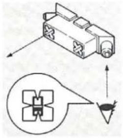
1 Horizontal alignment
Course adjustment Fine adjustment Fine adjustment
natural_image
Illustration of hands using a power switch to install a panel (no text or symbols present)-
Align the position of the lens bracket by hand.
-
Look into the viewfinder, and turn the horizontal alignment dial for fine adjustment.
2 Vertical alignment
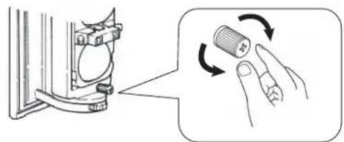
natural_image
Diagram showing a mechanical component with a magnified view of a cylindrical component being twisted, no text or symbols present.-
Look into the viewfinder, and turn the dial for fine adjustment by screwdriver or manually.
-
Right; upward / left; downward
4-2 Check by alarm LED
Remember to obtain the maximum voltage from the monitor jack by using a voltmeter so as to obtain the most stable beam (refer to Step 4-3).
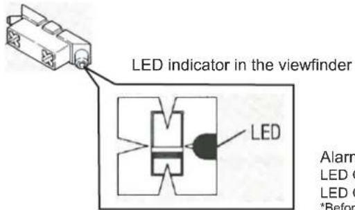
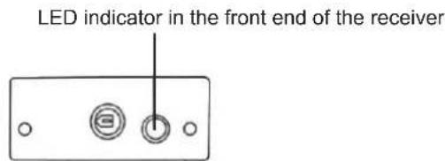
Alarm LED indicator status
LED ON: The beam energy emitted by the transmitter has not yet reached to the receiver. LED OFF: The beam energy emitted by the transmitter has reached to the receiver. *Before moving to the next step, confirm that LED indicator is OFF.
4-3 Carry out check from monitor jack
After adjustment by observing the LED indicator, use a voltmeter to check the voltage on the monitor jack to obtain the most stable beam.
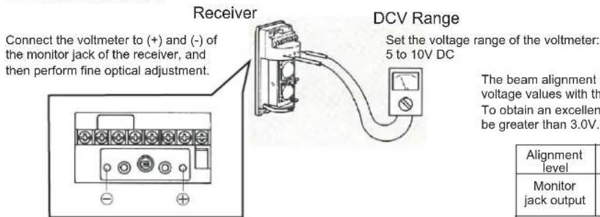
Insert the probe of the voltmeter into the monitor jack in front end of the receiver.
The beam alignment level can be obtained by comparing the measured voltage values with the parameter values in the following table. To obtain an excellent alignment level, the measured voltage value must be greater than 3.0V.
| Alignment level | Poor | Realign | Fair | Good | Excellent |
| Monitor jack output | 0 V ▶ 1.5 V ▶ 2.5 V ▶ 2.7 V ▶ 3.0 V ▶ | ||||
| Optical alignment for indoor useThe maximum voltage obtained from the monitor jack should be at least 2.5 V or more. | |||||
4-4 Walk test
- Check that the alarm indicating lamp is OFF.
- If the beam is not blocked and the indicating lamp is still ON, re-perform optical adjustment and check the wire connection (refer to Section 2-3).
- After adjustment and normal operation of the device, perform walk test at least 3 locations as in the following :
• In front of the transmitter
• In front of the receiver
● Midpoint between the receiver and the transmitter
5 Specifications
| Model | AX-330PLUS |
| Detection method | Infrared photoelectric |
| Coverage | 100 m / 330 ft. |
| Maximum arrival distance | 1 000 m / 3 300 ft. |
| Beam characteristics | Pulsed infrared |
| Interruption period | 50 to 500 ms (selectable) |
| Power supply | 10.5 to 28 VDC |
| Current consumption(Transmitter + Receiver) | Normal operation46 mA max. |
| Alarm period | 2 sec. (±1) nominal |
| Alarm output | Form C relay (28 VDC, 0.2 A max.) |
| Tamper switch | N.C., opens when the cover is removed (receiver only) |
| Operating temperature | -25°C to +55°C (-13°F to +131°F) |
| Environment humidity | 95% max. |
| Alignment angle | Vertical: ±5°, horizontal: ±90° |
| Installation | Wall installation/pole installation |
| Weight (Transmitter + Receiver) | 1 040 g (36.7 oz) |
* Specifications and design are subject to change without prior notice.
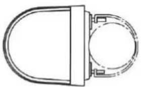
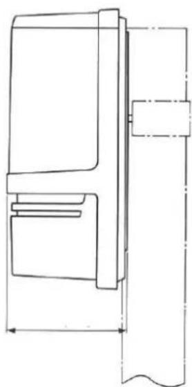
6 Dimensions
natural_image
Simple line drawing of a door handle and circular component (no text or symbols)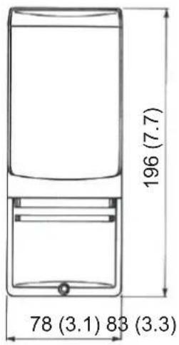
natural_image
Technical line drawing of a mechanical component with no visible text or symbols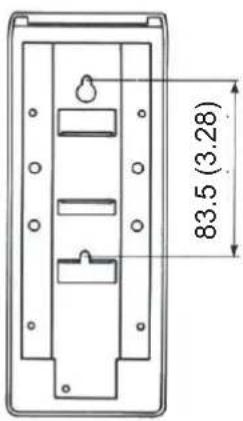
Unit: mm (inch)
7 Troubleshooting list
7-1 "No Action" on the transmitter or receiver after power has been applied.
START
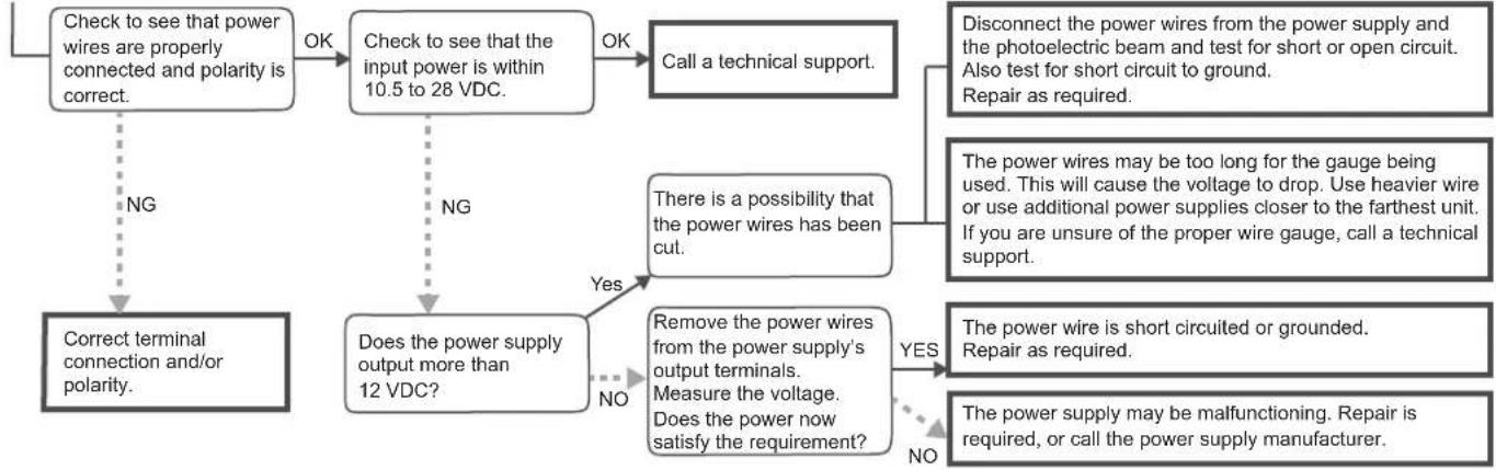
flowchart
graph TD
    A["Check to see that power wires are properly connected and polarity is correct."] -->|NG| B["Correct terminal connection and/or polarity."]
    A -->|OK| C["Check to see that the input power is within 10.5 to 28 VDC."]
    C -->|NG| D["Does the power supply output more than 12 VDC?"]
    C -->|OK| E["Call a technical support."]
    E --> F["Disconnect the power wires from the power supply and the photoelectric beam and test for short or open circuit. Also test for short circuit to ground. Repair as required."]
    E --> G["There is a possibility that the power wires has been cut."]
    G --> H["Remove the power wires from the power supply's output terminals. Measure the voltage. Does the power now satisfy the requirement?"]
    G --> I["Yes"]
    G --> J["No"]
    H --> K["The power wire is short circuited or grounded. Repair as required."]
    I --> L["The power supply may be malfunctioning. Repair is required, or call the power supply manufacturer."]
    J --> M["No"]
7-2 "No Action" on alarm zone even though the beams are completely blocked.
START
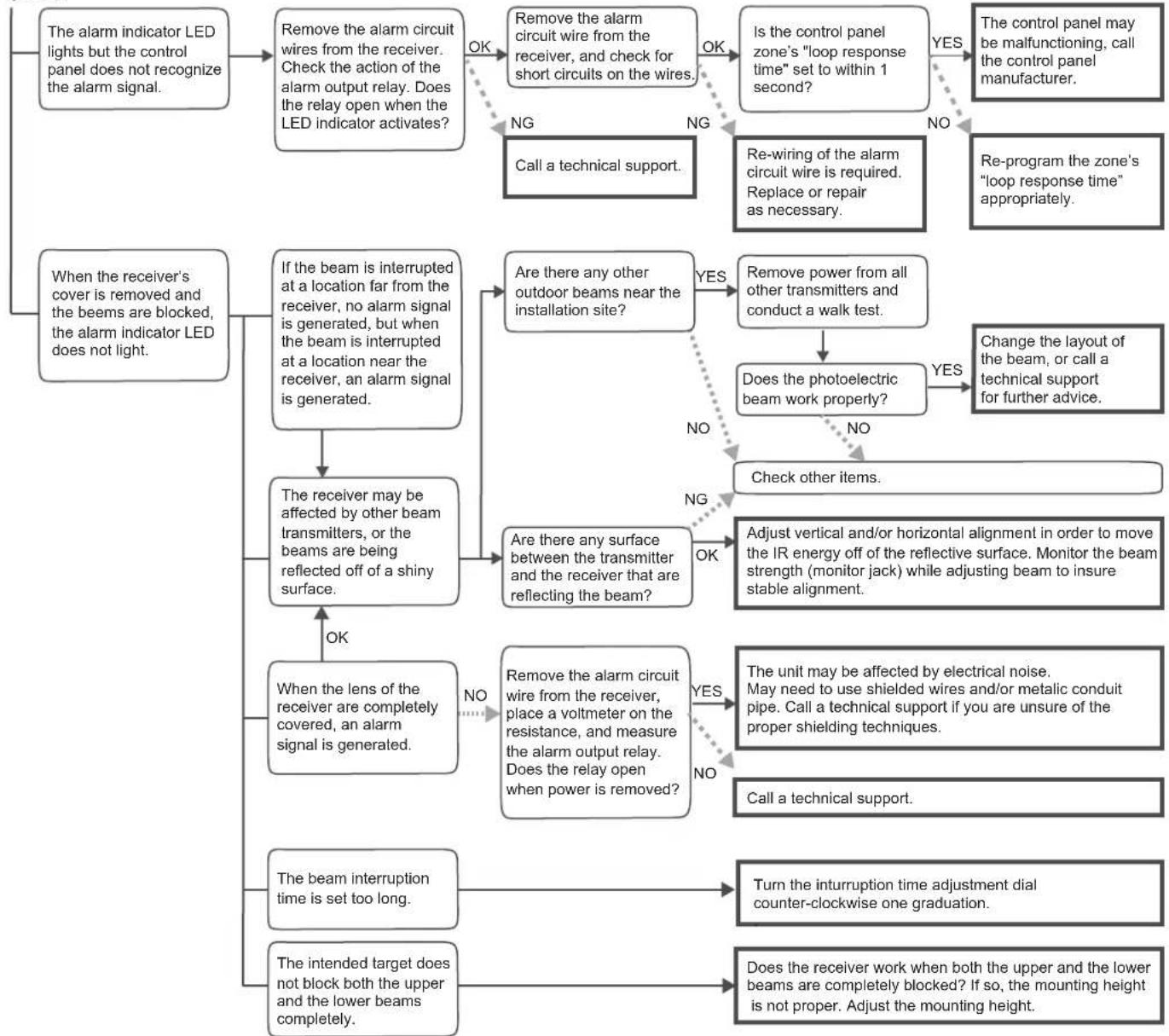
flowchart
graph TD
    A["The alarm indicator LED lights but the control panel does not recognize the alarm signal."] --> B["Remove the alarm circuit wires from the receiver. Check the action of the alarm output relay. Does the relay open when the LED indicator activates?"]
    B -->|OK| C["NG"]
    C --> D["NG"]
    D --> E["NG"]
    E --> F["NG"]
    F --> G["NG"]
    G --> H["NG"]
    H --> I["NG"]
    I --> J["NG"]
    J --> K["NG"]
    K --> L["NG"]
    L --> M["NG"]
    M --> N["NG"]
    N --> O["NG"]
    O --> P["NG"]
    P --> Q["NG"]
    Q --> R["NG"]
    R --> S["NG"]
    S --> T["NG"]
    T --> U["NG"]
    U --> V["NG"]
    V --> W["NG"]
    W --> X["NG"]
    X --> Y["NG"]
    Y --> Z["NG"]
    Z --> AA["NG"]
    AA --> AB["NG"]
    AB --> AC["NG"]
    AC --> AD["NG"]
    AD --> AE["NG"]
    AE --> AF["NG"]
    AF --> AG["NG"]
    AG --> AH["NG"]
    AH --> AI["NG"]
    AI --> AJ["NG"]
    AJ --> AK["NG"]
    AK --> AL["NG"]
    AL --> AM["NG"]
    AM --> AN["NG"]
    AN --> AO["NG"]
    AO --> AP["NG"]
    AP --> AQ["NG"]
    AQ --> AR["NG"]
    AR --> AS["NG"]
    AS --> AT["NG"]
    AT --> AU["NG"]
    AU --> AV["NG"]
    AV --> AW["NG"]
    AW --> AX["NG"]
    AX --> AY["NG"]
    AY --> AZ["NG"]
    AZ --> BA["NG"]
    BA --> BB["NG"]
    BB --> BC["NG"]
    BC --> BD["NG"]
    BD --> BE["NG"]
    BE --> BF["NG"]
    BF --> BG["NG"]
    BG --> BH["NG"]
    BH --> BI["NG"]
    BI --> BJ["NG"]
    BJ --> BK["NG"]
    BK --> BL["NG"]
    BL --> BM["NG"]
    BM --> BN["NG"]
    BN --> BO["NG"]
    BO --> BP["NG"]
    BP --> BQ["NG"]
    BQ --> BR["NG"]
    BR --> BS["NG"]
    BS --> BT["NG"]
    BT --> BU["NG"]
    BU --> BV["NG"]
    BV --> BW["NG"]
    BW --> BX["NG"]
    BX --> BY["NG"]
    BY --> BZ["NG"]
    BZ --> CA["NG"]
    CA --> CB["NG"]
    CB --> CC["NG"]
    CC --> CD["NG"]
    CD --> CE["NG"]
    CE --> CF["NG"]
    CF --> CG["NG"]
    CG --> CH["NG"]
    CH --> CI["NG"]
    CI --> CJ["NG"]
    CJ --> CK["NG"]
    CK --> CL["NG"]
    CL --> CM["NG"]
    CM --> CN["NG"]
    CN --> CO["NG"]
    CO --> CP["NG"]
    CP --> CQ["NG"]
    CQ --> CR["NG"]
    CR --> CS["NG"]
    CS --> CT["NG"]
    CT --> CU["NG"]
    CU --> CV["NG"]
    CV --> CW["NG"]
    CW --> CX["NG"]
    CX --> CY["NG"]
    CY --> CZ["NG"]
    CZ --> DA["NG"]
    DA --> DB["NG"]
    DB --> DC["NG"]
    DC --> DD["NG"]
    DD --> DE["NG"]
    DE --> DF["NG"]
    DF --> DG["NG"]
    DG --> DH["NG"]
    DH --> DI["NG"]
    DI --> DJ["NG"]
    DJ --> DK["NG"]
    DK --> DL["NG"]
    DL --> DJ
7-3 Alarm signal is being generated though beams are not blocked
START
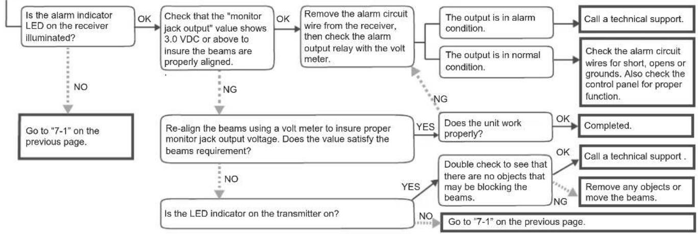
flowchart
graph TD
    A["Is the alarm indicator LED on the receiver illuminated?"] -->|NO| B["Go to "7-1" on the previous page."]
    A -->|OK| C["Check that the "monitor jack output" value shows 3.0 VDC or above to insure the beams are properly aligned."]
    C -->|NG| D["Re-align the beams using a volt meter to insure proper monitor jack output voltage. Does the value satisfy the beams requirement?"]
    C -->|OK| E["Remove the alarm circuit wire from the receiver, then check the alarm output relay with the volt meter."]
    E -->|NG| F["Does the unit work properly?"]
    E -->|NG| G["Does the output is in normal condition."]
    F --> H["Completed."]
    G --> I["Double check to see that there are no objects that may be blocking the beams."]
    I -->|NO| J["Remove any objects or move the beams."]
    I -->|NG| K["Go to "7-1" on the previous page."]
    H --> L["Call a technical support."]
    I --> M["Call a technical support."]
7-4 False activations
START
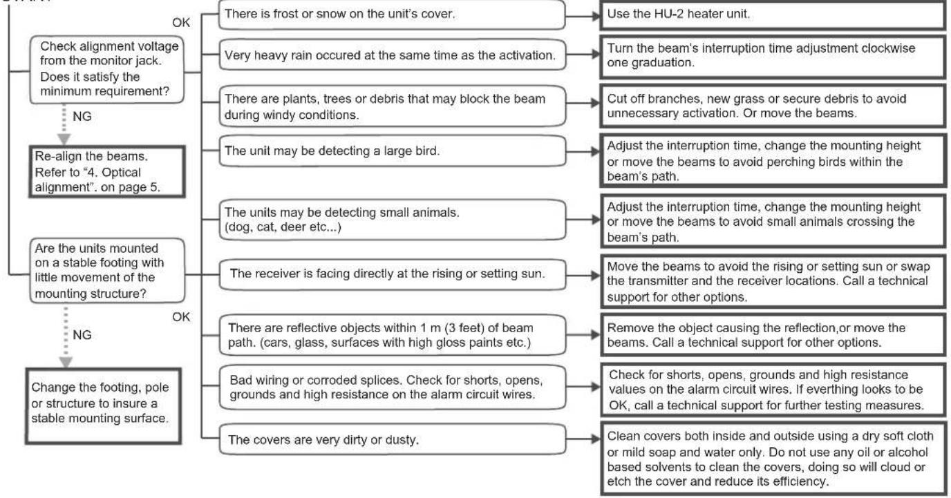
flowchart
graph TD
    A["Check alignment voltage from the monitor jack. Does it satisfy the minimum requirement?"] -->|NG| B["Re-align the beams. Refer to "4. Optical alignment". on page 5."]
    A -->|OK| C["Change the footing, pole or structure to insure a stable mounting surface."]
    B --> D["Are the units mounted on a stable footing with little movement of the mounting structure?"]
    D -->|NG| E["Change the footing, pole or structure to insure a stable mounting surface."]
    D -->|OK| F["There is frost or snow on the unit's cover."]
    F --> G["Use the HU-2 heater unit."]
    F --> H["Turn the beam's interruption time adjustment clockwise one graduation."]
    F --> I["Cut off branches, new grass or secure debris to avoid unnecessary activation. Or move the beams."]
    F --> J["Adjust the interruption time, change the mounting height or move the beams to avoid perching birds within the beam's path."]
    F --> K["Adjust the interruption time, change the mounting height or move the beams to avoid small animals crossing the beam's path."]
    F --> L["Move the beams to avoid the rising or setting sun or swap the transmitter and the receiver locations. Call a technical support for other options."]
    F --> M["Remove the object causing the reflection, or move the beams. Call a technical support for other options."]
    F --> N["Check for shorts, opens, grounds and high resistance values on the alarm circuit wires. If everything looks to be OK, call a technical support for further testing measures."]
    F --> O["Clean covers both inside and outside using a dry soft cloth or mild soap and water only. Do not use any oil or alcohol based solvents to clean the covers, doing so will cloud or etch the cover and reduce its efficiency."]
    F --> P["There are reflective objects within 1 m (3 feet) of beam path. (cars, glass, surfaces with high gloss paints etc.)"]
    P --> Q["Bad wiring or corroded splices. Check for shorts, opens, grounds and high resistance on the alarm circuit wires."]
    P --> R["The covers are very dirty or dusty."]
Important
The majority of false activations can be attributed to poor beam alignment.
When aligning the outdoor beams, accept the value of no less than the "EXCELLENT" value for the most stable and trouble free system.
Refer to the Installation Instructions for acceptable monitor jack voltage values.

Note;
This device is designed to detect moving objects and trigger alarms to the control panel.
It is only a part of the entire alarm system, and we do not bear the losses or consequences caused by invasions.
■ EU contact information
Manufacturer
OPTEX CO., LTD.
5-8-12 Ogoto, Otsu, Shiga, 520-0101 JAPAN
Authorized representative in Europe:
OPTEX (EUROPE) LTD.
/EMEA HEADQUARTERS
Marandaz House 1 Cordwallis Park.
Clivemont Road, Maidenhead, Berkshire,
SL67BU U.K.

OPTEX
OPTEX CO., LTD. (JAPAN)
URL: http://www.optex.net
OPTEX INC. (U.S.)
URL: http://www.optexamerica.com
OPTEX DO BRASIL LTDA. (Brazil)
URL: http://www.optex.net/br/es/sec
OPTEX (EUROPE) LTD. / EMEA HQ (U.K.)
URL: http://www.optex-europe.com
OPTEX TECHNOLOGIES B.V. (The Netherlands)
URL: http://www.optex.eu
OPTEX SECURITY SAS (France)
URL: http://www.optex-security.com
OPTEX SECURITY Sp.z o.o. (Poland)
URL: http://www.optex.com.pl
OPTEX PINNACLE INDIA, PVT., LTD. (India)
URL: http://www.optex.net/in/en/sec
OPTEX KOREA CO.,LTD. (Korea)
URL: http://www.optexkorea.com
OPTEX (DONGGUAN) CO.,LTD.
SHANGHAI OFFICE (China)
URL: http://www.optexchina.com
OPTEX (Thailand) CO., LTD. (Thailand)
URL: http://www.optex.net/th/th
Copyright (C) 2017 OPTEX CO.,LTD.
- FEATURES
- INTRODUCTION
- 1-2 PRECAUTIONS
- 1-3 PARTS IDENTIFICATION
- INSTALLATION
- 2-1 Normal installation
- Range/ height/ angle
- 2-2 Installing method
- Separating
- Mounting
- Wires and fixing
- Connecting
- Place the front cover
- 2-3 Terminal and wiring
- Receiver
- Transmitter
- Wiring distance
- Beam interruption time adjustment
- Optical alignment
- 4-1 Horizontal and vertical alignment
- 4-2 Check by alarm LED
- 4-3 Carry out check from monitor jack
- 4-4 Walk test
- Specifications
- Dimensions
- Troubleshooting list
- 7-1 "No Action" on the transmitter or receiver after power has been applied.
- 7-2 "No Action" on alarm zone even though the beams are completely blocked.
- 7-3 Alarm signal is being generated though beams are not blocked
- 7-4 False activations
- Important
- OPTEX
- OPTEX CO., LTD. (JAPAN)
Brand : OPTEX
Model : AX-330PLUS
Category : Detector