Futura FMD2 - Automotive VDL - Free user manual and instructions
Find the device manual for free Futura FMD2 VDL in PDF.


User questions about Futura FMD2 VDL
0 question about this device. Answer the ones you know or ask your own.
Ask a new question about this device
Download the instructions for your Automotive in PDF format for free! Find your manual Futura FMD2 - VDL and take your electronic device back in hand. On this page are published all the documents necessary for the use of your device. Futura FMD2 by VDL.
USER MANUAL Futura FMD2 VDL
natural_image
Line drawing of a device connected to a laptop via cable (no text or symbols present)WORKSHOP MANUAL
Futura FHD2/FMD2 E6
Main Group 0
1525 DD1020_01
Futura FHD2/FMD2 E6
Foreword
This workshop manual contains all the relevant information to help when tracing and solving technical problems, when making adjustments and when carrying out repair work.
The book contains diagrams, system descriptions, fault finding instructions and work instructions. It also contains safety regulations, which must be strictly observed.
Experienced mechanics
The technical information and the explanations of the repair work stated in this workshop manual have been compiled with the utmost care.
Whilst compiling this workshop manual, it has been assumed that the mechanic has the necessary experience and has had the required education or training to be able to carry out the work in a responsible and safe manner.
Vehicle type.
The information in this manual has been updated until the time of printing and only concerns the following vehicle series:
Futura FHD2/FMD2 E6
In this manual, this series of vehicles is referred to as:
"Futura FHD2/FMD2 E6".
Futura FHD2/FMD2 E6
0 General information
General information.... 1-1
Threaded connections 1-1
Locking compounds and sealants.... 1-7
Conversion tables 1-12
1 Safety regulations
General information.... 1-1
Warning symbols 1-1
General safety regulations.... 1-2
Safety regulations when carrying out work ..... 1-3
Liquid, lubricant and gas safety regulations.... 1-6
Safety regulations when jump starting.... 1-9
Avoiding the risk of fire.... 1-11
Safety regulations for welding work 1-12
After a collision.... 1-14
Wiring harnesses.... 1-15
Calibrating the tachograph.... 1-16
Xenon lighting 1-17
2 Diagnosis
Vehicle behaviour and performance...... 1-1
Introduction 1-1
Starting behaviour.... 1-2
Gear changing behaviour of a manual gearbox . 1-4
Abnormal tyre wear.... 1-7
Operation/warning/indication functions...... 1-14
Consumption.... 1-15
Exhaust smoke 1-18
Pulling force 1-19
Vibrations and abnormal noises.... 1-21
Systems 2-1
Introduction 2-1
CAN network.... 2-2
Clutch.... 2-7
Cooling system 2-10
Lubrication system.... 2-12
Intake and exhaust systems 2-13
Fuel system.... 2-15
Vehicle lighting.... 2-21
Disc brake construction.... 2-22
Steering mechanism 2-24
Components.... 3-1
Introduction 3-1
Engine.... 3-2
Driven axles 3-12
Axle mounting and suspension.... 3-13
Driver's seat.... 3-16
3 Repair guidelines
General information ....1-1
Technical documentation....1-1
Technical information 1-2
Environment 1-3
Cleanliness instructions....1-5
High-pressure hose 1-6
Tools....1-7
Work on the engine 1-8
Guidelines for a test drive and visual inspection .1-9
Components......2-1
General information....2-1
Plastic lines....2-2
Gaskets 2-5
Oil seals....2-6
Bearings 2-8
4 Liquid and lubricant guidelines
General guidelines ....1-1
General information....1-1
Alternative fuels....1-1
Biodiesel....1-2
Pure plant oil (PPO)....1-4
City diesel....1-4
AdBlue....1-5
5 Cleaning instructions
General information ....1-1
Cleaning the vehicle 1-2
Cleaning the engine....1-4
Cleaning the gearbox 1-5
Cleaning the interior of the vehicle .....1-6
Cleaning parts of the vehicle contaminated by liquids 1-7
6 Storage and preservation
Points of attention 1-1
Storage....1-1
Preparing for use....1-3
7 Paint treatment
Paint treatment 1-1
General instructions....1-1
Respraying/repairing conventional paint systems 1-3
Repairing the layer of zinc....1-5
Anticorrosion/antichip coating ....2-1
Anticorrosion coating 2-1
Antichip coating 2-2
Sealant seams....2-4
8 Instructions for jacking up and supporting the vehicle
Lifting, jacking up and supporting.... 1-1
General information 1-1
Wheel lifts 1-4
Central lifting columns.... 1-6
Placing axle supports under the frame ..... 1-8
Jacking up.... 1-11
Unconditional kneeling.... 1-13
Auxiliary tools for lifting the vehicle 1-14
Disclaimers
© 1525 VDL Bus & Coach bv, Valkenswaard, The Netherlands.
In the interest of continuous product development VDL Bus & Coach reserves the right to change specifications or products at any time without prior notice.
No part of this publication may be reproduced and/or published by printing, by photocopying, in digital format or in any way whatsoever without the prior consent in writing of VDL Bus & Coach.
This manual shall be governed by and applied in accordance with the laws of the Netherlands.
Any dispute here under shall be referred to the decision of the District Court of 's-Hertogenbosch in the Netherlands
Next remark is relevant if the text has been translated for your convenience from the English original into an other language.
A translation, however, can have the consequence that differences of interpretation arise with respect to the content and meaning of the text.
In all cases, therefore, the English version of this document will be regarded exclusively as the single and authentic source to establish the content and the meaning of the text in case of a dispute.
GENERAL INFORMATION
0
0
1. GENERAL INFORMATION
1.1 THREADED CONNECTIONS
1.1.1 DIPPED THREADED CONNECTIONS
The threaded connections on VDL Bus & Coach vehicles have been treated with a lubricant (dipped threaded connections). During manufacture, a wax dip is applied to galvanized nuts and bolts.
Black annealed and phosphated nuts and bolts are oil-dipped. The advantage of using a lubricant is that the friction created when tightening the threaded connections is reduced, so that the specified pretension can be more accurately and more easily obtained. The tightening torque can be reduced for the same pretension.
1.1.2 TORQUE
To achieve a small tolerance range for the pretension, it is necessary for the tightening torques of the dipped threaded connections to be accurately observed. Always use a torque spanner to accurately tighten the threaded connections to the correct torque.

Have torque spanners regularly checked and calibrated.
1.1.3 THREADED CONNECTIONS – GENERAL INFORMATION

Not observing the instructions given below may result in the bolt connections coming loose. This can cause damage to the vehicle and lead to a dangerous situation.
The following applies to all threaded connections (for both new and used vehicles):
- Standard connection: apply lubricant when fitting and tighten/retighten according to the standard for dipped bolts.
- Special connection: apply lubricant when fitting and tighten/retighten to the torque specified in the instructions.
- A lubricant must also be applied to new bolts taken from the warehouse. The highly variable coefficient of friction means that dry threaded connections are not permitted.
The following threaded connections are used on VDL Bus & Coach vehicles:
- Connections of strength classes 8.8 and 8.
0
- Flange nuts and flange bolts of strength classes 10.9 and 10.
- Flange nuts and flange bolts of strength classes 12.9 and 12.
- Clamping flange nuts and flange bolts of strength classes 12.9 and 12.
1.1.4 THREADED CONNECTION 10.9/10
As standard, a 10.9/10 threaded connection is tightened to a specified torque followed by an additional rotation. The additional rotation depends on the length of the bolt. See "Tightening torques" for the tightening torque and the appropriate additional rotation.
If one of these 10.9/10 threaded connections must be tightened to a different tightening torque, then this will be stated in the technical information for the component concerned.
1.1.5 OTHER THREADED CONNECTIONS
The 8.8/8 and 12.9/12 threaded connections and the 12.9/12 clamping flange bolt are usually only tightened to the standard tightening torques. See “Tightening torques” for the standard tightening torques.
If one of these threaded connections must be tightened to a different tightening torque, then this will be stated in the technical information for the component concerned.
1.1.6 REUSING FIXINGS (NUTS/BOLTS/THREADED ENDS)

Not observing the instructions given below may result in the bolt connections coming loose. This can cause damage to the vehicle and lead to a dangerous situation.
To obtain the correct pretension when reusing a threaded connection, the following procedure must be followed:
- Clean the thread (take particular care to remove any locking compound residue) and the fitting faces.
- Check the thread for damage.
To do so, screw on a new nut/bolt by hand.
If the new nut/bolt cannot be screwed along the entire length of the thread that is being checked, then the fixing may no longer be reused. - Apply one drop of engine oil to the first winding of the bolt (threaded end)/bottom winding of the nut and one drop to the fitting faces.
Comment
Only use engine oil as a lubricant for reused nuts and bolts. As a result of the differences in the coefficients of friction, lubricants other than engine oil or the factory applied grease must not be used under any circumstances.
- If a locking compound is specified, no oil should be applied to the thread. See "Locking compounds and sealants" for instructions on how to apply a locking compound.
- Tighten the connection to the specified torque.
1.1.7 NEW NUTS/BOLTS
If bolts do not visibly have lubricant applied to them, then lubricant must be applied to them.
To obtain the correct pretension when using new bolts, the following procedure must be followed:
- Apply one drop of engine oil to the first winding of the bolt/bottom winding of the nut and one drop to the fitting faces.
Comment
Only engine oil may be used as the lubricant to be applied. As a result of the differences in the coefficients of friction, lubricants other than engine oil or the factory applied grease must not be used under any circumstances.
- If a locking compound is specified, no oil should be applied to the thread. See "Locking compounds and sealants" for instructions on how to apply a locking compound.
- Tighten the connection to the specified torque.
0
1.1.8 TIGHTENING TORQUES FOR DIPPED THREADED CONNECTIONS
The tightening torques in the table below are the standard tightening torques and are only applicable to dipped threaded connections.
If one of these threaded connections must be tightened to a different tightening torque, then this will be stated in the technical information for the component concerned.
The quality is stamped on the nut or bolt, except on the clamping flange bolt.
The clamping flange bolt can be recognized by a groove between the hexagonal bolt head and the flange. Standard flange bolts do not have this groove.
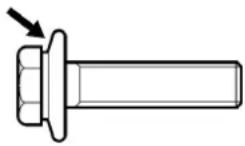
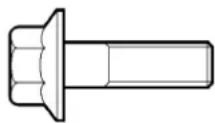
Clamping flange bolt Standard flange bolt
Overview of the standard tightening torques for flange bolts and nuts with strength class 10.9/10
| Thread indication Tightening torque (Nm) Additional rotation (approx. 10%) for bolt length L(mm) | |||||
| L ≤ 40 41-80 | 81-130 | 131-180 | |||
| M8 x 1.25 30 ± 2 30° 60° 90° 1 | 20° | ||||
| M9 x 1.25 35 ± 3 30° 60° 90° 1 | 20° | ||||
| M10 x 1.5 60 ± 4 45° 90° 120° | 150° | ||||
| M12 x 1.75 | 110 ± 8 | 30° | 60° | 90° | 120° |
| M12 x 1.25 | 110 ± 8 | 45° | 90° | 120° | 150° |
| M14 x 2 | 170 ± 15 | 30° | 60° | 90° | 120° |
| M14 x 1.25 | 170 ± 15 | 45° | 90° | 120° | 150° |
| M16 x 2 | 260 ± 20 | 30° | 60° | 90° | 120° |
| M16 x 1.5 | 260 ± 20 | 45° | 90° | 120° | 150° |
| M18 x 2.5 | 360 ± 30 | 30° | 60° | 90° | 120° |
| M18 x 1.5 | 360 ± 30 | 45° | 90° | 120° | 150° |
| M20 x 2.5 | 520 ± 40 | 30° | 60° | 90° | 120° |
| M20 x 1.5 | 520 ± 40 | 45° | 90° | 120° | 150° |
| M22 x 1.5 700 ± 50 45° 90° 12 | 0° 150° | ||||
Bolt length L is the length of the bolt between the head of the bolt and the nut.
If a component is secured using more than one bolt, all the bolts must first be tightened to the specified torque and then tightened further by the additional rotation.
Overview of standard tightening torques for fixings of strength class 8.8/8
| Thread indication Tightening torque (Nm) | |
| M4 x 0.7 2.8 ± 0.2 | |
| M5 x 0.8 5.5 ± 0.4 | |
| M6 x 1 9.6 ± 0.7 | |
| M8 x 1.25 23 ± 2 | |
| M10 x 1.5 46 ± 4 | |
| M12 x 1.75 79 ± 6 | |
| M12 x 1.25 87 ± 6 | |
| M14 x 2 125 ± 9 | |
| M14 x 1.5 135 ± 9 | |
| M16 x 2 195 ± 14 | |
| M16 x 1.5 210 ± 14 | |
| M18 x 2.5 213 ± 15 | |
| M18 x 1.5 315 ± 20 | |
| M20 x 2.5 298 ± 21 | |
| M20 x 1.5 440 ± 30 | |
| M22 x 2.5 540 ± 40 | |
| M22 x 1.5 590 ± 40 | |
| M24 x 3 680 ± 50 | |
| M24 x 2 740 ± 50 | |
| M27 x 3 1,000 ± 70 | |
| M27 x 2 1,100 ± 70 | |
| M30 x 3.5 1,350 ± 100 | |
Overview of standard tightening torques for fixings of strength class 12.9/12
| Thread indication Tightening torque (Nm) | |
| M8 32 ± 3 | |
| M10 67 ± 5 | |
| M12 113 ± 9 | |
| M14 178 ± 14 | |
| M16 274 ± 22 | |
| M18 385 ± 30 | |
| M20 550 ± 43 | |
| M22 740 ± 60 | |
| M24 925 ± 72 | |
| M27 1,370 ± 110 | |
0
Overview of the standard tightening torques for clamping flange nuts and bolts of strength class 12.9/12
| Thread indication Tightening torque (Nm) | |
| M12 x 1.25 178 ± 14 | |
| M14 x 1.5 274 ± 22 | |
| M16 x 1.5 425 ± 35 | |
| M18 x 1.5 550 ± 45 | |
| M18 x 2.5 500 ± 45 | |
Overview of the tightening torques for banjo bolts
| Thread indication Tightening torque (Nm) | |
| M6 8 ± 0.8 | |
| M8 15 ± 1.5 | |
| M10 30 ± 3 | |
| M12 40 ± 4 | |
| M14 50 ± 5 | |
| M16 60 ± 6 | |
| M18 70 ± 7 | |
Overview of the tightening torques for clamping ring cap nut connections for air lines
| Air line diameter Tightening torque (Nm) | |
| 8 mm 15 | |
| 10 mm 25 | |
1.2 LOCKING COMPOUNDS AND SEALANTS
1.2.1 LOCKING COMPOUNDS

Certain cleaning agents have a negative effect on the effectiveness of locking compounds. Therefore, the general rule is that after fixings and components have been cleaned with a cleaning agent, they must be treated with a cleaning liquid to ensure that the locking compound functions correctly.
| SUMMARY OF LOCKING COMPOUNDS | |||
| Product name Properties | Use Article number | ||
| Loctite 243 Locks with an average breaking strength.Can be unlocked using normal tools. | For locking threaded connections. | 40068197 | |
| Loctite 262 Locks with a high breaking strength.Difficult to unlock. | For locking threaded connections, such as pinion nuts. | 41279841 | |
| Loctite 638 Locks with a high breaking strength under a dynamic load.Difficult to unlock. | For locking cylindrical connections. | 40645557 | |
| Loctite 648 Locks with an average breaking strength.Withstands high temperatures. | For locking threaded connections in warm locations. | 41436842 | |
| Loctite 2701 Locks with a high breaking strength.Restores the fit in bearing houses.Seals to prevent leaks.Difficult to unlock. | For locking threaded connections, gear lever ball joints and expansion plugs. | 41340646 | |
0
Applying locking compounds
The following procedure must be followed when applying locking compounds to threaded connections:
- Clean both the internal and external thread.
Remove any grease from the thread using a suitable degreasing agent which leaves no residue that could reduce the effectiveness of the locking compound. - Depending on the diameter, apply one or more drops of locking compound to the thread. Never dip the bolt or stud into the locking compound.
- Apply a drop of oil under the bolt head. Locking compounds also reduce the frictional resistance, so that no oil has to be applied to the thread.
- Tighten the connection to the specified torque.
1.2.2 SEALANTS

Certain cleaning agents have a negative effect on the effectiveness of the sealant. Therefore, the general rule is that after fixings and components have been cleaned with a cleaning agent, they must be treated with a cleaning liquid to ensure that the sealant functions correctly.
| OVERVIEW OF SEALANTS | |||
| Product name Properties | Use Article number | ||
| Dirko D Withstands temperatures up to 180°C. Resistant to oil and coolant. | For sealing flush connections. | 41345014 | |
| Dow Corning 752 Withstands temperatures of -55°C to 220°C. Processing time of less than 15 minutes. Maximum drying time of 24 hours. Minimum sealing bead thickness of 4 mm. | Silicon sealant for sealing floor panels (feed-through connectors, etc.). | 40693628 | |
| Loctite 510 Withstands temperatures up to 200°C. Resistant to oil, brake fluid and coolant. | For sealing flush (flange) connections that are subjected to high operating temperatures, such as the flywheel housing. | 40697149 | |
| Loctite 518 Withstands temperatures up to 150°C. | For sealing differential and axle beam contact surfaces. | 41357034 | |
| Loctite 542 Seals small pipe | thread fittings of line systems.Contains nothing that can cause blockages in filters or valves.Maximum play of 0.25 mm. | Specially suitable for sealing hydraulic and pneumatic fittings. | 40697166 |
| Loctite 572 Seals against low pressures immediately after fitting. | Threaded connections 4029 | 2336 | |
| Loctite 574 Resistant to high pressures (up to 120 bar).Resistant to oil, brake fluid and coolant. | For sealing flush connections against high pressures. | 41246867 | |
| Loctite 5205 Surface sealant | specially intended for sealing aluminium components.Withstands temperatures up to 150°C.Resistant to water, coolant and oil. | For sealing aluminium components. | 41441339 |
| Loctite 5910 Silicon sealant, | resistant to oil.Withstands temperatures up to 200°C. | For sealing flush connections, such as the front and rear covers of gearboxes, the differential housing, hub caps, axle shaft flanges and the oil cooler. | 41663011 |
| Loctite Blue Withstands temperatures of 60°C to 260°C.Resistant to oil. | For sealing flexible constructions, such as (cylinder head) covers. | 41242895 | |
| Loctite From a gasket Hardens on contact with metal and when completely sealed. | For locking, securing and sealing. | 41322823 | |
| Loctite Ultra Copper Silicon sealant, resistant to oil.Withstands temperatures up to 350°C. | For sealing flush connections, such as hub caps. | 41284122 | |
| Loctite Ultra Grey Silicon sealant, resistant to coolant.Withstands temperatures up to 350°C. | For sealing (flush) connections in the cooling system. | 41284123 | |
1.2.3 OTHER PRODUCTS
| OVERVIEW OF SEALANTS | |||
| Product name Properties | Use Article number | ||
| Contact spray Cleaning product for cleaning and degreasing electronic and electrical connections. Dispels moisture and dirt from electrical contacts. | Cleaning electrical contact points. | 41387608 | |
| Copaslip Copper paste with excellent bonding properties that inhibits corrosion and withstands temperatures from 35°C to 1,100°C.Resistant to water, salts and acids.Prevents wear, oxidation, rust, corrosion and the seizure of metal surfaces. | For connections sensitive to oxidation or corrosion, such as battery terminals, exhaust connections, etc. | 41284344 | |
| Gleitmo 805 Protects untreated metal components against corrosion. | Components that have been installed with a close fit, such as wheel hub units. | 41443160 | |
| Loctite 401 Comment: | Drying time of a couple of seconds.Hardening time of 12 hours. | Fast-setting glue for gluing the rubber profile of a fixed window in a door. | 41246863 |
| Loctite 7063 Cleans and degreases.Highly inflammable.Non-corrosive. | For cleaning/degreasing materials that must be fitted with a locking compound. | 41322827 | |
| Loctite 7200 Gasket remover. For removing gaskets/gasket residue. | 41450211 | ||
| Loctite 7649 Locking glue activator. For installing the wheel speed sensor bus. | 41680227 | ||
| Molykote Longterm 2 PLUS | Lubricating grease, withstands temperatures from -30°C to +130°C. | Everywhere where lubrication grease is suitable and usual.For almost all ball bearings, roller bearings, friction bearings, guides, spline-shaft connections, threaded spindles and gear drives with a low rotational speed. | 41396271 |
| Molykote P37 Lubrication grease prevents corrosion which is resistant to temperatures up to 1,400°C. | For threaded connections that are subjected to high temperatures, such as for exhaust systems. | 41391619 |
| Molykote PG21 Lubrication grease which is water resistant and which prevents corrosion. | For the sealing rings of the MX engine cylinder lining. | 41738904 |
| Renolit HLT2 Lubrication grease (white). Disc brake adjustment mechanism. | 41448907 | |
| Staburags NBU 30 PTM Lubrication grease which is water resistant and prevents corrosion. | Wheel speed sensors. 41677646 | |
| Syntheso GL EP1 Lubrication grease (green). Disc brake rubber guides. 41448908 | ||
| Tectyl Protects hollow spaces against corrosion. | Can be used to protect metal objects. | 41343888 |
0
1.3 CONVERSION TABLES
Consumption
| km / l 1 / 100 km | miles/gallon | (Imp) | miles/gallon (US) |
| n 100/n n x 2.2825 | n x 2.352 | ||
| 100/n n 282.5/n | 235.2/n | ||
| n x 0.354 282.485 | n n n x 0.83 | ||
| n x 0.425 235.294 | n n x 1.202 n |
Specific use
| km / l 1 / 100 km | miles/gallon | (Imp) | miles/gallon (US) |
| n 100/n n x 2.2825 | n x 2.352 | ||
| 100/n n 282.5/n 235.2/n | |||
| n x 0.354 282.485 | n n n x 0.83 | ||
| n x 0.425 235.294 | n n x 1.202 n | ||
Speed
| cm/sec m/sec km/h feet/sec mile/h | ||||
| 1 0.01 | 0.036 | 0.03281 | 0.02237 | |
| 100 | 1 3.6 | 3.281 | 2.237 | |
| 27.78 | 0.2778 | 1 0.9113 | 0.6214 | |
| 30.48 | 0.3048 | 1.097 | 1 0.6818 | |
| 44.70 | 0.4470 | 1.609 | 1.467 | 1 |
Temperature
| n0Celsius = 9/5 n + 32 °F = 4/5 n0R= n + 273.15 K |
| n0Fahrenheit = 5/9 (n - 32) °C = 4/9 (n -32)0 R= 5/9 (n - 32) + 273.15 K |
| n0Réaumur = 5/4 n °C = 9/4 n + 32 °F = 5/4n + 273.15 K |
| n0Kelvin = n - 273.15 °C = 9/5 (n - 273.15) = 32 °F = 4/5 (n - 273.15) °R |
Weight units
| kg ounces | pounds (lbs) | short tons | (1) | long tons (1) | ton (metr.) |
| 1 | 35.27 | 2.205 | 0.001102 | 0.0009842 | 0.001 |
| 0.02835 | 1 | 0.0625 | 0.00003125 | 0.0000279 | 0.00002835 |
| 0.4536 16 1 | 0.0005 | 0.004464 | 0.004536 | ||
| 907.2 | 32000 | 2000 | 1 | 0.8929 | 0.9072 |
| 1016 | 35840 | 2240 | 1.12 | 1 | 1.016 |
| 1000 | 35274 | 2205 | 1.102 | 0.9842 | 1 |
(1) US + UK
Length units
| mm inches | feet yards m | km mile (stat.) | |||
| 1 0.03937 | 0.003281 0.00 | 1094 0.001 | 0.000001 0.0 | 000006214 | |
| 25.4 1 0.08 | 333 0.2777 | 0.0254 0.0000 | 254 0.00001 | 577 | |
| 304.8 12 1 | 0.3333 0.304 | 8 0.0003048 | 0.0001894 | ||
| 914.4 36 3 | 1 0.9144 0.00 | 09144 0.000 | 5682 | ||
| 1000 39.37 | 3.281 1.0936 | 1 0.001 | 0.0006214 | ||
| 1000000 | 39370 | 3281 1093.6 | 1000 1 0.62 | 14 | |
| 1609350 | 63360 | 5280 1760 | 1609 1.609 1 |
Surfaces
| mm^2 | cm^2 | square inches | square feet | square yards | m^2 |
| 1 | 0.01 | 0.00155 | 0.00001076 | 0.000001196 | 0.000001 |
| 100 | 1 | 0.155 | 0.001076 | 0.0001196 | 0.0001 |
| 645.2 | 6.452 | 1 | 0.006944 | 0.0007716 | 0.0006452 |
| 92900 | 929 | 144 | 1 | 0.1111 | 0.09290 |
| 836100 | 8361 | 1296 | 9 | 1 | 0.8361 |
| 1000000 | 10000 | 1550 | 10.76 | 1.196 | 1 |
Volume units
| cm^3 | US | dm^3 (liter) | |||
| cubic inches | pints quarts | gallons | (1) | ||
| 1 | 0.06102 | 0.002114 | 0.001057 | 0.0002642 | 0.001 |
| 16.39 | 1 | 0.03464 | 0.01732 | 0.004329 | 0.01639 |
| 473.2 | 28.874664 | 1 | 0.5 | 0.125 | 0.4732 |
| 946.4 | 57.75 | 2 | 1 | 0.25 | 0.9464 |
| 3785 | 231 | 8 | 4 | 1 | 3.785 |
| 1000 | 61.02 | 2.114 | 1.057 | 0.2642 | 1 |
(1) US gallon = 0.8327 Imp. gallon
| cm^3 | Imp. | dm^3 (liter) | |||
| cubic inches | pints quarts | gallons | (1) | ||
| 1 | 0.0610248 | 0.0017598 | 0.008799 | 0.000219975 | 0.001 |
| 16.387 | 1 | 0.02894 | 0.01447 | 0.003618 | 0.016387 |
| 568.2 | 34.67429136 | 1 | 0.5 | 0.125 | 0.5682 |
| 1136.49 | 69.319 | 2 | 1 | 0.25 | 1.13649 |
| 4545.95 | 277.274 | 8 | 4 | 1 | 4.54596 |
| 1000 | 61.0248 | 1.7598 | 0.8799 | 0.219975 | 1 |
(1) Imp. gallon = 1.201 US Gallons
Pressures
| Pa bar kg/cm | ^2 | Ibs/sq inch (psi) atm | ||
| 1 0.00001 0 | 0000101 0.00 | 0145 0.0000987 | ||
| 100000 1 1. | 0197162 14.50 | 00364 0.9868813 | ||
| 98066.5 0.9 | 80665 1 14.22 | 0.9678 | ||
| 6894.76 0.0 | 689476 0.0 | 70307 1 | 0.068046 | |
| 101322.3 | 1.013223 1.0332 | 14.70 1 | ||
| 133.32 | 0.0013332 | 0.0013595 | 0.01934 | 0.0013158 |
| 3386.23 0.0 | 338623 0.0 | 3453 0.4912 | 0.3342 | |
| 9797.82 0.0 | 979782 0.0 | 9991 1.421 | 0.09668 | |
| 248.89 | 0.0024889 | 0.002538 | 0.03609 | 0.002456 |
| Pa | Mercury at 15°C and g = 980.665 cm/sec ^2 | Water at 15°C and g = 980.665 cm/sec ^2 | ||
| mm | inches | m | inches | |
| 1 | 0.0075007 | 0.0002953 | 0.0001021 | 0.0040187 |
| 100000 | 750.06708 | 29.530981 | 10.207359 | 401.87015 |
| 98066.5 | 735.56454 | 28.96 | 10.01 | 0.9678 |
| 6894.76 | 51.715 | 2.036 | 0.7037 | 0.068046 |
| 101322.3 | 760 | 29.92 | 10.337 | 1 |
| 133.32 | 1 | 0.03937 | 0.01361 | 0.0013158 |
| 3386.23 | 25.40 | 1 | 0.3456 | 0.3342 |
| 9797.82 | 73.49 | 2.893 | 1 | 0.09668 |
| 248.89 | 1.867 | 0.07349 | 0.02540 | 0.002456 |
Energy
| Nm | mkg | ft.lbs. | kWh | pkh (metr.) | Hph | kcal |
| 1 | 0.1019716 | 0.7375607 | 0.0000002776 | 0.0000003776 | 0.0000003725 | 0.0002338882 |
| 9.80665 | 1 | 7.233 | 0.000002723 | 0.0000037037 | 0.000003653 | 0.002342 |
| 1.356259695 | 0.1383 | 1 | 0.0000003765 | 0.00000051206 | 0.000000505 | 0.0003238 |
| 3601001.88 | 367200 | 2656000 | 1 | 1.3599 | 1.341 | 860 |
| 2647795.5 | 270000 | 1952900 | 0.7353 | 1 | 0.9863 | 632.4 |
| 2684570.4375 | 273750 | 1980000 | 0.7455 | 1.0139 | 1 | 641.1 |
| 4187.43955 | 427 | 3088 | 0.001163 | 0.001581 | 0.00156 | 1 |
Power
| kw | pk (metr.) | mkg/sec | kcal/sec | HP | lbs/sec |
| 1 | 1.36 | 102 | 0.2389 | 1.341 | 737.7 |
| 0.7353 | 1 | 75 | 0.1757 | 0.9863 | 542.5 |
| 0.009804 | 0.01333 | 1 | 0.002342 | 0.01315 | 7.233 |
| 4.186 | 5.693 | 427 | 1 | 5.615 | 3088 |
| 0.7455 | 1.014 | 76.04 | 0.1781 | 1 | 550 |
| 0.001355 | 0.00184 | 0.1383 | 0.0003238 | 0.00182 | 1 |
SAFETY REGULATIONS
1
1. GENERAL INFORMATION
1.1 WARNING SYMBOLS

This symbol gives useful tips to simplify the work.

This symbol indicates a situation which requires extra attention.

This symbol indicates a situation which may result in damage to the vehicle.

This symbol indicates a situation which may result in personal injury.

This symbol indicates a situation which may result in damage to the environment.
Not observing the safety regulations and warnings may place the health and safety of the mechanic at risk. It may also cause serious damage to the vehicle or may even create a dangerous situation.
1.2 GENERAL SAFETY REGULATIONS
Not observing the safety regulations and warnings may place the health and safety of the mechanic at risk. It may also cause serious damage to the vehicle or may even create a dangerous situation.
General safety regulations
– Always observe the local laws and regulations that are intended to prevent accidents, injuries and damage.
- Observe all the warnings and safety instructions given in the instructions. Also see the "Component/system-related safety regulations" document.
- Always observe warnings and instructions given on labels and stickers that are fitted to the various components. Do not ignore them. They are there to ensure your health and safety!
– Work may only be carried out by the staff of VDL BUS & Coach dealers and workshops who have received sufficient training concerning these systems.
- Wear clean, well fitting clothes and, if necessary, apply protective cream to unprotected parts of your body. Long hair must be tied back or placed in a hairnet. Do not wear jewellery when carrying out work.
- Use approved ear protection when the noise level exceeds 80 dB(A) (the noise regulations may vary per country) for a long period of time and when there are loud noises for a short period of time.
- Work with reliable tools. Only use tools for their intended use. Regularly check and maintain tools.
- Some plastics, which may be used as sealing rings, may leave hazardous residues after a fire. Wear protective, acid-resistant clothing and PVC gloves when removing such fire residues.
Submerge such fire residues in or sprinkle them amply with a calcium hydroxide solution (slaked lime and water). Thoroughly clean the protective clothing after use and treat the gloves as chemical waste.
– Always disconnect the earth connection from a vehicle that has been damaged in a collision when it is in the workshop. This will prevent the risk of fire due to a short circuit in the wiring.
- Always read the safety instructions before replacing the clutch plate, the brake lining or the brake pads.
1.3 SAFETY REGULATIONS WHEN CARRYING OUT WORK

Not observing the safety regulations and warnings may place the health and safety of the mechanic at risk.
It may also cause serious damage to the vehicle or may even create a dangerous situation.
– Always observe the instructions and regulations given in the VDL Bus & Coach workshop documentation.
- Remain a safe distance from rotating and/or moving components.
- Make sure there is good ventilation or extraction equipment when carrying out work where vapours and/or gases are released.
- Always protect the vehicle from rolling away by applying the parking brake and, for example, placing chocks in front of and behind the wheels.
- Always use hoisting sheers when working under the vehicle.
- Be careful when working on tensioned springs, such as those in spring brake cylinders, valves, etc. Accidentally released springs may cause a serious injury. Small springs and circlips may also cause injury when accidentally released (wear goggles).
- The earth cable must always be removed from the battery when carrying out work that does not require the vehicle to have an electrical power source.
- In order to prevent people from starting the engine when work is being carried out on the vehicle, always disconnect the battery's earth connection. Place a sign that reads "DO NOT OPERATE" on the dashboard.

To prevent damage to electrical components, never disconnect the battery terminal clamps whilst the engine is running.
Turn off the contact switch and the main switch before disconnecting the connection between the battery terminal and the negative pole. Wait at least 80 seconds after turning off the contact switch before disconnecting the connection between the battery terminal clamp and the negative pole. If the connection is disconnected too quickly, the AdBlue lines may become blocked.
- Do not place tools or other materials on or near the batteries. This could short-circuit the battery or may even cause the battery to explode.
- Do not leave tools unattended on or in the vehicle.
-
Always wear protective gloves when working on components that must be heated.
-
Always use a tyre cage when fitting and inflating tyres.
Thoroughly clean tyres prior to balancing. Only use a balancing device which has a protective cover. - Always use the appropriate lifting gear (gearbox jack) or approved hoisting equipment when removing or installing heavy components. Attach the component securely to the lifting gear or hoisting equipment. The hoisting equipment must be checked before use.
- If possible, soundly support components.
- Be extremely careful when working on systems which may be pressurized, such as the fuel system, cooling system, brake system, steering gear, etc. If possible, depressurize the system before starting the work.
Be aware of a residual pressure and unscrew the connection a couple of turns to allow any residual pressure to escape before removing the connection.
- Avoid inhaling dust from the clutch plate or the brake lining. Always make sure there is good dust extraction when working on these components.
- When using lifting columns, check whether they are suitable for the vehicle's wheel size. Refer to the manufacturer's instruction manual for instructions on how to use lifting columns and for any safety instructions. If necessary, use wheel adaptors to prevent damage to the wheel bolts.

Place the vehicle in the unconditional kneeling position before raising the vehicle.
This will cause the pneumatic suspension system to be turned off.
- When charging the batteries, make sure there is good ventilation and avoid sparks or a naked flame.
Only use a quick-charger in the event of extreme urgency. The positive and negative cables must be disconnected from the battery when using a quick-charger.
– Work on the air conditioning unit may only be carried out by a company that is authorized to carry out such work.
Intake and exhaust systems
- There is a risk of being burnt, because a number of components, such as the exhaust pipe and the catalytic converter, are hot when the engine is running (or has been running). It can take some time for the hot components to cool down.
- A silencer with an integrated catalytic converter remains hot for longer than a silencer without a catalytic converter.
– Dust and materials that are released from a silencer when, for example, removing a silencer are harmful and must not be inhaled.
– The ceramic element of a silencer with a catalytic converter has a highly poisonous coating.
- It is not permitted to avoid using the exhaust gas after-treatment system or to strip it of components. It is also not permitted to use a urea solution (AdBlue) that does not meet the required specifications or to use the vehicle or the device without a urea solution (AdBlue).
SCR unit
- The SCR unit contains vanadium pentoxide (see DNX (Denox catalyst) "Safety data sheet").

See the product's safety data sheet for the properties, risks and safety information.
The SCR unit must be removed and disposed of in accordance with Directive 91/689/EEC-160802 and the local, regional and national legislation.
Always wear gloves and safety goggles when working on the SCR unit.
It is not permitted to open the SCR unit!
1.4 LIQUID, LUBRICANT AND GAS SAFETY REGULATIONS
– Always observe the safety information issued by VDL Bus & Coach and the suppliers.
- Various types of oil and other lubricants used on the vehicle can harm your health.
This also applies to coolant, screenwash fluid, AdBlue, coolant in air conditioning systems, battery acid and clutch fluid.
Therefore, avoid internal and external bodily contact with these liquids. Make sure there is good ventilation when these substances are being used.
– Pay attention when changing the oil. Hot oil may cause a serious injury.
- Avoid unnecessary contact with drained oil. Frequent contact causes skin damage.
– Hydraulic fluid is aggressive. Therefore, avoid hydraulic fluid from coming into contact with the vehicle.
- Make sure there is good extraction of harmful fumes from the work area.
- Make sure that ignition sources cannot come into contact with inflammable or explosive liquids and gases. If possible, keep these substances fully protected.
Diesel
– Diesel fuel is toxic and may, therefore, have a damaging effect on your health.
Therefore, avoid internal and external bodily contact with these liquids.
- Diesel is an extremely flammable liquid. It must not be exposed to a naked flame nor be brought into contact with hot components. The diesel fumes remaining in an empty fuel tank form an extremely explosive mixture.
AdBlue

See the AdBlue safety data sheet for the properties, risks and safety information. Always wear gloves and safety goggles when working on the AdBlue unit/exhaust gas after-treatment system.
- AdBlue is non-inflammable. If AdBlue is exposed to high temperatures, the solution breaks down into ammonia and carbon dioxide.
- Although AdBlue is not poisonous and not harmful to the environment, collect AdBlue separately.
-
Avoid AdBlue coming into contact with painted components. Spilt AdBlue can be easily removed with water. If AdBlue dries, it leaves a white film, which can be removed with water.
-
AdBlue corrodes metals, such as copper and aluminium. Alloys, such as brass, can also be damaged.
- If AdBlue comes into contact with the electrical installation (wiring harnesses and contacts), then the components concerned must be replaced.
- Do not allow AdBlue to come into contact with other chemicals.
- Carefully check the AdBlue lines for leaks.
Avoid bodily contact with AdBlue.
– In the event of skin contact: rinse with plenty of water.
– In the event of contact with the eyes: rinse with plenty of water for at least 15 minutes and seek medical assistance.
- If swallowed: rinse your mouth with plenty of water. Do not induce vomiting. Seek medical assistance.
– In the event of inhalation: get some fresh air and take a rest. Seek medical assistance.
- When adding AdBlue, the Webasto and the engine must be turned off and the main switch must be turned to the off position.
- If the AdBlue cap is opened at a high exterior temperature, then it is possible that ammonia fumes may escape. Ammonia has a strong, irritating smell and affects the eyes, skin and mucous membrane.
Therefore, turn your face away when removing the cap from the tank. - Refuelling with liquids other than AdBlue can cause problems with the exhaust gas after-treatment system and may cause the OBD symbol on the dashboard to light up.
- Make sure there is good ventilation or extraction when working with AdBlue.
Exhaust gases
- Make sure the exhaust fumes are properly extracted.
Exhaust gases contain carbon monoxide. Carbon monoxide is a deadly, colourless and odourless gas which, when inhaled, deprives the body of oxygen, leading to asphyxiation. Serious carbon monoxide poisoning can result in brain damage or even death.
- Do not allow the engine to run in a confined or unventilated space.
Batteries

Always charge batteries in a properly ventilated area and avoid sparks and naked flames. Always switch off the battery charger before disconnecting the cables. A quick-charger should only be used if absolutely necessary. Disconnect the battery cables when quick-charging.

Wear protective clothing, gloves and a mask when carrying out work where it is possible to come into contact with battery acid.

Battery acid is an aggressive liquid. In the event of skin contact: wash the affected area thoroughly with plenty of water. Contact a doctor if the affected area remains red or painful. Remove affected clothing and rinse with water. In the event of eye contact: wash for at least 15 minutes with plenty of water and contact a doctor. If swallowed: DO NOT induce vomiting, rinse your mouth, drink two glasses of water and contact a doctor. If inhaled: get some fresh air, take a rest and contact a doctor.
- To prevent damage to electronic components, never disconnect the battery terminal clamps when the engine is running.
- Always charge batteries in a properly ventilated area and avoid sparks and naked flames. An explosive gas mixture may be released when charging batteries.
1.5 SAFETY REGULATIONS WHEN JUMP STARTING

Both systems must have the same battery voltage (24 V).

Use thick start cables (at least 25 mm ^4 ) with insulated clamps.

Jump starting may only be performed with the aid of batteries. An auxiliary starting device may provide a voltage which is too large and this may cause damage to the vehicle's electrical system.

Never start the vehicle using a quick-charging device. The high voltage levels may damage the electrical components.

Prevent both vehicles from touching each other.

If the vehicle is started using separate batteries (approximately 24 V) or with the aid of another vehicle with a running engine (approximately 28 V), then the battery cables must not be disconnected.

When the battery has been fully discharged, it is important not to immediately remove the NATO plug/start cables once the engine is running. To prevent damage to the electrical system as a result of voltage peaks, the engine must have been running for at least 5 minutes before the start cables are removed.

It is permitted to start the vehicle by means of separate auxiliary batteries (approx. 24 Volt) or by means of another vehicle with a running engine (approx. 28 Volt). The battery cables must not be removed.
To prevent damage to the electrical system, it is not permitted to use a voltage greater than 28 V.

After starting the vehicle with the aid of auxiliary batteries, turn on as many energy consumers as possible in order to avoid a load dump when the start cables are removed.
If another vehicle is used to start the vehicle, turn on as many energy consumers on this vehicle as possible before the cables are removed.
1.6 AVOIDING THE RISK OF FIRE
- Make sure that ignition sources cannot come into contact with inflammable or explosive liquids and gases. If possible, keep these substances fully protected.
- Check the fuel lines for leaks and repair any leaks immediately.
Follow the instructions given below when installing steel fuel lines.
- Fit the fuel line so that it is free of tension.
- It is not permitted to bend pre-shaped fuel lines.
- Always refit a banjo bolt which has been removed from a fuel line using new sealing rings and tighten the banjo bolt to the specified torque.
- Check the connection for fuel leaks after tightening.
– Carelessly fitting steel fuel lines may result in a fuel leak, which creates a fire hazard.
- In the event of fuel and/or oil leaks or spillages, the engine encapsulation must be thoroughly cleaned. First, apply a degreasing agent to the encapsulation material. Then, wash down the encapsulation with a steam cleaner or a high-pressure hose.
- To avoid damage to the engine encapsulation when spraying it, maintain a minimum distance of 50~cm between the engine encapsulation and the sprayer nozzle.
– Clean the engine compartment, and in particular the encapsulation, at regular intervals by removing flammable material such as dead leaves and sawdust.
- Do not leave cleaning rags or similar materials in the engine compartment.
– Repair leaks in the exhaust system immediately. Badly corroded exhaust components should be replaced before they fail.
– Always remember to refit heat shields after removal.
- Never replace a defective fuse by a fuse of a higher rating or a bridge.
- When replacing the wiring, always use wiring with the same diameter.
– Always fuse connected accessories.
- Check wiring which is not protected by a fuse (battery cables, etc.) to make sure that it is undamaged and properly attached and positioned.
- Cover inflammable materials during welding and grinding. Welding splashes and grinding sparks can ignite materials and cause the fast dispersion of fire.
- Always remove inflammable, conductive materials and dust from the exhaust system.
– During spraying, damage repair and repair work, make sure no paint, varnish of other inflammable materials are applied to the exhaust system and the heat shields.
1.7 SAFETY REGULATIONS FOR WELDING WORK
1

It is not permitted to carry out welding work on the vehicle without special written permission from VDL Bus & Coach,
Failure to observe the welding regulations may cause serious damage to the chassis.

Failure to observe the instructions below may damage the electronic components.
General information
– Before starting any welding work on the bodywork or chassis frame, both the negative cable and the positive cable must first be disconnected from the batteries.
- Disconnect the connectors for the central electrical box, the generators, the electrical components, the electronic units, the CMU, the ECU, the IOU, the ABS unit, the dashboard and the ECM.
- Attach the welding set's earth clamp as close as possible to the area on the vehicle where the welding work is to be carried out and ensure that it makes good contact with the area being welded.
- Never attach the earth clamp to vehicle components, such as the engine, axles, springs, etc. Arcing on these components is also not permitted. Failure to observe these instructions may result in serious damage to bearings, springs, etc.
- The accessory or contact position of the contact lock/contact switch/main switch must not be turned on. Remove the key from the contact lock.
- Cover inflammable materials during welding and grinding. Welding splashes and grinding sparks can ignite materials and cause the fast dispersion of fire.
- Protect plastic lines, rubber components, wiring harnesses, operating cables, plastic components, piston rods of hydraulic cylinders, air bellows and springs (in particular, parabolic springs) against welding splashes. These components must not be exposed to temperatures greater than 70^ .
- After welding, apply a primer and paint to the welded areas and repair any paint damage.
Also pay attention to any paint damage on the underside of the welded area.
Welding work on the chassis
- When performing welding work on the vehicle, disconnect the connectors from all the electronic devices (including the sensors and actuators) if they are located within a distance of 1 metre from the welding point and within a distance of 1 metre from the earth clamp.
- Disconnect the battery clamps if they are located within a distance of 1 metre from the welding point or the earth clamp.
- If the battery clamps must be disconnected, all the electronic units assembled on the chassis must also be disconnected.
Welding work on the bodywork
– Follow the guidelines given in “Welding work on the chassis”. Also follow any special welding instructions given for performing welding work on the bodywork.
Comment
Protect plastic lines, wiring harnesses, operating cables, plastic components, air bellows and springs (in particular, parabolic springs) against welding splashes. These components must not be exposed to temperatures greater than 70^ C.
Stainless steel must not come into contact with other types of steel or materials which contain carbon. Therefore, use separate grinding discs, drills, etc. for stainless steel. Only grinding discs with an aluminium oxide or resin base may be used for stainless steel.
Steel brushes should be made of stainless steel.
1.8 AFTER A COLLISION
1.8.1 CHECKING THE SEATS AFTER A COLLISION
- Check the seat's attachment for cracks and fractures.
- Check whether the seat's attachment bolts have been overstressed. If in doubt, replace them.
- If the seat belts have been subjected to a heavy load during a collision, the entire mechanism must be replaced, even if no damage is visible.
1.8.2 CHECKING THE STEERING MECHANISM AFTER A COLLISION
The steering mechanism is one of the most safety critical components in a vehicle. Therefore, always treat the steering mechanism with care during repair work.
- The steering box must be either inspected by VDL Bus & Coach or replaced if there has been a collision which (may have) affected the steering box or other parts of the steering mechanism. This also applies if no external damage can be observed. The steering box may have suffered internal damage from the collision, making it unreliable.
The other steering mechanism components which may have been affected, such as the steering rods, track rods, steering arms, track rod arms, steering bracket, pitman arm and the attachment of components should be checked for deformation, cracks, fractures, etc.
- If possible, the affected components should be magnafluxed.
– Always replace damaged components. Do not take any risks. Always replace the components when in doubt. - It is not permitted to weld parts of the steering mechanism or the front axle beam.
- It is not permitted to straighten parts of the steering mechanism or the front axle beam.
1.9 WIRING HARNESSES
- After a wiring harness has been removed or replaced, it must be refitted and secured in the same position as it was before it was removed.
- Make sure the joins are watertight. Never remove sealing washers from connectors. Fit the connectors in the correct manner.
- Good earth connections are essential. There must be no paint or oxidation between the contact surfaces. Apply a conductive grease, such as "Coranode" or a similar product, before assembly. Tighten the attachment bolt securely.
- To prevent poor connections, the pins of connectors must always be installed and removed using special tools.
1.10 CALIBRATING THE TACHOGRAPH
- A roller test stand can be used to calibrate the tachograph (for example, after changing the type of tyres used on the vehicle).
- If the vehicle is equipped with ASR, this system will interpret the rotating rear wheels and the stationary front wheels as the rear wheels spinning. Since a reduction in acceleration is not applicable in this instance, the system will try to neutralize this spinning by braking the rear wheels. The result is that the vehicle will be thrown from the roller test stand. This is dangerous.
To prevent this from happening, the fuses for the EBS system must be removed, so that the EBS system is deactivated. However, this will be seen as an error by the system and will be registered in the memory. These errors must be reset with the aid of the diagnosis equipment after the calibration.
1.11 XENON LIGHTING
- The connection cable between the headlight and the ballast electronics carries a high voltage current and may not be disconnected.
- Disconnect the power supply to the headlights before changing the light bulbs.
- Never touch the fitting.
- Never turn on the ballast electronics without a bulb being fitted. This will lead to a voltage surge to the fitting.
- Wear safety glasses and safety gloves.
- The light is pressurized (risk of breaking).
- Never touch the light bulb's glass.
- If a xenon light breaks in an enclosed room (workshop), the room must be evacuated and ventilated for at least 20 minutes in order to avoid health risks caused by the gases.
- The light bulb which is replaced must be treated as hazardous waste.
- Only use light bulbs from the same manufacturer.
• After changing a light bulb, check the setting of the headlights.
DIAGNOSIS
2
1. VEHICLE BEHAVIOUR AND PERFORMANCE
1.1 INTRODUCTION
General information
The diagnosis information is intended to help you trace problems.
Possible causes of symptoms that are not detected by an electronic unit are given in the fault finding tables.
Faults that can be detected by an electronic unit can be read as an error code with the aid of diagnosis equipment.
Every possible cause of a “complaint by the driver” leads you to a solution and the repair work that it involves.
As shown in the diagram, the diagnosis information is divided into three separate sections. Besides this section, there are also sections for:
• Diagnosis, "Components"
- Diagnosis, "Systems"
In “Vehicle behaviour and performance”, the driver’s complaint is reduced to the possible causes. These possible causes lead to solutions or a link to one of the other fault finding tables in the Diagnosis “Systems” or “Components” sections.
Together, the three sections contain all the available fault finding tables.
1.2 STARTING BEHAVIOUR
1.2.1 THE STARTER MOTOR DOES NOT WORK
General information
- Is this symptom the result of a technical fault?
- External factors or improper use can also lead to this fault.
- It is important to get the correct image of the complaint by asking the customer or the driver for as much information as possible.
Question:
- Was the transmission in gear?
- Was an attempt made to start the vehicle immediately after the engine was turned off?
- Was an attempt made to start the engine immediately after an unsuccessful attempt was made to start the engine?
- Can the driver or the customer reproduce the fault?
Discuss the results with the customer or the driver.
| Possible cause Remedy | |
| Low battery voltage. Check the battery voltage. | |
| Fault in the electronic system. Check the symptom with the aid of the diagnosis equipment. | |
| Fault in the starter motor's electrical circuit. Check the starter motor's electrical circuit. | |
| The starter motor is faulty. Check the starter motor. | |
| The neutral gear is faulty. Check the neutral gear. |
1.2.2 THE STARTER MOTOR TURNS THE ENGINE OVER TOO SLOWLY
| Possible cause Remedy | |
| Low battery voltage. Check the battery voltage. | |
| Poor earth connection Check the earth connections. | |
| The starter motor is faulty. Check the starter motor. |
1.2.3 THE ENGINE IS DIFFICULT TO START
The starter motor turns the engine over, but it takes a long time before the engine is running correctly.
| Possible cause Remedy | |
| Fault in the electronic system. Check the symptom with the aid of the diagnosis equipment. | |
| Fault in the fuel system. See the fault finding table: “Engine is difficult to start, Fuel system, PR engine” 2 - 2.7.7 The engine is difficult to start (☐2 - 17). | |
| The compression pressure is too low. Check the compression pressure. | |
1.2.4 THE ENGINE TURNS OVER BUT DOES NOT START
The starter motor turns the engine over, but the engine does not start.
| Possible cause Remedy | |
| Fault in the electronic system. Check the symptom with the aid of the diagnosis equipment. | |
| There is air in the fuel system. Check whether the fuel system draws in air. | |
| The fuel filter is blocked. Replace the fuel filter. | |
| The fuel pressure in the low-pressure fuel system is too low. | Check the fuel pressure in the low-pressure fuel system. |
| The pressure relief valve remains open. Check the fuel pressure in the gallery. | |
| The fuel supply pump's delivery is too small. Check the fuel supply pump. | |
| Poor fuel quality. Flush the fuel system. | |
| The compression pressure is too low. Check the compression pressure. | |
1.2.5 THE ENGINE STARTS, RUNS AND THEN STALLS
| Possible cause Remedy | |
| Fault in the electronic system. Check the symptom with the aid of the diagnosis equipment. | |
| There is air in the fuel system. Check whether the fuel system draws in air. | |
| The fuel filter is blocked. Replace the fuel filter. | |
| The pressure relief valve remains open. Check the fuel pressure in the gallery. | |
| The fuel supply pump's delivery is too small. Check the fuel supply pump. | |
| Poor fuel quality. Flush the fuel system. | |
1.3 GEAR CHANGING BEHAVIOUR OF A MANUAL GEARBOX
1.3.1 IT IS DIFFICULT TO CHANGE GEAR
General information
- Is this symptom the result of a technical fault?
-
External factors or improper use can also lead to this fault.
-
The gears can be difficult to change when changing down gears in too large steps.
- The gears can be difficult to change if the viscosity of the gearbox oil is too high due to a low ambient temperature.
| Possible cause Remedy | |
| The gearbox oil level is too low. Check the gearbox's oil level. | |
| There is oil which has the wrong specifications in the gearbox. | Change the gearbox oil. |
| There is a fault in the mechanical gearbox mechanism. See the fault finding table below: “Faulty mechanical gearbox mechanism (1)”. | |
| The clutch is not released correctly. Check whether the clutch is released. | |
| There is a mechanical fault in the gearbox. See the fault finding table below: “Faulty mechanical gearbox mechanism (2)”. | |
| There is a fault in the Servoshift unit. Check the operation of the Servoshift unit. | |
| Faulty mechanical gearbox mechanism (1) | |
| Possible cause Remedy | |
| The gearbox mechanism’s rotating and hinged points are dry or they knock. | Check all of the gearbox mechanism’s rotating and hinged points for excessive play and/or sufficient lubrication. |
| The gearbox mechanism is not configured correctly. Check the gearbox mechanism’s configuration. | |
| Faulty mechanical gearbox mechanism (2) | |
| Possible cause Remedy | |
| The gearbox’s external transfer box is not correctly adjusted. | Check the setting of the external transfer box on the gearbox. |
| The holding element is faulty. Check the gearbox’s holding element. | |
| The wrong type of holding element has been fitted in the gearbox housing. | Check the gearbox’s holding element (spring). |
1.3.2 GEARS CANNOT BE SELECTED
| Possible cause Remedy | |
| There is a fault in the mechanical gearbox mechanism. See the fault finding table below: “Gears cannot be selected (1)”. | |
| There is a mechanical fault in the gearbox. See the fault finding table below: “Gears cannot be selected (2)”. | |
| Gears cannot be selected (1) | |
| Possible cause Remedy | |
| The gearbox mechanism’s rotating and hinged points are dry or they knock. | Check all of the gearbox mechanism’s rotating and hinged points for excessive play and/or sufficient lubrication. |
| The gearbox mechanism is not configured correctly. Check the gearbox mechanism’s configuration. | |
| There is too much play in the silent block in the selector rod. | Check the selector rod’s silent block for play. |
| Gears cannot be selected (2) | |
| Possible cause Remedy | |
| The gearbox's external transfer box is not correctly adjusted. | Check the setting of the external transfer box on the gearbox. |
| The holding element has been fitted too deeply. Check the gearbox's holding element. | |
| The holding element is faulty. Check the gearbox's holding element. | |
| The wrong type of holding element has been fitted in the gearbox housing. | Check the gearbox's holding element (spring). |
1.3.3 THE GEARBOX JUMPS OUT OF GEAR
| Possible cause Remedy | |
| There is a fault in the mechanical gearbox mechanism. See the fault finding table: “Gears cannot be selected (1)”. | |
| There is a mechanical fault in the gearbox. See the fault finding table: “Gears cannot be selected (2)”. | |
| The shift valve in the Servoshift unit is faulty. Check the shift valve in the Servoshift unit. | |
| The gearbox jumps out of gear (1) | |
| Possible cause Remedy | |
| The gearbox mechanism is not configured correctly. Check the gearbox mechanism's configuration. | |
| The gearbox jumps out of gear (2) | |
| Possible cause Remedy | |
| The gearbox's transfer box is not correctly adjusted. Check the setting of the external transfer box on the gearbox. | |
| The holding element is faulty. Check the gearbox's holding element. | |
| The wrong type of holding element has been fitted in the gearbox housing. | Check the gearbox's holding element (spring). |
1.4 ABNORMAL TYRE WEAR
Wear of the tread
Is this symptom the result of a technical fault? External factors or improper use can also lead to this fault. Wear of the middle of the tread can also be the result of driving too fast for a long period of time. One of the causes of worn patches on the tread is sudden and heavy braking.
1.4.1 WEAR OF THE TREAD
| Excessive wear of the tread in the middle of the tread | 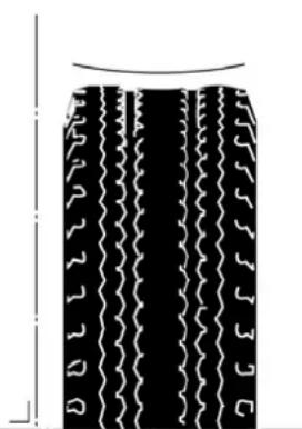 |
| Possible cause Remedy | |
| The tyre pressure is too high. Check the tyre pressure. | |
| Driving too fast for a long period of time. Check the type of tyre and instruct the driver. | |
1.4.2 FEATHER-LIKE WEAR IN THE TREAD
| The edge of the tread is feather-like and is worn more on one side than the other. The edges of the worn areas can be felt when a hand is rubbed over the tread. | 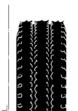 |
| Possible cause Remedy | |
| The toe-in is incorrectly set. The feather-like pattern can be felt when rubbing the tyre from the inside to the outside. | Check the toe. |
| The toe-out is incorrectly set. The feather-like pattern can be felt when rubbing the tyre from the outside to the inside. | Check the toe. |
| There is a problem with the stability when driving straight ahead. | Check the position of the rear axle. |
1.4.3 WEAR PATTERNS ON THE TREAD
| The tread profile contains areas with excessive wear (there is a knocking sound when driving and vibrations can be felt). | 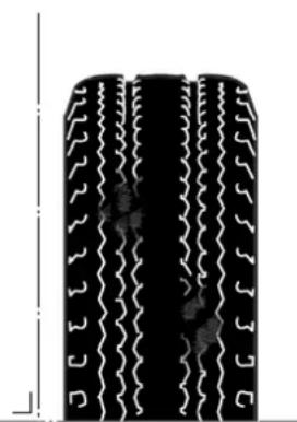 |
| Possible cause Remedy | |
| Damaged or worn mounting components. Check the mounting. | |
| Damaged or worn steering mechanism components. Check the steering mechanism. | |
| Damaged or worn shock absorbers. Check the shock absorbers. | |
| Unbalanced tyre/wheel combination. Check the wheel balance. | |
| Sudden and heavy braking (the wear pattern covers the entire tread). | Inform and instruct the driver. |
| Separation in the tyre as a result of internal damage, because holes in the road or kerbs have been hit whilst driving with a heavy load or whilst driving fast. | Replace the tyre. |
| Separation in the tyre as a result of overheating, because the tyre pressure was incorrect whilst driving with a heavy load or whilst driving fast. | Replace the tyre. |
| The brakes lock. See the fault finding table “Disc brake construction, Brakes drag, General information” 2 - 2.9.1 General information (12 - 22). | |
Wear on the inner shoulder
| The wear only occurs on the inner shoulder. The wear pattern increases the longer the deviation remains present. | 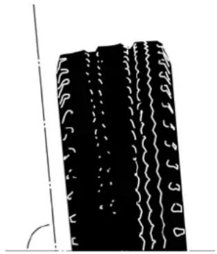 |
| Possible cause Remedy | |
| Too large negative wheel camber. Check the camber. | |
| Too large kingpin inclination. Check the kingpin inclination. |
Wear on the outer shoulder
| The wear only occurs on the outer shoulder. The wear pattern increases the longer the deviation remains present. | 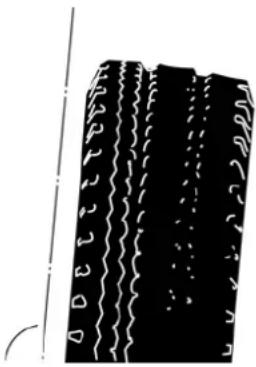 |
| Possible cause Remedy | |
| Too large positive wheel camber. Check the camber. | |
| Driving around corners too fast (the edge of the shoulder has been worn so that it has rounded off). | Check the type of tyre and instruct the driver. |
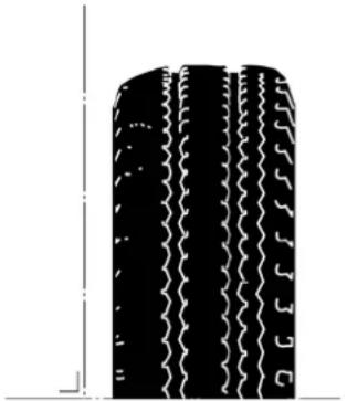 |
Wear on both shoulders
| The wear occurs on both the inner and outer shoulder. | 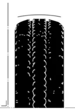 |
| Possible cause Remedy | |
| The tyre pressure is too low. Correct the tyre pressure. |
Cupping
| This type of wear almost only ever occurs on non-driven, non-steered axles. The wear pattern shows itself as feather-like wear on the shoulder of the tyre. The wear edges can be felt when a hand is rubbed over the shoul-der in the direction of rotation. |  |
| Possible cause Remedy | |
| Alignment Check the alignment of the wheels and axles. | |
| Damaged or worn mounting components. Check the axle | mounting. |
1.4.5 WEAR ON THE WALLS
Cuts
| The wall is damaged from the outside to the inside, which may have damaged the tyre body. | 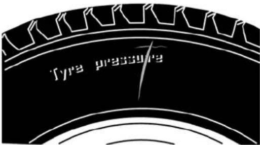 |
| Possible cause Remedy | |
| Cuts due to a sharp object. Change the tyre, because the | damaged wall may causea burst tyre after it has been pumped up. |
Damage due to knocks
| Initial internal damage to the tyre due to a heavy knock that has resulted in separation of the tyre, which has resulted in a lump on the wall. | 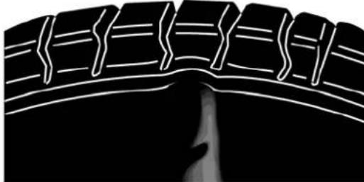 |
| Possible cause Remedy | |
| A knock against a sharp edge on a stone, kerb or hole in the road. | Change the tyre, because the damaged wall may cause a burst tyre after it has been pumped up. |
Wear patterns on the walls
| The wall contains areas with excessive wear. | 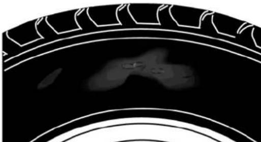 |
| Possible cause Remedy | |
| The tyre touches other parts of the vehicle whilst driving. | Check the play. |
| Incorrect type of tyre. Check the tyre sizes. | |
| Wrong type of rim (in particular, ET values). Check the tyre sizes. | |
| The tyre often comes into contact with the kerb or guide rails. | Instruct the driver. |
Circular wear on the walls
| The wear pattern covers the entire circumference of the tyre. | 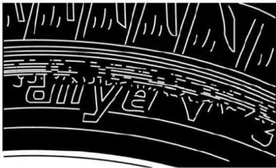 |
| Possible cause Remedy | |
| The tyre touches other parts of the vehicle whilst driving. | Check the play. |
| Incorrect type of tyre. Check the tyre sizes. | |
| Wrong type of rim (in particular, ET values). Check the tyre sizes. | |
| The tyre often comes into contact with the kerb or guide rails. | Instruct the driver. |
| The tyre has been used for a long period of time whilst the tyre pressure was too low. | Change the tyre, because the damaged wall may cause a burst tyre after it has been pumped up. |
Cracks or hairline cracks
| The wall is covered with cracks that may continue to the tyre body and may cause separation. | |
| Possible cause Remedy | |
| The age of the tyre. Check the DOT code. It is recommended | ed to not use tyres that are more than six years old. |
| Aging of the tyre under the influence of, for example, ozone, bending or welding. | Replace the tyre. |
1.5 OPERATION/WARNING/INDICATION FUNCTIONS
1.5.1 THE CRUISE CONTROL DOES NOT WORK
| Possible cause Remedy | |
| Mechanical fault/steering column's switch broken. Check | the steering column's switches in all positions. |
| The cut-out condition(s) for the cruise control is/are active. | Check for the presence of the cut-out condition(s). |
| The function is not programmed in the engine management electronic unit. | Check the engine management software and, if necessary, alter the master card. |
1.5.2 THE ENGINE SPEED CONTROL DOES NOT WORK
| Possible cause Remedy | |
| Mechanical fault/steering column’s switch broken. Check | the steering column’s switches in all positions. |
| The cut-out condition(s) for the cruise control is/are active. | Check for the presence of the cut-out condition(s). |
1.5.3 THE ENGINE CANNOT BE TURNED OFF
| Possible cause Remedy | |
| Fault in the electrical components and/or wiring. Check the electrical system. | |
| The power supply to the engine management electronic unit is not turned off. | Check the electrical system. |
| The power supply to the engine management electronic unit after the contact switch cannot be turned off with the switch/contact lock. | Check the electrical system. |
1.6 CONSUMPTION
1.6.1 HIGH FUEL CONSUMPTION
General information
- Is this symptom the result of a technical fault?
- External factors or improper use can also lead to this fault.
- It is important to get the correct image of the complaint by asking the customer or the driver for as much information as possible.
Question
- Under which road or weather conditions does this occur?
- How is the vehicle loaded?
- Is the vehicle being compared to a vehicle with totally different specifications, such as a vehicle with a more powerful engine?
- Is the vehicle being driven in the correct engine speed range?
Check
- The tachograph discs of journeys.
- Reliable fuel consumption information from journeys.
Discuss the results with the customer or the driver.
| If the complaint related to high fuel consumption is justified, check the following possible causes. | |
| Possible cause Remedy | |
| Incorrect type of components fitted. Check whether the correct components have been fitted, such as the turbo compressor, filters, etc. | |
| The vehicle is not correctly aligned. Check the alignment of the vehicle. | |
| The wrong type of tyre is used. Check the type and dimensions of the tyre. | |
| The brakes drag See the fault finding table: “Brakes drag, | Disc brake construction, General information” 2 - 2.9.1 General information (☐2 - 2 2) . |
| Fault in the electronic system. Check the symptom with the aid of the diagnosis equipment. | |
| Fault in the fuel system. See the fault finding table: "High fuel consumption, Fuel system" 2 - 2.7.8 High fuel consumption (☐2 - 17). | |
- Is this symptom the result of a technical fault?
- External factors or improper use can also lead to this fault.
- It is important to get the correct image of the complaint by asking the customer or the driver for as much information as possible.
Question
-
Ask for a good description of the use of the vehicle. The AdBlue consumption depends to a large extent on the use of the vehicle:
-
Low loads can result in a reduced use or no use of AdBlue.
- Heavy loads can result in an increased use of AdBlue.
- Long-lasting idling can result in a reduced use or no use of AdBlue.
- Low ambient temperatures can result in a reduced use or no use of AdBlue.
- High ambient temperatures can result in an increased use of AdBlue.
Discuss the results with the customer or the driver.
| Possible cause Remedy | |
| Leaking AdBlue tank filler cap. | Check the AdBlue tank's filler cap (liquid or white deposit) and, if necessary, replace it. |
| External AdBlue tank leak. Check the AdBlue tank for leaks | (liquid or white deposit). |
| External AdBlue line leak. Check the AdBlue lines for leaks | (liquid or white deposit). |
| Internal EAS unit leak. Check the outside of the EAS unit | (liquid or white deposit). |
| Fault in the EAS system. Carry out the “air circuit test” and | the “AdBlue circuit test” in the diagnosis equipment. Check the delivered quantity of AdBlue. |
1.6.3 HIGH OIL CONSUMPTION
| Before checking the following causes, check whether the consumption is higher than the maximum limit or whether it is caused by an excessive oil leak. | |
| Possible cause Remedy | |
| Faulty oil system. See the fault finding table: “High lubrication system oil consumption” 2 - 2.5.2 High oil consumption (☐2 - 12). | |
| Turbo compressor fault. See the fault finding table: “High turbo compressor oil consumption” 2 - 3.2.2 High oil consumption (☐3 - 2). | |
| Air compressor fault. Check the air compressor for carbon deposits. | |
| Mechanical engine fault. See the fault finding table: “High engine oil consumption, general information” 2 - 3.2.2 High oil consumption (☐3 - 2). | |
1.6.4 COOLANT CONSUMPTION
| Pressure-test the cooling system before checking the following causes. | |
| Possible cause Remedy | |
| External coolant leak See the fault finding table: “External coolant leak” 2 - 2.4.3 External coolant leak (☐2 - 11). | cooling system coolant leak” 2 - 2.4.3 External coolant leak (☐2 - 11). |
| Internal coolant leak See the fault finding table: “Internal coolant leak” 2 - 2.4.4 Internal coolant leak (☐2 - 11). | cooling system coolant leak” 2 - 2.4.4 Internal coolant leak (☐2 - 11). |
1.7 EXHAUST SMOKE
1.7.1 THE ENGINE EMITS BLACK SMOKE
| Possible cause Remedy | |
| The air filter element is blocked. Replace the air filter element. | |
| Air leak between the turbo compressor and the inlet manifold. | Check the hoses and pressure-test the intake section. |
| The compressor side of the turbo compressor is contaminated. | Clean the compressor side with a non-corrosive cleaning product or a soft brush.Check the inlet side for carbon deposits or other contamination. |
| Gas leak between the exhaust manifold and the cylinder head. | Check the attachment bolts and the gaskets. |
| Gas leak between the exhaust manifold and the turbo compressor. | Check the attachment bolts. |
| The turbo compressor is damaged. Trace the cause and replace the turbo compressor. | |
| Fault in the fuel system. See the fault finding table: “Black smoke, Fuel system”2 - 2.7.14 Black smoke development (☐2 - 19). | |
1.7.2 WHITE AND/OR BLUE SMOKE IS EMITTED FROM THE EXHAUST
| In cold conditions, it is normal for white smoke to be emitted after a cold start when the vehicle is fitted with a catalytic converter. The white smoke is water vapour and will disappear after a short time when the catalytic converter becomes warm. | |
| Possible cause Remedy | |
| The air filter element is blocked. Replace the air filter element. | |
| Air leak between the turbo compressor and the inlet manifold. | Check the flexible hoses and pressure-test the intake section. |
| Fault in the fuel system. See the fault finding table: “Black smoke, Fuel system”2 - 2.7.14 Black smoke development (☐2 - 19). | |
1.8 PULLING FORCE
1.8.1 LOSS OF PULLING FORCE
General information
- Is this symptom the result of a technical fault?
- External factors or improper use can also lead to this fault.
- It is important to get the correct image of the complaint by asking the customer or the driver for as much information as possible.
Question:
- Ask for a good description of the problem.
- What are the conditions under which the loss of pulling force is experienced (uphill, in rain, warm or cold engine, etc.)?
- Ask for reliable information concerning consumption during journeys.
- Ask for tachograph cards of journeys.
- Can the customer or driver reproduce the problem?
- Has the customer or a third party made changes to the vehicle (for example, changes to the software, rear axle gear ratio, gearbox, tyre size, etc.)?
Check
- The motor management and EAS for saved error codes and the correct software version.
- Whether the correct pump and injector codes have been programmed in the engine management unit.
- Vehicle specifications, including the bodywork and accessories.
Action
- Carry out an acceleration test.
- Make a boost pressure curve.
Comment: checking the boost pressure will, in general, only be of use if the vehicle has been driven at least 20,000 km.
Discuss the results with the customer or the driver.
| If the acceleration time is not achieved, check the following possible causes. | |
| Possible cause Remedy | |
| Incorrect type of components fitted. Check whether the correct components have been fitted.This refers to the turbo compressor, the filters, etc. | |
| The vehicle is poorly aligned. Check the alignment of the vehicle. | |
| The wrong type of tyre is used. Check the type and size of the tyres. | |
| The brakes drag See the fault finding table: “Brakes drag, | Disc brake con-struction, General information” 2 - 2.9.1 General information (12 - 2 2). |
| Fault in the electronic system. Check the symptom with the aid of the diagnosis equipment. | |
| Fault in the fuel system. See the fault finding table: “Loss of pulling force, Fuel system” 2 - 2.7.1 Loss of pulling force (12 - 15). | |
| Fault in intake and/or exhaust system. | See the fault finding table: “Loss of pulling force, Intake/exhaust system” 2 - 2.6.1 Loss of pulling force (12 - 13). |
1.9 VIBRATIONS AND ABNORMAL NOISES
1.9.1 THE ENGINE VIBRATES EXCESSIVELY
| Possible cause Remedy | |
| Unbalanced flywheel. Check the flywheel's attachment. | |
| The flywheel oscillates. Check the flywheel's attachment and whether the fly-wheel oscillates. | |
1.9.2 ABNORMAL NOISES FROM THE DRIVEN SHAFT
| Possible cause Remedy | |
| The differential rattles. See the fault finding table: “Differential rattles; Driven axles” 2 - 3.3.2 Vibrations and noises (☐3 - 12). | |
| Rattling noise in the differential See the fault finding table: “Rattling noise in differential, Driven axles, Vibrations and noises” 2 - 3.3.2 Vibrations and noises (☐3 - 12). | |
| Noises in the rear axle See the fault finding table: “Noise in the rear axle, Driven axles, Vibrations and noises” 2 - 3.3.2 Vibrations and noises (☐3 - 12). | |
1.9.3 NOISE IN THE REAR AXLE
| Possible cause Remedy | |
| Too low oil level. Top up the oil. | |
| The oil has the wrong viscosity. | Drain the oil and fill with oil that meets the specifications. |
| The attachment bolts have come loose. | Drain oil and check the drained oil for the presence of pieces of metal. |
| There is play in the pinion bearing. | Adjust the pinion bearing or, if necessary, replace it. |
1.9.4 ABNORMAL NOISE FROM THE AXLE MOUNTING
| Possible cause Remedy | |
| The axle mounting makes a noise. | Check the axle mounting. |
| The shock absorber makes a noise. | See the fault finding table: “Shock absorber makes a noise, Axle mounting and suspension, Shock absorber” 2 - 3.4.1 Shock absorber (☐3 - 13). |
1.9.5 ABNORMAL NOISE FROM THE ENGINE
| Possible cause Remedy | |
| Noise in the distribution box. | See the fault finding table: "Noise in the distribution box, PR engine, Vibrations and noises" 2 - 3.2.1 Vibrations and noises (☐3 - 2). |
1.9.6 NOISE IN THE DISTRIBUTION BOX
| Possible cause Remedy | |
| The distribution gear wheel is damaged. Check the distribution gear wheel. | |
| The distribution gear wheel play is not correct. Check the distribution gear wheel play. | |
| The distribution gear wheel is loose. Check the distribution gear wheel's attachment. | |
1.9.7 ABNORMAL NOISE FROM THE STEERING MECHANISM
| Possible cause Remedy | |
| The steering pump makes a screeching noise when steering | See the fault finding table: “Steering pump makes a screeching noise during steering, Steering mechanism, Noises” 2 - Fault finding tables (☐2 - 24). |
| The steering pump makes an abnormal noise See the fault finding table: “Steering pump makes an abnormal noise, Steering mechanism, Noises” 2 - Fault finding tables (☐2 - 24). | |
| The noise of metal against metal can be heard when steering | See the fault finding table: “The noise of metal against metal can be heard during steering, Steering mechanism, Noises” 2 - Fault finding tables (☐2 - 24). |
1.9.8 THE STEERING PUMP MAKES A SCREECHING NOISE WHEN STEERING
Is this symptom the result of a technical fault?
External factors or improper use can also lead to this fault.
The steering mechanism always makes a noise.
Normal noises:
- A hissing noise in the steering box when steering. The strength of the noise depends on the system pressure.
- A noise that increases in strength when the poppet valve opens.
- A loud noise when the pressure limiting valve opens.
| Possible cause Remedy | |
| The oil level is too low, so the steering pump draws in air. | Check the oil level. |
| Air in the steering oil circuit. Check the steering oil for the presence of air (foaming). | |
| The suction line is bent or pinched. Check the suction line. | |
| The suction opening in the reservoir is (partially) blocked. | Check the reservoir. |
1.9.9 THE STEERING PUMP MAKES AN ABNORMAL NOISE
Is this symptom the result of a technical fault?
External factors or improper use can also lead to this fault.
The steering mechanism always makes a noise.
Normal noises:
- A hissing noise in the steering box when steering. The strength of the noise depends on the system pressure.
- A noise that increases in strength when the poppet valve opens.
- A loud noise when the pressure limiting valve opens.
| The steering pump produces an abnormal noise when idling the engine.The noise strength increases when the engine speed increases. | |
| Possible cause Remedy | |
| Steering pump is worn. Replace the steering pump. | |
1.9.10 THE NOISE OF METAL AGAINST METAL CAN BE HEARD WHEN STEERING
Is this symptom the result of a technical fault?
External factors or improper use can also lead to this fault.
The steering mechanism always makes a noise.
Normal noises:
- A hissing noise in the steering box when steering.
The strength of the noise depends on the system pressure. - A noise that increases in strength when the poppet valve opens.
- A loud noise when the pressure limiting valve opens.
| Possible cause Remedy | |
| The steering box, steering bracket or pitman arm is loose. | Check the attachment of the steering mechanism's components. |
| There is play in the steering ball joint of the steering rod or track rod. | Check the steering ball joint. |
| Parts of the steering mechanism rub against each other. | Check the steering mechanism's mechanical components to see whether they rub. |
| There is play in the steering column's sliding joint. Check | the sliding joint for play. |
2. SYSTEMS
2.1 INTRODUCTION
General information
The diagnosis information is intended to help you trace problems.
Possible causes of symptoms that are not detected by an electronic unit are given in the fault finding tables.
Faults that can be detected by an electronic unit can be read as an error code with the aid of diagnosis equipment.
Every possible cause of a “complaint by the driver” leads you to a solution and the repair work that it involves.
As shown in the diagram, the diagnosis information is divided into three separate sections. Besides this section, there are also sections for:
- Diagnosis, "Vehicle behaviour and performance".
• Diagnosis, "Components".
In “Vehicle behaviour and performance”, the driver’s complaint is reduced to the possible causes. These possible causes lead to solutions or a link to one of the other fault finding tables in the Diagnosis “Systems” or “Components” sections.
Together, the three sections contain all the available fault finding tables.
2.2 CAN NETWORK
2.2.1 CAN NETWORK ISO 11898
CAN communication is not possible
CAN network fault finding table according to ISO 11898
| Communication with the electronic systems in the CAN network is no longer possible. | |
| Possible cause Remedy | |
| CAN-H short circuit to power supply. Check CAN-H. | |
| CAN-L short circuit to power supply. Check CAN-L. | |
CAN H short circuit to earth.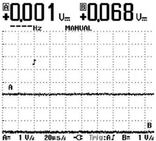 The measured signal can be recognized by:Channel A: CAN-H, no message signal, low signal voltage.Channel B: CAN-L, no message signal, low signal voltage. The measured signal can be recognized by:Channel A: CAN-H, no message signal, low signal voltage.Channel B: CAN-L, no message signal, low signal voltage. | Check CAN-H. |
| CAN-H short-circuits to CAN-L. Check CAN-H and CAN-L | |
| Connection with two terminating resistors is broken. | Check the connections to the terminating resistors. |
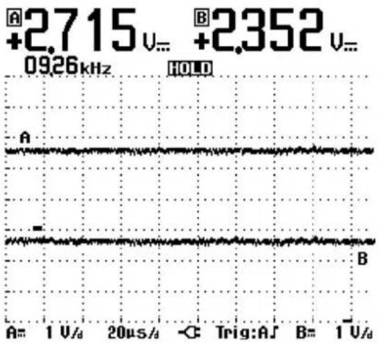 | |
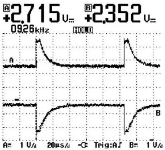 | |
| The measured signal can be recognized by:Channel A: CAN-H, no message signal, low signal voltage.Channel B: CAN-L, no message signal, low signal voltage.Comment:The signal may vary depending on the electronic unit that is used (vehicle configuration). CAN-H and CAN-L have the same voltage levels. | |
Faults in the CAN communication
CAN network fault finding table according to ISO 11898
| Communication with the electronic systems in the CAN network is still possible, but the faults will have a greater effect. | |
| Possible cause Remedy | |
CAN-L short circuit to earth. The measured signal can be recognized by:Channel A: CAN-H, message signal.Channel B: CAN-L, no message signal, low signal voltage. The measured signal can be recognized by:Channel A: CAN-H, message signal.Channel B: CAN-L, no message signal, low signal voltage. | Check CAN-L. |
Connection with one terminating resistor is broken. The measured signal can be recognized by:Channel A: CAN-H, signal interference.Channel B: CAN-L, signal interference. The measured signal can be recognized by:Channel A: CAN-H, signal interference.Channel B: CAN-L, signal interference. | Check the connection to the terminating resistor. |
CAN communication is not possible between some systems
CAN network fault finding table according to ISO 11898
| Communication with electronic systems that have been separated by the break in the CAN network is no longer possible. Communication between electronic systems that are located on the same side of the break is still possible. However, the fault has more effect in combination with an open connection to one of the terminating resistors. | |
| Possible cause Remedy | |
| CAN-H interrupted. Check CAN-H. | |
| CAN-L interrupted. Check CAN-H. | |
| Communication with electronic systems that have been separated by the break in the CAN network is no longer possible. Communication between electronic systems that are located on the same side of the break is still possible, but the faults will have a greater effect. | |
| Possible cause Remedy | |
| CAN-H and CAN-L interrupted. Check CAN-H and CAN-L | |
| Communication with the electronic systems in the CAN network for which the wiring has been switched over is no longer possible. | |
| Possible cause Remedy | |
| CAN-H and CAN-L have been switched over. Check the connection of the wiring for CAN-H and CAN-L. | |
2.2.2 CAN NETWORK ISO 11992/1
CAN communication is not possible
CAN network fault finding table according to ISO 11992/1
| Communication with the electronic systems in the CAN network is not possible. | |
| Possible cause Remedy | |
| CAN-H and CAN-L interrupted in the same location. Check CAN-H and CAN-L | |
| CAN-H short-circuits to CAN-L. Check CAN-H and CAN-L | |
| CAN-H and CAN-L have been switched over. Check CAN-H and CAN-L | |
Faults in the CAN communication
CAN network fault finding table according to ISO 11992/1
| Communication with the electronic systems in the CAN network is still possible, but the faults will have a greater effect. | |
| Possible cause Remedy | |
| CAN-H interrupted. Check CAN-H. | |
| CAN-L interrupted. Check CAN-L. | |
| CAN-H short circuit to power supply. Check CAN-H. | |
| CAN-L short circuit to power supply. Check CAN-L. | |
| CAN H short circuit to earth. Check CAN-H. | |
| CAN-L short circuit to earth. Check CAN-L. | |
2.3 CLUTCH
2.3.1 THE COUPLING IS NOT RELEASED
| Possible cause Remedy | |
| The liquid level in the hydraulic system is too low. Check | the hydraulic system for leaks.Top up the hydraulic liquid.Bleed the hydraulic system. |
| The pedal is incorrectly set. Check the pedal setting. | |
| The clutch release assembly's levers have broken off. Check the clutch for broken levers.Replace the clutch release assembly. | |
| The wrong clutch release assembly has been fitted. Fit the correct clutch release assembly. | |
| The clutch fork has broken. Check the clutch fork. | Replace the clutch fork. |
| The clutch release assembly is heavily contaminated or corroded. | Clean the entire clutch. |
| The clutch booster is faulty. Check the clutch booster. | Replace the clutch booster. |
| The thrust bearing has been fitted incorrectly. Check whether the thrust bearing has been fitted correctly.Fit the thrust bearing correctly. | |
| The clutch housing has come loose from the gearbox. Check the clutch housing's bolts. |
2.3.2 THE CLUTCH PEDAL DOES NOT RETURN
| Possible cause Remedy | |
| The pedal return spring is broken. Replace the spring. | |
| The clutch pedal bearing ring is worn. Check the bearing | and, if necessary, replace it. |
| Contamination in the hydraulic system. | Clean the system and fill with new liquid. |
| Air in the hydraulic system. Bleed the system. |
2.3.3 THE CLUTCH PEDAL GETS STUCK WHEN IT IS DEPRESSED
| Possible cause Remedy | |
| Leak in the hydraulic system. Check the system. | |
| Air in the hydraulic system. | Bleed the hydraulic system. |
| The declutch bearing has been fitted incorrectly. | Fit the declutch bearing correctly. |
| The hinged points of the fork or the fork itself knock. | Check the hinged points and the fork and, if necessary, replace them. |
| The clutch booster is faulty. Repair and/or replace the clutch booster. | |
| The sliding bush knocks or has broken off. | Check the sliding bush and, if necessary, replace it. |
2.3.4 THE PEDAL FORCE IS TOO GREAT
| Possible cause Remedy | |
| There is no pressure in circuit 4 of the brake system or the pressure is too low. | Check circuit 4 of the brake system. |
| The air line is pinched closed. Check the line and, if necessary, replace it. | |
| The hydraulic line is pinched closed. Check the line and, if necessary, replace it. | |
| The clutch pedal bearing ring is worn. Check the bearing and, if necessary, replace it. | |
| Faulty clutch booster and/or main cylinder. Repair or replace the clutch booster/main cylinder.Comment:If the seal has expanded, clean the system and fill with new fluid. | |
2.3.5 RESIDUAL PRESSURE IN THE CLUTCH SYSTEM
| Possible cause Remedy | |
| The bleed opening in the reservoir’s cap is closed. Check whether the bleed opening in the cap is open. | |
| The compensation bore in the main cylinder is closed due to an expanded seal or the thrust pin having an insufficient free stroke. | Check the thrust pin’s free stroke or repair/replace the main cylinder.Comment:If the seal has expanded, clean the system and fill with new fluid. |
2.3.6 FLUID LEAKS VIA THE VENTILATION OPENING
| Possible cause Remedy | |
| Leak via the piston seal in the clutch booster. Repair or replace the clutch booster.Comment:The presence of a drop of oil in the ventilation opening is normal and is not a reason to repair/replace the clutch booster. | |
2.3.7 THE CLUTCH SLIPS
| Possible cause Remedy | |
| The lining is worn. Replace the clutch plate. | |
| There is oil on the lining. Replace the clutch plate and check the engine oil sealsand the gearbox oil seals. | |
| There is grease on the lining. Too much oil has been used for the splines. Replace the clutch plate. | |
| There is dirt on the clutch plate and the flywheel. Clean the clutch plate and the surrounding area. | |
| The clutch plate has been burnt. Check the entire clutch and, if necessary, replace it. | |
| The clutch release assembly has no clamping force or it has been reduced. | Check the clutch release assembly and, if necessary, replace it. |
| The clutch release assembly is not released correctly Check the clutch release assembly. | |
| The splines have corroded. Replace the clutch plate and/or clean and apply grease to the splines. | |
2.3.8 THE CLUTCH RELEASE ASSEMBLY IS NOT RELEASED CORRECTLY
| Possible cause Remedy | |
| Air in the hydraulic system. | Top up the fluid and bleed the hydraulic system. |
| Leak in the hydraulic system. Check/repair the hydraulic system and top up the fluid. | |
| The clutch release assembly's levers have broken off. Replace the clutch release assembly. | |
| The wrong clutch release assembly has been fitted. Fit the correct clutch release assembly. | |
| The clutch fork has broken. Replace the fork. | |
| The clutch release assembly is heavily contaminated. Clean the entire clutch. | |
| The clutch booster is faulty. | Check the clutch booster and, if necessary, replace it. |
| The thrust bearing has been fitted incorrectly. | Fit the thrust bearing correctly. |
| The clutch housing has come loose from the gearbox. Tighten the clutch housing bolts to the correct torque. | |
2.4 COOLING SYSTEM
2.4.1 THE ENGINE TEMPERATURE RISES
| Possible cause Remedy | |
| Faulty intake system. Check the intake system. | |
| Incorrect poly V-belt tension. Check the poly V-belt tension. | If necessary, replace the poly V-belt or the poly V-belt tensioner. |
| The coolant level is too low. Check the coolant level. If necessary, top it up. | |
| A coolant hose is cracked or blocked. Check/clean the coolant hoses. | |
| The cooling system's intercooler and radiator are contaminated. | Check/clean the cooling system's intercooler and radiator. |
| The waste-gate setting too high. Check the waste-gate setting. | |
| The turbo compressor housing's air hose to the waste-gate diaphragm leaks or is not connected. | Check the air hose. If necessary, replace it. |
| The pressure cap is faulty or does not work. Check the pressure cap. | |
| The thermostat opens insufficiently or does not open. Check the thermostat and its operation. | |
| The coolant filter is contaminated. Check the coolant filter. | If necessary, replace the filter and clean the cooling system. |
| The wrong type of thermostat is fitted. Check the thermostat and its operation. | |
| The coolant pump is faulty. Check the coolant pump's shaft, bearings and fan. If necessary, replace the coolant pump. | |
| The fan drive is faulty. | Check the fan drive. |
| The temperature control is faulty. | Check the coolant temperature sensor.Check the control flow's return control at a high temperature. |
| Too high intarder pressure when the intarder is turned off. | See the fault finding table: “Constant braking when the intarder is turned off, cooling system” 2 - 2.4.2 Constant braking when the intarder is turned off (12 - 10) |
2.4.2 CONSTANT BRAKING WHEN THE INTARDER IS TURNED OFF
| Possible cause Remedy | |
| Too much oil in the gearbox. | Drain the excess oil. |
| The control pressure does not drop. | Check the retarder's control pressure when the retarder is turned off. |
| The volume control valve does not return to the rest position. | Check the operation of the volume control valve. |
2.4.3 EXTERNAL COOLANT LEAK
| Possible cause Remedy | |
| The radiator. Check the radiator. If necessary, pressure-test it. | |
| The coolant pump leaks. Check the coolant pump. If necessary, measure the bearing play. | |
| The cooler. Check the oil cooler. If necessary, pressure-test it. | |
| The pressure cap. Check the pressure cap. If necessary, pressure-test it. | |
| The heater leaks. Check the heater hoses. | |
| The coolant expansion reservoir leaks. Check the expansion reservoir for leaks. | |
| The expansion plug(s) leak(s). Replace the expansion plug(s). | |
2.4.4 INTERNAL COOLANT LEAK
| Possible cause Remedy | |
| The cylinder head gasket(s) is/are faulty. Check the cylinder head gasket(s). | |
| The cylinder head(s) or cylinder block are cracked. Check the cylinder heads and the cylinder block for internal cracks. If necessary, pressure-test it. | |
| The injection nozzle bushes leak. Check the cylinder heads. If necessary, pressure-test it. | |
| The compressor's cylinder head gasket is faulty. Replace the compressor's cylinder head gasket. | |
| The cooler. Check whether there is coolant in the lubrication oil system. | |
| The expansion plugs in the striking chamber (cylinder block) or on the top of the cylinder heads are faulty. | Replace the expansion plug(s). |
| The cylinder head bolts have not been tightened. | Check the tightening torque of the cylinder head bolts. |
2.5 LUBRICATION SYSTEM
2.5.1 ENGINE OIL PRESSURE TOO LOW
| Possible cause Remedy | |
| Engine oil level too low. Top up the engine oil to the maximum level. | |
| External oil leaks. Visually check the engine for leaks. If necessary, repair the lines. | |
| The engine oil pressure and temperature sensor is faulty. | Check the sensor. If necessary, replace them. |
| The oil does not meet the specifications. Change the engine oil and the oil filter. | |
| The oil temperature is too high. Check the oil cooler for constrictions. | |
| Oil is mixed with coolant or fuel. Change the engine oil and the oil filter.Check the oil cooler. | |
| The oil duct or oil supply line is loose or broken. Check the oil lines. If necessary, repair the lines. | |
| The oil pump does not work well enough. Check the oil pump. | |
| Worn main bearings and/or big-end bearings. | Check the main bearings and the big-end bearings. |
| Loose piston cooling grease box. Check the grease box. | If necessary, replace them. |
| Faulty internal oil delivery lines or seals. Check the oil delivery lines and seals. | |
| The oil filter is contaminated. Replace the oil filter. | |
2.5.2 HIGH OIL CONSUMPTION
| Possible cause Remedy | |
| The oil temperature is too high. Check whether the correct oil cooler has been fitted. | |
| The sump pressure is too high. | Check the compression pressure and carry out a cylinder leak test.Check the condition of the piston springs and the cylinder lining. |
| Oil with the incorrect specifications has been used in the engine. | If oil with the incorrect specifications has been used, drain the oil and fill the engine with oil that meets the specifications. |
| External oil leaks. Visually check the engine for leaks. If necessary, repair the leaks. | |
2.6 INTAKE AND EXHAUST SYSTEMS
2.6.1 LOSS OF PULLING FORCE
| This general symptom can be explained based on one of these more detailed causes. | |
| Possible cause Remedy | |
| Reduced power above a certain engine speed See the fault finding table: "Reduced power above a certain engine speed" 2 - 2.6.3 Reduced power above a certain engine speed (☐2 - 13). | |
| Reduced power at all engine speeds See the fault finding table: "Reduced power at all engine speeds" 2 - 2.6.2 Reduced power at all engine speeds (☐2 - 13). | |
| Reduced maximum engine speed See the fault finding table: "Reduced maximum engine speed" 2 - 2.6.4 Reduced maximum engine speed (☐2 - 14). | |
2.6.2 REDUCED POWER AT ALL ENGINE SPEEDS
| Possible cause Remedy | |
| The fuel fine filter is blocked. Replace the fuel filter and clean the system. | |
| The fuel pressure control valve remains open. Check the gallery pressure. | |
| The fuel supply pump's delivery is too small. | Check the fuel supply pump and the gallery pressure. |
| Poor fuel quality. | Drain the fuel, rinse the fuel system, replace the fuel filters and fill the fuel tank with fuel. |
| There is a fuel leak between the injector line(s) and the injector(s). | Check around the injector(s) for fuel leaks and, if necessary, replace the injector line(s). |
| There is a mechanical fault with the pump unit(s) or it/they is/are blocked. | Check the operation of the pump unit(s). |
| There is a mechanical fault with the injector(s). | Check the operation of the injector(s). |
2.6.3 REDUCED POWER ABOVE A CERTAIN ENGINE SPEED
| Possible cause Remedy | |
| The fuel fine filter is partially blocked. | Replace the fuel filter and clean the system. |
| There is a mechanical fault with the pump unit(s) or it/they is/are blocked. | Check the operation of the pump unit(s). |
| The gallery pressure is too low because the fuel pressure control valve remains open. | Check the fuel pressure control valve. |
| The gallery pressure is too low because of a low fuel supply pump delivery. | Check the fuel supply pump. |
2.6.4 REDUCED MAXIMUM ENGINE SPEED
| Possible cause Remedy | |
| The turbo compressor is damaged. Trace the cause of the | damage and replace the turbo compressor. |
2.6.5 THE EXHAUST GAS BACK PRESSURE IS TOO HIGH
| Possible cause Remedy | |
| Incorrect butterfly valve setting. Check the butterfly valve's setting. | |
| The butterfly valve is fitted in the wrong position. Check whether the butterfly valve has been fitted correctly. | |
| The butterfly valve is partially operated by a residual pressure in the operating cylinder. | Check the operating cylinder. |
| No original silencer fitted. Check the silencer. | |
| The exhaust pipe has been squeezed closed or has been internally blocked by a loose part. | Check the exhaust system for blockages and/or damage. |
| The catalytic converter in the silencer is blocked. Replace the silencer. | |
| The soot filter is blocked. Clean the soot filter (only for EEV). | |
2.6.6 THE INLET VACUUM PRESSURE IS TOO HIGH.
| Possible cause Remedy | |
| The air filter element is blocked. Replace the air filter element. | |
2.7 FUEL SYSTEM
2.7.1 LOSS OF PULLING FORCE
| This general symptom can be explained based on one of these more detailed causes. | |
| Possible cause Remedy | |
| Reduced power above a certain engine speed See the fault finding table: "Reduced power above a certain engine speed" 2 - 2.7.3 Reduced power above a certain engine speed (☐2 - 15). | |
| Reduced power at all engine speeds See the fault finding table: "Reduced power at all engine speeds" 2 - 2.7.2 Reduced power at all engine speeds (☐2 - 15). | |
| Reduced maximum engine speed See the fault finding table: "Reduced maximum engine speed" 2 - 2.7.4 Reduced maximum engine speed (☐2 - 16). | |
2.7.2 REDUCED POWER AT ALL ENGINE SPEEDS
| Possible cause Remedy | |
| The fuel fine filter is blocked. Replace the fuel filter and clean the system. | |
| The fuel pressure control valve remains open. Check the gallery pressure. | |
| The fuel supply pump's delivery is too small. | Check the fuel supply pump and the gallery pressure. |
| Poor fuel quality. | Drain the fuel, rinse the fuel system, replace the fuel filters and fill the fuel tank with fuel. |
| There is a fuel leak between the injector line(s) and the injector(s). | Check around the injector(s) for fuel leaks and, if necessary, replace the injector line(s). |
| There is a mechanical fault with the pump unit(s) or it/they is/are blocked. | Check the operation of the pump unit(s). |
| There is a mechanical fault with the injector(s). | Check the operation of the injector(s). |
2.7.3 REDUCED POWER ABOVE A CERTAIN ENGINE SPEED
| Possible cause Remedy | |
| The fuel fine filter is partially blocked. | Replace the fuel filter and clean the system. |
| There is a mechanical fault with the pump unit(s) or it/they is/are blocked. | Check the operation of the pump unit(s). |
| The gallery pressure is too low because the fuel pressure control valve remains open. | Check the fuel pressure control valve. |
| The gallery pressure is too low because of a low fuel supply pump delivery. | Check the fuel supply pump. |
2.7.4 REDUCED MAXIMUM ENGINE SPEED
| Possible cause Remedy | |
| There is air in the fuel system. Check whether any air is drawn in. Pay particular attention to the suction line and the delivery pump's oil seal. Bleed the fuel system. | |
| The fuel fine filter is blocked. Replace the fuel filter and clean the system. | |
| The fuel supply pump's delivery is too small. Check the fuel supply pump and the gallery pressure. | |
| There is a fuel leak between the injector line(s) and the injector(s). | Check around the injector(s) for fuel leaks and, if necessary, replace the injector line(s). |
| There is a mechanical fault with the pump unit(s) or it/they is/are blocked. | Check the operation of the pump unit(s). |
2.7.5 THE STARTER TURNS THE ENGINE OVER BUT THE ENGINE DOES NOT START
| Possible cause Remedy | |
| There is air in the fuel system. Check whether any air is drawn in. Pay particular attention to the suction line and the oil seal for the fuel delivery pump.Bleed the fuel system. | |
| The fuel filter is blocked. Replace the fuel filter and clean the system. | |
| No fuel supply/the fuel supply pump is faulty, no delivery. Check the fuel level.Check the lines for blockages and leaks.Check the fuel supply pump.Check the gallery pressure. | |
| The fuel pressure control valve remains open. Check the gallery pressure. | |
| Poor fuel quality. | Drain the fuel, rinse the fuel system, replace the fuel filters and fill the fuel tank with fuel. |
2.7.6 THE ENGINE STALLS, BUT RUNS AGAIN AFTER IT HAS BEEN RESTARTED
| Possible cause Remedy | |
| There is air in the fuel system. Check whether any air is | drawn in. Pay particular attention to the suction line and the oil seal for the fuel delivery pump.Bleed the fuel system. |
| The fuel pressure control valve remains open. Check the | gallery pressure. |
2.7.7 THE ENGINE IS DIFFICULT TO START
| Possible cause Remedy | |
| There is air in the fuel system. Check whether any air is drawn in.Bleed the fuel system. | |
| The fuel pressure control valve remains open. Check the gallery pressure. | |
| The fuel supply pump's delivery is too small. Check the fuel supply pump and, if necessary, replace it.Check the gallery pressure. | |
| The fuel filter is blocked. Replace the fuel filter and clean the system. | |
| There is a fuel leak between the injector line and the injector. | Check around the injector for fuel leaks.If necessary, replace the injector line. |
| Poor fuel quality. | Drain the fuel, rinse the fuel system, replace the fuel filters and fill the fuel tank with fuel. |
| There is a mechanical fault with the pump unit or it is blocked. | Check the operation of the pump unit. |
| There is a mechanical fault with the injector or it is blocked. | Check the operation of the injector. |
2.7.8 HIGH FUEL CONSUMPTION
| Possible cause Remedy | |
| Incorrectly programmed pump unit(s)/injector(s). Check the calibration codes and, if necessary, reprogram them. | |
| Poor fuel quality. | Drain the fuel, rinse the fuel system, replace the fuel filters and fill the fuel tank with fuel. |
| The fuel system leaks. Check for leaks. | |
| There is a mechanical fault with the pump unit(s) or it/they is/are blocked. | Check the operation of the pump unit(s). |
| There is a mechanical fault with the injector(s). Check the operation of the injector(s). | |
2.7.9 DIESEL KNOCK DURING ACCELERATION
| Possible cause Remedy | |
| There is air in the fuel system. Check whether any air is drawn in. Pay particular attention to the suction line and the oil seal for the fuel delivery pump.Bleed the fuel system. | |
| Poor fuel quality. | Drain the fuel, rinse the fuel system, replace the fuel filters and fill the fuel tank with fuel. |
| There is a mechanical fault with the pump unit(s). Check the operation of the pump unit(s). | |
| There is a mechanical fault with the injector(s). Check the operation of the injector(s). | |
2.7.10 THE ENGINE RUNS ERRATICALLY
| Possible cause Remedy | |
| There is air in the fuel system. Check whether any air is drawn in. Pay particular attention to the suction line and the oil seal for the fuel delivery pump.Bleed the fuel system. | |
| The fuel pressure control valve remains open. Check the gallery pressure. | |
| The fuel filter is blocked. Replace the fuel filter and clean the system. | |
| There is a fuel leak between the injector line(s) and the injector(s). | Check around the injector(s) for fuel leaks and, if necessary, replace the injector line(s). |
| Poor fuel quality. | Drain the fuel, rinse the fuel system, replace the fuel filters and fill the fuel tank with fuel. |
| The fuel supply pump's delivery is too small. Check the fuel supply pump and the gallery pressure. | |
| There is a mechanical fault with the pump unit(s) or it/they is/are blocked. | Check the operation of the pump unit(s). |
| There is a mechanical fault with the injector(s). Check the operation of the injector(s). | |
| Incorrectly programmed pump unit(s)/injector(s). Check the calibration codes and, if necessary, reprogram them. | |
2.7.11 REDUCED ENGINE POWER AT ALL ENGINE SPEEDS
| Possible cause Remedy | |
| The fuel filter is blocked. Replace the fuel filter and clean | the system. |
| There is air in the fuel system. Check whether any air is | drawn in. Pay particular attention to the suction line and the oil seal for the fuel delivery pump.Bleed the fuel system. |
| The fuel pressure control valve remains open. Check the | gallery pressure. |
| The fuel supply pump's delivery is too small. Check the fuel supply pump and the gallery pressure. | |
| Poor fuel quality. | Drain the fuel, rinse the fuel system, replace the fuel filters and fill the fuel tank with fuel. |
| There is a fuel leak between the injector line(s) and the injector(s). | Check around the injector(s) for fuel leaks and, if necessary, replace the injector line(s). |
| There is a mechanical fault with the pump unit(s) or it/they is/are blocked. | Check the operation of the pump unit(s). |
| There is a mechanical fault with the injector(s). Check the operation of the injector(s). | |
2.7.12 REDUCED POWER ABOVE A CERTAIN ENGINE SPEED
| Possible cause Remedy | |
| The fuel fine filter is partially blocked. Replace the fuel filter and clean the system. | |
| There is a mechanical fault with the pump unit(s) or it/they is/are blocked. | Check the operation of the pump unit(s). |
| The gallery pressure is too low because the fuel pressure control valve remains open. | Check the fuel pressure control valve. |
| The gallery pressure is too low because of a low fuel supply pump delivery. | Check the fuel supply pump. |
2.7.13 WHITE AND/OR BLUE SMOKE DEVELOPMENT
| Possible cause Remedy | |
| Incorrectly programmed pump unit(s)/injector(s). Check the calibration codes and, if necessary, reprogram them. | |
| Poor fuel quality. | Drain the fuel, rinse the fuel system, replace the fuel filters and fill the fuel tank with fuel. |
| There is air in the fuel system. Check whether any air is drawn in. Pay particular attention to the suction line and the oil seal for the fuel delivery pump.Bleed the fuel system. | |
| The fuel filter is blocked. Replace the fuel filter and clean the system. | |
| There is a mechanical fault with the pump unit(s) or it/they is/are blocked. | Check the operation of the pump unit(s). |
| There is a mechanical fault with the injector(s). Check the operation of the injector(s). | |
| The fuel supply pump's delivery is too small. Check the fuel supply pump and, if necessary, replace it.Check the gallery pressure. | |
2.7.14 BLACK SMOKE DEVELOPMENT
| Possible cause Remedy | |
| Incorrectly programmed pump unit(s)/injector(s). Check the calibration codes and, if necessary, reprogram them. | |
| There is a mechanical fault with the pump unit(s). Check the operation of the pump unit(s). | |
| There is a mechanical fault with the injector(s). Check the operation of the injector(s). | |
2.7.15 REDUCED MAXIMUM ENGINE SPEED
| Possible cause Remedy | |
| There is air in the fuel system. Check whether any air is drawn in. Pay particular attention to the suction line and the oil seal for the fuel delivery pump.Bleed the fuel system. | |
| The fuel filter is blocked. Replace the fuel filter and clean the system. | |
| The fuel supply pump's delivery is too small. Check the fuel supply pump and the gallery pressure. | |
| There is a fuel leak between the injector line(s) and the injector(s). | Check around the injector(s) for fuel leaks and, if necessary, replace the injector line(s). |
| There is a mechanical fault with the pump unit(s) or it/they is/are blocked. | Check the operation of the pump unit(s). |
2.8 VEHICLE LIGHTING
2.8.1 THE XENON LIGHTING DOES NOT WORK ON ONE SIDE
| Possible cause Remedy | |
| The dipped beam fuse is faulty. Check/replace the fuse. | |
| No power supply to the ballast unit on the faulty side. Check the power supply to the ballast unit. | |
| The xenon bulb is faulty. Replace the xenon bulb. | |
| The ignition unit is faulty. Replace the ignition unit. | |
| The wiring between the ballast unit and the ignition unit is faulty. | Check the wiring. |
| The ballast unit is faulty. Replace the ballast unit. | |
| The ignition unit's connector has not been connected correctly. | Check whether the connector has been connected correctly. |
2.8.2 THE XENON LIGHTING DOES NOT WORK ON EITHER SIDE
| Possible cause Remedy | |
| The fuse is faulty Check/replace the fuse. | |
| The light switch is faulty. Check the light switch. | |
| The relay is faulty. Check the relay. | |
| The wiring is faulty. Check and repair or replace the wiring. |
2.8.3 DIFFERENCE IN COLOUR AFTER A NEW BULB HAS BEEN FITTED
| Possible cause Remedy | |
| There is a difference between the lifespan of the left-hand and right-hand bulbs. | Always replace the bulbs as a pair or find out whether it is possible to use CM (Colour Match) bulbs on one side. |
| The colour changes as the bulb gets older. Preferably fit bulbs from the same manufacturer on both sides. | |
Disc brake construction, general information
Is this symptom the result of a technical fault?
External factors or improper use can also lead to this fault.
| Possible cause Remedy | |
| Incorrectly set foot valve stop bolt (residual pressure). Check the setting of the foot valve. | |
| Heavily polluted brakes or damaged sliding surfaces on the brake shoes and/or brake anchor plate. | Check the movement of the brake shoes, clean the brakes |
| Different or incorrect brake lining quality. Check the brake lining. | |
| Slack or broken return spring. Check the return spring. | |
| Faulty automatic slack adjuster. Check the automatic brake slack adjuster. | |
| The pressure in the spring brake cylinders is too low whilst driving. | Check the air pressure in the spring brake cylinders. |
| The parking brake is not released. Check the release of the parking brake. | |
| Dirt under the foot valve or the floor mat is too high. Check whether the foot valve can move. | |
| The service brake system is not fully bled or it takes too long to bleed as result of a contaminated or blocked brake valve bleed openings. | Check the valve bleed openings. |
Irregular brake pad wear
| Possible cause Remedy | |
| Contaminated or corroded guide bushes. Check the guide bushes. | |
| Build-up of contamination between the moving parts of the disc brake construction. | Clean the disc brake construction. |
| Moisture and dirt on the internal mechanical components. | Check and clean the brake caliper's seals. |
| The brake pad is stuck in the brake caliper. Check the play between the brake pads and the brake carrier. | |
| Incorrect play between the brake pads and the brake carrier. | Check the play between the brake pads and the brake carrier. |
Increased brake pad wear
| Possible cause Remedy | |
| Overloading due to a heavy load. Check the vehicle load. | |
| Incorrect load-dependent control valve setting. Check the setting of the load-dependent valve. | |
| Incorrect pulling vehicle/trailer or front axle/rear axle adjustment. | Check the pulling vehicle/trailer or front axle/rear axle adjustment. |
| Faulty trailer brake system. Check the trailer brake system. | |
| The brake pad is stuck in the brake caliper. Check the play between the brake pads and the brake caliper. | |
| Incorrect play between the brake pads and the brake caliper. | Check the play between the brake pads and the brake caliper. |
| Incorrect trailer control valve or trailer reaction valve setting. | Check the trailer control valve setting or the trailer reaction valve setting. |
| Incorrectly set foot valve stop bolt (residual pressure). Check the setting of the foot valve. | |
| Heavily polluted brakes or damaged sliding surfaces on the brake pads. | Check the movement of the brake pads, clean the brakes. |
| Different or incorrect brake pad quality. Check the brake pads. | |
| Faulty automatic slack adjuster. Check the automatic brake slack adjuster. | |
| The pressure in the spring brake cylinders is too low whilst driving. | Check the air pressure in the spring brake cylinders. |
| The parking brake is not released. Check the release of the parking brake. | |
| Dirt under the foot valve or the floor mat is too high. Check whether the foot valve can move. | |
| The service brake system is not fully bled or it takes too long to bleed as result of a contaminated or blocked brake valve bleed openings. | Check the valve bleed openings. |
2.10 STEERING MECHANISM
2.10.1 STEERING MECHANISM
Warning symbol remains active
| Possible cause Remedy | |
| The oil level in the reservoir is too low. Check the oil level. | Check for leaks. |
| Faulty level sensor. Check the operation of the steering mechanism. | |
Air in the steering oil circuit.
| Possible cause Remedy | |
| The oil level in the reservoir is too low. Check the oil level. | Check for leaks. |
| The connections of the supply lines are badly sealed. Check the steering oil lines. | |
| Porous supply line. Replace the supply line. | |
| The steering pump is not internally sealed correctly. Replace the steering pump. | |
| There is air in the system. Bleed the system. | |
| A steering oil line is bent or pinched. Check the steering oil lines. | |
| The steering pump's delivery is too small. Check the steering pump's delivery. | |
Fault finding tables
| Fault Possible cause Remedy | ||
| Noises Air in the oil. | The oil level in the reservoir is too low. | Bleed the system.Top up the oil. |
| Faulty pump. | Repair.Replace. | |
| Both sides run heavily. | The oil level in the reservoir is too low. | Rectify the leak.Top up the oil. |
| The system draws in air. | Rectify the leak.Top up the oil.Bleed the system. | |
| The universal joint/steering column runs heavily. | Inspect.Replace. | |
| The filter is contaminated. | Replace. | |
| The steering mechanism is faulty. | Repair.Replace. | |
| Faulty pump. | Repair.Replace. | |
| Runs heavily to one side. | The steering limit is incorrectly set. | Adjust.Top up the oil. |
| The steering mechanism is faulty. | Repair.Replace. | |
| Runs heavily when turning quickly. | The system draws in air (suction side). | Rectify the leak.Top up the oil.Bleed the system. |
| Faulty pump. | Replace. | |
| Hindered return. The axle/axle | mounting runs heavily. Repair. | |
| The steering mechanism, steering column was installed in a stressed condition. | Rectify the stress. | |
| The steering column runs heavily. Rectify the heavy running. | ||
| The steering mechanism is faulty. Repair. | Replace. | |
| It is not possible to drive forwards in a straight line. | The oil level in the reservoir is too low. Rectify the leak. | Top up the oil.Bleed the system. |
| The axle/axle mounting/steering column is not free of stress. | Inspect.Replace. | |
| The steering mechanism is not free of stress. Inspect. | Replace. |
2
3. COMPONENTS
3.1 INTRODUCTION
General information
The diagnosis information is intended to help you trace problems. Possible causes of symptoms that are not detected by an electronic unit are given in the fault finding tables.
Faults that can be detected by an electronic unit can be read as an error code with the aid of diagnosis equipment.
Every possible cause of a “complaint by the driver” leads you to a solution and the repair work that it involves.
As shown in the diagram, the diagnosis information is divided into three separate sections. Besides this section, there are also sections for:
- Diagnosis, "Vehicle behaviour and performance" and
- Diagnosis, "Systems".
In “Vehicle behaviour and performance”, the driver’s complaint is reduced to the possible causes. These possible causes lead to solutions or a link to one of the other fault finding tables in the Diagnosis “Systems” or “Components” sections.
Together, the three sections contain all the available fault finding tables.
3.2 ENGINE
3.2.1 VIBRATIONS AND NOISES
Noise in the distribution box
| Possible cause Remedy | |
| The distribution gear wheel is damaged. Check the distribution gear wheel. | |
| The distribution gear wheel play is not correct. Check the distribution gear wheel play. | |
| The distribution gear wheel is loose. Check the distribution gear wheel's attachment. | |
3.2.2 HIGH OIL CONSUMPTION
Engine – general information
| Possible cause Remedy | |
| Leak from the oil cooler (oil in the engine's cooling system). | Check the oil cooler. |
| The oil temperature is too high. Check whether the correct oil cooler has been fitted. | |
| Too high sump pressure as a result of a too high blow-by. | Check the compression pressure and/or carry out a cylinder leak test. |
| Worn piston rings. See the fault finding table: “Worn piston blocks, Cylinder block and drive” The piston rings are worn (3 - 10). | |
| Bore-polishing in cylinder lining. See the fault finding table: “Bore-polishing, Cylinder block and drive” Bore-polishing (3 - 6). | |
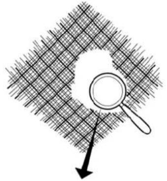 | |
| Damaged or worn valve guide or valve seals. | Check the valve guide and the valve seals. |
| The piston(s) has/have been fitted incorrectly. | Check whether the pistons have been fitted correctly. |
| Faulty injector seal. | Check the injector seal. |
Turbo compressor
| Possible cause Remedy | |
| The air filter element is blocked. Replace the air filter element and clean the turbine side of the turbo compressor. | |
| The turbo compressor oil return line is blocked. Check the oil line. If necessary, replace it. | |
| The compressor side of the turbo compressor is contaminated. | Clean the compressor side. |
| The turbo compressor is damaged. Trace the cause of the damage and replace the turbo compressor. | |
3.2.3 CYLINDER HEAD
The inlet valve is broken
| Possible cause Remedy | |
| The engine distribution is incorrectly configured. Check the engine distribution's configuration and also check the other pistons for valve impressions. | |
The outlet valve is broken
| Possible cause Remedy | |
| The engine oil level is too high. Check the gearbox's safety device. | Check the DMCI for relevant error codes. |
| The engine distribution is incorrectly configured. Check the engine distribution's configuration and also check the other pistons for valve impressions. | |
The outlet valve disc is burnt
| Possible cause Remedy | |
| Incorrect valve clearance. Check the valve clearance. | Check the other outlet valves. |
The cylinder head gasket is damaged
| Possible cause Remedy | |
| The head gaskets have not been fitted correctly and have started to leak. | Check the cylinder heads and the cylinder block. |
| The cylinder heads were not tightened according to the specified tightening procedure. | Check the cylinder heads and the cylinder block for damage and fit the cylinder heads. |
| One of more threaded holes for the cylinder head bolts are cracked or damaged. | Check the cylinder block. |
| The height of the cylinder lining above the cylinder block is incorrect. | Check the height of the cylinder lining. |
| The cylinder head is cracked. Check the cylinder heads. | |
| The surfaces of the cylinder head and the cylinder block have been knocked. | Check the surfaces of the cylinder heads and the cylinder block. |
| One or more cylinder head bolts of the wrong type or the wrong dimensions have been used. | Use the specified bolts. |
| The coolant temperature is too high See “The coolant temperature is too high, cooling system” The coolant temperature is too high (☐3 - 4). | |
The coolant temperature is too high
| Possible cause Remedy | |
| Faulty intake system. Check the intake system. | |
| Incorrect poly V-belt tension. Check the poly V-belt tension. | If necessary, replace the poly V-belt or the poly V-belt tensioner. |
| The coolant level is too low. Check the coolant level. If necessary, top it up. | |
| A coolant hose is cracked or blocked. Check/clean the coolant hoses. | |
| The cooling system's intercooler and radiator are contaminated. | Check/clean the cooling system's intercooler and radiator. |
| The waste-gate setting too high. Check the waste-gate setting. | |
| The turbo compressor housing's air hose to the waste-gate diaphragm leaks or is not connected. | Check the air hose. If necessary, replace it. |
| The pressure cap is faulty or does not work. Check the pressure cap. | |
| The thermostat opens insufficiently or does not open. Check the thermostat and its operation. | |
| The coolant filter is contaminated. Check the coolant filter. | If necessary, replace the filter and clean the cooling system. |
| The wrong type of thermostat is fitted. | Check the thermostat and its operation. |
| The coolant pump is faulty. | Check the coolant pump's shaft, bearings and fan. If necessary, replace the coolant pump. |
| The fan drive is faulty. | Check the fan drive's operation. |
The cylinder lining is worn
| No normal cylinder wear. | |
| Possible cause Remedy | |
| Highly polluted air has been drawn in over a long period of time. | Check the air filter and the entire air intake system. |
| Damaged piston(s). Check the piston(s). | |
| The cylinder lining has become worn due to poor cylinder lubrication. | Check the lubrication system. |
| The wrong piston rings have been fitted (load is too high). | Check whether the specified piston rings have been fitted. |
| The piston pin's locking spring is broken or has not been fitted. | Check the pistons. |
Bore-polishing
| Bore-polishing standard:The cylinder walls are honed. This means that the honing pattern consists of high points (A), shallow valleys (B) and deep valleys (C). | 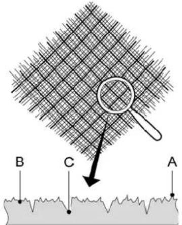 |
| If the deeper honing grooves (C) still show a regular pattern, then bore-polishing is not the problem. | 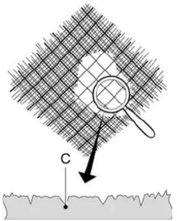 |
| Bore-polishing: smooth surfaces without a visible, regular honing pattern. A, B and C have disappeared. The cylinder bore must be replaced if there is any degree of bore-polishing. | 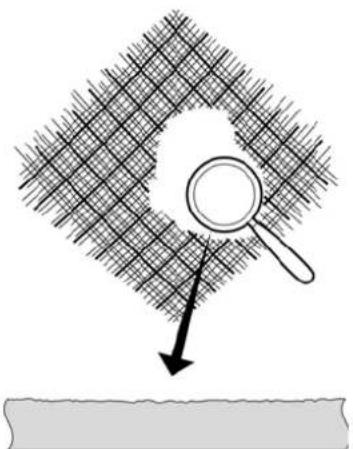 |
| Possible cause Remedy | |
| Oil with the incorrect specifications has been used in the engine. | Replace the cylinder lining and use engine oil that meets the specifications. |
| Excessive underloading or overloading of the engine during the running-in period. | Replace the cylinder lining, instruct the driver how the vehicle should be run in. |
The connecting rod is bent
| There is a layer of liquid above the piston (hydraulic lock) which has caused the connecting rod to bend. | |
| Possible cause Remedy | |
| There is water in the air filter as a result of:- Spraying clean with water.- Driving through very deep water. | Check whether the head gasket has been knocked.Inspect the cylinder head for cracks.Check the cylinder block and drive for consequential damage.Find out how long the water has been leaking. |
| The head gasket leaks or the cylinder head or the cylinder block is cracked. | Check the cylinder head gasket(s).Inspect the cylinder head(s) for cracks.Inspect the cylinder block for cracks. |
| A fuel injector does not close correctly. Check the operation of the injector(s). | |
The tappets are broken or cracked
| Possible cause Remedy | |
| If only the exhaust valve tappets have been broken: the engine speed is too high. | Check the engine protection data in the engine management system.Instruct the driver if the engine has had a too high engine speed a number of times.Check the camshaft for damage. |
| The corresponding valve is stuck. Check the valves. | Check the camshaft for damage. |
A tappet has pitting
| Possible cause Remedy | |
| The roller tappets are subjected to an extreme load as a result of the extremely intensive mechanical contact. This heavy load, in combination with lubrication problems, can cause pitting. | Reuse is not permitted in the event of excessive pitting. Check the camshaft for damage. Check the play between the roller tappet and the roller tappet strip. |
The camshaft displays pitting
| Possible cause Remedy | |
| During assembly, dirt has got between the camshaft and the roller tappet. | Check the camshaft and the roller tappets for damage. |
| There is too much play between the roller tappet and the roller tappet strip. | Check the play between the roller tappet and the roller tappet strip. |
The bearing shells are excessively worn
| Possible cause Remedy | |
| The lubrication oil has been diluted by coolant. Check the oil cooler.Check the cylinder block and the cylinder heads for cracks or a knocked head gasket by pressure-testing the cooling system.Check the bearing necks for damage and see whether they are the correct size.Check and clean the lubricating oil system. | |
| The lubrication oil has been diluted by fuel. Check the fuel system.Check the bearing necks for damage and see whether they are the correct size.Check and clean the lubricating oil system. | |
| Contaminated lubricating oil due to:- Contaminated oil filter.- Not changing the oil soon enough.- Not replacing the oil filter soon enough.- Excessive contamination within the replacement period.- Worn areas on the rotating section.- Broken oil filter.- Dirt which was not removed after assembly. | Check the bearing necks for damage and see whether they are the correct size.If the bearing necks have grooves, the crankshaft will have to be replaced or ground.Check and clean the lubricating oil system. |
| Too little lubricating oil due to:- The oil level being poorly checked.- Too low oil level.- Not topping up the oil.- Excessive oil use.- An external oil leak.- Air bubbles in the lubrication system due to a loose oil delivery line.The connecting rod bearings will be damaged first in the event of reduced oil pressure, because they are further away from the oil pump than the main bearing. | Check the engine for external oil leaks.Check the bearing necks for damage and see whether they are the correct size.If the bearing necks have grooves, the crankshaft will have to be replaced or ground.Check and clean the lubricating oil system. |
| No lubricating oil due to:- Loose or worn oil drain plug.- Blocked oil duct.- Incorrectly assembled bearing.If there is a sudden loss of oil, the main bearings will become worn first, because they will immediately not receive any more oil. | Check the bearing necks for damage and see whether they are the correct size.If the bearing necks have grooves, the crankshaft will have to be replaced or ground.Check and clean the lubricating oil system. |
The bearing shell has grooves on it
| Possible cause Remedy | |
| Dirt has got between the bearing shell and the initial bore of the main bearing or the piston rod during assembly. | Replace the bearing shells.Check the bearing necks for damage and see whether they are the correct size.Check and clean the lubricating oil system. |
PISTON
Valve impressions on the piston base
| Possible cause Remedy | |
| A broken valve spring. Check the valve springs. |
A number of pistons have a valve mark
| Possible cause Remedy | |
| The valve timing is incorrect. Check the valve timing. | |
| A distribution gear wheel is loose. Check the distribution | gear wheels. |
| The engine runs at a speed which is too high when all the outlet valves have touched the pistons. | Check the gearbox's safety device.Check the engine protection data in the engine management system.Instruct the driver if the engine has had a too high engine speed a number of times. |
| One or more teeth on the camshaft gear wheel are in the wrong position. | Check the position of the camshaft gear wheel. |
Impressions on the piston base
| Possible cause Remedy | |
| During work, a foreign object has got into the combustion chamber via the inlet/exhaust manifold. | Check the other pistons, the cylinder lining and the valves for damage.Check the inlet and outlet systems. |
The piston base is cracked
| Possible cause Remedy | |
| The mixture is too rich. Check the engine management system. | |
| The wrong injection moment. Check the engine management system. | |
| Poor fuel distribution due to poorly operating injectors. Check the operation of the injectors. | |
| Fuel injection when the engine brake is applied. Check the engine management system. | |
Pitting on the piston base
| The piston base has touched the cylinder head; there are no cracks. | |
| Possible cause Remedy | |
| The wrong cylinder head gasket has been fitted. Check w | whether the correct cylinder head gasket has been fitted. |
| Excessive play on the piston rod bearing or the piston pin is worn. | Check the piston rod and the piston. |
The piston rings are worn
| Check the cylinder lining for signs of wear. | |
| Possible cause Remedy | |
| Poor lubrication of the cylinder as a result of fuel in the lubrication oil. | Check the fuel system. |
| Poor lubrication of the cylinder as a result of coolant in the lubrication oil. | Check the cooling system. |
| The intake air is contaminated. Check the intake system. | |
| The piston rings are stuck in the groove. Check the size. | |
Piston ring groove enlarged
| Possible cause Remedy | |
| The piston ring is broken.When the ring was fitted, it was bent open too much, so that a hairline crack was produced. | Check the other piston rings. |
| The intake air is contaminated, so the piston rings are excessively worn. | Check the entire air intake system. |
Piston barrel enlarged around piston pin hole
| Damage caused by the piston pin lock spring (or springs) that has (or have) been driven out. | |
| Possible cause Remedy | |
| The lock spring for the piston pin is broken or has been fitted incorrectly. | |
| The piston rod has been bent. Check whether the piston rod is straight. | |
| Excessive play on the piston pin, piston pin hole in the piston, the piston pin eye or the piston rod bearings. | Check the piston rod bearings. |
The piston has grooves in it
| Mainly around the piston pin holes. | |
| Possible cause Remedy | |
| Excessive heating of the cylinder due to a lack of coolant. | Check the cooling system. |
| There are air bubbles in the cooling system. Check the bleeding system. | |
| Mainly on the delivery side of the piston. | |
| Possible cause Remedy | |
| The piston barrel has been cracked at the piston pin holes due to overheating. | Check the cooling system. |
| Slight grooves on the delivery side of the piston. | |
| Possible cause Remedy | |
| The piston is not sufficiently cooled/lubricated, since a cold engine has been brought to a high speed too quickly. | Check the cooling system. |
| On the surface of the piston barrel and te grooves stretch out to the area of the piston ring. | |
| Possible cause Remedy | |
| A lack of lubrication due to a bent oil injector or a too low engine oil level. | Check the oil injectors.Check the oil level. |
| In the area of the piston ring. | |
| Possible cause Remedy | |
| The lubrication oil has been washed away in places due to a leaking/dripping/partially blocked fuel injector. | Check the operation of the injector. |
| The entire surface of the piston barrel. | |
| Possible cause Remedy | |
| Overheating of the cylinder due to a lack of coolant/lubrication over a long period of time. | Check the cooling system and/or the lubrication system. |
The piston pin has grooves in it
| Possible cause Remedy | |
| Stuck piston pin due to too little play between the piston pin eye and the piston pin or between the piston pin and the piston. | Check the size of the connecting rod eye.Check the size of the piston pin.Check the size of the piston pin hole. |
| Faulty or bent oil injector. Check the oil injector(s). |
3.3 DRIVEN AXLES
3.3.1 GENERAL INFORMATION
Oil leak
| Possible cause Remedy | |
| The oil level too high Correct the oil level. | |
| The oil has the wrong viscosity. Drain the oil and fill with oil that meets the specifications. | |
| Oil seal leaks. Replace the oil seal. | |
| The bleed valve is blocked. Clean the bleed valve or replace it. | |
| There is an oil leak between the contact surfaces of the differential housing | Clean the contact surfaces and apply new sealant. |
3.3.2 VIBRATIONS AND NOISES
Rattling noise in the differential
| Possible cause Remedy | |
| Damaged or broken spider with stuck or seized ring gear.Caused by long-lasting, excessive wheel spinning. | Clean the entire differential and check all the components for damage.Replace all the damaged components. |
Noises in the rear axle
| Possible cause Remedy | |
| Too low oil level. Top up the oil. | |
| The oil has the wrong viscosity. Drain the oil and fill with oil that meets the specifications. | |
| The attachment bolts have come loose or differential block components have broken off. | Drain oil and check the drained oil for the presence of pieces of metal. |
| There is play in the pinion bearing. Adjust the pinion bearing or, if necessary, replace it. | |
3.4 AXLE MOUNTING AND SUSPENSION
3.4.1 SHOCK ABSORBER
Shock absorber does not work
| Possible cause Remedy | |
| Internal fault in the shock absorber. Replace the shock absorber. | |
| Too little oil in the shock absorber due to an oil leak. Replace the shock absorber. | |
Leaking shock absorber
| Note: a thin, greasy layer is normal. | |
| Possible cause Remedy | |
| Piston rod seal is faulty. Replace the shock absorber. | |
The shock absorber's damping is too firm
| Possible cause Remedy | |
| Wrong type of shock absorber is fitted. Replace the shock absorber. | |
| Internal fault in the shock absorber. Check the shock absorber. | |
Shock absorber damping too soft.
Is this symptom the result of a technical fault?
External factors or improper use can also lead to this fault.
It is important to obtain a proper idea of the problem.
Try to gain as much information as possible from the customer or driver.
This symptom can be the result of overloading the vehicle.
| Possible cause Remedy | |
| Wrong type of shock absorber is fitted. Replace the shock absorber. | |
| Internal shock absorber wear. Check the shock absorber. | |
| Oil leak from the shock absorber. Replace the shock absorber. | |
Shock absorber continues hitting
Is this symptom the result of a technical fault?
External factors or improper use can also lead to this fault.
It is important to obtain a proper idea of the problem.
Try to gain as much information as possible from the customer or driver.
This symptom can be the result of overloading the vehicle.
| Possible cause Remedy | |
| Broken stop block. Replace the stop block. | |
| Not enough shock absorption. See the fault finding table: “ | Shock absorber damping too soft, Axle mounting and suspension, Shock absorber”.Shock absorber damping too soft. (3 - 13) |
| The shock absorber is broken. See the fault finding table: “ | The damping does not work,Axle mounting and suspension, Shock absorber”.Shock absorber does not work (3 - 13) |
The shock absorber makes a noise (banging, rattling, etc.)
| Possible cause Remedy | |
| The shock absorber is loose. Tighten the shock absorber. | |
| The rubbers on the attachment are too soft. Replace the | attachment rubbers.Replace the shock absorber. |
| The shock absorber is touching other components. | Check whether the shock absorber touches other com-ponents. |
| The protective cover is loose. Secure the protective cover. | Replace the shock absorber. |
3.4.2 REAR AXLE ALIGNMENT
Axle tilt
Is this symptom the result of a technical fault?
External factors or improper use can also lead to this fault.
It is important to obtain a proper idea of the problem.
Try to gain as much information as possible from the customer or driver.
Pull can also be caused by an uneven distribution of the load.
| Check the alignment after every correction that is made and, if necessary, correct the alignment. | |
| Possible cause Remedy | |
| Incorrectly adjusted or faulty height control. Check the height control. | |
| Bent torque rod. Replace the torque rod. | |
| Incorrectly fitted torque rods (tandem axle pneumatic suspension). | Check the torque rod. |
| Difference in length between the torque rods on the left-hand and right-hand sides of the vehicle. | Adjust the length of the torque rod. |
| The axle beam is bent. Determine the cause (accident or overloading the vehicle) and replace the axle. | |
| The bodywork is heavier on one side. Check the wheel pressure. | |
| The chassis is bent. Check the chassis. | |
3.5 DRIVER'S SEAT
The seat cannot be raised
| Possible cause Remedy | |
| Insufficient system pressure. Check the supply of air to the chair. | |
| The air supply system is blocked. Check the air supply system. | |
| The pins for the level control valve do not press against the control discs' running surface. | Raise the chair to the highest position. |
The chair moves up and down by itself
| Possible cause Remedy | |
| There is a leak in the pneumatic system. | Check the level control valve, the air suspension and the air lines for leaks. |
| The cylinder in the control disc unit does not return to the original position. | Check the cylinder's attachment bolts. |
| Excessive resistance. Check the resistance in the frame | or the system. |
The chair's height cannot be adjusted
| Possible cause Remedy | |
| The adjustment cylinder does not move. Replace the adjustment cylinder. | |
| The height adjustment valve is faulty. Replace the valve or the control button. | |
| The shuttle valve is faulty. Replace the valve. | |
The chair works, but cannot be moved downwards
| Possible cause Remedy | |
| The air line is bent. Check the air line for bends. |
REPAIR GUIDELINES
1. GENERAL INFORMATION
1.1 TECHNICAL DOCUMENTATION
Technical knowledge level
The technical documentation has been written based on the assumption that the repair and maintenance work will be carried out by an experienced, well trained mechanic. This mechanic must be qualified to carry out the work in a responsible and safe manner.
Content of the technical documentation
The content is based on the products that are manufactured by VDL Bus & Coach and is in agreement with the standard conditions and regulations.
1.2 TECHNICAL INFORMATION
If tightening torques are stated in the "Technical information" with a certain tolerance, such as 700 Nm ± 50 Nm, a torque spanner must be set to the given value without giving attention to the tolerance. The function of the tolerance (50 Nm in the example) is for the use of the torque spanner.
These tightening torques deviate from the standard tightening torques given in the standard tightening torques overview.
The threaded connections which are not stated here must, therefore, be tightened to the torque given in the standard tightening torques overview.
If any attachment aids (attachment nuts and bolts) are replaced, it is very important that the new attachment aids are exactly the same length and quality as those being replaced, unless otherwise stated.
1.3 ENVIRONMENT
Carrying out work, such as maintenance work, regularly, on time and with the necessary skill helps to reduce pollution of the environment.
This can be achieved by noticing and repairing any leaks in time and by keeping the engine in an optimal condition (adjusting the valves, replacing the air filter element, etc.), so that there is a smaller emission of harmful gases.
It should also be mentioned that oils and liquids contain harmful elements which pollute the environment.
Therefore, make sure the drained oils, greases and liquids, as well as the used oil filters and fuel filters, are collected in appropriate, separate containers.
When working on the fuel system, collect any fuel that is released in a clean container. The fuel can be reused after it has been filtered.
If a vehicle or a component is cleaned with a high-pressure hose or a steam cleaner, then this must take place in a suitable washing area where oils and greases can be collected.
A number of components contain lubrication oil and/or grease. Always drain the liquids that are present in components when disposing of the vehicle or a component.

Always be conscious of the environment when carrying out work.
1.3.1 RECYCLING
- Drain environmentally harmful liquids, such as oil, hydraulic oil and coolant.
- Empty the air conditioning system.
- Separate the components that are considered to be chemical waste.
1.3.2 DISPOSAL OF COMPONENTS
Pay attention to the following when disposing of components:
• Non-chemical waste.
- Chemical waste.
Overview of components that must be considered to be chemical waste:
- Fuel filter
- Oil filter
- Battery.
- Catalytic converter (use the local regulations to determine whether this component should be considered to be chemical waste).
- Soot filter.
1.4 CLEANLINESS INSTRUCTIONS

Not observing the cleaning instructions may result in serious damage to the systems and/or components.
Always observe the warnings and the safety regulations.
Cleanliness
Make sure the work area and the tools are clean. Waste, components and tools may cause uncleanliness.
Cover seats and other parts of the vehicle when work must be carried out inside the vehicle.
Before cleaning the vehicle, check the engine, axles, gearbox, etc. for leaks.
Before starting the work, clean the area surrounding the components to be repaired or disassembled. Do not carry out repairs if the surrounding area is not clean or if this will have a negative effect on the repair, because it will result in mechanical damage.
Place clean, disassembled components in a dry location and cover them with a dry, suitable cover. Plug the areas where components have been removed so that no dirt can penetrate.
Cleanliness
Make sure components remain clean as long as they have not been unpacked.
As soon as a component has been unpacked, it must be assembled as quickly as possible in order to avoid the component from unnecessarily coming into contact with dirt. Only remove new components from the packaging at the moment they must be assembled.
Comment
Cover unpacked components if they cannot be assembled straight away.
1.5 HIGH-PRESSURE HOSE
It is advisable to clean a vehicle with a high-pressure hose before starting work on a vehicle. A clean vehicle makes the mechanic's work easier and enables him to notice any faults at an early stage.
Comment
Before cleaning the vehicle, check the engine, axles, gearbox, etc. for leaks.
If the vehicle is cleaned with a high-pressure hose, the high-pressure hose must be used with care. It is also important to observe the following points:
- Make sure doors, windows and roof hatches are securely closed when cleaning the vehicle.
- When cleaning the universal joint on the steering box, the spider seals may be forced open by the high-pressure jet of water, so that the grease behind them will be flushed away. As a result, the spider may get stuck and cause the steering mechanism to jam.
- A bleed valve is fitted to the steering mechanism's power-steering reservoir. Water may enter the tank through this valve, causing damage to the steering mechanism.
- Be careful not to damage the lamellae when cleaning the radiator/intercooler.
- Do not direct the jet of the high-pressure hose at the air conditioning system's condenser for too long. As a result of the high temperature, excessive pressure will build up in the system, which will cause damage to the system.
- Ensure that no water can enter the differential or the gearbox via the bleed openings.
- Make sure no water can enter via the bleed screws on the reservoirs for the clutch, brakes, trailing axle, etc.
-
The engine and engine compartment can be cleaned with a high-pressure hose. Make sure, in this case, not to spray directly on to electrical components, such as the starter motor, alternator, etc.
-
To avoid damage to the engine encapsulation when spraying it, maintain a minimum distance of 50~cm between the engine encapsulation and the sprayer nozzle.
- Do not aim the jet directly at electrical connections, such as connectors, lighting feed-through connections, etc.
- Make sure no water can enter the air intake system via the air inlet or its flexible seals.
- When the vehicle has been cleaned, it must be lubricated again with a grease gun or via the central lubrication system. This is important, because it prevents the penetration of moisture and dirt at the various pivot points.
1.6 TOOLS
Use good, reliable, approved tools for all the work.
Only use tightening tools for tightening and have them regularly calibrated.
If necessary, use special tools as specified in the instructions.
1.7 WORK ON THE ENGINE
- The earth cable must always be removed from the battery when carrying out work that does not require the vehicle to have an electrical power source.
- Dirt may enter the system when opening the engine or parts of the engine. This may cause serious damage to the engine. Therefore, clean the engine thoroughly before it is opened.
- The engine encapsulation must, if necessary, be thoroughly cleaned after all work, because there is a risk of fire if the inside of the encapsulation is dirty.
- A certain quantity of fuel may be released when removing engine components or fuel system components. To keep this quantity of fuel to a minimum, unscrew the tank cap to allow any excess pressure to escape. Collect any fuel that escapes and remain aware of the fire risk.
- A certain quantity of fuel will be released when removing components from the fuel system. To keep this quantity of fuel to a minimum, unscrew the tank cap to allow any excess pressure to escape.
- Dirt may enter the fuel system when disassembling components. This may cause serious damage. Therefore, clean the area surrounding the fuel system before it is opened. Disconnected lines must be plugged.
Comment
For the cleanliness instructions, see 3 - 1.4 Cleanliness instructions (☐1 - 5).
1.8 GUIDELINES FOR A TEST DRIVE AND VISUAL INSPECTION
A test drive is required after a safety-critical component has been repaired and a visual inspection is insufficient to determine the vehicle's correct driving behaviour. Check the warnings and the vehicle's driving behaviour during a test drive. Also check the brake system for leaks if repairs have been carried out on the brake system.
The electronic systems must not have any active warnings when the vehicle is delivered.
Carry out a system inspection if:
- There is a chance that a mechanic makes a wrong connection, such as if lines are of the same length.
- If repairs have been made to liquid-related systems.
2. COMPONENTS
2.1 GENERAL INFORMATION
All parts and components are carefully matched to each other, which helps to determine the original VDL Bus & Coach quality.
Logically, this quality can best be maintained by using original VDL Bus & Coach parts and components when parts and components need to be replaced.
From a maintenance point of view, this applies to components such as the windscreen wiper blades, air dryer element, gaskets, V-belts and filters.
If, for example, non-original VDL Bus & Coach filters are used, insufficient protection may be provided against microscopic dust particles in the air, hardly noticeable metal shavings in the oil and contamination in the fuel. This will result in:
- The early replacement of cylinders, pistons, bearings, valves, the injection pump and other moving parts.
• A reduction in the engine performance. - An increase in fuel consumption.

Therefore, always use original VDL Bus & Coach parts and components.
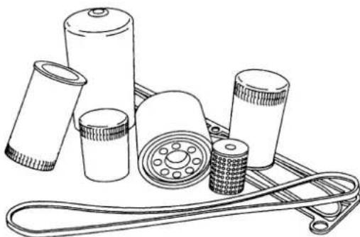
natural_image
Line drawing of various mechanical components including batteries, rollers, and a belt drive (no text or symbols)ILAz0037
2.2 PLASTIC LINES
Removing nipples or banjo unions from polyamide lines
- Heat the line to remove the nipple or banjo union. Never remove the nipple or banjo union by making an incision along the length of the line, because this could easily damage the line adaptor. Even minor damage to the hose adaptor will cause a leak.
Fitting nipples or banjo unions to polyamide lines
- Do not fit nipples or banjo unions to the same end of a line more than once, because this could result in a poor seal.
- Cut off the bit of the line that has been used before. If shortening the line means that it now makes a sharp curve or it becomes too short, a new line must be fitted.
- Always use a special pair of pliers (VDL Bus & Coach no. 40694829) to fit nipples and banjo unions in polyamide lines.
- Clamp the plastic line in the special tool (1).
- Use a plastic mallet to tap the nipple or banjo union into the line.
Never heat a plastic line when fitting nipples or banjo unions.
Leaking lines
To avoid dangerous situations, a leaking fuel or air line must be repaired as soon as possible.
A leaking fuel line may constitute a fire hazard, while a leaking air line may affect the vehicle's braking performance.
In the event of a leak from a line coupling, it is not permitted to continue tightening the cap nut or the banjo bolt.
- First check whether the leak is at the connection between the line and coupling or at the connection between the coupling and the component housing.
- Tighten banjo bolts to the specified torque.
- A cap nut may only be tightened a further half turn (180°) once. Tightening a cap nut further than this is possible, but may cause excessive deformation of the thrust washer and the line, which will seriously weaken the line.
- If the leak has not stopped after the cap nut has been tightened, it will be necessary to take the coupling apart.
- Check the parts for contamination and/or damage. One scratch along the length of the line adaptor for a nipple or a banjo union may be sufficient to cause a leak.
- In the case of a banjo bolt connection, check the sealing surfaces. Reconnect using new sealing rings. Tighten the banjo bolts to the specified torque.
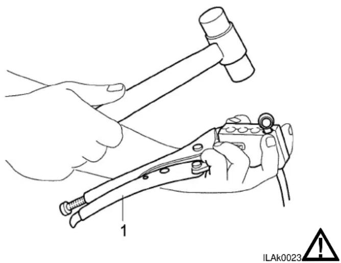
natural_image
Illustration of hands using a crimping tool to adjust a hensel, with no text or symbols present.Fitting clamping ring connections
For air connections where a clamping ring connection is used, the clamping ring connection must be fitted in such a way that the clamping ring (2) is slid as far as possible over the air line and is cut into (clamped on to) the polyamide line at least 2 mm from the end of the air line.
The strengthening sleeve (1) will then be pushed into the air line as far as the stop.
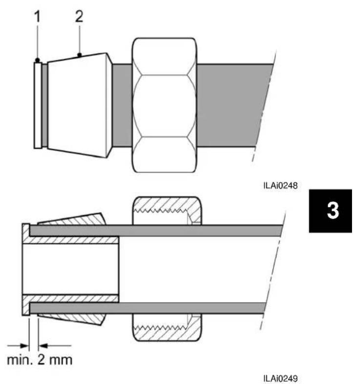
text_image
1 2 ILAi0248 min. 2 mm 3 ILAi0249Fitting a new clamping ring connection
- Make sure the air line is cut so that it is flat and has no burrs.
- Fit the cap nut and the clamping ring on to the air line.
- Push the strengthening sleeve into the air line so that it is fully in the air line. If necessary, use a rubber or mallet.
- Push the air line together with the clamping ring construction into the connection coupling until it touches and tighten the cap nut on to the coupling by hand.
- Tighten the cap nut to the specified torque.
- Loosen the connection and check whether the clamping ring is clamped to the air line at least 2 mm from the end of the line.
- Tighten the connection to the specified torque.
- Check whether there is an air leak.
Rubbing through of lines
Plastic lines may rub through when they touch each other or other parts of the vehicle.
Immediately replace any lines that show signs of wear.
When lines are fitted so close together or so close to other parts of the vehicle that they may touch each other or be expected to rub through, they must be secured so that they cannot touch each other or other parts of the vehicle. Use the specially developed line clamps to do this. These line clamps
are available for lines with a diameter of 6 mm, 10 mm and 22 mm. The line clamps can be joined together.
Rubbing through can sometimes be prevented by unscrewing an elbow piece or a T-piece and then retightening it in a slightly different position. Secure the lines with clamping straps.
2.3 GASKETS
2.3.1 PAPER AND KLINGERIT GASKETS (RUBBER-ARAMIDE FIBRE)
The workshop instruction manual gives information about which type of gasket is to be used in which situation.
Replacing gaskets
- Remove the old gasket before fitting a new one.
- Clean the contact surfaces and check them for damage.
- Paper gaskets should be lightly greased before being fitted. This type of gasket is used to seal flat surfaces and is resistant to oil and moderate heat.
- Do not apply grease to Klingerit gaskets before fitting. These gaskets usually have a layer of graphite applied to them. This type of gasket is used to seal flat surfaces and is resistant to oil, water and heat.
- There are different instructions for cylinder head gaskets.
- Always tighten the attachment bolts evenly.
The instructions give information about which type of sealing product is to be used in which situation.
Liquid gaskets, which replace conventional gaskets, have been developed to seal flat connections. They are resistant to oil, water and temperatures up to approx. 200^ C.
Apply the liquid gasket as described below.
Applying liquid gaskets
- Remove all sealant residue and clean the surfaces to be sealed.
- Sparingly apply the specified sealant to one of the surfaces to be sealed. Also apply sealant around studs, bores, etc. to ensure they are properly sealed.
- If sealant has got into an (oil) bore, it should be carefully removed.
- Put the surfaces to be sealed against each other and tighten the attachment bolts evenly.
2.4 OIL SEALS
2.4.1 REMOVING AND INSTALLING OIL SEALS
Removing an oil seal
- If possible, use the special tools VDL Bus & Coach no. 41329458 and VDL Bus & Coach no. 40694928, or VDL Bus & Coach no. 40694928 (A) and VDL Bus & Coach no. 40484899 (B) to remove oil seals. Be careful not to damage the chamber when removing an oil seal.
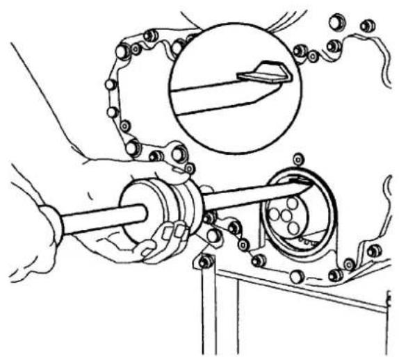
natural_image
Mechanical assembly diagram showing a shaft, gear mechanism, and circular component (no text or symbols)ILAk0024
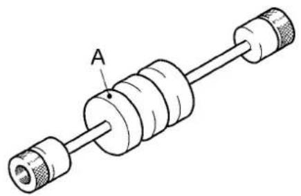
natural_image
Technical line drawing of a cylindrical mechanical component with labeled point A (no text or symbols beyond label)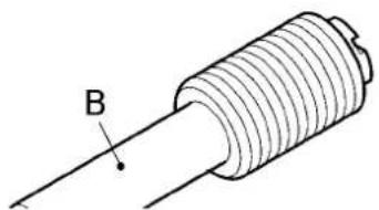
natural_image
Diagram of a solenoid with labeled point B, showing internal structure and conductor (no text or symbols beyond label)ILAk0025
Installing an oil seal
- Check the chamber in which the oil seal is to be fitted for damage. Repair any possible damage.
- Look for any marks on the outside of the oil seal which have been added to indicate the shaft's direction of rotation.
- Always use a suitable driving tool to install an oil seal and press the ring evenly into place in the chamber.
- Once a unitized oil seal has been removed from the chamber, it must not be reused.
- In most cases, a conventional oil seal with a steel sleeve is fitted with a liquid gasket and an oil seal with a rubber sleeve is fitted with oil or liquid soap.
- Unless otherwise stated, always fit unitized oil seals in a dry condition.
- Always apply a small amount of oil or grease to the sealing lip(s) and running surface of a conventional oil seal.
2.4.2 INSTALLING A SCAT SEAL
Scats are used in places where wires are exposed to heavy conditions (the environment or vehicle uses) and where there is, therefore, a risk of water getting into the connector. The Scat seal, which is made from silicon, prevents corrosion within the connector and maintains the sealing properties under changing temperatures. The Scat seal is pressed around the wire together with the contact pull relief. Scats are available in different colours and sizes.
2.5 BEARINGS
2.5.1 GENERAL INFORMATION
- A bearing must be replaced if it is worn, if it has become pitted (small dents in the running surface) and/or if the bearing has been exposed to excessive heat (blue spots).
- When fitting a bearing, make sure no force is transferred via the bearing's ball bearings or rollers, for example, by fitting a bearing to an axle by pushing the outer race.
- Clean the bearing before fitting it.
- Avoid dirt from getting into the bearing while it is being fitted.
- If the instructions specify that the bearing should be heated before it is fitted, avoid exceeding the specified temperature. Also avoid local overheating.
- Raise the temperature of the bearing evenly by heating it in an oil bath intended for this purpose. Another option is to place the bearing on an electric cooker. Pay close attention to the temperature when doing so.
2.5.2 FITTING BEARINGS INTO A BEARING HOUSING
- Always use a suitable driving tool.
- Centre the driving tool accurately on the outer bearing race.
- Press the bearing evenly into the housing, preferably using a pressing tool.
2.5.3 FITTING BEARINGS TO A SHAFT
- Always use a suitable punch.
- Centre the punch carefully on the inner bearing race.
- Press the bearing evenly on to the shaft, preferably using a pressing tool.
LIQUID AND LUBRICANT GUIDELINES
1. GENERAL GUIDELINES
1.1 GENERAL INFORMATION
See DW050335XX for an overview of all the permitted liquids and the lubricant specifications.
1.2 ALTERNATIVE FUELS
The worldwide demand for less polluting engine emissions and the increased use of renewable energy sources in order to reduce our dependence on fossil fuels are the most important reasons why alternative fuels are developed. A few of the alternative fuels which have been developed are:
- Biodiesel (FAME) (see 4 - 1.3 Biodiesel (☐1 - 2)).
- Pure plant oil (PPO) (see 4 - 1.4 Pure plant oil (PPO) (1 - 4)).
- City diesel (see 4 - 1.5 City diesel (☐1 - 4)).
1.3 BIODIESEL
All MX11 and MX-13 Euro 6 engines:
Only diesel which has been officially manufactured or mixtures with an alternative fuel containing no more than 7% biodiesel, in accordance with EN590, are permitted.
Biodiesel (FAME) is a fuel that is produced with the aid of agricultural products, such as rape oil, soyabean oil, sugar beet, sunflower oil and palm oil. Rape Methyl Ester (RME), Soyabean Methyl Ester (SME) and Palm Methyl Ester (PME) are used on a large scale. Together, they are known as Fatty Acid Methyl Esters (FAME).
The fatty oils are chemically modified since they particularly react with methanol (esterification), where the long tricyc-ine molecules are split into shorter fatty acid methylester molecules, with the result being a product that is generally similar to diesel with glycerine as a waste product.
Biodiesel properties
The advantages include:
- Biodiesel does not contain sulphur or aromatics, so the exhaust emissions generally contain less particulate matter.
- Biodiesel is biodegradable and non-poisonous. However, if biodiesel is mixed with normal diesel, it practically becomes non-biodegradable.
The disadvantages include:
- Biodiesel is unstable and degrades (at higher temperatures).
- Poor cold starts at low ambient temperatures.
- Lower vaporization effect when heated, which has a negative effect on the oil changing interval.
- Higher NOx levels are produced when burning biodiesel as a result of the high oxygen content – biodiesel has a lower volumetric energy density than diesel, which results in a higher fuel consumption (approx. 10%) and a loss of power (6 – 8%).
- Biodiesel is hygroscopic, which leads to the absorption of water during storage. Bacteria and fungi grow at the interface between water and biodiesel, which leads to the corrosion of components of the fuel injection system and blocked filters.
- Biodiesel is a solvent and can damage paint and elastomers.
- Biodiesel has a high solidification point – phosphorus, sodium and potassium can harm the catalytic converter in the SCR system.
- More maintenance.
Storage and use of fuel
- Users are reminded that fuel standards are only applicable until the time of delivery via the distribution network. After this time, it is the user's responsibility to protect the fuel against contamination with water and dirt during storage in storage tanks, in supply systems and during use in the vehicle, so that engines meet the performance, emission
and durability objectives for which they have been designed.
- Biodiesel is unstable and degrades at higher temperatures. The maximum storage time must, therefore, be limited to a maximum of:
- 4 weeks in fuel tanks of vehicles that are temporarily not in use.
- 6 months for storage in storage tanks and supply systems.
Comment
Biodiesel has solvent properties so that changing from diesel to biodiesel may cause any deposits in the fuel system to become unstuck and the filter to become blocked. When changing from diesel to biodiesel, it is recommended to check the filters after 1 or 2 refuellings and to replace any blocked filters. Biodiesel can cause problems at low temperatures, such as blockages to filters.
1.4 PURE PLANT OIL (PPO)
SVO (Straight Vegetable Oil) or Pure Plant Oil is a fuel that can be extracted from a number of agricultural products, of which rape seed is the most commonly used. In contrast to biodiesel, PPO fuels do not undergo esterification. As a result, they remain very (highly) viscous, even at normal and low temperatures, so that a preheated fuel supply system is essential to improve cold starts or to even make them possible. Engines will run at the operating temperature, but the use of the fuel results in an increase in emissions, deposits in combustion chambers and a reduction in performance and the useful life of fuel injection equipment. The use of PPO is not permitted as a fuel in combustion engines, because the aspects mentioned above lead to unacceptable damage and (reduced) expectations with regard to the useful life of the engine.
1.5 CITY DIESEL
Just like the current fuel for daily use, city diesel is refined from fossil fuel, but the composition is improved during the refining process. A lower sulphur content and a lower aromatics content are common for all city diesel fuels, which, together with other possible chemical changes during the refining process, result in almost sulphur-free emissions with less particulate matter (PM) and a lower nitrogen oxide (NOx) content. City diesel is also known as ULSD (Ultra Low Sulphur Diesel).
1.6 ADBLUE
AdBlue is a non-inflammable, non-poisonous, colourless, odourless and water soluble liquid. AdBlue is a liquid that consists of 32.5% urea and 67.5% water. Special additives are not permitted. If AdBlue comes into contact with painted or aluminium surfaces when refuelling, rinse the area concerned immediately with plenty of water.

AdBlue must meet the DIN 70070 specifications.
High temperatures
If AdBlue is heated in the tank to a temperature of 50 °C for a long period of time, ammonia fumes may be released from the AdBlue as a waste product. Ammonia fumes have a penetrating smell. Therefore, avoid inhaling ammonia fumes that may escape when unscrewing the AdBlue tank's filler cap. This concentration of ammonia fumes is not poisonous or harmful to your health.
Low temperatures
AdBlue freezes at a temperature of approx. -11°C.
Measuring the urea concentration in AdBlue
The urea concentration in AdBlue can be measured using a refractometer.
Use a soft, lint-free cloth to clean the prism and the flip lid and apply a few drops of the liquid to be measured on the prism (1). Closing the lid (2) will cause the liquid to be evenly distributed. Aim the refractometer at a light or a bright background so that the scale and the separation between light and dark can be seen more easily. Rotate the eye piece (3) so that the scale is clearly visible. The measured value for the sample can be read on the border between light and dark.
DIN V70070 refractometer scale for a 32.5% urea solution. At 20 °C, the permitted deviation is between 31.8% and 33.3%.
Special additives
Do not use any special additives for AdBlue and do not use tap water to dilute AdBlue. This can irreparably damage the exhaust gas after-treatment system. Liability for material errors is no longer valid in the event of damage as a result of the use of such additives or tap water.
Storage instructions
- Only use original storage tanks.
- Store in a cool, dry, ventilated area.
- Protect storage tanks against freezing.
- Observe the manufacturer's storage and usage instructions.
bar
| Value (%) | |-----------| | 33 | | 32 | | 31 | | 30 | | 29 | | 28 | | 27 | | 26 | | 25 | | 24 | | 23 | | 22 | | 21 | | 20 | | 15 | | 10 | | 5 | | 0 |ILAk0033
text_image
Technical diagram of a mechanical device with labeled parts 1, 2, and 3ILAk0034
Purity
To prevent faults to the exhaust gas after-treatment system, it is extremely important that the AdBlue is pure. If AdBlue is pumped from a tank for repair purposes, the tank must not be refilled with the liquid that has been pumped out, because the purity is then no longer guaranteed.

- Avoid bodily contact.
- In the event of skin contact, rinse with plenty of water.
- In the event of contact with the eyes, rinse with plenty of water for at least 15 minutes and seek medical assistance.
- If swallowed, rinse your mouth with plenty of water. Do not induce vomiting.
- Use in a ventilated area.

Rinse any spilt AdBlue with plenty of water.
CLEANING INSTRUCTIONS
1. GENERAL INFORMATION
The paint used on our vehicles offers excellent protection against ageing during the vehicle's lifespan. In order to maintain this protection, it is important for the vehicle to be regularly cleaned. This should be done at least once a year. It is important to do so at the end of the winter. Gritting salt has a negative effect on the chassis, the driveline and the bodywork. The underside of the vehicle must be checked for damage after the vehicle has been cleaned. A number of points of attention when cleaning the vehicle are given in this chapter.
1.1 CLEANING THE VEHICLE
Cleaning the vehicle with a high-pressure hose
If the vehicle is cleaned with a high-pressure hose, then attention must be given to the following:
- Make sure the doors, windows and roof hatches are securely closed when cleaning the vehicle.
- The maximum permitted water temperature is 50^ C.
- The maximum permitted water pressure is 80 bar.
- Maintain a minimum distance of 30 cm from the surface to be cleaned.
- It is not permitted to use additives.
- Do not aim the jet directly at electrical connections, such as connectors, lighting feed-through connections, etc.
- Avoid spraying valves, connectors, oil seals, seals and other sensitive parts, because this may lead to a fault.
- Never aim the jet of a high-pressure hose directly at the steering box.
- When cleaning the universal joint on the steering box, the spider seals may be forced open by the high-pressure jet of water, so that the grease behind them will be flushed away. As a result, the spider may get stuck and cause the steering mechanism to jam.
- Be careful not to damage the lamellae when cleaning the cooling unit's radiator/intercooler elements.
- Do not direct the jet of the high-pressure hose at the air conditioning system's condenser for too long. As a result of the high temperature, excessive pressure will build up in the system, which will cause damage to the system.
- Ensure that no water can enter via the bleed openings of any of the reservoirs.
- When cleaning the vehicle, make sure no water enters the air intake system via the air intake or the flexible seals.
- When the vehicle has been cleaned, it must be lubricated again with a grease gun or via the central lubrication system. This is important, because it prevents the penetration of moisture and dirt at the various pivot points.
- Do not aim the spray too long at the same place, because this can result in the penetration of moisture.
Cleaning the vehicle in a car wash
If the vehicle is cleaned in a car wash, then attention must be given to the following:
-
Make sure the doors, windows and roof hatches are securely closed when cleaning the vehicle.
-
The maximum permitted water temperature is 50 °C .
- The maximum permitted water pressure is 80 bar.
- The minimum distance to the chassis/bodywork is 30 cm.
- It is not permitted to use additives.
- The pH value must be between 6 and 8.
- Always rinse the vehicle with clean water.
- When the vehicle has been cleaned, it must be lubricated again with a grease gun or via the central lubrication system. This is important, because it prevents the penetration of moisture and dirt at the various pivot points.
1.2 CLEANING THE ENGINE
Cleaning the engine with a high-pressure hose
The engine and engine compartment can be cleaned with a high-pressure hose. If the engine is cleaned with a high-pressure hose, then attention must be given to the following:
- Carefully clean the engine encapsulation and the parts of the encapsulation. On account of the fire risk, make sure any spilt oil or diesel oil is cleaned up immediately. To avoid damage to the engine encapsulation when spraying it, maintain a minimum distance of 50 cm between the engine encapsulation and the sprayer nozzle.
- Do not spray directly at the electrical components, such as the starter motor and the alternator.
- Do not spray directly at electrical connections, such as the motor management system's connectors.
- Make sure no water can enter the air intake system via the air inlet or its flexible seals.
- Do not aim the spray too long at the same place, because this can result in the penetration of moisture.
Cleaning the engine with a steam cleaner

Wear protective clothing and safety goggles or a face mask when using a steam cleaner. Hot steam can cause a serious injury.
The following components must not be cleaned with a steam cleaner:
• Electrical components.
• Electrical wiring harnesses.
- Injectors.
- The fuel pump.
• (Poly) V-belts and hoses.
- Bearings (ball bearings or roller bearings).
• The electronic control module (ECM).
- EBM connectors.
- The dosing unit.
- The NO _x sensor.
• The engine encapsulation.
1.3 CLEANING THE GEARBOX
Cleaning the gearbox
Observe the following when cleaning the gearbox:
- Only use weak acidic cleaning products. Do not use alkaline cleaning products.
- After cleaning, the gearbox must be thoroughly rinsed with clean water.
- The water temperature during cleaning and rinsing must not be greater than 70^ C.
- The water pressure during cleaning and rinsing must not be greater than 70 bar.
- When spraying the gearbox, maintain a minimum distance of 50 cm between the gearbox and the sprayer nozzle to avoid damage to the gearbox.
- Plug the bleed openings and do not spray directly at the bleed openings.
- Do not spray directly at electrical components and electrical connections.
- Do not aim the spray too long at the same place, because this can result in the penetration of moisture.
Comments
- Give special attention to the strengthening ribs on the top of the gearbox because water could remain behind them.
- Make sure no water that contains cleaning product is left on the gearbox.
Avoiding damage to the paintwork
The ZF gearboxes used by VDL Bus & Coach have a paint layer applied to them during manufacture. This layer of paint is intended to prevent corrosion of the gearbox housing. Corrosion to the gearbox housing may eventually lead to holes in the gearbox housing, which will allow water to penetrate. This will, in time, lead to the gearbox no longer working. To prevent corrosion of the gearbox, it is extremely important that the layer of paint remains in a good condition. An incorrect cleaning method can result in damage to the paint layer and eventually lead to the paint peeling off.
Repairing the paint layer
If the gearbox's layer of paint is damaged or begins to peel off, then it must be repaired. A two-component polyurethane (PUR) paint must be used.
1.4 CLEANING THE INTERIOR OF THE VEHICLE
Cleaning the upholstery
If the chair or interior upholstery must be cleaned, then the following must be taken into consideration:
- Remove the excess dirt from the upholstery with a vacuum cleaner.
- Clean the upholstery using a suitable upholstery cleaner. Before use, read the instructions for the VDL Bus & Coach upholstery cleaner and try to use as little water as possible.
- Use a damp sponge and lightly rub in a circular motion.
- The floor covering can be removed and the excess dirt can be removed using a vacuum cleaner. In view of the drying time for the floor covering, use as little water as possible.

Do not use bleach to clean the upholstery.
Cleaning the dashboard and other plastic parts
The following must be taken into consideration when the dashboard or other plastic components must be cleaned:
- Remove the excess dirt using a vacuum cleaner.
- Clean the dashboard and/or plastic components with a damp cloth. For stubborn dirt, use a VDL Bus & Coach all-purpose cleaner. Read the instructions for the VDL Bus & Coach all-purpose cleaner before use.

Do not use solvents to clean plastic components or the dashboard, because they may cause permanent damage.
Cleaning the seat belts
- The seat belts may be cleaned with a mild soap. Try to use as little water as possible.
- Allow the seat belts to dry normally. Do not use other products, because the structure of the belt's material may become damaged and lose its safety function.
- Seat belts that are not clean may cause problems when automatically rolling up or down, which may have an adverse effect on safety.
1.5 CLEANING PARTS OF THE VEHICLE CONTAMINATED BY LIQUIDS
1.5.1 CONTAMINATED WITH COOLANT
Cleaning upholstery contaminated with coolant
- Remove the coolant stains with the aid of a VDL Bus & Coach upholstery cleaner.
- Try to remove the contamination as quickly as possible. Older stains are more difficult to remove.
Cleaning metal or plastic components contaminated with coolant
- In the event of contamination with coolant, the coolant must be removed from the metal or plastic components with a cloth.
- Rinse the surface afterwards with warm water. In the event of serious contamination, a steam cleaner may also be used.
- If a steam cleaner is used, do not aim the spray too long at the same place, because this can result in the penetration of moisture.
1.5.2 CONTAMINATED WITH DIESEL
Cleaning upholstery contaminated with diesel
- Remove the diesel stains with the aid of a VDL Bus & Coach upholstery cleaner.
- Try to remove the contamination as quickly as possible. Older stains are more difficult to remove.
Cleaning metal or plastic components contaminated with diesel
- In the event of contamination with diesel, the diesel must be removed from the metal or plastic components with a cloth.
- Rinse the surface afterwards with warm water. In the event of serious contamination, a steam cleaner may also be used.
- If a steam cleaner is used, do not aim the spray too long at the same place, because this can result in the penetration of moisture.
1.5.3 CONTAMINATED WITH ADBLUE
Cleaning upholstery contaminated with AdBlue
- Remove the AdBlue stains with the aid of a VDL Bus & Coach upholstery cleaner.
- Try to remove the contamination as quickly as possible. Older stains are more difficult to remove.
Cleaning metal or plastic components contaminated with AdBlue
- In the event of contamination with AdBlue, the AdBlue must be removed from the metal or plastic components with a cloth.
- Rinse the surface afterwards with warm water. In the event of serious contamination, a steam cleaner may also be used.
- If a steam cleaner is used, do not aim the spray too long at the same place, because this can result in the penetration of moisture.
STORAGE AND PRESERVATION
1. POINTS OF ATTENTION
1.1 STORAGE
If the vehicle is not going to be used for a long time, for example, because of a long construction time, measures must be taken to guarantee the quality of the vehicle. These measures depend on the estimated storage and/or construction times.
1.1.1 FLUIDS
- Check all the fluid levels, If necessary, top them up.
- Fill the fuel tank to the maximum level. This will prevent the formation of condensation.
- Check whether the coolant's freezing point meets the factory standard.
1.1.2 AIR CONDITIONING
- If the vehicle is going to be stored for longer than 3 months, the coolant must be removed and the system must be filled with nitrogen.
1.1.3 ELECTRICAL
• The batteries must be removed.
- Store the batteries in a dry location.
- During storage, connect the batteries to a trickle charger, so that the batteries remain continuously charged.
Contact VDL Bus & Coach for the measures to be taken if the vehicle is to be stored for a very long time.
1.1.4 TECHNOLOGY
- Check all the air tanks for condensation and drain any condensation that is present.
- Check the water separator for water and drain any water that is present.
- Place chocks in front of the wheels and release the parking brake by unscrewing the release bolts in the spring brake cylinders as far as possible.
- If the vehicle is going to be stored for less than 6 months, the tyres must be inflated to a pressure which is 0.5 bar greater than normal. If the vehicle still remains stored after 6 months, the tyres must be inflated to this pressure again.
- If the vehicle is going to be stored for longer than 6 months, the vehicle must be supported so that the tyres come off the ground.
1.1.5 EXTERIOR
Storage period of less than 3 months:
- Clean the vehicle (if wax has been applied).
- Repair paint damage.
- Preferably store vehicles indoors or under cover.
- The area where vehicles are parked must be dry and free of overgrowth.
- To prevent drying out, all the rubbers must be protected with, for example, acid-free Vaseline. This applies to:
- Door rubbers
- Window rubbers.
- Windscreen wipers
- Place the windscreen wipers so that they do not touch the windscreen.
- Close the windows, doors and emergency hatches. Make sure the doors are closed properly, so that they do not open if the air pressure drops.
Storage period of more than 3 months:
For a storage period of more than 3 months, the measures given below must be taken into consideration in order to avoid a decline in quality.
Preservation

Observe the applicable environmental regulations.
- Clean the vehicle thoroughly so that all the dirt and dust is removed.
- Use compressed air to remove any residue from the vehicle.
- Cover all the windows, headlights and tail lights.
- Use a spray gun to spray undiluted Rusan D5018 preservative (a FINA product) over the chassis frame and its fittings, all parts and components in the engine compartment and all painted sheet metal parts. Make sure that all plate edges, joints and cavities are sprayed.
- Use a brush to apply Rusan D5018 to the wheel studs.

Never spray Rusan D5018 into the brake drums or on the brake discs.
1.2 PREPARING FOR USE
When a vehicle has been stored and not been used for a long time, the work given below must be carried out in order to prepare the vehicle for use.
1.2.1 FLUIDS
- Check all the fluid levels, If necessary, top them up.
1.2.2 AIR CONDITIONING
- If the coolant has been drained, fill the systems and put them in operation.
1.2.3 ELECTRICAL
- Test the batteries (test report).
- Place the batteries back in the vehicle and connect them. (Use the batteries which have been in storage for the longest. These may, therefore, be batteries from another vehicle.)
- Put the tachograph back into operation. If the vehicle has been stored for more than a year, the tachograph's backup battery must be replaced.

Replace the backup battery according to the procedure. Not doing so will result in irreparable damage.
- Test all the functions.
Contact VDL Bus & Coach for the measures to be taken if the vehicle is to be stored for a very long time.
1.2.4 TECHNOLOGY
- Inflate the tyres to the correct pressure.
- Apply the parking brake by screwing the release bolt as far into the spring brake cylinders as possible.
• Take a test drive and check all the functions. - After the test drive, check all the air reservoirs for condensation. If necessary, drain any water.
- After the test drive, check the water separator for the presence of water. If water is observed, then the fuel tank must be drained. The water must be removed from the fuel.
1.2.5 EXTERIOR
For a storage period of less than 3 months:
- Clean the entire vehicle.
- Clean all the rubbers. This applies to:
- Door rubbers
- Window rubbers.
-
Windscreen wipers
-
Position the windscreen wipers so that they touch the windscreen.
- Repair any damage which may have been caused, including rust and/or corrosion damage (also to the underside of the vehicle).
For a storage period of more than 3 months:
Removing the preservation material

Observe the applicable environmental and safety regulations.
The vehicle should preferably be placed on a grid floor.

Most degreasing agents are inflammable.
The area should be suitable for the safe use of such products.
- Remove the preservative using a solvent, an emulsifying cleaner or a high-pressure, hot water hose with a solvent as an additive.
- Removal of the preservative using a high-pressure, hot water hose should be carried out carefully and evenly. Set the high-pressure, hot water hose to a maximum pressure of 100 bar and a maximum temperature of 90°C.
Never direct the jet too long at the same area, because the high pressure and high temperature may damage the paintwork or rubber components.
If the preservative has not been completely removed from some parts of the treated surface, repeat the process on the remaining preservative.

A steam cleaner is not suitable for removing the preservative, because it requires the use of calcium descaling products to keep the inside of the steam coil clean.

The dried-up residues of these products are almost impossible to remove and have a highly negative effect on the adhesive capacity of the paint (blistering).
- The vehicle must be thoroughly washed with water after removing the preservative.

PAINT TREATMENT
1. PAINT TREATMENT
1.1 GENERAL INSTRUCTIONS

Failure to follow the applicable safety instructions for using paints and related products can result in serious injury and/or danger.

Wear protective gloves and protective glasses when working with a rust-removal agent.

To avoid unnecessary environmental pollution when using paints and related products and when handling paint waste, always work according to the applicable environmental requirements.
This section gives instructions for respraying and repairing VDL Bus & Coach paint systems which have been applied to various base materials.
The products to be used are supplied by a number of manufacturers. However, only use products from reputable manufacturers that provide all the products for a complete paint layer structure. The processing of these products should be described in the instructions provided by the manufacturer.
Work according to the guidelines given below.
- For rust-removal, use a rust-removal agent with a phosphoric acid base.
- For cleaning, use an organic solvent without chlorine additives.
- Use a two-component epoxy or polyester-based primer.
- Use a two-component epoxy or polyester-based basic filler.
- Use a two-component epoxy or polyester-based spray filler.
- Use a two-component epoxy or polyester-based filler.
- Use a two-component PUR finishing coat, with a gloss level of 70 units for a chassis finishing coat (measured at 60 degree geometry).
– Maximum drying temperature of 80^ C. - For the paint layer structure, only use products from a single manufacturer.
- Use the products according to the manufacturer's instructions.
- Never use products in a spray cabin that contain silicon.
Removing rust
- Apply the rust-removal agent in accordance with the manufacturer's instructions.
The concentration of the rust-removal agent must be in ratio to the amount of rust. - Preferably use a rust-removal paste on vertical parts.
– Prevent rust-removal agents entering overlap joints.
– Leave the rust-removal agent to work for the time specified by the manufacturer.
– Rinse the area where rust has been removed at least twice with plenty of clean tap water.
– Dry the area where the rust has been removed from.
1.2 RESPRAYING/REPAIRING CONVENTIONAL PAINT SYSTEMS
General information
- This section gives guidelines concerning respraying and repairing conventional paint systems.
- Only use the products stated in the guidelines, because only then can the paint system be properly repaired.
- Carefully follow the paint manufacturer's instructions when applying paint.
- After welding, also treat the back of welded objects as described below.
Work according to the guidelines given below.
Cleaning
- Use sandpaper (P40 - P60) to remove the burnt paint residue from the area to be repaired.
- Use a rust remover to remove any rust.
- Use a solvent to clean the area to be treated.
- Sand the area to be treated using P80 sandpaper, so that it is completely clean and free of rust.
- Remove any dust from the sanded area with a tack rag.
- Remove any grease and dirt from the area to be treated.
Applying an undercoat
Primer to be used: Priomat ® EP Grundierfüller 4090 kieselgrau by Spies Hecker.
Hardener to be used: Priomat ® Härter 3110.
-
Apply an EP primer to the bare metal parts according to the manufacturer's instructions.
The minimum layer thickness is 20 m. For clamped surfaces (surfaces that are clamped together by a bolt connection, etc.), the thickness of the primer must be 20 m to 45 m. The EP primer can be applied with a brush or a roller. -
Leave the primer to evaporate for approximately 10 minutes.
Next, dry the primer for 30 - 60 minutes at a temperature of 60^ C or for 12 hours at room temperature, depending on the thickness of the layer of primer.

The primer cannot be dried using infrared radiation.
Applying the topcoat
Topcoat to be used: Percotex ® Steinslagschutz halbmatt RAL 7024 graphitgrau by Spies Hecker.
Hardener to be used: Priomat ® Härter 3840.
- Sand the primed areas with sandpaper. Use P320 - P500 sandpaper for dry sanding and P600 - P800 sandpaper for wet sanding. Remove any dust from the sanded area with a Tack rag and clean the area with a solvent.
- Apply the topcoat over the primer and the sanded areas according to the manufacturer's instructions. The minimum thickness is 40 m. Percotex can be applied with a brush or a roller.
- Allow the topcoat to evaporate for at least 60 minutes. Next, dry the topcoat for 60 minutes at a temperature of 70^ C or for 24 hours at room temperature ( 20^ C).
1.3 REPAIRING THE LAYER OF ZINC
Repair
- Only use the products stated in the guidelines, because only then can the paint system be properly repaired.
- Carefully follow the paint manufacturer's instructions when applying paint.
• After welding, also treat the back of welded objects as described below. - Observe the guidelines given below which meet the requirements of NEN-EN-ISO 1461.
1. Cleaning
- Remove any loose flakes of zinc.
- If the surface to be treated cannot be lightly blasted, clean it with a steel brush and/or coarse sandpaper.
- It the still intact layer of zinc 10 mm around the surface to be treated cannot be lightly blasted, clean it with a steel brush/coarse sandpaper.
- Use a Tack cloth to remove any dust from the area to be treated.
- Degrease the surface to be treated and the surrounding area with a solution of, for example, paint thinner.

It is not permitted to treat galvanized steel with a primer with an alkyd resin base.
2. Applying zinc paint
- Primer to be used: Redox EP Multi Primer from Sikkens or 622-Unibar Zinkrich from Baril Coatings.
- Apply a 2-component EP primer (enriched with zinc) to the pre-treated surface in 2 or 3 layers in accordance with the manufacturer's instructions.
The minimum thickness is 100 m. The EP primer can be applied with a brush or a roller.
3. Applying the topcoat
- Topcoat to be used: Redox PUR Finish from Sikkens.
- Apply the topcoat over the primer in accordance with the manufacturer's instructions. The minimum thickness is 50~ m . Redox PUR Finish can be applied with a brush or a roller.
- Apply an antichip coating to the entire treated area (see 7 - 2.2 Antichip coating ([2 - 2]).
2. ANTICORROSION/ANTICHIP COATING
2.1 ANTICORROSION COATING
Hollow cavities and the inside of beams should be demonstrably checked every year for faults.
They should be re-treated every three years. Hollow cavities and the inside of beams should be treated for corrosion after repair to prevent them from rusting on the inside.
2.1.1 PRODUCT
Only use Waxoyl Professional 120-4.
This wax is visible under UV light.
2.1.2 RE-TREATMENT
- Remove all the loose dirt.
- Apply the wax using a flexible tube according to the manufacturer's instructions.
- The required thickness is 40 - 50 m when dry.
2.2 ANTICHIP COATING
The underside of the vehicle is treated with an antichip coating during manufacture.
This coating should be demonstrably checked for damage every year.
This coating must be replaced no later than every three years. Damage to the antichip coating must be repaired as quickly as possible.
2.2.1 PRODUCTS
It is possible for the antichip coating to be different depending on the region in which the vehicle is used.
| Product When/where to use | |
| Dinitrol UBC 4942 Regions | with a temperature below or above 22 °C. |
2.2.2 INSPECTING THE ANTICHIP COATING
- Clean the underside of the vehicle (see 5 - 1.1 Cleaning the vehicle (1 - 2)).
- Check all the external components for damage and check the attachment of the protective layers, such as the antichip coating and the paint.
- Thoroughly check the corners where dirt can collect and, if necessary, remove any dirt.
- Make sure the wheel arches and the surrounding areas are clean.
- Make sure the water drainage holes are not blocked.
- The specified thickness on the underside of the chassis and the plate modules after drying must be at least 650 m (including the powder coating). In other locations, the minimum thickness after drying is 300 m.
Comment
Cracks may appear in time in the corners where the antichip coating is applied.
Small cracks must be repaired. For larger cracks, it is necessary to reapply the antichip coating.

2.2.3 RE-TREATMENT/REPAIR
- Remove the loose coating and the surface rust with a steel brush. Note: do not use a sanding disc or a similar tool, because this will affect the structure of the undercoat.
- Make sure all the parts are dry and free of dust and grease.
- Apply the antichip coating to all the specified parts where it has come loose/worn away. Do this according to the instructions provided by the manufacturer.
- Pay particular attention to the box girders, cross points of the crossbeams, cross points of the diagonals, the sealant seams, the longitudinal beams and the wheel arches.
- Finish the paint in accordance with the paint instructions.
2.2.4 COMPONENTS NOT TO BE TREATED
A coating must not be applied to the following components, because this may have an adverse effect on their operation.
| Wheel suspension Air bellows | Shock absorbersHeight control valvesHeight control sensors |
| Steering mechanism Steering shaft | Universal jointsHydraulic linesBevel gear case |
| Drive line All the drive components, | such as the engine, the gearbox, the drive shaft and the exhaust |
| Pneumatic components Valves | CouplingsAir reservoirs |
| Electrical components Connectors | Electronic unitsDistribution box or fuse box |
| Cables Gearbox cables, if present. | |
| Fuel tanks All the fuel tanks provided by VDL Bus & Coach, with the exception of the top | |
| Absorption materials All. | |
| Insulation materials All. | |

Absorption and insulation material must never be coated, painted or sprayed, because the absorbing, insulating and fire-resistant properties will then be lost.
2.3 SEALANT SEAMS
2.3.1 GENERAL INFORMATION
The seams between panels are sealed with an elastic sealant to prevent the penetration of dirt and moisture. The sealant may be burnt in the event of repair work close to the sealant seams. It is very important that the sealant seams are carefully repaired so as to prevent corrosion between the panel elements. Sealant seams must be demonstrably inspected every year and, if necessary, repaired.
A
B
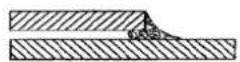
C
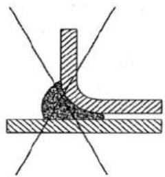
natural_image
Pure mechanical joint diagram without any text, numbers, or symbolsD
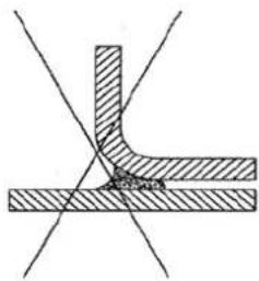
natural_image
Pure mechanical cross-section diagram without any text, numbers, or symbolsE
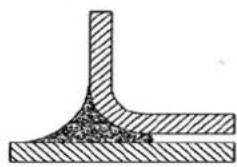
natural_image
Cross-sectional diagram of a mechanical joint or weld (no text or symbols)F
ILAf0019
A. Incorrect (too thick)
B. Incorrect (too thin)
C. Correct
D. Incorrect (too thick)
E. Incorrect (too thin)
F. Correct
2.3.2 REPAIRS TO SEALANT SEAMS
Follow the procedure given below to repair sealant seams:

Always read the manufacturer's instructions before use.
Preparing the surface
- Remove the old sealant.
- Repair the damaged layer of paint:
- Apply a layer of wash primer (Sigma 86DV - 30 mm) to the damaged surface.
- Drying time of the wash primer: minimum of 24 hours at 20 °C.
- Clean the surface with Sika Cleaner-205 using a clean, lint-free cloth or tissue.
Drying time of at least 10 minutes and no more than 2 hours at 20 °C.
- The surfaces must be clean, dry and free of all traces of grease, oil and dust.
Sealing
Do not apply sealant at a temperature below 5 °C or above 40 °C. The optimal application temperature is between 15 °C and 25 °C.
5. Apply sealant (Sikaflex-221) and smooth out the joins using Sika Tooling Agent N as shown in the diagrams above.
The seam must be smoothed out before a skin forms.
Clean the sealant seam with water after they have been smoothed out.
The sealant seam must be continuous and must not have any gaps (where moisture can penetrate).
- Use Sika Remover-208 to remove any excess sealant which has not yet hardened. Sealant that has hardened can only be removed mechanically.
Spraying
- Sikaflex-221 can be sprayed after a skin has formed. If desired, apply a layer of Sigmadur HB chassis coating to the sealant seam.
Baking finishes may only be applied after the sealant has fully hardened.
INSTRUCTIONS FOR JACKING UP AND SUPPORTING THE VEHICLE
1. LIFTING, JACKING UP AND SUPPORTING
1.1 GENERAL INFORMATION
These instructions are only intended as a guide to increase safety when jacking up, lifting and/or supporting the vehicle. Following these instructions does not relieve the user of his responsibility to carry out his duties safely. VDL Bus & Coach cannot be held responsible for any consequential damage caused as a result of lifting and/or supporting the vehicle, regardless of whether this is carried out in accordance with these instructions or not.
Various tasks in a workshop require a wheel, an axle or an entire vehicle to be moved vertically to allow the mechanic to carry out the work involved. In the situations given below, the equipment and the instructions are linked to individual work tasks.
1.1.1 SITUATION I
Inspection or work on the underside of the vehicle while the air bellows remain at the operating pressure.
The following conditions apply:
- The tyres remain in contact with the ground.
• The air bellows remain pressurized.
• People are under the vehicle.
Equipment
The following equipment can be used:
- Drive-on ramps.
- Grease pit.
– Vehicle lift that supports all wheels.
Instructions
* The use of the stated equipment is recommended over the use of other lifting equipment.
There are no specific instructions for their use.
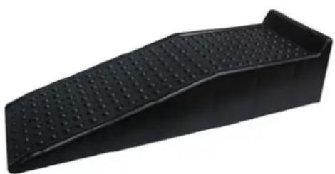
natural_image
Black rectangular object with a dotted surface and rounded base, resembling a ramp or roller (no text or symbols visible)Drive-on ramps
ILAz0291
1.1.2 SITUATION II
Inspection or work on the underside of the vehicle where lifting equipment is used.
The following conditions apply:
- The tyres are supported by wheel lifts or the two axles are supported by central lifting columns (not permitted for 3-axle vehicles).
• The air bellows are emptied (0.5 bar).
• People are under the vehicle.

Read the instructions provided with the lifting equipment to see whether the lifting equipment can be placed under the vehicle without the use of axle supports.
Equipment
The following equipment can be used:
- Wheel lifts.
- Central lifting columns (not recommended for 3-axle vehicles).
Instructions
- See 8 - 1.2 Wheel lifts (☐ 1 - 4) for instructions on how to use wheel lifts.
* See 1.3 Central lifting columns (☐1 - 6) for instructions on how to use central lifting columns.
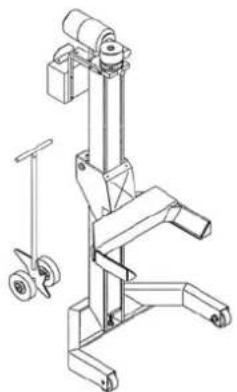
natural_image
Technical line drawing of a mechanical lifting device with wheels and a vertical guide (no text or symbols)Wheel lift
ILAz0282
1.1.3 SITUATION III
The same as situation II, except the wheels or axles must be removed and/or the lifting equipment does not provide sufficient safety.
The following conditions apply:
• The air bellows are emptied (0.5 bar) prior to lifting.
• After lifting, the vehicle is supported by axle supports.
• People are under the vehicle.
Equipment
The following equipment can be used:
- Wheel lifts.
– Central lifting columns (not recommended for 3-axle vehicles). - Workshop axle support.
– Workshop axle support with spindle.
Instructions
* See 8 - 1.4 Placing axle supports under the frame (☐1 - 8) for instructions on how to use axle supports.

natural_image
Red metal tripod stand with black handle and vertical support (no text or symbols visible)Workshop axle support
ILAz0290
1.1.4 SITUATION IV
Removing a wheel from a vehicle.
The following conditions apply:
- Only one wheel is raised off the ground.
- Nobody is under the vehicle.
Equipment
– Jack, jack stand.
Instructions
* See 1.5 Jacking up (☐1 - 11) for instructions on how to use a jack.
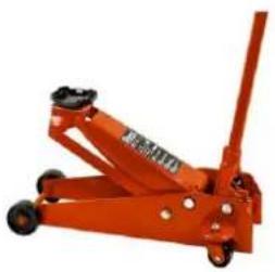
natural_image
Orange manual lift jack with black wheels and a vertical boom (no visible text or symbols)Trolley jack
ILAz0292
1.2 WHEEL LIFTS

Always read the supplier's instruction manual and instructions before using the wheel jacks and any auxiliary tools.
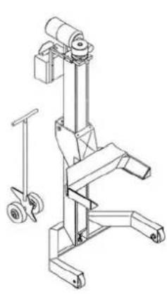
natural_image
Technical line drawing of a mechanical device with wheels and a vertical support (no text or symbols)Wheel lifts
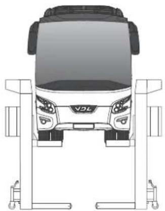
natural_image
Top-down line drawing of a car's front suspension system (no text or symbols)ILHz0042
Lifting instructions using wheel lifts
- Drive the vehicle as straight as possible to the middle of the work area.
- The contact switch must be turned off.

When the contact switch is turned on, the height control system produces too much movement, causing the vehicle to become unbalanced.
- If necessary, place wheel adaptors on the wheel lifts (see the supplier's instructions and 1.7 Auxiliary tools for lifting the vehicle (☐1 - 14)).
- For a 2-axle vehicle, place the four synchronized wheel lifts under the front axle and the rear axle. For a 3-axle vehicle, place the six synchronized wheel lifts under the front axle, the 2^nd axle and the 3^rd axle.

It is not permitted to use four wheel lifts to raise a 3-axle vehicle, because the lifting equipment and/or the vehicle components may be subjected to an excessive load.
- Lift the vehicle so that all the tyres are a couple of centimetres off the ground. Check the position of the wheels in the wheel lifts.

Make sure the bodywork does not touch the wheel lifts or any other obstacles.

- "Unconditionally kneel" the vehicle (see 1.6 Unconditional kneeling (☐ 1 - 13)).

Warn people in the immediate vicinity before raising or lowering the vehicle and stand in a safe location where you can observe the situation.
- Use the synchronized wheel lifts to raise the vehicle to the desired height.
Lowering the vehicle

Warn people in the immediate vicinity before raising or lowering the vehicle and stand in a safe location where you can observe the situation.
- Lower the synchronized wheel lifts.
- Stop lowering when the vehicle is a couple of centimetres off the ground.
- Turn off the "unconditional kneeling" function, so that the vehicle returns to the driving height.
- Lower the vehicle to the ground.
- Remove the wheel lifts from under the vehicle.
1.3 CENTRAL LIFTING COLUMNS

It is not permitted to use two lifting columns to lift a 3-axle vehicle, because the vehicle components are then subjected to an excessive load.

Always read the supplier's instruction manual and the supplier's instructions before using the lifting columns and the accessories.
The diagrams are for information purposes only. No rights can be derived from the diagrams. Auxiliary tools may have to be made through consultation with the lifting column supplier.
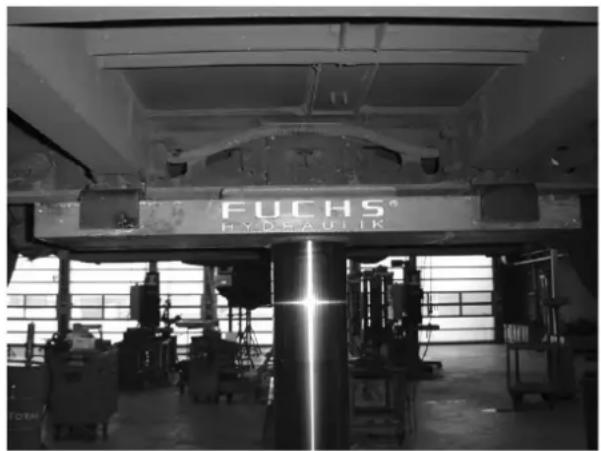
natural_image
Interior view of a factory with an FUCHS HYDEAUIK machine under a structural beam (no visible text or symbols on machinery)Central lifting column
ILAz0017
Lifting instructions for central lifting columns
- Drive the vehicle as straight as possible between the lifting columns whilst the vehicle is at the highest height.
- The contact switch must be turned off.

When the contact switch is turned on, the height control system produces too much movement, causing the vehicle to become unbalanced.
- Place the supports that are suitable for the axles in the correct position on the lifting columns. If necessary, fit a locking device (see the supplier's instructions and 1.7 Auxiliary tools for lifting the vehicle (☐1 - 14)).
- First, place the lifting column correctly under the rear axle and raise the rear axle so that the tyres come off the ground.
- Place the lifting column correctly under the front module (where the transverse beam crosses the longitudinal beams) and raise the front module so that the tyres come off the ground.

Be careful not to damage the shock absorber/shock absorber attachment or any other components.
- "Unconditionally kneel" the vehicle (see 1.6 Unconditional kneeling (1 - 13)).

Make sure the bodywork does not hit any obstacles.
- Operate the central lifting columns simultaneously and raise the vehicle to the desired height.

Warn people in the immediate vicinity before raising or lowering the vehicle and stand in a safe location where you can observe the situation.
Lowering the vehicle
- Lower the central lifting columns simultaneously.

Warn people in the immediate vicinity before raising or lowering the vehicle and stand in a safe location where you can observe the situation.
- Stop lowering when the vehicle is a couple of centimetres off the ground.
- Turn off the "unconditional kneeling" function, so that the vehicle returns to the driving height.
- Lower the vehicle further until the wheels touch the ground.
1.4 PLACING AXLE SUPPORTS UNDER THE FRAME

First, read the instructions concerning 8 - 1.2 Wheel lifts (☐1 - 4) and 8 - 1.3 Central lifting columns (☐1 - 6).

Read the instructions provided with the lifting equipment to see whether the lifting equipment can be placed under the vehicle without the use of axle supports. If not, use workshop axle supports.
Support points
The support points are strengthened locations in the frame where workshop axle supports can be placed.

The vehicle may only be supported at the frame's indicated support points.

Always work safely and follow the safety instructions supplied with the axle supports.
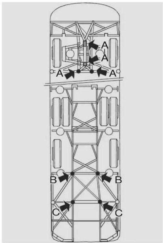
text_image
A A A B B C CILHf0003
8
Supporting order for a 2-axle vehicle
- Raise the vehicle to a height that is higher than the axle supports.
- At the front of the vehicle, place the axle supports under the support points (A).
- At the rear of the vehicle, place the axle supports under the support points (B). Use workshop axle supports with a spindle.

Make sure the difference in height between the axle supports placed on the left-hand and right-hand sides of the vehicle is no more than 5 mm. Use the spindle to minimize the height difference just before resting the vehicle on the axle supports.
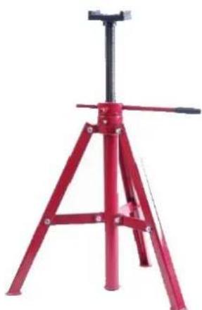
natural_image
Red industrial machine tripod with black handle and metal frame (no text or symbols visible)ILAz0290
Workshop axle support
- Make sure the axle supports under support points (A) support the vehicle first if the vehicle is lowered horizontally. Next, rotate the spindles of the two rear axle supports until the supports touch the support points.

Make sure the vehicle is level.
- For extra stability, an axle support can be placed under support point C. Next, rotate the extra support's spindle until the support touches the support point.
- If desired, the wheel lifts or the central lifting columns can now be lowered.
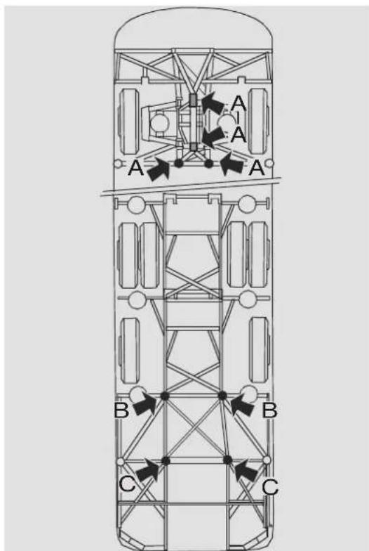
text_image
A A A B B C CILHf0003
Supporting order for a 3-axle vehicle
- Raise the vehicle to a height that is higher than the axle supports.
- At the front of the vehicle, place the axle supports under the support points (A).
- In the middle of the vehicle, place the axle supports under the support points (B). Use workshop axle supports with a spindle.
- For a 3-axle vehicle, also place axle supports at the rear of the vehicle under the support points (C). Use workshop axle supports with a spindle.

Make sure the difference in height between the axle supports placed on the left-hand and right-hand sides of the vehicle is no more than 5 mm. Use the spindle to minimize the height difference just before resting the vehicle on the axle supports.
- Make sure the axle supports under support points (A) support the vehicle first if the vehicle is lowered horizontally. Next, rotate the spindles of the four rear axle supports until the contact surfaces touch the support points.

Make sure the vehicle is level.
- If necessary, lower the wheel lifts.
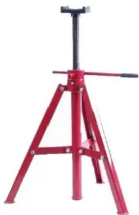
natural_image
Red industrial machine tripod with black handle and metal frame (no text or symbols visible)Workshop axle support
ILAz0290
1.5 JACKING UP
The contact switch must be turned off.

When the contact switch is turned on, the height control system produces too much movement, causing the vehicle to become unbalanced.

Always observe the instructions provided by the manufacturer of the jack.

Only place the jack under the indicated jacking points.
1.5.1 FRONT WHEEL JACK POINTS

Read the accompanying documentation before using the jack.
To jack up the front wheels, place the jack under the steering stub as indicated.
Position the jack so that the vehicle cannot slip off the jack.
To avoid damage to the wheel mounting/chassis, the jack must never be placed in the area between the two steering stubs.
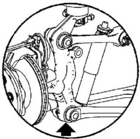
natural_image
Mechanical assembly diagram showing components like gears and springs inside a circular frame (no text or labels)ILAd0358

Always place jack stands under the frame when carrying out work under a vehicle that has been jacked up.
Also see 8 - 1.4 Placing axle supports under the frame (☐1 - 8).
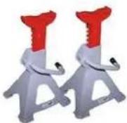
Jack stands
ILAz0293
1.5.2 JACK POINTS FOR THE 2 ^ND AXLE OF A 3-AXLE VEHICLE

Read the accompanying documentation before using the jack.
To jack up the driven rear axle, place the jack under the indicated locations.

To prevent deformation of the axle beam, the jack must not be placed in a location other than those indicated, under the axle beam or the differential housing.
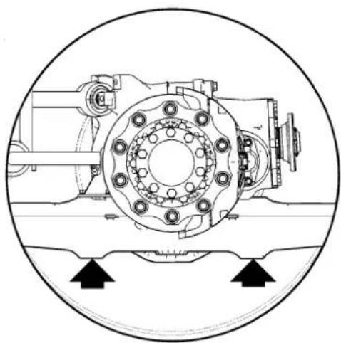
natural_image
Technical line drawing of a mechanical assembly with mounting holes and bearing housing (no text or symbols)ILAz0082
1.5.3 JACKING UP THE 3 ^RD AXLE OF A 3-AXLE VEHICLE

Read the accompanying documentation before using the jack.
To jack up the trailing axle, place the jack under the axle beam as indicated.

To prevent deformation of the axle beam, the jack must not be placed in a location other than those indicated, under the axle beam or the differential housing.
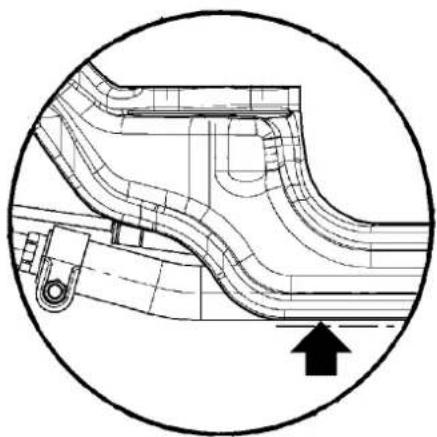
natural_image
Technical line drawing of a mechanical component or duct system enclosed in a circular boundary, with an arrow indicating direction (no text or symbols present)ILAz0083
1.6 UNCONDITIONAL KNEELING
The vehicle has a switch, which is only intended for the unconditional kneeling function.

Always apply the handbrake before turning off the ECAS system.
If work must be carried out on a vehicle, the ECAS system can be temporarily turned off to prevent the system from making adjustments whilst the work is carried out. The switch is located in the fuse box in the driver's sleeping compartment.
Manually bleeding the air bellows
If the vehicle does not have the function described above, the air bellows must be bled manually.
After doing so, disconnect the ECAS unit's connector.
Apply the parking brake.

Turn the ECAS system back on after completing the work.
1.6.1 BLEEDING THE AIR BELLOWS USING DIAGNOSIS EQUIPMENT
Use the Wabco or the Texa diagnosis equipment to blow off the air in the air bellows until the vehicle rests on the bump stops.
After doing so, disconnect the ECAS unit's connector.
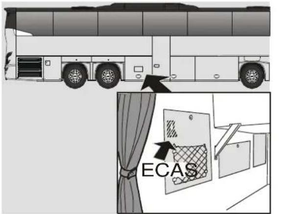
text_image
ECASILHh0244
1.7 AUXILIARY TOOLS FOR LIFTING THE VEHICLE
1.7.1 AUXILIARY TOOLS FOR THE WHEEL LIFTS
Place a wheel adaptor on each wheel lift so that if there is a puncture, the wheel rim cannot get between the support bracket.

Make sure the bodywork does not become damaged when lifting the vehicle.
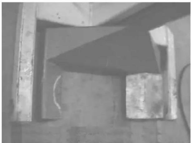
natural_image
Close-up of a mechanical component with a triangular blade and rectangular supports (no visible text or symbols)ILAz0021
1.7.2 AUXILIARY TOOLS FOR CENTRAL LIFTING COLUMNS
Use suitable supports with the appropriate separate auxiliary tools for the axles and slide them sufficiently far enough on to the lifting column's fixed support (see the instruction manual provided by the manufacturer of the lifting column).
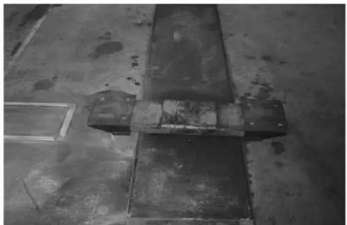
natural_image
Black-and-white photo of industrial metal beams and pipes on a concrete floor (no text or symbols visible)Front axle auxiliary tools
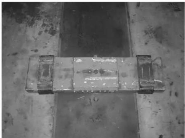
natural_image
Top-down view of a mechanical component with four protrusions on a concrete floor (no visible text or symbols)Rear axle auxiliary tools
ILAz0015