Futura FHD2 - Automotive VDL - Free user manual and instructions
Find the device manual for free Futura FHD2 VDL in PDF.


User questions about Futura FHD2 VDL
0 question about this device. Answer the ones you know or ask your own.
Ask a new question about this device
Download the instructions for your Automotive in PDF format for free! Find your manual Futura FHD2 - VDL and take your electronic device back in hand. On this page are published all the documents necessary for the use of your device. Futura FHD2 by VDL.
USER MANUAL Futura FHD2 VDL
These driver instructions contain information regarding the use of the vehicle. Pay particular attention to the safety regulations and the text concerning operation and maintenance before driving the vehicle for the first time. Make sure this instruction manual is always kept in the vehicle.
This instruction manual contains a number of groups. Each group is marked by a number in the margin (for example, 0) and starts with a table of contents.
The text may contain references to other pages, such as Instrument panel (37). The number after the book icon indicates the page which contains the information.
There is an index at the end of the book for quick reference.
Please ensure that you are fully familiar with the instructions provided in this documentation, as correct operation of the vehicle, together with regular preventative and scheduled maintenance, is decisive for the vehicle's resale value.
Furthermore, in many cases, this is a condition for a warranty claim.
Vehicle type:
Type ^a
Date of first use ....
VIN code ^b
Other information ....
Registration ....
a. On the identification plate fitted at the front entrance bay.
b. On the identification plate. The last eight digits form the chassis number (e.g. XMGDE02CS0H123456).

CONTENT
1 INTRODUCTION....1
2 OPERATION AND USE....17
3 SAFETY PRECAUTIONS AND EMERGENCY PROCEDURES .....71
4 MAINTENANCE....81
5 REPAIRS WHILST ON THE ROAD ....103
6 IDENTIFICATION ....127
7 TECHNICAL INFORMATION ....137

Disclaimer
© 1113 VDL Bus & Coach bv, Valkenswaard, The Netherlands.
In the interest of continuous product development, VDL Bus & Coach maintains the right to make changes to specifications or products at all times without prior notification.
No part of this publication may be copied and/or published by means of printing, photocopying, digitization or any other means whatsoever without prior written permission from VDL Bus & Coach.
This handbook must be interpreted and used in accordance with Dutch law. Any dispute will be placed before the court in 's-Hertogenbosch, the Netherlands.

Introduction
1 INTRODUCTION
INTRODUCTION.... 3
WARNING SYMBOLS 4
SAFETY INSTRUCTIONS .... 4
WARRANTY CONDITIONS......8
ENVIRONMENT......9
GENERAL TIPS....9
BATTERIES.... 14
AIR CONDITIONING SYSTEM.... 16
Introduction
Introduction
INTRODUCTION
Congratulations on purchasing your Futura FHD2.
You've made a good choice.
The Futura FHD2 has outstanding driving characteristics, excellent performance and operational reliability, low fuel consumption and an emphasis on safety and comfort.
Reliability, a long lifespan, safety and a comfortable ride are the characteristics of VDL Bus & Coach products.
Read this manual carefully before driving the vehicle for the first time to allow yourself to make the most of these characteristics and to fulfil your expectations.
A thorough knowledge of the maintenance instructions will increase driver satisfaction and will above all have a favourable influence on the durability of the vehicle. The capabilities of the vehicle can be fully exploited
Purpose
The aim of this manual is to familiarise the driver or user with the vehicle. VDL Bus & Coach wishes to pass on as much information as possible about the use, operation, safety and maintenance of the vehicle.
This instruction manual includes information about standard and optional features.
Alternative equipment, for example manual or automatic transmission, is discussed.
This means that you may skip certain sections in the manual which deal with equipment not fitted to your vehicle.
Layout
The layout of the manual is designed to be practical and to provide a clear overview.
There are 7 chapters in the manual.
Each chapter is numbered and is easy to locate using the dark markings in the margins.
Each chapter begins with a detailed contents section, which will help you find your way around the relevant chapter.

An index at the end of the manual will allow you to quickly locate topics.

Make sure this manual is always kept in the vehicle and read it carefully before driving the vehicle for the first time.

Introduction
1
WARNING SYMBOLS
The instruction manual includes the following symbols.
Take note of the tip or warning accompanying the symbol!

This symbol gives useful tips to simplify the work.

This symbol indicates a situation which requires extra attention.

This symbol indicates a situation which might result in damage to the vehicle.

This symbol indicates a situation which might result in personal injury.

This symbol indicates a situation which might result in damage to the environment.
SAFETY INSTRUCTIONS
The following safety instructions must be strictly observed in order to prevent endangering your own health and safety, as well as that of others.
See also Safety precautions and emergency procedures (71)
Warnings and safety instructions
Always read the instructions and warnings on labels and stickers.
Do not ignore them. They are there to ensure your health and safety!
ENGINE
Do not allow the engine to run in a confined or unventilated space.
Engine compartment
Keep away from moving parts.
Coolant reservoir filler cap
Do not remove the coolant reservoir's filler cap whilst the engine is at the operating temperature. Release the pressure first by slowly removing the filler cap.
Warning triangle
Always have a warning triangle in the vehicle (it is a legal requirement in some
countries) and possibly some other means of marking.
Safety vest
When carrying out emergency repairs, always wear a safety vest (it is a legal requirement in some countries) and, if necessary, also use other means of marking.
Fire extinguisher
Ensure that you are always in the possession of a fire extinguisher (it is a legal requirement in some countries). Its location is marked by

a sticker in the vehicle's interior (see Fire extinguisher (77)).
In the event of a fire: Certain plastic seals can, in the event of a fire, form gases which together with water form a corrosive acid. Therefore, do not touch any fire extinguisher fluid on the vehicle without wearing protective gloves.

Introduction
First-aid kit
Ensure that you are always in possession of a first aid kit (it is a legal requirement in some countries), see: First-aid kit (☐ 78).
Winter conditions
Whenever severe winter conditions are expected, make sure to fit winter tyres and snow-chains. See also Wheels and tyres (110 139).
Luggage
All luggage must be stowed so that it cannot shift or fly loose, even in an emergency stop. Bear in mind that the driving characteristics of a fully loaded vehicle differ from those of an empty vehicle.
Fluids and greases
Certain fluids and lubricants may be harmful to your health if they come into contact with your skin, are ingested or are inhaled. Therefore, avoid physical contact where possible.
Spilled fluids may react aggressively with other materials, so clear them up as quickly as possible.
To prevent risk of fire the engine and its surroundings must be kept free of (highly) flammable materials.
Welding
Read the workshop instructions before carrying out welding work on the vehicle and/or the bodywork.

Not observing these instructions may result in damage to the vehicle's electronics.
Batteries

Never disconnect the battery terminal clamps whilst the engine is running!
Always disconnect the battery's earth cable when working on the electrical system.
Never place tools on the battery. It may cause a short circuit or even cause the battery to explode.

See Tachograph (42) for instructions on how to disconnect the battery cables.
Charging the batteries
When charging the batteries, make sure there is good ventilation and avoid sparks and a naked flame.

Allow frozen batteries to thaw and remove all the filler caps before charging.
First connect the battery charger's positive clamp (+) to the battery's positive terminal (+) and then the negative clamp (-) to the negative terminal (-).
When the batteries have been charged, turn off the battery charger and then disconnect the negative clamp (-) first followed by the positive (+) clamp.
The battery cables may remain connected for normal charging.
Only use a quick-charger in the event of extreme urgency.

To avoid damage to the vehicle's electronics, both battery cables must be disconnected when quick-charging.

Do not use a speed starter set to start the vehicle as this may damage the vehicle electronics.

Introduction
1
Starting the vehicle using an auxiliary starting device
See Jump starting. (☐ 122) for instructions on how to start the vehicle using auxiliary starting devices.
System voltage
The vehicle has a 24 V electrical system. When replacing or upgrading electrical or electronic components, ensure that they are suitable for this voltage.
natural_image
Diagram of a bus with an overhead view showing a hand operating a device, and a curved arrow indicating motion (no text or symbols present)ILHh0041
Earth switch
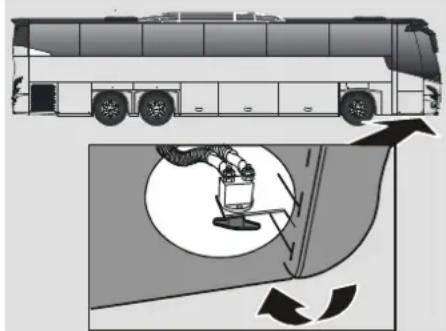
To prevent the batteries from discharging during long term parking (more than 2 weeks), the vehicle is provided with an earth switch which, when switched off, disconnects the entire coach power supply.
Before switching off, take care that:

See Tachograph (42) before switching off the earth switch.
- Stop the engine by first switching off the ignition. Then turn off the main switch.
-
Switch off the alarm.
-
Disconnect mains voltage connection (24 V connection for charging batteries via mains voltage) if applicable.
- Switch off the earth switch after a delay of at least 90 seconds, to allow for the after-running of various electrical systems on the vehicle.

Failure to meet the switching off conditions may have serious consequences for various electrical systems in the vehicle.
After switching on, adjust:
• The radio (default radio stations).
- Adjust the navigation system.
- The Clock.
- The timer of the control panel of the climate system.
- Tachograph:
If DTCO:
The tachograph keeps its adjustments and needs therefore no further adjustments.

Introduction
Mobile telephones and transmitters
The following precautions relate to the installation and use of mobile telephones and transmitters.
- It is permitted to install mobile telephones and transmitters in the vehicle if this is done carefully and is approved by VDL Bus & Coach.
- Mobile telephones and transmitters may be used in the vehicle if they have their own exterior, low-reflection aerial. This external aerial must be fitted correctly.

Using mobile telephones or transmitters without a separate external aerial may cause excessive electromagnetic fields (the resonance effect)
within the vehicle. This can lead to the vehicle's electronic equipment not working correctly, which will have a negative effect on the safety of the vehicle.

- In addition, the optimum range of this equipment can only be achieved with the use of an external aerial.
Always follow the operating instructions for mobile telephones and transmitters. - The transmitting power must not exceed the maximum permitted transmitting power. See the table given below:
Frequency range: Maximum transmitting power:
Shortwave (<50 100 W
MHz)
4 m band 20 W
2 m band 50 W
70 cm band 35 W
25 cm band 10 W
Installation of additional electrical/electronic equipment
All electric/electronic components retrofitted to VDL Bus & Coach vehicles must have type approval and the "E" marking in accordance with the ECE Guideline R10.

Interfering with the electronic system in any way may create a dangerous situation due to the system malfunctioning and will affect the warranty.

Damage or consequential damage caused as a result of the installation of equipment not approved by VDL Bus & Coach will not be covered by the VDL Bus & Coach warranty.

The vehicle's type approval may no longer be valid (.....) if the electronic or electrical devices used in the vehicle do not satisfy the stated conditions.

BUS & COACH
Introduction
1
Vehicle weights
Take care not to exceed the next weights.
• Maximum weight per axle
• Maximum vehicle weight (GVW)
• Maximum train weight (GCW)
• Maximum trailer weight
See also the vehicle identification plate.
Furthermore, conform to EU Guideline 96/53 EC, it is not permitted to drive a two-axle vehicle with a GVW > 18 tons or to drive a three-axle vehicle with a GVW > 26 tons internationally within the EU.
Retrofitted equipment
All materials retrofit to a VDL Bus & Coach vehicle which belong to the category of materials which should conform to fireproof regulations must meet EU Guideline 95/28 EC.
Original VDL Bus & Coach parts
All parts and components are carefully matched to each other, which among others determines the original VDL Bus & Coach quality.
Do not modify your vehicle with non-original VDL Bus & Coach parts.
Bear in mind that any modification to your VDL Bus & Coach vehicle with non-original parts may adversely affect its performance, safety, durability and the guarantee.
Modifications may also conflict with legal requirements.
WARRANTY CONDITIONS
Please ensure that you are fully familiar with the instructions provided in this documentation, as correct operation of the vehicle, together with regular preventive and scheduled maintenance, is decisive for the vehicle's re-sale value.
Furthermore in many cases this is a condition of the warranty provided.
The warranty conditions are mentioned in the "GENERAL SALES CONDITIONS" and in the "WARRANTY CONDITIONS".

Introduction
ENVIRONMENT
To prevent unnecessary damage to the environment, you should observe the following guidelines:
- Used liquids should be carefully collected and separated, and should then be handed over to an authorized site for recycling or disposal.
- Improper disposal of liquids is a criminal offence.
- Make sure the vehicle is regularly maintained. A properly maintained vehicle uses fuel more efficiently and emits less harmful exhaust gases.
- Do not allow the engine to idle unnecessarily and always drive using the appropriate engine speed.
GENERAL TIPS
Take note of the following recommendations before using the vehicle:
Pre-heater
- Do not allow the pre-heater to run in a closed or unventilated space.
- Do not operate the pre-heater where flammable or explosive materials, gases or dusts may be present.
- Do not operate the pre-heater over dry grass or other dry ground cover.
- Switch pre-heater off while refuelling vehicle and before entering fuelling stations.
- Never touch hot components of the heating system.
Refuelling

Switch off the engine and switch off the pre-heater before filling fuel tanks.
Use only diesel which is of a suitable quality.
Make sure the filler cap and the area around it are free of dust and avoid mixing water with the fuel when refuelling.

To prevent water condensation, do not allow the level of fuel in the tank to fall unnecessarily low.
AdBlue level
The EAS system consumes AdBlue liquid. The display on the instrument panel shows the tank contents of AdBlue liquid.
A yellow warning 'AdBlue level low' is shown if the tank contents have decreased to a specified minimum value. Fill up the AdBlue at the first opportunity. Insert the delivery nozzle fully into the neck of the tank so that the magnet in the neck opens.
Avoid AdBlue liquid coming into contact with painted components. Spilt AdBlue can be easily removed with water.

Introduction
1
AdBlue turns white when it dries. This white deposit can also be removed with water.

AdBlue is not poisonous and not harmful to the environment.
AdBlue legal minimum level
The EAS system switches off when the tank contents decrease below the absolute minimum. A yellow warning 'AdBlue tank empty' is shown.
This prevents the EAS unit from sucking in air.
A warning is displayed and the MIL indicator appears.

If this warning is ignored, automatic engine torque reduction may be expected.
The torque limiter is activated once the vehicle has been stationary for two seconds. Once the reason for the torque restriction has been removed, the full engine torque will be available after the next time the vehicle has remained stationary.

The EAS system is deactivated when the AdBlue temperature falls below -10^ C.

It may be considered a criminal offence not to use AdBlue according to the vehicle's specifications in order to reduce harmful emissions. It can invalidate the favourable conditions for purchase or operation of the vehicle obtained in the country of registration or the country in which the vehicle is used.
Running in
It is recommended to avoid placing the vehicle under a too heavy load during the running-in period.
This also applies when a reconditioned engine, gearbox or differential has been fitted.
For the first 1,500 km, you should, therefore:
- Avoid driving with a full load.
- Change down gear in good time: a relatively high engine speed is less harmful than overloading the engine with excessively low engine speeds.
- Do not drive with a trailer attached.

Following a cold start, use a moderate engine speed and avoid heavy acceleration until the engine reaches the operating temperature.
Pay attention to the instrument panel whilst driving and respond alertly when irregularities are observed.
Wheel nuts
The wheel nuts must be retightened using a torque spanner (600 Nm ± 3%) when 100 km have been travelled following delivery of the vehicle.

Introduction
Fuel economy
Driving economically does not mean driving slowly. It requires the driver to anticipate situations, to have a smooth driving style and to adapt his/her driving style to the conditions.
Keep the following in mind:
- Warm the engine as quickly as possible by driving off as soon as possible under a moderate load.
- Drive smoothly and avoid unnecessary acceleration and harsh braking.
- Change gear in good time and keep the engine speed in the optimal (green) range.
The most significant factor in fuel consumption is the driver himself and how he uses the accelerator pedal, the brake pedal and the gear lever.
Starting procedure

The engine cannot be started with the bonnet open.
Turn on via the main switch.
Depress the clutch pedal (not applicable to vehicles with automatic gearbox) and select neutral gear.

The engine cannot be started when the gearbox is not in neutral.

The following only applies to vehicles with an AS Tronic gearbox.
If the accelerator pedal is depressed when starting the engine, "FP" will be displayed on the dashboard and the vehicle will not select a gear.
Switch on the ignition.

After the engine has started, the engine speed should not be increased until the oil pressure warning light has gone out.
Clutch
Wear on the clutch depends to a great extent on the driver.
To reduce clutch wear to a minimum, follow these guidelines:
- On moving off, always select first gear and where possible a low engine speed.
- On accelerating after a gear change, give gas only after the clutch is fully engaged.
- Avoid riding the clutch.
- Avoid unnecessary acceleration in traffic queues.
- Use the brakes to stop.
Braking
The vehicle is equipped with an EBS (Electronic Braking System) system.
Some important control functions within the EBS system are:
- Braking deceleration control
- Wheel slip control between the front and rear axles for the purpose of braking force equalisation
- Braking equalisation control between prime mover and drawn vehicle
• ABS (Anti Block System) control
• ASR (Anti Skid Reduction) control

Introduction
1
When the brakes are applied whilst driving, the electronic unit will measure various signals. This results in average readings for: deceleration, brake pressure, wheel slip, etc. These readings will be stored in the electronic unit. The stored readings will be adjusted as necessary. In other words, the electronic unit 'learns' from the inputs.
The stored readings serve as a starting point for the deceleration and brake force distribution.

This system provides more safety, but it may not be a motive to take unnecessary risks whilst driving.

Do not adapt your driving and braking style to the EBS system.
In particular, do not brake later or harder. This will cause the tyres to wear more quickly and will put other road users at risk.

Braking distances with EBS are sometimes, but not always, shorter.
Retarder integration
Retarder integration is automatically available in the EBS system. The EBS system can also use braking torque support from the retarder. This has a positive effect on the service life of the brake linings
Retarder integration can be switched off, see: Vehicle functions (11 59).

ESC (Electronic Stability Control)

A vehicle equipped with ESC may unexpectedly brake hard in certain situations. Therefore, always wear a seat belt.
The ESC system (Electronic Stability Control) is a system comprising lateral and vertical stability control. If a critical situation arises when taking turns, for example when the vehicle is slipping or threatens to turn over, ESC intervenes by
reducing the engine torque and activating the braking system.

ESC is not a guarantee against instability. It helps the driver in unexpected, difficult situations, but there are physical limitations.
Stopping
Bring the vehicle to a halt.
Select neutral gear.
Allow the clutch pedal to rise (not applicable to vehicles with automatic gearbox).

Introduction
Parking

Exhaust system
The vehicle is equipped with a catalytic converter. The catalytic converter/exhaust system becomes very hot whilst driving. Do not park the vehicle or idle the engine over an easily inflammable surface, such as dry leaves or dry grass. This is a potential fire hazard.
Stop the vehicle.
Apply the parking brake by means of the brake lever.
When parking on an incline, the following should be considered:
- Place chocks in front of or behind the wheels of the rigid axle.
- Turn the front wheels so that the vehicle will not head out into the road if it should move for some reason.
Switch off the contact switch and the main switch.
Switching off the engine

After a long journey or when it has been put under heavy load, allow the engine to idle while stationary for a while before switching off.
Park the vehicle.
Stop the engine by first switching off the ignition.
Then turn off the main switch.

Turning off the ignition will activate the delay setting of the EAS system (exhaust gas after-treatment system). This may be audible on the outside of the vehicle (a gurgling noise in the region of the AdBlue tank).
Air leak
A rapidly falling air pressure reading whilst the engine is idling indicates an air leak.
The leak must be repaired without delay as the safety of the braking system is impaired.

text_image
ILHj0000Engine stop button in the engine compartment
The engine can if necessary be stopped using the button in the engine compartment.

In the British version, the stop button is accessible via the right-hand rear hatch.

Remember to reset the stop button before closing the engine compartment.
Speed limiter
The speed limiter on your vehicle is set at 100km/h.

Introduction
BATTERIES
General information
- The more often a battery is discharged, the shorter its lifespan will become.
- The lifespan of the batteries is determined by various factors, including the driving conditions and the climate. Through time, the batteries will lose starting capacity and must, therefore, be recharged if the vehicle is not driven or only driven for short distances for a longer period of time. The starting capacity is also reduced as a result of freezing weather conditions.
- To ensure the maximum lifespan, the batteries must always remain fully charged.
- If the vehicle is mainly used for short journeys or is not used for a longer period of time, then the charging condition of the batteries must be checked regularly or the batteries must be kept constantly charged with a trickle charger.
- Preferably change all the batteries at the same time.
- When changing the batteries, only replace them with batteries recommended by VDL Bus & Coach.
Charging the battery

Explosive oxyhydrogen is produced when recharging the batteries. Therefore, always ensure there is suitable ventilation when charging batteries.
- Avoid sparks and naked flames near batteries.
- Battery acid is an aggressive fluid.
In the event of inhalation: get some fresh air, take a rest and contact a doctor.
In the event of skin contact: neutralize the skin immediately with sodium carbonate or soapsuds and plenty of water. Contact a doctor if the affected area remains red or painful. Remove affected clothing, neutralize with sodium carbonate or soapsuds and rinse with plenty of water.
In the event of contact with the eyes: wash with clean, flowing water for at least 15 minutes and contact a doctor.
If swallowed: DO NOT induce vomiting. Rinse your mouth, drink plenty of water and contact a doctor.
• Always wear protective clothing, in particular, gloves and safety glasses, when working on the batteries.
- Keep children a safe distance from the batteries.
- When charging the batteries, make sure there is good ventilation and avoid sparks and a naked flame.
- Allow frozen batteries to thaw and remove all the filler caps before charging.
- Never disconnect the batteries whilst the engine is running.
- Regularly check whether the battery cables have been connected correctly and whether they are firmly attached to the battery.
- Always disconnect the battery's earth cable when working on the electrical system.
Introduction
Environment

Batteries contain harmful substances. It is legally prohibited to dispose of batteries with the household waste. Batteries must be collected separately and disposed of in a way which is not harmful to the environment.
- Always transport and store full batteries horizontally. Make sure the batteries cannot tip over during transport. Battery acid may then escape into the environment via the bleed openings or the filler caps.
Personal safety

To avoid injury, the following safety measures must always be observed when working on the batteries.
- Do not bend over the batteries.
-
Never place tools on a battery. It may cause a short circuit or may even cause the battery to explode. Only use insulated tools.
-
Pay attention to make sure you do not receive an electrostatic charge. Do not wear synthetic (nylon) clothes and do not rub fabric. For the same reason, do not slide or push batteries over a carpet or other synthetic material.
- Do not immediately touch a battery. To reduce the possibility of an electrostatic discharge, first stand outside of the vehicle and touch the bodywork (metal object).
- Do not rub cloths or rags over a battery. The battery may explode as a result of an electrostatic charge or through the creation of a spark.
Taking care of the batteries

To avoid freezing when the vehicle is not used for a longer period of time in extremely cold conditions, the batteries must be removed and stored in a location which is frost free.
- To avoid freezing when the vehicle is not used for a longer period of time in extremely cold conditions, the batteries must be removed and stored in a location which is frost free.
- Turn off the contact switch and the main switch before disconnecting the battery terminal clamps. If this is not done, electrical components (such as the generator) may be damaged.
- Wait at least 5 minutes after turning off the contact switch and the main switch before disconnecting the connection between the battery terminal clamp and the negative terminal.
- VDL Bus & Coach recommends that you do not carry out work such as charging or removing the batteries yourself. Preferably have this work carried out by a recognized workshop, such as a VDL Bus & Coach Service workshop.

Introduction
1
AIR CONDITIONING SYSTEM
The Pressure Equipment Directive 97/23 EC came into force on 29th May 2002. Also, European regulation no. 842/2006 regarding certain fluorinated greenhouse gases came into force on 4th July 2006 and many of the requirements came into force on 4th July 2007. The objective of this legislation is, amongst other things, to drastically reduce coolant emissions from cooling installations.
This is achieved by applying the following measures:
- The use of CFCs in new installations is forbidden.
- Technical requirements are placed on cooling installations.
• Work on cooling installations may only be carried out by qualified personnel.
The responsibilities of the owner/operator of the installation are being increased. Implementation is by means of a logbook and maintenance obligation.

Always observe the local legal regulations!

Regularly turn on the air conditioning system (at least once a month), even if no cooling is required, to prevent the compressor from leaking.

Operation and use
2 OPERATION AND USE
DOORS/HATCHES....19
CONTROLS AND INSTRUMENTS.... 23
MESSAGES ON THE DISPLAY.... 50
DISPLAY....54
PASSENGER COMPARTMENT....62
DRIVER'S SLEEPING COMPARTMENT.... 65
TOILET....66
KITCHEN....67
NAVIGATION SYSTEM....67
PNEUMATIC SUSPENSION (ECAS).... 67
STEERING MECHANISM....68
MIRRORS....69
INSTRUCTIONS FOR DRIVING WITH A TRAILING AXLE..... 70
Operation and use
Operation and use
DOORS/HATCHES
Passenger door/Central door
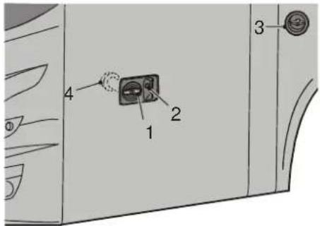
By turning the key, the handle (1) can be locked/unlocked. By turning the handle, the door is locked/unlocked
The door is opened/closed with push button (2).
A contact strip on the edge of the door prevents trapping when the door closes.
When the door is closed and the vehicle speed is above 5 km/h, the door can not be opened.
When the door is open and the vehicle speed is above 5 km/h, it will still be possible to close the door (see Priority 3(☐ 53)).
text_image
4 1 2 3ILHa0000
Connecting the vehicle to an external air supply
If the pneumatic system has been blown off and you wish to connect the vehicle to an external air supply, then the following must be taken into consideration:
- Open both doors.
- Pressurize the pneumatic system.
- Use the control switches to close and open the doors.

To avoid the door system from malfunctioning, it is necessary to follow the described procedure.
natural_image
Diagram of a car's front and rear dashboard with directional arrows indicating movement or force (no text or symbols)ILHa0001
Engine cover

Avoid contact with hot or moving parts when the bonnet is open.
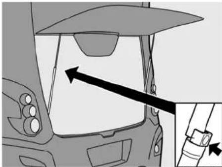
The bonnet is opened by undoing the lock with the key and pulling at the same time on the bonnet. The bonnet hinges upwards with the aid of 2 gas springs. When the bonnet is raised the left-hand gas spring is mechanically locked.

Release the lock before closing the bonnet.

Operation and use
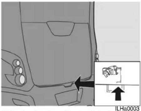
The lock is released by pushing the spacer cover against the spring, allowing the bonnet to be closed.
natural_image
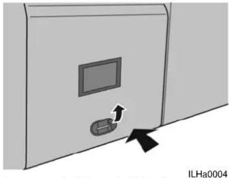
Diagram of a car interior with an inset showing a vehicle component labeled ILHa0003 (no text or symbols on the diagram itself)If the key breaks off in the lock the bonnet can also be opened by pushing up the red lever.

The bonnet can only be opened with this lever when the broken key is still in the lock.
natural_image
Diagram of a door with a monitor and scroll, showing an arrow pointing to the door (no text or symbols on the diagram itself)Luggage hatches / Driver's sleeping compartment hatch
The luggage compartments and the driver's sleeping compartment can be unlocked using the switches on the dashboard. If there is no air pressure available, the compartments can only be opened with a key (see Luggage hatch emergency operation (11 76)).

When using a key to open a hatch, the central locking system will no longer function. To reactivate the central locking system, the hatch must first be locked with the key.
Operation and use
Closing the luggage hatches
Always close flaps by means of the hand grip.
Engine compartment side flap.
The engine compartment side flap may be unlocked with a key and the flap can then be opened.
text_image
Technical diagram of a mechanical component with numbered parts labeled 1, 2, and 3ILHa0002
Fuel lid
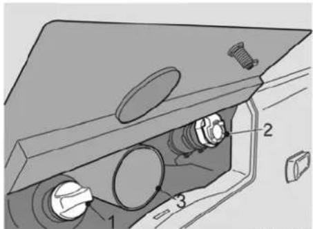
The fuel lid can be unlocked with a key. The lid can then be opened to give access to the AdBlue tank (1) and the diesel tank (2).
Glove compartment

Gloves which may be worn when filling fuel tanks can be stored in the glove compartment (3).
Filling
By pressing on the diesel fuel tank cap (2), e.g. with the filling pistol, the fuel tank cap will open.
Having refuelled diesel, also fill up the AdBlue tank with AdBlue liquid.

Switch off the engine and switch off the pre-heater before filling fuel tanks.

Operation and use
text_image
22 21 20 19 9 18 17 7 13 14 12 24 10 16 18 6 5 4 3 2 1 23 11 25 26 27 28ILHb0005
Operation and use
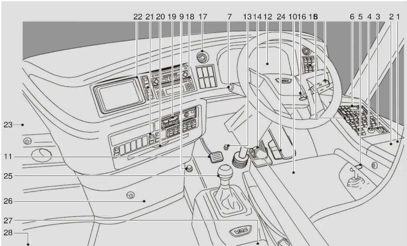
CONTROLS AND INSTRUMENTS
| 1. Driver's storage compartment 23 | |
| 2. 12 Volt and 24 Volt connections 23 | |
| 3. Mirror adjustment 23 | |
| 4. Contact switch 24 | |
| 5. Parking brake 24 | |
| 6. Climate system controls 27 | |
| 7. Left-hand combination switch 29 | |
| 8. Right-hand dashboard switches 30 | |
| 9. Engine brake 33 | |
| 10.Driver's seat | 34 |
| 11. Clutch pedal | 34 |
| 12. Instrument panel | 37 |
| 13. Steering wheel adjustments | 38 |
| 14. Brake pedal | 38 |
| 15.Right-hand combination switch | 39 |
| 16. Spare wheel compartment handle | 41 |
| 17. Ventilation grilles | 41 |
| 18.Audio | 41 |
| 19. Tachograph | 42 |
| 20. Cup holders | 42 |
| 21. Central dashboard switches | 43 |
| 22.Navigation system | 45 |
| 23. Refrigerator | 45 |
| 24. Accelerator pedal 45 | |
| 25. Gear shifting | 46 |
| 26. Central storage compartment 49 | |
| 27. Storage compartment behind the selector lever | 49 |
| 28.Hostess seat | 50 |
1. Driver's storage compartment
The upper section is lockable.
The lower section contains the hazard warning triangle, a safety vest and a flash light.
Intercom installation
The microphone for communication with the driver's sleeping compartment is located behind the driver's seat.
For operation of the communication handset see: Intercom installation (☐ 65).
2. 12 Volt and 24 Volt connections
There is a 12 Volt connection and a 24 Volt connection under the driver's storage compartment hatch, which are intended for accessories.
The 24 Volt plug also serves as a power supply for the inspection lamp.
The inspection lamp can only be used here if its adaptor plug is fitted, see: Plug (11) 107

An electrical consumer of up to 150W may be connected to this holder.

Before connecting an accessory, check which voltage the accessory is suitable for.
3. Mirror adjustment
The mirrors are adjustable electrically, provided the main switch and ignition are switched on, by moving the knob up, down, left or right.

Turning knob to the right operates right mirror.
Turning knob to the left operates left mirror.

Operation and use
natural_image
Circular dial indicator with pointer symbol, no text or numbers presentILHh0025
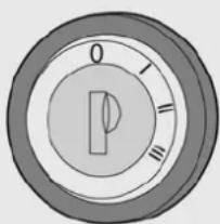
4. Contact switch
The ignition switch has four positions which, once the main switch is engaged, can be used as follows:
0: Neutral position
The key can be removed. All electric consumers which may be needed during a journey are now switched off.
I: Position 1
The key cannot be removed. All electric consumers which may be needed during a journey are now switched on.
All instrument indicator lamps are illuminated for 3 seconds for control purposes, and then only those that are active remain illuminated The fuel gauge and coolant temperature indicators go to maximum and then return to show the current reading. Switching to position 1 while the main menu is displayed switches to the driving menu.
II: II: Not used.
III: Starting
Operates the starter motor. The key must be turned further to the right against the spring pressure.

The engine cannot be started if the engine compartment door is open.
5. Parking brake
The parking brake operates only on the rear axle and is operated by moving the lever to the rear.
When the parking brake is applied a lamp is illuminated on the instrument panel.

The parking brake is released by moving the lever forwards.
Where air pressure is insufficient the ECAS symbol on the display will be illuminated and the parking brake will not release.
It is necessary to wait for the compressor to charge up the air supply before driving away see: Information menu (☐ 58).
If the foot brake is inoperable due to a fault the parking brake may also function as an emergency brake. The vehicle may be brought to a controlled stop by gradually raising the parking brake lever until it reaches its stop.

Using the parking brake as an emergency brake in a vehicle with an AS Tronic gearbox whilst driving on a slippery road may result in the engine stalling. Power assisted steering is then no longer available!

Operation and use

Operation and use
2
text_image
WABCO -3,0°C 22°CILHg0000
Operation and use
6. Climate system controls
General information
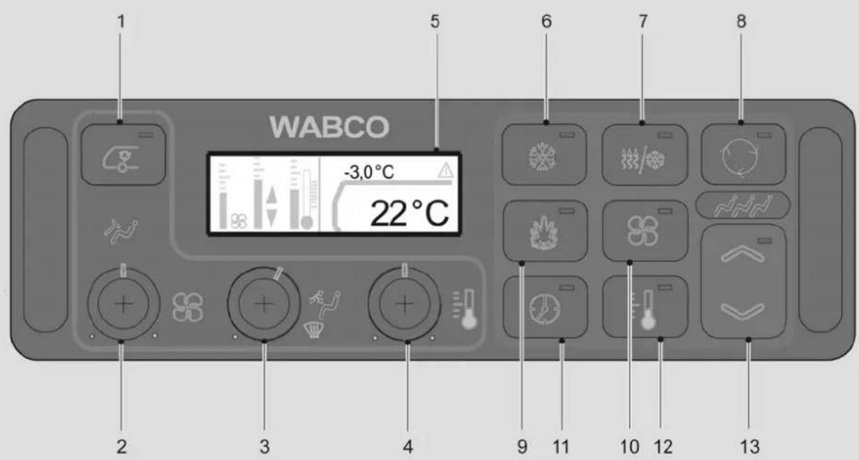
The controls 1 to 4 are the controls for the driver's compartment and the controls 6 to 13 are the controls for the passengers compartment.
1 Recirculated air - driver's compartment
At a push of the button for recirculated-air, the LED in this button and the function „recirculated-air - driver's compartment“ are activated.
2 Frontbox fan
By rotating the switch, the fan speed is adjusted to the required setting.
There are five different settings: off, low, medium 1, medium 2 and high.
3 Air supply adjustment for the driver's compartment
By rotating the switch, the direction of the air flow for the driver's compartment is selected. The following settings are possible: foot well fully open, foot well half open / windscreen half open, windscreen fully open, defrost.
4 Temperature adjustment - driver's compartment
By rotating the switch, the temperature is set for the driver's compartment. Rotating fully left max cooling is selected, Rotating fully right max heating is selected. In between the temperature is controlled automatically to the required set temperature.
5 Display
Normally the outside temperature is shown in the display. Depending on which button (1 to 4 for the driver's compartment and 6 to 13 for the passengers compartment) has been operated, corresponding changes will be shown in the display. When for a period of ±8 seconds no changes have been made, the display switches back to the outside
6 Automatic air conditioning mode
At a push of the air conditioning button, the LED in this button and the function "readiness of air conditioning" are activated. The air conditioning is switched on when all the conditions (separate functional description) are met.
7 Dehumidify
If the dehumidify button is pressed, the LED in this button is lit and the dehumidify function is activated. The dehumidify function is automatically deactivated 15 minutes after it has been activated.
8 Smog mode for the passenger compartment (and the driver's compartment)
A push of the smog button activates the LED in this button and the „smog“ function.
9 Automatic preheating function
At the push of the button, the LED in this button and the "readiness of pre-heating" function is activated. The pre-heating is switched on after all conditions (separate functional description) are fulfilled.
When only the main switch is turned on, e.g. during cleaning or a service, you can prevent the preheater from starting by setting the interior temperature as low as possible using buttons 12 and 13.

Operation and use
10 Fan adjustment in the passenger compartment
If the passenger fan button is pressed, then the fan speed will be activated. The value can be changed using button 13. When button 13 is pushed for longer than 1 second, the first value changes every second.
11 Setting the clock, switching times and activation periods

The actual time is normally transmitted via the clock in the tachograph/speedometer.
The actual time and the switching time are indicated in hours and minutes in the display.
One can program three weekly programs with one on-duration each which can be activated on as many weekdays as required. Only one on-duration - i.e. the next activated on-duration - may expire, then the activation has to be set anew.
Programming the timer
The timer is activated by a longer push (longer than 2 s) of button 11, the LED in button 13 flashes, and the time, weekday, etc. are adjusted by the right rocker button 13 (+) / (-).
Every chosen program can be opened for adjustment by pushing button 11.
If button 13 (+) / (-) is held during the adjustment, the adjusting speed slowly increases after 2s, in order that the time for example can be set quicker.
For quitting and storing the button 11 has to be actuated again.
The selecting menu is left if another button is pushed during the adjusting process or when no button is pushed for more than 60s.
Activating a program
A short push (less than 2 s) of button 11 opens the indication- and activation mode.
A program time (P1, P2 or P3) can be selected by pressing button 13 (+)/(-) and then activated by pressing button 11.
An activated on-duration is indicated as follows:
When the contact switch is turned on: "LED in button 11" on
When the contact switch is turned off: "LED in button 11" flashes short time in intervals of 3 s
12 Indication of the temperature in the passenger compartment
A push of the button activates the indication of the room temperature. The nominal value can be changed using button 13. When button 13 is pressed for more than 1 second, the value is changed in 1 °C steps every 1 second.
13 Button (+) button (-)
The buttons (+) and (-) form a button for the activation of the fan speed in the passenger compartment (activated by 10), the nominal temperature in the passenger compartment (activated by 12) and the timer (activated by 11).
Operation and use
text_image
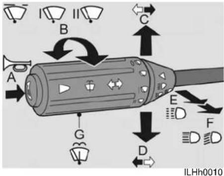
A B C D E F G ILHh00107. Left-hand combination switch
A. Air horn
The air horn operates when knob A is pressed.
B. Windscreen wipers
The windscreen wipers are operated by turning switch B.
The switch has 4 positions.
| Position 0: | Wipers off |
| Intermittent wipe | In this position the wipers operate every 8 seconds. |
| Position I: | Wipers on, low speed |
| Position II: | Wipers on, high speed |
C. Indicators, right
Moving the switch upwards operates the right indicator. The green indicator lamp in the instrument also flashes.
D. Indicators, left
Moving the switch downwards operates the left indicator. The green indicator lamp in the instrument also flashes.
For a brief use of the indicators the switch should be pushed slightly against the spring pressure.
E. Main beam flash
To flash the headlights, the switch must be moved upwards until it meets a resistance.
F. Main beam
The main beam works if the switch is moved upwards past the resistance, but only if the contact switch and the dipped beam have been turned on. The blue indicator lamp in the instrument illuminates when main beam is on.
G. Windscreen washers
If part G of the switch is pressed, the windscreen washer installation is activated and the windscreen wipers make two strokes.
Headlight washers
The headlight washers operate at the same time as the windscreen washers, when dipped beam is on.

Operation and use
text_image
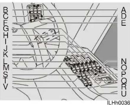
BCEGHJKLMSTV ADE NOPORU ILHh00368. Right-hand dashboard switches
| A. Main switch 30 | |
| B. Low current protection 30 | |
| C. Option 30 | |
| D. Front sidelights/dipped beam 30 | |
| E. Front and rear fog lights 31 | |
| F. Option 31 | |
| G. Electrically operated driver's side window | 31 |
| H. Electrically heated driver's side window | 31 |
| I. Driver's ventilation fan 31 | |
| J. Hostess ventilation fan | 31 |
| K. Reversing buzzer | 31 |
| L. Electrical roller blind | 31 |
| M. Electrical roller blind | 31 |
| A. Main switch 30 | |
| B. Low current protection 30 | |
| C. Option 30 | |
| D. Front sidelights/dipped beam 30 | |
| E. Front and rear fog lights 31 | |
| F. Option 31 | |
| G. Electrically operated driver's side window | 31 |
| H. Electrically heated driver's side window | 31 |
| I. Driver's ventilation fan 31 | |
| J. Hostess ventilation fan | 31 |
| K. Reversing buzzer | 31 |
| L. Electrical roller blind | 31 |
| M. Electrical roller blind | 31 |
| N. Ferry lift/rear kneeling | 31 |
| O. Ferry lift/front kneeling | 31 |
| P. Switching on and off of the optional wheelchair lift. | 32 |
| Q. School bus warning lights | 32 |
| R. Right/fixed trailing axle wheels | 32 |
| S. Trailing axle relief | 32 |
| T. Easy start off | 32 |
| U. Select | 32 |
| V. Activate | 33 |
A. Main switch
When it is switched on the main switch connects the battery with:

- the switches to operate the doors.
• The ignition.
• audio installation and other accessories, such as video, lighting in the toilet etc.
When the main switch is off the tachograph clock continues to run, the warning system may be used and the pre-heater can be activated if previously set.

The master switch can not be turned off when the engine is running.
B. Low current protection
Switching on overrules low current protection

C. Option
This position is not in use and can, therefore, be used to operate an optional instrument or accessory.
D. Front sidelights/dipped beam
The switch has three positions.

0: Off
1: Front sidelights on.
2: Front sidelights and dipped/main beam on (depending on the position of the steering column switch).
Dipped or main beam operates only with the main switch and ignition on.
Corner light (optional)
Functioning of the corner light is only possible when the vehicle lights are switched on.

Operation and use
At normal driving situation on a straight road the corner light is switched off.
When turning a corner (direction indicator) or slow driving at a curvy road (at a speed up to 20 km/h) the concerned corner light will automatically switch on.
When selecting reverse gear, both corner lights will also switch on as a parking aid.
E. Front and rear fog lights
The switch has three positions.

0: OFF
1: Front fog lights on
2: Front-, and rear fog lights on
Fog lights can only be switched on when front sidelight or dipped-, or main beam is on.

Switching off the main switch switches off the rear fog lamp, and the fog lights switch must be reset before the rear fog lamp can be switched on again.
F. Option
This position is not in use and can, therefore, be used to operate an optional instrument or accessory.
G. Electrically operated driver's side window
To open or close the driver's screen, the switch must be pressed on the top or the bottom side.

H. Electrically heated driver's side window
Simultaneous switching on and off of the driver's window and/or window in service door.
The light in the switch will be brightly lit when this function is in use.

I. Driver's ventilation fan
Turns the driver's ventilation fan on and off.

J. Hostess ventilation fan
Turns the hostess' ventilation fan on and off.

K. Reversing buzzer
Switching on/off a buzzer when driving in reverse.
L. Electrical roller blind
To open or close the left hand sun blind, push respectively the upper or lower part of this switch respectively.
M. Electrical roller blind
To open or close the right hand sun blind, push the upper or lower part of this switch respectively.
N. Ferry lift/rear kneeling
For the operation, see "Ferry lift/front kneeling".


O. Ferry lift/front kneeling
There are two ways of temporarily changing the coach level by pneumatic suspension, making it either higher or lower
than the neutral driving level. The temporary high adjustment is usually used to obtain more ground clearance for, e.g. boarding ferries. Adjusting downwards makes it easier for passengers to board.


Operation and use
If the pneumatic suspension is not in the neutral position this is indicated in both cases by the illumination of the yellow ECAS symbol in the display.
If the pneumatic suspension is not in the neutral position the warning light on the switch is illuminated.
0: Raising (front and rear)
1: Driving position (neutral)
2: Kneel (front)

If the vehicle is equipped with a lift for disabled people or with standing places, the vehicle speed is limited to 5 km/h when the vehicle is kneeled.

If the vehicle is not in the neutral position, the maximum vehicle speed may not exceed 5 km/h.

The ECAS system switches automatically to driving (neutral) position above 20 km/h, and switches in again if the speed falls below 5 km/h.
P. Switching on and off of the optional wheelchair lift.

This option will only function when main switch and parking brake are on.

If the vehicle has a trailing axle: ensure, before opening the lift door, that the trailing axle is in the straight-ahead position.
Q. School bus warning lights
The vehicle can be equipped with school bus warning lights as an optional extra. When the door is opened, the warning lights are turned on automatically. This function can be turned off using this switch.

R. Right/fixed trailing axle wheels
This switch is used to place the trailing axle in the straight-ahead position and to lock it in this position. This can be useful in particular manoeuvres at speeds below 30 km/h.

This switch may also be of assistance on extremely slippery roads. If this function is turned on, the red warning light in the switch will be lit.
S. Trailing axle relief
If, under extreme conditions, the grip of the driven wheels is not sufficient for the vehicle to pull away, this switch can be used to temporarily relieve the trailing axle (maximum 3 tons). As a result, more pressure will temporarily be placed on the driven wheels.

The trailing axle relief lasts for 80 seconds. If it is necessary to relieve the trailing axle again, you will have to wait at least 50 seconds before the system reacts again. This is due to legal requirements relating to the maximum axle loading.
If this function is turned on, the red warning light in the switch will be lit.
T. Easy start off
The vehicle is equipped with an electronic starting device (easy start). For more information, see Pulling away with starting assistance ([I] 47).
U. Select
To go through the various functions and menu's in the


Operation and use
display, push respectively the upper or lower part of this switch.
Upper part means one position forward, lower part means one position backward.

By using the emergency switch, it is not possible to meet the electrical system's switching off conditions. This may have serious consequences for various electrical systems in the vehicle. Therefore, only use the emergency switch in the event of an emergency.

The emergency switch can also be used to reset the electrical system.
For this, you have to turn off the contact switch and the main switch. Wait at least 2 minutes after turning off the contact switch to enable the EAS system to shut down.
Use the emergency switch to turn off all the electrical consumers, with the exception of the hazard warning lights, the pre-heater and the tachograph.
V. Activate
This switch accesses menu 1. Next by pushing this switch the, with the select switch, chosen function can be activated.

9. Engine brake
The engine brake may be used during prolonged braking, for example during descents or when braking from high speeds.
Depressing the engine brake operating knob provides extra braking via the engine. Fuel injection is reduced and the butterfly valve in the exhaust system is closed.
This reduces brake wear.
The additional power declines as the engine speed falls.

The engine brake does not function at engine speeds below 700 rpm.

Operation and use
text_image
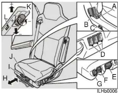
Technical diagram of a car seat assembly with labeled components and directional arrows indicating movement or force.10.Driver's seat

Set the seat in the desired position before starting to drive.
A: Shoulder adjustment
Pull the lever upwards and adjust the shoulder to the desired position.
B: Seat back adjustment
Pull the lever upwards and adjust the seat back to the desired position.
C: Seat heating
Switch on/off the seat heating.
D: Lumbar support adjustment
The air-cushion in the seat back can be filled (+) or emptied (-) by pushing on the top or bottom of the knob.
E: Seat height adjustment
Push or pull the handle up or down to adjust the seat to the desired height. The seat is adjustable over a range of 100 mm.
F: Vibration dampers
Raise the lever (Seating comfort "soft"), Press down the lever (Seating comfort "hard").

The vibration damper must be set so that it offers enough stance on a poor road surface, so the driver will not loose contact the pedals.
G: Quick lowering
Push the handle downward until the seat is lowered to its lowest position. (Useful when getting in or out).
When the handle is returned to its previous position, the seat returns to its former height.
H: Fore and aft adjustment
Pull the handle up and adjust the seat to the required position. The seat is adjustable over a range of 180 mm.
I: Adjusting the seat lengthways
Pull the handle upwards and adjust the seat to the required position.
J: Adjusting seat inclination
Pull the hand lever upward to place the seat in the desired position. Releasing the hand lever locks the seat in position.
K: Armrest adjustment (optional)
The knurled knob at the front can adjust the inclination.
L: Hands-free phone/microphone switch (optional)
Switches on/off the microphone/hands-free phone.
11. Clutch pedal
For an explanation of how to use the clutch, see Gear shifting (☐ 46).

Operation and use

Operation and use
text_image
A B C D E F G H I J K L 186333,5 km 18:00 Time: 20 km/h Time: 50 km/h km/h 10 20 50 100 150 200 250 300 400 500 600 700 800 900 1000 1100 1200 1300 1400 1500 1600 1700 1800 1900 2000 2100 2200 2300 2400 2500 2600 2700 2800 2900 3000 3100 3200 3300 3400 3500 3600 3700 3800 3900 4000 4100 4200 4300 4400 4500 4600 4700 4800 4900 5000 5100 5200 5300 5400 5500 5600 5700 5800 5900 6000 6100 6200 6300 6400 6500 6600 6700 6800 6900 7000 7100 7200 7300 7400 7500 7600 7700 7800 7900 8000 8100 8200 8300 8400 8500 8600 8700 8800 8900 9000 9100 9200 9300 9400 9500 9600 9700 9800 9900 1, 2, 3, 4, 5, 6, 7, 8, 9, 1, 2, 3, 4, 5, 6, 7, 8, 9, 1, 2, 3, 4, 5, 6, 7, 8, 9, 1, 2, 3, 4, 5, 6, 7, 8, 9, 1, 2, 3, 4, 5, 6, 8, 9, 1, 2, 3, 4, 5, 6, 8, 9, 1, 2, 3, 4, 5, 6, 8, 9, 1, 2, 3, 4, 5, 6, 8, 9, 1, 2, 3, 4, 5, 6, 8ILHh0011
Operation and use
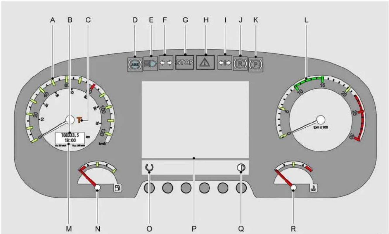
12. Instrument panel
| A. Speedometer 37 | |
| B. Odometer 37 | |
| C. Tachograph warning light 37 | |
| D. ABS warning light 37 | |
| E. Main beam warning light 37 | |
| F. Indicator warning lights (green) | 37 |
| G. Priority warning 1 | 37 |
| H. Priority warning 2 | 37 |
| I. Trailer indicator warning lights | 37 |
| J. Retarder warning light | 37 |
| K. Parking brake warning light | 38 |
| L. Rev counter | 38 |
| M. Clock/trip meter | 38 |
| N. Fuel gauge | 38 |
| O. Switching between the clock and the trip meter | 38 |
| P. display | 38 |
| Q. Brightness adjustment | 38 |
| R. Coolant temperature gauge | 38 |
General information
If the ignition is switched on while the main switch is on, all the warning lights will be lit for 3 seconds, with those that are active remaining on.
The fuel gauge and coolant temperature indicators go to maximum and then return to show the current reading.
A. Speedometer
The speedometer inner ring gives the speed in mph, the outer ring shows km/h.
B. Odometer
The odometer records the distance travelled.
C. Tachograph warning light
This lamp is illuminated when there is a fault in the tachograph, or when other problems occur, such as the absence of a tachograph disk.
D. ABS warning light
This lamp lights up when the main switch and ignition are switched on. The light should go out after a few seconds.
E. Main beam warning light
When the main beam is on, the blue indicator lamp is illuminated.
Selection between main and dipped beam is via the left hand combination switch on the steering column.
F. Indicator warning lights (green)
When the left or right indicators or the hazard warning lights are switched on, the indicator warning lights flash with the same frequency.
If one of the external indicator lamps fails to flash, the warning light flashes only once.
G. Priority warning 1
If this warning light is lit in combination with a fault symbol on the display, the vehicle must be brought to a standstill as quickly as possible and the engine must be turned off (see Messages on the display (☐ 50)).
H. Priority warning 2
If this warning light comes on in combination with a fault symbol on the display, there is a problem that must be solved as soon as possible, but the vehicle may be driven to the next available stopping place, see: Messages on the display (☐ 50).
I. Trailer indicator warning lights
These lamps operate when the indicator lamps are switched on and a trailer is in use.
J. Retarder warning light
This lamp lights up when the retarder operates.
The brake lights also operate.

Operation and use
K. Parking brake warning light
When the parking brake is operated the warning light will come on and the rear wheels will be locked.
L. Rev counter
The revolution counter has 4 regions:
Left hand region: Very economical
Green: Economical.
Middle region: Less economical.
Red: Avoid
M. Clock/trip meter
The clock shows the time and can be set by setting the tachograph clock.
Pushing knob (O) switches to trip meter allowing distance travelled to be measured.
N. Fuel gauge
The fuel gauge operates only when the ignition is on, and shows the fuel level in both tanks.
A warning symbol is illuminated in the display when the fuel in the tanks falls below the reserve level.

There is approximately 40 litres of fuel remaining.
O. Switching between the clock and the trip meter
Switching between clock and trip meter.
The trip meter can be reset to zero by pushing the knob in longer.
P. display
The display normally shows the driver menu. For instructions, see Display (☐ 54).
Q. Brightness adjustment
The brightness of the display can be adjusted to personal preference.
R. Coolant temperature gauge
Do not over exert the engine when the coolant temperature is below 50 °C.
The engine is at operating temperature when the temperature gauge is vertical or slightly further.
The warning symbol in the display is illuminated when the temperature rises above 110^ C.
The red field of the gauge starts at 0 °C.
If the coolant temperature suddenly rises and/or the pointer is in the red field, the following points should be checked:
• Coolant level, see: Coolant level (☐ 90).
• Poly V-belt and water hoses.
- Cooling fan.

13. Steering wheel adjustments
The steering wheel and steering column may be placed in the desired position by operation of the knob.
The steering column is locked when the pressure switch is released.

Adjusting is only possible when the parking brake is applied.
14. Brake pedal
For an explanation of how to use the brakes, see Braking (11 11).
Operation and use
text_image
B ⊕ D OFF Δ (○) OFF RES A E (○) C RESILHh0012
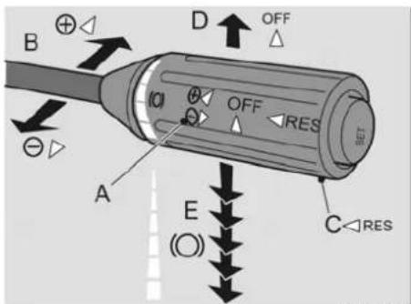
15. Right-hand combination switch
A. Cruise control

Cruise control can only be engaged when vehicle speed is above 30 km/h.
The cruise control can be set to the current speed by moving the combination switch towards or away from the steering wheel.

Only use the cruise control when traffic conditions permit a steady speed. Do not use the cruise control in busy traffic, on roads with many bends or on slippery surfaces.
B. Acceleration/deceleration
If a different speed is required to that set, moving the switch briefly towards the steering wheel will raise the speed by 1 km/h.
The speed can be increased smoothly by holding the switch in the raised position.
Moving the switch away from the steering wheel allows deceleration in the same manner.
The vehicle speed may also be increased with the cruise control switched on by depressing the accelerator.
C. Cruise control memory function
By pressing the "RES" button (C) the cruise control is re-engaged at last set speed used. If the current vehicle speed is lower than this speed, the cruise control will attempt to accelerate the vehicle speed to the last set speed.
D. Turning off the cruise control
Cruise control is switched off by moving the switch forwards.
The cruise control is also switched off if:
• The parking brake is released.
• The parking brake is applied.
• The retarder is operated.
• The clutch is operated.
• The engine brake is operated.
- Neutral.
E. Bremsomat (downhill speed control)/Retarder (Not if automatic gearbox)
The switch has 5 positions to the rear.
Position 1: Bremsomat
When driving downhill at the desired speed, the vehicle speed can be held constant at this value by putting the switch in position 1. The retarder determines the necessary braking force. If the braking force needed is greater than the maximum capacity of the retarder it must be supplemented by use of the engine brake or footbrake.

The Bremsomat will be set to the new speed when accelerating using the cruise control or the accelerator pedal, or when slowing down using the foot-brake, the engine brake or one of the retarder settings.

Operation and use
Positions 2 to 5: Retarder
Selecting between positions 2 to 5 allows you to switch between 4 different retarder braking forces. This can also be done whilst driving. The retarder light on the instrument panel constantly gives the driver information about the present situation. Operation of the retarder will be interrupted during ABS activity, but resumes afterwards.
The retarder also operates during operation of the footbrake pedal.
The engine brake can be used to supplement the retarder.

Ensure that, during hill descents, the engine speed does not fall below 1,600 rpm, as this reduces cooling, which in turn reduces the effectiveness of the retarder (does not apply to vehicles with an AS Tronic or automatic gearbox).
Where necessary, a lower gear should be selected to raise the engine speed and,
thereby, increase both the cooling capacity and the effectiveness of the retarder.
Safety instructions
The retarder should be used very cautiously on wet or slippery road surfaces.
The retarder operates on the driven axle only.

The vehicle may skid.
Switch off the retarder on very slippery surfaces, to avoid faulty operation see: Vehicle functions (☐ 59).

During hill descents, operate the retarder with hand control only, not the foot control.
If the effect of the retarder is insufficient, it may be supplemented with the engine brake or the service brake.
Hand gas
Hand gas may be selected when the vehicle is stationary whilst the handbrake is applied and the automatic gear lever is in neutral.
Pressing "SET" causes the stationary engine speed to be increased to 800 rpm.
By pressing "SET" twice, the stationary engine speed will be increased to 1,200 rpm.
By pressing "Set+" or "Set-", the rpm will be increased or decreased by 25 rpm.
By pressing "Set+" or "Set-" continuously, the idle engine speed can be infinitely set between the idling speed and the maximum engine speed (2,000 rpm).
Hand gas can be switched off by placing the control lever in the "off" position.
Hand gas also switches off when the brake pedal or accelerator pedal are depressed, or when the retarder or parking brake are applied.

Operation and use
natural_image
Line drawing of a car interior showing engine compartment with hoses and wheels (no text or symbols)ILHa0008
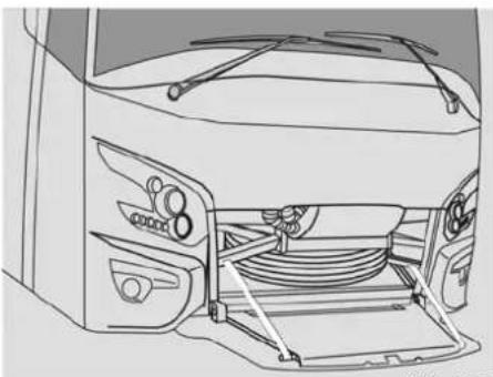
16. Spare wheel compartment handle
The spare wheel compartment is unlocked by pulling on this handle.
The spare wheel compartment is retained by a catch.
Removing this catch allows the spare wheel compartment to be fully swung down.
The spare wheel and the towing eye attachment are located in this compartment.

The spare wheel compartment handle may not be pulled during a journey.
Switches with no fixed location
The switches described below are associated with optional equipment which may be installed. These components may be found in a variety of locations on the dashboard, depending on customer's and national requirements and the number of options installed.
Destination indicator lighting
This switch operates the destination/route lighting.

Top lights
Switching the extra top lighting off and on.

AV switch

Message box above driver
This switch operates the message box with stop message above the driver.

Message box above driver
This switch operates the message box above the driver with the seatbelt message.

Panoramic camera
Switching on a camera with a panoramic view.

Laptop connection
Wireless pin microphone

AV switch for video/DVD player
Switches on the 24 V DC to 220 V AC transformer.

17. Ventilation grilles
The direction of the ventilation grills can be altered to suit personal preference.
Turning the knob on the ventilation grille to zero closes the grille.
18. Audio
See the manufacturer's documentation for further detail on the operation of the audio system.

Operation and use
19. Tachograph
DTCO (Digital tachograph)

The DTCO tachograph saves an error code if the power supply is turned off or the battery is empty. In some countries, the error code is interpreted as a breach of the law. To prevent the unit from saving an error code when disconnecting the battery cables, place a DTCO workshop card in the unit whilst the battery is disconnected.
If an error code is saved, contact a recognized DTCO workshop to calibrate the DTCO and to delete the code.
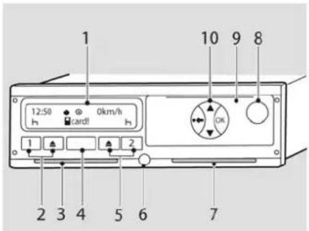
text_image
1 12:50 0km/h h card8 h 1 2 3 4 5 6 7 10 9 8 OKILHh0022
| 1 Display |
| 2 Operation driver 1 |
| 3 Card reader 1 |
| 4 Connection for calibration and download apparatus |
| 5 Operation driver 2 |
| 6 Sealing |
| 7 Card reader 2 |
| 8 Button for opening printer drawer |
| 9 Printer |
| 10 Menu selection buttons |
If DTCO: See the supplier's documentation for the operating instructions.
20. Cup holders
The cup holders are located in the dashboard. The cup holders can be used by pulling them forwards.

Operation and use
text_image
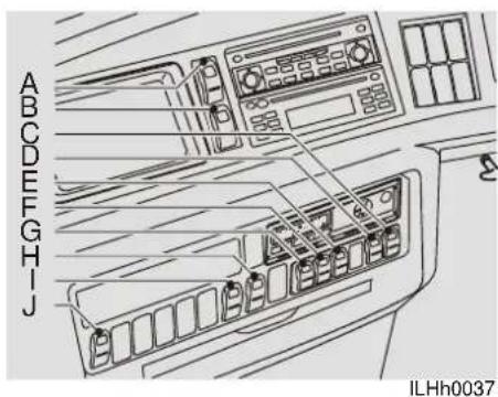
ABCDEFGHJ ILHh003721. Central dashboard switches
| A. Hazard warning lights 43 | |
| B. Emergency switch (depending on national regulations) | 43 |
| C. Open/close the passenger door 43 | |
| D. Open/ close the central door 44 | |
| E. Lighting for the driver's compartment and the passengers' compartment | 44 |
| F. Interior lighting 44 | |
| G. Passenger reading lights 44 | |
| H. Luggage compartment (left) unlocking | 45 |
| I. Unlocking the luggage compartment (right) | 45 |
| J. Via monitors 45 | |
A. Hazard warning lights
Operation of this switch makes the vehicle's indicators flash simultaneously. The hazard warning system can be used even if the main switch and ignition switch are off. The lamp in the switch is red and flashes.

If the main switch is on, then the green direction indicator warning lamp on the instrument panel also flashes.

Legal requirements on the use of hazard warning lights vary from country to country.
B. Emergency switch (depending on national regulations)
In the event of an emergency, all electrical consumers will go off, with the exception of the hazard warning lights, pre-heater and the tachograph (if applicable in the location).

By using the emergency switch, it is not possible to meet the electrical system's switching off conditions. This may have serious consequences for various electrical systems in the vehicle. Therefore, only use the emergency switch in the event of an emergency.
The emergency switch can also be used to reset the electrical system.
For this, you have to turn off the contact switch and the main switch. Wait at least 2 minutes after turning off the contact switch to enable the EAS system to shut down.
Use the emergency switch to turn off all the electrical consumers, with the exception of the hazard warning lights, the pre-heater and the tachograph.
C. Open/close the passenger door
This switch is used to open the passenger door. The red light in


Operation and use
the switch will also be lit. Use the switch again to close the door.
The door has a safety feature so that it immediately re-opens when the contact strip meets an obstruction during closing.

If the pneumatic system is blown off, the Connecting the vehicle to an external air supply (☐ 19) procedure must be followed in order to ensure that the door system functions correctly.
D. Open/ close the central door
This switch is used to open the central door. The red light in the switch will also be lit. Use the switch again closes the door.

The door has a safety feature so that it immediately re-opens when the contact strip meets an obstruction during closing.

The central door will not operate if the driver's sleeping compartment hatch to the side of the central door is not properly closed.

If the pneumatic system is blown off, the Connecting the vehicle to an external air supply (☐ 19) procedure must be followed in order to ensure that the door system functions correctly.
E. Lighting for the driver's compartment and the passengers' compartment
The switch has three positions.

0: Off
1: Courier lighting on.
2: Courier lighting and driver's compartment lighting on
These lamps are also illuminated when the door is opened.
F. Interior lighting
The switch has three positions.

0: Interior lighting off
1: Night illumination on
2: Night light and strip lighting on

It is advisable not to leave the interior lighting on for more than 10 minutes with the engine stopped, because of high current consumption.
G. Passenger reading lights
The switch has two positions.

0: Night lights and passenger reading lights off.
2: The reading lights above the passengers' head, the hostest call buttons and the stop buttons (optional) can only be used when the driver has released them using the passenger reading light switch. After being released, the buttons in question will be lit.

The driver can also use this switch to extinguish all reading lamps simultaneously.

Operation and use
H. Luggage compartment (left) unlocking
Operation of this switch unlocks all left hand side luggage flaps and switches on the luggage area lighting.


The luggage hatches lock automatically when the main switch is turned off.

The luggage compartment lighting will turn off automatically whilst driving.
I. Unlocking the luggage compartment (right)
Operation of this switch unlocks all right hand side luggage flaps and switches on the luggage area lighting.


The luggage hatches lock automatically when the main switch is turned off.

The luggage compartment lighting will turn off automatically whilst driving.
J. Via monitors
This switch makes it possible for images to be shown on the vehicle's monitors. It is standard to have one switch for one

system. It is possible to have a number of these switches fitted to display the images from a number of systems.
22. Navigation system
For a detailed description of the traffic navigation system, see the manufacturer's information supplied.
23. Refrigerator
The refrigerator has a capacity of 56 litres or 74 cans. It is also suitable for food. The temperature is controlled by thermostat, and is adjusted by turning a knob.
24. Accelerator pedal
For operating the accelerator pedal.

Operation and use
text_image
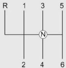
R 1 3 5 2 4 6ILHc0019
25. Gear shifting
GO-210-230 gearbox
A GO gearbox can be optionally fitted. The type of gearbox depends on which engine the vehicle has.

The engine cannot be started when the gearbox is not in neutral.
Pulling away in first gear.
Preferably keep your revs between 600 and 800 min-1. Do not push the accelerator pedal whilst driving on a flat road. Don't go beyond 1,000 min-1 in 1st and 2nd gear. In other words, make sure the rev counter remains in the green section! Modern
engines have almost 100% of the torque at an engine speed slightly higher than the idling speed. In other words, stay in the green area. Thanks to the high torque of modern engines, the vehicle can pull away at an almost stationary engine speed when the vehicle is fully loaded! This prevents fast wear of the clutch.
In order to avoid fast wear of the clutch plate and the clutch pressure group we strongly advise you when shunting this vehicle only to use the lowest gear. The gearbox is synchronized, so do not use the double declutch method.

Incorrect changing of gears may damage the engine or the clutch. The gearbox may only put in reverse when the vehicle is at a complete standstill. When changing down gear, always make sure the speed is not too fast for the gear being changed into.
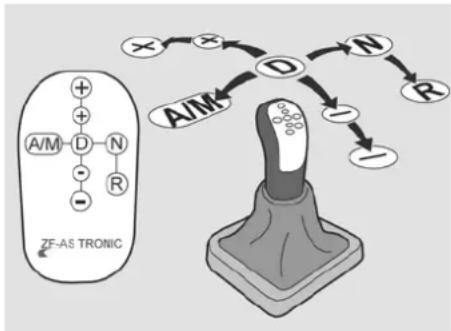
ZF AS Tronic automatic gearbox
Optionally a ZF AS Tronic gearbox can be applied. This gearbox is equipped with an integrated retarder (see Vehicle functions (59)).
The ZF AS Tronic is a fully automatic changing gearbox with automatic clutch control, which eliminates the need for a clutch pedal.

Operation and use
flowchart
graph TD
    A["ZF-AS TRONIC"] --> B["A/M"]
    B --> C["D"]
    C --> D["N"]
    D --> E["R"]
    E --> F["+"]
    F --> G["+"]
    G --> H["O"]
    H --> I["N"]
    I --> J["R"]
    J --> K["I"]
    K --> L["A/M"]
    style A fill:#f9f,stroke:#333
    style B fill:#ccf,stroke:#333
    style C fill:#cfc,stroke:#333
    style D fill:#fcc,stroke:#333
    style E fill:#cff,stroke:#333
    style F fill:#ffc,stroke:#333
    style G fill:#cfc,stroke:#333
    style H fill:#fcc,stroke:#333
    style I fill:#cfc,stroke:#333
    style J fill:#fcc,stroke:#333
    style K fill:#ffc,stroke:#333
    style L fill:#cfc,stroke:#333
ILHc0020
- Upshift 2 gears (spring point stop)
- Upshift 1 gear (first spring point)
A/M Change over from Automatic mode to Manual mode (and vice versa)
D Driving
N Neutral.
R Reverse - Downshift 1 gear (first spring point)
- Downshift 2 gears (spring point stop)

Whilst starting the engine, the range selector must be in the N (Neutral) position. Moving the range selector from R to D and visa versa, may only be undertaken when the vehicle is at a standstill.
Shifting
- Apply the service brake.
- Move range selector from "N" to "D" or "R".
If one tries to switch over to D or R without engaging the service brake the message BP (Brake Pedal) appears in the display.
The gearbox will still be in neutral.
To switch in after all:
- Move range selector back to "N"
- Apply the service brake.
- Move range selector from "N" to "D" or "R"

The driver is not allowed to leave the vehicle whilst the engine is running and a gear has been selected (selector lever in D or R)! The vehicle can be moved by releasing the brakes and simply depressing the accelerator. In order to prevent the vehicle from accidentally rolling forward, the service brake or parking brake must be applied.
The fully automatic mode (A) or the manual mode (M) is selected by moving the gear lever in the "A/M" direction. It is possible to change the mode at any time,
even when the vehicle is moving. It is not necessary to change the position of the accelerator pedal when switching modes. In the full automatic position, clutch and gear control are operated electronically and the engine will operate in the most economical area.
In case of manual operation, each intended gear change is checked by the electronics and if necessary, is ignored to prevent misuse of the driveline. The display of the AS Tronic shows to the driver all important system information, such as: neutral position, current gear, clutch overload or any faults in the system (see Explanation of AS Tronic messages (56)).
Pulling away with starting assistance
The vehicle is equipped with an electronic starting device (easy start). Its purpose is to prevent unintended moving of the vehicle during uphill or downhill dead starts.

BUS & COACH
Operation and use
The Easy Start function keeps the service brake applied for a short period after it has been released.

Once the brake pedal has been released, the brake will only remain applied for a short period of time. The vehicle can start moving.
The time at which the brake is released depends on the position of the accelerator pedal, the position of the clutch and the vehicle speed.
The brake is also released if the gearbox is shifted into neutral or if neither the brake pedal nor the accelerator pedal are depressed within a certain time period.
Switching off starting device
When switching on the contact switch, the starting device is switched on automatically.
When the vehicle speed is < 30 km/h, the electronic starting device (easy start) can be switched off using this switch.
This can be useful when manoeuvring or driving at low speeds, in a traffic jam or during city trips.

When operating the switch again or the vehicle speed increases to above 30 km/h, the starting-aid will be activated automatically.
Manoeuvring
First gear and R gear are provided as manoeuvring gear for very slow travel. In the manoeuvring mode, the vehicle (accelerator pedal) is more sensitive and the clutch activation differs from how it behaves in the normal mode.

Do not use the manoeuvring mode during traffic jams or at a slope of more than 10% as the continuously slipping clutch may lead to clutch overload in this position.
Activating manoeuvring mode:
By holding the selector lever in position A/M for a few seconds, the display will show MM. The manoeuvring mode will then be activated. By moving the selector lever to position R, the display will show RM. It will then be possible to manoeuvre in reverse.
Deactivating the manoeuvring mode
The manoeuvring mode can be deactivated by:
- again holding the range selector in position A/M.
- Operating the kick-down.
- switching up the gear selector.
The display will now show the selected gear.
If the gear lever remains in the A/M position for 3 seconds or more, then the letters "M or A" will be shown on the display. The letters "M or A" will disappear after a short time.
Clutch Protection
If there is a risk of the clutch being overloaded by several starting procedures being undertaken one

after another in short succession or by crawling in too high a gear, the "CL" display appears.
Select an operating mode in which there is no risk of clutch overloading, for example:
- Accelerate vehicle (to close the clutch).
- Stop.

Operation and use
- Set off quickly in a lower gear

Despite the clutch being automated, the driver still has considerable influence on the clutch's service life. To keep clutch wear levels as low as possible, we would recommend always selecting the lowest gear possible when setting off.
AS Tronic messages
For an explanation of the AS Tronic messages in the display, see Explanation of AS Tronic messages (56).
Gear changes in the automatic mode
All upshifts and downshifts are undertaken automatically.

The operating mode can be changed from manual to automatic at any time, even whilst the vehicle is being driven.
Whilst driving
Remove your hand from the selector lever whilst driving. Your hand may cause the selector lever to move to "neutral"

The driveline will be interrupted if a shift is made to neutral. If, at the same time, a screwdriver symbol appears on the display, stop immediately at a safe place and turn off the engine!
Start again (see Shifting (47)).
Stopping and parking

The gearbox is set automatically to N (Neutral) after the engine has been turned off or has been idling for 3 minutes.

When the engine has been turned off, there is no direct contact between the engine and the axle. The vehicle can, therefore, start to roll. Apply the parking brake
26. Central storage compartment
The storage compartment is opened by folding it forwards and can be locked with a key.
27. Storage compartment behind the selector lever
There is a small storage compartment behind the selector lever.
This can be locked with a key.

Operation and use
2
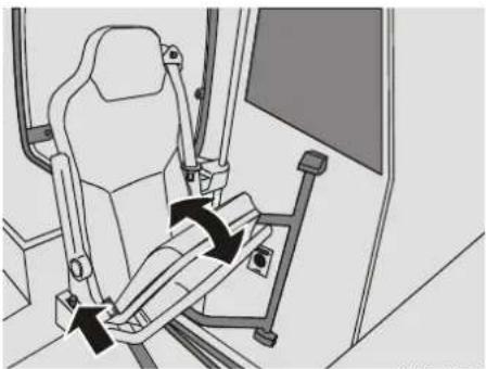
natural_image
Line drawing of a car seatbelt device with directional arrows indicating rotation (no text or symbols)ILHb0001
28. Hostess seat
The seat can be folded upwards by pulling the handle next to the hostess seat backwards. When getting out of the seat, it will automatically fold up.
MESSAGES ON THE DISPLAY
General information
Operation of the main switch brings up the start-up screen and after 5 seconds the driving menu will appear.
Messages may appear on the driving display, which are divided into three priority levels.
When the engine is running priority 1 will appear together with a pulsing buzzing sound, and the illumination of the red stop symbol on the instrument panel.
Priority 2 is signalled by a 3 second buzzing tone and the illumination of the orange warning symbol on the instrument panel.
Priority 3: Status is indicated by the illumination of a symbol on the display.
If priority 1 or 2, automatically the driving menu will appear, no matter which menu was active on that moment.
Priority 1
There is an urgent problem which may give rise to risk of personal injury or damage to the vehicle.
This is signalled by a pulsing buzzing sound, and the illumination of the red stop symbol on the instrument panel.

Stop as soon as possible in a safe place and switch off the engine and ignition.
Trace the fault and correct it or have it corrected. If the problem is corrected the buzzing and warning symbol will disappear automatically.

Warning
Coolant level too low.

Warning
Driver's sleeping compartment.

Safety warning
Luggage compartment
temperature high

Safety warning
Engine compartment
temperature high

Operation and use

Safety warning
Air pressure circuit 1 low

Safety warning
Air pressure circuit 2 low

Safety warning
Air pressure circuit trailing axle low

Warning
Coolant temperature high

Warning
Oil pressure too low

Warning
The oil level is too low.

Safety warning
ECAS fault (see: Pneumatic suspension (ECAS) (11 67)).

Warning
Gearbox problem

Warning
DMCI motor management problem

Warning
The trailing axle is not functioning correctly (see Instructions for driving with a trailing axle (☐ 70)).

Warning
Electronic Brake System problem (see EBS system (116)).

Warning
Emergency valve front door / central door operated
Priority 2
There is a problem which may cause damage to the vehicle if not corrected early.
This is signalled by a 5 second buzzing tone and the illumination of the orange warning symbol on the instrument panel.

Stop at the first opportunity and switch off the engine and ignition.
Trace the fault and correct it or have it corrected.
When the problem is corrected the warning symbol disappears automatically.

Warning
Alternator 1 charging current fault
Warning
Alternator 2 charging current fault

Brake pad wear indicator
Brake pads front axle due for replacement

Brake pad wear indicator
Brake pads driven axle due for replacement

BUI & COACH
Operation and use

Brake pad wear indicator
Brake pads trailing axle due for replacement

Warning
Power train CAN problem.

Warning
Vehicle CAN problem.

Warning
Low oil pressure

Warning
Low oil level

Warning
The oil level is too high.

Warning
DMCI motor management problem

Warning
Retarder fault

Warning
This symbol lights up when an error code has been recorded in one of the electronic units of the engine management system or the exhaust gas after-treatment system

The engine does not meet session legislation requirements at that moment.
If this warning is ignored automatic engine torque reduction may be expected. See also AdBlue legal minimum level (11 10)

The error codes can be d by the inspectors up to days after they have been ed.

Warning
Emission After treatment System (EAS) problem

Safety warning
Door system problem

Warning
Emergency hammer not in place

Warning
The trailing axle is not functioning correctly (see Instructions for driving with a trailing axle (70)).
Warning
The trailing axle electronics or sensor are not functioning correctly. This may result in reduced functionality of the ESC system.
Fuel indicator Fuel level is low
Warning
AdBlue level low
Warning
Gearbox problem

Warning
Electronic Brake System problem

Operation and use
Warning
Trailer Electronic Brake System problem
This is lit in combination with the red EBS light.

ECAS message (see
Pneumatic suspension (ECAS) (67).

Warning
Starter motor protection activated. Wait 15 minutes for cooling down the starter motor
Status is indicated by the illumination of a symbol on the display.
You may continue to drive but check the origin of the warning message and correct it at the first opportunity.

No oil level measurement possible (only displayed for 1 minute)

Check the oil level using the dipstick (see
Manually checking the oil level (☐ 88).

Sleeping compartment hatch open

Door open
When front and/or central door are open and the vehicle speed is higher than 5 km/h this symbol will appear in the display.

Drain tank is full

^1 Park the vehicle in an appropriate place before emptying the toilet.

Fresh water tank for washing hands is empty
Fuel pipe heating (Optional)

The symbol is lit when the ASR system or the drag torque control is active or when the stability control intervenes

The symbol is lit when the ASR increased slip control was activated via the ASR switch (see Vehicle functions (11) 59).

The symbol lights up when the retarder footbrake function is switched off (see Vehicle functions ([ 59]).

Hostess call operated by passenger

Stop button operated by passenger

Operation and use

Trailing axle relief
The load is relieved from the rear axle for 80 seconds. If you wish to relieve the rear axle again, it is necessary to wait for 50 seconds until the system reacts again. This is due to legal requirements relating to the maximum axle loading.

Wind screen heating
Switches off automatically after 15 minutes.

The symbol is lit when the toilet is occupied.

The symbol is lit when the front fog lights are turned on.

The symbol is lit when the rear fog light is turned on.

The symbol is lit when the Easy Start is turned off.

The symbol is lit when the reversing buzzer is turned off.

natural_image
Side view of a modern bus with 'FUTURA' branding on the front (no additional text or symbols visible)ILHh0042
DISPLAY
General information
Operation of the main switch brings up the start-up screen and after 5 seconds the driving menu will appear.
If from the driving menu another menu is chosen and there is for approximately 11 seconds no further operation, the driving menu will automatically open.
The various adjustments possible via the display are described in this section.
Selecting
To go through the various functions and menu's in the display, push respectively the upper or lower part of this switch.

Upper part means one position forward, lower part means one position backward.
Activating
Pressing this switch will access menu 1.

Next by pushing this switch the, with the select switch, chosen function can be activated.

Operation and use
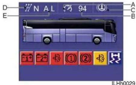
text_image
D E N AL 94 ① A C B -1+ -2+ +3 ① ② +3 + ILHh0029If the engine is running and there are one or more faults, then this will be shown by means of a symbol on the display (see Messages on the display (11 50)).
Messages at the top of the display
In the upper bar the display provides information on the status of the transmission.
| A Cruise control activated |
| B Saved cruise control speed (±1 km) |
| C Bremsomat activated |
| D AS Tronic activated gear messages |
| E AS Tronic messages |
Operation and use
AS Tronic activated gear messages

Automatic mode/Manual mode To switch the operating mode from automatic to manual, push the tip lever to the left.

Manual mode To switch the operating mode from automatic to manual, push the tip lever to the left.
Transmission in neutral position

Reverse gear is engaged.

Which gear is selected in the gearbox

Explanation of AS Tronic messages

System "self-check". Display appears when contact is "on".

"Brake pedal". Before shifting first operate the brake pedal.

Warning information
"Airless" Alternates with the normal display. The transmission compressed air system has insufficient pressure.
Only pull away once there is sufficient pressure in the pneumatic system. If the clutch doesn't open when stopping as a result of insufficient air pressure, the engine is "stalled".
⚠️If the gear is changed whilst the pneumatic pressure is too low, the transmission may remain in neutral to ensure that there is no direct drive and to prevent the engine brake from being ineffective.
Warning information
"Accelerator pedal". Move the accelerator pedal to the stationary position. If the display does not go out, there is a system error. Further travel is not possible.
⚠️If the accelerator pedal is depressed when starting the engine, the dashboard display will show the "FP" message and the vehicle will not select a gear.
Operation and use

Warning information
"Clutch" Alternates with the normal display. Clutch is overloaded. Select an operating mode in which the clutch will not be overloaded, for example:
-Accelerate vehicle (to close the clutch)
-Stop the vehicle
-Set off briskly in a lower gear
Even though the clutch is automated, the driver still has considerable influence on clutch service life. To keep levels of wear on the clutch low, we would recommend that when setting off, you always select the lowest gear possible.

Warning information
"Clutch Wear" Proceed to a recognized workshop to have the clutch exchanged at the next opportunity.

Warning information
"High temperature" (the transmission temperature is too high).

Warning information
"Electronic Error" Is displayed if the communication between the display and the transmission electronics is interrupted.

Warning information
"Easy Start" There is no temporary starting traction control.
The vehicle can start moving.

Warning information
"Neutral Shift" Set rotary switch to «N» Neutral.

Depending on the vehicle type, the transmission may automatically shift to neutral after a certain amount of time in order to protect the clutch's mechanical components.

Warning information
"Clutch Check" The clutch position is unclear.

Warning information
"Transmission Check" The transmission position cannot be learned.

Warning information
"Selector lever" is in the "in between" position.

Operation and use
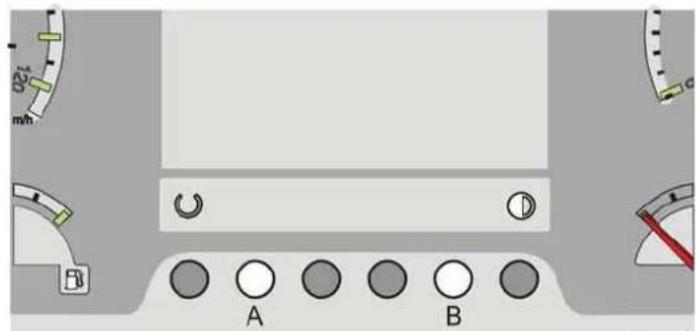
text_image
A BILHh0038
Error menu
When entering the error menu one can on-board check which problem occurred.
The error menu can be opened when next conditions are fulfilled:
- Switch on main switch
- Switch on contact switch
- Apply parking brake
If one of the above mentioned conditions is no longer present, the error menu will be closed and the driving menu will be opened.
When pressing switch A and B at the same time the error menu will open.
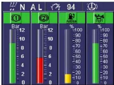
text_image
N A L 94 ① Bar 12 Bar 12 % 10 10 10 %- 8 8 80 6 6 70 4 4 60 2 2 50 0 0 30 10 10 0 AdeRun % 100 -100 90 80 70 60 50 40 30 20 10 0 % 100 80 70 60 50 40 30 20 10 0ILHh0027
Information menu
This display shows the air pressures in brake circuit 1 and brake circuit 2.
This display also shows the AdBlue level and the engine oil level (see Engine oil level electronically (87)).

If an “?” is given for the oil level, then this means that the oil level cannot be read. The oil measurement conditions have not been fulfilled.

Operation and use

text_image
N A L 94 ON OFF km OFF AUTOILHh0030
Vehicle functions
Vehicle functions and options can be switched on and off via this display.
1 Normally the retarder is switched on and is brought into operation by the initial movement of the footbrake pedal This extends the life of the brake components
Operating this control knob switches off the retarder footbrake function.
2 The ASR system is always switched on, but operating this switch allows increased slip of the driven wheels before the system intervenes.
The ASR system prevents the driven wheels slipping both when moving off and when in motion, in order to obtain optimal traction and stability



2 Depending on the condition of the road surface, the ASR system reduces engine power and/or regulates braking pressure when excessive slippage is detected. On consistent road surfaces control will primarily be by means of reduced engine power.
The ASR symbol on the display will light up when the ASR system is in operation

Operation of the ASR system is an indication of slippery road surfaces.
3 Mirror heating is on by default when the temperature falls below 15^ C Mirror heating can also be switched on at temperatures above 15^ C by operating this control knob
4 Speed warning: If speed warning is activated for a particular speed, the driver is warned by means of a buzzer when this speed is exceeded.
Operation and use
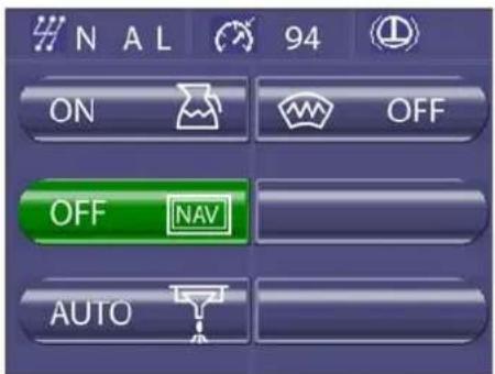
text_image
NAL 94 ON OFF OFF NAV AUTOILHh0031
Vehicle functions 2
Vehicle functions and options can be switched on and off via this display.
1 Kitchen users: Operation makes it possible to use the kitchen equipment.
2 Navigation on monitors: Operation displays the navigation on the monitors in the coach.
3 WC/drain tank emptying
The WC/drain tank can be emptied by means of this switch. This can only be activated when the coach is not moving and the engine is switched off.
⚠️ Empty only in a suitable location.
4 Wind screen heating
The wind screen heating can be switched on/off by means of this switch. The wind screen heating switches off automatically after 15 minutes.
Operation and use
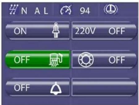
text_image
N A L 94 ON 220V OFF OFF OFF OFFILHh0032
Reversing camera (optional)
When switching over to reverse this display shows the view via the reversing camera.
Blind spot camera (optional)
If the vehicle's speed is below 35 km/h and the indicator at the hostess side is on, the display shows the view via the blind spot camera.
Vehicle functions 3
Vehicle functions and options can be switched on and off via this display.
1 Hostess call: After operation the passengers can use the hostess call switch in the personal setting units, see: Personal service units (☐ 64).
2 If the temperature drops below -15 °C, the fuel pipe heating is switched on as standard, although it can also be switched on manually if temperatures are higher than -15 °C.
3 Bus stop: After operation the passengers can use the bus stop switch in the personal setting units, see: Personal service units (☐ 64).
4 Invertor: Switching on the 24V DC to 220V AC invertor.
5 Vehicle lighting is on by default (Scandinavia)
Operating this control knob switches off the vehicle lighting.

Operation and use
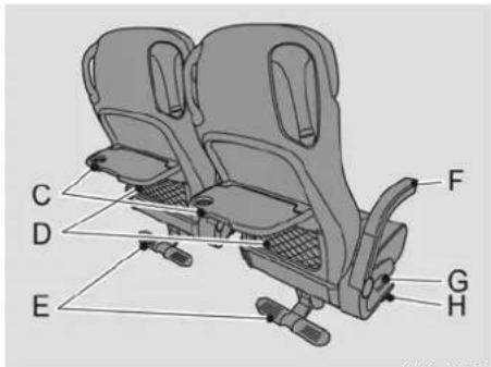
text_image
C D E F G HILHb0000
PASSENGER COMPARTMENT
Passenger seats
The seats fitted in the vehicle may vary from those described here, depending on the chosen option.

Fit the passengers' seats using the correct torque.
C Hinged table with space for drinking-glass.
D Magazine rack
E Footrest, adjustable by moving first up, then down.
F Armrest, folds away by first moving it upwards and then downwards.
G Knob (on the walkway side) and handle (on window side) for back support adjustment. The back support can be adjusted by 35^ to 45^ depending on the version fitted.
H Knob for sideways adjustment of the aisle side seat.
Passenger seat attachment nuts
In the rail necessary for the fixation of the seats there are recesses made to fit the fixation nuts.
In the floor these recesses are covered with removable pieces of rail.
In order to remove or add extra fixation nuts, these pieces of rail must be removed. The drawing shows the spots where you can find these recesses (A).
Also on the window side there are similar recesses. These are covered with aluminium covers that are fastened with tape: just pull to remove them. You can find these recesses (B) in the back and in the front of the coach and on the right hand side just in front of the rear rollover bar.
Operation and use
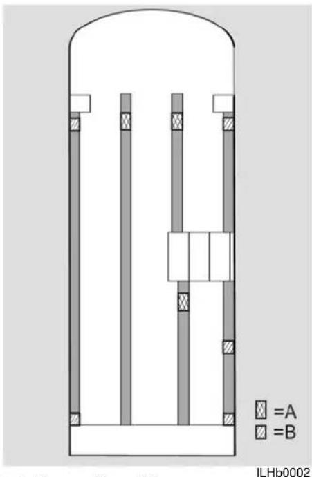
text_image
A B ILHb0002
Recess floor (A)
Recess side wall (B)
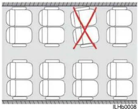
text_image
ILHb0008Seat attachment with quick-release system
Always align the seats at a right angle to the side wall.
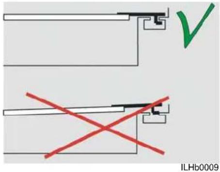
text_image
ILHb0009Always position the push rod correctly into the seat rail at the wall side.

Operation and use
2
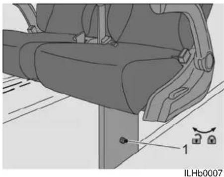
natural_image
Technical illustration of a car seat assembly with mounting bracket and labeled component (no text or symbols beyond label)Torques for passenger seat attachments
| Quick-release connections | 35 Nm (M10) |
| Gangway side 35 Nm (M10) | |
| Side wall side 35 Nm (M8) |

To prevent the construction from being overloaded, always observe the 35 Nm tightening torque for the quick-release bolt (1).

It is no permitted to remove parts or to modify the quick-release system. It is also not permitted to apply oil or grease to the system or to the seat rail.
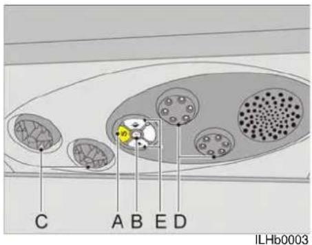
text_image
C A B E D ILHb0003Personal service units
A service unit is installed above each seat. Passengers can use these units to regulate the ventilation and to adjust the reading light to their personal preference. As an option, a speaker, stop and hostess call buttons can be fitted to each personal setting unit.
A The (optional) stop button can only be operated by the passenger when permitted in the display, see: Vehicle functions 3 (61). If the stop button is pressed, the stop symbol appears on the display and a buzzer sounds for several seconds. Opening the door resets this function.
B The (optional) courier call switch can only be operated by the passenger when permitted in the display, see: Vehicle functions 3 ( [ ] 61). When the hostess call button is pressed, the button above the passenger will change colour until the button is pressed again.
C The ventilator mouths may be turned to open or close them and also directed according to preference.
D Directional reading lamps.
E This button turns on the relevant reading light.
Operation and use
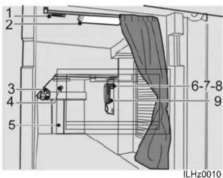
text_image
1 2 3 4 5 6-7-8 9 ILHz0010DRIVER'S SLEEPING COMPARTMENT
General information
The driver's sleeping compartment is entered via the left or right luggage flaps or the roller shutter in the central entry.
1. Air outlets
There are air outlets on each side allowing fresh air supply. The air outlets may be turned to open or close them and also directed according to preference.
2. Reading lights
In the driver's sleeping compartment there are two reading lights which can be switched on or off by switch 8.
3. Heating (optional)
Heating of the sleeping compartment functions on the same circuit as the under floor heaters. Temperature can be adjusted by the thermostatic valve.
4. Emergency unlocking
When necessary the luggage flap can be unlocked from the inside by pulling the bar.
5. Sleeping compartment window
For ventilation purposes the window can be opened to the inside by pressing the knob and at the same time pulling the upper side of the window to the inside.
6. Ventilator switch
When the main switch is on, the extractor fan can be turned on or off using this switch.
7. Warning switch
Operation of this switch gives the driver a warning message on the dashboard
8. Lighting switch
When the main switch is on, the reading light can be turned on or off using this switch.


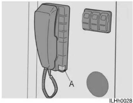
natural_image
Illustration of a wall-mounted telephone with attached case and circular button (no text or symbols)9. Intercom installation
The intercom unit can be used to speak to the driver from the sleeping compartment and vice versa.
A call is made by pushing button A which sounds a buzzer in the other receiver.
When the receiver is taken one can speak to each other.

Operation and use
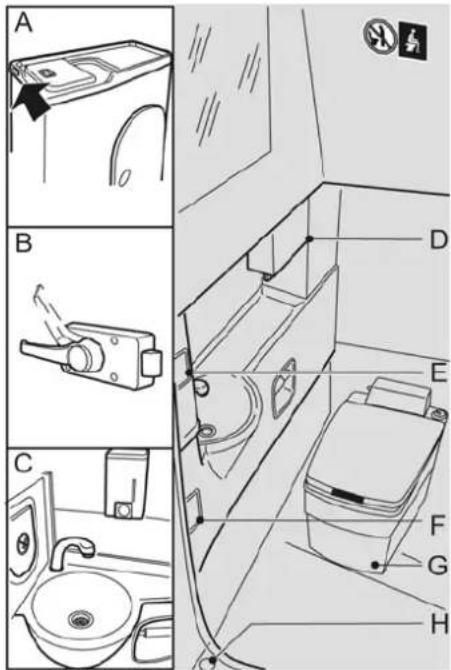
text_image
A B C D E F G HTOILET
General information
Depending on the chosen option, the toilet may differ from that described here.
The toilet air extraction operates continuously from the switching on of the contact switch.
A: Occupied sign, which is illuminated when the toilet lighting is turned on with switch E.
B: Lock, lockable from inside by moving the handle upwards, and from outside with a key.
C: Sink with 70 litre reservoir. The tap is operated (with the knee) by switch (F). To the left of the sink is a waste bin fitted with a smoke detector.
D: Paper towel dispenser
E: Light switch for two halogen spotlights and the occupied light A.
F: Knee-operated switch, for operating tap.
G: Chemical toilet with level indicator, and flushing via a knob.
For a detailed description of the WC see the manufacturer's information supplied.
H: Outlet, to allow water to drain away easily during cleaning.
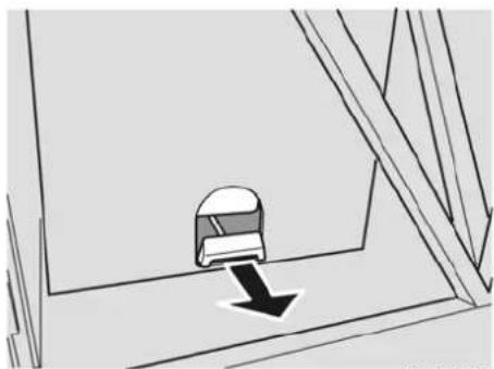
natural_image
Simple line drawing of a mechanical component with a downward arrow, no text or symbols presentILHk0010
WC/drain tank emptying
Depending on the chosen option the WC/ drain tank can be emptied by pulling the toilet slide which is accessible via the luggage compartment. An other possibility is by means of operating a switch, see: Vehicle functions 2 (☐ 60).

Park the vehicle in an appropriate place before emptying the toilet.

Operation and use
KITCHEN
For a detailed description of the on-board kitchen see the manufacturer's information supplied.
NAVIGATION SYSTEM
For a detailed description of the navigation system see the manufacturer's information supplied.
PNEUMATIC SUSPENSION (ECAS)
The Electronically Controlled Air Suspension is operated via a microprocessor.
The vehicle height is stored in the microprocessor memory.
If the actual vehicle height is different, this is adjusted for automatically.
ECAS control symbols
Any disturbance to the ECAS system is reported by the illumination of ECAS symbols on the display, see: Messages on the display (☐ 50).
If the red ECAS symbol flashes, then there is a serious fault.
- The level can not be checked or adjusted.
If the red ECAS symbol illuminates continuously in the driver menu there is a minor fault such as:
- No speed signal.
- The level can only be monitored to a limited extent.
- Low voltage, between 7.5 and 18 volts.
- Raising inoperative, regardless of valve position.

Operation and use
If the yellow ECAS symbol flashes in the driver menu, the storage pressure is too low.
If the yellow ECAS symbol is continuously illuminated, the level in question varies from the normal level: raising or kneeling required.
Raising/kneeling
The ECAS system is equipped to allow the whole vehicle to be raised, or to allow the front or rear axle to be kneeled separately. The capability to raise the vehicle may be used if more ground clearance is required, for example when boarding a ferry. The kneeling function may be used to allow passengers to alight more easily.
The front of the vehicle is raised or kneeled by means of the Ferry lift/front kneeling ([1] 31).
Position 0: Raise (front)
Position 1: Driving position (neutral)
Position 2: Kneel (front)
The rear of the vehicle can be raised or kneeled by means of the Ferry lift/rear kneeling (☐ 31).
Position 0: Raise (rear)
Position 1: Driving position (neutral)
Position 2: Kneel (rear)
Anti-tilt system
The vehicle can also be fitted with an anti-tilt system (obligatory in the UK).
Any vehicle can drive along a cambered surface at a certain angle. If this angle becomes too great, the vehicle will topple over.
The anti-tilt system increases the toppling angle by 5^ . This means that the vehicle will not topple over so easily.
STEERING MECHANISM
The steering mechanism is hydraulically assisted.

In temperatures below 0 °C, it is recommended to run the engine for several minutes, after a cold start, before moving the steering.

Do not continue to turn the steering wheel when the wheels touch an obstacle or when they have reached the maximum turning angle. Doing so may damage the steering mechanism.
The turning angle is 60^ and there are 6.8 turns from lock to lock

The vehicle can also be steered without the power steering, but this requires a large force.
Operation and use
MIRRORS
The mirrors are electrically heated and electrically adjustable. There are wide angle mirrors on the left (optional) and/or right.
The heating functions automatically but can switched on manually (see Vehicle functions (1) 59).
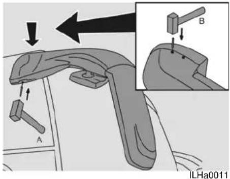
text_image
A B ILHa0011Removing mirrors
The mirrors can be removed (e.g. when cleaning the vehicle in a car wash) using a hammer and the punch provided.
Place the punch in the bottom recess. Use a hammer to tap the punch into the mirror. Remove the punch from the recess. The mirror can now be removed.
Replacing mirrors
The mirrors can be refitted by hooking them in the attachment. Place the punch in one of the two recesses at the top. Use a hammer to tap the punch in the mirror (hit the punch 2 or 3 times).
Remove the punch from the recess. The mirror will now be secured in place.

If the mirrors do not vibrate and the adjustment operates correctly, this indicates that they are properly fitted.

Operation and use
INSTRUCTIONS FOR DRIVING WITH A TRAILING AXLE
Steering mechanism
On vehicles fitted with a trailing axle (second rear axle) the trailing axle wheels are steerable at vehicle speeds up to 30 km/h. Driving the vehicle in forward or reverse gears the trailing axle will automatically steer. The steering angle of the trailing axle will be determined by:
- The sensors on the front axle which, up to 10 km/h, detect the steering direction of the front wheels and convert them to the vehicle electronics, which use this signals to actuate one of the locking cylinders of the trailing axle. By this the system prevents the trailing axle to steer in the wrong direction.
- The forces created between the tyre and road surface which takes care of the exact trailing of the trailing axle.

The trailing axle must be allowed time to return to the straight-ahead position. There should, therefore, be a delay of several seconds after selecting the forward or reverse gear before gently pulling away.

A slight movement of the vehicle may assist with straightening up the trailing axle wheels.
Automatic locking straight-ahead
To obtain more stable handling the trailing axle is locked in the straight-ahead position as soon as:
• Speed is above 30 km/h.
- ABS is activated.
- ASR is activated.
• Higher wheel slip is allowed.
- The trailing axle is temporarily unloaded.
- Malfunction in the system.
Manual locking straight-ahead
Whilst driving on loose ground or on a slippery road surface or using ferry lift the locking system can be activated by applying the straight ahead locking switch, see: Right/fixed trailing axle wheels (11 32).

To eliminate tyre wear and decrease the turning circle, it is important to de-activate the manual lock as soon as possible and continue using the automatic system.
Fault in the trailing axle locking system
If the trailing axle fails to lock at a speed above 30 km/h, the red prio 1 warning light will illuminate.


The road handling of the vehicle will become unstable in these circumstances. It is possible to drive but only with adjustments to speed and with the greatest care.
If the trailing axle is not functioning correctly, the yellow prio 2 warning light will illuminate. A VDL Bus & Coach service point should be consulted as possible to have the fault involve


Safety precautions and emergency procedures
3 SAFETY PRECAUTIONS AND EMERGENCY PROCEDURES
GENERAL INFORMATION ....73
ROOF HATCHES ....73
EMERGENCY OPERATION OF THE DOORS AND HATCHES.....74
FIRE EXTINGUISHER....77
SEAT BELTS....77
FIRST-AID KIT....78
HAZARD WARNING LIGHTS 78
EMERGENCY HAMMERS 78
EMERGENCY PROCEDURES....79
Safety precautions and emergency procedures
Safety precautions and emergency procedures
GENERAL INFORMATION
Before departure, the driver should provide the passengers with adequate information about the emergency procedures and should also ensure that all the emergency exits are unobstructed.
In an emergency, the driver and/or the passengers may exit the vehicle via the doors, windows or roof hatches.

Before setting off on a journey, check whether the roof hatches are closed properly.
ROOF HATCHES
The vehicle has two roof hatches.
The front roof hatch is an emergency hatch and the rear roof hatch is a service hatch.
The roof hatches have a ventilation position and can be used as an emergency exit.

A roof hatch must not be used to climb onto the roof for cleaning work.
Ventilation position
The roof hatch can be opened fore and aft for ventilation purposes by pushing (A) to the outside. To re-close the hatch, pull (A) towards the inside.
The roof hatches may be in the ventilation position whilst driving the vehicle, but if only the front ventilation position is used, the vehicle may not be driven at a speed greater than 100 km/h.

When fitting the hatches, they must be locked with the aid of the handles (B). To enable this locking action you have to pull (A) firmly towards the interior!
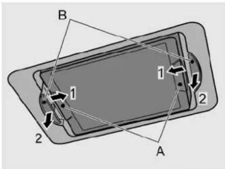
text_image
B 1 1 2 2 AILHz0012
Opening/Removing the emergency hatch
In the event of an emergency, the emergency hatch can be removed by first removing the protective covers (1) and then pulling the handles (2) in the direction of the arrow. The roof hatch can then be pushed outwards.
The hatch remains attached by a safety strap.

The emergency hatch can only be removed once and should, therefore, only be removed in the event of an emergency!

Safety precautions and emergency procedures
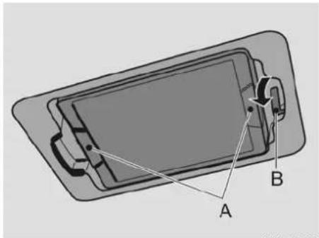
text_image
Diagram of a device with labeled components A and B, showing internal structure and connection points.ILHz0006
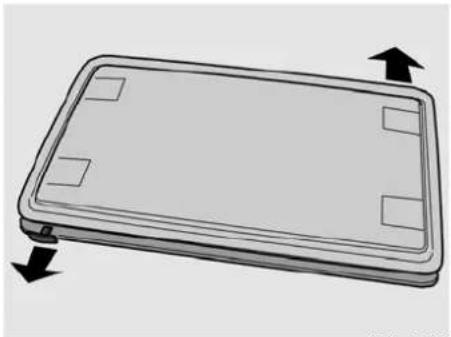
natural_image
Illustration of a rectangular electronic device with four square holes and bidirectional arrows indicating rotation (no text or symbols)ILHz0013
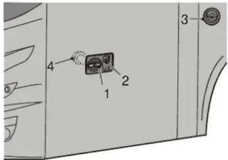
text_image
1 2 3 4ILHa0000
Opening the service hatch
If handle B at the rear of the hatch is turned, the hatch can be opened by approximately 100°.
Opening/Removing the roof hatches from the outside of the vehicle
In an emergency, the roof hatches can also be removed from outside the vehicle by pulling the handles.
EMERGENCY OPERATION OF THE DOORS AND HATCHES
Passenger door and central door
By turning the key the handle (1) can be locked/unlocked. By turning the handle the door is locked/unlocked
The door is opened/closed with push button (2).
If the door is unlocked and the normal door operation is not functioning, the door can still be opened by turning the emergency handle (3), allowing the door to be opened by hand.
A buzzer sounds and the red lamp in the switch illuminates.
Safety precautions and emergency procedures
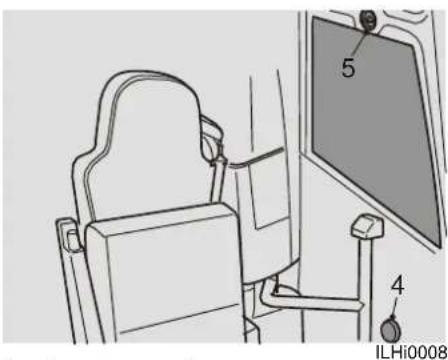
text_image
5 4 ILHi0008In the case of an emergency, the passenger and central door can be opened from inside by operating the emergency handle (5) which depressurises the system allowing the door to be opened by hand.

If the door does not open, turn the knob (4) to unlock the door.
After resetting the door system (opening and closing the doors with the switch), the buzzer will turn off and the red light in the switch will go out.

If the pneumatic system is blown off, the procedure Connecting the vehicle to an external air supply (☐ 19) must be followed in order to ensure that the door system functions correctly.
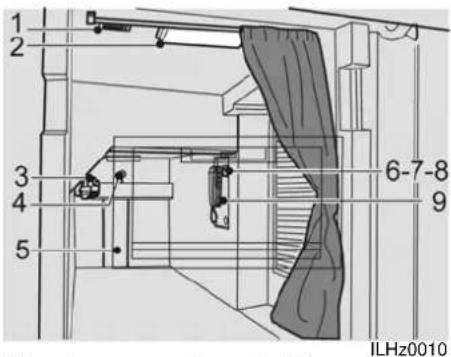
text_image
1 2 3 4 5 6-7-8 9 ILHz0010Sleeping compartment hatch
The left-hand sleeping compartment hatch can be unlocked from the inside by pulling the bar (4). The hatch can then be opened. The right-hand sleeping compartment hatch can only be opened from the outside using a key (see Luggage hatch emergency operation (76)).

When the middle door is open, only the left hand sleeping compartment hatch can be opened.

Safety precautions and emergency procedures
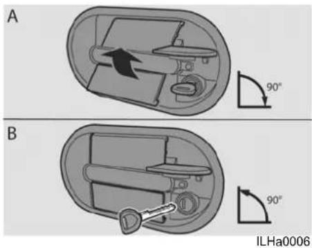
text_image
A B 90° 90° ILHa0006Luggage hatch emergency operation
If the luggage compartments and the driver's sleeping compartment cannot be unlocked using the switches on the dashboard, the compartments can only be opened by using a key.
A Turn the key 90° to the right (leave the key in the lock). Open the flap by operating the rocker handle (key remains in the 90° position). Return the rocker handle to the neutral position (key remains in the 90° position).
B Return the key in the 0^ position and remove the key.
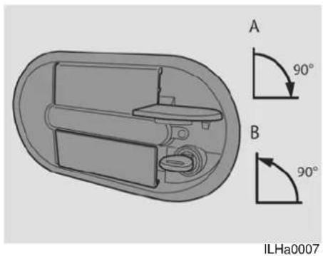
natural_image
Technical diagram of an electronic device showing internal components and two 90-degree angle annotations (A and B) with no readable text or symbols.Resetting the luggage hatch lock
If, after an emergency operation, the lock does not catch in the lock plate, the lock can be reset.
Turn the key 90° to the right (A) and return the key in the 0° position (B) without operating the rocker handle.

When using a key to open a hatch, the central locking system will no longer function. To re-use the central locking system, first lock the hatch with the key.

Before departing, always check whether the locking mechanism works correctly.

Safety precautions and emergency procedures
FIRE EXTINGUISHER
The fire extinguisher is located in the passenger space on the floor to the left and/or right at the front. It has a pressure gauge for checking whether the fire extinguisher is still in good working order. Make sure the fire extinguisher is inspected at least once a year.
If the fire extinguisher is used, it must be refilled as soon as possible.
SEAT BELTS
The driver's and hostesses seat are provided with triple point anchorage safety belts.
The passenger seats are provided with triple anchorage point safety belts.

A vehicle equipped with ESC may unexpectedly brake hard in certain situations. Therefore, always wear a seat belt.

It is your duty to ensure that the passengers use the safety belts properly!
Fastening
Insert the clip into its housing. When a clear click is heard, the belt is fastened. It is important for safety reasons that the belt fits snugly against the body.
The belt must not be crooked or twisted. The hip belt must sit low (i.e. not above the stomach).
Unfastening
Push in the red knob on the housing. Ensure that inertia reel belts are rolled up without the belt being twisted.
Inertia belt reel locking
Normally inertia reel belts are free to move. The belt locks because of:
- Pulling the belt out too fast.
- Braking and accelerating, and when the vehicle tilts excessively to one side.
- On bends.
Inspection
Check regularly that the belts are in good condition.
The locking function of an inertia reel belt can be checked by giving it a short tug.
The belt should lock and not be able to be withdrawn.

Safety precautions and emergency procedures
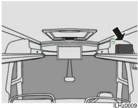
natural_image
Top-down view of a car dashboard and steering wheel (no text or symbols visible)FIRST-AID KIT
The first-aid kit is located in the luggage rack above the driver.
Ensure that you always have a complete first-aid kit (obligatory in some countries).

Replace any of the contents as soon as they are used.
HAZARD WARNING LIGHTS
The hazard warning lights must be used if you are forced to stop or park in a way that obstructs or endangers other traffic.
The hazard warning lights are turned on with switch Hazard warning lights (☐ 43).

Requirements for the use of hazard warning lights vary from country to country.
Hazard warning triangle/warning light
Place the warning triangle or warning lamp (in the toolkit) at least 30 metres behind the vehicle in case of danger.
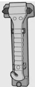
natural_image
Technical illustration of a mechanical tool or clamp device (no text or symbols visible)ILHz0001
EMERGENCY HAMMERS
In an emergency these hammers may be used to break glass or to cut through a safety belt.
The emergency hammers are located throughout the vehicle on the window stiles.
Break the lock and hit the sharp point against the window, preferably not in the middle of the window.

Take into consideration that the windows may be double glazed.

Safety precautions and emergency procedures
EMERGENCY PROCEDURES
Even a vehicle in good condition may be involved in an emergency, a breakdown or an accident. This almost inevitably leads to a dangerous traffic situation, since the vehicle may not come to a stop in a safe location.
The driver's actions immediately after an emergency has taken place can play an important role in limiting the consequences. Since emergency situations are very diverse, it is not possible to give a standard solution. However, there are often similarities, so that it is possible to give the following general rules:
- First ensure your own safety, then that of the passengers.
- Calm the passengers.
- Watch out for other traffic.
- Be careful where you stand and walk.
- Watch out for the release of hazardous substances.
- Act quickly and decisively, but remain calm and avoid panic reactions.
- Prevent accidents and the escalation of accidents.
- Ensure that other road users are warned by, for example, hazard warning lights, the vehicle's own lighting, the warning triangle or similar items.
- Switch off the engine and turn off the main switch.
- Prepare fire extinguishers and, if necessary, extinguish any fires which may break out.
If necessary, notify the emergency and rescue services.
Assist any injured persons.

Safety precautions and emergency procedures
Maintenance
4 MAINTENANCE
GENERAL INFORMATION......83
MAINTENANCE CHECKLIST 84
DAILY CHECKS/MAINTENANCE....87
WEEKLY CHECKS AND MAINTENANCE.... 91
OVERVIEW OF THE MONTHLY INSPECTIONS WHEN USING BIODIESEL....96
WATER SYSTEM....97
BEFORE THE WINTER....97
AFTER THE WINTER 99
EXTERIOR....99
TOUCHING UP PAINTWORK.... 100
INTERIOR MAINTENANCE.... 101
Maintenance
Maintenance
GENERAL INFORMATION
The durability, safety, depreciation and reliability of the vehicle is to a large extent dependent on the way it is cared for and on the regular performance of the maintenance prescribed by VDL Bus & Coach.
The driver's driving style and his care of the vehicle have a direct influence on the vehicle's condition.
The driver can often give the workshop information which is valuable for good maintenance.
The vehicle should be serviced according to the intervals given in the Futura FHD2 maintenance book. However, if the vehicle has to operate in dusty areas or under difficult conditions the frequency of maintenance should be increased.
The maintenance discussed here refers to activities the driver can carry out himself.
A checklist is provided listing the points to be covered by the driver.

Maintenance
MAINTENANCE CHECKLIST

Maintenance activities can be checked off on a copy of this list.
| Daily Weekly | ||
| Engine compartment | ||
| Possible oil, air or coolant leak ☐ ☐ | ||
| Check the engine oil levela | ☐ | ☐ |
| Check the AdBlue level ☐ ☐ | ||
| Check the fluid level of the hydraulic fan drivea | ☐ | |
| Check the coolant levela | ☐ | ☐ |
| Check the steering mechanism's hydraulic fluid levela | ☐ | |
| Check the air filter indicatora | ☐ | |
| Check the V-belts ☐ ☐ | ||
| Drain the fuel system's water separatora | ☐ | |
| Underbody | ||
| Drain water from air reservoirsa | ☐ | |
| Check transmission, rear axle and engine for leaks ☐ | ||
| Sides | ||
| Visually check the wheel nuts. ☐ | ||
| Check the tyre pressure. ☐ | ||
| Check tyres and rims for wear and damagea | ☐ | ☐ |
| Remove stones from the tread and from between the double tyres ☐ ☐ | ||
| Check the closure of all side flaps ☐ ☐ | ||
| Check the radiatora | ☐ | |
Maintenance
| Daily Weekly | ||
| Front | ||
| Check windscreen washer reservoir^a | □ | |
| Check the condition of the windscreen wipers □ | ||
| Check the spare tyre pressure □ | ||
| Roof | ||
| Check the roof unit dust filters^a | □ | |
| Rear | ||
| Check trailer connection^a | □ | |
| Interior | ||
| Check seats for secure mounting and covers for damage and soiling □ | ||
| Check clutch fluid^a | □ | |
| Check the front box dust filters^a | □ | |
| Check seat belt security and reel mechanisms □ | ||
| Check if first aid kit, emergency hammers and fire extinguisher(s) are present □ □ | ||
| Check if doors, emergency exits and emergency valves open and close □ □ | ||
| Check whether the spare parts, jack, tools and hazard triangle are present. □ □ | ||
| Electrical system | ||
| Check all exterior lights (parking lights, main and dipped beam, brake lights, fog lamps, reversing lights, clearance lights, registration plate lights, indicators and alarm lights) | □ | □ |
| Check the batteries' fluid level^a | □ | |
| Check all interior lighting (main lights, dashboard, reading lamps and entry lighting) | □ | □ |
| Check dashboard instruments and signal lamps for operation and correct signal before and after starting | □ | □ |
| Check the operation of the windscreen wipers and the air horn □ □ | ||
Maintenance
| Daily Weekly | ||
| In freezing conditions | ||
| Drain the water tank, boiler, coffee machine and toilet water supply ☐ ☐ | ||
| Windscreen washer antifreeze in reservoir ☐ ☐ | ||
| Antifreeze in chemical toilet ☐ ☐ | ||
a. These activities are discussed in more detail in the following pages.
Maintenance
DAILY CHECKS/MAINTENANCE
Carry out daily checks and maintenance as follows: Maintenance checklist (118 84).
Open the engine compartment see: Engine cover (19).

Preferably, turn off the engine before opening the engine compartment.
Engine oil level electronically
The engine oil level will be checked electronically.
To perform a reliable electronically oil measurement, following requirements have to be achieved.

The level can only be measured and displayed when the engine is turned off. Therefore, the level is not monitored whilst driving!

Make sure the vehicle is on a flat, horizontal surface.
1. At the start of a new day
- Turn on the main switch and wait till the instrument panel has completed the start up cycle.
- Turn the ignition switch to position I (see Contact switch (24)) (engine not running) and wait six seconds for the electronic oil level inspection to be completed.
The engine oil level can be checked on the display (see Display (54)).
2. After a journey
- Turn off the ignition switch and the main switch.
- Wait for 15 minutes and proceed as at the beginning of a new day.

The oil level is sufficient to start the engine if the symbol opposite is not visible.

Low oil level

If the oil level is low, the yellow "low oil level" symbol will be displayed together with the yellow DMCI warning symbol. The amber central warning light will also be lit (see 2 (☐ 51)).

Priority
In the display the oil level bar shows
Check the oil level using the dipstick, see: Manually checking the oil level (☐ 88).
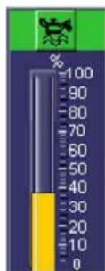

Maintenance
Oil level too high

If the oil level is too high, the yellow "oil level too high" symbol will be displayed together with the yellow DMCI warning symbol. The amber central warning light will also be lit (see 2 ( 51)).

Priority
In the display the oil level bar shows
Check the oil level using the dipstick, see: Manually checking the oil level (☐ 88).
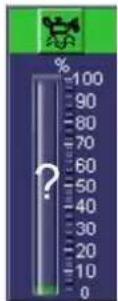
Oil level too low

If the oil level is too low, the red "oil level too low" symbol will be displayed together with the red DMCI warning symbol. The red central warning light will also be lit (see Priority 1 (☐ 50)).

In the display the oil level bar shows
Check the oil level using the dipstick, see: Manually checking the oil level (☐ 88).
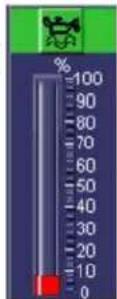
Oil level measurement not possible

If it is not possible to measure the oil level, the "No oil level measurement possible" symbol will be displayed (see 3 (☐ 53)).

Priority
In the display the oil level bar shows
Check the oil level using the dipstick, see: Manually checking the oil level (118 88).
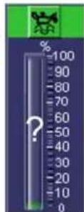
Manually checking the oil level
Use the dipstick to manually check the engine oil level.

Avoid skin contact with oil. Oil is bad for skin and health.
- Ensure the vehicle is standing on level ground.
- Turn off the engine and wait 5 minutes minimum.
- Remove the dipstick from its holder.

Maintenance
- Use a lint-free cloth to clean the dipstick.
- Insert the dipstick in its holder and wait a few seconds.
- Remove the dipstick again and read the engine oil level. It should always be between the two marks.
- Add oil as necessary via the filler opening.
Avoid overfilling.

An incorrect oil level may cause serious damage to the engine.
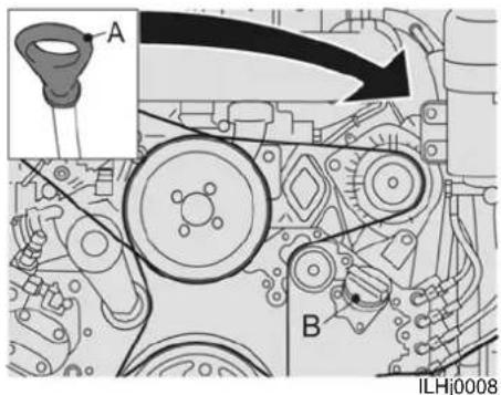
text_image
A B ILHJ0008PR engine dipstick and filler cap
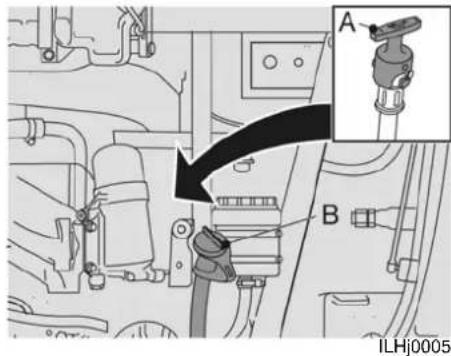
text_image
A B ILHj0005MX engine dipstick and filler cap
PR engines
- If the amber central warning light is displayed, 7.5 litres of oil must be added.
- If the red central warning light is displayed, 9 litres of oil must be added.
MX engines
- If the amber central warning light is displayed, 6 litres of oil must be added.
- If the red central warning light is displayed, 9 litres of oil must be added.

For the engine oil specification, see Fluid and lubricant specifications (144).

Maintenance
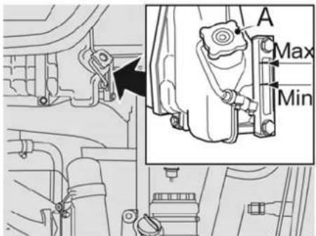
text_image
A Max MinILHj0001
4
Coolant level
Check coolant level when the engine is cold.
If coolant level is below the minimum, checks for leaks must be carried out.

When the coolant is warm, the cooling system will be pressurized. In that case cover the filler cap with a thick cloth and remove it slowly and gradually, allowing pressure to escape. Then remove it completely.

Coolant is a harmful liquid. Therefore, avoid skin contact to prevent poisoning.

To avoid damage to the engine block when adding cold coolant to a warm engine, add it slowly while the engine is running.
Remove filler cap A from the reservoir.
Fill the reservoir to the maximum.
See Technical information (137) for the coolant specifications.
Bring the engine to the operating temperature.
Switch off the engine and check the coolant level.
Maintenance
WEEKLY CHECKS AND MAINTENANCE
Carry out the following weekly checks and maintenance: Maintenance checklist (11) 84.
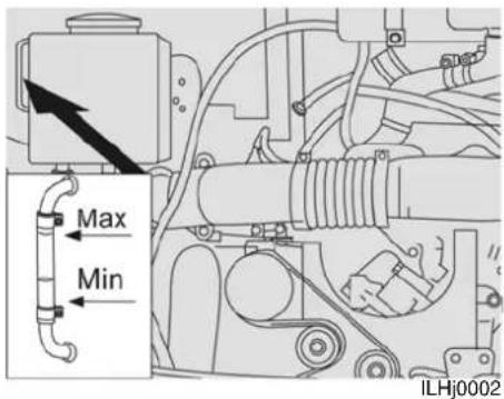
text_image
Max Min ILHj0002Hydraulic fluid
Check that the fluid level is between the two marks.
If necessary, top it up via the filler opening. See Technical information (☐ 137) for the hydraulic fluid specifications.
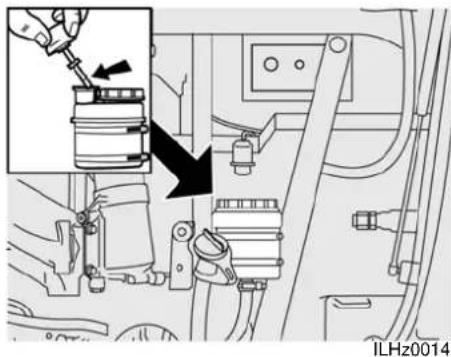
natural_image
Mechanical assembly diagram showing a piston and valve assembly with no visible text or symbolsPower steering fluid
When the engine is turned off, check whether the fluid is approximately 2 cm above the top mark on the dipstick.
If necessary, top up the fluid.
Start the engine (the engine cannot be started when the bonnet is open).
When the engine is idling, the fluid must reach the top mark on the dipstick.
See Technical information (137) for the power steering fluid specifications.

Maintenance
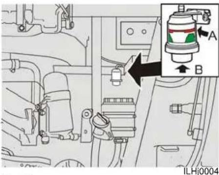
text_image
Technical diagram showing engine compartment with labeled parts A and B, including a highlighted component in the inset.Air filter
There is an indicator fitted, which indicates whether the filter needs to be replaced.
If the air filter is normal/clean, the indicator is in the green area.
If the indicator is in the red area (A), the air filter is seriously fouled and must be replaced.
Clean the filter housing before replacing the dust filter. After replacing the filter, reset the indicator by pressing button (B).

Do not use this space for storage.
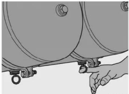
natural_image
Illustration of a hand adjusting a cylindrical mechanical component (no text or symbols visible)ILHi0006
Brake system air dryer
Drain the water from the air reservoirs by pulling on the ring.
The air tanks are best reached via the spoiler flap.
If more water is regularly drained off than has been usual, the air dryer filter element must be replaced (consult a VDL Bus & Coach workshop).
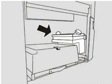
natural_image
Line drawing of a mechanical device with an arrow indicating direction (no text or symbols)ILHz0005
Windscreen washer fluid
Check the fluid level and, if necessary, top it up.
Add cleaning fluid in the summer.
Add special windscreen washer antifreeze in the winter.

Maintenance

natural_image
Diagram of a square frame with a shaded internal area and corner markers, labeled 'ILHj0013' at the bottom (no text or symbols within the diagram itself)Radiator
Check the gauze which is fitted in front of the cooling unit as extra protection against contamination. If necessary, clean the gauze.

Make sure the radiator's lamellae are not damaged.
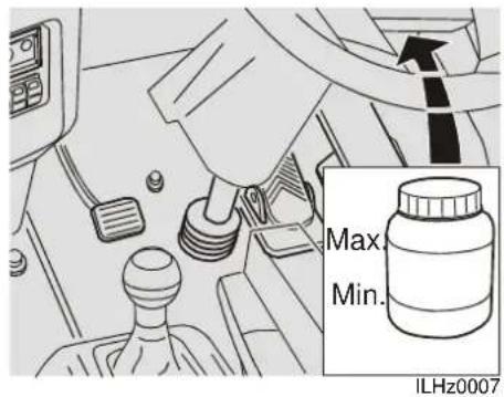
text_image
Max. Min. ILHz0007Clutch fluid
Check the level of the clutch fluid.
The fluid level must be between the marks. If necessary, top it up.
See Technical information (☐ 137) for the clutch fluid specifications.
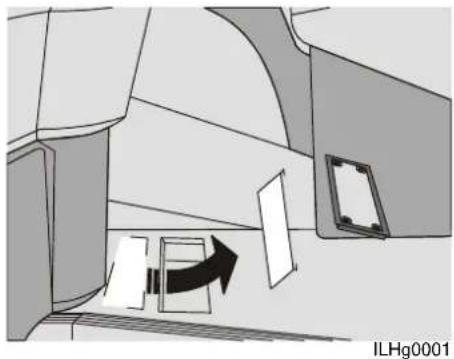
natural_image
Diagram of a mechanical or architectural component with an arrow indicating direction, no visible text or symbolsFront box dust filter
The dust filter in the front box is accessible via the hatch in the floor near the front entryway.
Unlock the hatch by loosening the bolts (5mm Allen key).
Remove the hatch.
Remove the filter.
Clean or if necessary replace the filter.
Clean the filter housing before replacing the dust filter.

Maintenance
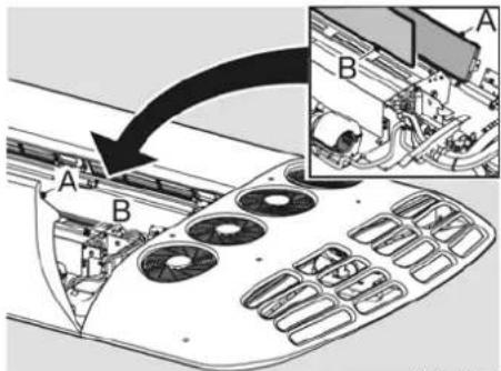
text_image
Diagram showing a device's internal structure with labeled components A and B, including a directional arrow indicating flow or transformation.ILHg0002
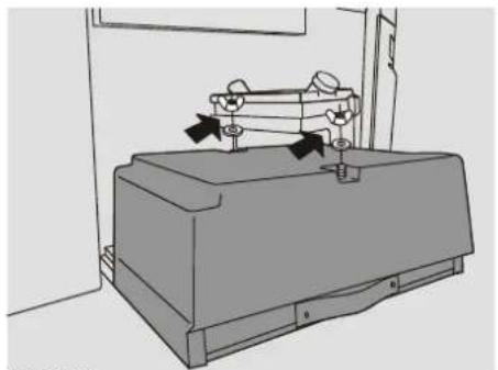
natural_image
Technical line drawing of a mechanical device with directional arrows indicating motion (no text or symbols)ILHh0039
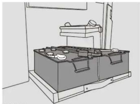
natural_image
Line drawing of a laboratory apparatus with labeled components (no text or symbols)ILHh0040
4 Roof unit dust filters
The dust filters are located in the roof units.

Except in case of emergency, it is not permitted to climb onto the roof by means of the roof hatches.
Clean the area around the roof units.
Open the roof units (cross-headed screwdriver).
Remove leaves, twigs etc. from filter A and clean the filter.
Clean the filter housing.
Check and if necessary replace filter B.
Close and lock the roof units.
Batteries
The batteries are located front right, behind a closeable flap.
The battery cover can be removed by undoing the two wing nuts.
Check the electrolyte level. it must be around 5 mm above the plates. Refill as necessary with distilled water.

Battery acid is an aggressive fluid. If it comes into contact with your clothes, eyes or skin, rinse with plenty of water.
Check that the battery contacts and clamps are clean and well-greased. If necessary, lubricate them with acid-free Vaseline.
Don't forget to replace the battery carriage securing pins after these checks.

Maintenance
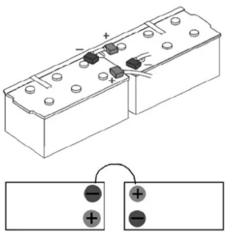
text_image
Diagram of a battery cell with positive and negative terminals, showing charge distribution and polarity labelsILAh0770
Disconnecting and connecting the battery cables

There is a risk of a short circuit if the battery's positive cable comes into contact with parts of the vehicle. An explosive gas (oxyhydrogen) may be released if there is a short circuit.

Do not place metal objects or tools on the batteries.
When removing the battery terminal clamps, always remove the black (-) cable before the red (+) cable.
When connecting the battery terminal clamps, always connect the red (+) cable before the black (-) cable.

The DTCO tachograph saves an error code if the battery terminal clamps are disconnected. In some countries, the error code is interpreted as a breach of the law. To prevent the unit from saving an error code when disconnecting the battery cables, place a DTCO workshop card in the unit whilst the battery is disconnected.
If an error code is saved, contact a recognized DTCO service dealer to calibrate the DTCO and to delete the code.
Disconnecting the battery terminal clamps
- Turn off all the electrical consumers.
- Turn off the contact switch and the main switch. If applicable, remove the contact switch key.
- Wait 5 minutes after turning off the contact switch and the main switch.
- Open the front left-hand service hatch.
- Open the battery box (see Batteries (☐ 94)).
- Disconnect the negative cable and then the positive cable from both batteries.
Connecting the battery terminal clamps
- Check whether the contact switch and the main switch are turned off. If applicable, remove the contact switch key.
- Check whether all the electrical consumers are turned off.
- Make sure the battery terminals and the battery terminal clamps are clean and well lubricated with Vaseline. If necessary, lubricate them with acid-free Vaseline.
- Connect the positive cable first and then the negative cable of both batteries.
- Close the battery box (see Batteries (11 94)).
- Close the service hatch.

Maintenance
OVERVIEW OF THE MONTHLY INSPECTIONS WHEN USING BIODIESEL
Diesel is a poisonous substance. Physical contact may lead to serious health problems.

Avoid bodily contact.

In the event of skin contact: remove the substance with paper or a cloth and wash with soap. Contact a doctor in the event of persistent irritation.

In the event of contact with the eyes: wash for at least 15 minutes with plenty of water and visit a doctor.

If swallowed: Do NOT induce vomiting. Rinse your mouth, drink a lot of water and contact a doctor.

In the event of inhalation: get some fresh air and take a rest. Contact a doctor.

Fuel is highly inflammable and may cause a fire or an explosion, which can result in a serious injury.

Collect any fuel which escapes.

Avoid sparks and a naked flame near the fuel.

Dirt in the fuel system may cause serious damage to the fuel system.

Work in a clean environment when working on the fuel system.

Clean the area around the fuel system's components before starting work on the fuel system.
Visually check the components listed below once a month for the following:
- (Flexible) fuel hoses between the lines and the engine for leaks. If necessary, replace them.
- The contents of the fuel tank for water, contamination and bacteria growth. If necessary, clean it.
- The seal of the fuel tank's filler cap for leaks. If necessary, replace it.
Maintenance
WATER SYSTEM

The owner of the vehicle is at all times responsible for the quality of the water used in the vehicle.
In order to reduce the development of legionella bacteria to a minimum, the following issues need to be considered:
Main water tank
- Rinse with disinfectant once a month. Fill the tank to the rim and then add disinfectant in accordance with the product instructions. Next, drain the water via the vehicle's line system and thoroughly rinse the system before using it again.
Extra (drinking-) water tank
- Inspect once a fortnight or inspect with every filling if the tank is not filled through the normal couplings, but through the inspection panel. - In case of scale formation in the tank, it should be cleaned according to the aforementioned method.
Water conduits
As the hosepipes are rinsed out while cleaning the tank, a visual inspection of the hosepipes while filling the water tank should be sufficient.
Connected devices
- The temperature of the water heater should be set to the maximum temperature (approx. 85^ C). Along with cleaning the tanks and the pipes, this will minimize the risk of infection.

Connecting a washing installation to the main water tank increases the risk of legionella infection.
BEFORE THE WINTER
Checking the antifreeze concentration
Check the coolant's antifreeze concentration If anti-freeze has not been added already, fill the cooling system with anti-freeze.

To avoid damage to the engine block when adding cold coolant to a warm engine, add it slowly while the engine is running.
Only use coolant or, if appropriate, anti-freeze which satisfies VDL Bus & Coach specifications (see Technical information (137) and Fluid and lubricant specifications (144)). No variation is permissible because of the aluminium radiator fitted.
Follow the manufacturer's instructions for the correct composition of coolant when adding anti-freeze.
Windscreen and headlight washer reservoir
Add antifreeze to the windscreen washer fluid.

Maintenance
Air conditioning
The air conditioning system has a so called "season-off control", which automatically takes care that the compressors run regularly for several minutes to allow oil to be pumped around the system, preventing the seals from drying out.
Fuel
During the winter months the fuel suppliers often use additives to prevent paraffin deposits, which cause blockages.
In extremely low temperatures a maximum of 20% petroleum may be added.
If this is not legally permitted, then a maximum of 20% unleaded petrol can be added.
Fuel additives to prevent paraffin deposits have only a preventative effect. They are not suitable for dissolving the paraffin.

Ensure that a spare fuel filter is available so that the filter can be replaced in the event of a blockage (also if it was caused by paraffin deposits) (see Replacing fuel filters (113)).
Batteries
The demands that are placed on the batteries in the winter are much higher than in the summer, because the lights, windscreen wipers, etc. are used more often. Also, the battery capacity is lower at lower temperatures.
A poorly charged battery can become frozen if it becomes very cold.
Regularly check the charging state of the batteries and, if necessary, lubricate the battery poles with acid-free Vaseline.
Locks
Use special lock oil for the locks (Teflon spray).
Avoid the use of de-icer sprays, because they have a negative effect on the locks.
Door and hatch rubbers
To avoid the doors and hatches from freezing closed, the rubbers must be regularly treated with talcum powder during the winter.
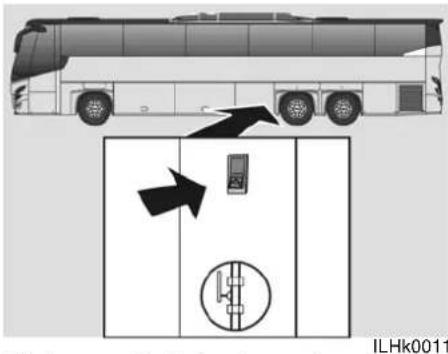
text_image
ILHk0011Kitchen and toilet water system
Operating this switch disables the water reservoir empty alarm.
The water can subsequently be pumped out of the tank by operating the tap in the vehicle.

Reset the switch after emptying the tank, so that the warning light works again. This will prevent the reservoir from running empty.

Make sure that all reservoirs and pipes are drained to prevent freezing.
Maintenance
AFTER THE WINTER
Cooling system
The anti-freeze mixture may be left in the system during the summer.
Windscreen and headlight washer reservoir
It is recommended to add cleaning fluid to the water.
EXTERIOR
Washing
Wash the vehicle as soon as it is dirty in winter, as salt and dampness easily cause corrosion.
Remove bird droppings as soon as possible from the paintwork! Bird droppings contain substances which attack and discolour paintwork. The discolouration cannot be polished away.

Always wash the vehicle in a suitable place.
You can wash the vehicle as follows:
Hand washing
- Carefully hose off the soiling from the underside of the vehicle (wheel arches, around mud flaps etc.).
- Hose down the whole vehicle to loosen the dirt. Avoid spraying directly into locks.
- Wash the vehicle using a sponge, with or without a cleaning agent. Use lukewarm water for preference, but avoid hot water.
- Dry the vehicle with a clean, soft chamois.
Cleaning with a high pressure jet washer
Take care that the spray head of the jet washer does not come closer than 30 cm from the coachwork. Also, avoid spraying into or near the locks of the various hatches and doors and the engine compartment.
Cleaning in a car wash
The vehicle can be washed quickly and simply in a vehicle washing machine.
Bear in mind, however, that the vehicle washing machine cannot clean the vehicle as carefully and effectively as you can with a sponge and water.
The car-wash brushes cannot reach into all areas.
Before entering the vehicle washing machine, ensure that any extra equipment is properly secured, or it may be pulled loose by the brushes.
Only wash the vehicle in a vehicle washing machine with clean brushes.

It is not recommended to use a vehicle washing machine for the first few months as the paint layers may not have sufficiently hardened.

Maintenance

Depending on the type of car wash, it may be necessary to fold in or remove the mirrors (see Removing mirrors (69)).
Cleaning agents
Car shampoo, or 5 - 10 cl ordinary washing-up liquid to 10 litres of water.
Spotting on aluminium may be removed with car polish.
Never use polishing paste or steel wool.
4
Waxing and polishing
You should wax and polish the vehicle if you find that the paint has lost its gloss and normal washing doesn't restore the original gloss.
Normally the vehicle exterior will need polishing only after a year.
You may apply wax before then.
Wash and dry the vehicle well before polishing or waxing.
Remove any asphalt and tar spots with white spirit.
Stubborn marks may be removed with a fine car paint polish.
There are many brands of polymer wash materials on the market. These are easy to work with and give a hard and very glossy
surface which protects the paint against oxidation, dirt and dulling.
TOUCHING UP PAINTWORK
General information
Paint damage on metal parts must be dealt with without delay to prevent rust formation.
It is advisable to check the paintwork regularly, perhaps after each wash, to touch up any possible damage.
Small spots and scratches can be touched up with a paintbrush.
Larger areas of paint damage require special equipment and expertise. It may be advisable to have more major damage repaired by a specialist workshop.
Minor scratches and stone damage
If the chipping caused by stones has not penetrated to the metal, and undamaged paint is still present, you may paint directly over the spot, after polishing to remove dirt.
If the chipping has penetrated to the metal you must proceed as follows.
- Sand the damage area down to the metal and remove sharp paint edges with a sharp knife.
Maintenance
- Use a rust removal agent on the metal, wait for several minutes and then wash well with water. Then rub dry. (this treatment is not needed on plastic substrates).
• Stir the primer well and apply it. - When the primer has dried apply the top coat with a brush.
INTERIOR MAINTENANCE
General information
Remove soiling as soon as possible before it has dried in. Soiling should be dissolved away, rather than rubbed, scraped or removed with a hard brush. Always work from the edge of the soiling towards the middle.
Cleaning upholstery
The fabric upholstery of the seats can generally be cleaned with soap and water or a detergent solution.
With difficult stains like oil, ice-cream and shoe-polish, a special cleaning agent may be used. Follow the cleaning agent manufacturer's instructions. Use solvent cleaners sparingly. Excessive use of solvents may damage the foam plastic filling of the seats.
Cleaning curtains and seat covers
Curtains and seat covers can normally be washed in cold water. If they are soiled they can be washed at 30°C. Bleach should not be used.
The use of washing powders may cause discolouration. To keep the colours uniform, the curtains or covers should all be washed at the same time. The covers should not be ironed.
Cleaning plastic
Plastic parts should be cleaned with a lukewarm solution of synthetic cleaning agent.

Avoid the use of trichloroethylene, petrol and similar materials on plastics.
Cleaning carpets
Soak up as much as possible with clean cloths. Vacuum around the affected area to avoid spread. Dampen the affected areas with textile cleaning agent on a clean cloth. Soak up the cleaning agent with a dry cotton wad. Repeat the process until the soiling is gone.

Maintenance
Repairs whilst on the road
5 REPAIRS WHILST ON THE ROAD
GENERAL INFORMATION...... 105
ON-BOARD TOOL KIT.... 106
ENGINE COMPARTMENT 107
WHEELS AND TYRES ....116
REPLACING LIGHT BULBS.... 120
REPLACING FUSES 121
JUMP STARTING. 122
TOWING.... 123
ITS-VDL.... 126
Repairs whilst on the road
Repairs whilst on the road
GENERAL INFORMATION
Although the vehicle may be well maintained, it is still possible that a problem arises, such as a flat tyre or a faulty headlight, that you will have to repair yourself in order to continue your journey.
Safety Safety vest

Before attempting to carry out repairs, you must first ensure your own safety and that of the passengers. Therefore, stop and park the vehicle in a safe place and, if necessary, allow the passengers to wait in a safe location close to the vehicle.
When carrying out emergency repairs, always wear a safety vest (it is a legal requirement in some countries) and, if necessary, also use other means of marking.
Cleanliness
It is extremely important that you make sure you keep the work area clean when repairing a fault, to avoid the repair work from resulting in another fault due to unnecessary contamination.
A clean work area also improves safety. Once the fault has been rectified, make sure to return the area to its original state.

Repairs whilst on the road
ON-BOARD TOOL KIT
The vehicle is equipped with an on-board tool kit including:
Number
Tool kit 1
4mm drift 1
Tommy bar/wheel nut span- 1 ner
Ring spanner 12 x 13 1
Ring spanner 14 x 15 1
Ring spanner 16 x 17 1
Ring/open-end spanner 18 1
Allen key set 1
cross-headed screwdriver 1
150 mm screwdriver 1
75 mm screwdriver 1
Bench hammer, 400 g 1
Adjustable spanner 1
Combination pliers 1
Water pump pliers 1
VDL Bus & Coach bag 1
Wheel key 2
Jack and foot 1
Jack rod 1
Tyre inflation hose 1
Inspection lamp with plug 1
Towing eye assembly 1
(mounted behind the spoiler flap)
Square spanner 1
Special spanner for hatches 2
Spare wheel puller 1
Lamp kit with fuses 1
The on-board tool kit is located in the extra storage compartment to the right behind the rear axle.
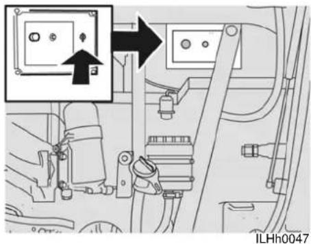
text_image
ILHh0047Inspection lamp connection
The 24 volt inspection lamp can be connected to 3 sockets in the vehicle.
Fuse box in engine compartment and main fuse box in luggage compartment:
The inspection lamp, without its plug, may be connected as shown in the illustration above.
24 Volt connection
To connect the inspection lamp to the 24 Volt connection, the adaptor plug must connected to the inspection lamp's plug (see Plug (107)).
Repairs whilst on the road
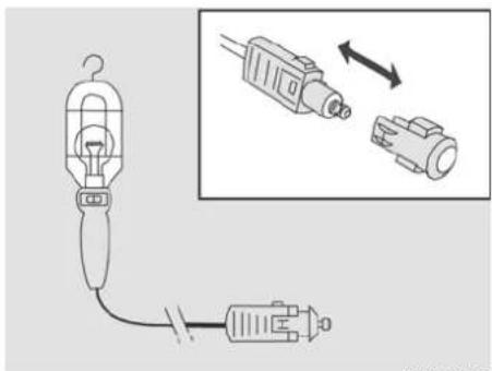
natural_image
Diagram showing a hairpin connected to a plug, with an inset illustrating the connector (no text or symbols present)ILHh0050
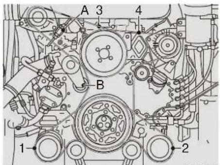
text_image
A 3 B 1 2 4 hILHj0007
If two V-belts are used for a drive, both belts must be replaced.
Plug
Fit the adaptor plug to the inspection lamp's plug for use in the 24 Volt connection as illustrated.
ENGINE COMPARTMENT
Changing the V-belts on a PR engine
1, 2 Replacing the air conditioning belts for a PR engine (☐ 108)
3 Removing and installing the generator V-belt for a PR engine (☐ 108)
4 Replacing a poly V-belt for a PR engine (☐ 109)

Always fit the same type of V-belt.

BUI & COJON
Repairs whilst on the road
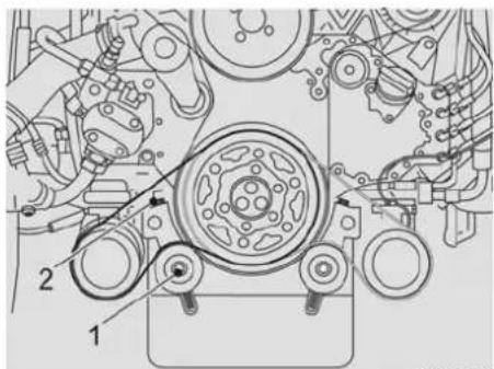
text_image
Technical diagram of a mechanical assembly with labeled parts 1 and 2, showing gears and shafts.ILHj0006
Replacing the air conditioning belts for a PR engine

Always fit the same type of V-belt.
- Unscrew bolt 1 from the pulley.
- Unscrew bolt 2 until the air conditioning belt can be removed.
-
Inspect the pulleys for damage, rust and grease deposits.
• Fit a new air conditioning belt. -
Use bolt 2 to adjust the air conditioning belt tension. If the V-belt is correctly tensioned, it can be pushed down 10 mm when slightly pressed between the air conditioning pulley and the crankshaft pulley (A).
- Tighten bolt 1.

Check the new V-belts after the first 50 km and have the V-belt tension checked as soon as possible by a VDL Bus & Coach service dealer.
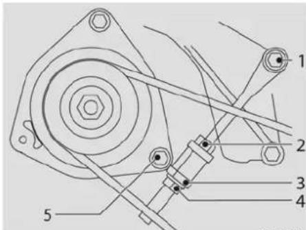
text_image
Technical diagram of a mechanical assembly with numbered components labeled 1 to 5ILHj0015
Removing and installing the generator V-belt for a PR engine
- Disconnect the earth cable from the battery.
- Unscrew the threaded spindle's lock nut (2).
- Unscrew the threaded spindle's attachment bolt (1).
- Unscrew the generator's bottom attachment bolt (5).
- Unscrew the threaded bush's (4) lock nut (3).
- Use the threaded bush (4) to move the generator until the V-belt(s) can be removed.
- Check the pulleys for damage, rust and grease deposits.

Repairs whilst on the road
- Fit the new V-belt(s).
- Adjust the V-belt tension (see "Adjusting the V-belt tension").
- Reconnect the battery's earth cable.

Check the setting of the new V-belts after the first 50 km and have the V-belt tension checked as soon as possible by a VDL Bus & Coach workshop.
Adjusting the generator V-belt tension for a PR engine
- Unscrew the threaded spindle's lock nut (2).
- Unscrew the threaded spindle's attachment bolt (1).
- Unscrew the generator's bottom attachment bolt (5).
- Unscrew the threaded bush's (4) lock nut (3).
- Move the generator by rotating the threaded bush (4) until the correct V-belt tension is obtained. If a V-belt is correctly tensioned, it can be pushed down 10 mm by slightly pressing it between the generator and the water pump pulley (A).
- Tighten the lock nuts (2 and 3) and the attachment bolts (1 and 5).

Check the new V-belts after the first 50 km and have the V-belt tension checked as soon as possible by a VDL Bus & Coach service dealer.
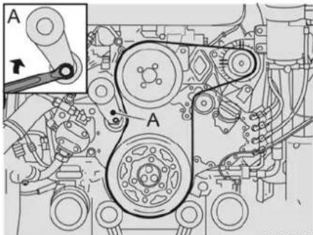
text_image
A A A A A A A A A A A A A A A A A A A A A A A A A A A A A A A A A A A A A A A A A A A A A A A A A A AILHj0014
Replacing a poly V-belt for a PR engine

Always fit the same type of poly V-belt.
- Disconnect the earth cable from the battery.
- Remove the V belt(s) from the extra generator and the air conditioning compressor (see Removing and installing the generator V-belt for a PR engine (108)).

Repairs whilst on the road
- Place a 17 mm ring spanner on the automatic belt tensioner's hexagon (A).

It is possible to temporarily block the tensioner with a 4 to 5 mm thick pin (drill bit) (see A in the diagram). This will make it easier to assemble and disassemble the poly V-belt.
- Slacken the poly V-belt so that it can be removed from the belt discs.
- If the tensioner has not been temporarily blocked, allow the automatic belt tensioner to slowly spring back to the stop.
- Remove the poly V-belt.
- Check the pulleys for damage, rust and grease deposits.
• Fit a new poly V-belt. - Place the new poly V-belt over as many pulleys as possible.
-
Use a 17 mm ring spanner to tighten the automatic belt tensioner (if it has not been temporarily blocked) and place the poly V-belt over the remaining pulleys. Allow the automatic belt tensioner to slowly spring back against the new poly V-belt.
-
If used, remove the blocking pin. The blocking pin can be removed by moving the pulley against the spring force.
- Check that the poly V-belt lays in all the pulley grooves.
- Fit the V-belt(s) that was/were removed from the extra generator and the air conditioning compressor (see Removing and installing the generator V-belt for a PR engine (108).
- Reconnect the battery's earth cable.
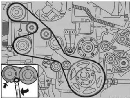
natural_image
Mechanical gear assembly diagram showing pulleys and gears (no text or labels)ILHj0016
Changing the V-belts on an MX engine
Replacing the air conditioning belt for an MX engine

Always fit the same type of V-belt.
- Slacken the multi-V belt by turning the spanner against the belt tensioner spring pressure.
- Place a drift at position C so that the spring tensioner is locked and remove the V-belt from the pulleys.
- Inspect the pulleys for damage, rust and grease deposits.
- Fit a new V-belt.

Repairs whilst on the road
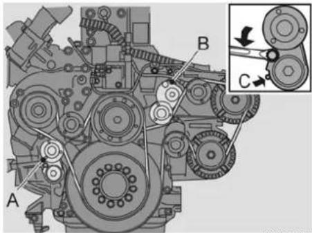
text_image
Technical diagram of an engine assembly with labeled components A, B, and C, showing gear and shaft connections.ILHj0017
Replacing the poly V-belt for an MX engine

Always fit the same type of poly V-belt.
- Disconnect the earth cable from the battery.
- Remove the air conditioning belt, see Replacing the air conditioning belt for an MX engine (111 110)
- Fit a suitable spanner to the automatic belt tensioning mechanism A and/or B.
-
Slacken the multi-V belt by turning the spanner against the belt tensioner spring pressure.
-
Place a drift at position C so that the spring tensioner is locked and remove the V-belt from the pulleys.
- Inspect the pulleys for damage, rust and grease deposits.
- Fit a new V-belt.
- Remove the drift and cautiously allow the automatic belt tensioner to take up tension against the new V-belt
- Check that the poly V-belt lays in all the pulley grooves.
- Install the air conditioning belt. Reconnect the battery's earth cable.
Replacing the fuel preliminary filter/water separator
Diesel is a poisonous substance. Physical contact may lead to serious health problems.

Avoid bodily contact.

In the event of skin contact: remove the substance with paper or a cloth and wash with soap. Contact a doctor in the event of persistent irritation.

In the event of contact with the eyes: wash for at least 15 minutes with plenty of water and visit a doctor.

If swallowed: Do NOT induce vomiting. Rinse your mouth, drink a lot of water and contact a doctor.

In the event of inhalation: get some fresh air and take a rest. Contact a doctor.

Repairs whilst on the road
⚠️ Fuel is highly inflammable and may cause a fire or an explosion, which can result in a serious injury.
Collect any fuel which escapes.
Avoid sparks and a naked flame near the fuel.
Dirt in the fuel system may cause serious damage to the fuel system.
Work in a clean environment when working on the fuel system.
Clean the area around the fuel system's components before starting work on the fuel system.
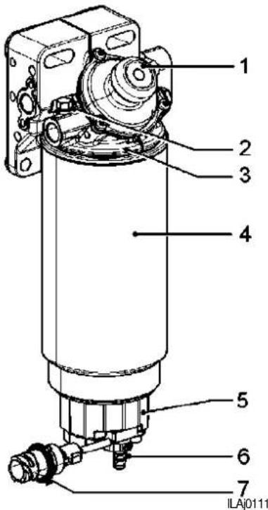
text_image
1 2 3 4 5 6 7 ILA0111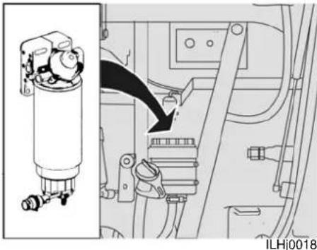
natural_image
Mechanical assembly diagram showing a cylindrical component connected to a motor or connector, with no visible text or symbols.Removing and installing the fuel preliminary filter
- Open the bleed plug (2).
- Drain the fuel out of the filter element by screwing the drain plug (6) open.
- Disconnect the connector (7) from the water sensor and the heating element.
- Remove the filter element (4) together with the base cover (5).
- Remove the base cover (5) from the filter element (4).
- Clean the seal of the base cover's (5) O-ring.
- Apply a thin layer of engine oil to the base cover's O-ring.
- Fit the base cover in the new filter.
Repairs whilst on the road
- Apply a thin layer of engine oil to the new filter's sealing ring.
- Fit the new filter element (4), together with the base cover (5), to the filter housing (3).
- Tighten the filter (3) by hand.
- Connect the connector (7) for the water sensor and the heating element.
- Bleed the fuel system (see Bleeding the fuel system with the fuel preliminary filter/water separator (113)).
Bleeding the fuel system with the fuel preliminary filter/water separator
- Open the bleed screw (2).
- Pump using the hand pump (1) until fuel without air bubbles flows out of the bleed screw (2).
• Tighten the bleed screw (2). - Start the engine and check the fuel system for leaks.
- If necessary, retighten the filter element (4) by hand.
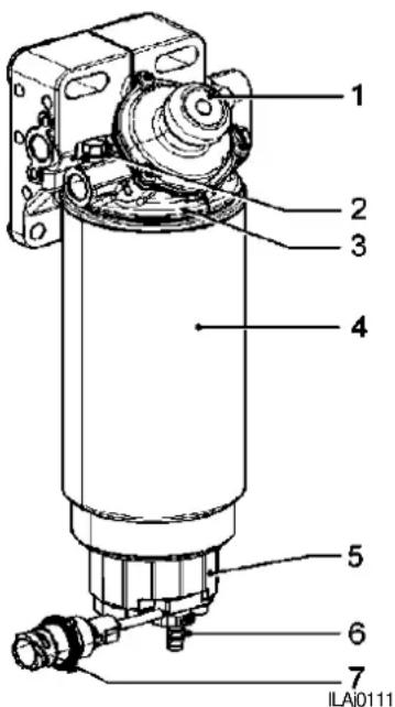
text_image
1 2 3 4 5 6 7 ILA0111Draining the water from the preliminary fuel filter/water separator
- Check the base cover (5) for the presence of water.
-
If necessary, open the drain plug (6) and use the hand pump (1) to pump out the water.
-
Close the drain plug (6).
- If necessary, bleed the fuel system (see Bleeding the fuel system with the fuel preliminary filter/water separator (113)).
Replacing fuel filters

Diesel is inflammable and may not be exposed to a naked flame or other heat sources, such as a hot engine. Collect any drained fuel in a suitable container.
Cleaning a coarse fuel filter
It may be necessary to clean the course filter as a result of, for example, paraffin deposits.
- Unscrew the lower part of the filter housing (1) and clean the filter.
- Check the sealing rubber and replace, if necessary.
- Lubricate the sealing rubber sparingly with engine oil.
- Reassemble the filter and filter housing in the reverse order (torque 10 Nm).
- Check the fuel system for leaks with the engine running.

Repairs whilst on the road
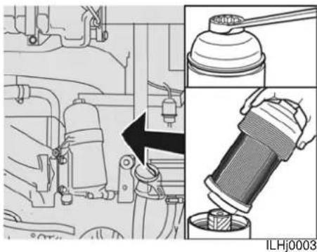
natural_image
Technical illustration of a mechanical assembly with exploded and assembled views (no text or symbols)Replace the fuel fine filter
The fuel fine filter is located on the right-hand side of the engine next to the power steering reservoir.
Replace the filter according to the method given below:
- Remove the filter by rotating the filter housing cap to the left, whereupon the filter element can be replaced.
- Check the sealing rubber and replace if necessary.
- Lubricate the sealing rubber sparingly with engine oil.
-
Place a new filter element in the cap and replace the cap, together with the filter element, in the filter housing.
-
Screw the new filter home (torque 25 Nm).
- Bleed the fuel system.
- Check the fuel system for leaks with the engine running.
If the display fails to function, the power supply is possibly disconnected.
- Check fuses 68, 70 and 94 (see fuse list).
- Check if the V-belt tension of the airco compressors is O.K., see: Replacing the poly V-belt for an MX engine (111).
- Check the dust filters in the roof units, see: Roof unit dust filters (1194).
- Check the dust filter in the frontbox, see: Front box dust filter (111 93).
The climate system is provided with on board diagnostics, which checks the operation of a number of components. If a fault is detected this is indicated by a warning triangle on the display.
Repairs whilst on the road
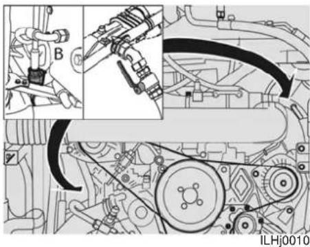
natural_image
Mechanical assembly diagram showing engine components and wiring (no text or labels)PR engine heating taps
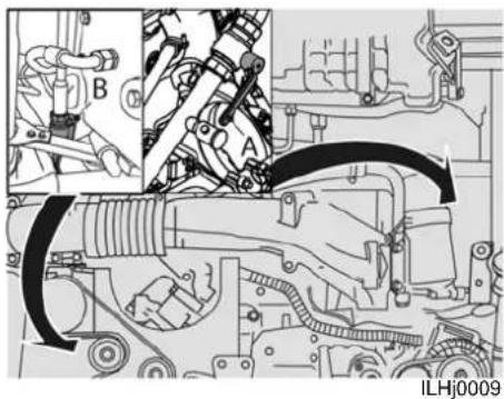
natural_image
Technical line drawing of an automotive engine assembly with labeled components (no readable text or symbols)MX engine heating taps
Heating system leaks
If leaks occur in the heating system, it is possible to isolate the system from the engine cooling system.
Valves (A + B) should be closed in the case of leaks in the climate system.

If the vehicle cannot be adequately heated, the water valves may be partly or completely closed: check the water taps and ensure that they are completely open.

Repairs whilst on the road
EBS SYSTEM
Illumination of the red warning light at speeds above about 7 km/h indicates a fault in the EBS system.
Check the EBS system fuses.
If the fault is not rectified by replacing the fuses, the journey may not be continued, because the EBS system is not working.

Have the EBS system repaired by an authorised workshop.
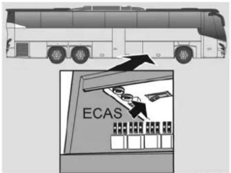
text_image
ECASILHi0009
PNEUMATIC SUSPENSION LEAK
If a spring bellows develops a fault the ECAS symbol will light up on the display. Switch the axle in question to "kneel" and then switch off the ECAS system. The switch is in the fuse box in the right luggage compartment.

The journey may continue, at a reduced speed.
The fault must be repaired as soon as possible.

natural_image
Mechanical component diagram showing a bolt and nut assembly with directional arrows (no text or symbols)ILHz0002
WHEELS AND TYRES
General information
VDL Bus & Coach fit their coaches with the so-called wheel hub centering system. Characteristics of wheel hub centring are:
- Wheels with cylindrical bolt holes.
- Wheel nuts with a loose, non-removable, flat thrust washer.

Use only the appropriate wheel hub centering wheels and wheel nuts.

Repairs whilst on the road
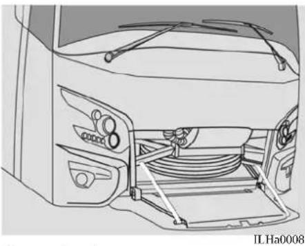
natural_image
Technical line drawing of a car front panel with hoses and control knobs (no text or symbols)Spare wheel
The spare wheel is located behind the spoiler flap.
The spoiler flap is opened by pulling on the handle next to the steering column, see: Spare wheel compartment handle ( 41).

First check whether the spare wheel is in a usable condition and, if necessary, inflate it to the correct pressure (see Tyre pressure (139)).
Remove the spare wheel by taking off the clamp and pulling a draw band through the wheel so that it can be pulled out.
Changing wheels
- Park the vehicle in a safe location on an asphalted, horizontal road surface.
- Block the wheels so that the vehicle cannot roll away.
- If necessary, turn on the hazard warning lights and place a warning triangle a distance of at least 30 m behind the vehicle.
- Remove the wheel cover by pulling it firmly.
- Clean the wheel nuts and apply a drop of oil to the screw thread.
- Unscrew the wheel nuts half a turn.
- Place the jack near the wheel to be replaced (see Jack points (118)) and jack up the vehicle until the wheel comes off the ground.

Read the documentation supplied with the jack before using it.
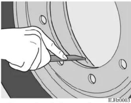
natural_image
Hand holding a tool interacting with a mechanical component (no visible text or symbols)- Remove the wheel nuts and remove the wheel.
- Before fitting the wheel, carefully clean the wheel hub's fitting edge and the inside edge of the spare wheel and remove any burrs or paint residue. Lightly smear the fitting face with grease.

Repairs whilst on the road
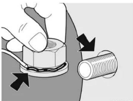
natural_image
Illustration of a hand adjusting a bolt with arrows indicating fastening or adjustment (no text or symbols)ILHz0004
- Clean the wheel studs and apply oil to the threads.
- Apply a drop of oil between the pressure ring and the wheel nut.
- Fit the wheel and tighten the nuts.
- Remove the jack and tighten the nuts sequentially and diagonally to the prescribed torque (600Nm ± 3%).
• Install the wheel cover.

Retighten after 100 km.
Stow the spare wheel and the tools. Do not forget the warning triangle.
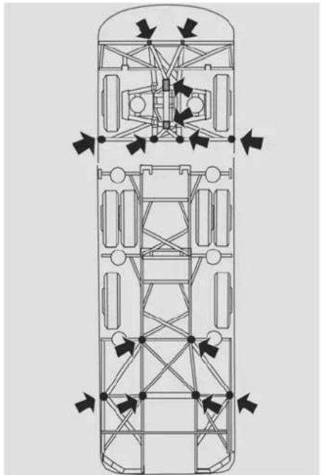
natural_image
Top-down schematic of a vehicle chassis with structural framework and directional arrows indicating movement or force (no text or labels)ILHf0000
Jack points
The jacking points detailed above have been provided to jack the vehicle up.
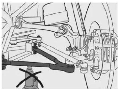
natural_image
Technical line drawing of a vehicle suspension system with mechanical components (no text or labels)ILHf0001

Never put a jack under the suspension triangle of the front axle or under the differential housing, or under the body of the rear axle.

Always use supports when working under a jacked up vehicle.

Read the documentation supplied with the jack before using it.
Repairs whilst on the road
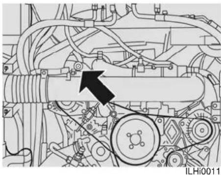
natural_image
Mechanical assembly diagram showing engine components and a black arrow indicating a specific part (no text or symbols present)PR engine emergency filler connection
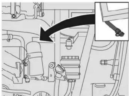
natural_image
Diagram showing a mechanical assembly with a black arrow pointing to a component labeled 'Screw' (no text or symbols present)ILHi0013
MX engine emergency filler connection
Inflating a tyre
Remove the cap from the emergency inflation connection.
Connect the tyre inflating hose.
Pump up the tyres. The engine must be running but the stored pressure must not be at maximum, otherwise the compressor will not deliver air.

The pressure can be lowered by operating the brake pedal.
For correct tyre pressures see: Tyre pressure (111 139).

Repairs whilst on the road
REPLACING LIGHT BULBS
General information
Never touch the glass of a light bulb with bare fingers. Traces of grease, oil or other irregularities will adhere to the glass and reduce the lifespan of the lamp.
The reflector will be affected by vaporization of the irregularities.

Use the light bulb's packaging as protection between your fingers and the glass.

Check the headlight setting when the headlight's bulb is replaced.
For a complete list of the lamps and there specifications see: Lighting (☐ 154).
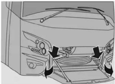
natural_image
Diagram of a car interior showing dashboard, steering wheel, and engine compartment with arrows indicating assembly or movement (no text or symbols)ILHa0010
Replacing headlamps
Open the spoiler flap handle (see Spare wheel compartment handle (☐ 41)) and open the relevant fog light space by pulling on the handle.
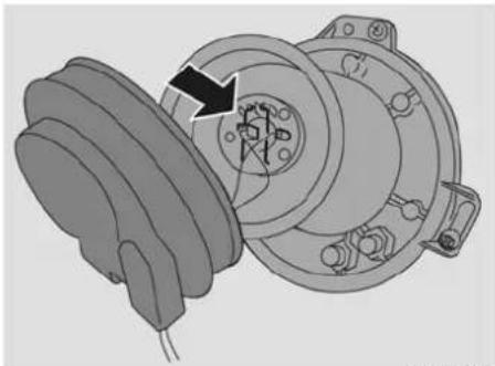
natural_image
Mechanical assembly diagram showing a gear and housing component with no visible text or symbolsILHh0048
Remove the protective cover on the light.
Pull out the light plug.
Unhook the spring.
Replace the bulb.

Make sure that the lamp engages in the recess in the reflector.
Headlights driver's side.
The bulbs on the driver's side are replaced in the same way.
Xenon lamps
Provided the lamps are not switched on and off excessively, Xenon lamps have a

Repairs whilst on the road
very long life span and the risk of lamp failure is extremely low.
However, if the bulbs are faulty, the vehicle can still be driven using the fog lights, but only if the local laws allow this.

Replacing xenon bulbs is a very specialized procedure and may only be carried out by highly trained technicians.
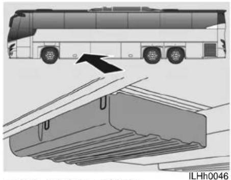
natural_image
Diagram of a bus exterior and interior space with an arrow indicating direction, no text or symbols present.REPLACING FUSES
Electrical circuit diagrams
Location of the supplied binders with vehicle specific electrical diagrams and fuse-, and relay lists is shown above.
General information
If an electrical component does not work, this may be due to a fuse which has blow as a result of a temporary excessive load.
The vehicle's fuses are in four locations.
• One fuse box is at the front right luggage compartment.
- One fuse box is in the left luggage compartment. In this fuse box there are mostly fuses and relay's for options
- One fuse box is in the passenger compartment behind the air intake grills in the ceiling at the middle of the coach. In this fuse box there are the fuses for the air fans of the climate system.

The air intake grille is fastened h Velcro.

Look in the fuse list supplied to see which fuse is to be checked.
The fuse lists are located in the electro boxes.

Repairs whilst on the road
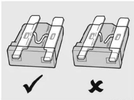
natural_image
Two identical 3D mechanical component diagrams with check and cross symbols, no text or labels present.ILHh0034
Pull the fuse out in a straight line and look on the inside to see whether the wire loop has burnt out.
If necessary, fit a new fuse of the same colour and with the same amperage as the previous fuse.
The amperage is stated on the fuse.

Never replace a faulty fuse with one of a higher capacity.
If fuses in the same location burn out repeatedly, there is a failure in the electrical installation and the vehicle must be taken to a workshop for inspection.
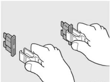
natural_image
Illustration of hands installing or adjusting a component with two separate parts (no text or symbols visible)ILHh0035
Pincers are provided to make it easy to change a fuse.

Spare fuses are supplied with the tool-kit.

Do not forget to replace the pli-ers after use.
JUMP STARTING.
If the vehicle is started with the aid of separate batteries (24V approx) or with the help of another vehicle with its engine running (28V approx) the battery cables must not be removed.

Do not use a speed starter set to start the vehicle as this may damage the vehicle electronics.

Do not cause sparks, because that may cause the batteries to explode.

Prevent the two vehicles from touching each other.
Repairs whilst on the road
Connect the start cable to the positive (+) battery clamp first and then to the negative (-) battery clamp. When removing the cables, remove the cable connected to the negative (-) clamp first before removing the cable connected to the positive (+) clamp. If the battery is fully discharged and the engine is running, it is important that the start cables are not removed immediately. To prevent damage to the electrical system due to voltage peaks, the engine must run for at least 3 minutes before the start cables are removed.
TOWING

Do not tow the vehicle whilst there are passengers onboard.
Safety
Always use a towing rod. Only in an emergency is it permitted to use an alternative means of towing. This may only be deviated from in an emergency situation.
Keep the speed to a maximum of 40 km/h in these circumstances.
Driving speed must always be matched to the conditions.

The drive shafts must always be uncoupled from the differential when towing over long distances to prevent damage to the gear box.

natural_image
Diagram of a car interior showing engine, air intake manifold, and exhaust pipe (no text or labels)ILHz0008
Fitting towing eye
A towing eye is supplied with each coach. The towing eye is located with the onboard tool kit in the luggage compartment to the right behind the rear wheel.
The towing eye may be screwed into a socket behind the spoiler flap, or in the rear bumper, above the exhaust.

Screw the towing eye in as far as possible.

Repairs whilst on the road
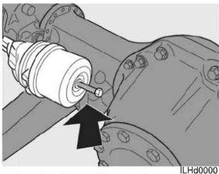
natural_image
Mechanical assembly diagram showing a bolted component inserted into a mechanical shaft (no text or symbols visible)Releasing the parking brake
Start the engine and bring the brake system up to pressure.

If it is not possible to start the engine, the parking brake can be freed by two different methods.
- Place chocks in front of or behind the wheels and turn the bolts of both brake spring cylinders as far as possible to the left with the aid of a 24 mm spanner. The coach can now be towed. Restore the operation of the brake spring cylinders as quickly as possible, by turning the bolts as far as possible to the right setting them with a torque of 40-50 Nm.
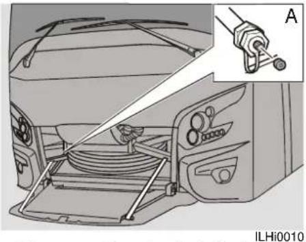
natural_image
Diagram of a car interior showing hoses and a hand gripping a cable, with no visible text or symbols.- The second method of freeing the parking brake makes use of the emergency air connection, to which an air hose can be connected to import air from another source.

To release the parking brake, the system must be pressurized to a pressure of at least 6 bar.

To release the parking brake, the system must be pressurized to a pressure of at least 6 bar.

The maximum pressure in the parking brake must not be greater than 11 bar.

If the engine is not running the vehicle's steering will be heavy due to the lack of power steering.

Turn on the hazard warning lights before towing and attach a "Towing" sign to the vehicle which is being towed.
Towing with a damaged differential
Hoist the vehicle from the rear and block the steering wheel.
Tow-start

Vehicles with an automatic transmission may not be tow started.
If the vehicle must be towed to start the engine, the ignition key must be turned to position I.
When towing it may happen that the batteries are too low to allow the main

Repairs whilst on the road
switch to be closed by the dashboard switch.
To prevent damage to the dynamos and regulator, main switch relay contacts 31 and 31a must be temporarily connected together (see drawing).
The main switch relay is located in the front of the right luggage compartment.
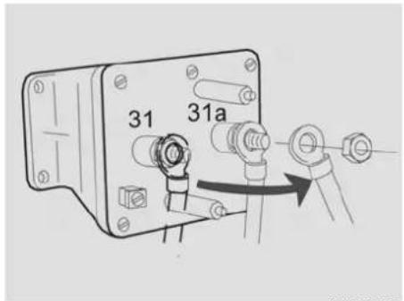
text_image
31 31aILHh0033
- Remove the battery earth clamp.
- Connect together the master switch relay cables with a bolt.
- Reconnect the battery earth clamp. The vehicle may now be towed to start the engine.
After the engine has run for a time and the batteries are sufficiently charged the master switch relay must be reconnected in the original configuration.
Proceed as follows:
- Switch off the engine.
- Remove the battery earth clamp.
- Restore master switch relay connections.
- Reconnect the battery earth clamp.
Towing other vehicles

The vehicle to be towed may not be heavier than 25 tonnes.

BUI & COJON
Repairs whilst on the road
ITS-VDL
ITS-VDL deals with emergencies and strandings, free of charge, 24 hours a day, 365 days a year.
ITS-VDL can be contacted via the following telephone number: +31 (0)40 294 80 80.
The international code for the Netherlands is 00-31 from most EC countries.
If you contact ITS-VDL, you must provide the following information.
This information can be found in the vehicle registration documents and on the type plate in the entrance bay or behind the driver's seat.
Make sure you have this information with you when phoning:
- Vehicle type
• Year of construction - Vehicle owner
- Chassis number
- Registration number
- Name of the workshop where the vehicle is serviced (home dealer).
- The exact location of the vehicle (ask somebody who knows the area).
- Telephone number which you can be reached at.
• The expected cause of the problem.
• Proof of guarantee
• ID card for identifying components.
If the home dealer is offering a payment guarantee for a repair, the invoice from the repairing dealer goes to the owner through the home dealer. This also applies to any VDL Bus & Coach spares supplied.
In this way the driver does not have to pay for any repairs and he can express in his own language what the cause of the breakdown is.
Once a driver has contacted ITS for assistance, he must not leave the place mentioned without first reporting this to ITS.
Spare parts delivery
In a number of countries the DAF dealer can supply both VDL Bus & Coach and DAF parts from stock.
Identification
6 IDENTIFICATION
VEHICLE IDENTIFICATION 129
ENGINE NUMBER.... 132
ENGINE IDENTIFICATION PLATE.... 132
PNEUMATIC CHARACTERISTIC DATA 133
DTCO IDENTIFICATION PLATE.... 134
PAINT IDENTIFICATION.... 134
KEY AND IDENTIFICATION NUMBERS .... 135
MASTER CARD.... 135

Identification
Identification
VEHICLE IDENTIFICATION
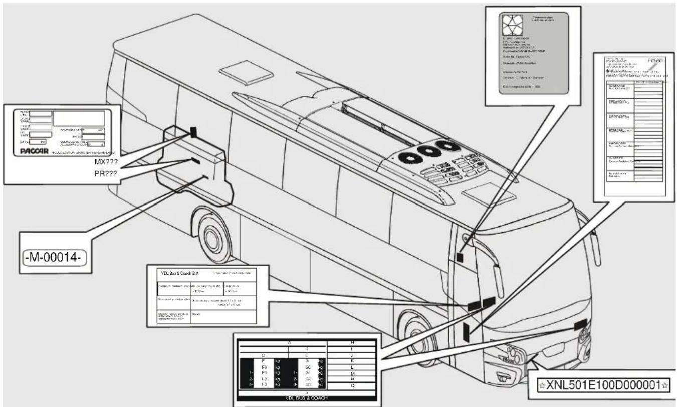
text_image
PACCAR MX??? PR??? -M-00014- VOL Bus & Coach BY Model: VOL Bus & Coach B.V. Model: VOL Bus & Coach B.V. Model: VOL Bus & Coach B.V. Model: VOL Bus & Coach B.V. Model: VOL Bus & Coach B.V. Model: VOL Bus & Coach B.V. Model: VOL Bus & Coach B.V. Model: VOL Bus & Coach B.V. Model: VOL Bus & Coach B.V. Model: VOL Bus & Coach B.V. Model: VOL Bus & Coach B.V.ILHa0012

BUI & COACH
The identification plate is located on the left-hand side of the entrance bay or behind the driver's seat.
| A Company name | |
| B Type approval number | |
| C Chassis number | |
| D Commercial type name | |
| E | T y p e |
| F Maximum permitted axle loads for the country of acceptance (see the country code) | |
| G Maximum technically permissible axle loads (all countries) | |
| H Engine number | |
| I Engine capacity | |
| J Emission classification | |
| K | T y r e t y p e |
| L | S p a r e |
| M | S pare |
| N Type/variant/version | |
| O | Sp a r e |
| P Country of manufacture | |
| A | H | |||||
| D | I | |||||
| C | E | J | ||||
| F | kg | G | kg | K | ||
| F0 | kg | G0 | kg | L | ||
| 1- | F1 | kg | 1- | G1 | kg | M |
| 2- | F2 | kg | 2- | G2 | kg | N |
| 3- | F3 | kg | 3- | G3 | kg | O |
| P VDL BUS & COACH | ||||||
ILHz0011
Identification
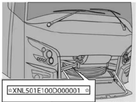
text_image
XNL501E100D000001ILHf0002
Chassis number
The chassis number is constructed in accordance with the international V.I.N. standard (Vehicle Identification Number)
The last 8 figures of the chassis number form the VDL Bus & Coach chassis number. Always mention these 8 figures when communicating about the vehicle, e.g. when ordering parts.
For controlling authorities the chassis number is also imprinted in the chassis beam behind the spare wheel compartment flap.
| XNL Company identity |
| 501 Commercial description |
| E Letter code for the axle configuration (E: 4 x 2.2 axles, of which one is driven) |
| 1 Diesel engine |
| 00 00 |
| D Production location code |
| 000001 Serial number |
Example: XNL501E100D000001
Axle loads
The maximum axle loads as stated in sections C, D and E are distributed as follows:
| blank | Total weight |
| 0 Train | weight (including trailer) |
| 1 Axle | load, front axle |
| 2 Axle | oad, rear axle |
| 3 Axle | oad, trailing axle |
| 4 Spare |
Country code
Stated here is the country the vehicle was produced for. The country codes of the Dutch approval body RDW are found here.
Type indication
Example: FHD2-122 410
| FHD2 | High version |
| 122 | Coach length in decimetres |
| 410 | engine (hp) |

Identification
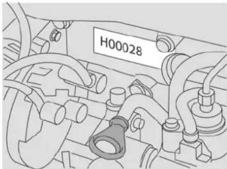
natural_image
Technical diagram of an engine bay with hoses and a labeled component (H00028), no readable text or symbols beyond the label.ILHj0012
ENGINE NUMBER
PR engine
The engine number is stamped on the engine block at the same height as the generator.

natural_image
Mechanical component diagram showing two cylindrical parts connected by a pipe, with no visible text or symbols.ILHj0011
MX engine
The engine number is stamped on the engine block at the same height as the compressor.
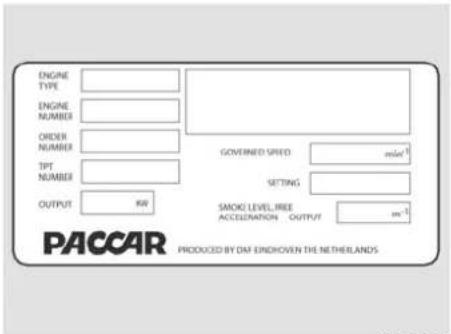
text_image
ENGINE TYPE ENGINE NUMBER ORDER NUMBER TPT NUMBER GOVERNED SPEED mode1 SETTING OUTPUT KW SMOKI LEVEL FREE ACCELERATION OUTPUT m-1 PACCAR PRODUCED BY DAF ENDOHEN THE NETHERLANDSILHj0021
ENGINE IDENTIFICATION PLATE
The engine identification plate states various engine details, such as:
- Engine type
- Engine number
- Order number.
- TPT number.
• Output.
• Governed speed. - Setting.
- Smoke level for free acceleration
Identification
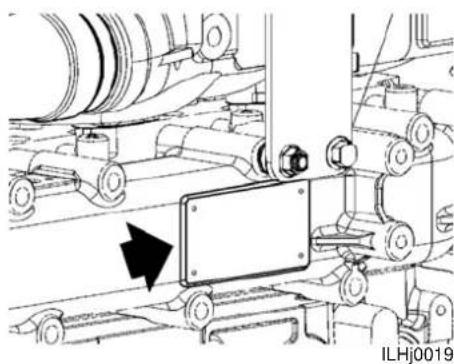
natural_image
Mechanical assembly diagram showing rollers and a component with directional arrow (no text or symbols)PR engine
The engine identification plate is fitted against the engine's inlet manifold.
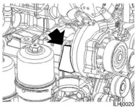
natural_image
Mechanical assembly diagram showing internal components and a black arrow indicating a specific part (no text or symbols present)MX engine
The engine identification plate is fitted against the engine's water pump housing.
| VDL Bus & Coach B.V. Pneumatic characteristic data | ||
| Compressor/unicoder valve | Max. cut-out pressure= 12.8 bar | Min. cut-in pressure= 10.5 bar |
| Four-circuit protection valve | Static closing pressure=circuit 1.2 > 5 barcircuit 3.4 > 4.5bar | |
| Minimum design pressurein the service brakingsystem for calculation | 8.0 bar | |
ILHi0012
PNEUMATIC CHARACTERISTIC DATA
The plate with information concerning the air pressure properties is located behind the driver's seat.
The plate includes details of the pneumatic system.

Identification
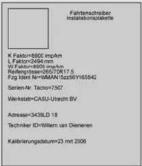
The plate includes details of the DTCO and is located at the side window above the driver.
text_image
LAKPASPOORT FAINTPASSPORT SPIES HECKER Inhibitor van Spies Heeler davastika van de Sistens METALAK BV Dr. Rooden-Heversat A 4204 JT 765. Vollande Sierle - 4204 JT 765. Telneton (2004) 521431 Fax (2004) 618 372 Kiel/Gicken/Cauleun/Farbon PERMACRON Avolack Serie 257 PERMASOLID NS dax Serie 150 PERMACRON Vorlacci Serie 293 PERMANYD Basslack Serie 280 PERMACRON Perlmutt Vorlack Serie 295 PERMANYD Perlmutt Basslack Serie 285 Bighonderheden/ ParticularsILHz0034
The most important information on this sticker is the international RAL numbers which enable paint of exactly the same colour to be ordered from any local paint supplier.
If possible VDL Bus & Coach always uses a RAL colour, unless the owner wants his own (company) colour. In these cases a code is mentioned which denotes the composition of that particular colour which remains available from VDL Bus & Coach. To avoid mistakes when ordering paint it is advisable always to include the chassis number along with the RAL numbers.
PAINT IDENTIFICATION
The paint identification and paint supplier are indicated on a sticker on the inside of the driver's locker.

Identification
KEY AND IDENTIFICATION NUMBERS
A number of keys are supplied with each vehicle. When replacing, e.g. one boot lid lock, it is possible to order a new lock with the same lock number as the rest. Keys with a specific serial number can be supplied afterwards.

We strongly recommend you keep a record of the keys' serial numbers.

Identification numbers for the various items of equipment fitted to the coach can also be reported here.
| Key and identification number: | |
| Contact switch | |
| Dashboard box | |
| Driver's locker | |
| Passenger door | |
| Middle door | |
| Emergency door | |
| Luggage flaps | |
| Engine cover | |
| Filler cap | |
| Safe | |
| Toilet | |
| toilet locker | |
| Refrigerator | |
| TV | |
| Video | |
| Radio | |
| CD player | |
| Navigation system | |
| Alarm system |
MASTER CARD
All important components of your vehicle and their identification numbers are listed on this card.

You must have the master card available when contacting ITS and when stranded.

Identification
Technical information
7 TECHNICAL INFORMATION
ENGINE....139
WHEELS AND TYRES 139
REFERENCE BRAKING FORCES.... 141
EXTRAPOLATION PRESSURE.... 143
FLUID AND LUBRICANT SPECIFICATIONS.... 144
TOW BAR INFORMATION 150
COUPLING AND UNCOUPLING.... 152
ELECTRICAL COMPONENTS.... 154
VEHICLE LAYOUT 156
Technical information
Technical information
ENGINE WHEELS AND TYRES
| Make DAF | |||
| Type | PR 265U MX 300U MX 340U | ||
| Location Vertically behind the rear axle | |||
| Construction method 4-stroke diesel engine, direct injection, 6 cylinders in line, turbo and intercooler. | |||
| Number of valves 24 | 24 | ||
| Bore x stroke 118 x 140 | 130 x 162 | ||
| Contents 9.2 litres | 12.9 litres | ||
| Compression ratio 17,5:1 | 16.5 :1 | ||
| Max. power 265 KW (360 hp) at 2,200 rpm | 300 KW (410 hp) at 1,900 rpm | 340 KW (460 hp) at 1,900 rpm | |
| Unloaded engine speed | Approx. 600 rpm | Approx. 550 rpm | |
| Maximum engine speed loaded | 2200 rpm | 1,900 rpm | |
| Max. torque | 1275 Nm between 1,200 – 1,700 rpm | 2,000 Nm between 1,000 – 1,500 rpm | 2300 Nm between 1,000 – 1,500 rpm |
| Speed limiter Via DMCI engine management | |||
| Emission U1 = Euro 5 / U2 = EEV / U3 = Euro 5 HD | |||
Tyre pressure
The stated tyre pressures are suitable for the stated maximum axle loads, provided the vehicle is used under normal conditions. For other conditions, see the information provided by the tyre manufacturer.
| Tyre size | Pressure (bar) | ||
| Front axle | Rear axle | Trailing axle | |
| 295/80 R 22.5 | 8.5 | 7,75 | 7,75 |
Torque
The wheel nut torque 600Nm ± 3%.

Retighten the wheel nuts after 100 km.
Winter tyres
The maximum speed specified by the tyre manufacturer must not be exceeded.
When determining the correct winter tyres, the specified load index and speed index of the tyres must be observed.
When using winter tyres, we recommend that you observe the guidelines, assembly instructions and tyre pressures specified by the tyre manufacturer.

Technical information
Snow chains
As the driver of a vehicle on wintry roads, you must observe the legal regulations, such as road traffic sign no. 268.
This sign makes the use of snow chains compulsory on a snowy or slippery road surface.


Snow chains may only be used in combination with the following tyres: Michelin XZA2 or Michelin XD Coach.
The other specifications are:
• Maximum height of the chain is 15mm.
• Maximum speed when driving with snow chains is 40km/h.
- The combination Michelin XD coach / snow chains is not allowed on the front axle.
- You may only drive on normal driving height.
- If there are chains mounted on the front axle, maximum steering is only allowed while driving slower than 10 km/h.
- The snow chains have to be mounted according the instructions of the manufacturer.

Do not use snow chains unnecessarily when there is no snow on the road surface, because that will wear down the snow chains and the tyres very quickly.

REFERENCE BRAKING FORCES
The reference values in the table have been intended for stipulating the braking deceleration using a roller test stand.
| Reference valves DISC brakes (N)a | |||||||
| Type of brake Disc Disc Disc | Disc | Disc | Discb | Disc Disc Disc | |||
| Brake cylinder 27" 24" 22" | 20" 18" 16" 14" 12" | ||||||
| Design axle torque 5569 43 | 322 4415 4041 | 3702 3362 | 2819 2411 | ||||
| Front axle X X --- --- --- --- | --- --- | ||||||
| Drive shaft --- X X --- --- --- | --- --- | ||||||
| Trailing axle --- --- --- X --- | X X X | ||||||
Technical information
| Pressure(bar) | 0 | . | 0 | 0 | 0 | 0 | 0 | 0 | 0 | 0 |
| 0 | . | 5 | 0 | 0 | 0 | 0 | 0 | 0 | 0 | |
| 1 | . | 0 | 4 | , | 0 | 0 | 0 | 3 | , | |
| 1.5 8,000 7,10 | 0 | 6,100 5,000 | 3,700 2,400 | 2,000 1,800 | ||||||
| 2.0 11,900 10 | 700 | 9,200 7,600 | 6,200 4,800 | 4,000 3,600 | ||||||
| 2.5 15,900 14 | 300 | 12,300 1 | 0,100 8,600 7 | 200 6,000 5,400 | ||||||
| 3.0 19,900 17 | 800 | 12,600 1 | 1,100 9,600 8 | 000 7,200 | ||||||
| 3.5 23,900 21 | 400 | 18,400 1 | 5,100 13,500 | 12,000 10,000 | 9,000 | |||||
| 4.0 27,900 25 | 000 | 21,500 1 | 7,600 16,000 | 14,400 12,000 | 10,800 | |||||
| 4.5 31,800 28 | 500 | 24,500 2 | 0,200 18,500 | 16,800 14,000 | 12,600 | |||||
| 5.0 35,800 32 | 100 | 27,600 2 | 2,700 20,900 | 19,200 16,000 | 14,400 | |||||
| 5.5 39,800 35 | 700 | 30,700 2 | 5,200 23,400 | 21,600 18,000 | 16,200 | |||||
| 6.0 43,800 39 | 200 | 33,700 2 | 7,700 25,800 | 24,000 20,000 | 18,000 | |||||
| 6.5 47,800 42 | 800 | 36,800 2 | 8,400 26,400 | 22,000 19,800 | ||||||
| 7.0 51,700 46 | 400 | 39,900 2 | 8,700 24,000 | |||||||
| 7.5 55,700 49 | 900 | 43,000 3 | 1,100 26,000 | |||||||
| 8.0 59,700 53 | 500 | 46,000 |
a. Reference Values are Axle values corresponding with a = 5 m/s^2 , in the case of 22,5 inch wheels
b. Derived values
Technical information
EXTRAPOLATION PRESSURE
| Type Engine of To - P2 Pmax Extrapolation pressure | (Pex) | |||||||||
| Nominal [bar] | Tolerance [bar] | Axle 1 [bar] | Axle 2 [bar] | Axle 3 [bar] | ||||||
| Futura | Euro 5 + EBS | 11104 | - | 2-axle | 8,8 | 10 | ±0,5 | 8,0 | 8,0 | - |
| Euro 5 + EBS | 11104 | - | 3-axle | 8,8 | 10 | ±0,5 | 8,0 | 8,0 | 8,0 | |
P2 = Cut-in pressure (minimum)
Pmax = Cut-out pressure (nominal / maximum)
Pex = Extrapolation pressure (guaranteed pressure in brake cylinder)
Technical information
FLUID AND LUBRICANT SPECIFICATIONS
General information
In order to comply with the warranty terms and to guarantee the durability, safety and reliability of VDL Bus & Coach products, it is essential that the correct lubricants, coolant and fuel are used and that they are changed in accordance with the specified changing intervals.
Never use additives with lubricants, coolant and fuel, except in the cases specified by VDL Bus & Coach.
Always follow the safety instructions below and the instructions that are supplied with the product.
Ask your lubricant and fuel supplier(s) whether the products they supply comply with the VDL Bus & Coach specifications.
In the following cases, no claims may be made against the VDL Bus & Coach warranty:
• Using oil of a lower grade than specified.
- Using oil of a lower/higher viscosity than specified.
- Exceeding the changing interval.
- Using lubricant, fuel, AdBlue or coolant which does not meet the requirements set by VDL Bus & Coach.
Safety

The fluids in the vehicle can cause serious injury and/or serious health problems in the event of bodily contact.

Avoid bodily contact with fuel, lubricants, coolant, battery acid and AdBlue.
In the event of bodily contact, always observe the following instructions:
- In the event of skin contact: remove the substance with paper or a cloth and wash with soap and water. If the irritation persists, contact a doctor.
- In the event of contact with the eyes: remove the substance with a soft cloth and rinse with water. If the irritation persists, contact a doctor.
- If swallowed: Do NOT induce vomiting. Rinse the mouth, drink two glasses of water and contact a doctor.
- In the event of inhalation: get some fresh air and take a rest.
Technical information
Battery acid
In the event of skin contact: rinse the skin with plenty of water.
If redness or pain persists, contact a doctor. Remove any contaminated clothes and rinse them with water.
In the event of contact with the eyes: wash the eyes for at least 15 minutes with plenty of water and contact a doctor.
If swallowed: Do NOT induce vomiting. Rinse the mouth, drink two glasses of water and contact a doctor.
In the event of inhalation: get some fresh air and take a rest.
AdBlue
Storage instructions
- Only use original storage tanks.
- Store in a cool, dry, ventilated area.
- Protect storage tanks against freezing.
- Observe the manufacturer's storage and usage instructions.
Safety instructions
- Avoid bodily contact.
• In the event of skin contact: rinse with plenty of water. - In the event of contact with the eyes: rinse with plenty of water for at least 15 minutes and seek medical assistance.
- If swallowed: rinse your mouth with plenty of water. Do not induce vomiting.
- In the event of inhalation: get some fresh air and take a rest. Seek medical assistance.
- Use in a ventilated area.
Procedure after a spillage
- Rinse with plenty of water.

AdBlue is neither toxic nor harmful to the environment.

Technical information
Engine
| Type DAF PR | x | DAF MX |
| Engine oil specifications ACEA E6 / .. W-40 | ||
| Volume of the lubricating oil system, including the oil filter | approx. 33 litres | approx. 39 litres |
| Sump capacity, maximum level approx. 26 litres | approx. 33 litres | |
| Sump capacity, minimum level approx. 18 litres | approx. 25 litres | |
Cooling system
| Coolant specifications | DAF 74002/BTPS 606A/DCEA 615 |
| Cooling/heating system volume | between 65 and 100 litres, depending on the model. |

The sticker on the coolant reservoir indicates the coolant which is used in the system.

Never mix coolant with different specifications.

Never fill with propylene glycol, since ethylene and propylene glycol are incompatible.


Coolant is poisonous. Protect the skin and eyes.

Coolant is harmful to the environment and must, therefore, be processed as industrial waste after use.
Technical information
Air conditioning
| Type DENSO | |
| Compressor type 10PA20 | |
| Lubrication oil specification | ND-oil 8 / PAG 46 |
| Total capacity per cycle 140 cc (for the compressor) +300 cc (for the reservoir) | |
| Coolant R134a Cycle 1 (right-hand side, including air conditioning front box) | Approx. 2.5 kg |
| Coolant R134a Cycle 2 (left-hand side, excluding air conditioning front box) | Approx. 2.2 kg |
Gearbox
| Type GO 170/230 | 210/ | ZF Ecomat ZF AS tronic | |
| Lubricant specifications | 75W90 synthetic API GL4 (MB235.11) | ZF Ecofluid A + class 14E (ZF TE-ML 14) | ZF Ecofluid M class 02E (ZF TE-ML 02) |
| Volume when changing oil | approx. 12.5 litres | approx. 18 litres | approx. 12 litres |
| Number of gears | 6 | 6 | 12 |
Retarder
| Type Voith R115E | ZF intarder | |
| Lubricant specifications | SAE 75W80 synthetic (Voith retarder 153.000831xx) | integrated in the automatic gear-box |
| Volume when changing | approx. 7 litres |
Shifting control
| Type | SGS Automatic | |
| Operation | Power-assisted two-cable shifting system | Electro-pneumatic |
Clutch
| Type | Single dry plate connection |
| Diameter | 430 mm |
| Operation | Hydraulic |
| Fluid specification Brake fluid DOT4 | |
Technical information
Front / trailing axle
| Type | ZF RL 75 E/ZF RL 75 A |
| Lubricant specificationsHub | Lithium soap grease(NLGI class 2, grease type KP2K-30) |
| Lubricant specificationsGrease nipples | Lithium soap grease(NLGI class 2, grease type KP2K-30) |
Rear axle
| Type | ZF A-132 |
| Axle bridge lubricant specification | SAE 80W-90 / API GL-5 |
| Axle bridge capacity | approx. 16 litre |
| Lubricant specificationsHub | (NLGI class 2, grease type KP2K-30) |
Steering mechanism
| Type | ZF 8098 |
| Fluid specification | ATF Type Shell Donax TM |
| Contents | approx. 10 litre |
| Wheel turning angle | 60^ |
| Gear ratio | 1:22.2/26.2 |
Hydraulic drive
| Fan | |
| Fluid specification | ATF type Shell Donax TZ(ZF TE-ML 14E) |
| Contents | approx. 9 litre |
Technical information
Fuel
Diesel or a diesel mixture must meet the EN 590 specifications. At extremely low temperatures, a maximum of 20% petroleum or a viscosity improver may be added in emergency situations, such as when stranded. If this is NOT LEGALLY PERMITTED, then a maximum of 20% unleaded petrol can be added. Only non-foaming fuel may be used when using a quick-refuelling unit.

The sulphur content of the diesel must be less than 50 ppm. If the sulphur content is greater than 50 ppm, then the oil changing interval must be altered accordingly.
Fuel must have a lubricating quality which meets the standard given below (lubricity standard): Test method: HFRR according to norm CEC-F-06-A96 Test value: < 460 µm

Switch off the engine and switch off the pre-heater before filling fuel tanks.
Capacity of the fuel tank: 1 x 500 litre approx + 1 x 387 litre (optional).
Urea (Adblue)
Urea (AdBlue) must comply with specification according DIN70070. Capacity of the urea tank: approx. 60 litre

AdBlue is neither toxic nor harmful to the environment.
Biodiesel

Contact your VDL Bus & Coach service dealer for information concerning the use of alternative fuels (e.g. biodiesel) and any consequences this may have.
Biodiesel must comply with the EN 14214 specifications.
Contact your VDL Bus & Coach service dealer for the conditions placed on using a mixture with more than 7% biodiesel.
Depending on its origin, biodiesel which satisfies EN 14214 may contain chemical elements which may have a negative effect on the exhaust gas after treatment system.
Therefore, it is the user's responsibility to carefully choose his biodiesel supplier.
Comment
Biodiesel has solvent properties so that changing from diesel to biodiesel may cause deposits in the fuel system to come loose and the filter to become blocked. When changing from diesel to biodiesel, it is recommended to check the filters after 1 or 2 refuellings and to replace any blocked filters. Biodiesel can cause problems at low temperatures, such as blockages to filters.
The use of biodiesel requires extra checks (see "Overview of the monthly checks when using biodiesel", Overview of the monthly inspections when using biodiesel ([1] 96)).
Capacity of the fuel tank: approximately 1 x 500 litres + 1 x 387 litres (optional)

Technical information
TOW BAR INFORMATION
Below is an overview of the approved tow bars which can be fitted and used with Futura FHD2 vehicles from Ch 10320501.
| Type Manufacturer | Type Approval number | Trailer | weight | D (kN) S (kg) Only in combination with a crossbeam and spacer (VDL Bus & Coach part no.) | ||
| Coupling ball MCB | 50221 e4*94 | /20*2989*00correction 01 | a | 31.0 350 300351 / 28 | 2448 | |
| Coupling ball Oris | D125/1 e1*94 | /20*0019*01 | A | 25.0 120 300351 / 28 | 3144 | |
| Coupling quick release system | Rockinger | Variobloc (assembly) | e1 00-0044 | A | 25.0 (combined with Oris D125/1) | 120 |
| Trailer coupling | Rockinger | 243B35000 | e1 00-0051 | A | 30 | 350 300 |
| Trailer coupling | Carspeed | Compact 40 | e2*94/20*1058*00 | A | 30^(b) | 350^(c) |
| Coupling quick release system | Rockinger | Variobloc (assembly) | e1 00-0044 | A | 30 (combined with Rockinger 243B11000) | 250 300 |
a. Depending on the vehicle weight
b. Max 30 kN (towing bracket is permitted for 54 kN)
c. Max 350 kg (towing bracket is permitted for 700kg)
Technical information
By using the following two formula's it's possible to calculate the technically permissible mass of the trailer:
For mechanical coupling devices unsuitable for transmitting vertical bearing loads the value "D" is (this does not apply to centre axle trailers):
$$ \mathrm{D} = (9, 8 1 \times \mathrm{T} \times \mathrm{R}) / (\mathrm{T} + \mathrm{R}) (\mathrm{kN}) $$
For mechanical coupling devices suitable for centre axle trailers the value "D" is not mentioned in the table:
hSee for "Dc" the manufacturer plate of the coupling device.
$$ \mathrm{Dc} = (9, 8 1 \times \mathrm{TxC}) / (\mathrm{T} + \mathrm{C}) (\mathrm{kN}) $$
T = Technically permissible maximum mass in tonnes of the towing vehicle including, if necessary, the vertical load of a centre axle trailer.
R= Technically permissible maximum mass in tonnes of the full trailer with drawbar free to move in the vertical plane or of the semi trailer.
C= Sum of the axle loads of the centre axle trailer carrying maximum permissible load, in tonnes.

Technical information
COUPLING AND UNCOUPLING
| Overview of combination possibilities | ||||
| Trailer without ABS (cor-rectly connected) | Trailer with ABS (cor-rectly connected) | Trailer with EBS (cor-rectly connected) | Trailer with EBS (5-pin ABS wiring harness instead of 7-pin EBS wiring harness) | |
| Pulling vehicle without ABS | Load-dependent brake control (mechanically active).No ABS control. | Load-dependent brake control (mechanically active).No ABS control. | No load-dependent brake control.No ABS control.nForbidden by law. | No load-dependent brake control.No ABS control.nForbidden by law. |
| Pulling vehicle with ABS | Load-dependent brake control (mechanically active).No ABS control. | Load-dependent brake control (mechanically active).ABS control active. | Load-dependent brake control (electronically active).ABS control active. | Load-dependent brake control (electronically active).ABS control active. |
| Pulling vehicle with EBS | Load-dependent brake control (mechanically active).No ABS control. | Load-dependent brake control (mechanically active).ABS control active. | Load-dependent brake control (electronically active).ABS control active.CAN communication. | Load-dependent brake control (electronically active).ABS control active. |
A trailer with ABS is fitted with an anti-lock braking system
A trailer with EBS is fitted with an electronically controlled brake system, which incorporates ABS.
Both versions are connected by means of a special plug to the extra socket of the ABS/EBS system on the prime mover.
If this plug is not connected, a yellow warning will appear on the display.

Consequences of not connecting an EBS trailer to a pulling vehicle with EBS via the ABS/EBS plug: No load-dependent brake control. No ABS (depends on the version of the EBS system on the trailer). No EBS control. Always the full braking force, regardless of the load.

Technical information
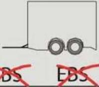 |  |  | |
 |  |  |  |
 |  |  |  |
 |  |  |  |
ILHi0007
Technical information
ELECTRICAL COMPONENTS
Generators
Type Alternating current Contents 28 V x 110 A
Batteries
number 2 Voltage 12 V Contents 230 Ah
Windscreen wiper system
Wiper blade length 100 cm Reservoir capacity 14 litres
Tow bar junction box
D+ connection Maximum 2 A Constant supply Maximum 7.5 A
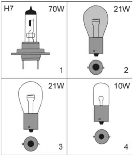
text_image
H7 70W 21W 1 2 21W 3 10W 4ILHh0043
Lighting
As an optional extra, xenon lighting is available for the main beam and dipped beam.

Replacing xenon bulbs is a highly skilled procedure and should only be carried out by suitably trained technicians.
Technical information
| number | Type Contents | |||
| A Dipped beam (H7) | 2 1/xenon 70 W | |||
| B Main beam (H7) | 2 1/xenon 70 W | |||
| C | F o g l a | 2 m | p1 $ | 70 W |
| D Day driving lights 10 LED -- | ||||
| E Front indicator lamp | 2 | 2 | 2 | |
| F Side indicator lamp | 2 | LED | -- | |
| G | Rear indicator lamp | 2 | LED | -- |
| H Rear lamp | 2 | LED | -- | |
| I | Brake light | 2 | LED | -- |
| J | Rear fog lamp | 1 | LED | -- |
| K Reversing lamp | 2 | LED -- | ||
| M | Side profile lamps | 12/14 | LED -- | |
| N Top lighting | 4 | LED | -- | |
| O | Registration plate lighting | 2 | LED | -- |
| Luggage space lighting | 8 | 4 | 1 | |
| Engine compartment light- ing | 1 | 3 | 21 W | |
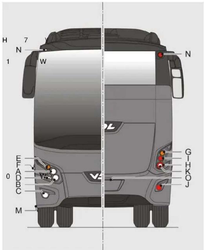
text_image
H 7 N 1 W N E F A 0 D B C M G H K O JILHa0005
Technical information
VEHICLE LAYOUT
Specified weights and dimensions are given in the following table. The actual weights (in particular) of the vehicles can vary from these specifications depending on the options installed. The vehicles are weighed before delivery and a copy of the weight registration form stating the actual empty weight is added to the delivery documents. Weights are expressed in kilograms and dimensions are expressed in millimetres.

If optional extras are fitted, the vehicle height may differ from the value stated below and/or mentioned on the sticker in your vehicle.
FHD2122 FHD2129 FHD2131 FHD2139 FHD2148
| Total length 12195 | 12875 13145 13945 14845 | ||||
| Total height including roof unit (A) 3700 3700 3700 3700 3700 | |||||
| Total width (B) | 2550 2550 2550 2550 | 2540 | |||
| Rear overhang (C) | 3340 | 3340 2790 3210 3210 | |||
| Wheelbase (D) 6150 6830 6150 6530 | 7430 | ||||
| Front overhang (E) 2705 | 2705 | 2705 2705 2705 | |||
| Wheelbase (F) - - 1500 1500 1500 | |||||
| Interior height | 1920 1920 1920 1920 | 1920 | |||
| Front entry step height | 342 | 342 | 342 | 342 | 342 |
| Centre entry step height | 368 | 368 | 368 | 370 | 370 |
| Turning circle | 20528 | 22096 | 20566 | 21440 | 23480 |
| Maximum front axle load | 7100 7100 7100 7100 7100 | ||||
| Maximum rear axle load | 12000 | 12000 | 12000 | 12000 | 100 |
| Maximum trailing axle load | - - 6200 6200 6200 | ||||
| Maximum total weight | 19100 | 19100 | 25300 | 25300 | 25300 |
| Luggage compartment capacity | 8.7 m^3 | 10.2 m^3 | 8.7 m^3 | 9.4 m^3 | 11.2 m^3 |

Technical information
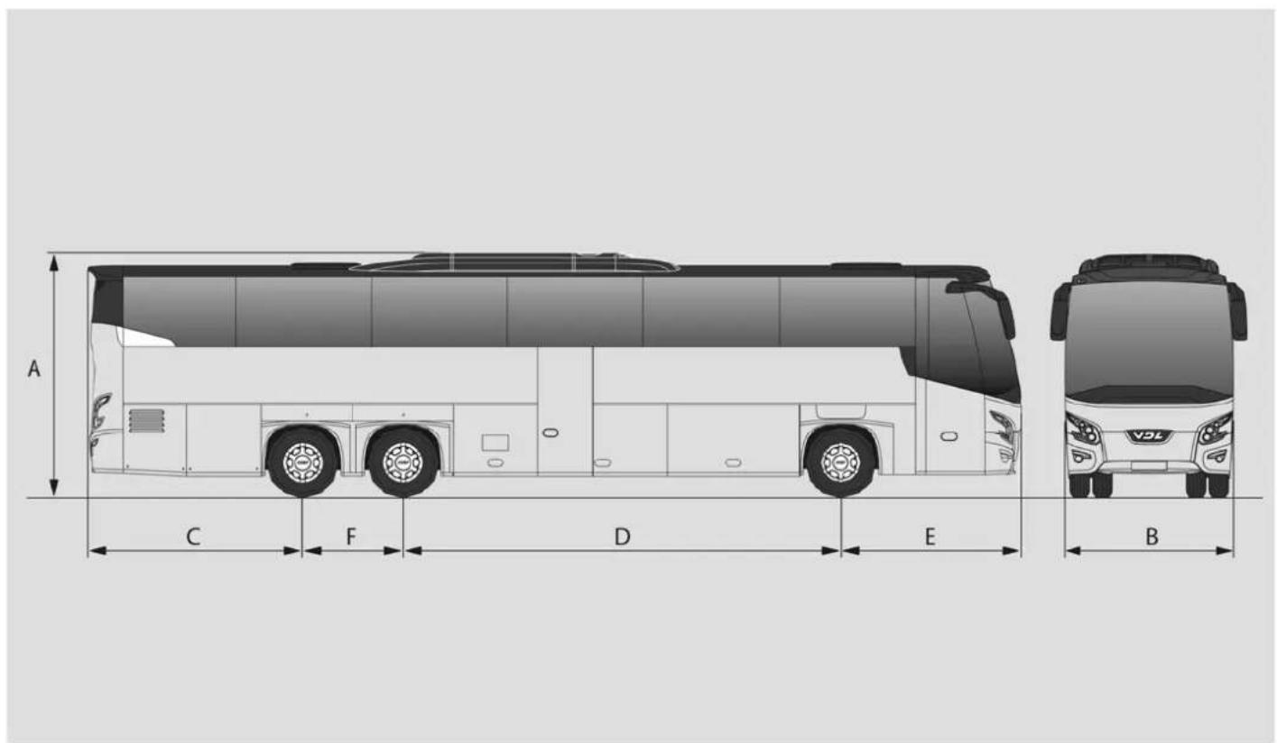
text_image
A C F D E BILHa0009
Technical information
A
ABS system 116
Accelerator pedal 45
AdBlue 145
AdBlue legal minimum level ..... 10
AdBlue level 9
Additional electric/electronic equipment 7
Air conditioning system ..... 16
Air filter 92
Air leaks 13
Air suspension (ECAS) 67
Anti-tilt system 68
Audio 41
B
Batteries
-Disconnect 5
-General information 14
-Removing 94
-Safety guidelines 5
Battery flap 20
Brake pedal 38
Brake system air dryer 92
Brakes 11
Bremsomat 39
C
Central dashboard switches ..... 43
Chassis number 131
Climate system
-Emergency operation....114
Clock 38
Clutch 11
Clutch fluid 93
Clutch pedal 34
Component delivery 126
Contact switch 24
Coolant level 90
Coolant temperature gauge ..... 38
Cooling system 146
Corner light 30
Cruise control 39
D
Destination indicator lighting ..... 41
Display 38
-Brightness adjustment ..... 38
-Clock/trip meter 38
-Descriptions 54
-Messages 50
Driver and hostess ventilation fan....31
Driver's compartment and hostess
lighting 44
Driver's seat 34
Driver's sleeping compartment ..... 65
Drivers storage compartment ..... 23
DTCO identification plate ..... 134
E
Earth switch 6
Electrical circuit diagrams ..... 121
Electrically operated driver's side
window 31
Electrically operated driver's screen 31, 32
Emergency hammers .....78
Emergency operation
-Luggage hatches 76
-Sleeping compartment hatch .... 75
Emergency procedures ..... 79
Engine brake 33
Engine cover 19
Engine number 132
- MX engine 132
- PR engine 132
Engine oil level check, manually ..... 88
Engine oil level electronically ..... 87
Engine stop button 13
ESC (Electronic Stability Control) .... 12
Extrapolation pressures....143
F
Fire extinguisher .....4, 77
First-aid kit 5,78
Fluid and lubricant specifications ... 144
Fog lamp front 31
Fog lamp rear 31
Fuel 144
Fuel gauge 38
Fuel lid 21

G
Gear shifting
-GO-210-230 gearbox ..... 46
-ZF AS Tronic automatic gearbox . 46
Gearbox
- lubricant specifications ..... 147
General tips 9
H
Hand gas 40
Hazard warning lights 78
hazard warning triangle 78
Headlight washers 29
Hostess seat 23
Hydraulic drive fluid 91
|
Inflating a tyre 119
Inspection lamp connection ..... 106
Inspection lamp plug 107
Instructions for driving with a trailing axle 70
Instrument panel 37
Intercom installation 65
ITS-VDL 126
J
Jack points 118
K
Kitchen. 67
L
Left roller blind 43, 44
Left-hand combination switch ..... 29
Luggage 5
Luggage flaps 20
Luggage flaps right 45
M
Maintenance
- Before the winter....97
- Weekly checks 91
-checklist 84
-Daily checks 87
-Exterior 99
-Interior 101
-When winter is over 99
Master card 135
Mirror adjustment 23
Mirrors 69
Mobile telephones 7
N
Navigation system .....45, 67
Night illumination....44
Night-lights/Passenger's reading lamps 31, 32
0
Odometer 37
On-board tool kit 106
Option 30
Original VDL Bus & Coach parts ..... 8
P
Paint identification .....134, 135
Parking brake 24
Parking/dipped lights 30
Passenger door....19, 43
Passenger fixation nuts 62
Passenger reading lights ..... 44
Passenger seats 62
Personal service units 64
Pneumatic suspension leak ..... 116
Poly V-belt
replacing, PR engine ..... 109
Power steering fluid 91
Pre-heater 9
R
Radiator 93
Raising and kneeling, rear ..... 31
Raising/kneeling 68
Refrigerator 45
Releasing the parking brake ..... 124
Replacing air-conditioning belts .... 108
Replacing fuses....121
Replacing light bulbs 120
-Headlights 120
xenon lamps 120
Replacing the air conditioning belt .. 110
Rev counter 38
Retarder 40
Right hand combination switch ..... 39
Right roller blind 43
Right/fixed trailing axle wheels ..... 32
Roof hatches 73
Roof unit dust filters 94
Running in 10
S
Safety instructions 4
Safety vest 4
Seat belts 77
Seats mountings with quick connection system 63
Service documentation reply form .... 1
Snow chains 140
Spare wheel 117
Spare wheel compartment handle ... 41
Speed limiter 13
Switches with no fixed location ..... 41
Switching off engine 13
System voltage 6
Starting procedure 11
Starting with the aid of auxiliary batteries 122
Starting the vehicle using an auxiliary start-
ing device 6
Steering mechanism 68
Steering wheel adjustments ..... 38
Stopping/Parking 12
T
Tachograph - DTCO 42
Toilet 66
Top lights 41
Touching up paintwork ..... 100
Tow hook junction box 154
Towing 123
Towing bracket data 150
Towing eye 123
Trailing axle relief 32
Transformer 41
Transmitters 7
Trip meter 38
Tyre pressure 139
U
Urea (AdBlue) 149
V
V-belt
- replacing, PR engine ..... 107
- tension, adjusting for a PR engine . 109
Vehicle dimensions....156
Vehicle identification 129
Ventilation grille 41
W
Warning light -ABS 37
-ECAS control symbols ..... 67
-Indicators 37
-Main beam 37
-Parking brake 38
-Priority warning 37
-Priority warning 1 ....37
-Retarder 37
-Tachograph 37
-Trailer indicator 37
Warning symbols 4
Warning triangle 4
Warranty conditions 8
Water system 97
Welding 5
Wheel nuts 10
Wheels and tyres .....116, 139
Windscreen washer fluid 92
Winter conditions 5
Winter tyres 139

DOCUMENTATION REPLY FORM
If you have any suggestions and/or comments concerning this manual or if you find any faults, please fill out this form and send it to:
| VDL Bus & CoachTraining and DocumentationP.O. box 6455550 AP ValkenswaardThe NetherlandsFax: +31 (0)40 2084499 | Company name : ......Name : ......Signature : ...... | |||
| Chassis number ...... | ||||
| Applicable document order number: | ...... Version: ...... | |||
| Type of document:(set marker If applicable) | Driver ☐ | Climate ☐ | ||
| Maintenance ☐ | Electrical diagrams ☐ | |||
| Workshop ☐ | Training ☐ | |||
| Parts ☐ | Others ☐ | |||
| Kind of inaccuracy(set marker If applicable) | Linguistic (Definition) not correct☐ | Mistake in technical data (values) Images☐ | ||
| Additional information(text, page number, etc.) | ...... | |||
| ...... | ||||
| ...... | ||||
VDL Bus & Coach will take your report seriously and, if necessary, we directly make an update in the document.