
UR44 - Hi-Fi STEINBERG - Free user manual and instructions
Find the device manual for free UR44 STEINBERG in PDF.


User questions about UR44 STEINBERG
0 question about this device. Answer the ones you know or ask your own.
Ask a new question about this device
Download the instructions for your Hi-Fi in PDF format for free! Find your manual UR44 - STEINBERG and take your electronic device back in hand. On this page are published all the documents necessary for the use of your device. UR44 by STEINBERG.
USER MANUAL UR44 STEINBERG
A Message from the UR44 Development Team....2
Accessory Disk (TOOLS for UR44 CD-ROM)....3
Cubase AI Download ....3
How to Read the Manual......4
Description of the Device ....5
Front Panel....5
Rear Panel 7
Software 9
Yamaha Steinberg USB Driver (Audio driver) 9
dspMixFx UR44 (Mixer) 10
Dedicated Windows for Cubase Series (Windows for Configuring the Device Settings from Cubase Series)....15
Sweet Spot Morphing Channel Strip (Compressor and Equalizer)....18
REV-X (Reverb)....20
Guitar Amp Classics ....21
Basic Operation....24
Using the UR44 with a Computer .....24
Using the UR44 with an iPad ....27
Troubleshooting....30
Appendix....32
Uninstalling TOOLS for UR44 32
Signal Flows....33
Block Diagrams ......35
A Message from the UR44 Development Team
Thank you for choosing the UR44 USB audio interface. The UR44 inherits the design philosophy of the previously released UR22, packing essential music production functions into a compact, durable unit that delivers outstanding sound quality on a par with our high-end models, while adding extra capacity and expandability.
The UR44 includes four D-PRE microphone preamplifiers and allows simultaneous recording of up to six channels. Every aspect of the D-PRE preamplifiers has been painstakingly engineered for optimum sound and overall performance, from parts selection to circuit design. These groundbreaking preamplifiers were first introduced in the Yamaha n12 and n8 digital mixing studios and then implemented in the Steinberg MR816 series and UR28M/UR824 interfaces, where they gained a reputation among discerning musicians and engineers for delivering an exquisite balance of smoothly extended highs, detailed midrange, and fat, punchy lows.
Of course there's more to music production than just great preamp performance. The same high quality must be maintained throughout the signal path, right up to the outputs that feed the monitor speakers. The UR44 development team has spared no effort in achieving that goal, with emphasis on realizing eminently clear, detailed spatial imaging and dynamic accuracy: left to right, near to far, loud to soft. The same approach was applied in the UR22, but the UR44 benefits from even further refinement overall. The UR44 also includes True Integrated Monitoring for lag-free monitoring while recording, plus top-class REV-X reverb effects, matching our high-end models for recording comfort, efficiency, and effect capability.
The UR44 additionally features Class Compliant mode for iOS support. In Class Compliant mode, the UR44 works with the iPad. It can be used with iOS compatible music production applications such as Steinberg Cubasis for convenient high-quality recording anywhere, at any time. There is also a loopback function that facilitates video delivery and other Internet related activities.
Top-quality recording capability is now available to just about anyone. It is our sincere hope that the UR44 will become a valued creative tool for all artists and engineers who work with sound, from beginners to seasoned professionals.
The Steinberg Hardware Development Team
Accessory Disk (TOOLS for UR44 CD-ROM)
The TOOLS for UR44 CD-ROM contains the following.
Operation Manual
• UR44 Operation Manual (this document)
- Basic FX Suite Operation Manual
TOOLS for UR44
TOOLS for UR44 is necessary when connecting the device to a computer. Make sure to install it before initially using the device. When you install the TOOLS for UR44, the following three software programs will be installed.
• Yamaha Steinberg USB Driver
This software allows communication between the device and a computer.
• Steinberg UR44 Applications
This software allows setting the parameters of the device from a computer or using the Link function between the device and Cubase series software. The software consists of the following two components.
- dspMixFx UR44
This software lets you set the device when using it with a DAW (Digital Audio Workstation) software other than Cubase series.
- UR44 Extension
This software allows you to link the device with Cubase series (for versions which supports the link function). To use this link function, see the Steinberg web site below.
http://www.steinberg.net/
- Basic FX Suite
Basic FX Suite is software consisting of VST3 Plug-ins of various effects and sound processing developed by Yamaha, some of which fully utilize modeling technology. When you install the Basic FX Suite, the following three software programs will be installed.
- Sweet Spot Morphing Channel Strip
This processing effect is a multi effect that features a compressor and equalizer.
- REV-X
This processing effect is a digital reverb platform developed by Yamaha for professional audio devices.
- Guitar Amp Classics
This processing effect features guitar amp simulations developed by Yamaha that fully utilize modeling technology.
NOTE
• TOOLS for UR44 does not support iPad.
- For instructions on using Basic FX Suite, refer to the Basic FX Suite Operation Manual included in the TOOLS for UR44 CD-ROM.
Cubase AI Download
We are offering Cubase AI as a free download via our website, specifically for customers who have purchased the UR44. In order to download the software, you'll need to first create a MySteinberg account in the Steinberg website. For the latest information, see the Steinberg web site below.
http://www.steinberg.net/getcubaseai/
How to Read the Manual
Make sure to read through the following documentation before using the device.
- Read me first (printed)
This is included with the package. Make sure to read through this manual carefully to ensure safe use before initially using the product.
- Getting Started (brochure)
This is included with the package. Read this manual when setting up the device. After finishing the setup as indicated in this manual, read the Operation Manual.
• Operation Manual (PDF)
This is included in the TOOLS for UR44 CD-ROM. Read through this manual to understand how to use the features of the product.
Conventions
Windows or Mac
When the procedures or explanations are specific to only one of the platforms, Windows or Mac, this is properly indicated in the manual. When the platforms do not appear, procedures or explanations are for both Windows and Mac.
Procedures
“→” appears on some procedures in the manual. For example, the string “Devices” → “Device Setup” → “Control Panel” indicates that you should perform the procedures in the following order.
- Click the "Devices" menu.
- Select the "Device Setup" option.
- Click the "Control Panel" button.
Keyboard Shortcuts
[Windows modifier key]/[Mac modifier key] + [key] shows the shortcut keys. For example, [Ctrl]/[command] + [Z] means "press [Ctrl] under Windows or [command] under Mac, then press [Z]."
Cubase
The phrase "Cubase" in this manual applies to all Cubase programs and versions (except Cubase LE). If the instructions are only for Cubase, "Cubase only" appears in the manual.
Screens
This manual predominantly uses screenshots of Windows. However, Mac screenshots are used when instructions of the function apply only to the Mac. Also, this manual uses screenshots of Cubase 7. If you are using another version of Cubase, the actual screenshots might not be the same. For details, refer to the Cubase manuals (PDF) opened from the [Help] menu.
Version Information
The letters "x.x.x" and "x.xx" indicate the version number.
Description of the Device
Front Panel
text_image
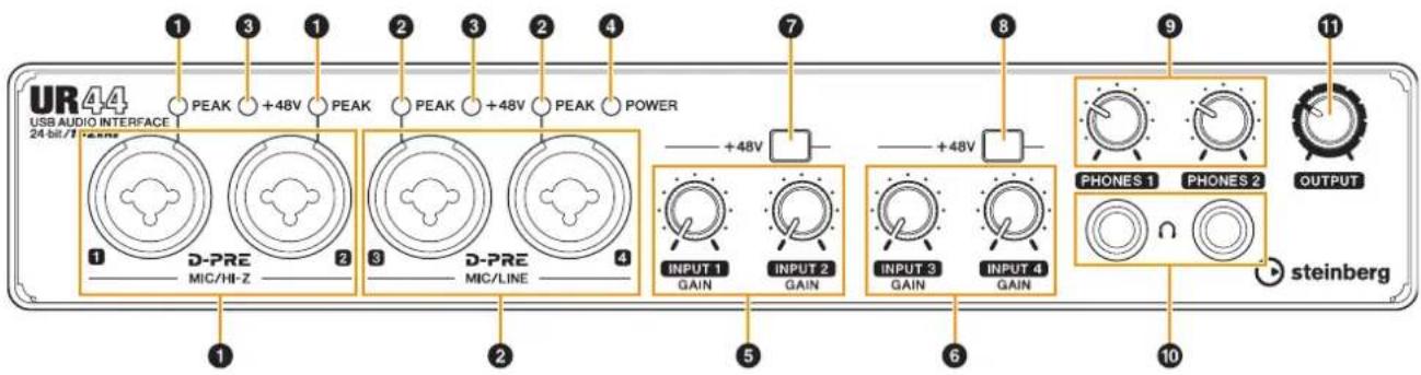
UR44 USB AUDIO INTERFACE 24-bit/1 Teams 1 PEAK +48V PEAK PEAK +48V PEAK POWER 1 D-PRE MIC/HI-Z 2 D-PRE MIC/LINE 3 +48V INPUT 1 GAIN INPUT 2 GAIN INPUT 3 GAIN INPUT 4 GAIN 7 +48V PHONES 1 PHONES 2 OUTPUT steinberg① [MIC/HI-Z 1/2] jack/[PEAK] indicator
For connection to a microphone, digital instrument, electric guitar, or electric bass. This jack can be connected to both XLR-type and phone-type (unbalanced only) plugs ^1 . The XLR-type is MIC only and the phone type is HI-Z only. The [PEAK] indicator lights in red when the signal is -3 dB or greater.
② [MIC/LINE 3/4] jack/[PEAK] indicator
For connection to a microphone or digital instrument. This jack can be connected to both XLR-type and phone-type (balanced/unbalanced) plugs ^1 . The XLR-type is MIC only and the phone type is LINE only. The [PEAK] indicator lights in red when the signal is -3 dB or greater.
*1 Plug types
![STEINBERG UR44 - ② [MIC/LINE 3/4] jack/[PEAK] indicator - 1](/content/2026/05/760574/images/3b445310cf010ce738d88d48805d2baff91f0781addc01f937afc2830e4711ea.jpg)
text_image
XLR-type (balanced) Phone-type (balanced) Phone-type (unbalanced)HINT
Setting optimum recording levels
The [PEAK] indicator lights in response to the level of input signal. To set optimum recording levels, increase the input level with the [INPUT GAIN] knob until the [PEAK] indicator lights in red, then slowly bring the level down until the indicator lights slightly when the input level is at maximum.
HINT
Proper use of the HI-Z or LINE inputs
HI-Z:
- Guitar and bass with passive pickups (battery-powered)
LINE:
- Effect device, preamp, direct box
- Guitar and bass with active pickups (not battery-powered)
• Digital instruments, such as synthesizer
③ [+48V] indicator
The indicator lights when the [+48V] switch (phantom power) is turned on.
④ [POWER] indicator
The indicator lights when the power is turned on. The indicator flashes continuously when the computer or iPad does not recognize the device.
⑤ [INPUT 1/2 GAIN] knob
Adjusts the input signal level of the [MIC/HI-Z 1/2] jack.
⑥ [INPUT 3/4 GAIN] knob
Adjusts the input signal level of the [MIC/LINE 3/4] jack.
![STEINBERG UR44 - ⑥ [INPUT 3/4 GAIN] knob - 1](/content/2026/05/760574/images/08ac5c34ee436115eb7579e94e3b746eac01cb6ee8c0632f8bda2f8a00c5dd82.jpg)
text_image
UR44 USB AUDIO INTERFACE 24 bit/1 1 PEAK +48V PEAK PEAK +48V PEAK POWER D-PRE MIC/HI-Z 2 3 D-PRE MIC/LINE 4 +48V INPUT 1 GAIN INPUT 2 GAIN INPUT 3 GAIN INPUT 4 GAIN 7 +48V PHONES 1 PHONES 2 OUTPUT steinberg⑦ [+48V] switch
Turns the phantom power on (—) and off (■). When you turn this switch on, phantom power will be supplied to the [MIC/HI-Z 1/2] jack. The [+48V] indicator lights when the switch is turned on. Turn this switch on when using a phantom powered condenser microphone.
⑧ [+48V] switch
Turns the phantom power on (—) and off (■). When you turn this switch on, phantom power will be supplied to the [MIC/LINE 3/4] jack. The [+48V] indicator lights when the switch is turned on. Turn this switch on when using a phantom powered condenser microphone.
Phantom Power Precautions

CAUTION
Always turn phantom power OFF when it is not required.
When using phantom power, observe the following to prevent noise and possible damage to UR44 or connected equipment.
- When connecting devices not requiring phantom power to the [MIC/HI-Z 1/2] [MIC/LINE 3/4] jacks, make sure to turn phantom power OFF.
- Do not connect or disconnect any devices while phantom power is turned ON.
- Set all output level controls to minimum when turning phantom power ON or OFF.
⑨ [PHONES 1/2] knobs
For adjusting the output signal level of the [PHONES] jack. The [PHONES 1] knob adjusts the output of the corresponding [PHONES 1] jack below it, while the [PHONES 2] knob adjusts the output of the corresponding [PHONES 2] jack. This output signal level is not affected by the [OUTPUT] knob.
⑩ [PHONES 1/2] jack
For connection to a set of headphones. [PHONES 1] outputs the MIX 1 signals. [PHONE 2] outputs the MIX 1 or MIX 2 signals. To select the output signal of the [PHONES 2], refer to "Headphone Area" (page 17) in the section "dspMixFx UR44" or the "Headphones Window" (page 13) in the section "Dedicated Windows for Cubase Series."
HINT
What is MIX?
MIX refers to the stereo output signals which flow in the device. The input signals to the device flow to each MIX. Refer to the section "Signal Flow" (page 33).
⑪ [OUTPUT] knob
Adjusts the output signal level of the [MAIN OUTPUT] jacks. This output signal level is not affected by the [PHONES] knob.
Rear Panel
text_image
UR44 USB AUDIO INTERFACE 24bit/192ms D-PRE 12V --- + - USB 2.0 OFF ON CC MODE OUT IN MIDI L R MAIN OUTPUT 3 LINE OUTPUT 1 2 3 4 5 6 7 8 LINE OUTPUT 5 6 LINE INPUT① [⏻] (Standby/On) switch
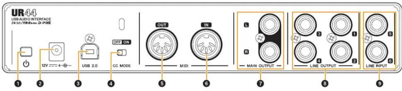
Sets the power of the device to On (■) or Standby (■).
CAUTION
Even when the [☐] switch is in the standby position, electricity is still flowing to the unit. If you do not plan to use the unit for a while, be sure to unplug the AC power adaptor from the outlet.
NOTICE
- Setting the [ ⏻] switch to on and standby in rapid succession can cause it to malfunction.
- After setting the [ ⏻] switch to standby, wait for about six seconds before setting it to on again.
NOTE
When setting the [∅] switch to standby, the settings on the Scene (page 11) and [PHONES 2] output signal are saved to the device settings. Please note that the settings are not saved if you turn the power off by disconnecting the power cable when the [∅] switch is on.
② DC IN [12V]
For connection to the AC power adaptor.
③ [USB 2.0] port
For connection to a computer or iPad. Apple iPad Camera Connection Kit or Lightning to USB Camera Adapter are required when connecting the UR44 with an iPad.
USB Port Precautions
NOTICE
Be sure to observe the following points when connecting to the computer's USB interface. Failing to do so may result in the computer freezing or shutting down, as well as corruption or even loss of data. If the device or computer does freeze, restart the application or computer.
- Be sure to wake the computer from sleep/suspended/stand by mode before making a connection to the computer's USB port.
- Before turning on the power to the device, connect the computer to the USB port.
- Before turning on/off the device or plugging/unplugging the USB cable, quit any open application software on the computer.
- When connecting or disconnecting the USB cable, be sure to set all output level controls to the minimum.
- Wait at least six seconds between connecting or disconnecting the USB cable.
4 [CC MODE] switch
Turns the Class Compliant mode on and off. Make sure to turn the [CC MODE] switch on when connecting the device to an iPad. Also, make sure to turn the [CC MODE] switch on before turning on the [∅] switch. The Class Compliant mode will not change if the [CC MODE] switch is turned on after the [∅] switch has been turned on.
![STEINBERG UR44 - [CC MODE] switch - 1](/content/2026/05/760574/images/3ea68f931a6c632ede575efa7bd0fd8311eeee6a6985eeae29964d7680b1ee47.jpg)
text_image
UR44 USB AUDIO INTERFACE 24-bit/192MHz D-PRE 12V ---+ - USB 2.0 OFF ON CC MODE OUT IN MIDI L R MAIN OUTPUT 3 LINE OUTPUT 1 2 3 4 5 6 7 8 LINE OUTPUT LINE INPUT 9⑤ [MIDI OUT] jack
For connection to the MIDI IN jack of a MIDI device. This transmits MIDI signals from the computer.
6 [MIDI IN] jack
For connection to the MIDI OUT jack of the MIDI device. This receives and inputs MIDI signals to the computer.
Select [Steinberg UR44-1] for the MIDI port when using a MIDI jack with an iPad application. Please note that [Steinberg UR44-2] is not available.
⑦ [MAIN OUTPUT] jacks
For connection to monitor speakers. These jacks can be connected to phone-type (balanced/unbalanced) plugs ^2 . This outputs the MIX 1 signals. To adjust the output signal level, use the [OUTPUT] knob on the front panel.
8 [LINE OUTPUT 1 to 4] jacks
For connection to external devices with line level signals. These jacks can be connected to phone-type (balanced/unbalanced) plugs ^2 . The [LINE OUTPUT 1/2] jack outputs the MIX 1 signal and the [LINE OUTPUT 3/4] jack outputs the MIX 2 signal.
9 [LINE INPUT 5/6] jacks
For connection to digital instrument. These jacks can be connected to phone-type (balanced/unbalanced) plugs ^*2 . You can select the input signal level of the [LINE INPUT 5/6] jacks between “+4 dBu” and “-10 dBV.” Select “+4 dBu” when connecting a professional audio device, and select “-10 dBV” when connecting a consumer device. The default initial setting is “-10 dBu.” To select the input signal level, use the “Setup Window” (page 14) in the section “dspMixFx UR44” or the “Settings Window” (page 17) in the “Dedicated Windows for Cubase Series.”
*2 Plug types
![STEINBERG UR44 - [LINE INPUT 5/6] jacks - 1](/content/2026/05/760574/images/6c7cb5689452f6f45bcb556a05d22eec5295802a71f31415b480958e230f1fff.jpg)
text_image
Phone-type (balanced) Phone-type (unbalanced)Software
Introduction
This section explains software operations for using the UR44 with a computer.
NOTE
The software programs below do not apply to iPad.
Yamaha Steinberg USB Driver (Audio driver)
Overview
Yamaha Steinberg USB Driver is a software program which allows communication between the UR44 and a computer. Yamaha Steinberg USB Driver has a control panel from which you can select the general settings of the audio driver for Windows and view the information for Mac.
Windows
How to Open the Window
- [Control Panel] → [Hardware and Sound] or [Sounds, Speech, and Audio Devices] → [Yamaha Steinberg USB Driver]
- From the Cubase series menu, [Devices] → [Device Setup...] → [Yamaha Steinberg USB ASIO] → [Control Panel]
How to Switch the Window
Click the upper tabs to select the desired window.
Steinberg UR44 window
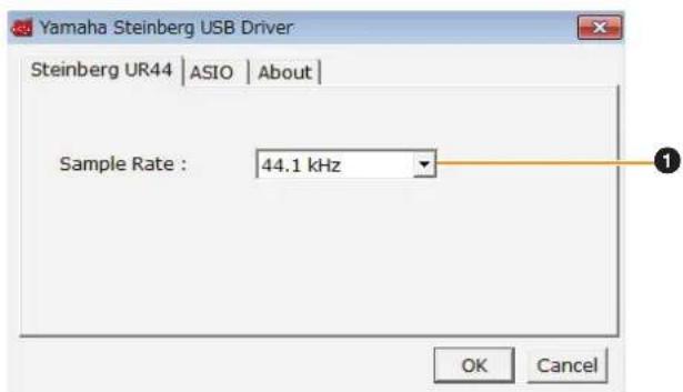
This window is for selecting the sample rate of the device.
text_image
Yamaha Steinberg USB Driver Steinberg UR44 | ASIO | About | Sample Rate : 44.1 kHz OK Cancel① Sample Rate
Selects the sample rate of the device.
Options: 44.1 kHz, 48 kHz, 88.2 kHz, 96 kHz, 176.4 kHz, 192 kHz
NOTE
For Mac, select the sample rate of the device via the Audio MIDI Setup.
ASIO window
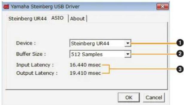
This window is for selecting the ASIO driver settings.
text_image
Yamaha Steinberg USB Driver Steinberg UR44 ASIO About Device : Steinberg UR44 Buffer Size : 512 Samples Input Latency : 16.440 msec Output Latency : 19.410 msec OK Cancel① Device
Selects the device that will be using the ASIO driver. This function is available when connecting to the computer two or more devices to the computer that are compatible with the Yamaha Steinberg USB Driver.
② Buffer Size
Selects the buffer size for the ASIO driver. The range varies depending on the specified sample rate.
| Sample Rate Range | |
| 44.1 kHz/48 kHz 64 Samples – 2048 Samples | |
| 88.2 kHz/96 kHz 128 Samples – 4096 Samples | |
| 176.4 kHz/192 kHz 256 Samples – 8192 Samples | |
③ Input Latency/Output Latency
Indicates the delay time for the audio input and output in millisecond units.
Audio latency varies depending on the value of the ASIO buffer size. The lower the value of the ASIO buffer size, the lower the value of audio latency.
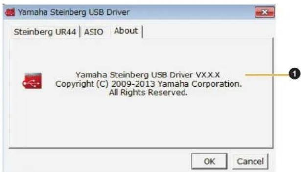
About window
This window indicates information about the audio driver.
text_image
Yamaha Steinberg USB Driver Steinberg UR44 | ASIO | About | Yamaha Steinberg USB Driver VX.X.X Copyright (C) 2009-2013 Yamaha Corporation. All Rights Reserved. OK Cancel① About
Indicates the version and copyright of the audio driver.
Mac
How to Open the Window
- [System Preferences] [Yamaha Steinberg USB]
- From the Cubase series menu, [Devices] → [Device Setup...] → [Steinberg UR44] → [Control Panel] → [Open Config App]
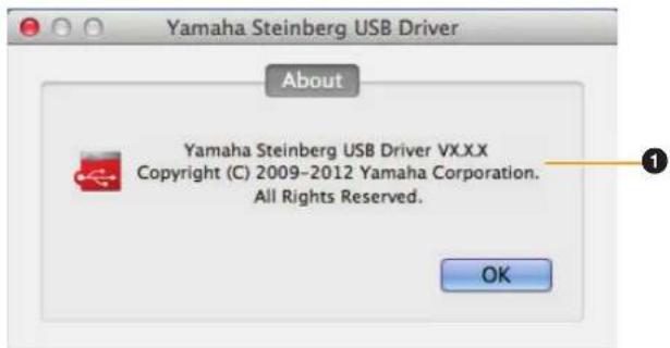
About window
This window indicates information about the audio driver.
text_image
Yamaha Steinberg USB Driver About Yamaha Steinberg USB Driver VX.XX Copyright (C) 2009-2012 Yamaha Corporation. All Rights Reserved. OK① About
Indicates the version and copyright of the audio driver.
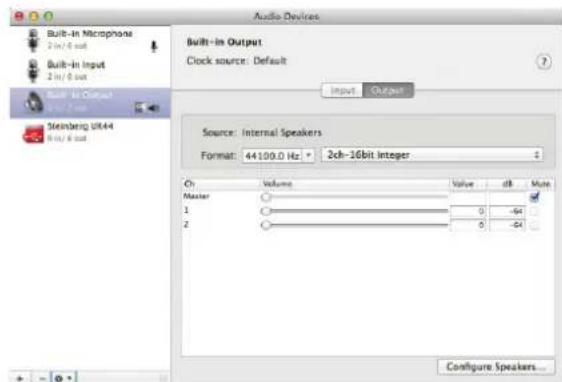
HINT
How to select the sample rate
Select the sample rate of the device from [Audio MIDI Setup].
text_image
Audio Devices Built-in Microphone 2 in/8 out Built-in Input 2 in/8 out Built-in Output Steinberg UR-44 9 in/8 out Built-in Output Clock source: Default Input Output Source: Internal Speakers Format: 44100.0 Hz • 2ch-16bit Integer Ch Volume Value dB Mode Master 1 2 0 -64 0 -64 Configure Speakers...How to select the buffer size
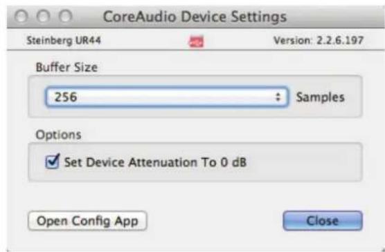
Select the buffer size in the window for selecting buffer size, which can be opened from an application, such as DAW software.
text_image
CoreAudio Device Settings Steinberg UR44 Version: 2.2.6.197 Buffer Size 256 : Samples Options ✓ Set Device Attenuation To 0 dB Open Config App ClosedspMixFx UR44 (Mixer)
Overview
This software is for operating the convenient built-in DSP mixer and DSP effects. The DSP mixer allows you to mix up to six input channels down to two stereo outputs. A number of DSP effects for processing the input signals are also provided, and since the processing/mixing is hardware-based, there is no monitoring latency.
NOTE
You cannot operate dspMixFx UR44 while a Cubase series DAW is running. When Cubase is running, configure the DSP mixer and DSP effect from "Dedicated Windows for Cubase Series" (page 15).
How to Open the Window
Windows
[All Programs] or [All apps] → [Steinberg UR44] → [dspMixFx UR44]
Mac
[Applications] → [dspMixFx UR44]
Controls and Functions
Tool Area
This is the area for configuring the overall common settings of dspMixFx UR44.

text_image
12 --- STORE ①②③④⑦⑤⑥① Quit
Quits dspMixFx UR44.
② Minimize
Minimizes the dspMixFx UR44 window.
③ Menu
Provides four different menus for various settings.
| Menu Description | |
| Open Opens the settings file of dspMixFx UR44. | |
| Save Saves the settings file of dspMixFx UR44 to a computer. | |
| Import Scene Imports a scene from the settings file of dspMixFx UR44. Select the desired settings file of dspMixFx UR44 and import the desired scene on the left side of the [IMPORT SCENE] window. The window appears after the file is selected in the file selection dialog. Select the destination for importing on the right side of the window. Click [OK] to import it. | |
| Menu Description | |
| Initialize All Scenes | Deletes all the saved scenes. |
4 Scene
Indicates the scene name. You can change the scene name by clicking on it.
Clicking the button on the right opens the window for calling up other scenes. Call up the desired scene by clicking it. To cancel calling up the scene, click outside of the window.
⑤ STORE
Opens the scene store window. Enter the desired scene name into the STORE NAME field. Select the destination for storing the scene in the No. NAME field. Click [OK] to store the scene.
⑥ Selecting windows
Selects the desired dspMixFx UR44 window. The selected window icon will light in red.
| Menu Description | |
| Main window (page 11) | |
| Setup window (page 14) | |
| Information window (page 14) | |
7 Help
Opens the Operation Manual (this manual).
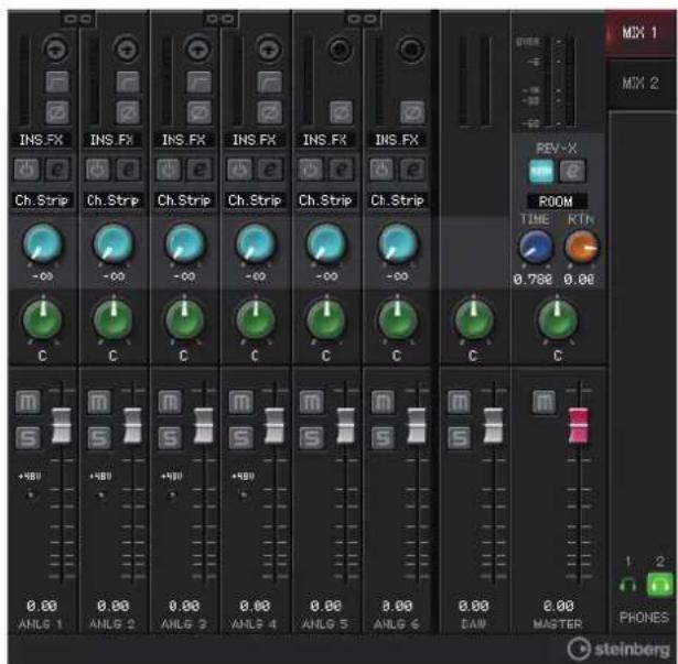
Main Window
This window is for configuring the entire signal flow.
text_image
INS.FX INS.FX INS.FX INS.FX INS.FX INS.FX Ch.Strip Ch.Strip Ch.Strip Ch.Strip Ch.Strip Ch.Strip -00 -00 -00 -00 -00 -00 C C C C C C C +98V +98V +98V AHL6 1 AHL6 2 AHL6 3 AHL6 4 AHL6 5 AHL6 6 0.00 0.00 0.00 0.00 0.00 0.00 0.00 0.00 PEK OFF MIX 1 MIX 2 REV-X ROOM TIME RTN 0.788 0.00 C C C C M 1 2 PHONES steinbergChannel Area
This is the area for configuring the input channel settings.

text_image
MON.FX Ch.Strip -00 C +4BU 0.00 ANLG 1 1 2 3 4 5 6 7 8 9 10 11 12 13① Channel Link
Turns on (lit) and off (dark) the channel link of two adjacent channels. When you turn this on, two mono channels will become one stereo channel.
② Level Meter
Indicates the signal level.
③ High Pass Filter
Turns on (lit) and off (dark) the high pass filter (not available on [LINE INPUT 5/6]). To select the cutoff frequency of the high pass filter, use the "Setup Window" (page 14) in the section "dspMixFx UR44."
④ Phase
Turns on (lit) and off (dark) the phase inversion of the signal.
⑤ Effect Insertion location
Selects the insertion location of an effect.
| Options Description | |
| MON.FX Applies an effect to only the monitor signal (sent to the device). | |
| INS.FX Applies an effect to both the monitor signal (sent to the device) and the recording signal (sent to a DAW software). |
6 Effect On/Off
Turns the Effect on (lit) and off (dark).
⑦ Effect Edit
Opens (lit) and closes (dark) the selected effect setup window.
8 Effect Type
Indicates the effect type.
The maximum number of Channel Strip and Guitar Amp Classics iterations which can be used simultaneously has restrictions. Refer to the "Limitations on the use of effects" (page 34).
⑨ REV-X Send
Adjusts the signal level which is sent to REV-X.
Range: -∞ dB - +6.00 dB
10 Pan
Adjusts the pan.
Range: L16 - C - R16
⑪ Mute
Turns the mute on (lit) and off (dark).
12 Solo
Turns the solo on (lit) and off (dark).
⑬ +48V
Indicates the on/off status of the phantom power function of the device.
14 Fader
Adjusts the signal level.
Range: -∞ dB - +6.00 dB
DAW Area
This is the area for configuring the DAW channel settings.

text_image
1 2 3 4 5 0.00 DAW① Level Meter
Indicates the signal level.
② Pan
Adjusts the pan.
Range: L16 - C - R16
③ Mute
Turns the mute on (lit) and off (dark).
4 Solo
Turns the solo on (lit) and off (dark).
⑤ Fader
Adjusts the signal level.
Range: -∞ dB - +6.00 dB
Master Area
This is the area for configuring the master channel settings.
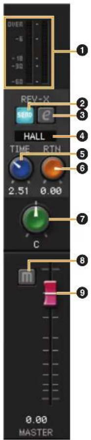
text_image
OVER -6 -10 -90 -60 REV-X SERD e HALL TIME RTN 2.51 0.00 C 0.00 MASTER① Level Meter
Indicates the signal level.
② REV-X Send On/Off
Turns REV-X on (lit) and off (dark).
You can turn this on for either MIX 1 or MIX 2.
③ REV-X Edit
Opens (lit) and closes (dark) the "REV-X" (page 20) setup window.
④ REV-X Type
Selects the REV-X type.
Options: Hall, Room, Plate
⑤ REV-X Time
Adjusts the reverb time of REV-X. This parameter links to Room Size. The adjustable range varies depending on REV-X type.
| REV-X type Range |
| Hall 0.103 sec – 31.0 sec |
| Room 0.152 sec – 45.3 sec |
| Plate 0.176 sec – 52.0 sec |
⑥ REV-X Return Level
Adjusts the return level of REV-X.
Range: -∞ dB - +6.00 dB
7 Pan
Adjusts the pan.
Range: L16 - C - R16
8 Mute
Turns the mute on (lit) and off (dark).
9 Fader
Adjusts the signal level.
Range: -∞ dB - +6.00 dB
HINT
Fader operations
| Function Operation | |
| Set to 0 dB Double-click the fader | |
| Slide all channel faders at the same time | [Ctrl]/[command] + [Shift] + drag the fader |
MIX Area
This is the area for selecting the MIX you want to configure.
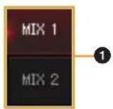
① MIX
Selects the MIX you want to configure.
You can copy the Main window settings of the MIX by dragging and dropping.
Headphone Area
This is the area for selecting the output signal of the headphone.
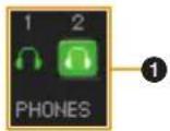
① PHONES On/Off
Turns on (lit) and off (dark) the headphones output.
You can output the MIX selected in the MIX area to the PHONES by turning this on.
NOTE
With [PHONES 2], either MIX 1 or MIX 2 can be selected; [PHONES 1] is fixed to MIX 1 and cannot be changed.
Setup Window
This windows is for configuring the common settings of the device.
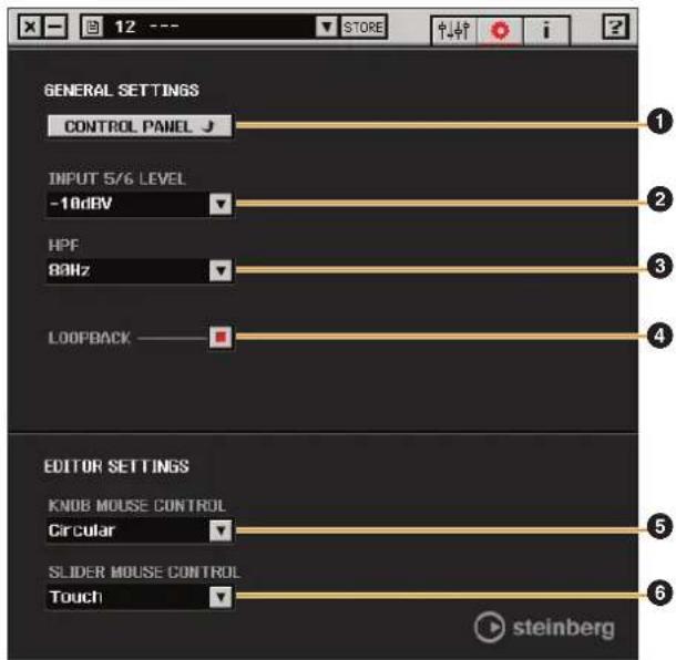
text_image
12 --- STORE GENERAL SETTINGS CONTROL PANEL J INPUT 5/6 LEVEL -10dBV HPF 80Hz LOOPBACK EDITOR SETTINGS KNOD MOUSE CONTROL Circular SLIDER MOUSE CONTROL Touch steinberg① CONTROL PANEL
For Windows, this opens the "Control Panel of the Audio Driver" (page 9). For Mac, this opens Audio MIDI Setup.
② INPUT 5/6 LEVEL
Selects the input signal level of [LINE INPUT 5/6].
Options: +4 dBu, -10 dBV
③ HPF
Selects the cutoff frequency of the high pass filter (not available on [LINE INPUT 5/6]).
Options: 120 Hz, 100 Hz, 80 Hz, 60 Hz, 40 Hz
④ LOOPBACK
Turns the Loopback function on (lit) and off (dark).
HINT
What is Loopback?
Loopback is a function that mixes the input audio signals (LINE, Guitar, MIC etc) and the audio signals playing back in the software into two channels in the UR44, and back to the computer for live broadcasting via the Internet.
When the Loopback function is set to ON, the audio signals output from MIX 1 in the DSP mixer (dspMix FX) in the device are returned to the computer for actual broadcasting. Refer to the section "Signal Flow" (page 33). When using multi-track recording in audio recording software, set the Loopback function to OFF.
⑤ KNOB MOUSE CONTROL
Selects the method of operating the knobs on dspMixFx UR44.
| Options Description | |
| Circular Drag | in a circular motion to increase and decrease the parameter. Drag in a dial clockwise to increase, and counterclockwise to decrease. If you click any point on the knob, the parameter will jump there instantly. |
| Linear Drag in | a linear motion to increase and decrease the parameter. Drag upward or rightward to increase, and downward or leftward to decrease. Even if you click any point on the knob, the parameter will not jump there. |
⑥ SLIDER MOUSE CONTROL
Selects the method of operating the sliders and faders on dspMixFx UR44.
| Options Description |
| Jump Click any point on the slider and fader to increase and decrease the parameter. If you click any point on the slider and fader, the parameter will jump there instantly. |
| Touch Drag the handle of the slider and fader to increase and decrease the parameter. Even if you click any point on the slider and fader, the parameter will not jump there. |
Information Window
This window indicates information about dspMixFx UR44 and the device.
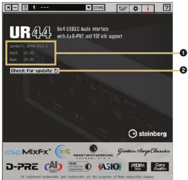
text_image
UR44 6x4 USB2.0 Audio Interface with 4xD-PRE and 192 kHz support dcpMixFx: UR44 VEN.3 Boot: VX.XX Main: VX.XX Check for update steinberg DSPMixFx™ GUEST SPOT MORNING D-PRE AI TRUE INTIGRAVEI MUSTORIAL ASIO WDM Tech Core Audio All registered trademarks and trademarks are the property of their respective owners① Version Information
Indicates the version of the firmware and software.
② Check for update
Checks whether or not you have the latest software and firmware version, via the Internet. If a new version is found, follow the on-screen instructions for updating.
Dedicated Windows for Cubase Series (Windows for Configuring the Device Settings from Cubase Series)
Overview
These are the windows for configuring the device settings from Cubase series. The dedicated windows for Cubase series allow you to configure the parameters which are configured by dspMixFx UR44. Two types of windows are available: Input Settings and Hardware Setup.
Input Settings Window
This window is for configuring the input settings of the device. The signal flow is from top to bottom.
The settings on this window (except for the +48V indicator) are saved to the Cubase project file.

flowchart
graph TD
    A["In"] --> B["fx e"]
    B --> C["ChStrp"]
    C --> D["dm"]
    D --> E["rev e"]
    E --> F["Control Signals"]
How to Open the Window
The Input Settings window appears in the Mixer window
- [Devices] → [MixConsole] to open the Mixer window.
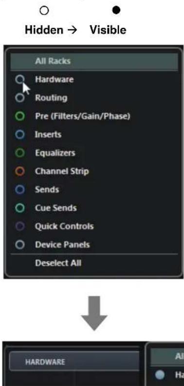
- Click [Racks] to open the rack selector.
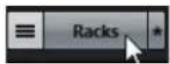
The rack selector appears.
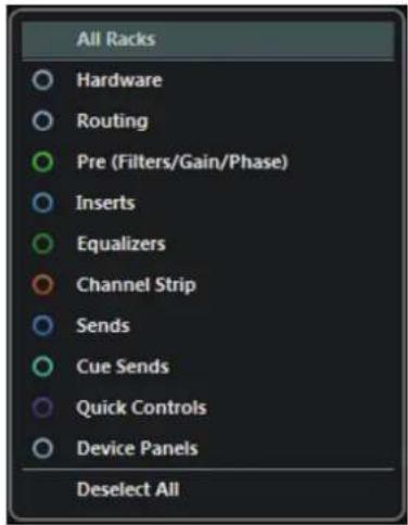
text_image
All Racks Hardware Routing Pre (Filters/Gain/Phase) Inserts Equalizers Channel Strip Sends Cue Sends Quick Controls Device Panels Deselect All- Click ○ next to the [Hardware] to show [HARDWARE] in the Mixer window.
text_image
Hidden → Visible All Racks Hardware Routing Pre (Filters/Gain/Phase) Inserts Equalizers Channel Strip Sends Cue Sends Quick Controls Device Panels Deselect All HARDWARE All Ha4. Click [HARDWARE].
![STEINBERG UR44 - Click [HARDWARE]. - 1](/content/2026/05/760574/images/f27c3fa72799306ef6b4276ac9d43543adc12f355c04e02492ff625abb009d8d.jpg)
The Input Settings window appears in the Mixer window as shown below.
![STEINBERG UR44 - Click [HARDWARE]. - 2](/content/2026/05/760574/images/a17482f5d2a48ecc8f1360ae7aa43e5edc523f65b1864b25515ff2c6c970fe40.jpg)
text_image
HAC/DAIR Ch/Step 0.00 -31.3 Stereo inControls and Functions
text_image
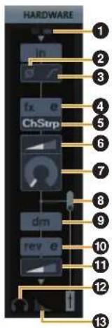
HARDWARE In fx e ChStrp dm rev e 1 2 3 4 5 6 7 8 9 10 11 12 13① +48V
Indicates the phantom power on/off status.
② Phase
Turns on (lit) and off (dark) the phase inversion of the signal.
③ High Pass Filter
Turns on (lit) and off (dark) the high pass filter (not available on [LINE INPUT 5/6]). To select the cutoff frequency of the high pass filter, use the "Settings Window" (page 17) in the section "Dedicated Windows for Cubase Series."
4 Effect Edit
Opens the selected effect setup window.
⑤ Effect type
Selects the effect.
The maximum number of Channel Strip and Guitar Amp Classics iterations which can be used simultaneously has restrictions. Refer to the "Limitations on the use of effects" (page 34).
⑥ DRIVE / Output Level
When Channel Strip is selected, this adjusts the degree to which the compressor is applied. The higher the value, the greater the effect.
Range: 0.00 - 10.00
When Guitar Amp Classics is selected, this adjusts the output level.
Range: 0.00 - 1.00
7 MORPH
Adjusts the Channel Strip Sweet Spot Data. (Refer to the "MORPH" in the section "Channel Strip" on page 18). When Guitar Amp Classics is selected, MORPH is not displayed.
⑧ Effect Insertion location
Selects the insertion location of an effect.
| Insertion location | Description |
| Upper (OFF) Turns the effect off. | |
| Middle (MON.FX) | Applies an effect Strip to only the monitor signal (sent to the device). |
| Lower (INS.FX) | Applies an effect Strip to both the monitor signal (sent to the device) and the recording signal (sent to the DAW software). |
⑨ Output Position of the Direct Monitoring Signal
Indicates the position from which the audio signals for monitoring will be output when turning on Direct Monitoring in the device settings on Cubase.
10 REV-X Edit
Opens the "REV-X" (page 20) setup window.
⑪ REV-X Send
Adjusts the signal level which is sent to the REV-X.
Range: -∞ dB - +6.00 dB
⑫ Headphones Edit
Opens the "Headphones Window" (page 17) in the section "Dedicated Windows for Cubase Series."
⑬ Reverb Routing Edit
Opens the "Reverb Routing Window" (page 17) in the section "Dedicated Windows for Cubase Series."
Hardware Setup Window
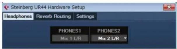
This window is for configuring the general settings of the device. Click the upper tabs to select the window. Only the settings on the Reverb Routing window are saved to the Cubase project file.
text_image
Steinberg UR44 Hardware Setup Headphones Reverb Routing Settings PHONES1 PHONES2 Mix 1 L/R Mix 2 L/RHow to Open the Window
Follow the steps below to open the window.
[Devices] → [Audio Hardware Setup]
Controls and Functions
Headphones Window
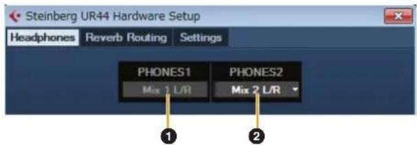
This window is for selecting the output signal of the PHONES on the device. (PHONES 2 only)
text_image
Steinberg UR44 Hardware Setup Headphones Reverb Routing Settings PHONES1 PHONES2 Mix 1 L/R Mix 2 L/R ① ②① PHONES 1
Indicates the output signal of [PHONES 1].
② PHONES 2
Selects the output signal of [PHONES 2].
Reverb Routing Window
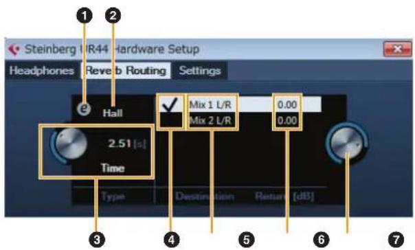
This window is for configuring the "REV-X" (page 20) settings.
text_image
Steinberg VR44 Hardware Setup Headphones Reverb Routing Settings Hall 2.51 [s] Time Mix 1 L/R Mix 2 L/R 0.00 0.00 Type Destination Return [dB]① REV-X Edit
Opens the "REV-X" (page 20) setup window.
② REV-X Type
Selects the REV-X type.
Options: Hall, Room, Plate
③ REV-X Time
Adjusts the reverb time of REV-X. This parameter links to Room Size. The adjustable range varies depending on the REV-X type.
| REV-X type Range |
| Hall 0.103 sec – 310 sec |
| Room 0.152 sec – 45.3 sec |
| Plate 0.176 sec – 52.0 sec |
④ REV-X Send Source Select
Selects the send source signal which is sent to REV-X. You can select one signal at a time. The checkmark indicates the selected signal.
⑤ REV-X Send Source
Indicates the signal which is sent to REV-X.
⑥ REV-X Return Level
Indicates the return level of REV-X.
⑦ REV-X Return Level Knob
Adjusts the return level of the selected (highlighted) signal.
Range: -∞ dB - +6.00 dB
Settings Window
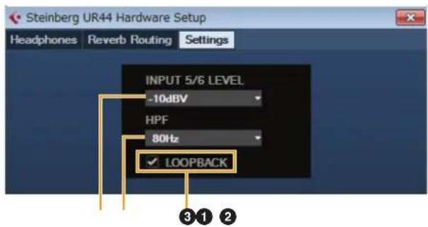
This window is for configuring the device settings.
text_image
Steinberg UR44 Hardware Setup Headphones Reverb Routing Settings INPUT 5/6 LEVEL -10dBV HPF 80Hz ✓ LOOPBACK ③①②① INPUT 5/6 LEVEL
Selects the input signal of [LINE INPUT 5/6].
Options: +4 dBu - 10 dBV
② HPF
Selects the cutoff frequency of the high pass filter (not available on [LINE INPUT 5/6]).
Options: 120 Hz, 100 Hz, 80 Hz, 60 Hz, 40 Hz
③ LOOPBACK
Turns the Loopback function on (lit) and off (dark). Refer to the "LOOPBACK" in the section "dspMixFx UR44" (page 14).
Sweet Spot Morphing Channel Strip (Compressor and Equalizer)
Overview
The Sweet Spot Morphing Channel Strip ("Channel Strip" for short) is a multi-effect that combines compression and EQ. Advanced sound engineering know-how is condensed into a number of convenient presets that can be simply and instantly recalled, for professional results.
Four channel strips are provided, and each can be assigned to the monitor sound only, or to both the monitor and recorded sound.
The Channel Strip equipped with the device and the Channel Strip of the VST Plug-in version have the same parameters. When using the Channel Strip on Cubase series programs, you can share the settings between the built-in Channel Strip and the Channel Strip of the VST Plug-in version as a preset file. When using the built-in Channel Strip on Cubase series programs, turn on the "Direct Monitoring" setting in the program. Also, when assigning the Channel Strip of the VST Plug-in version to the effect slot on Cubase series programs, select it from the "Dynamics" category (in the case of the default settings). Please note that you cannot use the built-in Channel Strip when the sample rate is set to 176.4 kHz or 192 kHz.
How to Open the Window
From Dedicated Windows for Cubase Series
Select the "Channel Strip" from the "Effect Type", then click "Channel Strip Edit" in the section "Input Settings Window" (page 16).
From dspMixFx UR44
Select the "Channel Strip" from the "Effect Type", then click "Channel Strip Edit" in the section "Channel Area" (page 12).
Controls and Functions
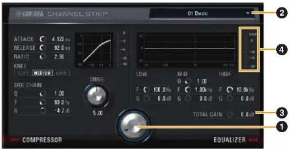
Common to Compressor and Equalizer
text_image
YAMA CHANNEL STRIP 01 Basic ATTACK 4.122 Hz RELEASE 92.0 Hz RATIO 2.56 KNEE SOLD MEDIUM 2.000 DRIVE SIDE CHAIN 0 1.00 F 93.0 Hz G -4.7 dB 5.00 COMPRESSOR EQUALIZER LOW MID HIGH 0 1.00 F 100.0 Hz F 1.30 Hz F 10.0 Hz G 0.0 dB G 0.0 dB G 0.0 dB TOTAL GAIN 0.0 dB ① ② ③ ④① MORPH
Adjusts the parameter of the Sweet Spot Data. You can simultaneously adjust the compressor and equalizer settings which are set to five points around this knob by turning this knob. When you set the knob to the middle of adjacent two points, the compressor and equalizer settings will be set to an intermediate value.
② Sweet Spot Data
Selects the Sweet Spot Data.
③ TOTAL GAIN
Adjusts the total gain of the Channel Strip.
Range: -18.0 dB - +18.0 dB
④ Level Meter
Indicates the output level of the Channel Strip.
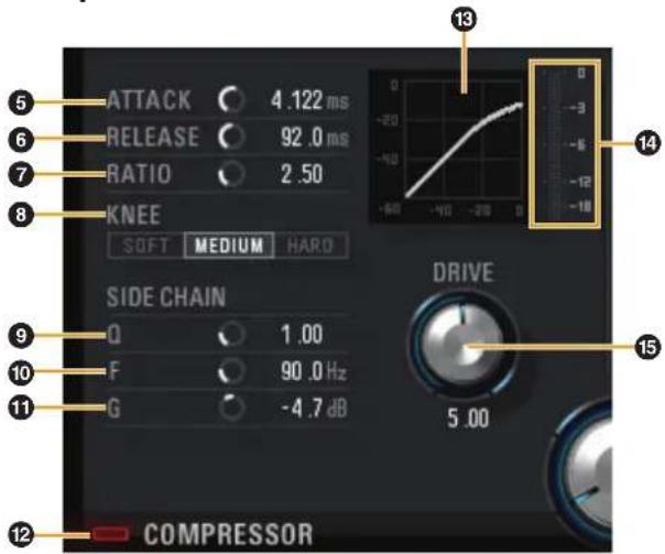
Compressor
text_image
5 6 7 8 ATTACK 4.122 ms RELEASE 92.0 ms RATIO 2.50 KNEE SOFT MEDIUM HARD SIDE CHAIN Q 1.00 F 90.0 Hz G -4.7 dB DRIVE 5.00 13 14 15 12 COMPRESSOR5 ATTACK
Adjusts the attack time of the compressor.
Range: 0.092 msec - 80.00 msec
6 RELEASE
Adjusts the release time of the compressor.
Range: 9.3 msec - 999.0 msec
7 RATIO
Adjusts the ratio of the compressor.
Range: 1.00 - ∞
8 KNEE
Selects the knee type of the compressor.
| Options Description | |
| SOFT Produces the most gradual change. | |
| MEDIUM Results in a setting midway between SOFT and HARD. | |
| HARD Produces the sharpest change. |
9 SIDE CHAIN Q
Adjusts the band width of the side chain filter.
Range: 0.50 - 16.00
⑩ SIDE CHAIN F
Adjusts the center frequency of the side chain filter.
Range: 20.0 Hz - 20.0 kHz
⑪ SIDE CHAIN G
Adjusts the gain of the side chain filter.
Range: -18.0 dB - +18.0 dB
⑫ COMPRESSOR On/Off
Turns the compressor on (lit) and off (dark).
13 Compressor Curve
This graph indicates the approximate compressor response. The vertical axis indicates the output signal level, and the horizontal axis indicates the input signal level.
14 Gain Reduction Meter
Indicates the gain reduction.
15 DRIVE
Adjusts the degree to which the compressor is applied. The higher the value, the greater the effect.
Range: 0.00 - 10.00
Equalizer
text_image
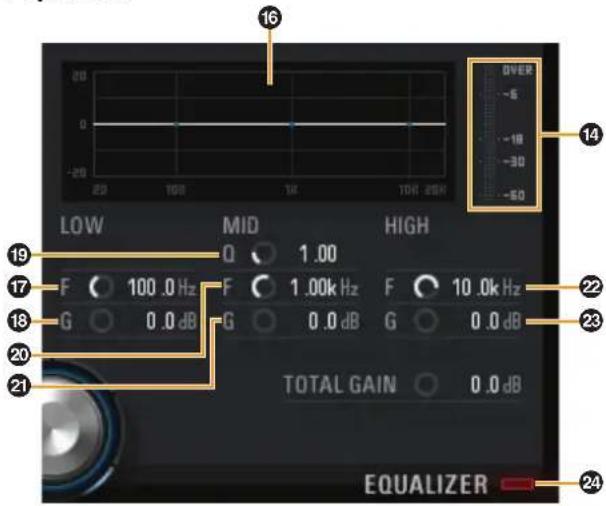
16 20 0 -20 20 100 10K 20K LOW MID HIGH Q 1.00 F 100.0 Hz F 1.00kHz F 10.0kHz G 0.0 dB G 0.0 dB G 0.0 dB TOTAL GAIN 0.0 dB EQUALIZER 19 17 F 100.0 Hz F 1.00kHz F 10.0kHz 18 G 0.0 dB G 0.0 dB G 0.0 dB 22 23 2416 Equalizer Curve
This graph indicates the characteristics of the 3-band equalizer. The vertical axis indicates the gain, and the horizontal axis indicates the frequency. You can adjust LOW, MID, and HIGH by dragging each handle in the graph.
17 LOW F
Adjusts the center frequency of the low band.
Range: 20.0 Hz - 1.00 kHz
18 LOW G
Adjusts the gain of the low band.
Range: -18.0 dB - +18.0 dB
19 MID Q
Adjusts the band width of the middle band.
Range: 0.50 - 16.00
20 MID F
Adjusts the center frequency of the middle band.
Range: 20.0 Hz - 20.0 kHz
21 MID G
Adjusts the gain of the middle band.
Range: -18.0 dB - +18.0 dB
22 HIGH F
Adjusts the center frequency of the high band.
Range: 500.0 Hz - 20.0 kHz
23 HIGH G
Adjusts the gain of the high band.
Range: -18.0 dB - +18.0 dB
24 EQUALIZER On/Off
Turns the equalizer on (lit) and off (dark).
REV-X (Reverb)
Overview
REV-X is a digital reverb platform developed by Yamaha for pro audio applications.
One REV-X effect is included in this unit. Input signals can be sent to the REV-X effect, and the REV-X effect is applied only to the monitor outputs. Three types of REV-X are available: Hall, Room, and Plate.
The hardware REV-X equipped with the device and REV-X of the VST Plug-in version have essentially the same parameters. However, the [OUTPUT] and [MIX] parameters are only available in the VST Plug-in version. When using REV-X on Cubase series programs, you can share the settings between the built-in REV-X and REV-X of the VST Plug-in version as a preset file. When using the built-in REV-X on Cubase series programs, turn on the "Direct Monitoring" setting in the program. Also, when assigning REV-X of the VST Plug-in version to the effect slot on Cubase series programs, select it from the "Reverb" category (in the case of the default settings).
The built-in REV-X is equipped with an "FX Bus" which is used for sending the signal from DAW software to REV-X. For example, to send the recorded audio data to REV-X, you can check the sound with REV-X, which is used for monitoring during the recording.
How to Open the Window
From Dedicated Windows for Cubase Series
- Click "REV-X Edit" (page 16) in the section "Input Settings Window."
- Click "REV-X Edit" (page 17) in the section "Reverb Routing Window."
From dspMixFx UR44
Click "REV-X Edit" (page 13) in the section "Master Area."
Controls and Functions
text_image
YAMAHA RFV-HALL 1 - 10 Reverb Time 2.51s HPF 30Hz Initial Delay 3.5ms LPF 6.3Hz Decay 27 Hi Ratio 8.8 Roco Size 29 Low Ratio 1.2 Diffusion 10 Low Freq 0.0Hz Hi Ratio [0.0] High Ratio [1.2] Diffusion [18] Low Freq [0.0Hz] Reverb Time [2.51s] Initial Delay [3.5ms] Decay [57] Room Size [29] 12 13 14 15NOTE
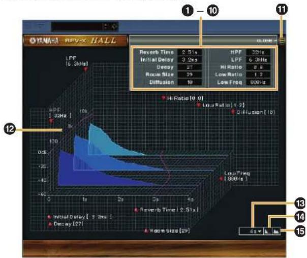
This section uses the Hall type of REV-X as an example.
① Reverb Time
Adjusts the reverb time. This parameter links to Room Size. The adjustable range varies depending on the REV-X type.
| REV-X type Range |
| Hall 0.103 sec – 31.0 sec |
| Room 0.152 sec – 45.3 sec |
| Plate 0.176 sec – 52.0 sec |
② Initial Delay
Adjusts the time that elapses between the direct, original sound and the initial reflections that follow it.
Range: 0.1 msec - 200.0 msec
③ Decay
Adjusts the characteristic of the envelope from the moment the reverberation starts to the moment it attenuates and stops.
Range: 0 - 63
4 Room Size
Adjusts the size of the simulated room. This parameter links to Reverb Time.
Range: 0 - 31
⑤ Diffusion
Adjusts the spread of the reverberation.
Range: 0 - 10
6 HPF
Adjusts the cutoff frequency of the high pass filter.
Range: 20 Hz - 8.0 kHz
⑦ LPF
Adjusts the cutoff frequency of the low pass filter.
Range: 1.0 kHz - 20.0 kHz
8 Hi Ratio
Adjusts the duration of reverberation in the high frequency range by using a ratio relative to the Reverb Time. When you set this parameter to 1, the actual specified Reverb Time is fully applied to the sound. The lower the value, the shorter the duration of reverberation in the high frequency range.
Range: 0.1 - 1.0
9 Low Ratio
Adjusts the duration of reverberation in the low frequency range by using a ratio relative to the Reverb Time. When you set this parameter to 1, the actual specified Reverb Time is fully applied to the sound. The lower the value, the shorter the duration of reverberation in the low frequency range.
Range: 0.1 - 1.4
10 Low Freq
Adjusts the frequency of the Low Ratio.
Range: 22.0 Hz - 18.0 kHz
⑪ OPEN/CLOSE
Opens and closes the window for adjusting the reverb settings.
12 Graph
Indicates the characteristics of reverberation. The vertical axis indicates the signal level, the horizontal axis indicates the time, and the Z-axis indicates the frequency. You can adjust the characteristics of reverberation by dragging the handles in the graph.
13 Time Axis Setting
Select the display range of the time (horizontal axis) on the graph.
Display range: 500 msec – 50 sec
14 Zoom Out
Zooms out the display range of the time (horizontal axis) on the graph.
15 Zoom In
Zooms in the display range of the time (horizontal axis) on the graph.
HINT
- You can reset some parameters to the default value by holding the [Ctrl]/[command] key while you click on the knobs, sliders, and faders.
- You can adjust the parameters more finely by holding the [SHIFT] key while you drag on the knobs, sliders, and faders.
Guitar Amp Classics
Overview
Guitar Amp Classics are guitar amp effects that make extensive use of advanced Yamaha modeling technology. Four amp types with different sonic characteristics are provided.
Please note that you cannot use the Guitar Amp Classics when the sample rate is set to 176.4 kHz or 192 kHz. The maximum number of Channel Strip and Guitar Amp Classics iterations which can be used simultaneously has restrictions. Refer to the "Limitations on the use of effects" (page 34).
How to Open the Window
From Dedicated Windows for Cubase Series
Select the "Guitar Amp Classics" from the "Effect Type", then click "Channel Strip Edit" in the section "Input Settings Window" (page 15).
From the dspMixFx UR44
Select the "Guitar Amp Classics" from the "Effect Type", then click "Channel Strip Edit" in the section "Channel Area" (page 11).
Controls and Functions
CLEAN
text_image
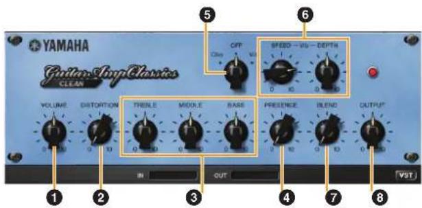
YAMAHA Guitar/LoopClassics CLEAN OFF Clay 10 SPEED - 100 - DEPTH VOLUME DISTORTION TRESLE MIDDLE BASS PRESENCE BLEND OUTPUT IN OUT VSTThis amp type is optimized for clean tones, effectively simulating the tight brilliance of transistor amplifiers. The tonal character of this amp model provides an ideal platform for recording with multi-effects. It also features built-in chorus and vibrato effects.
① VOLUME
Adjusts the amplifier's input level.
② DISTORTION
Adjusts the depth of distortion produced.
③ TREBLE/MIDDLE/BASS
These three controls adjusts the amplifier's tonal response in the high, middle, and low frequency ranges.
④ PRESENCE
Can be adjusted to emphasize the high frequencies and overtones.
⑤ Cho/OFF/Vib
Turns the Chorus or Vibrato effect on or off. Set to [Cho] to turn the Chorus effect on, or to [Vib] to turn the Vibrato effect on.
6 SPEED/DEPTH
These controls adjust the speed and depth of the Vibrato effect when it is on.
The SPEED and DEPTH controls only work with the Vibrato effect, and are disengaged when the Cho/OFF/Vib control, above, is set to "Cho" or "OFF."
⑦ BLEND
Adjusts the balance between the direct and effect sound.
8 OUTPUT
Adjusts the final output level.
CRUNCH
text_image
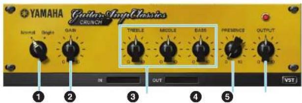
YAMAHA Guitar Amp Classics CRUNCH Normal Height Gain TREEL MIDDLE BASS 0 10 0 10 0 IN OUT VSTThis is the amp type to use when you want lightly overdriven crunch tones. The CRUNCH model simulates the type of vintage tube amplifiers that are favored for blues, rock, soul, R&B, and similar styles.
① Normal/Bright
Selects a normal or bright tonal character. The [Bright] setting emphasizes the high-frequency overtones.
② GAIN
Adjusts the input level applied to the preamp stage. Rotate clockwise to increase the amount of overdrive produced.
③ TREBLE/MIDDLE/BASS
These three controls adjusts the amplifier's tonal response in the high, middle, and low frequency ranges.
④ PRESENCE
Can be adjusted to emphasize the high frequencies and overtones.
⑤ OUTPUT
Adjusts the final output level.
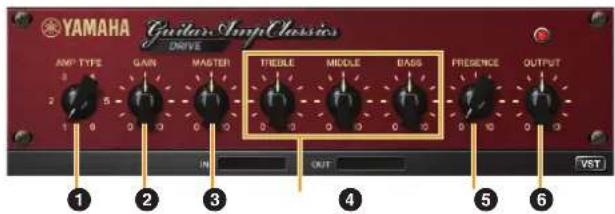
DRIVE
text_image
YAMAHA Guitar Amp Classics DRIVE AMP TYPE GAIN MASTER TIEDLE MIDDLE BASS FREEDENCE OUTPUT 1 2 3 4 5 6 IN OUT VSTThe DRIVE amp type provides a selection of distortion sounds that simulate the tonal character or several high-gain tube amplifiers. From mildly overdriven crunch to heavy distortion suitable for hard rock, heavy metal, or hardcore styles, this model offers a wide range of sonic capabilities.
① AMP TYPE
Six amplifier types are provided. Types 1 and 2 feature relatively mild distortion that allows picking nuances to come through naturally. Types 3 and 4 have more pronounced overtones, resulting in a fat, soft tone. Types 5 and 6 deliver wild, aggressive distortion with a tight attack. The even-numbered amp types have greater presence and range than the odd-numbered types.
② GAIN
Adjusts the input level applied to the preamp stage. Rotate clockwise to increase the amount of distortion produced.
③ MASTER
Adjusts the output level from the preamp stage.
④ TREBLE/MIDDLE/BASS
These three controls adjusts the amplifier's tonal response in the high, middle, and low frequency ranges.
⑤ PRESENCE
Can be adjusted to emphasize the high frequencies and overtones.
6 OUTPUT
Adjusts the final output level.
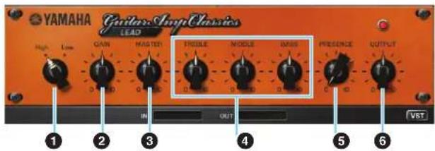
LEAD
text_image
YAMAHA Guitar Amp Classics LEAD High Low Gain Master TROCLE MIDDLE MASS PRESENCE OUTPUT IN OUT VSTThe LEAD amp type simulates a high-gain tube amp that is rich in overtones. It is ideally suited to playing lead guitar lines that will project well in an ensemble, but it can also be set up for crisp accompaniment tones as well.
① High/Low
Selects the amp output type. The [High] setting simulates a high-output amp, and allows the creation of more distorted tones.
② GAIN
Adjusts the input level applied to the preamp stage. Rotate clockwise to increase the amount of distortion produced.
③ MASTER
Adjusts the output level from the preamp stage.
④ TREBLE/MIDDLE/BASS
These three controls adjusts the amplifier's tonal response in the high, middle, and low frequency ranges.
⑤ PRESENCE
Can be adjusted to emphasize the high frequencies and overtones.
6 OUTPUT
Adjusts the final output level.
HINT
Using the GAIN, MASTER, and OUTPUT Controls
The tonal character of the DRIVE and LEAD amp types can be adjusted over a wide range via the GAIN, MASTER, and OUTPUT controls. GAIN adjusts the level of the signal applied to the preamp stage, affecting the amount of distortion produced. MASTER adjusts the output level from the preamp stage that is then fed to power amp stage. The GAIN and MASTER control settings have a large effect on the final sound, and the MASTER control may need to be turned up fairly high in order to drive the power stage sufficiently for optimum tone. The OUTPUT control adjusts the final output level from the amp model without affecting the distortion or tone, and is useful for adjusting the guitar's volume without changing any other aspects of the sound.
Basic Operation
Using the UR44 with a Computer
Introduction
This section covers basic operation instructions. The explanations in this section assume that the TOOLS for UR44 has been properly configured according to the "Getting Started" instructions included with the package.
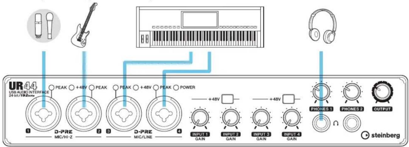
Connection Example
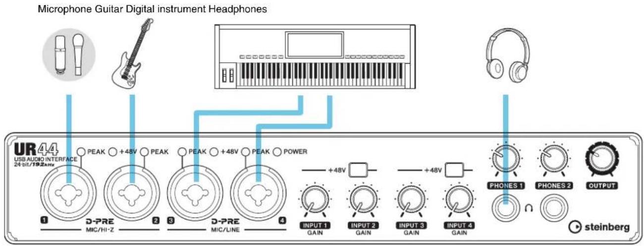
text_image
Microphone Guitar Digital instrument Headphones UR44 USB AUDIO INTERFACE 24 bit/192kHz 1 D-PRE MIC/HI-Z 2 PEAK ○ +48V ○ PEAK 3 D-PRE MIC/LINE 4 POWER +48V □ +48V □ INPUT 1 GAIN INPUT 2 GAIN INPUT 3 GAIN INPUT 4 GAIN PHONES 1 PHONES 2 OUTPUT steinberg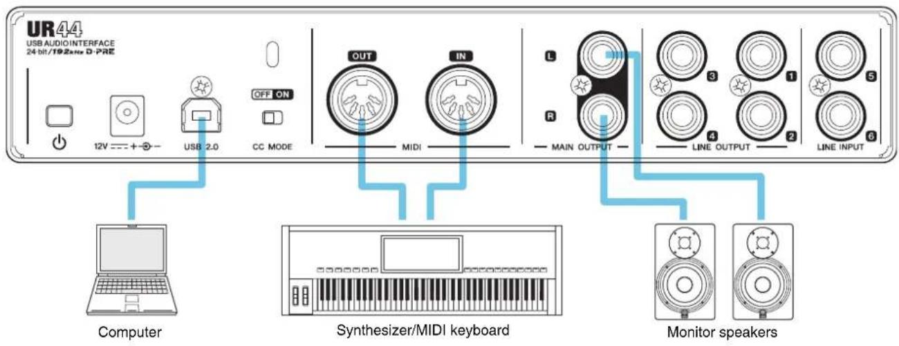
flowchart
graph LR
    A["Computer"] --> B["12V --- + -"]
    B --> C["USB 2.0"]
    C --> D["OFF ON"]
    D --> E["MIDI"]
    E --> F["OUT"]
    E --> G["IN"]
    F --> H["L"]
    G --> I["R"]
    H --> J["MAIN OUTPUT"]
    I --> K["3"]
    I --> L["4"]
    I --> M["1"]
    I --> N["2"]
    I --> O["5"]
    I --> P["6"]
    Q["Synthesizer/MIDI keyboard"] --> R["Computer"]
    S["Monitor speakers"] --> T["Computer"]
    U["Line INPUT"] --> V["Line OUTPUT"]
    W["Line OUTPUT"] --> X["Line INPUT"]
CAUTION
Make sure to set all volume levels to minimum before connecting or disconnecting the external device. Otherwise, high-volume output may damage your hearing or the equipment.
Configuring Audio Driver Settings on the DAW Software
Cubase Series Programs
- Make sure that all applications have been closed.
- Make sure that the [①] switch has been turned on (—).
- Double-click the shortcut of Cubase series on the desktop to start Cubase.
- When the [ASIO Driver Setup] window appears while the Cubase series program is launching, confirm that the device is selected, then click [OK].
The audio driver settings are now complete.
Programs other than Cubase Series
- Make sure that all applications have been closed.
- Make sure that the [①] switch has been turned on (—).
- Launch the DAW software.
- Open the audio interface settings window.
- (Windows only) Select the ASIO Driver for the audio driver settings.
- Set the ASIO Driver for Windows and audio interface for Mac as follows.
Windows
Set the [Yamaha Steinberg USB ASIO] to the ASIO Driver settings.
Mac
Set the UR44 to the audio interface settings.
The audio driver settings are now complete.
Recording/Playback
Cubase Series Programs
- Launch the Cubase series DAW.
The [steinberg hub] window appears. - Select the project template [Steinberg UR44 Vocal-Inst Recording 1-C7] in [Recording] on the [steinberg hub] window, then click [Create].
- Turn on Direct Monitoring as follows.
[Devices] → [Device Setup] → [Yamaha Steinberg USB ASIO] (Windows) or [Steinberg UR44] (Mac) → enter checkmark to [Direct Monitoring] → [OK]

text_image
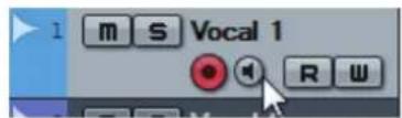
Yamaha Steinberg USB ASIO Control Panel Internal Clock Source ■ Externally Clocked ✓ Direct Monitoring- Confirm that the [Record Enable] and [Monitor] indicators are turned on (lit) for the audio track.
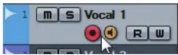
text_image
1 m S Vocal 1 R W- While singing into the microphone, adjust the input signal level of the microphone with the [INPUT GAIN] knob on the device.
To achieve optimum recording levels, increase the input level with the [INPUT GAIN] knob until the [PEAK] indicator lights in red, then slowly bring the level down until the indicator lights slightly when the input level is maximum.
- Continue singing into the microphone and adjust the output signal level of the headphones with the [PHONES] knob on the device.
7. Set the Channel Strip settings and REV-X settings on the Input Settings window.
Select the Channel Strip Insertion location depending on the desired insert point. The default setting is "Lower" (applied to both the monitor signal and the recording signal). For details on the Insertion location, refer to the "Effect Insertion location" (page 16) in the section "Dedicated Windows for Cubase Series."
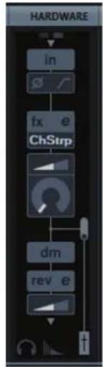
flowchart
graph TD
    A["Hardware"] --> B["in"]
    B --> C["fx e ChStrp"]
    C --> D["dm"]
    D --> E["rev e"]
- Click [●] to start the recording.
- After finishing the recording, click [■] to stop it.
- Turn [Monitor] off (dark) for the just-recorded audio track.
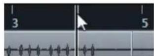
- Click the Ruler to move the project cursor to the desired point for starting playback.
- Click [▶] to check the recorded sound.
When listening to the sound over monitor speakers, adjust the output signal level by the [OUTPUT LEVEL] knob on the device.
For more detailed instructions on using Cubase series programs, refer to the PDF manual, available from [Help] in the Cubase series menu.
Programs Other Than Cubase Series
- Launch your DAW software.
- Open dspMixFx UR44.
For instructions on how to open dspMixFx UR44, refer to the section "How to Open the Window" (page 10). - Adjust the input signal level of the microphone with the [INPUT GAIN] knob on the device.
To achieve optimum recording levels, increase the input level with the [INPUT GAIN] knob until the [PEAK] indicator lights in red, then slowly bring the level down until the indicator lights slightly when the input level is maximum. - Adjust the output signal level of the headphone with the [PHONES] knob on the device.
- Set the Channel Strip settings and REV-X settings on dspMixFx UR44.
- Start recording on your DAW software.
- After finishing recording, stop it.
- Playback the newly recorded sound to check it.
For more detailed instructions on using the DAW software, refer to your particular DAW's software manual.
Using the UR44 with an iPad
Introduction
This section covers basic instructions for operating with Cubasis (an iPad app sold by Apple). The explanations here assume that the settings for using the UR44 with iPad have been properly configured according to the "Getting Started" instructions included with the package.
For the latest Cubasis information, see the Steinberg web site below.
http://www.steinberg.net/
NOTE
iOS applications may not be supported in your area. Please check with your Yamaha dealer.
Connection Example
Microphone Guitar Digital instrument Headphones
text_image
UR44 USB AUDIO INTERFACE 24 bit/192bite 1 D-PRE MIC/HI-Z 2 PEAK ○ +48V ○ PEAK 3 D-PRE MIC/LINE 4 POWER +48V □ +48V □ INPUT 1 GAIN INPUT 2 GAIN INPUT 3 GAIN INPUT 4 GAIN PHONES 1 PHONES 2 OUTPUT steinberg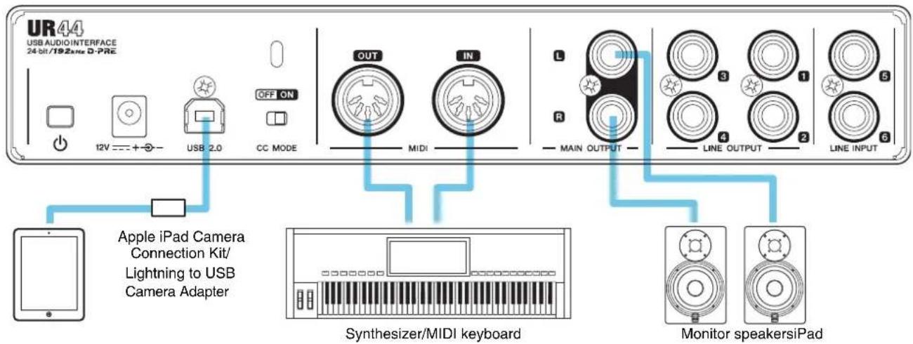
text_image
UR44 USB AUDIO INTERFACE 24 bit/192MHz D-PRE 12V + - USB 2.0 OFF ON CC MODE OUT MIDI IN L R MAIN OUTPUT 3 4 LINE OUTPUT 1 2 LINE INPUT 5 6 Apple iPad Camera Connection Kit/ Lightning to USB Camera Adapter Synthesizer/MIDI keyboard Monitor speakersiPadCAUTION
Make sure to set all volume levels to minimum before connecting or disconnecting the external device. Otherwise, high-volume output may damage your hearing or the equipment.
Recording/Playback
- After turning the [CC MODE] switch on, turn on the [∅] switch on (—).
- Open Cubasis.
- Double-tap the Project [Template].
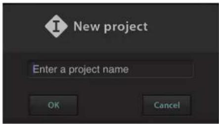
- Enter a project name and tap [OK] in the [New project] window.
text_image
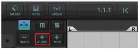
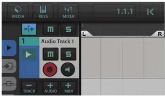
New project Enter a project name OK Cancel- Tap [+AUDIO] to add an AUDIO track.
text_image
MEDIA KEYS MIXER 1.1.1 L R - TRACK + AUDIO + MIDI
text_image
MEDIA KEYS MIXER 1.1.1 Audio Track 1 L R TRACK AUDIO MIDI- Tap on the far left of your screen to show the track menu, with [Audio input] at the top.
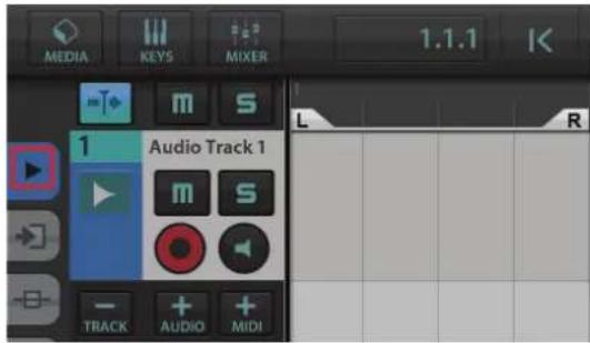
text_image
MEDIA KEYS MIXER 1.1.1 Audio Track 1 L R TRACK AUDIO MIDI
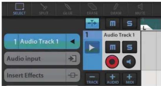
text_image
SELECT SPLIT GLUE ENASE CHAW MUTE 1 Audio Track 1 Audio input Insert Effects 1 Audio Track 1 m s TRACK AUDIO MIDI- Tap to show the details window and set the input bus for the track by tapping a number.
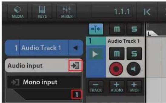
text_image
MEDIA KEYS MIXER 1.1.1 Audio Track 1 Audio input Mono input 1 Audio Track 1 TRACK AUDIO MIDI- Tap to turn monitoring on (lit).
- Adjust the input signal level of the microphone with the [INPUT GAIN] knob on the device.
To achieve optimum recording levels, increase the input level with the [INPUT GAIN] knob until the [PEAK] indicator lights in red, then slowly bring the level down until the indicator lights slightly when the input level is maximum.
-
While singing into the microphone, adjust the output signal level of the headphones by the [PHONES] knob on the device.
-
Tap [●] to start the recording.
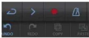
- Tap [☐] to stop the recording.
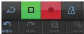
- Tap and slide on the ruler to move the playback position.
text_image
COPY PASTE TRANSPOSE 3You can also tap to return to the beginning of the recording.
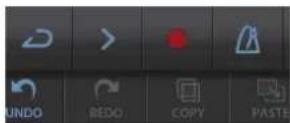
- Tap [>] to playback the recorded sound.
dspMixFx for iPad
From your iPad, you conveniently control built-in DSP mixer functions and DSP effects by using dspMixFx for iPad.
For details on dspMixFx for iPad, see the Steinberg web site below.
http://www.steinberg.net/
Troubleshooting
[POWER] does not light.
- Is the AC adaptor connected correctly?
The UR44 is not a bus-powered type device. Refer to the Getting Started instructions to turn on the [∅] switch.
Power indicator does not switch from flashing to being continuously lit.
- Is the [CC MODE] switch set properly?
Refer to the section "Rear Panel" (page 7) to confirm the [CC MODE] switch settings.
- (Computer only) Has TOOLS for UR44 been installed properly?
Refer to the Getting Started instructions to complete TOOLS for UR44 installation.
- Has the power of your computer or iPad been turned on?
Refer to the Getting Started instructions to turn on the power of a computer or iPad.
- Confirm whether or not a proper USB cable is used.
If the USB cable is broken or damaged, replace the USB cable with a new one. Make sure to use a USB cable no longer than 3 meters.
No sound
- Are the volume controls of the device set to appropriate levels?
Confirm the levels of the [OUTPUT] knob and [PHONES] knob.
- Are the microphones and monitor speakers connected to the device properly?
Refer to the section "Connection Examples" (pages 24, 27) to confirm the connection.
- Is the [CC MODE] switch set properly?
Refer to the section "Rear Panel" (page 7) to confirm the [CC MODE] switch settings.
- Are the audio driver settings on DAW software set properly?
Refer to the section "Configuring the Audio Driver Settings on DAW Software" (page 25) to set it.
- Is the [ASIO Driver] setting on the Cubase series program set properly?
From the Cubase series menu, open the [Devices] → [Device Setup...] → [VST Audio System], then confirm that the [Yamaha Steinberg USB ASIO] (Windows) or [Steinberg UR44] (Mac) is selected on the [ASIO Driver].
- Was the power of the device turned on before starting the DAW software?
Before starting the DAW software, connect the device to a computer and turn on the power of the device.
- (Computer only) Has TOOLS for UR44 been installed properly?
Refer to the Getting started instructions to complete TOOLS for UR44 installation.
- Are any USB devices you are not using connected to the computer?
Remove them, and then check the sound again.
- Are any other applications running at the same time?
Quit all applications you are not using and check the sound again.
Unusual sound (noise, interruption, or distortion)
• Is the buffer size set too low?
Increase the buffer size compared to the current settings; refer to the section "Yamaha Steinberg USB Driver" (page 9) for instructions.
- Does your computer satisfy the system requirements?
Confirm the system requirements. For the latest information, see the Steinberg web site below.
http://www.steinberg.net/
- Are you recording or playing long continuous sections of audio?
The audio data processing capabilities of your computer will depend on a number of factors including CPU speed and access to external devices. Reduce the audio tracks and check the sound again.
- Is a network adaptor for wired/wireless LAN running?
Disable the suspected network adaptor. Some network adaptors can cause noise.
For the latest support information, refer to the Steinberg Website below.
http://www.steinberg.net/
Appendix
Uninstalling TOOLS for UR44
To uninstall the software, you must remove the following software one by one.
• Yamaha Steinberg USB Driver
• Steinberg UR44 Applications
- Basic FX Suite
Follow the steps below to uninstall TOOLS for UR44.
Windows
- Disconnect all USB devices other than the mouse and keyboard from the computer.
- Start the computer and log on to the Administrator account.
Exit any open applications and close all open windows.
- Open the window for the uninstall operation as follows.
Select [Control Panel] → [Uninstall a Program] to call up the [Uninstall or change a program] panel.
- Select the software to be uninstalled from the list.
• Yamaha Steinberg USB Driver
• Steinberg UR44 Application
- Basic FX Suite
- Uninstall them as follows.
Click the [Uninstall] / [Uninstall / Change]. If the [User Account Control] window appears, click [Continue] or [Yes].
Follow the on-screen instructions to remove the software.
Uninstalling TOOLS for UR44 is now complete.
Mac
- Disconnect all USB devices other than the mouse and keyboard from the computer.
- Start the computer and log in to the Administrator account.
Exit any open applications and close all open windows.
- Insert the TOOLS for UR44 CD-ROM into the CD-ROM drive.
-
Open the CD-ROM then double-click the following files.
-
Uninstall Yamaha Steinberg USB Driver
- Uninstall Steinberg UR44 Application
-
Uninstall Basic FX Suite
-
Click [Run] when the "Welcome to the *** uninstaller." message appears.
*** represents the software name.
After that, follow the onscreen instructions to uninstall the software.
- After completing the uninstallation, an "Uninstallation completed." window appears. Click [Restart].
- When the message prompting you to restart your computer appears, click [Restart].
Uninstalling TOOLS for UR44 is now complete.
Signal Flows
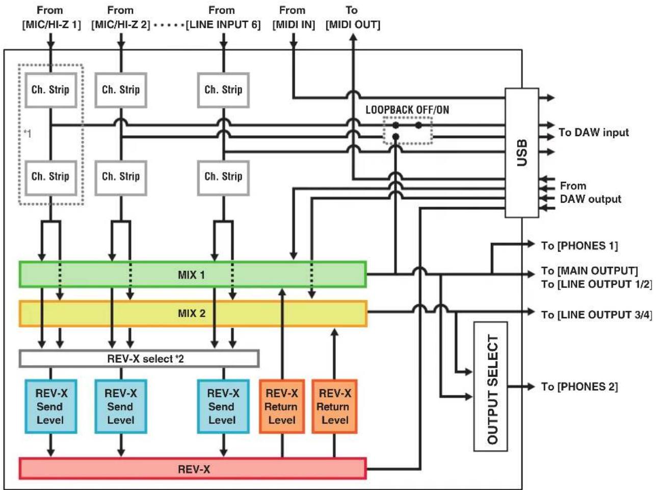
The following chart indicates the signal flow in the device.
NOTE
- The controllers on the device, such as the [INPUT GAIN] knob, [OUTPUT] knob are not included in this chart.
- To configure each parameter, use the "dspMixFx UR44" (page 10) or "Dedicated Windows for Cubase Series" (page 15).
- Please note that you cannot use the built-in Channel Strip (Ch. Strip) and Guitar Amp Classics when the sample rate is set to 176.4 kHz or 192 kHz.
flowchart
graph TD
    A["From [MIC/HI-Z 1"]] --> B["Ch. Strip"]
    C["From [MIC/HI-Z 2"]] --> D["Ch. Strip"]
    E["From [LINE INPUT 6"]] --> F["Ch. Strip"]
    G["From [MIDI IN"]] --> H["Ch. Strip"]
    I["To [MIDI OUT"]] --> J["USB"]
    B --> K["MIX 1"]
    D --> K
    F --> K
    H --> K
    J --> K
    K --> L["MIX 2"]
    L --> M["REV-X select *2"]
    M --> N["REV-X Send Level"]
    M --> O["REV-X Send Level"]
    M --> P["REV-X Send Level"]
    M --> Q["REV-X Return Level"]
    M --> R["REV-X Return Level"]
    N --> S["REV-X"]
    O --> S
    P --> S
    Q --> S
    R --> S
    S --> T["REV-X"]
    U["LOOPBACK OFF/ON"] --> J
    V["To DAW input"] --> J
    W["From DAW output"] --> J
    X["To [PHONES 1"]] --> Y["OUTPUT SELECT"]
    Z["To [MAIN OUTPUT"] --> Y
    AA["To [LINE OUTPUT 1/2"]] --> Y
    AB["To [LINE OUTPUT 3/4"]] --> Y
    AC["To [PHONES 2"]] --> Y
*1 The following chart indicates an effect insertion location.
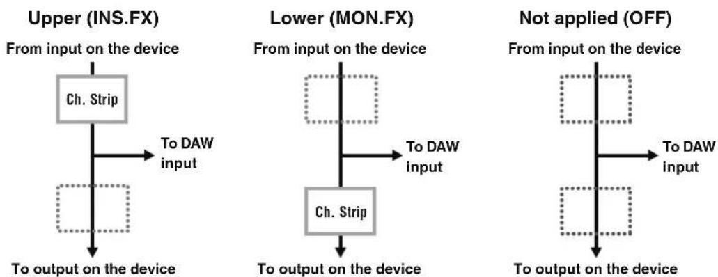
flowchart
graph TD
    A["Upper (INS.FX)<br>From input on the device"] --> B["Ch. Strip"]
    B --> C["To DAW input"]
    D["Lower (MON.FX)<br>From input on the device"] --> E["Ch. Strip"]
    E --> F["To DAW input"]
    G["Not applied (OFF)<br>From input on the device"] --> H["Ch. Strip"]
    H --> I["To DAW input"]
    J["To output on the device"] --> K["Ch. Strip"]
    K --> L["To output on the device"]
*2 You can turn this on for either MIX 1 or MIX 2.
Limitations on the use of effects
The maximum number of Channel Strip and Guitar Amp Classics iterations which can be used simultaneously are limited to the following. For example, Channel Strip can be used for two mono channels, while Guitar Amp Classics can be used for one mono channel simultaneously.
| Channel Strip Guitar Amp Classics | |||
| Mono Stereo Mono Stereo | |||
| 4 | 0 | 0 | - |
| 2 | 1 | 0 | - |
| 2 | 0 | 1 | - |
| 0 | 2 | 0 | - |
| 0 | 1 | 1 | - |
Block Diagrams
UR44 - 44.1/48/88.2/96 kHz
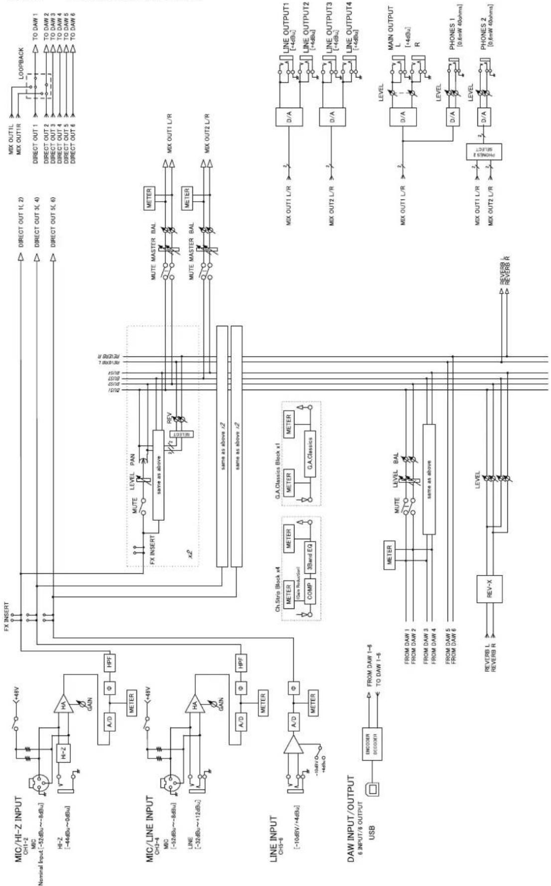
flowchart
graph TD
    A["MIC/HI-Z INPUT"] --> B["Ch1-2"]
    A --> C["Nominal Input (-52dBu~-8dBu)"]
    A --> D["HI-Z (-44dBu~0dBu)"]
    A --> E["HA Gain"]
    E --> F["A/D"]
    F --> G["Φ"]
    G --> H["HPF"]
    H --> I["METER"]
    I --> J["FX INSERT"]
    J --> K["FOCUS"]
    K --> L["DIRECT OUT 1(2)"]
    K --> M["DIRECT OUT 3(4)"]
    K --> N["DIRECT OUT 5(6)"]
    O["MIC/LINE INPUT"] --> P["Ch3-4"]
    O --> Q["NM (-52dBu~-8dBu)"]
    O --> R["LIME (-32dBu~+12dBu)"]
    O --> S["HA Gain"]
    S --> T["A/D"]
    T --> U["Φ"]
    U --> V["HPF"]
    V --> W["METER"]
    W --> X["FX INSERT"]
    X --> Y["MUTE LEVEL PAN"]
    Y --> Z["same as above"]
    Z --> AA["REV"]
    AA --> AB["MUTE MASTER BAL"]
    AB --> AC["METER"]
    AC --> AD["MIX OUT1 L/R"]
    AC --> AE["MIX OUT2 L/R"]
    AF["LINE INPUT CHS-6"] --> AG["-10dBV/+4dBu"]
    AG --> AH["Line INPUT CHS-6"]
    AH --> AI["Line INPUT CHS-6"]
    AJ["DAW INPUT/OUTPUT USB"] --> AK["ENCODER DECOcker"]
    AK --> AL["FROM DAW 1-6 TO DAW 1-6"]
    AL --> AM["FROM DAW 1 FROM DAW 2"]
    AL --> AN["FROM DAW 3 FROM DAW 4"]
    AL --> AO["FROM DAW 5 FROM DAW 6"]
    AP["REV-BL REVERB R"] --> AQ["REV-X"]
    AQ --> AR["LEVEL"]
    AR --> AS["REVERB L REVERB R"]

    subgraph Channel Controls
        B
        P
        S
        W
        X
        Y
        Z
        AA
        AB
        AC
        AE
        AF
        AG
        AH
        AI
        AJ
        AK
        AL
        AM
        AN
        AO
        AP
    end

    subgraph Line Outputs
        X
        Y
        Z
        AA
        AB
        AC
        AE
        AF
        AG
        AH
        AI
        AJ
        AK
        AL
        AM
        AN
        AO
        AP
    end

    subgraph Outputs
        X
        Y
        Z
        AA
        AB
        AC
        AE
        AF
        AG
        AH
        AI
        AJ
        AK
        AL
        AM
        AN
        AO
        AP
    end

    subgraph Outputs
        X
        Y
        Z
        AA
        AB
        AC
        AE
        AF
        AG
        AH
        AI
        AJ)
    end

    subgraph Outputs
        X
        Y
        Z
        AA
        AB
        AC
        AE
        AF
        AG
        AH
        AI
        AJ)
    end

    subgraph Outputs
        X
        Y
        Z
        AA
        AB
        AC
        AE
        AF
        AG
        AH
        AI
        AJ)
    end

    subgraph Outputs
        X
    end

    subgraph Outputs
        Y
    end

    subgraph Outputs
        Z
    end

    subgraph Outputs
        AA
    end

    subgraph Outputs
        AB
    end

    subgraph Outputs
        AC
    end

    subgraph Outputs
        AF
    end

    subgraph Outputs
        AG
    end

    subgraph Outputs
        AH
    end

    subgraph Outputs
        AI
    end

    subgraph Outputs
        AJ
    end

    subgraph Outputs
        AK
    end

    subgraph Outputs
        AL
    end

    subgraph Outputs
        AM
    end

    subgraph Outputs
        AN
    end

    subgraph Outputs
        AO
    end

    subgraph Outputs
        AP1["CHS-6"] --> AQ["-10dBV/+4dBu"]
    end

    subgraph Outputs
        AQ --> AR["-10dBV/+4dBu"]

    subgraph Outputs:
        AS["CHS-6"] --> AT["-10dBV/+4dBu"]

    subgraph Outputs:
        AU["CHS-6"] --> AV["-10dBV/+4dBu"]

    subgraph Outputs:
        AW["CHS-6"] --> AX["-10dBV/+4dBu"]

    subgraph Outputs:
        AY["CHS-6"] --> AZ["-10dBV/+4dBu"]

    subgraph Outputs:
        BA["CHS-6"] --> BB["-10dBV/+4dBu"]

    subgraph Outputs:
        BC["CHS-6"] --> BD["-10dBV/+4dBu"]

    subgraph Outputs:
        BE["CHS-6"] --> BF["-10dBV/+4dBu"]

    subgraph Outputs:
        BG["CHS-6"] --> BH["-10dBV/+4dBu"]

    subgraph Outputs:
        BI["CHS-6"] --> BJ["-10dBV/+4dBu"]

    subgraph Outputs:
        BK["CHS-6"] --> BL["-10dBV/+4dBu"]

    subgraph Outputs:
        BM["CHS-6"] --> BN["-10dBV/+4dBu"]

    subgraph Outputs:
        BO["CHS-6"] --> BP["-10dBV/+4dBu"]

    subgraph Outputs:
        BQ["CHS-6"] --> BR["-10dBV/+4dBu"]

    subgraph Outputs:
        BS["CHS-6"] --> BT["-10dBV/+4dBu"]

    subgraph Outputs:
        BU["CHS-6"] --> BV["-10dBV/+4dBu"]

    subgraph Outputs:
        BW["CHS-6"] --> BX["-10dBV/+4dBu"]

    subgraph Outputs:
        BY["CHS-6"] --> BZ["-10dBV/+4dBu"]

    subgraph Outputs:
        BQG["CHS-6"] --> CC["-10dBV/+4dBu"]

    subgraph Outputs:
        DB["CHS-6"] --> DC["-10dBV/+4dBu"]

    subgraph Outputs:
        DV["CHS-6"] --> DW["-10dBV/+4dBu"]

    subgraph Outputs:
        DX["CHS-6"] --> DXG["-10dBV/+4dBu"]

    subgraph Outputs:
        DXG --> DXH["CHS-6"]

    subgraph Outputs:
        DXH --> DXJ["GAS-Classics Block x1"]
            GAGA["GAS-Classics Block x1"]
            GAGB["GAS-Classics Block x1"]
            GAGC["GAS-Classics Block x1"]
            GAGD["GAS-Classics Block x1"]
            GAGE["GAS-Classics Block x1"]
            GAGF["GAS-Classics Block x1"]
            GAGG["GAS-Classics Block x1"]
            GAGH["GAS-Classics Block x1"]
            GAGI["GAS-Classics Block x1"]
            GAGJ["GAS-Classics Block x1"]
            GAGK["GAS-Classics Block x1"]
            GAGL["GAS-Classics Block x1"]
            GAGM["GAS-Classics Block x1"]
            GAGN["GAS-Classics Block x1"]
            GAGO["GAS-Classics Block x1"]
            GAGP["GAS-Classics Block x1"]
            GAGQ["GAS-Classics Block x1"]
            GAGR["GAS-Classics Block x1"]
            GAGS["GAS-Classics Block x1"]
            GAGT["GAS-Classics Block x1"]
            GAGU["GAS-Classics Block x1"]
            GAGW["GAS-Classics Block x1"]
            GAGX["GAS-Classics Block x1"]
            GAGY["GAS-Classics Block x1"]
            GAGZ["GAS-Classics Block x1"]
            GAGXG["GAS-Classics Block x1"]
            GAGYGG["GAS-Classics Block x1"]
            GAGZX["GAS-Classics Block x1"]
            GAGZXG["GAS-Classics Block x1"]
            GAGZXH["GAS-Classics Block x1"]
            GAGZXI["GAS-Classics Block x1"]
            GAGZXJ["GAS-Classics Block x1"]
            GAGZXK["GAS-Classics Block x1"]
            GAGZXL["GAS-Classics Block x1"]
            GAGZXM["GAS-Classics Block x1"]
            GAGZXN["GAS-Classics Block x1"]
            GAGZXO["GAS-Classics Block x1"]
            GAGZXP["GAS-Classics Block x1"]
            GAGZXQ["GAS-Classics Block x1"]
            GAGZXQG["GAS-Classics Block x1"]
            GAGZXQH["GAS-Classics Block x1"]
            GAGZXQI["GAS-Classics Block x1"]
            GAGZXQJ["GAS-Classics Block x1"]
            GAGZXQK["GAS-Classics Block x1"]
            GAGZXQL["GAS-Classics Block x1"]
            GAGZXQM["GAS-Classics Block x1"]
            GAGZXQN["GAS-Classics Block x1"]
            GAGZXQO["GAS-Classics Block x1"]
            GAGZXQP["GAS-Classics Block x1"]
            GAGZXQQ["GAS-Classics Block x1"]
            GAGZXQR["GAS-Classics Block x1"]
            GAGZXQS["GAS-Classics Block x1"]
            GAGZXQU["GAS-Classics Block x1"]
            GAGZXQV["GAS-Classics Block x1"]
            GAGZXQW["GAS-Classics Block x1"]
            GAGZXQX["GAS-Classics Block x1"]
            GAGZXQY["GAS-Classics Block x1"]
            GAGZXQZ["GAS-Classics Block x1"]
            GAGZXQXG["GAS-Classics Block x1"]
            GAGZXQXI["GAS-Classics Block x1"]
            GAGZXQXJ["GAS-Classics Block x1"]
            GAGZXQXK["GAS-Classics Block x1"]
            GAGZXQXL["GAS-Classics Block x1"]
            GAGZXQXM["GAS-Classics Block x1"]
            GAGZXQXN["GAS-Classics Block x1"]
            GAGZXQXO["GAS-Classics Block x1"]
            GAGZXQXP["GAS-Classics Block x1"]
            GAGZXQXQ["GAS-Classics Block x1"]
            GAGZXQXQG["GAS-Classics Block x1"]
            GAGZXQXQI["GAS-Classics Block x1"]
            GAGZXQXQJ["GAS-Classics Block x1"]
            GAGZXQXQK["GAS-Classics Block x1"]
            GAGZXQXQL["GAS-Classics Block x1"]
            GAGZXQXQM["GAS-Classics Block x1"]
            GAGZXQXQN["GAS-Classics Block x1"]
            GAGZXQXQO["GAS-Classics Block x1"]
            GAGZXQXQXG["GAS-Classics Block x1"]
            GAGZXQXQXI["GAS-Classics Block x1"]
            GAGZXQXQXJ["GAS-Classics Block x1"]
            GAGZXQXQXK["GAS-Classics Block x1"]
            GAGZXQXQXL["GAS-Classics Block x1"]
            GAGZXQXQXM["GAS-Classics Block x1"]
            GAGZXQXQXN["GAS-Classics Block x1"]
            GAGZXQXQXO["GAS-Classics Block x1"]
            GAGZXQXQXP["GAS-Classics Block x1"]
            GAGZXQXQXQ["HOSERS 7 SELECT"] & VENUELE & REVERLE & REVERLE & REVERLE & REVERLE & REVERLE & REVERLE & REVERLE & REVERLE & REVERLE & REVERLE & REVERLE & REVERLE & REVERLE & REVERLE & REVERLE & REVERLE & REVERLE & REVERLE & REVERLE & REVERLE & REVERLE & REVERLE & REVERLE & REVERLE & REVERLE & REVEBL & REVERBL & REVERBL & REVERBL & REVERBL & REVERBL & REVERBL & REVERBL & REVERBL & REVERBL & REVERBL & REVERBL & REVERBL & REVERBL & REVERBL & REVERBL & REVERBL & REVERBL & REVERBL & REVERBL & REVERBL & REVERBL & REVERBL & REVERBL & REVERBL & REVERBL & REVEBL & REVEBL & REVEBL & REVEBL & REVEBL & REVEBL & REVEBL & REVEBL & REVEBL & REVEBL & REVEBL & REVEBL & REVEBL & REVEBL & REVEBL & REVEBL & REVEBL & REVEBL & REVEBL & REVEBL & REVEBL & REVEBL & REVEBL & REVEBL & REVEBL & REFE BL & REFE BL & REFE BL & REFE BL & REFE BL & REFE BL & REFE BL & REFE BL & REFE BL & REFE BL & REFE BL & REFE BL & REFE BL & REFE BL & REFE BL & REFE BL & REFE BL & REFE BL & REFE BL & REFE BL & REFE BL & REFE BL & REFE BL & REFE BL & REFE BL & REFE SL |
UR44 - 176.4/192 kHz
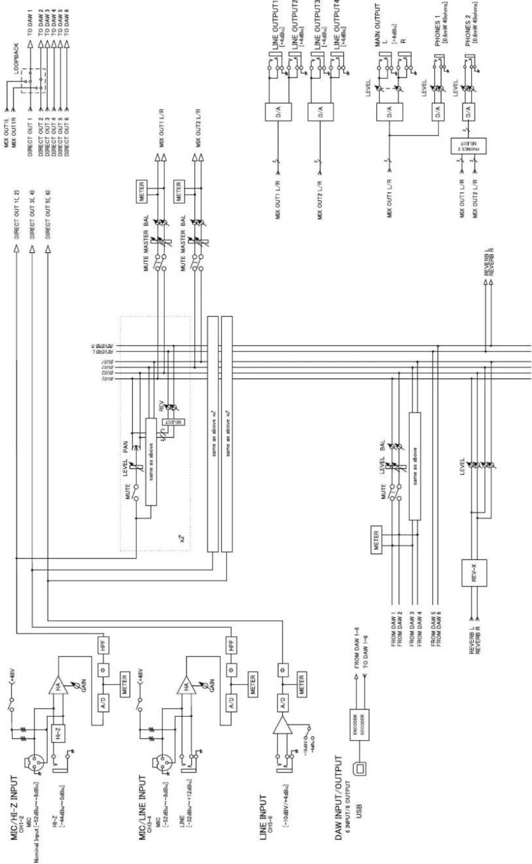
flowchart
Electrical signal processing flowchart for DAC system, showing input channels (MIC, LINE, RAW) and output stages (DAW, DAC, OUTPUT) with channel state transitions and measurement points.UR44 - 44.1/48/88.2/96 kHz - iPad
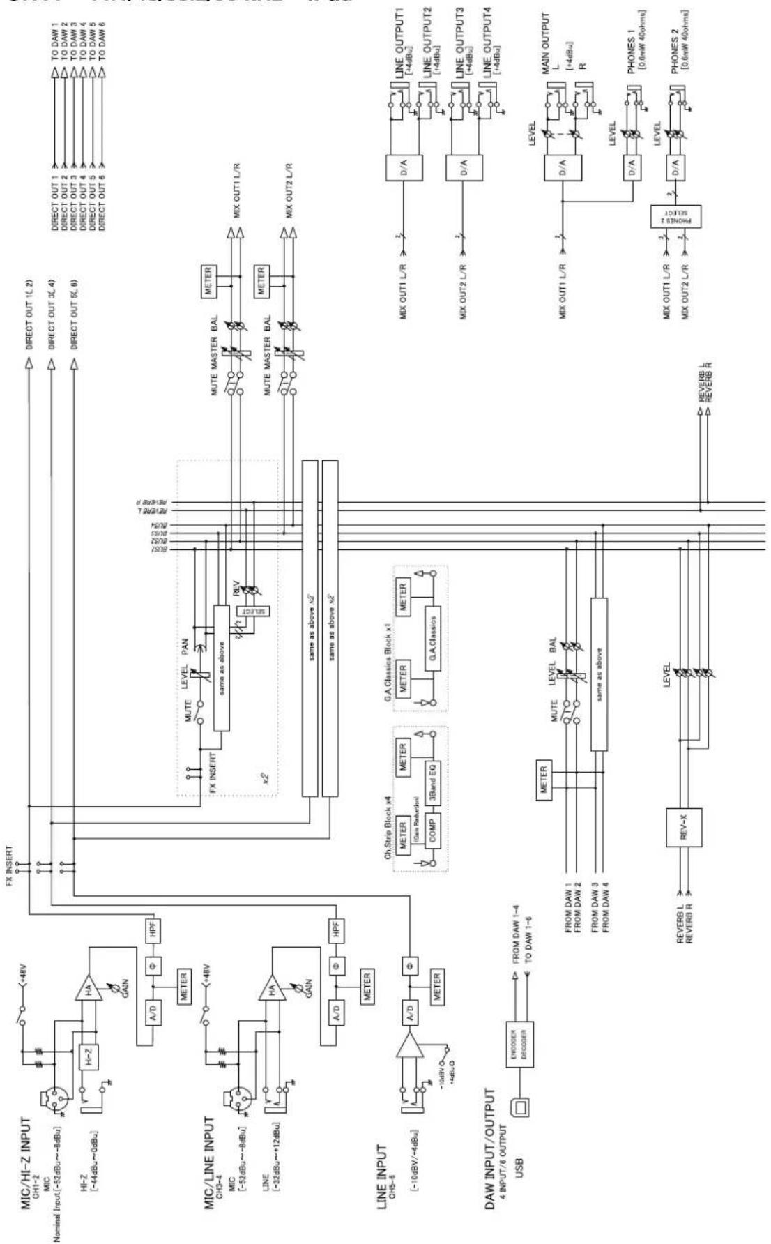
flowchart
graph TD
    subgraph Input
        A["MIC/HI-Z INPUT CH1-2"] --> B["HI-Z -4dBu"]
        C["Nominal Input [-52dBu~-8dBu"]] --> D["HI-Z"]
        E["HI-Z [-4dBu~0dBu"]] --> F["A/D"]
        F --> G["Φ"]
        G --> H["HPF"]
        I["METER"] --> J["FX INSERT"]
        K["LINE INPUT CHS-6"] --> L["Line -32dBu~+12dBu"]
        M["DAW INPUT/OUTPUT USB"] --> N["ENCODER DECODER"]
        O["FROM DAW 1-4 TO DAW 1-6"] --> P["FROM DAW 1"]
        Q["FROM DAW 2"] --> R["FROM DAW 3"]
        S["FROM DAW 4"] --> T["FROM DAW 4"]
        U["REV-X"] --> V["LEVEL"]
    end

    subgraph Channel
        W["FX INSERT"] --> X["same as above"]
        X --> Y["MUTE LEVEL PAN"]
        X --> Z["REV"]
        X --> AA["MUTE MASTER BAL"]
        X --> AB["METER"]
        X --> AC["MUTE MASTER BAL"]
        X --> AD["METER"]
        AE["Same as above x2"] --> AF["same as above x2"]
        AF --> AG["Ch.Strip Block x4"]
        AF --> AH["G.A.Classics Block x1"]
        AF --> AI["G.A.Classics"]
    end

    subgraph Output
        AJ["MIX OUTPUT1 L/R"] --> AK["D/A"]
        AL["LINE OUTPUT1 +4dBu"] --> AM["D/A"]
        AN["MIX OUTPUT2 L/R"] --> AO["D/A"]
        AP["LINE OUTPUT2 +4dBu"] --> AQ["D/A"]
        AR["LINE OUTPUT3 +4dBu"] --> AS["D/A"]
        AT["LINE OUTPUT4 +4dBu"] --> AU["D/A"]
        AV["MIX OUT1 L/R"] --> AW["D/A"]
        AX["MIX OUT2 L/R"] --> AY["D/A"]
        AZ["MIX OUT1 L/R"] --> BA["D/A"]
        BB["MIX OUT2 L/R"] --> BC["D/A"]
        BD["MAIN OUTPUT L +4dBu"] --> BE["D/A"]
        BF["PHONES 1 [0.6mW 40ohms"]] --> BG["D/A"]
        BH["PHONES 2 [0.6mW 40ohms"]] --> BI["D/A"]
    end

    J --> AK
    AK --> AL
    AL --> AM
    AM --> AN
    AN --> AO
    AO --> AP
    AP --> AQ
    AQ --> AR
    AR --> AS
    AS --> AT
    AT --> AU
    AU --> AV
    AV --> BI
    BI --> BJ
    BJ --> BK
    BK --> BL
    BL --> BM
    BM --> BN
    BN --> BO
    BO --> BP
    BP --> BR
    BR --> BS
    BS --> BT
    BT --> BU
    BU --> BV
    BV --> BW
    BW --> BX
    BX --> BY
    BY --> BZ
    BZ --> CA
    CA --> CB
    CB --> CC
    CC --> DC
    DC --> DV
    DV --> DW
    DW --> BXZ
    BXZ --> BXZL
    BXZL --> BXZL1
    BXZL1 --> BXZL2
    BXZL2 --> BXZL3
    BXZL3 --> BXZL4
    BXZL4 --> BXZL5
    BXZL5 --> BXZL6
    BXZL6 --> BXZL7
    BXZL7 --> BXZL8
    BXZL8 --> BXZL9
    BXZL9 --> BXZL10
    BXZL10 --> BXZL11
    BXZL11 --> BXZL12
    BXZL12 --> BXZL13
    BXZL13 --> BXZL14
    BXZL14 --> BXZL15
    BXZL15 --> BXZL16
    BXZL16 --> BXZL17
    BXZL17 --> BXZL18
    BXZL18 --> BXZL19
    BXZL19 --> BXZL20
    BXZL20 --> BXZL21
    BXZL21 --> BXZL22
    BXZL22 --> BXZL23
    BXZL23 --> BXZL24
    BXZL24 --> BXZL25
    BXZL25 --> BXZL26
    BXZL26 --> BXZL27
    BXZL27 --> BXZL28
    BXZL28 --> BXZL29
    BXZL29 --> BXZL30

    subgraph Control
        B
        F
        J
        X
        Y
        Z
        AA
        AB
        AC
        AD
        AE
        AF
        AG
        AH
        AI
        AJ
        AK
        AL
        AM
        AN
        AO
        AP
        AQ
        AR
        AS
        AT
        AU
        AV
        AW
        AX
        AZ
        BA
        BB
        BC
        BD
        BE
        BF
        BG
        BH
        BI
        BJ
        BK
        BL
        BM
        BN
        BO
        BP
        BPB
        BPX
        BPYX
        BPZXXXXXXXXXXXXXXXXXXXXXXXXXXXXXXXXXXXXXXXXXXXXXXXXXXXXXXXXXXXXXXXXXXXXXXXXXXXXXXXXXXXXXXXXXXXXXXXXXXXXXK

    subgraph Control_Output_Output_Output_Output_Output_Output_Output_Output_Output_Output_Output_Output_Output_Output_Output_Output_Output_Output_Output_Output_Output_Output_Output_Output_Output_Output_Output_Output_Output_Output_Output_Output_Output_Output_Output_Output_Output_Output_Output_Output_Output_Output_Output_Output_Output_Output_Output_Output_Output_Output_Current_Output_Output_Output_Output_Output_Output_Output_Output_Output_Output_Output_Output_Output_Output_Output_Output_Output_Output_Output_Output_Output_Output_Output_Output_Output_Output_Output_Output_Output_Output_Output_Output_Output_Output_Output_Output_Output_Output_Output_Output_Output_Output_Output_Output_Output_AU_TOUT_DAW_DAW_DAW_DAW_DAW_DAW_DAW_DAW_DAW_DAW_DAW_DAW_DAW_DAW_DAW_DAW_DAW_DAW_DAW_DAW_DAW_DAW_DAW_DAW_DAW_DAW_DAW_DAW_DAW_DAW_DAW_DAW_DAW_DAW_DAW_DAW_DAW_DAW_DAW_DAW_DAW_DAW_DAW_DAW_DAW_DAW_DAW_DAW_DAW_DAW_DAM_TOUT_DAW_DAW_DAW_DAW_DAW_DAW_DAW_DAW_DAW_DAW_DAW_DAW_DAW_DAW_DAW_DAW_DAW_DAW_DAW_DAW_DAW_DAW_DAW_DAW_DAW_DAW_DAW_DAW_DAW_DAW_DAW_DAW_DAW_DAW_DAW_DAW_DAW_DAW_DAW_DAW_DAW_DAW_DAW_DAW_DAW_DAW_DAW_DAW_DAM_TPO_TOUT_TOWD_WTO_TOWD_WTO_TOWD_WTO_TOWD_WTO_TOWD_WTO_TOWD_WTO_TOWD_WTO_TOWD_WTO_TOWD_WTO_TOWD_WTO_TOWD_WTO_TOWD_WTO_TOWD_WTO_TOWD_WTO_TOWD_WTO_TOWD_WTO_TOWD_WTO_TOWD_WTO_TOWD_WTO_TOWD_WTO_TOWD_WTCO_TOUT_TOWD_WTO_TOWD_WTO_TOWD_WTO_TOWD_WTO_TOWD_WTO_TOWD_WTO_TOWD_WTO_TOWD_WTO_TOWD_WTO_TOWD_WTO_TOWD_WTO_TOWD_WTO_TOWD_WTO_TOWD_WTO_TOWD_WTO_TOWD_WTO_TOWD_WTO_TOWD_WTO_TOWD_WTO_TOWCOTOTU_TOUT_TOUT_TOUT_TOUT_TOUT_TOUT_TOUT_TOUT_TOUT_TOUT_TOUT_TOUT_TOUT_TOUT_TOUT_TOUT_TOUT_TOUT_TOUT_TOUT_TOUT_TOUT_TOUT_TOUT_TOUT_TOUT_TOUT_TOUT_TOUT_TOUT_TOUT_TOUT_TOUT_TOUT_TOUT_TOUT_TOUT_TOUT_TOUT_TOUT_TOUT_TOUT_TOUT_TOUT_TOUT_TOUT_TOUT_TOUT_TOUT_TOUT_TAVTOM TOWD_WTO TOWD_WTO TOWD_WTO TOWD_WTO TOWD_WTO TOWD_WTO TOWD_WTO TOWD_WTO TOWD_WTO TOWD_WTO TOWD_WTO TOWD_WTO TOWD_WTO TOWD_WTO TOWD_WTO TOWD_WTO TOWD_WTO TOWD_WTO TOWD_WTO TOWD_WTO TOWD_WTOP TOWTOM TOWTOM TOWTOM TOWTOM TOWTOM TOWTOM TOWTOM TOWTOM TOWTOM TOWTOM TOWTOM TOWTOM TOWTOM TOWTOM TOWTOM TOWTOM TOWTOM TOWTOM TOWTOM TOWTOM TOWTOM TOWTOM TOWTOM TOWTOM TOWTOM TOWTUM TOWTOM TOWTOM TOWTOM TOWTOM TOWTOM TOWTOM TOWTOM TOWTOM TOWTOM TOWTOM TOWTOM TOWTOM TOWTOM TOWTOM TOWTOM TOWTOM TOWTOM TOWTOM TOWTOM TOWTOM TOWTOM TOWTOM TLOWTOM TLOWTOM TLOWTOM TLOWTOM TLOWTOM TLOWTOM TLOWTOM TLOWTOM TLOWTOM TLOWTOM TLOWTOM TLOWTOM TLOWTOM TLOWTOM TLOWTOM TLOWTOM TLOWTOM TLOWTOM TLOWTOM TLOWTOM TLOWTOM TLOWTOM TLOWTOM TLOWTOM TLOWTOM THOWATM TO OUT METER METER METER METER METER METER METER METER METER METER METER METER METER METER METER METER METER METER METER METER METER METER METER METER METER METER METER METER METER METER METER METER METER METER METER METER METER METER METER METER METER METER METER METER METER METER METER METER METER METER MTER METER METER METER METER METER METER METER METER METER METER METER METER METER METER METER METER METER METER METER METER METER METER METER METER METER METER METER METER METER METER METER METER METER METER METER METER METER METER METER METER METER METER METER METER METER METER METER METER METER MITER METER METER METER METER METER METER METER METER METER METER METER METER METER METER METER METER METER METER METER METER METER METER METER METER METER METER METER METER METER METER METER METER METER METER METER METER METER METER METER MTER MTAIN TO OUT TO OUT TO OUT TO OUT TO OUT TO OUT TO OUT TO OUT TO OUT TO OUT TO OUT TO OUT TO OUT TO OUT TO OUT TO OUT TO OUT TO OUT TO OUT TO OUT TO OUT TO OUT TO OUT TO OUT TO OUT TO OUT TO OUT TO OUT TO OUT TO OUT TO OUT TO OUT TO OUT TO OUT TO OUT TO OUT TO OUT TO OUT TO OUT TO OUT TO OUT TO OUT TO OUT TO OUT TO OUT TO OUT TO OUT TO OUT TO OUT TO OUT TO OTU_OUT_V_OUT_V_OUT_V_OUT_V_OUT_V_OUT_V_OUT_V_OUT_V_OUT_V_OUT_V_OUT_V_OUT_V_OUT_V_OUT_V_OUT_V_OUT_V_OUT_V_OUT_V_OUT_V_OUT_V_OUT_V_OUT_V_OUT_V_OUT_V_OUT_V_OUT_V_OUT_V_OUT_V_OUT_V_OUT_V_OUT_V_OUT_V_OUT_V_OUT_V_OUT_V_OUT_V_OUT_V_OUT_V_OUT_V_OUT_V_OUT_V_OUT_V_OUT_V_OUT_V_OUT_V_OUT_V_OUT_V_OUT_V_OUT_V_OUT_V_OUT V_OUT_V_OUT_V_OUT_V_OUT_V_OUT_V_OUT_V_OUT_V_OUT_V_OUT_V_OUT_V_OUT_V_OUT_V_OUT_V_OUT_V_OUT_V_OUT_V_OUT_V_OUT_V_OUT_V_OUT_V_OUT_V_OUT_V_OUT_V_OUT_V_OUT_V_OUT_V_OUT_V_OUT_V_OUT_V_OUT_V_OUT_V_OUT_V_OUT V_OUT V_OUT V_OUT V_OUT V_OUT V_OUT V_OUT V_OUT V_OUT V_OUT V_OUT V_OUT V_OUT V_OUT V_OUT V_OUT V_OUT V_OUT V_OUT V_OUT V_OUT V_OUT V_OUT V_OUT V_OUT V_OUT V_OUT V_OUT V_OUT V_OUT V_OUT V_OUT V_OUT V_OUT V_OUT V_OUT V_OUT V_OUT V_OUT V_OUT V_OUT V_OUT V_OUT V_OUT V_OUT V_OUT V_OUT V_OUT V_OUT V_OUTV_OUT V_OUT V_OUT V_OUT V_OUT V_OUT V_OUT V_OUT V_OUT V_OUT V_OUT V_OUT V_OUT V_OUT V_OUT V_OUT V_OUT V_OUT V_OUT V_OUT V_OUT V_OUT V_OUT V_OUT V_OUT V_OUT V_OUT V_OUT V_OUT V_OUT V_OUT V_OUT V_OUT V_OUT V_OUT V_OUT V_OUT V_OUT V_OUT V_OUT V_OUT V_OUT V_OUT V_OUT V_OUT V_OUT V_OUT V_OUT V_OUT V_OUT GNDICER Decoder → FROM DAW 1-4 → FROM DAW 1-6

    subgraph Channel_Positions:
        X["CH Strip Block x4"] & X["GA Classics Block x1"] & X["COMP"] & X["3Band EQ"] & X["LEA Level BAL"] & X["REVERB_L REVERB_R"]

        Y["MONITOR"] & Z["ENOCODER"] & AA["ENOCODER"] & AB["ENOCODER"] & AC["ENOCODER"] & AD["ENOCODER"] & AE["ENOCODER"] & AF["ENOCODER"] & AG["ENOCODER"] & AH["ENOCODER"] & AI["ENOCODER"] & AJ["ENOCODER"] & AK["ENOCODER"] & AL["ENOCODER"] & AM["ENOCODER"] & AN["ENOCODER"] & AO["ENOCODER"] & AP["ENOCODER"] & AQ["ENOCODER"] & AR["ENOCODER"] & AS["ENOCODER"] & AT["ENOCODER"] & AU["ENOCODER"] & AV["ENOCODER"] & AW["ENOCODER"] & AX["ENOCODER"] & AY["ENOCODER"] & AZ["ENOCODER"] & BA["ENOCODER"] & BB["ENOCODER"] & BC["ENOCODER"] & DA["ENOCODER"] & DB["ENOCODER"] & BE["ENOCODER"] & BF["ENOCODER"] & BG["ENOCODER"] & BH["ENOCODER"] & BI["ENOCODER"] & BJ["ENOCODER"] & BK["ENOCODER"] & BL["ENOCODER"] & BM["ENOCODER"] & BN["ENOCODER"] & BO["ENOCODER"] & BP["ENOCODER"] & BQ["ENOCODER"] & BR["ENOCODER"] & BS["ENOCODER"] & BT["ENOCODER"] & BU["ENOCODER"] & BV["ENOCODER"] & BW["ENOCODER"] & BX["ENOCODER"] & BY["ENOCODER"] & BZ["ENOCODER"] & CA["ENOCODER"] & CB["ENOCODER"] & CK["ENOCODER"] & CL["ENOCODER"] & CD["ENOCODER"] & CE["ENOCODER"] & CF["ENOCODER"] & CG["ENOCODER"] & DH["ENOCODER"] & DI["ENOCODER"] & DJ["ENOCODER"] & DK["ENOCODER"] & DL["ENOCODER"] & DY["ENOCODER"] & DYV [INJ/TINJ/TINJ/TINJ/TINJ/TINJ/TINJ/TINJ/TINJ/TINJ/TINJ/TINJ/TINJ/TINJ/TINJ/TINJ/TINJ/TINJ/TINJ/TINJ/TINJ/TINJ/TINJ/TINJ/TINJ/TINJ/TINJ/TINJ/TINJ/TINJ/TINJ/TINJ/TINJ/TINJ/TITU_SOTU_SOTU_SOTU_SOTU_SOTU_SOTU_SOTU_SOTU_SOTU_SOTU_SOTU_SOTU_SOTU_SOTU_SOTU_SOTU_SOTU_SOTU_SOTU_SOTU_SOTU_SOTU_SOTU_SOTU_SOTU_SOTU_SOTU_SOTU_SOTU_SOTU_SOTU_SOTU_SOTU_SOT U SOT U SOT U SOT U SOT U SOT U SOT U SOT U SOT U SOT U SOT U SOT U SOT U SOT U SOT U SOT U SOT U SOT U SOT U SOT U SOT U SOT U SOT U SOT U SOT U SOT U SOT U SOT U SOT U SOT U SOT U SOT U SOT U SOT U SGT U SGT U SGT U SGT U SGT U SGT U SGT U SGT U SGT U SGT U SGT U SGT U SGT U SGT U SGT U SGT U SGT U SGT U SGT U SGT U SGT U SGT U SGT U SGT U SGT U SGT U SGT U SGT U SGT U SGT U SGT U SGT U SGT U SGT
UR44 - 176.4/192 kHz - iPad
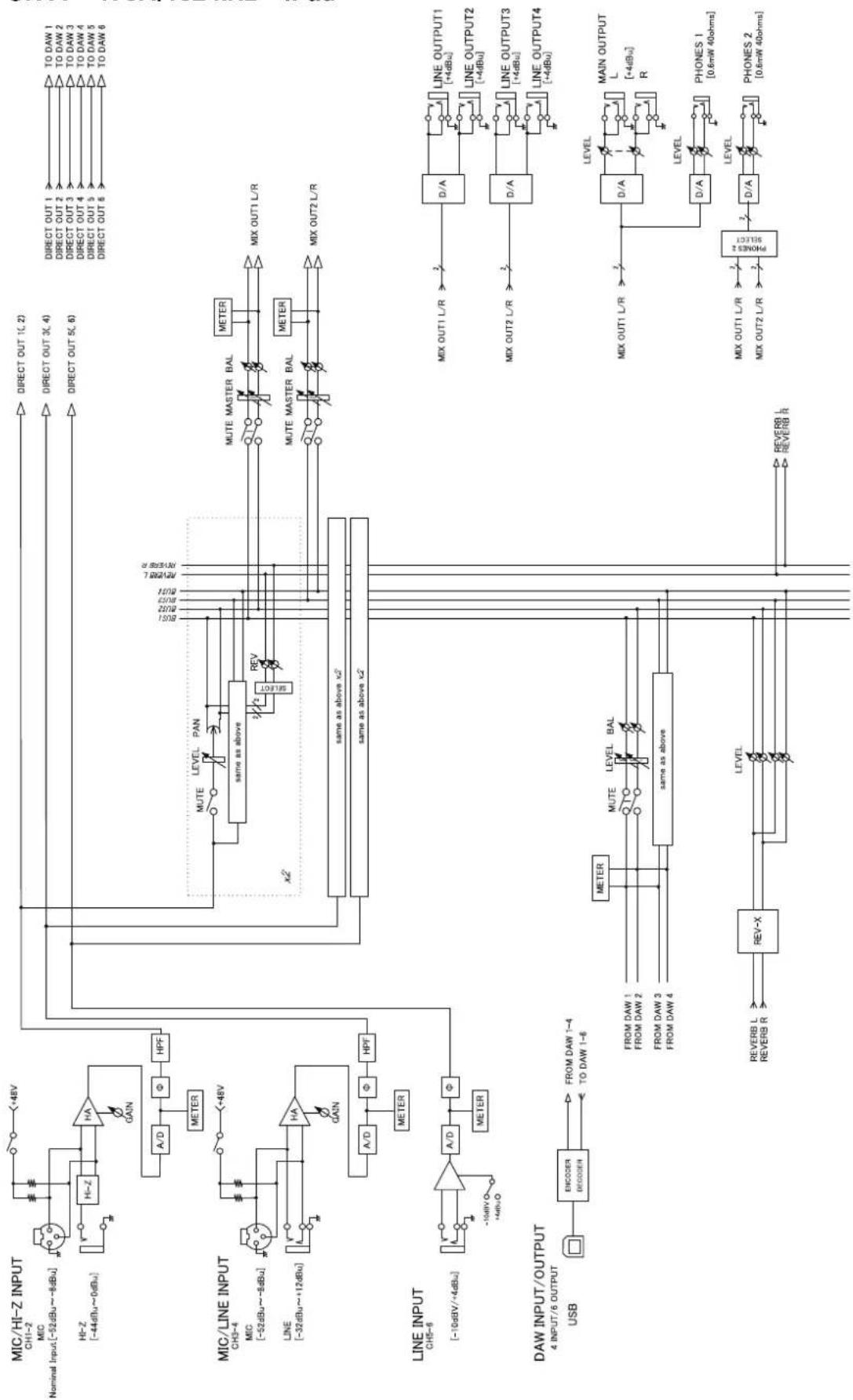
flowchart
graph TD
    subgraph CH1-2
        A["HI-Z 10dBu~8dBu"] --> B["HI-Z 10dBu"]
        B --> C["A/D"]
        C --> D["Φ"]
        D --> E["HPF"]
        E --> F["METER"]
    end

    subgraph CH3-4
        G["HI-Z 10dBu~8dBu"] --> H["HI-Z 10dBu"]
        H --> I["A/D"]
        I --> J["Φ"]
        J --> K["HPF"]
        K --> L["METER"]
    end

    subgraph CH5-6
        M["HI-Z 10dBu~8dBu"] --> N["HI-Z 10dBu"]
        N --> O["A/D"]
        O --> P["Φ"]
        P --> Q["HPF"]
        Q --> R["METER"]
    end

    subgraph OUTPUT
        S["USB ENCODER DECODER"] --> T["FROM DAW 1-4 TO DAW 1-6"]
        T --> U["METER"]
        U --> V["FROM DAW 1"]
        U --> W["FROM DAW 2"]
        U --> X["FROM DAW 3"]
        U --> Y["FROM DAW 4"]
        Z["REV-X"] --> AA["LEVEL"]
        AA --> AB["REVERB L"]
        AA --> AC["REVERB R"]
    end

    subgraph OUTPUT
        AD["MUTE LEVEL PAN"] --> AE["same as above"]
        AE --> AF["REV"]
        AF --> AG["MUTE MASTER BAL"]
        AG --> AH["METER"]
        AH --> AI["MIX OUT1 L/R"]
        AH --> AJ["MUTE MASTER BAL"]
        AJ --> AK["METER"]
        AK --> AL["MIX OUT2 L/R"]

    subgraph OUTPUT
        AM["MIX OUT1 L/R"] --> AN["D/A"]
        AN --> AO["LINE OUTPUT1 +4dBu"]
        AN --> AP["LINE OUTPUT2 +4dBu"]
        AN --> AQ["LINE OUTPUT3 +4dBu"]
        AN --> AR["LINE OUTPUT4 +4dBu"]

    subgraph OUTPUT
        AS["D/A"] --> AT["D/A"]
        AT --> AU["LEVEL"]
        AU --> AV["MAIN OUTPUT L +4dBu"]
        AU --> AW["R"]
        AS --> AX["D/A"]
        AX --> AY["LEVEL"]
        AY --> AZ["PHONES 1 [0.6mW 40ohms"]]
        AS --> BA["D/A"]
        BA --> BB["LEVEL"]
        BB --> BC["PHONES 2 [0.6mW 40ohms"]]
    end

    CH1-2 --> CH1-2
    CH3-4 --> CH3-4
    CH5-6 --> CH5-6

    style CH1-2 fill:#f9f,stroke:#333
    style CH3-4 fill:#f9f,stroke:#333
    style CH5-6 fill:#f9f,stroke:#333
Steinberg Web Site http://www.steinberg.net/
C.S.G., PA Development Division © 2013-2014 Yamaha Corporation
403MW-C0