Apollo x8p - Hi-Fi Universal Audio - Free user manual and instructions
Find the device manual for free Apollo x8p Universal Audio in PDF.


| Product Type | Thunderbolt 3 Audio Interface |
| Brand | Universal Audio |
| Model | Apollo x8p |
| Category | Hi-Fi Audio Interface |
| Dimensions (Chassis Only) | 19 x 1.75 x 12.125 inches (48.26 x 4.45 x 30.80 cm) |
| Depth (Including Protrusions) | 13.5 inches (34.29 cm) |
| Weight (Bare Unit) | 9 lbs (4.08 kg) |
| Shipping Weight | 16.6 lbs (7.52 kg) US |
| Power Supply | External AC-to-DC, Level VI compliant, 100-240V AC, 12V DC 6A, Max 72W |
| Sample Rates | Up to 192 kHz at 24-bit |
| Simultaneous I/O | 18 inputs x 22 outputs |
| Microphone Preamps | 8 Unison-enabled, gain +10 to +65 dB, +48V phantom power |
| Hi-Z Inputs | 2 (front panel), 1M Ohm impedance |
| Line Outputs | 8 via DB25, +24 dBu max |
| Monitor Outputs | 2 balanced TRS, +24 dBu max, 129 dB dynamic range |
| Headphone Outputs | 2 stereo TRS, independent volume controls |
| Digital I/O | ADAT/S/PDIF optical, Word Clock BNC, Thunderbolt 3 (2 ports) |
| DSP Processing | HEXA Core (6 SHARC processors), realtime UAD plug-in support |
| Surround Sound | Up to 7.1 (future software release) |
| Operating Level | Switchable +20 dBu / +24 dBu headroom |
| Included Software | Console application, UAD Meter & Control Panel, Realtime Analog Classics Plus plug-in bundle |
| Construction | 1U rack-mountable, premium build quality |
| Maintenance | Clean with dry cloth; no user-serviceable parts inside |
| Safety | Do not open; use only with supplied power supply; follow all safety instructions |
| Spare Parts & Repairability | Contact Universal Audio technical support for repair service; no user-replaceable parts |
| Warranty | One year limited warranty (parts and labor) |
| General Information | Ideal for professional tracking, overdubbing, and mixing; combines elite conversion with UAD DSP |
Frequently Asked Questions - Apollo x8p Universal Audio
User questions about Apollo x8p Universal Audio
0 question about this device. Answer the ones you know or ask your own.
Ask a new question about this device
Download the instructions for your Hi-Fi in PDF format for free! Find your manual Apollo x8p - Universal Audio and take your electronic device back in hand. On this page are published all the documents necessary for the use of your device. Apollo x8p by Universal Audio.
USER MANUAL Apollo x8p Universal Audio
A Letter from Bill Putnam Jr.
Thank you for choosing this Apollo X Series audio interface to become a part of your studio. We know that any new piece of gear requires an investment of time and money — and our goal is to make your investment pay off.
Universal Audio interfaces like Apollo X exemplify a commitment to craftsmanship that we've forged over the past 60 years — from our original founding in the 1950s by my father, Bill Putnam Sr., to our current mission combining the best of both classic analog and modern digital audio technologies.
Starting with its ultra high-quality I/O and superior A/D and D/A conversion, Apollo X is designed to set new benchmarks in sonic performance. Breakthrough fidelity is just the beginning, however, as Apollo X's onboard HEXA Core processing lets you power the full range of UAD plug-ins, including classic mic preamps, EQs, dynamics processors, reverbs, guitar amps, and much more. With more than 100 acclaimed UAD plug-ins at your fingertips, the sonic choices are limitless.
At UA, we are dedicated to the idea that technology should serve the creative process, inspiring our customers to go further. These are the ideals my father embodied with his classic designs, and we like to think this spirit lives on today in products like Apollo X.
Please feel free to reach out to us via our website www.uaudio.com, and via our social media channels. We look forward to hearing from you, and thank you once again for choosing Universal Audio.
Sincerely,
natural_image
Abstract line drawing with curved strokes and a straight line (no text or symbols)Bill Putnam Jr.
Table Of Contents
Tip: Click any section or page number to jump directly to that page.
A Letter from Bill Putnam Jr. 2
Introduction 4
Apollo x8p Thunderbolt 3 Audio Interface 4
Apollo x8p Features 7
Apollo x8p Documentation Overview 10
Additional Resources 11
Front Panel 12
Rear Panel 24
Digital I/O 25
Analog I/O 28
Interconnections.... 32
Installation Notes 32
Connection Notes 32
Typical Setup 34
Apollo Expanded: Multi-Unit Thunderbolt 3 Wiring.... 35
Software Setup....36
Specifications 37
Block Diagram....41
DB25 Wiring 42
Troubleshooting 43
Notices....44
Warranty 44
Repair Service 44
Maintenance 44
Important Safety Information 45
Technical Support 48
Universal Audio Knowledge Base 48
YouTube Support Channel 48
Universal Audio Community Forums 48
Contact Universal Audio Support....48
Introduction
Apollo x8p Thunderbolt 3 Audio Interface
Elite-Class Audio Conversion with Eight Unison Mic Preamps, HEXA Core Processing, and Surround Sound Monitoring.
Apollo x8p allows music engineers, producers, and project studios to track, overdub, and mix with new world-beating A/D and D/A conversion, HEXA Core UAD plug-in processing, and 7.1 surround sound monitoring ^† — all in a sleek rackmount Thunderbolt 3 audio interface for Mac or PC.
Built upon UA's 60-year heritage of audio craftsmanship, this 18 x 22 interface distinguishes itself with eight Unison™-enabled mic preamps, providing authentic emulations of preamps from Neve, API, Manley, Helios, SSL and more, plus all-new HEXA Core processing — yielding 50% more DSP for running UAD Powered Plug-Ins in real time.
In addition to its elite-class audio conversion, Apollo x8p features selectable operating level for compatibility with professional +24 dBu gear, as well as integrated monitor controller features and a built-in talkback mic.
- Experience elite-class A/D and D/A conversion nearing the widest dynamic range and lowest signal to noise available — at any price
- Track and mix with powerful HEXA Core processing, featuring 6 UAD DSP chips for running more award-winning UAD Powered Plug-Ins in real time
- Record through 8 Unison-enabled mic/line preamps — giving you fully authentic preamp emulations from Neve, API, Manley, SSL, Helios, and more
- Easily connect to pro-level studio gear with switchable +24 / +20 dBu headroom settings
- Work in surround formats up to 7.1, ^ complete with room calibration and fold-down
- Integrated talkback and built-in cues for easy communication and slating takes
^ Surround sound support for Apollo X will be in a future software release. For the latest Apollo X software, visit www.uaudio.com.
*All trademarks are recognized as property of their respective owners. Individual UAD Powered Plug-Ins sold separately.
Elite-Class A/D and D/A Conversion
With thousands of chart-topping songs and hundreds of Grammy-winning albums under their belt, Apollo interfaces are no strangers to tracking stellar-sounding records. To improve on the previous generation Apollo interface's class-leading audio conversion, UA engineers obsessively auditioned the latest A/D and D/A converters — ultimately pairing elite-class 24-bit/192 kHz converters with all-new analog circuitry for an ultra-pristine signal path.
With 129 dB dynamic range and -118 dB THD+N, Apollo x8p's open, natural sound quality rivals any dedicated high-end converter on the market — regardless of price — and is the perfect starting point for applying UAD processing.
Realtime UAD HEXA Core Processing
Apollo x8p features new HEXA Core processing, with six DSP chips and 50% more UAD plug-in processing power than previous Apollos. This lets you run more UAD plug-ins, whether you're tracking in real time with channel strips from Neve, Manley, or API, or running high UAD plug-in counts when mixing in your DAW.
From the tube warmth of Pultec EQs on guitars to the musical tube limiting of the LA-2A on vocals, or the pump of a genuine 1176 or Fairchild 670 tube compressor on drums, your recordings will take a giant leap forward with a rich, three-dimensional analog sound that UAD plug-ins provide.
Unison™ Technology: The Genuine Sound of Neve, API, & Manley Preamps
Perfect for musicians, engineers, producers, and sound designers, Apollo x8p features eight Unison-enabled mic preamps, letting you track through exacting mic preamp emulations from Neve, API, Manley, SSL, Helios, and Universal Audio.* A Universal Audio exclusive, Unison technology nails the tone of these sought-after tube and solid state mic pres — including their input impedance, gain stage “sweet spots,” and the component-level circuit behaviors of the original hardware.
The secret to Unison is its hardware-software integration between Apollo's mic preamps and its onboard Realtime UAD processing.
A Full Suite of Classic Analog Processing Onboard
Of course, a hallmark feature of Apollo is its Realtime UAD Processing, letting you run the full library of UAD plug-ins with near-zero latency. Apollo x8p includes the Realtime Analog Classics Plus plug-in bundle, so you can record and mix with the world's only authentic Teletronix LA-2A, 1176LN, and Fairchild compressors, the Unison-enabled UA 610-B Tube Preamp & EQ, and guitar and bass amps from Marshall and Ampeg.
Access the World of UAD Powered Plug-Ins
Going beyond the included Realtime Analog Classics Plus plug-ins, Apollo x8p lets you tap into the full UAD Powered Plug-In library of name-brand vintage EQs, compressors, reverbs, tape machines, channel strips, and more — at near-zero latency, regardless of your audio software's buffer size and without taxing your computer's CPU.
With exclusive emulations from SSL, Neve, Studer, Manley, API, Ampex, Lexicon, Fender, Helios, and more, ^* it's like having a studio full of iconic analog gear, in a single rack space. And unlike competing interfaces, these award-winning DSP-powered plug-ins are also available in your DAW for mixing.
Surround Sound Monitoring ^ and +24 dBu Operation
With comprehensive surround monitoring support for formats up to 7.1, ^† Apollo x8p is a boon for engineers and producers working on audio and music for video games, television, and the web. In addition, Apollo x8p offers selectable +24 dBu operation for out-of-the-box compatibility with professional mixing consoles and other high-end pro audio equipment.
Build a Networked Studio System Over Thunderbolt
Apollo x8p offers 18 x 22 simultaneous inputs/outputs (8 x 8 analog I/O) and two built-in Thunderbolt 3 ports, which are backwards-compatible with Thunderbolt 1 and 2 Macs via adapter (sold separately). This allows users of any Thunderbolt-equipped Apollo Twin or Apollo rackmount audio interfaces to easily combine up to four Apollos and six total UAD-2 devices — adding fast, high-bandwidth I/O and DSP as your studio grows.
^† Surround sound support for Apollo X will be in a future software release. For the latest Apollo X software, visit www.uaudio.com.
*All trademarks are recognized as property of their respective owners. Individual UAD Powered Plug-Ins sold separately.
Apollo x8p Features
Key Features:
- 18 x 22 Thunderbolt 3 audio interface with class-leading 24-bit/192 KHz conversion
- Realtime UAD HEXA Core Processing for tracking through UAD plug-ins at near-zero latency, regardless of audio buffer size
- 8 Unison-enabled mic preamps with realtime preamp emulations from Neve, API, SSL, Manley, Universal Audio, and more*
- Surround monitor controller up to 7.1 format ^
- Includes “Realtime Analog Classics Plus” UAD plug-in bundle featuring UA 610-B Tube Preamp; Legacy Pultec EQ, LA-2A, and 1176 compressors; Marshall Plexi Classic; Ampeg SVT-VR Classic and more
- UAD HEXA Core processing onboard for additional mixing horsepower for Pro Tools, Logic, Cubase, Ableton, and other major DAWs
- Combine up to 4 Thunderbolt-equipped Apollos and 6 total UAD devices; backward-compatible with Thunderbolt 1 and 2 via optional adapter
- Selectable +24 dBu operation for easy compatibility with professional mixing consoles and tape machines
- Convenient front panel monitoring functions including Alt Speakers, Talkback mic, and assignable Dim or Mono
- Uncompromising UA analog design, superior components, and premium build quality
- Free, industry-leading technical support — on the phone and online — from knowledgeable audio engineers
^ Surround sound support for Apollo X will be in a future software release.
For the latest Apollo X software, visit www.uaudio.com.
*All trademarks are recognized as property of their respective owners. Individual UAD Powered Plug-Ins sold separately.
Audio Interface Features
• Sample rates up to 192 kHz at 24-bit word length
• 18 x 22 simultaneous input/output channels
- Eight channels of analog-to-digital conversion via mic, line, or high-impedance inputs
• 14 channels of digital-to-analog conversion via:
• Eight mono line outputs via DB25 connector
- Stereo monitor outputs
- Two stereo headphone outputs
- Up to 8 channels of digital I/O via optical TOSLINK (switchable):
- Up to eight channels ADAT I/O with S/MUX for high sample rates
- Two channels S/PDIF I/O with sample rate conversion
- Two Thunderbolt 3 ports facilitates daisy-chaining of other Thunderbolt devices
Microphone Preamplifiers
- Eight high-resolution, ultra-transparent, digitally-controlled analog mic preamps
- Unison™ technology for deep integration with UAD preamp, amp, and pedal plug-ins
- Front panel and software control of all preamp parameters
- Switchable low cut filter, 48V phantom power, pad, polarity inversion, and stereo linking
Monitoring
- Stereo monitor outputs (independent of the eight line outputs)
- Front panel control of monitor levels and muting
- Two stereo headphone outputs with independent mix buses
- Independent front panel volume controls for headphone outputs
- Front panel pre-fader metering of monitor bus levels
- S/PDIF outputs can be set to mirror the monitor outputs
- Up to two alternate stereo monitor outputs selectable via front panel or Console software
- Assignable front panel monitor function switch for alternate speakers, dim, & mono
UAD-2 Inside
- HEXA DSP featuring six SHARC ^ processors
• Realtime UAD Processing on all analog and digital inputs - Same features and functionality as other UAD-2 devices when used with DAW
- Can be combined with other UAD-2 devices for increased mixing DSP
- Includes UAD Powered Plug-Ins "Realtime Analog Classics Plus" bundle
- Complete UAD Powered Plug-Ins library is available at the UA online store
Software
Console application:
- Analog-style control interface for realtime monitoring and tracking
- Enables Realtime UAD Processing with UAD plug-ins
- Remote control of Apollo x8p features and functionality
• Virtual I/O for routing DAW tracks through Console
Console Recall plug-in:
- Saves Console configurations inside DAW sessions for easy recall
- Convenient access to Console's monitor controls via DAW plug-in
• VST, RTAS, AAX 64, and Audio Units plug-in formats
UAD Meter & Control Panel application:
- Configures global UAD settings and monitors system usage
Other
- Easy firmware updates
• 1U rack-mountable form factor
• One year warranty includes parts and labor
Apollo x8p Documentation Overview
Documentation for Apollo x8p and UAD Powered Plug-Ins are separated by areas of functionality, as described below. The user manuals are placed on the system drive during software installation, and they can be downloaded at www.uaudio.com.
Apollo Manual Files
Note: All manual files are in PDF format. PDF files require a free PDF reader application such as Acrobat Reader (Mac & Windows) or Preview (Mac).
Apollo Hardware Manuals
Each Apollo model has a unique hardware manual. The Apollo hardware manuals contain complete hardware-related details about one specific Apollo model. Included are detailed descriptions of all hardware features, controls, connectors, and specifications.
Note: Each hardware manual contains the unique Apollo model in the file name.
Apollo Software Manual
The Apollo Software Manual is the companion guide to the Apollo hardware manuals. It contains detailed information about how to configure and control all Apollo software features using the Console application, Console Settings window, and Console Recall plug-in. Refer to the Apollo Software Manual to learn how to operate the software tools and integrate Apollo's functionality into the DAW environment.
Note: Each Apollo connection protocol (Thunderbolt, FireWire, USB) has a unique software manual.
UAD System Manual
The UAD System Manual is the complete operation manual for Apollo's UAD-2 functionality and applies to the entire UAD-2 product family. It contains detailed information about installing and configuring UAD devices, the UAD Meter & Control Panel application, buying optional plug-ins at the UA online store, and more. It includes everything about UAD except Apollo-specific information and individual UAD plug-in descriptions.
UAD Plug-Ins Manual
The features and functionality of all individual UAD Powered Plug-Ins is detailed in the UAD Plug-Ins Manual. Refer to this document to learn about the operation, controls, and user interface of each UAD plug-in that is developed by Universal Audio.
Direct Developer Plug-In Manuals
UAD Powered Plug-Ins includes plug-in titles created by our Direct Developer partners. Documentation for these 3rd-party plug-ins are separate files written and provided by the plug-in developers. The file names for these plug-in manuals are the same as the plug-in titles.
Accessing Installed Documentation
Any of these methods can be used to access installed documentation:
- Choose "Documentation" from the Help menu within the Console application
- Click the "Product Manuals" button in the Help panel within the UAD Meter & Control Panel application
- Manuals are also available online at help.uaudio.com
Host DAW Documentation
Each host DAW software application has its own particular methods for configuring and using audio interfaces and plug-ins. Refer to the host DAW's documentation for specific instructions about using audio interface and plug-in features within the DAW.
Additional Resources
For additional resources, or if you need to contact Universal Audio for assistance, see the Technical Support page.
Front Panel
This section describes the features and functionality of all controls and visual elements on the Apollo x8p front panel.
Tip: All front panel functions (except the METER switch, headphone volume knobs, and power switch) can be controlled remotely with the included Console software application. Changes made with the front panel controls are mirrored in the Console application, and vice versa.
text_image
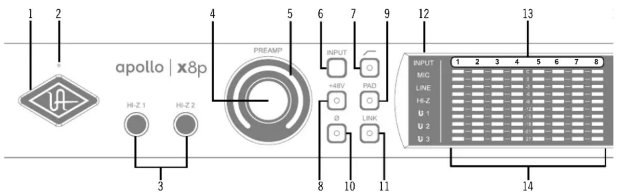
1 2 apollo | x8p HI-Z 1 HI-Z 2 3 4 5 6 7 9 PREAMP INPUT +48V PAD ∅ LINK 8 10 11 12 13 INPUT MIC LINE HI-Z U 1 U 2 U 3 1 2 3 4 5 6 7 8 C 0 -3 -6 -9 -12 -15 -18 -21 -27 14Apollo x8p front panel (left portion)
(1) Power Indicator (UA Logo)
The Universal Audio logo illuminates when the external power supply is properly connected to the AC outlet and the power input on the rear of the unit, and the Power switch (#27) is in the up position.
(2) Talkback Microphone
The built-in talkback mic is located inside of this hole. The talkback function is configured and operated in the included Console software application.
Caution: The talkback microphone is sensitive. To avoid equipment damage, do not insert any object into the mic hole, apply pressurized air into the mic hole, or use a vacuum over the mic hole.
(3) Hi-Z Inputs 1 & 2
The Hi-Z (high impedance) JFET direct inputs are for connecting low-level passive devices such as electric guitar and bass instruments into channels 1 & 2 for A/D conversion. Hi-Z input gain levels are adjusted with the Preamp control for the associated channel.
The Hi-Z inputs have a default input impedance of 1M Ohms. The input impedance may vary when Unison plug-ins are inserted on the channel within the Console application. For details, see the Unison chapter in the Apollo Software Manual.
Important: Connect only 14 " unbalanced TS mono phone plugs to the Hi-Z inputs. TRS stereo plugs cannot be used.
Automatic Input Detection
Hi-Z inputs 1 & 2 use the same A/D converter channels as the corresponding Mic 1 & 2 and Line 1 & 2 inputs. When a device is plugged into a Hi-Z input, the Mic and Line inputs for the channel are overridden, the Mic/Line switch for the channel has no effect, and the stereo link is severed (if active).
Important: To use Mic or Line inputs 1 or 2, its corresponding Hi-Z input must be disconnected.
(4) Preamp Gain & Channel Select Knob
This rotary encoder with integrated switch has three functions:
Rotate - Rotating the knob adjusts the preamp gain for the selected input channel.
Press - Pressing the knob selects which preamp channel (1 - 8) is adjusted by the front panel preamp controls.
Press+Hold – When a Unison plug-in is active in the channel's dedicated Unison insert within the Console application, pressing and holding the knob for two seconds enters/exits Unison Gain Stage Mode.
Each of these three functions above is explained in greater detail below.
Preamp Gain
The preamp gain of analog inputs 1 – 8 is adjusted with the rotary control. The preamp channel to be adjusted is set with the Channel Select (press) function. The input to be adjusted (Mic, Line, or Hi-Z) is determined by the state of the channel's Mic/Line input switch (#6) or Hi-Z input (if connected).
Rotating the knob clockwise increases the preamp gain for the selected channel. The available gain range for the preamp channels is 10 dB to 65 dB for the Mic, Line, and Hi-Z inputs.
More than one full revolution of the knob is needed to move through the available range. This feature increases the control resolution for more precise preamp gain adjustments.
Tip: To adjust signal levels for inputs 9 – 18, use the output level controls of devices connected to those inputs.
Line Input Gain Bypass
By default, line inputs 1 – 8 are routed through the channel's preamp so that the line input level can be adjusted with the Gain knob. However, line inputs 1 – 8 can be individually set to completely bypass the channel's preamp circuitry and instead be routed directly to the channel's A/D converter at a fixed reference level.
This feature is set with the LINE INPUT GAIN menus in the Hardware panel within the Console Settings window. See the Apollo Software Manual for details.
Tip: This feature routes the preamp channel's line input signal directly into the A/D converter for the purest path when additional gain is not needed (for example, when connecting external mic preamps to preamp channel line inputs).
When the channel's LINE INPUT GAIN menu is set to BYPASS in Console Settings and the input mode is set to LINE:
- The Preamp Gain Indicator ring (#5) for the channel is solid green.
- When the Preamp Gain knob (#4) is rotated, the ring flashes to indicate that no gain adjustment is occurring.
- If a Unison plug-in is in the channel's dedicated Unison insert in Console, the Unison plug-in is bypassed.
Channel Select
Pressing the PREAMP knob changes the currently selected preamp channel, which determines which input (1 - 8) is adjusted by the front panel preamp controls. A preamp channel is selected for adjustment when its Channel Select Indicator (#13) is illuminated.
Each time the knob is pressed, the selected preamp channel increments to the next preamp channel. If stereo linking is active, the stereo pairs are selected.
Gain Stage Mode
Using Gain Stage Mode, up to three gain parameters within Unison UAD plug-ins can be remotely controlled with the front panel PREAMP knob.
Gain Stage Mode is activated by pressing and holding the PREAMP knob for two seconds when a Unison plug-in is active in the channel's dedicated Unison insert within the Console application. When Gain Stage Mode is active, pressing and holding the knob for two seconds deactivates Gain Stage Mode.
Gain Stage Mode is active when the Channel Select Indicator (#13) for the currently selected channel is flashing. In this state, pressing the PREAMP knob cycles through the available gain parameters within the Unison plug-in so each gain stage in the plug-in can be adjusted with the front panel PREAMP knob. The gain stage being controlled is shown by the front panel Unison Indicators (#12).
Note: For complete details about Gain Stage Mode, see the Unison chapter within the Apollo Software Manual.
(5) Preamp Gain Level & State Indicator
Preamp Gain Level Indicator
The amount of preamp gain for the currently selected channel is indicated by the illuminated ring surrounding the PREAMP knob.
The ring indicates relative gain levels and is not calibrated to indicate any specific dB value. However, precise numerical dB gain values for the preamps are displayed within the Console application.
Note: If the ring is at maximum and flashes when the PREAMP knob is rotated, the channel's LINE input is selected and LINE INPUT GAIN is set to BYPASS. See Line Input Gain Bypass for additional details.
Preamp State Indicator
In addition to the channel's relative preamp gain, the ring around the knob also indicates the current state of the preamp channel:
Unlit – The preamp gain is set to its minimum value (rotate the PREAMP knob clockwise increase gain).
Green (variable) – The preamp is in default operating mode with variable gain.
Green (fixed at maximum) – LINE is selected for the channel (#6) and LINE INPUT GAIN is set to BYPASS in the Hardware panel within the Console Settings window.
Orange – A UAD Unison plug-in is active in Console's dedicated Unison insert for the channel, and the PREAMP knob adjusts the first gain parameter in the Unison plug-in.
Amber (Channel Select Indicator flashing) – A UAD Unison plug-in is active in Console's dedicated Unison insert for the channel, the channel is in Gain Stage Mode, and the PREAMP knob adjusts the second gain parameter in the Unison plug-in (if available).
Green (channel select indicator flashing) – A UAD Unison plug-in is active in Console's dedicated Unison insert for the channel, the channel is in Gain Stage Mode, and the PREAMP knob adjusts the clean gain parameter in the Unison plug-in.
Note: See the Unison chapter within the Apollo Software Manual for complete details about Unison operation and Gain Stage Mode.
(6 - 11) Preamp Options
This set of six switches control the preamp options for input channels 1 – 8. Press the switches to toggle the setting. The current state of each preamp option is indicated by the LED within each switch. Each switch function is detailed below.
(6) Input (Mic/Line)
This switch switches between the channel's Mic (XLR) and Line ( 1/4" ) inputs on the rear panel combo jacks. This switch has no effect if the channel's Hi-Z input is connected (the Hi-Z input must be disconnected to use the Mic/Line inputs).
Tip: Line inputs 1 – 8 can be set to bypass the preamp circuitry. See Line Input Gain Bypass for additional details.
(7) Low Cut Filter
When enabled, the channel's input signal passes through a low cut (high pass) filter. This 2nd-order coincident-pole filter has a cutoff frequency of 75Hz with a slope of 12dB per octave.
The low cut filter affects the Mic, Line, and Hi-Z inputs. Low Cut is typically used to eliminate rumble and other unwanted low frequencies from the input signal.
(8) Phantom Power (+48V)
When enabled, 48 volts of phantom power is supplied at the channel's rear panel XLR input. Most modern condenser microphones require 48V phantom power to operate. This option can only be activated when the Mic/Line input switch (#6) is set to Mic.
Caution: To avoid potential equipment damage, disable +48V phantom power on the channel before connecting or disconnecting its XLR input.
Depending on the current configuration of the hardware and software, there may be a delay when changing the +48V state to minimize the clicks/pops that are inherent when engaging phantom power. The +48V switch LED will blink rapidly during any delay.
(9) Pad
When enabled, the channel's XLR input signal level is attenuated by 20 dB. Pad does not effect the Line or Hi-Z inputs.
Pad can be used to reduce signal levels when overload distortion is present at low preamp gain levels, such as when particularly sensitive microphones are used on loud instruments, and/or if the A/D converter is clipping.
(10) Polarity
When enabled, the polarity (aka phase) of the input channel's signal is inverted. Polarity affects the Mic, Line, and Hi-Z inputs.
Tip: Polarity inversion can help reduce phase cancellations when more than one microphone is used to record a single source.
(11) Stereo Link
This switch links the preamp controls of adjacent preamp channels together (1+2, 3+4, 5+6, 7+8) to create stereo input pairs. When channels are linked as a stereo pair, any preamp control adjustments will affect both channels of the stereo signal identically.
Note: Only the same type of inputs can be linked (Mic/Mic or Line/Line). The Hi-Z inputs cannot be linked.
(12) INPUT Indicators
These indicators (MIC, LINE, HI-Z, Unison 1/2/3) display which hardware input is currently active for the channel, and whether or not Unison technology is active on the input.
To select MIC or LINE, use the INPUT switch (#6). To select Hi-Z, plug a 14 " mono TS cable into the Hi-Z input. To activate Unison, place a Unison UAD plug-in into the input's dedicated Unison insert in the Console application.
LINE indicator color
The color of the LINE indicator changes to reflect the state of the LINE INPUT GAIN setting, which is configured in the Hardware panel within the Console Settings window.
White – LINE INPUT GAIN is ON. The line input is routed through the preamp so the input gain can be adjusted.
Green – LINE INPUT GAIN is OFF. The preamp circuitry is bypassed and the line input is fixed at a reference level of +4 dBu. Note that Unison cannot be active on a channel when its LINE INPUT GAIN is OFF.
Unison Input Indicators

The U1 indicator is lit when a Unison UAD plug-in is active on the currently selected preamp channel. Unison technology is activated by placing a Unison UAD plug-in into the dedicated Unison insert for the input channel in the Console application.
By default, the U1 indicator is lit when the Unison plug-in is active. When Unison's Gain Stage Mode is active, the three Unison indicators (U1, U2, U3) show which Unison plug-in gain parameter can be remotely controlled with the front panel PREAMP knob.
The U2 and U3 indicators illuminate only when the preamp channel is in Unison Gain Stage Mode. In this state, different Unison plug-in gain stage parameters are selected for adjustment by pressing the PREAMP knob.
Note: See the Unison chapter within the Apollo Software Manual for complete details about Unison operation and Gain Stage Mode.
(13) Channel 1 – 8 Select Indicators
The currently selected preamp channel is indicated by the illuminated numbers above level meters 1 – 8. When a preamp channel (or channels, when stereo linked) is selected, its channel number is illuminated. The currently selected channel increments when the PREAMP knob (#4) is pressed.
(14) Channel Level Meters
The 10-segment LED channel meters display the input or output signal peak levels for analog channels 1 – 8. Input or output metering is selected with the METER switch (#20). The input/output state is shown by the METER indicators (#17).
The dB values of the meter LEDs are indicated between the meters for channels 4 and 5. When digital clipping occurs in input (when 0 dBFS is exceeded), the red “C” (clip) LED illuminates.
Input Channel Meters
When set to INPUT, the channel meters display the signal peak input levels for analog channels 1 – 8 at the input to the A/D converters.
Avoid digital clipping at the channel's A/D converter by reducing the output level of the device connected to the channel's input, and/or in the case of channels 1 – 4, by reducing the preamp gain and/or engaging the Pad (#9) and readjusting gain as needed.
Output Channel Meters
When set to OUTPUT, the channel meters display the signal peak output levels for analog channels 1 – 8 at the output of the D/A converters.
text_image
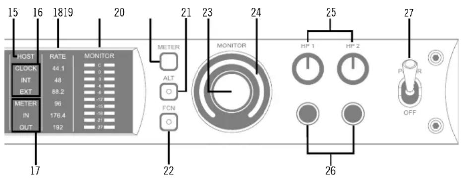
15 16 1819 20 HOST RATE MONITOR CLOCK 44.1 C INT 48 -3 EXT 88.2 -6 METER 96 -12 IN 176.4 -16 OUT 192 -21 21 23 24 METER ALT FCN 22 MONITOR 25 HP 1 HP 2 26 P R OFFApollo x8p front panel (right portion)
(15) HOST Indicator
The HOST indicator displays the status of the Thunderbolt connection to the host computer system. The possible states are:
Lit – The unit is communicating with the host computer and operating normally.
Unlit – The unit is starting up or it is not recognized by the host computer. Verify software installation and Thunderbolt connections.
Red – System error. Please contact UA technical support if the issue persists.
(16) CLOCK Indicators
The clock source and status are displayed with these indicators. Either internal (INT) or external (EXT) is displayed. The clock source is set within the Console application; see the Apollo Software Manual for details.
Internal Clock
When set to internal clock, the INT indicator is illuminated white.
External Clock
Apollo x8p can use an external digital clock source from the Word Clock or optical TOSLINK (S/PDIF and ADAT) inputs. The EXT indicator has two possible states:
White – When set to external clock and a valid clock signal is detected at the specified port, the EXT indicator is illuminated white and Apollo x8p is synchronized to the external clock source.
Red – When set to external clock and a valid clock signal is NOT detected at the specified port, the EXT indicator is illuminated red and the internal clock remains active instead. In this situation, if/when the specified external clock becomes available, Apollo x8p switches back to the external clock, and the EXT indicator is illuminated and white.
Important: When set to use any external clock source, Apollo x8p's sample rate must be manually set to match the sample rate of the external clock.
(17) METER Indicators
These indicators show the current state of the Channel Level Meters (#14). The current state is changed with the METER switch (#20).
IN – When IN is illuminated, the channel meters display analog input signal levels.
OUT – When OUT is illuminated, the channel meters display analog output signals levels.
(18) Sample Rate Indicators
These indicators display the current sample rate setting for A/D and D/A conversion. The sample rate is set within the Console application or the host DAW; see the Apollo Software Manual for details.
(19) Monitor Output Level Meters
The 10-segment LED meters display the signal peak output levels of the rear panel Left & Right Monitor outputs at the output of the D/A converters. These meters are before the Monitor Level control (pre-fader) and reflect the D/A converter levels regardless of the current Monitor Level and Headphone Level knob settings.
The dB values of the monitor meter LEDs are indicated between the left and right channel meters. When digital clipping occurs, the red "C" (clip) LED illuminates.
If the monitor output level clips, reduce the monitor output level within the DAW and/or reduce the output level of individual channels feeding the monitor output bus within the Console application.
(20) Meter Switch
This switch determines whether the Channel Level Meters (#14) are displaying input levels or output signal levels. Pressing the switch toggles the state of the meters and the Meter Indicators (#17).
(21) Monitor ALT Switch
When ALT monitoring is configured in the Hardware panel within the Console Settings window (when ALT COUNT is set to a non-zero value), this switch toggles between the main monitor outputs and the ALT 1 outputs (line outputs 1 & 2).
When the ALT switch is engaged:
- The monitor signals are routed to outputs 1 & 2 instead of the main monitor outputs.
- The orange LED within the switch is illuminated.
- The Monitor Level Indicator (#24) is orange instead of green.
For complete details about how to configure and use the ALT monitoring features, refer to the Apollo Software Manual.
Tip: ALT 2 outputs (line outputs 3 & 4) can be selected with the FCN switch (#22) when configured in Console Settings, or in the MONITOR column within the Console application.
(22) Monitor Function Switch (FCN)
This is an assignable switch that can be configured to control one of three monitoring functions. The function of the switch is configured with the FCN SWITCH ASSIGN menu in the Hardware panel within the Console Settings window. See the Apollo Software Manual for details.
The amber LED within the switch flashes when the monitoring function is active. The function is toggled with the switch is pressed again. The available functions are:
ALT 2 – Selects the ALT 2 monitor speakers. The monitor signals are routed to outputs 3 & 4 instead of the main monitor outputs, and the Monitor Level Indicator ring (#24) is amber instead of green when ALT 2 is active.
MONO – Sums the left and right channels of the stereo monitor mix into a monophonic signal. The Monitor Level Indicator ring (#24) flashes when MONO is active.
DIM – Attenuates the signal level at the monitor outputs by the dB amount set in the CONTROL ROOM strip within the Console application. The Monitor Level Indicator ring (#24) flashes when DIM is active.
TALKBACK – Activates the talkback mic and the DIM function. Talkback is active when the button is lit. Press and release the button quickly to latch talkback ON. To momentarily activate the function and deactivate when the button is released, press for longer than 0.5 seconds. The Monitor Level Indicator ring (#24) flashes when talkback is active.
Note: When more than one Apollo interface is connected in a multi-unit configuration, the FCN switch is operable on the designated monitor unit only.
(23) Monitor Level & Mute Knob
This rotary encoder serves two functions. Rotating the knob adjusts the monitor output level, and pressing the knob mutes the monitor outputs.
Monitor Level
Rotating the knob clockwise increases the signal level at the Left & Right Monitor Outputs on the rear panel. If ALT monitor outputs are configured and active, this knob controls the signal level at the ALT monitoring line outputs.
Monitor Mute
Pressing the Monitor knob toggles the mute state of the signals at the Left & Right Monitor Outputs on the rear panel. If ALT monitoring is configured in the Hardware panel within the Console Settings window (when ALT COUNT is a non-zero value), the ALT monitor outputs are also muted by this control.
When the monitor outs are muted, the Monitor Level Indicator ring (#24) is red.
Note: Monitor Mute does not mute the headphone outputs.
(24) Monitor Level & Monitor State Indicator
Tip: The Monitor Level and Monitor State indications are reflected in the Monitor column within the Console application.
Monitor Output Level Indicator
The relative signal level at the rear panel monitor outputs (and ALT monitor outputs, if configured) is indicated by the illuminated ring surrounding the Monitor Level knob.
This indicator is after the Monitor Level control (post fader). The ring indicates relative gain levels and is not calibrated to indicate any specific dB value.
Tip: Precise numerical dB gain values for the Monitor Level Knob are displayed within the Console application.
Monitor State Indicator
The color of the indicator ring indicates the current state of the monitor outputs:
Green - The main monitor outputs are active with variable level control.
Red - The main monitor outputs (and ALT monitor outputs, if configured) are muted.
Orange – The ALT 1 monitor outputs are active.
Amber - The FCN switch is active and assigned ALT 2.
Flashing – The monitor DIM, MONO, and/or TALKBACK functions are active.
(25) Headphone Level Knobs 1 & 2
These knobs control the volume of Headphone Outputs 1 & 2 on the front panel. Each headphone output has its own volume control.
(26) Headphone Outputs 1 & 2
These 14 " stereo TRS phone jacks are for stereo headphones. Headphone outputs 1 & 2 are individually addressable.
By default, both headphone outputs mirror the monitor outputs. When mirroring the monitor outputs, the headphone outputs are unaffected by Monitor Mute (#23), to facilitate recording/tracking with headphones while the monitor speakers are muted.
Unique mixes can be created for each headphone output using the CUE functions within Console or by assigning mix buses from a DAW to the headphone outputs via the device drivers.
(27) Power Switch
This switch applies power to Apollo x8p. When the unit is powered on, the Universal Audio logo (#1) is illuminated. The external power supply must be properly connected for this switch to function.
Rear Panel
text_image
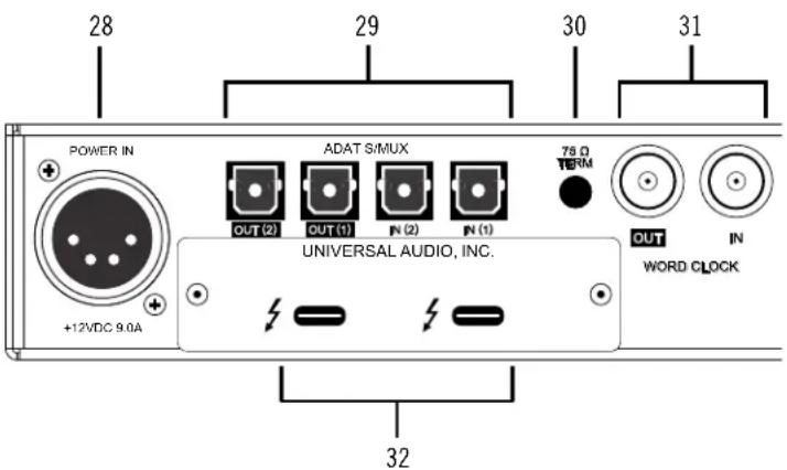
28 29 30 31 POWER IN ADAT S/MUX 75.0 TERM OUT (2) OUT (1) N (2) N (1) UNIVERSAL AUDIO, INC. OUT IN WORD CLOCK +12VDC 9.0A 32Apollo x8p rear panel (digital portion)
(28) Power Input
The included external power supply connects to this 4-pin locking XLR jack. Apollo x8p requires 12 volts DC power and draws a maximum of 72 watts (30 watts typical).
To eliminate risk of circuit damage, connect only the factory-supplied power supply. Use the Power switch on the front panel to power the unit on and off.
Important: Do not disconnect the power supply while Apollo x8p is in use, and confirm the Power switch is in the “off” position before connecting or disconnecting the power supply.
Digital I/O
(29) Optical TOSLINK Ports
The optical TOSLINK ports can use either the ADAT or S/PDIF digital protocols for interconnecting with other audio hardware devices in the digital domain. Two optical inputs and two optical outputs are provided.
By default, the ADAT protocol is active for all optical ports. The protocol used by the optical input and output ports can be individually set in the Hardware panel within the Console Settings window. See the Apollo Software Manual for details.
Each protocol is detailed below.
ADAT S/MUX Optical I/O
When set to ADAT, the optical ports use the ADAT Lightpipe Optical Interface protocol, routing a total of eight channels of digital audio. The channels routed by the ports depend on the current system sample rate.
At sample rates of 44.1 kHz and 48 kHz, the original ADAT protocol is used, and eight audio channels are routed on one ADAT port. At higher sample rates, industry standard S/MUX is used to maintain high-resolution transfers.
Important: To utilize all eight channels with the optical ports at sample rates of 88.2 kHz and above, ADAT ports 1 & 2 must both be connected to the other device, and the other device must also support the ADAT S/MUX protocol.
The following behaviors apply to the ADAT ports:
- At sample rates of 44.1 kHz and 48 kHz, port 1 supports eight channels of I/O. Output 2 mirrors output 1, and input 2 is disabled.
- At sample rates of 88.2 kHz and 96 kHz, up to four channels of audio are routed per port (eight channels total, when both ports are used).
- At sample rates of 176.4 kHz and 192 kHz, up to two channels of audio are routed per port (four channels total, when both ports are used). Only four ADAT channels are supported at 176.4 kHz and 192 kHz.
The ADAT port channel assignments described above are summarized in this table:
| ADAT PORT CHANNEL ROUTING | ||||
| Sample Rate (kHz) | Input Port 1 Input Port 2 Output Port 1 | Output Port 2 | ||
| 44.1 & 48 1 – 8 | Disabled 1 – 8 1 – 8 (mirror of port 1) | |||
| 88.2 & 96 1 – 4 | 5 – 8 1 – 4 5 – 8 | |||
| 176.2 & 192 1 – | 2 3 – 4 1 – 2 3 – 4 | |||
S/PDIF Optical I/O
When set to S/PDIF, the optical ports use the S/PDIF protocol. The S/PDIF optical ports provide two channels of digital I/O with resolutions up to 24-bit at 96 kHz.
S/PDIF Sample Rate Conversion
Sample rate conversion can be performed on the S/PDIF input; this setting is enabled within the S/PDIF channel's input strip in the Console application. When the sample rate of the incoming S/PDIF signal does not match the sample rate specified in the Console application, the S/PDIF signal is converted to match Apollo x8p's sample rate. If Apollo x8p is set to use S/PDIF as the master clock source, sample rate conversion is inactive.
Tip: The S/PDIF output can be configured to mirror the Monitor Outputs (#33), for routing the stereo monitor signal to the stereo S/PDIF input of other devices. This feature is set with the DIGITAL MIRROR menu in the Hardware panel within the Console Settings window.
(30) 75 Ohm Word Clock Termination Switch
This switch provides internal 75-ohm word clock input signal termination when required. Word clock termination is active when the switch is engaged (depressed).
Apollo x8p's termination switch should only be engaged when Apollo x8p is set to sync to external word clock and it is the last device at the receiving end of a word clock cable. For example, if Apollo x8p is the last “slave” unit at the end of a clock chain (when Apollo x8p's word clock OUT port is not used), termination should be active.
(31) Word Clock I/O
Word Clock In
Apollo x8p's internal clock can be synchronized (slaved) to an external master word clock. This is accomplished by setting Apollo x8p's clock source to Word Clock within the Console application, connecting the external word clock's BNC connector to Apollo x8p's word clock input, and setting the external device to transmit word clock. If Apollo x8p is the last device in the clock chain, the Termination switch (#30) should be engaged.
Important: Apollo x8p's sample rate must be manually set to match the incoming clock's sample rate.
Note: Apollo x8p can be synchronized to an external "1x" clock signal only. Superclock, overclocking, and subclocking are not supported.
Word Clock Out
This BNC connector transmits a standard (1x) word clock when Apollo x8p is set to use its internal clock. The clock rate sent by this port matches the current system sample rate, as specified within the Console application.
When Apollo x8p is set to use external word clock as its clock, Apollo x8p is a word clock slave. If the incoming external word clock is within ±0.5% of a supported sample rate (44.1 kHz, 48 kHz, 88.2 kHz, 96 kHz, 176.4 kHz, 192 kHz), Word Clock Out will mirror Word Clock In with a slight phase delay (about 40ns).
Because Apollo x8p's word clock output is not a true mirror of the word clock input, word clock out should not be used to daisy chain the word clock if Apollo x8p is in the middle of the word clock chain. The correct method to connect Apollo x8p in the middle of a word clock chain is to use a T-connector at Apollo x8p's word clock input and leave Apollo x8p's word clock output unconnected (the Termination switch should not be engaged in this scenario)
(32) Thunderbolt 3 Ports
Apollo x8p has two Thunderbolt 3 ports. One port is used to connect Apollo x8p to a Thunderbolt 3 port on the host computer. Thunderbolt 3 peripheral devices may be serially connected (daisy-chained) to the second Thunderbolt 3 port.
When Apollo x8p is properly communicating with the host computer via Thunderbolt, the HOST indicator (#15) illuminates.
Note: Apollo x8p can be used with Thunderbolt 1 and Thunderbolt 2 ports on Apple Mac computers via the Apple Thunderbolt 3 to Thunderbolt 2 Adapter. Connections to Thunderbolt 1 or Thunderbolt 2 ports on Windows PCs are not supported.
Thunderbolt Bus Power
Per the Thunderbolt specification, bus power is supplied to downstream (daisy-chained) Thunderbolt peripheral devices. Apollo x8p must be powered on for the daisy-chained peripheral to receive Thunderbolt bus power.
Analog I/O
text_image
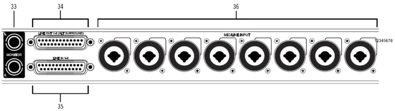
33 34 36 L M MONITOR R LINE OUT LS (ALT SURROUND) LINE IN 1-8 MIO LINE INPUT 12345678 35Apollo x8p rear panel (analog portion)
(33) Left & Right Monitor Outputs
These balanced 14 " TRS phone jacks are line-level analog outputs typically used for connection to a stereo loudspeaker monitoring system. Unbalanced 14 " TS cables can also be used. The Monitor Outputs are DC coupled.
The signal levels and muting at these outputs are controlled with the Monitor Level & Mute knob (#23).
The Monitor Outputs can be configured to use an operating level of +4 dBu (default value) or -10 dBV. This option is set in the Hardware panel within the Console Settings window. See the Apollo Software Manual for details.
The Monitor Outputs are completely independent and separately addressable from the eight Line Outputs (except when ALT monitoring is configured). By default, these outputs are labeled MON L and MON R in Apollo's device drivers. In the DAW, the "1–2" or "L–R" or "Main" outputs are routed to these outputs (these labels vary within each particular DAW).
Tip: The S/PDIF output (#29) can be configured to mirror the Monitor Outputs, for routing the stereo monitor signal to the stereo S/PDIF input of other devices. This feature is set with the DIGITAL MIRROR menu in the Hardware panel within the Console Settings window.
(34) DB25 Line Outputs 1 - 8
The eight line-level analog outputs are accessed via this female DB25 connector. The DB25 jack carries eight balanced line-level channel outputs using standardized Tascam wiring. All Line Outputs are DC coupled.
Note: See DB25 Wiring for connector pinouts.
Line Output Headroom
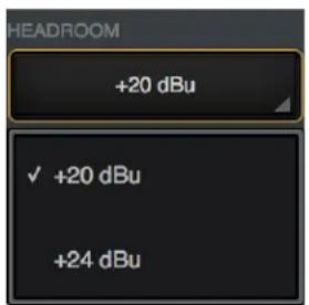
By default, the operating level of the line outputs is +20 dBu. The line outputs and inputs can be globally configured to operate at +24 dBu signal levels with the HEADROOM menu in the Settings>Hardware panel within the Console application.
+24 dBu operation is typically used for interfacing with professional audio equipment such as large format consoles, analog tape machines, and similar devices that require higher signal levels. For additional details about +24 dBu operation, see the Apollo Software Manual.
text_image
HEADROOM +20 dBu ✓ +20 dBu +24 dBuHeadroom menu within Console Settings
Line Output Reference Levels
The Line Outputs can be configured in adjacent pairs to use either -10 dBV or +4 dBu reference levels. This function is configured in the Hardware panel within the Console Settings window. See the Apollo Software Manual for details.
ALT Outputs 1 - 4
Apollo x8p features ALT (alternate) monitoring capabilities. ALT monitoring can be used to control up to two alternate pairs of monitor speakers.
When ALT monitoring is enabled, the output level and muting of line outputs 1 & 2 (ALT 1) and 3 & 4 (ALT 2) are controlled by the Monitor Level & Mute knob (#23). ALT monitoring is enabled in the Hardware panel within the Console Settings window by increasing the ALT COUNT setting to a non-zero value.
Analog Inputs Overview
The analog preamp channel 1 – 8 inputs can be accessed via individual XLR/TRS combo jacks or a single DB25 connector.
Each preamp channel accepts a mic or line input. Mic inputs use the XLR jacks, while line inputs can use the TRS jacks or the DB25 connector. The front panel INPUT switch (#6) is used to select mic or line input for a channel.
Important: To use a 14 " or DB25 line input, the channel's INPUT indicator (#12) must be set to LINE with the INPUT switch (#6) or the channel's MIC/LINE switch within the Console application.
Using the XLR and DB25 inputs facilitates simultaneous connection of mic and line cables to the same input channel, enabling the ability to switch between mic and line inputs without cable re-patching.
Analog Inputs 1 - 8 Gain
XLR Input Gain
The XLR mic inputs 1 – 8 are always routed into the channel's microphone preamplifier. The gain is controlled by the PREAMP knob (#4) when the channel is selected, or the Console application. The mic preamps provide up to 65 dB of gain.
^1/4 " & DB25 Input Gain
Line inputs 1 – 8 can be individually routed into the channel's preamplifier for variable gain adjustments, or the preamp circuitry can be completely bypassed for the purest path directly into the A/D converter. This option is set with the LINE INPUT GAIN menu in the Hardware panel within the Console Settings window. By default, line inputs 1 – 8 are routed into the preamp.
When the preamps are bypassed, line inputs 1 – 8 operate at a fixed reference level of +4 dBu. When routed into the preamps, gain for line inputs 1 – 8 is continuously variable with up to 65 dB of available gain.
Note: For related information, see Line Input Gain Bypass.
Line Inputs Headroom
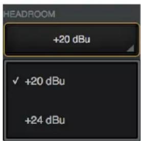
By default, the operating level of the line inputs is +20 dBu. The line inputs and outputs can be globally configured to operate at +24 dBu signal levels with the HEADROOM menu in the Settings>Hardware panel within the Console application.
+24 dBu operation is typically used for interfacing with professional audio equipment such as large format consoles, analog tape machines, and similar devices that require higher signal levels. For additional details about +24 dBu operation, see the Apollo Thunderbolt Software Manual.
text_image
HEADROOM +20 dBu ✓ +20 dBu +24 dBuHeadroom menu within Console Settings
(35) DB25 Line Inputs 1 - 8
The line inputs can be accessed via this female DB25 connector. The single DB25 jack carries eight balanced line-level channel inputs using standardized Tascam wiring.
All DB25 line inputs are DC coupled. For connector pinouts, see DB25 Wiring.
The DB25 line inputs are normalled to the TRS combo jacks. If a DB25 line input is active and a 1/4" cable is plugged into the same channel's combo jack input, the DB25 input is disconnected and the combo jack input is used instead.
Important: To use a DB25 line input, the channel's input must be set to LINE and its 14 " connector (including Hi-Z input) must not be connected.
(36) Mic/Line Combo Inputs 1 - 8
XLR plugs are routed to the channel's microphone input, and TRS plugs are routed to the channel's line input.
Combo jack inputs 1 - 8 are switched between the XLR and Line connections using the front panel Input switch (#6) or the Console application.
XLR Mic Inputs 1 - 8
The combo jack balanced Microphone inputs accept XLR plugs. Pin 2 is wired positive (hot).
+48V phantom power is available for the XLR inputs via the front panel switch (#6) or the Console application.
Caution: To avoid potential equipment damage, disable +48V phantom power on the channel before connecting or disconnecting its XLR input.
14 " Line Inputs 1 - 8
The combo jack line inputs 1 - 8 accept balanced 14 " TRS phone plugs. Unbalanced 14 " TS plugs can also be used. All 14 " Combo inputs are DC coupled.
Interconnections
Installation Notes
- Apollo X may get hot during normal operation if it doesn't receive adequate airflow circulation around its chassis vents. For optimum results when mounting Apollo X in a rack, leaving at least one empty rack space above the unit to allow adequate airflow for cooling is strongly recommended.
- If Apollo X is installed near other heat generating equipment, external cooling (such as a fan) may be needed to keep the ambient temperature below 104°F (40°C).
-
As with any sound system, the following steps are recommended to avoid audio spikes in your speakers and headphones:
-
Apply power to the speakers last, after all other devices (including Apollo x8p) are powered on.
- Turn off the speakers first, before all other devices (including Apollo x8p) are powered off.
- Remove headphones from ears before powering Apollo x8p on or off.
Connection Notes
Thunderbolt
- Apollo X must be connected via a Thunderbolt 3 cable (not included) to computers that have Thunderbolt 3 ports.*
- Connect only one Thunderbolt 3 cable between Apollo X and the host computer. Thunderbolt is a bidirectional protocol.
- Apollo X cannot be bus powered via Thunderbolt. The included external power supply must be used.
- Thunderbolt bus power is supplied to downstream (daisy-chained) peripheral devices. Apollo X must be powered on for the daisy-chained peripheral to receive Thunderbolt bus power.
*Note: With Mac computers only, Apollo X can be connected to Thunderbolt 1 and Thunderbolt 2 computer ports via the Apple Thunderbolt 3 to Thunderbolt 2 adapter. Visit help.uaudio.com for details.
Apollo Expanded
- When more I/O and/or DSP is needed, up to four Apollo interfaces and six UAD devices total can be cascaded together via Thunderbolt in a multiple-unit configuration. For complete details about multi-unit cascading, refer to the Apollo Thunderbolt Software Manual.
About Thunderbolt 3 Ports and Cables
Important: Although Thunderbolt 3 always uses USB-C connectors, not all USB-C ports are Thunderbolt 3 ports. Similarly, not all USB-C cables are Thunderbolt 3 cables. Always connect Apollo x8p to a Thunderbolt 3 port with a Thunderbolt 3 cable.
USB-C is not Thunderbolt 3
Thunderbolt 3 uses USB-C connections to transfer data and power. However, USB-C is simply a connector type; it doesn't determine the type of data used by the connector. For example, USB-C connections can be used for Thunderbolt 3, USB 3.1, and other data protocols, so USB-C connections are not always interchangeable.
Does your USB-C connector support Thunderbolt 3?
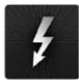
To determine if a USB-C port or cable connector supports Thunderbolt 3, look for the Thunderbolt icon. The Thunderbolt icon on a USB-C port or cable means the connector supports Thunderbolt 3. Alternately, confirm Thunderbolt 3 compatibility with the device and/or cable manufacturer.

natural_image
Close-up of a black cable with a lightning bolt symbol on its side (no text or labels)
natural_image
Close-up of a black electronic device with a white stylus symbol on the side (no text or symbols visible)Thunderbolt icon on USB-C cable (left) and USB-C port (right)
Typical Setup
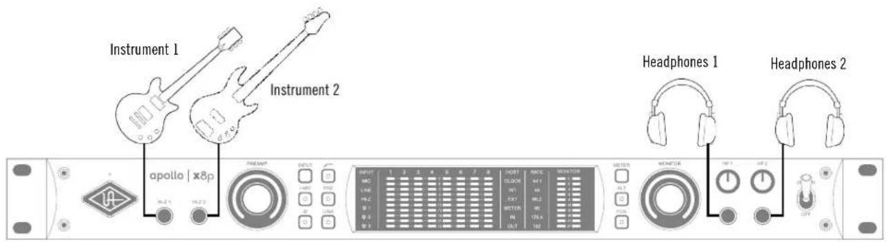
The diagram below illustrates an Apollo x8p setup example that could be used for recording an ensemble. ALT monitors are connected for comparing different speakers to the DB25 line outputs via a DB25 audio breakout snake.
text_image
Instrument 1 Instrument 2 Apollo | x8p HEADP INPUT INPUT INPUT INPUT INPUT INPUT INPUT INPUT INPUT INPUT INPUT INPUT INPUT INPUT INPUT INPUT INPUT INPUT INPUT INPUT INPUT INPUT INPUT INPUT INPUT INPUT INPUT INPUT INPUT INPUT INPUT INPUT INPUT INPUT INPUT INPUT INPUT INPUT INPUT INPUT INPUT INPUT INPUT INPUT INPUT INPUT INPUT INPUT INPUT INPUT OUTPUT OUTPUT OUTPUT OUTPUT OUTPUT OUTPUT OUTPUT OUTPUT OUTPUT OUTPUT OUTPUT OUTPUT OUTPUT OUTPUT OUTPUT OUTPUT OUTPUT OUTPUT OUTPUT OUTPUT OUTPUT OUTPUT OUTPUT OUTPUT OUTPUT OUTPUT OUTPUT OUTPUT OUTPUT OUTPUT OUTPUT OUTPUT OUTPUT OUTPUT OUTPUT OUTPUT OUTPUT OUTPUT OUTPUT OUTPUT OUTPUT OUTPUT OUTPUT OUTPUT OUTPUT OUTPUT OUTPUT OUTPUT OUTPUT OUTPUT Output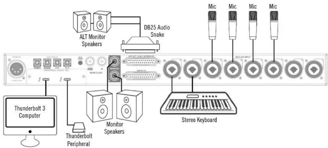
text_image
ALT Monitor Speakers DB25 Audio Snake THunderbolt 3 Computer Thunderbolt Peripheral Monitor Speakers LIVE OUT 14/ALT SUPERIOR MONITOR Stereok KeyboardTypical Apollo x8p connections
Apollo Expanded: Multi-Unit Thunderbolt 3 Wiring
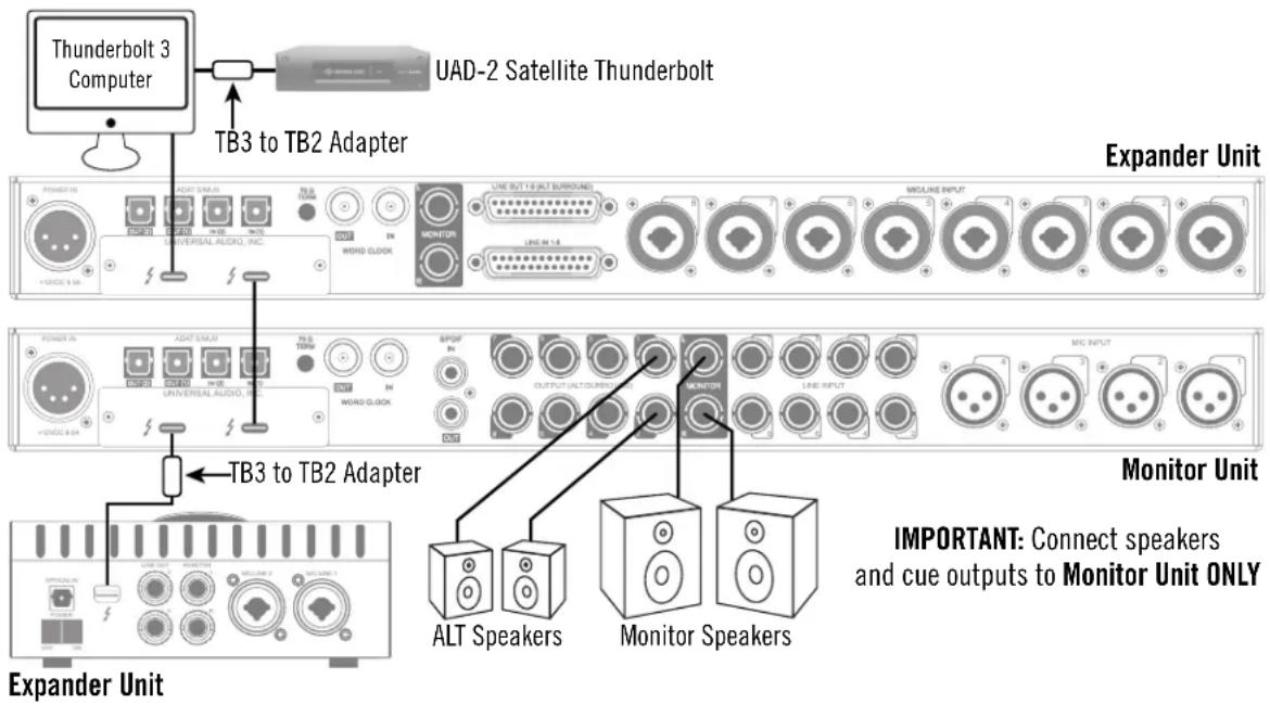
The diagram below illustrates an example of how to interconnect multiple Apollo units and the host computer via Thunderbolt 3.
Important: For complete details about system operation when multi-unit cascading, see the Apollo Software Manual.
text_image
Thunderbolt 3 Computer UAD-2 Satellite Thunderbolt TB3 to TB2 Adapter Expander Unit INTUERIAL AUDIO, INC. UNIVERSAL AUDIO, INC. MONITOR LINE OUT 1 & ALT SURROUND LINE IN 1 & B MACHINE INPUT MCC INPUT TEMPOR INTERNATIONAL AUDIO, INC. UNIVERSAL AUDIO, INC. WORD CLOCK OUTPUT ALTOURANCE COMPRESS COMPRESS COMPRESS COMPRESS COMPRESS COMPRESS COMPRESS COMPRESS COMPRESS COMPRESS COMPRESS COMPRESS COMPRESS COMPRESS COMPRESS COMPRESS COMPRESS COMPRESS COMPRESS COMPRESS COMPRESS COMPRESS COMPRESS COMPRESS COMPRESS COMPRESS COMPRESS COMPRESS COMPRESS COMPRESS COMPRESS COMPRESS COMPRESS COMPRESSConnecting multiple Apollo X units via Thunderbolt 3
Apollo Expanded Wiring Notes
- Apollo device ordering and Thunderbolt ports used (second port on Apollo vs. second port on computer, placement within daisy chain, etc) is not important.
- In this example diagram, an Apollo x8 is the monitor (master) unit designated in the Console Settings window. Connect speakers (including ALT speakers) and any cue outputs to the monitor unit only.
- Do not interconnect any Word Clock, FireWire, ADAT, or MADI ports between any Apollo units. All Apollo clocking is automatically managed via Thunderbolt.
- Up to four Apollo units and six UAD devices total can be combined within the same system.
- The computer and all Apollo/UAD units must be connected to the same Thunderbolt bus.
- Apollo X-series units with Thunderbolt 3 can be mixed with older Apollo units with Thunderbolt 2 by using compatible Thunderbolt 3 to Thunderbolt 2 adapters.
Note: On Mac systems only, Apollo X can be connected to Thunderbolt 1 and Thunderbolt 2 computers via the Apple Thunderbolt 3 to Thunderbolt 2 adapter. Visit help.uaudio.com for details.
Software Setup
Note: Items on this page are detailed in the Apollo Software Manual.
System Requirements
All system requirements must be met for Apollo X to operate properly. Before proceeding with installation, see the system requirements in the Apollo Software Manual.
Software Installation
The software must be installed to use the hardware and UAD plug-ins. The UAD Powered Plug-Ins software installer contains the Apollo X software, drivers, and UAD plug-ins.
Registration and Authorization
Apollo X must be registered and authorized to unlock UAD plug-ins that are bundled with the product. To register and authorize Apollo x8p, visit:
• www.uaudio.com/register
Note: For optimum results, connect and power on Apollo X before installing the software.
Latest Software
To obtain the latest UAD installer after initial registration, visit:
• www.uaudio.com/downloads
System Configuration
Complete details about setting up the Apollo X system, including how to integrate with a DAW and related information, are included in the Apollo Software Manual.
Console Application
The included Console application is the software interface for the Apollo X hardware. Console controls Apollo X and its digital mixing, monitoring, and Realtime UAD Processing features. Console is also used to configure Apollo X I/O settings such as sample rate, clock source, and reference levels.
For complete details about how to operate Console, refer to the Apollo Software Manual.
UA Support Videos
Informational videos are available to help you get started with Apollo X:
- help.uaudio.com
Specifications
All specifications are typical performance unless otherwise noted. Tested with the Audio Precision APx555 Audio Analyzer under the following conditions: 48 kHz internal sample rate, 24-bit sample depth, 20 kHz measurement bandwidth, +24 dBu headroom, balanced output, and internal clock.
| SYSTEM | |
| I/O Complement | |
| Microphone Inputs Eight | |
| High Impedance (Hi-Z) Instrument Inputs Two | |
| Analog Line Inputs Eight | |
| Analog Line Outputs (DC coupled) Eight (ten including Monitor outputs) | |
| Analog Monitor Outputs (DC coupled) Two (one stereo pair) | |
| Headphone Outputs Two stereo | |
| Digital Input Ports (TOSLINK optical) Two (ADAT or S/PDIF, selectable) | |
| Digital Output Ports (TOSLINK optical) Two (ADAT or S/PDIF, selectable) | |
| Thunderbolt 3 Ports Two | |
| Word Clock One input, one output | |
| A/D - D/A Conversion | |
| Simultaneous A/D conversion Eight channels | |
| Simultaneous D/A conversion 14 channels | |
| Supported Sample Rates (kHz) | 44.1, 48, 88.2, 96, 176.4, 192 |
| Bit Depth Per Sample | 24 |
| Analog Round-Trip Latency | 1.1 milliseconds @ 96 kHz sample rate |
| Analog Round-Trip Latency through four UAD legacy plug-ins (included) via Console software | 1.1 milliseconds @ 96 kHz sample rate (no additional latency via Realtime UAD Processing) |
(continued)
ANALOG I/O
Microphone Inputs 1 – 8
Frequency Response 20 Hz – 20 kHz, ±0.05 dB
Dynamic Range 122 dB (A-weighted)
Total Harmonic Distortion + Noise Ratio (1 kHz @ 4.9 dBu) -114 dB (0.00020%)
Maximum Input Level (PAD on) 26 dBu
Default Input Impedance 5.5k Ohms (variable via Unison plug-ins)
Gain Range +10 dB to +65 dB
Pad Attenuation (switchable per input) 20 dB (variable via Unison plug-ins)
Phantom Power +48V (switchable per mic input)
Connector Type XLR Female, pin 2 positive (Combo XLR/TRS)
Hi-Z Inputs 1 - 2
Frequency Response 20 Hz – 20 kHz, ±0.04 dB
Dynamic Range 121 dB (A-weighted)
Total Harmonic Distortion + Noise Ratio (1 kHz @ 11.2 dBu) -111 dB (0.00028%)
Maximum Input Level 12.4 dBu
Default Input Impedance 1M Ohms (variable via Unison plug-ins)
Gain Range +10 dB to +65 dB
Connector Type 1/4" Female TS Unbalanced
Line Inputs 1 - 8
Frequency Response 20 Hz – 20 kHz, ±0.04 dB
Dynamic Range 123 dB (A-weighted)
Total Harmonic Distortion + Noise Ratio (1 kHz @ 23 dBu) -113 dB (0.00022%)
Maximum Input Level 24 dBu
Input Impedance 10K Ohms
Gain Range +10 dB to +65 dB
Connector Type (8) 14 " Female TRS Balanced (Combo XLR/TRS)
(1) Female DB25 (Tascam wiring), Normalled
Line Outputs 1 - 8
Frequency Response 20 Hz – 20 kHz, ±0.07 dB
Dynamic Range 127 dB (A-weighted)
Total Harmonic Distortion + Noise Ratio (1 kHz @ -1 dBFS) -119 dB (0.00011%)
Maximum Output Level 24 dBu
Output Impedance 100 Ohms
Connector Type Female DB25 (Tascam wiring)
Monitor Outputs 1 - 2
Frequency Response 20 Hz – 20 kHz, ±0.06 dB
Dynamic Range 129 dB (A-weighted)
Total Harmonic Distortion + Noise Ratio (1 kHz @ -1 dBFS) -118 dB (0.00012%)
Maximum Output Level 24 dBu
Output Impedance 100 Ohms
Connector Type 1/4" Female TRS Balanced
Stereo Headphone Outputs 1 – 2
Frequency Response 20 Hz – 20 kHz, ±0.05 dB
Dynamic Range 125 dB (A-weighted)
Total Harmonic Distortion + Noise Ratio (1 kHz @ -1 dBFS) -102 dB (0.00080%)
Maximum Output Power (into 300 ohm load) 150 mW RMS
Connector Type 1/4" Female TRS Stereo
(continued)
| DIGITAL I/O |
| S/PDIF |
| Connector Type (shared with ADAT) Optical TOSLINK JIS F05 |
| Format IEC 958 |
| Supported Sample Rates (kHz) 44.1, 48, 88.2, 96 |
| ADAT |
| Connector Type (shared with S/PDIF) Optical TOSLINK JIS F05 |
| Format ADAT Digital Lightpipe with S/MUX |
| Supported Sample Rates (kHz) 44.1, 48, 88.2, 96, 176.4, 192 |
| Channel Assignments @ 44.1 kHz, 48 kHz Port 1 = Channels 1 – 8, Port 2 = 1 – 8 (mirrored) |
| Channel Assignments @ 88.2 kHz, 96 kHz Port 1 = Channels 1 – 4, Port 2 = Channels 5 – 8 |
| Channel Assignments @ 176.4 kHz, 192 kHz Port 1 = Channels 1 – 2, Port 2 = Channels 3 – 4 |
| Word Clock |
| Connector Type BNC |
| Lock Range ±4% of any supported sample rate |
| Word Clock Input Termination 75 Ohms, switchable |
| Synchronization Sources |
| Internal, Word Clock, ADAT, S/PDIF |
(continued)
| ELECTRICAL | |
| Power Supply External AC-to-DC Power Supply, Level VI compliant | |
| AC Input Connector Type IEC Male | |
| AC Requirements 100V – 240V AC, 50 – 60 Hz | |
| DC Connector Type XLR 4-Pin Locking Male (Neutrik P/N NC4MDM3-H) | |
| DC Requirements 12 VDC, 6A | |
| Maximum Power Consumption 72W (30W typical) | |
| ENVIRONMENTAL | |
| Ambient Temperature Range 32° to 104° F (0° to 40° C) | |
| MECHANICAL | |
| Dimensions | |
| Width 19 in (48,26 cm) | |
| Height (1U rack space) 1.75 in (4,45 cm) | |
| Depth, Chassis Only 12.125 in (30,80 cm) | |
| Depth, Including Knob & Jack Protrusions 13.5 in (34,29 cm) | |
| Shipping Box (Width x Depth x Height) | 23.5 in x 17 in x 7.5 in(59,69 cm x 43,18 cm x 19,05 cm) |
| Weight | |
| Shipping Weight (with box & accessories) | USA: 16.6 lbs (7.52 kg)EU & UK: 16.9 lbs (7.64 kg) |
| Weight (bare unit) 9 lbs (4.08 kg) | |
| Package Contents | |
| Apollo x8p Audio Interface Unit | |
| External Power Supply | |
| AC Power Cable (IEC), Region Specific | |
| Set of (4) Rack-Mount Screws | |
| Getting Started URL Card | |
Block Diagram
flowchart
graph TD
    subgraph_INPUT_CHANNELS_1-2["INPUT CHANNELS 1 - 2"]
        A["+45V ON/OFF"] --> B["+48V MIC PAD IN/OUT"]
        C["+45V ON/OFF"] --> D["+48V MIC/PAGE IN/OUT"]
        E["Line IN 1/4" TRS"] --> F["Line IN 1/4" TRS"]
        G["Line IN 1/4" TRS"] --> H["Line IN 1/4" TRS"]
        I["Line IN 1/4" TRS"] --> J["Line IN 1/4" TRS"]
        K["Line IN 1/4" TRS"] --> L["Line IN 1/4" TRS"]
        M["Line IN 1/4" TRS"] --> N["Line IN 1/4" TRS"]
        O["Line IN 1/4" TRS"] --> P["Line IN 1/4" TRS"]
        Q["Line IN 1/4" TRS"] --> R["Line IN 1/4" TRS"]
        S["Line IN 1/4" TRS"] --> T["Line IN 1/4" TRS"]
        U["Line IN 1/4" TRS"] --> V["Line IN 1/4" TRS"]
        W["Line IN 1/4" TRS"] --> X["Line IN 1/4" TRS"]
        Y["Line IN 1/4" TRS"] --> Z["Line IN 1/4" TRS"]
        AA["Line IN 1/4" TRS"] --> AB["Line IN 1/4" TRS"]
        AC["Line IN 1/4" TRS"] --> AD["Line IN 1/4" TRS"]
        AE["Line IN 1/4" TRS"] --> AF["Line IN 1/4" TRS"]
        AG["Line IN 1/4" TRS"] --> AH["Line IN 1/4" TRS"]
        AI["Line IN 1/4" TRS"] --> AJ["Line IN 1/4" TRS"]
        AK["Line IN 1/4" TRS"] --> AL["Line IN 1/4" TRS"]
        AM["Line IN 1/4" TRS"] --> AN["Line IN 1/4" TRS"]
        AO["Line IN 1/4" TRS"] --> AP["Line IN 1/4" TRS"]
        AQ["Line IN 1/4" TRS"] --> AR["Line IN 1/4" TRS"]
        AS["Line IN 1/4" TRS"] --> AT["Line IN 1/4" TRS"]
        AU["Line IN 1/4" TRS"] --> AV["Line IN 1/4" TRS"]
        AW["Line IN 1/4" TRS"] --> AX["Line IN 1/4" TRS"]
        AY["LINE OUT"] --> AZ["+20dBu / +24dBu HEADROOM SELECT"]
        BA["LINE OUT"] --> BB["+20dBu / +24dBu HEADROOM SELECT"]
        BC["LINE OUT"] --> BD["+20dBu / +24dBu HEADROOM SELECT"]
        BE["LINE OUT"] --> BF["+20dBu / +24dBu HEADROOM SELECT"]
        BG["LINE OUT"] --> BH["+20dBu / +24dBu HEADROOM SELECT"]
        BI["LINE OUT"] --> BJ["+20dBu / +24dBu HEADROOM SELECT"]
        BK["LINE OUT"] --> BL["+20dBu / +24dBu HEADROOM SELECT"]
        BM["LINE OUT"] --> BN["+20dBu / +24dBu HEADROOM SELECT"]
        BO["LINE OUT"] --> BP["+20dBu / +24dBu HEADROOM SELECT"]
        BQ["LINE OUT"] --> BR["+20dBu / +24dBu HEADROOM SELECT"]
        BS["LINE OUT"] --> BT["+20dBu / +24dBu HEADROOM SELECT"]
        BU["LINE OUT"] --> BV["+20dBu / +24dBu HEADROOM SELECT"]
        BW["LINE OUT"] --> BX["+20dBu / +24dBu HEADROOM SELECT"]
        BYD["LINE OUT"] --> BZ["+20dBu / +24dBu HEADROOM SELECT"]
        CA["LINE OUT"] --> CB["+20dBu / +24dBu HEADROOM SELECT"]
        CC["LINE OUT"] --> CD["+20dBu / +24dBu HEADROOM SELECT"]
        DA["VCO"] --> DB["CLOCK OSCILLATORS AUDIO CLOCKS"]
    end

    subgraph MIXER_CLOCKING/SYNC_SYSTEM_CONTROL["MIXER CLOCKING/SYNC SYSTEM CONTROL"]
        BQ --> DC["CLOCK OSCILLATORS AUDIO CLOCKS"]
        DB --> DC
        DC --> E
        DC --> FX["CLOCK OSCILLATORS AUDIO CLOCKS"]
    end

    subgraph OUTPUT_VOLUME
        FB["Globa Setting"] --> GA["DVA"]
        GB["Globa Setting"] --> GH["DVA"]
        I["Globa Setting"] --> I
        J["Globa Setting"] --> J
        K["Globa Setting"] --> K
        L["Globa Setting"] --> L
        M["Globa Setting"] --> M
        N["Globa Setting"] --> N
        O["Globa Setting"] --> O
    end

    subgraph OUTPUT_VOLUME
        P["FMODE"] --> Q["FMODE VOLUME"]
        R["D/A"] --> S["D/A VOLUME"]
    end

    subgraph HEADPHONES_1 & 2_L/R
        T["6 SHARO® DSP's"] --> U["U=6 DRAM's"]
        V["BMCBNC TB TB TB"]
    end

    subgraph FRONT_PANEL
        W["WG TERM ON/OFF"] --> X["WG TERM ON/OFF"]
        Y["BNCBNC TB TB TB TB"]
    end

    subgraph PCie_OPTION_CARD_SLOT
        Z["WORI CLOCK I/O THUNDERBOLT™3 PORTS"]
    end

    subgraph CPU_CLKING/SYNC_SYSTEM_CONTROL
        AA["POLI"] --> AB["VCO"]
        AC["CLOCK OSCILLATORS AUDIO CLOCKS"]
    end

    subgraph MONITOR_OUTPUTS
        AD["S/PDIF / ADAT IN OPTIOOPTO OPTIO"] --> AE["S/PDIF / ADAT OUT OPTIOOPTO OPTIO"]

    subgraph LINE OUTPUTS_1-8
        AE --> AF
        AF --> AG
        AG --> AH
        AH --> AI
        AI --> AJ
        AJ --> AK
    end

    subgraph LINE OUTPUTS_1-8
        AK --> AL["S/PDIF / ADAT OUT OPTIOOPTO OPTIO"]

    subgraph HEADPHONES_1 & 2_L/R
        AL --> AM["S/PDIF / ADAT OUT OPTIOOPTO OPTIO"]

    subgraph LINE OUTPUTS_1-8
        AM --> AN["S/PDIF / ADAT OUT OPTIOOPTO OPTIO"]

    subgraph LINE OUTPUTS_1-8
        AN --> AO["S/PDIF / ADAT OUT OPTIOOPTO OPTIO"]

    subgraph LINE OUTPUTS_1-8
        AO --> AP["S/PDIF / ADAT OUT OPTIOOPTO OPTIO"]

    subgraph LINE OUTPUTS_1-8
        AP --> AQ["S/PDIF / ADAT OUT OPTIOOPTO OPTIO"]

    subgraph LINE OUTPUTS_1-8
        AQ --> AR["S/PDIF / ADAT OUT OPTIOOPTO OPTIO"]

    subgraph LINE OUTPUTS_1-8
        AR --> AS["S/PDIF / ADAT OUT OPTIOOPTO OPTIO"]

    subgraph LINE OUTPUTS_1-8
        AS --> AT["S/PDIF / ADAT OUT OPTIOOPTO OPTIO"]

    subgraph LINE OUTPUTS_1-8
        AT --> AU["S/PDIF / ADAT OUT OPTIOOPTO OPTIO"]

    subgraph LINE OUTPUTS_1-8
        AU --> AV["S/PDIF / ADAT OUT OPTIOOPTO OPTIO"]

    subgraph LINE OUTPUTS_1-8
        AV --> AW["S/PDIF / ADAT OUT OPTIOOPTO OPTIO"]

    subgraph LINE OUTPUTS_1-8
        AW --> AX["S/PDIF / ADAT OUT OPTIOOPTO OPTIO"]

    subgraph LINE OUTPUTS_1-8
        AX --> AY["S/PDIF / ADAT OUT OPTIOOPTO OPTIO"]

    subgraph LINE OUTPUTS_1-8
        AY --> AZ["S/PDIF / ADAT OUT OPTIOOPTO OPTIO"]

    subgraph LINE OUTPUTS_1-8
        AZ --> BA["S/PDIF / ADAT OUT OPTIOOPTO OPTIO"]

    subgraph LINE OUTPUTS_1-8
        BA --> BB["S/PDIF / ADAT OUT OPTIOOPTO OPTIO"]

    subgraph LINE OUTPUTS_1-8
        BB --> BC["S/PDIF / ADAT OUT OPTIOOPTO OPTIO"]

    subgraph LINE OUTPUTS_1-8
        BC --> BD["S/PDIF / ADAT OUT OPTIOOPTO OPTIO"]

    subgraph LINE OUTPUTS_1-8
        BD --> BE["S/PDIF / ADAT OUT OPTIOOPTO OPTIO"]

    subgraph LINE OUTPUTS_1-8
        BE --> BF["S/PDIF / ADAT OUT OPTIOOPTO OPTIO"]

    subgraph LINE OUTPUTS_1-8
        BF --> BG["S/PDIF / ADAT OUT OPTIOOPTO OPTIO"]

    subgraph LINE OUTPUTS_1-8
        BG --> BH["S/PDIF / ADAT OUT OPTIOOPTO OPTIO"]

    subgraph LINE OUTPUTS_1-8
        BH --> BI["S/PDIF / ADAT OUT OPTIOOPTO OPTIO"]

    subgraph LINE OUTPUTS_1-8
        BI --> BJ["S/PDIF / ADAT OUT OPTIOOPTO OPTIO"]

    subgraph LINE OUTPUTS_1-8
        BJ --> BK["S/PDIF / ADAT OUT OPTIOOPTO OPTIO"]

    subgraph LINE OUTPUTS_1-8
        BK --> BL["S/PDIF / ADAT OUT OPTIOOPTO OPTIO"]

    subgraph LINE OUTPUTS_1-8
        BL --> BM["S/PDIF / ADAT OUT OPTIOOPTO OPTIO"]

    subgraph LINE OUTPUTS_1-8
        BL --> BN["S/PDIF / ADAT OUT OPTIOOPTO OPTIO"]

    subgraph LINE OUTPUTS_1-8
        BN --> BO["S/PDIF / ADAT OUT OPTIOOPTO OPTIO"]

    subgraph LINE OUTPUTS_1-8
        BO --> BP["S/PDIF / ADAT OUT OPTIOOPTO OPTIO"]

    subgraph LINE OUTPUTS_1-8
        BP --> BQ["S/PDIF / ADAT OUT OPTIOOPTO OPTIO"]

    subgraph LINE OUTPUTS_1-8
        BQ --> BR["S/PDIF / ADAT OUT OPTIOOPTO OPTIO"]

    subgraph LINE OUTPUTS_1-8
        BR --> BS["S/PDIF / ADAT OUT OPTIOOPTO OPTIO"]

    subgraph LINE OUTPUTS_1-8
        BS --> BT["S/PDIF / ADAT OUT OPTIOOPTO OPTIO"]

    subgraph LINE OUTPUTS_1-8
        BT --> BU["S/PDIF / ADAT OUT OPTIOOPTO OPTIO"]

    subgraph LINE OUTPUTS_1-8
        BU --> BV["S/PDIF / ADAT OUT OPTIOOPTO OPTIO"]

    subgraph LINE OUTPUTS_1-8
        BV --> BW["S/PDIF / ADAT OUT OPTIOOPTO OPTIO"]

    subgraph LINE OUTPUTS_1-8
        BW --> BX["S/PDIF / ADAT OUT OPTIOOPTO OPTIO"]

    subgraph LINE OUTPUTS_1-8
        BX --> BY["S/PDIF / ADAT OUT OPTIOOPTO OPTIO"]

    subgraph LINE OUTPUTS_1-8
        BY --> BZ["S/PDIF / ADAT OUT OPTIOOPTO OPTIO"]

    subgraph LINE OUTPUTS_1-8
        BY --> CA["S/PDIF / ADAT OUT OPTIOOPTO OPTIO"]

    subgraph LINE OUTPUTS_1-8
        CA --> CB["S/PDIF / ADAT OUT OPTIOOPTO OPTIO"]

    subgraph LINE OUTPUTS_1-8
        CB --> CC["S/PDIF / ADAT OUT OPTIOOPTO OPTIO"]

    subgraph LINE OUTPUTS_1-8
        CC --> CD["S/PDIF / ADAT OUT OPTIOOPTO OPTIO"]

    subgraph LINE OUTPUTS_1-8
        CD --> CE["S/PDIF / ADAT OUT OPTIOOPTO OPTIO"]

    subgraph LINE OUTPUTS_1-8
        CE --> CF["S/PDIF / ADAT OUT OPTIOOPTO OPTIO"]

    subgraph LINE OUTPUTS_1-8
        CF --> CG["S/PDIF / ADAT OUT OPTIOOPTO OPTIO"]

    subgraph LINE OUTPUTS_1-8
        CG --> CH["S/PDIF / ADAT OUT OPTIOOPTO OPTIO"]

    subgraph LINE OUTPUTS_1-8
        CH --> CI["S/PDIF / ADAT OUT OPTIOOPTO OPTIO"]

    subgraph LINE OUTPUTS_1-8
        CI --> CJ["S/PDIF / ADAT OUT OPTIOOPTO OPTIO"]

    subgraph LINE OUTPUTS_1-8
        CJ --> CK["S/PDIF / ADAT OUT OPTIOOPTO OPTIO"]

    subgraph LINE OUTPUTS_1-8
        CK --> CL["S/PDIF / ADAT OUT OPTIOOPTO OPTIO"]

    subgraph LINE OUTPUTS_1-8
        CL --> CM["S/PDIF / ADAT OUT OPTIOOPTO OPTIO"]

    subgraph LINE OUTPUTS_1-8
        CM --> CN["S/PDIF / ADAT OUT OPT IOPTO"]
    end

    style A fill:#f9f,stroke:#333,stroke-width:2px,stroke-dasharray: 5 5
DB25 Wiring
Apollo x8p's line inputs and outputs can be accessed via 25-pin D-sub female connectors. Each DB25 jack carries eight balanced line-level audio channels on the standardized Tascam pinouts also used with Digidesign and Avid products.
DB25 Connector Pin Numbers
The pin numbers for female DB25 connectors are shown in the diagram below. When facing the Apollo x8p rear panel, pin 1 is the upper rightmost pin.
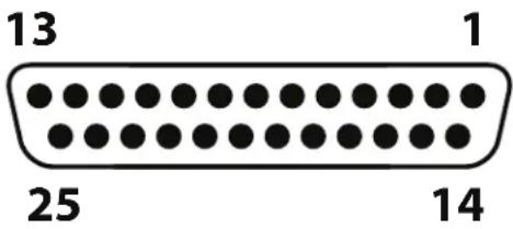
text_image
13 1 25 14Apollo x8p female DB25 pin numbers
DB25 Connector Wiring
The signals carried on the female DB25 connector pins are listed in the table below. Pinouts are identical for inputs and outputs.
| Apollo x8p DB25 Connector Pinouts | ||
| Pin Channel Signal Pin Channel Signal | Signal Pin Channel Signal | |
| 1 8 Hot 9 3 Cold 17 6 Cold | ||
| 2 8 Ground 10 2 Hot 18 5 Hot | ||
| 3 7 Cold 11 2 Ground 19 5 Ground | ||
| 4 6 Hot 12 1 Cold 20 4 Cold | ||
| 5 6 Ground 13 – No Connect | 21 3 Hot | |
| 6 5 Cold 14 8 Cold 22 3 Ground | ||
| 7 4 Hot 15 7 Hot 23 2 Cold | ||
| 8 4 Ground 16 7 Ground 24 1 Hot | ||
| 25 1 Ground | ||
Troubleshooting
If Apollo x8p isn't behaving as expected, here are some common troubleshooting items to confirm. If you are still experiencing issues after performing these checks, contact Technical Support.
| SYMPTOM ITEMS TO CHECK | |
| Unit won't power on • Confirm power supply connections at power supply input and back of unit• Confirm Power switch is in UP position• Confirm AC power is available at wall socket by plugging in a different device | |
| No monitor output • Confirm connections, power, and volume of monitoring system• Confirm monitor knob is turned up• Confirm monitor outputs are not muted (push monitor knob)• Confirm monitor LEDs are active (check signal flows) | |
| Can't hear preamp channels • Confirm preamp gain is turned up for the channel(s)• Confirm MUTE is not engaged in Console input channel strip | |
| Can't hear mic or line input(s) • Confirm mic/line switch setting is correct for the channel• Confirm nothing is plugged into the channel's Hi-Z input• Confirm MUTE is not engaged in Console input channel strip | |
| Can't hear Hi-Z input(s) • Confirm volume on connected device is turned up• Confirm Hi-Z input cable is 1/4" TS only (not TRS)• Confirm MUTE is not engaged in Console input channel strip | |
| Can't hear mic input(s) • Confirm -48V phantom power is enabled (if required by microphone) | |
| Preamp controls have no effect on channel | • Confirm desired channel is selected for control (push PREAMP knob to select)• Preamp controls are not available for non-preamp channels |
| Can only adjust preamp input channels | • Signal levels for all non-preamp inputs, including digital inputs, are adjusted at the device connected to those inputs |
| Audio glitches and/or dropouts during playback | • Increase audio buffer size setting• Confirm clocking setups; check cable connections and confirm all device clocks are synchronized to one master clock device |
| Undesirable echo/phasing • Confirm only one input monitoring system is enabled (Console or DAW – not both) | |
| HOST indicator is unlit or red • Confirm Thunderbolt 3 connections• Confirm Apollo X software is installed• Power Apollo X off then on, and restart computer• Reinstall Apollo X software• Try a different Thunderbolt 3 cable | |
| Static and/or white noise is heard when nothing is plugged in | • Mute or lower preamp gain to minimum on all unused preamp channels (mic preamps can emit noise even when nothing is plugged in)• Some UAD plug-ins model the noise characteristics of the original equipment. Defeat the noise model in the UAD plug-in GUI, or mute the channel containing the plug-in to temporarily mute the noise |
| Various LEDs inside the unit are blinking | • This is normal operational behavior that can be safely ignored |
| Apollo X is behaving unexpectedly | • As a last resort, perform a hardware reset on the unit by following these steps:1. Power off Apollo X2. Press and hold the PREAMP, LOW CUT, and POLARITY controls3. Power on Apollo X while continuing to hold all three controls4. After all front panel LEDs flash rapidly (after several seconds), release the controls |
Notices
Warranty
Universal Audio provides a limited warranty on all UA hardware products. To learn more, visit help.uaudio.com. The limited warranty gives you specific legal rights. You may also have other rights which vary by state or country.
Repair Service
If you are having trouble with Apollo X, first check all system setups, connections, and operating instructions. If that doesn't help, contact our technical support team.
To learn about repair service, or for technical support, visit help.uaudio.com.

Maintenance
- CAUTION: To reduce the risk of electric shock, do not open the unit.
- Apollo X does not contain a fuse or any other user-replaceable parts. The unit is internally calibrated at the factory. No internal user adjustments are available.
Important Safety Information

Before using this unit, be sure to carefully read the applicable items of these operating instructions and the safety suggestions. Afterwards, keep them handy for future reference. Take special care to follow the warnings indicated on the unit, as well as in the operating instructions.
1) Read these instructions.
2) Keep these instructions.
3) Heed all warnings.
4) Follow all instructions.
5) Do not use this apparatus near water.
6) Clean only with dry cloth.
7) Do not block any ventilation openings. Install in accordance with the manufacturer's instructions.
8) Do not install near any heat source such as radiators, heat registers, stoves, or other apparatus (including amplifiers) that produce heat.
9) Do not defeat the safety purpose of the polarized or grounding-type plug. A polarized plug has two blades with one wider than the other. A grounding type plug has two blades and a third grounding prong. The wide blade or the third prong are provided for your safety. If the provided plug does not fit into your outlet, consult an electrician for replacement of the obsolete outlet.
10) Protect the power cord from being walked on or pinched particularly at plugs, convenience receptacles, and the point where they exit from the apparatus.
11) Only use with attachments/accessories specified by the manufacturer.
12) Use only with the cart, stand, tripod, bracket, or table specified by the manufacturer, or sold with the apparatus. When a cart is used, use the caution when moving the cart/ apparatus combination to avoid injury from tip-over.
13) Unplug this apparatus during lightning storms or when unused for long periods of time.
14) Refer all servicing to qualified service personnel. Servicing is required when the apparatus has been damaged in any way, such as power-supply cord or plug is damaged, liquid has been spilled or objects have fallen into the apparatus, the apparatus has been exposed to rain or moisture, does not operate normally, or has been dropped.
Description of symbols used

The lightning flash represented by the arrow symbol in an equilateral triangle is intended to alert users to the presence of high voltage within the unit that could cause an electrical shock hazard.

The exclamation mark in an equilateral triangle is intended to alert users to the existence of important instructions in the manual relating to the use and maintenance of the unit.
FCC Compliance
Federal Communications Commission
United States Class A Manual Statements
Note: This equipment has been tested and found to comply with the limits for a Class A digital device pursuant to Part 15 of the FCC Rules. These limits are designed to provide reasonable protection against harmful interference when the equipment is operated in a commercial environment. This equipment generates, uses, and can radiate radio frequency energy and, if not installed and used in accordance with the instruction manual, may cause harmful interference to radio communications. Operation of this equipment in a residential area is likely to cause harmful interference to radio communications. Operation of this equipment in a residential area is likely to cause harmful interference in which case the user will be required to correct the interference at their own expense.
Any modifications to the unit, unless expressly approved by Universal Audio, could void the User's authority to operate the equipment.
- Canada: Innovation, Science and Economic Development Canada Interference Causing Equipment Standard ICES-003, Issue 6, dated January 2016 (class A)
- Japan: VCCI-CISOR 32:2016, “Technical Requirements” for multimedia equipment (class A)
- EN 55022:2010, “Information technology equipment – Radio disturbance characteristics – Limits and method of measurements” (Class A)
- CISPR 22:2008, “Information technology equipment – Radio disturbance characteristics – Limits and method of measurement” (Class A)
- EN 55032:2010, “Electromagnetic compatibility of multimedia equipment – Emission Requirements”
- CISPR 32:2010, “Electromagnetic compatibility of multimedia equipment – Emissions requirements”
- EN 55024:2010, “Information technology equipment – Immunity characteristics. Limits and method of measurement”
- CISPR 24:2010 +A1:2015, “Information technology equipment – Immunity characteristics. Limits and method of measurement.”
- TCVN 7189:2009, “Information technology equipment – Radio disturbance characteristics – Limits and method of measurements”
• Korea: KN32/KN35: 2015, Multimedia Class A
Disclaimer
The information contained in this manual is subject to change without notice. Universal Audio, Inc. makes no warranties of any kind with regard to this manual, including, but not limited to, the implied warranties of merchantability and fitness for a particular purpose. Universal Audio, Inc. shall not be liable for errors contained herein or direct, indirect, special, incidental, or consequential damages in connection with the furnishing, performance, or use of this material.
End User License Agreement
Your rights to the Software are governed by the accompanying End User License Agreement, a copy of which can be found at: www.uaudio.com/eula
Trademarks
Universal Audio, the Universal Audio “diamond” logo, Apollo, Apollo Twin, Apollo 16, Unison technology, UAD, UAD Series, UAD-1, UAD-2, UAD-2 Satellite, Powered Plug-Ins, 1176LN, 1176SE, Teletronix, LA-2A, LA-3A, LA-610, LA-610MkII, 2-1176, 2-610, 6176, 710 Twin-Finity, 2192, 4-710d, Cambridge EQ, DreamVerb, Plate 140, Precision Limiter, RealVerb Pro, Precision Buss Compressor, Precision De-Esser, Precision Maximizer, and “Analog Ears | Digital Minds,” are among the trademarks, trade names, and service marks owned by UA that may appear on the Site, many of which are registered in the United States and other countries. This is not a comprehensive list of all UA trademarks. All UA trademarks inure to the benefit of UA. Other trademarks and trade names that may appear on the Site and which are not owned by UA are owned by the respective owners.
Copyright
Copyright ©2018 Universal Audio, Inc. All rights reserved.
This manual and any associated software, artwork, product designs, and design concepts are subject to copyright protection. No part of this document may be reproduced, in any form, without prior written permission of Universal Audio, Inc.
Technical Support
Universal Audio Knowledge Base
The UA Knowledge Base is your complete technical resource for configuring, operating, troubleshooting, and repairing UA products.
You can watch helpful support videos, search the Knowledge Base for answers, get updated technical information that may not be available elsewhere, and more.
UA Knowledge Base
YouTube Support Channel
The Universal Audio Support Channel at youtube.com includes helpful support videos for setting up and using UA products.
UA YouTube Support Channel
Universal Audio Community Forums
The unofficial UA discussion forums are a valuable resource for all Universal Audio product users. This website is independently owned and operated.
www.uadforum.com
Contact Universal Audio Support
To contact UA support staff for technical or repair assistance, please visit:
help.uaudio.com

UNIVERSAL AUDIO