DZR12 - Speaker YAMAHA - Free user manual and instructions
Find the device manual for free DZR12 YAMAHA in PDF.


| Product Type | Powered 2-way loudspeaker (Bass-reflex) |
| Dimensions (W x H x D, with rubber foot) | 410 x 646 x 394 mm |
| Weight | 21.4 kg |
| Frequency Range (-10 dB) | 39 Hz - 20 kHz |
| Maximum SPL | 139 dB SPL (peak, pink noise @1 m) |
| Coverage Angle | H90° x V60° (rotatable horn) |
| Amplifier Type | Class-D |
| Dynamic Power Rating | 1,600 W |
| Continuous Power Rating | 1,200 W |
| Transducers | LF: 12" cone, 3" voice coil, neodymium magnet; HF: 2" voice coil, 1" throat compression driver, titanium diaphragm, neodymium magnet |
| Enclosure Material | Plywood with durable polyurea coating, black |
| DSP Processing | 96 kHz sampling, FIR filter, AD/DA |
| Display | LCD with backlight, brightness and contrast adjustment, BLACKOUT function |
| Inputs | 2x Combo (XLR/phone) line level, max +24 dBu |
| Outputs | 2x XLR (THRU/DSP OUT selectable) |
| USB Terminal | USB 2.0 host (5V/500mA) for firmware update, data backup, PIN code |
| Dante (DZR12-D only) | 2x etherCON, 2-in/2-out, 1000BASE-T, daisy chain |
| Power Consumption (Idle) | 45 W |
| Power Consumption (1/8 Power) | 150 W |
| AC Power Requirements | 100-240 V, 50/60 Hz (depending on region); supplied V-Lock AC cord |
| Fan Noise (Lowest Speed) | NC 30 |
| Protection Features | Speaker clip limiting, thermal, over-current, DC-fault, power supply thermal, output over-voltage |
| Pole Socket | 2x 35 mm diameter (0° or -7° tilt) |
| Rigging Points | M10 x 8 (top/side), M8 x 2 (bottom) |
| Options | U-brackets (UB-DZR12H/UB-DZR12V), cover (SPCVR-DZR12), wheels (SPW-1) |
| Maintenance | Clean with dry cloth; avoid solvents; do not block vents |
| Safety | Use only supplied power cord; ensure proper ventilation; disconnect power during maintenance |
| Spare Parts / Repairability | Contact Yamaha dealer; service by qualified personnel |
Frequently Asked Questions - DZR12 YAMAHA
User questions about DZR12 YAMAHA
0 question about this device. Answer the ones you know or ask your own.
Ask a new question about this device
Download the instructions for your Speaker in PDF format for free! Find your manual DZR12 - YAMAHA and take your electronic device back in hand. On this page are published all the documents necessary for the use of your device. DZR12 by YAMAHA.
USER MANUAL DZR12 YAMAHA
| DZR315 | DXS18xLF |
| DZR315-D | DXS18xLF-D |
| DZR15 | DXS15xLF |
| DZR15-D | DXS15xLF-D |
| DZR12 | |
| DZR12-D | |
| DZR10 | |
| DZR10-D |
Reference Manual
Contents
Introduction 3
DZR(-D), DXS-XLF(-D) Series Product Lineup 3
Main Features 3
Main Functions 4
Structure of Manuals....4
Functions 5
Full-range Speaker (Rear) 5
Subwoofer (Rear) 5
Rear Panel Full range Subwoofer 6
Power Section 7
Dante Section Dante model 8
Panel Operations 9
Basic Operations 9
HOME Screen and Its Functions 10
Alert Messages.... 12
Initialization....12
Screen Functions 13
Screen Structure....13
PRESET Screen 13
RECALL....14
STORE....14
CLEAR....14
TITLE 14
PROTECT 15
HPF Screen Full range 15
LPF Screen Subwoofer 15
D-CONTOUR Screen Full range 15
D-XSUB Screen Subwoofer 16
EQ Screen 16
DELAY Screen 16
CARDIOID Screen Subwoofer 17
ROUTER Screen....18
UTILITY Screen 19
PANEL SETUP....19
PANEL LOCK 20
DEVICE BACKUP 23
DANTE SETUP Dante model 23
INPUT REDUNDANCY Dante model 25
NETWORK Dante model 26
DEVICE INFORMATION 27
INITIALIZE....27
LOG 28
UPDATE FIRMWARE 28
DEVICE SETUP 29
Muting from an External Device Dante model 29
About Dante Dante model 30
Dante Network System 30
Dante Settings 31
Connecting to Danle Devices 31
Integration with Yamaha Digital Mixers 32
Reference 34
Precautions when Using the USB Terminal 34
Using USB Flash Drives 34
Function Tree 35
Message List 39
Patch Correspondence Chart when Using Quick Config 41
Troubleshooting 42
Dante-related Terms 43
Specifications 44
Dimensions....49
Block Diagram....55
Index 56
Introduction
Thank you for purchasing the Yamaha DZR(-D) series POWERED LOUDSPEAKER and DXS-XLF(-D) series POWERED SUBWOOFER. (See the series product lineup below.) These products are designed for live performance, sound reinforcement and fixed installation sound system applications. This manual provides instructions on installation, setup, configuring of the connections, and detailed operation of these speakers for installers, constructors, or general users familiar with speakers. Please read this manual together with the Owner's Manual that comes packaged with the product to get full use out of this product and its functions.
* Unless specifically noted otherwise, illustrations in this manual are based on the DZR12-D and DXS18XLF-D.
* In this manual the Dante model (-D) series is referred to as DZR-D, DXS-XLF-D.
DZR(-D), DXS-XLF(-D) Series Product Lineup
| Type Standard Model Dante Model (-D) | ||
| Full Range | 3-way 15" DZR315 DZR315-D | |
| 2-way 15" DZR15 DZR15-D | ||
| 2-way 12" DZR12 DZR12-D | ||
| 2-way 10" DZR10 DZR10-D | ||
| Subwoofer | 18" DXS18XLF DXS18XLF-D | |
| 15" DXS15XLF DXS15XLF-D | ||
Main Features
- Strong plywood cabinet features a high output Class D amplifier. Full-range models feature powerful sound pressure capability in a lightweight package by using neodymium magnets.
- Optimized pairing of a highly durable speaker unit with a fixed directional horn, for sparkling highs with punchy and powerful bass.
• Full-range models feature an FIR filter for crossover and frequency adjustments. Low latency for DSP and AD/DA, thanks to 96 kHz sampling rate. - LCD screen for loading presets, and for making precise graphical adjustments to EQ, delay, and routings. Easily transfer settings by using a USB flash drive.
- Dante models (-D) support the transmission of digital audio and remote control via a Dante network.
- 2-way models support use on a stand or use as a floor monitor. Rotation of the horn, several rigging points, and optional brackets allow a variety of installation methods.
Main Functions
- Processing
Incorporates new FIR filter technology in addition to signal processing know-how built up through years of product development experience in order to deliver the next level in sound quality. The DSP, AD/DA sampling frequency (Fs) is 96 kHz.
- Display → See page 6
The display enables users to set a broad range of functions using simple commands while finely tuning EQ, delay, routing and other settings using a graphical interface. Includes a back light for adjusting luminance.
- Presets → See pages 11, 13
A set of recall-only factory presets (one to three) and savable user presets (eight) are available. Select the desired preset from the factory presets when using the DZR and DXS-XLF series product together.
● Network → See pages 8, 30
Dante-compatible models not only allow for audio input/output across a Dante network, they also enable users to control and monitor this product on a computer, etc.
● Integration with Yamaha digital mixers → See page 32
Connect a Dante-compatible model with a RIVAGE PM series, CL series, QL series or TF series device over a network to monitor patching and device status without a Dante Controller. Yamaha provides a unique system solution centered around its digital mixers.
● Other useful functions
- Safeguard functions are in place to prevent malfunction. Alert messages and other notifications are used to inform users when an issue occurs. See page 12
- Comes equipped with a panel lock feature preventing operational errors and tampering. Connect a USB flash drive with the PIN code saved to it to temporarily unlock the panel. Remove the stick to lock the panel again. See page 20
- Internal data can be stored on a USB flash drive, making it easy to copy the same settings to a replacement device. See page 23
Structure of Manuals
- Owner's Manual (included with the product)
This manual describes product functions and basic product operation.
• Reference Manual (this manual)
This manual describes settings and operations in detail.
Functions
Full-range Speaker (Rear)
text_image
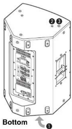
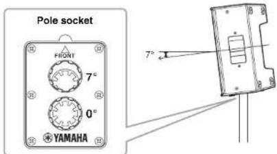
Bottom①Tiltable pole socket
This mount has two pole sockets. You can choose the angle of the speaker so that it is positioned horizontal to the floor or tilting down toward the floor by 7 degrees. Compatible with commercially available speaker stands and speaker poles of 35mm diameter. (These sockets are not available on the DZR315(-D).)
text_image
Pole socket FRONT 7° 0° YAMAHA 7°②Screw holes for U-bracket
For installing with the separately sold U-brackets. (These sockets are not available on the DZR315(-D).)
③Screw holes for eye bolts
For installing the speaker using eye bolts. The screw holes for eye bolts go through the cabinet wall.
Subwoofer (Rear)
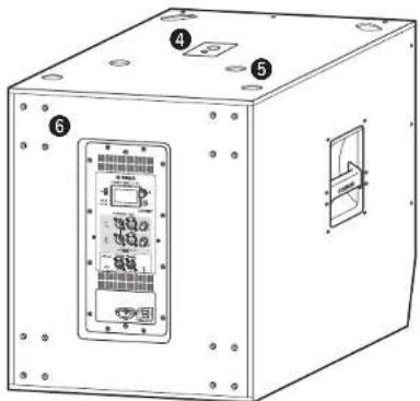
text_image
Technical diagram of a device box with labeled components and internal panel layout④ Dual pole sockets
Compatible with commercially available speaker poles of 35 mm diameter and M20 screw.

35 mm diameter

M20 screw
When using a pole socket to install a speaker, observe the following conditions for safety.
| Subwoofer Speaker to be installed | Length of the pole | |
| DXS18XLF(-D) | Weight: 26 kg or lessHeight: 76.0 cm or less(DZR15(-D) or smaller) | 104 cm or less |
| DXS15XLF(-D) | Weight: 22 kg or lessHeight: 64.5 cm or less(DZR12(-D) or smaller) | 82 cm or less |
| Weight: 18 kg or lessHeight: 53.7 cm or less(DZR10(-D) or smaller) | 104 cm or less | |
⑤Feet cups
When stacking multiple speakers, align the rubber feet of the upper speaker to the feet cups of the lower one.
⑥Wheel mounting screws
For installing the separately sold Yamaha SPW-1 wheels. If you are not using wheels, do not remove these screws. Otherwise, the leakage of air will affect sound quality.
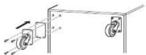
NOTE
- For more information about installing wheels and related precautions, refer to the corresponding manual for the wheels.
- Do not install any item other than the SPW-1 wheels.
Functions
Rear Panel
Full range
Subwoofer

text_image
YAMAHA DZR12-D LIMIT POWER HOME FIR (tuning) THRU OUTPUT INPUT LINE 2 LINE THRU DSP OUT @Dante™ LINK 2 10 UNI 1 10 SYNC Available only on Dante models. See the "■Dante Section" (page 8).①USB terminal
Connect a USB flash drive to save/load internal memory on this product. USB flash drives are also used to perform firmware updates. You can also save a PIN code used to lock the panel to a USB flash drive, and then connect the USB flash drive to temporarily unlock the panel.
For more information about using the USB terminal and USB flash drives, see "Precautions when Using the USB Terminal" and "Using USB Flash Drives" (page 34).
②[LIMIT] indicator
Lights red when the limiter for protecting the speaker is active. If the indicator remains on, lower the level of the input signal. This flashes together with the ① [POWER] indicator when a serious system error is detected at product startup. This indicator will turn off automatically when BLACKOUT is ON (see page 20).
③[POWER] indicator
Lights green when the power is on. Flashes when the protection function is active and the output is muted. ("MUTED" appears on the HOME screen in the display at this time.) This flashes together with the ② [LIMIT] indicator when a serious system error is detected at product startup.
NOTE
The [POWER] indicator will not automatically turn off even if BLACKOUT (page 20) is ON.
④Display
Shows the settings for various functions. Users can finely tune EQ, delay, routing and other settings using a graphical interface. The display includes a back light, enabling users to adjust the brightness and contrast of the display, configure BLACKOUT (automatic off) settings (see page 20).
NOTE
- The display will darken after one minute of panel inactivity and turn off after 25 minutes of inactivity to protect the display, even if the BLACKOUT (page 20) setting is off. Either press a key on the rear panel or press the main knob to wake the display.
- The display will start flashing when the Identify function is used on a Dante Controller or Dante devices (RIVAGE PM, CL, QL, and TF series, etc.).
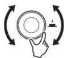
⑤Main knob
Turn the knob to move the cursor that appears in the display and change parameter values. Press the knob to execute a setting.

⑥[]\*(Back) key
Press this button to return to the previous screen. Press and hold this button for at least one second to return to the HOME screen.
⑦[LEVEL] controls
Adjust the level that is input to the [INPUT] jacks.
⑧[INPUT] jacks
Combo jacks for line level input. Accept both XLR and phone plugs. This enables you to mix levels for two input signals separately. Not compatible with mic input.
⑨[THRU/OUTPUT] jacks
XLR output jacks. Switch the DZR(-D) series channel 2 and DXS-XLF(-D) series channel 1 and 2 output signals using the 10 [THRU/DSP OUT] switch. The DZR(-D) series channel 1 output is fixed to [THRU].
DZR(-D) Series DXS-XLF(-D) Series
![YAMAHA DZR12 - ⑨[THRU/OUTPUT] jacks - 1](/content/2026/05/760287/images/3400a138ef65e69af041c5859d57c59d03659660849940ff714039d1bb4e9de6.jpg)
text_image
THRU/OUTPUT 1 LINE 2 LINE THRU DSP OUT THRU OUTPUT 1 LINE 2 LINE THRU DSP OUT⑩[THRU/DSP OUT] switch
This switch determines whether signals output from the output jack are passed through the input jack as is ([THRU]), or whether the signal receives DSP processing before input ([DSP OUT]). When this is set to [DSP OUT], you can set the output signal. For more information about signals that can be output, see "ROUTER Screen" - "③ OUTPUT" (page 19).
⑪ Vents
A cooling fan is installed on the exhaust side. The fan will start once the amp exceeds a certain temperature. Fan speed is controlled based on the temperature of the amp and power source. When the speaker is in use, make sure that all of the vents are free from obstruction.
Power Section
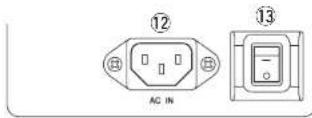
⑫[AC IN] Jack
Connect the supplied AC power cord here. First, connect the power cord to this product, then insert the power cord plug into the AC outlet. When removing the power cord, perform this procedure in reverse order. While the internal power supply functions within the 100V – 240V range, the limiter may not work properly if a different voltage to that shown is used, since the maximum output and limiter setting are optimized according to the voltage used. Do not use a voltage setting other than that shown.
![YAMAHA DZR12 - ⑫[AC IN] Jack - 1](/content/2026/05/760287/images/75993c2b7922436031f2ee4c960c69f37195efd09cb9b6758b5637ca91bb14c4.jpg)
WARNING
Use only the supplied power cord/plug.

CAUTION
Be sure to turn the power off before connecting or disconnecting the power cord.
Insert the power cord fully until it is locked by the latching lock mechanism (V-Lock).
Press the V-Lock latch to disconnect the power cord.
⑬Power switch
Turns the power supply on [-] or off [☐].

WARNING
A small amount of current flows even when the power switch is off. If you intend to not use the speaker for a long time, be sure to unplug the power cord from the outlet.
NOTE
- Depending on the timing when the power switch is turned on/off, it might take up to 15 seconds for the power to turn on.
- When using multiple devices, we recommend turning each device on one at a time. If multiple devices are turned on at the same time, the devices might not start up correctly due to a voltage drop at the power supply.
Dante Section
Dante model
text_image
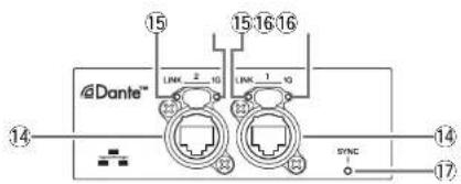
@Dante™ LINK 2 10 LINK 1 10 SYNC 14 15 15 16 16 14 17⑭Dante jacks
These are etherCON jacks for connecting with Dante devices and computers. The two jacks are primary connectors that can be linked in a daisy chain connection (see page 30). This connection cannot be used in a redundant (secondary) network.
NOTE
Use STP (Shielded Twisted Pair) cables to prevent electromagnetic interference. Make sure that the metal parts of the plugs are electrically connected to the STP cable shield by conductive tape or comparable means.
⑮[LINK] indicator
Shows the communication status of Dante jacks. Lights green when an Ethernet cable is connected correctly to the Dante jack. This indicator will turn off automatically when BLACKOUT is ON (see page 20).
NOTE
This indicator may flash for 30 seconds when the power is turned on when connected to a network device.
⑯[1G] indicator
This indicator will light up in orange when the Dante network is functioning as a Giga-bit Ethernet. This indicator will turn off automatically when BLACK-OUT is ON (see page 20).
Functions
⑰[SYNC] indicator
Lights steady or flashes green according to the Dante communication status, as shown in the following table. This indicator will turn off automatically when BLACK-OUT is ON (see page 20).
| Steady | Operating normally as a clock follower on the Dante network |
| Continuously flashes | Operating normally as a clock leader on the Dante network |
| Periodically flashes one time | Incorrect DANTE Fs selling |
| Periodically flashes two times | Dante network cable not connected |
| Periodically flashes three times | Incorrect Dante network connection |
Panel Operations
Basic Operations
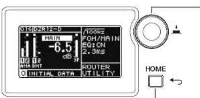
text_image
016J02R12-0 MAIN -6.5 dB Hz MHz DNT dB SP /100Hz FOH/MAIN EQ:ON 2.3MIS ROUTER UTILITY INITIAL DATA HOMEMain knob
The main knob is used to move the cursor and adjust parameter values. Parameters with a broad range of values can be adjusted more quickly based on the speed at which the main knob is turned.
Press this key to move up one level from the current level, or to return to the previous screen. Press and hold this button for at least one second to return to the HOME screen.
1. Turn the main knob to select an item. The selected item is highlighted.
The ▶ on the right indicates that there are deeper menu items.
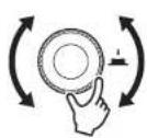
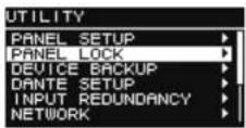
2. Press the main knob to execute a selection.

3. Repeat steps 1 and 2 until you reach the edit parameter screen.
Edit selectable parameters
Turn the main knob to select. The value will be updated and the sound will change when you press the main knob to execute the change.
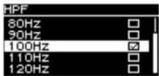
Edit continuous parameters
Turn the main knob to change the parameter value. The value is changed in real time as you turn the knob.
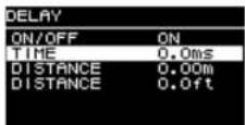
4. For selectable parameters, press the main knob to execute the edited value.
Press the [↑(Back) key to return to the previous screen (press and hold for at least one second to return to the HOME screen).
HOME Screen and Its Functions
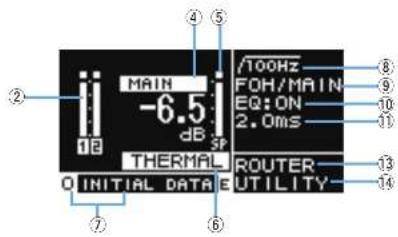
The HOME screen will appear when the power switch is turned on. Refer to the HOME screen for the model in use.
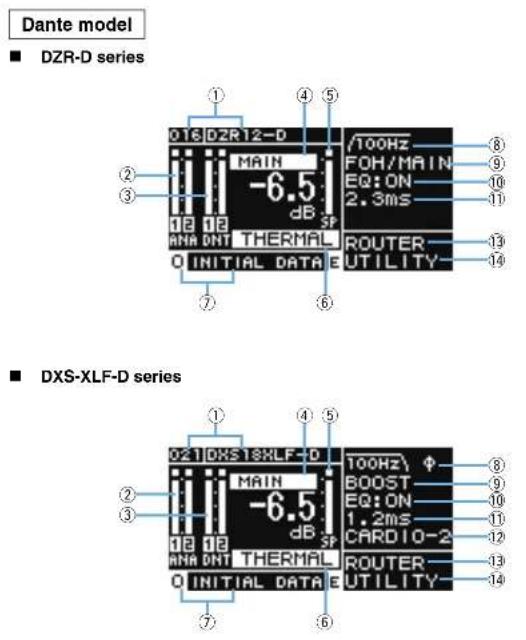
Standard model
■ DZR series
text_image
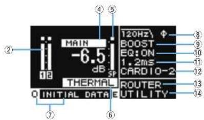
MAIN -6.5 dB SP THERMAL O INITIAL DATA E /100Hz FOH/MAIN EQ: ON 2.0ms ROUTER- UTILITY- 8 9 10 11 13 14 ② ④ ⑤ ⑥ ⑦■ DXS-XLF series
text_image
MAIN -6.5 dB SP THERMAL Q INITIAL DATA E 120Hz Φ BOOST EQ: ON 1.2ms CARDIO-2 ROUTER- UTILITY ② ④ ⑤ ⑥ ⑦ ⑧ ⑨ ⑩ ⑪ ⑫ ⑬ ⑭ ⑮ ⑯ ⑰ ⑱ ⑲ ⑳ ⑴NOTE
• Even while displaying other than the HOME screen, if you do not operate the panel for 5 minutes, the screen automatically returns to the HOME screen.
- The above screens of the Dante models are examples when setting LABEL of ① to 'DZR12-D' and 'DXS18XLF-D,' respectively.
①UNIT ID, LABEL Dante model
Shows the UNIT ID and label assigned so that DZR-D or DXS-XLF-D series devices on the Dante network can be recognized. When the DANTE MODE (page 23) is set to Quick Config, this will show as "OC," and the name of the selected TF series output channel. Go to the DANTE SETUP screen to configure and display Dante settings.
②Input Meter
Shows analog input signal levels. On Dante models this will appear as ANA. Clipped input signals will light up at the top when clipping occurs. In Backup mode, the CH label for the line in standby mode flashes (Dante models only).
③Input Meter (DNT) Dante model
Shows digital input signal (Dante) levels. Clipped input signals will light up at the top when clipping occurs. In Backup mode, the CH label for the line in standby mode flashes.
④MAIN Level
Sets and displays output levels. (Unit: dB)
⑤SP Output Meter
Shows output levels. Sigma ( ) clipping at the top will light up when clipping occurs within a channel.
⑥Protection (THERMAL, MUTED)
Appears when safeguard functions have been activated, "THERMAL" is shown when a high temperature is detected in the amplifier, and output levels are reduced. If operating conditions further deteriorate, this will change to "MUTED," and the output signal will be muted.
⑦PRESET
Shows the preset number and title of the set preset. This enables you to save, load and change audio settings. ☑ symbol) will appear when parameters have been changed.
⑧HPF Full range
Sets and displays the high-pass filter frequency.
LPF Subwoofer
Sets and displays the low-pass filter frequency and the POLARITY. An indication will appear when POLARITY is set to INVERTED.
⑨D-CONTOUR Full range
Sets and display the D-CONTOUR mode.
D-XSUB Subwoofer
Sets and displays the D-XSUB mode.
⑩EQ
Shows whether the equalizer (6 Band EQ) is on or off. You can configure EQ settings while checking the frequency response characteristics.
⑪DELAY
Sets and displays the delay.
⑫CARDIOID Subwoofer
Sets and displays the cardioid mode.
⑬ ROUTER
Configures the routing of the audio signal.
⑭UTILITY
Sets and displays the device operating settings.
- PANEL SETUP: Sets the brightness and contrast of the display, and automatic turn off settings for the display and indicators.
- PANEL LOCK: Configures panel lock settings, and saves and loads PIN codes.
• DEVICE BACKUP: Saves and loads settings data.
• DANTE SETUP Dante model : Sets and displays Dante-related settings.
- INPUT REDUNDANCY Dante model : Configures and displays items related to input redundancy.
• NETWORK Dante model : Sets and displays network-related settings.
- DEVICE INFORMATION: Shows device status, and device-specific information.
- INITIALIZE: Resets to the default settings.
- LOG: Shows recorded logs and saves logs to a USB flash drive.
- UPDATE FIRMWARE: Updates the firmware for the device, and the Dante module.
- DEVICE SETUP: Compensales for the difference in latency due to hardware differences. (Firmware V1.3.0 or later, hardware version A only.)
Alert Messages
When an error occurs, an alert message will appear on the display.
For more details on each error message and notification, see the "Message List" (page 39).
E.g.)
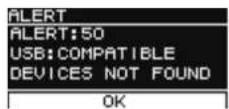
Select OK and the message will disappear.
Select VIEW LOGS to display the LOG screen.
Initialization
You can reset to the default settings for this product in the following two ways.
- Initializing to the default settings by navigating from the HOME screen and selecting UTILITY → INITIALIZE
(See page 27.)
- Initializing to the default settings when you have forgotten your PIN code, etc.
Use the following method to reset to the default settings if you are unable to select INITIALIZE on the UTILITY screen because of a forgotten PIN code, etc.
- Disconnect all the cables except the power cord.

WARNING
A sudden loud sound might occur when initializing is completed, if an audio signal is present.
- Turn the power switch off.
-
After the [POWER] indicator turns off, turn the power switch back on.
-
While pressing and holding the main knob, turn the main knob at least five clicks in a counter-clockwise direction within two seconds of the [POWER] indicator light coming on. (Keep pressing and holding the main knob.)
If the procedure is not finished properly in time, the model name logo will appear. In this case, repeat the procedure again from step 2.
- When the [POWER] indicator starts flashing and the screen shown below appears, release the main knob.
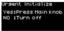
NOTE
To cancel the initialization process at this point, turn the power switch off
- Press the main knob.
This product will be restarted automatically.
- Wait until the HOME screen appears.
NOTICE
Turning the power switch off before the HOME screen appears could cause a malfunction.
Screen Functions
Screen Structure
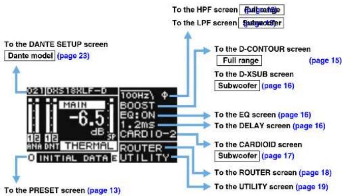
Turn the main knob to move the cursor to the desired menu item and select it to move to the corresponding screen.
text_image
To the DANTE SETUP screen Dante model (page 23) 0210XST6XLF-D MAIN -6.5 dB SP ANA DNT THERMAL 0 INITIAL DATA B 100Hz BOOST EQ: ON 1.2ms CARDIO-2 ROUTER UTILITY To the PRESET screen (page 13) To the HPF screen To the LPF screen Full range Subwoofer To the D-CONTOUR screen Full range To the D-XSUB screen Subwoofer (page 16) To the EQ screen (page 16) To the DELAY screen (page 16) To the CARDIOID screen Subwoofer (page 17) To the ROUTER screen (page 18) To the UTILITY screen (page 19)PRESET Screen
As presets which is sound related setting, allows you to recall/store/clear the settings, edit titles, and set the protection of the settings. The recall-only presets are always protected. An ☐ (E symbol) (page 11) will appear on the HOME screen when parameters have been changed.
Full range (factory default settings)
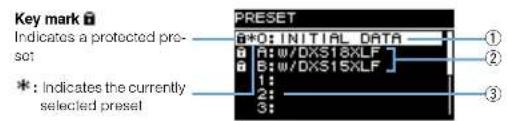
text_image
Key mark Indicates a protected pre- sot *: Indicates the currently selected preset PRESET ① ② ③Subwoofer (factory default settings)
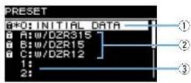
①INITIAL DATA
Resets to the default settings. Recall only.
②Factory presets
When using DZR and DXS-XLF series models in combination with one another, you can optimize the crossover frequency, levels and delay by loading presets for each model name. Recall only.
NOTE
The presels are equipped assuming that one DZR and one DXS-XLF having the same signal routes are set up. When analog inputs are used together with Dante inputs, or when several DZR and DXS-XLF are set up, each setting must be adjusted manually.
③User preset list
Save up to eight settings. It allows you to recall/store/clear the settings, edit titles, and set protection for the settings.
Screen Functions
Turn the main knob to select the preset, and press the main knob to execute it. A screen showing a list of possible actions will appear.
E.g.) The selected preset title: PRESET1
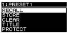
RECALL
Loads a saved preset.
The preset number and title of the preset selected will appear.
Adds a title to the current setting configurations and stores it to a preset.
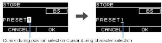
text_image
STORE BS PRESET1 CANCEL | OK → STORE BS PRESET1 CANCEL | OK Cursor during position selection Cursor during character selectionTurn the main knob to select the position to enter text, and then press the main knob to enter text input mode. When in text input mode, turn the main knob to select the character you wish to enter, and then press the main knob to enter the character.
Move the cursor to BS and press the main knob to delete the last character entered.
When in text input mode, press the [←] (Back) key to resume position selection. During position selection, select OK to execute the title, or CANCEL to cancel the text entry. Note that protected presets cannot be overwritten.
CLEAR
Deletes a stored preset.
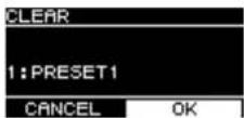
Note that protected presets, and the currently selected preset cannot be deleted.
TITLE
Edits the title of a stored preset.
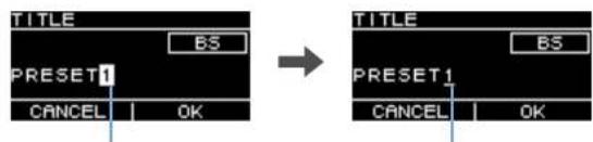
text_image
TITLE BS PRESET1 CANCEL | OK TITLE BS PRESET1 CANCEL | OKCursor during position selection Cursor during character selection
Turn the main knob to select the position to edit text, and then press the main knob to enter text input mode. When in text input mode, turn the main knob to select the character you wish to enter, and then press the main knob to enter the character.
Move the cursor to BS and press the main knob to delete the last character entered.
When in text input mode, press the [ ] (Back) key to resume position selection. During position selection, select OK to execute the title, or CANCEL to cancel the title changes. Note that titles of protected presets cannot be edited.

PROTECT
Turns protected for a stored preset on/off.
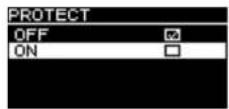
Set this to ON to prevent presets from being overwritten (STORE), deleted (CLEAR) or preset title changes (TITLE). A key mark (page 13) will appear on the left side of the preset title on the PRESET screen.
NOTE
Be aware that using RESTORE FROM USB (page 23, "■ DEVICE BACKUP" ②) will overwrite presets even if they are protected.
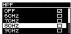
HPF Screen
Full range
Sets the HPF (high-pass filter) cutoff frequency. Select OFF or set a specific frequency.
LPF Screen
Subwoofer
Sets the LPF (low-pass filter) cutoff frequency and the polarity.
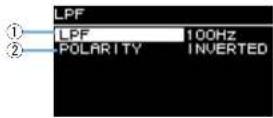
①LPF
Select the LPF cutoff frequency.
②POLARITY
Select the polarity. When set to INVERTED, a ∅ symbol will appear on the HOME screen.
D-CONTOUR Screen
Full range
Switches a D-CONTOUR preset
Set to the optimal frequency response characteristics according to the application.
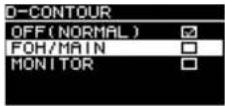
- OFF (NORMAL): Turns D-CONTOUR off. This is a general-purpose frequency response characteristic setting.
- FOH/MAIN: Boosts the high and low frequency components so that the frequency response characteristic is suitable for main speaker use. The boost amount is automatically adjusted to provide well-balanced, clear audio based on the volume.
- MONITOR: Reduces the low frequency range, which could otherwise tend to be boomy if the speaker is set directly on the floor, providing vital clarity when using as a floor monitor. This reduces latency and changes the phase characteristics.
D-XSUB Screen Subwoofer
Switches a D-XSUB preset.
Set to the optimal frequency response characteristics according to the application and genre of music.
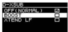
- OFF (NORMAL): Turns D-XSUB off. This is a general-purpose frequency response characteristic setting.
- BOOST: Boosts the frequency band accentuating a sense of punch in the audio.
- XTEND LF (extended LF): Extends playback frequencies to cover lower frequencies.
EQ Screen
Adjusts the frequency response characteristics for all speakers. Adjust the 6 Band EQ parameters to your liking as well the intended application.
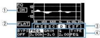
text_image
EQ ON FLAT A B C D E F BYF3 FREQ GAIN Q TYPE OFF 3.00K-3.0 2.00 PEQ①ON/OFF
Turns the 6 Band EQ on/off. When off, only the outline of EQ characteristics will be shown on the display.
②FLAT
Sets the amount of gain on all bands to 0 dB.
③ Bands A - F
Select the desired band whose parameters you wish to check. Press the main knob on the selected band to have the cursor move to the parameter display.
④Parameter Display
Shows the parameters of each band. Move the cursor to a parameter name and press the main knob to start setting parameter values. Press the [↑(Back) key to return the cursor to the parameter name. Press the [↑(Back) key again to return to the band selection screen.
DELAY Screen
Sets the delay time. This is used to compensate for the distance between speakers, etc. Set this by time or distance.
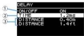
①ON/OFF
Turns the delay on/off.
②TIME [ms]
Sets the delay time in milliseconds.
③DISTANCE [m, ft]
Sets the delay time by physical distance (in meters or in feet).
NOTE
The three delay time indications change in conjunction. The last edited unit will appear on the HOME screen.
Screen Functions
CARDIOID Screen Subwoofer
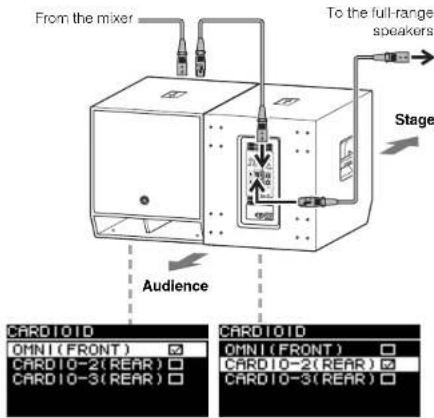
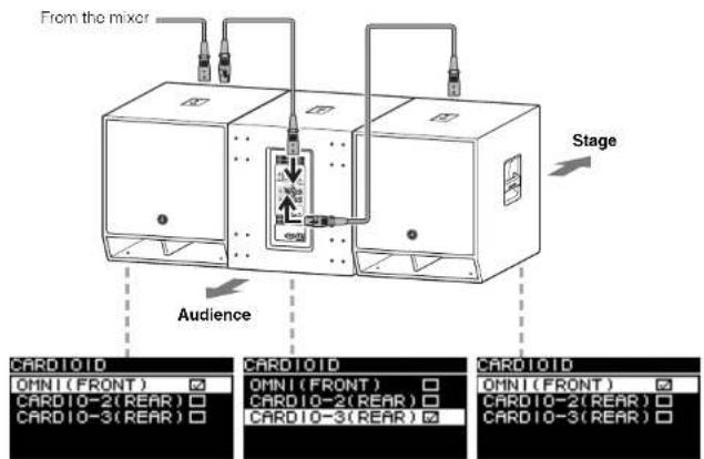
Sets the cardioid mode.
Change settings based on the number of speakers in use and their orientation. Set this to OMNI (FRONT) when not using the cardioid mode.
NOTE
For more information about setting up cardioid mode, see the Owner's Manual.
- Screen when two subwoofers are placed side by side
text_image
From the mixer To the full-range speakers Stage Audience CARDIOID OMNI(FRONT) CARDIO-2(REAR) CARDIO-3(REAR) CARDIOID OMNI(FRONT) CARDIO-2(REAR) CARDIO-3(REAR)- Screen when three subwoofers are placed side by side
text_image
From the mixer Stage Audience CARDIOID OMNI(FRONT) CARDIO-2(REAR) CARDIO-3(REAR) CARDIOID OMNI(FRONT) CARDIO-2(REAR) CARDIO-3(REAR) CARDIOID OMNI(FRONT) CARDIO-2(REAR) CARDIO-3(REAR)ROUTER Screen
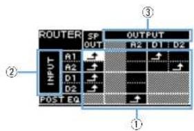
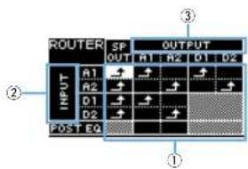
Sets routing, Dante input levels, analog output levels and output levels to a Dante network.
NOTE
- On Danle models, the analog signal sent to the DZR-D or DXS-XLF-D can be output to the Danle network and set as the input source for the mixer.
* Dante output settings are supported by firmware V1.2.2 or later and Dante module firmware 4.1.6.7-4.1.6.5-1.1.0 or later. - For more information about the signal flow in routing, see the "Block Diagram" (page 55).
Dante model
■ DZR-D series
text_image
ROUTER SP OUTPUT R1 R2 D1 D2 INPUT A1 A2 D1 D2 POST EQ ① ② ③■ DXS-XLF-D series
text_image
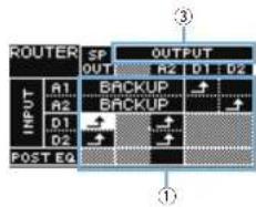
ROUTER SP OUTPUT R1 R2 D1 D2 OUTPUT R1 R2 D1 D2 POST EQ ① ② ③In Backup mode, options for the analog input are limited.
■ DZR-D series ■ DXS-XLF-D series
text_image
ROUTER SP OUTPUT OUT OUT R2 D1 D2 INPUT A1 BACKUP ↑ A2 BACKUP ↓ D1 ↑ D2 ↑ POST EQ ③ ①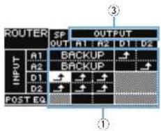
text_image
ROUTER SP OUTPUT OUT A1 A2 D1 D2 INPUT A1 BACKUP ↑ A2 BACKUP ↓ D1 → ↑ D2 → ↑ POST EQStandard model
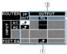
■ DZR series
text_image
ROUTER SP OUTPUT INPUT A1 OUT R2 POST EQ■ DXS-XLF series
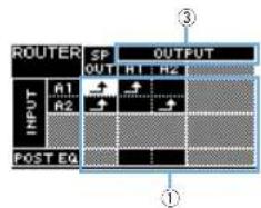
text_image
ROUTER SP OUTPUT INPUT A1 R2 POST EQ ③ ①①Routing
Configure the routing of the audio signal.
Check the input source (INPUT) and output destination (OUTPUT), and set the intersecting points. By default, signals from all input jacks will be output from the speakers. Routing cannot be performed for shaded areas on the screen.
②INPUT Dante model
Sets two Dante input levels, sensitivity and the degree of delay compensation.
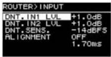
• DNT. IN1 LVL: Sets Dante input level D1. It can be set in 0.5 dB increments.
• DNT. IN2 LVL: Sets Dante input level D2. It can be set in 0.5 dB increments.
- DNT. SENS. (DANTE SENSITIVITY): Sets the input sensitivity for the digital signal sent from the Dante network to the amplifier. The input sensitivity set acts as the clip level for the speakers. Set this to either -14 dBFS (default setting) or -6 dBFS. When the [LEVEL] control is in the center position (0 dB), set this to -14 dBFS to ensure proper balance with the input level from the Dante network and the analog input level from devices having a maximum output of +24 dBu (which include many of Yamaha digital mixers). Make fine adjustment with DNT, IN1 LVL, DNT, IN2 LVL.
- ALIGNMENT (DELAY ALIGNMENT): Set this to ON, and set a delay here to compensate for the time lag between the analog input and the Dante input. Note that the appropriate delay setting will vary depending on the Dante settings configured and the combination of connected devices. As the Dante input typically lags behind, this delay setting will apply to the analog input. When you set the ALIGNMENT, refer to the "Route Latency Values" (page 46).
③ OUTPUT
Sets the output level. Output levels can be set in 0.5 dB increments.
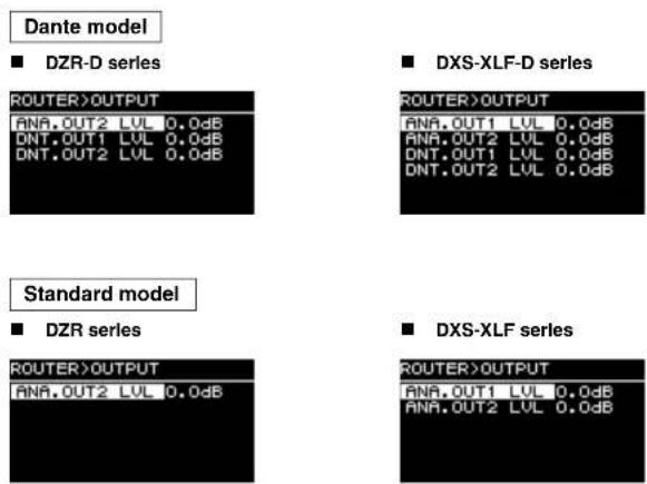
• ANA. OUT1 LVL: Sets analog output level A1 (page 7 ⑨, channel 1 output level).
• ANA. OUT2 LVL: Sets analog output level A2 (page 7 ⑨, channel 2 output level).
• DNT. OUT1 LVL: Sets Dante output level D1.
• DNT. OUT2 LVL: Sets Dante output level D2.
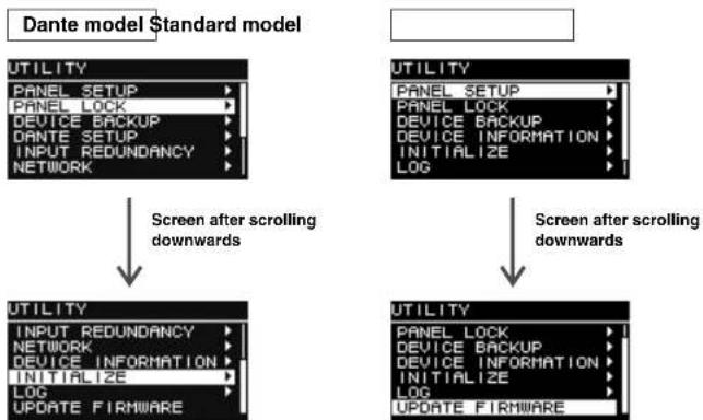
UTILITY Screen
The UTILITY screen is used to configure device settings, and save and load settings data to and from a USB flash drive.
■ PANEL SETUP
Sets the rear panel display method.
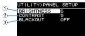
①BRIGHTNESS
Sets the brightness of the back light of the display. This setting can be set in 10 steps from 1 to 10.
②CONTRAST
Sets the contrast of the display.
This setting can be set in 16 steps from 1 to 16. Configure your display according to the operating environment so that it is easy to see. A higher contrast is recommended when viewing the display from above, such as with a subwoofer. Note, however, that setting the contrast too high may make the display harder to see directly from the front.
③BLACKOUT
The BLACKOUT setting is used to automatically turn the display and indicators off when the panel is not in use.
Turn this on to have the display and indicators automatically turn off as follows.
• After five seconds of panel inactivity: The display darkens slightly.
- After 15 seconds of panel inactivity: The display/indicators except the [POWER] indicator will turn off (see the table below).
Either press a key on the rear panel or press the main knob to wake the display/turn on the indicators.
| Display/indicator Automatically turns off when BLACKOUT is on | ||
| [POWER] indicator | (page 6 3) | Does not automatically turn off |
| Display | (page 6 4) | Off |
| [LIMIT] indicator | (page 6 2) | Off |
| [LINK] indicator | (page 8 15) | Off |
| [1G] indicator | (page 8 16) | Off |
| [SYNC] indicator | (page 8 17) | Off |
NOTE
- The [POWER] indicator will always remain on, even when the BLACKOUT setting is turned on.
- The display will darken after one minute of panel inactivity and turn off after 25 minutes of inactivity to protect the display, even if the BLACKOUT setting is off.
PANEL LOCK
Locks the operating panel to prevent inadvertent operating errors.
When doing so, users will be able to set a four-digit PIN code identifying the user. Also, the PIN code can be saved to and loaded from a USB flash drive.
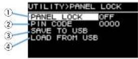
①PANEL LOCK
Sets the panel lock.
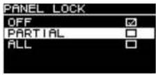
- OFF: Panel lock is off.
- PARTIAL: Locks off operations appearing on the display panel. MAIN Level settings can still be configured.
- ALL: Disables all actions except to remove the panel lock.
NOTE
- For more information on releasing the panel lock, see "Removing a Panel Lock" (page 22).
- If a PIN code has been set, the PIN code must be entered even when the setting of the panel lock is changed from OFF to PARTIAL or ALL.
②PIN CODE
Sets a PIN code (any four digits) for the panel lock.
Once a PIN code has been set, the PIN code must be entered to release the panel lock.
NOTE
- If you have forgotten the PIN code, you can still release the panel lock by initializing this product. See "Initializing to the default settings when you have forgotten your PIN code, etc." (page 12).
- The default PIN code setting is 0000. You will not be required to enter the PIN code to release the panel lock when the PIN code is set to 0000.
- Setting PIN Codes
1. Open the PIN code Input screen.
Navigate from the HOME screen to select UTILITY → PANEL LOCK → PIN CODE. The cursor is on the first digit of the PIN code.
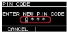
- Turn the main knob to select a number, and then press the main knob to enter it.
Once entered, the cursor will move to the next digit.
3.Enter subsequent numbers in the same way.
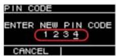
NOTE
You can correct the PIN code while it is being input by pressing the [1 Back] key and selecting the desired digit with the main knob.
- Press the main knob to execute OK.
This will determine the PIN code.
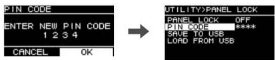
text_image
PIN CODE ENTER NEW PIN CODE 1 2 3 4 CANCEL OK → UTILITY>PANEL LOCK PANEL LOCK OFF PIN CODE ***** SAVE TO USB LOAD FROM USBNOTE
If the PIN code is set to 0000, the PIN code has not been set. In this state, PIN code input is not needed to set or release the panel lock.
③SAVE TO USB
Saves the PIN code to a USB flash drive.
Connect the USB flash drive to the USB terminal, and then select SAVE TO USB.
Select YES on the confirmation screen. If "SAVE SUCCEDED" appears, the process is complete. Select OK to return to the previous screen.
NOTE
- If the PIN code saved to a USB flash drive matches the PIN code saved to this product, the panel lock will be released while the USB flash drive is connected to this product. (This is useful for avoiding the regular lock release process when you wish to temporarily release the lock to change a parameter, for example.)
- For more details on potential alert messages, see the "Message List" (page 39).
④LOAD FROM USB
Loads the PIN code saved to a USB flash drive.
You can set the same PIN code for multiple DZR, DXS-XLF series devices.
Connect the USB flash drive to the USB terminal, and then select LOAD FROM USB.
Select YES on the confirmation screen. If "LOAD SUCCEEDED" appears, the process is complete. Select OK to return to the previous screen.
NOTE
- Retrieving a PIN code from a USB flash drive when the panel lock is turned off will set the panel lock setting to PARTIAL.
- For more details on potential alert messages, see the 'Message List' (page 39).
- Removing a Panel Lock
If a PIN code has not been set
The default PIN code setting is 0000. You will not be required to enter the PIN code when the PIN code is set to 0000.
When the panel controls are operated while the panel is locked, the following message appears in the display.
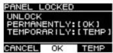
- To permanently remove the panel lock: Turn the main knob to select OK, and then press the main knob to execute it.
- To temporarily remove the panel lock: Turn the main knob to select TEMP, and then press the main knob to execute it. Note that turning the power back on or panel inactivity for five minutes will restore the panel lock setting.
If a PIN code has been set
When the panel controls are operated while the panel is locked, the following message appears in the display.
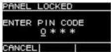
Enter the four-digit PIN code you set.
Turn the main knob to select a number, and then press the main knob to enter it.
E.g.) PIN code: 1234
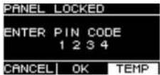
- To permanently remove the panel lock: Turn the main knob to select OK, and then press the main knob to execute it.
- To temporarily remove the panel lock: Turn the main knob to select TEMP, and then press the main knob to execute it. Note that turning the power back on or panel inactivity for five minutes will restore the panel lock setting.
NOTE
You will not be required to enter the PIN code when the PIN code is set to 0000 (the default setting).
If the PIN code has been saved to a USB flash drive
Connect the USB flash drive the PIN code has been saved to this product. The panel lock will be removed for the duration that the USB flash drive is connected to this product. Remove the USB flash drive to restore the panel lock.
(For more information about saving PIN codes, see "UTILITY Screen" - "■ PANEL LOCK" - "③ SAVE TO USB"; page 21).
■ DEVICE BACKUP
Saves and loads the user settings to and from a USB flash drive.
Use this function when you want to set multiple DZR, DXS-XLF series devices to the same setting configuration, or change to another DZR, DXS-XLF series device while retaining the same settings.
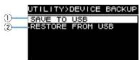
①SAVE TO USB
Saves settings data to a USB flash drive.
Connect the USB flash drive to the USB terminal, and then select SAVE TO USB and enter the file name. File names can be up to 16 characters long. Only half-width alphanumeric characters and some symbols are supported.
Turn the main knob to select the position to enter text, and then press the main knob to enter text input mode. When in text input mode, turn the main knob to select a character, and then press the main knob to enter the character.
NOTE
For more details on potential alert messages, see the 'Message List' (page 39).
②RESTORE FROM USB
Loads settings files stored to a USB flash drive.
Connect the USB flash drive to the USB terminal, and then select RESTORE FROM USB. A list of files stored to the USB flash drive will appear on the screen. Select the file you want to load. Up to 20 files can be displayed on the screen.
NOTE
- Audio will be muted temporarily when settings are changed to avoid noise being output.
- For more details on potential alert messages, see the "Message List" (page 39).
- When changing file names on your computer, make sure the new file name is 16 characters or less and only uses half-width alphanumeric characters or the following symbols: #, #, %, \&, , · , + = , , [·] , _· = · , [ ·] (space). Note that you will not be able to load a file that does not follow these naming conventions.
- Be aware that using RESTORE FROM USB will overwrite presets even if they are protected (see page 15, "■ PROTECT").
DANTE SETUPDante model
This screen is used to configure Dante settings and display the Dante network status.
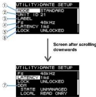
text_image
UTILITY>DANTE SETUP MODE STANDARD UNIT ID 21 LABEL Fs 48kHz LATENCY 1ms LOCK UNLOCKED Screen after scrolling downwards UTILITY>DANTE SETUP Fs 48kHz LATENCY 1ms LOCK UNLOCKED DDI STATE UNMANAGED LOCAL READ ONRY①MODE (DANTE MODE)
Sets the mode used when connecting this product to the Dante network.
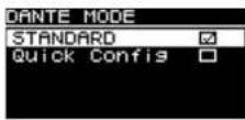
- STANDARD: Select this when not using the TF series Quick Config function.
- Quick Config: Select this when using the TF series Quick Config function.
NOTE
If there are multiple TF series devices on the Dante network, only select the TF series "with OUTPUT" check box for one device. Patches will not be applied correctly if multiple devices are selected.
\*PATCH
Set the MODE to Quick Config to display the PATCH screen and add PATCH item. Select the TF series output channel to be patched to this product on the PATCH screen. For more details, see "Patch Correspondence Chart when Using Quick Config" (page 41).
NOTE
It will take several seconds for patches to actually change after changing the selling of PATCH.
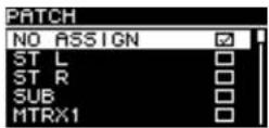
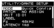
When the MODE is set to Quick ConfigPATCI
②UNIT ID
Sets an ID assigned so that DZR-D or DXS-XLF-D series devices on the Dante network can be recognized individually.
The UNIT ID set will be applied after restarting this product. Avoid using the same ID for the same model devices on the same network.
NOTE
• The setting range is 01 to FE (hexadecimal range).
- This is the same UNIT ID as that on NETWORK (page 26). A UNIT ID can be changed from either menu location.
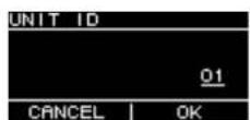
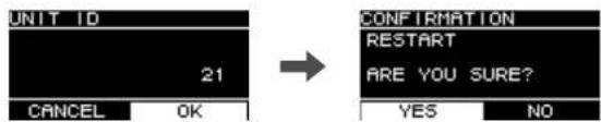
Turn the main knob to select the character you wish to enter, and then press the main knob to enter the character. When the restart confirmation screen appears, select YES. The setting will be applied after restarting this product.
text_image
UNIT ID 21 CANCEL OK CONFIRMATION RESTART ARE YOU SURE? YES NOThe UNIT ID set will appear on the HOME screen.
③LABEL
Sets a label for this product. Set a label that clearly identifies this product to make it easier to find from the Dante Controller, etc.
NOTE
- Label names can contain a maximum of 12 characters.
- Only half-width alphanumeric characters and some symbols are supported.
• The label set will form part of the Device Label.
If a LABEL is not set (default setting):
Y#####-Yamaha-xxxxxxxxxx-****
: UNIT ID
x: Model name (maximum of 10 characters)
*****: Last six digits of the MAC address
If a LABEL has been set:
7: LABEL (maximum of 12 characters)
*****: Last six digits of the MAC address
④Fs (DANTE Fs)
Sets the sampling frequency for Dante input/output. Select a sampling frequency from 44.1 kHz, 48 kHz, 88.2 kHz or 96 kHz.
⑤LATENCY (DANTE LATENCY)
Sets the signal latency (Dante latency) for transmitting and receiving over the Dante network. Select a latency amount from 1 ms, 2 ms or 5 ms.
The Dante latency must correspond to the connection method used and the size of the network.
| 1ms | Use this setting when signals pass through up to 10 devices, including network switches |
| 2ms | This setting is suited to Giga-bil Ethernet networks that include 100 Mbps nodes |
| 5ms This setting can be safely applied to just about any network environment | |
The 1 ms setting may not allow enough time for data transmission on systems with 10 or more Dante devices, including network switches, etc., connected in a daisy chain, resulting in audio skips. If skipping occurs, increase the latency time setting.
NOTE
If two devices with different latency settings are patched together, the slower latency time setting will be applied.
⑥LOCK
Shows the Dante Device Lock status. Use the Dante Controller to configure settings. "LOCKED" will appear when the lock setting is applied, and "UNLOCKED" will appear when the lock is released. When locked, you will not be able to change Dante settings.
⑦DDM (Dante Domain Manager)
This shows the status of any DDM servers on the network, and domain participation status.
• STATE: Shows the domain participation status.
- DOMAIN: Participating in a domain.
- DISCONNECTED: Participating in a domain, but not connected to a DDM server.
- UNMANAGED: Not participating in a domain.
- LOCAL: Shows the access status for Dante settings (including DANTE PATCH) configured for this product currently in use.
- READ WRITE: Changes permitted.
- READ ONLY: Changes not permitted.
■ INPUT REDUNDANCYDante model
NOTE
The INPUT REDUNDANCY function works independently of the redundancy function of the Dante network.
- Backup mode
In this mode, if Dante input audio is interrupted due to a problem such as an input device failure, the line for the backup source will be enabled automatically. If the original input audio is subsequently restored, the primary line will be enabled automatically.
Dante In (CH1 or 2) is used for the primary source, and Analog In (CH1 or 2) is used for the backup source. The channel combination is fixed.
| PRIMARY SOURCE BACKUP SOURCE | |
| Dante In 1 Analog In 1 | |
| Dante In 2 Analog In 2 | |
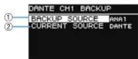
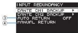
① DANTE CH1 (or CH2) BACKUP SOURCE
Specifies whether the backup source is enabled or disabled.
②CH1 (or CH2) CURRENT SOURCE
Displays the currently enabled line: primary source (Dante) or backup source (Analog).
③AUTO RETURN
If this setting is turned ON, the input source will be reverted automatically to the primary line when the primary line is restored.
④MANUAL RETURN
When the primary line is restored, the input source must be reverted manually to the primary line.
(Applies only when AUTO RETURN is set to OFF.)
NOTE
- Backup mode will be enabled 60 seconds after the power is turned on.
- After the Dante input signal is interrupted, it will take approximately two to three seconds until Backup mode kicks in. During this time, audio will be interrupted.
- Backup mode will also be enabled if you remove Dante's input/output patches. In such an event, even if you set up the patches again, Backup mode will remain in effect if AUTO RETURN has been set to OFF. To restore the primary line, you must execute the MANUAL RETURN function.
Screen Functions
■ NETWORKDante model
Configures network settings used to control this product with an external device. The settings changed will be applied after restarting this product.
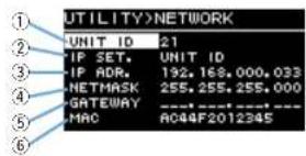
text_image
UTILITY>NETWORK UNIT ID 21 IP SET. UNIT ID IP ADR. 192.168.000.033 NETMASK 255.255.255.000 GATEWAY MAC A044F2012345①UNIT ID
Sets an ID assigned so that DZR-D or DXS-XLF-D series devices on the Dante network can be recognized individually. See "UTILITY Screen" – "■ DANTE SETUP" – "② UNIT ID" (page 24).
②IP SET. (IP SETTING)
Select how the IP address is set.
- UNIT ID: Set to 192.168.0.### (### = UNIT ID).
- DHCP: Sets an IP address assigned from the DHCP server. The IP address, NETMASK and GATEWAY will be retrieved automatically. If the DHCP server is not on the network, a link-local address (169.254.xxx.xxx) will be used.
• STATIC IP: Sets an IP address manually.
NOTE
When using this product while connected to a CL series or CL series device, set a different address using the same subnet as the IP address set on the FOR DEVICE CONTROL on the mixer. Also, when using this product while connected to a RIVAGE PM series device, set a different address using the same subnet as the IP address set on the SIOT IP SETTING on the mixer.
③IP ADR.
Shows the IP address. Use this to set the IP address if STATIC IP is selected as the IP SET setting.
④NETMASK
Shows the subnet mask. Use this to set the subnet mask if STATIC IP is selected as the IP SET, setting.
⑤GATEWAY
Shows the default gateway. Use this to set the default gateway if STATIC IP is selected as the IP SET. setting.
⑥MAC
Shows the MAC address. This address is shown for reference and cannot be changed.
■ DEVICE INFORMATION
Shows device status, and device-specific information.
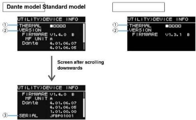
flowchart
graph TD
    A["Utility>DEVICE INFO"] --> B["Screen after scrolling downwards"]
    C["UTILITY>DEVICE INFO"] --> B
    D["SERIAL"] --> B
①THERMAL
Shows the amplifier temperature in five stages. The limiter will be activated based on the temperature detected.
②VERSION
- FIRMWARE: Shows the firmware version. The rightmost alphabet indicates the hardware version. (Firmware V1.3.0 or later.)
• Dante Dante/modele Dante versions. - With the DZR315(-D), this field indicates the part version information for the target MF unit.
- For information on the correct combination of firmware version and target MF unit version, refer to the compatibility chart on the website (https://usa.yamaha.com/support/updates/dzr_dxs_xlf_firm.html).
③SERIAL | Dante model
Shows the serial number.
INITIALIZE
Initializes the data of all settings.

WARNING
Disconnect all the cables except the power cord before this operation. A sudden loud sound might occur when initializing is completed, if an audio signal is present.
For initializing, when the screen shown below appears, press the main knob. When a confirmation screen appears, select YES to restart this product. If you cancel the initialization procedure, press the 1 key when the screen shown below appears.
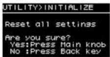
NOTICE
The HOME screen will appear after restarting, indicating that the initialization procedure is complete. Turning the power switch off before the HOME screen appears could cause a malfunction.
LOG
Shows internal action logs, and saves them to a USB flash drive.
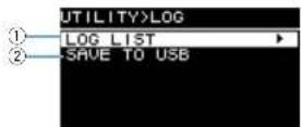
①LOG LIST
Shows all internally recorded action logs.
Logs will be shown in the order that events occur. Time is displayed in "NNNN HHH:MM:SS" format. This indicates that the event occurred HHH (hours) MM (minutes) SS (seconds) after the NNNNth time the power was turned on. The column on the right shows the alert ID.
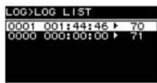
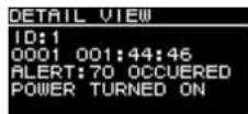
Turn the main knob to select an event, and then press the main knob to execute and display the DETAIL VIEW screen. For more details on each event message, see the "Message List" (page 39).
②SAVE TO USB
Saves the latest action log to a USB flash drive. This function is provided for user support.
UPDATE FIRMWARE
Use a USB flash drive to update this product firmware and Dante module firmware.
Download the latest update files from the Yamaha Pro Audio website. https://www.yamahaproaudio.com/
Save the update files to the USB flash drive. Connect the USB flash drive to the USB terminal, and then select UPDATE FIRMWARE.
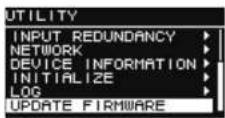
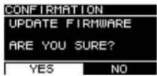
Select YES on the confirmation screen to restart this product.
When restarting, the following confirmation screen will appear.
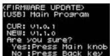
- To update: Press the main knob. The update progress will be shown as a percentage (%). When the update is complete, this product will start normally. Do not disconnect the USB flash drive while the update is in progress.
- To cancel the update: Press the [←] (Back) key.
Screen Functions
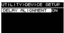
■ DEVICE SETUP
(Firmware V1.3.0 or later, hardware version A only.)
When used in combination with a device of hardware version B, setting it to ON compensates for the difference in latency due to the difference in hardware versions.
Muting from an External Device Dante model
You can mute speaker audio using an external device (such as the RIVAGE PM, CL, QL, and TF series). When muted, "MUTED from REMOTE" will appear on the HOME screen. This device can only be used to unmute muted audio. Turning the power off and on while audio is muted from an external device will cancel the mute setting.
● Unmuting audio muted from an external device
- Turn the main knob to select "MUTED from REMOTE".
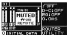
- Press the main knob to select this and unmute the audio.
For more information about muting audio with an external device, see the Owner's Manual supplied with the external device in use.
Dante Network System
• Outline of Dante
The DZR-D and DXS-XLF-D feature not only analog input/output signals, but also Dante technology to transmit digital audio signals. Dante is a network audio protocol developed by Audinate. It is designed to deliver multi-channel audio signals at various sampling frequencies and bit rates as well as device control signals in the same network, over a Gigabit Ethernet (GbE) network.
Visit the Audinate website for more information on Dante. https://www.audinate.com/
More information on Dante is also posted on the Yamaha Pro Audio website. https://www.yamahaproaudio.com/
NOTE
Please do not use the EEE function (*) of network switches in a Dante network.
Although power management should be negotiated automatically in switches that support EEE, some switches do not perform the negotiation properly. This may cause EEE to be enabled in Dante networks when it is not appropriate, resulting in poor synchronization performance and occasional dropouts.
Therefore we strongly recommend that:
- If you use managed switches, ensure that they allow EEE to be disabled. Make sure that EEE is disabled on all ports used for real-time Dante traffic.
- If you use unmanaged switches, make sure to not use network switches that support the EEE function, since EEE operation cannot be disabled in these switches.
* EEE (Energy Efficient Ethernet) is a technology that reduces switch power consumption during periods of low network traffic. It is also known as Green Ethernet and IEEE802.3az.
- Connections
There are two ways to connect the DZR-D and DXS-XLF-D to a Dante network. Both devices can be used in combination with one another.
Daisy Chain Network
A daisy chain is a wiring scheme in which multiple devices are connected together in sequence. In this way, networking is simple and requires no network switches. If you connect a large number of devices, you must set a higher latency value to avoid audio glitches that could be caused by an increased delay in signal transfer among the devices. Also, if a connection is broken in a daisy chain network, the signal flow is interrupted at that point and no signal will be transferred beyond that point.
Star Network
In a star network, each device is connected to a central network switch. Using a GbE-compatible network switch enables you to configure a wide-band, large-scale network. We recommend a network switch that features various functions to control and monitor the network (such as QoS, the ability to assign priority to data flows—for example, clock synchronization or audio transmission on certain circuits). DZR-D and DXS-XLF-D cannot be used in a redundant (secondary) network because the two Dante jacks of DZR-D and DXS-XLF-D are primary connectors.
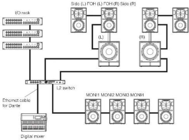
System setup example
This example uses only DZR-D and DXS-XLF-D series speakers.
flowchart
graph TD
    A["I/O rack"] --> B["L2 switch"]
    C["Digital mixer"] --> B
    D["Mon1 MONI2 MONI3 MONI4"] --> B
    B --> E["(L)"]
    B --> F["(R)"]
    E --> G["Sido (L) FOH (L) FOH (R) Side (R)"]
    F --> H["Sido (L) FOH (L) FOH (R) Side (R)"]
Configuration with Dante Models
Limit the number of Dante devices to within 10 units, including switches, in a single daisy chain. If the number of Dante devices exceeds 10 units, communication latency within the network will increase and the audio might drop out. To prevent this, set a higher Danle Latency value (page 24, ⑤ LATENCY), or use an L2 switch (that supports Giga-bil Ethernet) to create branches in the network.
NOTE
It is important to setup a well-balanced system that leverages the advantages offered by both daisy chain and star network connections.
Dante Settings
When using the DZR-D and DXS-XLF-D in a connection to a Dante network, use the DANTE SETUP screen to configure various Dante settings.
Navigate from the HOME screen and select UTILITY → DANTE SETUP to open the DANTE SETUP screen. To open the DANTE SETUP screen, you can also navigate from the HOME screen and select UNIT ID, LABEL (the upper left of the HOME screen). See page 13.
DANTE SETUP screen
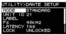
* For more information about each function, see "Screen Functions" – "UTILITY Screen"
■ DANTE SETUP" (page 23).
Connecting to Dante Devices
- About Dante Controller
Dante Controller is a software application that allows configuration and audio routing of Dante networks. Use this application if you plan to connect to Dante devices other than Yamaha digital mixers compatible to integration with DZR-D and DXS-XLF-D, or apply more advanced settings.
Please download the latest version of the Dante Controller application from the website listed below.
https://www.yamahaproaudio.com/
To run Dante Controller, the computer must feature a GbE (Giga-bit Ethernet)-compatible connector.
In Dante Controller, you can apply the following main settings.
• I/O patch settings on the Routing tab in Network View
- Clock leader settings on the Clock Status tab in Network View
- Sampling rate settings on the Device Config tab in Device View
NOTE
I/O patch settings and other Dante-related settings cannot be changed if Dante Device Lock has been enabled on the Dante Controller. To change these settings, first remove the Dante Device Lock on the Dante Controller.
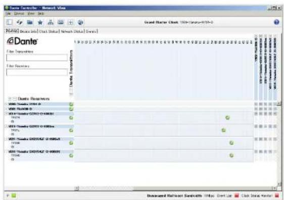
• Dante Controller Settings
Start Dante Controller and open Network View.
Set the audio routing between Dante devices in Network View. All Dante devices on the network will appear on this screen. Click the cells [+] where transmitting and receiving devices intersect to show all the channels, and then establish audio routes. A green check box icon will appear when a route has been set.
text_image
Dante Controller - Network Status File Edit View Help Grand Master Clock 1984-03-2015-07-0 REDAI [Data Int] Data Status [Network Status Events] Data Transfers Data Reactions Dante Transfers Dante Reactions Dante Channel 0000-0 Dante Channel 0 Dante Channel 0001-0-0000-0 Dante Channel 0 Dante Channel 0002-0-0000-0 Dante Channel 0 Dante Channel 0003-0-0000-0 Dante Channel 0 Dante Channel 0004-0-0000-0 Dante Channel 0 Dante Channel 0005-0-0000-0 Dante Channel 0 Dante Channel 0006-0-0000-0 Dante Channel 0 Dante Channel 0007-0-0000-0 Dante Channel 0 Dante Channel 0008-0-0000-0 Dante Channel 0 Dante Channel 0009-0-0000-0 Dante Channel 0 Dante Channel 0010-0-0011-1 Dante Channel 1 Dante Channel 11 Unsupervised Network Bandwidth https: Event Log Click State CenterFor more details, see the Dante Controller User's Manual.
Also, for more information about the Dante channels assigned to the output signals from the transmitting devices (digital mixers, etc.), see the relevant manuals for the transmitting devices.
Integration with Yamaha Digital Mixers
The DZR-D and DXS-XLF-D can be patched with Yamaha digital mixers (RIVAGE PM, CL, QL, TF or DM7 series, or DM3) without using Dante Controller. In such cases, the number of the devices which can be patched is 24 at the maximum, including other Dante devices. When patching with more than 25 devices, use Dante Controller.
If a RIVAGE PM, CL, QL, TF or DM7 series device, or a DM3 device being patched has a clock rate of 48 kHz, the DANTE Fs setting of DZR-D and DXS-XLF-D must also be set to 48 kHz. Even when this is set to 48 kHz, the DZR-D and DXS-XLF-D will still run at 96 kHz internally using an internal SRC (Sampling Rate Converter). Use Dante Controller when establishing a complex system that requires advanced settings, or large-scale systems.
The following functions are available when using the DZR-D and DXS-XLF-D in combination.
• TF series
- Automatic patch settings by Quick Config function (See page 23, "DANTE SETUP" ①)
• Major status monitoring - Mule control
- Identify function
DM3
• Automatic patch settings via the AUTO Setup function
● RIVAGE PM series, CL series, QL series, DM7 series
- Patch settings from the mixer screen (Set a different UNIT ID for the DZR-D and DXS-XLF-D devices connected.)
• Major status monitoring
• Major parameters control - Identify function
NOTE
If the digital mixer cannot recognize the DZR-D or DXS-XLF-D, and the DZR-D or DXS-XLF-D does not appear on the digital mixer screen, check the digital mixer firmware version.
About Dante
The Yamaha digital mixers compatible to integration with DZR-D and DXS-XLF-D, and supported firmware versions are as follows.
| Digital mixer Supported firmware version | |
| RIVAGE PM series V5.0 and later | |
| CL series V5.1 and later | |
| QL series V5.1 and later | |
| TF series V3.6 and later | |
| DM7 series V1.03 and later | |
| DM3 V1.03 and later | |
To use the abovementioned functions, you will need to update to the supported firmware version.
For more information on the use of Yamaha digital mixers, see the relevant manual for the model in use.
https://www.yamahaproaudio.com/
Reference
Precautions when Using the USB Terminal
- Compatible USB devices
- Use a USB flash drive. You will not be able to use any other USB device (USB hub, mouse, computer keyboard, etc.) when connected.
- This product is compatible with USB1.1 to 2.0 USB flash drives (however, not all USB flash drives have been verified for compatibility).
NOTICE
The USB terminal is rated at a maximum of 5V/500mA. An alert message will appear on the display when attempting to connect a device that requires a current exceeding 500mA, and the power supply will be stopped.
- Connecting a USB flash drive
- Do not insert or remove a USB flash drive while a message appears on the screen. Doing so may prevent the product from functioning properly, or may damage the USB flash drive itself and the data contained within.
- Wait several seconds before reinserting a USB flash drive after removing it.
NOTICE
When using a USB extension cable, use a cable that is no longer than 1 m.
Using USB Flash Drives
- USB flash drive format
Use a USB flash drive formatted to FAT32 or FAT16. Format the flash drive on your computer. Note that USB flash drives formatted on other devices may not work properly with this product.
● Preventing accidental data erasure
Your USB flash drive may come with a write-protect function to prevent accidental data erasure. Use the write-protect feature to prevent important data from being overwritten. Conversely, when saving data, check that the USB flash drive's write-protect function is off before using the flash drive.
● Turning the power off when connecting the USB flash drive
Make sure the system is not accessing the USB flash drive (check that there are no messages on the display) before turning the power off. Failure to do so may damage the USB flash drive itself and the data contained within.
Function Tree
| Function | Category | Settings | Default value | Setting range | Full range Subwoofer | Page number | |||
| Standard Dante Standard Dante | |||||||||
| METER Input | Meter Shows analog input signal levels. (On Dante models this will appear as ANA.) | - to 0dBFS | (×2) | (×2) | (×2) | (×2) | 11 | ||
| Input Meter (DNT) Shows digital input signal (Dante) levels. | - to 0dBFS | (×2) | (×2) | 11 | |||||
| UNIT ID | Shows the ID assigned so that DZR-D or DXS-XLF-D series devices on the Dante network can be recognized. | 01 | 01 to FE | 11, 24, 26 | |||||
| LABEL | Shows the label. | - | 12 characters | 11, 24 | |||||
| MAIN Level | Sets the output level. (Unit: dB) | 0.0dB | - to 80 to +10.0dB | 11 | |||||
| SP Output Meter | Shows the output level. | - | - to 0dBFS | 11 | |||||
| Protection (THERMAL MUTED) | Appears when safeguard functions have been activated. | Hidden | THERMAL, MUTED | 11 | |||||
| MUTED from REMOTE | Mules audio from an external device. | 011 | 29 | ||||||
| Function | Category | Parameter | Default value | Setting range | Full range Subwoofer | Page number | |||
| Standard Dante Standard Dante | |||||||||
| TUNING | HPF | OFF, 60Hz, 70Hz, 80Hz, 90Hz, 100Hz, 110Hz, 120Hz | OFF | 60Hz to 120Hz | 11, 15 | ||||
| LPF | 60Hz, 70Hz, 80Hz, 90Hz, 100Hz, 110Hz, 120Hz | 120Hz | 60Hz to 120Hz | 11, 15 | |||||
| POLARITY | NORMAL | NORMAL, INVERTED | |||||||
| D-CONTOUR | OFF (NORMAL), FOH/MAIN, MONI-TOR | OFF (NORMAL) | OFF (NORMAL), FOH/MAIN, MONITOR | 11, 15 | |||||
| D-XSUB | OFF (NORMAL), BOOST, XTEND LF | OFF (NORMAL) | OFF (NORMAL), BOOST, XTEND LF | 11, 16 | |||||
| EQ (6 bands) | ON, OFF | ON | ON, OFF | 11, 16 | |||||
| BYPSSONON, OFF (×6) (×6) (×6) | ON | ON, OFF | (×6) | (×6) | (×6) | (×6) | |||
| FREQ20.0Hz to 20.0kHz (×6) (×6) (×6) | 20.0Hz to 20.0kHz (×6) (×6) (×6) | 20.0Hz to 20.0kHz (×6) (×6) (×6) | (×6) | (×6) | (×6) | (×6) | |||
| GAIN | 0.0 | -10.0 to +10.0dB | (×6) | (×6) | (×6) | (×6) | |||
| Q | 2.00 | 0.7 to 10.0 | (×6) | (×6) | (×6) | (×6) | |||
| TYPE | PEQ | PEQ, LO SHELF 6dB, LO SHELF 12dB, HI SHELF 6dB, HI SHELF 12dB, HPF, LPF | (×6) | (×6) | (×6) | (×6) | |||
| DELAY | ON, OFF | ON | ON, OFF | 11, 16 | |||||
| ms | 0.0ms | 0.0 to 140.0ms | |||||||
| m | 0.00m | 0.00 to 48.10m | |||||||
| ft | 0.0ft | 0.0 to 157.8ft | |||||||
| CARDIOID | OMNI (FRONT), CARDIO-2 (REAR), CARDIO-3 (REAR) | OMNI (FRONT) | OMNI (FRONT), CARDIO-2 (REAR), CARDIO-3 (REAR) | 11, 17 | |||||
Reference
| Function | Category | Parameter | Default value | Setting range | Full range | Subwoofer | Page number | ||
| Standard | Dante | Standard | Dante | ||||||
| ROUTER Routing SP OUT (On), — (Off) √ | √ √ √ | ↗ | ↗ | 18 | |||||
| A1 <Analog OUTPUT 1> (On), — (Off) | √ ↗ √ | ↗ | |||||||
| A2 <Analog OUTPUT 2> (On), — (Off) | √ ↗ √ | √ ↗ √ | |||||||
| D1 <Dante OUTPUT 1> (On), — (OII) √ | ↗ | √ ↗ | |||||||
| D2 <Dante OUTPUT 2> (On), (OII) √ | ↗ | √ ↗ | |||||||
| INPUT DNT. IN1 LVL | +1.0dB ↔, -30.0 to +10.0dB √ | √ | 18 | ||||||
| +1.0dB ↔, -30.0 to +10.0dB √ | √ | ||||||||
| DNT. IN2 LVL <Dante Input Level 2> | -14dBFS -14dBFS, -6dBFS √ | √ | |||||||
| DNT. SENS. (DANTE SENSITIVITY) | OFF OFF, ON | √ | |||||||
| 1.70ms | 0.00ms to 20.00ms | √ | √ | ||||||
| OUTPUT | ANA. OUT1 LVL <Analog Output Level 1> | 0.0dB | ↔, -60.0 to +10.0dB | √ | 19 | ||||
| ANA. OUT2 LVL <Analog Output Level 2> | 0.0dB | ↔, -60.0 to +10.0dB | √ | √ | √ | ||||
| DNT. OUT1 LVL <Dante Output Level 1> | 0.0dB | ↔, -80.0 to +10.0dB √ | √ | ||||||
| DNT. OUT2 LVL <Dante Output Level 2> | 0.0dB | ↔, -60.0 to +10.0dB √ | √ | ||||||
| UTILITY | PANEL SETUP | BRIGHTNESS | 6 | 1 to 10 | √ | √ | √ | √ | 19 |
| CONTRAST | Full range: 5. Subwoofer: 12 | 1 to 16 | √ | √ | √ | √ | 20 | ||
| BLACKOUT | OFF OFF, ON | √ √ | √ | √ | |||||
| PANEL LOCK | PANEL LOCK | OFF | OFF, ON | √ | √ | √ | √ | 20 | |
| PIN CODE | 0000 | Four-digit numeral | √ | √ | √ | √ | |||
| SAVE TO USB | — | — | √ | √ | √ | √ | 21 | ||
| LOAD FROM USB — | — | √ √ | √ | √ | |||||
| DEVICE BACKUP | SAVE TO USB | — | — | √ | √ | √ | √ | 23 | |
| RESTORE FROM USB | — | — | √ | √ | √ | √ | |||
Reference
| Function | Category | Parameter | Default value | Setting range | Full range | Subwoofer | Page number | ||
| Standard | Dante | Standard | Dante | ||||||
| UTILITY | DANTE SETUP | MODE (DANTE MODE) | STANDARD | STANDARD, Quick Config | √ | √ | 23 | ||
| "PATCH | NO ASSIGN | See the "Patch Correspondence Chart when Using Quick Config" (page 41) | √ | √ | |||||
| UNIT ID 01 01 to FE √ | √ | 11, 24 | |||||||
| LABEL | 12 characters(alphanumeric characters, -) | √ | √ | ||||||
| Fs (DANTE Fs) 48kHz 44.1kHz, 48kHz, 38.2kHz, 96kHz √ | √ | 24 | |||||||
| LATENCY (DANTE LATENCY) | 1ms | 1ms, 2ms, 5ms | √ | √ | |||||
| LOCK | UNLOCKED | UNLOCKED, LOCKED | √ | √ | 25 | ||||
| DDM | — | — | — | — | — | — | |||
| STATE | DISCONNECTED | DOMAIN, DISCONNECTED, UNMANAGED | √ | √ | |||||
| LOCAL | READ ONLY | READ WRITE, READ ONLY | √ | √ | |||||
| INPUT REDUNDANCY | DANTE CH1 BACKUP SOURCE | OFF | OFF, A1 | √ | √ | 25 | |||
| CH1 CURRENT SOURCE | — | -, DANTE, ANALOG | √ | √ | |||||
| DANTE CH2 BACKUP SOURCE | OFF | OFF, A2 | √ | √ | |||||
| CH2 CURRENT SOURCE | — | -, DANTE, ANALOG | √ | √ | |||||
| AUTO RETURN | ON | OFF, ON | √ | √ | |||||
| MANUAL RETURN (Executable when AUTO RETURN is set to OFF.) | — | — | √ | √ | |||||
| NETWORK | UNIT ID | 01 | 01 to FE | √ | √ | 11, 26 | |||
| IP SET (IP SETTING) | DHCP | UNIT ID, DHCP, STATIC IP | √ | √ | 26 | ||||
| IP ADR. | — | IPv4 | √ | √ | |||||
| NETMASK | — | IPv4 | √ | √ | |||||
| GATEWAY | — | IPv4 | √ | √ | |||||
| MAC | — | — | √ | √ | |||||
| DEVICE INFORMATION | THERMAL | — | — | √ | √ | √ | √ | 27 | |
| VERSION | — | — | — | — | — | — | |||
| FIRMWARE | — | — | √ | √ | √ | √ | |||
| MF UNIT | — | — | √ | √ | — | — | |||
| Dante | — | — | √ | √ | |||||
| SERIAL | — | — | √ | √ | |||||
| INITIALIZE | — | — | — | √ | √ | √ | √ | 27 | |
| LOG | LOG LIST | — | — | √ | √ | √ | √ | 28 | |
| SAVE TO USB | — | — | √ | √ | √ | √ | |||
| UPDATE FIRMWARE | — | — | — | √ | √ | √ | √ | 28 | |
| DEVICE SETUP | DELAY ALIGNMENT | OFF | OFF, ON | √ | √ | √ | √ | 29 | |
Reference
| Function | Category | Parameter | Default value | Setting range | Full range | Subwoofer | Page number | ||||
| Standard | Dante | Standard | Dante | ||||||||
| PRESET O: INITIAL DATA | RECALL — — √ | √ | √ | √ | 14 | ||||||
| A to C(*) : Factory presets1 to B: User presets | STORE — — √ | √ | √ | √ | |||||||
| CLEAR — — √ | √ | √ | √ | ||||||||
| * Number values may changedepending on the model inuse. | TITLE — — √ | √ | √ | √ | |||||||
| PROTECT — — √ | √ | √ | √ | 15 | |||||||
Message List
| Number Message Symptom Countermeasure | |||
| 01-11 SYSTEM ERROR | The product does not start up properly. | Turn the power off and wait at least six seconds before turning the power back on. If the problem persists, try initializing this product. If this still does not resolve the problem, please contact your Yamaha dealer. | |
| 12 CURRENT MEMORY ERROR | |||
| 13 PRESET MEMORY ERROR | |||
| 14 | SYSTEM ERROR | ||
| 15 | |||
| 17 | DUPLICATE IP ADDRESS | A duplicate IP address is in use. | Set the IP address to one that does not overlap with another IP address. |
| 20 OUTPUT CURRENT OVER | Circuit protection has been activated due to excess amplifier output current. | The product may be faulty.Please contact your Yamaha dealer. | |
| 22 AMP TEMP TOO HIGH stop1[*] An output limiter has been applied due to excess temperature detected in the amplifier.(*: HF or LF) | Either reduce the output level, or wait for the heat to subside before using again. Alternatively, keep the rear panel out of direct sunlight, and ensure that the area around the rear panel is well ventilated. | ||
| 23 AMP TEMP TOO HIGH stop2[*] | |||
| 25 AMP TEMP TOO HIGH stop3[*] | Audio output has been muted due to excess temperature detected in the amplifier.(*: HF or LF) | Wait for the heat to subside before using again. Alternatively, keep the rear panel out of direct sunlight, and ensure that the area around the rear panel is well ventilated. | |
| 27 POWER SUPPLY TEMP TOO HIGH[*] | A limiter was applied due to an abnormally high temperature detected in the power supply unit.(*: HF or LF) | Continuing use may cause the power supply unit to malfunction. Reduce the output level before using again. | |
| 34 AMP PROTECT (LIMIT)[*] | An output limiter has been applied due to an abnormality detected in the amplifier.(*: HF or LF) | Wait for the heat to subside before using again. The product may be faulty if symptoms persist even after cooling down. Please contact your Yamaha dealer. | |
| 35 HF/OVER TEMP PROTECT (DOWN) | Audio output has been muted due to an abnormality detected in the amplifier. | ||
| 42 INPUT D[*] CHANGED TO A[*] | The Input Redundancy function has switched the audio from Dante to Analog. (*: CH number) | Check to see whether there are any problems with the primary audio line (Dante). | |
| 43 INPUT D[*] NOT CONNECTED | Disconnection of Danie input has been detected. (*: CH number) | Check to see whether there are any problems with the Danie audio line. | |
| 50 USB: COMPATIBLE DEVICES NOT FOUND Compatible USB flash drive not connected. | Only use supported USB flash drives. For a list of USB flash drives tested to work, visit the Yamaha Pro Audio website (https://www.yamanaproaudio.com/). | ||
| 51 USB: NO FILE SYSTEM | The USB flash drive's file system is inaccessible. | Use a USB flash drive that has been properly formatted to FAT32 or FAT16. | |
| 52 USB: FILE NOT FOUND | The relevant file cannot be found on the USB flash drive. | Check that the file has been saved properly to the USB flash drive, and then try again. | |
| 53 USB: ILLEGAL FILE Invalid file used. Replace the invalid file with a compatible file and try again. | |||
| 54 | USB: INCOMPATIBLE FORMAT | Incompatible file format used. | Replace the invalid file with a compatible file and try again. |
Reference
| Number | Message | Symptom | Countermeasure |
| 55 USB: I/O ERROR Cannot read/write USB flash drive properly. | Check that the USB flash drive in use works properly on a computer or some other device. Use a USB flash drive that has been tested to work. For a list of USB flash drives tested to work, visit the Yamaha Pro Audio website (https://www.yamshaproaudio.com/) If this still does not resolve the problem, please contact your Yamaha dealer. | ||
| 56 | USB: STORAGE FULL! | Insufficient USB flash drive space. | Use a USB flash drive with a sufficient amount of available space. |
| 58 USB: LOAD ERROR | An error occurred while loading a file from a USB flash drive. Internal data corruption may have occurred within this product. | Please try again. A message appears on the display while the USB flash drive is being accessed. Do not remove the USB flash drive while the message appears. | |
| 59 USB: OVER CURRENT | The power supply slopped due to excess current flowing to the USB terminal. | Remove the USB flash drive from the USB terminal, and then turn on the power again. | |
| 65 INCOMPATIBLE DATA LOADED | Changed incompatible data contained within the loaded file to the default settings. | — | |
| 70 POWER TURNED ON The power turned on. — | |||
| 71 POWER TURNED OFF The power turned off. — | |||
| 72 SHORT INTERRUPTION | Restarted system after performing a shutdown due to an instantaneous power failure. | Connect to a stable power source. | |
| 73 HOST FIRMWARE UPDATE COMPLETED Firmware update completed. | |||
| 74 PANEL UNLOCKED Removed panel lock. — | |||
| 77 PRESET RECALLED[*] Recalled presel. (*: Presel number) | |||
| 78 PRESET STORED[*] | Stored presel. (*: Presel number) | — | |
| 79 PRESET CLEARED[*] | Cleared preset. (*: Preset number) | — | |
| 80 BACKUP DATA LOADED | Loaded settings data from the USB flash drive using RESTORE FROM USB on the DEVICE BACKUP screen. | — | |
| 61 PIN CODE LOADED | Loaded PIN code from the USB flash drive. | — | |
| 62 PIN CODE CHANGED | PIN code has been changed. | — | |
| 63 WRONG PIN CODE | Wrong PIN code entered. | — | |
| 85 Danle FIRMWARE UPDATE COMPLETED Successfully updated the Danle firmware. | — | ||
| 90 | ALL DATA INITIALIZED | All parameter settings reset back to their default values. | — |
| 91 | — | ||
Patch Correspondence Chart when Using Quick Config
| DZR-D, DXS-XLF-D TF series | ||
| Option on the PATCH screen(see page 24) | ROUTER INPUT | Output channel |
| NO ASSIGN | D1 | — |
| D2 | — | |
| ST L | D1 ST L | |
| D2 | — | |
| ST R | D1 ST R | |
| D2 | — | |
| SUB | D1 SUB | |
| D2 | — | |
| MTRX1 | D1 MTRX1 | |
| D2 | — | |
| MTRX2 | D1 MTRX2 | |
| D2 | — | |
| MTRX3 | D1 MTRX3 | |
| D2 | — | |
| MTRX4 | D1 MTRX4 | |
| D2 | — | |
| AUX 1 | D1 AUX 1 | |
| D2 | — | |
| AUX 2 | D1 AUX 2 | |
| D2 | — | |
| AUX 3 | D1 AUX 3 | |
| D2 | — | |
| AUX 4 | D1 AUX 4 | |
| D2 | — | |
| AUX 5 | D1 AUX 5 | |
| D2 | — | |
| AUX 6 | D1 AUX 6 | |
| D2 | — | |
| AUX 7 | D1 AUX 7 | |
| D2 | — | |
| AUX 8 | D1 AUX 8 | |
| D2 | — | |
| DZR-D, DXS-XLF-D TF series | ||
| Option on the PATCH screen(see page 24) | ROUTER INPUT | Output channel |
| AUX 9 | D1 AUX 9 | |
| D2 | — | |
| AUX10 | D1 AUX 0 | |
| D2 | — | |
| AUX11 | D1 AUX 1 | |
| D2 | — | |
| AUX12 | D1 AUX 2 | |
| D2 | — | |
| AUX13 | D1 AUX 3 | |
| D2 | — | |
| AUX14 | D1 AUX 4 | |
| D2 | — | |
| AUX15 | D1 AUX 5 | |
| D2 | — | |
| AUX16 | D1 AUX 6 | |
| D2 | — | |
| AUX17 | D1 AUX 7 | |
| D2 | — | |
| AUX18 | D1 AUX 8 | |
| D2 | — | |
| AUX19 | D1 AUX 9 | |
| D2 | — | |
| AUX20 | D1 AUX20 | |
| D2 | — | |
| MONI L | D1 MONI L | |
| D2 | — | |
| MONI R | D1 MONI R | |
| D2 | — | |
| ST L/R | D1 ST L | |
| D2 ST R | ||
| ST L/SUB | D1 ST L | |
| D2 SUB | ||
| DZR-D, DXS-XLF-D TF series | ||
| Option on the PATCH screen(see page 24) | ROUTER INPUT | Output channel |
| ST R/SUB | D1 ST R | |
| D2 SUB | ||
| MTRX1/2 | D1 MTRX1 | |
| D2 MTRX2 | ||
| MTRX3/4 | D1 MTRX3 | |
| D2 MTRX4 | ||
| AUX 1/2 | D1 AUX 1 | |
| D2 AUX 2 | ||
| AUX 3/4 | D1 AUX 3 | |
| D2 AUX 4 | ||
| AUX 5/6 | D1 AUX 5 | |
| D2 AUX 6 | ||
| AUX 7/8 | D1 AUX 7 | |
| D2 AUX 8 | ||
| AUX 9/10 | D1 AUX 9 | |
| D2 AUX 10 | ||
| AUX11/12 | D1 AUX 11 | |
| D2 AUX 12 | ||
| AUX13/14 | D1 AUX 13 | |
| D2 AUX 14 | ||
| AUX15/16 | D1 AUX 15 | |
| D2 AUX 16 | ||
| AUX17/18 | D1 AUX 17 | |
| D2 AUX 18 | ||
| AUX19/20 | D1 AUX 19 | |
| D2 AUX 20 | ||
| MONI L/R | D1 MONI L | |
| D2 MONI R | ||
Troubleshooting
| Symptom Possible causes | Possible solution | |
| Power does not come on. | Time between turning the power on/coll is too short. | Wait about 20 seconds after turning the power off before turning it back on again. |
| No sound. | Routing is not appropriate. | On the HOME screen, if there is a signal in the INPUT meter but no signal in the SP Output Meter, check if the signal is routed to SP OUT under ROUTER in the settings. |
| Dante modelLevel is low in DSP. | Check the INPUT level on the ROUTER screen, and raise the level if it is too low. | |
| No sound, or intermittent sound. Too many Dante devices in the daisy chain for the current latency settings. | With the default setting (1 msec), a single daisy chain can have up to 10 units. When connecting more than 10 units, use an L2 switch (that supports Giga-bit Ethernet) to create branches in the network. | |
| Volume becomes low suddenly. | Protection function is active because the amp is too hot, triggering the limitor. | In such cases, "THERMAL" is displayed on the HOME screen. To reduce the amplifier temperature, reduce the output level and improve the ventilation around the rear panel. Additionally, shield the rear panel from direct sunlight. |
| Sound is interrupted suddenly. | Protection function is active because the amp became holler, triggering the mute function. | In such cases, "MUTED" is displayed on the HOME screen, and at the same time the [POWER] indicator flashes. To reduce the amplifier temperature, reduce the output level and improve the ventilation around the rear panel. Additionally, shield the rear panel from direct sunlight. The system will recover once the temperature goes down. |
| The speaker units are damaged. | If there is no sound even though MUTED is not displayed on the HOME screen and there is a signal in the SP Output Meter, the speaker units might be damaged. Please contact your Yamaha dealer. | |
| Display goes off alter a few moments. | The protection function for the display is active. | Press either the main knob or the [←→] (Back) key to return to the normal display |
| The screen display goes off in a few seconds. | The BLACKOUT function has been set to ON. | Press either the main knob or the [→Back) key to return to the normal display. To turn this setting off permanently, navigate from the HOME screen to UTILITY → PANEL SETUP → BLACKOUT and turn the setting off. |
| The [LIMIT] indicator remains lit. Or, the indicator frequently lights up. | The input signal is too large. | To reduce the degree to which the [LIMIT] indicator turns on, either reduce the MAIN Level, or reduce the level of the input signal. |
| The operating panel locks up alter turning the power back on, even after removing the PANEL LOCK. | This occurs when TEMPORARILY (TEMP) is selected when removing the PANEL LOCK | When TEMPORARILY (TEMP) is selected, the panel lock is temporarily released, but it is applied again when turning the power back on. To permanently remove the panel lock, select PERMA-NENTLY (OK). (See page 22) |
| Screen commands are unavailable for use. | You have forgotten/entered the wrong PIN code. | Follow the procedure described in "Initializing to the default settings when you have forgotten your PIN code, etc." to reset this product. (See page 12) |
| A "USB: OVER CURRENT" message appears on the screen. Or, the USB flash drive does not work. | The connection between the product and the USB device has been cut due to excess current flowing to the USB terminal. | Remove the USB flash drive from the USB terminal, and then turn on the power to this product again. |
| "Diagnosis mode" or "Service mode" appears on the screen. | This product is in the mode used for service purposes. Turn the power switch off and then turn the power switch back on. | |
Dante-related Terms
| Ultimo (ULT/UXT) | This is a Dante module for small models. The DZR-D and the DXS-XLF-D use the 2-in/2-out Ultimo module. |
| Dante Device Lock | This is a lock function that prevents Dante settings from being changed. Set this in Dante Controller. |
| Daisy Chain | A daisy chain is a wiring scheme in which multiple devices are connected together in sequence. Also referred to as a switched connection.The DZR-D and DXS-XLF-D contain an internal L2 switch, and the two Dante jacks are primary connectors that can be linked in a daisy chain connection. This connection cannot be used in a redundant (secondary) network. |
| Latency | This is a time setting that affects audio signal buffering. This setting is dependent on the Dante device and the number of network switch hops present. As more hops increase the transmission delay, selling too low a latency may cause the audio transmission to lag, resulting in skips in the audio. Increasing the latency is safer, but also results in a larger delay. The minimum value for the Ultimo module is 1 ms. If two devices with different latency settings are patched together, the slower latency time setting will be applied. |
| UNIT ID | Sets an ID so that connected devices recognize individual DZR-D and DXS-XLF-D devices. This enables the transmitting and receiving of audio signals over a Dante network, and the use of a remote controller. Avoid using the same ID for the same model devices on the same network. |
| Device Label | This is used to identify Dante devices on a Dante network. Under normal circumstances, the Dante device receiving the transmission identifies the Dante device sending the transmission using its Devico Label.By default, Yamaha devices are identified as:Y### - Yamaha - Model name - Last six digits of the MAC address(Where #### is three-digit hexadecimal representing the UNIT ID.)E.g.) Y001 Yamaha DXS15XLF-D *****When setting this on this product, up to 12 characters can be used, not including the initial five characters (Y###-) and the last 7 characters (-***) When setting this on Dante Controller, though all characters can be input, the initial five characters will revert back to their original Y###- when restarting this product. To use the characters you input, keep using the initial five characters (Y###-) without changing, and set other characters as desired. This enables characters other than the initial five characters (Y###-) to appear in the LABEL (page 24). In this case, if the last six characters are matched to the MAC address of this product, these characters don't appear in the LABEL.In a system combining this product with RIVAGE PM, CL or QL series devices, should a malfunctioning unit be replaced, setting the same UNIT ID as the UNIT ID of the original unit to the replaced unit enables automatic restoring of the original patches. |
Specifications
The contents of this manual apply to the latest specifications as of the publishing date. To obtain the latest manual, access the Yamaha website then download the manual file.
● General Specifications
0 dBu is referenced to 0.775 Vrms.
| DZR315(-D) | DZR15(-D) | DZR12(-D) | DZR10(-D) | DXS18XLF(-D) | DXS15XLF(-D) | ||
| System Type | 3-way, Bi-amped Pow- ered speaker, Bass-reflex | 2-way. Bi-amped powered speaker, Bass-reflex Powered subwooer. Bass-reflex | |||||
| Frequency Range (-10 dB) 31 Hz 20 kHz 34 Hz 20 kHz 39 Hz | 20 kHz 44 Hz 20 kHz 30 Hz | 150 Hz 33 Hz 150 Hz | |||||
| Coverage Angle H75° × V50° | H90° × V50° (Rotalable) | H90° × V60° (Rotalable) | H90° × V60° (Rotalable) | ||||
| Crossover Frequency, Type | 700 Hz (FIR-X)2.5 kHz (Passive) | 1.7 kHz (FIR-X) 1.8 kHz | 1.8 kHz (FIR-X) | — | |||
| Maximum SPL *1 | 143 dB SPL 139 dB | SPL 139 dB SPL 137 dB SPL | 136 dB SPL 136 dB SPL | ||||
| Transducers | LF | 15° Cone,3° Voice coil,Neodymium magnet | 15° Cone,3° Voice coil,Neodymium magnet | 12° Cone,3° Voice coil,Neodymium magnet | 10° Cone,3° Voice coil,Neodymium magnet | 18° Cone,4° Voice coil,Ferrite magnet | 15° Cone,4° Voice coil,Ferrite magnet |
| MF | 8° Cone,1.5° Voice coil,Ferrite magnet | ||||||
| HF | 2° Voice coil, 1° Throat compression driver, Titanium diaphragm, Neodymium magnet. | ||||||
| Enclosure Material, Finish, Color | Plywood, Durable polyurea coating, Black | ||||||
| Floor Monitor Anglo | — | 50° Symmetrical | 50° Symmetrical | 50° | — | ||
| Dimensions(W × H × D, with rubber foot) | 550 × 897 × 520 mm | 450 × 761 × 460 mm | 410 × 646 × 394 mm | 315 × 537 × 345 mm | 550 × 657 × 720 mm | 450 × 587 × 600 mm | |
| Weight | 41.6 kg | 25.2 kg | 21.4 kg | 17.9 kg | 48.9 kg | 40.0 kg | |
| Grillo | Matto black powder coated perforated stool grille with cloth mesh | ||||||
| Handlos | Aluminium dio-cast, Side × 2 | Aluminium dio-cast.Top × 1. Side × 1 | Aluminium dio-cast, Side × 2 | ||||
| Pole Socket | — | ∅35 mm × 2 (0" or -7") | ∅35 mm (Depth 80 mm).M20 (Threaded depth 25 mm) | ||||
| Rigging Points | M10 × 16 | M10 × 12 | M10 × 8, M8 × 2 | — | |||
| Magnetically Shield | Non magnetically shielded | ||||||
| Amplifier Type | Class-D | Class-D | |||||
| Power Rating *2 | Dynamic | 2,000 W (LF: 1,000 W, MF/HF: 1,000 W) | 1,600 W | ||||
| Burst (20 ms) | 1,100 W (LF: 1,000 W, MF/HF: 100 W) | 1,300 W | |||||
| Continuous | 950 W (LF: 850 W, MF/HF: 100 W) | 1,200 W | |||||
| Cooling | Fan cooling, Variable speeds. | ||||||
Reference
| DZR315(-D) | DZR15(-D) | DZR12(-D) | DZR10(-D) | DXS18XLF(-D) | DXS15XLF(-D) | ||
| Latency: Analog IN to SP OUT | Except MONITOR Mode | ≤ 5.1 ms 3.9 ms | ≤ | ≤ 1.1 ms | |||
| MONITOR Mode | 2.1 ms 2.6ms | ≤ | |||||
| Controllable Signal Processing | MAIN Level, HPF (OFF, 60 Hz-120 Hz, 24 dB/oct BW), D-CONTOUR, EQ (6 bands), DELAY (0-140 ms), Routing | MAIN Level, LPF (60 Hz-120 Hz, 24 dB/oct BW), POLARITY, D-XSUB, EQ (6 bands), DELAY (0-140 ms), CARDIO/D, Routing | |||||
| Protection | Speaker Clip limiting, Integral power protection DC-lault | ||||||
| Amplifier Thermal Output over current | |||||||
| Power Supply Thermal Output over voltage, Output over current | |||||||
| DSP, AD/DA 96 kHz processing with 96 kHz AD/DA and FIR filter | |||||||
| Connectors | Analog IN Combo × 2. Line level (Maximum +24 dBu). Input impedance 20 kΩ | ||||||
| Input Sensitivity 0 dBu (Volume: max), +10 dBu (Volume: center) | |||||||
| Analog OUT XLR3-32 × 2, CH1: THRU (fix), CH2: THRU or DSP OUT XLR3-32 × 2, CH1/2: THRU or DSP OUT | |||||||
| Dants (-D model only) | otherCON CAT5c × 2 (Daisy Chain), 2 IN / 2 OUT (Fs: 44.1 kHz, 48 kHz, 88.2 kHz, 96 kHz) and Remote Control, 1000BASE-T | ||||||
| USB USB2.0 host: 5 V 500 mA | |||||||
| AC IN IEC AC inlet × 1 (V-Lock) | |||||||
| Residual Noise | LEVEL: Min | LF: -59 dBu, HF: -60 dBu | -59 dBu | ||||
| Fan noise level (1m from rear panel) | Highest Speed | NC 40 | NC 40 | ||||
| Lowest Speed | NC 30 | NC 30 | |||||
| Idle Power Consumption | 45 W | 40 W | |||||
| 1/8 Power Consumption | 150 W | 180 W | |||||
| Heat Dissipation | 129 kcal/h | 155 kcal/h | |||||
| AC Power Requirements *3 | Depending on area of purchase; 100-240 V or 220-240 V, 50/60 Hz | ||||||
| Inrush Current (1 msec) | 5.6 A (AC 220-240 V), 6.6 A (AC 120 V), 6.8 A (AC 100 V). | 2.5 A (AC 220-240 V), 4.4 A (AC 120 V), 5.0 A (AC 100 V) | |||||
| Temperature Range | Operation: 5°C to 40°C, Storage: -20°C to 50°C | ||||||
| AC Cord | 2.5 m (V-Lock) | ||||||
| Options | U-bracket | — | UB-DZR15H, UB-DZR15V | UB-DZR12H, UB-DZR12V | UB-DZR10H, UB-DZR10V | — | |
| Cover | SPCVR-DZR315 | SPCVR-DZR15 | SPCVR-DZR12 | SPCVR-DZR10 | SPCVR-DXS18X | SPCVR-DXS15X | |
| Wheel | — | SPW-1 | |||||
*1: Measured peak SPL with pink noise @1 m.
*2: Dynamic: Total peak power of individual outputs. Measured at minimum load impedance, with protection released. Burst/Continuous: Measured at nominal impedance, with protection activated.
*3: While both devices will work at a voltage of between 100 V to 240 V, as limiter settings vary depending on the supply voltage, make sure to use this product at the supply voltage indicated on the rear panel of this product.
Reference
- Route Latency Values
For details on how to check the hardware version, see "UTILITY screen" – "■ DEVICE INFORMATION" – "② VERSION" – "FIRMWARE" (page 27).
Hardware Version A
When used in combination with a device of hardware version B, turning the setting ON in HOME screen → UTILITY → DEVICE SETUP → DELAY ALIGNMENT will compensate for the difference in latency with hardware version B.
The DELAY ALIGNMENT setting menu is displayed only for devices with hardware version A in firmware V1.3.0 or later.
| DZR315(-D) DZR15(-D), DZR12(-D), DZR10(-D) | DXS18XLF(-D),DXS15XLF(-D) | |||||
| D-CONTOUR mode — | ||||||
| OFF (NORMAL),FOH/MAIN | MONITOR | OFF (NORMAL),FOH/MAIN | MONITOR — | |||
| Analog IN → SP OUT 4.5 ms 1.5 ms 3.3 ms 2.0 ms 0.5 ms ≤ | ≤ | ≤ | ≤ | ≤ | ||
| Dante IN → SP OUT | DANTE Fs = 96 kHz 6.0 ms 3.0 ms 4.8 ms 3.5 ms 2.0 ms *1 | ≤ | ≤ | ≤ | ||
| DANTE Fs = 88.2 kHz 6.0 ms 3.0 ms 4.8 ms 3.5 ms 2.0 ms *1 | ≤ | ≤ | ≤ | |||
| DANTE Fs = 48 kHz 6.5 ms 3.5 ms 5.3 ms 4.0 ms 2.5 ms *1 | ≤ | ≤ | ≤ | |||
| DANTE Fs = 44.1 kHz 6.6 ms 3.6 ms 5.4 ms 4.1 ms 2.6 ms *1 | ≤ | ≤ | ≤ | |||
| All models | ||
| Analog IN → LINE OUT 0.2 ms | ≤ | |
| Analog IN → Dante OUT | DANTE Fs = 96 kHz 1.7 ms *1 ≤ | |
| DANTE Fs = 88.2 kHz 1.7 ms *1 ≤ | ||
| DANTE Fs = 48 kHz 2.2 ms *1 ≤ | ||
| DANTE Fs = 44.1 kHz 2.3 ms *1 ≤ | ||
| Dante IN → LINE OUT | DANTE Fs = 96 kHz 1.7 ms *1 ≤ | |
| DANTE Fs = 88.2 kHz 1.7 ms *1 ≤ | ||
| DANTE Fs = 48 kHz 2.2 ms *1 ≤ | ||
| DANTE Fs = 44.1 kHz 2.3 ms *1 ≤ | ||
*1: Includes Darle latency of 1 ms
Reference
Hardware Version B
| DZR315(-D) DZR15(-D), DZR12(-D), DZR10(-D) | DXS18XLF(-D),DXS15XLF(-D) | |||||
| D-CONTOUR mode — | ||||||
| OFF (NORMAL),FOH/MAIN | MONITOR | OFF (NORMAL),FOH/MAIN | MONITOR — | |||
| Analog IN → SP OUT 5.1 ms 2.1 ms 3.9 ms 2.6 ms 1.1 ms ≤ | ≤ | ≤ | ≤ | ≤ | ||
| Dante IN → SP OUT | DANTE Fs = 96 kHz 6.2 ms 3.2 ms 5.0 ms 3.7 ms 2.2 ms *1 | ≤ | ≤ | ≤ | ||
| DANTE Fs = 88.2 kHz 6.3 ms 3.3 ms 5.1 ms 3.8 ms 2.3 ms *1 | ≤ | ≤ | ≤ | |||
| DANTE Fs = 48 kHz 6.7 ms 3.7 ms 5.5 ms 4.2 ms 2.7 ms *1 | ≤ | ≤ | ≤ | |||
| DANTE Fs = 44.1 kHz 6.8 ms 3.8 ms 5.6 ms 4.3 ms 2.8 ms *1 | ≤ | ≤ | ≤ | |||
| All models | ||
| Analog IN → LINE OUT 0.8 ms | ≤ | |
| Analog IN → Dante OUT | DANTE Fs = 96 kHz 1.9 ms *1 | ≤ |
| DANTE Fs = 88.2 kHz 2.0 ms *1 | ≤ | |
| DANTE Fs = 48 kHz 2.4 ms *1 | ≤ | |
| DANTE Fs = 44.1 kHz 2.5 ms *1 | ≤ | |
| Dante IN → LINE OUT | DANTE Fs = 96 kHz 1.9 ms *1 | ≤ |
| DANTE Fs = 88.2 kHz 2.0 ms *1 | ≤ | |
| DANTE Fs = 48 kHz 2.4 ms *1 | ≤ | |
| DANTE Fs = 44.1 kHz 2.5 ms *1 | ≤ | |
*1: Includes Dante latency of 1 ms.
Reference
● Current Draw and Power Consumption
1 Btu = 1.005.06 J = 0.252 kcal, 1 W = 0.86 kcal
DZR315(-D), DZR15(-D), DZR12(-D), DZR10(-D)
| 100V/50Hz | Current Draw (A) @100 V | Watt (W) Thermal Dissipation | |||||
| Power Consumption (In) | Power Consumption (Out) | Watts Dissipated | Btu/h | kcal/h | |||
| Idle | 0.9 | 45 | 0 | 45 | 154 | 39 | |
| 1/8 out | LF: 3Ω / HF: 8Ω 2.3 150 | 78 | 72 512 | 129 | |||
| 1/3 out | LF: 3Ω / HF: 8Ω | 5.3 | 345 | 207 | 138 | 1,177 | 297 |
| 110V-120V/60Hz | Current Draw (A) @120 V | Watt (W) Thermal Dissipation | |||||
| Power Consumption (In) | Power Consumption (Out) | Watts Dissipated | Btu/h | kcal/h | |||
| Id/o | 0.7 | 45 | 0 | 45 | 154 | 39 | |
| 1/8 out | LF: 30 / HF: 80 | 2.1 | 150 | 78 | 72 | 512 | 129 |
| 1/3 out LF: 30 / HF: 80 4.4 340 | 207 133 | 1,160 | 292 | ||||
| 220V–240V/50Hz | Current Draw (A) @230 V | Watt (W) Thermal Dissipation | |||||
| Power Consumption (In) | Power Consumption (Out) | Watts Dissipated | Btu/h | kcal/h | |||
| Idle | 0.5 | 45 | 0 | 45 | 154 | 39 | |
| 1/8 out | LF: 3Ω / HF: 8Ω 1.3 150 | 78 | 72 512 | 129 | |||
| 1/3 out | LF: 3Ω / HF: 8Ω | 2.7 | 325 | 207 | 118 | 1,109 | 280 |
DXS18XLF(-D), DXS15XLF(-D)
| 100V/50Hz | Current Draw (A) @100 V | Watt (W) Thermal Dissipation | |||||
| Power Consumption (In) | Power Consumption (Out) | Watts Dissipated | Btu/h | kcal/h | |||
| Idle | 0.7 | 40 | 0 | 40 | 137 | 34 | |
| 1/8 out | LF: 40 | 2.7 | 180 | 100 | 80 | 614 | 155 |
| 1/3 out | LF: 40 | 6.1 | 404 | 267 | 137 | 1,379 | 347 |
| 110V-120V/60Hz | Current Draw (A) @120 V | Watt (W) Thermal Dissipation | |||||
| Power Consumption (In) | Power Consumption (Out) | Watts Dissipated | Btu/h | kcal/h | |||
| Idle | 0.6 | 40 | 0 | 40 | 137 | 34 | |
| 1/8 out | LF: 40 | 2.2 | 180 | 100 | 80 | 614 | 155 |
| 1/3 out | LF: 40 | 5.0 | 396 | 267 | 129 | 1,351 | 341 |
| 220V-240V/50Hz | Current Draw (A) @230 V | Watt (W) Thermal Dissipation | |||||
| Power Consumption (In) | Power Consumption (Out) | Watts Dissipated | Btu/h | kcal/h | |||
| Idle | 0.5 | 40 | 0 | 40 | 137 | 34 | |
| 1/8 out | LF: 4Ω | 1.4 | 180 | 100 | 80 | 614 | 155 |
| 1/3 out | LF: 4Ω | 2.7 | 380 | 267 | 113 | 1,297 | 327 |
Dimensions
■ DZR315(-D)
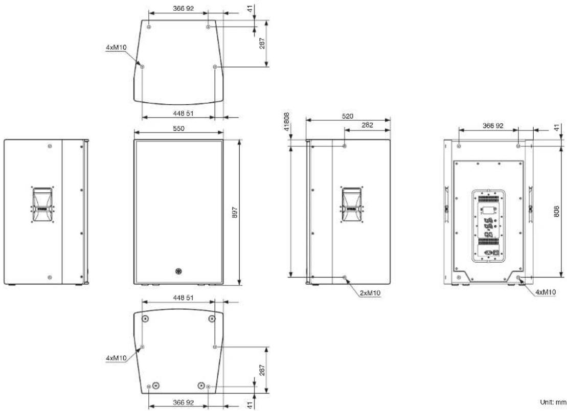
Unit: mm
Reference
■ DZR15(-D)
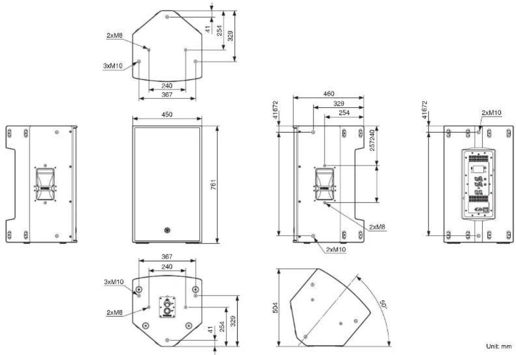
Unit mm
Reference
■ DZR12(-D)
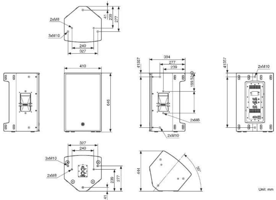
Unit mm
Reference
■ DZR10(-D)
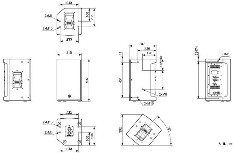
Unit mm
Reference
■ DXS18-XLF(-D)
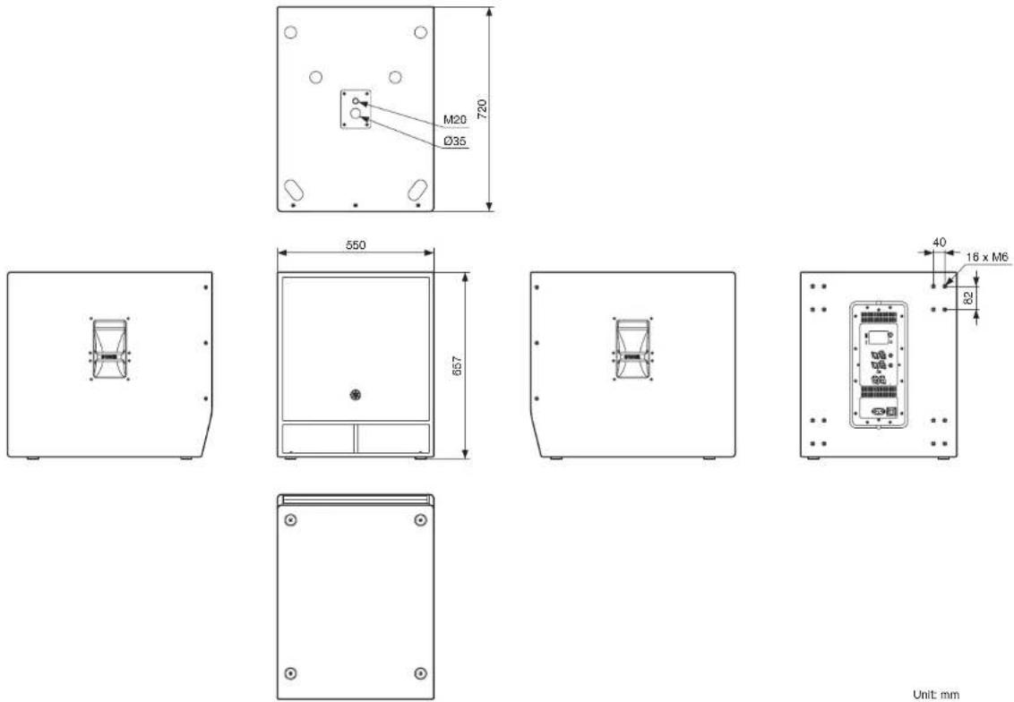
Unit mm
Reference
■ DXS15-XLF(-D)
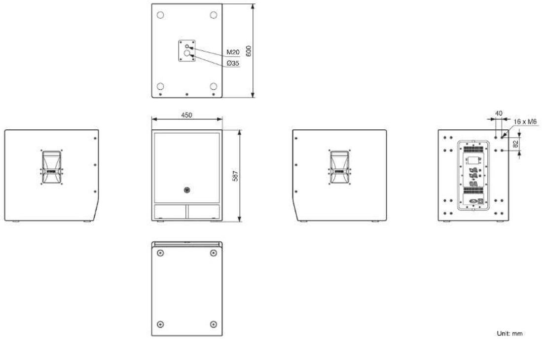
Unit mm
Reference
Block Diagram
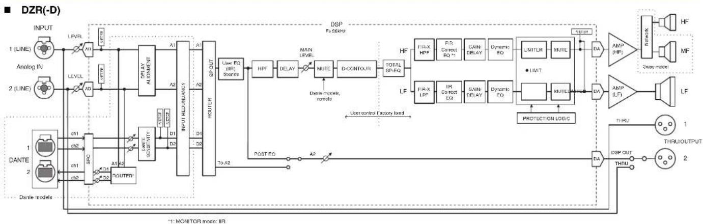
flowchart
graph TD
    A["INPUT"] --> B["Analog IN"]
    B --> C["1 (LINE)"]
    B --> D["2 (LINE)"]
    A --> E["DANTE"]
    A --> F["Dante models"]
    C --> G["LEVEL"]
    D --> H["LEVEL"]
    G --> I["ND"]
    H --> J["ND"]
    I --> K["DELAY ALGORITHM"]
    J --> L["DELAY ALGORITHM"]
    K --> M["A1"]
    L --> N["A2"]
    M --> O["INPUT REDUNDAYANCE"]
    N --> P["INPUT REDUNDAYANCE"]
    O --> Q["A3"]
    P --> R["A4"]
    Q --> S["SP-OUT"]
    R --> T["SP-OUT"]
    S --> U["User EQ (IIR) Sources"]
    T --> V["HPF"]
    U --> W["DELAY"]
    V --> X["MUTE"]
    W --> Y["D-CONTOUR"]
    X --> Z["TOTAL SP-EQ"]
    Y --> AA["HF"]
    Z --> AB["LF"]
    AA --> AC["FIR-X HPF"]
    AA --> AD["FIR-LPF"]
    AB --> AE["FIR-Correct EQ*1"]
    AC --> AF["FIR-Delay"]
    AD --> AG["GAIN DELAY"]
    AE --> AH["GAIN DELAY"]
    AF --> AI["Dynamic EQ"]
    AG --> AJ["Dynamic EQ*"]
    AH --> AK["LIMITLR"]
    AH --> AL["MUTL"]
    AI --> AM["PROTECTION LOGIC"]
    AJ --> AN["PROTECTION LOGIC"]
    AK --> AO["DA"]
    AL --> AP["DA"]
    AM --> AQ["AMP (HP)"]
    AN --> AR["AMP (LF)"]
    AQ --> AS["THRU"]
    AR --> AT["THRU OUTPUT"]
    AS --> AU["DSP OUT"]
    AT --> AV["DSP OUT"]
    AU --> AW["THRU"]
    AV --> AX["THRU OUTPUT"]
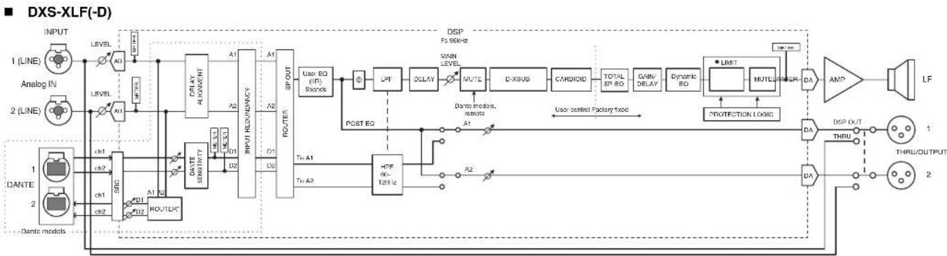
flowchart
graph LR
    INPUT["INPUT"] --> LEVEL1["LEVEL"]
    ANALOGIN["Analog IN"] --> LEVEL2["LEVEL"]
    2["2(LINE)"] --> LEVEL3["LEVEL"]
    1["DANTE"] --> CH1["CH1"]
    2["DANTE"] --> CH2["CH2"]
    CH1 --> SRC1["SRC1"]
    CH2 --> SRC2["SRC2"]
    SRC1 --> D01["D01"]
    SRC2 --> D02["D02"]
    D01 --> ROUTER1["ROUTER"]
    D02 --> ROUTER2["ROUTER"]
    ROUTER1 --> DATESENSIVITY["DATE SEVERITY"]
    ROUTER2 --> DATESENSIVITY
    DATESENSIVITY --> DELAYALIGNMENT["DELAY ALIGNMENT"]
    DELAYALIGNMENT --> A1["A1"]
    DELAYALIGNMENT --> A2["A2"]
    A1 --> INPUTREDUNDENCY["INPUT REDUNDENCY"]
    A2 --> INPUTREDUNDENCY
    INPUTREDUNDENCY --> GPOUT["GP OUT"]
    GPOUT --> UserEQ["User EQ (INT) / BOURS"]
    UserEQ --> LPF["LPF"]
    LPF --> DELAY["DELAY"]
    DELAY --> MUTE["NUTE"]
    MUTE --> CXSUB["CXSUB"]
    CXSUB --> CARDIOD["CARDIOD"]
    CARDIOD --> TOTALSPRD["TOTAL SP RD"]
    CARDIOD --> GAINDELAY["GAIN DELAY"]
    CARDIOD --> DynamicEQ["Dynamic EQ"]
    DynamicEQ --> LIMIT["MULTI"]
    LIMIT --> METER["MULTI PETER"]
    METER --> DA["DA"]
    DA --> AMP["AMP"]
    AMP --> LF["LF"]
    DA --> DUTOUT["DUT OUT THRU"]
    DA --> THRUOUTPUT["THRU OUTPUT 2"]
    LPF --> POSTEQ["POST EQ"]
    POSTEQ --> ToA1["To A1"]
    PostEQ --> ToA2["To A2"]
    ToA1 --> HPF60-12X1/2["HPF 60-12X1/2"]
    ToA2 --> HPF60-12X1/2
    style INPUT fill:#f9f,stroke:#333
    style ANALOGIN fill:#ccf,stroke:#333
    style 2(LINE) fill:#cfc,stroke:#333
    style 1(DANTE) fill:#fcc,stroke:#333
    style 2(DANTE) fill:#fcc,stroke:#333
* Dante output settings are supported by firmware V1.2.2 or later and Dante module firmware 4.1.6.7-4.1.6.5-1.1.0 or later.
Index
Numeric
[1G] indicator....8
A
[AC IN] jack 7
ALIGNMENT (DELAY ALIGNMENT) 18
ALL....20
ANA. OUT1 LVL 19
ANA. OUT2 LVL 19
B
[←] (Back) key 6,9
Bands....16
BLACKOUT....20
BOOST....16
BRIGHTNESS....19
BS 14
C
CARDIOID....11, 17
cardioid mode....11, 17
CONTRAST 20
D
Daisy Chain Network 30
Dante Controller....31, 32
Dante Device Lock 25
Dante jacks 8
Dante latency....24
D-CONTOUR 11, 15
DDM (Dante Domain Manager) 25
DELAY 11,16
Device Label 24
DHCP 26
Display....6
DISTANCE 16
DNT. IN1 LVL 18
DNT. IN2 LVL 18
DNT. OUT1 LVL 19
DNT. OUT2 LVL 19
DNT. SENS. (DANTE SENSITIVITY) 18
Dual pole sockets ....5
D-XSUB....11, 16
E
E symbol 11
EQ 11,16
equalizer 11
F
Factory presets 13
Feet cups 5
FIRMWARE....27
FLAT....16
FOH/MAIN....15
Fs (DANTE Fs) 24
G
GATEWAY....26
H
high-pass filter 11, 15
HPF 11,15
1
INITIAL DATA 13
INPUT 18
[INPUT] jacks....7
Input Meter 11
Input Meter (DNT) 11
Input Redundancy 25
INVERTED....11,15
IP ADR. 26
IP SET. (IP SETTING) 26
L
LABEL 11,24
LATENCY (DANTE LATENCY) 24
[LEVEL] controls 6
[LIMIT] indicator 6
[LINK] indicator 8
LOAD FROM USB....21
LOCAL 25
LOCK 25
LOG LIST 28
low-pass filter.... 11, 15
LPF 11, 15
M
MAC 26
Main knob 6,9
MAIN Level 11
MODE (DANTE MODE) 23
MONITOR 15
MUTED from REMOTE....29
Reference
N NETMASK 26
O OFF (NORMAL)....15, 16 OUTPUT....19
P Parameter Display....16 PARTIAL....20 PATCH....24 PIN CODE....20 POLARITY....11, 15 [POWER] indicator....6 Power switch....7 PRESET....11, 13 Protection....11
Q Quick Config 23
R RESTORE FROM USB....23 ROUTER....11, 18 Routing....18
S SAVE TO USB 21, 23, 26 Screw holes for eye bolts 5 Screw holes for U-bracket 5 SERIAL 27 SP Output Meter 11 STANDARD 23 Star Network 30
STATE....25 STATIC IP....26 [SYNC] indicator....8
T TEMP....22 THERMAL....27 [THRU/DSP OUT] switch....7 [THRU/OUTPUT] jacks....7 Tiltable pole socket....5 TIME....16
U UNIT ID....11,24,26 USB terminal....6 User preset list....13 UTILITY....11,19
V Vents .... 7 VERSION.... 27
W Wheel mounting screws....5
X XTEND LF (extended LF)....16
© 2018 Yamaha Corporation Published 04/2024 IP-E0