OK 638 G - Range hood Mora - Free user manual and instructions
Find the device manual for free OK 638 G Mora in PDF.


User questions about OK 638 G Mora
0 question about this device. Answer the ones you know or ask your own.
Ask a new question about this device
Download the instructions for your Range hood in PDF format for free! Find your manual OK 638 G - Mora and take your electronic device back in hand. On this page are published all the documents necessary for the use of your device. OK 638 G by Mora.
USER MANUAL OK 638 G Mora
Instructions for use
Návod k použití
Návod na použitie
text_image
6x 3.9x6mm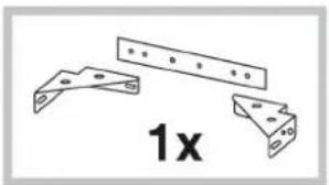
natural_image
Technical drawing of three metal bracket components with mounting holes and a label '1x' (no text or symbols on the brackets themselves)
text_image
2x 3.9x9.5mm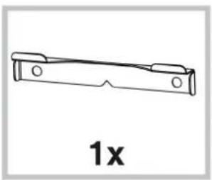
natural_image
Simple line drawing of a mechanical bracket with circular holes, labeled '1x' below (no text or symbols on the object itself)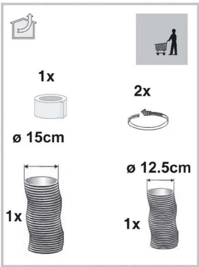
text_image
1x Ø 15cm 2x Ø 12.5cm 1x 1x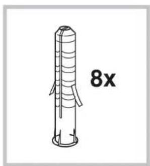
text_image
8x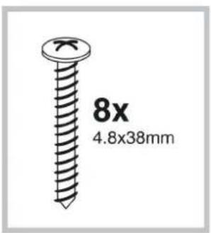
text_image
8x 4.8x38mm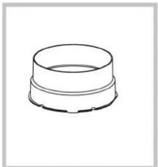
natural_image
Simple line drawing of a cylindrical mechanical component (no text or symbols)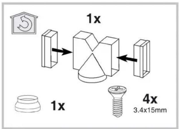
text_image
1x 1x 4x 3.4x15mm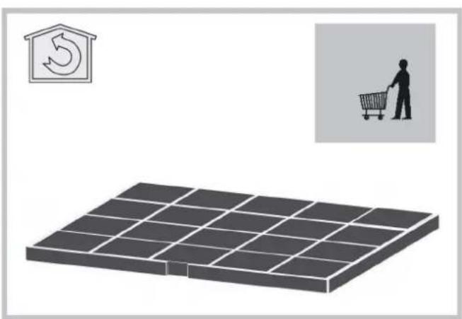
natural_image
Illustration of a solar panel array with a recycling symbol and a shopping cart, no text or labels present.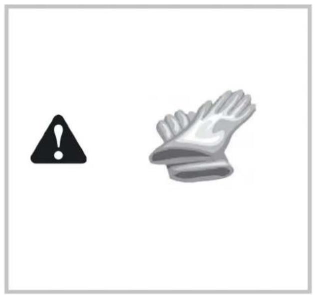
natural_image
Two warning symbols: a black exclamation mark and a gray glove with a white border (no text or labels)
text_image
L = 65 cm min. 90°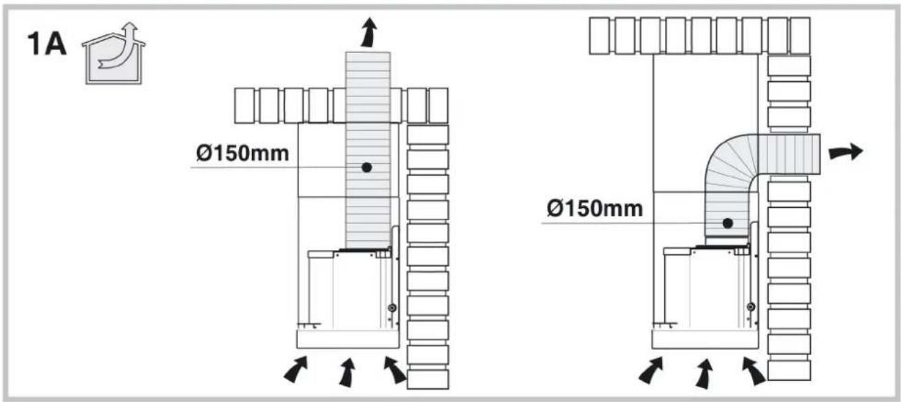
text_image
1A Ø150mm Ø150mm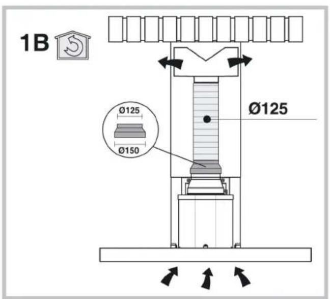
text_image
1B Ø125 Ø150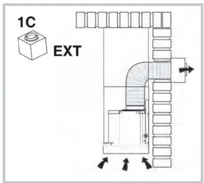
text_image
1C EXT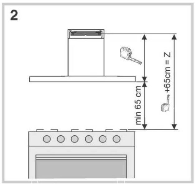
text_image
2 min 65 cm +65cm = Z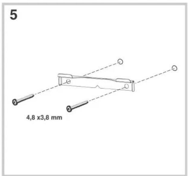
text_image
5 4,8 x3,8 mm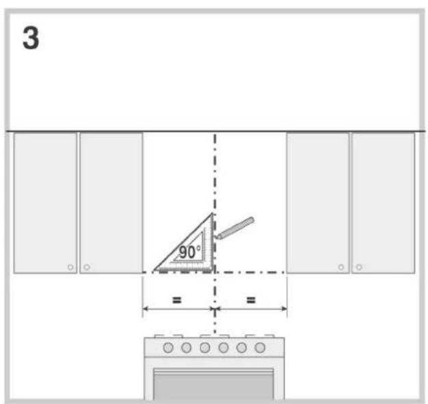
text_image
3 90° =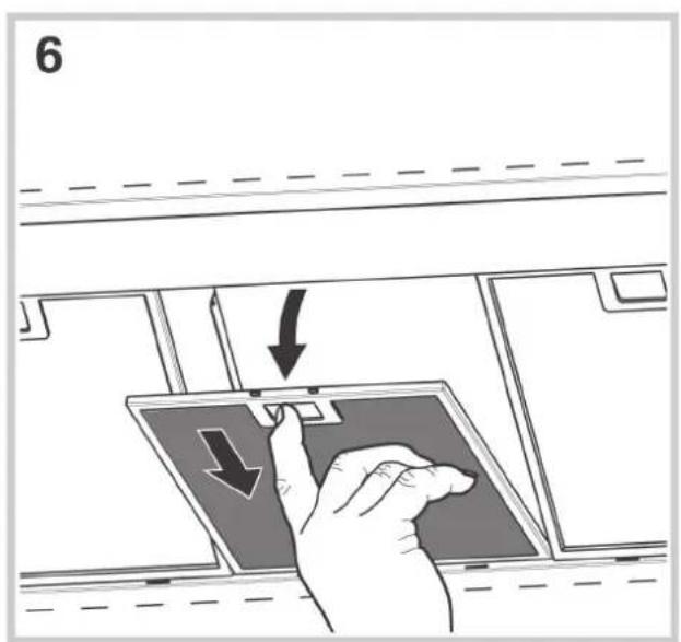
text_image
6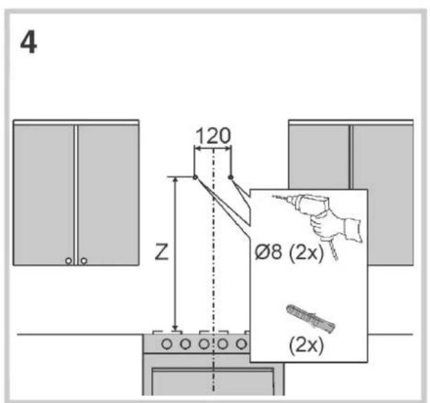
text_image
4 120 Z Ø8 (2x) (2x)
natural_image
Technical line drawing of a mechanical device with a base platform and a curved arm (no text or symbols)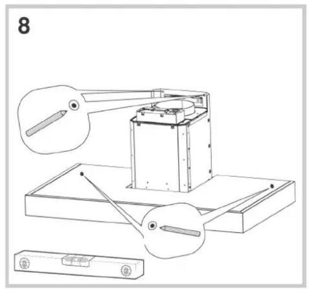
text_image
8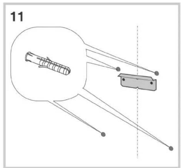
natural_image
Diagram of a mechanical component with labeled parts and a dashed vertical line (no text or symbols present)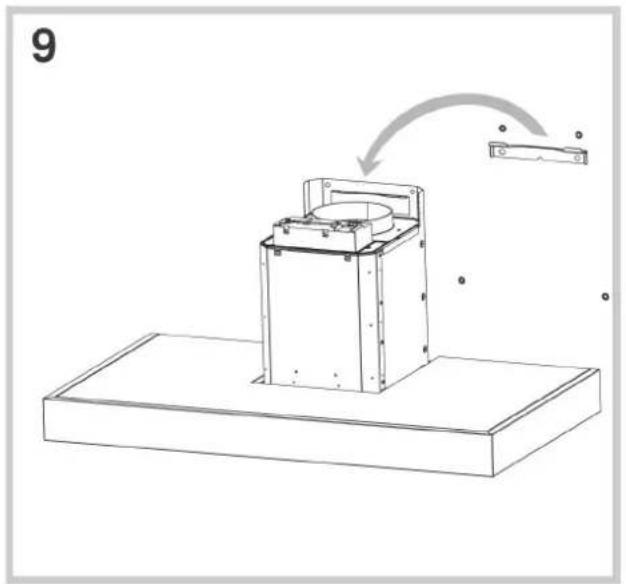
natural_image
Technical line drawing of a mechanical assembly with a base platform and a component, no text or symbols present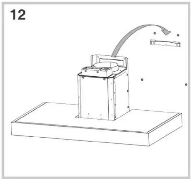
natural_image
Technical line drawing of a mechanical device with a curved arrow indicating motion or force, no text or symbols present
text_image
10 Ø 8 mm
text_image
13 4,8 x 3,8 mm
text_image
14 EXT
text_image
18 Ø 8 mm
text_image
15 3.9 x 6 mm 248 mm
text_image
19
text_image
16 =
text_image
20 4.8 x 38 mm
natural_image
Technical line drawing of a mechanical assembly with a suspended component and a separate view labeled '17' (no text or symbols on the diagram itself)
text_image
21A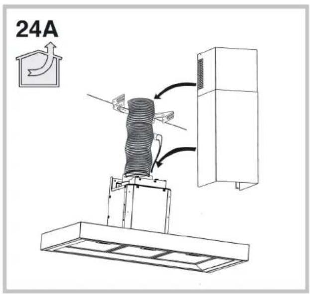
text_image
24A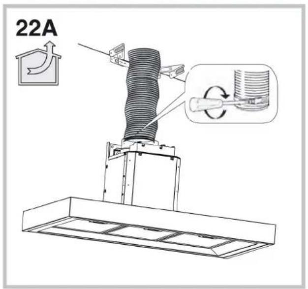
text_image
22A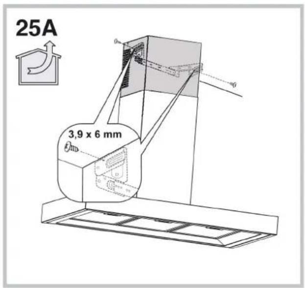
text_image
25A 3,9 x 6 mm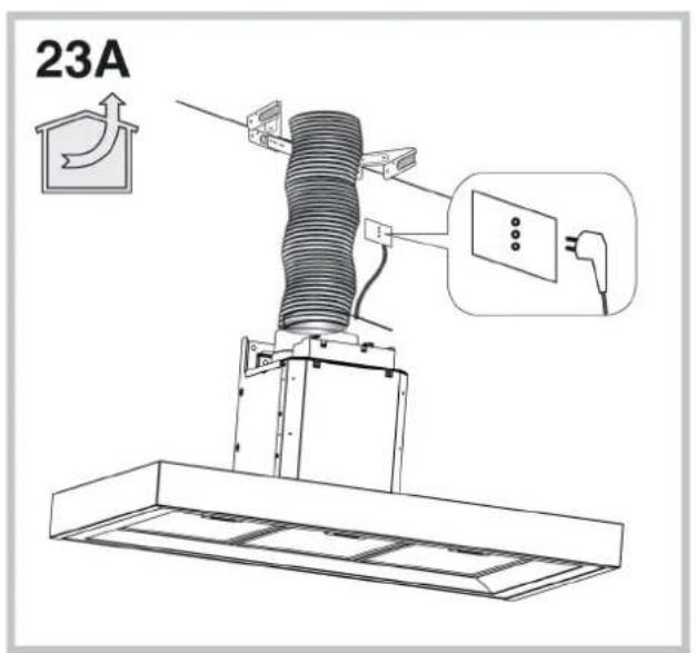
text_image
23A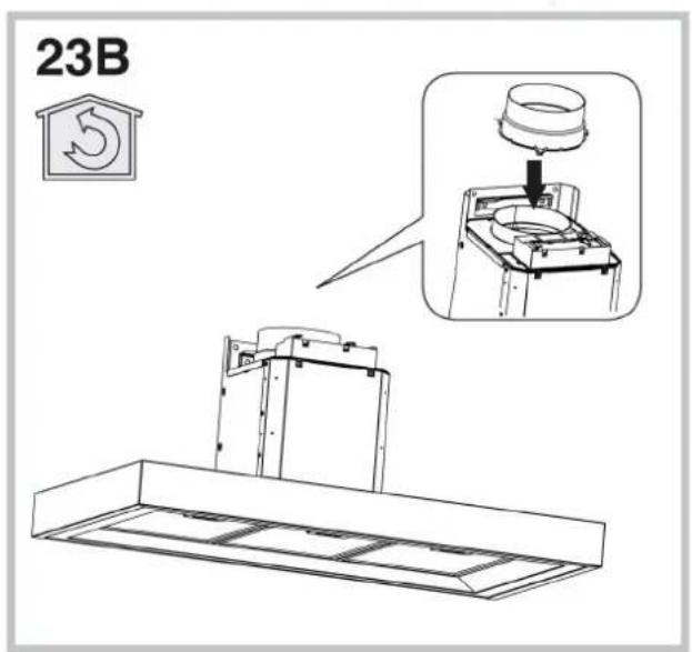
text_image
23B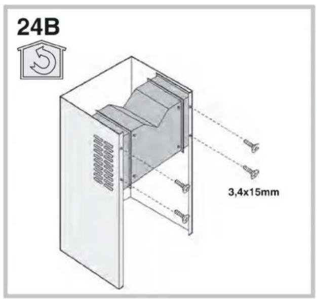
text_image
24B 3,4x15mm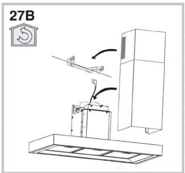
text_image
27B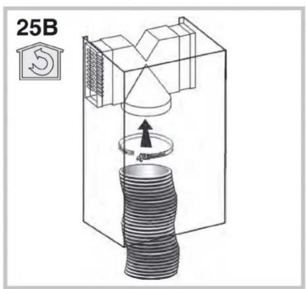
text_image
25B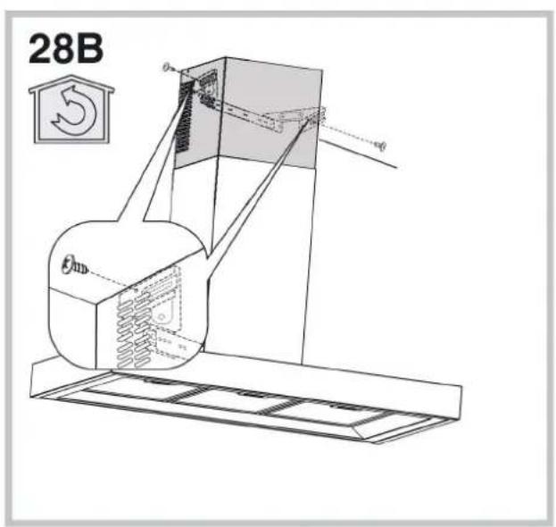
text_image
28B θ θ θ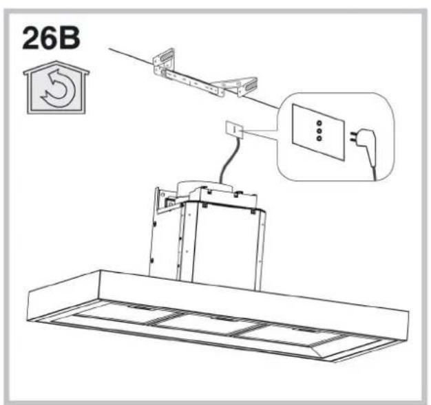
text_image
26B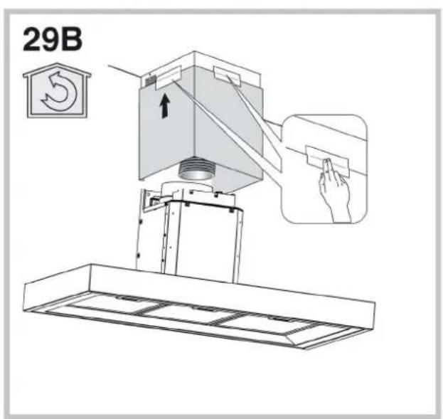
text_image
29B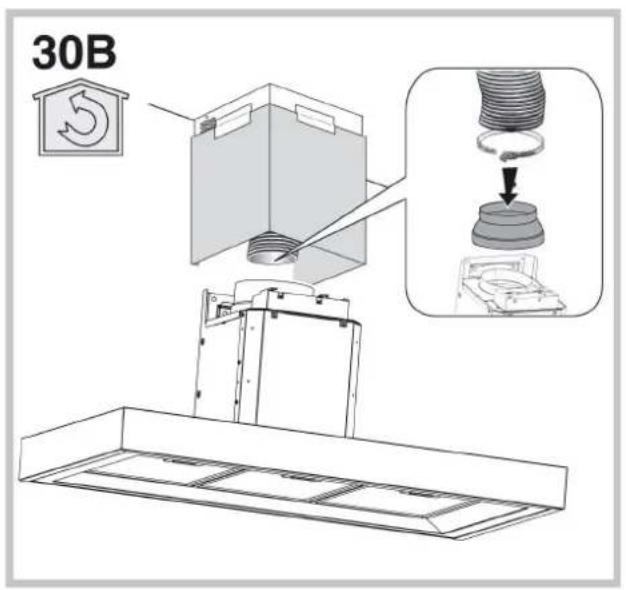
text_image
30B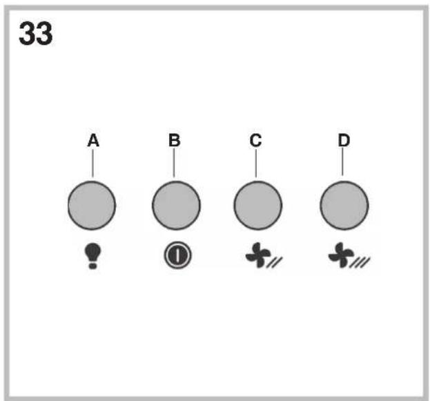
text_image
33 A B C D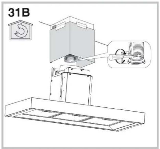
text_image
31B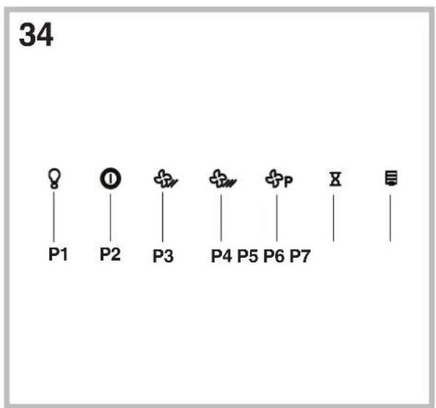
text_image
34 P1 P2 P3 P4 P5 P6 P7 X E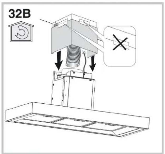
text_image
32B! The appliance must be installed by a qualified person in compliance with the instructions provided.

Wear gloves when carrying out installation and maintenance
operations.
If the supply cord is damaged, it must be replaced by the manufacturer, its service agent or similarly qualified persons in order to avoid a hazard.
Warning: Failure to install the screws or fixing device in accordance with these instructions may result in electrical hazards.
The hood can look different to that illustrated in the drawings in this booklet. The instructions for use, maintenance and installation, however, remain the same.
AIR VENT
(for ducting versions)
! Prepare the hole and the air vent duct (150 mm diameter).
! Use a duct of the minimum indispensable length.
! Use a duct with as few elbows as possible (maximum elbow angle: 90°).
! Avoid drastic changes in the duct cross-section.
! Use a duct with an as smooth as possible inside.
! The duct must be made of certified material.
! Do not connect the hood to smoke exhaust ducts for the products of combustion (boilers, fireplaces, stoves, etc).
! For the air vents comply with the provisions laid down by the competent authorities.
In addition, the air must not be evacuated through a hole in the wall unless specifically intended for this purpose.
! Fit air intakes in the room to prevent the hood from creating a negative pressure in the room (which must not exceed 0.04 mbar); if the hood is used at the same time as non-electrical equipment (gas-, oil- and charcoal-fired stoves, etc.) the exhaust gas may be sucked in by the heat source.
FILTERING OR DUCTING VERSION?
The hood may be in filtering or in ducting version. Decide from the outset which type is to be installed.
For better efficiency, we recommend installing the hood in the ducting version (if possible).

Ducting version
The hood purifies the air and evacuates it to the outside through an exhaust duct (diameter 150 mm).

Filtering version
The hood purifies the air and recycles the clean air back into the room. For this version, the following are required: 1 air baffle, 1 reducer, 1 charcoal filter. The upper flue air evacuation slots must be positioned at the top.
Only for hoods equipped with electronic control:
The 4th speed (intensive) is automatically lowered to 3rd speed after 5 minutes of operation to optimise energy consumption; in hoods with voltage 120V/60Hz this function is not active and the 4th speed is indicated by the letter b (Booster).
- If the hood is left on (lights and/or motor), after 10 hours in the absence of commands from the user, it will automatically switch to OFF condition with all services switched off. In hoods with voltage 120V/60Hz this function is not active.
- The Buzzer emits a "beep" each time that a command is set from the keyboard or remote control (optional).
- In the event of interruption of power during the hood, if you restore the hood in the OFF state, then the engine must be reactivate manually.
Only for hoods equipped with infrared sensor controls: The unit is equipped with infrared sensor controls that, if exposed to direct sunlight may not work properly; use curtains or other devices to shield the sunlight.
CONTROLS
Controls of Fig. 33
Key A: light switch
Key B: first speed motor ON/OFF switch.
Key C: second speed switch.
Key D: third speed switch.
Controls of Fig. 34
P1: It turns on an off the light.
P2: It starts the engine setting it to the first speed (the icon is highlighted). Other speed icons remain inactive.
P3: It starts the engine setting it to the second speed (the icon is highlighted). Other speed icons remain inactive.
P4: It starts the engine setting it to the third speed (the icon is highlighted). Other speed icons remain inactive.
P5: It starts the engine setting it to the fourth speed (the icon is blinking). Other speed icons remain inactive. The maximum speed is set to be maintained for maximum 5 minutes, after this time the speed will be automatically adjusted to the third speed.
P6: It starts the timer (the icon is highlighted). By running the timer (5 minutes), the engine stops automatically after 5 minutes.
P7: FILTER ALARM. After 30 hours of operation the icon is highlighted to indicate that the filter should be cleaned.
After 120 hours of operation the icon is highlighted to indicate that the grease filter should be cleaned and the charcoal filters - replaced.
To RESET the alarm, press the icon while it is highlighted (or while it is blinking).
MAINTENANCE
! Before cleaning or maintenance cut the power.
Cleaning the hood
WHEN TO CLEAN IT: clean it at least every 2 months to prevent the risk of fire.
EXTERNAL CLEANING: use a cloth moistened in lukewarm water and neutral detergent (for painted hoods); use specific products for steel, copper or brass hoods.
INTERNAL CLEANING: use a cloth (or brush) soaked in denatured ethyl alcohol.
WHAT NOT TO DO: do not use abrasive or corrosive products (e.g. metal sponges, brushes, too hard brushes, very aggressive detergents, etc.)
Cleaning the grease filters
WHEN TO CLEAN IT: clean it at least every 2 months to prevent the risk of fire, in according to use.
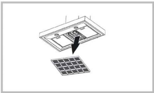
HOW TO REMOVE THE FILTERS: push the catch near the handle towards the rear of the hood and pull the filter downwards
HOW TO CLEAN THE FILTERS: hand wash or in the dishwasher using a neutral detergent. If washing in the dishwasher, possible discoloration of the filters does not in any way compromise their functioning.
Replacing the charcoal filter
(for filtering version only)
WHEN TO REPLACE IT: replace it at least every 6 months, in according to use.
HOW TO REMOVE IT: If using the hood in the filtering version, the charcoal filter will have to be replaced. To switch off, pull the latch inward and rotate the filter downwards.
natural_image
Diagram showing a solar panel installation with an arrow pointing to the component (no text or symbols present)Lighting
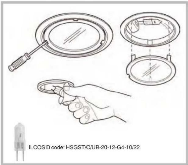
Halogen Lamps:
replace it with lamps of the same type.
text_image
ILCOS D code: HSGST/C/UB-20-12-G4-10/22Led Lamps:
If the light spot is damaged, it must be replaced only by the manufacturer, its service agent or similarly qualified persons in order to avoid a hazard.
natural_image
Diagram showing a solar panel being placed into a device with an arrow indicating the component (no text or symbols present)Osvětlení
Halogenové žárovky:
text_image
ILCOS D code: HSGST/C/UB-20-12-G4-10/22Led Lampy:
natural_image
Diagram showing a device with internal components and a separate solar panel, no text or symbols presentRazsvetljava
text_image
ILCOS D code: HSGST/C/UB-20-12-G4-10/22Led Lampy: