SY-103E6-E33-C55-L52-900 - Range hood Hanseatic - Free user manual and instructions
Find the device manual for free SY-103E6-E33-C55-L52-900 Hanseatic in PDF.


| Product Type | Range Hood |
| Brand | Hanseatic |
| Model | SY-103E6-E33-C55-L52-900 |
| Width | 90 cm |
| Installation Type | Wall-mounted or recessed |
| Number of Fan Speeds | 3 |
| Lighting | LED (integrated) |
| Control Type | Touch control or buttons |
| Suction Capacity | Approx. 600 m³/h |
| Noise Level | Approx. 55-65 dB(A) |
| Energy Class | A+ |
| Annual Energy Consumption | Approx. 50 kWh |
| Filter Type | Aluminium grease filter (washable) |
| Charcoal Filter | Optional for recirculation mode |
| Duct Diameter | 150 mm |
| Power Supply | 220-240 V, 50 Hz |
| Power of Motor | Approx. 200 W |
| Dimensions (H x W x D) | Approx. 130 x 900 x 450 mm |
| Weight | Approx. 12 kg |
| Maintenance | Clean grease filter monthly; replace charcoal filter every 6 months |
| Safety Features | Auto shut-off, overload protection |
| Spare Parts Available | Filters, LED bulbs, control board |
| Repairability Index | 7/10 (estimated) |
| Included Accessories | Installation kit, recirculation kit (if applicable) |
Frequently Asked Questions - SY-103E6-E33-C55-L52-900 Hanseatic
User questions about SY-103E6-E33-C55-L52-900 Hanseatic
0 question about this device. Answer the ones you know or ask your own.
Ask a new question about this device
Download the instructions for your Range hood in PDF format for free! Find your manual SY-103E6-E33-C55-L52-900 - Hanseatic and take your electronic device back in hand. On this page are published all the documents necessary for the use of your device. SY-103E6-E33-C55-L52-900 by Hanseatic.
USER MANUAL SY-103E6-E33-C55-L52-900 Hanseatic
natural_image
Technical line drawing of a mechanical component with mounting holes and a flat plate (no text or symbols)Gebrauchsanleitung
Anleitung/Version:
196188_DE_20180405
natural_image
3D diagram of a double-tube kitchen chimney with airflow arrows indicating direction (no text or symbols)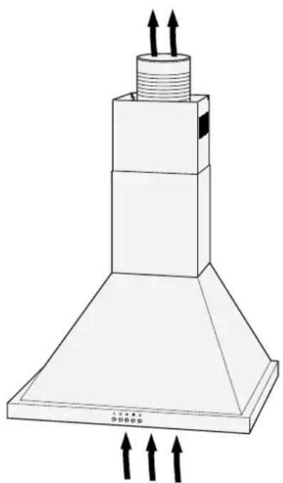
natural_image
Technical line drawing of a mechanical component with three upward arrows indicating force or movement (no text or symbols)text_image
(10) (11) (12)text_image
(13) (14) (15)natural_image
Diagram of a lighting setup with two circular components and a central device, labeled (11), showing no text or symbols.text_image
(13) KLICK (14) (15)natural_image
Technical line drawing of a rectangular electronic component with mounting holes and a label (6) pointing to its edge (no text or symbols on the diagram itself)text_image
(7) (8) 2x (3)natural_image
Technical line drawing of a mechanical bracket with mounting holes (no text or symbols)text_image
(2)(8)(6) 2xnatural_image
Front view of a white electronic device with two circular buttons at the bottom (no text or symbols visible)Bevor Sie beginnen
text_image
(13) (14) (15)text_image
(13) KLICK (14) (15)text_image
(13) (14) (15)text_image
(13) KLICK (14) (15)natural_image
Technical line drawing of a mechanical component with mounting holes and a flat plate (no text or symbols)User manual
Manual/version:
196188_GB_20180405
Article no.:412 340
Reproduction, even of ex-
cerpts, is not permitted!
Wall-mounted headroom hood
Table of contents
Delivery GB-3
Package contents . . . . . . . . . . . . . . GB-3
Check the delivery . . . . . . . . . . . . GB-3
For your safety. . . . . . . . . . . . . . . . . . . . . . . . . . . . . . . . GB-4
Intended use GB-4
Explanation of terms . . . . . . . . . . . . GB-4
Explanation of symbols . . . . . . . . . GB-4
Safety notices . . . . . . . . . . . . . . . . . . GB-4
Circulation or exhaust air operation? . GB-8
Circulation air operation . . . . . . . GB-8
Exhaust air operation . . . . . . . . . . GB-8
Preparations for assembly . . . . . . . GB-9
For exhaust air operation . . . . . . . GB-9
Connection for power supply ..... GB-9
Materials required for assembly . . . GB-10
Parts list . . . . . . . . . . . . . . . . . . . . . . . . . . . . . . . . . . . . . . GB-10
Tools and aids . . . . . . . . . . . . . . . . . . GB-10
Screws GB-10
Assembly GB-11
Space requirements . . . . . . . . . GB-11
Attachment dimensions . . . . . . . GB-11
Before getting started . . . . . . . . . GB-12
Place the drill holes . . . . . . . . . . GB-12
Attaching the exhaust hood ..... GB-13
Attaching the exhaust air hose . . GB-14
Installing the flue screen . . . . . . . GB-14
Final steps GB-16
Operation GB-17
Before getting started . . . . . . . . GB-17
Switching the appliance on and off . GB-17
Setting the time . . . . . . . . . . . . . . GB-17
Switching on the fan . . . . . . . . . . GB-17
Changing the fan setting . . . . . . . GB-18
Switching off the fan . . . . . . . . . . GB-18
Lighting GB-18
Activated charcoal filter . . . . . . . . GB-18
Tips on saving energy . . . . . . . . . GB-18
Care and maintenance . . . . . . . . . GB-19
Cleaning the housing . . . . . . . . GB-19
Cleaning the grease filters . . . . . . GB-19
Inserting/replacing activated charcoal filters . . . . . . . . . . . . . . . . . GB-20
Troubleshooting table . . . . . . . . . . . GB-22
Our customer service .... GB-23
General customer service . . . . . . GB-23
Spare parts . . . . . . . . . . . . . . . . . . . . GB-23
Ordering activated charcoal filters GB-23
Environmental protection . . . . . . . . GB-24
Disposing of old electrical devices in anenvironmentally friendly manner . . GB-24
Disposing of activated charcoal filters . . . . . . . . . . . . . . . . . . . . . . . . . . GB-24
Packaging . . . . . . . . . . . . . . . . . . . . GB-24
Data sheet GB-25

Before using the appliance, first read the safety notices and user manual carefully from be-
ginning to end. This is the only way to ensure you can use all the functions safely and reliably. Be sure to also observe the national regulations in your country, which are valid in addition to the regulations specified in this user manual.
Keep all safety notices and instructions for future reference. Pass all safety notices and instructions on to the subsequent user of the product.
Delivery
Package contents
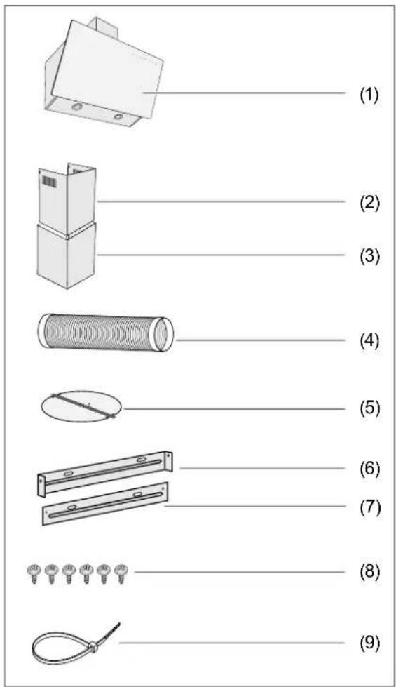
(1) Exhaust hood
(2) Upper part of the flue screen
(3) Lower part of the flue screen
(4) Exhaust air operation: Exhaust air hose
(5) Exhaust air operation: Check valve
(6) Wall mount for upper flue screen
(7) Retaining plate for lower flue screen
(8) Plate screws 4.0 × 8 mm
(9) Cable ties
The screws and dowels required to mount the appliance on a wall are not included in the package contents, as their type and dimensions will vary depending on the characteristics of the wall. Please have a specialist advise you as to which ones you need see "Materials required for assembly" on page GB-10).
An activated charcoal filter for air circulation is not included in the package contents. To order accessories, see "For your safety" on page GB-4.
Check the delivery
- Unpack the appliance.
- Remove all parts of the packaging, plastic profiles, tape and foam padding.
- Check that the delivery is complete.
- Check whether the appliance was damaged during transit.
- If the delivery is incomplete or the appliance has been damaged during transit, please contact our service department (see page GB-23).
For your safety
Intended use
This appliance is intended to be used to remove cooking fumes and airborne grease from a cooktop in a private household. It is not designed for use in a commercial setting.
Use the appliance exclusively as described in this user manual. Any other use is deemed improper and may result in damage to property or even personal injury. The manufacturer accepts no liability for damage caused by improper use.
Explanation of terms
The following symbols can be found in this user manual.

WARNING
This symbol indicates a hazard with a medium level of risk which, if not avoided, could result in death or serious injury.

CAUTION
This symbol indicates a hazard with a low level of risk which, if not avoided, could result in minor or moderate injury.

NOTICE
This symbol warns against possible damage to property.

This symbol refers to useful additional information.
Explanation of symbols
Broken glass
Safety notices
In this chapter you will find general safety instructions which you must always observe for your own protection and that of third parties. Please also observe the warning notices in the individual chapters on operation, setup etc.
Risks in handling household electrical appliances

WARNING
Risk of electric shock!
Touching live parts may result in severe injury or death.
■ Only use the appliance indoors. Do not use in wet rooms or in the rain.
- If the mains plug is no longer accessible after installation, an all-pole disconnecting device complying with overvoltage category III must be connected to the house wiring with a contact gap of at least 3 mm; this includes fuses, circuit breakers and contactors.
■ Take care to prevent the risk of tripping when laying the mains cord.
■ Do not kink or pinch the mains cord or lay it over sharp edges.
- Keep the appliance, the mains plug and the mains cord away from open flames and hot surfaces.
■ Always touch the mains plug, not the mains cord.
■ Never touch the mains plug with wet hands.
■ Never immerse the mains cord or plug in water or any other liquids.
- Do not put any objects in or through the housing openings, and also make sure that children cannot insert any objects into them.
■ Do not operate or continue to operate the appliance, if
– it shows visible signs of damage, e.g. the power cord is defective,
– it starts smoking or there is a smell of burning,
- it makes unfamiliar noises.
In such cases, remove the mains plug or unscrew/isolate the fuse and contact our service department (see page GB-23).
■ If the mains cord of the appliance is damaged, it must be replaced by the manufacturer, through customer service or by a qualified specialist. Inspections and repairs to the appliance may only be carried out by authorised specialists.
■ Only parts corresponding to the original appliance specifications may be used for repairs. This appliance contains electrical and mechanical parts which are essential for protection against potential sources of danger.
■ Independent or improper repairs made to the appliance may cause damage to property and personal injury; any liability and warranty claims will be forfeited. Never try to repair a defective or suspected defective appliance yourself.
- In the event of a fault, as well as before extensive cleaning, pull out the mains plug or isolate/unscrew the fuse.
Fire hazard!
■ The appliance corresponds to protection class I and may only be connected to a plug with a protective conductor that has been installed properly. Do not connect to a multiple socket outlet, power strip, timer or to a separate remote-controlled system for distance monitoring and control.
Risks for certain groups of people

WARNING
Risk of suffocation!
- Do not allow children to play with the packaging fi Im. Children could become entangled when playing and suffocate.
■ Prevent children from pulling small parts from the device or taking them out of the accessory bag and putting them in their mouths.

CAUTION
Dangers for children and people with limited physical, sensory or mental capacity!
■ This appliance can be used by children aged eight years and above and by persons with reduced physical, sensory or mental abilities, or who lack experience and/or knowledge, if they are supervised or have been instructed in the safe use and understand the dangers associated with its use.
■ Cleaning and maintenance must not be carried out by children unless they are supervised.
■ Children must not be allowed to play with the appliance.
Risks in handling exhaust hoods

WARNING
Risk of electric shock!
■ Before drilling the holes to mount the appliance on the wall, ensure that no wires or cables (power, gas, water etc.) will be damaged (check with a line locator).
■ If a glass cover is broken, the exhaust hood must not be used until the glass cover has been replaced. If this is the case, contact our customer service (see page GB-23).

CAUTION
Risk of injury!
■ When mounting, please note that some parts may have sharp edges.
■ Use a stable stepladder to mount.
■ Only use mounting materials that are suitable for the characteristics of the ceiling and walls. When in doubt, consult an expert.
Fire hazard!
■ The distance between the cooking surfaces and the lower edge of the exhaust hood must be at least 65 cm for gas stoves.
■ For gas stovetops, you must read the user manual for the stovetop! If the manual stipulates a larger distance, this must be observed.
■ Do not fl ambé foods under the exhaust hood!
■ Only deep-fry foods under the exhaust hood under constant supervision.
- Keep the exhaust hood clean. Grease build-ups can ignite when heated to high temperatures.
■ There is a risk of fire if the appliance is not cleaned properly in accordance with the instructions.
Risk of burns!
■ Touchable parts may become hot if used with cooking appliances.
Risks during exhaust air operation

WARNING
Risk of suffocation/explosion!
The air in the room where the exhaust hood is operating is extracted by fan and released outside. If, in this room, a fi replace requiring indoor air – such as a gas fi re or other fuel-based heating system – is also in use, the oxygen that is necessary for combustion may also be extracted. This can result in the fl ame being extinguished and gas being released or the room becoming saturated with exhaust fumes.
- It is possible to run the appliance without any risk by, for example, providing non-sealable openings in doors, windows or ventilation conduits through which the combustion air can escape, and by achieving a negative pressure level in the installation space of maximum 0.04 mbar. This prevents the exhaust fumes from being sucked back into the room.
■ In order to determine the necessary measures, the entire ventilation system throughout the home must be reviewed. Consult the gas safety consultant who is responsible for the home.
■ Never attach the exhaust hood to a ventilation shaft, chimney or smokestack! The air being extracted must not travel through a channel in which warm air circulates. The extracted air may only be released to the outside through a separate air channel intended exclusively for the exhaust hood.

NOTICE
Risk of material damage!
■ To operate the air extraction, a wall or ceiling break of at least 15.5 cm in diameter is required.
■ We recommend having a specialist (electrician) carry out this break (core drilling).
■ If the exhaust air hose passes through an exterior wall, the air outlet on the outside must have a cover with self-opening slits (not included in the package contents). Have this installed by the same specialist that is carrying out the wall break.
- Please note: The shorter and straighter the exhaust hose, the more powerful the exhaust function will be.
■ In Germany, statutory requirements for extracting exhaust air vary from state to state. Consult a gas safety consultant.
Circulation or exhaust air operation?
natural_image
Technical line drawing of a chimney with airflow arrows indicating direction (no text or symbols)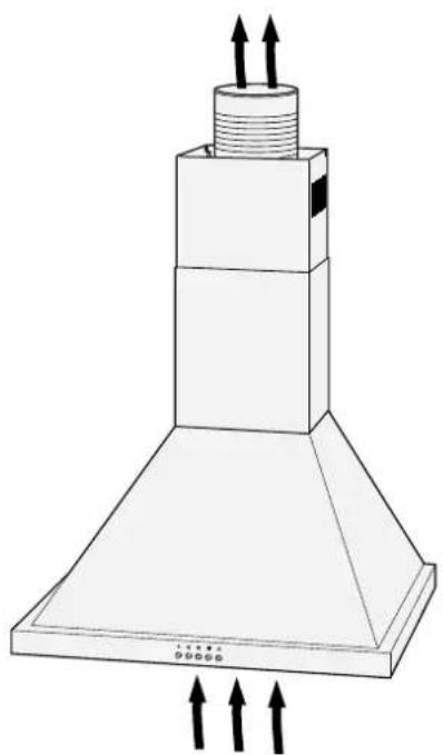
natural_image
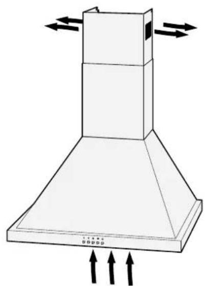
Technical line drawing of a chimney with ventilation ducts and mounting base (no text or symbols)The images show an example of where the extracted fumes are conducted to. They do not show the appliance described here.
Circulation air operation
When air is circulated, the cooking fumes are sucked in and, following filtering, returned to the indoor air through the air outlets at the top of the appliance.
Filtering takes place through the grease filter and also through an activated charcoal filter (odour filter with activated charcoal; not included in the package contents). Source of supply see "Our customer service" on page GB-23).
- Advantage: Simple assembly
- Disadvantage: Increasing clogging of the activated charcoal filter reduces the effectiveness of the filter and exhaust functions. The activated charcoal filter must be replaced depending on use; check it at least every six months.
Exhaust air operation
When air is extracted, the cooking fumes are sucked in, filtered through the grease filter, and released to the outdoors through the exhaust air hose.
- Advantage: Charcoal filter not required; very little odour.
- Disadvantages:
– Wall break with hose connection necessary.
- Open fireplaces may only be used in the same room with limitations. Ask your local gas safety consultant about local regulations before installing.

If you rent your home, you must obtain approval from the owner before installing the appliance.
Preparations for assembly
For exhaust air operation

WARNING
Risk of suffocation/explosion!
■ Never attach the exhaust hood to a ventilation shaft, chimney or smokestack! The air being extracted must not travel through a channel in which warm air circulates. The extracted air may only be released to the outside through a separate air channel intended exclusively for the exhaust hood.

NOTICE
Risk of material damage!
■ We recommend having a specialist carry out all preparations.
Before you can begin assembly, all of the following conditions must be met:
– There must be a wall or ceiling break of at least 15.5 cm in diameter.
- If the exhaust air hose passes through an exterior wall, the air outlet on the outside must have a cover with self-opening slits (not included in the package contents).
To keep subsequent energy usage as low as possible, we recommend
- placing the exhaust air channels as straight as possible and avoiding any sharp angles (curves or bends are preferable). Each bend increases energy usage.
- not reducing the cross-section of the fan connector. The wider the diameter of the exhaust air hose and the smoother its interior surface, the better the extraction function will be.
– selecting a ventilation conduit with exterior shutters that can open completely during use.
Connection for power supply

WARNING
Risk of electric shock!
■ The mains plug must be as accessible as possible during use, i.e. the plug must be accessible even after the exhaust hood has been installed.
- If the mains plug is no longer accessible after installation, an all-pole disconnecting device complying with overvoltage category III must be connected to the house wiring with a contact gap of at least 3 mm; this includes fuses, circuit breakers and contactors.
■ Electrical installation may be performed only by a certified specialist. If an additional socket is required, have an electrician perform the installation.
- Do not connect to a multiple socket outlet, power strip, timer or to a separate remote-controlled system for distance monitoring and control.
To ensure that the exhaust hood will perform optimally and that no obtrusive cabling is visible, plan the connection for power supply carefully before installation: The exhaust hood must be placed over the centre of the cooking zone.
Materials required for assembly
Parts list
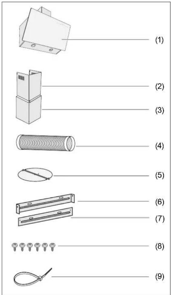
(1) Exhaust hood
(2) Upper part of the flue screen
(3) Lower part of the flue screen
(4) Exhaust air operation: Exhaust air hose
(5) Exhaust air operation: Check valve
(6) Wall mount for upper flue screen
(7) Retaining plate for lower flue screen
(8) Plate screws 4.0 × 8 mm
(9) Cable ties
Tools and aids
You will need:
- Screwdriver
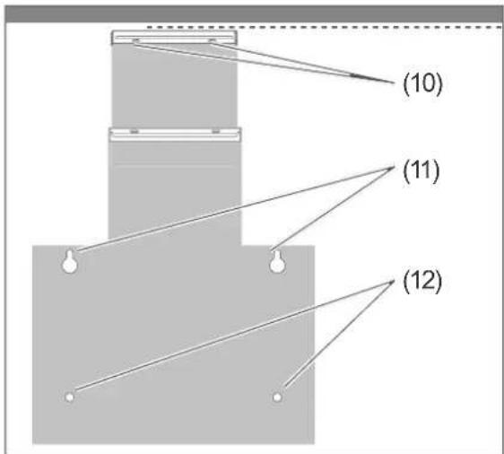
- Drill with stone bit, correctly sized for the (10), (11), and (12) screws.
- Measuring tape / ruler
- Level
- Pencil
- Stable stepladder
- Work gloves
We also recommend having a second person with you to help.
Screws
The screws and dowels required to mount the appliance on a wall are not included in the package contents, as their type and dimensions will vary depending on the characteristics of the wall.
Please have a specialist advise you as to which ones you need.
text_image
(10) (11) (12)In total, you will need
- 2 round-head screws (10) to attach the wall mount (6) for the upper flue screen (2)
- 2 round-head screws (11) to hang the ex-haust hood, maximum 4 mm
- 2 round-head screws (12) with flat washers to secure the exhaust hood (1), maximum 4 mm
- 4 suitable dowels
Assembly
Space requirements
Attachment dimensions
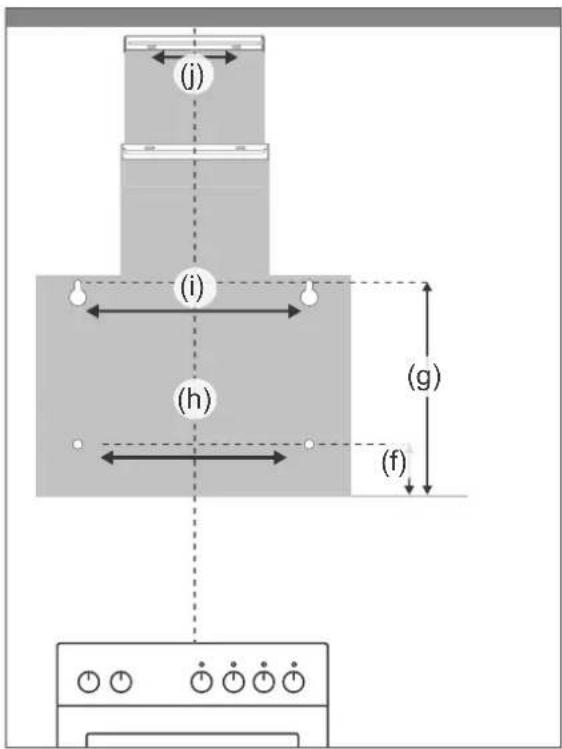
text_image
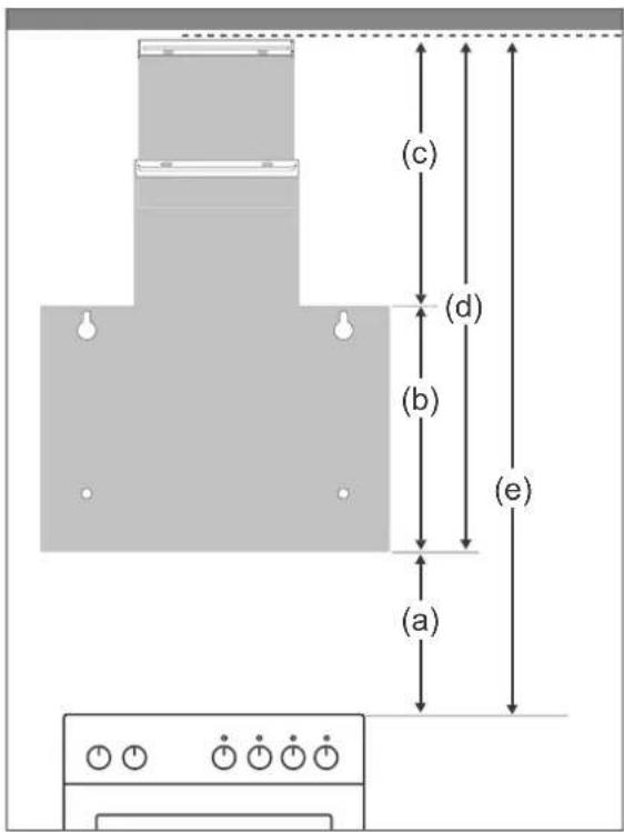
(j) (i) (h) (g) (f)| Important units: | Dimensions in cm | |
| (a) | Minimum distance between stovetop and lower edge of exhaust hood (1) | 65 - 75 |
| (b) | Height of exhaust hood (1) | 39 |
| (c) | Height of the entire flue screen, (2) and (3) | 40(50) - 77 |
| (d) | Height of the entire appli-ance, (1), (2) and (3) | 79(89) - 118 |
| (e) | Space required above the stovetop | 144(154) - 191 |
The images and tables show the minimum distances that must be complied with and how much leeway you have while installing.
The figures in brackets refer to circulation air operation; the ventilation slits must be kept clear.
| Calculating drill holes: | Dimensions in cm | |
| (f) | Height of the safety screws (12) for exhaust hood (1) | 8 |
| (g) | Height of the attachment screws (11) for exhaust hood (1) | 35.5 |
| (h) | Distance between the safety screws (12) for ex-haust hood (1) | 35 |
| (i) | Distance between the at-tachment screws (11) for exhaust hood (1) | 35 |
| (i) | Distance between the at-tachment screws (10) for the wall mount (2) for the upper flue screen (6) | 10.5 |
Before getting started
- Read chapter "For your safety" on page GB-4 and all the safety notices.
-
Drill holes at the marked points, using a diameter that can accommodate the dowels.
-
Place the dowels into the holes.
Place the drill holes

WARNING
Risk of injury!
Improper installation of the appliance can lead to injury.
■ Before drilling the holes, ensure that no wires or cables (power, gas, water etc.) will be damaged (check with a line locator).

CAUTION
Fire hazard!
■ The distance between the cooking surfaces and the lower edge of the exhaust hood must be at least 65 cm for gas stoves.
■ For gas stovetops, you must read the user manual for the stovetop! If the manual stipulates a larger distance, this must be observed.
-
In order to place the appliance exactly over the centre of the stovetop, first use the pencil to draw a vertical guiding line on the wall. Ideally, use a level or a plumb bob from the ceiling of the room to the middle of the stovetop.
-
Draw the six drill holes on the wall, following the diagram on page 12. Make sure the distances between the holes are correct.
Attaching the exhaust hood
text_image
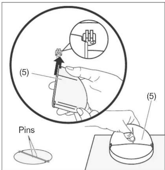
(5) (5) Pins- Place the two halves of the check valve (5) into the opening on the top of the exhaust hood (1). Make sure that the pins on the valve are facing outwards.
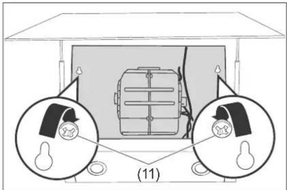
- Screw the two round-head screws (11) for hanging the exhaust hood into the dowels. There must be enough space between the wall and the heads of the screws so that the exhaust hood can be hung by the keyhole openings.
text_image
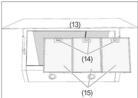
(13) (14) (15)- Flip the cover (13) up.
- Open the locks (14) on the grease filters (15) and carefully pull the grease filters (15) downwards to remove them.
natural_image
Diagram of a room setup with two circular insets showing internal components, no text or symbols present- Carefully hang the exhaust hood on the two round-head screws (11) using the keyhole openings.
- If necessary, remove the exhaust hood again to loosen or tighten the screws in order to ensure that the hood is flush with the wall.
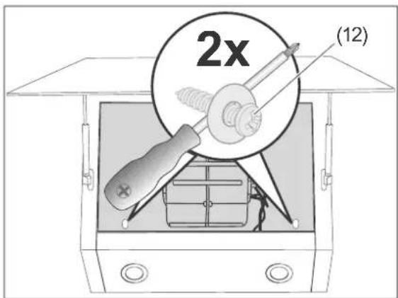
text_image
2x (12)- Turn two round-head screws (12) into the prepared dowels to secure the exhaust hood, and screw the exhaust hood tightly to the wall.
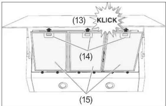
text_image
(13) KLICK (14) (15)- Place the grease filters (15) with the pins into the openings.
- Push the locks (14) up; snap the grease filters (15) in and release the locks.
- Close the cover (13) again and allow it to click into place. The exhaust hood is now mounted to the wall.
Attaching the exhaust air hose
The exhaust air hose (4) must be installed if you intend to use the exhaust hood with exhaust air operation.
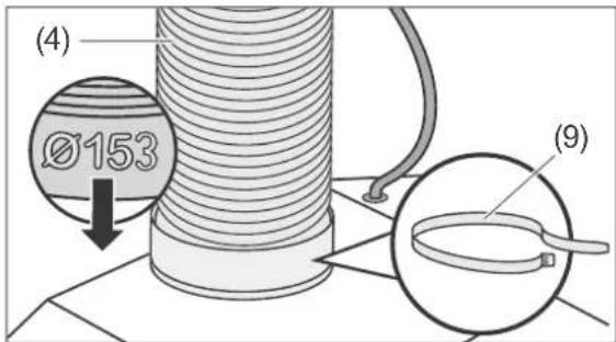
text_image
(4) Ø153 (9)- Insert the end of the exhaust hose (4) with the larger diameter (153 mm) into the connection with the check valve.
- Secure the lower end of the exhaust hose with the cable tie (9).
Installing the flue screen
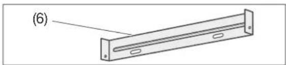
natural_image
Technical line drawing of a rectangular electronic component with mounting holes and a label (6) pointing to its edge (no text or symbols on the object itself)- Screw the wall mount for the upper flue screen (6) into the prepared dowels using 2 round-head screws (10).
text_image
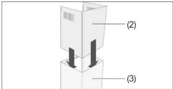
(2) (3)- Push the upper part (2) of the flue screen halfway into the lower part (3) of the flue screen.
text_image
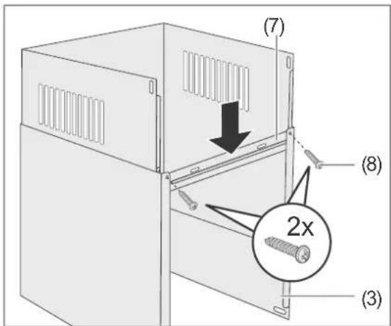
(7) (8) 2x (3)- Place the retaining plate (7) onto the lower flue screen (3) so that it lines up with the chamfers on the inside. (Screws and elongated holes should point upwards).
- Turn two plate screws (8) from the outside through the retaining plate (7) and the lower flue screen (3). Tighten the screws somewhat, but only loosely.
natural_image
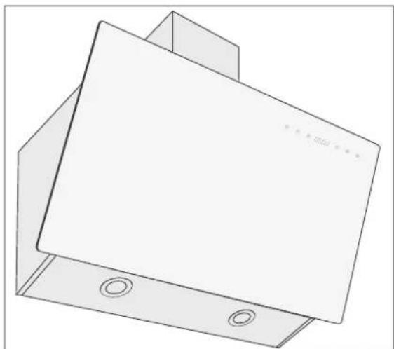
3D technical line drawing of a mechanical component with mounting holes and a flat plate (no text or symbols)- Place the upper (2) and lower (3) parts of the flue screen onto the exhaust hood (1) with the closed side of the flue screen facing upwards.
text_image
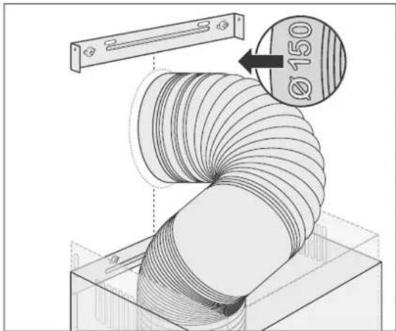
Ø 150- Only for exhaust air operation: Insert the exhaust air hose (4) into the connection at the wall break (hose end with 150 mm diameter).
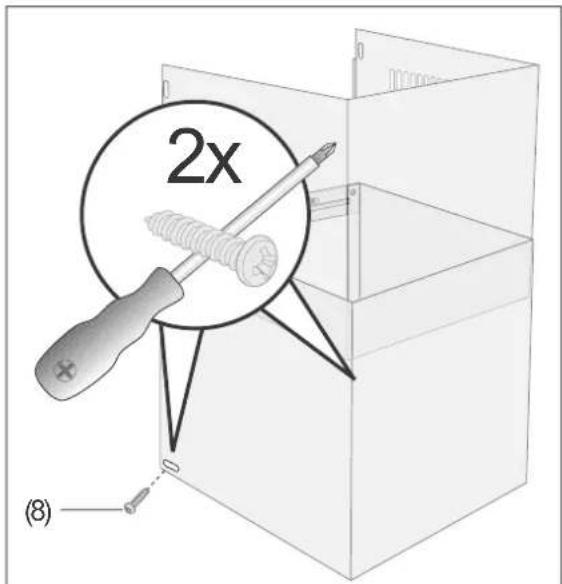
text_image
2x (8)- Fasten the lower part (3) of the flue screen with 2 plate screws (8) to the sides of the exhaust hood (1).
Final steps

WARNING!
Never use a damaged appliance.
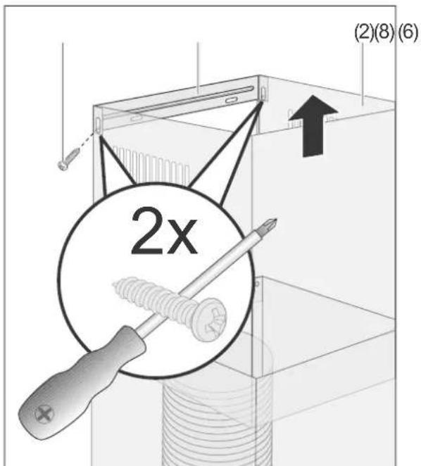
text_image
(2)(8)(6) 2x- Pull the upper part of the flue screen (2) all the way up to the wall mount for the upper flue screen (6).
- Screw the upper flue screen on tightly using two plate screws (8).
- Connect the mains plug to a properly installed socket.
Installation is now complete.
Operation
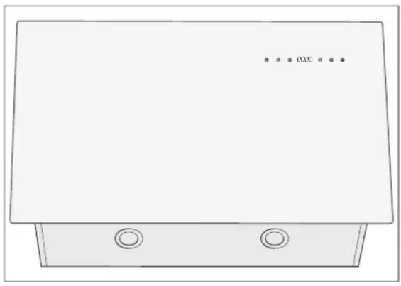
natural_image
Simple line drawing of a rectangular device with two circular ports and three dots on top (no text or symbols)Before getting started
- Read chapter "For your safety" on page GB-4 and all the safety notices.
- Install the exhaust hood as described in chapter "Assembly" on page GB-11.
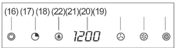
text_image
(16)(17)(18)(22)(21)(20)(19) 1200Switching the appliance on and off
- To switch the appliance on, touch the sensor (16) An audible signal will sound; the colour on the display will change to blue.
- To switch the appliance off, touch the sensor (16) ⏻ again. An audible signal will sound; the colour on the display will change to white.
Setting the time
When the appliance is first connected to the mains, the time displayed is 12:00.
To change Central European Time (CET) to daylight savings time, you need to manually set the clock forward at the end of March and back again at the end of October.
- Switch on the appliance as described in the chapter "Switching the appliance on and off" on page GB-17.
- Touch and hold the sensor (17) for about three seconds. An audible signal will sound; the display i_2 will start to flash.
- Use the sensors (20) ⚙ and (21) ⚙ set the hour.
- Touch the sensor (17) 📍 again. An audible signal will sound; the display 📄 will start to flash.
- Use the sensor (20) to set the minutes.
- Touch the sensor (17) or the sensor (16) again to finish setting the time.
The fan has three settings: (20) ☑low, (21) ☺medium and (22) ☑high.
- To switch the fan on, touch the sensor for the desired setting. An audible signal will sound; the colour on the display will change to blue.
Changing the fan setting
- To change the fan setting, touch the sensor for the (other) desired setting. An audible signal will sound; the colour on the display will change to blue.
– the sensor for the current fan setting once more.
Lighting

WARNING
Risk of injury!
■ If one of the LEDs ceases to work, it must be changed by an authorised service technician. Note for the service technician: This exhaust hood requires LEDs with the ILCOS D-Code DSR-0.5-S-64 DC12 V, 0.5 W.
Your exhaust hood is equipped with two LED lights. The lighting can be switched on or off independently of the fans.
- To switch the lighting on or off, touch the sensor (18) 📋.
Activated charcoal filter
- When using the appliance for air circulation, only do so with activated charcoal filters inserted.
- If neighbours complain about odours, it may be a good idea to insert activated charcoal filters for exhaust air operation, too.
- For the source of supply, please see chapter "Our customer service" on page GB-23.
- To insert, see "Inserting/replacing activated charcoal filters" on page GB-20.
Tips on saving energy
- Only switch on the fan when needed; otherwise, energy will be wasted.
- Let the fan run as long as cooking fumes or steam are present.
- The fan is not needed when cooking only briefly or warming up foods that have little or no odour.
- Ensure that there is enough supply air; otherwise, the exhaust hood may not function optimally. If necessary, open the window or kitchen door.
– Clean the grease filters (15) regularly.
Care and maintenance

WARNING
Risk of injury!
■ Before cleaning the exhaust hood or changing the filter, pull out the mains plug. If the mains plug is difficult to access, switch off the corresponding fuse or pull it out.
Cleaning the housing

CAUTION
Fire hazard!
Improper handling of the appliance or incorrect maintenance can result in grease residue catching fi re.
■ Grease residue on the exhaust hood or in the grease fi Iters can catch fi re if exposed to high temperatures. For this reason, clean the surfaces of the exhaust hood and grease fi Iters regularly.

We recommend cleaning the sur- s of the exhaust hood after every
- Wipe the surfaces with a soft, damp cloth and a little dishwashing detergent. Do not use any sharp objects or scouring powders, as these can scratch the surface.
- Clean glass surfaces with standard glass cleaner.
Cleaning the grease filters

NOTICE
Risk of material damage!
- Handle the grease fi Iters carefully to avoid bending or creasing the fine mesh.
■ Only reinsert the grease filters after cleaning once they are fully dry.
Clean the grease filters once a month – or more frequently if necessary – in the dishwasher (up to 60 °C), or soak in lukewarm water with detergent.
- Unplug the mains plug or switch off the corresponding circuit.
text_image
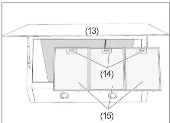
(13) (14) (15)- Flip the cover (13) up.
- Push down the locks (14) on the grease filters (15) and carefully remove the grease filters (15).
- Wash the grease filters (15) in a dishwasher or in the sink like ordinary dishware.
text_image
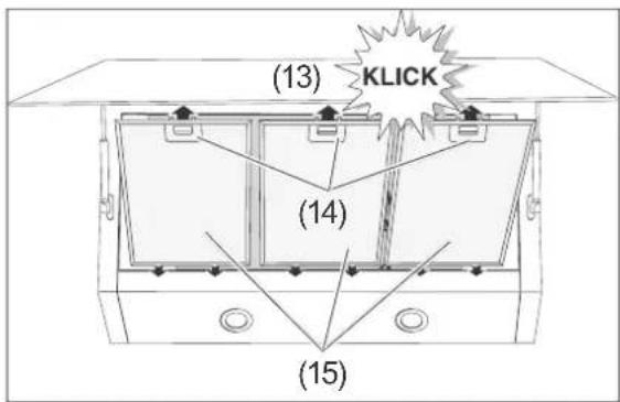
(13) KLICK (14) (15)- Once the grease filters (15) are fully dry, insert them with the pins into the openings.
- Push the locks (14) down; snap the grease filters (15) in and release the locks.
- Close the cover (13) again and allow it to click into place.
- Switch the power back on.
Inserting/replacing activated charcoal filters
Activated charcoal filters are required for circulation air operation. They help combat odours. They have to be replaced as soon as the cooking odours can no longer be adequately filtered.
If used frequently, you should change the filters regularly. Check them at least every 6 months.
For the source of supply, please see chapter "Our customer service" on page GB-23.
- Unplug the mains plug or switch off the corresponding circuit.
text_image
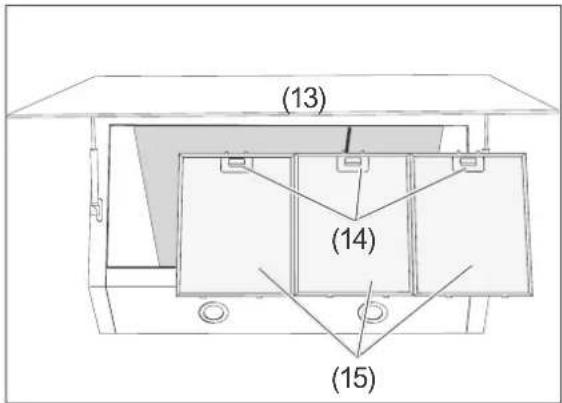
(13) (14) (15)- Flip the cover (13) up.
- Push down the locks (14) on the grease filters (15) and carefully remove the grease filters (15).
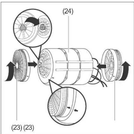
- Only when replacing: The two charcoal filters (23) are located to the right and left of the motor (24). Loosen the two charcoal filters and remove them.
text_image
(24) (23) (23)- Place the new charcoal filters to the right and left of the motor and tighten them in an anti-clockwise direction. Allow the lock to click into place.
text_image
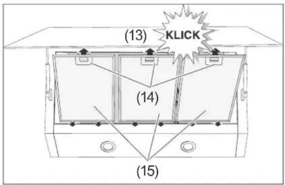
(13) KLICK (14) (15)- Place the grease filters (15) with the pins into the openings.
- Push the locks (14) down; snap the grease filters (15) in and release the locks (14).
- Close the cover (13) again and allow it to click into place.
- Switch the power back on.
- Dispose of the used charcoal filters with household waste.
Troubleshooting table
Malfunctions can occur in all electrical appliances. This does not necessarily mean there is a defect in the appliance. For this reason, please check the tables to see if you can correct the malfunction.

WARNING
Risk of electric shock in case of improper repair!
Never try to repair a defective or suspected defective appliance yourself. You can put your own and future users' lives in danger. Only authorised specialists are allowed to carry out this repair work.
| Problem Possible causes Solutions, tips | |
| Fans and lighting not working. | The appliance is dis-connected from the mains. |
| Lighting not working. LED bulb is defective. Contact an electrician. | |
| Grease is dripping off the appliance. | Grease filter is clogged. |
| Circulation air operation: Odours are not adequately removed; weak airflow. | Grease filter is clogged. |
| Exhaust air operation: Poor performance. | The exhaust hood does not have a sufficient air supply. |
| The exhaust air hose is bent or too long. | |
Our customer service
In order for us to help you quickly, please tell us:
| Name of appliance Model Article number | ||
| hanseatic Exhaust hood | SY-103E6-E33-C55-L52-900 412 | 340 |
General customer service
Please contact your mail order company's product advice centre if you have questions, complaints, repair orders or accessory orders
Spare parts
Customers in Germany
Please contact
Hermes Fulfilment GmbH:
Tel. 0049 (0)57 32 99 66 00
Monday - Thursday 8am - 3pm, Friday 8am - 2pm
Email: ERSATZTEILSERVICE-ELEKTROKLEINGERAETE@hermes-ws.com
Customers in Austria
Please contact your mail order company's customer service centre or product advice centre.
Please note:
You are responsible for the condition of the appliance and its proper use in the household.
If you call out for customer service due to an operating error, you will incur charges, even during the guarantee/warranty period.
Damage resulting from non-compliance with this user manual unfortunately cannot be recognised.
Ordering activated charcoal filters
An activated charcoal filter is only required for air circulation and is not included in the package contents.
You can order these using the following order number: 812 120.
Environmental protection
Disposing of old electrical devices in an environmentally friendly manner
Electrical appliances contain harmful substances as well as valuable resources.
Every consumer is therefore required by law to dispose of old electrical appliances at an authorised collection or return point. They will thus be made available for environmentally-sound, resource-saving recycling.
You can dispose of old electrical appliances free of charge at your local recycling centre.
Please contact your dealer directly for more information about this topic.
Disposing of activated charcoal filters
You can dispose of activated charcoal filters with your household waste.
Packaging

Our packaging is manufactured from environmentally friendly, recyclable materials:
– Outer packaging made of cardboard
– Moulded parts made of foamed, CFC-free polystyrene (PS) parts
– Films and bags made of polyethylene (PE)
– Tension bands made of polypropylene (PP).
If you have the space available, we recommend storing the packaging at least for the duration of the warranty period. If the appliance needs to be sent out for repairs or brought to a repair centre, only the original packaging will provide sufficient protection.
If you would like to dispose of the packaging, please dispose of it in an environmentally friendly way.
Data sheet
Data sheet for exhaust hoods in accordance with Ordinance (EU) No. 65/2014.
| Brand | hanseatic | |
| Model code SY-103E6-E33-C55-L52-900 | ||
| Article number 412 340 | ||
| Annual energy use in kWh/a*) AEC | _hood = 42.1 | |
| Energy efficiency class *) A | ||
| Fluid-dynamic efficiency *) FDE | _hood = 32.4 | |
| Fluid-dynamic efficiency class A | ||
| Lighting efficiency LE | _hood = 11.1 | |
| Lighting efficiency class E | ||
| Grease segregation degree in % 80 | ||
| Grease segregation degree class C | ||
| Airflow in m3/h | at minimum speed 372.5 | |
| at maximum speed 613.2 | ||
| at highest setting - | ||
| Airborne noise emissions in dB | at minimum speed 65 | |
| at maximum speed 73 | ||
| at highest setting - | ||
| Power consumption when switched off | P_0 = 0.48 | |
| Power consumption when ready for operation | P_s = - | |
| Time-delay factor | f = 0.8 | |
| Energy efficiency index | EEI_hood = 46 | |
| Optimal metered air volume flow in m3/h | Q_BEP = 355.4 | |
| Optimal metered air pressure in Pa | P_BEP = 443 | |
| Optimal metered electrical input power in W | W_BEP = 134.9 | |
| Nominal output of lighting system in W | W_L = 3.7 | |
| Average light intensity of the lighting system on the cooking surface in lux | E_middle = 41 | |
| Mains connection in V~/Hz | 220-240/50 | |
| Protection class | I | |
| Lighting, hrs in W | 2 × LED bulbs, max. 0.5 W | |
| Dimensions (W × D) in cm | 90 × 45.5 | |
| Weight in kg (SY-103E6-E33-C55-L52-900) | 18.5 | |
| Total height in cm | max. 118 | |
| Height of the flue screen in cm | 40 - 77 | |
| Exhaust air hose connection in cm | ø 15.0 | |
*) Calculated on the basis of document ‘COMMISSION DELEGATED REGULATION (EU) No 65/2014 of 1 October 2013 supplementing Directive 2010/30/EU’