
Icon - Shower head TEKA - Free user manual and instructions
Find the device manual for free Icon TEKA in PDF.

| Product Type | Shower head |
| Brand | Teka |
| Model | Icon |
| Diameter | 120 mm (approx.) |
| Weight | 0.25 kg (approx.) |
| Material | Chrome-plated brass |
| Minimum Operating Pressure | 0.5 bar |
| Maximum Operating Pressure | 8 bar |
| Connection Type | 1/2" thread |
| Spray Patterns | Single mode (standard) |
| Cleaning Method | Soapy water or specific chrome cleaner; rinse and dry with soft cloth |
| Limescale Removal | Soak in vinegar for a few minutes; avoid detergents or acids |
| Warranty | 5 years against manufacturing defects |
| Spare Parts Availability | Genuine spare parts from manufacturer |
| Repairability | Cartridge and seals can be replaced |
Frequently Asked Questions - Icon TEKA
User questions about Icon TEKA
0 question about this device. Answer the ones you know or ask your own.
Ask a new question about this device
Download the instructions for your Shower head in PDF format for free! Find your manual Icon - TEKA and take your electronic device back in hand. On this page are published all the documents necessary for the use of your device. Icon by TEKA.
USER MANUAL Icon TEKA
2.2.1 CON PINZAS O ACOPLAMIENTO
exposed and concealed mixers
1- Technical Information
2- Installation
3- Calibration
4- Maintenance / Replacement
5- Cleaning
6- Problems and solutions
7- Guarantee
Thank you for choosing this product.
This product has been manufactured using selected materials in order to last without loosing its functionality or look.
Read instructions and recommendations fully in this guide before installing the mixer to ensure a proper use and the essential care.

TECHNICAL INFORMATION
Thermostaic mixers are designed for use with hot water supplies from pressurised storage heaters (with min. output power of 18 kW, equal to 250 kcal/min.) from electrical or gas-fired boilers.
Tab.1 Thermostatic mixer characteristics
| Minimum operating pressure, without resistance | 0.5 bar |
| Maximum operating pressure | 8 bar |
| Maximum water temperature | 90°C (194°F) |
| Temperature regulation | From 20° (68°F) to 60°C (140°F) |
| For installation where the mains pressure exceeds 5 bar, a pressure reducing valve should be fitted on the main water supply |
Tab.2 Thermostatic Cartridge Calibration Conditions
| Hot and cold water pressure | 3 bar |
| Hot water temperature | 65±5 C^ (149± 41 ^ ) |
| Cold water temperature | 15±5 C^ (59±41 ^ ) |
IMPORTANT: all the thermostatic cartridges have been set in factory under balanced pressures at 3 bar (equal to 0.3Mpa or to 3 Atm.).
N.B.: the optimal performance of a thermostatic mixer is achieved with equal pressures (hot and cold).
WARNING: it is advisable to thoroughly flush through the water supply pipes before installing the thermostatic mixer.
Ensure that connections are made with hot water to the left side and cold water to the right side. If the hot and cold water supply pipes are reversed, the mixer CANNOT WORK. Follow carefully the indications placed on the thermostatic mixer body: red sticker, connection to the hot water supply.
In case of replacement of an existing mixer, remove the previous "S"- connectors and replace them with the ones supplied with the new product.
2.1 INSTALLATION THERMOSTATIC SHOWER/BATH SHOWER MIXER
2.1.1 INSTALLATION WITH NUTS
Screw the "S" connectors ( 12 " thread) on the water supply pipes in the wall using a 14mm. wrench key 01. Verify with the proper tools that the "S" connectors are parallel with the floor axis and have a distance of 150mm centres 02. Screw the two flanges onto the already fitted connectors 03.
Place a fibre washer into each of the nuts and screw them to the "S" connectors making sure that the red mark side is connected to the hot water supply 04.
2.1.2 INSTALLATION WITH COUPLING
Screw the "S" connectors (1/2" thread) on the water supply pipes in the wall using a 12mm. wrench key 01. Verify with the proper tools that the "S" connectors are parallel with the floor axis and have a distance of 150 mm centres 02. Insert the two flanges onto the back extensions of the thermostatic mixer body. Mount the thermostatic mixer body on the "S" connectors 05 and push it till the flanges are perfectly tight to the wall, making sure that the red mark side is connected to the hot water supply label" is connected to the. Tighten the fixing screws alternately for a correct alignment and fixing of the thermostatic mixer body using the supplied 3 mm. hexagonal key.
2.2 INSTALLATION SHOWER COLUMN
2.2.1 INSTALLATION WITH NUT OR COUPLING
Insert the wall bracket and the sliding shower holder onto the tube 06. Screw the vertical tube and the curved one together 07. Fit the complete riser tube on the top connection outlet of the thermostatic mixer 08, slide the wall bracket as per image; check with proper tools that the riser is perfectly vertical and mark holes position for the wall plugs and fixing screws 09. Remove the riser tube, drill the wall with a 6 mm. drill, making sure that the mixer is protected from debris. Insert the wall plugs 10. Push the riser down into the top connection outlet on the valve and secure the wall bracket by using the supplied screws 11; tighten the riser nut on the top outlet. Alternatively tighten the grub screw on the riser to fix it in a suitable position, using a 2/2,5 mm. hexagonal key 12. Adjust the distance of the wall bracket acting on the central pin (A) and check with proper tools that the riser is in straight vertical position. Slide the cover of the bracket onto the wall. Screw the shower head.
2.2.2 INSTALLATION WITH FIXED WALL DISTANCE
Insert the sliding shower holder onto the vertical tube and connect it to the horizontal one 13. Insert the riser into the top connection outlet of the thermostatic mixer making sure it is completely fitted in. check with proper tools that the riser is perfectly vertical and mark holes position for the wall plugs of the horizontal tube. Remove the riser tube, drill the wall, making sure that the mixer is protected from debris. Insert the wall plugs 10. Push the riser down into the top connection outlet of the valve and fix the horizontal tube to the wall with the screws provided. Slide the cover of the bracket onto the wall. Screw the shower head.
2.3 INSTALLATION THERMOSTATIC BASIN/BIDET/SINK MIXER
Undo the screw on the back of the thermostatic mixer, fit the spout on the body making sure that the open part of the white ring is positioned on the screw hole. Tight the screw by using a screwdriver 16
. Connect the two flexible pipes (red and blue one) to the thermostatic mixer body following the hot and cold marks 17.
Insert the supplied non return valves into the hot and cold water supply pipes, fit the filter washers and connect the flexible connection hoses 18.
Fit the thermostatic mixer to the sanitary ware using the supplied fixing kit.
2.4 INSTALLATION CONCEALED THERMOSTATIC MIXER
Concealed thermostatic mixers are supplied complete with a rear box support in zinc-coated steel as a guide to the right depth of the recess and to give measure limits for the finished surface. This also isolates and protects the mixer during the installation work.
Place the thermostatic mixer into the wall and make sure that the recess has the required size to accept the box, use the cover "A" as surface for the wall finish 30. Take off the cover 31, connect hot water (3/4") to the left side (HOT) and cold water (3/4") to the right side (COLD), the other water outlets (1/2") as required.
Thermostatic mixer with two outlets: connect the showerhead (1/2") to the top outlet and the handset or any other accessories (32) to the right outlet (1/2").
Before clipping the cover onto the metal box, turn on the flow control and test for eventual leaks and make sure that the mixer unit is perpendicular. Make sure that the fixing holes on the box cover and on the finished surface do match 33.
Once plaster or tiling up work is finished, take off the plastic protection caps, fit the face plate with the sponge backing and slide tight to the wall; alternatively place the face plate, insert the seals and flanges and slide tight to the wall 34.
Where required fit the handles or the lever 35
On off/diverting handle: make sure that the spindle of the diverting cartridge has the reference point "B" on the underside and in horizontal position 36. Insert the handle with the push button on the upper side and place the pin on the stop of the adaptor ring, Do not turn the spindle of the diverting cartridge (the push button must be perpendicular to the flat surface of the cartridge pin). Tighten the screw and insert the cap or tighten the grub screw keeping the handle tight to the diverter 37.
On off/diverting lever: fit the lever setting the central outlet position of the diverter 38. Tighten the screw and the cap, alternatively tighten the grub screw keeping the lever tight to the diverter.
Temperature control handle: fit the handle keeping the override button lined up with the black line marked on the spindle of the thermostatic cartridge 39.
CALIBRATION
3.1 CALIBRATION OF THE THERMOSTATIC CARTRIDGE
The thermostatic mixer is adjusted in factory to provide an outlet temperature of about 38^ when positioned on the scale indicator of the handle.
If the selected temperature does not correspond to the supplied water, the thermostatic mixer must be calibrated following the local installation conditions.
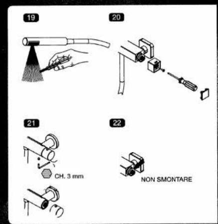
Turn the water on, position the temperature control handle at 38^ C and measure the temperature of the water with a medical thermometer. Turn the temperature control handle, with safety button pressed, until you reach a stable temperature of 38^ 19.
Without turning the handle any further, remove the handle cap, undo the screw and take off the temperature control handle 20. In case of handle without cap, undo the grub screw and remove the handle 21. Refit the handle and make sure that the mark on the body is lined up with the 38°C indication of the handle. Tighten the screw and place the handle cap or tighten the grub screw keeping the handle tight to the thermostatic mixer.
CAUTION: The black adaptor ring on the thermostatic cartridge must never be removed 22
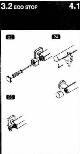
3.2 CALIBRATION OF THE "ECO STOP" SYSTEM
The thermostatic mixers provided with Ecostop system are performed to give a third part of water compared to the flow in fully open position.
Pressing the safety button you can override the Ecostop system stop and obtain the maximum water flow. It is possible to adjust the Ecostop set flow rate.
Without turning the Ecostop control handle, remove the handle cap, undo the screw and take off the handle 23. In case of handle without cap, undo the grub screw and remove the handle 24.
Take off the regulation ring 25. Fit again the regulation ring turning it anti-clockwise to increase the flow or clockwise to reduce it. Replace the handle, tighten the screw and place the handle cap or tighten the grub screw keeping the handle tight to the mixer.

MAINTENANCE / REPLACEMENT
Before any maintenance work is started, shut off the stop valves.
To ensure a long lasting functionality, a regular and accurate maintenance is recommended.
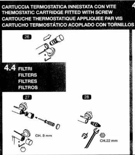
4.1 THEMOSTATIC CARTRIDGE FITTED WITH SCREW
Undo the grub screw on the underside of the thermostatic mixer body to remove the thermostatic cartridge), which pulls out (it is not necessary to take off the temperature control handle. Clean the limestone with vinegar (do not use any detergents or acids) and lubricate the seals with thermoresistant grease 26). Replace the thermostatic cartridge properly and follow procedure in reverse order to fit all the other parts.
4.2 THERMOSTATIC MIXER SCREWED UP
Remove the handle cap, undo the screw and take off the temperature control handle.
In case of handles without cap, unscrew the grub screw and remove the handle.
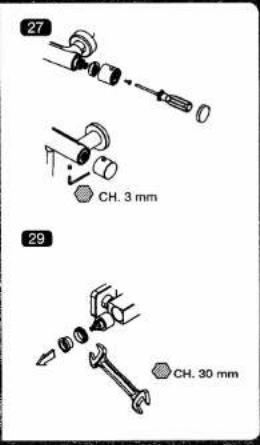
Take off the stop ring taking care of its fitting position 27. When re-assembling put this in the same
position. Unscrew the thermostatic cartridge 28, clean the limestone with vinegar (do not use any detergents or acids) and lubricate the gaskets with thermoresistant grease.
Proceed re-installing the thermostatic cartridge in its proper seat making the operation in the reverse order. If the 38°C selected temperature is not performed, then refer to paragraph "CALIBRATION OF THE THERMOSTATIC CARTRIDGE".
4.3 DIVERTING CARTRIDGE
Remove the handle cap, undo the screw to remove the diverting control handle. In case of a handle without cap, then unscrew the grub screw and remove the handle 37.
Take off the adaptor ring. Remove the retaining nut using a dynamometric key or a 30 mm. wrench key (caution: if a dynamometric key is not available, it is advisable to mark the position of the locking nut with an ink pen or similar instrument), take off and wash the diverting cartridge from debris 30.
Refit the diverting cartridge making sure that the locating pegs are positioned in their holes properly, refit the retaining nut and tighten using a max. force of 10/12 Nm (alternatively replace the retaining nut having the marks aligned). Refit the adaptor ring and follow the same procedure in reverse order to refit the handle.
4.4 FILTERS (ONLY FOR CONCEALED MIXER)
If necessary take off the handles and/or the lever. Take off the plate and eventually the sponge washer too. By using an exagonal key, unscrew the plugs, remove the filters and clean their nets. If the filters holes are obstructed, soak the filters in the vinegar for a few minutes. Reassemble all the pieces following the above instructions in reverse order. Repeat this operation from time to time in order to ensure good working of the mixer 40.
⑤ CLEANING
In order to preserve the surface finish of the thermostatic mixer, it is necessary to observe some instructions regarding the aftercare:
- To remove dirt and limescale, use only soapy water or specific products for chrome-plated surfaces, rinse and dry with soft cloth.
- Avoid using detergents or acids, abrasives on chrome-plated, coloured, gold-plated or burnished surfaces.
- For the plastic and rubber parts do not clean with bleaches, chemicals or anything similar, but follow the same procedure as for the mixer body.

PROBLEMS AND SOLUTIONS
- If the thermostatic mixer does not set the temperature properly:
Turn the hot and cold water on, making the temperature control handle turn several times until the temperature returns to normal.
- If the thermostatic mixer does not give hot or cold water:
Check that the water pipes or the filters on the body are free of obstructions and that pressures are comparable.
- If the thermostatic does not set the temperature of 38^ :
Check to ensure that the local installation conditions are as described in paragraph 3. Technical information. If such conditions are respected, then reset the thermostatic cartridge as indicated in paragraph 4.1 Calibration of the thermostatic cartridge.
- If the temperature control handle is hard to turn:
Open the water and the temperature control handle several times making the water flow, until it loosens.

GUARANTEE
Please keep this brochure as a purchase proof and control coupon.
The thermostatic mixer you have purchased has a 5 years guarantee against defects in manufacture or material.
THE GUARANTEE DOES NOT COVER THE FOLLOWING:
Wrong and improper use of the thermostatic mixer
Faulty installation or carried out with improper tools
Negligent or inadequate maintenance or improper use of the cleaning products
Components subjected to wear and tear (aerators, O Rings, etc.)
Damage caused by limestone or impurities in the water pipes
Damage caused by the use of non-ALPI spare parts
Damages caused by chemical, electro-chemical, electrical influence
In case of claims it is necessary to return the mixer:
- duly packed together with purchase proof (invoice, ticket, etc.)
• with control coupon and specifying the kind of defects.
Your supplier will apply the guarantee.
If claim is covered by the guarantee, the mixer will be replaced or repaired free of charge.
N.B.: returned mixers with non-original control coupons (copies, altered, modified or belonging to other ranger) or missing ones, cannot be accepted. Subject to technical modifications.
MISCELATORE TERMOSTATICO ESTERNO / THERMOSTATIC EXPOSED MIXER MITIGEUR THERMOSTATIQUE APPARENT / MEZCLADOR TERMOSTÁTICO EXTERNO


REGOLAZIONE/CALIBRATION/REGLAGE/REGULACION

MANUTENZIONE/MAINTENANCE/ENTRETIEN/MANTENIMIENTO
3.1 CARTUCCIA TERMOSTATICA THERMOSTATIC CARTRIDGE CARTOUCHE THERMOSTATIQUE CARTUCHO TERMOSTÁTICO
4.3 CARTUCCIA DEVIATRICE DIVERTING CARTRIDGE CARTOUCHE SELECTEUR S CARTUCHO DESVIADOR
MISCELATORE TERMOSTATICO INCASSO / CONCEALED THERMOSTATIC MIXER MITIGEUR THERMOSTATIQUE ENCASTRE' / MEZCLADOR TERMOSTÁTICO DE EMPOTRAR

- CON PINZAS O ACOPLAMIENTO
- exposed and concealed mixers
- TECHNICAL INFORMATION
- INSTALLATION THERMOSTATIC SHOWER/BATH SHOWER MIXER
- INSTALLATION WITH NUTS
- INSTALLATION WITH COUPLING
- INSTALLATION SHOWER COLUMN
- INSTALLATION WITH NUT OR COUPLING
- INSTALLATION WITH FIXED WALL DISTANCE
- INSTALLATION THERMOSTATIC BASIN/BIDET/SINK MIXER
- INSTALLATION CONCEALED THERMOSTATIC MIXER
- CALIBRATION
- CALIBRATION OF THE THERMOSTATIC CARTRIDGE
- CALIBRATION OF THE "ECO STOP" SYSTEM
- MAINTENANCE / REPLACEMENT
- THEMOSTATIC CARTRIDGE FITTED WITH SCREW
- THERMOSTATIC MIXER SCREWED UP
- DIVERTING CARTRIDGE
- FILTERS (ONLY FOR CONCEALED MIXER)
- ⑤ CLEANING
- PROBLEMS AND SOLUTIONS
- GUARANTEE
- THE GUARANTEE DOES NOT COVER THE FOLLOWING:
- MISCELATORE TERMOSTATICO ESTERNO / THERMOSTATIC EXPOSED MIXER MITIGEUR THERMOSTATIQUE APPARENT / MEZCLADOR TERMOSTÁTICO EXTERNO
- MISCELATORE TERMOSTATICO INCASSO / CONCEALED THERMOSTATIC MIXER MITIGEUR THERMOSTATIQUE ENCASTRE' / MEZCLADOR TERMOSTÁTICO DE EMPOTRAR
Brand : TEKA
Model : Icon
Category : Shower head