Opus 2 M1 - Pregnant Wharfedale - Free user manual and instructions
Find the device manual for free Opus 2 M1 Wharfedale in PDF.


User questions about Opus 2 M1 Wharfedale
0 question about this device. Answer the ones you know or ask your own.
Ask a new question about this device
Download the instructions for your Pregnant in PDF format for free! Find your manual Opus 2 M1 - Wharfedale and take your electronic device back in hand. On this page are published all the documents necessary for the use of your device. Opus 2 M1 by Wharfedale.
USER MANUAL Opus 2 M1 Wharfedale
text_image
Opus² USER MANUAL Opus² - M1 Opus² - M2 Opus² - Stand Opus² - 1 Opus² - 2 Opus² - 3 Opus² - AV System Opus² - Tri Centre Opus² - Tri Surround Opus² - SW250 Subwoofer Opus² - SW300 Subwoofer Opus² - SW380 Subwoofer Wharfedale Loudspeakers Ltd. IAG House, Sovereign Court, Ermine Business Park, Huntingdon PE29 6XLI, England. Tel: 0845 458 0011 / +44 (0) 1480 447700 Fax: +44 (0) 1480 131767 www.wharfedale.co.ukOpus ^2
User Cautions


TO REDUCE THE RISK OF ELECTRIC SHOCK DO NOT REMOVE COVER (OR BACK) NO USER-REMOVEABLE PARTS INSIDE REFER SERVICING TO QUALIFIED PERSONNE
ADVERTISSEMENT: RISQUE DE CHOC ELECTRIQUE- NE PAS OUVRIR
IMPORTANT SAFETY INFORMATION
Read these instructions.
Keep these instructions
Head all warnings
Follow all instructions.
Do not use this apparatus near water.
Clean only with dry cloth.
Do not block any ventilation openings.
Install in accordance with the manufacturer's instructions.
Do not install near any heat sources such as radiators, heat registers, stoves, or other apparatus (including amplifiers) that produce heat.
Do not defeat the safety purpose of the polarized or grounding type plug. A polarized plug has two blades with one wider than the other. A grounding type plus has two blades and a thin
grounding prong. The wider blade or the third prong are provided for your safety. If the provided drug does not fit into your outlet, consult an electrician for replacement of the obsolete outlet. Protect the power card from being walked on or pinched,
particularly at plugs, convenience receptacles, and the point where they exit from the apparatus.
Use only attachments/accessories specified by the manufacture.

Use only with a cart, stand, tripod, bracket, or table specified by the manufacturer, or sold with the apparatus. When a car is used, use caution when moving the carboparasites combination to avoid injury from the eye.
Uping this apparatus during lightning storms or when unused for long periods of time.
Refer all servicing to qualified service personnel. Servicing is required when the apparatus has been damaged in any way, such as power-supply cont or plug is damaged, liquid has been spilled or objects have fallen into the apparatus, the apparatus has been exposed to rain or moisture, does not operate normally, or has been dropped.
Warning: E produce her staffs on electrical shock denotes this product to rain or moisture. The product must not be exposed to dirocing and plashing and no objectified with liquids such as severe offlowers should be plated in the product.
No naked flame sources such as candles should be placed on the product.
Caution: Changes or modifications nor expressly approved by the manufacturer could void the user's authority to operate this device.
WarningOpus® Subwoofer: The mains power switch for this

This symbol indicates that there are important operating and maintenance instructions in the literature accompanying this unit.

This symbol indicates that dangerous voltage constituting a risk of electric shock is present within this unit.
appliance is located on the near panel. To permit free access to this switch, the apparatus must be located in an open area without any obstructions.
NOTE:Opus®Subwoofers:
This equipment has been tested and found to comply with the limits for a Class B digital device, pursuant to part 15 of the FCC Rules. These limits are designed to provide reasonable protection against harmful interference in a residential installation.
This equipment generates, uses and can radiate radio frequency energy and, if not installed and used in accordance with the instructions, may cause harmful interference to radio.
communications. However, there is no guarantee that
interference will not occur in a particular installation. If this equipment does cause harmful interference to radio or television reception, which can be determined by turning the equipment off and on, the user is encouraged to try to correct the interference by one or more or the following measures:
• Recent or relocate the receiving antenna.
- Increase the separation between the equipment and receiver. - Connect the equipment into an outlet on a circuit, different from that to which the receiver is connected.
- Consult the dealer or an experienced radio/TV technician for help.
IMPORTANTNOTICETOUKUSERS
The power corn on your subwoofer may be supplied with a plug incorporating a fuse, the value of which is indicated on the pin face of the plug. Should the fuse need to be replaced, an ASIA or BSI approved BSI 362 fuse must be used of the same rating. If the plug is cut-off, it must NOT be re-used. Dispose of any such plug safety. There is a danger of electric shock if a cut-off plug is inserted into a mains socket.
ConnectingaMainsPlug
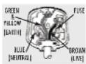
The wires in the mains load are coloured in accordance with the code. Blue, NEUTRAL, Brown.
LIVE: Green/Yellow: Earth.
As these colours may not
correspond to the coloured
markings Identifying the terminal
In your plug, proposed as follows: The 51 UK wire saw by uppress
to the terminal marked with the letter N or coloured BLUE or BLACK. The BROWN wire must be connected to the terminal marks with the letter L or coloured BROWN or RED. The
GREEN/YFLOW wire must be connected to the terminal marked with the letter E or coloured GREEN or marked with the symbol


Opus ^2
Opus ^2
Conclusion
Quality Management
Your Opus loudspeakers have been constructed to the highest standards of quality throughout. The acoustic components and the whole system have been manufactured to very light tolerances of +/- 1 decibel of sound pressure level for each driver throughout the operational range of the unit.
All drive unit components are serially numbered and test compared to golden reference originals retained in our factory quality control department. This scruculous attention to deal enables us to ensure not only that all Cput2 loudspeakers exactly replicate the performance characteristics of our reference test samples, it also enables us to give a extended guarantee of identical replacement parts should they ever be required.
A certificate of contemporary to the original prototype specification, confirmed by the Opus designer and engineering director is included in this park.
Servicing
Servicing of Opus products should only be carried out by authorised service agents. If service is required the equipment should not return, securely packaged, preferably using original packaging, to your dealer.
In the UK equipment may be returned to the IAG Service Centre. In the USA equipment may be returned to the Service address shown on this page. Always telephone before returning any equipment. A note should be enclosed giving your name, address, telephone number, and a brief description of the reason for return.
If you require Service outside the Warranty period, do not hesitate to contact your dealer.
Service Addresses
For technical support, servicing or product queries and information please contact either your local retailer or the offices below.
UK
Wharfedale International Ltd.
Unit 4
St Margaret's Way
Shukley Meadows Industrial Estate
Huntingdon
Cermis
PE29 6EB
England
Tel:+44(0)1480 452561
Fax: +44 (0)1480 413408
USA
AG America, Inc.
8440 154th Avenue NE
Redmond, Washington 98052
US
Tel: +1 425 861 3909
Fax: +1 425 861 3906
[Non-Text]
Asia
ING
Room 2310 - 2311 Press Building.
Sherman Road C,
Sherzhen,
China
Tel: +66-755-82091200
Fax: +86-755-82091205

Produced after 13th August 2005.
Waste electrical products should not be disposed of with
household waste. Please recycle where facilities exist.
Check with your Local Authority or retailer for recycling advice.
Contents
- Before You Begin
- Getting Started
- Setting Up Your Loudspeaker
- Setting Up Your Subwoofer
• About Your Loudspeaker
• Quality Assurance - Specifications
Within This Pack
• Certificate of Quality Assurance
- White Cotton Gloves
- Accessories
Opus²
Opus ^2 Opus
Before You Begin...
Before connecting and using your loudspeakers, please bear the following points in mind:
- Switch off the amplifier and all sources before making connections to your sound system. When you switch on the system or change sources, set the volume control to minimum and turn up the level gradually.
The position of your Volume Control is NOT a reliable guide as to the maximum capabilities of your sound system. Playing the system with extreme settings of volume and lone controls may damage the amplifier and loudspeakers. - Do no, connect loudspeaker terminals to the mains supply.
- Ensure that your loudspeakers are correctly wired and are in phase. Do not subject your loudspeakers to excessive cold, heat or sunlight.
WARNING: to reduce the risk of fire or electrical shock do not expose this product to rain or moisture. The product must not be exposed to chipping and splashing and an object fitted with liquids, such as a vase of flowers, should be placed on the product.
No naked flame sources - such as candles - must be placed on the product. Do not place heavy objects on top of launspeaker cabinets. If you play the launspeakers with the prizes removed he careful to prepare the drive units from children and parts.
Do not use makeshift stands. Always it a manufacturer's approved stand using the instructions and the things provided. Your dealer will advise you.
Do not attempt to disnandle the logospeters. There are no user serviceable parts inside and you will invalidate the warranty. - At the Front and Centre loudspeakers are screened, but you should sit front loudspeakers at least 0.5 m away from TV sets and magnetic storage media. The Opus ^2 Til-Centre and the AxCentre loudspeakers may satisfy he operate close to a TV set.
- When connecting your loudspeakers, do not run cable across areas of open floor where they may be a source of danger. Run them safely, second room boundaries if necessary.
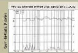
Measurement and Analysis-2
line
| Time | Opas-Ti-Centre Distortion | |------|--------------------------| | 0 | 0.0 | | 10 | 0.2 | | 20 | 0.3 | | 30 | 0.4 | | 40 | 0.5 | | 50 | 0.6 | | 60 | 0.7 | | 70 | 0.8 | | 80 | 0.9 | | 90 | 1.0 | | 100 | 1.1 |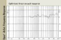
line
| Time | Frequency Response | |------|---------------------| | 0 | 0 | | 10 | 0 | | 20 | 0 | | 30 | 0 | | 40 | 0 | | 50 | 0 | | 60 | 0 | | 70 | 0 | | 80 | 0 | | 90 | 0 | | 100 | 0 | | 110 | 0 | | 120 | 0 | | 130 | 0 | | 140 | 0 | | 150 | 0 | | 160 | 0 | | 170 | 0 | | 180 | 0 | | 190 | 0 | | 200 | 0 | | 210 | 0 | | 220 | 0 | | 230 | 0 | | 240 | 0 | | 250 | 0 | | 260 | 0 | | 270 | 0 | | 280 | 0 | | 290 | 0 | | 300 | 0 |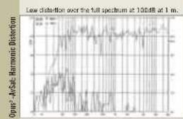
line
| Sample ID | Low Distortion | | --------- | -------------- | | 1 | 0.5 | | 2 | 0.6 | | 3 | 0.7 | | 4 | 0.8 | | 5 | 0.9 | | 6 | 1.0 | | 7 | 0.9 | | 8 | 0.8 | | 9 | 0.7 | | 10 | 0.6 | | 11 | 0.5 | | 12 | 0.4 | | 13 | 0.3 | | 14 | 0.2 | | 15 | 0.1 | | 16 | 0.0 | | 17 | -0.1 | | 18 | -0.2 | | 19 | -0.3 | | 20 | -0.4 | | 21 | -0.5 | | 22 | -0.6 | | 23 | -0.7 | | 24 | -0.8 | | 25 | -0.9 | | 26 | -1.0 | | 27 | -0.9 | | 28 | -0.8 | | 29 | -0.7 | | 30 | -0.6 | | 31 | -0.5 | | 32 | -0.4 | | 33 | -0.3 | | 34 | -0.2 | | 35 | -0.1 | | 36 | 0.0 | | 37 | 0.1 | | 38 | 0.2 | | 39 | 0.3 | | 40 | 0.4 | | 41 | 0.5 | | 42 | 0.6 | | 43 | 0.7 | | 44 | 0.8 | | 45 | 0.9 | | 46 | 1.0 | | 47 | 0.9 | | 48 | 0.8 | | 49 | 0.7 | | 50 | 0.6 | | 51 | 0.5 | | 52 | 0.4 | | 53 | 0.3 | | 54 | 0.2 | | 55 | 0.1 | | 56 | 0.0 | | 57 | -0.1 | | 58 | -0.2 | | 59 | -0.3 | | 60 | -0.4 | | 61 | -0.5 | | 62 | -0.6 | | 63 | -0.7 | | 64 | -0.8 | | 65 | -0.9 | | 66 | -1.0 | | 67 | -0.9 | | 68 | -0.8 | | 69 | -0.7 | | 70 | -0.6 | | 71 | -0.5 | | 72 | -0.4 | | 73 | -0.3 | | 74 | -0.2 | | 75 | -0.1 | | 76 | 0.0 | | 77 | 0.1 | | 78 | 0.2 | | 79 | 0.3 | | 80 | 0.4 | | 81 | 0.5 | | 82 | 0.6 | | 83 | 0.7 | | 84 | 0.8 | | 85 | 0.9 | | 86 | 1.0 | | 87 | 0.9 | | 88 | 0.8 | | 89 | 0.7 | | 90 | 0.6 | | 91 | 0.5 | | 92 | 0.4 | | 93 | 0.3 | | 94 | 0.2 | | 95 | 0.1 | | 96 | 0.0 | | 97 | -0.1 | | 98 | -0.2 | | 99 | -0.3 | | 100 | -0.4 |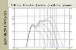
line
| Time (s) | Filter Curve | | -------- | ------------ | | 0 | 0 | | 10 | 10 | | 20 | 20 | | 30 | 30 | | 40 | 40 | | 50 | 50 | | 60 | 60 | | 70 | 70 | | 80 | 80 | | 90 | 90 | | 100 | 100 |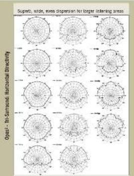
text_image
Superbic, wide, even dispersion for larger listening areas Open - Tri-Surmond Microtial Directivity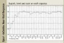
line
| Time Point | Odds-AoCertric Mean-Vall Responses | | ---------- | ---------------------------------- | | 0 | 0.0 | | 1 | 0.2 | | 2 | 0.4 | | 3 | 0.6 | | 4 | 0.7 | | 5 | 0.8 | | 6 | 0.9 | | 7 | 0.95 | | 8 | 0.98 | | 9 | 0.99 | | 10 | 1.0 | | 11 | 1.0 | | 12 | 1.0 |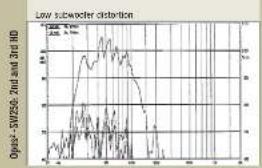
line
| Optax | Low parameter distortion | |-------|--------------------------| | SW2560 | 12 | | Znd and 3rd HD | 8 |Opus²
Opus²
Measurement and Analysis-1
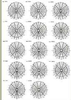
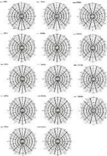
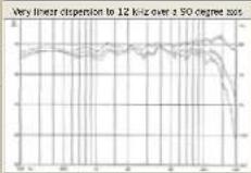
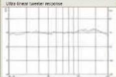
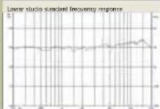
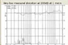
These actual test plots exemplify the stringent standards of acoustical measurement and performance in Opus ^2 loudspeakers.
Remarkably similar dispersion oh both axes due to our unique drive unit configuration with central tower placement
Opus ^2 : M1: Vertical Directivity
natural_image
Grid of 12 identical circular diagrams with concentric rings and radial lines, no text or symbols present.Opus ^a -ML: Horizontal Directivity
natural_image
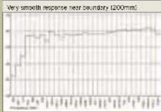
Grid of 12 identical circular diagrams with radial lines, no text or symbols presentOps ^2 -M2: Near Wall Response
Opas ^2-1 : Axial Response 0:30.45°
Opus ^2 1: Spectral Decay

Opus ^2 -2: Frequency Response
Opius ^2 -3: Frequency Response
Opius ^2 : 3, 2nd and 3rd HD
Safely Unpacking Your Loudspeakers
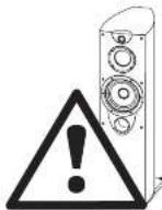
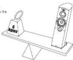
Opus speakers are heavy. Take care when
removing them four their packaging. Enlist the hop of a trend if necessary
natural_image
Line drawing of a balance scale with a 6 kg mass and a vertical speaker (no text or symbols)Always take care when firing heavy objects. I find the sneakers out by their sides.
Unpacking the Opus ^2 1.2 &3
If your floor is at all yunnarals, protect the floor surface with a cloth or towel.
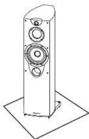
Carefully remove each loudspeaker from its packing carton. For especially careful when removing the polythere bag. The sounders come with the blind complete and already rated. The carton too says, "Open other one." So you:
Open the bottom
- Reinose polystyrene
Lift: As galle Sartan och - open leg containing speaker
- Tape the cartin taps back.
- Litt cartao cft, leaving loudspeaker standing on the floor
Linear the grilles and place them on the loudspeakers. - Be careful not to damage soft floor surfaces with spikes
natural_image
Line drawing of a tall speaker tower with three speakers and a base platform (no text or symbols)Unpacking the Opus ^1 M1, M2, AV, Tri-Centre & Tri-Surround
Lrt out the polystyrene packing pieces and unpack the loudspeakers being careful not to lift the loudspeakers out with the polythene bags. Remove the polysthene bags. The AV speakers are packed as a system with two AWS satellites and one AWC centre loudspeaker.
Unpacking the Opus ^2 Stands
Before proceeding, protect the floor surface with a cloth or towel. The stanks are packed facing each other. Lift each stand out from the packing and then invert it so that the spikes are on the floor.
Unpacking the Opus ^2 SW250,300 and 380 Subwoofers
Open the carton and remove all the top packing pieces. I fit the subsuffer out taking care not to damage the cariner. When lifting the unit from the carton support it from the bottom. DO NOT attempt to lift the subsuffer out of the carton using the polythons bag. The unit is heavy if you cannot manage it easily, get someone to assist you.
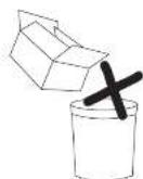
If possible, keep the packaging in case you need to move or return your space. If you dispose of the packing, do so with regard to all recycling regulations in your area
Opus ^2
Opus ^2 Opus
What's In The Box?
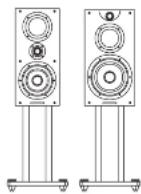 Opus ^2 -M1, M2, Stands Opus ^2 -M1, M2, Stands | 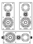 | 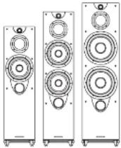 Opus ^2 -1, 2, 3Opus ^2 -/- Opus ^2 -1, 2, 3Opus ^2 -/- |
 User Pack User Pack User Pack User Pack User Pack User Pack |  |  |
| Accessories: Accessories:Opus ^2 - M1, M2One Pair of Gloves8 Rubber HotOpus ^2 - StandsSoft Floor Solve Seats (2 Sets)One Pair of Gloves | Accessories:One Pair of Gloves9 Screw headers3 Security Ties3 Tc Screws & Washers2 Ltr Brackets2 Bracket Knots | Two Pairs of GlovesSoft Floor Solve Seats (1 Set)One Pair of 8-Wire Lukis |
Opus ^2 -1, 2, 3Opus ^2 -AV System
Accessories: Accessories:
Accessories:
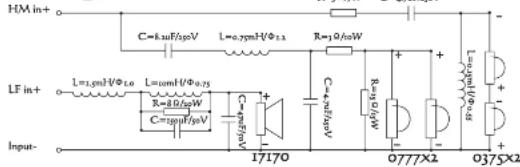
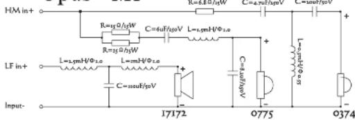
Crossover Network Topology -2
Opus² - Surround
text_image
HM in+ LF in+ Input- C=8.3μF/μS L=0.7μmH/Φ2.1 R=2Ω/μS C=4.5μF/μS R=10μM/Φ0.75 C=20μF/μS 17170 0777X2 0375X2Opus² -M1
text_image
HM in+ R=15Ω/dB/W C=6μF/μB/V L=1.5mH/Φ±0 R=15Ω/dB/W LF in+ L=1.5mH/Φ±0 L=1.5mH/Φ±0 C=3.5μF/μV Input- 17172 Q775 Q374Opus² -M2
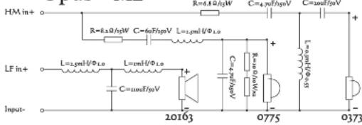
text_image
HM in+ R=8.5Ω/μW C=4.5Ω/μSv C=120μV R=6.5Ω/μW C=6.5Ω/μSv L=2.5Ω/Φ1.0 LF in+ L=2.5Ω/Φ1.0 L=2.5Ω/Φ1.0 C=120μV 20163 0775 0373 Input-Opus ^2 -AvS/AvC
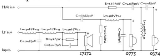
text_image
HM in+ LF in+ Input- R=4.0V/μW C=6.0V/μW L=1.2V/μW R=15V/μW C=100V/μW C=3.5V/μW L=1.2V/μW C=3.5V/μW 17172 R=1.5V/μW C=1.5V/μW L=1.2V/μW C=3.5V/μW 0775 0374Opus²
Opus²
Crossover Network Topology - I
Opus ^2 -1
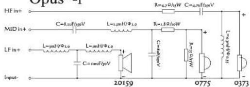
text_image
Opus 1 HF in+ MID in+ LF in+ Input- R=4.0Ω/kW C=4.0Ω/kW L=1.0Ω/kW L=1.0Ω/kW C=1.0Ω/kW R=3.0Ω/kW L=2.0Ω/kW C=2.0Ω/kW 20159 0775 0373Opus ^2 -2
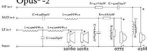
text_image
Opus -2 HF in+ MID in+ LF in+ Input- C=1.3uF/pV L=1.5mH/Φ1.0 R=4.7uW C=4.9uF/pV L=1.5mH/Φ1.0 R=1.8uW C=1.6uF/pV L=0.7mH/Φ1.0 C=1.0uF/pV C=4.6uF/pV 20160 20162 0775 0368Opus ^2 -3
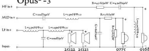
text_image
Opus -5 HF in + MID in + LF in + Input C=100F/pV L=1.5mH/Φ1.0 C=100F/pV L=1.5mH/Φ1.0 C=100F/pV 25122 25123 R=67Ω/kW C=4.9Ω/kW R=3Ω/kW R=10Ω/kW R=0.5Ω/kW 0775 0368Opus ^2 - Centre
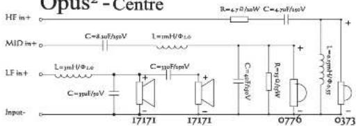
text_image
Opus-Centre HF in+ MID in+ LF in+ Input- R=4.70/μW C=4.70/μW C=8μW/μV L=1μH/Φ1.0 C=μW/μV C=μW/μV C=μW/μV R=4.70/μW C=4.70/μW 17171 17171 0776 0373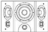 | 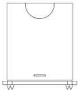 | |
| Opus2 - Tri-Centre | Opus2 - Tri-Surround | Opus2 - Subwoofer |
 User Pack User Pack User Pack User Pack User Pack User Pack |  |  |
| Accessories: Accessories:One Pair of Gloves4 Rubber FeetOne Pair of B-Wire Links | Accessories:One Pair of Gloves4 Screw Freezers2 Security Fees.2 Tin Screw and Washors. | Two Pairs of GlovesSoil Floor Spike Seats (4)Remote Control Handset2 RemainsPower Care |
Opus²
Opus ^2 Opus
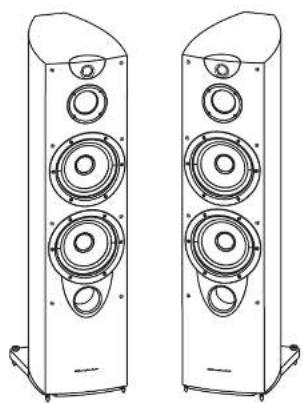
Setting Up Your Loudspeakers
natural_image
Line drawing of two identical multi-tiered speakers with speaker holes (no text or symbols)Subwoofer Drive Unit Specifications
As we design and manufacture our own drive units entirely in-house, we are able to design the perfect driver for each situation.
Our unique 'H-lamy' technology produces drivers capable of delivering spectacular bass performance with distortion lower than any other drivers of similar size.
The aim of any large format driver is to have a linear pictoric motion with the minimum core distortion and break-up possible, even when driven extremely hard. Our 'Iri I am cone achieves this using a combination of Carbon fiber and glass fibers.
The cone material is a composite construction consisting of a hydraulically moulded and chernous lamination of three layers. The inner layer is bi-directional carbon weave, the outer two layers are a bi-directional glass 'bre weave. In addition, the outer tip includes thin edge straining to further reinforce the recurring cone.
The result is a cone that is light ya, incredibly strong, ensuring very low energy losses, even at extreme levels, and without the muddy' always associated with lesser cone materials.
| Parameter | Opus2-SW 250 | Opus2-SW 300 | Opus2-SW 380 |
| Frame material | Aluminium | Aluminium | Aluminium |
| Cone & dome material | In-lam glasscarbon | In-lam glasscarbon | In-lam glasscarbon |
| Surround | s r b p Single roll | s r b p Single roll | s r b p Single roll |
| Solders | Single | Single | Dual |
| Coil size & type | 51.3mm Al-4 Layer | 51.3mm Al-4 Layer | 51.3mm Al-4 Layer |
| Magnet weight | 2380gm | 2470gm | 2720gm |
| Gap flux density | 0.77 | 1.11 | 1.11 |
| Top plate thickness | 8mm | 8mm | 10mm |
| Optimum working range | 3GHz 80GHz | 31Hz 200Hz | 35Hz 500Hz |
| Thiele Small parameters | |||
| Effective cone diameter | 250 mm | 300 mm | 380 mm |
| Ra | 6.2 O | 6.2 O | 6.2 O |
| Fs | 3GHz | 31Hz | 35Hz |
| Qtrs | 5.94 | 7.79 | 9.04 |
| Qes | 0.36 | 0.45 | 0.57 |
| Qts | 0.36 | 0.41 | 0.52 |
| Mins | 100gm | 76.8gm | 185gm |
| Cms | 0.25mmN | 0.85mmN | 0.11mmN |
| Vas | 3BL | 140.4L | 1.1L |
| BL | 17.24N/A | 14.67N/A | 2.1N/A |
Opus²
Opus²
Subwoofer Specifications
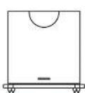
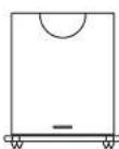
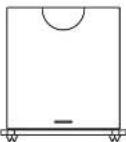
| Parameter | Opus2 - SW 250 | Opus2 - SW 300 | Opus2 - SW 380 |
| Transducer Complement | One | One | One |
| Bass driver | 12" 250 mm | 12" 300mm | 16" 380mm |
| Input Impedance | 10kΩ | 10kΩ | 10kΩ |
| Frequency response Boundary | 30~100 Hz | 2.5~9.0 Hz | 2.5~9.5 Hz |
| Avg. max output @ 1m | 1.5th | 1.14m | 1.05th |
| Low pass filter range | 35~85Hz in 10 Hz steps | 35~85Hz in 10 Hz steps | 35~85Hz in 10 Hz steps |
| Amplifier Output Power (RMS) | 250 Watts | 200 Watts | 600 Watts |
| Line Input sensitivity (150W output) | 300msy | 325msy | 300msy |
| Exclosure type | soated | soated | soated |
| Cabinet Wall Offset | 60 mm | 80 mm | 80 mm |
| Construction material | 25mm MΩ | 25mm MΩ | 25mm MΩ |
| Finish | Selected wood venters in high glass plane lacquer finish to match Group loadpassers | ||
| Overall dimensionsHxWxD | 420 x 420 x 375 mm | 520 x 390 x 450 mm | 570 x 465 x 570 mm |
| Net Weight | 27 kg | 29.5 kg | 40.6 kg |
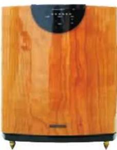
The SW series of suboperators offers a level of performance previously unheard of in their class.
Revolutionary drive units, amplifier modules and filter stages feature on every model. They strike the perfect balance between power and sound quality, offering remarkable sound pressure levels, yet retaining enough control to satisfy the most discerning amplitude and music level. This is possible only through the use of space-age materials and cutting edge technology in our drive units.
Solid, well-engineered power amplifiers, dedicated to the producer of low-frequency energy are used across the range. Power is targeted specifically at the most important section of the bass spectrum, with very little loss and a controller: roll-off allowing for super integration with air lift and home cinema systems.
The filter action controls the integration with your main speakers and ensures the transition is seamless. Designed using six discrete circuits, signal purity is regarded as paramount. Each circuit has a different crossover frequency (25 Hz to 85 Hz in 10 Hz steps). The filter is 24 dB/octava-in
each mode, it is possible to switch off all filters and allow the AV successor to control the effective frequency range of the subscaler. This is preferable in high-end systems.
Finally, the 31 am cone is evolutionary in terms of technology and performance. Details on the next page, it is one of the most advanced cones ever seen in a moving-coil loudspeaker coupled with an elongated voice coil with a maximum excursion of 24mm .
natural_image
Close-up of a wooden electronic device with a circular top and black base (no visible text or symbols)Preparing Your Loudspeakers
Adjusting Spikes
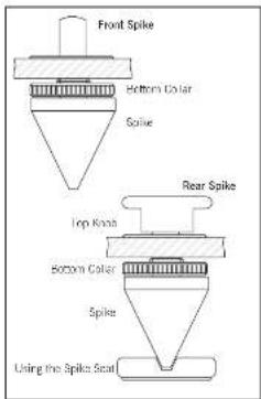
Floor standing Opus ^1 loudspeakers, the Opus ^2 subworkers and the loudspeaker stand come pre-fitted with the plinters and spikes.
Adjusting the Front Spikes: Stacken the retaining solar at the bottom of the spike. Adjust the spin in and out as required. Do not sit upright the spikes at this time.
Adjusting the Rear Spikes: Stacken II the returning collar at the bottom of the spike. Release the locking knob on the top. Turn spike out and down to level.
When the loudspeakers are level: Re-lock up knot and then tighten all the soils. Make sure the soils are fully tightened.
If you are using the Opus? stands to support the M1 or M2, we suggest you level the stand before you place the speakers on them.
WARNING: Opus speakers and stands are heavy and the spikes could generate softer floor materials over extended periods. Spic seats are supplied to protect sensitive floors and floor coverings.
Choosing Loudspeaker Cable
Specialist audio cable usually offers better performance than general purpose "bell" or "zip" wire.
Choose a cable of suitable diameter - cable that is too thin will limit the dynamics of the sound and may impact the bass response. Audio cable is polarized, with two cores of different colours, or often a raised tilt or coloured tracer in the case of twin cable.
Before you purchase your cable, we suggest that you give careful thought to the positioning of your loudspeakers. This is especially the case if you are bi- or in-wiring your loudspeakers.
Cable lengths to loudspeaker pairs should be the same for left and right channels in order to equalise the signal transmission. Allow some stock in your speaker cables so you can alter their position to best advantage, but do not have your cables over long
Preparing Loudspeaker Cable
Split the twin cores to a depth of about 40mm. Carefully strip the insulation from each end, leaving about | Crane of bare wire. If the cable is stranded, lightly twist to gather any loose strands.
text_image
Front Spike Bottom Color Spike Rear Spike Top Knee Bottom Color Spike Using the Spike Seal
Opus²
Opus ^2 Opus
Connections And Terminals
Crossover Networks
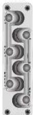
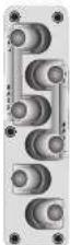
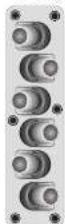
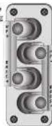
Opus ^1 , 1,2,3 and Tri-Centra-Industances use a specialty designed tri-level transformer pair with six terminal winding points. This facilitates standard single wiring, advanced blowing, for the ex-compton to a audophile, no wiring. Follow that drawing carefully to see the orientation of the longitudinal terminals. The upper terminals connected to the castle unit, the middle pair to the mid-range and the lower pair to the base units. As supported, the above terminal pair is connected to the mid-range pair and best terminal pair via removable metal shapes. There should be left in place for standard single cable installators. A second blowing strip is previous which connects the bass and misangle terminal stairs leaving the treve pair to be separately wired. Refer to the diagrams approximate
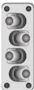
Opus ^1 -M1 and M2 loudspeakers use a blivring laser essentially similar to the blivring panel above but with your terminal blivring peers. This facilitates standard surges wiring, and advanced blivring. Follow the blowing carefully to see the correct orientation of the loudspeaker terminals. The upper terminals connect to the distance and fibre units, the lower pair to the barn and. Although the loudspeakers are full three-way designs, blivring terminals perform arbitrarily in these loudspeakers' horizontal applications without the added complexity and cost of a full blivring configuration. The terminal straps are left and right handed for certification.
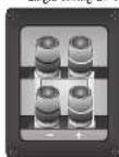
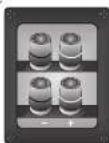
The Oous" -Tri-surround, AVS and AVC Iodopressors use a blowing panel as shown on the right. These have the triple and bass terminal pairs in a vertical configuration with and again these are connected by removable straps to facilitate single and blowing. Follow the drawing carefully to see the correct orientation of the loud speaker terminals. The upper terminals connect to the triple and microwave units, the lower part to the base unit.
Connecting a Terminal
Uncrew the terminal. Insert the bare end of the bare into the hold in the base of the terminal. Tighten security. When connecting terminals make sure you leave no strands of bare wire this, can short across to adjacent terminals.
As an alternative to home with you can use specialist space connectors. Your Opus dealer will be pleased to advise you.
Single
Wiring
Di-Wiring
Tri-Wiring
Single
Wiring
[Non-Text]
Bi-
Wiring
Single Wiring By Wiring
Midrange Specifications
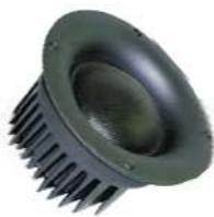
Part number 07/5 & 07/5
Demo material & size 75mm text
Coil size & type. 75mm aluminium
Magrst d1 x d2 x h 70x32x15
Magnetweight 24-Bern
SPI 1w @ 1m 20HP
Es 5COH _2
Frequency range -3dB 400Hz 5kHz
Distortion at 100dB @ 1m 1vically < 1%
Tweeter Specifications
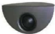
Part number 0373.0374, 0375, 0368
Dome material & size 25mm textile
Coil size & type Zorom aluminium
Magnet dl • h 2x1/ x 4mm Nccdavium
Magnet weight 14gm
SPI 1w @0.1m 224H & 2/4H
5c Light
Frequency range -3dB 500Hz-40kHz
Upper frequency limit - 10kHz
Crossover Specifications
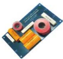
natural_image
Electronic circuit board with various components including capacitors, inductors, and resistors (no visible text or symbols)Crossover sections 3 way
Type Bulterwerte
Vinga Tropic Vare Elated CEC
Connections Armisolter
Crossover points at -5dB 500 & 75GHz 900 Hz
Bass 400 & 90GHz
mid 3000 420Hz
Tweeter 3002-400Hz
Opus²
Opus²
Bass Drive Unit Specifications


Parameter
| Nominal size | 1.70mm 6.5" | 1.70mm 6.5" | 1.70mm 6.5" | 200mm 8 | 200mm 8" |
| Frame material | Aluminum | Aluminum | Aluminum | Aluminum | Aluminum |
| Cone & dome material | Tri-lam glasscarbon | Tri-lam glasscarbon | Tri-lam glasscarbon | Tri-um glasscarbon | Woven carbon fibre |
| Sunround | slop Single roll | slop Single roll | slop Single roll | slop Single roll | slop Single roll |
| Coll size & type | 25mm Al/2 Layer | 25mm Al/2 Layer | 25mm Al/4 Layer | 38mm Al/4 Layer | 38mm Al/2 Layer |
| Magnet weight | 357g | 347g | 357g | 992g | 900 g |
| Gap flux density | 0.77T | 0.77T | 0.77T | 1.1T | 1.1T |
| Top plate thickness | 6mm | 6mm | 6mm | 6mm | 6mm |
| Optimum warming range | 40Hz-1000Hz | 40Hz-1000Hz | 40Hz-1200Hz | 25Hz-800Hz | 25Hz-800Hz |
| Thickel Small parameters | |||||
| Effective cone diameter | 140mm | 140mm | 140mm | 155mm | 165mm |
| Ro | 11.4G | 3.4G | 3.4G | 3.5G | 3.6G |
| Fs | 62.1GHz | 64.3GHz | 67GHz | 25.2GHz | 31.9GHz |
| Qms | 3.12 | 5.25 | 4.74 | 3.28 | 2.93 |
| Qps | 0.73 | 0.65 | 0.51 | 0.42 | 0.4 |
| Qfs | 0.61 | 0.73 | 0.61 | 0.47 | 0.56 |
| Mems | 18.71gm | 16.56gm | 20.67gm | 38.01gm | 29.1gm |
| Cass | 0.59mmN | 0.37mmN | 0.76mmN | 0.37mmN | 0.68mmN |
| Vol | 19.62L | 12.14L | 23.26L | 61.96L | 56.42L |
| BL | 10.03 | 5.71 | 6.12 | 7.35mm | 7.16mm |


Parameter
| Nominal size | 230 mm 8" | 250 mm 5" | 250 mm 10" | 250 mm 10" |
| Frame material | Aluminum | Aluminum | Aluminum | Aluminum |
| Cone & dome material | Woven carbon fiber | Woven carbon fiber | Woven carbon fiber | Woven carbon fiber |
| Sunround | stop Single roll | stop Single roll | stop Single roll | stop Single roll |
| Coll size & type | 38mm Al-2 Layers | 38mm Al-2 Layers | 38mm Al-2 Layers | 38mm Al-2 Layers |
| Magnet weight | 900 g | 900g | 900g | 900g |
| Gas flux density | 1.17 | 1.17 | 1.17 | 1.17 |
| Top plate thickness | 5mm | 5mm | 5mm | 6mm |
| Optimum working range | 25Hz-80GHz | 25Hz-80GHz | 25Hz-80GHz | 25Hz-80GHz |
| Thode Small parameters | ||||
| Effective cone diameter | 165mm | 165mm | 200mm | 200mm |
| Ro | 7.20 | 7.20 | 7.20 | 7.20 |
| Fs | 34.9GHz | 30.8GHz | 51.7GHz | 40.2GHz |
| Qms | 2.67 | 2.67 | 4.31 | 4.47 |
| Qgs | 0.65 | 0.78 | 1.19 | 1.15 |
| Qts | 0.53 | 0.6 | 0.38 | 0.3 |
| Mins | 24.31gm | 25gm | 31.7gm | 33.05 |
| Cm | 0.80mmN | 0.94mmN | 0.30mmN | 0.47mmN |
| Van | 54.62L | 55.8L | 41.2L | 65.1L |
| HL | 7.7 gm | 6.5 gm | 7.9 gm | 7.2 gm |
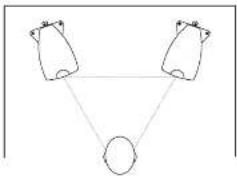
Positioning Stereo Loudspeakers
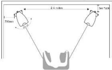
The distance between the speakers should be the same as between you and the speakers.
Angle speakers inwards for a more precise stereo image
flowchart
graph TD
    A["Input Node 1"] --> C["Output Node"]
    B["Input Node 2"] --> C["Output Node"]
    D["Input Node 3"] --> C["Output Node"]
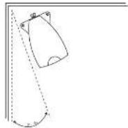
If the loudspeakers are placed too close to the walls, the bars will increase but may be empty and indistinct. If the loudspeakers are placed further away from the walls, the inward edge (Tone in) may be increased by up to 40%, although this may rest at the width of the optimum listening position. As personal tests plays a large role, experiment with different configurations and play a wide range of programme actions finalizing the position of your spaces.
The table below shows the ideal distance your model should be from the wall
- Opus M1: 30CrTi
c Opus² M2 : 200mm - OPus² 1 : 30cm
- OPus² 2:10Gmm
。 OPus ^2 3 : 100mm - Opus® Subwoofers: up to 100 mm
text_image
2.5 inches 700mm See Table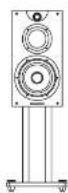
Opus ^2 M1 and M2
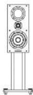
The M1 and M2 are designed for stand environing. The Opus Stand has been specifically designed to opt make their performance. As an alternative the M1 and M2 may be wall mounted on rigid brackets or place on rigid shelves. It isly the top of the speaker would be at sea level to a seated audience. If the rear panels of the sessions are placed close to the walls the amount of base will be increased but the clarity may well suffer, you should experiment until you get its best result.
Opus²
Opus ^2 Opus
Connecting Stereo Loudspeakers - I
Standard Loudspeaker Wiring
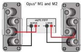
Choose a suitable length of twin car speaker cable for each channel, and prepare the ends. Unsome each terminal a few turns.
Connect the red, positive (1-2) terminal of the Left outspeaker to no corresponding red, positive (1-2) amplify terminal. Connect the black, negative (3) terminals similarly. Tighten the terminals securely. Repeat this procedure for the Right Channel.
You can connect to either set of terminals. Ensure the linking stars are in place and that all terminals are tightened down.
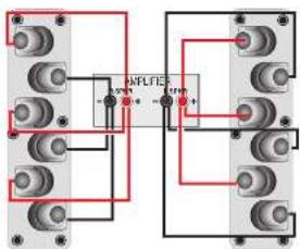
Bi-Wiring
Using separate cables for treble, and bass units in a B-wiring configuration reduces intermodulation effects and improves headroom and clarity.
To Bi wire, you will need to install two lengths of hair care cable between the amplifier and each
oudspeaker.
Note: Some amplifiers have two pairs of outper
terminals to facilitate re-wiring but this is not essential. The advantages of bearing are fully retained if your amplifier has only one pair of transducer terminals
the channel (as in the illustrations): Opus ^2 M1 and M2:
Remove the oil-wiring chaos from each pair of terminals.
Opus' 1,2,3.
Uncrew each terminal a few turns and remove the metal in link straps. Use the bit link straps supplied in accessories to connect the treble and mid-range terminals. Connect the cables between the amplifier and the outspeakers as indicated and re-gritten all terminals securely.
text_image
Opus² M1 and M2 ANPLIFIER - 5V 0.5V + 1.5V 0.5V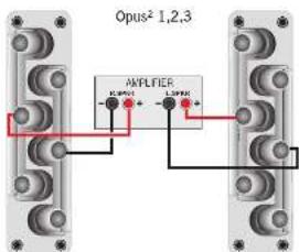
text_image
Opus² 1,2,3 AMPLIFIER -1.0V + - -1.0V + - -1.0V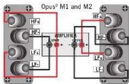
text_image
Opus² M1 and M2 HF₄ HF- LFP LFP LFP LFP LFP LFP LFP LFP LFP LFP LFP LFP LFP LFP LFP LFP LFP LFP LFP LFP LFP LFP LFP LFP LFP LFP LFP LFP LFP LFP LFP LFP LFP LFP HFL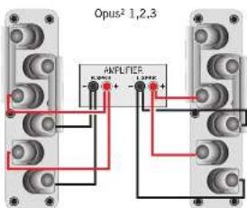
text_image
Opus² 1,2,3 AFLFE5 K=0.000+ 1.398K+
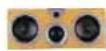


Opus² - 3 Opus² - Tri-Centre Opus² - Tri-Surround Opus² - AvC Opus² - AvS
| 20# | 10# | Hz | 10# | 10# |
| 260mm x 2 | 170 mm x 2 | 120 mm | 120mm | 120mm |
| 3.75 mm tape | 3.75 mm tape | 3.75 mm x 2 tape | 3.75 mm tape | 3.75 mm tape |
| 1.75 mm tape | 1.75 mm tape | 1.75 mm x 2 tape | 1.75 mm tape | 1.75 mm tape |
| 6dBm | 6dBm | 6dBm | 6dBm | 6dBm |
| 4.0 - 3.4 | 4.5 - 2.4 | 4.0 - 1.2 | 4.0 - 1.8 | 4.0 - 1.8 |
| 35 Hz - 43 kHz | 75 Hz - 43 kHz | 60 Hz - 43 kHz | 45 Hz - 43 kHz | 45 Hz - 43 kHz |
| 27 Hz | 70 Hz | 50 Hz | 40 Hz | 40 Hz |
| 45 MHz | 45 MHz | 45 kHz | 45 kHz | 45 MHz |
| 400 mm | 100 - 400 mm | 0 mm | 0 mm | 0 mm |
| 9 dB | 89 dB | 89 dB | 88 dB | 88 dB |
| >3% | 20-200 >5% | >3% | >3% | >3% |
| >1% | 200-45k >1% | >1% | >1% | >1% |
| 300 W | 200 W | 100 W | 100 W | 100 W |
| 100 - 500 W | 70 - 100 W | 40 - 200 W | 40 - 200 W | 40 - 200 W |
| 1.5 dB | 1.5 dB | 110 dB | 108 dB | 108 dB |
| 90° to 14 kHz | 80° to 12 kHz | 160° to 10 kHz | 90° to 14 kHz | 90° to 14 kHz |
| 70° to 12 kHz | 80° to 12 kHz | 90° to 12 kHz | 70° to 14 kHz | 70° to 14 kHz |
| pordal / smart | smart | pordal | scaled | scaled |
| o 1/2 2 L | 2o L | 12 L | 9 L | 9 L |
| 30 Hz | 60 Hz | 60 Hz | 70 Hz | 70 Hz |
| 650 Hz, 3 kHz | 900 Hz, 4 kHz | 700 Hz, 3.5 kHz | 700 Hz, 4 kHz | 700 Hz, 4 kHz |
| 1.8 & 3.4 mm M U* | 1.0 & 2.5 mm M U* | 15 mm MOP | 15 mm MOP | 15 mm MOP |
| 025123 | 17173 | 17170 | 17172 | 17172 |
| 025122 | ||||
| 0775 | 0775 | 0775 | 0775 | 0775 |
| 0368 | 0378 | 0375 | 0374 | 0374 |
| 1210 X 315 X 420 | 242 X 575 X 320 | 290 X 460 X 180 | 230 X 500 X 140 | 500 X 730 X 140 |
| 40.0 kg | 14.7 kg | 10.6 kg | 9.0 kg | 9.0 kg |
Opus²
Opus²
Opus ^2 Specifications
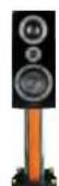
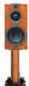
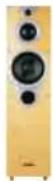
| Parameter | Opus2 - M1 | Opus2 - M2 | Opus2 - 1 | Opus2 - 2 |
| Transducer complement | hours | hours | hours | hours |
| Basic Driver Core | 170cm | 200cm | 200 mm | 200mm x 2 |
| Soft Done Mid-range | 3 /5 mm lattile | 3 /50mm lattile | 3 /5 mm latile | 3 /5 mm latile |
| Soft Done Twator | 1 /5 mm lattile | 1 /50mm lattile | 1 /50mm latile | 1 /50 mm latile |
| Nominal importance | 6.0 hrs | 5.0hrs | 6.0hm | 6.0mm |
| Impedance variation ohms | 4 . 2 - 2.5 | 5 . 0 - 2.5 | 5 . 0 - 3.5 | 4 . 5 - 3.4 |
| Frequency Responses / 1/2dB | 42 Hz 43 dB | 40 Hz 42 k | 3 Hz - 43 kHz | 30 Hz - 23 kHz |
| 1F limit: 10 dB | 38 Hz | 36 Hz | 28 Hz | 28 Hz |
| 1F limit - 10 dB | 45 kHz | 45 kHz | 45 kHz | 45 kHz |
| Hot rear to wall on set | 800 mm | 200 mm | 300 mm | 100 mm |
| SPI (1w @) lml | 87ds | 88db | 89 db | 90 db |
| Distortion 20 - 600Hz 100cd @1m | >3% | >3% | >3% | >3% |
| 100 L/order | >1% | >1% | >1% | >1% |
| Power Handling | ||||
| Continuous Programme | 75 W | 100 W | 150 W | 250 W |
| Recommended Ampifier Power | 40 - 150 watts | 50 - 200 watts | 50 - 300 w | 100 - 300 w |
| Max Peak SPL | 106 db | 105 db | 109 db | 116 db |
| Horizontal Coverage (mm.) | 90 to 14x. lb | 90 to 14x. lb | 90 to 14kHz | 80 to 14 x Hz |
| Vertical Coverage (mm.) | 70 to 12Hz | 70 to 12Hz | 70 to 12kHz | 70 to 12 x Hz |
| Enclosure type: Base/Mid | Pulsed | Pulsed | Pulsed / Sealed | Pulsed / Sealed |
| Volume Base / Mid | 18 L | 2 L | 3.3 / 1.0 L | 3.0 / 1.4 L |
| System ID | 70 Hz | 70 Hz | 35 Hz | 30 Hz |
| Continuous Frequencies | 650 Hz, 13Kp | 700 Hz, 3Kp | 650 Hz, 3 Kp | 650 Hz, 3 Kp |
| Construction Material | 1.5 & 3.0 mm / U+F | 1.8 & 3.3 mm / U+D | 1.8 & 3.3 mm / MU + | 1.8 & 3.3 mm / MU + |
| Finishing | Soated wood surfaces in high-gose plane acquire. Blume Eye Mask. | Roasted: Chlorine, Black | ||
| Component Part Numbers | ||||
| Basis | 17172 | 20164 | 20129 | 20162 |
| Screw / Mid | 20160 | |||
| Mid-range Dore | 0775 | 0775 | 0775 | 0775 |
| Exercise | 05/4 | 05/8 | 05/8 | 08/8 |
| Product Dimensions (Overall) | 510 X 290 X 560 | 505 X 255 X 450 | 1005 X 290 X 410 | 1140 X 290 X 410 |
| Nett Weight | 12.0 kg | 16.4 kg | 18.0 kg | 14.5 kg |
text_image
AFLFE - 10V - 10V +Connecting Stereo Loudspeakers -2
Tri-Wiring - Opus 1, 2, 3
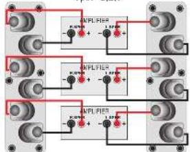
The advantages of driving can be extended by driving. Here such drives unit is separately connected to the quarter for the almost entirely. The advantages of driving can be fully realised by optimising the type of cable used to connect the drive units. Your Ours does not will be pleased to assist you to make the correct choice. Unscraw each terminal a few turns and remove the motor link straps. Connect the cables between the amplifier and the loudspeaker as indicated and re-tigition all terminals security.
Bi- and Tri-Amping
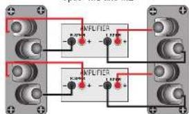
Using separate amplifiers for track, mind and bass units further improves performance by ensuring that each oscillator is constantly driven, operating each drive unit with its individual amplifier means that, such amplifier channel sees a nanoword frequency range. This both mainlines signal delivery and reduces distortion artifacts to negligive proportions. Although all the amplifiers on one channel need not have the same power output, the amplifiers must be phase coherent and have identical voltage gains. The amplifier setup used must obviously be identical to both channels.
Opus² 1,2,3:
You can bi-amp the loudspeakers, or use two amplifiers with one amplifier connected to the bass channel, and the other connected to miroange and nble terminals in a bi-wiring configuration. IMPORTANT!
If you are considering multi-amping, unless you know exactly what you are doing it is essential that you seek the advice of your Opus dealer before proceeding further.
Opus ^2 M1 and M2
text_image
INFLITER INFLITEROpus ^2 1,2,3
text_image
AMPLIFIER -0.25V + -1.8V AMPLIFIER -0.25V + -1.8V AMPLIFIER -0.25V + -1.8VOpus ^2
Opus ^2 Opus
Positioning AV Speakers
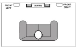
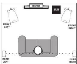
Front Loudspeakers: The front loudspeakers are placed on either side of the TV monitor, 2 to 3 metres apart and somewhat above the listener. The speakers should be angled slightly so they are aimed towards the listeners.
Reer Surround channels: The reproduced sound should be as room filling as possible. We recommend slacing the speakers in a high position, behind the listener's head. If the rear wall is more than 1 metre behind the listening seat, an alternative position is on the side walls. If the walls are a long way from the listening seat, consider stand mounting the outspeakers.
Centre Channel: Most of the dialogue comes from the centre loudspeaker. Speech should appear to originate from the actors mouths. Operating height is important. Ideally the front and centre channels speakers should be at the same height. The front of the cabinet should be level with the IV screen.
The Opus ^2 Av System
The Opus ^2 Av System is a three speaker system. The system comprises a pair of AvS Satellite loudspeakers and a single AvC Centre channel loudspeaker. Both loudspeakers are three-way units.
The loudspeakers are designed for wall mounting integral keyhole slots are provided end, for additional safety, a security fixing kit is included with each loudspeaker.
The Opus? AvC may be well mounted on its integral keyhole slots, or on a social mounting bracket. When mounted on its bracket the speaker may be angled vertically for optimum effect. The bracket mount is shown in the illustrations.
The loudspeakers' small front to back profile makes them ideal as partnering speakers for Plasma or ICD screens.
The Opus ^2 Ae system may be used together with an Opus ^2 Subwoofer to add full 5.1 correctly to a conventional Stereo system - their 3-way design and voting making an ideal surround sound complement to regular Opus ^2 Inirdspeakers.
The Opus² Tri-Centre loudspeaker may be freezing or mounted on a stool shell.
The Opus ^2 Tri-Surround is designed for wall mounting. The unique design of this lauciscaster enables its use either on the rear or the side walls of the room. We suggest that you near mount these outspeakers where possible.
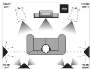
flowchart
graph TD
    A["FRONT LEFT"] --> B["SUB"]
    B --> C["FRONT RIGHT"]
    D["Central Center"] --> E["Sub"]
    E --> F["FRONT RIGHT"]
    G["REAR LEFT"] --> H["Sub"]
    H --> I["FRONT RIGHT"]
    J["Top Right"] --> K["Sub"]
    K --> L["FRONT RIGHT"]
2 Channel System with Centre Channel Re-inforcement
text_image
FRONT LEFT CENTRE FRONT RIGHT5.1 System
text_image
CENTRE SUB FRONT LEFT FRONT RIGHT REAR LEFT REAR RIGHTThe Opus ^2 Drive Units-2
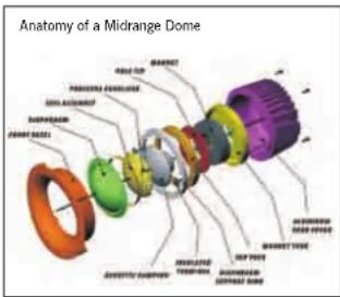
The 75 mm Soft Dome Midrange Unit
A new studio monitor quality large dome mid-range drive unit is used over the crucial midband frequencies, 700 Hz - 4 kHz. A key feature of this driver is exceptionally low distortion over its entire working range - typically less than 1% at a Sound Pressure
Level of 200 cbs at 1 meter. The driver is mounted in a custom matched fascia plate which provides partial nor shearing, giving a broad angle of dispersion at its upper crossover point. The fascia plate is the cast aluminium, designed to place the units as close as possible for aluminium ingipator and to create a joint source effect. The dome is driven by a large 75 mm voice coil based on a hard aluminium torner to provide maximum rapidity and to maintain a cool coil operating temperature by maximizing thermal radiation. The diaphragm supporting ring is the cast aluminium to maintain perfect concreativity of the moving parts during assembly. The dome is pressure equalities by a closely coupled underside perforated dome buffer and a rear chamber within an extended die cast aluminium finned near cover which serves as a boat tank and breaks up internal cylinder resonances. A powerful high flux shield bolt magnet provides ample reserves of motor force to the dome.
text_image
Anatomy of a Midrange Dome25 mm Soll Dome Tweeler
The highest frequencies are handled by a soft dome driver. Extensive research at Whartsdale has established that properly engineered soft domes are a better choice than metallic based domes which add their own typical character to the treble response.
The new Ocular Twister has been re-engineered with a specialty fine gauge aluminium cell to reduce the moving mass and expand response to beyond 45 dB. For above audio frequency, Careful attention to detail has resulted in wide dispersion with very low distortion again typically below 1% at an S/P of 100 db at 1 metre. The unit uses a fully selected high flux neodymium magnet, and produces a typical SPI of 95 dB at 1 metre at an input of one Watt. Dist. core aluminium structural parts are used throughout and a rear cover isolates the tower come from the pressure of other speaker components.
Crossover and Internal Wiring
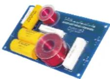
All model's feature printed circuit boards with large copper tracks to maximize signal transfer and component layouts designed to eliminate inference from any residual stray magnetic fields. The printed circuit boards are mounted or vibration on free mountings. Most models have two printed circuit boards to separate the base inductors from more coupling the midrange and tower units.
The basis inducer has a large magnetic field when operating, which would otherwise moisture the other industries. All industries feature paired layer winding and large gauges of wire are used to keep insertion loss to a minimum. Capacitors in crossover networks pose special problems. The Opus' range features high grade low-loss, low-eq, polypropylene or reversible electrolytic capacitors specially selected for their outstanding acidic properties. These capacitors are marked with the 'White-scale super audio capacitor' logo. The internal cables use are specially made and assembled in our factory: 4 multiple strand oxygen-free copper wires are plated into a single cable for all connection runs within the speaker.
Opus ^2
Opus ^2 Opus
The Opus ^2 Drive Units
Bass Drivers
Opus ^2 bass units are of two main types.
The smallest cabinets use a triple laminated cone of glass/barbour glass. Smaller cabinets intensity reflections that can pass back through the cone. The special "tr lam" construction minimises these reflections because of its extreme rigidity - the small increase in cone mass being more than offset by the performance improvements.
The larger cabinets use larger drivers and here low cone mass is of crucial importance. Im maintaining impulse response and performance.
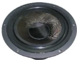
Our latest cone designs for the large format models utilise our own carbon weave and miniating processes. Carbon fibre has increased longitudinal strength and is used in many structures where high length and light weight are key regulates examples of structures using carbon fibre include normal 1 racing cars, amplifiers and spocraft. The carbon fibre bundles are woven and unprecedented with special bonding resins that are subsequently pressure formed and cast cured. The resulting material is exceptionally rigid and consists very low levels of internal resonance. As a consequence, energy losses in the cone transfer mechanism are very low.
natural_image
Close-up of a black speaker emitting sound waves (no text or symbols visible)Because our bass drivers are just that, our bass cones maintain true pistonic action over their entire designed low frequency range. The cone is terminated with a conventional large half-all of synthetic butyl rubber with prawn damping qualities.
Voice coils in high performance outspeakers have to withstand extremes of mechanical stress and heat. The lateral strength of Opus' voice coils is very high. We use a combination of hard hard aluminium and resin bonded glass fibre. The ability of our voice coils to resist deformation under extreme stress contributes towards some of the lowest distortion figures over seen in conventional drivers. The coils are covered with a dust gap of the same material as the cone.
Large, high performance traditional female magnet systems are used throughout. All Opus ^® large format speakers are fully magnetically skilled with additional bucking magnets and steel covers on the brass driver magnets. You can operate an Opus ^® speaker close to the most magnetically sensitive IV monitor with no fears over screen interference.
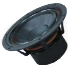
Motional noise can be a problem with high output bass systems. The high pressure injection die cast aluminium chassis used on our bass drivers feature an open design where no new legs maximise the open areas of the frame to all but eliminate rear reflections. Trapped or compressed air within the driver unit can easily move through vents in the voice rail, through the magnet structure, through the spider, and from the underside of the central cap both through holes in the bone and the magnet central core.
natural_image
Close-up of a black speaker with visible sound waves and foam cover (no text or symbols)Wall Mounting AV Speakers
text_image
320 nm Security strap mounting Opus² Tri-Sat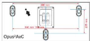
text_image
350 nm 190 nm 198 nm 125 nm Opus²AvC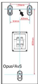
text_image
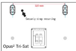
120mm 60mm 80mm 400mm Opus²AvSThe AvC and AvS speakers feature a three-point mounting system. Two point mounting is the simpler option and this is the method to use unless you feel you need the security of three-point mounting. Ensure the wall is sound, free of construction, hidden pipes etc. and capable of supporting the loudspeaker plus a small amount of pulling force. You will also need suitable wall things and some 38mm No 8 Hound Foar screws.
1: Getting started
Draw a horizontal line on the wall and mark off the mounting centres of your low speaker referring to the top dimension of the drawings.
Drill and plug two holes.
The screw header consists of a plastic spacer and a washer. Thread a washer and a plastic spacer onto each screw. Thread one of the screws through one eyelet of the security strap. Let the security strap hang tree.
Screw both header assemblies firmly to the wall. Do not over tighten the screw. The spacer should rest against the wall and not be driven into the surface.
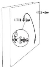
2: Attaching the loudspeaker
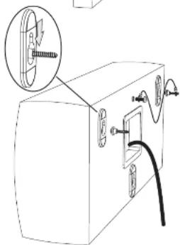
Remove the plastic insert from the security mounting thread between the keyhole slots.
Connect the connecting wire to the loudspeaker but do not connect the cable to the amplifier. You will need to use a profile cable, your dealer will recommend a suitable product. Lift the loudspeaker up to the mounting position. With the screw, attach the security strap to the loudspeaker security mounting.
Align the keyhole slots over the screw headers and gently pull down until the speaker is securely fastened. You may now connect the loudspeaker to the amplifier.
On the Ax speakers, ensure the connecting cable does not foul the lower keshore slot.
This operation may need two people. If you are in any doubt about your ability to carry out this procedure, consult a suitably qualified builder or domestic electrician.
text_image
Diagram showing a device with a magnified inset highlighting a mechanical component, likely for assembly or repair instructions.Opus²
Opus ^2 Opus
Mounting the Opus ^2 AvC Bracket
Using one of the two brackets as a template mark cut four horizontal lying points on the wall.
Insert one bracket, place one bracket over the other and a each the bracket to the wall with three screws.
I heard the four inch screw over one loop of the security strap. Attach firmly to the wall. Remove the two screw covers from the sides of the cabinet.
Connect the cable to the loudspeaker but do not attach the cable to the amplifier.
Over the loudspeaker up to the bracket and attach the security swap to the cabinet with the supplied screw.
Now attach the loudspeaker to the bracket with the two large fixing knobs. You may now connect the loudspeaker cable to the amplifier. To adjust the vertical angle: Slaxon the fixing knobs a quarter of a horn, adjust the angle and re-lighten the loudspeaker.

Connecting AV Speakers
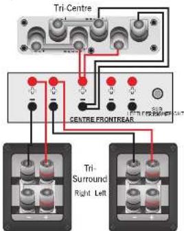
The Tin Centre may be made, so, or it wased. By Wiring is perhaps the most popular splice.
the In-Surrounds may be mono-wired as shown, or in a large installation, Hi wired.
text_image
Tri Centre CENTRE FRONTEAR Tri- Surround Right LeftConnecting the Opus ^2 AV System
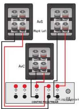
The system may be more wired as shown, or hi wired.
text_image
AvS Right Left AvC CENTRE FRONTREAR LEFT:50V 40V 30V+TThe Opus ^2 Series
About Your Loudspeakers
The Opus series of speakers is the latest iteration of the highly acclaimed original Opus range. New models have been introduced to extend the range of applications. These new models together with the latest versions of the award-winning established models access the needs or both the most discerning audophile and the most avid mode contrast.
All the passive speakers in the Opus' range are 3-way loudspeakers - a blend of impeccable performance, phenomenal dynamics and stunning good ocks.
Features of the range include:
Magnetically shielded front loudspeaker models eliminate interference with conventional television sets.
- Very low distortion across the entire audio band
- Low, controlled, excursion of bass and bass mid drive units.
- High flux magnet systems for good dynamic response to rapid transients
- Wideband dispersion for excellent stereo image and staging
- No hearing, 'lobing' or polar response anomalies in effects loudspeakers.
- Fully integrated design and manufacture – a seamless blend of acoustic performance and design aesthetics.
The Opus ^2 Cabinet
The enclosure of your speaker is a piece of fire furniture.
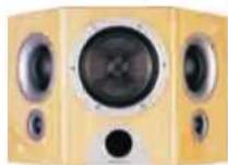
Real wood veneers are selected and pattern matched by hand before being laid. Over a period of several days a high gloss (many finish) applied. This involves several openings of lacquer, each layer is laboriously cut and polished before the next coal is applied. Only through this time consuming and skilled techniques, can we achieve the deep and zealous finish which complicates the Opus' range.
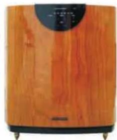
Every Opus ^2 speaker model has an individually designed curved cabinet which maintains utility and farm. Conventional parallel slot stones create acoustic waves within the cabinet – the interaction of these waves creating, and walks in the forward response. The commands areaved and braced geometry of Ours' cabinets allied to a dense, acoustically next cabinet material prevents the build up at damaging resonances and results in clear precise sound, tree from cabinet elevations.
natural_image
Exterior view of a wooden electronic device with a circular top and black base (no visible text or symbols)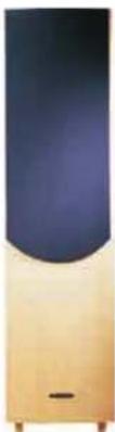
natural_image
Illustration of a vertical shelf with a dark blue top and a gold-yellow base, no text or symbols visible.Opus ^2
Opus ^2
About Your Loudspeaker
Opus ^2 Subwoofers
Introduction
Opus' subwooters are intended for use with very high quality sound reproducing systems in the home. Your subwooter will probably be used in conjunction with Opus loudspeakers though they will partner any high-performance audiophile or home cinema amplification and loudspeakers. There are three subwooters in the range - all the subwooters offer the same connection facilities. All the subwooters are remote controlled for ease of setup and adjustment.
Positioning the subwoofer
Although the unit may be placed almost anywhere in the room, we recommend that it be placed in front of the listener and as control to the listening position as possible. There should be a mains outlet within easy reach. The subwoofer should not be operated within 450mm of a television set as the drive unit magnet may distant the picture. Remember that there should be a line of sight between the listening position and the front of the subwoofer otherwise the handset remote functions will not be accessible.
We suggest: you initially position the subwoofer about 20cm (8 inches) from the wall. Placing the unit close to the wall will enhance the bass: placing it across the corner of the room, will increase the bass further, possibly at the expense of clarity. Do not place the subwoofer close to surfaces or objects that may rattle. The floor under the subwoofer should be sound with no loose floortrants, etc. Experiment with locations and sources before making a final decision.
Installing Batteries in the Handset
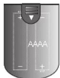
The handset operates on two L16 (RA) batteries which are supplied. The battery compartment is located at the rear of the handset. Unwrap the batteries and slide the cover off the handset. Place the batteries in the handset observing the polarity. The correct orientation is shown on the diagram. When the batteries are installed, replace the cover.
Before Connecting the Subwoofer
e Switch off your amplifier and all connected source units at the mains.
- Unplug the power cords to all system components if necessary
- Make sure the subwoofer is disconnected from the mains and that the ON/OFF switch is OFF
Before re-connecting your system to the AC power supply, check that all the connections are properly made
e Check that all speaker terminals are done up tightly.
o Ensure that there are no strands of wire shorting adjacent speaker terminals
Signal cables should be properly terminated and fully screened to minimise hum. If you connect your subwoofer via the low level signal inputs, the cable between your control unit or processor and the subwoofer could be quite long so screening is particularly important. Consult your dealer if in doubt.
Opus ^2
Opus ^2
Connecting Your Subwoofer
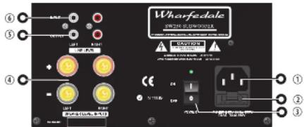
All Opus ^2 Subwoofers have the same Rear Panel connectivity
Connecting to a Digital AV Processor
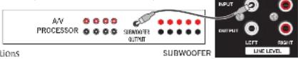
If your AV processor has a line level or LFE subwoofer output you should use this connection. You will need to purchase a single screened ROS phone load from your dealer.
Connect a mono RCA phono cable from the processor to the Subwoofer left line input.
Stereo Line Level Connections
Stereo line level connections will be necessary where where there is no dedicated single subwoofer output, but where there is a separate pramp output, or, if an integrated amplifier, a pro-main link that can be separated.
The output must be controlled by the system volume control - a tape output is unsuitable. If in order, consult your dealer.
Connect a stereo RCA phono cable from the line output of the preamp to the Subwoofer line inputs.
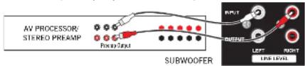
text_image
AV PROCESSOR/ STEREO PREAM Pseudo-OUT SUBWOOFER OUTPUT LEFT RIGHT LINK LEVELStereo High (Speaker Level) Connections
The high level Speaker connections should be used only if your amplifier does not have a line level subwoofer output. In this connection the subwoofer is led together with the front loudspeakers. For this you will need two extra bin core cables.
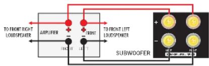
flowchart
graph TD
    A["TO FRONT RIGHT LOUSPEAKER"] --> B["AMPLIFIER"]
    C["TO FRONT LEFT LOUSPEAKER"] --> D["FRONT"]
    B --> E["THC IT"]
    D --> F["THC IT"]
    E --> G["SUBWOOFER"]
    F --> G
    G --> H["+"]
    G --> I["-"]
Looking After Your Loudspeaker
natural_image
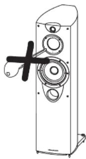
Line drawing of a speaker tower with visible sound waves and a black cross symbol (no text or labels)Do not open the speakers, there are no user serviceable parts inside.
Never touch the drive units either with an object or your hands.
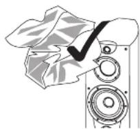
Remove marks from the cabinet and polish it with a soft, slightly damp cloth.
Do not apply furniture sprays or solvents - these can spill the finish.
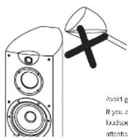
Avoid getting any liquid behind the grille. If you are dentally spill liquid on your loudspeakers, take them to your dealer for attention before using them again.
Opus ^2
Opus ^2
Delay and LFE Settings
The purpose of delay is to enable surround and dialogue information to arrive at the listener's ears at the same time as the Front channels, even when the listening seat is in a non-ideal position.
Rear Delay: if the listening position is equidistant from the Front and Rear speakers, a low delay setting should be set. The closer the listener is to the Rear speakers the higher should be the delay setting used.
Centre Delay: If the Centre speaker is level with for slightly behind the Front speakers, set the delay to zero. If the Centre speaker is forward of the Front speakers, increase the delay.
LFE: In domestic systems the LFE channel typically feels into the subwoofer. Where no subwoofer is used, the LFE signal is combined with Front Channel information. When you set the LFE level at your AV processor, use care as the powerful low frequencies can overload domestic loudspeakers.
If you hear popping or thumping noises coming from the front loudspeakers or subweater, immediately turn the AV Processor's volume level down and then back off the U-E level. This should cure the problem. If it does not, back off the volume level at the subweater if you are using one until the problem disappears.
Please read the relevant sections of your AV amplifier manus and familiarise yourself with the various issues. If you are unsure, consult your dealer for help.
Expanding the System
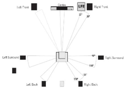
Doby Labs, DTS and T-HX offer 6.1 and 7.1 formats which extend the 5.1 principle by adding one or two extra rear effects channels. Although the precise configuration of these systems will depend on the capabilities of your processor and you should be guided by those instructions, we would make some observations.
For most 6.1 and 7.1 farms, and especially Colby ES: the listening seat should not be too close to the rear wall. Optimising the time delay so that information from all speakers arrives at the listening seat coherently is critical if the benefits of these systems are to be fully realized. THX adjustments in particular need to be followed to the letter.
Dolby Labs Recommended 7.1 Placement
(Single Back channel for 6.1 shown dotted)
text_image
Left Front Centre LFE Right Front 25° 30° Left Surround 40° Right Surround 110° 35° Left Back 130° Right BackOperating Your Subwoofer
Check that all connections to the subcarrier have been properly made and that the main volume control is at minimum. Plug the supplied power cord into the mains socket on the rear panel.
Plug in the mains plug and switch the power on. Now switch the subwasher or with the rest of your system.
The subwoofer on/off switch has a rocker action; press the upper part to switch the equipment or and the lower part to switch it off. When switched on the light above the power switch will glow and the subwoofer will be operational.
Operation
All control functions are carried out using the remote handset. The handset must be painted at the subwoofer and be in line of sight for it to operate.
Standby: Operating the Standby key brings the subwater in and out of Standby.

text_image
Wharfendola abmetry 70mm 30mm 25mm 100mm START GEAR I J J J J J J J J J J J J J J J J J J J J J J J J J J J J J J J J SUBHOOPER CONTROLThe preset light will not light
if no preset has been set up
or if a preset is over-ridden.
In Sandby, the Volume.
Filter, Preset and Phase
Figures are being used.
Stall parents to his family.
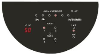
Volume: Press the Volume
Volume level. Upside
Volume - kms. a decrease
the successor volume.
The volume range on the front panel display varies from (C9@minimum) to (maximum).
Low Pass Filters: Pressing the appropriate filler key will select the frequency at which the subwoofer rolls off. The filler has stops at Off and 3.5Hz 8.5Hz in 10 Hz increments. When OFF is selected the subwoofer operates over its full designed range. Pressing other keys covers the maximum operating frequency. The Low Pass Filter value should be chosen having regard to the nature of the Firms, speakers and programming material. Follow the Setup Notes on Page 1 and the instruction manual of your AV ancestor (if used) for more guidance.
Phase: This key toggles the subwoofer between 0^ and 180^ phase shift.
Presets: Four different settings of exit, frequency and charge can be stored. Pressing and holding any of the preset keys on the remote for 3 seconds will cause the current settings or be stored in that preset. The display will show the preset number then flash the preset number once to show it has stored the preset. In change from one preset to another. Press a preset key on the remote for less than 3 seconds to recall the settings of this preset. The display will show the preset number.
If you select a preset and then alter any aspect of the setup, the preset light will extinguish (as the setup no longer matches the preset).
Notes: When brought out of standby for the first time, the unit will display the factory presets. Thereafter, bringing the unit out of standby will revert it to the operational state last used. If you switch the power on and off at the rear panel while the unit is in standby; the unit will power up to a normal operating state (i.e., not in standby). To enter standby again press the Standby key
A Note on the Front Panel indicators. When you bring the unit out of Standby or perform any operation using the hardware, the front panel lights will indicate the current setup and volume. After 10 seconds the lights will extinguish and the panel will go dark. This is intentional and the purpose is to minimise any distraction from the programme in play. The light above the mains power switch on the rear panel will always remain illuminated whenever the subwoofer is switched on at the mains.
text_image
LAVING LATER 50.00 12.00 50.00 1 2 3 4 5 6 7 8 9 10 11 12 13 14 15 16 17 18 19 20 21 22 23 24 25 26 27 28 29 30 31 32 33 34 35 36 37 38 39 40 41 42 43 44 45 46 47 48 49 50Opus ^2
Opus ^2
Setting Up Your Active Subwoofers
Setting up of the subwoofer should be performed with all tone controls and filters on your amplifier or processor set 'flat'.
Listening rooms are not clear. Because of room geometry and construction there will be areas with severe peaks at some frequencies and severe troughs at others. If you see sound speakers, in such areas the response will be highly non-linear. It is easier to treat high frequency irregularities by the use of draps, soft furnishings etc., but very hard to do the same at base frequencies due to the very long wavelengths - at 40 Hz the wavelength is almost 9 metres.
To help locate standing waves in your listening room, one idea is to sit in the listening seat and recruit a friend with a cheap voice to speak as he moves around the area where you propose to sit your subscales - you will soon find out where not to sit it. Where the voice sounds most natural is a good place to start.
Although the subwoofer's bass output is enhanced by walls or corners, so after its coloration. As the drive unit faces downward, the floor will influence the sound. The surface under the subwoofer should be stable and unobsinuated. If the carers is very thick, consider placing the subwoofer on a solid surface such as a marble slab. If you place the subwoofer where it amplifies the irregularities of the room or the main speakers the result will be bloated, coloured bass. It acoustic guitar and male voice sounds coloured when the subwoofer is operating and less coloured when in standby, you need to address the positioning first before adjusting any controls.
Loudspeaker Phasing: Make sure that all loudspeaker channels are connected in phase. If there is a doubt about the way the loudspeakers are connected, check their phasing by playing a more source - the sound should appear from a point midway between the front loudspeakers. If this position is indefinite, reverse the connections to one speaker. Correctly connected loudspeakers give a definite centre sound source with fuller bodied tailor and bass registers.
Setting the Phase of the Subwoofer: Phase at very low frequencies is not straightforward to detect. Initially we suggest you temporarily set the low pass filter to "on" and the phase to 0^ and by some bass heavy music in Stereo through the main speakers and the subwoofer. From the listening position, switch the phase between 0^ and 180^ . The setting which appears to give the greater bass output is correct. Now follow the instructions below for selling the low pass filter.
Low Pass Filter. If you are using a digital AV processor the initial subwoofer setting should be 'CHF' as the processor will have its own base management system.
Setting Loudspeaker Sizes: Most digital AV Processors ask you to specify the size of speakers in the various channels. These are usually 'Large' or 'Small'. This sets the bass management for the system. All Coup's regular loudspeakers can be set to Large Smaller loudspeakers (and possibly also the MI should be set to 'Small' for the Front channels, as the subwoofer will be better at providing a crew. Deebs bars. Choose 'Small' for the surround channels and also for the Centre channel, so that any bass from these channels will be directed to the subwoofer. Set the 'Subwoofer' option on the processor to 'On' or 'Yes'.
After experimenting with various sources you may need to adjust the IPF settings. Try to ensure the subwoofer blends into the sound stage. Setting the subwoofer to Standby should reduce the bass extension, not change the bass level - as always personal taste plays an important part.
Setting levels:
Once the boutscaler settings have been "ralfised, put the AV amplifier into its "Test" mode (see instructions supplied with your processor.) Adjust the levels until all channels are reproduced at equal touchress.
When adjusting the subwoofer output level avoid setting too high a level or you will swamp the sound with bass which be bring to listen to and may limit the subwoofer's ability to respond to large bass transients. Set a sensible level going into the subwoofer from the processor. The volume display should be around 50 at normal listening levels.
LPE: This channel was originally an additional basic channel with its own dedicated subwoofer. In predictive however, if any speakers are sat to: Small, the LPE channel is combined with the basis from those channels and fed into the subwoofer. When you set the LTE level from your AV processor, use care as the LTE channel contains powerful low frequencies which although normal in a cinema, may overload a domestic subwoofer. It during a programme, you hear copying or thumping noises from the subwoofer; turn the AV Processor volume level down and back of the LTE level. If this does not cure the problem, lower the subwoofer volume level.
Setting Up a Home Theatre System
Some of this chapter may appear to repeat the content of the Subwoofer pages - the content however is different.
Placement
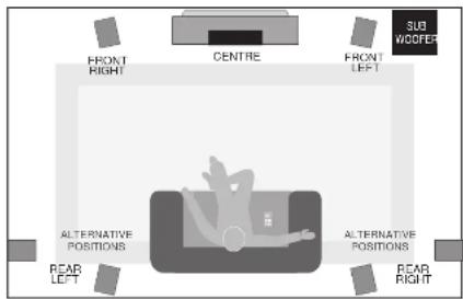
Front And Effects Channels
The front loudspeakers are placed on either side of the television screen, 2 to 3 metres apart. The speakers should be angled slightly as they are aimed towards the listeners.
We recommend placing the rear effects speakers in a high position, behind the listener's head. If the rear or side walls are a long way from the listening seat, consider stand mounting the loudspeakers. In the centre loudspeaker is very high or low angle it towards the listeners' ear level. The front face of the centre and surround loudspeakers should also be in line as far as possible.
Subwoofer
As the ear is unable to detect the direction from which deep bass originates, this allows you freedom to position the unit. Varying the distance from the wall alters the bass. Pacing the subwater across a cancer boasts the bass but may impair clarity. The performance of Home Theatre systems can often be enhanced by using a pair of subwooters.
text_image
FRONT RIGHT CENTRE FRONT LEFT SUB WOOFER ALTERNATIVE POSITIONS ALTERNATIVE POSITIONS PEAR LEFT PEAR RIGHTSetting Loudspeaker Sizes
Many digital AV Processors ask you to specify the size of speakers in all channels - usually 'Large' or 'Small'. The Opus ^2 M2, 1, 2, and 3 may be safely set to 'Large'. The Opus ^3 M1 and In-Danche may be set to 'Large' for smaller systems or rooms, or Small' for large scale systems. The AvC, AvS and Tri-Surmond speakers should be set to 'Small'. As always personal preference will play its part.
If you are not using a subwoofer: Set the Front Speakers to 'Large'. Set the 'Subwoofer' option on the processor to 'Off' or 'No'. The Front channels will now receive all the system bass.
If you are using a subwoofer: When set to 'Small' all the system bass will go into the subwoofer. If you choose 'Large' the Front channel bass will be reproduced from the Front speakers.
Once the loudspeaker settings have been finalised, put the AV amplifier into its "Test" mode (see instructions supplied with your processor). Adjust the level of each channel until all channels are reproduced at equal loudness.
You may need to adjust the subwoofer output level. Avoid setting too high a level or you will swamp the sound with bass and may limit the subwoofer's ability to respond to large bass transients. You should also set a sensible level going into the subwoofer from the AV processor.