
BHG720SS - Cooker BAUMATIC - Free user manual and instructions
Find the device manual for free BHG720SS BAUMATIC in PDF.


| Product Type | Freestanding Cooker |
| Brand | Baumatic |
| Model | BHG720SS |
| Colour/Finish | Stainless Steel |
| Overall Width | 70 cm |
| Overall Height | 85-90 cm (adjustable) |
| Overall Depth | 60 cm |
| Weight | Approx. 55 kg |
| Power Supply | 220-240 V, 50-60 Hz (oven); Gas supply (hob) |
| Hob Type | Gas hob with 4 burners |
| Burner Types | 1 rapid, 1 semi-rapid, 2 auxiliary |
| Oven Type | Electric fan oven |
| Oven Capacity | 70 litres |
| Oven Functions | Conventional, fan, grill, fan-assisted grill |
| Cleaning Type | Standard enamel; some models may have catalytic liners (check manual) |
| Flame Failure Device | Yes, on all burners |
| Child Lock | Yes, on oven door and controls |
| Timer | Integrated programmable timer with alarm |
| Spare Parts Availability | Common parts available through Baumatic service and authorized distributors |
| Repairability Index | 7/10 (typical for this class) |
| Energy Efficiency Class (Oven) | A (typical for electric fan ovens) |
| Installation Type | Freestanding, requires gas connection and electrical outlet |
| Warranty | Standard manufacturer warranty (typically 2 years) |
Frequently Asked Questions - BHG720SS BAUMATIC
User questions about BHG720SS BAUMATIC
0 question about this device. Answer the ones you know or ask your own.
Ask a new question about this device
Download the instructions for your Cooker in PDF format for free! Find your manual BHG720SS - BAUMATIC and take your electronic device back in hand. On this page are published all the documents necessary for the use of your device. BHG720SS by BAUMATIC.
USER MANUAL BHG720SS BAUMATIC
BHG625SS / BHG695SS /
BHG720SS / BHG790SS
Gas hobs
INSTRUCTION MANUAL

natural_image
Simple line drawing of a fish with fins and tail (no text or symbols)User Manual for your Baumatic
BHG620SS / BHG625SS / BHG690SS / BHG695SS
60 cm 4 Burner gas hob
BHG720SS / BHG790SS
70 cm 5 Burner gas hob

text_image
Baumatic®NOTE: This User Instruction Manual contains important information, including safety & installation points, which will enable you to get the most out of your appliance. Please keep it in a safe place so that it is easily available for future reference; for you or any person not familiar with the operation of the appliance.
GS 09/03/12
Contents
Environmental note 4
Important safety information 5 - 7
Specifications 8 - 13
BHG620SS / BHG690SS 8
BHG625SS / BHG695SS 9
BHG720SS 10
BHG790SS 11
Electrical details 11
Gas details 12
Gas hob surface layout 12 - 13
Using the gas hob 13 - 15
Before first use 13
Switching the hob on 13 - 14
Automatic ignition with flame failure device 14
Energy saving tips 14 - 15
Cleaning 15 - 16
Cleaning the hob top 15
After each use 16
Cleaning the hob burners 16
Maintaining the cast iron pan stands 16
Installation 17 - 28
Positioning 18 - 19
Unpacking the appliance 19
Installing the appliance 19 - 22
Gas connection 22
Ventilation requirements 23
Gas Safety (Installation and Use) Regulations 24
Gas Adjustment (Conversion to LPG) 25 - 26
Minimum flow adjustment for hob gas taps 26
Gas tap maintenance 27 - 28
Electrical connection 28
Replacing the mains supply cable 28
My appliance isn't working correctly 29
Baumatic consumables 30
Contact details 31
Environmental note
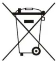
This appliance is marked according to the European directive 2002/96/EC on Waste electrical and Electronic Equipment (WEEE). By ensuring this product is disposed of correctly, you will help prevent potential negative consequences for the environment and human health, which could otherwise be caused by inappropriate waste handling of this product.
The symbol

on the product, or on the documents accompanying the product, indicates that this appliance may not be treated as household waste. Instead it shall be handed over to the applicable collection point for the recycling of electrical and electronic equipment.
Disposal must be carried out in accordance with local environmental regulations for waste disposal.
For more detailed information about treatment, recovery and recycling of this product, please contact your local city office, your household waste disposal service or the shop where you purchased the product.
natural_image
Simple line drawing of a trash bin with crossed lines indicating no waste or restriction (no text or symbols)
- The packaging materials that Baumatic uses are environmentally friendly and can be recycled.
- Please discard all packaging material with due regard for the environment.
Important safety information

text_image
Warning symbol with exclamation mark inside triangleYour safety is of the utmost importance to Baumatic. Please make sure that you read this instruction booklet before attempting to install or use the appliance. If you are unsure of any of the information contained in this booklet, please contact the Baumatic Advice Line.
General Information
- This appliance is designed for domestic household use and for the cooking and frying of domestic foodstuffs.
○ IMPORTANT: The adjacent furniture and all materials used in the installation must be able to withstand a minimum temperature of 85^ C above the ambient temperature of the room it is located in, whilst in use.
- Certain types of vinyl or laminate kitchen furniture are particularly prone to heat damage or discolouration at temperatures below the guidelines given above.
- Any damage caused by the appliance being installed in contravention of this temperature limit, will be the liability of the owner.
- Your new appliance is guaranteed against electrical or mechanical defects, subject to certain exclusions that are noted in Baumatic's Conditions Of Guarantee. The foregoing does not affect your statutory rights.
- The use of this appliance for any other purpose or in any other environment without the express agreement of Baumatic Ltd. will invalidate any warranty or liability claim.
- You should not use this appliance to store items on or as a work surface.
- No modifications to the appliance are permitted by Baumatic Ltd.
- You should not store or place flammable or highly flammable liquids/materials on top of or near the appliance. Items made from aluminium, plastic or plastic film should also be kept away from the appliance, as they may fuse to the surface.
- Repairs may only be carried out by Baumatic service engineers or their authorised service agent.
Child Safety
○ Baumatic strongly recommend that babies and young children are prevented from being near to the appliance and not allowed to touch the appliance at any time. During and after use, all surfaces will be hot.
- If it is necessary for younger family members to be in the kitchen, please ensure that they are kept under close supervision at all times.
- Older children should only be allowed to utilise the appliance when supervised.
General Safety
- The appliance should only be installed and connected by a GASSAFE registered installer.
- Care should be taken to ensure that the units and work surfaces that you build the appliance into, meet with the relevant standards.
During use
○ Any film or stickers that are present on the hob surface when it is delivered should be removed before use.
o Care should be used when utilising the appliance, otherwise there is a risk of burns being caused.
- You should not allow the electrical connection cables to come into contact with the hob surface when it is hot or any hot cookware.
- If fat and oil overheats, then it can ignite extremely quickly. For this reason, when cooking with fat and oil the appliance should not be left unattended.
○ Make sure that all of the cooking zones are switched off after use.
Cleaning
- Cleaning of the hob should be carried out on a regular basis.
- IMPORTANT: Before attempting to clean the appliance, it should be disconnected from the mains and cool.
- Great care should be taken whilst using this appliance and when following the cleaning procedure.
- You should not use a steam jet or any other high pressure cleaning equipment to clean the appliance.
Installation

text_image
Warning symbol with exclamation mark inside triangleThis appliance must be correctly installed by a GASSAFE registered installer, strictly in accordance with the manufacturer's instructions and the relevant British Standards. Please see the specific section of this booklet that refers to installation.
○ Baumatic Ltd. declines any responsibility for injury or damage, to person or property, as a result of improper use or installation of this appliance.
- If the appliance is being used in a Leisure Accommodation Vehicle, the requirements of N 721 MUST be followed.
○ Baumatic Ltd. DO NOT recommend that this appliance is installed on any type of marine vessel.
Declaration of conformity
This appliance complies with the following European Directives:
-2006/95/CE General regulations / Low tension
-2009/142/CE Concerning gas appliances
-1935/2004/CE 90/128/EEC This appliance is suitable to come in contact with food
-2004/108/CE Electromagnetic compatibility
The manufacturer declares that the hob is built using certified materials and requires the appliance to be installed in accordance with the standards currently in force. This appliance must be used by a trained person for domestic purposes only.
Specifications
BHG620SS / BHG690SS
text_image
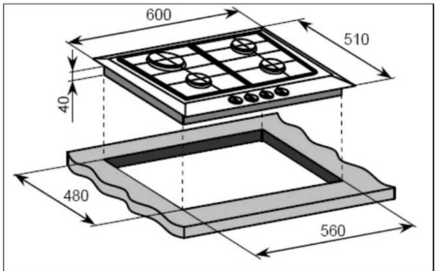
600 510 40 480 560Product dimensions: Aperture dimensions:
Depth: 510 mm Depth: 480 mm
Width: 600 mm Width: 560 mm
Height: 40 mm
Product specifications:
○ 1 x 3.00 kW rapid burner
- 2 x 1.75 kW semi-rapid burners
○ 1 x 1.00 kW auxiliary burner
- Front control operation
- Automatic ignition
- Heavy duty cast iron pan stands
- Flame failure safety device on each burner
Standard accessories:
- LPG conversion jets
text_image
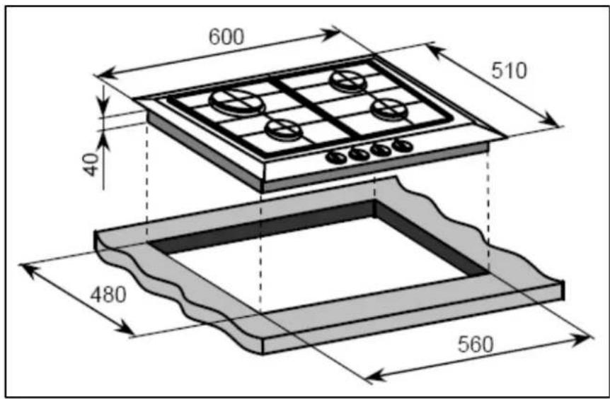
600 510 40 480 560Product dimensions: Aperture dimensions:
Depth: 510 mm Depth: 480 mm
Width: 600 mm Width: 560 mm
Height: 40 mm
Product specifications:
○ 1 x 3.80 kW triple crown (wok) burner
- 2 x 1.75 kW semi-rapid burners
○ 1 x 1.00 kW auxiliary burner
- Front control operation
- Automatic ignition
- Heavy duty cast iron pan stands
- Flame failure safety device on each burner
Standard accessories:
○ LPG conversion jets
- Wok stand
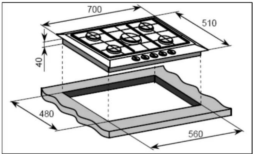
BHG720SS
text_image
700 510 40 480 560Product dimensions: Aperture dimensions:
Depth: 510 mm Depth: 480 mm
Width: 700 mm Width: 560 mm
Height: 40 mm
Product specifications:
○ 1 x 3.80 kW triple crown (wok) burner
○ 1 x 3.00 kW rapid burner
○ 2 x 1.75 kW semi-rapid burners
○ 1 x 1.00 kW auxiliary burner
- Front control operation
- Automatic ignition
- Heavy duty cast iron pan stands
- Flame failure safety device on each burner
Standard accessories:
- LPG conversion jets
- Wok stand
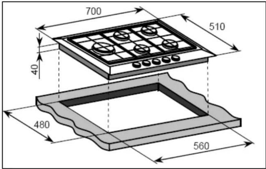
BHG790SS
text_image
700 510 40 480 560Product dimensions: Aperture dimensions:
Depth: 510 mm Depth: 480 mm
Width: 700 mm Width: 560 mm
Height: 40 mm
Product specifications:
○ 1 x 3.80 triple crown (wok) burner
○ 1 x 3.00 kW rapid burner
○ 2 x 1.75 kW semi-rapid burners
○ 1 x 1.00 kW auxiliary burner
- Front control operation
- Automatic ignition
- Heavy duty cast iron pan stands
- Flame failure safety device on each burner
Standard accessories:
○ LPG conversion jets
○ Wok stand
Electrical details
Rated Voltage: 220 - 240 Vac 50 / 60 Hz
Supply Connection: 3 A (double pole switched fused outlet with 3mm contact gap)
Max Rated Inputs: 0.80 kW
Mains Supply Lead: 3 core x 0.75mm² (Type RR-F
Gas details
Connection: Rp 1/2 (ISO R7)
Type: Natural Gas (20 mbar)
Alternative LPG G30 (28-30/37 mbar)
For future reference please record the following information which can be found on the rating plate and the date of purchase which can be found on your sales invoice. The rating plate of your hob is located on the underneath of the appliance. Therefore it is a good idea to record this information before you install your appliance.
Model Number
Serial Number
Date of Purchase ....
Gas hob surface layout
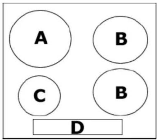
BHG620SS / BHG690SS
text_image
A B C B DA = 3.00 kW rapid burner
B = 1.75 kW semi-rapid burner
C = 1.00 kW auxiliary burner
D = Control panel
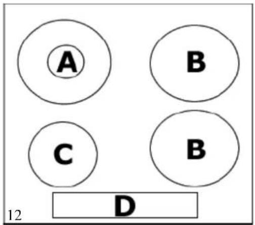
BHG625SS / BHG695SS
text_image
A B C B D 12A = 3.80 kW triple crown (wok) burner
B = 1.75 kW semi-rapid burner
C = 1.00 kW auxiliary burner
D = Control panel
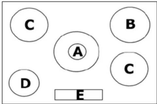
BHG720SS
text_image
C A B D E CA = 3.80 kW triple crown (wok) burner
B = 3.00 kW rapid burner
C = 1.75 kW semi-rapid burner
D = 1.00 kW auxiliary burner
E = Control panel
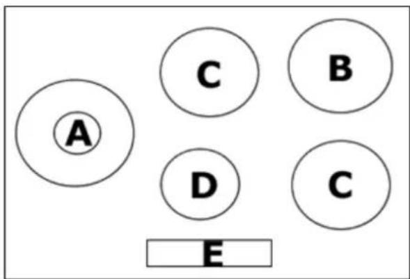
BHG790SS
text_image
A C B D C EA = 3.80 triple crown (wok) burner
B = 3.00 kW rapid burner
C = 1.75 kW semi-rapid burner
D = 1.00 kW auxiliary burner
E = Control panel
Using the gas hob
Before first use

IMPORTANT: You should clean the hob surface (see "Cleaning and maintenance" section).
Switching the hob on
The following symbols will appear on the control panel, next to each control knob:
● = gas off
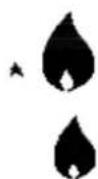
Large flame: maximum setting
Small flame: minimum setting
- The minimum setting is at the end of the anti-clockwise rotation of the control knob.
- All operation positions must be selected between the maximum and minimum position.
- Never select a knob position between the maximum and off position.
- The symbol on the control panel, next to the control knob will indicate which gas burner it operates.
Automatic ignition with flame failure safety device
The appliance is fitted with a flame failure safety device on each burner, which is designed to stop the flow of gas to the burner head in the event of the flame going out.
To ignite a burner:
- Press in the control knob of the burner that you wish to light and turn it anti-clockwise to the maximum position.
- If you keep the control knob depressed, the automatic ignition for the burner will operate.
- You should hold down the control knob for 20 seconds after the flame on the burner has lit.
- After this 20 second interval, turn the control knob to your required setting between the maximum and minimum setting symbols.
- To switch the burner off, turn the control knob fully clockwise to the gas off position.
- In case of power failure, the burners can be lit by carefully using a match.
Energy saving tips
| PANS BURNERS | ||
| Minimum diametre | Maximum diametre | |
| Wok 220 mm | 260 mm | |
| Rapid 180 mm | 220 mm | |
| Semi-rapid | 120 mm | 200 mm |
| Auxiliary | 80 mm | 160 mm |
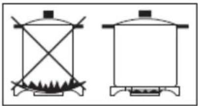
- The diameter of the bottom of the pan should correspond to that of the burner.
natural_image
Two simple line drawings of a gas stove with heating elements and a lid, no text or symbols present.- The burner flame must never extend beyond the diametre of the pan.
- Use flat bottomed pans only.
- When possible, keep a lid on the pan whilst cooking.
- Cook vegetables with as little water as possible, to reduce cooking times.
IMPORTANT: Always place pans centrally over the hob burners and position them so that the handles cannot get accidentally caught or knocked off. You should also make sure that the handle is not over one of the other hob burner flames.
Cleaning

Cleaning operations must only be carried out when the hob is cool.
The appliance should be disconnected from your mains supply before commencing any cleaning process.
Cleaning the hob top

Any residues that are left on the hob top surface from cleaning agents will damage it. You should remove any residues with warm soapy water.

Abrasive cleaners or sharp objects will damage the hob surface; you should clean it using warm soapy water.

Although it is easier to clean some deposits whilst the hob surface is still warm. Make sure that the hob surface, pan supports and hob burners have all cooled sufficiently before you attempt to touch them.
After each use
- Remove the pan stands and wipe the appliance over with a soft, damp cloth that has been put into warm soapy water. The cloth should be wrung out after being taken out of the soapy water.
- Dry the appliance by rubbing the surface with a soft, clean cloth.
- We would recommend that an appropriate stainless steel cleaner and polish is regularly used on the stainless steel surfaces of this appliance.
Cleaning the hob burners
The hob burners should be cleaned once a week or more frequently if they get soiled.
- IMPORTANT: Make sure that the hob surface, pan stands and hob burners have cooled before you attempt to touch them.
- Remove the hob burners by pulling them upwards and away from the hob top.
- Soak them for about ten minutes in hot water and a little detergent.
- After cleaning and washing them, wipe and dry them carefully.
Before placing the burners back on the hob top, make sure that the gas jet is not blocked. - IMPORTANT: Make sure that you reassemble the burners in the original way.
Maintaining the cast iron pan stands
- IMPORTANT: Make sure that the hob surface and pan stands have cooled before you attempt to touch them.
- Wipe the pan stands over with a soft, damp cloth that has been put into warm soapy water. The cloth should be wrung out after being taken out of the soapy water.
○ Using a paper towel, thoroughly dry the pan stands.
To maintain the appearance of the cast iron pan stands, we would recommend that you rub a small amount of olive oil into the pan stands, after you have finished cleaning them.
Installation

The installation must be carried out by a GASSAFE registered installer, in accordance with the current version of the following.
○ Gas Safety Regulations (Installation & Use)
○ Building Regulations (issued by the Department of Environment)
○ Building Standards (Issued by the Scottish Development Department)
○ IEE Wiring Regulations
- Electricity at Work Regulations BS 6172
○ Installation of Domestic Gas Cooking Appliances (if necessary, BS 5482 Installation of Domestic LPG Appliances)
- BS 5440 Installation of Flues and Ventilation for Gas Appliances
○ Baumatic Ltd Installation Instructions
Positioning

The adjacent furniture must be able to withstand a minimum temperature rise of 85^ C above the ambient temperature of the room it is located in, during periods of use.
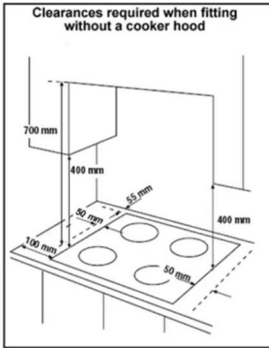
text_image
Clearances required when fitting without a cooker hood 700 mm 400 mm 55 mm 50 mm 100 mm 400 mm 50 mm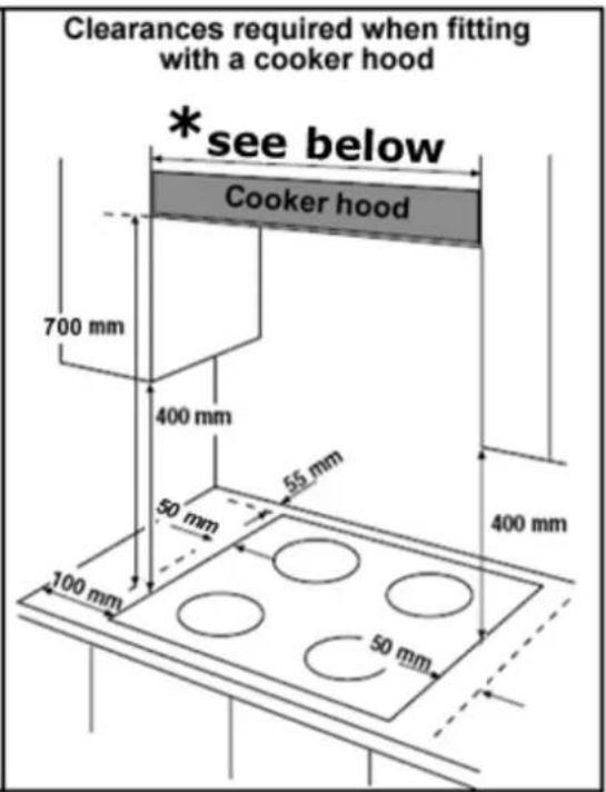
text_image
Clearances required when fitting with a cooker hood *see below Cooker hood 700 mm 400 mm 50 mm 65 mm 100 mm 400 mm 50 mm* 600 mm (BHG620SS / BHG690SS / BHG625SS / BHG695SS)
* 700 mm (BHG720SS / BHG790SS)
- This appliance can be located in a kitchen, a kitchen diner or a bed sitting room. IMPORTANT: The appliance must not be installed in a bathroom or shower room.
This appliance is classified as Class 3 and therefore is to be built into a kitchen unit (depending on size) or 600mm worktop, providing the following minimum distances are allowed:
- The edges of the hob must be a minimum distance of 55 mm from a side or rear wall.
- 700 mm between the highest point of the hob surface (including the burners) and the underside of any horizontal surface directly above it.
- 400 mm between the hob surface, providing that the underside of the horizontal surface is in line with the outer edge of the hob. If the underside of the horizontal surface is lower than 400 mm, then it must be at least 50 mm away from the outer edges of the hob.
- 50 mm clearance around the appliance and between the hob surface and any combustible materials.
Unpacking the appliance
When unpacking the appliance please check that the following items are contained within the packaging:
1 x Baumatic hob
Pan stands
Burner assemblies
Instruction manual
Baumatic warranty card
Fixing screws
Clamps
Sealing strip
LPG conversion jets
Wok stand (BHG625SS / BHG695SS / BHG720SS / BHG790SS)
Self-adhesive label for amending the gas category on the appliance's rating plate (required if the LPG conversion jets are used).
Installing the appliance
BHG620SS / BHG690SS
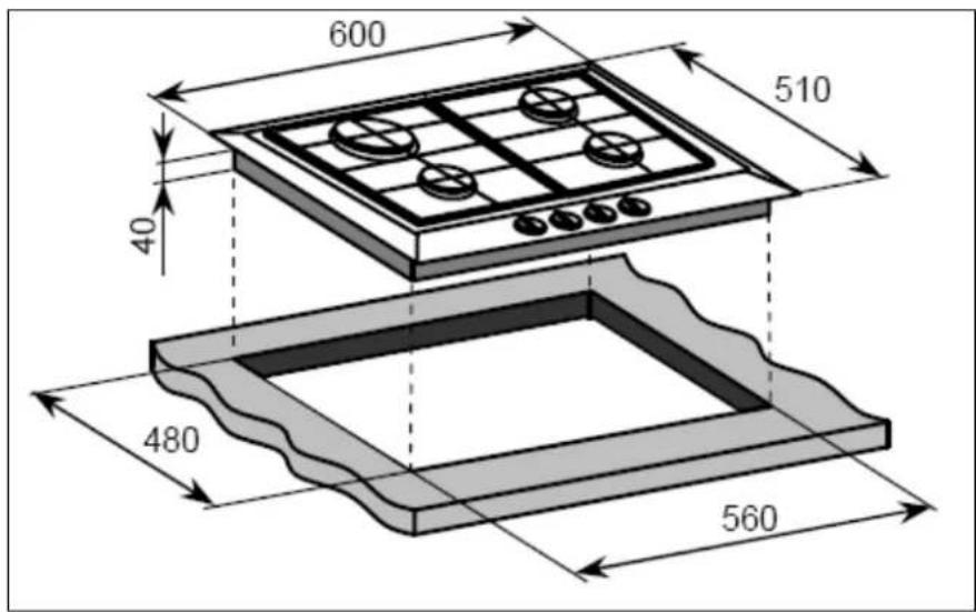
text_image
600 510 40 480 560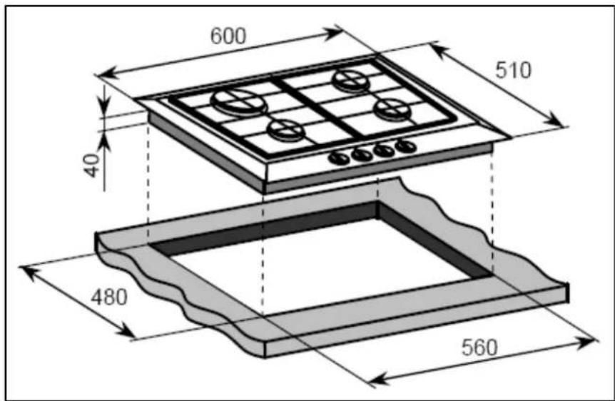
text_image
600 510 40 480 560BHG720SS
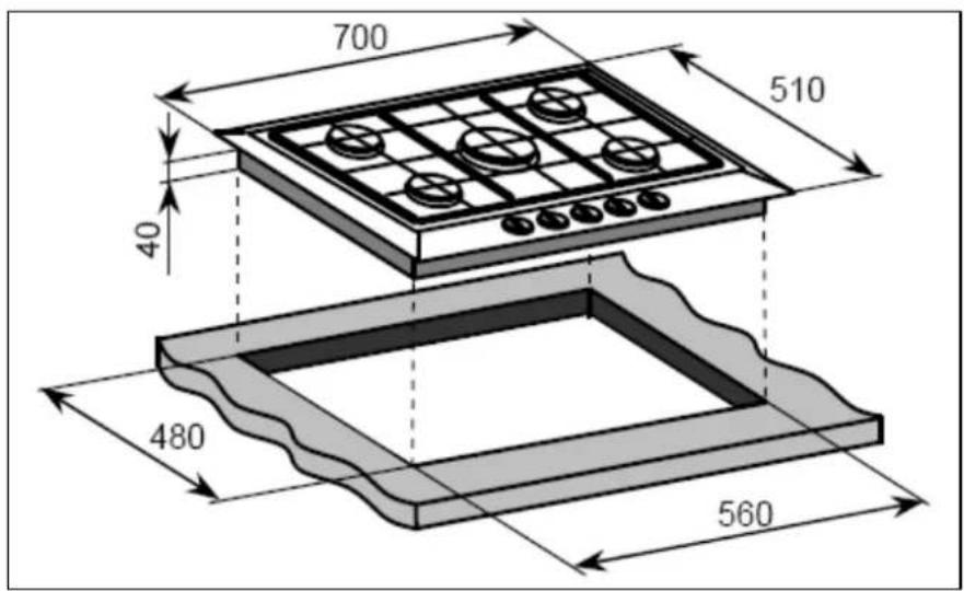
text_image
700 510 40 480 560BHG790SS
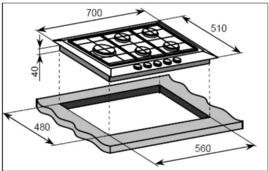
text_image
700 510 40 480 560- Cut a hole in the worktop that corresponds with the relevant drawing for your hob on pages 19 - 20.
All models
text_image
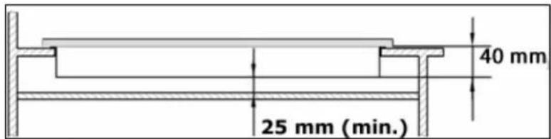
40 mm 25 mm (min.)○ IMPORTANT: You must have a gap of at least 25 mm between the underneath of the appliance and any surface that is below it.
natural_image
Line drawing of two hands holding a long rod with a pen, no text or symbols present- Carefully turn the hob upside down and place it on a cushioned mat.
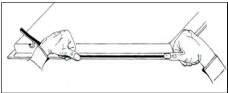
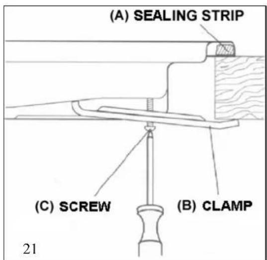
○ Apply the sealing strip (A) provided around the edge of the appliance.
- The protective covering must be removed from both sides.
- Do not leave a gap in the sealing agent or overlap the thickness.
○ IMPORTANT: Do not use a silicon sealant to seal the appliance against the aperture. This will make it difficult to remove the hob from the aperture in future if it needs to be serviced.
text_image
(A) SEALING STRIP (C) SCREW (B) CLAMP 21(A) Sealing strip
(B) Clamp
(C) Screw
- Place the clamp (B) over the holes that match the size of the screws. There are one set of screw holes in each corner of the hob. Slightly tighten a screw (C) through the clamp (B) so that the clamp is attached to the hob, but so that you can still adjust the position of it.
- Carefully turn the hob back over and then gently lower it into the aperture hole that you have cut out.
- On the underneath of the hob, adjust the clamps into a position that is suitable for your worktop. Then fully tighten the screws (C) to secure the hob into position.
Gas connection

This appliance must be installed by a competent person in accordance with the current versions of the following UK (United Kingdom) or ROI (Republic of Ireland) Regulations and Safety Standards or their European Norm Replacements.
Important information
- This hob is supplied to run on natural gas only and cannot be used on any other type of gas without modification.
- Conversion for use on LPG and other gases must only be undertaken by a qualified person. For information on the use of other gases, please contact the Baumatic Advice Line.
- The hob must be installed by a qualified person, in accordance with the current edition of the Gas Safety (Installation and Use) (Amendment) Regulations and the relevant building/I.E.E. Regulations.
- Failure to install the appliance correctly could invalidate Baumatic's guarantee and lead to prosecution under the regulations quoted above.
- In the UK, GASSAFE registered installers are authorised to undertake the installation and service work, in compliance with the above regulations.
Ventilation requirements
- The room containing the hob should have an air supply in accordance with the current edition of BS 5440: Part 2:
- The room must have opening windows or equivalent; some rooms may also require a permanent vent.
○ If the room has a volume between 5 and 10m ^3 , it will require an air vent of 50cm ^2 (effective area). Unless it has a door which opens directly to the outside.
○ If the room has a volume of less than 5m^3 , it will require an air vent of 100cm^2 (effective area). - If it is installed in a room with a volume that exceeds 11m^3 , then no air vent is required.
- If there are any other fuel burning appliances in the same room the current edition of BS 5440: Part 2: should be consulted to determine air vent requirements.
- Ensure that the room containing the hob is well ventilated, keep natural ventilation holes or install a mechanical ventilation device (mechanical cooker hood).
- Prolonged intensive use of the appliance may call for additional ventilation, either by the opening of a window, or by increasing the level of the mechanical ventilation device (where present).
- This hob is not fitted with a device for discharging the products of combustion. Ensure that the ventilation rules and regulations are followed.
- The walls behind and near the hob should be resistant to heat, steam and condensation.
- Remember that the quantity of air necessary for combustion must never be less than 2m^3/h for each kW of power (see total power in kW on the appliance rating plate).
Gas Safety (Installation and Use) Regulations
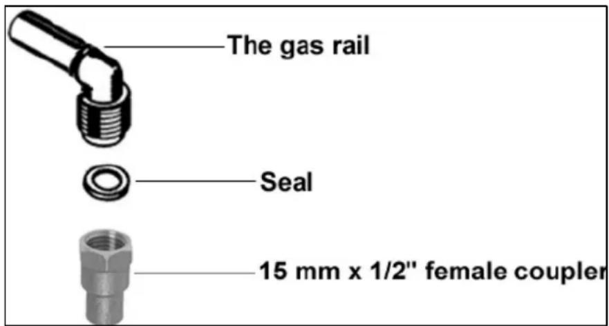
IMPORTANT: The appliance MUST be connected to the gas supply by use of a 15 mm x 12 female coupler, seal, copper pipe and an isolation tap fitted in an easily accessible position.
- It is the law that all gas appliances are installed by competent persons in accordance with the current edition of the Gas Safety Installation and Use Regulations.
- It is in your interest and that of safety to ensure compliance with the law.
- In the UK, GASSAFE registered installers work to safe standards of practice. The cooker must also be installed in accordance with the current edition of BS 6172. Failure to install the hob correctly could invalidate the warranty, liability claims and lead to prosecution.
text_image
The gas rail Seal 15 mm x 1/2" female coupler- Put the gas seal inside of the 15 mm x 12 female coupler.
- Fully tighten the 15 mm x 12 " female coupler and seal onto the gas rail.
○ IMPORTANT: The female coupler must be positioned the right way up, as shown in the picture on the previous page.
Gas pressure may be checked on a semi-rapid hob burner. Remove the appropriate injector and attach a test nipple. Light the other burners and observe that the gas pressure complies with the gas standards in force.
○ IMPORTANT: On completion carry out a gas soundness test.
Gas adjustment (Conversion to LPG)

All work must be carried out by a GASSAFE registered engineer.
IMPORTANT: Always isolate the hob from the electricity supply before changing the injectors and/or adjusting the minimum flow of the burners.
natural_image
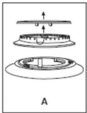
Diagram of a mechanical assembly with layered components and directional arrows, labeled A (no text or symbols present)○ Remove the pan-stands, burners and flame spreaders (A).
natural_image
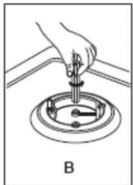
Hand using a tool to adjust or install a mechanical component, labeled B (no text or symbols on the diagram itself)○ Unscrew the injector (B) and replace it with the stipulated injector for the new gas supply (see table on next page).
| GENERAL INJECTORS TABLE | ||||
| Kind of gas | Nozzle mm/100 | Burners | Power (in watts) | |
| Max. | Min. | |||
| Natural 95/ | 55/95 | Wok | 3800 | 1700 |
| 129 | Rapid | 3000 | 1500 | |
| 97 | Semi-rapid | 1750 | 900 | |
| 76 | Auxiliary | 1000 | 500 | |
| L.P.G. | 65/41/65 | Wok | 3800 | 1300 |
| Butane | 87 | Rapid | 3000 | 700 |
| Propane | 65 | Semi-rapid | 1750 | 400 |
| 51 | Auxiliary | 1000 | 350 | |
- Reassemble all the burners carefully; in particular you should make sure that the flame spreader is correctly placed on the burner.
○ IMPORTANT: The minimum flow adjustment process must be completed before the appliance is next used.
Minimum flow adjustment for hob gas taps.

All work must be carried out by a GASSAFE registered engineer.
IMPORTANT: Always isolate the hob from the electricity supply before changing the injectors and/or adjusting the minimum flow of the burners.
natural_image
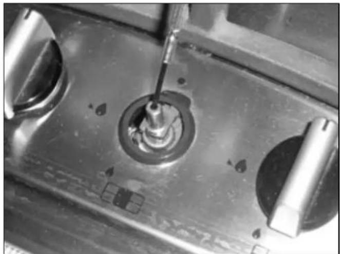
Close-up of a mechanical component with a central knob and two circular features, no visible text or symbols.○ Switch the burner on and set the knob at the minimum position.
- Remove the knob from the tap and place a small bladed screwdriver in the centre of the tap shaft.
- Unscrew the adjusting screw, in order to increase the gas flow or tighten the adjusting screw to decrease the gas flow.
- The correct adjustment is obtained when the flame has a length of about 3 - 4 mm.
- For butane/propane gas, the adjusting screw must be tightly screwed in.
- Refit the control knob.
○ Make sure that the flame does not go out by quickly turning from maximum flow to minimum flow. If it does then remove the control knob and make further adjustments to the gas flow, testing it again once the adjustment has been made.
- Repeat this process for each one of the gas taps.
Gas tap maintenance

These maintenance operations MUST ONLY be carried out by a GASSAFE registered engineer.
IMPORTANT: Before carrying out any maintenance operations, disconnect the appliance from the gas and electricity supplies.
If a gas tap becomes stiff to operate, then you should proceed as follows:
- Remove the control knobs, pan supports, burners, hob fixing screws and clamps.
- Remove the hob from the worktop and remove any underside protective covers.
○ Disconnect the fixings holding the tap to the fascia panel and separate the assembly. Then clean the cone and seating, with a cloth dampened with solvent.
○ Lightly smear the cone with high temperature grease, reassemble into position and rotate a few times. - Remove the cone again and remove any excess grease, making sure that the gas ducts are not obstructed with grease.
- Carefully reassemble the components and perform a gas soundness test.
If it becomes necessary to replace a gas tap, then you should proceed as follows:
- Remove the control knobs, pan supports, burners, hob fixing screws and clamps.
- Remove the hob from the worktop and remove any underside protective covers.
- Disconnect the fixings holding the tap to the fascia panel and separate the assembly.
- Disconnect the gas pipe from the gas tap, and then disassemble them from the gas rail by removing the fixing screws.
- When fitting a new tap, ensure that a new gasket is used.
- Reconnect the gas tap, perform a gas soundness test and then reassemble the hob.
Electrical connection

This appliance must be installed by a qualified person in accordance with the latest edition of the I.E.E. Regulations and in compliance with Baumatic's instructions.
Before connecting the appliance, make sure that the supply voltage marked on the rating plate corresponds with your mains supply voltage.
○ Cable type: H05 RRF 3 core x 0.75 mm ^4 (Type RR-F
- The mains supply cable is supplied with this product.
Replacing the mains supply cable
If the mains supply cable is damaged, then it must be replaced by an appropriate replacement which can be obtained from the Baumatic Spares Department.
The mains supply cable should be replaced in accordance with the following instructions:
○ Switch the appliance off at your mains supply.
- Open the box of the supply board.
- Unscrew the clamp fixing the cable.
- Replace the cable with one of the same length and in accordance with the specification given above.
- The "green-yellow" earth wire must be connected to the terminal marked 12 It must be about 10 mm longer than the live and neutral wires.
- The "blue" neutral wire must be connected to the terminal marked with letter (N) - the live wire must be connected to the terminal marked with letter (L).
My appliance isn't working correctly

text_image
Warning symbol image with exclamation mark inside triangleIMPORTANT: If your appliance appears not to be operating correctly, then you should disconnect it from your mains supply and then contact the Customer Care Department on telephone number (0118) 933 6911.
DO NOT ATTEMPT TO REPAIR THE APPLIANCE YOURSELF.
Please note that if an engineer is asked to attend whilst the product is under guarantee and finds that the problem is not the result of an appliance fault, then you may be liable for the cost of the call out charge.
The appliance must be accessible for the engineer to perform any necessary repair. If your appliance is installed in such a way that an engineer is concerned that damage will be caused to the appliance or your kitchen, then he will not complete a repair.
This includes situations where appliances have been tiled in, sealed in with sealant, have wooden obstructions placed in front of the appliance, like plinths. Or any installation other than the one specified by Baumatic Ltd. has been completed.
Please refer to the conditions of guarantee that appear on the warranty card that you receive with the appliance.
IMPORTANT: Baumatic Ltd. operates a policy of continuous improvement and reserves the right to adjust and modify its products without prior notification.
Baumatic Consumables
- BC001 Degreaser for Dishwashers (200 g)
- BC002 Descaler for Washing Machines and Dishwashers (200 g)
- BC003 Ceramic Hob Cleaner (250 ml)
- BC004 Oven Cleaner (250 ml)
- BC005 Stainless Steel Cleaner and Protector (250 ml)
- BC007 E-Cloth - General Purpose Cloth
- BC008 Microwave Cover
To order a Baumatic consumable product please call 0123 5437 244 and quote the product code. You can also order online from eshop.baumatic.co.uk
Baumatic®
United Kingdom
Baumatic Ltd., Baumatic Buildings, 6 Bennet Road, Reading, Berkshire RG2 0QX United Kingdom
Sales Telephone
(0118) 933 6900
Sales Fax
(0118) 931 0035
Customer Care Telephone
(0118) 933 6911
Customer Care Fax
(0118) 986 9124
Spares Telephone
(01235) 437244
Advice Line Telephone
(0118) 933 6933
E-mail:
sales@baumatic.co.uk customercare@baumatic.co.uk spares@baumatic.co.uk technical@baumatic.co.uk
Website:
www.baumatic.co.uk
Facebook:
www.facebook.com/baumatic.uk
Republic of Ireland
Service Telephone
1-890 812 724
Spares Telephone
091 756 771
Czech Republic
Baumatic CR spol s.r.o.
Lípovà 665
460 01 Liberec 4
Czech Republic
+420 483 577 200
www.baumatic.cz
Slovakia
Baumatic Slovakia, s.r.o.
Galvániho 7/D
Slovakia
+421 255 640 618
Germany
Baumatic GmbH
Bachstr.10-12
D-32 257 Bünde
Deutschland
+49 (0) 5223 99408 0
www.baumatic.de
Italy
Baumatic Italia S.R.L.
Via Galvani N.3
35011 Campodarsego (PD)
+3904 9920 2297
www.baumatic.it
Holland
Baumatic Benelux B.V.
Dukdalfweg 15d
1332 BH ALMERE
Nederland
+31(0)36 549 1553
www.baumatic.nl