
PHC620SS - Cooker BAUMATIC - Free user manual and instructions
Find the device manual for free PHC620SS BAUMATIC in PDF.


User questions about PHC620SS BAUMATIC
0 question about this device. Answer the ones you know or ask your own.
Ask a new question about this device
Download the instructions for your Cooker in PDF format for free! Find your manual PHC620SS - BAUMATIC and take your electronic device back in hand. On this page are published all the documents necessary for the use of your device. PHC620SS by BAUMATIC.
USER MANUAL PHC620SS BAUMATIC
natural_image
Simple line drawing of a fish with fins and tail, no text or symbols presentUser Manual for your Baumatic
PHC620SS 60 cm
PHC622SS 60 cm
PHC720SS 77 cm
Front touch control 4 hyperspeed zone ceramic hob.

text_image
Baumatic®NOTE: This User Instruction Manual contains important information, including safety & installation points, which will enable you to get the most out of your appliance. Please keep it in a safe place so that it is easily available for future reference; for you or any person not familiar with the operation of the appliance.
DD 24/05/10
Contents
| Environmental note | 4 | ||||||||||
| Important | safety | information | 5 - 8 | ||||||||
| S p | e | c | i | f | i | c | a | t | i | o | n |
| Ceramic | hob | surface | layout | 13 | |||||||
| Control | panel | layout | |||||||||
| Cooking | zone | indicators | and | neon's | |||||||
| U s | i | n | g | t | h | e | c | e | r | a | |
| Before | first | use | 14 | ||||||||
| T o | u | c | h | c | o | n | t | r | o | l | s |
| T u | r | n | i | n | g | t | h | e | h | o | |
| Turning on a zone and setting a power level | |||||||||||
| Turning | off | a | zone | gradually | |||||||
| Turning | off | a | zone | instantly | |||||||
| T u | r | n | i | n | g | t | h | e | h | o | |
| Turning on a dual circuit zone | |||||||||||
| Turning off a dual circuit's outer section | |||||||||||
| Residual | heat | indicator | 17 | - | 1 | ||||||
| L o | c | k | i | n | g | t | h | e | h | o | |
| Safety | cut-off | 18 | - | 1 | |||||||
| Automatic | pre-heating | 19 | - | 20 | |||||||
| Increasing the power level during automatic pre-heating | |||||||||||
| Switching off automatic pre-heating | |||||||||||
| T h | e | h | o | b | t | i | m | e | r | ||
| H o | b | g | u | i | d | e | l | i | n | e | s |
| Cleaning and maintenance | 23 - 25 | ||||||||||
| Cleaning the ceramic hob top | |||||||||||
| A f | t | e | r | e | a | c | h | u | s | e | |
| Cleaning table | |||||||||||
| Using a ceramic hob scraper | |||||||||||
| Using a specialist ceramic hob cleaner | |||||||||||
| I n | s | t | a | l | l | a | t | i | o | n | |
| P o | s | i | t | i | o | n | i | n | g | ||
| Unpacking | the | appliance | 26 | ||||||||
| Installing | the | appliance | 26 | ||||||||
| E l | e | c | t | r | i | c | a | l | c | o | n |
| Connecting the mains supply cable | |||||||||||
| Replacing the mains supply cable | |||||||||||
| My appliance isn't working correctly | 30 - 32 | ||||||||||
| Contact details | 33 | ||||||||||
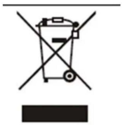
This appliance is marked according to the European directive 2002/96/EC on Waste electrical and Electronic Equipment (WEEE). By ensuring this product is disposed of correctly, you will help prevent potential negative consequences for the environment and human health, which could otherwise be caused by inappropriate waste handling of this product.
The symbol

on the product, or on the documents accompanying the product, indicates that this appliance may not be treated as household waste. Instead it shall be handed over to the applicable collection point for the recycling of electrical and electronic equipment.
Disposal must be carried out in accordance with local environmental regulations for waste disposal.
For more detailed information about treatment, recovery and recycling of this product, please contact your local city office, your household waste disposal service or the shop where you purchased the product.
text_image
Diagram of a trash bin with crossed and unbroken lines indicating no waste or discharge- The packaging materials that Baumatic uses are environmentally friendly and can be recycled.
- Please discard all packaging material with due regard for the environment.
Important safety information

text_image
Warning symbol with exclamation mark inside triangleYour safety is of the utmost importance to Bauma. Please make sure that you read this instruction booklet before attempting to install or use the appliance. If you are unsure of any of the information contained in this booklet, please contact the Baumatic Advice Line.
General Information
- This appliance is designed for domestic household use and for the cooking and frying of domestic foodstuffs.
- IMPORTANT: The adjacent furniture and all materials used in the installation must be able to withstand a minimum temperature of 85°C above the ambient temperature of the room it is located in, whilst in use.
o Certain types of vinyl or laminate kitchen furniture are particularly prone to heat damage or discolouration at temperatures below the guidelines given above. - Any damage caused by the appliance being installed in contravention of this temperature limit, will be the liability of the owner.
- Your new appliance is guaranteed against electrical or mechanical defects, subject to certain exclusions that are noted in Baumatic's Conditions Of Guarantee. The foregoing does not affect your statutory rights.
- The use of this appliance for any other purpose or in any other environment without the express agreement of Baumatic Ltd. will invalidate any warranty or liability claim.
- You should not use this appliance to store items on or as a work surface.
- No modifications to the appliance are permitted by Baumatic Ltd.
- You should not store or place flammable or highly flammable liquids/materials on top of or near the appliance. Items made from aluminium, plastic or plastic film should also be kept away from the appliance, as they may fuse to the surface.
- Repairs may only be carried out by Baumatic Service Engineers or their authorised service agent.
Child Safety
○ Baumatic strongly recommend that babies and young children are prevented from being near to the appliance and not allowed to touch the appliance at any time. During and after use, all surfaces will become hot.
- If it is necessary for younger family members to be in the kitchen, please ensure that they are kept under close supervision at all times.
- Older children should only be allowed to utilise the appliance when supervised.
General Safety
√ The appliance should only be installed and connected by a suitably qualified person.
√ Care should be taken to ensure that the units and work surfaces that you build the appliance into, meet with the relevant standards.
√ If you notice any scratches, splits or cracks in the ceramic glass, you should immediately switch off the appliance and disconnect it from your mains supply. Otherwise there is the risk of electric shock occurring.
During use
√ Any film or stickers that are present on the hob surface when it is delivered should be removed before use.
√ Care should be used when utilising the appliance, otherwise there is a risk of burns being caused.
- You should not allow the electrical connection cables to come into contact with the hob surface when it is hot or any hot cookware.
- If fat and oil overheats, then it can ignite extremely quickly. For this reason, when cooking with fat and oil the appliance should not be left unattended.
√ Make sure that all of the cooking zones are switched off after use.
Cleaning
- Cleaning of the hob should be carried out on a regular basis.
- IMPORTANT: Before attempting to clean the appliance, it should be disconnected from the mains and allowed to cool.
- Great care should be taken whilst using this appliance and when following the cleaning procedure.
- You should not use a steam jet or any other high pressure cleaning equipment to clean the appliance.
Installation

text_image
Warning symbol with exclamation mark inside triangleThis appliance must be correctly installed by a suitably qualified person, strictly in accordance with the manufacturer's instructions. Please see the specific section of this booklet that refers to installation.
○ Baumatic Ltd. declines any responsibility for injury or damage, to person or property, as a result of improper use or installation of this appliance.
Declaration of conformity
This appliance complies with the following European Directives:
-73/23/EEC dated 19/02/1973 Low Voltage Directive.
-89/336/EEC dated 03/05/1989 EMC Directive inclusive of Amending Directive 92/31/EEC.
-93/68/EEC dated 22/07/1993 CE Marking Directive.
-89/109/EEC dated 25/01/1992 Materials that can touch food.
- The manufacturer declares that the hob is built using certified materials and requires the appliance to be installed in accordance with the standards currently in force. This appliance must be used by a trained person for domestic purposes only.
To avoid damaging your appliance
- The ceramic glass can be damaged by objects falling onto it.
- The ceramic glass edge can be damaged by knocks from cookware.
- Cast iron and cast aluminium cookware with damaged bases may scratch the ceramic surface if they are dragged across it.
o Pans should be lifted on and off the hob surface and not dragged.
- Cooking zones should not be switched on without cookware placed on it. Also the cookware should not be empty.
Specifications
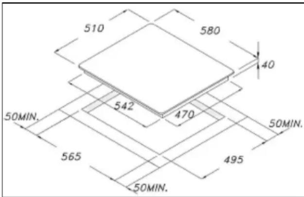
PHC620SS
text_image
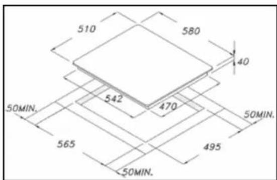
510 580 40 542 470 50MIN. 565 50MIN. 495 50MIN.Product dimensions
Height: 40 mm
Width: 580 mm
Depth: 510 mm
Aperture dimensions
Depth: 495 mm
Width: 565 mm
Product specifications:
o 1 x 0.75/2.20 kW double hyperspeed zone (∅ 120/210 mm)
○ 1 x 1.10/2.00 kW oval hyperspeed zone (∅ 170/265 mm)
- 2 x 1.20 kW hyperspeed zone (∅ 140 mm)
- Front touch control operation
- 4 individual residual heat indicators
o Safety lock
- Timer
- Wrap around designer frame
Standard accessories
- Ceramic hob scraper
Electrical details
Rated Voltage:
230 Vac 50 Hz
Supply Connection: 30 A (double
pole switched fused
outlet with 3mm contact gap)
Max Rated Inputs: 6.6 kW
Mains Supply Lead: 3 core x 6 mm ^4 (not supplied)
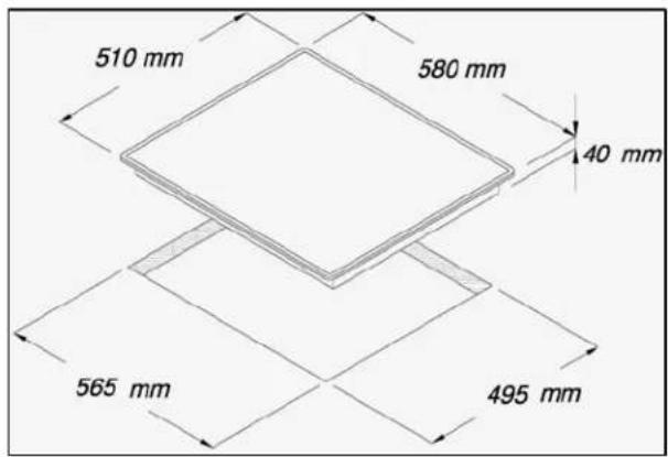
PHC622SS
text_image
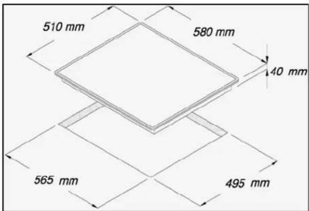
510 mm 580 mm 40 mm 565 mm 495 mmProduct dimensions
Height: 40 mm
Width: 580 mm
Depth: 510 mm
Aperture dimensions
Width: 565 mm
Depth: 495 mm
Product specifications
o 1 x 0.75/2.20 kW double hyperspeed zone (∅ 140/210 mm)
○ 1 x 1.10/2.00 kW oval hyperspeed zone (∅ 140/240 mm)
○ 2 x 1.20 kW hyperspeed zone (∅ 140 mm)
- Front touch control operation
- 4 individual residual heat indicators
- Safety lock
- Timer
- Stainless steel frame
Standard accessories
- Ceramic hob scraper
Electrical details
Rated Voltage: 230 Vac 50 - 60 Hz
Supply Connection: 30 A (double pole switched fused outlet with 3mm contact gap)
Max Rated Inputs: 6.3 kW
Mains Supply Lead: 3 core x 6 mm ^4 (not supplied)
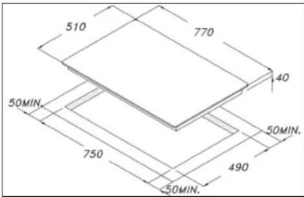
PHC720SS
text_image
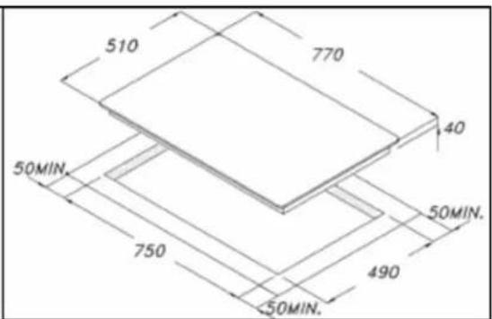
510 770 40 50MIN. 750 50MIN. 490 50MIN.Product dimensions
Height: 40 mm
Width: 770 mm
Depth: 510 mm
Aperture dimensions
Depth: 490 mm
Width: 750 mm
Product specifications
o 1 x 0.75/2.20 kW double hyperspeed zone (∅ 120/210 mm)
○ 1 x 1.10/2.00 kW hyperspeed rectangular zone (∅ 140/240 mm)
○ 1 x 1.80 kW hyperspeed zone (∅ 180 mm)
○ 1 x 1.20 kW hyperspeed zone (∅ 140 mm)
- Front touch control operation
- Timer
- Wrap around designer frame
- 4 individual heat indicators
- Safety lock
Standard accessories
- Ceramic hob scraper
Electrical details
Rated Voltage:
230 Vac 50 Hz
Supply Connection: 32 A (double
pole switched fused
outlet with 3mm contact gap)
Max Rated Inputs: 7.2 kW
Mains Supply Lead: 3 core x 6 mm ^4 (not supplied)
For future reference please record the following information which can be found on the rating plate and the date of purchase which can be found on your sales invoice. The rating plate of your hob is located on the underneath of the appliance. Therefore it is a good idea to record this information before you install your appliance.
Model Number
Serial Number
Date of Purchase ....
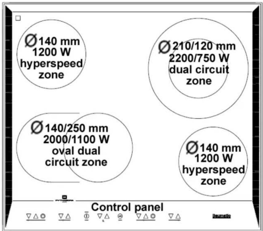
Ceramic hob surface layout
PHC620SS
text_image
Ø 140 mm 1200 W hyperspeed zone Ø 210/120 mm 2200/750 W dual circuit zone Ø 140/250 mm 2000/1100 W oval dual circuit zone Ø 140 mm 1200 W hyperspeed zone Control panelPHC622SS
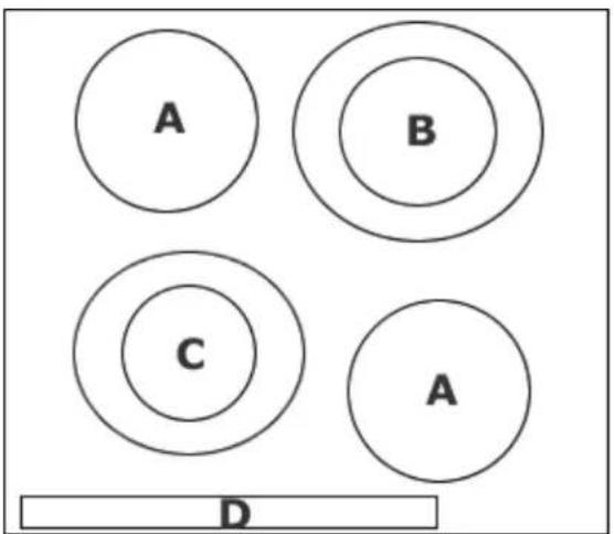
text_image
A B C A DA = 1.20 kW hyperspeed zone (∅ 140 mm)
B = 1.10/2.00 kW oval hyperspeed zone (∅ 140/240 mm)
C = 0.75/2.20 kW double hyperspeed zone (∅ 140/210 mm)
D = Control panel
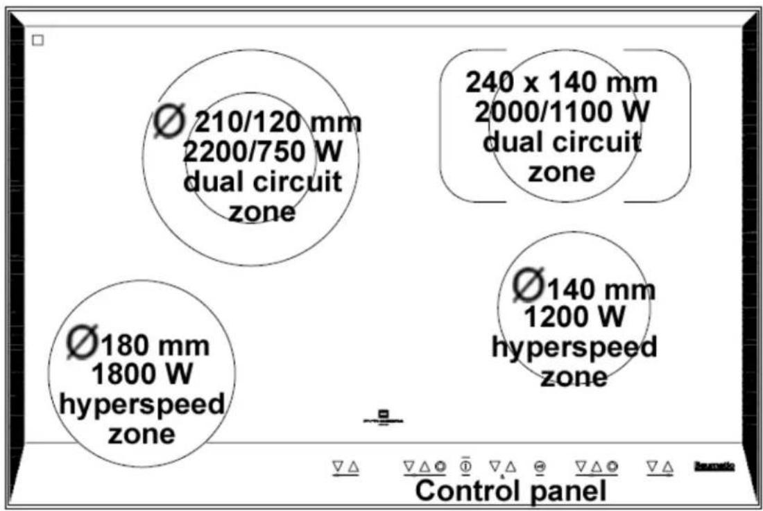
PHC720SS
text_image
Ø 210/120 mm 2200/750 W dual circuit zone Ø 180 mm 1800 W hyperspeed zone 240 x 140 mm 2000/1100 W dual circuit zone Ø 140 mm 1200 W hyperspeed zone Control panelControl panel layout
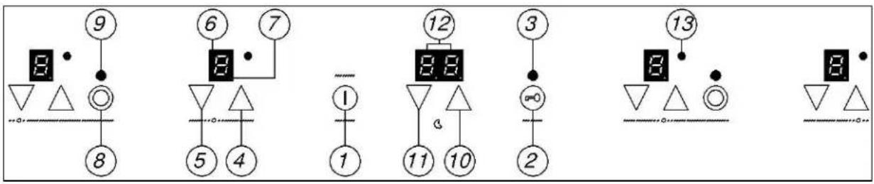
PHC620SS/ PHC622SS
text_image
Diagram showing numbered symbols and geometric shapes with numbers, likely representing a puzzle or logic layout.PHC720SS

text_image
Diagram showing numbered positions of electrical or mechanical components with symbols and numbers, possibly representing a circuit or signal layout.- ON/OFF button
- Safety lock button
- Safety lock neon
- Plus button
- Minus button
- Cooking zone indicator
- Decimal point symbol
- Dual circuit ON/OFF button
- Dual circuit indicator neon
- Timer plus button
- Timer minus button
- Timer display
- Timer neon
Cooking zone indicators and neon's
PHC620SS/ PHC622SS
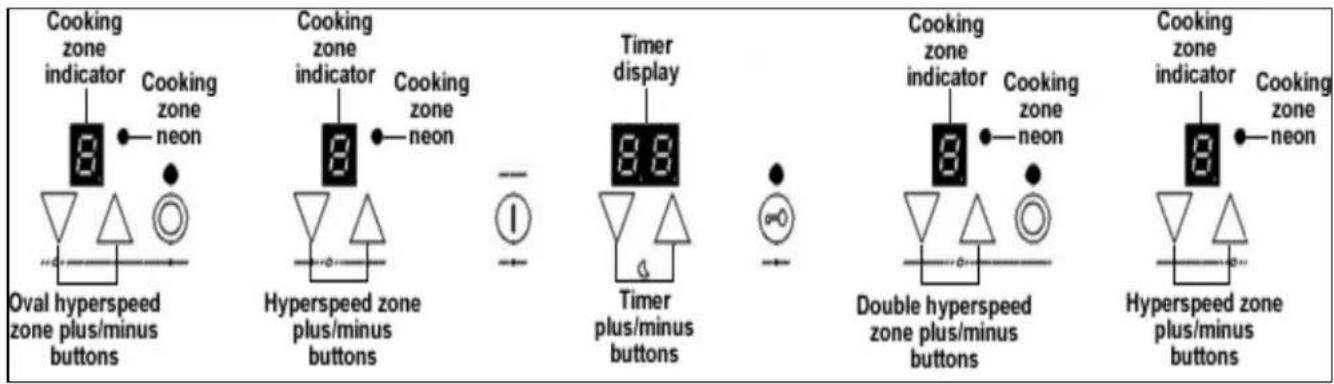
text_image
Cooking zone indicator Cooking zone neon Oval hyperspeed zone plus/minus buttons Cooking zone indicator Cooking zone neon Hyperspeed zone plus/minus buttons Timer display Timer plus/minus buttons Cooking zone indicator Cooking zone neon Double hyperspeed zone plus/minus buttons Cooking zone indicator Cooking zone neon Hyperspeed zone plus/minus buttonsPHC720SS
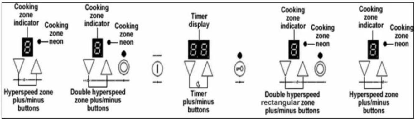
text_image
Cooking zone indicator Cooking zone neon Hyperspeed zone plus/minus buttons Cooking zone indicator Cooking zone neon Double hyperspeed zone plus/minus buttons Timer display Timer plus/minus buttons Cooking zone indicator Cooking zone neon Double hyperspeed rectangular zone plus/minus buttons Cooking zone indicator Cooking zone neon Hyperspeed zone plus/minus buttonsUsing the ceramic hob
Before first use

IMPORTANT: You should clean the ceramic hob surface (see "Cleaning and maintenance" section).
- You should switch on one cooking zone at a time, for 5 minutes at the maximum setting. This will help to eliminate any new smell that exists and evaporate any humidity that has formed on the heating elements during transit.
- Do not burn off more than one zone at once.
- You must place a saucepan filled half full with cold water on each zone as you burn it off.
Touch controls
- All operations are performed by means of the touch controls that can be found on the control panel.
- Each touch control has a visual display that corresponds to it.
- Every time you press a touch control, an acoustic signal will sound.
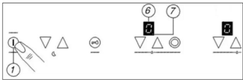
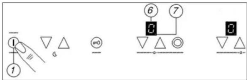
Turning the hob on
text_image
Diagram showing electrical or mechanical symbols with numbered components and connections, including triangle and circle elements.- Press the ON/OFF button (1)
- The cooking zone indicators (6) will all read "0".
- The decimal point symbols (7) will flash on and off.
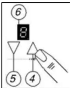
Turning on a zone and setting a power level
IMPORTANT: A zone must be selected within 10 seconds of turning the hob on.
text_image
⑥ 8 ⑤ ④- Press the plus (4) button for the zone that you want to use.
- Adjust the zone between power levels 1 and 9, using the plus (4) and minus (5) buttons. By holding down either of these buttons, the value on the zone indicator (6) will adjust up or down every 0.3 seconds.
- If when holding down the plus (4) or minus (5) buttons the power level reaches zero. You will need to press either the plus (4) or minus (5) button again, to continue adjusting the power level.
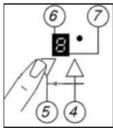
Turning off a zone gradually
text_image
⑥ ⑦ 8 ⑤ ④o Press the minus button (5) until the number in the cooking zone indicator (6) reaches "0". After 3 seconds, the zone will switch off automatically.
○ An "H" will show in the cooking zone indicator (6) until the temperature of the zone falls below 60°C (see the section on the "residual heat indicator" for further information).
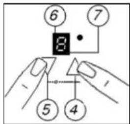
Turning off a zone instantly
text_image
⑥ ⑦ 8 ⑤ ④o Press the minus button (5) and the plus button (4) simultaneously.
- The zone will switch off immediately.
○ An "H" will show in the cooking zone indicator (6), alternating with "0". (See the section on the "residual heat indicator" below).
Turning the hob off
Once you have switched off all of the cooking zones, you should turn off the hob.
text_image
Diagram showing electrical or mechanical symbols with numbered components and connections, including triangle and circle elements.o Press the ON/OFF button (1).
It is possible to turn the hob off at any time by pressing the ON/OFF button (1).
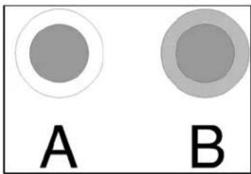
Turning on a dual circuit zone
natural_image
Two labeled circles (A and B) with no text or symbols inside, one large and one small, against a white background.The dual circuit zones have two cooking areas that you can use, a central section and an outer section. You can use the central section (A) independently or both sections (B) at once.
text_image
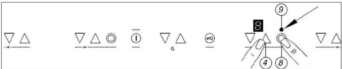
Diagram showing various geometric shapes and symbols with numbered labels, likely illustrating a basic electrical or mechanical concept.- Use the plus (4) or minus (5) buttons of the dual circuit zone that you wish to use and select a power level between 1 and 9.
o The central section of the duel circuit zone will switch on.
- If you wish to also activate the outer section of a duel circuit zone, you should press the dual circuit ON/OFF button (8). The dual circuit indicator neon (9) will light.
Turning off a dual circuit's outer section
- Both zones of the dual circuit most be switched on.
o Press the dual circuit ON/OFF button (8).
- The dual circuit indicator neon (9) will go out and the outer section will switch off.
Residual heat indicator
natural_image
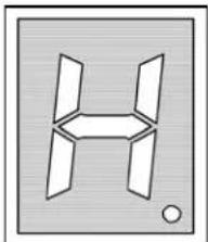
Abstract geometric shape resembling a stylized letter 'H' with four triangular panels, no text or symbols present.○ After a zone is switched off, the corresponding cooking zone indicator (6) will show the letter "H", alternating with "0". This means that the temperature of the zone is over 60°C and is therefore high enough to cause injury.
- If you switch off the appliance using the ON/OFF button (1) then only the "H" will appear in the cooking zone indicator (6).
When the temperature falls below 60^ C, then the letter "H" and "O" will stop alternating (if the hob is still switched on), or the "H" will go out (if the hob is not switched on).
- IMPORTANT: The residual heat indicator will disappear if your mains supply is cut.
Locking the hob top
flowchart
graph TD
    1["①"] --> A["△"]
    1 --> B["△"]
    A --> C["3"]
    B --> C
    C --> D["2"]
    style 1 fill:#fff,stroke:#000
    style 2 fill:#fff,stroke:#000
    style 3 fill:#fff,stroke:#000
    style 4 fill:#fff,stroke:#000
    style 5 fill:#fff,stroke:#000
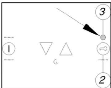
- The whole hob top can be locked by pressing the safety lock button (2) whilst the appliance is turned on.
- The safety lock neon (3) will light to show that the safety lock feature has been switched on.
- When the safety lock feature is activated, it will disable any of the other buttons on the control panel, except the ON/OFF button (1).
To disable the safety lock feature, you should press the safety lock button (2) again. The safety lock neon (3) will go out and you are then able to adjust the power of any zone on the hob top.
○ IMPORTANT: If the appliance is switched off whilst the safety lock feature is activated, then it will still be activated the next time that you turn the appliance on. Therefore before you can turn on a zone and set it to a power level, you will need to deactivate the safety lock by pressing the safety lock button (2).
Safety cut-off
- If one or more of the cooking zones are accidentally left on, a safety cut off will activate after a certain period of time. The length of time depends on the power level that a zone or zones have been set on.
| LEVEL | TIME LIMIT | |
| 1 | 10 | hours |
| 2 - 3 | 5 hours | |
| 4 | 4 | hours |
| 5 | 3 | hours |
| 6 - 8 | 2 hours | |
| 9 | 1 | hour |
- If the safety cut off has activated, the symbol "H" will appear in the cooking zone indicator (6) that applies to the cooking zone that has been left on. To reset the appliance, you should press the ON/OFF button (1).
- If the plus (4) or minus (5) buttons are pressed, then the length of time before the safety cut-out will activate is reset.
Automatic pre-heating
text_image
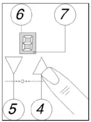
6 7 8 5 4- This feature will set a cooking zone to maximum power and will then automatically set the cooking zone to a power level that you have selected after a certain period of time.
- Press the minus button (5) once and power level 9 appears on the cooking zone indicator (6), then release the minus button.
- Press the plus button (4) once and a flashing decimal point symbol will appear on the cooking zone indicator (6), then release the plus button.
- Use the minus button (5) to adjust the zone to the power level that you want to cook at.
- When the minus button (5) is released, the decimal point will stop flashing and the power level that you have selected will appear on the cooking zone indicator (6).
Once the automatic pre-heating time period is over, the hob will beep once and the decimal point symbol will go out. Only the actual power level will show on the cooking zone indicator (6).
- The period of time that a zone will automatically pre-heat for before dropping to the actual power level, is shown in the table below:-
| LEVEL | TIME LIMIT |
| 1 1 minute 11 seconds | |
| 2 2 minutes 44 seconds | |
| 3 4 minutes 47 seconds | |
| 4 5 minutes 28 seconds | |
| 5 6 minutes 29 seconds | |
| 6 1 minutes 11 seconds | |
| 7 2 minutes 44 seconds | |
| 8 2 minutes 44 seconds | |
| 9 | N/A |
Increasing the power level during automatic pre-heating
text_image
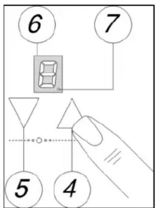
6 7 5 4○ If a zone is already within automatic pre-heating mode and you wish to adjust the power level. Make sure that the decimal point symbol (7) is present in the cooking zone indicator.
○ Increase the power level by pressing the plus button (4).
- The pre-heating time will be adjusted. It will take into account the amount of time that has already elapsed.
Switching off automatic pre-heating
text_image
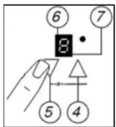
⑥ ⑦ 8 - ⑤ ④- If a zone is already within automatic pre-heating mode and you wish cancel it. Make sure that the decimal point symbol (7) is present in the cooking zone indicator.
- Press the minus button (5), the automatic pre-heating mode will then be cancelled and you can use the hob in normal operation once more.
- IMPORTANT: Please note that switching off automatic pre-heating will not switch off the zone, it will still be necessary for you to do this manually.
The hob timer
text_image
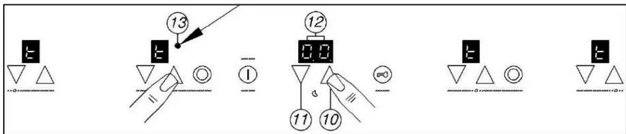
Diagram illustrating a sequence of electrical or mechanical components with numbered annotations and symbols, likely for circuit or signal processing.- Touch either the plus (10) or minus (11) buttons of the timer. The timer display (12) will show "00" and a "t" symbol will appear on all of the cooking zone indicators.
○ After selecting the timer, a zone must be selected within 10 seconds by pressing one of the plus (4) or minus (5) buttons. You should use these buttons to select your desired power level. - The zone will switch on and start to heat, the timer neon (13) will switch on next to the relevant cooking zone indicator (6).
○ Use the plus (10) and minus (11) buttons to adjust the time that appears in the timer display (12).
Once the minus or plus buttons are released, the countdown will start immediately. - The timer will be assigned to the zone that you have switched on.
- You can adjust the time that has been set, by using the plus (10) or minus (11) buttons for the timer.
- At the end of the time period that has been set, an acoustic signal will sound that lasts for 30 seconds, "00" will flash on the timer display (12) and the selected zone will switch off.
To cancel the audible alarm, press either the minus (11) or plus (10) buttons for the timer. - The timer can only be used for one zone at a time. Any other zones that you have in use will not switch off at the end of the countdown time.
- If you wish to cancel the timer setting before it reaches the end of the countdown period, press the plus (10) and minus (11) buttons of the timer simultaneously.
- IMPORTANT: If you cancel the timer setting, the selected zone will still remain on, therefore you will need to turn the zone off manually.
Hob guidelines
- The first few times the hob top is used, it may give off an acrid, burning smell. This smell will disappear completely with repeated use.
- The hob surface is fitted with cooking areas of different diametre and power.
- The positions where the heat will radiate from are clearly marked on the hob top. The saucepans must be positioned exactly on these zones for efficient heating to occur. Pans should have the same diametre as the cooking zone that they are being used on.
- You should not use saucepans with rough bottoms, as this can scratch the ceramic surface.
Before use, make sure that the bottoms of the saucepans are clean and dry. - When cold, the bottom of the pans should be slightly concave, as they expand when hot and lie flat on the surface of the hob. This will allow the heat to transfer more easily.
- The best thickness for the bottom of the pans is 2 - 3 mm of enamelled steel and 4 - 6 mm for stainless steel with sandwich type bottoms.
- If these rules are not followed, then there will be a great loss of heat and energy. Heat not absorbed by the saucepan, will spread to the hob, frame and surrounding cabinets.
- Preferably cover pans with a lid to permit cooking at a lower heat.
- Always cook vegetables and potatoes, etc. in as little water to reduce cooking times.
- Food or liquid that has high sugar content may damage the hob top if it comes into contact with the ceramic hob surface. Any spillages should be wiped up immediately, however this may not prevent the hob surface from becoming damaged.
- IMPORTANT: The ceramic hob surface is tough; however it is not unbreakable and can be damaged. Especially if pointed or hard objects are allowed to fall on it with some force.
- DO NOT USE THE HOB IF THE SURFACE BECOMES BROKEN OR CRACKED. YOU SHOULD CONTACT THE BAUMATIC CUSTOMER CARE DEPARTMENT IMMEDIATELY.
Cleaning and maintenance

text_image
Warning symbol with exclamation mark inside triangleCleaning operations must only be carried out when the hob is cool.
The appliance should be disconnected from your mains supply before commencing any cleaning process.
Cleaning the ceramic hob top

Any residues that are left on the hob top surface from cleaning agents will damage it. You should remove any residues with warm water mixed with a little washing up liquid.

Abrasive cleaners or sharp objects will damage the hob surface; you should clean it using warm water mixed with a little washing up liquid.

Although it is easier to clean some deposits whilst the hob surface is still warm. You should take care not to burn yourself if cleaning the hob surface when it is still warm.
After each use
- Wipe the appliance over with a damp cloth.
- Dry the appliance by rubbing the surface with a clean cloth.
Cleaning table
| Type of deposit | Remove immediately? | Remove when the appliance has cooled down? | What should I use to remove the deposit? |
| Sugar or food/liquid containing sugar | Yes | No | Ceramic scraper |
| Tin foil or plastic | Yes No Ceramic hob | scraper | |
| Fat splashes No | Yes Ceramic hob | cleaner | |
| Metallic discolourations | No | Yes | Ceramic cleaner |
| Water splashes or water rings | No | Yes | Ceramic cleaner |
Using a ceramic hob scraper
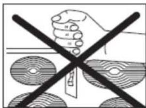
Your appliance will be provided with a hob scraper. The following guidelines should also be followed when using the ceramic hob scraper:-
text_image
Warning symbol showing a hand holding a tool crossed with a crossed-out black line, indicating incorrect use or absence of a device.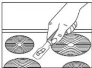
natural_image
Hand holding a tool over four circular objects, no text or symbols visible- The scraper should be placed on the ceramic surface at an angle.
o Residues should be removed by sliding the blade carefully over the ceramic surface. - The ceramic surface should be wiped with a damp cloth that has been placed in warm water mixed with a small amount of washing up liquid.
- Dry the appliance by rubbing the surface with a clean cloth.
Using a specialist ceramic hob cleaner
It is possible to purchase a specialist ceramic hob cleaner/conditioner.
You should follow the instructions given by the manufacturer of the specialist ceramic hob cleaner. You should ensure that it is suitable for use on your appliance.
Installation

The installation must be carried out by a suitably qualified person, in accordance with the current version of the following.
- UK Regulations and Safety Standards or their European Norm Replacements.
○ Building Regulations (issued by the Department of the Environment).
○ Building Standards (issued by the Scottish Development Department).
○ IEE Wiring Regulations. - Electricity At Work Regulations.
Positioning

The adjacent furniture must be able to withstand a minimum temperature rise of 85^ C above the ambient temperature of the room it is located in, during periods of use.
This appliance is classified as Class 3 and therefore is to be built into a kitchen unit (depending on size) or 600 mm worktop, providing the following minimum distances are allowed:
- 700 mm between the hob surface and the underside of any horizontal surface above it.
- 50 mm clearance around the appliance and between the hob surface and any combustible materials.
Unpacking the appliance
When unpacking the appliance please check that the following items are contained within the packaging:
1 Baumatic hob
1 Ceramic hob scraper
1 Installation and instruction manual
1 Baumatic guarantee card
4 Fixing brackets
4 Fixing screws
4 Spring clips
1 Sealing strip
Installing the appliance
PHC620SS
text_image
510 580 40 542 470 50MIN. 565 50MIN. 495 50MIN.PHC720SS
text_image
510 770 40 50MIN. 50MIN. 750 490 50MIN.PHC622SS
text_image
510 mm 580 mm 40 mm 565 mm 495 mmCut a hole in the worktop that corresponds with the drawings shown above.
text_image
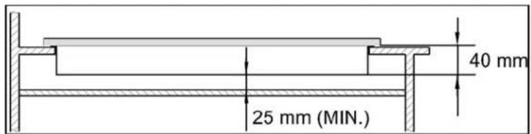
25 mm (MIN.) 40 mm○ IMPORTANT: You must have a gap of at least 25 mm between the underneath of the appliance and any surface that is below it.
natural_image
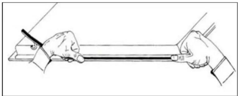
Line drawing of two hands holding a long rod or rod on a flat surface, with a ruler partially visible (no text or symbols)o Carefully turn the hob upside down and place it on a cushioned mat.
○ Apply the sealing strip provided around the edge of the appliance.
o The protective covering must be removed from both sides.
o. Do not leave a gap in the sealing agent or overlap the thickness.
○ IMPORTANT: Do not use a silicon sealant to seal the appliance against the aperture. This will make it difficult to remove the hob from the aperture in future, particularly if it needs to be serviced.
text_image
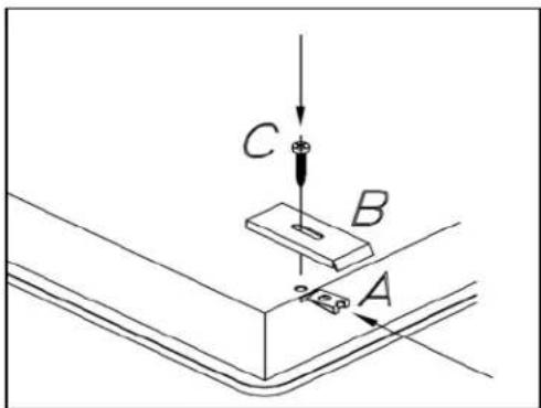
C B A(A) Clip
(B) Fixing bracket
(C) Screw
- You should insert a clip (A) into the holes which are located in each corner of the hob.
- Place the fixing brackets (B) over each hole and clip, and then place a screw (C) through the hole and fixing bracket (B). Tighten the screws a little way, so that they stay in place. IMPORTANT: Do not tighten the screws fully.
- Carefully turn the hob back over and then gently lower it into the aperture hole that you have cut out.
text_image
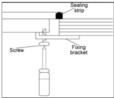
Sealing strip Screw Fixing bracket○ On the underneath of the hob, locate the fixing brackets (B) and turn them so that they locate on the underneath of the worktop and the hob.
- Fully tighten the screws (C) to secure the hob into position.
Electrical connection

This appliance must be installed by a qualified person in accordance with the latest edition of the I.E.E. Regulations and in compliance with Baumatic's instructions.
Before connecting the appliance, make sure that the supply voltage marked on the rating plate corresponds with your mains supply voltage.
WARNING: THIS APPLIANCE MUST BE EARTHED.
- The PHC620SS/ PHC622SS appliance must be wired into a 30 A double pole switched fused spur outlet, having 3 mm contact separation and placed in an easily accessible position adjacent to the appliance. It should not be located above the appliance and no more than 1.25m away from it.
The PHC720SS appliance must be wired into a 32 A double pole switched fused spur outlet, having 3 mm contact separation and placed in an easily accessible position adjacent to the appliance. It should not be located above the appliance and no more than 1.25m away from it.
- The spur outlet must still be accessible even when your oven is located in its operating position.
○ Cable type: H05 RRF 3 core x 6 mm ^4
Connecting the mains supply cable
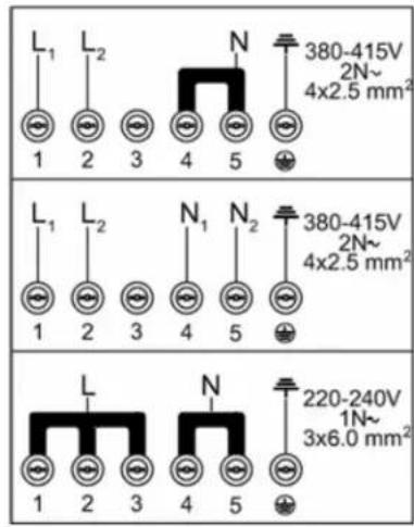
- The mains terminal block is located on the underside of the hob and the terminals are accessible by removing the terminal block cover by removing the cover screw.
- The cable connections must be in accordance with the diagram located on the bottom of the hob.
text_image
L₁ L₂ N 380-415V 2N~ 4x2.5 mm² 1 2 3 4 5 L₁ L₂ N₁ N₂ 380-415V 2N~ 4x2.5 mm² 1 2 3 4 5 L N 220-240V 1N~ 3x6.0 mm² 1 2 3 4 5o 1, 2 and 3 are the live connection, 4 and 5 are the neutral connection and the remaining one is the earth connection.
- The live wire MUST be placed in connection number 1.
The neutral wire MUST be placed in connection number 4.
The earth wire MUST be placed in the connection marked with the ⏻ symbol.
- The brass links must be positioned as marked in the above diagram and once established ALL terminal screws must be tightened down firmly.
- Fit the cable and refit the cable clamp.
If when the hob is first switched on, only two of the zones work, you should recheck that the terminal screws are all fully tightened between the links. This should be done before contacting the Baumatic Customer Care Department.
○ IMPORTANT: The appliance must NOT be connected to the mains supply by means of a 13A plug and socket.
- The cable can be looped if necessary, but make sure that is not kinked or trapped when the hob is in position. Care must be taken to avoid the cable being in contact with hot parts of the appliance.
Replacing the mains supply cable
If the mains supply cable is damaged, then it must be replaced by an appropriate replacement.
The mains supply cable should be replaced in accordance with the following instructions:
- Switch the appliance off at the control switch.
- Open the terminal block on the underside of the hob.
- Unscrew the terminal screws fixing the cable.
- Replace the cable with one of the same length and in accordance with the specification given on page 25.
- The "green-yellow" earth wire must be connected to the terminal marked 12 . It must be about 10 mm longer than the live and neutral wires.
- The "blue" neutral wire must be connected to the terminal marked with letter (N) - the live wire must be connected to the terminal marked with letter (L).
My appliance isn't working correctly
- The cooking zones are not functioning or will not switch on.
* It has been more than 10 seconds since the appliance was switched on. You should switch the appliance on again, using the ON/OFF button.
* The safety lock has been switched on (see the "Locking the hob top" section for information on how to turn off the safety lock).
* Several cooking zone selection buttons have been pressed at once. You should only touch one cooking zone selection button at once.
* The safety cut out has been triggered. Press the ON/OFF button (1) to reset the appliance.
* Check that the mains electrical supply to the appliance is correct and working. Check the mains fuse.
- The residual heat indicator has not come on after I have switched a cooking zone off.
* The cooking zone has only been turned on for a short period of time; therefore it did not go above 60°C.
* IMPORTANT: If the cooking zone does appear to be hotter than 60°C and the residual heat indicator has not come on, you should call the Baumatic Customer Care Department.
○ A humming sound is heard when a cooking zone is selected.
* This is normal; the sound will disappear when the zone heats up.
- The cooking zones have become discoloured
* This maybe caused by burnt on remnants of food. This will not affect the working of the appliance. However you should make sure that the cleaning instructions are being followed regularly.
○ Only two of the zones on my hob are working
* You should recheck that the terminal screws are all fully tightened between the links.

text_image
Warning symbol image with exclamation mark inside a triangleIMPORTANT: If your appliance appears not to be operating correctly, then you should disconnect it from your mains supply and then contact the Customer Care Department on telephone number (0118) 933 6911.
DO NOT ATTEMPT TO REPAIR THE APPLIANCE YOURSELF.
Please note that if an engineer is asked to attend whilst the product is under guarantee and finds that the problem is not the result of an appliance fault, then you may be liable for the cost of the call out charge.
The appliance must be accessible for the engineer to perform any necessary repair. If your appliance is installed in such a way that an engineer is concerned that damage will be caused to the appliance or your kitchen, then he will not complete a repair.
This includes situations where appliances have been tiled in, sealed in with sealant, have wooden obstructions placed in front of the appliance, like plinths. Or any installation other than the one specified by Baumatic Ltd. has been completed.
Please refer to the conditions of guarantee that appear on the warranty card that you receive with the appliance.
IMPORTANT: Baumatic Ltd. operates a policy of continuous improvement and reserves the right to adjust and modify its products without prior notification.
Baumatic®
United Kingdom
Baumatic Ltd.,
Baumatic Buildings,
6 Bennet Road,
Reading, Berkshire
RG2 0QX
United Kingdom
Sales Telephone
(0118) 933 6900
Sales Fax
(0118) 931 0035
Customer Care Telephone
(0118) 933 6911
Customer Care Fax
(0118) 986 9124
Spares Telephone
(01235) 437244
Advice Line Telephone
(0118) 933 6933
E-mail:
sales@baumatic.co.uk
customercare@baumatic.co.uk
spares@baumatic.co.uk
technical@baumatic.co.uk
Website:
www.baumatic.co.uk
Republic of Ireland
Service Telephone
1-890 812 724
Spares Telephone
091 756 771
Czech Republic
Baumatic CR spol s.r.o.