
WLA-5200AP - Access Point AIRLIVE - Free user manual and instructions
Find the device manual for free WLA-5200AP AIRLIVE in PDF.


| Product Type | 802.11a/b/g Multi-function Wireless Access Point |
| Brand | AirLive (OvisLink Corp.) |
| Model | WLA-5200AP |
| Wireless Standards | IEEE 802.11a/b/g |
| Data Rate | Up to 54 Mbps (802.11a/g), 11 Mbps (802.11b) |
| Frequency Bands | 2.4 GHz and 5 GHz |
| Ports | 2x 10/100 Ethernet (LAN1, LAN2) |
| Power Supply | DC 12V, 1A (adapter included) |
| Antenna | External, fixed |
| Operation Modes | Access Point, Client (Infrastructure/Ad-hoc), Bridge, WDS Repeater, Universal Repeater, WISP (Client Router), WISP + Universal Repeater |
| Security | WEP 64/128, WPA-PSK, WPA2-PSK, 802.1x/RADIUS with TKIP/AES |
| Management | Web-based GUI (HTTP) at 192.168.1.254 |
| Additional Features | MAC address filtering, system log, statistics, WatchDog timer, firmware upgrade, backup/restore settings, site survey |
| LED Indicators | Power (green), LAN1 (yellow), LAN2 (yellow), Wireless (yellow) |
| Regulatory | FCC Part 15 Class B, CE, R&TTE Directive 1999/5/EC |
| Safety | Complies with EN 60950-1 for IT equipment |
| Cleaning | Use a dry cloth to clean the exterior. Do not use liquid cleaners. |
| Spare Parts and Repairability | No spare parts available from manufacturer. Contact technical support for repair options. |
| Operating Temperature | 0°C to 40°C (estimated) |
| Humidity | Up to 90% non-condensing (estimated) |
Frequently Asked Questions - WLA-5200AP AIRLIVE
User questions about WLA-5200AP AIRLIVE
0 question about this device. Answer the ones you know or ask your own.
Ask a new question about this device
Download the instructions for your Access Point in PDF format for free! Find your manual WLA-5200AP - AIRLIVE and take your electronic device back in hand. On this page are published all the documents necessary for the use of your device. WLA-5200AP by AIRLIVE.
USER MANUAL WLA-5200AP AIRLIVE
802.11a/b/g Multi-function Wireless Access Point

natural_image
Row of black geometric shapes including stars, triangles, and circles (no text or symbols)
natural_image
Collection of network equipment including OrisLink, Ethernet, and server racks (no visible text or symbols)Declaration of Conformity
We, Manufacturer/Importer
OvisLink Corp.
5F., NO.6, Lane 130, Min-Chuan Rd.,
Hsin-Tien City, Taipei County, Taiwan
Declare that the product
802.11a/b/g Multi-function Wireless Access Point
WLA-5200AP
is in conformity with
In accordance with 89/336 EEC-EMC Directive and 1999/5 EC-R & TTE Directive
Clause Description
■ EN 301 893 v1.2.3 Broadband Radio Access Network(BRAN); 5GHz high (2003-08) performance RLAN; Harmonized EN Covering essential requirements of Article 3.2 of the R&TTE Directive.
■ EN 300 328 v1.6.1 Electromagnetic compatibility and Radio spectrum matters (ERM); Wideband transmission equipment operating in the 2.4GHz ISM band And using spread spectrum modulation techniques; Part 1: technical Characteristics and test conditions Part2 : Harmonized EN covering Essential requirements under article 3.2 of the R&TTE Directive
■ EN 301 489-1 v1.5.1 Electromagnetic compatibility and Radio spectrum Matters (ERM); (2004-11) Electromagnetic compatibility(EMC) standard for radio equipment
■ EN 301 489-17 v1.2.1 And services; Part 17: Specific conditions for Wideband data and (2002-08) HIPERLAN equipment
■ EN 50371:2002 Generic standard to demonstrate the compliance of low power Electronic and electrical apparatus with the basic restrictions related to human exposure to electromagnetic field (10MHz – 300GHz) -General public
■ EN 60950-1:2001/ Safety for information technology equipment including electrical A11:2004 Business equipment
CE marking
CE1177①
Manufacturer/Importer
Signature :
Name :
Position/ Title :
Albert Y.
Albert Yeh
Vice President
(Stamp)
Date : 2007/5/29
WLA-5200AP CE Declaration Statement
| Country | Declaration Country | Declaration | |
| csČesky [Czech] | OvisLink Corp. tímto prohlašuje, že tento WLA-5200AP je ve shodě se základními požadavky a dalšími příslušnými ustanoveními směrnice 1999/5/ES. | ItLietuvių[Lithuanian] | SiuO OvisLink Corp. deklaruoja, kad šis WLA-5200AP atitinka esminius reikalavimus ir kitas 1999/5/EB Direktyvos nuostatas. |
| daDansk [Danish] | Undertegnede OvisLink Corp. erklærer herved, at følgende udstyr WLA-5200AP overholder de væsentlige krav og øvrige relevante krav i direktiv 1999/5/EF. | nlNederlands [Dutch | Hierbij verklaart OvisLink Corp. dat het toestel WLA-5200AP in overeenstemming is met de essentiële eisen en de andere relevante bepalingen van richtlijn 1999/5/EG. |
| deDeutsch[German] | Hiermit erklärt OvisLink Corp., dass sich das Gerät WLA-5200AP in Übereinstimmung mit den grundlegenden Anforderungen und den übrigen einschlägigen Bestimmungen der Richtlinie 1999/5/EG befindet. | mtMalti [Maltese] | Hawnhekk, OvisLink Corp, jiddikjara li dan WLA-5200AP jikkonforma mal-ħtiġijiet essenzjali u ma provvedimenti oħrajn relevanti li hemm fid-Dirrettiva 1999/5/EC. |
| etEesti [Estonian] | Käesolevaga kinnitab OvisLink Corp. seadme WLA-5200AP vastavust direktiivi 1999/5/EÜ põhinõuetele ja nimetatud direktiivist tulenevatele teistele asjakohastele sätetele. | huMagyar[Hungarian] | Alulírott, OvisLink Corp nyilatkozom, hogy a WLA-5200AP megfelel a vonatkozó alapvető követelményeknek és az 1999/5/EC irányelv egyéb előírásainak. |
| enEnglish | Hereby, OvisLink Corp., declares that this WLA-5200AP is in compliance with the essential requirements and other relevant provisions of Directive 1999/5/EC. | plPolski [Polish] | Niniejszym OvisLink Corp oświadcza, že WLA-5200AP jest zgodny z zasadniczymi wymogami oraz pozostałymi stosownymi postanowieniami Dyrektywy 1999/5/EC. |
| esEspañol[Spanish] | Por medio de la presente OvisLink Corp. declara que el WLA-5200AP cumple con los requisitos esenciales y cualesquiera otras disposiciones aplicables o exigibles de la Directiva 1999/5/CE. | ptPortuguês[Portuguese] | OvisLink Corp declara que este WLA-5200AP está conforme com os requisitos essenciais e outras disposições da Directiva 1999/5/CE. |
| elΕλληνική [Greek] | ME THN ΠΑΡΟΥΣΑ OvisLink Corp. ΔΗΛΩΝΕΙ OTI WLA-5200AP ΣΥΜΜΟΡΦΩΝΕΤΑΙ ΠΡΟΣ ΤΙΣ ΟΥΣΙΩΔΕΙΣ ΑΠΑΙΤΗΣΕΙΣ ΚΑΙ ΤΙΣ ΛΟΙΠΕΣ ΣΧΕΤΙΚΕΣ ΔΙΑΤΑΞΕΙΣ ΤΗΣ ΟΔΗΓΙΑΣ 1999/5/EK. | slSlovensko[Slovenian] | OvisLink Corp izjavlja, da je ta WLA-5200AP v skladu z bistvenimi zahtevami in ostalimi relevantnimi določili direktive 1999/5/ES. |
| frFrançais [French] | Par la présente OvisLink Corp. déclare que l'appareil WLA-5200AP est conforme aux exigences essentielles et aux autres dispositions pertinentes de la directive 1999/5/CE | skSlovensky [Slovak] | OvisLink Corp týmto vyhlasuje, že WLA-5200AP splňa základné požiadavky a všetky príslušné ustanovenia Smernice 1999/5/ES. |
| itItaliano [Italian] | Con la presente OvisLink Corp. dichiara che questo WLA-5200AP è conforme ai requisiti essenziali ed alle altre disposizioni pertinenti stabilite dalla direttiva 1999/5/CE. | fiSuomi [Finnish] | OvisLink Corp vakuuttaa täten että WLA-5200AP tyyppinen laite on direktiivin 1999/5/EY oleellisten vaatimusten ja sită koskevien direktiivin muiden ehtojen mukainen |
| lvLatviski [Latvian] | Ar šo OvisLink Corp. deklarē, ka WLA-5200AP atbilst Direktīvas 1999/5/EK būtiskajām prasībām un citiem ar to saisítītajiem noteikumiem. | Íslenska [Icelandic] | Hér með lýsir OvisLink Corp yfir því að WLA-5200AP er í samræmi við grunnkröfur og aðrar kröfur, sem gerðar eru í tilskipun 1999/5/EC. |
| svSvenska[Swedish] | Härmed intygar OvisLink Corp. att denna WLA-5200AP står I överensstämmelse med de väsentliga egenskapskrav och övriga relevanta bestämmelser som framgår av direktiv 1999/5/EG. | noNorsk [Norwegian] | OvisLink Corp erklærer herved at utstyret WLA-5200AP er i samsvar med de grunnleggende krav og øvrige relevante krav i direktiv 1999/5/EF. |
Acopy of the full CE report can be obtained from the following address:
OvisLink Corp.
5F, No.6 Lane 130,
Min-Chuan Rd, Hsin-Tien City,
Taipei, Taiwan, R.O.C.
This equipment may be used in AT, BE, CY, CZ, DK, EE, FI, FR, DE, GR, HU, IE, IT, LV, LT, LU, MT, NL, PL, PT, SK, SI, ES, SE, GB, IS, LI, NO, CH, BG, RO, TR
FCC Certifications
This equipment has been tested and found to comply with the limits for a Class B digital device, pursuant to Part 15 of the FCC Rules. These limits are designed to provide reasonable protection against harmful interference in a residential installation. This equipment generates, uses and can radiate radio frequency energy and, if not installed and used in accordance with the instructions, may cause harmful interference to radio communications. However, there is no guarantee that interference will not occur in a particular installation. If this equipment does cause harmful interference to radio or television reception, which can be determined by turning the equipment off and on, the user is encouraged to try to correct the interference by one or more of the following measures:
- Reorient or relocate the receiving antenna.
- Increase the separation between the equipment and receiver.
- Connect the equipment into an outlet on a circuit different from that to which the receiver is connected.
- Consult the dealer or an experienced radio/TV technician for help.
CAUTION:
Any changes or modifications not expressly approved by the grantee of this device could void the user's authority to operate the equipment.
This device complies with Part 15 of the FCC rules. Operation is subject to the following two conditions: (1) This device may not cause harmful interference, and (2) This device must accept any interference received, including interference that may cause undesired operation.
FCC RF Radiation Exposure Statement
This equipment complies with FCC RF radiation exposure limits set forth for an uncontrolled environment. This equipment should be installed and operated with a minimum distance of 20cm between the radiator and your body.
CE Mark Warning
This is a Class B product. In a domestic environment, this product may cause radio interference, in which case the user may be required to take adequate measures. All trademarks and brand names are the property of their respective proprietors. Specifications are subject to change without prior notification.
Table of Contents
INTRODUCTION....1
FEATURES 1
APPLICATION 2
PARTS NAMES AND FUNCTIONS ....3
HARDWARE CONNECTION....5
ABOUT THE WIRELESS OPERATION MODES......6
AP MODE....6
CLIENT MODE (INFRASTRUCTURE) 7
CLIENT MODE (AD-HOC) 7
BRIDGE MODE 8
WDS REPEATER MODE....9
UNIVERSAL REPEATER MODE 10
WISP (CLIENT ROUTER) MODE 11
WISP + UNIVERSAL REPEATER MODE ....11
CONFIGURATION....12
LOGIN....12
STATUS....12
System 13
Statistics....13
Active Client 14
WIRELESS MODE 14
Wireless mode....14
AP modes....15
Client Mode Settings....17
Advanced Settings (AP/ Client/WISP Mode) 18
Security (AP/Client/WISP Mode)....21
Bridge Mode Setting....23
Advanced Settings (Bridge/Repeater Mode) 24
Security (Bridge/Repeater Mode)......27
WDS Control 30
Repeater Mode Settings ....31
Access Control (Repeater mode)....32
WISP mode Settings....34
WISP + Universal Repeater Mode Setting....37
TCP/IP 41
Basic....41
OTHER 42
Upgrade Firmware 42
Backup/Restore Settings....42
Region Settings....43
Password....43
System Log 44
INTRODUCTION
AirLive WLA-5200AP is an IEEE802.11a/b/g compliant 11 Mbps & 54 Mbps Ethernet Wireless Access Point. The Wireless Access Point is equipped with two 10/100 M Auto-sensing Ethernet ports for connecting to LAN and also for cascading to next Wireless Access Point.
This Access Point provides 64/128bit WEP encryption, WPA and IEEE802.1x which ensures a high level of security to protects users' data and privacy. The MAC Address filter prevents the unauthorized MAC Addresses from accessing your Wireless LAN. Your network security is therefore double assured.
The web-based management utility is provided for easy configuration that your wireless network connection is ensured to be always solid and hassle free.
Features
- Two LAN ports for Wireless AP cascade
• Support WPA-PSK and WPA2-PSK
Support of 7 Wireless modes:
AP, Client, Bridge, WDS Repeater, Universal Repeater, WISP (Client Router), and WISP + Universal Repeater modes
- Support data rate automatic fallback
• Automatic channel selection - Client access control
• Support 802.1x/Radius client with, TKIP, AES and TKIP_AES encryption - Support IAPP
- Adjustable Tx power, Tx rate, and SSID broadcast
- Allow WEP 64/128 bit
- Web interface management
• Support System event log and statistics
• MAC filtering (For wireless only)
• Support wireless 802.11 SNMP management - WatchDog timer to warm boot system
Application
Example 1

flowchart
graph TD
    A["WLA-5200AP 802.11 a/b/g Wireless Access Point"] --> B["802.11 a/b/g PC Card"]
    B --> C["xDSL / Cable Modem"]
    C --> D["Broadband Router"]
    D --> E["Internet"]
    E --> F["PC Card"]
    F --> G["Wireless Signal"]
Example 2

flowchart
graph TD
    A["To Next Wireless AP"] --> B["802.11 a/b/g PC Card"]
    B --> C["802.11 a/b/g PC Card"]
    C --> D["802.11 a/b/g Wireless Access Point"]
    D --> E["802.11 a/b/g Wireless Access Point"]
    E --> F["To Back-bone"]
Parts Names and Functions
1. Front Panel: (LED Indicators)

| LED Indicator | Color | Status | |
| Solid Flashing | |||
| Power Yellow | Low Turns solid green when the power is applied to this device. | N/A. | |
| LAN1, LAN2 | Yellow Turns solid Yellow when the Ethernet cable is connected the LAN port. | Receiving/ Sending data | |
| Wireless Yellow | Yellow Turns solid Yellow when the power is applied to this device. | Receiving/ Sending data | |
Table 1: LED Indicators
2. Rear Panel: Connection Ports

| Port/button Functions | |
| LAN ports (LAN1,LAN2) | Use standard LAN cables (RJ45 connectors) to connect your PCs to these ports.If required, any port can be connected to another hub. Any LAN port will automatically function as an "Uplink" port when necessary. |
| (Factory) RESET | Press over 3 seconds to reboot this device.Press for over 10 seconds to restore factory settings.Performing the Factory Reset will erase all previously entered device settings. |
| 12V DC | Connects the power adapter plug |
Table 2: Connection Ports
HARDWARE CONNECTION
Note: Before you starting hardware connection, you are advised to find an appropriate location to place the Access Point. Usually, the best place for the Access Point is at the center of your wireless network, with line of straight to all your wireless stations. Also, remember to adjust the antenna; usually the higher the antenna is placed, the better will be the performance.

- Connect to your local area network: connect a Ethernet cable to one of the Ethernet port (LAN1, or LAN2) of this Wireless Access Point, and the other end to a hub, switch, router, or another wireless access point.
- Power on the device: connect the included AC power adapter to the Wireless Access Point's power port and the other end to a wall outlet.
- Configure your PC: Make sure your local PC(s) has wireless network adapter(s) installed.
This device provides seven operational applications with AP, Bridge, Client (Ad-hoc), Client (Infrastructure), WDS Repeater, Universal Repeater, WISP(Client Router) mode which are mutually exclusive.
This device is shipped with configuration that is functional right out of the box. If you want to change the settings in order to perform more advanced configuration or even change the mode of operation, you can use the web-based utility provided by the manufacturer as described in the following sections.
AP Mode
When acting as an access point, this device connects all the stations (PC/notebook with wireless network adapter) to a wired network. All stations can have the Internet access if only the Access Point has the Internet connection.
To set the operation mode to Access Point, please go to "Wireless → Basic Settings", in the "Mode" field click the down arrow ▼ to select AP mode.

Client Mode (Infrastructure)
If set to Client (Infrastructure) mode, this device can work like a wireless station when it's connected to a computer so that the computer can send packets from wired end to wireless interface.
To set the operation mode to Client (Infrastructure), please go to "Wireless →Basic Settings", in the "Mode" field click the down arrow ▼ to select Client mode, and then select "Network Type" as "Infrastructure".

flowchart
graph TD
    A["Internet"] --> B["Broadband Router"]
    B --> C["Client Mode (Infrastructure)"]
    C --> D["Computer"]
Client Mode (Ad-hoc)
If set to the Client (Ad-hoc) mode, this device can work like a wireless station when it is connected to a computer so that the computer can send packets from wired end to wireless interface. You can share files and printers between wireless stations (PC and laptop with wireless network adapter installed).
To set the operation mode to Client (Ad-hoc), please go to “Wireless → Basic Settings”, in the “Mode” field click the down arrow ▼ to select Client mode, and then select Network Type as “Ad-hoc”.

Bridge Mode
You will be able to connect two wireless LANs together under the Bridge mode. This only works with another Wireless a/b/g Access Point. If enabled you must enter the MAC address of that Wireless a/b/g Access Point.
To set the operation mode to Bridge mode, please go to "Wireless → Basic Settings", in the "Mode" field click the down arrow ▼ to select Bridge mode.

WDS Repeater Mode
A repeater's function is to extend the wireless coverage of another wireless AP or router.
For WDS repeater to work, the remote wireless AP/Router must also support WDS function.
To set the operation mode to WDS Repeater, please go to "Mode →Repeater", click the "Setup" button
in the “Network Type” field, select as “WDS Repeater” for configuration

flowchart
graph LR
    A["WDS Wireless Router"] -->|Signal| B["WDS Repeater"]
    B -->|Signal| A
    A -->|Red Arrow Down| C["NoteBook"]
    B -->|Red Arrow Down| C
Universal Repeater Mode
A universal repeater can also extend the wireless coverage of another wireless AP or router without requiring the remote device to have WDS function.
Therefore, it can work with almost any wireless device.
To set the operation mode to Universal Repeater, please go to "Mode →Repeater", click the "Setup" button
in the "Network Type" field, select as "Universal Repeater" for configuration
Note: When you are using the universal repeater mode, please make sure the remote AP/Router 's WDS function is turned off..

flowchart
graph LR
    A["Wireless Router"] -->|Signal| B["Universal Repeater"]
    B -->|Signal| A
    A -->|Signal| C["Laptop"]
    style A fill:#cce5ff,stroke:#333
    style B fill:#cce5ff,stroke:#333
    style C fill:#e6f7ff,stroke:#333
WISP (Client Router) Mode
WISP (Client Router) mode
In WISP mode, the AP will behave just the same as the Client mode for wireless function. However, router functions are added between the wireless WAN side and the Ethernet LAN side. Therefore, the WISP subscriber can share the WISP connection without the need for extra router.
To set the operation mode to WISP mode, please go to "Mode →WISP", click the "Setup" button
for configuration

flowchart
graph LR
    B["Client Router"] -->|NAT| PC1["PC"]
    B -->|NAT| PC2["PC"]
    B -->|NAT| PC3["PC"]
    subgraph Client Router
        A["Switch"] -->|NAT| PC1
        A -->|NAT| PC2
        A -->|NAT| PC3
    end
    style Client Router fill:#f9f9f9,stroke:#333
WISP + Universal Repeater Mode
In this mode, the AP behaves virtually the same as the WISP mode, except one thing: the AP can also send wireless signal to the LAN side. That means the AP can connect with the remote WISP AP and the indoor wireless card, and then provide IP sharing capability all at the same time! However, the output power is divided between 2 wireless sides and proper antenna installation can influence the performance greatly.

flowchart
graph LR
    A["Router"] -->|WISP + Universal| B["Outdoor AP"]
    B -->|WISP + Universal| C["Laptop"]
    B -->|WISP + Universal| D["Laptop"]
Login
- Start your computer. Connect an Ethernet cable between your computer and the Wireless Access Point.
- Make sure your wired station is set to the same subnet as the Wireless Access Point, i.e. 192.168.1.254
- Start your WEB browser. In the Address box, enter the following:
http://192.168.1.254

- Enter airlive in the Username and password column when you are prompted the login screen.

The configuration menu is divided into four categories: Status, Wireless, TCP/IP, and Other settings. Click on the desired setup item to expand the page in the main navigation page. The setup pages covered in this utility are described below.
Status
In this screen, you can see the current settings and status of this Access Point. You can change settings by selecting specific tab described in below.
System
WLAN Access Point
Status | Wireless | TCP/IP | Other
System / Statistics / Active Clients
This page shows the current status and some basic settings of the device.
System
Product Model Wireless AP
Firmware Version V6.1.0.0.4e_b4
Firmware Date 2006/05/05 13:22:37
Loader Version 0.0.19
Rome Driver Version 3.5-2
| System | |
| Product Model | Shows the product model name. |
| Firmware Version | The current version of the firmware installed in this device. |
| Firmware Date | Shows the firmware date. |
| Loader Version | The SSID differentiates one WLAN from another, therefore, all access points and all devices attempting to connect to a specific WLAN must use the same SSID. It is case-sensitive and must not exceed 32 characters. A device will not be permitted to join the BSS unless it can provide the unique SSID. An SSID is also referred to as a network name because essentially it is a name that identifies a wireless network. |
| Rome Driver Version | Shows the Rome driver version. |
Statistics
The Statistics table shows the packets sent/received over wireless and ethernet LAN respectively.

Active Client
Shows the information of the devices that are currently associating with this Wireless Access Point.

Wireless Mode
Wireless mode
This page includes all wireless mode settings and major parameters. When you choose each wireless mode that will cause the device to reboot for the new wireless mode take effect.

AP modes

| Alias Name | The distinguishing name of this device, you may change the default alias name by entering a new one in this column. |
| □ Disable Wireless LAN Interface | Check the box to disable the Wireless LAN Interface, by so doing, you won’t be able to make wireless connection with this Access Pointin the network you are located. In other words, this device will not be visible by any wireless station. |
| Band | Choose a mode from the pull-down list.11b/g mixed: Select to allow both wireless-b and wireless-g devices on the network.11B only: Select to allow only wireless-B devices on the network.11G only: Select to allow only wireless-G devices on the network.11A (indoor): Select to allow only wireless-A devices on the indoor network.11A (outdoor): Select to allow only wireless-G devices on the network.11A (indoor): Select to allow only wireless-A devices on the outdoor network. |
| SSID | The SSID differentiates one WLAN from another; therefore, all access points and all devices attempting to connect to a specific WLAN must use the same SSID. It is case-sensitive and must not exceed 32 characters. A device will not be permitted to join the BSS unless it can provide the unique SSID. An SSID is also referred to as a network name because essentially it is a name that identifies a wireless network. |
| Channel Number | Allow user to set the channel manually or automatically.If set channel manually, just select the channel you want to specify.If “Auto” is selected, user can set the channel range to have Wireless Access Point automatically survey and choose the channel with best situation for communication.The number of channels supported depends on the region of this Access Point. All stations communicating with the Access Point must use the same channel. |
| Apply Changes | Press to save the new settings on the screen. |
| Reset | Press to discard the data you have entered since last time you press Apply Change. |
Client Mode Settings

| Alias Name | The distinguishing name of this device, you may change the default alias name by entering a new one in this column. |
| □ Disable Wireless LAN Interface | Check the box to disable the Wireless LAN Interface, by so doing, you won't be able to make wireless connection with this Access Point in the network you are located. In other words, this device will not be visible by any wireless station. |
| Band | Choose a mode from the pull-down list.11b/g mixed: Select to allow both wireless-b and wireless-g devices on the network.11B only: Select to allow only wireless-B devices on the network.11G only: Select to allow only wireless-G devices on the network.11A (indoor): Select to allow only wireless-A devices on the indoor network.11A (outdoor): Select to allow only wireless-G devices on the network.11A (indoor): Select to allow only wireless-A devices on the outdoornetwork. |
| Network Type | You can choose the Ad-Hoc mode and Infrastructure mode |
| SSID | The SSID differentiates one WLAN from another; therefore, all access points and all devices attempting to connect to a specific WLAN must use the same SSID. It is case-sensitive and must not exceed 32 characters. A device will not be permitted to join the BSS unless it can provide the unique SSID. An SSID is also referred to as a network name because essentially it is a name that identifies a wireless network. |
| Channel Number | Allow user to set the channel manually or automatically.If set channel manually, just select the channel you want to specify.If “Auto” is selected, user can set the channel range to have Wireless Access Point automatically survey and choose the channel with best situation for communication.The number of channels supported depends on the region of this Access Point. All stations communicating with the Access Point must use the same channel. |
Advanced Settings (AP/ Client/WISP Mode)
It is not recommended that settings in this page to be changed unless advanced users want to change to meet their wireless environment for optimal performance
Wireless Advanced Configuration
Fragment Threshold:
RTS Threshold:
Data Rate:
Preamble Type:
Tx Burst:
802.11g Protection:

Enable Watch Dog
Watch Interval:
Watch Host:
Apply
Reset
Close
2346 (256\~2346)
2347 (0\~2347)
Auto
Long Preamble
Enable
Auto
1 (1\~60 minutes)
192.168.1.254
| Fragment Threshold | Fragmentation mechanism is used for improving the efficiency when high traffic flows along in the wireless network. If your 802.11g Wireless LAN PC Card often transmit large files in wireless network, you can enter new Fragment Threshold value to split the packet. The value can be set from 256 to 2346. The default value is 2346. |
| RTS Threshold | RTS Threshold is a mechanism implemented to prevent the “Hidden Node” problem. “Hidden Node” is a situation in which two stations are within range of the same Access Point, but are not within range of each other. Therefore, they are hidden nodes for each other. When a station starts data transmission with the Access Point, it might not notice that the other station is already using the wireless medium. When these two stations send data at the same time, they might collide when arriving simultaneously at the Access Point. The collision will most certainly result in a loss of messages for both stations.Thus, the RTS Threshold mechanism provides a solution to prevent data collisions. When you enable RTS Threshold on a suspect “hidden station”, this station and its Access Point will use a Request to Send (RTS). The station will send an RTS to the AccessPoint, informing that it is going to transmit the data. Upon receipt, the Access Point will respond with a CTS message to all station within its range to notify all other stations to defer transmission. It will also confirm the requestor station that the Access Point has reserved it for the time-frame of the requested transmission.If the “Hidden Node” problem is an issue, please specify the packet size. The RTS mechanism will be activated if the data size exceeds the value you set..The default value is 2347.Warning: Enabling RTS Threshold will cause redundant network overhead that could negatively affect the throughput performance instead of providing a remedy.This value should remain at its default setting of 2347. Should you encounter inconsistent data flow, only minor modifications of this value are recommended. |
| Beacon Interval | Beacon Interval is the amount of time between beacon transmissions. Before a station enters power save mode, the station needs the beacon interval to know when to wake up to receive the beacon (and learn whether there are buffered frames at the access point). |
| Data Rate | By default, the unit adaptively selects the highest possible rate for transmission. Select the basic rates to be used among the following options: Auto, 1, 2, 5.5, 11 or 54 Mbps. For most networks the default setting is Auto which is the best choice. When Auto is enabled the transmission rate will select the optimal rate. If obstacles or interference are present, the system will automatically fall back to a lower rate. |
| Preamble Type | A preamble is a signal used in wireless environment to synchronize the transmitting timing including Synchronization and Start frame delimiter. In a “noisy” network environment, the Preamble Type should be set to Long Preamble. The Short Preamble is intended for applications where minimum overhead and maximum performance is desired. If in a “noisy” network environment, the performance will be decreased. |
| Tx Burst | Select the check box to enable the Tx Burst function. |
| 802.11g Protection | The 802.11g standard includes a protection mechanism to ensure mixed 802.11b and 802.11g operations. If there is no such kind of mechanism exists, the two kinds of standards may mutually interfere and decrease network’s performance. |
| Enable Watch DogWatch IntervalWatch Host | Check the box to enable this watch dog function and set the Watch dog time Interval (1~60 mins) and type the ip address of the host ip |
| Apply Change | Press to save the new settings on the screen. |
| Reset | Press to discard the data you have entered since last time you press Apply Change. |
Security (AP/Client/WISP Mode)
Here you can configure the security of your wireless network. Selecting different method will enable you to have different level of security. Please note that by using any encryption, by which data packet is encrypted before transmission to prevent data packets from being eavesdropped by unrelated people, there may be a significant degradation of the data throughput on the wireless link.
Wireless Security Configuration
Authentication Type:
Encryption:


Authentication Type: Open System or Shared Key/Shared Key/Open System
If Open System or Shared Key/Shared Key/Open System is selected, users will have to Set WEP keys with an encryption either WEP64 or WEP128. Only the Open System can set the encryption to None (Without any WEP Key protection mechanism)
- HEX: If you are using hexadecimal numbers (0-9, or A-F).
- ASCII: If you are using ASCII characters (case-sensitive).
- Ten hexadecimal digits or five ASCII characters are needed if 64-bit WEP is used
- 26 hexadecimal digits or 13 ASCII characters are needed if 128-bit WEP is used
Wireless Security Configuration
Authentication Type:
Open System or Shared Key
Encryption:
WEP64
Default Key: Key 1
WEP Key 1: (Only 5 or 10 characters.)
WEP Key 2: (Only 5 or 10 characters.)
WEP Key 3: (Only 5 or 10 characters.)
WEP Key 4: (Only 5 or 10 characters.)
| Type | ASCII | HEX |
| WEP64 | 5 | 10 |
| WEP128 | 13 | 26 |
Apply
Reset
Close
Authentication Type: WPA-PSK/WPA2-PSK
If WPA-PSK/WPA2-PSK is selected, users will have to select the Encryption from the pull-down list, TKIP, AES or TKIP_AES and then enter a passphrase.
Wireless Security Configuration
Authentication Type:
WPA-PSK
Encryption:
TKIP
Passphrase: (at least 8 characters)
Apply
Reset
Close
Bridge Mode Setting

| Alias Name | The distinguishing name of this device, you may change the default alias name by entering a new one in this column. |
| □ Disable Wireless LAN Interface | Check the box to disable the Wireless LAN Interface, by so doing, you won't be able to make wireless connection with this Access Point in the network you are located. In other words, this device will not be visible by any wireless station. |
| Band | Choose a mode from the pull-down list.11b/g mixed: Select to allow both wireless-b and wireless-g devices on the network.11B only: Select to allow only wireless-B devices on the network.11G only: Select to allow only wireless-G devices on the network.11A (indoor): Select to allow only wireless-A devices on the indoor network.11A (outdoor): Select to allow only wireless-G devices on the network.11A (indoor): Select to allow only wireless-A devices on the outdoor network. |
| Channel Number | Allow user to set the channel manually or automatically.If set channel manually, just select the channel you want to specify.If “Auto” is selected, user can set the channel range to have Wireless Access Point automatically survey and choose the channel with best situation for communication.The number of channels supported depends on the region of this Access Point. All stations communicating with the Access Point must use the same channel. |
| Advanced Setting |
Advanced Settings (Bridge/Repeater Mode)
It is not recommended that settings in this page to be changed unless advanced users want to change to meet their wireless environment for optimal performance
Wireless Advanced Configuration
| Fragment Threshold: | 2346 (256~2346) |
| RTS Threshold: | 2347 (0~2347) |
| Beacon Interval: | 100 (20~1024 ms) |
| Data Rate: | Auto |
| Preamble Type: | Long Preamble |
| Hide SSID: | Enable |
| Tx Burst: | Enable |
| 802.11g Protection: | Auto |
| Tx Power Level : | Level 1 (default) |
| AckTimeOut: | 50 (1~255 us) |
| Enable Watch Dog | |
| Watch Interval: | 1 (1~60 minutes) |
| Watch Host: | 192.168.1.254 |
| Apply Reset Close | |
| Fragment Threshold | Fragmentation mechanism is used for improving the efficiency when high traffic flows along in thewireless network. If your 802.11g Wireless LAN PC Card often transmit large files in wireless network, you can enter new Fragment Threshold value to split the packet. The value can be set from 256 to 2346. The default value is 2346. |
| RTS Threshold | RTS Threshold is a mechanism implemented to prevent the “Hidden Node” problem. “Hidden Node” is a situation in which two stations are within range of the same Access Point, but are not within range of each other. Therefore, they are hidden nodes for each other. When a station starts data transmission with the Access Point, it might not notice that the other station is already using the wireless medium. When these two stations send data at the same time, they might collide when arriving simultaneously at the Access Point. The collision will most certainly result in a loss of messages for both stations.Thus, the RTS Threshold mechanism provides a solution to prevent data collisions. When you enable RTS Threshold on a suspect “hidden station”, this station and its Access Point will use a Request to Send (RTS). The station will send an RTS to the Access Point, informing that it is going to transmit the data. Upon receipt, the Access Point will respond with a CTS message to all station within its range to notify all other stations to defer transmission. It will also confirm the requestor station that the Access Point has reserved it for the time-frame of the requested transmission.If the “Hidden Node” problem is an issue, please specify the packet size. The RTS mechanism will be activated if the data size exceeds the value you set..The default value is 2347.Warning: Enabling RTS Threshold will cause redundant network overhead that could negatively affect the throughput performance instead of providing a remedy.This value should remain at its default setting of 2347. Should you encounter inconsistent data flow, only minor modifications of this value are recommended. |
| Beacon Interval | Beacon Interval is the amount of time between beacon transmissions. Before a station enters power save mode, the station needs the beacon interval to know when to wake up to receive the beacon (and learnwhether there are buffered frames at the access point). |
| Data Rate | By default, the unit adaptively selects the highest possible rate for transmission. Select the basic rates to be used among the following options: Auto, 1, 2, 5.5, 11or 54 Mbps. For most networks the default setting is Auto which is the best choice. When Auto is enabled the transmission rate will select the optimal rate. If obstacles or interference are present, the system will automatically fall back to a lower rate. |
| Preamble Type | A preamble is a signal used in wireless environment to synchronize the transmitting timing including Synchronization and Start frame delimiter. In a “noisy” network environment, the Preamble Type should be set to Long Preamble. The Short Preamble is intended for applications where minimum overhead and maximum performance is desired. If in a “noisy” network environment, the performance will be decreased. |
| Hide SSID | Select enabled to allow all the wireless stations to hide the SSID of this router. |
| Tx Burst | Select the check box to enable the Tx Burst function. |
| 802.11g Protection | The 802.11g standard includes a protection mechanism to ensure mixed 802.11b and 802.11g operations. If there is no such kind of mechanism exists, the two kinds of standards may mutually interfere and decrease network’s performance. |
| Tx Power Level | Totally have 6 Tx Power Level, default is Level one you can select Level2~Level6 to reduce the Tx Power |
| AckTimeOut | Maximum time, in microseconds, that the failover daemon will wait for an ACK or NOACK message to be received from the peer failover daemon. For each message the failover daemon sends, the peer failover daemon sends an ACK or NOACK message to indicate that the peer is still functioning. Default: 50 microseconds |
| Enable Watch Dog Watch Interval Watch Host | Check the box to enable this watch dog function and set the Watch dog time Interval (1~60 mins) and type the ip address of the host ip |
| Apply Change | Press to save the new settings on the screen. |
| Reset | Press to discard the data you have entered since last time you press Apply Change. |
Security (Bridge/Repeater Mode)
Here you can configure the security of your wireless network. Selecting different method will enable you to have different level of security. Please note that by using any encryption, by which data packet is encrypted before transmission to prevent data packets from being eavesdropped by unrelated people, there may be a significant degradation of the data throughput on the wireless link.
Wireless Security Configuration
Authentication Type:
Open System
Encryption:
None

Apply
Reset
Close
Authentication Type: Open System or Shared Key/Shared Key/Open System
If Open System or Shared Key/Shared Key/Open System is selected, users will have to Set WEP keys with an encryption either WEP64 or WEP128. Only the Open System can set the encryption to None (Without any WEP Key protection mechanism)
- HEX: If you are using hexadecimal numbers (0-9, or A-F).
- ASCII: If you are using ASCII characters (case-sensitive).
- Ten hexadecimal digits or five ASCII characters are needed if 64-bit WEP is used
- 26 hexadecimal digits or 13 ASCII characters are needed if 128-bit WEP is used
Wireless Security Configuration
Authentication Type:
Open System or Shared Key
Encryption:
WEP64
Default Key: Key 1
WEP Key 1: (Only 5 or 10 characters.)
WEP Key 2: (Only 5 or 10 characters.)
WEP Key 3: (Only 5 or 10 characters.)
WEP Key 4: (Only 5 or 10 characters.)
| Type | ASCII | HEX |
| WEP64 | 5 | 10 |
| WEP128 | 13 | 26 |
Apply
Reset
Close
Authentication Type: WPA-PSK/WPA2-PSK
If WPA-PSK/WPA2-PSK is selected, users will have to select the Encryption from the pull-down list, TKIP, AES or TKIP_AES and then enter a passphrase.
Wireless Security Configuration
Authentication Type:
WPA-PSK
Encryption:
TKIP
Passphrase: (at least 8 characters)
Apply
Reset
Close
Authentication Type: Open System with 802.1x/WPA-RADIUS/WPA2-RADIUS

If the Open System with 802.1x/WPA-RADIUS/WPA2-RADIUS is selected, users will have to select the Encryption from the pull-down list, TKIP, AES or TKIP_AES and configure a RADIUS server, the RADIUS Server will proceed to check the 802.1x Authentication. Only the Open System with 802.1x can set the encryption to None (Without any WEP Key protection mechanism)
| Port | Enter the RADIUS Server’s port number provided by your ISP. The default is 1812 |
| IP Address | Enter the RADIUS Server’s IP Address provided by your ISP |
| Password | Enter the password that the AP shares with the RADIUS Server |

| WDS MAC Table Create | |
| Device Comment | You may enter up to 20 characters as a remark to the previous MAC Address. |
| Device MAC | Enter the MAC Address of a station that is allowed to access this Access Point. |
| Remove | To remove clients from access to this Access Point, you may firstly check the Select checkbox next to the MAC address and Comments, and press Remove button |
Repeater Mode Settings

| Alias Name | The distinguishing name of this device, you may change the default alias name by entering a new one in this column. |
| □ Disable Wireless LAN Interface | Check the box to disable the Wireless LAN Interface, by so doing, you won't be able to make wireless connection with this Access Point in the network you are located. In other words, this device will not be visible by any wireless station. |
| Repeater Type | You can choose WDS Repeater or Universal Repeater mode |
| Band | Choose a mode from the pull-down list.11b/g mixed: Select to allow both wireless-b and wireless-g devices on the network.11B only: Select to allow only wireless-B devices on the network.11G only: Select to allow only wireless-G devices on the network.11A (indoor): Select to allow only wireless-A devices on the indoornetwork.11A (outdoor): Select to allow only wireless-G devices on the network.11A (indoor): Select to allow only wireless-A devices on the outdoor network. |
| SSID | The SSID differentiates one WLAN from another; therefore, all access points and all devices attempting to connect to a specific WLAN must use the same SSID. It is case-sensitive and must not exceed 32 characters. A device will not be permitted to join the BSS unless it can provide the unique SSID. An SSID is also referred to as a network name because essentially it is a name that identifies a wireless network. |
| Channel Number | Allow user to set the channel manually or automatically.If set channel manually, just select the channel you want to specify.If “Auto” is selected, user can set the channel range to have Wireless Access Point automatically survey and choose the channel with best situation for communication.The number of channels supported depends on the region of this Access Point. All stations communicating with the Access Point must use the same channel. |
| SSID of extended interface | If you choose the Universal Repeater modeThis filed just can let you fill in the SSID of extended interface, the SSID can be the same with this device or not;please make sure the remote AP/Router WDS function is turned off. |
| Advanced Settings | Same as the Bridge mode. |
| Security | Same as the Bridge mode |
| Access Control | Please see details as below: |
| WDS Control | Same as the Bridge mode |
Access Control (Repeater mode)
You can define the Access Control Policy Rule, to allow or reject those clients whose wireless MAC addresses listed in the access control list can /or can't access this Access Point.

| Policy Choose | Select the Access Control Mode from the pull-down menu. Disable: Select to disable Wireless Access Control Mode. Allow: Only the stations shown in the table can associate with the AP. Reject: Stations shown in the table won't be able to associate with the AP. |
| Device Comment | You may enter up to 20 characters as a remark to the previous MAC Address. |
| Device MAC | Enter the MAC Address of a station that is allowed to access this Access Point. |
| Add | Press add the Device to the Access Allow list |
| Remove | To Remove clients from access to this Access Point, you may firstly check the Select checkbox next to the MAC address and Comments, and press Remove |
| Reset | Press to discard the data you have entered since last time you press Apply Change. |
| Close | Close this window . |
WISP mode Settings

| Alias Name | The distinguishing name of this device, you may change the default alias name by entering a new one in this column. |
| □ Disable Wireless LAN Interface | Check the box to disable the Wireless LAN Interface, by so doing, you won't be able to make wireless connection with this Access Point in the network you are located. In other words, this device will not be visible by any wireless station. |
| Band | Choose a mode from the pull-down list.11b/g mixed: Select to allow both wireless-b and wireless-g devices on the network.11B only: Select to allow only wireless-B devices on the network.11G only: Select to allow only wireless-G devices on the network.11A (indoor): Select to allow only wireless- A devices on the indoor network.11A (outdoor): Select to allow only wireless-G devices on the network.11A (indoor): Select to allow only wireless- A devices on the outdoor network. |
| Network Type | You can choose the Ad-Hoc mode and Infrastructure mode |
| SSID | The SSID differentiates one WLAN from another; therefore, all access points and all devices attempting to connect to a specific WLAN must use the same SSID. It is case-sensitive and must not exceed 32 characters. A device will not be permitted to join the BSS unless it can provide the unique SSID. An SSID is also referred to as a network name because essentially it is a name that identifies a wireless network. |
| Channel Number | Allow user to set the channel manually or automatically.If set channel manually, just select the channel you want to specify.If “Auto” is selected, user can set the channel range to have Wireless Access Point automatically survey and choose the channel with best situation for communication.The number of channels supported depends on the region of this Access Point. All stations communicating with the Access Point must use the same channel. |
| Advance Settings | Same as the AP/Client mode |
| Security | Same as the AP/Client mode's Security settings |
| Site Survey | Wireless Site Survey  Click site survey setup button that will shows the WISP Outdoor AP list and you can select which WISP AP you want to connect . Click site survey setup button that will shows the WISP Outdoor AP list and you can select which WISP AP you want to connect . |
| WAN Port |       You can choose the different WAN mode , like Static IP, DHCP, PPPOE, PPTP or L2TP method. You can choose the different WAN mode , like Static IP, DHCP, PPPOE, PPTP or L2TP method. |
| Virtual Server | 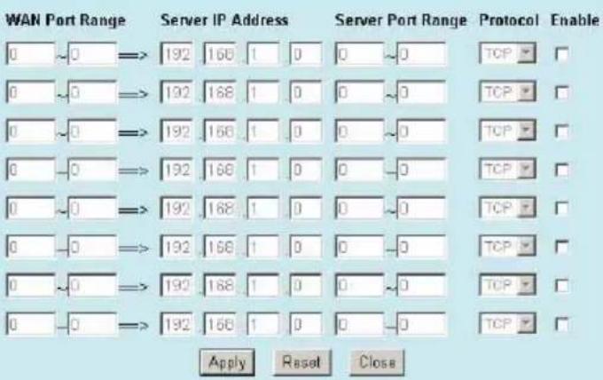 The Virtual server which using single port number can be accelerated by hardware at wirespeed.Define virtual server ip address and port range, Protocol and check the box to enable virtual server, The Virtual server which using single port number can be accelerated by hardware at wirespeed The Virtual server which using single port number can be accelerated by hardware at wirespeed.Define virtual server ip address and port range, Protocol and check the box to enable virtual server, The Virtual server which using single port number can be accelerated by hardware at wirespeed |
| Special Application | 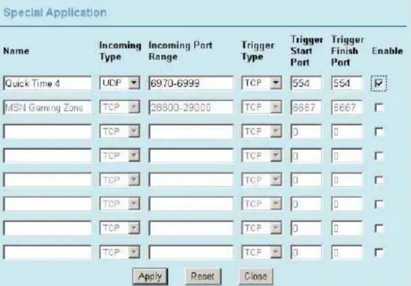 You can define special application that can allow outside users to access your internal application behind this AP, like QuickTime ,MSN gaming zone... You can define special application that can allow outside users to access your internal application behind this AP, like QuickTime ,MSN gaming zone... |
| DMZ | DMZ Configuration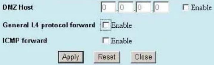 Note: DMZ settings will not be worked until WAN have connected.DMZ settings will not be worked until WAN have connected Note: DMZ settings will not be worked until WAN have connected.DMZ settings will not be worked until WAN have connected |
DMZ Configuration

WISP + Universal Repeater Mode Setting

| Alias Name | You can set the alias name for this device (not exceeding 32 characters). |
| □ Disable Wireless LAN Interface | Check the box to disable the Wireless LAN Interface, by so doing, you won't be able to make wireless connection with this Access Point in the network you are located. In other words, this device will not be visible by any wireless station. |
| Band | You can choose one mode of the following you need.11b/g mixed: Select to allow both wireless-b and wireless-g devices on the network.11B only: Select to allow only wireless-B devices on the network.11G only: Select to allow only wireless-G devices on the network.11A (indoor): Select to allow only wireless-A devices on the indoor network.11A (outdoor): Select to allow only wireless-G devices on the network.11A (indoor): Select to allow only wireless-A devices on the outdoor network. |
| AP SSID | The SSID differentiates one WLAN from another; therefore, all access points and all devices attempting to connect to a specific WLAN must use the same SSID. It is case-sensitive and must not exceed 32 characters. A device will not be permitted to join the BSS unless it can provide the unique SSID. An SSID is also referred to as a network name because essentially it is a name that identifies a wireless network |
| WISP SSID | The SSID differentiates one WLAN from another; therefore, all access points and all devices attempting to connect to a specific WLAN must use the same SSID. It is case-sensitive and must not exceed 32 characters. A device will not be permitted to join the BSS unless it can provide the unique SSID. An SSID is also referred to as a network name because essentially it is a name that identifies a wireless network |
| Channel Number | The number of channels supported depends on the region of this Access Point. All stations communicating with the Access Point must use the same channel. |
| SSID of extended Interface | When in Universal Repeater mode, you have to enter the ESSID of other's AP/Router that device want to connect.The device SSID and the SSID of extended interface can be the same or different. When you are using the universal repeater mode, please make sure the remote AP/Router WDS function is turned off. |
| Site Survey | Wireless Site Survey  Click site survey setup button that will shows the WISP Outdoor AP list and you can select which WISP AP you want to connect. Click site survey setup button that will shows the WISP Outdoor AP list and you can select which WISP AP you want to connect. | |
| Security | Please refer the AP mode settings→ Security for details,This setting used Wireless client or remote AP to link this device. | |
| Advance Setting | Please refer the AP mode settings→ Advance Setting for details. | |
| Access Control | Please refer the AP mode setting → Access Control for details. | |
| WAN Port | WAN ModeStatic IPDHCPPPPoEPPTPL2TP You can choose the different WAN mode , like Static IP,DHCP,PPPOE,PPTP or L2TP method. You can choose the different WAN mode , like Static IP,DHCP,PPPOE,PPTP or L2TP method. | |
| Virtual Server | Virtual Server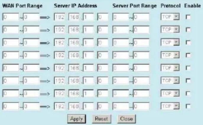 The Virtual server which using single port number can be accelerated by hardware at wirespeed. The Virtual server which using single port number can be accelerated by hardware at wirespeed. | Define virtual server ip address and port range,Protocol and check the box to enable virtual server, The Virtual server which using single port number can be accelerated by hardware at wire-speed. |
WAN Mode
Static IP
DHCP
PPPoE
C PPTP
C L2TP
- The Virtual server which using single port number can be accelerated by hardware at wirespeed.
Virtual Server
| Special Application | Special Application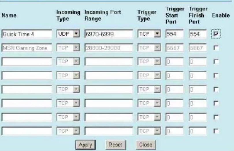 You can define special application that can allow outside users to access your internal application behind this AP, like QuickTime ,MSN gaming zone... You can define special application that can allow outside users to access your internal application behind this AP, like QuickTime ,MSN gaming zone... |
| DMZ | DMZ Configuration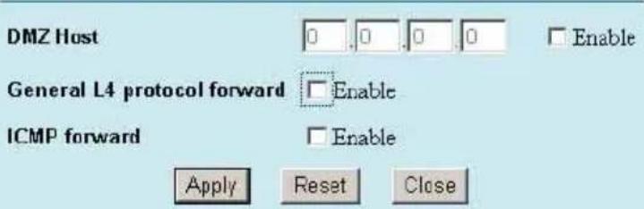 Note: DMZ settings will not be worked until WAN have connected.DMZ settings will not be worked until WAN have connected Note: DMZ settings will not be worked until WAN have connected.DMZ settings will not be worked until WAN have connected |
| Remote Mangement | Remote Management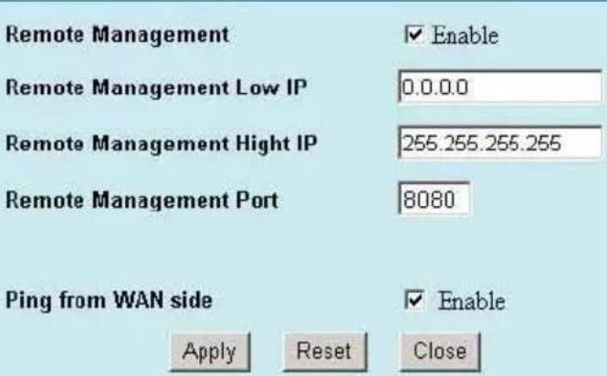 You can enable the Remote management function and define the portnumber let can be managed from internet You can enable the Remote management function and define the portnumber let can be managed from internet |
Special Application
DMZ Configuration
Remote Management
Basic
In this page, you can change the TCP/IP settings of this Access Point, select to enable/disable the DHCP Client, 802.1d Spanning Tree, and Clone MAC Address.

| IP Address | This field can be modified only when DHCP Client is disabled. If your system manager assigned you static IP settings, then you will have to enter the information provided. |
| Subnet Mask | Enter the information provided by your system manager. |
| Default Gateway | Enter the information provided by your system manager. |
| DNS | Enter the Domain Name Service IP address. |
| DHCP | Select Disable, Client or Server from the pull-down menu.Disable: Select to disable DHCP server function.Client: Select to automatically get the LAN port IP address from ISP (For ADSL/Cable Modem).Server: Select to enable DHCP server function. |
| DHCP Client Range | 253 IP addresses continuing from 192.168.1.1 to 192.168.1.253 |
| Show Client | Click to show Active DHCP Client table. |
| Clone MAC Address | You can specify the MAC address of your Access Point to replace the factory setting. |
| Apply Changes | Press to save the new settings on the screen. |
| Reset | Press to discard the data you have entered since last time you press Apply Change. |
Other
Upgrade Firmware

- Download the latest firmware from your distributor and save the file on the hard drive.
- Start the browser, open the configuration page, click on Other, and click Upgrade Firmware to enter the Upgrade Firmware window. Enter the new firmware's path and file name (i.e. C:\FIRMWARE\firmware.bin). Or, click the Browse button, find and open the firmware file (the browser will display to correct file path).
- Click Update to start the upgrade.
Backup/Restore Settings

This function enables users to save the current configurations as a file (i.e. config.bin) To load configuration from a file, enter the file name or click Browse... to find the file from your computer.anc click update button .
Factory Default: Click to restore the default configuration.
System Restart Click to restart the device.
Region Settings

You can select your country region : Europe, America, South America
Note !! Select the Country Region will affect the each Channel number of each Wireless mode.
Password
For secure reason, it is recommended that you set the account to access the web server of this Access Point. Leaving the user name and password blank will disable the protection. The login screen prompts immediately once you finish setting the account and password. Remember your user name and password for you will be asked to enter them every time you access the web server of this Access Point.

| User Name | Set your new User name. User name can be up to 15 characters long. User name can contain letter, number and space. It is case sensitive. |
| Password | Set your new password. Password can be up to 15 characters long. Password can contain letter, number and space. It is case sensitive. |
| Confirm Password | Re-enter the new password for confirmation. |
| Apply | Press to save the new settings on the screen. |
System Log
This page displays log events with time when events happened, log events' types, log sources and the description for events themselves. System manager can use the system log to trace when problems occur.
Check to enable the system log function and then click Apply to save your configuration.


- 802.11a/b/g Multi-function Wireless Access Point
- Declaration of Conformity
- Clause Description
- FCC Certifications
- CAUTION:
- FCC RF Radiation Exposure Statement
- CE Mark Warning
- Table of Contents
- INTRODUCTION....1
- HARDWARE CONNECTION....5
- ABOUT THE WIRELESS OPERATION MODES......6
- CONFIGURATION....12
- INTRODUCTION
- Features
- Application
- Parts Names and Functions
- Front Panel: (LED Indicators)
- Rear Panel: Connection Ports
- HARDWARE CONNECTION
- AP Mode
- Client Mode (Infrastructure)
- Client Mode (Ad-hoc)
- Bridge Mode
- WDS Repeater Mode
- Universal Repeater Mode
- WISP (Client Router) Mode
- WISP + Universal Repeater Mode
- Login
- Status
- System
- WLAN Access Point
- Statistics
- Active Client
- Wireless Mode
- AP modes
- Client Mode Settings
- Advanced Settings (AP/ Client/WISP Mode)
- Wireless Advanced Configuration
- Security (AP/Client/WISP Mode)
- Wireless Security Configuration
- Authentication Type: Open System or Shared Key/Shared Key/Open System
- Authentication Type: WPA-PSK/WPA2-PSK
- Bridge Mode Setting
- Advanced Settings (Bridge/Repeater Mode)
- Security (Bridge/Repeater Mode)
- Authentication Type: Open System with 802.1x/WPA-RADIUS/WPA2-RADIUS
- Repeater Mode Settings
- Access Control (Repeater mode)
- WISP mode Settings
- WISP + Universal Repeater Mode Setting
- Basic
- Other
- Upgrade Firmware
- Backup/Restore Settings
- Region Settings
- Password
- System Log
Brand : AIRLIVE
Model : WLA-5200AP
Category : Access Point