
WHA-5500CPE - Access Point AIRLIVE - Free user manual and instructions
Find the device manual for free WHA-5500CPE AIRLIVE in PDF.


| Product Type | Outdoor Wireless Access Point / CPE |
| Model | WHA-5500CPE |
| Brand | AirLive |
| Dimensions (Approx.) | 260 x 120 x 80 mm |
| Weight (Approx.) | 600 g |
| Power Supply | PoE (802.3af) or 24V Passive PoE |
| Wireless Standards | IEEE 802.11a/n (5 GHz) |
| Maximum Data Rate | 300 Mbps |
| Antenna | Integrated Directional (17 dBi) |
| Operating Modes | Access Point, Client Bridge, WDS, Repeater |
| Security | WEP, WPA, WPA2, MAC Filtering, SSID Broadcast Disable |
| Management | Web interface, Telnet, SNMP |
| Weatherproof Rating | IP65 (Outdoor Rated) |
| Cleaning Instructions | Wipe with a dry, soft cloth. Do not use liquids or sprays. |
| Safety Certifications | FCC, CE, RoHS |
| Power over Ethernet | Yes, supports both 802.3af and passive 24V |
| Mounting | Pole mount kit included, also wall mountable |
| Operating Temperature | -20°C to 65°C |
| Firmware Upgrade | Via web interface, supports TFTP |
| Warranty | 2 years limited warranty (check local terms) |
Frequently Asked Questions - WHA-5500CPE AIRLIVE
User questions about WHA-5500CPE AIRLIVE
0 question about this device. Answer the ones you know or ask your own.
Ask a new question about this device
Download the instructions for your Access Point in PDF format for free! Find your manual WHA-5500CPE - AIRLIVE and take your electronic device back in hand. On this page are published all the documents necessary for the use of your device. WHA-5500CPE by AIRLIVE.
USER MANUAL WHA-5500CPE AIRLIVE
802.11a Multi-Function Outdoor CPE
Version 2.0
User's Manual
Air Live®
Powered by OvisLink Corp.
Copyright & Disclaimer
No part of this publication may be reproduced in any form or by any means, whether electronic, mechanical, photocopying, or recording without the written consent of OvisLink Corp.
OvisLink Corp. has made the best effort to ensure the accuracy of the information in this user's guide. However, we are not liable for the inaccuracies or errors in this guide. Please use with caution. All information is subject to change without notice
All Trademarks are properties of their respective holders.
Table of Contents
1. Introduction....1
1.1 Overview....1
1.2 How to Use This Guide....1
1.3 Firmware Upgrade and Tech Support....3
1.4 Features....4
1.5 Wireless Operation Modes....5
1.5.1 Access Point Mode....5
1.5.2 Repeater Mode 5
1.5.3 WDS Bridge Mode 6
1.5.4 Bridge Infrastructure Mode....6
1.5.5 Client Infrastructure Mode....7
1.5.6 Client Ad Hoc Mode 8
1.5.7 WISP Router Mode 8
1.5.8 AP Router Mode....9
2. Installing the WHA-5500CPE....10
2.1 Before You Start....10
2.2 Package Content ...... 11
2.3 Hardware Installation....11
2.3.1 Mounting Configuration 14
2.3.2 Antenna polarization 15
3. Configuring the WHA-5500CPE 16
3.1 Important Information....16
3.2 Prepare your PC 17
3.3 Management Interface....17
Web Management (HTTP):......17
Secured Web Management (HTTPS):......18
Command Line Interface (Telnet):....19
3.4 Introduction to Web Management....19
3.4.1 Getting into Web Management 20
3.4.2 Welcome Screen and Login 22
3.5 Initial Configurations ......24
3.5.1 Choose the wireless Operation Modes....24
3.5.2 Change the Device's IP Address 25
3.5.3 Change the Country Code....26
3.5.4 Set the Time and Date....27
3.5.5 Change System Management....27
3.5.6 Change Password....28
4. Web Management: Wireless and WAN Settings ......29
4.1 About WHA-5500CPE's Menu Structure....29
4.2 Operation Modes (Wireless and WAN Settings)....30
4.2.1 Regulatory Domain....31
4.2.2 Network SSID....31
4.2.3 Site Survey 32
4.2.4 Signal Survey 33
4.2.5 Lock-to-AP 33
4.2.6 Radio Mode (11a, SuperA, TurboA)....33
4.2.7 SuperA Option 34
4.2.8 Channel 34
4.2.9 Channel Width 36
4.2.10 Security Settings 36
4.2.11 Distance....40
4.2.12 Transmit Power 40
4.2.13 Advance Settings (Wireless) 41
4.2.14 Access Control (ACL)....43
4.2.15 Multiple SSID 44
4.2.16 WMM QoS....48
4.2.17 RADIUS Settings....51
4.2.18 Bandwidth Control....52
4.3 WDS Settings ....57
4.4 Router Mode Settings ....59
4.4.1 WISP Router Mode....59
4.4.2 AP Router Mode....59
4.4.3 WAN Port Settings....60
4.4.4 Dynamic DNS Settings....61
4.4.5 Remote Management Settings 61
4.4.6 IP Routing Settings 62
4.4.7 DHCP Server....63
4.4.8 Multiple DMZ....64
4.4.9 Virtual Server Settings....64
4.4.10 Special Applications....65
4.4.11 IP Filtering Settings....66
5. Web Management 2: System Configuration, Tools and Status......67
5.1 System Configuration....67
5.1.1 Device IP Settings....67
5.1.2 Time Settings 69
5.1.3 Password Settings 69
5.1.4 System Management....70
5.1.5 Ping Watchdog 71
5.1.6 Firmware Upgrade 72
5.1.7 Configuration Save and Restore 72
5.1.8 Factory Default 73
5.2 Tools....74
5.2.1 Network Ping 74
5.2.2 Network Traceroute 74
5.3 Device Status....76
5.3.1 Device Information....76
5.3.2 Wireless Information....77
5.3.3 Internet Information....77
5.3.4 Wireless Client Table 78
5.3.5 System Log 78
6. Command Line Interface ....79
6.1 System Commands....79
6.2 Debugging Commands....81
6.3 Show Commands....82
6.4 Set Commands....87
6.5 Enable/Disable Commands 94
6.6 Add/Delete Commands....95
7. Application Example: Infrastructure 99
7.1 Application Environment 99
7.2 Device A: Access Point Mode 100
7.2.1 Device A Wireless Settings 101
7.2.2 Device A Bandwidth Management 103
7.3 Device B: Bridge Infrastructure Mode....105
7.3.1 Device B Wireless Settings....105
7.3.2 Device B Total Bandwidth Control....107
7.4 Device C: Client Infrastructure Mode....108
7.4.1 Device C IP Address 108
7.4.2 Device C Wireless Settings....109
8. Application Example 2: Bridge Network....111
8.1 Preparation for Building Outdoor Bridge Networks 111
8.2 WDS Bridge vs. Bridge Infrastructure 113
8.3 WDS Bridge Network Example....115
9. Application Example 3: Router and Repeater ....121
9.1 Application Environment ....121
9.2 WHA-5500CPE in WISP Router Mode 122
9.2.1 WISP Router: Wireless Settings....122
9.2.2 WISP Router: WAN Port and Virtual Server 124
9.3 WHA-5500CPE in Repeater Mode 127
9.3.1 Repeater Router: Wireless Settings....127
10. Emergency Firmware Recovery ....130
10.1 How Emergency Upgrade Works....130
10.2 Emergency Upgrade Procedure ....130
11. Frequent Asked Questions ....133
12. Specifications....136
12.1 Hardware Features....136
12.1.1 General Hardware Feature 136
12.1.2 Antenna 136
12.1.3 Power Supply 136
12.1.4 Dimension and Weight....136
12.2 Radio Specifications ....137
12.2.1 Frequency Band 137
12.2.2 Rate and Modulation.... 137
12.2.3 TX Output Power....137
12.2.4 Receiver Sensitivity 137
12.2.5 Supported WLAN Mode.... 137
12.3 Software Feature ....138
12.3.1 Operation Mode .... 138
12.3.2 Management Interface 138
12.3.3 Channel Width (Rate Mode) 138
12.3.4 Advance Functions.... 138
13. Wireless Network Glossary....140
1
Introduction
1.1 Overview
The WHA-5500CPE is a wireless outdoor multi-function device based on IEEE 802.11a 5-GHz radio technologies. When installed in upright position, it is rain and splash proof. It features an integrated 18dBi patch antenna and 802.3af to simplify the installation. The firmware of the AP provides up to 8 operations modes* to satisfy different application environments. This guide is for firmware version V2.00e01a or newer. If you have older firmware, please go to www.airlive.com to download the latest version.
1.2 How to Use This Guide
WHA-5500CPE is an advanced wireless CPE with many functions. It is recommended that you read through the entire user's guide whenever possible. The user guide is divided into different chapters. You should read at least go through the first 3 chapters before attempting to install the device.
Recommended Reading
□ Chapter 1
■ 1.5 Operation Modes: This section explains the usage of each wireless operation mode. It is a must read.
☐ Chapter 2: This chapter is about hardware installation. You should read through the entire chapter.
Chapter 3:
■ 3.1 Important Information: This section has default settings information such as IP, password, SSID, and recommended browser
■ 3.3 Management Interface: This section introduces Web, HTTPS, and Telnet.
■ 3.4 Introduction to Web Management: This section tells you how to get into the Web UI using HTTP and HTTPS. In addition, it also explains about the basic menu structure.
■ 3.5 Initial Configurations: This section guide you through the essential initial configurations such as choosing operation mode, set device IP, password, and change frequency domain.
☐ Chapter 4 Web Management – Wireless and WAN Settings: This chapter explain the wireless functions and router mode settings in the WHA-5500CPE. If time permitted, you should read through the entire chapter.
■ 4.2 Operation Mode (wireless): Operation mode is the page where all the wireless settings and router mode settings are. Therefore, it is advised that you must read through the entire section.
- 4.2.3 Site Survey: Site Survey is the connection wizard that will search for available networks and let you connect with the select network by simply clicking. It also includes RSSI signal survey for antenna alignment.
- 4.2.8 and 4.2.9 Channel and Channel Width: This part explains the concept of variable Channel Width and how to use them. Channel Width can be 40MHz, 20MHz, 10MHz, or 5MHz.
- 4.2.13 Bandwidth Management: Be sure to read about WHA-5500CPE's powerful Bandwidth Control that allow you to limit up/downlink speed by interface, IP, MAC address, or IP segment. This section provides step-by-step examples also.
■ 4.3 WDS Settings: Here explains the WDS setting page. After reading this section, please go to Chapter 8: Bridge Network example to see step-by-step instructions on setting up a multi-point WDS Bridge network.
■ 4.4 Router Modes: This section includes WAN port, virtual server, remote management, virtual servers and all router related settings.
☐ Chapter 5: Web Management 2: Configurations, Tools and Status
This chapter explains all the non-wireless settings and status such as IP settings, Ping Watchdog.
■ 5.1.5 PING Watchdog: PING watchdog is a crucial function to keep your wireless connection alive. When WHA-5500CPE can't get a response from remote devices, it will attempt to re-establish the connection. WHA-5500CPE's PING watchdog goes the extra step to allow 2 sets of IP to avoid false alarm.
■ 5.1.7 Configuration Save and Restore: You should always backup your configurations so you can restore in the event of system crash.
☐ Chapter 6: Command Line Interface
This chapter explains all the commands in the Telnet interface. Be sure to “save config” after making all changes. In case you forget a command, just type “help” to display all available commands and their usage.
☐ Chapter 7: Application Example: Infrastructure
In this chapter, you will learn how to use AP mode, Client Infrastructure Mode, and Bridge Infrastructure mode in one application example. In addition, you will also learn how to make multiple SSID and bandwidth control.
☐ Chapter 8: Application Example 2: WDS Bridge
This chapter tells you the basic knowledge about building a long distance connection. Then it will describe the differences between WDS bridge and Bridge Infrastructure mode, and how to make a choice between them. At last, a step-by-step instruction on how to build a multipoint WDS network is provided.
☐ Chapter 9: Application Example 3: Repeater and WISP Router
A step-by-step application example on Repeater and WISP router
☐ Chapter 10: Emergency Firmware Recovery
It your WHA-5500CPE can no longer be access due to firmware crash. You might be able to recover it following the procedure on this chapter.
☐ Chapter 11: Frequent Asked Questions
If you have a question about WHA-5500CPE that is not found on other part of this guide, you might find your answer here. Including how to make connection with Mikrotik AP, how to save password settings on the browser...etc.
☐ Chapter 13: Wireless Network Glossary
Explanations on wireless network technical terms from A to Z. Highly recommended for referencing when you encounter an unfamiliar term.
1.3 Firmware Upgrade and Tech Support
If you encounter a technical issue that can not be resolved by information on this guide, we recommend that you visit our comprehensive website support at www.airlive.com. The tech support FAQ are frequently updated with latest information.
In addition, you might find new firmwares that either increase software functions or provide bug fixes for WHA-5500CPE. You can reach our on-line support center at the following link:
http://www.airlive.com/support/support_2.jsp
Since 2009, AirLive has added the “Newsletter Instant Support System” on our website. AirLive Newsletter subscribers receive instant email notifications when there are new download or tech support FAQ updates for their subscribed airlive models. To become an AirLive newsletter member, please visit: http://www.airlive.com/member/member_3.jsp

Figure 1.4: AirLive Newsletter Support System
1.4 Features
■ Atheros AR-2313 + AR-5112 108mbps 802.11a chipset
■ 4MB Flash and 32MB SDRAM
■ 8 wireless multi-function modes: Access Point, Repeater, WDS Bridge, Bridge Infrastructure, Client Infrastructure, Client Ad Hoc, WISP Router, AP Router.
■ 18dBi Integrated Antenna: Vertical Polarization, Horizontal Polarization, External Antenna options switchable by software. 15 degree Horizontal and Vertical coverage in the forward direction.
■ Built from High Temperature resistant ABS material with Anti-UV protection
■ Power by 48V 802.3af PoE system
■ Support Super Channels
■ Support 5/10/20/40MHz Channel Width
■ Slide out housing design for easy maintenance.
■ Metal Wall Mount and Pole Mount included
■ Total Bandwidth and Per-User Bandwidth Control
■ Limit Bandwidth of HTTP, FTP, Torrent, and eDonkey traffic in router mode
■ Site Survey, RSSI signal Survey, and RSSI LED indicator.
■ Multi-SSID, TAG VLAN, WMM, TOS
■ ACK Timeout Adjustment for long distance connection.
■ Emergency firmware recovery mode
■ Web, HTTPS, and Telnet
1.5 Wireless Operation Modes
The WHA-5500CPE can perform as a multi-function wireless device. Through the AirLogic web interface, users can easily select which wireless mode they wish the WHA-5500CPE to perform.
The WHA-5500CPE can be configured to operate in the following wireless operation modes:
1.5.1 Access Point Mode
When operating in the Access Point mode, the WHA-5500CPE becomes the center hub of the wireless network. All wireless cards and clients connect and communicate through WHA-5500CPE. This type of network is known as "Infrastructure network". Other WHA-5500CPE or 802.11a CPE can connect to AP mode through "Client Infrastructure Mode" or "Bridge Infrastructure Mode". The Access Point mode will act as "WDS AP" when connecting with the "Bridge Infrastructure mode". Please see Chapter 8 for step-by-step application example of this operation mode.

flowchart
graph LR
    A["Laptop"] --> B["AP Mode"]
    B --> C["WHA-5500CPE"]
    C --> D["Client Infrastructure"]
    D --> E["PC"]
    D --> F["PC"]
    D --> G["LAN"]
    G --> H["Bridge Infrastructure"]
1.5.2 Repeater Mode
In Repeater mode, the WHA-5500CPE functions as a repeater that extends the range of remote wireless LAN. The WHA-5500CPE's repeater mode is a universal repeater, not WDS repeater. Because the radio is divided into client + AP mode, the Repeater mode will have less performance and distance. We recommended using a dual radio product like Airlive WLA-9000AP or WH-9200AP if you require full performance in this application. Please see Chapter 10 for step-by-step application example of this operation mode.

1.5.3 WDS Bridge Mode
This mode is also known as “WDS Pure MAC mode”. When configured to operate in the Wireless Distribution System (WDS) Mode, the WHA-5500CPE provides bridging functions with remote LAN networks in the WDS system. The system will support up to total of 8 bridges in a WDS network (by daisy chain). However, each bridge can only associate with maximum of 4 other bridges in the WDS configuration. This mode is best used when you want to connect LAN networks together wirelessly (for example, between office and warehouse). If you have more than 2 AP in WDS Bridges mode, please remember to turn on the “802.1d Spanning Tree” or “STP” option on to avoid network loop. This mode usually delivers faster performance than infrastructure mode. Please see Chapter 9 for step-by-step application example of this operation mode.

flowchart
graph TD
    A["Office LAN"] -->|802.1d STP| B["WDS Bridge"]
    B -->|802.1d STP| C["Factory LAN"]
    C -->|802.1d STP| D["Warehouse LAN"]
    D -->|802.1d STP| E["WDS Bridge"]
    E -->|802.1d STP| F["Office LAN"]
    style A fill:#f9f,stroke:#333
    style B fill:#ccf,stroke:#333
    style C fill:#cfc,stroke:#333
    style D fill:#fcc,stroke:#333
    style E fill:#cff,stroke:#333
1.5.4 Bridge Infrastructure Mode
This mode is also known as "WDS Station" or "Client mode with MAC address
transparency". The Bridge Infrastructure mode can only connect with "Access Point" mode. 2 Bridge Infrastructure can not connect with each other. It works like client mode with MAC address transparency function. In another word, the MAC addresses of the PCs will be passed instead of the AP's wireless MAC address. If you require Bridge connection with WPA-PSK or WPA-PSK2 connection, please use this mode instead. However, this mode might not work with some outdoor APs. If it occurs, please use Client Infrastructure or WDS Bridge instead. Please see Chapter 8 for step-by-step application example of this operation mode.
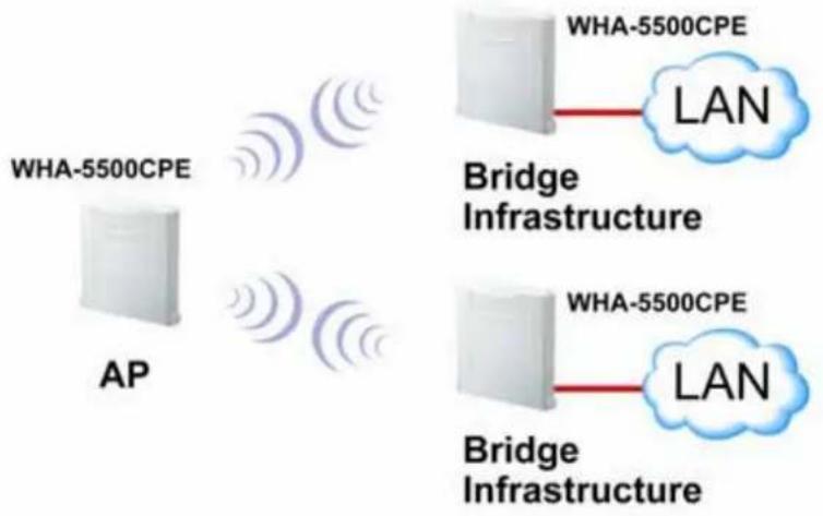
flowchart
graph LR
    A["AP"] -->|WHA-5500CPE| B["Bridge Infrastructure"]
    B -->|LAN| C["WHA-5500CPE"]
    B -->|LAN| D["Bridge Infrastructure"]
1.5.5 Client Infrastructure Mode
This mode is also known as "Client" mode. In Client Infrastructure mode, the WHA-5500CPE acts as if it is a wireless adapter to connect with a remote Access Point. Users can attach a computer or a router to the LAN port of WHA-5500CPE to get network access. This mode is often used by WISP on the subscriber's side. Please see Chapter 8 for step-by-step application example of this operation mode.

flowchart
graph LR
    A["Client Infrastructure (Multi User)"] --> B["AP Mode"]
    C["Client Infrastructure (Single User)"] --> D["AP Mode"]
    B --> E["WH-9200AP"]
    D --> E
    E --> F["PC"]
    style A fill:#f9f,stroke:#333
    style C fill:#f9f,stroke:#333
    style B fill:#ccf,stroke:#333
    style D fill:#ccf,stroke:#333
    style E fill:#cff,stroke:#333
    style F fill:#cff,stroke:#333
For WHA-5500CPE, there are 2 types of Client Infrastructure Mode: "Single User" and "Multiple-User". When "Single User" is chosen, only one PC that is connected behind the AirMax can get IP address from remote DHCP server. When "multiple user" is chosen,
more than one PC can get IP address from remote DHCP server. However, in Client Infrastructure mode, the WHA-5500CPE always sends the WHA-5500CPE's wireless MAC address to the remote AP. If you want the WHA-5500CPE to send the PC's MAC addresses to remote AP, then you should use the "Bridge Infrastructure" mode. Bridge Infrastructure provides the "Mac Address Transparency" functionality.

flowchart
graph LR
    subgraph Multiple User Client Mode
        A["Outdoor AP"] -->|Signal| B["DHCP Server"]
        C["Client Mode"] -->|Signal| D["DHCP Server"]
        E["PC"] --> F["PC"]
    end
    subgraph Single User Client Mode
        G["Outdoor AP"] -->|Signal| H["DHCP Server"]
        I["Client Mode"] -->|Signal| J["DHCP Server"]
        K["PC"] --> L["PC"]
    end
1.5.6 Client Ad Hoc Mode
In Client Ad Hoc mode, WHA-5500CPE can connect to other wireless adapters without access point. Users can attach a computer or a router to the LAN port of WHA-5500CPE to get network access.
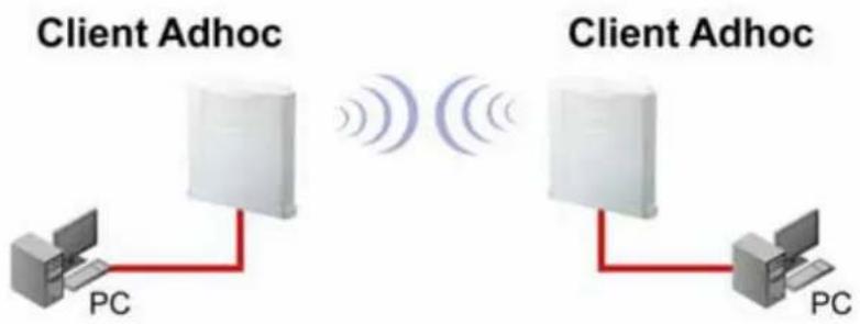
1.5.7 WISP Router Mode
In WISP Router Mode, WHA-5500CPE connects to the remote Access Point as in Client Infrastructure Mode. On the LAN side, it acts like a wired router for IP sharing function. This mode is best used for IP sharing application for WISP subscribers. In this mode, the WAN is the wireless client side, the LAN is the wired side. Please see Chapter 10 for step-by-step application example of this operation mode.

In AP Router Mode, the WHA-5500CPE behaves like a wireless router. The LAN port of the WHA-5500CPE will become WAN port. The wireless network of WHA-5500CPE becomes the LAN side. Please note when this mode is used, the only way to manage the WHA-5500CPE is through the wireless side unless remote management is opened.

flowchart
graph TD
    A["Client AP"] --> B["AP Router"]
    B --> C["Internet"]
    D["Laptop"] --> B
    E["Computer"] --> B
    B --> F["Wireless Signal"]
2
Installing the WHA-5500CPE
This section describes the hardware features and the hardware installation procedure for the WHA-5500CPE. For software configuration, please go to chapter 3 for more details.
2.1 Before You Start
It is important to read through this section before you install the WHA-5500CPE
■ The WHA-5500CPE comes with everything you need to start installation with exception of the PoE Ethernet Cable. You can use a good quality CAT-5E outdoor graded Ethernet cable (shielded with anti-UV) according to the length you need.
■ The WHA-5500CPE must be installed in the upright position if the unit is located in outdoor or wet environments.

■ The use of 5GHz spectrum, Turbo modes, and 5/10MHz channel bandwidth might be prohibited in some countries. Please consult with your country's telecom regulation first.
■ You must set the distance parameter to make long distance connection work. Please refer to chapter 4 of this user's guide for details.
■ The integrated antenna has forward coverage angle of 30 degree both in vertical and horizontal direction.
■ The WHA-5500CPE is a 5GHz CPE device only, it can not operate in 2.4GHz.
■ If you choose to use the external antenna, please remember to connect the external antenna first before power on WHA-5500CPE.
2.2 Package Content
The WHA-5500CPE package contains the following items:
■ One WHA-5500CPE main unit
■ One 48V 0.4A DC power adapter with a splitter
■ Wall Mounting kit
■ One CD of the WHA-5500CPE Quick Star Guide

natural_image
White rectangular electronic device with ventilation slots and ventilation duct (no visible text or symbols)WHA-5500CPE

natural_image
Collection of metal bracket components including mounting flanges, bolts, and screw fasteners (no text or symbols visible)Mounting Kits

natural_image
Two electronic devices: a black-and-white network adapter with cables and a white connector with two ports (no visible text or symbols)PoE Kits
Regarding to the specification of each application, the PoE Ethernet cable is not included in the package.
You may choose outdoor specification Ethernet cable according to the length you need.
2.3 Hardware Installation
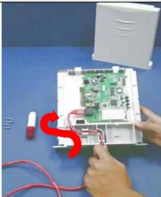
Please take the device unit from the color box, a scroll driver, an Ethernet cable with adequate length according to your application.
- A scroll driver and Ethernet Cable, four screws and WHA-5500CPE main unit
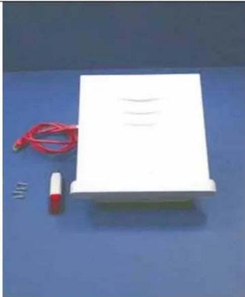
natural_image
White electronic device with red cable and a small red component on blue background (no text or symbols visible)- Open the housing of WHA-5500CPE.

natural_image
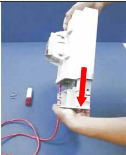
Close-up of hands assembling a white electronic device with green PCB pattern and red arrow indicating downward motion (no text or symbols)| 3. Turn the WHA-5500CPE to another side, the RJ-45 jack is at the middle of LEFT side of main board. | 4. Plug one side of RJ-45 cable into the Ethernet port. |
 | 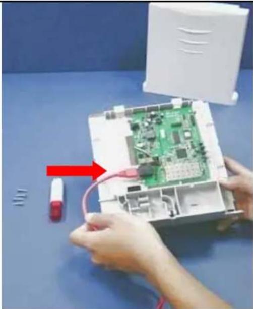 |
- Put the Ethernet cable along the module, till the exit (at the bottom of Housing).
natural_image
Close-up of hands assembling a green circuit board on a blue table, with red arrows indicating a process (no text or symbols visible)- Make sure that the other side of Ethernet cable is out of housing. Close the housing.
natural_image
Close-up of hands assembling a white electronic device with red arrow indicating assembly (no text or symbols visible)-
Scroll up 4 screws well. Be careful, this is very important; it could protect your device against the water.
-
Plug the Ethernet to the PoE "P + DATA OUT" jack of injector.

natural_image
Close-up of hands assembling a white mechanical component with wires, no visible text or symbols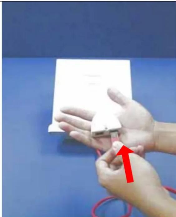
natural_image
Close-up of hands holding a small object with red arrows pointing to the part, against a blue background (no text or symbols)-
Plug the power cord of adaptor into the injector "POWER IN" port.
-
Plug the Data Ethernet cable to the port "DATA IN" of injector.

natural_image
Hand holding a white object with a red arrow pointing downward, next to a black rectangular device and red rope on a blue surface (no text or symbols visible)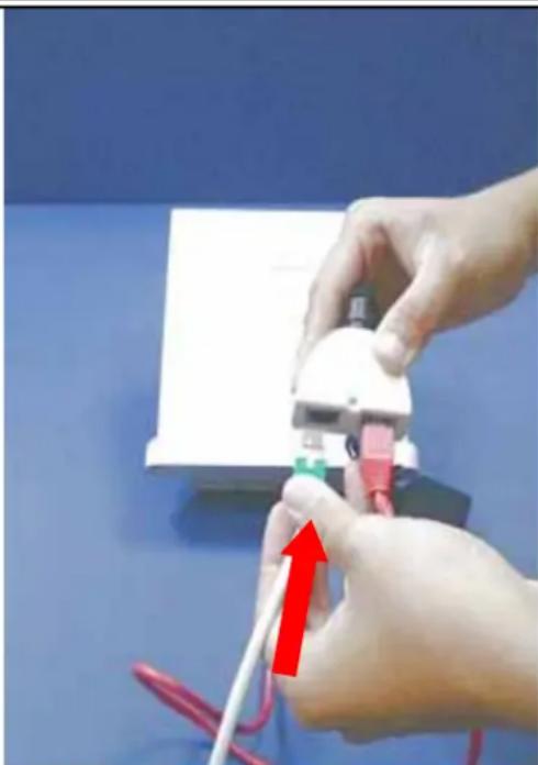
natural_image
Close-up of hands connecting a white electronic device to a red cable with a green connector, against a blue background (no text or symbols visible)2.3.1 Mounting Configuration
Your WHA-5500CPE comes standard with 2 plastic straps for pole mounting. Please follow the procedure below to install:

① Antenna body - 1pc
② M6 washer(φ16mm) - 4 pcs
③ M6 S/W - 6 pcs
④ M6-16 screw - 4 pcs
⑤ M-Shaped mounting - 1 pc
⑥ Lock frame - 1 pc
⑦ M6 washer(φ12mm) - 2 pcs
⑧ M6-60 screw - 2 pcs
⑨ 5"/32-16 screw - 4 pcs
⑩ Plastic anchor - 4 pcs
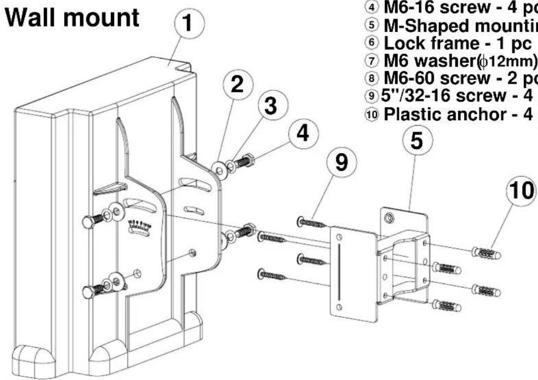
① Antenna body - 1pc
② M6 washer(φ16mm) - 4 pcs
③ M6 S/W - 6 pcs
④ M6-16 screw - 4 pcs
⑤ M-Shaped mounting - 1 pc
⑥ Lock frame - 1 pc
⑦ M6 washer(φ12mm) - 2 pcs
⑧ M6-60 screw - 2 pcs
⑨5"/32-16 screw - 4 pcs
⑩ Plastic anchor - 4 pcs
2.3.2 Antenna polarization
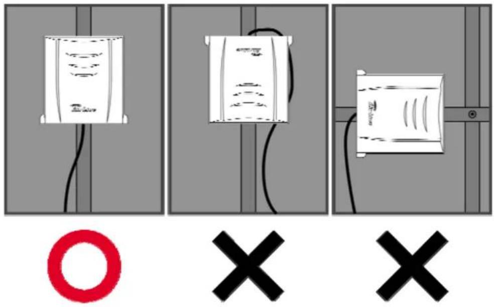
■ Pease install the CPE in the UP RIGHT position only.
■ Do not put the CPE into water.

■ Pease do not tilt the CPE more than 15 degree angle from vertical.
3
Configuring the WHA-5500CPE
The WHA-5500CPE offers many different types of management interface. You can configure through standard web browser (http), secured web (https), command line (telnet). In this chapter, we will explain WHA-5500CPE's available management interfaces and how to get into them. Then, we will provide the introduction on Web Management and recommended initial settings. For detail explanations on Web Management functions, please go to Chapter 4 and 5. For Command-Line interface, please go to Chapter 6.
3.1 Important Information
The following information will help you to get start quickly. However, we recommend you to read through the entire manual before you start. Please note the password and SSID are case sensitive.
☐ The default IP address is: 192.168.1.1 Subnet Mask: 255.255.255.0
☐ The default user's name is: airlive
☐ The default password is: airlive
☐ The default SSID is: airlive
☐ The default wireless mode is : Client mode
☐ After power on, please wait for 2 minutes for WHA-5500CPE to finish boot up
☐ Please remember to click on “Apply” for new settings to take effect
☐ When you set the “Regulatory Domain” to “All Channels”, the WHA-5500CPE will display all the available channels. However, please make sure the frequency you select is legal to use in your country.
☐ Please remember to enter the correct "Distance" parameter in wireless settings. Failure to do so can result in poor performance.
☐ The default country code is : United Kingdom.
If you are living outside of EU, please go to Operation Mode->Setup->Regulatory Domain to change country.
3.2 Prepare your PC
The WHA-5500CPE can be managed remotely by a PC through either the wired or wireless network. The default IP address of the WHA-5500CPE is 192.168.1.1 with a subnet mask of 255.255.255.0. This means the IP address of the PC should be in the range of 192.168.1.2 to 192.168.1.254.
To prepare your PC for management with the WHA-5500CPE, please do the following:
- Connect your PC directly to the LAN port on the DC Injector of WHA-5500CPE
- Set your PC's IP address manually to 192.168.1.100 (or other address in the same subnet)

You are ready now to configure the WHA-5500CPE using your PC.
3.3 Management Interface
The WHA-5500CPE can be configured using one the management interfaces below:
■ Web Management (HTTP): You can manage your WHA-5500CPE by simply typing its IP address in the web browser. Most functions of WHA-5500CPE can be accessed by web management interface. We recommend using this interface for initial configurations. To begin, simply enter WHA-5500CPE's IP address (default is 192.168.1.1) on the web browser. The default username and password are both "airlive".

■ Secured Web Management (HTTPS): HTTPS is also using web browser for configuration. But all the data transactions are securely encrypted using SSL encryption. Therefore, it is a safe and easy way to manage your WHA-5500CPE. We highly recommend WISP and service provider to use HTTPS for management.
To begin, simply enter https://192.168.1.1 on your web browser. A security alert screen from your browser will pop up. Please grant all permission and get certificate to WHA-5500CPE. After you pass the security warning screen, you will enter the secured web management interface. The default username and password are both "airlive".


For more information about Web Management and HTTPS, please make sure to read through “Introduction to Web Management” in this chapter, Chapter 4, and Chapter 5
■ Command Line Interface (Telnet): WHA-5500CPE can be managed through the command line interface (CLI). It is possible to write a text script file, and then paste it into the CLI to execute several commands at once. However, Telnet does not encrypt its message. Therefore, it is not secure. The default Telnet management port is TCP port 23.
To use the CLI, please open the command line window. Then type "telnet 192.168.1.1" to start.
![Command Prompt Microsoft Windows XP [Version 5.1.2600] (C) Copyright 1985-2001 Microsoft Corp. C:\Documents and Settings\Administrator>telnet 192.168.1.1](/content/2026/05/1066385/images/27dd9403bb330d250d75c05a6f5f2849e29dd2a7321c85f0971e6aa378312480.jpg)
When asked for password, please enter "airlive".
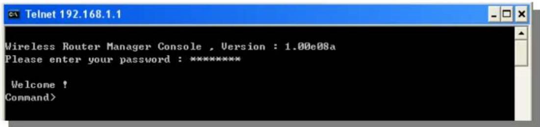
To get a list of available command and their usage, please type "help" on the command prompt.

For more information about Telnet configuration, please go to Chapter 6 Command Line Interface.
3.4 Introduction to Web Management
The WHA-5500CPE offers both normal (http) and secured (https) Web Management interfaces. Their share the same interface and functions, and they can both be accessed through web browsers. The only difference is HTTPS are encrypted for extra security. Therefore, we will discuss them together as “Web Management” on this guide.
If you are placing the WHA-5500CPE behind router or firewall, you might need to open virtual server ports to WHA-5500CPE on your firewall/router
■ HTTP: TCP Port 80
■ HTTPS: TCP/UDP Port 443
This procedure is not necessary in most cases unless there is a router/firewall between your PC and WHA-5500CPE.
3.4.1 Getting into Web Management
Normal Web Management (HTTP)
To get into the Normal Web Management, simply type in the WHA-5500CPE's IP address (default IP is 192.168.1.1) into the web browser's address field.

Secured Web Management (HTTPS)
To get into the Secured Web Management, just type "https://192.168.1.1" into the web browser's address field. The "192.168.1.1" is WHA-5500CPE's default IP address. If the IP address is changed, the address entered in the browser should change also.

A security warning screen from your browser will then pop-up depending on the browser you use. Please follow step below to clear the security screen.
☐ Internet Explorer: Select "Yes" to proceed
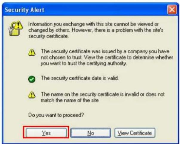
□ Firefox:
- Select "or you can add an exception"

- Click on "Add Exception"
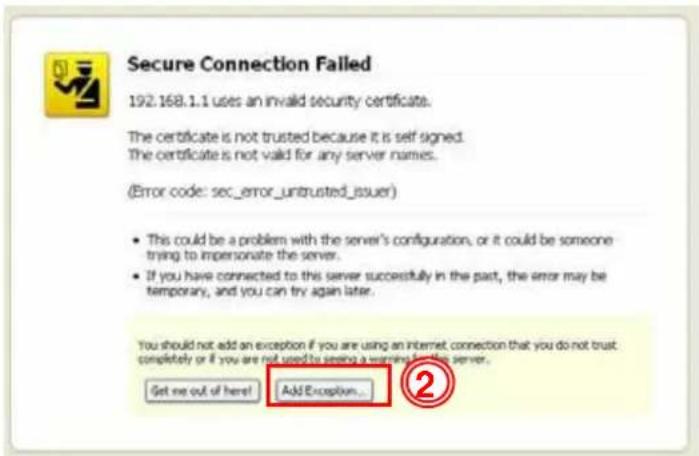
- Click on "Get Certificate". Then, please enter WHA-5500CPE's IP address. Finally, please click on "Confirm Security Exception."

3.4.2 Welcome Screen and Login
After the procedure above, the Welcome Screen will appear. Welcome Screen gives a brief introduction of the WHA-5500CPE's main function category. By click on the function category, it will direct you to the corresponding web management menu.
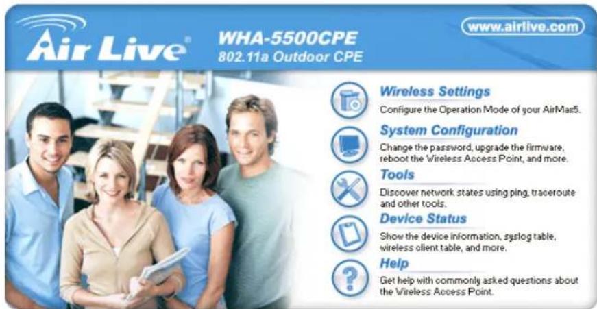
- Wireless Settings: Click on this part will bring you to the wireless operation mode menu. The WHA-5500CPE's wireless settings are different between wireless modes. Only functions that are applicable to the wireless mode will show to simplify configuration. For example, multiple SSID option is only workable for Access Point and AP Router mode. Therefore, the function will only appear in these 2 modes. For this reason, the first step to configure the WHA-5500CPE is to select the wireless mode. The router mode specific functions are also in this menu category. For explanation of different wireless modes, please refer to Chapter 1.
■ System Configuration: All non-wireless and router mode settings are in this category. The system configurations including changing password, upload
firmware, backup configuration, settings PING watchdog, and setting management interface. The default management timeout is 10 minutes; we recommend you should change password and management timeout during the first time login.
■ Tools: Discover network states using ping, traceroute and other tools.
■ Device Status: This section for monitoring the status of WHA-5500CPE. It provides information on device status, Ethernet status, wireless status, wireless client table, and system log.
■ Help: This is the online help system for quick reference. We still recommend you to read this user's guide for more information.
TIPS: You can choose any menu categories to begin; you can switch to other menu later
When you choose one of the menu categories, the WHA-5500CPE will require you to enter the username and password. Please enter "airlive" (all lower cases) for both username and password.

After you enter the correct password, the following screen will appear corresponding to the menu category you selected.

☐ Language Menu: You can select the language from the right side of main menu bar.
3.5 Initial Configurations
We recommend users to browse through WHA-5500CPE's web management interface to get an overall picture of the functions and interface. Below are the recommended initial configurations for first time login:
3.5.1 Choose the wireless Operation Modes
The wireless settings of WHA-5500CPE are dependant on the wireless operation mode you choose. Therefore, the first step is to choose the operation mode. For explanation on when to use what operation mode, please refer to Chapter 1
When you click on the "Wireless Settings" on the welcome screen or the "Operation Mode" on the top menu bar, the following screen will appear.

Follow the example below to change to "Client Infrastructure" mode
- Select "Client Infrastructure" mode.
- Click on "change mode" button
- The AP will reboot, wait for about one minute

3.5.2 Change the Device's IP Address
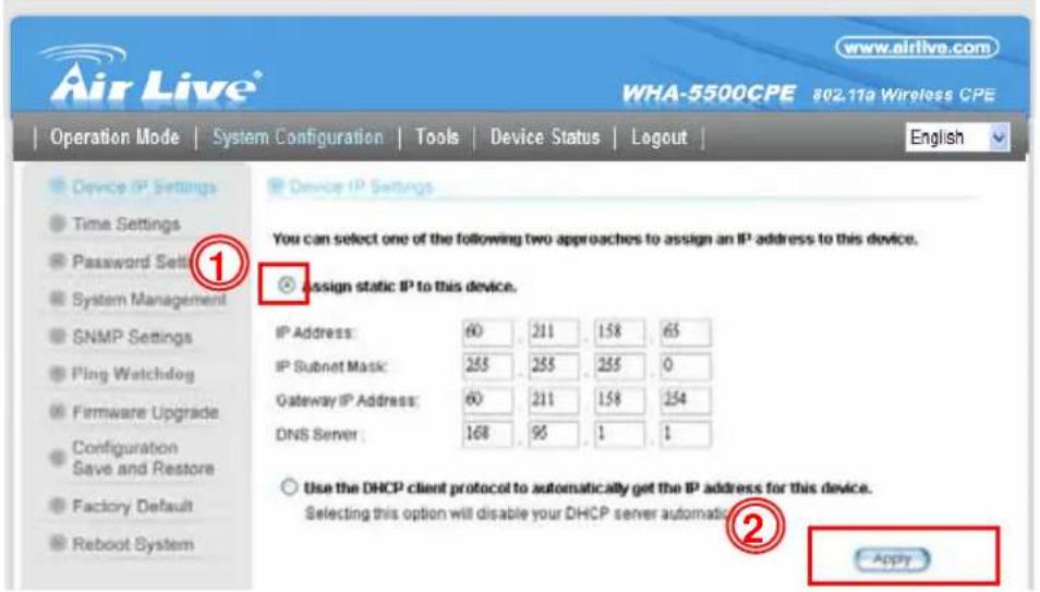
The default IP address is at 192.168.1.1. You should change it to the same subnet as your network. Also, if you want to manage WHA-5500CPE remotely, you have to set the Gateway and DNS server information.
To setup the IP settings for WHA-5500CPE, please select "System Configuration" -> Device IP Settings". After entering the IP information, click on "Apply" to finish.
3.5.3 Change the Country Code
The legal frequency and channels in 5GHz spectrum varies between countries. The default country code is United Kingdom which should require no changes If you are living in Europe. If you are living outside EU, you should change the country code accordingly. In the example below, we will change the country code to United States which enables the use of 5.8GHz spectrum.
Step 1. Select "Operation Mode" -> "Setup"

Step 2. From the Regulatory Domain, please select your country

Step 3. Select the United States from the list.
Step 4. Click on "Apply" to finish.
3.5.4 Set the Time and Date
It is important that you set the date and time for your WHA-5500CPE so that the system log will record the correct date and time information. Please go to "System Configuration" ->Time Settings. We recommend you choose "Enable NTP" so the time will be keep even after reboot. If your WHA-5500CPE is not connected to Internet, please enter the time manually. Please remember to select your local time zone and click "Apply" to finish.

3.5.5 Change System Management
It is recommended that you change the system management settings first. Please go to "System Configuration"-> "System Management". The default web management time out is 10 minutes, you can set to longer period if needed. For WISP administrators, you can consider turning off HTTP and Telnet for security purpose.

3.5.6 Change Password
You should change the password for WHA-5500CPE at the first login. To change password, please go to "System Configuration" -> "Password Settings" menu.

4
Web Management: Wireless and WAN Settings
In this chapter, we will explain about the wireless settings and router mode settings in web management interface. Please be sure to read through Chapter 3's "Introduction to Web Management" and "Initial Configurations" first. For system configurations, device status, and other non-wireless related settings; please go to Chapter 5.
4.1 About WHA-5500CPE's Menu Structure
The WHA-5500CPE's web management menu is divided into 3 main menus: Operation Modes, System Configurations, and Device Status. The main menus are displayed in "Top Menu Bar". Within each main menu category, there are sub-menu options which are displayed on the "Side Menu Bar"

Operation Mode: This menu is where you will find wireless and WAN settings. The WHA-5500CPE's wireless settings are dependant on the wireless operation mode you choose; only the applicable wireless settings for selected operation mode are shown. For example; WAN port setting is available only for AP Router and WISP Router mode, it will only be shown in those modes. To access wireless settings, click on the "Setup" button within each operation mode. For explanation on different wireless modes, please refer to Chapter 1. We will talk about functions in this menu for this chapter.
System Configuration: All settings besides Wireless and WAN functions are in this category. The system configuration including changing password, upload firmware, backup configuration, settings PING watchdog, and setting management interface. We will talk about this menu's function in Chapter 5.
■ Device Status: This section for monitoring the status of WHA-5500CPE. It provides information on device status, Ethernet status, wireless status, wireless client table, and system log.
■ Logout: Please make sure to Logout after you finish all settings.
■ Language Bar: You can change the web interface to some other languages by the pull down menu.
4.2 Operation Modes (Wireless and WAN Settings)
The wireless settings of WHA-5500CPE are dependant on the wireless operation mode you choose. Therefore, the first step is to choose the operation mode. For explanation on when to use what operation mode, please refer to Chapter 1.
When you select "Wireless Settings" in the welcome screen, or click on the "Operation Mode" on the top menu; the following screen will appear:
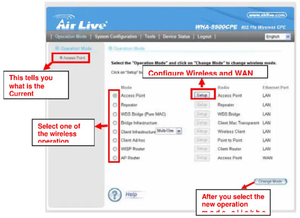
■ Mode: The available wireless operation modes for WHA-5500CPE. Select one and click on "Change Mode" button to switch between modes..
■ Setup: Click here to configure the Wireless and WAN(in router mode) settings.
■ Radio: This explain how the radio function in the particular operation mode
■ Ethernet: This shows whether the radio
Once you click on the "Setup" page, the wireless settings will appear.

4.2.1 Regulatory Domain
Operation Mode -> Setup -> Regulatory Domain
The legal frequency and channels in 5GHz spectrum varies between countries. Please select your country from here. There is a special domain called "All Channels" which will show all the channels. It is for compatibility testing only. Please make sure the channel you used is allowed in your country when select this special domain.
4.2.2 Network SSID
Operation Mode -> Setup -> Network SSID
The SSID is the network name used to identify a wireless network. The SSID must be the same for all devices in the same wireless network. In WHA-5500CPE; it is possible to create more than one SSID in AP and AP Router mode, please check the “Multiple SSID & VLAN” section in this chapter. Conversely, several access points on a network can have the same SSID. The SSID length is up to 32 characters. The default SSID is “airlive”.
■ Enable Wireless: The default wireless is on. You can uncheck this box to disable wireless interface.
■ Disable SSID Broadcast: If you check this box, the SSID will be hidden; only users
who know the SSID can associate with this network.
4.2.3 Site Survey
Operation Mode -> Setup -> Site Survey
The Site Survey function in WHA-5500CPE provides 4 important functions
In Client and Bridge Infrastructure mode, site survey will scan for available AP network. Then allow user to select and connect to the AP. This greatly simplify the installation
■ Once Site Survey displays the available AP or Bridge networks, you can select a particular SSID to display its RSSI value continuously. This function is called “Signal Survey”. Signal Survey can be used for antenna alignment. For detail explanation of about RSSI value, please visit “How to Make Antenna Alignment” Chapter.
■ For WDS Bridge mode, the Site Survey will scan for available AP and Bridge networks. User can then find the MAC address (BSSID) of the remote Bridges.
■ For AP and AP router mode, the Site Survey allows administrator to check what channels are already occupied for choosing a cleaner channel.
When you click on Site Survey, the following screen will appear. It might take a few minutes to scan all the channels in the 5GHz spectrum.
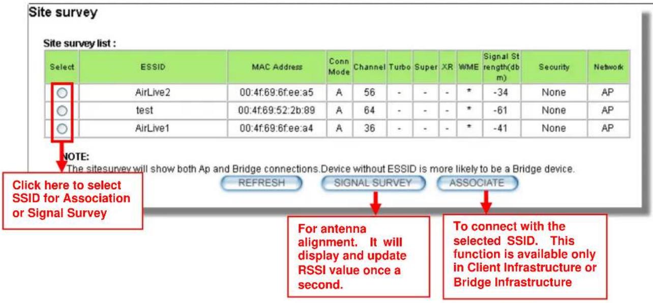
■ Associate: Please choose a SSID before click on this button. This button is available only in Client Infrastructure or Bridge Infrastructure modes. Once you click on this button, WHA-5500CPE will attempt to make a connection with the selected ESSID. If there is encryption needed, the WHA-5500CPE will prompt you to enter the encryption key. Please make sure you enter the correct encryption key, the WHA-5500CPE will not check whether the encryption key is correct.
■ RSSI: RSSI is a value to show the Receiver Sensitivity of the WHA-5500CPE. In general, remote APs with stronger signal will display higher RSSI values. For RSSI value, the smaller the absolute value is, the stronger the signal. For example,
"-50db" has stronger signal than "-80dB". For outdoor connection, signal stronger than -60dB is considered as a good connection.
4.2.4 Signal Survey
Operation Mode -> Setup -> Site Survey -> Signal Survey
The Signal Survey will continuously display the RSSI value of the selected SSID for antenna alignment purpose. To use Signal Survey function, please enter the "Site Survey" function first; please refer to the instruction in the above section. Once you select the ESSID and click on the "Signal Survey" button, the following screen will appear.

■ BSSID: This is the remote AP's MAC address.
■ Channel: The current scanned channel
■ Signal Strength: This is the RSSI value. It will refresh itself every second. The smaller the absolute value of the RSSI, the stronger the signal. For example -38dbm is stronger than -70dBm.
4.2.5 Lock-to-AP
Operation Mode -> Setup -> Lock-to-AP
This function is applicable only to Client mode, Bridge Infrastructure, and WISP Router mode. When this function is enables, the WHA-5500CPE will put priority to associate with AP on the list. If “Force connect with AP added below” is selected, the WHA-5500CPE will only connect with AP on the list.
4.2.6 Radio Mode (11a, SuperA, TurboA)
Operation Mode -> Setup -> Radio Mode
WHA-5500CPE has 4 different options for WLAN transmission. All devices in the same network should use the same WLAN mode.
- 11a mode (normal-A): This is the IEEE standard for WiFi operating in 5GHz frequency band. 11a is the most stable mode. If you are getting packet loss or disconnection using Super-A or Turbo-A mode. Please use 11a mode instead.
- SuperA: Super-A add Bursting, Compression, and Fast Frames to increase the speed over 11a mode. If you live in countries that prohibit the channel binding technology (i.e. Europe), you should choose “Super-A” If you need more speed than 11a mode. However, this mode is not as stable as 11a mode.
- Super-A with Static Turbo: Turbo mode uses channel binding technology to increase the speed further over Super-A mode. This mode might not be allowed in countries that prohibit channel binding (i.e. some EU countries). This mode will always turn on the turbo mode in all conditions
- Super-A with Dynamic Turbo: Dynamic Turbo mode will be turn on only when adjacent channel is not used. It is also known as intelligent turbo mode. This mode might not be allowed in countries that prohibit channel binding (i.e. some EU countries). In addition, this mode does not work in WDS Bridge mode

If you select "11a" or "Super-A" mode, you can still combine them with Turbo mode when you select "40MHz" Channel Width.
4.2.7 SuperA Option
Operation Mode -> Setup -> SuperA Option
When you select Radio Mode with "Super-A", the SuperA Options will be available.
■ Bursting: Allow more data frame to be sent over given period of time by overhead reduction.
■ Compression: Increasing throughput by compressing data frame in real time
■ Fast Frame: Utilizing frame aggregation and removing interframe pauses to increase the throughput.
It is recommended to select all 3 options except for compatibility reasons with remote AP.
4.2.8 Channel
Operation Mode -> Setup -> Channel
The channel is the frequency range used by radio. In 802.11a standard, each channel occupies 20MHz width. For 2 wireless devices to connect, they must use the same channel. The number of available legal channels might be different between countries. For example, Channel 149 to 161 are available only to United States and a few other countries. If you are living outside EU, please change the country from the “Regulatory Domain” option in this page. Below is the table list of channels and frequency.
| Frequency Domain Channel Frequency (MHz) | ||
| 5.15 to 5.25GHzU-NII LowETSI Band1 | 36 | 5180 |
| 40 | 5200 | |
| 44 | 5220 | |
| 48 | 5240 | |
| 5.25 to 5.35GHzU-NII MidETSI Band1 | 52 | 5260 |
| 56 | 5280 | |
| 60 | 5300 | |
| 64 | 5320 | |
| 5.47 to 5.725GHzU-NII World WideETSI Band3 | 100 | 5500 |
| 104 | 5520 | |
| 108 | 5540 | |
| 112 | 5560 | |
| 116 | 5580 | |
| 120 | 5600 | |
| 124 | 5620 | |
| 128 | 5640 | |
| 132 | 5660 | |
| 136 | 5680 | |
| 140 | 5700 | |
| U-NII Upper | 149 | 5745 |
| 153 | 5765 | |
| 157 | 5785 | |
| 161 | 5805 | |
| ISM | 165 | 5825 |
■ Show All Channels: When you set the “Regulatory Domain” to “All Channles”, it will display all the channel numbers regardless of what channel width is elected. For example, when you select “20MHz” for channel width, check this option will display channels “36,37,38, 39, 40....” Instead of “36, 40, 44...etc). This allows you to use a non-standard channel to avoid interference or for privacy purpose.
4.2.9 Channel Width
Operation Mode -> Setup -> Channel Width
In 802.11a spec, each channel occupies 20MHz channel width. Therefore, each channel will jump by number of 4 (i.e. 36, 40, 44...etc). You can change the Channel Width to 40MHz(Turbo), 10MHz(Half) or 5MHz(Quarter) to either increase performance or reduce the interference problem.
■ Turbo (40MHz): Each channel will use 40MHz, double the normal size, to increase the performance by channel binding. This option is not allowed in countries inside EU
■ Normal (20MHz): This is the default channel width specified by IEEE 802.11a specification
■ Half (10MHz): Using this option will double the available channels for deployment in congested areas. However, the performance will also drop by half when using this option. When you are in Client mode, you can put the “Regulatory Domain” to “all Channels” to maintain compatibility with other AP.
■ Quarter (5MHz): Using this option will increase the available channels by 4 times. It is a good choice for deployment in very congested areas. However, the performance will also drop greatly when using this option. When you are in Client mode, you can put the “Regulatory Domain” to “all Channels” to maintain compatibility with other AP.
4.2.10 Security Settings
Operation Mode -> Setup -> Security Settings
Security settings allow you to use encryption to secure your data from eavesdropping. You can select different security policy to provide association authentication and/or data encryption. The WHA-5500CPE features various security policies including WEP, 802.1x, WPA, WPA-PSK, WPA2, WPA2-PSK, WPA-Auto, and WPA-PSK-Auto. Please note not all security policies are available in all operation modes. For example, only WEP is available currently in WDS Bridge mode and Client Adhoc mode. All wireless devices on the same network must use the same security policy. We recommend using WPA-PSK or WPA2-PSK whenever possible. For WDS Bridge and Client Adhoc mode, we recommend using WEP-152 encryption.
WEP
WEP Encryption is the oldest and most available encryption method. However, it is also the least secure. Due to the limitation of the chipset, only WEP encryption is available for WDS Bridge Pure MAC mode and Client Adhoc mode.

■ Select one of the WEP key for wireless network: There are total of 4 possible keys for WEP encryption. You need to choose which key will be used for encryption. All wireless devices on the same network have to use the same settings. We recommend using WEP Key 1 as in default setting.
■ WEP Keys: Please enter the WEP keys used for encryption. You need to fill at least the "Select WEP Key". For example; if you choose "Encrypt Data with WEP Key 1" in the previous field, then it is necessary to fill WEP Key 1. The length of key is dependant on the Key Length and Key type you choose.
■ Key Length: The WHA-5500CPE offers 64bit, 128 bit, and 152 bit for WEP key length. The longer the Key Length, the more secure the encryption is.
■ Key Type: 2 types are available: ASCII and HEX. ASCII is a string of ASCII code including alphabetical characters, space, signs and numbers (i.e. "airlivepass12"). HEX is a string of 16-bit hexadecimal digits (0..9, a, b, c, d, e, f). All wireless devices on the network must match the exact key length and Key type. Some Wireless clients only allow HEX type for WEP.
■ ASCII-64: This is a key with 64-bit key length of ASCII type. Please enter 5 ASCII Characters if you choose this option. For example, "passw"
■ HEX-64: This is a key with 64-bit key length of HEX type. Please enter 10 Hexadecimal digits if you choose this option. For example, "12345abcdef"
■ ASCII-128: This is a key with 64-bit key length of ASCII type. Please enter 13 ASCII Characters if you choose this option. For example, "airlivewepkey"
■ HEX-128: This is a key with 128-bit key length of HEX type. Please enter 26 Hexadecimal digits if you choose this option. For example, "1234567890abcdef1234567890"
■ ASCII-152: This is a key with 64-bit key length of ASCII type. Please enter 16 ASCII Characters if you choose this option. For example, "airlivewepkey123"
■ HEX-152: This is a key with 128-bit key length of HEX type. Please enter 32
Hexadecimal digits if you choose this option. For example, "1234567890abcdef1234567890abcdef"
802.1x
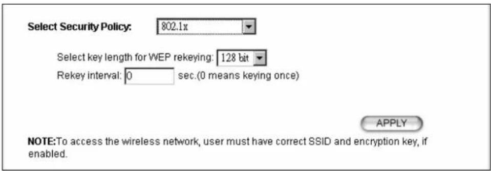
802.1x allows users to leverage a RADIUS server to do association authentications. You can also enable dynamic WEP key (128 bit) to have data encryption. You do not have to enter the WEP key manually because it will be generated automatically and dynamically.
■ Rekey interval is time period that the system will change the key periodically. The shorter the interval is, the better the security is.

After you have finished the configuration wizard, you have to configure the RADIUS Settings in "Operation Mode -> Setup -> RADIUS Settings" in order to make the 802.1x function work.
WPA, WPA2, WPA-AUTO
Wi-Fi Protected Access (WPA) introduces the Temporal Key Integrity Protocol (TKIP) that provides added security. WPA2 adds full support for 802.11i standard and the CCMP (AES Encryption). The WPA-AUTO tries to authenticate wireless clients using WPA or WPA2. All 3 requires a RADIUS server available in order to do authentication (same as 802.1x), thus there is no shared key required.
Select Security Policy:

WPA Encryption Type: ○ TKIP ○ CCMP(AES) ● Both WPA Group Rekey Interval: 300 sec.(0 means disable rekey)

■ Encryption Type: There are two encryption types TKIP and CCMP (AES). While CCMP provides better security than TKIP, some wireless client stations may not be equipped with the hardware to support it. You can select Both to allow TKIP clients and CCMP clients to connect to the Access Point at the same time.
■ Group Rekey Interval: A group key is used for multicast/broadcast data, and the re-key interval is time period that the system will change the group key periodically. The shorter the interval is, the better the security is. The default is 300 sec.
WPA-PSK, WPA2-PSK, WPA-PSK-Auto
Wi-Fi Protected Access (WPA) with Pre-Shared Key (PSK) provides better security than WEP keys. It does not require a RADIUS server in order to provide association authentication, but you do have to enter a shared key for the authentication purpose. The encryption key is generated automatically and dynamically. WPA2-PSK adds CCMP and AES encryption for even better security. WPA-PSK-AUTO tries to authenticate wireless clients using WPA-PSK or WPA2-PSK.
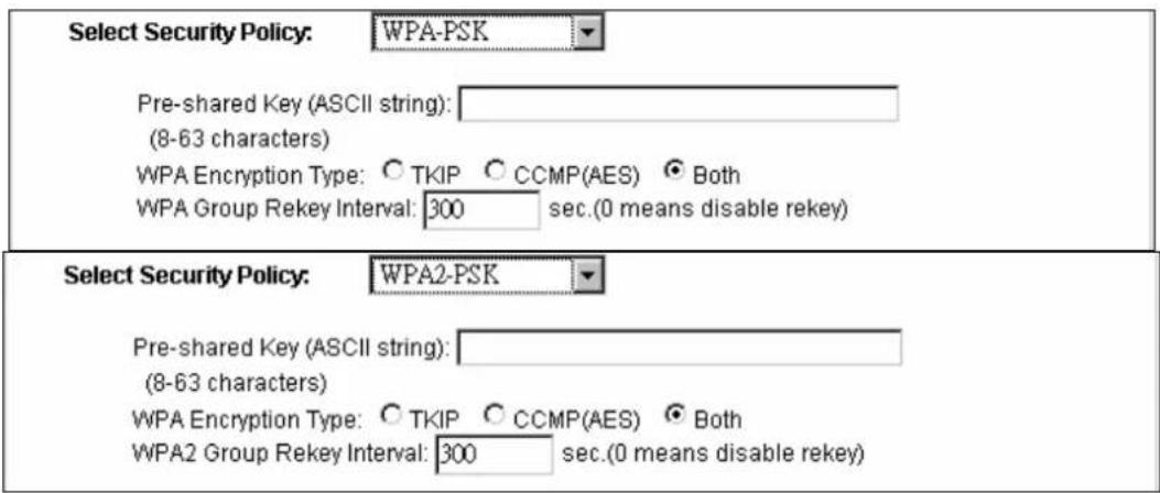

■ Pre-shared Key: This is an ASCII string with 8 to 63 characters. Please make sure that both the WHA-5500CPE and the wireless client stations use the same key.
■ Encryption Type: There are two encryption types TKIP and CCMP (AES). While CCMP provides better security than TKIP, some wireless client stations may not be equipped with the hardware to support it. You can select Both to allow TKIP clients and CCMP clients to connect to the Access Point at the same time.
■ Group Rekey Interval: A group key is used for multicast/broadcast data, and the re-key interval is time period that the system will change the group key periodically. The shorter the interval is, the better the security is. The default is 300 sec.
4.2.11 Distance
Operation Mode -> Setup -> Distance
Please enter the distance to the remote wireless device here. The WHA-5500CPE will then calculate the appropriate ACK Timeout value autom
atically. It is very important that you enter the correct distance for long distance connection. Failure to do so will result in poor performance.
4.2.12 Transmit Power
Operation Mode -> Setup -> Transmit Power
You can adjust the transmit output power of the WHA-5500CPE's radio from 10dBm to 24dBm. The higher the output power, the more distance WHA-5500CPE can deliver. However, it is advised that you use just enough output power so it will not create excessive interference for the environment. Also, using too much power at close distance can create serious performance drop due to signal distortion.
At less than 200meter distance, the best output power is about 14dBm. At 2km distance; the best output power setting is 18dBm for "11a" and "Super-A without Turbo", 24dBm for "Super-A with Static/Dynamic Turbo".
4.2.13 Advance Settings (Wireless)
Operation Mode -> Setup -> Advance Settings
This page includes all the wireless settings that change the RF behaviors of WHA-5500CPE. It is important to read through this section before attempting to make changes.

■ Beacon Interval: Beacon Interval: The device broadcasts beacon frames regularly to announce its existence. The beacon Interval specifies how often beacon frames are transmitted in time unit of milliseconds. The default value is 100, and a valid value should be between 1 and 65,535.
■ RTS Threshold: RTS/CTS frames are used to gain control of the medium for transmission. Any unicast (data or control) frames larger than specified RTS threshold must be transmitted following the RTS/CTS handshake exchange mechanism. The RTS threshold should have a value between 256-2347 bytes, with a default of 2347. It is recommended that this value does not deviate from the default too much.
■ Fragmentation: When the size of a unicast frame exceeds the fragmentation threshold, it will be fragmented before the transmission. It should have a value of 256-2346 bytes, with a default of 2346. If you experience a high packet error rate, you should slightly decrease the Fragmentation Threshold.
■ DTIM Interval: The WHA-5500CPE buffers packets for stations that operate in the power-saving mode. The Delivery Traffic Indication Message (DTIM) informs such power-conserving stations that there are packets waiting to be received by them. The DTIM interval specifies how often the beacon frame should contain DTIMs. It should have a value between 1 to 255, with a default value of 3.
■ User Limitation: This limitation applies to number of wireless clients the device can associate. If you need to serve wireless connection to large number of users in one location. You can deploy many APs and limit the number of wireless clients, so any additional wireless connection attempt will be rejected (therefore, redirect to other AP). The range of user limitation is from 1 to 100.
■ Age Out Timer: Set the age out timer for the wireless client. If there is no traffic from client for more than the timer, the wireless client will be dropped. The default is 300 sec. This function is available only for the Access Point and AP router mode.
■ Rate Control: Select here to change the Data Rate for the radio. Lower data rate sometimes provide longer distance. In most cases, however, we recommend to keep the setting at "Best".
■ Noise Immunity: Adaptive Noise Immunity is one of the new function in Atheros driver to enhance the performance in interference environment.
■ AckTimeOut: When a packet is sent out from one wireless station to the other, it will waits for an Acknowledgement frame from the remote station. The station will only wait for a certain amount of time, this time is called the ACK timeout. If the ACK is NOT received within that timeout period then the packet will be re-transmitted resulting in reduced throughput. If the ACK setting is too high, then throughput will be lost due to waiting for the Ack Window to timeout on lost packets. If the ACK setting is too low then the ACK window will have expired and the returning packet will be dropped, greatly lowering throughput. By having the ability to adjust the ACK setting we can effectively optimize the throughput over long distance links.
The easiest way to enter AckTimeOut value is by entering the distance in "Operation Mode -> Setup -> Distance". The WHA-5500CPE will then calculate and enter the correct value for you.
■ Enable Radio eXtended Range: XR is Atheros eXtended technology to increase range. When XR is turned on, the radio can increase the receiver sensitivity greatly. However, performance may be reduced significantly also. Use this mode only if you can trade more distance for lower performance.
■ Enable privacy separator: Select the check box to prohibit data transmission between client stations. This function is also known as "Client Isolation".
■ Enable 802.1d: Enable the Spanning Tree Protocol to prevent forming a network loop. This option is especially important for WDS Bridge mode.
■ Enable 802.11d: Also known as “Global Roaming”. 802.11d is a standard for use in countries where systems using other standards in the 802.11 family are not allowed to operate.
4.2.14 Access Control (ACL)
Operation Mode -> Setup -> Access Control
The WHA-5500CPE allows you to define a list of MAC addresses that are allowed or denied to access the wireless network. This function is available only for Access Point and AP Router modes.
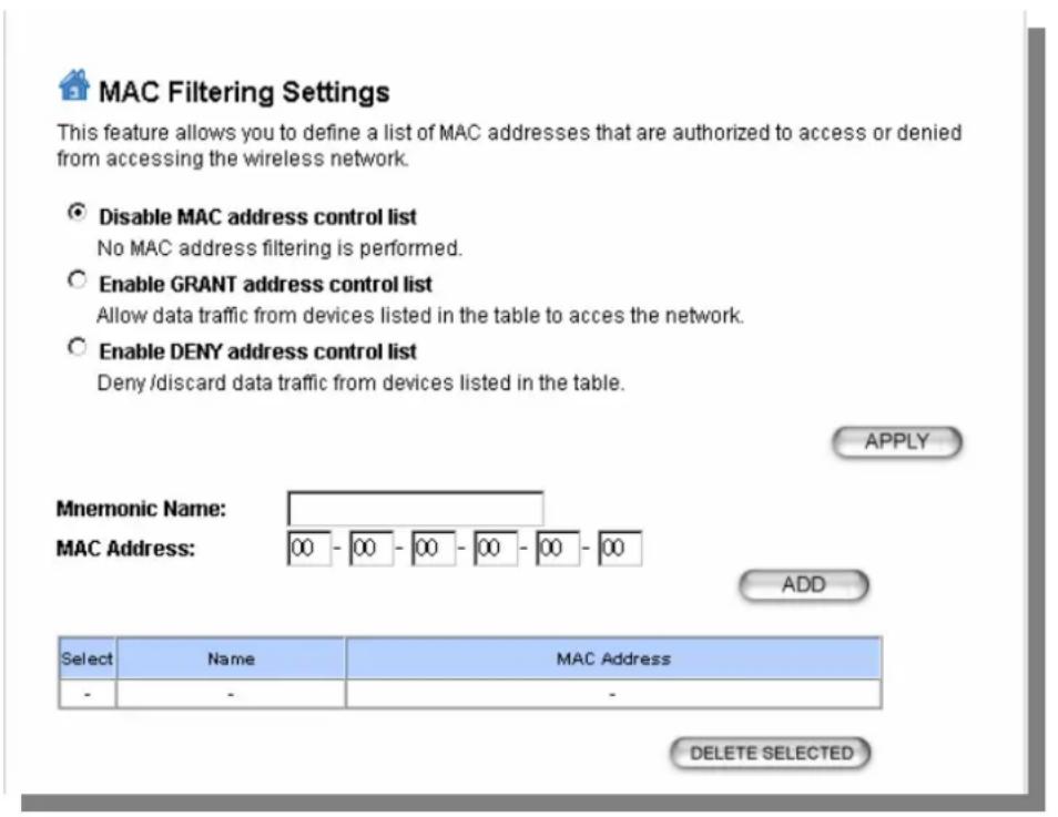
■ Disable MAC address control list: When selected, no MAC address filtering will be performed.
■ Enable GRANT address control list: When selected, data traffic from only the specified devices in the table will be allowed in the network.
■ Enable DENY address control list: When selected, data traffic from the devices specified in the table will be denied/discarded by the network.
To add a MAC address into the table, enter a Mnemonic Name and the MAC Address, and then click Add. The table lists all configured MAC Filter entries.
To delete entries, check the corresponding Select boxes and then press Delete Selected.
4.2.15 Multiple SSID
Operation Mode -> Setup -> Multiple SSID
This function is available only for Access Point and AP Router modes. Multiple SSID allows WHA-5500CPE to create up to 4 different wireless networks (SSID). It is also known as “Virtual AP” function. Each SSID can have its Encryption type, VLAN Tag, and TOS settings. In the following diagram, the WHA-5500CPE uses Multiple SSID function to create separate Bridge and Client network. Each has its own encryption policies.

flowchart
graph TD
    A["Bridge Network"] --> B["Client Network"]
    B --> C["AP Mode"]
    C --> D["WHA-5500CPE"]
    C --> E["NB"]
    C --> F["PC"]
    B --> G["Client Mode"]
    H["Bridge Infrastructure"] --> I["IP: 192.168.2.1/24"]
    H --> J["IP: 192.168.1.1/24"]
    H --> K["SSID: BridgeNet, Security: WPA2-PSK, VLAN ID: 200"]
    H --> L["SSID: ClientNet, Security: WPA-PSK, VLAN ID: 100"]
Configuring the Multiple SSID
When you click on the "Multiple SSID" button, the following screen will appear

How to add a SSID
You can add up to 4 SSID in WHA-5500CPE. Please follow the procedure below:
- Enter the SSID name (i.e. BridgeNet)
- Select the Security Policy (i.e. WPA2-PSK)
- Enter the Security Key (i.e. BridgeNetKey).
- Click on "Apply" to add SSID

How to Modify or Delete a SSID
Please follow the procedure below:
- Select the SSID you want to modify or delete
- The SSID's settings will be displayed in the box area. Modify any settings.
- Click on "APPLY" to complete the modification
- Or click on "Delete Selected" to delete the SSID

Configure the VLAN and DiffServ Markings
When you check the Enable VLAN for All SSIDs and/or Enable DiffServ Marking, the following screen will appear:
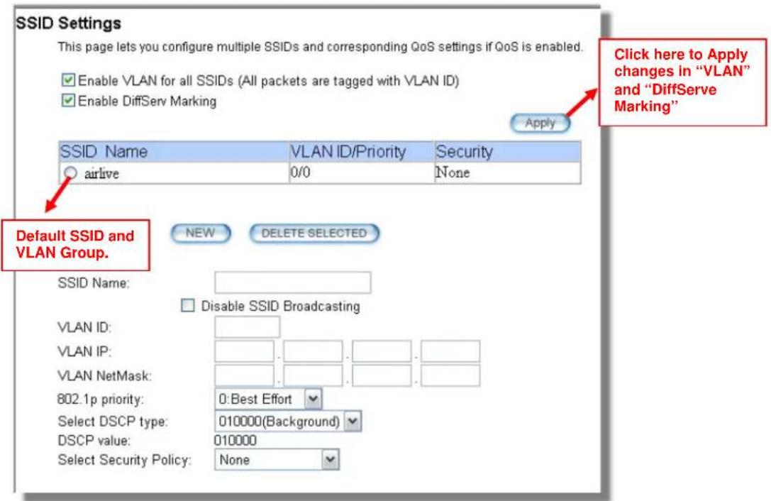
■ Enable VLAN for All SSIDs: Once this function is enabled, you can specify an individual VLAN ID and priority tag for each SSID. The packets from a SSID will be forwarded to the Ethernet with the corresponding configured VLAN ID written. You need to click on the top "APPLY" button after making changes.
■ Enable DiffServ Marking: When this function is enabled, you can configure a DSCP value for each SSID. Then a packet from a station using this SSID will be forwarded with the DSCP value labeled. You need to click on the top "APPLY" button after making changes.
■ VLAN ID: Packets going out of this VLAN will be tagged with the VLAN ID. Packets coming into the AP will be dropped if the VLAN Tag does not match. The valid range is between 0 to 4095. The VLAN ID "0" is the default VLAN group.
■ VLAN IP: Each SSID can be given with different VLAN IP group. Please notice that the management IP in the VLAN will also be changed. For example, if you define the VLAN IP to be 192.168.2.X subnet, then the WHA-5500CPE's management IP in the group will change to 192.168.2.1.
■ VLAN IP NetMask: Define your VLAN IP scope here
■ 802.1p Priority: Define your 802.1p priority Tag here. Value from 0 to 7
■ Select DSCP TYPE: Assign the 6-digit DifferServ Code(DSCP) for the packets in the SSID network for QoS purpose. There are 8 preset values. To assign your own value, please select "Best Effort"
■ DSCP Value: When you select "Best Effort" DSCP Type, you can enter the 6-dgit DSCP Value here.
■ Select Security Policy: Select the encryption used for this SSID VLAN group. This policy can be different in each SSID VLAN group. For example, one SSID
can be using WEP, the other policy can use WPA-PSK.

Once you enable the VLAN ID. The incoming packet from Ethernet port to your VLAN group must carry the same VLAN ID tag or the packet will be dropped.
4.2.16 WMM QoS
Operation Mode -> Setup -> WMM QoS
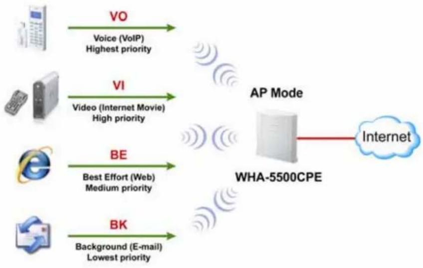
Wi-Fi Multimedia (WMM) is a standard to prioritize traffic for multimedia applications. The WMM Settings is to specify parameters on multiple data queue for better performance of differentiated wireless traffic like Voice-over-IP (VoIP), other types of audio, video, and streaming media as well as traditional IP data over the AP.
flowchart
graph LR
    A["Telephone"] -->|VO\nVoice (VoIP)\nHighest priority| B["AP Mode\nWHA-5500CPE"]
    C["Phone"] -->|VI\nVideo (Internet Movie)\nHigh priority| B
    D["Email"] -->|BE\nBest Effort (Web)\nMedium priority| B
    E["Desktop"] -->|BK\nBackground (E-mail)\nLowest priority| B
    B --> F["Internet"]
Configure the WMM QoS Parameters
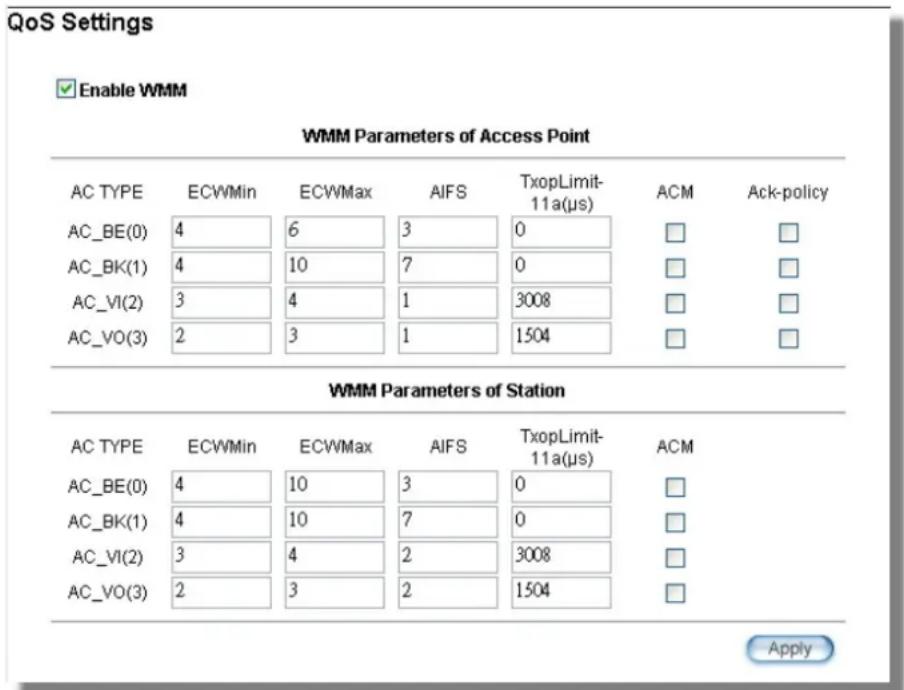
■ AC Type
The queue and associated priorities and parameters for transmission are as follows:
☐ Data 0 (Best Effort, BE): Medium priority queue, medium throughput and delay. Most traditional IP data is sent to this queue.
☐ Data 1 (Background, BK): Lowest priority queue, high throughput. Bulk data that requires maximum throughput and is not time-sensitive is sent to this queue (FTP data, for example):
☐ Data 2 (Video, VI): High priority queue, minimum delay. Time-sensitive data such as Video and other streaming media are automatically sent to this queue.
☐ Data 3 (Voice, VO): Highest priority queue, minimum delay. Time-sensitive data such as Voice over IP (VoIP) is automatically sent to this queue.
Packets in a higher priority queue will be transmitted before packets in a lower priority queue.
■ ECWmin and ECWmax
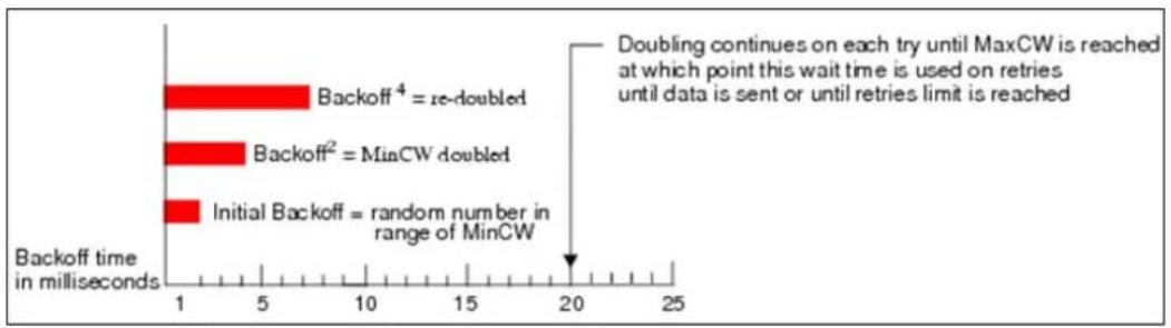
If an access point detects that the medium is in use, it uses the DCF random backoff timer to determine the amount of time to wait before attempting to access a given channel again. Each access point waits some random period of time between retries. The wait time (initially a random value within a range specified as the Minimum Contention Window increases exponentially up to a specified limit Maximum
Contention Window.
The random delay avoids most of the collisions that would occur if multiple APs got access to the medium at the same time and tried to transmit data simultaneously. The more active users you have on a network, the more significant the performance gains of the backoff timer will be in reducing the number of collisions and retransmissions.
bar
| Backoff time in milliseconds | Value | |---|---| | Backoff⁴ = re-doubled | 7 | | Backoff² = MinCW doubled | 4 | | Initial Backoff = random number in range of MinCW | 1 |The random backoff used by the access point is a configurable parameter. To describe the random delay, a "Minimum Contention Window" (ECWMin) and a "Maximum Contention Window" (ECWMax) is defined.
☐ ECWmin: The value specified for the Minimum Contention Window is the upper limit of a range for the initial random backoff wait time. The number used in the random backoff is initially a random number between 0 and the number defined for the Minimum Contention Window.
☐ ECWmax: If the first random backoff time ends before successful transmission of the data frame, the access point increments a retry counter, and doubles the value of the random backoff window. The value specified in the Maximum Contention Window is the upper limit for this doubling of the random backoff. This doubling continues until either the data frame is sent or the Maximum Contention Window size is reached.

AIFS
The Arbitration Inter-Frame Spacing (AIFs) specifies a wait time (in milliseconds) for data frames. 802.11e uses interframe spaces to regulate which frames get access to available channels and to coordinate wait times for transmission of different types of data. The AIFs ensures that multiple access points do not try sending data at the same time but instead wait until a channel is free. Valid values for AIFs are 1 through 255.
■ Transmission Opportunity
The Transmission Opportunity (TXOP) is an interval of time when a WMM client station has the right to initiate transmissions onto the wireless medium. This value specifies (in milliseconds) the Transmission Opportunity (TXOP) for client stations; that is, the interval of time when a WMM client station has the right to initiate transmissions on the wireless network.

We recommend that you use the default settings on the WMM QoS page. Changing these values can lead to unexpected blockages of traffic on your wireless LAN, and the blockages might be difficult to diagnose.
4.2.17 RADIUS Settings
Operation Mode -> Setup -> RADIUS Setting
RADIUS servers provide centralized authentication services to wireless clients. Two RADIUS servers can be defined: one acts as a primary, and the other acts as a secondary backup. If you choose to use 802.1x, WPA, or WPA2 as security policy, you might need to set the RADIUS server settings.
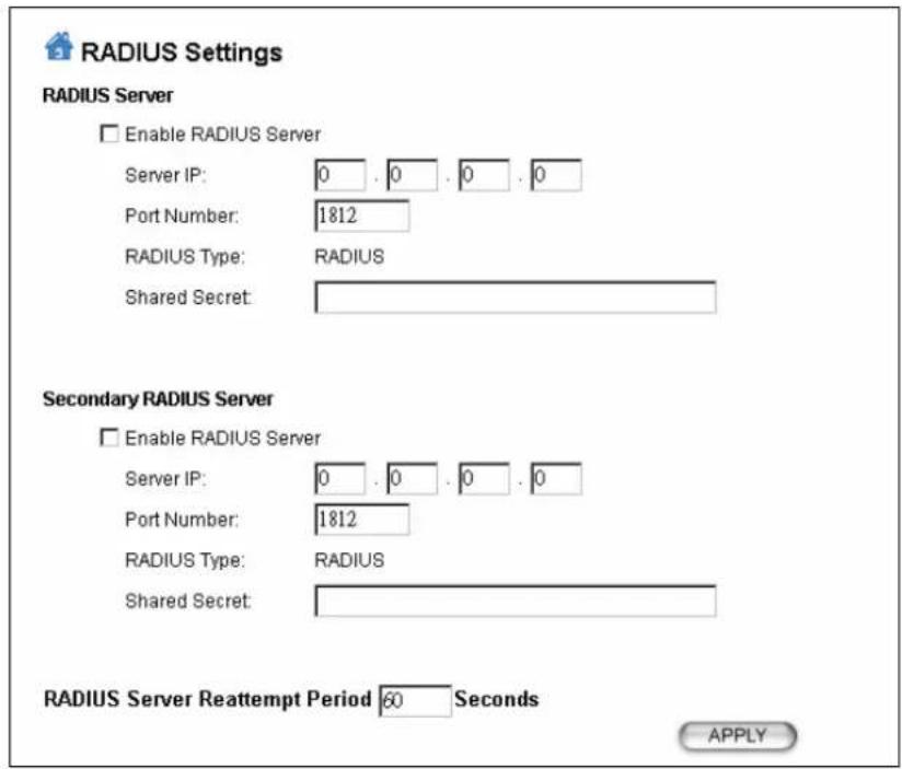
To Enable RADIUS Server:
■ Server IP: The IP address of the RADIUS server.
■ Port Number: The port number that your RADIUS server uses for authentication. The default setting is 1812.
■ RADIUS Type: RADIUS
■ Shared Secret: This is used by your RADIUS server in the Shared Secret field in RADIUS protocol messages. The shared secret configured in the WHA-5500CPE must match the shared secret configured in the RADIUS server. The shared secret can contain up to 64 alphanumeric characters.
■ RADIUS Server Reattempt Period: The number of times the WHA-5500CPE should attempt to contact the primary server before giving up
4.2.18 Bandwidth Control
Operation Mode -> Setup -> Bandwidth Control
Bandwidth Control can limit the maximum speed of entire wireless interface or individual device. It is also known as Traffic Shaping. The WHA-5500CPE provides both Total Bandwidth and Per-User Bandwidth Control for both uplink and downlink speed. It controls the speed of both wireless and wired interface.
To configure, please click on the "Bandwidth Control" button under wireless settings. The following screen will appear:
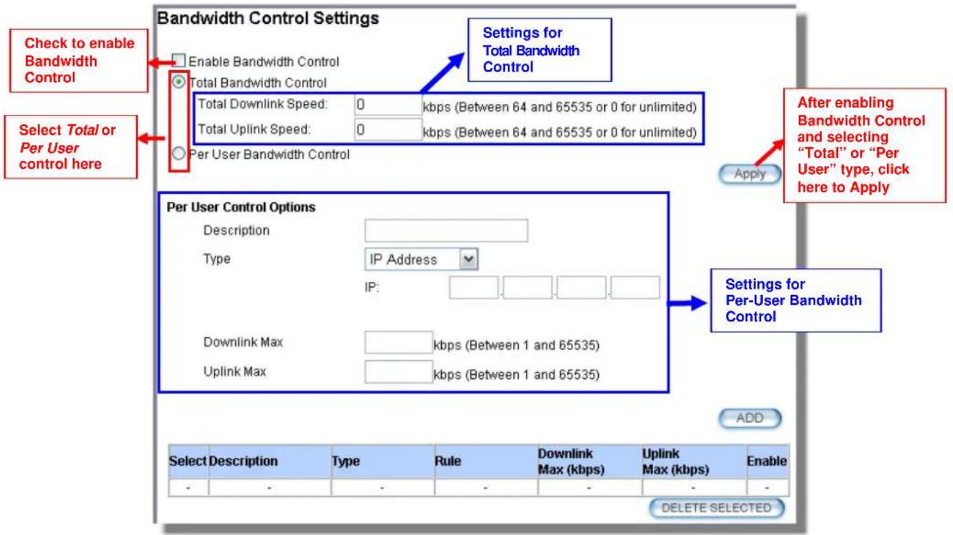
■ Enable Bandwidth: Check to enable Bandwidth Control. Uncheck to disable it. The default value is disabled.
You must select between Total Bandwidth and Per-User Bandwidth. They can not be enabled at the same time.
■ Total Bandwidth: Total Bandwidth control limit the bandwidth between Wireless and Ethernet interface. Therefore, it is most suitable for Client Infrastructure Mode, Bridge Mode, and WISP Router Mode. For WISP operator who use WHA-5500CPE as the client side device; setting the Total Bandwidth control on the WHA-5500CPE will easy the loading on the AP for bandwidth management. To begin, please enable the Bandwidth Management first. Then enter the downlink and uplink speed; click on Apply to finish.
☐ Total Downlink Speed: Enter speed you wish to limit the download traffic in Kbps units.
☐ Total Uplink Speed: Enter the speed you wish to limit the upload traffic in Kbps units.
■ Per User Bandwidth Control: Per user Bandwidth Control can limit speed of individual PC and network device. The WHA-5500CPE allows multiple Per-User
bandwidth rules and can limit the bandwidth by IP address, MAC address, or IP segment. Please first enable the Bandwidth Control, then select "Per User Bandwidth Control" to begin. It is recommended to use this type of bandwidth control for Access Point and AP Router mode.
Per User Control Options
☐ Description: Enter a description for the bandwidth policy. For example, "VIP" subscriber
☐ Type: WHA-5500CPE offers 3 types of Per-User Control
■ IP Address: To limit the bandwidth of one single IP address.
■ IP Segment: To limit the bandwidth the entire IP segment.
For example; if you enter the address of 192.168.1.20 with subnet mask of 255.255.255.248, the WHA-5500CPE will limit bandwidth of IP addresses from 192.168.1.17 to 192.168.1.22. Please use an online IP calculate if you are not familiar with IP segment calculation. Below is an example link: http://www.subnet-calculator.com/
Because the Ethernet interface is also controlled by the Bandwidth Manager, it is recommended that devices on the Ethernet side to use a wider IP subnet mask that will cover the IP range of the controlled IP segment. Therefore, the devices on Ethernet interface will not be limited by bandwidth control and still can communicate with the IP segment. For example, if your IP segment is set to 192.168.1.20 / 255.255.255.248, then the devices on the Ethernet side should be 192.168.1.X / 255.255.255.0.
■ MAC address: To limit the bandwidth of one single MAC address.
■ Port Range: This is available only in WISP router and AP Router mode. It can limit the bandwidth by application ports.
■ Application: This option is available only in WISP router and AP Router mode. It can limit the bandwidth of HTTP, FTP, BitTorrent, and eDonkey traffic.
☐ Downlink Max: Enter the speed you wish to limit the download traffic in kbps units.
☐ Uplink Max: Enter the speed you wish to limit the upload traffic in kbps units
■ Example 1: Total Bandwidth Control
In this example, the WHA-5500CPE is in Client Infrastructure mode connecting to a remote AP. We want to limit the Bandwidth of the link to 2048Kbps download and 512kbps Upload.
☐ Step 1 to 3: From Operation Mode menu, select "Setup" -> "Bandwidth Control"

☐ Step 4 to 7: Enable the Bandwidth Control and select the "Total Bandwidth Control". Then enter the "2048" for Total Downlink Speed and "512"kbps for Total Uplink Speed. Click "Apply" to finish

■ Example 2: Per User Bandwidth Control
In this example, the WHA-5500CPE is Access Point mode. There is a wireless client connecting to WHA-5500CPE with MAC address of 00:04:6F:11:11:11. We want to limit the bandwidth of the wireless client to 1024 downstream and 512K upstream using WHA-5500CPE's Per-User Bandwidth Control.

flowchart
graph LR
    A["AP Mode"] --> B["WHA-5500CPE"]
    B --> C["MAC Address: 00:04:6F:11:11:11"]
    C --> D["Wireless Client"]
    D --> E["PC"]
    B -->|512Kbps| C
    B -->|1024Kbps| D
Step 1. Enable Bandwidth Control and select "Per User Bandwidth Control"
Step 2. Enter Description for this policy (Wireless Client)
Step 3. Select "MAC Address", then enter the MAC address of the wireless client.
Step 4. Enter the downlink speed as "1024" and uplink speed as "512".
Step 5. Click on "Add" button to add the bandwidth policy
Step 6. This new policy should appear on the button. You can enable/disable it.

4.3 WDS Settings
Operation Mode -> Setup -> WDS Settings
WDS Bridge mode can make Point-to-Point and Multi-Point connections. Because of its faster performance, it is frequently used to build point-to-point bridge connection and backbone networks. In a WDS network, each node can have up to 4 connections. However, the total number of devices in a WDS network should not exceed 8. Currently, the WDS Bridge mode can only use WEP encryptions policy.
TIPS: For step-by-step instructions on how to build a WDS bridge network, please be sure to read through Chapter 9: WDS Bridge Example for details.
In this section, we will talk about the WDS Settings which is available only in WDS Bridge (Pure MAC) mode. WDS Bridges are using BSSID (AP's Wireless MAC address) to authenticate each other. Therefore, it is necessary to know the remote Bridge's wireless MAC addresses. You can always do a "Site Survey" to find out the MAC Addresses.
When you click on WDS settings, the following screen will appear:

☐ WEP Key: You can set up to 4 keys, each key can have different Key Length and Key type. When you add an entry to the WDS setting and select WEP
encryption, the system will ask you which key to use. All devices on the network must have the same sets of keys, but each link can have use different key. We recommend using WEP-152 whenever possible for better security.
☐ Adding a new WDS link
The WDS link are created by entering the remote Bridge's information. This process must be repeated on both side of the bridge.
- Name: This is the name for the WDS Link. You can enter any name for your own reference (i.e. WarehouseLink).
- SSID: SSID is the network ID for the wireless link. If you have more than one WDS link or if you want to make WDS connection with Mikrotik devices, this field is required. Each WDS Link must have a different SSID name. If you only have one WDS link, you can leave this field empty.
- MAC Address: Please enter the remote bridge's wireless MAC address in this field. This wireless SSID can be found on the device label. You can also use Site Survey function to assist you.
- Select Security Settings: You can choose to use WEP encryption for better security. It is necessary to enter the same set of keys in the same WDS network. When you select WEP, the WHA-5500CPE will ask you to select from one of the 4 keys. Please be sure to select the same key on both side of the link.
- Press Add to finish
4.4 Router Mode Settings
Operation Mode -> Setup
This section will explain WAN port settings and other functions that are available only in WISP router and AP Router mode.
4.4.1 WISP Router Mode
The WISP Router mode is also known as Client Router. The wireless side is connected to the remote AP as in Client Infrastructure mode. Between the wireless and LAN is the IP sharing router function. This is used to share WISP connection. The WAN is on the wireless side.

In AP Router mode, the POE port of the WHA-5500CPE will turn into the WAN port. The wireless interface will become the LAN side. It will turn WHA-5500CPE into a wireless router. Since the Ethernet interface becomes WAN; if your PC is connected to the POE port, the management IP will change to the WAN IP (192.168.2.1). The remote management will be automatically turned on to allow you managing the device from the POE WAN port.

flowchart
graph TD
    A["Client AP"] -->|Wireless Signal| B["LAN"]
    B --> C["AP Router"]
    C -->|WAN| D["Internet"]
    C -->|WAN| E["Laptop"]
When you select the WISP Router or AP Router mode, additional wireless settings will appear for WAN port settings.
| WAN Port Settings: | Setup |
| Dynamic DNS Settings: | Setup |
| Remote Management: | Setup |
| IP Routing Settings: | Setup |
| DHCP Server Settings: | Setup |
| Multiple DMZ: | Setup |
| Virtual Server Settings: | Setup |
| Special Applications: | Setup |
| IP Filtering Settings: | Setup |
4.4.3 WAN Port Settings
Operation Mode -> Setup -> WAN Port Settings
The WHA-5500CPE support different authentication and IP assignment standards for the WAN port. It includes fixed IP, DHCP, PPPoE and PPTP protocols. Please consult with your ISP about what authentication type is used for the WAN port convection.

- Clone MAC Address: Some service provider (Cable Modem provider) lock to certain MAC address. In this situation, the WAN port of WHA-5500CPE need to clone the MAC address. Please check the “Clone MAC address” box and enter the address that need to be cloned.
□ Cloned MAC Address :
If your ISP requires you to use a specific WAN Ethernet MAC address, check this box and enter the MAC address here.
MAC Address: 00.00.00.00.00.00
4.4.4 Dynamic DNS Settings
Operation Mode -> Setup -> Dynamic DNS Settings
Dynamic DNS (DDNS) allows you to create a hostname that points to your dynamic IP or static IP address or URL. WHA-5500CPE provide Dynamic DNS client using DynDNS, please visit http://www.dyndns.org for detail.

4.4.5 Remote Management Settings
Operation Mode -> Setup -> Remote Management
Remote Management allows administrator to manage the WHA-5500CPE from WAN side. You can also change the management port and other settings here.
■ HTTP Port No: The default port for HTTP is Port 80, you can change the value here
■ Timeout: The default management timeout is 10 minutes. After timeout, the WHA-5500CPE will ask you to login again. You can change the timeout value here.
■ HTTP Web Server Access: You can enable or disable HTTP service from WAN side
■ HTTPS Web server Access: You can enable or disable HTTPS Web Server Access from WAN side
■ Response to WAN ping: You can disable or enable whether WHA-5500CPE will response to PING command.

4.4.6 IP Routing Settings
Operation Mode -> Setup -> IP Routing Settings
The IP Routing Settings allows you to configure routing feature in the gateway

■ Dynamic Routing:
Select the routing protocol scheme used for the router's LAN / WAN port.
■ Static Routing:
This allows you to manually configure static network routes. Static routes will override routes learned by standard routing protocol discover methods.
■ IP Routing Table:
To delete a static route from the table, select the route and click DELETE SELECTED.
Note: Changes to the routing table will take effect immediately.
4.4.7 DHCP Server
Operation Mode -> Setup -> IP Routing Settings
DHCP Server Settings is to assign private IP address to the devices in your local area network (LAN). The default LAN IP address of WHA-5500CPE is 192.168.1.1, changing WHA-5500CPE's IP address will also change the DHCP server's IP subnet.
You can also lock IP address to MAC address manually; the DHCP server will keep the IP for the MAC address.

4.4.8 Multiple DMZ
Advanced Settings >> Multiple DMZ
Multiple DMZ opens all TCP/UDP ports to particular IP address on the LAN side. It allows setting up servers behind the WHA-5500CPE.
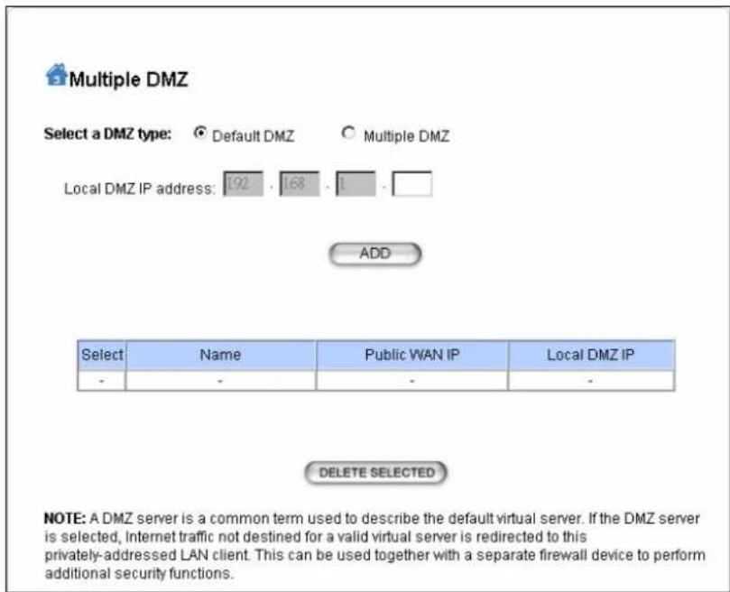
Select a DMZ type and then enter the local DMZ IP address.
A DMZ server is a common term used to describe the default virtual server. If the DMZ server is selected, Internet traffic not destined for a valid virtual server is redirected to this privately addressed LAN client. This can be used together with a separate firewall device to perform additional security functions.
4.4.9 Virtual Server Settings
Advanced Settings >> Virtual Setting
This allows you to specify one or more applications running on server computers on the LAN that may be accessed by any Internet user. Internet data destined for the specified public port will be directed to the specified private port number on the LAN client with the specified private IP address. For step-by-step example on Virtual Server settings, please go to section 10.2.2.

4.4.10 Special Applications
Advanced Setting >> Special Applications
Some Internet application such as Instant Messaging or games use groups of ports, and are not easy to work behind a firewall. To work well with these special applications we will open ports to let traffic pass through.
Note: You can use up to 3 sets of opened ports for a specific application. The opened ports can be separated by a comma and no spaces are allowed (e.g. 2300-2305, 4300-4305, 5300-5305).

Special Applications
Some Internet applications such as Instant Messaging or Games in particular use groups of ports, and are not easy to work behind a firewall. To work well with these special applications we will open ports to let traffic pass through. Before you set up special application, please see your applications' help for such information.
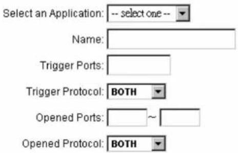
4.4.11 IP Filtering Settings
Advanced Setting>>IP Filtering Settings
IP filtering is simply a mechanism that decides which types of IP datagram will be processed normally and which will be discarded.

This allows you to define rules for allowing / denying access from / to the Internet.
Please do set both inbound/outbound in order to get complete connection. Only inbound or outbound will not allow to get response from the destination IP.
Disable IP filtering: No IP filtering is performed.
Grant IP access: Data traffic satisfying rules below are allowed/forwarded.
Deny IP access: Data traffic satisfying rules below are denied/filtered.
You can also define IP filtering rule, such as:
Name; IP Protocol; Apply to either Outbound to the Internet or Inbound from the Internet;
Source IP Address and Dest. (Destination) IP Address.
To grant or deny IP address, select ADD or Delete Selected.
5
Web Management 2: System Configuration, Tools and Status
In this chapter, we will explain about System Configurations in web management interface. Please be sure to read through Chapter 3's "Introduction to Web Management" and "Initial Configurations" first.
5.1 System Configuration
When you click on the "System Configuration" menu on the top menu bar, the following screen will appear. The system configuration includes all non-wireless settings. We will explain their functions here.

5.1.1 Device IP Settings
System Configurations>> Device IP Settings
The Device IP Settings screen allows you to configure the IP address and subnet of the device. Although you can rely on a DHCP server to assign an IP address to the WHA-5500CPE automatically, it is recommended that you configure a static IP address manually in most applications.

Device IP Settings
You can select one of the following two approaches to assign an IP address to this device.

Assign static IP to this device.
IP Address:
IP Subnet Mask:
Gateway IP Address:
DNS Server:


Use the DHCP client protocol to automatically get the IP address for this device.
Selecting this option will disable your DHCP server automatically.
APPLY
Assign Static IP to the Device
If you choose to assign the IP address manually, enable the checkbox of "Assign static IP to this device" and then fill in the following fields
■ IP Address and IP Subnet Mask: Default values are 192.168.1.1 and 255.255.255.0 respectively. It is important to note that there are similar addresses falling in the standard private IP address range and it is an essential security feature of the device. Because of this private IP address, the device can no longer be accessed (seen) from the Internet.
■ Gateway IP Address: Enter the IP address of your default gateway.
■ DNS Server: The Domain Name System (DNS) is a server on the Internet that translates logical names such as “www.yahoo.com” to IP addresses like 66.218.71.80. In order to do this, a query is made by the requesting device to a DNS server to provide the necessary information. If your system administrator requires you to manually enter the DNS Server addresses, you should enter them here.
■ Click APPLY to go to the next screen.
Use DHCP Client Protocol to Get IP automatically
If you choose to use a DHCP Server to acquire an IP address for the WHA-5500CPE automatically, enable the checkbox “Use the DHCP client protocol to automatically get the IP address for this device”. Then click Next to go to the next screen. As a reminder, you might loss the IP address of WHA-5500CPE when IP is assigned dynamically.
5.1.2 Time Settings
System Configuration ->Time Settings
It is important that you set the date and time for your WHA-5500CPE so that the system log will record the correct date and time information. We recommend you choose "Enable NTP" so the time will be keep even after reboot. If your WHA-5500CPE is not connected to Internet, please enter the time manually. Please remember to select your local time zone and click "Apply" to finish.

5.1.3 Password Settings
System Configuration ->Time Settings
To change password, please go to "System Configuration" -> "Password Settings" menu.

5.1.4 System Management
System Configuration -> System Management
In this page, administrator can change the management parameters and disable/enable management interface.

System Administration
■ HTTP Port No: The default port for HTTP is Port 80, you can change the value here
■ Timeout: The default management timeout is 10 minutes. After timeout, the WHA-5500CPE will ask you to login again. You can change the timeout value here.
■ HTTP Web Server Access: You can enable or disable HTTP service from WAN side
■ HTTPS Web server Access: You can enable or disable HTTPS Web Server Access from WAN side
■ Response to WAN ping: You can disable or enable whether WHA-5500CPE will response to PING command.
Telnet: Disable/Enable Telnet Interface.
UPnP: Click here to enable UPnP. It is recommended not to open UPnP for security reason.
Syslog: Syslog is an IETF (Internet Engineering Task Force - the Internet standards body)-conformant standard for logging system events (RFC-3164). When the WHA-5500CPE encounters an error or warning condition (ie., a log-in attempt with an invalid password), it will create a log in the system log table. To be able to remotely view such system log events, you need to check the Enable Syslog box and configure the IP address of a Syslog daemon. When doing so, the WHA-5500CPE will send logged events over network to the daemon for future reviewing.
Syslog server IP address: System event messages generated by the wireless access point will be sent to a Syslog daemon running on a server identified by this IP address
5.1.5 Ping Watchdog
System Configuration -> Ping Watchdog
The Ping Watchdog will ping remote IP addresses to make sure the wireless connection is active, if not, it can either reconnect or reboot. To prevent the AP from power recycling, the PING watchdog will start 10 minutes after power up to prevent power recycle problem.

■ PING Frequency means: "How often the CPE will PING". For example, it will PING once every "1" minute.
■ Fail Tries means "How many times fails before the CPE will judge the PING failed". For example "2" means the CPE will reconnect if the PING doesn't respond for 2 times.
When you set the Ping Frequency to every "2" minutes and Fail Tries to "2". It means the CPE will ping every 2 minutes, after the second failure, it will reconnect.
Actions:
■ Reconnect: the WHA-5500CPE will attempt to re-establish the connection. It is recommend to use this option for WDS Bridge connection.
■ Reboot: the WHA-5500CPE will do a power recycle.
5.1.6 Firmware Upgrade
System Configuration -> Firmware Upgrade
can upgrade the firmware of your WHA-5500CPE (the software that controls your WHA-5500CPE's operation). Normally, this is done when a new version of firmware offers new features that you want, or solves problems that you have encountered with the current version.

■ Upgrade Firmware:
To update the WHA-5500CPE firmware, first download the firmware from AirLive web site to your local disk, and then from the above screen enter the path and filename of the firmware file (or click Browse to locate the firmware file). Next, Click the Upgrade button to start.
The new firmware will be loaded to your WHA-5500CPE. After a message appears telling you that the operation is completed, you need to reset the system to have the new firmware take effect.

Do not power off the device while upgrading the firmware. It is recommended that you do not upgrade your WHA-5500CPE unless the new firmware has new features you need or if it has a fix to a problem that you've encountered.
5.1.7 Configuration Save and Restore
System Configuration -> Configuration Save and Restore
You can save system configuration settings to a file, and later download it back to the WHA-5500CPE by following the steps.
Step 1 Select Configuration Save and Restore from the System Configurations menu.

Step 2 Enter the path of the configuration file to save-to/restore-from (or click the Browse button to locate the configuration file). Then click the SAVE TO FILE button to save the current configuration into the specified file, or click the RESTORE FROM FILE button to restore the system configuration from the specified file.
5.1.8 Factory Default
System Configuration -> Factory Default
You can reset the configuration of your WHA-5500CPE to the factory default settings.
Step 1 Select Factory Default from the System Configuration menu.
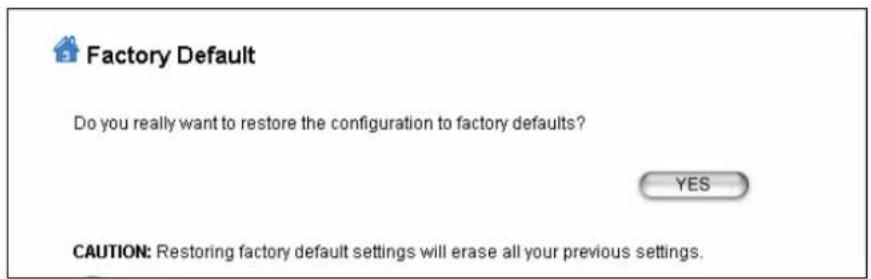
Step 2 Click YES to go ahead and restore the configuration to the factory default.
5.2 Tools
5.2.5 Network Ping
Please assign a IP address or a domain name for ping function.

5.2.2 Network Traceroute
Please assign a IP address or domain name for traceroute function.
![Air Live® www.airlive.com WHA-5500CPE 802.11a Outdoor CPE Operation Mode | System Configuration | Tools | Device Status | Logout | Network Traceroute Please assign a IP address or domain name for network traceroute function. Destination IP Address: [xxx.xxk.xxk.xxk] Destination Domain: Max hop: 30 (default: 30 hops) Traceroute Stop Result Host Response Time Help](/content/2026/05/1066385/images/df6c2a2deee074fb529bcd83c4ebb686a4d1bdf4d27f84f8aaaa302f617aa83c.jpg)
5.3 Device Status
When you click on the "Device Status" on the top menu bar, the sub menu for device status will appear.
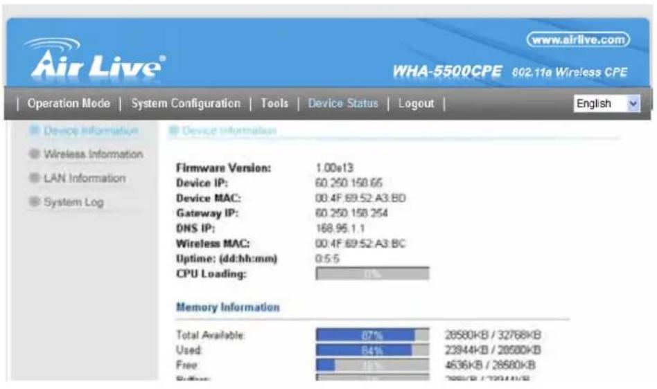
5.3.1 Device Information
This page shows the general information about WHA-5500CPE such as firmware version, device IP/MAC, WAN IP/MAC(in router modes), Gateway IP(in router modes), DNS IP...etc. Below are some additional explanations on some status information of this page:
■ CPU Loading Display the CPU usage.
■ Memory Information Display how much memory is used and free.
■ Firmware version: The first WHA-5500CPE firmware release is 1.00e10. In general, AirLive will refer to its firmware as exx (such as e10) version on the release note
■ Wireless MAC: This is the wireless MAC address (BSSID) of this AiMax5. This is the address to enter on the remote WDS Bridge for the WDS link.
■ Uptime: This is the time that the WHA-5500CPE has been running since last power up.
■ ARP Table Display the corresponding IP and MAC address Table.
5.3.2 Wireless Information
This page shows the information about wireless status such as current operation mode, wireless traffic, error packets, RSSI, Remote device's BSSD, connecting State, channel, and encryption used.

5.3.3 Internet Information
This page shows the information about WAN port of the WHA-5500CPE. It includes the type of WAN port authentication used and the IP address information about the WAN port.

5.3.4 Wireless Client Table
This function is available in AP mode and AP Router mode only. It displays the information about wireless clients that are associated with WHA-5500CPE. It includes signal strength, TX and RX data rate, MAC address, and the state.

5.3.5 System Log
The System Log displays the system activities, login, and system error report. If you need to report a problem to Air Live, please be sure to send us the System Log information also.

6
Command Line Interface
In this chapter, we will explain commands that are available through Telnet interface. We will provide descriptions for the commands, example settings and the WHA-5500CPE's response. The purpose for this chapter is to introduce available CLI commands only. For detail descriptions on the concept and application of the settings, please refer to chapter 4 and chapter 5.
Before reading this chapter, please go through Section 3.3 of Chapter 3. It contains information on how to login Telnet. For quick reference, the login and password is as bellowed:
Telnet
☐ Password: airlive
You can get a list of available commands by typing "help" at the command prompt.

You must remember to save the configurations by typing “save config” at the command prompt after making changes, otherwise, the configuration will be lost after reboot.
6.1 System Commands
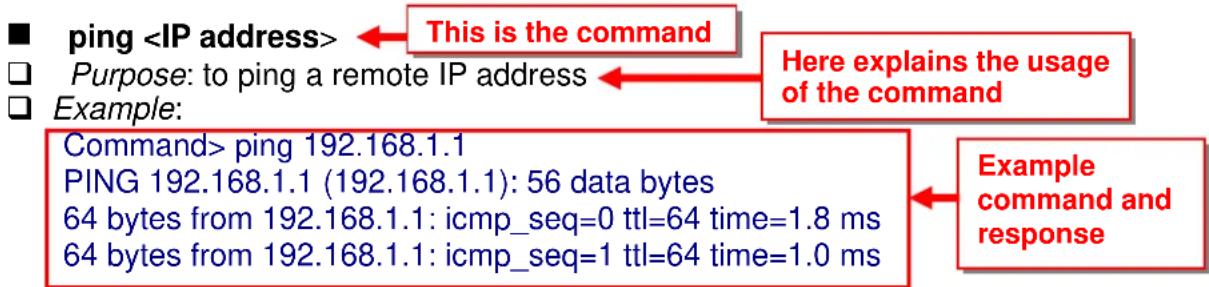
flowchart
graph TD
    A["ping <IP address>"] --> B["This is the command"]
    C["Purpose: to ping a remote IP address"] --> D["Here explains the usage of the command"]
    E["Example:"] --> F["Command> ping 192.168.1.1\nPING 192.168.1.1 (192.168.1.1): 56 data bytes\n64 bytes from 192.168.1.1: icmp_seq=0 ttl=64 time=1.8 ms\n64 bytes from 192.168.1.1: icmp_seq=1 ttl=64 time=1.0 ms"]
    F --> G["Example command and response"]
■ change password
☐ Purpose: Change login password
Example:
Command> change password 123
password is set to: 123
■ ftptest
Purpose: Test if a SSID's connection is okay
Example:
Command> ftptest airlive 11a 40
Set SSID : airlive, mode = 11a, channel = 40 ok!
■ save config
☐ Purpose: save configuration file. Please remember to "save config" after making changes
Example:
Command> save config
None
clear config
☐ Purpose: Clear configuration to default
Example:
Command> clear config
Are you sure? (y/n): y
Write flash block [/dev/mtd3]
Write file is [/etc/defsysconfig.conf]
Rebooting...
■ webservice
☐ Purpose: Enable or Disable Web management interface on LAN or WAN
Example:
Command> webservice lan enable
webservice from Ian enable
■ site survey
☐ Purpose: Site Survey display
Example:
Command> site survey
Please wait a moment for site survey...
| ESSID | MAC Address | Conn Mode | Channel | Turbo | Super | XR | WME | Signal | Strength(dbm) | Security | Network |
| airlive | 00:4f:79 | 90:00:27 | A | 36 | - | -- | * | -49 | None | ||
| airlive | 00:4f:69 | 52:a1:ca | A | 36 | - | -- | * | -61 | None | ||
| WHA-5500CPE-ap | 00:4f:69 | 90:00:01 | A | 36 | - | -- | * | -56 | |||
| AP | |||||||||||
■ signal survey
☐ Purpose : Display continuous RSSI for the remote AP/Bridge
Example :
Command> signal survey 00-4f-69-52-a1-ed 36
| BSSID | Channel | Signal Strength(dbm) |
| 00-4F-69-52-A1-ED | 36 | -40 |
| BSSID | Channel | Signal Strength(dbm) |
| 00-4F-69-52-A1-ED | 36 | -40 |
…
6.2 Debugging Commands
This debugging commands are commands used for manufacturing testing process. If a z_debug command looks similar to a Set command, please use the Set command instead.
■ z_debug http logout
Purpose : log out HTTP
Example :
Command> z_debug http logout
■ z_debug signature
☐ Purpose: Enable or disable signature check on firmware
Example:
Command> z_debug signature disable
Are you sure? (y/n): y
Signature check is now DISABLED!!!
■ z_debug add ssid
☐ Purpose: This command will replace the default ssid with the new one. It will not add an additional SSID. We recommend to use the following commands instead:
■ add ssid
■ set ssid
Example: Command> z_debug add ssid air1
■ z_debug reboot ☐ Purpose: reboot your WHA-5500CPE ☐ Example:
Command> z_debug reboot Rebooting...
■ z_debug set port radio1 11a
☐ Purpose: Set SSID and Channel. We recommend using set commands instead;
■ set ssid
■ set rate mode
Example:
Command> z_debug set port radio1 11a air2 64
6.3 Show Commands
Show Commands are command that show the settings and status of WHA-5500CPE
■ show arp table
□ Purpose: Show ARP Table
Example:
| Command> show arp table | |||
| IP address | Flags | HWaddress | Device |
| 192.168.1.100 | C | 00:1D:60:5E:AE:A0 | lan |
■ show http
☐ Purpose: Show HTTP service settings
Example:
Command> show http HTTP service port: 80 HTTP session timeout: 10 minutes
■ show upnp
☐ Purpose: Show UPnP information
Example:
Command> show upnp
UPnP is disabled
show mac
Purpose: show the MAC address table in MAC filter mode. This might change to show the wireless MAC address of WHA-5500CPE in future firmware release
Example:
Command> show mac
Filter Name MAC address
ailrive 00-4f-62-24-12-34
■ show mac filter
☐ Purpose: show mac address table in the Access Control List
Example:
Command> show mac filter
Filter Name MAC address
hello 00-4f-62-24-12-34
airlive 00-4f-62-24-11-11
■ show mac filter mode
☐ Purpose: Show whether the current MAC address is enable or not
Example:
Command> show mac filter mode
MAC filter mode: disable
■ show mac filter
☐ Purpose: show mac filter status with the filter name
Example:
Command> show mac filter hello
Filter Name MAC address
hello
00-4f-62-24-12-34
■ show radius server
☐ Purpose: Show radius server settings
Example:
Command> show radius server
RADIUS Server
State
IP/Port
Primary
Disabled
0.0.0.0/1812
Secondary
Disabled
0.0.0.0/1812
RADIUS Server reattempt: 60 seconds
■ show radius server
☐ Purpose: Show settings of primary or secondary radius server
Example:
Command> show radius server primary
RADIUS Server: primary
State: Disabled
Server IP: 0.0.0.0
Port Number: 1812
Shared Secret:
■ show log level
☐ Purpose: show log level
Example:
Command> show log level
Log level is 8
■ show telnet / system
☐ Purpose: show telnet management information and system status
Example:
Command> show telnet
Telnet session timeout: 0 minutes
Telnet port number: 23
Telnet state: enable
Command> show system
System Name: WHA-5500CPE
S/W Version: 1.00e09a
H/W Version: S0A
System LAN MAC: 00-4F-79-90-00-16
Wireless MAC: 00-4F-79-90-00-15
WMAC-0: 00-4F-79-90-00-15
show rssi
☐ Purpose: Show RSSI signal strength
Example:
Command> show rssi
Please wait a moment for site survey...
| ESSID | MAC Address | Signal Strength(dbm) |
| airlive | 0:4f:69:52:a1:ca | -59 |
| WHA-5500CPE-ap | 00:4f:69:90:00:01 | -47 |
■ show mode
☐ Purpose: Show what operation is AirMax currently set to
Example:
Command> show mode
operation mode: access point
■ show wireless setting
☐ Purpose: Show wireless settings
Example:
Command> show wireless setting
Radio[1] operation mode: access point
ssid name : air2
wireless state : enable
ssid broadcast : enable
radio[1] mode : 11a
radio[1] channel : 64
■ show wireless security
☐ Purpose: Show current wireless security policy
Example:
Command> show wireless security
Radio1 security policy: none
■ show
☐ Purpose: Show LAN or WAN port IP settings
Example:
Command> show lan settings
Lan ip type : static
Lan ip address : 192.168.1.1
Lan ip netmask : 255.255.255.0
Lan ip gateway : 192.168.1.254
Lan ip dnsserv : 0.0.0.0
show firmware version
show vlan ssid list
show wds settings
show advanced wireless
show syslogd
■ show ratemode
☐ Purpose: Show whether the AirMax is using 5MHz, 10MHz, or 20MHz channel width
Example:
Command> show ratemode
Ratemode is Full(20Mhz);
■ show noise immunity
☐ Purpose: Show the noise immunity setting
Example:
Command> show noise immunity
Noise immunity is enable
6.4 Set Commands
The Set Commands are to make changes to the WHA-5500CPE's settings
■ set http timeout
☐ Purpose: Set the timeout value for HTTP management
Example:
Command> set http timeout 10
HTTP timeout: 10 minutes
■ set system
Purpose: Set the system's location and contact info
Example: Command> set system location 60 System Location: 60
■ set system name
Purpose: Set system's name
Example:
Command> set system name airlive
System Name: airlive
■ set mac filter mode
☐ Purpose: Set MAC filter mode or disable MAC filtering.
Example:
Command> set mac filter mode disabled
mac filter mode is set to disabled
■ set radius server reattempt
☐ Purpose: set radius server reattempt interval in minutes
Example:
Command> set radius server reattempt 20
/etc/wlan/ap_service: 17: uname: not found
killall: wpa_supplicant: no process killed
/etc/wlan/ap_service: 17: uname: not found
Using /lib/modules/2.4.25-LSDK-5.1.0.42/wlan/ath_hal.o
Using /lib/modules/2.4.25-LSDK-5.1.0.42/wlan/ath_rate_atheros.o
Using /lib/modules/2.4.25-LSDK-5.1.0.42/wlan/ath_dfs.o
Using /lib/modules/2.4.25-LSDK-5.1.0.42/wlan/ath_ahb.o
<mapping sub-ioctl turbo to cmd 0x8BE0-1>
<mapping sub-ioctl set_installmode to cmd 0x8BE0-75>
<mapping sub-ioctl set_threslower to cmd 0x8BE0-76>
<mapping sub-ioctl set_threslow to cmd 0x8BE0-77>
<mapping sub-ioctl set_thresbetter to cmd 0x8BE0-78>
<mapping sub-ioctl set_thresbest to cmd 0x8BE0-79>
<mapping sub-ioctl maccmd to cmd 0x8BE0-17>
RTNETLINK answers: No such file or directory
RADIUS Server Reattempt Period: 20 Seconds
■ set telnet port
☐ Purpose: change the telnet port numer
Example:
Command> set telnet port 23
Changing telnet port may cause current telnet connections to be lost. Are you sure? (y/n): y Telnet port number: 23
■ set telnet timeout
☐ Purpose: Set Telnet management timeout
Example:
Command> set telnet timeout 10
Changing telnet timeout may cause current telnet connections to be lost. Are you sure ? (y/n) : y Telnet session timeout: 10 minutes
■ set wmm qos
☐ Purpose: Enable or Disable WMM QoS
Example:
Command> set wmm qos disable set wmm qos disable successful!
■ set log level <1-7>
Purpose: Set the log level
Example:
Command> set log level 7 set log level 7 successful
■ set client isolation
☐ Purpose: Enable or Disable client isolation / privacy separator
Example:
Command> set client isolation disable Set client isolation disable successful!
■ set operation mode
☐ Purpose: set or change operation mode
Example:
Command> set operation mode AP Operation mode is already setting!
Command> set operation mode wds_bridge System should be reboot...
Are you sure? (y/n): y
■ set
☐ Purpose: enable/disable ping response or web server on the lan/wan side
Example:
Command> set lan ping enable set lan ping already enable
■ set lan ip
☐ Purpose: set LAN IP address such as IP, Subnet mask, gateway, and DNS server
Example:
Command> set lan ip 192.168.1.1 sm 255.255.255.0 gw 192.168.1.254 dns 168.95.1.1
killall: dnsmasq: no process killed
LAN IP address : 192.168.1.1
Netmask : 255.255.255.0
Gateway : 192.168.1.254
DNS server : 168.95.1.1
■ set
☐ Purpose: Enable or Disable the wireless interface
Example:
Command> set enable Radio1 enabled
■ set ssid
☐ Purpose: Replace current main SSID name with a new one
Example:
Command> set ssid WHA-5500CPE
■ set ssid remotessid
☐ Purpose: Set the remote SSID name for repeater mode
Example:
Command> set ssid remotessid airlive2
■ set broadcast
☐ Purpose: Enable or disable SSID broadcast
Example:
Command> set broadcast enable Radio1 broadcast enabled
■ set radio mode
☐ Purpose: set radio mode to 11a | supera_no_turbo | supera_static_turbo. | supera_dynamic_turbo
Example:
Command> set radio mode supera_no_turbo Radio1 radio mode: supera_no_turbo
■ set channel
☐ Purpose: set wireless channel
Example:
Command> set channel 36 Radio1 channel: 36
■ set beacon interval
☐ Purpose: set beacon interval for wireless interface. For explanation on advance wireless parameters, please refer to section 4.2.14
Example:
Command> set beacon interval 100
Radio1 beacon internal: 100
■ set rts threshold
☐ Purpose: set rts threshold. For explanation on advance wireless parameters, please refer to section 4.2.14
Example:
Command> set rts threshold 2347
Radio1 RTS threshold: 2347
■ set fragmentation
☐ Purpose: set fragmentation value. For explanation on advance wireless parameters, please refer to section 4.2.14
Example:
Command> set fragmentation 2346
Radio1 fragmentation: 2346
■ set dtim interval
☐ Purpose: To set dtim interval value. For explanation on advance wireless parameters, please refer to section 4.2.14
Example:
Command> set dtim interval 1
Radio1 DTIM interval: 1
■ set user limitation
☐ Purpose: To set the user limit for wireless interface
Example:
Command> set user limitation 100
Radio1 user limitation: 100
■ set age out time
☐ Purpose: To set the age timeout for wireless clients.
Example:
Command> set age out time 5
Radio1 age out time: 5
■ set transmit power
☐ Purpose: To set the TX output power value of the radio
Example:
Command> set transmit power 20
Radio1 transmit power: 20
■ set data rate
☐ Purpose: To set the date rate. For example, 54mbps, 36mbps....etc
Example:
Command> set data rate 54
Radio1 data rate: 54
■ set acktimeout <11A>
☐ Purpose: To set the ACK timeout value
Example:
Command> set acktimeout 25
AckTimeOut for radio1: 11A=25
■ set vlan for ssid
☐ Purpose: Enable VLAN function
Example:
Command> set vlan for ssid enable
■ set diffserv marking
☐ Purpose: To enable diffserv marking function in multiple SSID & VLAN configuration.
Example:
Command> set diffserv marking enable
■ set security
☐ Purpose: To remove security policy from a SSID
Example:
Command> set security airlive none
Set Radio1 no security!
■ set security
☐ Purpose: To set the WEP security policy
Example:
Command> set security WHA-5500CPE wep 1 64 hex 1234567890
Radio1 authentication type : wep !
■ set security
☐ Purpose: to set the WPA or WPA2 security policy
Example:
Command> set security WHA-5500CPE wpa2 tkip interval 300
Radio1 authentication type : wpa2 !
■ set security
☐ Purpose: to set the WPA-PSK or WPA2-PSK security policy
Example:
Command> set security WHA-5500CPE wpa2-psk aes interval 300 12345678
Radio1 authentication type : wpa2-psk !
■ set ratemode
Purpose:
Example:
Command> set ratemode full
Rate mode is Full(20Mhz)
■ set noise immunity
☐ Purpose: To enable/disable the noise immunity level
Example:
Command> set noise immunity on
Noise immunity is enable
6.5 Enable/Disable Commands
Commands to enable or disable settings
■ ( enable/disable ):
☐ Purpose: To enable or disable UPnP
Example:
Command>enable upnp
(Upnp)descDocName: BD.xml
UPnP Daemon: Initializing UPnP with descDocUrl=http://192.168.1.1:80/BD.xml
UPnP Daemon: ipaddress=192.168.1.1 port=80
UPnP Daemon: conf_dir_path=/var/upnp
Initializing UPnP SDK ...
UPnP SDK Successfully Initialized.
Setting the Web Server Root Directory to /var/upnp
Successfully set the Web Server Root Directory.
UpnpGetServerPort(): 49152
Registering the root device with descDocUrl http://192.168.1.1:49152/BD.xml
IGD root device successfully registered.
Advertisements Sent. Listening for requests ...
Command> disable upnp
Shutting down on signal 15...
UPnP is disabled
■
☐ Purpose: To enable or disable syslog
Example:
Command> enable syslogd
Invalid configuration specified.
Command> disable syslogd
Syslogd is disabled
■
☐ Purpose: To enable or disable primary/secondary radius server
Example:
Command> enable radius server primary
Invalid configuration specified.
Command> enable radius server secondary
Invalid configuration specified.
6.6 Add/Delete Commands
Commands to add or delete settings
( add/delete ): add mac filter < Mnemonics Name> < MAC address, XX-XX-XX-XX-X-XX>
☐ Purpose: to add an entry to the MAC address filter
Example:
Command> add mac filter aaa 00-4f-62-24-12-34
/etc/wlan/ap_service: 17: uname: not found
killall: wpa_supplicant: no process killed
/etc/wlan/ap_service: 17: uname: not found
Using /lib/modules/2.4.25-LSDK-5.1.0.42/wlan/ath_hal.o
Using /lib/modules/2.4.25-LSDK-5.1.0.42/wlan/ath_rate_atheros.o
Using /lib/modules/2.4.25-LSDK-5.1.0.42/wlan/ath_dfs.o
Using /lib/modules/2.4.25-LSDK-5.1.0.42/wlan/ath_ahb.o
RTNETLINK answers: No such file or directory
RTNETLINK answers: No such file or directory
mac filter aaa(00-4F-62-24-12-34) is added
■ delete mac filter < Mnemonics Name>
☐ Purpose: to delete a mac filter entry
Example:
Command> delete mac filter aaa
/etc/wlan/ap_service: 17: uname: not found
killall: wpa_supplicant: no process killed
/etc/wlan/ap_service: 17: uname: not found
Using /lib/modules/2.4.25-LSDK-5.1.0.42/wlan/ath_hal.o
Using /lib/modules/2.4.25-LSDK-5.1.0.42/wlan/ath_rate_atheros.o
Using /lib/modules/2.4.25-LSDK-5.1.0.42/wlan/ath_dfs.o
Using /lib/modules/2.4.25-LSDK-5.1.0.42/wlan/ath_ahb.o
■ delete wds
☐ Purpose: To delete a WDS link
Example:
Command> delete wds bridge
delete wds
■ add radius server primary
☐ Purpose: to add a primary radius server
Example:
Command> add radius server primary
enter server IP:
192.168.1.100
enter port number (1\~65535):
655
enter shared secret:
123
enable server (yes/no):
yes
/etc/wlan/ap_service: 17: uname: not found
killall: wpa_supplicant: no process killed
/etc/wlan/ap service: 17: uname: not found
Using /lib/modules/2.4.25-LSDK-5.1.0.42/wlan/ath_hal.o
Using /lib/modules/2.4.25-LSDK-5.1.0.42/wlan/ath_rate_atheros.o
Using /lib/modules/2.4.25-LSDK-5.1.0.42/wlan/ath_dfs.o
Using /lib/modules/2.4.25-LSDK-5.1.0.42/wlan/ath_ahb.o
■ add radius server
☐ Purpose: to add a primary or secondary radius server
Example:
Command> add radius server secondary
enter server IP:
192.168.1.200
enter port number (1\~65535):
766
enter shared secret:
234
enable server (yes/no):
yes
/etc/wlan/ap_service: 17: uname: not found
killall: wpa_supplicant: no process killed
/etc/wlan/ap_service: 17: uname: not found
Using /lib/modules/2.4.25-LSDK-5.1.0.42/wlan/ath_hal.o
Using /lib/modules/2.4.25-LSDK-5.1.0.42/wlan/ath_rate_atheros.o
Using /lib/modules/2.4.25-LSDK-5.1.0.42/wlan/ath_dfs.o
Using /lib/modules/2.4.25-LSDK-5.1.0.42/wlan/ath_ahb.o
RTNETLINK answers: No such file or directory
RTNETLINK answers: No such file or directory
add radius server secondary successfully
■ add wds
☐ Purpose: to add a WDS Link
Example:
Command> add wds bridge 00-4f-60-52-12-34
add wds
■ add ssid
☐ Purpose: to add a new ssid (AP and AP Router mode) to the multiple SSID list.
Example:
Command> add ssid air03 broadcast enable
Add R1 ssid
7
Application Example: Infrastructure
In this chapter, you will learn how to utilize WHA-5500CPE's Access Point mode, Client Infrastructure Mode, and Bridge Infrastructure mode in one application example. In addition, you will also learn how to configure multiple SSID and bandwidth control.
7.1 Application Environment
In this application example, an WHA-5500CPE in Access Point mode is in the center of an infrastructure topology with two virtual wireless networks. The first wireless network is the AP-Client network and the second network is the Bridge network. Each wireless network has its own SSID, security Policy and Bandwidth policy. On the left hand side is an WHA-5500CPE in Bridge Infrastructure mode. On the right hand side are an WHA-5500CPE (Client Mode), a notebook, and a PC.
Below is the general description about the devices of the network.

flowchart
graph LR
    subgraph SSID:bridgeinf
        A["AP Mode"] -->|Downlink: 2MB\nUplink: 512K| B["Bridge Infrastructure"]
        B -->|Downlink: 10MB\nUplink: 10MB| A
    end

    subgraph SSID:airliveclient
        C["Client Mode"] --> D["WHA-5500CPE 192.168.1.100"]
        D --> E["NB 192.168.1.101"]
        E --> F["L 192.168.1.102"]
    end

    style SSID fill:#f9f,stroke:#333
    style SSID fill:#ccf,stroke:#333
Device A: WHA-5500CPE in Access Point Mode
☐ Using multiple SSID to create 2 wireless network
■ airliveclient: A network for wireless clients with WPA-PSK security policy.
■ bridgeinf: A bridge network with WPA-PSK2 security policy
☐ Enable Per-User bandwidth Control for the "airliveclient" network
■ The wireless client network will be limited to a subnet of 6 IP addresses.
■ Each IP address will be limited to 512Kbps upload and 2MB download speed.
Device B: WHA-5500CPE in Bridge Infrastructure Mode
☐ Using Total bandwidth Control to limit the Bridge traffic to 10Mbps both way.
☐ Use Site Survey wizard to make the connection in a simple one stop process.
Device C: WHA-5500CPE in Client Infrastructure Mode
☐ Connect to the Access Point using Client Infrastructure Multiple User mode.
☐ Use Site Survey to connect and associate with the AP.
7.2 Device A: Access Point Mode
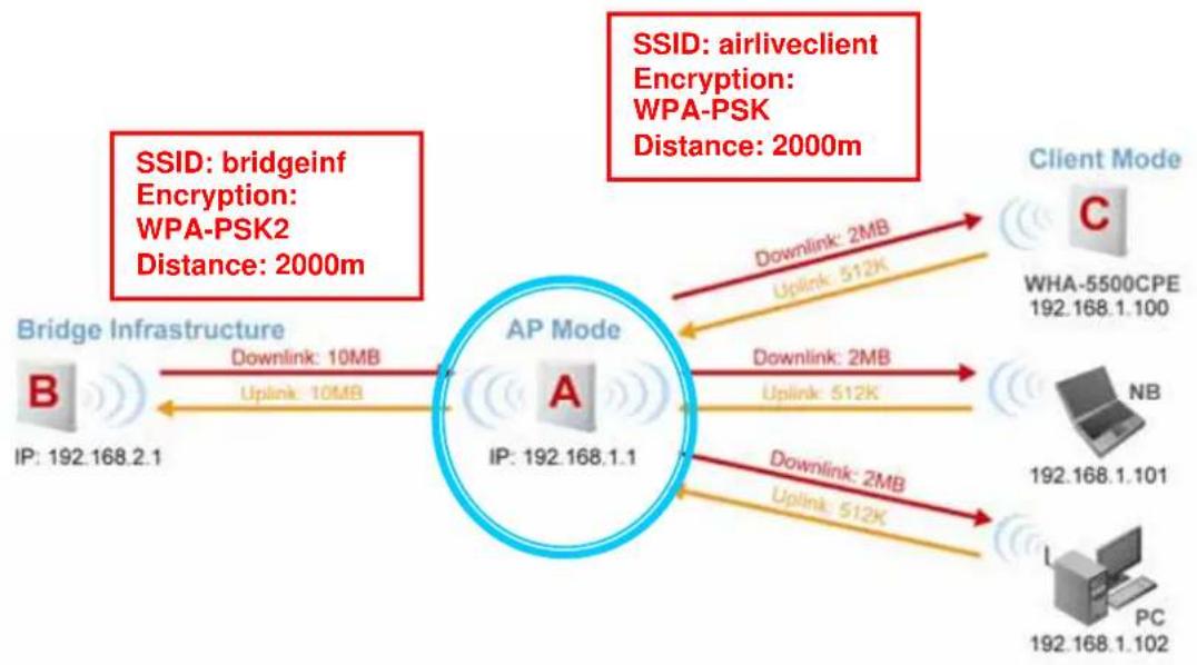
flowchart
graph TD
    A["AP Mode"] -->|Downlink: 2MB\nUplink: 512K| B["Client Mode C"]
    A -->|Downlink: 2MB\nUplink: 512K| C["WHA-5500CPE 192.168.1.100"]
    A -->|Downlink: 2MB\nUplink: 512K| D["NB 192.168.1.101"]
    A -->|Downlink: 2MB\nUplink: 512K| E["PC 192.168.1.102"]
    F["Bridge Infrastructure"] -->|Downlink: 10MB\nUplink: 10MB| G["B"]
    F --> H["IP: 192.168.2.1"]
    I["SSID: airlineclient\nEncryption: WPA-PSK\nDistance: 2000m"] --> A
    I --> J["SSID: bridgeinf\nEncryption: WPA-PSK2\nDistance: 2000m"]
The configuration of Device A involves the followings:
☐ Using multiple SSID to create 2 wireless network
■ airliveclient: A network for wireless clients with WPA-PSK security policy.
■ bridgeinf: A bridge network with WPA-PSK2 security policy
☐ Enable Per-User bandwidth Control for the "airliveclient" network
■ The wireless client network will be limited to a subnet of 6 IP addresses.
■ Each IP address will be limited to 512Kbps upload and 2Mbps download speed.
7.2.1 Device A Wireless Settings
Step 1 Click on "setup" button on the "Operation Mode" page

Step 2 On the wireless setting page, please enter the SSID, Channel, and distance. Then press "Apply" to make changes.
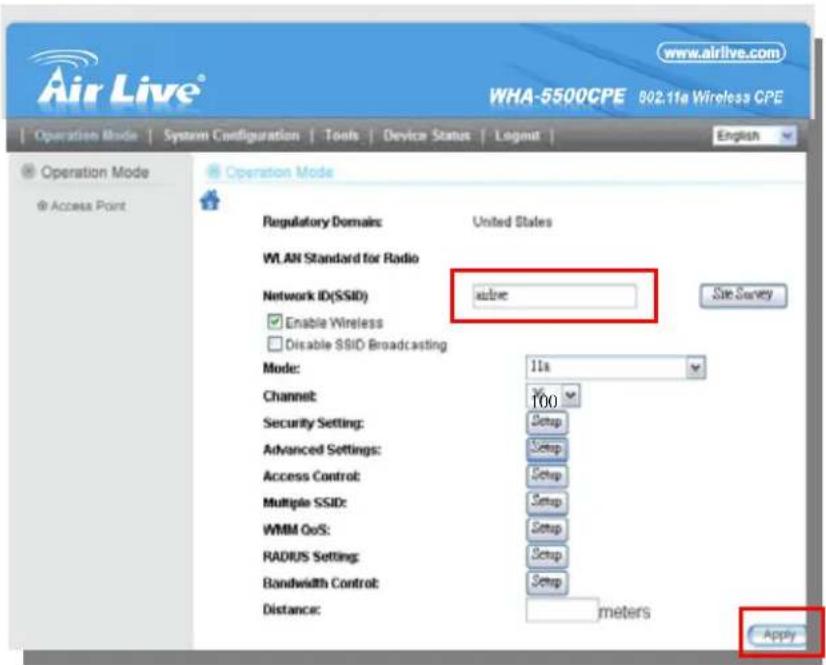
Step 3 Click on the "Security Settings". Then choose "WPA-PSK" Policy. Enter the "airliveclientkey" as the pre-share key.

Step 4 Go back to the wireless setting page and click on "Multiple SSID" button

Step 5 Follow the procedure below to create a new SSID "bridgeinf"
- Enter the SSID name "bridgeinf"
- Select WPA-PSK as the security policy
- Enter the pre-share key as "bridgeinfkey"
- Click on "Apply" to add
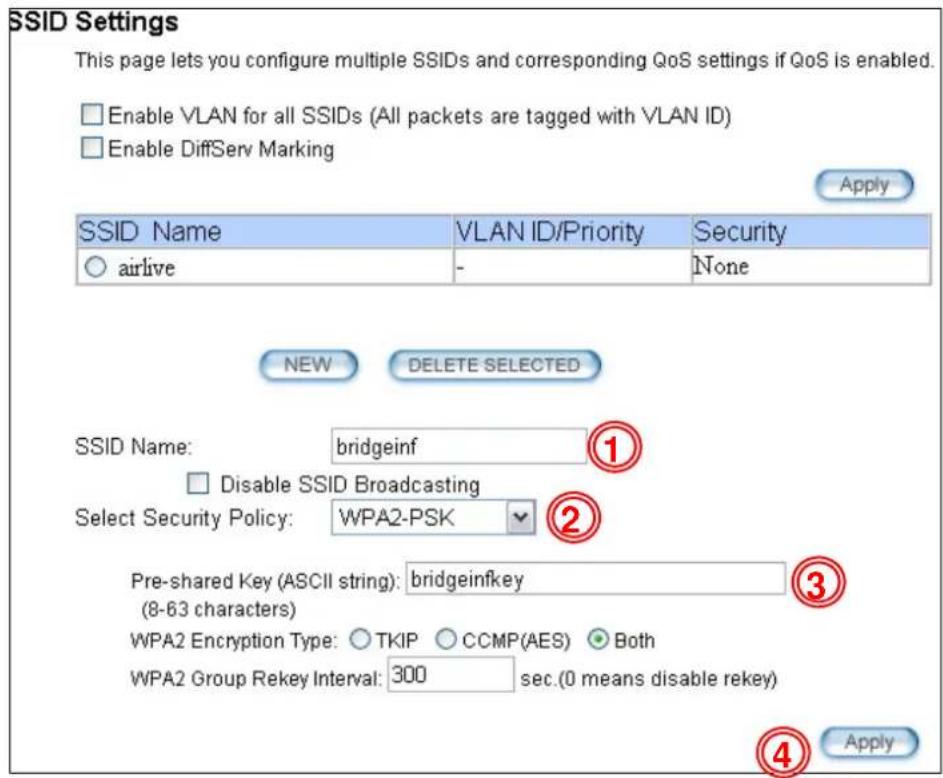
7.2.2 Device A Bandwidth Management
This purpose is to limit the bandwidth of each wireless client in “airliveclient” network to have a download bandwidth of 2048kbps and upload speed of 512kbps. We should set the policy as followed.
☐ Set the Per-User Bandwidth Control by “IP Segment”. The IP segment here has address of 192.168.1.100 with subnet mask of 255.255.255.248. The available host IP addresses will be 192.168.1.96 to 192.168.1.02. If you are not familiar with IP subnet calculation, please use an on-line IP calculator. Here is an example link: http://www.subnet-calculator.com/
☐ Set the uplink as 512kbps, downlink as 2048mbps
Step 1 Select the "Bandwidth Control" from the "Operation Mode->Setup" menu
Step 2 Once you have entered the Bandwidth Control menu, please follow the steps below
- Enable Bandwidth Control
-
Select "Per-User Bandwidth Control."
-
Enter "for client" in description
- Select "IP Segment. Enter 192.168.1.100 for IP, and "255.255.255.248" for subnet mask.
- Enter 2048 for downlink and 512 for uplink
- Click on "Add" to add the bandwidth policy.

Note: Because the Bandwidth Control will limit devices on both wireless and Ethernet side, it is recommended to set the IP address of Ethernet side to have a larger IP scope so it will not be limited by the IP segment policy. In this example, please set the devices on the Ethernet side to have subnet mask of 255.255.255.0.
7.3 Device B: Bridge Infrastructure Mode
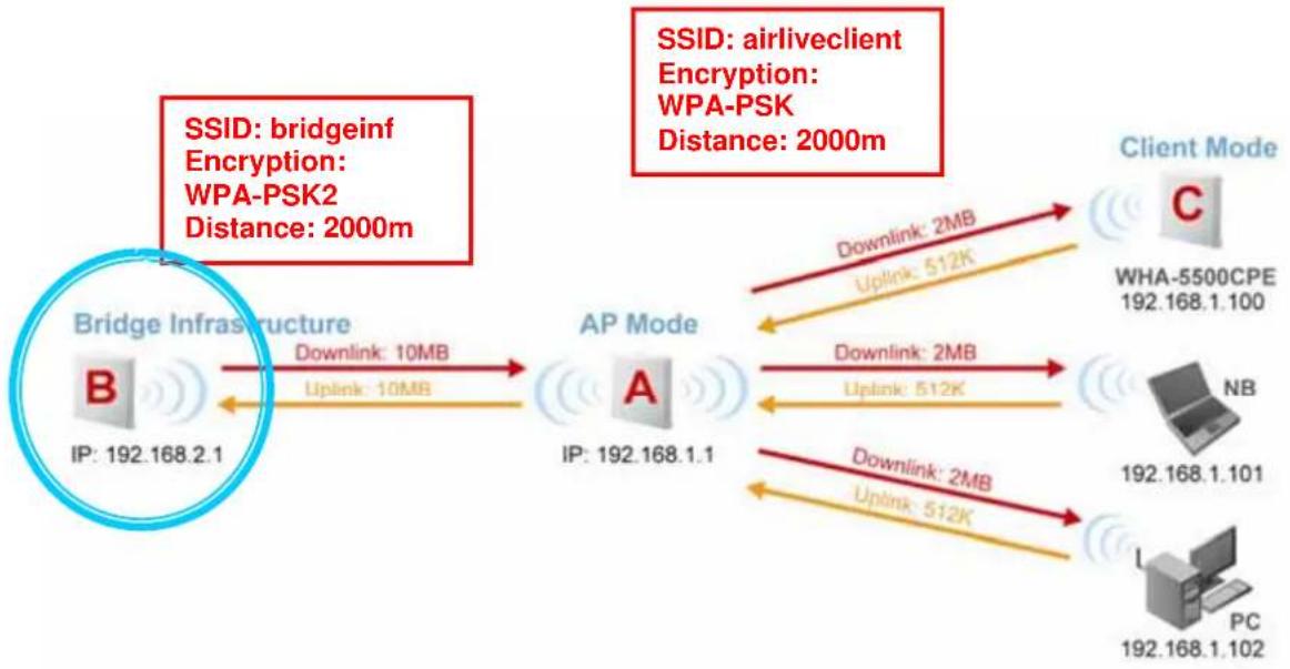
flowchart
graph LR
    A["Bridge Infrastructure"] -->|Downlink: 10MB\nUplink: 10MB| B["AP Mode"]
    B -->|Downlink: 2MB\nUplink: 512K| C["Client Mode"]
    C -->|Downlink: 2MB\nUplink: 512K| D["WHA-5500CPE 192.168.1.100"]
    D --> E["NB 192.168.1.101"]
    E --> F["PC 192.168.1.102"]
    F --> G["Client Mode"]
    style A fill:#f9f,stroke:#333
    style B fill:#ccf,stroke:#333
    style C fill:#cfc,stroke:#333
    style D fill:#fcc,stroke:#333
    style E fill:#cff,stroke:#333
    style F fill:#ffc,stroke:#333
    style G fill:#fcc,stroke:#333
The configuration settings on the Device B will be as followed
☐ Set it to "Bridge Infrastructure Mode"
☐ Use "Site Survey" function to associate and connect with the Device A.
☐ Set "Total Bandwidth Control" to limit the bandwidth to 10Mbps both upstream and downstream
7.3.1 Device B Wireless Settings
Step 1 Select "Bridge Infrastructure" mode and Click on "change mode" button

Step 2 Enter the Network ID(SSID) and distance information. Then click on "Apply"

Step 3 Click on "Site Survey" in wireless settings page and the following screen will appear. Select "Bridgeinf", then press "ASSOCIATE" button to connect.
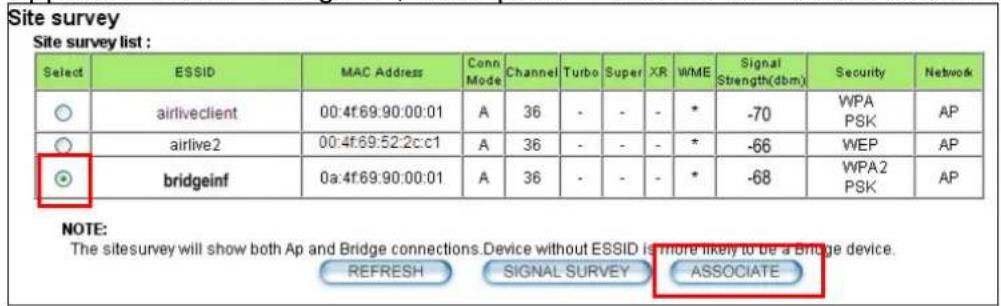
Step 4 The WHA-5500CPE will prompt you to enter security policy information. Select WPA2-PSK and enter "bridgeinfkey" for Pre-Shared Key.

Step 3 Click on "Apply". After a few seconds, the following screen will appear to show successful connection.

7.3.2 Device B Total Bandwidth Control
Step 1 Select "Bandwidth Control" from the wireless setting page.

Step 2 Enable Bandwidth Control, then select Total Bandwidth Control. Enter 10000Kbps (10Mbps) for both downlink and uplink bandwidth. Click on Apply to finish.
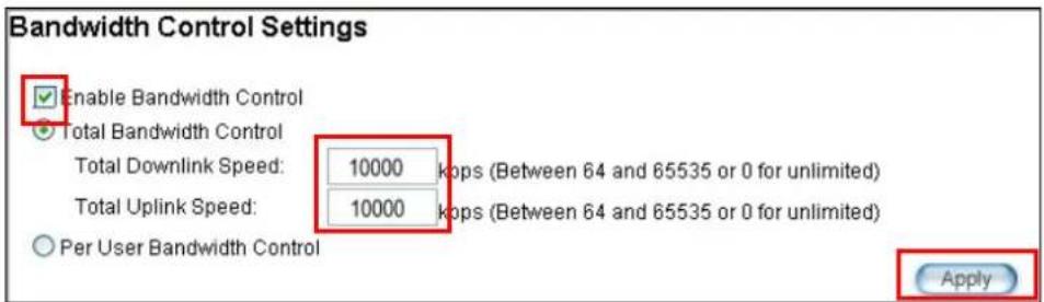
7.4 Device C: Client Infrastructure Mode

flowchart
graph LR
    A["Bridge Infrastructure"] -->|Downlink: 10MB\nUplink: 10MB| B["AP Mode"]
    B -->|Downlink: 2MB\nUplink: 512K| C["Client Mode"]
    C -->|Downlink: 2MB\nUplink: 512K| D["WHA-5500CPE 192.168.1.100"]
    D -->|Downlink: 2MB\nUplink: 512K| E["PC 192.168.1.102"]
    F["SSID: bridgeinf\nEncryption: WPA-PSK2\nDistance: 2000m"] --> B
    G["SSID: airliveclient\nEncryption: WPA-PSK\nDistance: 2000m"] --> C
Device C: WHA-5500CPE in Client Infrastructure Mode
☐ Set device IP to 192.168.1.100 with subnet mask of 255.255.255.248
☐ Connect to the Access Point using Client Infrastructure Multiple User mode.
☐ Use Site Survey to connect and associate with the AP.
7.4.1 Device C IP Address
Step 1 Go to "System Configuration -> Device IP settings". Select "Assign Static IP to this device". Then enter the IP address and Subnet Mask as bellowed. Click Apply when finished.

7.4.2 Device C Wireless Settings
Step 1 Go to "Operation Mode" menu. Select "Client Infrastructure", and then click on "Change Mode" button.

Step 2 Press "Setup" to enter the wireless settings page. Enter the distance information and click on "APPLY" button.

Step 3 Press "Site Survey" button, the following page should appear. Select "airliveclient" and press "Associate" button to connect
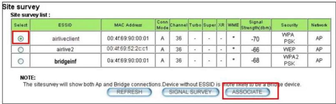
Step 4 The WHA-5500CPE will prompt you to enter security policy information. Select WPA-PSK and enter "airliveclientkey" for Pre-Shared Key.

Step 5 Click on "Apply". After a few seconds, the following screen will appear to show successful connection.

You have now setup a successful Infrastructure network with WHA-5500CPE in Access Point, Bridge Infrastructure, and Client Infrastructure modes
8
Application Example 2: Bridge Network
Before reading this chapter, please read section 4.3 first on WDS settings. In this chapter, you will learn to how to build a WDS Bridge network by following our step by step example. In addition, we will talk about the general concepts and knowledge about building a long distance connection.
This chapter is divided into 3 sections
☐ 8.1: Preparation for Building Outdoor Bridge Networks: This section provides basic knowledge about building long distance outdoor bridge connection.
☐ 8.2: WDS Bridge vs. Bridge Infrastructure: Here we will discuss the differences between the 2 bridge mode.
☐ 8.3: WDS Bridge Network Example: A step-by-step guide to building a multiple link Bridge network.
8.1 Preparation for Building Outdoor Bridge Networks
1. Write down the WLAN MAC address in advance
Please remember to write down the WLAN MAC addresses of the AP for installation. The WDS bridge require to enter remote Bridge's MAC address for WDS authentication.
2. Always do a Google Earth search on the intended installation before departing
Please get information on location, elevation, and distance between the points of your installation site
3. Bring a pair of high powered binoculars for site survey
You might often find that the installation points are difficult to find over long distance. A pair of hi powered binocular will help finding the objects. Look for landmarks that are easy to identify.
4. Bring Long Distance Walkie-Talkie System
There are hi-powered offering that can work over distance of 5km or more. Communication is absolutely necessary on both sides during installation.
5. You need a clear Line of sight
More than 60% of First Fresnel Zone must be cleared for acceptable performance.
6. Secured Mounting is important
If the mounting is not secured and shakes during wind, the performance might be drastically reduced.
7. Remember to set correct Distance for long distance connection
Without setting the correct distance parameter (or ACKtimeout), the Bridge might not even transmit data at all.
8. Use just enough output power
Excessive output power not only creates serious interference for everyone, it actually can reduce the performance. An RSSI value around 60dB provides the optimal performance.
9. Always do a site survey for antenna alignment
Most AirLive APs have site survey and signal survey function. It is important that the antennas are aligned properly. If you are setting up 5GHz bridge, please use "11a" mode first for antenna alignment. You can change to Super or Turbo mode after the connection is established.
10. Use the correct Super or Turbo modes
- 11a mode (normal-A): This is the IEEE standard for WiFi operating in 5GHz frequency band. 11a is the most stable mode. If you are getting packet loss or disconnection using Super-A or Turbo-A mode. Please use 11a mode instead.
- SuperA without Turbo: Super-A adds Bursting and Compression to increase the speed over 11a mode. If you live in countries that prohibit the channel binding technology (i.e. Europe), you should choose “Super-A without Turbo) if you need more speed than 11a mode. However, this mode is not as stable as 11a mode or Super-A with Turbo-A modes.
- Super-A with Static Turbo: Turbo mode uses channel binding technology to increase the speed further over Super-A and 11-A mode. This mode might not be allowed in countries that prohibit channel binding (i.e. some EU countries). This mode will always turn on the turbo mode in al conditions
- Super-A with Dynamic Turbo: Dynamic Turbo mode will be turn on only when adjacent channel is not used. It is also known as intelligent turbo mode. This mode might not be allowed in countries that prohibit channel binding (i.e. some EU countries).
11. For multi-point connection, use bandwidth control to manage the variable distance problem
Using ACKtimeout for point-to-point connection is no problem. However, for point to multi-point connection, it becomes a problem at the center point. In the diagram below, the WHA-5500CPE at point A is the center hub. While wireless clients at B, C, and D can set correct ACKtimeout values to point A, the center AP can set only one Acktimeout value.

flowchart
graph TD
    A["AP Mode"] -->|3km| B["WHA-5500CPE"]
    C["Client Mode"] -->|1km| D["WHA-5500CPE"]
    E["Client Mode"] -->|2km| F["WHA-5500CPE"]
    style A fill:#f9f,stroke:#333
    style B fill:#ccf,stroke:#333
    style C fill:#cfc,stroke:#333
    style D fill:#fcc,stroke:#333
    style E fill:#cff,stroke:#333
    style F fill:#ffc,stroke:#333
To illustrate this problem; when you set the ACKtimeout at Point A to 2km distance. The likely result will be Point B will get about 90% of the bandwidth, Point C gets 10% , and Point D gets nothing at all.
To solve this problem, please use total bandwidth control at point B, C, D to limit the bandwidth to about 40% of total bandwidth each maximum. Then set the AP's(Point A) ACKtimeout value to 3km distance (the furthest point). All 3 points should then get acceptable share of the bandwidth.
12. Use XR mode when you can't connect with the extra sensitivity
Atheros eXtended Range mode will improve the AP's receiver sensitivity to as high as -105dB. However, when this mode is used, the performance may be reduced greatly.
8.2 WDS Bridge vs. Bridge Infrastructure
When you want to build a bridge connection, there are 2 choices with WHA-5500CPE:
☐ WDS Bridge (Pure MAC): WDS Bridge mode can make Point-to-Point and Multi-Point connections. It also delivers faster performance than infrastructure networks. In a WDS network, each node can have up to 4 connections but the total number of devices should not exceed 8. Currently, the WDS Bridge mode can only
use WEP encryptions policy.

flowchart
graph TD
    A["Office LAN"] -->|802.1d STP| B["WDS Bridge"]
    B -->|802.1d STP| C["Warehouse LAN"]
    C -->|802.1d STP| D["Factory LAN"]
    D -->|WDS Bridge| B
    style A fill:#f9f,stroke:#333
    style B fill:#ccf,stroke:#333
    style C fill:#cfc,stroke:#333
    style D fill:#fcc,stroke:#333
☐ Bridge Infrastructure: Bridge Infrastructure mode connects to AP mode to form a star topology. Bridge Infrastructure mode can not make a Point-to-Point connection. However, it works with WPA-PSK and WPA2-PSK encryption. This mode is also unknown as Client Mode with MAC Address Transparency.

flowchart
graph LR
    A["AP"] -->|WHA-5500CPE| B["Bridge Infrastructure"]
    B -->|LAN| C["WHA-5500CPE"]
    B -->|LAN| D["Bridge Infrastructure"]
When to use which bridge mode:
□ WDS Bridge Mode:
■ When you making point-to-point connection. For example, when you build wireless bridge network between office and warehouse.
■ When you require fast performance
■ When you require multiple star topologies.
□ Bridge Infrastructure
■ When you are connection both Bridge network and wireless client to the remote Access Point
■ When you require more advance security like WPA and WPA2
TIPS: For step-by-step instruction on how to setup Bridge Infrastructure mode, please go to Chapter 8 Application Example: Infrastructure Mode.
8.3 WDS Bridge Network Example
In this WDS Bridge example, you will learn how to:
Setup the WDS settings
☐ Set to use different encryption key for different Link
□ SSID's function for WDS bridge
☐ PING watchdog to maintain the WDS Link.
There are total of 3 bridges; with Bridge1 in the middle of Bridge 2 and Bridge 3.
☐ The link between Bridge 1 and Bridge 3 will be using WEP Key 1 with SSID airlive1-3.
☐ The link between Bridge 1 and Bridge 2 will be using WEP Key2 with SSID airlive1-2.

flowchart
graph TD
    A["WDS Bridge 3"] -->|WDS| B["WDS Bridge 1"]
    B -->|WDS| C["WDS Bridge 2"]
    D["MAC: 00-4f-79-90-00-23\nSSID: airlive3\nIP: 192.168.1.3"] --> E["MAC: 00-4f-79-90-00-0b\nSSID: airlive1\nIP: 192.168.1.1"]
    F["MAC: 00-4f-79-90-00-14\nSSID: airlive2\nIP: 192.168.1.2"] --> G["MAC: 00-4f-79-90-00-14\nSSID: airlive2\nIP: 192.168.1.2"]
WDS Bridge 1 Settings
- Enter the WEP Encryption Keys. You can enter 4 keys with different key-length and key type. In this example, we have 4 WEP keys with WEP152-HEX, WEP152-ASCII, WEP128-ASCII, and WEP64-ASCII. Click on "Apply" after entering the keys.
2. Adding the first WDS Link to WDS Bridge 3
■ Name: WDS3
■ SSID: airlive1-3
■ MAC address: you should enter the MAC address of WDS Bridge 3:00-4f-79-90-00-23
■ Select Security Policy: Select "WEP" encryption. The WHA-5500CPE will ask
you to select which key to use. You can select same key or different key for different WDS link (however, both side of the same link must use the same key). In this case, the Link between Bridge 1 and 3 is using Key1.
- Click on "Add" to add the WDS Link.
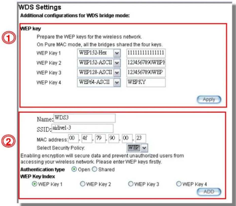
3. Adding the second WDS Link to WDS Bridge 2
■ Name: WDS2
■ SSID: airlive1-2
■ MAC address: please enter the MAC address of WDS Bridge2:00-4f-79-90-00-14
■ Select Security Policy: Select "WEP" encryption. The WHA-5500CPE will ask you to select which key to use. The Link between Bridge 1 and 3 is using Key2.
- Click on "Add" to add the WDS Link.
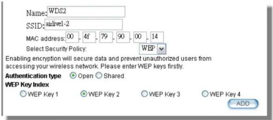
The following table will be displayed to show the added WDS links:
| Select | Name | SSID | MAC Address | Security | WEP key Index |
| ○ | WD3 | airlive1-3 | 00-4f-79-90-00-23 | WEP | 1 |
| ○ | WD2 | airlive1-2 | 00-4f-79-90-00-14 | WEP | 2 |
DELETE SELECTED
- Setup the PING watchdog. Ping watchdog will reboot or reconnect the WHA-5500CPE when the remote device does not respond to PING command. It helps maintain the WDS Link. Please setup the PING watchdog according to graphic below:

WDS Bridge 2 Settings
-
Enter the WEP Encryption Keys. In this example, we have 4 WEP keys with WEP152-HEX, WEP152-ASCII, WEP128-ASCII, and WEP64-ASCII. Click on "Apply" after entering the keys.
-
Adding the WDS Link to WDS Bridge 1
■ Name: WDS1
■ SSID: airlive1-2
■ MAC address: you should enter the MAC address of WDS Bridge 1:00-4f-79-90-00-0b
■ Select Security Policy: Select "WEP" encryption. The WHA-5500CPE will ask you to select which key to use. You can select same key or different key for different WDS link (however, both side of the same link must use the same key). In this case, the Link between Bridge 1 and 2 is using Key2.
- Click on "Add" to add the WDS Link.

- Setup the PING watchdog. Please setup the PING watchdog according to graphic below:
© Ping Watchdog
The Ping Watchdog will ping up to 2 IP addresses for connection status. If the remote IP addresses do not respond to Ping, the device will either reconnect or power reboot.

IP Address 1:
IP Address 2:
Ping Frequency:
Failed tries:
Action:

Note: Watchdog will take effect 10 minutes after startup. IP Address 2 is optional, when filled, both IP Address 1 and IP Address 2 must fail to respond for watchdog to take action.

WDS Bridge 3 Settings
-
Enter the WEP Encryption Keys. In this example, we have 4 WEP keys with WEP152-HEX, WEP152-ASCII, WEP128-ASCII, and WEP64-ASCII. Click on "Apply" after entering the keys.
-
Adding the WDS Link to WDS Bridge 1
■ Name: WDS1
■ SSID: airlive1-3
■ MAC address: you should enter the MAC address of WDS Bridge 1:00-4f-79-90-00-0b
■ Select Security Policy: Select "WEP" encryption. The WHA-5500CPE will ask you to select which key to use. You can select same key or different key for different WDS link (however, both side of the same link must use the same key). In this case, the Link between Bridge 1 and 3 is using Key1.
- Click on "Add" to add the WDS Link.
WDS Settings
Additional configurations for WDS bridge mode:
WEP key

Prepare the WEP keys for the wireless network.
On Pure MAC mode, all the bridges shared the four keys.

Apply


Enabling encryption will secure data and prevent unauthorized users from accessing your wireless network. Please enter WEP keys firstly.
Authentication type Open Shared
WEP Key Index
iVEP Key 1
○ WEP Key 2
○ WEP Key 3
○ WEP Key 4
ADD
- Setup the PING watchdog. Please setup the PING watchdog according to graphic below:
② Ping Watchdog
The Ping Watchdog will ping up to 2 IP addresses for connection status. If the remote IP addresses do not respond to Ping, the device will either reconnect or power reboot.

IP Address 1:
IP Address 2:
Ping Frequency:
Failed tries:
Action:

Note: Watchdog will take effect 10 minutes after startup. IP Address 2 is optional, when filled, both IP Address 1 and IP Address 2 must fail to respond for watchdog to take action.
Apply
After the above settings, the 3 WDS bridges should connect properly. Be sure to set the Distance parameter for long distance connection.
9
Application Example 3: Router and Repeater
In this chapter, you will learn how to use Repeater mode and WISP Router mode in one network example. In addition, some router settings such as how to setup virtual server will also be demonstrated.
9.1 Application Environment
In the following application, the network is consisted of an Outdoor AP in the center, an WHA-5500CPE in WISP Router mode on the left, and a WHA-5500CPE in Repeater mode on the right.

flowchart
graph TD
    A["WISP Mode"] --> B["FTP Server: 192.168.2.100"]
    B --> C["WhA-5500CPE"]
    C --> D["Outdoor AP"]
    D --> E["SSID: OutdoorAP Encryption: WPA-PSK"]
    E --> F["Repeater Mode"]
    F --> G["Wi-Fi"]
    style A fill:#f9f,stroke:#333
    style B fill:#ccf,stroke:#333
    style D fill:#cfc,stroke:#333
    style F fill:#fcc,stroke:#333
WHA-5500CPE in WISP Mode
☐ Make a wireless connection on the wireless WAN side to the Outdoor AP
☐ Use Site Survey wizard to establish connection
☐ Create a virtual server to LAN side FTP Server at 192.168.2.100
WHA-5500CPE in Repeater Mode
☐ Repeat the signal from Outdoor AP. On the WHA-5500CPE settings the Remote AP's SSID will be "Outdoor AP"
☐ On the wireless LAN side, the SSID will become “airlive”
9.2 WHA-5500CPE in WISP Router Mode
The following is the configuration procedure for the WHA-5500CPE in WISP Router Mode:
☐ Change the WHA-5500CPE to WISP Router Mode
☐ Change the LAN IP subnet to 192.168.2.X
□ Change the WAN port IP
☐ Use Site Survey to connect with the Outdoor AP
☐ Open Virtual Server to FTP server on the LAN side
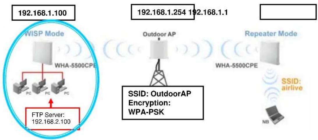
flowchart
graph TD
    A["WISP Mode"] --> B["PC"]
    A --> C["PC"]
    A --> D["PC"]
    A --> E["FTP Server: 192.168.2.100"]
    F["Outdoor AP"] --> G["TEKT Tower"]
    H["Repeater Mode"] --> I["WHA-5500CPE"]
    J["Repeater Mode"] --> K["NB"]
    L["Repeater Mode"] --> M["SSID: outdoorAP Encryption: WPA-PSK"]
    N["Repeater Mode"] --> O["SSID: airlive"]
    P["Repeater Mode"] --> Q["192.168.1.254 192.168.1.1"]
    R["Repeater Mode"] --> S["192.168.1.100"]
9.2.1 WISP Router: Wireless Settings
Step 1 Go to "Operation Mode" menu. Select "WISP Router", and then click on "Change Mode" button.

Step 2 Go to "System Configurations -> Device IP settings". Change the LAN IP address to "192.168.2.1". Changing this IP address will also change the DHCP IP range to 192.168.2.x subnet. Note: Please make sure your PC's IP address is also changed to 192.168.2.x subnet in order to configure the WHA-5500CPE.
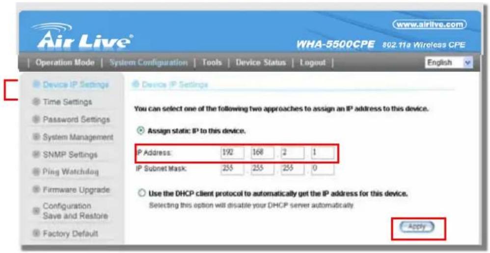
Step 3 Go to "Operation Mode -> Setup" to enter the wireless settings. Select "Outdoor AP" and click on the "Associate" button

Step 4 WHA-5500CPE will prompt you to enter the security policy. Select "WPA-PSK" and enter "outdoorapkey" for the Pre-Shared Key.
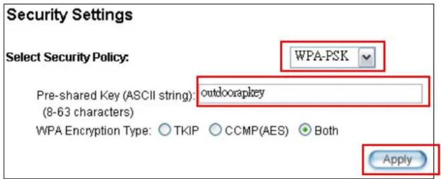
Step 5 Click on "Apply". After a few seconds, the following screen will appear to show successful connection.

9.2.2 WISP Router: WAN Port and Virtual Server
Objective:
- Change WAN port's IP address to 192.168.1.100
- open a virtual server port to the FTP server at 192.168.2.100.
Step 1 Go to "Operation Mode" menu, click on "Setup" button. On the wireless settings page, select "WAN port" button.
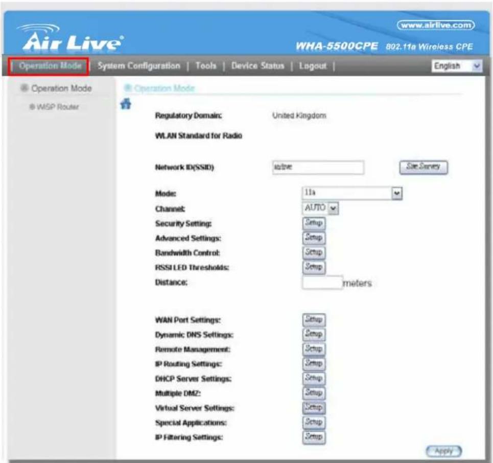
Step 2 On the WAN port setting pave, Enter the Static IP information as bellowed:

Step 3 Go to "Operation Mode" menu, click on "Setup" button. On the wireless settings page, choose "Virtual Server" button.

Step 4 Select "FTP" for Service Name. Enter 192.168.2.100 for the FTP server's IP address. Then click on "Add" to finish

Step 5 Once the virtual server is added, it will be displayed in the boxed area.
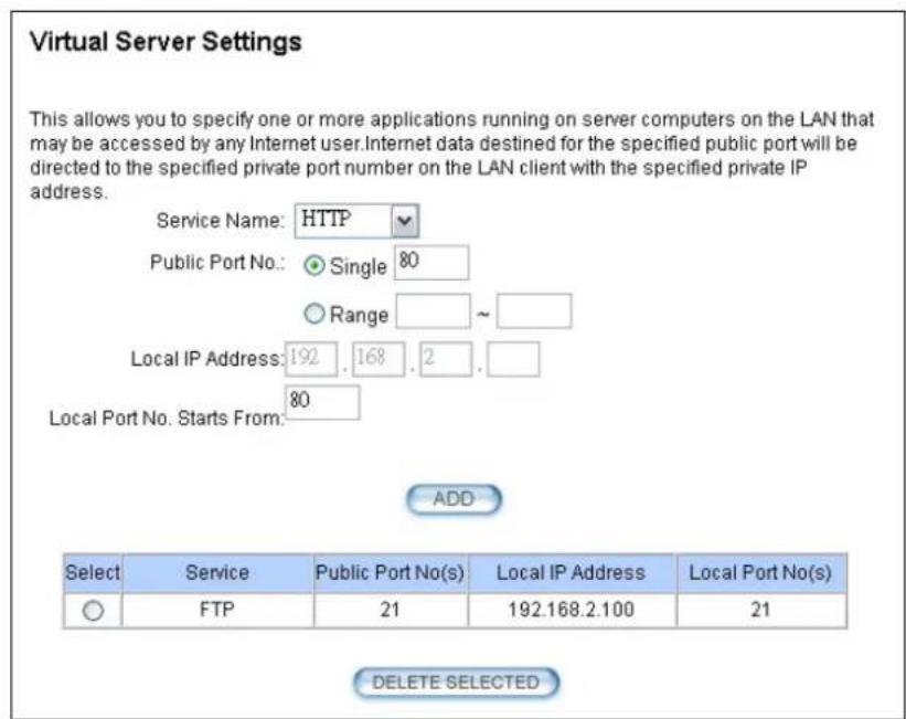
9.3 WHA-5500CPE in Repeater Mode
The following is the configuration procedure for the WHA-5500CPE in Repeater:
☐ Change the WHA-5500CPE to Repeater Mode
☐ Use "Site Survey" function to find remote AP with SSID "OutdoorAP", then establish connection
☐ The local wireless network's SSID is airlive.
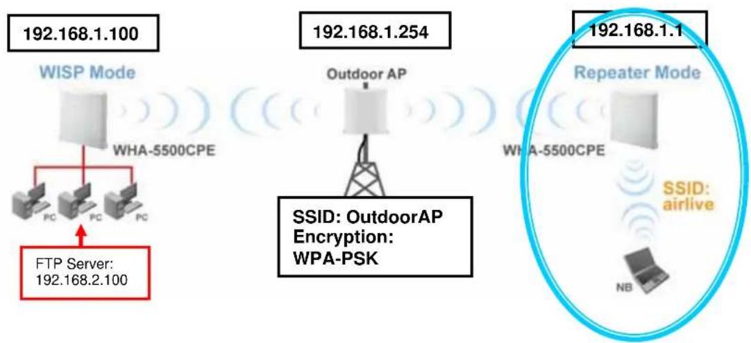
flowchart
graph TD
    A["WISP Mode"] --> B["FCP Server 192.168.2.100"]
    B --> C["WHA-5500CPE"]
    D["Outdoor AP"] --> E["Wireless Tower"]
    F["Repeater Mode"] --> G["Wi-Fi Antenna"]
    H["Repeater Mode"] --> I["Wi-Fi Antenna"]
    J["Repeater Mode"] --> K["Wi-Fi Antenna"]
    L["Repeater Mode"] --> M["Wi-Fi Antenna"]
    N["Repeater Mode"] --> O["Wi-Fi Antenna"]
    P["Repeater Mode"] --> Q["Wi-Fi Antenna"]
    R["Repeater Mode"] --> S["Wi-Fi Antenna"]
    T["Repeater Mode"] --> U["Wi-Fi Antenna"]
    V["Repeater Mode"] --> W["Wi-Fi Antenna"]
    X["Repeater Mode"] --> Y["Wi-Fi Antenna"]
    Z["Repeater Mode"] --> AA["Wi-Fi Antenna"]
    AB["Repeater Mode"] --> AC["Wi-Fi Antenna"]
    AD["Repeater Mode"] --> AE["Wi-Fi Antenna"]
    AF["Repeater Mode"] --> AG["Wi-Fi Antenna"]
    AH["Repeater Mode"] --> AI["Wi-Fi Antenna"]
    AJ["Repeater Mode"] --> AK["Wi-Fi Antenna"]
    AL["Repeater Mode"] --> AM["Wi-Fi Antenna"]
    AN["Repeater Mode"] --> AO["Wi-Fi Antenna"]
    AP["Repeater Mode"] --> AQ["Wi-Fi Antenna"]
    AR["Repeater Mode"] --> AS["Wi-Fi Antenna"]
    AT["Repeater Mode"] --> AU["Wi-Fi Antenna"]
    AV["Repeater Mode"] --> AW["Wi-Fi Antenna"]
    AX["Repeater Mode"] --> AY["Wi-Fi Antenna"]
    AZ["Repeater Mode"] --> BA["Wi-Fi Antenna"]
    BB["Repeater Mode"] --> BC["Wi-Fi Antenna"]
    BD["Repeater Mode"] --> BE["Wi-Fi Antenna"]
    BF["Repeater Mode"] --> BG["Wi-Fi Antenna"]
    BH["Repeater Mode"] --> BI["Wi-Fi Antenna"]
    BJ["Repeater Mode"] --> BK["Wi-Fi Antenna"]
    BL["Repeater Mode"] --> BM["Wi-Fi Antenna"]
    BN["Repeater Mode"] --> BO["Wi-Fi Antenna"]
    BP["Repeater Mode"] --> BQ["Wi-Fi Antenna"]
    BR["Repeater Mode"] --> BS["Wi-Fi Antenna"]
    BT["Repeater Mode"] --> BU["Wi-Fi Antenna"]
    BV["Repeater Mode"] --> BW["Wi-Fi Antenna"]
    BX["Repeater Mode"] --> BY["Wi-Fi Antenna"]
    BZ["Repeater Mode"] --> CA["Wi-Fi Antenna"]
    CBZ["Repeater Mode"] --> DA["Wi-Fi Antenna"]
    DBZ["Repeater Mode"] --> DB["Wi-Fi Antenna"]
    DCZ["Repeater Mode"] --> DD["Wi-Fi Antenna"]
    DJZ["Repeater Mode"] --> DE["Wi-Fi Antenna"]
    DFZ["Repeater Mode"] --> DG["Wi-Fi Antenna"]
    DHZ["Repeater Mode"] --> DI["Wi-Fi Antenna"]
    DJZ --> DJZ
    DKZ --> DKZ
9.3.1 Repeater Router: Wireless Settings
Step 1 Go to "Operation Mode" menu. Select "Repeater", and then click on "Change Mode" button.

Step 2 Click on the "Setup" button and the wireless setting page will appear. Please take a look at the description on the graphic below
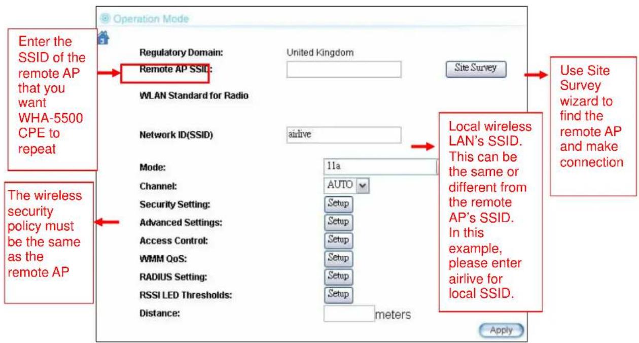
flowchart
graph TD
    A["Enter the SSID of the remote AP that you want WHA-5500 CPE to repeat"] --> B["Regulatory Domain: Remote AP SSID"]
    B --> C["WLAN Standard for Radio"]
    C --> D["Network ID(SSID)"]
    D --> E["Mode: 11a"]
    E --> F["Channel: AUTO Setup"]
    F --> G["Security Setting: Setup"]
    G --> H["Advanced Settings: Setup"]
    H --> I["Access Control: Setup"]
    I --> J["WMM QoS: Setup"]
    J --> K["RADIUS Setting: Setup"]
    K --> L["RSSI LED Thresholds: Setup"]
    L --> M["Distance: meters"]
    M --> N["Apply"]

    O["Site Survey"] --> P["Local wireless LAN's SSID. This can be the same or different from the remote AP's SSID. In this example, please enter airlive for local SSID."]
    P --> Q["Use Site Survey wizard to find the remote AP and make connection"]
Step 3 Click on Site Survey button, the following screen will appear. Choose "OutdoorAP", and then click on "Associate" button to connect.

Step 4 WHA-5500CPE will prompt you to enter the security policy. Select "WPA-PSK" and enter "outdoorapkey" for the Pre-Shared Key.

Step 5 Click on "Apply". After a few seconds, the following screen will appear to show successful connection.

Now you should have established successful WISP Router and Repeater connections.
10
Emergency Firmware Recovery
The WHA-5500CPE features an Emergency Recovery function in the bootloader to recovery the AP in case of a firmware crashed. When you can't access the WHA-5500CPE, please first try to repower the CPE or restore the settings to default. You should find the CPE at 192.168.1.1.
If it still can not solve the problem, you can try to recover the CPE using the method described in this chapter. Do not power off the WHA-5500CPE or your PC during process. Please read through this chapter carefully before attempting to perform the upgrade. If the WHA-5500CPE is damaged by improper use of this procedure, it will void your warranty. It is recommended to have your dealer or distributor performing this procedure.
10.1 How Emergency Upgrade Works
The WHA-5500CPE's flash memory is divided into "firmware" and "bootloader" area. The bootloader area will check if the AP's firmware is crashed at each bootup. If it detects the firmware is crashed, the AP will try to download the firmware file "zImage" from remote TFTP server(with IP address 192.168.1.254) automatically. Therefore, you must prepare a PC with TFTP server software before performing the upgrade procedure.

flowchart
graph TD
    A["Firmware"] --> B["Bootloader"]
    B --> C["WHA-5500CPE"]
    C --> D["zImage"]
    D --> E["PC with TFTP Server"]
10.2 Emergency Upgrade Procedure
-
Set your PC's IP address to 192.168.1.254 and connect your PC directly to the WHA-5500CPE.
-
Set the PC as TFTP server, IP address of PC is 192.168.1.254, subnet mask is 255.255.255.0.
- We recommend the freeware of tftp server, such as "tftpd32".
- Run the TFTP server application.


Fig. tftpd32 application main window and setting window.
- Assign the tftp folder in the tftp server. Click on "browse" the folder to select the directory

Fig. tftpd32 application: Click on "browse" the folder to select the directory
- Copy firmware file into the tftp server folder.
- Rename this firmware file as "zImage" without file name extension. Please make sure the letter case match exactly. To check if the file is available in the tftpd32 folder, please click in tftpd32 main page "Show Dir".

Fig. "Show Dir" to check available files in tftp server folder
- Power on the WHA-5500CPE again. If firmware crashed, the device will scan the 192.168.1.254 for TFTP server and read the tftp upload file.
- Wait for about 20 seconds, a pop-up window shows the firmware repair progress screen.(Shown as Fig. 3)

Fig.. Tftpd32 show at the beginning of firmware repair progress.

Do not power off the PC or the WHA-5500CPE during this process! Any disconnection or interruption can damage the WHA-5500CPE permanently.
- Device will continue proceeding. If you click on the "log viewer" of tftpd32, you can see progress of work shown as Fig. 4.
![Tftpd32 by Ph. Jounin Current Directory H:\tftpd32.323 Server interface 192.168.1.254 Browse Show Dir Tftp Server Syslog server Log viewer Connection received from 192.168.1.1 on port 0 [27/12 09:51:38.500] Read request for file . Mode octet [27/12 09:51:38.500] Using local port 1287 [27/12 09:51:38.500] : sent 7393 blks, 3784832 bytes in 51 s. 0 blk resent [27/12 09:52:29] Clear Copy Current Action Listening on port 69 About Settings Help](/content/2026/05/1066385/images/c53360ecabb43f77350c5b1acca0e91a4576bc8390ff8c769756844d3818652f.jpg)
Fig. 4 Repair progress shown in tftpd32 syslog Log viewer
- Please wait for 5 minutes for the device to reboot. When finish rebooting, the wireless LED will be on. The device can then be accessed again at 192.168.1.1. If the WHA-5500CPE's not accessible after 5 minutes, please power reboot the WHA-5500CPE.
- Open your web browser and type "192.168.1.1" to confirm the WHA-5500CPE is restored.
11
Frequent Asked Questions
In this chapter, we will address some frequent asked questions about WHA-5500CPE
Question: I forgot my password or the IP address of WHA-5500CPE.
Answer: Please restore your settings to default by press the reset button for more than 5 seconds. You should be able to find your WHA-5500CPE at 192.168.1.1 with password "airlive".
Question: Where is Super Channels for WHA-5500CPE?
Answer: Please make sure you have the license to use the Super Channels. When you select "All Channels" as the Regulatory Domain, the Super Channels will appear on your channel list.
Question: I heard WHA-5500CPE can limit the bandwidth of BitTorrent and eDonkey traffic. But I don't see the option on the Bandwidth Control.
Answer: The option to limit bandwidth by application or port is available only on WISP router and AP Router modes.
Question: How can I make connection with Mikrotik AP?
Answer: The WHA-5500CPE can connect with Mirkrotik AP using Bridge Infrastructure Mode(Supports WEP, WPA-PSK, WPA2-PSK), Client Infrastructure mode (support WEP, WPA-PSK, WPA2-PSK) and WDS Bridge mode (support
WEP). If using Bridge Infrastructure mode (WDS station), please enable "WDS Dynamic" on Mikrotik's "AP Bridge" mode. If using WEP, please choose "Static Key Required" on the Mirkrotik setting. For step-by-step example, please visit AirLive.com's support page at: http://www.airlive.com/support/support_1.jsp. Type "WHA-5500CPE" at the support search.
Question: When I plug in the POE cable and power adapter, the WHA-5500CPE's power LED is not on?
Answer: Please make sure you have connected the PoE cable to the correct port on the DC injector. Moreover, you should use an Ethernet cable with 4 twisted pairs (CAT5 or better) for POE cable.
Question: When I use an external antenna with WHA-5500CPE?
Answer: Yes, you will need our RG-178MXFN converting cable. Please visit the link for detail procedure: http://69.64.87.53/airlive_fileserver/uploads/FAQ/WHA-5500CPE_To_Externa1_Antenna.pdf
Question: I tried the Emergency Upgrade procedure. But it doesn't work, why?
Answer: Please make sure the firmware file is renamed to "zImage" without any file extension. The file name has to match exactly with the big capital "I".
Question: Where is the signal survey function that displays the RSSI value continuously?
Answer: The “Signal Survey” function is inside the Site Survey function. You can access from “Operation Mode -> Setup -> Site Survey” menu.
Site survey
Site survey list :
| Select | ESSID | MAC Address | Conn Mode | Channel | Turbo | Super | XR | WME | Signal Strength(db m) | Security | Network |
| ○ | AirLive2 | 00:4f:69:6f:ee:a5 | A | 56 | - | - | - | * | -34 | None | AP |
| ○ | test | 00:4f:69:52:2b:89 | A | 64 | - | - | - | * | -61 | None | AP |
| ○ | AirLive1 | 00:4f:69:6f:ee:a4 | A | 36 | - | - | - | * | -41 | None | AP |
NOTE:
The sitesurvey will show both Ap and Bridge connections. Device without ESOID is more likely to be a Bridge device.

Question: When do I use Per-User Bandwidth Control by IP, MAC, or IP segment?
Answer: In general, IP address control limits the devices on the end node (i.e. PC and WISP router). MAC address control can limit the traffic of a AP/CPE in wireless client mmode.
☐ IP address: When you want to limit the bandwidth of a single notebook computer, PC, or WISP router.
☐ MAC address: When you want to limit the bandwidth of a remote AP/CPE in Client mode. For example, another WHA-5500CPE in client mode
IP Segment:: When you want to limit the bandwidth of an entire IP range. For example, all the PCs using the DHCP server to get IP addresses.
12
Specifications
The specification of WHA-5500CPE is subject to change without notice. Please use the information with caution.
12.1 Hardware Features
12.1.1 General Hardware Feature
■ Atheros AR-2313 + AR-5112 chipset
■ 802.11a/Super A/Turbo-A mode support (Atheros Proprietary)
■ 4MB Flash, 32MB SDRAM
■ RoHS compliant
■ One 10/100 Mbps Ethernet Port / PoE Port with Auto MDI/MDI-X support
■ 802.3af 48V
■ 802.11h compatible
■ DFS and DFSII compliant
■ 20dBm Transmit Output power
■ Rain and splash proof housing
■ Metal Wall / Pole Mount Kit
12.1.2 Antenna
■ Integrated 18 dBi patch directional antenna
■ H-Plane Coverage Angle: 13.5° - 15.5 degree in the forward direction
■ E-Plane Coverage Angle: 13^ - 16^ degree in the forward direction
12.1.3 Power Supply
■ Power Adapter Voltage : input 100\~240Vac/50\~60Hz , output 12V/1A
■ POE Adapter, DC Injector provided
12.1.4 Dimension and Weight
■ L x W x H : 225mm x 122mm x 225mm
■ Weight :920 g(without Mounting kit)
12.2 Radio Specifications
12.2.1 Frequency Band
■ 5.15 to 5.25GHz: U-NII Low and ETSI Band1
■ 5.25 to 5.35GHz: U-NII Mid and ETSI Band2
■ 5.47 to 5.725GHz: U-NII World Wide and ETSI Band3
■ 5.745 to 5.825GHz, U-NII Upper Band
12.2.2 Rate and Modulation
■ Data Rate : 6, 9, 12, 18, 24, 36, 48, 54Mbps
■ Modulation: Orthogonal Frequency Division Multiplexing (OFDM)
12.2.3 TX Output Power
■ 54 Mbps @ 17 dBm
■ 48 Mbps @ 18 dBm
■ 36 Mbps @ 19 dBm
■ 6, 9, 12, 18, 24 Mbps @ 20 dBm
12.2.4 Receiver Sensitivity
■ 54Mbps@-71 dBm
■ 12Mbps@-88 dBm
■ 6Mbps@-90 dBm
12.2.5 Supported WLAN Mode
■ 11a mode
■ SuperA without Turbo
■ SuperA with Dynamic Turbo
■ SuperA with Static Turbo
12.3 Software Feature
12.3.1 Operation Mode
■ Access Point Mode (AP mode)
■ Client Infrastructure Mode
■ Client Adhoc Mode
■ WDS Bridge Mode
■ Bridge Infrastructure Mode
■ Repeater Mode
■ WISP Router Mode
■ AP Router Mode
12.3.2 Management Interface
■ Web HTTP
■ Secured Web (HTTPS)
Telnet (CLI)
12.3.3 Channel Width (Rate Mode)
■ Turbo: 40Mhz
■ Full: 20 MHz (default)
■ Half: 10 MHz
■ Quarter: 5 MHz
12.3.4 Advance Functions
■ Site Survey with RSSI Signal Survey
■ Total Bandwidth and Per-User Bandwidth Management
■ Noise Immunity
■ Multiple SSID and Tag VLAN
■ QoS (802.11e WMM)
■ Wi-Fi, WPA compatible interoperability
■ WPA with PSK/TKIP/AES support ,WPA2 support
■ Privacy Separator support
■ Support adjustable output power
■ 152-bit WEP support (Atheros Proprietary)
■ ACK Timeout Adjustment
■ Bootloader Protection and Emergency Firmware Upload Code
■ Radius Supported
■ Firmware upgrade and configuration backup via Web
13
Wireless Network Glossary
The wireless network glossary contains explanation or information about common terms used in wireless networking products. Some of information in this glossary might be outdated, please use with caution.
802.11a
An IEEE specification for wireless networking that operates in the 5 GHz frequency range (5.15 GHz to 5.850 GHz) with a maximum of 54 Mbps data transfer rate. The 5 GHz frequency band is not as crowded as the 2.4 GHz band. In addition, the 802.11a have 12 non-overlapping channels, comparing to 802.11b/g's 3 non-overlapping channels. This means the possibility to build larger non-interfering networks. However, the 802.11a deliver shorter distance at the same output power when comparing to 802.11g.
802.3ad
802.3ad is an IEEE standard for bonding or aggregating multiple Ethernet ports into one virtual port (also known as trunking) to increase the bandwidth.
802.3af
This is the PoE (Power over Ethernet) standard by IEEE committee. 803.af uses 48V POE standard that can deliver up to 100 meter distance over Ethernet cable.
802.11b
International standard for wireless networking that operates in the 2.4 GHz frequency band (2.4 GHz to 2.4835 GHz) and provides a throughput up to 11 Mbps.
802.1d STP
Spanning Tree Protocol. It is an algorithm to prevent network from forming. The STP protocol allows network to provide a redundant link in the event of a link failure. It is advised to turn on this option for multi-link bridge network.
802.11d
Also known as “Global Roaming”. 802.11d is a standard for use in countries where systems using other standards in the 802.11 family are not allowed to operate.
802.11e
The IEEE QoS standard for prioritizing traffic of the VoIP and multimedia applications. The WMM is based on a subset of the 802.11e.
802.11g
A standard provides a throughput up to 54 Mbps using OFDM technology. It also operates in the 2.4 GHz frequency band as 802.11b. 802.11g devices are backward compatible with 802.11b devices.
802.11h
This IEEE standard defines the TPC (transmission power control) and DFS(dynamic frequency selection) required to operate WiFi devices in 5GHz for EU.
802.11i
The IEEE standard for wireless security. 802.11i standard includes TKIP, CCMP, and AES encryption to improve wireless security. It is also known as WPA2.
802.1Q Tag VLAN
In 802.1Q VLAN, the VLAN information is written into the Ethernet packet itself. Each packet carries a VLAN ID(called Tag) as it traveled across the network. Therefore, the VLAN configuration can be configured across multiple switches. In 802.1Q spec, possible 4096 VLAN ID can be created. Although for some devices, they can only view in frames of 256 ID at a time.
802.1x
802.1x is a security standard for wired and wireless LANs. In the 802.1x parlance, there are usually supplicants (client), authenticator (switch or AP), and authentication server (radius server) in the network. When a supplicants request a service, the authenticator will pass the request and wait for the authentication server to grant access and register accounting. The 802.1x is the most widely used method of authentication by WISP.
Adhoc
A Peer-to-Peer wireless network. An Adhoc wireless network do not use wireless AP or router as the central hub of the network. Instead, wireless client are connected directly to each other. The disadvantage of Adhoc network is the lack of wired interface to Internet connections. It is not recommended for network more than 2 nodes.
Access Point (AP)
The central hub of a wireless LAN network. Access Points have one or more Ethernet ports that can connect devices (such as Internet connection) for sharing. Multi-function Access Point can also function as an Ethernet client, wireless bridge, or repeat signals from other AP. Access Points typically have more wireless functions comparing to wireless routers.
ACK Timeout
Acknowledgement Timeout Windows. When a packet is sent out from one wireless station to the other, it will waits for an Acknowledgement frame from the remote station. The station will only wait for a certain amount of time, this time is called the ACK timeout. If the ACK is NOT received within that timeout period then the packet will be re-transmitted resulting in reduced throughput. If the ACK setting is too high then throughput will be lost due to waiting for the Ack Window to timeout on lost packets. If the ACK setting is too low then the ACK window will have expired and the returning packet will be dropped, greatly lowering throughput. By having the ability to adjust the ACK setting we can effectively optimize the throughput over long distance links. This is especially true for 802.11a and 802.11g networks. Setting the correct ACK timeout value need to consider 3 factors: distance, AP response time, and interference. The WHA-5500CPE provide ACK adjustment capability in form of either distance or direct input. When you enter the distance parameter, the WHA-5500CPE will automatically calculate the correct ACK timeout value.
Bandwidth Management
Bandwidth Management controls the transmission speed of a port, user, IP address, and application. Router can use bandwidth control to limit the Internet connection speed of individual IP or Application. It can also guarantee the speed of certain special application or privileged IP address - a crucial feature of QoS (Quality of Service) function. The WHA-5500CPE's features both "Per-user Bandwidth Control" and "Total Bandwidth Control". "Per-user Bandwidth Control" allow administrator to define the maximum bandwidth of each user by IP, IP Group, or MAC address. Total Bandwidth defines the maximum bandwidth of wireless or Ethernet interface.
Bootloader
Bootloader is the under layering program that will start at the power-up before the device loads firmware. It is similar to BIOS on a personal computer. When a firmware crashed, you might be able to recover your device from bootloader.
Bridge
A product that connects 2 different networks that uses the same protocol. Wireless bridges are commonly used to link network across remote buildings. For wireless application, there are 2 types of Bridges. WDS Bridge can be used in Point-to-Point or Point-to-Multipoint topology. Bridge Infrastructure works with AP mode to form a star topology.
Cable and Connector Loss: During wireless design and deployment, it is important to factor in the cable and connector loss. Cable and connector loss will reduce the output power and receiver sensitivity of the radio at connector end. The longer the cable length is, the more the cable loss. Cable loss should be subtracted from the total output power during distance calculation. For example, if the cable and connector loss is 3dBm and the output power is 20dBm; the output power at the cable end is only 17dBm.
Client
Client means a network device or utility that receives service from host or server. A client device means end user device such as wireless cards or wireless CPE.
CPE Devices
CPE stands for Customer Premises Equipment. A CPE is a device installed on the end user's side to receive network services. For example, on an ADSL network, the ADSL modem/router on the subscriber's home is the CPE device. Wireless CPE means a complete Wireless (usually an AP with built-in Antenna) that receive wireless broadband access from the WISP. The opposite of CPE is CO.
CTS
Clear To Send. A signal sent by a device to indicate that it is ready to receive data.
DDNS
Dynamic Domain Name System. An algorithm that allows the use of dynamic IP address for hosting Internet Server. A DDNS service provides each user account with a domain name. A router with DDNS capability has a built-in DDNS client that updates the IP address information to DDNS service provider whenever there is a change. Therefore, users can build website or other Internet servers even if they don't have fixed IP connection.
DHCP
Dynamic Hosting Configuration Protocol. A protocol that enables a server to dynamically assign IP addresses. When DHCP is used, whenever a computer logs onto the network, it automatically gets an IP address assigned to it by DHCP server. A DHCP server can either be a designated PC on the network or another network device, such as a router.
DMZ
Demilitarized Zone. When a router opens a DMZ port to an internal network device, it opens all the TCP/UDP service ports to this particular device. The feature is used commonly for setting up H.323 VoIP or Multi-Media servers.
DNS
A program that translates URLs to IP addresses by accessing a database maintained on a collection of Internet servers.
Domain Name
The unique name that identifies an Internet site. Domain Names always have 2 or more parts, separated by dots. In www.airlive.com, the "airlive.com" is the doman name.
DoS Attack
Denial of Service. A type of network attack that floods the network with useless traffic. Many DoS attacks, such as the Ping of Death and Teardrop attacks, exploit limitations in the TCP/IP protocols.
Encryption
Encoding data to prevent it from being read by unauthorized people. The common wireless encryption schemes are WEP, WPA, and WPA2.
ESSID (SSID)
The identification name of an 802.11 wireless network. Since wireless network has no physical boundary liked wired Ethernet network, wireless LAN needs an identifier to distinguish one network from the other. Wireless clients must know the SSID in order to associate with a WLAN network. Hide SSID feature disable SSID broadcast, so users must know the correct SSID in order to join a wireless network.
Firewall
A system that secures a network and prevents access by unauthorized users. Firewalls can be software, router, or gateway. Firewalls can prevent unrestricted access into a network, as well as restricting data from flowing out of a network.
Firmware
The program that runs inside embedded device such as router or AP. Many network devices are firmware upgradeable through web interface or utility program.
FTP
File Transfer Protocol. A standard protocol for sending files between computers over a TCP/IP network and the Internet.
Fragment Threshold
Frame Size larger than this will be divided into smaller fragment. If there are interferences in your area, lower this value can improve the performance. If there are not, keep this parameter at higher value. The default size is 2346. You can try 1500, 1000, or 500 when there are interference around your network.
Full Duplex
The ability of a networking device to receive and transmit data simultaneously. In wireless environment, this is usually done with 2 or more radios doing load balancing.
Gateway
In the global Internet network, the gateways are core routers that connect networks in different IP subnet together. In a LAN environment with an IP sharing router, the gateway is the router. In an office environment, gateway typically is a multi-function device that
integrates NAT, firewall, bandwidth management, and other security functions.
Hotspot
A place where you can access Wi-Fi service. The term hotspot has two meanings in wireless deployment. One is the wireless infrastructure deployment, the other is the Internet access billing system. In a hotspot system, a service provider typically need an authentication and account system for billing purposes, and a wireless AP network to provide access for customers.
IGMP Snooping
Internet Group Management Protocol (IGMP) is a Layer 3 protocol to report IP multicast memberships to neighboring multicast switches and routers. IGMP snooping is a feature that allows an Ethernet switch to "listen in" on the IGMP conversation between hosts and routers. A switch support IGMP snooping has the possibility to avoid multicast traffic being treated as broadcast traffic; therefore, reducing the overall traffic on the network.
Infrastructure Mode
A wireless network that is built around one or more access points to provide wireless clients access to wired LAN / Internet service. The opposite of Infrastructure mode is Adhoc mode.
IP address
IP (Internet Protocol) is a layer-3 network protocol that is the basis of all Internet communication. An IP address is 32-bit number that identifies each sender or receiver of information that is sent across the Internet. An IP address has two parts: an identifier of a particular network on the Internet and an identifier of the particular device (which can be a server or a workstation) within that network. The new IPv6 specification supports 128-bit IP address format.
IPsec
IP Security. A set of protocols developed by the IETF to support secure exchange of packets at the IP layer. IPsec has been deployed widely to implement Virtual Private Networks (VPNs). IPsec supports two encryption modes: Transport and Tunnel. Transport mode encrypts only the data of each packet, but leaves the header untouched. The more secure Tunnel mode encrypts both the header and the payload. On the receiving side, an IPSec-compliant device decrypts each packet.
LACP (802.3ad) Trunking
The 802.3ad Link Aggregation standard defines how to combine the several Ethernet ports into one high-bandwidth port to increase the transmission speed. It is also known as port trunking. Both device must set the trunking feature to work.
MAC
Media Access Control. MAC address provides layer-2 identification for Networking Devices. Each Ethernet device has its own unique address. The first 6 digits are unique for each manufacturer. When a network device have MAC access control feature, only the devices with the approved MAC address can connect with the network.
Mbps
Megabits Per Second. One million bits per second; a unit of measurement for data transmission
MESH
Mesh is an outdoor wireless technology that uses Spanning Tree Protocol (STP) and Wireless Distribution system to achieve self-forming, self-healing, and self-configuring outdoor network. MESH network are able to take the shortest path to a destination that does not have to be in the line of site.
MIMO
Multi In Multi Out. A Smart Antenna technology designed to increase the coverage and performance of a WLAN network. In a MIMO device, 2 or more antennas are used to increase the receiver sensitivity and to focus available power at intended Rx.
NAT
Network Address Translation. A network algorithm used by Routers to enable several PCs to share single IP address provided by the ISP. The IP that a router gets from the ISP side is called Real IP, the IP assigned to PC under the NAT environment is called Private IP.
Node
A network connection end point, typically a computer.
Packet
A unit of data sent over a network.
Passphrase
Used much like a password, a passphrase simplifies the WEP encryption process by automatically generating the WEP encryption keys for the company products.
POE
Power over Ethernet. A standard to deliver both power and data through one single Ethernet cable (UTP/STP). It allows network device to be installed far away from power source. A POE system typically compose of 2 main component: DC Injector (Base Unit) and Splitter(Terminal Unit). The DC injector combines the power and data, and the splitter separates the data and power back. A PoE Access Point or CPE has the splitter built-in to the device. The IEEE 802.3af is a POE spec that uses 48 volt to deliver power up to 100 meter distance.
Port
This word has 2 different meaning for networking.
- The hardware connection point on a computer or networking device used for plugging in a cable or an adapter.
- The virtual connection point through which a computer uses a specific application on a server.
PPPoE
Point-to- Point Protocol over Ethernet. PPPoE relies on two widely accepted standards: PPP and Ethernet. PPPoE is a specification for connecting the users on an Ethernet to the Internet through a common broadband medium, such as a single DSL line, wireless device or cable modem.
PPTP
Point-to-Point Tunneling Protocol: A VPN protocol developed by PPTP Forum. With PPTP, users can dial in to their corporate network via the Internet. If users require data encryption when using the Windows PPTP client, the remote VPN server must support MPPE (Microsoft Point-To-Point Encryption Protocol) encryption. PPTP is also used by some ISP for user authentication, particularly when pairing with legacy Alcatel / Thomson
ADSL modem.
Preamble Type
Preamble are sent with each wireless packet transmit for transmission status. Use the long preamble type for better compatibility. Use the short preamble type for better performance
Rate Control
Ethernet switches' function to control the upstream and downstream speed of an individual port. Rate Control management uses "Flow Control" to limit the speed of a port. Therefore, the Ethernet adapter must also have the flow control enabled. One way to force the adapter's flow control on is to set a port to half-duplex mode.
RADIUS
Remote Authentication Dial-In User Service. An authentication and accounting system used by many Internet Service Providers (ISPs). When you dial in to the ISP, you must enter your username and password. This information is passed to a RADIUS server, which checks that the information is correct, and then authorizes access to the ISP system. Radius typically uses port 1812 and port 1813 for authentication and accounting port. Though not an official standard, the RADIUS specification is maintained by a working group of the IETF.
Receiver Sensitivity
Receiver sensitivity means how sensitive is the radio for receiving signal. In general; the slower the transmission speed, the more sensitive the radio is. The unit for Receiver Sensitivity is in dB; the lower the absolute value is, the higher the signal strength. For example, -50dB is higher than -80dB.
RJ-45
Standard connectors for Twisted Pair copper cable used in Ethernet networks. Although they look similar to standard RJ-11 telephone connectors, RJ-45 connectors can have up to eight wires, whereas telephone connectors have only four.
Router
An IP sharing router is a device that allows multiple PCs to share one single broadband
connection using NAT technology. A wireless router is a device that combines the functions of wireless Access Point and the IP sharing router.
RSSI
Receiver Sensitivity Index. RSSI is a value to show the Receiver Sensitivity of the remote wireless device. In general, remote APs with stronger signal will display higher RSSI values. For RSSI value, the smaller the absolute value is, the stronger the signal. For example, “-50db” has stronger signal than “-80dB”. For outdoor connection, signal stronger than -60dB is considered as a good connection.
RTS
Request To Send. A packet sent when a computer has data to transmit. The computer will wait for a CTS (Clear To Send) message before sending data.
RTS Threshold
RTS (Request to Send). The RTS/CTS(clear to send) packet will be send before a frame if the packet frame is larger than this value. Lower this value can improve the performance if there are many clients in your network. You can try 1500, 1000 or 500 when there are many clients in your AP's network.
SNMP
Simple Network Management Protocol. A set of protocols for managing complex networks. The SNMP network contains 3 key elements: managed devices, agents, and network-management systems (NMSs). Managed devices are network devices that content SNMP agents. SNMP agents are programs that reside SNMP capable device's firmware to provide SNMP configuration service. The NMS typically is a PC based software such as HP Openview that can view and manage SNMP network device remotely.
SSL
Secure Sockets Layer. It is a popular encryption scheme used by many online retail and banking sites to protect the financial integrity of transactions. When an SSL session begins, the server sends its public key to the browser. The browser then sends a randomly generated secret key back to the server in order to have a secret key exchange for that session. SSL VPN is also known as Web VPN. The HTTPS interface use SSL for data encryption.
Subnet Mask
An address code mask that determines the size of the network. An IP subnet are determined by performing a BIT-wise AND operation between the IP address and the subnet mask. By changing the subnet mask, you can change the scope and size of a network.
Subnetwork or Subnet
Found in larger networks, these smaller networks are used to simplify addressing between numerous computers. Subnets connect to the central network through a router, hub or gateway. Each individual wireless LAN will probably use the same subnet for all the local computers it talks to.
Super A
Super A is an Atheros proprietary turbo mode to increase speed over standard 802.11a mode. It adds Bursting and Compression to increase the speed. If you live in countries that prohibit the channel binding technology (i.e. Europe), you should choose “Super-A without Turbo) if you need more speed than 11a mode
TCP
A layer-4 protocol used along with the IP to send data between computers over the Internet. While IP takes care of handling the actual delivery of the data, TCP takes care of keeping track of the packets that a message is divided into for efficient routing through the Internet.
Turbo A
Turbo A is an Atheros proprietary turbo mode to increase speed over standard 802.11a mode. It uses channel binding technology to increase speed. There are 2 types of Turbo A modes: Dynamic Turbo and Static Turbo. In Dynamic Turbo, the channel binding will be used only if necessary. In Static Turbo, the channel binding is always on. This protocol may be combined with Super-A model to increase the performance even more. The used of channel binding might be prohibited in EU countries.
TX Output Power
Transmit Output Power. The TX output power means the transmission output power of the radio. Normally, the TX output power level limit for 2.4GHz 11g/b is 20dBm at the antenna end. The output power limit for 5GHz 802.11a is 30dBm at the antenna end..
UDP
User Datagram Protocol. A layer-4 network protocol for transmitting data that does not require acknowledgement from the recipient of the data.
Upgrade
To replace existing software or firmware with a newer version.
Upload
To send a file to the Internet or network device.
URL
Uniform Resource Locator. The address of a file located on the Internet.
VPN
Virtual Private Network. A type of technology designed to increase the security of information transferred over the Internet. VPN creates a private encrypted tunnel from the end user's computer, through the local wireless network, through the Internet, all the way to the corporate network.
Walled Garden
On the Internet, a walled garden refers to a browsing environment that controls the information and Web sites the user is able to access. This is a popular method used by ISPs in order to keep the user navigating only specific areas of the Web
WAN
Wide Area Network. A communication system of connecting PCs and other computing devices across a large local, regional, national or international geographic area. A WAN port on the network device means the port (or wireless connection) that is connected to the Internet side of the network topology.
WEP
Wired Equivalent Privacy. A wireless encryption protocol. WEP is available in 40-bit (64-bit),
108-bit (128-bit) or 152-bit (Atheros proprietary) encryption modes.
Wi-Fi
Wireless Fidelity. An interoperability certification for wireless local area network (LAN) products based on the IEEE 802.11 standards. The governing body for Wi-Fi is called Wi-Fi Alliance (also known as WECA).
WiMAX
Worldwide Interoperability for Microwave Access. A Wireless Metropolitan Network technology that complies with IEEE 802.16 and ETSI Hiperman standards. The original 802.16 standard call for operating frequency of 10 to 66Ghz spectrum. The 802.16a amendment extends the original standard into spectrum between 2 and 11 Ghz. 802.16d increase data rates to between 40 and 70 Mbps/s and add support for MIMO antennas, QoS, and multiple polling technologies. 802.16e adds mobility features, narrower bandwidth (a max of 5 mhz), slower speed and smaller antennas. Mobility is allowed up to 40 mph.
WDS
Wireless Distribution System. WDS defines how multiple wireless Access Point or Wireless Router can connect together to form one single wireless network without using wired uplinks. WDS associate each other by MAC address, each device
WLAN
Wireless Local Area Network. A type of local-area network that uses high-frequency radio waves rather than wires to communicate between nodes. The most popular standard for WLAN is the 802.11 standards.
WMM
Wi-Fi Multimedia (WMM) is a standard to prioritize traffic for multimedia applications. The WMM prioritize traffic\ on Voice-over-IP (VoIP), audio, video, and streaming media as well as traditional IP data over the AP.
WMS
Wireless Management System. An utility program to manage multiple wireless AP/Bridges.
WPA
Wi-Fi Protected Access. It is an encryption standard proposed by WiFi for advance protection by utilizing a password key (TKIP) or certificate. It is more secure than WEP encryption. The WPA-PSK utilizes pre-share key for encryption/authentication.
WPA2
Wi-Fi Protected Access 2. WPA2 is also known as 802.11i. It improves on the WPA security with CCMP and AES encryption. The WPA2 is backward compatible with WPA. WPA2-PSK utilizes pre-share key for encryption/authentication.


- User's Manual
- Air Live®
- Powered by OvisLink Corp.
- Copyright & Disclaimer
- Table of Contents
- Introduction....1
- Installing the WHA-5500CPE....10
- Configuring the WHA-5500CPE 16
- Introduction to Web Management....19
- Initial Configurations ......24
- Web Management: Wireless and WAN Settings ......29
- Web Management 2: System Configuration, Tools and Status......67
- Tools....74
- Device Status....76
- Command Line Interface ....79
- Application Example: Infrastructure 99
- Application Example 2: Bridge Network....111
- Application Example 3: Router and Repeater ....121
- WHA-5500CPE in WISP Router Mode 122
- WHA-5500CPE in Repeater Mode 127
- Emergency Firmware Recovery ....130
- Frequent Asked Questions ....133
- Specifications....136
- Hardware Features....136
- Radio Specifications ....137
- Software Feature ....138
- Wireless Network Glossary....140
- 1
- Introduction
- Overview
- How to Use This Guide
- Recommended Reading
- □ Chapter 1
- Chapter 3:
- ☐ Chapter 5: Web Management 2: Configurations, Tools and Status
- ☐ Chapter 6: Command Line Interface
- ☐ Chapter 7: Application Example: Infrastructure
- ☐ Chapter 8: Application Example 2: WDS Bridge
- Firmware Upgrade and Tech Support
- Features
- Wireless Operation Modes
- Access Point Mode
- Repeater Mode
- WDS Bridge Mode
- Bridge Infrastructure Mode
- Client Infrastructure Mode
- Client Ad Hoc Mode
- WISP Router Mode
- 2
- Installing the WHA-5500CPE
- Before You Start
- Package Content
- Hardware Installation
- Mounting Configuration
- Antenna polarization
- 3
- Configuring the WHA-5500CPE
- Important Information
- Prepare your PC
- Management Interface
- Introduction to Web Management
- Getting into Web Management
- Normal Web Management (HTTP)
- Secured Web Management (HTTPS)
- □ Firefox:
- Welcome Screen and Login
- Initial Configurations
- Choose the wireless Operation Modes
- Change the Device's IP Address
- Change the Country Code
- Set the Time and Date
- Change System Management
- Change Password
- 4
- Web Management: Wireless and WAN Settings
- About WHA-5500CPE's Menu Structure
- Operation Modes (Wireless and WAN Settings)
- Regulatory Domain
- Operation Mode -> Setup -> Regulatory Domain
- Network SSID
- Operation Mode -> Setup -> Network SSID
- Site Survey
- Operation Mode -> Setup -> Site Survey
- Signal Survey
- Operation Mode -> Setup -> Site Survey -> Signal Survey
- Lock-to-AP
- Operation Mode -> Setup -> Lock-to-AP
- Radio Mode (11a, SuperA, TurboA)
- Operation Mode -> Setup -> Radio Mode
- SuperA Option
- Channel
- Operation Mode -> Setup -> Channel
- Channel Width
- Operation Mode -> Setup -> Channel Width
- Security Settings
- Operation Mode -> Setup -> Security Settings
- WEP
- 802.1x
- WPA, WPA2, WPA-AUTO
- WPA-PSK, WPA2-PSK, WPA-PSK-Auto
- Distance
- Transmit Power
- Advance Settings (Wireless)
- Operation Mode -> Setup -> Advance Settings
- Access Control (ACL)
- Operation Mode -> Setup -> Access Control
- Multiple SSID
- Operation Mode -> Setup -> Multiple SSID
- Configuring the Multiple SSID
- How to add a SSID
- How to Modify or Delete a SSID
- Configure the VLAN and DiffServ Markings
- WMM QoS
- Operation Mode -> Setup -> WMM QoS
- Configure the WMM QoS Parameters
- ■ AC Type
- ■ ECWmin and ECWmax
- Contention Window.
- AIFS
- ■ Transmission Opportunity
- RADIUS Settings
- Bandwidth Control
- Operation Mode -> Setup -> Bandwidth Control
- Per User Control Options
- ■ Example 1: Total Bandwidth Control
- ■ Example 2: Per User Bandwidth Control
- WDS Settings
- Operation Mode -> Setup -> WDS Settings
- ☐ Adding a new WDS link
- Router Mode Settings
- Operation Mode -> Setup
- WISP Router Mode
- WAN Port Settings
- Operation Mode -> Setup -> WAN Port Settings
- Dynamic DNS Settings
- Remote Management Settings
- IP Routing Settings
- ■ Dynamic Routing:
- ■ Static Routing:
- ■ IP Routing Table:
- DHCP Server
- Operation Mode -> Setup -> IP Routing Settings
- Multiple DMZ
- Advanced Settings >> Multiple DMZ
- Virtual Server Settings
- Advanced Settings >> Virtual Setting
- Special Applications
- Advanced Setting >> Special Applications
- Special Applications
- IP Filtering Settings
- Advanced Setting>>IP Filtering Settings
- 5
- Web Management 2: System Configuration, Tools and Status
- System Configuration
- Device IP Settings
- System Configurations>> Device IP Settings
- Device IP Settings
- Assign Static IP to the Device
- Use DHCP Client Protocol to Get IP automatically
- Time Settings
- System Configuration ->Time Settings
- Password Settings
- System Management
- System Configuration -> System Management
- System Administration
- Ping Watchdog
- System Configuration -> Ping Watchdog
- Actions:
- Firmware Upgrade
- System Configuration -> Firmware Upgrade
- ■ Upgrade Firmware:
- Configuration Save and Restore
- System Configuration -> Configuration Save and Restore
- Factory Default
- Tools
- Network Ping
- Network Traceroute
- Device Status
- Device Information
- Wireless Information
- Internet Information
- Wireless Client Table
- System Log
- 6
- Command Line Interface
- Telnet
- System Commands
- ■ change password
- Debugging Commands
- Show Commands
- ■ show radius server
- ■ show log level
- ■ show telnet / system
- show rssi
- ■ show mode
- ■ show wireless setting
- Set Commands
- Enable/Disable Commands
- Add/Delete Commands
- ■ delete wds
- ■ add radius server primary
- ■ add radius server
- ■ add wds
- 7
- Application Example: Infrastructure
- Application Environment
- Device A: Access Point Mode
- Device A Wireless Settings
- Device A Bandwidth Management
- Device B: Bridge Infrastructure Mode
- Device B Wireless Settings
- Device B Total Bandwidth Control
- Device C: Client Infrastructure Mode
- Device C IP Address
- Device C Wireless Settings
- 8
- Application Example 2: Bridge Network
- Preparation for Building Outdoor Bridge Networks
- Write down the WLAN MAC address in advance
- Always do a Google Earth search on the intended installation before departing
- Bring a pair of high powered binoculars for site survey
- Bring Long Distance Walkie-Talkie System
- You need a clear Line of sight
- Secured Mounting is important
- Remember to set correct Distance for long distance connection
- Use just enough output power
- Always do a site survey for antenna alignment
- Use the correct Super or Turbo modes
- For multi-point connection, use bandwidth control to manage the variable distance problem
- Use XR mode when you can't connect with the extra sensitivity
- WDS Bridge vs. Bridge Infrastructure
- When to use which bridge mode:
- □ WDS Bridge Mode:
- □ Bridge Infrastructure
- WDS Bridge Network Example
- WDS Bridge 1 Settings
- Adding the first WDS Link to WDS Bridge 3
- Adding the second WDS Link to WDS Bridge 2
- WDS Bridge 2 Settings
- © Ping Watchdog
- WDS Bridge 3 Settings
- WDS Settings
- ② Ping Watchdog
- 9
- Application Example 3: Router and Repeater
- Application Environment
- WHA-5500CPE in WISP Mode
- WHA-5500CPE in Repeater Mode
- WHA-5500CPE in WISP Router Mode
- WISP Router: Wireless Settings
- WISP Router: WAN Port and Virtual Server
- Objective:
- WHA-5500CPE in Repeater Mode
- Repeater Router: Wireless Settings
- 10
- Emergency Firmware Recovery
- How Emergency Upgrade Works
- Emergency Upgrade Procedure
- 11
- Frequent Asked Questions
- Site survey
- NOTE:
- 12
- Specifications
- Hardware Features
- General Hardware Feature
- Antenna
- Power Supply
- Dimension and Weight
- Radio Specifications
- Frequency Band
- Rate and Modulation
- TX Output Power
- Receiver Sensitivity
- Supported WLAN Mode
- Software Feature
- Operation Mode
- Management Interface
- Channel Width (Rate Mode)
- Advance Functions
- 13
- Wireless Network Glossary
- 802.11a
- 802.3ad
- 802.3af
- 802.11b
- 802.1d STP
- 802.11d
- 802.11e
- 802.11g
- 802.11h
- 802.11i
- 802.1Q Tag VLAN
- Adhoc
- Access Point (AP)
- ACK Timeout
- Bandwidth Management
- Bootloader
- Bridge
- Client
- CPE Devices
- CTS
- DDNS
- DHCP
- DMZ
- DNS
- Domain Name
- DoS Attack
- Encryption
- ESSID (SSID)
- Firewall
- Firmware
- FTP
- Fragment Threshold
- Full Duplex
- Gateway
- Hotspot
- IGMP Snooping
- Infrastructure Mode
- IP address
- IPsec
- LACP (802.3ad) Trunking
- MAC
- Mbps
- MESH
- MIMO
- NAT
- Node
- Packet
- Passphrase
- POE
- Port
- PPPoE
- PPTP
- Preamble Type
- Rate Control
- RADIUS
- Receiver Sensitivity
- RJ-45
- Router
- RSSI
- RTS
- RTS Threshold
- SNMP
- SSL
- Subnet Mask
- Subnetwork or Subnet
- Super A
- TCP
- Turbo A
- TX Output Power
- UDP
- Upgrade
- Upload
- URL
- VPN
- Walled Garden
- WAN
- Wi-Fi
- WiMAX
- WDS
- WLAN
- WMM
- WMS
- WPA
- WPA2
Brand : AIRLIVE
Model : WHA-5500CPE
Category : Access Point