
WL-5460AP v2 - Access Point AIRLIVE - Free user manual and instructions
Find the device manual for free WL-5460AP v2 AIRLIVE in PDF.


| Product Type | Access Point (IEEE 802.11b/g) |
| Brand / Model | AirLive WL-5460AP v2 |
| Dimensions (L x W x H) | 135 x 100 x 26 mm |
| Weight | 180 g |
| Power Supply | DC 12V, 1A |
| Radio Frequency | 2.4 GHz ISM band |
| Wireless Standards | 802.11b (up to 11 Mbps), 802.11g (up to 54 Mbps) |
| Antenna | Detachable dipole, 2 dBi, reverse SMA connector |
| Ethernet Ports | 2 x 10/100 Mbps Auto-sensing (LAN1, LAN2; LAN2 = WAN in Gateway mode) |
| Operation Modes | AP, Client, Bridge, WDS Repeater, Universal Repeater, WISP (Client Router), WISP+Universal Repeater, Gateway (AP+Router) |
| Wireless Security | WEP 64/128-bit, WPA-PSK (TKIP/AES), WPA2-PSK (AES), 802.1x RADIUS, WPA Enterprise |
| Additional Features | Wireless Client Isolation, ACK Timeout adjustment, TX Power regulation (8 levels), QoS Traffic Control, MAC filtering, URL filtering, Site Survey, Internet WatchDog, Emergency Recovery |
| Management | Web-based (HTTP), Telnet, Firmware upgrade via Web or TFTP |
| Operating Temperature | 0°C to 60°C |
| Storage Temperature | -20°C to 65°C |
| Humidity (non-condensing) | 20% to 80% (operating), 95% max (storage) |
| Regulatory Approvals | FCC Part 15 Class B, CE, EN 300 328, EN 301 489, EN 55022, EN 55024, EN 60950-1 |
Frequently Asked Questions - WL-5460AP v2 AIRLIVE
User questions about WL-5460AP v2 AIRLIVE
0 question about this device. Answer the ones you know or ask your own.
Ask a new question about this device
Download the instructions for your Access Point in PDF format for free! Find your manual WL-5460AP v2 - AIRLIVE and take your electronic device back in hand. On this page are published all the documents necessary for the use of your device. WL-5460AP v2 by AIRLIVE.
USER MANUAL WL-5460AP v2 AIRLIVE
54Mbps Multi-Function Wireless AP
User's Manual
Declaration of Conformity
We, Manufacturer/Importer
OvisLink Corp.
5F., NO.6, Lane 130, Min-Chuan Rd.,
Hsin-Tien City, Taipei County, Taiwan
Declare that the product
Wireless AP
AirLive WL-5460AP, WL-5450AP
is in conformity with
In accordance with 89/336 EEC-EMC Directive and 1999/5 EC-R & TTE Directive
Clause Description
■ EN 300 328 V1.6.1 Electromagnetic compatibility and Radio spectrum Matters (ERM); Wideband transmission equipment operating in the 2.4GHz ISM band And using spread spectrum modulation techniques; Part 1: technical Characteristics and test conditions Part2: Harmonized EN covering Essential requirements under article 3.2 of the R&TTE Directive
■ EN 301 489-1 V1.4.1 Electromagnetic compatibility and Radio spectrum Matters (ERM); (2002-08) Electromagnetic compatibility(EMC) standard for radio equipment and Services; Part 17: Specific conditions for wideband data and HIPERLAN equipment ■ EN 301 489-17 V1.2.1 (2002-08)
■ EN 55022: 1998/A1 Limits and methods of measurement of radio disturbance characteristics of information technology equipment :2000/A2:2003
■ EN 55024:1998/A1 Information Technology equipment-Immunity characteristics-Limits and :2001/A2:2003 Methods of measurement
■ EN 50385 Product standard to demonstrate the Compliance of radio base stations and Fixed terminal stations for wireless Telecommunication System with the Basic restrictions or the reference levels related to human exposure to radio Frequency electromagnetic fields (110 MHz - 40 GHz) - General public
■ EN 60950-1:2001/ Safety for information technology equipment including electrical business equipment A11:2004
■ CE marking
C€0560①
Manufacturer/Importer
Signature :
Name :
Albert Y. C
Albert Yeh
Position/ Title : Vice President
Date : 2005/8/17
(Stamp)
AirLive WL-5460AP / WL-5450AP CE Declaration Statement
| Country Declaration Country Declaration | |||
| csČesky [Czech] | OvisLink Corp. tímto prohlašuje, že tento AirLive WL-5460AP / WL-5450AP je ve shodě se základními požadavky a dalšími příslušnými ustanoveními směrnice 1999/5/ES. | ItLietuvių[Lithuanian] | ŠiuO OvisLink Corp. deklaruoja, kad šis AirLive WL-5460AP / WL-5450AP atitinka esminius reikalavimus ir kitas 1999/5/EB Direktyvos nuostatas. |
| daDansk [Danish] | Undertegnede OvisLink Corp. erklærer herved, at følgende udstyr AirLive WL-5460AP / WL-5450AP overholder de væsentlige krav og øvrige relevante krav i direktiv 1999/5/EF. | nlNederlands [Dutch | Hierbij verklaart OvisLink Corp. dat het toestel AirLive WL-5460AP / WL-5450AP in overeenstemming is met de essentiële eisen en de andere relevante bepalingen van richtlijn 1999/5/EG. |
| deDeutsch[German] | Hiermit erklärt OvisLink Corp., dass sich das Gerät AirLive WL-5460AP / WL-5450AP in Übereinstimmung mit den grundlegenden Anforderungen und den übrigen einschlägigen Bestimmungen der Richtlinie 1999/5/EG befindet. | mtMalti [Maltese] | Hawnhekk, OvisLink Corp, jiddikjara li dan AirLive WL-5460AP / WL-5450AP jikkonforma mal-ħtiġijiet essenzjali u ma provvedimenti oħrajn relevanti li hemm fid-Dirrettiva 1999/5/EC. |
| etEesti [Estonian] | Käesolevaga kinnitab OvisLink Corp. seadme AirLive WL-5460AP / WL-5450AP vastavust direktiivi 1999/5/EŰ põhinõuetele ja nimetatud direktiivist tulenevatele teistele asjakohastele sätetele. | huMagyar[Hungarian] | Az OvisLink Corporation kijelenti, hogy az AirLive WL-5460AP / WL-5450AP megfelel az 1999/05/CE irányely alapvető követelményeinek és egyéb vonatkozó rendelkezéseinek. |
| enEnglish | Hereby, OvisLink Corp., declares that this AirLive WL-5460AP / WL-5450AP is in compliance with the essential requirements and other relevant provisions of Directive 1999/5/EC. | plPolski [Polish] | Niniejszym OvisLink Corp oświadcza, že AirLive WL-5460AP / WL-5450AP jest zgodny z zasadniczymi wymogami oraz pozostałymi stosownymi postanowieniami Dyrektywy 1999/5/EC. |
| esEspañol[Spanish] | Por medio de la presente OvisLink Corp. declara que el AirLive WL-5460AP / WL-5450AP cumple con los requisitos esenciales y cualesquiera otras disposiciones aplicables o exigibles de la Directiva 1999/5/CE. | ptPortuguês[Portuguese] | OvisLink Corp declara que este AirLive WL-5460AP / WL-5450AP está conforme com os requisitos essenciais e outras disposições da Directiva 1999/5/CE. |
| elΕλληνική [Greek] | ME THN ΠΑΡΟΥΣΑ OvisLink Corp. ΔΗΛΩΝΕΙΟΤΙ AirLive WL-5460AP / WL-5450AP ΣΥΜΜΟΡΦΩΝΕΤΑΙ ΠΡΟΣ ΤΙΣ ΟΥΣΙΩΔΕΙΣ ΑΠΑΙΤΗΣΕΙΣ ΚΑΙ ΤΙΣ ΛΟΙΠΕΣ ΣΧΕΤΙΚΕΣ ΔΙΑΤΑΞΕΙΣ ΤΗΣ ΟΔΗΓΙΑΣ 1999/5/ΕΚ. | slSlovensko[Slovenian] | OvisLink Corp izjavlja, da je ta AirLive WL-5460AP / WL-5450AP v skladu z bistvenimi zahtevami in ostalimi relevantnimi določili direktive 1999/5/ES. |
| frFrançais [French] | Par la présente OvisLink Corp. déclare que l'appareil AirLive WL-5460AP / WL-5450AP est conforme aux exigences essentielles et aux autres dispositions pertinentes de la directive 1999/5/CE. | skSlovensky [Slovak] | OvisLink Corp týmto vyhlasuje, že AirLive WL-5460AP / WL-5450AP spĺňa základné požiadavky a všetky príslušné ustanovenia Smernice 1999/5/ES. |
| itItaliano [Italian] | Con la presente OvisLink Corp. dichiara che questo AirLive WL-5460AP / WL-5450AP è conforme ai requisiti essenziali ed alle altre disposizioni pertinenti stabilite dalla direttiva 1999/5/CE. | fiSuomi [Finnish] | OvisLink Corp vakuuttaa täten että AirLive WL-5460AP / WL-5450AP typpinen laite on direktiivin 1999/5/EY oleellisten vaatimusten ja sită koskevien direktiivin muiden ehtojen mukainen |
| lvLatviski [Latvian] | Ar źo OvisLink Corp. deklarē, ka AirLive WL-5460AP / WL-5450AP atbilst Direktīvas 1999/5/EK būtiskajām prasībām un citiem ar to saistītajiem noteikumiem. | Íslenska [Icelandic] | Hér með lýsir OvisLink Corp yfir því að AirLive WL-5460AP / WL-5450AP er í samræmi við grunnkröfur og aðrar kröfur, sem gerðar eru í tilskipun 1999/5/EC. |
| svSvenska[Swedish] | Härmed intygar OvisLink Corp. att denna AirLive WL-5460AP / WL-5450AP står I överensstämmelse med de väsentliga egenskapskrav och övriga relevanta bestämmelser som framgår av direktiv 1999/5/EG. | noNorsk [Norwegian] | OvisLink Corp erklærer herved at utstyret AirLive WL-5460AP / WL-5450AP er i samsvar med de grunnleggende krav og øvrige relevante krav i direktiv 1999/5/EF. |
A copy of the full CE report can be obtained from the following address:
OvisLink Corp.
5F, No.6 Lane 130,
Min-Chuan Rd, Hsin-Tien City,
Taipei, Taiwan, R.O.C.
This equipment may be used in AT, BE, CY, CZ, DK, EE, FI, FR, DE, GR, HU, IE, IT, LV, LT, LU, MT, NL, PL, PT, SK, SI, ES, SE, GB, IS, LI, NO, CH, BG, RO, TR
Regulatory Information
Federal Communication Commission Interference Statement
This equipment has been tested and found to comply with the limits for a Class B digital device, pursuant to Part 15 of the FCC Rules. These limits are designed to provide reasonable protection against harmful interference in a residential installation. This equipment generates, uses and can radiate radio frequency energy and, if not installed and used in accordance with the instructions, may cause harmful interference to radio communications. However, there is no guarantee that interference will not occur in a particular installation. If this equipment does cause harmful interference to radio or television reception, which can be determined by turning the equipment off and on, the user is encouraged to try to correct the interference by one of the following measures:
- Reorient or relocate the receiving antenna.
- Increase the separation between the equipment and receiver.
- Connect the equipment into an outlet on a circuit different from that to which the receiver is connected.
- Consult the dealer or an experienced radio/TV technician for help.
FCC Caution: To assure continued compliance, (example - use only shielded interface cables when connecting to computer or peripheral devices) any changes or modifications not expressly approved by the party responsible for compliance could void the user's authority to operate this equipment. This device complies with Part 15 of the FCC Rules.
Operation is subject to the following two conditions: (1) This device may not cause harmful interference, and (2) this device must accept any interference received, including interference that may cause undesired operation.
IMPORTANT NOTE
FCC Radiation Exposure Statement:
This equipment complies with FCC radiation exposure limits set forth for an uncontrolled environment. This equipment should be installed and operated with minimum distance 20cm between the radiator & your body.
This transmitter must not be co-located or operating in conjunction with any other antenna or transmitter.
Copyright Statement
No part of this publication may be reproduced, stored in a retrieval system, or transmitted in any form or by any means, whether electronic, mechanical, photocopying, recording or otherwise without the written consent of OvisLink Corp.
Windows ^TM 95/98 and Windows ^TM 2000 are trademarks of Microsoft ^® Corp.
Pentium is trademark of Intel.
All copyright reserved.
Table of Contents
1. Introduction .... 5
1.1 Overview 5
1.2 Firmware Features ....7
1.3 Installing WL-5460AP....10
1.3.1 Package Content....10
1.3.2 Hardware Presentation....11
1.3.3 Configuration Setups ...... 13
1.3.4 Hardware Connection.... 14
2. Operation Mode 16
2.0 Change Operation Mode 17
2.1 About the Operation Modes....17
2.1 About the Operation Modes....18
2.1.1 Access Point Mode....18
2.1.2 Client Mode 20
2.1.3 Bridge Mode....21
2.1.4 WDS Repeater....22
2.1.5 Universal Repeater 23
2.1.6 WISP (Client Router) mode 24
2.1.7 WISP + Universal Repeater mode....25
2.1.8 Gateway (AP + Router) 26
3. Wireless Settings 27
3.1 Access Point Mode Settings 27
3.2 Client Mode Settings 29
3.3 Bridge Mode Settings....31
3.4 WDS Repeater Mode Settings 33
3.5 Universal Repeater Mode Settings 36
3.6 WISP Mode Settings 38
3.7 WISP + Universal Mode Settings....41
3.8 Gateway Mode(AP+Router) Settings 45
3.9 Wireless Security 49
3.10 Advanced Wireless Settings....54
3.11 Access Control ....57
3.12 QoS Traffic Control....58
4. System Management 67
4.1 LAN Interface Setup....67
4.2 Upgrade Firmware....69
4.3 Save / Reload Settings 70
4.4 Change Password 72
4.5 Enable System Log 73
4.6 NTP Settings ....74
5 System Recovery....75
- Specification....78
1. Introduction
1.1 Overview
AirLive WL-5460AP is an IEEE802.11b/g compliant 11 Mbps & 54 Mbps Ethernet Wireless Access Point. The Wireless Access Point is equipped with two 10/100 M Auto-sensing Ethernet ports for connecting to LAN and also for cascading to next Wireless Access Point. AirLive WL-5460AP provides 64/128bit WEP encryption, WPA and IEEE802.1x which ensures a high level of security to protect users' data and privacy. The MAC Address filter prevents the unauthorized MAC Addresses from accessing your Wireless LAN. Your network security is therefore double assured.
The web-based management utility is provided for easy configuration that your wireless network connection is ensured to be always solid and hassle free.
Wireless Client Isolation
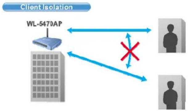
The WL-5460APv2 features the new Wireless Client Isolation function previous available only in more expensive APs. When you enable this function, the wireless clients will not be able to see each other. Therefore, it is an important function for office and Hotspot operator to protect the security between different wireless users.
ACK Timeout and TX Power Regulation
The WL-5460APv2 features ACK timeout function to let you adjust the timeout value for long distance operation. In addition, 5-level TX power adjustment let you match different antennas for law compliance. The ability to set lower TX output power is also crucial if you want to match the AP with external power amplifier.
Extended Security Features
The WL-5460APv2 support WEP, WPA and WPA2 security functions. In addition, WPA enterprise for 802.1x authenticator are featured for AP and WDS mode. The combination of Encryption, Hide SSID and Access Control ensures your wireless network is completely secured from intruder.
Whether it's for office or home environment, the AirLive 802.11g family bring you the maximum performance and security for today's high speed wireless network.
Application
Example 1
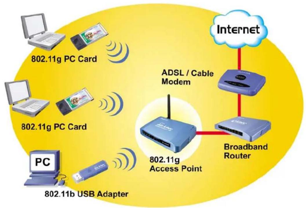
flowchart
graph TD
    A["802.11g PC Card"] --> B["802.11g Access Point"]
    C["802.11g PC Card"] --> B
    D["802.11b USB Adapter"] --> B
    E["PC"] --> F["802.11g USB Adapter"]
    G["Internet"] --> H["Broadband Router"]
    H --> I["802.11g Cable Modem"]
    style A fill:#f9f,stroke:#333
    style C fill:#f9f,stroke:#333
    style D fill:#f9f,stroke:#333
    style E fill:#f9f,stroke:#333
    style G fill:#f9f,stroke:#333
    style H fill:#ccf,stroke:#333
    style I fill:#ccf,stroke:#333
Example 2
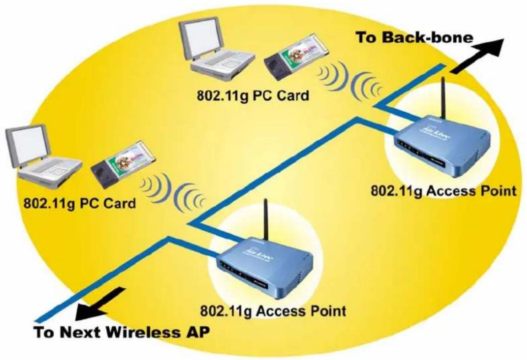
flowchart
graph TD
    A["802.11g PC Card"] -->|Wireless Signal| B["802.11g PC Card"]
    B --> C["802.11g Access Point"]
    C --> D["To Back-bone"]
    D --> E["802.11g Access Point"]
    E --> F["To Next Wireless AP"]
1.2 Firmware Features
AirLive Wireless AP Firmware Features
Firmware e11: The Most Powerful AP Firmware Ever!
WL-5460AP
As the leading global WISP solution provider, AirLive understands the application environments of WISP operators. As a result, we are constantly upgrading our AP's firmware to meet the changing demand of WISP operators. The latest E11 firmware adds high end features not commonly found in the AP of this class. The AirLive multi-function Access Points not only work for long distance application, they work much better than the competitions.
8 Wireless Operation Modes
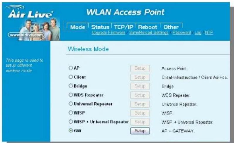
The AirLive WL-5460AP can operate in 8 different wireless modes. It can work as a Wireless Router, AP, Client, Repeater, Bridge, and much more. Whether it is for home, office, or WISP; the AirLive AP has a solution for you.
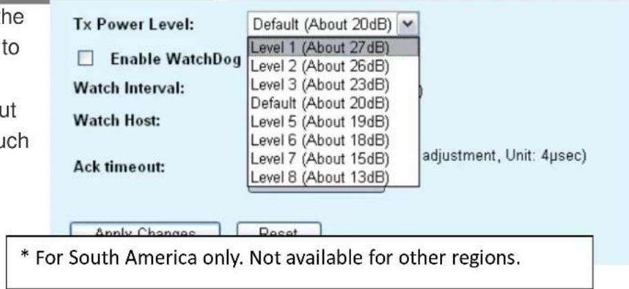
Up to 400mW of Output Power\*
AirLive's high quality hardware let the AP expand its RF output power up to 26dBm using South American firmware. That's 4 times the output power of regular AP! It means much greater distance and coverage.
Traffic Control QoS Function
Traffic Control is a great tool to control the bandwidth of the WISP subscribers. Therefore, the WISP operators can offer different class of connection speeds for different subscription fees - just like the ADSL service! The AirLive advance Traffic Control firmware can control the bandwidth by Interface or IP/MAC.
Traffic Control QoS
Access Point with Traffic Control
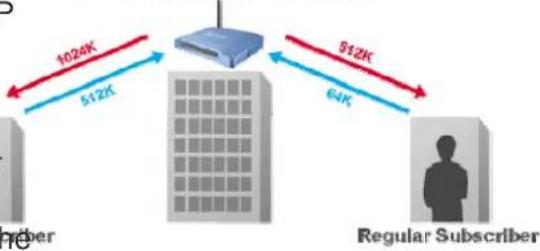
flowchart
graph TD
    A["Regular Subscriber"] -->|6K| B["Server"]
    B -->|912K| C["Data Transfer"]
    C -->|1024K| D["Data Transfer"]
    style A fill:#f9f,stroke:#333
    style B fill:#bbf,stroke:#333
    style C fill:#dfd,stroke:#333
    style D fill:#dfd,stroke:#333
Dynamic Signal Survey Function for Antenna Alignment
Having trouble align your antenna Signal Survey correctly to the other outdoor AP? The AirLive Wireless Signal Survey
Survey
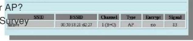
Antenna Alignment Survey
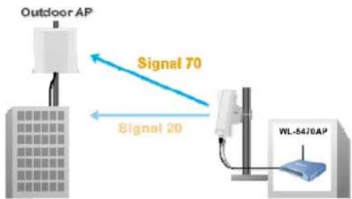
flowchart
graph LR
    A["Outdoor AP"] -->|Signal 70| B["WL-5470AP"]
    B -->|Signal 20| A
function tells you the receiving signal strength
dynamically as your antenna turns. It automatically refreshes itself in the process, therefore, making antenna alignment much simpler than before.
Wireless Site Survey Connection Wizard
During a new WISP service installation, the installer will to find out which outdoor AP provide the best signal in the for connection. The AirLive wireless site survey function provides one step setup for process. First, the site page shows which AP has strongest the signal. Then installer performs antenna
Wireless Site Survey
| SSID | RSSID | Channel | Type | Encrypt | Signal | Select |
| testd | 00:0b | 11 (B+G) | AP | WPA, PSK | 100 | |
| Gateway | 00:4f | 11 (B+G) | AP | no | 85 | |
| airlva | 00:50 | 1 (B+G) | AP | no | 83 | |
| AirForce-2 | 0a:4 | 2 (B+G) | AP | no | 82 | |
| AirLive | 00:4 | 2 (B+G) | AP | no | 82 | |
| Airforce-1 | 0E:4f | 2 (B+G) | AP | no | 82 | |
| Freedom | 00:05 | 6 (B) | AP | WEP | 67 | |
| 802.11g-SSID | 00:e0 | 11 (B+G) | AP | no | 63 | |
| CL-WLAN | 00:13 | 1 (B+G) | AP | WPA | 62 |
Refresh
Connect
Signal Survey
alignment by using the signal survey function. At last, the installer simply clicks on
need
area
this
survey
the
the
"connect" button to establish connection. The site survey is available even in AP mode, so the installer can check the channels used by surrounding APs to avoid interferences.
Telnet Function
Some WISP operators prefer use CLI command line for configurations. The latest firmware provide full comma line feature via Telnet.
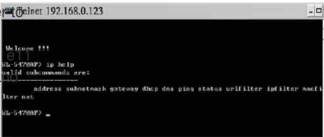
Wireless Client Isolation
AirLive firmware's Client
Isolation function protects the security and privacy of each individual subscriber.
Therefore, subscriber does not need to worry about hacker attacks in the same wireless network.
flowchart
graph TD
    A["Client Isolation"] --> B["WL-5470AP"]
    B --> C{Isolation}
    C -->|Blue Arrow Left| D["Human icon"]
    C -->|Blue Arrow Right| E["Human icon"]
    C -->|Red X| F["Unknown"]
    F --> C
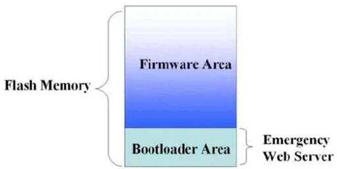
Emergency Recovery
How many times your machine crashed and lost access completely?
The AirLive's Emergency web server function means you can recover your AP even during if the machine failed during a firmware upgrade. This greatly reduces the service loading for WISP operators.
1.3 Installing WL-5460AP
This section describes the installation procedure for the WL-5460AP. It starts with a summary of the content of the package you have purchased, followed by steps of how to power up and connect the WL-5460AP. Finally, this section explains how to configure a Windows PC to communicate with the WL-5460AP.
1.3.1 Package Content
The WL-5460AP package contains the following items:
√ One WL-5460AP main unit
√ One 12V DC power adapter
√ Indoor detachable Omni Antenna x 1
√ One CD of the WL-5460AP
√ Quick Start Guide
1.3.2 Hardware Presentation
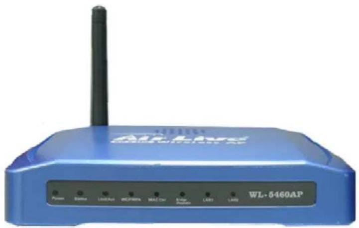
natural_image
Blue wireless router device labeled WL-5460AP with antenna and control buttons (no readable text beyond branding)
| LED # Display Color Indication | |||
| 1 Power Green Lights on when the device is powered. | |||
| 2 Status Red Lights on when the device is booting, lights off after boot successfully. | |||
| 3 Link/Act Green Lights on when any one client connected. Blinking when sending or receiving data. | |||
| 4 WEP/WPA Green Lights on when wireless security is enabled | |||
| 5 MAC Ctrl Green lights on when MAC control is enabled. | |||
| 6 Bridge / Green Repeater | Green | Lights on when Bridge or Repeater is enabled | |
| 7 LAN1 Green Lights on when the port is actively connected, blinking when transmitting or receiving data. | |||
| 8 LAN2 | Green | ||
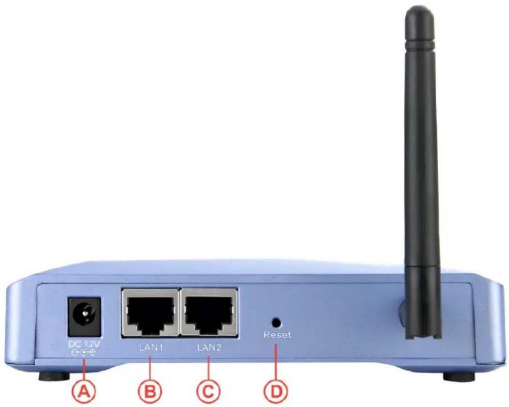
| Item # Function Description | ||
| A Power Adaptor 12V 1A | power supply adaptor delivered with product. | |
| B | LAN1 LAN port | |
| C LAN2 LAN port 2 or WAN port(Gateway Mode only) | ||
| D | (Factory) Reset | Press over 3 seconds to reboot this device.Press for over 10 seconds to restore factory settings.Performing the Factory Reset will erase all previously entered device settings. |
1.3.3 Configuration Setups
The factory default settings of WL-5460AP are as following:
| Settings Default Value | |
| Device Name | WL-5460AP |
| Radio | 802.11b/g |
| SSID | airlive |
| Channel | 11 |
| WEP | Disabled |
| IP Address | 192.168.100.252 |
| DHCP Server | Disabled. Available and default enabled when each of the wireless is configured as a gateway. |
| DHCP IP Range | 192.168.100.100 ~ 192.168.100.200 |
1.3.4 Hardware Connection
Note: Before you starting hardware connection, you are advised to find an appropriate location to place the Access Point. Usually, the best place for the Access Point is at the center of your wireless network, with line of straight to all your wireless stations. Also, remember to adjust the antenna; usually the higher the antenna is placed; the better will be the performance.
![[Wireless Access Point] Default IP address: 192.168.100.252E SSID: AirLine Channel: 11 Encryption: Disabled Device name: WL-5460AP Encryption: Disabled [PC-WLAN] IP address: 192.168.100.XX SSID: AirLine Channel: 11 Encryption: Disabled Power Adapter DC 12V Wireless LAN Card To Ethernet network equipment, e.g. Router, Switch, or another Wireless Access Point](/content/2026/05/758229/images/ad504e1cb8d7017488d22cb634cb3c2427d7f11a6935908ec98beb50431fc6c3.jpg)
- Connect to your local area network: connect an Ethernet cable to one of the Ethernet port (LAN1 or LAN2) of this Wireless Access Point, and the other end to a hub, switch, router, or another wireless access point.
- Power on the device: connect the included AC power adapter to the Wireless Access Point's power port and the other end to a wall outlet.
- Check the LED:
The Power and LAN # LED should be ON. LAN# LED will even blink if there is traffic.
The Link/Act LED will be on in static when associated with a station and blink whenever this AP receives data packets in the air.
If the Status LED glows after self-test, it means the Wireless Access Point fails on self test.
Please ask your dealer for technical support.
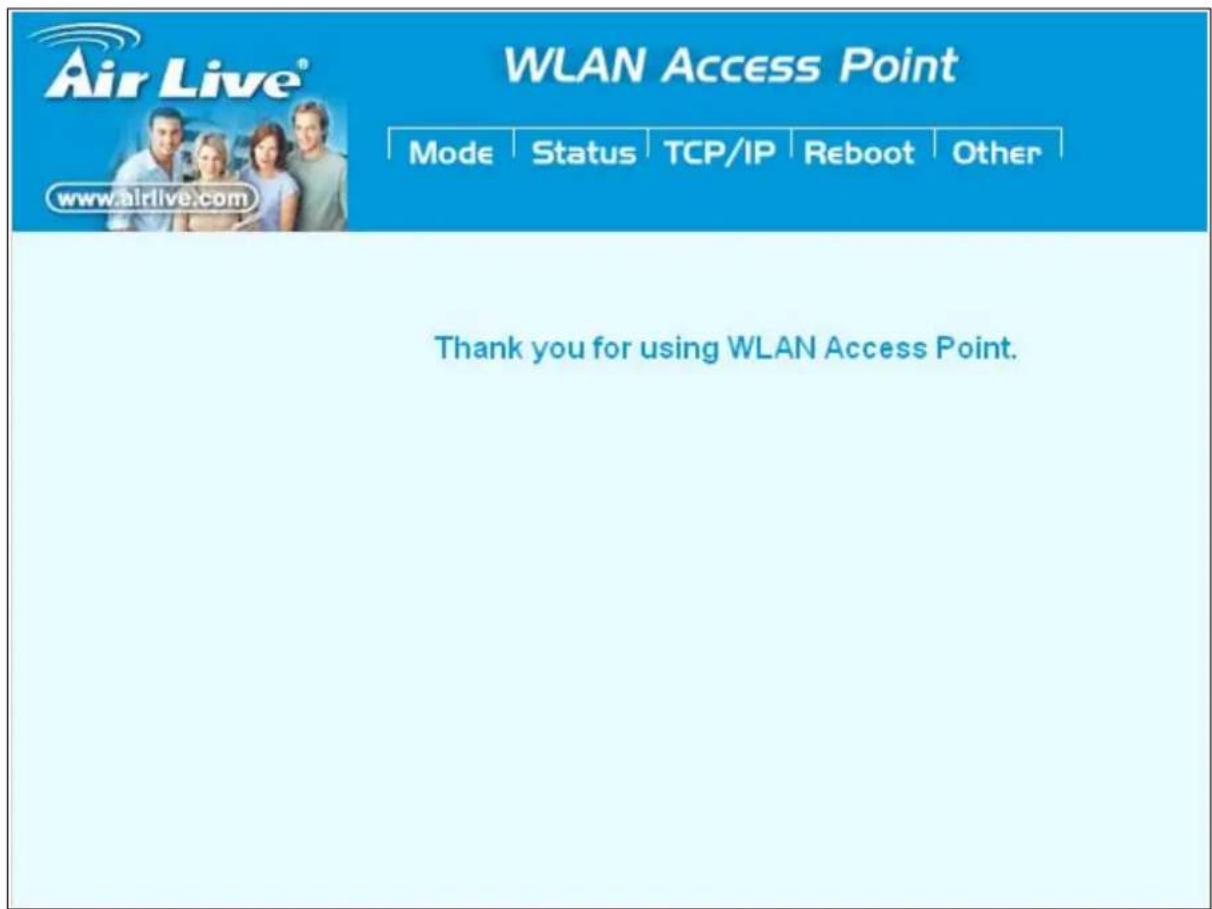
1 Please make sure your computer IP is in the same subnet as the AP (i.e. 192.168.100.x).
2 Please make sure your computer has wireless network adapter installed.
3 Open the web browser and enter http://192.168.100.252/.
2. Operation Mode
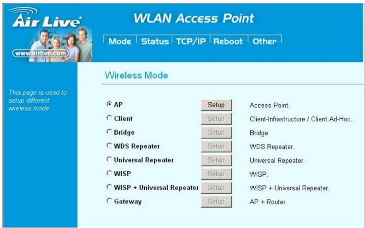
The WL-5460AP device provides all 8 modes of wireless operational applications with:
| Mode Radio LAN 1 | LAN 2 | ||
| AP | AP | LAN | LAN |
| Client | Client | LAN | LAN |
| Bridge | WDS | LAN | |
| WDS Repeater WDS + AP LAN LAN | |||
| Universal Repeater AP + Client LAN LAN | |||
| WISP | Client | Router | LAN |
| WISP + Universal Repeater | Client Router + AP | LAN | LAN |
| Gateway | AP+ Router | WAN | LAN |
LAN
2.0 Change Operation Mode
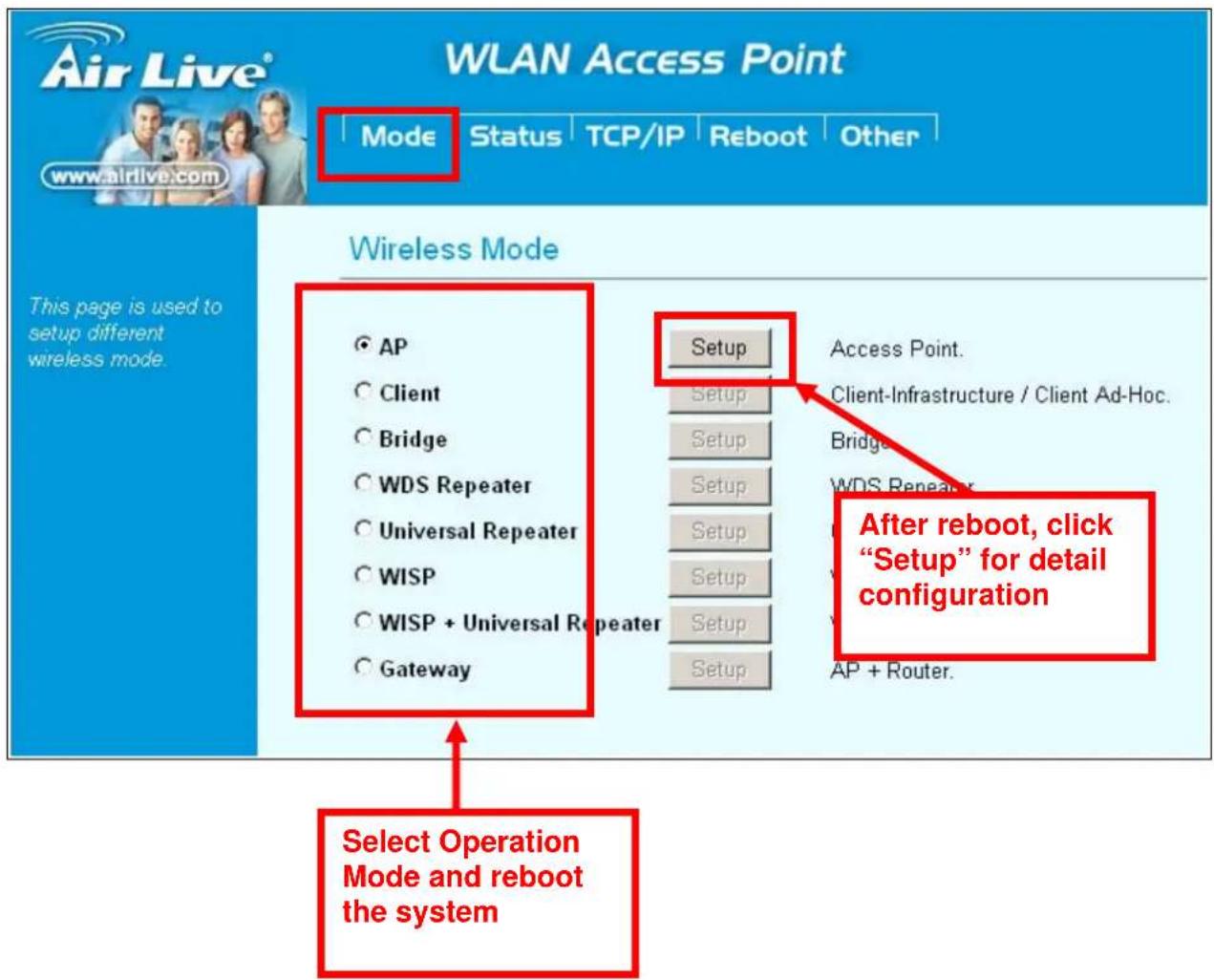
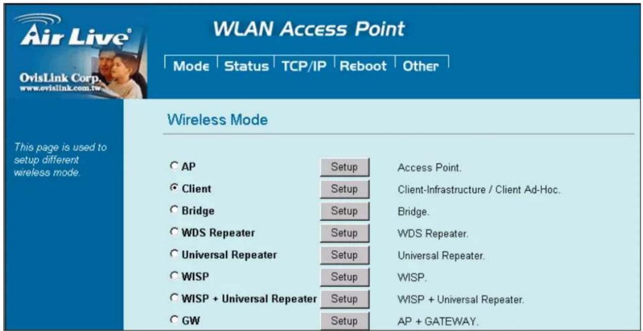
WL-5460AP is default in AP mode. If the mode had been changed, click the "Mode" button to change back.
To change operation Mode:
- Click on "Mode"
- Select Operation Mode in the main page
- Reboot device
- Click Setup for detail configuration
2.1 About the Operation Modes
This device provides four operational applications with Access Point, Bridge, Client (Ad-hoc) and Client (Infrastructure) modes, which are mutually exclusive.
This device is shipped with configuration that is functional right out of the box. If you want to change the settings in order to perform more advanced configuration or even change the mode of operation, you can use the web-based utility provided by the manufacturer as described in the following sections.
2.1.1 Access Point Mode
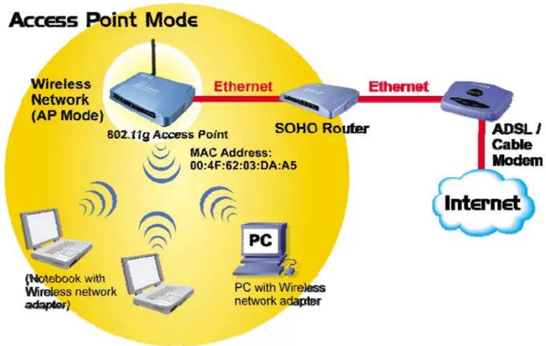
When acting as an access point, this device connects all the stations (PC/notebook with wireless network adapter) to a wired network. All stations can have the Internet access if only the Access Point has the Internet connection.
See the sample application below.
flowchart
graph LR
    A["Wireless Network (AP Mode)"] -->|802.11g Access Point MAC Address: 00:4F:62:03:DA:A5| B["SOHO Router"]
    B -->|Ethernet| C["ADSL / Cable Modem"]
    C --> D["Internet"]
    E["PC"] --> F["PC with Wireless network adapter"]
    G["(Notebook with Wireless adapter)"] --> H["PC"]
To set the operation mode to Access Point, please go to "Mode" field and select the "AP" mode.

WLAN Access Point
Mode
Status
TCP/IP
Reboot
Other
Wireless Mode
This page is used to setup different wireless mode.
AP
C Client
Bridge
C WDS Repeater
Universal Repeater
C WISP
© WISP + Universal Repeater
CGW
Setup
Setup
Setup
Setup
Setup
Setup
Setup
Setup
Access Point.
Client-Infrastructure / Client Ad-Hoc.
Bridge.
WDS Repeater.
Universal Repeater.
WISP.
WISP + Universal Repeater.
AP + GATEWAY.
2.1.2 Client Mode
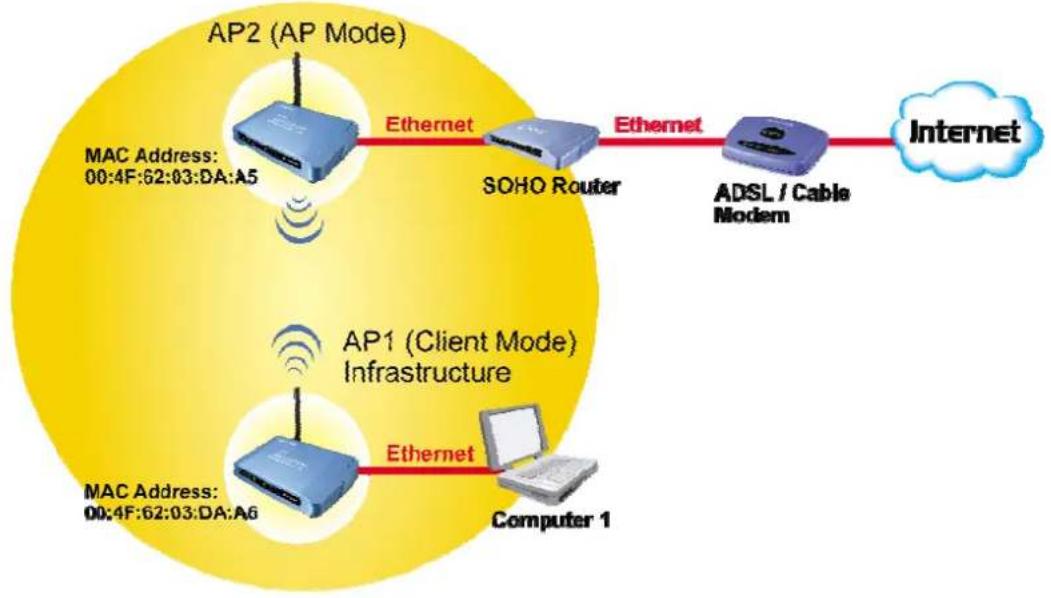
If set to Client (Infrastructure) mode, this device can work like a wireless station when it's connected to a computer so that the computer can send packets from wired end to wireless interface.
Refer to the illustration below. This station (AP1 plus the connected computer 1) can associate to another Access Point (AP2), and then can have the Internet access if the other Access Point (AP2) has the Internet connection.
Client Mode (Infrastructure)
flowchart
graph LR
    A["AP2 (AP Mode)"] -->|Ethernet| B["SOHO Router"]
    B -->|Ethernet| C["ADSL / Cable Modem"]
    C --> D["Internet"]
    E["AP1 (Client Mode) Infrastructure"] -->|Ethernet| F["Computer 1"]
    G["MAC Address: 00:4F:62:03:DA:A5"] --> A
    H["MAC Address: 00:4F:62:03:DA:A6"] --> E
To set the operation mode to Client (Infrastructure), please go to “Mode” field and select the “Client” mode.
2.1.3 Bridge Mode
The WDS (Wireless Distributed System) function let this access point acts as a wireless LAN access point and repeater at the same time. Users can use this feature to build up a large wireless network in a large space like airports, hotels and schools ...etc. This feature is also useful when users want to bridge networks between buildings where it is impossible to deploy network cable connections between these buildings.
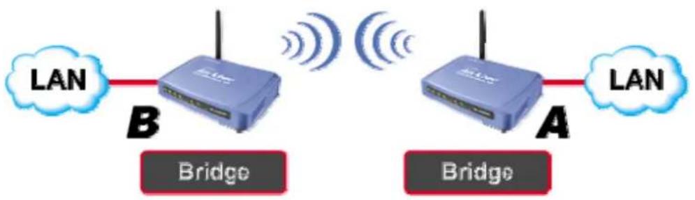
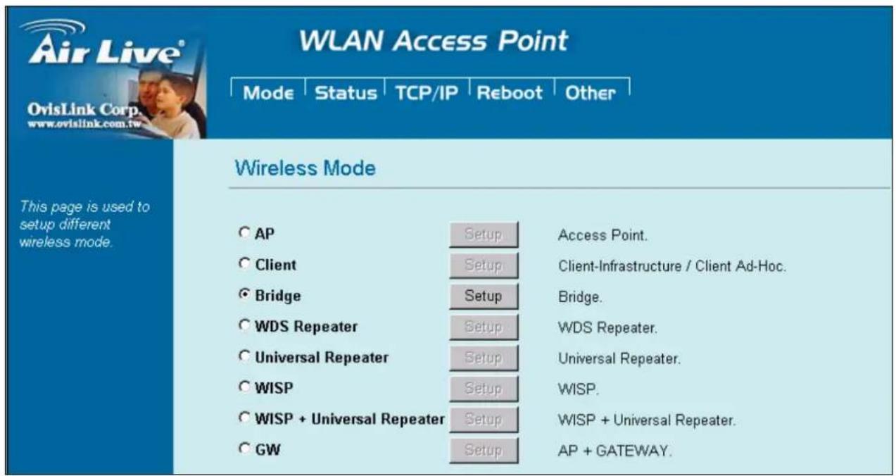
To set the operation mode to Client (Infrastructure), please go to "Mode" field and select the "Bridge" mode.
2.1.4 WDS Repeater
Refer to the illustration below. While acting as Bridges, AP1 (with Station 1 being associated to) and AP2 (with Station 2 being associated) can communicate with each other through wireless interface (with WDS). Thus Station 1 can communicate with Station 2 and both Station 1 and Station 2 are able to access the Internet if only AP1 or AP2 has the Internet connection.
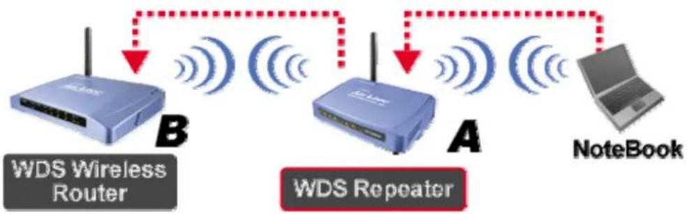
flowchart
graph LR
    A["WDS Wireless Router"] -->|B| B["WDS Repeater"]
    B -->|A| C["NoteBook"]
    C -->|Dashed arrow| A
    style A fill:#cce5ff,stroke:#333
    style B fill:#cce5ff,stroke:#333
    style C fill:#e6f7ff,stroke:#333
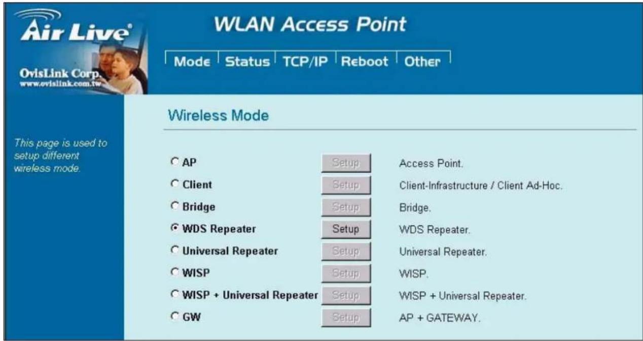
To set the operation mode to Client (Infrastructure), please go to "Mode" field and select the "WDS Repeater" mode.
2.1.5 Universal Repeater
An universal repeater can also extend the wireless coverage of another wireless AP or router. But the universal repeater does not require the remote device to have WDS function. Therefore, it can work with almost any wireless device.
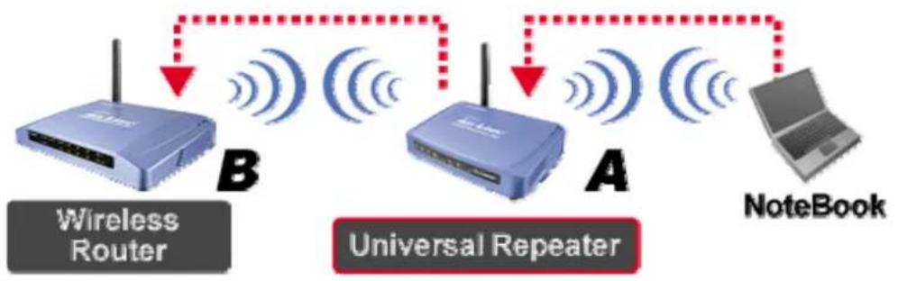
flowchart
graph LR
    A["Wireless Router"] -->|B| B["Universal Repeater"]
    B -->|A| C["Laptop"]
    style A fill:#cce5ff,stroke:#333
    style B fill:#cce5ff,stroke:#333
    style C fill:#f9f9f9,stroke:#333
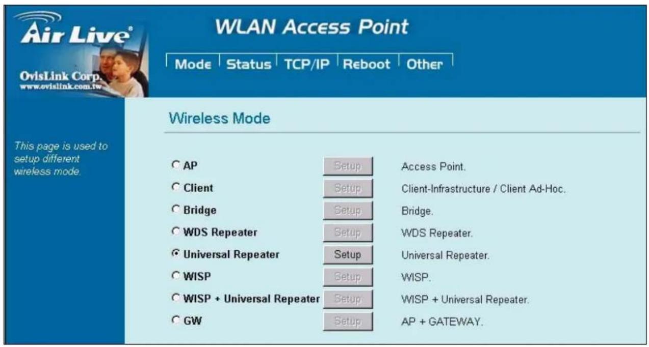
To set the operation mode to Client (Infrastructure), please go to "Mode" field and select the "Universal Repeater" mode.
2.1.6 WISP (Client Router) mode
In WISP mode, the AP will behave just the same as the Client mode for wireless function. However, router functions are added between the wireless WAN side and the Ethernet LAN side. Therefore, the WISP subscriber can share the WISP connection without the need for extra router.
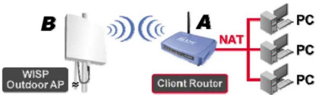
flowchart
graph LR
    B["Client Router"] -->|NAT| PC1["PC"]
    B -->|NAT| PC2["PC"]
    B -->|NAT| PC3["PC"]
    A["Client Router"] -->|NAT| PC4["PC"]
    A -->|NAT| PC5["PC"]
    A -->|NAT| PC6["PC"]
    style B fill:#f9f,stroke:#333
    style A fill:#bbf,stroke:#333
To set the operation mode to Client (Infrastructure), please go to "Mode" field and select the "WISP" mode.
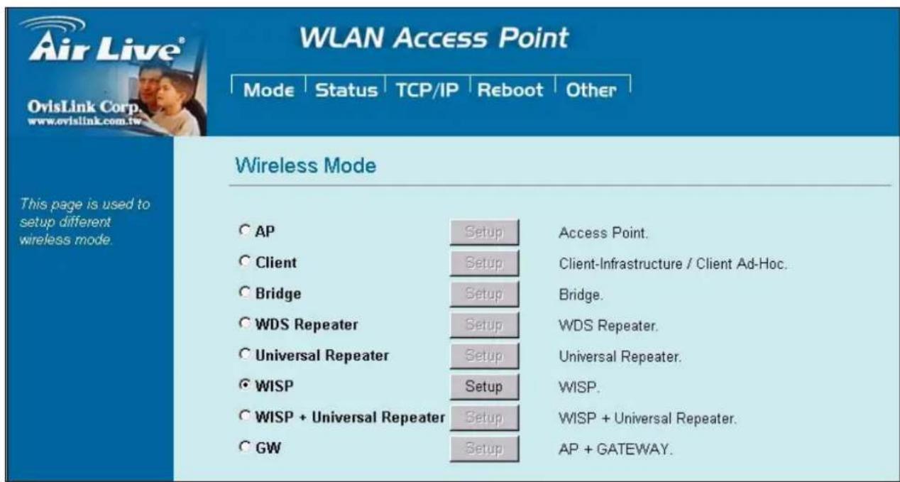
2.1.7 WISP + Universal Repeater mode
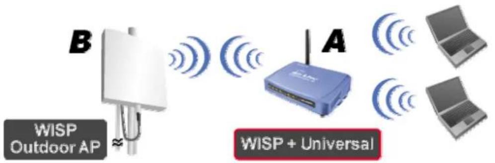
In this mode, the AP behaves virtually the same as the WISP mode, except one thing: the AP can also send wireless signal to the LAN side. That means the AP can connect with the remote WISP AP and the indoor wireless card, and then provide IP sharing capability all at the same time!
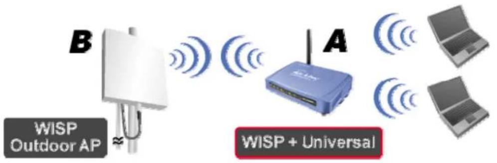
To set the operation mode to Client (Infrastructure), please go to "Mode" field and select the "WISP + Universal Repeater" mode.
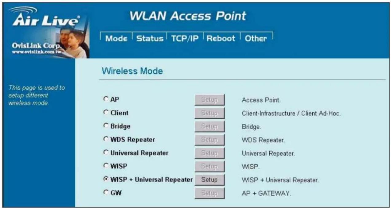
2.1.8 Gateway (AP + Router)
In this mode, router functions are added between one Ethernet port and the other network interface. The radio is an AP mode which allow wireless client to share the internet connection.
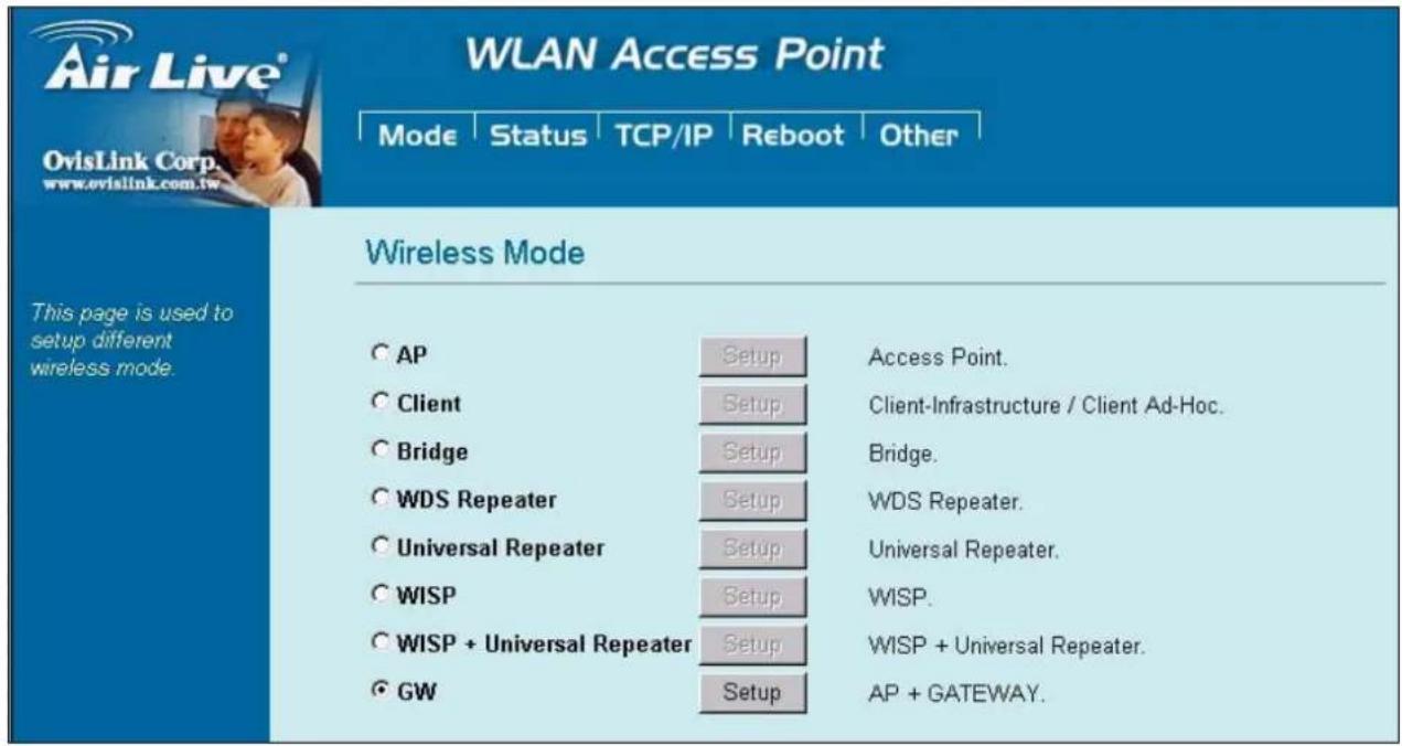
To set the operation mode to Client (Infrastructure), please go to "Mode" field and select the "Gateway" mode.
To set the operation mode to "GW Mode", Please go to "Mode → GW" and click the Setup button for configuration.
3. Wireless Settings
This section guides you to configure the mode of the Radio interface.
3.1 Access Point Mode Settings
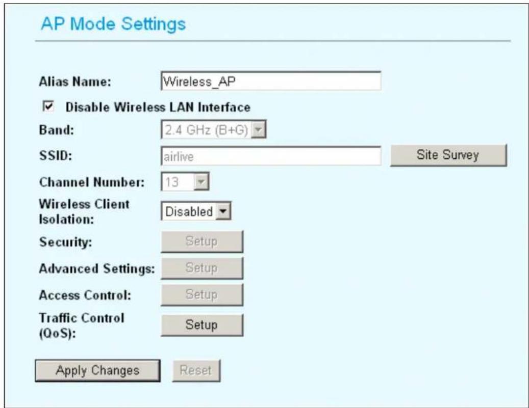
Alias Name: Another name for WL-5460AP.
Disable Wireless LAN Interface: Check the box to disable the Wireless LAN Interface, by so doing, you won't be able to make wireless connection with this Access Point in the network you are located. In other words, this device will not be visible by any wireless station.
Band: You can choose one mode of the following you need.
- 2.4GHz (B): 802.11b supported rate only.
- 2.4GHz (G): 802.11g supported rate only.
- 2.4GHz (B+G): 802.11b supported rate and 802.11g supported rate.
The default is 2.4GHz (B+G) mode.
SSID (Network ID): The SSID differentiates one WLAN from another; therefore, all access points and all devices attempting to connect to a specific WLAN must use the same SSID. It is case-sensitive and must not exceed 32 characters. A device will not be permitted to join the BSS unless it can provide the unique SSID. An SSID is also
referred to as a network name because essentially it is a name that identifies a wireless network.
In this mode, the SSID is provided for client connection.
Channel Number: Allow user to set the channel manually or automatically. If set channel manually, just select the channel you want to specify. If "Auto" is selected, user can set the channel range to have Wireless Access Point automatically survey and choose the channel with best situation for communication. The number of channels supported depends on the region of this Access Point. All stations communicating with the Access Point must use the same channel.
Wireless Client Isolation: This is to separate wireless client if needed. Wireless clients can not communicate to each other if the field is enabled.
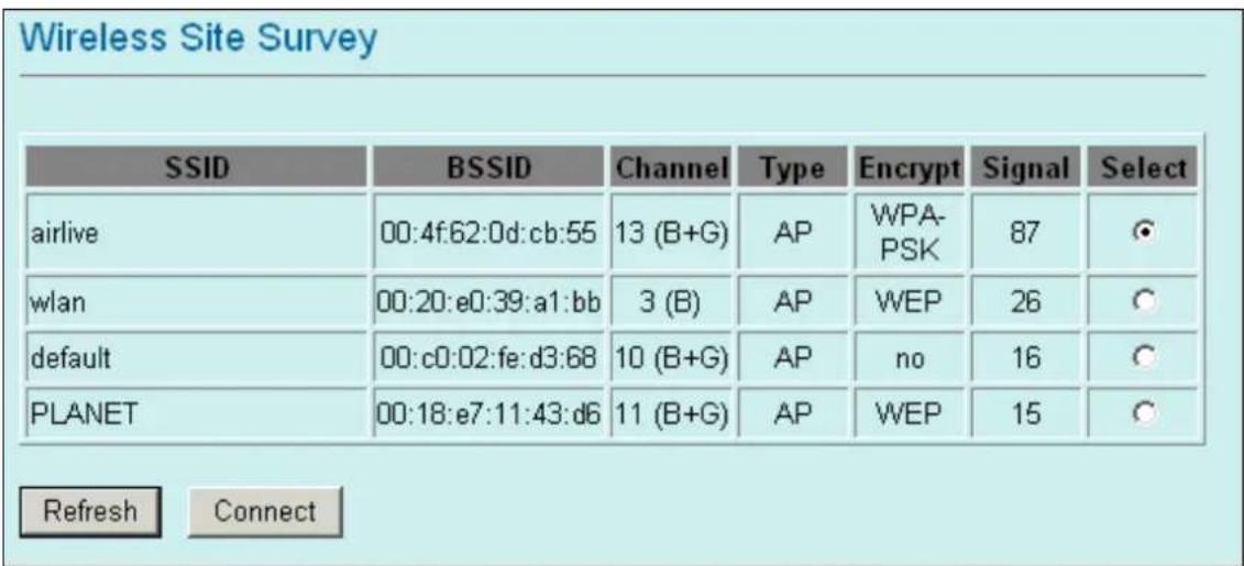
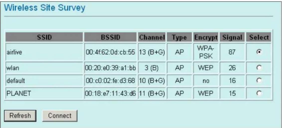
Site Survey: Site survey helps to find out available access point around. You can also check to prevent using same SSID or channel with other AP.
To configure the security connection, please refer to Section 3.9 Wireless Security Settings ..... To configure the Advanced Settings, please refer to Section 3.10 Advanced Wireless Settings ..... To configure the access control, please refer to Section 3.11 Access Control Settings ..... To configure the Traffic Control, please refer to Section 3.12 Access Control Settings ....
3.2 Client Mode Settings
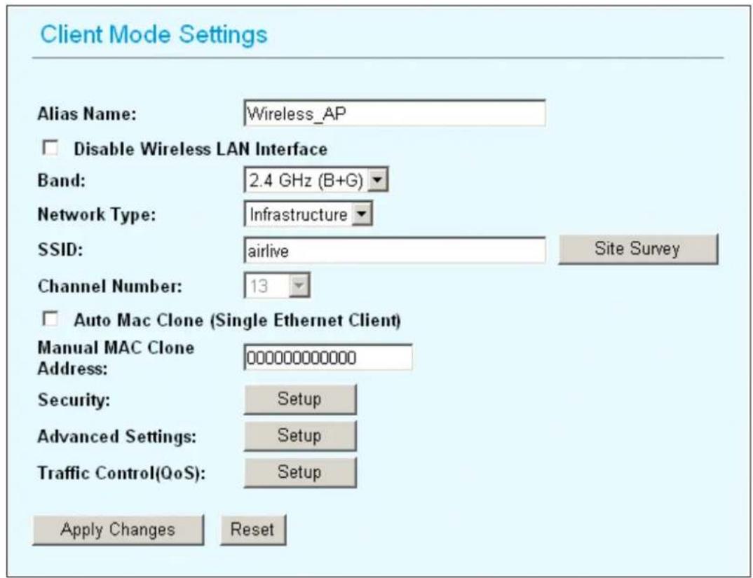
Alias Name: Another name for WL-5460AP.
Disable Wireless LAN Interface: Check the box to disable the Wireless LAN Interface, by so doing, you won't be able to make wireless connection with this Access Point in the network you are located. In other words, this device will not be visible by any wireless station.
Band: You can choose one mode of the following you need.
- 2.4GHz (B): 802.11b supported rate only.
- 2.4GHz (G): 802.11g supported rate only.
- 2.4GHz (B+G): 802.11b supported rate and 802.11g supported rate.
The default is 2.4GHz (B+G) mode.
SSID (Network ID): The SSID differentiates one WLAN from another; therefore, all access points and all devices attempting to connect to a specific WLAN must use the same SSID. It is case-sensitive and must not exceed 32 characters. A device will not be permitted to join the BSS unless it can provide the unique SSID. An SSID is also referred to as a network name because essentially it is a name that identifies a wireless network.
In this mode, the SSID is the available remote Access Point to connect to.
Channel Number: Allow user to set the channel manually or automatically. If set channel manually, just select the channel you want to specify. If "Auto" is selected, user can set the channel range to have Wireless Access Point automatically survey and choose the channel with best situation for communication. The number of channels supported depends on the region of this Access Point. All stations communicating with the Access Point must use the same channel.
Auto Mac Clone (Single Ethernet Client): If your ISP restricts service to PCs only, use the MAC Clone feature to copy a PC Media Access Control (MAC) address to your router. This procedure will cause the router to appear as a single PC, while allowing online access to multiple computers on your network.
Manual MAC Clone Address: You can also manually provide MAC address to the router. This solves the problem if you have more than one PC which need to access the internet..
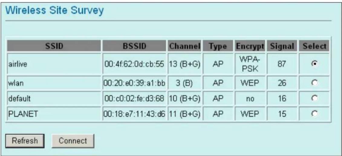
Site Survey: Site survey helps to find out available access point around. You can also check to prevent using same SSID or channel with other AP.
To configure the security connection, please refer to Section 3.9 Wireless Security Settings ..... To configure the Advanced Settings, please refer to Section 3.10 Advanced Wireless Settings ..... To configure the access control, please refer to Section 3.11 Access Control Settings ..... To configure the Traffic Control, please refer to Section 3.12 Access Control Settings ....
3.3 Bridge Mode Settings
Bridge Mode Settings
Alias Name:
Wireless_AP

Disable Wireless LAN Interface
Band:
2.4 GHz (B+G)
Channel Number:
13
802.1d Spanning Tree:
Disabled
WDS Security:
Setup
Advanced Settings:
Setup
Apply Changes
Reset
AP MAC Address:
Site Survey
Comment:
Add MAC Address
Reset
Show Statistics
AP MAC List:
| MAC Address | Comment | Select |
| 00:4f:62:03:da:a1 | Node 1 | |
| 00:4f:62:03:da:ce | Node 2 | |
| Delete Selected Delete All Reset | ||
Alias Name: Another name for WL-5460AP.
Disable Wireless LAN Interface: Check the box to disable the Wireless LAN Interface, by so doing, you won't be able to make wireless connection with this Access Point in the network you are located. In other words, this device will not be visible by any wireless station.
Band: You can choose one mode of the following you need.
- 2.4GHz (B): 802.11b supported rate only.
- 2.4GHz (G): 802.11g supported rate only.
- 2.4GHz (B+G): 802.11b supported rate and 802.11g supported rate.
The default is 2.4GHz (B+G) mode.
Channel Number: Allow user to set the channel manually or automatically. If set channel manually, just select the channel you want to specify. If "Auto" is selected, user can set the channel range to have Wireless Access Point automatically survey
and choose the channel with best situation for communication. The number of channels supported depends on the region of this Access Point. All stations communicating with the Access Point must use the same channel.
802.1d Spanning Tree: Spanning tree is to prevent bridge loop when there are multiple active paths between network nodes. Bridge loop could cause connection fail or broadcast storm. Spanning tree allows a network design to include spare (redundant) links to provide automatic backup paths if an active link fails, without the danger of bridge loops, or the need for manual enabling/disabling of these backup links.
AP MAC Address: Fill the MAC address of the remote WDS node which you want to connect to.
Site Survey: Use this button to find out the remote WDS node and check the signal strength. It helps to build up you WDS network correctly.
To configure the security connection, please refer to Section 3.9 Wireless Security Settings ..... To configure the Advanced Settings, please refer to Section 3.10 Advanced Wireless Settings ..... To configure the access control, please refer to Section 3.11 Access Control Settings ..... To configure the Traffic Control, please refer to Section 3.12 Access Control Settings ....
3.4 WDS Repeater Mode Settings
WDS Repeater Mode Settings
Alias Name:
Wireless_AP

Disable Wireless LAN Interface
Band:
2.4 GHz (B+G)
SSID:
airlive
Channel Number:
13
Wireless Client Isolation:
Disabled
802.1d Spanning Tree:
Disabled
Security:
Setup
WDS Security:
Setup
Advanced Settings:
Setup
Access Control:
Setup
Apply Changes
Reset
AP MAC Address:
Site Survey
Comment:
Add MAC Address
Reset
Show Statistics
AP MAC List:
| MAC Address | Comment | Select |
| 00:4f:62:03:da:a1 | Node 1 | |
| 00:4f:62:03:da:ce | Node 2 | |
| Delete Selected Delete All Reset | ||
Alias Name: Another name for WL-5460AP.
Disable Wireless LAN Interface: Check the box to disable the Wireless LAN Interface, by so doing, you won't be able to make wireless connection with this Access Point in the network you are located. In other words, this device will not be visible by any wireless station.
Band: You can choose one mode of the following you need.
- 2.4GHz (B): 802.11b supported rate only.
- 2.4GHz (G): 802.11g supported rate only.
- 2.4GHz (B+G): 802.11b supported rate and 802.11g supported rate.
The default is 2.4GHz (B+G) mode.
SSID (Network ID): Provide SSID for wireless client survey and connection. The SSID differentiates one WLAN from another; therefore, all access points and all devices attempting to connect to a specific WLAN must use the same SSID. It is case-sensitive and must not exceed 32 characters. A device will not be permitted to join the BSS unless it can provide the unique SSID. An SSID is also referred to as a network name because essentially it is a name that identifies a wireless network. In this mode, the SSID is provided for wireless client connection.
Channel Number: Allow user to set the channel manually or automatically. If set channel manually, just select the channel you want to specify. If "Auto" is selected, user can set the channel range to have Wireless Access Point automatically survey and choose the channel with best situation for communication. The number of channels supported depends on the region of this Access Point. All stations communicating with the Access Point must use the same channel.
802.1d Spanning Tree: Spanning tree is to prevent bridge loop when there are multiple active paths between network nodes. Bridge loop could cause connection fail or broadcast storm. Spanning tree allows a network design to include spare (redundant) links to provide automatic backup paths if an active link fails, without the danger of bridge loops, or the need for manual enabling/disabling of these backup links.
AP MAC Address: Fill the MAC address of the remote WDS node which you want to connect to.
Site Survey: Use this button to find out the remote WDS node and check the signal strength. It helps to build up you WDS network correctly.
To configure the security connection, please refer to Section 3.9 Wireless Security Settings ..... To configure the Advanced Settings, please refer to Section 3.10 Advanced Wireless Settings ....
To configure the access control, please refer to Section 3.11 Access Control Settings .....
To configure the Traffic Control, please refer to Section 3.12 Access Control Settings .....
3.5 Universal Repeater Mode Settings
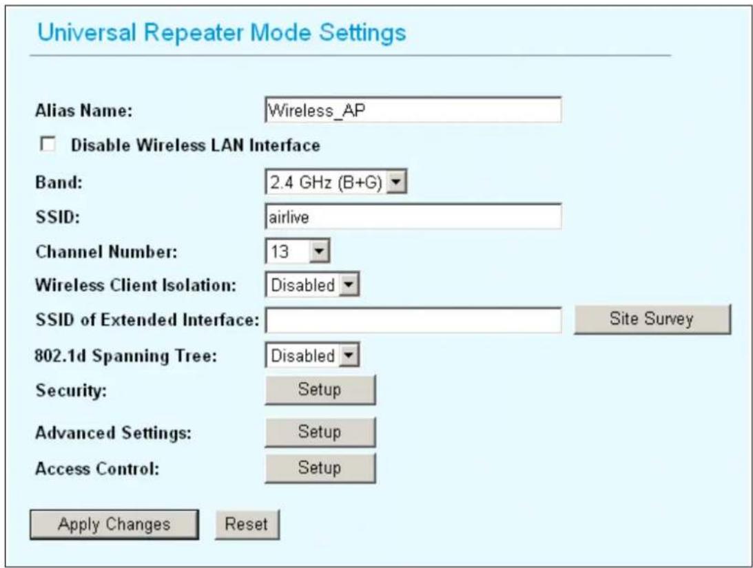
Alias Name: Another name for WL-5460AP.
Disable Wireless LAN Interface: Check the box to disable the Wireless LAN Interface, by so doing, you won't be able to make wireless connection with this Access Point in the network you are located. In other words, this device will not be visible by any wireless station.
Band: You can choose one mode of the following you need.
- 2.4GHz (B): 802.11b supported rate only.
- 2.4GHz (G): 802.11g supported rate only.
- 2.4GHz (B+G): 802.11b supported rate and 802.11g supported rate.
The default is 2.4GHz (B+G) mode.
SSID (Network ID): Provide SSID for wireless client survey and connection. The SSID differentiates one WLAN from another; therefore, all access points and all devices attempting to connect to a specific WLAN must use the same SSID. It is case-sensitive and must not exceed 32 characters. A device will not be permitted to join the BSS unless it can provide the unique SSID. An SSID is also referred to as a network name because essentially it is a name that identifies a wireless network.
This field is to provide for wireless client connection.
Channel Number: Allow user to set the channel manually or automatically. If set channel manually, just select the channel you want to specify. If “Auto” is selected, user can set the channel range to have Wireless Access Point automatically survey and choose the channel with best situation for communication. The number of channels supported depends on the region of this Access Point. All stations communicating with the Access Point must use the same channel.
➢ SSID of Extended Interface: This field is the SSID of remote Access Point to connect to.
802.1d Spanning Tree: Spanning tree is to prevent bridge loop when there are multiple active paths between network nodes. Bridge loop could cause connection fail or broadcast storm. Spanning tree allows a network design to include spare (redundant) links to provide automatic backup paths if an active link fails, without the danger of bridge loops, or the need for manual enabling/disabling of these backup links.
Site Survey: Use this button to find out the remote Access Point and check the signal strength.
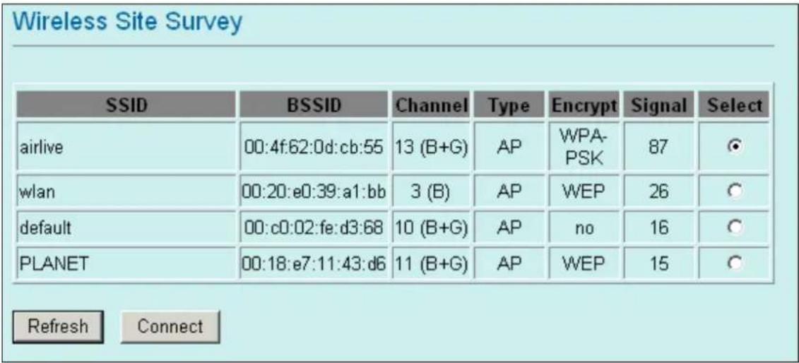
To configure the security connection, please refer to Section 3.9 Wireless Security Settings .....
To configure the Advanced Settings, please refer to Section 3.10 Advanced Wireless Settings .....
To configure the access control, please refer to Section 3.11 Access Control Settings .....
To configure the Traffic Control, please refer to Section 3.12 Access Control Settings .....
3.6 WISP Mode Settings
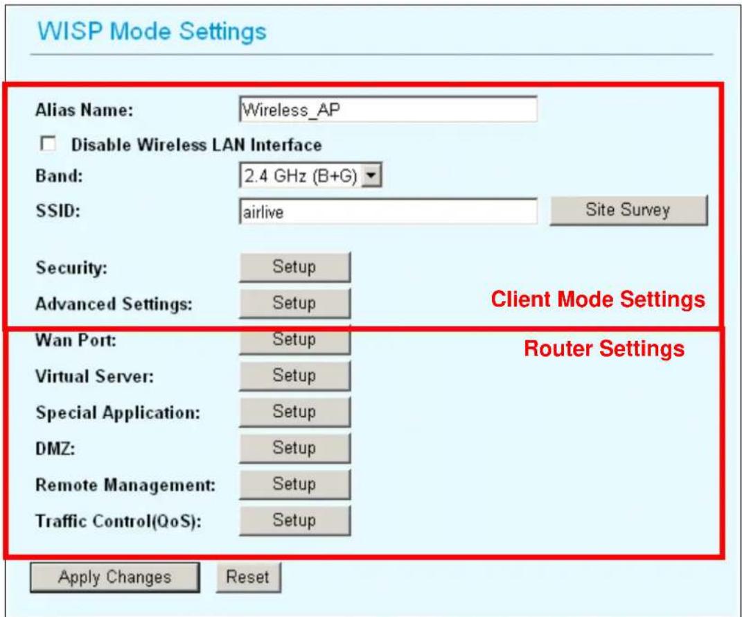
Alias Name: Another name for WL-5460AP.
Disable Wireless LAN Interface: Check the box to disable the Wireless LAN Interface, by so doing, you won't be able to make wireless connection with this Access Point in the network you are located. In other words, this device will not be visible by any wireless station.
Band: You can choose one mode of the following you need.
- 2.4GHz (B): 802.11b supported rate only.
- 2.4GHz (G): 802.11g supported rate only.
- 2.4GHz (B+G): 802.11b supported rate and 802.11g supported rate.
The default is 2.4GHz (B+G) mode.
SSID (Network ID): The SSID differentiates one WLAN from another; therefore, all access points and all devices attempting to connect to a specific WLAN must use the same SSID. It is case-sensitive and must not exceed 32 characters. A device will not be permitted to join the BSS unless it can provide the unique SSID. An SSID is also referred to as a network name because essentially it is a name that identifies a wireless network.
In this mode, the SSID is the remote WISP CPE to connect to.
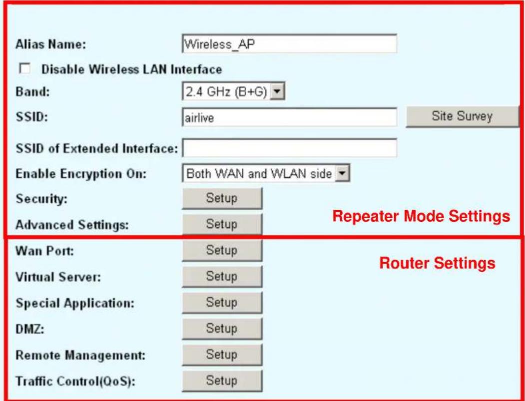
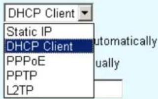
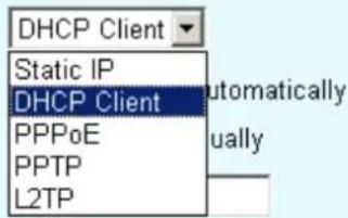
WAN Port: WL-5460AP provides 4 methods for client to access the internet. This depends on the location and the service which the ISP provides. You need to contact the ISP for detail information.
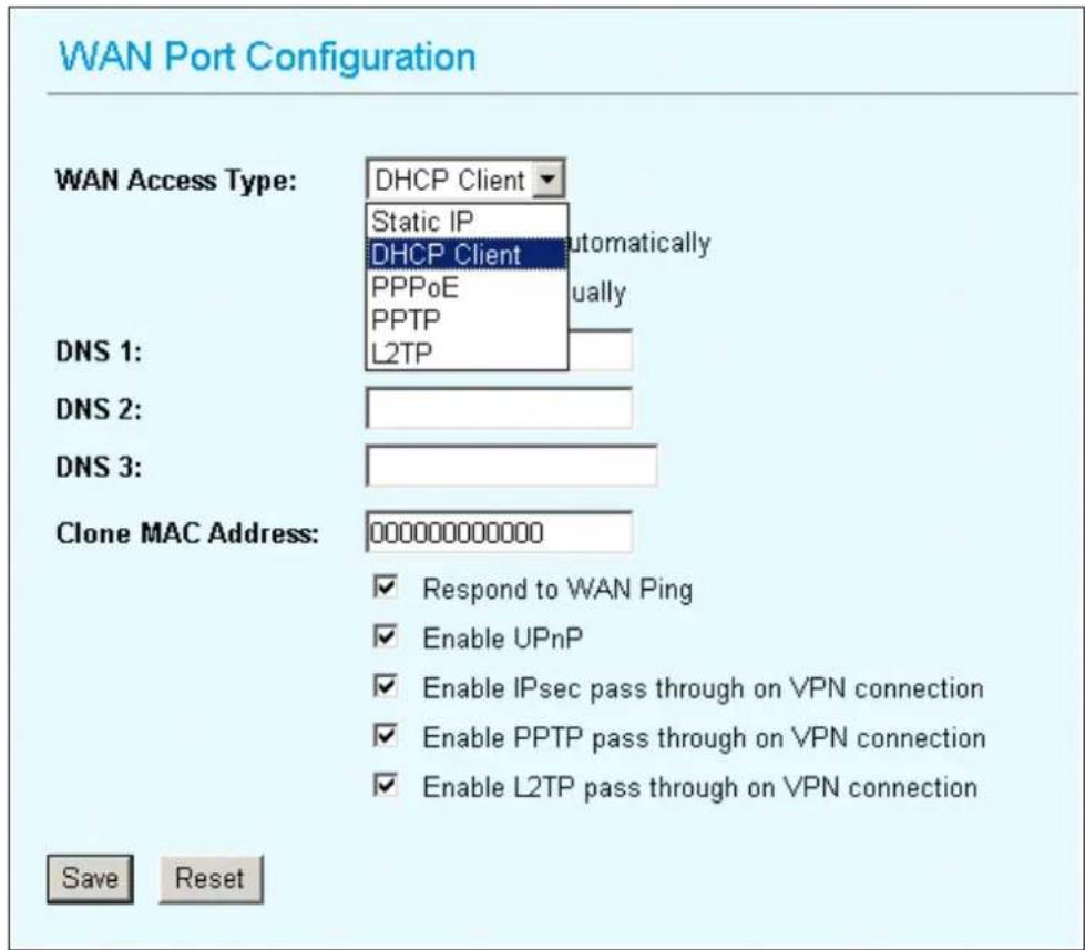
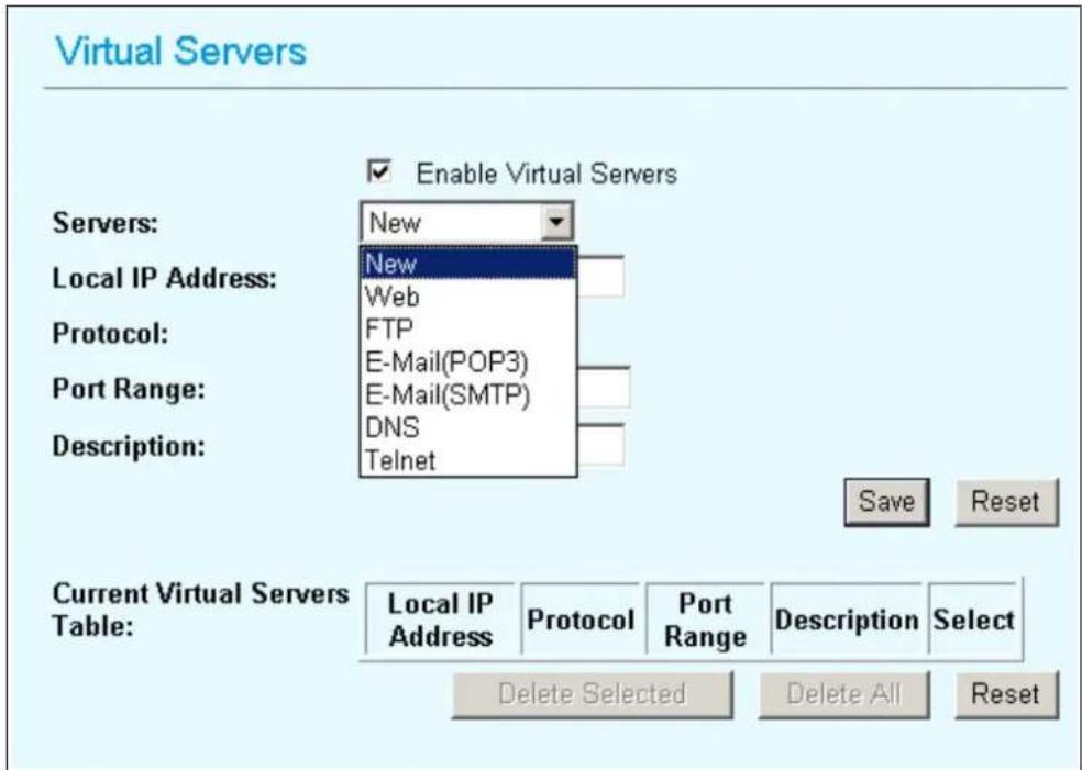
Virtual Server: You can use Virtual Server Settings to provide connection on internet. For example, you can have your own web server at home and provide access on internet. This will need port 80 by default for Virtual Server Settings.
Special Application: This is to enable internet service such as sound, video and so on. The routing firewall often stops these services for security reason.
DMZ: You can use DMZ Settings to provide connection on internet. For example, you can have your own web server at home and provide access on internet. This will need port 80 by default for Virtual Server Settings.
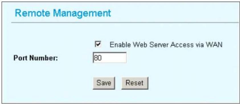
Remote Management: This is to configure WL-5460AP be managed from internet. Note that port 80 is always used by web service. You can change the port to prevent conflict.
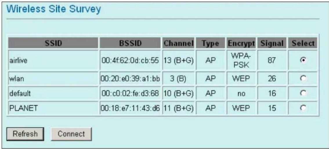
Site Survey: Site survey helps to find out available access point around. You can also check to prevent using same SSID or channel with other AP.

To configure the security connection, please refer to Section 3.9 Wireless Security Settings ..... To configure the Advanced Settings, please refer to Section 3.10 Advanced Wireless Settings ..... To configure the access control, please refer to Section 3.11 Access Control Settings ..... To configure the Traffic Control, please refer to Section 3.12 Access Control Settings ....
3.7 WISP + Universal Mode Settings
WISP + Universal Repeater Mode Settings
Apply Changes
Reset
Alias Name: Another name for WL-5460AP.
Disable Wireless LAN Interface: Check the box to disable the Wireless LAN Interface, by so doing, you won't be able to make wireless connection with this Access Point in the network you are located. In other words, this device will not be visible by any wireless station.
Band: You can choose one mode of the following you need.
- 2.4GHz (B): 802.11b supported rate only.
- 2.4GHz (G): 802.11g supported rate only.
- 2.4GHz (B+G): 802.11b supported rate and 802.11g supported rate.
The default is 2.4GHz (B+G) mode.
SSID (Network ID): The SSID differentiates one WLAN from another; therefore, all access points and all devices attempting to connect to a specific WLAN must use the same SSID. It is case-sensitive and must not exceed 32 characters. A device will not be permitted to join the BSS unless it can provide the unique SSID. An SSID is also
referred to as a network name because essentially it is a name that identifies a wireless network.
In this mode, the SSID is the remote WISP CPE to connect to.
Site Survey: Site survey helps to find out available access point around. You can also check to prevent using same SSID or channel with other AP.
➢ SSID of Extended Interface: This field is the SSID of remote Access Point to connect to.
WAN Port: Allow user to set the channel manually or automatically. If set channel manually, just select the channel you want to specify. If "Auto" is selected, user can set the channel range to have Wireless Access Point automatically survey and choose the channel with best situation for communication. The number of channels supported depends on the region of this Access Point. All stations communicating with the Access Point must use the same channel.
WAN Port: WL-5460AP provides 4 methods for client to access the internet. This depends on the location and the service which the ISP provides. You need to contact the ISP for detail information.
WAN Port Configuration
WAN Access Type:
DNS 1:
DNS 2:
DNS 3:
Clone MAC Address:
0000000000000
Respond to WAN Ping
Enable UPnP
☑ Enable IPsec pass through on VPN connection
☑ Enable PPTP pass through on VPN connection
☑ Enable L2TP pass through on VPN connection
Save
Reset
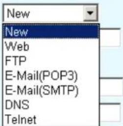
Virtual Server: You can use Virtual Server Settings to provide connection on internet. For example, you can have your own web server at home and provide access on internet. This will need port 80 by default for Virtual Server Settings.
Virtual Servers
Servers:
Local IP Address:
Protocol:
Port Range:
Description:
Enable Virtual Servers
Save
Reset
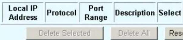
Current Virtual Servers Table:
Special Application: This is to enable internet service such as sound, video and so on. The routing firewall often stops these services for security reason.
DMZ: You can use DMZ Settings to provide connection on internet. For example, you can have your own web server at home and provide access on internet. This will need port 80 by default for Virtual Server Settings.
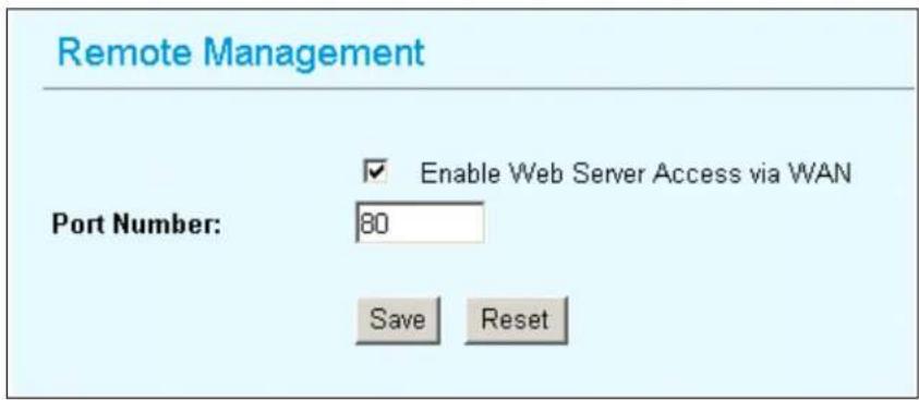
Remote Management: This is to configure WL-5460AP be managed from internet. Note that port 80 is always used by web service. You can change the port to prevent conflict.
To configure the security connection, please refer to Section 3.9 Wireless Security Settings .....
To configure the Advanced Settings, please refer to Section 3.10 Advanced Wireless Settings .....
To configure the access control, please refer to Section 3.11 Access Control Settings .....
To configure the Traffic Control, please refer to Section 3.12 Access Control Settings .....
3.8 Gateway Mode (AP + Router) Settings
Important Notice: When change to Gateway mode, the LAN 2 becomes to WAN port.
GW Mode Settings
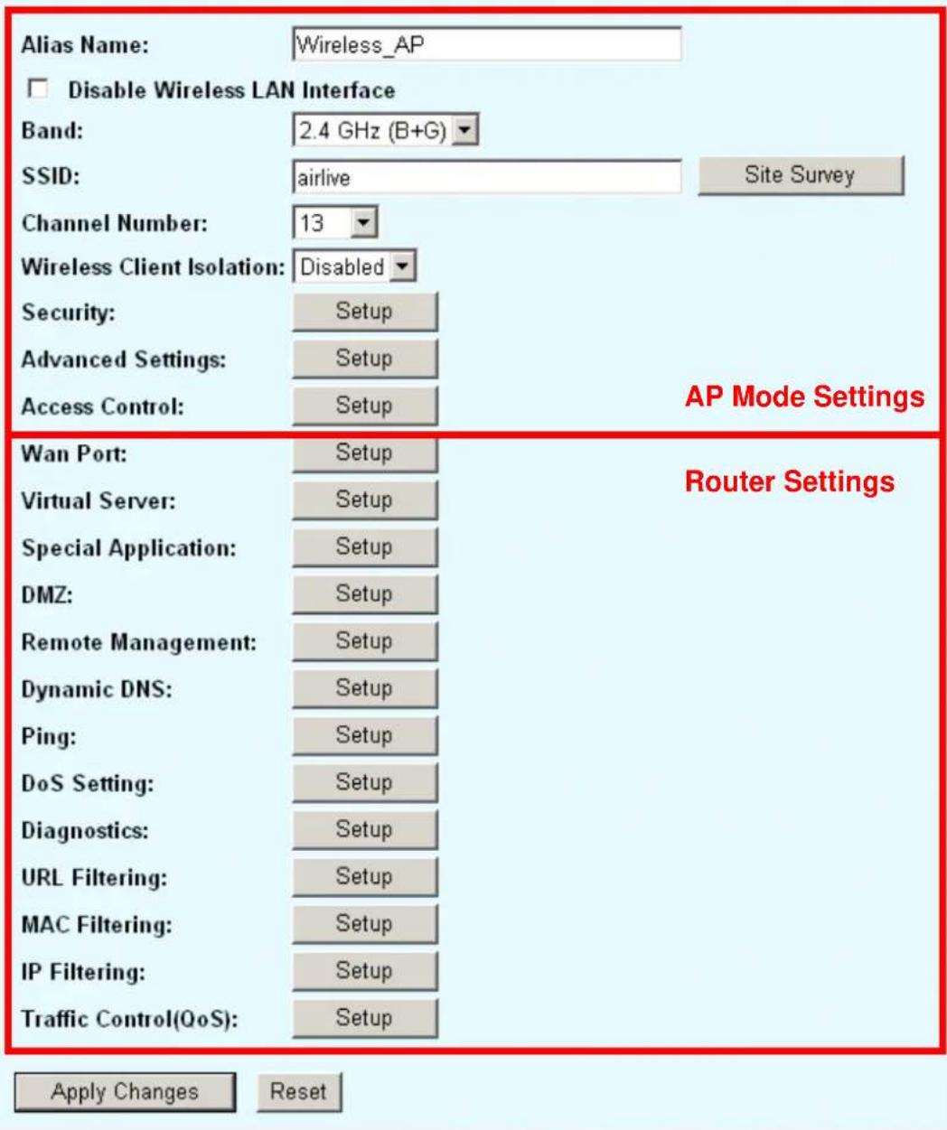
Alias Name: Another name for WL-5460AP.
Disable Wireless LAN Interface: Check the box to disable the Wireless LAN Interface, by so doing, you won't be able to make wireless connection with this Access Point in the network you are located. In other words, this device will not be visible by any wireless station.
Band: You can choose one mode of the following you need.
- 2.4GHz (B): 802.11b supported rate only.
- 2.4GHz (G): 802.11g supported rate only.
- 2.4GHz (B+G): 802.11b supported rate and 802.11g supported rate.
The default is 2.4GHz (B+G) mode.
Site Survey: Site survey helps to find out available access point around. You can also check to prevent using same SSID or channel with other AP.
SSID (Network ID): The SSID differentiates one WLAN from another; therefore, all access points and all devices attempting to connect to a specific WLAN must use the same SSID. It is case-sensitive and must not exceed 32 characters. A device will not be permitted to join the BSS unless it can provide the unique SSID. An SSID is also referred to as a network name because essentially it is a name that identifies a wireless network.
In this mode, the SSID is provided for client connection.
Channel Number: Allow user to set the channel manually or automatically. If set channel manually, just select the channel you want to specify. If "Auto" is selected, user can set the channel range to have Wireless Access Point automatically survey and choose the channel with best situation for communication. The number of channels supported depends on the region of this Access Point. All stations communicating with the Access Point must use the same channel.
Wireless Client Isolation: This is to separate wireless client if needed. Wireless clients can not communicate to each other if the field is enabled.
Site Survey: Site survey helps to find out available access point around. You can also check to prevent using same SSID or channel with other AP.
WAN Port (LAN2): WL-5460AP provides 4 methods for client to access the internet. This depends on the location and the service which the ISP provides. You need to contact the ISP for detail information.
WAN Port Configuration
WAN Access Type:
DNS 1:
DNS 2:
DNS 3:
Clone MAC Address:
0000000000000
Respond to WAN Ping
Enable UPnP
☑ Enable IPsec pass through on VPN connection
☑ Enable PPTP pass through on VPN connection
☑ Enable L2TP pass through on VPN connection
Save
Reset
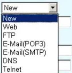
Virtual Server: You can use Virtual Server Settings to provide connection on internet. For example, you can have your own web server at home and provide access on internet. This will need port 80 by default for Virtual Server Settings.
Virtual Servers
Servers:
Local IP Address:
Protocol:
Port Range:
Description:
Enable Virtual Servers
Save
Reset
Current Virtual Servers Table:
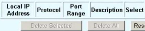
Special Application: This is to enable internet service such as sound, video and so on. The routing firewall often stops these services for security reason.
DMZ: You can use DMZ Settings to provide connection on internet. For example, you can have your own web server at home and provide access on internet. This will need port 80 by default for Virtual Server Settings.
Remote Management: This is to configure WL-5460AP be managed from internet. Note that port 80 is always used by web service. You can change the port to prevent conflict.
Dynamic DNS: Dynamic DNS (DDNS) allows you to create a hostname that points to your dynamic IP or static IP address or URL. WL-5460AP provide Dynamic DNS client using DynDNS, please visit http://www.dyndns.org for detail.
Ping: You can enable to the "Response to WAN Ping" to allow remotely ping your WL-5460AP.
DoS Setting: In WL5460AP, a denial-of-service attack (DoS attack) can block or limit the system sending network flood to your local computer.
- Diagnostics: The nslookup command can be used in diagnostics to find the IP addresses of a particular computer, using DNS lookup. The name means "name server lookup". The most common version of the program is included as part of the BIND package.
URL Filtering: The URL filter database is used for internet filtering that blocks access to unwanted web content by URLs.
MAC Filtering: Enables you to allow or deny Internet access to users within the LAN based upon the MAC address of their network interface.
IP Filtering: The IP filter function enables you to define a minimum and maximum IP address range filter; all IP addresses falling within the range are not allowed Internet access
To configure the security connection, please refer to Section 3.9 Wireless Security Settings .....
To configure the Advanced Settings, please refer to Section 3.10 Advanced Wireless Settings .....
To configure the access control, please refer to Section 3.11 Access Control Settings .....
To configure the Traffic Control, please refer to Section 3.12 Access Control Settings .....
3.9 Wireless Security
Here you can configure the security of your wireless network. Selecting different method will enable you to have different level of security. Please note that by using any encryption, by which data packet is encrypted before transmission to prevent data packets from being eavesdropped by unrelated people, there may be a significant degradation of the data throughput on the wireless link.
WL-5460AP provides WEP, WPA-PSK (TKIP), WPA2-PSK (AES) and WPA2-PSK (AES) security policy.
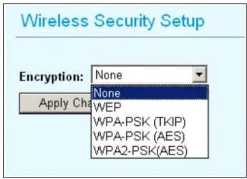
WEP
WEP allows you to use data encryption to secure your data from being eavesdropped by malicious people. It allows 2 types of key: 64 (WEP64) and 128 (WEP128). You can
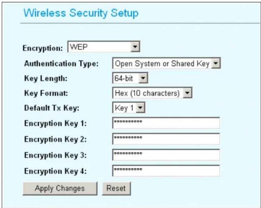
configure up to 4 keys using either ASCII or Hexadecimal format.
Key Settings: The length of a WEP64 key must be equal to 5 bytes and a WEP128 key is 13 bytes
Default Tx Key: You have to specify which of the four keys will be active. Once you enable the WEP function, please make sure that both the WL-5460AP and the wireless client
stations use the same key.

Some wireless client cards only allow Hexadecimal digits for WEP keys. Please note that when configuring WEP keys, a WEP128 ASCII key looks like "This is a key"(13 characters), while a WEP128 Hex key looks like
"546869732069732061206b6579"(26 HEX) (hexadecimal notation are 0-9 and A-F).
WPA-PSK (TKIP) / WPA-PSK (AES)
Wi-Fi Protected Access (WPA) with Pre-Shared Key (PSK) provides better security than WEP keys. It does not require a RADIUS server in order to provide association authentication, but you do have to enter a shared key for the authentication purpose. The encryption key is generated automatically and dynamically.
There are two encryption types TKIP and CCMP (AES). While CCMP provides better security than TKIP, some wireless client stations may not be equipped with the hardware to support it.
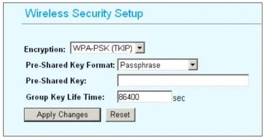
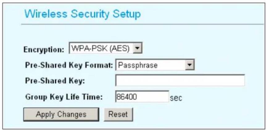
Pre-shared Key: This is an ASCII string with 8 to 63 characters. Please make sure that both the WL-5460AP and the wireless client stations use the same key.
Group Key Life Time: A group key is used for multicast/broadcast data, and the re-key interval is time period that the system will change the group key periodically. The shorter the interval is, the better the security is. The default is 300 sec.
WPA2-PSK (AES)
Enter the Pre-shared Key to initiate WPA2 security. All devices try to access the network should have the matching encryption key.
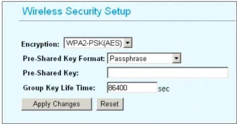
Pre-shared Key: This is an ASCII string with 8 to 63 characters. Please make sure that both the WL-5460AP and the wireless client stations use the same key.
Encryption Type: There are two encryption types TKIP and CCMP (AES). While CCMP provides better security than TKIP, some wireless client stations may not be equipped with the hardware to support it.
Group key Life Time: A group key is used for multicast/broadcast data, and the re-key interval is time period that the system will change the group key periodically. The shorter the interval is, the better the security is. The default is 300 sec.
802.1X (Radius)
Authentication by the remote server (RADIUS Server).
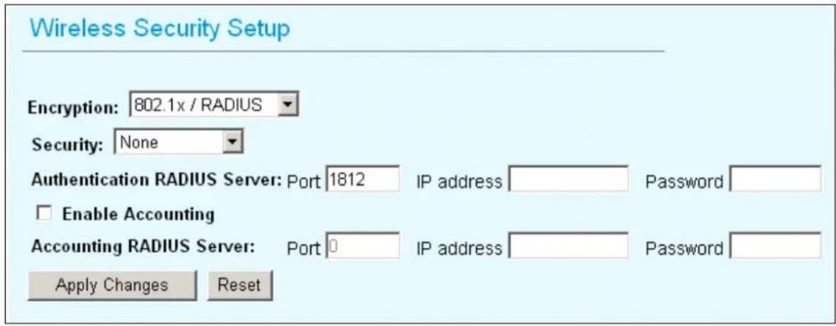
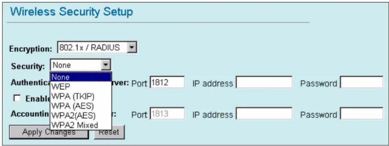
Security: You can select None, WEP, WPA (TKIP), WPA (AES), WPA2 (AES), WPA2 Mixed method for data encryption.
- WEP: 802.1x Authentication is enabled and the RADIUS Server will proceed to check the 802.1x Authentication, and make the RADIUS server to issue the WEP key dynamically. You can select WEP 64bits or WEP 128bits for data encryption.
- WPA (TKIP) / WPA (AES): WPA-RADIUS authentication use WPA (Wi-Fi Protect Access) data encryption for 802.1x authentication. WPA is an encryption standard proposed by WiFi for advance protection by utilizing a password key (TKIP) or certificate. It is more secure than WEP encryption.
- WPA2-AES / WPA2-Mixed: The two most important features beyond WPA to become standardized through 802.11i/WPA2 are: pre-authentication, which enables secure fast roaming without noticeable signal latency. Pre-authentication provides a way to establish a PMK security association before a client associates. The advantage is that the client reduces the time that it's disconnected to the network.
Authentication RADIUS Server: Enter the RADIUS Server IP address and Password provided by your ISP.
- Port: Enter the RADIUS Server's port number provided by your ISP. The default is 1812.
- IP Address: Enter the RADIUS Server's IP Address provided by your ISP.
- Password: Enter the password that the AP shares with the RADIUS Server.
Accounting RADIUS Server: Enter the Accounting RADIUS Server IP address and Password provided by your ISP.
3.10 Advanced Wireless Settings
When click on Advanced Setup button under client mode, a pop-up window appears and show parameter as follow:
Fragmentation:
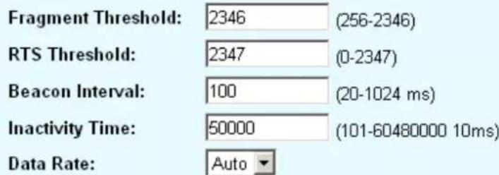
Fragmentation mechanism is used for improving the efficiency when high traffic flows along in the wireless network. If your 802.11g Wireless LAN PC Card often transmit large files in wireless network, you can enter new Fragment Threshold value to split the packet. The value can be set from 256 to 2346. The default value is 2346.
Wireless Advanced Settings
Enable WatchDog
Apply Changes
Reset
RTS Threshold: RTS Threshold is a mechanism implemented to prevent the “Hidden Node” problem. “Hidden Node” is a situation in which two stations are within range of the same Access Point, but are not within range of each other. Therefore, they are hidden nodes for each other. When a station starts data transmission with the Access Point, it might not notice that the other station is already using the wireless medium. When these two stations send data at the same time, they might collide when arriving simultaneously at the Access Point. The collision will most certainly result in a loss of messages for both stations.
Thus, the RTS Threshold mechanism provides a solution to prevent data collisions. When you enable RTS Threshold on a suspect “hidden station”, this station and its Access Point will use a Request to Send (RTS). The station will send an RTS to the Access Point, informing that it is going to transmit the data. Upon receipt, the Access Point will respond with a CTS message to all station within its range to notify all other stations to defer
transmission. It will also confirm the requestor station that the Access Point has reserved it for the time-frame of the requested transmission.
If the "Hidden Node" problem is an issue, please specify the packet size. The RTS mechanism will be activated if the data size exceeds the value you set..
The default value is 2347.
Warning: Enabling RTS Threshold will cause redundant network overhead that could negatively affect the throughput performance instead of providing a remedy.
This value should remain at its default setting of 2347. Should you encounter inconsistent data flow, only minor modifications of this value are recommended.
Beacon Interval: Beacon Interval is the amount of time between beacon transmissions. Before a station enters power save mode, the station needs the beacon interval to know when to wake up to receive the beacon (and learn whether there are buffered frames at the access point).
Data Rate: By default, the unit adaptively selects the highest possible rate for transmission. Select the basic rates to be used among the following options: Auto, 1, 2, 5.5, 11 or 54 Mbps. For most networks the default setting is Auto which is the best choice. When Auto is enabled the transmission rate will select the optimal rate. If obstacles or interference are present, the system will automatically fall back to a lower rate.
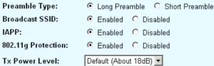
Preamble Type: A preamble is a signal used in wireless environment to synchronize the transmitting timing including Synchronization and Start frame delimiter. In a "noisy" network environment, the Preamble Type should be set to Long Preamble. The Short Preamble is intended for applications where minimum overhead and maximum performance is desired. If in a "noisy" network environment, the performance will be decreased.
Broadcast SSID: Select enabled to allow all the wireless stations to detect the SSID of this Access Point.
IAPP: IAPP (Inter Access Point Protocol) is designed for the enforcement of unique association throughout a ESS (Extended Service Set) and a secure exchange of station's security context between current access point (AP) and new AP during handoff period.
802.11g Protection: The 802.11g standard includes a protection mechanism to ensure mixed 802.11b and 802.11g operation. If there is no such kind of mechanism exists, the two kinds of standards may mutually interfere and decrease network's performance.
Tx Power Level: For countries that impose limit on WLAN output power, it might be necessary to reduce TX (transmit) power. There are 7 TX Power Levels to choose from —
select a level to make sure that the output power measured at the antenna end will not exceed the legal limit in your country.
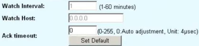
Enable WatchDog: Check and enable this watch dog function.
Watch Interval: Setup the interval time for watch dog function between 1 to 60 mins.
Watch Host: Enter the watch dog host ip address.
Ack timeout: When a packet is sent out from one wireless station to the other, it will wait for an Acknowledgement frame from the remote station. If the ACK is NOT received within that timeout period then the packet will be re-transmitted resulting in reduced throughput. If the ACK setting is too high then throughput will be lost due to waiting for the ACK Window to timeout on lost packets. By having the ability to adjust the ACK setting we can effectively optimize the throughput over long distance links. This is especially true for 802.11a and 802.11g networks
You can set as default for auto adjustment.
3.11 Access Control
When Enable Wireless Access Control is checked, only those clients whose wireless MAC addresses listed in the access control list can access this Access Point. If the list contains no entries with this function being enabled, then no clients will be able to access this Access Point.
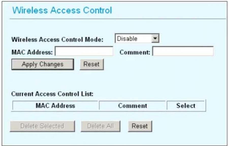
Wireless Access Control Mode: Select the Access Control Mode from the pull-down menu.
- Disable: Select to disable Wireless Access Control Mode.
- Allow Listed: Only the stations shown in the table can associate with the AP.
- Deny Listed: Stations shown in the table won't be able to associate with the AP.
MAC Address: Enter the MAC Address of a station that is allowed to access this Access Point.
Comment: You may enter up to 20 characters as a remark to the previous MAC Address.
3.12 QoS Traffic Control
What is Traffic Control QoS?
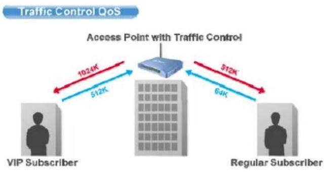
Traffic Control is a great tool to control the bandwidth of the WISP subscribers. Therefore, the WISP operators can offer different class of connection speeds for different subscription fees - just like the ADSL service! The AirLive advance firmware can control the bandwidth by Interface or IP/MAC.
flowchart
graph TD
    A["VIP Subscriber"] -->|1024K| B["Access Point with Traffic Control"]
    C["Regular Subscriber"] -->|512K| B
    B -->|64K| D["Regular Subscriber"]
    style A fill:#f9f,stroke:#333
    style C fill:#f9f,stroke:#333
    style B fill:#ccf,stroke:#333
What type of Traffic Bandwidth Control does the E11 firmware offer?
The E11 firmware's Traffic Bandwidth limits the "Maximum Data Rate". There are 2 types of Traffic Control it offers.
Interface Control
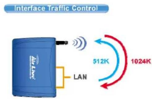
The interface QoS controls the data rate at the WLAN and LAN interfaces. Therefore, all traffics are controlled the same way. This type of traffic control is suitable when AP is used as a Client AP in "Client Mode" and WISP mode. So WISP can control the maximum data rate
Individual IP/MAC Control
The AP can set the maximum data rate for each IP or MAC addresses. This type of traffic control is most suitable for outdoor AP in "AP" or "Gateway" mode.

flowchart
graph TD
    A["Individual IP/MAC Control"] --> B["IP1"]
    A --> C["IP2"]
    A --> D["MAC"]
    B -->|384K| E["IP4K"]
    B -->|256K| F["IP2K"]
    B -->|1024K| G["MAC"]
    C -->|128K| H["IP4K"]
    C -->|64K| I["IP2K"]
    C -->|512K| J["MAC"]
What is the Output Rate?
The "Output Rate" is the data speed out of an interface. There are 3 types Output Rate supported by the AP
- LAN Output Rate: This is the speed of the traffic out of the LAN port. In gateway mode, the LAN Output Rate includes both the wired LAN and WLAN interface.
- WLAN Output Rate: This is the speed of the traffic out of the Wireless LAN
- WAN Output Rate: This is the speed of the traffic out of the WAN port. In WISP mode, the WAN Output Rate also includes the WLAN interface.
The AP's Web UI will tell you which types of output rate it supports, it differs in each wireless mode.
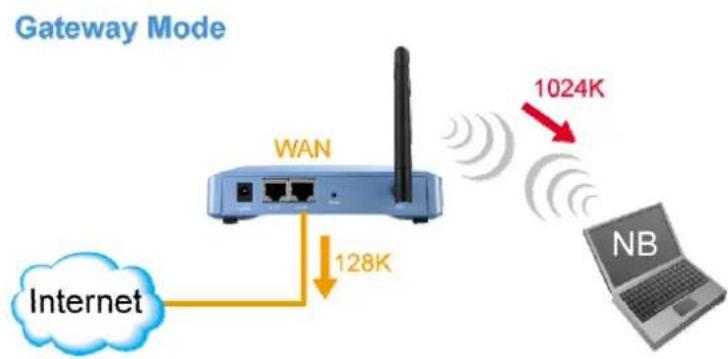
In the following example:
● The AP is in Gateway Mode
● The WAN Output Rate is 128K
● The LAN/WLAN Output Rate is 1024K
In this setup, the notebook users get an upstream bandwidth of 128K and downstream bandwidth of 1024K.
flowchart
graph LR
    A["Internet"] -->|128K| B["WAN"]
    B --> C["1024K"]
    C --> D["NB"]
    style A fill:#fff,stroke:#333
    style B fill:#e6f7ff,stroke:#333
    style C fill:#ffcccc,stroke:#333
    style D fill:#ccf,stroke:#333
Configure the Traffic Control QoS
From the Mode Setting page, please choose the "Traffic Control(QoS)" on the bottom of the list.
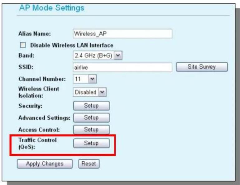
Once you click on the "setup" button, a new window will pop-up with the Traffic Control settings. They are divided into "A", "B", "C", "D" section for further explanations.
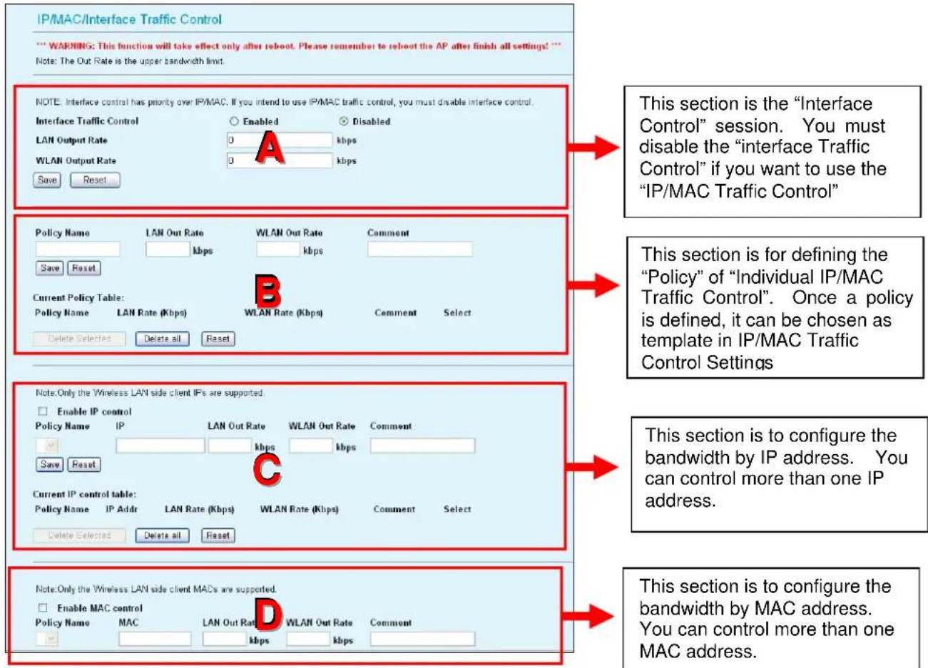
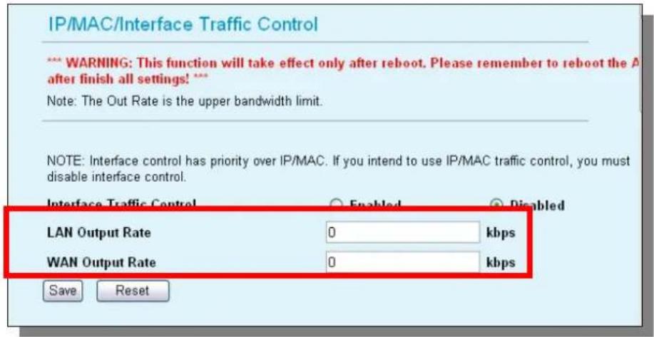
A. Interface Control Settings:
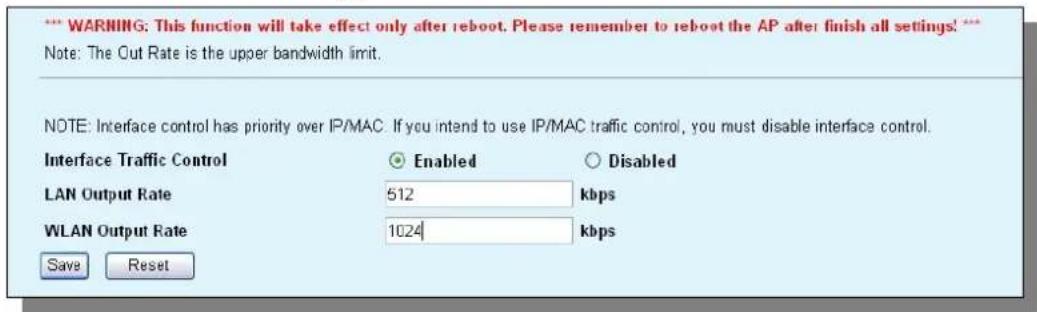
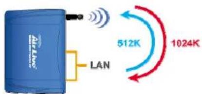
In the Interface Control Settings, the AP only controls the total bandwidth limit of an interface. For example, if you want to limit the output data rate of the LAN to 512K and the
output data rate of WLAN to 1024K. You should perform the following steps:
Interface Traffic Control
- Enable the "Interface Traffic Control
- Enter "512" in the "LAN Output Rate"
- Enter "1024" in the "WLAN Output Rate"
- Click on "Save"
- Reboot the AP.
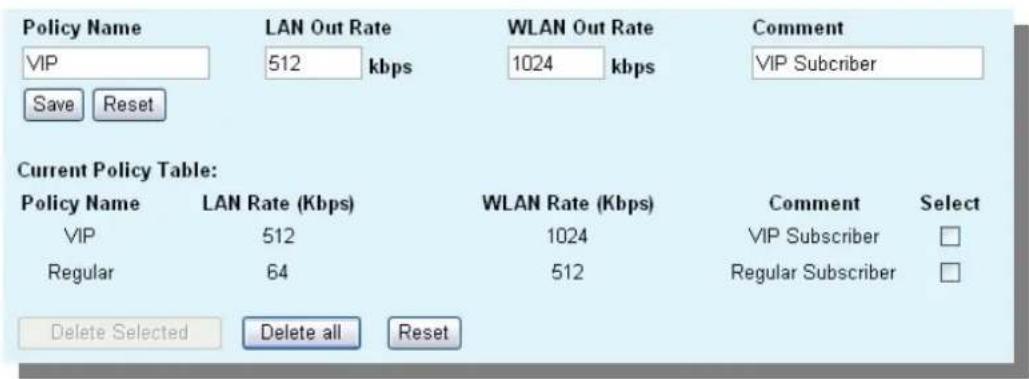
B. Define Policy
A policy is a set of bandwidth rules that can be used as a template. For example, if you want to provide 2 kinds of bandwidth speed to the users:
- VIP Subscriber:
■ LAN Out Rate: 512 Kbps
■ WLAN Out Rate: 1024 Kbps
● Regular Subscriber:
■ LAN Out Rate: 64 Kbps
■ WLAN Out Rate: 512 Kbps
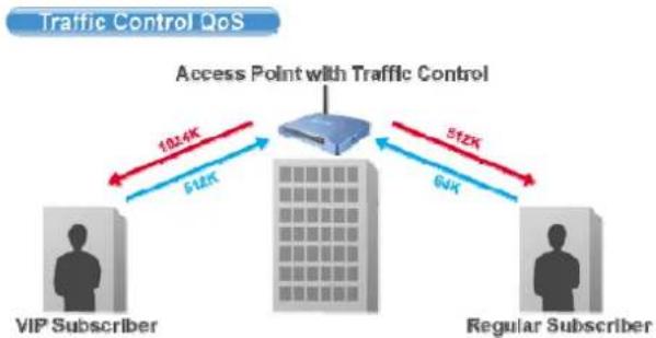
flowchart
graph TD
    A["VIP Subscriber"] -->|1814K| B["Access Point with Traffic Control"]
    C["Regular Subscriber"] -->|512K| B
    B -->|6JK| D["Output"]
You can configure the bandwidth rule as policies "VIP" and "Regular".
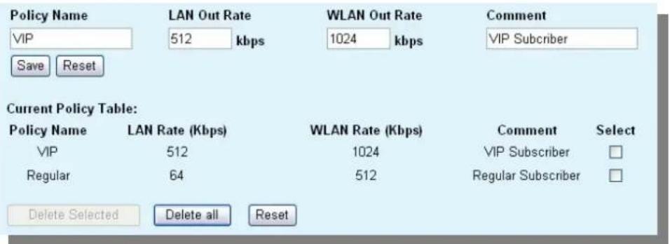
Please follow the step below to create a new policy "VIP"
-
Enter "VIP" for the "PolicyName"
-
Enter "512" for the "LAN Out Rate"
- Enter "1024" for the "WLAN Out Rate"
- Enter "VIP Subscriber" for the "Comment"
-
Click on "Save" button
-
Now the "VIP" policy will show up in the "Current Policy Table"
Once finished, the administrator will be able to choose the policy "VIP" for their IP/MAC Traffic Control.
C. Bandwidth Control by IP address
You can set the maximum bandwidth of a PC or a subscriber by using the IP Control.
Please follow the procedure below to setup IP Traffic Control
- Please make sure the "Interface Traffic Control" is disabled
- Before you start, please check the following area to see which client IPs are supported. It differs between each mode.
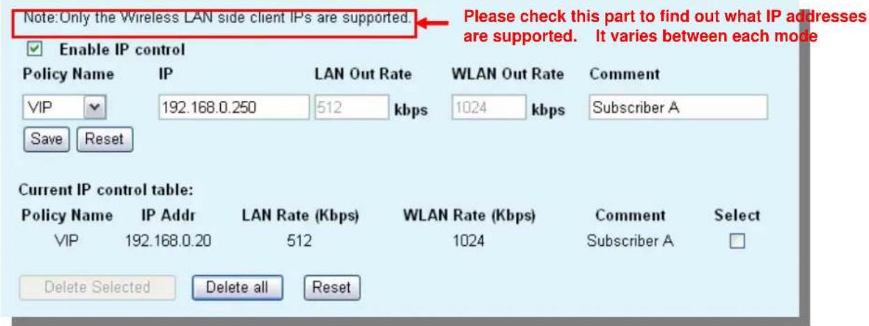
- Enable the IP Control
- If you have defined a Policy already, please choose a Policy name. The "Out Rates" will be automatically pasted from the Policy template. You cannot change the Out Rates if you have chosen a Policy
- If you want to define new Data Rate, please do not choose any policies. Then you can enter the values in the "LAN", "WLAN", or "WAN" Out Rates.
- Press "Save" to save settings
- Reboot your AP.
D. Bandwidth Control by MAC address
You can set the maximum bandwidth of a PC or a subscriber by using the MAC Control.
Please follow the procedure below to setup MAC Traffic Control
- Please make sure the "Interface Traffic Control" is disabled
- Before you start, please check the following area to see which client MACs are supported. It differs between each mode.
3. Enable the MAC Control
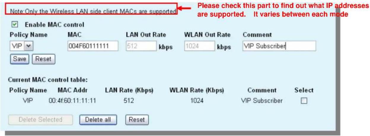
- If you have defined a Policy already, please choose a Policy name. The "Out Rates" will be automatically pasted from the Policy template. You cannot change the Out Rates if you have chosen a Policy
- If you want to define new Data Rate, please do not choose any policies. Then you can enter the values in the "LAN", "WLAN", or "WAN" Out Rates.
- Press "Save" to save settings
- Reboot your AP.
Application Example
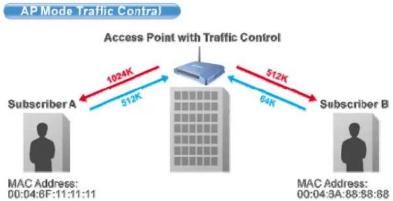
Example1: AP Mode Traffic Control
flowchart
graph LR
    A["Subscriber A"] -->|1024K 512K| B["Access Point with Traffic Control"]
    B -->|512K 64K| C["Subscriber B"]
    D["MAC Address: 00:04:6F:11:11:11"] --> A
    E["MAC Address: 00:04:6A:88:88:88"] --> C
In this example, the AP is installed outdoor to provide Internet service. There are 2 different type of Internet service offered by the WISP:
- VIP Service:
■ Upstream Data Rate: 512 Kbps
■ Downstream Data Rate: 1024 Kbps
● Regular Service:
■ Upstream Data Rate: 64 Kbps
■ Downstream Data Rate: 512 Kbp
The Subscriber's information is as followed:
■ Subscriber A
- VIP Service
● MAC Address of the PC or Wireless Client: 00:04:6F:11:11:11
■ Subscriber B
● Regular Service
● MAC Address of the PC or Wireless Client: 00:04:6A:88:88:88
Step-by-Step Configuration
- Please disable the "Interface Traffic Control"
- On the Policy, please add the "VIP" and "Regular" policies as shown on the graph below
- Please enable the "MAC Control"
- Please fill in the 2 entries as shown on the graphic below
Note: Only the Wireless LAN side client MACs are supported.
Enable MAC control
Policy Name

Save
Reset
MAC
LAN Out Rate

WLAN Out Rate

Comment

Current MAC control table:
Policy Name
VIP
MAC Addr
00:04:6f:11:11:11
Regular
00:4f:6a:88:88:88
LAN Rate (Kbps)
512
64
WLAN Rate (Kbps)
1024
512
Comment
Subscriber A
Subscriber B
Select
□
□
Delete Selected
Delete all
Reset
- Reboot the AP
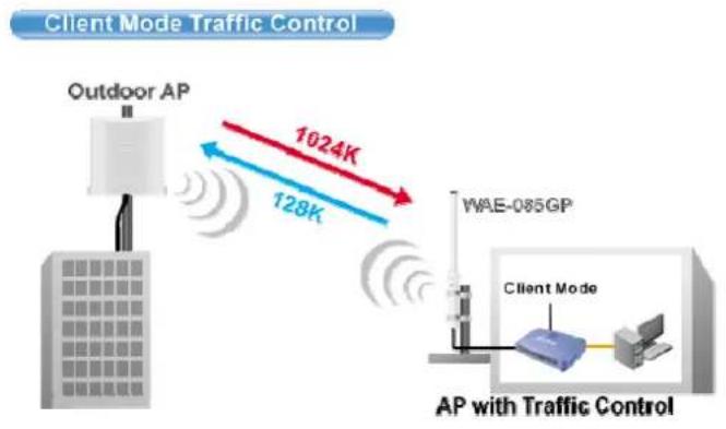
Example2: Client Mode Traffic Control
In the following example, the AP is used as the wireless client to the WISP Service. The Service provider need to restrict the bandwidth of the AP to 1024K Downstream and 128K Upstream.
flowchart
graph LR
    A["Outdoor AP"] -->|1024K| B["WAE-085GP"]
    A -->|128K| B
    B --> C["AP with Traffic Control"]
    style A fill:#f9f,stroke:#333
    style B fill:#ccf,stroke:#333
    style C fill:#cff,stroke:#333
Step-by-Step Configuration
NOTE: Interface control has priority over IP/MAC. If you intend to use IP/MAC traffic control, you must disable interface control.
Interface Traffic Control
LAN Output Rate
WLAN Output Rate
Save
Reset
Enabled
1024
128
○ Disabled
kbps
kbps
- Please enable the "Interface Traffic Control"
- Enter "1024" in the "LAN Output Rate" field
- Enter "128" in the "WLAN Output Rate" field
- Press "Save"
- Reboot the AP
4. System Management
4.1 LAN Interface Setup
In this page, you can change the TCP/IP settings of this Access Point; select to enable/disable the DHCP Client, 802.1d Spanning Tree, and Clone MAC Address.
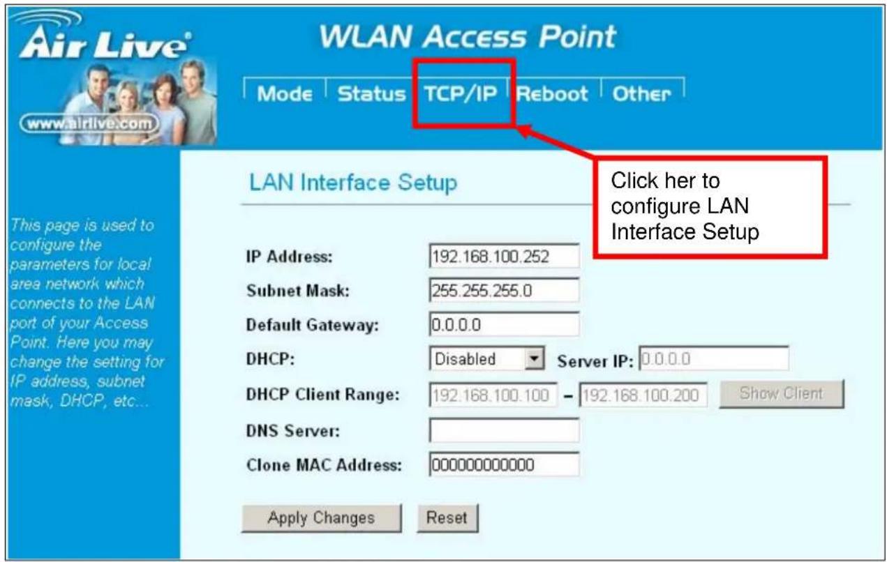
IP Address: This field can be modified only when DHCP Client is disabled. If your system manager assigned you static IP settings, then you will have to enter the information provided.
Subnet Mask: Enter the information provided by your system manager.
Default Gateway: Enter the information provided by your system manager.
DHCP: Select Disable, Client or Server from the pull-down menu.
- Disable: Select to disable DHCP server function.
- Client: Select to automatically get the LAN port IP address from ISP (For ADSL/Cable Modem).
- Server: Select to enable DHCP server function.
DHCP Client Range: WL-5060AP IP addresses continuing from 192.168.100.1 to 192.168.100.253
DNS Server: Enter the Domain Name Service IP address.
Clone MAC Address: You can specify the MAC address of your Access Point to replace the factory setting.
4.2 Upgrade Firmware
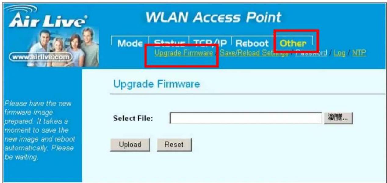
To Upgrade Firmware:
- Download the latest firmware from your distributor and save the file on the hard drive.
- Start the browser, open the configuration page, click on Other, and click "Upgrade Firmware" to enter the Upgrade Firmware window. Enter the new firmware's path and file name (i.e. C:\FIRMWARE\firmware.bin). Or, click the "Browse" button, find and open the firmware file (the browser will display to correct file path).
- Click Reset to clear all the settings on this page. Or click Upload to start the upgrade.
4.3 Save / Reload Settings
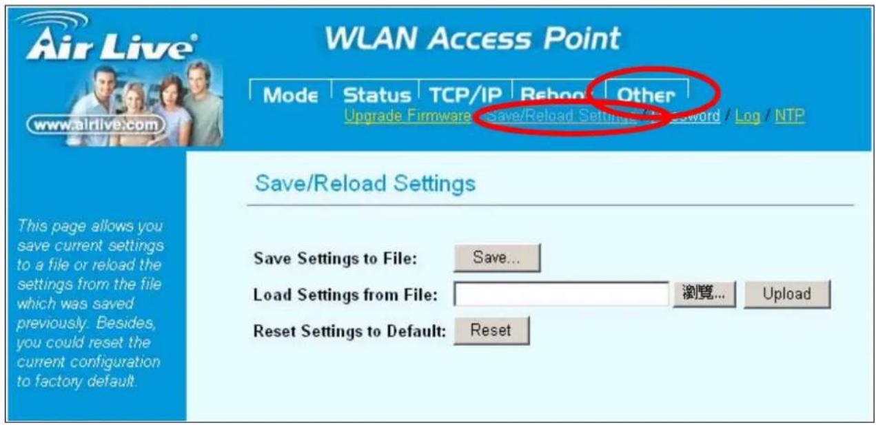
This function enables users to save the current configurations as a file (i.e. config.dat) To load configuration from a file, enter the file name or click Browse... to find the file from your computer.
Save Settings to File: Click "SAVE" to save the current configuration to file.
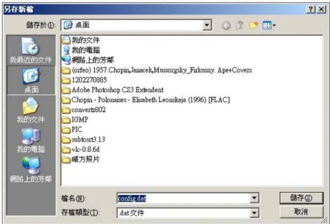
When prompted the upper left screen, select "Save this file to disk", and the upper right screen will prompt you a dialog box to enter the file name and the file location.
Load Settings From File: Click "Browse"... if you want to load a pre-saved file, enter the file name with the correct path and then click on Upload. Or click Browse... to select the file.
Reset: Click to restore the default configuration.
4.4 Change Password
For secure reason, it is recommended that you set the account to access the web server of this Access Point. Leaving the user name and password blank will disable the protection. The login screen prompts immediately once you finish setting the account and password. Remember your user name and password for you will be asked to enter them every time you access the web server of this Access Point.
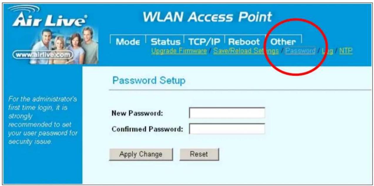
New Password: Set your new password. Password can be up to 30 characters long. Password can contain letter, number and space. It is case sensitive. Confirm Password: Re-enter the new password for confirmation.
4.5 Enable System Log
This function can list all log information about device.
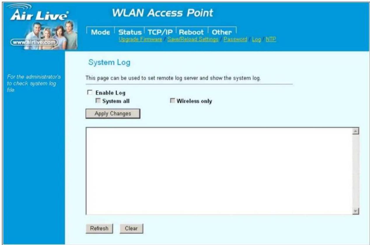
Enable Log: Enabled or Disabled display system log information.
System All: List system all log information.
Wireless Only List: wireless log information only.
Refresh: Refresh log information.
Clear: Clear all information in window.
4.6 NTP Settings
This function can set system time from local computer or Internet.
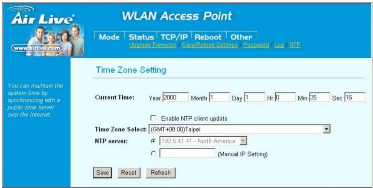
Current Time: Setting system time
Enable NTP client update: Enable or Disable setting system from Internet NTP Server.
Time Zone Select: Select system time zone.
NTP Server: Select NTP Server by Server List or Manual Input.
5 System Recovery
WL-5460AP provides the system recovery emergency code function that can restore the machine after firmware crashed.
Please check if your WL-5460AP's serial number is e5460AP70500001 or later. If it is, it has emergency code function. Otherwise, it doesn't. Once you make sure it has emergency code function. Please follow the steps below:
- Unplug the power of WL-5460AP.
- Hold the reset button while plugging the power. Do not release the reset button until the "Status" LED goes off.
- Set your PC's IP address to 192.168.1.199. Connect your PC to the WL-5460AP.
- Open your web browser, then type "192.168.1.6". You should see the emergency code page where you can upload your AirLive firmware again.
If your WL-5460AP's serial number is before e5460AP70500001, it does not have emergency code function. It needs to update bootloader first.
To upload the bootloader and firmware:
- Copy the two files, "boot_v14a.bin" and "5460APv2e9_httpupgrade", to the location
- “C:\5460AP”:
- Connect the Ethernet cable to the LAN 1 port of WL-5460AP (this step is mandatory).
- Open the internet protocol setup dialog and enter IP addresses as shown below:
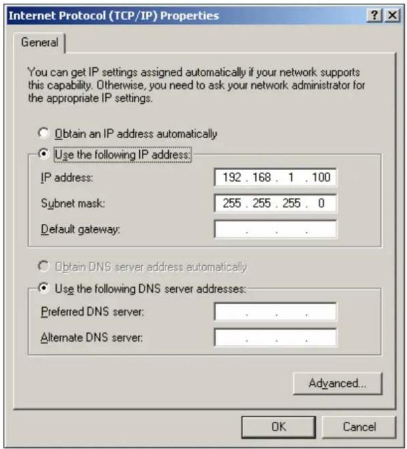
- While pressing and holding the Reset button of WL-5460AP, connect WL-5460AP to its power supply. Keep holding the Reset button until the red light of the Status LED goes off.
- Launch DOS Command Prompt and type the following commands:
CD\5460AP
tftp -i 192.168.1.6 put boot_v14a.bin
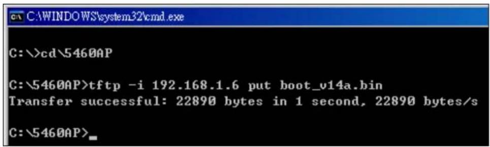
- WL-5460AP will then reboot itself. After it has completed rebooting, open the internet protocol setup dialog and enter IP addresses as illustrated below:
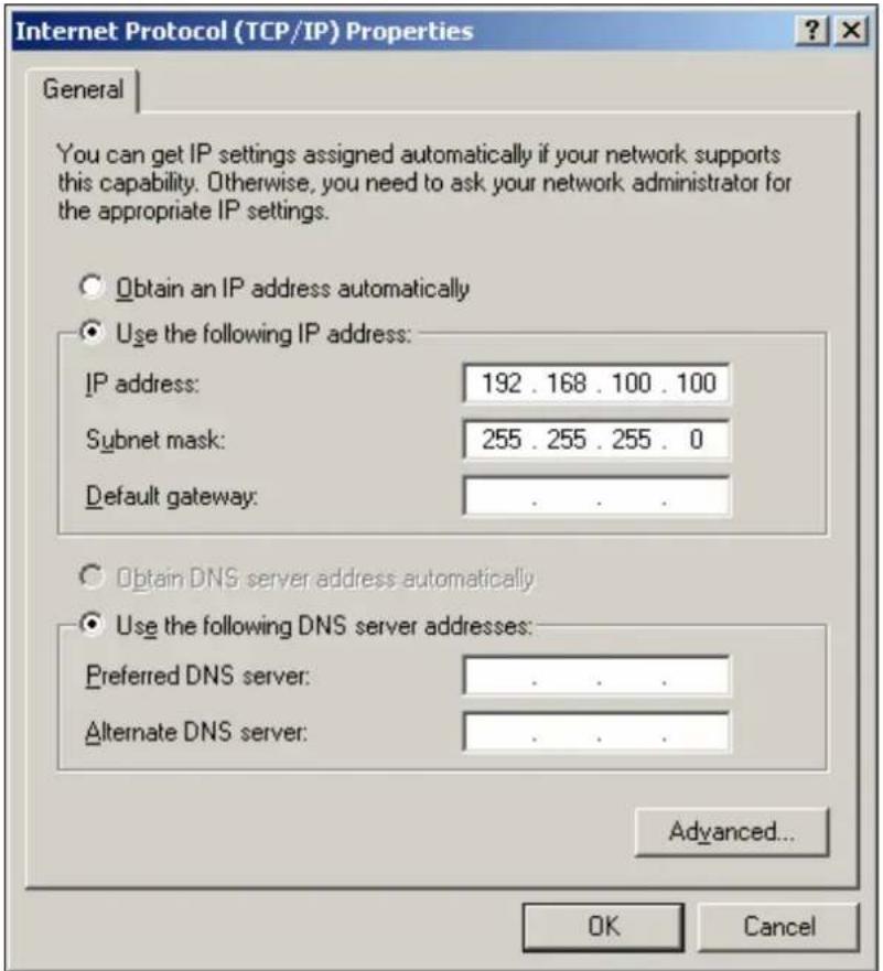
- Open the WL-5460AP configuration menu and choose the category 'Other'. Then choose the feature "Firmware Upgrade".
Click the Browse button to find and open the firmware file. Then click the Upload button to start upgrading the firmware.
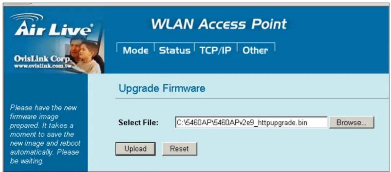
- Wait for about 30\~40 seconds. After the WL-5460AP UI is re-launched, the upgrade of Boot Loader and Firmware are now complete for your WL-5460AP.
6. Specification
| Feature | AP, Bridge, Client, Repeater functionsWISP Client Router modeWISP + Universal Repeater ModeDetachable Antenna, 2 LAN ports802.1x, WPA, WPA2 and Web Mgt.TX power regulation in 4 levelsWatchdog function use PINGWireless Client Isolation (e8 firmware)ACK Timeout AdjustmentDHCP Relay function802.11g Protection |
| Hardware | 2 x 10/100Mbps LAN Port2MB Flash, 16MB SDRAMReversed SMA Antenna PortPower, LAN, WLAN LED indicators |
| Antenna | 2 dBi detachable Dipole AntennaReversed SMA Connector |
| Frequency Range | USA (FCC) 11 Channels: 2.412GHz~2.462GHzEurope (ETSI) 13 Channels : 2.412GHz~2.472GHzJapan (TELEC) 14 Channels :2.412GHz~2.483GHz |
| Modulation Technique | 11g Orthogonal Frequency Division Multiplexing (64QAM, 16QAM, QPSK, BPSK)11b Direct Sequence Spread Spectrum (CCK, DQPSK, DBPSK)Data Rate: 54, 48, 36, 24, 18,11, 5.5, 2, 1 Mbps |
| Output Power | 18dBmAdjustable in 4 levels |
| WISP Mode | DHCP, PPTP, L2TP, PPPoE ISP Authentication SupportWireless Client function as WANWISP mode is not the same router modeTo configure the WISP mode, you PC must be connected to the LAN port |
| Security | 64/128-bit WEPWPA/WPA2-PSK support802.1x Radius SupportWPA Enterprise support in AP/WDS mode |
| Configuration | Web ManagementWDS (Bridge, Client, Repeater) modeHide ESSID802.1xMAC Access ControlMAC Access TableWireless Client Isolation (e8 firmware)SSID, Channel, RTS Threshold, Frag Threshold |
| Environmental | Operating temperature: 0~60°COperating humidity (non-condensing): 20~80%Storage temperature: -20~65°CStorage humidity: 95% Max |
| Power Supply | DC12V |
| EMI | FCC, CE |
| Product Weight (g) | 180 g |
| Product Size(L x W x H (mm)) | 135 x 100 x 26mm |

- User's Manual
- Declaration of Conformity
- Clause Description
- Regulatory Information
- Federal Communication Commission Interference Statement
- IMPORTANT NOTE
- FCC Radiation Exposure Statement:
- Copyright Statement
- Table of Contents
- Introduction .... 5
- Operation Mode 16
- Wireless Settings 27
- System Management 67
- Introduction
- Overview
- Wireless Client Isolation
- ACK Timeout and TX Power Regulation
- Extended Security Features
- Application
- Firmware Features
- AirLive Wireless AP Firmware Features
- WL-5460AP
- Wireless Operation Modes
- Up to 400mW of Output Power\*
- Traffic Control QoS Function
- Traffic Control QoS
- Dynamic Signal Survey Function for Antenna Alignment
- Wireless Site Survey Connection Wizard
- Telnet Function
- Emergency Recovery
- Installing WL-5460AP
- Package Content
- Hardware Presentation
- Configuration Setups
- Hardware Connection
- - Check the LED:
- Operation Mode
- Change Operation Mode
- About the Operation Modes
- Access Point Mode
- WLAN Access Point
- Wireless Mode
- Client Mode
- Bridge Mode
- WDS Repeater
- Universal Repeater
- WISP (Client Router) mode
- WISP + Universal Repeater mode
- Gateway (AP + Router)
- Wireless Settings
- Access Point Mode Settings
- Client Mode Settings
- Bridge Mode Settings
- Bridge Mode Settings
- WDS Repeater Mode Settings
- WDS Repeater Mode Settings
- Universal Repeater Mode Settings
- WISP Mode Settings
- WISP + Universal Mode Settings
- WAN Port Configuration
- WAN Access Type:
- Clone MAC Address:
- Virtual Servers
- Current Virtual Servers Table:
- Gateway Mode (AP + Router) Settings
- GW Mode Settings
- Wireless Security
- WEP
- WPA-PSK (TKIP) / WPA-PSK (AES)
- WPA2-PSK (AES)
- 802.1X (Radius)
- Advanced Wireless Settings
- Fragmentation:
- Wireless Advanced Settings
- Enable WatchDog
- Access Control
- QoS Traffic Control
- What is Traffic Control QoS?
- What type of Traffic Bandwidth Control does the E11 firmware offer?
- Interface Control
- Individual IP/MAC Control
- What is the Output Rate?
- Configure the Traffic Control QoS
- Interface Control Settings:
- Define Policy
- Bandwidth Control by IP address
- Bandwidth Control by MAC address
- Enable the MAC Control
- Application Example
- - VIP Service:
- ● Regular Service:
- Step-by-Step Configuration
- Example2: Client Mode Traffic Control
- System Management
- LAN Interface Setup
- Upgrade Firmware
- Save / Reload Settings
- Change Password
- Enable System Log
- NTP Settings
- System Recovery
- Specification
Brand : AIRLIVE
Model : WL-5460AP v2
Category : Access Point