
V70 New Edition (2008) - Automobile VOLVO - Free user manual and instructions
Find the device manual for free V70 New Edition (2008) VOLVO in PDF.


| Type de produit | Automobile - Station wagon |
| Marque | Volvo |
| Modele | V70 New Edition (2008) |
| Moteurs disponibles | 2.5T (200 ch), 3.2 (238 ch), T6 (285 ch), D5 (185 ch), 2.4D (163 ch) |
| Boite de vitesses | Manuelle (M66) ou Automatique (TF-80SC) |
| Carburant | Essence ou Diesel |
| Capacite du reservoir | 70 litres |
| Securite - Airbags | Conducteur (SRS), passager avant (SRS), lateraux (SIPS), rideaux gonflables (IC) |
| Securite - Ceintures | Rappel de ceinture, pretensionneurs, detection passager arriere |
| Securite - Enfants | Fixations ISOFIX, appuis-tete integres deux positions, serrures de securite enfants |
| Securite - Anti-collision | Systeme de freinage d'urgence, alerte de collision* |
| Alarme | Alarme antivol avec detecteur de mouvement et d'inclinaison* |
| Ouverture sans cle | Keyless drive (optionnel) |
| Climatisation | Climatisation automatique (ECC) |
| Systeme audio | Radio, CD, MP3, prise AUX, commandes au volant |
| Frein de stationnement | Electrique |
| Aide au stationnement | Capteurs de stationnement* |
| Regulateur de vitesse | Regulateur de vitesse et adaptatif* |
| Entretien - Huile moteur | ACEA A5/B5, SAE 0W-30 (selon decal) |
| Entretien - Liquide de frein | DOT 4+ (0.6 L) |
| Pneus | Pression ECO recommandee, pneus hiver possibles |
Frequently Asked Questions - V70 New Edition (2008) VOLVO
User questions about V70 New Edition (2008) VOLVO
0 question about this device. Answer the ones you know or ask your own.
Ask a new question about this device
Download the instructions for your Automobile in PDF format for free! Find your manual V70 New Edition (2008) - VOLVO and take your electronic device back in hand. On this page are published all the documents necessary for the use of your device. V70 New Edition (2008) by VOLVO.
USER MANUAL V70 New Edition (2008) VOLVO
natural_image
Side profile of a silver sedan car, no visible text or symbols on the vehicle bodyVOLVO V70 & XC70
OWNER'S MANUAL

WEB EDITION
DEAR VOLVO OWNER
THANK YOU FOR CHOOSING VOLVO
We hope you will enjoy many years of driving pleasure in your Volvo. The car has been designed for the safety and comfort of you and your passengers. Volvo is one of the safest cars in the world. Your Volvo has also been designed to satisfy all current safety and environmental requirements.
In order to increase your enjoyment of the car, we recommend that you familiarise yourself with the equipment, instructions and maintenance information contained in this owner's manual.

natural_image
Close-up of a Volvo car wheel rim with five spokes and a circular logo on the wheel (no text or symbols beyond branding)
Table of contents

00 Introduction
Important information 6
Environment 8

01 Safety
Safety in the passenger compartment..... 12
Safety mode.... 25
Child safety 26

02 Locks and alarm
Remote control key/key blade 38
Privacy locking * 43
Battery replacement, remote control key/PCC * 44
Keyless drive * 45
Locking/unlocking.... 47
Child safety locks.... 50
Alarm * 51
Table of contents


03 Your driving environment
Instruments and controls.... 56
Ignition positions 65
Seats 66
Steering wheel....70
Lighting....71
Wipers and washing 80
Windows, rearview and door mirrors..... 82
Power sunroof* 86
Starting the engine 88
Gearboxes 91
All Wheel Drive - AWD (All Wheel Drive)* ... 95
Foot brake 96
Hill Descent Control (HDC) 97
Parking brake....98

04 Comfort and driving pleasure
Menus and messages 104
Climate control 109
Audio system ....120
Trip computer 130
Compass * ....132
DSTC –Stability and traction control
system 133
Adapting driving characteristics .....134
Cruise control* 135
Adaptive cruise control* 136
Collision warning system with brake
support* 140
Parking assistance* 143
BLIS* -Blind Spot Information System .....146
Comfort inside the passenger
compartment 149
Built-in phone* 153

05 During your journey
Recommendations during driving 160
Refuelling.... 163
Fuel.... 164
Loading 166
Cargo area.... 170
Warning triangle 173
Driving with a trailer.... 174
Towing 180

Table of contents

06 Maintenance and specifications
Engine compartment 184
Lamps 189
Wiper blades and washer fluid.... 195
Battery.... 197
Fuses....200
Wheels and tyres.... 205
Car care.... 217
Type designations 221
Specifications 222

07 Index


Introduction
Important information
Reading the Owner's Manual
Preface
A good way of getting to know your new car is to read the owner's manual, ideally before your first journey. This will give you the opportunity to familiarise yourself with new functions, to see how best to handle the car in different situations, and to make the best use of all the car's features. Please pay attention to the safety instructions contained in the manual.
The equipment described in the owner's manual is not present in all cars. In addition to standard equipment, this manual also describes options (factory fitted equipment) and certain accessories (retrofitted extra equipment).
Volvo cars are adapted for the varying requirements of different markets, as well as for national or local legal requirements and regulations.
The specifications, design features and illustrations in this owner's manual are not binding. We reserve the right to make modifications without prior notice.
© Volvo Car Corporation
Option
All types of options are marked with an asterisk * in the Owner's Manual.
Certain functionality and equipment can be purchased as options when a new car is ordered. The range of options may apply to all cars or sometimes only to certain variants and/or certain markets.
Contact your authorised Volvo dealer for more information.
Special texts

WARNING
Texts marked with WARNING advise of risk of personal injury.

IMPORTANT
Texts marked with IMPORTANT advise of risk of material damage.

NOTE
Texts marked with NOTE give advice or tips that facilitate use of features and functions for example.
Footnote
There is footnote information in the Owner's Manual that is located at the bottom of the page or directly adjacent to a table. This information is an addition to the text that it refers to via a number.
Message texts
There are displays in the car that show text messages. These text messages are highlighted in the Owner's Manual by means of the text being slightly larger and printed in grey. Example DIM text.
Procedure lists
Procedures where action must be taken in a certain sequence are numbered in the Owner's Manual.

When there is a series of illustrations for step-by-step instructions each step is numbered in the same way as the corresponding illustration.

Arrows appear numbered and unnumbered and are used to illustrate a movement.
If there is no series of illustrations for step-by-step instructions then the different steps are numbered with normal numbers.
Important information
Position lists
1 Red circles containing a number are used in overview images where different components are pointed out. The number recurs in the position list featured in connection with the illustration that describes the item.
Step lists
A list of steps is used when there is a numbered sequence in the Owner's Manual. Example:
- Coolant
- Engine oil
Recording data
One or more of the computers in your Volvo are capable of recording detailed information. This information is intended for use in research to enhance safety and for diagnosing faults in some of the in-car systems. The data may include details regarding seatbelt use by the driver and passengers, the functions of various vehicle systems and modules, and status information about the engine, throttle, steering, brakes and other systems. This data can also include details of the way the car is driven. This type of information can include, without being limited to, specific details such as vehicle speed, the use of the brake and accelerator pedals and steering wheel position. This latter type of data can be stored for a limited period while the car is being driven and subsequently during a collision or a near-collision. Volvo Car Corporation will not disclose the stored information without consent. However, Volvo Car Corporation may be forced to disclose the information due to national legislation. Volvo Car Corporation and its authorised workshops may also read and use the information.
Accessories and extra equipment
The incorrect connection and installation of accessories can negatively affect the car's electrical system. Certain accessories only function when their associated software is installed in the car's computer system. Always contact an authorised Volvo workshop before installing accessories which are connected to, or affect, the electrical system.

Introduction
Environment
Volvo Cars' environmental philosophy

natural_image
Black-and-white landscape photo of a rural path leading to a vast field with scattered trees under a cloudy sky (no text or symbols visible)Environmental care, safety and quality are the three core values which influence all operations of the Volvo Car Corporation. We also believe that our customers share our consideration for the environment.
Your Volvo complies with strict international environmental standards and is also manufactured in one of the cleanest and most resource-efficient plants in the world. Volvo Car Corporation has global ISO certification, which includes the environmental standard (ISO 14001) covering factories, central functions, as well as several of our other units.
We also set requirements for our partners so
that they work systematically with environmental issues.
EPI (Environmental Product Information) is supplied for all Volvo models. Here you can see how the environment is affected during the entire lifecycle of the car.
Read more at www.volvocars.com/EPI
Fuel consumption
Volvo cars have competitive fuel consumption in each of their respective classes.
Lower fuel consumption generally results in
lower emission of the greenhouse gas, carbon dioxide.
It is possible for the driver to influence fuel consumption. For more information read under the heading, Reducing environmental impact below.
Efficient emission control
Your Volvo is manufactured following the concept "Clean inside and out" – a concept that encompasses a clean interior environment as well as highly efficient emission control. In many cases the exhaust emissions are well below the applicable standards.
Environment
Clean air in the passenger compartment
A passenger compartment filter prevents dust and pollen from entering the passenger compartment via the air intake.
A sophisticated air quality system, IAQS* (Interior Air Quality System) ensures that the incoming air is cleaner than the air in the traffic outside.
The system consists of an electronic sensor and a carbon filter. The incoming air is monitored continuously and if there is an increase in the level of certain unhealthy gases such as carbon monoxide then the air intake is closed. Such a situation may arise in heavy traffic, queues and tunnels for example.
The entry of nitrous oxides, ground-level ozone and hydrocarbons is prevented by the carbon filter.
Textile standard
The interior of a Volvo is designed to be pleasant and comfortable, even for people with contact allergies and for asthma sufferers. Extreme attention has been given to choosing environmentally-compatible materials. This means that they also fulfil the requirements in the Öko-Tex 100 standard 1 , a major advance towards a healthier passenger compartment environment.
Öko-Tex certification covers seatbelts, carpets and fabrics for example. The leather in the upholstery undergoes chromium-free tanning with natural plant substances and fulfils the certification requirements.
Volvo workshops and the environment
Regular maintenance creates the conditions for a long service life with low fuel consumption for your car. In this way you contribute to a cleaner environment. When Volvo's workshops are entrusted with the service and maintenance of your car it becomes part of our system. We make clear demands regarding the way in which our workshops are designed in order to prevent spills and discharges into the environment. Our workshop staff have the knowledge and the tools required to guarantee good environmental care.
Reducing environmental impact
You can easily help reduce environmental impact, for example, by driving economically, by purchasing eco-labelled car care products and by servicing and maintaining the car according to the instructions in the owner's manual.
The following advice will help you to do your bit for the environment: (for further advice on how you can protect the environment and drive economically, see page 160):
- Decrease fuel consumption by choosing ECO tyre pressure, see page 215.
- A roof load and ski box increase air resistance, leading to higher fuel consumption. Remove them directly after use.
- Remove unnecessary items from the car. The greater the load the higher the fuel consumption.
- If the car is equipped with an engine block heater use it for a few hours before starting from cold. This reduces fuel consumption and exhaust emissions.
- Drive gently and avoid braking too hard.
- Drive in the highest gear possible. Low engine speeds result in lower fuel consumption.
- Use engine braking to slow down.
- Avoid letting the engine idle. Pay attention to local regulations. Switch off the engine when stationary for longer periods.
• Always dispose of environmentally hazardous waste, such as batteries and oils, in an environmentally safe manner. If uncertain about disposal, consult an authorised Volvo workshop for advice.
• Service your car regularly. - High speed increases consumption considerably due to increased wind resistance. A doubling of speed increases wind resistance four times.
These hints will help reduce fuel consumption without increasing travel time or lessening the enjoyment of driving. Apart from being kind to your car, you'll be saving money - and the Earth's resources.
Safety in the passenger compartment.... 12
Safety mode.... 25
Child safety 26
SAFETY

natural_image
Close-up of a black hard drive buckle with visible teeth and mounting bracket (no text or symbols)01


01 Safety
Safety in the passenger compartment
Always use seatbelts

natural_image
Close-up of a robotic arm with red directional arrows indicating movement or force (no text or symbols)Heavy braking can have serious consequences if the seatbelts are not used. Ensure that all passengers use their seatbelts.
It is important that the seatbelt lies against the body so it can provide maximum protection. Do not lean the backrest too far back. The seatbelt is designed to protect in a normal seating position.
Putting on a seatbelt
Pull the seatbelt out slowly and secure it by pressing the buckle into the lock. A loud "click" indicates that the seatbelt has locked.
The buckles only fit the intended lock in the rear seat. 1
1 Certain markets
Releasing the seatbelt
Press the red lock button and then let the seatbelt retract. If the seatbelt does not retract fully, feed the seatbelt in by hand so that it does not hang loose.
The seatbelt locks and cannot be withdrawn:
- if it is pulled out too quickly.
• during braking and acceleration.
- if the car leans heavily.
Keep in mind the following:
- do not use clips or anything else that can prevent the seatbelt from fitting properly.
- ensure that the seatbelt is not twisted or caught on anything.
- the hip strap must be positioned low down (not over the abdomen).
- tension the hip strap over the lap by pulling the diagonal shoulder belt as illustrated.

WARNING
The seatbelts and airbags interact. If a seatbelt is not used or is used incorrectly, this may diminish the protection provided by the airbag in the event of a collision.

WARNING
Each seatbelt is designed for only one person.

WARNING
Never modify or repair the seatbelts yourself. Contact an authorised Volvo workshop.
If a seatbelt has been subjected to a major load, such as in conjunction with a collision, the entire seatbelt must be replaced. Some of the protective characteristics of the seatbelt may have been lost, even if it appears to be undamaged. In addition, replace the seatbelt if the belt is worn or damaged. The new seatbelt must be type-approved and intended for installation in the same position as the replaced seatbelt.
Safety in the passenger compartment
Seatbelts and pregnancy

natural_image
Interior view of a car showing a robotic arm and steering wheel (no text or symbols visible)The seatbelt should always be worn during pregnancy. But it is crucial that it be worn in the correct way. The diagonal section should wrap over the shoulder then be routed between the breasts and to the side of the abdomen.
The lap section should lay flat over the thighs and as low as possible under the abdomen. – It must never be allowed to ride upward. Remove all slack from the seatbelt and ensure that it fits close to the body. In addition, check that there are no twists in the seatbelt.
As the pregnancy progresses, pregnant drivers should adjust their seats and steering wheel such that they can easily maintain control of the vehicle as they drive (which means that they must be able to easily operate the
foot pedals and steering wheel). They should strive to position the seat with as large a distance as possible between their abdomen and the steering wheel.
Seatbelt reminder 1
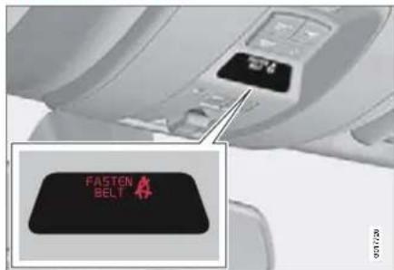
An audio signal and indicator lamp remind anyone not wearing a seatbelt to use one. The audio reminder is speed dependent, and in some cases time dependent. The visual reminder is located in the roof console and the combined instrument panel.
Child seats are not covered by the seatbelt reminder system.
Rear seat
The seatbelt reminder in the rear seat has two subfunctions:
• To provide information on which seatbelts are being used in the rear seat. The message is shown on the information display when the seatbelts are being used or
1 Certain markets

01 Safety
01
Safety in the passenger compartment
when the rear doors are opened. The message is automatically cleared after approx. 30 seconds or it can be acknowledged manually by pressing the READ button.
- Provides a warning if one of the rear seatbelts is unfastened during travel. This warning takes the form of a message on the information display along with the audio/visual signal. The warning stops when the seatbelt is re-fastened, or it can also be acknowledged manually by pressing the READ button.
The message on the information display showing which seatbelts are in use is always available. Press the READ button to see stored messages.
Certain markets
An audio signal and indicator lamp remind the driver if not wearing a seatbelt to use one. At low speed, the audio reminder will sound for the first six seconds.
Seatbelt tensioner
All the seatbelts are equipped with belt tensioners. A mechanism in the seatbelt tensioner tightens the seatbelt in the event of a sufficiently violent collision. The seatbelt then provides more effective restraint for the occupants.
Warning symbol on the combined instrument panel

The airbag system is continually monitored by the system's control module. The warning symbol on the combined instrument panel illuminates in ignition position II or III. The symbol goes out after approx. 6 seconds provided the airbag system is fault-free.

WARNING
If the warning symbol for the airbag system remains illuminated or illuminates while driving, it means that the airbag system does not have full functionality. The symbol indicates a fault in the seatbelt tensioner system, SIPS, IC system or some other fault in the SRS system. Contact an authorised Volvo workshop urgently.
Safety in the passenger compartment
As well as the warning symbol, a message may appear on the information display in appropriate cases. If the warning symbol malfunctions, the warning triangle illuminates and the message SRS Airbag Service required or SRS Airbag Service urgent appears on the display. contact an authorised Volvo workshop urgently.
Airbag (SRS) on the driver's side

natural_image
Diagram of a robotic car interior showing a highlighted red area on the back of a human figure (no text or symbols present)The car has an SRS airbag (Supplemental Restraint System) on the driver's side to supplement the protection afforded by the seat-belt. This airbag is fitted into the centre of the steering wheel. The steering wheel is marked SRS AIRBAG.

WARNING
The seatbelts and airbags interact. If a seatbelt is not used or is used incorrectly, this may diminish the protection provided by the airbag in the event of a collision.
Passenger airbag (SRS)

natural_image
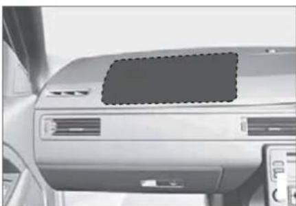
3D illustration of a person driving a car with a red highlighted triangular area, no text or symbols presentThe car has an airbag to supplement the protection afforded by the seatbelt on the passenger side. This airbag is folded up into a compartment above the glovebox. The cover panel is marked SRS AIRBAG.

WARNING
To minimise the risk of injury if the airbag deploys, passengers must sit as upright as possible with their feet on the floor and backs against the backrest. Seatbelts must be secured.

WARNING
Do not put objects in front of or above the dashboard where the passenger airbag is located.

01 Safety
01
Safety in the passenger compartment

WARNING
Never place a child in a child seat or on a booster cushion in the front seat if the airbag is activated. 1
Never allow a child to stand or sit in front of the front passenger seat. No one shorter than 140 cm should ever sit in the front passenger seat if the airbag is activated.
Failure to follow the advice given above can endanger the life of the child.
1 For information on how to activate/deactivate the airbag, see page 18.
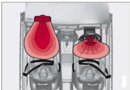
Airbag system

natural_image
Diagram of a vehicle's internal components with highlighted parts, showing no text or symbolsSRS system, left-hand drive
natural_image
Diagram of two identical mechanical components with red highlighted sections, no text or symbols presentSRS system, right-hand drive
The SRS system consists of airbags and sensors. A sufficiently violent collision trips the sensors and the airbag(s) are inflated with hot
gas. To cushion the impact, the airbag deflates when compressed. When this occurs, smoke escapes into the car. This is completely normal. The entire process, including inflation and deflation of the airbag, occurs within tenths of a second.

WARNING
Repairs must only be performed by an authorised Volvo workshop. Any interference in the airbag system could cause malfunction and result in serious personal injury.

NOTE
The sensors react differently depending on the course of the collision and whether or not the seatbelts on the driver and passenger side are used.
It is therefore possible that only one (or none) of the airbags may inflate in a collision. The airbag system senses the force of the collision on the car and adapts accordingly so that one or more airbags is deployed.
The capacity of the airbags is also adapted to the collision force to which the vehicle is subjected.
Safety in the passenger compartment

natural_image
Interior view of a car dashboard and air vent (no visible text or symbols)Location of the front passenger airbag in a left-hand drive car
natural_image
Interior view of a car dashboard and air conditioner unit (no visible text or symbols)Location of the front passenger airbag in a right-hand drive car

01 Safety
Safety in the passenger compartment
PACOS*

Indicator in the roof console showing that the passenger airbag (SRS) is deactivated.
The airbag (SRS) for the front passenger seat can be deactivated if the car is equipped with a switch, PACOS (Passenger Airbag Cut Off Switch). For information on how to activate/deactivate, see page 19.
Messages
A text message and a symbol in the roof panel indicate that the airbag for the front passenger seat is deactivated (see illustration above).
A warning symbol in the roof panel indicates that the airbag for the front passenger seat is activated (see illustration below).

Indicator in roof console showing that the passenger airbag (SRS) is activated.
NOTE
When the remote control key is turned to ignition position II or III the warning symbol for the airbag is shown in the combined instrument panel for approx. 6 seconds (see page 14).
Following which, the indicator in the roof console is illuminated showing the correct status for the front passenger seat airbag. For more information on the different ignition positions, see page 65.
Activating/deactivating
The switch for the passenger airbag (PACOS) is located on the passenger end of the instrument panel and is accessible when the passenger door is open, (see under the heading, Switch – PACOS below). Check that the switch is in the required position. Volvo recommends that the key blade be used to change position.
For information on the key blade, see page 42. (Other items with a shape similar to a key can also be used.)
WARNING
Failure to follow the advice given above could endanger the life of passengers in the car.
WARNING
If the car is equipped with a front passenger airbag, but has no switch (PACOS, Passenger Airbag Cut Off Switch), then the airbag is always activated.
WARNING
Never place a child in a child seat or on a booster cushion in the front seat if the airbag is activated and the symbol in the roof console is illuminated. Failure to follow this advice could endanger the life of the child.
Safety in the passenger compartment

WARNING
Do not allow anyone to sit in the front passenger seat if the message in the roof panel (see page 18) indicates that the airbag is deactivated and if the warning symbol for the airbag system is also displayed in the combined instrument panel. This indicates that there has been a severe malfunction. Contact an authorised Volvo workshop immediately.
Switch - PACOS

Switch location.
A The airbag is activated. With the switch in this position, persons taller than 140 cm can sit in the front passenger seat, but never children in a child seat or on a booster cushion.
B The airbag is deactivated. With the switch in this position, children in a child seat or on a booster cushion can sit in the front passenger seat, but never persons taller than 140 cm.

WARNING
Activated airbag (passenger seat):
Never place a child in a child seat or on a booster cushion on the front passenger seat when the airbag is activated. This applies to everyone shorter than 140 cm.
Deactivated airbag (passenger seat):
No one taller than 140 cm should ever sit in the front passenger seat when the airbag is deactivated.
Failure to follow the advice given above could endanger life.

01 Safety
01
Safety in the passenger compartment
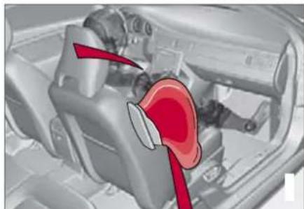
Side airbags - SIPS bags
natural_image
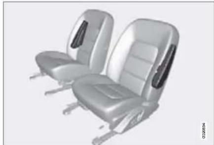
3D rendering of two silver automotive seat chairs with side ribs and backrests (no text or symbols visible)A large proportion of the collision force is transferred by the SIPS (Side Impact Protection System) to beams, pillars, the floor, the roof and other structural parts of the body. The side airbags at the driver's and front passenger seats protect the chest area and the hip and are an important part of the SIPS. The SIPS bag system consists of two main components, side airbag and sensors. The
side airbags are located in the front seat backrests.

WARNING
Repairs must only be performed by an authorised Volvo workshop.
Any interference in the SIPS bag system could cause malfunction and result in serious personal injury.

WARNING
Do not put objects in the area between the outside of the seat and the door panel, since this area is required by the side airbag.

WARNING
Use only seat covers approved by Volvo. Other seat covers may impede the operation of the side airbags.

WARNING
The side airbag is a supplement to the seat-belts. Always use a seatbelt.
Child seats and side airbags
The side airbag does not diminish the protection provided by the car to children seated in a child seat or on a booster cushion.
A child seat/booster cushion can be placed on the front passenger seat provided that the car does not have an activated 1 passenger airbag.
Safety in the passenger compartment
SIPS bags

natural_image
Interior view of a car showing the wheel and dashboard with red highlighted areas (no text or symbols visible)Driver's seat, left-hand drive
natural_image
3D rendering of a car interior showing engine and exhaust components (no text or symbols)Front passenger seat, left-hand drive
The SIPS bag system consists of side airbags and sensors. A sufficiently violent
collision trips the sensors and the side airbags are inflated. The airbag inflates between the occupant and the door panel and thereby cushions the initial impact. The airbag deflates when compressed by the collision. The side airbag is normally only deployed on the side of the collision.
SIPS bag decal

The SIPS airbag decal is located on the door pillar
Inflatable Curtain - IC

natural_image
Side view of a silver minivan with red accent panels (no text or symbols visible)The inflatable curtain IC (Inflatable Curtain) is a supplement to the SIPS and SRS airbags. It is fitted in the headlining along both sides of the roof and protects all of the vehicle's outer seats. A sufficiently violent collision trips the sensors and the inflatable curtain is inflated. The inflatable curtain helps to prevent the driver and passengers from striking their heads on the inside of the car during a collision.

01 Safety
01
Safety in the passenger compartment

WARNING
Never hang or attach heavy items onto the handles in the roof. The hook is only designed for light clothing (not for solid objects such as umbrellas for example).
Do not screw or install anything onto the car's headlining, door pillars or side panels. This could compromise the intended protection. Only ever use Volvo genuine parts that are approved for placement in these areas.

WARNING
Do not load the car higher than 50 mm under the top edge of the side windows. Otherwise, the intended protection of the inflatable curtain, which is concealed in the headlining, may be compromised.

WARNING
The inflatable curtain is a supplement to the seatbelts.
Always use a seatbelt.
Protection against whiplash injury – WHIPS

The whiplash protection system (WHIPS) consists of energy absorbing backrests and specially designed head restraints in the front seats. The system is actuated by a rear-end collision, where the angle and speed of the collision, and the nature of the colliding vehicle all have an influence.

WARNING
The WHIPS system is a supplement to the seatbelts. Always use a seatbelt.
Properties of the seat
When the WHIPS system is deployed, the front seat backrests are lowered backward to alter the seating position of the driver and front seat passenger. This reduces the risk of whiplash injury.

WARNING
Never modify or repair the seat or WHIPS system yourself. Contact an authorised Volvo workshop.
WHIPS system and child seats/booster cushions
The WHIPS system does not diminish the protection provided by the car to children
Safety in the passenger compartment
seated in a child seat or on a booster cushion.
Correct seating position
For the best possible protection, the driver and front seat passenger should sit in the centre of the seat with as little space as possible between the head and the head restraint.

WARNING
If a seat has been subjected to extreme forces, such as due to a rear-end collision, the WHIPS system must be checked by an authorised Volvo workshop.
Part of the WHIPS system's protective capacity may have been lost even if the seats appear to be undamaged. Contact an authorised Volvo workshop to have the system checked even after a minor rear-end collision.
Do not obstruct the WHIPS system

natural_image
3D illustration of a humanoid robot driving on a steering wheel, with a red X symbol overlay (no text or symbols present)
WARNING
Do not squeeze rigid objects between the rear seat cushion and the front seat back-rest. Make sure you do not to obstruct the function of the WHIPS system.

natural_image
Illustration of a humanoid robot driving a car with a red X symbol on the steering wheel (no text or symbols present)
WARNING
If a rear seat backrest is folded down, the corresponding front seat must be moved forward so that it does not touch the folded backrest.

01 Safety
Safety in the passenger compartment
When the systems deploy
| System Triggered | |
| Seatbelt tensioner, front seat | In a frontal collision and or side-impact accident and or rear-end collision |
| Seatbelt tensioner, rear seat In a frontal collision | |
| Airbags (SRS) | In a frontal collision1 |
| Side airbags (SIPS) | In a side-impact accident1 |
| Inflatable Curtain IC | In a side-impact accident1 |
| Whiplash protection WHIPS In a rear-end collision | |
1 The bodywork of the car could be greatly deformed in a collision even without airbag deployment. A number of factors such as the rigidity and weight of the object hit, the speed of the car, the angle of the collision etc. affects how the different safety systems of the car are activated.
If the airbags have deployed, the following is recommended:
- Have the car transported to an authorised Volvo workshop. Do not drive with deployed airbags.
- Let an authorised Volvo workshop replace components in the car's safety system.
• Always contact a doctor.

NOTE
The SRS, SIPS, IC and belt tensioner systems are deployed only once during a collision.

WARNING
The airbag control module is located in the centre console. If the centre console is drenched with water or other liquid, disconnect the battery cables. Do not attempt to start the car since the airbags may deploy. Have the car transported to an authorised Volvo workshop.

WARNING
Never drive with deployed airbags. They can make steering difficult. Other safety systems may also be damaged. The smoke and dust created when the airbags are deployed can cause skin and eye irritation/injury after intensive exposure. In case of irritation, wash with cold water. The rapid deployment sequence and airbag fabric may cause friction and skin burns.
Safety mode
Safety mode
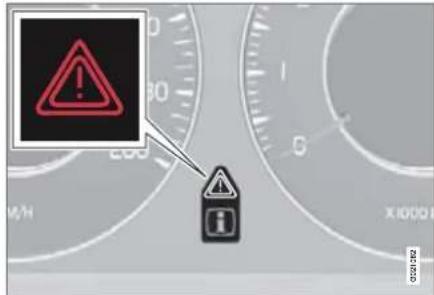
If the car is involved in a collision, the text Safety mode - See manual may appear on the information display. This means that the car has reduced functionality. Safety mode is a protective state that is enforced when the collision may have damaged any of the car's vital functions, such as the fuel lines, sensors for one of the safety systems, or the brake system.
Attempting to start the car
First, check that no fuel is leaking from the car. There must be no smell of fuel either.
If everything seems normal and you have checked for indications of fuel leakage, you may attempt to start the car.
Firstly, remove the remote control key and then reinsert it. The car's electronics will then try to reset themselves to normal mode. Then try to start the car. If the message Safety mode is still shown on the display then the car must not be driven or towed. Even if the car appears to be driveable, hidden damage may make the car impossible to control once moving.
Moving the car
If Normal mode is shown after Safety mode has been reset, the car can be moved carefully out of a dangerous position. Do not move the car further than necessary.

WARNING
Never attempt to repair your car or reset the electronics yourself if the car has been in safety mode. This could result in personal injury or the car not functioning as normal. Always allow an authorised Volvo workshop to check and restore the car to normal status after Safety mode has been displayed.

WARNING
Never, under any circumstances, attempt to restart the car if it smells of fuel when the Safety mode message is displayed. Leave the car at once.

WARNING
If the car is in safety mode it must not be towed. It must be transported to an authorised Volvo workshop.

01 Safety
01
Child safety
Children should sit comfortably and safely
The position of a child in the car and the choice of equipment are dictated by the child's weight and size, for more information see page 28.

NOTE
Legislation regarding the placement of children in cars varies from country to country. Check what laws apply.
Children of all ages and sizes must always sit correctly secured in the car. Never allow a child to sit on the knee of a passenger.
Volvo's own child safety equipment is designed for your car. Use Volvo genuine equipment to best ensure that the mounting points and attachments are correctly positioned and are sufficiently strong.

NOTE
If problems arise when fitting child safety products, contact the manufacturer for clearer instructions.
Child seats

natural_image
Interior view of a car with a red 'X' symbol overlay, indicating no text or symbols on the diagram itself.Child seats and airbags are not compatible.
Volvo has child safety products that are designed for and tested by Volvo.

NOTE
When using child safety products it is important to read the installation instructions included.
Do not attach the straps for the child seat to the horizontal adjustment bar, springs, rails or beams under the seat. Sharp edges can damage the straps.
Allow the back of the child seat to rest against the dashboard. This applies to cars without a passenger airbag, or where the airbag is deactivated.
Location of child seats
You may place:
- a child seat or booster cushion on the front passenger seat, provided the passenger airbag 1 is not activated.
- a rear-facing child seat in the rear seat that uses the back of the front seat as support.
Always place a child in the rear seat if the passenger airbag is activated. A child sitting on the front passenger seat could suffer serious injury if the airbag deploys.

WARNING
Never place a child in a child seat or on a booster cushion in the front seat if the airbag (SRS) is activated.
No one shorter than 140 cm should ever sit in the front passenger seat if the airbag (SRS) is activated.
Failure to follow the advice given above can endanger the life of the child.
1 For information on activated/deactivated airbag (SRS), see page 18.
Child safety

WARNING
Booster cushions/child seats with steel braces or some other design that could rest on the seatbelt buckle's opening button must not be used, as they could cause the seatbelt buckle to open accidentally.
Do not allow the upper section of the child seat to rest against the windscreen.
Airbag decal

Decal located on instrument panel end face on the passenger side.

Decal located on instrument panel end face on the passenger side (Australia only).

01 Safety
01
Child safety
Recommended child seats
| Weight/Age | Front seat | Outer rear seat | Centre rear seat |
| Group 0max. 10 kg(0–9 months)Group 0+max 13 kg | Volvo Child seat – rear-facing child seat, secured with the car’s seatbelt and straps.Type approval: E5 03135 | Volvo Child seat – rear-facing child seat, secured with the car’s seatbelt, straps and support legs.Type approval: E5 03135 | |
| Britax Baby Safe Plus – rear-facing child seat, secured with the ISOFIX fixture system.Type approval: E1 03301146 | Britax Baby Safe Plus – rear-facing child seat, secured with the ISOFIX fixture system.Type approval: E1 03301146 | Britax Baby Safe Plus – rear-facing child seat, secured with the car’s seatbelt.Type approval: E1 03301146 | |
| Group 19–18 kg(9–36 months) | Volvo Child seat – rear-facing child seat, secured with the car’s seatbelt and straps.Type approval: E5 03135 | Volvo Child seat – rear-facing child seat, secured with the car’s seatbelt, straps and support legs.Type approval: E5 03135 | |
| Britax Freeway – rear-facing child seat, secured with the ISOFIX fixture system and straps.Type approval: E5 03171 | Britax Freeway – rear-facing child seat, secured with the ISOFIX fixture system and straps.Type approval: E5 03171 | ||
| Group 2/315 – 36 kg(3–12 yr) | Volvo Booster cushion – with or without backrest.Type approval: E5 03139 | Volvo Booster cushion – with or without backrest.Type approval: E5 03139 | Volvo Booster cushion – with or without backrest.Type approval: E5 03139 |
| Volvo 2-stage Integrated booster cushion – available as a factory fitted option.Type approval: E.G. XXXXX |
With regard to other child seats your car should be included in the manufacturer's enclosed list of vehicles or be universally approved in accordance with the ECE R44 legal requirement.
Child safety
Integrated two-stage booster cushions*

natural_image
Illustration of a person sitting in a car seat with a red safety belt, no text or symbols presentCorrect position, the seatbelt is positioned above the shoulder.

natural_image
Interior view of a car showing a person seated in a seat with a red X symbol on the seat (no text or symbols present)Incorrect position, the head must not be positioned above the head restraint and the seatbelt must not be below the shoulder.
The booster cushions are specially designed to provide optimum safety. In combination with the seatbelt they are approved for children who weigh between 15 and 36 kg and who are 95 to 140 cm in height.
Check before driving that:
- the 2-stage integrated booster cushion is correctly set (see table) and in locked position
- the seatbelt is in contact with the child's body and is not slack or twisted
- the seatbelt does not lie across the child's throat or below the shoulder (see illustration above)
- the lap section of the seatbelt is positioned low over the pelvis to provide optimal protection.
Stage 1 Stage 2
Weight 22 - 36 kg 15-25 kg
Height 115 - 140 cm 95 - 120 cm
For instructions on adjusting the booster cushion's two levels, see page 29-30.
Raising the two-stage booster cushion
Stage 1


natural_image
Hand pressing a black car seatbelt on a vehicle (no text or symbols visible)1 Pull the handle forward (1) and up (2) in order to release the booster cushion.
2 Press the booster cushion backwards to lock.

01 Safety
01
Child safety
Stage 2

natural_image
Interior view of a car seatbelt with a red arrow pointing to the seat area (no text or symbols visible)
1 Start from level 1. Press the button.
2 Lift the booster cushion up at the front edge (1) and press it back (2) against the backrest to lock.
WARNING
Repair or replacement should only be performed by an authorised Volvo workshop. Do not make any modifications or additions to the booster cushion. If an integrated booster cushion has been subjected to a major load, such as in conjunction with a collision, the entire booster cushion must be replaced. Even if the booster cushion appears to be undamaged, it may not afford the same level of protection. The booster cushion must also be replaced if it is heavily worn.
NOTE
It is not possible to adjust the booster cushion from stage 2 to stage 1. It must first be reset by being fully folded into the seat cushion. Refer to the heading below, Lowering the two-stage booster cushion.
Lowering the two-stage booster cushion
Lowering can take place from both the upper and lower stage to fully lowered position in the cushion. However, it is not possible to adjust the booster cushion from the upper stage to the lower stage.

natural_image
Hand pressing a black seatbelt on a vehicle rearrest door, with a red arrow indicating the down-left motion (no text or symbols present)
natural_image
Person pressing down on a car seatbelt, with a red arrow indicating the load (no text or symbols present)Child safety
1 Pull the handle forwards to release the cushion.
2 Press down with your hand in the centre of the cushion in order to lock it.

WARNING
If the instructions regarding the two-stage booster cushion are not followed then this could cause serious injury to a child in the event of an accident.

IMPORTANT
Check that there are no loose objects (e.g. toys) left behind in the space under the cushion before lowering.

NOTE
The booster cushion must be lowered first when lowering the backrest.
Child safety locks, rear doors
The controls for operating the rear door power windows and the rear door opening handles can be blocked from opening from the inside. For more information, see page 50.
ISOFIX fixture system for child seats

natural_image
Interior view of a car seat with red arrows indicating movement or force points (no text or symbols)Mounting points for the ISOFIX fixture system are concealed behind the lower section of the rear seat backrest, in the outer seats.
The location of the mounting points is indicated by symbols in the backrest upholstery (see illustration above).
Press the seat cushion down to access the mounting points.

NOTE
The ISOFIX fixture system is an accessory for the passenger seat.
Always follow the manufacturer's installation instructions when connecting a child seat to the ISOFIX mounting points.

01 Safety
01
Child safety
Size classes
Child seats are in different sizes – cars are in different sizes. This means that not all child seats are suitable for all seats in all car models.
Consequently a size classification has been introduced for child seats using the ISOFIX fixture system in order to assist users in choosing the correct child seat (see table below).
| Size class | Description |
| A Full size, front-facing child seat | |
| B Reduced size (alt.1), front-facing child seat | |
| B1 Reduced size (alt.2), front-facing child seat | |
| C Full size, rear-facing child seat | |
| D Reduced size, rear-facing child seat | |
| E Rear-facing infant seat | |
| F Transverse infant seat, left-hand | |
| G Transverse infant seat, right-hand | |
Child safety
Types of ISOFIX child seat
| Type of child seat Weight (Age) | Size class | Passenger seats for ISOFIX installation of child seats | ||
| Front seat Outer rear seat | ||||
| Infant seat transverse | max. 10 kg (0-9 months) | F -- | ||
| G -- | ||||
| Infant seat, rear-facing max. 10 kg (0-9 months) | E OK OK | |||
| Infant seat, rear-facing max. 13 kg (0-12 months) | E OK OK | |||
| D OK OK | ||||
| C - OK | ||||
| Child seat, rear-facing | 9-18 kg (9-36 months) | D | OK | OK |
| C - OK | ||||
| Child seat, rear-facing 9-18 kg (9-36 months) B | OK1 | OK1 | ||
| B1 | OK1 | OK1 | ||
| A | OK1 | OK1 | ||
1 Volvo recommends rear-facing child seats for this group.

WARNING
Never place a child in the passenger seat if the car is equipped with an activated air-bag.

NOTE
If an ISOFIX child seat has no size classification then the car model must be included on the child seat's vehicle list.

NOTE
Contact a Volvo dealer for Volvo recommendations on ISOFIX child seats.

01 Safety
01
Child safety
Upper mounting points for child seats
natural_image
Interior view of a vehicle with three seats and three down arrows indicating downward motion (no text or symbols)should sit in rear-facing child seats for as long as possible.
For detailed information on how the child seat should be tensioned in the upper mounting points, see the seat manufacturer's instructions.

WARNING
The child seat's straps must always be routed under the rear head restraints before being tensioned at the mounting point.
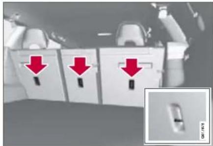
The car is equipped with upper mounting points for certain front-facing child seats. These mounting points are located on the rear of the seat.
For cars with folding head restraints on the outside seats the head restraints should be folded to facilitate the installation of this type of child seat.
For cars equipped with a cargo cover over the cargo area, the cargo cover must be removed before a child seat can be fitted in the mounting points.
The upper mounting points are primarily intended for use with front-facing child seats. Volvo recommends that small children
01 Safety

Remote control key/key blade 38
Privacy locking * 43
Battery replacement, remote control key/PCC* 44
Keyless drive* 45
Locking/unlocking.... 47
Child safety locks....50
Alarm * 51
LOCKS AND ALARM


natural_image
Close-up of a black rectangular key with icons for security, lighting, and function buttons (no text or symbols visible)02

02 Locks and alarm
Remote control key/key blade
General
The car is supplied with two remote control keys or PCCs (Personal Car Communicator). They are used to start the car and for locking and unlocking.
More remote control keys can be ordered – up to six can be programmed and used for the same car.
The PCC has increased functionality compared with the remote control key. Only the remote control key is referred to in the remainder of this chapter when describing functions available in both the PCC and remote control key.

WARNING
If there are children in the car:
Always remember to switch off the power supply to locks, power windows and sun-roof by removing the remote control key if the driver leaves the car.
Detachable key blade
A remote control key contains a detachable metal key blade for mechanical locking/un-locking of the driver's door, glovebox and tailgate (privacy locking).
For key blade functions, see page 42.
For privacy locking, see page 43.
The key blades' unique code is available at authorised Volvo workshops, who can order new key blades.
Loss of a remote control key
If you lose a remote control key then new ones can be ordered at an authorised Volvo workshop. The remaining remote control keys must then be taken to the workshop. The code of the missing remote control key must be erased from the system as a theft prevention measure.
The current number of keys registered to the car can be checked under Car settings → Car key memory → Number of keys. For a description of the menu system, see page 104.
Key memory – door mirrors and driver's seat\*
The settings are automatically connected to each respective remote control key, see page 67 and 84.
The function can be activated/deactivated under Car settings → Car key memory → Seat & mirror positions. For a description of the menu system, see page 104.
For cars with Keyless drive function, see page 45.
Indicator for locking/unlocking
When the car is locked or unlocked using the remote control key, the direction indicators confirm that locking/unlocking was correctly performed:
- Locking; one flash
- Unlocking; two flashes.
After locking the indication is only given if all locks are activated once the doors have been closed.
The function can be activated/deactivated under Car settings → Light settings → Lock confirmation light or Car settings → Light settings → Unlock confirmation light. For a description of the menu system, see page 104.
Immobiliser
Each remote control key has a unique code. The car can only be started with the correct remote control key with the correct code.
The following error messages in the information display (on the combined instrument
Remote control key/key blade
panel) are related to the electronic immobiliser:
Message Specification
| Key error Try again | Error reading remote control key during start. Try to start the car again. |
| Car key Not found | Applies only to the PCC's Keyless drive function. Errors reading the PCC during starting. Try to start the car again. |
| Immobiliser See manual | Remote control key function error during start. Contact an authorised Volvo workshop. |
For starting the car, see page 88.
Low battery in remote control key
The batteries should be replaced if;
- the information symbol illuminates and Car key Battery low is shown in the display
and/or
- the locks repeatedly do not react to signals from the remote control key within 20 metres.
For changing the battery, see page 44.
Functions

Remote control key

PCC* (Personal Car Communicator)
1 Locking
② Unlocking
③ Approach lighting
4 Tailgate
5 Panic function
Total airing function (global opening)
One long press (at least 4 seconds) on button or opens or closes all windows (also closes the sunroof).

WARNING
If the sunroof and windows are closed using the remote control key, check that no one is in danger of getting hands caught.
The function can be used to quickly air the car in hot weather for example.
Function buttons
Locking – Locks the doors and tailgate and then activates the alarm.
Unlocking – Unlocks the doors and tailgate while the alarm is deactivated.
The function can be changed from unlocking all doors simultaneously, to opening the driver's door after one press of the button and opening the remaining doors after a further press of the button (within 10 seconds).

02 Locks and alarm
Remote control key/key blade
The function is changed under Car settings → Lock settings Doors unlock. For a description of the menu system, see page 104.
Approach lighting – Used to switch on the car's lighting at a distance. For more information, see page 76.
Tailgate – Unlocks the tailgate without opening it 1 . For more information, see page 48.
Panic function – Used to attract attention in an emergency.
Press and hold the red button for at least 3 seconds or press it twice within 3 seconds to activate the direction indicators and the horn.
The function can be turned off with the same button once it has been active for at least 5 seconds. Otherwise the function switches off automatically after 2 minutes and 45 seconds.
Range
The remote control has a range of up to 20 m from the car.

NOTE
The remote control key functions can be disrupted by surrounding radio waves, buildings, topographical conditions etc. The car can always be locked/unlocked using the key blade, see page 42.
Unique functions PCC*

1 Information button
② Indicator lamps
Using the information button enables access to certain information from the car via the indicator lamps ②
Using the information button
-
Press the information button .1
-
All indicator lamps flash for approximately 7 seconds and the light travels around on the PCC. This indicates that the information from the car has been read. If any of the other buttons are pressed during this time then the reading is interrupted.
Remote control key/key blade

NOTE
If none of the indicator lamps illuminates with repeated use of the information button and in different locations (as well as after 7 seconds and after the light has travelled around on the PCC), contact an authorised Volvo workshop.
The indicator lamps provide the information shown in the following illustration.


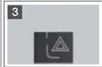
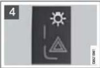
1 Green continuous light: The car is locked.
2 Yellow continuous light: The car is unlocked.
3 Red continuous light: The alarm has been triggered.
4 Red light flashing alternately in the two indicator lamps: indicates, using the HBS
(Heart Beat Sensor), that someone may be in the car. This indication is only displayed if the alarm was triggered.
Range
The PCC lock functions have a range of up to 20 m from the car.
The approach lighting, panic function and the functions controlled by the information button have a range of up to a maximum of 100 m from the car.

NOTE
The information button functions can be disrupted by surrounding radio waves, buildings, topographical conditions etc.
Out of PCC range
If the PCC is too far away from the car for the information to be read then the status the car was last left in is shown, without the light travelling around on the PCC.
The PCC that was last used for locking/un-locking will show the correct status.

NOTE
If no indicator lamps illuminate when the information button is used then this can be because the last communication between the PCC and the car was disrupted by surrounding radio waves, buildings, topographical conditions etc.
Heart Beat Sensor
The function operates using an HBS (Heart beat sensor). HBS is a supplement to the car's alarm system and can indicate at a distance whether anybody is in the car. This indication is only displayed if the alarm was triggered.
The HBS detects an individual's heartbeat that is transmitted to the car's bodywork. For this reason the function of the HBS can be disturbed in an environment subject to noise and vibration.
Keyless drive
See page 45.

02 Locks and alarm
Remote control key/key blade
Detachable key blade
Using the remote control key's detachable key blade;
- the driver's door can be opened manually if central locking is not activated with the remote control key
- access to the glovebox and cargo area (privacy locking) 1 is blocked, see 43.
Removing the key blade

natural_image
3D rendering of a silver mobile phone case with red arrows indicating internal components (no text or symbols)Slide the spring-loaded catch 10 the side while pulling the key blade straight out backwards 2
Inserting the key blade
Carefully refit the key blade in place in the remote control key to avoid damaging it.
- Hold the remote control key with the slot pointed up and lower the key blade into its slot.
- Lightly press the key blade. You should hear a "click" when the key blade is locked in.
Unlocking doors with the key blade
If central locking cannot be activated with the remote control key, e.g. if the batteries are discharged, then the driver's door can be opened as follows:
- Unlock the driver's door using the key blade in the door handle's keyhole.

NOTE
When the driver's door is unlocked using the key blade and is opened, the alarm is triggered.
- Deactivate the alarm by inserting the remote control key in the ignition switch.
Privacy locking\*
Privacy locking 4 .
natural_image
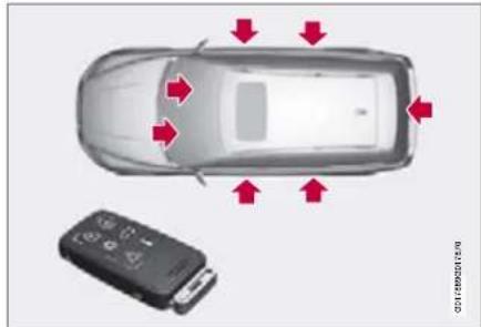
Top-down view of a car with red arrows indicating movement or change, alongside a small black device (no text or symbols visible)Active locks for remote control key, with key blade and privacy locking not activated.
This function is intended for when the car is left for service, with a hotel parking valet or similar. The glovebox is then locked and the tailgate lock is disconnected from the central locking. The cargo area cannot be opened with either the central locking button in the front doors or the remote control key.
This means that the remote control key without key blade can only be used to activate/deactivate the alarm, to open the doors and to drive the car.
The remote control key is handed over without the detachable key blade which the owner then keeps.
Activating/deactivating

natural_image
Interior view of a car dashboard with directional arrows and a warning sign (no readable text or symbols)Activating privacy locking.
To activate privacy locking:
Insert the key blade in the glovebox lock.
Turn the key blade 180 degrees clockwise.
Pull out the key blade (the information display shows a message).
NOTE
Do not reinsert the key blade into the remote control key but keep it in a safe place instead.
- Deactivation takes place in reverse order. For information on locking the glovebox only, see page 48.
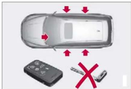
Active locks for remote control key, without key blade and with privacy locking activated.
1 Certain markets.

02 Locks and alarm
Battery replacement, remote control key/PCC\*
Replacing the battery

natural_image
3D rendering of a silver mobile phone case with two red arrows pointing to internal components (no text or symbols)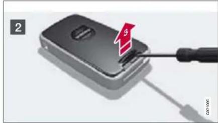
natural_image
Close-up of a black handheld device with a red arrow and screwdriver inserted, no visible text or symbolsBattery type: CR2430, 3 V (one in remote control key and two in the PCC).
Opening
1 Slide the spring-loaded catch to the side while pulling the key blade straight out backwards
2 Insert a screwdriver in the hole behind the spring-loaded catch and gently prise the remote control key up.
NOTE
Turn the remote control key over with the buttons facing up, this is to avoid the batteries falling out when it is opened.
IMPORTANT
Avoid touching the battery and its terminals with your fingers, as this could damage their functionality.
Battery replacement

3 Closely study how the battery/batteries are secured on the inside of the cover, with regard to their (+) and (−) sides.
Remote control key
A Carefully prise out the battery. Install a new one with the (+) side down.
PCC
B Carefully prise out the batteries. First install one new one with the (+) side up. Position the white plastic tab in between and finally install a second new battery with the (+) side down.
Assembly
- Press the remote control key together.
- Hold the remote control key with the slot pointed up and lower the key blade into its slot.
- Lightly press the key blade. You should hear a "click" when the key blade is locked in.
IMPORTANT
Make sure that you dispose of old batteries in an environmentally-friendly way.
Keyless drive\*
Keyless drive (only PCC\*)
Keyless lock and ignition system

natural_image
Top-down view of a car with two circular outline highlighting the front and side (no text or symbols)The keyless drive function in the PCC allows the car to be unlocked, driven and locked without the need for a key. You simply have to have the PCC with you. The system makes it easier and more convenient to open the car, for example when your hands are full.
The car's two PCCs incorporate the Keyless function. Additional PCCs can be ordered.
PCC range
In order to open a door or the tailgate, a PCC must be no more than approx. 1.5 metres from the car's door handle or tailgate. This means that the person who wishes to lock or unlock a door must be carrying the PCC. It is not possible to lock or unlock a door if the
PCC is on the other side of the car to the door.
The red circles in the illustration indicate the range covered by the system's antennas.
If all PCCs are removed from the car and if all doors are closed then a warning message is shown in the information display and an audio reminder signal sounds at the same time. The message disappears when a PCC is brought back to the car.
The warning message and audio reminder signal disappear when the PCC is brought back to the car after;
- a door has been opened and closed
- the PCC is inserted into the ignition switch
- the READ button has been pressed.
Handling the PCC safely
If a PCC with keyless drive function is left in the car, it is deactivated temporarily when the car is locked. This prevents unauthorised entry.
However, if someone breaks into the car, opens the door and finds the PCC, it can be reactivated. It is therefore important to handle all PCCs with equal care.

IMPORTANT
Never leave a PCC behind in the car.
Interference to PCC function
Electromagnetic fields and screening can interfere with the keyless drive system. For this reason, do not place the PCC near mobile phones or metallic objects.
If interference is experienced nonetheless, use the PCC and key blade in the normal way, see page 39.
Unlocking
Open the doors with the door handles or open the tailgate with the tailgate's handle.
Unlocking with the key blade
If the keyless drive function in the PCC is not operating, then the driver's door can be unlocked with the key blade. In this case central locking is not activated.

NOTE
Unlocking with the key blade triggers the alarm. For deactivation, see page 51.
Key memory – driver's seat and door mirrors\*
PCC memory function
If several people with PCCs approach the car, then the settings for seat and mirrors are implemented for the person who opens the driver's door.

02 Locks and alarm
Keyless drive\*
The settings are changed in two ways after the driver's door has been opened:
- From the driver's seat position: press the unlock button on the PCC, see page 39
- Press the button for seat settings, see page 67.
Locking
Lock the doors and the tailgate by pressing the lock button on one of the door handles on the outside.
All doors and the tailgate must be closed before the car can be locked. Otherwise the car will not be locked.

NOTE
On cars with automatic transmission, the gear selector must be set in the P position – otherwise the car cannot be locked or the alarm armed.
Lock settings
The keyless function can be adapted to specify which of the car doors are to be unlocked, under Car settings -ock settings → Keyless entry. For a description of the menu system, see page 104.
Antenna location

The keyless system has a number of integrated antennae located around the car:
① Tailgate, by wiper motor
② Door handle, left rear
③ Roof, above centre rear seat
4 Cargo area, central and furthest in under the floor
⑤ Door handle, right rear
6 Centre console, under the rear section
⑦ Centre console, under the front section.

WARNING
People with pacemaker operations should not come closer than 22 cm to the keyless system's antennae with their pacemaker. This is to prevent interference between the pacemaker and the keyless system.
Locking/unlocking
From the outside
The remote control key locks/unlocks all doors and the tailgate simultaneously. The lock buttons and door handles are disengaged during locking which also prevents opening from the inside, so-called dead-locks, see page 49 (only applies to certain markets).
The fuel filler flap can be opened when the car is unlocked. It cannot be opened if the car is locked and the alarm is armed.

NOTE
The car can be locked even if a door is open 1 . It is also locked when the door is closed, and there is a risk that the remote control key will be locked in.
1 Only applies to cars in certain markets, but not to cars with Keyless drive.

WARNING
Be aware that there is a risk that you can be locked in the car if it is locked from the outside.
Automatic relocking
If none of the doors or the tailgate is opened within two minutes of unlocking, all are locked again automatically. This function prevents the car from being left unlocked unintentionally. For cars with alarms, see page 51.
From the inside
natural_image
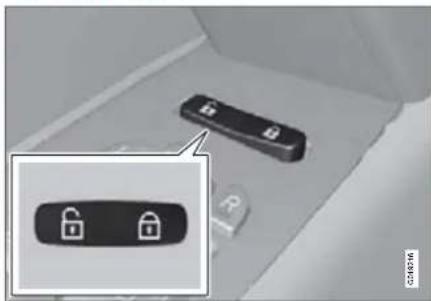
Close-up of a car interior showing two black padlock buttons with white lock icons, one highlighted (no text or symbols visible)All of the doors and the tailgate can be locked or unlocked simultaneously using the door buttons on the door panel.
Unlocking
Press the door unlock button. Press and hold to also open all windows.
Locking
Press the door lock button after the front doors are closed. Press and hold to also close all of the windows and the sunroof.
All the doors can be locked manually with their respective lock buttons after they have been closed. Pull the door handle once to unlock the door. Pull the door handle twice to open the door.
Automatic locking
The doors and tailgate can be locked automatically when the car starts to move.
This function can be activated/deactivated under Car settings → Lock settings → Doors automatic lock. For a description of the menu system, see page 104.

02 Locks and alarm
Locking/unlocking
Glovebox
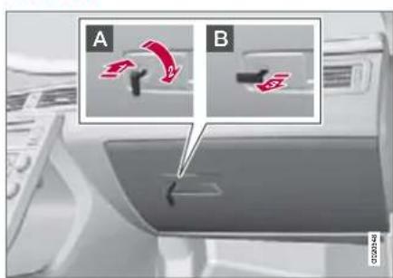
A Lock the glovebox by turning the key blade a quarter of a turn (90 degrees) clockwise. The keyhole is horizontal in the locked position.
B Unlock by carrying this out in reverse order.
The keyhole is vertical in the unlocked position.
The glovebox can only be locked and unlocked with the removable key blade in the remote control key.
For information on privacy locking, see page 43.
Tailgate
natural_image
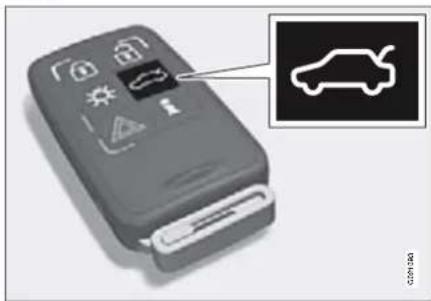
Close-up of a gray remote control device with warning icons and a car icon (no text or symbols on the device itself)Unlocking with the remote control key Press the remote control key button to unlock the tailgate.
NOTE
On cars with the power operated tailgate option, the tailgate is opened – otherwise it is only unlocked, see page 167.
The alarm indicator on the instrument panel goes out to show that the whole car is not armed. The alarm's level and movement sensors and the sensors for opening the tailgate are automatically disconnected. The doors remain locked and armed.
When the tailgate is closed again it is then locked, and the disconnected alarm functions are reactivated.
Locking with the remote control key
Press the remote control key button for locking, see page 39.
The alarm indicator on the instrument panel starts to flash, which shows that the alarm is armed.
If the doors are locked when the tailgate is closed then it remains unlocked until the car is locked with the remote control key.
Unlocking the car from inside
natural_image
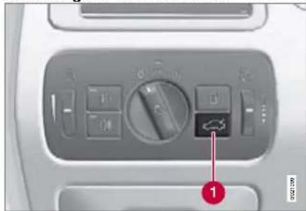
Close-up of a car air conditioner control panel with a directional arrow indicator (no text or symbols on the panel itself)Press the headlamp control panel button 1 to unlock the tailgate.
Locking/unlocking
Deadlocks 1

Deactivating with the button or display menu.
When deadlocked, the doors cannot be opened from the inside if they are locked. The deadlocks are activated with the remote control key and are set after a 10 second delay after the doors are locked.
The car can only be unlocked from a deadlock state with the remote control key. The driver's door can also be unlocked from the outside with the key blade.
Deactivating with the button
If someone is going to stay in the car but the doors must be locked from the outside, then the deadlocks function can be temporarily deactivated as follows:
- Press the button. Deactivation must be carried out within one minute from when the remote control key is removed from the ignition switch.
- The light in the button remains illuminated until the car is locked.
- A message is shown on the instrument panel display for 10 seconds or until the car is locked.
NOTE
If the car is equipped with an alarm: Remember that the car's alarm is armed when the car is locked. If any of the doors are opened from the inside then the alarm will be triggered.
If the car is equipped with an alarm with movement and tilt detectors*, then these are also deactivated at the same time, see page 53.
The detectors are reactivated and deadlocks re-engaged the next time the car is started.
WARNING
Do not allow anyone to remain in the car without first deactivating the deadlocks to avoid the risk of anyone being locked in.
Deactivating with the display menu
Certain cars have no button but instead deactivation takes place in the menu system. For a description of the system, see page 104.
- Go into the menu system under Car settings.
- Select Reduced Guard. An active menu option is indicated with a cross.
Otherwise the same applies as for deactivating with the button.

02 Locks and alarm
Child safety locks
Manual blocking of the rear doors

The child safety locks are located on the trailing edge of the rear doors and are only accessible when the doors are open.
- Use the key blade to turn the lock and thus activate or deactivate the child safety lock.
A The door cannot be opened from inside.
B The doors can be opened from inside.

NOTE
Cars with electric child safety locks do not have manual child locks.
Electrical locking of the rear doors* and power windows

natural_image
Close-up of a car interior control panel with icons and a magnified inset showing a battery symbol (no text or labels visible)When the electric child safety lock is active;
- the rear windows can only be opened with the driver's door controls
- the rear doors cannot be opened from the inside.
-
Child safety locks are activated in ignition position I or II.
-
Press the switch on the driver's door. The information display shows a message.
The lamp on the button illuminates when the locks are activated.

WARNING
Always keep the car unlocked during a journey. In the event of an accident, this allows the emergency services to get into the car quickly.
Passengers in the rear seat cannot open the doors from inside if the child safety locks are activated.
Alarm\*
General
The alarm is triggered if;
- a door, the bonnet or the tailgate is opened
- a non-approved key is used in the keyhole or if force is exerted on the keyhole.
- a movement is detected in the passenger compartment (if fitted with a movement detector)
- the car is raised or towed away (if fitted with a tilt detector*)
- a battery cable is disconnected.
- anyone tries to disconnect the siren.
If there is a fault in the alarm system, a message appears on the information display. Contact an authorised Volvo workshop.

NOTE
The movement detectors trigger the alarm in the event of movements in the passenger compartment. For this reason the alarm could be triggered if the car is left with a window open or if an electric passenger compartment heater is used. To avoid this: close the windows when leaving the car and aim the air from the passenger compartment heater so that it is not directed up into the passenger compartment.

NOTE
Do not attempt to repair or modify alarm system components. All such attempts could affect the terms of insurance.
Alarm indicator

natural_image
Close-up of a car roof with a red arrow pointing to a small black object, and an inset image of a mouse on the roof (no text or symbols visible)An alarm indicator on the dashboard indicates the alarm system's status:
- lamp off – the alarm is disarmed
- the lamp flashes once every other second
- Alarm is armed
- the lamp flashes rapidly after disarming the alarm (and until the remote control key is inserted in the ignition switch and ignition position I is selected) – the alarm has been triggered.
Arming the alarm
Press the remote control key lock button. A long flash from the car's direction indicators confirms that the alarm is armed and that the doors are locked.
The way in which the car confirms that the alarm is armed can be adapted to your requirements under Car settings -ock settings → Keyless entry. For a description of the menu system, see page 104.
Disarming the alarm
Press the remote control key unlock button. Two short flashes from the car's direction indicators confirm that the alarm is disarmed and that the doors are unlocked.
Deactivating a triggered alarm
Press the remote control key unlock button or insert the remote control key in the ignition switch. Confirmation is given by two short flashes from the direction indicators.

02 Locks and alarm
Alarm\*
Other alarm functions
Automatic re-arming of the alarm
This function prevents the car being left with alarm disarmed unintentionally.
If the car is unlocked with the remote control key (and the alarm is disarmed) and none of the doors or the tailgate is opened within two minutes, then the alarm is automatically re-armed. The car is locked at the same time.
Alarm signals
When the alarm is triggered, the following happens:
- A siren sounds for less than 30 seconds. The siren has its own battery which is independent of the car battery.
- The direction indicators flash for five minutes or until the alarm has been deactivated.
Remote control key not working
If the remote control key is not working, the alarm can still be switched off and the car started as follows:
-
Open the driver's door with the key blade. The alarm is triggered and the siren sounds.
-
Insert the remote control key in the keyhole. The alarm is deactivated. The alarm indicator flashes quickly until the remote control key is inserted.
Reduced alarm level
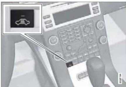
Deactivating with the button or display menu.
To avoid inadvertently triggering the alarm, for example during a ferry crossing, the movement and tilt detectors* can be temporarily deactivated.
Alarm\*
Deactivating with the button
- Press the button. Deactivation must be carried out within one minute from when the remote control key is removed from the ignition switch.
- The light in the button remains illuminated until the car is locked.
- A message is shown on the instrument panel display for 10 seconds or until the car is locked.
If the car is equipped with deadlocks, they are also deactivated at the same time, see page 49.
The next time the car is started the detectors are reactivated and deadlocks re-engaged.
Deactivating with the display menu
Certain cars have no button but instead deactivation takes place in the menu system. For a description of the system, see page 104.
- Go into the menu system under Car settings.
- Select Reduced Guard. An active menu option is indicated with a cross.
Otherwise the same applies as for deactivating with the button.
Testing the alarm system
Testing the movement detector in the passenger compartment
- Close all windows. Remain in the car.
- Arm the alarm, see page 51.
- Wait 15 seconds.
- Trigger the alarm by moving your arms forward and back at backrest height. A siren sounds and all direction indicators flash.
- Deactivate the alarm by unlocking the car with the remote control key.
Testing the alarm sensors in the doors
- Arm the alarm, see page 51.
- Wait 15 seconds.
- Unlock the driver's door using the key blade.
- Open the driver's door. A siren sounds and all direction indicators flash.
- Deactivate the alarm by unlocking the car with the remote control key.
Testing the alarm sensors in the bonnet
-
Sit in the car and deactivate the alarm, see page 51.
-
Arm the alarm, see page 51. Remain in the car and lock the doors with the button on the remote control key.
- Wait 15 seconds.
- Open the bonnet with the handle under the dashboard. A siren sounds and all direction indicators flash.
- Deactivate the alarm by unlocking the car with the remote control key.
Instruments and controls 56
Ignition positions.... 65
Seats 66
Steering wheel 70
Lighting 71
Wipers and washing....80
Windows, rearview and door mirrors 82
Power sunroof* 86
Starting the engine....88
Gearboxes....91
All Wheel Drive – AWD (All Wheel Drive)* 95
Foot brake 96
Hill Descent Control (HDC)....97
Parking brake 98
YOUR DRIVING ENVIRONMENT

03


03 Your driving environment
Instruments and controls
Instrument overview
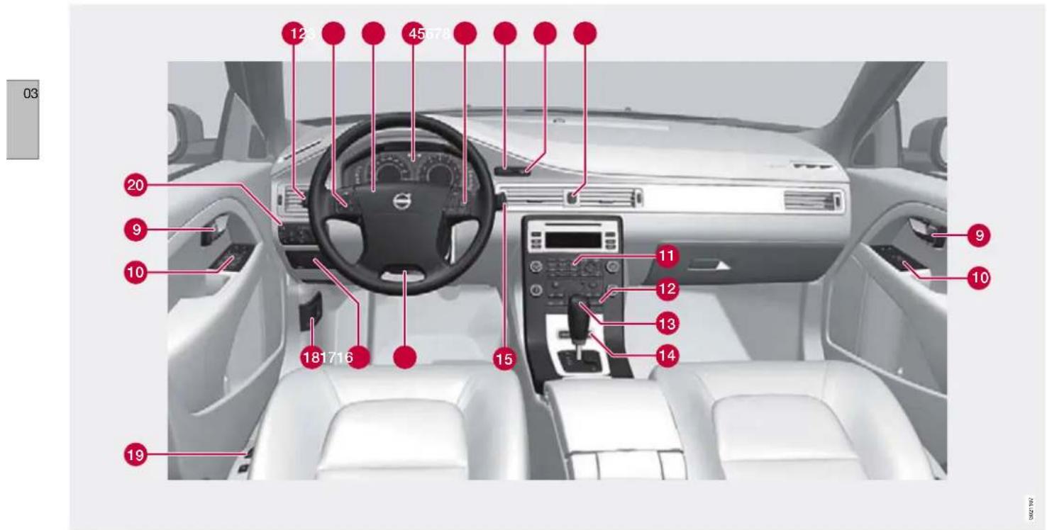
Left-hand drive
03 Your driving environment

Instruments and controls
| Function Page Function Page | |||||
| 1 | Menus and messages, direction indicators, main/ dipped beam, trip computer | 107, 74, 72, 130 | 11 | Menu control, climate control and audio system 104, 112, 123 | |
| 2 | Cruise control | 135, 64 | 12 | Climate control, ECC* | 112 |
| 3 | Horn, airbags | 70, 15 | 13 | Gear selector | 91 |
| 4 | Combined instrument panel | 60, 64 | 14 | Controls for active chassis (Four-C)* | 134 |
| 5 | Menu, audio and phone control | 104, 120 | 15 | Wipers and washing | 80, 81 |
| 6 | Ignition switch | 88 | 16 | Steering wheel adjustment | 70 |
| 7 | Start/stop button | 65 | 17 | Parking brake* | 98 |
| 8 | Hazard warning flashers | 74 | 18 | Bonnet opener | 184 |
| 9 | Door handle | - | 19 | Seat adjustment* | 66 |
| 10 | Control panel | 82, 84, 47 | 20 | Headlamp control, opener for fuel filler flap and tail-gate | 71, 163 |

03 Your driving environment
Instruments and controls

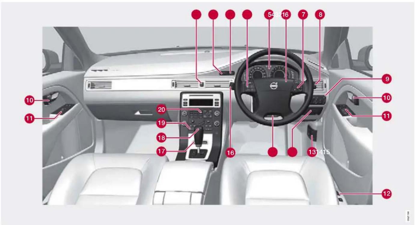
Right-hand drive
03 Your driving environment

Instruments and controls
| Function Page Function Page | |||||
| 1 | Hazard warning flashers | 74 | 11 | Control panel | 82, 84, 47 |
| 2 | Ignition switch 65 Seat adjustment* 66 | 12 | |||
| 3 | Start/stop button | 88 | 13 | Bonnet opener | 184 |
| 4 | Cruise control | 135, 136 | 14 | Parking brake | 98 |
| 5 | Combined instrument panel | 60, 64 | 15 | Steering wheel adjustment | 70 |
| 6 | Horn, airbags | 70, 15 | 16 | Menus and messages, direction indicators, main/dipped beam, trip computer | 107, 74, 72, 130 |
| 7 | Menu, audio and phone control | 104, 120 | 17 | Controls for active chassis (Four-C)* | 134 |
| 8 | Wipers and washing | 80, 81 | 18 | Gear selector | 91 |
| 9 | Headlamp control, opener for fuel filler flap and tail-gate | 71, 163 | 19 | Climate control, ECC* | 112 |
| 10 | Door handle | - | 20 | Menu control, climate control and audio system | 104, 112, 123 |

03 Your driving environment
Instruments and controls
Information displays

Information displays
The information displays show information on some of the car's functions, e.g. cruise control, trip computer and messages. The information is shown with text and symbols.
There are further descriptions under the functions that use the information displays.
Meters

Meters in the combined instrument panel
1 Speedometer
② Fuel gauge, see also refuelling, page 163.
③ Tachometer
The meter indicates engine speed in thousands of revolutions per minute (rpm).
Indicator, information and warning symbols
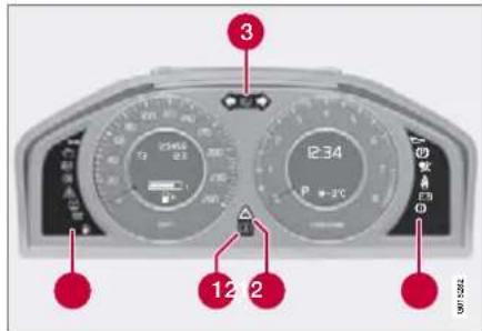
Indicator and warning symbols
① Indicator and information symbols
② Indicator and warning symbols 1
③ Main beam and direction indicator symbol
Functionality check
All indicator and warning symbols illuminate in ignition position II or when the engine is started. When the engine has started, all the symbols should go out except the parking brake symbol, which only goes out when the brake is disengaged.
03 Your driving environment

Instruments and controls
If the engine does not start or if the functionality check is carried out in ignition position II then all symbols go out after 5 seconds except the symbol for a faults in the car's emissions system and the symbol for low oil pressure.
Indicator and information symbols
| Symbol Specification | |
| Direction indicators on trailer | |
| Fault in emissions system | |
| ABS fault | |
| Rear fog lamp | |
| Stability system | |
| Engine preheater (diesel) | |
| Low level in fuel tank | |
| Information, read display text | |
| Main beam On | |
| Left-hand direction indicators | |
| Right-hand direction indicators | |
Direction indicators on trailer
This symbol flashes when the direction indicators are used and the trailer is connected. If the symbol flashes more quickly then one of the lamps on the car or the trailer is broken.
Fault in emissions system
Drive to an authorised Volvo workshop to have the system checked.
ABS fault
If this symbol illuminates then the system is not working. The car's regular brake system continues to work, but without the ABS function.
-
Stop the car in a safe place and turn off the engine.
-
Restart the engine.
-
Drive to an authorised Volvo workshop to have the ABS checked if the symbol remains illuminated.
0‡ Rear fog lamp
This symbol illuminates when the rear fog lamp is on.
Stability system
A flashing symbol indicates that the stability system is operating. If the symbol illuminates with constant glow then there is a fault in the system.
Engine preheater (diesel)
This symbol illuminates during engine preheating. Preheating occurs when the temperature is below -2 °C. The car can be started once the symbol goes out.
Low level in fuel tank
This symbol illuminates when there are approximately eight litres of fuel left in a petrol-engined car, or seven litres in a diesel-engined car.
Information, read display text
When one of the car's systems does not behave as intended, this information symbol illuminates and a text appears on the information display. The message text is cleared using the READ button, see page 107 or it disappears automatically after a time (time depending on which function is indicated). The information symbol can also illuminate in conjunction with other symbols.
NOTE
When a service message is shown, the symbol and message are cleared using the READ button, or disappear automatically after a time.
Main beam On
The symbol illuminates when main beam is on and with main beam flash

03 Your driving environment
Instruments and controls
Left-hand direction indicators
Right-hand direction indicators Both direction indicator symbols flash when the hazard warning flashers are used.
Indicator and warning symbols
| Symbol Specification | |
| Low oil pressure1 | |
| Parking brake applied | |
| Airbags – SRS | |
| Seatbelt reminder | |
| Alternator not charging | |
| Fault in brake system | |
| Warning | |
1 For certain engine variants, the symbol for low oil pressure is not used. Warnings are given via display text, see page 185 and 186.
Low oil pressure
If this symbol illuminates during driving then the engine's oil pressure is too low. Stop the engine immediately and check the engine oil
level, top up if necessary. If the symbol illuminates and the oil level is normal, contact an authorised Volvo workshop.
Parking brake applied
This symbol illuminates with a constant glow when the parking brake is applied. With the electric parking brake, this symbol flashes while it is being applied and then illuminates with a constant glow.
A flashing symbol means that a fault has arisen. Read the message on the information display.
NOTE
This symbol also illuminates when the mechanical parking brake is only lightly applied.
Airbags - SRS
If this symbol remains illuminated or illuminates while driving, it means a fault has been detected in the seatbelt buckle, SRS, SIPS, or IC systems. Drive immediately to an authorised Volvo workshop to have the system checked.
Seatbelt reminder
This symbol illuminates if someone in a front seat has not put on their seatbelt or if someone in a rear seat has taken off their seatbelt.
Alternator not charging
This symbol illuminates during driving if a fault has occurred in the electrical system. Contact an authorised Volvo workshop.
Fault in brake system
If this symbol illuminates, the brake fluid level may be too low. Stop the car in a safe place and check the level in the brake fluid reservoir, see page 188.
If the brake and ABS symbols illuminate at the same time, there may be a fault in the brake force distribution system.
- Stop the car in a safe place and turn off the engine.
- Restart the engine.
- If both symbols extinguish, continue driving.
- If the symbols remain illuminated, check the level in the brake fluid reservoir. See page 188. If the brake fluid level is normal but the symbols are still illuminated, the car can be driven, with great care, to an authorised Volvo workshop to have the brake system checked.
Instruments and controls

WARNING
If the brake fluid is under the MIN level in the brake fluid reservoir, do not drive further before topping up the brake fluid. The reason for the loss of brake fluid must be investigated by an authorised Volvo workshop.

WARNING
If the brake and ABS symbols are on at the same time, there is a risk that the rear end will skid during heavy braking.

Warning
The red warning symbol illuminates when a fault has been indicated which could affect the safety and/or driveability of the car. An explanatory text is shown on the information display at the same time. The symbol remains visible until the fault has been rectified but the text message can be cleared with the READ button, see page 107. The warning symbol can also illuminate in conjunction with other symbols.
Action:
- Stop in a safe place. Do not drive the car further.
- Read the information on the information display. Implement the action in accord-
ance with the message in the display. Clear the message using READ.
Reminder – doors not closed If one of the doors, the bonnet 1 or tailgate is not closed properly then the information or warning symbol illuminates together with an explanatory text message in the combined instrument panel. Stop the car in a safe place as soon as possible and close the door, bonnet or tailgate, whichever is open.
If the car is driven at a speed lower than 7 km/h then the information symbol illuminates.
If the car is driven at a speed higher than 7 km/h then the warning symbol illuminates.

03 Your driving environment
Instruments and controls
Trip meter
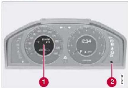
Trip meter and button
The meters are used to measure short distances.
① Display for trip meter
2 Controls for switching between trip meter T1 and T2, as well as resetting the trip meter.
The meters are used to measure short distances. A short press on switches between the two trip meters T1 and T2. A long press (more than 2 seconds) resets an active trip meter to zero. The distance is shown in the display 1
Clock

Clock and setting knob
1 Controls for setting the clock.
② Information display for showing the time.
Turn the knob clockwise/anticlockwise to set the time. The set time is shown in the information display ②
The clock can be temporarily replaced by a symbol in conjunction with a message, see page 107.
Controls for trip meter and clock

natural_image
Close-up of a rotary dial with measurement scale and control buttons (no readable text or symbols)Location of controls
03 Your driving environment

Ignition positions
Functions

Ignition switch with remote control key, start/stop button
Insert and remove the remote control key
The remote control key is inserted into the ignition switch. With one gentle push the remote control key is captured into the correct position.
The remote control key is withdrawn from the ignition switch by means of one touch. The key is then ejected and can be removed. Automatic transmission* must be in position P.
For information on the audio system's functions with remote control key removed, see page 120.
IMPORTANT
Foreign objects in the ignition switch can impair the function or destroy the lock. Do not insert the remote control key backwards! Grip the end with the detachable key blade. See page 42.
Ignition position 0
Insert the remote control key in the ignition switch.
Ignition position I
Press the remote control key into the ignition switch and press START/STOP.
NOTE
The brake/clutch must not be depressed if ignition positions I or II are required.
Ignition position II
Press the remote control key into the ignition switch and press START/STOP for approx. 2 seconds.
Starting the engine III
Start the engine, see page 88.
Stop engine
Press START/STOP. (If the engine is running and the car is moving, keep the button depressed until the engine stops).
Return to ignition position 0
Press START/STOP to return from I, II, or III to ignition position 0.
NOTE
During towing, ignition position II should be used so that the lighting can be switched on.
Position Function
| 0 | Odometer, clock and temperature gauge are illuminated. The steering lock is deactivated. The audio system can be used. |
| I | Sunroof, power windows, phone, ventilation fan, ECC, windscreen wipers can be used. |
| II | The headlamps come on. Warning/indicator lamps illuminate for 5 seconds. All equipment operates apart from heated seats and rear window defroster which only work when the engine is running. |

03 Your driving environment
Seats
Front seats

① Lumbar support, turn the wheel 1 .
2 Forward/backward: lift the handle to adjust the distance to the steering wheel and pedals. Check that the seat is locked after changing position.
3 Raise/lower front edge of seat cushion, pump up/down.
4 Adjust backrest rake, turn the wheel.
⑤ Raise/lower the seat, pump up/down.
6 Control panel for power seat*.

WARNING
Adjust the position of the driver's seat before setting off, never while driving. Check that the seat is locked in position.
Lowering the front seat backrest

The passenger seat backrest can be folded forward to make room for long loads.
Move the seat as far back/down as possible.
2 Adjust the backrest to an upright position
3 Lift the catches on the rear of the back-rest and fold it forward.
Push the seat forward so that the head restraint "locks" in under the glovebox.
Power seat*
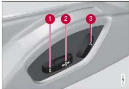
1 Front edge of seat cushion up/down
② Seat forward/backward and up/down
③ Backrest rake
The power front seats have overload protection which is tripped if a seat is blocked by an object. If this happens, turn off the ignition and wait a short time before adjusting the seat again.
Only one of the electric motors can be used at a time.
03 Your driving environment

Seats
Preparations
The seats can be adjusted for a certain time after unlocking the door with the remote control key without the key in the ignition switch. Seat adjustment is normally made when the ignition is on and can always be made when the engine is running.
Seat with memory function*

Store setting
- Adjust the seat and the door mirrors.
- Press and hold the button, while depressing the ② or ③ button.
Using a stored setting
Press one of the memory buttons ① ③ until the seat and the door mirrors stop. If you release the button then the movement of the seat will stop.
Key memory\* in remote control key
The positions of the driver's seat and the door mirrors are stored in the key memory when the car is locked with the remote control key.

natural_image
Close-up of a car interior showing seatbelt and dashboard, with red arrows indicating rotation or movement (no text or symbols)When the car is unlocked with the same remote control and the driver's door is opened the driver's seat and also the door mirrors automatically adopt the positions stored in the key memory.
NOTE
The seat and the door mirrors do not move if they are already in the relevant position.
It is also possible to use the key memory by pressing the unlock button on the remote control key when the driver's door is open.
The key memory can be activated/deactivated under Car key memory -eat & mirror positions. For a description of the menu system, see page 104.
NOTE
The key memory in the two remote controls and the seat memory are completely independent of each other.

03 Your driving environment
Seats
Emergency stop
If the seat accidentally begins to move, press one of the buttons to stop the seat.
Restarting to reach the seat position stored in the key memory is performed by pressing the unlock button on the remote control key. In this situation the driver's door must be open.

WARNING
Risk of crushing! Make sure that children do not play with the controls. Check that there are no objects in front of, behind or under the seat during adjustment. Ensure that none of the backseat passengers will be trapped.
Heated/ventilated seats\*
See page 112.
Rear seats
Head restraint, centre seat, rear

natural_image
Interior view of a car with a black seatbelt and red directional arrows indicating movement or change (no text or symbols present)The head restraint is adjusted vertically according to the height of the passenger. The top of the head restraint is adjusted to the rear centre of the head. Slide it up as required. To lower the head restraint again, the button (located in the centre between the backrest and head restraint, see illustration) must be pressed in while the head restraint is pressed down.
Manual lowering of the outer head restraints, rear seat

natural_image
Interior view of a car showing the backrest and seat area with red arrows indicating features (no text or symbols present)Pull the locking handle closest to the head restraint to fold the head restraint forward.
The head restraint is moved back manually until a "click" can be heard.
03 Your driving environment

Seats
Lowering the rear seat backrest

natural_image
Interior view of a modern vehicle showing the backrest and seat area (no visible text or symbols)
The triple-section rear seat backrest can be folded in different ways in order to facilitate loading long objects.

NOTE
The front seats may need to be pushed forwards, and/or the backrests adjusted upwards, in order that the rear backrests can be folded forward fully.
- The left-hand backrest can be folded separately.
- The centre backrest can be folded separately.
- The right-hand backrest can be folded together with the centre backrest.
- All backrests can be folded together.
1 If the centre backrest is being lowered - release and adjust down the centre backrest's head restraint. The outer head restraints are lowered automatically when the outer backrests are lowered.
2 Pull up the backrest's locking handle A while folding the backrest forward at the same time. A red indicator on the lock catch shows that the backrest is no longer locked in place.
Raising takes place in reverse order.

NOTE
When the backrest has been raised, the red indicator should no longer be showing. If it is still showing then the backrest is not locked in place.

WARNING
Check that the backrests and head restraints in the rear seats are firmly locked after raising.

03 Your driving environment
Steering wheel
Adjusting

Adjusting the steering wheel
The steering wheel can be adjusted for both height and depth:
① Lever - releasing the steering wheel
② Possible steering wheel positions
1. Pull the lever towards you to release the steering wheel.
2. Adjust the steering wheel to the position that suits you.
3. Push back the lever to fix the steering wheel in place. If the lever is stiff, press the steering wheel lightly at the same time as you push the lever back.

WARNING
Adjust and secure the steering wheel before driving.
With speed related power steering* the level of steering force can be adjusted, see page 134.
Keypads*

Keypads in the steering wheel
1 Cruise control, see page 135
Adaptive cruise control, see page 136
② Audio and phone control, see page 120
Horn

natural_image
Interior view of a car dashboard with steering wheel and dashboard (no visible text or symbols)Horn
Press the centre of the steering wheel to signal.
03 Your driving environment

Lighting
Light switches

Overview, light switches
① Thumbwheel for adjusting display and instrument lighting
② Rear fog lamp
③ Front fog lamps*
4 Light switches
⑤ Thumbwheel for headlamp levelling
Headlamp levelling
The load in the car changes the vertical alignment of the headlamp beam, which could dazzle oncoming motorists. Avoid this by adjusting the height of the beam. Lower the beam if the car is heavily laden.
- Have the engine running or use ignition position I.
- Roll the thumbwheel up/down to raise/lower beam alignment.
Cars with Bi-Xenon headlamps and Active Bi-Xenon headlamps* have automatic headlamp levelling and are not equipped with a thumbwheel.
Instrument lighting
Different display and instrument lighting is switched on depending on ignition position.
The display lighting is automatically subdued in darkness and the sensitivity is set with the thumbwheel.
The intensity of the instrument lighting is adjusted with the thumbwheel.

03 Your driving environment
Lighting
Main/dipped beam
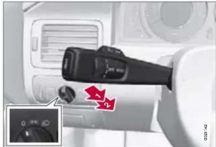
natural_image
Close-up of a camera control panel with adjustment knobs and a magnified inset showing a dial (no text or symbols visible)Headlamp control and stalk switch
Position Specification
| 0 | Automatic*/deactivated dipped beam. Only main beam flash. |
| EDGE | Position/parking lamps |
| ED | Automatic dipped beam.Main beam and main beam flash work in this position. |

NOTE
Main beam can only be activated in position ☐D.
Main beam flash
Move the stalk switch gently to position toward the steering wheel. Main beam comes on until the stalk switch is released.
Dipped beam
When the engine is started, dipped beam is activated automatically* if the headlamp control is in position. If necessary, automatic dipped beam for this position can be deactivated by an authorised Volvo workshop.
In position dipped beam is always activated automatically when the engine is running or with ignition position II.
Main beam
Main beam can only be activated when the headlamp control is in position Acti-vate/deactivate main beam by moving the stalk switch to the end position towards the steering wheel and release.
When main beam has been activated the symbol 10 dominates in the combined instrument panel.
Active Bi-Xenon Lights*

natural_image
Top-down view of a car emitting exhaust smoke through a curved road (no text or symbols visible)Headlamp pattern with function deactivated (left) and activated (right) respectively
If the car is equipped with active headlamps (Active Bi-Xenon Lights, ABL) the light from the headlamps follows the steering wheel movement in order to provide maximum lighting in bends and junctions and so provide increased safety.
The function is activated automatically when the car is started. The button in the centre console illuminates when the function is activated, it flashes in the event of a malfunction. The function is only active in twilight or darkness and only when the car is moving.
The function can be deactivated/activated with the button.
03 Your driving environment

Lighting
Position/parking lamps

Headlamp control in position for position/parking lamps
Turn the headlamp control to the centre position (number plate lighting comes on at the same time).
Rear position lamps also come on when the tailgate is opened in order to alert anybody behind.
Brake light
The brake light automatically comes on during braking.
Emergency brake light and automatic hazard warning flashers, EBL
Emergency Brake Lights, EBL are activated in the event of heavy braking or if the ABS brakes are activated. This function means that the brake light flashes to immediately alert cars travelling behind.
The system is activated if ABS is used for more than 0.5 seconds or in the event of heavy braking, however, only when braking from speeds above 50 km/h. When the speed of the car is lower than 30 km/h the brake lights shine normally again and the hazard warning flashers are switched on automatically. The hazard warning flashers remain on until the car accelerates again but can be deactivated with the button for hazard warning flashers
Front fog lamps*
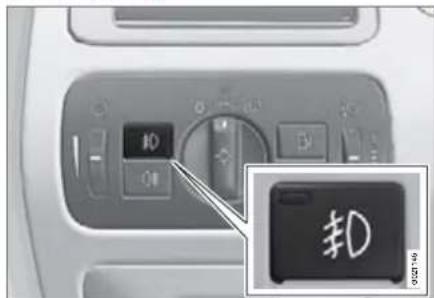
Button for front fog lamps
The front fog lamps can be switched on along with main/dipped beam or position/parking lamps.
Press the button for on/off. The light in the button illuminates when the fog lamps are on.

NOTE
Regulations for using front fog lamps vary between different countries.

03 Your driving environment
Lighting
Rear fog lamp

Button for rear fog lamp
The rear fog lamp consists of one rear lamp and can only be switched on in combination with main/dipped beam or the front fog lamps.
Press the button for on/off. The light in the button illuminates when the rear fog lamp is on.
The rear fog lamp indicator symbol 104 the combined instrument panel and the light in the button illuminate when the rear fog lamp is switched on.
The rear fog lamps are switched off automatically when the car is started.

NOTE
Regulations for using rear fog lamps vary between different countries.
Hazard warning flashers

Hazard warning flashers
Press the button to activate the hazard warning flashers. Both direction indicator symbols in the combined instrument panel flash when the hazard warning flashers are in use.
The hazard warning flashers are activated automatically when the car brakes so suddenly that the emergency brake lights (EBL) are activated and speed is below 30 km/h. They remain on when the car has stopped and are deactivated automatically when the car is driven off again or the button is depressed.
Direction indicators/flashers

Direction indicators/flashers
Continuous flash sequence
Move the stalk switch up or down to position?
The stalk switch remains in its position and is moved back manually, or automatically by the steering wheel movement.
Short flash sequence
Move the stalk switch up or down to position and release. The direction indicators flash three times.
Direction indicator symbols
See page 60.
03 Your driving environment

Lighting
Interior lighting
Front roof lighting
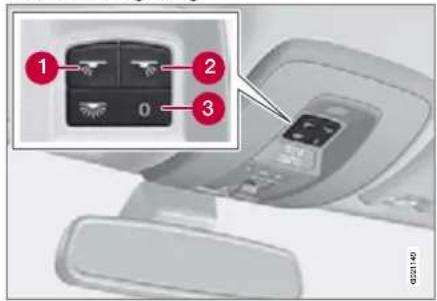
Controls for reading lamps and front roof lighting
① Reading lamp, left-hand side
② Reading lamp, right-hand side
③ Interior lighting
The front reading lamps are controlled with the and buttons in the roof console.
The switch for passenger compartment lighting has three positions for the lighting throughout the whole of the passenger compartment.
- Off – right-hand side depressed, automatic lighting deactivated.
- Neutral position – automatic lighting activated.
- On – left-hand side depressed, passenger compartment lighting on.
Automatic lighting
The passenger compartment lighting is switched on and off automatically when the button for passenger compartment lighting is in neutral position.
The lighting comes on and remains on for 30 seconds if:
- the car is unlocked from the outside with the key or remote control
- the engine is switched off and the ignition is in position 0
The lighting switches off when:
- the engine is started.
• the car is locked from outside
The lighting comes on and remains on for two minutes if one of the doors is open.
The passenger compartment lighting can be switched on and off manually within 30 minutes from when the car is unlocked.
If the lighting is switched on manually and the car is locked then it will be switched off automatically after one minute.
Rear roof lighting

natural_image
Exterior view of a modern office building (no signage)Rear roof lighting
The lamps are switched on or off by pressing each respective button.
Courtesy lighting
The courtesy lighting is switched on or off automatically when one of the front doors is opened or closed.
Glovebox lighting
The glovebox lighting is switched on or off automatically when its door is opened or closed.

03 Your driving environment
Lighting
Home safe lighting
Some of the exterior lighting can be kept switched on to work as home safe lighting after the car has been locked.
- Remove the remote control key from the ignition switch.
- Move the left-hand stalk switch towards the steering wheel to the end position and release it. The function can be activated in the same way as with main beam flash, see page 72.
- Get out of the car and lock the door. When the function is activated, dipped beam, the parking lamps, direction indicator lamps, door mirror lamps, number plate lighting, inner roof lamps and courtesy lighting are switched on.
The time for which the home safe lighting can be kept switched on can be set under Car settings → Light settings Home safe lighting. For a description of the menu system, see page 104.
Approach lighting
Approach lighting is switched on with the remote control key, see page 39, and is used to switch on the car's lighting at a distance.
When the function is activated with the remote control the parking lamps, direction indicator lamps, door mirror lamps, number plate lighting, inner roof lamps and courtesy lighting are switched on.
The time for which the approach lighting can be kept switched on can be set under Car settings → Light settings → approach lighting. For a description of the menu system, see page 104.
Adjusting headlamp pattern

natural_image
Top-down view of a car driving on a road with a dashed lane and a white vehicle silhouette (no text or symbols)Headlamp pattern, left-hand traffic
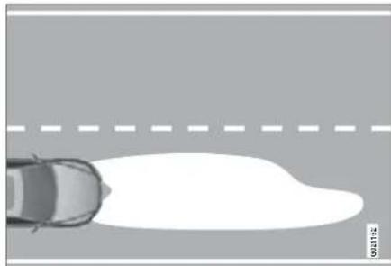
natural_image
Top-down view of a car driving on a road with a dashed lane and a white curved area (no text or symbols)Headlamp pattern, right-hand traffic
The headlamp pattern must be adjusted to avoid dazzling oncoming motorists and be set for either right or left-hand traffic. The
03 Your driving environment

Lighting
correct pattern will also better illuminate the verge.
Bi-Xenon and Active Bi-Xenon headlamps\*

Headlamp control for adjusting headlamp pattern
A Normal position – the headlamp pattern is correct for the country in which the car was delivered.
B Adapted position – designed for opposite headlamp pattern.

WARNING
The headlamps must be handled with extreme care due to the Xenon lamp being supplied from a high-voltage unit.
The country in which the car is delivered determines whether position is designed for right or left-hand traffic.
Example 1
If a car that is delivered in Sweden shall be driven in the UK then the headlamps should be set to the adjusted position, see the illustration.
Example 2
A car that is delivered in the UK is designed for left-hand traffic and is driven there with the headlamps in normal position, see the illustration.
Halogen headlamps
The headlamp pattern for halogen head-lamps is readjusted by masking the head-lamp lens. The headlamp pattern may not be as good.
Masking the headlamps
- Copy the A and B templates for left-hand drive cars or the C and D templates for right-hand drive cars with a scale of 1:2, for templates, see page 79. Use a photocopier with a zoom function for example:
• A = L H D R i g h t
• B = LHD Left
• C = R H D R i g h t
• D = R H D L e f t
- Transfer the template to a self-adhesive waterproof material and cut it out. Also mark out the red dots.
- Position the self-adhesive templates so that the red dots correspond with the dots on the headlamp lenses that form reference points, see page 78.

03 Your driving environment
Lighting
Masking the halogen headlamps
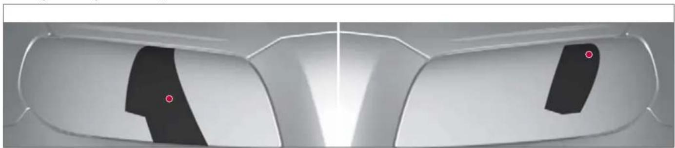
natural_image
Close-up of a car's front and rear windows with black and red markings (no visible text or symbols)Masking left-hand drive cars

natural_image
Close-up of a car's front and side panels with black and white highlights, no visible text or symbolsMasking right-hand drive cars
Lighting
Figures, halogen headlamps


03 Your driving environment
Wipers and washing
Windscreen wipers
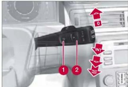
Windscreen wipers and windscreen washers
① Rain sensor, on/off
② Thumbwheel sensitivity/frequency
Windscreen wipers off
0 Move the stalk switch to position 0 to switch off the wind-screen wipers.
Single sweep

Raise the stalk switch and release to make one sweep.
Intermittent wiping
INT Set the number of sweeps per time unit with the thumbwheel when intermittent wiping is selected.
Continuous wiping

The wipers sweep at normal speed.

The wipers sweep at high speed.
IMPORTANT
Before activating the wipers during winter - ensure that the wiper blades are not frozen in and that any snow or ice on the windscreen (and rear window) is scraped away.
IMPORTANT
Use plenty of washer fluid when the wipers are cleaning the windscreen. The windscreen must be wet when the windscreen wipers are operating.
Rain sensor\*
The rain sensor automatically starts the windscreen wipers based on how much water it detects on the windscreen. The sensitivity of the rain sensor can be adjusted using the thumbwheel.
When the rain sensor is activated a light in the button the rain sensor symbol shown in the right-hand display in the combined instrument panel.
Activating and setting the sensitivity When activating the rain sensor, the car must be running or in ignition position I or II while the windscreen wiper stalk switch must be in position 0.
Activate the rain sensor by pressing the button. The windscreen wipers make one sweep.
Press the stalk switch up for the wipers to make an extra sweep.
Turn the thumbwheel upward for higher sensitivity and downward for lower sensitivity. (An extra sweep is made when the thumbwheel is turned upward.)
Deactivating
Deactivate the rain sensor by pressing the button or move the stalk switch down to another wiper program.
The rain sensor is automatically deactivated when the key is removed from the ignition switch or five minutes after the ignition is switched off.
IMPORTANT
The windscreen wipers could start and be damaged in an automatic car wash. Deactivate the rain sensor while the car is running or in ignition position I or II. The symbol in the combined instrument panel and the lamp in the button go out.
03 Your driving environment

Wipers and washing
Washing the headlamps and windows

natural_image
Close-up of a camera lens interacting with a control panel, showing no visible text or symbols.Washing function
Washing the windscreen
Move the stalk switch toward the steering wheel to start the windscreen and headlamp washers.
The windscreen wipers will make several more sweeps once the stalk switch has been released. The headlamps are washed alternately to prevent light intensity being reduced.

NOTE
One headlamp is washed at a time.
Heated washer nozzles*
The washer nozzles are heated automatically in cold weather to prevent the washer fluid freezing solid.
High-pressure headlamp washing\*
High-pressure headlamp washing consumes a large quantity of washer fluid. To save fluid, the headlamps are washed automatically at every fifth wash cycle.
Wiper and washer, rear window
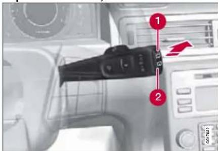
Press the stalk switch forward (see arrow above) to initiate rear window washing and wiping. The control at the end of the stalk has:
1 Rear window wiper – intermittent wiping
② Rear window wiper – continuous speed
Wiper - reversing
Engaging reverse gear while the windscreen wipers are on initiates intermittent rear window wiping 1 . The function stops when reverse gear is disengaged.
If the rear window wiper is already on at continuous speed, no change is made.

NOTE
On cars with rain sensor, the rear window wiper is activated with reversing, if the sensor is activated and it is raining.
1 This function (intermittent wiping for reverse) can be deactivated. Contact an authorised Volvo workshop.

03 Your driving environment
Windows, rearview and door mirrors
General
Laminated glass

The glass is reinforced which provides better protection against break-ins and improved sound insulation in the passenger com-
partment. All windows* have laminated glass.
Water and dirt-repellent coating\*

Windows are treated with a coating that improves the view in difficult
weather conditions. Maintenance, see page 217.

IMPORTANT
Do not use a metal ice scraper to remove ice from the windows. Use the defroster to remove ice from the mirrors. An ice scraper could scratch the mirror glass!
Power windows
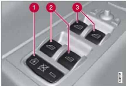
Driver's door control panel
1 Switch for electric child safety locks* and disengaging rear power window buttons, see page 31.
② Rear window controls
3 Front window controls

WARNING
Check that none of the rear seat passengers is in danger of becoming trapped in any way caught when closing the windows from the driver's door.

WARNING
Make sure that children or other passengers are not in danger of becoming trapped in any way when closing the windows, in particular when the remote control key is used.

WARNING
If there are children in the car, remember to always switch off the supply to the power windows by removing the remote control key if the driver leaves the car.
03 Your driving environment

Windows, rearview and door mirrors
Operating
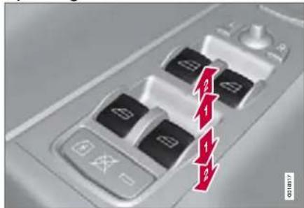
Operating the power windows
Operating without auto
2 Operating with auto
All power windows can be operated using the control panel in the driver's door. Each control panel in the other doors can only control its own respective power window. The power windows can only be controlled with one control panel at a time.
In order that the power windows can be used the car must be in ignition position I or II. After the car has been running the power windows can be operated for several minutes even when the remote control key has been removed, but not however after the door has been opened.
Closing of the windows is stopped and the window is opened if anything prevents its movement. It is possible to force the pinch protection when closing has been interrupted, e.g. with ice, by continuously holding the button up until the window is closed. The pinch protection is reactivated after a brief pause.
Operating without auto
Move one of the controls up/down gently. The power windows move up/down as long as the control is held in position.
Operating with auto
Move one of the controls up/down to the end position and release it. The window runs automatically to its end position.
Remote control and central locking buttons
All side windows can be opened/closed automatically with the remote control or the central locking buttons:
Press and hold the lock button until the windows start to open/close. To interrupt opening/closing, press the lock button again.
Resetting
If the battery is disconnected then the function for automatic opening must be reset so that it can work correctly.
- Gently raise the front section of the button to raise the window to its end position and hold it there for one second.
- Release the button briefly.
- Raise the front section of the button again for one second.

WARNING
Resetting must be carried out to ensure that pinch protection works.

03 Your driving environment
Windows, rearview and door mirrors
Door mirrors

natural_image
Close-up of a keyboard with directional arrows and control buttons (no readable text or symbols)Door mirror controls
Adjusting
- Press the L button for the left-hand door mirror or the R button for the right-hand door mirror. The light in the button illuminates.
- Adjust the position with the joystick in the centre.
- Press the L or R button again. The light should no longer be illuminated.

WARNING
The mirrors are the wide angle type for optimum surveillance. Objects may appear further away than they actually are.
Retractable power door mirrors\*
The mirrors can be retracted for parking/driving in narrow spaces:
- Press down the L and R buttons at the same time.
- Release them after approximately one second. The mirrors automatically stop in the fully retracted position.
Fold out the mirrors by pressing down the L and R buttons at the same time. The mirrors automatically stop in the fully extended position.
Storing the position\*
The mirror positions are stored in the key memory when the car has been locked with the remote control key. When the car is unlocked with the same remote control the mirrors and the driver's seat adopt the stored positions when the driver's door is opened.
The function can be activated/deactivated under Car key memory -eat & mirror positions. For a description of the menu system, see page 104.
Angling the door mirror when parking* The door mirror can be angled down for the driver to view the side of the road when parking for example. Engage reverse gear and
press the L or R button. The door mirror resets when reverse gear is disengaged.
Automatic retraction when locking* When the car is locked/unlocked with the remote control key the door mirrors are automatically retracted/extended.
The function can be activated/deactivated under Car settings Retract mirrors when locking. For a description of the menu system, see page 104.
Resetting to neutral*
Mirrors that have been moved out of position by an external force must be electrically reset to the neutral position for electric retracting/ extending to work.
- Retract the mirrors with the L and R buttons.
- Fold them out again with the L and R buttons.
The mirrors are now reset in neutral position.
Home safe and approach lighting
The light on the door mirrors illuminates when approach lighting or home safe lighting is selected, see page 76.
03 Your driving environment

Windows, rearview and door mirrors
Rear window and door mirror defrosters
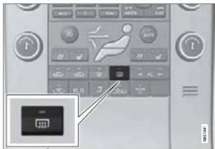
Use the defroster to quickly remove misting and ice from the rear window and the door mirrors.
Press the button once to start simultaneous rear window and door mirror defrosting. The light in the button indicates that the function is active. Defrosting is deactivated automatically and its duration is controlled by the outside temperature.
The rear window is demisted/defrosted automatically if the car is started in an outside temperature lower than +7 °C.
Defrosting can be selected under Climate settings Auto, rear defroster. Select between On or Off.
Interior rearview mirror
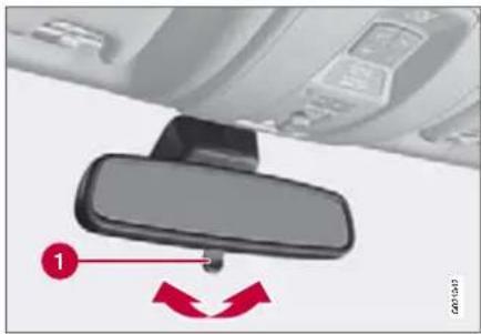
natural_image
Interior view of a car showing a rearview mirror and dashboard (no text or symbols visible)Manual dimming
1 Control for dimming.
Bright light from behind could be reflected in the rearview mirror and dazzle the driver. Use dimming by means of the dimming control when lights from behind are distracting:
- Use dimming by moving the control in towards the passenger compartment.
- Return to normal position by moving the control towards the windscreen.
Automatic dimming\*
Bright light from behind is automatically dimmed by the rearview mirror. The control is
not available in mirrors with automatic dimming.

03 Your driving environment
Power sunroof\*
General
The sunroof controls are located in the roof panel. The sunroof can be opened vertically and horizontally. Ignition position I or II is required for the sunroof to be opened.
Horizontal opening

natural_image
Close-up of a car's rear bumper with red arrows indicating movement, inset shows close-up of a vehicle component (no text or symbols)Horizontal opening, backward/forward
Opening, automatic
2 Opening, manual
3 Closing, manual
Closing, automatic
Opening
For maximum sunroof opening, move the control back to position and release.
Open manually by pulling the control backwards to the point of resistance. The sun-
roof moves to maximum open position as long as the button is kept depressed.
Closing
Close manually by pressing the control forward to the point of resistance. The sun-roof moves to closed position as long as the button is kept depressed.

WARNING
Risk of crushing when sunroof is closed. The sunroof's pinch protection only works during automatic closing, not manual.
Close automatically by pressing the control to position and then release it.
The power supply to the sunroof is switched off by removing the remote control key from the ignition switch.

WARNING
If there are children in the car: Remember to always switch off the power supply to the sunroof by removing the remote control key if the driver leaves the car.
Vertical opening
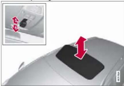
natural_image
Top-down view of a car's rear bumper with red arrows indicating upward motion (no text or symbols)Vertical opening, raised at the rear edge
5 Opening: open by pressing the rear edge of the control upward.
6 Closing: close by pressing the rear edge of the control downward.
03 Your driving environment

Power sunroof\*
Closing using the remote control key or central locking button
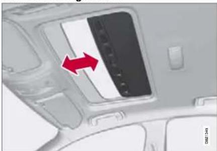
natural_image
Interior view of a car showing a vehicle with a red arrow pointing to the side panel (no text or symbols visible)One long press on the lock button closes the sunroof and all the windows. The doors and the tailgate are locked. To interrupt closing, press the lock button again.

WARNING
If the sunroof is closed using the remote control key, check that no one is in danger of becoming trapped in any way.
Sunscreen
The sunroof features a manual, sliding interior sunscreen. The sunscreen slides back automatically when the sunroof is opened. Grip the handle and slide the screen forward to close it.
Pinch protection
The sunroof's pinch protection function is triggered if it is blocked by an object during automatic closing. If blocked, the sunroof will stop and automatically open to the previous position.

03 Your driving environment
Starting the engine
Petrol and diesel engines

Ignition switch with remote control key, start and stop button (see more information on page 65).
- For cars with remote control key, insert the remote control key into the ignition switch. Gently push it forward until it is pulled in.

IMPORTANT
Do not insert the remote control key backwards! Grip the end with the detachable key blade. See page 42.
- Hold the clutch pedal fully depressed 1 . Depress the brake pedal in cars with automatic gearbox.
1 If the car is moving then it is enough to press the START/STOP button to start the car.
- Press the START/STOP button and release the button.
The starter motor works until the engine has started, but for no longer than 10 seconds (diesel up to 60 seconds). If the engine has not started after 10 seconds, try again by holding in the START/STOP button until the engine starts.

WARNING
Always remove the remote control key from the ignition switch when leaving the car, especially if there are children in the car.

WARNING
Never remove the remote control key from the ignition switch while driving or when the car is being towed. The steering lock could be activated which would mean that the car cannot be steered.
Never remove the remote control key with the keyless drive* function from the car while driving or during towing.

NOTE
The idling speed can be noticeably higher than normal for certain engine types during cold starting. This is so that the emissions system can reach normal operating temperature as quickly as possible, which minimises exhaust emissions and protects the environment 1 .
1 If D or R position is engaged with automatic transmission, without the car being driven, then the engine speed is of course reduced, but at the same time it takes longer to reach operating temperature, so the environmental aspect is offset.
Keyless drive\*
Follow steps 2–3 for starting petrol and diesel engines.

NOTE
One precondition for starting the car is that the car's remote control keys with the key-less drive* function are located inside the passenger compartment or the cargo area.
Steering lock
The steering lock is deactivated when the remote control key is inserted into the ignition switch 2 and activated when the remote control key is removed from the ignition switch.
03 Your driving environment

Starting the engine
Activate the steering lock when leaving the car to reduce the risk of car theft.
Diesel particle filter (DPF)
Diesel cars are equipped with a particle filter, which results in more efficient emission control. The particles in the exhaust gases are collected in the filter during normal driving. So-called "regeneration" is started in order to burn away the particles and empty the filter. This requires the engine to have reached normal operating temperature.
Regeneration of the filter takes place automatically at an interval of approximately 300–900 km depending on driving conditions. Regeneration normally takes between 10 and 20 minutes. During this time fuel consumption may increase slightly.
Regeneration in cold weather
If the car is frequently driven short distances in cold weather then the engine does not reach normal operating temperature. This means that regeneration of the diesel particle filter does not take place and the filter is not emptied.
When the filter has become approximately 80% full of particles, a yellow warning triangle illuminates on the dashboard, and a message is shown, Soot filter full. See manual is shown on the dashboard display.
Start regeneration of the filter by driving the car until the engine reaches normal operating temperature, preferably on a main road or motorway. The car should then be driven for approximately 20 minutes more.
When regeneration is complete the warning text is cleared automatically.
Use the parking heater* in cold weather so that the engine reaches normal operating temperature more quickly.

IMPORTANT
If the filter fills up with particles then it can be difficult to start the engine and the filter will be incapable of functioning. Then there is a risk that the filter will have to be replaced.
2 On cars with Keyless drive * the steering lock is deactivated when the start button is pressed in for the first time. The steering lock is activated when the engine is switched off and the driver's door is opened.

03 Your driving environment
Starting the engine
Jump starting
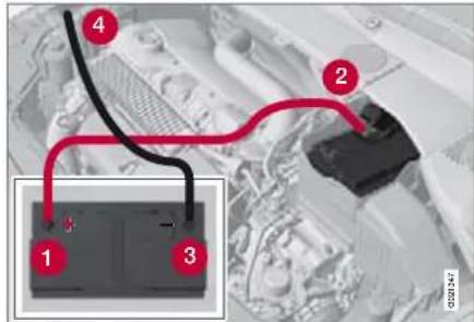
If the battery is flat then the car can be started with current from another battery.
The following points are recommended when using a donor battery in order to avoid the risk of an explosion:
- Turn the car's ignition to position 0, see page 65.
- Ensure that the donor battery is 12 volt.
- If the donor battery is in another car, switch off the donor car's engine in the other car and ensure that the cars do not touch one another.
-
Connect the red jump lead to the positive terminal on the donor battery 1
-
Open the clips on the front cover of the battery in your car and remove the cover, see page 198.
- Connect the starter cable to the positive terminal on the battery in your car, located under a folding plastic cover.
- Connect one clamp from the black jump lead to the donor battery's negative terminal 3
- Connect the other clamp to an earthing point, (right-hand engine mounting at the top, the outer screw head). Check that the jump lead clamps are fixed securely so that there are no sparks during the starting procedure.

IMPORTANT
Connect the start cable carefully to avoid short circuits with other components in the engine compartment.
- Start the engine of the "donor car". Let the engine run a few minutes at a speed slightly higher than idle (1500 rpm).
- Start the engine of the car with the flat battery. Do not touch the crocodile clips during the start procedure. There is a risk of sparks forming.
- Remove the jump leads, first the black and then the red. Make sure that none of the clamps on the black jump lead
comes into contact with the battery's positive terminal or the clamp connected to the red jump lead.

WARNING
The battery can generate oxyhydrogen gas, which is highly explosive. One spark, which can be generated if you connect a jump lead incorrectly, is sufficient to make the battery explode. The battery contains sulphuric acid, which can cause serious burns. If the acid comes into contact with eyes, skin or clothing, flush with large quantities of water. If acid splashes into the eyes, seek medical attention immediately.
03 Your driving environment

Gearboxes
Manual gearbox

natural_image
Close-up of a car gear shift lever with no visible text or symbols on the component itselfDepress the clutch pedal fully during each gear change. Take your foot off the clutch pedal between gear changes. Follow the shifting pattern indicated.
For the best possible fuel economy, use the highest gear possible as often as possible.
Reverse gear inhibitor
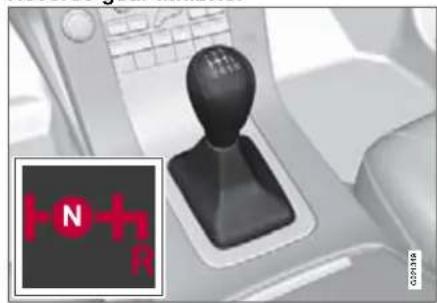
natural_image
Interior view of a car gear shift lever with a red indicator light icon (no text or symbols on the lever itself)Only engage reverse gear when the car is stationary.

03 Your driving environment
Gearboxes
Automatic gearbox, Geartronic*

natural_image
Close-up of a car gear shift lever mechanism (no text or symbols visible)The information display shows the position of the gear selector using the following indications: P, R, N, D, S, 1, 2, 3, 4, 5 or 6. See page 60.
Gear positions
Parking position (P)
Select P when starting the engine or when the car is parked. The brake pedal must be depressed to disengage the gear selector from the P position.
The gearbox is mechanically blocked when the P position is engaged. Activate the elec-
tric parking brake by pressing the button, see page 98.
IMPORTANT
The car must be stationary when position P is selected.
Reverse (R)
The car must be stationary when position R is selected.
Neutral position (N)
No gear is engaged and the engine can be started. Apply the parking brake if the car is stationary with the gear selector in position N.
Drive (D)
D is the normal driving position. Shifting up and down takes place automatically based on the level of acceleration and speed. The car must be stationary when the gear selector is moved to position D from position R.
Geartronic\* - Sport mode (S) 1
The Sport programme provides sportier characteristics and allows higher engine speed for the gears. At the same time it responds more quickly to acceleration. During active driving, the use of a lower gear is prioritised, leading to a delayed upshift.
Sport mode is obtained by moving the lever from D position to the right-hand end position at M. The information display shifts the indication from D to S.
Sport mode can be selected at any time while driving.
03 Your driving environment

Gearboxes
Geartronic\* - manual gear positions (M)
The driver can also change gear manually using the Geartronic automatic gearbox. The car engine-brakes when the accelerator pedal is released.
Manual gearshift mode is obtained by moving the lever from position D to the right-hand end position at M. The information display shifts the indication from D to one of the figures 1-6, depending which gear is engaged just then, see page 60.
Move the lever forwards towards + (plus) to change up a gear and release the lever, which returns to its rest position at M.
Pull the lever back towards - (minus) to change down a gear and release the lever.
The manual gearshift mode M can be selected at any time while driving.
To return to automatic driving mode; move the lever to the left-hand end position at D.
Geartronic automatically shifts down if the driver allows the speed to decrease lower than a level suitable for the selected gear, in order to avoid jerking and stalling.

NOTE
If the gearbox has a Sport programme then the gearbox will only become manual after the lever has been moved forwards or backwards in its M position. The information display then shifts the indication from S to show which of the gears 1–6 is engaged.
Kick-down
When the accelerator pedal is pressed all the way to the floor (beyond the position normally regarded as full acceleration) a lower gear is immediately engaged. This is known as kickdown.
If the accelerator is released from the kick-down position, the gearbox automatically changes up.
Kick-down is used when maximum acceleration is needed, such as for overtaking.
Safety function
To prevent overrevving the engine, the gearbox control program has a protective downshift inhibitor which prevents the kick-down function.
Geartronic does not permit downshifting/ kick-down which would result in an engine speed high enough to damage the engine. Nothing happens if the driver still tries to shift down in this way at high engine speed – the original gear remains engaged.
When kick-down is activated the car can change one or more gears at a time depending on engine speed. The car changes up when the engine reaches its maximum speed in order to prevent damage to the engine.
Mechanical gear selector inhibitor
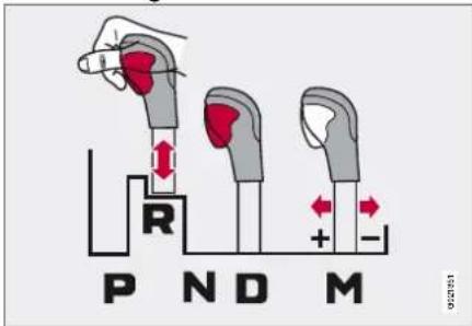
The gear selector can be moved forward and back freely between N and D. Other positions are locked with a latch that is released with the inhibitor button on the gear selector.
With the inhibitor button depressed the lever can be moved forwards or backwards between P, R, N and D.

03 Your driving environment
Gearboxes
Automatic gear selector inhibitor
The automatic gearbox has special safety systems:
Keylock
To remove the remote control key from the ignition switch, the gear selector must be in the P position. The remote control key is locked in all other positions.
Parking position (P)
Stationary car with engine running:
Keep your foot on the brake pedal when moving the gear selector to another position.
Electric gear inhibitor - Shiftlock Parking position (P)
To be able to move the gear selector from P to other gear positions, the brake pedal must be depressed and the ignition must be in position II, see page 88.
Shiftlock - Neutral (N)
If the gear selector is in the N position and the car has been stationary for at least 3 seconds (irrespective of whether the engine is running) then the gear selector is locked.
To be able to move the gear selector from N to another gear position, the brake pedal must be depressed and the ignition must be in position II, see page 88.
Deactivating the automatic gear selector inhibitor

natural_image
Interior view of a car dashboard with a hand tool inserted, showing a close-up of the handle (no text or symbols visible)If the car cannot be driven, e.g. due to a flat battery, the gear selector must be moved from the P position so that the car can be moved.
Lift away the rubber mat on the floor behind the centre console and open the hatch.
Fully insert the key blade. Press the key blade down and keep it held down. Move the gear selector from the P position. For information on the key blade, see page 38.
03 Your driving environment

All Wheel Drive - AWD (All Wheel Drive)*
All Wheel Drive is always engaged
All Wheel Drive means that the car is driving on all four wheels at the same time.
The power is automatically distributed between the front and rear wheels. An electronically controlled clutch system distributes the power to the wheels that have the best grip on the current road surface. This provides the best traction and prevents wheel spin. Under normal driving conditions, the majority of power is transmitted to the front wheels.
All Wheel Drive improves driving safety in rain, snow and icy conditions.

03 Your driving environment
Foot brake
General
The car is equipped with two brake circuits. If one brake circuit is damaged then this will mean that the brakes engage at a deeper level and harder pressure on the pedal is needed to produce the normal braking effect.
The driver's brake pedal pressure is reinforced by a brake servo.

WARNING
The brake servo only works when the engine is running.
If the brake is used when the engine is switched off then the pedal will feel stiff and more force must be used to brake the car.
In very hilly terrain or when driving with a heavy load the brakes can be relieved by using engine braking. Engine braking is most efficiently used if the same gear is used downhill as up.
For more general information on heavy loads on the car, see page 227.
Anti-lock braking system
The car is equipped with ABS (Anti-lock Braking System) that prevents the wheels from locking during braking. This means the ability to steer is maintained and it is easier to swerve to avoid a hazard for example. Vibra-
tion may be felt in the brake pedal when this is engaged and this is normal.
After the engine has been started and the car has reached 20 km/h there is a short automatic test of the ABS system. The test may be felt as pulses in the brake pedal.
Cleaning the brake discs
Coatings of dirt and water on the brake discs may result in delayed brake function. This delay is minimised by cleaning the brake linings.
Manual cleaning is advisable with wet road surfaces, prior to long-stay parking and after the car has been washed. Carry this out by braking gently during a short period while en route.
Emergency Brake Assistance
Emergency Brake Assistance (EBA) helps to increase brake force and so reduce braking distance. The EBA system detects the driver's braking style and increases brake force as necessary. The brake force can be reinforced up to the level when the ABS system is engaged. The EBA function is interrupted when the pressure on the brake pedal is reduced.

NOTE
When EBA is activated the brake pedal lowers slightly more than usual, depress (hold) the brake pedal as long as necessary. If the brake pedal is released then all braking ceases.
Symbols in the combined instrument panel
Symbol Specification

Constant glow – Check the brake fluid level. If the level is low, fill with brake fluid and check for the cause of the brake fluid loss.
Constant glow for two seconds when the engine is started – There was a fault in the brake system's ABS function when the engine was last running.

WARNING
If and illu ate at the same time then a fault may have arisen in the brake system.
If the level in the brake fluid reservoir is normal at this stage, drive carefully to the nearest authorised Volvo workshop and have the brake system checked.
If the brake fluid is under the MIN level in the brake fluid reservoir, do not drive further before topping up the brake fluid.
The reason for the loss of brake fluid must be investigated.
03 Your driving environment

Hill Descent Control (HDC)
General 1
HDC can be compared to an automatic engine brake. When you release the accelerator on downhill gradients the car is normally braked by means of the engine striving for low engine idling speeds, so-called engine braking. But the steeper the road and the more load there is in the car, the faster the car rolls despite engine braking. In order to then reduce speed the driver has to assist using the footbrake.
The function makes it possible to increase/reduce speed on steep downhill gradients, with a foot only on the accelerator pedal, without using the footbrake. The brake system brakes itself and automatically provides a low and even speed, so allowing the driver to fully focus on steering.
HDC is particularly helpful on steep gradients with an uneven road surface and slippery sections. E.g. when launching a boat on a trailer from a ramp.

WARNING
HDC does not work in all situations, but is instead only intended to be supplementary assistance.
The driver always has ultimate responsibility that the car is driven safely.
Function

natural_image
Close-up of a car on a landline telephone with a speedometer icon (no text or symbols visible)HDC is engaged or disengaged using a switch on the centre console. A lamp in the button illuminates when the function is engaged. When HDC is operating the symbol illuminates and the display shows Hill Descent Control ON.
The function only operates in first gear position and in reverse gear. For an automatic gearbox, gear position 1 must be selected, which is shown with the figure 1 in the trip computer display, see page 93.

NOTE
HDC cannot be activated in an automatic gearbox with the gear selector in position D.
Operation
HDC allows the car to roll at a maximum of 10 km/h forwards with engine braking and 7 km/h backwards. However, any speed within the gear's speed register can be selected using the accelerator pedal. When the accelerator pedal is released, the car is braked quickly to 10 or 7 km/h respectively, irrespective of the hill's gradient and without the need for the footbrake.
The brake lights come on automatically when the function is operating. The driver can brake or stop the car at any time by using the foot-brake.
HDC is deactivated:
- with the on/off button on the centre console
- if a gear higher than 1 is selected on a manual gearbox
- if a gear higher than 1 is selected on an automatic gearbox, or if the gear selector is moved to position D.
The function can be disengaged at any time. If it takes place on a steep downhill gradient then the braking effect will not release directly, but slowly instead.

NOTE
When HDC is activated, engine response during acceleration seems slower than normal.

03 Your driving environment
Parking brake
Parking brake, electric\*
An electric parking brake has the same applications as a manual parking brake, e.g. when starting uphill.
Function
A faint electric motor noise can be heard when the parking brake is being applied. The noise can also be heard during the automatic function checking of the parking brake.
If the car is stationary when the parking brake is applied then it only acts on the rear wheels. If it is applied when the car is moving then the normal foot brake is used, i.e. the brake acts on all four wheels. Brake function changes over to the rear wheels when the car is almost stationary.
Low battery voltage
If the battery voltage is too low then the parking brake can neither be released nor applied. Connect a donor battery if the battery voltage is too low, see page 90.
How to apply the parking brake

Parking brake control
- Press the foot brake pedal down firmly.
- Press the control.
- Release the foot brake pedal and make sure that the car is at a standstill position.
- When parking the vehicle always put the gear selector in position 1 (for manual transmission) or P (for automatic transmission).
The symbol 📄 the combined instrument panel flashes until the parking brake is fully applied. When the symbol illuminates the parking brake is applied.
In an emergency the parking brake can be applied when the vehicle is moving by holding in the control. When the control is
released or the accelerator pedal is depressed the braking is interrupted.

NOTE
In the event of emergency braking at speeds above 10 km/h a signal sounds during the braking procedure.
Parking on a hill
If the car is parked facing uphill; turn the wheels away from the kerb.
If the car is parked facing downhill, turn the wheels towards the kerb.
How to release the parking brake
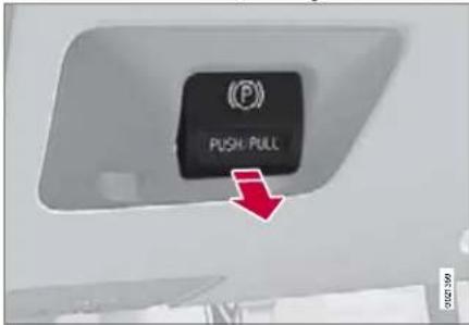
Parking brake control
03 Your driving environment

Parking brake
Cars with manual gearbox
Releasing manually
- Insert the remote control key in the ignition switch.
- Depress the brake pedal firmly.
- Pull the control.

NOTE
The parking brake can also be released manually by depressing the clutch pedal instead of the brake pedal. Volvo recommends the use of the brake pedal.
Releasing automatically
- Start the engine.
- Ease up the clutch and depress the accelerator.

IMPORTANT
It is possible to release the parking brake automatically, even when the gear lever is in neutral position, if the engine is running.
Cars with automatic gearbox
Releasing manually
- Put the seatbelt on.
- Insert the remote control key in the ignition switch.
- Depress the brake pedal firmly.
- Pull the control.
Releasing automatically
- Put the seatbelt on.
- Start the engine.
- Move the gear selector to position D or R and depress the accelerator.

NOTE
For safety reasons, the parking brake is only released automatically if the engine is running and the driver is wearing a seatbelt. The parking brake is released immediately on cars with automatic gearbox when the accelerator pedal is depressed and the gear selector is in position D or R.
Heavy load uphill
A heavy load, such as a trailer, can cause the car to roll backward when the parking brake is released automatically on a steep incline. Avoid this by holding in the control while driving off. Release the control when the engine achieves traction.
Cars with Keyless drive\* function
Release manually by pressing the START/STOP button, then depress the brake or clutch pedal and pull the control.
Symbols
Symbol Specification

Read the message on the information display

A flashing symbol indicates that the parking brake is applied.
If the symbol flashes in any other situation then this means that a fault has arisen. Read the message on the information display.
Messages


03 Your driving environment
Parking brake
Parking brake not fully released – A fault is preventing the parking brake from being released. Contact an authorised Volvo workshop. A warning signal sounds if you pull away with this error message.
Parking brake not applied – A fault is preventing the parking brake from being applied. Try to apply and release. Contact a Volvo workshop if the message remains.
The message is also illuminated on cars with manual gearbox when the car is driven at low speed with the door open in order to alert the driver that the parking brake may have been unintentionally disengaged.
Parking brake Service required – A fault has arisen. Contact a Volvo workshop if the fault remains.
If the car has to be parked before the fault has been rectified then the wheels must be turned as if parking on a hill and the gear selector must be in position 1 (manual gearbox) or P (automatic gearbox).
Replacing the brake linings
The rear brake linings must be replaced by an authorised Volvo workshop due to the design of the electric parking brake.
03 Your driving environment

Menus and messages 104
Climate control ....109
Audio system 120
Trip computer 130
Compass * 132
DSTC –Stability and traction control system 133
Adapting driving characteristics 134
Cruise control* 135
Adaptive cruise control* 136
Collision warning system with brake support* 140
Parking assistance * 143
BLIS* –Blind Spot Information System 146
Comfort inside the passenger compartment 149
Built-in phone* 153
COMFORT AND DRIVING PLEASURE

natural_image
Black and white photo of a car on a mountain road with two cars ahead, showing wheel rim and tire (no visible text or symbols)04


04 Comfort and driving pleasure
Menus and messages
Centre console
Some functions are controlled from the centre console via the menu system or via the keypad in the steering wheel. Each function is described under its respective section.
The current menu level is shown at the top right of the centre console's display.
Centre console controls

Centre console with information display and controls for menus.
① Navigation button – scrolls and selects among menu options
② ENTER – selects menu options
③ MENU – leads to the menu system
4 EXIT – leads back one step in the menu structure. A long press leads out from the menu system.
Steering wheel keypad

① ENTER*
② EXIT*
③ Navigation buttons – up/down.
If the steering wheel keypad has ENTER and EXIT then the buttons to have the same function as in the centre console.
Search paths
Access to some functions is provided directly via the function buttons and some are reached via the menu system.
Search paths to the menu system functions are stated in the form: Car settings dock
settings, which is on the assumption that the following is carried out beforehand:
- Press MENU.
- Scroll to Menu and press ENTER.
- Scroll to Submenu and press ENTER.
The navigation button can be used instead of ENTER and EXIT when navigating the menu hierarchy. The right-hand arrow is equal to ENTER and the left-hand arrow to EXIT.
The menu options are numbered and can also be selected directly with the numerical keypad (only 1 - 9).
04 Comfort and driving pleasure

Menus and messages
Menu overview
The phone and audio sources have different main menus. The following menus are included in all main menus:
Car key memory
Seat & mirror positions*
Car settings
Fold mirr. when locking*
Collision warn. settings*
Information
Light settings
Lock settings
Reduced Guard 1
Parking camera settings*
Steering force level*
Climate control settings
Automatic blower adjust
Auto. rear defroster
Recirculation timer
Reset climate settings
Main menu AM
Audio settings 2
Sound stage
Equalizer, front
Equalizer, rear
Auto. volume control
Reset the audio settings
Main menu FM
FM settings
News
TP (Traffic information)
Radio text
PTY (Programme type)
Advanced radio settings
Audio settings
Main menu CD
Random
Off
Folder 3
Disc 2
Single disc 4
All discs 3
CD settings
Disc text*
News
TP (Traffic information)
Audio settings
Main menu AUX
Volume, AUX input
Audio settings
1 Certain models.
2 The menu option for audio settings is available in all audio sources.
3 Only in systems that allow the playback of MP3 and WMA format audio files.
4 Only in systems with CD changer.

04 Comfort and driving pleasure
Menus and messages
| Main menu, built-in phone | Voice mail number |
| Call register | Diversions |
| Last 10 missed calls | Phone settings |
| Last 10 received calls | Network selection |
| Last 10 dialled calls | SIM security |
| Erase list | Edit PIN code |
| Call duration | Sounds and volume |
| Phone book | IDIS |
| New contact | Reset Phone settings |
| Search | |
| Copy all | |
| Erase SIM | |
| Erase phone | |
| Memory status | |
| Messages | |
| Read | |
| Write new | |
| Message settings | |
| Call options | |
| Send my number | |
| Call waiting | |
| Automatic answer |
04 Comfort and driving pleasure

Menus and messages
Combined instrument panel

Information display and controls for menus
1 READ – access to message list and message confirmation.
② Thumbwheel – browse between menu options.
3 RESET – reset the active function. Used in certain cases to select/activate a function, see the explanation under each respective function.
The menus shown on the information displays in the combined instrument panel are controlled with the left-hand stalk switch.
The menus shown depend on ignition position. If a message appears then this must be acknowledged with READ for the menus to be shown.
Menu overview 1
To empty tank
average
Instantaneous
Average speed
Lane departure warning
Tyre pressure Calibration
Current speed
Park heat timer AM/PM
Park vent timer AM/PM
Park timer mode
Direct start Park heat
Direct start Park el.heat
Direct start Park vent
Additional heat auto
Rest heat start
DSTC
Message

Text message in the information display
When a warning, information or indicator symbol illuminates, a corresponding message appears on the information display. An error message is stored in a memory list until the fault is rectified.
Press READ to acknowledge and browse between the messages.

NOTE
If a warning message appears while you are using the trip computer, the message must be read (press READ) before the previous activity can be resumed.

04 Comfort and driving pleasure
Menus and messages
| Message Specification | |
| Stop safely | Stop and switch off the engine. Serious risk of damage. Contact an authorised Volvo workshop. |
| Stop engine | Stop and switch off the engine. Serious risk of damage. Contact an authorised Volvo workshop. |
| Service urgent | Have the car checked by an authorised Volvo workshop immediately. |
| Service required | Have the car checked by an authorised Volvo workshop as soon as possible. |
| See manual | Read the owner's manual. |
| Book time for maintenance | Time to book regular service at an authorised Volvo workshop. |
Message Specification
| Time for regular maintenance | Time for regular service at an authorised Volvo workshop. The timing is determined by the number of kilometres driven, number of months since the last service, engine running time and oil grade. |
| Maintenance overdue | If the service intervals are not followed then the warranty does not cover any damaged parts.Contact an authorised Volvo workshop for service. |
| Temporarily OFF | A function has been temporarily switched off and is reset automatically while driving or after starting again. |
| Power save mode | The audio system is switched off to save energy. Charge the battery. |
04 Comfort and driving pleasure

Climate control
General
Air conditioning
The car is equipped with Electronic Climate Control (ECC) or Electronic Temperature Control (ETC). The climate control system cools or heats as well as dehumidifies the air in the passenger compartment.

NOTE
The air conditioning can be switched off, but to ensure the best possible climate comfort in the passenger compartment and to prevent the windows from misting, it should always be on.
Actual temperature
The temperature you select corresponds to the physical experience with reference to factors such as air speed, humidity and solar radiation 1 etc. in and around the car.
The system includes a sun sensor 1 which detects the side from which the sun is shining. This means that the temperature can differ between the right and left-hand air vents despite the controls being set for the same temperature on both sides.
1 Only applies to ECC
Sensor location
- The sun sensor is located on the top side of the dashboard. 1
- The temperature sensor for the passenger compartment is located below the climate control panel.
- The outside temperature sensor is located on the door mirror.
- The humidity sensor* is located in the interior rearview mirror. 1

NOTE
Do not cover or block the sensors with clothing or other objects.
Side windows and sunroof
To ensure that the air conditioning works optimally, the side windows, and sunroof if appropriate, should be closed.
Misting windows
Remove misting on the insides of the windows by primarily using the defroster function.
To reduce the risk of misting, clean the windows with a normal window cleaning agent.
Temporary shut-off of the air conditioning
When the engine requires full power, e.g. for full acceleration or driving uphill with a trailer,
the air conditioning could be temporarily switched off. There may then be a temporary increase in temperature.
Condensation
In warm weather, condensation from the air conditioning may drip under the car. This is normal.
Ice and snow
Remove ice and snow from the climate control system air intake (the grille between the bonnet and the windscreen).
Fault tracing and repair
Entrust fault tracing and repair of the climate control system to an authorised Volvo workshop only.
Refrigerant
The climate control system contains R134a refrigerant. This refrigerant contains no chlorine, which means that it is harmless to the ozone layer. Have an authorised Volvo workshop carry out the filling/changing of refrigerant.
Total airing function
The function opens/closes all side windows simultaneously and can be used for example to quickly air the car during hot weather, see page 39.

04 Comfort and driving pleasure
Climate control
Passenger compartment filter
All air entering the car's passenger compartment is cleaned with a filter. This must be replaced at regular intervals. Follow the Volvo Service Programme for the recommended replacement intervals. If the car is used in a severely contaminated environment, it may be necessary to replace the filter more often.

NOTE
There are different types of passenger compartment filter. Make sure that the correct filter is fitted.
Clean Zone Interior Package (CZIP)\*
This option keeps the passenger compartment clear of allergy and asthma inducing substances. For more information, see the Clean Zone Interior brochure included when the car is purchased. The following is included:
- An enhanced fan function that means that the fan starts when the car is opened with the remote control key. The fan fills the passenger compartment with fresh air. The function starts when required and is disengaged automatically after a time or when one of the passenger compartment doors is opened. The time interval during
which the fan blows will be gradually reduced until the car is four years old.
- Interior Air Quality System (IAQS). A fully automatic system that cleans the air in the passenger compartment from contaminants such as particles, hydrocarbons, nitrous oxides and ground-level ozone.
Use of tested materials in the interior equipment.
The materials have been developed in order to minimise the quantity of dust in the passenger compartment and they contribute to making the passenger compartment easier to keep clean. The carpets in both the passenger compartment and the cargo area are removable and easy to remove and clean. Use cleaning agents and car care products recommended by Volvo, see page 219.

NOTE
In cars with the Clean Zone Interior Package the IAQS air filter must be replaced every 15 000 km or once per year. In cars without the Clean Zone Interior Package the IAQS air filter must be replaced at the normal service.
Menu settings
It is possible to change the default settings for three of the climate control system's functions via the centre console, see page 104:
- Fan speed in automatic mode 1 , see page 114.
- Recirculation timer for passenger compartment air, see page 114.
• Automatic rear window defrosting, see page 85.
All climate control system functions are set to original position with RESET via the display.
04 Comfort and driving pleasure

Climate control
Air distribution

natural_image
3D rendering of a car interior with red arrows indicating airflow or movement, no text or symbols presentThe incoming air is divided between 20 different vents in the passenger compartment.
Air distribution is fully automatic in AUTO mode. 1
If necessary it can be controlled manually, see page 116.
Air vents in the dashboard
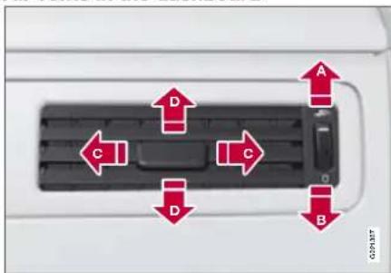
A Open
B Closed
Lateral airflow
Vertical airflow
Aim the outer vents at the side windows to remove misting.
A certain air flow always comes from the vents in order to maintain a good climate in the passenger compartment.
Air vents in the door pillars

A Open
B Closed
Lateral airflow
Vertical airflow
Aim the vents at the windows to remove misting.
Aim the vents into the passenger compartment to maintain a comfortable climate in the rear seat.
Remember that small children may be sensitive to air flows and draughts.

04 Comfort and driving pleasure
Climate control
Climate control
Electronic Temperature Control, ETC
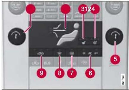
1 Fan
② Air distribution
③ Heated front seats, left-hand side
4 Heated front seats, right-hand side
⑤ Temperature control
6 AC ON/OFF – Air conditioning On/Off
⑦ Rear window and door mirror defrosters, see page 85
8 Max. defroster
9 Recirculation
Electronic climate control, ECC*

1 Ventilated front seats*, left-hand side
2 Fan
③ Heated front seats, left-hand side
4 Air distribution
⑤ Heated front seats, right-hand side
6 AUTO
7 Ventilated front seats*, right-hand side
8 Temperature control, right-hand side
9 AC ON/OFF – Air conditioning On/Off
10 Rear window and door mirror defrosters, see page 85
11 Max. defroster
12 Recirculation/Air quality system
13 Temperature control, left-hand side
Operation
Ventilated front seats*

Ventilated front seats can only be specified when ECC is installed in the car. The ventilation system consists of fans in the seats and backrests that drive air through the seat uphol-
stery. The cooling effect increases the cooler the passenger compartment air becomes.
The ventilation is regulated from the climate control and takes seat temperature, solar radiation and outside temperature into consideration.
The ventilation can be used at the same time as seat heating. For example, the function can be used to dry damp from clothing.
The ventilation system can be activated when the engine is running. There are three comfort levels that produce different cooling and dehumidification outputs:
- Comfort level three: press the button once for maximum output – three lamps illuminate.
- Comfort level two: press the button twice for a lower output – two lamps illuminate.
04 Comfort and driving pleasure

Climate control
- Comfort level one: press the button three times for the lowest output – one lamp illuminates.
Press the button four times to switch off the function – no lamps illuminate.

NOTE
The seat ventilation should be used carefully by people sensitive to draughts. Comfort level one is recommended for long-term use.

IMPORTANT
The seat ventilation cannot be started when passenger compartment temperature is less than 5 °C. This is to avoid chilling anyone sitting in the seat.
Fan

Turn the knob to increase or decrease fan speed. If AUTO 1 is selected then fan speed is regulated automatically. The previously set fan speed is disengaged.

NOTE
If the fan is fully disengaged the air conditioning is not engaged which may result in a risk of misting windows.
Heated seats\*
Front seats
- Press the button once for the highest heat level – three lamps illuminate.
- Press the button twice for a lower heat level – two lamps illuminate.
- Press the button three times for the lowest heat level – one lamp illuminates.
- Press the button four times to switch off the heat – no lamps illuminate.
Rear seats

Heat control takes place in the same way as for the front seat.
Air distribution

The figure consists of three buttons. When the buttons are pressed a lamp in front of the respective part of the figure illuminates and shows which air distribution is
selected, see page 116.

04 Comfort and driving pleasure
Climate control
Auto\*
The AUTO function is only available if ECC is installed in the car. The function automatically regulates temperature, air conditioning, fan speed, recirculation and air
distribution.
If you select one or more manual functions, the other functions continue to be controlled automatically. The air quality sensor is engaged and all manual settings are switched off when AUTO is pressed. The display shows AUTO CLIMATE.
Fan speed in automatic mode can be set under Climate settings Automatic blower adjust. Choose between Low, Normal or High.
For a description of the menu system, see page 104.
Temperature control

ECC: The temperatures on the driver and passenger sides can be set independently.
ETC: The whole of the passenger compartment is reg-
ulated using the knob.
When the car is started, the most recent setting is resumed.

NOTE
Heating or cooling cannot be hastened by selecting a higher/lower temperature than the actual temperature required.
AC - Air conditioning on/off

ON: The air conditioning is controlled by the system's AUTO function. This way, incoming air is cooled and dehumidified.
OFF: When the defroster
function is activated the air conditioning is switched on automatically (can be switched off using the AC button).
Defroster
Used to quickly remove misting and ice from the windscreen and side windows. Air flowing to the windows. The light in the defroster button illuminates
when the function is active.
The following also takes place in order to provide maximum dehumidification in the passenger compartment:
- the air conditioning is automatically engaged
• recirculation is automatically disengaged.
The air conditioning can be disengaged manually using the AC button. When the defroster function is switched off the climate control resumes to the previous settings.
Recirculation/Air quality system
Recirculation

When recirculation is engaged the right-hand orange light illuminates in the button 1 . The function is selected to shut out bad air, exhaust gases etc. from the
passenger compartment. The air in the passenger compartment is recirculated, i.e. no outside air is taken into the car when this function is activated. If the air in the car recirculates for too long, there is a risk of misting on the insides of the windows.
Timer
With the timer function activated the system will exit manually activated recirculation mode according to a time that depends on the outside temperature. This reduces the risk of ice, misting and bad air. Activate/
1 Only applies to ECC
04 Comfort and driving pleasure

Climate control
deactivate the function under Climate control settings +Decirculation timer . For a description of the menu system, see page 104.

NOTE
When Defroster is selected, recirculation is always deactivated.
Air quality system*
The air quality system separates gases and particles to reduce the levels of odours and pollution in the passenger compartment. If the outside air is contaminated then
the air intake is closed and the air is recirculated. When the AUTO button is depressed the air quality sensor is always engaged.
Activating recirculation/air quality sensor 1

Switch between the three functions by pressing the button repeatedly.
- The left-hand orange lamp illuminates – the air quality sensor is disengaged.
- The centre green lamp illuminates – recirculation not engaged, providing it is not required for cooling in hot weather.
- The right-hand orange lamp illuminates – recirculation is engaged.

NOTE
The air quality sensor should always be engaged in order to obtain the best air in the passenger compartment. Recirculation is limited in cold weather to avoid misting. If the insides of the windows start misting up, disengage the air quality sensor, and the defroster functions for the windscreen, the side and the rear windows should also be used to demist the windows.
Activating recirculation 1

Switch between recirculation on/off by repeatedly pressing the button. The lamp illuminates when recirculation is engaged.

04 Comfort and driving pleasure
Climate control
Air distribution table
| Air distribution Use Air distribution Use | |||||
 | Air to windows. Some air flows from the air vents. The air is not recirculated. Air conditioning is always engaged. | To remove ice and misting quickly. |  | Air to the floor and windows. Some air flows from the dashboard air vents. | To ensure comfortable conditions and good demisting in cold or humid weather. |
 | Air to windscreen and side windows. Some air flows from the air vents. | To prevent misting and icing in a cold and humid climate, (not at too low fan speed to enable this). |  | Air to floor and from dashboard air vents. | In sunny weather with cool outside temperatures. |
 | Airflow to windows and from dashboard air vents. | To ensure good comfort in warm, dry weather. |  | Air to floor. Some air flows to the dashboard air vents and windows. | To warm or cool the feet. |
 | Airflow to the head and chest from the dashboard air vents. | To ensure efficient cooling in warm weather. |  | Airflow to windows, from dashboard air vents and to the floor. | To cool the feet or provide warmer air to the upper body in cold weather or hot, dry weather. |
04 Comfort and driving pleasure

Climate control
Fuel-driven parking heater\*
General information about the parking heater
The parking heater can be started immediately or set using the timer. Here, start time refers to the time the car is heated and ready. The car's electronic system calculates when heating should be started based on the outside temperature. The heater is not run if the outdoor temperature exceeds 15 °C. At temperatures from -10 °C and below, the maximum running time of the parking heater is 50 minutes. When the parking heater is running, Park heat ON is shown on the information display.

WARNING
The car must be outdoors when the parking heater is used.

NOTE
When the parking heater is active there may be smoke from the right-hand wheel housing which is perfectly normal.


WARNING
Fuel which spills out can be ignited. Switch of the parking heater before starting to refuel. Check the information display to see that the parking heater is switched off.
Parking on a hill
If the car is parked on a steep hill, the front of the car should point downhill to ensure that there is a supply of fuel to the parking heater.
Battery and fuel
If the battery has insufficient charge or the fuel level is too low, the parking heater will be switched off automatically. A message appears on the information display. Confirm the message by pressing the READ button, see page 118.

IMPORTANT
Repeated use of the parking heater combined with short journeys may discharge the battery and impair starting. If the parking heater is used regularly, the car must be driven for the same time as the parking heater is run to ensure that the alternator has time to correspondingly charge the battery.

04 Comfort and driving pleasure
Climate control
Operation
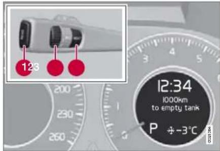
1 READ button
② Thumbwheel
③ RESET button
For more information on the information display and READ, see page 107.
Message in the information display
When the timer settings or direct start are activated, the information symbol illuminates on the combined instrument panel and an explanatory text appears in the information display. The display also indicates which timer is active when the driver removes the remote control key from the keyhole to leave the car.
Clock/timer
If the car clock is reset the timer settings are deleted.
Direct start/shutdown
- Use the thumbwheel to scroll to Direct start Park heat.
- Press RESET to switch between ON and OFF. ON: The parking heater is controlled manually. OFF: The parking heater is controlled automatically.
With direct start the parking heater will be activated for 50 minutes. Heating of the passenger compartment will begin as soon as the engine coolant has reached a temperature of 38 °C.

NOTE
The car can be started and driven while the parking heater is still running.
Setting the timer
It is only possible to set times for the following 24 hours.

NOTE
The engine must be switched off when setting the timer.
- Scroll with the thumbwheel to Park heat timer.
- Touch RESET to move to the flashing hours setting.
- Scroll with the thumbwheel to the hours required.
- Touch RESET to move to the flashing minutes setting.
- Scroll with the thumbwheel to the minutes required.
- Touch RESET to confirm the setting.
- Press RESET to activate the timer. After setting PM a second start time can be programmed for AM. Access this with the thumbwheel 2 Set the alternative start time in the same way as for AM.
04 Comfort and driving pleasure

Climate control
Additional heater (diesel)*

1 READ button
② Thumbwheel
③ RESET button
The additional heater may be required for achieving the correct temperature in the passenger compartment during cold weather.
The additional heater starts automatically when extra heat is required and the engine is running. It is switched off automatically when the correct temperature is reached or when the engine is switched off.

NOTE
When the additional heater is active there may be smoke from the right-hand wheel housing which is perfectly normal.
Auto mode or shutdown
The additional heater can be switched off for short distances if required.
- Use the thumbwheel to scroll to additional heat auto.
- Press RESET to switch between ON and OFF.

04 Comfort and driving pleasure
Audio system
General
The audio system can be equipped with different options and different versions. There are three system versions: Performance, High Performance and Premium Sound. The system version is shown in the display when the audio system is started.
Dolby Surround Pro Logic II and the symbol ▲e trademarks of Dolby Laboratories Licensing Corporation. The Dolby Surround Pro Logic II System is manufactured under license from Dolby Laboratories Licensing Corporation.
Remote control key and ignition positions
The audio system can be used without the remote control key in the ignition switch for 15 minutes at a time.

NOTE
Remove the remote control key from the ignition switch if the audio system is used when the engine is switched off. This is to avoid discharging the battery unnecessarily.
If the audio system is active when the engine is switched off then it is activated automatically the next time the engine is started.
Overview

① Input for external audio source (AUX)
② Steering wheel keypad
③ Centre console control panel
4 Control panel with headphones socket*
Steering wheel keypad

1 Confirm selection in menu system, accept call.
2 Lead up in menu system. Interrupt current function. End/refuse calls, clear entered characters.
3 Volume
4 A short press scrolls between CD tracks or preset radio stations. A long press fast-winds CD tracks or searches radio stations automatically.
04 Comfort and driving pleasure

Audio system
Rear control panel with headphones socket\*
Headphones with an impedance of 16-32 ohm and sensitivity of 102 dB or higher are recommended for best sound reproduction.

① Volume
② Scroll/search forward and backward
③ Audio source, activating
4 Headphones sockets (3.5 mm)
Activating/deactivating
The control panel is activated with MODE when the audio system is active. Deactivation is automatic when the audio system is deactivated or with a long press on MODE.
Scroll/search forward and backward
Short presses on are used to scroll between CD tracks or preset radio stations. Long presses are used to fast-wind CD tracks or to search for radio stations automatically.
Limitations
• The audio source (FM, AM, CD etc.) played back in the speakers cannot be controlled from the rear control panel.
- RDS messages may not appear if the radio is playing back in the headphones while another audio source is playing back in the speakers.
Menus and MY KEY 1
Some functions are controlled from the menu system in the centre console. For more information on menus, see page 104. For information on the audio system's functions together with handsfree or phone, see page 155.
Store favourite functions with MY KEY.
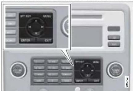
- Select the function to be stored in the menu. Only a selection of the functions can be stored.
- Hold MY KEY depressed for more than two seconds.
- Activate the stored function with a short press on MY KEY.
1 The MY KEY function is not available if the car is equipped with built-in phone as an option.

04 Comfort and driving pleasure
Audio system
The following functions can be stored with MY KEY:
CD/CD changer
- Random (CD changer)
- News
• TP - Track information
04
FM
- News
• TP - Radio text
- Search PTY
• Show PTY text
AUDIO SETTINGS
- Sound setting
• Auto. volume control
04 Comfort and driving pleasure

Audio system
Audio functions
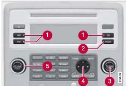
Centre console, controls for audio functions
1 Internal audio sources: AM, FM and CD
② External audio source. For connection, see page 120
3 Pushbutton and knob controls for adjusting the sound pattern
4 Navigation button
⑤ Volume and on/off
Audio volume and automatic volume control
The audio system compensates for disrupting noises in the passenger compartment by increasing the volume with the speed of the car. The level of compensation can be set at low, medium or high. Select the level under Audio settings→auto volume control.
External audio source audio volume
The AUX input can be used for connecting an MP3 player for example, see page 120.
NOTE
The audio quality may be impaired if the player is charged while the audio system is in AUX mode. In which case, avoid charging the player.
Sometimes the AUX external audio source can be heard at a different volume to the internal audio sources. If the audio volume of the external audio source is too high then the sound quality can be impaired. Prevent this by adjusting the input volume of the AUX input:
- Set the audio system in AUX mode using MODE and navigate with Volume, AUX input.
- Turn the control or press / the navigation button.
Audio controls
Press the control repeatedly to browse among the following options. The adjustment is made by turning the control.
NOTE
Press Menu to access the audio settings. For more information, see page 104.
- Bass – Bass level.
- Treble – Treble level.
- Fader – Balance between the front and rear speakers.
• Balance – Balance between the right and left-hand speakers. - Subwoofer* – Level for bass speaker. Turning the control anticlockwise to MIN deactivates the Subwoofer. The Subwoofer is located as illustrated below.

natural_image
Interior view of a car showing rear seats and a small inset image of a battery pack (no text or symbols visible)
04 Comfort and driving pleasure
Audio system
- Surround 1 - Surround settings.
Under Surround 3 channel stereo or Dolby Surround Pro logic II can be activated by selecting 3-ch or Dpl2 respectively. This enables the following options: - Centre level 1 – Level for centre speaker.
- Surround level 1 – Level for surround.
Sound levels for different frequencies can be adjusted separately using the equalizer 2 . - Go to Audio settings and select Equalizer Front or Equalizer Rear.
The sound level for the wavelength is adjusted with ▲ on the navigation button. Press ▶ to select another wavelength. - Use ENTER to save or EXIT to close.
Sound stage 3
The sound experience can be optimised for the driver's seat, both front seats or the rear seat. Select one of the options under Audio settings-Boundstage.
Equalizer
Optimum sound reproduction
The audio system is calibrated for optimum sound reproduction by means of digital signal processing.
This calibration takes into account loudspeakers, amplifiers, passenger compartment acoustics, listener position etc. for each combination of car model and audio system.
There is a also a dynamic calibration that takes into account the position of the volume control, radio reception and vehicle speed.
The controls explained in these operating instructions, e.g. Bass, Treble and Equalizer, are only intended for the user to be able to adapt the sound reproduction according to personal taste.
CD functions
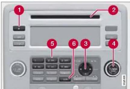
Centre console, controls for CD functions
1 CD eject
2 CD insert and eject slot
3 Navigation button for changing CD tracks
4 Fast-wind and change CD track
5 CD changer position selection*
6 Scan CD
Start playback (CD player)
If a music CD is in the player when CD is pressed then playback is started automatically. Otherwise, insert a disc and press CD.
1 Premium Sound
2 Certain audio systems
3 Premium Sound
04 Comfort and driving pleasure

Audio system
Start playback (CD changer)
If a CD position with a music CD is already selected when CD is pressed then playback starts automatically. Otherwise select a disc with the number buttons 1-6 / the navigation button.
Insert a CD (CD changer)
- Select an empty position with the number buttons 1-6 or ▲ on the navigation button.
An empty position is marked on the display. The text Insert disc shows that a new disc can be inserted. The CD changer can hold up to six CDs.
- Insert a CD in the CD changer slot.
Disc eject
A CD will stay in the ejected position for approx. 12 seconds. Following which it is re-inserted in the player and playback continues.
Eject individual discs by pressing the eject button.
Eject all discs with a long press on the eject button. The entire magazine is emptied disc by disc.
Pause
If the volume is turned down completely, the CD player is stopped. The player is restarted when volume is increased.
on
Audio files 1
The CD player also supports MP3 and WMA format audio files.

NOTE
Some copy protected audio files may not be read by the player.
When a CD containing audio files is inserted into the player the disc's directory structure is read in. It may take a while before playback starts depending on the quality of the disc.
Navigation and playback
If a disc containing audio files is inside the CD player then ENTER leads to the disc's directory structure. The directory structure is navigated in the same way as the audio system's menu structure. Audio files have the
symbol and directories have the symbol. Start audio file playback with
ENTER.
When the playback of a file is finished the playback of the other files in the same directory continues. Directory change takes place automatically when all files in the current directory have been played back.
Fast-wind/change CD tracks and audio files
Short presses ▶ on the navigation button are used to scroll between CD tracks/audio files. Long presses are used to fast-wind CD tracks/audio files. The steering wheel keypad can also be used for this purpose. Track change can also be made by turning Tuning.
Scan CD
This function plays the first ten seconds of each CD track/audio file. Press SCAN to activate. Interrupt with EXIT or SCAN to continue playback of the current CD track/audio file.
Random
This function plays the tracks in random order. The random CD tracks/audio files can be scrolled through in the normal way.

04 Comfort and driving pleasure
Audio system

NOTE
It is only possible to scroll between random CD tracks on the current disc.
Different messages appear depending on which random function has been selected:
- RANDOM means that the tracks from only one music CD are played
- RND ALL means that all tracks on all music CDs in the CD changer are played.
- RANDOM FOLDER means that the audio files in a directory on the current CD are played.
CD player
If a normal music CD is being played, activate/deactivate under Random.
If a disc with audio files is being played back, activate/deactivate under Random → Folder.
CD changer
If a normal music CD is being played under Random Single disc or Random All discs, then the option All discs only applies to the music CDs in the changer.
If a CD with audio files is being played, activate/deactivate instead under Random → Folder. If you select another CD the function is deactivated.
Track information
If track information is stored on a music CD then it can be shown on the display. This also applies to MP3 and WMA files for Premium Sound and High Performance. Activate/deactivate in CD mode under CD settings → Track information.
04 Comfort and driving pleasure

Audio system
Radio functions
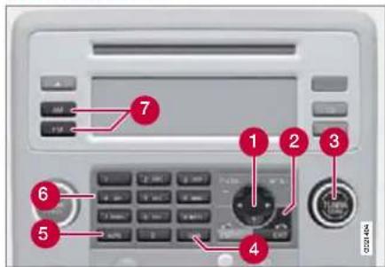
Centre console, controls for radio functions
① Navigation button for tuning, automatic
② Cancel function in progress
③ Tuning, manual
4 Scan wavelength
⑤ Preset storage, automatic
6 Preset buttons and preset storage, manual
7 Select wavelength AM and FM (FM1 and FM2)
Tuning, automatic
- Select wavelength using FM or AM.
- Press ▶ on the navigation button.
Tuning, manual
- Select wavelength using FM or AM.
- Turn TUNING.
Preset
Ten station presets can be stored per wavelength. FM has two memories for presets: FM1 and FM2. Only radio stations played through the car's speakers can be stored as presets. The stored presets are selected using the preset buttons.
Preset storage can be carried out manually or automatically.
Preset storage, manual
- Tune into a station.
- Hold in one of the preset buttons until the message Channel stored appears on the display.
Preset storage, automatic
The function is especially useful in areas where the radio stations and their frequencies are unfamiliar. The ten strongest radio stations are stored automatically in a separate memory.
- Select wavelength using FM or AM.
- Hold in AUTO until Autostoring... appears on the display.
Once Autostoring... disappears from the display, the stations are stored. The radio con-
tinues in Auto mode and Auto appears on the display. The automatically stored presets can now be selected using the preset buttons. Automatic preset storage can be cancelled using EXIT.
Auto mode is cancelled by pressing for example AUTO or FM.
Returning to Auto mode provides access to the autostored presets:
1. Press AUTO.
Auto appears on the display.
2. Press a preset button.
Scan wavelength
The function automatically searches the current wavelength for strong stations. When a station is found, it is played for approx. eight seconds before scanning is resumed. While the station is playing it can be stored as a preset as usual.
- Select wavelength using AM or FM.
- Press SCAN.
SCAN appears on the display. Close using SCAN or EXIT.
RDS functions
Radio Data System – RDS links FM transmitters into a network. An FM transmitter in such

04 Comfort and driving pleasure
Audio system
a network sends information that gives an RDS radio the following functions:
- Automatically switches to a stronger transmitter if reception in the area is poor.
• Searches for programme type, such as traffic information or news. - Receives text information on current radio programme.

NOTE
Some radio stations do not use RDS or only some if its functionality.
If a required programme type is located the radio can switch stations interrupting the audio source currently in use. For example, if the CD player is in use, it is paused. The interrupting transmission is played at a pre-set volume, see page 129. The radio returns to the previous audio source and volume when the set programme type is no longer broadcast.
The programme functions alarm (ALARM), traffic information (TP), news (NEWS), and programme types (PTY) interrupt one another in order of priority, where alarm has the highest priority and programme types has the lowest. For further programme interruption settings, see EON and REG,
page 129. Press EXIT to return to the interrupted audio source.
Alarm
This function is used to warn of serious accidents and catastrophes. The alarm cannot be temporarily interrupted or deactivated. The message ALARM! appears on the display when an alarm message is transmitted.
Traffic information - TP
This function allows traffic information broadcast within a set station's RDS network to break through. The symbol TP shows that the function has been activated. If the set station can send traffic information then eTPears on the display.
Activate/deactivate under FM settings → TP.
TP from current station/all stations
The radio can interrupt with traffic information from only the set (current) station or from all stations.
Go to FM settings Advanced radio settings TP TP Station to change.
News
This function allows news broadcasts within a set station's RDS network to break
through. The symbol NEWS shows that the function is active.
Activate/deactivate under FM settings → News.
News from current/all stations
The radio can interrupt with news from only the set (current) station or from all stations. Go to FM settings Advanced radio settings news station to change.
Programme types - PTY
The PTY function can be used to select different programme types, such as pop music and serious classic. The PTY symbol indicates that the function is active. This function allows programme types broadcast within a set station's RDS network to break through.
Activate in FM mode by selecting a programme type under FM settings +PTY Select PTY.
Deactivate by clearing the PTYs under FM settings ▶ clear all PTYs .
PTY search
This function searches the entire wavelength for the selected programme type.
- Select a PTY under FM settings → PTY Select PTY
04 Comfort and driving pleasure

Audio system
- Go to FM settings PTY Search PTY.
If the radio finds any of the selected programme types then the display shows >| To seek. To continue searching for another broadcast of the selected programme types, press -on the navigation button.
Display of programme type
The programme type of the current station can be shown on the display.
Activate/deactivate in FM mode under FM settings PTY Show PTY

NOTE
Not all radio stations support display of programme type.
Radio text
Some RDS stations transmit information on programme content, artists, etc. This information can be shown on the display.
Activate/deactivate in FM mode under Radio text.
Automatic frequency update - AF
This function selects one of the strongest transmitters for a set station. The function
may need to search through the entire FM wavelength to find a strong transmitter. If this occurs, the radio mutes and PI Seek Press Exit to cancel appears on the display.
Activate/deactivate in FM mode under FM settings → Advanced radio settings → F.
Regional radio programmes - REG
This function causes the radio to continue with a regional transmitter even if its signal strength is low. The symbol REG shows that the function is active.
Activate/deactivate in FM mode under FM settings Advanced radio settings Regional.
Enhanced Other Networks - EON
This function is useful in urban areas with many regional radio stations. It allows the distance between the car and the radio station transmitter to determine when programme functions should interrupt the current audio source.
Activate/deactivate in FM mode by selecting one of the options under FM settings → Advanced radio settings → EON:
- Local – interrupts only if the radio station transmitter is close.
- Distant 1 – interrupts if the station transmitter is far away, even if there is a lot of static.
- Off – no interruption for programmes from other transmitters.
Resetting RDS functions
All radio settings can be reset to the original factory settings. The reset is carried out in FM mode under FM settings → Advanced radio settings → Reset all.
Volume control, programme types
The interrupting programme types, e.g. NEWS or TP, are heard at the volume selected for each respective programme type. If the volume level is adjusted during the programme interruption, the new level is saved until the next programme interruption.
1 Default/Factory setting.

04 Comfort and driving pleasure
Trip computer
General

Information display and controls
1 READ – confirms
2 Thumbwheel – browse between menus and options in the trip computer list
③ RESET - resets
To scroll through trip computer information, turn the thumbwheel up or down in steps. Continue turning to return to the starting point.
Functions
NOTE
If a warning message appears while you are using the trip computer, this message must be acknowledged in order to revert to the trip computer function. Acknowledge by pressing READ.
To change unit specified for distance and speed, contact an authorised Volvo workshop.
Current speed\*
Current speed is displayed in mph if the speedometer is graduated in km/h. If the speedometer is graduated in mph then the current speed is shown in km/h.
Average speed
The car calculates the average speed from the last resetting. Reset using RESET.
Instantaneous
Current fuel consumption is calculated every second. The information on the display is updated every couple of seconds. When the car is stationary, "----" appears on the display.
Average
The average fuel consumption since the last reset. Reset using RESET.
NOTE
There may be a slight error in the reading if a fuel-driven additional 1 and/or parking heater * has been used.
1 Only diesel-engined cars.
Km to empty tank
The calculation is based on the average fuel consumption over the last 30 km and the remaining driveable fuel quantity. The display shows the approximate distance that can be driven with the fuel quantity remaining in the tank. When fuel for less than 20 km remains then the display shows
"----" km to empty tank.
NOTE
There may be a slight error in the reading if a fuel-driven parking heater* has been used or if driving style has been changed.
Resetting
- Select average speed or average.
04 Comfort and driving pleasure

Trip computer
- Press and hold RESET for approx.
1 second to reset the selected function.
If RESET is kept depressed for at
3 three seconds then average speed
and average are reset simultaneously.

04 Comfort and driving pleasure
Compass\*
Operation

natural_image
Close-up of a car rearview mirror with 'SW' label, no visible text or symbols on the object itself.Rearview mirror with compass.
The upper right-hand corner of the rearview mirror has an integrated display that shows the compass direction in which the front of the car is pointing. Eight different directions are shown with English abbreviations: N (north), NE (north east), E (east), SE (south east), S (south), SW (south west), W (west) and NW (north west).
The compass is activated automatically when the car is started or in ignition position II. To deactivate/activate the compass, use a paper clip for example and press in the button on the rear side of the mirror.
Adjusting
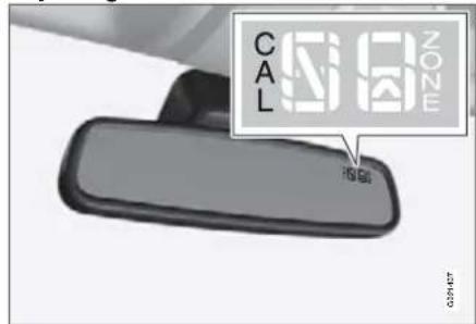
Calibrating the compass.
The compass may need calibrating to work correctly. CAL is shown in the mirror's display if the compass needs calibrating.
- Stop the car in a large open area.
- Start the car.
- Press and hold the button on the rear of the rearview mirror (use a paper clip or similar) until CAL is shown again (approx. 6 seconds).
- Drive off as usual. CAL disappears from the display when calibration is complete.
Alternative calibration method: Drive slowly in a circle at a speed of no more than eight km/h until CAL disappears from the display when calibration is complete.
Selecting the zone

Magnetic zones.
The earth is divided into 15 magnetic zones. The correct zone must be selected for the compass to work correctly.
- Ignition position II.
- Press and hold the button on the rear of the rearview mirror (use a paper clip or similar) for at least 3 seconds. The number for the current area is shown.
- Press the button repeatedly until the number for the required geographic area (1–15) is shown.
- The display will revert to showing the compass direction after a few seconds.
04 Comfort and driving pleasure

DSTC -Stability and traction control system
General information on DSTC
The stability and traction control system, DSTC (Dynamic Stability and Traction Control) helps the driver to avoid skidding and improves the car's traction.
The system limits the driving and brake force of the wheels individually so that skidding can be avoided. This increases manoeuvrability and as a result safety in the event of sudden movement.
Traction is improved by means of the system distributing the driving force between the wheels. The system primarily engages at low speed on poor road surfaces.
The activation of the system during braking may be noticed as a throbbing sound. The car may accelerate slower than expected when the accelerator pedal is depressed.
Messages in the information display
DSTC Temporarily OFF System temporarily reduced due to excessive brake disc temperature. The function is reactivated automatically when the brakes have cooled.
DSTC Service required System disabled due to a fault.
Stop the car in a safe place and turn off the engine. If the message remains when the engine is restarted, drive to an authorised Volvo workshop.
Symbols in the combined instrument panel
If the symbols and are displayed at the same time, read the message on the information display.
If the symbol appears alone then it may appear as follows:
- Flashing light means that the system is now being activated.
- Constant glow for 2 seconds means system check when the engine is started.
- Constant glow after starting the engine or while driving means system fault.
Reduced operation
System operation during skidding and acceleration can be reduced. Operation during skidding is delayed and so allows more skidding which provides greater freedom for dynamic driving. Traction in deep snow or sand is improved as traction is no longer limited.
Operation
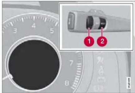
- Turn the thumbwheel until the DSTC menu is shown.
DSTC ON means that the system function is unchanged.
DSTC spin control OFF means that system operation is reduced.
- Press and hold RESET until the DSTC menu is changed.
The system remains reduced until the engine is next started.

WARNING
The car's driving characteristics may deteriorate if the function is reduced.

04 Comfort and driving pleasure
Adapting driving characteristics
Active chassis (Four C)\*
Active chassis, Four-C (Continuously Controlled Chassis Concept), regulates the characteristics of the shock absorbers so that the car's driving characteristics can be adjusted. There are three settings: Comfort, Sport and Advanced.
Comfort
This setting means that the car is perceived as being more comfortable and is recommended for longer journeys. Shock absorption is soft and the movement of the body is smooth and gentle.
Sport
This setting means that the car is perceived as being more sporty and is recommended for more active driving. Steering response is faster than in the Comfort mode. Shock absorption is harder and the body follows the road in order to reduce rolling during fast cornering.
Advanced
This setting is only recommended on very even and smooth road surfaces.
The shock absorbers are optimised for maximum roadholding and rolling in bends is further minimised.
Operation

Chassis settings
Use the buttons in the centre console to change setting. The setting in use when the engine is switched off is activated next time the engine is started.
Speed related steering force\*
Steering force increases with the speed of the car to give the driver enhanced sensitivity. At low speed the car is easy to steer in order to facilitate parking for example.
Steering force can be changed under Car settings → Steering force level For a description of the menu system, see page 104. This menu cannot be accessed while the car is in motion.
04 Comfort and driving pleasure

Cruise control\*
Operation
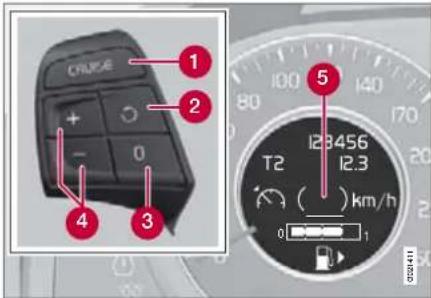
Display and controls
1 Standby mode
② Resume set speed
③ Deactivating
4 Activate/set speed
5 Set speed (in brackets = standby mode)
Activating and setting the speed
In order to enable the activation of cruise control, it must first be engaged in standby mode with the CRUISE button ① The symbol ② Minates in the display and the text (---) km/h ⑤ shows that cruise control is in standby mode.
Cruise control is then activated with +br -, after which the current speed is stored
and is used as the set speed. The display text
(---) km/h changes to show the set speed, e.g. 100 km/h.,
NOTE
Cruise control cannot be engaged at speeds below 30 km/h.
Adjusting the set speed
In active mode the speed is adjusted with long or short presses on ▶r . —
A temporary increase in speed using the accelerator, such as while overtaking, does not affect the cruise control setting. When the accelerator is released the car will return to the set speed.
NOTE
If one of the cruise control buttons is kept depressed for more than approx. one minute then cruise control is disengaged. The engine must then be switched off in order to then reset cruise control.
Deactivation
Cruise control is disengaged with CRUISE or by switching off the engine. The set speed is cleared.
Temporary deactivation
Press ☐ disengage cruise control temporarily. The saved speed is shown in brackets in the display, e.g. (100) km/h.
Automatic temporary deactivation
Cruise control is deactivated spontaneously when the driving wheels spin or if the car's speed falls below approx. 30 km/h. Cruise control is also deactivated when the brakes are used, when the gear selector is moved to neutral position or if the accelerator pedal is depressed for a longer time (approx. 60 seconds). Cruise control then changes over to standby mode and the set speed is saved.
Resume set speed
If cruise control has been deactivated temporarily, it can be reactivated by pressing ☐ The speed is then set to the previously set speed.
NOTE
A significant increase in speed may arise after the speed has been resumed with ☐.

04 Comfort and driving pleasure
Adaptive cruise control\*
General
Adaptive Cruise Control – (ACC) is designed to assist the driver with support on long straight roads in steady traffic, for example on motorways and main roads.
Maintenance of cruise control components must only be performed by an authorised Volvo workshop.

WARNING
Adaptive cruise control cannot cover all driving situations and traffic, weather and road conditions.
The Function section on page 136 and after informs about limitations that the driver must be aware of before using the adaptive cruise control.
When driving you are responsible for maintaining the correct distance and speed, even when adaptive cruise control is used. You must always pay attention to the traffic conditions and intervene when adaptive cruise control is not maintaining a suitable speed or suitable distance.
Function

Functions overview
1 Warning lamp, braking by driver required
② Controls
3 Radar sensor
Adaptive cruise control consists of the cruise control system and coordinated spacing system.

WARNING
Adaptive cruise control is not a collision avoidance system. The driver must intervene if the system does not detect a vehicle in front.
Adaptive cruise control does not brake for slow or stationary vehicles.
Do not use the adaptive cruise control, for example, in city traffic, in dense traffic, at junctions, on slippery surfaces, with a lot of water or slush on the road, in heavy rain/snow, in poor visibility, on winding roads or on slip roads.
The distance to the vehicle ahead is measured by a radar sensor. The speed is regulated by acceleration and braking. It is normal for the brakes to emit a low sound when they are being used by cruise control.

WARNING
The brake pedal moves when the cruise control brakes. Do not rest your foot under the brake pedal as it could become trapped.
The cruise control objective is to follow the vehicle ahead but in the same lane and at a set distance. If the radar sensor has not detected a vehicle ahead then the only objec-
04 Comfort and driving pleasure

Adaptive cruise control\*
tive is the set speed. This is also the case if the speed of the vehicle ahead exceeds the cruise control set speed.
The adaptive cruise control aims to control the speed in a smooth way. In situations that demand sudden braking you must brake yourself. This applies with large differences in speed, or if the vehicle in front brakes heavily. Due to limitations in the radar sensor, braking may come unexpectedly or not at all, see page 140.
Adaptive cruise control can only be activated above 30 km/h. If speed falls below 30 km/h or if engine speed becomes too slow then the adaptive cruise control disengages and stops braking. In which case the driver must immediately take over and maintain the distance to vehicles in front. The highest speed setting is 200 km/h. In some situations when the system cannot be activated Cruise Unavailable is shown in the display, see page 139.
Warning lamp, braking by driver required
Adaptive cruise control has a braking capacity that is equivalent to approximately 30% of the car's braking capacity. If the car needs to brake more heavily than cruise control capacity and the driver does not brake then a signal sounds and the red warning lamp illuminates the windscreen. The red warning lamp may be difficult to notice in strong sunlight or when sunglasses are being worn.
WARNING
Cruise control only warns of vehicles detected by the radar sensor. Consequently there may be no warning or it may be subject to a delay. Do not wait for a warning but brake when it is necessary.
Automatic deactivation
Adaptive cruise control is dependent on other systems e.g. stability and traction control system (DSTC). If any of these systems stop working then cruise control is automatically deactivated.
In the event of automatic deactivation a signal will sound and the message Cruise Cancelled is shown in the display. You must then intervene and adapt your driving and speed to vehicles in front.
An automatic deactivation can be due to:
• speed falls below 30 km/h
- wheels lose traction
- brake temperature is high
• engine speed is too low
- the radar sensor is blocked e.g. by wet snow or rain
Operation

Display and controls
① Activate and resume settings, increase speed
② Standby mode, on/off
3 Set distance
4 Activating and setting the speed
Driver operation
Cruise control is deactivated when the brakes are used, the gear selector is moved to neutral position, or if the accelerator pedal is depressed for a longer period. Cruise control then changes over to standby mode and the driver has full control of the car. If the accelerator pedal is kept depressed for a shorter period, for example during overtaking, cruise control is temporarily disengaged and

04 Comfort and driving pleasure
Adaptive cruise control\*
then re-engaged when the accelerator pedal is released.
Activating and setting the speed
To enable cruise control activation it must first be engaged in standby mode with 📄 The set time interval is briefly shown in the display. Cruise control is activated with +, after which the current speed is stored and used as the set speed. The set speed is shown in the display. In active mode the speed is adjusted with long or short presses on + or - The Button has the same function as +, but results in a lower increase in speed.

NOTE
If cruise control does not seem to react to activation the reason may be that the time interval to the closest vehicle prevents an increase in speed.

NOTE
In some situations cruise control cannot be activated. In which case Cruise Unavailable is shown in the display, see page 139.
Set time interval
The set time interval to vehicles in front is increased with and decreased with.
The current time interval is shown briefly in the display following adjustment. Five different time intervals can be chosen from. A longer time interval means smoother speed control. The recommended time interval is three to five. Time intervals one and two are primarily intended for driving in queues in heavy traffic, in which case you must intervene more often.

NOTE
Only use the time interval that is allowed in accordance with local traffic regulations.
Deactivating and resuming settings
Cruise control is deactivated, either with a short press on ☐ by means of driver intervention, e.g. braking. The set speed is then shown in brackets. Speed and time interval are resumed with one press on ☐

NOTE
A significant increase in speed may arise after the speed has been resumed with ☐
A short press on instandby mode or a long press in active mode deactivates cruise control. The set speed is cleared and cannot be resumed.
The radar sensor and its limitations
The radar sensor is used both by the adaptive cruise control and the collision warning system. It is designed to detect cars or larger vehicles driving in the same direction. The radar sensor does not detect pedestrians, or oncoming, slow or stationary vehicles, objects and obstacles. Warnings are not given and braking is not applied in such cases.
Modification of the radar sensor could result in it being illegal to use.

WARNING
Accessories or other objects must not be installed in front of the grille.
The capacity of the radar sensor to detect vehicles in front is reduced significantly:
- if the radar sensor become cannot detect other vehicles e.g. in heavy rain or slush, or if other objects have collected in front of the radar sensor.

NOTE
Keep the surface in front of the radar sensor clean.
- if the speed of vehicles in front is significantly different from your own speed.
04 Comfort and driving pleasure

Adaptive cruise control\*
The radar sensor has a limited field of vision. In some situations it may detect a vehicle other than the one expected or not detect any vehicle at all.
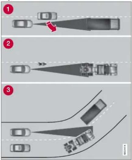
Radar sensor field of vision (grey)
Sometimes the radar sensor cannot detect vehicles at close quarters, for example a vehicle that drives in between your car and vehicles in front.
2 Small vehicles, such as motorcycles, or vehicles not driving in the centre of the lane can remain undetected.
3 In bends the radar sensor may detect the wrong vehicle or lose a detected vehicle from view.
Symbols on the display
| Symbol Specification | |
| Standby mode or active mode without detected vehicle. | |
| Active mode with detected vehicle to which cruise control adapts the speed. | |
| Distance information. | |
Messages on the display
| Message Specification | |
| Radar blockedSee manual | Cruise control temporarily disengaged. This message is shown if the radar sensor is blocked and cannot detect other vehicles e.g. in heavy rain or if slush has collected in front of the radar sensor. |
| Message Specification | |
| Cruise Cancelled | The cruise control has been shut down. The driver must regulate the speed. |
| Cruise Service required | Cruise control not working. Contact an authorised Volvo workshop. |
| Cruise Unavailable | Cruise control cannot be activated. This could be due to: traction control and stability function (DSTC) has been reduced, see page 133brake temperature is highthe radar sensor is blocked e.g. by wet snow or rain. |

04 Comfort and driving pleasure
Collision warning system with brake support\*
General
The collision warning system (Collision Warning with Brake Support) is an aid designed to warn the driver who is at risk from driving into a vehicle in front that is driving in the same direction.
The brake support reduces the collision speed.
Maintenance of collision warning system components must only be performed by an authorised Volvo workshop.

WARNING
The collision warning system does not work in all driving situations and traffic, weather and road conditions. The collision warning system does not react to slow vehicles, stationary vehicles or vehicles travelling in another direction to the host vehicle.
Warnings are given at the earliest in the event of high collision risk. The Function section and after informs about limitations that the driver must be aware of before use.
The collision warning system has brake support that only reduces collision speed if the driver brakes.
Never wait for a collision warning. When driving you are responsible for maintaining the correct distance and speed, even when the collision warning system is used.
Function

Functions overview
① Visual warning signal, collision risk
2 Sensor
The radar sensor detects vehicles in front that are driving in the same direction as you. In the event of there being a risk of collision with such a vehicle your attention is drawn with a red warning lamp and a warning sound.
If the risk of collision still increases after the warning then the brake support is activated. The brake support prepares the brake system for rapid braking and the brakes are applied gently, which may be noticed as a slight jerk. If the brake pedal is depressed sufficiently quickly then braking is implemented with full brake function, even if the force on
the pedal is light. The collision warning system is active between 7 km/h and 180 km/h.
04 Comfort and driving pleasure

Collision warning system with brake support\*
Operation
Some settings are controlled from the centre console via a menu system. For information on how the menu system is used, see page 104.

Button for activating/deactivating the warning signals.

NOTE
The brake support is not affected by the settings described here.
Activating/deactivating warning signals
The collision warning system's audio and visual signals can be activated/deactivated using the light in the button indicates that the warning signals are activated.
The warning sound and warning lamp are activated automatically when the car is started. The automatic activation can be deselected under Car settings collision warn. settings → On at start up
The warning sound can be activated/deactivated separately under Car settings 🔍ol- lision warn. settings → Warning sound.

NOTE
When adaptive cruise control is used the warning lamp and warning sound are used by the cruise control even if it has been deactivated by the driver.
Set warning distance
The sensitivity states how early the visual and any audible warning is triggered. Select one of the options under Car settings → Collision warn. settings → Warning distance.

NOTE
In some situations warnings may seem to be late, even though the warning distance has been set to Long.
Checking settings
The current settings are most easily checked by pressing twice on if quick succession. The settings are shown in the display.
Messages on the display
Radar blocked See manual – The collision warning system is temporarily disengaged. The message is shown e.g. in heavy rain or if slush has collected in front of the radar sensor. See the section on radar sensor limitations, page 140
Collision warn. Service required – The collision warning system is disengaged. Contact an authorised Volvo workshop if the message remains.

04 Comfort and driving pleasure
Collision warning system with brake support\*
Limitations
The visual warning signal may be difficult to notice in strong sunlight or when sunglasses are being worn. For this reason always activate the warning sound during such conditions.
The incorrect warnings may be in the form of both audio and visual signals. One way of reducing the number of incorrect warnings is to reduce the warning distance.

NOTE
The visual warning signal can be temporarily disengaged in the event of high passenger compartment temperature caused by strong sunlight for example. If this occurs then the warning sound is activated even if it is deactivated in the menu system.
Warnings may not appear if the distance to the vehicle in front is very small or if steering wheel and pedal movements are large, e.g. a very active driving style.
Warnings may be triggered late, be absent or triggered unnecessarily if the traffic situation means that the radar sensor cannot accurately detect a vehicle in front. The collision warning system uses the same radar sensors as adaptive cruise control. For more information on the radar sensor and its limitations, see page 140.
An absent or late warning means that there is no brake support or it comes late.
04 Comfort and driving pleasure

Parking assistance\*
General 1
Parking assistance is used as an aid to parking. A signal indicates the distance to the detected obstacle.
Parking assistance is available in two variants:
- Rear only
- Both front and rear.

WARNING
Parking assistance does not relinquish the driver's own responsibility during parking. The sensors have blind spots where obstacles cannot be detected. Be aware of children and animals near the car.
Function
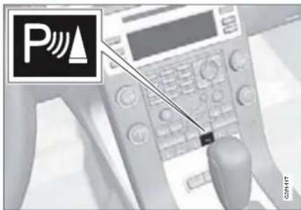
The system is automatically activated when the car is started and the lamp in the switch for Off/On is illuminated. If parking assistance is deactivated with the button, then the lamp goes out.
The shorter the distance to the obstacle in front or behind, the faster the acoustic signal. If the volume of another audio source from the audio system is high, then this is automatically lowered.
The tone becomes constant at a distance of about 30 cm. If there are objects within this distance both behind and in front of the car, then the signal alternates between the front and rear loudspeakers.
Rear parking assistance

The distance covered to the rear of the car is about 1.5 metres. The audio signal for obstacles behind comes from the rear loudspeakers.
Rear parking assistance is activated when reverse gear is engaged.
The system must be deactivated when reversing with a trailer, or bike carrier on the towbar or similar. Otherwise they would trigger the sensors.

NOTE
Rear parking assistance is deactivated automatically when towing a trailer if Volvo genuine trailer wiring is used.

04 Comfort and driving pleasure
Parking assistance\*
Front parking assistance

The distance covered to the front of the car is about 0.8 metres. The audio signal for obstacles in front comes from the front loudspeaker.
The front parking assistance is active at speeds of below 15 km/h, even during reversing. The system is deactivated at a higher speed. However, the lamp in the button remains illuminated in order to indicate that the system is activated for the next time the driver shall park. When the speed is below 10 km/h the system is reactivated.

NOTE
Front parking assistance is deactivated when the parking brake is applied.

NOTE
When fitting auxiliary lamps: Remember that they must not obscure the sensors – the auxiliary lamps could then be detected as obstacles.
Fault indicator
If the information symbol illuminates with constant glow and the information display shows Park assist syst Service required then parking assistance is disengaged.

IMPORTANT
In certain conditions the parking assistance system may produce incorrect warning signals that are caused by external audio sources that emit the same ultrasonic frequencies that the system works with.
Examples of such sources include horns, wet tyres on asphalt, pneumatic brakes and exhaust noises from motorcycles etc.
04 Comfort and driving pleasure

Parking assistance\*
Cleaning the sensors

natural_image
Front view of a car with a close-up inset showing a connector detail (no text or symbols visible)Sensor location, front
The sensors must be cleaned regularly to ensure that they work properly. Clean them with water and car shampoo.

NOTE
Dirt, ice and snow covering the sensors may cause incorrect warning signals.

natural_image
Side view of a car with red arrows pointing to the side panel, showing no visible text or symbols.Sensor location, rear

04 Comfort and driving pleasure
BLIS\* – Blind Spot Information System
General information on BLIS

1 BLIS camera
② Indicator lamp
③ BLIS symbol
BLIS is an information system based on digital camera technology that under certain conditions can help the driver to notice vehicles moving in the same direction as the host vehicle in the so-called "blind spot".
IMPORTANT
Repair of the BLIS system components must only be performed by an authorised Volvo workshop.
WARNING
The system is a supplement to, not a replacement for, a safe driving style and use of the rearview mirrors. It can never replace the driver's attention and responsibility. The responsibility for changing lanes safely always rests with the driver.
The system is designed to work most effectively when driving in dense traffic on multi-lane highways.
When a camera has detected a vehicle inside the blind spot zone the indicator lamp illuminates with a constant glow.
NOTE
The lamp illuminates on the side of the car where the system has detected the vehicle. If the car is overtaken on both sides at the same time then both lamps illuminate.
BLIS advises the driver with a message if a fault arises in the system. If for example the system's cameras are obscured then the BLIS indicator lamp flashes and a message is shown on the information display. In such cases, check and clean the lenses. If necessary, the system can be switched off temporarily by pressing the BLIS button, see page 147.
Blind spots

A = approx. 9.5 m and B = approx. 3 m
04 Comfort and driving pleasure

BLIS\* - Blind Spot Information System
Activating/deactivating

Button for activating/deactivating
BLIS is activated when the engine is started. The indicator lamps in the door panels flash three times when BLIS is activated.
The system can be deactivated/activated when the engine is started by pressing BLIS.
When BLIS is deactivated the light in the button goes out and a text message is shown on the dashboard display.
When BLIS is activated the light in the button illuminates, a new text message is shown on the display and the indicator lamps in the door panels flash three times. Press the READ button to clear the text message. For more information on messages, see page 107.
When BLIS operates
The system operates when the car is driven at a speed above 10 km/h.
Overtaking
The system is designed to react if:
- you overtake another vehicle at a speed of up to 10 km/h faster than the other vehicle
- you are overtaken by a vehicle travelling up to 70 km/h faster than you are travelling.

WARNING
BLIS does not work in sharp bends. BLIS does not work when the car is reversing. A wide trailer coupled to the car can conceal other vehicles in adjacent lanes. It can prevent the vehicle in the screened area from being detected by BLIS.
Daylight and darkness
In daylight the system reacts to the shape of the surrounding vehicles. The system is designed to detect motor vehicles such as cars, trucks, buses and motorcycles.
In darkness the system reacts to the head-lamps of surrounding vehicles. If the head-lamps of surrounding vehicles are not switched on then the system does not detect
the vehicles. This means for example that the system does not react to a trailer without headlamps which is towed behind a car or truck.

WARNING
The system does not react to bicycles or mopeds.
The BLIS cameras can be disrupted by intensive light or when driving in the dark when there are no light sources (e.g. street lighting or other vehicles). The system may then interpret the lack of light as if the cameras have been blocked.
In both cases a message is shown in the information display.
When driving in such conditions system performance may be temporarily deteriorate and a text message is shown, see page 148. If the message disappears automatically then BLIS has returned to normal functionality.
The BLIS cameras have limitations similar to the human eye, i.e. they "see" worse in heavy snowfall or thick fog for example.

04 Comfort and driving pleasure
BLIS\* – Blind Spot Information System
Cleaning
In order to work most effectively the BLIS camera lenses must be clean. The lenses can be cleaned with a soft cloth or damp sponge. Clean the lenses carefully so that they are not scratched.

IMPORTANT
The lenses are electrically heated to melt ice or snow. If necessary, brush snow away from the lenses.
Messages on the display
| Message Specification | |
| Blind-spot info sys-tem ON | BLIS system on |
| Blind spot syst. Serv-ice required | BLIS not functioning.Contact an authorised Volvo workshop. |
| Blind spot syst. Cam-era blocked | The BLIS camera is blocked by dirt, snow or ice. Clean the lenses. |
| Blind spot syst.Reduced function | The BLIS camera is disrupted by fog or strong sunlight shining directly into the cam-era.The camera resets itself when the environ-ment has returned to normal. |
| Blind-spot info sys-tem OFF | BLIS system off |
Limitations
In some situations the BLIS indicator lamp may illuminate despite there being no other vehicle within the blind spot.

NOTE
If the BLIS indicator lamp illuminates on isolated occasions despite there being no other vehicle within the blind spot then this does not mean that a fault has arisen in the system.
In the event of a fault in the BLIS system the display shows the text BLIS Serv. required.
Here are several examples of situations where the BLIS indicator lamp may illuminate even if there is no other vehicle within the blind spot.

natural_image
Illustration of a car under rain with visible sensor or sensor points (no text or symbols)Reflection from shiny wet road surface.

natural_image
3D rendering of a car parked on a road with red directional arrows indicating lanes (no text or symbols)Own shadow on large light smooth surface, e.g. noise barrier or concrete road surface.

natural_image
Illustration of a car on a road with light rays projecting onto a sun, showing the mirror and vehicle (no text or symbols)Low stationary sunlight shining into the camera.
04 Comfort and driving pleasure

Comfort inside the passenger compartment
Storage spaces
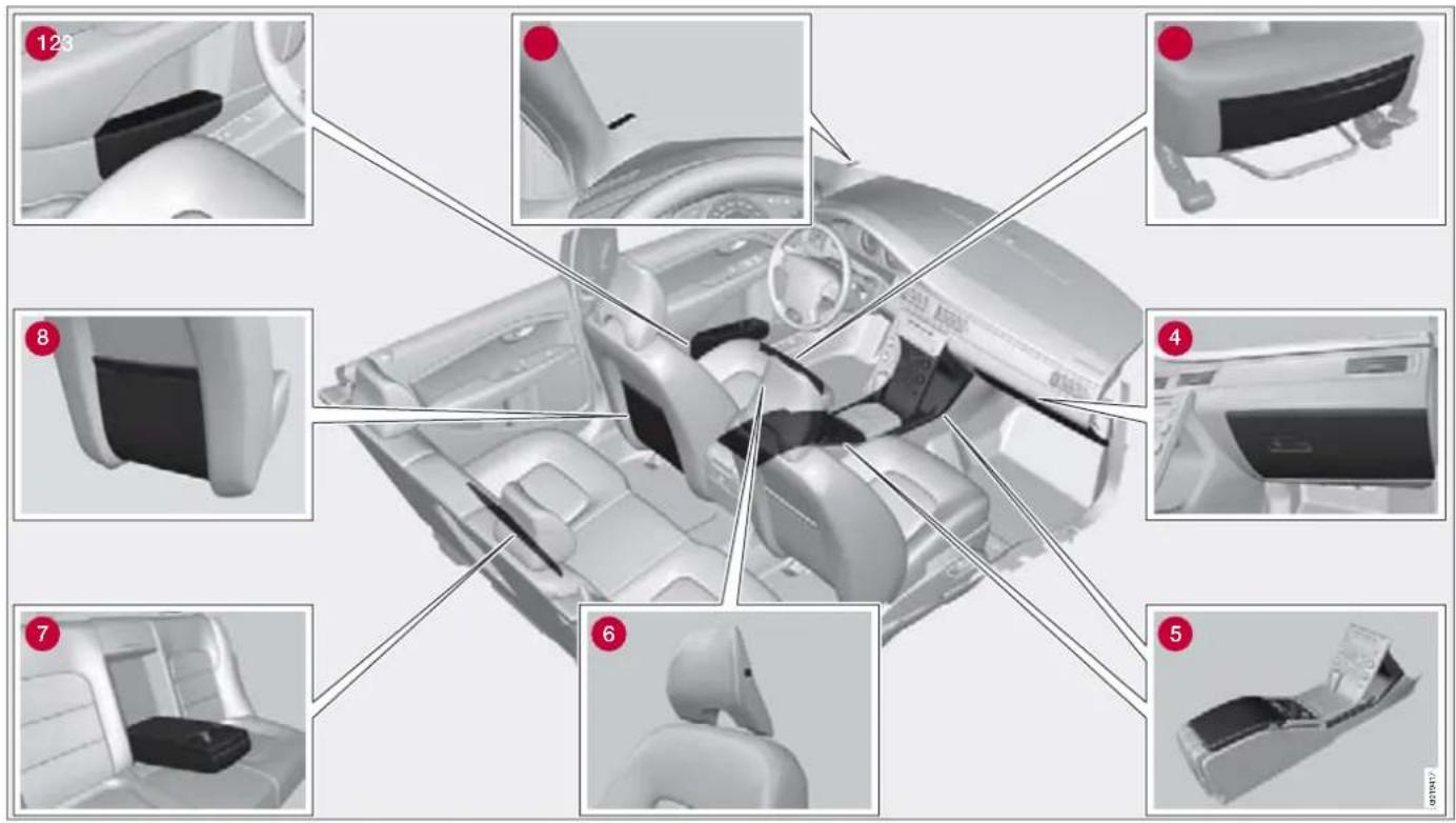

04 Comfort and driving pleasure
Comfort inside the passenger compartment
1 Storage compartment in door panel
② Storage pocket on front edge of front seat cushions*
③ Ticket clip
4 Glovebox
⑤ Storage compartment, cup holder
6 Jacket holder
⑦ Cup holder in armrest, rear seat*
8 Storage pocket
Jacket holder
The jacket holder is only designed for light clothing.
Tunnel console

1 Storage compartment (e.g. for CD discs) and AUX input under the armrest (and storage tray*).
2 Includes cup holder for driver and passenger, and 12 V socket and small compartment. (If ashtray and cigarette lighter are specified then the 12 V socket is replaced by a cigarette lighter and the small compartment by a detachable ash-tray.)
Cigarette lighter and ashtray\*
The ashtray in the tunnel console is emptied by lifting it straight up.
Activate the lighter by pushing in the button. The button pops out when the lighter is hot. Pull out the lighter and light a cigarette on the heated coils.
Glovebox

natural_image
Interior view of a car dashboard with two labeled sections (A and B) showing red curved arrows pointing to a component on the dashboard (no text or symbols present)The owner's manual and maps can be kept here. There are also holders for pens and fuel cards. The glovebox can be locked manually with the key blade, see page 42.
04 Comfort and driving pleasure

Comfort inside the passenger compartment
Floor mats\*
Volvo supplies specially manufactured floor mats.

WARNING
The floor mat at the driver's seat must be firmly fitted and secured in the attachment clips to prevent it from being trapped around and under the pedals.
Vanity mirror

natural_image
Close-up of a small electronic device component with a rectangular lens or cover (no visible text or symbols)Vanity mirror with lighting.
The light illuminates automatically when the cover is lifted.
12 V socket
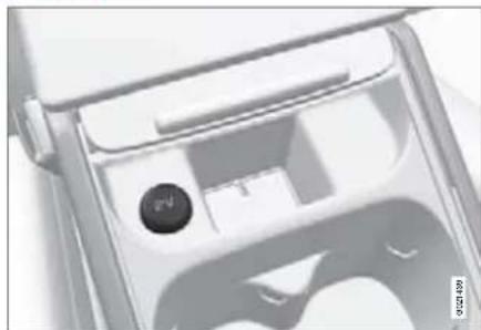
natural_image
Close-up of a mechanical component with a circular button and internal structure (no visible text or symbols)12 V socket in tunnel console, front seat.

natural_image
Close-up of a white appliance control panel with buttons and a circular indicator (no readable text or symbols)12 V socket in tunnel console, rear seat.
The electrical socket can be used for 12 V accessories, such as mobile phone chargers and coolers. The maximum current is 10 A.

04 Comfort and driving pleasure
Comfort inside the passenger compartment
For the socket to supply current, the ignition must be in at least position I, see page 65.

WARNING
Always leave the plug in the socket when the socket is not in use.
Electrical socket in cargo area*

natural_image
Close-up of a metallic tool interacting with a door panel, no visible text or symbolsFold down the cover to access the electrical socket. It works irrespective of whether or not the ignition is switched on. Use the electrical socket with the engine running to avoid discharging the battery.
First aid equipment\*
The equipment is located in the cargo area. The bag has a Velcro strap so that it can be attached to the cargo area wall.
04 Comfort and driving pleasure

Built-in phone\*
General

System overview
① Microphone
② SIM card reader
③ Keypad, see page 120.
4 Control panel
5 Privacy handset
Safety
Only entrust phone servicing to an authorised Volvo workshop. The built-in phone must be switched off during refuelling or in the vicinity of blasting work. IDIS limits the menu system depending on the speed of the car, see page 156.
Remember
SIM card
The phone can only be used with a valid SIM card (Subscriber Identity Module). For installation, see page 157. Emergency calls to emergency numbers can be made without a SIM card.
NOTE
The built-in phone cannot read 3G type SIM cards. Combined 3G/GSM cards work. Contact the network operator if the SIM card needs to be changed.
Menus and controls
The menus are navigated using the control panel and the steering wheel keypad. For general information on menus, see page 104. For information on the phone's controls, see previous page.
On/Off
Switch on the phone with a short press on PHONE. Enter the PIN code if necessary. The symbol shows that the phone is switched on. When this symbol is shown calls can be received even if the CD menu for example is shown in the display. Briefly press PHONE to use the phone menus and to dial
out. The text PHONE shows that the phone menu is active.
Switch off the phone with one long press on PHONE.

04 Comfort and driving pleasure
Built-in phone\*
Making and receiving calls
Making calls
- Switch on the phone.
- If PHONE is not shown in the display, briefly press PHONE.
- Dial the number or use the phone book, see page 155.
- Press ENTER for handsfree calls or pick up the privacy handset. Release the handset by pulling it down.
Ending a call
End a call by pressing EXIT or by hanging up the privacy handset.
Incoming calls
Press ENTER for handsfree calls or pick up the privacy handset. If the privacy handset is off the hook when the phone rings then calls must be received using ENTER.
End a call by pressing EXIT or by hanging up the privacy handset. Refuse calls using EXIT.
Automatic answer
The automatic answer function means that calls are accepted automatically. Activate/deactivate under Phone settings Call options Automatic answer .
Call waiting
The function enables a new call to be answered during an ongoing call. The new call is answered as usual and the previous call is put on hold. Activate/deactivate under Phone settings Call options Call waiting.
Automatic diversions
Incoming calls can be diverted automatically depending on the type of call and situation. Activate/deactivate under Call options → Diversions.
During a call
Press MENU or ENTER during a call to access the In-call menu.
To call
- Put the call on hold under Hold.
- Dial the number of the third party or use the Phonebook menu option.
Switch between calls using the Change menu option.
Conference calls
A conference call consists of several parties. It can be initiated when a call is underway and another is on hold. The Connect menu option starts the conference call.
All ongoing calls are disconnected if the conference call is terminated.
Switching between the privacy handset and handsfree
Switch from handsfree to the privacy handset by picking up the privacy handset or selecting Handset in the menu.
Switch from the privacy handset to hands-free using the Handsfree menu option.
04 Comfort and driving pleasure

Built-in phone\*
Mute mode
Mute mode involves deactivating the microphone, see page 153. Activate/deactivate the microphone using the Microphone On/Off menu option.
Audio settings
Call volume
The phone uses the front door speakers. Call volume can be controlled when the text PHONE is shown at the top of the display. Use the steering wheel keypad or VOLUME.
Audio system volume
Providing there is no ongoing call taking place, the audio system volume is controlled as usual with VOLUME. In order to control audio system volume during an ongoing call you have to switch to one of the audio sources.
The audio source can be automatically muted for incoming calls under Phone settings → Sounds and volume → Mute radio.
Signals and volume
Change the ring signal under Phone settings → Sounds and volume → Ring signals .
Activate/deactivate the message beep under Phone settings → Sounds and volume → Message beep.
Control the ring volume under Phone settings → Sounds and volume → Ring volume. Adjust using ▲ on the navigation button.
Phone book
Contact information can be stored on the SIM card or in the phone.
Storing contacts in the phone book
- Press MENU and scroll to Phonebook → New contact.
- Enter a name and press ENTER. For information on text input.
- Enter a number and press ENTER.
- Scroll to SIM card or Phone memory and press ENTER.
Searching for contacts
The easiest way to search in the phone book is with long presses on the keys 2 to 9. This starts a search in the phone book based on the key's first letter.
The phone book can also be reached with /▲ on the navigation button or with ▶ on the steering wheel keypad.
The search can also be performed from the phone book's Search menu under Phone book Search :
- Enter the first few letters of the contact and press ENTER, or simply press ENTER.
- Scroll to a contact and press ENTER to call.

04 Comfort and driving pleasure
Built-in phone\*
Erasing contacts
Erase a contact in the phone book by selecting it and pressing ENTER. Then scroll to Erase and press ENTER.
Erase all contacts under Phonebook → Erase SIM or Erase phone.
Copying entries between the SIM card and the phone book
Scroll to Phonebook Copy all SIM to phone or Phone to SIM and press ENTER.
Voice mail number
Voice mail number can be changed under Phone settings -Ball options Voice mail number. If there is no number stored then this menu can be reached with one long press on 1. Press 1 for a long time to use the stored number.
Other functions and settings
IDIS
IDIS (Intelligent Driver Information System) can, in active driving situations, delay or refuse ring signals from incoming calls. This way less attention is distracted from driving. IDIS is deactivated under Phone settings → IDIS.
Reading messages
- Scroll to Messages Read and press ENTER.
- Scroll to a message and press ENTER.
- The message text is shown in the display. Further options are obtained by pressing ENTER.
Writing and sending messages
- Scroll to Messages → Write new and press ENTER.
- Enter text and press ENTER. For information on text input.
- Scroll to Send and press ENTER.
- Enter a phone number and press ENTER.
Message settings
Message settings are not normally changed. The network provider has further information
on these settings. There are three options under Messages +Message settings:
- SMSC number which specifies the message centre which will transfer the messages.
- Validity time which specifies how long the message will be stored in the message centre.
- Message type.
Call lists
Lists of received, dialled and missed calls are stored in Call list. Dialled calls are also shown by pressing ENTER. The phone numbers in the lists can be saved in the phone book.
Call duration
Call duration is stored under Call list Call duration. Reset the values under Call list → Call duration Reset timers .
Show/hide number for third party
The phone number can be temporarily hidden under Call options Send my number.
IMEI number
In order to block a phone the network provider must be advised of the phone's IMEI number. Dial *#06# to show the number in
04 Comfort and driving pleasure

Built-in phone\*
the display. Write it down and keep it in a safe place.
Network selection
The network can be selected either automatically or manually under Phone settings → Network selection.
SIM code and security
The PIN code can protect the SIM card from unauthorised use. The code can be changed under Phone settings Edit PIN code.
Change the security level under Phone settings -SIM security . Select maximum security with the On option. The code will then need to be entered each time the phone is switched on. Select the next highest security level with the Automatic option. The phone then stores the code and automatically specifies it when the phone is switched on. When the SIM card is used with another phone the code must be entered manually. Select minimum security with the Off option. The SIM card can then be used without the code at all.
Reset to factory settings
The phone settings are fully reset under Phone settings Reset Phone settings.
Installing the SIM card

natural_image
Interior view of a printer setup with a red arrow pointing to a device component (no visible text or symbols)
1 Make sure that the phone is deactivated. Pull out the SIM card holder which is located in the glovebox.
2 Place the SIM card with the metal surface visible and fit the cover on the SIM card holder Refit the SIM card holder.
Recommendations during driving.... 160
Refuelling 163
Fuel.... 164
Loading 166
Cargo area.... 170
Warning triangle 173
Driving with a trailer 174
Towing 180
DURING YOUR JOURNEY
natural_image
Black-and-white photo of a car driving through a highway with rolling hills and a visible mirror reflection (no text or symbols)05


05 During your journey
Recommendations during driving
General
Economical driving
Economical driving and reducing environmental impact result from driving gently with anticipation and adapting your driving style and speed to the current situation (for further advice on how you can reduce environmental impact, see page 9).
- Do not let the engine idle, but drive at light loads as soon as it is possible.
- A cold engine consumes more fuel than a warm one.
- Do not drive with unnecessary loads in the car.
- Do not use winter tyres when the roads are dry.
- Remove the load carrier when it is not in use.
- Use the parking heater* in cold weather so that the engine reaches its normal operating temperature more quickly.
Slippery driving conditions
Practise driving on slippery surfaces under controlled conditions to learn how the car reacts.
Driving in water
The car can be driven through water at a maximum depth of 25 cm at a maximum speed of 10 km/h. Extra caution should be exercised when passing through flowing water.
During driving in water, maintain a low speed and do not stop the car. When the water has been passed, depress the brake pedal lightly and check that full brake function is achieved. Water and mud for example can make the brake linings wet resulting in delayed brake function.
Clean the electric contacts of the electric engine block heater and trailer coupling after driving in water and mud.
Do not let the car stand with water over the sills for any long period of time. This could cause electrical malfunctions.

IMPORTANT
Engine damage can occur if water enters the air filter.
In greater depths, water can enter the transmission. This reduces the lubricating ability of the oils and shortens the service life of the systems.
In the event of engine stop in water do not try restart. Tow the car from the water.
Engine and cooling system
Under special conditions, for example when driving in hilly terrain, extreme heat or with heavy loads, there is a risk that the engine and cooling system will overheat. Proceed as follows to avoid overheating the engine.
- Maintain a low speed when driving with a trailer up long, steep ascents.
- Do not turn the engine off immediately you stop after a hard drive.

NOTE
It is normal for the engine's cooling fan to operate for a while after the engine has been switched off.
- Remove any auxiliary lamps from in front of the grille when driving in extreme high temperatures.
- Do not exceed engine speeds of 4500 rpm (3500 rpm for diesel engines) if driving with a trailer or caravan in hilly terrain. The oil temperature could become too high.
05 During your journey

Recommendations during driving
Open tailgate
Avoid driving with the tailgate open. If it is however necessary, only drive for a short distance. Close all windows, set the air distribution to the windscreen and floor and run the fan at the highest speed.

WARNING
Do not drive with the tailgate open. Toxic exhaust fumes can be drawn into the car through the cargo area.
Do not overload the battery
The electrical functions in the car load the battery to varying degrees. Avoid using the ignition position II when the engine is switched off. Use ignition position I instead, as less power is consumed.
Also, be aware of different accessories that load the electrical system. Do not use functions which use a lot of power when the engine is switched off. Examples of functions that use a lot of power:
- ventilation fan
- windscreen wipers
• audio system (high volume) - parking lamps
If the battery voltage is low, a message appears on the information display. The energy-saving function shuts down certain functions or reduces certain functions such as the ventilation fan and audio system. Charge the battery by starting the engine.
Before a long journey
- Check that the engine is working normally and that fuel consumption is normal.
- Make sure that there are no leaks (fuel, oil or other fluid).
- Check all bulbs and tyre tread depths.
- Carrying a warning triangle is a legal requirement in certain countries.

05 During your journey
Recommendations during driving
Winter driving
Check the following in particular before the cold season:
- The engine coolant must contain at least 50% glycol. This mixture protects the engine down to approximately -35 °C. To achieve optimum antifreeze protection, different types of glycol must not be mixed.
- The fuel tank must be kept filled to prevent condensation.
- Engine oil viscosity is important. Oils with lower viscosity (thinner oils) facilitate starting in cold weather and also reduce fuel consumption while the engine is cold. For more information on suitable oils, see page 227.

IMPORTANT
Low viscosity oil must not be used for hard driving or in hot weather.
- The condition of the battery and charge level must be inspected. Cold weather places great demands on the battery and its capacity is reduced by the cold.
- Use washer fluid to avoid ice forming in the washer fluid reservoir.
To achieve optimum roadholding Volvo recommends using winter tyres on all four wheels if there is a risk of snow or ice.

NOTE
The use of winter tyres is a legal requirement in certain countries. Studded tyres are not permitted in certain countries.
Slippery driving conditions
Practise driving on slippery surfaces under controlled conditions to learn how the car reacts.
Refuelling
Refuelling
Opening/closing the fuel filler flap

The engine must be switched off before the fuel filler flap can be opened. Open using the button on the lighting panel. The fuel filler flap is located on the right-hand rear wing, as indicated by the symbol's arrow in the information display.
Close the fuel filler flap by pressing it in until a click confirms that it is closed.
Opening/closing the fuel cap

A certain overpressure may arise in the tank in the event of high outside temperatures. Open the cap slowly.
After refuelling, refit the cap and turn it until one or more "clicks" are heard.
Filling up with fuel
Do not overfill the tank but fill until the pump nozzle cuts out.

NOTE
Excess fuel in the tank can overflow in hot weather.

05 During your journey
Fuel
General
Fuel of a lower quality than that recommended by Volvo must not be used as engine power and fuel consumption is negatively affected.

WARNING
Fuel which spills onto the ground can be ignited.
Switch off the fuel-driven heater before starting to refuel.
Never carry an activated mobile phone when refuelling. The ring signal could cause spark build-up and ignite petrol fumes, leading to fire and injury.

NOTE
Extreme weather conditions, driving with a trailer or driving at high altitudes in combination with fuel grade are factors that could affect the car's performance.
Diesel
Diesel must fulfil the EN 590 or JIS K2204 standards. Diesel engines are sensitive to contaminants, such as excessively high volumes of sulphur particles for example. Only use diesel fuel from well-known producers. Never use diesel of dubious quality.
At low temperatures ( -40\ ircC to -6\ ircC ), a paraffin precipitate may form in the diesel fuel, which can lead to ignition problems. Special diesel fuel designed for low temperatures around freezing point is available from the major oil companies. This fuel is less viscous at low temperatures and reduces the risk of paraffin precipitate.
The risk of condensation in the fuel tank is reduced if the tank is kept well filled. When refuelling, check that the area around the fuel filler pipe is clean. Avoid spilling fuel onto the paintwork. Wash off any spillage with detergent and water.

IMPORTANT
Only ever use fuel that fulfils the European diesel standard.

IMPORTANT
Diesel type fuels which must not be used: special additives, Marine Diesel Fuel, fuel oil, RME 1 (Rape Methyl Ester) and vegetable oil. These fuels do not fulfil the requirements in accordance with Volvo recommendations and generate increased wear and engine damage that is not covered by the Volvo warranty.
1 Diesel fuel may contain a certain amount of RME, but further amounts must not be added.

IMPORTANT
For model year 2006 or later the sulphur content must be a maximum of 50 ppm.
Empty tank
No special procedures are required if the tank runs dry. The fuel system is bled automatically if the ignition switch is kept in position II for approx. 60 seconds before the start attempt.
Draining condensation from the fuel filter
The fuel filter separates condensation from the fuel. Condensation can disrupt engine operation.
05 During your journey

Fuel
The fuel filter must be drained at the intervals specified in the Service and Warranty Booklet or if you suspect that the car has been filled with contaminated fuel.

IMPORTANT
Certain special additives remove the water separation in the fuel filter.
Petrol
Petrol must meet the EN 228 standard. Most engines can be run with octane ratings of 95 and 98 RON. 91 RON should only be used in exceptional cases.
- 95 RON can be used for normal driving.
- 98 RON is recommended for optimum performance and minimum fuel consumption.
When driving in temperatures above +38 °C, fuel with the highest possible octane rating is recommended for optimum performance and fuel economy.

IMPORTANT
Always refuel with unleaded petrol so as not to damage the catalytic converter. In order that Volvo's warranty shall remain valid, never mix alcohol with petrol, as the fuel system could be damaged. Do not use additives not recommended by Volvo.
Catalytic converters
The catalytic converters are designed to purify exhaust gases. They are located close to the engine in order to quickly reach operating temperature.
The catalytic converters consist of a monolith (ceramic or metal) with channels. The chan-
nel walls are lined with a thin layer of platinum, rhodium and palladium. These metals act as catalysts, i.e. they participate in and accelerate a chemical reaction without being used up themselves.
Lambda-sond TM oxygen sensor The Lambda-sond is part of a control system intended to reduce emissions and improve fuel economy.
An oxygen sensor monitors the oxygen content of the exhaust gases leaving the engine. This value is fed into an electronic system that continuously controls the injectors. The ratio of fuel to air directed to the engine is continuously adjusted. These adjustments create optimal conditions for efficient combustion, and together with the three-way catalytic converter reduce harmful emissions (hydrocarbons, carbon monoxide and nitrous oxides).

05 During your journey
Loading
General
The load capacity is affected by what is mounted on the car, such as a towbar, load carriers and roof box. The load capacity of the car is also reduced by the number of passengers and their weight.

WARNING
The car's driving characteristics change depending on the weight and distribution of the load.
Loading the cargo area
Stop the engine and apply the parking brake when loading or unloading long objects. The gear lever/selector can be knocked out of position by long loads, which could set the car in motion.
- Position the load firmly against the back-rest in front.
- Put wide loads in the centre.
- Heavy objects should be placed as low as possible. Avoid placing heavy loads on a lowered backrest.
- Cover sharp edges with something soft to avoid damaging the upholstery.
- Secure all loads to the load retaining eyelets with straps or web lashings.
Lowering the rear seat backrest
To simplify loading in the cargo area, the rear seats of the car can be folded down, see page 69.

WARNING
A loose object weighing 20 kg can, in a frontal collision at a speed of 50 km/h, carry the impact of an item weighing 1000 kg. Always secure the load.

WARNING
The protection provided by the inflatable curtain in the headlining may be compromised or eliminated if the load is too high. Never load cargo above the backrest. During heavy braking the load may otherwise shift, causing injury to the car's occupants.

WARNING
Always secure the load. During heavy braking the load may otherwise shift, causing injury to the car's occupants.
Protect sharp edges with something soft. Turn off the engine and apply the parking brake when loading or unloading long objects. Otherwise you may accidentally knock the gear lever or gear selector with the load and cause a gear to engage and the car to move off.
05 During your journey

Loading
Power operated tailgate\*

WARNING
Pay attention to the risk of crushing when opening/closing. Before starting to open/close, make sure that there is nobody close to the tailgate as a crushing injury could have serious consequences. Always operate the tailgate with caution.

IMPORTANT
Pay attention to the height of the roof when using power operation. Do not use power tailgate operation with low roof heights or be ready to stop the opening, see the chapter "Stopping tailgate opening".

NOTE
When power operation is activated the rear lamp clusters are lit.
To open
Opening can be carried out in three ways:
- The button on the lighting panel, hold it depressed for a short time.
- There remote control key, hold the button depressed for a short time.
- Tailgate handle – pull the handle and the tailgate opens.
To close
Close using the close button on the tailgate or manually.
- Press the button to close the tailgate automatically.
Interrupt tailgate opening

natural_image
Top-down view of a car head panel with a small icon pointing to the front panel (no text or symbols visible)- Tailgate button : Press the button again – opening is interrupted. (Press a third time to resume closing).
- Tailgate outside handle: Press the handle's button again – opening is interrupted.
Securing loads
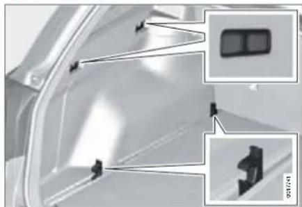
natural_image
Interior view of a vehicle showing structural components and a close-up of a vehicle's front panel (no text or symbols visible)On both sides of the cargo area there are several mounting points designed for securing loads. They are located in the floor and in the top edge of both sides of the cargo area.

WARNING
Hard, sharp and/or heavy objects that are loose or protrude could cause injury during heavy braking.
Always secure large and heavy objects with a seatbelt or cargo retaining straps.

05 During your journey
Loading
Floor rails

natural_image
Top-down view of a car trunk with red wire handles, showing internal components (no text or symbols)Load secured in both upper and lower mounting points
In the floor of the cargo area there are two rails with movable cargo retaining hooks for securing items in the cargo area using cargo retaining straps.

IMPORTANT
Do not use other adjustable straps as these could pull and break the mounting points.
Cargo retaining straps

natural_image
Two identical red cable clips with black connectors, shown from top and bottom angles (no text or symbols)Strap retention
One loop of the cargo retaining strap around one of the cargo retaining hooks secures the strap and prevents it from sliding around the hook.

NOTE
A suitable width for a cargo retaining strap is approx. 25 mm.
Moving a cargo retaining hook


Fold the cargo retaining hook down in the direction to which its opening points.

Slide the hook to the required position.

Fold the hook up – it is self-locking.

NOTE
There must be at least 50 cm between the cargo retaining hooks in the rail.
05 During your journey

Loading
Removing a cargo retaining hook
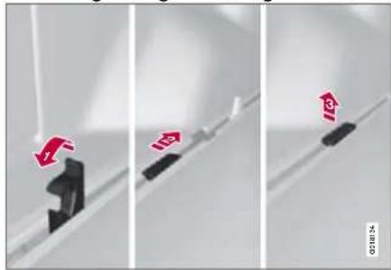
The cargo retaining hooks can be easily removed from the rail, e.g. for cleaning the bottom of the rail.
Fold the cargo retaining hook down in the direction to which its opening points.
2 Slide the hook to the cut-out opening.
3 Lift the hook straight up.
Cargo retaining hook correctly fitted/incorrectly fitted
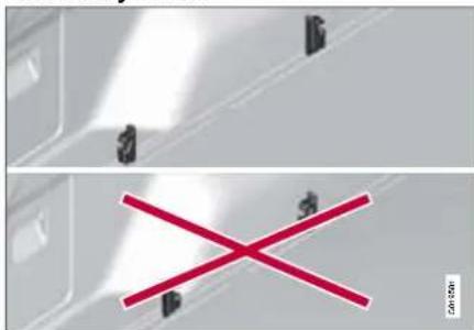
Fit the cargo retaining hooks correctly!
It is important that the cargo retaining hooks are fitted correctly. The hooks' openings must point away from each other.
WARNING
Fit the cargo retaining hooks correctly. Otherwise the cargo retaining strap will move the cargo retaining hook down so that it loosens and the strap slides off.
Bag holder*
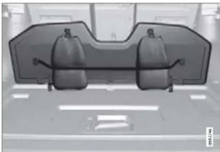
natural_image
Top-down view of a vehicle rear bumper with two side-mounted gear heads (no visible text or symbols)Bag holder under folding hatch in the floor.
The bag holder keeps carrier bags in place and prevents them from overturning and spreading their contents across the cargo area.
- Fold up the hatch in the cargo area.
- Tension and secure the carrier bags using the strap.

05 During your journey
Cargo area
Safety grille*

natural_image
Two-panel technical illustration of a car interior showing front and side views with structural grid patterns (no text or symbols)A protective grille prevents cargo from being thrown forward in the passenger compartment in the event of heavy braking. For safety reasons, the grille must always be mounted and secured correctly.
Folding up
Take hold of the bottom of the safety grille and pull back/up.

IMPORTANT
The safety grille cannot be folded up or down when the cargo cover is fitted.
Installation
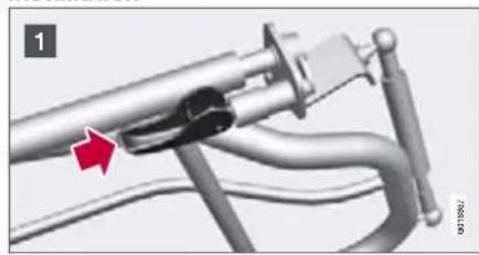
natural_image
Mechanical assembly diagram showing a lever mechanism with a red arrow indicating motion (no text or symbols present)
natural_image
Mechanical assembly diagram showing a lever mechanism with red arrows indicating motion (no text or symbols present)
natural_image
Mechanical assembly diagram showing a lever mechanism with red arrows indicating motion direction (no text or symbols)
NOTE
The safety grille is most easily fitted and removed by two people via the rear doors. When fitting, the handle, see
illustration 1 - 3, must be on the front of the grille.
The backrests must be lowered to allow the safety grille to be fitted, see page 69.
1 Position the handle in fitting position, see illustration. Press gently on the handle to enable it to be turned into position, see arrow.
2 Press the strut in towards the grille and align the grille in the roof mounting.
3 Turn the handle 90° Press gently as illustrated if necessary. Secure the grille by angling the handle 90°
Removal
Removal of the grille takes place in reverse order to the description in the previous section entitled Installation.
05 During your journey

Cargo area
Cargo cover
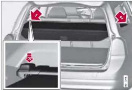
natural_image
Interior view of a car showing rear door, side profile, and interior seat (no visible text or symbols)Cargo cover
Application
Pull the cargo cover over the load and hook it into the holes in the cargo area's rear pillars.

IMPORTANT
The safety grille cannot be folded up or down when the cargo cover is fitted.
Fitting the cargo cover
- Move one end piece of the cover into the recess on the side panel.
- Move the other end piece of the cover into the corresponding recess.
-
Press both sides in. A "click" should be audible and the red marking should disappear.
-
Check that both end pieces are locked.
Removing the cargo cover
- Press in one end piece button and lift it out.
- Carefully angle the cover up/out and the other end piece loosens automatically.
Lowering the cargo cover's rear sealing disc
In its rolled-in position, the cargo cover's rear sealing disc protrudes horizontally into the cargo area when it is fitted.
- Pull the sealing disc back gently, free from its support shelves, and lower.
Safety net\*
The safety net's cassette is mounted on the rear of the backrest. The net is produced from strong nylon fabric and is in two pieces. The two pieces have different widths and the widest one is fitted to the right (seen from behind the car). It is folded up from the back of the backrest and locks itself after approx. 1 minute if the rear seat backrests are raised. The net can also be used when the rear seat is folded forward.
Using with raised backrests

Pull the right-hand piece of the net up by pulling the strap.
2 Hook the rod into the mounting on the right-hand side.

05 During your journey
Cargo area
Then pull out the rod and hook it into the left-hand side.
4 Pull up the left-hand cargo net in the same way as the right-hand one and secure it to the rod.
Removal takes place in reverse order.
Removing the safety net cassettes.
- Pull back one of the net's mountings to the larger hole and pull it out.
- Remove the other mounting in the same way.
Removing the safety net's storage cassette.
- Lower the whole of the backrest.
- Slide the cassette outwards until it has released from the mounting brackets.

WARNING
Cargo area loads must be well secured even if the safety net is correctly fitted.
Using the safety net in combination with the cargo cover
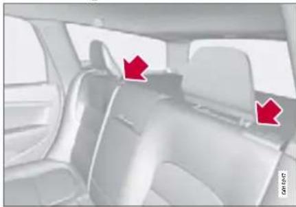
natural_image
Interior view of a car showing the rear seat and side seats with red arrows pointing to specific areas (no text or symbols visible)The straps for raising are located by the arrows. Follow the same procedure as described in the previous chapter, "Using the cargo net with raised backrests".
Front seat
The passenger seat backrest can also be folded for an extra long load, see page 66.
Roof load
Using load carriers
To avoid damaging the car and for maximum possible safety while driving, the load carriers designed by Volvo are recommended.
Carefully follow the installation instructions supplied with the carriers.
- Check periodically that the load carriers and load are properly secured. Lash the load securely with retaining straps.
- Distribute the load evenly over the load carriers. Put the heaviest objects at the bottom.
- The size of the area exposed to the wind, and therefore fuel consumption, increase with the size of the load.
- Drive gently. Avoid quick acceleration, heavy braking and hard cornering.

WARNING
The car's centre of gravity and driving characteristics are altered by roof loads.
For information on maximum permitted roof load, including load carriers and any space box, see page 224.
05 During your journey

Warning triangle
Warning triangle

natural_image
Interior view of a car showing the rear door and side panel with red indicator lights (no text or symbols visible)
natural_image
3D triangular object with red arrows pointing to its edge, shown in a zoomed-in inset (no text or symbols)
natural_image
Diagram showing a black triangle with red arrows indicating direction, no text or symbols present1 Lift the floor mat and take out the warning triangle.
2 Take the warning triangle from the case, fold out and assemble the two loose sides.
3 Fold out the warning triangle's support legs.
Follow the regulations for the use of a warning triangle. Position the warning triangle in a suitable place with regard to traffic.
Ensure the warning triangle and its case are properly secured in the cargo area after use.
NOTE
If the floor hatch is not closed then privacy locking does not work, see page 43.
First aid

natural_image
3D model of a car trunk with red plastic components, shown in an inset view (no text or symbols)A case with first aid equipment is located under the floor in the cargo area

05 During your journey
Driving with a trailer
General
If the towing bracket is mounted by Volvo, then the car is delivered with the necessary equipment for driving with a trailer.
- The car's towing bracket must be of an approved type.
- If the towbar is retrofitted, check with your Volvo dealer that the car is fully equipped for driving with a trailer.
- Distribute the load on the trailer so that the weight on the towing bracket complies with the specified maximum towball load.
- Increase the tyre pressure to the recommended pressure for a full load. For tyre pressure label location, see page 214.
- Clean the towing bracket regularly and grease the towball.
- Do not tow a heavy trailer when the car is brand new. Wait until it has been driven at least 1000 km.
- The brakes are loaded much more than usual on long and steep downhill slopes. Downshift to a lower gear and adjust your speed.
- The engine is loaded more heavily than usual when driving with a trailer.
- If the car is driven with a heavy load in a hot climate, the engine may overheat. If the temperature in the engine's cooling system is too high the warning symbol is
illuminated and the information display shows High engine temp Stop safely. Stop the car in a safe way and allow the engine to run at idling speed for several minutes and cool down. If High engine temp Stop engine or Cool-ant level low, Stop engine then the engine must be switched off after stopping the car.
- The automatic gearbox has a built-in protection system that engages in the event of overheating. If the temperature in the gearbox is too high then the warning symbol illuminates and the information display shows Transmission hot Reduce speed or Transmission hot Stop safely. Follow the instructions and reduce speed or stop the car in a safe way and allow the engine to run at idling speed for several minutes to enable the gearbox to cool down. In the event of overheating the car's air conditioning may be temporarily switched off.
- In the interests of safety, you should restrict speed to 80 km/h, even if the laws of certain countries allow for higher speeds.
- Move the gear selector to position P when parking an automatic car with a hitched trailer. Always use the parking brake. Block the wheels with chocks when parking a car with hitched trailer on a hill.
Trailer cable
An adapter is required if the car's towing bracket has 13 pin electrics and the trailer has 7 pin electrics. Use an adapter cable approved by Volvo. Make sure the cable does not drag on the ground.
Direction indicators on trailer
A symbol in the combined instrument panel flashes when the direction indicators are used and the trailer is connected. If the symbol flashes more quickly then one of the lamps on the car or the trailer is broken, see page 61.
Automatic gearbox
Parking on a hill
- Activate the parking brake.
- Move the gear selector to position P.
Starting on a hill - Move the gear selector to position D.
- Release the parking brake.
Steep gradients
- Do not use a higher manual gear than the engine can "handle". It is not always economical to drive in high gears.
- Avoid driving with a trailer on inclines of more than 15%.
05 During your journey

Driving with a trailer
Level control\*
The rear shock absorbers maintain a constant height irrespective of the car's load (up to the maximum permissible weight). When the car is stationary the rear of the car lowers slightly, which is normal.
Trailer weights
National vehicle regulations can limit trailer weights and speeds. Towbars can be certified for higher towing weights than the car can actually tow. For Volvo's permitted trailer weights, see page 223.

WARNING
Follow the stated recommendations for trailer weights. Otherwise, the car and trailer may be difficult to control in the event of sudden movement and braking.
Towing bracket
If the car is equipped with a detachable towbar, the towball mounting instructions must be followed carefully, see page 177.

WARNING
Be sure to attach the trailer's safety cable to the correct place.

WARNING
If the car is fitted with a Volvo detachable towbar: Follow the assembly instructions for the towball section carefully. The towball section must be locked with the key before setting off. Check that the indicator window shows green.

NOTE
Always detach the towball section after use. Keep it in the cargo area.

05 During your journey
Driving with a trailer
Specifications Important checks

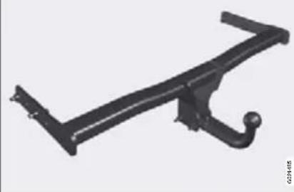
natural_image
Mechanical bracket component (no visible text or symbols)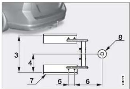
Dimensions, mounting points (mm)
| 1 (V70) | 1129 |
| 1 (XC70) | 1113 |
| 2 (V70) | 93 |
| 2 (XC70) | 77 |
| 3 | 855 |
| 4 | 428 |
| 5 | 112 |
| 6 | 346 |
| 7 | Side member |
| 8 | Ball centre |
- The towball must be cleaned and greased regularly.

NOTE
If a towball hitch with vibration damper is used, it is not necessary to grease the towball.
05 During your journey

Driving with a trailer
Installing the towball

natural_image
Close-up of a black mechanical component with two red arrows pointing to features, no visible text or symbols.1 Remove the protective cover by pressing up the catch and pulling the cover straight back

natural_image
Close-up of a white mechanical component with a red arrow pointing to a small black square (no text or symbols visible)3 The indicator window must show red.

natural_image
Close-up of a mechanical component with a red arrow pointing to a small feature, no visible text or symbols.5 The indicator window must show green.

natural_image
Close-up of a mechanical device with a key inserted, showing a red arrow indicating motion (no text or symbols present)2 Ensure that the mechanism is in the unlocked position by turning the key clockwise.

natural_image
Mechanical assembly diagram showing a lever and gear mechanism with a red arrow indicating motion direction (no text or symbols)4 Insert the towball section until you hear a click.

natural_image
Illustration of a robotic arm with a key and red arrow indicating motion (no text or symbols)5 Turn the key anticlockwise to locked position. Remove the key from the lock.

05 During your journey
Driving with a trailer

natural_image
Diagram of a mechanical device with red arrows indicating motion or force direction (no text or symbols)7 Check that the towball section is secure by pulling it up, down and back. If the towball section is not fitted correctly then it must be removed and refitted in accordance with the previous instructions.
IMPORTANT
Only grease in the towball for the towing hitch, the remainder of the towball section should be clean and dry.

natural_image
Mechanical linkage component with chain and bracket (no visible text or symbols)8 The trailer's safety cable must be secured in the towing bracket's mounting eye.
05 During your journey

Driving with a trailer
Removing the towball

natural_image
Illustration of a mechanical device with a key and red arrow indicating rotation (no text or symbols)1 Insert the key and turn it clockwise to the unlocked position.

natural_image
Mechanical component diagram showing a lever and gear assembly with a red arrow indicating motion (no text or symbols)3 Turn the locking wheel down fully, until it comes to a stop. Hold it in this position while pulling the towball rearward and upward.

natural_image
Close-up of a mechanical component with red arrows indicating parts (no text or symbols)2 Push in the locking wheel and turn it anticlockwise until you hear a click.

natural_image
3D rendered object with a red arrow pointing to a black curved surface, no visible text or symbols4 Push the protective cover until it snaps tight.
WARNING
Firmly secure the towbar's loose towball if it is stored in the car's cargo area.

05 During your journey
Towing
General
Never tow the car to bump start it. Use a donor battery if the battery is discharged and the engine does not start.

IMPORTANT
Bump starting the car can damage the catalytic converter.
Automatic gearbox
Move the gear selector to position N.

IMPORTANT
A car with an automatic gearbox must not be towed at speeds above 80 km/h or further than 80 km.
Note that the car must always be towed with the wheels rolling forward.
- A car with an automatic gearbox and raised front suspension (2WD), must not be towed at speeds above 80 km/h. Note that the car must always be towed with the wheels rolling forward.
- A car with an automatic gearbox, All Wheel Drive (AWD) and raised front suspension, must not be towed at speeds above 80km / h . It should not be towed further than 80km . Note that the car must always be towed with the wheels rolling forward.
Manual gearbox
Move gear lever into neutral. The tow rope must always be taut in order to avoid violent jerks. Be prepared to depress the brake pedal.

WARNING
The steering lock stays in the position it was in when the power was cut off. The steering lock must be unlocked before towing. The ignition must be in position II. Never remove the remote control key from the ignition switch while driving or when the car is being towed.

WARNING
The brake servo and power steering do not work when the engine is switched off. The brake pedal must be pressed about five times harder than normal, and the steering will be considerably heavier than normal.
Towing eye
Use the towing eye if the car needs to be towed on the road. The towing eye is attached in the recess on the right-hand side of the front or rear bumper.
After use, unscrew the towing eye and return it into the cargo area.

WARNING
The towing eye is only designed for towing on roads, not for recovering the car. Call a recovery service for recovery assistance.
Find out the highest legal speed before towing the car.

WARNING
Insert the remote control key in the ignition switch to unlock the steering lock (so that the car can be steered) before towing.
05 During your journey

Towing
Fitting the towing eye

natural_image
Mechanical assembly diagram showing components inside a vehicle frame (no text or symbols)1 Take out the towing eye that is located under the floor hatch in the cargo area.
For the XC70: Release the bottom edge of the cover on the bumper with a screw-driver or coin. Screw in the towing eye firmly, right in up to the flange.
Use the wheel wrench to tighten the towing eye.
NOTE
On certain cars with fitted towbar the towing eye cannot be secured in the rear mounting. In which case, secure the tow rope in the towbar.
For this reason it is advisable to store the towbar's towball in the car, see page 179.
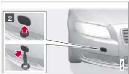
natural_image
Close-up of a car's head and side profile showing a key inserted into the dashboard (no text or symbols visible)2 For the V70: Press the marked edge of the cover into the bumper and release. Fold aside the cover and screw in the towing eye firmly, right in up to the flange.
Engine compartment....184
Lamps 189
Wiper blades and washer fluid.... 195
Battery.... 197
Fuses....200
Wheels and tyres.... 205
Car care.... 217
Type designations 221
Specifications.... 222
MAINTENANCE AND SPECIFICATIONS

natural_image
Close-up of metallic gear teeth and gears against a dark background (no text or symbols visible)06


06 Maintenance and specifications
Engine compartment
General
Volvo service programme
To keep the car as safe and reliable as possible, follow the Volvo service programme as specified in the Service and Warranty Booklet. Have an authorised Volvo workshop carry out service and maintenance work. Volvo workshops have the personnel, special tools and service literature to guarantee the highest quality of service.

IMPORTANT
For the Volvo warranty to apply, check and follow the instructions in the Service and Warranty Booklet.
Check regularly
Check the following oils and fluids at regular intervals, e.g. when refuelling:
- Coolant
- Engine oil
• Power steering fluid - Washer fluid

WARNING
Bear in mind that the radiator fan may start automatically some time after the engine has been switched off.
Always have the engine cleaned by a work-shop. There is a risk of fire if the engine is hot.
Opening and closing the bonnet

natural_image
Interior view of a vehicle showing a black plastic component inserted into a car's seat, with a red arrow pointing to it (no text or symbols visible)
natural_image
Close-up of a car's front bumper with tweezers and a small inset showing a black object (no text or symbols visible)1 Pull the handle by the pedals. You will hear when the catch releases.
2 Move the catch to the left and open the bonnet. (The catch hook is located between the headlamp and grille, see illustration.)

WARNING
Check that the bonnet locks properly when closed.
06 Maintenance and specifications

Engine compartment
Engine compartment, overview

The appearance of the engine compartment may vary depending on engine variant
1 Coolant expansion tank
② Power steering fluid reservoir
③ Engine oil dipstick
4 Radiator
⑤ Filler opening for engine oil
6 Brake and clutch fluid reservoir (left-hand drive)
⑦ Battery
8 Relay and fuse box
9 Filling washer fluid
10 Air filter
WARNING
High voltage output from the ignition system. The voltage in the ignition system is highly dangerous. The ignition must therefore always be in position 0 for work in the engine compartment, see page 65.
Do not touch the spark plugs or ignition coils when the ignition is in ignition position II or when the engine is hot.
Checking the engine oil
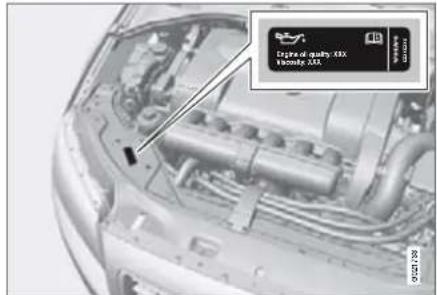
Decal for oil grade
Volvo recommends Castrol oil products. If the car is driven in adverse conditions, see Volvo's recommendations on page 227.

06 Maintenance and specifications
Engine compartment

IMPORTANT
In order to fulfil the requirements for the engine's service intervals all engines are filled with a specially adapted synthetic engine oil at the factory. The choice of oil has been made very carefully with regard to service life, starting characteristics, fuel consumption and environmental impact. An approved engine oil must be used in order that the recommended service intervals can be applied. Only use a prescribed grade of oil (see the engine compartment decal) for both filling and oil change, otherwise you will risk affecting service life, starting characteristics, fuel consumption and environmental impact. Volvo Car Corporation disclaims all warranty liability if engine oil of the prescribed grade and viscosity is not used.
Volvo uses different systems for warning of low oil level or low oil pressure. Certain variants have an oil pressure sensor, and then the lamp for oil pressure is used. Other variants have an oil level sensor, and then the driver is informed via the warning symbol in the centre of the instrument unit as well as by display texts. Certain models have both variants. Contact a Volvo dealer for more information.
Filling and dipstick

natural_image
Close-up of a car hood with internal components and close-ups of a circular component (no visible text or symbols)Petrol engine

natural_image
Close-up of a mechanical component with internal components and two magnified insets (no visible text or symbols)Diesel engine
Change in accordance with the intervals specified in the Service and Warranty Booklet.

IMPORTANT
When filling oil to top up, the oil being filled must be of the same grade, see page 227.
Checking the oil level in a new car is especially important before the first scheduled oil change.
The most accurate measurements are made on a cold engine before starting. The measurement will be inaccurate if taken immediately after the engine is switched off. The dipstick will indicate that the level is too low because the oil has not had time to flow down into the oil sump.
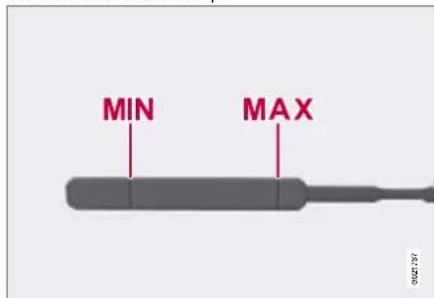
The oil level must be within the area marked on the dipstick.
06 Maintenance and specifications

Engine compartment
Park the car on a level surface, switch off the engine and wait 10-15 minutes to allow the oil time to run back to the sump. For capacities, see page 228.
Checking with a cold engine
- Wipe the dipstick clean.
- Check the level using the dipstick. It must be between the MIN and MAX marks.
- If the level is close to the MIN mark, start by topping up with 0.5 litres of oil. Top up until the level is nearer to MAX than MIN on the dipstick.

IMPORTANT
Never fill above the MAX mark. Oil consumption may increase if too much oil is poured into the engine.

WARNING
Do not spill oil onto the hot exhaust manifold due to the risk of fire.
Checking with a warm engine
- Wipe the dipstick clean.
- Check the oil level using the dipstick.
- If the level is close to the MIN mark, start by topping up with 0.5 litres of oil. Top up until the level is nearer to MAX than MIN on the dipstick.
Coolant
Checking and topping up the coolant

natural_image
Exterior view of a car showing engine compartment and internal components (no visible text or symbols)When topping up the coolant, follow the instructions on the packaging. To optimise refrigerant and corrosion protection ensure that the mixture of coolant is always 50% water and 50% coolant. Never top up with water only. The risk of freezing increases with both too little and too much coolant concentrate. For capacities, see page 229.

IMPORTANT
Always use coolant with anti-corrosion agent as recommended by Volvo. New cars are filled with coolant that can withstand temperatures down to approximately - 35 °C.
Check the coolant regularly
The level must lie between the MIN and MAX marks on the expansion tank. If the system is not filled sufficiently, high temperatures could occur, causing a risk of damage to the engine.

WARNING
Coolant can be very hot. If the coolant requires topping up when the engine is at operating temperature, unscrew the expansion tank cap slowly to gently release the overpressure.

06 Maintenance and specifications
Engine compartment
Brake and clutch fluid
Checking the level
Brake and clutch fluid have a common reservoir. The level must be between the MIN and MAX marks that are visible inside the reservoir. Check the level regularly.
Change the brake fluid every other year or at every other regular service.
For capacities and recommended fluid grade, see page 229. The fluid should be changed annually on cars driven in conditions requiring hard, frequent braking, such as driving in mountains or tropical climates with high humidity.

WARNING
If the brake fluid is under the MIN level in the brake fluid reservoir, do not drive further before topping up the brake fluid. The reason for the loss of brake fluid must be investigated by an authorised Volvo workshop.
Filling
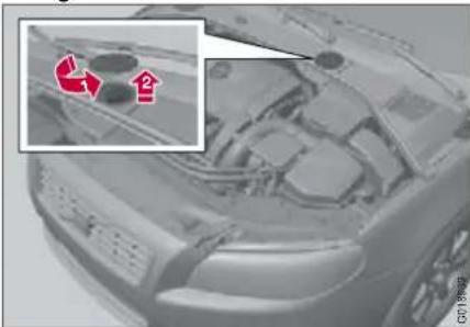
natural_image
Close-up of a car's front engine compartment with red arrows pointing to internal components (no visible text or symbols)The fluid reservoir is located on the driver's side
The fluid reservoir is protected under the cover over the cold section in the engine compartment. The round cover must be removed first before the reservoir cap can be reached.
- Turn and open the cover located on the covering.
- Unscrew the reservoir cap and fill the fluid. The level must be between the MIN and MAX marks, which are located on the inside of the reservoir.

IMPORTANT
Remember to close the cap.
Power steering fluid


IMPORTANT
Keep the area around the power steering fluid reservoir clean when checking.
Check the level frequently. The fluid does not require changing. The fluid level must be between the MIN and MAX marks. For capacities and recommended fluid grade, see page 229.

NOTE
If a fault should arise in the power steering system or if the engine is switched off and the car must be towed, it can still be steered.
06 Maintenance and specifications

Lamps
General
All bulb specifications are given on page 194. The following list contains bulbs and point-source lamps that are specialised or unsuitable for replacement except at a workshop:
- General interior lighting in the roof, reading lamps
- Gloveboxlighting
• Direction indicators, door mirror - Approach lighting
- Brake light, fog lamp, reversing lamp
- Rear side position lamps, position lamps
• Active Bi-Xenon, Bi-Xenon lights - LED lamps, general

WARNING
On cars with Bi-Xenon and Active Bi-Xenon headlamps, Xenon lamp replacement must be carried out at an authorised Volvo workshop. The headlamps must be handled with extreme care due to the Xenon lamp's high-voltage unit.

IMPORTANT
Never touch the glass part of the bulbs with your fingers. Grease and oils from your fingers are vaporised by the heat, coating the reflector and then causing damage.
Front lamp housing

natural_image
Close-up of a car engine bay with red directional arrows indicating movement or change (no text or symbols visible)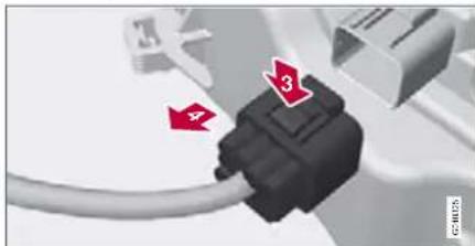
natural_image
Close-up of a black USB connector with red arrows pointing to its pins (no text or symbols visible)All front bulbs (except those for fog lamps) are replaced by first removing the whole lamp housing from the engine compartment.

WARNING
Always switch off the ignition and remove the remote control key before starting to replace a bulb.
Removing the headlamp
-
Switch off the ignition by pressing quickly on the start/stop button and removing the remote control key.
-
Withdraw the lamp housing's locking pins
- Pull the lamp housing straight forward 2
- Detach the lamp housing connector by pressing down the clip with your thumb and at the same time guiding out the connector with your other hand.

IMPORTANT
Do not pull the electrical cable, only the connector
- Lift out the lamp housing and place it on a soft surface to avoid scratching the lens.
- Replace the bulb in question, see page 194.
Installing the headlamp
- Plug in the connector, a "click" should be heard.
-
Reinstall the lamp housing and locking pins. Check that they are correctly inserted.
-
Check the lighting.
The lamp housing must be plugged in and installed before the lighting is switched on or the remote control key is inserted into the ignition switch.

06 Maintenance and specifications
Lamps
Removing the cover
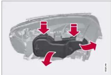
natural_image
Diagram of a car engine compartment with red arrows indicating flow or movement (no text or symbols present)
NOTE
Before starting to replace a bulb, read through page 189.
- Open the lock clamp by pressing up/out.
- Press down the clips on the cover and remove it.
Reinstall the cover in reverse order.
Dipped beam, halogen

natural_image
Mechanical component diagram showing a bracket with a red arrow pointing to a cable or connector (no text or symbols present)- Detach the headlamp.
- Remove the cover.
- Detach the bulb by pressing the holder downwards.
- Unplug the connector from the bulb.
- Fit the new bulb in the socket and snap it in. It can only be secured in one position.
Reinstall the parts in reverse order.
Main beam, Halogen
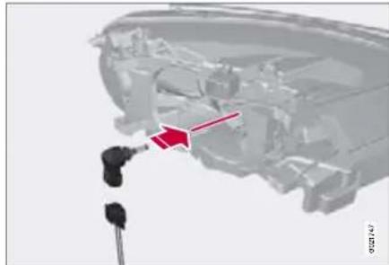
natural_image
Mechanical component diagram showing a bracket with two connectors and a red arrow indicating a specific part (no text or symbols present)- Detach the headlamp.
- Remove the cover.
- Detach the bulb by turning anticlockwise.
- Unplug the connector from the bulb.
- Replace the bulb and align it in the socket & turn clockwise in order to secure it. It can only be secured in one position.
Reinstall the parts in reverse order.
06 Maintenance and specifications

Lamps
Extra main beam Active Bi-Xenon and Bi-Xenon*
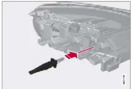
natural_image
Mechanical component diagram showing a disassembled assembly with a red arrow pointing to a specific part (no text or symbols present)- Detach the headlamp.
- Remove the cover, see page 190.
- Detach the bulb by pressing the holder downwards.
- Unplug the connector from the bulb.
- Fit the new bulb in the socket and snap it in. It can only be secured in one position.
Reinstall the parts in reverse order.
Position/parking lamps
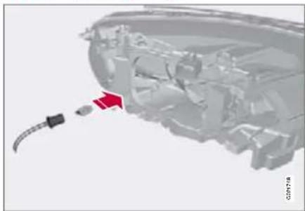
natural_image
Close-up of a mechanical component with a red arrow pointing to a small connector (no visible text or symbols)- Detach the headlamp.
- Remove the cover, see page 190.
- For better access, detach the main beam bulb first.
- Pull the cable in order to withdraw the bulb holder.
- Remove the blown bulb and fit a new one. It can only be secured in one position.
- Fit the bulb holder in the socket and press until a "click" is heard.
Reinstall the parts in reverse order.
Direction indicators/flashers

natural_image
Mechanical component with red arrow pointing to a circular opening, showing internal wiring and housing (no text or symbols)- Detach the headlamp.
- Remove the small round cover.
- Pull the bulb holder in order to extract the bulb.
- Remove the blown bulb and fit a new one. It can only be installed in one way.
- Fit the bulb holder in the socket and press until a "click" is heard.
- Refit the cover. It must be fitted and pressed in until a "click" is heard.
Reinstall the parts in reverse order.

06 Maintenance and specifications
Lamps
Side marker lamps

natural_image
Mechanical assembly diagram showing a component being inserted into a housing, with a magnified inset highlighting a circular component (no text or symbols present)
NOTE
Before starting to replace a bulb, read through page 189.
- Detach the headlamp.
- Remove the small round cover.
- Pull the cable in order to withdraw the bulb holder.
- Remove the blown bulb and fit a new one. It can only be installed in one way.
- Fit the bulb holder in the socket and press until a "click" is heard.
- Refit the cover. It must be fitted and pressed in until a "click" is heard.
Reinstall the parts in reverse order.
Fog lamps
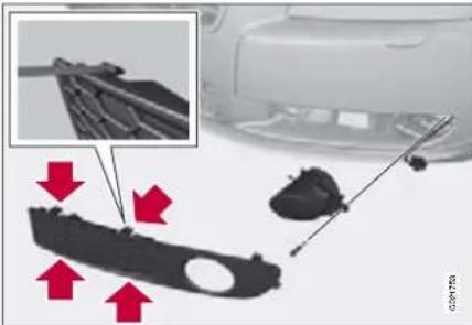
natural_image
Mechanical component assembly with red arrows indicating parts of a housing and tool (no text or symbols visible)- Remove the cover by pressing in the clips and pulling straight out.
- Unscrew the lamp housing screw and pull it out.
- Turn the bulb anticlockwise and remove it.
- Fit a new bulb by turning clockwise.
- Refit the bulb. (The profile of the bulb holder corresponds to the profile of the foot of the bulb.)
- Refit the bulb holder. The TOP mark on the bulb holder must always be upward.
Lamp housing, rear, direction indicators
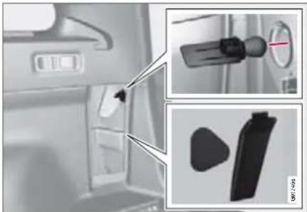
natural_image
Interior view of a car showing the door, seatbelt, and battery compartment (no text or symbols visible)The direction indicator bulb in the rear lamp cluster is replaced from inside the cargo area.
- Open the panel.
- Remove the insulation by pulling it straight out.
- Loosen the whole of the lamp by turning its handle anticlockwise.
- Detach the bulb by pulling it straight out.
Reinstall the parts in reverse order.

NOTE
If an error message remains after a faulty bulb has been replaced, contact an authorised Volvo workshop.
06 Maintenance and specifications

Lamps
Location of rear bulbs
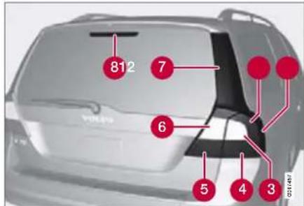
Lamp lens, right-hand side
1 Position lamps/brake light (LED)
② Side position lights, SML (LED)
3 Direction indicators
4 Reflector, rear
⑤ Rear fog lamp (one side)
6 Reversing lamp
7 Brake light (LED)
8 Brake light (LED)
Number plate lighting

natural_image
Close-up of a car rear bumper with two red arrows pointing to the front and side (no text or symbols visible)- Remove the screws with a screwdriver.
- Carefully detach the entire lamp housing and withdraw it.
- Replace the bulb.
- Refit the entire lamp housing and screw it into place.
Courtesy lighting

natural_image
Interior view of a car dashboard and steering wheel, showing the steering wheel and dashboard (no visible text or symbols)
NOTE
Before starting to replace a bulb, read through page 189.
- Insert a screwdriver at the short end of the lens closest to the tunnel console and turn gently so that the lens comes loose. (Applies to both lamps).
- Turn carefully until the lens comes loose.
- Replace the bulb.
- Refit the lens.

06 Maintenance and specifications
Lamps
Cargo area lighting

natural_image
Interior view of a vehicle showing a mounted vehicle with a red warning sign (no visible text or symbols)- Insert a screwdriver and gently prise so that the lamp housing comes loose.
- Replace the bulb.
- Check that the bulb illuminates and press back the lamp housing.
Vanity mirror lighting
Removing the mirror glass

natural_image
Close-up of a car interior showing a door, screwdriver, and red directional arrow (no text or symbols)- Insert a screwdriver underneath the lower edge, in the centre. Carefully prise up the lug on the edge.
- Insert the screwdriver underneath the edge on the left and right-hand sides (by the black rubber sections), and prise carefully so that the glass comes loose in the lower edge.
- Carefully detach and lift aside the entire mirror glass and cover.
- Replace the bulb.
Fitting the mirror glass
- Press the three lugs at top edge of the mirror glass back into position.
- Then press the three lower lugs back into position.
Specification, bulbs
| Lighting Output | W Type | |
| Extra main beam, Bi Xenon, ABL | 55 H7 | |
| Dipped beam, halogen | 55 H7 | |
| Main beam, Halogen | 65 H9 | |
| Front direction indicators | 21 H21W | |
| Direction indicators, rear | 21 PY21W | |
| Front fog lamps 35 H8 | ||
| Courtesy, cargo area, number plate lighting | 5 | Tubular lamp SV8.5 |
| Vanity mirror | 1.2 | Tubular lamp SV5.5 |
| Front position and parking lamps | 5 W5W | |
| Front side marker lamps | 5 W5W | |
| Glovebox lighting | 5 | Tubular lamp SV8.5 |
06 Maintenance and specifications

Wiper blades and washer fluid
Wiper blades
Service position
The wiper blades must be in service position to facilitate replacement or washing.
- Turn the ignition to position 0, see page 65 and keep the remote control key in the ignition switch.
- Move the right-hand stalk switch up for about 1 second. The wipers then move to standing straight up.
The wipers return to the starting position when the car is started.
Replacing the wiper blades, windscreen

natural_image
Mechanical component diagram showing a shaft with two red arrows indicating movement or force directions (no text or symbols present)
natural_image
Close-up of a mechanical component with a red arrow pointing to a section, no visible text or symbols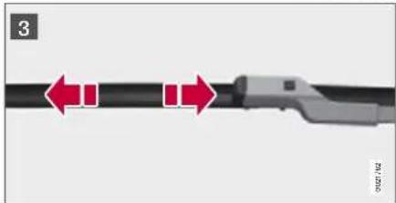
natural_image
Close-up of a mechanical component with red arrows indicating motion or movement, no visible text or symbols1 Turn up the wiper arm. Press the button located on the wiper blade mounting and pull straight out parallel with the wiper arm.
2 Slide in the new wiper blade until a "click" is heard.
3 Check that the blade is firmly installed.
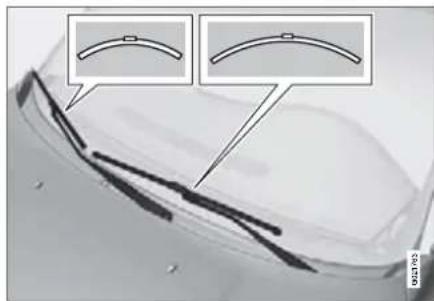
natural_image
Close-up of a transparent container with curved glass strips and two inset diagrams showing arc-like structures (no text or symbols)
NOTE
The wiper blades are different lengths. The blade on the driver's side is longer than the blade on the passenger side.

06 Maintenance and specifications
Wiper blades and washer fluid
Replacing the wiper blades, rear window

natural_image
Diagram showing a black tool interacting with a metallic blade, with a red arrow indicating rotation (no text or symbols present)- Fold out the wiper arm.
- Grip the inner section of the blade (by the arrow).
- Turn anticlockwise to use the blade's end position against the wiper arm as a lever to detach the blade more easily.
- Press the new wiper blade into position. Check that it is firmly installed.
- Lower the wiper arm.
Filling washer fluid

natural_image
Interior view of a car showing engine compartment and dashboard structure (no visible text or symbols)The windscreen and headlamp washers share a common reservoir.
IMPORTANT
Add washer antifreeze during the winter so that the fluid does not freeze in the pump, reservoir and hoses. For capacities, see page 229.
Cleaning
Clean the wiper blades with a lukewarm soap solution or car shampoo.
06 Maintenance and specifications

Battery
Warning symbols on the battery

Use protective goggles
Further information in the owner's manual.
Store the battery out of the reach of children.
The battery contains corrosive acid.
Avoid sparks and naked flames.
Risk of explosion.
Handling
- Check that the battery cables are correctly connected and tightened.
- Never disconnect the battery when the engine is running.
The service life and function of the battery is influenced by factors such as the number of starts, discharging, driving style, driving conditions, climatic conditions etc.
Never use a quick charger to charge the battery.
WARNING
Batteries can generate oxyhydrogen gas, which is highly explosive. One spark, which can be generated if you connect jump leads incorrectly, is sufficient to make the battery explode. The battery contains sulphuric acid, which can cause serious burns. If the acid comes into contact with eyes, skin or clothing, flush with large quantities of water. If acid splashes into the eyes, seek medical attention immediately.
NOTE
The life of the battery is shortened if it becomes discharged repeatedly.

NOTE
An expended battery must be recycled in an environmentally safe manner, as it contains lead.

06 Maintenance and specifications
Battery
Changing
Removal

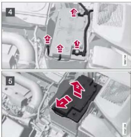
Switch off the ignition and wait for 5 minutes.
1 Open the clips on the front cover and remove the cover.
2 Release the rubber moulding so that the rear cover is free.
3 Remove the rear cover by screwing one quarter turn and lifting it away.
WARNING
Connect and disconnect the positive and negative cables in the correct sequence.
4 Detach the black negative cable. Detach the red positive cable, detach the ventilation hose from the battery and loosen the screw holding the battery clamp.
5 Move the battery to the side and lift it up.
06 Maintenance and specifications

Battery
Installation
- Lower the battery into the battery box.

natural_image
Close-up of a black automotive battery pack with a red arrow pointing to it, mounted on an engine (no visible text or symbols)- Move the battery inward and to the side until it reaches the rear edge of the box.
- Screw in the battery with the screw in the clamp.
- Connect the ventilation hose.
- Connect the red positive cable.
- Connect the black negative cable.
- Press in the rear cover. (See Removal).
- Reinstall the rubber moulding. (See Removal).
- Reinstall the front cover and secure it with the clips. (See Removal).

06 Maintenance and specifications
Fuses
General
All electrical functions and components are protected by a number of fuses in order to protect the car's electrical system from damage by short circuiting or overloading. If an electrical component or function does not work, it may be because the component's fuse was temporarily overloaded and failed. If the same fuse fails repeatedly then there is a fault in the circuit. In which case, contact an authorised Volvo workshop to have the system checked.
Changing
- Look in the fuse diagram to locate the fuse.
- Pull out the fuse and check from the side to see whether the curved wire has blown.
- If this is the case, replace it with a new fuse of the same colour and amperage.
Location, fuse boxes
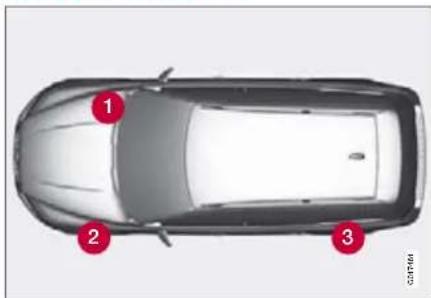
natural_image
Top-down view of a car with three red circular markers indicating specific positions (no text or symbols present)Location of fuse boxes, left-hand drive
If the car is right-hand drive, the fuse box changes side.
1 Under the glovebox
② Engine compartment
③ Cargo area
Fuses
Engine compartment

natural_image
3D rendering of a car engine compartment with an inset close-up showing internal components (no text or symbols visible)
On the inside of the cover are tweezers that facilitate the removal and fitting of fuses.
Positions
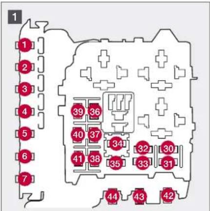
![[15] [20] [16] [27] [24] [21] [17] [28] [25] [22] [18] [29] [26] [23] [19]](/content/2026/05/758185/images/1eb1712f08bd932558ce74190315972ebd6c76c5559b30a7b53c9b7db5b8a06d.jpg)

1 Engine compartment, upper
2 Engine compartment, front
3 Engine compartment, lower
These fuses are all located in the engine compartment box. Fuses in are located under 1.
- 16 -33 and 35 -41 are of the "MiniFuse" type.
- Fuses 8 —15 and 34 are of the "JCASE" type and must only be replaced by an authorised Volvo workshop.
- Fuses 1 —7 and 42 —44 are of the "Midi Fuse" type and must only be replaced by an authorised Volvo workshop.

06 Maintenance and specifications
Fuses
| Function A | ||
| 1 | Primary fuse CEM KL30A 50 | |
| 2 | Primary fuse CEM KL30B 50 | |
| 3 | Primary fuse RJBA KL30 60 | |
| 4 | Primary fuse RJBB KL30 60 | |
| 5 | Primary fuse RJBD KL30 50 | |
| 6 | Reserve | |
| 7 | PTC Air preheater* 100 | |
| 8 | Reserve | |
| 9 | Windscreen wipers 30 | |
| 10 | Parking heater* 25 | |
| 11 | Ventilation fan 40 | |
| 12 | Reserve | |
| 13 | ABS pump 40 | |
| 14 | ABS valves 20 | |
| 15 | Reserve | |
| 16 | Headlamp levelling* (Active Bi-Xenon, Bi-Xenon) | 10 |
| 17 | Primary fuse CEM 20 | |
| 18 | Radar, ACC control module* | 5 |
| 19 | Speed related power steering | 5 |
| 20 | Engine Control Module (ECM), transm. SRS | 10 |
| Function | A | |
| 21 | Heated washer nozzles | 10 |
| 22 | Vacuum pump I5T 20 | |
| 23 | Lighting panel | 5 |
| 24 | Headlamp washers | 15 |
| 25 | 12 V socket, front and rear seat | 15 |
| 26 | Sunroof*, Roof console/ECC* | 10 |
| 27 | Relay, engine compartment box | 5 |
| 28 | Auxiliary lamps* | 20 |
| 29 | Horn | 15 |
| 30 | Engine Control Module (ECM) | 10 |
| 31 | Control module, automatic gear-box* | 15 |
| 32 | Compressor A/C | 15 |
| 33 | Relay coils 5 | |
| 34 | Starter motor relay | 30 |
| 35 | Ignition coils/Glow system diesel | 20/10 |
| 36 | Engine Control Module (ECM)petrol/diesel | 10/15 |
| 37 | Injection system | 15 |
| 38 | Engine valves | 10 |
| 39 | EVAP, Lambda-sond, Injection(petrol/diesel) | 15/10 |
| Function | A | |
| 40 | Crankcase ventilation heater (5-cyl petrol)/Diesel filter heater, crankcase ventilation heater (5-cyl diesel) | 20/20 |
| 41 | Leakage diagnosis* | 5 |
| 42 | Glow plugs diesel | 70 |
| 43 | Cooling fan | 50 |
| 44 | Cooling fan | 60 |
06 Maintenance and specifications

Fuses
Under the glovebox
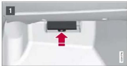
natural_image
Interior view of a white appliance with a black rectangular component and a red upward arrow indicating direction (no text or symbols)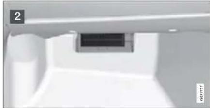
natural_image
Interior view of a minimalist room with a dark central display and white walls (no text or symbols visible)Fold aside the interior trim covering the fuse box.
1 Press the cover's lock and fold it up.
2 The fuses are accessible.
Positions

Function A
1 Rain sensor 5
2 SRS system 10
3 ABS brakes. Electric parking brake 5
4 Accelerator pedal*, air heater (PTC) 7.5 Heated seats*
5 Reserve
6 ICM display. CD & Radio, RSE sys-tem* 15
7 Steering wheel module 7.5
8 Reserve
9 Main beam 15
10 Sunroof* 20
11 Reversing lamps. 75
Function A
12 Reserve
13 Front fog lamp* 15
14 Windscreen washers 15
15 Adaptive cruise control ACC* 10
16 Reserve
17 Roof lighting. Control panel driver's 7.5 door/
Power passenger seat*
18 Information display 5
19 Power driver's seat* 5
20 Reserve
21 Remote control key receiver. Alarm 5 sensors
22 Fuel pump 20
23 Electric steering lock 20
24 Reserve
25 Lock, tank/tailgate 10
26 Alarm siren. ECC 5
27 Start/stop button 5
28 Brake light switch 5

06 Maintenance and specifications
Fuses
Cargo area

The fuse box is located behind the upholstery on the left-hand side.
Positions
| Module A (black). Function A | ||
| 1 | Control panel, driver's door 25 | |
| 2 | Control panel, passenger door 25 | |
| 3 | Control panel, rear door, left 25 | |
| 4 | Control panel, rear door, right 25 | |
| 5 | Reserve | |
| 6 | 12 V socket cargo area, refrigerator* 15 | |
| 7 | Rear window defroster 30 | |
| 8 | Reserve | |
| 9 | Trailer socket 2* 15 | |
| 10 | Power seat driver's side 25 | |
| 11 | Trailer socket 1* 40 | |
| 12 | POT (automatic tailgate opening)* 30 |
| Module B (white). Function | A | |
| 1 | Reserve | |
| 2 | Control module Four C^* | 15 |
| 3 | Seat heating, driver's side front* | 15 |
| 4 | Seat heating, passenger side front* | 15 |
| 5 | Seat heating right rear* | 15 |
| 6 | AWD control module | 10 |
| 7 | Seat heating left rear* | 15 |
| Module B (white). Function | A | |
| 8 | Reserve | |
| 9 | Power seat passenger side | 25 |
| 10 | Keyless drive* | 20 |
| 11 | Electric parking brake* left | 30 |
| 12 | Electric parking brake* right 30 |
| Module D (blue). Function | A | |
| 1 | Display RTI*, parking camera* | 10 |
| 2 | Reserve | |
| 3 | Bass speaker | 25 |
| 4 | Reserve | |
| 5 | Audio amplifier | 25 |
| 6 | Audio system | 15 |
| 7 | Phone | 5 |
| Reserve 8 - 12 |
06 Maintenance and specifications

Wheels and tyres
General
Tyres greatly affect the car's driving characteristics. The type of tyre, dimensions, tyre pressure and speed rating are important for how the car performs.
Direction of rotation

natural_image
Top-down view of a car showing the wheel rim and side profile, with an inset highlighting the wheel's edge detail (no text or symbols present)The arrow shows the tyre's direction of rotation
Tyres with a tread pattern which are designed to only turn in one direction have the direction of rotation marked with an arrow. The tyre must always rotate in the same direction throughout its lifespan. Tyres should only be switched between front and rear positions, never between left and right-hand sides, or vice versa. If the tyre is mounted incorrectly, the car's braking char-
acteristics and capacity to force rain and slush out of the way are adversely affected.

NOTE
Ensure that tyres of the same type and dimensions, and also the same make, are fitted to all four wheels.
Follow the recommended tyre pressures specified on the tyre pressure label, see page 215.
Changing wheels
Removing

Mounting points
Set up the warning triangle if a wheel must be replaced at a busy location. The car and jack must be on a firm horizontal surface.
- Apply the parking brake and engage first gear, or position P if the car has an automatic gearbox.
- Take out the spare wheel, jack and wheel wrench that are located under the carpet in the cargo area.

NOTE
Use the jack belonging to the car.

06 Maintenance and specifications
Wheels and tyres
- Place chocks in front of and behind the wheels which will remain on the ground. Use heavy wooden blocks or large stones.

natural_image
Close-up of a car wheel with a tool inserted, showing red arrows indicating motion direction (no text or symbols)- (For cars with steel rims.) Prise off the wheel cover with the end of the wheel wrench, or pull it off by hand.
- Loosen the wheel nuts 12 -1 turn anticlockwise with the wheel wrench.
- There are two jacking points on each side of the car. Crank the foot of the jack down so it is pressed squarely on the ground. Check that the jack sits in the anchorage as illustrated and that the foot is positioned vertically under the anchorage.
- Lift the car so that the wheel is free. Remove the wheel bolts and lift off the wheel.
Installation
- Clean the contact surfaces on the wheel and hub.
- Put on the wheel. Screw in the wheel bolts.
- Lower the car so that the wheels cannot rotate.
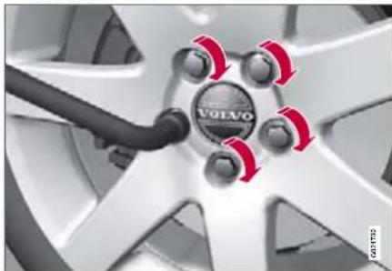
natural_image
Close-up of a Volvo car wheel with red brake calipers and a black cable (no text or symbols visible)- Tighten the wheel bolts crosswise. It is important that the wheel bolts are tightened properly. Tighten to 140 Nm. Check the torque with a torque wrench.
- Fit on the wheel cover (for cars with steel rims).

NOTE
The hubcap outlet for the valve must be located over the valve on the rim when fitted.

WARNING
Never crawl under the car when it is raised on the jack.
Passengers must leave the car when it is raised on the jack.
Park the car so that passengers have the car - or preferably a crash barrier - between them and the road.
06 Maintenance and specifications

Wheels and tyres
Tyre care
Tyre age
All tyres older than six years should be checked by an expert even if they seem undamaged. Tyres age and decompose, even if they are hardly ever or never used. The function can therefore be affected. This also applies to spare tyres, winter tyres and tyres saved for future use. Examples of external signs which indicate that the tyre is unsuitable for use are cracks or discoloration.
New tyres

natural_image
Top-down view of a car tire with a circular head and rim, no visible text or symbolsTyres are perishable. After a few years they begin to harden at the same time as the friction capacity/characteristics gradually deteriorate. For this reason, aim to get as fresh tyres as possible when you replace them.
This is especially important with regard to winter tyres. The week and year of manufacture, the tyre's DOT marking (Department of Transportation), are stated with four digits, for example 1502. The tyre in the illustration was manufactured in week 15 of 2002.
Summer and winter tyres
When summer and winter wheels are changed they should be marked with which side of the car they were mounted on, for example L for left and R for right.
Wear and maintenance
The correct tyre pressure results in more even wear, see page 215. To achieve the best traction and more even wear on the tyres, the regular switching of the front and rear tyres with each other is recommended. The first change should be after 5 000 km and then at intervals of 10 000 km, this is to avoid differences in tread depth. Tyres with the greatest tread depth should always be fitted to the rear wheels to decrease the risk of skidding. Contact an authorised Volvo workshop if you are uncertain about tread depth.
Wheels should be stored lying down or hanging up, and not standing up.

WARNING
A damaged tyre can lead to loss of control of the car.
Tyres with tread wear indicators
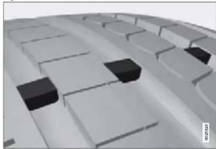
natural_image
3D architectural rendering of a modern building complex with white walls and black blocks (no text or symbols visible)Tread wear indicators are narrow treadless bands across the width of the tread. On the side of the tyre are the letters TWI (Tread Wear Indicator). When the tyre's tread depth is down to 1.6 mm, the tread depth will be level in height with the tread wear indicators. Change to new tyres as soon as possible. Remember that tyres with little tread depth provide very poor grip in rain and snow.
Rims and wheel bolts

IMPORTANT
The wheel bolts must be tightened to 140 Nm. Overtightening can damage the nuts and the bolts.
Only use rims that are tested and approved by Volvo and which are Volvo genuine acces-

06 Maintenance and specifications
Wheels and tyres
sories. Check the torque with a torque wrench.
Locking wheel bolts
Locking wheel bolts can be used on both aluminium and steel rims.
Winter tyres
Volvo recommends winter tyres with particular dimensions. These are stated on the tyre pressure label, see page 214. The tyre dimensions are dependent on the engine variant. When driving on winter tyres, the correct tyres must be fitted to all four wheels.
NOTE
Ask a Volvo dealer which rim and tyre types are most suitable.
Studded tyres
Studded winter tyres should be run in gently for 500-1000 km so the studs settle properly into the tyre. This gives the tyre, and especially the studs, a longer service life.
NOTE
The legal provisions for the use of studded tyres vary from country to country.
Tread depth
Road conditions with ice, slush and low temperatures place considerably higher demands on tyres than summer conditions. Volvo therefore recommends not to drive on winter tyres that have a tread depth of less than 4 millimetres.
Using snow chains
Snow chains may only be used on the front wheels (also applies to all-wheel drive cars).
Never drive faster than 50 km/h with snow chains. Avoid driving on bare ground as this wears out both the snow chains and tyres. Never use quick-fit snow chains as the space between the brake discs and the wheels is too small.
IMPORTANT
Use Volvo genuine snow chains or equivalent chains designed for the car model, and tyre and rim dimensions. Consult an authorised Volvo workshop
06 Maintenance and specifications

Wheels and tyres
Tools
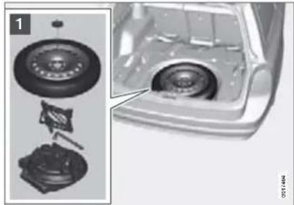
natural_image
Mechanical assembly diagram showing tire components and housing (no text or symbols)A foam block, located in the spare wheel rim, contains all tools. The tools consist of a towing eye, jack and wheel wrench. The foam block is screwed into a bracket in the bottom of the spare wheel well.
Jack
The original jack should only be used for changing wheels. The jack's thread must always be well greased.
Spare wheel\*
The spare wheel (Temporary spare) is only intended for temporary use. Replace the spare wheel with a normal wheel as soon as possible. The car's handling may be altered by the use of the spare wheel. The correct tyre pressure for the spare wheel is stated on the tyre pressure table, see page 215.
IMPORTANT
Never drive faster than 80 km/h with a spare wheel on the car.
IMPORTANT
The car must never be driven fitted with more than one temporary spare wheel.
The spare wheel is located in the spare wheel well with the outside down. Three foam blocks, two under the spare wheel and one over/inside affix the spare wheel in position. The upper one contains all tools.
The same bolt runs through to secure the spare wheel and the foam blocks.
Taking out the spare wheel
- Fold the rear edge of the floor mat forward.
- Undo the retaining screw.
- Lift out the foam block with its tools.
- Lift out the spare wheel.
The lower block does not need to be lifted out.
After use
The foam block and spare wheel must be replaced in the reverse order to taking out.
NOTE
If the floor hatch is not closed then privacy locking does not work, see page 43.

06 Maintenance and specifications
Wheels and tyres
Emergency puncture repair\*
General
The emergency puncture repair kit is used to seal a puncture as well as to check and adjust the tyre pressure. It consists of a compressor and a bottle with sealing fluid. The kit works as a temporary repair. The sealing fluid bottle must be replaced before its expiration date and after use.
The sealing fluid effectively seals tyres punctured in the tread.

NOTE
The emergency puncture repair kit is only intended for sealing tyres with a puncture in the tread.
The emergency puncture repair kit has limited capacity to seal tyres which have punctures in the wall. Do not seal tyres with the emergency puncture repair kit if they have larger slits, cracks or similar damage.
12 V sockets for the compressor are located by the centre console in the front, by the rear seat and in the cargo area. Choose the electrical socket that is closest to the punctured tyre.
Taking out the emergency puncture repair kit
Set up the warning triangle adjacent to a trafficked location. The emergency puncture repair kit is located under the floor in the cargo area.
- Fold the rear edge of the floor mat forward.
- Unscrew the retaining screw.
- Lift away the foam block holding the jack and wheel wrench.
- Lift up the emergency puncture repair kit.
Replace the parts after use.

WARNING
You should not drive faster than 80 km/h after the emergency tyre repair kit has been used. The temporarily sealed tyre must be changed as soon as possible (maximum driving distance: 200 km).
06 Maintenance and specifications

Wheels and tyres
Overview
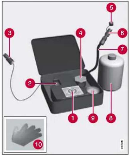
① Decal, maximum permitted speed
② Switch
3 Cable
4 Bottle holder (orange cap)
5 Protective cap
6 Pressure reducing valve
7 Air hose
8 Sealing fluid bottle
9 Pressure gauge
10 Gloves
Inflating the tyres
The car's original tyres can be inflated by the compressor.
- The compressor must be switched off. Make sure that the switch is in position 0 and locate the cable and air hose.
- Unscrew the wheel's dust cap and screw in the air hose valve connection to the bottom of the thread on the tyre's air valve.
- Connect the cable to one of the car's 12 V sockets and start the car.

WARNING
Inhaling car exhaust fumes can result in danger to life. Never leave the engine running in sealed areas or areas that lack sufficient ventilation.
- Start the compressor by flicking the switch to position I.
- Inflate the tyre to the pressure specified on the tyre pressure decal, (release air using the pressure reducing valve if the tyre pressure is too high).

IMPORTANT
Risk of overheating. The compressor must not run for more than 10 minutes.
- Switch off the compressor. Detach the air hose and cable.
- Refit the dust cap.

06 Maintenance and specifications
Wheels and tyres
Sealing punctured tyres

For information on the function of the parts, see the illustration on page 211.
- Open the lid of the emergency puncture repair kit.
- Detach the decal for maximum permitted speed and affix it to the steering wheel.
-
Check that the switch is in position 0 and locate the cable and the air hose.
-
Put on the gloves.
WARNING
The sealing fluid can irritate the skin. In the case of contact with skin, wash away the fluid with soap and water.
- Unscrew the orange cap and unscrew the bottle's stopper.
NOTE
Do not break the bottle seal. The seal is broken when the bottle is screwed in.
- Screw the bottle into its holder.
WARNING
Do not unscrew the bottle, it is equipped with a reverse catch to prevent leakage.
- Unscrew the wheel's dust cap and screw in the air hose valve connection to the bottom of the thread on the tyre's air valve.
- Plug the cable into the 12 V socket and start the car.
- Flick the switch to position I.
WARNING
Never stand next to the tyre when the compressor is running. If cracks or unevenness arise then the compressor must be switched off immediately. The journey should not be continued. Contact an authorised tyre centre.
NOTE
When the compressor starts, the pressure can increase up to 6 bar but the pressure drops after approximately 30 seconds.
- Inflate the tyre for 7 minutes.
IMPORTANT
Risk of overheating. The compressor must not run for more than 10 minutes.
- Switch off the compressor to check the pressure on the pressure gauge. Minimum pressure is 1.8 bar and maximum is 3.5 bar.
WARNING
If the pressure is below 1.8 bar then the hole in the tyre is too big. The journey should not be continued. Contact an authorised tyre centre.
06 Maintenance and specifications

Wheels and tyres
- Switch off the compressor and unplug the cable from the 12 V socket.
- Detach the hose from the tyre valve and fit the valve cap.
- As soon as possible drive approximately 3 km at a maximum speed of 80 km/h so that the sealing fluid can seal the tyre.
Rechecking the repair and pressure
- Reconnect the equipment.
-
Read the tyre pressure on the pressure gauge.
-
If it is below 1.3 bar then the tyre is insufficiently sealed. The journey should not be continued. Contact a tyre centre.
-
If the tyre pressure is higher than 1.3 bar, the tyre must be inflated to the pressure specified on the tyre pressure decal. Release air using the pressure reducing valve if the tyre pressure is too high.
- Switch off the compressor. Detach the air hose and cable. Refit the dust cap.

WARNING
Do not unscrew the bottle, it is equipped with a reverse catch to prevent leakage.
- Return the emergency puncture repair kit to the cargo area.

NOTE
The sealing fluid bottle and hose must be replaced after use. Replacement must be performed by an authorised Volvo workshop.

WARNING
Check the tyre pressure regularly.
Drive to the nearest authorised Volvo workshop for the replacement/repair of the damaged tyre. Advise the workshop that the tyre contains sealing fluid.

WARNING
You should not drive faster than 80 km/h after the emergency tyre repair kit has been used. Contact an authorised Volvo workshop for inspection of the sealed tyre (maximum driving distance is 200 km). The staff there can determine whether or not the tyre can be repaired or if it needs to be replaced.
Replacing the sealing fluid canister
Replace the bottle when the expiration date has passed. Treat the old bottle as environmentally hazardous waste.

IMPORTANT
Read the safety instructions on the bottom of the bottle.

06 Maintenance and specifications
Wheels and tyres
Specifications
Designation of dimensions
The dimensions are stated on all car tyres. Example of designation: 225/50R17 94 W.
| 225 Section width (mm) | |
| 50 Ratio between section height and width (%) | |
| R Radial ply | |
| 17 Rim diameter in inches (") | |
| 94 Tyre load index | |
| W Speed rating (in this case 270 km/h). | |
Speed ratings
The car is approved as a whole, which means that dimensions and speed ratings must not differ from those specified on the car's registration document.
The only exception to these conditions is winter tyres (both those with metal studs and those without). If such a tyre is chosen, the car must not be driven faster than the speed
rating of the tyre. (For example, class Q can be driven at a maximum of 160 km/h).
Traffic regulations determine how fast a car can be driven, not the speed rating of the tyres.
| Q 160 km/h (used only on winter tyres) | |
| T 190 km/h | |
| H | 210 km/h |
| V | 240 km/h |
| W 270 km/h | |
| Y | 300 km/h |

NOTE
It is the maximum permitted speed that is stated in the table.
Tyre pressure

natural_image
Interior view of a car showing the steering wheel, dashboard, and side door (no visible text or symbols)The tyre pressure decal on the driver's side door pillar (between frame and rear door) shows which pressures the tyres should have at different loads and speed conditions, this is also specified in the tyre pressure table, see page 215.
- Tyre pressure for the car's recommended wheel dimension
• ECO pressure - Spare wheel pressure (Temporary Spare)

NOTE
Temperature differences change tyre pressure.
06 Maintenance and specifications

Wheels and tyres
Recommended tyre pressure
| Variant V70 Tyre size | Speed (km/h) | Load,1-3 persons | Max. load | |||
| Front (kPa) 1 (kPa) | Rear | Front (kPa) | Rear (kPa) | |||
| 6-cyl 225/55 R 16, 225/50 R 17 | 0 – 160 230 | 210 260 260 | ||||
| 245/45 R 17 | 160 + 280 280 | 300 300 | ||||
| 245/40 R 18 0 – 160 230 210 260 260 | ||||||
| 160 + 270 270 | 290 290 | |||||
| 5-cyl diesel 185 hp | 225/55 R 16 | 0 – 160 220 | 210 260 260 | |||
| 225/50 R 17, 245/45 R 17 | ||||||
| 160 + 260 260 | 270 270 | |||||
| 245/40 R 18 0 – 160 230 210 260 260 | ||||||
| 160 + 260 260 | 270 270 | |||||
| 5-cyl diesel 163 hp | 225/55 R 16 | 0 – 160 220 | 210 260 260 | |||
| 225/50 R 17 | ||||||
| 5-cyl petrol | 245/45 R 17 | 160 + 260 260 | 270 270 | |||
| 245/40 R 18 0 – 160 230 210 260 260 | ||||||
| 160 + 260 260 | 270 270 | |||||
| 205/60 R 16 0 – 160 230 210 260 260 | ||||||
| 160 + 270 270 | 290 290 | |||||
| All | All2 | 0 – 160 | 2602 | 2602 | 2602 | 2602 |
| Spare wheel 3 | T 125/80 R 17 | max. 80 | 420 | 420 | 420 | 420 |
1 In certain countries there is the "bar" unit beside the SI unit "Pascal": 1 bar = 100 kPa
2 ECO pressure, economical driving
3 Temporary Spare

06 Maintenance and specifications
Wheels and tyres
| Variant XC70 | Tyre size | Speed (km/h) | Load,1-3 persons | Max. load | ||
| Front (kPa) 1 (kPa) | Rear | Front (kPa) | Rear (kPa) | |||
| 6-cyl, 5-cyl 215/65 R 16, 235/55 R 17235/50 R 18 | 0 – 160 230 230 260 260 | |||||
| 160 + 240 240 280 280 | ||||||
| All | All2 | 0 – 160 | 2602 | 2602 | 2602 | 2602 |
| Spare wheel 3 | T 125/80 R 17 max. 80 420 420 420 420 | |||||
1 In certain countries there is the "bar" unit beside the SI unit "Pascal": 1 bar = 100 kPa
2 ECO pressure, economical driving
3 Temporary Spare
Fuel economy, ECO pressure
At speeds under 160 km/h, the general tyre pressure for full load is recommended in order to obtain optimum fuel economy.
Checking the tyre pressure
The tyre pressures must be checked every month. This also applies to the car's spare wheel. After several few kilometres of driving, the tyres warm up and the pressure increases. Check tyre pressures on cold tyres. "Cold tyres" means the tyres are the same temperature as the ambient temperature.
Inadequate tyre pressure increases fuel consumption, shortens tyre lifespan and impairs the car's roadholding. Driving on tyres with
tyre pressure that is too low could result in the tyres overheating and being damaged. Tyre pressure affects travelling comfort, road noise and steering characteristics.

NOTE
Tyre pressure decreases over time, this is a natural phenomenon. Tyre pressure also varies depending on ambient temperature.
06 Maintenance and specifications

Car care
Washing the car
Wash the car as soon as it becomes dirty. Wash the car in a car wash with oil separator. Use car shampoo.
- Remove bird droppings from the paint-work as soon as possible. Bird droppings contain chemicals that affect and discolour paintwork very quickly. An authorised Volvo workshop is recommended for the removal of any discoloration.
- Hose down the underbody. If using a pressure washer, keep the nozzle at least 30 cm from the painted surfaces.
- Rinse the entire car to remove loose dirt. Do not spray directly onto the locks.
- Wash using a sponge, car shampoo and plenty of lukewarm water.
- Clean the wiper blades with a lukewarm soap solution or car shampoo.
- Use cold degreasing agent on very dirty surfaces.
- Dry the car using a clean, soft chamois or a water scraper.

WARNING
Always have the engine cleaned by a work-shop. There is a risk of fire if the engine is hot.

NOTE
Outside lighting such as headlamps, fog lamps and rear lamps may temporarily have condensation on the inside of the lens. This is a natural phenomenon, all outside lighting is designed to withstand this. Condensation is normally vented out of the lamp housing when it has been switched on for a time.
Automatic car washes
An automatic car wash is a simple and quick way of washing the car, but it cannot reach everywhere. Handwashing the car is recommended for achieving optimum results.

NOTE
During the first few months a new car must only be handwashed. This is because the paintwork is more sensitive when it is new.

WARNING
Always test the brakes after washing the car, including the parking brake, to ensure that moisture and corrosion do not attack the brake pads and reduce braking performance.
Lightly depress the brake pedal now and then when driving long distances in rain or
slush. The heat from the friction causes the brake linings to warm up and dry. Do the same thing after starting in very damp or cold weather.
Exterior plastic, rubber and trim components
A special cleaning agent available from Volvo dealers is recommended for cleaning coloured plastic parts, rubber and trim components, such as glossy trim mouldings. When using such a cleaning agent the instructions must be followed carefully.

IMPORTANT
Avoid waxing and polishing on plastic and rubber.
Polishing glossy trim mouldings could wear away or damage the glossy surface.
Polishing agent that contains abrasive must not be used.
Rims
Only use cleaning agent recommended by Volvo. Strong rim cleaning agents can damage the surface and cause stains on chrome-plated aluminium rims.

06 Maintenance and specifications
Car care
Polishing and waxing
Polish and wax the car if the paintwork is dull or to give the paintwork extra protection.
The car does not need to be polished until it is at least one year old. However, the car can be waxed during this time. Do not polish or wax the car in direct sunlight.
Wash and dry the car thoroughly before you begin polishing or waxing. Clean off asphalt and tar stains using Volvo tar remover or white spirit. More stubborn stains can be removed using fine rubbing paste designed for car paintwork.
Polish first with a polish and then wax with liquid or solid wax. Follow the instructions on the packaging carefully. Many preparations contain both polish and wax.

IMPORTANT
Paint treatment such as preserving, sealing, protection, lustre sealing or similar could damage the paintwork. Paintwork damage caused by such treatments is not covered by Volvo warranty.
Cleaning front side windows that have a water-repellent surface (option)

Never use products such as car wax, degreaser or similar on glass sur-
faces as this could ruin their water-repellent properties.
Take care when cleaning so as not to damage the glass surface.
To avoid damaging glass surfaces when removing ice – only use plastic ice scrapers.
There is natural wear of the water-repellent coating.
Treatment with a special finishing agent available from Volvo dealers is recommended in order to maintain the water-repellent properties. This should be used first after three years and then each year.
Rustproofing – inspection and maintenance
The car received a thorough and complete rustproofing at the factory. Parts of the body are made of galvanised sheet metal. The underbody is protected by a wear-resistant anti-corrosion compound. A thin, penetrating rustproofing fluid was sprayed into the exposed members, cavities, closed sections and side doors.
Under normal conditions the rustproofing does not require treatment for approximately 12 years. After this period, it should be treated at three-year intervals. Please contact an authorised Volvo workshop if the car needs further treatment.
Dirt and road salt can lead to corrosion so it is important to keep the car clean. The car's rustproofing needs to be checked regularly and touched-up if necessary in order for it to be maintained.
06 Maintenance and specifications

Car care
Cleaning the interior
Only use cleaning agents and car care products recommended by Volvo. Clean regularly and follow the instructions included with the car care product.
Stains on fabric upholstery and roof upholstery
A special fabric cleaning agent, available from authorised Volvo dealers, is recommended to avoid impairing the fire retardant qualities of the upholstery. Use water and a synthetic detergent to clean the seatbelts. Make sure the seatbelt is dry before allowing it to retract.

IMPORTANT
Sharp objects and Velcro may damage the fabric upholstery.
Treating stains on leather upholstery
Volvo leather upholstery is chromium-free and approved in accordance with the Öko-Tex 100 standard.
The leather is refined and processed so that it retains its natural characteristics. It is given a protective coating, but regular cleaning is required in order to maintain both characteristics and appearance. Volvo offers a comprehensive product for the cleaning and treatment of leather upholstery which, when
used in accordance with the instructions, preserves the leather's protective coating. After a period of use the natural appearance of the leather will nevertheless emerge, depending more or less on the surface texture of the leather. This is a natural maturing of the leather and shows that it is a natural product.
To achieve best results Volvo recommends cleaning and application of the protective cream once to four times per year (or more if required). Ask a Volvo dealer about Volvo's Leather care product.

IMPORTANT
Never use strong solvents. Such products may damage fabric, vinyl and leather upholstery.

IMPORTANT
Note that materials with colour that runs when dry (new jeans, suede garments etc.) may discolour the upholstery material.
Washing instructions for leather upholstery
-
Pour the leather cleaner on the dampened sponge and squeeze out a strong foam.
-
Work the dirt away with gentle circular movements.
-
Dab accurately with the sponge on the stains. Allow the sponge to absorb the stain. Do not rub.
- Wipe off with soft paper or a cloth and allow the leather to dry completely.
Protective treatment of leather upholstery
- Pour a small amount of the protective cream on the felted cloth and massage in a thin layer of cream with gentle circular movements on the leather.
- Allow the leather to dry for 20 minutes before use.
The leather has now been given improved protection against stains and improved UV protection.
Treating stains on interior plastic, metal and wood parts
A fibrillated fibre or microfibre cloth, lightly moistened with water, available from Volvo dealers, is recommended for cleaning interior parts and surfaces.
Do not scrape or rub stains. Never use strong stain removers. A special cleaning agent available from Volvo dealers can be used for more difficult cleaning.
Carpets and cargo area
Remove inlaid carpets for separate cleaning of the floor carpet and the inlaid carpets. Use a vacuum cleaner to remove dust and dirt.

06 Maintenance and specifications
Car care
Touching up paintwork
Paint is an important part of the car's rust-proofing and should therefore be checked regularly. To avoid the onset of rust, damaged paintwork should be rectified immediately. The most common types of paintwork damage are stone chips, scratches, and stains on the edges of wings and doors.
Materials
• primer in a can
- paint in a can or touch-up pen
- brush
- masking tape
Colour code

It is important that the exact correct colour is used. The product decal specifies the car's colour code, see page 221.
Repairing stone chips

natural_image
Illustration of a hand using a tool to mark a surface, with an inset showing the same tool's tip (no text or symbols present)Before work is begun, the car must be clean and dry and at a temperature above 15 °C.
- Apply a piece of masking tape over the damaged surface. Then remove the tape to remove any loose paint.
- Stir the primer well and apply using a fine brush or a matchstick. Apply paint using a brush once the primer is dry.
- For scratches, proceed as above, but mask around the damaged area to protect the undamaged paintwork.
- After a few days, polish the touched-up areas. Use a soft rag and a small amount of lapping paste.

NOTE
If the stone chip has not penetrated to the bare metal and there is an undamaged colour coat, you can paint straight after cleaning the damaged surface.
06 Maintenance and specifications

Type designations
Decal location

Knowing the car's type designation, vehicle identification and engine numbers can facilitate all contact with an authorised Volvo dealer regarding the car and when ordering spare parts and accessories.
1 Type designation, vehicle identification number, maximum permissible weights, codes for colour and upholstery and type approval number.
② Decal for parking heater.
③ The engine oil decal specifies oil grade and viscosity.
4 Engine type designation, component and serial number.
⑤ Gearbox type designation and serial number.
A Manual gearbox B Automatic gearbox
6 Car's identification number. (VIN Vehicle Identification Number)
Further information on the car is presented in the registration document.

06 Maintenance and specifications
Specifications
Dimensions V70

| Position in illustration | Dimensions mm | |
| A Wheelbase 2816 | ||
| B Height 4823 | ||
| C Load length, floor, folded seat | 1878 | |
| D Load length, floor 1089 | ||
| E Height 1547 | ||
| F Front track 1578 | ||
| G Rear track 1576 | ||
| H Width 1861 | ||
| I | Width including door mirrors | 2106 |
06 Maintenance and specifications

Specifications
Dimensions XC70

| Position in illustration | Dimensions mm | |
| A Wheelbase 2815 | ||
| B Height 4838 | ||
| C Load length, floor, folded seat | 1878 | |
| D Load length, floor | 1089 | |
| E Height 1604 | ||
| F Front track 1604 | ||
| G Rear track 1570 | ||
| H Width 1861 | ||
| I | Width including door mirrors | 2119 |

06 Maintenance and specifications
Specifications
Weights
Kerb weight includes the driver, the fuel tank 90% full and all fluids. The weight of passengers and accessories, such as a towbar, load carriers, space box etc. and towball load (when a trailer is hitched, see table), influences the payload and must not be included in the kerb weight. Permitted weight (in addition to driver) = Gross vehicle weight - Kerb weight.
① Gross vehicle weight
② Max. train weight (car+trailer)
③ Max. front axle load
4 Max. rear axle load
5 Equipment level
Max. load: See registration document.
Max. roof load: 100 kg.

WARNING
The car's driving characteristics change depending on how heavily it is loaded and how the load is distributed.
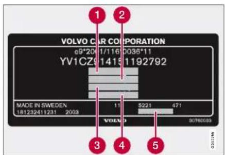
For information on decal location, see page 221.
06 Maintenance and specifications

Specifications
Towing capacity and towball load
| Model Gearbox | Trailer weight with brake (kg) | Towball load (kg) | |
| All All 0 – 1200 50 | |||
| 2.5T Manual (M66) max. 1800 75 | |||
| Automatic (TF-80SC) max. | 1800 75 | ||
| 3.2 | Automatic (TF-80SC) | max. 1800 | 75 |
| T6 Automatic (TF-80SC) max. 2000 90 | |||
| 2.4D Manual (M66) max. 1600 75 | |||
| Automatic (TF-80SC) max. | 1800 75 | ||
| D5 Manual (M66) max. 1600 75 | |||
| Automatic (TF-80SC) max. | 2000 90 | ||
| Trailer weight without brake (kg) | Towball load (kg) |
| max. 750 50 |

NOTE
The use of stabilising devices is recommended with trailers heavier than 1800 kg.

06 Maintenance and specifications
Specifications
Engine specifications
| Specification/Model | 2.5T | 3.2 | T6 | D5 | 2.4D |
| Engine designation | B5254T6 | B6324S | B6304T2 | D5244T4 | D5244T5 |
| Output (kW/rpm) | 147/4500 | 175/6200 | 210/xx | 136/4000 | 120/4000 |
| Output (hp/rpm) | 200/4800 | 238/6200 | 285/xx | 185/4000 | 163/4000 |
| Torque (Nm/rpm) | 300/1500-4500 | 320/3200 | 400/1500-xx | 400/2000-2750 | 340/1750-2750 |
| No. of cylinders | 5 | 6 | 6 | 5 | 5 |
| Bore (mm) | 83 | 84 | 82 | 81 | 81 |
| Stroke (mm) | 93.2 | 96 | 93.2 | 93.1 | 93.1 |
| Swept volume (litres) | 2,521 | 3,192 | 2,953 | 2,400 | 2,400 |
| Compression ratio | 9.0:1 | 10.8:1 | 9.3:1 | 17.0:1 | 17.0:1 |
06 Maintenance and specifications

Specifications
Engine oil
Adverse driving conditions
Adverse driving conditions can lead to abnormally high oil temperature or oil consumption.
Check the oil level more frequently for long journeys:
- towing a caravan or trailer.
• in mountainous regions. - at high speeds.
- in temperatures colder than -30ircC or hotter than +40ircC
- shorter driving distances (shorter than 10 km) at low temperatures (under 5ircC ).
This can produce abnormally high oil temperature or oil consumption.
Choose a fully synthetic engine oil for adverse driving conditions. It provides extra protection for the engine.
Volvo recommends Castrol oil products.
IMPORTANT
In order to fulfil the requirements for the engine's service intervals all engines are filled with a specially adapted synthetic engine oil at the factory. The choice of oil has been made very carefully with regard to service life, starting characteristics, fuel consumption and environmental impact. An approved engine oil must be used in order that the recommended service intervals can be applied. Only use a prescribed grade of oil (see the engine compartment decal) for both filling and oil change, otherwise you will risk affecting service life, starting characteristics, fuel consumption and environmental impact. Volvo Car Corporation disclaims all warranty liability if engine oil of the prescribed grade and viscosity is not used.

heatmap
| Temperature (°C) | -30 | -20 | -10 | 0 | 10 | 20 | 30 | 40 | |---|---|---|---|---|---|---|---|---| | *F | -22 | -4 | 14 | 32 | 50 | 68 | 86 | 104 | | *F* | -22 | -4 | 14 | 32 | 50 | 68 | 86 | 104 | SAE 0W-30 SAE 0W-40 SAE 5W-30 SAE 5W-40Viscosity chart

06 Maintenance and specifications
Specifications

The following applies when the adjacent decal is fitted in the car's engine compartment. For information on decal location, see page 221.
Oil grade: ACEA A5/B5
Viscosity: SAE 0W-30
| Engine variant | Volume between MIN and MAX (litres) | Volume (litres) |
| 2.5T B5254T6 1.3 5.5 | ||
| 3.2 B6324S 1.2 7.4 | ||
| T6 B6304T2 1.2 7.4 | ||
| D5 D5244T4 1.5 6.0 | ||
| 2.4D D5244T5 1.5 6.0 |
06 Maintenance and specifications

Specifications
Other fluids and lubricants
| Fluid | System | Volume (litres) | Prescribed grade |
| Gearbox oil | Manual (M66) | 2.0 | Transmission fluid MTF 97309 |
| Automatic (TF-80SC) 7.0Transmission fluid JWS 3309 | |||
| Coolant | Petrol engine 3.2 | 8.9 | Coolant with corrosion inhibitor mixed with water, see packaging. |
| Petrol engine 2.5T 9.0 | |||
| Petrol engine T6 | 8.9 | ||
| Diesel engine | 12.5 | ||
| Air conditioning 1 | - | - | Oil: PAGRefrigerant: R134a (HFC134a) |
| Brake fluid | 0.6 DOT 4+ | ||
| Power steering | 1.2 | Power steering fluid WSS M2C204-A2 or equiv-alent product. | |
| Washer fluid | 6.54.52 | Use a washer antifreeze recommended by Volvo, mixed with water. | |
1 Varies depending on the engine variant. Contact an authorised Volvo workshop for the correct information.
2 Cars without headlamp washing

NOTE
Under normal driving conditions the gearbox oil does not need changing during its service life. However, it may be necessary under adverse driving conditions, see page 227.

06 Maintenance and specifications
Specifications
Consumption, emissions and volume
| Model Engine Gearbox | Consumption litre/100 km | Emissions of carbon dioxide (CO2) g/km | Tank volume (litres) | ||
| 2.5T | B5254T6 | Manual (M66) | 9.3 | 222 | 70 |
| Automatic (TF-80SC) 10.2 243 | |||||
| 3.2 | B6324S | Automatic (TF-80SC) | 10.5 | 251 | |
| AWD | Automatic (TF-80SC) | 11.4 | 272 | ||
| T6 | B6304T2 | Automatic (TF-80SC) | 11.3 | 270 | |
| D5 | D5244T4 | Manual (M66) | 6.5 | 172 | |
| Automatic (TF-80SC) | 7.4 | 195 | |||
| Manual (M66) AWD | 7.3 | 193 | |||
| Automatic (TF-80SC) AWD | 8.3 219 | ||||
| 2.4D | D5244T5 | Manual (M66) | 6.5 | 172 | |
| Automatic (TF-80SC) | 7.4 | 195 | |||
Fuel consumption and emissions of carbon dioxide
Official fuel consumption figures are based on a standard driving cycle in accordance with EU Directive 80/1268 comb. Fuel consumption is influenced if the car is equipped
with extra equipment that affects the car's weight. The manner in which the car is driven, and other non-technical factors also influence fuel consumption. For more information, see page 9.
06 Maintenance and specifications

Specifications
Electrical system
General
12 volt system with a voltage-regulated alternator. Single pole system in which the chassis and engine block are used as conductors. The negative terminal is connected to the chassis.
Performance, battery
| Engine 2.5T 3.0T | 3.2 | D52.4D | |
| Voltage (V) 12 12 12 | |||
| Cold start capacity(A) | 520-800 | 520-700 | 700 |
| Reserve capacity(min) | 100-150 | 100-135 | 135 |

IMPORTANT
If the battery is replaced, replace it with a battery of the same cold start capacity and reserve capacity as the original (see the decal on the battery).
Type approved remote control system
Country
A, B, CY, CZ,
D. DK. E. EST.
F, FIN, GB, GR,
H, I, IRL, L, LT,
LV, M, NL, P,
PL, S, SK, SLO
IS, LI, N, CH
HR
ROK Delphi 2003-07-15, Ger-
CE 1
many R-LPD1-03-0151
BR
1 Delphi hereby certifies that this remote control system conforms to the essential characteristic requirements and other relevant regulations of directive 1999/5/EC.
2 Information not available at time of going to press.
RC

CCAB06LP1940T4

06 Maintenance and specifications
06 Maintenance and specifications


Alphabetical index
A
ABL - Active Bi-Xenon Lights ....72
ABS 96
AC 114
ACC - Adaptive cruise control .....136
Adapting driving characteristics .....134
Adaptive cruise control ....136
radar sensor 138
Additional heater 119
Adjusting headlamp pattern 76
Active Bi-Xenon headlamps 76
Bi-Xenon headlamps ....76
Halogen headlamps ....77
Adjusting the steering wheel 70
Adverse driving conditions ......227
AF - automatic frequency update .....129
Air conditioning 114
general 109
Air conditioning, AC 114
Air distribution 111, 116
Air quality system 115
Air vents 111
Airbag 15
deactivation/activation 18
AIRBAG system 14
Airbags
activating/deactivating, PACOS ..... 19
Alarm 51
alarm indicator 51
alarm signals 52
arming 51
checking the alarm 40
deactivating a triggered alarm 51
disarming 51
other functions 52
RDS traffic warning 128
reduced alarm level 52
temporary disarming of the alarm ..... 52
testing the alarm system 53
All Wheel Drive (AWD) 95
Allergy and asthma inducing substances 110
Anti-skid 133
Approach lighting 76
Audio
audio system 120
headphones socket 121
profile for seats 124
settings 123
source 123
surround 123
volume 123
volume, auto. volume control 123
volume, external audio source ...... 123
volume, programme types 129
Audio files 124
Audio system 120
Audio volume phone/media player .... 155
AUTO climate control settings .... 114 preset storage .... 127
Auto. volume control 123
Automatic car washes 217
Automatic dimming 85
Automatic gearbox ....92 manual gear positions (Geartronic) .... 93
Automatic locking 47
Automatic relocking ....47
AUX 120, 123 volume 123
B
Backrest front seat, lowering ....66 rear seat, lowering ....69
Bass speaker 123
Battery 90,197
handling 197
maintenance 197
remote control key/PCC 44
replacement 198
Alphabetical index

specifications ......231
warning symbols 197
Blind spot 146
Blind Spot Information System, BLIS .....146
BLIS 146
Brake and clutch fluid ....188
Brakes 96
anti-lock braking system, ABS .....96
brake fluid, volume and grade .....230
brake lights 73
brake system 96
electric parking brake 98
emergency brake assistance .....96
emergency brake assistance, EBA .....96
emergency brake light, EBL 73
filling brake fluid 188
symbols in the combined instrument panel 96
Built-in phone 153
Bulbs, replacement 189
cargo area lighting 194
courtesy lighting 193
dipped beam, halogen 190
direction indicators ....191
extra main beam 191
front fog lamps 192
main beam, halogen 190
parking lamps 191
position lamps ....191
rear lamps 192
side marker lamps 192
vanity mirror 194
C
Call waiting 154
Calls
functions during a call 154
making and receiving 154
Car care 217
Car care, leather upholstery 219
Car upholstery 219
Car wash 217
Cargo area
cargo cover 171
safety grille 170
safety net 171
Cargo cover 171
Catalytic converter 165
CD
changer 124
functions 124
Chassis settings 134
Child
location in the car 26
Child safety locks 31, 50
Child safety products 26
Child seats 26
ISOFIX fixture system for child seats .... 31
recommended 28
size classes for child seats with the
ISOFIX fixture system 32
two stage integrated booster cushion ...29
upper mounting points for child seats .. 34
Cigarette lighter
rear seat 151
Cigarette lighter socket
front seat 150
Clean Zone Interior 110
Cleaning
automatic car washes 217
car wash 217
rims 217
seatbelts 219
upholstery 219
Climate control 109
general 109
sensors 109
Climate control system, electronic ..... 112
Clock 64
Collision 25
Collision warning system 140
radar sensor 138

Alphabetical index
Collision warning system with brake support* 140
Colour code, paint 220
Comfort inside the passenger compartment ....149
Compass ....132 adjusting the zone ....132 calibration ....132
Condensation 164
Condensation in headlamps .....217
Coolant level 187
Cruise control 135
D
Deadlocks ....49 deactivation ....49
Decal - SIPS bag 21
Deep water 160
Defroster 114
Diesel filter 164
Diesel particle filter 89
Dimensions 222, 223
Dipped beam 190
Direction indicators 74
Disengaging the gear selector inhibitor .....94
Display lighting 71
Dolby Surround Pro Logic II ......120, 123
Door mirrors 84
Driving under adverse driving conditions ..... 227
Driving in water 160
Driving with a trailer 174 towball load 225 towing weight 225 trailer weight 224
DSTC, see also Stability system deactivating/activating .... 133 operation .... 133
E
ECC -electronic climate control ..... 112
Economical driving 160
Electric parking brake low battery voltage .... 98 releasing automatically .... 98 releasing manually .... 98
Electrical socket cargo area .... 152 front seat .... 151 rear seat .... 151
Electrical system 231
Electronic immobiliser 38
Emergency calls 157
Emergency equipment first aid kit .... 152 warning triangle .... 173
Emissions of carbon dioxide 230
Engine overheating .... 174 starting .... 88
Engine braking, automatic 97
Engine compartment bonnet .... 184 coolant .... 187 general .... 184 oil .... 186 overview .... 185 power steering fluid .... 188
Engine specifications 226
Environment clean air in the passenger compartment .8 efficient emission control ....8 fuel consumption ....8 reducing environmental impact ....8 textile standard ....8 Volvo Cars' environmental philosophy ....8 Volvo workshops and the environment ... 8
EON -Enhanced Other Networks ..... 129
Equalizer 124
External audio source AUX output .... 120
Alphabetical index

volume 123
Extra main beam 191
F
Fan 113
Fast-wind CD 125
First aid equipment 173
Floor mats ....151
Fluids capacities 229
Fog lamp rear ....74
Fog lamps front ....73
Foot brake 96
Four-C 134
Frequency update, automatic ....129
Front fog lamps 73
Fuel ....164 consumption ....230 fuel consumption ....8 fuel economy ....216 fuel filter ....164
Fuse box cargo area ....204 engine compartment ....201 glovebox ....203
Fuses 200
G
Gear selector inhibitor 94
Gear selector inhibitor, mechanical disengagement 94
Gearbox 91 automatic 92 manual 91
Geartronic 93
Glass coating .... 82 laminated/reinforced .... 82 surface treated .... 82
Global opening ....39, 109 Glovebox ....150 locking ....48
H
Hazard warning flashers 74
HBS -Heart Beat Sensor 41 HDC 97
Head restraint, centre seat 68
Headlamp levelling .... 71 Active Bi-Xenon headlamps .... 71 Bi-Xenon headlamps .... 71 Headlamp pattern, adjusting .... 76
Headlamp washing 81
Headlamps ....72, 189 headlamp washing ....81
Headphones socket 121
Heated washer nozzles 81
Heating .... 114 rear window .... 85 seats .... 113
High engine temperature .... 174 High-pressure headlamp washing .... 81
Hill Descent Control 97
Home safe lighting ....76
Hoot 70 Horn 70
IAQS –Interior Air Quality System ...... 110
IC-Inflatable Curtain 21
IDIS – Intelligent Driver Information System 156
Ignition positions 65
Ignition switch 65
IMEI number .... 156 Immobiliser .... 38
Important information 6
Incoming calls 154

Alphabetical index
Indicator lamps, PCC 40
Indicator symbols 60
Indicators 74
Inflatable Curtain 21
Information and warning symbols ....60
Information button 40
Information displays 60
Instrument lighting ....71
Instrument overview 56
Instruments and controls ....56
Interior lighting 75
Interior rearview mirror 85
ISOFIX fixture system for child seats .....31
J
Jump starting 90
K
Key 38
keyless lock and ignition system .....45
PCC 38
remote control key 38
Key blade 42
Keyless drive 45,88
Keyless start (keyless drive) 88
Keylock 94
Keypad in the steering wheel 70
right-hand side 120
L
Laminated glass 82
Lamps
cargo area lighting 194
courtesy lighting 193
dipped beam 190
direction indicators 191
extra main beam 191
front fog lamps 192
general 189
headlamps 189
main beam 190
number plate lighting 193
parking lamps 191
position lamps 191
rear lamps 192
side marker lamps 192
specifications 194
vanity mirror 194
Leather upholstery, washing instructions 219
Light switches 71
Lighting
Active Bi-Xenon Lights, ABL 72
approach lighting 76
automatic 75
control 75
fog lamp, rear 74
front fog lamps 73
headlamp levelling 71
home safe lighting 76
in the passenger compartment 75
instrument lighting 71
main/dipped beam 72
position/parking lamps 73
replacing bulbs, see also Bulbs .....189
Loading 166
cargo area 166
load retaining eyelets 167
roof load 172
Location of child seats 26
Locks
automatic locking 47
boot lid 47
glovebox 47
lock button on inside 47
locking 47
unlocking 47
Low oil level 186
Lubricants 229
M
Main/dipped beam 72
Maintenance
rustproofing 218
Making calls 154
Alphabetical index

Manual gear positions (Geartronic) .....93
Manual gearbox 91
Media player 123
Memory function in seats 67
Menus and messages ....104
Messages in the combined instrument
panel 107
Meters in the combined instrument panel ..60
Mirror
heated 85
interior 85
Mirrors
door 84
Misting
attending to the windows 109
condensation in headlamps 217
remove with the air vents 116
removing with defroster function .....114
timer function 114
MP3 functions 124
MY KEY 121

NEWS 128
News broadcast 128
0
Oil
adverse driving conditions 227
capacities 228
engine oil 227
filter 186
gearbox oil 229
oil grade 227
power steering fluid 229
Oil level 186
Overheating 174
P
PACOS 19
switch 18
Paint
colour code 220
Paintwork
damage and touch-up 220
stone chips and scratches 220
Panel lighting 71
Panic function 40
Parking assistance 143
Parking heater 117
parking on a hill 117
time setting 118
Passenger compartment filter 110
PCC – Personal Car Communicator
functions 39
range 41
Phone 153
built-in, overview 153
calling from the phone book 155
receiving a call 154
standby mode 153
Phonebook
using numbers 155
PI seek 129
Polishing 218
Position/parking lamps 73
POT (Power Operated Tailgate) 167
Power steering fluid 188
Power sunroof 86
Power windows 82
Pregnancy 13
Preset storage 127
Programme functions ...... 127
Programme type 128
PTY-Programme type 128
Putting calls on hold 154

Radar sensor 138

Alphabetical index
Radio
AF ....129
EON 129
frequency update 129
preset storage 127
PTY 128
radio text 129
REG 129
settings 127
stations ....127
Rain sensor 80
Random, CD and audio files .....125
RDS functions .....127
resetting 129
Reading the Owner's Manual 6
"Important" dialogue boxes ......6
"Warning" dialogue boxes ......6
message texts 6
note dialogue boxes ....6
options 6
point lists ......6
position lists 6
procedure lists ......6
Rear bulbs
location 193
Recirculation 114
Recommendations during driving .....160
Recovery 181
Refrigerant 109
Refuelling
fuel cap 163
fuel filler flap, electrical opening ..... 163
Refuse calls 154
REG -Regional radio programmes ..... 129
Remote control key 38
battery 39
detachable key blade 38
functions 39
range 40
replacing the battery 44
Remote control system, type approved ... 231
Remote control, see Remote control key .. 38
Resetting the door mirrors 84
Resetting the power windows 83
Reverse gear inhibitor 91
Rims cleaning 217
RND -Random 125
Rustproofing 218
S
Safety 12
Safety grille 170
Safety in the passenger compartment .....12
Safety mode 25
Safety net 171
SCAN CD and audio files .... 125 radio stations .... 127
Seat power seat 66
Seatbelt reminder 13
Seatbelts 12
seatbelt tensioner 14
Seats 66
head restraints, rear 68
heating 113
key memory 67
lowering the front backrest 66
lowering the rear backrests 69
manual setting 66
memory function 67
power seats 66
ventilated front seats 112
Service programme 184
Side airbags ....20
Signal input, external 120
SIM card 157
SIPS bags 20
Alphabetical index

Soot filter full 89
Spare wheel 209
Specifications 224
Spin control 133
SRS AIRBAG 15
SRS system
general 16
Stability and traction control system .....133
Stability system 133
Stains 219
Standby mode, phone 153
Starting the engine 88
Station search 127
Steering force level, speed adapted .....134
Steering lock 88
Steering wheel
keypad 153
keypad, adaptive cruise control .....137
keypad, left-hand side .....135
right-hand keypad 120
steering wheel adjustment .....70
Stone chips and scratches ....220
Storage spaces in the passenger
compartment 149
Sunroof blocking during automatic closing .86, 87
opening and closing 86
sunscreen 87
ventilation position 86
Surround 120, 123
Symbols 133
indicator symbols 60
information symbols 60
warning symbols 60
T
Tailgate
locking 39,48
Tailgate, power operated opening ..... 167
Tank volume 230
Temperature
Temperature control 114
Testing the alarm system 53
Timer 114
Total airing function 39, 109
Towball load 225
Towbar 175
Towing 181
towing eye 181
Towing bracket 175
Towing weight 225
TP - traffic information 128
Track information 126
Traction control 133
Traffic information 128
Trailer
driving with a trailer 174
Transmission 91
Trip computer 130
Trip meter 64
Type approved, remote control system ... 231
Type designations 221
Tyres
direction of rotation 205
maintenance 207
pressure 215
puncture 209
specifications 214
speed ratings 214
tread wear indicators 207
winter tyres 208
U
Unlocking
from inside 47
from outside 47
keyless 47
tailgate 47

Alphabetical index
V
Vanity mirror 194
Ventilation 111
Vibration damper 176
Volume, audio 123
Volume, see also Audio volume .....123
W
Warning decal - SIPS bag ....21
Warning lamp
adaptive cruise control ....136
collision warning system 141
stability and traction control system ...133
Warning lamps 60
Airbags SRS 62
alternator not charging 62
fault in brake system 62
low oil pressure 62
parking brake applied 62
seatbelt reminder 62
warning 62
Warning sound
adaptive cruise control 136
collision warning system ....141
Warning symbol, AIRBAG system .....14
Warning triangle 173
Washer
headlamps 81
windscreen 81
Washer nozzles, heated 81
Washers
washer fluid, filling 196
Washing the car 217
Water and dirt-repellent coating 82
Water-repellent surface, cleaning 218
Waxing 218
Weights
front axle load 224
gross vehicle weight 224
kerb weight 224
maximum train weight 224
rear axle load 224
roof load 224
towball load 224
trailer weight 224
Wheels
changing 205
fitting 206
rims 207
snow chains 208
spare wheel 209
Wheels and tyres 205
Whiplash injury 22
WHIPS 22
Windows, rearview and door mirrors ..... 82
Windscreen washing 81
Windscreen wiper, rear 81
Windscreen wipers 80
Winter tyres 208
Wiper blades
cleaning 195, 196
replacement 195
service position 195
Wipers and washing 80
Volvo. for life
VOLVO
Volvo Car Corporation TP 9686 (English), AT 0720, Printed in Sweden, Göteborg 2007, Copyright © 2000-2007 Volvo Car Corporation


- OWNER'S MANUAL
- DEAR VOLVO OWNER
- Table of contents
- Introduction
- Safety
- Locks and alarm
- Your driving environment
- Comfort and driving pleasure
- During your journey
- Maintenance and specifications
- Index
- Introduction
- Important information
- Reading the Owner's Manual
- Preface
- Option
- Special texts
- WARNING
- IMPORTANT
- NOTE
- Footnote
- Message texts
- Procedure lists
- Position lists
- Step lists
- Recording data
- Accessories and extra equipment
- Environment
- Fuel consumption
- Efficient emission control
- Clean air in the passenger compartment
- Textile standard
- Volvo workshops and the environment
- Reducing environmental impact
- 01
- Safety in the passenger compartment
- Putting on a seatbelt
- Releasing the seatbelt
- Keep in mind the following:
- Rear seat
- Certain markets
- Seatbelt tensioner
- Messages
- Activating/deactivating
- Child seats and side airbags
- Protection against whiplash injury – WHIPS
- Properties of the seat
- WHIPS system and child seats/booster cushions
- Correct seating position
- Safety mode
- Attempting to start the car
- Moving the car
- Child safety
- Children should sit comfortably and safely
- Location of child seats
- Airbag decal
- Stage 1 Stage 2
- Lowering the two-stage booster cushion
- Child safety locks, rear doors
- Size classes
- 02
- Remote control key/key blade
- General
- Detachable key blade
- Loss of a remote control key
- Key memory – door mirrors and driver's seat\*
- Indicator for locking/unlocking
- Immobiliser
- Low battery in remote control key
- Total airing function (global opening)
- Function buttons
- Range
- Using the information button
- Out of PCC range
- Heart Beat Sensor
- Keyless drive
- Inserting the key blade
- Unlocking doors with the key blade
- Privacy locking\*
- Battery replacement, remote control key/PCC\*
- Opening
- Remote control key
- PCC
- Assembly
- Keyless drive\*
- Keyless drive (only PCC\*)
- PCC range
- Unlocking
- Key memory – driver's seat and door mirrors\*
- Locking
- Lock settings
- Locking/unlocking
- From the outside
- Automatic relocking
- Automatic locking
- Locking with the remote control key
- Deactivating with the button
- Deactivating with the display menu
- Child safety locks
- Alarm\*
- Arming the alarm
- Disarming the alarm
- Deactivating a triggered alarm
- Other alarm functions
- Automatic re-arming of the alarm
- Alarm signals
- Remote control key not working
- Testing the alarm system
- Testing the movement detector in the passenger compartment
- Testing the alarm sensors in the doors
- Testing the alarm sensors in the bonnet
- 03
- Instruments and controls
- Functionality check
- Direction indicators on trailer
- Fault in emissions system
- ABS fault
- 0‡ Rear fog lamp
- Stability system
- Engine preheater (diesel)
- Low level in fuel tank
- Information, read display text
- Main beam On
- Low oil pressure
- Parking brake applied
- Airbags - SRS
- Seatbelt reminder
- Alternator not charging
- Fault in brake system
- Action:
- Ignition positions
- Insert and remove the remote control key
- Ignition position 0
- Ignition position I
- Ignition position II
- Starting the engine III
- Stop engine
- Return to ignition position 0
- Seats
- Preparations
- Store setting
- Using a stored setting
- Key memory\* in remote control key
- Emergency stop
- Heated/ventilated seats\*
- Rear seats
- Steering wheel
- Lighting
- Headlamp levelling
- Instrument lighting
- Main beam flash
- Dipped beam
- Main beam
- Brake light
- Emergency brake light and automatic hazard warning flashers, EBL
- Continuous flash sequence
- Short flash sequence
- Direction indicator symbols
- Interior lighting
- Automatic lighting
- Courtesy lighting
- Glovebox lighting
- Home safe lighting
- Approach lighting
- Bi-Xenon and Active Bi-Xenon headlamps\*
- Example 1
- Example 2
- Halogen headlamps
- Masking the headlamps
- Wipers and washing
- Windscreen wipers off
- Single sweep
- Intermittent wiping
- Continuous wiping
- Rain sensor\*
- Deactivating
- Washing the windscreen
- High-pressure headlamp washing\*
- Windows, rearview and door mirrors
- Laminated glass
- Water and dirt-repellent coating\*
- Power windows
- Resetting
- Adjusting
- Retractable power door mirrors\*
- Storing the position\*
- Home safe and approach lighting
- Manual dimming
- Automatic dimming\*
- Power sunroof\*
- Closing
- Closing using the remote control key or central locking button
- Sunscreen
- Pinch protection
- Starting the engine
- Steering lock
- Diesel particle filter (DPF)
- Regeneration in cold weather
- Gearboxes
- Gear positions
- Reverse (R)
- Drive (D)
- Geartronic\* - Sport mode (S) 1
- Geartronic\* - manual gear positions (M)
- Kick-down
- Automatic gear selector inhibitor
- Keylock
- Parking position (P)
- Shiftlock - Neutral (N)
- All Wheel Drive is always engaged
- Foot brake
- Anti-lock braking system
- Cleaning the brake discs
- Emergency Brake Assistance
- Symbols in the combined instrument panel
- Symbol Specification
- Hill Descent Control (HDC)
- General 1
- Operation
- Parking brake
- Parking brake, electric\*
- Function
- Low battery voltage
- Parking on a hill
- Cars with manual gearbox
- Cars with automatic gearbox
- Cars with Keyless drive\* function
- Symbols
- Replacing the brake linings
- 04
- Menus and messages
- Centre console
- Search paths
- Menu overview
- Menu overview 1
- Climate control
- Air conditioning
- Actual temperature
- Sensor location
- Side windows and sunroof
- Misting windows
- Temporary shut-off of the air conditioning
- Condensation
- Ice and snow
- Fault tracing and repair
- Refrigerant
- Total airing function
- Passenger compartment filter
- Clean Zone Interior Package (CZIP)\*
- Use of tested materials in the interior equipment.
- Menu settings
- Heated seats\*
- Auto\*
- Temperature control
- AC - Air conditioning on/off
- Defroster
- Recirculation/Air quality system
- Recirculation
- Timer
- Fuel-driven parking heater\*
- General information about the parking heater
- Battery and fuel
- Message in the information display
- Clock/timer
- Direct start/shutdown
- Setting the timer
- Auto mode or shutdown
- Audio system
- Remote control key and ignition positions
- Overview
- Steering wheel keypad
- Rear control panel with headphones socket\*
- Scroll/search forward and backward
- Limitations
- Menus and MY KEY 1
- FM
- AUDIO SETTINGS
- Audio volume and automatic volume control
- External audio source audio volume
- Audio controls
- Equalizer
- Optimum sound reproduction
- Start playback (CD player)
- Start playback (CD changer)
- Insert a CD (CD changer)
- Disc eject
- Pause
- Navigation and playback
- Fast-wind/change CD tracks and audio files
- Scan CD
- Random
- CD player
- CD changer
- Track information
- Tuning, automatic
- Tuning, manual
- Preset
- Preset storage, manual
- Preset storage, automatic
- Press AUTO.
- Scan wavelength
- RDS functions
- Alarm
- Traffic information - TP
- TP from current station/all stations
- News
- News from current/all stations
- Programme types - PTY
- PTY search
- Display of programme type
- Radio text
- Automatic frequency update - AF
- Regional radio programmes - REG
- Enhanced Other Networks - EON
- Resetting RDS functions
- Volume control, programme types
- Trip computer
- Functions
- Current speed\*
- Average speed
- Instantaneous
- Average
- Km to empty tank
- Compass\*
- DSTC -Stability and traction control system
- General information on DSTC
- Messages in the information display
- Reduced operation
- Adapting driving characteristics
- Active chassis (Four C)\*
- Comfort
- Sport
- Advanced
- Speed related steering force\*
- Cruise control\*
- Activating and setting the speed
- Adjusting the set speed
- Deactivation
- Temporary deactivation
- Automatic temporary deactivation
- Resume set speed
- Adaptive cruise control\*
- Warning lamp, braking by driver required
- Automatic deactivation
- Driver operation
- Set time interval
- Deactivating and resuming settings
- The radar sensor and its limitations
- Symbols on the display
- Messages on the display
- Collision warning system with brake support\*
- Activating/deactivating warning signals
- Set warning distance
- Checking settings
- Parking assistance\*
- Fault indicator
- BLIS\* – Blind Spot Information System
- BLIS\* - Blind Spot Information System
- When BLIS operates
- Overtaking
- Daylight and darkness
- Cleaning
- Comfort inside the passenger compartment
- Jacket holder
- Cigarette lighter and ashtray\*
- Floor mats\*
- First aid equipment\*
- Built-in phone\*
- Safety
- Remember
- SIM card
- Menus and controls
- On/Off
- Making and receiving calls
- Making calls
- Ending a call
- Incoming calls
- Automatic answer
- Call waiting
- Automatic diversions
- During a call
- To call
- Conference calls
- Switching between the privacy handset and handsfree
- Mute mode
- Call volume
- Audio system volume
- Signals and volume
- Phone book
- Storing contacts in the phone book
- Searching for contacts
- Erasing contacts
- Copying entries between the SIM card and the phone book
- Voice mail number
- Other functions and settings
- IDIS
- Reading messages
- Writing and sending messages
- Message settings
- Call lists
- Call duration
- Show/hide number for third party
- IMEI number
- Network selection
- SIM code and security
- Reset to factory settings
- 05
- Recommendations during driving
- Economical driving
- Slippery driving conditions
- Driving in water
- Engine and cooling system
- Open tailgate
- Do not overload the battery
- Before a long journey
- Winter driving
- Refuelling
- Filling up with fuel
- Fuel
- Diesel
- Empty tank
- Draining condensation from the fuel filter
- Petrol
- Catalytic converters
- Loading
- Loading the cargo area
- Lowering the rear seat backrest
- Power operated tailgate\*
- To open
- To close
- Cargo area
- Folding up
- Removal
- Application
- Fitting the cargo cover
- Removing the cargo cover
- Lowering the cargo cover's rear sealing disc
- Safety net\*
- Removing the safety net cassettes.
- Removing the safety net's storage cassette.
- Using the safety net in combination with the cargo cover
- Front seat
- Roof load
- Using load carriers
- Warning triangle
- Driving with a trailer
- Trailer cable
- Automatic gearbox
- Level control\*
- Trailer weights
- Towing bracket
- Towing
- Manual gearbox
- Towing eye
- 06
- Engine compartment
- Volvo service programme
- Check regularly
- Coolant
- Check the coolant regularly
- Brake and clutch fluid
- Checking the level
- Lamps
- Front lamp housing
- Removing the headlamp
- Installing the headlamp
- Fitting the mirror glass
- Wiper blades and washer fluid
- Wiper blades
- Service position
- Battery
- Warning symbols on the battery
- Handling
- Installation
- Fuses
- Changing
- Function A
- Wheels and tyres
- Changing wheels
- Tyre care
- Tyre age
- Summer and winter tyres
- Wear and maintenance
- Rims and wheel bolts
- Winter tyres
- Studded tyres
- Tread depth
- Using snow chains
- Jack
- Spare wheel\*
- Taking out the spare wheel
- After use
- Emergency puncture repair\*
- Taking out the emergency puncture repair kit
- Inflating the tyres
- Rechecking the repair and pressure
- Replacing the sealing fluid canister
- Specifications
- Designation of dimensions
- Speed ratings
- Car care
- Washing the car
- Automatic car washes
- Rims
- Polishing and waxing
- Cleaning front side windows that have a water-repellent surface (option)
- Rustproofing – inspection and maintenance
- Cleaning the interior
- Stains on fabric upholstery and roof upholstery
- Treating stains on leather upholstery
- Treating stains on interior plastic, metal and wood parts
- Carpets and cargo area
- Touching up paintwork
- Materials
- Type designations
- Weights
- Engine oil
- Adverse driving conditions
- Fuel consumption and emissions of carbon dioxide
- Electrical system
- Type approved remote control system
- Country
- Alphabetical index
- A
- Airbags
- Audio
- B
- C
- D
- E
- F
- G
- H
- J
- K
- L
- Locks
- M
- 0
- P
- T
- Tailgate
- Temperature
- Trailer
- Tyres
- U
- V
- W
- Washer
- Washers
- Wheels
- VOLVO
Brand : VOLVO
Model : V70 New Edition (2008)
Category : Automobile