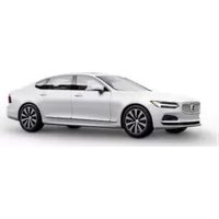
S90 (2024) - Automobile VOLVO - Free user manual and instructions
Find the device manual for free S90 (2024) VOLVO in PDF.


| Product Type | Full-size luxury sedan |
| Brand | Volvo |
| Model | S90 (2024) |
| Drivetrain | Front-engine, front-wheel drive or all-wheel drive |
| Engine Options | 2.0L turbocharged B5 mild hybrid (295 hp), B6 mild hybrid (300 hp), T8 twin-engine plug-in hybrid (455 hp) |
| Transmission | 8-speed automatic (Geartronic) |
| Fuel Type | Gasoline / Plug-in hybrid (T8) |
| Overall Length | 196.6 in (4995 mm) |
| Overall Width | 74.6 in (1895 mm) |
| Overall Height | 57.1 in (1451 mm) |
| Wheelbase | 119.5 in (3035 mm) |
| Curb Weight | Approx. 3,900–4,600 lbs (1,770–2,090 kg) depending on configuration |
| Fuel Tank Capacity | 15.9 gallons (60 liters) |
| Battery Capacity (T8) | 11.6 kWh (high-voltage lithium-ion) |
| Electric Range (T8) | Up to 21 miles (34 km) WLTP |
| Key Safety Features | City Safety, Pilot Assist, Lane Keeping Aid, Blind Spot Information System, Cross Traffic Alert, Road Sign Information |
| Infotainment System | 9-inch touchscreen with Google built-in (Android Automotive OS), Apple CarPlay, wireless charging |
| Seating Capacity | 5 passengers |
| Major Maintenance Intervals | Oil change every 10,000 miles or 12 months, cabin air filter every 20,000 miles |
| Spare Parts Availability | Authorized Volvo dealers and certified parts retailers |
| Reparability Index | Designed for repairability; major components accessible with standard tools |
| Warranty | 4 years / 50,000 miles limited warranty, 3 years / 36,000 miles complimentary maintenance |
Frequently Asked Questions - S90 (2024) VOLVO
User questions about S90 (2024) VOLVO
0 question about this device. Answer the ones you know or ask your own.
Ask a new question about this device
Download the instructions for your Automobile in PDF format for free! Find your manual S90 (2024) - VOLVO and take your electronic device back in hand. On this page are published all the documents necessary for the use of your device. S90 (2024) by VOLVO.
USER MANUAL S90 (2024) VOLVO
natural_image
Front view of a white car's head and grille (no visible text or symbols)
bar
| Category | Value | |---|---| | Category 1 | 100 | | Category 2 | 100 | | Category 3 | 100 | | Category 4 | 100 | | Category 5 | 100 | | Category 6 | 100 | | Category 7 | 100 | | Category 8 | 100 | | Category 9 | 100 | | Category 10 | 100 | | Category 11 | 100 | | Category 12 | 100 | | Category 13 | 100 | | Category 14 | 100 | | Category 15 | 100 | | Category 16 | 100 | | Category 17 | 100 | | Category 18 | 100 | | Category 19 | 100 | | Category 20 | 100 | | Category 21 | 100 | | Category 22 | 100 | | Category 23 | 100 | | Category 24 | 100 | | Category 25 | 100 | | Category 26 | 100 | | Category 27 | 100 | | Category 28 | 100 | | Category 29 | 100 | | Category 30 | 100 | | Category 31 | 100 | | Category 32 | 100 | | Category 33 | 100 | | Category 34 | 100 | | Category 35 | 100 | | Category 36 | 100 | | Category 37 | 100 | | Category 38 | 100 | | Category 39 | 100 | | Category 40 | 100 | | Category 41 | 100 | | Category 42 | 100 | | Category 43 | 100 | | Category 44 | 100 | | Category 45 | 100 | | Category 46 | 100 | | Category 47 | 100 | | Category 48 | 100 | | Category 49 | 100 | | Category 50 | 100 | | Category 51 | 100 | | Category 52 | 100 | | Category 53 | 100 | | Category 54 | 100 | | Category 55 | 100 | | Category 56 | 100 | | Category 57 | 100 | | Category 58 | 100 | | Category 59 | 100 | | Category 60 | 100 | | Category 61 | 100 | | Category 62 | 100 | | Category 63 | 100 | | Category 64 | 100 | | Category 65 | 100 | | Category 66 | 100 | | Category 67 | 100 | | Category 68 | 100 | | Category 69 | 100 | | Category 70 | 100 | | Category 71 | 100 | | Category 72 | 100 | | Category 73 | 100 | | Category 74 | 100 | | Category 75 | 100 | | Category 76 | 100 | | Category 77 | 100 | | Category 78 | 100 | | Category 79 | 100 | | Category 80 | 100 | | Category 81 | 100 | | Category 82 | 100 | | Category 83 | 100 | | Category 84 | 100 | | Category 85 | 100 | | Category 86 | 100 | | Category 87 | 100 | | Category 88 | 100 | | Category 89 | 100 | | Category 90 | 100 | | Category 91 | 100 | | Category 92 | 100 | | Category 93 | 100 | | Category 94 | 100 | | Category 95 | 100 | | Category 96 | 100 | | Category 97 | 100 | | Category 98 | 100 | | Category 99 | 100 | | Total (Total) |VÄLKOMMEN!
We hope you will enjoy many years of driving pleasure in your Volvo. The car has been designed for the safety and comfort of you and your passengers. Volvo strives to design one of the safest cars in the world. Your Volvo is also designed to meet applicable safety and environmental requirements.
To increase your enjoyment of your Volvo, we recommend that you read the instructions and maintenance information in this owner's
manual. The owner's manual is also available as a mobile app (Volvo Manual) and on the Volvo Cars support site (support.volvocars.com).
We encourage everyone to always wear their seatbelt in this and other cars. Please do not drive if you are under the influence of alcohol or medication – or have an impaired ability to drive in some other way.
TABLE OF CONTENTS
OWNER INFORMATION
Owner information 18
Owner's manual in centre display 19
Navigate in the owner's manual in the centre display 20
Owner's Manual in mobile devices 22
Volvo Cars support site 23
Reading the owner's manual 23
YOUR VOLVO
Volvo ID 28
Creating and registering a Volvo ID 28
Drive-E - cleaner driving pleasure 30
IntelliSafe – driver support and safety 33
Sensus - online connectivity and entertainment 34
Software updates 37
Recording data 37
Terms & Conditions for Services 38
Customer Privacy Policy 39
Important information on acces- 39
sones and auxiliary equipment
Installation of accessories 40
Connection of equipment to the car's diagnostic socket 40
Showing the car's identification number 41
Change of market when importing or relocating 42
Driver distraction 42
SAFETY
Safety 46
Safety during pregnancy 47
Whiplash Protection System 47
Pedestrian Protection System 49
Seatbelts 50
Putting on and taking off seatbelts 50
Seatbelt tensioner 52
Resetting the electric seatbelt 53 tensioner
Door and seatbelt reminder 53
Airbags 55
Driver airbags 55
Passenger airbag 56
Activating and deactivating pas-senger airbag* 58
Side airbags 60
Inflatable curtains 61
Safety mode 61
Starting and moving the car after safety mode 62
Child safety 63
Child seats 64
Upper mounting points for child seats 64
Lower mounting points for child seats 65
i-Size/ISOFIX mounting points for 66 child seats
Child seat positioning 66
Child seat mounting 67
Table for location of child seats 70 using the car's seatbelts
Table for location of i-Size child seats 72
Table for location of ISOFIX child seats 73
Integrated child seat ^* 76
Folding up the seat cushion in the 77 integrated child seat*
Folding down the seat cushion in 78 the integrated child seat*
DISPLAYS AND VOICE CONTROL
Displays and controls by the driver in a left-hand drive car 80
Displays and controls by the driver in a right-hand drive car 81
Driver display 83
Driver display settings 85
Fuel gauge 86
Hybrid gauge 86
Hybrid battery gauge 87
Trip computer 88
Show trip data in the driver display 90
Resetting the trip meter 91
Show trip statistics in the centre 91 display
Settings for trip statistics 92
Date and time 92
Outside temperature gauge 93
Indicator and warning symbols 93
License agreement for the driver 96 display
App menu in the driver display 102
Managing the app menu in the driver display 103
Messages in the driver display 104
Managing messages in the driver 105 display
Handling a message saved from the driver display 105
Overview of centre display 107
Managing the centre display 110
Activating and deactivating centre 113 display
Navigating in the centre display's 113 views
Managing subviews in centre display 117
Function view in centre display 120
Moving apps and buttons in centre display 122
Symbols in the centre display's status bar 122
Keyboard in centre display 124
Changing keyboard language in 127 centre display
Enter the characters, letters and 127 words manually in the centre display
Changing the appearance in the centre display 129
Switching off and changing the volume of the system sound in the centre display 129
Changing system units 130
Changing system language 130
Other settings in the centre dis- 130 play's top view
| Open contextual setup in the centre display | 131 |
| Resetting user data for change of ownership | 132 |
| Resetting settings in the centre display | 132 |
| Table showing centre display settings | 133 |
| Driver profiles | 134 |
| Selecting driver profile | 135 |
| Renaming a driver profile | 135 |
| Protect driver profile | 136 |
| Linking remote control key to driver profile | 136 |
| Resetting settings in the driver profiles | 138 |
| Message in centre display | 138 |
| Managing messages in the centre display | 139 |
| Handling a message saved from the centre display | 139 |
| Head-up display* | 140 |
| Activating and deactivating the head-up display* | 142 |
| Settings for head-up display* | 142 |
| Voice recognition | 143 |
| Using voice recognition | 144 |
| Controlling a telephone with voice recognition | 146 |
| Voice control of radio and media | 147 |
| Settings for voice recognition | 148 |
LIGHTING
| Lighting control | 150 |
| Adjusting light functions via the centre display | 151 |
| Adapting the headlamp pattern from the headlamps | 152 |
| Position lamps | 152 |
| Daytime running lights | 153 |
| Dipped beam | 153 |
| Using main beam | 154 |
| Active main beam | 155 |
| Using direction indicators | 156 |
| Active bending lights* | 157 |
| Rear fog lamp | 158 |
| Brake lights | 158 |
| Emergency brake lights | 159 |
| Hazard warning flashers | 159 |
| Using home safe lighting | 160 |
| Approach light duration | 160 |
| Interior lighting | 160 |
| Adjusting interior lighting | 162 |
WINDOWS, GLASS AND MIRRORS
Windows, glass and mirrors 166
Pinch protection for windows and sun blinds 166
Reset sequence for pinch protection 167
Power windows 168
Operating power windows 168
Using the sun blind* 170
Rearview and door mirrors 171
Adjusting rearview mirror dimming 171
Angling adjustment of the door mirrors 172
Sunroof ^* 174
Operating the sunroof ^* 175
Wiper blades and washer fluid 177
Using windscreen wipers 177
Using the rain sensor 178
Activating and deactivating the 179 rain sensor's memory function
Using windscreen and headlamp washers 180
SEATS AND STEERING WHEEL
Manual front seat 182
Power* front seat 183
Adjusting the power* front seat 183
Storing position for seat, door mirrors and head-up display* 184
Using a stored position for seat, 185 door mirrors and head-up display*
Massage settings* in the front seat 186
Adjusting massage settings* in the front seat 187
Adjusting* the length of the seat 188 cushion in the front seat
Adjusting the side support* in the 189 front seat
Adjusting the lumbar support* in the front seat 190
Adjusting the passenger seat from the driver's seat* 191
Lowering the backrests in the rear seat* 192
Adjusting the head restraints in 193 the rear seat
Steering wheel controls and horn 195
Steering lock 195
Adjusting the steering wheel 196
CLIMATE
Climate 198
Climate zones 198
Climate control - sensors 199
Perceived temperature 199
Controlling the climate control 200 system using voice control
Air quality 201
CleanZone ^* 201
Clean Zone Interior Package ^* 202
Interior Air Quality System* 202
Activating and deactivating the air quality sensor* 203
Passenger compartment filter 203
Advanced Air Cleaner* 204
Air distribution 204
Changing air distribution 205
Opening, closing and aiming the air vents 205
Table of air distribution options 207
Climate controls 210
Activating and deactivating heated front seat* 211
Activating and deactivating automatic start of heated front seat* 212
Activating and deactivating heated rear seat* 212
| Activating and deactivating ventilated front seat* | 213 |
| Activating and deactivating the heated steering wheel* | 214 |
| Activating and deactivating automatic start of heated steering wheel* | 214 |
| Activating auto climate control | 214 |
| Activating and deactivating air recirculation | 215 |
| Activating and deactivating time setting for air recirculation | 216 |
| Activating and deactivating max defroster | 216 |
| Activating and deactivating the heated windscreen* | 217 |
| Activating and deactivating automatic start of heated windscreen* | 218 |
| Activating and deactivating the heated rear window and door mirrors | 218 |
| Activating and deactivating automatic starting of the heated rear window and door mirrors | 219 |
| Regulating fan level for front seat | 219 |
| Regulating temperature for front seat | 220 |
| Synchronising temperature | 221 |
| Activating and deactivating air conditioning | 221 |
| Parking climate | 222 |
| Preconditioning | 222 |
| Start and switch off preconditioning | 223 |
| Preconditioning time setting | 224 |
| Adding and editing time setting for preconditioning | 225 |
| Activating and deactivating time setting for preconditioning | 226 |
| Removing time setting for preconditioning | 227 |
| Precleaning* | 228 |
| Starting and switching off pre-cleaning* | 228 |
| Climate comfort when parking | 229 |
| Starting and switching off climate comfort when parking | 229 |
| Symbols and messages for parking climate control | 231 |
| Heater | 233 |
| Parking heater | 234 |
| Additional heater | 235 |
| Activating and deactivating automatic start of auxiliary heater | 236 |
KEY, LOCKS AND ALARM
| Locking and unlocking | 238 |
| Lock confirmation | 238 |
| Lock indication setting | 240 |
| Remote control key | 240 |
| Locking and unlocking with the remote control key | 242 |
| Settings for remotely controlled and inside unlocking | 243 |
| Unlocking the boot lid with the remote control key | 244 |
| Remote control key range | 244 |
| Replacing the battery in the remote control key | 245 |
| Ordering more remote control keys | 249 |
| Care Key - restricted remote control key | 249 |
| Care Key settings | 250 |
| Detachable key blade | 251 |
| Locking and unlocking with the detachable key blade | 252 |
| Immobiliser | 253 |
| Type approval for the remote control key system | 254 |
| Keyless and touch-sensitive surfaces* | 269 |
| Keyless locking and unlocking* | 270 |
| Settings for Keyless entry* | 271 |
| Keyless* unlocking of boot lid | 271 |
| Antenna locations for the start and lock systems | 272 |
| Locking and unlocking from inside the car | 273 |
| Unlocking the boot lid from the inside of the car | 274 |
| Activating and deactivating child safety locks | 274 |
| Automatic locking when driving | 275 |
| Closing and locking boot lid with button* | 276 |
| Operating the boot lid with foot movement* | 277 |
| Private locking | 279 |
| Activating and deactivating private locking | 279 |
| Alarm* | 280 |
| Activating and deactivating alarms* | 282 |
| Reduced alarm level* | 282 |
| Double lock* | 283 |
DRIVER SUPPORT
| Driving support systems | 286 |
| Speed-dependent steering force | 286 |
| Electronic stability control | 287 |
| Electronic Stability Control in sport mode | 288 |
| Activating or deactivating sport mode for electronic stability control | 289 |
| Symbols and messages for electronic stability control | 290 |
| Connected Safety | 292 |
| Activating or deactivating Connected Safety | 293 |
| Limitations of Connected Safety | 293 |
| Road Sign Information* | 294 |
| Activating or deactivating road sign information* | 295 |
| Display mode for road sign information* | 296 |
| Road Sign Information and Sensus Navigation* | 298 |
| Warning for speed limitation and speed camera from road sign information* | 298 |
| Activating or deactivating warnings from road sign information* | 299 |
| Limitations of Road Sign Information* | 300 |
| Speed limiter | 301 |
| Selecting and activating speed limiter | 302 |
| Deactivating the speed limiter | 303 |
| Temporary deactivation of speed limiter | 304 |
| Limitations for speed limiter | 304 |
| Automatic speed limiter | 304 |
| Activating or deactivating the automatic speed limiter | 306 |
| Changing the tolerance for the automatic speed limiter | 307 |
| Limitations for automatic speed limiter | 307 |
| Cruise control | 308 |
| Selecting and activating cruise control | 309 |
| Deactivating cruise control | 310 |
| Standby mode for cruise control | 310 |
| Adaptive cruise control* | 311 |
| Controls for adaptive cruise control* | 312 |
| Display mode for adaptive cruise control* | 313 |
| Selecting and activating adaptive cruise control* | 314 |
| Deactivating adaptive cruise control* | 315 |
| Standby mode for adaptive cruise control* | 316 |
| Limitations for adaptive cruise control* | 317 |
| Change between cruise control and adaptive cruise control* in the centre display | 318 |
| Symbols and messages for adaptive cruise control* | 319 |
| Pilot Assist* | 321 |
| Controls for Pilot Assist* | 323 |
| Display mode for Pilot Assist* | 324 |
| Selecting and activating Pilot Assist* | 326 |
| Deactivate Pilot Assist* | 327 |
| Standby mode for Pilot Assist* | 327 |
| Temporary disabling of steering assistance with Pilot Assist* | 328 |
| Limitations of Pilot Assist* | 329 |
| Symbols and messages for Pilot Assist* | 332 |
| Cornering support* | 333 |
| Activating or deactivating cornering support* | 334 |
| Limitations for cornering support* | 334 |
| Overtaking Assistance* | 335 |
| Use Overtaking Assistance | 335 |
| Warning from driver support in the event of a collision risk | 336 |
| Change of target with driver support | 337 |
| Set the stored speed for driver support | 338 |
| Set time interval to vehicle ahead | 339 |
| Drive modes when using time interval to vehicles | 340 |
| Automatic braking with driver support | 340 |
| Lane assistance | 341 |
| Activating or deactivating lane assistance | 343 |
| Selecting assistance option for lane assistance | 344 |
| Limitations of Lane assistance | 344 |
| Symbols and messages for lane assistance | 345 |
| Display mode for lane assistance | 347 |
| City SafetyTM | 348 |
| Subfunctions for City Safety | 349 |
| Setting the warning distance for City Safety | 351 |
| Detection of obstacles with City Safety | 352 |
| City Safety in cross traffic | 354 |
| Limitations for City Safety in cross traffic | 355 |
| City Safety steering assistance for evasive manoeuvre | 356 |
| Limitations of City Safety steering assistance when taking evasive action | 356 |
| Automatic braking in the event of an impeded evasive manoeuvre with City Safety | 357 |
| City Safety brakes for oncoming vehicles | 357 |
| Limitations of City Safety | 358 |
| Messages for City Safety | 361 |
| Steering assistance at risk of collision | 362 |
| Activating or deactivating steering assistance in the event of a collision risk | 363 |
| Steering assistance upon risk of run-off | 363 |
| Steering assistance upon risk of head-on collision | 364 |
| Steering assistance upon risk of rear-end collision* | 365 |
| Limitations for steering assistance at risk of collision | 366 |
| Symbols and messages for steering assistance upon risk of collision | 367 |
| Rear Collision Warning* | 368 |
| Limitations of Rear Collision Warning* | 368 |
| BLIS* | 369 |
| Activating or deactivating BLIS | 370 |
| Limitations of BLIS | 371 |
| Messages for BLIS | 372 |
| Driver Alert Control | 373 |
| Activating or deactivating Driver Alert Control | 374 |
| Select rest stop guidance in the event of a warning from Driver Alert Control | 374 |
| Limitations of Driver Alert Control | 375 |
| Distance Warning* | 375 |
| Activating or deactivating distance warning | 376 |
| Limitations of Distance Warning | 376 |
| Cross Traffic Alert* | 377 |
| Activating or deactivating Cross Traffic Alert* | 378 |
| Limitations of Cross Traffic Alert* | 378 |
| Messages for Cross Traffic Alert* | 380 |
| Park Assist* | 381 |
| Park Assist Pilot front, rear and along the sides* | 382 |
| Activating or deactivating the parking assistance system* | 383 |
| Limitations of Parking assistance | 384 |
| Symbols and messages for Park Assist Pilot | 386 |
| Park assist camera* | 387 |
| Park assist camera locations and surveillance areas* | 388 |
| Park assist lines for park assist camera* | 390 |
| Sensor fields for parking assistance system | 392 |
| Activate park assist camera | 394 |
| Symbols and messages for Park assist camera | 395 |
| Park Assist Pilot* | 397 |
| Parking variants with Park Assist Pilot* | 398 |
| Using Park Assist Pilot* | 399 |
| Leaving parallel parking with Park Assist Pilot* | 402 |
| Limitations of Park Assist Pilot* | 402 |
| Messages for Park Assist Pilot* | 405 |
| Radar unit | 406 |
| Type approval for radar device | 407 |
| Camera unit | 415 |
| Limitations for camera and radar unit | 415 |
| Recommended maintenance for camera and radar unit | 418 |
| Symbols and messages for camera and radar unit | 420 |
ELECTRIC OPERATION AND CHARGING
| General information on electric drive | 424 |
| Charging the hybrid battery | 425 |
| Charging current | 426 |
| Charging cable | 427 |
| Ground fault breaker in the charging cable | 429 |
| Temperature monitoring of the charging cable | 430 |
| Opening and closing the hatch for the charging input socket | 431 |
| Starting hybrid battery charging | 431 |
| Charging status in the car's charging input socket | 434 |
| Charging status in the charging cable's control unit | 435 |
| Charging status in the car's driver display | 437 |
| Stopping hybrid battery charging | 439 |
| Symbols and messages relating to hybrid drive in the driver display | 441 |
| Long-term storage of vehicles with hybrid batteries | 443 |
STARTING AND DRIVING
Starting the car 446
Switching off the car 447
Ignition positions 448
Selecting ignition mode 449
Alcohol lock ^* 450
Bypass of the alcohol lock ^* 450
Before starting the engine with the alcohol lock ^* 451
Brake functions 451
Foot brake 451
Brake assistance 453
Braking on wet roads 453
Braking on gritted roads 453
Brake system maintenance 454
Parking brake 454
Activating and deactivating the 455 parking brake
Automatic parking brake activation 456 setting
Parking on a hill 456
In the event of a fault in the parking brake 457
Automatic braking when stationary 457
Activating and deactivating the automatic brake at a standstill 458
Help when starting on a hill 459
Auto braking after a collision 459
Regenerative braking* 459
Gearbox 460
Automatic gearbox 460
Changing gear with automatic gearbox 461
Changing gear with steering wheel 462 paddles*
Gear selector inhibitor 464
Kick-down function 464
Launch function* 464
Symbols and messages for automatic gearbox 465
Gear shift indicator 465
All-wheel drive 465
Drive systems 466
Starting and stopping the combustion engine 467
Drive modes 467
Changing drive mode 471
Energy distribution using map data* 472
Level control* and shock absorption 473
Settings for level control* 476
Economical driving 476
Range 477
Hold and Charge 478
Preparations for a long trip 479
Winter driving 480
Driving in water 481
Opening and closing the fuel filler flap 481
Filling fuel 482
Handling of fuel 484
Petrol 485
Petrol particle filter 486
Overheating in the engine and drive system 486
Overloading the starter battery 487
Using jump starting with another battery 488
Towbar ^* 489
Specifications for towbar* 490
Extendable and retractable towbar* 491
Driving with a trailer 493
Trailer stability assist* 495
Checking trailer lamps 496
Towbar-mounted bicycle rack* 497
Towing 498
Fitting and removing the towing eye 498
Recovery 499
HomeLink ^®* 500
Programming HomeLink ^®* 501
Using HomeLink®* 503
Type approval for HomeLink ^®* 503
Compass ^* 504
Activating and deactivating the 504 compass*
Calibrating the compass ^* 504
SOUND, MEDIA AND INTERNET
| Sound, media and Internet | 508 |
| Audio settings | 508 |
| Sound experience* | 509 |
| Apps | 510 |
| Downloading apps | 511 |
| Updating apps | 512 |
| Deleting apps | 512 |
| Radio | 513 |
| Start radio | 513 |
| Changing radio band and radio station | 514 |
| Searching for radio stations | 515 |
| Save radio channels in the Radio Favourites app | 516 |
| Settings for radio | 516 |
| RDS radio | 518 |
| Digital radio* | 518 |
| Link between FM and digital radio* | 519 |
| Media player | 519 |
| Media playback | 520 |
| Controlling and changing media | 521 |
| Searching media | 522 |
| Gracenote® | 523 |
| Video | 524 |
| Playing a video | 524 |
Playing back DivX ^® 524
Settings for video 525
Media via Bluetooth ^® 525
Connecting a device via Bluetooth ^® 525
Media via USB port 526
Connecting a device via USB port 526
Technical specifications for USB devices 527
Compatible media formats 527
Apple® CarPlay® 528
Using Apple ^® CarPlay ^®* 529
Settings for Apple ^® CarPlay ^®* 531
Tips for using Apple® CarPlay® 531
Android Auto* 532
Using Android Auto* 533
Settings for Android Auto* 534
Tips for using Android Auto* 535
Phone 535
Connecting a phone to the car via 536
Bluetooth for the first time
Connecting a phone to the car via 538
Bluetooth automatically
Connecting a phone to the car via 539
Bluetooth manually
Disconnecting a Bluetooth-con- 539
nected phone
| Switch between Bluetooth-connected phones | 539 |
| Removing devices connected to Bluetooth | 540 |
| Managing phone calls | 540 |
| Managing text messages | 541 |
| Settings for text messages | 542 |
| Managing the phone book | 542 |
| Settings for phone | 543 |
| Settings for Bluetooth devices | 544 |
| Internet-connected car* | 544 |
| Connect the car to the Internet via a Bluetooth-enabled phone | 545 |
| Connect the car to the Internet via a phone (Wi-Fi) | 546 |
| Connect the car to the Internet via car modem (SIM card) | 546 |
| Settings for car modem* | 547 |
| Sharing Internet access from the car via a Wi-Fi hotspot | 548 |
| No or poor Internet connection | 549 |
| Remove Wi-Fi network | 549 |
| Wi-Fi technologies and security | 550 |
| User terms and conditions and data sharing | 550 |
| Activating and deactivating data sharing | 551 |
Data sharing for services 551
Storage space on hard disk 552
License agreement for audio and media 553
WHEELS AND TYRES
| Tyres | 564 |
| Dimension designation for tyre | 566 |
| Dimension designation for wheel rim | 567 |
| Tyres' rotation direction | 567 |
| Tread wear indicators on the tyres | 568 |
| Checking tyre pressure | 568 |
| Adjusting tyre pressure | 569 |
| Recommended tyre pressure | 570 |
| Tyre pressure monitoring system* | 571 |
| Saving a new reference value for tyre pressure monitoring* | 572 |
| See tyre pressure status in the centre display* | 573 |
| Action in the event of warning for low tyre pressure | 574 |
| Messages for tyre pressure monitoring* | 575 |
| Changing wheel | 575 |
| Tool kit | 577 |
| Jack* | 578 |
| Wheel bolts | 578 |
| Spare wheel* | 579 |
| Handling the spare wheel* | 580 |
| Winter tyres | 580 |
| Snow chains | 581 |
| Emergency puncture repair kit | 582 |
Using a puncture repair kit 583
Inflating tyres with the compressor 586
from the puncture repair kit
LOADING, STORAGE AND PASSENGER COMPARTMENT
Passenger compartment interior 590
Tunnel console 591
Electrical sockets 591
Using electrical sockets 592
Using the glovebox 593
Sun visors 594
Cargo area 594
Recommendations for loading 595
Roof load and loading on load carriers 596
Bag hooks 596
Load retaining eyelets 597
Through-load hatch in the rear seat* 597
First aid kit ^* 597
Warning triangle 598
MAINTENANCE AND SERVICE
Volvo service programme 600
Data transfer between car and 600
workshop via Wi-Fi
Download Center 601
Managing system updates via the 601
Download Centre
Car status 602
Book service and repair 603
Sending car information to a workshop 604
Raise the car 605
Servicing the climate control system 608
Head up display when replacing 608
the windscreen*
Opening and closing the bonnet 609
Engine compartment overview 610
Engine oil 611
Checking and filling with engine oil 613
Coolant 614
Topping up coolant 614
Starter battery 617
Hybrid battery 619
Symbols on the batteries 619
Battery recycle 620
Fuses and central electrical units 620
Replacing a fuse 621
| Fuses in engine compartment | 622 |
| Fuses under glovebox | 629 |
| Fuses in cargo area | 634 |
| Bulb replacement | 639 |
| Cleaning the interior | 639 |
| Cleaning the centre display | 640 |
| Cleaning the Head-up display* and driver display | 641 |
| Cleaning fabric upholstery and headlining | 641 |
| Cleaning the seatbelts | 642 |
| Cleaning textile floor and entrance mats | 642 |
| Cleaning leather upholstery* | 643 |
| Cleaning the leather steering wheel | 644 |
| Cleaning interior plastic, metal and wood parts | 644 |
| Cleaning the exterior | 645 |
| Polishing and waxing | 645 |
| Handwashing | 646 |
| Automatic car wash | 647 |
| High-pressure washing | 649 |
| Cleaning the wiper blades | 649 |
| Cleaning exterior plastic, rubber and trim components | 650 |
| Cleaning wheel rims | 651 |
| Rustproofing | 651 |
| Car paintwork | 651 |
| Touching up minor paintwork damage | 652 |
| Colour codes | 653 |
| Replacing windscreen wiper blades | 653 |
| Set the wiper blades in service position | 654 |
| Filling washer fluid | 655 |
SPECIFICATIONS
| Type designations | 658 |
| Dimensions | 661 |
| Weights | 663 |
| Towing capacity and towball load | 664 |
| Engine specifications | 666 |
| Engine oil — specifications | 667 |
| Adverse driving conditions for engine oil | 668 |
| Transmission fluid – specifications | 669 |
| Brake fluid – specifications | 669 |
| Fuel tank - volume | 669 |
| Air conditioning — specifications | 670 |
| Fuel consumption and CO2 emissions | 672 |
| Approved wheel and tyre sizes | 675 |
| Minimum permitted tyre load index and speed rating for tyres | 676 |
| Approved tyre pressures | 677 |
ALPHABETICAL INDEX
Alphabetical Index 679

bar
| Category | Value | |---|---| | Category 1 | 100 | | Category 2 | 100 | | Category 3 | 100 | | Category 4 | 100 | | Category 5 | 100 | | Category 6 | 100 | | Category 7 | 100 | | Category 8 | 100 | | Category 9 | 100 | | Category 10 | 100 | | Category 11 | 100 | | Category 12 | 100 | | Category 13 | 100 | | Category 14 | 100 | | Category 15 | 100 | | Category 16 | 100 | | Category 17 | 100 | | Category 18 | 100 | | Category 19 | 100 | | Category 20 | 100 | | Category 21 | 100 | | Category 22 | 100 | | Category 23 | 100 | | Category 24 | 100 | | Category 25 | 100 | | Category 26 | 100 | | Category 27 | 100 | | Category 28 | 100 | | Category 29 | 100 | | Category 30 | 100 | | Category 31 | 100 | | Category 32 | 100 | | Category 33 | 100 | | Category 34 | 100 | | Category 35 | 100 | | Category 36 | 100 | | Category 37 | 100 | | Category 38 | 100 | | Category 39 | 100 | | Category 40 | 100 | | Category 41 | 100 | | Category 42 | 100 | | Category 43 | 100 | | Category 44 | 100 | | Category 45 | 100 | | Category 46 | 100 | | Category 47 | 100 | | Category 48 | 100 | | Category 49 | 100 | | Category 50 | 100 | | Category 51 | 100 | | Category 52 | 100 | | Category 53 | 100 | | Category 54 | 100 | | Category 55 | 100 | | Category 56 | 100 | | Category 57 | 100 | | Category 58 | 100 | | Category 59 | 100 | | Category 60 | 100 | | Category 61 | 100 | | Category 62 | 100 | | Category 63 | 100 | | Category 64 | 100 | | Category 65 | 100 | | Category 66 | 100 | | Category 67 | 100 | | Category 68 | 100 | | Category 69 | 100 | | Category 70 | 100 | | Category 71 | 100 | | Category 72 | 100 | | Category 73 | 100 | | Category 74 | 100 | | Category 75 | 100 | | Category 76 | 100 | | Category 77 | 100 | | Category 78 | 100 | | Category 79 | 100 | | Category 80 | 100 | | Category 81 | 100 | | Category 82 | 100 | | Category 83 | 100 | | Category 84 | 100 | | Category 85 | 100 | | Category 86 | 100 | | Category 87 | 100 | | Category 88 | 100 | | Category 89 | 100 | | Category 90 | 100 | | Category 91 | 100 | | Category 92 | 100 | | Category 93 | 100 | | Category 94 | 100 | | Category 95 | 100 | | Category 96 | 100 | | Category 97 | 100 | | Category 98 | 100 | | Category 99 | 100 | | Total (Total) |OWNER INFORMATION
OWNER INFORMATION
Owner information
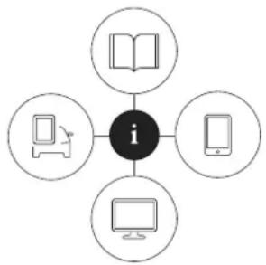
Owner's information is available in several different product formats, both digital and printed. The owner's manual is available in the car's centre display, as a mobile app and on the Volvo Cars support site. There is a Quick Guide and a supplement to the owner's manual available in the glovebox, with specifications and fuse information, amongst other things. A printed owner's manual can be ordered.
flowchart
graph TD
    A[" "] --> B["i"]
    C[" "] --> B
    D[" "] --> B
    E[" "] --> B
The car's centre display ^1
In the centre display, drag down the top view and tap on Owner's manual. Available here are options for visual navigation with exterior and interior images of the car. The information is searchable and
is also divided into categories.
Mobile app

In App Store or Google Play, search for "Volvo Manual", download the app to your smartphone or tablet and select the car. Available in the app are video tutorials and options for visual navigation
with exterior and interior images of the car. The content is searchable, and the various sections are designed to facilitate navigation
Volvo Cars support site

Go to volvocars.com/support and select your country. Here you can find owner's manuals, both online and in PDF format. On the Volvo Cars support site there are also video tutorials and further
information and help regarding your Volvo and your car ownership. The page is available for most markets.
Printed information

There is a supplement to the owner's manual ^1 in the glovebox that contains information on fuses and specifications, as well as a summary of important and practical information.
There is also a Quick Guide available in printed format that helps you to get started with the most commonly used functions in the car.
Depending on equipment level selected, market, etc. additional owner's information may also be available in printed format in the car.
A printed owner's manual and associated supplement can be ordered. Contact a Volvo dealer to order.
IMPORTANT
The driver is always responsible that the vehicle is driven safely in traffic and that applicable laws and regulations are followed. It is also important that the car is maintained and handled in accordance with Volvo's recommendations in the owner's information.
If there should be a difference between the information in the centre display and the printed information then it is always the printed information that applies.
i NOTE
Changing the language in the centre display may mean that some owner's information is not compliant with national or local laws and regulations. Do not switch to a language that is difficult to understand as this may make it difficult to find your way back through the screen structure.
Related information
• Owner's manual in centre display (p. 19)
- Owner's Manual in mobile devices (p. 22)
• Volvo Cars support site (p. 23)
• Reading the owner's manual (p. 23)
Owner's manual in centre display
A digital ^2 version of the owner's manual is available in the car's centre display. The digital owner's manual can be accessed from the top view, and in some cases the contextual owner's manual can also be accessed from the top view.
NOTE
The digital owner's manual is not available while driving.
Owner's manual
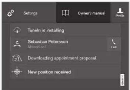
Top view with button for owner's manual.
To open the owner's manual - drag down the top view in the centre display and tap on Owner's manual.
The information in the owner's manual can be accessed directly via the owner's manual homepage or its top menu.
OWNER INFORMATION
Contextual owner's manual
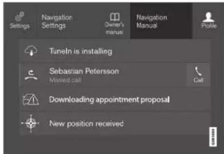
Top view with button for contextual owner's manual.
The contextual owner's manual is a shortcut to an article in the owner's manual that describes the active function shown on the screen.
When the contextual owner's manual is available, it is shown to the right of Owner's manual in the top view.
Tapping on the contextual owner's manual therefore opens an article in the owner's manual that is related to the content that is shown on the screen. E.g. tap on Navigation Manual – an article that is related to navigation opens.
This only applies to some of the apps in the car. For downloaded third party apps, for example, it is not possible to access app-specific articles.
Related information
- Navigate in the owner's manual in the centre display (p. 20)
- Navigating in the centre display's views (p. 113)
• Downloading apps (p. 511)
Navigate in the owner's manual in the centre display
The digital owner's manual can be accessed from the centre display top view in the car. The content is searchable, and the various sections are designed to facilitate navigation.
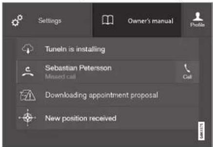
The owner's manual is accessed from the top view.
- To open the owner's manual - drag down the top view in the centre display and tap on Owner's manual.
There is a range of different options for finding information in the owner's manual. The options can be accessed from the owner's manual homepage and from the top menu.
Opening the menu in the top menu
- Press the upper list in the owner's manual.
A menu with different options for finding information is opened:
Homepage

Tap on the symbol to go back to the start page in the owner's manual.
Categories

The articles in the owner's manual are structured into main categories and subcategories. The same article can be found in several appropriate categories so that it can be found more easily.
- Press Categories.
The main categories are shown in a list.
- Tap on a main category (☐).
A list of subcategories (☐) and articles (☐) is shown.
- Tap on an article to open it.
To go back, press the back arrow.
Featured articles

Press the symbol to access a page with links to a selection of articles that can be useful to read in order to get to know the more common functions of the car. The articles can also be accessed via
categories, but are collected here for faster access. Tap on an article in order to read it in its entirety.
Hotspots for exterior and interior

Exterior and interior overview images of the car. Different parts are designated with hotspots that lead to articles about those parts of the car.

Exterior or interior images are shown with so-called hotspots in place. The hotspot leads to articles about the corresponding part of the car. Swipe horizontally over the screen to browse among the images.
- Tap on a hotspot.
The title of the article about the area is shown.
- Tap on the title to open the article.
To go back, press the back arrow.
Favourites

Press the symbol to access the articles saved as favourites. Tap on an article in order to read it in its entirety.
Saving or deleting articles as favourites
Save an article as favourite by pressing ☆at the top right when an article is open. When an article has been saved as a favourite the star is filled in: ★.
To remove an article as a favourite, press the star again in the current article.
Video

Press the symbol to view brief instruction videos for various functions in the car.
OWNER INFORMATION
Information

Tap on the symbol to obtain information about which version of the owner's manual is available in the car as well as other useful information.
Using the search function in the top menu
- Tap on ☑ the top menu of the owner's manual. A keyboard appears in the lower part of the screen.
-
Type in a keyword, such as "seatbelt".
Suggestions for articles and categories are shown while letters are being entered.
-
Tap on the article or category to access it.
Related information
• Owner's manual in centre display (p. 19)
• Keyboard in centre display (p. 124)
• Reading the owner's manual (p. 23)
Owner's Manual in mobile devices
The owner's manual is available as a mobile app ^3 from both the App Store and Google Play. The app is adapted for smartphones and tablets.

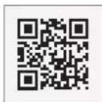
The owner's manual can be downloaded as a mobile app from the App Store or Google Play. The QR code provided here takes you directly to the app. Alternatively, you can search for "Volvo manual" in
the App Store or Google Play.
The app contains a video along with exterior and interior images where different parts of the car are highlighted with so-called hotspots, which lead to articles about the area in question. The content is searchable, and the
various sections are designed to facilitate navigation.

The mobile app is available from both the App Store and Google Play.
Related information
• Reading the owner's manual (p. 23)
Volvo Cars support site
More information on your car is available on the Volvo Cars website and support site.
Support on the Internet
Go to volvocars.com/support to visit the site. The support site is available for most markets.
It contains support for functions such as web-based services and functions, Volvo On Call*, the navigation system* and apps. Videos and step-by-step instructions explain different procedures, e.g. how to connect the car to the Internet via a mobile phone.
Downloadable information
Maps
For cars equipped with Sensus Navigation there is the facility to download maps from the support page.
Owner's manuals as PDF
Owner's manuals are available for download in PDF format. Select car model and model year to download the manual as required.
Contact
The support site contains contact details to customer support and your nearest Volvo retailer.
Create a Volvo ID on the Volvo Cars website
Create a personal Volvo ID and manage it on volvocars.com.
Related information
- Volvo ID (p. 28)
Reading the owner's manual
To help you get to know your new car, read the Owner's Manual before you drive it for the first time.
Reading the owner's manual is a way to become familiar with new functions, get advice on how to handle the car in different situations and learn how to make use of all the car's features. Please pay attention to the safety instructions contained in the owner's manual.
The intention of this owner's information is to explain all possible functions, options and accessories included in a Volvo vehicle. It is not intended as an indication or guarantee that all of these features, functions and options are included in every vehicle. Some terminology used may not exactly match terminology used in sales, marketing and advertising materials.
Development work is constantly underway in order to improve our product. Modifications may mean that information, descriptions and illustrations in the owner's manual differ from the equipment in the car. We reserve the right to make modifications without prior notice.
Do not remove this manual from the car - if problems should arise then the necessary information about where and how to seek professional help will be missing.
© Volvo Car Corporation
▶▶
OWNER INFORMATION
Options/accessories
In addition to standard equipment, the owner's manual also describes options (factory fitted equipment) and certain accessories (retrofitted extra equipment).
All, at the time of publication known, options and accessories are marked with an asterisk:
The equipment described in the owner's manual is not available in all cars - they have different equipment depending on adaptations for the needs of different markets and national or local laws and regulations.
In the event of uncertainty over what is standard or an option/accessory, contact a Volvo dealer.
Special texts

WARNING
Warning texts appear if there is a risk of injury.

IMPORTANT
Important texts appear if there is a risk of damage.

NOTE
Note texts give advice or tips that facilitate the use of e.g. features and functions.
Decals
The car contains different types of decal which are designed to convey important information in a clear manner. The decals in the car have the following descending degree of importance for the warning/information.
Warning of personal injury
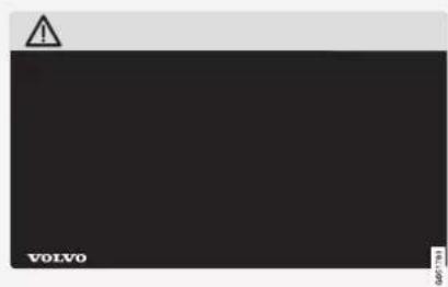
Black ISO symbols on yellow warning field, white text/image on black message field. Used to indicate the presence of danger which, if the warning is ignored, may result in serious personal injury or fatality.
Risk of property damage

White ISO symbols and white text/image on black or blue warning field and message field. Used to indicate the presence of danger which, if the warning is ignored, may result in damage to property.
Information

White ISO symbols and white text/image on black message field.

NOTE
It is not intended that the decals illustrated in the owner's manual should be exact replicas of those in the car. They are included to show their approximate appearance and location in the car. The information that applies to your particular car is available on the respective decals for your car.
Illustrations and video clips
Illustrations and video clips used in the owner's manual are sometimes schematic and are intended to provide an overall picture or example of a certain function. They may devi-
ate from the car's appearance depending on equipment level and market.
Related information
• Owner's manual in centre display (p. 19)
• Owner's Manual in mobile devices (p. 22)
• Volvo Cars support site (p. 23)

bar
| Category | Value | |---|---| | Category 1 | 100 | | Category 2 | 100 | | Category 3 | 100 | | Category 4 | 100 | | Category 5 | 100 | | Category 6 | 100 | | Category 7 | 100 | | Category 8 | 100 | | Category 9 | 100 | | Category 10 | 100 | | Category 11 | 100 | | Category 12 | 100 | | Category 13 | 100 | | Category 14 | 100 | | Category 15 | 100 | | Category 16 | 100 | | Category 17 | 100 | | Category 18 | 100 | | Category 19 | 100 | | Category 20 | 100 | | Category 21 | 100 | | Category 22 | 100 | | Category 23 | 100 | | Category 24 | 100 | | Category 25 | 100 | | Category 26 | 100 | | Category 27 | 100 | | Category 28 | 100 | | Category 29 | 100 | | Category 30 | 100 | | Category 31 | 100 | | Category 32 | 100 | | Category 33 | 100 | | Category 34 | 100 | | Category 35 | 100 | | Category 36 | 100 | | Category 37 | 100 | | Category 38 | 100 | | Category 39 | 100 | | Category 40 | 100 | | Category 41 | 100 | | Category 42 | 100 | | Category 43 | 100 | | Category 44 | 100 | | Category 45 | 100 | | Category 46 | 100 | | Category 47 | 100 | | Category 48 | 100 | | Category 49 | 100 | | Category 50 | 100 | | Category 51 | 100 | | Category 52 | 100 | | Category 53 | 100 | | Category 54 | 100 | | Category 55 | 100 | | Category 56 | 100 | | Category 57 | 100 | | Category 58 | 100 | | Category 59 | 100 | | Category 60 | 100 | | Category 61 | 100 | | Category 62 | 100 | | Category 63 | 100 | | Category 64 | 100 | | Category 65 | 100 | | Category 66 | 100 | | Category 67 | 100 | | Category 68 | 100 | | Category 69 | 100 | | Category 70 | 100 | | Category 71 | 100 | | Category 72 | 100 | | Category 73 | 100 | | Category 74 | 100 | | Category 75 | 100 | | Category 76 | 100 | | Category 77 | 100 | | Category 78 | 100 | | Category 79 | 100 | | Category 80 | 100 | | Category 81 | 100 | | Category 82 | 100 | | Category 83 | 100 | | Category 84 | 100 | | Category 85 | 100 | | Category 86 | 100 | | Category 87 | 100 | | Category 88 | 100 | | Category 89 | 100 | | Category 90 | 100 | | Category 91 | 100 | | Category 92 | 100 | | Category 93 | 100 | | Category 94 | 100 | | Category 95 | 100 | | Category 96 | 100 | | Category 97 | 100 | | Category 98 | 100 | | Category 99 | 100 | | Total (Total) |YOUR VOLVO
YOUR VOLVO
Volvo ID
Volvo ID is a personal ID that gives access to a wide range of services via a single username and password.

NOTE
The services available may vary over time and depend on equipment level and market.
Examples of services:
- Volvo On Call app* – check the car with your phone. For example, you can check fuel level, show the nearest petrol station and lock the car remotely.
- Send to Car – send addresses from map services on the Web, directly to the car.
- Book service and repair – register a workshop/dealer and book a service directly from the car.

NOTE
If the username/password for a service (e.g. Volvo On Call) is changed, then it is also changed automatically for other services.
Volvo ID is created from the car, volvocars.com or the Volvo On Call app ^1 .
When a Volvo ID is registered in the car, several services will be made available. Several Volvo IDs can be used for the same car and several cars can even be connected to the same Volvo ID.
Related information
- Creating and registering a Volvo ID (p. 28)
• Book service and repair (p. 603)
Creating and registering a Volvo ID
It is possible to create a Volvo ID in different ways. If the Volvo ID is created at volvocars.com or with Volvo On Call app ^2 , the Volvo ID must also be registered to the car to enable use of the various Volvo ID services.
Create a Volvo ID with the Volvo ID app
- Download the Volvo ID app from Download Centre in the centre display's app view.
- Start the app and register a personal email address.
- Follow the instructions that are automatically sent to the specified email address.
A Volvo ID has now been created and automatically registered to the car. Volvo ID services can now be used.
Create a Volvo ID on the Volvo Cars website
- Go into volvocars.com and log in ^3 using the icon at the top right. Select Create Volvo ID.
- Enter a personal email address.
- Follow the instructions that are automatically sent to the specified email address.
A Volvo ID has now been created. Read below to learn how to register the ID to the car.
Create a Volvo ID with the Volvo On Call app ^4
- Download the latest version of the Volvo On Call app to the phone ^4 .
- Select to create Volvo ID.
- The web page for creating a Volvo ID opens. Fill in the requested information.
- Tick the box to accept the terms and conditions.
- Press the button that creates your Volvo ID.
- An e-mail message is sent to the address given. Click on the link in the e-mail message to activate Volvo ID.
Now the Volvo ID is ready to use.
Registering your Volvo ID to the car
If you created your Volvo ID via the web or the Volvo On Call app, register it to your car as follows:
- If not done already, download the Volvo ID app from Download Centre in the centre display's app view.
NOTE
To download apps, the car must be connected to the Internet.
-
Start the app and enter your Volvo ID/your email address.
-
Follow the instructions that are automatically sent to the email address linked to your Volvo ID.
Your Volvo ID is now registered to the car. Volvo ID services can now be used.
Related information
- Volvo ID (p. 28)
• Downloading apps (p. 511) - Managing system updates via the Download Centre (p. 601)
• Internet-connected car* (p. 544)
YOUR VOLVO
Drive-E - cleaner driving pleasure Volvo Car Corporation is constantly working on the development of safer and more effi-
cient products and solutions in order to reduce the negative impact on the environment.

natural_image
Black-and-white panoramic view of a coastal landscape with snow-covered islands and rocky outcrops, reflecting in calm water (no text or symbols)Environmental care is one of Volvo Cars' core values and influences all operations. The environmental work is based on the whole life cycle of the car and takes into account the environmental impact it has, from design to scrapping and recycling. Volvo Cars' basic principle is that every new product developed must have less impact on the environment than the product it replaces.
Volvo's environmental management work has resulted in the development of more effective and less polluting drivelines Drive-E. Personal environment is also important to Volvo - the air inside a Volvo is, for example, cleaner than the air outside thanks to the climate control system.
Your Volvo complies with stringent international environmental standards. All Volvo's manufacturing units must be ISO 14001 certified, and this supports a systematic approach to the operation's environmental issues, which leads to continuous improvement with reduced environmental impact. Holding the ISO certificate also means that environmental laws and regulations in force are complied with. Volvo also requires that its partners must also meet these requirements.
Fuel consumption
Since a large part of a car's total environmental impact stems from its use, the emphasis of Volvo Cars' environmental work is on reducing fuel consumption, carbon dioxide emissions and other air pollutants. Volvo cars have competitive fuel consumption in each of their respective classes. Lower fuel consumption generally results in lower emission of the greenhouse gas, carbon dioxide.
Contributing to a better environment
An energy-efficient and economical car can contribute to reduced environmental impact and also involve reduced costs for the owner of the car. As the driver, it is easy to reduce fuel consumption and thereby save money and contribute to a better environment - here is some advice:
- Plan for an effective average speed. Speeds above approx. 80 km/h (approx. 50 mph) and below 50 km/h (approx. 30 mph) lead to increased energy consumption.
- Follow the Service and Warranty Booklet's recommended intervals for service and maintenance of the car.
- Avoid letting the engine idle - switch off the engine when stationary for longer periods. Pay attention to local regulations.
- Plan the journey - a lot of unnecessary stops and uneven speed contribute to increased fuel consumption.
- Use preconditioning – it can improve the range of the hybrid battery and reduce the energy requirement while driving.
- Make it a habit to charge the car from the mains power circuit on a regular basis.
Also remember to always dispose of environmentally hazardous waste, such as batteries and oil, in an environmentally safe manner. Consult a workshop in the event of uncertainty about how this type of waste should be discarded - an authorised Volvo workshop is recommended.
Efficient emission control
Your Volvo is manufactured following the concept "Clean inside and out" – a concept that encompasses a clean interior environment as well as highly efficient emission control. In many cases the exhaust emissions are well below the applicable standards.
Clean air in the passenger compartment
An air filter helps prevent dust and pollen entering the passenger compartment via the air intake.
The Interior Air Quality System (IAQS) ^* ensures that the incoming air is cleaner than the air in the traffic outside.
The system cleans the air in the passenger compartment from contaminants such as particles, hydrocarbons, nitrous oxides and ground-level ozone. If the outside air is contaminated then the air intake is closed and the air is recirculated. Such a situation may arise in heavy traffic, queues and tunnels for example.
IAQS is a part of the Clean Zone Interior Package (CZIP)*, which also includes a function that allows the fan to start when the car is unlocked with the remote control key.
Interior
The material used in the interior of a Volvo is carefully selected and has been tested in order to be pleasant and comfortable. Some of the details are hand-made, such as the seams of the steering wheel that are sewn by hand. The interior is monitored in order not to emit strong odours or substances that cause discomfort in the event of e.g. high heat and bright light.
Volvo workshops and the environment
Regular maintenance creates the conditions for a long service life and low fuel consumption for your car. In this way you also contribute to a cleaner environment. When Volvo's workshops are entrusted with the service and maintenance of your car it becomes part of Volvo's system. Volvo makes clear demands regarding the way in which workshop premises shall be designed in order to prevent spills and discharges into the environment. The workshop staff have the knowledge and the tools required to guarantee good environmental care.
Recycling
Since Volvo works from a life cycle perspective, it is also important that the car is recycled in an environmentally sound manner. Almost all of the car can be recycled. The last owner of the car is therefore requested to contact a retailer for referral to a certified/approved recycling facility.
▶▶
YOUR VOLVO
Related information
- Fuel consumption and CO _2 emissions (p. 672)
• Economical driving (p. 476) - Range (p. 477)
- Start and switch off preconditioning (p. 223)
• Air quality (p. 201)
IntelliSafe – driver support and safety
IntelliSafe is the Volvo Cars concept for car safety. IntelliSafe comprises a number of systems ^6 , whose purpose is to make a car journey safer, to prevent injuries and to protect passengers and other road users.

WARNING
The functions are supplementary aids - they cannot handle all situations in all conditions.
The driver always bears responsibility that the vehicle is driven safely and that applicable road traffic rules and regulations are followed.
Support
With the aim of assisting the driver to drive the car in a safer way, IntelliSafe has the following functions.
• Active main beam
- Tunnel detection
- Pilot Assist
• Cross Traffic Alert*
- Blind Spot Information*
- Park Assist*
- Park Assist Pilot*
- Park assist camera*
• Road Sign Information*
• Electronic stability control - Roll Stability Control
- Speed limiter*
- Cruise control
• Adaptive cruise control*
• Rear Collision Warning - Driver Alert Control
- All-wheel drive ^7
Prevention
With the aim of assisting the driver to avoid an accident, IntelliSafe has the following functions.
- City Safety
• Distance Warning* - Lane assistance
- Collision Avoidance
Protection
With the aim of protecting the driver and passengers in certain situations in the event of an accident, IntelliSafe has the following collaborative functions.
• Whiplash Protection System
• Pedestrian Protection System
- Seatbelts with seatbelt tensioners
Airbags

NOTE
Read the individual sections on each system in order to fully understand the functions and learn about important warnings.
Related information
• Active main beam (p. 155)
- Safety (p. 46)
• Driving support systems (p. 286)
YOUR VOLVO
Sensus - online connectivity and entertainment
Sensus makes it possible to use different types of apps and turn the car into a Wi-Fi hotspot.
This is Sensus
SENSUS
Sensus offers an intelligent interface and online connectivity with the digital world. An intuitive navigation structure makes it possible to receive relevant support, information and entertainment when it is necessary, without distracting the driver.
Sensus covers all solutions in the car that are connected with entertainment, online connectivity, navigation* and the user interface between driver and car. It is Sensus that makes communication possible between you, the car and the outside world.
Information when it is needed, where it is needed
The different displays in the car provide information at the right time. The information is shown in different locations based on how it should be prioritised by the driver.
YOUR VOLVO

Different types of information are shown in different displays depending on how the information should be prioritised.
Head-up display*

The head-up display shows selected information that the driver should deal with as soon as possible. Such information may, for example,
include traffic warnings, speed information and navigation* information. Road Sign Information and incoming phone calls are also shown in the head-up display. The display is operated via the right-hand steering wheel keypad and via the centre display.
Driver display

The driver display shows information on speed and e.g. incoming calls or song tracks being
▶▶
YOUR VOLVO
played. The display is operated via the two steering wheel keypads.
Centre display
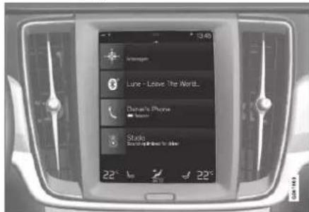
Many of the main functions of the car are controlled from the centre display, a touch screen which reacts to touch. The number of physical buttons and controls in the car is therefore minimal. The screen can even be operated while wearing gloves.
From here, for example, you can control the climate control system, the entertainment system and seat position*. The information that is shown in the centre display can be acted on by the driver or someone else in the car when the opportunity arises.
Voice recognition system
The voice recognition system can be used without the driver needing to take his/her hands off the steering wheel. The system can understand natural speech. Use voice recognition to, for example,
play back a song, call someone, increase the temperature or read out a text message.
Related information
• Head-up display* (p. 140)
- Driver display (p. 83)
• Overview of centre display (p. 107)
• Voice recognition (p. 143)
• Internet-connected car* (p. 544)
- Sharing Internet access from the car via a Wi-Fi hotspot (p. 548)
Software updates
So that you as a Volvo customer get the best experience of your car, Volvo continuously develops the systems in the cars and the services that you are offered.
In connection with service at an authorised Volvo dealer, the software in your Volvo will be updated to the latest version. The latest software update allows you to benefit from available improvements, including improvements from earlier software updates.
For more information about available updates and frequently asked questions, visit volvocars.com/support.

NOTE
Functionality after updating may vary depending on market, model, model year and options.
Related information
- Sensus - online connectivity and entertainment (p. 34)
- Managing system updates via the Download Centre (p. 601)
Recording data
As part of Volvo's safety and quality assurance, certain information about the vehicle's operation, functionality and incidents are recorded in the car.
Event Data Recorder (EDR)
This vehicle is equipped with an "Event Data Recorder" (EDR). Its primary purpose is to register and record data related to traffic accidents or collision-like situations, such as times when the airbag deploys or the vehicle strikes an obstacle in the road. The data is recorded in order to increase understanding of how vehicle systems work in these types of situations. The EDR is designed to record data related to vehicle dynamics and safety systems for a short time, usually 30 seconds or less.
The EDR in this vehicle is designed to record data related to the following in the event of traffic accidents or collision-like situations:
• How the various systems in the car worked
- Whether the driver and passenger seatbelts were fastened/tensioned
- The driver's use of the accelerator or brake pedal
• The travel speed of the vehicle
This information can help us understand the circumstances in which traffic accidents, injuries and damage occur. The EDR only records
data when a non-trivial collision situation occurs. The EDR does not record any data during normal driving conditions. Similarly, the system never registers who is driving the vehicle or the geographic location of the accident or near-miss situation. However, other parties, such as the police, could use the recorded data in combination with the type of personally identifiable information routinely collected after a traffic accident. Special equipment and access to either the vehicle or the EDR is required to be able to interpret the registered data.
In addition to the EDR, the car is equipped with a number of computers designed to continually check and monitor the function of the car. They can record data during normal driving conditions, but in particular register faults affecting the vehicle's operation and functionality, or upon activation of the vehicle's driver support function (e.g. City Safety and the auto brake function).
Some of the recorded data is required to enable service and maintenance technicians to diagnose and remedy any faults that occurred in the vehicle. The registered information is also needed to enable Volvo to satisfy legal requirements laid out in laws and by government authorities. Information registered in the vehicle is stored in its computer until the vehicle is serviced or repaired.
YOUR VOLVO
In addition to the above, the registered information can be used in aggregate form for research and product development with the aim of continuously improving the safety and quality of Volvo cars.
Volvo will not contribute to the above-described information being disclosed to third parties without the vehicle owner's consent. To comply with national legislation and regulations, Volvo may be forced to disclose information of this nature to the police or other authorities who may assert a legal right to access such. Special technical equipment which Volvo and workshops that have entered into agreements with Volvo have access to is required to be able to read and interpret the recorded data. Volvo is responsible that the information, which is transferred to Volvo during servicing and maintenance, is securely stored and managed and that its management complies with relevant legal requirements. For further information - contact a Volvo retailer.
Vehicle Connectivity Module (VCM High)
Vehicles equipped with VCM High can collect data on the vehicle's safety functions as well as other functions in the vehicle. Data are collected for product development, quality follow-up and safety work, as well as to improve and monitor the vehicle's quality and its safety functions. The purpose of data collection is
also to manage Volvo Car Corporation's warranty undertakings, as well as to meet legal requirements related to engine emissions data.
NOTE
In conjunction with data collection, Volvo may use a small part of the vehicle's data plan of up to 10 MB/month.
Terms & Conditions for Services
Volvo offers services that help to enhance car safety and comfort.
These services include everything from assistance in emergencies to navigation and various maintenance services.
Before using the services, it is important for you to read the support information relating to the Terms & Conditions for Services at volvocars.com.
Related information
• Customer Privacy Policy (p. 39)
Customer Privacy Policy
Volvo respects and safeguards the personal integrity of everyone visiting our website. This policy regards to the handling of customer data and personal information. The purpose is to give current, past and potential customers a general understanding of:
- The circumstances in which we gather and process your personal data.
• The types of personal data we gather.
• The reason we gather your personal data.
• How we handle your personal data.
For more information on the policy, search support information at volvocars.com.
Related information
- User terms and conditions and data sharing (p. 550)
• Terms & Conditions for Services (p. 38)
• Recording data (p. 37)
Important information on accessories and auxiliary equipment
The incorrect connection and installation of accessories and extra equipment can negatively affect the car's electronic system.
We strongly recommend that Volvo owners only install Volvo approved original accessories, and that installation of accessories is only carried out by trained and qualified Volvo service technicians. Certain accessories only function when associated software is installed in the car's computer system.
The equipment described in the owner's manual is not available in all cars - they have different equipment depending on adaptations for the needs of different markets and national or local laws and regulations.
Options or accessories described in this manual are marked with an asterisk. In the event of uncertainty over what is standard or an option/accessory, contact a Volvo retailer.
WARNING
The driver always bears the ultimate responsibility that the car is used safely and that laws and regulations in force are followed.
It is also important that the car has maintenance and service according to Volvo's recommendations, the owner's information and the service and warranty booklet.
If the on-board information differs from the printed owner's manual then the printed information always has precedence.
Related information
• Installation of accessories (p. 40)
- Connection of equipment to the car's diagnostic socket (p. 40)
- Reading the owner's manual (p. 23)
YOUR VOLVO
Installation of accessories
We strongly recommend that Volvo owners only install Volvo approved original accessories, and that installation of accessories is only carried out by trained and qualified Volvo service technicians. Certain accessories only function when associated software is installed in the car's computer system.
- Volvo original accessories are tested to ensure that they function with the car systems for performance, safety and emissions control. In addition, a trained and qualified Volvo service technician knows where accessories may or may not be safely installed in your Volvo. Always seek the advice of a trained and qualified Volvo service technician before installing any accessories in or on your car.
- Accessories that are not approved by Volvo may not have been specifically tested for use with your car.
- Some of the car's performance or safety systems can be negatively affected if you install accessories that have not been tested by Volvo, or if you permit someone without experience of the car to install accessories.
- Damage that is caused by accessories installed in a non-approved or incorrect way is not covered by any new car warranty. More warranty information can be found in the service and warranty booklet.
Volvo does not accept any liability for deaths, personal injury or costs arising as a result of the installation of non-original accessories.
Related information
- Important information on accessories and auxiliary equipment (p. 39)
Connection of equipment to the car's diagnostic socket
Incorrect connection and installation of software or diagnostic tools may have a negative effect on the car's electronic system.
We strongly recommend that Volvo owners only install Volvo approved original accessories, and that installation of accessories is only carried out by trained and qualified Volvo service technicians. Certain accessories only function when associated software is installed in the car's computer system.

natural_image
Interior view of a vehicle showing a mechanical component with a red arrow pointing to a specific part (no text or symbols visible)Data link connector (On-board Diagnostic, OBDII) is under the instrument panel on the driver's side.

NOTE
Volvo Cars accepts no liability for the consequences if unauthorised equipment is connected to the On-board Diagnostic socket (OBDII). This socket should only be used by trained and qualified Volvo service technicians.
Related information
- Important information on accessories and auxiliary equipment (p. 39)
Showing the car's identification number
When contacting a Volvo dealer concerning your Volvo On Call subscription, for example, you will need the car's identification number (VIN ^® ).
-
Tap on Settings in the centre display's top view.
-
Continue to System System Information Vehicle Identification Number.
The car's identification number is shown.
Another way of finding VIN is:
• on the first page of the service and warranty booklet
• in the car's registration document
- look on the dashboard through the car's windscreen.
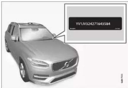
VIN is positioned in a similar place on all models.
YOUR VOLVO
Change of market when importing or relocating
When you import a car or relocate a car to another country, it is important that you register the car in the new market in order, for example, for the online services to work correctly, as well as to ensure that the car complies with local requirements and laws.
Visit an authorised Volvo dealer
To get help to register the car, visit an authorised Volvo dealer.
If you do not do this then you may experience that apps, Volvo On Call ^9 , software downloads and other online services are affected and do not work correctly.
Creating a new Volvo ID in your new home market
When you relocate to another country you should create a Volvo ID in the new country. If you have already created a Volvo ID in another country and want to use the same email address, you must first delete your Volvo ID in the region you originally created it. Alternatively, you can create a new Volvo ID using another e-mail address.
For cars with Volvo On Call ^9
Download the Volvo On Call app from the country where the car will be used and link the app to your car.
NOTE
Visit an authorised Volvo dealer if you have imported or relocated with your car to a new country.
Available services may vary depending on market and car model.
NOTE
If the car is exported to another market, Volvo is not responsible for any adaptations to the car in order to comply with requirements or laws that apply in the importing market. Read more in Service and Warranty or contact your Volvo workshop for more information.
Related information
• Book service and repair (p. 603)
Driver distraction
The driver is responsible for doing everything possible to ensure the safety of themselves, their passengers and other road users. Part of this responsibility is avoiding distractions such as carrying out an activity that is not related to operating the car in a driving environment.
Your new Volvo is, or can be, equipped with content-rich entertainment and communications systems. This could be mobile phones with handsfree, navigation systems and audio systems with lots of functions. You may also have other portable electronic devices for your own convenience. Used correctly, in a safe way they can enrich the driving experience. If they are used in the wrong way they could distract you.
We wish to give the following warnings regarding such systems, to indicate Volvo's concern for your safety. Never use a device or function in the car in such a way that it will distract you from the task of driving safely. Distractions can lead to serious accidents.
Apart from these general warnings, we offer the following advice regarding the new functions that may be in the car:
YOUR VOLVO

WARNING
- Never use a hand-held mobile phone while driving. In some areas it is forbidden for the driver to use a mobile phone while the car is moving.
- If the car is equipped with a navigation system you must only set and change the itinerary when the car is parked.
- Never program the audio system while the car is moving. Program the radio's presets when the car is parked and then use the programmed presets for faster and simpler use of the radio.
- Never use laptops or hand-held computers while the car is moving.
Related information
• Sound, media and Internet (p. 508)

bar
| Category | Value | |---|---| | Category 1 | 100 | | Category 2 | 100 | | Category 3 | 100 | | Category 4 | 100 | | Category 5 | 100 | | Category 6 | 100 | | Category 7 | 100 | | Category 8 | 100 | | Category 9 | 100 | | Category 10 | 100 | | Category 11 | 100 | | Category 12 | 100 | | Category 13 | 100 | | Category 14 | 100 | | Category 15 | 100 | | Category 16 | 100 | | Category 17 | 100 | | Category 18 | 100 | | Category 19 | 100 | | Category 20 | 100 | | Category 21 | 100 | | Category 22 | 100 | | Category 23 | 100 | | Category 24 | 100 | | Category 25 | 100 | | Category 26 | 100 | | Category 27 | 100 | | Category 28 | 100 | | Category 29 | 100 | | Category 30 | 100 | | Category 31 | 100 | | Category 32 | 100 | | Category 33 | 100 | | Category 34 | 100 | | Category 35 | 100 | | Category 36 | 100 | | Category 37 | 100 | | Category 38 | 100 | | Category 39 | 100 | | Category 40 | 100 | | Category 41 | 100 | | Category 42 | 100 | | Category 43 | 100 | | Category 44 | 100 | | Category 45 | 100 | | Category 46 | 100 | | Category 47 | 100 | | Category 48 | 100 | | Category 49 | 100 | | Category 50 | 100 | | Category 51 | 100 | | Category 52 | 100 | | Category 53 | 100 | | Category 54 | 100 | | Category 55 | 100 | | Category 56 | 100 | | Category 57 | 100 | | Category 58 | 100 | | Category 59 | 100 | | Category 60 | 100 | | Category 61 | 100 | | Category 62 | 100 | | Category 63 | 100 | | Category 64 | 100 | | Category 65 | 100 | | Category 66 | 100 | | Category 67 | 100 | | Category 68 | 100 | | Category 69 | 100 | | Category 70 | 100 | | Category 71 | 100 | | Category 72 | 100 | | Category 73 | 100 | | Category 74 | 100 | | Category 75 | 100 | | Category 76 | 100 | | Category 77 | 100 | | Category 78 | 100 | | Category 79 | 100 | | Category 80 | 100 | | Category 81 | 100 | | Category 82 | 100 | | Category 83 | 100 | | Category 84 | 100 | | Category 85 | 100 | | Category 86 | 100 | | Category 87 | 100 | | Category 88 | 100 | | Category 89 | 100 | | Category 90 | 100 | | Category 91 | 100 | | Category 92 | 100 | | Category 93 | 100 | | Category 94 | 100 | | Category 95 | 100 | | Category 96 | 100 | | Category 97 | 100 | | Category 98 | 100 | | Category 99 | 100 | | Total (Total) |SAFETY
SAFETY
Safety
The vehicle is equipped with several safety systems that work together to protect the vehicle's driver and passengers in the event of an accident.
The car is equipped with a number of sensors that react in the event of an accident and activate different safety systems, such as different types of airbags and seatbelt tensioners.
Depending on the specific accident situation, such as collisions at different angles, roll-over or driving off the road, the systems react in different ways to provide good protection.
There are also mechanical safety systems such as Whiplash Protection System. The car is also constructed so that a large part of the force of a collision is distributed to beams, pillars, floor, roof and other parts of the body.
The car's safety mode may be activated after a collision if an important function in the car has been damaged.
Warning symbol in driver display

The warning symbol is illuminated in the driver display when the car's electrical system is set in ignition position II. The symbol is extin-
guished after approx. 6 seconds if the car's safety system is fault-free.

WARNING
If the warning symbol remains illuminated or is switched on during driving and the message SRS airbag Service urgent Drive to workshop is shown in the driver display, it means that part of one of the safety systems does not have full functionality. Volvo recommends that an authorised Volvo workshop should be contacted as soon as possible.

WARNING
Never modify or repair the car's various safety systems yourself. Defective work in one of the systems can cause malfunction and result in serious personal injury. Volvo recommends that an authorised Volvo workshop should be contacted.

If the specific warning symbol is broken then the general warning symbol is illuminated instead and the driver display shows the same message.
Related information
• Safety during pregnancy (p. 47)
- Seatbelts (p. 50)
- Airbags (p. 55)
• Whiplash Protection System (p. 47)
• Pedestrian Protection System (p. 49)
- Safety mode (p. 61)
• Child safety (p. 63)
Safety during pregnancy
It is important that the seatbelt is used correctly during pregnancy, and that pregnant drivers adjust their seating position.
Seatbelt

natural_image
3D illustration of a human car seat with red arrows indicating pressure points on the abdomen (no text or symbols present)The diagonal section should wrap over the shoulder then be routed between the breasts and to the side of the abdomen.
The lap section should lay flat over the thighs and as low as possible under the abdomen. - It must never be allowed to ride upward. Remove the slack from the seatbelt and ensure that it fits as close to the body as possible. In addition, check that there are no twists in the seatbelt.
Seating position
As the pregnancy progresses, pregnant drivers must adjust the seat and steering wheel such
that they can easily maintain control of the vehicle as they drive (which means that they must be able to easily operate the foot pedals and steering wheel). The aim should be to position the seat with as large a distance as possible between abdomen and steering wheel.
Related information
- Safety (p. 46)
- Seatbelts (p. 50)
• Manual front seat (p. 182)
• Power* front seat (p. 183)
Whiplash Protection System
Whiplash Protection System (WHIPS) reduces the risk of whiplash injuries. The system consists of energy absorbing backrests and seat cushion, as well as a specially designed head restraint in the front seats. WHIPS is deployed in the event of a rear-end collision, where the angle and speed of the collision and the nature of the colliding vehicle all have an influence.
When WHIPS is deployed, the front seat backrests are lowered backward and the seat cushions move downward to change the seating position of the driver and front seat passenger. Its movement helps to absorb some of the forces that can arise and cause whiplash.

WARNING
WHIPS is a supplement to the seatbelts. Always use a seatbelt.
▶▶
SAFETY
◀◀

WARNING
Never modify or repair the seat or WHIPS yourself. Volvo recommends that an authorised Volvo workshop should be contacted.
If the front seats have been subjected to a major load, such as in conjunction with a collision, the seats must be replaced. Some of the seats' protective properties may have been lost even if they do not appear damaged.
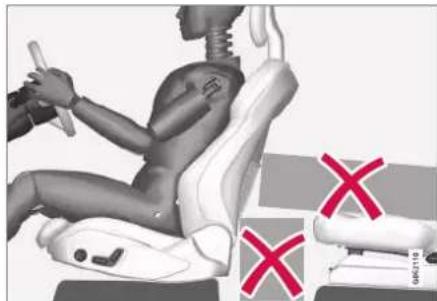
natural_image
3D rendered human figure seated in a car seat with red X marks indicating failure or absence (no text or symbols present)Do not leave any objects on the floor behind or under the front seats or in the rear seat that may prevent WHIPS from functioning.

WARNING
Do not squeeze rigid objects between the rear seat cushion and the front seat's back-rest.
If a backrest in the rear seat is lowered then any load must be secured to prevent it from sliding up to the front seat backrest in the event of a collision.

WARNING
If a backrest in the rear seat is lowered or a rear-facing child seat is used in the rear seat, the corresponding front seat must be moved forward so that it does not make contact with the lowered backrest or child seat.
Seating position
For good protection from WHIPS the driver and passenger must have the correct seating position and make sure that the system's function is not obstructed.
Set the correct seating position in the front seat before driving starts.
Driver and front seat passenger should sit in the centre of the seat with as little space as possible between the head and the head restraint.
WHIPS and child seats
The protection provided by the car to children seated in a child seat or on a booster cushion is not diminished by WHIPS.
Related information
- Safety (p. 46)
• Manual front seat (p. 182)
• Power* front seat (p. 183)
• Rear Collision Warning* (p. 368)
Pedestrian Protection System
The Pedestrian Protection System (PPS) Is a system which, in certain frontal collisions, contributes to mitigating a pedestrian's impact with the car.
In certain frontal collisions with a pedestrian, the sensors in the front of the car react and the system is activated.
When PPS is activated, the following occur:
• The rear section of the bonnet is raised.
- An automatic alarm is sent via Volvo On Call*.
The sensors are active at a speed of approx. 25-50 km/h (15-30 mph).
The sensors are designed to detect a collision with an object that has similar properties to those of the human leg.

NOTE
There may be objects in the traffic environment that prompt a signal to the sensors that is similar to a collision with a pedestrian. It is possible that the system will be activated in the event of a collision with such an object.

WARNING
Do not fit any accessories or change anything in the front. Incorrect intervention at the front may cause incorrect function in the system and lead to serious injury and damage to the car.
Volvo recommends that genuine wiper arms are used and that only genuine parts are used for them.

WARNING
Never modify or repair the system yourself. Volvo recommends that an authorised Volvo workshop should be contacted. Defective work in the system could cause malfunction and result in serious personal injury.

WARNING
Volvo recommends contacting an authorised Volvo workshop in the event of any damage to the front of the car in order to ensure that the system is intact.
Symbols in the driver display
Symbol Specification

PPS has been activated, or a fault has occurred in the system. Follow the recommendation given.
Related information
- Safety (p. 46)
SAFETY
Seatbelts
Heavy braking can have serious consequences if the seatbelts are not used. It is important that the seatbelt lies against the body so it can provide good protection. Do not lean the backrest too far back. The seatbelt is designed to protect in a normal seating position.

WARNING
Remember not to clip or hook the seatbelt to hooks or other interior fittings, as this prevents the belt from tightening properly.

WARNING
The seatbelts and airbags interact. If a seatbelt is not used or is used incorrectly, this may diminish the protection provided by the airbag in the event of a collision.

WARNING
Never modify or repair the seatbelts yourself. Volvo recommends that an authorised Volvo workshop should be contacted.
If the seatbelt has been subjected to a major load, such as in conjunction with a collision, the entire seatbelt must be replaced. Some of the seatbelt's protective properties may have been lost even if the seatbelt does not appear damaged. The seatbelt must also be replaced if it shows signs of wear or damage. The new seatbelt must be type-approved and designed for installation at the same location as the replaced seatbelt.
Related information
- Safety (p. 46)
- Seatbelt tensioner (p. 52)
- Putting on and taking off seatbelts (p. 50)
• Door and seatbelt reminder (p. 53)
Putting on and taking off seatbelts
Make sure that all passengers have fastened their seatbelts before starting to drive.
Putting on seatbelts
- Pull out the seatbelt slowly and make sure it is not twisted or damaged.

NOTE
The seatbelt is equipped with an inertia reel that is locked in the following situations:
- if the belt is extended too quickly.
• during braking and acceleration. - if the car leans heavily.
- when driving in bends.
SAFETY
- Lock the belt by inserting the locking tab in the intended buckle.
A loud "click" indicates that the belt has locked.

WARNING
Always insert the tongue of the seatbelt into the buckle on the correct side. The seatbelts and buckles would otherwise possibly not function as intended in the event of a collision. There is a risk of serious injury.
- In the front seats the seatbelt can be adjusted for height.

natural_image
Close-up of a mechanical component with two red arrows pointing to specific areas (no text or symbols visible)Press together the seat mounting and move the seatbelt up or down.
Position the belt as high as possible without it chafing against your throat.
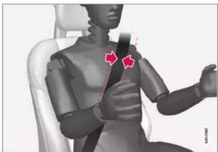
natural_image
3D rendered human figure seated in a chair, showing seatbelt and belt (no text or symbols)The seatbelt must pass over the shoulder (not down over the arm).
- Tension the hip strap over the lap by pulling the diagonal shoulder belt up towards the shoulder.

natural_image
Close-up of a person's seatbelt with red arrows indicating movement or pressure points (no text or symbols)The hip strap must be positioned low down (not over the abdomen).
▶▶
SAFETY
◀◀

WARNING
Each seatbelt is designed for only one person.

WARNING
Remember not to clip or hook the seatbelt to hooks or other interior fittings, as this prevents the belt from tightening properly.

WARNING
Do not make any damages on seatbelts nor insert any foreign objects into a buckle. The seatbelts and buckles would then possibly not function as intended in the event of a collision. There is a risk of serous injury.
Taking off seatbelts
- Press the red button on the seatbelt buckle and then let the belt retract.
- If the seatbelt does not retract fully, feed it in by hand so that it does not hang loose.
Related information
- Seatbelts (p. 50)
- Seatbelt tensioner (p. 52)
• Door and seatbelt reminder (p. 53)
Seatbelt tensioner
The car is fitted with standard seatbelt tensioners and electric seatbelt tensioners that can tension the seatbelts in critical situations and collisions.
Standard seatbelt tensioner
All the seatbelts are equipped with a standard seatbelt tensioner.
The seatbelt tensioner tensions the seatbelt in the event of a collision with sufficient force in order to more effectively restrain the occupant.
Electric seatbelt tensioner
The driver and front passenger seatbelts are equipped with an electric seatbelt tensioner.
The seatbelt tensioners work together and can be activated together with the driver support systems City Safety and Rear Collision Warning. In critical situations, such as panic braking, driving off the road (e.g. the car rolls into a ditch, lifts off the ground or hits something in the terrain), skidding, or risk of collision, the seatbelt can be tensioned by the seatbelt tensioner's electric motor.
The electric seatbelt tensioner helps to adjust the occupant to a better position, reducing the risk of striking the car's interior and improving the effect of safety systems, such as the car's airbags.
When the critical situation has come to an end, the seatbelt and the electric seatbelt pretensioner are restored automatically, but they can also be restored manually.

IMPORTANT
If the passenger airbag is deactivated, the electric seatbelt tensioner on the passenger side will also be deactivated.

WARNING
Never modify or repair the seatbelts yourself. Volvo recommends that an authorised Volvo workshop should be contacted.
If the seatbelt has been subjected to a major load, such as in conjunction with a collision, the entire seatbelt must be replaced. Some of the seatbelt's protective properties may have been lost even if the seatbelt does not appear damaged. The seatbelt must also be replaced if it shows signs of wear or damage. The new seatbelt must be type-approved and designed for installation at the same location as the replaced seatbelt.
Related information
- Seatbelts (p. 50)
- Putting on and taking off seatbelts (p. 50)
-
Resetting the electric seatbelt tensioner (p. 53)
-
Activating and deactivating passenger airbag* (p. 58)
• City Safety™ (p. 348)
• Rear Collision Warning* (p. 368)
Resetting the electric seatbelt tensioner
The electric seatbelt tensioner is designed to be reset automatically, but the seatbelt tensioner can be reset manually if the belt remains extended.
- Stop the car at a safe place.
- Unfasten the seatbelt and then refasten it.
The seatbelt and electric seatbelt tensioner are reset.
WARNING
Never modify or repair the seatbelts yourself. Volvo recommends that an authorised Volvo workshop should be contacted.
If the seatbelt has been subjected to a major load, such as in conjunction with a collision, the entire seatbelt must be replaced. Some of the seatbelt's protective properties may have been lost even if the seatbelt does not appear damaged. The seatbelt must also be replaced if it shows signs of wear or damage. The new seatbelt must be type-approved and designed for installation at the same location as the replaced seatbelt.
Related information
- Seatbelt tensioner (p. 52)
- Seatbelts (p. 50)
Door and seatbelt reminder
The system reminds unbelted occupants to wear a seatbelt, and also warns about an open door, bonnet or lid.
Driver display graphics

Graphics in the driver display with different types of warnings. The warning colour on the door and boot lid is dependent on the speed of the car.
The driver display's graphics show which seats in the car are occupied by belted and unbelted passengers.
The same graphic also shows if the bonnet, boot lid, fuel filler flap or any door is open.
The graphic can be acknowledged by pressing the O button on the right-hand steering wheel keypad.
▶▶
SAFETY
Seatbelt reminder
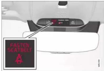
Visual reminder in the roof console.
A visual reminder is given in the roof console and by means of the warning symbol in the driver display.
The acoustic reminder is dependent on speed, driving time and distance.
The belt status of the driver and passengers is shown in the driver display's graphic when a belt is buckled or unbuckled.
Child seats are not covered by the seatbelt reminder system.
Front seat
A visual and acoustic reminder remind the driver and front seat passenger to use a seat-belt if either of them is not wearing one.
Rear seat
The seatbelt reminder in the rear seat has two subfunctions:
- Provides information on which seatbelts are being used in the rear seat. The driver display's graphics are shown when the seatbelts are in use.
- Reminding that a seatbelt in the rear seat is unfastened during a journey by means of a visual and acoustic reminder. The reminder will cease once the seatbelt has been put on again.
Reminder for doors, bonnet, boot lid and fuel filler flap
If the bonnet, boot lid, fuel filler flap or any door is not closed properly, the graphic in the driver display shows what is open. Stop the car in a safe place as soon as possible and close the source of the warning.

If the car is driven at a speed lower than approx. 10 km/h (6 mph) then the driver display's information symbol illuminates.

If the car is driven at a speed higher than approx. 10 km/h (6 mph) then the driver display's warning symbol illuminates.
Related information
- Seatbelts (p. 50)
- Putting on and taking off seatbelts (p. 50)
Airbags
The car is equipped with airbags and inflatable curtains for driver and passengers.

NOTE
The detectors react differently depending on the nature of the collision and whether or not the seatbelts are fastened. Applies to all belt positions.
It is therefore possible that only one (or none) of the airbags may inflate in a collision. The detectors sense the force of the collision on the vehicle and the action is adapted accordingly so that none, one or more airbags are deployed.

WARNING
The airbag system's control module is located in the centre console. If the centre console is drenched with water or other liquid, disconnect the cables to the starter battery. Do not attempt to start the car since the airbags may deploy. Recovering the car. Volvo recommends that it is transported to an authorised Volvo workshop.
Deployed airbags
If any of the airbags have deployed, the following is recommended:
• Recovering the car. Volvo recommends that it is transported to an authorised
Volvo workshop. Do not drive with deployed airbags.
- Volvo recommends engaging an authorised Volvo workshop to handle the replacement of components in the car's safety systems.
• Always contact a doctor.

WARNING
Never drive with deployed airbags. They can make steering difficult. Other safety systems may also be damaged. The smoke and dust created when the airbags are deployed can cause skin and eye irritation/injury after intensive exposure. In case of irritation, wash with cold water. The rapid deployment sequence and airbag fabric may cause friction and skin burns.
Related information
- Safety (p. 46)
- Driver airbags (p. 55)
• Passenger airbag (p. 56) - Side airbags (p. 60)
• Inflatable curtains (p. 61)
Driver airbags
As a supplement to the seatbelts, the car is equipped with steering wheel airbag and knee airbag ^1 on the driver's side.

natural_image
Interior view of a car dashboard with red seatbelt and control panel (no visible text or symbols)Steering wheel airbag and knee airbag ^1 on the driver's side in the front seat.
In the event of a frontal collision, the airbags help to protect the head, neck, face and chest of the driver as well as the knees and legs.
A sufficiently violent collision trips the sensors and the airbag/airbags is inflated. The airbag cushions the initial collision impact for the occupant. The airbag deflates when compressed by the collision. When this occurs, smoke escapes into the car. This is completely normal. The entire process, including inflation and deflation of the airbag, occurs within tenths of a second.
SAFETY
◀◀

WARNING
The seatbelts and airbags interact. If the belt is not used or is used incorrectly, this may diminish the protection provided by the airbag in the event of a collision.
To minimise the risk of injury if the airbag deploys, passengers must sit as upright as possible with their feet on the floor and backs against the backrest.

WARNING
Volvo recommends that an authorised Volvo workshop should be contacted for repair. Defective work in the airbag system could cause malfunction and result in serious personal injury.
Steering wheel airbag location
This airbag is fitted into the centre of the steering wheel. The steering wheel is marked AIRBAG.
Knee airbag ^1 location
The airbag is folded up in the lower part of the instrument panel on the driver's side. Its cover panel is marked AIRBAG.

WARNING
Do not place or attach any object on the top or front of the panel where the knee airbag is stowed.
Related information
Airbags (p. 55)
- Passenger airbag (p. 56)
Passenger airbag
As a supplement to the seatbelts, the vehicle is equipped with an airbag on the passenger side in the front seat.

natural_image
Interior view of a car dashboard and infotainment unit (no visible text or symbols)Passenger side front airbag.
In the event of a frontal collision, the airbag helps to protect the head, neck, face and chest of the passenger as well as the knees and legs.
A sufficiently violent collision trips the sensors and the airbag is inflated. The airbag cushions the initial collision impact for the occupant. The airbag deflates when compressed by the collision. When this occurs, smoke escapes into the car. This is completely normal. The entire process, including inflation and deflation
of the airbag, occurs within tenths of a second.

WARNING
The seatbelts and airbags interact. If the belt is not used or is used incorrectly, this may diminish the protection provided by the airbag in the event of a collision.
To minimise the risk of injury if the airbag deploys, passengers must sit as upright as possible with their feet on the floor and backs against the backrest.

WARNING
Volvo recommends that an authorised Volvo workshop should be contacted for repair. Defective work in the airbag system could cause malfunction and result in serious personal injury.
Passenger airbag location
The airbag is folded up into a compartment above the glovebox. Its cover panel is marked AIRBAG.

WARNING
Do not put objects in front of or above the dashboard where the passenger airbag is located.
Label for passenger airbag

Label on the passenger side's sun visor.
The warning label for the passenger airbag is positioned as shown above.
WARNING
If the car is not equipped with a switch to activate/deactivate the passenger airbag, the airbag will always be activated.

WARNING
Never allow anybody to stand or sit in front of the front passenger seat.
Never use a rear-facing child seat on the front passenger seat if the airbag is activated.
Front-facing passengers (children and adults) must never sit on the front passenger seat if the passenger airbag is deactivated.
Failure to follow the advice given above can endanger life or lead to serious personal injury.
Related information
• Airbags (p. 55)
- Driver airbags (p. 55)
- Activating and deactivating passenger airbag* (p. 58)
SAFETY
Activating and deactivating passenger airbag\*
The passenger airbag can be deactivated if the car is equipped with a switch, Passenger Airbag Cut Off Switch (PACOS).
The switch for the passenger airbag is located on the passenger end of the instrument panel and is accessible when the passenger door is open.
Check that the switch is in the required position.
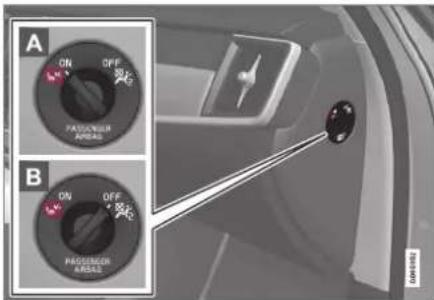
A ON - The airbag is activated and all front-facing passengers (children and adults) can sit safely on the passenger seat.
B OFF - The airbag is deactivated and children in rear-facing child seats can sit safely on the passenger seat.
WARNING
If the car is not equipped with a switch to activate/deactivate the passenger airbag, the airbag will always be activated.
Activating passenger airbag
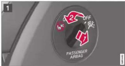
1 Pull the switch outward and turn from OFF to ON.
The driver display shows the message Passenger airbag on Please acknowledge.
NOTE
If the passenger airbag has been activated/deactivated with the car in ignition position I or lower, a message is shown in the driver display and the following indicator in the roof console approx. 6 seconds after the car's electrical system has been set in ignition position II.
- Confirm the message by pressing the right-hand steering wheel keypad's O button.

A text message and a warning symbol in the roof console indicate that the airbag for the front passenger seat is activated.

WARNING
Never use a rear-facing child seat on the front passenger seat when the airbag is activated.
The passenger airbag must always be activated when front-facing passengers (children and adults) are sitting in the front passenger seat.
Failure to follow the advice given above can endanger life or lead to serious personal injury.
Deactivating passenger airbag

1 Pull the switch outward and turn from ON to OFF.
The driver display shows the message Passenger airbag off Please acknowledge.
i NOTE
If the passenger airbag has been activated/deactivated with the car in ignition position I or lower, a message is shown in the driver display and the following indicator in the roof console approx. 6 seconds after the car's electrical system has been set in ignition position II.
- Confirm the message by pressing the right-hand steering wheel keypad's O button.
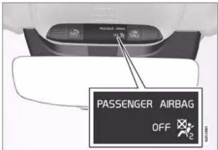
A text message and a symbol in the roof console indicate that the airbag for the front passenger seat is deactivated.
WARNING
Front-facing passengers (children and adults) must never sit on the passenger seat when the airbag is deactivated.
Failure to follow the advice given above can endanger life or lead to serious personal injury.
SAFETY
◀◀
IMPORTANT
If the passenger airbag is deactivated, the electric seatbelt tensioner on the passenger side will also be deactivated.
Related information
- Seatbelt tensioner (p. 52)
• Child seats (p. 64)
Side airbags
The side airbags on the driver's and passenger seats act to protect the chest and hips in the event of a collision.
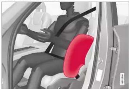
natural_image
3D rendered illustration of a person seated inside a car, highlighting the seat area (no text or symbols)The side airbags are fitted in the outer back-rest frames of the front seats and help to protect the driver and passengers in the front seat.
A sufficiently violent collision trips the sensors and the side airbags are inflated. The airbag inflates between the occupant and the door panel and thereby cushions the initial impact. The airbag deflates when compressed by the collision. The side airbag is normally only deployed on the side of the collision.
WARNING
Volvo recommends that an authorised Volvo workshop should be contacted for repair. Defective work in the side airbag system could cause malfunction and result in serious personal injury.
WARNING
Do not put objects in the area between the outside of the seat and the door panel, since this area is required by the side airbag.
Volvo recommends the use only of car seat covers approved by Volvo. Other seat covers may impede the operation of the side airbags.
WARNING
Side airbags are a supplement the seatbelts. Always use a seatbelt.
Side airbags and child seats
The protection provided by the car to children seated in a child seat or on a booster cushion is not diminished by the side airbag.
Related information
• Airbags (p. 55)
Inflatable curtains
The inflatable curtain, Inflatable Curtain (IC), helps to prevent the driver and passengers from striking their heads on the inside of the car during a collision.

natural_image
Interior view of a modern car with white leather seats and red decorative panel (no visible text or symbols)The inflatable curtain is mounted along both sides of the headlining and helps protect the driver and outer seat passengers of the car. The panels are labelled with IC AIRBAG.
A sufficiently violent collision trips the sensors and the inflatable curtain is inflated.

WARNING
Volvo recommends that an authorised Volvo workshop should be contacted for repair. Defective work in the inflatable curtain system can cause malfunction and result in serious personal injury,

WARNING
Never hang or attach heavy items onto the handles in the roof. The hooks are only designed for light coats and jackets (not for solid objects such as umbrellas).
Do not screw or install anything onto the car's headlining, door pillars or side panels. This could compromise the intended protection. Volvo recommends only using Volvo genuine parts that are approved for fitting within these areas.

WARNING
Leave 10 cm (4 inches) space between the load and the side windows if the car is loaded to above the top edge of the door windows. Otherwise, the intended protection of the inflatable curtain, which is concealed in the headlining, may be compromised.

WARNING
The inflatable curtain is a supplement to the seatbelts. Always use a seatbelt.
Related information
- Airbags (p. 55)
Safety mode
Safety mode is a protective state that is triggered when a collision may have damaged any of the car's vital functions, such as the fuel lines, sensors for any of the safety systems, or the brake system.
If the car has been in a collision, the message Safety mode See Owner's manual may be shown on the driver display with a warning symbol as long as the display is not damaged and the car's electrical system is still in working order. This message means that the car has reduced functionality.

WARNING
Never, under any circumstances, attempt to restart the car if it smells of fuel when the Safety mode See Owner's manual message is shown in the driver display. Leave the car at once.
If the car is in safety mode, it is possible to attempt to reset the system in order to start and move the car for a short distance, if in a dangerous traffic situation for example.
SAFETY
◀◀

WARNING
Never attempt to repair your car or reset the electronics yourself if the car has been in safety mode. This could result in personal injury or the car not functioning as normal. Volvo recommends engaging an authorised Volvo workshop to check and restore the car to normal status after Safety mode See Owner's manual has been shown.

WARNING
If the car is in safety mode it must not be towed. It must be transported from its location. Volvo recommends that it is transported to an authorised Volvo workshop.
Related information
- Safety (p. 46)
- Starting and moving the car after safety mode (p. 62)
- Recovery (p. 499)
Starting and moving the car after safety mode
If the car is in safety mode, it is possible to attempt to reset the system in order to start and move the car for a short distance, if in a dangerous traffic situation for example.
Starting the car after safety mode
- Check the general damage situation of the car and whether any fuel has been leaking. There must be no smell of fuel either. If there is only minor damage and a check has revealed no fuel leaks, starting can be attempted.

WARNING
Never, under any circumstances, attempt to restart the car if it smells of fuel when the Safety mode See Owner's manual message is shown in the driver display. Leave the car at once.
- Switch off the car.
- Then try to start the car.
The car's electronics carry out a systems check and then try to resume normal status. The driver display shows the message Car start System check, wait during this time. This can take up to one minute.
- Then try to start the car again when the message Car start System check, wait is no longer shown in the driver's display.

IMPORTANT
If the message Safety mode See Owner's manual is still shown on the display the car must not be driven or towed but a vehicle recovery service must then be used instead. Even if the car appears to be driveable, hidden damage may make the car impossible to control once moving.
Moving the car after safety mode
- If the driver display shows the message Normal mode The car is now in normal mode after a start attempt, the car can be carefully moved if standing in a dangerous position.
- Do not move the car further than necessary.

WARNING
If the car is in safety mode it must not be towed. It must be transported from its location. Volvo recommends that it is transported to an authorised Volvo workshop.
Related information
• Safety mode (p. 61)
• Starting the car (p. 446)
- Recovery (p. 499)
Child safety
Children must always sit secure while travelling in the car.
Volvo has child safety equipment (child seats and attachment devices) which is designed for fitting in this particular car. Using Volvo's child safety equipment, you obtain good conditions for a child to travel safely in the car. In addition, the child safety equipment fits in well and is simple to use.
The equipment that should be used is selected taking account of the weight and size of the child.
Volvo recommends that children travel in a rear-facing child seat until as late an age as possible, at least until 4 years of age, and then in a front-facing child seat until the child is 140 cm (4 feet 7 inches) tall.
NOTE
Legal provisions about the type of child seat that must be used for children of different ages and heights vary from country to country. Check what does apply.
NOTE
When using child safety equipment, it is important to read the installation instructions included.
In the event of questions when fitting child safety equipment, contact the manufacturer for clearer instructions.
Children of all ages and sizes must always sit correctly secured in the car. Never allow a child to sit on the knee of a passenger.
Related information
- Safety (p. 46)
• Child seats (p. 64) - Activating and deactivating child safety locks (p. 274)
SAFETY
Child seats
Suitable child seats should always be used when children are travelling in the car.
Children should sit comfortably and safely. Make sure that the child seat is positioned, mounted and used correctly.
Look in the installation instructions for the child seat for the correct fitting.

NOTE
When using child safety equipment, it is important to read the installation instructions included.
In the event of questions when fitting child safety equipment, contact the manufacturer for clearer instructions.

NOTE
Never leave a child seat loose in the car. Always secure it according to the instructions for the child seat, even when it is not in use.

NOTE
Long-term installation and use of child seats may cause wear and tear on the car's fittings. Volvo recommends using the kick guard accessory to protect the car's fittings.
Related information
• Child safety (p. 63)
• Integrated child seat* (p. 76)
• Upper mounting points for child seats (p. 64)
• Lower mounting points for child seats (p. 65)
- i-Size/ISOFIX mounting points for child seats (p. 66)
• Child seat positioning (p. 66)
- Activating and deactivating passenger air bag* (p. 58)
Upper mounting points for child seats
The car is equipped with upper mounting points for child seats on the rear seat's outer seats.
The upper mounting points are primarily intended for use with front-facing child seats.
Always follow the manufacturer's installation instructions when connecting a child seat to the upper mounting points.
The location of the mounting points
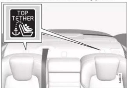
The location of the mounting points is indicated by symbols on the parcel shelf behind the rear seat.
The mounting points are located on the parcel shelf behind the rear seat's outer seats.

WARNING
The child seat's upper straps must be routed through the hole in the head restraint leg before they are tensioned at the mounting point. If this is not possible, follow the recommendations from the child seat manufacturer.

NOTE
Fold the head restraints in order to facilitate fitting this type of child seat in cars with folding head restraints on the outer seats.
Related information
• Child seats (p. 64)
• Lower mounting points for child seats (p. 65)
- i-Size/ISOFIX mounting points for child seats (p. 66)
- Table for location of child seats using the car's seatbelts (p. 70)
Lower mounting points for child seats
The car is equipped with lower mounting points for child seats in the front seat* and the rear seat.
The lower mounting points are designed to be used in conjunction with certain rear-facing child seats.
Always follow the manufacturer's installation instructions when connecting a child seat to the lower mounting points.
The location of the mounting points

natural_image
Interior view of a car dashboard and seat area showing white leather seats and dashboard controls (no text or symbols visible)Mounting point locations in the front seat.
The mounting points in the front seat are located on the sides of the passenger seat's legroom.
The mounting points in the front seat are only mounted if the vehicle is equipped with a
switch to activate/deactivate the passenger airbag*.
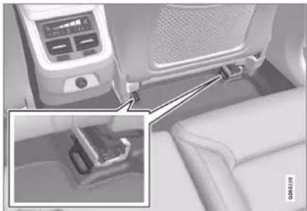
natural_image
Interior view of a car seatbelt with a digital display and side-mounted buttons (no visible text or symbols)Mounting point locations in the rear seat.
The mounting points in the rear seat are located on the rear section of the front seat's floor rails.
Related information
• Child seats (p. 64)
• Upper mounting points for child seats (p. 64)
- i-Size/ISOFIX mounting points for child seats (p. 66)
- Table for location of child seats using the car's seatbelts (p. 70)
SAFETY
i-Size/ISOFIX mounting points for child seats
The car is equipped with i-Size/ISOFIX mounting points for child seats in the rear seat.
i-Size/ISOFIX ^2 is a fixture system for car child seats that is based on an international standard.
Always follow the manufacturer's installation instructions when connecting a child seat to the i-Size/ISOFIX mounting points.
The location of the mounting points

Mounting point locations are indicated by symbols ^2 on the upholstery of the backrest.
The mounting points for i-Size/ISOFIX are located behind covers in the lower section of the rear seat's backrest, in the outer seats.
Lift the covers in order to access the mounting points.
Related information
• Child seats (p. 64)
• Upper mounting points for child seats (p. 64)
• Lower mounting points for child seats (p. 65)
• Table for location of i-Size child seats (p. 72)
• Table for location of ISOFIX child seats (p. 73)
Child seat positioning
It is important to position the child seat in the right place in the car. The choice of location depends, amongst other things, on the type of child seat and whether the passenger airbag is activated.

natural_image
Interior view of a car showing steering wheel, dashboard, and red X symbol (no text or labels)Rear-facing child seat and airbag are not compatible.
Always fit rear-facing child seats in the rear seat if the passenger airbag is activated. If a child is sitting on the front passenger seat then he/she could suffer serious injury if the airbag deploys.
If the passenger airbag is deactivated then rear-facing child seats can be fitted on the front passenger seat.

NOTE
Regulations regarding the placement of children in cars vary from country to country. Check what does apply.

WARNING
Never allow anybody to stand or sit in front of the front passenger seat.
Never use a rear-facing child seat on the front passenger seat if the airbag is activated.
Front-facing passengers (children and adults) must never sit on the front passenger seat if the passenger airbag is deactivated.
Failure to follow the advice given above can endanger life or lead to serious personal injury.
Label for passenger airbag

Label on the passenger side's sun visor.
The warning label for the passenger airbag is positioned as shown above.
Related information
• Child seats (p. 64)
• Child seat mounting (p. 67)
- Table for location of child seats using the car's seatbelts (p. 70)
• Table for location of i-Size child seats (p. 72)
• Table for location of ISOFIX child seats (p. 73)
Child seat mounting
It is important to remember a number of things when a child restraint system is mounted and used, which depend on where the child restraint system is positioned.

WARNING
Booster cushions/child seats with steel braces or some other design that could rest on the seatbelt buckle's opening button must not be used, as they could cause the seatbelt buckle to open accidentally.
Do not secure the straps for the child seat into the seat's horizontal adjustment bar or in springs, rails or beams under the seat. Sharp edges may damage the straps.
Do not allow the upper section of the child seat to rest against the windscreen.

NOTE
When using child safety equipment, it is important to read the installation instructions included.
In the event of questions when fitting child safety equipment, contact the manufacturer for clearer instructions.
SAFETY
◀◀

NOTE
Never leave a child seat loose in the car. Always secure it according to the instructions for the child seat, even when it is not in use.

NOTE
Long-term installation and use of child seats may cause wear and tear on the car's fittings. Volvo recommends using the kick guard accessory to protect the car's fittings.
Installation in the front seat
- When fitting rear-facing child seats, check that the passenger airbag is deactivated.
- When fitting front-facing child seats, check that the passenger airbag is activated.
- Only use child seats that are recommended by Volvo, are universally approved or are semi-universal, and where the car is included on the manufacturer's vehicle list.
-
ISOFIX child seats can only be fitted when the car is equipped with the ISOFIX console ^3 accessory.
-
If the child seat is equipped with lower straps, Volvo recommends that the lower mounting points are used with these ^4 .
- If the child seat is equipped with support legs, always fit the support leg/support legs directly to the floor. Never fit a support leg to a footrest or other object.
- The ISOFIX guide can be used in order to facilitate child seat installation.
Installation in the rear seat
- Only use child seats that are recommended by Volvo, are universally approved or are semi-universal, and where the car is included on the manufacturer's vehicle list.
- A child seat with support legs must not be fitted in the centre seat.
- The outer seats are equipped with the ISOFIX fixture system and are approved for i-Size ^4 .
-
The outer seats are equipped with upper mounting points. Volvo recommends that child seat's upper straps should be pulled through the hole in the head restraint before being tensioned at the mounting point. If this is not possible, follow the recommendations from the child seat manufacturer.
-
If the child seat is equipped with lower straps, never adjust the position of the seat in front after the straps have been fitted in the lower mounting points. Always remember to remove the lower straps when the child seat is not installed.
- If the child seat is equipped with support legs, always fit the support leg/support legs directly to the floor. Never fit a support leg to a footrest or other object.

natural_image
3D rendering of a car seat assembly with a vertical measurement line and angle indicator (no text or symbols)With the installation of an infant seat in the rear seat, Volvo recommends a distance of at least 50 mm (2 tum) from the front part of the infant seat to the rearmost part of the seat in front.
SAFETY
Related information
• Child seat positioning (p. 66)
- Table for location of child seats using the car's seatbelts (p. 70)
• Table for location of i-Size child seats (p. 72)
- Table for location of ISOFIX child seats (p. 73)
SAFETY
Table for location of child seats using the car's seatbelts
The table gives a recommendation for which child seats suit which locations, and for what size of child.
NOTE
Always read the owner's manual section on installing a child seat before installing one in the car.
| Weight Front seat (with deactivated airbag, only rear-facing child seats) ^A | Front seat (with activated airbag, only front-facing child seats) ^A | Outer rear seat Centre rear seat | ||
| Group 0max 10 kg | U^B,C | X | U^C | U^C |
| Group 0+max 13 kg | U^B,C | X | U^C | U^C |
| Group 19-18 kg | L^D | UF^B,E | U, L^D | U |
| Group 215-25 kg | L^D | UF^B | UF^G, B^*, H, L^D | UF^F |
| Weight Front seat (with deactivated airbag, only rear-facing child seats) ^A | Front seat (with activated airbag, only front-facing child seats) ^A | Outer rear seat | Centre rear seat |
| Group 322-36 kg | X | UF^B | U^G,I, B^*,H |
| U^I |
U: Suitable for universal category restraints approved for use in this mass group.
UF: Suitable for front-facing universally approved child seats.
L: Suitable for particular child restraints. These restraints may be of the specific vehicle, restricted or semi-universal categories.
B: Built-in restraint approved for this mass group.
X: The seat is not suitable for children in this mass group.
A The seat cushion extension must always be retracted for the installation of child seats.
^B Adjust the backrest to a more upright position.
c Volvo recommends: Volvo infant seat (type approval E1 04301146).
D Volvo recommends: Volvo reversible seat in the rear-facing position (type approval E5 04192); Volvo rear-facing seat (type approval E5 04212).
F Volvo recommends rear-facing child seat for children in this mass group.
F Volvo recommends: Volvo reversible seat in the front-facing position (type approval E5 04191); booster cushion with and without back (type approval E5 04216); Volvo booster cushion with back-rest (type approval E1 04301169); Volvo booster seat (type approval E1 04301312).
G Volvo recommends: Römer KidFix XP (type approval E1 04301312).
H Volvo recommends: Integrated child seat (type approval E5 04220).
1 Volvo recommends: booster cushion with and without back (type approval E5 04216); Volvo booster cushion with backrest (type approval E1 04301169).

WARNING
Never use a rear-facing child seat on the front passenger seat if the passenger airbag is activated.
- Table for location of ISOFIX child seats (p. 73)
- Seatbelts (p. 50)
Related information
• Child seat positioning (p. 66)
• Child seat mounting (p. 67)
• Table for location of i-Size child seats (p. 72)
SAFETY
Table for location of i-Size child seats
The table gives a recommendation for which i-Size child seats suit which locations, and for what size of child.
The child seat must be approved in accordance with UN Reg R129.

NOTE
Always read the owner's manual section on installing a child seat before installing one in the car.
| Type of child seat | Front seat (with deactivated airbag, only rear-facing child seats) | Front seat (with activated airbag, only front-facing child seats) | Outer rear seat | Centre rear seat |
| i-Size child seats X X | i-U^A | X | ||
| i-U: Suitable for i-Size "universal" child seat, front-facing and rear-facing.X: Not suitable for universally approved child seats. | ||||
^ Volvo recommends that children travel in a rear-facing child seat until as late an age as possible, at least until 4 years of age.
Related information
• Child seat positioning (p. 66)
• Child seat mounting (p. 67)
• Table for location of child seats using the car's seatbelts (p. 70)
- Table for location of ISOFIX child seats (p. 73)
- i-Size/ISOFIX mounting points for child seats (p. 66)
SAFETY
Table for location of ISOFIX child seats
The table gives a recommendation for which ISOFIX child seats suit which locations, and for what size of child.
The child seat must be approved in accordance with UN Reg R44 and the car model must be included in the manufacturer's vehicle list.

NOTE
Always read the owner's manual section on installing a child seat before installing one in the car.
| Weight | Size classA | Type of child seat Front seat (with deactivated airbag, only rear-facing child seats)B,C | Front seat (with activated airbag, only front-facing child seats)B,C | Outer rear seat Centre rear seat |
| Group 0 max 10 kg | E Rear-facing infant seat | IL^B,D, X^E | X | IL^D |
| Group 0+ max 13 kg | E Rear-facing infant seat | IL^B,D,F, X^E | X | IL^D |
| D Rear-facing child seat |
▶▶
73
SAFETY
◀◀
| Weight | Size classA | Type of child seat Front seat (with deactivated airbag, only rear-facing child seats)B,C | Front seat (with activated airbag, only front-facing child seats)B,C | Outer rear seat Centre rear seat |
| Group 19-18 kg | A Front-facing child seat | X | ILB,F,G,XE | |
| B1 Front-facing child seat | ||||
| C Rear-facing child seat | ILB,F,XF | X | ||
| D Rear-facing child seat | ||||
IL: Suitable for particular ISOFIX child restraint systems. These child restraint systems are those of the specific vehicle, restricted or semi-universal categories.
IUF: Suitable for ISOFIX forward child restraint systems of universal category approved for use in the mass group.
X: Not suitable for ISOFIX child restraint systems.
A For child seats with the ISOFIX fixture system there is a size classification to help users choose the right type of child seat. The size class can be read on the child seat's label.
B Works for the installation of ISOFIX child seats that are semi-universally approved (IL) if the car is equipped with the ISOFIX console accessory (the accessory range varies depending on market).
There are no upper mounting points for child seats here.
c The seat cushion extension must always be retracted for the installation of child seats.
D. Volvo recommends: Volvo infant seat secured using the ISOFIX fixture system (type approval E1 04301146).
E. Applicable if the car is not fitted with an ISOFIX bracket.
F Adjust the backrest so that the head restraint does not interfere with the child seat.
a Volvo recommends rear-facing child seat for children in this mass group.
H Volvo recommends: BeSafe IZi Kid X3 ISOfix (type approval E5 04200).

WARNING
Never use a rear-facing child seat on the front passenger seat if the passenger airbag is activated.
i NOTE
If an i-Size/ISOFIX child seat has no size classification, the car model must be included on the vehicle list for the child seat.

NOTE
Volvo recommends contacting an authorised Volvo dealer for information about which i-Size/ISOFIX child seats Volvo recommends.
SAFETY
Related information
• Child seat positioning (p. 66)
• Child seat mounting (p. 67)
- Table for location of child seats using the car's seatbelts (p. 70)
- Table for location of i-Size child seats (p. 72)
- i-Size/ISOFIX mounting points for child seats (p. 66)
SAFETY
Integrated child seat\*
The integrated child seats on the outer positions in the rear seat allow children to sit comfortably and safely.
The child seat is specially designed to provide children with good safety, together with the car's seatbelt. The seat cushion can be raised in two positions depending on the weight of the child.
The child seat is approved for children who weigh 15-36 kg (33-80 lbs) and are at least 95 cm (37 inches) tall.

natural_image
3D illustration of a person sitting in a car seat with red arrows indicating movement or pressure points (no text or symbols present)Correct position, the seatbelt should be positioned in on the shoulder.
Check before driving that:
- the seat cushion is raised to the correct position for the weight of the child
• the seat cushion in locked in position
• the seatbelt is in contact with the child's body and is not slack or twisted
• the seatbelt does not lie across the child's throat or below the shoulder
- the lap section of the seatbelt is positioned low over the pelvis to provide optimal protection.
WARNING
Volvo recommends that repair or replacement of the integrated child seat is only performed by an authorised Volvo workshop. Do not make any modifications or additions to the child seat. If an integrated child seat has been subjected to a heavy load, e.g. in connection with a collision, then the seat cushion, seatbelt and backrest, or possibly the whole seat, must be replaced. Even if the child seat appears to be undamaged, it may not afford the same level of protection. This also applies if the seat cushion was in lowered position during a collision or similar. The seat cushion must also be replaced if it is heavily worn.
WARNING
If the instructions for the integrated child seat are not followed then the child could sustain serious injury in the event of an accident.
Related information
• Child seats (p. 64)
- Folding up the seat cushion in the integrated child seat* (p. 77)
- Folding down the seat cushion in the integrated child seat* (p. 78)
SAFETY
Folding up the seat cushion in the integrated child seat\*
The seat cushion should always be folded up when the integrated child seat is in use. The seat cushion can be folded up in two positions. The position that should be used depends on the weight of the child.
| Lower position | Upper position | |
| Weight | 22-36 kg(50-80 lbs) | 15-25 kg(33-55 lbs) |
Lower position:

natural_image
Interior view of a car seatbelt with red directional arrows indicating movement (no text or symbols)1 Pull the handle forwards and upwards to release the seat cushion.
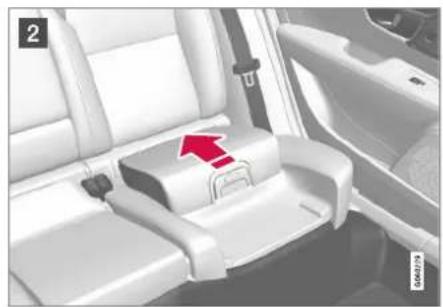
natural_image
Interior view of a car seatbelt with a red arrow pointing to the seat (no text or symbols visible)2 Press the seat cushion backwards to lock. Upper position, start from the lower position:

natural_image
Interior view of a car seatbelt with a red arrow pointing to the seat (no text or symbols visible)1 Press the button to release the seat cushion.

natural_image
Interior view of a car seatbelt with red directional arrows indicating movement or positioning (no text or symbols)2 Lift the seat cushion up at the front edge and press it back against the backrest to lock.
WARNING
If the instructions for the integrated child seat are not followed then the child could sustain serious injury in the event of an accident.
NOTE
It is not possible to adjust the seat cushion from the upper position to the lower position. From the upper position, the seat cushion must first be fully lowered into the rear seat, and then folded up to the lower position.
▶▶
SAFETY
Related information
• Integrated child seat* (p. 76)
- Folding down the seat cushion in the integrated child seat* (p. 78)
Folding down the seat cushion in the integrated child seat\*
The seat cushion should be folded down into the rear seat when the integrated child seat is not being used.
i NOTE
It is not possible to adjust the seat cushion from the upper position to the lower position. From the upper position, the seat cushion must first be fully lowered into the rear seat, and then folded up to the lower position.

natural_image
Interior view of a car seatbelt with a red arrow pointing to the lower side (no text or symbols visible)1 Pull the handle forwards to release the seat cushion.
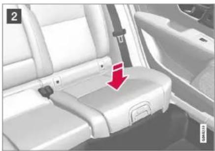
natural_image
Interior view of a car showing seatbelt and seat, with a red arrow pointing to the seat (no text or symbols visible)2 Press down with your hand in the centre of the seat cushion in order to lock it.
IMPORTANT
Check that there are no loose objects (e.g. toys) left behind in the space under the child seat's seat cushion before lowering.
i NOTE
Before the rear backrest is lowered, the child seat's seat cushion must be lowered first.
Related information
• Integrated child seat* (p. 76)
- Folding up the seat cushion in the integrated child seat* (p. 77)
DISPLAYS AND VOICE CONTROL
DISPLAYS AND VOICE CONTROL
Displays and controls by the driver in a left-hand drive car
The overviews show where the displays and controls near the driver are located.
Steering wheel and instrument panel

1 Position lamps, daytime running lights, dipped beam, main beam, direction indicators, rear fog lamp, resetting the trip meter
2 Steering wheel paddles for manual gear changing in an automatic gearbox*
3 Head-up display*
4 Driver display
⑤ Wipers and washing, rain sensor*
6 Right-hand steering wheel keypad
7 Steering wheel adjustment
8 Horn
9 Left-hand steering wheel keypad
10 Bonnet opening
11 Display lighting, boot lid unlocking/opening*/closing*, halogen headlamp levelling
Roof console

1 Front reading lamps and interior lighting
③ Display in roof console, ON CALL button*
4 Manual dimming of interior rearview mirror
Centre and tunnel console

1 Centre display
② Hazard warning flashers, defrosting, media
3 Gear selector
4 Start knob
5 Drive mode control
6 Parking brake
7 Automatic braking when stationary
Driver's door
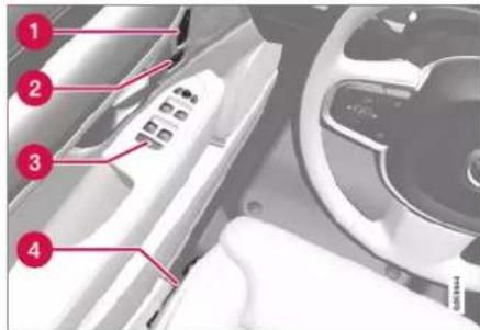
① Memories for power front seat*, door mirror and head-up display* settings
② Central locking
3 Power windows, door mirrors, electric child lock*
4 Adjusting front seat
Related information
• Manual front seat (p. 182)
- Adjusting the power* front seat (p. 183)
• Adjusting the steering wheel (p. 196)
• Lighting control (p. 150)
• Starting the car (p. 446)
- Driver display (p. 83)
• Overview of centre display (p. 107)
Gearbox (p. 460)
Displays and controls by the driver in a right-hand drive car
The overviews show where the displays and controls near the driver are located.
Steering wheel and instrument panel

1 Position lamps, daytime running lights, dipped beam, main beam, direction indicators, rear fog lamp, resetting the trip meter
② Steering wheel paddles for manual gear changing in an automatic gearbox*
3 Head-up display*
4 Driver display
⑤ Wipers and washing, rain sensor*
6 Right-hand steering wheel keypad
⑦ Display lighting, boot lid unlocking/opening*/closing*, halogen headlamp levelling
8 Bonnet opening
9 Horn
10 Steering wheel adjustment
11 Left-hand steering wheel keypad
Roof console
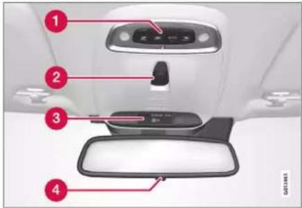
1 Front reading lamps and interior lighting
② Sunroof
③ Display in roof console, ON CALL button*
4 Manual dimming of interior rearview mirror
▶▶
DISPLAYS AND VOICE CONTROL
Centre and tunnel console

1 Centre display
2 Hazard warning flashers, defrosting, media
3 Gear selector
4 Start knob
5 Drive mode control
6 Parking brake
7 Automatic braking when stationary
Driver's door
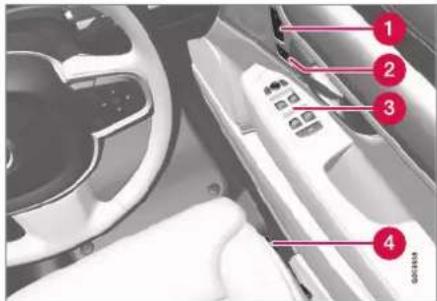
1 Memories for power front seat*, door mirror and head-up display* settings
② Central locking
3 Power windows, door mirrors, electric child lock*
4 Adjusting front seat
Related information
• Manual front seat (p. 182)
- Adjusting the power* front seat (p. 183)
• Adjusting the steering wheel (p. 196)
• Lighting control (p. 150)
• Starting the car (p. 446)
- Driver display (p. 83)
• Overview of centre display (p. 107)
Gearbox (p. 460)
Driver display
The driver display shows information about the car and driving.
The driver display contains gauges, indicators and indicator and warning symbols. The content of the driver display depends on the car's equipment, settings and which functions are active at that time.
The driver display is activated as soon as a door is opened, i.e. in ignition position 0. The driver display extinguishes after a while if it is not used. To reactivate it, proceed with one of the following:
• Depress the brake pedal.
• Activate ignition position I.
- Open one of the doors.

WARNING
If the driver display should extinguish, not illuminate on activation/start or be fully or partially illegible, the car must not be used. You should visit a workshop immediately. Volvo recommends an authorised Volvo workshop.

WARNING
In the event of a fault in the driver display the information on e.g. brakes, airbags or other safety systems may not be shown. In which case, the driver cannot check the status of the car's systems or receive current warnings and information.

The figure is schematic - parts may vary depending on car model.
Location in the driver display:
| On the left In the middle On the right | ||
| Speedometer Indicator and warning symbols | Tachometer/Hybrid gauge^A | |
| Trip meter Outside temperature gauge Gear shift indicator | ||
| Odometer^B | Clock Drive mode | |
| Cruise control and speed limiter information Messages, in some cases with graphics Fuel gauge | ||
| Road Sign Information* | Door and seatbelt information Hybrid battery gauge | |
| - Charging status Distance to empty tank | ||
| - Media player Distance to empty battery | ||
DISPLAYS AND VOICE CONTROL
◀◀
| On the left In the middle On the right | ||
| - | Navigation map* | Instantaneous fuel consumption |
| - Phone App menu (activated via steering wheel keypad) | ||
| - Voice recognition - |
A Depends on drive mode selected.
B Accumulated mileage.
Dynamic symbol
The dynamic symbol in its basic form.
The centre of the driver display contains a dynamic symbol that changes appearance for different types of message. An amber or red marker around the symbol indicates the degree of severity of a control or warning message.

Examples of indicator symbol.
With an animation, the basic shape can be turned into a graphic showing where a problem is situated, or in order to clarify information.
Related information
• Driver display settings (p. 85)
• Indicator and warning symbols (p. 93)
- Trip computer (p. 88)
- Messages in the driver display (p. 104)
- Managing the app menu in the driver display (p. 103)
- Drive modes (p. 467)
Driver display settings
Settings for the driver display's display options can be made via the driver display's app menu and via the centre display's settings menu.
Settings via the driver display's app menu

The figure is schematic - parts may vary depending on car model.
The app menu is opened and controlled using the right-hand keypad on the steering wheel.
In the app menu, you can choose which information is shown on the driver display from:
- trip computer
- media player
- phone
- navigation system*.
Settings via the centre display
Selecting information type
- Tap on Settings in the centre display's top view.
- Press My Car Displays Driver Display Information.
- Select what should be shown in the background:
• Show no information in background
• Show information for current playing media
• Show navigation even if no route is set
Selecting theme
- Tap on Settings in the centre display's top view.
- Tap on My Car Displays Display Themes
-
Select a theme (appearance) for the driver display:
-
Glass
- Minimalistic
- Performance
- Chrome Rings
Selecting language
- Tap on Settings in the centre display's top view.
2. Tap on System System Languages
and Units → System Language to select language.
A change will affect the language in all displays.
These settings are personal and are saved automatically to the active driver profile.
Related information
- Driver display (p. 83)
- Managing the app menu in the driver display (p. 103)
- Other settings in the centre display's top view (p. 130)
DISPLAYS AND VOICE CONTROL
Fuel gauge
The fuel gauge in the driver display shows the fuel level in the tank.
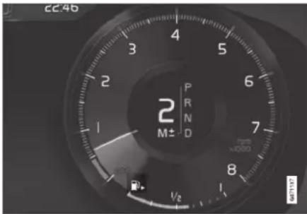
The figure is schematic - parts may vary depending on car model.
The beige zone in the fuel gauge indicates the quantity of fuel in the tank.
When the fuel level is low, the fuel pump symbol illuminates and turns amber colour. The trip computer also shows the distance to empty tank.
Related information
- Driver display (p. 83)
• Hybrid battery gauge (p. 87)
• Filling fuel (p. 482)
• Fuel tank - volume (p. 669)
Hybrid gauge
In drive modes Hybrid and Pure, the driver display shows a hybrid gauge that can help the driver to drive the car in a more energy-efficient way.

The hybrid gauge shows in different ways the relationship between how much power is being taken from the electric motor and how much power is available.
Symbols in the hybrid gauge

Indicates current level for available electric motor power. If the symbol is filled in, it means that the electric motor is in use.

If the symbol is not filled in, it means that the electric motor is not in use.

Indicates the power level when the combustion engine starts. If the symbol is filled in, it means that the combustion engine is in use.

Indicates the power level when the internal combustion engine is due to start. If the symbol is not filled in, it means that the combustion engine is

Indicator that shows that the hybrid battery is being charged e.g. if the brake pedal is gently depressed.
Driver-requested power
The pointer in the hybrid gauge indicates the amount of engine power requested by the driver by regulating the accelerator pedal. The higher the reading on the scale, the more power is requested by the driver in the current gear. The marker between the lightning flash and the drop shows the point at which the internal combustion engine starts.
Example:

The car is started but stationary, no power is requested.

The car generates current to the battery, the battery is charged, e.g. when the brake pedal is pressed lightly or during engine braking down a hill.
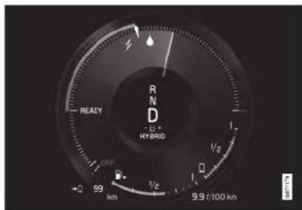
The electric motor cannot supply the amount of engine power requested and the internal combustion engine starts.
Related information
• Drive modes (p. 467)
• Driver display (p. 83)
- Foot brake (p. 451)
- Range (p. 477)
- Starting and stopping the combustion engine (p. 467)
Hybrid battery gauge
The hybrid battery gauge shows how much energy there is in the hybrid battery.

The energy in the hybrid battery is used for the electric motor, but also to cool or heat the car. The trip computer calculates an approximate distance for the energy left in the hybrid battery.
DISPLAYS AND VOICE CONTROL
Symbols in the hybrid battery gauge

The Symbol in the hybrid battery gauge indicates that the Hold function is activated, and the Symbol indicates that the Charge function is activated.
Related information
- Driver display (p. 83)
• Charging the hybrid battery (p. 425)
• Hold and Charge (p. 478)
Trip computer
The car's trip computer records vales such as e.g. distance, fuel consumption and average speed whilst driving.
In order to facilitate fuel-efficient driving, information is recorded about both instantaneous and average fuel consumption. The information from the trip computer can be shown in the driver display.

Examples of trip computer information in the driver display. The figure is schematic - parts may vary depending on car model.
The following meters are included in the trip computer:
- Trip meter
- Odometer
• Instantaneous fuel consumption
• Distance to empty tank
• Distance to empty battery
• Tourist - alternative speedometer
Units for distance, speed, etc. can be changed via system settings in the centre display.
Trip meter
There are two trip meters, TM and TA.
TM can be reset manually and TA is reset automatically if the car is not used for at least four hours.
The following information is registered while driving:
- Mileage
- Driving time
- Average speed
• Average fuel consumption
The values apply from the trip meter's latest reset.
Odometer
The odometer records the car's total mileage. This value cannot be reset to zero.
Instantaneous fuel consumption
This gauge shows the fuel consumption that the car has at the moment. The value is updated approximately every second.
Distance to empty tank

The trip computer calculates the remaining mileage with the fuel available in the tank.
The calculation is based on the average fuel consumption over the last 30 km (20 miles) and the remaining drivable fuel quantity.
When the gauge shows "----", there is not enough fuel left to be able to calculate the remaining mileage. Refuel as soon as possible.

NOTE
There may be a slight deviation if the driving style has been changed.
An economic driving style generally results in a longer driving distance.
Distance to empty battery

The approximate distance that can be driven with the remaining amount of energy in the hybrid battery is indicated adjacent to this symbol.
The calculation is based on the average consumption of normally loaded vehicle, during normal driving and taking into account whether the air conditioning (AC) is switched on or off. When changing between the Hybrid and Pure drive modes, the calculated distance
increases since the Pure mode has reduced climate settings (ECO climate).
No guaranteed range on electric power remains when the gauge shows "----".
NOTE
There may be a slight deviation if the driving style has been changed.
An economic driving style generally results in a longer driving distance.
Start value for fully charged hybrid battery
Since it is difficult to anticipate driving style and other factors that affect the range for electric operation, Volvo has decided to use a start value when the car is fully charged. The start value indicates an up-to figure instead of a forecast for the range for electric operation. The difference in start value between Hybrid and Pure is due to the car being allowed to use more energy from the hybrid battery in Pure mode, as well as that the car changes over to ECO climate.
Mileage for electric operation
In order to achieve the longest possible mileage for electric operation, the driver of an electrically powered car also has to think about energy conservation. The more consumers there are (stereo, electric heating in windows/mirrors/seats, very cold air from the climate
control system, etc.) that are active - the shorter the potential mileage.
i NOTE
In addition to high current take-off in the passenger compartment, sudden acceleration and braking, high speed, heavy loads, low outside temperature and uphill gradients also reduce the possible driving distance.
Tourist - alternative speedometer
The alternative digital speedometer makes it easier to drive in countries where speed limit signs are in a different unit than that shown in the car's instruments.
The digital speed is then shown in the opposite unit to that shown in the analogue speedometer. If the analogue speedometer is graduated in mph, the digital speedometer shows the corresponding speed in km/h and vice versa.
Related information
• Show trip data in the driver display (p. 90)
- Resetting the trip meter (p. 91)
• Show trip statistics in the centre display (p. 91)
- Driver display (p. 83)
• Changing system units (p. 130)
DISPLAYS AND VOICE CONTROL
Show trip data in the driver display
The trip computer's recorded and calculated values can be shown in the driver display. The values are saved in a trip computer app. Via the app menu, you can choose which information is shown on the driver display.
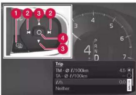
Open and navigate in the app menu ^1 using the right-hand steering wheel keypad.
1 App menu
2 Left/right
3 Up/down
4 Confirm
- Open the app menu in the driver display by pressing (1). (It is not possible to open the app menu while there is an unacknowledged message in the driver display. The message first has to be confirmed by pressing the O button (4) before the app menu can be opened.)
-
Navigate to the trip computer app to left or right with (2).
The top four menu rows show measured values for trip meter TM. The next four menu rows show measured values for trip meter TA. Scroll up or down in the list with (3).
-
Scroll down to the option buttons to select which information to show in the driver display:
-
Odometer
• Distance to empty tank
• Distance to empty battery
• Tourist (alternative speedometer) - Mileage for trip meter TM, TA, or no display of mileage
- Instantaneous fuel consumption, average consumption for TM or TA, alternatively, no display of fuel consumption
Select or deselect an option with the O button (4). The change is made immediately.
Related information
- Trip computer (p. 88)
- Resetting the trip meter (p. 91)
Resetting the trip meter
Reset the trip meter using the left-hand stalk switch.
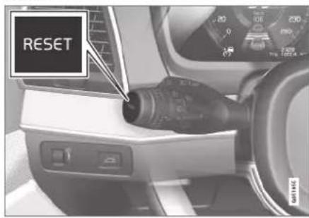
- Reset all information in trip meter TM (i.e. mileage, average consumption, average speed and driving time) with a long press on the RESET button on the left-hand stalk switch.
Pressing the RESET button resets only the mileage.
The trip meter TA can only be reset automatically when the car has not been used for four or more hours.
Related information
- Trip computer (p. 88)
Show trip statistics in the centre display
Trip statistics from the trip computer are displayed graphically in the centre display and provide an overview that facilitates more fuel-efficient driving.

Open the Driver performance app in app view in order to show the trip statistics.
Each bar in the diagram symbolises a distance of 1, 10 or
100 km, alternatively miles. The bars are filled in from the right as driving progresses. The bar on the far right shows the value for the current distance.
The average fuel consumption and total driving time are calculated since the last time the trip statistics were reset.
Fuel and electricity consumption are shown in separate graphs. Electricity consumption is "net" consumption, i.e. energy consumed minus regenerated energy created during braking.

bar
| Metric | Value | |--------|-------| | Speed | 6.8 | | Power Consumption (kW/100km) | 10.1 | | Duration (min) | 23 |Trip statistics from the trip computer ^2 .
NOTE
When driving with electric operation, fuel consumption can be indicated in the trip statistics if the additional heater ^3 is running.
Related information
- Settings for trip statistics (p. 92)
- Trip computer (p. 88)
DISPLAYS AND VOICE CONTROL
Settings for trip statistics
Reset or adjust settings for trip statistics.
- Open the Driver performance app in app view in order to show the trip statistics.

-
Press Preferences to
-
change graph scale. Select resolution 1, 10 or 100 km/miles for the bar.
- reset data after every trip. Performed when the car has been stationary for more than 4 hours.
- reset data for the current trip.
Trip statistics, calculated average consumption and total driving time are always reset simultaneously.
Units for distance, speed, etc. can be changed via system settings in the centre display.
Related information
• Show trip statistics in the centre display (p. 91)
- Trip computer (p. 88)
- Resetting the trip meter (p. 91)
Date and time
The clock is shown in both the driver display and the centre display.
Clock location

In certain situations, messages and information may cover the clock in the driver display. In the centre display, the clock is located at the top right of the status bar.
Date and time settings
- Select Settings System Date and Time in the centre display's top view to change settings for time and date format. Adjust the date and time by pressing the up or down arrow on the touch screen.
Automatic time for cars with GPS
When the car is equipped with a navigation system, Auto Time can be selected. The time
zone is then adjusted automatically based on the location of the car. For certain types of navigation systems, the current location (country) must also be set to obtain the right time zone. If Auto Time is not selected, time and data are adjusted with arrow up or arrow down on the touch screen.
Summer time
In certain countries, it is possible to select the Auto Daylight Saving Time setting for automatic setting of summer time. For other countries, the Daylight Saving Time setting can be selected manually.
Related information
- Driver display (p. 83)
- Other settings in the centre display's top view (p. 130)
Outside temperature gauge
The outside temperature is shown in the driver display.
A sensor detects the temperature outside of the car.
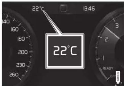
If the car has been stationary, the gauge may display a temperature reading that is too high.

When the outside temperature is in the range -5^ to +2^ (23°F to 36°F), a snowflake symbol lights up that warns of potentially slippery
conditions.
The symbol is also illuminated briefly in the head-up display*, if the car is equipped with one.
Change the unit for the temperature gauge, etc. via system settings in the centre display's top view.
Related information
- Driver display (p. 83)
• Changing system units (p. 130)
Indicator and warning symbols
The indicator and warning systems alert the driver to the fact that a function is activated, a system is working, or a defect or serious error has occurred.
Red symbols

Warning
The red warning symbol illuminates when a fault has been detected which could affect the safety or drivability of the car. An explanatory text is shown on the driver display at the same time.
The warning symbol can also illuminate in conjunction with other symbols.

Seatbelt reminder
Illuminates or flashes when someone in the car is not wearing a seatbelt.

Airbags
An error has been detected in any of the car's safety systems.
Read the message on the driver display and contact a workshop. Volvo recommends that an authorised Volvo workshop is contacted.
▶▶

Fault in brake system
An error has occurred on the braking system.
Read the message on the driver display and contact a workshop. Volvo recommends that an authorised Volvo workshop is contacted.

Parking brake
Light illuminated permanently: The parking brake is activated.
Flashing: an error has occurred with the parking brake. Read the message in the driver display.

Faults in the electrical system
An error has occurred on the electrical system.
Read the message on the driver display and contact a workshop. Volvo recommends that an authorised Volvo workshop is contacted.

High engine temperature
The engine temperature is too high. Read the message in the driver display.

Collision risk
City Safety warns of a risk of collision with other vehicles, pedestrians, cyclists or large animals.

Low oil pressure
The engine oil pressure is too low. Stop the engine immediately and check the engine oil level, top up if necessary.
If the symbol lights up and the oil level is normal, read the message on the display and contact a workshop. Volvo recommends that an authorised Volvo workshop is contacted.
Amber symbols

Information
A fault has occurred in one of the car's systems. Read the message in the driver display.
The information symbol can also illuminate in conjunction with other symbols.

Fault in brake system
An error has occurred on the braking system. Read the message in the driver display.

ABS fault
The system is disengaged. The car's regular brake system continues to work, but without the ABS function.

Emissions system
Emissions systems fault. Drive to a workshop for checking, Volvo recommends that an authorised Volvo workshop is contacted.

Rear fog lamp
The rear fog lamp is illuminated.

Tyre pressure system
Low tyre pressure.
If there is a fault in the tyre pressure system, the symbol will flash for approx. 1 minute and then illuminate with a constant glow. This may be because the system cannot detect or warn of low tyre pressure as intended.

Fault in the headlamp system
A fault has occurred on the head-lamp system. Read the message in the driver display.

Lane assistance
Lane assistance warns/intervenes.

Reduced performance
Temporary fault on drivetrain. Read the message in the driver display.

Stability system
Light on permanently: a fault has occurred in the system.
Flashing: the system is working.

Stability system, sport mode
Sport mode is selected.
Blue symbols

Active main beam
Active main beam is activated and switched on.

Main beam
Main beam is switched on,
Green symbols

Automatic brake
The function is activated and the service brake or parking brake is operating.

Front fog lamps
The front fog lamp is switched on.

Position lamps
The position lamps are switched on.

Left and right-hand direction indicator
The direction indicator is being used.

White/grey symbols

Active main beam
Active main beam is activated, but does not come on.

Preconditioning
Engine and compartment heater/air conditioning pre-condition the car.

Lane assistance
White symbol: Lane assistance is on and road lines are detected.
Grey symbol: Lane assistance is on but road lines are not detected.

Rain sensor
The rain sensor is activated.
Related information
- Driver display (p. 83)
DISPLAYS AND VOICE CONTROL
License agreement for the driver display
A license is an agreement for the right to operate a certain activity or the right to use someone else's entitlement according to the terms and conditions in the agreement. The following text is Volvo's agreement with the manufacturer or developer.
Boost Software License 1.0
Permission is hereby granted, free of charge, to any person or organization obtaining a copy of the software and accompanying documentation covered by this license (the "Software") to use, reproduce, display, distribute, execute, and transmit the Software, and to prepare derivative works of the Software, and to permit third-parties to whom the Software is furnished to do so, all subject to the following: The copyright notices in the Software and this entire statement, including the above license grant, this restriction and the following disclaimer, must be included in all copies of the Software, in whole or in part, and all derivative works of the Software, unless such copies or derivative works are solely in the form of machine-executable object code generated by a source language processor.
THE SOFTWARE IS PROVIDED "AS IS", WITHOUT WARRANTY OF ANY KIND, EXPRESS OR IMPLIED, INCLUDING BUT NOT LIMITED TO THE WARRANTIES OF
MERCHANTABILITY, FITNESS FOR A PARTICULAR PURPOSE, TITLE AND NON-INFRINGEMENT. IN NO EVENT SHALL THE COPYRIGHT HOLDERS OR ANYONE DISTRIBUTING THE SOFTWARE BE LIABLE FOR ANY DAMAGES OR OTHER LIABILITY, WHETHER IN CONTRACT, TORT OR OTHERWISE, ARISING FROM, OUT OF OR IN CONNECTION WITH THE SOFTWARE OR THE USE OR OTHER DEALINGS IN THE SOFTWARE.
BSD 4-clause "Original" or "Old" License Copyright (c) 1982, 1986, 1990, 1991, 1993 The Regents of the University of California. All rights reserved.
Redistribution and use in source and binary forms, with or without modification, are permitted provided that the following conditions are met:
- Redistributions of source code must retain the above copyright notice, this list of conditions and the following disclaimer.
- Redistributions in binary form must reproduce the above copyright notice, this list of conditions and the following disclaimer in the documentation and/or other materials provided with the distribution.
- All advertising materials mentioning features or use of this software must display the following acknowledgement:
This product includes software developed by the University of California, Berkeley and its contributors.
- Neither the name of the University nor the names of its contributors may be used to endorse or promote products derived from this software without specific prior written permission.
THIS SOFTWARE IS PROVIDED BY THE REGENTS AND CONTRIBUTORS "AS IS" AND ANY EXPRESS OR IMPLIED WARRANTIES, INCLUDING, BUT NOT LIMITED TO, THE IMPLIED WARRANTIES OF MERCHANTABILITY AND FITNESS FOR A PARTICULAR PURPOSE ARE DISCLAIMED. IN NO EVENT SHALL THE REGENTS OR CONTRIBUTORS BE LIABLE FOR ANY DIRECT, INDIRECT, INCIDENTAL, SPECIAL, EXEMPLARY, OR CONSEQUENTIAL DAMAGES (INCLUDING, BUT NOT LIMITED TO, PROCUREMENT OF SUBSTITUTE GOODS OR SERVICES; LOSS OF USE, DATA, OR PROFITS; OR BUSINESS INTERRUPTION) HOWEVER CAUSED AND ON ANY THEORY OF LIABILITY, WHETHER IN CONTRACT, STRICT LIABILITY, OR TORT (INCLUDING NEGLIGENCE OR OTHERWISE) ARISING IN ANY WAY OUT OF THE USE OF THIS SOFTWARE, EVEN IF ADVISED OF THE POSSIBILITY OF SUCH DAMAGE.
BSD 3-clause "New" or "Revised" License
Copyright (c) 2011-2014, Yann Collet.
Redistribution and use in source and binary forms, with or without modification, are permitted provided that the following conditions are met:
- Redistributions of source code must retain the above copyright notice, this list of conditions and the following disclaimer.
- Redistributions in binary form must reproduce the above copyright notice, this list of conditions and the following disclaimer in the documentation and/or other materials provided with the distribution.
- Neither the name of the organisation nor the names of its contributors may be used to endorse or promote products derive from this software without specific prior written permission.
THIS SOFTWARE IS PROVIDED BY THE COPYRIGHT HOLDERS AND CONTRIBUTORS "AS IS" AND ANY EXPRESS OR IMPLIED WARRANTIES, INCLUDING, BUT NOT LIMITED TO, THE IMPLIED WARRANTIES OF MERCHANTABILITY AND FITNESS FOR A PARTICULAR PURPOSE ARE DISCLAIMED. IN NO EVENT SHALL THE COPYRIGHT HOLDER OR CONTRIBUTORS BE LIABLE FOR ANY DIRECT, INDIRECT, INCIDENTAL,
SPECIAL, EXEMPLARY, OR CONSEQUENTIAL DAMAGES (INCLUDING, BUT NOT LIMITED TO, PROCUREMENT OF SUBSTITUTE GOODS OR SERVICES; LOSS OF USE, DATA, OR PROFITS; OR BUSINESS INTERRUPTION) HOWEVER CAUSED AND ON ANY THEORY OF LIABILITY, WHETHER IN CONTRACT, STRICT LIABILITY, OR TORT (INCLUDING NEGLIGENCE OR OTHERWISE) ARISING IN ANY WAY OUT OF THE USE OF THIS SOFTWARE, EVEN IF ADVISED OF THE POSSIBILITY OF SUCH DAMAGE.
BSD 2-clause "Simplified" license
Copyright (c)
Redistribution and use in source and binary forms, with or without modification, are permitted provided that the following conditions are met:
-
Redistributions of source code must retain the above copyright notice, this list of conditions and the following disclaimer.
-
Redistributions in binary form must reproduce the above copyright notice, this list of conditions and the following disclaimer in the documentation and/or other materials provided with the distribution.
THIS SOFTWARE IS PROVIDED BY THE COPYRIGHT HOLDERS AND
CONTRIBUTORS "AS IS" AND ANY EXPRESS OR IMPLIED WARRANTIES, INCLUDING, BUT NOT LIMITED TO, THE IMPLIED WARRANTIES OF MERCHANTABILITY AND FITNESS FOR A PARTICULAR PURPOSE ARE DISCLAIMED. IN NO EVENT SHALL THE COPYRIGHT OWNER OR CONTRIBUTORS BE LIABLE FOR ANY DIRECT, INDIRECT, INCIDENTAL, SPECIAL, EXEMPLARY, OR CONSEQUENTIAL DAMAGES (INCLUDING, BUT NOT LIMITED TO, PROCUREMENT OF SUBSTITUTE GOODS OR SERVICES; LOSS OF USE, DATA, OR PROFITS; OR BUSINESS INTERRUPTION) HOWEVER CAUSED AND ON ANY THEORY OF LIABILITY, WHETHER IN CONTRACT, STRICT LIABILITY, OR TORT (INCLUDING NEGLIGENCE OR OTHERWISE) ARISING IN ANY WAY OUT OF THE USE OF THIS SOFTWARE, EVEN IF ADVISED OF THE POSSIBILITY OF SUCH DAMAGE.
The views and conclusions contained in the software and documentation are those of the authors and should not be interpreted as representing official policies, either expressed or implied, of the FreeBSD Project.
DISPLAYS AND VOICE CONTROL
FreeType Project License
- Copyright 1996-1999 by David Turner, Robert Wilhelm, and Werner Lemberg Introduction The FreeType Project is distributed in several archive packages; some of them may contain, in addition to the FreeType font engine, various tools and contributions which rely on, or relate to, the FreeType Project. This license applies to all files found in such packages, and which do not fall under their own explicit license. The license affects thus the FreeType font engine, the test programs, documentation and makefiles, at the very least. This license was inspired by the BSD, Artistic, and IJG (Independent JPEG Group) licenses, which all encourage inclusion and use of free software in commercial and freeware products alike. As a consequence, its main points are that: o We don't promise that this software works. However, we are be interested in any kind of bug reports. ('as is' distribution) o You can use this software for whatever you want, in parts or full form, without having to pay us. ('royalty-free' usage) o You may not pretend that you wrote this software. If you use it, or only parts of it, in a program, you must acknowledge somewhere in your documentation that you've used the FreeType code. ('credits') We specifically permit and encourage the inclusion of this
software, with or without modifications, in commercial products, provided that all warranty or liability claims are assumed by the product vendor. Legal Terms 0. Definitions Throughout this license, the terms 'package', 'FreeType Project', and 'FreeType archive' refer to the set of files originally distributed by the authors (David Turner, Robert Wilhelm, and Werner Lemberg) as the 'FreeType project', be they named as alpha, beta or final release. 'You' refers to the licensee, or person using the project, where 'using' is a generic term including compiling the project's source code as well as linking it to form a 'program' or 'executable'. This program is referred to as 'a program using the FreeType engine'. This license applies to all files distributed in the original FreeType archive, including all source code, binaries and documentation, unless otherwise stated in the file in its original, unmodified form as distributed in the original archive. If you are unsure whether or not a particular file is covered by this license, you must contact us to verify this. The FreeType project is copyright (C) 1996-1999 by David Turner, Robert Wilhelm, and Werner Lemberg. All rights reserved except as specified below. 1. No Warranty THE FREETYPE ARCHIVE IS PROVIDED 'AS IS' WITHOUT WARRANTY OF ANY KIND, EITHER
EXPRESSED OR IMPLIED, INCLUDING, BUT NOT LIMITED TO, WARRANTIES OF MERCHANTABILITY AND FITNESS FOR A PARTICULAR PURPOSE. IN NO EVENT WILL ANY OF THE AUTHORS OR COPYRIGHT HOLDERS BE LIABLE FOR ANY DAMAGES CAUSED BY THE USE OR THE INABILITY TO USE, OF THE FREETYPE PROJECT. As you have not signed this license, you are not required to accept it. However, as the FreeType project is copyrighted material, only this license, or another one contracted with the authors, grants you the right to use, distribute, and modify it. Therefore, by using, distributing, or modifying the FreeType project, you indicate that you understand and accept all the terms of this license.
- Redistribution Redistribution and use in source and binary forms, with or without modification, are permitted provided that the following conditions are met: o Redistribution of source code must retain this license file ('licence.txt') unaltered; any additions, deletions or changes to the original files must be clearly indicated in accompanying documentation. The copyright notices of the unaltered, original files must be preserved in all copies of source files. o Redistribution in binary form must provide a disclaimer that states that the software is based in part of the
work of the FreeType Team, in the distribution documentation. We also encourage you to put an URL to the FreeType web page in your documentation, though this isn't mandatory. These conditions apply to any software derived from or based on the FreeType code, not just the unmodified files. If you use our work, you must acknowledge us. However, no fee need be paid to us.
- Advertising The names of FreeType's authors and contributors may not be used to endorse or promote products derived from this software without specific prior written permission. We suggest, but do not require, that you use one or more of the following phrases to refer to this software in your documentation or advertising materials: 'FreeType Project', 'FreeType Engine', 'FreeType library', or 'FreeType Distribution'.
- Contacts There are two mailing lists related to FreeType: o freetype@freetype.org Discusses general use and applications of FreeType, as well as future and wanted additions to the library and distribution. If you are looking for support, start in this list if you haven't found anything to help you in the documentation. o devel@freetype.org Discusses bugs, as well as engine internals, design issues, specific licenses,
porting, etc. o http://www.freetype.org Holds the current FreeType web page, which will allow you to download our latest development version and read online documentation. You can also contact us individually at: David Turner david.turner@freetype.org Robert Wilhelm robert.wilhelm@freetype.org Werner Lemberg werner.lemberg@freetype.org
Libpng License
This copy of the libpng notices is provided for your convenience. In case of any discrepancy between this copy and the notices in the file png.h that is included in the libpng distribution, the latter shall prevail.
COPYRIGHT NOTICE, DISCLAIMER, and LICENSE:
If you modify libpng you may insert additional notices immediately following this sentence.
libpng versions 1.0.7, July 1, 2000, through 1.0.13, April 15, 2002, are Copyright (c) 2000-2002 Glenn Randers-Pehrson and are distributed according to the same disclaimer and license as libpng-1.0.6 with the following individuals added to the list of Contributing Authors
Simon-Pierre Cadieux
Eric S. Raymond
Gilles Vollant
and with the following additions to the disclaimer:
There is no warranty against interference with your enjoyment of the library or against infringement. There is no warranty that our efforts or the library will fulfill any of your particular purposes or needs. This library is provided with all faults, and the entire risk of satisfactory quality, performance, accuracy, and effort is with the user.
libpng versions 0.97, January 1998, through 1.0.6, March 20, 2000, are Copyright (c) 1998, 1999 Glenn Randers-Pehrson, and are distributed according to the same disclaimer and license as libpng-0.96, with the following individuals added to the list of Contributing Authors:
Tom Lane
Glenn Randers-Pehrson
Willem van Schaik
libpng versions 0.89, June 1996, through 0.96, May 1997, are Copyright (c) 1996, 1997 Andreas Dilger Distributed according to the same disclaimer and license as libpng-0.88, with the following individuals added to the list of Contributing Authors:
John Bowler
Kevin Bracey
Sam Bushell
▶▶
DISPLAYS AND VOICE CONTROL
Magnus Holmgren
Greg Roelofs
Tom Tanner
libpng versions 0.5, May 1995, through 0.88, January 1996, are Copyright (c) 1995, 1996 Guy Eric Schalnat, Group 42, Inc.
For the purposes of this copyright and license, "Contributing Authors" is defined as the following set of individuals:
Andreas Dilger
Dave Martindale
Guy Eric Schalnat
Paul Schmidt
Tim Wegner
The PNG Reference Library is supplied "AS IS". The Contributing Authors and Group 42, Inc. disclaim all warranties, expressed or implied, including, without limitation, the warranties of merchantability and of fitness for any purpose. The Contributing Authors and Group 42, Inc. assume no liability for direct, indirect, incidental, special, exemplary, or consequential damages, which may result from the use of the PNG Reference Library, even if advised of the possibility of such damage.
Permission is hereby granted to use, copy, modify, and distribute this source code, or
portions hereof, for any purpose, without fee, subject to the following restrictions:
-
The origin of this source code must not be misrepresented.
-
Altered versions must be plainly marked as such and must not be misrepresented as being the original source.
-
This Copyright notice may not be removed or altered from any source or altered source distribution.
The Contributing Authors and Group 42, Inc. specifically permit, without fee, and encourage the use of this source code as a component to supporting the PNG file format in commercial products. If you use this source code in a product, acknowledgment is not required but would be appreciated.
A "png_get_copyright" function is available, for convenient use in "about" boxes and the like:
printf("%s", png_get_copyright(NULL));
Also, the PNG logo (in PNG format, of course) is supplied in the files "pngbar.png" and "pngbar.jpg (88x31) and "pngnow.png" (98x31).
Libpng is OSI Certified Open Source Software. OSI Certified Open Source is a certification mark of the Open Source Initiative.
Glenn Randers-Pehrson randeg@alum.rpi.edu April 15, 2002
MIT License
Copyright (c)
Permission is hereby granted, free of charge, to any person obtaining a copy of this software and associated documentation files (the "Software"), to deal in the Software without restriction, including without limitation the rights to use, copy, modify, merge, publish, distribute, sublicense, and/or sell copies of the Software, and to permit persons to whom the Software is furnished to do so, subject to the following conditions:
The above copyright notice and this permission notice shall be included in all copies or substantial portions of the Software. THE SOFTWARE IS PROVIDED "AS IS", WITHOUT WARRANTY OF ANY KIND, EXPRESS OR IMPLIED, INCLUDING BUT NOT LIMITED TO THE WARRANTIES OF MERCHANTABILITY, FITNESS FOR A PARTICULAR PURPOSE AND NONINFRINGEMENT. IN NO EVENT SHALL THE AUTHORS OR COPYRIGHT HOLDERS BE LIABLE FOR ANY CLAIM, DAMAGES OR OTHER LIABILITY, WHETHER IN AN ACTION OF CONTRACT, TORT OR OTHERWISE, ARISING FROM, OUT OF OR IN CONNECTION WITH THE SOFTWARE OR THE USE OR OTHER DEALINGS IN THE SOFTWARE.
zlib License
The zlib/libpng License Copyright (c)
This software is provided 'as-is', without any express or implied warranty. In no event will the authors be held liable for any damages arising from the use of this software.
Permission is granted to anyone to use this software for any purpose, including commercial applications, and to alter it and redistribute it freely, subject to the following restrictions:
-
The origin of this software must not be misrepresented; you must not claim that you wrote the original software. If you use this software in a product, an acknowledgment in the product documentation would be appreciated but is not required.
-
Altered source versions must be plainly marked as such, and must not be misrepresented as being the original software.
-
This notice may not be removed or altered from any source distribution.
SGI Free Software B License Version 2.0. SGI FREE SOFTWARE LICENSE B (Version 2.0, Sept. 18, 2008)
Copyright (C) [dates of first publication] Silicon Graphics, Inc. All Rights Reserved.
Permission is hereby granted, free of charge, to any person obtaining a copy of this software and associated documentation files (the "Software"), to deal in the Software without restriction, including without limitation the rights to use, copy, modify, merge, publish, distribute, sublicense, and/or sell copies of the Software, and to permit persons to whom the Software is furnished to do so, subject to the following conditions: The above copyright notice including the dates of first publication and either this permission notice or a reference to http://oss.sgi.com/projects/FreeB/ shall be included in all copies or substantial portions of the Software.
THE SOFTWARE IS PROVIDED "AS IS", WITHOUT WARRANTY OF ANY KIND, EXPRESS OR IMPLIED, INCLUDING BUT NOT LIMITED TO THE WARRANTIES OF MERCHANTABILITY, FITNESS FOR A PARTICULAR PURPOSE AND NONINFRINGEMENT. IN NO EVENT SHALL SILICON GRAPHICS, INC. BE LIABLE FOR ANY CLAIM, DAMAGES OR OTHER LIABILITY, WHETHER IN AN ACTION OF CONTRACT, TORT OR OTHERWISE, ARISING FROM, OUT OF OR IN CONNECTION WITH THE SOFTWARE OR THE USE OR OTHER DEALINGS IN THE SOFTWARE.
Except as contained in this notice, the name of Silicon Graphics, Inc. shall not be used in
▶▶
DISPLAYS AND VOICE CONTROL
advertising or otherwise to promote the sale, use or other dealings in this Software without prior written authorization from Silicon Graphics, Inc.
Related information
- Driver display (p. 83)
App menu in the driver display
The app menu in the driver display provides quick access to commonly used functions for certain apps.

The figure is schematic.
The app menu in the driver display can be used instead of the centre display and is controlled using the right-hand keypad on the steering wheel. The app menu makes it easier to switch between different apps or functions within the apps without having to let go of the steering wheel.
App menu functions
Different apps give access to different types of functions. The following apps and their associated functions can be controlled from the app menu:
| App Functions | |
| Trip computer | Selection of trip meter, selection of what to show in the driver display, etc. |
| Media player | Selection of active source for the media player. |
| Phone Calling | a contact from the call list. |
| Navigation Guide to destination, etc. | |
Related information
- Driver display (p. 83)
• Overview of centre display (p. 107) - Managing the app menu in the driver display (p. 103)
Managing the app menu in the driver display
The app menu in the driver display is operated with the steering wheel's right-hand keypad.
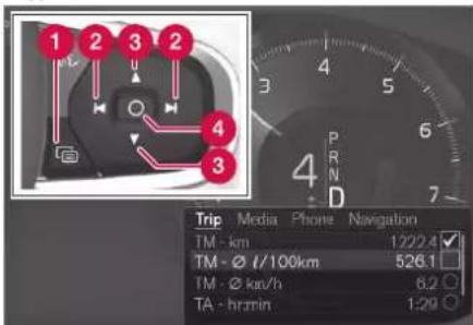
The app menu and the steering wheel's right-hand keypad. The figure is schematic.
1 Open/close
2 Left/right
3 Up/down
4 Confirm
Opening/closing the app menu
- Press on open/close (1).
The app menu opens/closes.
i NOTE
It is not possible to open the app menu while there is an unacknowledged message in the driver display. The message has to be confirmed first before the app menu can be opened.
The app menu closes automatically after a period of inactivity or after certain options have been selected.
Navigating and selecting in the app menu
- Navigate between the apps by pressing on the left or right (2).
Functions for previous/next app are shown in the app menu.
-
Browse through the functions for the selected app by tapping on up or down (3).
-
Confirm or highlight an option for the function by pressing on confirm (4).
The function is activated and for some options the app menu then closes.
If the app menu is opened again, the functions of the most recently selected app are shown first.
Related information
• App menu in the driver display (p. 102)
- Messages in the driver display (p. 104)
DISPLAYS AND VOICE CONTROL
Messages in the driver display
The driver display can show messages to inform or assist the driver in the event of different events.

Examples of messages in the driver display. The figure is schematic - parts may vary depending on car model.
The driver display shows messages that are of high priority for the driver.
Messages can be shown in different parts of the driver display depending on what other information is currently being displayed. After a while, or when the message has been acknowledged/action taken if required, the message disappears from the driver display. If a message needs to be saved, it is placed in the Car Status app, which is opened from the app view in the centre display.
Message composition may vary and they can be shown together with graphics, symbols or buttons for acknowledging the message or accepting a request, for example.
Service messages
Shown below is a selection of important service messages and their meanings.
| Message Specification | |
| Stop safelyA | Stop and switch off the engine. Serious risk of damage - consult a work-shopB, |
| Turn off engineA | Stop and switch off the engine. Serious risk of damage - consult a work-shopB, |
| Service urgent Drive to work-shopA | Contact a workshopBto check the car immediately. |
| Service requiredA | Contact a workshopBto check the car as soon as possible. |
| Regular maintenanceBook time for maintenance | Time for regular service - contact a workshopB.Shown before the next service date. |
| Message Specification | |
| Regular maintenanceTime for maintenance | Time for regular service - contact a workshop ^B . Shown at the next service date. |
| Regular maintenanceMaintenance overdue | Time for regular service - contact a workshop ^B . Shown when the service date has passed. |
| Temporarily off^A | A function has been temporarily switched off and is reset automatically while driving or after starting again. |
A Part of message, shown together with information on where the problem has arisen.
B An authorised Volvo workshop is recommended.
Related information
- Managing messages in the driver display (p. 105)
- Handling a message saved from the driver display (p. 105)
• Message in centre display (p. 138)
Managing messages in the driver display
Messages in the driver display are handled using the steering wheel's right-hand keypad.

Examples of messages in the driver display and the steering wheel's right-hand keypad. The figure is schematic - parts may vary depending on car model.
1 Left/right
2 Confirm
Some messages in the driver display contain one or more buttons for acknowledging the message or accepting a request, for example.
Managing a new message
For messages with buttons:
-
Navigate between the buttons by pressing on the left or right (1).
-
Confirm the selection by pressing on confirm (2).
The message disappears from the driver display.
For messages without buttons:
- Close the message by pressing on confirm (2), or allow the message to close automatically after a while.
The message disappears from the driver display.
If a message needs to be saved, it is placed in the Car Status app, which is opened from the app view in the centre display. The message Car message stored in Car Status application is shown in the centre display in conjunction with this.
Related information
- Messages in the driver display (p. 104)
- Handling a message saved from the driver display (p. 105)
• Message in centre display (p. 138)
Handling a message saved from the driver display
Whether saved from the driver display or the centre display, messages are managed in the centre display.
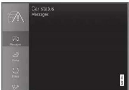
Saved messages can be seen in the Car Status app.
Messages that are shown in the driver display and that need to be saved are added in the Car Status app in the centre display. The message Car message stored in Car Status application is shown
in the centre display in conjunction with this.
DISPLAYS AND VOICE CONTROL
Reading a saved message
To read a saved message immediately:
- Press the button to the right of the Car message stored in Car Status application message in the centre display.
The saved message is shown in the Car Status app.
To read a saved message later:
- Open the Car Status app from the app view in the centre display.
The app is opened in the bottom sub-view of the home view.
- Select the Messages tab in the app.
A list of saved messages is shown.
- Tap on a message to expand/minimise.
More information on the message is shown in the list and the image to the left in the app shows information about the message graphically.
Managing a saved message
In maximised mode, some messages have two buttons available to book service or read the owner's manual.
To book service for a saved message:
- In maximised mode for the message, press Request appoint.Call to make Appointment ^4 for help in booking service.
With Request appoint.: The Appointments tab opens in the app and creates a request to book service and repair work.
With Call to make Appointment: The phone app is initiated and calls a service centre to book service and repair work.
To read the owner's manual for a saved message:
- In maximised mode for the message, press Owner's manual to read about the message in the owner's manual.
The owner's manual opens in the centre display and shows information linked to the message.
Saved messages in the app are deleted automatically each time the engine is started.
Related information
- Messages in the driver display (p. 104)
- Managing messages in the driver display (p. 105)
• Message in centre display (p. 138)
DISPLAYS AND VOICE CONTROL
Overview of centre display
Many of the car's functions are controlled from the centre display. Presented here is the centre display and its options.
▶▶
107
DISPLAYS AND VOICE CONTROL
◀◀
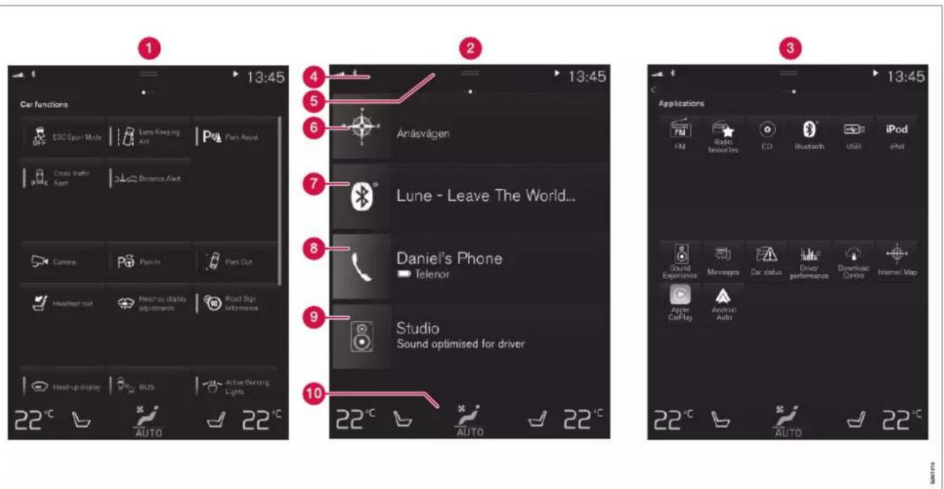
Three of the centre display's basic views. Swipe right or left to access the function or app view respectively ^5 .
1 Function view - car functions that are activated or deactivated with a press. Certain
functions are also so-called trigger functions, which means they open a window
with setting options. Examples of these include Camera. Settings for the head-up
DISPLAYS AND VOICE CONTROL
display* are also made from the function view, but adjustments are made using the steering wheel's right-hand keypad.
2 Home view - the first view that is shown when the screen is started.
3 App view – apps that have been downloaded (third-party apps) and apps for embedded functions, such as FM radio. Tap on an app icon to open the app.
4 Status bar - the activities in the car are shown right at the top of the screen. Network and connection information is shown on the left-hand side of the status bar, while media-related information, the clock and indication about on-going background activity are shown on the right.
5 Top view - drag the tab down in order to access the top view. Settings, Owner's manual, Profile and the car's saved messages are accessed from here. In some cases contextual settings (e.g. Navigation Settings) and the contextual owner's manual (e.g. Navigation Manual) can also be accessed in the top view.
6 Navigation - leads to map navigation, with e.g. Sensus Navigation*. Tap on the sub-view to expand it.
7 Media - recently used apps associated with media. Tap on the subview to expand it.
8 Phone - the phone function can be reached from here. Tap on the subview to expand it.
9 Extra subview - recently used apps or car functions that do not belong in any of the other subviews. Tap on the subview to expand it.
10 Climate row - information and direct interaction to set temperature and seat heating for example*. Tap on the symbol in the centre of the climate row in order to open the climate view with more setting options.
NOTE
If necessary, the climate control can be used to cool the media system in the centre display. In these cases, the message Climate system Cooling the infotainment system is shown in the driver display.
Related information
• Managing the centre display (p. 110)
- Navigating in the centre display's views (p. 113)
• Function view in centre display (p. 120)
- Apps (p. 510)
Symbols in the centre display's status bar (p. 122)
- Other settings in the centre display's top view (p. 130)
- Open contextual setup in the centre display (p. 131)
• Owner's manual in centre display (p. 19)
• Media player (p. 519) - Phone (p. 535)
• Climate controls (p. 210) - Switching off and changing the volume of the system sound in the centre display (p. 129)
- Changing the appearance in the centre display (p. 129)
• Changing system language (p. 130)
• Changing system units (p. 130)
• Cleaning the centre display (p. 640)
• Message in centre display (p. 138)
DISPLAYS AND VOICE CONTROL
Managing the centre display
Many of the car's functions are controlled and regulated from the centre display. The centre display is a touch screen that reacts to touch.
Using the touch screen functionality in the centre display
The screen reacts differently depending on whether it is touched by dragging, swiping, or tapping. Actions such as browsing between different views, marking objects and scrolling
in a list can be performed by touching the screen in different ways.
An infrared light curtain just above the surface of the screen enables the screen to detect a finger that is just in front of the screen. This technology makes it possible to use the screen even with gloves on.
Two people can interact with the screen at the same time, e.g. to adjust the climate for the driver and passenger side respectively.
IMPORTANT
Do not use sharp objects on the screen as they may scratch it.
The table below presents the different procedures for operating the screen:
| Procedure Execution Result | |
 | Press once. Highlights an object, confirms a selection or activates a function. |
| Press twice in quick succession. | |
| Press and hold. Grabs an object. Can be used to move apps or map points on the map. Press and hold your finger against the screen and at the same time drag the object to the desired location. | |
 | Tap once with two fingers. |
DISPLAYS AND VOICE CONTROL
| Procedure Execution Result | ||
 | Drag Changes between different views, scrolls a list, text or view. Hold depressed and drag in order to move apps or map points on the map. Drag horizontally or vertically across the screen. | |
 | Swipe/drag quickly | Changes between different views, scrolls a list, text or view. Drag horizontally or vertically across the screen.Note that touching the upper section of the screen may cause the top view to open. |
 | Drag apart Zooms in. | |
 | Drag together Zooms out. | |
DISPLAYS AND VOICE CONTROL
Returning to home view from another view
- Briefly press the home button below the centre display.
The last position of the home view is shown.
- Briefly press again.
All subviews of the home view are set to their default mode.

NOTE
In home view standard mode - briefly press the home button. An animation that describes access to the different views is shown on the screen.
Scrolling in a list, article or view
When a scroll indicator is visible in the screen, it is possible to scroll downward or upward in the view. Swipe downwards/upwards anywhere in the view.
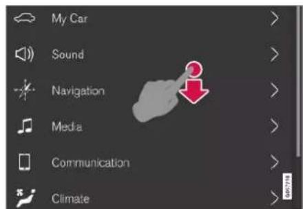
The scroll indicator appears in the centre display when it is possible to scroll in the view.
Using the controls in the centre display

Temperature control,
The control is used for many of the car's functions. Regulate e.g. temperature by means of one of the following:
- drag the control to the desired temperature,
- tap on + or – in order to raise or lower the temperature gradually, or
- tap on the desired temperature on the control.
Related information
- Activating and deactivating centre display (p. 113)
- Moving apps and buttons in centre display (p. 122)
• Keyboard in centre display (p. 124)
Activating and deactivating centre display
The centre display can be dimmed and reactivated using the home button beneath the screen.

Home button for the centre display.
The effect of using the home button that the screen dims and the touchscreen no longer reacts to touch. The climate row will still be shown. All functions connected to the screen are still running, such as climate, audio, guidance* and apps. When the centre display is dimmed, it is a good opportunity to clean the screen. The dimming function can also be used to fade the screen so that it does not disturb while driving.
- Give a long press on the physical home button below the screen.
The screen goes dark except for the climate row, which continues to be shown. All functions connected to the screen are still running.
- Reactivate the screen - briefly tap on the home button.
The view that was displayed before the screen was switched off will be shown again.
NOTE
The screen cannot be deactivated when a prompt to perform an action is shown on the screen.
NOTE
The centre display deactivates automatically when the engine is off and the driver's door is opened.
Related information
• Cleaning the centre display (p. 640)
- Changing the appearance in the centre display (p. 129)
• Overview of centre display (p. 107)
Navigating in the centre display's views
There are five different basic views in the centre display: home view, top view, climate view, app view and function view. The screen is started automatically when the driver's door is opened.
Home view
Home view is the view that is shown when the screen is started. It consists of four subviews: Navigation, Media, Phone and an extra sub-view.
An app or car function selected from the app or function view starts in the respective sub-view of the home view. E.g. FM radio starts in the Media tile.
The extra tile shows the last used app or car function that is not associated with any of the other three areas.
The subviews show brief information about each different app.
NOTE
When the car is started, the home view's various sub-views show information on the current status of apps.
▶▶
DISPLAYS AND VOICE CONTROL
◀◀

NOTE
In home view standard mode - briefly press the home button. An animation that describes access to the different views is shown on the screen.
Status bar
The activities in the car are shown at the top of the screen. Network and connection information is shown on the left-hand side of the status bar, while media-related information, the clock and indication that background activity is in progress are shown on the right.
Top view

Top view dragged down.
A tab is located in the centre of the status bar at the top of the screen. Open the top view by
pressing on the tab or by dragging/swiping from the top downwards across the screen.
In the top view, access is always available to:
- Settings
- Owner's manual
Profile
• The car's saved messages.
In the top view, access is given to the following in some cases:
- Contextual setting (e.g. Navigation Settings). Change settings directly in the top view when an app (e.g. navigation) is running.
- Contextual Owner's Manual (e.g. Navigation Manual). Gain access directly in the top view to articles in the digital owner's manual that are related to the content displayed on screen.
Exit the top view - press outside the top view, on the home button or at the bottom of the top view and drag upward. The underlying view is then visible and available for use again.
NOTE
The top view is not available during starting/shutdown or when a message is shown on the screen. It is also not available when climate view is shown.
Climate view
The climate row is always visible at the bottom of the screen. The most common climate settings can be made directly there, such as setting temperature and seat heating*.

Press the symbol in the centre of the climate row to open the climate view and gain access to more climate settings.

Press the symbol to close the climate view and return to the previous view.
App view

App view with the car's apps.
Swipe from right to left ^6 across the screen in order to access the app view from the home view. Apps that have been downloaded (third-party apps) and apps for embedded functions, such as FM radio, are found here. Certain apps show brief information directly in the app
view, such as the number of unread text messages for Messages.
Tap on an app to open it. The app then opens in the tile to which it belongs, e.g. Media.
You can scroll down in the app view, depending on the number of apps. Do this by swiping/dragging from the bottom and up.
Go back to the home view again by swiping from left to right ^6 across the screen, or by pressing the home button.
Function view

The function view with buttons for different car functions.
Swipe from left to right ^6 across the screen in order to access the function view from the home view. From here you can activate or deactivate different car functions, e.g. BLIS*, Lane Keeping Aid* and Park Assist*.
DISPLAYS AND VOICE CONTROL
Depending on the amount of functions, it is also possible here to scroll downward in the view. Do this by swiping/dragging from the bottom and up.
Unlike in app view, where an app is opened with a press, a function is activated or deactivated by pressing the relevant function button. Some functions (trigger functions) open in a new window when pressed.
Go back to the home view again by swiping from right to left ^6 across the screen, or by pressing the home button.
Related information
• Managing subviews in centre display (p. 117)
- Symbols in the centre display's status bar (p. 122)
- Other settings in the centre display's top view (p. 130)
- Open contextual setup in the centre display (p. 131)
• Owner's manual in centre display (p. 19)
• Driver profiles (p. 134)
• Climate controls (p. 210)
- Apps (p. 510)
• Function view in centre display (p. 120)
• Overview of centre display (p. 107)
DISPLAYS AND VOICE CONTROL
Managing subviews in centre display
Home view consists of four subviews: Navigation, Media, Phone and an extra subview. These views can be expanded.
▶▶
117
DISPLAYS AND VOICE CONTROL
Expanding a subview from default mode

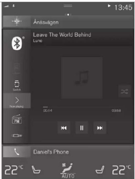
Standard mode and expanded mode of a subview in the centre display.
Expanding a subview:
- For tiles Navigation, Media and Phone: Press anywhere on the subview. When a tile is expanded, the extra tile in the home view is temporarily forced away. The other two tiles are minimised and only certain information is shown. When the extra tile is tapped, the other three tiles are minimised and only certain information is displayed.
The expanded view provides access to the basic functions of the app.
Closing an expanded subview:
- The subview can be closed in three different ways.
- Tap on the upper part of the expanded subview.
- Tap on another tile (this tile will then open in expanded mode instead).
- Briefly press the physical home button below the centre display.
Opening or closing a subview in full screen mode
The extra tile ^7 and the tile for Navigation can be opened out in full screen mode, with even more information and more setting options.
When a new subview is opened in full-screen mode, no information from the other subviews is shown.

In expanded mode, open the app in full screen - press on the symbol.

Press on the symbol to go back to the expanded mode, or press the home button at the bottom of the screen.
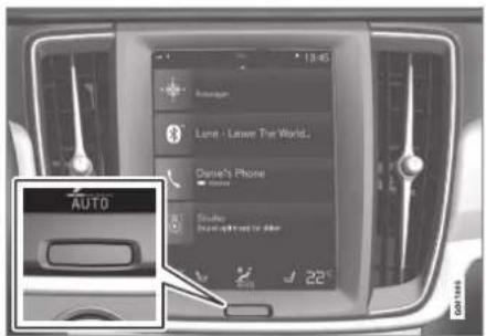
Home button for the centre display.
There is always the option to go back to home view by pressing the home button. To go back to the home view's standard view from full screen mode – press twice on the home button.
Related information
• Managing the centre display (p. 110)
- Activating and deactivating centre display (p. 113)
- Navigating in the centre display's views (p. 113)
DISPLAYS AND VOICE CONTROL
Function view in centre display
All the buttons for car functions are located in the function view, one of the centre display's basic views. Navigate to the function view
from home view by swiping from left to right across the screen ^8 .
Different types of buttons
There are three different types of buttons for car functions; see below:
| Type of button Property Affects car function | ||
| Function buttons Have on/off positions.When a function is running, an LED indicator illuminates to the left of the icon for the button. Press the button to activate/deactivate a function. | Most buttons in function view are function buttons. | |
| Trigger buttons Do not have on/off positions.When a trigger button is depressed, a window for the function is opened. For example, it may be a window to change seat position. | CameraHeadrest FoldHead-up Display Adjustments | |
| Parking buttons Have on, off and scan modes.Similar to the function buttons but with an extra position for parking scanning. | Park InPark Out | |
The buttons' different modes
When the LED indicator illuminates in green on a function or parking button, the function is activated. When a function is activated, extra text with an explanation for certain functions is shown. The text is shown for a few seconds and then the button is shown with the LED indicator illuminated.
For Lane Keeping Aid, the text Works only at certain speeds is shown, for example, when the button is depressed.
Press the button once briefly to activate or deactivate the function.

The function is deactivated when the LED indicator is extinguished.

When a warning triangle is shown in the right-hand section of the button there is something not working as intended.
Related information
• Managing the centre display (p. 110)
- Navigating in the centre display's views (p. 113)
DISPLAYS AND VOICE CONTROL
Moving apps and buttons in centre display
The apps and buttons for car functions in the app view and function view respectively can be moved and organised as desired.
-
Swipe from right to left ^9 to access the app view, or swipe from left to right ^9 to access the function view.
-
Tap on an app or button and hold it down.
The app or button changes size and becomes slightly transparent. It is then possible to move it.
- Drag the app or button to a vacant space in the view.
The maximum number of rows available for use in order to position apps or buttons is 48. To move an app or button outside the visible view, drag it to the bottom of the view. New rows are then added, where the app or button can be located.
An app or button can thus be located further down and is then not visible in the normal mode for the view.
Swipe across the screen to scroll up or down in the view.
NOTE
Hide the apps that you rarely or never use by moving them to the bottom, off the visible screen. This way it will be easier to find the apps you use more often.
NOTE
Apps and car function buttons cannot be added to locations that are already occupied.
Related information
• Function view in centre display (p. 120)
- Apps (p. 510)
• Managing the centre display (p. 110)
Symbols in the centre display's status bar
Overview of the symbols that can be shown in the centre display's status bar.
The status bar shows activities in progress and, in some cases, their status. Not all symbols are shown all the time due to the limited space in the status bar.
| Symbol | Specification |
| Connected to the Internet. | |
| R | Roaming activated. |
| Signal strength in mobile phone network. | |
| Bluetooth device connected. | |
| Bluetooth activated but no device connected. | |
| Information sent to and from GPS. | |
| Connected to Wi-Fi network. | |
| Tethering activated (Wi-Fi hotspot). The car then shares the available connection. |
DISPLAYS AND VOICE CONTROL
| Symbol | Specification |
| Car modem activated. | |
| USB sharing active. | |
| Process in progress. | |
| Timer for preconditioning active. | |
| Audio source being played back. | |
| Audio source stopped. | |
| Phone call in progress. | |
| Audio source muted. | |
| NEWS | News is received from the radio channel. |
| TP | Traffic information is received. |
| 15:45 | Clock. |
Related information
-
Navigating in the centre display's views (p. 113)
• Message in centre display (p. 138)
• Internet-connected car* (p. 544) -
Connecting a device via USB port (p. 526)
- Phone (p. 535)
• Date and time (p. 92)
DISPLAYS AND VOICE CONTROL
Keyboard in centre display
The centre display keyboard makes it possible make entries using keys. It is also possible to "draw in" letters and characters on the screen by hand.
The keyboard can be used to enter characters, letters and numbers, e.g. to write text messages from the car, enter passwords or search for articles in the digital owner's manual.
The keyboard is only shown when entries can be made on the screen.
DISPLAYS AND VOICE CONTROL

The image shows an overview of some of the buttons which may be shown in the keyboard. The appearance varies depending on language settings and the context in which the keyboard is being used.
▶▶
DISPLAYS AND VOICE CONTROL
◀◀
1 Row of suggested words or characters ^10 . The suggested words are adjusted as new letters are being entered. Browse among the suggestions by pressing on the right and left arrows. Tap on a suggestion to select it. Note that this function is not supported by all language selections. If not available, the row will not be shown on the keyboard.
2 The characters available on the keyboard depend on which language was selected (see point 7). Tap on a character to enter it.
3 The button works in different ways, depending on the context in which the keyboard is used - either to enter @ (when an email address is entered) or to create a new row (for normal text input).
4 Hides the keyboard. If this is not possible, the button is not shown.
5 Used to enter capital letters. Press again to enter one capital letter and then continue with lower-case letters. Another press makes all letters capital letters. The next press restores the keyboard to lower-case letters. In this mode, the first letter after a full stop, exclamation mark or question mark is a capital letter. The first letter in the text field is also a capital letter. In text fields intended for names or
addresses, each word automatically starts with a capital letter. In text fields for password, web address or email address entry, all letters are automatically lower case unless otherwise set with the button.
6 Number entry. The keyboard (2) is then shown with numbers. Press ABC, which in number mode is shown instead of 123, to return to the letter keyboard, or #\~ to open the keyboard with special characters.
7 Changes text input language, e.g. EN. The available characters and word suggestions (1) vary depending on the selected language. To make it possible to change languages for the keyboard, the languages must first be added under Settings.
8 Space.
9 Undoes entered text. Pressing briefly deletes one character at a time. Hold the button depressed to delete characters more quickly.
10 Changes keyboard mode to write letters and characters by hand instead.
Pressing the confirmation button above the keypad (not visible in the illustration) confirms the entered text. The appearance of the button differs depending on context.
Variants of a letter or character

Variants of a letter or character, e.g. é or è, can be entered by holding down the letter or character. A box is displayed showing possible variants of letters or characters. Press the required variant. If no variant is selected, the original letter/character is entered.
Related information
- Changing keyboard language in centre display (p. 127)
- Enter the characters, letters and words manually in the centre display (p. 127)
• Managing the centre display (p. 110)
• Managing text messages (p. 541)
Changing keyboard language in centre display
To make it possible to switch between different languages for the keyboard, the languages must first be added under Settings.
Adding or deleting languages in settings
The keyboard is automatically set to the same languages as the system language. The keyboard language can be manually adapted without affecting the system language.
- Press Settings in the top view.
- Press System System Languages and Units → Keyboard Layouts.
- Select one or more languages from the list.
It is now possible to switch between the selected languages directly from the keyboard for text input.
If no languages have been actively selected under Settings, the keyboard retains the same language as the car's system language.
Switching between different languages in the keyboard

When a number of languages have been selected in Settings, the button in the keyboard is used to switch between the different languages.
To change keyboard language with list;
- Give a long press on the button.
A list opens.
- Select the required language. If more than four languages have been selected under Settings, it is possible to scroll in the list from the keyboard.
The keyboard is adapted to the selected language and other word suggestions are given.
To change the keyboard language without displaying the list:
- One short press of the button.
The keyboard is adapted to the next language in the list without displaying the list.
Related information
• Changing system language (p. 130)
• Keyboard in centre display (p. 124)
Enter the characters, letters and words manually in the centre display
The centre display keyboard allows you to enter characters, letters and words on the screen by "drawing" by hand.

Press the button on the keyboard to change from typing with the keys to entering letters and characters by hand.

1 Area for writing characters/letters/words/parts of word.
2 The text field where the characters or word suggestions ^11 appear as they are written on screen (1).
DISPLAYS AND VOICE CONTROL
◀◀
3 Suggestions for characters/letters/word/part of word. It is possible to scroll through the list.
4 Space. A space can also be created by entering a dash (-) in the area for handwritten letters (1). See the heading "Entering a space in the free text field with handwriting recognition" below.
5 Undo entered text. Press briefly to delete one character/one letter at a time. Wait a moment before pressing again to delete the next character/letter, etc.
6 Return to the keyboard with regular character input.
7 Switch off/on sound when entering.
8 Hide the keyboard. If this is not possible, the button is not shown.
9 Change text input language.
Writing characters/letters/words by hand
- Write a character, a letter, a word or parts of a word in the area for hand-written letters (1). Write a word or parts of a word above each other or on a line.
A number of suggested characters, letters or words is shown (3). The most likely choice is found at the top of the list.
IMPORTANT
Do not use sharp objects on the screen as they may scratch it.
- Enter the character/letters/word by waiting a moment.
The character/letter/word at the top of the list is entered. It is also possible to select a different character by pressing the required character, letter or word in the list.
Deleting/changing characters/letters written by hand

Delete all characters in the text field (2) by swiping across the handwriting field (1).
- There are several options for deleting/ changing characters/letters:
- Press the intended letter or word in the list (3).
- Press the text undo button (5) to delete the letter and begin again.
- Swipe horizontally from right to left ^12 over the area for handwritten letters (1). Delete multiple letters by swiping over the area several times.
- Pressing the X in the text field (2) deletes all of the entered text.
Changing row in the free text field with handwriting

Change row by hand by drawing the above character in the handwriting field ^13 .
Entering a space in the free text field with handwriting recognition

Enter a space by drawing a dash from left to right ^14 .
Related information
• Keyboard in centre display (p. 124)
Changing the appearance in the centre display
The appearance of the screen in the centre display can be changed by selecting a theme.
- Press Settings in the top view.
- Press My Car Displays Display Themes.
- Then select a theme, e.g. Minimalistic or Chrome Rings.
As a supplement to these appearances, it is possible to choose between Normal and Bright. With Normal, the screen background is dark and the text is light. This alternative is the default for all themes. A light variant can also be selected, in which the background is light and the text is dark. This alternative can be useful in e.g. strong daylight.
This alternative is always available for the user and is not affected by the surrounding lighting.
Related information
- Other settings in the centre display's top view (p. 130)
- Activating and deactivating centre display (p. 113)
• Cleaning the centre display (p. 640)
Switching off and changing the volume of the system sound in the centre display
The centre display can be used to change the volume of the system sound or switch off the system sound altogether.
- Press Settings in the top view in the centre display.
- Press Sound System Volumes.
- Under Touch Sounds, drag the control to change the volume/switch off screen touch sounds. Drag the control to the desired volume.
Related information
• Overview of centre display (p. 107)
- Other settings in the centre display's top view (p. 130)
• Audio settings (p. 508)
DISPLAYS AND VOICE CONTROL
Changing system units
Units settings are defined in the centre display's Settings menu.
- Press Settings in the top view in the centre display.
- Continue to System System Languages and Units → Units of Measurement.
- Select a unit standard:
• Metric - kilometres, litres and degrees Celsius.
- Imperial - miles, gallons and degrees Celsius.
• US - miles, gallons and degrees Fahrenheit.
The units in the driver display, centre display and head-up display are changed.
Related information
• Overview of centre display (p. 107)
- Other settings in the centre display's top view (p. 130)
• Changing system language (p. 130)
Changing system language
Language settings are defined in the centre display menu Settings.
NOTE
Changing the language in the centre display may mean that some owner's information is not compliant with national or local laws and regulations. Do not switch to a language that is difficult to understand as this may make it difficult to find your way back through the screen structure.
- Press Settings in the top view in the centre display.
- Continue to System System Languages and Units.
- Select System Language. Languages that support voice recognition have a voice recognition symbol.
The language in the driver display, centre display and head-up display is changed.
Related information
• Overview of centre display (p. 107)
- Other settings in the centre display's top view (p. 130)
• Changing system units (p. 130)
Other settings in the centre display's top view
You can change settings and information for many of the car's functions via the centre display.
- Open the top view by pressing on the tab at the top or by dragging/swiping from the top downwards across the screen.
- Press Settings to open the settings menu.

Top view with button for Settings.
- Press on one of the categories and the subcategories to navigate to the required setting,
- Change one or more settings. Different types of setting are changed in different ways.
The changes are saved immediately.

A subcategory In the settings menu with different types of settings (here, a multi-selector button and radio buttons).
Related information
• Overview of centre display (p. 107)
- Resetting settings in the centre display (p. 132)
• Table showing centre display settings (p. 133)
Open contextual setup in the centre display
It is possible to use contextual setup for most of the car's basic apps so that you can change settings directly in the top view in the centre display.

Top view with button for contextual setting.
Contextual setting is a shortcut for accessing a specific setting relating to the active function shown on screen. The apps installed in the car from the beginning, e.g. FM radio and USB, are a part of Sensus and are part of the car's embedded functions. The settings for these apps can be changed directly via contextual setting in the top view.
When contextual setup is available:
-
Drag down top view when an app is in expanded mode, e.g. Navigation.
-
Press Navigation Settings.
A navigation settings page opens.
- Change settings as desired and confirm the selections.
Press Close or the physical home button beneath the centre display to close setup view.
Most of the car's basic apps have this contextual setting option, but not all.
Third party apps
Third party apps are not included in the car's system from the beginning, but are the type that can be downloaded e.g. Volvo ID. Here the settings are always made inside the app and not from the top view.
Related information
- Other settings in the centre display's top view (p. 130)
• Overview of centre display (p. 107) - Resetting settings in the centre display (p. 132)
• Downloading apps (p. 511)
DISPLAYS AND VOICE CONTROL
Resetting user data for change of ownership
In the event of a change of ownership, user data and system settings should be restored to factory settings.
The settings in the car can be reset at different levels. Restore all user data and system settings to the original factory settings in the event of a change of ownership. In the event of a change of ownership it is also important to change the owner of the Volvo On Call* service.
Related information
- Resetting settings in the centre display (p. 132)
- Resetting settings in the driver profiles (p. 138)
Resetting settings in the centre display
It is possible to reset the defaults for all settings defined in the centre display settings menu.
Two types of reset
There are two different types of restore operation in the settings menu:
- Factory reset - clears all data and files and resets all settings to their default values.
- Reset Personal Settings - clears personal data and resets personal settings to their default values.
Resetting settings
Follow these instructions to reset your settings.
NOTE
Factory reset is only possible when the car is stationary.
- Tap on Settings in the centre display's top view.
- Continue to System Factory reset.
- Select the required reset type.
A pop-up window is shown.
- Press OK to confirm the reset.
For Reset Personal Settings, the reset must be confirmed by pressing Reset for the active profile or Reset for all profiles.
Selected settings are reset.
Related information
• Overview of centre display (p. 107)
- Other settings in the centre display's top view (p. 130)
• Table showing centre display settings (p. 133)
Table showing centre display settings
The settings menu in the centre display has a number of main categories and subcategories where settings and information for many of the car's functions are collected.
There are seven main categories: My Car, Sound, Navigation, Media, Communication, Climate and System.
In turn, each category contains a number of subcategories and setting options. The tables below show the first level of subcategories. The setting options for a function or area are described in more detail in the corresponding section of the owner's manual.
Some settings are personal, which means that they can be saved to Driver Profiles. Other settings are global, which means they are not linked to a driver profile.
My Car
| Subcategories |
| Displays |
| IntelliSafe |
| Drive Preferences/Individual Drive Mode* |
| Lights and Lighting |
| Mirrors and Convenience |
| Subcategories |
| Locking |
| Parking Brake and Suspension |
| Wipers |
| Sound |
| Subcategories |
| Tone |
| Balance |
| System Volumes |
| Navigation |
| Subcategories |
| Map |
| Route and Guidance |
| Traffic |
| Media |
| Subcategories |
| AM/FM radio |
| DAB* |
| Gracenote® |
| Subcategories |
| TV* |
| Video |
| Communication |
| Subcategories |
| Phone |
| Text Messages |
| Android Auto* |
| Apple CarPlay* |
| Bluetooth Devices |
| Wi-Fi |
| Car Wi-Fi Hotspot |
| Car Modem Internet* |
| Volvo On Call* |
| Volvo Service Networks |
Climate
The main category Climate has no subcategories.
System
| Subcategories |
| Driver Profile |
| Date and Time |
| System Languages and Units |
| Privacy and Data |
| Keyboard Layouts |
| Voice Control* |
| Factory reset |
| System Information |
Related information
• Overview of centre display (p. 107)
- Other settings in the centre display's top view (p. 130)
- Resetting settings in the centre display (p. 132)
Driver profiles
Many of the settings made in the car can be adapted according to the driver's personal preferences and can be saved in one or more driver profiles.
The personal settings are automatically saved in the active driver profile. Each key can be linked to a driver profile. When the linked key is used, the car is adapted to the settings of that specific driver profile.
What settings are saved in the driver profiles?
Many of the settings defined in the car will be saved automatically in the active driver profile unless the profile is protected. In the car, the settings defined are either personal or global. Only personal settings are saved in driver profiles.
Settings that can be saved in a driver profile include, amongst other things, screens, mirrors, front seats, navigation*, audio and media system, language and voice control.
Some settings, referred to as global settings, can be changed but are not saved to a specific driver profile. Changes to global settings affect all profiles.
Global settings
The global settings are not changed when changing between driver profiles. They remain
the same regardless of which driver profile is active.
Keyboard layout settings are an example of global settings. If driver profile X is used to add additional languages to the keyboard, these remain available for use even if driver profile Y is used. The keyboard layout settings are not saved to a specific driver profile - the settings are global.
Personal preferences
If driver profile X was used to e.g. set centre display brightness, driver profile Y is not affected by this setting. It has been saved to driver profile X - the brightness setting is a personal setting.
Related information
• Selecting driver profile (p. 135)
• Renaming a driver profile (p. 135)
- Linking remote control key to driver profile (p. 136)
- Protect driver profile (p. 136)
- Resetting settings in the driver profiles (p. 138)
• Table showing centre display settings (p. 133)
Selecting driver profile
When the centre display has been started, the selected driver profile is shown at the top of the screen. The driver profile last used is the one that will be active next time the car is unlocked. It is possible to change to another driver profile after the car has been unlocked. However, if the remote control key has been linked to a driver profile then this is what is selected when the car is started.
There are three options for changing to another driver profile.
Option 1:
- Tap on the name of the driver profile shown in the top of the centre display when the display has been started.
A list of selectable driver profiles is shown.
-
Select the driver profile required.
-
Press Confirm.
The driver profile is selected and the system loads the settings for the new driver profile.
Option 2:
-
Drag down the top view in the centre display.
-
Press Profile.
The same list as for Option 1 is shown.
-
Select the driver profile required.
-
Press Confirm.
The driver profile is selected and the system loads the settings for the new driver profile.
Option 3:
-
Drag down the top view in the centre display.
-
Press Settings in the top view in the centre display.
-
Press System Driver Profiles.
A list of selectable driver profiles is shown.
- Select the driver profile required.
The driver profile is selected and the system loads the settings for the new driver profile.
Related information
• Driver profiles (p. 134)
- Navigating in the centre display's views (p. 113)
• Renaming a driver profile (p. 135)
- Linking remote control key to driver profile (p. 136)
Renaming a driver profile
It is possible to change the name of the different driver profiles used in the car.
-
Press Settings in the top view in the centre display.
-
Press System Driver Profiles.
-
Select Edit Profile.
A menu opens, where the profile can be edited.
- Tap in the box Profile Name.
A keyboard appears, and it is possible to change the name. Tap on ▼ to close the keyboard.
- Save the name change by pressing Back or Close.
The name has now been changed.
NOTE
A profile name cannot start with a space, as the profile name will not then be saved.
Related information
• Selecting driver profile (p. 135)
• Keyboard in centre display (p. 124)
DISPLAYS AND VOICE CONTROL
Protect driver profile
In some cases it is preferable not to save various settings defined in the car to the active driver profile. In this case, it is possible to protect the driver profile.

NOTE
Protecting a driver profile is only possible when the car is stationary.
To protect a driver profile:
- Press Settings in the top view in the centre display.
- Press System Driver Profiles.
- Select Edit Profile.
A menu opens, where the profile can be edited.
-
Select Protect Profile to protect the profile.
-
Save your profile protection option by pressing Back/Close.
When the profile is protected, settings defined in the car will not be saved automatically to the profile. Instead, your changes must be saved manually under Settings System Driver Profiles → Edit Profile by pressing Save current settings to the profile. When the profile is unprotected, on the other hand, your settings will be saved automatically to the profile.
Related information
• Driver profiles (p. 134)
Linking remote control key to driver profile
It is possible to link your key to a driver profile. The driver profile along with all of its settings will then be automatically selected every time the car is used with that specific remote control key.
The first time the remote control key is used, it is not linked to any specific driver profile. When the car is started, the Guest profile will automatically be activated.
A driver profile can be selected manually without linking it to the key. When the car is unlocked, the last active driver profile is activated. Once the key has been linked to a driver profile, a driver profile does not need to be selected when that specific key is used.
Linking a remote control key to a driver profile

NOTE
Connecting a remote control key to a driver profile is only possible when the car is stationary.
First select the profile to be linked to the key, if the profile to be linked is not already active.
The active profile can then be linked to the key.
- Press Settings in the top view in the centre display.
- Press System Driver Profiles.
- Select the desired profile. The display returns to the home view. The Guest profile cannot be linked to a key.
-
Drag down the top view again and tap on Settings System Driver Profiles → Edit Profile.
-
Select Connect key to link the profile with the key. It is not possible to link a driver profile to a different key than the one currently being used in the car. If there are multiple keys in the car, the message More than one key is found, put the key you want to connect on backup reader will be displayed.

Backup reader's location in the tunnel console.
When the message Profile connected to key is shown, the key and the driver profile are linked.
- Press OK.
This key is now linked to the driver profile and will remain linked as long as the Connect key box is not unticked.
Related information
• Driver profiles (p. 134)
- Renaming a driver profile (p. 135)
• Remote control key (p. 240)
DISPLAYS AND VOICE CONTROL
Resetting settings in the driver profiles
Settings that have been saved to one or more driver profiles can be reset if the car is stationary.

NOTE
Factory reset is only possible when the car is stationary.
- Press Settings in the top view.
- Press System Factory reset Resc Personal Settings.
- Select one of the options Reset for the active profile, Reset for all profiles or Cancel.
Related information
- Driver profiles (p. 134)
- Resetting settings in the centre display (p. 132)
Message in centre display
The centre display can show messages to inform or assist the driver in the event of different events.

Example of a message in the centre display's top view.
The centre display shows messages that are of lower priority for the driver.
Most messages are shown above the centre display's status bar. After a while, or when any required action related to the message has been taken, the message disappears from the status bar. If a message needs to be saved, it is positioned in the top view in the centre display.
Message composition may vary and they can be shown together with graphics, symbols or a button for activating/deactivating a function linked to the message.
Pop-up messages
In some cases, a message is shown in the form of a pop-up window. Pop-up messages have higher priority than messages shown in the status bar and require acknowledgement/action before they disappear.
Related information
- Managing messages in the centre display (p. 139)
- Handling a message saved from the centre display (p. 139)
- Messages in the driver display (p. 104)
Managing messages in the centre display
Messages in the centre display are handled in centre display views.

Example of a message in the centre display's top view.
Some messages in the centre display have a button (or several buttons in pop-up messages) for e.g. activating/deactivating a function linked to the message.
Managing a new message
For messages with buttons:
- Press the button to perform the action or allow the message to close automatically after a while.
The message disappears from the status bar.
For messages without buttons:
- Close the message by tapping on it, or allow the message to close automatically after a while.
The message disappears from the status bar.
If a message needs to be saved, it is positioned in the top view in the centre display.
Related information
• Message in centre display (p. 138)
- Handling a message saved from the centre display (p. 139)
- Messages in the driver display (p. 104)
Handling a message saved from the centre display
Whether saved from the driver display or the centre display, messages are managed in the centre display.
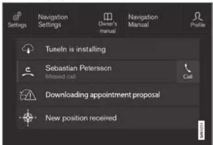
Examples of saved messages and possible options in the top view.
Messages that are shown in the centre display that need to be saved are added in the top view of the centre display.
DISPLAYS AND VOICE CONTROL
Reading a saved message
- Open the top view in the centre display.
A list of saved messages is shown. Messages with an arrow to the right can be maximised.
- Tap on a message to expand/minimise.
More information on the message is shown in the list and the image to the left in the app shows information about the message graphically.
Managing a saved message
Some messages have a button for e.g. activating/deactivating a function linked to the message.
- Press the button to perform the action.
Saved messages in the top view are deleted automatically when the car is switched off.
Related information
• Message in centre display (p. 138)
- Managing messages in the centre display (p. 139)
- Messages in the driver display (p. 104)
Head-up display\*
The head-up display supplements the car's driver display and projects information from the driver display onto the windscreen. The projected image can only be seen from the driver position.
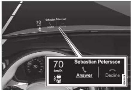
The head-up display shows warnings and information relating to speed, cruise control functions, navigation, etc. in the driver's field of vision. Road Sign Information and incoming phone calls can also be shown in the head up display.
NOTE
The driver's ability to see the information in the head-up display is impaired by the following
• use of polarising sunglasses
- a driving position which means that the driver is not sitting centred in the seat
- objects on the display unit's cover glass
• unfavourable light conditions.
IMPORTANT
The display unit from which the information is projected is located in the instrument panel. To avoid damage to the display unit's cover glass - do not store any objects on the cover glass and make sure that no objects fall down onto it.

Examples of what can be shown in the display,
1 Speed
② Cruise control
3 Navigation
4 Road signs
A number of symbols can be shown temporarily in the head-up display e.g.:

If the warning symbol illuminates - read the warning message in the driver display.

If the information symbol illuminates - read the message in the driver display.

The snowflake symbol illuminates in the event of a risk of icy conditions.
NOTE
Certain visual defects may cause headaches and a feeling of stress during the use of the head-up display.
City Safety in the head-up display
In the event of a collision warning, the information in the head-up display is replaced by the warning symbol for City Safety. This graphic is illuminated even if the head-up display is switched off.

natural_image
Close-up of a car dashboard with steering wheel, speedometer, and car front panel (no visible text or symbols)The warning symbol for City Safety flashes in order to attract the driver's attention if there is a risk of collision.
Related information
- Activating and deactivating the head-up display* (p. 142)
- Cleaning the Head-up display* and driver display (p. 641)
- Head up display when replacing the windscreen* (p. 608)
DISPLAYS AND VOICE CONTROL
Activating and deactivating the head-up display\*
The head-up display can be activated and deactivated when the car has been started.

Press the Head-up Display button in the centre display function view. An indicator in the button illuminates when the function is activated.
Related information
- Settings for head-up display* (p. 142)
• Head-up display* (p. 140)
Settings for head-up display\*
Adjust the settings for the head-up display's projection onto the windscreen.
Settings can be defined when the car has been started and a projected image is shown on the windscreen.
Selecting display options
Select which functions are to be shown in the head-up display.
- Tap on Settings in the centre display's top view.
- Press My Car Displays Head-Up Display Options.
- Select one or more functions:
• Show Navigation
• Show Road Sign Information
• Show Driver Support
• Show Phone
The setting is saved as a personal setting in the driver profile.
Adjusting brightness and vertical position

- Press the Head-up Display Adjustments button in the centre display function view.
- Adjust the brightness and vertical position of the projected image in the driver's field of vision using the steering wheel's right-hand keypad.

1 Reducing the brightness
② Increasing the brightness
3 Raising the position
4 Lowering the position
5 Confirm
The brightness of the graphics is automatically adapted to their background light conditions. The brightness is also affected by the adjustment of the brightness in the car's other displays.
The height position can be stored in the memory function for the power* front seat using the keypad in the driver's door.
Calibrate the horizontal position
The head-up display's horizontal position may need to be calibrated if the windscreen or display unit is replaced. Calibration means that the projected image is rotated clockwise or anticlockwise.
- Tap on Settings in the centre display's top view.
- Select My Car Displays Head-Up Display Options → Head-Up Display Calibration.
- Calibrate the image's horizontal position with the steering wheel's right keypad.

1 Rotate anticlockwise
2 Rotate clockwise
3 Confirm
Related information
• Head-up display* (p. 140)
- Activating and deactivating the head-up display* (p. 142)
• Driver profiles (p. 134)
- Storing position for seat, door mirrors and head-up display* (p. 184)
Voice recognition
Voice control ^15 allows you to control functions in the car, e.g. climate system, radio or a Bluetooth-connected phone with spoken commands. In cars equipped with Sensus Navigation ^* , the navigation system can also be controlled with voice recognition.
What is voice control?
Voice control is an aid that can facilitate the use of different commands in your car. In principle, it works like a normal application in which you enter information in a fixed sequence in order to perform a task, but instead of typing on a keyboard you use voice commands. It may therefore be a good idea to learn how, and in what order, a voice command should be spoken in order to achieve the desired result.
The voice control system allows you to control certain infotainment and climate functions using voice commands. The system can respond with speech and by showing information in the driver display.
DISPLAYS AND VOICE CONTROL

WARNING
The driver always holds overall responsibility for driving the vehicle in a safe manner and complying with all applicable rules of the road.

natural_image
Interior view of a car dashboard and steering wheel, showing dashboard, steering wheel, and steering wheel (no visible text or symbols)Voice control system microphone
System updating
The voice recognition system is continuously improved. It is recommended to always have the latest version installed.
Download updates at volvocars.com/support.
i NOTE
Not all system languages support voice recognition. The ones that do are highlighted with the symbol in the list of available system languages. Read more about where the information can be found in the section on settings for voice recognition.
Related information
• Using voice recognition (p. 144)
- Controlling a telephone with voice recognition (p. 146)
• Voice control of radio and media (p. 147)
- Controlling the climate control system using voice control (p. 200)
• Settings for voice recognition (p. 148)
Using voice recognition
Start voice control ^16

To give commands via the voice control system, you have a "dialogue" with the system. Depress the steering wheel button for voice recognition to activate the system and initiate a dialogue
using voice commands. After you have pressed the button, a beep tone can be heard and the voice control symbol is shown in the driver display.
This shows that the system has started to listen and you can start to say the commands. As soon as you start to talk, the system is trained to recognise and understand your voice. This takes several seconds and is done automatically, which means that you do not need to start any voice training manually.
Remember the following:
- Speak after the tone with a normal voice at a normal tempo.
- Do not speak while the system is replying (the system cannot understand commands during this time).
- Avoid background noise in the passenger compartment by having the doors, windows and sunroof* closed.

NOTE
Not all system languages support voice recognition. The ones that do are highlighted with the symbol in the list of available system languages. Read more about where the information can be found in the section on settings for voice recognition.
In general, the system works by listening for a basic command which is followed by more detailed commands that specify what you want the system to do.
To change the system audio volume, turn the rotary volume knob when the voice speaks. It is possible to use other buttons during voice control. However, other sounds will be silenced during dialogue with the system,
which means that it is not possible to execute any functions linked with audio using the buttons.
Cancel voice control
Voice control can be cancelled in different ways:
- Tap briefly on 📊 and say "Cancel".
- Give a long press on the steering wheel button for voice control until you hear two beeps. This stops voice recognition even when the system is speaking.
Voice control is also cancelled if you do not reply during a dialogue. The system will first ask for a reply three times and if there is still no response then voice control will be cancelled automatically.
To speed up communication and skip the prompts from the system, press the steering wheel button for voice control Ⓤ. This cancels the system voice and you can say the next command.
Example of voice recognition control
-
Press 映
-
Say "Call [Forename] [Surname] [number category]", e.g. "Call Robin Smith Mobile".
The system dials the selected contact from the phonebook. If the contact has several phone numbers (e.g. home, mobile, work), the right category must be referred to.
Commands/phrases
The following commands can generally be used, regardless of the situation:
- "Repeat" - repeats the last voice instruction in the ongoing dialogue.
- "Cancel" - discontinue the dialogue. ^17
- "Help" - starts a help dialogue. The system replies with the commands available in the current situation, a prompt or an example.
Commands for specific functions such as phone and radio are described in specific sections.
Digits
The number commands are stated differently depending on the function to be controlled:
- Phone numbers and postcodes must be spoken individually, number by number, e.g. "zero, three, one, two, two, four, four, three" (03122443).
- House numbers can be spoken individually or in groups, e.g. "two, two" or "twenty-two" (22). For English and Dutch, several groups can be said in sequence, e.g. "twenty-two, twenty-two" (22 22). For English, double or triple can be used, e.g. "double zero" (00). Numbers can be given within the range 0-2300.
- Frequencies can be spoken as "ninety eight point eight" (98.8), "a hundred and four point two" or "hundred four point two" (104.2).
Speed and repetition mode
It is possible to adjust the speed if the system is speaking too quickly.
Repetition mode can be enabled so that the system repeats what you have said.
To change the speed or activate/deactivate repetition mode:
-
Press Settings in the top view.
-
Press System Voice Control and select settings.
-
Repeat Voice Command
- Speech Rate
Related information
• Voice recognition (p. 143)
- Controlling a telephone with voice recognition (p. 146)
• Voice control of radio and media (p. 147)
• Controlling the climate control system using voice control (p. 200)
- Settings for voice recognition (p. 148)
Controlling a telephone with voice recognition ^18
Call a contact, have messages read aloud or dictate brief messages with voice control commands to a Bluetooth connected telephone.
To specify a contact in the phone book, the voice recognition command must include contact information that is entered in the phone book. If a contact, e.g. Robyn Smith, has several phone numbers then the number category can also be stated, e.g. Home or Mobile: "Call Robin Smith Mobile".
Press and say one of the following commands:
- "Call [contact]" - dials the selected contact from the phone book.
- "Call [phone number]" - dials the phone number.
- "Recent calls" - displays the call list.
- "Read message" - message is read out. If there are several messages - select which message should be read out.
- "Message to [contact]" – the user is requested to say a brief message. The message is then repeated aloud and the user can choose to send ^19 or revise the
message. For this function to work, the car must be connected to the Internet.

NOTE
Not all system languages support voice recognition. The ones that do are highlighted with the Ⓥ symbol in the list of available system languages. Read more about where the information can be found in the section on settings for voice recognition.
Related information
• Voice recognition (p. 143)
• Using voice recognition (p. 144)
• Voice control of radio and media (p. 147)
- Controlling the climate control system using voice control (p. 200)
• Settings for voice recognition (p. 148)
• Internet-connected car* (p. 544)
Voice control of radio and media ^20
Commands for radio and media player device control are shown below.
Tap on and say one of the following commands:
• "Media" - starts a dialogue for media and radio and shows examples of commands.
- "Play [artist]" - plays back music by the selected artist.
- "Play [song title]" - plays back the selected song,
- "Play [song title] from [album]" - plays back the selected song from the selected album.
- "Play [radio station]" - starts playing back the selected radio channel.
- "Tune to [frequency]" - starts the selected radio frequency in the current frequency band. If no radio source is active, the FM band is started by default.
- "Tune to [frequency] [wavelength]" - starts the selected radio frequency in the selected frequency band.
• "Radio" - starts FM radio.
• "Radio FM" - starts FM radio.
• "DAB" - starts DAB radio*.
- "USB" - starts playback from USB.
- "iPod" - starts playback from iPod.
- "Bluetooth" - starts playback from a Bluetooth-connected media source.
- "Similar music" — plays back music similar to the music currently playing back from USB devices.

NOTE
Not all system languages support voice recognition. The ones that do are highlighted with the symbol in the list of available system languages. Read more about where the information can be found in the section on settings for voice recognition.
Related information
• Voice recognition (p. 143)
• Using voice recognition (p. 144)
- Controlling a telephone with voice recognition (p. 146)
• Controlling the climate control system using voice control (p. 200)
- Settings for voice recognition (p. 148)
DISPLAYS AND VOICE CONTROL
Settings for voice recognition ^21
Settings for the voice control system are selected here.
Settings System Voice Control
Settings can be made within the following areas:
- Repeat Voice Command
Gender - Speech Rate
Audio settings
Select audio settings under:
Settings Sound System Volumes Voice Control

Language settings
Voice recognition is not possible for all languages. Languages available for voice recognition are marked with an icon in the language list - .
Changing the language also affects menu, message and help texts.
Settings System System Languages and Units → System Language
Related information
• Voice recognition (p. 143)
• Using voice recognition (p. 144)
- Controlling a telephone with voice recognition (p. 146)
- Controlling the climate control system using voice control (p. 200)
• Voice control of radio and media (p. 147)
• Audio settings (p. 508)
• Changing system language (p. 130)
LIGHTING
LIGHTING
Lighting control
The different lighting controls are used to control both exterior and interior lighting. The left-hand stalk switch activates and adjusts the exterior lighting. The interior brightness is adjusted using a thumbwheel on the instrument panel.
Exterior lighting

Rotating ring in the left-hand stalk switch.
When the car's electrical system is in ignition position II, the following functions are available for the rotating ring's different positions:
| Position | Specification |
| Daytime running lights.Main beam flash can be used. | |
| Daytime running lights and position lamps.Position lamps when the car is parked. ^A Main beam flash can be used. | |
| Dipped beam and position lamps.Main beam can be activated.Main beam flash can be used. |
| Position | Specification |
| AUTO | Daytime running lights and position lamps in daylight.Dipped beam and position lamps in weak daylight or darkness, or when the front fog lamp* and/or rear fog lamp are activated.The Active main beam function can be activated.Main beam can be activated when dipped beam is switched on.Main beam flash can be used. |
| Active main beam on/off. |
A If the car is stationary but running, the rotating ring can be moved to 300° position from another position to switch on only the position lamps instead of other lighting.
Volvo recommends that AVTode is used when the vehicle is driven.

WARNING
The car's lighting system is not able to determine when daylight is too weak or sufficiently strong, e.g. in fog and rain, in all situations.
The driver is always responsible for ensuring that the car is driven with a beam pattern suitable for the traffic situation and in accordance with applicable traffic regulations.
Thumbwheel in instrument panel

natural_image
Interior view of a car dashboard with a control panel and indicator lights (no visible text or symbols)Thumbwheel (to left) for adjusting interior brightness.
Related information
- Adjusting light functions via the centre display (p. 151)
• Interior lighting (p. 160) - Position lamps (p. 152)
• Using direction indicators (p. 156)
• Using main beam (p. 154)
• Dipped beam (p. 153)
• Rear fog lamp (p. 158)
• Active bending lights* (p. 157)
- Brake lights (p. 158)
• Emergency brake lights (p. 159)
• Hazard warning flashers (p. 159)
Adjusting light functions via the centre display
Several light functions can be adjusted and activated via the centre display. This applies to active main beam, home safe lighting and approach light, for example.
- Tap on Settings in the centre display's top view.
- Press My Car Lights and Lighting.
- Select Exterior Lights or Interior Lighting and then select the function that needs to be adjusted.
Related information
• Lighting control (p. 150)
• Active main beam (p. 155)
• Using home safe lighting (p. 160)
• Approach light duration (p. 160)
• Using direction indicators (p. 156)
- Other settings in the centre display's top view (p. 130)
• Function view in centre display (p. 120)
LIGHTING
Adapting the headlamp pattern from the headlamps
This car does not need to reset the headlamp pattern when changing from right to left-hand traffic, and vice versa.
Related information
- Other settings in the centre display's top view (p. 130)
• Function view in centre display (p. 120)
• Active bending lights* (p. 157)
Position lamps
Position lamps can be used so that other road users can see the car if it stops or is parked. The position lamp is switched on with the rotating ring on the stalk switch.
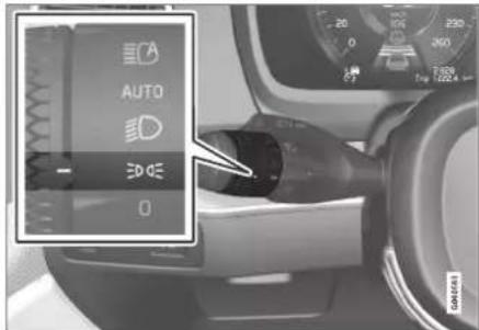
Stalk switch rotating ring in position lamps position.
Turn the rotating ring to the position - the position lamps are switched on (number plate lighting is switched on at the same time).
If the car's electrical system is in ignition position II then the daytime running lights are switched on instead of the front position lamps. When the rotating ring is in this position, the position lamps are switched on regardless of the ignition position of the car's electrical system.
If the car is stationary but running, the rotating ring can be moved to the position lamp EDOE
position from another position to switch on only the position lamps instead of other lighting.
When driving for more than 30 seconds at max. 10 km/h (approx. 6 mph), or if the speed exceeds 10 km/h (approx. 6 mph), the daytime running lights are switched on. The driver should turn to a position other than ⚡️DOE.
If the boot lid is opened when it is dark outside, the rear position lamps are switched on (if not already switched on) to warn road users approaching from behind. This takes place irrespective of the position of the rotating ring or the ignition position of the car's electrical system.
Related information
• Lighting control (p. 150)
- Ignition positions (p. 448)
Daytime running lights
The car has sensors that detect the light conditions in the surroundings. The daytime running lights are switched on when the rotating ring on the stalk switch is in position 0,
DOE or AUS well as when the car's electrical system is in ignition position II. In position AUTO, the headlamps change automatically to dipped beam in weak daylight or darkness.

Stalk switch rotating ring in AUTO position.
If the stalk switch rotating ring is in the AUTO position, the daytime running lights (DRL ^1 ) are switched on when the car is driven in daylight. The car automatically changes lighting from daytime running light to dipped beam in weak daylight or darkness. Changing to dipped
beam also takes place if the front fog lamp* and/or rear fog lamp are activated.
WARNING
This system help to save energy - it cannot determine in all situations when daylight is too weak or sufficiently strong, e.g. in mist and rain.
The driver is always responsible for ensuring that the car is driven with the correct beam pattern for the traffic situation and in accordance with applicable traffic regulations.
Related information
• Lighting control (p. 150)
- Ignition positions (p. 448)
• Dipped beam (p. 153)
Dipped beam
When driving with the stalk switch's rotating ring in the AUTO position, dipped beam is activated automatically in weak daylight or darkness or when the car's electrical system is in ignition position II.

Stalk switch rotating ring in AUTO position.
With the stalk switch's rotating ring in AUTO position, dipped beam is also activated automatically if the rear fog lamp is activated.
With the stalk switch's rotating ring in the
D position, dipped beam is always activated when the car's electrical system is in ignition position II.
LIGHTING
Tunnel detection
The car detects when it is driven into a tunnel and switches from daytime running lights to dipped beam.
Note that the rotating ring in the left-hand stalk switch must be in AUTO mode for tunnel detection to work.
Related information
• Lighting control (p. 150)
- Ignition positions (p. 448)
• Daytime running lights (p. 153)
Using main beam
Main beam is operated with the left-hand stalk switch. Main beam is the car's strongest lighting and should be used when driving in the dark for better visibility, as long as it does not dazzle other road users.

Steering wheel stalk switch with rotating ring.
Main beam flash
Move the stalk switch backwards slightly to main beam flash position. Main beam comes on until the stalk switch is released.
Main beam
2 Main beam can be activated when the steering wheel stalk switch's rotating ring is in position AUTO ^2 or . Activate
main beam by moving the stalk switch forwards.
3 Deactivate by moving the stalk switch backwards.
When main beam has been activated the symbol illuminates in the driver display.
Related information
• Lighting control (p. 150)
• Active main beam (p. 155)
LIGHTING
Active main beam
Active main beam is a function which uses a camera sensor at the top edge of the windscreen to detect the headlamp beams from oncoming traffic or the rear lights of vehicles in front, and then switches from main beam to dipped beam.
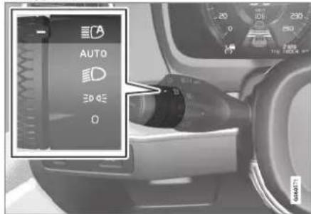
The symbol represents active main beam.
The function can start while driving in the dark when the car's speed is approx. 20 km/h (approx. 12 mph) or higher. The function can also take streetlights into account. When the camera sensor no longer detects any oncoming car or car in front, main beam is switched on again after about a second.
Activate active main beam
Active main beam is activated and deactivated by turning the left-hand stalk switch to position ECA . The rotating ring then returns to position AUTO. When active main beam is activated, the symbol ECA illuminates with a white glow in the driver display. When main beam is activated, the symbol shines blue.
If active main beam is deactivated while main beam is on, the lighting is immediately reset to dipped beam.
Active main beam does not need to be reactivated every time the car is started.
Adaptive functionality
For cars with LED ^3 headlamps ^* , active main beam has adaptive functionality ^4 . In this case, unlike what happens during conventional dimming, the light beam continues to illuminate with main beam on both sides of oncoming traffic or vehicles ahead – only the part of the light beam that points directly to the vehicle is dimmed.

natural_image
Top-down view of a road with two cars approaching each other, showing a light beam (no text or symbols)Adaptive functionality: Dipped beam directly towards oncoming vehicle, but continued main beam on both sides of the vehicle.
The main beam is partly dimmed, i.e. if the light beam shines with slightly more than dipped beam, the symbol in the driver display shines blue.
Limitations for active main beam
The camera sensor on which the function is based has limitations.
▶▶
LIGHTING
◀◀

If this symbol is shown in the driver display, together with the message Active High Beam Temporarily unavailable, then switching
between main and dipped beam must be performed manually. The Ⓔ symbol extinguishes when these message are shown.

The same applies if this symbol is shown together with the message Windscreen sensor Sensor blocked, see Owner's manual.
Active main beam may be temporarily unavailable e.g. in situations with dense fog or heavy rain. When active main beam becomes available again, or the windscreen sensors are no longer blocked, the message goes out and the
symbol illuminates.

WARNING
Active main beam is an aid for using the optimum beam pattern when conditions are favourable.
The driver always bears responsibility for manually switching between main and dipped beam when traffic situations or weather conditions so require.
Related information
• Lighting control (p. 150)
• Using main beam (p. 154)
- Limitations for camera and radar unit (p. 415)
Using direction indicators
The car's direction indicators are operated with the left-hand stalk switch. The direction indicator lamps flash three times or continuously, depending on how far up or down the stalk switch is moved.

Direction indicators.
Short flash sequence

Move the stalk switch up or down to the first position and release. The direction indicator lamps flash three times. If the function is deactivated via the centre display, the lamps will flash once.

NOTE
- This automatic flashing sequence can be stopped by moving the stalk switch immediately in the opposite direction.
- If the symbol for direction indicators in the driver display flashes more quickly than normal - see the message in the driver display.
Continuous flash sequence
2 Move the stalk switch up or down to its end position.
The stalk switch remains in its position and is moved back manually, or automatically by the steering wheel movement.
Related information
• Hazard warning flashers (p. 159)
- Adjusting light functions via the centre display (p. 151)
Active bending lights\*
Active bending lights are designed to provide additional illumination in bends and junctions. Cars with LED ^5 headlamps* can have active bending lights, depending on the car's equipment level.
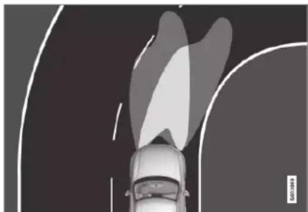
natural_image
Top-down view of a car with abstract curved shapes above it, no visible text or symbolsHeadlamp pattern with function deactivated (left) and activated (right) respectively.
Active bending lights follow steering wheel movements to provide additional illumination in bends and junctions and can thereby provide the driver with improved visibility.
The function is activated automatically when the car is started. In the event of a fault in the function, the 🔔 symbol illuminates in the driver display at the same time as the driver display shows an explanatory text.
The function is only active in weak daylight or darkness and only when the car is moving and dipped beam is switched on.
Deactivating/activating the function
The function is activated when the car is supplied from the factory and can be deactivated/activated via the centre display's function view.

Press the Active Bending Lights button.
Related information
- Adjusting light functions via the centre display (p. 151)
LIGHTING
Rear fog lamp
The rear fog lamp is considerably stronger than the normal rear lights and should only be used in reduced visibility due to fog, snow, smoke or dust so that other road users have an early warning of a vehicle ahead.

natural_image
Interior view of a car dashboard with a speaker icon and control buttons (no readable text or symbols)Button for rear fog lamp.
The rear fog lamp is a lamp at the rear of the car, on the driver's side.
The rear fog lamp can only be switched on when ignition position II is active and the rotating ring on the stalk switch is in position AUTO or .
Press the button to switch the lights on/off. The symbol in the driver display illuminates when the rear fog lamp is switched on.
The rear fog lamp switches off automatically when the car is switched off or when the
rotating ring on the stalk switch is set to the 0 or position.
NOTE
Regulations on the use of rear fog lamps vary from country to country.
Related information
• Lighting control (p. 150)
- Ignition positions (p. 448)
Brake lights
The brake light automatically comes on during braking.
The brake light is illuminated when the brake pedal is depressed and when the car is braked automatically by one of the driver support systems.
Related information
• Emergency brake lights (p. 159)
- Brake functions (p. 451)
• Driving support systems (p. 286)
Emergency brake lights
Emergency brake lights are activated to alert vehicles behind about heavy braking.
The function means that the brake light flashes instead of - as in normal braking - shining with a constant glow.
The emergency brake lights are activated during heavy braking or if the ABS system is activated at high speeds.
After the driver brakes to a low speed and then releases the brake, the brake light returns to normal glow.
The car's hazard warning flashers are activated at the same time. These flash until the driver accelerates the car to a higher speed again or switches off the car's hazard warning flashers.
Related information
- Brake lights (p. 158)
- Foot brake (p. 451)
• Hazard warning flashers (p. 159)
Hazard warning flashers
Hazard warning flashers warn other road users by means of all of the car's direction indicators being activated simultaneously. The function can be used to give a warning in the event of traffic hazards.

Button for hazard warning flashers.
Press the button to activate the hazard warning flashers.
The hazard warning flashers are automatically activated when the car brakes so powerfully that the emergency brake lights are activated and the speed is low. The hazard warning flashers start to flash after the emergency brake lights have stopped flashing and are then deactivated automatically when the car drives away again or are deactivated if the button is depressed.
NOTE
Regulations for the use of hazard warning flashers may vary between countries.
Related information
• Emergency brake lights (p. 159)
• Using direction indicators (p. 156)
LIGHTING
Using home safe lighting
Some of the exterior lighting can be kept switched on to work as home safe lighting after the car has been locked.
To activate the function:
- Switch off the car.
- Move the left-hand stalk switch forward toward the instrument panel and release.
- Get out of the car and lock the door.
A symbol in the driver display is illuminated to indicate that the function is activated and outer lighting is switched on: Position lamps, headlamp beams, number plate lighting and lighting in outer handles*.
The length of time that home safe lighting remains on can be set via the centre display.
Related information
- Adjusting light functions via the centre display (p. 151)
• Approach light duration (p. 160)
Approach light duration
Approach lighting is switched on when the car is unlocked and is used to switch on the car's lighting at a distance.
The function is activated when the remote control key is used for unlocking. In daylight, position lamps, interior roof lamps, floor lights and cargo area lighting are activated. In weak daylight or darkness, number plate lighting and lighting in the outer handles are also activated* with their light source aimed towards the ground.
The lighting stays on for approx. 2 minutes if no doors are opened. If a door is opened within the activation time, the time for the interior lighting and lighting in the outer handles* will be extended.
The function can be activated and deactivated via the centre display.
Related information
- Adjusting light functions via the centre display (p. 151)
• Using home safe lighting (p. 160)
• Remote control key (p. 240)
Interior lighting
The passenger compartment is equipped with several types of lighting, e.g. general interior lighting, adjustable decor illumination and reading lighting.
All lighting in the passenger compartment can be switched on and off manually at least 5 minutes from when:
- the car has been switched off and its electrical system is in ignition position 0
- the car has been unlocked but it has not yet been started.
Front roof lighting

Controls in roof console for the front reading lamps and passenger compartment lighting.
1 Reading lamp, left-hand side
② Passenger compartment lighting
3 Auto function for passenger compartment lighting
4 Reading lamp, right-hand side
Reading lighting
The reading lamps on the right and left-hand sides can be turned on and off by briefly pressing the buttons in the roof console. Brightness is adjusted by holding the button pressed in.
Passenger compartment lighting
The floor lighting and interior roof lighting are switched on or off with a short press on the button in the roof console.
Auto function for passenger compartment lighting
The automatic function is activated by a short press on the AUTO button in the roof console. With the automatic system activated, the light indicator in the button illuminates and the passenger compartment lighting is switched on and off according to the following.
The passenger compartment lighting comes on when:
• The car is unlocked
• The car is switched off
• A side door is opened.
The passenger compartment lighting goes off when:
• The car is locked
• The car is started
• A side door is closed
- A side door has remained open for approx. 2 minutes.
Rear roof lighting
The rear area of the car has reading lighting, which is also used as passenger compartment lighting.

natural_image
Top-down view of a car dashboard with two buttons and a central screen (no text or symbols visible)Reading lamps above the rear seat.
The reading lamps are switched on or off by briefly pressing the button on the lamp. Brightness is adjusted by holding the button pressed in.
Glovebox lighting
Glovebox lighting is switched on and off respectively when the lid is opened or closed.
Sun visor mirror lighting\*
The lighting for the mirror in the sun visor is switched on and off respectively when the cover is opened or closed.
Ground lighting\*
The ground lighting is switched on or off when the corresponding door is opened or closed.
Door sill lighting
The door sill lighting is switched on or off when a door is opened or closed.
Lighting in cargo area
The lighting in the cargo area is switched on or off when the boot lid is opened or closed.
Decor lighting
The ambient light is switched on when you open the doors and is switched off when the car is locked. The intensity of the decor lighting can be adapted in the centre display and also precisely adjusted using the thumbwheel in the instrument panel.
Ambience lights\*
The car is equipped with LEDs that make it possible to change the colour of the light. These lights are switched on when the car is running. The ambience light can be adapted in
▶▶
LIGHTING
the centre display and also precisely adjusted using the thumbwheel in the instrument panel.
Lighting in storage compartments in doors
The lighting in the storage compartments in the doors is switched on when you open the doors and is switched off when the car is locked. The brightness can be precisely adjusted using the thumbwheel in the instrument panel.
Lighting in the tunnel console's front cup holder
The lighting in the front cup holders is switched on when the car is unlocked and is switched off when the car is locked. The brightness can be precisely adjusted using the thumbwheel in the instrument panel.
Related information
• Adjusting interior lighting (p. 162)
• Lighting control (p. 150)
- Ignition positions (p. 448)
• Passenger compartment interior (p. 590)
Adjusting interior lighting
The lamps inside the car come on differently depending on the ignition position used. The interior lighting can be adjusted with a thumbwheel in the instrument panel, and certain light functions can also be adjusted via the centre display.
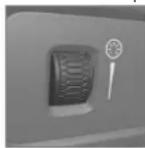
The thumbwheel on the instrument panel, to the left of the steering wheel, is used to adjust the brightness of the display lighting, controls lighting, ambient decor illumination and ambience light*.
Adjusting ambient decor illumination
- Press Settings in the top view in the centre display.
- Press My Car Lights and Lighting → Interior Lighting.
- Choose between the following settings:
• Under Ambient Light Intensity, select from Off, Low and High.
• Under Ambient Light Level, select from Reduced and Full.
Adjusting ambience light\*
The car is equipped with a number of LEDs that make it possible to change the colour of the light. These lights are switched on when the car is running.
Changing the brightness of the lights
- Press Settings in the top view in the centre display.
- Press My Car Lights and Lighting Interior Lighting Interior Mood Lighting.
- Under Interior Mood Light Intensity, select from Off, Low and High.
Changing the colour of the light
- Press Settings in the top view in the centre display.
- Press My Car Lights and Lighting → Interior Lighting Interior Mood Lighting.
- Choose between By Temperature and By Colour in order to change the colour of the light.
With the By Temperature option, the light changes according to the set passenger compartment temperature.
With the By Colour option, the Theme Colours subcategory can be used to adjust further.
LIGHTING
Related information
• Interior lighting (p. 160)
- Adjusting light functions via the centre display (p. 151)
- Ignition positions (p. 448)

bar
| Category | Value | |---|---| | Category 1 | 100 | | Category 2 | 100 | | Category 3 | 100 | | Category 4 | 100 | | Category 5 | 100 | | Category 6 | 100 | | Category 7 | 100 | | Category 8 | 100 | | Category 9 | 100 | | Category 10 | 100 | | Category 11 | 100 | | Category 12 | 100 | | Category 13 | 100 | | Category 14 | 100 | | Category 15 | 100 | | Category 16 | 100 | | Category 17 | 100 | | Category 18 | 100 | | Category 19 | 100 | | Category 20 | 100 | | Category 21 | 100 | | Category 22 | 100 | | Category 23 | 100 | | Category 24 | 100 | | Category 25 | 100 | | Category 26 | 100 | | Category 27 | 100 | | Category 28 | 100 | | Category 29 | 100 | | Category 30 | 100 | | Category 31 | 100 | | Category 32 | 100 | | Category 33 | 100 | | Category 34 | 100 | | Category 35 | 100 | | Category 36 | 100 | | Category 37 | 100 | | Category 38 | 100 | | Category 39 | 100 | | Category 40 | 100 | | Category 41 | 100 | | Category 42 | 100 | | Category 43 | 100 | | Category 44 | 100 | | Category 45 | 100 | | Category 46 | 100 | | Category 47 | 100 | | Category 48 | 100 | | Category 49 | 100 | | Category 50 | 100 | | Category 51 | 100 | | Category 52 | 100 | | Category 53 | 100 | | Category 54 | 100 | | Category 55 | 100 | | Category 56 | 100 | | Category 57 | 100 | | Category 58 | 100 | | Category 59 | 100 | | Category 60 | 100 | | Category 61 | 100 | | Category 62 | 100 | | Category 63 | 100 | | Category 64 | 100 | | Category 65 | 100 | | Category 66 | 100 | | Category 67 | 100 | | Category 68 | 100 | | Category 69 | 100 | | Category 70 | 100 | | Category 71 | 100 | | Category 72 | 100 | | Category 73 | 100 | | Category 74 | 100 | | Category 75 | 100 | | Category 76 | 100 | | Category 77 | 100 | | Category 78 | 100 | | Category 79 | 100 | | Category 80 | 100 | | Category 81 | 100 | | Category 82 | 100 | | Category 83 | 100 | | Category 84 | 100 | | Category 85 | 100 | | Category 86 | 100 | | Category 87 | 100 | | Category 88 | 100 | | Category 89 | 100 | | Category 90 | 100 | | Category 91 | 100 | | Category 92 | 100 | | Category 93 | 100 | | Category 94 | 100 | | Category 95 | 100 | | Category 96 | 100 | | Category 97 | 100 | | Category 98 | 100 | | Category 99 | 100 | | Total (Total) |WINDOWS, GLASS AND MIRRORS
WINDOWS, GLASS AND MIRRORS
Windows, glass and mirrors
The car contains several different windows, glass panes and mirrors. Some of the windows in the car are laminated.
The windscreen has laminated glass, and laminated glass is available as an option for certain other glass areas. Laminated glass is reinforced, which provides better protection against break-ins and improved sound insulation in the passenger compartment.

The symbol is shown on the windows where the glass is laminated. ^1
Related information
- Pinch protection for windows and sun blinds (p. 166)
-
Sunroof* (p. 174)
• Power windows (p. 168)
• Rearview and door mirrors (p. 171)
• Using the sun blind* (p. 170)
• Head-up display* (p. 140)
• Using windscreen wipers (p. 177)
• Using windscreen and headlamp washers (p. 180) -
Activating and deactivating the heated windscreen* (p. 217)
- Activating and deactivating the heated rear window and door mirrors (p. 218)
Pinch protection for windows and sun blinds
All power windows and sun blinds* have pinch protection which is deployed if they are blocked by any object while opening or closing.
In the event of blocking, the movement stops and then reverses automatically to approx. 50 mm (approx. 2 inches) from the blocked position (or to full ventilation position).
It is possible to force pinch protection when closing has been cancelled, e.g. when ice is formed, by continuing to press the control in one and the same direction.
If any fault arises with the pinch protection, a reset sequence can be tested.

WARNING
If the starter battery is disconnected, the automatic opening and closing function must be reset to work properly. A reset must take place for pinch protection to work.
Related information
- Reset sequence for pinch protection (p. 167)
• Operating power windows (p. 168)
WINDOWS, GLASS AND MIRRORS
• Using the sun blind* (p. 170)
• Operating the sunroof* (p. 175)
Reset sequence for pinch protection
If a problem occurs with the electrical functions for the electric windows, a reset sequence can be tested.
Electrically-operated sun blinds* have a reset sequence that can be tested if necessary.

WARNING
If the starter battery is disconnected, the automatic opening and closing function must be reset to work properly. A reset must take place for pinch protection to work.
In the event of problems with the sunroof, contact a workshop. ^2
Reset the power window
- Start with the window in closed position.
- Then operate the controls in the manual position 3 times upwards to closed position.
The system is initialised automatically.
If problems persist, contact a workshop.
Reset sun blind\*
-
Start with the sun blind retracted.
-
Press the control against retracting mode for approx. 15 seconds.
The system is initialised automatically.
Related information
- Pinch protection for windows and sun blinds (p. 166)
• Operating power windows (p. 168)
• Using the sun blind* (p. 170)
WINDOWS, GLASS AND MIRRORS
Power windows
Each door has a control panel for the electrically-driven power windows. The driver's door has controls for operating all windows and also to activate the child safety locks.
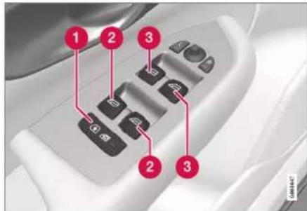
Driver's door control panel.
Electric child safety locks* that deactivate the controls in the rear doors to prevent doors or windows from being opened from the inside.
② Controls for rear windows.
3 Controls for front windows.
WARNING
Children, other passengers or objects may be trapped by the moving parts.
• Always operate the windows with caution.
- Do not allow children to play with the controls.
• Never leave children alone in the car.
- Remember to always switch off the power supply to the power windows by setting the car's electrical system in ignition position 0, and then take the key with you when leaving the car.
- Never put an object or part of the body through the windows, even if the car's electrical system is fully disconnected.
Related information
• Operating power windows (p. 168)
- Pinch protection for windows and sun blinds (p. 166)
- Reset sequence for pinch protection (p. 167)
Operating power windows
Using the driver's door control panel, all power windows can be operated - using the control panels in the other doors operates the power window in the individual door.
The power windows are equipped with pinch protection. If any fault arises with the pinch protection, a reset sequence can be tested.
WARNING
Children, other passengers or objects may be trapped by the moving parts.
- Always operate the windows with caution.
- Do not allow children to play with the controls.
• Never leave children alone in the car. - Remember to always switch off the power supply to the power windows by setting the car's electrical system in ignition position 0, and then take the key with you when leaving the car.
- Never put an object or part of the body through the windows, even if the car's electrical system is fully disconnected.

natural_image
Close-up of a car interior control panel with buttons and a red downward arrow overlay (no text or symbols)Operating the power windows.
Operating without auto. Move one of the controls gently up or down. The power windows move up or down as long as the control is held in position.
Operating with auto. Move one of the controls up or down to the end position and release it. The window runs automatically to its end position.
In order for the power windows to be used, the ignition position must be I or II. The power windows can be operated for a few minutes after the car has been switched off and after the ignition has been switched off - although not after a door has been opened. It is only possible to operate one control at a time.
It can also be operated using a remote control key or keyless opening* with the door handle.
WARNING
Check that children or other passengers are not at risk of crushing when all the windows are closed with a remote control key or keyless opening* with a door handle.
NOTE
One way to reduce the pulsating wind noise when the rear windows are open is to also open the front windows slightly.
NOTE
The windows cannot be opened at speeds above approx. 180 km/h (approx. 112 mph), but they can be closed.
The driver always bears responsibility for following traffic regulations in force.
NOTE
It may not be possible to operate windows at low temperatures.
Related information
• Power windows (p. 168)
- Pinch protection for windows and sun blinds (p. 166)
- Reset sequence for pinch protection (p. 167)
• Keyless locking and unlocking* (p. 270)
- Locking and unlocking with the remote control key (p. 242)
WINDOWS, GLASS AND MIRRORS
Using the sun blind\*
The sun blinds are built into each of the rear doors, and there is a sun blind built into the rear parcel shelf.
Rear door – manually operated

natural_image
Close-up of a car's front panel showing the lid and side door, with no visible text or symbols.The figure is schematic - the version may vary.
1 Hook with associated catch
- Pull up the sun blind and attach it to the hook in the upper door frame.
The window can still be opened and closed with the sun blind up.
Rear window parcel shelf

natural_image
Interior view of a white car with rear seats and side seats, showing a red arrow pointing to the dashboard (no text or symbols visible)There is an electrically operated sun blind built on the rear window shelf.
In order that the sun blind can be operated, the car's electrical system must be in ignition position II.
NOTE
It may not be possible to operate the sun blind in low temperatures.
Operating via the centre display
Give a short tap on the Rear Sun Curtain button in the function view in the centre display - the sun blind is operated automatically to its end position, up or down.
Related information
- Pinch protection for windows and sun blinds (p. 166)
- Reset sequence for pinch protection (p. 167)
• Power windows (p. 168)
WINDOWS, GLASS AND MIRRORS
Rearview and door mirrors
The rearview mirrors and door mirrors can be used to give the driver better visibility to the rear.
Interior rearview mirror
The interior rearview mirror is equipped with HomeLink*, automatic dimming* and compass*.
The interior rearview mirror is adjusted by angling it manually.
Door mirrors

WARNING
Both mirrors are bent to provide optimal vision. Objects may appear to be further away than they actually are.
The door mirror positions are adjusted with the joystick in the driver's door control panel.
There are also a number of automatic settings that can be linked to the memory function buttons for the power seat*.
Related information
- HomeLink®* (p. 500)
- Compass* (p. 504)
- Adjusting rearview mirror dimming (p. 171)
• Angling adjustment of the door mirrors (p. 172)
- Storing position for seat, door mirrors and head-up display* (p. 184)
- Activating and deactivating the heated rear window and door mirrors (p. 218)
Adjusting rearview mirror dimming
Bright light from behind could be reflected in the rearview mirrors and dazzle the driver. Use dimming when disturbed by light from behind.
Manual dimming
The interior rearview mirror can be dimmed with a control in the mirror's lower edge.

natural_image
Diagram of a car side mirror with red directional arrows indicating rotation (no text or symbols)1 Control for manual dimming.
- Use dimming by moving the control in towards the passenger compartment.
- Return to normal mode by moving the control towards the windscreen.
The control for manual dimming is not available on mirrors with automatic dimming.
▶▶
WINDOWS, GLASS AND MIRRORS
Automatic dimming\*
If bright light comes from behind, the rearview mirrors automatically dim when it is dark outside or when the light is limited, for example when driving in tunnels. Automatic dimming is always active while driving, apart from when gearbox reverse position is selected.

NOTE
When sensitivity is changed there is no immediately noticeable change in dimming, but the change takes place gradually.
Dimming sensitivity will affect both the interior rearview mirror and the door mirrors.
To change dimming sensitivity:
-
Press Settings in the top view in the centre display.
-
Press My Car Mirrors and Convenience.
-
Under Rearview Mirror Auto Dimming, select Normal, Dark or Light.
The interior rearview mirror contains two sensors - one forward facing and one rearward facing - that work together to identify and eliminate dazzling light. The forward facing sensor detects ambient light, while the rear-
ward facing sensor detects the light from vehicle headlights behind.
For the door mirrors to be equipped with automatic dimming, the interior rearview mirror must also be equipped with automatic dimming.
NOTE
If the sensors are obscured by e.g. parking permits, transponders, sun visors or objects in the seats or on the parcel shelf in such a way that light is prevented from reaching the sensors, then the dimming function of the interior rearview and door mirrors is reduced.
Related information
• Rearview and door mirrors (p. 171)
• Angling adjustment of the door mirrors (p. 172)
Angling adjustment of the door mirrors
To ensure better visibility to the rear, the door mirrors need to be set to the preferences of the driver.
There are a number of automatic settings that can also be linked to the memory function buttons for the power seat*.
Using controls for door mirrors

natural_image
Close-up of a car interior control panel with buttons and directional arrows (no text or symbols visible)Controls for door mirrors.
The door mirror positions are adjusted with the joystick in the driver's door control panel. Ignition position must be at least 1.
-
Press the L button for the left-hand door mirror or the R button for the right-hand door mirror. The light in the button illuminates.
-
Adjust the position with the joystick in the centre.
- Press the L or R button again. The light should no longer be illuminated.
Folding in rearview mirrors electrically\*
The mirrors can be retracted for parking/driving in narrow spaces.
- Depress the L and R buttons simultaneously.
- Release them after approximately 1 second. The mirrors automatically stop in the fully retracted position.
Fold out the mirrors by pressing down the L and R buttons simultaneously. The mirrors automatically stop in the extended position with the previous setting.
Resetting to neutral
Mirrors that have been moved out of position by an external force must be reset electrically to their original position for electric retracting/extending* to work correctly.
- Fold in the door mirrors by pressing down the L and R buttons simultaneously.
-
Fold them out again by pressing the L and R buttons simultaneously.
-
Repeat the above procedure as necessary. The mirrors are returned to the original position.
Angling during parking ^3
A door mirror can be angled down for the driver to view the side of the road when parking, for example.
- Engage reverse gear and press the L or R button.
Note that the button may need to be pressed twice, depending on whether it was already preselected. The button flashes when the door mirror is angled down. When reverse gear is disengaged, the door mirror automatically starts to return after approx. 3 seconds and then reaches its original position after approx. 8 seconds.
Automatic angling during parking ^3
With this setting, the door mirror is automatically angled down when reverse gear is selected. The folded position is preset and cannot be adjusted.
- Tap on Settings in the centre display's top view.
-
Press My Car Mirrors and Convenience.
-
Under Exterior Mirror Tilt at Reverse, select Off, Driver, Passenger or Both to activate/deactivate and to select which review mirror should be angled.
You can make the door mirror return to its original position by pressing the L or R button twice.
Automatic retraction when locking\*
In the centre display, you can set all the rearview and door mirrors to retract/extend automatically when the car is locked/unlocked using the key.
- Tap on Settings in the centre display's top view.
- Press My Car Mirrors and Convenience.
- Select Fold Mirror When Locked to activate/deactivate.
NOTE
If you manually fold the mirrors with the L and R buttons and then lock the car, they will not fold out automatically when you unlock the car, even if this setting has been made. They must be manually folded out.
WINDOWS, GLASS AND MIRRORS
Related information
• Rearview and door mirrors (p. 171)
• Adjusting rearview mirror dimming (p. 171)
- Storing position for seat, door mirrors and head-up display* (p. 184)
- Activating and deactivating the heated rear window and door mirrors (p. 218)
Sunroof\*
The sunroof can be opened vertically at the rear edge (ventilation position) or horizontally (open position).
The sunroof has a wind deflector. There is also an inner sunscreen that is closed manually.

natural_image
Top-down view of a car interior showing the intake manifold and red arrow indicator (no text or symbols)The sunroof is operated with a control located in the roof. The control is activated when the car's electrical system is in ignition position I or II.
WARNING
Children, other passengers or objects may be trapped by the moving parts.
• Always operate the windows with caution.
- Do not allow children to play with the controls.
• Never leave children alone in the car.
- Remember to always switch off the power supply to the power windows by setting the car's electrical system in ignition position 0, and then take the key with you when leaving the car.
- Never put an object or part of the body through the windows, even if the car's electrical system is fully disconnected.
IMPORTANT
- Do not open the sunroof when load carriers are fitted.
- Do not place any heavy objects on the sunroof.
IMPORTANT
- Remove ice and snow before opening the sunroof. Take care not to scratch surfaces or damage strips.
- Do not operate the sunroof if it has frozen closed.
Wind deflector
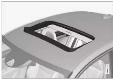
natural_image
Top-down view of a car's front dashboard and vent slots (no text or symbols visible)The sunroof has a wind deflector that is folded up when the sunroof is in the open position.
Related information
• Operating the sunroof* (p. 175)
- Pinch protection for windows and sun blinds (p. 166)
• Keyless locking and unlocking* (p. 270)
- Locking and unlocking with the remote control key (p. 242)
Operating the sunroof\*
When operating with the control that is fitted in the roof, the sunroof is first opened horizontally to a comfort position.
In ventilation position, the sunroof is raised at the rear edge.
WARNING
Children, other passengers or objects may be trapped by the moving parts.
- Always operate the windows with caution.
- Do not allow children to play with the controls.
• Never leave children alone in the car. - Remember to always switch off the power supply to the power windows by setting the car's electrical system in ignition position 0, and then take the key with you when leaving the car.
- Never put an object or part of the body through the windows, even if the car's electrical system is fully disconnected.
IMPORTANT
- Do not open the sunroof when load carriers are fitted.
- Do not place any heavy objects on the sunroof.
IMPORTANT
- Remove ice and snow before opening the sunroof. Take care not to scratch surfaces or damage strips.
- Do not operate the sunroof if it has frozen closed.

natural_image
Medical device with a close-up inset showing a small black object labeled '14' and '12', no visible text or symbols on the device itself.Opening, manual
2 Opening, automatic
▶▶
WINDOWS, GLASS AND MIRRORS
◀◀
3 Closing, manual
4 Closing, automatic
The movement of the sunroof is stopped if the control is released during manual operation, or when the sunroof reaches the comfort position or the maximum opening or closing position. The movement is also stopped if the control is operated again while the movement is in progress.
In order that the sunroof can be operated, the car's electrical system must be in ignition position I or II.
It can also be operated using a remote control key or keyless opening* with the door handle.

WARNING
Check that children or other passengers are not at risk of crushing when all the windows are closed with a remote control key or keyless opening* with a door handle.
IMPORTANT
Check that the sunroof is properly closed when closing.
Manual operation
- To open the sunroof, press the control rearward to the position for manual opening. The sunroof first reaches comfort position. ^4 In order to open to maximum opening position – press the control backwards a second time.
Close the sunroof by repeating the preceding procedure in reverse order - press the control forward/downward to the manual closing position instead.
Automatic operation
- To open the sunroof, press the control backwards to the position for automatic opening and release. The sunroof first reaches comfort position. ^4 To open to the maximum opening position – press the control a second time backward to the position for automatic opening and release.
Close the sunroof by repeating the preceding procedure in reverse order - press the control forward/downward to the automatic closing position instead.
The sunroof does not stop at comfort position during closing.

NOTE
It may not be possible to operate windows at low temperatures.
Ventilation position

natural_image
Medical scanner device with a close-up inset showing a black button labeled '2' and red arrows pointing to the button (no readable text or symbols)Ventilation position, vertically at the rear edge.
Open by pressing the control upward.
Close by pressing the control forward/ downward.
When ventilation position is selected, the sun-roof is raised at the rear edge.
Sunscreen
The sunroof features a manual, sliding interior sunscreen. The sunscreen slides back automatically when the sunroof is opened. Grip the
handle and slide the sunscreen forward to close it.
Related information
- Sunroof* (p. 174)
- Pinch protection for windows and sun blinds (p. 166)
• Keyless locking and unlocking* (p. 270) - Locking and unlocking with the remote control key (p. 242)
Wiper blades and washer fluid
Together with the washer fluid, the wipers aim to improve visibility as well as headlamp pattern.
The washer nozzles are heated* automatically in cold weather to prevent the washer fluid from freezing.
Information indicating that the washer fluid needs topping up appears in the driver display when there is approx. 1 litre (1 qt) of washer fluid remaining.
Related information
• Using the rain sensor (p. 178)
• Using windscreen and headlamp washers (p. 180)
- Activating and deactivating the rain sensor's memory function (p. 179)
• Filling washer fluid (p. 655)
- Set the wiper blades in service position (p. 654)
• Replacing windscreen wiper blades (p. 653)
• Using windscreen wipers (p. 177)
Using windscreen wipers
The windscreen wipers are designed to clean the windscreen. Different settings for the windscreen wipers are set using the right-hand stalk switch.

Right-hand stalk switch.
The thumbwheel is used to set rain sensor sensitivity and wiper swipe frequency.
Single sweep
Lower the stalk switch and release to make one sweep.
Windscreen wipers off
0 Move the stalk switch to position 0 to switch off the windscreen wipers.
▶▶
WINDOWS, GLASS AND MIRRORS
Intermittent wiping
INT Move the lever up to switch the wipers to intermittent wiping. Set the number of sweeps per time unit with the thumbwheel when intermittent wiping is selected.
Continuous wiping

Raise the stalk switch for the wipers to sweep at normal speed.

Raise the stalk switch further for the wipers to sweep at high speed.
IMPORTANT
Before activating the wipers - ensure that the wiper blades are not frozen in, and that any snow or ice on the windscreen is scraped away.
IMPORTANT
Use plenty of washer fluid when the wipers are cleaning the windscreen. The windscreen must be wet when the windscreen wipers are operating.
Related information
• Using the rain sensor (p. 178)
• Using windscreen and headlamp washers (p. 180)
• Wiper blades and washer fluid (p. 177)
- Activating and deactivating the rain sensor's memory function (p. 179)
• Filling washer fluid (p. 655) - Set the wiper blades in service position (p. 654)
- Replacing windscreen wiper blades (p. 653)
Using the rain sensor
The rain sensor automatically starts the wind-screen wipers based on how much water it detects on the windscreen. Rain sensor sensitivity can be adjusted with the thumbwheel on the right-hand stalk switch.
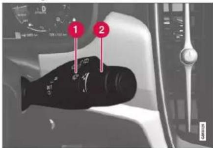
Right-hand stalk switch.
1 Rain sensor button
② Thumbwheel sensitivity/frequency
When the rain sensor is activated, the rain sensor symbol 📋 is shown in the driver display.
Activating the rain sensor
When activating the rain sensor, the car must be running or in ignition position I or II while the windscreen wiper stalk switch is in position 0 or in the position for a single sweep.
Activate the rain sensor by pressing the rain sensor button 🔒.
Move the lever down to make the wipers move.
Turn the thumbwheel upward for higher sensitivity and downward for lower sensitivity. An extra sweep is made when the thumbwheel is turned upward.
Deactivating the rain sensor
Deactivate the rain sensor by pressing the rain sensor button 📋 or moving the stalk switch up to another wiper program.
The rain sensor is deactivated automatically in ignition position 0 or when the engine is switched off.
The rain sensor is deactivated automatically when wiper blades are set in service position. The rain sensor is reactivated when service mode has been deactivated.
IMPORTANT
The windscreen wipers could start and be damaged in an automatic car wash. Deactivate the rain sensor while the car is running or when the car's electrical system is in ignition position I or II. The symbol in the driver display extinguishes.
Related information
• Using windscreen and headlamp washers (p. 180)
• Wiper blades and washer fluid (p. 177)
- Activating and deactivating the rain sensor's memory function (p. 179)
• Filling washer fluid (p. 655)
- Set the wiper blades in service position (p. 654)
• Replacing windscreen wiper blades (p. 653)
• Using windscreen wipers (p. 177)
Activating and deactivating the rain sensor's memory function
The rain sensor automatically starts the wind-screen wipers based on how much water it detects on the windscreen.
When the memory function is activated, the rain sensor button does not need to be pressed every time the vehicle is started:
-
Tap on Settings in the centre display's top view.
-
Press My Car Wipers.
-
Select Rain Sensor Memory to activate/deactivate the memory function.
Related information
• Using the rain sensor (p. 178)
• Using windscreen and headlamp washers (p. 180)
• Wiper blades and washer fluid (p. 177)
• Filling washer fluid (p. 655)
- Set the wiper blades in service position (p. 654)
- Replacing windscreen wiper blades (p. 653)
• Using windscreen wipers (p. 177)
WINDOWS, GLASS AND MIRRORS
Using windscreen and headlamp washers
Windscreen and headlamp washers are designed to clean the windscreen and headlamps. Windscreen and headlamp washers are started using the right-hand stalk switch.
Starting windscreen and headlamp washers

natural_image
Interior view of a car dashboard with a black fish-shaped object and a red arrow pointing to it (no visible text or symbols)Washing function, right-hand stalk switch.
- Move the right-hand stalk switch toward the steering wheel to start the windscreen and headlamp washers.
The windscreen wipers will make several more sweeps once the stalk switch has been released.
IMPORTANT
Avoid activating the washer system when it is frozen or the washer reservoir is empty, otherwise there is a risk of damaging the pump.
Headlamp washing\*
To save fluid, the headlamps are washed automatically at a defined interval when the headlamps are switched on.
Reduced washing
If only approx. 1 litre (1 qt) of washer fluid remains in the reservoir and the message Washer fluid Level low, refill, together with
the symbol, is shown in the driver display, then the supply of washer fluid to the headlamps is switched off. This is to prioritise cleaning the windscreen and the visibility through it. The headlamps are only washed if main or dipped beam is switched on.
Related information
• Using the rain sensor (p. 178)
• Wiper blades and washer fluid (p. 177)
- Activating and deactivating the rain sensor's memory function (p. 179)
• Filling washer fluid (p. 655)
- Set the wiper blades in service position (p. 654)
• Replacing windscreen wiper blades (p. 653)
• Using windscreen wipers (p. 177)
SEATS AND STEERING WHEEL
SEATS AND STEERING WHEEL
Manual front seat
The car's front seats have a range of setting options in order to enhance comfort.

1 Raise/lower the front edge of the seat cushion* by pumping up/down. ^1
2 Change the length* of the seat cushion by pulling the lever up and moving the seat cushion forward/backward by hand.
3 Adjust the seat forward/backward by lifting the handle and adjusting the distance to the steering wheel and pedals. Check that the seat is locked after the position has been adjusted.
4 Change the lumbar support* by pressing the button upward/downward/forward/back. ^2
5 Raise/lower the seat by means of adjusting the control up/down.
6 Change the backrest inclination by turning the control knob.
WARNING
Adjust the position of the driver's seat before setting off, never while driving. Make sure that the seat is in locked position in order to avoid personal injury in the event of heavy braking or an accident.
Related information
• Power* front seat (p. 183)
- Adjusting the power* front seat (p. 183)
- Storing position for seat, door mirrors and head-up display* (p. 184)
• Using a stored position for seat, door mirrors and head-up display* (p. 185)
- Adjusting massage settings* in the front seat (p. 187)
- Adjusting* the length of the seat cushion in the front seat (p. 188)
- Massage settings* in the front seat (p. 186)
- Adjusting the side support* in the front seat (p. 189)
- Adjusting the lumbar support* in the front seat (p. 190)
- Adjusting the passenger seat from the driver's seat* (p. 191)
Power\* front seat
The car's front seats have a range of setting options in order to enhance comfort. The power seat can be moved forwards/backwards and upwards/downwards. The front edge of the seat cushion can be raised/lowered as well as adjusted in length* and the backrest inclination can be changed. The lumbar support* can be adjusted upward/downward/forward/backward. ^3
Seat setup can take place when the engine is running and within a certain time after unlocking the door without the engine running. Adjustment can also be performed within a certain time after the engine has been switched off.
IMPORTANT
The power seats have overload protection that is triggered if any seat is blocked by an object. If this happens, remove the object and then move the seat again.
Related information
• Manual front seat (p. 182)
- Adjusting the power* front seat (p. 183)
- Storing position for seat, door mirrors and head-up display* (p. 184)
• Using a stored position for seat, door mirrors and head-up display* (p. 185)
- Adjusting massage settings* in the front seat (p. 187)
- Adjusting* the length of the seat cushion in the front seat (p. 188)
- Massage settings* in the front seat (p. 186)
- Adjusting the side support* in the front seat (p. 189)
- Adjusting the lumbar support* in the front seat (p. 190)
- Adjusting the passenger seat from the driver's seat* (p. 191)
Adjusting the power\* front seat
Set the preferred seat position using the control on the front seat's seating section. To set the various comfort functions, turn the multifunction control ^4 up/down.
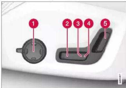
The Illustration shows the controls from a car with four-way lumbar support*. Cars with two-way lumbar support* do not have the rotatable multifunction control.
In cars with four-way lumbar support*, turn the multifunction control ^1 up/down to set the different comfort functions. In cars with two-way lumbar support*, use the round button to adjust the lumbar support forward/backward.
2 Raise/lower the seat cushion front edge by adjusting the control up/down.
SEATS AND STEERING WHEEL
3 Raise/lower the seat by means of adjusting the control up/down.
4 Move the seat forward/backward by adjusting the control forward/backward.
⑤ Change the backrest inclination by adjusting the control forward/backward.
Only one movement (forward/back/up/down) can be made at a time.
The backrests of the front seats cannot be lowered fully forward.
Related information
• Manual front seat (p. 182)
• Power* front seat (p. 183)
- Storing position for seat, door mirrors and head-up display* (p. 184)
- Using a stored position for seat, door mirrors and head-up display* (p. 185)
- Adjusting massage settings* in the front seat (p. 187)
- Adjusting* the length of the seat cushion in the front seat (p. 188)
- Massage settings* in the front seat (p. 186)
- Adjusting the side support* in the front seat (p. 189)
- Adjusting the lumbar support* in the front seat (p. 190)
- Adjusting the passenger seat from the driver's seat* (p. 191)
Storing position for seat, door mirrors and head-up display\*
You can store the position for power* seat, door mirrors and head-up display* in the memory buttons.
Store two different positions for the power* seat, the door mirrors and the head-up display* using the memory buttons. The buttons are located on the inside of one of the front doors or both*.

1 Button M for storing settings.
② Memory button.
③ Memory button.
Storing a position
-
Adjust seat, door mirrors and head-up display to the desired position.
-
Press and hold the M button depressed. The light indicator in the button illuminates.
- Within three seconds, press and hold the 1 or 2 button.
When the position has been stored in the selected memory button, an acoustic signal can be heard and the light indicator in the M button extinguishes.
If none of the memory buttons is depressed within three seconds then the M button extinguishes and no storing takes place.
The seat, the door mirrors or the head-up-display must be readjusted before a new memory can be set.

NOTE
All driver profiles need to be set in Protect Profile mode in order for the stored positions to work.
Related information
• Manual front seat (p. 182)
• Power* front seat (p. 183)
- Adjusting the power* front seat (p. 183)
- Using a stored position for seat, door mirrors and head-up display* (p. 185)
- Adjusting massage settings* in the front seat (p. 187)
- Adjusting* the length of the seat cushion in the front seat (p. 188)
- Massage settings* in the front seat (p. 186)
- Adjusting the side support* in the front seat (p. 189)
- Adjusting the lumbar support* in the front seat (p. 190)
- Adjusting the passenger seat from the driver's seat* (p. 191)
• Angling adjustment of the door mirrors (p. 172) - Settings for head-up display* (p. 142)
• Protect driver profile (p. 136)
Using a stored position for seat, door mirrors and head-up display\*
If the positions for the power* seat, the door mirrors and the head-up display* have been stored, they can be activated by using the memory buttons.
Using a stored setting

A stored setting can be used with the front door either open or closed:
Open front door
- Depress one of the memory buttons 1 (2) or 2 (3) with a short press. Power seat, door mirrors and head-up display move and then stop at the positions stored in the selected memory button.
▶▶
SEATS AND STEERING WHEEL
◀ Closed front door
- Hold one of the memory buttons 1 (2) r 2 (3) depressed until seat, door mirrors and head-up display stop in the positions that are stored in the selected memory button.
If the memory button is released, the movement of the seat, door mirrors and head-up display will be stopped.

WARNING
- Because the driver's seat can be adjusted with the ignition off, children should never be left unattended in the vehicle.
- Movement of the seat can be STOPPED at any time by pressing any button on the power seat control panel.
- Do not adjust the seat while driving.
• Make sure there is nothing under the seats when they are being adjusted.

NOTE
All driver profiles need to be set in Protect Profile mode in order for the stored positions to work.
Related information
• Manual front seat (p. 182)
• Power* front seat (p. 183)
• Adjusting the power* front seat (p. 183)
- Storing position for seat, door mirrors and head-up display* (p. 184)
- Adjusting massage settings* in the front seat (p. 187)
- Adjusting* the length of the seat cushion in the front seat (p. 188)
- Massage settings* in the front seat (p. 186)
- Adjusting the side support* in the front seat (p. 189)
- Adjusting the lumbar support* in the front seat (p. 190)
- Adjusting the passenger seat from the driver's seat* (p. 191)
• Angling adjustment of the door mirrors (p. 172)
- Settings for head-up display* (p. 142)
Massage settings\* in the front seat
Both the multi-function control on the side of the seat and the centre display can be used in order to change the settings. The range of settings is shown in the centre display.

natural_image
Close-up of a black circular mechanical component with a handle, shown against a plain background (no text or symbols visible)Multi-function control, located on the side of the seat's seating section.
Settings for massage
The following setting options are available for massage:
- On/Off: Select On/Off in order to switch on/off the massage function.
-
Programs 1-5: There are 5 preset massage programs. Select between Swell, Tread, Advanced, Lumbar and Shoulder.
-
Intensity: Select between Low, Normal and High.
• Speed: Select between Slow, Normal and Fast.
Restarting massage
The massage function is deactivated automatically after 20 minutes. Reactivation of the function is performed manually.
- Tap on Restart, which is shown in the centre display, to restart the selected massage program.
The massage program restarts. If no action is taken, the message remains shown in the top view.
Related information
• Manual front seat (p. 182)
• Power* front seat (p. 183)
- Adjusting the power* front seat (p. 183)
- Storing position for seat, door mirrors and head-up display* (p. 184)
- Using a stored position for seat, door mirrors and head-up display* (p. 185)
- Adjusting massage settings* in the front seat (p. 187)
- Adjusting* the length of the seat cushion in the front seat (p. 188)
- Adjusting the side support* in the front seat (p. 189)
- Adjusting the lumbar support* in the front seat (p. 190)
- Adjusting the passenger seat from the driver's seat* (p. 191)
Adjusting massage settings\* in the front seat
Both the multi-function control on the seat and the centre display can be used in order to change the settings. The range of settings is shown in the centre display.
Adjusting massage settings in the front seat
The front seat has massage in the backrest. The massage is performed by air cushions that can massage with different settings.
The massage function can only be activated when the car's engine is running.

- Activate the multi-function control by turning the control ① upwards/downwards. The seat settings view will be shown in the centre display.
▶▶
SEATS AND STEERING WHEEL
-
Select Massage in the seat settings view.
-
To choose between the different massage functions, select either directly in the centre display or by moving the cursor up/down using the multi-function control's upper ③ /lower ⑤ button. Change the setting in the selected function directly in the centre display, by pressing the arrows, or by using the multi-function control's front ②/rear ④ button.
Related information
• Manual front seat (p. 182)
• Power* front seat (p. 183)
• Adjusting the power* front seat (p. 183)
- Storing position for seat, door mirrors and head-up display* (p. 184)
- Using a stored position for seat, door mirrors and head-up display* (p. 185)
- Adjusting* the length of the seat cushion in the front seat (p. 188)
- Massage settings* in the front seat (p. 186)
- Adjusting the side support* in the front seat (p. 189)
- Adjusting the lumbar support* in the front seat (p. 190)
- Adjusting the passenger seat from the driver's seat* (p. 191)
Adjusting\* the length of the seat cushion in the front seat
Depending on equipment level selected, seat cushion length is adjusted either using the multifunction control* on the side of the seat's seat cushion, or manually using a control on the front of the seat cushion.
Adjusting the length of the seat cushion using the multifunction control
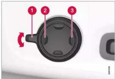
Multifunction control, located on the side of the seat cushion.
-
Activate the multi-function control by turning the control ① upwards/downwards. The seat settings view will be shown in the centre display.
-
Select Cushion extension in the seat settings view.
-
Press the front section of the four-way button ② to extend the seat cushion.
- Press the rear section of the four-way button ③ to retract the seat cushion.
Adjusting the length of the seat cushion manually
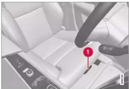
natural_image
Interior view of a car seatbelt with a finger pointing to the seatbelt (no text or symbols visible)Control for seat cushion adjustment.
- Grip the handle in the front of the seat and pull upwards.
- Adjust the length of the seat cushion.
- Release the handle and make sure that the seat cushion has reached the correct position.
Related information
• Manual front seat (p. 182)
• Power* front seat (p. 183)
- Adjusting the power* front seat (p. 183)
- Storing position for seat, door mirrors and head-up display* (p. 184)
- Using a stored position for seat, door mirrors and head-up display* (p. 185)
- Adjusting massage settings* in the front seat (p. 187)
- Massage settings* in the front seat (p. 186)
- Adjusting the side support* in the front seat (p. 189)
- Adjusting the lumbar support* in the front seat (p. 190)
- Adjusting the passenger seat from the driver's seat* (p. 191)
Adjusting the side support\* in the front seat
Increase comfort in the front seat by adjusting the sides of the backrest.

Multi-function button, located on the side of the seat base section.
The sides of the backrest can be adjusted to provide side support. Both the multi-function control on the seat and the centre display can be used in order to change the settings. The range of settings is shown in the centre display.
To adjust the side support:
-
Activate the multi-function control by turning the it up/down ① The seat settings view will be shown in the centre display.
-
Select Side bolsters in the seat settings view.
-
Press the front section of the four-way button to increase side support ②.
- Press the rear section of the four-way button to decrease side support ③.
Related information
• Manual front seat (p. 182)
• Power* front seat (p. 183)
- Adjusting the power* front seat (p. 183)
- Storing position for seat, door mirrors and head-up display* (p. 184)
- Using a stored position for seat, door mirrors and head-up display* (p. 185)
- Adjusting massage settings* in the front seat (p. 187)
- Adjusting* the length of the seat cushion in the front seat (p. 188)
- Massage settings* in the front seat (p. 186)
- Adjusting the lumbar support* in the front seat (p. 190)
- Adjusting the passenger seat from the driver's seat* (p. 191)
SEATS AND STEERING WHEEL
Adjusting the lumbar support\* in the front seat
The lumbar support is adjusted using a control on the side of the seat cushion.

natural_image
Close-up of a black circular mechanical component with a handle, mounted on a white surface (no text or symbols visible)Multifunction control in cars with four-way lumbar support*.

natural_image
Close-up of a circular mechanical component with a slot, shown from an angle (no text or symbols visible)Control in cars with two-way lumbar support*.
The lumbar support is adjusted using the multifunction control in cars with four-way lumbar support*, or using the round button in cars with two-way lumbar support*. The control is located on the side of the seat's seating section. Depending on the equipment level selected, the lumbar support can be adjusted forward/back and up/down (four-way lumbar support) or forward/back (two-way lumbar support).
Adjust the lumbar support in the car using the four-way lumbar support
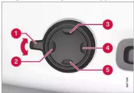
-
Activate the multi-function control by turning the control ① upwards/downwards. The seat settings view will be shown in the centre display.
-
Select Lumbar in the seat settings view.
-
Press the round button up ③/down ⑤ to move the lumbar support upwards/downwards.
- Press the front section 2 of the button to increase lumbar support.
- Press the rear section ④ of the button to decrease lumbar support.
Adjust the lumbar support in the car using the two-way lumbar support

- Press the front section of the round button to increase lumbar support.
- Press the rear section ② of the round button to decrease lumbar support.
Related information
• Manual front seat (p. 182)
• Power* front seat (p. 183)
- Adjusting the power* front seat (p. 183)
- Storing position for seat, door mirrors and head-up display* (p. 184)
- Using a stored position for seat, door mirrors and head-up display* (p. 185)
- Adjusting massage settings* in the front seat (p. 187)
- Adjusting* the length of the seat cushion in the front seat (p. 188)
- Massage settings* in the front seat (p. 186)
- Adjusting the side support* in the front seat (p. 189)
- Adjusting the passenger seat from the driver's seat* (p. 191)
Adjusting the passenger seat from the driver's seat\*
The front passenger seat can be adjusted from the driver's seat.
Activating the function
The function is activated via the function view in the centre display:

Press the Adjust Passenger Seat button to activate.
Adjust passenger seat
From activation of the function, the driver must adjust the passenger seat within 10 seconds. If no adjustment is made within this time the function is deactivated.
The driver adjusts the passenger seat using the controls on the driver's seat:
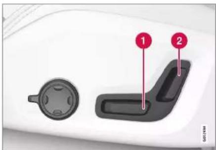
1 Move the passenger seat forward/backward by adjusting the control forward/backward.
2 Change the passenger seat's backrest inclination by adjusting the control forward/backward.
Related information
• Manual front seat (p. 182)
• Power* front seat (p. 183)
- Adjusting the power* front seat (p. 183)
- Storing position for seat, door mirrors and head-up display* (p. 184)
- Using a stored position for seat, door mirrors and head-up display* (p. 185)
- Adjusting massage settings* in the front seat (p. 187)
▶▶
SEATS AND STEERING WHEEL
- Adjusting* the length of the seat cushion in the front seat (p. 188)
- Massage settings* in the front seat (p. 186)
- Adjusting the side support* in the front seat (p. 189)
- Adjusting the lumbar support* in the front seat (p. 190)
Lowering the backrests in the rear seat\*
The rear seat's backrest is divided into two parts. The two parts can be folded forward individually.
WARNING
- Adjust the seat and fix it before driving away. Take care when adjusting the seat. Uncontrolled or careless adjustment can lead to trapping injuries.
- When loading long objects, they must always be strapped in securely to avoid injury and damage during sudden braking.
- Always switch off the engine and apply the parking brake when loading and unloading the car.
- For cars with automatic gearbox, set the gear selector in P to prevent it from being moved by mistake.
IMPORTANT
There must be no objects on the rear seat when the backrest is to be folded down. The seat belts must not be connected either. Otherwise there is a risk of damaging the rear seat upholstery.
IMPORTANT
The seat cushion on the integrated child seat* must be in the lowered position before lowering the rear seat backrest.
The armrest* for the centre seat must be raised before lowering the seat.
Through-load hatch* in the rear seat must be closed before lowering.
i NOTE
When private locking is activated, the rear seat must be in upright position for locking to work. With the rear seat in lowered position, locking will not work.
NOTE
The front seats may need to be pushed forwards, and/or the backrests adjusted upwards, in order that the rear backrests can be fully folded forward.
Lowering the backrest
To facilitate folding of the rear seat, the car must be stationary and at least one rear door open.

natural_image
Interior view of a car seat with a highlighted control panel (no text or symbols visible)Buttons for seat folding, located on the upper section of the rear seat.
- Ensure that there are no occupants or objects in the rear seat.
- Lower the centre seat's head restraint manually.
- Press and hold one of the buttons located in the parcel shelf on the left-hand side of the car.
- The seat is released from the lock but remains in the same position. The head restraints are lowered automatically.
- Lower the backrest manually to the horizontal position.
Raising the backrest
Raising the backrest to upright position is carried out manually:
- Move the backrest up/back.
- Press the backrest until the lock engages.
- Raise the head restraints manually.
- If necessary, raise the centre seat's head restraint.
WARNING
Check that the backrests and head restraints in the rear seat are locked properly after being folded up.
The head restraints of the outer seats must always be raised when there are passengers on any of the rear seats.
Related information
- Adjusting the head restraints in the rear seat (p. 193)
• Private locking (p. 279) - Activating and deactivating private locking (p. 279)
Adjusting the head restraints in the rear seat
Adjust the centre seat head restraint according to the height of the passenger. Fold down the outer seat head restraints* to improve rearward visibility.
Adjust the head restraint for the centre seat
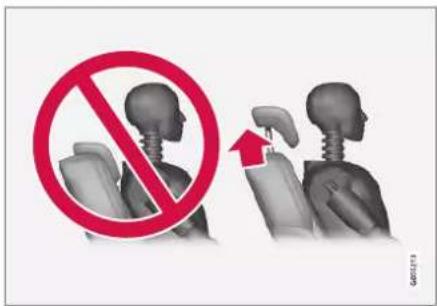
The centre seat's head restraint must be adjusted according to the passenger's height so that, if possible, the whole of the back of the head is covered. Slide it up manually as required.
SEATS AND STEERING WHEEL
◀◀

natural_image
Interior view of a car seatbelt with red directional arrows indicating movement (no text or symbols)To lower the head restraint, the button (see illustration) must be depressed while the restraint is carefully moved down.

WARNING
The centre seat head restraint must be in its lowest position when the centre seat is not used. When the centre seat is used, the head restraint must be correctly adjusted to the height of the passenger so that it covers the whole of the back of the head if possible.
Fold down the rear seat's outer head restraints via the centre display\*
The outer head restraints can be retracted via the centre display's function view. You can lower the head restraints in ignition position 0.
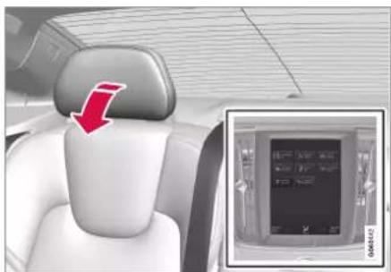
natural_image
Interior view of a car showing the rear seat, white backrest, and digital display (no visible text or symbols)
Press the Headrest Fold button to activate/deactivate lowering.
Move the head restraint back manually until a click is heard.

WARNING
Do not lower the outer head restraints if there are passengers in any of the outer rear seats.

WARNING
The head restraint must be in locked position after being folded up.
Related information
- Lowering the backrests in the rear seat* (p. 192)
Steering wheel controls and horn
The steering wheel houses the horn and controls for e.g. the driver support systems and voice control.

Keypads and paddles* in the steering wheel.
1 Controls for driver support systems. ^5
② Paddle shifter* for manual gear changing in an automatic gearbox.
3 Controls for voice control and menu, message and phone handling.
Horn

natural_image
Interior view of a car dashboard with Volvo logo and steering wheel (no visible text or symbols)The horn is located in the centre of the steering wheel.
Related information
• Steering lock (p. 195)
• Adjusting the steering wheel (p. 196)
• Steering lock (p. 195)
• Adjusting the steering wheel (p. 196)
Steering lock
The steering wheel lock makes it difficult to steer the car if it is stolen, for example. A mechanical noise can be perceived when the steering lock is locked or unlocked.
Activating the steering lock
The steering lock is activated when the car is locked from the outside and the engine is switched off. If the car is left unlocked then the steering lock will be activated automatically after a while.
Deactivating the steering lock
The steering lock is deactivated when the car is unlocked from outside. If the car is not locked, the steering wheel lock will be deactivated as long as the remote control key is in the passenger compartment and the car is started.
Related information
• Steering wheel controls and horn (p. 195)
• Adjusting the steering wheel (p. 196)
SEATS AND STEERING WHEEL
Adjusting the steering wheel
The steering wheel can be adjusted in different positions.
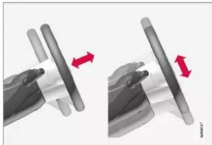
natural_image
Two mechanical assembly diagrams showing a cylindrical component being inserted, with red arrows indicating direction (no text or symbols present)The steering wheel can be adjusted for height and for depth.
The steering wheel is adjusted in different ways depending on whether or not the car is equipped with knee airbag ^6 .

WARNING
Adjust the steering wheel and fix it before driving away. The steering wheel must never be adjusted while driving.
Adjusting the steering wheel in a car with a knee airbag
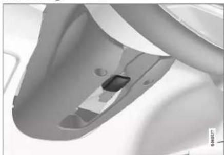
natural_image
Close-up of a mechanical component with a small inset showing a small rectangular object (no visible text or symbols)Lever for steering wheel adjustment.
- Push the lever forwards to release the steering wheel.
- Adjust the steering wheel to the position that suits you.
- Pull the lever back to fix the steering wheel in place. If the lever is stiff, press or raise the steering wheel slightly at the same time as you move the lever back.
Adjusting the steering wheel in a car without a knee airbag

natural_image
Close-up of a white toilet sink with a small vent and handle (no visible text or symbols)Lever for steering wheel adjustment.
- Pull the lever backwards to release the steering wheel.
- Adjust the steering wheel to the position that suits you.
- Push the lever forwards to secure the steering wheel. If the lever is stiff, press or raise the steering wheel slightly at the same time as you move the lever back.
Related information
• Steering lock (p. 195)
• Steering wheel controls and horn (p. 195)
- Adjusting the power* front seat (p. 183)
• Speed-dependent steering force (p. 286)
CLIMATE
CLIMATE
Climate
The car is equipped with electronic climate control. The climate control system cools or heats as well as dehumidifies the air in the passenger compartment.
All climate control system functions are controlled from the centre display and physical buttons in the centre console.
Some functions for the rear seat can also be controlled from the climate controls* at the rear of the tunnel console.

NOTE
If necessary, the climate control can be used to cool the media system in the centre display. In these cases, the message Climate system Cooling the infotainment system is shown in the driver display.
Related information
• Climate zones (p. 198)
• Climate control - sensors (p. 199)
• Perceived temperature (p. 199)
- Controlling the climate control system using voice control (p. 200)
- Parking climate (p. 222)
- Heater (p. 233)
• Air quality (p. 201)
• Air distribution (p. 204)
• Climate controls (p. 210)
Climate zones
The number of climate zones that the car is divided into governs the options for setting different temperatures for different parts of the passenger compartment.
2-zone climate
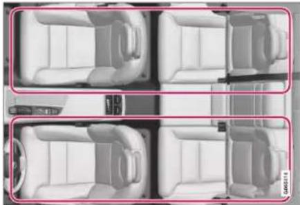
natural_image
Top-down view of four white car seats arranged in a grid layout (no text or symbols visible)Climate zones with 2-zone climate.
With 2-zone climate, the temperature in the passenger compartment can be set separately for the left and right-hand sides.
Related information
• Climate (p. 198)
Climate control - sensors
The climate control system has a number of sensors to help control the climate in the car. Do not cover or block the sensors with clothing or other objects.
Sensor location
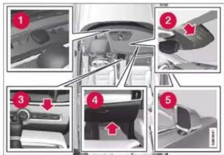
1 Sun sensor - on the upper side of the instrument panel.
2 Moisture sensor - in the casing by the interior rearview mirror.
3 Temperature sensor for the passenger compartment - by the physical buttons in the centre console.
4 Airborne particulate matter sensor* — on the underside of the glovebox.
5 Outside temperature sensor - in the right-hand door mirror.
With the Interior Air Quality System* there is also an air quality sensor that is fitted into the climate control system air intake.
Related information
• Climate (p. 198)
• Interior Air Quality System* (p. 202)
Perceived temperature
The climate control system regulates the climate in the passenger compartment based on the perceived temperature, not on actual temperature.
The temperature you select in the passenger compartment corresponds to the physically perceived temperature as affected by factors such as the ambient temperature, air speed, humidity, solar radiation, etc. in and around the car at the time.
The system includes a sun sensor which detects on which side the sun is shining into the passenger compartment. This means that the temperature can differ between the right and left-hand side's air vents despite the controls being set for the same temperature on both sides.
Related information
• Climate (p. 198)
CLIMATE
Controlling the climate control system using voice control ^1
Commands for voice control of the climate control system in order to e.g. change temperature, activate a heated seat* or change fan level.
Tap on and say one of the following commands:
- "Climate" - starts a dialogue for climate control and shows examples of commands.
- "Set temperature to X degrees" - sets the desired temperature.
- "Raise temperature"/"Lower temperature" - raise/lower the temperature setting one step.
- "Sync temperature" - synchronises the temperature for all climate zones in the car with the temperature set for the driver's side.
- "Air on feet"/"Air on body" - opens the desired air flow.
- "Air on feet off"/"Air on body off" - closes the desired air flow.
- "Set fan to max"/"Turn off fan" - changes the air flow to Max/Off.
-
"Raise fan speed"/"Lower fan speed" - raises/lowers the fan level one step.
-
"Turn on auto" - activates automatic climate regulation.
- "Air condition on"/"Air condition off" - activates/deactivates the air conditioning.
- "Recirculation on"/"Recirculation off" - activates/deactivates the air circulation.
- "Turn on defroster"/"Turn off defroster" - activates/deactivates defrost-ing of windows and door mirrors.
- "Turn on max defroster"/"Turn max defroster off" - activates/deactivates the max defroster.
- "Turn on electric defroster"/"Turn off electric defroster" - activates/deactivates the heated windscreen*.
- "Turn on rear defroster"/"Turn off rear defroster" - activates/deactivates the heated rear window and door mirrors.
- "Turn steering wheel heat on"/"Turn steering wheel heat off" - activates/deactivates the heated steering wheel*.
- "Raise steering wheel heat"/"Lower steering wheel heat" - raises/lowers the setting for the heated steering wheel* one step.
-
"Turn on seat heat"/"Turn off seat heat" - activates/deactivates the heated seat*.
-
"Raise seat heat"/"Lower seat heat" - raises/lowers the setting for the heated seat* one step.
- "Turn on seat ventilation"/"Turn off seat ventilation" - activates/deactivates the seat ventilation*.
- "Raise seat ventilation"/"Lower seat ventilation" - raises/lowers the setting for the ventilated seat* one step.
NOTE
Not all system languages support voice recognition. The ones that do are highlighted with the symbol in the list of available system languages. Read more about where the information can be found in the section on settings for voice recognition.
Related information
• Climate (p. 198)
• Voice recognition (p. 143)
• Using voice recognition (p. 144)
- Settings for voice recognition (p. 148)
Air quality
The materials selected for the passenger compartment and the air cleaning system ensure that the air quality in the passenger compartment is high.
Materials in the passenger compartment
The interior of the passenger compartment is designed to be pleasant and comfortable, even for people with contact allergies and for asthma sufferers.
Tested materials have been developed in order to reduce the quantity of dust in the passenger compartment and to contribute to making the passenger compartment easier to keep clean.
The carpets in both the passenger compartment and the cargo area are removable and easy to remove and clean.
Use cleaning agents and car care products recommended by Volvo to clean the interior.
Air cleaning system
In addition to the passenger compartment filter, the car is equipped with an air cleaning system that helps to maintain high air quality in the passenger compartment.
Related information
• Climate (p. 198)
- CleanZone* (p. 201)
• Clean Zone Interior Package* (p. 202)
• Interior Air Quality System* (p. 202)
• Advanced Air Cleaner* (p. 204)
• Passenger compartment filter (p. 203)
CleanZone\*
The CleanZone function checks and indicates whether or not all conditions have been met for good air quality in the passenger compartment.

A The indicator is visible in the climate view in the centre display.
B The indicator is visible in the climate row when the climate view is not open.
If the conditions have not been met then the Clean Zone text is white. When all conditions have been met, this is indicated by the text changing colour to blue.
Conditions that need to be met:
• That all doors and the boot lid are closed.
- That all side windows and the sunroof* are closed.
▶▶
CLIMATE
- That the air quality system Interior Air Quality System* is activated.
• That the ventilation fan is activated.
• That the air recirculation is deactivated.

NOTE
CleanZone does not indicate that the air quality is good. It only indicates that the conditions for good air quality have been met.
Related information
• Air quality (p. 201)
• Clean Zone Interior Package* (p. 202)
• Interior Air Quality System* (p. 202)
• Passenger compartment filter (p. 203)
Clean Zone Interior Package\*
Clean Zone Interior Package (CZIP) comprises a series of modifications that keep the passenger compartment even clearer from allergy and asthma-inducing substances, among other things.
The following is included:
- An enhanced fan function that means that the fan starts when the car is unlocked with the remote control key. The fan fills the passenger compartment with fresh air. The function starts when required and is disengaged automatically after a time or when one of the passenger compartment doors is opened. The amount of time the fan runs is reduced gradually due to reduced need up until the car is 4 years old.
- The fully automatic air quality system Interior Air Quality System (IAQS).
Related information
• Air quality (p. 201)
- CleanZone* (p. 201)
• Interior Air Quality System* (p. 202)
• Passenger compartment filter (p. 203)
Interior Air Quality System\*
Interior Air Quality System (IAQS) is a fully automatic air quality system that separates gases and particles to reduce the levels of odours and contaminants in the passenger compartment.
IAQS is a part of the Clean Zone Interior Package (CZIP) and cleans the air in the passenger compartment from contaminants such as particles, hydrocarbons, nitrous oxides and ground-level ozone.
If the air quality sensor senses that the outside air is contaminated, the air intake is closed and air recirculation is activated.

NOTE
The air quality sensor must always be enabled to ensure the best air in the passenger compartment.
In a cold climate recirculation is limited so as to prevent misting.
In the event of misting, the defrost functions for windscreen, side windows and rear window should be used.
Related information
- Activating and deactivating the air quality sensor* (p. 203)
• Air quality (p. 201) - CleanZone* (p. 201)
• Clean Zone Interior Package* (p. 202)
• Passenger compartment filter (p. 203)
Activating and deactivating the air quality sensor\*
The air quality sensor is part of the fully automatic air quality system Interior Air Quality System (IAQS).
It is possible to set whether the air quality sensor should be activated/deactivated.
- Press Settings in the top view in the centre display.
- Press Climate.
- Select Air Quality Sensor to activate/deactivate the air quality sensor.
Related information
• Interior Air Quality System* (p. 202)
Passenger compartment filter
All air entering the car's passenger compartment is cleaned with a filter.
Replacing the passenger compartment filter
To maintain high climate system performance, the filter must be changed at regular intervals. Follow the Volvo Service Programme for the recommended replacement intervals. If the car is used in a severely contaminated environment, it may be necessary to replace the filter more often.

NOTE
There are different types of passenger compartment filter. Make sure that the correct filter is fitted.
Related information
• Air quality (p. 201)
- CleanZone* (p. 201)
• Clean Zone Interior Package* (p. 202)
• Interior Air Quality System* (p. 202)
CLIMATE
Advanced Air Cleaner\*
Advanced Air Cleaner is a fully-automatic air purifier that collects contaminants in the form of small airborne particulate matter and exhaust gases in the passenger compartment filter, which improves the climate in the passenger compartment.
The function is started automatically when the fan is started.
Small airborne particulate matter is sometimes called PM_2.5 (particles smaller than 2.5 m), the content of such particles in the car is measured by one of the car's climate sensors. The content in the car is presented in the downloadable Air Quality app.
Related information
• Air quality (p. 201)
• Interior Air Quality System* (p. 202)
- CleanZone* (p. 201)
• Clean Zone Interior Package* (p. 202)
• Passenger compartment filter (p. 203)
• Climate control - sensors (p. 199)
Air distribution
The climate control system distributes the incoming air via a number of different vents in the passenger compartment.
Automatic and manual air distribution
With auto-regulated climate running the air distribution takes place automatically. If necessary, the air distribution can be controlled manually.
Adjustable air vents
Some of the air vents in the car are adjustable, which means that you can open/close the vent to aim the air flow.
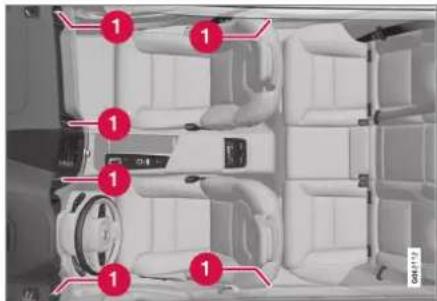
Location of adjustable air vents in the passenger compartment.
Four on the instrument panel and one on each of the door pillars between the front and rear doors.
Related information
• Climate (p. 198)
• Changing air distribution (p. 205)
- Opening, closing and aiming the air vents (p. 205)
• Table of air distribution options (p. 207)
Changing air distribution
The air distribution can be changed manually if required.

- Open climate view in the centre display by pressing the symbol in the middle of the climate row.

The air distribution buttons in the climate view.
1 Air distribution - windscreen defroster vents
2 Air distribution - air vents in instrument panel and centre console
3 Air distribution - air vents in the floor
- Press one or more of the air distribution buttons in order to open/close the corresponding air flow.
The air distribution is changed and the buttons illuminate/extinguish.
Related information
• Air distribution (p. 204)
- Opening, closing and aiming the air vents (p. 205)
• Table of air distribution options (p. 207)
Opening, closing and aiming the air vents
Some air vents in the passenger compartment can be opened, closed and aimed individually.
If the car's outer vents are aimed at the side windows then misting can be eliminated.
If the car's outer vents are aimed inwards then, in a hot climate, a comfortable environment is obtained in the passenger compartment.
Opening and closing the air vents
Air vents on the instrument panel:
- Turn the rotary knob in the middle of the air vent to open/close the air flow from the vent.
The air flow is at maximum when the marking on the knob is in vertical position.
Air vents in the door pillars:
- Roll the thumbwheel under the air vent in order to open/close the air flow from the vent.
The longer the white lines on the thumbwheel that are visible, the higher the air flow.
Aiming the air vents
- Move the lever in the middle of the air vent horizontally/vertically to direct the air flow from the vent.
CLIMATE
Related information
• Air distribution (p. 204)
• Changing air distribution (p. 205)
• Table of air distribution options (p. 207)
CLIMATE
Table of air distribution options
The air distribution can be changed manually if required. The following options are available for setting.
| Air distribution Purpose | ||
 | If all air distribution buttons are deselected in manual mode, the climate control system returns to automatically regulated climate control. | |
 | Main air flow from the defroster vents. Some air flows from other air vents. | Counteracts misting and icing in a cold and humid climate (to achieve this, fan level must not be low). |
 | Main air flow from the air vents in the instrument panel. Some air flows from other air vents. | Provides efficient cooling in a hot climate. |
 | Main air flow from the air vents at the floor. Some air flows from other air vents. | Provides heat or cooling to the floor. |
▶▶
CLIMATE
◀◀
| Air distribution Purpose | ||
 | Main air from the defroster vents and air vents in the instrument panel. Some air flows from other air vents. | Provides good comfort in hot and dry climates. |
 | Main air flow from the defroster vents and air vents at the floor. Some air flows from other air vents. | Provides good comfort and good demisting in a cold or humid climate. |
 | Main air flow from the air vents in the instrument panel and air vents at the floor. Some air flows from other air vents. | Provides good comfort in sunny weather with cool out-door temperatures. |
 | Main air flow from the defroster vents, from the air vents in the instrument panel and air vents at the floor. | Gives balanced comfort in the passenger compartment. |
CLIMATE
Related information
• Air distribution (p. 204)
- Opening, closing and aiming the air vents (p. 205)
• Changing air distribution (p. 205)
CLIMATE
Climate controls
The climate control system's functions are controlled from physical buttons in the centre console, the centre display and the climate controls at the rear of the tunnel console*.
Physical buttons in centre console

1 Button for heated windscreen* and max defroster.
② Button for heated rear window and door mirrors.
Climate row in centre display
The most common climate functions can be regulated from the climate row.

1 Temperature controls for driver and passenger side.
2 Controls for heated* and ventilated* driver and front passenger seat, as well as heated steering wheel*.
3 Button for access to the climate view. The graphic on the button shows activated climate settings.
Climate view in centre display
Open climate view by pressing the symbol in the middle of the climate row.
Depending on equipment level, the climate view can be divided into several tabs. Change between the tabs by swiping left/right or by pressing the respective heading.
Main climate
In addition to the climate row's functions, other main climate functions can also be controlled in the Main climate tab.

1 Max, Electric, Rear - Controls for defrosting the windows and door mirrors.
② AC - Controls for air conditioning.
3 Recirc - Controls for air recirculation.
4 Controls for air distribution.
5 Fan control.
6 AUTO - Auto regulating the climate.
Parking climate
The car's parking climate control can be regulated in the Parking climate tab.
Climate controls at rear of tunnel console\*
If the car is equipped with heated rear seats* there are physical buttons at the rear of the tunnel console for controlling this function.
Related information
• Climate (p, 198)
- Activating and deactivating heated front seat* (p. 211)
- Activating and deactivating heated rear seat* (p. 212)
- Activating and deactivating ventilated front seat* (p. 213)
- Activating and deactivating the heated steering wheel* (p. 214)
• Activating auto climate control (p. 214)
- Activating and deactivating air recirculation (p. 215)
- Activating and deactivating max defroster (p. 216)
- Activating and deactivating the heated windscreen* (p. 217)
- Activating and deactivating the heated rear window and door mirrors (p. 218)
• Regulating fan level for front seat (p. 219)
• Synchronising temperature (p. 221) - Activating and deactivating air conditioning (p. 221)
Activating and deactivating heated front seat\*
The seats can be heated in order to increase comfort for driver and passengers when it is cold.

- Press the left or right-hand side's steering wheel and seat button in the climate row in the centre display in order to open the controls for seat and steering wheel.
If the car is not equipped with ventilated seats or heated steering wheel (for the driver's side), the button for heated seats is immediately available in the climate row.

- Repeatedly press the button for heated seats in order to change between the four levels: Off, High, Medium and Low.
The level changes and the button shows the set level.
▶▶
CLIMATE
◀◀

WARNING
Heated seats must not be used by people who find it difficult to perceive an increase in temperature due to a lack of sensation or who otherwise have problems operating the controls for the heated seats.
Related information
• Climate controls (p. 210)
- Activating and deactivating automatic start of heated front seat* (p. 212)
Activating and deactivating automatic start of heated front seat\*
The seats can be heated in order to increase comfort for driver and passengers when it is cold.
It is possible to set whether automatic start of heated seats should be activated/deactivated when the engine is started. With automatic start activated, heating will start in the event of low ambient temperature.
- Press Settings in the top view in the centre display.
- Press Climate.
- Select Auto Driver Seat Heating Level and Auto Passenger Seat Heating Level to activate/deactivate automatic start of heated driver's and passenger seat.
An "A" is shown at each button for heated front seats in the climate row when automatic starting has been activated.
- Select Low, Medium or High to select level after the function has been activated.
Related information
• Climate controls (p. 210)
- Activating and deactivating heated front seat* (p. 211)
Activating and deactivating heated rear seat\*
The seats can be heated in order to increase comfort for driver and passengers when it is cold.
Activating and deactivating the heated rear seat from the rear seat

natural_image
Interior view of a car seat with two directional buttons and a switch, no visible text or symbolsButtons for heated seats at the rear of the tunnel console.
- Press repeatedly on the left or right-hand side's physical buttons for heated seats at the rear of the tunnel console to switch between the four levels: Off, High, Medium and Low.
The level changes and the LEDs in the button show the set level.
CLIMATE

WARNING
Heated seats must not be used by people who find it difficult to perceive an increase in temperature due to a lack of sensation or who otherwise have problems operating the controls for the heated seats.
Related information
• Climate controls (p. 210)
Activating and deactivating ventilated front seat\*
The seats can be ventilated to provide increased comfort in a hot climate, for example.
The ventilation system consists of fans in the seats and backrests that draw air through the seat upholstery. The cooling effect increases the cooler the passenger compartment air becomes. The system can be activated when the engine is running.

- Press the left or right-hand side's steering wheel and seat button in the climate row in the centre display in order to open the controls for seat and steering wheel.
If the car is not equipped with heated seats or heated steering wheel (for the driver's side), the button for ventilated seats is immediately available in the climate row.

- Repeatedly press the button for ventilated seats in order to change between the four levels: Off, High, Medium and Low.
The level changes and the button shows the set level.
Related information
• Climate controls (p. 210)
CLIMATE
Activating and deactivating the heated steering wheel\*
The steering wheel can be heated in order to increase comfort for the driver when it is cold.

- Press the driver's side steering wheel and seat button in the climate row of the centre display in order to open the controls for seat and steering wheel.
If the car is not equipped with heated seats or ventilated seats, the button for heated steering wheel is immediately available in the climate row.

- Repeatedly press the button for heated steering wheel in order to change between the four levels: Off, High, Medium and Low.
The level changes and the button shows the set level.
Related information
• Climate controls (p. 210)
- Activating and deactivating automatic start of heated steering wheel* (p. 214)
Activating and deactivating automatic start of heated steering wheel\*
The steering wheel can be heated in order to increase comfort for the driver when it is cold.
It is possible to set whether automatic start of heated steering wheel should be activated/deactivated when the engine is started. With automatic start activated, heating will start in the event of low ambient temperature.
- Press Settings in the top view in the centre display.
- Press Climate.
- Select Auto Steering Wheel Heating Level to activate/deactivate automatic start of heated steering wheel.
An "A" is shown at the button for heated steering wheel in the climate row when automatic starting has been activated.
- Select Low, Medium or High to select level after the function has been activated.
Related information
- Activating and deactivating the heated steering wheel* (p. 214)
Activating auto climate control
With auto climate control activated, multiple climate functions are controlled automatically.

- Open climate view in the centre display by pressing the symbol in the middle of the climate row.
-
Give a short or long press on AUTO Climate.
-
Short press - air recirculation, air conditioning and air distribution are controlled automatically.
- Long press - air recirculation, air conditioning and air distribution are controlled automatically, temperature and fan speed are changed to standard settings: 22 °C (72 °F) and level 3.
Auto-regulation of the climate is activated and the button illuminates.

NOTE
Temperature and fan speed can be changed without deactivating the automatically-regulated climate control system. The automatically-regulated climate control system is deactivated when the air distribution is changed manually or when maximum defroster is activated.
Related information
• Climate controls (p. 210)
Activating and deactivating air recirculation
Air recirculation shuts out bad air, exhaust gases, etc. from outside the car by the climate control system reusing the air in the passenger compartment.

- Open climate view in the centre display by pressing the symbol in the middle of the climate row.

- Press Recirc.
Air recirculation is activated/deactivated and the button illuminates/extinguishes.
IMPORTANT
If the air in the car is recirculated for too long then there is a risk of misting on the insides of the windows.
NOTE
It is not possible to activate air recirculation when max defroster is activated.
Related information
• Climate controls (p. 210)
- Activating and deactivating time setting for air recirculation (p. 216)
CLIMATE
Activating and deactivating time setting for air recirculation
Air recirculation shuts out bad air, exhaust gases, etc. from outside the car by the climate control system reusing the air in the passenger compartment.
It is possible set whether the air recirculation timer should be activated/deactivated. When the timer is activated, air recirculation is automatically switched off after 20 minutes.
- Press Settings in the top view in the centre display.
- Press Climate.
- Select Recirculation Timer to activate/deactivate the air recirculation timer.
Related information
- Activating and deactivating air recirculation (p. 215)
Activating and deactivating max defroster
Max defroster is used to quickly remove mist and ice from windows.
Max defroster deactivates auto-regulation of the climate and air recirculation, activates air conditioning and changes the fan level to 5 and the temperature to HI.
NOTE
Changing the fan level to 5 increases the noise level.
When max defroster is deactivated, the climate control system returns to the previous settings.
Activating and deactivating max defroster from centre console
There is a physical button in the centre console for quick access to max defroster.
With heated windscreen* the max defroster can only be activated individually from the climate view in the centre display.

natural_image
Close-up of a remote control panel with four function icons (shutter, switch, battery, and power) on its sides, no visible text or labels.Physical button in the centre console.
Cars without heated windscreen:
- Press the button.
Max defroster is activated/deactivated and the button illuminates/extinguishes.
Cars with heated windscreen:
- Press the button repeatedly in order to switch between the three levels:
- Activated heated windscreen
- Activated heated windscreen and max defroster
- Deactivated.
Heated windscreen and max defroster are activated/deactivated and the button illuminates/extinguishes.

NOTE
Max defroster starts with a certain delay in order to avoid a short increase in fan level if the heated windscreen is deactivated by two quick presses of the button.
Activating and deactivating max defroster from centre display

- Open climate view in the centre display by pressing the symbol in the middle of the climate row.

- Press Max.
Max defroster is activated/deactivated and the button illuminates/extinguishes.
Related information
• Climate controls (p. 210)
Activating and deactivating the heated windscreen\*
A heated windscreen is used to quickly remove mist and ice from the window.
Activating and deactivating heated windscreen from centre console
In the centre console is a physical button for rapid access to the heated windscreen.

natural_image
Close-up of a car dashboard with four function buttons (air, exhaust, air intake, exhaust) and a 'GREEN' label at the bottom right (no readable text on buttons)Physical button in the centre console.
- Press the button repeatedly in order to switch between the three levels:
• Activated heated windscreen
- Activated heated windscreen and max defroster
- Deactivated.
Heated windscreen and max defroster are activated/deactivated and the button illuminates/extinguishes.
Activating and deactivating heated windscreen from centre display

- Open climate view in the centre display by pressing the symbol in the middle of the climate row.

- Press Electric.
Heated windscreen is activated/deactivated and the button illuminates/extinguishes.

NOTE
A triangular area at the end of each side of the windscreen is not electrically heated, where de-icing may take longer.

NOTE
The heated windscreen may affect the performance of transponders and other communication equipment.
▶▶
CLIMATE
Related information
• Climate controls (p. 210)
- Activating and deactivating automatic start of heated windscreen* (p. 218)
Activating and deactivating automatic start of heated windscreen\*
A heated windscreen is used to quickly remove mist and ice from the window. It is possible to set whether automatic start of heated windscreen should be activated/deactivated when the engine is started. With automatic start activated, heating will start when there is a risk of ice or misting on the windscreen/window. The heating switches off automatically when the windscreen/window is sufficiently warm and the ice or misting is gone.
- Press Settings in the top view in the centre display.
- Press Climate.
- Select Auto Front Defroster to activate/deactivate automatic start of heated windscreen.
Related information
- Activating and deactivating the heated windscreen* (p. 217)
Activating and deactivating the heated rear window and door mirrors
The heated rear window and door mirrors are used to quickly remove mist and ice from the windows and mirrors.
Activating and deactivating heated rear window and door mirrors from centre console
In the centre console is a physical button for rapid access to the heated rear window and door mirrors.

natural_image
Close-up of a car's front panel with control buttons and warning symbols (no readable text)Physical button in the centre console.
- Press the button.
Heated rear window and door mirrors are activated/deactivated and the button illuminates/extinguishes.
Activating and deactivating heated rear window and door mirrors from centre display

- Open climate view in the centre display by pressing the symbol in the middle of the climate row.

- Press Rear.
Heated rear window and door mirrors are activated/deactivated and the button illuminates/extinguishes.
Related information
• Climate controls (p. 210)
- Activating and deactivating automatic starting of the heated rear window and door mirrors (p. 219)
Activating and deactivating automatic starting of the heated rear window and door mirrors
The heated rear window and door mirrors are used to quickly remove mist and ice from the windows and mirrors.
It is possible to set whether automatic start of heated rear window and door mirrors should be activated/deactivated when the engine is started. With automatic start activated, heating will start when there is a risk of ice or misting on the windscreen/window. The heating switches off automatically when the windscreen/window is sufficiently warm and the ice or misting is gone.
- Press Settings in the top view in the centre display.
- Press Climate.
- Select Auto Rear Defroster to activate/deactivate automatic start of heated rear window and door mirrors.
Related information
- Activating and deactivating the heated rear window and door mirrors (p. 218)
Regulating fan level for front seat ^2
The fan can be set to several different automatically controlled fan speeds for the front seat.

- Open climate view in the centre display by pressing the symbol in the middle of the climate row.

natural_image
Abstract grayscale graphic with geometric shapes and a control panel (no text or symbols)Fan control buttons in the climate view.
- Tap on the desired fan level, Off, 1-5 or Max.
Fan level is changed and the buttons for the selected level illuminate.
CLIMATE
◀◀
IMPORTANT
If the fan is fully switched off then the air conditioning is not engaged, which results in a risk of misting on the insides of the windows.
NOTE
The climate control system automatically adjusts the air flow within the selected fan level based on requirements. This means that the fan speed may change even though the fan level is the same.
Related information
• Climate controls (p. 210)
Regulating temperature for front seat ^3
The temperature can be set to the desired number of degrees for the front seat's climate zones.
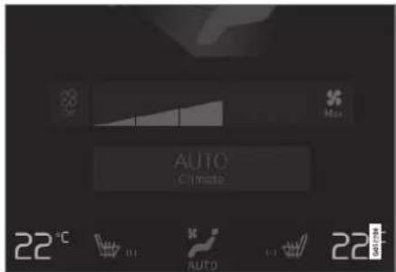
Temperature buttons in the climate row.
- Press the left or right-hand side temperature button in the centre display's climate row to open the controls.

Temperature control.
-
Regulate the temperature by either of the following:
-
drag the control to the desired temperature, or
- press +/- to raise/lower the temperature gradually.
The temperature changes and the button shows the set temperature.
NOTE
Heating or cooling cannot be hastened by selecting a higher or lower temperature than the actual desired temperature.
Related information
• Climate controls (p. 210)
Synchronising temperature
The temperature in the car's different climate zones can be synchronised with the temperature set on the driver's side.

Synchronisation button on the driver's side temperature controls.
- Press the driver's side temperature button in the centre display's climate row in order to open the controls.
- Press Synchronise temperature.
The temperature for all zones in the car is synchronised with the temperature set for the driver's side and the synchronisation symbol is shown adjacent to the temperature button.
The synchronisation is stopped by means of a further press on Synchronise temperature or by means of changing the temperature settings for a climate zone other than the driver's.
Related information
• Climate controls (p. 210)
Activating and deactivating air conditioning
The air conditioning cools and dehumidifies incoming air as required.
When the air conditioning is activated, the climate control system automatically controls starting and switching off as required.

- Open climate view in the centre display by pressing the symbol in the middle of the climate row.

- Press AC.
Air conditioning is activated/deactivated and the button illuminates/extinguishes.
NOTE
Close all side windows and the sunroof* so that the air conditioning should work as well as possible.
▶▶
CLIMATE
◀◀

NOTE
It is not possible to activate the air conditioning when the fan control is in Off position.
Related information
• Climate controls (p. 210)
Parking climate
Parking climate control is a generic term for various functions that improve the passenger compartment climate when the car is parked, e.g. preconditioning.

Functions belonging to the parking climate control are controlled from the Parking climate in climate view in the centre display. Open climate
view by pressing the symbol in the middle of the climate row.
Related information
• Climate (p. 198)
• Preconditioning (p. 222)
- Precleaning* (p. 228)
• Climate comfort when parking (p. 229)
- Symbols and messages for parking climate control (p. 231)
Preconditioning
Preconditioning is a climate function which, if possible, attempts to reach comfort temperature in the passenger compartment before departure.
Preconditioning can use direct start or be set via the timer.
The function utilises several systems in different cases:
- In a cold climate, the parking heater warms up the passenger compartment to a comfortable temperature.
- The air conditioning, in a hot climate, cools the passenger compartment to the comfort temperature.
- Activation of heated steering wheel* and heated seats* for driver and passenger can be selected.
- Heated windscreen, rear window and door mirrors are automatically activated as required.
During preconditioning in a hot climate, condensation from the air conditioning may drip under the car. This is normal.

NOTE
Preconditioning is only available when the car is connected to an electrical socket. ^4 A charging station that is not constantly active, due to a timer, may result in preconditioning failure.
If the car is not connected to an electrical socket, it is still possible to cool the passenger compartment briefly in a warm climate by starting preconditioning directly.

NOTE
During preconditioning of the passenger compartment, the car works to reach comfort temperature and not the temperature set in the climate control system.

NOTE
Precleaning* starts automatically when preconditioning is completed.
Related information
• Parking climate (p. 222)
- Start and switch off preconditioning (p. 223)
• Preconditioning time setting (p. 224)
- Precleaning* (p. 228)
Start and switch off preconditioning
Preconditioning heats or cools the passenger compartment, if possible, prior to driving. The function can use direct start from the centre display or a mobile phone.
Start and switch off from car

- Open climate view in the centre display by pressing the symbol in the middle of the climate row.
- Select the Parking climate tab.
- Select whether seat heating and steering wheel heating should be activated during preconditioning by ticking/unticking the boxes for the respective function.
- Press Start Pre-con. & Cleaning.
Preconditioning is started/switched off and the button is illuminates/extinguishes.

NOTE
Preconditioning is only available when the car is connected to an electrical socket. ^5 A charging station that is not constantly active, due to a timer, may result in preconditioning failure.
If the car is not connected to an electrical socket, it is still possible to cool the passenger compartment briefly in a warm climate by starting preconditioning directly.

NOTE
The car's doors and windows should be closed during the preconditioning of the passenger compartment.

NOTE
Precleaning* starts automatically when preconditioning is completed.
CLIMATE
◀◀

WARNING
Do not use preconditioning ^6 :
- In unventilated spaces indoors. Exhaust gases are emitted if the heater starts.
- In locations with combustible or flammable material nearby. Fuel, gas, long grass, sawdust, etc. may ignite.
- When there is a risk that the heater's exhaust line may be blocked. For example, deep snow inside the front right-hand wheel housing can obstruct the heater's ventilation.
Remember that the preconditioning can be started by a timer that has been set for a long time in advance.
Starting from the app
Starting the pre-conditioning, as well as information on selected settings, can be managed from a device that has the Volvo On Call* app. Preconditioning heats or cools the compartment (with the car's air conditioning) until a comfortable temperature is reached.
The passenger compartment can also be pre-conditioned with the car remote start function
(Engine Remote Start - ERS) ^7 via the Volvo On Call* app.
Related information
- Parking climate (p. 222)
• Preconditioning (p. 222)
• Preconditioning time setting (p. 224) - Precleaning* (p. 228)
Preconditioning time setting
The timer can be set so that the preconditioning is finished at a predetermined time.
The timer can handle up to 8 different settings for
• a time on a single date
- a time on one or more days of the week, with or without repetition.

NOTE
Preconditioning is only available when the car is connected to an electrical socket. A charging station that is not constantly active, due to a timer, may result in preconditioning failure.
If the car is not connected to an electrical socket, it is still possible to cool the passenger compartment briefly in a warm climate by starting preconditioning directly.
Related information
• Preconditioning (p. 222)
- Adding and editing time setting for preconditioning (p. 225)
^5 Not applicable to fuel-driven auxiliary heater.
^6 Applicable to fuel-driven auxiliary heater.
7 Certain markets.
^9 Not applicable to fuel-driven auxiliary heater.
- Activating and deactivating time setting for preconditioning (p. 226)
- Removing time setting for preconditioning (p. 227)
Adding and editing time setting for preconditioning
The timer for preconditioning can manage up to 8 time settings.
Adding a time setting

The button to add a time setting in the Parking climate tab in the climate view.
- Open the climate view in the centre display.
-
Select the Parking climate tab.
-
Press Add timer.
A pop-up window is shown.

NOTE
It is not possible to add a time setting if there already are 8 settings entered for the timer. Delete a time setting in order to be able to add a new one.
- Tap on Date to set the time for a single date.
Tap on Days to set the time for one or more days of the week.
With Days: Activate/deactivate repetition by ticking/unticking the box for Repeat weekly.
- With Date: Select the date for preconditioning by scrolling the date list with the arrows.
With Days: Select the days of the week for preconditioning by tapping on the buttons for the days of the week.
- Set the time when the preconditioning should be finished by scrolling with the arrows.
CLIMATE
- Tap on Confirm in order to add the time setting.
The time setting is added to the list and is activated.

WARNING
Do not use preconditioning ^9 :
- In unventilated spaces indoors. Exhaust gases are emitted if the heater starts.
- In locations with combustible or flammable material nearby. Fuel, gas, long grass, sawdust, etc. may ignite.
- When there is a risk that the heater's exhaust line may be blocked. For example, deep snow inside the front right-hand wheel housing can obstruct the heater's ventilation.
Remember that the preconditioning can be started by a timer that has been set for a long time in advance.
Editing a time setting
- Open the climate view in the centre display.
-
Select the Parking climate tab.
-
Press the time setting that is to be changed.
A pop-up window is shown.
- Edit the time setting in the same way as described in "Adding a time setting" above.
Related information
• Preconditioning (p. 222)
• Preconditioning time setting (p. 224)
- Activating and deactivating time setting for preconditioning (p. 226)
- Removing time setting for preconditioning (p. 227)
Activating and deactivating time setting for preconditioning
A time setting in the timer for preconditioning can be activated or deactivated based on need.

The timer buttons in the Parking climate tab in the climate view.
-
Open the climate view in the centre display.
-
Select the Parking climate tab.
-
Activate/deactivate a time setting by tapping on the timer button to the right of the setting.
The time setting is activated/deactivated and the button illuminates/extinguishes.

WARNING
Do not use preconditioning ^10 :
- In unventilated spaces indoors. Exhaust gases are emitted if the heater starts.
- In locations with combustible or flammable material nearby. Fuel, gas, long grass, sawdust, etc. may ignite.
- When there is a risk that the heater's exhaust line may be blocked. For example, deep snow inside the front right-hand wheel housing can obstruct the heater's ventilation.
Remember that the preconditioning can be started by a timer that has been set for a long time in advance.
Related information
• Preconditioning (p. 222)
• Preconditioning time setting (p. 224)
- Adding and editing time setting for preconditioning (p. 225)
- Removing time setting for preconditioning (p. 227)
Removing time setting for preconditioning
A time setting for preconditioning that is no longer required can be deleted.
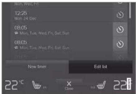
The button for editing the list/deleting the lime setting in the tab Parking climate in the climate view.
- Open the climate view in the centre display.
- Select the Parking climate tab.
- Press Edit list.
- Press the delete icon to the right in the list.
The icon changes to the text Delete.
- Press Delete to confirm.
The time setting is removed from the list.
Related information
• Preconditioning (p, 222)
• Preconditioning time setting (p. 224)
- Adding and editing time setting for preconditioning (p. 225)
- Activating and deactivating time setting for preconditioning (p. 226)
CLIMATE
Precleaning\*
Precleaning the car prior to departure is used to improve air quality in the passenger compartment.
Precleaning can only be started directly from the centre display, but it also starts automatically when preconditioning ends.
This function uses the ventilation to blow fresh air into the passenger compartment and then circulates the air through the air conditioning system's passenger compartment filter.
Related information
- Parking climate (p. 222)
- Starting and switching off precleaning* (p. 228)
• Preconditioning (p. 222)
Starting and switching off precleaning\*
Precleaning improves the air quality in the passenger compartment prior to driving. The function can use direct start from the centre display or a mobile phone.
Start and switch off from car

- Open climate view in the centre display by pressing the symbol in the middle of the climate row.
- Select the Parking climate tab.
- Press Start Pre-cleaning.
Precleaning is started/switched off and the button is illuminates/extinguishes.
Starting from the app\*
Start of precleaning and information about the selected settings can be managed from a device that has the Volvo On Call* app.
NOTE
Precleaning always starts automatically when preconditioning is completed.
Related information
- Parking climate (p. 222)
- Precleaning* (p. 228)
• Preconditioning (p. 222)
Climate comfort when parking
The climate in the car's passenger compartment can be maintained while the car is parked, e.g. if the engine needs to be switched off but the driver or passenger(s) wants to remain in the car and maintain the level of climate comfort.
Starting climate comfort retention is only possible via direct start from the centre display.
The function utilises several systems in different cases:
- Residual heat from the engine, in a cold climate, heats the passenger compartment to comfort temperature.
- When it is warm, the ventilation cools the passenger compartment by blowing in air from outside the car.

NOTE
Climate comfort retention is switched off when the car is locked from the outside to avoid using residual heat unnecessarily. Use of the function is intended to maintain climate comfort when driver or passengers remain inside the car.
There is a limit to how long climate comfort can be maintained in a cold climate, which depends on the amount of residual heat available.
Related information
- Parking climate (p. 222)
- Starting and switching off climate comfort when parking (p. 229)
Starting and switching off climate comfort when parking
Climate comfort retention maintains the climate in the passenger compartment after driving. The function can use direct start from the centre display.

- Open climate view in the centre display by pressing the symbol in the middle of the climate row.
- Select the Parking climate tab.
- Press Keep climate comfort.
Climate comfort retention is started/switched off and the button illuminates/extinguishes.

NOTE
It is not possible to start climate comfort retention if there is not enough residual heat in the engine to maintain the passenger compartment climate, or if the outside temperature is above approx. 20^ C ( 68^ F).
CLIMATE
◀◀

NOTE
Climate comfort retention is switched off when the car is locked from the outside to avoid using residual heat unnecessarily. Use of the function is intended to maintain climate comfort when driver or passengers remain inside the car.
There is a limit to how long climate comfort can be maintained in a cold climate, which depends on the amount of residual heat available.
Related information
• Climate comfort when parking (p. 229)
CLIMATE
Symbols and messages for parking climate control
A number of symbols and messages regarding parking climate control can be shown in the driver display.
Messages relating to parking climate control can also be displayed in a device which has the Volvo On Call* app.

This symbol illuminates in the driver display when the parking heater is active. ^11
| Symbol | Message Specification | |
| Parking climateService required | Parking climate control is disengaged. Contact a workshop ^A to check the function as soon as possible. | |
| Parking climateTemporarily unavailable | Parking climate control is temporarily disengaged. If the problem persists for some time, contact a workshop ^A to check the function. | |
| Parking climateUnavailable Fuel level too low ^B | Parking climate control cannot be activated when the fuel level is too low to start the parking heater. Fill the vehicle's fuel tank. | |
| Parking climateUnavailable Charge level too low | Parking climate control cannot be activated if the charge level of the hybrid battery is too low to start the parking heater. Start the car. |
CLIMATE
◀◀
| Symbol | Message Specification | |
 | Parking climateUnavailable, not connected to the mains ^C | The parking climate control cannot be activated if the charging cable is not connected. Connect the charging cable. |
 | Parking climateLimited Charge level too low | The running time for parking climate control is limited when the state of charge in the hybrid battery is low. Start the car. |
A An authorised Volvo workshop is recommended.
B Applies to fuel-driven heater.
^c Applies to the high-voltage heater.
Related information
- Parking climate (p. 222)
Heater
The heater has two subfunctions that help to heat the passenger compartment or engine in different situations.
The heater has two subfunctions:
- Parking heater - heats the passenger compartment, if necessary, when the parking climate control's preconditioning is activated.
- Additional heater - heats the passenger compartment and engine, if necessary, during driving.
Either a fuel-driven heater or a high-voltage heater is used, depending on the market. ^12
The heater is fitted in the front right-hand wheel housing.

NOTE
When the heater is running ^13 , smoke may be emitted from the right-hand front wheel housing and a low hum may be heard. A ticking sound from the fuel pump may also be heard from the rear section of the car. This is perfectly normal.
Battery and charging
The heater is powered by the car's hybrid battery. If the charge level of the hybrid battery is too low, then the heater is switched off automatically and the driver display shows a message.
NOTE
Make sure that there is enough charge in the battery if the heater needs to be used. The car must be connected to an electrical socket for the heater to be used for preconditioning.
Fuel and refuelling ^14

Warning label on fuel filler flap.
The heater uses fuel from the car's normal fuel tank.
If the car is parked on a steep hill, the front of the car should point downhill to ensure that there is a supply of fuel to the heater.
If the level in the fuel tank is too low then the heater is switched off automatically and the driver display shows a message.
NOTE
Make sure there is enough fuel in the car's fuel tank if the heater needs to be used.
WARNING
Fuel which spills out could be ignited. Switch off the fuel-driven heater before starting to refuel.

Check in the driver display that the heater is switched off. This symbol is lit when it is working as a parking heater.
Related information
• Climate (p. 198)
- Parking heater (p. 234)
• Additional heater (p. 235)
CLIMATE
Parking heater
The parking heater heats the passenger compartment as necessary before driving if the car's preconditioning is activated.
The parking heater is one of two subfunctions of the car's heater. The heater is fitted in the front right-hand wheel housing.

When this symbol illuminates in the driver display, the parking heater may be active. ^15

NOTE
When the heater is running ^16 , smoke may be emitted from the right-hand front wheel housing and a low hum may be heard. A ticking sound from the fuel pump may also be heard from the rear section of the car. This is perfectly normal.
The parking heater starts automatically if the parking climate's preconditioning is activated and the passenger compartment needs to be heated up.
Depending on factors such as battery level, passenger compartment temperature and ambient temperature, the heater has different running times, but never longer than 30 minutes.

NOTE
Make sure there is enough fuel in the car's fuel tank if the parking heater needs to be used. ^17
Make sure that there is enough charge in the hybrid battery if the parking heater needs to be used. The car must be connected to an electrical socket for the heater to be used for preconditioning.

WARNING
Do not use preconditioning ^18 :
- In unventilated spaces indoors. Exhaust gases are emitted if the heater starts.
- In locations with combustible or flammable material nearby. Fuel, gas, long grass, sawdust, etc. may ignite.
- When there is a risk that the heater's exhaust line may be blocked. For example, deep snow inside the front right-hand wheel housing can obstruct the heater's ventilation.
Remember that the preconditioning can be started by a timer that has been set for a long time in advance.

WARNING
If there is a smell of fuel, unusual amounts of smoke, black smoke, or unusual sounds coming from the parking heater ^19 ; switch off the heater and, if possible, pull out its fuse. Volvo recommends that an authorised Volvo workshop should be contacted for repair.
Related information
- Heater (p. 233)
• Additional heater (p. 235)
Additional heater
The auxiliary heater helps to heat the passenger compartment and engine while driving. The additional heater is one of two subfunctions of the car's heater. The heater is fitted in the front right-hand wheel housing.
NOTE
When the heater is running ^20 , smoke may be emitted from the right-hand front wheel housing and a low hum may be heard. A ticking sound from the fuel pump may also be heard from the rear section of the car. This is perfectly normal.
The additional heater starts and is controlled automatically when heating is required while the car is being driven.
It switches off automatically when the car is switched off.
NOTE
Make sure there is enough fuel in the car's fuel tank if the auxiliary heater needs to be used. ^21
Related information
- Heater (p. 233)
- Parking heater (p. 234)
- Activating and deactivating automatic start of auxiliary heater (p. 236)
CLIMATE
Activating and deactivating automatic start of auxiliary heater
The auxiliary heater helps to heat the passenger compartment and engine while driving. It is possible to set whether automatic start for the additional heater should be activated/deactivated.
- Press Settings in the top view in the centre display.
- Press Climate.
- Select Additional Heater to activate/deactivate automatic start of the additional heater.

NOTE
Volvo recommends that the automatic start for the additional heater should be switched off for short driving distances. ^22

NOTE
If the auxiliary heater's automatic starting is deactivated, this may impede comfort in the passenger compartment as the climate control system will then have no heat source during electrical operation.
Related information
• Additional heater (p. 235)
KEY, LOCKS AND ALARM
KEY, LOCKS AND ALARM
Locking and unlocking
The car can be locked and unlocked in several different ways.
The car can be locked and unlocked
• using the buttons on the remote control key
- using the detachable key blade (if the battery in the remote control key is exhausted)
- without a key* (Passive Entry), the remote control key must be within range
• from the inside of the car using the locking controls in the doors
- remote unlocking with Volvo On Call*.
There are two types of remote control keys to the car.
For cars equipped with keyless locking and unlocking*, a slightly smaller, lighter and button-less key (Key Tag) is supplied.
A Care Key* (restricted remote control key) makes it possible to set restrictions for some of the car's properties e.g. the car's maximum speed and the loudspeaker system's maximum volume.
Related information
- Locking and unlocking with the remote control key (p. 242)
• Keyless locking and unlocking* (p. 270)
- Locking and unlocking from inside the car (p. 273)
- Private locking (p. 279)
- Alarm* (p. 280)
Lock confirmation
The car indicates with hazard warning flash-ers when the car is locked or unlocked.
Exterior indication
Locking
- The car's hazard warning flashers indicate locking by flashing and retracting the door mirrors ^1 .
Unlocking
- The car's hazard warning flashers indicate unlocking by two flashes and extending the door mirrors ^1 .
All doors, the boot lid and the bonnet must be closed for the car to indicate that it is locked. If locking takes place with just the driver door closed ^2 , locking will take place but the lock indication with hazard warning flashers will only take place when all doors, the boot lid and the bonnet have been closed.
KEY, LOCKS AND ALARM
Lock and alarm indicator on the instrument panel
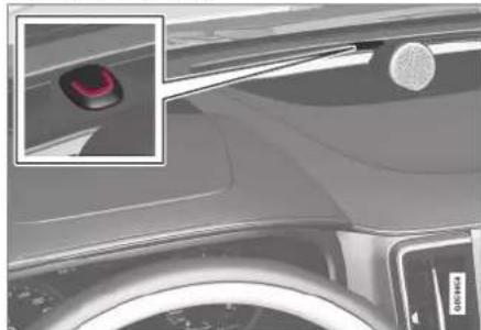
natural_image
Close-up of a car's rearview showing the red sensor on the roof and a circular button, with no visible text or symbols.The lock and alarm indicator shows the status of the locking system:
• A long flash indicates locking.
- Short flashes indicate that the car is locked.
- Rapid flashes after disarming the alarm* indicate that the alarm has been triggered.
Indication in lock buttons
Front door

natural_image
Close-up of a car interior panel with two buttons and a lock icon (no text or symbols visible)Lock buttons with indicator lamp in the front door.
An illuminated indicator lamp in the lock button of either front door indicates that all doors are locked. If any door is opened, the lamp will extinguish in both doors.
Rear door*
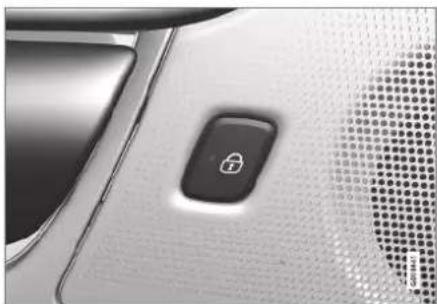
natural_image
Close-up of a car's front panel showing a black padlock icon on a textured surface (no text or symbols visible)Lock button with indicator lamp in the rear door.
An illuminated indicator lamp in the lock button for one of the doors indicates that the door in question is locked. If any door is unlocked, its lamp will extinguish while the others will continue to illuminate.
Other indication
The home safe lighting and approach light functions can also be activated when locking and unlocking.
Related information
- Lock indication setting (p. 240)
- Locking and unlocking (p. 238)
• Approach light duration (p. 160)
• Using home safe lighting (p. 160)
KEY, LOCKS AND ALARM
Lock indication setting
It is possible to select various options for how the car confirms locking and unlocking in the settings menu in the centre display.
To change the locking response setting:
- Tap on Settings in the centre display's top view.
- Press My Car Docking.
-
Press Visible Locking Feedback to select when the car is to give a visible response:
-
Lock
- Unlock
- Both
Or switch off the function by selecting Off.
To change the setting for retractable rearview mirrors* when locking:
- Tap on Settings in the centre display's top view.
- Press My Car Mirrors and Convenience.
- Select Fold Mirror When Locked to activate or deactivate the function.
Related information
- Lock confirmation (p. 238)
Remote control key
The remote control key locks and unlocks the doors and boot lid. The remote control key needs to be inside the car for it to be started.

natural_image
Three black and gray electronic devices with circular logos, shown from front, top, and side views (no visible text or symbols on the devices themselves)Remote control key ^3 , Care Key or respective key tag (Key Tag) ^* .
The remote control key is not physically used when starting since the car is equipped with support for keyless starting (Passive Start) as standard. You simply need to have the key in the front part of the passenger compartment.
For cars equipped with keyless locking and unlocking (Passive Entry)* the key can be anywhere in the car to start the car. In this case, a slightly smaller, lighter key tag (Key Tag) is also supplied.
The remote control keys can be linked to different driver profiles to save personal preferences in the car.
WARNING
The remote control key contains a button cell battery. Keep new and used batteries out of the reach of children. If someone swallows a battery it may cause serious injury.
If damage is discovered, e.g. if the battery cover cannot be closed properly, then the product should not be used. Keep defective products out of the reach of children.
Remote control key buttons

natural_image
Two black Volvo-branded electronic devices with visible branding and front buttons (no text or symbols on the device body)The remote control key has four buttons - one on the left-hand side and three on the right-hand side.
Locking - Pressing the button locks the doors, boot lid and fuel filler flap and also arms the alarm*.
Press and hold to close all of the windows and the sunroof* simultaneously.
* Option/accessory.
Unlocking - Pressing the button unlocks the doors and boot lid and also deactivates the alarm.
A longer press opens all windows simultaneously. This total airing function can be used, for example, to quickly air the car in hot weather.
Boot lid - Unlocks and disarms the alarm for the boot lid only. On cars with power operated boot lid*, the boot lid is opened automatically when the button is held depressed. The boot lid is also closed with a long press – acoustic warning signals sound. On cars without power operated boot lid, the boot lid is opened mechanically, by spring pressure, using a long press.
△ Panic function - Used to attract attention in an emergency. Press and hold the button for at least 3 seconds or press it twice within 3 seconds to activate the direction indicators and the horn. The function can be turned off with the same button once it has been active for at least 5 seconds. Otherwise the function switches off automatically after 3 minutes.
WARNING
If anyone is left in the car, make sure the power windows and sunroof* are de-energised by always taking the remote control key with you when you leave the car
NOTE
Be aware of the risk of locking the remote control key in the car.
- A remote control key or key tag left in the car will be deactivated when the car is locked and the alarm is armed using another valid key. The "Double lock" function is also deactivated. The key left behind is reactivated when the car is unlocked.
- A Care Key left in the car will be deactivated even when the car is locked using Volvo On Call, and reactivated when the car is unlocked using Volvo On Call or with another valid key.
Button-less key (Key Tag)\*
The key tag provided with the keyless locking and unlocking function works in the same way as the standard remote control key as regards keyless starting and locking and unlocking. The key is waterproof to a depth of approx. 10
metres (30 feet) for up to 60 minutes. It has no detachable key blade and the battery cannot be replaced.
Care Key - restricted remote control key
A Care Key allows the car owner to set a limit for the speed of the car. The limitation is intended to encourage the car to be driven in a safe manner, e.g. when being loaned out.
Interference
Remote control key functions for keyless starting and keyless locking and unlocking* can be disrupted by electromagnetic fields and screening.
NOTE
Avoid storing the remote control key close to metal objects or electronic apparatus, e.g. mobile phones, tablets, laptops or chargers - preferably no closer than 10-15 cm (4-6 inches).
If there is still interference - use the remote control key's detachable key blade to unlock and then place the key in the backup reader in the cup holder to disarm the car and allow the car to be started.
KEY, LOCKS AND ALARM
◀◀

NOTE
When the remote control key is placed in the cup holder, make sure that no other car keys, metal objects or electronic apparatus (e.g. mobile phones, tablets, laptops or chargers) are in the cup holder. Several car keys close to each other in the cup holder can cause interference with each other.
Related information
• Starting the car (p. 446)
- Locking and unlocking with the remote control key (p. 242)
• Remote control key range (p. 244)
- Replacing the battery in the remote control key (p. 245)
• Detachable key blade (p. 251)
- Care Key - restricted remote control key (p. 249)
• Immobiliser (p. 253)
- Linking remote control key to driver profile (p. 136)
Locking and unlocking with the remote control key
The buttons on the remote control key can be used to lock and unlock all doors and the boot lid simultaneously.
Locking with the remote control key
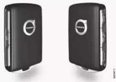
natural_image
Two black USB flash drives with circular logo designs, shown from front and side views (no text or symbols on device body)The figure is schematic - parts may vary depending on car model.
- Press the remote control key 📋 button to lock the car.
For the lock sequence to be activated, the driver door must be closed ^4 . If any of the other doors or the boot lid are open, these are locked and alarmed ^ only when they are closed. The alarm's movement detectors ^ are activated when all the doors and the boot lid are closed and locked.

NOTE
Be aware of the risk of locking the remote control key in the car.
- A remote control key or key tag left in the car will be deactivated when the car is locked and the alarm is armed using another valid key. The "Double lock" function is also deactivated. The key left behind is reactivated when the car is unlocked.
- A Care Key left in the car will be deactivated even when the car is locked using Volvo On Call, and reactivated when the car is unlocked using Volvo On Call or with another valid key.
Locking when the boot lid is open

NOTE
If the car has been locked while the boot lid is open, be careful not to leave the remote control key in the cargo area when the boot lid is closed and the car is completely locked ^4 .
Unlocking with the remote control key
- Press the remote control key button to unlock the car.
Automatic relocking
If none of the doors or the boot lid is opened within 2 minutes of unlocking, they are locked automatically. This function prevents the car from being left unlocked unintentionally.
When the remote control key does not work

NOTE
Always try moving closer to the car and making another unlock attempt.
If it is not possible to lock or unlock with the remote control key, the battery may be discharged - in which case, lock or unlock the driver's door with the detachable key blade.
Related information
- Settings for remotely controlled and inside unlocking (p. 243)
- Unlocking the boot lid with the remote control key (p. 244)
• Remote control key (p. 240) - Replacing the battery in the remote control key (p. 245)
- Locking and unlocking with the detachable key blade (p. 252)
Settings for remotely controlled and inside unlocking
It is possible to select different sequences for remotely controlled unlocking.
To change setting:
- Tap on Settings in the centre display's top view.
- Press My Car Locking Remote and Interior Unlock.
- Select option:
- All Doors - unlocks all doors simultaneously.
- Single Door - unlocks the driver's door. Unlocking all of the doors requires two presses on the remote control key's unlock button.
The settings made here also affect central unlocking via opening handles from the inside.
Related information
- Locking and unlocking with the remote control key (p. 242)
- Locking and unlocking from inside the car (p. 273)
KEY, LOCKS AND ALARM
Unlocking the boot lid with the remote control key
It is possible to unlock just the boot lid using a button on the remote control key.
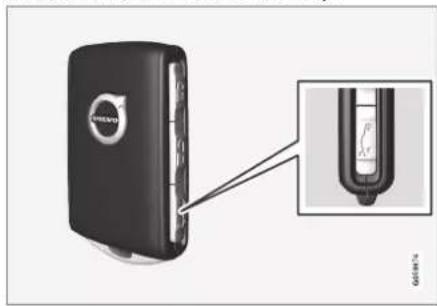
natural_image
Close-up of a black Volvo car with a close-up inset showing internal components (no text or symbols visible)- Press the remote control key's button.
The boot lid is unlocked but remains closed.
The side doors are still locked and the alarm is armed*. The lock and alarm indicator on the instrument panel extinguishes in order to show that the entire car is not locked.
If the boot lid is not opened within 2 minutes then it is relocked and the alarm is re-armed.
Power operated boot lid\*
- Hold the remote control key cotton depressed (approx. 1.5 seconds).
The boot lid opens mechanically while the side doors remain locked and their alarm functions armed.
Related information
- Locking and unlocking with the remote control key (p. 242)
Remote control key range
In order for the remote control key to work properly it needs to be within a certain distance from the car.
For manual use
The remote control key's functions for e.g. locking/unlocking that are activated by pressing on 🔒 or 🔒 have a range that extends approx. 20 metres (65 feet) from the car.
If the car does not verify a button being pressed - move closer and try again.
For keyless* use
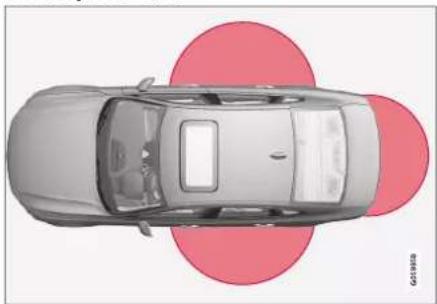
natural_image
Top-down view of a car with two red circular overlays (no text or symbols)The marked area in the illustration shows areas covered by the system's antennas.
For keyless use, a remote control key or the button-less key (Key Tag) must be within a semicircular area with a radius of approx.
* Option/accessory.
1.5 metres (5 feet) on both long sides and approx. 1 metre (3 feet) from the boot lid.

NOTE
The remote control key functions may be disrupted by surrounding radio waves, buildings, topographical conditions, etc. The car can always be locked/unlocked with the key blade.
If the remote control key is removed from the car

If the remote control key is removed from the car when the engine is running, the warning message Car key not found Removed from car is
shown in the driver display and an acoustic reminder sounds when the last door is closed.
The message extinguishes when the key is returned to the car, followed by a press of the right-hand keypad's O button, or when the last door is closed.
Related information
• Remote control key (p. 240)
- Antenna locations for the start and lock systems (p. 272)
• Keyless and touch-sensitive surfaces* (p. 269)
Replacing the battery in the remote control key
The battery in the remote control key needs to be replaced when it has become discharged.
NOTE
All batteries have a limited service life and must eventually be replaced (does not apply to Key Tag). The service life of the battery varies depending on how often the vehicle/key is used.

The battery for the remote control key should be replaced if
- the information symbol illuminates and the message Car key battery low is shown in the driver display
- the locks repeatedly do not react to signals from the remote control key within 20 metres (65 feet) of the car.

NOTE
Always try moving closer to the car and making another unlock attempt.
The battery in the button-less key ^5 (Key Tag) cannot be replaced - a new key can be ordered from an authorised Volvo workshop.

IMPORTANT
A discharged Key Tag must be handed over to an authorised Volvo workshop. The key must be deleted from the car since it is still possible to use it to start the car via back-up start.
KEY, LOCKS AND ALARM
Opening the key and changing the battery

1 Hold the remote control key with the front visible and the Volvo logo facing the right way - slide the button at bottom edge by the key ring to the right. Slide the front side's shell a few millimetres upwards.
The shell will then come free and can be lifted off the key.

2 Turn the key, move the button to the side and slide the back shell a few millimetres upwards.
The shell will then come free and can be lifted off the key.

natural_image
3D illustration of a screwdriver pressing down on a black electronic device with a red arrow indicating rotation (no text or symbols)3 Use a screwdriver or similar to turn the battery cover anticlockwise until the markings meet at the OPEN text.
Carefully lift away the battery cover by pressing e.g. a fingernail into the recess.
Then prize the battery cover upwards.
KEY, LOCKS AND ALARM

natural_image
3D model of a black and silver device with a red upward arrow on the cover (no text or symbols)4 The battery (+) side is facing upwards. Then carefully prize loose the battery as illustrated.
IMPORTANT
Avoid touching new batteries and their contact surfaces with your fingers as this may impair their function.
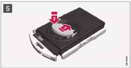
natural_image
3D rendering of a black electronic device with a circular button and directional arrows, no visible text or symbols5 Install a new battery with the (+) side up. Avoid touching the remote control key's battery contacts with your fingers.
Place the battery in the holder with the edge down. Then slide the battery forwards so that it fastens under the two plastic catches. Press the battery down so that it fastens under the upper black plastic catch.
NOTE
Use batteries with the designation CR2032, 3 V.
NOTE
Volvo recommends that the batteries to be used in the remote control key fulfil UN Manual of Test and Criteria, Part III, subsection 38.3. Batteries fitted in the factory or replaced by an authorised Volvo workshop fulfil the above criteria.

natural_image
3D diagram of a device with a tool and red arrow indicating rotation or movement (no text or symbols)6 Refit the battery cover and turn it clockwise until the marking aligns with the CLOSE text.
KEY, LOCKS AND ALARM
◀◀

natural_image
Black hard drive cover with red directional arrows indicating left and right sides (no text or symbols)7 Reposition the rear side's shell and press it down until a clicking sound can be heard.
2 Then slide the shell back.
A further click will indicate that the shell is properly positioned and securely attached.
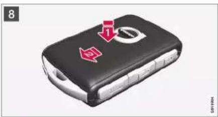
natural_image
Black handheld car with red warning sign and arrow pointing to a circular symbol (no text or numbers visible)8 Turn the remote control key over and refit the front side's shell by pressing it down until a clicking sound can be heard.
2 Then slide the shell back.
A further click will indicate that the shell is securely attached.

WARNING
Check that the battery is fitted correctly with the correct polarity. If the remote control key shall not be used for a long time, remove the battery to avoid battery leakage and damage. Batteries with damage or leaks may cause corrosive injury on contact with the skin. Therefore, use protective gloves when handling damaged batteries.
- Keep batteries out of the reach of children.
- Do not leave batteries lying around since they can be swallowed by children or pets.
- Batteries must not: be dismantled, short-circuited or thrown into open flames.
- Do not charge non-rechargeable batteries, this may cause an explosion.
Before use, the remote control key should be checked to avoid causing damage. If damage is discovered, e.g. if the battery cover cannot be closed properly, then the product should not be used. Keep defective products out of the reach of children.

IMPORTANT
Make sure that exhausted batteries are disposed of in a manner which is kind to the environment.
KEY, LOCKS AND ALARM
Related information
- Locking and unlocking with the detachable key blade (p. 252)
• Starting the car (p. 446)
• Remote control key (p. 240)
Ordering more remote control keys
The car is supplied with two remote control keys. A button-less key is supplied if the car is equipped with keyless locking and unlocking*. Additional keys can be ordered.
A total of twelve keys can be programmed and used for one single car. If additional keys are ordered, additional driver profiles are added - one per new remote control key. This also applies for the key tag.
Loss of a remote control key
If you lose a remote control key then a new one can be ordered at a workshop - an authorised Volvo workshop is recommended. The remaining remote control keys must be taken to the workshop. The code of the missing key must be erased from the system as a theft prevention measure.
The current number of keys registered to the car can be checked via driver profiles in the centre display's top view, select Settings →
System Driver Profiles.
Related information
• Remote control key (p. 240)
Care Key - restricted remote control key
A Care Key allows the car owner to set a limit for the speed of the car. The limitation is intended to encourage the car to be driven in a safe manner such as when being loaned out, for example.
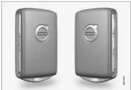
natural_image
Two identical Volvo 3.0s hard drives displayed side by side, no visible text or symbols on the device body.For a Care Key, you can set your car's maximum speed. Other functions of the key are the same as those of a normal remote control key.
The limits are intended to act as measures to reduce the risk of accidents, thereby making it feel safer to hand over the car to e.g. young drivers, valet parking or a workshop.
Ordering Care Key
One or more Care Key can be ordered from a Volvo dealer. A total of eleven keys with restrictions can be programmed and used for
▶▶
KEY, LOCKS AND ALARM
a single car - at least one must be a normal remote control key.
Limitations of Care Key
The key is linked to a special Care Key driver profile, and when it is active, the key's settings cannot be changed. It is not possible to change to another driver profile either; this requires a normal remote control key.
The driver profile is activated when the car is unlocked with a Care Key without a normal remote control key in the vicinity.

NOTE
In the event of a change of driver, the car must be locked and unlocked in order to activate a new driver profile.
Setting options
The following limitations are available to be set:
• speed interval: 50-180 km/h (30-112 mph)
• Increments: 1 km/h (1 mph)
| Symbol Specification | |
| Speed limitation is active. | |
Related information
• Care Key settings (p. 250)
• Remote control key (p. 240)
Care Key settings
Change the maximum speed of a Care Key via the centre display.
- Unlock the car with the normal remote control key.
-
Tap on Settings in the centre display's top view.
-
Press System Driver Profiles Care Key.
-
Change the settings you want.
Related information
- Care Key - restricted remote control key (p. 249)
KEY, LOCKS AND ALARM
Detachable key blade
The remote control key contains a detachable key blade of metal with which a number of functions can be activated and some operations carried out.
The key blade's unique code is provided by authorised Volvo workshops, which are recommended when ordering new key blades.
The key blade's application areas
Using the remote control key's detachable key blade
- the left-hand ^7 front door can be opened manually if central locking cannot be activated with the remote control key
• all doors are emergency-locked - the rear doors' mechanical child lock can be activated and deactivated.
The button-less key ^8 does not have a detachable key blade. If necessary, use the detachable key blade from the normal remote control key.
Detaching the key blade
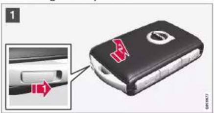
1 Hold the remote control key with the front visible and the Volvo logo facing the right way - slide the button at bottom edge by the key ring to the right. Guide the front side's shell a few millimetres upwards.
2 The shell will then come free and can be lifted off the key.

natural_image
3D illustration of a black battery pack with a red upward arrow on top (no text or symbols)2 Detach the key blade by angling it up.

natural_image
Black car keychain with red warning symbol and arrow pointing to a circular button (no text or symbols on the main body)3 Return the key blade to its intended position in the remote control key after use.
Refit the shell by pressing it downward until a clicking sound is heard.
2 Then slide the shell back.
A further click will indicate that the shell is securely attached.
KEY, LOCKS AND ALARM
Related information
- Locking and unlocking with the detachable key blade (p. 252)
• Remote control key (p. 240)
Locking and unlocking with the detachable key blade
Amongst other things, the detachable key blade can be used to unlock the car from the outside - e.g. if the remote control key's battery has become discharged.
Unlocking

natural_image
Two-panel image showing a car interior with highlighted parts, no text or symbols present.Pull out the front door handle on the left-hand side to its end position so that the lock cylinder becomes visible ^9 .
2 Insert the key in the lock cylinder.
3) Turn clockwise 45 degrees so that the key blade is pointing straight back.
Turn the key back 45 degrees to its starting position. Remove the key from the lock cylinder and release the handle so that the rear section of the handle is resting against the car again.
- Pull out the handle.
The door opens.
NOTE
When the door is unlocked using the key blade and is then opened, the alarm is triggered. The alarm must be deactivated manually, see separate section.
Locking
The left-hand front door can be locked with its lock cylinder and the detachable key blade.
The other doors have a locking switch at the end that must be pushed in using the key blade – then they are mechanically locked/inhibited from opening from outside.
The doors can still be opened from the inside.
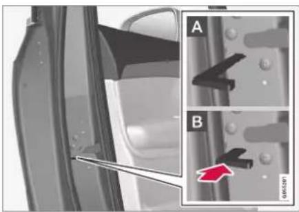
natural_image
Close-up of a car door panel with a tool inserted, showing two views (A and B) of the handle and a red arrow pointing to a component on the side (no text or symbols present)Manual locking of the door. Not to be confused with the child safety lock.
- Remove the detachable key blade from the remote control key.
- Insert the key blade in the hole for lock reset.
- Press in the key until the key bottoms, approximately 12 mm (0.5 inches).
A The door can be opened from both the outside and the inside.
B The door is blocked against opening from the outside. To return to position A, the inner door handle must be opened.
NOTE
- A door's lock reset only locks that particular door - not all doors simultaneously.
- A manually locked rear door with child lock activated cannot be opened from inside or outside. The door can then only be unlocked with the key buttons, central locking button, the keyless locking system* or Volvo On Call*.
Related information
• Detachable key blade (p. 251)
- Activating and deactivating alarms* (p. 282)
• Starting the car (p. 446)
- Replacing the battery in the remote control key (p. 245)
• Remote control key (p. 240)
Immobiliser
The electronic immobiliser is a theft protection system that prevents an unauthorised person from starting the car.
The car can only be started with the correct remote control key.
The following error message in the driver display is related to the electronic immobiliser:
| Symbol | Message Specification | |
 | Car key not foundSeeOwner's manual | Error reading the remote control key during starting - place the key on the key symbol in the cup holder and try again. |
Related information
• Remote control key (p. 240)
- Ordering more remote control keys (p. 249)
KEY, LOCKS AND ALARM
Type approval for the remote control key system
Type approval for the car's remote key system can be seen in the following tables.
For detailed information on type approval, go to volvocars.com.
Lock system keyless start (Passive Start) and keyless locking/unlocking (Passive Entry*)
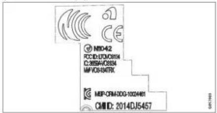
CEM marking for the remote control key system. For supplementary type approval numbers, see following tables.
| Country/Area Type approval | |
| Argentina CNC ID: C-14771 | |
| Brazil MT-3245/2015 |  ANATEL0589-15-6830 ANATEL0589-15-6830 (01) 0 7897843840961### (01) 0 7897843840961### |
KEY, LOCKS AND ALARM
| Country/Area Type approval | ||
| Europe Delphi Deutschland | GmbH, 42367 Wuppertal hereby declares that this VO3-134TRX conforms to the essential property requirements and other relevant provisions contained in directive 2014/53/EU (RED).The full text of the EU declaration of conformity can be found at volvocars.com | |
| The United Arab Emi-rates | ER37847/15DA0062437/11 | |
| Indonesia Nomor: 38301/SDPPI/2015 | ||
| Jordan TRC/LPD/2014/250 | ||
| Malaysia RDBV/29A/1118/S(18-4233), RDBV/23A/1018/S(18-4231) | ||
| Mexico IFETEL: RLVDEVO15-0396 | ||
| Namibia TA-2016-02 |  Communications Regulatory Authority of Namibia Communications Regulatory Authority of Namibia | |
▶▶
KEY, LOCKS AND ALARM
◀◀
| Country/Area Type approval | |
| Russia | |
| Serbia P1614120100 | |
| South Africa TA-2014-1868 |  |
KEY, LOCKS AND ALARM
Remote control key
KEY, LOCKS AND ALARM
◀◀
| Country/Area Type approval | ||
| Philippines ESD-1919938C |  NTCType ApprovedNo.: ESD-1919938CGEN703 NTCType ApprovedNo.: ESD-1919938CGEN703 | |
| The United Arab Emirates | TRA REGISTERED No:ER72465/19 DEALER No:DA36976/14GEN703 | |
| Ghana NCA Approved: ZRO-M8-7E3-138 | ||
| IndonesiaA | Sertifikat Nomor: 65073/SDPPI/2019PLG ID: 8093 |  |
NTC
KEY, LOCKS AND ALARM
| Country/Area Type approval | ||
| CU (Customs Union)Kazakhstan, Russia |  | |
| Morocco AGREE | PAR L'ANRT MAROCNuméro d'agrément: MR 20402 ANRT 2019Date d'agrément: 10/07/2019 | |
| Moldova |  | |
| Nigeria Connection and use of this communication equipment is permitted by the Nigerian Communications Commission | ||
| Oman | 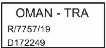 | |
▶▶
KEY, LOCKS AND ALARM
◀◀
KEY, LOCKS AND ALARM
KEY, LOCKS AND ALARM
◀◀
| Country/Area Type approval | |
| Belarus | |
| Zambia |
A Only applies to Indonesia.
KEY, LOCKS AND ALARM
Key Tag
KEY, LOCKS AND ALARM
◀◀
| Country/Area Type approval | |
| Philippines ESD-1919939C |  NTCType ApprovedNo.: ESD-1919939CGM7001 NTCType ApprovedNo.: ESD-1919939CGM7001 |
| The United Arab Emirates | TRA REGISTERED No:ER72467/19 DEALER No:DA36976/14GPT7002 |
| CU (Customs Union)Kazakhstan, Russia |
KEY, LOCKS AND ALARM
| Country/Area Type approval | ||
| Indonesia^A | Sertifikat Nomor: 65072/SDPPI/2019PLG ID: 8093 |  |
| Morocco AGREE | PAR L'ANRT MAROCNuméro d'agrément: MR 20403 ANRT 2019Date d'agrément: 10/07/2019 | |
| Moldova |  | |
| Nigeria Connection and use of this communications equipment is permitted by the Nigerian Communications Commission | ||
| Oman |  | |
KEY, LOCKS AND ALARM
◀◀
KEY, LOCKS AND ALARM
KEY, LOCKS AND ALARM
◀◀
| Country/Area Type approval | |
| Belarus | |
| Zambia |
A Only applies to Indonesia.
Related information
• Remote control key (p. 240)
Keyless and touch-sensitive surfaces\*
With the keyless locking and unlocking function, carrying the remote control key in a pocket or bag will suffice. The car is locked or unlocked via a touch-sensitive surface on the door handle.
Touch-sensitive surfaces
Door handle
The outside of the door handles contains a recess for locking, while the inside contains a touch-sensitive surface for unlocking.

1 Touch-sensitive recess for locking
② Touch-sensitive surface for unlocking
i NOTE
It is important that only one touch-sensitive surface is activated at a time. Gripping the handle while touching the lock surface risks giving double commands. This means that the requested activity (locking/unlocking) will not be executed, or will be executed with a delay.
Boot lid handle
The boot lid handle has a rubberised pressure plate that is only used for unlocking.

natural_image
Front view of a modern sedan car with visible grille and dashboard (no text or symbols)NOTE
Be aware that the system may be activated in connection with car washing if the remote control key is in range.
Related information
• Keyless locking and unlocking* (p. 270)
• Keyless* unlocking of boot lid (p. 271)
KEY, LOCKS AND ALARM
Keyless locking and unlocking\*
With keyless locking and unlocking, it is sufficient to touch the door handle's touch-sensitive surface to lock or unlock the car.

NOTE
One of the car's remote control keys must be within range for locking and unlocking to work.

1 Touch-sensitive recess for locking
② Touch-sensitive surface for unlocking

NOTE
Be aware that the system may be activated in connection with car washing if the remote control key is in range.
Keyless locking
All side doors must be closed to be able to lock the car. The boot lid, on the other hand, can be open when locking the car with a side door handle.
- Touch the marked surface towards the rear on the outside of a door handle after the door has been closed. Or press the
button on the underside of the boot lid before it closes.The lock indicator on the instrument panel starts to flash to indicate the car is locked.
To close all side windows and the sunroof simultaneously - place a finger against the touch-sensitive recess on the outside of the door handle and hold it there until all side windows and the sunroof have been closed.
Locking when the boot lid is open
If the car has been locked and the boot lid is still open, make sure that the remote control key is not left in the cargo area when the boot lid is closed.

NOTE
If the key is detected inside the car, the boot lid will not lock when it is closed.
Keyless unlocking
- Grasp a door handle or gently press the rubberised pressure plate beneath the boot lid handle to unlock the car.
The lock indicator on the instrument panel stops flashing to indicate that the car is unlocked.

natural_image
Front view of a silver sedan with visible rear livery and dashboard, showing front panel and side window (no text or symbols)Rubberised pressure plate on the boot lid can only be used for unlocking.
Automatic relocking
If none of the doors or the boot lid is opened within 2 minutes of unlocking, they are locked automatically. This function prevents the car from being left unlocked unintentionally.
Related information
- Settings for Keyless entry* (p. 271)
• Keyless* unlocking of boot lid (p. 271)
• Keyless and touch-sensitive surfaces* (p. 269)
Settings for Keyless entry\*
It is possible to select different sequences for Keyless entry.
To change setting:
- Tap on Settings in the centre display's top view.
- Tap on My Car Locking Keyless Unlock
- Select option:
- All Doors - unlocks all doors simultaneously.
- Single Door - unlocks selected door.
Related information
• Keyless locking and unlocking* (p. 270)
• Keyless and touch-sensitive surfaces* (p. 269)
Keyless\* unlocking of boot lid
With keyless locking and unlocking, it is sufficient to press lightly on the rubberized pressure plate on the boot lid handle to unlock.
NOTE
One of the car's remote control keys must be within range behind the car for unlocking to work.
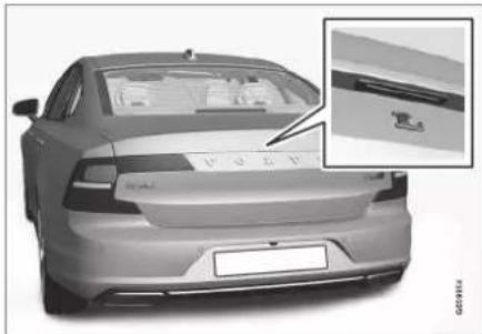
natural_image
Front view of a silver sedan with visible grille and side panel, showing rear livery and dashboard (no text or symbols)The boot lid is held closed by an electrical lock.
To open:
- Press gently on the rubberised pressure plate beneath the boot lid handle.
The lock is released.
▶▶
KEY, LOCKS AND ALARM
- Lift by the outside handle in order to open the boot lid.
IMPORTANT
- Minimal force is required to release the boot lid's lock - just gently press the rubberised panel.
- Do not place the lift force on the rubber panel when opening the boot lid - lift the handle. Using too much force may damage the electrical contacts on the rubber panel.
It is also possible to open the boot lid hands-free with a kicking motion under the rear bumper, see separate section.
WARNING
Do not drive with an open boot lid! Toxic exhaust fumes could be drawn into the car through the cargo area.
Related information
- Operating the boot lid with foot movement* (p. 277)
• Keyless and touch-sensitive surfaces* (p. 269)
• Remote control key range (p. 244)
Antenna locations for the start and lock systems
An antenna for the keyless starting system and antennas for the keyless locking system* are built into the car.

Antenna locations:
1 Under the cup holder in the front section of the tunnel console
② In the upper front section of the left-hand rear door ^10
3 In the upper front section of the right-hand rear door ^10
4 In the cargo area ^10
WARNING
People with pacemaker operations should not come closer than 22 cm (9 inches) to the keyless system's antennas with their pacemaker. This is to prevent interference between the pacemaker and the keyless system.
Related information
• Keyless and touch-sensitive surfaces* (p. 269)
• Remote control key range (p. 244)
KEY, LOCKS AND ALARM
Locking and unlocking from inside the car
The doors and boot lid can be locked and unlocked from inside using the central locking controls in the front doors.
Central locking

natural_image
Close-up of a car interior panel with two connected buttons (no text or symbols visible)Locking and unlocking button with indicator lamp in the front door.
Unlocking using a button in the front door
- Press the button to unlock all side doors and the boot lid.
Alternative unlocking method

natural_image
Close-up of a car's side panel showing the front and rear door, with no visible text or symbols.Opening handle for alternative unlocking in the side door ^11 .
- Pull the opening handle on one of the side doors and release.
Depending on the settings in the remote control key, either all doors will be unlocked or only the selected door will be unlocked and opened.
To change this setting, tap on Settings → My Car Locking Remote and Interior Unlock in the centre display's top view.
Locking using a button in the front door
- Press the Button - both front doors must be closed.
All doors and the boot lid are locked.
Locking using a button in the rear door*

natural_image
Close-up of a car's front panel showing a black padlock icon on a textured surface (no text or symbols visible)Locking button with indicator lamp in the rear door.
The rear door lock buttons lock their respective rear door.
Unlocking the rear door
- Pull the opening handle.
The rear door is unlocked and opened ^12 .
KEY, LOCKS AND ALARM
Related information
- Settings for remotely controlled and inside unlocking (p. 243)
- Unlocking the boot lid from the inside of the car (p. 274)
- Activating and deactivating child safety locks (p. 274)
Unlocking the boot lid from the inside of the car
The boot lid can be unlocked from inside by pressing the button on the instrument panel.

natural_image
Close-up of a car dashboard control panel with buttons and icons (no readable text or symbols)- Brief press on the button on the instrument panel.
The boot lid can be unlocked and opened from the outside by grasping the rubberised pressure plate.
With the power operated boot lid option*:
- Long press on the button on the instrument panel.
The boot lid opens.
Related information
- Locking and unlocking from inside the car (p. 273)
Activating and deactivating child safety locks
The child safety lock prevents the rear doors from being opened from inside.
The child lock can be either manual or electrical*.
Manual child lock
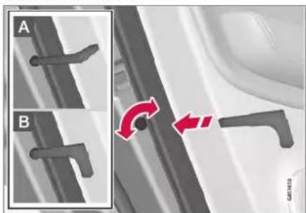
Manual child lock. Not to be confused with manual door locks.
- Use the remote control key's detachable key blade to turn the knob.
A The door is blocked against opening from the inside.
B The door can be opened from both the outside and the inside.

NOTE
- A door's knob control only blocks that particular door - not both rear doors simultaneously.
• Cars with an electric child safety lock do not have a manual child lock.
Electric child lock\*
The electric child lock can be activated and deactivated in all ignition positions above 0. Activation and deactivation can be performed up to 2 minutes after switching off the car, provided that no door is opened.

natural_image
Close-up of a car air conditioner control panel with an open button and indicator lights (no text or symbols visible)Activation and deactivation button.
- Lamp lit – the lock is activated.
- Lamp not lit - the lock is deactivated.
When the child lock is activated, the following is possible, the rear:
- windows are only opened with the buttons in the driver's door.
• doors cannot be opened from inside. If the child lock is activated when the car is switched off, it will remain activated the next time the car is started.
Symbols and messages
| Symbol | Message Specification | |
| Rear child lock Activated | The child lock is activated. | |
| Rear child lock Deactivated | The child lock is deactivated. | |
Related information
- Locking and unlocking from inside the car (p. 273)
• Detachable key blade (p. 251)
Automatic locking when driving
The doors and boot lid are locked automatically when the car starts to move.
To change this setting:
-
Tap on Settings in the centre display's top view.
-
Press My Car Locking.
-
Select Auto Lock Doors While Driving to deactivate or activate this function.
Related information
- Locking and unlocking from inside the car (p. 273)
KEY, LOCKS AND ALARM
Closing and locking boot lid with button\*
The buttons on the underside of the boot lid can close and lock the car automatically.

natural_image
Interior view of a car trunk with a control panel and two icons on the side (no text or symbols visible)Location of button/buttons on the underside of the boot lid.
IMPORTANT
During manual boot lid operation, open or close it slowly. Do not use force to open/ close it if there is resistance. It may be damaged and stop working correctly.
Closing ^13
- Press the button on the underside of the boot lid.
The boot lid closes automatically and remains unlocked.
NOTE
- The button is active 24 hours after the hatch has been left open. Thereafter, it must be closed manually.
- If the flap has been open for more than 30 minutes, it will close at a slow speed.
Locking ^14
- Press the button on the underside of the boot lid.
- Close the hatch manually.
The boot lid and the doors are locked
Closing and locking ^15
- Press the button on the underside of the boot lid.
The boot lid is closed automatically and the car is locked ^16 .
NOTE
- One of the car's remote control keys must be within range for locking and unlocking to work.
- When using keyless* locking or closing, three signals will sound if the key is not detected sufficiently close to the tail-gate.
13 Applies to cars with power operated boot lid.
^14 Applies to cars with the keyless locking/unlocking option.
^15 Applies to cars with keyless locking/unlocking and power operated boot lid.
16 All doors must be closed for locking the car.
Cancel closing
- Press the button on the instrument panel.
- Press the remote control key's button.
- Press the closing button on the underside of the boot lid ^13 .
- Press the rubberised pressure plate beneath the outside handle.
• Using a kicking motion*.
The movement of the boot lid is stopped, and it returns to fully open. The boot lid can then be operated manually.
Pinch protection
If something with sufficient resistance prevents the boot lid from closing then the pinch protection is activated.
- The movement is stopped, the boot lid returns to fully open and a long signal sounds.

WARNING
Pay attention to the risk of crushing when closing.
Check that there is nobody near the boot lid before starting to close it as a crush injury may have severe consequences.
Always operate the boot lid with caution.
Related information
- Operating the boot lid with foot movement* (p. 277)
• Remote control key range (p. 244)
Operating the boot lid with foot movement\*
A function which allows the boot lid to open and close by moving a foot under the rear bumper makes life easier when your hands are full.
If the car is equipped with keyless locking and unlocking* then you can open the boot lid with a foot movement.
The function with both opening and closing of the boot lid is also available when the car is equipped with power operated boot lid*.

NOTE
The foot-operated boot lid function is available in two versions:
• Only opening with foot movement.
- Both opening and closing with foot movement.
Note that the function for closing with foot movement requires power operated boot lid*.
KEY, LOCKS AND ALARM
◀◀

natural_image
Diagram of a car's rear suspension system with red sensor waves (no text or labels)The sensor is positioned to the left of centre in the bumper.
One of the car's remote control keys must be within range behind the car, approx. 1 metre (3 feet), for opening and closing to be possible. This also applies to an already unlocked car in order to avoid accidental opening e.g. in a car wash.
Opening and closing with foot movement

natural_image
Illustration of a person's foot stepping on a car tire with red sound waves indicating motion (no text or symbols)Kicking motion within the detector's activation area.
- Make one forward kicking motion under the left part of the rear bumper. Then take a step back. The bumper must not be touched.
A short acoustic signal sounds when opening and closing is activated - the boot lid is opened/closed.
If several kicking motions take place without an approved remote control key being located behind the car, opening or closing will not be possible until after a certain delay.
Do not leave your foot positioned under the car during the kicking motion. This could cause activation to fail.
Cancel closing with a foot movement
- Make one forward kicking motion while closing is in progress in order to stop the movement of the boot lid.
The movement of the boot lid is stopped and it returns to fully open. The boot lid can then be operated manually.
The remote control key does not have to be in the vicinity of the car to cancel closing.

NOTE
There is a risk of reduced function, or no function, if the rear bumper is loaded with large amounts of ice, snow, dirt or similar. For this reason, make sure you keep it clean.

NOTE
Pay attention to the possibility that the system may be activated in a car wash or similar if the remote key is within range.
Related information
• Keyless and touch-sensitive surfaces* (p. 269)
• Remote control key range (p. 244)
Private locking
The boot lid and rear seat backrest can be locked with the private locking function when the car is taken in for service, left at a hotel or similar. The function prevents the boot lid from being opened and locks the rear seat backrest in upright position.

The private locking function button is located in the centre display function view. Depending on the current status of the lock, Private Locking Unlocked or Private Locking Locked is
shown.
Related information
- Activating and deactivating private locking (p. 279)
Activating and deactivating private locking
Private locking is activated with a function button in the centre display and an optional PIN code.
NOTE
The car needs to be in ignition mode I as a minimum for the private locking function to be activated.
Private locking has two codes:
- A security code is created the first time the function is used.
- A new PIN code is selected every time the function is activated.
Enter the security code before using for the first time
A security code needs to be selected during the first time the function is used. It can then be used to deactivate private locking if the selected PIN code has been forgotten or lost. The security code acts as a PUK code for all subsequent PIN codes set for the private locking function.
Save the security code in a safe place.
To create a security code:
- Press the button for private locking in the function view.

A pop-up window is shown.
- Enter the preferred security code and press Confirm.
The security code is saved. The private locking function is now ready for activation.
Activate private locking
NOTE
When private locking is activated, the rear seat must be in upright position for locking to work.
KEY, LOCKS AND ALARM
- Press the button for private locking in the function view.

A pop-up window is shown.
- Enter the code to be used in order to unlock the boot lid and rear seat after locking and tap on Confirm.
The boot lid and rear seat are locked. Confirmation of locking takes place by means of a green indicator being shown by the button in the function view.
Deactivate private locking
- Press the button for private locking in the function view.

A pop-up window is shown.
- Enter the code that was used for locking and tap on Confirm.
The boot lid and rear seat are unlocked. Confirmation of unlocking takes place by means of the green indicator by the button in the function view extinguishing.
Forgotten PIN code
If the PIN code has been forgotten or the wrong PIN code has been entered more than three times, the security code can be used to deactivate private locking.
If the car is unlocked via Volvo On Call* or the Volvo On Call app, private locking will be deactivated automatically.
Forgotten security code
If the security code has also been forgotten, contact an authorised Volvo dealer for help with deactivating private locking.
Related information
• Private locking (p. 279)
Alarm\*
The alarm provides audible and visual warnings if anyone enters the car without a valid remote control key or manipulates the starter battery or alarm siren.
Alarm indicator

natural_image
Close-up of a car's rear wheel and side mirror, showing a red sensor or sensor on the windshield (no text or symbols visible)A red LED on the instrument panel indicates the alarm system's status:
• LED not lit – alarm not armed.
- The LED flashes once every other second – alarm is armed.
- After the alarm has been disarmed, the LED flashes rapidly for a maximum of 30 seconds or until ignition position I has been activated - the alarm has been triggered.
When armed, the alarm is triggered if:
- a door, the bonnet or the boot lid is opened ^17
- a movement is detected in the passenger compartment (if fitted with a movement detector*)
- the car is raised or towed away (if fitted with a tilt detector*)
• the starter battery's cable is disconnected
• the siren is disconnected.
Alarm signals
When the alarm has been triggered, the following happens:
- A siren sounds for 30 seconds or until the alarm is switched off.
- Hazard warning flashers flash for 5 minutes or until the alarm is switched off.
If the cause of alarm activation is not rectified, the alarm cycle is repeated up to 10 times ^17 .
Movement and tilt sensors\*
Movement and tilt detectors react to movements inside the car ^18 e.g. if the window is broken or if anyone tries to tow the car away.
To avoid triggering the alarm unintentionally:
- Close all windows when leaving the car.
- Close the hatch.
- If the climate control is used – aim the airflow so that it does not point upwards in the passenger compartment.
It is also possible to reduce the alarm level in the centre display.
Symbols and messages
| Symbol | Message Specification | |
 | Alarm system failureService required | Contact a workshop – an authorised Volvo workshop is recommended. |
NOTE
Do not attempt to repair or alter components in the alarm system yourself. Any such attempts may affect the terms of the insurance.
Related information
- Activating and deactivating alarms* (p. 282)
• Reduced alarm level* (p. 282)
• Double lock* (p. 283)
KEY, LOCKS AND ALARM
Activating and deactivating alarms\*
The alarm is activated when the car is locked, and is deactivated when the car is unlocked. It is also possible to deactivate the alarm without a working key.
Activating and deactivating alarms
The alarm is activated when the car is locked, and is deactivated when the car is unlocked.
Deactivate the alarm without a functioning remote control key
The car can be unlocked and disarmed even if the remote control key does not work e.g. if the remote control key's battery is dead.
- Open the driver's door with the detachable key blade.
The alarm is triggered.

The backup reader's location in the cup holder.
- Place the remote control key on the key symbol in the backup reader in the tunnel console's cup holder.
- Turn the start knob clockwise and release it.
The alarm is deactivated.
Switching off a triggered alarm
- Press the remote control key's unlock button or set the car in ignition position I by turning the start knob clockwise and then releasing.
Related information
- Alarm* (p. 280)
Reduced alarm level\*
Reduce the alarm level, e.g. when travelling on a car ferry.
The alarm's movement and tilt detectors react to movements inside the car. These detectors are switched off in reduced alarm level.
Activating reduced alarm level
- Press the Reduced Guard button in the centre display function view.
The function is now activated.
Related information
- Alarm* (p. 280)
• Double lock* (p. 283)
KEY, LOCKS AND ALARM
Double lock\*
Double lock means that all opening handles are released mechanically when locking from the outside, which makes it impossible to open the doors from the inside.
Double lock is activated when locking with a remote control key or with keyless locking*, and takes place with a delay of approx.
10 seconds after the doors have locked. If a door is opened within the delay time then the sequence is interrupted and the alarm is deactivated.
The car can only be unlocked with a remote control key, keyless unlocking* or the Volvo On Call app * when double lock is activated.
The front left door can also be unlocked with the detachable key blade. If the car is unlocked with the detachable key blade, the alarm will be triggered.

WARNING
Do not lock the car from the outside while there is anyone left in the car.
Related information
• Reduced alarm level* (p. 282)
- Alarm* (p. 280)

bar
| Category | Value | |---|---| | Category 1 | 100 | | Category 2 | 100 | | Category 3 | 100 | | Category 4 | 100 | | Category 5 | 100 | | Category 6 | 100 | | Category 7 | 100 | | Category 8 | 100 | | Category 9 | 100 | | Category 10 | 100 | | Category 11 | 100 | | Category 12 | 100 | | Category 13 | 100 | | Category 14 | 100 | | Category 15 | 100 | | Category 16 | 100 | | Category 17 | 100 | | Category 18 | 100 | | Category 19 | 100 | | Category 20 | 100 | | Category 21 | 100 | | Category 22 | 100 | | Category 23 | 100 | | Category 24 | 100 | | Category 25 | 100 | | Category 26 | 100 | | Category 27 | 100 | | Category 28 | 100 | | Category 29 | 100 | | Category 30 | 100 | | Category 31 | 100 | | Category 32 | 100 | | Category 33 | 100 | | Category 34 | 100 | | Category 35 | 100 | | Category 36 | 100 | | Category 37 | 100 | | Category 38 | 100 | | Category 39 | 100 | | Category 40 | 100 | | Category 41 | 100 | | Category 42 | 100 | | Category 43 | 100 | | Category 44 | 100 | | Category 45 | 100 | | Category 46 | 100 | | Category 47 | 100 | | Category 48 | 100 | | Category 49 | 100 | | Category 50 | 100 | | Category 51 | 100 | | Category 52 | 100 | | Category 53 | 100 | | Category 54 | 100 | | Category 55 | 100 | | Category 56 | 100 | | Category 57 | 100 | | Category 58 | 100 | | Category 59 | 100 | | Category 60 | 100 | | Category 61 | 100 | | Category 62 | 100 | | Category 63 | 100 | | Category 64 | 100 | | Category 65 | 100 | | Category 66 | 100 | | Category 67 | 100 | | Category 68 | 100 | | Category 69 | 100 | | Category 70 | 100 | | Category 71 | 100 | | Category 72 | 100 | | Category 73 | 100 | | Category 74 | 100 | | Category 75 | 100 | | Category 76 | 100 | | Category 77 | 100 | | Category 78 | 100 | | Category 79 | 100 | | Category 80 | 100 | | Category 81 | 100 | | Category 82 | 100 | | Category 83 | 100 | | Category 84 | 100 | | Category 85 | 100 | | Category 86 | 100 | | Category 87 | 100 | | Category 88 | 100 | | Category 89 | 100 | | Category 90 | 100 | | Category 91 | 100 | | Category 92 | 100 | | Category 93 | 100 | | Category 94 | 100 | | Category 95 | 100 | | Category 96 | 100 | | Category 97 | 100 | | Category 98 | 100 | | Category 99 | 100 | | Total (Total) |DRIVER SUPPORT
DRIVER SUPPORT
Driving support systems
The car is equipped with different driver support systems which can assist the driver in different situations, either actively or passively.
For example, the systems can help the driver to:
- maintain a set speed
- maintain a certain time interval to the vehicle ahead
• prevent a collision by giving a warning to the driver and braking the car
• help the driver to park.
Some of the systems are fitted as standard while others are options – which alternative applies is market dependent.
Related information
- IntelliSafe – driver support and safety (p. 33)
• Speed-dependent steering force (p. 286)
• Electronic stability control (p. 287)
• Connected Safety (p. 292)
• City Safety™ (p. 348)
• Road Sign Information* (p. 294)
• Speed limiter (p. 301)
• Automatic speed limiter (p. 304)
• Cruise control (p. 308)
• Adaptive cruise control* (p. 311)
- Pilot Assist* (p. 321)
• Cornering support* (p. 333)
• Overtaking Assistance* (p. 335)
• Lane assistance (p. 341)
• Steering assistance at risk of collision (p. 362)
• Rear Collision Warning* (p. 368)
- BLIS* (p. 369)
• Driver Alert Control (p. 373)
• Distance Warning* (p. 375)
• Cross Traffic Alert* (p. 377)
• Park Assist* (p. 381)
• Park assist camera* (p. 387)
- Radar unit (p. 406)
- Camera unit (p. 415)
Speed-dependent steering force
Speed related power steering causes the steering wheel force to increase with the speed of the car so as to be able to give the driver enhanced sensitivity. On motorways the steering is firmer. When parking and at low speed steering is light and requires less effort.
Reduced power
In rare situations, the power steering may need to work at reduced power, and turning the steering wheel may then seem slightly heavier. This may occur when the power steering becomes too hot and then needs temporary cooling. It may also occur if the power supply is disrupted.

In the event of reduced power, the message Power steering Assistance temporarily reduced is shown, as well as this symbol in the driver display.
While the power steering is working at reduced power, the driver support functions and steering assistance systems are not available.

WARNING
If the temperature increases too much, the servo may be forced to switch off completely. In such a situation, the driver display shows the Power steering failure Stop safely message, combined with a symbol.
Change the steering force level\*
Steering wheel resistance can be adjusted when using INDIVIDUAL drive mode.
- Tap on Settings in the centre display's top view.
- Select My Car Drive Modes → Steering Force.
Steering wheel resistance selection can only be accessed if the car is stationary or is moving at low speed and in a straight line.
Related information
• Driving support systems (p. 286)
- Drive modes (p. 467)
Electronic stability control
Electronic Stability Control (ESC ^1 ) helps the driver to avoid skidding and improves the car's traction.

The driver display shows this symbol when the system is engaged.
Braking from the system may be heard as a pulsing sound, and the car may accelerate
more slowly than expected when applying the throttle.
The system consists of the following subfunctions:
- Stability function ^2
• Spin control and traction control system
• Engine Drag Control - Trailer stability assist

WARNING
- The function is supplementary driver support intended to facilitate driving and make it safer – it cannot handle all situations in all traffic, weather and road conditions.
- The driver is advised to read all sections in the Owner's Manual that relate to this function to learn about factors such as its limitations and what the driver should be aware of before using the system.
- Driver support functions are not a substitute for the driver's attention and judgement. The driver is always responsible for ensuring the car is driven in a safe manner, at the appropriate speed, with an appropriate distance to other vehicles, and in accordance with current traffic rules and regulations.
Stability function ^2
The function checks the driving and brake force of the wheels individually in order to stabilise the car.
DRIVER SUPPORT
Spin control and traction control system
The function is active at low speed and brakes the drive wheels that spin so that additional traction shall be transferred to the drive wheels that are not spinning.
The function can also prevent the driving wheels from spinning against the road surface during acceleration.
Engine Drag Control
Engine Drag Control (EDC ^3 ) can prevent involuntary wheel locking, e.g. after shifting down or engine braking when driving in low gear on slippery road surfaces.
Involuntary wheel locking while driving can, amongst other things, impair the driver's ability to steer the car.
Trailer stability assist ^4
Trailer stability assist (TSA ^5 ) stabilises a car towing a trailer in situations where they begin snaking.

NOTE
Trailer Stability Assist is deactivated if ESC Sport Mode is activated.
Related information
• Driving support systems (p. 286)
- Activating or deactivating sport mode for electronic stability control (p. 289)
- Symbols and messages for electronic stability control (p. 290)
• Trailer stability assist* (p. 495)
Electronic Stability Control in sport mode
The stability system (ESC ^6 ) is always activated – it cannot be switched off. However, the driver can select ESC Sport Mode, which allows for a more active driving experience.
With the ESC Sport Mode subfunction selected, intervention from the system is reduced and the car is allowed to skid more and greater control than normal is thus transferred to the driver.
When ESC Sport Mode is selected, the function can be considered as deactivated, despite the function continuing to help the driver in many cases.

NOTE
With ESC Sport Mode selected, Trailer Stability Assist (TSA ^7 ) is deactivated.
ESC Sport Mode also provides more traction even if the car has become bogged down or is driving on a loose surface, such as in sand or deep snow.
DRIVER SUPPORT
Related information
• Electronic stability control (p. 287)
- Activating or deactivating sport mode for electronic stability control (p. 289)
• Trailer stability assist* (p. 495)
Activating or deactivating sport mode for electronic stability control
The stability system (ESC ^8 ) is always activated – it cannot be switched off. However, the driver can select sport mode, which allows for a more active driving experience.

Activate or deactivate the function using this button in the centre display's function view.
- Illuminated button indication – the function is activated.
- Extinguished button indication – the function is deactivated.

The driver display indicates activated ESC Sport Mode by displaying this symbol with a constant glow until the function is deactivated or the engine is switched off. The next time the engine is
started, the system is back in its normal mode again.
The ESC Sport Mode function cannot be selected when one of the following functions is activated:
- Speed limiter
- Cruise control
• Adaptive cruise control* - Pilot Assist*
Related information
• Electronic Stability Control in sport mode (p. 288)
• Electronic stability control (p. 287)
DRIVER SUPPORT
Symbols and messages for electronic stability control
shown on the driver display. Here are some examples.
A number of symbols and messages regarding electronic stability control (ESC ^9 ) can be
| Symbol Message Specification | ||
 | Constant glow for approx. 2 seconds | System check when the engine is started. |
 | Flashing light The system is being activated. | |
 | Constant glow | Sport mode is activated. NOTE: The system is not deactivated in this mode – it is partly reduced. |
DRIVER SUPPORT
| Symbol Message Specification | ||
 | ESCTemporarily off | The system has been temporarily reduced due to excessive brake temperature - the function is reactivated automatically when the brakes have cooled. |
 | ESCService required | The system is disengaged. Stop the car in a safe place, switch off the engine and start it again. |
A text message can be cleared by briefly pressing the ○ button, located in the centre of the steering wheel's right-hand keypad.
If a message remains: Contact a workshop – an authorised Volvo workshop is recommended.
Related information
• Electronic stability control (p. 287)
DRIVER SUPPORT
Connected Safety ^10
Connected Safety communicates information between your own car and other vehicles via the Internet ^11 . The function is intended to make a driver aware that there may be a potentially dangerous traffic situation further ahead on the same road.
The function can inform the driver whether another vehicle further ahead on the same road has activated its hazard warning flashers or detected slippery driving conditions. Information about slippery driving conditions is also given if your own car detects slippery surfaces.
Connected Safety can help the driver with the following:
• Alarm on hazard warning flashers
• Alarm on slippery driving conditions
Connected Safety communication between vehicles only works for vehicles equipped with the function and which have it activated.
Alarm on hazard warning flashers
If your own car's hazard warning flashers are activated, information about this can be sent to vehicles approaching your own car's position.

When your own car is approaching a vehicle with flashing hazard warning flashers, this symbol is shown on the driver display.
In vehicles with head-up display, the warning symbols for Connected Safety are also shown there.
Alarm on slippery driving conditions
If your own car detects reduced friction between your tyres and the road, information on this can be sent to vehicles approaching your own car's position.

If an ice alert is triggered, this symbol is displayed on the Driver display when a vehicle approaches the slippery road section, both in your own car and in other vehicles that have received the information
via Connected Safety.
In vehicles with head-up display, the warning symbols for Connected Safety are also shown there.
WARNING
- The function is supplementary driver support intended to facilitate driving and make it safer – it cannot handle all situations in all traffic, weather and road conditions.
- The driver is advised to read all sections in the Owner's Manual that relate to this function to learn about factors such as its limitations and what the driver should be aware of before using the system.
- Driver support functions are not a substitute for the driver's attention and judgement. The driver is always responsible for ensuring the car is driven in a safe manner, at the appropriate speed, with an appropriate distance to other vehicles, and in accordance with current traffic rules and regulations.
Related information
• Driving support systems (p. 286)
- Activating or deactivating Connected Safety (p. 293)
• Limitations of Connected Safety (p. 293)
• Internet-connected car* (p. 544)
Activating or deactivating Connected Safety
For Connected Safety to be able to share information on road conditions with other vehicles, the function needs to be activated. The function can be deactivated if you do not want to share information.

Activate or deactivate the function using this button in the centre display's function view.
- Illuminated button indication – the function is activated.
- Extinguished button indication – the function is deactivated.
When activated, special terms and conditions that appear on the display must be acknowledged by the driver before a connection to the Internet ^12 can be made. For example, a situation where the driver must accept data being sent from the car using his/her mobile phone.
If there is no Internet connection, your own car will still inform you, the driver, that slippery driving conditions have been detected by your own car. For Connected Safety to work fully, your own car needs to be connected to the Internet.
Related information
• Connected Safety (p. 292)
• Internet-connected car* (p. 544)
- User terms and conditions and data sharing (p. 550)
• Limitations of Connected Safety (p. 293)
Limitations of Connected Safety
Information about vehicles with activated hazard warning flashers or which have detected slippery driving conditions is not always communicated between all vehicles within the same area.
This can be because for example:
• Poor or no contact with the Internet.
- Vehicles on slippery surfaces make manoeuvres that are too weak for friction between tyres and road surface to be detectable, e.g. steering wheel movement, acceleration or braking.
- Vehicles that have detected slippery surfaces, or have activated their hazard warning flashers, do not have the function activated.
- Vehicles that have detected slippery surfaces, or have activated their hazard warning flashers, are not equipped with the function.
- There may be no warning due to missing or defective global positioning/satellite navigation.
- Detection of slippery surfaces or activation of hazard warning flashers has taken place
DRIVER SUPPORT
◀◀
on a road which is missing from Volvo Cars database.
- Connected Safety is not available in all markets and does not cover all areas - a retailer for Volvo has information on current areas.

WARNING
- In certain situations, the function may give incorrect warnings for slippery driving conditions.
- The function cannot always detect other vehicles with activated hazard warning flashers or detect all sections of road with slippery surfaces.
Related information
• Connected Safety (p. 292)
• Internet-connected car* (p. 544)
Road Sign Information\*
The Road Sign Information function (RSI ^13 ) can help the driver to observe speed-related road signs and certain prohibition signs.
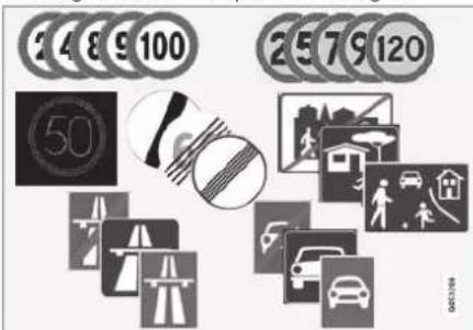
Examples of readable signs ^14 .
RSI can provide information about such things as current speed, when a motorway or road is starting/ending, when overtaking is prohibited or when the direction of travel is one-way.
If the car passes a speed limit sign, it will be shown on the driver's display and the head-up display*.
Road sign information (RSI ^15 ) also includes subfunctions that can warn the driver if a
speed limit has been exceeded or in connection with speed cameras.

NOTE
In certain markets, the Road Sign Information function* is only available in combination with Sensus Navigation*.

WARNING
- The function is supplementary driver support intended to facilitate driving and make it safer – it cannot handle all situations in all traffic, weather and road conditions.
- The driver is advised to read all sections in the Owner's Manual that relate to this function to learn about factors such as its limitations and what the driver should be aware of before using the system.
-
Driver support functions are not a substitute for the driver's attention and judgement. The driver is always responsible for ensuring the car is driven in a safe manner, at the appropriate speed, with an appropriate distance to other vehicles, and in accordance with current traffic rules and regulations.
-
Warning for speed limitation and speed camera from road sign information* (p. 298)
- Limitations of Road Sign Information* (p. 300)
Activating or deactivating road sign information\*
The Road Sign Information function (RSI ^16 ) is optional – the driver can choose to activate or deactivate this function.

Activate or deactivate the function using this button in the centre display's function view.
- Illuminated button indication – the function is activated.
- Extinguished button indication – the function is deactivated.
Related information
- Driving support systems (p. 286)
- Activating or deactivating road sign information* (p. 295)
- Display mode for road sign information* (p. 296)
- Road Sign Information and Sensus Navigation* (p. 298)
▶▶
DRIVER SUPPORT
◀◀

NOTE
- If the automatic speed limiter function is activated, road sign information is shown in the driver display even if the Road Sign Information function is not activated.
- To remove road sign information from the driver display, you must deactivate both the automatic speed limiter and Road Sign Information.
- When the automatic speed limiter function is activated but Road Sign Information is deactivated, no warnings are given from Road Sign Information. Road Sign Information must also be activated in order to receive warnings.
Related information
• Road Sign Information* (p. 294)
• Automatic speed limiter (p. 304)
- Limitations of Road Sign Information* (p. 300)
Display mode for road sign information\*
The Road Sign Information function (RSI ^17 ) shows road signs in different ways depending on the sign and the situation.
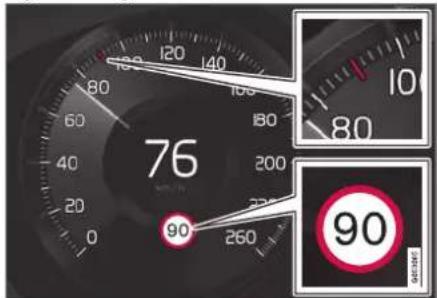
Example ^18 of detected speed information.
When the function detects a road sign with an imposed speed limit, the driver display shows the sign as a symbol combined with a coloured indication on the speedometer.
If the car is fitted with Sensus Navigation*, speed-related information is also obtained from map data, which means that the driver display can show or change information on the speed limit without having passed a speed-related sign.

An additional sign, such as "no overtaking", may be shown together with the speed limit symbol.

If the driver enters a road marked with a no-entry sign at the roadside, the symbol for this sign flashes on and off on the driver display as a warning.
If the car is equipped with Sensus Navigation*, information from map data is used to determine whether the car is being driven in the wrong direction.
The driver can also get an acoustic warning when driving towards a road marked with a no-entry sign if the Road Sign Audio Warning function is activated.
Speed limit or end of motorway
When the function detects an "indirect speed limit sign" stating the end of the current speed limit - e.g. at the end of a motorway - a symbol appears with the corresponding road sign in the driver's display.
16 Road Sign Information
17 Road Sign Information
10 Road signs are market-dependent - the illustrations in these instructions only show examples.
If the car is equipped with Sensus Navigation*, direct speed limit signs are normally displayed – indirect speed limit signs are only displayed if map data has no information on the speed limit for the road section in question.
Example of indirect speed limit sign:

End of all restrictions.
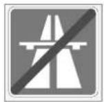
End of motorway.
The driver display symbol extinguishes after 10-30 seconds and remains so until the next speed related sign is passed.
Changed speed limit
When passing a direct speed limit sign when a speed limit changes, a symbol with the corresponding road sign appears in the driver's display.

Example of direct speed limit sign.
The driver display symbol extinguishes after about 5 minutes until the next speed-related sign is passed.
If the car is fitted with Sensus Navigation*, speed limit signs are shown in the driver display when map data contains information on the speed limit for the road section in question, even if no direct sign has been passed. If there is no information in map data, the sign is extinguished approx. 3 minutes after the last passing of a speed limit sign.
Additional signs
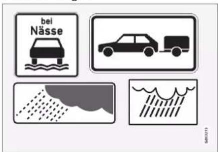
Examples of additional signs.
Sometimes different speed limits are signed for the same road - an additional sign then indicates the circumstances under which the different speeds apply. The road section may be particularly susceptible to accidents in rain and/or fog, for example.
An additional sign relating to rain is displayed only if the windscreen wipers are in use.
If a trailer is connected to the car's electrical system and you pass a speed sign with the additional sign "trailer", the indicated speed will appear on the driver display.
DRIVER SUPPORT
◀◀

Some speed limits only apply after a certain distance or at a certain time of day. The driver's attention is drawn to this fact by means of a symbol for an additional sign below the speed symbol. The additional
symbol in the driver display will show either "DIST" or "TIME".
Sign for "School" and "Children at play"

If a warning sign for "School" or "Children at play" is included in the satellite navigator's map data ^19 , the driver display shows a sign of this type.
Related information
• Road Sign Information* (p. 294)
- Limitations of Road Sign Information* (p. 300)
Road Sign Information and Sensus Navigation\*
If the car is equipped with Sensus Navigation*, speed information is read from the navigation unit in the following cases:
- On detection of signs that indirectly indicate a speed limit, such as motorway, dual carriageway and city limit signs.
- If a previously detected speed sign is assumed not to apply any longer, but no new sign has been detected.
NOTE
In certain markets, the Road Sign Information function* is only available in combination with Sensus Navigation*.
NOTE
If a downloaded third-party app is used for navigation then there is no support for speed-related information.
Related information
• Road Sign Information* (p. 294)
Warning for speed limitation and speed camera from road sign information\*
Road sign information (RSI ^20 ) includes sub-functions that can warn the driver if a speed limit has been exceeded or in connection with speed cameras.
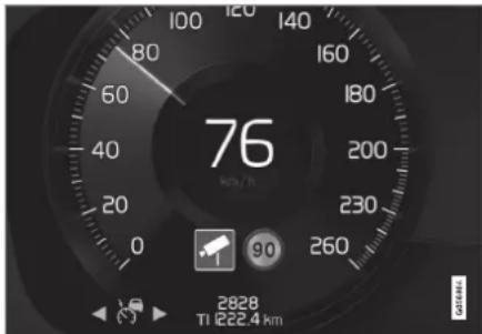
Examples of information on speed camera and speed limit in the driver display
Warning for speed limit

The speed warning is given by the driver display symbol ^21 showing the applicable maximum permitted speed temporarily flashing when this speed is exceeded.
^19 Only in cars with Sensus Navigation*.
20 Road Sign Information
21 Road signs are customised for each market – the one shown here is just an example.
A speed warning is always given if the speed limit is exceeded in connection with speed camera information.
Speed Limit Warning warns the driver when the applicable speed limit or stored maximum speed is exceeded – this warning is repeated once after approx. 1 minute within the same speed limit area unless the driver reduces the speed.
A new warning for exceeding the speed limit, including a reminder, will be given only when the car reaches a new/different speed limit area.

NOTE
To get an acoustic warning if you exceed the required speed, the Speed Limit Warning function must be activated and the Road Sign Audio Warning subfunction must be set to On. An acoustic warning is then given if the car's speed exceeds the speed indicated by the Road Sign Information function in the driver display.
Warning for speed camera

A car equipped with road sign information and Sensus Navigation can provide information on an upcoming speed camera in the driver display ^22 .
If the car exceeds a detected speed limit with the Speed Limit Warning function activated, a speed warning is given when the car approaches a speed camera, provided that the navigation map for the area in question contains information on speed cameras.

NOTE
An option is available to receive an acoustic warning for speed cameras independently of the car's speed and exceeded speed limit, even if the Road Sign Audio Warning function is deactivated.
Related information
• Road Sign Information* (p. 294)
- Activating or deactivating warnings from road sign information* (p. 299)
- Limitations of Road Sign Information* (p. 300)
Activating or deactivating warnings from road sign information\*
The subfunction Speed Limit Warning for Road Sign Information (RSI ^23 ) is optional – the driver can choose to activate or deactivate this subfunction.
Activating speed warning
- Select Settings My Car Intell Safe
→ Road Sign Information in the centre display's top view. - Select Speed Limit Warning.
The function is activated and a speed limit selector appears.
Adjust the limit for Speed Warning
The driver can select to receive a warning at a higher speed than the signed speed.
-
Select Settings By Car IntelliSafe
→ Road Sign Information in the centre display's top view. -
Select Speed Limit Warning.
The function is activated and a speed limit selector appears.
22 Information on speed cameras on the navigation map is not available for all markets/areas. 23 Road Sign Information
DRIVER SUPPORT
- Adjust the limit for Speed Warning by pressing the up/down arrows on the screen.

Note that the function does not give any consideration to selected limit adjustment when the driver display shows the speed camera symbol.
Activating acoustic warning in connection with speed warning
- Select Settings MyCar IntelSafe
→ Road Sign Information in the centre display's top view. - Select/deselect Road Sign Audio Warning to activate/switch off the acoustic warning.
With the Road Sign Audio Warning function activated, the driver is also warned when driving towards one-way traffic/no-entry entrance.
Activate speed camera warning
If the car is fitted with Sensus Navigation* and map data contains information on speed cameras, the driver can opt to receive an audible warning when approaching a speed camera.
- Select Settings MyCar IntellSafe
→ Road Sign Information in the centre display's top view.
- Select/deselect Speed Camera Audio Warning to activate/switch off the audible speed camera warning.
Related information
• Road Sign Information* (p. 294)
- Warning for speed limitation and speed camera from road sign information* (p. 298)
- Limitations of Road Sign Information* (p. 300)
Limitations of Road Sign Information\*
The Road Sign Information (RSI ^24 ) function may have limitations in certain situations. Examples of what can reduce the function are as follows:
- Faded signs
• Signs positioned on bends - Rotated or damaged signs
• Signs positioned high above the roadway - Fully/partially obscured or poorly positioned signs
- Signs completely or partly covered with frost, snow and/or dirt
- Digital road maps ^25 are out-of-date, inaccurate or have no speed information ^26

NOTE
In certain markets, the Road Sign Information function* is only available in combination with Sensus Navigation*.
DRIVER SUPPORT

NOTE
The RSI function may interpret some types of bicycle rack, connected to the electrical socket for trailers, as a connected trailer. In such cases, the driver display may show incorrect speed information.

NOTE
This function uses the car's camera and radar units, which have certain general limitations.
Related information
• Road Sign Information* (p. 294)
- Limitations for camera and radar unit (p. 415)
Speed limiter
A speed limiter (SL ^27 ) can be likened to a reverse cruise control - the driver regulates the speed using the accelerator pedal but is prevented from accidentally exceeding a pre-selected/set maximum speed by the speed limiter.

Buttons and symbols for the function.
1 : Activates the speed limiter from standby mode and resumes stored maximum speed
① + : Increases the stored maximum speed
2: From standby mode – activates the speed limiter and stores current speed
2 ( ) : From active mode – deactivates/ changes the speed limiter to standby mode
③ — : Reduces stored maximum speed
4 Marker for stored max speed
⑤ The car's current speed
6 Stored maximum speed
24 Road Sign Information
25 In cars equipped with Sensus Navigation*.
25 Map data with speed information does not exist for all areas.
27 Speed Limiter
▶▶
DRIVER SUPPORT
◀◀

WARNING
- The function is supplementary driver support intended to facilitate driving and make it safer – it cannot handle all situations in all traffic, weather and road conditions.
- The driver is advised to read all sections in the Owner's Manual that relate to this function to learn about factors such as its limitations and what the driver should be aware of before using the system.
- Driver support functions are not a substitute for the driver's attention and judgement. The driver is always responsible for ensuring the car is driven in a safe manner, at the appropriate speed, with an appropriate distance to other vehicles, and in accordance with current traffic rules and regulations.
Related information
• Driving support systems (p. 286)
• Limitations for speed limiter (p. 304)
- Selecting and activating speed limiter (p. 302)
• Deactivating the speed limiter (p. 303)
• Temporary deactivation of speed limiter (p. 304)
- Set the stored speed for driver support (p. 338)
• Automatic speed limiter (p. 304)
Selecting and activating speed limiter
The speed limiter function (SL ^28 ) must first be selected and activated in order to be able to regulate the speed.

The speed limiter cannot be activated until after the engine has been started. The lowest maximum speed that can be stored is 30 km/h (20 mph).
- Press ◀ (1) or ▶ (3) to scroll to the symbol
for the speed limiter

(4).
The symbol is grey – the speed limiter is in standby mode.
- When speed limiter is selected – press the steering wheel button (2) to activate.
The symbol is white – the speed limiter is started and the current speed is stored as maximum speed.
Related information
• Speed limiter (p, 301)
• Deactivating the speed limiter (p. 303)
- Temporary deactivation of speed limiter (p. 304)
Deactivating the speed limiter
The speed limiter (SL ^29 ) can be deactivated and switched off.

-
Press the steering wheel button (R).
The symbol and indicators turn grey – the speed limiter is set in standby mode and the driver can exceed the set speed limit.
-
Press the steering wheel button ◀ (1) or ▶ (3) to change to another function.
The driver display's symbol and indicator for speed limiter (4) are switched off – which deletes the stored maximum speed.
Related information
• Speed limiter (p. 301)
- Selecting and activating speed limiter (p. 302)
• Temporary deactivation of speed limiter (p. 304)
DRIVER SUPPORT
Temporary deactivation of speed limiter
The speed limiter (SL ^30 ) can be temporarily deactivated and set in standby mode.
The speed limiter can also be temporarily deactivated and overridden with the accelerator pedal without the speed limiter first having to be set in standby mode - e.g. to be able to quickly accelerate the car out of a situation.
In which case, proceed as follows:
-
Fully depress the accelerator pedal and release it to interrupt acceleration when the desired speed has been reached.
In this mode, the speed limiter is still activated and the driver display's symbol is therefore WHITE.
-
Fully release the accelerator pedal when the temporary acceleration is finished.
The car is then engine-braked automatically to below the last stored maximum speed.
Related information
• Speed limiter (p. 301)
- Selecting and activating speed limiter (p. 302)
• Deactivating the speed limiter (p. 303)
Limitations for speed limiter
Speed limiter (SL ^31 ) has certain general limitations.
On steep downhill gradients the speed limiter's braking effect may be inadequate and hence the stored maximum speed may be exceeded. In this case, the driver is alerted by the message Speed limit exceeded in the driver display.
NOTE
A text message that the maximum speed is exceeded will be activated if the speed has been exceeded by at least 3 km/h (approx. 2 mph).
Related information
• Speed limiter (p. 301)
Automatic speed limiter
The Automatic Speed Limiter (ASL ^32 ) function helps the driver to adapt the car's maximum speed to the speed shown on the road signs.
The Speed Limiter function (SL ^33 ) can be changed to Automatic Speed Limiter (ASL).
The automatic speed limiter uses speed information from the Road Sign Information* (RSI ^34 ) function to automatically adapt the car's maximum speed.
WARNING
Even if the driver clearly sees the speed-related road sign, the speed information from the Road Sign Information* (RSI) function to ASL may be incorrect – in such cases the driver must intervene him/herself and accelerate or brake to a suitable speed.
30 Speed Limiter
31 Speed Limiter
32 Automatic Speed Limiter
33 Speed Limiter

WARNING
- The function is supplementary driver support intended to facilitate driving and make it safer – it cannot handle all situations in all traffic, weather and road conditions.
- The driver is advised to read all sections in the Owner's Manual that relate to this function to learn about factors such as its limitations and what the driver should be aware of before using the system.
- Driver support functions are not a substitute for the driver's attention and judgement. The driver is always responsible for ensuring the car is driven in a safe manner, at the appropriate speed, with an appropriate distance to other vehicles, and in accordance with current traffic rules and regulations.
| Colour of sign symbol | Meaning |
| Greenish yellow | The automatic speed limiter is active. |
| Grey The automatic speed limiter is set in standby mode. | |
| Orange Automatic speed limiter is in temporary standby mode - e.g. due to a road sign not being read. | |
| Symbol SL ASL | |||
 | √ | √ | |
| WHITE symbol: Function active, GREY symbol: Standby mode. | |||
 | √ | ||
| Sign symbol after "70" = Automatic Speed Limiter is activated. | |||
Symbol for which speed limiter function is active
The symbol display in the driver display changes depending on whether it is cruise control or automatic cruise control that is active.
Related information
- Driving support systems (p. 286)
- Activating or deactivating the automatic speed limiter (p. 306)
- Changing the tolerance for the automatic speed limiter (p. 307)
- Limitations for automatic speed limiter (p. 307)
• Speed limiter (p. 301)
• Road Sign Information* (p. 294)
Symbol for automatic speed limiter

The sign symbol (displayed alongside the stored speed, "70", in the centre of the speedometer) can be shown in three colours with the fol-
lowing meanings:
DRIVER SUPPORT
Activating or deactivating the automatic speed limiter
The automatic speed limiter function (ASL ^35 ) can be activated and deactivated as a supplement to the speed limiter (SL ^36 ).
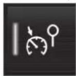
Activate or deactivate the function using this button in the centre display's function view.
- GREEN button indication – the function is activated. Press the steering wheel button Ⓧ to start the automatic speed limiter with the current speed.
- GREY button indication – the function is deactivated. Normal speed limiter is activated instead.
i NOTE
- If the automatic speed limiter function is activated, road sign information (RSI ^37 ) is shown in the driver display even if the Road Sign Information is not activated.
- To remove road sign information from the driver display, you must deactivate both the automatic speed limiter and Road Sign Information.
- When the automatic speed limiter function is activated but Road Sign Information is deactivated, no warnings are given from Road Sign Information. Road Sign Information must also be activated in order to receive warnings.
Deactivating the automatic speed limiter
To deactivate the automatic speed limiter:
- Tap on the button in the function view.
GREY button indication – ASL is switched off and SL is activated instead.
WARNING
After switching from ASL to SL the car will no longer follow the signed speed limit but only the stored maximum speed.
Related information
• Speed limiter (p. 301)
• Automatic speed limiter (p. 304)
- Limitations for automatic speed limiter (p. 307)
• Road Sign Information* (p. 294)
Changing the tolerance for the automatic speed limiter
The Automatic Speed Limiter function (ASL ^38 ) can be set for different tolerance levels. The tolerance is adjusted in the same way as the speed setting is in the speed limiter. If, for example, the car follows a signed speed limit of 70km/h (43 mph) the driver can instead choose to allow the car to maintain 75 km/h (47 mph).

Buttons and symbols for the function
- Press the steering wheel button ⏻ until 70 km/h (43 mph) in the centre of the speedometer (2) changes to 75 km/h (47 mph).
After which, the car uses the selected tolerance 5 km/h (4 mph) as long as signs passed are showing 70 km/h (43 mph).
The tolerance is followed until a road sign with a lower or higher speed is passed - then the car follows the new signed speed limit instead and the tolerance is deleted from the memory.
NOTE
The maximum selectable tolerance is +/- 10 km/h (5 mph).
Related information
• Automatic speed limiter (p. 304)
- Limitations for automatic speed limiter (p. 307)
• Road Sign Information* (p. 294)
Limitations for automatic speed limiter
Automatic speed limitation (ASL ^39 ) takes place using speed information from the Road Sign Information function ^* (RSI ^40 ) – not from the speed limit road signs that the car passes.
If road sign information cannot interpret and provide speed information to the driver support systems, the automatic speed limiter is set in standby mode and changes to normal speed limiter. In such cases the driver must intervene and brake to a suitable speed.
The automatic speed limiter will be reactivated when road sign information can once again interpret and provide speed information.
Related information
• Speed limiter (p. 301)
• Automatic speed limiter (p. 304)
• Road Sign Information* (p. 294)
38 Automatic Speed Limiter
39 Automatic Speed Limiter
40 Road Sign Information - RSI
DRIVER SUPPORT
Cruise control
The cruise control (CC ^41 ) helps the driver maintain an even speed, which can result in more relaxed driving on motorways and long, straight roads in regular traffic flows.

Buttons and symbols for the function
1: Activates cruise control from standby mode and resumes stored speed
1 +: Increases the stored speed
2: From standby mode – activates cruise control and stores current speed
2: From active mode – deactivates/changes cruise control to standby mode
3 —: Reduces stored speed
4 Marker for stored speed
5 The car's current speed
6 Stored speed
NOTE
In cars equipped with adaptive cruise control* (ACC ^12 ), it is possible to switch between cruise control and adaptive cruise control.
WARNING
- The function is supplementary driver support intended to facilitate driving and make it safer – it cannot handle all situations in all traffic, weather and road conditions.
- The driver is advised to read all sections in the Owner's Manual that relate to this function to learn about factors such as its limitations and what the driver should be aware of before using the system.
- Driver support functions are not a substitute for the driver's attention and judgement. The driver is always responsible for ensuring the car is driven in a safe manner, at the appropriate speed, with an appropriate distance to other vehicles, and in accordance with current traffic rules and regulations.
Using engine braking instead of the foot brake
With Cruise Control, speed is regulated with less frequent application of the foot brake. On a downhill gradient it may sometimes be desirable to start moving a little faster and
limit the acceleration by engine braking. In this case the driver can temporarily disable foot brake application by Cruise Control.
To do so, proceed as follows:
- Depress the accelerator pedal about half-way down and release.
Cruise Control will disengage its automatic foot braking and then uses engine braking only.
Related information
• Driving support systems (p. 286)
- Selecting and activating cruise control (p. 309)
• Deactivating cruise control (p. 310)
• Standby mode for cruise control (p. 310)
- Set the stored speed for driver support (p. 338)
- Change between cruise control and adaptive cruise control* in the centre display (p. 318)
Selecting and activating cruise control
The cruise control function (CC ^43 ) must first be selected and activated in order to be able to regulate the speed.

In order to start the cruise control from the standby mode, the car's current speed must be 30 km/h (20 mph) or higher.
- Press ◀ (1) or ▶ (3) to scroll to the symbol
for cruise control

The symbol is grey – cruise control is in standby mode.
- When cruise control is selected – press the steering wheel button Ⓧ (2) to activate.
The symbol is white – cruise control is started and the current speed is stored as maximum speed. The lowest speed that can be stored is 30 km/h (20 mph).
Reactivating cruise control to the last stored speed
- When cruise control is selected – press the steering wheel button ⬤ to activate.
The cruise control markings and symbols in the driver display change colour from GREY to WHITE — the car will now follow the most recently stored speed again.
WARNING
A significant increase in speed may follow when the speed is resumed with the steering wheel button.
Related information
• Cruise control (p. 308)
• Deactivating cruise control (p. 310)
• Standby mode for cruise control (p. 310)
DRIVER SUPPORT
Deactivating cruise control
Cruise control (CC ^44 ) can be deactivated and switched off.

-
Press the steering wheel button (9).
The symbol and indicators turn grey – cruise control is set in standby mode.
-
Press the steering wheel button ▶ (1) or ▶ (3) to change to another function.
The driver display's symbol and indicator for cruise control (4) are switched off – which deletes the stored maximum speed.
Related information
• Cruise control (p. 308)
- Change between cruise control and adaptive cruise control* in the centre display (p. 318)
- Selecting and activating cruise control (p. 309)
• Standby mode for cruise control (p. 310)
Standby mode for cruise control
Cruise control (CC ^45 ) can be deactivated and set in standby mode. This can take place due to driver intervention or automatically. Standby mode means that the function is selected in the driver display but not activated. In this case, cruise control does not regulate speed.
Standby mode on driver intervention
Cruise control is deactivated and set to standby mode if any of the following occur:
• The foot brake is used.
• The gear selector is moved to N position.
- The clutch pedal is held depressed for longer than 1 minute.
- The driver maintains a speed higher than the stored speed for longer than 1 minute.
The driver must then control the speed himself/herself.
A temporary increase in speed with the accelerator pedal, e.g. during overtaking, does not affect the setting - the car returns to the last stored speed when the accelerator pedal is released.
Automatic standby mode
Activation of automatic standby mode can be due to one of the following:
• The wheels are losing traction.
• The engine speed is too low/high.
- Brake temperature is too high.
• Speed falls below 30 km/h (20 mph).
The driver must then control the speed himself/herself.
Related information
• Cruise control (p. 308)
- Selecting and activating cruise control (p. 309)
• Deactivating cruise control (p. 310)
Adaptive cruise control\*46
The adaptive cruise control (ACC ^47 ) can help the driver to maintain a constant speed, combined with a preset time interval to the vehicle ahead.

natural_image
Top-down diagram of a car showing sensor waves and a close-up of the roof panel (no text or symbols)The camera and radar unit measures the distance to the vehicle ahead.
An adaptive cruise control can provide a more relaxing driving experience on long journeys on motorways and long straight main roads in smooth traffic flows.
The driver selects the desired speed and a time interval to the vehicle ahead. If the camera and radar unit detects a slower vehicle in front of the car, the speed is adapted automatically via the preset time interval to the vehicle.
When the road is clear again the car returns to the selected speed.
If the cornering support* function is activated, this may also affect the speed of the car.
The adaptive cruise control aims to:
- regulate the speed smoothly. In situations that demand sudden braking the driver must brake himself/herself. This applies in cases of large speed differences or if the vehicle in front brakes suddenly. Due to the limitations of the radar unit, braking may come unexpectedly or not at all.
- follow the vehicle ahead in the same lane at a time interval set by the driver. If the radar unit cannot see any vehicle in front then the car will instead maintain the speed set and stored by the driver. This also takes place if the speed of the vehicle ahead increases and exceeds the stored speed.

WARNING
- The function is supplementary driver support intended to facilitate driving and make it safer – it cannot handle all situations in all traffic, weather and road conditions.
- The driver is advised to read all sections in the Owner's Manual that relate to this function to learn about factors such as its limitations and what the driver should be aware of before using the system.
- Driver support functions are not a substitute for the driver's attention and judgement. The driver is always responsible for ensuring the car is driven in a safe manner, at the appropriate speed, with an appropriate distance to other vehicles, and in accordance with current traffic rules and regulations.

IMPORTANT
Maintenance of driver support components must only be performed at a workshop – an authorised Volvo workshop is recommended.
Related information
• Driving support systems (p. 286)
- Controls for adaptive cruise control* (p. 312)
• Display mode for adaptive cruise control* (p. 313)
- Selecting and activating adaptive cruise control* (p. 314)
- Limitations for adaptive cruise control* (p. 317)
Symbols and messages for adaptive cruise control* (p. 319)
- Warning from driver support in the event of a collision risk (p. 336)
- Set time interval to vehicle ahead (p. 339)
- Set the stored speed for driver support (p. 338)
• Automatic braking with driver support (p. 340)
• Change of target with driver support (p. 337)
• Overtaking Assistance* (p. 335)
Controls for adaptive cruise control\*48
A summary of how adaptive cruise control (ACC ^49 ) is controlled using the left-hand keypad on the steering wheel and how the function is shown in the display.
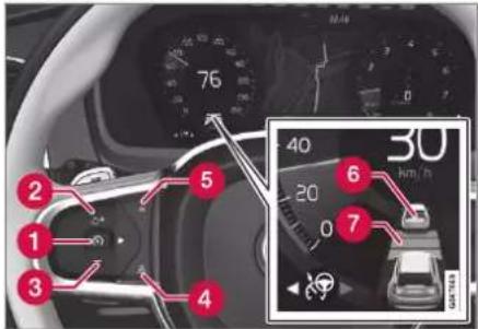
1 (S): From standby mode - activates and stores the current speed
1 ( ) : From active mode - deactivates/changes to standby mode
② : Activates the function from standby mode and resumes stored speed
② +: Increases the stored speed
3 —: Reduces stored speed
4 Increases the time interval to vehicles ahead
5 Reduces the time interval to vehicles ahead
6 Target vehicle indicator: The function has detected and is following a target vehicle at the preset time interval
7 Symbol for time interval to vehicles ahead
Related information
• Adaptive cruise control* (p. 311)
- Limitations for adaptive cruise control* (p. 317)
Display mode for adaptive cruise control\*50
The following image example shows how Adaptive cruise control (ACC ^51 ) can be shown in the display in the different context.
Speed

gauge
| Segment | Value | |---|---| | 1 | 230 | | 2 | 80 | | 3 | 100 | | 4 | 60 | 50 km/hIndication of speeds
① Stored speed
2 Speed of vehicle ahead
3 Current speed of your car
Time interval

The time interval is only adjusted to the vehicle ahead by the Adaptive cruise control when the distance symbol shows two vehicles. At the same time a speed range is marked.
When driving
In the following illustrative example, the road sign information* (RSI ^52 ) function informs the driver that the maximum permitted speed is 130 km/h (80 mph).
DRIVER SUPPORT
◀◀

The previous illustration shows that the adaptive cruise control is set to maintain 110 km/h (68 mph) and that there is no vehicle ahead to follow.

The previous illustration shows that the adaptive cruise control is set to maintain 110 km/h (68 mph) and at the same time is following a
vehicle ahead which is keeping the same speed.
Related information
• Adaptive cruise control* (p. 311)
- Limitations for adaptive cruise control* (p. 317)
Selecting and activating adaptive cruise control\*53
Adaptive cruise control (ACC ^54 ) must first be selected and then activated to enable it to control speed and distance.

To start the function requires the following:
- The driver's seatbelt must be buckled and the driver's door must be closed.
- There must be a vehicle (the "target vehicle") within reasonable distance in front of
the car, or the current speed must be at least 15 km/h (9 mph).
- For cars with manual gearbox. Speed must be at the lowest 30 km/h (20 mph).
- Press the steering wheel button ◀ (2) or ▶ (3) to scroll to the adaptive cruise control symbol 🏠 (4).
The symbol is grey – the adaptive cruise control is in standby mode.
- When speed limiter is selected – press the steering wheel button (1) to activate.
The symbol is white – the speed limiter is started and the current speed is stored as maximum speed.
Reactivating adaptive cruise control to the last stored speed
- When the adaptive cruise control is selected – press the steering wheel button ⚙ to activate.
The cruise control markings and symbols in the driver display change colour from GREY to WHITE — the car will now follow the most recently stored speed again.
WARNING
A significant increase in speed may follow when the speed is resumed with the steering wheel button.
Related information
• Adaptive cruise control* (p. 311)
- Deactivating adaptive cruise control* (p. 315)
- Change between cruise control and adaptive cruise control* in the centre display (p. 318)
- Limitations for adaptive cruise control* (p. 317)
Deactivating adaptive cruise control\*55
The adaptive cruise control (ACC ^56 ) can be deactivated and switched off.

- Press the steering wheel button (9).
The symbol and indicators turn grey – the adaptive cruise control is set in standby mode. The indicator for time interval and symbol for target vehicle, if activated, are also switched off.
▶▶
DRIVER SUPPORT
- Press the steering wheel button ◀ (2) or ▶ (3) to change to another function.
The driver display's symbol and indicator for adaptive cruise control (4) are switched off – which deletes the stored maximum speed.
WARNING
- With the adaptive cruise control is in standby mode, the driver must intervene and regulate both speed and distance to the vehicle ahead.
- When the adaptive cruise control is in standby mode and the car comes too close to a vehicle ahead, the driver may be warned of the short distance by the Distance Warning* function instead.
Related information
• Adaptive cruise control* (p. 311)
- Selecting and activating adaptive cruise control* (p. 314)
- Change between cruise control and adaptive cruise control* in the centre display (p. 318)
- Limitations for adaptive cruise control* (p. 317)
Standby mode for adaptive cruise control\*57
Adaptive cruise control (ACC ^58 ) can be deactivated and set to standby mode. This can take place due to driver intervention or automatically.
Standby mode means that the function is selected in the driver display but not activated. Adaptive cruise control does not then regulate the speed or distance to the vehicle in front.
Standby mode on driver intervention
The adaptive cruise control is deactivated and set in standby mode if any of the following occurs:
• The foot brake is used.
• The gear selector is moved to N position.
- The driver maintains a speed higher than the stored speed for longer than 1 minute.
- The clutch pedal is depressed for approx. 1 minute - applies to cars with manual gearbox.
A temporary increase in speed with the accelerator pedal, e.g. during overtaking, does not affect the setting - the car returns to the last stored speed when the accelerator pedal is released.
WARNING
- With the adaptive cruise control is in standby mode, the driver must intervene and regulate both speed and distance to the vehicle ahead.
- When the adaptive cruise control is in standby mode and the car comes too close to a vehicle ahead, the driver may be warned of the short distance by the Distance Warning* function instead.
Automatic standby mode
WARNING
With automatic standby mode, the driver is warned via an acoustic signal and a message on the driver display.
- The driver must then regulate the car's speed, apply the brakes as needed and maintain a safe distance to other vehicles.
Automatic standby mode may be engaged in the event of one of the following:
- One of the systems that Adaptive cruise control is dependent on stops working, e.g. stability control / anti-skid (ESC ^59 ).
• The driver opens the door.
• The driver takes off the seatbelt.
• The engine speed is too low/high.
• One or more wheels lose traction.
• The brake temperature is high.
• The parking brake is applied. - The camera and radar unit is covered by e.g. snow or heavy rainfall (camera lens/radio waves are blocked).
- The speed is below 5 km/h (3 mph) and ACC is uncertain whether the vehicle ahead is a stationary vehicle or an object, such as a speed bump.
- The speed is below 5 km/h (3 mph) and the vehicle ahead turns off so that ACC no longer has a vehicle to follow.
- The speed is reduced to below 30 km/h (20 mph) - only applies to cars with manual gearbox.
Related information
• Adaptive cruise control* (p. 311)
- Selecting and activating adaptive cruise control* (p. 314)
- Deactivating adaptive cruise control* (p. 315)
- Limitations for adaptive cruise control* (p. 317)
Limitations for adaptive cruise control\*60
Adaptive Cruise Control (ACC ^61 ) may have limitations in certain situations.
Steep roads and/or heavy load
Bear in mind that the adaptive cruise control is primarily intended for use when driving on level road surfaces. The function may have difficulty in keeping the correct distance from the vehicle ahead when driving on steep downhill slopes - in which case, be extra attentive and ready to brake.
Do not use adaptive cruise control if the car has a heavy load or a trailer is connected to the car.
Drive mode unavailable
Drive mode Off Road cannot be selected when the adaptive cruise control is activated.

WARNING
- This is not a collision avoidance system. The driver is always responsible and must intervene if the system does not detect a vehicle ahead.
- The function does not brake for humans or animals, and not for small vehicles such as bicycles and motorcycles. Nor for low trailers, oncoming, slow or stationary vehicles and objects.
- Do not use the function in demanding situations, such as in city traffic, at junctions, on slippery surfaces, with a lot of water or slush on the road, in heavy rain/snow, in poor visibility, on winding roads or on slip roads.

NOTE
This function uses the car's camera and radar units, which have certain general limitations.
Related information
• Adaptive cruise control* (p. 311)
- Limitations for camera and radar unit (p. 415)
Change between cruise control and adaptive cruise control\*62 in the centre display
When the normal cruise control (CC ^63 ) is selected in the driver display, it is possible to change to adaptive cruise control (ACC ^64 ) in the centre display's function view.
Activate or deactivate the function using this button in the centre display's function view.
- GREEN button indication – adaptive cruise control is deactivated and normal cruise control is set in standby mode.
- GREY button indication – normal cruise control is deactivated and adaptive cruise control is set in standby mode.
A symbol in the driver display shows which cruise control is active:
| Cruise control (CC) | Adaptive cruise con-trol (ACC) |
A WHITE symbol: Function active, GREY symbol: Standby mode
Related information
• Adaptive cruise control* (p. 311)
• Cruise control (p. 308)
DRIVER SUPPORT
Symbols and messages for adaptive cruise control\*65
A number of symbols and messages regarding the adaptive cruise control (ACC ^66 ) can
be shown via the driver display and/or the head-up display*.
▶▶
DRIVER SUPPORT
◀◀
| Symbol Message Specification | ||
 | The symbol is WHITE The car is maintaining the stored speed. | |
 | Adaptive Cruise Contr.UnavailableThe symbol is GREY | Adaptive cruise control is set to standby mode. |
 | Adaptive Cruise Contr.Service requiredThe symbol is GREY | The system does not function as it should. A workshop should be contacted - an authorised Volvo workshop is recommended. |
 | Windscreen sensorSensor blocked, see Owner's manual | Clean the windscreen in front of the camera and radar unit's detectors. |
A text message can be cleared by briefly pressing the button, located in the centre of the steering wheel's right-hand keypad.
If a message remains: Contact a workshop – an authorised Volvo workshop is recommended.
Related information
• Adaptive cruise control* (p. 311)
DRIVER SUPPORT
Pilot Assist\*67
Pilot Assist can help the driver to drive the car between the lane's side markings as well as to maintain an even speed, combined with a preselected time interval to the vehicle ahead.
Get to know Pilot Assist

The camera and radar unit measures the distance to the vehicle ahead and detects side markings.
① Camera and radar unit
② Distance readers
③ Readers, side markings
Pilot Assist helps to control your car and you may need to drive a few kilometres with Pilot Assist before you feel completely at home with the function. It is important to know
about all of the function's applications and limitations in order to safely use all of the advantages.
The Pilot Assist function is primarily intended for use on motorways and similar major roads where it can contribute to more comfortable driving and a more relaxed driving experience.
The driver selects the desired speed and a time interval to the vehicle ahead. Pilot Assist scans the distance to the vehicle ahead and the lane's side markings on the road surface using the camera unit. The preset time interval is maintained with automatic speed adjustment whilst the steering assistance helps to position the car in the lane.
If the cornering support* function is activated, this may also affect the speed of the car.
Pilot Assist regulates the speed with acceleration and braking. It is normal for the brakes to emit a low sound when they are being used to adjust the speed.
Pilot Assist strives to:
- regulate the speed smoothly. In situations that demand sudden braking the driver must brake himself/herself. This applies in cases of large speed differences or if the car in front brakes suddenly. Due to the limitations of the camera and radar unit,
braking may come unexpectedly or not at all.
- follow the vehicle ahead in the same lane at a time interval set by the driver. If the radar unit cannot see any vehicle in front then the car will instead maintain the speed set and stored by the driver. This also takes place if the speed of the vehicle ahead increases and exceeds the stored speed.
Position of the car in the lane
When Pilot Assist helps to steer, it attempts to place the car halfway between the visible lane markings. For a smoother drive, it is a good idea to allow the car to find a good position. The driver can always adjust the position him/herself by increasing the steering input. It is important that the driver checks to make sure the car is positioned safely in the lane.
If Pilot Assist does not position the car in an appropriate way in the lane, it is recommended to turn Pilot Assist off or switch to adaptive cruise control*.
DRIVER SUPPORT
Steering assistance

The current status of steering assistance is indicated by the colour of the steering wheel's symbol:
- GREEN steering wheel indicates active steering assis-
tance
- GREY steering wheel (as in illustration) indicates deactivated steering assistance.
Pilot Assist steering assistance takes into account the speed of the preceding car and the lane markings. The driver can at any time ignore the Pilot Assist steering recommendation and steer in another direction, e.g. to change lane or avoid an obstruction on the road.
If Pilot Assist cannot interpret the lane unambiguously, e.g. if the camera and radar unit does not see the lane's side markings, Pilot Assist temporarily deactivates steering assistance, but resumes it if the lane can be interpreted again - although the speed and distance control functions remain active. The steering wheel vibrates slightly when deactivated temporarily in order to alert the driver to the change.
WARNING
Pilot Assist steering assistance is automatically deactivated and is resumed without prior warning.
Round bends and when the road splits
Pilot Assist interacts with the driver, who should therefore not wait for the steering assistance from Pilot Assist but should always be prepared to increase his/her own steering input, especially in bends.
When the car approaches an exit or if the lane splits, the driver should steer towards the desired lane so that Pilot Assist can detect the desired direction.
Hands on the steering wheel
In order for Pilot Assist to function, the driver's hands must be on the steering wheel. It is also important for the driver always to carry on being active and alert when driving as Pilot Assist is unable to read all situations and the function may toggle between off and on without prior warning.

If Pilot Assist detects that the driver does not keep his/her hands on the steering wheel, the system gives a warning with a symbol and text message in the driver display in order to prompt the driver to
actively steer the car.
If the driver's hands still cannot be detected on the steering wheel after a few seconds, the prompt to actively steer the car is repeated, supplemented by an acoustic signal.
If Pilot Assist cannot detect the driver's hands on the steering wheel after a further few seconds, the warning signal becomes intensive and the steering function is deactivated. Pilot Assist must then be restarted using the steering wheel button 🔒.

WARNING
- The function is supplementary driver support intended to facilitate driving and make it safer – it cannot handle all situations in all traffic, weather and road conditions.
- The driver is advised to read all sections in the Owner's Manual that relate to this function to learn about factors such as its limitations and what the driver should be aware of before using the system.
- Driver support functions are not a substitute for the driver's attention and judgement. The driver is always responsible for ensuring the car is driven in a safe manner, at the appropriate speed, with an appropriate distance to other vehicles, and in accordance with current traffic rules and regulations.

IMPORTANT
Maintenance of driver support components must only be performed at a workshop – an authorised Volvo workshop is recommended.
Related information
• Driving support systems (p. 286)
- Selecting and activating Pilot Assist* (p. 326)
• Display mode for Pilot Assist* (p. 324)
• Limitations of Pilot Assist* (p. 329)
- Symbols and messages for Pilot Assist* (p. 332)
• Controls for Pilot Assist* (p. 323)
- Warning from driver support in the event of a collision risk (p. 336)
- Change of target with driver support (p. 337)
• Set time interval to vehicle ahead (p. 339)
- Set the stored speed for driver support (p. 338)
• Automatic braking with driver support (p. 340)
• Overtaking Assistance* (p. 335)
Controls for Pilot Assist\*68
A summary of how Pilot Assist is controlled using the left-hand keypad on the steering wheel and how the function is shown in the display.
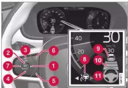
Buttons and symbols for the function.
1: Switches from adaptive cruise control* to Pilot Assist
2 : From standby mode - activates Pilot Assist and stores the current speed
② : From active mode - deactivates/changes Pilot Assist to standby mode
3: Activates Pilot Assist from standby mode and resumes the stored speed and time interval
③ + : Increases the stored speed
DRIVER SUPPORT
◀◀
4 —: Reduces stored speed
5 Increases the time interval to vehicles ahead
6 Reduces the time interval to vehicles ahead
7: Switches from Pilot Assist to adaptive cruise control
8 Function symbol
9 Symbols for target car
10 Symbol for time interval to vehicles ahead
11 Symbol for activated/deactivated steering assistance
Related information
- Pilot Assist* (p. 321)
Display mode for Pilot Assist\*69
The following image example shows how Pilot Assist can be shown in the display in different contexts.
Speed

gauge
| Segment | Value | |---|---| | 1 | 230 | | 2 | 80 | | 3 | 100 | | 4 | 60 | 50 km/hIndication of speeds.
1 Stored speed
2 Speed of vehicle ahead
3 Current speed of your car
Time interval

Pilot Assist only regulates the time interval to the vehicle ahead when the distance symbol shows a vehicle (1) above the steering wheel symbol.
Pilot Assist steering assistance is only active when the steering wheel symbol (2) has changed from GREY to GREEN.
When driving
In the following illustrative example, the road sign information (RSI ^70 ) function informs the driver that the maximum permitted speed is 130 km/h (80 mph).

DRIVER SUPPORT
The previous illustration shows that Pilot Assist is set to maintain 110 km/h (68 mph) and that there is no vehicle ahead to follow.
Pilot Assist provides no steering assistance since the lane's side markings cannot be detected.

The previous illustration shows that Pilot Assist is set to maintain 110 km/h (68 mph) and at the same time is following a vehicle ahead which is keeping the same speed.
Pilot Assist provides no steering assistance since the lane's side markings cannot be detected.
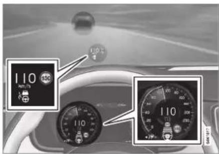
The previous illustration shows that Pilot Assist is set to maintain 110 km/h (68 mph) and at the same time is following a vehicle ahead which is keeping the same speed.
Here, Pilot Assist also provides steering assistance since the lane's side markings can be detected.

The previous illustration shows that Pilot Assist is set to maintain 110 km/h (68 mph) and that there is no vehicle ahead to follow.
Pilot Assist provides steering assistance as the lane markings can be detected.
Related information
- Pilot Assist* (p. 321)
• Limitations of Pilot Assist* (p. 329)
DRIVER SUPPORT
Selecting and activating Pilot Assist\*71
Pilot Assist must first be selected and then activated to be able to control speed and distance and to give steering assistance.
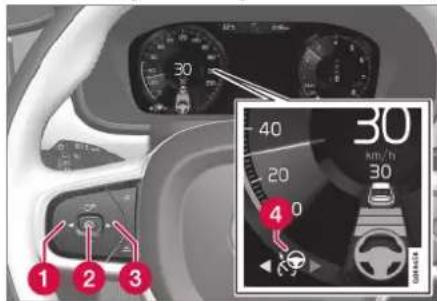
Green steering wheel indicates that Pilot Assist is providing steering assistance.
In order to start the Pilot Assist it is required that.
- The driver's seatbelt must be buckled and the driver's door must be closed.
- The lane's edge markings must be clear and must be detected by the car.
- There must be a vehicle (the "target vehicle") within reasonable distance in front of the car, or the current speed must be at least 15 km/h (9 mph).
• The speed must not exceed 140 km/h (87 mph).
- The driver must keep his/her hands on the steering wheel.
- There must be a vehicle (the "target vehicle") within reasonable distance in front of the car, or the current speed must be at least 15 km/h (9 mph).
- For cars with manual gearbox. Speed must be at the lowest 30 km/h (20 mph).
- Press ◀ (1) or ▶ (3) to scroll to the symbol for Pilot Assist 🔒 (4).
The symbol is grey – Pilot Assist is in standby mode.
- When Pilot Assist is selected – press the steering wheel button Ⓞ (2) to activate.
The symbol is white – Pilot Assist is started and the current speed is stored as maximum speed.
Reactivating Pilot Assist to last stored speed
- When Pilot Assist is selected – press the steering wheel button ⚙ to activate.
The cruise control markings and symbols in the driver display change colour from GREY to WHITE — the car will now follow the most recently stored speed again.

WARNING
A significant increase in speed may follow when the speed is resumed with the steering wheel button.
Related information
- Pilot Assist* (p. 321)
• Deactivate Pilot Assist* (p. 327)
• Limitations of Pilot Assist* (p. 329)
Deactivate Pilot Assist ^4
Pilot Assist can be deactivated and switched off.

Green steering wheel indicates that Pilot Assist is providing steering assistance.
- Press the steering wheel button (2).
The symbol and indicators turn grey – Pilot Assist is set in standby mode. The indicator for time interval and symbol for target vehicle, if activated, are also switched off.
- Press the steering wheel button ◀ (1) or ▶ (3) to change to another function.
The driver display's symbol and indicator for Pilot Assist (4) are switched off – which deletes the stored maximum speed.
WARNING
- With Pilot Assist in standby mode, the driver must intervene and steer, regulating both speed and distance to the vehicle ahead.
- When Pilot Assist is in standby mode and the car comes too close to a vehicle ahead, the driver is warned of the short distance by the distance warning* function instead.
Related information
• Adaptive cruise control* (p. 311)
- Selecting and activating adaptive cruise control* (p. 314)
- Change between cruise control and adaptive cruise control* in the centre display (p. 318)
- Limitations for adaptive cruise control* (p. 317)
- Temporary disabling of steering assistance with Pilot Assist* (p. 328)
Standby mode for Pilot Assist ^73
Pilot Assist can be deactivated and set in standby mode. This can take place due to driver intervention or automatically.
Standby mode means that the function is selected in the driver display but not activated. In this case, Pilot Assist does not regulate the speed or distance to the vehicle in front, or provide steering assistance.
Standby mode on driver intervention
Pilot Assist is deactivated and set in standby mode if any of the following occurs:
• The foot brake is used.
• The gear selector is moved to N position.
- The direction indicators are used for longer than 1 minute.
- The driver maintains a speed higher than the stored speed for longer than 1 minute.
- The clutch pedal is depressed for approx. 1 minute - applies to cars with manual gearbox.
◀ Automatic standby mode

WARNING
With automatic standby mode, the driver is warned via an acoustic signal and a message on the driver display.
- The driver must then regulate the car's speed, apply the brakes as needed and maintain a safe distance to other vehicles.
Automatic standby mode may be engaged in the event of one of the following.
- One of the systems that Pilot Assist is dependent on stops working, e.g. stability control / anti-skid ^74 .
- Hands not holding the steering wheel.
• The driver opens the door.
• The driver takes off the seatbelt.
• The engine speed is too low/high.
• One or more wheels lose traction.
• The brake temperature is high.
• The parking brake is applied. -
The camera and radar unit is covered by e.g. snow or heavy rainfall (camera lens/radio waves are blocked).
-
The speed is below 5 km/h (3 mph) and Pilot Assist is uncertain whether the vehicle ahead is a stationary vehicle or an object, such as a speed bump.
- The speed is below 5 km/h (3 mph) and the vehicle ahead turns off so that Pilot Assist no longer has a vehicle to follow.
- The speed is reduced to below 30 km/h (20 mph) - only applies to cars with manual gearbox.
Related information
- Pilot Assist* (p. 321)
- Selecting and activating Pilot Assist* (p. 326)
• Deactivate Pilot Assist* (p. 327)
• Limitations of Pilot Assist* (p. 329)
Temporary disabling of steering assistance with Pilot Assist\*75
Pilot Assist steering assistance can be temporarily disabled and resumed without prior warning.
When the direction indicators are used, Pilot Assist steering assistance is temporarily disengaged. When the direction indicator is switched off, steering assistance is reactivated automatically if the lane's edge markings can still be detected.
If Pilot Assist is unable to interpret the lane clearly, e.g. if the camera or radar unit is unable to see the side markings for the lane, Pilot Assist temporarily disables steering assistance – speed and distance regulation functions remain active. Steering assistance is resumed when the lane can be interpreted again. In these situations, slight vibration in the steering wheel may alert the driver to the fact that steering assistance has been deactivated temporarily.
Related information
- Pilot Assist* (p. 321)
- Selecting and activating Pilot Assist* (p. 326)
• Deactivate Pilot Assist* (p. 327)
• Limitations of Pilot Assist* (p. 329)
Limitations of Pilot Assist\*76
The Pilot Assist function may have limitations in certain situations.
The Pilot Assist function is an aid which can help the driver in many situations. But the driver is at all times responsible for maintaining a safe distance to surrounding objects and a correct position in the lane.
WARNING
In certain situations, Pilot Assist steering assistance may have difficulty helping the driver in the right way or it may be automatically deactivated - in which case, the use of Pilot Assist is not recommended. Examples of such situations may be that:
- the lane markings are unclear, worn, missing, or they cross each other, or if there are several sets of lane markings.
- the lane division is changed, e.g. when the lanes split or merge, as well as on slip roads.
- at roadworks and sudden changes in the roadway, e.g. when the lines may stop marking the correct route.
- edges or other lines than lane markings are present on or near the road, e.g. kerbs, joints or repairs to the road surface, edges of barriers, roadside edges or strong shadows.
• the lane is narrow or winding.
• the lane contains ridges or holes. - weather conditions are poor, e.g. rain, snow or fog or slush or impaired view
DRIVER SUPPORT
◀◀
with poor light conditions, back-lighting, wet road surface etc.
The driver should also note that Pilot Assist has the following limitations:
- High kerbs, roadside barriers, temporary obstacles (traffic cones, safety barriers, etc.) are not detected. Alternatively, they may be detected incorrectly as lane markings, with a subsequent risk of contact between the car and such obstacles. The driver must ensure him/herself that the car is at a suitable distance from such obstacles.
- The camera and radar sensor does not have the capacity to detect all oncoming objects and obstacles in traffic environments, e.g. potholes, stationary obstacles or objects which completely or partially block the route.
- Pilot Assist does not "see" pedestrians, animals, etc.
- The functions steering assist is force limited, which means that Pilot Assist cannot always help the driver to steer and keep the car within the lane.
- In cars equipped with Sensus Navigation*, the function has the option of using information from map data, which may result in varied performance.
- Pilot Assist is switched off if the power steering for speed related steering force is working with reduced power – e.g. during cooling due to overheating.

WARNING
Pilot Assist must only be used if there are clear lane lines painted on each side of the lane. All other use involves increased risk of contact with surrounding obstacles that cannot be detected by the function.

WARNING
- This is not a collision avoidance system. The driver is always responsible and must intervene if the system does not detect a vehicle ahead.
- The function does not brake for humans or animals, and not for small vehicles such as bicycles and motorcycles. Nor for low trailers, oncoming, slow or stationary vehicles and objects.
- Do not use the function in demanding situations, such as in city traffic, at junctions, on slippery surfaces, with a lot of water or slush on the road, in heavy rain/snow, in poor visibility, on winding roads or on slip roads.
The driver always has the possibility of correcting or adjusting a steering intervention
imposed by Pilot Assist and can turn the steering wheel to the desired position.
Steep roads and/or heavy load
Bear in mind that Pilot Assist is primarily intended for use when driving on level road surfaces. The function may have difficulty in keeping the correct distance from the vehicle ahead when driving on steep downhill slopes - in which case, be extra attentive and ready to brake.
Do not use Pilot Assist if the car has a heavy load or a trailer is connected to the car.

NOTE
Pilot Assist cannot be activated if a trailer, bicycle rack or similar is connected to the car's electrical system.
Drive mode unavailable
Off Road drive mode cannot be selected when Pilot Assist is activated.

NOTE
This function uses the car's camera and radar units, which have certain general limitations.
DRIVER SUPPORT
Related information
- Pilot Assist* (p. 321)
- Limitations for camera and radar unit (p. 415)
• Speed-dependent steering force (p. 286) - Drive modes (p. 467)
DRIVER SUPPORT
Symbols and messages for Pilot Assist\*77
A number of symbols and messages regarding Pilot Assist can be shown via the driver display and/or the head-up display*.
| Symbol Message Specification | ||
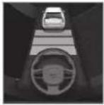 | Grey steering wheel symbol Indicates deactivated steering assistance. When Pilot Assist provides steering assistance, the steering wheel is green. | |
 | Symbol for hands on the steering wheel | The system cannot detect whether the driver has his/her hands on the steering wheel. Place your hands on the steering wheel and actively steer the car. |
 | Windscreen sensorSensor blocked, see Owner's manual | Clean the windscreen in front of the camera and radar unit's detectors. |
A text message can be cleared by briefly pressing the ○ button, located in the centre of the steering wheel's right-hand keypad.
If a message remains: Contact a workshop – an authorised Volvo workshop is recommended.
Related information
- Pilot Assist* (p. 321)
• Limitations of Pilot Assist* (p. 329)
Cornering support\*78
Curve Speed Assist can help the driver to reduce speed ahead of sharper bends if the preset speed for the driver support adaptive cruise control* or Pilot Assist* is estimated as being too high.

In connection with the function reducing the car's speed, this symbol is shown in the driver display.
The calculation is made using information from map data in the car's satellite navigator Sensus Navigation*. After the bend has been passed, the car resumes the previously preset speed.
The driver can cancel the function at any time by choosing to brake or by using the accelerator pedal.
WARNING
- The function is supplementary driver support intended to facilitate driving and make it safer – it cannot handle all situations in all traffic, weather and road conditions.
- The driver is advised to read all sections in the Owner's Manual that relate to this function to learn about factors such as its limitations and what the driver should be aware of before using the system.
- Driver support functions are not a substitute for the driver's attention and judgement. The driver is always responsible for ensuring the car is driven in a safe manner, at the appropriate speed, with an appropriate distance to other vehicles, and in accordance with current traffic rules and regulations.
Drive modes
Assistance during cornering depends on the drive mode set. If the drive mode options are unavailable, the function selects the Comfort option. Using the Dynamic option, the car negotiates bends with sporty characteristics and with slightly more powerful acceleration out of the bends.
Related information
- Activating or deactivating cornering support* (p. 334)
- Limitations for cornering support* (p. 334)
• Driving support systems (p. 286)
• Adaptive cruise control* (p. 311) - Pilot Assist* (p. 321)
- Drive modes (p. 467)
DRIVER SUPPORT
Activating or deactivating cornering support\*
The cornering support function can be activated as a complement to the adaptive cruise control* or Pilot Assist*. The driver can also choose to deactivate the function.

Activate or deactivate the function using this button in the centre display's function view.
- GREEN button indication – the function is activated.
- GREY button indication – the function is deactivated.
During subsequent engine starting, the last used setting is reactivated or settings are followed that were made in the driver profile linked to the key used ^79 .
Related information
• Cornering support* (p. 333)
- Limitations for cornering support* (p. 334)
Limitations for cornering support\*80
The cornering support function may have limitations in certain situations. A driver should be aware about the following examples of limitations.
- Cornering support may have limited performance on smaller roads and in built-up areas.
- On slip roads or intersections, the cornering support may be switched off temporarily.
- If the satellite navigator ^81 map data is not updated, cornering support may have limited functionality.
- If the satellite navigator ^81 does not have contact with the satellite system, cornering support may have limited functionality.
- On new or rebuilt roads, map data may be incorrect.
- When calculating a suitable cornering speed, any risk of reduced traction due to adverse weather or road conditions is not included.

NOTE
This function uses the car's camera and radar units, which have certain general limitations.
Related information
• Cornering support* (p. 333)
- Activating or deactivating cornering support* (p. 334)
- Limitations for camera and radar unit (p. 415)
Overtaking Assistance\*
Overtaking Assistance can help the driver when overtaking other vehicles. The function can be used with adaptive cruise control* or Pilot Assist*.
When adaptive cruise control or Pilot Assist is following another vehicle and the driver indicates the intention to overtake by activating the direction indicator ^82 , the systems help by accelerating the vehicle towards the vehicle ahead before the driver's vehicle reaches the overtaking lane.
The function then delays reducing speed in order to avoid premature braking when the driver's car is approaching a slower vehicle.
The function remains active until the driver's vehicle has cleared the overtaken vehicle.

WARNING
Be aware that this function can be activated in more situations than during overtaking, e.g. when a direction indicator is used to indicate a change of lane or exit to another road – the car will then accelerate briefly.

WARNING
- The function is supplementary driver support intended to facilitate driving and make it safer – it cannot handle all situations in all traffic, weather and road conditions.
- The driver is advised to read all sections in the Owner's Manual that relate to this function to learn about factors such as its limitations and what the driver should be aware of before using the system.
- Driver support functions are not a substitute for the driver's attention and judgement. The driver is always responsible for ensuring the car is driven in a safe manner, at the appropriate speed, with an appropriate distance to other vehicles, and in accordance with current traffic rules and regulations.
Related information
• Driving support systems (p. 286)
• Use Overtaking Assistance (p. 335)
• Adaptive cruise control* (p. 311)
- Pilot Assist* (p. 321)
Use Overtaking Assistance
Overtaking assistance can be used with adaptive cruise control* or Pilot Assist*. There are a number of criteria if Overtaking Assistance is to be used.
The following conditions must exist for Over-taking Assistance to be activated:
- there must be a vehicle in front (the "target vehicle")
- your car's current speed is at least 70 km/h (43 mph)
- the stored speed must be high enough for overtaking to take place safely.
To start the Overtaking Assistance:
- Activate the direction indicator.
Use the left-hand direction indicator in a left-hand drive car right in a right-hand drive car.Overtaking Assistance is started.

WARNING
When using the Overtaking Assistance System, the driver should be aware that there may be undesired acceleration if the conditions suddenly change.
Some situations should therefore be avoided, such as if:
- the car is approaching an exit to turn-off in the same direction as overtaking would normally occur.
- the vehicle ahead slows down before the driver's car has crossed over into the overtaking lane.
- the traffic in the overtaking lane slows down.
- a right-hand drive car is driven in a county with left-hand traffic (or vice versa).
Situations of this kind can be avoided by temporarily setting adaptive cruise control or Pilot Assist in standby mode.
Related information
• Overtaking Assistance* (p. 335)
• Adaptive cruise control* (p. 311)
- Pilot Assist* (p. 321)
- Standby mode for adaptive cruise control* (p. 316)
• Standby mode for Pilot Assist* (p. 327)
Warning from driver support in the event of a collision risk
The driver support systems of adaptive cruise control* and Pilot Assist* can warn the driver if the distance to the vehicle ahead suddenly becomes too short.

Audio and symbol for collision warning
1 Acoustic signal in the event of a risk of collision
② Warning signal in the event of a risk of collision
3 Distance measurement with the camera and radar unit
Adaptive cruise control and Pilot Assist use approx. 40% of the capacity of the foot brake. If the car needs to be braked more heavily than the driver support is capable of and the driver does not brake, the warning lamp and
acoustic warning are activated to alert the driver that immediate intervention is required.

WARNING
The driver support systems only warn of vehicles which their radar unit has detected – hence a warning may not be given, or it may be given with a certain delay. Never wait for a warning. Apply the brakes when the situation requires.

natural_image
Interior view of a car dashboard with steering wheel and dashboard (no visible text or symbols)Symbol for collision warning on the windscreen
In cars equipped with a head up display*, the warning is shown on the windscreen by a flashing symbol.

NOTE
Strong sunlight, reflections, extreme light contrasts, the use of sunglasses, or if the driver is not looking straight ahead may make the visual warning signal in the wind-screen difficult to recognise.
Related information
• Driving support systems (p. 286)
• Adaptive cruise control* (p. 311)
- Pilot Assist* (p. 321)
• Distance Warning* (p. 375)
• Head-up display* (p. 140)
Change of target with driver support
The driver supports of adaptive cruise control* and Pilot Assist*, in combination with automatic transmission, have a change of target function at certain speeds.
Change of target
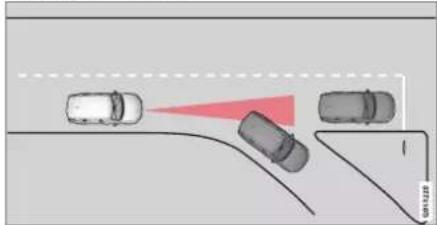
natural_image
Diagram showing three cars on a road with a red triangular object and a vertical line, no text or symbols present.If the target vehicle in front suddenly turns then there may be stationary traffic in front.
When the driver supports are following another vehicle at speeds below 30 km/h (20 mph) and changes target vehicle – from a moving vehicle to a stationary vehicle – the driver supports will slow down for the stationary vehicle.

WARNING
When the driver supports are following another vehicle at speeds in excess of approx. 30 km/h (20 mph) and the target is changed from a moving vehicle to a stationary vehicle, the driver supports will ignore the stationary vehicle and instead accelerate to the stored speed.
- The driver must then intervene him/herself and brake.
Automatic standby mode with change of target
The driver supports are disengaged and set in standby mode:
- when the speed is below 5 km/h (3 mph) and the driver supports are uncertain whether the target object is a stationary vehicle or another object, such as a speed bump.
- when the speed is below 5 km/h (3 mph) and the vehicle ahead turns off so that the driver supports no longer have a vehicle to follow.
Related information
• Driving support systems (p. 286)
• Adaptive cruise control* (p. 311)
- Pilot Assist* (p. 321)
DRIVER SUPPORT
Set the stored speed for driver support
It is possible to set stored speed for the speed limiter, cruise control, adaptive cruise control* and Pilot Assist* functions.

1 +: Increases the stored speed
2 —: Reduces stored speed
3 Stored speed
- Change a set speed with short presses on the steering wheel buttons + (1) or - (2) or by pressing and holding them.
- Short presses: Each press changes the speed in increments of +/- 5 km/h (+/- 5 mph).
- Press and hold: Release the button when the speed indicator (3) has moved to the desired speed.
The speed set after the last button press is stored in the memory.
Effect of the accelerator pedal
If the driver increases the car's speed using the accelerator pedal before pressing the steering wheel button ⏻, the speed stored will be the car's speed when the button is depressed, provided the driver's foot is on the accelerator pedal at the moment when the button is depressed.
A temporary increase in speed with the accelerator pedal, e.g. during overtaking, does not affect the setting - the car returns to the last stored speed when the accelerator pedal is released.
Possible speed
Automatic gearbox
The driver support functions can follow another vehicle at speeds from 0 km/h up to 200 km/h (125 mph).
Pilot Assist can give steering assistance from almost stationary up to 140 km/h (87 mph).
Note that the lowest programmable speed is 30 km/h (20 mph) – even though it is capable of following another vehicle down to 0 km/h, a speed lower than 30 km/h (20 mph) cannot be selected/stored.
Manual gearbox
the driver support functions can follow another vehicle at speeds from 30 km/h (20 mph) up to 200 km/h (125 mph).
Pilot Assist can give steering assistance from 30 km/h (20 mph) up to 140 km/h (87 mph).
The lowest programmable speed is 30 km/h (20 mph) – the maximum speed is 200 km/h (125 mph).
Related information
• Driving support systems (p. 286)
• Speed limiter (p. 301)
• Cruise control (p. 308)
• Adaptive cruise control* (p. 311)
- Pilot Assist* (p. 321)
Set time interval to vehicle ahead
It is possible to set the time interval to the vehicle ahead to be maintained by the adaptive cruise control*, Pilot Assist* and Distance Warning* functions.

Different time intervals to the vehicle in front can be selected and shown in the driver display as 1-5 horizontal lines - the more lines the longer the time interval. One line represents about 1 sec-
ond to the vehicle in front, 5 lines represents about 3 seconds.

NOTE
When the symbol in the driver display shows a car and a steering wheel, Pilot Assist follows a vehicle in front at a preset time gap.
When only one steering wheel is shown, there is no vehicle within a reasonable distance ahead.
NOTE
When the symbol in the driver display shows two cars, adaptive cruise control is following the vehicle in front at a pre-set time interval.
When only one car is shown, there is no vehicle within a reasonable distance ahead.

Control for time interval.
1 Decrease time interval
2 Increase time interval
3 Distance indicator
- Press the steering wheel button (1) or (2) to increase or decrease the time interval.
The distance indicator (3) shows the current time interval.
The adaptive cruise control allows the time interval to vary significantly in certain situations in order to allow the car to follow the vehicle in front smoothly and comfortably. At low speed, when the distances are short, the adaptive cruise control increases the time interval slightly.

NOTE
- The higher the speed the longer the calculated distance in metres for a given time interval.
- Only use the time intervals permitted by local traffic regulations.
- If the driver supports do not seem to respond with a speed increase when activated, it may be because the time window to the vehicle ahead is shorter than the set time window.

WARNING
- Only use a time window that suits the current traffic conditions.
- The driver should be aware that short time windows limit the amount of time available to react and take action in an unexpected traffic situation.
DRIVER SUPPORT
Related information
- Drive modes when using time interval to vehicles (p. 340)
• Driving support systems (p. 286)
• Adaptive cruise control* (p. 311) - Pilot Assist* (p. 321)
• Distance Warning* (p. 375)
• Head-up display* (p. 140)
Drive modes when using time interval to vehicles
The driver can select different driving styles for how driver support should maintain the preset time interval to the vehicle ahead. Selection is made via the drive mode control DRIVE MODE.
Select one of the following options:
- Pure – The driver support focuses on good fuel economy, which means longer time interval to the vehicle ahead.
- Hybrid – The driver support focuses on following the set time interval to the vehicle ahead as smoothly as possible.
- Power – The driver support focuses on following the set time interval to the vehicle ahead more closely, which in certain cases may mean heavier acceleration and braking.
Related information
• Set time interval to vehicle ahead (p. 339)
• Driving support systems (p. 286)
- Drive modes (p. 467)
Automatic braking with driver support
The driver supports of adaptive cruise control* and Pilot Assist* have a special brake function in slow traffic and while stationary. In certain situations, the parking brake is applied in order to keep the car stationary.
Brake function in slow queues and while stationary
For shorter stops in connection with inching in slow traffic or at traffic lights, driving is automatically resumed if the stops do not exceed approx. 3 seconds - if it takes longer before the vehicle in front starts moving again then the driver support function is set in standby mode with automatic braking.
- The function is reactivated in one of the following ways:
- Press the steering wheel button ⚙ ^+ .
- Depress the accelerator pedal.
The function resumes following the vehicle ahead if it starts moving forward within approx. 6 seconds.

WARNING
A significant increase in speed may follow when the speed is resumed with the steering wheel button.

WARNING
Driver supports only warn of obstacles which their radar unit has detected – hence a warning may not be given, or it may be given with a certain delay.
- Never wait for a warning or intervention. Apply the brakes when the situation requires.

NOTE
The driver supports can hold the car stationary for a maximum of 5 minutes – then the parking brake is applied and the function is disengaged.
Before the driver supports can be reactivated, the parking brake must be released.
Cessation of automatic braking
In some situations, automatic braking ceases on coming to a standstill and the function is set in standby mode. This means that the brakes are released and the car may start to roll - the driver must therefore intervene and brake the car himself/herself to keep it stationary.
This may take place in any of the following situations:
- The driver puts his/her foot on the brake pedal.
• The parking brake is applied. - The gear selector is moved to P, N, or R position.
- The driver sets the adaptive cruise control or Pilot Assist to standby mode.
Automatic activation of parking brake
The Parking brake is applied if the function is holding the car stationary with the foot brake and:
- The driver opens the door or takes off his/her seatbelt.
- The function has kept the car stationary for more than approx. 5 minutes.
• The brakes have overheated.
• The driver switches the engine off.
Related information
• Driving support systems (p. 286)
• Adaptive cruise control* (p. 311)
- Pilot Assist* (p. 321)
- Brake functions (p. 451)
Lane assistance
The function of the Lane Keeping Aid (LKA ^83 ) is to help the driver to reduce the risk of the car accidentally leaving its own lane on motorways and similar major routes.
Lane Keeping Aid steers the car back into its lane and/or alerts the driver with vibrations in the steering wheel.
Lane Keeping Aid is active within the speed range 65–200 km/h (40–125 mph) on roads with clearly visible side lines.
On narrow roads the function may be unavailable, in which case it goes into standby mode. The function becomes available again when the road is wide enough.

A camera reads the side lines of the road/lane.
DRIVER SUPPORT
◀◀
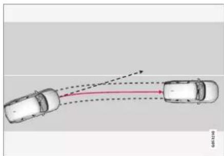
natural_image
Top-down diagram of two cars with red trajectory arrows indicating motion (no text or symbols)Lane assistance steers the car back into its lane.

Lane assistance warns with steering wheel vibrations.
Depending on settings, lane assistance acts in accordance with the following:
- Assist activated: When the car is approaching a lane line, the function will actively steer the car back into its lane by
applying a slight torque to the steering wheel.
- Warning activated: If the car is about to cross a lane line, the driver is warned by means of vibrations in the steering wheel.
There is also an option where both steering assistance and warning are activated simultaneously.
NOTE
When a direction indicator/flasher is switched on, there are no steering corrections or alerts from lane assistance.

WARNING
- The function is supplementary driver support intended to facilitate driving and make it safer – it cannot handle all situations in all traffic, weather and road conditions.
- The driver is advised to read all sections in the Owner's Manual that relate to this function to learn about factors such as its limitations and what the driver should be aware of before using the system.
- Driver support functions are not a substitute for the driver's attention and judgement. The driver is always responsible for ensuring the car is driven in a safe manner, at the appropriate speed, with an appropriate distance to other vehicles, and in accordance with current traffic rules and regulations.
Lane assistance does not intervene

natural_image
Diagram of four cars driving on a curved road with a red trajectory line (no text or symbols)Lane assistance does not engage on sharp inside curves.
In some situations, lane assistance allows lane lines to be crossed without intervening with either steering assistance or a warning – e.g. when using the direction indicators or if the car is allowed to cut the corners in bends.
Hands on the steering wheel
For steering assistance with lane assistance to work, the driver must have his/her hands on the steering wheel, which the system will continue to monitor.

If the driver does not keep his/her hands on the steering wheel, a warning signal is heard and a message encourages the driver to steer the car actively:
• Lane Keeping Aid Apply steering
If the driver follows the prompt to start steering, the function is set in standby mode and this message is shown:
• Lane Keeping Aid Standby until steering applied
The function will then be unavailable until the driver starts to steer the car again.
Related information
• Driving support systems (p. 286)
- Activating or deactivating lane assistance (p. 343)
• Limitations of Lane assistance (p. 344)
- Symbols and messages for lane assistance (p. 345)
Activating or deactivating lane assistance
The Lane Keeping Aid (LKA) function (LKA ^84 ) is optional – the driver can choose to activate or deactivate this function.

Activate or deactivate the function using this button in the centre display's function view.
- GREEN button indication – the function is activated.
- GREY button indication – the function is deactivated.
Related information
• Lane assistance (p. 341)
- Selecting assistance option for lane assistance (p. 344)
• Limitations of Lane assistance (p. 344)
DRIVER SUPPORT
Selecting assistance option for lane assistance
The driver can select how the Lane Keeping Aid (LKA ^85 ) should react if the car leaves its lane.
-
Select Settings MyCar Intelligence in the centre display's top view.
-
In the event of Lane Keeping Aid Mode, select how the function should react:
- Assist – the driver is given steering assistance without a warning.
- Warning – the driver is only warned by steering wheel vibration.
- Both – the driver is given a warning both from the steering wheel vibrating and from steering assistance.
Related information
• Lane assistance (p. 341)
Limitations of Lane assistance
In certain demanding conditions lane assistance (LKA ^86 ) may have difficulty helping the driver correctly. In such cases it is recommended to switch off this function.
Examples of such conditions are:
road works
• winter road conditions
- poor road surface
• a very "sporty" driving style
• poor weather with reduced visibility
- roads with unclear or non-existent side markings
- sharp edges or lines other than the lane's side markings
- as the steering servo for speed-dependent steering wheel resistance is working at reduced power – e.g. when cooling due to overheating.
The function is unable to detect barriers, rails or similar obstacles at the side of the carriageway.
NOTE
This function uses the car's camera and radar units, which have certain general limitations.
Related information
• Lane assistance (p. 341)
• Speed-dependent steering force (p. 286)
- Limitations for camera and radar unit (p. 415)
DRIVER SUPPORT
Symbols and messages for lane assistance
A number of symbols and messages regarding lane assistance (LKA ^87 ) can be shown
on the driver display. Here are some examples.
| Symbol Message Specification | ||
 | Driver support systemReduced functionality Service required | The system does not function as it should. A workshop should be contacted ^A . |
 | Windscreen sensorSensor blocked, see Owner's manual | The ability of the camera to scan the roadway in front of the car is reduced. |
DRIVER SUPPORT
◀◀
| Symbol Message Specification | ||
 | Lane Keeping AidApply steering | The LKA steering assistance does not function if the driver does not have his/her hands on the steering wheel. Follow the instruction and steer the car. |
 | Lane Keeping AidStandby until steering applied | LKA is set in standby mode until the driver starts to steer the car again. |
A. An authorised Volvo workshop is recommended.
A text message can be cleared by briefly pressing the ○ button, located in the centre of the steering wheel's right-hand keypad.
If a message persists, contact a workshop ^4 .
Related information
• Lane assistance (p. 341)
• Display mode for lane assistance (p. 347)
• Limitations of Lane assistance (p. 344)
Display mode for lane assistance
Lane assistance (LKA ^88 ) is visualised by symbols in the driver display depending on the situation.

Here are some examples of symbols and the situations in which they are shown:
Available
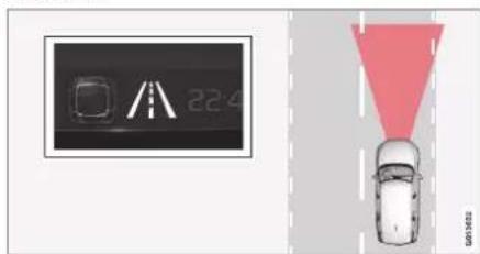
Available — the lane lines in the symbol are WHITE. Lane assistance is scanning one or both lane lines.
Unavailable
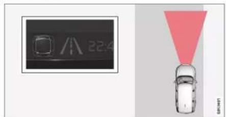
Unavailable — the lane lines in the symbol are GREY.
The Lane assistance cannot detect the lane lines, the speed is too low or the road is too narrow.
Indication of steering assistance/warning

Steering assistance/warning - the lane lines in the symbol are COLOURED.
Lane assistance indicates that the system is giving a warning and/or attempting to steer the car back into the lane.
Related information
• Lane assistance (p. 341)
• Limitations of Lane assistance (p. 344)
DRIVER SUPPORT
City Safety™
City Safety ^89 can use lights, sound and a brake pulse warning to alert the driver to pedestrians, cyclists, larger animals and vehicles.
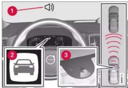
Function overview
1 Acoustic signal in the event of a risk of collision
2 Warning signal in the event of a risk of collision
3 Distance measurement with the camera and radar unit
The function can help the driver avoid a collision when, for example, driving in heavy traffic, where changes in the traffic ahead coupled with inattentiveness can lead to an incident. City Safety then activates brief, heavy braking
and the car normally stops just behind the vehicle in front.
The function helps the driver by automatically braking the car in the event of an imminent risk of collision if the driver does not react in time by braking and/or swerving.
City Safety is activated in situations where the driver should have started braking earlier, which is why it cannot help the driver in every situation. The function is designed to be activated as late as possible in order to avoid unnecessary intervention. Automatic braking takes place only after or at the same time as the collision warning.
The driver or passengers are not normally aware of City Safety - it only intervenes in a situation where a collision is immediately imminent.

WARNING
- The function is supplementary driver support intended to facilitate driving and make it safer – it cannot handle all situations in all traffic, weather and road conditions.
- The driver is advised to read all sections in the Owner's Manual that relate to this function to learn about factors such as its limitations and what the driver should be aware of before using the system.
- Driver support functions are not a substitute for the driver's attention and judgement. The driver is always responsible for ensuring the car is driven in a safe manner, at the appropriate speed, with an appropriate distance to other vehicles, and in accordance with current traffic rules and regulations.
Related information
• Driving support systems (p. 286)
• Subfunctions for City Safety (p. 349)
- Setting the warning distance for City Safety (p. 351)
• Detection of obstacles with City Safety (p. 352)
• City Safety brakes for oncoming vehicles (p. 357)
- Automatic braking in the event of an impeded evasive manoeuvre with City Safety (p. 357)
• City Safety in cross traffic (p. 354)
- City Safety steering assistance for evasive manoeuvre (p. 356)
• Limitations of City Safety (p. 358)
- Messages for City Safety (p. 361)
Subfunctions for City Safety
City Safety ^90 can help to prevent a collision or reduce the collision speed. The function consists of several subfunctions.
Ability to reduce speed
If the speed difference between the driver's car and the obstacle is greater than the following specified speeds, the City Safety auto-brake function cannot prevent a collision but it can mitigate the consequences of a collision.
Vehicles
For a vehicle in front, City Safety can reduce the speed by up to 60 km/h (37 mph).
Cyclists
For a cyclist, City Safety can reduce the speed by up to 50 km/h (30 mph).
Pedestrians
For a pedestrian, City Safety can reduce speed by up to 45 km/h (28 mph).
Large animals
In the event of a risk of a collision with a large animal, City Safety can reduce the car's speed by up to 15 km/h (9 mph).
The brake function for large animals is primarily intended to reduce the force of the impact at higher speeds and is most effective at speeds above 70 km/h (43 mph) but less effective at lower speed.
The steps of City Safety
City Safety carries out three steps in the following order:
- Collision warning
- Brake support
- Auto Brake
DRIVER SUPPORT
1 - Collision warning
The driver is first warned of a potentially imminent collision.
In cars equipped with a head up display*, the warning is shown on the windscreen by a flashing symbol.

natural_image
Close-up of a car dashboard with steering wheel and speedometer (no visible text or symbols)Symbol for collision warning on the windscreen
NOTE
Strong sunlight, reflections, extreme light contrasts, the use of sunglasses, or if the driver is not looking straight ahead may make the visual warning signal in the wind-screen difficult to recognise.
City Safety can detect pedestrians, cyclists or vehicles that are stationary or moving in the same direction as the car and are ahead. City Safety can also detect pedestrians, cyclists or
large animals that are crossing the road in front of the car.
In the event of a risk of collision with a pedestrian, larger animal, cyclist or vehicle, the driver is alerted by means of a visual, acoustic and brake pulse warning. There is no brake pulse warning at lower speeds, sudden driver braking or acceleration. The brake pulse frequency varies according to the car's speed.
2 - Brake support
If the risk of collision has increased further after the collision warning then the brake support is activated.
Brake support reinforces the driver's braking action if the system considers that the braking is not sufficient to avoid a collision.
3 - Auto Brake
The automatic brake function is activated last.
If in this situation the driver has not yet started to take evasive action and the risk of collision is imminent then the automatic braking function is deployed - this takes place irrespective of whether or not the driver brakes. Braking then takes place with full brake force in order to reduce collision speed, or with limited brake force if it is sufficient to avoid a collision.
The seatbelt tensioner can be activated in connection with the engagement of the automatic brake function.
In some situations, the action of Auto-brake may begin with light braking and then progress to full brake action.
When City Safety has prevented a collision with a stationary object, the car remains stationary in anticipation of positive action by the driver. If the car has been braked to avoid collision with a slower vehicle in front, its speed is reduced to match that of the vehicle in front.
NOTE
On cars with manual gearbox, the engine stops when the Auto-brake function has stopped the car, unless the driver has managed to depress the clutch pedal beforehand.
The driver can always interrupt a braking intervention by firmly depressing the accelerator pedal.
i NOTE
When City Safety brakes, the brake lights come on.
When City Safety is activated and brakes the vehicle, the driver display shows a text message to the effect that the function is/has been active.

WARNING
City Safety must not be used by the driver to change his/her driving style - the driver must not rely on City Safety alone and allow it to do the braking.
Related information
• City Safety™ (p. 348)
• City Safety in cross traffic (p. 354)
• City Safety brakes for oncoming vehicles (p. 357)
• Limitations of City Safety (p. 358)
• Head-up display* (p. 140)
- Seatbelt tensioner (p. 52)
Setting the warning distance for City Safety
City Safety ^91 is always activated, but the driver can select the warning distance for the function.
NOTE
The City Safety function cannot be deactivated. It is activated automatically when the engine/electric operation is started and remains switched on until the engine/electric operation is switched off.
The warning distance determines the sensitivity of the system and regulates the distance at which a visual, acoustic and brake pulse warning should be deployed.
To select warning distance:
- Select Settings My Car IntelliSafe in the centre display's top view.
- Under City Safety Warning, select either Late, Normal or Early to set the desired warning distance.
If the Early setting produces too many warnings, which could be perceived as irritating in certain situations, the Normal or Late warning distance can be selected.
When warnings are perceived as being too frequent or disturbing, the warning distance can be reduced, which reduces the total number of warnings and instead leads to City Safety giving a warning at a later stage.
The Late warning distance should therefore only be used in exceptional cases, as in dynamic driving.
DRIVER SUPPORT
◀◀

WARNING
- No automatic system can guarantee 100% correct function in all situations. Therefore, never test City Safety by driving at people, animals or vehicles - this may cause severe damage and injury and risk lives.
- City Safety warns the driver when there is a risk of a collision, but it cannot shorten the driver's reaction time.
- Even if the warning distance has been set to Early warnings could be perceived as being late in certain situations, e.g. when there are large differences in speed or if vehicles ahead suddenly brake heavily.
- With the warning distance set at Early, the warnings will come more in advance. This may mean that the warnings come more frequently than at the warning distance Normal, but it is recommended since it can make City Safety more effective.
Related information
• City Safety™ (p. 348)
• Limitations of City Safety (p. 358)
• Rear Collision Warning* (p. 368)
Detection of obstacles with City Safety
City Safety ^92 can help the driver to detect vehicles, cyclists, large animals and pedestrians.
Vehicles
City Safety detect most vehicles that are stationary or moving in the same direction as the driver's own car. This function can also detect oncoming vehicles and cross traffic in certain cases.
In order that City Safety shall be able to detect a vehicle in the dark, the vehicle's front and rear lights must be working and clearly illuminated.
Cyclists

natural_image
Silhouette illustration of a person riding a bicycle with a side view of a person on a bike (no text or symbols)Examples of what City Safety interprets as a cyclist — with clear body outline and bicycle outline.
Good performance requires that the system function that detects a cyclist must receive the clearest possible information about the body and bicycle outline, requiring the ability to identify the bicycle, head, arms, shoulders, legs, upper and lower body plus a normal human pattern of movement.
If large parts of the cyclist's body or bicycle are not visible to the function's camera then the system cannot detect a cyclist.
For the function to be able to detect a cyclist, he/she must be an adult and riding a bicycle designed for adults.

WARNING
City Safety is supplementary driver support, but it cannot detect all cyclists in all situations and, for example, cannot see:
• partially obscured cyclists.
• cyclists if the background contrast for the cyclists is poor.
• cyclists wearing clothing that obscures the body outline.
• bicycles loaded with large objects.
Warnings and brake interventions could be late or not occur at all. The driver is always responsible that the vehicle is driven correctly and with a safety distance adapted to the speed.
Pedestrians

natural_image
Silhouettes of two human figures in walking and walking poses (no text or symbols)Examples of what the system regards as pedestrians with clear body outlines.
Good performance requires that the system function that detects a pedestrian must receive the clearest possible information about the body outline, requiring the ability to identify the head, arms, shoulders, legs, upper and lower body plus a normal human pattern of movement.
In order that it shall be possible to detect a pedestrian there must be a contrast with the background and this will be affected by such things as clothes, the background and the weather. With poor contrast the pedestrian may either be detected late or not at all, which may mean that warnings and braking are late or omitted.
City Safety can also detect pedestrians in the dark if they are illuminated by the car's head-lamps.

WARNING
City Safety is supplementary driver support, but it cannot detect all pedestrians in all situations and, for example, cannot see:
- partially obscured pedestrians, people in clothing that hides their body contour or pedestrians shorter than 80 cm (32 in.).
• pedestrians if the background contrast for the pedestrians is poor.
• pedestrians who are carrying larger objects.
Warnings and brake interventions could be late or not occur at all. The driver is always responsible that the vehicle is driven correctly and with a safety distance adapted to the speed.
DRIVER SUPPORT
Large animals

natural_image
Silhouette of a moose and a horse in motion, no text or symbols presentExamples of what City Safety interprets as large animals - standing still or walking slowly and with clear body outline.
Good performance requires that the system function that detects a large animal (e.g. elk and horse) must receive the clearest possible information about the body outline, requiring the ability to identify the animal directly from the side in combination with what is a normal pattern of movement for the animal.
If parts of the animal's body are not visible to the function's camera then the system cannot detect the animal.
City Safety can also detect large animals in the dark if they are illuminated by the car's head-lamps.
WARNING
City Safety is supplementary driver support, but it cannot detect all large animals in all situations and, for example, cannot see:
• partially obscured large animals.
- larger animals seen from the front or from behind.
• large animals that run or move quickly.
- large animals if the background contrast for the animals is poor.
- small animals such as dogs and cats, for example.
Warnings and brake interventions could be late or not occur at all. The driver is always responsible that the vehicle is driven correctly and with a safety distance adapted to the speed.
Related information
• City Safety™ (p. 348)
• Limitations of City Safety (p. 358)
City Safety in cross traffic
City Safety ^93 can help the driver when turning and crossing the path of another oncoming vehicle at an intersection.
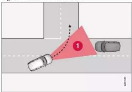
① Sector in which City Safety can detect oncoming crossing vehicles.
For City Safety to detect an oncoming vehicle on a collision course, the oncoming vehicle must first enter the sector in which City Safety can analyse the situation.
The following further criteria must also be fulfilled:
- your car must be travelling at no less than 4 km/h (3 mph)
- your car must turn to the left in markets with right-hand traffic (or to the right in left-hand traffic)
- the oncoming vehicle must have its head-lamps switched on.
Related information
• City Safety™ (p. 348)
• Limitations of City Safety (p. 358)
Limitations for City Safety in cross traffic
In some cases City Safety may have difficulty helping the driver deal with collision risks due to oncoming cross traffic.
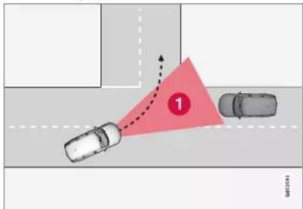
Examples are:
• Stability control ESC intervenes in the event of slippery driving conditions.
- If the oncoming vehicle is detected too late.
- If the oncoming vehicle is obscured by something.
- If the oncoming vehicle has headlamps switched off.
- If the oncoming vehicle drives in an unpredictable manner, for example, abruptly changes lanes at a late stage.
NOTE
This function uses the car's camera and radar units, which have certain general limitations.
Related information
• City Safety in cross traffic (p. 354)
• Limitations of City Safety (p. 358)
- Limitations for camera and radar unit (p. 415)
DRIVER SUPPORT
City Safety steering assistance for evasive manoeuvre
City Safety steering assistance can help the driver to steer away from a vehicle/obstacle when it is not possible to avoid a collision simply by braking. City Safety steering assistance cannot be switched off, it is always activated.

flowchart
graph TD
    A["1"] --> B["→"]
    B --> C["2"]
    style A fill:#f9f,stroke:#333
    style C fill:#bbf,stroke:#333
1 Your car steers away.
② Slow moving/stationary vehicles or obstacles.
City Safety engages by amplifying the driver's steering input, which only occurs after the driver has begun an evasive manoeuvre - and then only if the driver is not steering enough to avoid a collision.
In parallel with the amplified steering input, the brake system is also used to further amplify the steering input. The function also
helps to straighten the car again after passing the obstacle.
City Safety steering assistance can detect:
- Vehicles
• cyclists - Pedestrians
- larger animals.
Related information
• City Safety™ (p. 348)
- Limitations of City Safety steering assistance when taking evasive action (p. 356)
• Limitations of City Safety (p. 358)
Limitations of City Safety steering assistance when taking evasive action
City Safety may have limited functionality in certain situations and fail to intervene e.g.:
• outside the speed range 50-100 km/h (30-62 mph)
• if the driver initiates an evasive manoeuvre
- if the steering servo creating speed-dependent steering wheel resistance is working at reduced power – e.g. when cooling due to overheating.
NOTE
This function uses the car's camera and radar units, which have certain general limitations.
Related information
- City Safety steering assistance for evasive manoeuvre (p. 356)
• Limitations of City Safety (p. 358)
• Speed-dependent steering force (p. 286) - Limitations for camera and radar unit (p. 415)
Automatic braking in the event of an impeded evasive manoeuvre with City Safety
City Safety ^94 has the facility to assist the driver by automatically braking the car earlier when it is not possible to avoid a collision by only steering away.
City Safety assists the driver by continuously attempting to anticipate whether there are "escape routes" to the side in case a slow or stationary vehicle ahead is discovered at a late stage.

flowchart
graph TD
    A["Step 1: Top-down car"] --> B["Step 2: Left arrow"]
    B --> C["Step 3: Right arrow"]
    C --> D["Step 4: Bottom-right arrow"]
    D --> E["Step 5: Left arrow"]
    E --> F["Step 6: Right arrow"]
    F --> G["Step 7: Bottom-left arrow"]
    G --> H["Step 8: Right arrow"]
    H --> I["Step 9: Left arrow"]
Your car (1) "sees" no options for evading the vehicle ahead (2) and can therefore auto-brake earlier.
1 Your car
② Slow/stationary vehicle
City Safety does not intervene with the auto-brake function as long as the driver him/herself has the opportunity to avoid a collision via a steering manoeuvre.
However, if City Safety anticipates that an evasive manoeuvre is not possible due to traffic in an adjacent lane, the function can assist the driver by automatically starting to brake at an earlier stage.
Related information
• City Safety™ (p. 348)
• Limitations of City Safety (p. 358)
City Safety brakes for oncoming vehicles
City Safety can assist the driver to use emergency braking for an oncoming vehicle in your car's lane.
If an oncoming vehicle enters your car's lane and a collision is unavoidable, City Safety can reduce the car's speed with a view to reducing the violence of the impact.

1 Your car
② Oncoming vehicles
DRIVER SUPPORT
For this function to work, the following criteria must be met:
- your car must be travelling at more than 4 km/h (3 mph)
• the road section must be straight - your car's lane must have clear lane markings
- your car must be positioned straight in its own lane
- the oncoming vehicle must be within your car's lane markings
- the oncoming vehicle must have its head-lamps switched on
- this function can only handle "front to front" collisions
- this function can only detect vehicles with four wheels.

WARNING
Warnings and brake interventions due to an impending collision with an oncoming vehicle always come very late.
Related information
• City Safety™ (p. 348)
• Limitations of City Safety (p. 358)
Limitations of City Safety
The City Safety ^95 function may have limitations in certain situations.
Surroundings
Low objects
Low-hanging objects, e.g. a flag/pennant for projecting load, or accessories such as auxiliary lamps and bull bars that are higher than the bonnet limit the function.
Skidding
On slippery road surfaces the braking distance is extended, which may reduce the capacity of City Safety to avoid a collision. In such situations, the anti-lock brakes and the stability control ESC ^96 are designed to give the best possible braking force with maintained stability.
Oncoming light
The visual warning signal in the windscreen may be difficult to notice in the event of strong sunlight, reflections, when sunglasses are being worn or if the driver is not looking straight ahead.
Heat
In the event of high passenger compartment temperature, caused by e.g. strong sunlight, the visual warning signal in the windscreen may be temporarily disengaged.
The camera and radar unit's field of view
The camera's field of vision is limited, which is why pedestrians, large animals, cyclists and vehicles in some situations cannot be detected, or they are detected later than anticipated.
Dirty vehicles may be detected later than others and if it is dark, motorcycles may be detected late or not at all.
If a text message in the driver display indicates that the camera or radar unit is obstructed, City Safety may be unable to detect pedestrians, large animals, cyclists, vehicles or road lines ahead of the car. This means that the functionality of City Safety may be reduced.
However, an error message is not shown in all situations where the windscreen sensors are obstructed. The driver must therefore take care to keep the area of windscreen in front of the camera and radar unit clear.

IMPORTANT
Maintenance of driver support components must only be performed at a workshop – an authorised Volvo workshop is recommended.
Driver intervention
Reversing
When your own car is reversing, City Safety is temporarily deactivated.
Low speed
City Safety is not activated at very low speeds - below 4 km/h (3 mph) - and the system therefore does not intervene in situations where your car is approaching a vehicle ahead very slowly, e.g. when parking.
Active driver
Driver commands are always prioritised, which is why City Safety does not intervene or postpone warning/intervention in situations where the driver is steering and accelerating in a decisive manner, even if a collision is unavoidable.
Active and aware driving behaviour can therefore delay a collision warning and intervention in order to minimise unnecessary warnings.
Important warnings
WARNING
Driver supports only warn of obstacles which their radar unit has detected – hence a warning may not be given, or it may be given with a certain delay.
- Never wait for a warning or intervention. Apply the brakes when the situation requires.
WARNING
- Warnings and brake interventions could be implemented late or not at all if a traffic situation or external influences mean that the camera and radar unit cannot detect pedestrians, cyclists, large animals or vehicles correctly.
- For vehicles to be detected at night, their headlamps and rear lamp cluster must be switched on and shining clearly.
- The camera and radar unit has a limited range for pedestrians and cyclists. The system can provide effective warnings and brake interventions as long as the relative speed is below 50 km/h (30 mph). For stationary or slow-moving vehicles, warnings and brake interventions are effective at vehicle speeds up to 70 km/h (43 mph). Speed reduction for large animals is less than 15 km/h (9 mph) and can be achieved at vehicle speeds above 70 km/h (43 mph). The warning and brake intervention for large animals is less effective at lower speeds.
- Warnings for stationary or slow-moving vehicles as well as large animals
DRIVER SUPPORT
◀◀
may be disengaged due to darkness or poor visibility.
- Warnings and brake interventions for pedestrians and cyclists are deactivated at vehicle speeds exceeding 80 km/h (50 mph).
- Do not place, stick or mount anything on the outside or inside of the wind-screen in front of or around the camera and radar unit — this can interfere with camera-dependent functions.
- Objects, snow, ice or dirt in the area of the camera sensor may reduce its functionality, fully deactivate it or give incorrect function response.

WARNING
- The City Safety auto-brake function can prevent a collision or reduce collision speed, but to ensure full brake performance the driver should always depress the brake pedal – even when the car auto-brakes.
- The warning and steering assistance are only activated if there is a high risk of collision – you must therefore never wait for a collision warning or for City Safety to intervene.
- The warning and brake intervention for pedestrians and cyclists are deactivated at vehicle speeds exceeding 80 km/h (50 mph).
- City Safety does not activate any auto-brake functions in the event of heavy acceleration.

NOTE
This function uses the car's camera and radar units, which have certain general limitations.
Market limitation
City Safety is not available in all countries. If City Safety does not appear in the centre dis-
play's Settings menu, the car is not equipped with this function.
Search path in the top view of the centre display:
- Settings My Car IntelliSafe
Related information
• City Safety™ (p. 348)
- Limitations for camera and radar unit (p. 415)
DRIVER SUPPORT
Messages for City Safety
A number of messages regarding City Safety can be shown in the driver display. Here are some examples.
| Message Specification | |
| City SafetyAutomatic intervention | When City Safety brakes or has done an automatic braking, several of the driver display symbols may be illuminated in connection with a text message being shown. |
| City SafetyReduced functionality Service required | The system does not function as it should. A workshop should be contactedA. |
^ An authorised Volvo workshop is recommended.
A text message can be cleared by briefly pressing the ○ button, located in the centre of the steering wheel's right-hand keypad.
If a message persists, contact a workshop ^4 .
Related information
• City Safety™ (p. 348)
DRIVER SUPPORT
Steering assistance at risk of collision
The function Collision avoidance can help the driver reduce the risk of the car leaving its lane unintentionally and/or colliding with another vehicle or obstacle by actively steering the car back into its lane and/or swerving. The function consists of these subfunctions:
• Steering assistance upon risk of run-off
• Steering assistance upon risk of head-on collision
- Steering assistance upon risk of rear-end collision*
After automatic engagement, the driver display indicates that this has occurred via a text message:
Collision avoidance Automatic intervention
WARNING
- The function is supplementary driver support intended to facilitate driving and make it safer – it cannot handle all situations in all traffic, weather and road conditions.
- The driver is advised to read all sections in the Owner's Manual that relate to this function to learn about factors such as its limitations and what the driver should be aware of before using the system.
- Driver support functions are not a substitute for the driver's attention and judgement. The driver is always responsible for ensuring the car is driven in a safe manner, at the appropriate speed, with an appropriate distance to other vehicles, and in accordance with current traffic rules and regulations.
NOTE
It is always the driver who decides how much the car should steer – the car can never take command.
Related information
• Driving support systems (p. 286)
- Activating or deactivating steering assistance in the event of a collision risk (p. 363)
• Steering assistance upon risk of run-off (p. 363)
• Steering assistance upon risk of head-on collision (p. 364)
• Steering assistance upon risk of rear-end collision* (p. 365)
- Limitations for steering assistance at risk of collision (p. 366)
- Symbols and messages for steering assistance upon risk of collision (p. 367)
Activating or deactivating steering assistance in the event of a collision risk
The steering assistance function is optional – the driver can choose to activate or deactivate it.

Activate or deactivate the function using this button in the centre display's function view.
- GREEN button indication – the function is activated.
- GREY button indication – the function is deactivated.
This function is activated automatically each time the engine is started ^97 .
NOTE
When the Collision avoidance function is deactivated, all subfunctions are switched off:
• Steering assistance at risk of road departure
• Steering assistance at risk of oncoming collision
• Steering assistance at risk of rear-end collision*
Even though it is possible to deactivate the function, it is advisable for the driver to always have it activated since it improves driving safety in most cases.
Related information
• Steering assistance at risk of collision (p. 362)
- Limitations for steering assistance at risk of collision (p. 366)
Steering assistance upon risk of run-off
Steering assistance has a number of subfunctions. Steering assistance in the event of runoff risk can help the driver and reduce the risk of the car accidentally leaving the road by actively steering the car back onto the road.
The function has two activation levels on intervention:
• Steering assistance only
• Steering assistance with brake intervention
Steering assistance only
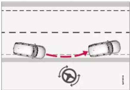
Intervention with steering assistance
DRIVER SUPPORT
Steering assistance with brake intervention

Intervention with steering assistance and braking
Brake intervention helps in situations where steering assistance alone is not sufficient. The brake force is adapted automatically depending on the situation at the time of road run-off.
The function is active within the speed range 65-140 km/h (40-87 mph) on roads with clearly visible lane markings/lines.
A camera scans the edges of the road and the painted side markings. If the car is about to leave the side of the road, the car is steered back onto the road and if the steering intervention is not enough to avoid run-off, the brakes are also activated.
However, the function does not intervene with either steering assistance or brake intervention if the direction indicators are used. And if the function detects that the driver is actively
driving the car, activation of the function will be delayed.
Related information
• Steering assistance at risk of collision (p. 362)
- Limitations for steering assistance at risk of collision (p. 366)
Steering assistance upon risk of head-on collision
Steering assistance has a number of subfunctions. Steering assistance upon risk of head-on collision can help a distracted driver who does not notice that the car is heading into the opposite lane.
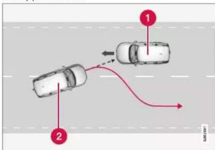
flowchart
graph TD
    A["1 Car"] -->|Right Arrow| B["2 Car"]
    B -->|Left Arrow| A
The function can assist by guiding the car back to its own lane.
1 Oncoming vehicles
2 Your car
At the same time as steering intervention is activated, collision warning for driver support is also activated. However, the brake pulse included in the collision warning will not be activated.
The function is active within the speed range 60-140 km/h (37-87 mph) on roads with clearly visible lane markings/lines.
If the car is about to leave its own lane while an oncoming vehicle is approaching at the same time, the function can help the driver to steer the car back into its own lane.
However, the function does not intervene with steering assistance if the direction indicator is used. And if the function detects that the driver is actively driving the car, activation of the function will be delayed.
Related information
• Steering assistance at risk of collision (p. 362)
- Warning from driver support in the event of a collision risk (p. 336)
- Limitations for steering assistance at risk of collision (p. 366)
Steering assistance upon risk of rear-end collision\*
Steering assistance has a number of subfunctions. Steering assistance if there is a risk of rear-end collision can help a distracted driver who does not notice that the car is about to leave its own lane while an oncoming vehicle is approaching at the same time, either from behind or in the blind spot.

flowchart
graph TD
    A["1 Car"] --> B["2 Car"]
    B --> C["→"]
    style A fill:#f9f,stroke:#333
    style B fill:#f9f,stroke:#333
    style C fill:#ccf,stroke:#333
The function can assist by steering the car back to its own lane.
1 Other vehicle in the blind spot
② Your car
If the car is about to leave its own lane while another vehicle is in the blind spot, or another vehicle is approaching rapidly in an adjacent lane at the same time, the function can help.
the driver to steer the car back into its own lane.
The function can even assist if the driver intentionally changes lanes using direction indicators without noticing that another vehicle is approaching.
The function is active within the speed range 60-140 km/h (37-87 mph) on roads with clearly visible lane markings/lines.
The lamps in the door mirrors flash during steering intervention, regardless of whether the BLIS ^98 function is activated. An acoustic signal can also be heard.
Related information
• Steering assistance at risk of collision (p. 362)
BLIS* (p. 369)
- Limitations for steering assistance at risk of collision (p. 366)
DRIVER SUPPORT
Limitations for steering assistance at risk of collision
In certain situations the function may have limited functionality and fail to intervene in the following cases, for example:
• for small vehicles, such as motorcycles
- if the majority of the car has steered into the adjacent lane
- on roads/in lanes with unclear or non-existent lane markings
• outside the speed range 60-140 km/h (37-87 mph)
- as the steering servo for speed-dependent steering wheel resistance is working at reduced power – e.g. when cooling due to overheating.
Other demanding situations can include:
road works
• winter road conditions
- narrow roads
- poor road surface
• a very "sporty" driving style
• poor weather with reduced visibility.
In these demanding situations, the function may have difficulty helping the driver correctly. In such cases it is recommended to switch off this function.
NOTE
This function uses the car's camera and radar units, which have certain general limitations.
Related information
• Steering assistance at risk of collision (p. 362)
• Steering assistance upon risk of run-off (p. 363)
• Steering assistance upon risk of head-on collision (p. 364)
- Steering assistance upon risk of rear-end collision* (p. 365)
Symbols and messages for steering assistance upon risk of collision
A number of symbols and messages regarding steering assistance may be shown in the driver display. Here are some examples.
| Symbol Message Specification | ||
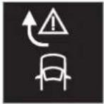 | Collision avoidanceAutomatic intervention | When the function is activated, a message is shown to the driver indicating that the system has been activated. |
 | Windscreen sensorSensor blocked, see Owner's manual | The ability of the camera to scan the roadway in front of the car is reduced. |
A text message can be cleared by briefly pressing the ○ button, located in the centre of the steering wheel's right-hand keypad.
If a message remains: Contact a workshop – an authorised Volvo workshop is recommended.
Related information
• Steering assistance at risk of collision (p. 362)
- Limitations for steering assistance at risk of collision (p. 366)
DRIVER SUPPORT
Rear Collision Warning\*99
The Rear Collision Warning ^100 (RCW) function can help the driver to avoid being hit by a vehicle approaching from behind. Drivers in vehicles behind can be warned about an imminent collision by the function flashing intensively with the direction indicators.
If, at a speed below 30 km/h (20 mph), the function detects that the car is in danger of being hit from behind, the seatbelt tensioners may tension the front seatbelts. The Whiplash Protection System is also activated in the event of a collision.
Immediately before a collision from behind, this function may also activate the foot brake in order to reduce the forward acceleration of the car during the collision. However, the foot brake is only activated if the car is stationary. The foot brake releases immediately if the accelerator pedal is depressed.
This function is activated automatically each time the engine is started.
WARNING
- The function is supplementary driver support intended to facilitate driving and make it safer – it cannot handle all situations in all traffic, weather and road conditions.
- The driver is advised to read all sections in the Owner's Manual that relate to this function to learn about factors such as its limitations and what the driver should be aware of before using the system.
- Driver support functions are not a substitute for the driver's attention and judgement. The driver is always responsible for ensuring the car is driven in a safe manner, at the appropriate speed, with an appropriate distance to other vehicles, and in accordance with current traffic rules and regulations.
Related information
• Driving support systems (p. 286)
- Limitations of Rear Collision Warning* (p. 368)
• Whiplash Protection System (p. 47)
Limitations of Rear Collision Warning\*101
In certain cases the Rear Collision Warning (RCW) may have difficulty helping the driver in the event of a collision risk. This can, for example, be if:
• the vehicle approaching from behind is detected too late
• the vehicle approaching from behind changes lane at the last moment
- a trailer, bicycle rack or similar is connected to the car's electrical system - the function is then deactivated automatically.
NOTE
In certain markets, RCW does not give a warning with the direction indicators due to local traffic regulations - in such cases, this part of the function is deactivated.
i NOTE
This function uses the car's camera and radar units, which have certain general limitations.
DRIVER SUPPORT
Related information
• Rear Collision Warning* (p. 368)
- Setting the warning distance for City Safety (p. 351)
- Limitations for camera and radar unit (p. 415)
BLIS\*
The BLIS ^102 function is intended to help the driver detect vehicles diagonally behind and to the side of the car so as to provide assistance in heavy traffic on roads with several lanes in the same direction.

natural_image
Interior view of a car showing the side mirror and dashboard (no visible text or symbols)Location of BLIS lamp
BLIS is a driver aid intended to give a warning of:
• vehicles in the car's blind spot
- quickly approaching vehicles in the left and right lanes closest to the car.

Principle of BLIS
1 Zone in blind spot
② Zone for quickly approaching vehicle
The system is designed to react when:
- your car is overtaken by other vehicles
- another vehicle is quickly approaching your car.
When BLIS detects a vehicle in Zone 1 or a quickly approaching vehicle in Zone 2, the indicator lamp on the door mirror on the affected side illuminates with a constant glow. If the driver activates the direction indicator on the same side as the warning, the indicator lamp will change over from a constant glow to flashing with a more intense light.
DRIVER SUPPORT
BLIS is active when the driver's vehicle is travelling at a speed above 10 km/h (6 mph).
If passing vehicles drive more than 15 km/h (9 mph) faster than the driver's vehicle, BLIS will not react.

NOTE
The lamp illuminates on the side of the car where the system has detected the vehicle. If the car is overtaken on both sides at the same time then both lamps illuminate.

WARNING
- The function is supplementary driver support intended to facilitate driving and make it safer – it cannot handle all situations in all traffic, weather and road conditions.
- The driver is advised to read all sections in the Owner's Manual that relate to this function to learn about factors such as its limitations and what the driver should be aware of before using the system.
- Driver support functions are not a substitute for the driver's attention and judgement. The driver is always responsible for ensuring the car is driven in a safe manner, at the appropriate speed, with an appropriate distance to other vehicles, and in accordance with current traffic rules and regulations.
Related information
• Driving support systems (p. 286)
• Activating or deactivating BLIS (p. 370)
• Limitations of BLIS (p. 371)
- Messages for BLIS (p. 372)
Activating or deactivating BLIS
The BLIS ^103 function can be activated or deactivated.

Activate or deactivate the function using this button in the centre display's function view.
- GREEN button indication – the function is activated.
- GREY button indication – the function is deactivated.
If BLIS is activated when starting the engine, the function is confirmed by the door mirror indicator lamps blinking once.
If BLIS was deactivated when the engine was switched off, it will continue to be deactivated when the engine is next started and no indicator lights will then be illuminated.
Related information
- BLIS* (p. 369)
• Limitations of BLIS (p. 371)
Limitations of BLIS
The BLIS ^104 function may have limitations in certain situations.

natural_image
Rear view of a silver sedan (no visible text or symbols)Keep the surface indicated clean - on both the left and right-hand sides of the car ^105 .
Examples of limitations:
- Dirt, ice and snow covering the sensors may reduce the functions and deactivate alerts.
- The BLIS function is automatically deactivated if a trailer, bicycle rack or similar is connected to the car's electrical system.
- For good performance of BLIS, there should be no bicycle rack, luggage carrier or similar mounted on the car's towbar.
WARNING
• BLIS does not work on sharp bends.
- BLIS does not work when the car is reversing.
NOTE
This function uses the car's radar units, which have certain general limitations.
Related information
- BLIS* (p. 369)
- Limitations for camera and radar unit (p. 415)
DRIVER SUPPORT
Messages for BLIS
A number of messages regarding BLIS ^106 can be shown in the driver display. Here are some examples,
| Message Specification | |
| Blind spot sensorService required | The system does not function as it should. A workshop should be contactedA. |
| Blind spot system offTrailer attached | BLIS and CTABhave been deactivated as a trailer has been connected to the car's electrical system. |
A. An authorised Volvo workshop is recommended.
B Cross Traffic Alert*
A text message can be cleared by briefly pressing the ○ button, located in the centre of the steering wheel's right-hand keypad.
If a message persists, contact a workshop ^A .
Related information
- BLIS* (p. 369)
• Cross Traffic Alert* (p. 377)
Driver Alert Control
The Driver Alert Control (DAC) function is intended to help make the driver aware that he or she is starting to drive less consistently, e.g. if the driver becomes distracted or starts to fall asleep.
The objective for the function is to detect slowly deteriorating driving ability and it is primarily intended for major roads. The function is not intended for city traffic.
The function is activated when speed exceeds 65 km/h (40 mph) and remains active as long as the speed is over 60 km/h (37 mph).
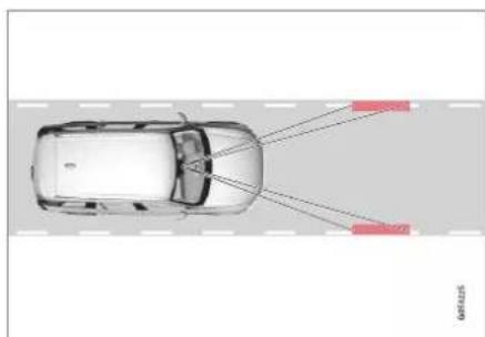
natural_image
Top-down view of a car with red arrows pointing to the lane, no text or symbols presentDriver Alert Control reads the position of the car in the lane.
A camera detects the edge markings painted on the carriageway and compares the alignment of the road with the driver's steering wheel movements.

natural_image
Top-down view of a car driving on a curved road with a red winding line (no text or symbols)The car is being driven erratically in the lane.

If driving behaviour becomes noticeably inconsistent, the driver is alerted by this symbol in the driver display, combined with an acoustic signal and the text message Time
to take a break.
If the car is equipped with Sensus Navigation* and has the function Rest Stop Guidance activated, suggestions for an appropriate place for a break are also displayed.
The warning is repeated after a time if driving behaviour has not improved.
WARNING
Driver Alert Control should not be used to extend a period of driving. The driver should instead plan for breaks at regular intervals and make sure they are well rested.
WARNING
An alarm from Driver Alert Control should be taken very seriously, as a sleepy driver is often not aware of his/her own condition.
If the alarm sounds or you feel fatigued:
- Stop the car safely as soon as possible and rest.
Studies have shown that it is just as dangerous to drive while tired as it is to drive under the influence of alcohol or other stimulants.

WARNING
- The function is supplementary driver support intended to facilitate driving and make it safer – it cannot handle all situations in all traffic, weather and road conditions.
- The driver is advised to read all sections in the Owner's Manual that relate to this function to learn about factors such as its limitations and what the driver should be aware of before using the system.
- Driver support functions are not a substitute for the driver's attention and judgement. The driver is always responsible for ensuring the car is driven in a safe manner, at the appropriate speed, with an appropriate distance to other vehicles, and in accordance with current traffic rules and regulations.
Related information
• Driving support systems (p. 286)
- Activating or deactivating Driver Alert Control (p. 374)
- Select rest stop guidance in the event of a warning from Driver Alert Control (p. 374)
- Limitations of Driver Alert Control (p. 375)
Activating or deactivating Driver Alert Control
The Driver Alert Control (DAC) function can be activated or deactivated.
-
Tap on Settings in the centre display's top view.
-
Select My Car IntelliSafe Driver Alert.
-
Select or deselect Alertness Warning to activate or deactivate the function.
Related information
• Driver Alert Control (p. 373)
- Limitations of Driver Alert Control (p. 375)
Select rest stop guidance in the event of a warning from Driver Alert Control
In cars equipped with Sensus Navigation*, the driver can activate a guide that can automatically suggest an appropriate rest area when Driver Alert Control (DAC) issues a warning.
It is possible to select whether the Rest Stop Guidance function should be activated or deactivated.
-
Tap on Settings in the centre display's top view.
-
Select My Car IntelliSafe Driver Alert.
-
Select or deselect Rest Stop Guidance to activate or deactivate the function.
Related information
• Driver Alert Control (p. 373)
- Limitations of Driver Alert Control (p. 375)
Limitations of Driver Alert Control
The Driver Alert Control (DAC) function may have limitations in certain situations.
In some cases the system may issue a warning despite driving ability not deteriorating, for example:
• in strong side winds
• on rutted road surfaces.

WARNING
In some cases, driving behaviour is not affected despite driver fatigue – e.g. when using the Pilot Assist* function – resulting in the driver not getting a warning from DAC.
It is therefore important to always stop and take a break at the slightest feeling of fatigue, regardless of whether the function has given a warning.

NOTE
This function uses the car's camera and radar units, which have certain general limitations.
Related information
• Driver Alert Control (p. 373)
- Limitations for camera and radar unit (p. 415)
Distance Warning\*107
The Distance Warning function can assist the driver to notice that the time interval to the vehicle ahead may be too short. This requires the car to be equipped with a head-up display* to be able to display Distance Warning.
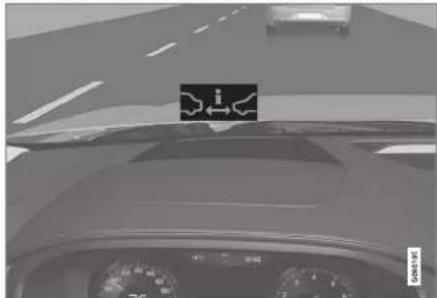
natural_image
Interior view of a car dashboard with steering wheel and dashboard display (no readable text or symbols)Distance Warning symbol on the windscreen with head-up display.
In cars equipped with head-up display, a symbol is shown on the windscreen for as long as the time interval to the vehicle ahead is shorter than the preset value. However, this assumes that the Show Driver Support function is activated via the settings in the car's menu system.
Distance warning is active at speeds above 30 km/h (20 mph) and only reacts to
the vehicle ahead travelling in the same direction. No distance information is provided for oncoming, slow or stationary vehicles.

NOTE
Strong sunlight, reflections, extreme light contrasts, the use of sunglasses, or if the driver is not looking straight ahead may make the visual warning signal in the wind-screen difficult to recognise.

NOTE
Distance warning is deactivated during the time the adaptive cruise control* or Pilot Assist* is active.

WARNING
Distance warning only reacts if the time window to the vehicle ahead is shorter than the preset value – the speed of the driver's vehicle is not affected.

WARNING
- The function is supplementary driver support intended to facilitate driving and make it safer – it cannot handle all situations in all traffic, weather and road conditions.
- The driver is advised to read all sections in the Owner's Manual that relate to this function to learn about factors such as its limitations and what the driver should be aware of before using the system.
- Driver support functions are not a substitute for the driver's attention and judgement. The driver is always responsible for ensuring the car is driven in a safe manner, at the appropriate speed, with an appropriate distance to other vehicles, and in accordance with current traffic rules and regulations.
Related information
- Activating or deactivating distance warning (p. 376)
• Limitations of Distance Warning (p. 376) - Set time interval to vehicle ahead (p. 339)
- Warning from driver support in the event of a collision risk (p. 336)
• Head-up display* (p. 140)
Activating or deactivating distance warning ^108
The distance warning function can be deactivated. The function is only available in cars that can show information on the windscreen with a so-called head-up display*.
Activate or deactivate the function using this button in the centre display's function view.
- GREEN button indication – the function is activated.
- GREY button indication – the function is deactivated.
Distance Warning is activated automatically each time the engine is started.
Related information
• Distance Warning* (p. 375)
• Limitations of Distance Warning (p. 376)
Limitations of Distance Warning ^109
The distance warning function may have limitations in certain situations. The function is only available in cars that can show information on the windscreen with a so-called head-up display*.

WARNING
- A vehicle's size may affect the ability to be detected, e.g. motorcycles, which could mean that the warning lamp illuminates at a shorter time window than set or that the warning is temporarily absent.
- Extremely high speeds can cause the lamp to illuminate at a shorter time window than that set due to limitations in radar unit range.

NOTE
This function uses the car's camera and radar units, which have certain general limitations.
Related information
• Distance Warning* (p. 375)
- Limitations for camera and radar unit (p. 415)
• Head-up display* (p. 140)
Cross Traffic Alert\*110
Cross Traffic Alert (CTA) is a driver support that supplements BLIS ^111 and is designed to help the driver detect traffic crossing behind the car when it is reversing.
The auto-brake subfunction can help the driver to stop the car in the event of a risk of collision with an unobserved vehicle.

Examples of areas where Cross Traffic Alert can assist the driver to detect obstacles during reversing.
The function is primarily designed to detect vehicles. In favourable conditions it may also be able to detect smaller objects, such as cyclists and pedestrians.
The function is only active if the car rolls backwards or if reverse gear has been selected.
If the function senses that something is approaching from the side, this is indicated with:
- an acoustic signal - the sound is heard in the left-hand or right-hand speaker according to the direction from which the object approaches.
• an illuminated icon in the Park Assist System graphic on the screen. - an icon on the Park assist camera top view.

natural_image
Top-down view of a white car with a red abstract shape on the side, against a dark background (no text or symbols)Illuminated Icon for Cross Traffic Alert In the Park Assist System graphic on the screen.
If the driver does not observe the warning from the function and a collision is unavoidable, the auto-brake function engages in order to stop the car, after which the driver display shows an explanatory text message on why the car was braked.
WARNING
- The function is supplementary driver support intended to facilitate driving and make it safer – it cannot handle all situations in all traffic, weather and road conditions.
- The driver is advised to read all sections in the Owner's Manual that relate to this function to learn about factors such as its limitations and what the driver should be aware of before using the system.
- Driver support functions are not a substitute for the driver's attention and judgement. The driver is always responsible for ensuring the car is driven in a safe manner, at the appropriate speed, with an appropriate distance to other vehicles, and in accordance with current traffic rules and regulations.
DRIVER SUPPORT
Related information
• Driving support systems (p. 286)
- Activating or deactivating Cross Traffic Alert* (p. 378)
- Limitations of Cross Traffic Alert* (p. 378)
- Messages for Cross Traffic Alert* (p. 380)
BLIS* (p. 369)
• Park Assist* (p. 381)
Activating or deactivating Cross Traffic Alert\*112
The driver can choose to switch off the Cross Traffic Alert (CTA) function.
Activate or deactivate the function using this button in the centre display's function view.
- GREEN button indication – the function is activated.
- GREY button indication – the function is deactivated.
The function is activated automatically each time the engine is started.
Related information
• Cross Traffic Alert* (p. 377)
- Limitations of Cross Traffic Alert* (p. 378)
- Messages for Cross Traffic Alert* (p. 380)
Limitations of Cross Traffic Alert\*113
The Cross Traffic Alert (CTA) function with auto-brake may have limited functionality in certain situations. Brake Intervention is active at speeds below 15 km/h.

WARNING
The auto-brake subfunction can only detect and brake for other vehicles that are moving – not for stationary obstacles, a cyclist or a pedestrian, for example.
The function has a certain limitation – the sensors cannot "see" through other parked vehicles or obstructions, for example.
Here are some examples of situations where the function's "field of vision" may be already limited and approaching vehicles cannot therefore be detected until they are very close:
DRIVER SUPPORT
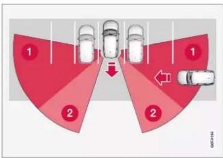
flowchart
graph TD
    A["1"] --> B["2"]
    B --> C["1"]
    C --> D["2"]
    D --> E["1"]
    style A fill:#f9f,stroke:#333
    style B fill:#f9f,stroke:#333
    style C fill:#f9f,stroke:#333
    style D fill:#f9f,stroke:#333
    style E fill:#f9f,stroke:#333
The car is parked deep inside a parking slot,

flowchart
graph TD
    A["Top Path"] --> B{Path 1}
    B --> C["Left Path"]
    B --> D["Right Path"]
    C --> E["Bottom Path"]
    D --> F["Bottom Path"]
    style A fill:#f9f,stroke:#333
    style B fill:#ccf,stroke:#333
    style C fill:#cfc,stroke:#333
    style D fill:#fcc,stroke:#333
    style E fill:#ffc,stroke:#333
    style F fill:#fcc,stroke:#333
In an angled parking slot Cross Traffic Alert may be completely "blind" on one side.
1 Blind sector.
② Sector in which the function can detect/"see".
However, as your car slowly reverses, the angle it makes with the obstructing vehicle/object changes and the blind sector rapidly decreases.
Examples of further limitations
- The auto-brake subfunction only detects moving vehicles and therefore cannot "see" and brake for stationary obstacles, a cyclist or a pedestrian, for example.
- Dirt, ice and snow covering the sensors may reduce the functions and deactivate alerts.
- CTA is automatically deactivated if a trailer, bicycle rack or similar is connected to the car's electrical system.
- For good performance of CTA, there should be no bicycle rack, luggage carrier or similar mounted on the car's towbar.
NOTE
This function uses the car's radar units, which have certain general limitations.
Related information
• Cross Traffic Alert* (p. 377)
- Limitations for camera and radar unit (p. 415)
DRIVER SUPPORT
Messages for Cross Traffic Alert\*114
A number of messages regarding Cross Traffic Alert (CTA) can be shown in the driver display. Here are some examples.
| Message Specification | |
| Blind spot sensorService required | The system does not function as it should. A workshop should be contactedA. |
| Blind spot system offTrailer attached | BLISBand CTA have been deactivated as a trailer has been connected to the car's electrical system. |
A. An authorised Volvo workshop is recommended.
B Blind Spot Information System
A text message can be cleared by briefly pressing the ○ button, located in the centre of the steering wheel's right-hand keypad.
If a message persists, contact a workshop ^A .
Related information
• Cross Traffic Alert* (p. 377)
- BLIS* (p. 369)
• Limitations of Cross Traffic Alert* (p. 378)
Park Assist\*
The Parking Assistance System (PAS ^115 ) uses sensors to assist the driver when manoeuvring in tight spaces by indicating the distance to obstacles through acoustic signals combined with a graphic in the centre display.

natural_image
Top-down architectural rendering of a car inside a cylindrical structure (no text or symbols visible)Screen view showing obstacle zones and sensor sectors.
The centre display shows an overview of the relationship between the car and detected obstacles.
The highlighted sector indicates the location of the obstacle. The closer the car symbol is to a highlighted sector box at the front/back, the shorter the distance between the car and detected obstacle.
The side sectors change colour as the distance between the car and an object is reduced.
The shorter the distance to the obstacle, the faster the signal sounds. Other sound from the audio system is muted automatically.
The acoustic signal for obstacles ahead and to the sides is active when the car is moving but stops after the car has been stationary for approx. 2 seconds. The acoustic signal for obstacles behind is also active when the car is stationary.
At a distance within approx. 30 cm (1 ft) from an obstacle behind or in front of the car, the tone is constant and the active sensor field closest to the car symbol is filled.
At a distance within approx. 25 cm (0.8 ft) from an obstacle To the sides, the tone pulses intensively and the active sector field changes colour from ORANGE to RED.
The volume of the parking assistance signal can be adjusted while the signal is sounding by means of the [>II] knob on the centre console. Adjustment can also be performed in the top view's Settings menu option.

NOTE
Except in the sector nearest to the car symbol, audible warnings are only given for objects directly in the path of the car.

WARNING
- The function is supplementary driver support intended to facilitate driving and make it safer – it cannot handle all situations in all traffic, weather and road conditions.
- The driver is advised to read all sections in the Owner's Manual that relate to this function to learn about factors such as its limitations and what the driver should be aware of before using the system.
- Driver support functions are not a substitute for the driver's attention and judgement. The driver is always responsible for ensuring the car is driven in a safe manner, at the appropriate speed, with an appropriate distance to other vehicles, and in accordance with current traffic rules and regulations.
DRIVER SUPPORT
Related information
• Driving support systems (p. 286)
- Park Assist Pilot front, rear and along the sides* (p. 382)
- Activating or deactivating the parking assistance system* (p. 383)
- Symbols and messages for Park Assist Pilot (p. 386)
• Limitations of Parking assistance (p. 384)
Park Assist Pilot front, rear and along the sides\*
Parking Assistance System (PAS ^116 ) has different behaviour depending on which part of the car is approaching an obstacle.
Forwards

The warning signal has a constant tone at less than approx. 30 cm (1 ft) from an obstacle.
The Parking Assistance System's front detectors are activated automatically when the engine is started. They are active at speeds below 10 km/h (6 mph).
The measuring range is approx. 80 cm (2.5 ft) in front of the car.
NOTE
Parking assistance is deactivated when the parking brake is used or P mode is selected in a car with an automatic gearbox.
IMPORTANT
When auxiliary lamps are fitted: Remember that these must not obscure the sensors - the auxiliary lamps may then be perceived as an obstacle.
Backwards
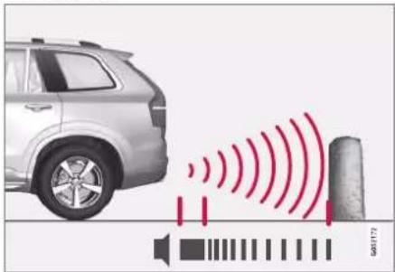
The warning signal has a constant tone at less than approx. 30 cm (1 ft) from an obstacle.
The sensors for reverse are activated if the car rolls backward without a gear engaged or when the gear lever is moved to reverse position.
The measuring range is approx. 1.5 metres (5 ft) behind the car.
When reversing with a trailer connected to the car's electrical system, parking assistance backward is deactivated automatically.

NOTE
When reversing with e.g. a trailer or bike carrier on the towbar - without Volvo genuine trailer wiring - parking assistance may need to be switched off manually in order that the sensors do not react to them.
Along the sides

natural_image
Top-down view of a car with concentric red wave patterns around the roof, no text or symbols present.The warning signal pulses intensively at less than approx. 25 cm (0.8 ft) from an obstacle.
Parking assistance side sensors are activated automatically when the engine is started. They are active at speeds below 10 km/h (6 mph).
The measuring range is approx. 25 cm (0.8 ft) from the sides.
However, the detection range of the side sensors increases significantly when the steering angle of the front wheels is increased, and obstacles of up to approx. 90 cm (3 ft) located diagonally behind or in front of the vehicle are detected when the steering wheel is turned.
Related information
• Park Assist* (p. 381)
- Sensor fields for parking assistance system (p. 392)
Activating or deactivating the parking assistance system\*
The Parking Assistance System (PAS ^117 ) can be activated or deactivated.
The front and side parking assistance detectors are activated automatically when the engine is started. The rear detectors are activated if the car rolls backwards or when reverse gear is engaged.

Activate or deactivate the function using this button in the centre display's function view.
- GREEN button indication – the function is activated.
- GREY button indication – the function is deactivated.
In cars equipped with a park assist camera*, Park Assist Pilot can also be activated or deactivated from the relevant camera view.
Related information
• Park Assist* (p. 381)
• Limitations of Parking assistance (p. 384)
DRIVER SUPPORT
Limitations of Parking assistance
The Parking Assistance System (PAS ^118 ) cannot detect everything in all situations and may therefore have limited functionality in some cases.
A driver should be aware about the following examples of Park Assist Pilot's limitations:

WARNING
- The parking sensors have blind spots where obstacles cannot be detected.
- Pay particular attention if there are people and animals near the car.
- Bear in mind that the front of the car may swing out towards oncoming traffic during the parking manoeuvre.

WARNING

Pay additional attention while reversing when this symbol is shown if a trailer, bicycle rack or similar is mounted and electrically connected to the car.
the parking assistance sensors rearward are switched off and will not warn of any obstacles.

IMPORTANT
Objects e.g. chains, thin glossy poles or low barriers may be in the "signal shadow" and are then temporarily not detected by the sensors - the pulsating tone may then unexpectedly stop instead of changing over to the expected constant tone.
The sensors cannot detect high objects, such as projecting loading docks.
- In such situations, pay extra attention and manoeuvre/reposition the car particularly slowly or stop the current parking manoeuvre - there may be a high risk of damage to vehicles or other objects since information from the sensors is not always reliable in such situations.
DRIVER SUPPORT
IMPORTANT
In certain conditions the parking assistance system may produce incorrect warning signals that are caused by external sound sources with the same ultrasonic frequencies that the system works with.
Examples of such sources include horns, wet tyres on asphalt, pneumatic brakes, exhaust noises from motorcycles, etc.
i NOTE
Since a towbar is configured with the car's electrical system, towbar protrusion is included when the function measures the distance to an object behind the car.
Related information
• Park Assist* (p. 381)
DRIVER SUPPORT
Symbols and messages for Park Assist Pilot
driver display and/or the centre display. Here are some examples.
Symbols and messages for Parking Assistance System (PAS ^119 ) can be shown in the
| Symbol Message Specification | ||
| The rearward parking assistance sensors are deactivated, so there are no acoustic warnings for obstacles/objects. | ||
| Park Assist System Sensors blocked, cleaning needed | One or more of the function's sensors are blocked - check and correct as soon as possible. | |
| Park Assist System Unavailable Service required | The system does not function as it should. A workshop should be contactedA. | |
A. An authorised Volvo workshop is recommended.
A text message can be cleared by briefly pressing the ○ button, located in the centre of the steering wheel's right-hand keypad.
If a message persists, contact a workshop ^4 .
Related information
• Park Assist* (p. 381)
• Limitations of Parking assistance (p. 384)
DRIVER SUPPORT
Park assist camera\*
Park assist camera (PAC ^120 ) can assist the driver when manoeuvring in tight spaces by indicating obstacles with a camera image and graphics in the centre display.
The park assist camera is a support function which is activated automatically when reverse gear is selected or manually via the centre display.
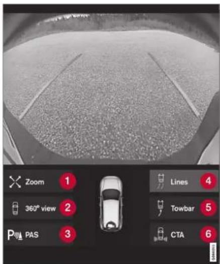
Example of camera view.
1 Zoom ^121 - zoom in/out
② 360° view* - activates/deactivates all cameras
3 PAS ^122 - activates/deactivates the parking assistance sensors
4 Lines - activates/deactivates park assist lines
⑤ Towbar* - activates/deactivates the towbar park assist line*123
6 CTA* - activates/deactivates Cross Traffic Alert
Objects/obstacles may be closer to the car than they appear to be on screen.
WARNING
• The parking sensors have blind spots where obstacles cannot be detected.
• Pay particular attention if there are people and animals near the car.
- Bear in mind that the front of the car may swing out towards oncoming traffic during the parking manoeuvre.
▶▶
DRIVER SUPPORT
◀◀

WARNING
- The function is supplementary driver support intended to facilitate driving and make it safer – it cannot handle all situations in all traffic, weather and road conditions.
- The driver is advised to read all sections in the Owner's Manual that relate to this function to learn about factors such as its limitations and what the driver should be aware of before using the system.
- Driver support functions are not a substitute for the driver's attention and judgement. The driver is always responsible for ensuring the car is driven in a safe manner, at the appropriate speed, with an appropriate distance to other vehicles, and in accordance with current traffic rules and regulations.
• Activate park assist camera (p. 394)
Symbols and messages for Park assist camera (p. 395)
- Limitations for camera and radar unit (p. 415)
• Park Assist* (p. 381)
• Cross Traffic Alert* (p. 377)
Park assist camera locations and surveillance areas\*
The Park assist cameras (PAC ^124 ) can display a composite 360° view and separate views for each of the four cameras: rear, front, left or right camera view.
Related information
• Driving support systems (p. 286)
- Park assist camera locations and surveillance areas* (p. 388)
- Park assist lines for park assist camera* (p. 390)
- Sensor fields for parking assistance system (p. 392)
360° view*
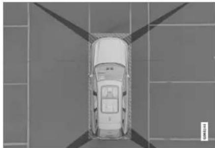
natural_image
Top-down view of a car parked in a parking lot with diagonal roof lines (no visible text or symbols)The "field of vision" of the parking cameras with approximate coverage area.
The 360° view function activates all parking cameras, whereupon the four sides of the car are shown simultaneously in the centre display, which helps the driver to observe what is around the car when manoeuvring at slow speeds.
From the 360° view, each camera view can be activated separately:
- Press the screen for the desired "field of vision" of the camera, e.g. on the surface in front of/above the front camera.
A camera symbol on the centre display's car symbol indicates which of the cameras is active.
If the car is also equipped with Park Assist System*
then distance to detected obstacles is illustrated with fields in different colours.
The cameras can be activated automatically or manually.
Backwards

natural_image
Side view of a car's rear bumper with a close-up inset showing the blade and mounting detail (no text or symbols visible)The backwards-facing camera is fitted above the registration plate.
The backward-facing camera shows a wide area behind the car. For certain models, part of the bumper can be seen as well as the tow-bar in some cases.
Objects shown in the centre display may appear slightly tilted — this is normal.
Forwards
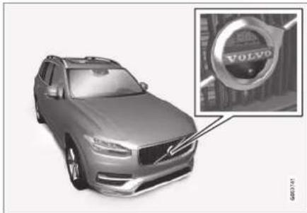
natural_image
Exterior view of a Volvo SUV (no signage or text overlays)The forwards parking camera is located in the grille.
The front camera can be helpful on an exit road with limited visibility to the sides, e.g. when driving out of a garage. It is active at speeds up to 25 km/h (16 mph) - following which, the front camera is switched off.
If the car does not reach 50 km/h (30 mph) and the speed falls below 22 km/h (14 mph) within 1 minute after the forward-facing camera has been extinguished, the camera is reactivated.
DRIVER SUPPORT
The sides

natural_image
Close-up of a car's side mirror and rearview mirror (no text or symbols visible)The side cameras are positioned in each door mirror.
The side cameras can show what is along each side of the car.
Related information
• Park assist camera* (p. 387)
• Activate park assist camera (p. 394)
- Limitations for camera and radar unit (p. 415)
Park assist lines for park assist camera\*
The Park assist cameras (PAC ^125 ) indicate the position of the car in relation to its surroundings by displaying lines on the screen.
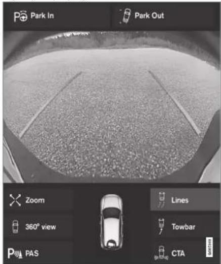
Example of park assist lines
Park assist lines show the intended route for the car's external dimensions with the current steering wheel angle - this can facilitate paral-
lel parking, reversing into tight spaces and when connecting a trailer.
The lines on the screen are projected as if they were at ground level behind the car and respond directly to steering wheel movements, showing the driver the path the car will take - also when the car is turning.
These park assist lines include the car's most protruding parts, e.g. towbar, door mirrors and corners.
NOTE
- When reversing with a trailer which is not connected electrically to the car, the park assist lines on the display show the route the car will take – not the trailer.
- The screen shows no park assist lines when a trailer is connected electrically to the car's electrical system.
- Park assist lines are not shown when zooming in.
IMPORTANT
- Remember, that with the rear camera view selected, the monitor only displays the area behind the car. Be aware of the sides and front of the car when manoeuvring in reverse.
- The same applies vice versa – note what happens to the rear parts of the car when the front camera view is selected.
- Note that the park assist lines show the shortest route. Therefore, pay extra attention to the car's sides so that they do not go against/over something when the steering wheel is turned when driving forward or that the front sweeps against/over something when the steering wheel is turned when reversing.
Park assist lines in 360° view*

natural_image
Top-down view of a car on a road with red trajectory lines, no visible text or symbols360° view with park assist lines
With the 360° view, park assist lines are shown behind, in front of and at the side of the car (depending on the direction of travel):
- When driving forwards: Front lines
- When reversing: Side lines and reversing lines
With front or rear camera selected, the park assist lines appear regardless of the car's direction of travel.
With one side camera selected, the park assist lines only appear when reversing.
Towbar assist line*

Towbar with park assist line
1 Towbar - activates the towbar assist line.
② Zoom - zoom in/out.
To use the camera for connecting a trailer:
▶▶
DRIVER SUPPORT
1. Press Towbar (1).
The park assist lines for the towbar's intended path appear - the car's park assist lines will disappear at the same time.
Park assist lines for both car and tow-bar cannot be shown at the same time.
- Press Zoom (2) when a more precise manoeuvring is required.
The camera view zooms in.
Related information
• Park assist camera* (p. 387)
- Park assist camera locations and surveillance areas* (p. 388)
- Limitations for camera and radar unit (p. 415)
- Towbar* (p. 489)
Sensor fields for parking assistance system
If the car is equipped with the Parking Assistance System (PAS ^126 ) then the distance is shown in the Parking Assistance Camera (PAC ^127 ) 360° view with coloured fields for each sensor that registers an obstacle.
Sensor fields backwards and forwards

The screen can show coloured sensor fields on the car symbol.
The fields for the sensors for forwards and reverse change colour as the distance to the
obstacle decreases – from AMBER through ORANGE to RED.
| Field colour reverse | Distance in metres (feet) |
| Yellow 0.6-1.5 (2.0-4.9) | |
| Orange 0.3-0.6 (1.0-2.0) | |
| Red 0-0.3 (0-1.0) | |
| Field colour forwards | Distance in metres (feet) |
| Yellow 0.6-0.8 (2,0-2.6) | |
| Orange 0.3-0.6 (1.0-2.0) | |
| Red 0-0.3 (0-1.0) | |
For RED sensor fields, the pulsating acoustic signal changes over to a constant tone.
Sensor field to the sides
Warning signals depend on the intended route of the car. When the steering wheel is turned, therefore, there may also be a warning for obstacles diagonally in front of or diagonally behind the car, not just straight ahead or directly behind.

Parking sensor sectors where obstacles can be detected.
1 Left-hand side front sensor field
② Obstacle sector in the car's intended route forwards – depending on steering wheel angle
3 Sector with RED field colour and intensively pulsing tone
4 Right-hand side rear sensor field
5 Obstacle sector in the car's intended route in reverse – depending on steering wheel angle.
The colour of the side fields changes with reduced distance to the obstacle – from AMBER to RED.
| Colour of side fields | Distance in metres (feet) |
| Yellow 0.25 | -0.9 (0.8-3.0) |
| Red 0-0.25 | (0-0.8) |
In the case of RED sensor fields, the acoustic signal changes from pulsing to intensively pulsing.
Related information
• Park Assist* (p. 381)
• Park assist camera* (p. 387)
- Park assist camera locations and surveillance areas* (p. 388)
- Limitations for camera and radar unit (p. 415)
DRIVER SUPPORT
Activate park assist camera
The park assist camera (PAC ^128 ) is activated automatically when reverse gear is engaged or manually with one of the centre display's function buttons.
Camera view when reversing
When reverse gear is engaged, the screen shows the 360° view if it or any of the side views was the last used camera view, otherwise the rear view is shown.
Camera view for manual camera activation

Activate the parking camera with this button in the centre display's function view.
The screen then initially shows the last used camera view. However, after each
engine start, the previously shown side view is replaced by the 360° view and the previously shown zoomed rear view is replaced by the rear view.
- GREEN button indication – the function is activated.
- GREY button indication – the function is deactivated.
Automatic deactivation of camera
The front view extinguishes at 25 km/h (16 mph) to avoid distracting the driver – it reactivates automatically if the speed drops to 22 km/h (14 mph) within 1 minute, on the condition that the speed has not exceeded 50 km/h (31 mph).
Other camera views are extinguished at 15 km/h (9 mph) and not reactivated.
Related information
• Park assist camera* (p. 387)
• Limitations of Parking assistance (p. 384)
- Limitations for camera and radar unit (p. 415)
Symbols and messages for Park assist camera
play and/or the centre display. Here are some examples.
Symbols and messages for Park assist camera (PAC ^129 ) can be shown in the driver dis-
| Symbol Message Specification | ||
 | The rearward parking assistance sensors are deactivated, so there are no acoustic warnings and field marks for obstacles/objects. | |
 | The camera is disengaged. | |
| Park Assist System Sensors blocked, cleaning needed | One or more of the function's sensors are blocked - check and correct as soon as possible. | |
| Park Assist System Unavailable Service required | The system does not function as it should. A workshop should be contactedA. | |
An authorised Volvo workshop is recommended.
DRIVER SUPPORT
A text message can be cleared by briefly pressing the ○ button, located in the centre of the steering wheel's right-hand keypad. If a message persists, contact a workshop ^A .
Related information
• Park assist camera* (p. 387)
- Limitations for camera and radar unit (p. 415)
DRIVER SUPPORT
Park Assist Pilot\*
Park Assist Pilot (PAP ^130 ) can assist the driver to manoeuvre the car while parking. The function can also assist with steering when driving out from parallel parking. The function first checks if a space is large enough and if so then assists the driver to steer the car into the space.
The centre display indicates with symbols, graphics and text the various operations to be carried out and when to do so.
WARNING
- The function is supplementary driver support intended to facilitate driving and make it safer – it cannot handle all situations in all traffic, weather and road conditions.
- The driver is advised to read all sections in the Owner's Manual that relate to this function to learn about factors such as its limitations and what the driver should be aware of before using the system.
- Driver support functions are not a substitute for the driver's attention and judgement. The driver is always responsible for ensuring the car is driven in a safe manner, at the appropriate speed, with an appropriate distance to other vehicles, and in accordance with current traffic rules and regulations.
• Leaving parallel parking with Park Assist Pilot* (p. 402)
• Limitations of Park Assist Pilot* (p. 402)
- Messages for Park Assist Pilot* (p. 405)
Related information
• Driving support systems (p. 286)
- Parking variants with Park Assist Pilot* (p. 398)
• Using Park Assist Pilot* (p. 399)
DRIVER SUPPORT
Parking variants with Park Assist Pilot\*
Park Assist Pilot (PAP ^131 ) can be used for both parallel and perpendicular parking. Parallel parking

flowchart
graph TD
    A["1"] --> B["Vehicle with signal"]
    B --> C["2"]
    C --> D["Vehicle with signal"]
    D --> E["3"]
    E --> F["Vehicle with signal"]
    style A fill:#f9f,stroke:#333
    style C fill:#f9f,stroke:#333
    style E fill:#f9f,stroke:#333
The principal of parallel parking.
The function parks the car using the following steps:
- A parking space is identified and measured.
- The car is reversed into the space.
- The car is positioned in the space by means of driving forward/backward.
With the Park Out function, a parallel-parked car can also get help from the function with leaving the parking space.
Perpendicular parking

Principle for perpendicular parking.
The function parks the car using the following steps:
- A parking space is identified and measured.
- The car is reversed into the space and then positioned in the space by means of driving forward/backward.
NOTE
When leaving a parking space, the Park Out function must only be used for a parallel-parked car - it does not work for a perpendicular-parked car.
Related information
• Park Assist Pilot* (p. 397)
• Leaving parallel parking with Park Assist Pilot* (p. 402)
Using Park Assist Pilot\*
Park Assist Pilot (PAP ^132 ) helps the driver park via three steps. The function can also help the driver to leave a parking space. This function measures space and steers the car – the driver's job is to:
- keep an eye on what is happening around the car
- follow the instructions in the centre display
- select a gear (reverse/forward) – an acoustic signal indicates when the driver should change gear
• regulate and maintain a safe speed - brake and stop.
Symbols, graphic and/or text appear on the centre display when the different steps are to be performed.
The function can be activated if the following criteria are met once the engine has been started:
• No trailer is attached to the car
• Speed is lower than 30 km/h (20 mph).
NOTE
The distance between the car and parking spaces should be 0.5–1.5 metres (1.6–5.0 ft) while the function is searching for a parking space.
Parking with Park Assist Pilot
The function parks the car using the following steps:
- A parking space is identified and measured.
- The car is reversed into the space.
- The car is positioned into the space - the system may then request that the driver changes gear and brakes.
Find and measure parking spaces

The function can be activated in the centre display's function view.
It can also be accessed from the camera views.
- GREEN button indication – the function is activated.
- GREY button indication – the function is deactivated.

Principle for searching before parallel parking.

Principle for searching before perpendicular parking.
Drive no faster than 30 km/h (20 mph) for parallel parking or 20 km/h (12 mph) for perpendicular parking.
DRIVER SUPPORT
- Tap on the Park In button in the function view or in the camera view.
The function searches for a parking space and checks whether it is big enough.
- Be prepared to stop the car when the graphic and message on the centre display state that a suitable parking space has been found.
A pop-up window is shown.
- Select Parallel parking or Perpendicular parking and select reverse gear.

NOTE
The function searches the area for parking, displays instructions and guides the car in on its passenger side. But if required the car can also be parked on the driver's side of the street:
- Activate the direction indicator to the driver's side - then the system searches for a parking space on that side of the car instead.
Reversing in to the parking space
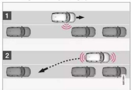
flowchart
graph TD
    A["Top Lane 1"] --> B["Top Lane 2"]
    B --> C["Top Lane 3"]
    C --> D["Top Lane 4"]
    D --> E["Top Lane 5"]
    E --> F["Top Lane 6"]
    F --> G["Top Lane 7"]
    G --> H["Top Lane 8"]
    H --> I["Top Lane 9"]
    I --> J["Top Lane 10"]
    style A fill:#f9f,stroke:#333
    style B fill:#f9f,stroke:#333
    style C fill:#f9f,stroke:#333
    style D fill:#f9f,stroke:#333
    style E fill:#f9f,stroke:#333
    style F fill:#f9f,stroke:#333
    style G fill:#f9f,stroke:#333
    style H fill:#f9f,stroke:#333
    style I fill:#f9f,stroke:#333
    style J fill:#f9f,stroke:#333
Principle for reversing into parallel parking.

Principle for reversing into perpendicular parking.
1. Check that the area behind the car is clear, then engage reverse gear.
- Reverse slowly and carefully without touching the steering wheel - and no faster than 7 km/h (4 mph).
- Be prepared to stop the car when instructed by the graphic and message on the centre display.
NOTE
- Keep your hands away from the steering wheel when the function is activated.
- Make sure that the steering wheel is not hindered in any way and can rotate freely.
- To achieve optimum results - wait until the steering wheel is fully turned before starting to drive backward/forward.
DRIVER SUPPORT
Positioning the car in the parking space

Principle for positioning during parallel parking.

natural_image
Top-down view of a car with five cars and red signal waves indicating sensor or sensor coverage (no text or symbols)Principle for positioning during perpendicular parking,
- Move the gear selector to the gear position as instructed by the system, wait until the steering wheel has been turned and drive forward slowly.
- Be prepared to stop the car when instructed by the graphic and message on the centre display.
- Select reverse gear and drive slowly backwards.
- Be prepared to brake the car when instructed by the graphic and message on the centre display.
The function is deactivated automatically and the graphics and message show that parking is complete. It may be necessary for the driver to correct the car's position. Only the driver can determine whether the car is properly parked.
IMPORTANT
The warning distance is shorter when the sensors are used by Park Assist Pilot (PAP ^133 ) compared with when Park Assist System uses the sensors.
Auto-brake during parking sequence
If the parking sensors detect a vehicle or pedestrian within the intended route in front of
or behind the car during a parking manoeuvre, the car is auto-braked to stationary.
The driver display then shows a pop-up message where the driver can choose to cancel the parking manoeuvre by tapping on Cancel, or tap Resume to continue the parking sequence.
Proceed as follows after selecting Resume:
- Check that there is free space around the car and follow the instructions in the centre display, such as:
To continue – Gently accelerate away from object.
Related information
• Park Assist Pilot* (p. 397)
• Limitations of Park Assist Pilot* (p. 402)
DRIVER SUPPORT
Leaving parallel parking with Park Assist Pilot\*
The Park Out function can help the driver to leave a parking space when the car is parallel parked.

NOTE
When leaving a parking space, the Park Out function must only be used for a parallel-parked car - it does not work for a perpendicular-parked car.

The Park Out function is activated in the centre display's function view or in the camera view.
- GREEN button indication – the function is activated.
- GREY button indication – the function is deactivated.
- Tap on the Park Out button in the function view or in the camera view.
-
Use the direction indicator to select the direction in which the car should leave the parking space.
-
Be prepared to stop the car when instructed by the graphic and message on the centre display - follow the instructions in the same way as for the parking procedure.
Note the steering wheel can "spring" back when the function is completed - the driver may then need to turn the steering wheel back to the maximum steering angle in order to leave the parking space.
If the function considers that the driver can leave the parking space without any extra manoeuvring then the function will be stopped, even if the driver may consider that the car is still in the parking space.
Related information
• Park Assist Pilot* (p. 397)
• Limitations of Park Assist Pilot* (p. 402)
Limitations of Park Assist Pilot\*
The Park Assist Pilot (PAP ^134 ) function cannot detect everything in all situations and may therefore have limited functionality. A driver should be aware about the following examples of Park Assist Pilot limitations.

WARNING
- The parking sensors have blind spots where obstacles cannot be detected.
• Pay particular attention if there are people and animals near the car. - Bear in mind that the front of the car may swing out towards oncoming traffic during the parking manoeuvre.

IMPORTANT
Objects situated higher than the sensor detection area are not included when calculating the parking manoeuvre, which could cause the function to swing into the parking space too early – such parking spaces should be avoided for this reason.
Parking is discontinued
A parking sequence will be discontinued:
• if the driver moves the steering wheel
- if the car is driven too quickly - above 7 km/h (4 mph)
- if the driver presses Cancel in the centre display
- when the anti-lock brakes or the Electronic stability control are engaged - e.g. when a wheel loses grip on a slippery road
- as the steering servo for speed-dependent steering wheel resistance is working at reduced power – e.g. when cooling due to overheating
Where applicable, a message in the centre display states the reason for a parking sequence being discontinued.
IMPORTANT
Under certain circumstances, the function is unable to find parking spaces - one reason for this may be the fact that there is interference with the sensors from external sound sources which emit the same ultrasound frequencies as those with which the system works.
Examples of such sources include horns, wet tyres on asphalt, pneumatic brakes and exhaust noises from motorcycles etc.
NOTE
Dirt, ice and snow covering the sensors will reduce their function and may prevent measurement.
Driver responsibility
The driver should bear in mind that the function is an aid – not an infallible, fully-automatic function. The driver must therefore be prepared to interrupt a parking step.
There are also a few details to bear in mind while parking, e.g.:
- The driver is always responsible for determining whether the space selected by the function is suitable for parking.
- Do not use the function if snow chains or a spare wheel are fitted.
- Do not use the function if cargo items are protruding from the car.
- Heavy rain or snow may cause the system to measure the parking space incorrectly.
- During the search and check-measurement of the parking space, the function may miss objects positioned deep in the parking space.
- Parking spaces on narrow streets are not always feasible, since the space required for manoeuvring may not be sufficient.
- Use approved tyres ^135 with the correct tyre pressure - this affects the ability of the function to park the car.
- The function bases itself on the locations of vehicles already parked nearby – if they are inappropriately parked, your own car's tyres and wheel rims may be damaged by contact with the kerb.
• Perpendicular parking spaces may be missed or offered unnecessarily if one
DRIVER SUPPORT
parked car is protruding more than other parked cars.
- The function is designed for parking on straight streets – not sharp curves or bends. For this reason, make sure the car is parallel to the potential parking spaces when the function measures the space.
Related information
• Park Assist Pilot* (p. 397)
• Speed-dependent steering force (p. 286)
- Limitations for camera and radar unit (p. 415)
Messages for Park Assist Pilot\*
Messages for Park Assist Pilot (PAP ^136 ) can be shown in the driver display and/or the centre display. Here are some examples.
| Message Specification | |
| Park Assist SystemSensors blocked, cleaning needed | One or more of the function's sensors are blocked - check and correct as soon as possible. |
| Park Assist SystemUnavailable Service required | The system does not function as it should. A workshop should be contactedA. |
^A An authorised Volvo workshop is recommended.
A text message can be cleared by briefly pressing the ○ button, located in the centre of the steering wheel's right-hand keypad.
If a message persists, contact a workshop ^A .
Related information
• Park Assist Pilot* (p. 397)
- Limitations of Park Assist Pilot* (p. 402)
DRIVER SUPPORT
Radar unit
The radar unit is used by several driver support systems and has the task of sensing other vehicles.
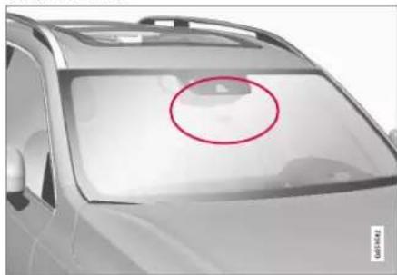
natural_image
Side view of a car's front window with a red circle highlighting the area (no text or symbols)Radar unit location
The radar unit is used by the following functions:
• Distance Warning*
- Adaptive cruise control*
- Pilot Assist*
- Lane assistance
- City Safety
• Steering assistance at risk of collision
Modification of the radar unit could result in its use being illegal.
Related information
- Driving support systems (p. 286)
- Limitations for camera and radar unit (p. 415)
• Recommended maintenance for camera and radar unit (p. 418)
• Type approval for radar device (p. 407)
DRIVER SUPPORT
Type approval for radar device
Here you can find type approval for the car's radar units for adaptive cruise control*
(ACC ^137 ), Pilot Assist* and BLIS* ^138 .
| Market | ACC & PA | BLIS | Symbol Type approval | Proval |
| Europe | √ |  | Hereby, Delphi Electronics and Safety declares that L2C0054TR / L2C0055TR are in compliance with the essential requirements and other relevant provisions of Directive 2014/53/EU (RED). The original declaration of conformity can be accessed at the following link www.delphi.com/automotive-homologation.Frequency Band: 76GHz - 77GHzMaximum Output Power: 55dBm EIRPThe Declaration of Conformity may be consulted at Delphi Electronics & Safety / 2151 E. Lincoln Road / Kokomo, Indiana 46902 USA | |
| √ | Hereby, Hella KgaA Hueck & Co. Declares that the radio equipment type RS4 is in compliance with Directive 2014/53/EU.The full text of the EU declaration of conformity is available at the following internet address: www.hella.com/vcc.Technical information: Frequency range: 24.05 ... 24.25 GHz Transmission power: 20 dBm (maximum) EIRPManufacturer and Address: Manufacturer: Hella KGaA Hueck & Co. Address: Rixbecker Straße 75, 59552 Lippstadt, Germany | |||
| The United Arab Emirates (UAE) | √ |  | Registered No: ER37536/15Dealer No: DA37380/15 | |
| √ | Registered No: ER53878/17Dealer No: DA44932/15 | |||
| Ghana | √ | NCA Approved: 1R3-1M-7E1-0B7 |
DRIVER SUPPORT
| Market | ACC & PA | BLIS | Symbol Type approval | 37295/POSTEL/20144927 |
| Indonesia | √ | Certificate number: 50459/SDPPI/2017Country of origin GermanyCertificate number: 53578/SDPPI/2017Country of origin ChinaPLG ID: 6051 | ||
| Jamaica | √ | This product contains a Type Approved Module by Jamaica: SMA – “RS4”. | ||
| Jordan | √ | Type Approval No.: TRC/LPD/2014/255Equipment Type: Low Power Device (LPD) | ||
| √ | Type Approval No.: TRC/LPD/2017/63Equipment Type: Low Power Device (LPD) | |||
| Malaysia | √ |  | CID F 15000578 | |
| Morocco | √ | AGREE PAR L'ANRT MAROCNUMÉRO D'AGRÉMENT: MR 9929 ANRT 2014DATE D'AGRÉMENT: 26/12/2014 |
▶▶
DRIVER SUPPORT
◀◀
| Market | ACC & PA | BLIS | Symbol Type approval | |
| Russia | √ |  | ||
| Serbia | √ |  | И011 14 | |
| √ | И011 17 | |||
| Singapore | √ |  | DA 105753 | |
| √ | DA 103238 | |||
| South Africa | √ |  | TA-2014/1824 | |
| √ | TA-2016/3407 |
▶▶
411
DRIVER SUPPORT
◀◀
◀ Type approval for radio equipment
| Market Symbol Type approval | ||
| Europe |  | Hereby, Volvo cars, declares that all radio equipment's are in compliance with the essential requirements and other relevant provisions of Directive 2014/53/EU. |
| Japan |  | R 204-750001This device is granted pursuant to the Japanese Radio Law and the Japanese Telecommunications Business Law. This device should not be modified (otherwise the granted designation number will become invalid). |
For detailed information on type approval, go to volvocars.com/support.
Related information
- Radar unit (p. 406)
• Adaptive cruise control* (p. 311) - Pilot Assist* (p. 321)
BLIS* (p. 369)
Camera unit
The camera unit is used by several driver support systems and has the task of for example detecting lane lines or traffic signs.
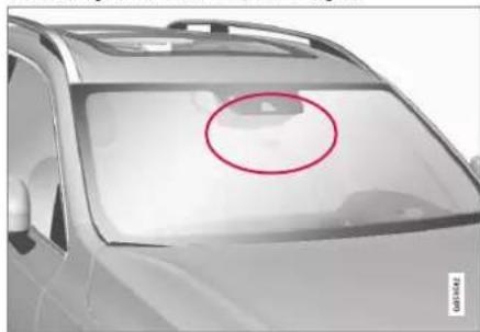
natural_image
Side view of a car's front window with a red circle highlighting the area (no text or symbols)Location of the camera unit
The camera unit is used by the following functions:
• Adaptive cruise control*
- Pilot Assist*
- Lane assistance*
• Steering assistance at risk of collision
- City Safety
- Driver Alert Control*
• Road Sign Information*
• Active main beam*
- Park Assist*
Related information
• Driving support systems (p. 286)
- Limitations for camera and radar unit (p. 415)
• Recommended maintenance for camera and radar unit (p. 418)
Limitations for camera and radar unit
The camera and radar unit has certain limitations – which in turn also limit those functions that use the unit. A driver should be aware about the following examples of limitations.
▶▶
DRIVER SUPPORT
Common limitations for camera and radar
Blocked unit

natural_image
Side view of a car's front bumper with a red circle highlighting the area (no text or symbols)The marked area must be cleaned regularly and kept free from stickers, objects, shade film, etc.
The camera unit is placed inside the upper section of the windscreen together with the car's radar unit.
Do not place, stick or mount anything on the inside or outside of the windscreen, in front of or around the camera and radar unit – this may interfere with camera and radar-based functions. This may result functions being reduced, being switched off completely or giving incorrect function responses.
High temperature
At very high temperatures the camera and radar unit can temporarily be switched off for about 15 minutes after the engine is started so as to protect the unit's electronics. The camera and radar unit restarts automatically when the temperature has fallen sufficiently.
Damaged windscreen
NOTE
If not rectified it can lead to reduced performance for the driver support systems that use the camera and radar unit. This may result functions being reduced, being switched off completely or giving incorrect function responses.
The following is also applicable so as not to risk incorrect function for the driver supports that use the radar unit:
- If a scratch, crack or stone chip appears on the windscreen in front of any of the "windows" for the camera and radar unit and covers an area of approx. 0.5 × 3.0 mm ( 0.02 × 0.12 in.) or more, a workshop ^139 must be contacted so that the windscreen can be replaced.
-
Volvo recommends not repairing cracks, scratches or stone chips in the area in front of the camera and radar unit – the entire windscreen should be replaced instead.
-
Before replacing a windscreen, contact a workshop ^139 to verify that the correct windscreen has been ordered and will be fitted.
- The same type of windscreen wipers or windscreen wipers approved by Volvo must be fitted when the windscreen is replaced.
- When replacing the windscreen, the camera and radar unit must be recalibrated by a workshop ^139 to ensure the functionality of all the camera and radar-based systems in the car.
Further limitations for radar
Vehicle speed
The radar unit's ability to detect a vehicle ahead is greatly reduced if the speed of the vehicle ahead is very different to the speed of your own car.
DRIVER SUPPORT
Limited field of vision
The radar unit has a limited field of vision. In some situations another vehicle is not detected, or the detection is made later than expected.

The radar unit's field of vision
Sometimes the radar unit is late at detecting vehicles at close distances - e.g. a
vehicle that drives in between your car and the vehicle ahead.
2 Small vehicles, such as motorcycles, or vehicles not driving in the centre of the lane can remain undetected.
3 In bends, the radar unit may detect a different vehicle than intended or lose a detected vehicle from view.
Low trailers

natural_image
Diagram showing a car and two vehicles with a red triangular highlight on their side (no text or symbols)Low trailer in radar shadow
Low trailers can also be difficult for the radar unit to detect, or are not detected at all - the driver should therefore be particularly careful when driving behind low trailers when the adaptive cruise control* or Pilot Assist* is activated.
Further limitations for camera
Impaired vision
The cameras have limitations similar to the human eye, i.e. may "see" worse in for example intense snowfall or rain, dense fog, heavy
dust storms and snow flurries. Under such conditions, the functions of camera-dependent systems could be significantly reduced or temporarily disengaged.
Strong oncoming light, reflections in the carriageway, snow or ice on the road surface, dirty road surfaces or unclear lane markings can also significantly reduce camera function when it is used to scan the carriageway to detect pedestrians, cyclists, large animals and other vehicles.
▶▶
DRIVER SUPPORT
Further limitations for Park assist camera\*
Blind sectors

natural_image
Top-down view of a car parked in a parking lot with diagonal lanes (no visible text or symbols)There are "blind" sectors between the cameras' fields of vision.
In the park assist camera's 360° view* obstacles/objects may "vanish" in the gaps between the individual cameras.

WARNING
Pay attention to the possibility that, even if it only looks like a relatively small part of the image is obscured, a relatively large sector could be hidden from view. An obstacle could thereby go undetected until the car is very close to it.
Light conditions
The camera image is adjusted automatically according to prevailing light conditions.
Because of this, the image may vary slightly in brightness and quality. Poor light conditions can result in reduced image quality.
NOTE
A bike carrier or other accessory mounted on the rear of the car could obscure the camera's view.
Related information
- Camera unit (p. 415)
- Radar unit (p. 406)
• Recommended maintenance for camera and radar unit (p. 418)
• Park assist camera* (p. 387)
• Volvo Cars support site (p. 23)
Recommended maintenance for camera and radar unit
In order that the camera and radar units shall function correctly, they must be kept clear of dirt, ice and snow, and be cleaned regularly with water and car shampoo.
i NOTE
Dirt, ice and snow covering the sensors may cause incorrect warning signals, reduced or no function.

natural_image
Top-down view of a car with red circles highlighting the front and side edges (no text or symbols)Location of the parking sensors
DRIVER SUPPORT

natural_image
Rear view of a silver sedan (no visible text or symbols)Location of rear radar units. Keep the surface indicated clean – on both the left and right-hand sides of the car.
- To ensure best possible functionality, the surfaces in front of the sensors must be kept clean.
- Do not affix any objects, tape or labels in the area of the sensors.
- Clean camera lenses regularly with lukewarm water and car shampoo - be careful not to scratch the lenses.
IMPORTANT
Maintenance of driver support components must only be performed at a workshop – an authorised Volvo workshop is recommended.
Related information
- Camera unit (p. 415)
- Radar unit (p. 406)
- Limitations for camera and radar unit (p. 415)
• Park assist camera* (p. 387)
DRIVER SUPPORT
Symbols and messages for camera and radar unit
Here are examples of some of the display messages and symbols regarding the camera and radar units that can be shown in the driver display.
Detector blocked

If the driver display shows this symbol and the message Windscreen sensor Sensor blocked, see Owner's manual, this means that
the camera and radar unit cannot detect other vehicles, cyclists, pedestrians and large animals in front of the car, and that the car's camera-based and radar-based functions may be disrupted.
The following table presents examples of possible causes for a message being shown, along with the appropriate action:
| Cause Action | |
| The windscreen surface in front of the camera and radar unit is dirty or covered with ice or snow. | Clean dirt, ice and snow from the windscreen surface in front of the camera and radar unit. |
| Thick fog and heavy rain or snow block the radar signals or the camera view. | No action. Sometimes the unit does not work during heavy rain or snowfall. |
| Water or snow from the road surface swirls up and blocks the radar signals or camera view. | No action. Sometimes the unit does not work on a very wet or snow-covered road surface. |
| Dirt has appeared between the inside of the windscreen and the camera and radar unit. | Visit a workshop to have the windscreen inside the unit's cover cleaned - an authorised Volvo workshop is recommended. |
| Strong oncoming light No action. The camera unit is reset automatically in more favourable light conditions. | |
Defective camera

If a camera sector is black and contains this symbol then it means that the camera is out of order.

natural_image
Top-down view of a car parked in a parking lot with a road sign visible (no text or symbols on the car itself)The car's left-hand camera is out of order.
A black camera sector is also shown in the following instances, but then without the symbol for defective camera:
Pay additional attention while reversing when this symbol is shown if a trailer, bicycle rack or similar is mounted and electrically connected to the car.
The symbol indicates that
the parking assistance sensors rearward are switched off and will not warn of any obstacles.
Related information
- Camera unit (p. 415)
- Radar unit (p. 406)
- Limitations for camera and radar unit (p. 415)
• Volvo Cars support site (p. 23)

bar
| Category | Value | |---|---| | Category 1 | 100 | | Category 2 | 100 | | Category 3 | 100 | | Category 4 | 100 | | Category 5 | 100 | | Category 6 | 100 | | Category 7 | 100 | | Category 8 | 100 | | Category 9 | 100 | | Category 10 | 100 | | Category 11 | 100 | | Category 12 | 100 | | Category 13 | 100 | | Category 14 | 100 | | Category 15 | 100 | | Category 16 | 100 | | Category 17 | 100 | | Category 18 | 100 | | Category 19 | 100 | | Category 20 | 100 | | Category 21 | 100 | | Category 22 | 100 | | Category 23 | 100 | | Category 24 | 100 | | Category 25 | 100 | | Category 26 | 100 | | Category 27 | 100 | | Category 28 | 100 | | Category 29 | 100 | | Category 30 | 100 | | Category 31 | 100 | | Category 32 | 100 | | Category 33 | 100 | | Category 34 | 100 | | Category 35 | 100 | | Category 36 | 100 | | Category 37 | 100 | | Category 38 | 100 | | Category 39 | 100 | | Category 40 | 100 | | Category 41 | 100 | | Category 42 | 100 | | Category 43 | 100 | | Category 44 | 100 | | Category 45 | 100 | | Category 46 | 100 | | Category 47 | 100 | | Category 48 | 100 | | Category 49 | 100 | | Category 50 | 100 | | Category 51 | 100 | | Category 52 | 100 | | Category 53 | 100 | | Category 54 | 100 | | Category 55 | 100 | | Category 56 | 100 | | Category 57 | 100 | | Category 58 | 100 | | Category 59 | 100 | | Category 60 | 100 | | Category 61 | 100 | | Category 62 | 100 | | Category 63 | 100 | | Category 64 | 100 | | Category 65 | 100 | | Category 66 | 100 | | Category 67 | 100 | | Category 68 | 100 | | Category 69 | 100 | | Category 70 | 100 | | Category 71 | 100 | | Category 72 | 100 | | Category 73 | 100 | | Category 74 | 100 | | Category 75 | 100 | | Category 76 | 100 | | Category 77 | 100 | | Category 78 | 100 | | Category 79 | 100 | | Category 80 | 100 | | Category 81 | 100 | | Category 82 | 100 | | Category 83 | 100 | | Category 84 | 100 | | Category 85 | 100 | | Category 86 | 100 | | Category 87 | 100 | | Category 88 | 100 | | Category 89 | 100 | | Category 90 | 100 | | Category 91 | 100 | | Category 92 | 100 | | Category 93 | 100 | | Category 94 | 100 | | Category 95 | 100 | | Category 96 | 100 | | Category 97 | 100 | | Category 98 | 100 | | Category 99 | 100 | | Total (Total) |ELECTRIC OPERATION AND CHARGING
ELECTRIC OPERATION AND CHARGING
General information on electric drive
Recharge runs like a regular car, but certain functions differ from a car that only runs on petrol or diesel. The electric motor drives the car mostly at low speeds, the petrol engine at higher speeds, as well as during more active driving.
The driver display shows some information that is unique to the Recharge - charging information, selected drive mode, distance to empty battery as well as the hybrid battery's charge level.
It is possible to set the car in different drive modes while driving, e.g. electric operation only or, when power is required, both electric motor and petrol engine. The car calculates a combination of drivability, driving experience, environmental impact and fuel economy according to the drive mode selected.
In order that the car should have optimal function it is important that the hybrid battery with associated electrical drive systems, as well as the petrol engine and its drive systems, have the correct operating temperature. Battery capacity may be reduced considerably if the battery is too cold or too hot. Preconditioning prepares the car's drive systems and the passenger compartment before departure so that both wear and energy needs during the journey are reduced. The range for the hybrid battery increases.
The hybrid battery which drives the electric motor is charged via a charging cable but can also be charged by gentle braking and engine braking in gear position B. The hybrid battery can also be charged by the car's engine.
Important to know
Car without power
Bear in mind that important functions such as the servo brakes and power steering are limited when the car is without power.
WARNING
The brake servo only works when the electric motor or internal combustion engine is running.
Towing not permitted
Towing the car is not permitted since this damages the electric motor.
Exterior engine noise
WARNING
Remember that the car does not emit any engine noise when it is only powered by the electric motor and may therefore be difficult to notice by children, pedestrians, cyclists and animals. This is especially true at low speeds, such as in car parks.
High-voltage current

WARNING
Several components in the car work with high-voltage current that could be dangerous in the event of incorrect intervention. These components, and all orange-coloured cables, must only be handled by qualified personnel.
Do not touch anything that is not clearly described in the owner's manual.
Related information
• Charging the hybrid battery (p. 425)
• Hybrid gauge (p. 86)
- Drive modes (p. 467)
- Start and switch off preconditioning (p. 223)
• Hybrid battery (p. 619)
• Automatic gearbox (p. 460)
- Towing (p. 498)
Charging the hybrid battery
In addition to the fuel tank, as in a conventional car, the car is equipped with a rechargeable battery - a so-called hybrid battery of the lithium-ion type.
The hybrid battery is charged using a charging cable which is located in a storage compartment in the cargo area.

NOTE
Volvo recommends a charging cable in accordance with IEC 62196 and IEC 61851 which supports temperature monitoring.
The time it takes for the hybrid battery to be charged is dependent on the charging current that is used.

NOTE
The capacity of the hybrid battery decreases slightly with age and use, which may result in increased use of the petrol engine and thereby slightly increased fuel consumption.

WARNING
Replacing the hybrid battery must only be performed by a workshop - an authorised Volvo workshop is recommended.
Charging cable handle and charging input socket
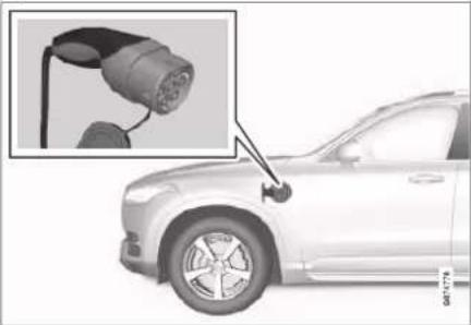
natural_image
Side view of an electric vehicle with a plug inserted into the charger, showing no text or symbols on the car body.Charging cable handle and charging input socket.
Charging status is indicated in three ways:
- Indicators on the charging cable's control unit.
- Indicator lamp in the car's charging input socket.
• Illustration and text in the driver display.
The starter battery is charged when the hybrid battery is charging and terminated when the hybrid battery is fully charged.
If the hybrid battery's temperature is below -10 °C (14 °F) or above 40 °C (104 °F) then it may mean that some of the car's functions are changed or unavailable because the capacity of the hybrid batteries is reduced outside this temperature range.
Electric operation is not possible if the temperature of the battery is too low or too high. If drive mode PURE is then selected, the combustion engine starts.
Decal on the inside of the charging flap
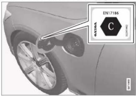
Use charging that is approved for use in the car in accordance with the identifier ^1 on the inside of the charging input socket flap.
ELECTRIC OPERATION AND CHARGING
Charging with fixed control unit in accordance with mode 3 ^4
In certain markets the control unit is installed within a charging station connected to the mains power circuit. In which case, the charging cable has no control unit of its own. Therefore, use the charging station's charging cable and follow the instructions at the charging station.
Energy recovery during braking

Indication in driver display during energy recovery.
Energy is regenerated to the battery during light pressure on the brake pedal or during engine braking.
The function is available in all drive modes together with gear position D or B.
Related information
• Charging cable (p. 427)
• Charging current (p. 426)
- Opening and closing the hatch for the charging input socket (p. 431)
• Starting hybrid battery charging (p. 431)
• Stopping hybrid battery charging (p. 439)
- Charging status in the charging cable's control unit (p. 435)
- Charging status in the car's charging input socket (p. 434)
- Charging status in the car's driver display (p. 437)
- Symbols and messages relating to hybrid drive in the driver display (p. 441)
• Automatic gearbox (p. 460)
• Changing drive mode (p. 471)
- Long-term storage of vehicles with hybrid batteries (p. 443)
• Regenerative braking* (p. 459)
Charging current
Charging current is used for charging the hybrid battery as well as preconditioning of the car. Charging takes place with a charging cable connected to the car's charging input socket and a 230 V socket ^3 (alternating current).
When the charging cable is activated, the driver display shows a message and a lamp in the car's charging input socket illuminates.
The charging current is mainly used for battery charging, but is also used for preconditioning the car. When the car's hybrid battery is charged, the starter battery is also charged.
IMPORTANT
Never unplug the charging cable from the 230 V socket (alternating current) while charging is in progress - there is then a risk of damaging the 230 V socket. Always stop charging first before unplugging the charging cable from the car's charging input socket and then from the 230 V socket.
IMPORTANT
Ensure that the wall socket fuse can handle the specified amperage for the charging cable.
i NOTE
- If the weather is very hot or very cold, some of the charging current is used to heat/cool the hybrid battery and the passenger compartment, which results in a longer charging time.
- The charging time is extended if preconditioning has been selected. The time required depends mainly on the outside temperature.
Charging time
Charging times may vary. The following charging times are applicable when air conditioning or any other consumer is not affecting charging. If charging time seems long, it should be investigated.
Charging times for charging with 230V
| Current intensity (A)A | Charging time (hours) |
| 6 | 8 |
| 10 | 4 |
| 16 | 3 |
^A Maximum charging current may vary depending on market.
Fuse
Normally several 230 V consumers are included in a fuse circuit, so additional consumers (e.g. lighting, vacuum cleaner, electric drill, etc.) can be on the same fuse.
Related information
• Charging cable (p. 427)
- Charging status in the charging cable's control unit (p. 435)
- Charging status in the car's driver display (p. 437)
- Charging status in the car's charging input socket (p. 434)
- Start and switch off preconditioning (p. 223)
• Stopping hybrid battery charging (p. 439)
Charging cable
The charging cable with its control unit is used to charge the car's hybrid battery.

natural_image
Close-up of a car's side panel showing internal components (no visible text or symbols)The charging cable is located in the storage compartment to the right of the cargo area.
WARNING
Only use the charging cable provided with your car or a replacement cable recommended by Volvo.
Specifications, charging cable
| Ambient temperature | -32 °C to 50 °C(-25 °F to 122 °F) |

WARNING
- The charging cable has a built-in circuit breaker. Charging must only take place with grounded and approved sockets.
- Children should be supervised when in the vicinity of the charging cable when it is plugged in.
- High voltage in the charging cable. Contact with high voltage can cause death or serious personal injury.
- Do not use the charging cable if it is damaged in any way. A damaged or inoperative charging cable must only be repaired by a workshop - an authorised Volvo workshop is recommended.
- Always position the charging cable so that it will not be driven over, stepped on, tripped over or damaged in some other way, or cause personal injury.
- Disconnect the charger from the wall outlet before cleaning it.
- Never connect the charging cable to an extension cord or a multiple plug socket.
-
Do not use one or more adapters between the charging cable and the electrical socket.
-
Do not use an external timer between the charging cable and the electrical socket.
Also, refer to the manufacturer's instructions for using the charging cable and its components.
IMPORTANT
Multiple plugs, external timers, adapters, extension cables, overvoltage protection or similar devices must not be used together with the charging cable as this result in a risk of fire, electric shocks, etc.
An adapter between the 230 V socket (alternating current) and the charging cable may only be used if the adapter is approved in accordance with IEC 61851 and IEC 62196.
IMPORTANT
Never unplug the charging cable from the 230 V socket (alternating current) while charging is in progress - there is then a risk of damaging the 230 V socket. Always stop charging first before unplugging the charging cable from the car's charging input socket and then from the 230 V socket.

IMPORTANT
Clean the charging cable with a clean cloth, moistened with water or a mild detergent. Do not use chemicals or solvents.
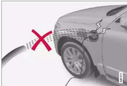
natural_image
Illustration of a car with a red X mark and a broken cable, no text or symbols present
WARNING
The charging cable and its associated parts must not be swamped or immersed in water.

IMPORTANT
Avoid exposing the control unit and its plug to direct sunlight. In such cases, the overheating protection in the plug is at risk of reducing or interrupting the charging of the hybrid battery.
Related information
- Charging status in the charging cable's control unit (p. 435)
- Ground fault breaker in the charging cable (p. 429)
• Temperature monitoring of the charging cable (p. 430)
• Charging the hybrid battery (p. 425)
Ground fault breaker in the charging cable
The control unit for the charging cable charging cable has a built-in ground fault breaker that protects the car and the user from electric shocks caused by system faults.
WARNING
Charging the hybrid battery must only take place with grounded and approved 230 V sockets (alternating current). If the capacity for the socket or fuse circuit is unknown, ask a licensed electrician to check the capacity. Charging above the capacity of a fuse circuit may lead to fire or damage the fuse circuit.
WARNING
- The charging cable's overvoltage protection helps to protect the car's charging system, but cannot guarantee that overload will never occur.
- Never use visibly worn or damaged electrical sockets. This could cause fire or serious injury.
- Never connect the charging cable to a cable extension.
- Maintenance or replacement of the hybrid battery must only be performed by a trained and qualified Volvo service technician.
- Do not use a charging cable that has not been recommended.
- An external timer must not be used between the charging cable and the electrical socket.
- One or more adapters must not be used between the charging cable and the power socket.
ELECTRIC OPERATION AND CHARGING
◀◀
IMPORTANT
The ground fault breaker does not protect the 230 V socket (alternating current)/electrical installation.
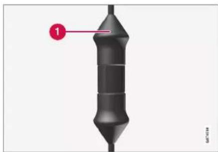
natural_image
3D diagram of a cylindrical object with a labeled point '1' pointing to its top surface (no text or symbols on the object itself)Control unit LED ^4 lamp.
1 LED lamp
If the control unit's built-in ground fault breaker is tripped then the LED lamp illuminates with a red constant glow - check the 230 V socket (alternating current).

IMPORTANT
- Check the capacity of the socket.
- Other electronic equipment connected to the same fuse circuit must be disconnected if the total load is exceeded.
- Do not connect the charging cable if the socket is damaged.
Related information
• Charging cable (p. 427)
- Charging status in the charging cable's control unit (p. 435)
Temperature monitoring of the charging cable
For the car's hybrid battery to be charged safely every time, the control unit for the charging cable and the plug have built-in monitoring devices for the temperature.
Temperature monitoring takes place in the control unit and the plug.
i NOTE
Volvo recommends a charging cable in accordance with IEC 62196 and IEC 61851 which supports temperature monitoring.
Monitoring in the control unit
Charging is switched off if the temperature of the control unit is too high. This is to protect the electronics. This may take place at a high outside temperature, for example, and/or when strong sunlight shines directly on the control unit.
Monitoring at the plug
If the temperature at the power source to which the charging cable is connected is too high, the charging current is reduced. If the temperature exceeds a critical level, charging is stopped completely.
IMPORTANT
If the temperature monitoring has automatically lowered the charging current repeatedly and charging has been interrupted then the cause of the overheating must be investigated and rectified.
Related information
• Charging cable (p. 427)
- Charging status in the charging cable's control unit (p. 435)
Opening and closing the hatch for the charging input socket
The flap for the hybrid battery's charging input socket is opened manually.

natural_image
Close-up of a car's wheel and battery plug with red directional arrows indicating motion (no text or symbols)Press in the rear section of the cover and release.
2 Open the cover.
Close the cover for the charging input socket in reverse order.
Related information
• Starting hybrid battery charging (p. 431)
• Stopping hybrid battery charging (p. 439)
• Charging the hybrid battery (p. 425)
Starting hybrid battery charging
The car's hybrid battery is charged with a charging cable between the car and a 230 V socket ^5 (alternating current).
Only use the charging cable supplied with the car or a replacement cable recommended by Volvo.
IMPORTANT
Never connect the charging cable when there is a risk of thunderstorm or lightning strike.
NOTE
Volvo recommends a charging cable in accordance with IEC 62196 and IEC 61851 which supports temperature monitoring.
ELECTRIC OPERATION AND CHARGING
◀◀

WARNING
- The hybrid battery must only be charged at maximum permitted charging current or lower in accordance with applicable local and national recommendations for hybrid charging from 230 V sockets (alternating current)/plugs.
- Charging the hybrid battery must only take place from an approved grounded 230 V socket ^6 or from a charging station with a loose charging cable (Mode 3) supplied by Volvo.
- The control unit's ground fault breaker protects the car, but there may still be a risk of overloading the 230 V mains power circuit.
- Avoid visible worn or damaged mains sockets since they may lead to fire damage and/or personal injury if used.
- Never use an extension cable.
- Never use an adapter or external timer.

WARNING
- The charging cable has a built-in circuit breaker. Charging must only take place with grounded and approved sockets.
- Children should be supervised when in the vicinity of the charging cable when it is plugged in.
- High voltage in the charging cable. Contact with high voltage can cause death or serious personal injury.
- Do not use the charging cable if it is damaged in any way. A damaged or inoperative charging cable must only be repaired by a workshop - an authorised Volvo workshop is recommended.
- Always position the charging cable so that it will not be driven over, stepped on, tripped over or damaged in some other way, or cause personal injury.
- Disconnect the charger from the wall outlet before cleaning it.
- Never connect the charging cable to an extension cord or a multiple plug socket.
-
Do not use one or more adapters between the charging cable and the electrical socket.
-
Do not use an external timer between the charging cable and the electrical socket.
Also, refer to the manufacturer's instructions for using the charging cable and its components.

IMPORTANT
Check that the 230 V socket (alternating current) has adequate power capacity for charging electric vehicles – in the event of uncertainty, the socket must be checked by a qualified professional.
Note that the car must be switched off before charging.
ELECTRIC OPERATION AND CHARGING
Take the charging cable out from the storage compartment on the right-hand side of the cargo area.
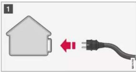
1 Connect the charging cable to a 230 V socket. Never use an extension cable.

natural_image
Close-up of a car's side profile showing wheel, battery, and charging plug (no text or symbols visible)2 Open the charging hatch. Remove the charging handle's protective cover and then press the handle the whole way into the socket for the car.

natural_image
Close-up of an electric vehicle charging at a car, showing battery and wheel (no text or symbols visible)3 Clamp the charging handle's cover in place as illustrated.
IMPORTANT
To avoid damage to the paint, e.g. in the event of high winds, position the charging handle's protective cover so that it does not touch the car.
- The charging cable's charging handle is fastened/locked in, and charging starts within 5 seconds. When charging has started, the LED lamp in the charging input socket flashes with a green glow. The driver display shows the remaining estimated charging time or whether charging is not working as intended.
Battery charging can be interrupted for a while if the car is unlocked. If the charging cable is left in the charging input socket, the charge will restart again after a while.
IMPORTANT
Never unplug the charging cable from the 230 V socket (alternating current) while charging is in progress - there is then a risk of damaging the 230 V socket. Always stop charging first before unplugging the charging cable from the car's charging input socket and then from the 230 V socket.
Condensation from the air conditioning may drip under the car during charging. This is normal and takes place due to cooling of the hybrid battery.
ELECTRIC OPERATION AND CHARGING
Related information
• Charging the hybrid battery (p. 425)
- Opening and closing the hatch for the charging input socket (p. 431)
- Charging status in the car's charging input socket (p. 434)
- Charging status in the car's driver display (p. 437)
- Charging status in the charging cable's control unit (p. 435)
• Stopping hybrid battery charging (p. 439)
Charging status in the car's charging input socket
The charging input socket shows the charging status using an LED lamp.

natural_image
Close-up of a car charging plug with a red arrow pointing to the internal component (no text or symbols visible)LED lamp location in the car's charging input socket.
The LED lamp shows the existing status while charging is in progress. If the LED lamp does not illuminate, check that the cable is firmly plugged into the wall socket and the socket in the car. The white, red, yellow or blue lamps are activated when the passenger compartment lighting is switched on - they remain switched on for a while after the passenger compartment lighting has been switched off.
| LED lamp's glow | Specification |
| White LED light | |
| Yellow | Waiting modeA- waiting for charging to start. |
| Flashing green | Charging in progressB. |
| Green | Charging completeC |
| Red A fault has arisen. | |
| Blue Scheduled charging | |
A For example, after a door has been opened or if the charging cable's handle is not locked in.
^5 The slower the flashing, the closer to fully charged.
© Extinguishes after a while.
Related information
• Charging the hybrid battery (p. 425)
- Charging status in the car's driver display (p. 437)
- Charging status in the charging cable's control unit (p. 435)
• Stopping hybrid battery charging (p. 439)
ELECTRIC OPERATION AND CHARGING
Charging status in the charging cable's control unit
The indicator on the charging cable's control unit shows the status of ongoing charging as well as status after completed charging.

natural_image
3D rendered mechanical component with a pointed tip and segmented body, labeled with number 1 (no text or symbols on the object itself)Control unit LED ^7 lamp.
1 LED lamp
ELECTRIC OPERATION AND CHARGING
◀◀
| LED Status Specification Recommended action | |||
| Extin-guished | Charging is not possible. | No power supply to charging cable. | 1. Unplug the charging cable from the socket.2. Plug the charging cable into the socket again or use another socket.3. If the problem persists – contact Volvo Support. |
| White light Charging possible. | The charging cable is ready to be plugged into the car. | If the LED lamp is white but charging is not possible:1. Unplug the charging cable from the charging input socket.2. Plug the charging cable into the charging input socket again.3. If the indicator does not flash white within approx. 10 seconds – first unplug the charging cable from the charging input socket and then from the power socket.Plug the charging cable into the charging input socket and the socket again.4. If the problem persists – contact Volvo Support. | |
| Flashes white | Charging in progress. | The car's electronics have started charging Charging in progress. | Wait until the batteries are fully charged. |
| Illuminates in red | Charging is not possible. | Temporary fault. 1. Unplug the charging cable from the charging input socket.2. Wait for a short time.3. Plug the charging cable into the charging input socket again.4. If the problem persists – contact Volvo Support. | |
| Flashes red Charging is not possible. | Critical fault. First remove the charging cable from the charging input socket and then from the power outlet. If the problem persists – contact Volvo Support. | ||
Related information
• Charging the hybrid battery (p. 425)
- Charging status in the car's charging input socket (p. 434)
- Charging status in the car's driver display (p. 437)
• Stopping hybrid battery charging (p. 439)
Charging status in the car's driver display
is shown for as long as the driver display is operating.
The driver display shows the status for charging with both image and text. The information
| Image Message | Specification | |
 | Fully charged at: [Time] is shown together with an animation with blue pulsating light through the charging cable. | Charging continues and an approximate time for when the battery is estimated to be fully charged is shown. |
 | The text Charging complete is shown. An illustration of the car is shown with an LED indicator at the charging input socket that illuminates in green. | The battery is fully charged. |
 | The text Charging error is shown. The LED indicator at the charging input socket illuminates in red. | A fault has occurred, check the connection of the charging cable to the car's charging input socket and to the 230 V socket^ (alternating current). |
A The voltage in the socket may vary depending on market.
ELECTRIC OPERATION AND CHARGING
◀◀

NOTE
If the driver display is not used for a while then it is dimmed. Reactivate the display by means of one of the following:
• depress the brake pedal.
• open one of the doors.
- set the car in ignition position I by turning the START knob clockwise and releasing.
Related information
• Charging the hybrid battery (p. 425)
- Symbols and messages relating to hybrid drive in the driver display (p. 441)
- Charging status in the car's charging input socket (p. 434)
- Charging status in the charging cable's control unit (p. 435)
• Stopping hybrid battery charging (p. 439)
Stopping hybrid battery charging
Finish charging by unlocking the car, unplugging the charging cable from the car's charging input socket and then from the 230 V socket ^8 (alternating current).
IMPORTANT
Before the charging cable is disconnected from the car's charging input socket, the car must be unlocked using the unlock button on the remote control key. This must be carried out even if the doors on the car are already unlocked. If the car is not unlocked using the unlock button, this may lead to damage to the charging cable or to the system.
NOTE
Always unlock the car so that charging is stopped before the connection to the 230 V socket (alternating current) is unplugged. Note that the charging cable must be unplugged from the car's charging input socket before being unplugged from the 230 V socket, partly to avoid damage to the system and partly to avoid stopping the charging unintentionally.
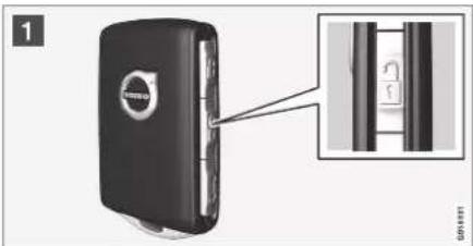
1 Unlock the car with the remote control key - charging is finished and the charging cable's locked handle releases/is unlocked.

natural_image
Close-up of a car's side profile showing engine plug and wheel assembly (no text or symbols visible)2 Unplug the cable from the car's charging input socket and close the hatch.

3 Unplug the cable from the 230 V socket. Return the charging cable to the car's storage compartment on the right of the cargo area.
The charging cable is locked automatically
If the charging cable is not unplugged from the charging input socket, it is locked in again automatically shortly after unlocking in order to maximise charging and range, as well as to facilitate preconditioning prior to the journey. The charging cable can be unplugged again if the car is unlocked using the remote control key. For cars with Passive Entry*, you can lock and unlock using the handle again.
Related information
- Opening and closing the hatch for the charging input socket (p. 431)
• Charging cable (p. 427)
ELECTRIC OPERATION AND CHARGING
- Charging the hybrid battery (p. 425)
• Starting hybrid battery charging (p. 431)
Symbols and messages relating to hybrid drive in the driver display
A number of symbols and messages regarding Recharge can be shown in the driver
display. They may also be shown in combination with general indicator and warning symbols and are then extinguished when the problems have been rectified.
| Symbol | Message Specification | |
 | 12 V BatteryCharging fault, service urgent. Drive to workshop | Hybrid battery fault. Contact a workshop ^A to check the battery as soon as possible. |
 | 12 V BatteryCharging fault Stop safely | Hybrid battery fault. Stop the car safely and contact a workshop ^A to have the battery checked as soon as possible. |
 | 12 V BatteryFuse failure Service required | Hybrid battery fault. Contact a workshop ^A to check the function as soon as possible. |
 | HV batteryOverheated, stop safely | The temperature of the hybrid battery seems to be rising abnormally. Stop the car and switch off the engine. Wait at least 5 minutes before continuing to drive. Call a workshop ^A or check from the outside that everything seems normal before continuing to drive. |
 | Reduced performanceMax car speed limited | The hybrid battery is not sufficiently charged for driving at high speeds. Charge the battery as soon as possible. |
 | Propulsion systemHarsh behaviour at low speed, car ok to use | The hybrid system does not function as intended. Contact a workshop ^A to check the function as soon as possible. |
ELECTRIC OPERATION AND CHARGING
◀◀
| Symbol | Message Specification | |
 | Hybrid system failureService required | The hybrid system is disengaged. Contact a workshop ^A to check the function as soon as possible. |
 | Charge cableRemove before start | Shown when the driver tries to start the car and the charging cable is connected to the car.Disconnect the charging cable and close the charging hatch. |
A An authorised Volvo workshop is recommended.
Related information
• Starting hybrid battery charging (p. 431)
• Stopping hybrid battery charging (p. 439)
• Charging the hybrid battery (p. 425)
• Indicator and warning symbols (p. 93)
• Hybrid gauge (p. 86)
• Hybrid battery gauge (p. 87)
Long-term storage of vehicles with hybrid batteries
To minimise hybrid battery degradation during prolonged storage (longer than 1 month) of the vehicle a charge level of approximately 25% is recommended as indicated on the driver display.
Proceed as follows:
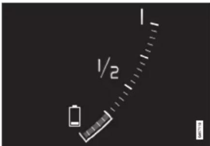
-
If the state of charge is high – run the car until approx. 25% remains. If the state of charge is low – charge the battery until a level of approx. 25% is reached.
-
If storage has lasted longer than 6 months or the hybrid battery charge level is significantly lower than 25% – charge the battery to approx. 25% again to compensate for the natural self-discharge that occurred during the prolonged storage. Continuously check the charge level in the driver display.
NOTE
Choose the coolest location possible for the vehicle in order to minimise aging of the battery during long-term storage. During summer the vehicle should preferably remain indoors or outdoors in the shade, depending on where the temperature is lowest.
Related information
• Starting hybrid battery charging (p. 431)
• Hybrid battery gauge (p. 87)
• Charging the hybrid battery (p. 425)

bar
| Category | Value | |---|---| | Category 1 | 100 | | Category 2 | 100 | | Category 3 | 100 | | Category 4 | 100 | | Category 5 | 100 | | Category 6 | 100 | | Category 7 | 100 | | Category 8 | 100 | | Category 9 | 100 | | Category 10 | 100 | | Category 11 | 100 | | Category 12 | 100 | | Category 13 | 100 | | Category 14 | 100 | | Category 15 | 100 | | Category 16 | 100 | | Category 17 | 100 | | Category 18 | 100 | | Category 19 | 100 | | Category 20 | 100 | | Category 21 | 100 | | Category 22 | 100 | | Category 23 | 100 | | Category 24 | 100 | | Category 25 | 100 | | Category 26 | 100 | | Category 27 | 100 | | Category 28 | 100 | | Category 29 | 100 | | Category 30 | 100 | | Category 31 | 100 | | Category 32 | 100 | | Category 33 | 100 | | Category 34 | 100 | | Category 35 | 100 | | Category 36 | 100 | | Category 37 | 100 | | Category 38 | 100 | | Category 39 | 100 | | Category 40 | 100 | | Category 41 | 100 | | Category 42 | 100 | | Category 43 | 100 | | Category 44 | 100 | | Category 45 | 100 | | Category 46 | 100 | | Category 47 | 100 | | Category 48 | 100 | | Category 49 | 100 | | Category 50 | 100 | | Category 51 | 100 | | Category 52 | 100 | | Category 53 | 100 | | Category 54 | 100 | | Category 55 | 100 | | Category 56 | 100 | | Category 57 | 100 | | Category 58 | 100 | | Category 59 | 100 | | Category 60 | 100 | | Category 61 | 100 | | Category 62 | 100 | | Category 63 | 100 | | Category 64 | 100 | | Category 65 | 100 | | Category 66 | 100 | | Category 67 | 100 | | Category 68 | 100 | | Category 69 | 100 | | Category 70 | 100 | | Category 71 | 100 | | Category 72 | 100 | | Category 73 | 100 | | Category 74 | 100 | | Category 75 | 100 | | Category 76 | 100 | | Category 77 | 100 | | Category 78 | 100 | | Category 79 | 100 | | Category 80 | 100 | | Category 81 | 100 | | Category 82 | 100 | | Category 83 | 100 | | Category 84 | 100 | | Category 85 | 100 | | Category 86 | 100 | | Category 87 | 100 | | Category 88 | 100 | | Category 89 | 100 | | Category 90 | 100 | | Category 91 | 100 | | Category 92 | 100 | | Category 93 | 100 | | Category 94 | 100 | | Category 95 | 100 | | Category 96 | 100 | | Category 97 | 100 | | Category 98 | 100 | | Category 99 | 100 | | Total (Total) |STARTING AND DRIVING
STARTING AND DRIVING
Starting the car
The car is started using the start knob in the tunnel console when the remote control key is in the passenger compartment.

natural_image
Close-up of a car control panel with buttons and a speed limit dial (no readable text or symbols)Start knob in the tunnel console.

WARNING
Before starting:
- Fasten the seatbelt.
- Adjust the seat, steering wheel and mirrors.
• Make sure that the brake pedal can be fully depressed.
The remote control key is not physically used when starting the car since it is equipped with support for keyless starting (Passive start).
To start the car:
IMPORTANT
The car cannot be started if the charging cable is still engaged. Make sure the charging cable is removed from the charging input socket before the starting the car.
-
The remote control key must be inside the car. For cars with Passive Start, the key needs to be located in the front part of the passenger compartment. With the option for keyless locking/unlocking* of the car, the key can be anywhere in the car.
-
Hold the brake pedal depressed ^1 fully. For cars with automatic gear changing, make sure that gear position P or N is selected. For cars with a manual gearbox, make sure that the gear lever is in neutral position or that the clutch pedal is depressed.
-
Turn the start knob clockwise and then release it. The control automatically returns to its starting position.
When the engine is started, the starter motor works until the engine is started or until its overheating protection triggers.
When starting in normal conditions, the car's electric drive motor is prioritised - the petrol
engine remains switched off. This means that after the start knob has been turned clockwise, the electric motor has "started" and the car is ready to drive. A started car is indicated by the driver display's indicator lamps extinguishing and its preset theme illuminating.
However there are situations where the petrol engine is started instead e.g. in the event of the temperature being too low or if the hybrid battery needs charging.
Error messages
If the Car key not found message is shown in the driver display when starting, place the remote control key by the backup reader. Then try to start the car again.

Backup reader's location in the tunnel console.

NOTE
When the remote control key is positioned by the backup reader, make sure that there are no car keys, metal objects or electronic apparatus by the backup reader, (e.g. mobile phones, tablets, laptops or chargers). Several car keys close to one another by the backup reader may cause interference with each other.
If the message Car start System check, wait is shown in the driver display when starting, wait until the message disappears and then try to start the car again.

IMPORTANT
If the engine fails to start after 3 attempts - wait for 3 minutes before making a further attempt. Starting capacity increases if the battery is allowed to recover.

NOTE
The car cannot be started if the hybrid battery is discharged.

WARNING
Never remove the remote control key from the car while driving.

WARNING
Always take the remote control key out from the car when leaving the car and make sure the car's electrical system is in ignition position 0 - especially if there are children in the car.

NOTE
The idling speed can be noticeably higher than normal for certain engine types during cold starting. This is done in order that the emissions system can reach normal operating temperature as quickly as possible, which minimises exhaust emissions and protects the environment.
Related information
• Switching off the car (p. 447)
- Ignition positions (p. 448)
• Adjusting the steering wheel (p. 196)
• Using jump starting with another battery (p. 488)
• Selecting ignition mode (p. 449)
Switching off the car
The car is switched off using the start knob in the tunnel console.

natural_image
Close-up of a car air conditioner panel with control buttons and a digital display (no visible text or symbols)Start knob in the tunnel console.
To switch off the car:
- Turn the start knob clockwise and release it - the car is switched off. The control automatically returns to its starting position.
If the gear selector for cars with an automatic gearbox is not in position P or if the car rolls:
- Turn the knob clockwise and hold it until the car is switched off.
Related information
• Starting the car (p. 446)
- Ignition positions (p. 448)
• Adjusting the steering wheel (p. 196)
▶▶
STARTING AND DRIVING
• Using jump starting with another battery (p. 488)
• Selecting ignition mode (p. 449)
Ignition positions
The car's electrical system can be set in different levels/positions and in this way make the different functions available.
In order to facilitate the use of a limited number of functions with the engine switched off, the car's electrical system can be set in three different levels - 0, I and II. These levels are described with the denomination "ignition position" throughout the owner's manual.
The following table shows the functions available in each ignition position/level:
| Level | Functions |
| 0 | Odometer, clock and temperature gauge are illuminated ^A .Power* seats can be adjusted.The power windows can be used.The centre display is started and can be used ^A .The infotainment system can be used ^A .In this mode, the functions are controlled by time and are switched off automatically after a short while. |
| 1 | Sunroof, power windows, 12V power socket in the passenger compartment, Bluetooth, navigation, phone, ventilation fan and windscreen wipers can be used.Power seats can be adjusted.12 V power sockets* in the cargo area can be used.Power is taken from the battery in this ignition position. |
| II | The headlamps come on.Warning/indicator lamps illuminate for 5 seconds.Several other systems are activated. However, heating in seat cushions and the rear window can only be activated after the car has been started.This ignition position consumes a lot of current from the battery and should therefore be avoided! |
A Also activated when the door is opened.
Related information
• Starting the car (p. 446)
• Adjusting the steering wheel (p. 196)
• Using jump starting with another battery (p. 488)
• Selecting ignition mode (p. 449)
Selecting ignition mode
The car's electrical system can be set in different levels/positions and in this way make the different functions available.
Selecting ignition position
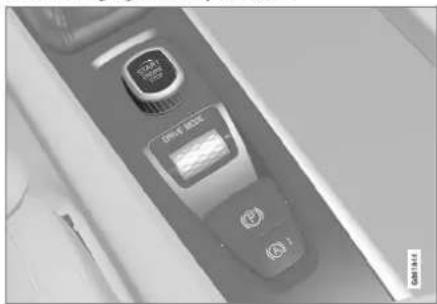
natural_image
Close-up of a car air conditioner panel with buttons and display (no visible text or symbols)Start knob in the tunnel console.
- Ignition position 0 – Unlock the car and store the remote control key inside the car.
i NOTE
To reach level I or II without starting the engine - do not depress the brake pedal, or the clutch pedal for cars with manual gear changing, when these ignition positions are to be selected.
- Ignition position I – Turn the start knob clockwise and release it. The control automatically returns to its starting position.
- Ignition position II – Turn the start knob clockwise and hold it in position for approx. 5 seconds. Then release the knob, which automatically returns to its starting position.
- Back to ignition position 0 – To return to ignition position 0 from position I and II – Turn the start knob clockwise and release. The control automatically returns to its starting position.
Related information
• Starting the car (p. 446)
• Switching off the car (p. 447)
- Ignition positions (p. 448)
• Adjusting the steering wheel (p. 196)
• Using jump starting with another battery (p. 488)
STARTING AND DRIVING
Alcohol lock\*
The function of the alcohol lock is to prevent the car from being driven by individuals under the influence of alcohol. Before the engine can be started the driver must take a breath test that verifies that he/she is not under the influence of alcohol. Alcohol lock calibration takes place in accordance with each market's limit value in force for driving legally. The car has an interface for the electrical connection of the different makes and models of alcohol lock recommended by Volvo. The interface facilitates alcohol lock connection, and gives the option of an integrated function including messages related to the alcohol lock in the car's main display. For information about a specific alcohol lock, please refer to the owner's manual from the respective alcohol lock manufacturer.

WARNING
The alcohol lock is an aid and does not exempt the driver from responsibility. It is always the responsibility of the driver to be sober and to drive the car safely.
Related information
• Bypass of the alcohol lock* (p. 450)
- Before starting the engine with the alcohol lock* (p. 451)
• Starting the car (p. 446)
- Ignition positions (p. 448)
Bypass of the alcohol lock\*
In the event of an emergency situation or if the alcohol lock is out of order, it is possible to bypass the alcohol lock in order to drive the car.
For deactivation via the alcohol lock, see supplier's manual.
Related information
• Alcohol lock* (p. 450)
- Before starting the engine with the alcohol lock* (p. 451)
• Starting the car (p. 446)
- Ignition positions (p. 448)
Before starting the engine with the alcohol lock\*
The alcohol lock is activated automatically and is then ready for use when the car is opened.
To bear in mind
In order to obtain correct function and as accurate a measurement result as possible:
- Avoid eating or drinking approx. 5 minutes before the breath test.
- Avoid excess windscreen washing - the alcohol in the washer fluid may result in an incorrect measurement result.

NOTE
After a completed period of driving, the engine can be restarted within 30 minutes without a new breath test.
Related information
• Bypass of the alcohol lock* (p. 450)
• Alcohol lock* (p. 450)
• Starting the car (p. 446)
- Ignition positions (p. 448)
Brake functions
The car's brakes are used to reduce the speed or prevent the car from rolling. In addition to the foot brake and parking brake, the car is equipped with several automatic brake assist functions. These can assist the driver by not needing to keep his/her foot on the brake pedal when at a traffic light, or when starting on an uphill gradient.
Depending on the car's equipment, the following auto braking functions are available:
• Automatic brake when stationary (Auto Hold)
• Hill start assist (Hill Start Assist)
• Auto braking after a collision
- City Safety
Related information
- Foot brake (p. 451)
- Parking brake (p. 454)
• Automatic braking when stationary (p. 457)
• Auto braking after a collision (p. 459)
• Help when starting on a hill (p. 459)
• City Safety™ (p. 348)
Foot brake
The foot brake is part of the brake system. The car is equipped with two brake circuits. If a brake circuit is damaged, the brake pedal may engage deeper. Higher pressure on the pedal will therefore be needed to produce the normal braking effect.

WARNING
The brake servo only works when the electric motor or internal combustion engine is running.
If the foot brake is used when the car is switched off, the brake pedal needs to be depressed passed the normal braking position using a higher pressure to brake the car.
In very hilly terrain or when driving with a heavy load the brakes can be relieved by using engine braking in gearshift mode B.
Anti-lock braking system
The car has anti-lock brakes (ABS ^2 ), which prevents the wheels from locking while braking and allows maintained steering control. Vibration may be felt in the brake pedal when this is engaged and this is normal.
A short test of the ABS system is made automatically after the car has been started when the driver releases the brake pedal. A further
STARTING AND DRIVING
automatic test of the system may be made at low speed. The test may be felt as pulses in the brake pedal.
Light braking charges the hybrid battery
The electric motor's engine brake is used during light braking. The car's kinetic energy is then converted to electrical energy instead, which is used to charge the hybrid battery. Battery charging with electric motor braking is indicated in the driver display.

The driver display indicates charging during electric motor braking.
This function is active in the speed interval 150-5 km/h (93-3 mph). During heavier braking, as well as outside the speed interval, braking is supplemented by the hydraulic brake system. The driver's display shows this by the indicator being down in the red zone.
Symbols in the driver display
Symbol Specification

Check the brake fluid level. If the level is low, fill with brake fluid and check for the cause of the brake fluid loss.

Fault in pedal sensor.

Constant glow for 2 seconds when the engine is started: Automatic function check.
Constant glow for more than 2 seconds: Fault in the ABS system. The car's normal brake system is still working, but without the ABS function.

If the message Brake pedal Characteristics changed Service required is shown, the system for "Brake-by-wire" is disengaged. The brake pedal needs to be depressed passed the normal braking position using a higher pressure to brake the car.
WARNING
If both the warning lamps for brake fault and ABS fault illuminate at the same time, a fault has occurred in the brake system.
• If the level in the brake fluid reservoir is normal at this stage, drive carefully to
the nearest workshop and have the brake system checked - an authorised Volvo workshop is recommended.
- If the brake fluid is below the MIN level in the brake fluid reservoir, do not drive further before topping up the brake fluid. The reason for the loss of brake fluid must be investigated.
Related information
- Brake assistance (p. 453)
• Automatic braking when stationary (p. 457)
• Help when starting on a hill (p. 459)
• Braking on wet roads (p. 453)
• Braking on gritted roads (p. 453) - Brake system maintenance (p. 454)
- Brake lights (p. 158)
Brake assistance
The brake assist system (BAS ^3 ) helps to increase brake force during braking, and can thereby shorten the braking distance. The system detects the way in which the driver brakes and increases brake force where necessary. The brake force can be boosted up to the level when the ABS system is engaged.
Related information
- Foot brake (p. 451)
Braking on wet roads
When driving for a prolonged period of time in heavy rain without braking, the braking effect may be delayed slightly when next using the brakes.
This may also be the case after a car wash. It is then necessary to depress the brake pedal more forcefully. You should therefore maintain a greater distance to the vehicles in front.
Brake the car firmly after driving on wet roads or using a car wash. This warms up the brake discs, enabling them to dry faster and protecting them against corrosion. Bear in mind the current traffic situation when braking.
Related information
- Foot brake (p. 451)
• Braking on gritted roads (p. 453)
Braking on gritted roads
When driving on salted roads, a layer of salt may form on the brake discs and brake linings.
This may extend braking distance. You should therefore maintain a greater safety distance to vehicles in front. In addition, make sure you do the following:
- Brake now and again to remove any layer of salt. Make sure that other road users are not put at risk by the braking.
- Gently depress the brake pedal after finishing driving and before starting your next trip.
Related information
- Foot brake (p. 451)
• Braking on wet roads (p. 453)
STARTING AND DRIVING
Brake system maintenance
Check brake system components regularly for wear.
To keep the car as safe and reliable as possible, follow the Volvo service intervals as specified in the Service and Warranty Booklet. After replacing brake linings and brake discs, braking effect is only adapted after they have been "worn in" for a few hundred kilometres (miles). Compensate for the reduced braking effect by depressing the brake pedal harder. Volvo recommends only fitting brake linings that are approved for your Volvo.
IMPORTANT
The wear on the brake system's components must be checked regularly.
Contact a workshop for information about the procedure or engage a workshop to carry out the inspection - an authorised Volvo workshop is recommended.
Related information
- Foot brake (p. 451)
Parking brake
The parking brake prevents the car from rolling away from stationary by means of mechanically locking/blocking two wheels.

natural_image
Close-up of a car's side panel with buttons and a central touchscreen (no readable text or symbols)The control for the parking brake is located in the tunnel console between the seats.
A faint electric motor noise can be heard when the electrically-operated parking brake is being applied. The noise can also be heard during the automatic function checking of the parking brake.
If the car is stationary when the parking brake is activated, it only acts on the rear wheels. If it is activated when the car is moving then the normal foot brake is used, i.e. the brake acts on all four wheels. Brake function changes over to the rear wheels when the car is almost stationary.
Related information
- Activating and deactivating the parking brake (p. 455)
- Parking on a hill (p. 456)
- In the event of a fault in the parking brake (p. 457)
• Automatic braking when stationary (p. 457)
Activating and deactivating the parking brake
Use the parking brake to prevent the car from rolling from stationary.
Activating the parking brake

- Pull the control upward.
The symbol in the driver display illuminates when the parking brake is activated.
- Check that the car is stationary.
Symbol in the driver display
Symbol Specification

The symbol is illuminated when the parking brake is activated. If the symbol flashes, it indicates a fault has occurred. Read the message in the driver display.
Automatic activation
The parking brake is activated automatically
- when the car is switched off and the setting for automatic activation of the parking brake is activated in the centre display.
- when gear position P is selected on a steep hill.
- if the Auto hold (Automatic brake when stationary) function is activated and
- the car has been stationary for a long time (5-10 minutes)
• the car is switched off
• the driver leaves the car.
Emergency brake
In an emergency, the parking brake can be activated when the car is in motion by pulling and holding up the control. Braking stops when the control is released, or if the accelerator pedal is depressed.
NOTE
An acoustic signal sounds while emergency braking is active at high speeds.
Deactivating the parking brake

Deactivate manually
To deactivate the parking brake, the engine needs to be running.
-
Depress the brake pedal firmly.
-
Press the control down.
The parking brake releases and the symbol in the driver display extinguishes.
STARTING AND DRIVING
Deactivate automatically
- Start the car.
- Depress the brake pedal firmly. Select gear position D or R and depress the accelerator pedal.
The parking brake releases and the symbol in the driver display extinguishes.
i NOTE
For automatic deactivation, either the driver has to have put on their seatbelt or the driver door has to be closed.
Related information
• Automatic parking brake activation setting (p. 456)
• In the event of a fault in the parking brake (p. 457)
- Parking brake (p. 454)
- Parking on a hill (p. 456)
Automatic parking brake activation setting
Choose whether the parking brake is to be activated automatically when the car is switched off.
To change setting:
- Tap on Settings in the centre display's top view.
- Press My Car Parking Brake and Suspension to select or deselect the function Auto Activate Parking Brake.
Related information
- Activating and deactivating the parking brake (p. 455)
- Parking brake (p. 454)
Parking on a hill
Always use the parking brake when parking on a hill.
WARNING
Always use the parking brake when parking on an inclined surface. Engaging a gear or the automatic transmission's P position is not sufficient to hold the car stationary in all situations.
If the car is parked facing uphill:
- Turn the wheels away from the kerb. If the car is parked facing downhill:
• Turn the wheels towards the kerb.
Heavy load uphill
A heavy load, such as a trailer, can cause the car to roll backward when the parking brake is released automatically on a steep incline. Avoid this by pulling the control upwards while driving the car away. Release the control when the engine achieves traction.
Related information
- Activating and deactivating the parking brake (p. 455)
In the event of a fault in the parking brake
Contact an authorised Volvo workshop if it is not possible to deactivate or activate the parking brake after several attempts.
An acoustic warning signal sounds when driving with the parking brake activated.
If the car must be parked before a possible fault is rectified, then the wheels must be turned as for parking on a hill and the gear selector must be in position P.
Low battery voltage
If the battery voltage is too low then the parking brake can be neither deactivated nor activated. Connect a donor battery if the battery voltage is too low.
Replacing the brake linings
The rear brake linings must be replaced at a workshop due to the design of the electrically-operated parking brake - an authorised Volvo workshop is recommended.
Symbols in the driver display
Symbol Specification

If the symbol flashes, it indicates a fault has occurred. See the message in the driver display.

Fault in brake system. See the message in the driver display.

Information message in driver display.
Related information
- Activating and deactivating the parking brake (p. 455)
- Parking on a hill (p. 456)
• Starter battery (p. 617)
• Volvo service programme (p. 600)
Automatic braking when stationary
Automatic brake when stationary (Auto hold) means that the driver can release the brake pedal while maintaining braking effect when the car has stopped at traffic lights or a junction.
When the car has stopped, the brakes are activated automatically. The function can use either foot brake or parking brake to hold the car stationary and it works on all gradients.
When driving off, the brakes are released automatically if the driver is wearing the seat-belt and/or the driver's door is closed.
NOTE
When braking to a standstill on an uphill or downhill slope, the brake pedal should be depressed a little harder before being released to ensure the car does not roll.
The parking brake is activated if
• the car is switched off
• the driver's door is opened
• the driver's seatbelt is unbuckled
- the car has been stationary for a longer time (5-10 minutes).
STARTING AND DRIVING
Symbols in the driver display
Symbol Specification

The symbol is illuminated when the function uses the foot brake to keep the car stationary.

The symbol is illuminated when the function uses the parking brake to keep the car stationary.
Related information
- Activating and deactivating the automatic brake at a standstill (p. 458)
- Foot brake (p. 451)
- Parking brake (p. 454)
• Help when starting on a hill (p. 459)
Activating and deactivating the automatic brake at a standstill
The automatic brake function at a standstill is activated using the button in the tunnel console.

natural_image
Close-up of a car's drive shift lever with control buttons and a central touchscreen (no visible text or symbols)- Press the button in the tunnel console to activate or deactivate the function.
The indicator in the button illuminates when the function is activated. Activated function remains even when the car is started next time.
Applicable when switching off

If the function is active and holds the car with the foot brake (A-symbol illuminated in the driver display), the brake pedal must be depressed at
the same time as the button is depressed in order to deactivate.
- The function remains deactivated until it is reactivated.
- When the function is deactivated, hill start assist (HSA) remains active to prevent the car from rolling backwards when starting on an uphill gradient.
Related information
• Automatic braking when stationary (p. 457)
Help when starting on a hill
Hill start assist (HSA ^4 ) prevents the car from rolling backwards when starting on an uphill gradient. When reversing uphill, it prevents the car from rolling forwards.
The function means that the pedal pressure in the brake system remains for several seconds while the driver's foot is moved from brake pedal to accelerator pedal.
The temporary braking effect releases after several seconds or when the driver starts to drive away.
The Hill Start Assist is activated when stopping on a sleep slope. The function is available even when the automatic braking when stationary (Auto hold) function is deactivated.
Related information
• Automatic braking when stationary (p. 457)
- Foot brake (p. 451)
Auto braking after a collision
In the event of a collision in which the activation level is reached for the pyrotechnic seat-belt tensioners or airbags, or if a collision with a large animal is detected, the car's brakes are automatically applied. This function is to prevent or reduce the effects of any subsequent collision.
After a serious collision there is a risk that it is no longer possible to control and steer the car. In order to avoid or mitigate a possible further collision with a vehicle or an object in the vehicle's path, the auto braking system is activated automatically and brakes the car in a safe manner.
Brake lights and hazard warning lights are activated during braking. When the car has stopped, the hazard warning lights continue to flash and the parking brake is applied.
If braking is not appropriate, e.g. if there is a risk of being hit by following traffic, the system can be overridden by the driver depressing the accelerator pedal.
The function assumes that the brake system is intact after the collision.
Related information
• Rear Collision Warning* (p. 368)
BLIS* (p. 369)
- Brake functions (p. 451)
Regenerative braking\*
The car recovers kinetic energy during braking in order to reduce fuel consumption and emissions.

The battery symbol is shown in the driver display when the car is generating power for the battery.
The function is available in all drive modes together with gear position D or B.
Activating brake regeneration
Brake regeneration is activated by gentle pressure on the brake pedal or during engine braking.
Regeneration increases during engine braking when manual gearshift mode B is selected.
Related information
• Drive modes (p. 467)
- Changing gear with automatic gearbox (p. 461)
STARTING AND DRIVING
Gearbox
The gearbox is part of the car's powertrain (power transmission) between engine and drive wheels. The function of the gearbox is to change the gear ratio depending on speed and power requirements.
The car has an eight-speed automatic gear-box, and an electric motor for rear-wheel drive. The number of gear changes means that the engine's torque and power range can be used effectively.
Two of the gears are overdrive gears that save fuel when driving at constant engine speed. Both the gear lever and the shift paddles can be used to shift up or down manually. The driver display shows the selected gear position.
Related information
• Automatic gearbox (p. 460)
• Gear shift indicator (p. 465)
Automatic gearbox
Gears are selected automatically so that you can drive as energy-efficiently as possible. The gearbox also has a manual gearshift mode.
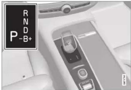
Overview of gear lever and shift pattern in the driver display.
The driver display shows the selected gear position:
P, R, N, D or B.
Related information
- Changing gear with automatic gearbox (p. 461)
- Changing gear with steering wheel paddles* (p. 462)
• Gear selector inhibitor (p. 464) - Kick-down function (p. 464)
- Launch function* (p. 464)
• Gear shift indicator (p. 465)
- Symbols and messages for automatic gearbox (p. 465)
Changing gear with automatic gearbox
Change gear position by pressing the spring-loaded gear selector forwards or backwards, or sideways for manual shifting.
Changing gear

Overview of gear lever and gear positions.
Gear positions
Parking - P

natural_image
Close-up of a car interior control panel with buttons and a play button (no visible text or symbols)Overview of gear lever and position P.
Parking is activated with the P button located next to the gear selector.
The gearbox is mechanically blocked when the P position is engaged.
Select position P for parking. The car can start in position P. The car must be stationary when the P position is selected.
To park - first apply the parking bake and then select P position.

WARNING
Always use the parking brake when parking on an inclined surface. Engaging a gear or the automatic transmission's P position is not sufficient to hold the car stationary in all situations.

NOTE
To be able to lock the car and arm the alarm, the gear position must be in P.
Help functions
The system will change to the P position automatically:
• if the car is switched off in position D or R.
- if the driver unfastens the seatbelt and opens the driver's door when the car is running in a mode other than P.
To park a car without wearing the seatbelt and with the door open - exit the P position by selecting R or D again.
If the car is switched off in N position there is no automatic change-over to P position. This makes it possible to wash the car in an automatic car wash.
Reverse - R
Select position R to reverse. The car must be stationary when the R position is selected.
▶▶
STARTING AND DRIVING
Neutral - N
The car freewheels in position N. The car can start in position N. Apply the parking brake if the car is stationary with the gear selector in the N position.
In order to change from N position to another gear position, the brake pedal must be depressed and the ignition position must be II.
Drive position - D
D is the normal driving position. Shifting up and down takes place automatically based on the level of acceleration and speed.
The car must be stationary when changing gear from R position to D position.
Brake - B
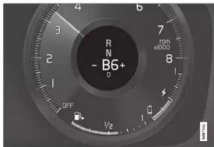
Overview of brake positions in the driver display. In B position, it is possible to change gear manually. The car brakes using its electric
motor when the accelerator pedal is released, while also charging the hybrid battery.
Position B is selected by moving the gear selector backwards from the D position.
- Press the gear selector to the right to "+" (plus) to change up one step and release it.
- Press the gear selector to the left to "-" (minus) to change down one step and release it.
- Press the gear selector backwards to return to the D position.
The gearbox automatically shifts down if the speed decreases to a level lower than appropriate for the selected gear, in order to avoid jerking and stalling.
Related information
• Automatic gearbox (p. 460)
• Gear selector inhibitor (p. 464)
- Changing gear with steering wheel paddles* (p. 462)
- Kick-down function (p. 464)
Changing gear with steering wheel paddles\*
The steering wheel paddles are a complement to the gear selector and make it possible to change gear manually without releasing hands from the steering wheel.
The function is available in position D or B.

① "-" : Selects the next lower gear.
② "+": Selects the next higher gear.
Switch
To change gear:
- Pull one of the paddles backwards - towards the steering wheel - and release.
A gear change occurs at each pull of the paddle, provided that the engine speed does not leave the permitted range. The driver display shows the current gear.
In B position the steering wheel paddles are automatically activated.
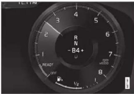
Driver display when changing gear with steering wheel paddles in manual gearshift mode.
Activating the steering wheel paddles in position D
To be able to change gear with the steering wheel paddles, they must be activated:
- Pull one of the paddles toward the steering wheel.
A figure in the driver display indicates current gear.

Driver display when changing gear with steering wheel paddles.
Deactivating the steering wheel paddles in position D
Manual deactivation
- Pull the right-hand paddle (+) toward the steering wheel and hold in place until the number in the driver display extinguishes.
The gearbox returns to position D.
Automatic deactivation
The steering wheel paddles are deactivated after a short time if they are not used. This is indicated by means of the figure for the current gear extinguishing. The exception is during engine braking - then the paddles are activated for as long as engine braking is in progress.
Related information
• Automatic gearbox (p. 460)
- Changing gear with automatic gearbox (p. 461)
• Gear shift indicator (p. 465)
STARTING AND DRIVING
Gear selector inhibitor
The gear selector Inhibitor prevents accidental changing between different gear positions in an automatic gearbox.
Automatic gear selector inhibitor
The automatic gear selector inhibitor has special safety systems.
From park position – P or neutral position – N
In order to move the gear selector from P or N position to another gear position, the brake pedal must be depressed and the ignition position must be II. For some gearbox variants, the engine must be running.
If the gear selector is in the N position and the car has been stationary for at least 3 seconds (irrespective of whether the engine is running) then the gear selector is locked.
Message in the driver display
If the gear selector is inhibited a message is shown in the driver display e.g. Gear lever Press brake pedal to activate gear lever.
The gear selector is not inhibited mechanically.
Related information
• Automatic gearbox (p. 460)
- Changing gear with automatic gearbox (p. 461)
Kick-down function
Kick-down can be used when maximum acceleration is needed such as for overtaking. When the accelerator pedal is pressed all the way to the floor (beyond the position normally regarded as full acceleration) a lower gear is immediately engaged. This is known as kick-down.
If the accelerator is released from the kick-down position, the gearbox automatically changes up.
Safety function
To prevent over-revving of the engine, the gearbox control program has a protective downshift inhibitor.
The gearbox does not permit downshifting/ kick-down which would result in an engine speed high enough to damage the engine. Nothing happens if the driver still tries to shift down in this way at high engine speed – the original gear remains engaged.
On kick-down the car can shift down one or more steps at a time, depending in engine speed. The car shifts up when the engine has reached is maximum engine speed in order to prevent engine damage.
Related information
• Automatic gearbox (p. 460)
Launch function\*
Launch can be used when maximum acceleration is required from stationary. The function is available in the following drive modes: Hybrid, Constant AWD, Power and Individual.
Activate Launch
Make sure the car is stationary and the wheels are pointing straight forward.
- Move to gear position D.
- Depress the brake pedal fully.
- Then fully depress the accelerator pedal.
- Release the brake pedal within 2 seconds.

NOTE
If the Launch function does not work, wait a few minutes and let the drivetrain cool down to working temperature before retrying.

IMPORTANT
The drivetrain is subject to wear and tear when using Launch and therefore the function is only available a limited number of times.
Related information
• Automatic gearbox (p. 460)
Symbols and messages for automatic gearbox
If a fault should occur in the gearbox, a symbol and a message are shown in the driver display.

IMPORTANT
To prevent damage to any drive system components, the working temperature of the gearbox is checked. If there is a risk of overheating, a warning symbol illuminates in the driver display and a text message is shown - follow the recommendation given.
Symbol Specification
An error has occurred in the transmission. Read the message in the driver display.

Hot or overheated gearbox. Read the message in the driver display.

Temporary fault on drivetrain. Read the message in the driver display.
Related information
• Automatic gearbox (p. 460)
Gear shift indicator
The gear shift indicator in the driver display shows the current gear during manual gear-shifting and when it is appropriate to engage the next gear for optimum fuel economy.
For eco-driving during manual gear changing, it is important to drive in the right gear and to change gear in good time.
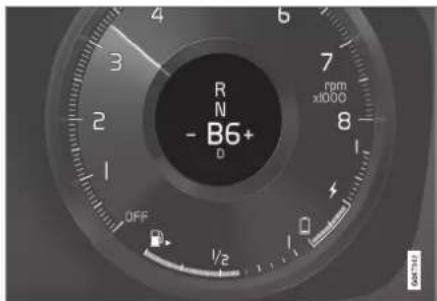
Gear shift indicator in the driver display ^5 .
The gear shift indicator is shown in gear position B. The gear shift indicator shows the current gear in the driver display and indicates recommended shifting to a higher gear by a flashing plus sign.
Related information
• Automatic gearbox (p. 460)
All-wheel drive
All-wheel drive (AWD ^6 ) means that the car is driving all four wheels at the same time, which improves traction.
The electric motor that drives the rear wheels enables electric all-wheel drive functionality. All-wheel drive characteristics vary depending on the selected drive mode.
Related information
- Drive modes (p. 467)
Gearbox (p. 460)
STARTING AND DRIVING
Drive systems
The car combines an internal combustion engine that drives the front wheels with an electric motor that drives the rear wheels.
Two drive systems
Depending on the driver-selected drive mode and available electric energy, the two drive systems can be used either individually or in parallel.
The electric motor is supplied its energy from a hybrid battery fitted in the tunnel console. The hybrid battery can be charged in a wall socket, or in a special charging station. The internal combustion engine can also charge the hybrid battery with a special high-voltage generator.
Both the internal combustion engine and electric motor can generate motive force directly to the wheels. An advanced control system combines the properties of both drive systems in order to provide optimum driving economy.

Hybrid battery - The function of the hybrid battery is to store energy. It receives energy when charging from the mains power circuit, during regenerative braking or from the high-voltage generator. It provides energy for electric operation as well as for temporarily operating the electric air conditioning during the preconditioning of the passenger compartment.
2 Internal combustion engine - The internal combustion engine starts when the energy level in the hybrid battery is insufficient for the engine power that the driver requests.
3 High voltage generator ^7 - Charges the hybrid battery. Starter motor for the internal combustion engine. Can support the
internal combustion engine with extra electrical energy.
4 Electric motor - Powers the car in electric operation. If necessary, provides extra torque and power during acceleration. Provides electrical all-wheel drive functionality. Recycles brake energy to electrical energy.
Related information
- General information on electric drive (p. 424)
- Starting and stopping the combustion engine (p. 467)
- Drive modes (p. 467)
Gearbox (p. 460)
Starting and stopping the combustion engine
An advanced control system determines the extent to which the car is driven on internal combustion engine, electric motor or both in parallel. During electric operation, the car may sometimes need to start the internal combustion engine automatically due to external circumstances, e.g. in low outside temperatures, which is completely normal. In addition, the internal combustion engine always starts when the hybrid battery reaches its lowest state of charge.
Climate settings at low temperatures
In low outside temperatures, the internal combustion engine sometimes starts automatically in order to achieve the desired passenger compartment temperature and air quality. The amount of time that the internal combustion engine runs can be affected by
• lowering the temperature
• reducing the fan strength
• activating drive mode Pure.
Electric operation in low or high temperatures
In low or high outside temperatures, the car's range and output for electric operation may be reduced and affect how often the internal combustion engine is started automatically.
Emission control
To ensure that emission control operates as energy-efficiently as possible, the internal combustion engine must be run for several minutes once it has been started. The duration of the internal combustion engine's running time varies depending on the temperature of the catalytic converter.
Related information
• Drive systems (p. 466)
• Economical driving (p. 476)
- Range (p. 477)
• Drive modes (p. 467)
Drive modes
Selection of drive mode affects the car's driving characteristics in order to enhance the driving experience and facilitate driving in special situations.
Using the drive modes it is possible to quickly have access to the car's numerous functions and settings for different driving needs. Each drive mode is adapted to provide optimum driving characteristics:
- Steering
- Brakes
- Shock absorption
- Driver display
• Climate settings
• Engine/gearbox/all-wheel drive
Select the drive mode adapted for the current driving conditions. Remember that not all drive modes are available in all situations.
Selectable drive modes

WARNING
Remember that the car does not emit any engine noise when it is only powered by the electric motor and may therefore be difficult to notice by children, pedestrians, cyclists and animals. This applies in particular at low speeds such as in car parks.
STARTING AND DRIVING
◀◀

WARNING
Do not leave the car in an unventilated area with activated drive mode and the fuel-driven engine switched off - automatic engine start occurs at low energy level in the hybrid battery, and the exhaust gases could then cause serious injury to people and animals.
Hybrid
- This is the car's normal mode where the electric motor and internal combustion engine work together.
When the car starts, it is in the Hybrid mode. The control system uses both the electric motor and internal combustion engine – individually or in parallel – and adapts use with regard to performance, fuel consumption and comfort. The capacity to run solely with the electric motor depends on the hybrid battery's energy level and, for example, the need for heating or cooling in the passenger compartment.
If high power output is available, it is possible to drive with electrical power alone. When the accelerator pedal is depressed, only the electric motor is activated until a certain position is reached. The internal combustion engine starts when this position is exceeded and the energy level in the battery is insufficient for the engine power that the driver requests with the accelerator pedal.
At low energy level (hybrid battery almost empty) the battery's energy level must be maintained, leading to the internal combustion engine starting more often. Charge the hybrid battery from a 230 VAC socket with the charging cable, or activate Charge in the function view in order to restore the capacity to run on electricity alone.
The drive mode is designed for low energy consumption with a mix of the electric motor and the internal combustion engine, without compromising the climate comfort and driving experience. When higher acceleration is required, maximum additional power from the electric drive line is used.
The car also senses if the driving conditions require all-wheel drive and automatically engages it if necessary. All-wheel drive and electric additional power are always available regardless of the battery's state of charge.
Information in the driver display
When driving in hybrid mode the driver display shows a hybrid gauge. The pointer in the hybrid gauge indicates how much energy the driver requests with the accelerator pedal. The marking between the lightning bolt and the drop shows how much energy is available.
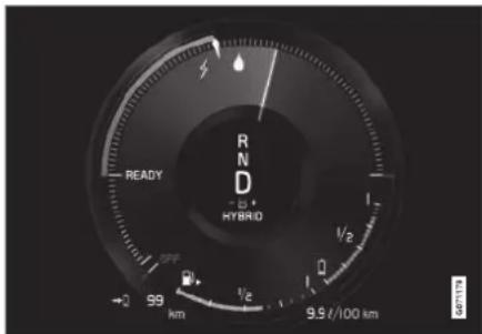
The driver display for propulsion with both the electric motor and internal combustion engine.

The driver display also shows when energy is returned to the battery (regenerated) during light braking.
Pure
- Drive the car with electric motor, with energy consumption as low as possible and with lowest possible carbon dioxide emissions.
The drive mode prioritises driving on the hybrid battery. This means, for example, that the output of certain climate settings is reduced to provide the longest possible mileage on electric power alone.
The Pure mode is available when the hybrid battery has a sufficiently high energy level. The internal combustion engine also starts in the Pure mode if the energy level in the battery falls too low. The internal combustion engine also starts
• if the speed exceeds 125 km/h (78 mph)
- if the driver requests more motive force than electric drive can provide
- in the event of system/component limitations e.g. low outside temperature.

NOTE
The internal combustion engine may start temporarily in certain driving situations when the Pure drive mode is in use. This is in order to provide the wheels with the desired torque in driving situations that require higher load, e.g. when driving with a trailer or on an uphill gradient.
The drive mode is adapted for maximum range with electric propulsion and especially developed for urban traffic. Pure means lowest combustion even when the hybrid battery is empty. The climate in the passenger compartment is regulated to Eco climate, and in slippery driving conditions, more wheel spin can be permitted before all-wheel drive is activated automatically.
ECO climate control
In the Pure drive mode, eco climate control is activated automatically in the passenger compartment in order to reduce energy consumption.
NOTE
When the Pure drive mode is activated, several parameters in the climate control system's settings are changed, and several electricity consumer functions are reduced. Certain settings can be reset manually, but full functionality is only regained by leaving Pure drive mode or adapting Individual drive mode with full climate functionality.
In the event of difficulties due to misting, press the button for max. defroster which has normal functionality.
Constant AWD
- Improve the car's roadholding and traction with enhanced all-wheel drive.
The drive mode locks the car in all-wheel drive. An adapted distribution between the front and rear axle torque provides good traction, stability and roadholding, for example on slippery roads, when driving with a heavy trailer, or when towing. Constant AWD drive mode is always available regardless of the battery's state of charge.
Both the internal combustion engine and electric motor are engaged in order to drive all four wheels, which results in increased fuel consumption.
In the car's other drive modes, the car automatically adapts the need for all-wheel drive to the road surface, and can engage the electric motor or start the internal combustion engine when necessary.
STARTING AND DRIVING
Power
- The car has sportier characteristics and faster response to accelerating.
The drive mode adapts the combined power from the internal combustion engine and electric motor by means of the car being driven by both front and rear wheels. The gear changes become faster and more distinct, and the gearbox prioritises a gear with greater traction. Steering response is faster and shock absorption is harder.
Both the internal combustion engine and electric motor are engaged in order to drive all four wheels, which results in increased fuel consumption.
The drive mode is adapted for maximum performance and response on acceleration. It changes the internal combustion engine's accelerator pedal response, gear shift pattern and boost pressure system. Chassis settings, steering and brake response are also as good as possible. Power drive mode is always available regardless of the battery's state of charge.
The Power mode is also available in the Polestar Engineered version*.
Individual
- Adapting a drive mode according to individual preferences.
Select a drive mode to start from, and then adjust the settings according to the desired driving characteristics. These settings are saved in an individual driver profile.
An individual drive mode is only available if it is first activated in the centre display.
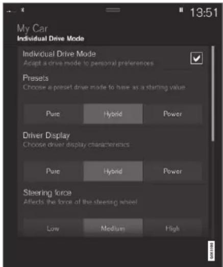
Settings view ^8 for individual drive mode.
1. Press Settings in the top view.
- Press My Car Individual Drive Mode and select Individual Drive Mode.
- In Presets, select a drive mode to start from: Pure, Hybrid, Power or Polestar Engineered*.
Possible adjustments apply to settings for:
- Driver Display
- Steering Force
• Powertrain Characteristics - Brake Characteristics
- Suspension Control
• ECO Climate
Using the electric motor or internal combustion engine
An advanced control system determines the extent to which the car is driven on internal combustion engine, electric motor or both in parallel.
The primary function is to use the engine or motor and the available energy in the hybrid battery as efficiently as possible, with regard to the characteristics of the different drive modes as well as the driver's request for power via the accelerator pedal.
There are also cases where temporary limitations in the system, or functions governed by
legal requirements aimed at maintaining a low level of total emissions for the car, may use the internal combustion engine to a greater extent.
Related information
• Changing drive mode (p. 471)
- Range (p. 477)
- Energy distribution using map data* (p. 472)
• Hybrid gauge (p. 86)
- General information on electric drive (p. 424)
• Regenerative braking* (p. 459)
Changing drive mode
Select the drive mode adapted for the current driving conditions.
Change the drive mode using the control in the centre console.
Remember that not all drive modes are available in all situations.
To change drive mode:

natural_image
Close-up of a car's side panel showing the 'Drive Mode' button and control buttons (no readable text beyond labels)- Press the drive mode control DRIVE MODE.
A pop-up menu is opened in the centre display.
-
Roll the wheel upward or downward until the desired drive mode is highlighted.
-
Press the drive mode control or tap directly on the touch screen to confirm the selection.
The selected drive mode is indicated in the driver display.
Related information
- Drive modes (p. 467)
STARTING AND DRIVING
Energy distribution using map data\*
In the driving position Hybrid the car is powered by both the electric motor and the internal combustion engine. If a destination has been selected in the navigation system*, the Predictive Efficiency ^9 function distributes the electric energy consumption along the whole driving distance using the map data.
In addition to the map data, the function also takes into account speed limits, traffic and elevation differences.
The electric motor is used primarily when driving at low speeds e.g. during city driving with more stops and starts. The combustion engine is used primarily when driving at high speeds and can, in good conditions, generate power for the electric motor.
Conditions for the function
For the function to work requires that a number of conditions are met:
- A destination is set in the navigation system and the driving distance to the destination is longer than the range possible only on electric drive.
• Hybrid drive mode is selected. - The Hold and Charge functions are deactivated.
Tips for use
If the car is used for commuting to work and it is not possible to charge the car at the place of work, specify the place of work as an intermediate destination and your home as the final destination. The discharging of the hybrid battery will then take place over your runs both to and from work.
Add similar commuting routes, i.e. the route between two charging points, as Favourites in the navigation system to facilitate arrival.
Related information
• Regenerative braking* (p. 459)
- Drive modes (p. 467)
- Range (p. 477)
Level control\* and shock absorption
Level control and shock absorption are regulated automatically in the car.
With rear level control, the car maintains the same height at the rear regardless of load. Level control can also occur even after the car has been parked.
Shock absorption (Four-C)
On a car equipped with Four-C the shock absorption is adapted according to the drive
mode selected and the speed of the car. Shock absorption is normally set for optimum comfort and is regulated continuously depending on the road surface, the car's acceleration, braking and cornering.
During transport
During transport of the car on a ferry, train or truck, the car must be lashed around the tyres and not around other parts of the chassis. Changes in the air suspension may occur dur-
ing transport, which could affect the lashing negatively.
Symbols and messages
If a fault arises with the level control, a message is shown in the driver display.
| Symbol Message Specification | ||
 | SuspensionDeactivated by user | The active suspension has been switched off manually by the user. |
 | SuspensionTemporarily reduced performance | The active suspension's performance has been temporarily reduced due to extensive system use. |
STARTING AND DRIVING
◀◀
| Symbol Message Specification | ||
 | SuspensionService required | A fault has occurred. Visit a workshop ^A as soon as possible. |
 | Suspension failureStop safely | A critical fault has occurred. Stop safely, have the car transported (raised with all wheels on the flat-bed) to a workshop ^A . |
 | SuspensionSlow down Car too high | A fault has occurred. If the message appears whilst driving, contact a workshop ^A . |
 | SuspensionAuto adjusting car level | Level control of the car's rear axle to target height in progress. |
A An authorised Volvo workshop is recommended.
STARTING AND DRIVING
Related information
- Settings for level control* (p. 476)
• Drive modes (p. 467)
STARTING AND DRIVING
Settings for level control\*
Switch off the level control when the car is to be jacked up in order to prevent problems with automatic regulation.
Settings in the centre display
Disable Leveling Control
In certain cases the function must be deactivated e.g. before the car is raised with a jack*. The difference in level created when lifting with a jack would otherwise mean the automatic control starting to adjust the height, creating an undesired effect.
Deactivating the function via the centre display:
- Press Settings in the top view.
- Press My Car Parking Brake and Suspension.
- Select Disable Leveling Control.
Related information
- Level control* and shock absorption (p. 473)
- Recommendations for loading (p. 595)
Economical driving
To achieve the longest possible range, the driver should plan driving and adapt driving style and speed to the prevailing situation.
Before driving
- Precondition the car before driving if possible using the charging cable connected to the mains power circuit.
- If preconditioning is not possible when it is cold outside, use seat heating and steering wheel heating first of all. Avoid warming up the whole of the interior which takes energy from the hybrid battery.
- Choice of tyres and tyre pressure can affect energy consumption - seek advice on suitable tyres from an authorised Volvo dealer.
- Remove unnecessary items from the car - the greater the load the higher the consumption.
While driving
• Activate drive mode Pure.
- Activate the Hold function at higher speeds during journeys that are longer than the range of the electricity.
- If possible, avoid using the Charge function to charge the hybrid battery.
- Drive at a steady speed and keep a good distance to other vehicles and objects in order to avoid braking.
- The hybrid battery is recharged during braking by braking gently with the brake pedal.
- High speed results in increased energy consumption since the wind resistance increases with speed.
- In a cold climate, reduce electrical heating of windows, mirrors, seats and steering wheel, if possible.
- Avoid driving with open windows.
- Do not hold the car stationary on a hill with the accelerator pedal. Instead, activate the function for braking when stationary.
- If possible, deactivate the climate control while driving a short distance after preconditioning.
After driving
- If possible, park in an acclimated garage with charging facilities.
Related information
• Regenerative braking* (p. 459)
- Range (p. 477)
- Checking tyre pressure (p. 568)
• Show trip statistics in the centre display (p. 91)
• Automatic braking when stationary (p. 457)
• Hold and Charge (p. 478)
Range
The car's range depends on several factors. The ability to achieve a long range varies according to the circumstances and conditions under which the car is being driven. The certified value for the car's mileage should not be interpreted as an expected range. The certified value should primarily be used to compare different cars and is obtained during special test cycles.
Range in the driver display
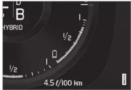
When the car is delivered from the factory, or after a factory reset, the range is based on the certified value
When the car has been driven for a while, the range is based on historical driving patterns. The amount of history used depends on the battery's state of charge. Therefore, the less
charge there is in the hybrid battery, the faster the range adapts to a changed driving pattern.
Factors that affect the range
In addition to historical trip data, there are several different factors that affect the range. The longest range is achieved under extremely favourable conditions when all factors have a positive impact.
Examples of factors that affect the range:
speed
• climate settings
- topography
- preconditioning
- tyres and tyre pressure
- traffic situation
• temperature and weather
- road conditions.
STARTING AND DRIVING
Range based on speed and outside temperature
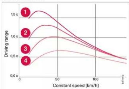
line
| Constant speed [km/h] | Driving range (Line 1) | Driving range (Line 2) | Driving range (Line 3) | Driving range (Line 4) | | --------------------- | ---------------------- | ---------------------- | ---------------------- | ---------------------- | | 0 | 1.5x | 1.0x | 0.75x | 0.5x | | 50 | 1.25x | 1.0x | 0.8x | 0.6x | | 100 | 0.75x | 0.7x | 0.6x | 0.5x | | 150 | 0.5x | 0.5x | 0.5x | 0.4x |1 20 °C (68 °F) outside temperature and passenger compartment climate Off.
20 °C (68 °F) outside temperature and passenger compartment climate On.
3 35 °C (95 °F) outside temperature and passenger compartment climate On.
4 -10 °C (14 °F) outside temperature and passenger compartment climate On.
The graph shows the approximate relationship between constant speed and range, where a lower constant speed has a positive effect on range.
A higher outside temperature and deactivated climate control are also more beneficial for the range.
Related information
• Show trip statistics in the centre display (p. 91)
• Checking tyre pressure (p. 568)
Hold and Charge
In some situations, it can be useful to be able to control the hybrid battery's state of charge while driving is in progress. This is possible with the functions Hold and Charge. Hold and Charge are available in all drive modes. The functions are cancelled if Pure drive mode is activated.
Activating Hold and Charge
The functions are activated in the centre display's function view.
Hold

Battery level sustained for later use.
The function maintains the charge in the hybrid battery for electric drive and saves available electricity for later
use e.g. for driving in an urban environment.
The car works as for normal hybrid operation with discharged battery where, in addition to re-using brake-generated energy, for example, the car starts the internal combustion engine more often in order to maintain the charge in the battery.
Charge

Engine charges hybrid battery.
The function charges the hybrid battery with assistance from the internal combustion engine for using
increased electric operation at a later time.
Symbols in the driver display
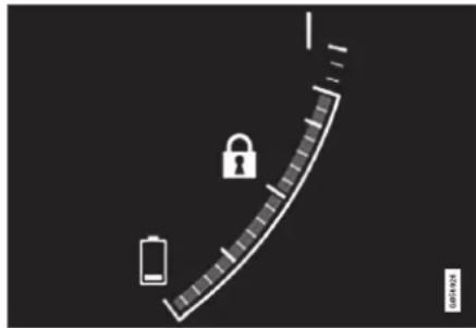
The symbol is shown in the hybrid battery gauge when Hold is activated.

natural_image
Diagram showing a battery and lightning bolt on a curved scale against a dark background (no text or symbols)The symbol is shown in the hybrid battery gauge when Charge is activated.
Related information
- Range (p. 477)
• Hybrid gauge (p. 86)
Preparations for a long trip
Before a driving holiday or some other type of long journey, it is important to check the car's functions and equipment particularly carefully.
Check that
- the engine is working normally and that fuel consumption is normal
• there are no leaks (fuel, oil or other fluid) - braking effect on braking works as intended
- the tyres have sufficient tread depth and pressure. Change to winter tyres when driving to areas where there is a risk of snowy or icy road surfaces
• starter battery charging is good
• the wiper blades are in good condition - a warning triangle and high-visibility vest are located in the car - legally required in certain countries
Related information
- Checking tyre pressure (p. 568)
- Fuel consumption and CO₂ emissions (p. 672)
• Filling washer fluid (p. 655)
• Winter driving (p. 480)
• Economical driving (p. 476) - Settings for car modem* (p. 547)
▶▶
STARTING AND DRIVING
- Recommendations for loading (p. 595)
• Driving with a trailer (p. 493) - Pilot Assist* (p. 321)
• Speed limiter (p. 301)
• Emergency puncture repair kit (p. 582)
Winter driving
For winter driving it is important to perform certain checks of the car in order to ensure that it can be driven safely.
Check the following in particular before the cold season:
- The engine coolant must contain 50% glycol. This mixture protects the engine against frost down to approx. -35°C (-31°F). To avoid health risks, different types of glycol must not be mixed.
- The fuel tank must be kept filled to prevent condensation.
- Engine oil viscosity is important. Oils with lower viscosity (thinner oils) facilitate starting in cold weather and also reduce fuel consumption while the engine is cold.
- The condition of the starter battery and charge level must be inspected. Cold weather places great demands on the starter battery and its capacity is reduced by the cold.
- Use washer fluid with antifreeze to avoid ice forming in the washer fluid reservoir.
See the separate section for engine oil recommendations.
Slippery driving conditions
To achieve optimum roadholding Volvo recommends using winter tyres on all wheels if there is a risk of snow or ice.

NOTE
The use of winter tyres is a legal requirement in certain countries. Studded tyres are not permitted in all countries.
Practise driving on slippery surfaces under controlled conditions to learn how the car reacts.
Related information
• Engine oil — specifications (p. 667)
• Winter tyres (p. 580)
- Snow chains (p. 581)
• Braking on gritted roads (p. 453)
• Braking on wet roads (p. 453)
• Filling washer fluid (p. 655)
• Starter battery (p. 617)
- Replacing windscreen wiper blades (p. 653)
• Topping up coolant (p. 614)
- Adverse driving conditions for engine oil (p. 668)
Driving in water
Wading means the car being driven through water e.g. on a flooded road. Driving in water must be performed with great caution.
Observe the following to prevent damage to the car when driving through water:
- The water level must not be higher than the floor of the car. If possible, check the depth at the deepest point before starting to drive through the water. Extra caution should be exercised when passing through flowing water.
- Do not drive faster than walking pace.
- Do not stop the car in the water. Drive forward carefully or reverse the car back out of the water.
- Remember that waves created by oncoming traffic may rise above the level for the floor of the car.
- Avoid driving through salt water (corrosion risk).
IMPORTANT
Parts of the car (e.g. engine, gearbox, driveline or electrical components) may be damaged when driving through water with a level higher than the floor of the car. Damaged caused to a component caused by submersion, hydrolock or lack of oil is not covered by the warranty.
In the event of stalling in water, do not try to restart. Instead, tow the car out of the water and transported on a low loader to a workshop. An authorised Volvo workshop is recommended.
When the water has been passed, depress the brake pedal lightly and check that full brake function is achieved. Water and mud for example can make the brake linings wet resulting in delayed brake function.
If necessary, clean the contact for the trailer coupling after driving in water and mud.
Related information
• Recovery (p. 499)
Opening and closing the fuel filler flap
The fuel filler flap is unlocked by pressing a button on the instrument panel.

In the driver display, the arrow next to the tank symbol indicates which side of the car the fuel filler flap is located.
STARTING AND DRIVING
◀◀
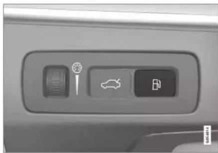
natural_image
Interior view of a car dashboard with control buttons and a car icon (no text or symbols visible)- Press the button on the instrument panel.
Pressure equalisation of the fuel tank involves a certain delay in opening the flap. The message Preparing for refuel Fuel lid will be unlocked when ready appears in the driver display, and when the system is ready the message Fuel tank Ready for refuelling appears in the driver display. If the internal combustion engine is switched on when the button is pressed, it is generally switched off and the car switches to electric mode.
NOTE
After the fuel filler flap has been opened, refuelling must take place within about 15 minutes. After this, the valve that was opened by pressing the button to open the fuel filler cap is closed, and it is no longer possible to refuel because the pump nozzle cuts out.
If the valve is closed before refuelling is complete - press the button again and wait until the driver display shows the message Fuel tank Ready for refuelling.
- After refuelling is finished - close the flap with a gentle press.
Related information
• Filling fuel (p. 482)
Filling fuel
The fuel tank is fitted with a coverless fuel filler system.
Refuelling the car at a petrol station

natural_image
Diagram showing a car interior with a lock and a mechanical component, no visible text or symbolsIt is important to feed the pump nozzle past the filler pipe's two openable hatches before starting to fuel the car.
Fuelling instruction:
- Switch off the car and open the fuel filler flap.

NOTE
After the fuel filler flap has been opened, refuelling must take place within about 15 minutes. After this, the valve that was opened by pressing the button to open the fuel filler cap is closed, and it is no longer possible to refuel because the pump nozzle cuts out.
If the valve is closed before refuelling is complete - press the button again and wait until the driver display shows the message Fuel tank Ready for refuelling.

Choose fuel that is approved for use in the car in accordance with the identifier ^10 on the inside of the fuel filler flap. See information on approved fuels and identifier in the section on "Petrol".
-
Insert the pump nozzle in the fuel filler opening. The filler pipe has two opening caps. The pump nozzle must be pushed past both caps before refuelling is started.
-
Do not overfill the tank but fill until the pump nozzle cuts out the first time.
The tank is full.

NOTE
Overfilled fuel in the tank can overflow in hot weather.
Topping up fuel from a fuel can
When filling with a fuel can, use the funnel located in the foam block under the floor hatch in the cargo area.
- Open the fuel filler flap.
- Insert the funnel in the fuel filler opening. The filler pipe has two opening caps. The funnel's pipe must be pushed past both caps before filling can be started.
Applicable to cars with fuel-driven auxiliary heater\*
Never use the fuel-driven heater when the car is in a filling station area.
STARTING AND DRIVING
◀◀

Decal on the inside of the fuel filler flap.
Related information
- Opening and closing the fuel filler flap (p. 481)
- Petrol (p. 485)
Handling of fuel
Do not use fuel with a lower quality than that recommended by Volvo, as this will negatively affect engine power and fuel consumption.

WARNING
Always avoid inhaling fuel vapour and getting fuel splashes in the eyes.
In the event of fuel in the eyes, remove any contact lenses and rinse the eyes in plenty of water for at least 15 minutes and seek medical attention.
Never swallow fuel. Fuels such as petrol, bioethanol and mixtures of them and diesel are highly toxic and could cause permanent injury or be fatal if swallowed. Seek medical attention immediately if fuel has been swallowed.

WARNING
Fuel which spills onto the ground can be ignited.
Switch off the fuel-driven heater before starting to refuel.
Never carry an activated mobile phone when refuelling. The ring signal could cause spark build-up and ignite petrol fumes, leading to fire and injury.

IMPORTANT
Mixtures of various fuel types or use of fuels which are not recommended will invalidate Volvo's guarantees and any supplementary service agreements; this is applicable to all engines.
Related information
- Petrol (p. 485)
Petrol
It is important to use the correct fuel during refuelling. Petrol is available with different octane ratings that are adapted for different types of driving.
Only use petrol from well-known producers. Never use fuel of dubious quality. The petrol must fulfil the EN 228 standard.
Identifier for petrol

Decal on the inside of the fuel filler flap.
The identifier in accordance with the CEN standard EN16942 is located on the inside of the fuel filler flap, and will be on corresponding fuel pumps and their nozzles at filling stations throughout Europe by 12 October 2018 at the latest.
These are the identifiers that apply for current standard fuels in Europe. Petrol with the following identifiers may be used in cars with petrol engine:

E5 is a petrol with maximum 2.7% oxygen and maximum 5 volume % ethanol.

E10 is a petrol with maximum 3.7% oxygen and maximum 10 volume % ethanol.
IMPORTANT
- Fuel that contains up to 10 percent by volume ethanol is permitted.
• EN 228 E10 petrol (max 10 percent by volume ethanol) is approved for use. - Ethanol higher than E10 (max. 10 percent by volume ethanol) is not permitted, e.g. E85 is not permitted.
Octane rating
• RON 95 can be used for normal driving.
- RON 98 is recommended for good power and low fuel consumption.
- An octane rating lower than RON 95 must not be used.
When driving in temperatures above +38 °C (100 °F), fuel with the highest octane rating is recommended for adapted performance and fuel economy.
IMPORTANT
- Use only unleaded petrol to avoid damaging the catalytic converter.
- Fuel containing metallic additives must not be used.
- Do not use any additives which have not been recommended by Volvo.
Related information
• Handling of fuel (p. 484)
- Filling fuel (p. 482)
• Petrol particle filter (p. 486)
- Fuel consumption and CO _2 emissions (p. 672)
STARTING AND DRIVING
Petrol particle filter ^11
Petrol cars are fitted with particle filters for more efficient emission control.
Particles in the exhaust gases are collected in the petrol particle filter during normal driving. In normal driving conditions, passive regeneration takes place, which leads to the particles being oxidised and burned away. The filter is emptied in this way.
If the car is driven at low speed or with repeated cold starts in low outside temperature, active regeneration may be necessary. Regeneration of the particulate filter is automatic and normally takes 10-20 minutes. Fuel consumption may temporarily increase during regeneration.
When driving short distances at low speeds in a petrol car
The capacity of the emissions system is affected by how the car is driven. Driving varying distances and at different speeds is important in order to achieve performance that is as energy-efficient as possible.
Driving short distances at low speeds (or in cold climates) frequently, where the engine does not reach normal operating temperature, can lead to problems that can eventually cause a malfunction and trigger a warning message. If the vehicle is mostly driven in city
traffic, it is important to regularly drive at higher speeds to allow the emissions system to regenerate.
- The car should be driven on A-roads at speeds in excess of 70 km/h (44 mph) for at least 20 minutes between each refuelling.
Related information
- Petrol (p. 485)
Overheating in the engine and drive system
Under certain conditions, e.g. hard driving in hilly terrain and hot climate, there is a risk that the engine and drive system may overheat – in particular with a heavy load.
- In the event of overheating, the engine's power may be limited temporarily.
- Remove any auxiliary lamps from in front of the grille when driving in hot climates.
- If the temperature in the engine's cooling system becomes too high then a warning symbol is illuminated and the driver display shows the message Engine temperature High temperature Stop safely. Stop the car in a safe way and allow the engine to run at idling speed for several minutes and cool down.
- If the message Engine temperature High temperature Turn off engine or Engine coolant Level low, turn off engine is shown, stop the car and switch off the engine.
- In the event of overheating in the gearbox, an alternative gear shift program will be selected. In addition, a built-in protection function is activated that, amongst other things, illuminates a warning symbol and the driver display shows the message Transmission warm Reduce speed to
lower temperature or Transmission hot Stop safely, wait for cooling. Follow the recommendation given, reduce speed or stop the car in a safe way and allow the engine to run at idling speed for several minutes to enable the gearbox to cool down.
- If the car overheats, the air conditioning may be switched off temporarily.
- Do not turn the engine off immediately you stop after a hard drive.

NOTE
It is normal for the engine's cooling fan to operate for a time after the engine has been switched off.
Symbols in the driver display
| Symbol | Specification |
| High engine temperature. Follow the recommendation given. | |
| Low level, coolant. Follow the recommendation given. | |
| Gearbox hot/overheated/cooled. Follow the recommendation given. |
Related information
• Topping up coolant (p. 614)
• Driving with a trailer (p. 493)
• Preparations for a long trip (p. 479)
• Gear shift indicator (p. 465)
Overloading the starter battery
The electrical functions in the car load the starter battery to varying degrees. Avoid using the ignition position II when the car is switched off. Instead, use ignition position I - which uses less power.
Also, be aware of different accessories that load the electrical system. Do not use functions which use a lot of power when the car is switched off. Examples of such functions are:
- ventilation fan
headlamps - windscreen wiper
• audio system (high volume).
If the starter battery voltage is low, a message is shown in the driver display. The energy-saving function then shuts down certain functions or reduces certain functions such as the ventilation fan and/or audio system.
- In which case, charge the starter battery by starting the car and then running it for at least 15 minutes - starter battery charging is more effective during driving than running the engine at idling speed while stationary.
Related information
• Starter battery (p. 617)
- Ignition positions (p. 448)
STARTING AND DRIVING
Using jump starting with another battery
If the starter battery is discharged then the car can be started with current from another battery.
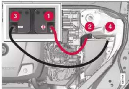
Charging point for jump-starting own car.
IMPORTANT
The car's charging point is only intended for jump-starting the car itself. The charging point is not intended for jump-starting another car. Using the charging point to jump start another car may cause a fuse to blow, which means the charging point will stop working.
When a fuse has blown the message 12 V Battery Fuse failure Service required is shown in the driver display. Volvo recom-
mends that an authorised Volvo workshop is contacted.
When jump-starting the car, the following steps are recommended to avoid short circuits or other damage:
- Set the car's electrical system in ignition position 0.
- Check that the donor battery has a voltage of 12 V.
- If the donor battery is installed in another car - switch off the donor car's engine and make sure that the two cars do not touch each other.
- Connect one of the red jump lead's clamps to the donor battery's positive terminal (1).
IMPORTANT
Connect the start cable carefully to avoid short circuits with other components in the engine compartment.
- Open the positive jump-starting point's cover (2).
-
Connect the red jump lead's other clamp onto the car's positive jump-starting point (2).
-
Connect one of the black jump lead's clamps to the donor battery's negative terminal (3).
- Connect the black jump lead's other clamp onto the car's negative jump-starting point (4).
- Check that the jump lead clamps are affixed securely so that there are no sparks during the starting attempt.
-
Start the engine of the "donor car" and allow it to run a few minutes at a speed slightly higher than idle approx. 1500 rpm.
-
Start your own car's engine. If the start attempt fails then extend the charging time to 10 minutes, and then make a new start attempt.
i NOTE
When starting the engine in normal conditions the car's electric drive motor is prioritised - the petrol engine remains switched off. This means that after the start knob has been turned clockwise, the electric motor has "started" and the car is ready to move. A started motor is indicated by the driver display's indicator lamps extinguishing and its preset theme illuminating.
IMPORTANT
Do not touch the connections between cable and car during the starting attempt. There is a risk of sparks forming.
- Remove the jump leads in reverse order - first the black and then the red.
Make sure that none of the black jump lead's clamps comes into contact with the car's positive jump-starting point/donor battery's positive terminal or the clamp connected to the red jump lead.
WARNING
- The battery can generate oxyhydrogen gas, which is highly explosive. A spark can be formed if a jump lead is connected incorrectly, and this can be enough for the battery to explode.
- Do not connect the jump leads to any fuel system component or any moving part. Be careful of hot engine parts.
- The battery contains sulphuric acid, which can cause serious burns.
- If sulphuric acid comes into contact with eyes, skin or clothing, flush with large quantities of water. If acid splashes into the eyes - seek medical attention immediately.
• Never smoke near the battery.
NOTE
The car cannot be started if the hybrid battery is discharged.
Related information
• Starting the car (p. 446)
- Ignition positions (p. 448)
• Adjusting the steering wheel (p. 196)
• Selecting ignition mode (p. 449)
Towbar\*
The car can be equipped with a towbar that makes it possible to tow e.g. a trailer behind the car.
There may be different towbar variants available for the car. Contact a Volvo dealer for more information.
IMPORTANT
When the engine is switched off, the constant battery voltage to the trailer connector can be switched off automatically so as not to drain the starter battery.
IMPORTANT
The towball needs regular cleaning and lubrication with grease in order to prevent wear.
NOTE
When a hitch with a vibration damper is used, the towball must not be lubricated.
This also applies when fitting a bicycle rack that is clamped in around the towball.
NOTE
If the car is equipped with a towbar, there is no rear mounting for a towing eye.
STARTING AND DRIVING
Related information
- Extendable and retractable towbar* (p. 491)
• Driving with a trailer (p. 493)
• Towbar-mounted bicycle rack* (p. 497)
• Specifications for towbar* (p. 490)
Specifications for towbar\*
Dimensions and mounting points for towbar.
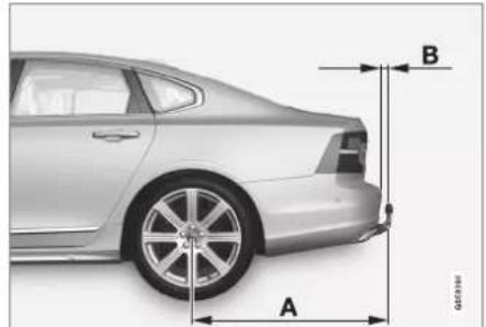

| Dimensions, mounting points in mm (inches) |
| A 1229 (48.4) |
| B 111.8 (4.4) |
| C 875 (34.4) |
| D 437.5 (17.2) |
| E See the image above |
| F 310.5 (12.2) |
| G Ball centre |
Related information
- Towbar* (p. 489)
- Towing capacity and towball load (p. 664)
Extendable and retractable towbar\*
The retractable tow hook is easy to retract or extend as required. In the retracted position, the towbar is completely concealed.

WARNING
Follow the instructions for retracting and extending the towbar carefully.

WARNING
Do not press the extend/retract button if a trailer or accessory is attached to the tow bar.
Extending the towbar

WARNING
Avoid standing close to the bumper in the centre behind the car when extending the towing hitch.
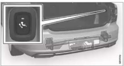
natural_image
Front view of a car with a digital display showing a person silhouette inside (no text or symbols visible)Open the boot lid. A button for extending/retracting the towbar is located on the right-hand side at the rear of the cargo area. An indicator lamp in the button must illuminate with a constant orange glow for the extension function to be active.
- Press and release the button – extension might not start if the button is pressed for too long.

natural_image
Exterior view of a car backrest with a red arrow indicating upward motion, alongside a traffic sign showing light and running figures (no text or symbols on the car itself)The towbar extends out and down in an unlocked position - the indicator lamp flashes orange. The tow hook is ready to continue moving to the locked position.
▶▶
STARTING AND DRIVING
3.

natural_image
Side view of a car's rear bumper with a close-up of a person walking (no text or symbols visible)Move the towbar to its end position, where it is secured and locked in place - the indicator lamp illuminates with a constant orange glow.
The towbar is ready for use.
IMPORTANT
When the tow bar is activated by pressing a key and has been placed in the unlocked position:
Wait at least 2 seconds before the tow bar is moved to the locked position. If the tow bar does not remain in the locked position, wait another few seconds and try again.
Do not kick the tow bar.
WARNING
Take care to secure the trailer's safety cable in the intended bracket.
i NOTE
Power save mode activates after a while and the indicator lamp goes out. The system is reactivated by closing and reopening the boot lid. This applies when retracting or extending the towbar.
If the car detects a connected trailer electrically, the indicator lamp stops illuminating with a constant glow.
Retracting the towbar
IMPORTANT
Make sure that there is no plug or adapter in the electrical socket when retracting the towbar.
- Open the boot lid. Press and release the button on the right-hand side at the rear of the cargo area - retraction might not start if the button is pressed for too long.
The towbar automatically lowers in an unlocked position - the indicator lamp in the button flashes orange.
2.

Lock the towbar by moving it back to its retracted position, where it is locked.
The indicator lamp will now illuminate with a constant glow if the towbar is correctly retracted.

natural_image
Diagram showing a car with a vehicle undercarriage and a close-up of a person in motion (no text or symbols)IMPORTANT
When the tow bar is activated by pressing a key and has been placed in the unlocked position:
Wait at least 2 seconds before the tow bar is moved to the locked position. If the tow bar does not remain in the locked position, wait another few seconds and try again.
Do not kick the tow bar.
Related information
• Driving with a trailer (p. 493)
- Towbar* (p. 489)
Driving with a trailer
When driving with a trailer, there are a number of points that are important to think about regarding the towbar, the trailer and how the load is positioned in the trailer.
Payload depends on the car's kerb weight. The total of the weight of the passengers and all accessories, e.g. towbar, reduces the car's payload by a corresponding weight.
The car is supplied with the necessary equipment for towing a trailer.
- The car's towbar must be of an approved type.
- Distribute the load on the trailer so that the weight on the towbar complies with the specified maximum towball load. Towball load is calculated as part of the car's payload.
- Increase the tyre pressure to the recommended pressure for a full load.
- The engine is loaded more heavily than usual when driving with a trailer.
- Do not tow a heavy trailer when the car is brand new. Wait until it has been driven at least 1000 km (620 miles).
-
The brakes are loaded much more than usual on long and steep downhill slopes. Downshift to a lower gear when shifting manually and adjust your speed.
-
Follow the regulations in force for the permitted speeds and weights.
- Maintain a low speed when driving with a trailer up long, steep ascents.
- The maximum indicated trailer weight only applies to heights up to 1000 metres above sea level (3280 ft). At higher elevations, the engine output and the vehicle's climbing ability are reduced due to the reduced air density, and the maximum trailer load must therefore be reduced. The weight of the car and trailer must be decreased by 10% for each additional 1000 m (3280 ft) or part thereof.
- Avoid driving with a trailer on inclines of more than 12%.
i NOTE
Extreme weather conditions, driving with a trailer or driving at high altitudes, in combination with poorer fuel quality than recommended, are factors that considerably increase the car's fuel consumption.
Trailer connector
An adapter is required if the car's towbar has a 13 pin connector and the trailer has a 7 pin connector. Use an adapter approved by Volvo. Make sure the cable does not drag on the ground.
▶▶
STARTING AND DRIVING
◀◀
IMPORTANT
When the engine is switched off, the constant battery voltage to the trailer connector can be switched off automatically so as not to drain the starter battery.
Trailer weights
WARNING
Follow the stated recommendations for trailer weights. Otherwise, the car and trailer may be difficult to control in the event of sudden movement and braking.
NOTE
The stated maximum permitted trailer weights are those permitted by Volvo. National vehicle regulations can further limit trailer weights and speeds. Towbars can be certified for higher towing weights than the car can actually tow.
Level control\*
The car's system for level control endeavours to maintain a constant height regardless of load (up to the maximum permissible weight). When the car is stationary the rear of the car lowers slightly, which is normal.
When driving in hilly terrain and hot climates
Under certain circumstances, there may be a risk of overheating when towing a trailer. If the engine and drive system overheats, a warning symbol comes on in the driver display and a message is displayed.
The automatic gearbox adapts the gears depending on load and engine speed.
Steep inclines
Do not lock the automatic gearbox in a higher gear than the engine "can cope with" - it is not always a good idea to drive at a high gear with low engine speed.
Parking on a hill
- Depress the brake pedal fully.
- Activate the parking brake.
- Select gear position P.
- Release the brake pedal.
Block the wheels with chocks when parking a car with hitched trailer on a hill.
Starting on a hill
- Depress the brake pedal fully.
- Select gear position D.
- Releasing the parking brake.
- Release the brake pedal and start driving off.
Related information
• Trailer stability assist* (p. 495)
- Checking trailer lamps (p. 496)
- Towing capacity and towball load (p. 664)
• Overheating in the engine and drive system (p. 486)
- Adverse driving conditions for engine oil (p. 668)
- Extendable and retractable towbar* (p. 491)
Trailer stability assist\*
The function of trailer stability assist (TSA ^12 ), which is included in the stability system ESC ^13 , is to stabilise cars towing trailers in situations where they begin snaking. The function is available with towbar installation, contact a Volvo dealer for more information.
Reasons for snaking
The snaking phenomenon can occur with any car/trailer combination. Snaking normally occurs at high speeds. However, there is a risk of it occurring at lower speeds if the trailer is overloaded or the load is improperly distributed, e.g. too far back.
In order for snaking to occur, there must be a triggering factor, e.g.:
- Car with trailer subjected to a sudden and powerful side wind.
- Car with trailer drives on an uneven road surface or in a pothole.
- Sweeping steering wheel movements.
If snaking has started, it could be difficult or even impossible to suppress. This makes the car/trailer combination difficult to control and there is a risk that you could, for example, end up in the wrong lane or leave the carriageway.
Trailer stability assist function
The trailer stability assist function continually monitors the car's movements, particularly lateral movements. If snaking is detected, the front wheels are individually braked. This serves to stabilise the car/trailer combination. This is often enough to help the driver regain control of the car.
If snaking is not eliminated the first time that trailer stability assist intervenes, the car/trailer combination is braked with all wheels and engine power is reduced. Once snaking has been gradually suppressed and the car/trailer combination is stable once again, the system stops regulating and the driver once again has full control of the car.
NOTE
The stability function is deactivated if the driver chooses to activate ESC Sport Mode via the menu system in the centre display.
Trailer stability assist may fail to intervene if the driver uses severe steering wheel movements to try to rectify the snaking because in such a situation the system cannot determine whether it is the trailer or the driver causing the snaking.

When Trailer Stability Assist (TSA) is operating, the ESC symbol flashes in the driver display.
NOTE
Retrofitting a towbar requires an update of the car's software, contact a Volvo dealer.
Related information
• Driving with a trailer (p. 493)
• Electronic stability control (p. 287)
STARTING AND DRIVING
Checking trailer lamps
When connecting a trailer - check that all the trailer lamps work before departure.
Direction indicators and brake lights on the trailer
If one or more of the trailer's direction indicators or brake light bulbs is broken, the driver display shows a symbol and a message. Other lights on the trailer must be checked manually by the driver before setting off.
| Symbol | Message |
| Trailer turn indicator Right turn indicator malfunctionTrailer turn indicator Left turn indicator malfunction | |
| Trailer brake light Malfunction |
If any lamp for the trailer's direction indicators is broken, the driver display symbol for direction indicators will also flash more quickly than normal.
Rear fog lamp on trailer
When connecting the trailer, the rear fog lamp may not light up on the car. In such cases, the rear fog lamp function switches to the trailer. Upon activation of the rear fog lamp, check
therefore that the trailer is equipped with a rear fog lamp to travel safely.
Checking trailer lamps\*
Automatic checking
After a trailer is connected electrically, it is possible to check that the trailer lamps are working via an automatic lamp activation. The function helps the driver check that the trailer lamps are working before starting off.
The car must be switched off to perform the check.
-
When a trailer is connected to the towbar, the Automatic Trailer Lamp Check message is shown in the driver display.
-
Confirm the message by pressing the right-hand steering wheel keypad's O button.
The lamp check starts.
-
Exit the car to check lamp functionality.
All trailer lamps start to flash - then the lamps are switched on one at a time.
-
Visually check that all lamps available on the trailer are operational.
-
After a moment, all lamps on the trailer flash again.
The check is complete.
Switching off automatic checking
The automatic checking function can be switched off in the centre display.
- Press Settings in the top view.
- Press My Car Lights and Lighting.
- Deselect Automatic Trailer Lamp Check.
Manual checking
If the automatic checking is switched off then it is possible to start the check manually.
- Press Settings in the top view.
- Press My Car Lights and Lighting.
- Select Manual Trailer Lamp Check.
The lamp check starts. Exit the car to check lamp functionality.
Related information
• Driving with a trailer (p. 493)
Towbar-mounted bicycle rack\*
When using a bicycle rack, the bicycle racks that Volvo has developed are recommended. This is in order to avoid damage to the car and in order to achieve the maximum possible safety during a journey. Volvo's bicycle racks are available for purchase at authorised Volvo dealers.
Carefully follow the instructions enclosed with the bicycle rack.
- Bicycle rack including load must weigh a maximum of 75 kg (165 pounds).
- The bicycle rack may be designed for a maximum of three bicycles.
WARNING
Incorrect use of the bicycle rack may cause damage to the towbar and car.
The bicycle rack can loosen from the towbar if it
• is incorrectly fitted on the towball
• is overloaded, see the bicycle rack's instructions for maximum load weight
- is used for carrying something other than bicycles.
The car's driving characteristics are affected when a bicycle rack is fitted on the towbar.
For example due to:
- increased weight
• reduced acceleration capacity
• reduced ground clearance
• changed braking capacity.
Recommendations for loading bicycles on the bicycle rack
The larger the distance between the load's centre of gravity and the towball, the greater the load on the towbar.
Load according to the following recommendations:
• Fit the heaviest bicycle furthest in, closest to the car.
- Keep the load symmetrical and as close to the centre of the car as possible e.g. by loading the bicycles facing alternately if several bicycles are loaded.
- Remove loose objects from the bicycle for transportation, e.g. bicycle basket, battery, child seat. Partly to reduce the load on the towbar and bicycle rack, and partly to reduce the wind resistance, which affects fuel consumption.
- Do not use protective covers on the bicycles. This may affect manoeuvrability, impair visibility and increase fuel con-
sumption. It may also lead to an increased load on the towbar.
Related information
- Towbar* (p. 489)
STARTING AND DRIVING
Towing
During towing, the car is towed by another vehicle by means of a towline.
Towing the car is not permitted as this will damage the electric motor. Instead, the car must be transported raised with all the wheels on a recovery vehicle's platform, neither of the wheel pairs may have road contact.
When towing another car
Towing a car requires a lot of energy - use the Constant AWD drive mode. This then charges the hybrid battery, in combination with improving the car's driving characteristics and roadholding.
Find out the statutory maximum speed limit for towing before the towing begins.
Jump starting
Tow-starting the motor is not permitted as this will damage the electric motor. Use a donor battery if the starter battery is discharged and the engine does not start.

IMPORTANT
The electric drive motor and the catalytic converter may be damaged during attempts to tow-start the car.
Related information
• Fitting and removing the towing eye (p. 498)
• Hazard warning flashers (p. 159)
• Recovery (p. 499)
• Using jump starting with another battery (p. 488)
• Selecting ignition mode (p. 449)
Gearbox (p. 460)
Fitting and removing the towing eye
Use the towing eye if the car shall tow another vehicle. The towing eye is screwed into a threaded socket behind a cover on the right-hand side of the rear bumper.

NOTE
If the car is equipped with a towbar, there is no rear mounting for a towing eye.
Fitting the towing eye

natural_image
Close-up of a mechanical component with an inset showing a magnified view of a cylindrical tool (no text or symbols visible)
Take out the towing eye from the foam block under the floor in the cargo area ^14 .
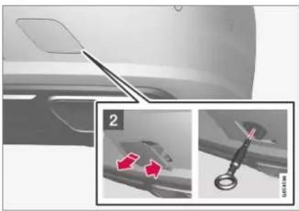
natural_image
Close-up of a car interior showing a curved panel and a close-up of a mechanical component with red arrows indicating motion (no text or symbols)2 Remove the cover – press on the marking with a finger while you fold out the opposite side/corner.
The cover pivots around its centre line and can then be removed.
- Screw in the towing eye until it reaches its end stop.

Screw the eye in firmly. For example, thread through the wheel bolt wrench* and use it as a lever.
IMPORTANT
It is important that the towing eye is firmly screwed into place - right in until it stops.
Removing the towing eye
- Unscrew and remove the towing eye after use and return it to its foam block.
Finish by refitting the cover onto the bumper.
Related information
- Towing (p. 498)
- Recovery (p. 499)
- Tool kit (p. 577)
Recovery
For recovery, the car is taken away with the help of another vehicle.
Call a recovery service for recovery assistance.
The towing eye can be used to pull the car up onto a recovery vehicle with a flatbed platform.
IMPORTANT
Note that the car must always be transported raised up with all the wheels on the recovery vehicle's platform.
Applies to cars with level control*: If the car is equipped with air suspension, this must be disabled before the car is raised. Deactivating the function via the centre display.
- Press Settings in the top view.
- Press My Car Parking Brake and Suspension.
- Select Disable Leveling Control.
The car's position and ground clearance determine whether it is possible to pull it up onto a flatbed platform. If the slope of the recovery vehicle's ramp is too steep, or if the ground clearance under the car is inadequate, then the car may be damaged if you try to pull it up. The car should then be lifted using the recovery vehicle's lifting device.
▶▶
STARTING AND DRIVING
◀◀

WARNING
No one/nothing is allowed to remain behind the recovery vehicle while the car pulled up onto the flatbed platform.
Related information
• Fitting and removing the towing eye (p. 498)
HomeLink®\*15
HomeLink ^®16 is a programmable remote control, integrated in the car's electrical system, which can remotely control up to three different devices (e.g. garage door opener, alarm system, outdoor and indoor lighting) and thereby replace the remote controls for them.
General

The figure is schematic - the version may vary.
1 Button 1
② Button 2
3 Button 3
4 Indicator lamp
HomeLink® is supplied built-in to the interior rearview mirror. The HomeLink® panel consists of three programmable buttons and one indicator lamp in the mirror glass.
For more information about HomeLink®, visit homelink.com or call 00 8000 466 354 65 (or the toll number +49 6838 907 277) ^17 .
Save the original remote controls for future programming (e.g. when changing to another car or for use in another vehicle).

IMPORTANT
The programming for the buttons should be deleted when the car is sold.
Related information
• Using HomeLink ^®* (p. 503)
• Programming HomeLink®* (p. 501)
• Type approval for HomeLink ^® (p. 503)
Programming HomeLink®\*18
Follow these instructions to program HomeLink ^® , reset all programming or reprogram individual buttons.

NOTE
In certain vehicles the ignition must be switched on or in "accessory position" before HomeLink® can be programmed or used. If possible, fit new batteries in the remote control that shall be replaced by HomeLink® for faster programming and improved transmission of the radio signal. The HomeLink® buttons should be reset before programming.

WARNING
While programming HomeLink ^® , the garage door or gate being programmed may activate. For this reason, make sure that nobody is in the vicinity of the door or gate while programming is in progress. The car should be outside the garage while a garage door opener is being programmed.
- Aim the remote control towards the HomeLink® button to be programmed and hold it approx. 2-8 cm (approx. 1-3 inches) from the button. Do not obstruct the indicator lamp on HomeLink®,
Note: The ability of some remote controls to program HomeLink® is improved at a distance of approx. 15-20 cm (approx. 6-12 inches). Bear this in mind if problems occur with the programming.
-
Press and hold depressed both the button on the remote control and the button to be reprogrammed on HomeLink ^® .
-
Do not release the buttons until the indicator lamp has switched from flashing slowly (approx. once per second) to either flashing quickly (approx. 10 times per second) or illuminating with a constant glow.
If the indicator lamp illuminates with a constant glow: Indication that the programming has finished. Press the programmed button twice to activate.
If the indicator lamp flashes quickly: The device to be programmed to HomeLink® may have a security function that requires extra steps. Test by pressing the programmed button twice to see whether the programming is working. Otherwise, continue with the following steps.
STARTING AND DRIVING
◀◀

-
Locate programming button ^19 on the receiver for the garage door or similar. It is normally located close to the antenna's bracket on the receiver.
-
Depress and release the receiver's programming button once. The programming must be completed within 30 seconds of the button being depressed.
-
Press and release the button on HomeLink® that you want to program. Repeat the sequence of pressing/holding/releasing a second time and, depending on the receiver model, even a third time.
Programming is now be complete and the garage door, gate or similar should now be activated when the programmed button is depressed.
In the event of programming problems, contact HomeLink® at homelink.com, or call
00 8000 466 354 65 (or the toll number +49 6838 907 277) ^20 .
Reprogramming individual buttons
To reprogram an individual HomeLink® button, proceed as follows:
- Press the desired button and hold it depressed for approx. 20 seconds.
- Once the indicator lamp on HomeLink® starts to flash slowly, programming can continue as normal.
Note: If the button to be reprogrammed is not programmed with a new unit, it will resume the previously saved programming.
Resetting the HomeLink® buttons
It is only possible to reset all of the HomeLink® buttons at the same time, not each button individually. Individual buttons can only be reprogrammed.
- Press and hold depressed the outer buttons (1 and 3) on HomeLink® for approx. 10 seconds.
When the indicator lamp changes over from a constant glow to starting to flash, the buttons are reset and ready to be reprogrammed.
Related information
• Using HomeLink®* (p. 503)
- HomeLink®* (p. 500)
• Type approval for HomeLink ^® (p. 503)
Using HomeLink®\*21
When HomeLink® is fully programmed it can be used in place of the separate original remote controls.
Depress the programmed button. The garage door, gate, alarm system or similar is activated (may take a few seconds). If the button is depressed for more than 20 seconds then the reprogramming is started. The indicator lamp illuminates or flashes when the button has been depressed. Naturally the original remote controls can still be used in parallel with HomeLink® if required.

NOTE
When the ignition has been switched off, HomeLink® works for at least 7 minutes.

NOTE
HomeLink® cannot be used if the car is locked and the alarm is armed* from the outside.

WARNING
- If HomeLink® is used to control a garage door or gate, ensure that nobody is near the door or gate while it is in motion.
- Do not use HomeLink® for any garage door that does not have safety stop and safety reverse.
Related information
- HomeLink®* (p. 500)
• Programming HomeLink®* (p. 501)
• Type approval for HomeLink®* (p. 503)
Type approval for HomeLink®\*22
Type approval for EU
Gentex Corporation hereby declares that HomeLink® Model UAHL5 complies with the Radio equipment directive 2014/53/EU.
Wavelength within which the radio equipment functions:
• 433.05MHz-434.79MHz <10mW E.R.P.
• 868.00MHz-868.60MHz <25mW E.R.P.
• 868.70MHz-868.20MHz <25mW E.R.P.
• 869.40MHz-869.65MHz <25mW E.R.P.
• 869.70MHz-870.00MHz <25mW E.R.P.
Certificate holder address: Gentex Corporation, 600 North Centennial Street, Zeeland MI 49464, USA
For more information, search support information on type approval at volvocars.com
Related information
- HomeLink®* (p. 500)
STARTING AND DRIVING
Compass\*
The upper right-hand corner of the rearview mirror has an integrated display that shows the compass direction ^23 in which the front of the car is pointing.
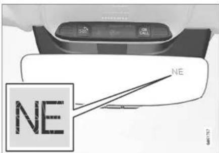
Rearview mirror with compass.
Eight different compass directions are shown by their English abbreviations: N (north), NE (north east), E (east), SE (south east), S (south), SW (south west), W (west) and NW (north west).
Related information
- Activating and deactivating the compass* (p. 504)
• Calibrating the compass* (p. 504)
Activating and deactivating the compass\*
The upper right-hand corner of the rearview mirror has an integrated display that shows the compass direction ^24 in which the front of the car is pointing.
The compass is activated automatically when the car is started.
To deactivate/activate the compass manually:
- Depress the button on the underside of the rearview mirror using e.g. a paper clip.
If the compass is deactivated when the car is switched off, it will not be activated the next time the car is started. In this case, the compass needs to be activated manually.
Related information
- Compass* (p. 504)
• Calibrating the compass* (p. 504)
Calibrating the compass\*
The earth is divided into 15 magnetic zones. The compass ^25 should be calibrated if the car is moved between several magnetic zones.
- Stop the car in a large open area free from steel structures and high-voltage power lines.
- Start the car and switch off all electrical equipment (air conditioning, wipers, etc.) and ensure that all doors are closed.
NOTE
Calibration may fail or not start at all if electrical equipment is not switched off.
- Hold the button on the underside of the rearview mirror depressed for approx. 3 seconds (use a paper clip, for example). The number for the current magnetic zone is shown.
STARTING AND DRIVING
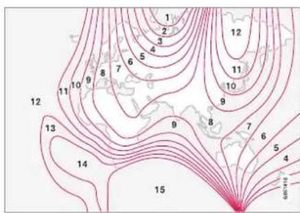
Magnetic zones.
- Press the button repeatedly until the required magnetic zone (1–15) is shown. See the map of magnetic zones for the compass.
- Wait until the display returns to showing the character C, or hold the button on the underside of the rearview mirror depressed for approx. 6 seconds until the character C is shown.
-
Drive slowly in a circle at a speed of no more than 10 km/h (6 mph) until a compass direction is shown in the display, indicating that calibration is complete. Then drive a further 2 circles to fine-tune calibration.
-
Cars with heated windscreen*: If the character C is shown in the display when the heated windscreen is activated, perform the calibration in accordance with point 6 above with the heated windscreen activated.
-
Repeat the above procedure as necessary.
Related information
- Compass* (p. 504)
- Activating and deactivating the compass* (p. 504)

bar
| Category | Value | |---|---| | Category 1 | 100 | | Category 2 | 100 | | Category 3 | 100 | | Category 4 | 100 | | Category 5 | 100 | | Category 6 | 100 | | Category 7 | 100 | | Category 8 | 100 | | Category 9 | 100 | | Category 10 | 100 | | Category 11 | 100 | | Category 12 | 100 | | Category 13 | 100 | | Category 14 | 100 | | Category 15 | 100 | | Category 16 | 100 | | Category 17 | 100 | | Category 18 | 100 | | Category 19 | 100 | | Category 20 | 100 | | Category 21 | 100 | | Category 22 | 100 | | Category 23 | 100 | | Category 24 | 100 | | Category 25 | 100 | | Category 26 | 100 | | Category 27 | 100 | | Category 28 | 100 | | Category 29 | 100 | | Category 30 | 100 | | Category 31 | 100 | | Category 32 | 100 | | Category 33 | 100 | | Category 34 | 100 | | Category 35 | 100 | | Category 36 | 100 | | Category 37 | 100 | | Category 38 | 100 | | Category 39 | 100 | | Category 40 | 100 | | Category 41 | 100 | | Category 42 | 100 | | Category 43 | 100 | | Category 44 | 100 | | Category 45 | 100 | | Category 46 | 100 | | Category 47 | 100 | | Category 48 | 100 | | Category 49 | 100 | | Category 50 | 100 | | Category 51 | 100 | | Category 52 | 100 | | Category 53 | 100 | | Category 54 | 100 | | Category 55 | 100 | | Category 56 | 100 | | Category 57 | 100 | | Category 58 | 100 | | Category 59 | 100 | | Category 60 | 100 | | Category 61 | 100 | | Category 62 | 100 | | Category 63 | 100 | | Category 64 | 100 | | Category 65 | 100 | | Category 66 | 100 | | Category 67 | 100 | | Category 68 | 100 | | Category 69 | 100 | | Category 70 | 100 | | Category 71 | 100 | | Category 72 | 100 | | Category 73 | 100 | | Category 74 | 100 | | Category 75 | 100 | | Category 76 | 100 | | Category 77 | 100 | | Category 78 | 100 | | Category 79 | 100 | | Category 80 | 100 | | Category 81 | 100 | | Category 82 | 100 | | Category 83 | 100 | | Category 84 | 100 | | Category 85 | 100 | | Category 86 | 100 | | Category 87 | 100 | | Category 88 | 100 | | Category 89 | 100 | | Category 90 | 100 | | Category 91 | 100 | | Category 92 | 100 | | Category 93 | 100 | | Category 94 | 100 | | Category 95 | 100 | | Category 96 | 100 | | Category 97 | 100 | | Category 98 | 100 | | Category 99 | 100 | | Total (Total) |SOUND, MEDIA AND INTERNET
SOUND, MEDIA AND INTERNET
Sound, media and Internet
The audio and media system consists of media player and radio. You can also connect a phone via Bluetooth to use handsfree functions or play music wirelessly in the car. When the car is connected to the Internet you can also use apps for media playback.

natural_image
Interior view of a car dashboard and steering wheel, showing the steering wheel and dashboard (no visible text or symbols)Overview of audio and media
Control the functions with your voice, steering wheel keypad or the centre display. The number of speakers and amplifiers depends on which audio system the car is equipped with.
System updating
The audio and media system is continuously improved. It is recommended to download system updates when new ones are available.
Related information
• Media player (p. 519)
- Radio (p. 513)
- Phone (p. 535)
• Internet-connected car* (p. 544)
- Apps (p. 510)
• Voice recognition (p. 143)
- Ignition positions (p. 448)
• Driver distraction (p. 42)
• Managing system updates via the Download Centre (p. 601)
• License agreement for audio and media (p. 553)
Audio settings
The sound reproduction quality is preset, but it can be adjusted as well.
The volume is normally adjusted with the volume control below the centre display or with the right-hand steering wheel keypad. This applies, for example, during playback of music, radio, ongoing phone calls and active traffic messages.
Sound reproduction
The sound system is pre-calibrated by means of digital signal processing. This calibration takes into account loudspeakers, amplifiers, passenger compartment acoustics, listener position, etc., for each combination of car model and audio system. There is also a dynamic calibration that takes into account the setting of the volume control and vehicle speed.
Personal preferences
Various settings are available in the top view under Settings Sound depending on the car's audio system.
Premium Sound\* (Bowers & Wilkins)
- Tone – settings for bass, treble, equalizer, etc.
- Balance – balance between right/left loudspeakers and balance between front/rear loudspeakers.
- System Volumes – adjusts volume in the various systems of the car, e.g. Voice Control, Park Assist and Phone Ringtone.
High Performance Pro\* (Harman Kardon)
• Equaliser – equalizer setting.
• Balance – balance between right/left loudspeakers and balance between front/rear loudspeakers.
- System Volumes – adjusts volume in the various systems of the car, e.g. Voice Control, Park Assist and Phone Ringtone.
High Performance
- Tone – settings for bass, treble, equalizer, etc.
- Balance – balance between right/left loudspeakers and balance between front/rear loudspeakers.
- System Volumes – adjusts volume in the various systems of the car, e.g. Voice
Control, Park Assist and Phone Ringtone.
Related information
• Sound experience* (p. 509)
• Media player (p. 519)
• Settings for voice recognition (p. 148)
- Settings for phone (p. 543)
• Sound, media and Internet (p. 508)
• Internet-connected car* (p. 544)
Sound experience\*
Sound experience is an app that provides access to further audio settings.
Sound Experience is opened from the app view in the centre display. The following settings can be defined, depending on the audio system fitted to the car:
Premium Sound\* (Bowers & Wilkins)
- Studio – the sound can be adjusted so that it can primarily be adapted for Driver, All and Rear.
- Individual stage - surround sound mode with settings for intensity and enclosure.
• Concert hall - reproduces the acoustics from Gothenburg's Concert Hall. - Jazz club – reproduces the acoustics from the Nefertiti Jazz Club.
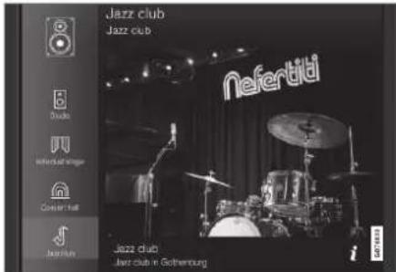
Recreate the acoustics from Nefertiti Jazz Club.
▶▶
SOUND, MEDIA AND INTERNET
High Performance Pro\* (Harman Kardon)
- Seat Optimisation – the sound can be adjusted so that it can primarily be adapted for Driver, All and Rear.
- Surround - surround sound mode with level settings.
- Tone – settings for bass, treble, equalizer, etc.
Related information
• Audio settings (p. 508)
- Navigating in the centre display's views (p. 113)
Apps
The app view contains apps that give access to some of the car's services.
Swipe from right to left ^1 across the centre display's screen in order to access the app view from the home view. Apps that have been downloaded (third-party apps) and apps for embedded functions, such as FM radio, are found here.

App view (generic image, basic apps vary by market and model)
Some basic apps are always available. More apps such as web radio and music services can be downloaded when the car is connected to the Internet.
Certain apps are only available for use if the car is connected to the Internet.
Start an app by pressing the app in the centre display's app view,
All the apps used should be updated to the latest version.
Related information
• Downloading apps (p. 511)
- Updating apps (p. 512)
- Deleting apps (p. 512)
• Apple® CarPlay®* (p. 528)
• Android Auto* (p. 532)
- Internet-connected car* (p. 544)
• Storage space on hard disk (p. 552)
- User terms and conditions and data sharing (p. 550)
Downloading apps
New apps can be downloaded when the car is connected to the Internet.
NOTE
Data download may affect other services that transmit data, e.g. Internet radio. If the effect on other services is experienced as disruptive then the download can be interrupted. Alternatively, it may be appropriate to switch off or interrupt other services.
NOTE
When downloading using a phone, pay extra attention to the data traffic costs.
- Open the Download Centre app in the app view.

-
Select New apps in order to open a list of apps that are available but not installed in the car.
-
Tap on the row for an app in order to expand in the list and get more information about the app.
- Select Install in order to start the download and installation of the desired app.
The status of the download and installation is shown while it is in progress.
A message is shown if a download cannot be started for the moment. The app will remain in the list and it is possible to try to start a download again.
Cancelling the download
- Tap on Abort to cancel a download in progress.
Note that only the download can be cancelled, when the installation phase has started, this cannot be cancelled.
Related information
- Apps (p. 510)
- Updating apps (p. 512)
- Deleting apps (p. 512)
• Internet-connected car* (p. 544) - Managing system updates via the Download Centre (p. 601)
• Storage space on hard disk (p. 552)
SOUND, MEDIA AND INTERNET
Updating apps
The apps can be updated when the car is connected to the Internet.

NOTE
Data download may affect other services that transmit data, e.g. Internet radio. If the effect on other services is experienced as disruptive then the download can be interrupted. Alternatively, it may be appropriate to switch off or interrupt other services.

NOTE
When downloading using a phone, pay extra attention to the data traffic costs.
If an app is being used during an ongoing update, it will be restarted in order for the installation to be completed.
Update all
- Open the Download Centre app in the app view.

- Select Install all.
Updating is started.
Update some
- Open the Download Centre app in the app view.
- Select Application updates in order to open a list of all available updates.
- Locate the desired app and select Install.
Updating is started.
Related information
- Apps (p. 510)
• Downloading apps (p. 511) - Deleting apps (p. 512)
- Managing system updates via the Download Centre (p. 601)
• Internet-connected car* (p. 544)
Deleting apps
Apps can be uninstalled when the car is connected to the Internet.
An app that is being used must be closed in order for the uninstallation to be completed.
- Open the Download Centre app in the app view.

- Select Application updates in order to open a list of all installed apps.
- Locate the desired app and select Uninstall in order to start the uninstalla- tion of the app.
When the app has been uninstalled, it disappears from the list.
Related information
- Apps (p. 510)
• Downloading apps (p. 511) - Updating apps (p. 512)
- Managing system updates via the Download Centre (p. 601)
• Internet-connected car* (p. 544)
SOUND, MEDIA AND INTERNET
Radio
It is possible to listen to the FM bands and to digital radio (DAB) ^* . When the car is online, it is also possible to listen to Internet radio.


The radio can be operated using voice recognition, the steering wheel keypad or the centre display.
Related information
• Start radio (p. 513)
- Changing radio band and radio station (p. 514)
- Save radio channels in the Radio Favourites app (p. 516)
- Settings for radio (p, 516)
• Digital radio* (p. 518)
• RDS radio (p. 518)
• Internet-connected car* (p. 544)
• Voice control of radio and media (p. 147)
• Media player (p. 519)
Start radio
The radio is started from the centre display app view.
- Open the required frequency band (e.g. FM) from the app view.

- Select a radio station.
Related information
- Radio (p. 513)
• Searching for radio stations (p. 515)
▶▶
SOUND, MEDIA AND INTERNET
- Changing radio band and radio station (p. 514)
- Save radio channels in the Radio Favourites app (p. 516)
- Settings for radio (p. 516)
• Voice control of radio and media (p. 147)
Changing radio band and radio station
There are instructions here for changing the radio band, the list in the radio band and the radio station in the selected list.
Changing radio band
Swipe to show the app view in the centre display and select the preferred radio band (e.g. FM), or open the driver display's app menu using the right-hand keypad on the steering wheel and make your selection from there.
Changing lists within the frequency band

-
Press Library.
-
Select playback from Stations, Favourites, Genres or Ensembles ^2 .
- Tap on the desired station from the list.
Favourites - only plays back selected favourite channels.
Genres - only plays back channels broadcasting the selected genre/programme type, e.g. pop or classical.
Changing stations within the selected list
- Press on 🐘️ und the centre display or the steering wheel's right-hand keypad.
The highlight moves up or down one place in the selected playlist.
You can also change radio station in the selected list via the centre display.
Related information
- Radio (p. 513)
• Searching for radio stations (p. 515)
• Voice control of radio and media (p. 147) - Save radio channels in the Radio Favourites app (p. 516)
- Settings for radio (p. 516)
• App menu in the driver display (p. 102)
Searching for radio stations
The radio automatically compiles a station list of the radio stations within the area that are transmitting the strongest signals.

The parameters you can search on depend on the frequency band selected:
• FM - station, genre and frequency.
• DAB* - ensembles and stations.
-
Press Library.
-
Press
Search view with keyboard is opened.
- Enter the search terms.
Searching takes place with each input of a character and the search results are shown by category.
Manual tuning

Searching manually makes it possible to find and tune to stations that are not on the automatically compiled list of the strongest stations in the area.
On changing over to manual tuning, the radio no longer changes frequency automatically when reception is poor.
- Press Manual tuning, pull the control or press K. W. a long press, the search jumps to the next available station in the frequency band. It is also possible to use the right keypad on the steering wheel.
Related information
- Radio (p. 513)
-
Start radio (p. 513)
-
Changing radio band and radio station (p. 514)
• Voice control of radio and media (p. 147) - Settings for radio (p. 516)
SOUND, MEDIA AND INTERNET
Save radio channels in the Radio Favourites app
It is possible to add a radio channel to the Radio favourites app and the favourites list for the radio band (e.g. FM). Instructions on how to add and remove radio channels can be found below.
Radio Favourites

The Radio Favourites app shows saved radio channels from all frequency bands.
- Open the app Radio favourites from the app view.
- Tap on the desired station in the list to start listening.
Adding and removing radio favourites
- Tap on add a channel to or from frequency band favourites and the Radio Favourites app.
- Tap on Library, select Edit and tap on 📋 to remove a radio channel from the favourites.
When a radio channel is saved from a station list, the radio will automatically search for the best frequency. But if a radio channel is saved
from a manual station search, the radio does not automatically change to a stronger frequency.
If a radio channel is removed from the Radio Favourite app, the channel will also be removed from the favourites list for the relevant frequency band.
Related information
- Radio (p. 513)
• Start radio (p. 513)
• Searching for radio stations (p. 515) - Changing radio band and radio station (p. 514)
• Voice control of radio and media (p. 147) - Settings for radio (p. 516)
• App menu in the driver display (p. 102)
Settings for radio
There are various radio functions to activate and deactivate.
Cancelling traffic messages
The broadcast of traffic messages etc. can be temporarily interrupted by tapping on ○ in the right-hand steering wheel keypad or by tapping on Cancel in the centre display.
Activating and deactivating radio functions
Drag down the top view and select Settings
→ Media and the desired radio band to view available functions.
FM Radio
• Show Broadcast Information: shows information on programme content, artists, etc.
- Freeze Program Name: select to stop the programme service name from scrolling continuously. Instead it freezes after 20 seconds.
- Select Announcements: ^3
- Local Interruptions: interrupts the current media playback and broadcasts information about traffic disruptions in the neighbourhood. Playback of previous media source is resumed when the message is finished. The Local Interruptions function is a geographically restricted version of the Traffic Announcements function. The Traffic Announcements function must be activated at the same time.
- News: interrupts the current media playback and broadcasts news. Playback of previous media source is resumed when the news broadcast is finished.
- Alarm: interrupts the current media playback and sends alerts about major accidents and disasters. Playback of
previous media source is resumed when the message is finished.
- Traffic Announcements: interrupts the current media playback and broadcasts information about traffic disruptions. Playback of previous media source is resumed when the message is finished.
DAB\* (digital radio)
- Sort Services: option for how channels will be sorted. Either alphabetically or by service number.
- DAB To DAB Handover: starts the function for linking within DAB. If reception of a radio channel is lost, another channel is found automatically in another channel group (ensemble).
- DAB To FM Handover: starts the function for linking between DAB and FM. If reception of a radio channel is lost, an alternative FM frequency is searched for automatically.
• Show Broadcast Information: select to show radio text or selected types of radio text, e.g. artist.
• Show Program Related Images: select whether or not to show images for programmes on the screen.
- Select Announcements: select the types of messages to be received while DAB is playing. Selected messages will interrupt the current media playback to play back the message. Playback of previous media source is resumed when the message is finished.
- Alarm: interrupts the current media playback and sends alerts about major accidents and disasters. Playback of previous media source is resumed when the message is finished.
- Traffic Flash: receives information about traffic disruptions.
• News Flash: receives news.
- Transport Flash: receives information about public transport, e.g. ferry and train timetables.
- Warning/Services: receives information about incidents of lower significance than the Alarm function, e.g. power failures.
Related information
- Radio (p. 513)
• Digital radio* (p. 518) - Symbols in the centre display's status bar (p. 122)
SOUND, MEDIA AND INTERNET
RDS radio
RDS (Radio Data System) means that the radio automatically changes to the strongest transmitter. RDS provides the ability to receive e.g. traffic information and to search for certain programme types.
RDS links FM transmitters into a network. An FM transmitter in such a network sends information that gives an RDS radio the following functions:
- Switch automatically to a stronger transmitter if reception in the area is poor.
- Search for programme category, e.g. programme types or traffic information.
- Receive text information on current radio programme.

NOTE
Some radio stations do not use RDS or only selected parts of its functionality.
When broadcasting news or traffic messages, the radio can switch stations, interrupting the audio source currently in use. The radio returns to the previous audio source and volume when the set programme type is no longer broadcast. To go back earlier, press ○ on the right-hand steering wheel keypad or tap Cancel in the centre display.
Related information
- Radio (p. 513)
- Settings for radio (p. 516)
Digital radio\*
Digital radio (DAB ^4 ) is a digital broadcasting system for radio. The radio supports DAB, DAB+ and DMB ^5 .

The radio can be operated using voice recognition, the steering wheel keypad or the centre display.

The digital radio app is launched from app view in the centre display.
Digital radio is played back in the same way as other radio bands, such as FM. Besides the option to select playback from Stations, Favourites and Genres, there is also the option to select playback from subchannels and Ensembles. An ensemble is a set of radio channels (a channel group) broadcasting on the same frequency.
In the cases where the radio channel transmits its logotype, it is downloaded and shown beside the station name (download time varies).
DAB subchannel
Secondary components are usually named subchannels. These are temporary and can contain e.g. translations of the main programme into other languages. Subchannels are indicated with an arrow symbol in the channel list.
Related information
- Link between FM and digital radio* (p. 519)
- Changing radio band and radio station (p. 514)
• Searching for radio stations (p. 515) - Save radio channels in the Radio Favourites app (p. 516)
• Voice control of radio and media (p. 147) - Settings for radio (p. 516)
Link between FM and digital radio\*
The function enables the digital radio (DAB) to switch from a channel with poor or no reception to the same channel in another channel group (ensemble) with better reception, within DAB and/or between DAB and FM.
DAB to DAB and DAB to FM linking
- Press Settings in the top view.
- Press Media DAB.
- Tick/untick DAB To DAB Handover and/or DAB To FM Handover in order to activate/deactivate the respective functions.
Related information
• Digital radio* (p. 518)
- Radio (p. 513)
- Settings for radio (p. 516)
Media player
The media player can play back audio from external audio sources connected via the USB port or Bluetooth. It can also play back video format via the USB port.
When the car is connected to the internet, it is also possible to listen to web radio, audio books and music services via apps.
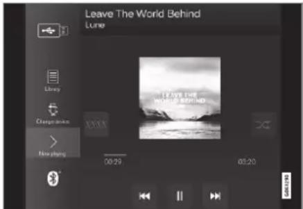

The media player is operated from the centre display, but several functions can be operated using the steering wheel's right-hand keypad or voice control.
The radio is operated in the media player and is described in a separate section.
SOUND, MEDIA AND INTERNET
Related information
• Media playback (p. 520)
• Controlling and changing media (p. 521)
• Searching media (p. 522)
- Apps (p. 510)
- Radio (p. 513)
- Video (p. 524)
• Media via Bluetooth® (p. 525)
• Media via USB port (p. 526)
• Internet-connected car* (p. 544)
Media playback
The media player is controlled from the centre display. Several functions can also be operated using the steering wheel's right-hand keypad or voice control.
The media player also operates the radio, which is described in a separate section.
Starting the media source

App view. (Generic image, basic apps vary by market and model.)
USB memory
- Insert the USB memory.
- Open the app USB from the app view.
- Select what to play back.
Playback begins.
Mp3 player and iPod®

NOTE
To start playback from iPod, use the iPod app (not USB).
When an iPod is used as audio source, the car's audio and media system has a menu structure that is similar to the iPod player's own menu structure.
- Connect media source.
- Start playback from the connected media source.
- Open the app (iPod, USB) from the app view.
Playback begins.
Bluetooth connected device
- Activate Bluetooth in the media source.
- Connect media source.
- Start playback from the connected media source.
- Open the app Bluetooth from the app view.
Playback begins.
Media with Internet connection
Play back media from Internet-connected apps:
- Connect the car to the Internet.
- Open the current app from the app view.
Playback begins.
Read the separate section on how apps are downloaded.
Video
- Connect media source.
- Open the app USB from the app view.
- Tap on the title of the desired item to play back.
Playback begins.
Apple CarPlay
CarPlay is described in a separate section.
Android Auto
Android Auto is described in a separate section.
Related information
- Managing the app menu in the driver display (p. 103)
- Radio (p. 513)
• Controlling and changing media (p. 521) - Connecting a device via USB port (p. 526)
- Connecting a device via Bluetooth® (p. 525)
• Downloading apps (p. 511)
• Internet-connected car* (p. 544) - Video (p. 524)
• Apple® CarPlay®* (p. 528)
• Android Auto* (p. 532)
• Voice control of radio and media (p. 147)
• Compatible media formats (p. 527)
Controlling and changing media
The playback of media can be controlled with voice control, steering wheel keypad or the centre display.

The media player can be operated by voice recognition, from the steering wheel keypad or the centre display.

Volume - turn the control knob under the centre display or press ▲▼ on the steering wheel's right-hand keypad in order to increase or decrease the volume.
Play/pause - tap on the image belonging to the song being played back, the physical button under the centre display or ○ on the steering wheel's right-hand keypad.
▶▶
SOUND, MEDIA AND INTERNET
Change track/song - tap on the desired track in the centre display, press on 🐎 or 🐎 under the centre display or on the steering wheel's right-hand keypad.
Fast forward/move in time - tap on the time axis in the centre display and drag sideways, or press and hold ▶ or ▶der the centre display or on the steering wheel's right-hand keypad.
Changing media - select from previous sources in the app, in the app view, press on the desired app or select with the steering wheel's right-hand keypad via the app menu


Library - tap on the button to play back from the library.

Shuffle - tap on the button to shuffle the playback order.

Similar - tap on the button in order to use Gracenote to search for similar music on the USB device and to create a playlist from it. The playlist can contain a maximum of 50 songs.
Change device - tap on the button in order to switch between USB devices when several are connected.
Related information
• Media player (p. 519)
• Searching media (p. 522)
• Audio settings (p. 508)
- Apps (p. 510)
- Gracenote® (p. 523)
• Voice control of radio and media (p. 147)
Searching media
It is possible to search by artist, composer, song titles, album, video, audio book, playlist and, when the car is connected to the Internet, podcasts (digital media via Internet).

-
Press
Search view with keyboard is opened.
-
Enter the search terms.
-
Press Search.
Connected devices are searched and the search results are listed by category.
Swipe sideways across the screen to show each category separately.
Related information
• Media player (p. 519)
- Internet-connected car* (p. 544)
• Media playback (p. 520)
- Enter the characters, letters and words manually in the centre display (p. 127)
Gracenote®
Gracenote Identifies artist, album, song titles and associated images, which are shown during playback.
Gracenote MusicID ^® is a standard for music recognition. Information on the music can be presented by means of the identification and analysis of the metadata in the music files. Sometimes metadata from different sources can be inconsistent or inadequate.
Gracenote has support for phonetic processing of artist name, album titles and genres, and in this way, voice control can be used to play back music.
- Press Settings in the top view.
- Press Media Gracenote ^® .
- Select settings for Gracenote data:
- Gracenote® Online Search - searches in Gracenote's online database for playing media.
- Gracenote® Multiple Results - selects how to display Gracenote data if there are more than one search results.
1 - the file's original data are used.
2 - Gracenote data are used.
3 - Gracenote or original data can be selected.
• None - no results are shown.
Updating Gracenote
The content of the Gracenote database is updated continuously. Download the latest update to take advantage of improvements.
For information and downloading see volvocars.com/support.
Related information
• Media playback (p. 520)
• License agreement for audio and media (p. 553)
• Voice control of radio and media (p. 147)
SOUND, MEDIA AND INTERNET
Video
Videos on USB-connected devices can be played back using the media player. No picture is shown when the car starts to move, but only the audio is played back. The picture is shown again when the car is stationary.
Information on compatible formats for media can be found in a separate section.
Related information
- Playing a video (p. 524)
- Playing back DivX® (p. 524)
- Settings for video (p. 525)
• Compatible media formats (p. 527)
Playing a video
Videos are played using the USB app in the app view.
- Connecting a media source (USB device).
- Open the app USB from the app view.
- Tap on the title of the desired item to play back.
Playback begins.
Finding video files may be problematic if the USB device also contains music and audio tracks. In this case, it is possible to find them by going to Library and selecting the video tab.
Related information
- Video (p. 524)
- Playing back DivX® (p. 524)
- Settings for video (p. 525)
• Compatible media formats (p. 527)
Playing back DivX®
This DivX Certified ^® device must be registered in order to play back purchased DivX Video-on-Demand (VOD) films.
- Press Settings in the top view.
- Tap Video DDX® VOD and retrieve the registration code.
- Go to vod.divx.com for more information and to complete the registration.
Related information
• Video (p. 524)
- Playing a video (p. 524)
- Settings for video (p. 525)
• Compatible media formats (p. 527)
Settings for video
Certain language settings can be changed for video playback.
With the video player in full screen mode, or by opening the top view and pressing
Settings Media Video, the following can be adjusted: Audio Language and Subtitle Language.
Related information
- Video (p. 524)
Media via Bluetooth®
The car's media player is equipped with Bluetooth and can wirelessly play audio files from external Bluetooth devices, such as mobile phones and tablets.
For the media player to be able to play back audio files wirelessly from an external device, the device must first be connected to the car via Bluetooth.
Related information
- Connecting a device via Bluetooth® (p. 525)
- Connecting a phone to the car via Bluetooth for the first time (p. 536)
• Media playback (p. 520)
• Compatible media formats (p. 527)
Connecting a device via Bluetooth®
Connect a Bluetooth ^® device to the car for wireless playback of media and to provide the car with an Internet connection where possible.
Many phones on the market now have wireless Bluetooth® technology, but not all of them are fully compatible with the car.
For information on compatibility, see volvocars.com/support.
The procedure for connecting a media device is the same as for connecting a phone to the car via Bluetooth ^® .
Related information
• Media via Bluetooth® (p. 525)
- Connecting a phone to the car via Bluetooth for the first time (p. 536)
• Media playback (p. 520)
SOUND, MEDIA AND INTERNET
Media via USB port
An external audio source, e.g. an iPod® or MP3 player, can be connected to the audio system via the car's USB port.
Devices with rechargeable batteries are recharged when connected via USB and the ignition is in position I, II or the engine is running.
The content of the external source can be loaded more quickly if it only consists of compatible formats. Video files can also be played back via the USB port.
Certain MP3 players have their own file system that the car does not support.
Related information
- Connecting a device via USB port (p. 526)
• Media playback (p. 520) - Video (p. 524)
- Ignition positions (p. 448)
• Technical specifications for USB devices (p. 527)
• Apple® CarPlay®* (p. 528)
• Android Auto* (p. 532)
Connecting a device via USB port
An external audio source, e.g. an iPod ^ or MP3 player, can be connected to the audio system via one of the car's USB ports.
The phone must be connected to the USB port with white frame (when there are two USB ports) when using Apple CarPlay* and Android Auto*.

natural_image
Close-up of a hand holding a device in a car interior, with an inset showing a close-up of a device (no visible text or symbols)USB inputs (type A) in the tunnel console. Allow the cable to lie forwards so that it is not trapped when the lid is closed.

natural_image
Interior view of a car air conditioner unit with a circular dial indicator and control panel (no visible text or symbols)USB Inputs (type C) on rear of tunnel console for charging telephones and tablets for example ^6 .
Related information
• Media playback (p. 520)
• Media via USB port (p. 526)
• Media player (p. 519)
• Technical specifications for USB devices (p. 527)
• Technical specifications for USB devices (p. 527)
• Apple® CarPlay® (p. 528)
• Android Auto* (p. 532)
Technical specifications for USB devices
The following specifications must be met to allow the contents of the USB devices to be read.
No folder structure will be shown in the centre display during playback.
| Max number | |
| Files 15 000 | |
| Folders 1 000 | |
| Folder levels 8 | |
| Playlists 100 | |
| Items in a playlist 1 000 | |
| Subfolders No limit |
Technical specification for USB A connector
- Type A socket
- Version 2.0
• Voltage supply 5 V
• Current supply max. 2.1 A
Technical specification for USB C connector
- Type C socket
- Version 3.1
• Voltage supply 5 V
• Current supply max, 3.0 A
Related information
• Media via USB port (p. 526)
Compatible media formats
The following file formats must be used for media playback.
Audio files
| Format | File extension Codec |
| MP3 .mp3 MPEG1 Layer III, MPEG2 Layer III, MP3 Pro (mp3 compatible), MP3 HD (mp3 compatible) | |
| AAC .m4a, .m4b, .aac AAC | LC (MPEG-4 part III Audio), HE-AAC (aacPlus v1/v2) |
| WMA .wma WMA8/9, | WMA9/10 Pro |
| WAV .wav LPCM | |
| FLAC .flac FLAC | |
Video files
| Format | File extension |
| MP4 | .mp4, .m4v |
| MPEG-PS | .mpg, .mp2, .mpeg, .m1v |
SOUND, MEDIA AND INTERNET
◀◀
| Format File extension | |
| AVI .avi | |
| AVI (DivX) .avi, .divx | |
| ASF .asf, .wmv | |
Subtitles
| Format File extension | |
| SubViewer .sub | |
| SubRip .srt | |
| SSA .ssa | |
DivX®
DivX certified devices have been tested for high-quality DivX (.divx, .avi) video playback. When you see the DivX logo, you have the freedom to play DivX films.
| Profile DivX Home Theater |
| Video codec DivX, MPEG-4 |
| Resolution 720x576 |
| Bit rate 4.8Mbps |
| Frame rate 30 fps |
| File extension .divx, .avi |
| Max file size 4 GB |
| Audio codec MP3, AC3 | |
| Subtitles XSUB | |
| Special functions | Multiple subtitles, multiple audio, resume play |
| Reference Meets all requirements of the DivX Home Theater profile. Visit divx.com for more information and software tools to convert your files into DivX Home Theater video. | |
Related information
• Media player (p. 519)
- Video (p. 524)
- Playing back DivX® (p. 524)
Apple ^® CarPlay ^®*
CarPlay ^7 gives you the option to listen to music, make phone calls, get directions, send/receive messages and use Siri, all while you stay focused on your driving.

CarPlay works with selected iOS devices. If the car does not already support CarPlay there is the option to install it retroactively. Contact a Volvo dealer to install CarPlay.
Information about which apps are supported and which iOS devices are compatible is available on Apple's website: www.apple.com/ios/carplay/. Using apps that are not compatible with CarPlay may sometimes mean that the connection between the device and the car is broken. Please note that Volvo is not responsible for the content in CarPlay.
When using map navigation via CarPlay, there is no guidance in the driver display or head-up display, but only in the centre display.
When navigation is started through Apple CarPlay, ongoing native turn-by-turn route guidance will be ended.
The CarPlay apps can be controlled via the centre display, the iOS device or using the steering wheel's right-hand keypad (applies to certain functions). The apps can also be voice-controlled using Siri. A long press on the
steering wheel button Ⓧ starts voice control using Siri and a short press activates the car's own voice control. If Siri breaks off too early, hold the steering wheel button Ⓧ ^8 depressed.
By using Apple CarPlay you acknowledge the following: Apple CarPlay is a service provided by Apple Inc. under its terms and conditions. Volvo Cars is thus not responsible for Apple CarPlay or its features/applications. When using Apple CarPlay, certain information from your car (including its position) is transferred to your iPhone. In relation to Volvo Cars, you are fully responsible for your and any others person's use of Apple CarPlay.
Related information
• Using Apple® CarPlay®* (p. 529)
- Settings for Apple® CarPlay®* (p. 531)
• Voice recognition (p. 143)
- Resetting settings in the centre display (p. 132)
Using Apple ^® CarPlay ^®*
To use CarPlay ^9 , Siri voice control must be activated on your iOS device. The device also needs an Internet connection via Wi-Fi or the mobile network for all functions to work.
Connect an iOS device and start CarPlay
NOTE
CarPlay can only be used if Bluetooth is deactivated. A phone or media player connected to the car via Bluetooth will therefore not be available when CarPlay is active. An alternative Internet source must be used to connect to the Internet for the car's apps. Use Wi-Fi or the car's built-in modem*.
To start CarPlay from an iOS device that has not been connected previously:
-
Connect an iOS device with support for CarPlay to the USB port. In the cases where there are two USB ports, the one with the white frame around the port must be used.
-
Read the terms and conditions and then tap on Accept to connect.
The subview with CarPlay is opened and compatible apps are shown.
- Tap on the desired app.
The app starts.
▶▶
* Option/accessory. 529
SOUND, MEDIA AND INTERNET
Starting CarPlay
To start CarPlay from an iOS device that has been connected previously:
- Connect an iOS device to the USB port. In the cases where there are two USB ports, the one with the white frame around the port must be used.
If the setting for automatic start is selected - the name of the device will be shown. The tile with CarPlay is opened automatically in the cases where the home view is shown when connecting the iOS device.
-
If the tile with CarPlay does not open automatically, tap on the device name. The subview with CarPlay is opened and compatible apps are shown.
-
If an app is active in the same tile, tap on Apple CarPlay in the app view.
The subview with CarPlay is opened and compatible apps are shown.
- Tap on the desired app.
The app starts.
CarPlay runs in the background if another app is started, or is already active when connecting, in the same tile. To show CarPlay in the subview again - tap on the CarPlay icon in the app view.
Switch the connection between CarPlay and iPod
CarPlay to iPod
- Press Settings in the top view.
- Continue to Communication Apple CarPlay.
- Untick the box for the iOS device that shall no longer start CarPlay automatically when the USB cable is connected.
- Disconnect and connect the iOS device to the USB port.
- Open the app iPod from the app view.
iPod to CarPlay
- Tap on Apple CarPlay in the app view.
- Read the information in the pop-up window and then tap on OK.
- Disconnect and connect the iOS device to the USB port.
The subview with Apple CarPlay is opened and compatible apps are shown ^10 .
Related information
• Connecting a device via USB port (p. 526)
• Apple® CarPlay®* (p. 528)
- Settings for Apple® CarPlay®* (p. 531)
- Connect the car to the Internet via a phone (Wi-Fi) (p. 546)
- Connect the car to the Internet via car modem (SIM card) (p. 546)
• Voice recognition (p. 143)
Settings for Apple ^® CarPlay ^®*
Settings for IOS device connected with CarPlay ^11,12 .
Automatic start
- Press Settings in the top view.
-
Continue to Communication Apple CarPlay and select setting:
-
Tick the box - CarPlay starts automatically when the USB cable is connected.
- Untick the box - CarPlay does not start automatically when the USB cable is connected.
If the car is shared by a lot of people, such as in a car pool, it is worth noting that a maximum of 20 iOS devices can be stored simultaneously in the list. When the list is full and a new device is connected the oldest one is deleted.
To delete the list, the settings must be reset in the centre display (factory reset).
System volumes
-
Press Settings in the top view.
-
Tap on Sound System Volumes and make the settings for the following:
-
Voice Control
- Navi Voice Guidance
- Phone Ringtone
Related information
• Apple® CarPlay®* (p. 528)
• Using Apple® CarPlay®* (p. 529)
- Resetting settings in the centre display (p. 132)
Tips for using Apple ^® CarPlay ^®*
Here are some useful tips for using CarPlay ^®13 .
- Update your iOS device with the latest version of the iOS operating system and ensure that the apps have been updated.
- In the event of a problem with CarPlay, disconnect the iOS device from the USB port and reconnect. Otherwise, try to close the app on the device that is not working and then restart the app, or try closing all apps and restart your device.
- If the apps do not appear when CarPlay starts (black screen), try minimising and expanding the tile for CarPlay.
- Using apps that are not compatible with CarPlay may sometimes mean that the connection between the iOS device and the car is broken. Information about supported apps and compatible telephone devices can be found on the Apple website. You can also search for CarPlay in the App Store to find information about apps that are compatible with CarPlay on your market.
- Using Siri it is possible to write/dictate and read out messages. Messages are read out and dictated in the language
▶▶
SOUND, MEDIA AND INTERNET
◀◀
selected in the settings for Siri. When the message is written/dictated, no text will be shown in the centre display – instead, the text will appear on the iOS device. When Siri is used, note that the telephone's microphones are used and that the quality is therefore dependent on the position of the telephone.
- If the device is connected to the car via Bluetooth, the connection will be interrupted when CarPlay is used. Resume the Internet connection in the car by sharing the Internet via the Wi-Fi hotspot from the device.
- Some of the CarPlay functions (such as voice call and messages) mean that use of the car's own functions is stopped and CarPlay is shown automatically instead. If this behaviour is not wanted, deselect the display of the equivalent function in CarPlay under the phone's settings for notifications.
• CarPlay only works with iPhone ^14 .

NOTE
Availability and functionality may vary depending on market.
Related information
• Apple® CarPlay®* (p. 528)
- Connect the car to the Internet via a phone (Wi-Fi) (p. 546)
Android Auto\*
Android Auto ^15 gives you the option to listen to music, make phone calls, get directions and use car-adapted apps from an Android device. Android Auto works with selected Android devices.

Information about which apps are supported and which Android devices are compatible is available on the website: www.android.com/auto/. For third-party apps, see Google Play. Please note that Volvo is not responsible for the content in Android Auto.
Android Auto is started from the app view. After Android Auto has been started once, the app will be started automatically the next time
the device is connected. Automatic start can be deactivated under settings.

NOTE
When a device is connected to Android Auto it is possible to stream via Bluetooth to another media player. Bluetooth is active while Android Auto is being used.
When using map navigation via Android Auto there is no guidance in the driver display or head-up display, but only in the centre display.
Android Auto can be controlled via the centre display using the steering wheel's right-hand keypad or voice control. Holding down the steering wheel button ⚙️ starts Google Assistant and a short press deactivates it.
By using Android Auto, you acknowledge the following: Android Auto is a service provided by Google Inc. under its terms and conditions. Volvo Cars is not responsible for Android Auto or its features or applications. When you use Android Auto, your car transfers certain information (including its location) to your connected Android phone. You are fully responsible for your and any other person's use of Android Auto.
Related information
• Using Android Auto* (p. 533)
- Settings for Android Auto* (p. 534)
Using Android Auto\*
To use the Android Auto ^16 app, the app must be installed on your Android device and the device must be connected to the car's USB port.

NOTE
For installation of Android Auto to be possible, the car must be equipped with two USB ports (USB hub) ^* . If the car only has one USB port then it is not possible to use Android Auto.
The first time an Android is connected
- Connect your Android device to the USB input with a white frame.
- Read the information in the pop-up window and then tap on OK.
- Tap on Android Auto in the app view.
- Read the terms and conditions and then tap on Accept to connect.
The subview with Android Auto is opened and compatible apps are shown.
- Tap on the desired app.
The app starts.
SOUND, MEDIA AND INTERNET
Previously connected Android
-
Connect your device to the USB input with a white frame.
If the setting for automatic start is selected - the name of the device is shown.
-
Tap on the device name – the tile with Android Auto is opened and compatible apps are shown.
-
If the setting for automatic start is not selected - open the Android Auto app from the app view.
The subview with Android Auto is opened and compatible apps are shown.
- Tap on the desired app.
The app starts.
Android Auto runs in the background if another app is started in the same subview. To show Android Auto in the subview again - tap on the Android Auto icon in the app view.
Related information
• Android Auto* (p. 532)
- Settings for Android Auto* (p. 534)
• Connecting a device via USB port (p. 526)
• Voice recognition (p. 143)
Settings for Android Auto\*
Settings for an Android device that has been connected for the first time with Android Auto ^17 .
Automatic start
- Press Settings in the top view.
- Press Communication Android Auto and select setting:
- Tick the box - Android Auto starts automatically when the USB cable is connected.
- Untick the box - Android Auto does not start automatically when the USB cable is connected.
A maximum of 20 Android devices can be stored in the list. When the list is full and a new device is connected the oldest one is deleted.
A factory reset has to be executed in order to clear the list.
System volumes
-
Press Settings in the top view.
-
Tap on Sound System Volumes and make the settings for the following:
-
Voice Control
• Navi Voice Guidance - Phone Ringtone
Related information
• Android Auto* (p. 532)
• Using Android Auto* (p. 533)
- Resetting settings in the centre display (p. 132)
Tips for using Android Auto\*
Here are some useful tips for using Android Auto ^18 .
- Ensure that your apps are updated.
- When starting the car, wait until the centre display has started, connect the device and then open Android Auto from the app view.
- In the event of problems with Android Auto, disconnect your Android device from the USB port and then reconnect via USB. Otherwise, try closing the app on the device and then restarting the app.
- When a device is connected to Android Auto it is still possible to playback media via Bluetooth to another media player. The Bluetooth function is on when Android Auto is used.
- If the icon for Android Auto is greyed out, this means no device is connected. When you connect your device the icon will be illuminated. If the icon is not visible at all then the car does not have support for connecting a device for this purpose.
- If the device is connected to the car via Bluetooth, the connection will be interrupted when Android Auto is used. Resume the Internet connection in the car by sharing the Internet via the Wi-Fi hotspot from the device.
Related information
• Android Auto* (p. 532)
- Connect the car to the Internet via a phone (Wi-Fi) (p. 546)
Phone
A phone with Bluetooth can be connected wirelessly to the car's built-in hands-free system.
The audio and media system acts as hands-free, with the facility to remotely control a selection of the phone's functions. The phone can still be operated with its own keys even if it is connected to the car.
When a phone has been connected online and connected with the car, it can be used make calls, send/receive messages, play back media wirelessly and be used as an Internet connection.
The phone is operated from the centre display, but also via voice recognition and the app menu, which are accessed from the right-hand steering wheel keypad.
SOUND, MEDIA AND INTERNET
Overview

1 Microphone.
2 Phone.
3 Phone operation from centre display.
4 Keypad for operating phone functions that are shown in the driver display and voice recognition.
5 Driver display.
Related information
• Managing phone calls (p. 540)
• Managing the phone book (p. 542)
• Managing text messages (p. 541)
- Connecting a phone to the car via Bluetooth for the first time (p. 536)
- Connecting a phone to the car via Bluetooth automatically (p. 538)
- Connecting a phone to the car via Bluetooth manually (p. 539)
• Disconnecting a Bluetooth-connected phone (p. 539) - Switch between Bluetooth-connected phones (p. 539)
- Removing devices connected to Bluetooth (p. 540)
• Settings for phone (p. 543)
• Voice recognition (p. 143) - Managing the app menu in the driver display (p. 103)
• Audio settings (p. 508) - Connect the car to the Internet via a Bluetooth-enabled phone (p. 545)
Connecting a phone to the car via Bluetooth for the first time
Connect a phone with Bluetooth activated to then be able to make calls from the car, send/receive messages, play back media wirelessly and connect the car to the Internet.
It is possible to have two Bluetooth devices connected at once, in which case one of them can only play back wirelessly. The most recently connected phone will automatically be connected to make calls, send/receive messages, play back media and provide an Internet connection. It is possible to change what the phone is to be used for under Bluetooth Devices via the settings menu in the centre display's top view. Your mobile phone needs to be equipped with Bluetooth and support tethering.
After the device has been connected/registered a first time via Bluetooth, it no longer needs to be visible/discoverable, but only have Bluetooth activated. A maximum of 20 connected Bluetooth devices can be stored in the car.
There are two options for connecting. Either search the phone from the car or search the car from the phone.
Option 1 - search phone from car
-
Make the phone searchable/visible via Bluetooth.
-
Open the phone tile in the centre display.
-
If there is no phone connected to the car, tap on Add phone.
-
If there is a phone connected to the car, tap on Change. In the pop-up window, tap on Add phone.
Available Bluetooth devices are listed. The list is updated as new devices are detected.
-
Tap on the name of the phone to be connected.
-
Check that the specified number code in the car matches that in the phone. In which case, choose to accept in both places.
-
On the phone, choose to accept or reject any options for phone contacts and messages.

NOTE
- The message function must be activated in certain phones.
- Not all mobile phones are fully compatible and may therefore not show contacts and messages in the car.
Option 2 - search car from phone
-
Open the phone tile in the centre display.
-
If there is no phone connected to the car, tap on Add phone make car discoverable.
-
If there is a phone connected to the car, tap on Change .In the pop-up window, tap on Add phone Make car discoverable.
-
Activate Bluetooth on the phone.
-
Search on the phone for Bluetooth devices,
Available Bluetooth devices are listed.
-
Select the name of the car on the phone.
-
A pop-up window for the connection is shown in the car. Confirm the connection.
- Check that the specified number code in the car matches the one shown in the external device. In which case, choose to accept in both places.
- On the phone, choose to accept or reject any options for phone contacts and messages.

NOTE
- The message function must be activated in certain phones.
- Not all mobile phones are fully compatible and may therefore not show contacts and messages in the car.

NOTE
If the phone's operating system is updated then the connection may be broken. In which case, delete the phone from the car and then connect again.
Related information
- Phone (p. 535)
- Connecting a phone to the car via Bluetooth automatically (p. 538)
- Connecting a phone to the car via Bluetooth manually (p. 539)
• Disconnecting a Bluetooth-connected phone (p. 539) - Switch between Bluetooth-connected phones (p. 539)
- Removing devices connected to Bluetooth (p. 540)
• Settings for Bluetooth devices (p. 544)
SOUND, MEDIA AND INTERNET
• Internet-connected car* (p. 544)
- Connect the car to the Internet via a Bluetooth-enabled phone (p. 545)
Connecting a phone to the car via Bluetooth automatically
It is possible to connect a phone to the car automatically via Bluetooth. The phone has to have been connected to the car for the first time.
It is only the two last connected phones that can be connected automatically.
- Activate Bluetooth in the phone before setting the car in ignition position I.
- Set the car in ignition position I or higher.
The phone will connect.
Related information
- Phone (p. 535)
- Connecting a phone to the car via Bluetooth for the first time (p. 536)
- Connecting a phone to the car via Bluetooth manually (p. 539)
- Disconnecting a Bluetooth-connected phone (p. 539)
- Switch between Bluetooth-connected phones (p. 539)
- Removing devices connected to Bluetooth (p. 540)
- Settings for Bluetooth devices (p. 544)
• Internet-connected car* (p. 544) - Connect the car to the Internet via a Bluetooth-enabled phone (p. 545)
- Ignition positions (p. 448)
Connecting a phone to the car via Bluetooth manually
It is possible to connect a phone to the car manually via Bluetooth. The phone has to have been connected to the car for the first time.
-
Activate Bluetooth on the phone.
-
Open the subview for phone.
Connected phones are listed.
- Tap on the name of the phone to be connected.
The phone will connect.
Related information
- Phone (p. 535)
- Connecting a phone to the car via Bluetooth for the first time (p. 536)
- Connecting a phone to the car via Bluetooth automatically (p. 538)
- Disconnecting a Bluetooth-connected phone (p. 539)
- Switch between Bluetooth-connected phones (p. 539)
- Removing devices connected to Bluetooth (p. 540)
- Settings for Bluetooth devices (p. 544)
- Internet-connected car* (p. 544)
- Connect the car to the Internet via a Bluetooth-enabled phone (p. 545)
Disconnecting a Bluetooth-connected phone
It is possible to disconnect a phone connected to Bluetooth, and it will then no longer be connected to the car.
- When the phone is out of range of the car it is automatically disconnected. If disconnection occurs during an active call, then the call will be continued on the phone.
- It is also possible to disconnect the phone by manually deactivating Bluetooth.
Related information
- Phone (p. 535)
- Settings for phone (p. 543)
- Switch between Bluetooth-connected phones (p. 539)
- Removing devices connected to Bluetooth (p. 540)
- Settings for Bluetooth devices (p. 544)
Switch between Bluetooth-connected phones
It is possible to switch between a number of Bluetooth-connected phones.
-
Open the tile for the phone.
-
Tap on Change or drag down the top view and tap on Settings →
Communication Bluetooth Devices
→ Add device.
Available Bluetooth devices are listed.
- Tap on the phone to be connected.
Related information
- Phone (p. 535)
- Connecting a phone to the car via Bluetooth for the first time (p. 536)
- Settings for Bluetooth devices (p. 544)
- Disconnecting a Bluetooth-connected phone (p. 539)
- Removing devices connected to Bluetooth (p. 540)
SOUND, MEDIA AND INTERNET
Removing devices connected to Bluetooth
It is possible to remove phones from the list of registered Bluetooth devices, for example.
-
Press Settings in the top view.
-
Press Communication Bluetooth Devices.
Registered Bluetooth devices are listed.
-
Tap on the device to be removed.
-
Tap on Remove device and confirm your selection.
The device is no longer registered to the car.
Related information
- Phone (p. 535)
- Connecting a phone to the car via Bluetooth for the first time (p. 536)
- Disconnecting a Bluetooth-connected phone (p. 539)
- Switch between Bluetooth-connected phones (p. 539)
• Settings for Bluetooth devices (p. 544)
Managing phone calls
Call handling in the car for a Bluetooth-connected phone.

Generic illustration.
Making phone calls
- Open the subview for phone.
-
Select call from call history, enter number using the keypad or via the contact list. It is possible to search or browse in the contact list. Tap on ☆ in the contact list in order to add a contact under Favourites.
-
Press to make a call.
-
Tap on ↻ to end the call.
You can also make calls from the call log via the app menu, which is accessed from the right-hand steering wheel keypad 📄.
Making multi-party calls
During a call:
- Press Add call.
- Choose to make a call from the call log, favourites or the contact list.
- Tap on an entry/row in the call log, or tap on alongside the contact in the contact list.
- Tap on Swap call to switch between the parties.
- Tap on ⬇ to end the active call.
Conference calls
During an active multi-party call:
- Tap on Join calls to merge the active multi-party call.
- Tap on ↻ to end the call.
Incoming phone calls
Incoming phone calls are shown in the driver display and the centre display. Manage the call on the right-hand steering wheel keypad or in the centre display.
- Tap on Answer/Reject.
- Tap on ⬇ to end the call.
Incoming phone call during an active call
- Tap on Answer/Reject.
- Tap on to end the call.
Private call
– During the current call, press Privacy and select setting:
- Switch to mobile phone - the hands-free function is disconnected and the call continues on your mobile phone.
- Driver focused - the microphone in the roof on the passenger side is switched off and the call continues with the car's handsfree function.
Related information
- Phone (p. 535)
- Connecting a phone to the car via Bluetooth for the first time (p. 536)
- Controlling a telephone with voice recognition (p. 146)
- Managing the app menu in the driver display (p. 103)
- Enter the characters, letters and words manually in the centre display (p. 127)
• Managing the phone book (p. 542)
• Managing text messages (p. 541)
• Audio settings (p. 508)
Managing text messages ^19
Message handling in the car for a Bluetooth-connected phone.
In some phones, the message function must be activated. Not all phones are compatible. In such cases, they cannot display contacts and messages in the car.
Managing text messages in the centre display
Text messages are only shown in the centre display if the setting is selected.

Press Messages in the app view to manage text messages in the centre display.
Reading text messages in the centre display

Press the icon to get the message read aloud.
Sending text messages in the centre display ^20
-
You can reply to a message or create a new message.
-
Reply to message — tap on the contact whose message you wish to reply to, then tap on Answer.
-
Create new message - tap on Create new. Select a contact or enter a number.
-
Compose the message.
-
Press Send.
Managing text messages in the driver display
Text messages are only shown in the driver display if the setting is selected.
Reading a new text message in the driver display
- To have the message read aloud – select Read out with the steering wheel keypad.
Dictating a reply in the driver display
After the text message has been read out, it is possible to reply briefly with dictation if the car is connected to the Internet.
- Press Answer with the steering wheel keypad. A dictation dialogue starts.
SOUND, MEDIA AND INTERNET
Message notification
It is possible to activate and deactivate notifications in the text message settings.
Related information
- Phone (p. 535)
• Settings for text messages (p. 542) - Settings for phone (p. 543)
• Internet-connected car* (p. 544) - Controlling a telephone with voice recognition (p. 146)
- Enter the characters, letters and words manually in the centre display (p. 127)
- Connecting a phone to the car via Bluetooth for the first time (p. 536)
- User terms and conditions and data sharing (p. 550)
Settings for text messages
Settings for text messages on connected phone.
- Press Settings in the top view.
-
Press Communication Text Messages and select settings:
-
Notification in centre display - shows message notifications in the centre display's status bar.
- Notification in driver display - displays notifications in the driver's display and incoming messages can be managed using the steering wheel's right-hand keypad.
- Text message tone - select tone for incoming text messages.
Related information
- Phone (p. 535)
- Connecting a phone to the car via Bluetooth for the first time (p. 536)
• Managing text messages (p. 541) - Settings for phone (p. 543)
Managing the phone book
When a phone is connected to the car with Bluetooth, contacts can be managed directly in the centre display.
Up to 3000 contacts can be shown from the phone selected in the centre display.

1 Browse between the letters and # find a matching contact. Depending on existing contacts in the phone book, only matching letters are shown.
② Search contacts - tap on to search for a phone number of name in the contact list.
3 Favourites - tap on add/remove a contact to/from the favourites list.
Sorting
The contact list is sorted in alphabetical order where special characters and numbers are sorted under # . It is possible to sort by first name or surname, and this setting is adjusted in the telephone setup.
Related information
- Phone (p. 535)
• Settings for phone (p. 543) - Controlling a telephone with voice recognition (p. 146)
- Enter the characters, letters and words manually in the centre display (p. 127)
- Connecting a phone to the car via Bluetooth for the first time (p. 536)
Settings for phone
When the telephone is connected to the car, the following settings can be made:
-
Press Settings in the top view.
-
Press Communication Phone and select settings:
-
Ringtones - select ringtone. It is possible to use a ringtone from the phone or the car. Some phones are not fully compatible and their ringtones may therefore not be available for use in the car.
- Sort Order - select sort order of contact list.
Call notifications in head up display\*
- Tap on Settings in the centre display's top view.
- Press My Car Displays Head-Up Display Options.
- Select Show Phone.
Related information
- Phone (p. 535)
- Settings for text messages (p. 542)
- Settings for Bluetooth devices (p. 544)
- Connecting a phone to the car via Bluetooth for the first time (p. 536)
• Head-up display* (p. 140)
• Audio settings (p. 508)
SOUND, MEDIA AND INTERNET
Settings for Bluetooth devices
Settings for Bluetooth-connected devices.
-
Press Settings in the top view.
-
Press Communication Bluetooth Devices and select settings:
-
Add device - starts the pairing of a new device.
• Previously paired devices - lists registered/paired devices. - Remove device - removes the connected device.
- Allowed services for this device - sets device usage options: calling, sending/receiving messages, streaming media and as Internet connection.
- Internet connection - connects the car to the Internet via the device's Bluetooth connection.
Related information
- Phone (p. 535)
- Settings for phone (p. 543)
• Internet-connected car* (p. 544) - Connecting a phone to the car via Bluetooth for the first time (p. 536)
Internet-connected car\*
When the car is connected to the Internet, it is possible – for example – to use web radio and music services via apps, download software and contact your retailer from the car. The car is connected via Bluetooth, Wi-Fi or with the car's built-in modem* (SIM card).
When the car is connected to the Internet, it is possible to share the car's Internet connection (Wi-Fi hotspot) so that other devices such as tablets can access the Internet ^21 .
The Internet status is indicated by a symbol in the centre display's status bar.

NOTE
Data is transferred when using the internet (data traffic), which can have a cost.
Activation of data roaming can result in further charges.
Contact your network operator about the cost for data traffic.
NOTE
When using Apple CarPlay, it is only possible to connect the car to the Internet using Wi-Fi or the car modem*.
NOTE
When using Android Auto, it is possible to connect the car to the Internet using Wi-Fi, Bluetooth or the car modem*.
Before connecting the car to the Internet, search support information on terms and conditions for services and privacy policy for customers at volvocars.com.
Related information
- Symbols in the centre display's status bar (p. 122)
- Connect the car to the Internet via a Bluetooth-enabled phone (p. 545)
- Connect the car to the Internet via a phone (Wi-Fi) (p. 546)
- Connect the car to the Internet via car modem (SIM card) (p. 546)
- Apps (p. 510)
• No or poor Internet connection (p. 549) - Sharing Internet access from the car via a Wi-Fi hotspot (p. 548)
- Remove Wi-Fi network (p. 549)
• Wi-Fi technologies and security (p. 550) - Volvo ID (p. 28)
- User terms and conditions and data sharing (p. 550)
Connect the car to the Internet via a Bluetooth-enabled phone
Create an Internet connection via Bluetooth by sharing your phone's Internet access and access several online services in the car.
- To be able to connect the car to the Internet via a Bluetooth-connected phone, the phone has to have already been connected to the car via Bluetooth for a first time.
- Make sure that your phone supports tethering and that this function is activated. On an iPhone, this function is known as "tethering". On Android phones, this function may have different names but is frequently known as "hotspot". For iPhones, the menu page "tethering" must also be open until the Internet connection has been established.
- If the phone has been connected via Bluetooth previously, press Settings in the centre display top view.
- Press Communication Bluetooth Devices.
-
Tick the box for Bluetooth Internet connection under the heading Internet connection.
-
If another connection source has been used, confirm the option to change connection.
Your car is now connected to the Internet via the Bluetooth-connected phone.

NOTE
The telephone and network provider must support tethering (Internet connection sharing), and the subscription must include data.

NOTE
When using Apple CarPlay, it is only possible to connect the car to the Internet using Wi-Fi or the car modem*.
Related information
• Internet-connected car* (p. 544)
- Connect the car to the Internet via car modem (SIM card) (p. 546)
- Connecting a phone to the car via Bluetooth for the first time (p. 536)
- Connect the car to the Internet via a phone (Wi-Fi) (p. 546)
• Apple® CarPlay®* (p. 528)
• No or poor Internet connection (p. 549)
- Settings for Bluetooth devices (p. 544)
SOUND, MEDIA AND INTERNET
Connect the car to the Internet via a phone (Wi-Fi)
Create an Internet connection via Wi-Fi by tethering your phone and access online services in the car.
-
Make sure that your phone supports tethering and that this function is activated. On an iPhone, this function is known as "tethering". On Android phones, this function may have different names but is frequently known as "hotspot". For iPhones, the menu page "tethering" must also be open until the Internet connection has been established.
-
Press Settings in the top view.
-
Continue to Communication WiFi.
-
Activate/deactivate by ticking/unticking the box for Wi-Fi.
-
If another connection source has been used, confirm the option to change connection.
-
Tap on the network name of the network to be connected.
-
Enter the network password.
The car connects to the network.
Note that certain phones switch off tethering after the contact with the car has been disconnected, e.g. when leaving the car and until the next time it is used. The tethering in the phone
therefore needs to be reactivated the next time it is used.
When a phone is connected to the car, it is saved for future use. To show a list of saved networks or manually delete saved networks,
go to Settings Communication Wi-Fi
→ Saved networks.
NOTE
The telephone and network provider must support tethering (Internet connection sharing), and the subscription must include data.

CERTIFIED
Technical and safety requirements for Wi-Fi connection, are described in a separate section.
Related information
• Internet-connected car* (p. 544)
- Remove Wi-Fi network (p. 549)
• No or poor Internet connection (p. 549)
• Wi-Fi technologies and security (p. 550)
Connect the car to the Internet via car modem (SIM card)
It is possible to establish an Internet connection via the car modem and a personal SIM card (P-SIM) ^* .
Cars equipped with Volvo On Call will use the Internet connection with car modem for the services.
1.

natural_image
Interior view of a vehicle chassis with a highlighted electronic device (no visible text or symbols)Fit a personal SIM card into the holder under the cargo area floor.
Note that a mini SIM is required to fit the car's card reader.
- Press Settings in the top view.
-
Press Communication C→ Modem Internet.
-
Activate/deactivate by ticking/unticking the box for Car modem Internet.
- If another connection source has been used, confirm the option to change connection.
- Enter the SIM card's PIN code.
The car connects to the network.

NOTE
Note that the SIM card used for Internet connection via P-SIM cannot have the same telephone number as the SIM card that the phone uses. If this is disregarded, it will not be possible to route calls correctly to the telephone. Therefore, use a SIM card with a separate telephone number for the Internet connection, or a data card that does not handle telephone calls and is therefore unable to disrupt the function of the telephone.
Related information
- Internet-connected car* (p. 544)
• No or poor Internet connection (p. 549) - Settings for car modem* (p. 547)
Settings for car modem\*
The car is equipped with a modem that can be used to connect the car to the Internet. It is also possible to share the Internet connection via Wi-Fi.
-
Press Settings in the top view.
-
Press Communication Ca→Modem Internet and select settings:
-
Car modem Internet - select whether to use the car modem as Internet connection.
- Data usage - tap on Reset resets the counters for received and sent data volume.
Network.
Select network operator - automatic or manual selection of network operator.
Data roaming - if the box is ticked, the car modem will attempt to connect to the Internet when the car is abroad and outside its home network. Note that this may result in heavy costs. Check your roaming agreement for data traffic abroad with your network provider in your home country.
- SIM card PIN.
Change PIN - a maximum of 4 digits can be entered.
Disable PIN - select whether the PIN code shall be required for access to the SIM card.
- Send request code — used e.g. to top up or check the balance on a prepaid card. Functionality depends on the provider.

NOTE
Note that the SIM card used for Internet connection via P-SIM cannot have the same telephone number as the SIM card that the phone uses. If this is disregarded, it will not be possible to route calls correctly to the telephone. Therefore, use a SIM card with a separate telephone number for the Internet connection, or a data card that does not handle telephone calls and is therefore unable to disrupt the function of the telephone.
Related information
- Connect the car to the Internet via car modem (SIM card) (p. 546)
• No or poor Internet connection (p. 549)
SOUND, MEDIA AND INTERNET
Sharing Internet access from the car via a Wi-Fi hotspot
When the car is online, its Internet connection can be shared to allow other devices to use it ^22 .

The network operator (SIM card) must support tethering (sharing of the Internet connection).
- Press Settings in the top view.
- Press Communication Co Wi-Fi Hotspot.
- Tap on Network name and name the shared connection.
- Tap on Password and select a password to be entered on connecting devices.
- Tap on Frequency band and select the frequency on which the hotspot is to transmit data. Note that selection of frequency band is not available in all markets.
- Activate/deactivate by ticking/unticking the box for Car Wi-Fi Hotspot.
- If Wi-Fi has been used as a connection source, confirm the option to change connection.
It is now possible for external devices to connect to the car's tethering (Wi-Fi hotspot).

NOTE
Activation of Wi-Fi-hotspot can result in further charges from your network operator.
Contact your network operator about the cost for data traffic.
Connection status is indicated by the symbol in the centre display's status bar.
Press Connected devices to see a list of the currently connected devices.
Related information
- Symbols in the centre display's status bar (p. 122)
• Internet-connected car* (p. 544)
• No or poor Internet connection (p. 549)
No or poor Internet connection
Factors that affect the Internet connection. The amount of data transferred is dependent on the services or apps in use in the car. For example, streaming audio can require large amounts of data which requires a good connection and good signal strength.
Phone to car
The speed of the Internet connection may vary depending on the location of the phone in the car. Move the phone closer to the centre display in order to increase the signal strength. Ensure that there is no source of interference in between.
Phone to network operator
The speed of the mobile network varies depending on the coverage in the present location. Poor network coverage may occur, for example in tunnels, in mountainous country, in deep valleys or indoors. The speed also depends on the agreement you have with your network.

NOTE
In the event of problems with data traffic, contact your network operator.
Restarting the phone
If there are problems with the Internet connection then it may help to restart the phone.
Related information
- Internet-connected car* (p. 544)
• Wi-Fi technologies and security (p. 550)
Remove Wi-Fi network
Removing a network that is not to be used.
-
Press Settings in the top view.
-
Continue to Communication Wi-Fi → Saved networks.
- Tap on Forget alongside the network to be removed.
- Confirm the selection.
The car will no longer connect to the network in future.
Remove all networks
All networks can be removed simultaneously by restoring factory settings. Please note that all user data and system settings are reset to original factory settings.
Related information
• Internet-connected car* (p. 544)
• No or poor Internet connection (p. 549)
- Resetting settings in the centre display (p. 132)
- Connect the car to the Internet via a phone (Wi-Fi) (p. 546)
SOUND, MEDIA AND INTERNET
Wi-Fi technologies and security
Possible network types to connect to. It is only possible to connect to the following types of network:
• Frequency — 2.4 or 5 GHz ^23 .
• Standards — 802.11 a/b/g/n.
• Security type — WPA2-AES-CCMP.
The car's Wi-Fi system is designed to handle Wi-Fi devices inside the car.
If several devices operate on the frequency at the same time then it may result in reduced performance.
Related information
- Internet-connected car* (p. 544)
User terms and conditions and data sharing
The first time certain services and apps are started, a pop-up window with the headings Terms and conditions and Data sharing may be shown.
The purpose is to inform about Volvo's user terms and conditions and policy for data sharing. By accepting data sharing, the user accepts that certain information is sent from the car. This is required so that certain services and apps can have full functionality.
The data sharing function for online services and apps is deactivated as default ^24 . Data sharing needs to be activated so that certain online services and apps in the car can be used. Data sharing can be set from the centre display's settings menu or in connection with the services or apps being started in the centre display.
Privacy and data sharing
With the software update made available November 2017, privacy and data sharing settings were introduced for online services and downloaded apps. The settings can be found under Privacy and data in the settings menu in the car's centre display.
There you can select the online services which are allowed to share data. Data sharing for downloaded apps can also be deactivated there. Note that services and apps cannot be used as intended if data sharing is deactivated.
After a factory reset or e.g. a workshop visit or software update, the data sharing settings may have been reset to their default settings. In which case, reactivate data sharing for online services and for downloaded apps.
NOTE
Privacy and data sharing settings are unique for every driver profile.
Related information
- Activating and deactivating data sharing (p. 551)
Activating and deactivating data sharing
Data sharing for services and apps required can be set in the centre display's settings menu.
- Tap on Settings in the centre display's top view.
- Press System Privacy and data.
- Select activation or deactivation of data sharing for individual services and all apps.
If data sharing has not been activated for an online service or downloaded apps, this can be done when they are started in the centre display. If this is the first time a service is started, or e.g. after a factory reset or certain software updates, Volvo's terms and conditions for online services need to be approved. Note that data sharing will then also be activated for other services or apps for which sharing has already been approved.

NOTE
After a visit to a Volvo workshop, you may need to reactivate data sharing so that the online services and apps shall work again.
Related information
- User terms and conditions and data sharing (p. 550)
Data sharing for services
If you have not activated data sharing for an online service or for downloaded apps, you can do this in connection with starting them in your centre display. If this is the first time you are starting a service, or e.g. after a factory reset or certain software updates, you also need to approve Volvo's terms and conditions for online services.
Activate data sharing when you start a service
- Select the function or service to be activated.
If this is the first time you are using the service and also after e.g. a factory reset or certain software updates, you first need to approve Volvo's terms and conditions for online services in order to continue.

▶▶
SOUND, MEDIA AND INTERNET
- Select to approve data sharing for the service or to cancel.
If you select to approve, data sharing is activated and you can start to use the service.
Activate data sharing when you start an app
To approve data sharing for an app that needs the function, start the app and tap on Allow in the pop-up window.
You can deactivate data sharing for services and apps in the settings menu under System
→ Privacy and data Data Sharing.
Storage space on hard disk
It is possible to view how much free space there is on the car's hard disk.
Storage information for the car's hard disk, including total capacity, available capacity and how much space is used for installed apps can be shown. The information is available under
Settings System System Information
→ Storage.
Related information
- Apps (p. 510)
License agreement for audio and media
A license is an agreement for the right to operate a certain activity or the right to use someone else's entitlement according to the terms and conditions in the agreement. The following texts are Volvo's agreements with manufacturers/developers.
Bowers & Wilkins

Bowers & Wilkins and B&W are trademarks of the B&W Group Ltd. Nautilus is a trademark of B&W Group Ltd. Continuum is a trademark of Bowers & Wilkins. Trademarks of Bowers & Wilkins applicable in selected markets.
Dirac Unison®

Dirac Unison co-optimises the loudspeakers in frequency, time and space for the best possible bass integration and clarity. It enables a faithful reproduction of the acoustic characteristics of specific performance venues. Using advanced algorithms, Dirac Unison controls all loudspeakers digitally based on acoustic high-precision measurements. Like a conductor of an orchestra, it guarantees that the loudspeakers perform in perfect unison.
DivX®

DivX ^® , DivX Certified ^® and associated logo-types are trademarks belonging to DivX, LLC and are used under licence.
This DivX Certified ^® device can play back DivX ^® Home Theater video files up to 576p (including .avi, .divx). Download free software on www.divx.com to create, play back and stream digital video.
ABOUT DIVX VIDEO-ON-DEMAND: This DivX Certified ^® device must be registered in order to play back purchased DivX Video-on-Demand (VOD) films. Get the registration code by locating the DivX VOD section in the device's settings menu. Go to vod.divx.com for more information on how to complete the registration.
Patent numbers
Protected by one or more of the following US patents. 7,295,673; 7,460,668; 7,515,710; 8,656,183; 8,731,369; RE45,052.
Gracenote ^4

▶▶
SOUND, MEDIA AND INTERNET
Parts of the content are copyright © of Gracenote or its suppliers.
Gracenote, Gracenote logo and logotype, "Powered by Gracenote" and Gracenote MusicID are either registered trademarks or trademarks of Gracenote, Inc. in the USA and/or other countries.
Gracenote® End User License Agreement
This program or device contains software from Gracenote, Inc. of Emeryville, California, USA ("Gracenote"). The software from Gracenote ("Gracenote software") activates this program to perform disc and/or file identification and obtain music-related information, including name, artist, track and title ("Gracenote data") from online servers or embedded databases (together called "Gracenote servers") and in order to perform other actions. You may only use Gracenote data in accordance with the intended end-user functions for this program or this device.
You agree to only use Gracenote data, Grace-note software and Gracenote servers for your own personal non-commercial use. You agree not to assign, copy, transfer or transmit this Gracenote software or any Gracenote data to any third party. YOU AGREE NOT TO USE OR EXPLOIT GRACENOTE DATA, GRACENOTE SOFTWARE OR GRACENOTE SERVERS, EXCEPT AS EXPRESSLY PERMITTED IN THIS AGREEMENT.
You agree that your non-exclusive right to use Gracenote data, Gracenote software and Gracenote servers will be terminated if you violate these restrictions. If your license is terminated you agree to cease all use of Gracenote data, Gracenote software and Gracenote servers. Gracenote holds exclusive rights to all Gracenote data, all Gracenote software and all Gracenote servers, including all ownership rights. Gracenote will under no circumstances have any obligation to pay you for any information you provide. You agree that Gracenote, Inc. may enforce the company's rights under this agreement against you directly in its own name.
The Gracenote service uses a unique identifier to track enquiries for statistical purposes. The purpose of a randomly assigned numeric identifier is to enable the Gracenote service to count enquiries without knowing anything about who you are. Additional information is available on the web page for Gracenote's privacy policy for the Gracenote service.
The Gracenote software and everything included in Gracenote data are licensed to you "as is". Gracenote provides no undertakings or warranties, express or implied, as to the accuracy of the Gracenote data contained in the Gracenote servers. Gracenote reserves the right to delete data from the Gracenote servers or to change data categories for any reason that Gracenote deems sufficient. No war-
ranty is provided that the Gracenote software or Gracenote servers are fault-free or that the Gracenote software or Gracenote servers will operate without interruption. Gracenote has no obligation to provide you with new, improved or additional data types or categories that Gracenote may provide in the future, and the company reserves the right to discontinue its services at any time.
GRACENOTE DISCLAIMS ALL WARRANTIES, EITHER EXPRESS OR IMPLIED, INCLUDING, BUT NOT LIMITED TO, THE IMPLIED WARRANTIES OF MERCHANTABILITY, FITNESS FOR A PARTICULAR PURPOSE, TITLE AND NON-INFRINGEMENT OF INTELLECTUAL PROPERTY RIGHTS. GRACENOTE DOES NOT GUARANTEE THE RESULTS OBTAINED THROUGH YOUR USE OF THE GRACENOTE SOFTWARE OR A GRACENOTE SERVER. GRACENOTE WILL IN NO EVENT BE LIABLE FOR ANY CONSEQUENTIAL DAMAGE OR FOR ANY LOST PROFITS OR REVENUES.
© Gracenote, Inc. 2009
Sensus software
This software uses parts of sources from clib2 and Prex Embedded Real-time OS - Source (Copyright (c) 1982, 1986, 1991, 1993, 1994), and Quercus Robusta (Copyright (c) 1990, 1993), The Regents of the University of California. All or some portions are derived
from material licensed to the University of California by American Telephone and Telegraph Co. or Unix System Laboratories, Inc. and are reproduced herein with the permission of UNIX System Laboratories, Inc. Redistribution and use in source and binary forms, with or without modification, are permitted provided that the following conditions are met: Redistributions of source code must retain the above copyright notice, this list of conditions and the following disclaimer. Redistributions in binary form must reproduce the above copyright notice, this list of conditions and the following disclaimer in the documentation and/or other materials provided with the distribution. Neither the name of the
This software is based in part on the work of the Independent JPEG Group.
This software uses parts of sources from "libtess". The Original Code is: OpenGL Sample Implementation, Version 1.2.1, released January 26, 2000, developed by Silicon Graphics, Inc. The Original Code is Copyright (c) 1991-2000 Silicon Graphics, Inc. Copyright in any portions created by third parties is as indicated elsewhere herein. All Rights Reserved. Copyright (C) [1991-2000] Silicon Graphics, Inc. All Rights Reserved. Permission is hereby granted, free of charge, to any person obtaining a copy of this software and associated documentation files (the "Software"), to deal in the Software without restriction, including without limitation the rights to use, copy, modify, merge, publish, distribute, sublicense, and/or sell copies of the Software, and to permit persons to whom the Software is furnished to
do so, subject to the following conditions: The above copyright notice including the dates of first publication and either this permission notice or a reference to http://oss.sgi.com/projects/FreeB/ shall be included in all copies or substantial portions of the Software. THE SOFTWARE IS PROVIDED "AS IS", WITHOUT WARRANTY OF ANY KIND, EXPRESS OR IMPLIED, INCLUDING BUT NOT LIMITED TO THE WARRANTIES OF MERCHANTABILITY, FITNESS FOR A PARTICULAR PURPOSE AND NONINFRINGEMENT. IN NO EVENT SHALL SILICON GRAPHICS, INC. BE LIABLE FOR ANY CLAIM, DAMAGES OR OTHER LIABILITY, WHETHER IN AN ACTION OF CONTRACT, TORT OR OTHERWISE, ARISING FROM, OUT OF OR IN CONNECTION WITH THE SOFTWARE OR THE USE OR OTHER DEALINGS IN THE SOFTWARE. Except as contained in this notice, the name of Silicon Graphics, Inc. shall not be used in advertising or otherwise to promote the sale, use or other dealings in this Software without prior written authorization from Silicon Graphics, Inc.
This software is based in parts on the work of the FreeType Team.
This software uses parts of SSLeay Library: Copyright (C) 1995-1998 Eric Young (eay@cryptsoft.com). All rights reserved
▶▶
SOUND, MEDIA AND INTERNET
Linux software
This product contains software licensed under GNU General Public License (GPL) or GNU Lesser General Public License (LGPL), etc.
You have the right of acquisition, modification, and distribution of the source code of the GPL/LGPL software.
You may download Source Code from the following website at no charge: http://www.embedded-carmultimedia.jp/linux/oss/download/TVM_8351_013
The website provides the Source Code "As Is" and without warranty of any kind.
By downloading Source Code, you expressly assume all risk and liability associated with downloading and using the Source Code and complying with the user agreements that accompany each Source Code.
Please note that we cannot respond to any inquiries regarding the source code.
camellia:1.2.0
Copyright (c) 2006, 2007
NTT (Nippon Telegraph and Telephone Corporation). All rights reserved.
Redistribution and use in source and binary forms, with or without modification, are permitted provided that the following conditions are met:
- Redistributions of source code must retain the above copyright notice, this list of conditions and the following disclaimer as the first lines of this file unmodified.
- Redistributions in binary form must reproduce the above copyright notice, this list of conditions and the following disclaimer in the documentation and/or other materials provided with the distribution.
THIS SOFTWARE IS PROVIDED BY NTT "AS IS" AND ANY EXPRESS OR IMPLIED WARRANTIES, INCLUDING, BUT NOT LIMITED TO, THE IMPLIED WARRANTIES OF MERCHANTABILITY AND FITNESS FOR A PARTICULAR PURPOSE ARE DISCLAIMED. IN NO EVENT SHALL NTT BE LIABLE FOR ANY DIRECT, INDIRECT, INCIDENTAL, SPECIAL, EXEMPLARY, OR CONSEQUENTIAL DAMAGES (INCLUDING, BUT NOT LIMITED TO, PROCUREMENT OF SUBSTITUTE GOODS OR SERVICES; LOSS OF USE, DATA, OR PROFITS; OR BUSINESS INTERRUPTION) HOWEVER CAUSED AND ON ANY THEORY OF LIABILITY, WHETHER IN CONTRACT, STRICT LIABILITY, OR TORT (INCLUDING NEGLIGENCE OR OTHERWISE) ARISING IN ANY WAY OUT OF THE USE OF THIS SOFTWARE, EVEN IF ADVISED OF THE POSSIBILITY OF SUCH DAMAGE.
Unicode: 5.1.0
COPYRIGHT AND PERMISSION NOTICE
Copyright c 1991-2013 Unicode, Inc. All rights reserved. Distributed under the Terms of Use in http://www.unicode.org/copyright.html.
Permission is hereby granted, free of charge, to any person obtaining a copy of the Unicode data files and any associated documentation (the "Data Files") or Unicode software and any associated documentation (the "Software") to deal in the Data Files or Software without restriction, including without limitation the rights to use, copy, modify, merge, publish, distribute, and/or sell copies of the Data Files or Software, and to permit persons to whom the Data Files or Software are furnished to do so, provided that (a) the above copyright notice(s) and this permission notice appear with all copies of the Data Files or Software, (b) both the above copyright notice(s) and this permission notice appear in associated documentation, and (c) there is clear notice in each modified Data File or in the Software as well as in the documentation associated with the Data File(s) or Software that the data or software has been modified.
THE DATA FILES AND SOFTWARE ARE PROVIDED "AS IS", WITHOUT WARRANTY OF ANY KIND, EXPRESS OR IMPLIED, INCLUDING BUT NOT LIMITED TO THE WARRANTIES OF MERCHANTABILITY,
SOUND, MEDIA AND INTERNET
FITNESS FOR A PARTICULAR PURPOSE AND NONINFRINGEMENT OF THIRD PARTY RIGHTS. IN NO EVENT SHALL THE COPYRIGHT HOLDER OR HOLDERS INCLUDED IN THIS NOTICE BE LIABLE FOR ANY CLAIM, OR ANY SPECIAL INDIRECT OR CONSEQUENTIAL DAMAGES, OR ANY DAMAGES WHATSOEVER RESULTING FROM LOSS OF USE, DATA OR PROFITS, WHETHER IN AN ACTION OF CONTRACT, NEGLIGENCE OR OTHER TORTIOUS ACTION, ARISING OUT OF OR IN CONNECTION WITH THE USE OR PERFORMANCE OF THE DATA FILES OR SOFTWARE.
Except as contained in this notice, the name of a copyright holder shall not be used in
advertising or otherwise to promote the sale, use or other dealings in these Data Files or Software without prior written authorization of the copyright holder.
Declaration of Conformity

SOUND, MEDIA AND INTERNET
◀◀
SOUND, MEDIA AND INTERNET
| Country/Area | |
| Kazakh-stan: |  |
| Model name: NR 0VManufacturer: Mitsubishi Electric CorporationExporting country: Japan |
▶▶
SOUND, MEDIA AND INTERNET
◀◀
| Country/Area | |
| China: | 1.■使用频率: 2.4 - 2.4835 GHz ■等效全向辐射功率(EIRP):天线增益 < 10 dBi 时: ≤slant 100 mW 或 ≤slant 20 dBm (1)■最大功率谱密度:天线增益 < 10 dBi 时: ≤slant 20 dBm / MHz (EIRP) (1)■载频容限:20 ppm■带外发射功率(在 2.4 - 2.4835 GHz 频段以外) ≤slant -80 dBm / Hz (EIRP) ■杂散发射(辐射)功率(对应载波 ± 2.5 倍信道带宽以外): ≤slant 36 dBm / 100 kHz (30 - 1000 MHz) ≤slant -33 dBm / 100 kHz (2.4 - 2.4835 GHz) ≤slant -40 dBm / 1 MHz (3.4 - 3.53 GHz) ≤slant -10 dBm / 1 MHz (5.725 - 5.85 GHz) ≤slant 30 dBm / 1 MHz (其它 1 - 12.75 GHz) 2.不得擅自更改发射频率、加大发射功率(包括额外加装射频功率放大器),不得擅自外接天线或改用其它发射天线;3.使用时不得对各种合法的无线电通信业务产生有害干扰;一旦发现有干扰现象时,应立即停止使用,并采取措施消除干扰后方可继续使用;4.使用微功率无线电设备,必须忍受各种无线电业务的干扰或工业、科学及医疗应用设备的辐射干扰;5.不得在飞机和机场附近使用。 |
SOUND, MEDIA AND INTERNET
SOUND, MEDIA AND INTERNET
◀◀
• Sound, media and Internet (p. 508)
• Internet-connected car* (p. 544)
• Media player (p. 519)
- Gracenote® (p. 523)
- Sensus - online connectivity and entertainment (p. 34)
WHEELS AND TYRES
WHEELS AND TYRES
Tyres
The function of the tyres is to carry load, provide grip on the road surface, dampen vibration and protect the wheel from wear. The tyres greatly affect the car's driving characteristics. The type of tyre, dimensions, tyre pressure and speed rating are important for how the car performs.
The car is fitted with tyres according to the tyre information sticker found on the driver's side door pillar (between the front door and the rear door).

WARNING
A damaged tyre may lead to loss of control over the car.
Recommended tyres
On delivery, the car is equipped with Volvo original tyres that have the VOL ^1 marking on the side of the tyres. These tyres are carefully adapted to the car. In the event of changing tyres, it is therefore important that the new tyres also have this marking in order for the car's driving characteristics, comfort and fuel consumption to be maintained.
New tyres
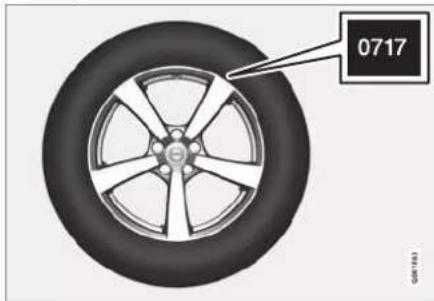
natural_image
Close-up of a car wheel rim with a black label pointing to the number 0717 (no other text or symbols)Tyres are perishable. After a few years they begin to harden at the same time as the friction capacity/characteristics gradually deteriorate. For this reason, aim to get as fresh tyres as possible when you replace them. This is especially important with regard to winter tyres. The last four digits in the sequence mean the week and year of manufacture. This is the tyre's DOT marking (Department of Transportation), and this is stated with four digits, for example 0717. The tyre is then manufactured in week 07, year 2017.
Tyre age
All tyres older than 6 years old should be checked by an expert even if they seem undamaged. Tyres age and decompose, even if they are hardly ever or never used. The function can therefore be affected. This applies to all tyres that are stored for future use. Examples of external signs which indicate that the tyre is unsuitable for use are cracks or discolouration.
Tyre economy
- Maintain the correct tyre pressure.
- Avoid fast starts, heavy braking and squealing tyres.
• Tyre wear increases with speed.
• Correct wheel alignment is very important. - Unbalanced wheels worsen tyre economy and travelling comfort.
- The tyres must have the same direction of rotation during their entire service life.
- When you change tyres, the tyres with the best tread must be fitted on the rear wheels to reduce the risk of oversteer during heavy braking.
- If you drive over kerbstones or deep holes you can damage the tyres and/or wheel rims permanently.
Tyre rotation
The car has no mandatory tyre rotation. Driving style, tyre pressure, climate and road condition affect how quickly the tyres age and
wear. Correct tyre pressure results in more even wear.
To avoid differences in tread depth and to prevent wear patterns forming on the tyres, the front and rear wheels should be switched with each other. A suitable distance for the first change is approx. 5000 km (approx. 3100 miles) and then at 10000 km (approx. 6200 miles) intervals.
Volvo recommends the an authorised Volvo workshop is contacted for checking if you are uncertain about tread depth. If significant differences in wear (> 1 mm difference in tread depth) between tyres have already occurred, then the least worn tyres must always be fitted on the rear. Understeer is normally easier to correct than oversteer, and leads to the car continuing forwards in a straight line rather than having the rear end skidding to one side, resulting in possible complete loss of control over the car. This is why it is important for the rear wheels never to lose grip before the front wheels.
Storing wheels and tyres
When you store complete wheels (tyres fitted on wheel rims) they should be hung up or positioned lying on their sides on the floor.
Tyres not fitted on rims must be stored lying on their sides or standing upright, but not hung up.
IMPORTANT
Tyres should be stored in a cool, dry and dark place, and should never be stored close to solvents, petrol, oils, etc.
WARNING
- Wheel rim size and tyre size for your Volvo are specified to meet stringent requirements for stability and driving characteristics. Unapproved combinations of wheel rim size and tyre size may have a negative effect on the car's stability and driving characteristics.
- Any damage caused by the fitting of unapproved combinations of wheel rim size and tyre size is not covered by the new car warranty. Volvo accepts no liability for death, personal injury or any costs caused by such installations.
Related information
- Checking tyre pressure (p. 568)
• Tyres' rotation direction (p. 567)
• Tread wear indicators on the tyres (p. 568) - Tyre pressure monitoring system* (p. 571)
• Emergency puncture repair kit (p. 582)
• Dimension designation for tyre (p. 566)
• Approved wheel and tyre sizes (p. 675)
• Recommendations for loading (p. 595)
WHEELS AND TYRES
Dimension designation for tyre
Designations for tyre dimension, load index and speed rating.
The car has an approval for the complete vehicle with certain combinations of wheel rims and tyres.
Designation of dimensions
All tyres have a dimension designation, such as: 245/45 R18 100 W.
| 245 | Tyre width (mm) |
| 45 | Ratio between tyre wall height and tyre width (%) |
| R | Radial ply |
| 18 | Rm diameter in inches |
| 100 | Codes for the maximum permitted tyre load, tyre load index (LI) |
| W | Speed rating for maximum permitted speed, speed rating (SS). (In this case 270 km/h (168 mph).) |
Load index
Each tyre has a certain capacity to carry a load, a load index (LI). The car's weight determines the load capacity required of the tyres.
Speed rating
Each tyre can withstand a certain maximum speed. Tyre speed rating, SS (Speed Symbol), must at least correspond with the car's top speed. The table below shows the maximum permitted speed for each speed rating (SS). The only exception to these regulations is winter tyres ^2 , where a lower speed rating may be used. If such a tyre is selected, the car must not be driven more quickly than the tyre is rated for. For example, cars with Q rating tyres must be driven at speeds not exceeding 160 km/h (100 mph). The road conditions and applicable road traffic rules determine how quickly the car can be driven, not the speed rating of the tyres.
| NOTEThe maximum permitted speed is specifiedin the table. | |
| Q | 160 km/h (100 mph) (used only onwinter tyres) |
| T | 190 km/h (118 mph) |
| H | 210 km/h (130 mph) |
| V | 240 km/h (149 mph) |
| W | 270 km/h (168 mph) |
| Y | 300 km/h (186 mph) |

WARNING
The lowest permitted tyre load index (LI) and speed rating (SS) for the tyres for each respective engine variant are shown in the specifications, which can be found in the printed owner's manual. If a tyre with too low a load index or speed rating is used, it may overheat and be damaged.
Related information
- Tyres (p. 564)
- Dimension designation for wheel rim (p. 567)
• Approved wheel and tyre sizes (p. 675)
• Minimum permitted tyre load index and speed rating for tyres (p. 676)
Dimension designation for wheel rim
Wheel and rim dimensions are designated in accordance with the examples in the table below.
The car has an approval for the complete vehicle with certain combinations of wheel rims and tyres.
All wheel rims have a dimension designation, for example: 8Jx18x42.
| 8 Rim width in inches |
| J Rim flange profile |
| 18 Rim diameter in inches |
| 42 Off-set in mm (distance from wheel centre to wheel contact surface against the hub) |
Related information
- Tyres (p. 564)
• Dimension designation for tyre (p. 566)
• Approved wheel and tyre sizes (p. 675)
Tyres' rotation direction
Tyres with a tread pattern which are designed to only turn in one direction have the direction of rotation marked with an arrow.

natural_image
Side view of a car showing the wheel rim and side panel, with an inset highlighting the wheel (no text or symbols present)The arrow shows the tyre's direction of rotation.
- The tyre must always rotate in the same direction throughout its lifespan.
- Tyres should only be switched between front and rear positions, never between left and right-hand sides, or vice versa.
- If the tyres are fitted incorrectly, the car's braking characteristics and capacity to force rain and slush out of the way are adversely affected.
- Tyres with the greatest tread depth should always be fitted to the rear of the car (to decrease the risk of skidding).

NOTE
Make sure that both pairs of wheels have the same type and dimension, and also the same make.
Related information
- Tyres (p. 564)
WHEELS AND TYRES
Tread wear indicators on the tyres Tread wear indicators show the status of the tyre's tread depth.

natural_image
3D architectural rendering of a multi-level building complex with gray and black blocks (no text or symbols visible)A tread wear indicator is a narrow elevation across the longitudinal grooves of the tyre's tread pattern. On the side of the tyre are the letters TWI (Tread Wear Indicator). When the tyre's tread depth is down to 1.6 mm (1/16 inch), the tread will be level in height with the tread wear indicators. Change to new tyres as soon as possible. Remember that tyres with little tread depth provide very poor grip in rain and snow.
Related information • Tyres (p. 564)
Checking tyre pressure
Correct tyre pressure helps to improve driving stability, save fuel and extend the service life of the tyres.
Tyre pressure decreases over time, this is a natural phenomenon. Tyre pressure also varies depending on ambient temperature. Driving on tyres with tyre pressure that is too low could result in the tyres overheating and being damaged. Tyre pressure affects travelling comfort, road noise and driving characteristics.
Check the tyre pressures monthly. Use the recommended tyre pressure for cold tyres in order to maintain good tyre performance. Tyre pressure that is too low or too high may cause uneven wear on the tyres.
WARNING
- Tyre pressure that is too low is the most common cause of tyre failure and may result in serious cracks in the tyre, the tread loosening or the tyre exploding, with unexpected loss of control of the car and increased risk of personal injury.
- Tyres with pressure that is too low reduce the load capacity of the car.
Cold tyres
The tyre pressure must be checked when the tyres are cold. Tyres are considered cold when they have the same temperature as the surrounding air. This temperature is normally reached when the car has been parked for at least three hours.
After having driven approximately 1.6 km (1 mile) these tyres are considered as warm. If you have to drive further than this to inflate the tyres, first check and record the tyre pressure and inflate to a suitable tyre pressure when you arrive at the pump.
When the outside temperature changes, the tyre pressure also changes. A decrease in temperature of 10 degrees causes the tyre pressure to decrease 1 psi (7 kPa). Check the tyre pressure regularly and adjust to the correct pressure, which is specified on the car's tyre information decal or certification label.
If you check the tyre pressure when the tyres are warm then you must never release any air. The tyres are warm due to driving and it is normal for the pressure to increase above the recommended pressure for cold tyres. A warm tyre with tyre pressure equal to or below the recommendation for cold tyres may have a pressure that is far too low.
Related information
• Adjusting tyre pressure (p. 569)
• Recommended tyre pressure (p. 570)
- Tyre pressure monitoring system* (p. 571)
- Tyres (p. 564)
Adjusting tyre pressure
Tyre pressure decreases over time, this is a natural phenomenon. The tyre pressure must therefore sometimes be adjusted in order to maintain the recommended tyre pressure. Use the recommended tyre pressure for cold tyres in order to maintain good tyre performance and even tread wear.
NOTE
To avoid incorrect tyre pressure, the pressure should be checked on cold tyres. "Cold tyres" means the tyres are the same temperature as the ambient temperature (approx. 3 hours after the car has been driven). After a few kilometres of driving, the tyres warm up and the pressure increases.
- Remove the cap from the valve on one tyre and then press the tyre pressure gauge firmly down onto the valve.
-
Inflate the tyres to the correct pressure, see the decal on the door pillar on the driver's side showing the recommended pressure for factory fitted tyres.
-
Refit the dust cap.
NOTE
- After a tyre has been inflated, always refit the dust cap in order to avoid damage to the valve from gravel, dirt, etc.
-
Only use plastic dust caps. Metal dust caps can rust and become difficult to unscrew.
-
Check the tyres visually for any implanted nails or other objects that could puncture the tyre and cause leakage.
-
Check the sidewalls for any cavities, cuts, bumps or other irregularities.
-
Repeat this for all tyres, including the spare tyre*.
NOTE
If you have over-inflated, release air by pressing in the metal pin in the centre of the valve. Then check the pressure again using the tyre pressure gauge.
Some spare tyres require a higher tyre pressure than other tyres. Check in the tyre pressure table or on the tyre pressure label.
WHEELS AND TYRES
Related information
• Recommended tyre pressure (p. 570)
• Checking tyre pressure (p. 568)
- Inflating tyres with the compressor from the puncture repair kit (p. 586)
• Approved tyre pressures (p. 677)
Recommended tyre pressure
The tyre pressure label on the driver's side door pillar (between frame and rear door) shows which pressures the tyres should have at different loads and speed conditions.
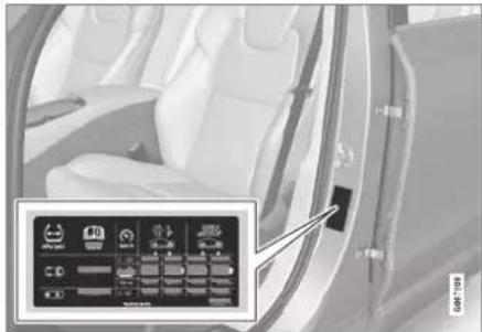
natural_image
Interior view of a car with white seats and a door, showing a control panel with icons (no readable text or symbols)Tyre pressure label location
The decal displays the designation for the factory-fitted tyres on the car, as well as load limits and tyre pressure.
i NOTE
It is not intended that the decals illustrated in the owner's manual should be exact replicas of those in the car. They are included to show their approximate appearance and locations in the car. The information that applies to your particular car can be found on the decal on the car.
Improved fuel economy with ECO pressure For a light load (max. 3 people) and a speed of up to 160 km/h (100 mph), the ECO pressures can be chosen for good fuel economy. However, the lower comfort pressures are recommended instead if improved noise and travelling comfort are desired.
Related information
• Checking tyre pressure (p. 568)
• Approved tyre pressures (p. 677)
Tyre pressure monitoring system\*
The tyre pressure monitoring system ^3 gives a warning with an indicator symbol in the driver display when the pressure in one or more of the car's tyres is too low.

This symbol illuminates to indicate low tyre pressure. Check the tyre pressure in the Car Status app in the centre display.
If there is a fault in the sys-
tem the tyre pressure warning symbol flashes for approximately one minute and then remains illuminated.
System description
The tyre pressure monitoring system measures differences in rotation speed between the different wheels via the ABS system in order to be able to determine whether they have the correct tyre pressure. If the tyre pressure is too low, the tyre's diameter is changed and, as a result, so is its rotation speed. By comparing the tyres with each other the system can determine whether one or more tyres have pressure that is too low.
General information on the tyre monitoring system
In the information below, the tyre monitoring system is referred to generically as TPMS.
Each tyre, including the spare tyre*, should be checked once a month. When checking, the tyre should be cold and have the air pressure recommended by the car manufacturer specified on the tyre pressure label or in the tyre pressure table. If the car has tyres of a different size than that recommended by the manufacturer, find out what the correct air pressure level is for these.
As an extra safety feature, the car is equipped with a tyre pressure monitoring system (TPMS), which shows when the air pressure in one or more tyres is too low. When the indicator symbol for low air pressure is lit, stop and check the tyres as soon as possible and inflate to the correct air pressure.
Driving with tyres that have tyre pressure that is too low may cause the tyre to overheat, which can cause a tyre failure. Low tyre pressure also reduces fuel efficiency as well as tyre service life, and can affect car handling and stopping ability. Note that TPMS does not replace regular tyre maintenance. It is the driver's responsibility to maintain correct tyre pressure, even if the limit for low tyre pressure has not been reached so that the indicator symbol illuminates.
The car is also equipped with a TPMS system fault indicator, which indicates when the system is not functioning correctly. The TPMS
system fault indicator is combined with the indicator symbol for low tyre pressure. When the system detects a fault, the symbol in the driver display will flash for about one minute and then remain illuminated. This procedure will be repeated when the car is started until the fault has been rectified. When the symbol is illuminated, the system's ability to detect or warn of low tyre pressure may be affected.
A TPMS system fault can occur for several reasons, such as after changing to a spare tyre, or changing tyres or wheels that prevent TPMS from functioning correctly.
Always check the indicator symbol for TPMS after changing one or more tyres in order to ensure the new tyre or wheel is working correctly with TPMS.
To bear in mind
- Always save a new tyre pressure in the system after changing a wheel or adjusting tyre pressure.
- If you change to tyres of a different size to the ones fitted at the factory, the system must be reset by storing a new tyre pressure for these tyres to avoid false warnings.
- If a spare wheel* is used, it is possible that the tyre pressure monitoring system does
WHEELS AND TYRES
◀◀
not work correctly due to the differences between the wheels.
- The system does not replace the need for regular tyre inspection and maintenance.
- It is not possible to switch off the tyre pressure monitoring system.

WARNING
- Incorrect tyre pressure may lead to tyre failure, which could result in the driver losing control of the car.
- The system cannot indicate sudden tyre damage in advance.
Related information
• Recommended tyre pressure (p. 570)
- See tyre pressure status in the centre display* (p. 573)
• Action in the event of warning for low tyre pressure (p. 574)
- Saving a new reference value for tyre pressure monitoring* (p. 572)
- Messages for tyre pressure monitoring* (p. 575)
Saving a new reference value for tyre pressure monitoring\*
In order for the system for tyre pressure monitoring ^4 to work correctly, a reference value for the tyre pressure must be saved. This must take place every time the tyres are changed or the tyre pressure is changed so that the system can warn about low pressure correctly.
For example, when driving with a heavy load or at high speed above 160 km/h (100 mph), the tyre pressure should be adjusted in accordance with Volvo's recommended tyre pressure values. The system is then reset by saving a new tyre pressure.
Perform the following procedure to store a new tyre pressure as a reference value in the system:
- Switch off the car.
- Inflate the tyres to the correct pressure, see the decal on the door pillar on the driver's side showing the recommended pressure for factory fitted tyres.
- Start the car.
- Open the Car Status app in the app view.
- Press TPMS.

NOTE
The car must be stationary for the Store Pressure button to be selectable.
- Press Store Pressure.
- Tap on OK to confirm that the tyre pressure in all four tyres has been checked and adjusted.
- Drive the car until the new tyre pressure has been saved. The new tyre pressure is stored when the car is driven at a speed above 35 km/h (22 mph).
When sufficient data has been collected for the system to be able to detect low tyre pressure, the animation showing storage progress disappears from the centre display. The system does not provide additional confirmation that a new tyre pressure has been saved.
If storing fails, a message is shown: Storing pressure unsuccessful. Try again.

WARNING
The exhaust gases contain carbon monoxide, which is invisible and odourless, but highly toxic. The procedure to save a new tyre pressure must therefore always be performed outdoors or in a workshop with exhaust extraction.
Related information
• Recommended tyre pressure (p. 570)
• Adjusting tyre pressure (p. 569)
- See tyre pressure status in the centre display* (p. 573)
• Action in the event of warning for low tyre pressure (p. 574)
• Tyre pressure monitoring system* (p. 571)
See tyre pressure status in the centre display\*
With the system for tyre pressure monitoring ^5 , tyre pressure status can be viewed in the centre display.
Checking status
Several minutes driving above 35 km/h (22 mph) are required for the system to become active.
- Open the Car Status app in the app view.
- Tap on TPMS to show the status of the tyres.
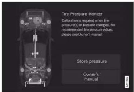
The figure is schematic. Layout may vary depending on car model or updated software.
Related information
- Saving a new reference value for tyre pressure monitoring* (p. 572)
• Action in the event of warning for low tyre pressure (p. 574)
• Tyre pressure monitoring system* (p. 571) - Car status (p. 602)
- Messages for tyre pressure monitoring* (p. 575)
WHEELS AND TYRES
Action in the event of warning for low tyre pressure
When the system for tyre pressure ^6 warns that tyre pressure is too low, action is required.

Check and rectify the tyre pressure when the indicator symbol for the system is illuminated and the Tyre pressure low message is shown.
- Switch off the car.
- Check the tyre pressure in all four tyres with a tyre pressure gauge.
- Inflate the tyres to the correct pressure, see the decal on the door pillar on the driver's side showing the recommended pressure for factory fitted tyres.
- Always save a new tyre pressure in the system via the centre display after the tyre pressure has been adjusted.
Note that the indicator symbol does not extinguish until the low tyre pressure has been rectified and storing a new tyre pressure has been started.
NOTE
To avoid incorrect tyre pressure, the pressure should be checked on cold tyres. "Cold tyres" means the tyres are the same temperature as the ambient temperature (approx. 3 hours after the car has been driven). After a few kilometres of driving, the tyres warm up and the pressure increases.
NOTE
- After a tyre has been inflated, always refit the dust cap in order to avoid damage to the valve from gravel, dirt, etc.
- Only use plastic dust caps. Metal dust caps can rust and become difficult to unscrew.
WARNING
- Incorrect tyre pressure may lead to tyre failure, which could result in the driver losing control of the car.
- The system cannot indicate sudden tyre damage in advance.
Related information
• Recommended tyre pressure (p. 570)
• Adjusting tyre pressure (p. 569)
- Saving a new reference value for tyre pressure monitoring* (p. 572)
• See tyre pressure status in the centre display* (p. 573)
• Tyre pressure monitoring system* (p. 571)
- Inflating tyres with the compressor from the puncture repair kit (p. 586)
Messages for tyre pressure monitoring\*
A number of messages for the tyre pressure monitoring system ^7 can be shown. Here are some examples.
| Driver display: Tyre pressure low Check Car Status app in center display | The indicator symbol switches on to indicate that there is low tyre pressure in one or more tyres. See the Car Status app in the centre display for more information. |
| Driver display: Tyre pressure system Temporarily unavailable | The indicator symbol flashes and changes to constant glow after approx. 1 minute. The system is currently unavailable, activated shortly. |
| Driver display: Tyre pressure system Service required | The indicator symbol flashes and changes to constant glow after approx. 1 minute. The system is not working correctly, contact a workshop ^A . |
A An authorised Volvo workshop is recommended.
Related information
• Tyre pressure monitoring system* (p. 571)
- Saving a new reference value for tyre pressure monitoring* (p. 572)
• Action in the event of warning for low tyre pressure (p. 574)
• Car status (p. 602)
• Volvo Cars support site (p. 23)
Changing wheel
Wheel changes must always be performed correctly. Instructions on how a wheel is removed and mounted and what is important to remember are provided below. Check that the tyre dimension is approved for use on the car.
WARNING
- If a wheel must be changed in a trafficked environment, passengers must stand in a safe place.
- Use a jack designed for the car when changing tyres. Use supports to secure the car for all other work.
- Never crawl under the car or reach under with a part of your body when it is raised on a jack.
- Passengers must leave the car when it is raised on the jack.
WHEELS AND TYRES
◀◀
IMPORTANT
- When the jack* is not in use it must be stored in its storage space under the cargo area floor.
- The jack included with the car is only designed for occasional, short-term use, such as when changing a wheel after a puncture. Only the jack belonging to the specific model is to be used to jack up the car. If the car is to be jacked up more often, or for a longer time than is required just to change a wheel, use of a garage jack is recommended. In this instance, follow the instructions for use that come with the equipment.
Removing a wheel
Read through all instructions before beginning. Take out the tools needed before jacking up the car.
- Activate the hazard warning flashers and set out a warning triangle if a wheel shall be changed in a trafficked location.
- Make sure that the parking brake is activated and engage gear position P.
-
Chock in front of and behind the wheels that remain on the ground. Use, for example, heavy wooden blocks or large stones.
-
Screw together the towing eye with the wheel wrench to the stop position.
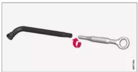
natural_image
Two mechanical tools or tools, one black and one metallic, shown against a plain background (no text or symbols visible)- Remove the plastic caps from the wheel bolts with the intended tool.
- With the car still on the ground, use the wheel bolt wrench/towing eye to undo the wheel bolts 12 -1 turn by pressing downwards (anticlockwise). Always start with the lockable wheel bolts*.
- Follow the instructions for how to safely raise the car with the jack.
- Raise the car high enough to allow the wheel to be removed to move freely. Remove the wheel bolts and lift off the wheel.
Mounting a wheel
-
Clean the surfaces between wheel and hub.
-
Put on the wheel. Tighten the wheel bolts thoroughly.
Do not use lubricant on the threads of the wheel bolts. - Lower the car so that the wheels cannot rotate.
- Tighten the wheel bolts crosswise. It is important that the wheel bolts are tightened properly. Tighten to 140 Nm (103 foot-pound). Check the tightening torque with a torque wrench.

natural_image
Close-up of a Volvo wheel hub with numbered red-labeled components (no text or symbols beyond component numbers)-
Refit the plastic caps over the wheel bolts.
-
Check the tyre pressure and save the new tyre pressure in the system for tyre pressure monitoring*.

WARNING
The wheel bolts may need to be re-tightened several days after the wheel change. Temperature differences and vibration may mean that they are not attached equally as tightly.

NOTE
- After a tyre has been inflated, always refit the dust cap in order to avoid damage to the valve from gravel, dirt, etc.
- Only use plastic dust caps. Metal dust caps can rust and become difficult to unscrew.
Related information
- Settings for level control* (p. 476)
• Warning triangle (p. 598) - Raise the car (p. 605)
- Tool kit (p. 577)
- Saving a new reference value for tyre pressure monitoring* (p. 572)
Tool kit
Tools that can be useful during towing, wheel changes or similar are stored in the car's cargo area.

All tools are located in the foam block under the cargo area floor.
1 Jack*
② Tool for removing the plastic caps from the wheel bolts
3 Funnel for filling fluids
4 Wheel wrench* and towing eye
If the car is fitted with a spare wheel*, there is a jack and a wheel bolt wrench.
Related information
- Changing wheel (p. 575)
- Jack* (p. 578)
• Emergency puncture repair kit (p. 582)
• Fitting and removing the towing eye (p. 498)
WHEELS AND TYRES
Jack\*
The jack can be used to raise the car, for example, to change to a wheel.

natural_image
Mechanical linkage component with articulated arms and a central rod (no text or symbols visible)IMPORTANT
- When the jack* is not in use it must be stored in its storage space under the cargo area floor.
- The jack included with the car is only designed for occasional, short-term use, such as when changing a wheel after a puncture. Only the jack belonging to the specific model is to be used to jack up the car. If the car is to be jacked up more often, or for a longer time than is required just to change a wheel, use of a garage jack is recommended. In this instance, follow the instructions for use that come with the equipment.
The jack needs to be cranked together to the correct position in order to have space.
Applies to cars with Leveling Control*: If the car is equipped with the air suspension option then this function must be deactivated before the car is raised with the jack.
Related information
- Tool kit (p. 577)
- Raise the car (p. 605)
Wheel bolts
Wheel bolts are used to attach the wheels to the hubs.
Only use rims that are tested and approved by Volvo and which are Volvo genuine accessories.
Check the tightening torque of the wheel bolts with a torque wrench.
Do not use lubricant on the threads of the wheel bolts.
WARNING
The wheel bolts may need to be re-tightened several days after the wheel change. Temperature differences and vibration may mean that they are not attached equally as tightly.
IMPORTANT
The wheel bolts must be tightened to 140 Nm. (103 foot-pound). Overtightening or loose tightening may damage the nuts and the bolts.
Lockable wheel bolt kit\*
To loosen or tighten the lockable wheel bolts – turn the wrench in the lock bolt until it fully engages in the code grooves. Always start with the lockable wheel bolts if the wheel shall
be removed. When fitting the wheel, finish with the lock screw.
IMPORTANT
Remember not to use bending force when you loosen/tighten the wheel bolts. This could damage the code groove in the lock bolt and the wheel wrench and so make it impossible to fit/remove the wheel.
When the wheel wrench is not in use it must be stored in its place in the foam block under the cargo area floor. It is important to remember this if the car is due to visit a workshop in order to have the tool available. If you lose the wrench, contact your Volvo dealer.
Related information
• Changing wheel (p. 575)
- Tool kit (p. 577)
Spare wheel\*
The spare wheel, the Temporary Spare type, can be used to temporarily replace a punctured normal wheel.
The spare wheel is only designed for temporary use. Replace it with a normal wheel as soon as possible.
The car's driving characteristics can be changed when the spare wheel is used and the ground clearance is reduced. Do not wash the car in an automatic car wash if the Temporary Spare is being used.
Recommended tyre pressure must be maintained regardless of the position of the temporary spare wheel on the car.
If the spare wheel is damaged, a new one can be purchased from a Volvo dealer.
WARNING
- Never drive faster than 80 km/h (50 mph) with a spare wheel fitted on the car.
- The car must never be driven fitted with more than one "Temporary Spare" wheel.
- The car may have different driving characteristics while driving with the spare wheel. The spare wheel must be replaced with a normal wheel as soon as possible.
- The spare wheel is smaller than the normal wheel, which affects the car's ground clearance. Look out for high kerbs and do not machine-wash the car.
- Follow the manufacturer's recommended tyre pressure for the spare wheel.
- On all-wheel drive cars, the drive on the rear axle can be disengaged.
- If the spare wheel is fitted to the front axle then it is not possible to use snow chains at the same time.
• The spare wheel must not be repaired.
WHEELS AND TYRES
◀◀
IMPORTANT
The car must not be driven with tyres of different sizes or with a spare wheel other than the one supplied with the car. Using different-sized wheels can cause serious damage to the car's transmission.
Related information
- Changing wheel (p. 575)
• Recommended tyre pressure (p. 570)
Handling the spare wheel\*
Follow these instructions for handling the spare wheel.

natural_image
3D rendering of a black cylindrical device with X-bracing placed inside a car cab (no text or symbols visible)The illustration is generic and appearance may differ.
The spare wheel is stored in a bag and must be secured with two straps on the floor of the cargo area while driving. The straps must be tensioned crosswise over the wheel and attached in the car's four load retaining eyelets.
Tools for changing wheels are located under the cargo area floor.
Related information
- Spare wheel* (p. 579)
- Tool kit (p. 577)
• Changing wheel (p. 575)
Winter tyres
Winter tyres are adapted for winter road conditions.
Volvo recommends winter tyres with particular dimensions. Tyre dimensions are dependent on engine variant. When driving on winter tyres, the correct type of tyres must be fitted to all four wheels.
Tips for changing to winter tyres
When summer and winter wheels are changed, mark which side of the car they were mounted on, for example L for left and R for right.
Contact a Volvo dealer for advice on which rim and tyre type suit your car best.
Studded tyres
Studded winter tyres should be run in gently for 500-1000 km (300-600 miles), so the studs settle properly into the tyres. This gives the tyre, and especially the studs, a longer service life.
NOTE
Laws regarding the use of studded tyres may vary. Always follow local laws and regulations.
Tread depth
Road conditions with ice, slush and low temperatures place considerably higher demands
on tyres than summer conditions. Volvo therefore recommends not to drive on winter tyres that have a tread depth of less than 4 mm (0.15 inches).
Related information
• Changing wheel (p. 575)
• Winter driving (p. 480)
- Tread wear indicators on the tyres (p. 568)
• Approved wheel and tyre sizes (p. 675)
• Volvo Cars support site (p. 23)
Snow chains
Use of snow chains and/or winter tyres can help to improve the traction in winter conditions.
Volvo recommends that snow chains are not used on wheel dimensions greater than 18 inches.
WARNING
Use Volvo genuine snow chains or equivalent chains designed for the car model, and tyre and rim dimensions. Only single-sided snow chains are permitted.
In the event of uncertainty about the show chain, Volvo recommends that an authorised Volvo workshop should be contacted. The wrong snow chains may cause serious damage to the car and lead to an accident.
IMPORTANT
Snow chains can be used on the car with the following restrictions:
• Always follow the mounting instructions from the manufacturer carefully. Fit the chains as tensioned as possible and tension them at regular intervals.
- Snow chains must only be used on the front wheels (also applies to all-wheel drive cars).
- In some cases, snow chains must NOT be used, such as if accessory, aftermarket or "special" tyres and wheels are fitted that have a different size to the original tyres and wheels. Sufficient distance must be maintained between the chains and brakes, suspension and body components.
- Check local regulations with regard to using snow chains before fitting them.
- Never exceed the chain manufacturer's specified maximum speed. You must never exceed 50 km/h (30 mph) under any circumstances.
- Avoid bumps, holes or sharp turns when driving with snow chains.
- Avoid driving on bare ground as this wears out both the snow chains and tyres.
WHEELS AND TYRES
◀◀
- Driving with snow chains may have a negative effect on the car's driving characteristics. Avoid fast or sharp turns, as well as braking with locked wheels.
- Some types of chain that are firmly tensioned affect brake components and must therefore NOT be used.
You can obtain more information on snow chains from a Volvo dealer.
Related information
• Winter driving (p. 480)
Emergency puncture repair kit
The emergency puncture repair kit ^8 , is used to seal a puncture as well as to check and adjust the air pressure in the tyre.
Cars equipped with spare tyre* do not have the puncture repair kit.
The puncture repair kit consists of a compressor and a bottle with sealing fluid. The sealing works as a temporary repair.
NOTE
The sealing fluid is effective at sealing tyres with tread punctures but has limited ability to seal tyres with sidewall punctures. Do not use the emergency puncture repair kit on tyres displaying larger slits, cracks or similar damage.
NOTE
The compressor is intended for temporary emergency puncture repair and is approved by Volvo.
Location
The puncture repair kit is located in the foam block under the cargo area floor.

natural_image
White plastic bottle next to a black electronic device with two circular buttons and a grid of small images (no visible text or symbols)Sealing fluid expiry date
The bottle of sealing fluid must be replaced if the bottle's expiry date has passed (see the decal on the bottle). Treat the old bottle as environmentally hazardous waste.
Related information
• Using a puncture repair kit (p. 583)
• Inflating tyres with the compressor from the puncture repair kit (p. 586)
- Tyres (p. 564)
Using a puncture repair kit
The emergency puncture repair kit (TMK ^9 ) can be used to seal a puncture. Read through all instructions before use.
Overview

1 Electrical cable
2 Air hose
3 Pressure reducing valve
4 Protective cap
5 Label, maximum permitted speed
6 Bottle holder (orange cap)
7 Pressure gauge
8 Sealing fluid bottle
9 Switch
Connecting

i NOTE
Do not break the bottle's seal before use. The seal is broken automatically when the bottle is screwed in.
WARNING
Please keep the following points in mind when using the tyre sealing system:
- The sealing fluid bottle contains 1) rubber latex, natural and 2) ethanediol. These substances are harmful if swallowed.
- The contents of this bottle may cause allergic skin reactions or otherwise be potentially harmful to the respiratory tract, the skin, the central nervous system, and the eyes.
Precautions:
• Store out of the reach of children.
- Harmful if ingested.
- Avoid prolonged or repeated contact with the skin. If sealing fluid has come into contact with your clothes, remove them.
- Wash thoroughly after handling.
First aid:
- Skin: Wash affected areas of skin with soap and water. Get medical attention if symptoms occur.
- Eyes: Flush with plenty of water for least 15 minutes, occasionally lifting
WHEELS AND TYRES
◀◀
the upper and lower eyelids. Get medical attention if symptoms occur.
• Inhalation: Move the exposed person to fresh air. If irritation persists, get medical attention.
- Ingestion: Do NOT induce vomiting unless directed to do so by medical personnel. Get medical attention.
- Disposal: Dispose of this material and its container at a hazardous or special waste collection point.

WARNING
Do not remove the bottle or air hose when the puncture repair kit is being used.
1. Preparations
Set up the warning triangle and activate the hazard warning lights if a tyre is being sealed in a trafficked location.
If the puncture was caused by a nail or similar, allow this to remain in the tyre. It helps to seal the hole.
- Detach the decal for maximum permitted speed that is affixed on one side of the compressor. Affix it visibly on the wind-screen as a reminder to observe the speed limit. You should not drive faster than 80 km/h (50 mph) after the emergency tyre repair kit has been used.
- Check that the switch is in position 0 (Off), and locate the electrical cable and the air hose.
- Unscrew the orange-coloured cap from the compressor, and unscrew the cork from the sealing fluid bottle.
- Screw in the bottle to the bottom of the bottle holder.
The bottle and the bottle holder are equipped with a reverse catch to prevent sealant leakage. When the bottle is screwed in it cannot be unscrewed from the bottle holder again. The bottle must be removed at a workshop ^10 .

WARNING
Do not unscrew the bottle, it is equipped with a reverse catch to prevent leakage.
- Unscrew the tyre's dust cap and screw in the air hose's valve connection to the bottom of the thread on the tyre's air valve.
Check that the pressure reducing valve on the air hose is fully screwed in.
7. Begin puncture repair
Connect the electrical cable to the closest 12 V socket and start the car.

NOTE
Make sure that none of the other 12 V sockets is in use when the compressor is operating.

WARNING
Do not leave children in the car without supervision when the engine is running.

WARNING
Inhaling car exhaust fumes could result in danger to life. Never leave the engine running in sealed areas or areas that lack sufficient ventilation.
- Start the compressor by flicking the switch to position I (On).
When the compressor starts, the pressure can increase up to 6 bar (88 psi), but the pressure drops after about 30 seconds.

WARNING
Never stand next to the tyre when the compressor is running. If cracks or unevenness arise then the compressor must be switched off immediately. The journey should not be continued. Call roadside assistance for recovery to a tyre centre. Volvo recommends an authorised tyre centre.
- Inflate the tyre for 7 minutes.

IMPORTANT
The compressor must not be operated for longer than 10 minutes - risk of overheating.
- Switch off the compressor to check the pressure on the pressure gauge. Minimum pressure is 1.8 bar (22 psi) and maximum is 3.5 bar (51 psi). Release air using the pressure reducing valve if the tyre pressure is too high.

WARNING
If the pressure is below 1.8 bar (22 psi) then the hole in the tyre is too big. The journey should not be continued. Call roadside assistance for recovery to a tyre centre. Volvo recommends an authorised tyre centre.
-
Switch off the compressor and detach the electrical cable.
-
Unscrew the air hose from the tyre valve and refit the dust cap on the tyre.

NOTE
- After a tyre has been inflated, always refit the dust cap in order to avoid damage to the valve from gravel, dirt, etc.
-
Only use plastic dust caps. Metal dust caps can rust and become difficult to unscrew.
-
Fit the protective cap on the air hose in order to avoid leakage of the remaining sealing fluid. Place the equipment in the cargo area.
- As soon as possible, drive at least 3 km (2 miles) at a maximum speed of 80 km/h (50 mph) so that the sealing fluid can seal the tyre, and then perform a follow-up check.

WARNING
Sealant will spurt out of the puncture during the first few rotations of the tyre. Make sure that nobody is standing near the car and gets the sealing fluid splashed onto them when the car is driven away. The distance should be at least 2 metres (7 feet).
15. Follow-up inspection
Connect the air hose on the tyre valve and screw in the valve connection to the bottom of the tyre valve's thread. The compressor must be switched off.
WHEELS AND TYRES
-
Read the tyre pressure on the pressure gauge.
-
If it is below 1.3 bar (19 psi) then the tyre is insufficiently sealed. The journey should not be continued. Call roadside assistance for recovery.
- If the tyre pressure is higher than 1.3 bar (19 psi), the tyre must be inflated to the pressure specified in accordance with the tyre pressure label on the driver's side door pillar (1 bar = 100 kPa = 14.5 psi). Release air using the pressure reducing valve if the tyre pressure is too high.

WARNING
Check the tyre pressure regularly.
Volvo recommends that the car is driven to the nearest authorised Volvo workshop for the replacement/repair of the damaged tyre. Advise the workshop that the tyre contains sealing fluid.
The sealing fluid bottle and hose must be replaced after use. Volvo recommends that these replacements be performed by an authorised Volvo workshop.

WARNING
Maximum mileage with tyres containing sealing fluid is 200 km (120 miles).

NOTE
The compressor is an electrical device. Follow local regulations related to waste management.
Related information
• Recommended tyre pressure (p. 570)
• Emergency puncture repair kit (p. 582)
• Inflating tyres with the compressor from the puncture repair kit (p. 586)
Inflating tyres with the compressor from the puncture repair kit
The car's original tyres can be inflated using the compressor in the emergency puncture repair kit.
-
The compressor must be switched off. Make sure that the switch is in position 0 (Off), and take out the electrical cable and the air hose.
-
Unscrew the tyre's dust cap and screw in the air hose's valve connection to the bottom of the thread on the tyre's air valve.
Check that the pressure reducing valve on the air hose is fully screwed in.
- Connect the electrical cable to the closest 12 V socket and start the car.

WARNING
Inhaling car exhaust fumes could result in danger to life. Never leave the engine running in sealed areas or areas that lack sufficient ventilation.

WARNING
Do not leave children in the car without supervision when the engine is running.
- Start the compressor by flicking the switch to position I (On).
IMPORTANT
Risk of overheating. The compressor must not run for more than 10 minutes.
- Inflate the tyre to the pressure specified on the tyre pressure label on the driver side door pillar. Release air using the pressure reducing valve if the tyre pressure is too high.
- Switch off the compressor. Detach the air hose and the electrical cable.
- Refit the dust cap on the tyre.
i NOTE
- After a tyre has been inflated, always refit the dust cap in order to avoid damage to the valve from gravel, dirt, etc.
- Only use plastic dust caps. Metal dust caps can rust and become difficult to unscrew.
i NOTE
The compressor is an electrical device. Follow local regulations related to waste management.
Related information
• Recommended tyre pressure (p. 570)
• Using a puncture repair kit (p. 583)
• Emergency puncture repair kit (p. 582)

bar
| Category | Value | |---|---| | Category 1 | 100 | | Category 2 | 100 | | Category 3 | 100 | | Category 4 | 100 | | Category 5 | 100 | | Category 6 | 100 | | Category 7 | 100 | | Category 8 | 100 | | Category 9 | 100 | | Category 10 | 100 | | Category 11 | 100 | | Category 12 | 100 | | Category 13 | 100 | | Category 14 | 100 | | Category 15 | 100 | | Category 16 | 100 | | Category 17 | 100 | | Category 18 | 100 | | Category 19 | 100 | | Category 20 | 100 | | Category 21 | 100 | | Category 22 | 100 | | Category 23 | 100 | | Category 24 | 100 | | Category 25 | 100 | | Category 26 | 100 | | Category 27 | 100 | | Category 28 | 100 | | Category 29 | 100 | | Category 30 | 100 | | Category 31 | 100 | | Category 32 | 100 | | Category 33 | 100 | | Category 34 | 100 | | Category 35 | 100 | | Category 36 | 100 | | Category 37 | 100 | | Category 38 | 100 | | Category 39 | 100 | | Category 40 | 100 | | Category 41 | 100 | | Category 42 | 100 | | Category 43 | 100 | | Category 44 | 100 | | Category 45 | 100 | | Category 46 | 100 | | Category 47 | 100 | | Category 48 | 100 | | Category 49 | 100 | | Category 50 | 100 | | Category 51 | 100 | | Category 52 | 100 | | Category 53 | 100 | | Category 54 | 100 | | Category 55 | 100 | | Category 56 | 100 | | Category 57 | 100 | | Category 58 | 100 | | Category 59 | 100 | | Category 60 | 100 | | Category 61 | 100 | | Category 62 | 100 | | Category 63 | 100 | | Category 64 | 100 | | Category 65 | 100 | | Category 66 | 100 | | Category 67 | 100 | | Category 68 | 100 | | Category 69 | 100 | | Category 70 | 100 | | Category 71 | 100 | | Category 72 | 100 | | Category 73 | 100 | | Category 74 | 100 | | Category 75 | 100 | | Category 76 | 100 | | Category 77 | 100 | | Category 78 | 100 | | Category 79 | 100 | | Category 80 | 100 | | Category 81 | 100 | | Category 82 | 100 | | Category 83 | 100 | | Category 84 | 100 | | Category 85 | 100 | | Category 86 | 100 | | Category 87 | 100 | | Category 88 | 100 | | Category 89 | 100 | | Category 90 | 100 | | Category 91 | 100 | | Category 92 | 100 | | Category 93 | 100 | | Category 94 | 100 | | Category 95 | 100 | | Category 96 | 100 | | Category 97 | 100 | | Category 98 | 100 | | Category 99 | 100 | | Total (Total) |LOADING, STORAGE AND PASSENGER
COMPARTMENT
LOADING, STORAGE AND PASSENGER COMPARTMENT
Passenger compartment interior
Overview of the passenger compartment's interior and storage locations.
Front seat

natural_image
Interior view of a modern car dashboard and steering wheel (no visible text or symbols)Storage compartment in the door panel and by the steering wheel, glovebox and sun visors.

natural_image
Interior view of a car dashboard with red arrows pointing to key compartments (no text or symbols visible)Storage spaces with cup holder, electrical socket, mesh pocket* and USB port in the tunnel console.
Rear seat

natural_image
Interior view of a car showing white leather seats and rear seats with red arrows pointing to specific compartments (no text or symbols visible)Storage compartment in the door panel, cup holder* in the centre seat backrest, storage pocket* on the front seat backrest and also USB ports in the tunnel console.
WARNING
Keep loose objects such as mobile phones, cameras, remote controls for accessories, etc. in the glove compartment or other compartments. Otherwise they may injure people in the car in the event of sudden braking or a collision.
IMPORTANT
Keep in mind that high gloss surfaces, for example, are easily scratched by metal objects. Do not place keys, phones and other items on sensitive surfaces.
Related information
• Electrical sockets (p. 591)
• Using the glovebox (p. 593)
• Sun visors (p. 594)
• Tunnel console (p. 591)
• Connecting a device via USB port (p. 526)
Tunnel console
The tunnel console is located between the front seats.

1 Storage compartment with cup holder.
② Storage compartment with 12 V socket and USB port under the armrest.
3 Climate controls for the rear seat climate functions* or storage compartment. There are also USB ports underneath.

WARNING
Keep loose objects such as mobile phones, cameras, remote controls for accessories, etc. in the glove compartment or other compartments. Otherwise they may injure people in the car in the event of sudden braking or a collision.
IMPORTANT
Keep in mind that high gloss surfaces, for example, are easily scratched by metal objects. Do not place keys, phones and other items on sensitive surfaces.
i NOTE
One of the detectors for the alarm* is located under the tunnel console's cup holder. Avoid leaving coins, keys and other metal objects in the cup holder, since this may trigger the alarm.
NOTE
The USB sockets can be used for charging a mobile phone or tablet, for example. Only the front USB input can be used to play media in the car's audio system.
Related information
• Passenger compartment interior (p. 590)
• Electrical sockets (p. 591)
• Climate controls (p. 210)
Electrical sockets
There is one 12V electrical socket in the tunnel console and one 12V electrical socket* in the luggage compartment/cargo area.
If a problem occurs with an electrical socket, contact a workshop - an authorised Volvo workshop is recommended.
12 V electrical socket

12 V electrical socket in tunnel console, front seat.
The 12 V sockets can be used for various accessories designed for this, such as music players, cooler boxes and mobile phones.
LOADING, STORAGE AND PASSENGER COMPARTMENT
◀◀

natural_image
Close-up of a car interior with a small electronic device labeled 'RV' and a magnified inset showing its logo (no readable text or symbols beyond the label)12 V electrical socket in cargo area*.
Related information
• Passenger compartment interior (p. 590)
• Using electrical sockets (p. 592)
Using electrical sockets
12 V sockets can be used for various accessories designed for this, such as music players, cooler boxes and mobile phones.
For the sockets to supply current, the car's electrical system must be set in the lowest ignition position I. The sockets are then active as long as the starter battery level does not become too low.
If the engine is switched off and the car is locked, the sockets are deactivated. If the engine is switched off and the car is not locked, or is locked with double lock temporarily deactivated, then the sockets continue to be active for a further seven minutes.
NOTE
Remember that use of the electrical socket with the engine switched off entails a risk of discharging the starter battery, which can limit functionality.
Accessories that are connected to the electrical sockets may be activated even when the car's electrical system is disconnected or if preconditioning is used. For this reason, disconnect the connectors when they are not in use in order to avoid the starter battery being discharged.
WARNING
- Do not use accessories with large or heavy connectors - they can damage the socket or come loose when driving.
- Do not use accessories that can cause interference to the car's radio receiver or electrical system for example.
- Position the accessory so that it is not at risk of injuring the driver or passengers in the event of heavy braking or collision.
- Keep an eye on connected accessories as they can generate heat that can burn passengers or the interior.
Using 12 V sockets
- Remove the blanking plug (tunnel console) or fold down the cover (cargo area) in front of the socket and plug in the accessory's connector.
- Unplug the accessory's connector and refit the blanking plug (tunnel console) or fold up the cover (cargo area) when the socket is not in use or if the socket is left unattended.
IMPORTANT
Maximum socket output is 120 W (10 A) per socket.
LOADING, STORAGE AND PASSENGER COMPARTMENT
Related information
• Electrical sockets (p. 591)
• Passenger compartment Interior (p. 590)
Using the glovebox
The glovebox is located on the passenger side. The printed owner's manual and maps can be kept in the glovebox, for example. There is also space for a pen and card holder.
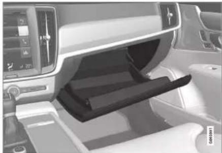
natural_image
Interior view of a car dashboard and seat area showing the rearrest seat cover (no visible text or symbols)Locking and unlocking the glovebox\*
The glovebox can be locked, e.g. when the car is taken in for service, left at a hotel or similar. The glovebox can only be locked/unlocked with the accompanying key.

natural_image
Interior view of a car dashboard with digital displays and a hand gesture overlay (no visible text or symbols)The key's designated storage space. The figure is schematic – the design may vary.
▶▶
* Option/accessory. 593
LOADING, STORAGE AND PASSENGER COMPARTMENT
◀◀

natural_image
Interior view of a car showing a seatbelt switch with two highlighted parts (no text or symbols visible)The figure is schematic - the design may vary. Locking the glovebox:
Insert the key in the glovebox lock cylinder.
2 Turn the key 90 degrees clockwise.
3 Pull out the key.
– Unlock by carrying this out in reverse order.
Related information
• Passenger compartment interior (p. 590)
- Private locking (p. 279)
Sun visors
There are sun visors in the roof in front of the driver seat and the front seat passenger seat which can be folded down and angled out to the side when necessary.

natural_image
Interior view of a car showing the rearview mirror and side mirror (no text or symbols visible)The figure is schematic - the design may vary.
The mirror lighting* is switched on automatically when the guard is lifted up.
The mirror frame incorporates a holder for e.g. cards or tickets.
Related information
• Passenger compartment interior (p. 590)
Cargo area
Inside the car's cargo area, it is possible to secure the load so that it stays in place while driving.
With folding* backrests in the rear seat, the cargo area can be made more spacious. There are load retaining eyelets and bag holders available for holding the load securely in place.
If the car is equipped with a spare wheel then this is attached on the cargo area floor. The car's towing eye and puncture repair kit are stored under the cargo area floor.
Related information
- Recommendations for loading (p. 595)
- Bag hooks (p. 596)
• Load retaining eyelets (p. 597)
Recommendations for loading
There are a number of things that are important to bear in mind when loading the car. Payload depends on the car's kerb weight. The total of the weight of the passengers and all accessories reduces the car's payload by a corresponding weight.

WARNING
The car's driving properties change depending on the weight and positioning of the load.
Loading in the cargo area
Good things to remember when loading:
- Position the load firmly against the rear seat's backrest.
- Heavy objects should be placed as low as possible. Avoid placing heavy loads on lowered backrests.
- Cover sharp edges with something soft to avoid damaging the upholstery.
- Secure all loads to the load retaining eyelets with straps or web lashings.

WARNING
A loose object weighing 20 kg (44 pounds) can, in a frontal collision at a speed of 50 km/h (30 mph) carry the impact of an item weighing 1000 kg (2200 pounds).

WARNING
Leave 10 cm (4 inches) space between the load and the side windows if the car is loaded to above the top edge of the door windows. Otherwise, the intended protection of the inflatable curtain, which is concealed in the headlining, may be compromised.

WARNING
Always secure the load. During heavy braking the load may otherwise shift, causing injury to the car's occupants.
Cover sharp edges and sharp corners with something soft.
Switch off the engine and apply the parking brake when loading/unloading long items. Otherwise you may accidentally knock the gear lever or gear selector with the load into a drive position - and the car could then move off.
Increasing the space in the cargo area
To expand the cargo area and simplify loading, the rear seat's backrest can be lowered*. Note that objects must not prevent the function of the WHIPS system for the front seats if any of the rear seat's backrests is folded down.
A through-load hatch* in the rear seat can be folded down for carrying long and narrow loads.
Related information
- Load retaining eyelets (p. 597)
- Lowering the backrests in the rear seat* (p. 192)
- Through-load hatch in the rear seat* (p. 597)
- Roof load and loading on load carriers (p. 596)
- Level control* and shock absorption (p. 473)
- Weights (p. 663)
LOADING, STORAGE AND PASSENGER COMPARTMENT
Roof load and loading on load carriers
For loading on the car's roof, the load carriers that Volvo have developed are recommended. This is in order to avoid damage to the car and in order to achieve the maximum possible safety during a journey. Volvo's load carriers are available for purchase at authorised Volvo retailers.
Carefully follow the installation instructions supplied with the carriers.
- Distribute the load evenly over the load carriers. Put the heaviest objects at the bottom.
- Check periodically that the load carriers and load are properly secured. Lash the load securely with retaining straps.
- If the load is longer than the car at the front, e.g. a canoe or kayak, fit the towing eye to its front socket and attach the bungee to this.
- The size of the area exposed to the wind, and therefore fuel consumption, increase with the size of the load.
- Drive gently. Avoid quick acceleration, heavy braking and hard cornering.
WARNING
The car's centre of gravity and driving characteristics are altered by roof loads. Follow the car's specifications with regard to weights and maximum permitted load.
Related information
• Recommendations for loading (p. 595)
- Weights (p. 663)
Bag hooks
Bag hooks keep carrier bags in place and prevent them from overturning and spreading their contents across the cargo area.
Along the sides

natural_image
Close-up of a car interior showing a door panel and a close-up inset of the door handle (no text or symbols visible)There is a bag hook in the side panel on each side of the cargo area.
IMPORTANT
The bag hooks may be loaded with a maximum of 5 kg (11 lbs).
Related information
• Recommendations for loading (p. 595)
• Using the glovebox (p. 593)
Load retaining eyelets
Use the load retaining eyelets to attach straps in order to anchor items in the cargo area.

natural_image
Front view of a modern car with visible engine compartment and a close-up inset showing a logo (no text or symbols)
WARNING
Hard, sharp and/or heavy objects which protrude may cause injury under violent braking.
Always secure large and heavy objects with a seatbelt or cargo retaining straps.
Related information
• Recommendations for loading (p. 595)
- Weights (p. 663)
Through-load hatch in the rear seat\*
The hatch in the rear seat's backrest can be opened to transport long narrow items, e.g. skis.

natural_image
Interior view of a vehicle door with a red downward arrow indicating a cut or change (no text or symbols visible)The figure is schematic - parts may vary depending on car model.
- In the cargo area, grip the hatch's handle and fold down the hatch.
- Fold forward the armrest in the rear seat.
If the private locking function is used then the through-load hatch must be closed.
Related information
• Recommendations for loading (p. 595)
• Private locking (p. 279)
• Load retaining eyelets (p. 597)
First aid kit\*
The first aid kit contains first aid equipment. Store the first aid kit in an appropriate place in the cargo area, e.g. in the space on the right-hand side. The first aid kit has Velcro straps and can be attached directly to the panel.
Related information
- Cargo area (p. 594)
LOADING, STORAGE AND PASSENGER COMPARTMENT
Warning triangle
Use the warning triangle to warn other road users if the car is stationary in traffic. Also activate the hazard warning flashers.
Storage spaces
The warning triangle is fitted with two clips on the inside of the boot lid.
Folding up the warning triangle
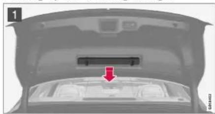
natural_image
Top-down view of a car trunk with a red arrow pointing to the rear vent (no text or symbols visible)
natural_image
Triangular warning sign with red arrows pointing downward, no text or symbols present
1 Remove the warning triangle's case by opening both latches.
2 Remove the warning triangle from the case, unfold it and put the ends together.
3 Fold out the warning triangle's support legs.
Follow the regulations for the use of a warning triangle. Position the warning triangle in a suitable place with regard to traffic.
Replace the warning triangle with case on the inside of the boot lid after use.
Related information
- Cargo area (p. 594)
• Hazard warning flashers (p. 159)
MAINTENANCE AND SERVICE
MAINTENANCE AND SERVICE
Volvo service programme
To keep the car as safe and reliable as possible, follow the Volvo service programme as specified in the Service and Warranty Booklet.
Volvo recommends engaging an authorised Volvo workshop to perform the service and maintenance work. Volvo workshops have the personnel, special tools and service literature that can provide the highest quality of service.
IMPORTANT
For the Volvo warranty to apply, check and follow the instructions in the Service and Warranty Booklet.
Service and repair
Service the car regularly. Follow Volvo's recommended service intervals.
If inspection and repair are required then only an authorised Volvo workshop may carry out the work.
WARNING
Do not carry out any repairs of your own on this vehicle. Electrical cables and/or components that have detached must only be rectified by an authorised workshop - an authorised Volvo workshop is recommended.
Charging cable with control unit
IMPORTANT
Do not modify the control unit in any way.
Related information
• Car status (p. 602)
• Book service and repair (p. 603)
- Connection of equipment to the car's diagnostic socket (p. 40)
• Servicing the climate control system (p. 608)
- Brake system maintenance (p. 454)
• Engine compartment overview (p. 610)
Data transfer between car and workshop via Wi-Fi
Volvo's workshops have a specific Wi-Fi network for data transfer between your car and the workshop. Your workshop visit will be simpler and more efficient when the transfer of diagnostic information and software can take place via the workshop's network. During a workshop visit, your service technician may want to connect your car to the workshop's network via Wi-Fi to perform fault-tracing and software download. For this type of communication, the car only connects to a workshop's network. It is not possible to connect the car to another Wi-Fi network, such as at home, in the same way as to a workshop's network.
Connection with the remote control key
Connection is normally handled by the service technician who then uses the remote control key buttons. That's why it's important to take a key with buttons with you for the workshop visit. Press three times on the lock button on the remote control key to connect the car to the workshop's network via Wi-Fi.
When the car is connected to a Wi-Fi network, the symbol appears in the centre display.

WARNING
The car must not be driven when connected to the workshop's networks and systems.
Related information
- Managing system updates via the Download Centre (p. 601)
• Book service and repair (p. 603)
Download Center
Several of the car's systems can be updated from the centre display with an online car ^1 .

The Download Centre app is started from app view in the centre display and enables:
- searching for and updating system software
- updating map data for Sensus Navigation*
- downloading, updating and uninstalling apps.
Related information
- Managing system updates via the Download Centre (p. 601)
• Downloading apps (p. 511) - Updating apps (p. 512)
- Deleting apps (p. 512)
• Internet-connected car* (p. 544) - Navigating in the centre display's views (p. 113)
Managing system updates via the Download Centre
Functions for online car and infotainment can be updated via the Download Centre. Updates can be made one at a time or all at once.
Searching for update

If an update is available, the message New software updates available See Download Center is shown in the centre display's status bar.
For system updates to be possible, the car must be connected to the Internet ^2 .
- Go to Download Centre in the centre display's app view.
If no search has been performed since the last time the infotainment system was started, a search is performed. No search is performed if a software installation is in progress.
A number on System updates shows how many updates are available. One tap shows a list of the updates that can be installed in the car.
MAINTENANCE AND SERVICE
◀◀

NOTE
Data download may affect other services that transmit data, e.g. Internet radio. If the effect on other services is experienced as disruptive then the download can be interrupted. Alternatively, it may be appropriate to switch off or interrupt other services.

NOTE
An update can be interrupted when the ignition is switched off and the car is left. However, the update does not have to be completed before the car is left, this is because the update is resumed the next time the car is used.
Update all system software
- Select Install all at the bottom of the list. If no list is desired, then the Install all option can be selected at System updates.
Update individual system software programs
- Select Install for the software required.
Cancelling software download
- Tap on X in the activity indicator that has replaced Install at the start of the download.
Note that only the download can be cancelled, when the installation phase has started, this cannot be cancelled.
Deactivating the background search for software update
Automatic search for software updates is activated when the car is delivered from the factory, but this function can be deactivated.
- Tap on Settings in the centre display's top view.
- Press System Download Centre.
- Deselect Auto Software Update.
Related information
• Download Center (p. 601)
• Internet-connected car* (p. 544)
- Navigating in the centre display's views (p. 113)
Car status
The general status of the car can be shown in the centre display.

The Car Status app is started from app view in the centre display and has four tabs:
- Messages - status messages
- Status - checking engine oil level and AdBlue level ^3
• TPMS - checking the tyre pressure - Appointments - appointment information and car information ^4
Related information
- Handling a message saved from the driver display (p. 105)
- Checking and filling with engine oil (p. 613)
• Tyre pressure monitoring system* (p. 571)
• Book service and repair (p. 603) - Sending car information to a workshop (p. 604)
- Navigating in the centre display's views (p. 113)
Book service and repair ^5
This service provides a way to send a booking request for service and workshop visit directly in the car.
When it is time for service, and in some cases when the car is in need of repair, a message will appear in the driver display and at the top of the centre display. The service date is determined by how much time has passed, hours that the engine has been running, or distance driven since the last service.
Before the service can be used
• Create a Volvo ID and register it to the car.
- To send and receive booking information, the car must be connected to the Internet ^6 .
Book a service
Fill in a booking request when so required or when a message indicating that the car needs a service or repair is shown.
- Open the Car Status app from the app view in the centre display.
-
Press Appointments.
-
Press Request appointment.
- Make sure that the correct Volvo ID is filled in.
- Make sure that the desired Workshop information is filled in.
- Fill in the field Tap to write information to the workshop if there is anything you would like done during the workshop visit or any other important information to your workshop.
- Press Send appointment request.
You will receive an appointment suggestion via e-mail within a couple of days ^7 .
In certain markets, once you have sent the appointment request, the message that the car needs service is extinguished in the driver display.
- Tap on Cancel request to cancel your request.
The booking enquiry sent from the car includes car information that facilitates workshop planning.
The retailer comes back with a digital booking proposal. Information about your dealer is also available in the car so that you can contact your workshop.
Accept the appointment suggestion
When the car has received an appointment suggestion, a message will be shown at the top of the centre display.
- Tap the message.
- If the suggested booking is acceptable, tap on Accept. Otherwise, tap on Send new proposal or Decline.
For certain markets, the system reminds you of a scheduled appointment time as it approaches and the navigation system ^8 can also guide you to the workshop when the time comes.
NOTE
If you experience problems with this service – contact your Volvo dealer.
MAINTENANCE AND SERVICE
Related information
• Car status (p. 602)
- Sending car information to a workshop (p. 604)
- Navigating in the centre display's views (p. 113)
- Volvo ID (p. 28)
• Internet-connected car* (p. 544)
Sending car information to a workshop ^9
It is possible to send information for the car at any time, e.g. if you book a workshop appointment and want to help your workshop by providing them with better data so that your visit can be planned. Sending car information is not the same as booking a service appointment.
- Open the Car Status app from the app view in the centre display.
- Press Appointments.
- Press Send car data.
A message that vehicle data are being sent is shown at the top of the centre display. You can cancel data transmission by tapping the X in the activity indicator.
The information is sent via the car's Internet connection ^10 .
This car information can be accessed by any retailer if they have the car's identification number (VIN ^11 ).
Car information content
The data sent is the last information saved (the last time the car was running) and includes information in the following areas:
• service requirement
• time since last service
function status
- fluid levels
- meter reading
- the car's vehicle identification number (VIN ^11 )
• the car's software version
• the car's diagnostics data.
Related information
• Book service and repair (p. 603)
• Car status (p. 602)
- Navigating in the centre display's views (p. 113)
• Internet-connected car* (p. 544)
Raise the car
When raising the car, it is important that the jack is fitted in the intended points on the car's underbody.

natural_image
Side view of a modern sedan car with a highlighted section showing the front wheel (no text or symbols visible)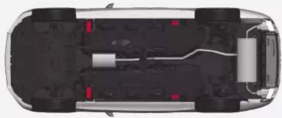
natural_image
Top-down cutaway view of a car showing internal components and structural layout (no text or symbols)The triangles in the plastic cover indicate the locations of the lifting points (marked in red).

NOTE
Applies to cars with Leveling Control*: If the car is equipped with air suspension, this must be disabled before the car is raised.

NOTE
Volvo recommends only using the jack that belongs to the car model in question. If a jack is selected other than the one recommended by Volvo, follow the instructions supplied with the equipment.
The normal car jack is only designed for occasional, short-term use, such as when changing a wheel after a puncture. If the car is to be jacked up more often, or for a longer time than is required just to change a wheel, use of a garage jack is recommended. In this instance, follow the instructions for use that come with the equipment.

WARNING
- Apply the parking brake and set the gear selector in Park position (P).
- Chock the wheels standing on the ground using solid wood blocks or large stones.
- Check that the jack is not damaged, that the threads are thoroughly lubricated and that it is free from dirt.
- Check that the jack is resting on a firm, level surface that is not slippery and is not slanted.
- The jack must be correctly attached in the jack's bracket.
- Never position anything between the ground and the jack, nor between the jack and the car's jacking point.
• Passengers must leave the car when it is raised on the jack. - If a wheel must be changed in a trafficked environment, passengers must stand in a safe place.
- Use a jack designed for the car when changing tyres. Use supports to secure the car for all other work.
- Never crawl under the car or reach under with a part of your body when it is raised on a jack.

WARNING
If the car is raised using a workshop jack, this must be placed beneath one of the four jacking points. Take care to position the workshop jack so that the car cannot slip off. Make sure that the jack plate is fitted with a rubber guard so that the car remains stable and is not damaged. Always use axle stands or similar.
When not in use, the jack* should be stored in its stowage space under the cargo area floor.
Read through all instructions before beginning. Take out the tools needed before jacking up the car.
- Set up the warning triangle and activate the hazard warning lights if, for example, a tyre is being changed in a trafficked location.
- Apply the parking brake and engage gear position P, or engage first gear if the car has a manual gearbox.
If the car is equipped with Leveling Control*, this must be disabled before the car is raised. -
Chock in front of and behind the wheels that remain on the ground. Use, for example, heavy wooden blocks or large stones.
-
Position the jack or the lift arms at the designated spots of the car's undercarriage. The triangle markings in the plastic cover indicate the locations of the jacking/lifting points. There are two jacking points on each side of the car. There is a recess for the jack at each point.

natural_image
Diagram showing a car with three views: top view of a sedan, front view of a car with a lift, and side view of a flatbed tool (no text or symbols present)- Position the jack on level, firm and non-slippery ground under the jacking point that will be used.
- Crank up until it is correctly aligned and so that it makes contact with the car's jacking point. Check that the head of the jack (or lifting arms at a workshop) is correctly positioned in the jacking point so that the bump in the centre of the head fits into the jacking point hole, and check that the base of the jack is positioned vertically below the jacking point.
MAINTENANCE AND SERVICE
-
Turn the jack so that the crank is as far away from the side of the car as possible, at which point the jack's arms are perpendicular to the direction of the car.
-
Raise the car high enough to perform the intended measure.
Related information
- Jack* (p. 578)
- Wheel bolts (p. 578)
- Tool kit (p, 577)
- Settings for level control* (p. 476)
MAINTENANCE AND SERVICE
Servicing the climate control system
The air conditioning system must only be serviced and repaired by an authorised workshop.
Troubleshooting and repair
The air conditioning system contains fluorescent tracing agents. Ultraviolet light must be used during leak detection.
Volvo recommends that an authorised Volvo workshop is contacted.
The car's climate control system uses a freon-free refrigerant either R1234yf or R134a depending on market. Information about which refrigerant the car's climate control system uses is printed on a decal located on the inside of the bonnet.

WARNING
The air conditioning system contains pressurised refrigerant R134a. This system must only be serviced and repaired by an authorised workshop.

WARNING
The air conditioning system contains pressurised refrigerant R1234yf. In accordance with SAE J2845 (Technician Training for Safe Service and Containment of Refrigerants Used in Mobile A/C System), service and repair of the refrigerant system must only be performed by trained and certified technicians in order to ensure the safety of the system.
Related information
• Volvo service programme (p. 600)
Head up display when replacing the windscreen\*
Cars with head-up display are equipped with a special type of windscreen that meets the requirements for displaying the projected image.
Volvo recommends that you contact an authorised Volvo workshop when replacing the windscreen. The correct version of the windscreen must be fitted in order that the head-up display's graphics shall be displayed correctly.
Related information
• Head-up display* (p. 140)
- Cleaning the Head-up display* and driver display (p. 641)
Opening and closing the bonnet
The bonnet can be opened using the handle in the passenger compartment and a handle under the bonnet.
Open the bonnet
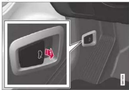
Pull the handle on the left of the brake pedal in order to release the bonnet from fully closed position.
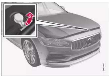
natural_image
Front view of a car with a visible side panel showing a hand turning a wheel (no text or symbols)2 Turn the handle under the bonnet anti-clockwise to release the bonnet from the lock catches and lift the bonnet.
Warning - bonnet not closed

When the bonnet is released, a warning symbol and graphics in the driver display will light up and an acoustic reminder will sound. If the
car starts rolling, an acoustic warning signal will repeat.
NOTE
If the warning symbol is lit or the warning signal is heard despite the bonnet being closed properly, contact an authorised Volvo workshop.
Close the bonnet
- Push the bonnet down until it starts to fall from its own weight.
- When the bonnet stops against the lock catch, push the bonnet to close it completely.
WARNING
Risk of crushing! Ensure that the closing path under the bonnet is not obstructed, otherwise there is a risk of personal injury.
WARNING
Check that the bonnet locks properly when closed. The bonnet must engage at both sides audibly.
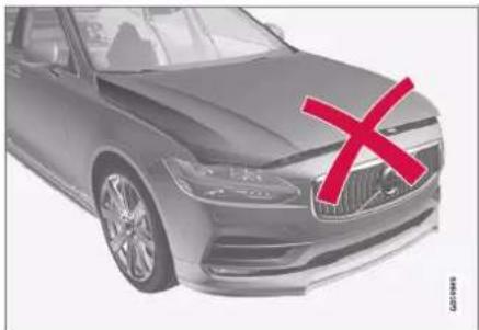
natural_image
Exterior view of a modern sedan with a red X mark on the roof (no text or symbols visible)Bonnet not completely closed.
MAINTENANCE AND SERVICE
natural_image
Front view of a silver sedan (no visible text or symbols)Bonnet completely closed.

WARNING

Never drive with an open bonnet!
If this symbol is visible – or something else indicates that the bonnet is not fully closed while driving – stop immediately
and close it properly.
Related information
• Engine compartment overview (p. 610)
• Door and seatbelt reminder (p. 53)
Engine compartment overview
The overview shows some service-related components.
Some of the components included in the car's electric drive system are located under the bonnet. Exercise caution in this area and only touch anything that is related to normal maintenance.

WARNING
Orange-coloured cables must only be handled by qualified personnel.

WARNING
Several components in the car work with high-voltage current that could be dangerous in the event of incorrect intervention.
- Do not touch anything that is not clearly described in the owner's manual.
• Exercise caution when checking/refilling fluids in the engine compartment.

The appearance of the engine compartment may differ depending on model and engine variant.
1 Coolant expansion tank
② Reservoir for brake fluid (located on the driver's side)
③ Washer fluid filler pipe
4 Central electrical unit
5 Air filter
6 Engine oil filler pipe

Location of warning decal for the engine compartment. The appearance of the engine compartment may differ depending on model and engine variant.

NOTE
It is not intended that the decals illustrated in the owner's manual should be exact replicas of those in the car. They are included to show their approximate appearance and locations in the car. The information that applies to your particular car can be found on the decal on the car.

WARNING
Remember that the radiator fan (located at the front of the engine compartment, behind the radiator) may start or continue to operate automatically for up to approx. 6 minutes after the engine has been switched off.
Always have the engine cleaned by a workshop - an authorised Volvo workshop is recommended. There is a risk of fire if the engine is hot.

WARNING
The ignition system works at a very high and hazardous voltage. The car's electrical system must always be in ignition position 0 when work is being performed in the engine compartment.
Do not touch the spark plugs or ignition coil when the car's electrical system is in ignition position II or when the engine is hot.
Related information
- Opening and closing the bonnet (p. 609)
• Filling washer fluid (p. 655)
• Topping up coolant (p. 614)
• Fuses in engine compartment (p. 622) - Checking and filling with engine oil (p. 613)
- Ignition positions (p. 448)
Engine oil
An approved engine oil must be used in order that the recommended service intervals and warranty can be applied.

Location of warning decal for the engine compartment. The appearance of the engine compartment may differ depending on model and engine variant.
Volvo recommends:

MAINTENANCE AND SERVICE
If the engine oil cannot be checked on a regular basis and the level falls too low, there is a risk that this will cause serious damage to the engine.
NOTE
It is not intended that the decals illustrated in the owner's manual should be exact replicas of those in the car. They are included to show their approximate appearance and locations in the car. The information that applies to your particular car can be found on the decal on the car.
IMPORTANT
In order to fulfil the requirements for the engine's service intervals all engines are filled with a specially adapted synthetic engine oil at the factory. The choice of oil has been made very carefully with regard to service life, starting characteristics, fuel consumption and environmental impact.
An approved engine oil must be used in order that the recommended service intervals can be applied. Only use a prescribed grade of oil for both filling and oil change, otherwise there is a risk of the service life, starting characteristics, fuel consumption and environmental impact of the car being affected.
If engine oil of the prescribed grade and viscosity is not used, engine related components may become damaged. Volvo disclaims any liability for any such damage.
Volvo recommends that oil changes are carried out at an authorised Volvo workshop.
Symbols for low oil level
Volvo uses different systems to warn about the oil level if it is too low/high, or in the event of low oil pressure. The driver display's warning symbol for low oil pressure is used for the oil pressure sensor. For oil level sensor,
the driver is informed via the driver display's warning symbol and display texts. Certain variants have both systems. Contact a Volvo dealer for more information.
Change the engine oil and oil filter in accordance with the intervals specified in the Service and Warranty Booklet. Using oil of a higher than specified grade is permitted. If the car is driven in adverse conditions, Volvo recommends using an oil of a higher grade than the one specified.
Related information
- Checking and filling with engine oil (p. 613)
• Engine oil — specifications (p. 667) - Adverse driving conditions for engine oil (p. 668)
• Volvo Cars support site (p. 23)
Checking and filling with engine oil The oil level is detected with the electronic oil level sensor.
See oil level in the centre display

Example of graphic for oil level in the centre display The oil level is visualised using the electronic oil level gauge in the centre display when the car has been started. The oil level should be checked regularly,
- Open the Car Status app from the app view in the centre display.
- Press Status to show the oil level.
NOTE
The system cannot directly detect changes when the oil is filled or drained. The car must have been driven approx. 30 km (approx. 20 miles) and have been stationary for 5 minutes with the engine switched off and on level ground before the oil level indication is correct.
NOTE
If the right conditions for measuring the oil level (time after engine shutdown, the car's inclination, outside temperature, etc.) are not met, then the message No value available will be shown in the centre display. This does not mean that there is something wrong in the car's systems.
IMPORTANT

If this symbol is shown then the oil pressure may be too low. Stop the car as quickly as possible and have the car recovered to a work-
shop – an authorised Volvo workshop is recommended.
Fill the engine oil
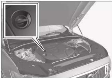
natural_image
Close-up of a car hood with an inset showing a camera lens (no text or symbols visible)Filler pipe ^12,13
In some cases, oil may need to be topped up between service intervals. No action with regard to engine oil level needs to be taken until a message is shown in the driver display.
WARNING
If the Engine oil level Service required message is shown, visit a workshop – an authorised Volvo workshop is recommended. The oil level may be too high.
WARNING
Do not spill oil onto the hot exhaust manifold due to the risk of fire.
IMPORTANT
If the Engine oil level low Refill 1 litre message is shown, fill only with the specified volume, e.g. 1 litre (1 quart).
Related information
• Engine oil (p. 611)
- Adverse driving conditions for engine oil (p. 668)
• Engine oil — specifications (p. 667)
- Ignition positions (p. 448)
• Car status (p. 602)
Coolant
The coolant ensures that surplus heat is distributed in the circuit, e.g. in order to heat the starter battery or provide heat for the passenger compartment.
Only coolant approved by Volvo should be used in order to prevent impairment of the cooling system, engine problems, etc.
Prescribed grade: Ready-mixed coolant approved by Volvo. If concentrated coolant is used, mix with 50% water (of approved water quality, not salt water, etc.). Consult a Volvo dealer if unsure.
Only coolant approved by Volvo should be used in order to prevent impairment of the cooling system, engine problems, etc.
WARNING
Swallowing coolant is hazardous, it may cause damage to organs (kidneys). The product contains ethylene glycol, inhibitor, water, etc.
Related information
• Topping up coolant (p. 614)
Topping up coolant
When topping up the coolant, follow the instructions on the packaging. Never top up with water only. The risk of freezing increases with both too little and too much coolant concentrate.
If there is coolant under the car, if there is coolant smoke, or if more than 2 litres (approx. 2 quarts) have been filled, always call for recovery to avoid the risk of engine damage due to a defective cooling system when attempting to start the car.
WARNING
The coolant may be very hot. Never open the cap when the coolant is hot. If a top-up is required, unscrew the expansion tank cap slowly to allow any overpressure to disappear.
MAINTENANCE AND SERVICE
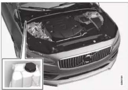
natural_image
Front view of a car with visible engine bay and dashboard, showing internal components (no text or symbols)Coolant expansion tank, left-hand drive car

natural_image
Close-up of a mechanical component with a circular hole and a red arrow marker (no visible text or symbols)
natural_image
Close-up of a car interior showing a circular opening with red markers, no visible text or symbols1 Screw off the cap in the plastic cover.
2 Screw off the cap and top up with coolant if necessary. The coolant level must not exceed the yellow MAX mark inside the expansion tank.
Reinstall the parts in reverse order.
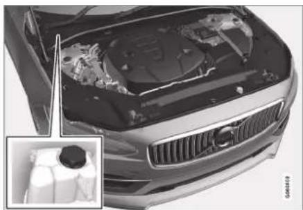
natural_image
Top-down view of a car's front hood showing engine compartment and dashboard (no visible text or symbols)Coolant expansion tank, right-hand drive car

natural_image
Close-up of a car's side profile with two red arrows pointing to the interior area (no text or symbols visible)
natural_image
Close-up of a car engine compartment with a red arrow pointing to the wheel (no visible text or symbols)1 Grip the hatch's handle and lift/jiggle the hatch from the plastic cover.
2 Screw off the cap and top up with coolant if necessary. The coolant level must not exceed the yellow MAX mark inside the expansion tank.
Reinstall the parts in reverse order.
MAINTENANCE AND SERVICE
◀◀
IMPORTANT
- Harmful if ingested. May cause organ (kidney) damage.
- Use ready-mixed coolant as recommended by Volvo. If concentrated liquid is used, make sure that the ratio is 50 % coolant to 50 % water of an approved quality.
• Do not mix different coolants. - Only new coolant should be used when replacing major cooling system components to ensure the system has sufficient corrosion protection.
- The engine must only be run with a well-filled cooling system. Otherwise, temperatures that are too high may occur resulting in the risk of damage (cracks) in the cylinder head.
- A high content of chlorine, chlorides and other salts may cause corrosion in the cooling system.
Related information
• Engine compartment overview (p. 610)
• Coolant (p. 614)
Starter battery
The starter battery is used to start up the electrical system and drive electrical equipment in the car. The hybrid battery is used when the internal combustion engine is started.
The electrical system is single-pole and uses the chassis and engine casing as a conductor.
The starter battery is a 12 V AGM battery (Absorbed Glass Mat), designed for regenerative charging, and to support the functionality of the car's different systems.
The service life and function of the starter battery is influenced by factors such as the number of starts, discharging, driving style, driving conditions, climatic conditions etc.
- Never disconnect the starter battery when the engine is running.
- Check that the cables to the starter battery are correctly connected and properly tightened.
WARNING
- The battery can generate oxyhydrogen gas, which is highly explosive. A spark can be formed if a jump lead is connected incorrectly, and this can be enough for the battery to explode.
- Do not connect the jump leads to any fuel system component or any moving part. Be careful of hot engine parts.
- The battery contains sulphuric acid, which can cause serious burns.
- If sulphuric acid comes into contact with eyes, skin or clothing, flush with large quantities of water. If acid splashes into the eyes - seek medical attention immediately.
• Never smoke near the battery.
The service life and capacity of the starter battery
The service life of the battery is affected by several factors, including factors such as the number of starts, discharging, driving style, driving conditions, climatic conditions, etc. Battery starting capacity decreases gradually with time and therefore needs to be recharged if the car is not used for a long time or when it is only driven short distances. Extreme cold further limits starting capacity. If the starter
battery is discharged a large number of times, it will negatively affect the service life.
In order to maintain the starter battery in good condition, it is recommended that there is at least 15 minutes driving/week or that the battery is connected to a battery charger with automatic trickle charging. A starter battery that is kept fully charged has a maximum service life.
Location

natural_image
Interior view of a vehicle showing a battery pack and wheel assembly (no visible text or symbols)The starter battery is located in the cargo area.
WARNING
If the starter battery is disconnected, the automatic opening and closing function must be reset to work properly. A reset must take place for pinch protection to work.
MAINTENANCE AND SERVICE
◀◀
IMPORTANT
On certain models, the battery is attached with a retaining strap. Make sure the retaining strap is properly tightened.
Specifications for starter battery
| Battery type H8 AGM | |
| Voltage (V) 12 | |
| Cold start capacityA - CCA ^B (A) | 850 |
| Size, L×B×H 353×175×190 mm (13.9×6.9×7.5 inches) | |
| Capacity (Ah) 95 |
A According to EN standard.
B Cold Cranking Amperes.
Volvo recommends entrusting battery replacement to an authorised Volvo workshop.
IMPORTANT
If the battery is replaced, make sure you replace it with a battery with the same size, cold starting capacity and type as the original battery (see the decal on the battery).
• Using jump starting with another battery (p. 488)
- Reset sequence for pinch protection (p. 167)
- Battery recycle (p. 620)
Related information
• Symbols on the batteries (p. 619)
• Hybrid battery (p. 619)
Hybrid battery
The car is equipped with a hybrid battery for electric motor operation - a maintenance-free rechargeable Lithium-ion type battery.

NOTE
The car cannot be started if the hybrid battery is discharged.
If both the starter battery and the hybrid battery are discharged then both batteries must be charged. In such a case, charging only the hybrid battery is not possible. In order for the hybrid battery to be charged, the starter battery must have a certain state of charge.

WARNING
The hybrid battery must only be replaced by a workshop - an authorised Volvo workshop is recommended.
The service life and capacity of the hybrid battery
The capacity of the hybrid battery diminishes with age and use, which may result in increased use of the internal combustion engine and, as a consequence, reduced fuel economy and reduced range during electric operation.
Coolant
The hybrid battery's cooling system has a separate expansion tank.
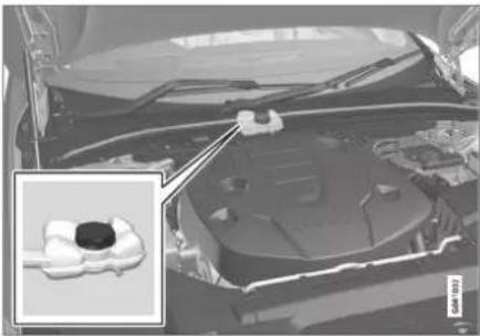
natural_image
Interior view of a car hood with engine compartment and dashboard (no visible text or symbols)
IMPORTANT
The hybrid battery's coolant must only be topped up by a workshop - an authorised Volvo workshop is recommended.
Specifications for hybrid battery
Type: Lithium-ion
Total amount of energy: 11.6 kWh.
Related information
• Symbols on the batteries (p. 619)
• Starter battery (p. 617)
• Charging the hybrid battery (p. 425)
• Battery recycle (p. 620)
Symbols on the batteries
There are information and warning symbols on the batteries.

Use protective goggles.

Further information in the owner's manual for the car.

Store the battery out of the reach of children.

The battery contains corrosive acid.
MAINTENANCE AND SERVICE
◀◀
 | Avoid sparks and naked flames. |
 | Risk of explosion. |
 | Must be taken for recycling. |
Related information
• Starter battery (p. 617)
• Hybrid battery (p. 619)
• Battery recycle (p. 620)
Battery recycle
A used starter battery must be recycled in an environmentally sound manner.
Consult a workshop in the event of uncertainty about how this type of waste should be discarded - an authorised Volvo workshop is recommended.
Related information
• Starter battery (p. 617)
• Hybrid battery (p. 619)
• Symbols on the batteries (p. 619)
Fuses and central electrical units
All electrical functions and components are protected by a number of fuses in order to protect the car's electrical system from damage by short circuiting or overloading.

WARNING
Never use a foreign object or a fuse with an amperage higher than that specified when replacing a fuse. This could cause significant damage to the electrical system and possibly lead to fire.

WARNING
Orange-coloured cables must only be handled by qualified personnel.

WARNING
Several components in the car work with high-voltage current that could be dangerous in the event of incorrect intervention.
Do not touch anything that is not clearly described in the owner's manual for the car.
If an electrical component or function does not work, it may be because the component's fuse was temporarily overloaded and failed. If the same fuse fails repeatedly then there is a fault in the circuit. Volvo recommends contacting an authorised Volvo workshop for checking.
Location of central electrical units
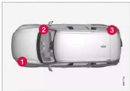
The figure is schematic - appearance may vary depending on car model.
Central electrical unit locations in a left-hand drive car. In a right-hand drive car the central electrical units under the glovebox change sides.
1 Engine compartment
② Under the glovebox
3 Cargo area
Related information
• Replacing a fuse (p. 621)
• Fuses in cargo area (p. 634)
• Fuses in engine compartment (p. 622)
• Fuses under glovebox (p. 629)
Replacing a fuse
All electrical functions and components are protected by a number of fuses in order to protect the car's electrical system from damage by short circuiting or overloading.
- Look in the fuse diagram to locate the fuse.
- Pull out the fuse and check from the side to see whether the curved wire has blown.
- If this is the case, replace it with a new fuse of the same colour and amperage.
WARNING
Never use a foreign object or a fuse with an amperage higher than that specified when replacing a fuse. This could cause significant damage to the electrical system and possibly lead to fire.
WARNING
Contact an authorised Volvo workshop about the fuses not mentioned in the owner's manual. If replacing the fuse is not performed correctly, it can cause serious damage to the electrical systems.
Related information
• Fuses and central electrical units (p. 620)
• Fuses in cargo area (p. 634)
• Fuses in engine compartment (p. 622)
• Fuses under glovebox (p. 629)
MAINTENANCE AND SERVICE
Fuses in engine compartment
Fuses in the engine compartment protect engine and brake functions, amongst other things.
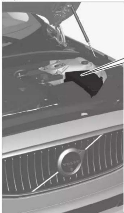
natural_image
Close-up of a Volvo car hood with visible engine compartment and grille (no text or symbols)
On the inside of the cover there are tweezers that facilitate the procedure for the removal and fitting of fuses.
The fuse box also provides space for several spare fuses.
Positions
On the inside of the cover is a label that shows the location of the fuses.
| Function Ampere Type | |||
| 1 | -- Micro | ||
| 2 | -- Micro | ||
| 3 | -- Micro | ||
| 4 | Control module for actuator for engagement/change of automatic gearbox gear positions 5 Micro | ||
| 5 | Control module for the high-voltage heater of the internal combustion engine's coolant 5 Micro | ||
| 6 | Control module for air conditioning; Shut-off valve for heat exchanger; Shut-off valve for coolant that passes through the climate control system | 5 Micro | |
| 7 | Control module for hybrid battery; High voltage converter for combined high-voltage generator/starter motor with voltage converter 500 V-12 V | 5 Micro | |
| 8 | -- Micro | ||
| 9 | Converter for control of the supply to the rear axle's electric motor 10 Micro | ||
| 10 | Control module for hybrid battery; High voltage converter for combined high-voltage generator/starter motor with voltage converter 500 V-12 V | 10 Micro | |
| 11 | Charging unit 5 Micro | ||
| 12 | Shut-off valve for the hybrid battery's coolant; Coolant pump 1 for hybrid battery 15 Micro | ||
| 13 | Coolant pump for electric drive system 15 Micro |
▶▶
MAINTENANCE AND SERVICE
◀◀
| Function Ampere Type | |||
| 14 | Cooling fan for hybrid components 25 | MCase^A | |
| 15 | - | - | MCase^A |
| 16 | - | - | MCase^A |
| 17 | - | - | MCase^A |
| 18 | Calculation unit 5 Micro | ||
| 19 | -- Micro | ||
| 20 | -- Micro | ||
| 21 | -- Micro | ||
| 22 | -- Micro | ||
| 23 | USB port in tunnel console, front* | 7,5 Micro | |
| 24 | 12 V socket in tunnel console, front 15 Micro | ||
| 25 | -- Micro | ||
| 26 | 12 V socket in cargo area* | 15 Micro | |
| 27 | -- Micro | ||
| 28 | Left-hand headlamp, LED^B | 15 Micro | |
| 29 | Right-hand headlamp, LED^B | 15 Micro | |
| 30 | -- Micro | ||
MAINTENANCE AND SERVICE
| Function Ampere Type | |||
| 31 | Heated windscreen* left-hand side | Shunt | MCaseA |
| 32 | Heated windscreen* left-hand side | 40 | MCaseA |
| 33 | Headlamp washers* | 25 | MCaseA |
| 34 | Windscreen washers 25 | MCaseA | |
| 35 | -- Micro | ||
| 36 | Horn 20 Micro | ||
| 37 | Siren* | 5 Micro | |
| 38 | Control module for brake system (valves, parking brake) 30 | MCaseA | |
| 39 | Windscreen wipers 30 | MCaseA | |
| 40 | - | - | MCaseA |
| 41 | Heated windscreen* right-hand side | 40 | MCaseA |
| 42 | Parking heater* | 20 | MCaseA |
| 43 | - | - | MCaseA |
| 44 | - | - | MCaseA |
| 45 | Heated windscreen* right-hand side | Shunt | MCaseA |
| 46 | Supplied when the ignition is switched on: Engine control module; Transmission components; Electric steering servo; Central electronic module | 5 Micro | |
▶▶
MAINTENANCE AND SERVICE
◀◀
| Function Ampere Type | |||
| 47 | Exterior car noise (certain markets) 5 Micro | ||
| 48 | Right-hand headlamp, LED^B | 15 Micro | |
| 49 | Alcohol lock* | 5 Micro | |
| 50 | -- Micro | ||
| 51 | -- Micro | ||
| 52 | Airbags; Passenger weight sensor 5 Micro | ||
| 53 | Left-hand headlamp, LED^B | 15 Micro | |
| 54 | Accelerator pedal sensor 5 Micro | ||
| 55 | Transmission control module; Control module for gear selector 15 Micro | ||
| 56 | Engine Control Module (ECM) 5 Micro | ||
| 57 | -- Micro | ||
| 58 | -- Micro | ||
| 59 | -- Micro | ||
| 60 | -- Micro | ||
| 61 | Engine control module; Actuator; Throttle unit; Valve for turbocharger 20 Micro | ||
| 62 | Solenoid valves, Valve for fuel leakage monitoring; Overpressure coupling 10 Micro | ||
| 63 | Vacuum regulators; Valve for electric bypass: Valve for ventilation 7,5 Micro | ||
MAINTENANCE AND SERVICE
| Function Ampere Type | |||
| 64 | Control unit, spoiler damper; Control unit, radiator damper 5 Micro | ||
| 65 | -- Micro | ||
| 66 | Lambda probe, front and rear 15 Micro | ||
| 67 | Solenoid for engine oil pump; Solenoid clutch A/C; Lambda probe, front, centre and rear 15 Micro | ||
| 68 | -- Micro | ||
| 69 | Engine Control Module (ECM) 20 Micro | ||
| 70 | Ignition coils; Spark plugs 15 Micro | ||
| 71 | - | - | MCase^A |
| 72 | - | - | MCase^A |
| 73 | Control module for transmission fluid pump 30 | MCase^A | |
| 74 | - | - | MCase^A |
| 75 | - | - | MCase^A |
| 76 | - | - | MCase^A |
| 77 | - | - | MCase^A |
| 78 | - | - | MCase^A |
This type of fuse should be replaced by a workshop. An authorised Volvo workshop is recommended.
B LED (Light Emitting Diode)
MAINTENANCE AND SERVICE
Related information
• Fuses and central electrical units (p. 620)
• Replacing a fuse (p. 621)
MAINTENANCE AND SERVICE
Fuses under glovebox
Fuses under the glovebox protect, amongst other things, electrical sockets, displays and door modules.

▶▶
MAINTENANCE AND SERVICE
On the inside of the cover there are tweezers that facilitate the procedure for the removal and fitting of fuses.
The fuse box in the engine compartment also provides space for several spare fuses.
Positions
On the inside of the cover is a label that shows the location of the fuses.
| Function Ampere Type | |||
| 1 | Intermediate voltage module^ | 10 Micro | |
| 2 | - | - | MCase ^B |
| 3 | -- Micro | ||
| 4 | Movement detector* | 5 Micro | |
| 5 | -- Micro | ||
| 6 | Driver display 5 Micro | ||
| 7 | Keypad in centre console 5 Micro | ||
| 8 | Sun sensor 5 Micro | ||
| 9 | -- Micro | ||
| 10 | -- Micro | ||
| 11 | Steering wheel module 5 Micro | ||
| 12 | Module for start knob and for parking brake control 5 Micro | ||
| 13 | Steering wheel module for heated steering wheel* | 15 Micro | |
| 14 | -- Micro | ||
MAINTENANCE AND SERVICE
| Function Ampere Type | |||
| 15 | -- Micro | ||
| 16 | -- Micro | ||
| 17 | Rear lamp housing control unit 15 Micro | ||
| 18 | Control module for climate control system 10 Micro | ||
| 19 | Steering lock 7,5 Micro | ||
| 20 | Diagnostic socket OBDII 10 Micro | ||
| 21 | Centre display 5 Micro | ||
| 22 | Fan module for climate control system, front 40 | MCase^R | |
| 23 | USB HUB 5 Micro | ||
| 24 | Controls lighting; Interior lighting; Dimming of interior rearview mirror*; Rain and light sensor*; Keypad in tunnel console, by legroom for rear seat*; Power front seats*; Control panels in rear doors; Fan module for climate control left/right | 7,5 Micro | |
| 25 | Control module for driver support functions 5 Micro | ||
| 26 | Sunroof* | 20 Micro | |
| 27 | Head-up display* | 5 Micro | |
| 28 | Passenger compartment lighting | 5 Micro | |
| 29 | Wireless charging plate | 5 Micro | |
| 30 | Display in roof console (Seatbelt reminder/Indicator for airbag on the front passenger seat) | 5 | Micro |
▶▶
MAINTENANCE AND SERVICE
◀◀
| Function Ampere Type | |||
| 31 | -- Micro | ||
| 32 | -- Micro | ||
| 33 | -- Micro | ||
| 34 | -- Micro | ||
| 35 | Control module for online car; Control module for Volvo On Call 5 Micro | ||
| 36 | -- Micro | ||
| 37 | Audio control device (amplifier) 40 | MCase^B | |
| 38 | - | - | MCase^B |
| 39 | Module for multi-band antenna 5 Micro | ||
| 40 | Modules for seat comfort (massage) front* | 5 Micro | |
| 41 | Alcohol lock* | 5 Micro | |
| 42 | -- Micro | ||
| 43 | Control module for fuel pump 15 Micro | ||
| 44 | Relay coil for transmission oil pumpConverter medium voltage; Integrated starter motor | 5 Micro | |
| 45 | Opening the boot lid/tailgate with foot motion* | 5 Micro | |
| 46 | Seat heating, driver's side front 15 Micro |
MAINTENANCE AND SERVICE
| Function Ampere Type | |||
| 47 | Seat heating, passenger side front 15 Micro | ||
| 48 | Coolant pump 7,5 Micro | ||
| 49 | -- Micro | ||
| 50 | Power driver's seat* | 20 Micro | |
| 51 | Control module for suspension (active chassis)* | 20 Micro | |
| 52 | -- Micro | ||
| 53 | Sensus control module 10 Micro | ||
| 54 | - | - | MCase^B |
| 55 | -- Micro | ||
| 56 | Electrically operated front passenger seat* | 20 Micro | |
| 57 | -- Micro | ||
| 58 | TV* (certain markets) | 5 Micro | |
| 59 | Primary fuse for fuses 52, 53, 57 and 58 15 Micro | ||
^A Only applies to cars with 48 V support battery.
B This type of fuse should be replaced by a workshop. An authorised Volvo workshop is recommended.
Related information
• Fuses and central electrical units (p. 620)
• Replacing a fuse (p. 621)
MAINTENANCE AND SERVICE
Fuses in cargo area
Fuses in the cargo area protect, amongst other things, power seats*, airbags and seat-belt tensioners.
MAINTENANCE AND SERVICE

natural_image
Close-up of a car trunk with visible internal components and a white line overlay (no text or symbols)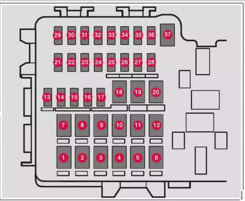
The central electrical unit is located on the right-hand side.
On the inside of the cover there are tweezers that facilitate the procedure for the removal and fitting of fuses.
The fuse box in the engine compartment also provides space for several spare fuses.
▶▶
MAINTENANCE AND SERVICE
Positions
On the inside of the cover is a label that shows the location of the fuses.
| Function Ampere Type | |||
| 1 | Rear window defroster 30 | MCase^ | |
| 2 | Central electronic module 40 | MCase^ | |
| 3 | Compressor for air suspension* | 40 | MCase^ |
| 4 | Lock motor for backrest on rear right-hand side 15 | MCase^ | |
| 5 | - | - | MCase^ |
| 6 | Lock motor for backrest on rear left-hand side 15 | MCase^ | |
| 7 | Door module right-hand side rear^B | 20 | MCase^ |
| 8 | Control module for reduction of nitrous oxides (diesel) 30 | MCase^ | |
| 9 | Power operated boot lid* | 25 | MCase^ |
| 10 | Electrically operated front passenger seat*Door module right-hand side front | 20 | MCase^ |
| 11 | Towbar control module* | 40 | MCase^ |
| 12 | Seatbelt pretensioner module, right-hand side 40 | MCase^ | |
| 13 | Internal relay coils 5 Micro | ||
| 14 | Control module for reduction of nitrous oxides (diesel) 15 Micro |
MAINTENANCE AND SERVICE
| Function Ampere Type | |||
| 15 | Door module left-hand side rear 20 Micro | ||
| 16 | Alcohol lock*, USB hub/accessory port | 5 Micro | |
| 17 | -- Micro | ||
| 18 | Towbar control module* | 25 | MCase^A |
| Accessory module 40 | |||
| 19 | Power driver seat*Door module left-hand side front | 20 | MCase^A |
| 20 | Seatbelt pretensioner module, left-hand side 40 | MCase^A | |
| 21 | Parking camera* | 5 Micro | |
| 22 | Rear light module back-up power supply 10 Micro | ||
| 23 | -- Micro | ||
| 24 | -- Micro | ||
| 25 | Supply when the ignition is switched on 10 Micro | ||
| 26 | -- Micro | ||
| 27 | -- Micro | ||
| 28 | Seat heating left-hand side rear* | 15 Micro | |
| 29 | -- Micro |
▶▶
MAINTENANCE AND SERVICE
◀◀
| Function Ampere Type | |||
| 30 | Blind Spot Information (BLIS)*: control module, exterior reversing sound | 5 Micro | |
| 31 | -- Micro | ||
| 32 | Seatbelt pretensioner modules, left-hand side 5 Micro | ||
| 33 | Actuator for exhaust gases (petrol, certain engine variants) 5 Micro | ||
| 34 | -- Micro | ||
| 35 | All Wheel Drive (AWD) control module* | 15 Micro | |
| 36 | Seat heating right-hand side rear* | 15 Micro | |
| 37 | - | - | MCaseA |
This type of fuse should be replaced by a workshop. An authorised Volvo workshop is recommended.
B Applicable only to cars with hybrid motors or a 48V support battery.
Related information
• Fuses and central electrical units (p. 620)
• Replacing a fuse (p. 621)
Bulb replacement
This car is equipped only with LED ^15 lamps and therefore no replaceable bulbs. Contact a workshop ^14 if a fault occurs in the lighting.
If a fault occurs in LED ^15 lamps, the entire lamp unit usually must be replaced.

NOTE
For information about bulbs not covered in this Owner's Manual, contact a Volvo dealer or an authorised Volvo workshop.

NOTE
Outside lighting such as headlamps and rear lamps may temporarily have condensation on the inside of the lens. This is normal, all exterior lighting is designed to withstand this. Condensation is normally vented out of the lamp housing when the lamp has been switched on for a time,
Cleaning the interior
Use cleaning agents and car care products recommended by Volvo. Clean regularly, and deal with stains straight away. Vacuuming is important prior to using cleaning agents.

IMPORTANT
- Certain items of coloured clothing (e.g. dark jeans and suede garments) may stain the upholstery. If this occurs, it is important to clean and treat these parts of the upholstery as soon as possible.
- Never use strong solvents such as washer fluid, pure petrol or white spirit or concentrated alcohol to clean the interior, since this may damage the upholstery as well as other interior materials.
- Never spray the cleaning agent directly onto components that have electrical buttons and controls. Wipe them instead using a moistened cloth containing the cleaning agent.
- Sharp objects and Velcro may damage the fabric upholstery.
- Only use cleaning agents on the type of material for which they were intended.
Related information
• Cleaning the centre display (p. 640)
• Cleaning fabric upholstery and headlining (p. 641)
• Cleaning the seatbelts (p. 642)
• Cleaning textile floor and entrance mats (p. 642)
• Cleaning leather upholstery* (p. 643)
- Cleaning the leather steering wheel (p. 644)
- Cleaning interior plastic, metal and wood parts (p. 644)
MAINTENANCE AND SERVICE
Cleaning the centre display
Dirt, stains and grease from fingers can affect the centre display's performance and readability. Clean the screen frequently with a microfibre cloth.
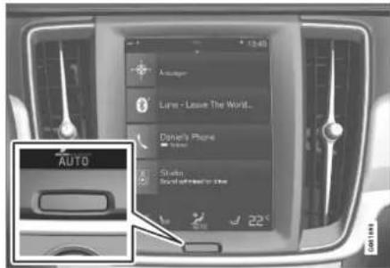
- Turn off the centre display with a long press on the home button.
- Wipe the screen with the microfibre cloth supplied or use another microfibre cloth of equivalent quality. Wipe the screen with a clean and dry microfibre cloth using small circular movements. If necessary, lightly moisten the microfibre cloth with clean water.
- Activate the display with a short press on the home button.
IMPORTANT
The microfibre cloth used to clean the centre display must be free from sand and dirt.
IMPORTANT
When cleaning the centre display, only use gentle pressure on the screen. Heavy pressure can damage the screen.
IMPORTANT
Do not spray any liquid or caustic chemicals directly on the centre display. Do not use window cleaning agent, other cleaning agents, aerosol spray, solvents, alcohol, ammonia or cleaning agent containing abrasive.
Never use abrasive cloths, paper towels or tissue paper, since they may scratch the centre display.
Related information
• Cleaning the interior (p. 639)
• Cleaning fabric upholstery and headlining (p. 641)
• Cleaning the seatbelts (p. 642)
• Cleaning textile floor and entrance mats (p. 642)
• Cleaning leather upholstery* (p. 643)
- Cleaning the leather steering wheel (p. 644)
• Cleaning interior plastic, metal and wood parts (p. 644)
Cleaning the Head-up display\* and driver display
Gently wipe the display's cover glass with a clean and dry microfibre cloth. If necessary, lightly moisten the microfibre cloth.
Never use strong stain removers. A special cleaning agent available from Volvo dealers can be used for more difficult cleaning.
Related information
- Activating and deactivating the head-up display* (p. 142)
• Head-up display* (p. 140)
Cleaning fabric upholstery and headlining
It is recommended to use a fabric cleaning agent when cleaning textile fabric. Clean if necessary, and treat stains straight away.
IMPORTANT
Never scrape or rub a stain since this may damage the upholstery.
IMPORTANT
Never use stain removing agent or strong solvents, they could damage the upholstery.
Cleaning fabric upholstery
- Start by vacuum cleaning the upholstery.
- Follow the instructions for the fabric cleaning agent.
- When cleaning fabric, a spray extraction cleaner is recommended for suction of the washing fluid and subsequent water rinsing.
IMPORTANT
Some coloured clothing (such as jeans and suede garments) may stain the fabric upholstery. Heavy stains such as oil may be difficult to remove.
IMPORTANT
Always clean the entire upholstery, even there are only individual stains. This is to avoid water rings.
NOTE
Do not remove the upholstery for cleaning.
Cleaning the headlining
- Brush the headlining carefully using a soft brush.
- Follow the instructions for the fabric cleaning agent.
- Then use a soft and lint-free cloth to wipe the headlining.
IMPORTANT
Careless cleaning can damage the headlin- ing.
Related information
• Cleaning the interior (p. 639)
• Cleaning the centre display (p. 640)
• Cleaning the seatbelts (p. 642)
• Cleaning textile floor and entrance mats (p. 642)
• Cleaning leather upholstery* (p. 643)
MAINTENANCE AND SERVICE
- Cleaning the leather steering wheel (p. 644)
- Cleaning interior plastic, metal and wood parts (p. 644)
Cleaning the seatbelts
Use cleaning agents and car care products recommended by Volvo. Clean regularly, and deal with stains straight away. Vacuuming is important prior to using cleaning agents.
Use water and a synthetic detergent. A special textile cleaning agent is available from Volvo retailers. Ensure that the seatbelt is dry before allowing it to retract.
Related information
• Cleaning the interior (p. 639)
• Cleaning the centre display (p. 640)
• Cleaning fabric upholstery and headlining (p. 641)
• Cleaning textile floor and entrance mats (p. 642)
• Cleaning leather upholstery* (p. 643)
- Cleaning the leather steering wheel (p. 644)
- Cleaning interior plastic, metal and wood parts (p. 644)
Cleaning textile floor and entrance mats
It is recommended to use a fabric cleaning agent when cleaning mats. Clean regularly, and deal with stains straight away. Vacuuming is important prior to using cleaning agents.
Remove inlaid carpets for separate cleaning of the floor carpet and the inlaid carpets. Each inlay mat is secured with pins.
-
Remove the inlay mat by taking hold of the inlay mat at each pin and lifting the mat straight up.
-
Use a vacuum cleaner to remove dust and dirt.

NOTE
The inlay mats must not be swung around without care or hit against objects to remove dirt since this can crack the inlay mats.
-
A textile cleaner is recommended for stains on the floor mat, after vacuuming.
-
After cleaning, fit the inlay mat in place by pressing it in at each pin.

WARNING
Only use one inlaid mat at each seat, and check before setting off that the mat by the driver's seat is firmly affixed and secured in the pins so that it does not get caught adjacent to and under the pedals.
Related information
• Cleaning the interior (p. 639)
• Cleaning the centre display (p. 640)
- Cleaning fabric upholstery and headlining (p. 641)
• Cleaning the seatbelts (p. 642)
• Cleaning leather upholstery* (p. 643)
- Cleaning the leather steering wheel (p. 644)
- Cleaning interior plastic, metal and wood parts (p. 644)
Cleaning leather upholstery\*
Use cleaning agents and car care products recommended by Volvo. Clean regularly, and deal with stains straight away. Vacuuming is important prior to using cleaning agents.
Volvo's leather upholstery* is treated to preserve its original appearance.
Leather upholstery* is a natural product that changes and acquires a beautiful patina over time. Regular cleaning and treatment are required in order that the properties and colours of the leather shall be preserved. Volvo offers a comprehensive product, Volvo Leather Care KitWipes, for cleaning and treatment of leather upholstery. The protective outer layer of the leather is preserved when this is used according to the instructions.
To achieve results that are as good as possible, Volvo recommends cleaning and application of the protective cream one to four times per year (or more frequently if required). Volvo Leather Care Kit/Wipes is available from Volvo dealers.
Cleaning the leather upholstery
-
Apply the leather cleaner to a damp sponge and squeeze until a foam is created.
-
Use the sponge on the stain in a circular motion.
-
Thoroughly dampen the stain using the sponge, allow the sponge to absorb the stain without scrubbing.
- Wipe the stain with a soft cloth and allow the leather to dry thoroughly.
Protecting the leather upholstery
- Apply a small amount of leather protective agent to a cloth and then apply it to the leather in light circular motions.
- Allow to dry for about 20 minutes.
Protecting the leather upholstery makes it more resistant to the stresses from the sun's UV radiation.
Related information
• Cleaning the interior (p. 639)
• Cleaning the centre display (p. 640)
• Cleaning fabric upholstery and headlining (p. 641)
• Cleaning the seatbelts (p. 642)
- Cleaning textile floor and entrance mats (p. 642)
- Cleaning the leather steering wheel (p. 644)
- Cleaning interior plastic, metal and wood parts (p. 644)
MAINTENANCE AND SERVICE
Cleaning the leather steering wheel
Use cleaning agents and car care products recommended by Volvo. Clean regularly, and deal with stains straight away. Vacuuming is important prior to using cleaning agents. Leather needs to breathe. Never cover the leather steering wheel with protective plastic. We recommend Volvo Leather Care Kit/Wipes for cleaning the leather steering wheel. First remove dirt, dust, etc. with a damp sponge or cloth.
IMPORTANT
Sharp objects, e.g. rings, can damage the leather on the steering wheel.
Related information
• Cleaning the interior (p. 639)
• Cleaning the centre display (p. 640)
• Cleaning fabric upholstery and headlining (p. 641)
• Cleaning the seatbelts (p. 642)
- Cleaning textile floor and entrance mats (p. 642)
• Cleaning leather upholstery* (p. 643)
- Cleaning interior plastic, metal and wood parts (p. 644)
Cleaning interior plastic, metal and wood parts
Use cleaning agents and car care products recommended by Volvo. Clean regularly, and deal with stains straight away.
A fibrillated fibre or microfibre cloth, lightly moistened with water, available from Volvo dealers, is recommended for cleaning interior parts and surfaces.
Do not scrape or rub stains. Never use strong stain removers, either.
IMPORTANT
Do not use solvent that contains alcohol when cleaning the glass for the driver display.
IMPORTANT
Keep in mind that high gloss surfaces are easily scratched. Clean these surfaces with a clean, dry microfibre cloth using small, circular motions. If needed, dampen the microfibre cloth with a little clean water.
Related information
• Cleaning the interior (p. 639)
• Cleaning the centre display (p. 640)
• Cleaning fabric upholstery and headlining (p. 641)
• Cleaning the seatbelts (p. 642)
• Cleaning textile floor and entrance mats (p. 642)
• Cleaning leather upholstery* (p. 643)
- Cleaning the leather steering wheel (p. 644)
Cleaning the exterior
The car should be washed as soon as it becomes dirty. This means that the car is easier to clean since the dirt does not attach as firmly. It also reduces the risk of scratches and keeps the car fresh. Perform the cleaning in a car wash with oil separator. Use car shampoo that is recommended by Volvo.
Related information
• Cleaning the exterior (p. 645)
• Polishing and waxing (p. 645)
• Handwashing (p. 646)
• Automatic car wash (p. 647)
• High-pressure washing (p. 649)
• Cleaning the wiper blades (p. 649)
- Cleaning exterior plastic, rubber and trim components (p. 650)
• Cleaning wheel rims (p. 651)
• Rustproofing (p. 651)
Polishing and waxing
Polish and wax the car if the paintwork is dull or to give the paintwork extra protection. The car does not need to be polished until it is at least one year old. However, the car can be waxed during this time. Do not polish or wax the car in direct sunlight, the surface being polished should be a maximum of 45^ C ( 113^ F).
- Wash and dry the car thoroughly before you begin polishing or waxing. Clean off asphalt and tar stains using tar remover or white spirit. More stubborn stains can be removed using fine rubbing paste designed for car paintwork. Use cleaning agent recommended by Volvo.
- Polish first with a polish and then wax with liquid or solid wax. Follow the instructions on the packaging carefully. Many preparations contain both polish and wax.
IMPORTANT
Never polish or wax any matt details on the car. This can destroy the matt effect and give the surface a permanent shine.
IMPORTANT
Avoid waxing and polishing on plastic and rubber.
When using degreasant on plastic and rubber, only rub with light pressure if it is necessary. Use a soft washing sponge.
Polishing glossy trim mouldings could wear away or damage the glossy surface layer.
Polishing agent that contains abrasive must not be used.
IMPORTANT
Use cleaning agent recommended by Volvo. Other treatment such as preserving, sealing, protection, lustre sealing or similar could damage the paintwork. Paintwork damage caused by such treatments is not covered by Volvo warranty.
Related information
• Cleaning the exterior (p. 645)
• Handwashing (p. 646)
• Automatic car wash (p. 647)
• High-pressure washing (p. 649)
• Cleaning the wiper blades (p. 649)
- Cleaning exterior plastic, rubber and trim components (p. 650)
▶▶
MAINTENANCE AND SERVICE
• Cleaning wheel rims (p. 651)
• Rustproofing (p. 651)
Handwashing
The car should be washed as soon as it becomes dirty. This means that the car is easier to clean since the dirt does not attach as firmly. It also reduces the risk of scratches and keeps the car fresh. Carry out cleaning in a cleaning area with an oil separator, and use car shampoo. Use cleaning agents and car care products recommended by Volvo.
Important points to remember when handwashing the car
- Avoid washing the car in direct sunlight. This can cause the detergent or wax to dry and have an abrasive effect.
- Remove bird droppings from the paintwork as soon as possible. They contain substances that damage and discolour paintwork very quickly. For example, use soft paper or sponge soaked in plenty of water. An authorised Volvo workshop is recommended for the removal of any discolouration.
- Wash the underbody, including wheel housings and bumpers.
-
Rinse the entire car until the dissolved dirt has been removed so as to reduce the risk of scratches from washing. Do not spray directly onto the locks.
-
If necessary, use cold degreasing agent on very dirty surfaces. Note that in this case, the surfaces must not be hot from the sun.
- Wash using a sponge, car shampoo and plenty of lukewarm water. Ensure that the sponge is dirt-free. Dirt on the sponge may cause you to scratch the car during washing.
- Clean the wiper blades with a lukewarm soap solution or car shampoo.
- Dry the car using a clean, soft chamois or a water scraper. If you avoid allowing drops of water to dry in strong sunlight, you reduce the risk of water drying stains which may need to be polished out.
- After the car has been washed, tar from asphalt may remain. Use tar remover that is recommended by Volvo to get rid of the last spots.

WARNING
Always have the engine cleaned by a work-shop. There is a risk of fire if the engine is hot.
IMPORTANT
Dirty headlamps have impaired functionality. Clean them regularly, e.g. when refuelling.
Do not use any corrosive cleaning agents but use water and a non-scratching sponge instead.
NOTE
Outside lighting such as headlamps and rear lamps may temporarily have condensation on the inside of the lens. This is normal, all exterior lighting is designed to withstand this. Condensation is normally vented out of the lamp housing when the lamp has been switched on for a time.
IMPORTANT
- Make sure that the sunroof ^* and sun visor are closed before washing the car.
- Never use polishing agent with abrasive properties on the sunroof.
- Never use wax on the rubber mouldings around the sunroof.
IMPORTANT
Remember to remove dirt from the drain holes in the doors and in the sills after washing the car.
Related information
• Cleaning the exterior (p. 645)
• Polishing and waxing (p. 645)
• Automatic car wash (p. 647)
• High-pressure washing (p. 649)
• Cleaning the wiper blades (p. 649)
• Cleaning exterior plastic, rubber and trim components (p. 650)
• Cleaning wheel rims (p. 651)
• Rustproofing (p. 651)
• Automatic parking brake activation setting (p. 456)
Automatic car wash
The car should be washed as soon as it becomes dirty. The longer the car is left dirty, the more difficult it will be to get it completely clean and there is a risk of scratching the paintwork.
Washing the car in an automatic car wash is a simple and quick way of getting it clean, but it cannot reach everywhere. Volvo recommends washing your car by hand or using an automatic car wash supplemented with washing by hand.
NOTE
Volvo recommends that the car is not washed in an automatic car wash during the first few months (this is because the paintwork has not fully hardened).
IMPORTANT
Before driving the car into an automatic car wash, deactivate the functions for automatic braking when stationary and automatic parking brake application. If these functions are not deactivated, the brake system will jam when the car is stationary and the car will not be able to move.
IMPORTANT
For car washes where the car is pulled forward with rolling wheels, the following applies:
- Before washing the car, make sure that the automatic rain sensor is deactivated, otherwise there is the risk of it starting and damaging the wiper arms.
- Make sure that the door mirrors are retracted, any auxiliary lamps secured, antennas retracted or removed, otherwise they risk being damaged by the automatic car wash.
- Drive into the car wash.
- Switch off the "Automatic braking at standstill" function using the button on the tunnel console.
- Switch off the "Automatic parking brake application" function via the top view of the centre display.
- Switch off the engine by turning the start knob in the tunnel console clockwise. Hold the knob in place for at least 2 seconds.
The car is ready for the car wash.
IMPORTANT
The system will automatically switch to P mode unless the above step is followed. The wheels are locked in P mode, which they should not be when putting the car through an automatic car wash.
NOTE
Be aware that if the car has the keyless locking and unlocking function*, the car can be locked/unlocked when the car is being washed if the remote control key is within range.
Test the brakes
WARNING
Always test the brakes after washing the car, including the parking brake, to ensure that moisture and corrosion do not attack the brake linings and reduce braking performance.
Depress the brake pedal now and then while driving long distances in rain or slush. The friction heat means that the brake linings heat up and dry out. Do the same after starting in very damp or cold weather.
Related information
• Cleaning the exterior (p. 645)
• Polishing and waxing (p. 645)
- Handwashing (p. 646)
• High-pressure washing (p. 649)
• Cleaning the wiper blades (p. 649)
• Cleaning exterior plastic, rubber and trim components (p. 650)
• Cleaning wheel rims (p. 651)
• Rustproofing (p. 651)
• Automatic braking when stationary (p. 457)
• Automatic parking brake activation setting (p. 456)
• Keyless and touch-sensitive surfaces* (p. 269)
High-pressure washing
The car should be washed as soon as it becomes dirty. The longer the car is left dirty, the more difficult it will be to get it completely clean and there is a risk of scratching the paintwork. Wash the car in a car wash with oil separator. Use car shampoo that is recommended by Volvo.
When using high-pressure washing, use sweeping movements and make sure that the nozzle does not come closer than 30 cm (13 in.) to the surface of the car. Do not spray directly onto the locks.
Related information
• Cleaning the exterior (p. 645)
• Polishing and waxing (p. 645)
• Handwashing (p. 646)
• Automatic car wash (p. 647)
• Cleaning the wiper blades (p. 649)
• Cleaning exterior plastic, rubber and trim components (p. 650)
• Cleaning wheel rims (p. 651)
• Rustproofing (p. 651)
Cleaning the wiper blades
The car should be washed as soon as it becomes dirty. The longer the car is left dirty, the more difficult it will be to get it completely clean and there is a risk of scratching the paintwork. Wash the car in a car wash with oil separator. Use car shampoo that is recommended by Volvo.
Asphalt, dust and salt residue on wiper blades, as well as insects, ice etc. on the windscreen, impair the service life of wiper blades.
When cleaning, set the wiper blades in service position.
NOTE
Wash the wiper blades and windscreen regularly with a lukewarm soap solution or car shampoo. Do not use any strong solvents.
Related information
• Cleaning the exterior (p. 645)
• Polishing and waxing (p. 645)
• Handwashing (p. 646)
• Automatic car wash (p. 647)
• High-pressure washing (p. 649)
• Cleaning exterior plastic, rubber and trim components (p. 650)
• Cleaning wheel rims (p. 651)
• Rustproofing (p. 651)
MAINTENANCE AND SERVICE
Cleaning exterior plastic, rubber and trim components
The car should be washed as soon as it becomes dirty. The longer the car is left dirty, the more difficult it will be to get it completely clean and there is a risk of scratching the paintwork. Use car shampoo that is recommended by Volvo.
A special cleaning agent available from Volvo dealers is recommended for the cleaning and care of coloured plastic parts, rubber and trim components, e.g. glossy trim mouldings. When using such a cleaning agent the instructions must be followed carefully.
Avoid washing the car with detergent with a pH value below 3.5 or above 11.5. This can cause discolouration of anodised aluminium components*, as illustrated. We advise against use of abrasive polishing agents, as illustrated.

natural_image
Side profile illustration of a sedan car (no text or symbols visible)Parts that should be washed using a cleaning agent with a pH value between 3.5 and 11.5.
IMPORTANT
Avoid waxing and polishing on plastic and rubber.
When using degreasant on plastic and rubber, only rub with light pressure if it is necessary. Use a soft washing sponge.
Polishing glossy trim mouldings could wear away or damage the glossy surface layer.
Polishing agent that contains abrasive must not be used.
IMPORTANT
Avoid washing the car with cleaning agent with a pH value lower than 3.5 or higher than 11.5. This may result in discolouration of anodised aluminium parts such as roof rack and around the side windows.
Never use metal polishing agent on anodised aluminium parts, this can result in discolouration and destroy the surface treatment.
Related information
• Cleaning the exterior (p. 645)
• Polishing and waxing (p. 645)
- Handwashing (p. 646)
• Automatic car wash (p. 647)
• High-pressure washing (p. 649)
• Cleaning the wiper blades (p. 649)
• Cleaning wheel rims (p. 651)
• Rustproofing (p. 651)
Cleaning wheel rims
The car should be washed as soon as it becomes dirty. The longer the car is left dirty, the more difficult it will be to get it completely clean and there is a risk of scratching the paintwork. Perform the cleaning in a car wash with oil separator. Use car shampoo that is recommended by Volvo.
Use rim cleaning agent recommended by Volvo.
Strong rim cleaning agents can damage the surface and cause stains on chrome-plated aluminium rims.
Related information
• Cleaning the exterior (p. 645)
• Polishing and waxing (p. 645)
• Handwashing (p. 646)
• Automatic car wash (p. 647)
• High-pressure washing (p. 649)
- Cleaning exterior plastic, rubber and trim components (p. 650)
• Cleaning wheel rims (p. 651)
• Rustproofing (p. 651)
Rustproofing
The car has protection against corrosion. Anti-corrosion protection for the body consists of metallic protective coatings on the sheet metal, a high-quality painting process, corrosion-protected and minimised metal overlap, and shielding plastic components, abrasion protection and supplemental rust inhibitor on exposed areas. In the chassis, exposed components of the wheel suspension are made of corrosion-resistant cast aluminium.
Inspection and maintenance
The car's anti-corrosion protection normally requires no maintenance, but a good way to reduce the risk of corrosion is to keep the car clean. Strong alkaline or acidic cleaning solutions must be avoided on glossy trim components. Any stone chips should be rectified as soon as they are discovered.
Related information
• Cleaning the exterior (p. 645)
• Polishing and waxing (p. 645)
- Handwashing (p. 646)
• Automatic car wash (p. 647)
• High-pressure washing (p. 649)
• Cleaning the wiper blades (p. 649)
- Cleaning exterior plastic, rubber and trim components (p. 650)
• Cleaning wheel rims (p. 651)
Car paintwork
The paintwork consists of several layers and is an important part of the car's rustproofing, and should therefore be checked regularly. The most common types of paintwork damage are stone chips, scratches, and marks on the edges of wings, doors and bumpers. To avoid the onset of rust, damaged paintwork should be rectified immediately.
Related information
- Touching up minor paintwork damage (p. 652)
• Colour codes (p. 653)
MAINTENANCE AND SERVICE
Touching up minor paintwork damage
Paint is an important part of the car's rust-proofing and should therefore be checked regularly. The most common types of paint-work damage are stone chips, scratches, and marks on e.g. the edges of wings, doors and bumpers.
To avoid the onset of rust, damaged paintwork should be rectified immediately.

NOTE
When paint is repaired the surface must be clean and dry. The temperature of the surface should be at least 15 °C (59 °F).
Materials that may be needed
- Primer – a special adhesive primer in a spray can is available for e.g. plastic-coated bumpers.
- Basecoat and clearcoat - available in spray cans or as touch-up pens/sticks ^16 .
- Masking tape.
- Fine sand paper.
Applying touch-up paint to the damaged surface
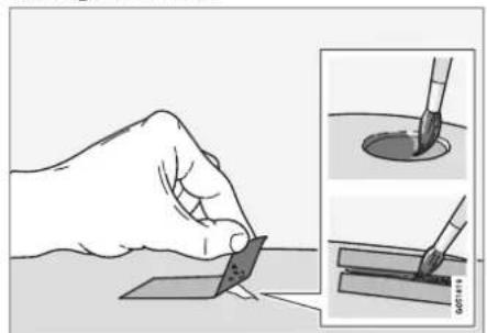
natural_image
Illustration of a hand holding a paper with a brush, alongside two steps showing the same brush tip (no text or symbols present)If the damage has not reached down to the metal, the touch-up paint can be applied directly after the surface has been cleaned.
- Apply a piece of masking tape over the damaged surface. Then remove the tape to remove any loose paint.
If the damage is down to the metal, use of a primer is appropriate. In the event of damage to a plastic surface, an adhesive primer should be used to give better results - spray into the lid of the spray can and brush on thinly.
- Before painting, gentle polishing using a very fine polishing agent may be carried out locally if required (e.g. if there are any uneven edges). The surface is thoroughly cleaned (grease and salt should be removed) and left to dry.
- Stir the primer well and apply using a fine brush, a matchstick or similar. Finish off with a basecoat and clearcoat once the primer has dried.
For scratches, implement the same procedure but mask around the damaged area to protect the undamaged paintwork.
Touch-up pens and spray paints for touching up paintwork are available from Volvo dealers.

NOTE
If the stone chip has not penetrated down to the meal and an undamaged layer of paint remains in place, fill in with base coat and clear coat as soon as the surface has been cleaned.
Related information
• Car paintwork (p. 651)
• Colour codes (p. 653)
MAINTENANCE AND SERVICE
Colour codes
Colour code
The decal for the colour code is positioned on the car's right-hand door pillar between the front and rear door and will be visible when the right-hand rear door is opened.

1 Exterior colour code
② Any secondary exterior colour code
Related information
• Car paintwork (p. 651)
- Touching up minor paintwork damage (p. 652)
Replacing windscreen wiper blades
The wiper blades sweep water away from the windscreen. Together with washer fluid, they aim to clean the windscreen and ensure visibility while driving. The wiper blades can be replaced.

natural_image
Illustration of a high-speed train on track with red arrows indicating motion direction (no text or symbols)
natural_image
Close-up of a black cable with a metallic clip and a red arrow pointing to a section (no text or symbols visible)1 Fold up the wiper arm when it is in service position. Service position is activated/deactivated via the function view in the centre display when the car is stationary and the windscreen wipers are not on. Press the button located on the wiper blade mounting and pull straight out parallel with the wiper arm.
2 Slide in the new wiper blade until a "click" is heard.
3. Check that the blade is firmly installed.
4. Fold the wiper arm back towards the windscreen.
The wiper blades are different lengths

natural_image
Diagram of a car with two curved arrows pointing to the dashboard, showing mechanical components (no text or symbols present)MAINTENANCE AND SERVICE
◀◀

NOTE
When replacing the wiper blades, note that they have different lengths. The blade on the driver's side is longer than on the passenger side.
Related information
• Using the rain sensor (p. 178)
• Using windscreen and headlamp washers (p. 180)
- Activating and deactivating the rain sensor's memory function (p. 179)
• Filling washer fluid (p. 655)
- Set the wiper blades in service position (p. 654)
• Using windscreen wipers (p. 177)
• Wiper blades and washer fluid (p. 177)
Set the wiper blades in service position
In some situations, the windscreen's wiper blades must be set in service position (vertical position), e.g. when they shall be replaced.

natural_image
Top-down view of a car showing its rear suspension system with visible blades and suspension points (no text or symbols)Wiper blades in service position.
In order to change, clean or lift the wiper blades (e.g. for scraping off ice from the wind-screen) they must be in service position.

IMPORTANT
Before placing the wiper blades in the service position, make sure that they are not frozen down.
Activating/deactivating service mode
Service mode can be activated/deactivated when the car is stationary and the windscreen
wipers are not on. Service mode is activated/deactivated via the function view in the centre display:

Press the Wiper Service Position button. The light indicator in the button illuminates when service mode is activated. When activated, the wipers move to the service position. To deactivate the
service mode, press Wiper Service Position again. The light indicator in the button extinguishes when service mode is deactivated.
The wiper blades also exit the service position if:
• Windscreen wiping is activated.
• Windscreen washing is activated.
• The rain sensor is activated.
• The car is driven away.

IMPORTANT
If the wiper arms in service position have been folded up from the windscreen, they must be folded back down onto the windscreen before the activation of wiping, washing or the rain sensor, as well as before driving. This is to avoid scraping the paint on the bonnet.
Related information
• Using the rain sensor (p. 178)
• Using windscreen and headlamp washers (p. 180)
- Activating and deactivating the rain sensor's memory function (p. 179)
• Filling washer fluid (p. 655)
- Replacing windscreen wiper blades (p. 653)
• Using windscreen wipers (p. 177)
• Wiper blades and washer fluid (p. 177)
Filling washer fluid
Washer fluid is used for cleaning the head-lamps and windscreen. Washer fluid with antifreeze must be used when the temperature is under the freezing point.

natural_image
Front view of a car hood with open lid and red arrow pointing to the engine compartment (no visible text or symbols)Washer fluid is filled into the reservoir with the blue cap. The reservoir is used for both wind-screen washer and headlamp washers*
NOTE
When approx. 1 litre (1 qt) of washer fluid remains in the reservoir, the message Washer fluid Level low, refill is shown in the driver display, together with the symbol.
Prescribed grade: Washer fluid recommended by Volvo – with frost protection dur-
ing cold weather and for temperatures below freezing point.
IMPORTANT
Use Volvo genuine washer fluid or equivalent with a recommended pH of between 6 and 8, in working dilution (e.g. 1:1 with neutral water).
IMPORTANT
Use washer fluid with antifreeze when the temperature is below freezing to avoid the fluid freezing inside the pump, reservoir and hoses.
Volume:
• Cars with headlamp washing: 5.5 litres (5.8 qts).
• Cars without headlamp washing: 3.5 litres (3.7 qts).
• Using the rain sensor (p. 178)
• Using windscreen and headlamp washers (p. 180)
- Activating and deactivating the rain sensor's memory function (p. 179)
- Set the wiper blades in service position (p. 654)
Related information
▶▶
MAINTENANCE AND SERVICE
Replacing windscreen wiper blades (p. 653)
• Using windscreen wipers (p. 177)
• Wiper blades and washer fluid (p. 177)
- Opening and closing the bonnet (p. 609)
SPECIFICATIONS
SPECIFICATIONS
Type designations
The decals in the car contain information such as chassis number, type designation, colour code, etc.
Label location

The illustration is schematic - details may vary depending on market and model.
Knowing the car's type designation, vehicle identification and engine numbers can facilitate all contact with an authorised Volvo dealer regarding the car and when ordering spare parts and accessories.
SPECIFICATIONS
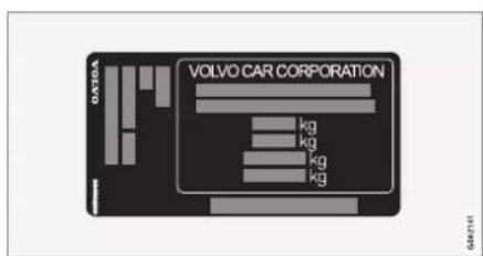
1 Decal for type designation, vehicle identification number, permissible maximum weights and code designation for exterior colour and type approval number. The decal is positioned on the door pillar, and will be visible when the right-hand rear door is opened.

② Decal for A/C system for cars with refrigerant R1234yf.

② Decal for A/C system for cars with refrigerant R134a.

③ Label for parking heater.

4 Decal for engine code and the engine's serial number. For certain engine alternatives there is no decal. In these cases, the engraved engine code can be read directly on the engine instead.

⑤ Label for engine oil.
SPECIFICATIONS
◀◀

6 Decal for gearbox type designation and serial number.

7 Decal for the car's identification number - VIN (Vehicle Identification Number).
Further information on the car is presented in the registration document.
NOTE
It is not intended that the decals illustrated in the owner's manual should be exact replicas of those in the car. They are included to show their approximate appearance and locations in the car. The information that applies to your particular car can be found on the decal on the car.
Related information
• Air conditioning — specifications (p. 670)
Dimensions
Measurement of car length, height, etc. can be read in the table.

| Dimensions mm inches | |||
| A | Ground clearance^ | 150 5,9 | |
| B | Wheelbase 2941 115.8 | ||
| C | Length 4969 195,6 | ||
| D | Load length, floor,folded seat | 1978 77.9 | |
| E | Load length, floor 1149 4 | 5.2 | |
| F | Height8 | 1446 56.9 |
| Dimensions mm inches | |||
| G | Load height 373 14.7 | ||
| H | Front track | 1628^C | 64.1^C |
| 1618^D | 63.7^D | ||
| 1617^E | 63.7^E | ||
| 1623^F | 63.9^F |
| Dimensions mm inches | |||
| I Rear track | 1629^C | 64.1^C | |
| 1619^D | 63.7^C | ||
| 1618^E | 63.7^E | ||
| 1624^F | 63.9^F | ||
| J Load width, floor 1014 39.9 | |||
| K Width 1890 74,4 | |||
SPECIFICATIONS
◀◀
| Dimensions mm inches | ||
| L | Width including door mirrors | 2019 79.5 |
| M | Width including folded-in door mir- rors | 1895 74.6 |
A At kerb weight plus 1 person. (Varies slightly depending on
tyre dimension, chassis option, etc.)
- Including low antenna, for kernel weight.
- Applies to cars with 17/18 inch wheels.
^D Applies to cars with 19 inch wheels.
E Applies to cars with 20 inch wheels.
F Applies to cars with 21 inch wheels.
Related information
- Weights (p. 663)
Weights
Max. gross vehicle weight, etc. can be read on a label in the car.
Kerb weight includes the driver, the fuel tank 90% full, plus and all oils and fluids.
The weight of passengers and accessories, and towball load (when a trailer is hitched) influence the load capacity and are not included in the kerb weight.
Permitted max. load = Gross vehicle weight - Kerb weight.
NOTE
The documented kerb weight applies to cars in the standard version - i.e. a car without extra equipment or accessories. This means that for every accessory added the loading capacity of the car is reduced correspondingly by the weight of the accessory.
Examples of accessories that reduce load capacity are the different equipment levels (e.g. Kinetic, Momentum, Summum), as well as other accessories such as towbar, load carrier, space box, audio system, auxiliary lamps, GPS, fuel-driven heater, safety grille, carpets, cargo cover, power seats, etc.
Weighing the car is a certain way of ascertaining the kerb weight of your own particular car.
WARNING
The car's driving characteristics change depending on how heavily it is loaded and how the load is distributed.

The decal is positioned on the door pillar, and will be visible when the right-hand rear door is opened.
1 Max. gross vehicle weight
② Max. train weight (car+trailer)
3 Max. front axle load
4 Max. rear axle load
5 Equipment level
Max. load: See registration document.
Max. roof load: 100 kg.
Related information
• Type designations (p. 658)
- Towing capacity and towball load (p. 664)
SPECIFICATIONS
Towing capacity and towball load
Towing capacity and towball load for driving with a trailer can be read in the tables.
Max. weight braked trailer
| NOTE |
| Use of vibration dampers on the towbar is recommended for trailers heavier than 1800 kg. |
| Engine | Engine codeA | Gearbox Max. | weight braked trailer (kg) Max. towball load (kg) |
| T8 Recharge B420 | 4T35 Automatic 2100 100 | ||
| T8 Recharge B420 | 4T34 Automatic 2100 100 |
A The engine code, component number and serial number can be found on the engine.
IMPORTANT
When driving with a trailer, it is permitted to exceed the vehicle's gross vehicle weight (including towball load) by a maximum of 100 kg (220 lbs), provided that speed is limited to 100 km/h (62 mph). National legal requirements for the vehicle combination, such as speed, etc. must be observed.
NOTE
If there is no weight data in the table, this is available in an enclosed supplement.
Max. weight unbraked trailer
| Max. weight unbraked trailer (kg) Max. towball load (kg) | |
| 750 50 |
SPECIFICATIONS
Related information
• Type designations (p. 658)
- Weights (p. 663)
• Driving with a trailer (p. 493)
• Trailer stability assist* (p. 495)
SPECIFICATIONS
Engine specifications
Engine specifications (power, etc.) for each respective engine alternative can be found in the table below.
The Recharge variant is driven both by a petrol engine and an electric drive motor (ERAD – Electric Rear Axle Drive).
NOTE
Not all engines are available in all markets.
NOTE
If there is no engine data in the table, this is available in an enclosed supplement.
| Engine | Engine code ^A | Output(kW/rpm) | Output(hp/rpm) | Torque(Nm/rpm) | No. of cylinders |
| T8 Recharge B4204T | 34 223/6000 303/6000 | 400/2200-4800 | 4 | ||
| T8 Recharge B4204T | 35 235/5700 320/5700 | 400/2200-5400 | 4 |
A The engine code, component number and serial number can be found on the engine.
Electric drive motor
Max. power output: 65 kW (87 hp).
Torque: 240 Nm.
Related information
• Type designations (p. 658)
• Engine oil — specifications (p. 667)
SPECIFICATIONS
Engine oil — specifications
Engine oil grade and volume for each respective engine alternative can be read in the table.
Volvo recommends:
Castrol
EDGE
PROFESSIONAL
Gesamt
| Engine | Engine codeA | Oil grade Volume, incl. oil filter | (litres, approx.) |
| T8 Recharge B4204T34 Castrol Edge Professional V 0W-20 or VCC RBS0-2AE 0W-20 5.6 | |||
| T8 Recharge B4204T35 5.6 | |||
A The engine code, component number and serial number can be found on the engine.
Related information
• Type designations (p. 658)
- Adverse driving conditions for engine oil (p. 668)
- Checking and filling with engine oil (p. 613)
• Engine oil (p. 611)
SPECIFICATIONS
Adverse driving conditions for engine oil
Adverse driving conditions can lead to abnormally high oil temperature or oil consumption. Below are some examples of adverse driving conditions.
Check the oil level more frequently for long journeys:
• towing a caravan or trailer
• in mountainous regions
- at high speeds
- in temperatures colder than -30 °C (-22 °F) or hotter than +40 °C (+104 °F).
The above also apply to shorter driving distances at low temperatures.
Choose a fully synthetic engine oil for adverse driving conditions. It provides extra protection for the engine.
Volvo recommends:

GOG?0065
IMPORTANT
In order to fulfil the requirements for the engine's service intervals all engines are filled with a specially adapted synthetic engine oil at the factory. The choice of oil has been made very carefully with regard to service life, starting characteristics, fuel consumption and environmental impact.
An approved engine oil must be used in order that the recommended service intervals can be applied. Only use a prescribed grade of oil for both filling and oil change, otherwise there is a risk of the service life, starting characteristics, fuel consumption and environmental impact of the car being affected.
If engine oil of the prescribed grade and viscosity is not used, engine related components may become damaged. Volvo disclaims any liability for any such damage.
Volvo recommends that oil changes are carried out at an authorised Volvo workshop.
Related information
• Engine oil — specifications (p. 667)
• Engine oil (p. 611)
Transmission fluid – specifications
Under normal driving conditions, the transmission fluid does not need to be changed during the service life of the gearbox. However, it may be necessary in adverse driving conditions.
Automatic gearbox
| Prescribed transmission fluid: AW-1 |
Related information
• Type designations (p. 658)
Brake fluid – specifications
Brake fluid is the medium in a hydraulic brake system that is used to transfer pressure from e.g. a brake pedal via a master brake cylinder, which in turn acts on the brake callipers.
Prescribed grade: Volvo Original or equivalent fluid compliant with a combination of Dot 4, 5.1 and ISO 4925 class 6.
NOTE
It is recommended that brake fluid is changed or filled by an authorised Volvo workshop.
Related information
• Engine compartment overview (p. 610)
Fuel tank - volume
The fuel tank's filling capacity can be read in the table below.
| All models | |
| Litres (approx) 60 | |
| US gallons (approx) 15.9 |
Related information
- Filling fuel (p. 482)
SPECIFICATIONS
Air conditioning — specifications
The car's climate control system uses a freon-free refrigerant either R1234yf or R134a depending on market. Information about which refrigerant the car's climate control system uses is printed on a decal located on the inside of the bonnet.
Prescribed grades and volumes of fluids and lubricants in the air conditioning system can be read below.
A/C decal
Decal for R134a

Decal for R1234yf

Symbol explanation R1234yf
Symbol Meaning

Caution

Mobile air conditioning system (MAC)

Lubricant type
Symbol Meaning

A trained and certified technician is required in order to service the mobile air conditioning system (MAC)

Flammable refrigerants
Refrigerant
Refrigerant amount is printed on the decal located on the inside of the bonnet.
Cars with R134a refrigerant
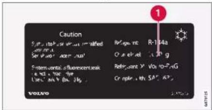
The air conditioning system contains pressurised refrigerant R134a. This system must only be serviced and repaired by an authorised workshop.
Cars with R1234yf refrigerant

The air conditioning system contains pressurised refrigerant R1234yf. In accordance with SAE J2845 (Technician Training for Safe Service and Containment of Refrigerants Used in Mobile A/C System), service and repair of the refrigerant system must only be performed by trained and certified technicians in order to ensure the safety of the system.
Compressor oil
| Volume Prescribed grade |
| 100 ml (3.38 fl. oz.) PAG SP-A2 |
Evaporator
IMPORTANT
The A/C system's evaporator must never be repaired or replaced with a previously used evaporator. A new evaporator must be certified and labelled in accordance with SAE J2842.
Related information
• Servicing the climate control system (p. 608)
SPECIFICATIONS
Fuel consumption and CO_2 emissions
The information in the tables below is in accordance with WLTP (Worldwide Harmonised Light-Duty Vehicles Test Procedure), which is an international test method for vehicles equivalent to a passenger car designed for laboratory testing.
The fuel consumption for a vehicle is measured in litres per 100 km and carbon dioxide emissions ( CO_2 ) are measured in gram CO_2 per km.
Explanation
| Weighted combined value. The value is weighted between elec-tric mode and fuel mode over the entire drive cycle. | |
| CO_2 | Gram CO_2 /km |
| Litres/100 km | |
| range | Certified value for the car's potential range ("up to") in km in electric mode. The value should not be interpreted as an expected range, and the range is difficult to achieve during normal driving. |
| Urban and suburban driving | |
| Average value over all four drive cycle phases (urban, suburban, extra-urban and motorway driving) | |
| aut | Automatic gearbox |
| Low value | |
| High value |
| i NOTE |
| If there is no consumption and emissions data in the table, this is available in an enclosed supplement. |
| NOTE |
| The capacity of the hybrid battery diminishes with age and use, which may result in increased use of the internal combustion engine and, as a consequence, reduced fuel economy and reduced range during electric operation. |
 | [IMAGE] | Orange | ||||
| CO_2 | [IMAGE] | [IMAGE] | [IMAGE] | |||
| T8 Recharge (B4204T34) | aut |  | - | - | _A | _A |
 | - | - | _A | _A | ||
A Drive mode PURE
The values in the table above for fuel consumption, CO_2 emissions, and range for electric mode are based on special drive cycles (see below). The car's weight may increase depending on its equipment level. Together with how heavily the car is loaded, this affects fuel consumption and CO_2 emissions, and reduces its range in electric mode. According to WLTP, each car has unique fuel consumption, CO_2 emission values and electric range values, depending on how the car is equipped. These values range between the low value and high value in the table above. In many markets, you can find your car's unique fuel consumption, CO_2 emission values and electric range values in the car's registration document.
The certified values for the car should not be interpreted as the expected values. The certification values are the comparative values
obtained during special drive cycles (see below).
There are several reasons for fuel consumption that is higher and an electric range that is shorter than the values in the table. Examples of these include:
- If the car is not regularly charged from the mains.
- If the car is equipped with extra equipment that affects its weight.
- Driving style.
- If the customer chooses wheels other than those mounted as standard on the basic version of the model, this could increase rolling resistance.
- High speed causes increased air resistance.
- Fuel quality, road and traffic conditions, weather and the condition of the car.
A combination of the examples above could increase consumption considerably.
There may be huge deviations in fuel consumption if comparing to the drive cycle profiles (see below), which are used in the certification of the car and on which consumption figures in the table are based. For further information, please refer to the referenced regulations.

NOTE
Extreme weather conditions, driving with a trailer or driving at high altitudes, in combination with poorer fuel quality than recommended, are factors that considerably increase the car's fuel consumption.
WLTP standard
From and including 1 September 2018, a new standard was introduced for calculating con-
▶▶
SPECIFICATIONS
sumption values in the car. The WLTP standard (Worldwide Harmonised Light-Duty Vehicles Test Procedure) represents the average driving conditions for everyday driving. In comparison with the previous standard (NEDC), WLTP takes into account more varied traffic situations and speeds, but also equipment and weight classes. Optional equipment that affects consumption is deactivated during testing, e.g. air conditioning, seat heating, etc. The new standard should provide more realistic figures when it comes to fuel consumption, carbon dioxide and emissions, as well as range for electric operation. The values are intended to allow comparison between different cars and not to represent your typical normal consumption and range for electric mode.
Drive cycle profiles
A drive cycle simulates actual average driving of the car. The standard is based on four different drive cycle profiles. The four drive cycle profiles are:
• Urban driving – slow driving
- Suburban driving – average driving
- Extra-urban driving – fast driving
- Motorway driving – very fast driving.
Every drive cycle is determined by different conditions such as speed, time and mileage, for example.
The official value for combined driving, which is shown in the table, is a combination of the results from the four drive cycles, in accordance with legal requirements.
The exhaust gases are collected in order to extrapolate the carbon dioxide emissions ( CO_2 emissions) during the four drive cycles. These were then analysed to determine the value for CO_2 emissions.
Related information
• Type designations (p. 658)
- Weights (p. 663)
Approved wheel and tyre sizes
In certain countries not all approved sizes are indicated by the registration document or
other documents. The following table shows all approved combinations of wheel rims and tyres.
√ = Approved
| Engine man/ | aut | 245/45 R18 | 255/40 R19 | 245/40 R20 |
| 8x18x42 | 8.5x19x47 | 8.5x20x47.5 | ||
| All engines aut | √ √ √ |
Related information
• Minimum permitted tyre load index and speed rating for tyres (p. 676)
• Type designations (p. 658)
• Dimension designation for tyre (p. 566)
• Dimension designation for wheel rim (p. 567)
- Snow chains (p. 581)
SPECIFICATIONS
Minimum permitted tyre load index and speed rating for tyres
The table below shows minimum permitted load index (LI) and speed rating (SS).
| Engine man/ | aut | Minimum permitted load index (LI) ^A | Minimum permitted speed rating (SS) ^B |
| All engines aut 99 H |
^ The tyre's load index must be at least equal to or greater than indicated in the table.
B The tyre's speed rating must be at least equal to or greater than indicated in the table.
Related information
• Approved wheel and tyre sizes (p. 675)
• Approved tyre pressures (p. 677)
• Type designations (p. 658)
• Dimension designation for tyre (p. 566)
- Dimension designation for wheel rim (p. 567)
Approved tyre pressures
Approved tyre pressures for each engine alternative can be found in the table.
NOTE
All engines, tyres or combinations of these are not always available in all markets.
| Engine Tyre size | Speed Load, 1-3 persons | Max. load | ECO pressure ^A | ||||
| Front (kPa) ^B | Rear (kPa) | Front (kPa) | Rear (kPa) | Front/rear (kPa) | |||
| All engines | 245/45 R18 | 0-160 km/h (0-100 mph) 240 240 | 260 260 260 | ||||
| 255/40 R19 | 160+ km/h (100+ mph) 300 300 | 320 320 - | |||||
| 245/40 R20 | |||||||
| Temporary Spare Tyre max | 80 km/h (max 50 mph) 420 420 420 | 420 - | |||||
A Economical driving.
B. In certain countries the "bar" unit is used alongside the SI unit "Pascal": 1 bar = 100 kPa.
Related information
• Type designations (p. 658)
- Checking tyre pressure (p. 568)
• Approved wheel and tyre sizes (p. 675)
• Recommended tyre pressure (p. 570)

bar
| Category | Value | |---|---| | Category 1 | 100 | | Category 2 | 100 | | Category 3 | 100 | | Category 4 | 100 | | Category 5 | 100 | | Category 6 | 100 | | Category 7 | 100 | | Category 8 | 100 | | Category 9 | 100 | | Category 10 | 100 | | Category 11 | 100 | | Category 12 | 100 | | Category 13 | 100 | | Category 14 | 100 | | Category 15 | 100 | | Category 16 | 100 | | Category 17 | 100 | | Category 18 | 100 | | Category 19 | 100 | | Category 20 | 100 | | Category 21 | 100 | | Category 22 | 100 | | Category 23 | 100 | | Category 24 | 100 | | Category 25 | 100 | | Category 26 | 100 | | Category 27 | 100 | | Category 28 | 100 | | Category 29 | 100 | | Category 30 | 100 | | Category 31 | 100 | | Category 32 | 100 | | Category 33 | 100 | | Category 34 | 100 | | Category 35 | 100 | | Category 36 | 100 | | Category 37 | 100 | | Category 38 | 100 | | Category 39 | 100 | | Category 40 | 100 | | Category 41 | 100 | | Category 42 | 100 | | Category 43 | 100 | | Category 44 | 100 | | Category 45 | 100 | | Category 46 | 100 | | Category 47 | 100 | | Category 48 | 100 | | Category 49 | 100 | | Category 50 | 100 | | Category 51 | 100 | | Category 52 | 100 | | Category 53 | 100 | | Category 54 | 100 | | Category 55 | 100 | | Category 56 | 100 | | Category 57 | 100 | | Category 58 | 100 | | Category 59 | 100 | | Category 60 | 100 | | Category 61 | 100 | | Category 62 | 100 | | Category 63 | 100 | | Category 64 | 100 | | Category 65 | 100 | | Category 66 | 100 | | Category 67 | 100 | | Category 68 | 100 | | Category 69 | 100 | | Category 70 | 100 | | Category 71 | 100 | | Category 72 | 100 | | Category 73 | 100 | | Category 74 | 100 | | Category 75 | 100 | | Category 76 | 100 | | Category 77 | 100 | | Category 78 | 100 | | Category 79 | 100 | | Category 80 | 100 | | Category 81 | 100 | | Category 82 | 100 | | Category 83 | 100 | | Category 84 | 100 | | Category 85 | 100 | | Category 86 | 100 | | Category 87 | 100 | | Category 88 | 100 | | Category 89 | 100 | | Category 90 | 100 | | Category 91 | 100 | | Category 92 | 100 | | Category 93 | 100 | | Category 94 | 100 | | Category 95 | 100 | | Category 96 | 100 | | Category 97 | 100 | | Category 98 | 100 | | Category 99 | 100 | | Total (Total) |ALPHABETICAL INDEX
ALPHABETICAL INDEX
1, 2, 3 ...
4WD 465
A
A/C (Air conditioning) 221
ABS
anti-lock brakes 451
Accessories and extra equipment 39 installation 40
Active bending lights 157
Active main beam 155
Active Park Assist 397
Limitations 402
Symbols and messages 405
Active Yaw Control 287
Adapting driving characteristics 467
Adaptive Cruise Control 311
activate 314
Auto brake 340
change cruise control functionality 318
change of target 337
controls 312
deactivate 315
display mode 313
fault tracing 317
Limitations 317
overtaking 335
setting the time interval 339
standby mode 316
stored speed 338
Symbols and messages 319
WARNING 336
Additional heater (Auxiliary heater) 235
Adjusting headlamp pattern/headlamp
beam 152
Adjusting the steering wheel 196
Advanced Air Cleaner 204
Aerial
location 272
Airbag 55
Activating/deactivating 58
driver's side 55
passenger side 56, 58
Airbag, see Airbag 55
Air conditioning 221
Air conditioning, fluid
volume and grade 670
Air conditioning system 198, 210
repair 608
Air distribution 204
Air vents 204, 205
change 205
defrosting 216
Recirculation 215
table of options 207
Air quality 201, 202
Advanced Air Cleaner 204
allergies and asthma 202
passenger compartment filter 203
Air recirculation 215
Alarm 280
deactivation 282
motion and tilt sensors 281
reduced alarm level 282
Alarm for hazard warning flashers 292
Alarm for slippery driving conditions 292
Alcohol lock 450,451
Allergy and asthma inducing sub-
nces. 202
All Wheel Drive (AWD) 465
Ambience lights
adapt 162
Android Auto 532, 533, 535
Apple CarPlay 528, 529, 531
Approach lighting 160
Apps 510
Assistance at risk of collision 362
activate/deactivate 363
Limitations 366
ALPHABETICAL INDEX
Symbols and messages 367 upon risk of head-on collision 364 upon risk of rear-end collision 365 upon risk of run-off 363
Audio and media 508
Audio settings 508, 542 phone 543 play media 520, 521 Text message 542
Auto climate control 214
Auto hold 457
Automatic brake 457 activate/deactivate 458 after collision 459 Driver support 286
Automatic car wash 647
Automatic car washes 647
Automatic gearbox 460, 461 kickdown 464 oil 669 trailer
Automatic locking 275
Automatic relocking 242, 270
Automatic speed limiter 304 activate/deactivate 306 Limitations 307 tolerance 307
Auxiliary heater 235 AWD, All Wheel Drive 465
B
Backrest front seat, adjusting 182, 183, 186, 187, 188, 189, 190 rear seat, lowering 192
Bag holder 596
Battery 488,617 Battery 617 Hybrid battery 619 jump starting 488 maintenance 617 overload 487 recycling 620 symbols on the battery 619
Bicycle rack towbar mounted 497 Blind Spot Information 369 BLIS 369 activate/deactivate 370 Limitations 371 Symbols and messages 372
Bluetooth connect 525 connect car to Internet 545 phone 535 settings 544
Bonnet, opening 609 Book service and repair 603
Boot lid closing and locking with button 276 Locking/unlocking 244, 271 opening/closing with foot movement 277 unlock from inside 274
Brake assist after collision 459
Brake energy 452,466
Brake fluid grade 669
Brake functions 451
Brake mode 461
Brakes 451 Anti-lock braking system, ABS 451 autobrake with adaptive cruise control 340 auto brake with Pilot Assist 340 automatic when stationary 457 brake assist system, BAS 453 brake light 158
ALPHABETICAL INDEX
| brake system 451emergency brake lights 159maintenance 454on gritted roads 453on wet roads 453Parking brake 454Brake systemfluid 669Bulbschange 639Bypass alcohol lock 450 | Cargo area 594electrical socket 591, 592lighting 161mounting points 597Car holiday 479Car key battery low 245Car modemconnect car to Internet 546settings 547Car status 602Tyre pressure 573Car upholstery 639, 641, 642, 643, 644Car washing 645, 646, 647, 649, 650, 651 | symbols in status bar 122views 113Change of owner 132Chargecar function 478Charge current 426Chargingfinish charging 439Hybrid battery 425open and close charging flap 431start charging 431Status 434, 435, 437Charging cable 427Checking the engine oil level 613Child lockactivate/deactivate 274Child safety 63Child seat 63, 64, 66, 67integrated child seat 76i-Size/ISOFIX mounting points 66lower mounting points 65positioning/fitting 66, 67table for location 70table of i-Size 72table of ISOFIX 73Upper mounting points 64City Safety 348brakes for oncoming vehicles 357 |
| Camera sensorsee Camera unit 415Camera unit 415Limitations 415maintenance and cleaning 418Symbols and messages 420Car care 645, 646, 647, 649, 650, 651Leather upholstery 643Care Keyrestricted remote control key 249settings 250Car functionsin centre display 120 | Catalytic converterRecovery 498central locking 273Centre displaychange appearance 129cleaning 640climate control 210function view 120Keyboard 124manage 110, 113, 117, 122messages 138, 139overview 107settings 130, 131switch off and change volume 129 |
ALPHABETICAL INDEX
cross traffic 354
evasive manoeuvre prevented 357
evasive manoeuvres 356
Limitations 358
limitations in the case of cross traffic 355
limitations in the case of evasive manoeuvres 356
obstacle detection 352
set warning distance 351
subfunctions 349
Symbols and messages 361
Cleaning 642, 644
automatic car wash 647
car washing 645, 646, 647, 649, 650,
centre display 640
Fabric upholstery 639, 641, 643 rims 651
Seatbelts 642
upholstery 639, 641, 642, 643, 644
Cleaning wheel rims 651
Cleaning wiper blades 649
CleanZone 201
Clean Zone Interior Package 202
Climate control 198, 210
auto-regulation 214
centre display 210
experienced temperature 199
fan control 219
Parking 222
rear seat 210
sensors 199
temperature control 220, 221
voice control 200
zones 198
Climate control system
Refrigerant 670
Clock, adjustment 92
CO2 emissions 672
Collision 46, 50, 55, 61
Collision warning
from behind 368
with adaptive cruise control 336
with Pilot Assist 336
Collision warning system
cross traffic rear 377
see City Safety 348
Colour code, paint 653
Colour codes 653
Combined instrument panel 83
settings 85
Compass 504
calibration 504
Condensation in headlamps 646, 647,
649,650
Connect car to Internet
no or poor connection 549
via a mobile device (WiFi) 546
via car modem 546
via telephone (Bluetooth) 545
Connected Safety
activate/deactivate 293
Limitations 293
Connect phone 536
Controls lighting 162
Control unit
charging status 435
Coolant 614
filling 614
Cooling system
overheating 486
Cornering support
activate/deactivate 334
Limitations 334
Corner Traction Control 287
Crash, see Collision 46
Cross Traffic Alert
activate/deactivate 378
Limitations 378
messages 380
Cruise control 308
activate 309
ALPHABETICAL INDEX
deactivate 310
standby mode 310
stored speed 338
Customer privacy policy 39
CZIP (Clean Zone Interior Package) 202
D
Data
recording 37
transfer between car and workshop 600
Data link connector 40
Data sharing 550, 551
Daytime running lights 153
Deadlock 283
Defrosting 216
Diagnosis
via the workshop's Wi-Fi 600
Digital radio (DAB) 518
Dimensions 661
Towbar 490
dipped beam 153
Dipstick, electronic 613
Direction indicator 156
Direction indicators 156
direction of rotation 567
Display
driver information 83
Display lighting 162
Distance Warning 375
activate/deactivate 376
Limitations 376
Set time interval 339
DivX ^® 524
Door mirrors 171
Dipping 171
resetting 172
store position 184,185
Download Centre 601
using 601
Drive-E
Environmental philosophy 30
Driver Alert Control 373
activate/deactivate 374
guide to rest stops 374
Limitations 375
Driver display 83
app menu 102,103
hybrid-related symbols and mes-
sages 441
messages 104
settings 85
Driver performance 91
settings 92
Driver profile 134
edit 135, 136, 138
select 135
driver support system 286
Driving mode 340
Drive systems 466
Drivetrain
Gearbox 460
Driving
cooling system 486
with a tailer 493
Driving in water 481
Driving mode 467
change 471
when using driver support 340
Driving with a trailer
towball load 664
towing capacity 664
E
ECO pressure 570,677
Electrically operated parking brake 454
Electrical socket 591
using 592
ALPHABETICAL INDEX
Electrical system 617
Electric drive motor specifications 666
Electric motor 466
Electric operation Driving 477 range 476
emergency brake lights 159
Emergency equipment first aid kit 597 warning triangle 598
Emergency puncture repair kit 582 Pump up tyre 586 using 583
Emissions of carbon dioxide 672
Energy distribution assisted by map data 472
Engine automatic start and stop of internal combustion engine 467 deactivate 447 overheating 486 start 446
Engine braking 451, 461
| Engine compartment | |
| coolant | 614 |
| Engine oil | 611 |
| overview | 610 |
| Engine drag control | 287 |
| Engine oil | 611, 668 |
| adverse driving conditions | 668 |
| check and top up | 613 |
| grade and volume | 667 |
| Engine specifications | 666 |
| Engine temperature | |
| high | 486 |
| Environment | 30 |
| Ethanol content | 485 |
| External dimensions | 661 |
F
| Fan | |
| Air distribution | 205 |
| Air vents | 205 |
| Control | 219 |
| Fault tracing | |
| Adaptive Cruise Control | 317 |
| City Safety 358 | |
| Ferry transport | 473 |
| First aid | 597 |
| First aid kit | 597 |
| Flooded road | 481 |
| Fluids, capacities | 655, 669, 670 |
| Fluids and oils | 614, 669, 670 |
| Fog lamp rear | 158 |
| Foot brake | 451 |
| Four-C | 473 |
| Front seat | |
| Climate control | 210 |
| Fan | 219 |
| heating | 211, 212 |
| Temperature | 220 |
| Ventilation 213 | |
| Front seat, manual | 182 |
| Front seat, power | 183 |
| adjusting seat | 183 |
| adjusting the passenger seat from the driver's seat | 191 |
| lumbar support | 190 |
| massage | 186, 187, 188 |
| multi-function control | 186, 187, 188, 189, side support |
| store position | 184, 185 |
| Fuel | 484, 485 |
| fuel consumption | 672 |
| identifier | 485 |
ALPHABETICAL INDEX
fuel gauge 86
Fuelling
filling 482
fuel filler flap 481
Fuel tank
volume 669
Fuel vapour 484
Fuse box 621
Fuses 620
changing 621
in cargo area 634
in engine compartment 622
under glovebox 629
G
Gearbox 460
automatic 460, 461, 465
Gear positions
automatic gearbox 461
Gear selector inhibitor 464
Gear shift indicator 465
Glass, laminated/reinforced 166
Glovebox 593
Gracenote® 523
Gross vehicle weight 663
Ground fault breaker 429
GSI - Gear selector assistance 465
H
Handbrake 454
Handwash 646
Hard disk
space 552
Hazard warning flashers 159
Headlamp beam adaptation 152
Headlamp control 150, 162
Headlamp pattern, adjusting 152
head restraint 193
Head up display activate/deactivate 142
cleaning 641
Distance Warning 375
settings 142
store position 142, 184, 185
windscreen replacement 608
Head-up display 140
Heated washer nozzles 177
Heater 233
auxiliary heater 235
parking heater 234
Heating
seats 211, 212
steering wheel 214
Windows 217,218
High engine temperature 486
High-pressure washing 649
Hill start assist
Hill Start Assist (HSA) 459
Hill Start Assist 459
Hold
car function 478
HomeLink® 500
program 501
Type approval 503
using 503
Home safe lighting, Homesafe Lighting,
Follow me home lighting, follow-me-
home lighting 160
Horn 195
Hybrid battery 619
charging 425
Hybrid battery meter 87
Hybrid meter 86
Hybrid operation 467, 472
ALPHABETICAL INDEX
|
IAQS (Interior Air Quality System) 202
IC (Inflatable Curtain) 61
ID, Volvo 28
Identification number 41
Ignition position 448, 449
Immobiliser 253
Immobilizer Immobiliser 253
Indicator symbols 93
Individual drive mode 467
Inflatable curtain 61
Inflatable Curtain 61
Information display 83, 85
Infotainment system (Audio and media) 508
Instrument lighting 162
Instrument overview left-hand drive car 80 right-hand drive car 81
Instruments and controls 80, 81
Integrated child seat 76
lowering 78
raising 77
| IntelliSafe | |
| Driver support | 33 |
| Interior Air Quality System | 202 |
| Interior lighting 160 | |
| adapt | 162 |
| Interior rearview mirror | 171 |
| Dipping | 171 |
| Intermittent wiping | 178 |
| Internet, see Internet-connected car | 544 |
| Internet-connected car | |
| book service and repair | 603 |
| send car information | 604 |
| system updates | 601 |
| iPod®, connection | 526 |
| ITPMS - Indirect Tyre Pressure Monitoring System | 571 |
J
| Jack | 578 |
| Journey statistics | 91 |
| Jump starting | 488 |
K
| Kerb weight | 663 |
| Key | 240 |
| Keyboard | 124, 127 |
| change language | 127 |
| Keyless | |
| Locking/unlocking 270 settings | 271 |
| touch-sensitive surfaces 269 | |
| Keypad in the steering wheel | 195 |
| Key tag | 240 |
L
| Labels | |
| location | 658 |
| Laminated glass | 166 |
| Lamps | |
| change | 639 |
| trailer | 496 |
| Lane assistance | 341 |
| activate/deactivate | 343 |
| display mode 347 | |
| Limitations | 344 |
| select assistance option | 344 |
| Symbols and messages | 345 |
| Lane Keeping Aidsee Lane assistance 341 | |
| Language 130 | |
| Large Animal Detection (LAD) 352 | |
| Launch function 464 | |
| Leather upholstery, washing instructions 643 | |
| Level control 473settings 476 | |
| License agreement 96, 553 | |
| Lifting tool 578 | |
| Lightingactive bending lights 157approach lighting 160Automatic main beam 155brake light 158controls 150, 160controls, instruments, display 162daytime running lights 153dipped beam | 153 |
| direction indicators | 156 |
| emergency brake lights | 159 |
| Hazard warning flashers | 159 |
| home safe lighting | 160 |
| in the passenger compartment | 160 |
| main beam | 154, 155 |
| position lamps | 152 |
| rear fog lamp 158 settings | 151 |
| Lighting, bulb replacement | 639 |
| Limp home | 460 |
| Load carriers | 596 |
| Loading | |
| General | 595 |
| load retaining eyelets | 597 |
| long load | 595 |
| Loading hooks | 596 |
| Load retaining eyelets cargo area | 597 |
| Lock | |
| Locking/unlocking | 242 |
| Lockable wheel bolts | 578 |
| Lock confirmation setting | 238 |
| 240 | |
| Locking/unlocking | |
| Boot lid | 244, 271 |
| Locks and remote control keys | 238 |
| Long-term storage | 443 |
| Low battery voltage | |
| Battery | 487 |
M
| Main beam | 154, 155 |
| Maintained climate comfort | 229 |
| start/shut-off | 229 |
| maintenance | |
| Rustproofing | 651 |
| Max. roof load | 663 |
| Media player 519, 520, 521 | |
| compatible file formats | 527 |
| voice control | 147 |
| Messages and symbols | |
| Adaptive Cruise Control | 319 |
| Assistance at risk of collision | 367 |
| BLIS | 372 |
| camera and radar unit | 420 |
| City Safety | 361 |
| Cross Traffic Alert | 380 |
| Lane assistance | 345 |
| Park Assist | 386 |
| Park assist camera | 395 |
| Park Assist Pilot | 405 |
| Pilot Assist | 332 |
| stability and traction control system | 290 |
| Messages in displays | 104, 138 |
| manage | 105, 139 |
| saved | 105, 139 |
ALPHABETICAL INDEX
Meters
fuel gauge 86
Hybrid battery 87
Mileage 88
Electric operation 476
Misting
condensation in headlamps 645, 647
Mobile phone, see Phone 536
Mood lighting 161
Motion sensor 281
0
Obstacle detection
City Safety 352
octane rating 485
Oil, see also Engine oil 667, 668
Oil filter 611
Oil level 613
Online car 544
no or poor connection 549
Option/accessory 23
Output 666
electric motor 666
outside temperature gauge 93
Overheating 486,493
Overtaking Assistance 335
activate 335
Owner's information 18
Owner's manual
in centre display 19,20
in mobile 22
OWNER'S MANUAL 23
P
PACOS (Passenger Airbag Cut Off
Switch) 58
Paddle on the steering wheel 195
Paintwork
colour code 653
damage and touch-up 651, 652, 653
Panorama roof
pinch protection 166
Parallel parking 397
Park Assist
activate/deactivate 383
forward, backward and along the
sides 382
Limitations 384
Symbols and messages 386
Park assist camera
activate 394
Limitations 415
locations and views 388
park assist lines 390
sensor fields 392
Symbols and messages 395
Park Assist Pilot 397
leave parking 402
parallel parking 398
perpendicular parking 398
using 399
Park Assist System 381
Parking
on hill 456
Parking brake 454
activate/deactivate 455
automatic activation 456
low battery voltage 457
Parking climate
Symbols and messages 231
Parking heater 234
Passenger Airbag Cut Off Switch 58
Passenger compartment filter 203
Passenger compartment heater (Parking heater) 234
Passenger compartment interior 590
electrical socket 591
glovebox 593
Sun visor 594
tunnel console 591
Passenger compartment lighting automatic 161
Pedestrian Protection System 49
Personal information (Customer privacy policy) 39
petrol 485
Petrol particle filter 486
Phone 535
Calls 540, 542
change to another 539
connect 536
connect automatically 538
connect manually 539
disconnect 539
remove 540
text message 541
voice control 146
Pilot Assist 321
activate 326
Auto brake 340
change of target 337
controls 323
deactivate 327
disabled steering assistance 328
display mode 324
Limitations 329
overtaking 335
setting the time interval 339
standby mode 327
stored speed 338
Symbols and messages 332
WARNING 336
Pinch protection 166
resetting 167
PIN code
Private locking 279
Polishing
Position lamp
Power save mode
Power seat
Power sunroof
Power windows
opening and closing 168
pinch protection 166
PPS (Pedestrian Protection System)
Precleaning
start/shut-off 228
Preconditioning
start/shut-off 223
Timer 224
Privacy policy (Customer privacy policy)
Private locking
activate/deactivate 279
Pump up tyre 586
R
Radar unit 406
Limitations 415
maintenance and cleaning 418
Symbols and messages 420
Type approval 407
Radio 513
change radio frequency and radio sta-
tion 514
DAB 518
search for radio station 515
settings 516
start 513
voice control 147
Radio favourites 516
Rain sensor 178, 179
Rain sensor memory function 179
Raising the car 605
Range
during electric operation 672
Rear Collision Warning 368
Limitations 368
Rear door
sun blind 170
Rear seat
Climate control 210
head restraint 193
ALPHABETICAL INDEX
heating 212
lowering the backrest 192
Rearview and door mirrors
angle external mirrors 172
compass 504
Dipping 171
door 171
electrically retractable 172
heating 218
interior 171
rear window
heating 218
sun blind 170
Recharge
General 424
Recommendations during driving 479
Recommendations for loading 595
Recovery 499
Refrigerant 608
climate control system 670
Refuelling 482
Regeneration 486
Regenerative braking 459
Remote control, HomeLink®
programmable 500
Remote control immobiliser 253
Remote control key 240
battery replacement 245
connect to driver profile 136
detachable key blade 251
loss 249
range 244
Remote control key system, type appro-
val 254
Remote updates 601
Resetting, trip meter 91
Resetting the door mirrors 172
Reversing camera 387
Rims
dimensions 567
Road run-off protection 363
Road sign information
Limitations 300
Road Sign Information 294
activate/deactivate 295
activating / deactivating warnings 299
display mode 296
Sensus Navigation 298
speed camera information 298
Speed warning 298
Rollover protection 287
Roll Stability Control 287
Roof load, max. weight 663
Rustproofing 651
S
Safety 46
pregnancy 47
Safety mode 61
start/movement 62
Sealing fluid 582
Seat, see Seats 182
Seatbelt 50
buckle/unbuckle 50
pregnancy 47
seatbelt reminder 53
seatbelt tensioner 52
Seatbelt, see Seatbelts 50
Seatbelt reminder 53
seatbelt tensioner
Resetting 53
Seatbelt tensioner 52
ALPHABETICAL INDEX
| Seats | |
| heating 211, 212 | |
| manual front seat 182 | |
| power front seat 183 | |
| store position 184, 185 | |
| Ventilation 213 | |
| whiplash protection 47 | |
| Security code 279 | |
| sensors | |
| Air quality 203 | |
| Camera unit 415 | |
| Climate control 199 | |
| Radar unit 406 | |
| Sensus | |
| connection and entertainment 34 | |
| Sensus Navigation | |
| Road Sign Information 298 | |
| Service position 654 | |
| Service programme 600 | |
| Settings | |
| Categories 133 | |
| contextual 131 | |
| Resetting 132 | |
| Side airbag | 60 |
| Side Impact Protection System | 60, 61 |
| SIM card | 547 |
| SIPS (Side Impact Protection System) | 60, 61 |
| Skidding | 480 |
| Ski hatch | 597 |
| slippery driving conditions | 480 |
| Snow chains 581 | |
| Software updates | 37 |
| Sound experience | 509 |
| spare wheel | 579 |
| manage | 580 |
| Speed camera information | 298 |
| activate/deactivate | 299 |
| Speed limiter | 301 |
| activate | 302 |
| automatic 304 | |
| deactivate 303 | |
| Limitations | 304 |
| stored speed | 338 |
| temporary deactivation | 304 |
| Speed ratings, tyres 566 | |
| Spin control | 287 |
| Stabiliser | |
| trailer | 495 |
| Stability and traction control system sport mode 288, 289 | 287 |
| Symbols and messages | 290 |
| Stains | 639, 641, 642, 643, 644 |
| Starting the engine after collision | 44662 |
| Start the car 446 | |
| State of charge car function | 478 |
| Steering assistance at risk of collision | 362 |
| Steering force, speed related | 286 |
| Steering force level, see Steering force | 286 |
| Steering lock 195 | |
| Steering wheel heating | 195, 196214 |
| keypad paddle | 195195 |
| steering wheel adjustment | 196 |
| Steering wheel paddles | 462 |
| Stickers location | 658 |
| Stone chips and scratches | 651, 652, 653 |
| Storage spaces glovebox | 590593 |
| Sun visor 594 tunnel console | 591 |
| Stored speed 338 | |
| Sun blind pinch protection | 166 |
| Rear door | 170 |
| rear window | 170 |
ALPHABETICAL INDEX
Sunroof 174
opening and closing 175
pinch protection 166
sunscreen 176
ventilation position 176
Sunscreen, sunroof 176
Sun visor 594
mirror lighting 161
Switching off the engine 447
Switch off engine 447
Symbols
dynamic 83
indicator symbols 93
warning symbols 93
Symbols and messages
centre display status field 122
hybrid related 441
parking climate 231
system updates 601
T
Target vehicle change 337
Temperature
Control 220, 221
experienced 199
Temperature monitoring 430
Temporary Spare 579
Terms and conditions services 38 user 550
Through-load hatch 597
Tilt detector 281
Time interval to the vehicle ahead 339
Tools 577
Top view 130
Total airing function 240
Towbar 489
foldable 491
specifications 490
Towing 498, 499
Towing capacity and towball load 664
Towing eye 498
Traction control 287
Traffic information 516
Trailer cable 493 driving with a trailer 493 Lamps 496 snaking 495
Trailer stability assist 288,495
Trailer Stability Assist 288
Transmission 460
Transmission oil grade 669
Tread 568
Tread depth 568 winter tyres 580
Tread wear indicators 568
Trip computer 88 show in driver display 90
Trip meter 88
Trip meter, resetting 91
Trip statistics settings 92
TSA - trailer stability assist 495
Tunnel console 591
Tunnel detection 153
Type approval HomeLink® 503 radar system 407 radio equipment 414 remote control key system 254
Type designations 658
Tyre load index 566
Tyre pressure Adjust 569 Check 568 label showing recommended pres- sure 570
Tyre pressure monitoring 571
action 574
save a new tyre pressure 572
Status 573
Tyre pressure table 677
Tyres
age 564
designation of dimensions 566
dimensions 675
direction of rotation 567
economy and wear 564
pressure 677
recommended 564
remove and mount 575
rotation during replacement 564
specifications 675, 676, 677
speed rating 566
Storage 564
tread wear indicators 568
tyre pressure table 677
winter tyres 580
U
Units 130
Unlocking
settings 243
with key blade 252
USB
jack for connecting media 526
V
Ventilation 204, 205
seats 213
Vibration damper 489
Video 524, 526
settings 525
Voice control 143
Climate control 200
phone 146
radio and media 147
settings 148
using 144, 146, 147, 148
VOL marking 564
Volvo ID 28
create and register 28
W
Warning lamps
Adaptive Cruise Control 336
Pilot Assist 336
stability and traction control system 287
Warning sound
Parking brake 457
Warning symbols 93
Safety 46
Warning triangle 598
Washer fluid 177,655
Washer nozzles, heated 177
Washers
headlamps 180
washer fluid, filling 655
windscreen 180
Waxing 645
Weights
kerb weight 663
Wheel bolts 578
Wheel rims
cleaning 651
Wheels
remove and mount 575
snow chains 581
ALPHABETICAL INDEX
Wheels and tyres approved dimensions 675 tyre load index and speed rating 676
whiplash protection 47
Whiplash Protection System 47
WHIPS (Whiplash Protection System) 47
Wi-Fi connect car to Internet 546 delete network 549 share internet connection, hotspot 548 technology and security 550
Window sun blind 170
Windows and glass 166
Windscreen heating 217 projected image 140, 142
Windscreen washing 180
Windscreen wiper 177 rain sensor 178, 179
Winter driving 480 snow chains 581 winter tyres 580
Wiper blades 177 changing 653 Service position 654
Wiper blades and washer fluid 177
VOLVO
TP 33060 (English), AT 2017, MY21, Copyright © 2000-2020 Volvo Car Corporation



- VÄLKOMMEN!
- TABLE OF CONTENTS
- OWNER INFORMATION
- YOUR VOLVO
- SAFETY
- DISPLAYS AND VOICE CONTROL
- LIGHTING
- WINDOWS, GLASS AND MIRRORS
- SEATS AND STEERING WHEEL
- CLIMATE
- DRIVER SUPPORT
- STARTING AND DRIVING
- LOADING, STORAGE AND PASSENGER COMPARTMENT
- MAINTENANCE AND SERVICE
- SPECIFICATIONS
- ALPHABETICAL INDEX
- The car's centre display 1
- Mobile app
- Volvo Cars support site
- Printed information
- IMPORTANT
- i NOTE
- Related information
- Owner's manual in centre display
- NOTE
- Contextual owner's manual
- Navigate in the owner's manual in the centre display
- Opening the menu in the top menu
- Homepage
- Categories
- Featured articles
- Hotspots for exterior and interior
- Favourites
- Saving or deleting articles as favourites
- Video
- Information
- Using the search function in the top menu
- Owner's Manual in mobile devices
- Support on the Internet
- Downloadable information
- Maps
- Owner's manuals as PDF
- Contact
- Create a Volvo ID on the Volvo Cars website
- Reading the owner's manual
- Options/accessories
- Special texts
- WARNING
- Decals
- Warning of personal injury
- Risk of property damage
- Illustrations and video clips
- Volvo ID
- Creating and registering a Volvo ID
- Create a Volvo ID with the Volvo ID app
- Create a Volvo ID with the Volvo On Call app 4
- Registering your Volvo ID to the car
- Fuel consumption
- Contributing to a better environment
- Efficient emission control
- Clean air in the passenger compartment
- Interior
- Volvo workshops and the environment
- Recycling
- IntelliSafe – driver support and safety
- Support
- Prevention
- Protection
- Sensus - online connectivity and entertainment
- This is Sensus
- Information when it is needed, where it is needed
- Voice recognition system
- Software updates
- Recording data
- Event Data Recorder (EDR)
- Vehicle Connectivity Module (VCM High)
- Terms & Conditions for Services
- Customer Privacy Policy
- Important information on accessories and auxiliary equipment
- Installation of accessories
- Connection of equipment to the car's diagnostic socket
- Showing the car's identification number
- Change of market when importing or relocating
- Visit an authorised Volvo dealer
- Creating a new Volvo ID in your new home market
- For cars with Volvo On Call 9
- Driver distraction
- Warning symbol in driver display
- Safety during pregnancy
- Seating position
- Whiplash Protection System
- WHIPS and child seats
- Pedestrian Protection System
- Symbols in the driver display
- Symbol Specification
- Seatbelts
- Putting on and taking off seatbelts
- Putting on seatbelts
- Taking off seatbelts
- Seatbelt tensioner
- Standard seatbelt tensioner
- Electric seatbelt tensioner
- Resetting the electric seatbelt tensioner
- Door and seatbelt reminder
- Seatbelt reminder
- Front seat
- Rear seat
- Reminder for doors, bonnet, boot lid and fuel filler flap
- Airbags
- Deployed airbags
- Driver airbags
- Steering wheel airbag location
- Knee airbag 1 location
- Passenger airbag
- Passenger airbag location
- Activating and deactivating passenger airbag\*
- Side airbags
- Side airbags and child seats
- Inflatable curtains
- Safety mode
- Starting and moving the car after safety mode
- Starting the car after safety mode
- Moving the car after safety mode
- Child safety
- Child seats
- Upper mounting points for child seats
- Lower mounting points for child seats
- i-Size/ISOFIX mounting points for child seats
- Child seat positioning
- Child seat mounting
- Installation in the front seat
- Installation in the rear seat
- Table for location of child seats using the car's seatbelts
- Table for location of i-Size child seats
- Table for location of ISOFIX child seats
- Integrated child seat\*
- Folding up the seat cushion in the integrated child seat\*
- Folding down the seat cushion in the integrated child seat\*
- Displays and controls by the driver in a left-hand drive car
- Displays and controls by the driver in a right-hand drive car
- Driver display
- Driver display settings
- Settings via the centre display
- Selecting information type
- Selecting theme
- Selecting language
- Tap on System System Languages
- Fuel gauge
- Hybrid gauge
- Symbols in the hybrid gauge
- Driver-requested power
- Hybrid battery gauge
- Trip computer
- Trip meter
- Odometer
- Instantaneous fuel consumption
- Distance to empty tank
- Distance to empty battery
- Start value for fully charged hybrid battery
- Mileage for electric operation
- Tourist - alternative speedometer
- Show trip data in the driver display
- Resetting the trip meter
- Show trip statistics in the centre display
- Settings for trip statistics
- Date and time
- Date and time settings
- Automatic time for cars with GPS
- Summer time
- Outside temperature gauge
- Indicator and warning symbols
- Red symbols
- Fault in brake system
- Parking brake
- Faults in the electrical system
- High engine temperature
- Collision risk
- Low oil pressure
- Amber symbols
- ABS fault
- Emissions system
- Rear fog lamp
- Tyre pressure system
- Fault in the headlamp system
- Lane assistance
- Reduced performance
- Stability system
- Stability system, sport mode
- Active main beam
- Main beam
- Automatic brake
- Front fog lamps
- Position lamps
- Left and right-hand direction indicator
- Preconditioning
- Rain sensor
- License agreement for the driver display
- Boost Software License 1.0
- BSD 3-clause "New" or "Revised" License
- BSD 2-clause "Simplified" license
- FreeType Project License
- Libpng License
- Magnus Holmgren
- MIT License
- zlib License
- App menu in the driver display
- App menu functions
- Managing the app menu in the driver display
- Opening/closing the app menu
- Navigating and selecting in the app menu
- Messages in the driver display
- Service messages
- Managing messages in the driver display
- Managing a new message
- Handling a message saved from the driver display
- Reading a saved message
- Managing a saved message
- Overview of centre display
- Managing the centre display
- Using the touch screen functionality in the centre display
- Returning to home view from another view
- Scrolling in a list, article or view
- Using the controls in the centre display
- Activating and deactivating centre display
- Navigating in the centre display's views
- Home view
- Status bar
- Climate view
- Managing subviews in centre display
- Expanding a subview:
- Opening or closing a subview in full screen mode
- Function view in centre display
- Different types of buttons
- Moving apps and buttons in centre display
- Symbols in the centre display's status bar
- Keyboard in centre display
- Changing keyboard language in centre display
- Adding or deleting languages in settings
- Switching between different languages in the keyboard
- Enter the characters, letters and words manually in the centre display
- Writing characters/letters/words by hand
- Deleting/changing characters/letters written by hand
- Changing the appearance in the centre display
- Switching off and changing the volume of the system sound in the centre display
- Changing system units
- Changing system language
- Other settings in the centre display's top view
- Open contextual setup in the centre display
- Third party apps
- Resetting user data for change of ownership
- Resetting settings in the centre display
- Two types of reset
- Resetting settings
- Table showing centre display settings
- Driver profiles
- What settings are saved in the driver profiles?
- Global settings
- Personal preferences
- Selecting driver profile
- Renaming a driver profile
- Protect driver profile
- Linking remote control key to driver profile
- Linking a remote control key to a driver profile
- Resetting settings in the driver profiles
- Message in centre display
- Pop-up messages
- Managing messages in the centre display
- Handling a message saved from the centre display
- Head-up display\*
- City Safety in the head-up display
- Activating and deactivating the head-up display\*
- Settings for head-up display\*
- Selecting display options
- Adjusting brightness and vertical position
- Calibrate the horizontal position
- Voice recognition
- What is voice control?
- System updating
- Using voice recognition
- Cancel voice control
- Example of voice recognition control
- Commands/phrases
- Digits
- Speed and repetition mode
- Controlling a telephone with voice recognition 18
- Voice control of radio and media 20
- Settings for voice recognition 21
- Audio settings
- Language settings
- Lighting control
- Adjusting light functions via the centre display
- Adapting the headlamp pattern from the headlamps
- Daytime running lights
- Dipped beam
- Tunnel detection
- Using main beam
- Main beam flash
- Activate active main beam
- Adaptive functionality
- Limitations for active main beam
- Using direction indicators
- Short flash sequence
- Continuous flash sequence
- Active bending lights\*
- Deactivating/activating the function
- Brake lights
- Emergency brake lights
- Hazard warning flashers
- Using home safe lighting
- Approach light duration
- Interior lighting
- Reading lighting
- Passenger compartment lighting
- Auto function for passenger compartment lighting
- Rear roof lighting
- Glovebox lighting
- Sun visor mirror lighting\*
- Ground lighting\*
- Door sill lighting
- Lighting in cargo area
- Decor lighting
- Ambience lights\*
- Lighting in storage compartments in doors
- Lighting in the tunnel console's front cup holder
- Adjusting interior lighting
- Adjusting ambient decor illumination
- Adjusting ambience light\*
- Changing the brightness of the lights
- Changing the colour of the light
- Pinch protection for windows and sun blinds
- Reset sequence for pinch protection
- Reset the power window
- Reset sun blind\*
- Power windows
- Operating power windows
- Using the sun blind\*
- Rearview and door mirrors
- Interior rearview mirror
- Door mirrors
- Adjusting rearview mirror dimming
- Manual dimming
- Control for manual dimming.
- Automatic dimming\*
- Angling adjustment of the door mirrors
- Folding in rearview mirrors electrically\*
- Resetting to neutral
- Angling during parking 3
- Automatic angling during parking 3
- Automatic retraction when locking\*
- Sunroof\*
- Operating the sunroof\*
- Manual operation
- Automatic operation
- Sunscreen
- Wiper blades and washer fluid
- Using windscreen wipers
- Single sweep
- Windscreen wipers off
- Intermittent wiping
- Continuous wiping
- Using the rain sensor
- Activating the rain sensor
- Deactivating the rain sensor
- Activating and deactivating the rain sensor's memory function
- Using windscreen and headlamp washers
- Headlamp washing\*
- Reduced washing
- Manual front seat
- Power\* front seat
- Adjusting the power\* front seat
- Storing position for seat, door mirrors and head-up display\*
- Storing a position
- Using a stored position for seat, door mirrors and head-up display\*
- Open front door
- ◀ Closed front door
- Massage settings\* in the front seat
- Settings for massage
- Restarting massage
- Adjusting massage settings\* in the front seat
- Adjusting massage settings in the front seat
- Adjusting\* the length of the seat cushion in the front seat
- Adjusting the side support\* in the front seat
- Adjusting the lumbar support\* in the front seat
- Adjust the lumbar support in the car using the four-way lumbar support
- Adjust the lumbar support in the car using the two-way lumbar support
- Adjusting the passenger seat from the driver's seat\*
- Activating the function
- Adjust passenger seat
- Lowering the backrests in the rear seat\*
- Lowering the backrest
- Raising the backrest
- Adjusting the head restraints in the rear seat
- Fold down the rear seat's outer head restraints via the centre display\*
- Steering wheel controls and horn
- Steering lock
- Activating the steering lock
- Deactivating the steering lock
- Adjusting the steering wheel
- Climate zones
- Climate control - sensors
- Perceived temperature
- Controlling the climate control system using voice control 1
- Air quality
- Materials in the passenger compartment
- Air cleaning system
- CleanZone\*
- Clean Zone Interior Package\*
- Interior Air Quality System\*
- Activating and deactivating the air quality sensor\*
- Passenger compartment filter
- Replacing the passenger compartment filter
- Advanced Air Cleaner\*
- Air distribution
- Automatic and manual air distribution
- Adjustable air vents
- Changing air distribution
- Opening, closing and aiming the air vents
- Opening and closing the air vents
- Aiming the air vents
- Climate controls
- Climate row in centre display
- Climate view in centre display
- Main climate
- Parking climate
- Climate controls at rear of tunnel console\*
- Activating and deactivating heated front seat\*
- Activating and deactivating automatic start of heated front seat\*
- Activating and deactivating heated rear seat\*
- Activating and deactivating the heated rear seat from the rear seat
- Activating and deactivating ventilated front seat\*
- Activating and deactivating the heated steering wheel\*
- Activating and deactivating automatic start of heated steering wheel\*
- Activating auto climate control
- Activating and deactivating air recirculation
- Activating and deactivating time setting for air recirculation
- Activating and deactivating max defroster
- Activating and deactivating max defroster from centre console
- Activating and deactivating max defroster from centre display
- Activating and deactivating the heated windscreen\*
- Activating and deactivating heated windscreen from centre console
- Activating and deactivating heated windscreen from centre display
- Activating and deactivating automatic start of heated windscreen\*
- Activating and deactivating the heated rear window and door mirrors
- Activating and deactivating heated rear window and door mirrors from centre console
- Activating and deactivating heated rear window and door mirrors from centre display
- Activating and deactivating automatic starting of the heated rear window and door mirrors
- Regulating fan level for front seat 2
- Regulating temperature for front seat 3
- Synchronising temperature
- Activating and deactivating air conditioning
- Start and switch off preconditioning
- Start and switch off from car
- Starting from the app
- Preconditioning time setting
- Adding and editing time setting for preconditioning
- Editing a time setting
- Activating and deactivating time setting for preconditioning
- Removing time setting for preconditioning
- Precleaning\*
- Starting and switching off precleaning\*
- Starting from the app\*
- Climate comfort when parking
- Starting and switching off climate comfort when parking
- Symbols and messages for parking climate control
- Heater
- Battery and charging
- Parking heater
- Additional heater
- Activating and deactivating automatic start of auxiliary heater
- Locking and unlocking
- Lock confirmation
- Exterior indication
- Other indication
- Lock indication setting
- Remote control key
- Button-less key (Key Tag)\*
- Care Key - restricted remote control key
- Interference
- Locking and unlocking with the remote control key
- Locking when the boot lid is open
- Unlocking with the remote control key
- Automatic relocking
- When the remote control key does not work
- Settings for remotely controlled and inside unlocking
- Unlocking the boot lid with the remote control key
- Power operated boot lid\*
- Remote control key range
- For manual use
- If the remote control key is removed from the car
- Replacing the battery in the remote control key
- Opening the key and changing the battery
- Ordering more remote control keys
- Loss of a remote control key
- Ordering Care Key
- Limitations of Care Key
- Setting options
- Care Key settings
- Detachable key blade
- The key blade's application areas
- Locking and unlocking with the detachable key blade
- Locking
- Immobiliser
- Type approval for the remote control key system
- Keyless and touch-sensitive surfaces\*
- Touch-sensitive surfaces
- Door handle
- Boot lid handle
- Keyless locking and unlocking\*
- Keyless locking
- Keyless unlocking
- Settings for Keyless entry\*
- Keyless\* unlocking of boot lid
- Antenna locations for the start and lock systems
- Locking and unlocking from inside the car
- Unlocking using a button in the front door
- Locking using a button in the front door
- Unlocking the rear door
- Unlocking the boot lid from the inside of the car
- Activating and deactivating child safety locks
- Electric child lock\*
- Automatic locking when driving
- Closing and locking boot lid with button\*
- Closing 13
- Locking 14
- Closing and locking 15
- Cancel closing
- Pinch protection
- Operating the boot lid with foot movement\*
- Opening and closing with foot movement
- Cancel closing with a foot movement
- Private locking
- Activating and deactivating private locking
- Enter the security code before using for the first time
- Activate private locking
- KEY, LOCKS AND ALARM
- Deactivate private locking
- Forgotten PIN code
- Forgotten security code
- Alarm\*
- Alarm signals
- Movement and tilt sensors\*
- Activating and deactivating alarms\*
- Activating and deactivating alarms
- Deactivate the alarm without a functioning remote control key
- Switching off a triggered alarm
- Reduced alarm level\*
- Activating reduced alarm level
- Double lock\*
- Driving support systems
- Speed-dependent steering force
- Reduced power
- Change the steering force level\*
- Electronic stability control
- Stability function 2
- Spin control and traction control system
- Engine Drag Control
- Trailer stability assist 4
- Electronic Stability Control in sport mode
- Activating or deactivating sport mode for electronic stability control
- Symbols and messages for electronic stability control
- Connected Safety 10
- Alarm on hazard warning flashers
- Alarm on slippery driving conditions
- Activating or deactivating Connected Safety
- Limitations of Connected Safety
- Road Sign Information\*
- Activating or deactivating road sign information\*
- Display mode for road sign information\*
- Speed limit or end of motorway
- Changed speed limit
- Sign for "School" and "Children at play"
- Road Sign Information and Sensus Navigation\*
- Warning for speed limitation and speed camera from road sign information\*
- Warning for speed limit
- Warning for speed camera
- Activating or deactivating warnings from road sign information\*
- Activating speed warning
- Adjust the limit for Speed Warning
- Activating acoustic warning in connection with speed warning
- Activate speed camera warning
- Limitations of Road Sign Information\*
- Speed limiter
- Selecting and activating speed limiter
- Deactivating the speed limiter
- Temporary deactivation of speed limiter
- Limitations for speed limiter
- Automatic speed limiter
- Symbol for which speed limiter function is active
- Symbol for automatic speed limiter
- Activating or deactivating the automatic speed limiter
- Deactivating the automatic speed limiter
- Changing the tolerance for the automatic speed limiter
- Limitations for automatic speed limiter
- Cruise control
- Using engine braking instead of the foot brake
- Selecting and activating cruise control
- Reactivating cruise control to the last stored speed
- Deactivating cruise control
- Standby mode for cruise control
- Standby mode on driver intervention
- Automatic standby mode
- Adaptive cruise control\*46
- Controls for adaptive cruise control\*48
- Display mode for adaptive cruise control\*50
- When driving
- Selecting and activating adaptive cruise control\*53
- Reactivating adaptive cruise control to the last stored speed
- Deactivating adaptive cruise control\*55
- Standby mode for adaptive cruise control\*57
- Limitations for adaptive cruise control\*60
- Steep roads and/or heavy load
- Drive mode unavailable
- Change between cruise control and adaptive cruise control\*62 in the centre display
- Symbols and messages for adaptive cruise control\*65
- Pilot Assist\*67
- Position of the car in the lane
- Steering assistance
- Round bends and when the road splits
- Hands on the steering wheel
- Controls for Pilot Assist\*68
- Display mode for Pilot Assist\*69
- Selecting and activating Pilot Assist\*71
- Reactivating Pilot Assist to last stored speed
- Deactivate Pilot Assist 4
- Standby mode for Pilot Assist 73
- ◀ Automatic standby mode
- Temporary disabling of steering assistance with Pilot Assist\*75
- Limitations of Pilot Assist\*76
- Symbols and messages for Pilot Assist\*77
- Cornering support\*78
- Drive modes
- Activating or deactivating cornering support\*
- Limitations for cornering support\*80
- Overtaking Assistance\*
- Use Overtaking Assistance
- Warning from driver support in the event of a collision risk
- Change of target with driver support
- Automatic standby mode with change of target
- Set the stored speed for driver support
- Effect of the accelerator pedal
- Possible speed
- Automatic gearbox
- Manual gearbox
- Set time interval to vehicle ahead
- Drive modes when using time interval to vehicles
- Automatic braking with driver support
- Brake function in slow queues and while stationary
- Cessation of automatic braking
- Automatic activation of parking brake
- Activating or deactivating lane assistance
- Selecting assistance option for lane assistance
- Limitations of Lane assistance
- Symbols and messages for lane assistance
- Display mode for lane assistance
- City Safety™
- Subfunctions for City Safety
- Ability to reduce speed
- Vehicles
- Cyclists
- Pedestrians
- Large animals
- The steps of City Safety
- - Collision warning
- - Brake support
- - Auto Brake
- Setting the warning distance for City Safety
- Detection of obstacles with City Safety
- City Safety in cross traffic
- Limitations for City Safety in cross traffic
- Examples are:
- City Safety steering assistance for evasive manoeuvre
- Limitations of City Safety steering assistance when taking evasive action
- Automatic braking in the event of an impeded evasive manoeuvre with City Safety
- City Safety brakes for oncoming vehicles
- Limitations of City Safety
- Surroundings
- Low objects
- Skidding
- Oncoming light
- Heat
- The camera and radar unit's field of view
- Driver intervention
- Reversing
- Low speed
- Active driver
- Important warnings
- Market limitation
- Messages for City Safety
- Steering assistance at risk of collision
- Activating or deactivating steering assistance in the event of a collision risk
- Steering assistance upon risk of run-off
- Steering assistance upon risk of head-on collision
- Steering assistance upon risk of rear-end collision\*
- Limitations for steering assistance at risk of collision
- Symbols and messages for steering assistance upon risk of collision
- Rear Collision Warning\*99
- Limitations of Rear Collision Warning\*101
- BLIS\*
- Activating or deactivating BLIS
- Limitations of BLIS
- Messages for BLIS
- Driver Alert Control
- to take a break.
- Activating or deactivating Driver Alert Control
- Select rest stop guidance in the event of a warning from Driver Alert Control
- Limitations of Driver Alert Control
- Distance Warning\*107
- Activating or deactivating distance warning 108
- Limitations of Distance Warning 109
- Cross Traffic Alert\*110
- Activating or deactivating Cross Traffic Alert\*112
- Limitations of Cross Traffic Alert\*113
- Examples of further limitations
- Messages for Cross Traffic Alert\*114
- Park Assist\*
- Park Assist Pilot front, rear and along the sides\*
- Activating or deactivating the parking assistance system\*
- Limitations of Parking assistance
- Symbols and messages for Park Assist Pilot
- Park assist camera\*
- Park assist camera locations and surveillance areas\*
- Park assist lines for park assist camera\*
- Press Towbar (1).
- Sensor fields for parking assistance system
- Sensor field to the sides
- Activate park assist camera
- Camera view when reversing
- Camera view for manual camera activation
- Automatic deactivation of camera
- Symbols and messages for Park assist camera
- Park Assist Pilot\*
- Parking variants with Park Assist Pilot\*
- Using Park Assist Pilot\*
- Parking with Park Assist Pilot
- Find and measure parking spaces
- Auto-brake during parking sequence
- Leaving parallel parking with Park Assist Pilot\*
- Limitations of Park Assist Pilot\*
- Parking is discontinued
- Driver responsibility
- Messages for Park Assist Pilot\*
- Radar unit
- Type approval for radar device
- Camera unit
- Limitations for camera and radar unit
- Common limitations for camera and radar
- High temperature
- Damaged windscreen
- Further limitations for radar
- Vehicle speed
- Limited field of vision
- Further limitations for camera
- Impaired vision
- Further limitations for Park assist camera\*
- Light conditions
- Recommended maintenance for camera and radar unit
- Symbols and messages for camera and radar unit
- Detector blocked
- Defective camera
- General information on electric drive
- Important to know
- Car without power
- Towing not permitted
- Exterior engine noise
- Charging the hybrid battery
- ELECTRIC OPERATION AND CHARGING
- Charging with fixed control unit in accordance with mode 3 4
- Charging current
- Charging time
- Fuse
- Charging cable
- Ground fault breaker in the charging cable
- LED lamp
- Temperature monitoring of the charging cable
- Monitoring in the control unit
- Monitoring at the plug
- Opening and closing the hatch for the charging input socket
- Starting hybrid battery charging
- Charging status in the car's charging input socket
- Charging status in the charging cable's control unit
- Charging status in the car's driver display
- Stopping hybrid battery charging
- The charging cable is locked automatically
- Symbols and messages relating to hybrid drive in the driver display
- Long-term storage of vehicles with hybrid batteries
- Starting the car
- Before starting:
- Error messages
- Switching off the car
- Ignition positions
- Selecting ignition mode
- Alcohol lock\*
- Bypass of the alcohol lock\*
- Before starting the engine with the alcohol lock\*
- To bear in mind
- Brake functions
- Foot brake
- Anti-lock braking system
- Light braking charges the hybrid battery
- Brake assistance
- Braking on wet roads
- Braking on gritted roads
- Brake system maintenance
- Activating and deactivating the parking brake
- Symbol in the driver display
- Automatic activation
- Emergency brake
- Deactivate manually
- Deactivate automatically
- Automatic parking brake activation setting
- Parking on a hill
- Heavy load uphill
- In the event of a fault in the parking brake
- Low battery voltage
- Replacing the brake linings
- Automatic braking when stationary
- Activating and deactivating the automatic brake at a standstill
- Applicable when switching off
- Help when starting on a hill
- Auto braking after a collision
- Regenerative braking\*
- Activating brake regeneration
- Gearbox
- Changing gear with automatic gearbox
- Gear positions
- Help functions
- Reverse - R
- Neutral - N
- Drive position - D
- Changing gear with steering wheel paddles\*
- Switch
- Activating the steering wheel paddles in position D
- Deactivating the steering wheel paddles in position D
- Manual deactivation
- Automatic deactivation
- Gear selector inhibitor
- Automatic gear selector inhibitor
- From park position – P or neutral position – N
- Message in the driver display
- Kick-down function
- Safety function
- Launch function\*
- Activate Launch
- Symbols and messages for automatic gearbox
- Gear shift indicator
- All-wheel drive
- Drive systems
- Two drive systems
- Starting and stopping the combustion engine
- Climate settings at low temperatures
- Electric operation in low or high temperatures
- Emission control
- Selectable drive modes
- Hybrid
- Information in the driver display
- Pure
- ECO climate control
- Constant AWD
- Power
- Individual
- Using the electric motor or internal combustion engine
- Changing drive mode
- Energy distribution using map data\*
- Conditions for the function
- Tips for use
- Level control\* and shock absorption
- Shock absorption (Four-C)
- During transport
- Symbols and messages
- Settings for level control\*
- Settings in the centre display
- Disable Leveling Control
- Economical driving
- Before driving
- While driving
- After driving
- Range
- Factors that affect the range
- Hold and Charge
- Activating Hold and Charge
- Charge
- Preparations for a long trip
- Winter driving
- Slippery driving conditions
- Driving in water
- Opening and closing the fuel filler flap
- Filling fuel
- Topping up fuel from a fuel can
- Applicable to cars with fuel-driven auxiliary heater\*
- Handling of fuel
- Petrol
- Octane rating
- Petrol particle filter 11
- When driving short distances at low speeds in a petrol car
- Overheating in the engine and drive system
- Overloading the starter battery
- Using jump starting with another battery
- Towbar\*
- Specifications for towbar\*
- Extendable and retractable towbar\*
- Extending the towbar
- Retracting the towbar
- Driving with a trailer
- Trailer connector
- Trailer weights
- Level control\*
- When driving in hilly terrain and hot climates
- Steep inclines
- Starting on a hill
- Trailer stability assist\*
- Reasons for snaking
- Trailer stability assist function
- Checking trailer lamps
- Direction indicators and brake lights on the trailer
- Rear fog lamp on trailer
- Checking trailer lamps\*
- Automatic checking
- Switching off automatic checking
- Manual checking
- Towbar-mounted bicycle rack\*
- Recommendations for loading bicycles on the bicycle rack
- Towing
- When towing another car
- Jump starting
- Fitting and removing the towing eye
- Removing the towing eye
- Recovery
- HomeLink®\*15
- Programming HomeLink®\*18
- Reprogramming individual buttons
- Resetting the HomeLink® buttons
- Using HomeLink®\*21
- Type approval for HomeLink®\*22
- Type approval for EU
- Compass\*
- Activating and deactivating the compass\*
- Calibrating the compass\*
- Sound, media and Internet
- Sound reproduction
- Premium Sound\* (Bowers & Wilkins)
- High Performance Pro\* (Harman Kardon)
- High Performance
- Sound experience\*
- Apps
- Downloading apps
- Cancelling the download
- Updating apps
- Update all
- Update some
- Deleting apps
- Radio
- Start radio
- Changing radio band and radio station
- Changing radio band
- Changing stations within the selected list
- Searching for radio stations
- Save radio channels in the Radio Favourites app
- Adding and removing radio favourites
- Settings for radio
- Cancelling traffic messages
- Activating and deactivating radio functions
- FM Radio
- DAB\* (digital radio)
- RDS radio
- Digital radio\*
- DAB subchannel
- Link between FM and digital radio\*
- DAB to DAB and DAB to FM linking
- Media player
- Media playback
- USB memory
- Bluetooth connected device
- Media with Internet connection
- Apple CarPlay
- Android Auto
- Controlling and changing media
- Searching media
- Gracenote®
- Updating Gracenote
- Playing a video
- Playing back DivX®
- Settings for video
- Media via Bluetooth®
- Connecting a device via Bluetooth®
- Media via USB port
- Connecting a device via USB port
- Technical specifications for USB devices
- Technical specification for USB A connector
- Technical specification for USB C connector
- Compatible media formats
- DivX®
- Apple ® CarPlay ®*
- Using Apple ® CarPlay ®*
- Connect an iOS device and start CarPlay
- Starting CarPlay
- Switch the connection between CarPlay and iPod
- CarPlay to iPod
- iPod to CarPlay
- Settings for Apple ® CarPlay ®*
- Automatic start
- System volumes
- Tips for using Apple ® CarPlay ®*
- Android Auto\*
- Using Android Auto\*
- The first time an Android is connected
- Previously connected Android
- Settings for Android Auto\*
- Tips for using Android Auto\*
- Phone
- Overview
- Connecting a phone to the car via Bluetooth for the first time
- Option 1 - search phone from car
- Option 2 - search car from phone
- Connecting a phone to the car via Bluetooth automatically
- Connecting a phone to the car via Bluetooth manually
- Disconnecting a Bluetooth-connected phone
- Switch between Bluetooth-connected phones
- Removing devices connected to Bluetooth
- Managing phone calls
- Making phone calls
- Making multi-party calls
- Conference calls
- Incoming phone calls
- Incoming phone call during an active call
- Private call
- Managing text messages 19
- Managing text messages in the centre display
- Reading text messages in the centre display
- Sending text messages in the centre display 20
- Managing text messages in the driver display
- Reading a new text message in the driver display
- Dictating a reply in the driver display
- Message notification
- Settings for text messages
- Managing the phone book
- Sorting
- Settings for phone
- Call notifications in head up display\*
- Settings for Bluetooth devices
- Internet-connected car\*
- Connect the car to the Internet via a Bluetooth-enabled phone
- Connect the car to the Internet via a phone (Wi-Fi)
- Connect the car to the Internet via car modem (SIM card)
- Settings for car modem\*
- Sharing Internet access from the car via a Wi-Fi hotspot
- No or poor Internet connection
- Phone to car
- Phone to network operator
- Restarting the phone
- Remove Wi-Fi network
- Remove all networks
- Wi-Fi technologies and security
- User terms and conditions and data sharing
- Privacy and data sharing
- Activating and deactivating data sharing
- Data sharing for services
- Activate data sharing when you start a service
- Activate data sharing when you start an app
- Storage space on hard disk
- License agreement for audio and media
- Patent numbers
- Gracenote® End User License Agreement
- Sensus software
- Linux software
- camellia:1.2.0
- Unicode: 5.1.0
- Tyres
- Recommended tyres
- Tyre age
- Tyre economy
- Tyre rotation
- Storing wheels and tyres
- Dimension designation for tyre
- Designation of dimensions
- Load index
- Speed rating
- Dimension designation for wheel rim
- Tyres' rotation direction
- Tread wear indicators on the tyres Tread wear indicators show the status of the tyre's tread depth.
- Checking tyre pressure
- Cold tyres
- Adjusting tyre pressure
- WHEELS AND TYRES
- Recommended tyre pressure
- Tyre pressure monitoring system\*
- System description
- General information on the tyre monitoring system
- Saving a new reference value for tyre pressure monitoring\*
- See tyre pressure status in the centre display\*
- Checking status
- Action in the event of warning for low tyre pressure
- Messages for tyre pressure monitoring\*
- Changing wheel
- Removing a wheel
- Mounting a wheel
- Tool kit
- Jack\*
- Wheel bolts
- Lockable wheel bolt kit\*
- Spare wheel\*
- Handling the spare wheel\*
- Winter tyres
- Tips for changing to winter tyres
- Studded tyres
- Tread depth
- Snow chains
- Emergency puncture repair kit
- Location
- Sealing fluid expiry date
- Using a puncture repair kit
- Precautions:
- First aid:
- Preparations
- Begin puncture repair
- Follow-up inspection
- Inflating tyres with the compressor from the puncture repair kit
- Passenger compartment interior
- Tunnel console
- Electrical sockets
- Using electrical sockets
- Using 12 V sockets
- Using the glovebox
- Locking and unlocking the glovebox\*
- Sun visors
- Cargo area
- Recommendations for loading
- Loading in the cargo area
- Increasing the space in the cargo area
- Roof load and loading on load carriers
- Bag hooks
- Load retaining eyelets
- Through-load hatch in the rear seat\*
- First aid kit\*
- Warning triangle
- Storage spaces
- Volvo service programme
- Service and repair
- Charging cable with control unit
- Data transfer between car and workshop via Wi-Fi
- Connection with the remote control key
- Download Center
- Managing system updates via the Download Centre
- Searching for update
- Update all system software
- Update individual system software programs
- Cancelling software download
- Deactivating the background search for software update
- Car status
- Book service and repair 5
- Before the service can be used
- Book a service
- Accept the appointment suggestion
- Sending car information to a workshop 9
- Car information content
- Raise the car
- Servicing the climate control system
- Troubleshooting and repair
- Head up display when replacing the windscreen\*
- Opening and closing the bonnet
- Warning - bonnet not closed
- Close the bonnet
- Engine compartment overview
- Engine oil
- Symbols for low oil level
- Coolant
- Topping up coolant
- Starter battery
- The service life and capacity of the starter battery
- Hybrid battery
- The service life and capacity of the hybrid battery
- Specifications for hybrid battery
- Symbols on the batteries
- Battery recycle
- Fuses and central electrical units
- Replacing a fuse
- Fuses in engine compartment
- Positions
- Fuses under glovebox
- Fuses in cargo area
- Bulb replacement
- Cleaning the interior
- Cleaning the centre display
- Cleaning the Head-up display\* and driver display
- Cleaning fabric upholstery and headlining
- Cleaning fabric upholstery
- Cleaning the headlining
- Cleaning the seatbelts
- Cleaning textile floor and entrance mats
- Cleaning leather upholstery\*
- Cleaning the leather upholstery
- Protecting the leather upholstery
- Cleaning the leather steering wheel
- Cleaning interior plastic, metal and wood parts
- Cleaning the exterior
- Polishing and waxing
- Handwashing
- Important points to remember when handwashing the car
- Automatic car wash
- Test the brakes
- High-pressure washing
- Cleaning the wiper blades
- Cleaning exterior plastic, rubber and trim components
- Cleaning wheel rims
- Rustproofing
- Inspection and maintenance
- Car paintwork
- Touching up minor paintwork damage
- Materials that may be needed
- Colour codes
- Colour code
- Replacing windscreen wiper blades
- Set the wiper blades in service position
- Activating/deactivating service mode
- Filling washer fluid
- Volume:
- Type designations
- Dimensions
- Weights
- Towing capacity and towball load
- Engine specifications
- Electric drive motor
- Engine oil — specifications
- Adverse driving conditions for engine oil
- Transmission fluid – specifications
- Brake fluid – specifications
- Fuel tank - volume
- Air conditioning — specifications
- A/C decal
- Symbol Meaning
- Refrigerant
- Evaporator
- Fuel consumption and CO_2 emissions
- WLTP standard
- Drive cycle profiles
- Approved wheel and tyre sizes
- Minimum permitted tyre load index and speed rating for tyres
- Approved tyre pressures
- 1, 2, 3 ...
- A
- B
- D
- E
- F
- G
- H
- |
- J
- K
- L
- M
- 0
- P
- R
- S
- T
- U
- V
- W
- VOLVO
Brand : VOLVO
Model : S90 (2024)
Category : Automobile