
XC90 T8 (2019) - Automobile VOLVO - Free user manual and instructions
Find the device manual for free XC90 T8 (2019) VOLVO in PDF.


| Type | Plug-in Hybrid SUV |
| Model Year | 2019 |
| Engine | 2.0L Supercharged & Turbocharged I4 + Electric Motor |
| Combined Power | Approx. 400 hp |
| Transmission | 8-speed Automatic |
| Drive | All-Wheel Drive (AWD) |
| Battery Capacity | 11.6 kWh (Lithium-ion) |
| Electric Range | Approx. 18 miles (WLTP) |
| Charging Time (AC) | Approx. 3 hours (240V, 16A) |
| Fuel Tank Capacity | 18.8 gallons |
| Dimensions (L x W x H) | 194.9 x 79.1 x 69.9 in |
| Wheelbase | 117.5 in |
| Curb Weight | Approx. 4,700 lbs |
| Seating Capacity | 7 |
| Infotainment System | Sensus with 9-inch Touchscreen |
| Smartphone Integration | Apple CarPlay, Android Auto |
| Safety Systems | City Safety, BLIS, Pilot Assist, Lane Keeping Aid |
| Climate Control | 4-Zone Automatic Climate Control |
| Heated Seats | Front and Rear |
| Maintenance Interval | Every 10,000 miles or 12 months |
Frequently Asked Questions - XC90 T8 (2019) VOLVO
User questions about XC90 T8 (2019) VOLVO
0 question about this device. Answer the ones you know or ask your own.
Ask a new question about this device
Download the instructions for your Automobile in PDF format for free! Find your manual XC90 T8 (2019) - VOLVO and take your electronic device back in hand. On this page are published all the documents necessary for the use of your device. XC90 T8 (2019) by VOLVO.
USER MANUAL XC90 T8 (2019) VOLVO
natural_image
Close-up of a white car's front headlights and grille (no visible text or symbols)VÄLKOMMEN!
We hope your Volvo will give you many years of happy motoring. The vehicle is designed for the safety and comfort of you and your passengers. Volvo strives to design one of the world's safest passenger vehicles. Your Volvo is also designed to meet applicable safety and environmental requirements.
To increase your enjoyment of your Volvo, we recommend that you read the instructions and maintenance information contained in this owner's
manual. The owner's manual is also available as a mobile app (Volvo Manual) and on Volvo Cars support page (support.volvocars.com).
We also encourage everyone to always use seat belts in this and other vehicles. You should also not drive if you are under the influence of alcohol or medicines or if your ability to drive is for some other reason impaired.
TABLE OF CONTENTS
OWNER'S INFORMATION
Owner's information 16
Owner's Manual in the center display 17
Navigate in the Owner's Manual in the center display 18
Owner's manual in mobile devices 20
Volvo Cars support site 21
Using the Owner's Manual 21
The Owner's Manual and the environment 24
YOUR VOLVO
Contacting Volvo 26
Volvo ID 26
Creating and registering a Volvo ID 26
Drive-E – purer driving pleasure 27
IntelliSafe - driver support 28
Sensus - connection and entertainment 30
Software Updates 33
Data recording 33
Terms & Conditions for Services 35
Customer Privacy Policy 35
Important information on accessories and extra equipment 35
Accessory installation 36
Connecting equipment to the vehicle's data link connector 37
Technician certification 38
Viewing the Vehicle Identification Number (VIN) 38
Volvo Structural Parts Statement 39
Driver distraction 39
SAFETY
Safety 42
Safety during pregnancy 43
Occupant safety 43
Reporting safety defects 44
Recall information 45
Whiplash Protection System 46
Seat belts 47
Buckling and unbuckling seat belts 48
Seat belt tensioners 50
Resetting the electric seat belt ten- sioners 51
Door and seat belt reminders 51
Airbags 52
Driver/passenger-side airbags 53
Occupant weight sensor 56
Side airbags 60
Inflatable curtain 60
Safety mode 61
Starting and moving the vehicle 62 when it is in safety mode
Child safety 63
Child restraints 65
Infant seats 67
Convertible seats 69
Booster cushions 71
Top tether anchors 72
Lower child seat attachment points 74
ISOFIX/LATCH lower anchors 74
Integrated booster cushion* 76
Folding up the integrated booster 77 cushion*
Folding down the integrated booster cushion* 78
DISPLAYS AND VOICE CONTROL
Instruments and controls in left-hand drive vehicles 82
Instrument panel 84
Instrument panel settings 86
Fuel gauge 87
Hybrid gauge 87
Hybrid gauge 88
Trip computer 89
Displaying trip data in the instrument panel 91
Resetting the trip odometer 92
Displaying trip statistics in the center 92 display
Trip statistics settings 93
Date and time 93
Ambient temperature sensor 94
Indicator symbols in the instrument panel 94
Warning symbols in the instrument panel 97
Instrument panel licenses 98
App menu in instrument panel 103
Handling the App menu in the instrument panel 104
Messages in the instrument panel 105
Handling messages in the instrument panel 106
Handling messages saved from the instrument panel 107
Center display overview 109
Handling the center display 112
Activating and deactivating the center display 115
Navigating in the center display's views 115
Handling tiles in the center display 119
Function view in the center display 122
Moving apps and buttons in the center display 124
Symbols in the center display status bar 124
Using the center display keyboard 126
Changing keyboard language in the center display 129
Entering characters, letters and words by hand in the center display 129
Changing the appearance of the center display 131
Turning off and adjusting the volume of the center display system sounds 131
Changing system units of measurement 132
Changing system language 132
Changing settings in the center display's Top view 132
Opening contextual setting in the center display 133
Resetting user data when the vehicle changes owners 134
Resetting center display settings 134
Table of settings in the center display 135
Driver profiles 136
Selecting a driver profile 137
Changing a driver profile's name 137
Protecting a driver profile 138
Linking a remote key to a driver profile 138
Resetting driver profile settings 139
Messages in the center display 140
Handling messages in the center display 140
Handling messages saved from the center display 141
Head-up display ^* 142
Activating and deactivating the head-up display* 143
Head-up display settings* 144
Voice control 145
Using voice commands 146
Voice control for cellular phones 147
Voice control for radio and media 148
Voice control settings 148
LIGHTING
Lighting panel and controls 152
Adjusting light functions via the center display 153
Parking lights 154
Daytime running lights 154
Low beams 155
Using high beam 156
Active high beam 157
Using turn signals 158
Active Bending Lights ^* 159
Rear fog light 159
Brake lights 160
Emergency brake lights 160
Hazard warning flashers 161
Using home safe lighting 161
Welcome Light 161
Interior Lighting 162
Adjusting interior lighting 164
WINDOWS, GLASS AND MIRRORS
Windows, glass and mirrors 166
Pinch protection for windows and sun curtains 166
Reset procedure for pinch protection 167
Power windows 167
Operating the power windows 168
Using sun curtains* 169
Rearview/door mirrors 169
Adjusting the rearview mirror dimming function 170
Adjusting the door mirrors 171
Panoramic roof ^* 172
Operating the panoramic roof* 173
Auto closing the panoramic roof* sun 175 curtain
Wiper blades and washer fluid 176
Using the windshield wipers 176
Using the rain sensor 177
Using the rain sensor's memory function 178
Using the windshield and headlight washers 179
Using the rear window wiper/washer 180
Using automatic rear window wiping 181 when backing up
SEATS AND STEERING WHEEL
Manual front seats 184
Power* front seats 185
Adjusting the power* front seats 185
Storing positions for seats, mirrors and head-up display* 186
Using stored positions for seats, mirrors and head-up display* 187
Front seat massage* settings 188
Adjusting front seat massage settings* 189
Adjusting* front seat cushion length 189
Adjusting front seat side bolster settings* 190
Adjusting front seat lumbar support* 191
Adjusting the passenger seat from the driver's seat* 192
Folding the second row backrests 193
Adjusting the second row head restraints 195
Moving the second row seats forward/rearward* 197
Adjusting the second row backrest tilt 197
Getting into and out of the third row 198 of seats*
Folding the third row backrests* 199
Steering wheel controls and horn 200
Adjusting the steering wheel 201
CLIMATE CONTROL
Climate 204
Climate zones 204
Climate control sensors 204
Perceived temperature 205
Climate control system voice commands 205
Air quality 206
Clean Zone ^* 207
Clean Zone Interior Package* 208
Interior Air Quality System* 208
Activating and deactivating the air quality sensor ^* 209
Passenger compartment air filter 209
Air distribution 209
Adjusting air distribution 210
Opening, closing and directing air vents 211
Air distribution options 212
Climate system controls 215
Activating and deactivating power front seats ^* 217
Activating and deactivating the heated front seat* 218
Activating and deactivating the heated rear seats* 218
Activating and deactivating front seat ventilation* 219
Activating and deactivating the heated steering wheel* 219
Activating and deactivating automatic steering wheel heating* 220
Activating auto climate control 220
Activating and deactivating recirculation 221
Activating and deactivating the recirculation timer setting 222
Activating and deactivating max defroster 222
Activating and deactivating the heated windshield* 223
Activating and deactivating automatic 224 windshield heating*
Activating and deactivating the heated rear window and door mirrors 225
Automatically activating and deactivating the heated rear window and door mirrors 225
Setting the blower speed for the front seats 226
Setting the blower speed for the rear seats 226
Setting the temperature for the front seats 228
Setting the temperature for the rear seats 228
Synchronize temperature 229
Activating and deactivating air conditioning 230
Activating and deactivating climate control for the third-row seats* 231
Parking climate 231
Preconditioning 232
Starting and stopping preconditioning 233
Preconditioning timer 234
Adding and editing timer settings for preconditioning 234
Activating and deactivating preconditioning timer 235
Deleting preconditioning timer settings 236
Climate comfort retaining function 237
Starting and switching off the climate retaining function when parking 237
Parking climate symbols and messages 238
Heater 239
Parking heater 239
Additional heater 239
Activating and deactivating the auxiliary heater 240
KEY, LOCKS AND ALARM
Lock indication 242
Lock confirmation settings 243
Remote key 243
Locking and unlocking using the remote key 246
Settings for remote and inside door 247 unlock
Unlocking the tailgate using the remote key 247
Remote key range 248
Replacing the remote key's battery 249
Ordering additional remote keys 252
Red Key - restricted remote key* 253
Red Key* settings 253
Detachable key blade 254
Locking and unlocking with detachable key blade 255
Electronic immobilizer 257
Start and lock system type designations 257
Keyless and touch-sensitive surfaces* 258
Keyless locking and unlocking ^ 259
Keyless unlock settings ^ 261
Keyless tailgate unlock ^* 261
Antenna locations for the start and lock system 262
Locking and unlocking from inside the vehicle 262
Unlocking the tailgate from inside the vehicle 264
Activating and deactivating child safety locks 264
Automatic locking when driving 266
Opening and closing the power tailgate* 266
Setting a maximum height for the 269 power tailgate*
Foot movement tailgate operation* 270
Private Locking 271
Activating and deactivating private locking 272
Alarm 273
Arming and disarming the alarm 274
DRIVER SUPPORT
| Driver support systems | 278 |
| Speed-dependent steering wheel resistance | 278 |
| Stability system Roll Stability Control | 279 |
| Electronic Stability Control | 279 |
| Electronic Stability Control Sport mode | 281 |
| Activating/deactivating Sport mode in Electronic Stability Control | 281 |
| Electronic Stability Control Sport mode limitations | 281 |
| Electronic Stability Control symbols and messages | 282 |
| Speed limiter | 283 |
| Activating and starting Speed Limiter | 284 |
| Managing Speed Limiter speed | 284 |
| Deactivating and putting Speed Limiter in standby mode | 285 |
| Reactivating Speed Limiter from standby mode | 286 |
| Turning off Cruise Control | 286 |
| Cruise Control limitations | 287 |
| Automatic Speed Limiter | 287 |
| Activating/deactivating Automatic Speed Limiter | 289 |
| Changing Automatic Speed Limiter tolerance | 290 |
| Automatic Speed Limiter limitations | 291 |
| Cruise control | 291 |
| Activating and starting Cruise Control | 292 |
| Managing Cruise Control speed | 293 |
| Deactivating and putting Cruise Control in standby mode | 294 |
| Reactivating Cruise Control from standby mode | 295 |
| Switching off Cruise Control | 296 |
| Distance Alert* | 296 |
| Head-up display for Distance Alert | 297 |
| Activating/deactivating Distance Alert | 298 |
| Setting a time interval for Distance Alert | 298 |
| Distance Alert limitations | 299 |
| Adaptive Cruise Control* | 300 |
| Adaptive Cruise Control and collision warning | 303 |
| Head-up display for Adaptive Cruise Control with collision warning | 304 |
| Activating and starting Adaptive Cruise Control | 304 |
| Managing Adaptive Cruise Control speed | 305 |
| Setting Adaptive Cruise Control time intervals | 306 |
| Deactivating/reactivating Adaptive Cruise Control | 307 |
| Passing assistance with Adaptive Cruise Control | 309 |
| Starting passing assistance with Adaptive Cruise Control | 310 |
| Limitations of passing assistance with Adaptive Cruise Control | 310 |
| Switching target vehicles with Adaptive Cruise Control | 310 |
| Automatic braking with Adaptive Cruise Control | 311 |
| Adaptive Cruise Control limitations | 312 |
| Switching between Cruise Control and Adaptive Cruise Control | 313 |
| Symbols and messages for Adaptive Cruise Control | 314 |
| Pilot Assist | 316 |
| Pilot Assist and collision warning | 319 |
| Head-up display for Pilot Assist during collision risks | 320 |
| Activating and starting Pilot Assist | 320 |
| Managing Pilot Assist speed | 322 |
| Setting a time interval for Pilot Assist | 323 |
| Deactivating/reactivating Pilot Assist | 324 |
| Passing assistance with Pilot Assist | 326 |
| Starting passing assistance with Pilot Assist | 327 |
| Passing assistance with Pilot Assist limitations | 327 |
| Switching target vehicles with Pilot Assist | 327 |
| Auto-hold braking with Pilot Assist | 328 |
| Pilot Assist limitations | 329 |
| Pilot Assist* symbols and messages | 330 |
| Radar sensor | 332 |
| Radar sensor limitations | 333 |
| Recommended maintenance for the radar sensor | 336 |
| Radar sensor type approval | 336 |
| Camera | 337 |
| Camera limitations | 338 |
| Recommended maintenance for the camera/radar sensor | 341 |
| City SafetyTM | 341 |
| City Safety parameters and sub-functions | 342 |
| Setting a warning distance for City Safety | 344 |
| Detecting obstacles with City Safety | 345 |
| City Safety in crossing traffic | 347 |
| Limitations of City Safety in crossing traffic | 348 |
| City Safety and delayed evasive maneuvers | 349 |
| City Safety braking for oncoming vehicles | 350 |
| City Safety limitations | 351 |
| City Safety messages | 353 |
| Rear Collision Warning | 354 |
| Rear Collision Warning limitations | 354 |
| BLIS* | 355 |
| Activating/deactivating BLIS | 356 |
| BLIS limitations | 357 |
| Recommended maintenance for BLIS | 358 |
| BLIS messages | 359 |
| Cross Traffic Alert* | 360 |
| Activating/deactivating Cross Traffic Alert | 361 |
| Cross Traffic Alert limitations | 361 |
| Recommended maintenance for Cross Traffic Alert | 362 |
| Cross Traffic Alert messages | 363 |
| Road Sign Information* | 364 |
| Activating/deactivating Road Sign Information | 365 |
| Road Sign Information and sign displays | 366 |
| Road Sign Information and Sensus Navigation | 366 |
| Road Sign Information with Speed Warning and Settings | 367 |
| Activating/deactivating Speed Warning in Road Sign Information | 368 |
| Road Sign Information with speed camera information | 368 |
| Road Sign Information limitations | 369 |
| Driver Alert Control | 370 |
| Activating/deactivating Driver Alert Control | 371 |
| Selecting guidance to a rest area if the Driver Alert Control warning has been given | 372 |
| Driver Alert Control limitations | 372 |
| Lane Keeping Aid | 372 |
| Steering assistance with Lane Keeping Aid | 374 |
| Activating/deactivating Lane Keeping Aid | 375 |
| Selecting type of assistance for Lane Keeping Aid | 375 |
| Lane Keeping Aid limitations | 376 |
| Lane Keeping Aid symbols and messages | 377 |
| Lane Keeping Aid symbols in the instrument panel | 379 |
| Steering assistance at risk of collision | 380 |
| Activating/deactivating steering assistance during collision risks | 380 |
| Run-Off Mitigation with steering assistance | 381 |
| Run-Off Mitigation with steering assistance levels | 381 |
| Activating/deactivating Run-Off Mitigation with steering assistance | 382 |
| Limitations of Run-Off Mitigation with steering assistance | 383 |
| Steering assistance during collision risks from oncoming traffic | 383 |
| Activating/deactivating Steering assistance during collision risks with oncoming vehicles | 384 |
| Limitations of steering assistance during collision risks from oncoming traffic | 385 |
| Steering assistance during collision risks from behind* | 386 |
| Activating/deactivating Steering assistance during collision risks from behind* | 387 |
| Limitations of steering assistance during collision risks from behind | 387 |
| Symbols and messages for steering assistance during collision risks | 389 |
| Park Assist* | 390 |
| Park Assist front, rear and sides | 391 |
| Activating/deactivating Park Assist | 392 |
| Park Assist limitations | 393 |
| Recommended maintenance for Park Assist | 394 |
| Park Assist symbols and messages | 395 |
| Park Assist Camera* | 396 |
| Park Assist Camera views | 397 |
| Park Assist Camera trajectory lines | 399 |
| Sensor field from Park Assist for Park Assist Camera | 401 |
| Starting the Park Assist Camera | 402 |
| Park Assist Camera limitations | 403 |
| Recommended maintenance of the Park Assist Camera | 404 |
| Park Assist Camera symbols and messages | 405 |
| Park Assist Pilot* | 406 |
| Types of parking with Park Assist Pilot | 406 |
| Parking with Park Assist Pilot | 408 |
| Leaving a parking space with Park Assist Pilot | 410 |
| Park Assist Pilot* limitations | 411 |
| Recommended maintenance for Park Assist Pilot | 413 |
| Park Assist Pilot* messages | 414 |
HYBRID INFORMATION
| General information about Twin Engine | 416 |
| Charging the hybrid battery | 417 |
| Charging current | 419 |
| Charge cable | 419 |
| Charging cable residual current device | 421 |
| Charging cable temperature monitoring | 422 |
| Opening and closing the charging socket cover | 422 |
| Initiating hybrid battery charging | 423 |
| Charging status in the vehicle's charging socket | 425 |
| Charging status in the charging cable's charging module | 425 |
| Charging status in the instrument panel | 427 |
| Stopping hybrid battery charging | 429 |
| Twin Engine symbols and messages in the instrument panel | 430 |
| Long-term storage of vehicles with hybrid batteries | 432 |
STARTING AND DRIVING
Starting the vehicle 434
Switching off the vehicle 436
Ignition modes 437
Selecting ignition mode 438
Brake functions 438
Brakes 439
Brake Assist System 441
Braking on wet roads 441
Braking on salted roads 441
Maintenance of the brake system 442
Parking brake 442
Activating and deactivating the park- 443 ing brake
Settings for automatically activating the parking brake 444
Parking on a hill 444
Parking brake malfunction 445
Auto-hold brakes 446
Activating and deactivating Auto-hold at a standstill 446
Hill Start Assist 447
Braking assist after a collision 447
Transmission 448
Gear selector positions for automatic transmissions 449
Using the steering wheel paddles* to shift 451
Shiftlock 452
The kickdown function 452
All Wheel Drive (AWD) 452
Drive systems 453
Starting and stopping the combustion engine in Twin Engine vehicles 454
Drive modes 454
Changing drive mode 459
Energy distribution in hybrid mode using map data* 460
Leveling control* and suspension 461
Leveling control settings* 464
Low Speed Control 464
Activating and deactivating Low 465 Speed Control using the function button
Hill Descent Control 466
Activating and deactivating Hill 467 Descent Control using the function button
Economical driving 467
Using the electric motor only 469
Factors affecting electric motor range 469
"Hold" and "Charge" functions 471
Preparing for a long trip 472
Winter driving 472
Driving through standing water 473
Opening/closing the fuel filler door 474
Refueling 475
Fuel 476
Octane rating 477
Emission controls 479
Overheating of engine and transmission 479
Battery drain 480
Jump starting using another battery 481
Detachable towbar ^* 482
Driving with a trailer 483
Trailer Stability Assist* 485
Checking trailer lights 486
Towing using a towline 487
Attaching and removing the towing eyelet 488
Recovery 489
HomeLink ^®* 489
Programming HomeLink ^® * 490
Using HomeLink ^®* 491
Type approval for HomeLink ^®* 492
Compass ^* 493
Activating and deactivating the compass* 493
Calibrating the compass ^* 493
AUDIO, MEDIA AND INTERNET
| Audio, media and Internet | 496 |
| Sound settings | 496 |
| Sound experience* | 497 |
| Apps | 498 |
| Download apps | 499 |
| Updating apps | 500 |
| Deleting apps | 500 |
| Radio | 501 |
| Starting the radio | 501 |
| Changing waveband and radio station | 502 |
| Searching for a radio station | 503 |
| Storing radio favorites | 503 |
| Radio settings | 504 |
| RBDS | 505 |
| HD RadioTM | 505 |
| Activating and deactivating the HD RadioTM | 506 |
| HD RadioTM sub-channels | 507 |
| HD RadioTM limitations | 508 |
| SiriusXM® Satellite radio* | 508 |
| Using SiriusXM® Satellite radio* | 509 |
| Settings for SiriusXM® Satellite radio* | 511 |
| SiriusXM Travel Link®* | 512 |
| SiriusXM Travel Link®* - Weather | 514 |
| SiriusXM Travel Link®* - Notifications | 515 |
| SiriusXM Travel Link®* - Fuel | 516 |
| SiriusXM Travel Link®* - Sports | 517 |
| Media player | 518 |
| Playing media | 518 |
| Controlling and changing media | 520 |
| Media searches | 521 |
| Gracenote® | 521 |
| CD player* | 522 |
| Video | 522 |
| Playing video | 523 |
| Playing DivX® | 523 |
| Video settings | 523 |
| Streaming media via Bluetooth® | 524 |
| Connecting a device via Bluetooth® | 524 |
| Playing media via the USB port | 524 |
| Connecting a device via the USB port | 525 |
| Technical specifications for USB devices | 525 |
| Compatible file formats for media | 526 |
| Apple® CarPlay®* | 527 |
| Using Apple® CarPlay®* | 527 |
| Settings for Apple® CarPlay®* | 528 |
| Tips for using Apple® CarPlay®* | 529 |
| Android Auto* | 530 |
| Using Android Auto* | 530 |
| Settings for Android Auto* | 531 |
| Tips for using Android Auto* | 532 |
| Phone | 532 |
| Connecting a phone to the car via Bluetooth for the first time | 533 |
| Connecting a phone to the car via Bluetooth automatically | 535 |
| Connecting a phone to the car via Bluetooth manually | 535 |
| Disconnecting a Bluetooth-connected phone | 536 |
| Switch between phones connected via Bluetooth | 536 |
| Disconnecting Bluetooth-connected devices | 536 |
| Handling phone calls | 537 |
| Handling text messages | 538 |
| Text message settings | 539 |
| Managing the phone book | 539 |
| Phone settings | 540 |
| Settings for Bluetooth devices | 541 |
| Internet-connected vehicle* | 541 |
| Connecting the vehicle to the Internet via a Bluetooth-connected phone | 543 |
| Connecting the vehicle to the Internet via a phone (Wi-Fi) | 543 |
| Connecting the vehicle to the Internet via vehicle modem (SIM card) | 544 |
| Vehicle modem settings | 545 |
| Sharing Internet from the vehicle via Wi-Fi hotspot (tethering) | 545 |
| No or poor Internet connection | 546 |
| Deleting Wi-Fi networks | 547 |
| Wi-Fi technology and security | 547 |
| Terms of use and data sharing | 548 |
| Activating and deactivating data sharing | 548 |
| Hard disk storage space | 548 |
| License agreement for audio and media | 549 |
WHEELS AND TIRES
| Tires | 560 |
| Tire direction of rotation | 562 |
| Tread wear indicator | 563 |
| Tire terminology | 563 |
| Tire sidewall designations | 564 |
| Uniform Tire Quality Grading | 566 |
| Checking tire pressure | 567 |
| Adjusting tire pressure | 568 |
| Recommended tire pressure | 569 |
| Tire pressure monitoring system* | 569 |
| Calibrating the tire pressure monitor-ing system* | 571 |
| Viewing tire pressure status in the center display* | 572 |
| Action when warned of low tire pressure | 573 |
| When changing wheels | 574 |
| Tool kit | 574 |
| Jack* | 575 |
| Wheel bolts | 575 |
| Removing a wheel | 576 |
| Installing a wheel | 578 |
| Spare wheel | 579 |
| Accessing the spare wheel | 580 |
| Snow tires | 581 |
| Snow chains | 581 |
| Tire sealing system | 582 |
| Using the tire sealing system | 583 |
| Inflate tires with the compressor included in the tire sealing system | 587 |
| Determining the vehicle's permitted weight | 588 |
LOADING, STORAGE AND PASSENGER COMPARTMENT
| Passenger compartment interior | 592 |
| Tunnel console | 593 |
| Electrical outlets | 594 |
| Using the electrical outlets | 596 |
| Using the glove compartment | 597 |
| Sun visors | 598 |
| Cargo compartment | 598 |
| Loading recommendations | 598 |
| Roof loads and load carriers | 600 |
| Grocery bag holders | 600 |
| Load anchoring eyelets | 601 |
| Installing and removing the cargo compartment cover* | 601 |
| Operating the cargo compartment cover* | 602 |
| Installing and removing the steel cargo grid* | 604 |
| Installing and removing the cargo net* | 606 |
MAINTENANCE AND SERVICE
| Volvo's service program | 610 |
| Data transfer between vehicle and workshop over Wi-Fi | 612 |
| Download Center | 613 |
| Handling system updates via Down-load Center | 613 |
| Vehicle status | 614 |
| Scheduling service and repairs | 615 |
| Sending vehicle information to the workshop | 616 |
| Hoisting the vehicle | 618 |
| Opening and closing the hood | 620 |
| Climate control system service | 621 |
| Replacing a windshield with head-up display* | 621 |
| Engine compartment overview | 622 |
| Engine oil | 623 |
| Checking and filling engine oil | 624 |
| Refilling coolant | 625 |
| Replacing bulbs | 626 |
| Start battery | 627 |
| Hybrid battery | 631 |
| Battery symbols | 632 |
| Fuses and fuseboxes | 632 |
| Replacing fuses | 633 |
| Fuses in the engine compartment | 634 |
| Fuses under the glove compartment | 638 |
| Fuses in the cargo compartment | 641 |
| Cleaning the interior | 645 |
| Cleaning the center display | 645 |
| Cleaning the head-up display* | 646 |
| Cleaning fabric upholstery and ceiling liner | 647 |
| Cleaning the seat belt | 647 |
| Cleaning floor mats and inlay mats | 647 |
| Cleaning leather upholstery | 648 |
| Cleaning the leather steering wheel | 649 |
| Cleaning interior plastic, metal and wood surfaces | 650 |
| Cleaning the exterior | 650 |
| Polishing and waxing | 651 |
| Hand washing | 651 |
| Automatic car washes | 653 |
| High-pressure washing | 654 |
| Cleaning the wiper blades | 654 |
| Cleaning exterior plastic, rubber and trim components | 655 |
| Cleaning rims | 656 |
| Corrosion protection | 656 |
| Paintwork | 657 |
| Touching up minor paint damage | 657 |
Color codes 658
Changing rear window wipers 659
Replacing windshield wiper blades 660
Windshield wipers in the service position 661
Filling washer fluid 662
SPECIFICATIONS
Type designations 664
Dimensions 667
Weights 669
Towing capacity and tongue weight 670
Engine specifications 671
Engine oil specifications 672
Coolant specifications 673
Transmission fluid specifications 673
Brake fluid specifications 673
Fuel tank volume 674
Air conditioning specifications 674
Approved tire pressure 675
INDEX
Index 677
OWNER'S INFORMATION
OWNER'S INFORMATION
Owner's information
Owner's information is available in several different formats, both digital and printed. The Owner's Manual is available on the vehicle's center display, as a mobile app and on Volvo Cars' support website. There is also a Quick Guide in the glove compartment, as well as a supplement to the Owner's Manual containing information about e.g. fuses, specifications, etc. A printed Owner's Manual can be ordered.
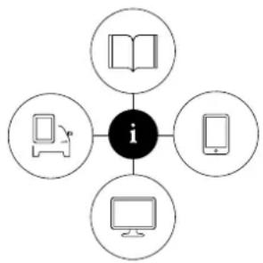
flowchart
graph TD
    A[" "] --> B["i"]
    C[" "] --> B
    D[" "] --> B
    E[" "] --> B
0.015051
Vehicle's center display ^1

In the center display, pull down Top view and tap Owner's manual. This gives you access to visual navigation with exterior and interior images of the vehicle. The information is searchable and is divided into catego-
ries.
Mobile app

In App Store or Google Play, search for "Volvo Manual". Download the app to your smartphone or tablet and select your vehicle model. The app contains instructive videos and offers visual navigation, includ-
ing exterior and interior images of the vehicle. You can easily navigate between sections in the Owner's Manual and the contents are searchable.
Volvo Cars support site

Go to support.volvocars.com and select your country. Owner's Manuals are available here for viewing online and in PDF format. The support site also contains instructive videos and additional information and
assistance concerning your vehicle and owning a Volvo. The website is available on most markets.
Printed information

The glove compartment contains a printed supplement to the Owner's Manual ^1 , which contains information on fuses and specifications as well as a summary of important and practical information.
There is also a printed Quick Guide with useful information about the most commonly used features and functions in your vehicle.
Other printed information may also be provided in the vehicle, depending on equipment level, market, etc.
A printed Owner's Manual and accompanying supplement can also be ordered. Contact a Volvo retailer to order.

CAUTION
The driver is always responsible for operating the vehicle in a safe manner and adhering to all applicable laws and regulations. It is also important that the vehicle is operated, maintained and serviced according to Volvo's recommendations provided in the owner's information.
If the information in the center display differs from the printed information, the printed information always takes precedence.

NOTE
Changing languages in the center display could mean that certain owner's information will not comply with national or local laws and regulations. Do not change to a language that you do not fully understand, as this could make it difficult to navigate back through the menu.
Related information
- Owner's Manual in the center display (p. 17)
• Owner's manual in mobile devices (p. 20)
• Volvo Cars support site (p. 21)
• Using the Owner's Manual (p. 21)
Owner's Manual in the center display
A digital version of the Owner's Manual is available in the vehicle's center display ^2 .
The digital Owner's Manual can be accessed from Top view and in certain cases, the contextual Owner's Manual can also be accessed from Top view.

NOTE
The digital Owner's Manual is not available during driving.
OWNER'S MANUAL
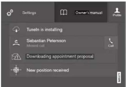
Top view with button for Owner's Manual.
To open the Owner's Manual, pull down Top view in the center display and tap Owner's manual.
The information in the Owner's Manual can be accessed directly via the Owner's Manual start page or via its Top menu.
OWNER'S INFORMATION
Contextual Owner's Manual

Top view with button for contextual Owner's Manual.
The contextual Owner's Manual is a shortcut to an article in the Owner's Manual describing the active function displayed on the screen. When a contextual Owner's Manual is available, it will be shown to the right of Owner's manual in Top view.
Tap the contextual Owner's Manual to open an article in the Owner's Manual related to the information displayed on the screen. For example, tap Navigation Manual to open an article related to navigation.
Certain apps in the vehicle only. For third-party apps that have been downloaded, it is not possible to e.g. access app-specific articles.
Related information
- Navigate in the Owner's Manual in the center display (p. 18)
- Navigating in the center display's views (p. 115)
• Download apps (p. 499)
Navigate in the Owner's Manual in the center display
The digital Owner's Manual can be accessed from the center display's Top view. The contents are searchable and it is easy to navigate among the various sections.

The Owner's Manual is accessed from Top view.
- To open the Owner's Manual, pull down Top view in the center display and tap Owner's manual.
There are a number of ways to find information in the Owner's Manual. The options can be accessed from the Owner's Manual start page and from the Top menu.
Opening the menu in the Top menu
- Tap the upper list in the Owner's Manual.
A menu will open, displaying different options for finding information;
Start page

Tap the symbol to return to the Owner's Manual start page.
Categories

The articles in the Owner's Manual are structured into main and sub-categories. The same article may appear in several relevant categories in order to help make them easier to find.
- Tap Categories.
The main categories are listed.
- Tap a main category (☐).
A list of sub-categories (☐) and articles (☐) will appear.
- Tap an article to open it.
To go back, tap the left arrow.
Quick Guide

Tap the symbol to go to a page with links to a selection of useful articles about the vehicle's most commonly used features and functions. The articles can also be accessed via categories, but have been collected
here for quick access. Tap an article to read it in its entirety.
Exterior and interior hotspots

Exterior and interior overviews of the vehicle. Hotspots are provided for certain functions, components, etc. Tap a hotspot to come to a relevant article.

Exterior or interior images of the vehicle are shown with hotspots. The hotspots lead to articles about the corresponding function, component, etc. Swipe the screen horizontally to scroll between the images.
- Tap a hotspot.
The title of a relevant article will be displayed.
- Tap the title to open the article.
To go back, tap the left arrow.
Favorites

Tap the symbol to go to articles saved as favorites. Tap an article to read it in its entirety.
Saving or deleting favorite articles
Save an article as a favorite by tapping the ☆ the upper right when the article is open. When an article has been saved as a favorite, the star symbol will be filled in: ★.
To remove an article from the list of favorites, tap its star again.
Video

Tap the symbol to go to brief instructive videos for various functions in the vehicle.
OWNER'S INFORMATION
Information

Tap the symbol for information about the current version of the Owner's Manual in your vehicle and other useful information.
Using the search function in the Top menu
- Tap in the Owner's Manual upper menu. A keyboard will appear at the bottom of the screen.
- Enter a search word, e.g. "seat belt".
Suggested articles and categories will be displayed as characters are entered.
- Tap the article or category to read it.
Related information
• Owner's Manual in the center display (p. 17)
• Using the center display keyboard (p. 126)
• Using the Owner's Manual (p. 21)
Owner's manual in mobile devices
The Owner's Manual is available as a mobile app ^3 and can be downloaded from the App Store and Google Play. The app is adapted for both smartphones and tablets.


The Owner's Manual can be downloaded as a mobile app from the App Store or Google Play. This QR code will take you directly to the app. You can also search for "Volvo manual" in the App Store or Google
Play.
The app contains videos and exterior/interior images of the vehicle. These images contain hotspots for various functions, components, etc., which lead directly to related information. You
can easily navigate between sections in the Owner's Manual and the contents are searchable.


The mobile app is available on both App Store and Google Play.
Related information
• Using the Owner's Manual (p. 21)
Volvo Cars support site
Volvo Cars' website and support site contain additional information about your vehicle.
Online support
Go to support.volvocars.com to visit the site. The support site is available in most markets.
The site contains support for e.g. Internet-based services and functions, Volvo On Call, the navigation system* and apps. Videos and step-by-step instructions explain various procedures, such as how to connect the vehicle to the Internet via a cellular phone.
Downloadable information
Maps
For vehicles equipped with Sensus Navigation maps can be downloaded from the support site.
Mobile apps
Beginning with model year 2014, the Owner's Manual is available as an app for certain Volvo models. The Volvo On Call app can also be downloaded from the support site.
Owner's manuals in PDF format
Owner's Manuals are available for downloading in PDF format. Select the vehicle model and year to download the desired manual.
Contact
Contact information for customer support and your nearest Volvo retailer are available on the support site.
Related information
- Contacting Volvo (p. 26)
- Volvo ID (p. 26)
Using the Owner's Manual
Reading your Owner's Manual is a good way to get to know your new Volvo, preferably before driving it for the first time.
Reading your Owner's Manual is a good way to familiarize yourself with new features and functions, get advice on the best way to handle your vehicle in different situations, and to learn how to get the most out of everything your Volvo has to offer. Pay particular attention to the safety warnings provided in the Owner's Manual.
The intention of this owner's information is to explain all of the possible features, functions and options included in a Volvo vehicle. It is not intended as an indication or guarantee that all of these features, functions and options are included in every vehicle. Some terminology used may not exactly match terminology used in sales, marketing and advertising materials.
Volvo continuously works to develop and improve our products. Modifications can mean that information, descriptions and illustrations in the Owner's Manual differ from the equipment in the vehicle. We reserve the right to make changes without prior notice.
Do not remove this manual from the vehicle. If a problem should occur, you will not have the necessary information on where and how to get professional assistance.
© Volvo Car Corporation
▶▶
OWNER'S INFORMATION
Option/accessory
In addition to standard equipment, the Owner's Manual also describes options (factory-installed equipment) and certain accessories (extra retro-fitted equipment).
All options and accessories are marked with an asterisk: *.
The equipment described in the Owner's Manual is not available in all vehicles. Vehicles may be equipped differently depending on market requirements and national or local laws and regulations.
For more information on which equipment is standard and which is an option or accessory, please contact your Volvo retailer.
Footnotes
Certain parts of the Owner's Manual contain information in the form of footnotes at the bottom of the page or at the end of a table. This information supplements the text that the footnote number refers to. If the footnote refers to text in a table, a letter is used instead of a number.
Messages
There are several displays in the vehicle that show messages and menu texts. The appearance of these texts differs from the normal texts provided. Example of messages and menu texts:
Phone, New message.
Decals
There are various types of decals affixed in the vehicle to communicate important information in a clear and concise manner. The importance of these decals is explained as follows, in descending order of importance.
Risk of injury

Black ISO symbols on a yellow warning field, white text/image on a black message field. Used to indicate potential danger. Ignoring a warning of this type could result in serious injury or death.
Risk of damage

White ISO symbols and white text/image on a black or blue warning field and message field. Used to indicate potential danger. Ignoring a warning of this type could result in damage.
Information

White ISO symbols and white text/image on a black message field.

NOTE
The decals shown in the Owner's Manual do not claim to be exact reproductions of those found in the vehicle. The purpose is to show approximately how they look and about where they are located. The information that applies for your vehicle in particular is found on the decal on the vehicle.
Procedures
Procedures that must be carried out in a certain order are shown as numbered lists in the Owner's Manual.

When a series of illustrations are provided along with the step-by-step instructions, the
numbers of the steps correspond with the numbers of the illustrations.
A Lists using letters instead of numbers are used in cases where the order in which the instructions are carried out is not important.
→ Arrows with or without numbers are used to indicate the direction of movement.
A Arrows with letters are used to indicate a movement in cases where the order in which the instructions are carried out is not important.
If there are no illustrations associated with step-by-step instructions, the steps are indicated by ordinary numbers.
Position lists
1 Red circles containing a number are used in general overview illustrations of components. The corresponding number is used in the position list's description of that component.
Bullet lists
Bullets are used for items (components, functions, information, etc.) that can be listed in a random order.
For example:
- Coolant
- Engine oil
Related information
Related information offers references to other parts of the manual containing information associated with the information you are currently reading.
Illustrations, images and video clips
Illustrations, images and video clips used in the Owner's Manual are sometimes generic and are intended to provide an overview or an example of a certain function or feature. They may vary depending on equipment level and market and may differ from the appearance of your vehicle.
Continues on next page
This symbol is shown in the lower right-hand corner to indicate that the current topic continues on the next page.
Continuation from previous page
This symbol is shown in the upper left-hand corner to indicate that the current topic is a continuation from the previous page.
Related information
• Owner's Manual in the center display (p. 17)
• Owner's manual in mobile devices (p. 20)
• Volvo Cars support site (p. 21)
OWNER'S INFORMATION
The Owner's Manual and the environment
The Owner's Manual is printed on paper from responsibly managed forests.
The Forest Stewardship Council (FSC)® symbol certifies that the paper pulp in the printed Owner's Manual comes from FSC®-certified forests or other responsibly managed sources.

MIX
Paper from responsible sources
FSC® C011209
Qas#e
Related information
- Drive-E – purer driving pleasure (p. 27)
YOUR VOLVO
YOUR VOLVO
Contacting Volvo
Use the following contact information if you would like to get in touch with Volvo in the United States or Canada.
In the USA:
Volvo Car USA, LLC
Customer Care Center
1 Volvo Drive,
P.O. Box 914
Rockleigh, New Jersey 07647
1-800-458-1552
www.volvocars.com/us
In Canada:
Volvo Car Canada Ltd.
Customer Care Centre
9130 Leslie Street, Suite 101
Richmond Hill, Ontario L4B 0B9
1-800-663-8255
www.volvocars.com/ca
Volvo ID
Volvo ID is a personal ID that gives you access to a range of services using a single username and password.
Examples of services:
- Volvo On Call-app - check your vehicle using your phone. You can check fuel level, find the nearest gas station and lock the vehicle remotely.
- Send to Car – send addresses from online map services directly to the vehicle.
- Book service and repairs – register your preferred workshop/retailer on volvocars.com to schedule service directly from the vehicle.
NOTE
If the username/password for a service (e.g. Volvo On Call) is changed, the change will also automatically be applied to other services.
A Volvo ID can be created from the vehicle or the Volvo On Call app.
When a Volvo ID is registered in the vehicle, additional services are available.
Related information
- Creating and registering a Volvo ID (p. 26)
• Scheduling service and repairs (p. 615)
Creating and registering a Volvo ID
A Volvo ID can be created in two ways. If your Volvo ID was created with the Volvo On Call app, the Volvo ID must also be registered to the vehicle to enable access to the Volvo ID services.
Creating a Volvo ID with the Volvo ID app
- Download the Volvo ID app from Download Center in the center display's App view.
- Start the app and register a personal email address.
- Follow the instructions that will be sent automatically to this email address.
A Volvo ID has now been created and is automatically registered to the vehicle. The Volvo ID services can now be used.
Creating a Volvo ID using the Volvo On Call app ^1
- Download the latest version of the Volvo On Call app from a smartphone, via e.g. App Store, Windows Phone or Google Play.
- On the app's start page, create a Volvo ID and enter a personal email address.
- Follow the instructions that will be sent automatically to this email address.
A Volvo ID has now been created. See below for information on how the ID is registered to the vehicle.
Registering your Volvo ID to the vehicle
If your Volvo ID was created using the Volvo On Call app, follow these steps to register the ID to the vehicle:
- If you have not already done so, download the Volvo ID app from Download Center in the center display's App view.

NOTE
To download apps the vehicle must be connected to the internet.
-
Start the app and enter your Volvo ID/email address.
-
Follow the instructions that will be automatically sent to the email address connected to your Volvo ID.
Your Volvo ID has now been registered to the vehicle. The Volvo ID services can now be used.
Related information
- Volvo ID (p. 26)
- Download apps (p. 499)
- Handling system updates via Download Center (p. 613)
- Internet-connected vehicle* (p. 541)
Drive-E – purer driving pleasure
Volvo is committed to the well-being of its customers. As a natural part of this commitment, we care about the environment in which we all live. Concern for the environment means an everyday involvement in reducing our environmental impact.
Volvo's environmental activities are based on a holistic view, which means we consider the overall environmental impact of a product throughout its complete life cycle. In this context, design, production, product use, and recycling are all important considerations. In production, Volvo has partly or completely phased out several chemicals including CFCs, lead chromates, asbestos, and cadmium; and reduced the number of chemicals used in our plants 50% since 1991.
Volvo was the first in the world to introduce into production a three-way catalytic converter with a Lambda sond, now called the heated oxygen sensor, in 1976. The current version of this highly efficient system reduces emissions of harmful substances (CO, HC, NOx) from the exhaust pipe by approximately 95 - 99% and the search to eliminate the remaining emissions continues. Volvo is the only automobile manufacturer to offer CFC-free retrofit kits for the air conditioning system of all models as far back as the 1975 model 240. Advanced electronic engine controls and cleaner fuels are bringing us closer to our
YOUR VOLVO
goal. In addition to continuous environmental refinement of conventional gasoline-powered internal combustion engines, Volvo is actively looking at advanced technology alternative-fuel vehicles.
When you drive a Volvo, you become our partner in the work to lessen the vehicle's impact on the environment. To reduce your vehicle's environmental impact, you can:
- Maintain proper air pressure in your tires. Tests have shown decreased fuel economy with improperly inflated tires.
- Follow the recommended maintenance schedule in your Warranty and Service Records Information booklet.
- Drive at a constant speed whenever possible.
- See a trained and qualified Volvo service technician as soon as possible for inspection if the check engine (malfunction indicator) light illuminates, or stays on after the vehicle has started.
- Properly dispose of any vehicle-related waste such as used motor oil, used batteries, brake pads, etc.
- When cleaning your vehicle, please use genuine Volvo car care products. All Volvo car care products are formulated to be environmentally friendly.
Twin Engine vehicles
- If possible, precondition the vehicle with the charging cable before driving.
- If preconditioning is not possible in cold weather, use the seal and steering wheel heating primarily. Avoid heating the entire passenger compartment, which reduces the hybrid battery's charge level.
- Choose the Pure drive mode to help minimize electric power consumption.
- In hilly terrain, put the gear selector in mode B to utilize the electric motor's braking function when the accelerator pedal is released. This helps charge the hybrid battery.
Related information
• Economical driving (p. 467)
• Starting and stopping preconditioning (p. 233)
- The Owner's Manual and the environment (p. 24)
• Air quality (p. 206)
IntelliSafe - driver support
IntelliSafe is Volvo Cars' philosophy regarding vehicle safety. IntelliSafe consists of a number of systems, both standard and optional, that are designed to help make driving safer, prevent accidents and protect passengers and other road users.
Support
IntelliSafe includes driver support functions such as Adaptive cruise control* which helps the driver to maintain an even speed combined with a pre-selected time interval to the vehicle ahead.
Pilot Assist ^2 helps the driver keep the vehicle in the current traffic lane by providing steering assistance and maintaining an even speed and a set time interval to the vehicle ahead.
Park Assist Pilot* helps the driver pull into and out of parking spaces.
Other examples of systems that can help the driver are the Active main beam, Cross Traffic Alert (CTA)* and Blind Spot Information (BLIS)* systems.
Prevention
City Safety is a function intended to help prevent accidents. The function can help prevent or mitigate a collision with pedestrians, cyclists, large animals or other vehicles. Light, sound and pulsations in the brake pedal are provided to alert of a
possible collision and help the driver act in time to prevent it. If the driver does not react to the warning and the risk of collision is determined to be imminent, City Safety can automatically apply the brakes.
Lane assistance (LKA) is another example of a function that can help prevent accidents by helping the driver - on expressways and similar larger roads - to reduce the risk of the car accidentally leaving its own lane.
The function Steering aid during increased collision risk can help the driver reduce the risk of the car leaving its lane unintentionally and/or colliding with another vehicle or obstacle by actively steering the car back into its lane and/or swerving.
Protection
To help protect the driver and passengers, the vehicle is equipped with seat belt tensioners that pull the seat belts taut in collisions and other critical situations. The vehicle also has airbags, inflatable curtains and the Whiplash Protection System (WHIPS), which helps prevent whiplash injuries.
Related information
• Driver support systems (p. 278)
• Active high beam (p. 157)
- Safety (p. 42)
- Seat belts (p. 47)
- Airbags (p. 52)
• Whiplash Protection System (p. 46)
YOUR VOLVO
Sensus - connection and entertainment
Sensus makes it possible to surf the Internet, use apps, and turn your vehicle into a Wi-Fi hotspot.
This is Sensus
SENSUS
085-2218
Sensus provides an intelligent interface and Internet connection to the digital world. An intuitive navigation structure offers access to relevant assistance, information and entertainment when it is needed, without distracting the driver.
Sensus includes all of the solutions in the vehicle related to entertainment, Internet connection and navigation*, and serves as the user interface between the driver and the vehicle. Sensus is what makes communication between you, the vehicle and the world around you possible.
Information when it's needed, where it's needed
The vehicle's displays present the right information at the right time. Information is presented in
different displays depending on how it should be prioritized by the driver.
YOUR VOLVO
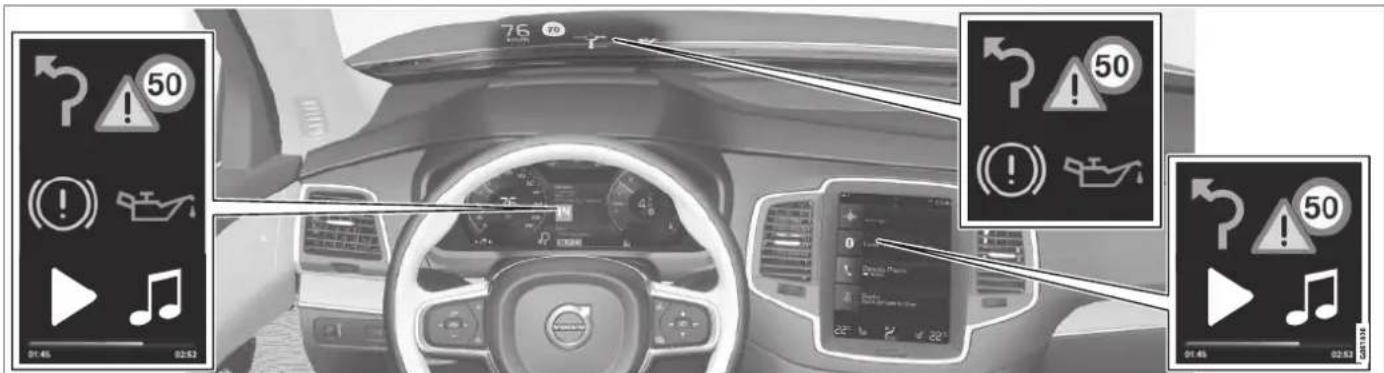
Different types of information are shown in different displays depending on how the information should be prioritized.
Head-up display*

The head-up display presents information that the driver should react to immediately. For example, traffic warnings, speed information
and navigation messages*. Road sign information and incoming phone calls are also shown in the head-up display. These can be handled using the right-side steering wheel keypad or the center display.
Instrument panel

The instrument panel displays information such as speed, incoming phone calls or the track
▶▶
YOUR VOLVO
currently playing. It is controlled using the steering wheel keypads.
Center display

Many of the vehicle's main functions are controlled from the center display, a touchscreen that reacts to taps and other gestures. This minimizes the number of physical buttons and controls needed in the vehicle. The screen can also be operated while wearing gloves.
The center display is used to control e.g. the climate and entertainment systems and to adjust the power seats*. The information presented in the center display can be handled by the driver or, in some situations, by a passenger.
Voice control system

The voice control system enables the driver to control certain vehicle functions without taking their hands off the wheel. The system can understand natural speech. Use voice commands to e.g. play a song, make a
phone call, increase the temperature in the passenger compartment or have a text message read aloud.
Related information
• Head-up display* (p. 142)
• Instrument panel (p. 84)
• Center display overview (p. 109)
• Voice control (p. 145)
- Internet-connected vehicle* (p. 541)
• Sharing Internet from the vehicle via Wi-Fi hotspot (tethering) (p. 545)
Software Updates
So that you as a Volvo customer shall have the best possible experience from your car, Volvo is continuously developing the systems in the cars and the services that you are offered.
You can update the software in your Volvo to the latest version when your car is serviced at an authorized Volvo dealer. The latest software update gives you access to new functions and improvements, as well as previous improvements included with previous software updates.
For more information about released updates and answers to frequently asked questions, please go to support.volvocars.com.

NOTE
Functionality after updating may vary depending on market, model, model year and options.
Related information
• Sensus - connection and entertainment (p. 30)
- Handling system updates via Download Center (p. 613)
Data recording
As part of Volvo's commitment to safety and quality, certain information is recorded regarding vehicle operation, functionality and incidents.
US market only:
EDR
This vehicle is equipped with an event data recorder (EDR). The main purpose of an EDR is to record, in certain crash or near crash-like situations, such as an air bag deployment or hitting a road obstacle, data that will assist in understanding how a vehicle's systems performed. The EDR is designed to record data related to vehicle dynamics and safety systems for a short period of time, typically 30 seconds or less. The EDR in this vehicle is designed to record such data as:
- How various systems in your vehicle were operating;
- Whether or not the driver and passenger safety belts were buckled/fastened;
• How far (if at all) the driver was depressing the accelerator and/or brake pedal; and,
• How fast the vehicle was traveling.
These data can help provide a better understanding of the circumstances in which crashes and injuries occur. NOTE: EDR data are recorded by your vehicle only if a non-trivial crash situation occurs; no data are recorded by the EDR under normal driving conditions and no
personal data (e.g., name, gender, age, and crash location) are recorded. However, other parties, such as law enforcement, could combine the EDR data with the type of personally identifying data routinely acquired during a crash investigation.
To read data recorded by an EDR, special equipment is required, and access to the vehicle or the EDR is needed. In addition to the vehicle manufacturer, other parties, such as law enforcement, that have the special equipment, can read the information if they have access to the vehicle or the EDR.
ASDR
This vehicle is equipped with an Active Safety Data Recorder (ASDR). This data recorder can record information related to the usage of the car, functional errors and active safety actuations (e.g. auto brake). The information saved is used by technicians for service and maintenance to diagnose and repair possible faults that has occurred in the vehicle and to fulfil certain legal requirements. The registered data can also, in congregated form, be used for research- and product development –purposes to continuously improve the safety and quality of Volvo Cars. For more information contact your local Volvo retailer.
YOUR VOLVO
Canadian market only:
This vehicle is equipped with an “Event Data Recorder” (EDR). The main purpose of the EDR is to register and record data in traffic accidents or accident-like situations, e.g. if an airbag deploys or if the vehicle hits an obstacle in the road. This data is recorded in order to help understand how the vehicle's systems perform in these types of situations. The EDR is designed to record data related to vehicle dynamics and safety systems for a short period of time, usually 30 seconds or less.
The EDR in this vehicle is designed to record data in traffic accidents or accident-like situations such as:
- How the various systems in the vehicle performed;
- Whether the driver and passenger seat belts were tightened/buckled;
- The driver's use of the accelerator/brake pedal;
• How fast the vehicle was moving.
This data can help provide a better understanding of the circumstances in which traffic accidents and injuries occur. The EDR records data only if a non-trivial accident situation occurs. EDR does not record any data during normal driving conditions. The system also never registers data on who is driving the vehicle or the geographical location of the accident or near-accident. However, other parties, such as law enforcement, could combine the EDR data with the type of personally identifiable information that is routinely acquired during an accident investigation. Special equipment and access to either the vehicle or the EDR is required to read this recorded data.
In addition to the EDR, the vehicle is equipped with a number of computers that continuously control and monitor the vehicle's performance. These computers may record data during normal driving conditions, particularly if they detect a fault relating to the vehicle's operation and functionality or upon activation of the vehicle's active driver support functions (e.g. City Safety or the auto-brake function).
Some of this recorded data is required by technicians performing service and maintenance in order to diagnose and rectify any faults that may have occurred in the vehicle. The recorded information is also needed to enable Volvo to fulfill legal and other regulatory requirements. Information registered in the vehicle is stored in its computers until the vehicle is serviced or repaired.
In addition to the above, the recorded information may be used in aggregated form for research and product development purposes in order to continuously improve the safety and quality of Volvo vehicles.
Volvo will not provide this information to any third parties without the vehicle owner's consent. However, national legislation and regulations may
require Volvo to disclose this type of information to law enforcement or other authorities that can claim a legal right to the information. Special technical equipment, which Volvo and workshops that have entered agreements with Volvo have access to, is required to read and interpret the recorded data. Volvo is responsible for ensuring that information provided to Volvo in conjunction with service and maintenance is stored and handled securely and in compliance with applicable legal requirements. For more information, please contact a Volvo retailer.
Related information
- Contacting Volvo (p. 26)
• Volvo Structural Parts Statement (p. 39)
Terms & Conditions for Services
Volvo offers services to help make driving your Volvo as safe and comfortable as possible.
These services comprise everything from assistance in emergencies to navigation and various maintenance services.
Before using the services, it is important to read the Terms and Conditions for the services at support.volvocars.com.
Related information
• Customer Privacy Policy (p. 35)
Customer Privacy Policy
Volvo respects and safeguards the personal privacy of everyone who visits our websites.
This policy refers to the handling of customer data and personal information. The purpose is to give current, past and potential customers a general understanding of:
- The circumstances in which we collect and process your personal data.
• The types of personal data we collect.
• Why we collect your personal data.
• How we process your personal data.
The policy can be read in its entirety at support.volvocars.com.
Related information
• Terms of use and data sharing (p. 548)
• Terms & Conditions for Services (p. 35)
• Data recording (p. 33)
Important information on accessories and extra equipment
Incorrectly connected or installed accessories or extra equipment may have an adverse effect on the vehicle's electronics.
We strongly recommend that Volvo owners use only genuine, Volvo-approved accessories, and that accessory installations be performed only by a trained and qualified Volvo service technician. Certain accessories only work when the associated software is installed in the vehicle's computer system.
The equipment described in the Owner's Manual is not available in all vehicles. Vehicles may be equipped differently depending on market requirements and national or local laws and regulations.
Optional or accessory equipment may not be available in all countries or markets. Please note that some vehicles may be equipped differently, depending on special legal requirements. For more information on which equipment is standard and which is an option or accessory, please contact your Volvo retailer.
YOUR VOLVO
◀◀

NOTE
Do not export your Volvo to another country before investigating that country's applicable safety and exhaust emission requirements. In some cases it may be difficult or impossible to comply with these requirements. Modifications to the emission control system(s) may render your Volvo not certifiable for legal operation in the U.S., Canada and other countries.

WARNING
CALIFORNIA proposition 65
Engine exhaust, some of its constituents, and certain vehicle components contain or emit chemicals known to the state of California to cause cancer, and birth defects or other reproductive harm. In addition, certain fluids contained in vehicles and certain products of component wear contain or emit chemicals known to the State of California to cause cancer, and birth defects or other reproductive harm.

WARNING
Certain components of this vehicle such as air bag modules, seat belt tensioners, adaptive steering columns, and button cell batteries may contain Perchlorate material. Special handling may apply for service or vehicle end of life disposal.
See www.dtsc.ca.gov/hazardouswaste/perchlorate.

WARNING
The driver is always responsible for operating the vehicle in a safe manner and for complying with current statutes and regulations.
It is also essential to maintain and service the vehicle according to Volvo's recommendations as stated in the owner's information and the service and warranty booklet.
If the on-board information differs from the printed owner's manual, the printed information always takes precedence.
Related information
• Accessory installation (p. 36)
- Connecting equipment to the vehicle's data link connector (p. 37)
• Using the Owner's Manual (p. 21)
Accessory installation
We strongly recommend that Volvo owners use only genuine, Volvo-approved accessories, and that accessory installations be performed only by a trained and qualified Volvo service technician. Certain accessories only work when the associated software is installed in the vehicle's computer system.
- Genuine Volvo accessories are tested to ensure compatibility with the performance, safety, and emission systems in your vehicle. Additionally, a trained and qualified Volvo service technician knows where accessories may and may not be safely installed in your Volvo. In all cases, please consult a trained and qualified Volvo service technician before installing any accessory in or on your vehicle.
- Accessories that have not been approved by Volvo may or may not be specifically tested for compatibility with your vehicle.
- Any of your vehicle's performance and safety systems could be adversely affected if you install accessories that Volvo has not tested, or if you allow accessories to be installed by someone unfamiliar with your vehicle.
- Damage caused by unapproved or improperly installed accessories may not be covered by your new vehicle warranty. See your Warranty and Service Records Information booklet for more warranty information. Volvo assumes no responsibility for death, injury, or expenses
that may result from the installation of non-genuine accessories.
Related information
- Important information on accessories and extra equipment (p. 35)
Connecting equipment to the vehicle's data link connector
Incorrectly connected or installed software or diagnostic tools may have an adverse effect on the vehicle's electronics.
We strongly recommend that Volvo owners use only genuine, Volvo-approved accessories, and that accessory installations be performed only by a trained and qualified Volvo service technician. Certain accessories only work when the associated software is installed in the vehicle's computer system.

natural_image
Close-up of a mechanical component with a red arrow pointing to a specific part (no visible text or symbols)On-board Diagnostic (OBDII) socket under the dashboard on the driver's side.
NOTE
Volvo Cars takes no responsibility for the consequences of connecting non-authorized equipment to the On-board Diagnostic (OBDII) socket. This socket should only be used by a trained and qualified Volvo service technician.
Type approval
USA
FCC ID: 2AGKKACUII-06
This device complies with part 15 of the FCC rules. Operation is subject to the following two conditions:
(1) This device may not cause harmful interference, and
(2) this device must accept any interference received, including interference that may cause undesired operation.
WARNING
Changes or modifications not expressly approved by the party responsible for compliance could void the user's authority to operate the equipment.
YOUR VOLVO
Canada
IC: 20839-ACUII06
This device complies with Industry Canada license-exempt RSS standards. Operation is subject to the following two conditions:
(1) this device may not cause interference, and
(2) This device must accept any interference received, including interference that may cause undesired operation.
Related information
- Important information on accessories and extra equipment (p. 35)
Technician certification
In addition to Volvo factory training, Volvo supports certification by the National Institute for Automotive Service Excellence (A.S.E.).
Certified technicians have demonstrated a high degree of competence in specific areas. Besides passing exams, each technician must also have worked in the field for two or more years before a certificate is issued. These professional technicians are best able to analyze vehicle problems and perform the necessary maintenance procedures to keep your Volvo at peak operating condition.
Twin Engine vehicles
Technicians performing work on a vehicle with electrification should also have the necessary training and specialized certification required for performing repairs and/or maintenance on a vehicle with electrification.
WARNING
A number of electrical components in Twin Engine vehicles use high-voltage current and can be extremely dangerous if handled incorrectly. These components and any orange wiring in the vehicle may only be handled by trained and qualified Volvo service technicians.
Viewing the Vehicle Identification Number (VIN)
When contacting a Volvo retailer, about e.g. your Volvo On Call subscription, your Vehicle Identification Number (VIN ^3 ) may be needed.
- Tap Settings in the Top view in the center display.
- Proceed to System System Information
→ Vehicle Identification Number.
The vehicle identification number will be displayed.
Volvo Structural Parts Statement
Volvo is one of the leading companies for car safety.
Volvo engineers and manufactures vehicles designed to help protect vehicle occupants in the event of a collision.
Volvos are designed to absorb the impact of a collision. This energy absorption system including, but not limited to, structural components such as bumper reinforcement bars, bumper energy absorbers, frames, rails, fender aprons, A-pillars, B-pillars and body panels must work together to maintain cabin integrity and protect the vehicle occupants.
The supplemental restraint system including but not limited to air bags, side curtain air bags, and deployment sensors work together with the above components to provide proper timing for air bag deployment.
Due to the above, Volvo Car USA does not support the use of aftermarket, alternative or anything other than original Volvo parts for collision repair.
Volvo Car USA also recommends using Volvo-approved replacement glass. The use of aftermarket glass, particularly a windshield, can have an adverse effect on collision avoidance and advanced lighting systems.
In addition Volvo does not support the use or reuse of structural components from an existing
vehicle that has been previously damaged. Although these parts may appear equivalent, it is difficult to tell if the parts have been previously replaced with non-OE parts or if the part has been damaged as a result of a prior collision. The quality of these used parts may also have been affected due to environmental exposure.
Related information
• Data recording (p. 33)
Driver distraction
A driver has a responsibility to do everything possible to ensure his or her own safety and the safety of passengers in the vehicle and others sharing the roadway. Part of this responsibility is avoiding distractions, including performing activities that are not directly related to controlling the vehicle in the driving environment.
Your new Volvo is, or can be, equipped with feature-rich entertainment and communication systems. These include hands-free cellular telephones, navigation systems, and multipurpose audio systems. You may also own other portable electronic devices for your own convenience. When used properly and safely, they enrich the driving experience. Improperly used, any of these could cause a distraction.
For all of these systems, we want to provide the following warning that reflects the strong Volvo concern for your safety. Never use these devices or any feature of your vehicle in a way that distracts you from the task of driving safely. Distraction can lead to a serious accident. In addition to this general warning, we offer the following guidance regarding specific new features that may be found in your vehicle:
YOUR VOLVO
◀◀

WARNING
- Never use a hand-held cellular telephone while driving. Some jurisdictions prohibit cellular telephone use by a driver while the vehicle is moving.
- If your vehicle is equipped with a navigation system, set and make changes to your travel itinerary only with the vehicle parked.
- Never program your audio system while the vehicle is moving. Program radio presets with the vehicle parked, and use your programmed presets to make radio use quicker and simpler.
- Never use portable computers or personal digital assistants while the vehicle is moving.
Related information
• Audio, media and Internet (p. 496)
SAFETY
SAFETY
Safety
The vehicle is equipped with a number of safety systems that work together to help protect the vehicle's driver and passengers in the event of an accident.
The vehicle is equipped with a number of sensors that may react in the event of an accident and activate different safety systems, such as the air-bag system and seat belt tensioners. Depending on the specific conditions of the accident, e.g. collisions at certain angles, overturning or swerving, the systems react differently to help provide the best protection.
There are also mechanical safely systems such as the Whiplash Protection System. The vehicle is also built so that a large part of the force of a collision is distributed to the vehicle's members, pillars, floor, roof and other parts of the body.
After an accident, the vehicle's safety mode may be activated if any important function in the vehicle has been damaged.
Warning symbol in the instrument panel

The warning symbol in the instrument panel illuminates when the vehicle's electrical system is in ignition mode II. The symbol will go out after approx. 6
seconds if no faults are detected in the vehicle's safety systems.

WARNING
If the warning symbol remains illuminated or switches on while driving and the message SRS airbag Service urgent Drive to workshop is displayed in the instrument panel, this indicates that something in the safety system is not functioning properly. Volvo recommends contacting an authorized Volvo workshop for repairs as soon as possible.

WARNING
Never attempt to alter or repair any of the vehicle's safety systems yourself. Incorrectly performed repairs to any system could impair function and lead to serious injury. Volvo recommends contacting an authorized Volvo workshop.

If this dedicated warning symbol is not functioning, the general warning symbol will illuminate instead and the same message will be displayed in the instru-
ment panel.
Related information
• Safety during pregnancy (p. 43)
• Occupant safety (p. 43)
• Reporting safety defects (p. 44)
• Recall information (p. 45)
- Seat belts (p. 47)
- Airbags (p. 52)
• Whiplash Protection System (p. 46) - Safety mode (p. 61)
• Child safety (p. 63)
Safety during pregnancy
It is important that seat belts are worn correctly during pregnancy and that pregnant drivers adjust their seating position accordingly.
Seat belt

natural_image
3D illustration of a human car seat with red arrows indicating pressure points (no text or symbols)The seat belt should fit closely against the shoulder, with the diagonal section between the breasts and to the side of the stomach.
The lap section of the seat belt should lie flat over the thighs and as far as possible under the stomach. Never let it ride upward. Remove unnecessary slack and make sure the seat belt fits as close as possible to the body. Make sure there are no twists in the seat belt.
Seating position
As pregnancy progresses, pregnant drivers should adjust the seat and steering wheel to a position that allows them to retain full control of
the vehicle (which means they should be able to easily reach the steering wheel and foot pedals). Try to maintain as much distance as possible between the stomach and the steering wheel.
Related information
- Safety (p. 42)
- Seat belts (p. 47)
• Manual front seats (p. 184)
• Power* front seats (p. 185)
Occupant safety
Safety is Volvo's cornerstone.
Volvo's concern for safety
Our concern for safety dates back to 1927 when the first Volvo rolled off the production line. Three-point seat belts (a Volvo invention), safety cages, and energy-absorbing impact zones were designed into Volvo vehicles long before it was fashionable or required by government regulation.
We will not compromise our commitment to safety. We continue to seek out new safety features and to refine those already in our vehicles. You can help. We would appreciate hearing your suggestions about improving automobile safety. We also want to know if you ever have a safety concern with your vehicle. Call us in the U.S. at: 1-800-458-1552 or in Canada at: 1-800-663-8255.
▶▶
SAFETY
Occupant safety reminders
How safely you drive doesn't depend on how old you are but rather on:
• How well you see.
- Your ability to concentrate.
- How quickly you make decisions under stress to avoid an accident.
The following suggestions are intended to help you cope with the ever changing traffic environment.
- Never drink and drive.
- If you are taking any medication, consult your physician about its potential effects on your driving abilities.
• Take a driver-retraining course.
• Have your eyes checked regularly. - Keep your windshield and headlights clean.
- Replace wiper blades when they start to leave streaks.
- Take into account the traffic, road, and weather conditions, particularly with regard to stopping distance.
- Never send text messages while driving.
- Refrain from using or minimize the use of a cell phone while driving.
Related information
- Safety (p. 42)
• Reporting safety defects (p. 44)
• Recall information (p. 45)
Reporting safety defects
The following information will help you report any perceived safety-related defects in your vehicle.
Reporting safety defects in the U.S.
If you believe that your vehicle has a defect which could cause a crash or could cause injury or death, you should immediately inform the National Highway Traffic Safety Administration (NHTSA) in addition to notifying Volvo Car USA, LLC. If NHTSA receives similar complaints, it may open an investigation, and if it finds that a safety defect exists in a group of vehicles, it may order a recall and remedy campaign. However, NHTSA cannot become involved in individual problems between you, your retailer, or Volvo Car USA, LLC. To contact NHTSA, you may either call the Auto Safety Hotline toll-free at
1-888-327-4236
(TTY: 1-800-424-9153) or write to: NHTSA, U.S. Department of Transportation, Washington D.C. 20590.
You can also obtain other information about motor vehicle safety from http://www.safercar.gov, where you can also enter your vehicle's VIN (Vehicle Identification Number) to see if it has any open recalls.
Volvo strongly recommends that if your vehicle is covered under a service campaign, safety or emission recall or similar action, it should be completed as soon as possible. Please check with your local retailer or Volvo Car USA, LLC if your vehicle is covered under these conditions.
NHTSA can be reached at:
Internet:
http://www.nhtsa.gov
Telephone:
1-888-DASH-2-DOT
(1-888-327-4236).
Reporting safety defects in Canada
If you believe your vehicle has a defect that could cause a crash or could cause injury or death, you should immediately inform Transport Canada in addition to notifying Volvo Car Canada Ltd.
Transport Canada can be contacted at: 1-800-333-0510
Teletypewriter (TTY): 613 990-4500
Fax: 1-819-994-3372
Mailing Address: Transport Canada - Road Safety, 80 rue Noël, Gatineau, (Quebec) J8Z 0A1
Related information
- Safety (p. 42)
• Occupant safety (p. 43)
• Recall information (p. 45) - Viewing the Vehicle Identification Number (VIN) (p. 38)
Recall information
On our website, select the "Own" tab on the upper left side of the screen and click the heading "Recall Information" on the right side of the screen. Enter your Vehicle Identification Number (VIN) for your vehicle (found at the base of the windshield). If your vehicle has any open Recalls, they will be displayed on this page.
You can also enter the Vehicle Identification Number in the search field on the National Highway Traffic Safety Administration's (NHTSA) website at: www.nhtsa.gov.
Volvo customers in Canada
For any questions regarding open recalls for your vehicle, please contact your authorized Volvo retailer. If your retailer is unable to answer your questions, please contact Volvo Customer Relations at 800-663-8255, Monday through Friday, 8:30 A.M. to 5:00 P.M. EST or volvocars.com/ca. You may also write us at:
Volvo Car Canada Ltd.
Customer Care Centre
9130 Leslie Street, Suite 101
Richmond Hill, Ontario L4B 0B9
www.tc.gc.ca
SAFETY
Related information
- Safety (p. 42)
• Reporting safety defects (p. 44)
• Occupant safety (p. 43)
Whiplash Protection System
The Whiplash Protection System (WHIPS) is designed to help reduce the risk of whiplash-type injuries. The system consists of energy absorbing backrests and seat cushions as well as specially designed head restraints in the front seats.
WHIPS is activated in the event of a rear-end collision and adapted to the angle and speed of the collision and to the characteristics of the colliding vehicle.
When WHIPS is activated, the front seat back-rests move rearward and the seat cushions move downward to change the sealing positions of the driver and front seat passenger. This movement helps absorb some of the forces that could result in whiplash.

WARNING
WHIPS is a supplement to the seat belt. Always wear your seat belt.

WARNING
Do not attempt to alter or repair the seat or WHIPS on your own. Volvo recommends contacting an authorized Volvo workshop.
If the front seats have been subjected to severe stress, e.g. in a collision, the seats must be replaced. Even if the seats appear undamaged, some of their protective properties may have been lost.

natural_image
3D rendered human figure seated in a car seat with red X marks indicating failure or absence (no text or symbols present)Do not place any objects on the floor behind or under the front seats or on the rear seat that could prevent WHIPS from functioning correctly.

WARNING
Do not squeeze box-like cargo between the rear seat cushion and the front seat backrest. If the rear seat backrests are folded down, cargo must be secured to prevent it from sliding forward against the front seat backrests in the event of a collision.

WARNING
If a rear seat backrest is folded down or if a rear-facing child restraint is being used in the rear seat, the seat in front must be moved forward so that it does not come into contact with the backrest or child restraint.
Seating position
For WHIPS to provide optimal protection, the driver and passenger must be seated correctly and the system's function must not be impeded in any way.
Set the front seat to the correct sealing position before starting to drive.
The driver and the front seat passenger should sit in the center of the seat with their heads as close as possible to the head restraints.
Related information
- Safety (p. 42)
• Manual front seats (p. 184)
• Power* front seats (p. 185)
• Rear Collision Warning (p. 354)
Seat belts
Seat belts should always be worn by all occupants in your vehicle. Children should be properly restrained using an infant seat, adjustable child seat or booster cushion as determined by age, weight and height.
Most states and provinces make it mandatory for occupants of a vehicle to use seat belts.
Seat belt maintenance
Check periodically that the seat belts are in good condition. Use water and a mild detergent for cleaning. Check the seat belt mechanism's function as follows: attach the seat belt and pull rapidly on the strap.
▶▶
SAFETY
◀◀

WARNING
- Never repair the belt yourself. Repairs should only be performed by a trained and qualified Volvo service technician.
- Any device used to induce slack into the shoulder belt portion of the three-point belt system will have a detrimental effect on the amount of protection available in the event of a collision.
- The seat back should not be tilted too far back. The shoulder belt must be taut in order to function properly.
- Do not use any type of child restraint in the front passenger seat. We recommend that children who have outgrown these devices sit in the rear seat with the seat belt properly fastened.
Related information
- Safety (p. 42)
- Seat belt tensioners (p. 50)
• Buckling and unbuckling seat belts (p. 48)
• Door and seat bell reminders (p. 51)
Buckling and unbuckling seat belts
Make sure that all passengers have buckled their seat belts before starting to drive.
Buckling seat belts
- Pull out the belt slowly and make sure it is not twisted or damaged.
If the seat belt in the second row center seating position is used, make sure it is properly positioned in the correct seat belt guide.

NOTE
Each seat belt is equipped with a retractor that will lock up in the following situations:
- if the belt is pulled out rapidly
• during braking and acceleration
• if the vehicle is leaning excessively - when driving in turns
- if the automatic locking retractor/emergency locking retractor (ALR/ELR) is activated. Each seat belt (except for the driver's) is equipped with an ALR function, which is designed to keep the seat belt taut when installing a child restraint. ALR is activated when the seat belt is pulled out as far as possible. If this is done, a sound from the seat belt retractor will be audible, which is normal. The seat belt can now only be fed into the retractor, not pulled out. This function is automatically disabled when the seat belt is unbuckled and fully retracted.
SAFETY
- Buckle the seat belt by pushing the latch plate into the receptacle.
A distinct "click" indicates that the bell is locked into place.

WARNING
Always insert the seat belt latch plate into the belt buckle on the correct side. Failure to do so could cause the seat belts and belt buckles to malfunction in a collision. There is a risk of serious injury.
- The height of the seat belts in the front seats and outboard rear seating positions can be adjusted.

natural_image
Close-up of a mechanical component with two red arrows pointing to a central feature (no text or symbols visible)Press the button on the seat belt holder and move the belt up or down.
Position the belt as high as possible without it chafing against the neck.

natural_image
3D rendered human torso in a seated chair with red arrows indicating points of interest (no text or symbols)The belt should be positioned closely over the shoulder (against the collarbone, not down over the arm).
- Tighten the lap section of the seat belt over the hips by pulling the diagonal section upward toward the shoulder.

natural_image
Mechanical assembly diagram showing a car seatbelt with red directional arrows indicating movement (no text or symbols present)The lap section of the seat belt should be positioned low on the hips (not against the abdomen).
▶▶
SAFETY

WARNING
Never use a seat belt for more than one occupant. Never wear the shoulder portion of the belt under the arm, behind the back or otherwise out of position. Such use could cause injury in the event of an accident. As seat belts lose much of their strength when exposed to violent stretching, they should be replaced after any collision, even if they appear to be undamaged.

WARNING
Do not use clips or fasten the belts around hooks or other parts of the interior. This will prevent the seat belt from fitting properly.

WARNING
Never damage the seat belts and never insert any foreign objects into the belt buckle. This may cause the seat belts and belt buckles to malfunction in a collision. There is a risk of serious injury.
Unbuckling seat belts
-
Press the red button on the seat belt receptacle and make sure the seat belt retracts fully into the retractor slot.
-
If it does not fully retract, guide the belt manually into the slot and make sure it does not hang loose.
If the seat belt in the second row center seating position is used, make sure it is properly positioned in the correct seat belt guide.
Related information
- Seat belts (p. 47)
- Seat belt tensioners (p. 50)
• Door and seat belt reminders (p. 51)
Seat belt tensioners
The vehicle is equipped with standard and electric seat belt tensioners that can help tension the seat belt in a critical situation or collision.
Standard seat belt tensioners
All seat belts are equipped with a standard seat belt tensioner.
In a collision of sufficiently violent force, the seat belt tensioners will tension the seat belts in order to more effectively restrain the occupants.
Electric seat belt tensioners
The driver's and front passenger's seat belts are equipped with electric seat belt tensioners.
The seat belt tensioners interact and can be activated in conjunction with the City Safety and Rear Collision Warning driver support systems. In critical situations, such as if the vehicle brakes suddenly, begins to skid or runs off the road (e.g. if the vehicle rolls into a ditch, lifts off the ground or hits an obstacle in the road), or if there is a risk of collision, the seat belts can be pulled taut by the seat belt tensioner's electric motor.
The electric seat belt tensioner helps to position the occupant more effectively in the seat, which reduces the risk of the occupant striking the interior of the passenger compartment and improves the effect of other safety systems such as the airbags.
When a critical situation has passed, the seat belt and the electric seat belt tensioner are reset automatically. However, they can also be reset manually.

WARNING
Never attempt to alter or repair the seat belt on your own. Volvo recommends contacting an authorized Volvo workshop.
If the seat belt has been exposed to extreme forces, e.g. in conjunction with a collision, the entire seat belt must be replaced. Even if the seat belt appears undamaged, some of its protective properties may have been lost. Also replace the seat belt if it is worn or damaged. The new seat belt must be type approved and intended for the same seating position as the replaced seat belt.
Related information
- Seat belts (p. 47)
• Buckling and unbuckling seat belts (p. 48) - Resetting the electric seat belt tensioners (p. 51)
• City Safety™ (p. 341)
• Rear Collision Warning (p. 354)
Resetting the electric seat belt tensioners
The electric seat belt tensioners are designed to be reset automatically, but if the seat belt remains taut it can be reset manually.
- Stop the vehicle in a safe location.
- Unbuckle the seat belt and then rebuckle it.
The seat belt and the electric seat belt tensioner will be reset.

WARNING
Never attempt to alter or repair the seat belt on your own. Volvo recommends contacting an authorized Volvo workshop.
If the seat belt has been exposed to extreme forces, e.g. in conjunction with a collision, the entire seat belt must be replaced. Even if the seat belt appears undamaged, some of its protective properties may have been lost. Also replace the seat belt if it is worn or damaged. The new seat belt must be type approved and intended for the same seating position as the replaced seat belt.
Related information
- Seat belt tensioners (p. 50)
- Seat belts (p. 47)
Door and seat belt reminders
This system is intended to remind occupants to buckle their seat belts and to alert the driver if a door, hood or other opening (trunk, sunroof, etc.) is open.
Graphics in the instrument panel
Graphics in the instrument panel with various types of warnings. The warning colors for the doors/tailgate vary depending on the vehicle's speed.
The instrument panel graphic shows the seats where seat belts are buckled and not buckled.
The same graphic also indicates if the hood, tailgate, fuel filler door or any door is open.
Confirm the graphic by briefly pressing the O button on the right-side steering wheel keypad.
SAFETY
Seat belt reminder

Reminder light in ceiling console.
The seat belt reminder consists of an audible signal and a symbol in the instrument panel.
The reminder light varies depending on the vehicle's speed, driving time and distance driven.
A seat belt status graphic in the instrument panel indicates when the driver's or a passenger's seat belt is buckled or unbuckled.
Child seats are not included in the seat belt reminder system.
Front seats
An audible signal and an indicator light remind unbuckled occupants to fasten their seat belts.
Rear seat
The rear seat belt reminder has two functions:
- To indicate which seat belts are buckled in the rear seats. This will also be displayed in an instrument panel graphic.
- To provide audio and visual reminders if any seat belt in the rear seat is removed while the vehicle is in motion. The reminder will stop when the seat belt has been rebuckled.
Door/hood/tailgate and fuel filler door reminder
If the hood, tailgate, fuel filler door or any door is not properly closed, this will be indicated by a graphic in the instrument panel. Stop the vehicle safely and close the open door, hood, etc.

If the vehicle is moving at a speed under approx. 10 km/h (6 mph), the information symbol will illuminate in the instrument panel.

If the vehicle is moving at a speed above approx. 10 km/h (6 mph), the warning symbol will illuminate in the instrument panel.
Related information
- Seat belts (p. 47)
• Buckling and unbuckling seat belts (p. 48)
Airbags
The vehicle is equipped with airbags and inflatable curtains for the driver and passengers.

WARNING
- If the airbag warning light stays on after the engine has started or if it illuminates while you are driving, have the vehicle inspected by a trained and qualified Volvo service technician as soon as possible.
- Never attempt to alter or repair any of the vehicle's safety systems yourself. Incorrectly performed repairs to any system could impair function and lead to serious injury. All work on these systems should be performed by a trained and qualified Volvo service technician.

WARNING
If your vehicle has become water-damaged in any way (e.g., soaked floor mats/standing water on the floor of the vehicle), do not attempt to start the engine. This may cause airbag deployment, which could result in serious injury. Volvo recommends towing the vehicle directly to an authorized Volvo workshop.
Before attempting to tow the vehicle:
-
Switch off the ignition for at least 10 minutes and disconnect the battery.
-
Follow the instructions for manually over-riding the shiftlock system.
Deployed airbags

WARNING
If any of the airbags have deployed:
- Do not attempt to drive the vehicle. Have it towed to an authorized workshop.
• If necessary, seek medical attention.
Related information
- Safety (p. 42)
• Driver/passenger-side airbags (p. 53)
- Side airbags (p. 60)
• Inflatable curtain (p. 60)
Driver/passenger-side airbags
As a supplement to the seat belts, the vehicle is equipped with driver and passenger side front airbags.
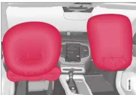
natural_image
Interior view of a car showing two red seats with control panel and dashboard (no visible text or symbols)Driver/passenger side front airbags.
In a frontal collision, the airbags help protect the driver's and passenger's head, face and chest and the driver's knees and legs.
A collision of a sufficiently violent force will trigger the sensors and one or more airbags will inflate. The airbag helps cushion the initial impact of the collision for the passenger. The airbag deflates when compressed by the collision. A small amount of powder will also be released from the airbag. This may appear to be smoke and is normal. The entire process, from inflation to deflation of the airbag, occurs within tenths of a second.

NOTE
The sensors react differently depending on the circumstances of the accident and whether or not the seat belt is used. Does not apply to all belt positions.
In some accident situations, only one (or none) of the airbags will be deployed. The sensors monitor the impact of the collision and react accordingly to deploy one, several or no airbags.

WARNING
The seat belt and the airbag work together. If the seat belt is not used or is used incorrectly, the airbag may not provide the intended protection in a collision.
To help prevent injury in the event the airbag is deployed, passengers should sit as upright as possible, with their feet on the floor and their backs against the seat backrest.

WARNING
Volvo recommends contacting an authorized Volvo workshop for repairs. Incorrectly performed repairs to the airbag system could impair function and lead to serious injury.
The front airbag system
The front airbag system includes gas generators surrounded by the airbags, and deceleration sen-
SAFETY
sors that activate the gas generators, causing the airbags to be inflated with nitrogen gas.
As the movement of the seats' occupants compresses the airbags, some of the gas is expelled at a controlled rate to provide better cushioning. The belt tensioners minimize slack in the seat belts and are activated for occupants wearing their seal belts. The entire process, from inflation to deflation of the airbag, occurs within tenths of a second.
The location of the front airbags is indicated by SRS AIRBAG embossed on the steering wheel pad and above the glove compartment, and by decals on both sun visors and on the front and far right side of the dash.
The driver's side front airbag is folded and located in the steering wheel hub.
The knee airbag is folded on the underside of the dashboard on the driver's side. The text AIRBAG is embossed on the panel.
The passenger's side front airbag is folded behind a panel located above the glove compartment.
WARNING
- The airbags in the vehicle are designed to be a SUPPLEMENT to-not a replacement for-the three-point seat belts. For maximum protection, wear seat belts at all times. Be aware that no system can prevent all possible injuries that may occur in an accident.
- Never drive with your hands on the steering wheel pad/airbag housing.
- The front airbags are designed to help prevent serious injury. Deployment occurs very quickly and with considerable force. During normal deployment and depending on variables such as seating position, one may experience abrasions, bruises, swellings, or other injuries as a result of deployment of one or both of the airbags.
- When installing any accessory equipment, make sure that the front airbag system is not damaged. Any interference in the system could cause malfunction.
Front airbag deployment
- The front airbags are designed to deploy during certain frontal or front-angular collisions, impacts, or decelerations, depending on the crash severity, angle, speed and object impacted. The airbags may also deploy in
certain non-frontal collisions where rapid deceleration occurs.
- The airbag system's sensors, which trigger the front airbags, are designed to determine if the collision is powerful enough to activate the belt tensioners and/or the airbags.
However, not all frontal collisions activate the front airbags.
- If the collision involves a nonrigid object (e.g., a snow drift or bush), or a rigid, fixed object at a low speed, the front airbags will not necessarily deploy.
- Front airbags do not normally deploy in a side impact collision, in a collision from the rear or in a rollover situation.
- The amount of damage to the bodywork does not reliably indicate if the airbags should have deployed or not.

NOTE
- Deployment of front airbags occurs only one time during an accident. In a collision where deployment occurs, the airbags and seat belt tensioners activate. Some noise occurs and a small amount of powder is released. The release of the powder may appear as smoke-like matter. This is a normal characteristic and does not indicate fire.
- Volvo's front airbags use special sensors that are integrated with the front seat buckles. The point at which the airbag deploys is determined by whether or not the seal belt is being used, as well as the severity of the collision.
- Collisions can occur where only one of the airbags deploys. If the impact is less severe, but severe enough to present a clear injury risk, the airbags are triggered at partial capacity. If the impact is more severe, the airbags are triggered at full capacity.

WARNING
- Do not use child safety seats or child booster cushions/backrests in the front passenger's seat. We also recommend that occupants under 140 cm (4 feet 7 inches) in height who have outgrown these devices sit in the rear seat with the seat belt fastened. See also the Occupant Weight Sensor information.
- Never drive with the airbags deployed. The fact that they hang out can impair the steering of your vehicle. Other safely systems can also be damaged.
- The smoke and dust formed when the airbags are deployed can cause skin and eye irritation in the event of prolonged exposure.
Should you have questions about any component in the SRS system, please contact a trained and qualified Volvo service technician or Volvo customer support:
In the United States
Volvo Car USA, LLC
Customer Care Center
1 Volvo Drive
P.O. Box 914
Rockleigh, New Jersey 07647
1-800-458-1552
www.volvocars.com/us
In Canada
Volvo Car Canada Ltd.
Customer Care Centre
9130 Leslie Street, Suite 101
Richmond Hill, Ontario L4B 0B9
1-800-663-8255
www.volvocars.com/ca
Airbag decals

Airbag decal on the outside of both sun visors
SAFETY
◀◀
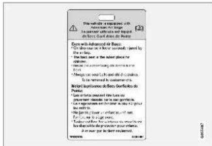
Passenger's side airbag decal

WARNING
- Children must never be allowed in the front passenger's seat.
- Occupants in the front passenger's seat must never sit on the edge of the seat, sit leaning toward the instrument panel or otherwise sit out of position.
- The occupant's back must be as upright as comfort allows and be against the seat back with the seat belt properly fastened.
- Feet must be on the floor, e.g., not on the dash, seat or out of the window.

WARNING
- No objects or accessory equipment, e.g. dashboard covers, may be placed on, attached to, or installed near the air bag cover (the area above the glove compartment) or the area affected by airbag deployment.
- There should be no loose articles, such as coffee cups on the floor, seat, or dashboard area.
- Never try to open the airbag cover on the steering wheel or the passenger's side dashboard. This should only be done by a trained and qualified Volvo service technician.
- Failure to follow these instructions can result in injury to the vehicle's occupants.
Related information
- Airbags (p. 52)
• Occupant weight sensor (p. 56)
Occupant weight sensor
The Occupant Weight Sensor (OWS) is designed to meet the regulatory requirements of Federal Motor Vehicle Safety Standard (FMVSS) 208 and is designed to disable (will not inflate) the passenger's side front airbag under certain conditions.
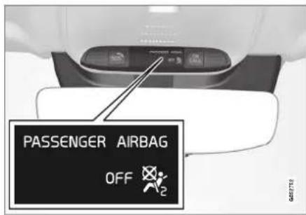
Occupant Weight Sensor (OWS) indicator light
Disabling the passenger's side front airbag
Volvo recommends that ALL occupants (adults and children) shorter than 140 cm (4 feet 7 inches) be seated in the back seat of any vehicle with a front passenger side airbag and be properly restrained for their size and weight.
The OWS works with sensors that are part of the front passenger's seat and seat belt. The sensors are designed to detect the presence of a properly
seated occupant and determine if the passenger's side front airbag should be enabled (may inflate) or disabled (will not inflate).
The OWS will disable (will not inflate) the passenger's side front airbag when:
- the front passenger's seat is unoccupied, or has small/medium objects in the front seat,
- the system determines that an infant is present in a rear-facing infant seat that is installed according to the manufacturer's instructions,
- the system determines that a small child is present in a forward-facing child restraint that is installed according to the manufacturer's instructions,
- the system determines that a small child is present in a booster seat,
- a front passenger takes his/her weight off of the seat for a period of time,
- a child or a small person occupies the front passenger's seat.
The OWS uses a PASSENGER AIRBAG OFF indicator lamp which will illuminate and stay on to remind you that the passenger's side front airbag is disabled. The PASSENGER AIRBAG OFF indicator lamp is located in the overhead console, near the base of the rearview mirror.
NOTE
When the ignition is switched on, the OWS indicator light will illuminate for several seconds while the system performs a self-diagnostic test.
However, if a fault is detected in the system:
• The OWS indicator light will stay on
- The SRS warning light will come on and stay on and a text message will be displayed.
WARNING
If a fault in the system is detected and indicated as described, be aware that the passenger's side front airbag will not deploy in the event of a collision. In this case, the SRS system and Occupant Weight Sensor should be inspected by a trained and qualified Volvo service technician as soon as possible.
WARNING
- Never try to open, remove or repair any components in the OWS system. This could cause the system to malfunction. Maintenance or repairs should only be carried out by an a trained and qualified Volvo service technician.
- The front passenger's seat should not be modified in any way. This could reduce pressure on the seat cushion, which might interfere with the OWS system's function.
SAFETY
◀◀
| Passenger's seat occu- pancy status | OWS indi-cator light status | Passenger's side front air-bag status |
| Seat unoccu-pied | OWS indi-cator light lights up | Passenger's side front air-bag disabled |
| Seat occu-pied by low weight occu-pant/object ^A | OWS indi-cator light lights up | Passenger's side front air-bag disabled |
| Seat occu-pied by heavy occupant/ object | OWS indi-cator light is not lit | Passenger's side front air-bag enabled |
A Volvo recommends that children always be properly restrained in appropriate child restraints in the rear seats. Do not assume that the passenger's side front airbag is disabled unless the PASSENGER AIRBAG OFF indicator lamp is lit. Make sure the child restraint is properly installed. If there is any doubt as to the status of the passenger's side front airbag, move the child restraint to the rear seat.
The OWS is designed to enable (may inflate) the passenger's side front airbag in the event of a collision anytime the system senses that a person of adult size is sitting properly in the front passenger's seat. The PASSENGER AIRBAG OFF indicator lamp will be off and remain off.
If a person of adult size is sitting in the front passenger's seat, but the PASSENGER AIRBAG OFF indicator lamp is on, it is possible that the
person isn't sitting properly in the seat. If this happens:
- Turn the vehicle off and ask the person to place the backrest in an upright position.
- Have the person sit upright in the seat, centered on the seat cushion, with the person's legs comfortably extended.
- Restart the vehicle and have the person remain in this position for about two minutes. This will allow the system to detect that person and enable the passenger's frontal airbag.
- If the PASSENGER AIRBAG OFF indicator lamp remains on even after this, the person should be advised to ride in the rear seat.
This indicates limitations in OWS classification capability. It does not indicate OWS malfunction.
Modifications
If you are considering modifying your vehicle in any way to accommodate a disability, for example by altering or adapting the driver's or front passenger's seat(s) and/or airbag systems, please contact Volvo at:
In the United States
Volvo Car USA, LLC
Customer Care Center
1 Volvo Drive
P.O. Box 914
Rockleigh, New Jersey 07647
1-800-458-1552
In Canada
Volvo Car Canada Ltd.
Customer Care Centre
9130 Leslie Street, Suite 101
Richmond Hill, Ontario L4B 0B9
1-800-663-8255

WARNING
- No objects that add to the total weight on the seat should be placed on the front passenger's seat. If a child is seated in the front passenger's seat with any additional weight, this extra weight could cause the OWS system to enable the airbag, which might cause it to deploy in the event of a collision, thereby injuring the child.
- The seat belt should never be wrapped around an object on the front passenger's seat. This could interfere with the OWS system's function.
- The front passenger's seat belt should never be used in a way that exerts more pressure on the passenger than normal. This could increase the pressure exerted on the weight sensor by a child, and could result in the airbag being enabled, which might cause it to deploy in the event of a collision, thereby injuring the child.

WARNING
- Keep the following points in mind with respect to the OWS system. Failure to follow these instructions could adversely affect the system's function and result in serious injury to the occupant of the front passenger's seat:
- The full weight of the front seat passenger should always be on the seat cushion. The passenger should never lift him/herself off the seat cushion using the armrest in the door or the center console, by pressing the feet on the floor, by sitting on the edge of the seat cushion, or by pressing against the backrest in a way that reduces pressure on the seat cushion. This could cause OWS to disable the front, passenger's side airbag.

WARNING
- Do not place any type of object on the front passenger's seat in such a way that jamming, pressing, or squeezing occurs between the object and the front seat, other than as a direct result of the correct use of the Automatic Locking Retractor/Emergency Locking Retractor (ALR/ELR) seat belt.
- No objects should be placed under the front passenger's seat. This could interfere with the OWS system's function.
Related information
• Driver/passenger-side airbags (p. 53)
SAFETY
Side airbags
The side airbags, on the driver's and passenger sides, protect the chest and hip in a collision.

natural_image
3D illustration of a person seated in a car, highlighted with a red cushion (no text or symbols)The side airbags are located in the front seats' outer backrest frames and help protect the driver and front seat passenger.
A collision of a sufficiently violent force will trigger the sensors and one or more side airbags will inflate. The side airbags inflate between the seat occupant and the door panel to help cushion the initial impact of the collision. The airbag deflates when compressed by the collision. The side airbags are normally only deployed on the side of the vehicle impacted by the collision.
WARNING
Volvo recommends contacting an authorized Volvo workshop for repairs. Incorrectly performed repairs to the side airbag system could impair function and lead to serious injury.
WARNING
Do not place any objects in the area between the outer edges of the seats and the door panels, as this could impair the function of the side airbags.
Volvo recommends only using seat covers approved by Volvo. Other seat covers could prevent the side airbags from functioning properly.
WARNING
The side airbag is a supplement to the seat belt. Always wear your seat belt.
Related information
• Airbags (p. 52)
Inflatable curtain
The inflatable curtain, Inflatable Curtain (IC), helps to prevent the driver and passengers from striking their heads on the inside of the vehicle during a collision.

natural_image
Interior view of a car with red and white panels, showing driver's feet and dashboard (no visible text or symbols)The inflatable curtains are installed along both sides of the inside of the roof and help protect occupants in the vehicle's outer seats. IC AIRBAG is embossed on the panels.
A collision of a sufficiently violent force will trigger the sensors and the inflatable curtain will inflate.
SAFETY

WARNING
Volvo recommends contacting an authorized Volvo workshop for repair. Incorrectly performed repairs to the inflatable curtain system could impair function and lead to serious injury.

WARNING
Never hang or attach heavy objects in the handle in the ceiling. The hooks are only intended for lightweight garments (not for hard objects such as umbrellas).
Never screw or mount anything to the vehicle's headlining, door pillars or side panels. This could impair the intended protective properties. Volvo recommends only using Volvo original parts that are approved for placement in these areas.

WARNING
If objects are loaded higher than the upper edge of the side windows, leave a 10 cm (4 in.) space between the objects and the window. Objects placed closer to this could impede the function of the inflatable curtain concealed inside the headlining.

WARNING
The inflatable curtain is a supplement to the seat belt. Always wear your seat belt.
Related information
• Airbags (p. 52)
Safety mode
Safety mode is a feature that is triggered after a collision if there is potential damage to an important function in the vehicle, such as the fuel lines, sensors for one of the safety systems, the brake system, etc.
If the vehicle has been involved in a collision, the text Safety mode See Owner's manual may appear in the instrument panel along with the warning symbol if the panel is undamaged and the vehicle's electrical system is intact. The message indicates that one or more of the vehicle's functions may be reduced.

WARNING
Never attempt to restart the vehicle if you smell fuel fumes when the message Safety mode See Owner's manual is displayed in the instrument panel. Leave the vehicle immediately.
If safety mode has been set, it may be possible to reset the system in order to start and move the vehicle a short distance, for example, if it is blocking traffic.
▶▶
61
SAFETY
◀◀

WARNING
Never attempt to perform repairs or reset electrical components on your own after the vehicle has been in safety mode. This could result in injury or prevent the vehicle from functioning properly. Volvo recommends having the vehicle inspected and reset to normal operating status by an authorized Volvo workshop after Safety mode See Owner's manual has been displayed.

WARNING
When the vehicle is in safety mode, it should not be towed behind another vehicle. It should be towed from the site on a tow truck. Volvo recommends towing the vehicle directly to an authorized Volvo workshop.
Related information
- Safety (p. 42)
- Starting and moving the vehicle when it is in safety mode (p. 62)
- Recovery (p. 489)
Starting and moving the vehicle when it is in safety mode
If safety mode has been set, it may be possible to reset the system in order to start and move the vehicle a short distance, for example, if it is blocking traffic.
Starting the vehicle when it is in safety mode
- Check the vehicle for damage, particularly for fuel leakage. Make sure you do not detect any gasoline fumes.
If the damage to the vehicle is minor and there is no fuel leakage/fumes, you may attempt to start the engine.

WARNING
Never attempt to restart the vehicle if you smell fuel fumes when the message Safety mode See Owner's manual is displayed in the instrument panel. Leave the vehicle immediately.
-
Switch off the ignition.
-
Then try to start the vehicle.
The vehicle's electrical system will perform a system check and then attempt to reset to normal operating mode. The message Vehicle start System check, wait will be displayed on the instrument panel during the check. This may take up to a minute.
- When Vehicle start System check, wait is no longer displayed in the instrument panel, try again to start the vehicle.

CAUTION
If the message Safety mode See Owner's manual is still displayed, the vehicle should not be driven or towed behind another vehicle. If the vehicle needs to be moved, it must be towed on a tow truck. Even if no damage is apparent, there may be hidden damage that could make the vehicle impossible to control.
Moving the vehicle when it is in safety mode
-
If the message Normal mode The vehicle is now in normal mode is displayed after attempting to start the engine, the vehicle may be moved carefully from its present position if, for example, it is blocking traffic.
-
Do not move the vehicle farther than absolutely necessary.

WARNING
When the vehicle is in safety mode, it should not be towed behind another vehicle. It should be towed from the site on a tow truck. Volvo recommends towing the vehicle directly to an authorized Volvo workshop.
Related information
- Safety mode (p. 61)
• Starting the vehicle (p. 434) - Recovery (p. 489)
Child safety
Children should always be seated safely when traveling in the vehicle.
General information
Volvo recommends the proper use of restraint systems for all occupants including children. Remember that, regardless of age and size, a child should always be properly restrained in a vehicle.
Your vehicle is also equipped with ISOFIX/LATCH attachments, which make it more convenient to install child seats.
Some restraint systems for children are designed to be secured in the vehicle by lap belts or the lap portion of a lap-shoulder belt. Such child restraint systems can help protect children in vehicles in the event of an accident only if they are used properly. However, children could be endangered in a crash if the child restraints are not properly secured in the vehicle. Failure to follow the installation instructions for your child restraint can result in your child striking the vehicle's interior in a sudden stop.
Holding a child in your arms is NOT a suitable substitute for a child restraint system. In an accident, a child held in a person's arms can be crushed between the vehicle's interior and an unrestrained person. The child could also be injured by striking the interior, or by being ejected from the vehicle during a sudden maneuver or impact. The same can also happen if the infant or child rides unrestrained on the seat. Other occupants should also be properly restrained to help reduce the chance of injuring or increasing the injury of a child.
All states and provinces have legislation governing how and where children should be carried in a vehicle. Find out the regulations existing in your state or province. Recent accident statistics have shown that children are safer in rear seating positions than front seating positions when properly restrained. A child restraint system can help protect a child in a vehicle. Here's what to look for when selecting a child restraint system:
It should have a label certifying that it meets applicable Federal Motor Vehicle Safety Standards (FMVSS 213) - or in Canada, CMVSS 213.
Make sure the child restraint system is approved for the child's height, weight and development - the label required by the standard or regulation, or instructions for infant restraints, typically provide this information.
In using any child restraint system, we urge you to carefully look over the instructions that are provided with the restraint. Be sure you understand them and can use the device properly and safely in this vehicle. A misused child restraint system can result in increased injuries for both the infant or child and other occupants in the vehicle.
▶▶
SAFETY
When a child has outgrown the child safety seat, you should use the rear seat with the standard seat belt fastened. The best way to help protect the child here is to place the child on a cushion so that the seat belt is properly located on the hips. Legislation in your state or province may mandate the use of a child seat or cushion in combination with the seat belt, depending on the child's age and/or size. Please check local regulations.
A specially designed and tested booster cushion and backrest can be obtained from your Volvo retailer. See also the article "Integrated booster cushion."

natural_image
Interior view of a car showing a red X symbol on the steering wheel (no text or symbols present)WARNING
- Do not use child safety seats or child booster cushions/backrests in the front passenger's seat. We also recommend that children under 140 cm (4 feet 7 inches) in height who have outgrown these devices sit in the rear seat with the seat belt fastened.
- On hot days, the temperature in the vehicle interior can rise very quickly. Exposure to these high temperatures for even a short period of time can cause heat-related injury or death. Small children are particularly at risk. Never leave children unattended in a vehicle.
Child seats should always be registered.
Volvo's recommendations
Why does Volvo believe that no child should sit in the front seat of a vehicle? It's quite simple really. A front airbag is a very powerful device designed, by law, to help protect an adult.
Because of the size of the airbag and its speed of inflation, a child should never be placed in the front seat, even if he or she is properly belted or strapped into a child safety seat. Volvo has been an innovator in the field of safety since it was founded. And we have no intention of resting on our laurels. But we need your help. Please
remember to put your children in the back seat, and buckle them up.
WARNING
A child restraint should never be reused if:
- The vehicle has been involved in a collision, no matter how minor
- Its history is unknown
- It is older than the manufacturer's expiration date
Volvo has some very specific recommendations
• Always wear your seat belt.
- Airbags are a SUPPLEMENTAL safety device which, when used with a three-point seat belt can help reduce serious injuries during certain types of accidents. Volvo recommends that you do not disconnect the airbag system in your vehicle.
- Volvo strongly recommends that everyone in the vehicle be properly restrained.
- Volvo recommends that ALL occupants (adults and children) shorter than 140 cm (4 feet 7 inches) be seated in the rear seat of any vehicle with a front passenger side airbag.
- Drive safely!
SAFETY
Related information
- Safety (p. 42)
• Child restraints (p. 65) - Activating and deactivating child safety locks (p. 264)
Child restraints
Suitable child restraints should always be used when children travel in the vehicle.
Child restraint systems

natural_image
3D rendered image of a car seatbelt with red safety harness (no text or symbols)Infant seat
There are three main types of child restraint systems: infant seats, convertible seats and booster cushions. They are classified according to the child's age and size.
The child restraint should be secured using a three-point seat belt, ISOFIX/LATCH anchors or top tether anchors.

natural_image
3D illustration of a car seat assembly with red safety straps, shown from two different angles (no text or symbols)Convertible seal
WARNING
A child seat should never be used in the front passenger seat of any vehicle with a front passenger airbag - not even if the "Passenger airbag off" symbol near the rear-view mirror is illuminated. If the severity of an accident were to cause the airbag to inflate, this could lead to serious injury or death to a child seated in this position.
▶▶
65
SAFETY
◀◀

natural_image
3D illustration of a person sitting in a car seat with a red belt, no text or symbols presentBooster cushion

WARNING
Always refer to the child restraint manufacturer's instructions for detailed information on securing the restraint.

WARNING
- When not in use, keep the child restraint system secured or remove it from the passenger compartment to help prevent it from injuring passengers in the event of a sudden stop or collision.
- A small child's head represents a considerable part of its total weight and its neck is still very weak. Volvo recommends that children up to age 4 travel, properly restrained, facing rearward. In addition, Volvo recommends that children should ride rearward facing, properly restrained, as long as possible.
Automatic Locking Retractor/ Emergency Locking Retractor (ALR/ ELR)
To make child seat installation easier, each seat belt (except for the driver's belt) is equipped with a locking mechanism to help keep the seat belt taut.
When attaching the seat belt to a child seat:
- Attach the seat belt to the child seat according to the child seat manufacturer's instructions.
- Pull the seat belt out as far as possible.
-
Insert the seat belt latch plate into the buckle (lock) in the usual way.
-
Release the seat belt and pull it taut around the child seat.
A sound from the seat belt retractor will be audible at this time and is normal. The belt will now be locked in place. This function is automatically disabled when the seat belt is unlocked and the belt is fully retracted.

WARNING
Do not use child safety seats or child booster cushions/backrests in the front passenger's seat. We also recommend that children who have outgrown these devices sit in the rear seat with the seat belt properly fastened.
Child restraint registration and recalls
Child restraints could be recalled for safety reasons. You must register your child restraint to be reached in a recall. To stay informed about child safety seat recalls, be sure to fill out and return the registration card that comes with new child restraints.
Child restraint recall information is readily available in both the U.S. and Canada. For recall information in the U.S., call the U.S. Government's Auto Safety Hotline at 1-800-424-9393 or go to http://www-odi.nhtsa.dot.gov/cars/problems/recalls/register/childseat/index.cfm. In Canada, visit Transport Canada's Child Safety website at http://www.tc.gc.ca/roadsafety/childsafety/menu.htm.
SAFETY
Related information
• Child safety (p. 63)
- Infant seats (p. 67)
- Convertible seats (p. 69)
- Booster cushions (p. 71)
• Integrated booster cushion* (p. 76)
• Top tether anchors (p. 72)
• Lower child seat attachment points (p. 74)
• ISOFIX/LATCH lower anchors (p. 74)
Infant seats
Suitable child restraints should always be used when children (depending on their age/size) are seated in the vehicle.
Securing an infant seat with a seat belt

natural_image
Interior view of a car showing the steering wheel and dashboard with a red X symbol overlay (no text or symbols present)Do not place the infant seat in the front passenger's seat
-
Place the infant seat in the rear seat of the vehicle.
-
Attach the seat belt to the infant seat according to the child restraint manufacturer's instructions.
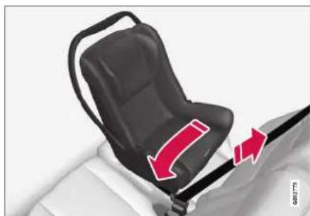
natural_image
Car seatbelt diagram showing black seat and white seat, with red arrows indicating clockwise motion (no text or symbols)Route the seat bell through the infant seat.
WARNING
- An infant seat must be in the rear-facing position only.
- The infant seat should not be positioned behind the driver's seat unless there is adequate space for safe installation.
▶▶
SAFETY
◀◀

WARNING
A child seat should never be used in the front passenger seat of any vehicle with a front passenger airbag - not even if the "Passenger airbag off" symbol near the rear-view mirror is illuminated. If the severity of an accident were to cause the airbag to inflate, this could lead to serious injury or death to a child seated in this position.
3.

natural_image
Close-up of a car seatbelt with a red arrow pointing to the seat (no text or symbols visible)Fasten the seat belt.
Fasten the seat belt by inserting the latch plate into the buckle (lock) until a distinct click is audible.

natural_image
3D illustration of a black seatbelt buckle being lifted by a red belt, with no text or symbols present.Pull out the shoulder section of the seat bell.
- Pull the shoulder section of the seat belt out as far as possible to activate the belt's automatic locking function.

NOTE
The locking retractor will automatically release when the seat belt is unbuckled and allowed to retract fully.
- Press the infant seat firmly in place, let the seat belt retract and pull it taut. A sound from the seat belt retractor's automatic locking function will be audible at this time and is normal. The seat belt should now be locked in place.

natural_image
Mechanical seat assembly diagram showing red directional arrows indicating movement or force (no text or symbols)Check that the infant seat is properly secured.
- Press and pull the infant seat along the direction of the seat belt to check that it is properly held in place by the seat belt.
SAFETY

WARNING
It should not be possible to move the child restraint more than 2.5 cm (1 in.) in any direction along the seat belt path.
The infant seat can be removed by unbuckling the seat belt and letting it retract completely.
Related information
• Child restraints (p. 65)
- Convertible seats (p. 69)
- Booster cushions (p. 71)
• Top tether anchors (p. 72)
• Lower child seat attachment points (p. 74)
• ISOFIX/LATCH lower anchors (p. 74)
Convertible seats
Suitable child restraints should always be used when children (depending on their age/size) are seated in the vehicle.
Securing a convertible seat with a seat belt

Do not place the convertible seat in the front passenger's seat.
Convertible seats can be used in either a forward or rearward-facing position, depending on the age and size of the child.

natural_image
3D illustration of a car seat assembly with red safety straps, shown from two different angles (no text or symbols)Route the seat bell through the convertible seat.

WARNING
Always use a convertible seat that is suitable for the child's age and size. See the convertible seat manufacturer's recommendations.
- Place the convertible seat in the rear seat of the vehicle.
SAFETY
◀◀

WARNING
- A small child's head represents a considerable part of its total weight and its neck is still very weak. Volvo recommends that children up to age 4 travel, properly restrained, facing rearward. In addition, Volvo recommends that children should ride rearward facing, properly restrained, as long as possible.
- Convertible child seats should be installed in the rear seat only.
-
A rear-facing convertible seat should not be positioned behind the driver's seat unless there is adequate space for safe installation.
-
Attach the seat belt to the convertible seat according to the child restraint manufacturer's instructions.

natural_image
3D rendering of a black car seatbelt with red diagonal band indicating force or grip (no text or symbols)Fasten the seat bell
- Fasten the seat belt by inserting the latch plate into the buckle (lock) until a distinct click is audible.
- Pull the shoulder section of the seat belt out as far as possible to activate the belt's automatic locking function.

NOTE
The locking retractor will automatically release when the seat belt is unbuckled and allowed to retract fully.
- Press the convertible seat firmly in place, let the seat belt retract and pull it taut. A sound from the seat belt retractor's automatic locking function will be audible at this time and is normal. The seat belt should now be locked in place.

natural_image
Car seat assembly diagram showing black seat, red belt, and gray seat (no text or symbols)Pull out the shoulder section of the seat belt.
- Push and pull the convertible seat along the seat belt path to ensure that it is held securely in place by the seat belt.

WARNING
It should not be possible to move the child restraint more than 2.5 cm (1 in.) in any direction along the seat belt path.
The convertible seat can be removed by unbuck-ling the seat belt and letting it retract completely.

natural_image
Close-up of a black car seatbelt with red directional arrows indicating force or movement (no text or symbols)Ensure that the convertible seat is securely in place.

WARNING
A child seat should never be used in the front passenger seat of any vehicle with a front passenger airbag - not even if the "Passenger airbag off" symbol near the rear-view mirror is illuminated. If the severity of an accident were to cause the airbag to inflate, this could lead to serious injury or death to a child seated in this position.
Related information
• Child restraints (p. 65)
- Infant seats (p. 67)
- Booster cushions (p. 71)
• Top tether anchors (p. 72)
• Lower child seat attachment points (p. 74)
• ISOFIX/LATCH lower anchors (p. 74)
Booster cushions
Suitable child restraints should always be used when children (depending on their age/size) are seated in the vehicle.
Securing a booster cushion

natural_image
3D illustration of a person sitting in a car seat with a red belt, no text or symbols presentPosition the child correctly on the booster cushion.
Booster cushions are recommended for children who have outgrown convertible seats.
- Place the booster cushion in the rear seat of the vehicle.
- With the child properly seated on the booster cushion, attach the seat belt to or around the cushion according to the manufacturer's instructions.
SAFETY
- Fasten the seat belt by inserting the latch plate into the buckle (lock) until a distinct click is audible.

natural_image
Interior view of a car seatbelt with red belt and white seat, no visible text or symbolsPositioning the seat belt,
- Ensure that the seat belt is pulled taut and fits snugly around the child.

WARNING
- The hip section of the three-point seat belt must fit snugly across the child's hips, not across the stomach.
- The shoulder section of the three-point seat belt should be positioned across the chest and shoulder.
- The shoulder belt must never be placed behind the child's back or under the arm.
Related information
• Child restraints (p. 65)
- Convertible seats (p. 69)
- Infant seats (p. 67)
• Top tether anchors (p. 72)
• Lower child seat attachment points (p. 74)
• ISOFIX/LATCH lower anchors (p. 74)
Top tether anchors
Your Volvo is equipped with child restraint top tether anchorages for all three seating positions in the rear seat. They are located on the rear side of the backrests.
Child restraint anchorages

Top tether anchors and symbols on the rear side of the second row backrests. There is no symbol for the center anchor position.
Securing a child seat
- Place the child restraint on the rear seat.
- Route the top tether strap under the head restraint and attach it to the anchor.
- Attach the strap for the lower tether anchors in the lower ISOFIX/LATCH attachment points. If the child restraint is not equipped with straps for the lower tether anchors, or if the child restraint is used on the center seating position, follow the instructions for attaching a child restraint using the automatic locking seal belt.
- Firmly tension all straps.
Refer also to the child seat manufacturer's instructions for information on securing the child seat.

NOTE
If the vehicle is equipped with a cargo compartment cover, this must be removed before a child seat can be attached in the tether anchors.

WARNING
• Always refer to the recommendations made by the child restraint manufacturer.
- Volvo recommends that the top tether anchors be used when installing a forward-facing child restraint.
- Never route a top tether strap over the top of the head restraint. The strap should be routed beneath the head restraint.
- Child restraint anchorages are designed to withstand only those loads imposed by correctly fitted child restraints. Under no circumstances are they to be used for adult seat belts or harnesses. The anchorages are not able to withstand excessive forces on them in the event of collision if full harness seat belts or adult seat belts are installed to them. An adult who uses a belt anchored in a child restraint anchorage runs a great risk of suffering severe injuries should a collision occur.
- Do not install rear speakers that require the removal of the top tether anchors or interfere with the proper use of the top tether strap.
Related information
• Child restraints (p. 65)
• Lower child seat attachment points (p. 74)
• ISOFIX/LATCH lower anchors (p. 74)
SAFETY
Lower child seat attachment points
The vehicle is equipped with lower child restraint attachment points in the second row of seats.
The lower child seat attachment points are intended for use with certain rear-facing child restraints.
Always follow the manufacturer's installation instructions when attaching a child seat to the lower child seat attachment points.
Location of child seat attachment points
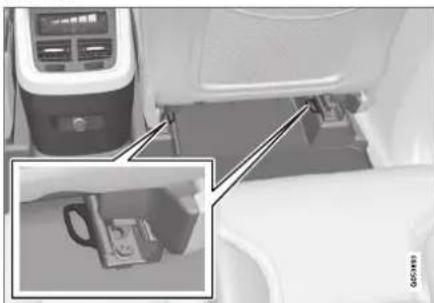
natural_image
Interior view of a vehicle showing a water dispenser and a mug inserted into the engine compartment (no visible text or symbols)Location of the child seat attachment points in the second row of seats.
The child seat attachment points in the second row of seats are located on the rear section of the front seat floor rails.
Related information
• Child restraints (p. 65)
• Top tether anchors (p. 72)
• ISOFIX/LATCH lower anchors (p. 74)
ISOFIX/LATCH lower anchors
Lower anchors for ISOFIX/LATCH-equipped child seats are located in the second row, outboard seats, hidden below the backrest cushions.
Using the ISOFIX/LATCH lower child seat anchors

natural_image
Interior view of a car showing seatbelt and passenger seat with a circular warning sign (no text or symbols on the diagram itself)Location of the ISOFIX/LATCH anchors
Symbols on the seat back upholstery mark the ISOFIX/LATCH anchor positions as shown. To access the anchors, kneel on the seat cushion and locate the anchors by feel. Always follow your child seat manufacturer's installation instructions, and use both ISOFIX/LATCH lower anchors and top tethers whenever possible.
To access the anchors
- Put the child restraint in position.
- Kneel on the child restraint to press down the seat cushion and locate the anchors by feel.
- Fasten the attachment on the child restraint's lower straps to the ISOFIX/LATCH lower anchors.
- Firmly tension the lower child seat straps according to the manufacturer's instructions.

WARNING
Volvo's ISOFIX/LATCH anchors conform to FMVSS/CMVSS standards. Always refer to the child restraint system's manual for weight and size ratings.
NOTE
- The rear center seat is not equipped with ISOFIX/LATCH lower tether anchors. If a child restraint is used in this seat, attach the restraint's upper anchor strap (if equipped with these) to the top tether anchor point for this strap and secure the child restraint with the vehicle's center seat belt.
- Always follow your child seat manufacturer's installation instructions, and use both ISOFIX/LATCH lower anchors and top tethers whenever possible.

Fasten the attachment correctly to the ISOFIX/LATCH lower anchors.
WARNING
- Be sure to fasten the attachment correctly to the anchor (see the illustration). If the attachment is not correctly fastened, the child restraint may not be properly secured in the event of a collision.
- The ISOFIX/LATCH lower child restraint anchors are only intended for use with child seats positioned in the outboard seating positions. These anchors are not certified for use with any child restraint that is positioned in the center seating position. When securing a child restraint in the center seating position, use only the vehicle's center seat belt.
Related information
• Child restraints (p. 65)
• Top tether anchors (p. 72)
• ISOFIX/LATCH lower anchors (p. 74)
SAFETY
Integrated booster cushion\*1
The integrated booster cushion in the second row center seating position helps ensure that a child can sit comfortably and safely.
The integrated booster cushion has been specially designed to help safeguard children in the rear seat when used with the vehicle's seat belts.
If using a booster cushion does not result in proper positioning of the shoulder strap, then the child should be placed in a properly secured child restraint. The shoulder belt must never be placed behind the child's back or under the arm.
Only used for children in the weight range 15-36 kg (33-80 lbs) and height range 97-137 cm (38-54 inches).
In Canada: 18 kg (40 lbs) is the minimum weight requirement for a child using booster cushions according to the Canadian regulation CMVSS 213.4
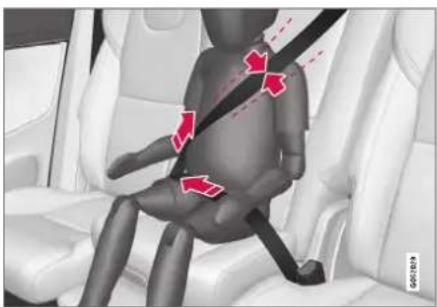
natural_image
3D illustration of a child sitting in a car seat with a belt buckle, showing red arrows indicating movement or pressure points (no text or symbols present)Correct seating position: the seat belt is positioned across the collarbone.
Before driving, make sure that:
• the booster cushion is locked into position
- the head restraint is set to the same height as the child's head, so that, if possible, the entire back of the child's head is covered
- the seat belt is taut, in contact with the child's body and not twisted
- the seat belt is not positioned across the child's throat or below the shoulder
- the lap section of the seat belt is placed low over the child's hips to provide the best protection.
WARNING
DEATH or SERIOUS INJURY can occur
- Follow all instructions on this child restraint and in the vehicle's owner's manual.
• Make sure the booster cushion is securely locked before the child is seated. - Only use for children who weigh between 15-36 kg (33-80 lbs) and who are between 97-137 cm (38-54 tum) in height. In Canada: 18 kg (40 lbs) is the minimum weight requirement for a child using booster cushions according to the Canadian regulation CMVSS 213.4
- Use only the vehicle's lap and shoulder belt system when restraining the child in this booster cushion.
- In the event of a collision while the integrated booster cushion was occupied, the entire booster cushion and seat belt must be replaced. The booster cushion should also be replaced if it is badly worn or damaged in any way. This work should be performed by a trained and qualified Volvo service technician only.
SAFETY
Related information
• Child restraints (p. 65)
- Folding up the integrated booster cushion* (p. 77)
- Folding down the integrated booster cushion* (p. 78)
Folding up the integrated booster cushion\*
When the integrated booster cushion is used, it must be folded up.

natural_image
Interior view of a car showing seatbelt and rear seats with red directional arrows indicating movement (no text or symbols)1 Pull the handle forward and upward to release the booster cushion.

natural_image
Interior view of a car seat with a red upward arrow on the backrest (no text or symbols visible)2 Press the booster cushion rearward to lock it into position.
▶▶
SAFETY
◀◀

WARNING
DEATH or SERIOUS INJURY can occur
- Follow all instructions on this child restraint and in the vehicle's owner's manual.
• Make sure the booster cushion is securely locked before the child is seated. - Only use for children who weigh between 15-36 kg (33-80 lbs) and who are between 97-137 cm (38-54 tum) in height. In Canada: 18 kg (40 lbs) is the minimum weight requirement for a child using booster cushions according to the Canadian regulation CMVSS 213.4
- Use only the vehicle's lap and shoulder belt system when restraining the child in this booster cushion.
- In the event of a collision while the integrated booster cushion was occupied, the entire booster cushion and seat belt must be replaced. The booster cushion should also be replaced if it is badly worn or damaged in any way. This work should be performed by a trained and qualified Volvo service technician only.
Related information
• Integrated booster cushion* (p. 76)
- Folding down the integrated booster cushion* (p. 78)
Folding down the integrated booster cushion\*
When the integrated booster cushion in the rear seat is not in use, it should be stowed (folded down).

natural_image
Interior view of a car seat and dashboard with a red arrow indicating direction (no text or symbols)
Pull the handle forward to release the booster cushion.
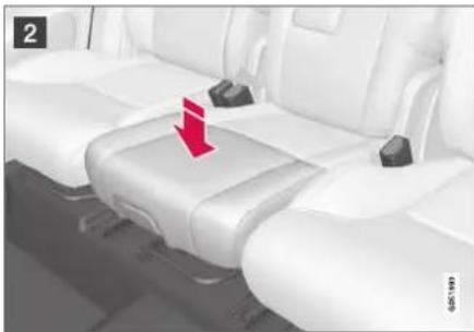
natural_image
Interior view of a car seat with white seats and a red arrow pointing to the side seat (no text or symbols visible)2 Press down on the center of the booster cushion to lock it into position.
CAUTION
Make sure that there are no objects (e.g. toys) on the seat under the integrated booster cushion before folding it down.
NOTE
The integrated booster cushion must be stowed (folded down) before folding down the seat backrest.
WARNING
DEATH or SERIOUS INJURY can occur
- Follow all instructions on this child restraint and in the vehicle's owner's manual.
• Make sure the booster cushion is securely locked before the child is seated. - Only use for children who weigh between 15-36 kg (33-80 lbs) and who are between 97-137 cm (38-54 tum) in height. In Canada: 18 kg (40 lbs) is the minimum weight requirement for a child using booster cushions according to the Canadian regulation CMVSS 213.4
- Use only the vehicle's lap and shoulder belt system when restraining the child in this booster cushion.
- In the event of a collision while the integrated booster cushion was occupied, the entire booster cushion and seat belt must be replaced. The booster cushion should also be replaced if it is badly worn or damaged in any way. This work should be performed by a trained and qualified Volvo service technician only.
Related information
• Integrated booster cushion* (p. 76)
- Folding up the integrated booster cushion* (p. 77)

bar
| Category | Value | |---|---| | Category 1 | 100 | | Category 2 | 100 | | Category 3 | 100 | | Category 4 | 100 | | Category 5 | 100 | | Category 6 | 100 | | Category 7 | 100 | | Category 8 | 100 | | Category 9 | 100 | | Category 10 | 100 | | Category 11 | 100 | | Category 12 | 100 | | Category 13 | 100 | | Category 14 | 100 | | Category 15 | 100 | | Category 16 | 100 | | Category 17 | 100 | | Category 18 | 100 | | Category 19 | 100 | | Category 20 | 100 | | Category 21 | 100 | | Category 22 | 100 | | Category 23 | 100 | | Category 24 | 100 | | Category 25 | 100 | | Category 26 | 100 | | Category 27 | 100 | | Category 28 | 100 | | Category 29 | 100 | | Category 30 | 100 | | Category 31 | 100 | | Category 32 | 100 | | Category 33 | 100 | | Category 34 | 100 | | Category 35 | 100 | | Category 36 | 100 | | Category 37 | 100 | | Category 38 | 100 | | Category 39 | 100 | | Category 40 | 100 | | Category 41 | 100 | | Category 42 | 100 | | Category 43 | 100 | | Category 44 | 100 | | Category 45 | 100 | | Category 46 | 100 | | Category 47 | 100 | | Category 48 | 100 | | Category 49 | 100 | | Category 50 | 100 | | Category 51 | 100 | | Category 52 | 100 | | Category 53 | 100 | | Category 54 | 100 | | Category 55 | 100 | | Category 56 | 100 | | Category 57 | 100 | | Category 58 | 100 | | Category 59 | 100 | | Category 60 | 100 | | Category 61 | 100 | | Category 62 | 100 | | Category 63 | 100 | | Category 64 | 100 | | Category 65 | 100 | | Category 66 | 100 | | Category 67 | 100 | | Category 68 | 100 | | Category 69 | 100 | | Category 70 | 100 | | Category 71 | 100 | | Category 72 | 100 | | Category 73 | 100 | | Category 74 | 100 | | Category 75 | 100 | | Category 76 | 100 | | Category 77 | 100 | | Category 78 | 100 | | Category 79 | 100 | | Category 80 | 100 | | Category 81 | 100 | | Category 82 | 100 | | Category 83 | 100 | | Category 84 | 100 | | Category 85 | 100 | | Category 86 | 100 | | Category 87 | 100 | | Category 88 | 100 | | Category 89 | 100 | | Category 90 | 100 | | Category 91 | 100 | | Category 92 | 100 | | Category 93 | 100 | | Category 94 | 100 | | Category 95 | 100 | | Category 96 | 100 | | Category 97 | 100 | | Category 98 | 100 | | Category 99 | 100 | | Total (Total) |DISPLAYS AND VOICE CONTROL
DISPLAYS AND VOICE CONTROL
Instruments and controls in left-hand drive vehicles
The overviews show the location of the vehicle's displays and controls.
Steering wheel and dashboard
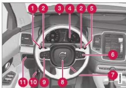
Parking lights, daytime running lights, low beams, high beams, turn signals, rear fog light, trip computer reset
② Steering wheel paddles for manual shifting*
3 Head-up display*
4 Instrument panel
⑤ Wipers and washers, rain sensor*
6 Right-side steering wheel keypad
⑦ Steering wheel adjustment
8 Horn
9 Left-side steering wheel keypad
10 Hood open
11 Display lighting, tailgate unlock/open*/ close*, halogen headlight height adjustment
Ceiling console

1 Front reading lights and courtesy lighting
2 Panoramic roof*
3 Ceiling console display ON CALL button
4 HomeLink®*
Center and tunnel console
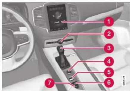
1 Center display
② Hazard warning flashers, defrosting, media, glove compartment open
3 Gear selector
4 Start knob
5 Drive modes
6 Parking brake
7 Auto-hold brakes
Driver's door
DISPLAYS AND VOICE CONTROL

1 Memory for power front seat settings*, door mirrors and head-up display*
② Central locking
3 Power windows, door mirrors, electric child safety locks*
4 Controls for front seat
Related information
• Manual front seats (p. 184)
• Adjusting the power* front seats (p. 185)
• Adjusting the steering wheel (p. 201)
• Lighting panel and controls (p. 152)
• Starting the vehicle (p. 434)
• Instrument panel (p. 84)
• Center display overview (p. 109)
• Transmission (p. 448)
DISPLAYS AND VOICE CONTROL
Instrument panel
The instrument panel displays information related to the vehicle and driving.
The instrument panel contains gauges, indicators and monitoring and warning symbols. What is shown in the instrument panel varies depending on the equipment, settings and functions currently active.
The instrument panel is activated as soon as a door is opened, i.e. in ignition mode 0. The panel will power down after a short period of time if it is not used. To reactivate it, do one of the following:
• Depress the brake pedal.
• Activate ignition mode I.
- Open one of the doors.
WARNING
If the instrument panel turns off, does not activate when the ignition is switched on, or part/all of the panel cannot be read, do not drive the vehicle. Consult a workshop immediately. Volvo recommends an authorized Volvo workshop.
WARNING
If the instrument panel is not functioning properly, information about brakes, airbags or other safety-related systems may not be displayed. The driver will then not be able to check the status of the vehicle systems or receive relevant warnings and information.

Location in the instrument panel:
| Left side In the center Right side | ||
| Speedometer Indicator and warning symbols | Tachometer/Hybrid gauge^A | |
| Trip odometer Ambient temperature sensor Gear indicator | ||
| Odometer^B | Clock Drive Mode | (Hybrid, Off Road, Pure, Power or AWD) |
| Cruise control/speed limiter information Message (also graphics in some cases) Fuel gauge | ||
| Road sign information^* | Door and seat belt status Hybrid gauge | |
| - Hybrid battery's charge level Distance to empty tank | ||
| - Media player Distance to discharged battery | ||
| - Navigation system map Current fuel consumption | ||
| - Phone App menu (activated using steering wheel keypad) | ||
| - Voice Control - | ||
| - | Compass^A | - |
A Depends on selected drive mode.
B Total distance.
Dynamic symbol
Dynamic symbol in basic mode.
In the center of the instrument panel is a dynamic symbol that changes appearance according to the type of message displayed. The severity of the control or warning symbol is indicated by an amber or red marking around the symbol. An animation may be used to change the symbol into a larger image in order to graphically depict the location of a problem or to clarify information.

Example with indicator symbol.
Related information
• Instrument panel settings (p. 86)
- Warning symbols in the instrument panel (p. 97)
- Indicator symbols in the instrument panel (p. 94)
- Trip computer (p. 89)
- Messages in the instrument panel (p. 105)
- Handling the App menu in the instrument panel (p. 104)
DISPLAYS AND VOICE CONTROL
Instrument panel settings
Display settings for the instrument panel can be set via the instrument panel's app menu and via the center display's Settings menu.
Settings via instrument panel's app menu

The illustration is generic - layout may vary.
The app menu will open and can be controlled using the right-side steering wheel keypad.
The app menu can be used to set what information will be displayed in the instrument panel:
- trip computer
• media player - phone
- navigation system.
Settings via center display
Selecting type of information
- Tap Settings in the center display's Top view.
- Tap My Car Displays Driver Display Information.
- Select a background:
• Show no information in the background
• Show information for current playing media
- Show navigation even if no route is set.
Select theme
- Tap Settings in the center display's Top view.
- Tap My Car Displays Display Themes
-
Select a theme (appearance) for the instrument panel:
-
Glass
- Minimalistic
- Performance
- Chrome Rings.
Select language
-
Tap Settings in the center display's Top view.
-
Tap System System Languages and Units → System Language to select language.
A change made here will affect the language in all displays.
The settings are personal and saved automatically in the active driver profile.
Related information
• Instrument panel (p. 84)
- Handling the App menu in the instrument panel (p. 104)
- Changing settings in the center display's Top view (p. 132)
Fuel gauge
The fuel gauge in the instrument panel shows the fuel level in the tank.

The beige area in the fuel gauge indicates the amount of fuel left in the tank.
When the fuel level is low and it is time to refuel, the fuel pump symbol will illuminate with an amber-colored light. The trip computer also indicates the approximate distance driven on the fuel remaining in the tank.
Related information
• Instrument panel (p. 84)
• Hybrid gauge (p. 88)
• Refueling (p. 475)
• Fuel tank volume (p. 674)
Hybrid gauge
In Hybrid and Pure drive modes, the instrument panel will display a hybrid gauge, which can help the driver achieve optimal driving economy.

The hybrid gauge shows the ratio between the electric motor's current power consumption and the remaining available power. This information is shown in various ways.
Symbols in the hybrid gauge

Indicates the current available power from the electric motor. A solid symbol indicates that the electric motor is being used.

A hollow symbol indicates that the electric motor is not being used.

Indicates the power level when the internal combustion engine starts. A solid symbol indicates that the internal combustion engine is being used.

Indicates the power level when the internal combustion engine will start. A hollow symbol indicates that the internal combustion engine is not being
used.

Indicates that the hybrid battery is being charged, e.g. by lightly pressing the brake pedal.
Driver-requested power
The hybrid gauge displays the amount of power requested (utilized) by the driver through pressure on the accelerator pedal. The higher the reading on the scale, the more power utilized in the current gear. The mark between the lightning symbol and the drop symbol indicates the point at which the combustion engine will start.
DISPLAYS AND VOICE CONTROL
For example:

The vehicle has been started, but is stationary and no power is being requested.
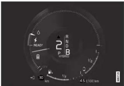
The vehicle is generating current to recharge the battery, e.g., during light braking or engine braking on a down-slope.

The electric motor cannot supply the requested power and the internal combustion engine will start.
Related information
- Drive modes (p. 454)
• Instrument panel (p. 84) - Brakes (p. 439)
• Using the electric motor only (p. 469)
• Starting and stopping the combustion engine in Twin Engine vehicles (p. 454)
Hybrid gauge
The hybrid battery gauge shows how much current is left in the hybrid battery.
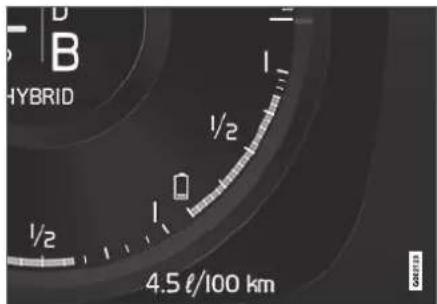
The current in the hybrid battery is used to power the electric motor, but can also be used to heat or cool the vehicle. The trip computer calculates an approximate driving distance with the remaining current in the hybrid battery.
Symbols in the hybrid battery gauge

The symbol in the hybrid battery gauge indicates that the Hold function is activated. The
symbol indicates that the Charge function is activated.
Related information
• Instrument panel (p. 84)
• Charging the hybrid battery (p. 417)
• "Hold" and "Charge" functions (p. 471)
Trip computer
The vehicle's trip computer registers data while driving such as mileage, fuel consumption and average speed.
To help promote fuel-efficient driving, data is recorded on both current and average fuel consumption. Data from the trip computer can be displayed in the instrument panel.
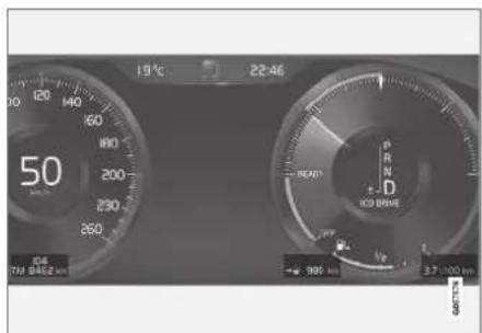
Example of trip computer information in the instrument panel. ^1
The trip computer includes the following gauges:
- Trip odometer
- Odometer
• Current fuel consumption
• Distance to empty tank
• Distance to discharged battery
- Tourist - alternative speedometer Unit standards for distance, speed, etc. can be changed via system settings in the center display.
Trip odometer
There are two trip odometers: TM and TA.
TM can be reset manually and TA is reset automatically if the vehicle is not used for four hours. During a drive, the trip odometer registers data on:
- Mileage
- Driving time
- Average speed
• Average fuel consumption
The readings since the trip odometer's last reset are displayed.
Odometer
The odometer records the vehicle's total mileage. This reading cannot be reset.
Current fuel consumption
This gauge shows the vehicle's fuel consumption at that moment. The reading is updated about once a second.
Distance to empty tank
The trip computer calculates the distance that can be driven on the fuel remaining in the tank.
DISPLAYS AND VOICE CONTROL
◀◀
This calculation is based on average fuel consumption during the last 30 km (20 miles) and the amount of fuel remaining in the tank.
When the gauge displays "----", there is not enough fuel remaining to calculate the remaining mileage. Refuel as soon as possible.

NOTE
This may vary if your driving style changes.
An economical driving style will generally increase how far you can drive on a certain amount of fuel.
Distance to discharged battery

The gauge shows the approximate distance that can be driven with the remaining current in the hybrid battery.
When the gauge displays "----", there is little charge remaining in the battery and distance cannot be reliably calculated.
This calculation is based on average consumption with a normally loaded vehicle in normal driving conditions, and takes into account whether the air conditioning is on or off. Changing drive modes from Hybrid to Pure may increase the calculated distance because Pure mode has reduced climate control settings (ECO Climate).

NOTE
This may vary if your driving style changes.
An economical driving style will generally increase how far you can drive on a certain amount of fuel.
Starting values for fully charged hybrid battery
Because it is difficult to predict driving style and other factors that affect the range of electric motors, Volvo uses a starting value when the vehicle is fully charged. This starting value provides an "up to" amount instead of a prediction on the range of the electric current in the motor. The difference in starting value between Hybrid and Pure is because the vehicle is permitted to use more current from the hybrid battery in Pure mode, and because the vehicle switches to ECO Climate.
Mileage when using electric motor
To achieve the longest possible mileage when using the electric motor, the driver of an electric vehicle also needs to think about conserving electricity. The more electricity consumers (stereo, heated windows/mirrors/seats, very cold air from climate control system, etc.) that are active, the shorter the potential mileage.

NOTE
In addition to high electrical consumption in the passenger compartment, rapid acceleration, sudden braking, high speeds, heavy loads, low ambient temperatures and driving up hills can reduce possible driving distance.
Tourist - alternative speedometer
The alternative digital speedometer makes it easier to drive in countries where speed limit signs are shown in a different measurement unit than the one shown in the vehicle's gauges.
When used, the digital speed is displayed in the opposite unit to that shown in the analog speedometer. If mph is used in the analog speedometer, the equivalent speed in km/h will be shown in the digital speedometer.
Related information
- Displaying trip data in the instrument panel (p. 91)
- Resetting the trip odometer (p. 92)
- Displaying trip statistics in the center display (p. 92)
• Instrument panel (p. 84) - Changing system units of measurement (p. 132)
Displaying trip data in the instrument panel
Data recorded and calculated by the trip computer can be displayed on the instrument panel.
This data is stored in a trip computer app. You can choose which information the instrument panel will display in the app menu.
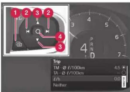
Open and navigate in the app menu ^2 using the right-hand steering wheel keypad.
1 App menu
2 Left/right
3 Up/down
4 Confirm
- Open the app menu in the instrument panel by pressing (1).
(The App menu cannot be opened while there is an unacknowledged message in the instrument panel. The message must be confirmed before the App menu can be opened.)
- Navigate to the trip computer app by moving left or right using (2).
The top four menu rows show measured values for trip odometer TM. The next four menu rows show measured values for trip odometer TA. Scroll up or down in the list using (3).
- Scroll down to the option buttons to choose which information to show in the instrument panel:
• Distance to empty tank
- Odometer
- Mileage for trip odometer TM, TA or no display of mileage
- Current fuel consumption, average fuel consumption for TM or TA, or no display of fuel consumption
• Tourist (alternative speedometer).
• Distance to discharged battery
Select or clear a selection using the O button (4). The change will apply immediately.
Related information
- Trip computer (p. 89)
- Resetting the trip odometer (p. 92)
DISPLAYS AND VOICE CONTROL
Resetting the trip odometer
Resetting the trip odometer using the left-side steering wheel lever.

- Reset all information in trip odometer TM (i.e. mileage, average fuel consumption, average speed and driving time) by pressing and holding the RESET button on the left-hand steering wheel lever.
Tapping the RESET button only resets the distance driven.
The TA trip odometer can not be manually reset. It resets automatically if the vehicle is not used for four hours or more.
Related information
- Trip computer (p. 89)
Displaying trip statistics in the center display
Trip computer statistics can be displayed graphically in the center display, providing an overview that facilitates more fuel-efficient driving.

Open the Driver performance app in the App view to display trip statistics.
Each bar in the graph represents a driving distance of 1 kilometers, 10 kilometers or
100 kilometers (or miles). The bars are added from the right as you drive. The bar at the far right shows the data for the current trip.
Average fuel consumption and total driving time are calculated from the most recent reset of the trip statistics.
Fuel and electricity consumption are shown in separate graphs. The electricity consumption shows "net" consumption, i.e. consumed current minus regenerated current generated by braking.
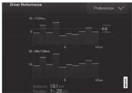
bar
Driver Performance | Driver | Speed (10-100km) | Power Consumption (kWh/100km) | | :--- | :--- | :--- | | Top | 5 | 6.8 | | Bottom | 10 | 10.1 |Trip computer statistics ^3 .
Related information
• Trip statistics settings (p. 93)
- Trip computer (p. 89)
Trip statistics settings
Trip statistics settings can be reset or adjusted.
- Open the Driver performance app in the App view to display trip statistics.
-
Tap Preferences to
-
change the graph scale. Select 1, 10 or 100 km/miles for the bar.
- reset data after each trip. Performed when the vehicle remains stationary for more than 4 hours.
- reset data for current trip.
Trip statistics, calculated average consumption, and total driving time are always reset simultaneously.
Unit standards for distance, speed, etc. can be changed via system settings in the center display.
Related information
- Displaying trip statistics in the center display (p. 92)
- Trip computer (p. 89)
- Resetting the trip odometer (p. 92)
Date and time
The clock is displayed in both the instrument panel and the center display.
Location of clock

Location of clock in 12" and 8" instrument panels.
In the center display, the clock is located at the top right of the status bar.
Certain messages and other information may obscure the clock in the instrument panel.
Time and date settings
- Select Settings System Data and
Time in the center display's Top view to change settings for time and date format.
Adjust the time and date by tapping the up or down arrows on the touchscreen.
Automatic time for vehicles with GPS
When the vehicle is equipped with a navigation system, Auto Time is also available. The time zone will then be automatically set to the vehicle's location. In some navigation systems, the current location must also be set to determine the correct time zone. If Auto Time is not selected, the time and date can be adjusted using the up and down arrows on the touchscreen.
Daylight savings time
In some countries, an automatic change to daylight savings time can be selected by activating Auto. For other countries, daylight savings time can be changed by selecting On or Off.
Related information
• Instrument panel (p. 84)
- Changing settings in the center display's Top view (p. 132)
DISPLAYS AND VOICE CONTROL
Ambient temperature sensor
The ambient temperature is shown in the instrument panel.
The sensor detects the temperature outside the vehicle.
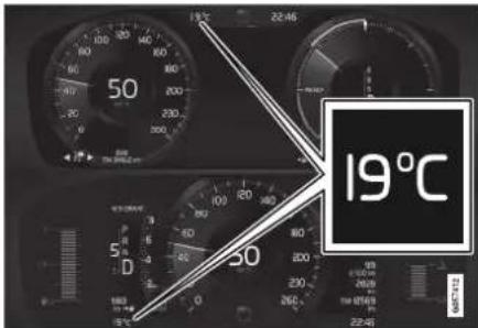
Location of the ambient temperature sensor in 12" and 8" instrument panels.
If the vehicle has been stationary, the sensor reading may be higher than the actual temperature.

When the ambient temperature is between -5^ and +2^ (23°F and 36°F), a snowflake symbol will be displayed in the instrument panel as a
warning for possible slippery conditions.
The snowflake symbol is also temporarily lit in the head-up display if the vehicle is equipped with one.
Change the measurement standard for the temperature sensor etc. via system settings in the center display's Top view.
Related information
• Instrument panel (p. 84)
- Changing system units of measurement (p. 132)
Indicator symbols in the instrument panel
The indicator symbols alert the driver that a function has been activated, that a system is running, or that a fault or error may have occurred.
Symbol Meaning

Information, see the message in the display
The information symbol illuminates and a message is displayed in the instrument panel if one of the vehicle's systems requires the driver's attention. The information symbol may also illuminate in combination with other symbols.

Fault in brake system
This symbol illuminates if there is a problem with the parking brake.

B
Symbol Meaning

A

B

A

B
Fault in ABS system
If this symbol is illuminated, the ABS system is malfunctioning. The vehicle's regular brakes will still work, but without the ABS function.
Auto-brake on
This symbol illuminates when the function is activated and the brakes or parking brakes are being used. The brakes hold the vehicle at a standstill after it has stopped.
Symbol Meaning

Tire pressure system
This symbol illuminates to indicate low tire pressure. If there is a fault in the tire pressure system, the symbol will first flash for approximately 1 minute and then glow steadily. This may occur if the system cannot detect or alert the driver of low tire pressure as intended.

Emission control system
If this symbol illuminates after starting the engine, it could indicate a fault in the vehicle's emission control system. Have the vehicle checked by a workshop. Volvo recommends contacting an authorized Volvo workshop.

Left/right turn signals
These symbols flash when the turn signals are used.

Symbol Meaning

Parking lights
This symbol illuminates when the parking lights are on.

Fault in headlight system
This symbol illuminates if a fault has been detected in the ABL (Active Bending Lights) function or another fault in the headlight system.

Active high beams on
This symbol lights up in blue when the active high beams are on.

Active high beams off
This symbol lights up in white when the active high beams are off.

High beams on
This symbol illuminates when the high beams are on or flashed.

Active high beams on
This symbol lights up in blue when the active high beams are on. Parking lights are on.
DISPLAYS AND VOICE CONTROL
◀◀
| Symbol | Meaning |
| Active high beams offThis symbol lights up in white when the active high beams are off.Parking lights are on. | |
| High beams onThis symbol illuminates when the high beams and parking lights are on. | |
| Rear fog light onThis symbol illuminates when the rear fog light is on. | |
| Rain sensor onThis symbol illuminates when the rain sensor is on. | |
| Preconditioning onThis symbol illuminates when the engine block/passenger compartment heater or air conditioning are preconditioning the vehicle. | |
| Stability systemThis symbol flashes when the stability system is actively working to stabilize the vehicle. If the symbol glows steadily, there is a fault in the system. |
| Symbol | Meaning |
| Active high beams offThis symbol lights up in white when the active high beams are off.Parking lights are on. | |
| High beams onThis symbol illuminates when the high beams and parking lights are on. | |
| Rear fog light onThis symbol illuminates when the rear fog light is on. | |
| Rain sensor onThis symbol illuminates when the rain sensor is on. | |
| Preconditioning onThis symbol illuminates when the engine block/passenger compartment heater or air conditioning are preconditioning the vehicle. | |
| Stability systemThis symbol flashes when the stability system is actively working to stabilize the vehicle. If the symbol glows steadily, there is a fault in the system. |
| Symbol Meaning | |
| Stability system, Sport modeThis symbol illuminates when Sport mode is activated. Sport mode offers a more active driving experience. | |
| Lane Keeping AidWhite symbol: Lane Keeping Aid is on and lane marker lines are detected.Gray symbol: Lane Keeping Aid is on but no lane marker lines are detected.Amber symbol: Lane Keeping Aid is alerting/intervening. | |
| Lane Keeping Aid and rain sensorWhite symbol: Lane Keeping Aid is on and lane marker lines are detected. The rain sensor is on.Gray symbol: Lane Keeping Aid is on but no lane marker lines are detected. The rain sensor is on. | |
| Symbol Meaning | |
| Stability system, Sport modeThis symbol illuminates when Sport mode is activated. Sport mode offers a more active driving experience. | |
| Lane Keeping AidWhite symbol: Lane Keeping Aid is on and lane marker lines are detected.Gray symbol: Lane Keeping Aid is on but no lane marker lines are detected.Amber symbol: Lane Keeping Aid is alerting/intervening. | |
| Lane Keeping Aid and rain sensorWhite symbol: Lane Keeping Aid is on and lane marker lines are detected. The rain sensor is on.Gray symbol: Lane Keeping Aid is on but no lane marker lines are detected. The rain sensor is on. | |
^ Canadian models.
B US models.
Related information
- Instrument panel (p. 84)
- Warning symbols in the instrument panel (p. 97)
Warning symbols in the instrument panel
The warning symbols alert the driver that an important function is activated or that a serious fault or error has occurred.
Symbol Meaning

WARNING
The red warning symbol illuminates to indicate that a fault has been detected that could affect safety and/or driveability. An explanatory message will be simultaneously displayed in the instrument panel. The warning symbol may also illuminate in combination with other symbols.

Seat belt reminder
This symbol will glow steadily or flash if the driver or front seat passenger has not fastened their seat belt or if anyone in the rear seat has removed their seat belt.
Symbol Meaning

Airbags
If this symbol remains illuminated or comes on while driving, a fault has been detected in one of the vehicle's safety systems. Read the message in the instrument panel. Volvo recommends contacting an authorized Volvo workshop.

Fault in brake system
If this symbol illuminates, the brake fluid level may be too low. Contact your nearest authorized workshop to have the brake fluid level checked and adjusted.
A

B

Parking brake on
This symbol glows steadily when the parking brake is applied.
A

A flashing symbol indicates that a fault has occurred. Read the message in the instrument panel.
Symbol Meaning

Low oil pressure
If this symbol illuminates while driving, the engine oil level is too low. Stop the engine immediately and check the engine oil level. Add oil if necessary. If the symbol illuminates and the oil level is normal, contact a workshop. Volvo recommends contacting an authorized Volvo workshop.

Generator not charging
This symbol illuminates during driving if a fault is detected in the electrical system. Contact a workshop. Volvo recommends contacting an authorized Volvo workshop.

Collision risk
City Safety warns the driver if there is a risk of a collision with another vehicle, pedestrian, cyclist or large animal.
^ Canadian models.
B US models.
Related information
- Indicator symbols in the instrument panel (p. 94)
• Instrument panel (p. 84)
DISPLAYS AND VOICE CONTROL
Instrument panel licenses
A license is an agreement on the right to conduct a certain activity or the right to use someone else's right according to terms and conditions specified in the agreement. The following text is Volvo's agreement with the manufacturer or developer.
Boost Software License 1.0
Permission is hereby granted, free of charge, to any person or organization obtaining a copy of the software and accompanying documentation covered by this license (the "Software") to use, reproduce, display, distribute, execute, and transmit the Software, and to prepare derivative works of the Software, and to permit third-parties to whom the Software is furnished to do so, all subject to the following: The copyright notices in the Software and this entire statement, including the above license grant, this restriction and the following disclaimer, must be included in all copies of the Software, in whole or in part, and all derivative works of the Software, unless such copies or derivative works are solely in the form of machine-executable object code generated by a source language processor.
THE SOFTWARE IS PROVIDED "AS IS", WITHOUT WARRANTY OF ANY KIND, EXPRESS OR IMPLIED, INCLUDING BUT NOT LIMITED TO THE WARRANTIES OF MERCHANTABILITY, FITNESS FOR A PARTICULAR PURPOSE, TITLE AND NON-INFRINGEMENT. IN NO EVENT SHALL THE
COPYRIGHT HOLDERS OR ANYONE DISTRIBUTING THE SOFTWARE BE LIABLE FOR ANY DAMAGES OR OTHER LIABILITY, WHETHER IN CONTRACT, TORT OR OTHERWISE, ARISING FROM, OUT OF OR IN CONNECTION WITH THE SOFTWARE OR THE USE OR OTHER DEALINGS IN THE SOFTWARE.
BSD 4-clause "Original" or "Old" License
Copyright (c) 1982, 1986, 1990, 1991, 1993 The Regents of the University of California. All rights reserved.
Redistribution and use in source and binary forms, with or without modification, are permitted provided that the following conditions are met:
- Redistributions of source code must retain the above copyright notice, this list of conditions and the following disclaimer.
- Redistributions in binary form must reproduce the above copyright notice, this list of conditions and the following disclaimer in the documentation and/or other materials provided with the distribution.
- All advertising materials mentioning features or use of this software must display the following acknowledgement: This product includes software developed by the University of California, Berkeley and its contributors.
- Neither the name of the University nor the names of its contributors may be used to
endorse or promote products derived from this software without specific prior written permission.
THIS SOFTWARE IS PROVIDED BY THE REGENTS AND CONTRIBUTORS "AS IS" AND ANY EXPRESS OR IMPLIED WARRANTIES, INCLUDING, BUT NOT LIMITED TO, THE IMPLIED WARRANTIES OF MERCHANTABILITY AND FITNESS FOR A PARTICULAR PURPOSE ARE DISCLAIMED. IN NO EVENT SHALL THE REGENTS OR CONTRIBUTORS BE LIABLE FOR ANY DIRECT, INDIRECT, INCIDENTAL, SPECIAL, EXEMPLARY, OR CONSEQUENTIAL DAMAGES (INCLUDING, BUT NOT LIMITED TO, PROCUREMENT OF SUBSTITUTE GOODS OR SERVICES; LOSS OF USE, DATA, OR PROFITS; OR BUSINESS INTERRUPTION) HOWEVER CAUSED AND ON ANY THEORY OF LIABILITY, WHETHER IN CONTRACT, STRICT LIABILITY, OR TORT (INCLUDING NEGLIGENCE OR OTHERWISE) ARISING IN ANY WAY OUT OF THE USE OF THIS SOFTWARE, EVEN IF ADVISED OF THE POSSIBILITY OF SUCH DAMAGE.
BSD 3-clause "New" or "Revised" License
Copyright (c) 2011-2014, Yann Collet.
Redistribution and use in source and binary forms, with or without modification, are permitted provided that the following conditions are met:
- Redistributions of source code must retain the above copyright notice, this list of conditions and the following disclaimer.
- Redistributions in binary form must reproduce the above copyright notice, this list of conditions and the following disclaimer in the documentation and/or other materials provided with the distribution.
- Neither the name of the organisation nor the names of its contributors may be used to endorse or promote products derive from this software without specific prior written permission.
THIS SOFTWARE IS PROVIDED BY THE COPYRIGHT HOLDERS AND CONTRIBUTORS "AS IS" AND ANY EXPRESS OR IMPLIED WARRANTIES, INCLUDING, BUT NOT LIMITED TO, THE IMPLIED WARRANTIES OF MERCHANTABILITY AND FITNESS FOR A PARTICULAR PURPOSE ARE DISCLAIMED. IN NO EVENT SHALL THE COPYRIGHT HOLDER OR CONTRIBUTORS BE LIABLE FOR ANY DIRECT, INDIRECT, INCIDENTAL, SPECIAL, EXEMPLARY, OR CONSEQUENTIAL DAMAGES (INCLUDING, BUT NOT LIMITED TO, PROCUREMENT OF SUBSTITUTE GOODS OR
SERVICES; LOSS OF USE, DATA, OR PROFITS; OR BUSINESS INTERRUPTION) HOWEVER CAUSED AND ON ANY THEORY OF LIABILITY, WHETHER IN CONTRACT, STRICT LIABILITY, OR TORT (INCLUDING NEGLIGENCE OR OTHERWISE) ARISING IN ANY WAY OUT OF THE USE OF THIS SOFTWARE, EVEN IF ADVISED OF THE POSSIBILITY OF SUCH DAMAGE.
BSD 2-clause "Simplified" license
Copyright (c)
Redistribution and use in source and binary forms, with or without modification, are permitted provided that the following conditions are met:
- Redistributions of source code must retain the above copyright notice, this list of conditions and the following disclaimer.
- Redistributions in binary form must reproduce the above copyright notice, this list of conditions and the following disclaimer in the documentation and/or other materials provided with the distribution.
THIS SOFTWARE IS PROVIDED BY THE COPYRIGHT HOLDERS AND CONTRIBUTORS "AS IS" AND ANY EXPRESS OR IMPLIED WARRANTIES, INCLUDING, BUT NOT LIMITED TO, THE IMPLIED WARRANTIES OF MERCHANTABILITY AND FITNESS FOR A PARTICULAR PURPOSE ARE DISCLAIMED. IN NO EVENT SHALL THE COPYRIGHT OWNER
OR CONTRIBUTORS BE LIABLE FOR ANY DIRECT, INDIRECT, INCIDENTAL, SPECIAL, EXEMPLARY, OR CONSEQUENTIAL DAMAGES (INCLUDING, BUT NOT LIMITED TO, PROCUREMENT OF SUBSTITUTE GOODS OR SERVICES; LOSS OF USE, DATA, OR PROFITS; OR BUSINESS INTERRUPTION) HOWEVER CAUSED AND ON ANY THEORY OF LIABILITY, WHETHER IN CONTRACT, STRICT LIABILITY, OR TORT (INCLUDING NEGLIGENCE OR OTHERWISE) ARISING IN ANY WAY OUT OF THE USE OF THIS SOFTWARE, EVEN IF ADVISED OF THE POSSIBILITY OF SUCH DAMAGE.
The views and conclusions contained in the software and documentation are those of the authors and should not be interpreted as representing official policies, either expressed or implied, of the FreeBSD Project.
DISPLAYS AND VOICE CONTROL
FreeType Project License
1.1 Copyright 1996-1999 by David Turner, Robert Wilhelm, and Werner Lemberg Introduction The FreeType Project is distributed in several archive packages; some of them may contain, in addition to the FreeType font engine, various tools and contributions which rely on, or relate to, the FreeType Project. This license applies to all files found in such packages, and which do not fall under their own explicit license. The license affects thus the FreeType font engine, the test programs, documentation and makefiles, at the very least. This license was inspired by the BSD, Artistic, and IJG (Independent JPEG Group) licenses, which all encourage inclusion and use of free software in commercial and freeware products alike. As a consequence, its main points are that: o We don't promise that this software works. However, we are be interested in any kind of bug reports. ('as is' distribution) o You can use this software for whatever you want, in parts or full form, without having to pay us. ('royalty-free' usage) o You may not pretend that you wrote this software. If you use it, or only parts of it, in a program, you must acknowledge somewhere in your documentation that you've used the FreeType code. ('credits') We specifically permit and encourage the inclusion of this software, with or without modifications, in commercial products,
provided that all warranty or liability claims are assumed by the product vendor. Legal Terms 0. Definitions Throughout this license, the terms 'package', 'FreeType Project', and 'FreeType archive' refer to the set of files originally distributed by the authors (David Turner, Robert Wilhelm, and Werner Lemberg) as the 'FreeType project', be they named as alpha, beta or final release. 'You' refers to the licensee, or person using the project, where 'using' is a generic term including compiling the project's source code as well as linking it to form a 'program' or 'executable'. This program is referred to as 'a program using the FreeType engine'. This license applies to all files distributed in the original FreeType archive, including all source code, binaries and documentation, unless otherwise stated in the file in its original, unmodified form as distributed in the original archive. If you are unsure whether or not a particular file is covered by this license, you must contact us to verify this. The FreeType project is copyright (C) 1996-1999 by David Turner, Robert Wilhelm, and Werner Lemberg. All rights reserved except as specified below. 1. No Warranty THE FREETYPE ARCHIVE IS PROVIDED 'AS IS' WITHOUT WARRANTY OF ANY KIND, EITHER EXPRESSED OR IMPLIED, INCLUDING, BUT NOT LIMITED TO, WARRANTIES OF MERCHANTABILITY AND FITNESS FOR A PARTICULAR PURPOSE.
IN NO EVENT WILL ANY OF THE AUTHORS OR COPYRIGHT HOLDERS BE LIABLE FOR ANY DAMAGES CAUSED BY THE USE OR THE INABILITY TO USE, OF THE FREETYPE PROJECT. As you have not signed this license, you are not required to accept it. However, as the FreeType project is copyrighted material, only this license, or another one contracted with the authors, grants you the right to use, distribute, and modify it. Therefore, by using, distributing, or modifying the FreeType project, you indicate that you understand and accept all the terms of this license.
- Redistribution Redistribution and use in source and binary forms, with or without modification, are permitted provided that the following conditions are met: o Redistribution of source code must retain this license file ('licence.txt') unaltered; any additions, deletions or changes to the original files must be clearly indicated in accompanying documentation. The copyright notices of the unaltered, original files must be preserved in all copies of source files. o Redistribution in binary form must provide a disclaimer that states that the software is based in part of the work of the FreeType Team, in the distribution documentation. We also encourage you to put an URL to the FreeType web page in your documentation, though this isn't mandatory. These conditions apply to any software derived from or based
on the FreeType code, not just the unmodified files. If you use our work, you must acknowledge us. However, no fee need be paid to us.
-
Advertising The names of FreeType's authors and contributors may not be used to endorse or promote products derived from this software without specific prior written permission. We suggest, but do not require, that you use one or more of the following phrases to refer to this software in your documentation or advertising materials: 'FreeType Project', 'FreeType Engine', 'FreeType library', or 'FreeType Distribution'.
-
Contacts There are two mailing lists related to FreeType: o freetype@freetype.org Discusses general use and applications of FreeType, as well as future and wanted additions to the library and distribution. If you are looking for support, start in this list if you haven't found anything to help you in the documentation. o devel@freetype.org Discusses bugs, as well as engine internals, design issues, specific licenses, porting, etc. o http://www.freetype.org Holds the current FreeType web page, which will allow you to download our latest development version and read online documentation. You can also contact us individually at: David Turner david.turner@freetype.org Robert Wilhelm robert.wilhelm@freetype.org Werner Lemberg werner.lemberg@freetype.org
Libpng License
This copy of the libpng notices is provided for your convenience. In case of any discrepancy between this copy and the notices in the file png.h that is included in the libpng distribution, the latter shall prevail.
COPYRIGHT NOTICE, DISCLAIMER, and LICENSE:
If you modify libpng you may insert additional notices immediately following this sentence. libpng versions 1.0.7, July 1, 2000, through 1.0.13, April 15, 2002, are Copyright (c) 2000-2002 Glenn Randers-Pehrson and are distributed according to the same disclaimer and license as libpng-1.0.6 with the following individuals added to the list of Contributing Authors
Simon-Pierre Cadieux
Eric S. Raymond
Gilles Vollant
and with the following additions to the disclaimer:
There is no warranty against interference with your enjoyment of the library or against infringement. There is no warranty that our efforts or the library will fulfill any of your particular purposes or needs. This library is provided with all faults, and the entire risk of satisfactory quality, performance, accuracy, and effort is with the user.
libpng versions 0.97, January 1998, through 1.0.6, March 20, 2000, are Copyright (c) 1998, 1999 Glenn Randers-Pehrson, and are distributed according to the same disclaimer and license as libpng-0.96, with the following individuals added to the list of Contributing Authors:
Tom Lane
Glenn Randers-Pehrson
Willem van Schaik
libpng versions 0.89, June 1996, through 0.96, May 1997, are Copyright (c) 1996, 1997 Andreas Dilger Distributed according to the same disclaimer and license as libpng-0.88, with the following individuals added to the list of Contributing Authors:
John Bowler
Kevin Bracey
Sam Bushell
Magnus Holmgren
Greg Roelofs
Tom Tanner
libpng versions 0.5, May 1995, through 0.88, January 1996, are Copyright (c) 1995, 1996 Guy Eric Schalnat, Group 42, Inc.
▶▶
DISPLAYS AND VOICE CONTROL
For the purposes of this copyright and license, "Contributing Authors" is defined as the following set of individuals:
Andreas Dilger
Dave Martindale
Guy Eric Schalnat
Paul Schmidt
Tim Wegner
The PNG Reference Library is supplied "AS IS". The Contributing Authors and Group 42, Inc. disclaim all warranties, expressed or implied, including, without limitation, the warranties of merchantability and of fitness for any purpose. The Contributing Authors and Group 42, Inc. assume no liability for direct, indirect, incidental, special, exemplary, or consequential damages, which may result from the use of the PNG Reference Library, even if advised of the possibility of such damage.
Permission is hereby granted to use, copy, modify, and distribute this source code, or portions hereof, for any purpose, without fee, subject to the following restrictions:
-
The origin of this source code must not be misrepresented.
-
Altered versions must be plainly marked as such and must not be misrepresented as being the original source.
-
This Copyright notice may not be removed or altered from any source or altered source distribution.
The Contributing Authors and Group 42, Inc. specifically permit, without fee, and encourage the use of this source code as a component to supporting the PNG file format in commercial products. If you use this source code in a product, acknowledgment is not required but would be appreciated.
A "png_get_copyright" function is available, for convenient use in "about" boxes and the like: printf("%s", png_get_copyright(NULL));
Also, the PNG logo (in PNG format, of course) is supplied in the files "pngbar.png" and "pngbar.jpg (88x31) and "pngnow.png" (98x31).
Libpng is OSI Certified Open Source Software. OSI Certified Open Source is a certification mark of the Open Source Initiative.
Glenn Randers-Pehrson randeg@alum.rpi.edu April 15, 2002
MIT License
Copyright (c)
Permission is hereby granted, free of charge, to any person obtaining a copy of this software and associated documentation files (the "Software"), to deal in the Software without restriction, including without limitation the rights to use, copy, modify, merge, publish, distribute,
sublicense, and/or sell copies of the Software, and to permit persons to whom the Software is furnished to do so, subject to the following conditions:
The above copyright notice and this permission notice shall be included in all copies or substantial portions of the Software.
THE SOFTWARE IS PROVIDED "AS IS", WITHOUT WARRANTY OF ANY KIND, EXPRESS OR IMPLIED, INCLUDING BUT NOT LIMITED TO THE WARRANTIES OF MERCHANTABILITY, FITNESS FOR A PARTICULAR PURPOSE AND NONINFRINGEMENT. IN NO EVENT SHALL THE AUTHORS OR COPYRIGHT HOLDERS BE LIABLE FOR ANY CLAIM, DAMAGES OR OTHER LIABILITY, WHETHER IN AN ACTION OF CONTRACT, TORT OR OTHERWISE, ARISING FROM, OUT OF OR IN CONNECTION WITH THE SOFTWARE OR THE USE OR OTHER DEALINGS IN THE SOFTWARE.
zlib License
The zlib/libpng License Copyright (c)
This software is provided 'as-is', without any express or implied warranty. In no event will the authors be held liable for any damages arising from the use of this software.
Permission is granted to anyone to use this software for any purpose, including commercial applications, and to alter it and redistribute it freely, subject to the following restrictions:
- The origin of this software must not be misrepresented; you must not claim that you wrote the original software. If you use this software in a product, an acknowledgment in the product documentation would be appreciated but is not required.
- Altered source versions must be plainly marked as such, and must not be misrepresented as being the original software.
- This notice may not be removed or altered from any source distribution.
SGI Free Software B License Version 2.0.
SGI FREE SOFTWARE LICENSE B (Version 2.0, Sept. 18, 2008)
Copyright (C) [dates of first publication] Silicon Graphics, Inc. All Rights Reserved. Permission is hereby granted, free of charge, to any person obtaining a copy of this software and associated documentation files (the "Software"), to deal in the Software without restriction, including without limitation the rights to use, copy, modify, merge, publish, distribute, sublicense, and/or sell copies of the Software, and to permit persons to whom the Software is furnished to do so, subject to the following conditions: The above copyright notice including the dates of first publication and either this permission notice or a reference to http://oss.sgi.com/projects/FreeB/ shall be included in all copies or substantial portions of the Software.
THE SOFTWARE IS PROVIDED "AS IS", WITHOUT WARRANTY OF ANY KIND, EXPRESS OR IMPLIED, INCLUDING BUT NOT LIMITED TO THE WARRANTIES OF MERCHANTABILITY, FITNESS FOR A PARTICULAR PURPOSE AND NONINFRINGEMENT. IN NO EVENT SHALL SILICON GRAPHICS, INC. BE LIABLE FOR ANY CLAIM, DAMAGES OR OTHER LIABILITY, WHETHER IN AN ACTION OF CONTRACT, TORT OR OTHERWISE, ARISING FROM, OUT OF OR IN CONNECTION WITH THE SOFTWARE OR THE USE OR OTHER DEALINGS IN THE SOFTWARE.
Except as contained in this notice, the name of Silicon Graphics, Inc. shall not be used in advertising or otherwise to promote the sale, use or other dealings in this Software without prior written authorization from Silicon Graphics, Inc.
Related information
• Instrument panel (p. 84)
App menu in instrument panel
The application menu (App menu) in the instrument panel provides quick access to commonly used functions for certain apps.

The App menu in the instrument panel can be used instead of the center display. The illustration is generic - layout may vary.
The App menu is displayed in the instrument panel and is controlled using the right-side steering wheel keypad. The app menu makes it easier to switch between different apps or functions within the apps without having to let go of the steering wheel.
App menu functions
Different apps provide access to different types of functions. The following apps and their functions can be controlled from the App menu:
▶▶
DISPLAYS AND VOICE CONTROL
◀◀
| App Functions | |
| Trip computer | Select a trip odometer, change instrument panel display settings, etc. |
| Media player | Select active source for media player. |
| Phone Call | contact from the call list. |
| Navigation Guide to destination, etc. | |
Related information
• Instrument panel (p. 84)
• Center display overview (p. 109)
- Handling the App menu in the instrument panel (p. 104)
Handling the App menu in the instrument panel
The App (application) menu in the instrument panel is controlled using the right-side steering wheel keypad.
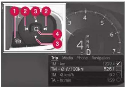
App menu and right-side steering wheel keypad.
1 Open/close
2 Left/right
3 Up/down
4 Confirm
Opening and closing the app menu
- Tap open/close (1).
(The App menu cannot be opened while there is an unacknowledged message in the instrument panel. The message must be confirmed before the App menu can be opened.) >The App men opens/closes.
The App menu turns off automatically after a period of inactivity or after certain selections are made.
Navigating and making selections in the App menu
- Navigate among the apps available by pressing the left/right arrow keys (2).
Functions for the previous/next app will be shown in the App menu.
- Scroll through the functions for the selected app using the up or down arrows (3).
- Confirm or make a selection for the function by pressing confirm (4).
The function will be activated and, for some selections, the App menu will then close.
The next time the App menu is opened, the functions for the most recently selected app will be displayed automatically.
Related information
• App menu in instrument panel (p. 103)
- Messages in the instrument panel (p. 105)
Messages in the instrument panel
The instrument panel shows messages in certain circumstances to inform or assist the driver.
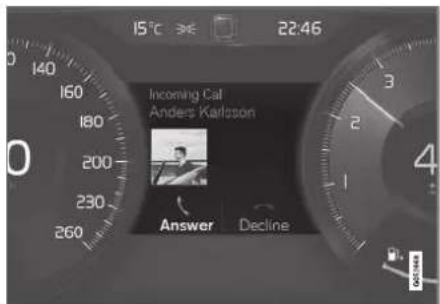
Message in the instrument panel.
High-priority messages for the driver are displayed in the instrument panel.
The messages may appear in different parts of the instrument panel depending on what other information is currently being displayed. The message will disappear from the instrument panel after a short period of time or after it has been acknowledged or any required action has been taken. Messages that need to be saved are stored in the Car Status app, which can be opened from the App view in the center display.
The message may be shown along with graphics, symbols or buttons to e.g. acknowledge the message or accept a request.
Service messages
The following table lists a selection of important service messages and what they mean.
| Message Meaning | |
| Stop safely^A | Stop and switch off the engine. Serious risk of damage - contact a work- shopB. |
| Turn off engine^A | Stop and switch off the engine. Serious risk of damage - contact a work- shopB. |
| Service urgent Drive to work- shopA | Contact a workshopBto have the vehicle inspected immediately. |
| Service requiredA | Contact a workshopBto have the vehicle inspected as soon as possible. |
| Regular main- tenance Book time for maintenance | Time for service - contact a workshopB. Shown before the next service date. |
| Regular main- tenance Time for main- tenance | Time for service - contact a workshopB. Shown on the next service date. |
| Regular maintenance | Time for service - contact a workshopB. Shown when the date for service has passed. |
| Maintenance overdue | |
| Temporarily off^A | A function has been temporarily deactivated and will be reactivated automatically while driving or after the engine is restarted. |
A Part of message, shown along with information on the location of the problem.
^3 An authorized Volvo workshop is recommended.
Related information
- Handling messages in the instrument panel (p. 106)
- Handling messages saved from the instrument panel (p. 107)
- Messages in the center display (p. 140)
Handling messages in the instrument panel
Messages in the instrument panel are controlled using the right-side steering wheel keypad.

Messages in the instrument panel and the right-side steering wheel keypad.
1 Left/right
2 Confirm
Some messages in the instrument panel contain one or more buttons for e.g. confirming the message or accepting a request.
Handling new messages
For messages with buttons:
-
Navigate among the buttons available by pressing the left/right arrow keys (1).
-
Confirm your selection by pressing confirm (2).
The message will disappear from the instrument panel.
For messages without buttons:
- Close the message by pressing confirm (2) or let the message automatically time-out after a short period.
The message will disappear from the instrument panel.
Messages that need to be saved are stored in the Car Status app, which can be opened from the App view in the center display. The message Vehicle message stored in Car Status app will simultaneously appear in the center display.
Related information
- Messages in the instrument panel (p. 105)
- Handling messages saved from the instrument panel (p. 107)
- Messages in the center display (p. 140)
Handling messages saved from the instrument panel
Messages saved from the instrument panel and center displays are handled in the center display.

Saved messages can be viewed in the Car Status app.

The messages displayed in the instrument panel that need to be saved are stored in the Car Status app in the center display. The message Vehicle message stored in Car
Status app will simultaneously
appear in the center display.
Reading saved messages
To read a saved message immediately:
- Tap the button to the right of the message Vehicle message stored in Car Status app in the center display.
The saved message will be displayed in the Car Status app.
To read saved messages at a later time:
- Open the Car Status app from App view in the center display.
The app will open in the bottom tile of Home view.
- Select the Messages tab in the app.
A list of saved messages will be displayed.
- Tap a message to expand/minimize it.
More information about the message will appear in the list and the image to the left of the app will display information about the message in graphic form.
Handling saved messages
In expanded form, some messages have two buttons available for booking service or reading the Owner's Manual.
Booking service for saved messages:
- With the message in expanded form, tap Request appoint.Call to make Appointment ^4 for assistance booking service.
With Request appoint.: The Appointments tab will open in the app and create a request for a service/repair appointment.
With Call to make Appointment: The phone app will open and call a service center to make an appointment for service or repairs.
Reading the Owner's Manual for saved messages:
- With the message in expanded form, tap Owner's manual to read relevant information about the message in the Owner's Manual.
The Owner's Manual will open in the center display and provide information related to the message.
Saved messages in the app are automatically deleted each time the engine is started.
DISPLAYS AND VOICE CONTROL
Related information
- Messages in the instrument panel (p. 105)
- Handling messages in the instrument panel (p. 106)
- Messages in the center display (p. 140)
DISPLAYS AND VOICE CONTROL
Center display overview
Many of the vehicle's functions can be controlled from the center display. The center display and its possibilities are presented below.
▶▶
109
DISPLAYS AND VOICE CONTROL
◀◀
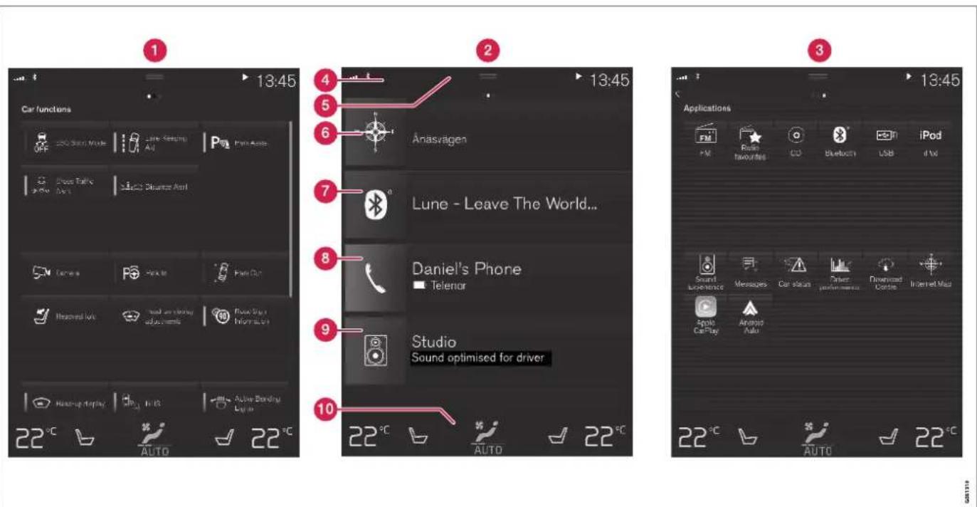
Three of the center display's basic views. Swipe to the right/left to access Function or App view ^5 .
1 Function view – vehicle functions that can be activated or deactivated with one tap. Certain
functions, called "trigger functions", open windows with settings options. One example
is the Camera. Settings for the head-up display* are also started from Function view, but
adjusted using the right-side steering wheel keypad.
② Home view – the initial view displayed when the screen is turned on.
3 App view – shows downloaded apps (third-party apps) as well as apps for integrated functions, such as FM radio. Tap an app icon to open that app.
4 Status bar – current vehicle activities are shown at the top of the screen. Network and connection information is shown to the left of the status bar. Media-related information, the clock and information about background activities are shown to the right.
5 Top view – pull the tab down to open Top view. From here, you can access Settings, Owner's manual, Profile and messages stored in the vehicle. In certain cases, contextual setting (e.g. Navigation Settings) and the contextual Owner's Manual (e.g. Navigation Manual) can also be accessed in Top view.
6 Navigation – takes you to map navigation with e.g. Sensus Navigation*. Tap the tile to expand it.
7 Media – most recently used media-related apps. Tap the tile to expand it.
8 Phone – used to access phone-related functions. Tap the tile to expand it.
9 Fourth tile – most recently used apps or vehicle functions not associated with the other tiles. Tap the tile to expand it.
10 Climate row - information and direct interaction to set temperature and seat heating for example*. Tap the symbol in the center of the climate bar to open Climate view and additional setting options.
Related information
• Handling the center display (p. 112)
• Navigating in the center display's views (p. 115)
• Function view in the center display (p. 122)
- Apps (p. 498)
- Symbols in the center display status bar (p. 124)
- Changing settings in the center display's Top view (p. 132)
- Opening contextual setting in the center display (p. 133)
• Owner's Manual in the center display (p. 17)
• Media player (p. 518)
- Phone (p. 532)
• Climate system controls (p. 215)
- Turning off and adjusting the volume of the center display system sounds (p. 131)
- Changing the appearance of the center display (p. 131)
• Changing system language (p. 132)
- Changing system units of measurement (p. 132)
• Cleaning the center display (p. 645)
- Messages in the center display (p. 140)
DISPLAYS AND VOICE CONTROL
Handling the center display
Many of the vehicle's functions and features can be controlled and adjusted from the center display. The center display is a touchscreen that reacts to taps and other gestures.
Using the center display's touchscreen
The touchscreen reacts differently depending on whether the user taps, drags or swipes the screen. It is possible to e.g. move between different views, mark objects, scroll in a list and move apps by touching the screen in various ways.
An infrared light curtain just above the surface of the screen enables the screen to detect when a finger is directly in front of the screen. This technology makes it possible to use the screen even while wearing gloves.
Two people can interact with the screen at the same time, e.g. to adjust climate system settings for both the driver and passenger sides.
CAUTION
Do not use sharp objects on the screen as this could cause scratches.
The following table presents the various procedures for using the screen:
| Procedure Gesture Result | |
 | Tap once. Marks an object, confirms a selection or activates a function. |
| Double-tap. Zooms in on a digital object, such as a map. | |
| Press and hold. Grabs hold of an object so it can be moved. Can be used to move apps or points on a map. Press and hold your finger on the screen and drag the object to the desired position. | |
 | Tap once with two fingers. Zooms out from a digital object, such as a map. |
DISPLAYS AND VOICE CONTROL
| Procedure Gesture Result | ||
 | Drag Moves between screen views or scrolls in a list, text or a view. Press and hold to drag apps or points on a map.Drag horizontally or vertically over the screen. | |
 | Swipe Moves between screen views or scrolls in a list, text or a view. Drag horizontally or vertically over the screen.Note that touching the upper part of the screen could cause Top view to open. | |
 | Stretch Zooms in. | |
 | Pinch Zooms out. | |
DISPLAYS AND VOICE CONTROL
Returning to Home view from another view
- Briefly press the home button below the center display.
The most recent Home view mode will be displayed.
- Press briefly again.
All of the Home view's tiles will return to standard mode.

NOTE
In Home view's standard mode – short press on the Home button. An animation describing access to the various views is shown on the screen.
Scrolling in lists, articles or views
A scroll indicator is displayed on the screen when it is possible to scroll up or down in the view.
Swipe down/up anywhere in the view.

The scroll indicator will be shown in the center display when it is possible to scroll in the view.
Using the center display controls

Temperature control.
Digital controls are available for many of the vehicle's functions. For example, to set the temperature:
• drag the control to the desired temperature,
- tap + or – to raise or lower the temperature by degrees, or
• tap the desired temperature on the control.
Related information
- Activating and deactivating the center display (p. 115)
- Moving apps and buttons in the center display (p. 124)
• Using the center display keyboard (p. 126)
Activating and deactivating the center display
The center display can be dimmed and reactivated using the home button under the screen.

Center display's home button.
When the home button is used, the screen will go dark and the touchscreen no longer reacts to touch. The climate bar will remain visible. All functions connected to the screen continue to operate, such as climate, audio, guiding* and apps. The center display screen can be cleaned when the display is dimmed. The dimming function can also be used to darken the screen so it is not a distraction while driving.
- Press and hold the button beneath the screen.
The screen will go dark (the climate bar will remain visible). All functions connected to the screen continue to operate.
- To reactivate the screen, briefly press the Home button.
The view that was displayed before the screen was turned off will be displayed again.
NOTE
The screen cannot be turned off when a prompt to perform an action is being displayed on the screen.
NOTE
The center display is turned off automatically when the engine is off and the driver's door is opened.
Related information
• Cleaning the center display (p. 645)
- Changing the appearance of the center display (p. 131)
• Center display overview (p. 109)
Navigating in the center display's views
There are five different basic views in the center display: Home view, Top view, Climate view, App view and Function view. The screen is automatically activated when the driver's door is opened.
Home view
Home view is the view displayed when the screen is activated. It consists of four tiles: Navigation, Media, Phone and a fourth tile.
An app or vehicle function selected from the App or Function views will start in the respective tile in Home view. For example, FM radio will start in the Media tile.
The fourth tile contains the most recently used app or vehicle function that is not related to the other three tiles.
The tiles display brief information about the respective apps.
i NOTE
When the vehicle is started, information on the current status of apps will be displayed in the respective tile in Home view.
▶▶
DISPLAYS AND VOICE CONTROL
◀◀

NOTE
In Home view's standard mode – short press on the Home button. An animation describing access to the various views is shown on the screen.

NOTE
When the vehicle is moving:
- Certain functions (e.g. using the center display's keyboard) may be deactivated.
- Certain texts (e.g. those generated by apps) will be shortened to three rows. Tap the Read out button to have the entire message read aloud.
- The message will be shortened to one row. Tap the Read out button to have the entire message read aloud.
Status bar
Current vehicle activities are shown at the top of the screen in the status bar. Network and connection information is shown to the left of the status bar. Media-related information, the clock and information about background activities are shown to the right.
Top view

Top view when expanded.
There is a tab in the center of the status bar at the top of the screen. Open Top view by tapping the tab or by dragging/swiping from the top of the screen downward.
Top view always provides access to:
- Settings
- Owner's manual
Profile
• The vehicle's stored messages.
In certain cases, Top view provides access to: - Contextual setting (e.g. Navigation Settings). Change settings directly in Top
view when an app (e.g. navigation) is being used.
- Contextual Owner's Manual (e.g. Navigation Manual). Access articles in the digital Owner's Manual related to the content shown on the screen, directly in Top view.
To exit Top view, tap the screen outside Top view, press the Home button or tap the screen at the bottom of Top view and swipe upward. The views behind will become visible again and can be used.

NOTE
The top view is not available at start-up/shutdown or when a message is being shown on the screen. Similarly, it is not available when the climate view is shown.
Climate view
The climate bar is always visible at the bottom of the screen. The most common climate settings can be made directly there, such as setting temperature and seat heating*.

Tap the symbol in the center of the climate bar to open Climate view and access additional climate system settings.

Tap the symbol to close Climate view and return to a previous view.
App view

App view showing the vehicle's apps.
Swipe the screen from right to left ^6 to access App view from Home view. This view displays downloaded apps (third-party apps) as well as apps for integrated functions, such as FM radio. Brief information will be displayed directly in App view for certain apps, such as unread text messages for Messages.
Tap an app to open it. It will then be opened in its associated tile, e.g. Media.
Depending on the number of apps, it is possible to scroll down in the App view. This is done by sweeping/dragging from the bottom upwards.
To return to Home view, swipe the screen from left to right ^6 or press the Home button.
Function view

Function view with buttons for various vehicle functions.
Swipe the screen from left to right ^6 to access Function view from Home view. From Function view, you can activate or deactivate various vehicle functions such as BLIS*, Lane Keeping Aid* and Park Assist*.
DISPLAYS AND VOICE CONTROL
If there are many functions, you can also scroll downward through the view. This is done by sweeping/dragging from the bottom upwards.
Unlike in App view, where you tap an app to open it, in Function view, tapping a function activates or deactivates it. Certain functions (trigger functions) open in their own window when tapped.
To return to Home view, swipe the screen from right to left ^6 or press the Home button.
Related information
• Handling tiles in the center display (p. 119)
- Symbols in the center display status bar (p. 124)
- Changing settings in the center display's Top view (p. 132)
- Opening contextual setting in the center display (p. 133)
• Owner's Manual in the center display (p. 17)
- Driver profiles (p. 136)
• Climate system controls (p. 215)
- Apps (p. 498)
• Function view in the center display (p. 122)
• Center display overview (p. 109)
DISPLAYS AND VOICE CONTROL
Handling tiles in the center display
Home view consists of four tiles: Navigation, Media, Phone and a fourth tile. These views can be expanded.
▶▶
DISPLAYS AND VOICE CONTROL
Expanding a tile from standard mode
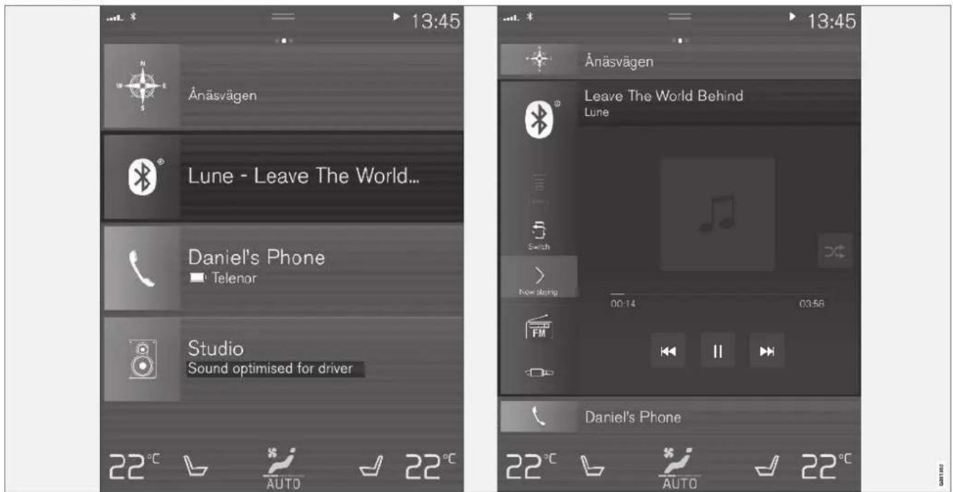
Standard mode and expanded mode of a tile in the center display.
Expanding a tile:
- For tiles Navigation, Media and Phone: Tap the screen anywhere in the tile. When a tile is expanded, the extra tile in Home view will be temporarily hidden. The other two tiles will be minimized and only show certain information. When the extra tile is tapped, the other three tiles are minimized and only certain information is displayed.
Expanded view provides access to the basic functions of the respective apps.
Closing an expanded tile:
- The tile can be closed in three different ways:
- Tap the top section of the expanded tile.
- Tap another tile (it will then be opened in expanded mode instead).
- Press briefly on the Home button under the center display.
Opening or closing a tile in full-screen mode
The fourth tile ^7 and tile for Navigation can be opened in full-screen mode to show additional information and possible settings.
When a tile is opened in full-screen mode, no information from the other tiles is displayed.

In expanded mode, open the app in full-screen mode. Tap the symbol.

To return to expanded mode, tap the symbol or press the Home button under the screen.
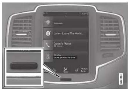
Center display's home button.
You can always press the Home button to return to Home view. To return to Home view's standard view from full-screen mode, press the Home button twice.
Related information
• Handling the center display (p. 112)
- Activating and deactivating the center display (p. 115)
- Navigating in the center display's views (p. 115)
DISPLAYS AND VOICE CONTROL
Function view in the center display
Function view, which is one of the center display's basic views, contains all of the vehicle's function buttons. From the Home view, navigate
to Function view by swiping from left to right over the screen ^8 .
Different types of buttons
There are three different types of buttons for vehicle functions; see below:
| Type of button Functions Vehicle function affected | |
| Function buttons Have On/Off modes.When a function is active, an LED indicator light will illuminate to the left of the button's icon.Press the button to turn the function on or off. | Most buttons in Function view are func-tion buttons. |
| Trigger buttons Do not have On/Off modes.Pressing a trigger button opens a window for the function. This can be, for example, a win-dow to change seat position. | CameraHeadrest FoldHead-up Display Adjustments |
| Parking buttons Have On/Off and scanning modes.Similar to function buttons, but have an extra mode for parking scanning. | Park InPark Out |
Button modes

When a function or parking button's LED indicator is green, the function is activated (on). For some functions, an additional text explaining the function will be shown when the function is initially activated. The text will be displayed for a few seconds and then the button will be displayed with the LED indicator illuminated.
For Lane Keeping Aid, for example, the text Works only at certain speeds will be displayed when the button is pressed.
Press the button once briefly to activate or deactivate the function.

The function is deactivated when the LED indicator light is switched off.

A warning triangle in the right-hand section of the button indicates that something is not working correctly.
Related information
• Handling the center display (p. 112)
- Navigating in the center display's views (p. 115)
DISPLAYS AND VOICE CONTROL
Moving apps and buttons in the center display
The apps and buttons for vehicle functions can be moved and organized in the App and Function views.
- Swipe from right to left ^9 to access App view or swipe from left to right ^9 to access Function view.
- Press and hold an app or button.
The app or button will change size and become slightly transparent. It can then be moved.
- Drag the app or button to an available position in the view.
A maximum of 48 rows can be used to position apps or buttons. To move an app or button outside the visible view, drag it to the bottom of the view. New rows will be added and the app or button can be placed in one of these.
Apps or buttons placed below the view's normal display will not be visible on the screen.
Swipe the screen to scroll up or down in the view to display information outside the view.
NOTE
Hide the apps that are rarely or never used by moving them far down, outside of the visible view. This makes it easier to find the apps used more frequently.
i NOTE
Apps and vehicle function buttons cannot be situated at spots already in use.
Related information
• Function view in the center display (p. 122)
- Apps (p. 498)
• Handling the center display (p. 112)
Symbols in the center display status bar
Overview of symbols displayed in the center display status bar.
The status bar shows current vehicle activities and in certain cases, also their status. Due to the limited space in the status bar, not all symbols will be displayed at all times.
| Symbol | Meaning |
| Connected to the Internet. | |
| Could not connect to Internet. | |
| R | Roaming activated. |
| Cell phone network signal strength. | |
| Bluetooth device connected. | |
| Bluetooth activated but no device connected. | |
| Information sent to and from GPS. | |
| Connected to Wi-Fi network. | |
| Tethering activated (Wi-Fi hotspot). This means that the vehicle shares an available Internet connection. | |
| Vehicle modem activated. | |
| USB sharing active. | |
| Action in progress. | |
| Timer for preconditioning active. ^A | |
| Audio source being played. | |
| Audio source paused. | |
| Phone call in progress. | |
| Audio source muted. | |
| NEWS | News broadcasts from current radio station. ^B |
| TP | Traffic information being received. ^B |
| 15:45 | Clock. |
A Only hybrid models.
3 Not available in all markets.
Related information
- Navigating in the center display's views (p. 115)
- Messages in the center display (p. 140)
• Internet-connected vehicle* (p. 541) - Connecting a device via the USB port (p. 525)
- Phone (p. 532)
• Date and time (p. 93)
DISPLAYS AND VOICE CONTROL
Using the center display keyboard
You can use the keyboard in the center display to enter characters or to switch to handwriting mode to "write" letters and characters on the screen.
The keyboard can be used to enter characters (letters, numbers, symbols, etc.) to e.g. send text messages from the vehicle, enter passwords or search for information in the digital Owner's Manual.
The keyboard will only appear when it is possible to enter text on the screen.

NOTE
The keyboard cannot be used while the vehicle is moving.
DISPLAYS AND VOICE CONTROL

The illustration shows an overview of some of the buttons that may be shown on the keyboard. The appearance may vary depending on language settings and the context in which the keyboard is used.
▶▶
DISPLAYS AND VOICE CONTROL
◀◀
1 Row showing suggestions for words or characters ^10 . The suggested words change as new letters are entered. Scroll through the list of suggested words by tapping the right or left arrows. Tap a suggestion to select it. Please note that this function is not available in all languages. When unavailable, this row will not be shown on the keyboard.
2 Available characters are adapted to the language selected for the keyboard (see number 7 below). Tap a character to enter it.
3 Different buttons are displayed here depending on the context in which the keyboard is used, e.g. @ to enter an email address or the return key to start a new line.
4 This button hides the keyboard. In cases where this is not possible, the button will not be displayed.
5 Used to enter uppercase letters. Tap once to enter one uppercase letter and then continue with lowercase letters. Tap twice for caps lock (all text will be entered in uppercase letters). Tap again to return the keyboard to lowercase letters. In this mode, the first letter after a period, exclamation point or question mark will be automatically entered in uppercase form. The first letter entered in text fields will also be uppercase. In text fields intended for names or addresses, each word will be automatically started with an
uppercase letter. In text fields intended for passwords, website addresses or email addresses, all letters will automatically be lowercase unless uppercase is selected.
6 Used to enter numbers. The number keyboard (2) will then be displayed. Tap ABC, which is shown instead of 123 in number mode, to return to the keyboard with letters, or #\~ to display the keyboard with special characters.
7 Used to change the keyboard language, e.g. EN. The available characters and word suggestions (1) vary depending on the selected language. In order to toggle between keyboard languages, the languages must first be added under Settings.
8 Space bar.
9 Delete. Tap to delete characters one at a time. Press and hold to delete multiple characters quickly.
10 Used to change to handwriting mode.
Tap the confirm button over the keyboard (not shown in illustration) once to confirm the text that has been entered. The button's appearance differs depending on the context.
Variants of letters or characters

Variants of a letter or character, e.g. é or è, can be entered by pressing and holding the letter or character. A box containing possible variants of the letter or character will appear. Tap the desired variant. If no variant is selected, the original letter/character will be used.
Related information
- Changing keyboard language in the center display (p. 129)
- Entering characters, letters and words by hand in the center display (p. 129)
• Handling the center display (p. 112)
• Handling text messages (p. 538)
Changing keyboard language in the center display
In order to toggle between keyboard languages, the languages must first be added under Settings.
Adding or deleting languages in Settings
The keyboard is automatically set to the same language as the system language. The keyboard language can be manually changed without affecting the system language.
- Tap Settings in Top view.
- Tap System System Languages and Units → Keyboard Layouts.
- Select one or more languages in the list.
It is now possible to toggle between the selected languages using the keyboard.
If no language has been selected under Settings, the keyboard will remain in the same language as the vehicle's system language.
Toggling between keyboard languages

If more than one language has been selected in Settings, the button in the keyboard can be used to switch between the different languages.
To toggle between keyboard languages from the list:
- Press and hold the button.
A list will appear.
- Select the desired language. If more than four languages have been selected under Settings, you can scroll through the list shown on the keyboard.
The keyboard and word suggestions will be adapted to the selected language.
To change keyboard language without displaying the list:
- Tap the button.
The keyboard layout will change to the next language in the list without displaying the list.
Related information
• Changing system language (p. 132)
• Using the center display keyboard (p. 126)
Entering characters, letters and words by hand in the center display
Characters, letters and words can be entered in the center display by handwriting them on the touchscreen.
Tap the button on the center display's keyboard to switch from the keyboard to handwriting mode.

① Space for entering characters/letters/words/parts of words.
② Text field displaying suggested characters or words ^11 as they are written on the screen (1).
DISPLAYS AND VOICE CONTROL
◀◀
3 Suggestions for characters/letters/words/parts of words. You can scroll through the list.
4 Space bar. Blank spaces can be created by writing a dash (−) in the field for handwritten letters (1). See "Writing blank spaces in free-text fields" below.
5 Delete. Tap once to erase one character/letter at a time. Wait a moment before tapping again to erase the next character, letter etc.
6 Return to the standard keyboard layout.
7 Switch off/on screen tap sounds.
8 Hide the keyboard. In cases where this is not possible, the button will not be displayed.
9 Change language for text input.
Handwriting characters/letters/words
- Write a character, a letter, a word or parts of a word in the field for handwritten letters (1). Write the word or part of the word vertically or horizontally.
A number of suggestions for characters, letters or words will be displayed (3). The most likely will be shown at the top of the list.
! CAUTION
Do not use sharp objects on the screen as this could cause scratches.
- The character/letter/word will be entered automatically after a short pause if no other action is taken.
The character/letter/word at the top of the list will be used. Tap one of the other characters/letters/words in the list to use it instead.
Erasing/changing handwritten characters/letters

Erase text in the text field (2) by swiping over the handwriting field (1).
- Characters/letters can be erased or changed in several ways:
- Tap the desired letter or word in the list (3).
- Tap the delete button (5) to erase the letter and start again.
- Swipe horizontally from right to left ^12 over the handwriting field (1). Erase several letters at once by swiping over the area several times.
- Tap the X box in the text field (2) to erase all written text.
New lines in free-text fields in handwriting mode

Create a new line by drawing above the characters in the handwriting field as shown in the illustration ^18 .
Writing blank spaces in free-text fields
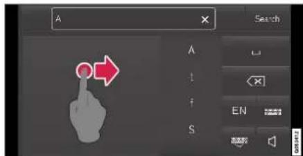
Make a blank space by drawing a line from left to right ^14 .
Related information
• Using the center display keyboard (p. 126)
Changing the appearance of the center display
The appearance of the center display can be changed by selecting a different theme.
- Tap Settings in the Top view.
- Tap My Car Displays Display Themes.
- Select a theme, e.g. Minimalistic or Chrome Rings.
In addition to these themes, you can also choose between Normal and Bright. In Normal, the background of the screen is dark and the text is light. This option is the default setting for all themes. If the bright version is selected, the background will be light and the text will be dark. This option can, for example, make the screen easier to see in bright daylight conditions.
These alternatives are always available for selection and are not affected by the ambient lighting.
Related information
- Changing settings in the center display's Top view (p. 132)
- Activating and deactivating the center display (p. 115)
• Cleaning the center display (p. 645)
Turning off and adjusting the volume of the center display system sounds
The volume of the center display system sounds can be adjusted or turned off completely.
- Tap Settings in the Top view in the center display.
- Tap Sound System Volumes.
- Pull the control under Touch Sounds to adjust the volume or turn off screen tap sounds. Pull the control to the desired sound level.
Related information
• Center display overview (p. 109)
- Changing settings in the center display's Top view (p. 132)
• Sound settings (p. 496)
DISPLAYS AND VOICE CONTROL
Changing system units of measurement
Unit settings are adjusted in the Settings menu in the center display.
- Tap Settings in the Top view in the center display.
- Proceed to System System Languages and Units → Units of Measurement.
-
Choose a measurement standard:
-
Metric - kilometers, liters and degrees Celsius.
- Imperial - miles, gallons and degrees Celsius.
• US - miles, gallons and degrees Fahrenheit.The units in the instrument panel, center display and head-up display are changed.
Related information
• Center display overview (p. 109)
- Changing settings in the center display's Top view (p. 132)
• Changing system language (p. 132)
Changing system language
Language settings are adjusted in the Settings menu in the center display.
NOTE
Changing languages in the center display could mean that certain owner's information will not comply with national or local laws and regulations. Do not change to a language that you do not fully understand, as this could make it difficult to navigate back through the menu.
- Tap Settings in the Top view in the center display.
- Proceed to System System Languages and Units.
- Select System Language. A voice control symbol indicates that the language can be used for voice commands.
Languages in the instrument panel, center display and head-up display are changed.
Related information
• Center display overview (p. 109)
- Changing settings in the center display's Top view (p. 132)
- Changing system units of measurement (p. 132)
Changing settings in the center display's Top view
You can change settings and information for many of the vehicle's functions via the center display.
- Open Top view by tapping the tab at the top of the screen or by dragging/swiping from the top of the screen downward.
- Tap Settings to open the Settings menu.
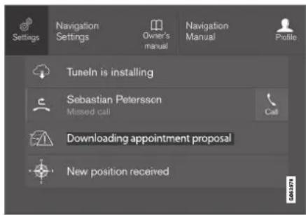
Top view with Settings button.
- Tap one of the categories and sub-categories to navigate to the desired setting.
- Change the setting(s). Different types of settings are changed in different ways.
Changes are saved immediately.
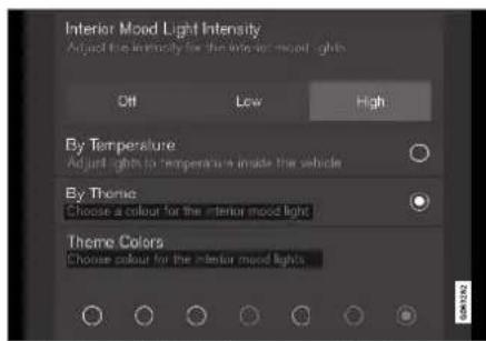
A sub-category in the Settings menu with various possible settings; has a multi-selection button and radio buttons.
Related information
• Center display overview (p. 109)
- Resetting center display settings (p. 134)
• Table of settings in the center display (p. 135)
Opening contextual setting in the center display
Most of the settings for the vehicle's basic apps can be changed directly in Top view in the center display via contextual settings.
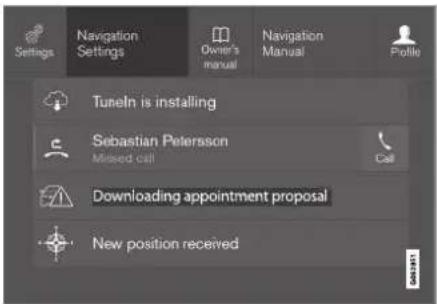
Top view with button for contextual settings.
Contextual setting is a shortcut for accessing specific settings related to the active function displayed on the screen. Apps that are factory-installed in your vehicle, e.g. FM radio and USB, are part of Sensus and are used to control the vehicle's integrated functions. The settings for these apps can be changed directly via contextual setting in Top view.
When contextual setting is available:
- Pull down Top view when an app is in expanded form, e.g. Navigation.
2. Tap Navigation Settings.
The navigation settings page will open.
- Change the desired settings and confirm.
Tap Close or press the Home button under the center display to close Settings view.
Most of the vehicle's basic apps have this contextual setting option, but not all.
Third-party apps
Third-party apps are apps that are not factory-installed in the vehicle's system, but can be downloaded, e.g. Volvo ID. Settings for these apps are changed in the apps themselves, not in Top view.
Related information
- Changing settings in the center display's Top view (p. 132)
• Center display overview (p. 109) - Resetting center display settings (p. 134)
• Download apps (p. 499)
DISPLAYS AND VOICE CONTROL
Resetting user data when the vehicle changes owners
If the vehicle changes owners, all user data and system settings should be reset to factory defaults.
Vehicle settings can be reset at different levels. Reset all user data and system settings to their original factory defaults when the vehicle changes owner. It is also important to change the owner of the Volvo On Call service.
Related information
- Resetting center display settings (p. 134)
- Resetting driver profile settings (p. 139)
Resetting center display settings
All settings made in the center display's Settings menu can be reset to default values.
Two types of reset
There are two ways to reset the settings in the Settings menu:
- Factory Reset- erases all data and files and resets all settings to factory default.
- Reset Personal Settings- erases personal data and resets personalized settings to factory default.
Resetting settings
Follow these instructions to reset the settings.
NOTE
Factory Reset is only possible when the vehicle is stationary.
- Tap Settings in the Top view in the center display.
- Proceed to System Factory Reset.
-
Select the type of reset you would like to do.
A pop-up window will appear.
-
Tap OK to confirm the reset.
For Reset Personal Settings, confirm the reset by tapping Reset for the active profile or Reset for all profiles.
The selected settings will be reset.
Related information
• Center display overview (p. 109)
- Changing settings in the center display's Top view (p. 132)
- Table of settings in the center display (p. 135)
Table of settings in the center display
The center display's Settings menu has a number of main categories and sub-categories that contain settings and information for many of the vehicle's features and functions.
There are seven main categories: My Car, Sound, Navigation, Media, Communication, Climate and System.
Each category, in turn, contains a number of sub-categories and possible settings. The table below shows the first level of sub-categories. The possible settings for a function or an area are described in more detail in their respective sections of the Owner's Manual.
Some settings are personal, which means that they can be saved to a Driver Profiles. Others are global, which means that they are not linked to a driver profile.
My Car
| Sub-categories |
| Displays |
| IntelliSafe |
| Drive Preferences/Individual Drive Mode* |
| Lights and Lighting |
| Mirrors and Convenience |
| Sub-categories |
| Locking |
| Parking Brake and Suspension |
| Wipers |
| Sound |
| Sub-categories |
| Tone |
| Balance |
| System Volumes |
| Navigation |
| Sub-categories |
| Map |
| Route and Guidance |
| Traffic |
| Media |
| Sub-categories |
| AM/FM Radio |
| SiriusXM |
| SiriusXM Travel Link |
| Sub-categories |
| Gracenote ^ |
| Video |
| Communication |
| Sub-categories |
| Phone |
| Text Messages |
| Android Auto* |
| Apple CarPlay* |
| Bluetooth Devices |
| Wi-Fi |
| Vehicle Wi-Fi Hotspot |
| Vehicle Modem Internet |
| Volvo On Call |
| Volvo Service Networks |
Climate
The Climate main category does not have any sub-categories.
← System
| Sub-categories |
| Driver Profile |
| Date and Time |
| System Languages and Units |
| Privacy and Data |
| Keyboard Layouts |
| Voice Control* |
| Factory Reset |
| System Information |
Related information
• Center display overview (p. 109)
- Changing settings in the center display's Top view (p. 132)
- Resetting center display settings (p. 134)
Driver profiles
Many of the vehicle's settings can be customized to the driver's personal preferences and saved in one or more driver profiles.
These personal settings are automatically saved in the active driver profile. Each key can be linked to one driver profile. When the linked key is used, the vehicle is customized to the specific settings of that driver profile.
Which settings are saved in driver profiles?
Many of the settings made in the vehicle will be automatically stored in the active driver profile if the profile is not protected. The vehicle has settings that can be made either personal or global. The personal settings are saved in driver profiles.
Settings that can be saved in a driver profile include, among other things, screens, mirrors, front seats, navigation*, audio and media system, language and voice control.
Some settings are global settings. These settings can be changed but are not saved to a specific driver profile. Changes to global settings affect all profiles.
Global settings
Global settings and parameters do not change when driver profiles are changed. They remain the same regardless of which driver profile is currently active.
Keyboard layout is an example of a global setting. If driver profile X is used to add additional keyboard languages, these languages will also be available for driver profile Y. The settings for keyboard layout are not saved to a specific driver profile - the settings are global.
Personal settings
If driver profile X has been used to e.g., set the brightness for the center display, driver profile Y will not be affected by this setting. It will only be saved to driver profile X because brightness setting is a personal setting.
Related information
• Selecting a driver profile (p. 137)
• Changing a driver profile's name (p. 137)
- Linking a remote key to a driver profile (p. 138)
• Protecting a driver profile (p. 138)
- Resetting driver profile settings (p. 139)
- Table of settings in the center display (p. 135)
Selecting a driver profile
When the center display starts up, the selected driver profile will be shown at the top of the screen. The most recently used driver profile will be active the next time the vehicle is unlocked. A different driver profile can be selected once the vehicle has been unlocked. However, if the remote key has been linked to a driver profile, this profile will be used instead.
There are two options for switching between driver profiles.
Option 1:
-
Tap the name of the driver profile shown at the top of the center display when the display starts up.
A list will appear, showing driver profiles that can be selected.
-
Select desired driver profile.
-
Tap Confirm.
The driver profile has now been selected and the system will load the settings stored in that profile.
Option 2:
-
Pull down Top view in the center display.
-
Tap Profile.
The same list as in option 1 will be displayed.
-
Select desired driver profile.
-
Tap Confirm.
The driver profile has now been selected and the system will load the settings stored in that profile.
Related information
• Driver profiles (p. 136)
- Navigating in the center display's views (p. 115)
• Changing a driver profile's name (p. 137)
- Linking a remote key to a driver profile (p. 138)
Changing a driver profile's name
It is possible to change the names of the different driver profiles used in the vehicle.
- Tap Settings in the Top view in the center display.
- Tap System Driver Profiles.
- Select Edit Profile.
A menu will open in which the driver profile can be changed.
- Tap the Profile Name box.
A keyboard will be displayed and can be used to change the name. Tap 🔼 to close the keyboard.
- Save the name change by pressing Back or Close.
The name has now been changed.
NOTE
Profile names may not begin with a space. If a space is entered first, the profile name will not be saved.
Related information
• Selecting a driver profile (p. 137)
• Using the center display keyboard (p. 126)
DISPLAYS AND VOICE CONTROL
Protecting a driver profile
It may not always be desirable to store settings made in the vehicle to the active driver profile. In these instances, the driver profile can be protected.

NOTE
Protecting a driver profile is only possible when the vehicle is stationary.
To protect a driver profile:
-
Tap Settings in the Top view in the center display.
-
Tap System Driver Profiles.
-
Select Edit Profile.
A menu will open in which the driver profile can be changed.
-
Tap Protect Profile to protect the profile.
-
Confirm your selection to protect the profile by tapping Back/Close.
When the profile is protected, settings made in the vehicle will not be automatically stored to the profile. The changes must instead be saved manually by tapping Save current settings to the profile. If the profile is not protected, the settings will be automatically stored to the profile.
Related information
• Driver profiles (p. 136)
Linking a remote key to a driver profile
A remote key can be linked to a driver profile. This driver profile and all of its settings will then automatically be selected every time the vehicle is used with that particular remote key.
The first time the remote key is used, it is not linked to any specific driver profile. The Guest profile is automatically activated when the ignition is switched on.
A driver profile can also be selected manually without linking it to any key. When the vehicle is unlocked, the last active driver profile will be activated. If the key has ever been linked to a driver profile, it is not necessary to manually select a driver profile when using that particular key.
Linking a remote key to a specific driver profile

NOTE
A remote key can only be connected to a driver profile when the vehicle is stationary.
First select the profile you would like to link to the key (if that profile is not already active). The active profile can then be linked to the key.
-
Tap Settings in the Top view in the center display.
-
Tap System Driver Profiles.
- Mark the desired profile. The display will return to Home view. The Guest profile cannot be linked to a remote key.
- Pull down Top view again and tap Settings → System Driver Profiles Edit Profile.
- Select Connect key to link the profile with the key. A driver profile can only be linked to the key currently being used in the vehicle. If there are any other keys in the vehicle, More than one key is found, put the key you want to connect on backup reader will be displayed.

Location of the backup reader in the tunnel console.
When Profile connected to key is displayed, the key and driver profile have been linked.
- Tap OK.
The key used is now linked to the driver profile and will remain so as long as the Connect key box is not deselected.
Related information
• Driver profiles (p. 136)
• Changing a driver profile's name (p. 137)
- Remote key (p. 243)
Resetting driver profile settings
Settings that have been saved for one or more driver profiles can be reset when the vehicle is stationary.
NOTE
Factory Reset is only possible when the vehicle is stationary.
- Tap Settings in the Top view.
- Tap System Factory Reset Reset Personal Settings.
- Select option Reset for the active profile, Reset for all profiles or Cancel.
Related information
• Driver profiles (p. 136)
- Resetting center display settings (p. 134)
DISPLAYS AND VOICE CONTROL
Messages in the center display
The center display shows messages in certain circumstances to inform or assist the driver.

Messages in the center display's Top view.
Messages with lower priority for the driver are shown in the center display.
Most of the messages are shown in the center display's status bar. The message will disappear from the status bar after a short period of time or after the required action has been taken. Messages that need to be saved are stored in Top view in the center display.
The message may be shown along with graphics, symbols or a button to e.g. activate/deactivate a function connected to the message.
Pop-up messages
Messages are sometimes shown as pop-up windows. Pop-up messages have a higher priority
than messages shown in the status bar and require acknowledgment/action before they disappear. Messages that need to be saved are stored in Top view in the center display.
Related information
- Handling messages in the center display (p. 140)
- Handling messages saved from the center display (p. 141)
- Messages in the instrument panel (p. 105)
Handling messages in the center display
Messages in the center display are handled in the center display's views.
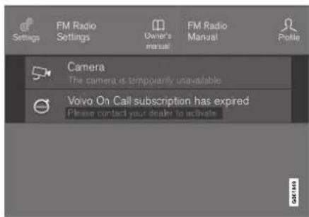
Messages in the center display's Top view.
Some messages in the center display have a button (or several buttons in a pop-up message) to e.g. activate/deactivate a function related to the message.
Handling new messages
For messages with buttons:
- Tap the button to perform the action or let the message automatically time-out after a short period.
The message will disappear from the status bar.
For messages without buttons:
- Close the message by tapping it or let the message automatically time-out after a short period.
The message will disappear from the status bar.
Messages that need to be saved are stored in Top view in the center display.
Related information
- Messages in the center display (p. 140)
- Handling messages saved from the center display (p. 141)
- Messages in the instrument panel (p. 105)
Handling messages saved from the center display
Messages saved from the instrument panel and center displays are handled in the center display.
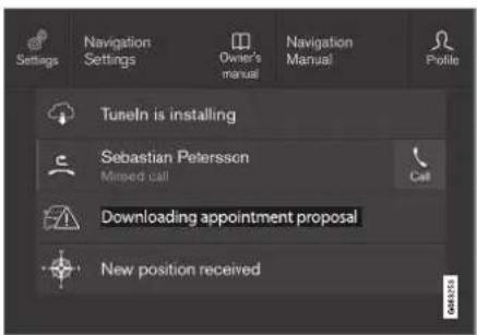
Saved messages and possible selections in Top view.
Messages that have been shown in the center display and that need to be saved are stored in the center display's Top view.
Reading saved messages
- Open Top view in the center display.
A list of saved messages will be displayed. Messages with an arrow to the right can be expanded.
- Tap a message to expand/minimize it.
More information about the message will appear in the list and the image to the left of the app will display information about the message in graphic form.
Handling saved messages
Some messages have a button to e.g. activate/deactivate a function related to the message.
- Tap the button to perform the action.
Saved messages in Top view are automatically deleted when the ignition is switched off.
Related information
- Messages in the center display (p. 140)
- Handling messages in the center display (p. 140)
- Messages in the instrument panel (p. 105)
DISPLAYS AND VOICE CONTROL
Head-up display\*
The head-up display is a complement to the instrument panel and projects information from the instrument panel onto the windshield. The projected images can only be seen from the driver's seat.

Incoming phone calls.
The head-up display projects warnings and information related to speed, cruise control functions, navigation, etc. onto the windshield in the driver's field of vision. Traffic information and incoming phone calls can also be shown on the head-up display.
i NOTE
The driver's ability to see information in the head-up display may be impeded by:
• the use of polarizing sunglasses
- a driving posture in which the driver is not centered in the seat
- objects on the display unit's glass cover
• unfavorable lighting conditions.
CAUTION
The information is projected from a display unit located in the dashboard. To help prevent damage to the display unit's glass cover, do not place any objects on the glass and prevent objects from falling onto it.

Examples of what might be shown on the display.
1 Speed
② Cruise control
3 Navigation
4 Road signs
A number of symbols may be projected temporarily onto the head-up display, including:

If the warning symbol appears, read the warning message in the instrument panel.

If the information symbol appears, read the warning message in the instrument panel.

The snowflake symbol will illuminate if there is a risk of slippery conditions.

NOTE
People with certain types of vision problems may experience headaches or eye strain when using the head-up display.
City Safety in head-up-display
If a collision warning is given, the information in the head-up display will be replaced by a City Safety graphic. This graphic will illuminate even if the head-up display is turned off.

natural_image
Interior view of a car dashboard with steering wheel and dashboard (no visible text or symbols)A City Safety graphic flashes to attract the driver's attention.
Related information
- Activating and deactivating the head-up display* (p. 143)
• Cleaning the head-up display* (p. 646) - Replacing a windshield with head-up display* (p. 621)
Activating and deactivating the head-up display\*
The head-up display can be activated and deactivated when the vehicle has been started.

Press the Head-up Display button in the center display's Function view. An indicator light in the button will illuminate when the function is activated.
Related information
• Head-up display settings* (p. 144)
• Head-up display* (p. 142)
DISPLAYS AND VOICE CONTROL
Head-up display settings\*
Adjusting settings for the head-up display.
Settings can be adjusted when the vehicle is started and a projected image is displayed on the windshield.
Selecting display options
Select the functions to be shown in the head-up display.
- Tap Settings in the center display's Top view.
- Tap My Car Displays Head-Up Display Options.
- Select one or more functions:
• Show Navigation
• Show Road Sign Information
• Show Driver Support
• Show Phone.
This setting is stored as a personal setting in the driver profile.
Adjusting brightness and height position

- Press the Head-up Display Adjustments button in the center display's Function view.
- Adjust the brightness of the projected image and the height position in the driver's field of vision using the right-side steering wheel lever.
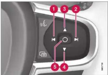
1 Decreasing brightness
② Increasing brightness
3 Raising position
4 Lowering position
5 Confirm
The brightness of the graphic is automatically adapted to the light conditions in its background. Brightness is also affected by adjustments to the brightness of the other displays in the vehicle.
The height position can be stored in the front power seat's* memory function using the keypad in the driver's door.
Calibrating the horizontal position
If the windshield or display unit has been replaced, the head-up display's horizontal position may need to be calibrated. Calibration means that the projected image is rotated clockwise or counterclockwise.
- Tap Settings in the center display's Top view.
- Select My Car Displays Head-Up Display Options → Head-Up Display Calibration.
- Calibrate the horizontal position of the image using the right-side steering wheel keypad.

1 Rotate counterclockwise
2 Rotate clockwise
3 Confirm
Related information
• Head-up display* (p. 142)
- Activating and deactivating the head-up display* (p. 143)
• Driver profiles (p. 136)
- Storing positions for seats, mirrors and head-up display* (p. 186)
Voice control ^15
The driver can use voice commands to control certain functions in the media player, a Bluetooth-connected phone, the climate system and the Volvo navigation system*.
Voice commands offer extra convenience and help minimize distractions so drivers can concentrate on driving and keep their attention on the road and traffic situation.
WARNING
The driver is always responsible for ensuring that the vehicle is operated in a safe manner and that all applicable traffic regulations are followed.
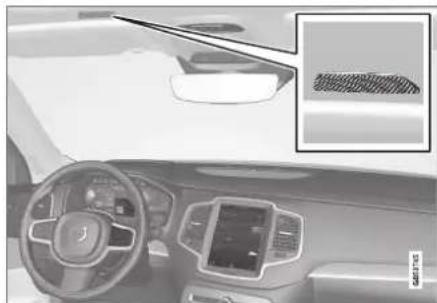
natural_image
Interior view of a car dashboard and infotainment system (no visible text or symbols)Voice control microphone
Voice control is carried out as a dialog, with spoken commands from the user and verbal respon-
▶▶
DISPLAYS AND VOICE CONTROL
ses from the system. The voice control system uses the same microphone as devices connected with Bluetooth, and the voice control system responds through the vehicle's loudspeakers. In certain cases, text messages will also be displayed in the instrument panel. The functions are controlled using the right-side steering wheel keypad and settings are made in the center display.
System updates
The voice control system is continuously improved. For optimal functionality, always download the latest update at support.volvocars.com.
Related information
• Using voice commands (p. 146)
• Voice control for cellular phones (p. 147)
• Voice control for radio and media (p. 148)
• Climate control system voice commands (p. 205)
• Voice control settings (p. 148)
Using voice commands ^16
Press the button for voice control 📊 on the right-side steering wheel keypad to activate the system and initiate a voice command dialog.
These may include:
- Wait until after the tone, and then speak in your normal voice at a normal speed.
- Do not speak while the system is responding (the system is unable to process commands during this time).
- Avoid background noises in the passenger compartment by keeping doors, windows and the panoramic roof* closed.
Voice control can be canceled by:
- saying "Cancel".
- pressing and holding the steering wheel keypad's voice command button .
To speed up the voice command dialog and skip system responses, press the voice command button while the system is responding and give your next command.
Voice command examples
Press say "Call [First name] [Last name] [number category]" - calls the selected contact from the phone book. If the contact has several phone numbers (e.g. home, cell, work), the right category must also be given.
Press 📣 and say "Call Robyn Smith cellular".
Commands/phrases
The following commands can always be used:
- "Repeat" - repeats the most recent voice command in the current dialog.
- "Cancel" - cancels the dialog.
- "Help" - initiates a help dialog. The system responds with commands that can be used in the current situation, an instruction or an example.
Commands for specific functions, such as phone and audio, are described in the sections related to that function.
15 Certain markets only.
16 Certain markets only.
Numbers
Number commands can be given in different ways depending on the function to be controlled:
- Phone numbers and zip codes should be given by stating each number individually, e.g. zero three one two two four four three (03122443).
- Addresses can be given by stating each number individually or in a group, e.g. two two or twenty-two (22). For English and Dutch language settings, groups of numbers can also be said in sequence, e.g. twenty-two twenty-two (22 22). For English, double or triple digits can also be used, e.g. double zero (00). Numbers in the range 0-2300 can be used.
- Frequencies can be given as ninety-eight point eight (98.8), one hundred four point two, or hundred four point two (104.2).
Related information
• Voice control (p. 145)
• Voice control for cellular phones (p. 147)
• Voice control for radio and media (p. 148)
• Climate control system voice commands (p. 205)
• Voice control settings (p. 148)
Voice control for cellular phones ^17
Call a contact in the phone book, have a text message read aloud or dictate short messages using voice commands to a Bluetooth-connected phone.
To access a contact in the phone book, the voice command must contain the contact information entered in the phone book. If a contact, e.g.
Robyn Smith, has several phone numbers listed in the phone book, a number category such as home or cellular can also be specified, i.e. "Call Robyn Smith cellular".
Tap and say one of the following commands:
- "Call [contact]" - call the selected contact from the phone book.
- "Call [phone number]" - call a phone number.
- "Recent calls" - display the list of recent calls.
- "Read message" - read a text message aloud. If there are several messages, select the message to read aloud.
- "Message to [contact]" - the user is prompted to dictate a short message. The message will then be read aloud and the user can choose to send ^18 or re-dictate the
message. The vehicle must be connected to the Internet to access this function.
Related information
• Voice control (p. 145)
• Using voice commands (p. 146)
• Voice control for radio and media (p. 148)
• Climate control system voice commands (p. 205)
• Voice control settings (p. 148)
• Internet-connected vehicle* (p. 541)
DISPLAYS AND VOICE CONTROL
Voice control for radio and media ^19
Voice commands for the radio and media players are shown below.
Tap and say one of the following commands:
- "Media" - initiates a dialog for media and radio and displays examples of commands.
- "Play [artist]" - plays music by the selected artist.
- "Play [song title]" - plays the selected song.
- "Play [song title] from [album]" - plays the selected song from the selected album.
- "Play [radio station]" - starts the selected radio station.
- "Tune to [frequency]" - tunes to the selected radio frequency in the currently active waveband. If no radio source is active, the FM band will be started as default.
- "Tune to [frequency] [waveband]" - tunes to the selected radio frequency on the selected waveband.
• "Radio" - starts FM radio.
• "Radio FM" - starts FM radio.
• "SiriusXM" - starts SiriusXM radio* -
"CD" - starts playback from CD*.
• "USB" - starts playback from USB. -
"iPod" - starts playback from iPod.
- "Bluetooth" - starts playback from a Bluetooth-connected media source.
- "Similar music" - plays music from a USB-connected device with music similar to that currently playing.
Related information
• Voice control (p. 145)
• Using voice commands (p. 146)
• Voice control for cellular phones (p. 147)
• Climate control system voice commands (p. 205)
• Voice control settings (p. 148)
Voice control settings ^20
Settings for the voice control system are made here.
Settings System Voice Control
Settings can be personalized in the following areas:
- Repeat Voice Command
Gender - Speech Rate
Sound settings
Select sound settings under:
Settings Sound System Volumes Voice Control
Language settings
The voice control system is not available for all languages. The languages available for voice commands are indicated by the icon in the list of languages.
Changing the language here will also change the language in the menus, messages and help texts.
Settings System System Languages and Units → System Language
DISPLAYS AND VOICE CONTROL
Related information
• Voice control (p. 145)
• Using voice commands (p. 146)
• Voice control for cellular phones (p. 147)
• Climate control system voice commands (p. 205)
• Voice control for radio and media (p. 148)
• Sound settings (p. 496)
• Changing system language (p. 132)

bar
| Category | Value | |---|---| | Category 1 | 100 | | Category 2 | 100 | | Category 3 | 100 | | Category 4 | 100 | | Category 5 | 100 | | Category 6 | 100 | | Category 7 | 100 | | Category 8 | 100 | | Category 9 | 100 | | Category 10 | 100 | | Category 11 | 100 | | Category 12 | 100 | | Category 13 | 100 | | Category 14 | 100 | | Category 15 | 100 | | Category 16 | 100 | | Category 17 | 100 | | Category 18 | 100 | | Category 19 | 100 | | Category 20 | 100 | | Category 21 | 100 | | Category 22 | 100 | | Category 23 | 100 | | Category 24 | 100 | | Category 25 | 100 | | Category 26 | 100 | | Category 27 | 100 | | Category 28 | 100 | | Category 29 | 100 | | Category 30 | 100 | | Category 31 | 100 | | Category 32 | 100 | | Category 33 | 100 | | Category 34 | 100 | | Category 35 | 100 | | Category 36 | 100 | | Category 37 | 100 | | Category 38 | 100 | | Category 39 | 100 | | Category 40 | 100 | | Category 41 | 100 | | Category 42 | 100 | | Category 43 | 100 | | Category 44 | 100 | | Category 45 | 100 | | Category 46 | 100 | | Category 47 | 100 | | Category 48 | 100 | | Category 49 | 100 | | Category 50 | 100 | | Category 51 | 100 | | Category 52 | 100 | | Category 53 | 100 | | Category 54 | 100 | | Category 55 | 100 | | Category 56 | 100 | | Category 57 | 100 | | Category 58 | 100 | | Category 59 | 100 | | Category 60 | 100 | | Category 61 | 100 | | Category 62 | 100 | | Category 63 | 100 | | Category 64 | 100 | | Category 65 | 100 | | Category 66 | 100 | | Category 67 | 100 | | Category 68 | 100 | | Category 69 | 100 | | Category 70 | 100 | | Category 71 | 100 | | Category 72 | 100 | | Category 73 | 100 | | Category 74 | 100 | | Category 75 | 100 | | Category 76 | 100 | | Category 77 | 100 | | Category 78 | 100 | | Category 79 | 100 | | Category 80 | 100 | | Category 81 | 100 | | Category 82 | 100 | | Category 83 | 100 | | Category 84 | 100 | | Category 85 | 100 | | Category 86 | 100 | | Category 87 | 100 | | Category 88 | 100 | | Category 89 | 100 | | Category 90 | 100 | | Category 91 | 100 | | Category 92 | 100 | | Category 93 | 100 | | Category 94 | 100 | | Category 95 | 100 | | Category 96 | 100 | | Category 97 | 100 | | Category 98 | 100 | | Category 99 | 100 | | Total (Total) |LIGHTING
LIGHTING
Lighting panel and controls
The lighting panel and controls can be used to adjust both exterior and interior lighting. The lighting ring on the left-side steering wheel lever can be used to activate and adjust the exterior lighting. The brightness of the interior lighting can be adjusted using the thumb wheel on the dashboard.
Exterior lighting

Lighting ring position.
When the vehicle's ignition is in mode II, the lighting ring positions have the following functions:
| Position | Meaning |
| 0 | US: Daytime running lights and parking lights are off.Canada: Daytime running lights and parking lights are on.High beam flash can be used. |
| EDGE | Parking lights when the vehicle is parked.US: Daytime running lights are off.Canada: Daytime running lights are on.High beam flash can be used. |
| ED | Low beams and parking lights.High beams can be activated.High beam flash can be used. |
| Position | Meaning |
| AUTO | Daytime running lights and parking lights in daylight conditions. ^A Low beams and parking lights in weak daylight or dark conditions or when the front fog lights* and/or rear fog light are activated.Active high beam can be activated.High beams can be activated when low beams are on.High beam flash can be used. |
| Active high beams on/off. |
A US models only: Daytime running lights and parking lights can be deactivated in the center display.
NOTE
Volvo recommends use of Daytime Running Lights in the US. Its use is mandatory in Canada.
Volvo recommends using position AUTen the vehicle is in motion.

WARNING
The vehicle lighting system cannot in all situations determine when the daylight is too weak or not strong enough, e.g. when there is fog or rain.
The driver is always responsible for driving the vehicle with lighting that is safe for the traffic conditions and as specified by applicable traffic regulations.
Thumbwheel in instrument panel

natural_image
Interior view of a car dashboard with a control panel and indicator lights (no visible text or symbols)Thumb wheel (to the left) for adjusting interior brightness.
Related information
- Adjusting light functions via the center display (p. 153)
• Interior Lighting (p. 162) - Parking lights (p. 154)
• Using turn signals (p. 158)
• Using high beam (p. 156)
- Low beams (p. 155)
• Rear fog light (p. 159)
• Active Bending Lights* (p. 159)
- Brake lights (p. 160)
• Emergency brake lights (p. 160)
• Hazard warning flashers (p. 161)
Adjusting light functions via the center display
A number of light functions can be adjusted and activated via the center display. These include active high beams, home safe lighting and approach lighting.
- Tap Settings in the Top view.
- Tap My Car Lights and Lighting.
- Select Exterior Lights or Interior Lighting and then the function that you would like to adjust.
Related information
• Lighting panel and controls (p. 152)
• Active high beam (p. 157)
• Using home safe lighting (p. 161)
• Welcome Light (p. 161)
• Using turn signals (p. 158)
- Changing settings in the center display's Top view (p. 132)
• Function view in the center display (p. 122)
LIGHTING
Parking lights
The parking lights can be used to help other road users see the vehicle if it is stopped or parked. Use the lighting ring on the steering wheel lever to turn on the parking lights.
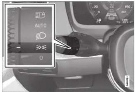
Lighting ring in the parking light position.
Turn the lighting ring to the 3° position to turn on the parking lights (the license plate lighting will also illuminate).
Canadian models: If the ignition is in the II position, the daytime running lights will illuminate instead of the front parking lights. With the lighting ring in this position, the parking lights will remain on regardless of what position the ignition is in.
US models: When AUTO mode is selected, the daytime running lights can be deactivated in the center display. The parking lights will also be
deactivated. In weak daylight or dark conditions, the parking lights and low beams will be illuminated.
In dark conditions, the rear parking lights also illuminate when the tailgate is opened to alert following traffic. This happens regardless of what position the lighting ring or ignition is in.
Related information
• Lighting panel and controls (p. 152)
- Ignition modes (p. 437)
Daytime running lights
The vehicle has sensors that detect ambient lighting conditions. With the lighting ring in the AUTO position, the daytime running lights will always be activated when the ignition is in mode II. In weak daylight or dark conditions, the headlights automatically switch to low beams.

Lighting ring in AUTO position.
With the steering wheel lever's lighting ring in the AUTO position, the daytime running lights (DRL ^1 ) will illuminate when the vehicle is driven in daylight conditions. The headlights will switch automatically from daytime running lights to low beams in weak daylight or dark conditions. The headlights will also switch to low beams if the front fog lights ^* and/or rear fog light are activated.
US models: When AUTO mode is selected, the daytime running lights can be deactivated in the center display. The parking lights will also be deactivated. In weak daylight or dark conditions, the parking lights and low beams will be illuminated.
US models: With the lighting ring in the 0 or position, the daytime running lights will be off.
Canadian models: With the lighting ring in the 0 or position, the daytime running lights will be on.

NOTE
Volvo recommends use of Daytime Running Lights in the US. Its use is mandatory in Canada.

WARNING
The system is an energy saving aid – it cannot in all situations determine when the daylight is too weak or not strong enough, e.g. when there is fog or rain.
The driver is always responsible for driving the vehicle with lighting that is safe for the traffic conditions and as specified by applicable traffic regulations.
Related information
• Lighting panel and controls (p. 152)
- Ignition modes (p. 437)
- Low beams (p. 155)
Low beams
When driving with the lighting ring in the AUTO position, low beam will be automatically activated in weak daylight or dark conditions, when the ignition is in the II position.
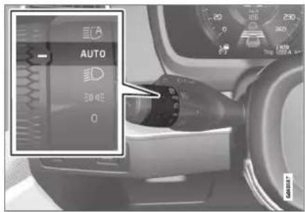
Lighting ring in AUTO position.
With the lighting ring in the AUETotion, the low beams will also be automatically activated if the rear fog light is activated.
With the lighting ring in the position, low beams will always be on when the ignition is in the position.
LIGHTING
Tunnel detection
The vehicle will detect if it enters a tunnel and shift from daytime running lights to low beams.
Note that the left-hand steering wheel lever must be in AUTO position for tunnel detection to work.
Related information
• Lighting panel and controls (p. 152)
- Ignition modes (p. 437)
• Daytime running lights (p. 154)
Using high beam
High beam is operated via the left-hand steering wheel lever. High beam is the vehicle's strongest lighting and should be used when driving in dark conditions, provided it does not blind other road users, to improve visibility.
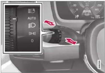
Steering wheel lever with lighting ring.
High beam flash
Move the steering wheel lever slightly backward to the high beam flash mode. The high beams will illuminate until the lever is released.
High beams
2 The high beams can be activated when the lighting ring is in mode AUTO ^2 or . D Activate high beams by moving the steering
wheel lever forward. Deactivate by moving the steering wheel lever backward.
When the high beams are activated, the symbol will be illuminated in the instrument panel.
Related information
• Lighting panel and controls (p. 152)
• Active high beam (p. 157)
Active high beam
Active high beams is a function that uses camera sensors in the upper edge of the windshield to detect the headlights of approaching vehicles or the taillights of the vehicle directly ahead. When either of these is detected, the vehicle's headlights will automatically switch from high beams to low beams.

Active high beam is enabled by moving the lighting ring on the steering wheel lever to AUTO.
The function can also detect street lighting. When the camera sensor no longer detects an approaching vehicle or a vehicle ahead, the headlights will return to high beams.
This function can be used in dark conditions when the vehicle's speed is approx. 20 km/h (approx. 12 mph) or higher.
If active high beams are deactivated when the high beams are on, the headlights will automatically switch to low beams.
When active high beams are activated, a white
ECA symbol will be displayed in the instrument panel.
When high beams are on, the symbol will be blue. For LED headlights, this applies even if the high beams are partially dimmed, i.e. if the headlights are illuminated with slightly more than low beams.
Vehicles with LED ^3 headlights\*
If the active high beams are equipped with the auto on/off function ^4 , the headlights will return to high beams a second or so after the camera sensor no longer detects the headlights of approaching vehicles or the taillights of a vehicle ahead.
Limitations for active high beams
The camera sensor on which the function is based has limitations.

If this symbol and the message Active High Beam Temporarily unavailable is displayed in the instrument panel, switching between high
and low beams must be done manually. The lighting ring on the steering wheel lever can remain in the AUTO position. The symbol will go out when the message is displayed.

The same applies if this symbol along with the message Windscreen sensor Sensor blocked, see Owner's manual is displayed.
Active high beams may be temporarily unavailable in certain situations, e.g. heavy fog or rain. When active high beams become available again, or the windshield sensors are no longer blocked, the message will disappear and the symbol will be displayed.

WARNING
Automatic high beam is an aid in using the best possible light based on prevailing conditions.
The driver is always responsible for manually switching between high and low beam when traffic situations or weather conditions require this.
LIGHTING
Related information
• Lighting panel and controls (p. 152)
• Using high beam (p. 156)
• Camera limitations (p. 338)
Using turn signals
The vehicle's turn signals are controlled using the left-side steering wheel lever. The turn signals flash three times or continuously, depending on how far up or down the lever is moved.

Turn signals.
Triple flash indicator
Move the steering wheel lever up or down to the first position and release. The turn signals will flash three times. If the function is deactivated via the center display, the signals will flash once.
NOTE
- This automatic flashing sequence can be interrupted by immediately moving the lever in the opposite direction.
- If the turn signal indicator flashes more quickly than normal, refer to the message in the instrument panel.
Continuous flashing sequence
2 Move the lever up or down as far as possible.
The lever will stop in its end position and can be moved back manually or automatically by moving the steering wheel.
Related information
• Hazard warning flashers (p. 161)
- Adjusting light functions via the center display (p. 153)
Active Bending Lights\*
Active Bending Lights (ABL) are designed to help provide maximum illumination in curves and intersections. Depending on equipment level, vehicles with LED ^5 headlights* may be equipped with Active Bending Lights.

natural_image
Top-down view of a car with airflow visualization above, showing no text or symbolsHeadlight pattern with function deactivated (left) and activated (right).
Active Bending Lights follow the movement of the steering wheel to help provide maximum illumination in curves and intersections, helping to improve visibility for the driver.
The function is automatically activated when the engine is started. If a fault is detected in the system, the 🔒 symbol will illuminate in the instrument panel and a message will be displayed.
The function is only active in weak daylight or dark conditions and only when the vehicle is moving and the low beams are on.
Deactivating/activating the function
The function is activated as the default factory setting and can be activated and deactivated in the center display's Function view:
Tap the Active Bending Lights button.
Related information
- Adjusting light functions via the center display (p. 153)
Rear fog light
The rear fog light is considerably brighter than ordinary taillights and should only be used to help other road users see the vehicle when visibility is reduced by conditions such as fog, snow, smoke or dust.

Rear fog light button.
The rear fog light consists of a light on the rear of the vehicle on the driver's side.
The rear fog light can only be switched on when the ignition is in II mode and the lighting ring is in position AUTO or .
Press the button for On/Off. The ⏻ symbol in the instrument panel illuminates when the rear fog light is on.
LIGHTING
The rear fog light turns off automatically when the ignition is switched off or when the steering wheel lever lighting ring is in position 0 or DO .

NOTE
Regulations concerning rear fog light use vary from country to country.
Related information
• Lighting panel and controls (p. 152)
- Ignition modes (p. 437)
Brake lights
The brake lights are automatically illuminated when braking.
The brake lights illuminate when the brake pedal is depressed. They also illuminate when the brakes are automatically applied by one of the driver support systems.
Related information
• Emergency brake lights (p. 160)
- Brake functions (p. 438)
Emergency brake lights
The emergency brake lights are activated to warn following vehicles of hard braking.
This function causes an additional taillight on each side of the vehicle to illuminate.
The emergency brake lights are activated in the event of hard braking or if the ABS system is activated and the vehicle is traveling at a high speed.
After the driver decelerates to a low speed and then releases the brake, the brake lights resume their normal brightness.
Related information
- Brake lights (p. 160)
- Brakes (p. 439)
• Hazard warning flashers (p. 161)
Hazard warning flashers
Hazard warning flashers warn other road users by all of the vehicle's turn signals being activated at the same time. The function can be used to warn about a traffic hazard.
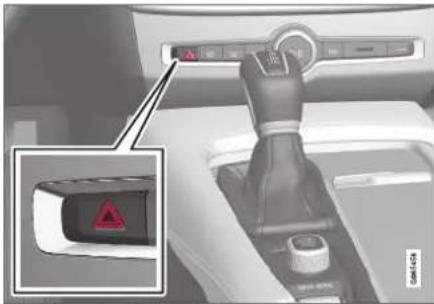
Hazard warning flashers button.
Press the button to activate the hazard warning flashers.

NOTE
Regulations concerning the use of hazard warning flashers may vary from country to country.
Related information
• Emergency brake lights (p. 160)
• Using turn signals (p. 158)
Using home safe lighting
Some of the exterior lights remain on to illuminate the area around the vehicle. This is called home safe lighting.
To activate home safe lighting:
- Switch off the ignition.
- Push the left-side steering wheel lever toward the dashboard and release.
- Exit the vehicle and lock the doors.
When the function is activated, a symbol will be shown in the instrument panel and the parking lights, outer door handle lights* and the license plate lights will be illuminated.
The length of time home safe lighting remains illuminated can be set in the center display.
Related information
- Adjusting light functions via the center display (p. 153)
• Welcome Light (p. 161)
Welcome Light
Approach lighting is activated when the vehicle is unlocked and can be used to provide light as you walk toward the vehicle.
The function is activated when the remote key is used for unlocking. The parking lights, outer door handle lights*, license plate lights, interior ceiling lights, footwell lighting and trunk/cargo compartment lighting will be illuminated. If a door is opened while the function is activated, the lighting in the outer door handle* and the interior lighting will remain illuminated for a longer period of time.
This function can be activated and deactivated in the center display.
Related information
- Adjusting light functions via the center display (p. 153)
• Using home safe lighting (p. 161) - Remote key (p. 243)
LIGHTING
Interior Lighting
The interior is equipped with several different types of lighting to improve the experience. This includes reading lamps, glove box lighting and ground lighting.
All lighting in the passenger compartment can be turned on and off manually within 5 minutes after:
- the engine has been switched off and the ignition is in mode 0.
- the vehicle is unlocked but the engine has not been started.
Front ceiling lighting

The controls in the ceiling console for the front reading lights and courtesy lighting.
1 Reading light left side
2 Passenger compartment lighting
③ Courtesy lighting auto switch
4 Reading light right side
Reading lights
The reading lights on the right and left sides are switched on and off by briefly pressing the buttons in the ceiling console. To adjust the brightness, press and hold the button.
Passenger compartment lighting
Briefly press the button in the ceiling console to switch on or off the footwell lighting and ceiling lighting.
Courtesy lighting auto switch
Activate the auto switch by briefly pressing the AUTO button in the ceiling console. With Auto activated, the indicator light in the button and the courtesy lighting come on and are turned off as follows.
The courtesy lighting:
- comes on when the vehicle is unlocked and when the ignition is switched off
• goes off when the engine is started and when the vehicle is locked - comes on or goes off when a side door is opened or closed
- remains on for 2 minutes if any of the side doors are open.
Rear roof lighting
Reading lights are located in the rear section of the vehicle and can also be used as passenger compartment lighting.
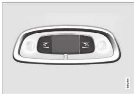
natural_image
Top-down view of a car dashboard with front and side panels (no text or symbols visible)Reading lights over the rear seat ^5 .

natural_image
Close-up of a white car interior with a metallic control panel and a small black button (no text or symbols visible)In vehicles with panoramic roofs*, there are two lamp units, one on each side of the ceiling. ^7
Briefly press the button on the light to turn on or off the reading lights. To adjust the brightness, press and hold the button.
^6 There are also reading lights over the third row of seats ^ . ^7 Does not apply to the third row of seats ^ .
Glove compartment lighting
The glove compartment lighting comes on or goes off when the glove compartment is opened or closed.
Vanity mirror lighting\*
The vanity mirror lighting comes on or goes off when the cover over the mirror is opened or closed.
Ground lighting\*
The ground lighting comes on or goes off when a door is opened or closed.
Doorsill lighting
The doorsill lighting comes on or goes off when a door is opened or closed.
Cargo compartment lighting
The cargo compartment lighting comes on or goes off when the cargo compartment is opened or closed.
Ambient Lighting
The ambient lighting comes on when the doors are opened and goes out when the vehicle is locked. Ambient lighting brightness can be adjusted in the center display and also fine-tuned using the thumb wheel in the dashboard.
Mood lighting\*
The vehicle is equipped with LEDs that provide faint lighting in various colors. This lighting is on when the engine is running. Mood lighting can be adjusted in the center display and also fine-tuned using the thumb wheel in the dashboard.
Lighting in the door storage compartments
Lighting in the door storage compartments comes on when the doors are opened and goes out when the vehicle is locked. The brightness can be adjusted using the thumb wheel in the dashboard.
Lighting in the tunnel console's front cup holder
The lighting in front console cup holders switches on when the vehicle is unlocked and off when the vehicle is locked. The brightness can be adjusted using the thumb wheel in the dashboard.
Related information
• Adjusting interior lighting (p. 164)
• Lighting panel and controls (p. 152)
- Ignition modes (p. 437)
• Passenger compartment interior (p. 592)
LIGHTING
Adjusting interior lighting
Illumination in the vehicle varies depending on ignition mode. The interior lighting can be adjusted with a thumb wheel in the dashboard and certain light functions can also be adjusted via the center display.
The thumb wheel on the dashboard to the left of the steering wheel can be used to adjust the brightness of the display lighting, instrument lights, ambient lighting and mood lighting*.
Adjust ambient decor lighting
- Tap Settings in the Top view in the center display.
- Tap My Car Lights and Lighting → Interior Lighting.
-
Choose from among the following settings:
-
Under Ambient Light Intensity, select Off, Low or High.
• Under Ambient Light Level, select Reduced or Full.
Adjusting mood lighting\*
The vehicle is equipped with several LEDs that provide faint lighting in various colors. This lighting is on when the engine is running.
Changing the brightness
- Tap Settings in the Top view in the center display.
- Tap My Car Lights and Lighting → Interior Lighting Interior Mood Lighting.
- Under Interior Mood Light Intensity, select Off, Low or High.
Changing the color of the light
- Tap Settings in the Top view in the center display.
- Tap My Car Lights and Lighting → Interior Lighting Interior Mood Lighting.
- Choose By Temperature or By Color to change the color of the light.
If By Temperature is selected, the light will change according to the temperature set for the passenger compartment.
If By Color is selected, the subcategory Theme Colors can be used to make further adjustments.
Related information
• Interior Lighting (p. 162)
- Adjusting light functions via the center display (p. 153)
- Ignition modes (p. 437)
WINDOWS, GLASS AND MIRRORS
WINDOWS, GLASS AND MIRRORS
Windows, glass and mirrors
The vehicle is equipped with controls for windows, glass and mirrors. Some of the windows in the car are laminated.
Laminated glass
The windshield has laminated glass. Laminated glass is also available as on option for some other glass surfaces. Laminated glass is reinforced, which provides better protection against break-ins and improved soundproofing in the passenger compartment.
The panoramic roof* also has laminated glass.

The symbol shows the windows containing laminated glass ^1
Related information
- Pinch protection for windows and sun cur-lains (p. 166)
• Panoramic roof* (p. 172)
• Power windows (p. 167)
• Rearview/door mirrors (p. 169)
• Using sun curtains* (p. 169)
• Head-up display* (p. 142)
• Using the windshield wipers (p. 176)
• Using the windshield and headlight washers (p. 179)
- Activating and deactivating the heated windshield* (p. 223)
- Activating and deactivating the heated rear window and door mirrors (p. 225)
Pinch protection for windows and sun curtains
All power windows and sun curtains* have a pinch protection function that is triggered if anything blocks them while they are opening or closing.
If pinch protection is activated, movement will stop and then retract automatically to approx. 50 mm (2 inches) from the point at which it was blocked (or to full ventilation position).
It is still possible to override pinch protection when closing is interrupted (e.g. due to ice) by pressing and holding down the control in the same direction.
If there is any problem with the pinch protection, a rest procedure can be tested.

WARNING
If the starter battery is disconnected, the function for automatic opening and closing must be reset to function correctly. A reset is required in order for the pinch protection to work.
Related information
- Reset procedure for pinch protection (p. 167)
• Operating the power windows (p. 168)
• Using sun curtains* (p. 169)
• Panoramic roof* (p. 172)
Reset procedure for pinch protection
If you experience any problems with the electrical functions for the power windows, you can try to perform a reset.
WARNING
If the starter battery is disconnected, the function for automatic opening and closing must be reset to function correctly. A reset is required in order for the pinch protection to work.
If the problem persists or if it affects the panoramic roof or sunroof, contact a workshop ^2 .
Resetting a power window
- Start with the window in the closed position.
- Then operate the window in manual mode three times upward toward the closed position.
The system will be automatically initiated.
Related information
- Pinch protection for windows and sun curtains (p. 166)
• Operating the power windows (p. 168)
• Using sun curtains* (p. 169)
Power windows
The power windows are operated using the control panels found in the doors. The driver's door has controls for operating all windows and for activating the child safety locks.

Driver's door control panel.
1 Electric child safety locks* that deactivate the controls in the rear doors to prevent the doors or windows from being opened from the inside.
② Rear window controls.
3 Front window controls.
The power windows have pinch protection. If there is any problem with the pinch protection, a rest procedure can be tested.

WARNING
Children, other passengers or objects can be trapped by the moving parts.
• Always operate the windows with caution.
- Do not allow children to play with the operating controls.
• Never leave a child alone in the vehicle.
- Remember to always cut the current to the power windows by setting the vehicle's electrical system to ignition mode 0 and then taking the remote key with you when leaving the vehicle.
- Never stick objects or body parts out through the windows, even if the vehicle electrical system is completely turned off.
Related information
• Operating the power windows (p. 168)
- Pinch protection for windows and sun curtains (p. 166)
- Reset procedure for pinch protection (p. 167)
Operating the power windows
All power windows can be operated using the control panel in the driver's door. The control panels in the other doors can be used to operate that particular door.
The power windows have pinch protection. If there is any problem with the pinch protection, a rest procedure can be tested.

WARNING
Children, other passengers or objects can be trapped by the moving parts.
• Always operate the windows with caution.
- Do not allow children to play with the operating controls.
• Never leave a child alone in the vehicle.
- Remember to always cut the current to the power windows by setting the vehicle's electrical system to ignition mode 0 and then taking the remote key with you when leaving the vehicle.
- Never stick objects or body parts out through the windows, even if the vehicle electrical system is completely turned off.
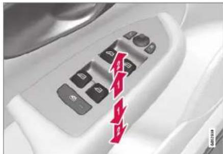
natural_image
Close-up of a car interior control panel with buttons and a red downward arrow overlay (no readable text or symbols)Operating the power windows.
Operating manually. Move one of the controls slightly up or down. The power windows go up or down while the control is held in position.
Operating with automatic controls. Move one of the controls up or down to its end position and release it. The window moves automatically to its fully closed/open position.
To use the power windows, the ignition must be in at least mode I or II. After the ignition has been switched off, the power windows can be operated for several minutes or until a door is opened. Only one control panel can be operated at a time.
It can also be operated using keyless opening* with the door handle.

WARNING
Make sure that no child or other passenger comes into contact with the windows as they are closing with keyless closing*.

NOTE
One way to reduce the pulsating wind noise heard when the rear windows are open is to also open the front windows slightly.

NOTE
The windows cannot be opened at speeds over approx. 180 km/h (ca112 mph), but they can be closed.
The driver is always responsible for following applicable traffic regulations.
Related information
• Power windows (p. 167)
- Pinch protection for windows and sun curtains (p. 166)
- Reset procedure for pinch protection (p. 167)
• Keyless locking and unlocking* (p. 259)
- Locking and unlocking using the remote key (p. 246)
Using sun curtains\*
There are integrated sun curtains in each rear door.
Rear door - manually operated
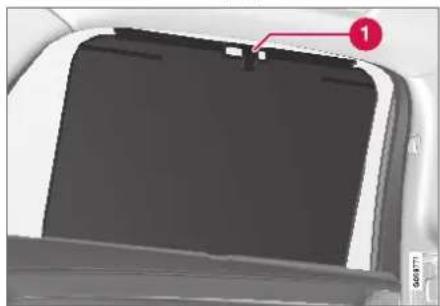
natural_image
Close-up of a car interior panel with a red label pointing to a component (no visible text or symbols)The illustration is generic - the design may vary.

Hook with locking mechanism
- Pull up the sun curtain and hook it to the upper section of the door frame.
The window can be opened and closed when the sun curtain is being used.
Related information
- Pinch protection for windows and sun curtains (p. 166)
- Reset procedure for pinch protection (p. 167)
• Power windows (p. 167)
Rearview/door mirrors
The rearview mirror and door mirrors can be used to improve the driver's visibility behind the vehicle.
Rearview mirror
The rearview mirror can be easily adjusted manually. The rearview mirror can be equipped with HomeLink*, auto-dim* and compass*.
Door mirrors

WARNING
The door mirror on the passenger side is curved to improve visibility. Objects in the mirror may appear farther away than they actually are.
The joystick in the drivers' door control panel is used to adjust the position of the door mirrors. There are also several automatic settings that can also be connected to the memory function buttons for the power seat*.
Related information
- HomeLink®* (p. 489)
- Compass* (p. 493)
- Adjusting the rearview mirror dimming function (p. 170)
• Adjusting the door mirrors (p. 171)
▶▶
WINDOWS, GLASS AND MIRRORS
- Storing positions for seats, mirrors and head-up display* (p. 186)
- Activating and deactivating the heated rear window and door mirrors (p. 225)
Adjusting the rearview mirror dimming function
Bright light entering the vehicle from behind, e.g. from the headlights of following vehicles, could reflect in the rearview mirror and door mirrors and cause a glare. Use the dimming function when light from behind is distracting.
Auto-dim
If bright light enters the vehicle from behind, the door mirrors will automatically dim. Auto-dim is always active when the engine is running, except when reverse gear is engaged.
NOTE
Adjustments to the sensitivity level will not be noticeable immediately but will instead take effect after a short period of time.
The sensitivity level for dimming will affect both the rearview mirror and door mirrors.
To change the dimming sensitivity level:
- Tap Settings in the Top view in the center display.
- Tap My Car Mirrors and Convenience.
- Under Rearview Mirror Auto Dimming, select Normal, Dark or Light.
The rearview mirror instead has two sensors - one pointing forward and one pointing rearward -
which work together to identify and eliminate glare. The forward-pointing sensor monitors ambient light, while the rearward-pointing sensor monitors light from the headlights of following vehicles.
For the door mirrors to be equipped with auto-dim, the rearview mirror must also be equipped with auto-dim.
NOTE
If the sensors are obstructed by e.g. a parking permit, transponder, sunshade or objects on the seats or in the cargo compartment in a way that prevents light from reaching the sensors, the auto-dim function in the door and rearview mirrors will be reduced.
Related information
• Rearview/door mirrors (p. 169)
• Adjusting the door mirrors (p. 171)
Adjusting the door mirrors
To improve visibility to the rear, the door mirrors need to be adjusted to the driver's height and seating position. There are several automatic settings that can also be connected to the memory function buttons for the power seat*.
Controls used for door mirrors
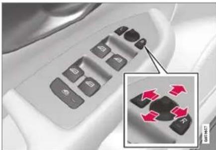
natural_image
Close-up of a car control panel with buttons and a magnified inset showing red directional arrows (no text or symbols)Door mirror controls.
The joystick in the drivers' door control panel is used to adjust the position of the door mirrors. The ignition must be in at least mode I.
-
Press the L button for the left door mirror or R for the right door mirror. The button will light up.
-
Adjust the position using the joystick located between the buttons.
-
Press the L or R button again. The light in the button will go out.
Automatically folding door mirrors\*
The door mirrors can be automatically folded when driving or parking in tight spaces.
- Press the L and R buttons at the same time.
- Release the buttons after about 1 second. The mirrors will automatically stop when they are completely folded in.
Open the mirrors by pressing L and R at the same time. The mirrors will automatically stop when they are completely open.
Resetting the mirrors' position
A mirror that has been moved out of position manually (e.g. hit or bumped into) must be electrically returned to its normal position for automatic folding* to function properly.
- Fold in the mirrors by pressing the L and R buttons at the same time.
- Open them again by pressing the L and R buttons at the same time.
- Repeat the above procedure as needed. The mirrors are now reset to their original positions.
Tilting when parking ^3
The door mirrors can be tilted down to help give the driver a better view along the sides of the vehicle, e.g. of the curb when parking.
- Select reverse gear and press the L or R mirror button.
Please note that the button may need to be pressed twice depending on settings. When the door mirror is tilted down, the light in the button will flash. When reverse gear is engaged, the door mirrors will automatically start to move after 3 seconds and will reach their original position after about 8 seconds.
Automatically tilting when parking ^3
With this setting, the door mirrors will automatically tilt down when reverse gear is engaged. The folded position is preset and cannot be adjusted. To immediately return the door mirrors to their original position, press the L or R button twice.
- Tap Settings in the center display's Top view.
- Tap My Car Mirrors and Convenience.
- Under Exterior Mirror Tilt at Reverse, select Off, Driver, Passenger or Both to activate/deactivate and to select which mirror to tilt.
WINDOWS, GLASS AND MIRRORS
Automatic folding when the vehicle is locked\*
The door mirrors can automatically fold in when the vehicle is locked and open when the vehicle is unlocked using the remote key.
- Tap Settings in the center display's Top view.
- Tap My Car Mirrors and Convenience.
- Select Fold Mirror When Locked to activate/deactivate.
Related information
• Rearview/door mirrors (p. 169)
- Adjusting the rearview mirror dimming function (p. 170)
- Storing positions for seats, mirrors and head-up display* (p. 186)
- Activating and deactivating the heated rear window and door mirrors (p. 225)
Panoramic roof\*
The panoramic roof is divided into two glass sections. The front section can be opened vertically at the rear edge (ventilation position) or horizontally (open position). The rear section cannot be moved.
The panoramic roof has a wind deflector and sun curtain made of perforated fabric (located beneath the glass sections) for extra protection in e.g. bright sunlight.
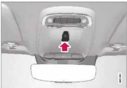
natural_image
Top-down view of a car interior showing the front and rear seats with a red arrow pointing to a black connector (no text or symbols visible)The panoramic roof and sun curtain are operated using the controls in the ceiling.
It can also be operated using keyless opening ^* with the door handle.
To operate the panoramic roof and sun curtain, the ignition must be in mode I or II.
WARNING
Children, other passengers or objects can be trapped by the moving parts.
• Always operate the windows with caution.
- Do not allow children to play with the operating controls.
- Never leave a child alone in the vehicle.
- Remember to always cut the current to the power windows by setting the vehicle's electrical system to ignition mode 0 and then taking the remote key with you when leaving the vehicle.
- Never stick objects or body parts out through the windows, even if the vehicle electrical system is completely turned off.
CAUTION
- Do not open the panoramic roof when load carriers are installed.
- Never place heavy objects on the panoramic roof.
CAUTION
- Remove ice and snow before opening the panoramic roof. Be careful not to scratch any surfaces or damage the trim.
- Do not operate the panoramic roof if it is frozen in place.
Wind blocker

natural_image
Top-down view of a car's front wheel and roof (no visible text or symbols)The panoramic roof is equipped with a wind blocker that folds up when the roof is open.
Related information
• Operating the panoramic roof* (p. 173)
- Auto closing the panoramic roof* sun curtain (p. 175)
- Pinch protection for windows and sun curtains (p. 166)
• Keyless locking and unlocking* (p. 259)
- Locking and unlocking using the remote key (p. 246)
Operating the panoramic roof\*
The panoramic roof and sun curtain are operated using a control in the ceiling panel, and both are equipped with pinch protection.
WARNING
Children, other passengers or objects can be trapped by the moving parts.
• Always operate the windows with caution.
- Do not allow children to play with the operating controls.
• Never leave a child alone in the vehicle.
- Remember to always cut the current to the power windows by setting the vehicle's electrical system to ignition mode 0 and then taking the remote key with you when leaving the vehicle.
- Never stick objects or body parts out through the windows, even if the vehicle electrical system is completely turned off.
CAUTION
- Do not open the panoramic roof when load carriers are installed.
- Never place heavy objects on the panoramic roof.
CAUTION
- Remove ice and snow before opening the panoramic roof. Be careful not to scratch any surfaces or damage the trim.
- Do not operate the panoramic roof if it is frozen in place.
To operate the panoramic roof and sun curtain, the ignition must be in mode I or II.
It can also be operated using keyless opening* with the door handle.
WARNING
Make sure that no child or other passenger comes into contact with the windows as they are closing with keyless closing*.
CAUTION
Check that the panoramic roof is properly closed when closing.
The movement of the roof will stop if the control is released during manual operation or when the glass has reached the comfort ^4 or fully open/closed position. The movement of both the panoramic roof and the sun curtain is also stopped if the control in the ceiling is operated again in the
WINDOWS, GLASS AND MIRRORS
direction opposite that of the current direction of movement.
The panoramic roof and sun curtain are also equipped with pinch protection. If there is any problem with the pinch protection, a rest procedure can be tested.

NOTE
For manual opening, the sun curtain must be completely open before the panoramic roof can be opened. For the reverse procedure, the panoramic roof must be completely closed before the sun curtain can be completely closed.
Opening and closing ventilation position

Ventilation position, rear edge raised.
Open by pushing the control upward once.
2 Close by pushing the control downward once.
When ventilation mode is selected, the rear edge of the front section of the roof is raised. If the sun curtain is fully closed when ventilation position is selected, it will automatically open approx. 50 mm (approx. 2 inches).
If the panoramic roof is closed from the ventilation position, the sun curtain will also automatically close.
Fully opening and closing the panoramic roof with the control in the ceiling
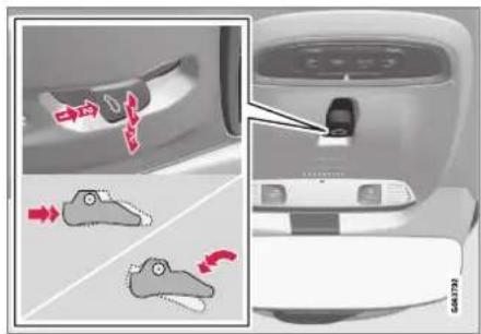
Operation, manual mode
2 Operation, automatic mode
Manual operation
- To open the sun curtain, pull the control backward to the manual open mode.
- To open the panoramic roof to the comfort position, pull the control backward a second time to the manual opening position.
- To open the panoramic roof fully, pull the control backward a third time to the manual opening position.
Close by repeating the above procedure in reverse - push the control forward/down to the manual closing position.
Auto operation
- To open the sun curtain to the fully open position, pull the control backward to the auto open mode and release.
- To open the panoramic roof to the comfort position, pull the control backward a second time to the automatic opening position and release.
- To open the panoramic roof fully, pull the control backward a third time to the automatic opening position and release.
Close by repeating the above procedure in reverse - push the control forward/down to the auto close position.
Automatic operation - rapid opening or closing
The panoramic roof and sun curtain can be opened or closed simultaneously:
- Open - press the control backward twice to the automatic operation position and release.
- Close - press the control forward/down twice to the automatic operation position and release.
Related information
• Panoramic roof* (p. 172)
• Auto closing the panoramic roof* sun curtain (p. 175)
- Pinch protection for windows and sun curtains (p. 166)
• Keyless locking and unlocking* (p. 259)
- Locking and unlocking using the remote key (p. 246)
Auto closing the panoramic roof\* sun curtain
With this function, the sun curtain closes automatically 15 minutes after the car has been locked if it is parked in hot weather. This is done to lower the passenger compartment temperature and protect the upholstery against being bleached by the sun.
The function is deactivated as the default factory setting and can be activated or deactivated using the center display.
-
Tap Settings in the Top view in the center display.
-
Tap My Car Locking.
Select Auto Close Sunroof Curtain to activate/deactivate.
NOTE
The sun curtain also closes when all windows are closed with keyless closing*.
Related information
• Panoramic roof* (p. 172)
• Operating the panoramic roof* (p. 173)
- Pinch protection for windows and sun curtains (p. 166)
▶▶
WINDOWS, GLASS AND MIRRORS
• Keyless locking and unlocking* (p. 259)
- Locking and unlocking using the remote key (p. 246)
• Keyless locking and unlocking* (p. 259)
- Locking and unlocking using the remote key (p. 246)
Wiper blades and washer fluid
The wipers and the washer fluid are used to improve visibility and the headlight pattern.
The washer nozzles are heated* automatically in cold weather to prevent the washer fluid from freezing.
When there is approximately 1 liter (1 qt) of washer fluid remaining, a message to refill will appear in the instrument panel.
Related information
• Using the rain sensor (p. 177)
- Using the windshield and headlight washers (p. 179)
• Using automatic rear window wiping when backing up (p. 181)
• Using the rain sensor's memory function (p. 178)
• Using the rear window wiper/washer (p. 180)
• Filling washer fluid (p. 662)
• Windshield wipers in the service position (p. 661)
• Replacing windshield wiper blades (p. 660)
• Changing rear window wipers (p. 659)
• Using the windshield wipers (p. 176)
Using the windshield wipers
The windshield wipers clean the windshield. The right-side steering wheel lever is used to adjust windshield wiper settings.

Right-hand steering wheel lever.
① Thumb wheel, used to set rain sensor sensitivity and interval wiper speed.
Single sweep
Move the lever down and release for a single sweep.
Wipers off
0 Move the lever to position 0 to turn off the windshield wipers.
Interval wipers
INT Set the number of sweeps per time unit with the thumb wheel when interval wipers are selected.
Continuous wipers

Move the lever upward for the wipers to operate at normal speed.

Move the lever upward again for the wipers to operate at high speed.

CAUTION
Before activating the wipers, make sure that the wiper blades are not frozen in place and that any snow or ice on the windshield and rear window has been scraped away.

CAUTION
Use plenty of washer fluid when the wipers clean the windshield. The windshield must be wet when the windshield wipers are working.
Related information
• Using the rain sensor (p. 177)
• Using the windshield and headlight washers (p. 179)
- Using automatic rear window wiping when backing up (p. 181)
• Wiper blades and washer fluid (p. 176)
• Using the rain sensor's memory function (p. 178)
• Using the rear window wiper/washer (p. 180)
• Filling washer fluid (p. 662)
• Windshield wipers in the service position (p. 661)
• Replacing windshield wiper blades (p. 660)
• Changing rear window wipers (p. 659)
Using the rain sensor
The rain sensor monitors the amount of water on the windshield and automatically starts the windshield wipers. Rain sensor sensitivity can be adjusted using the thumb wheel on the right-hand steering wheel lever.

Right-hand steering wheel lever.

Rain sensor button

Thumb wheel, sensitivity/interval wiper speed
When the rain sensor is activated, the rain sensor symbol will be displayed in the instrument panel.
Activating the rain sensor
When the rain sensor is activated, the engine must be running or the ignition must be in mode I or II. The windshield wiper lever must also be in position 0 or in the single sweep position.
▶▶
WINDOWS, GLASS AND MIRRORS
Activate the rain sensor by pressing the rain sensor button
If the lever is pressed down, the wipers will make additional sweeps across the windshield.
Turn the thumb wheel upward for increased sensitivity and downward for decreased sensitivity. The wipers will make one extra sweep when the thumb wheel is turned upward.
Deactivate the rain sensor
Deactivate the rain sensor by pressing the rain sensor button or moving the lever upward to another wiper mode.
The rain sensor is automatically deactivated in ignition mode 0 or when the engine is switched off.
The rain sensor is also automatically deactivated when the wiper blades are put in the service position. The rain sensor will reactivate when service mode is switched off.

CAUTION
The windshield wipers may start inadvertently and be damaged in automatic car washes. Deactivate the rain sensor when the engine is running or when the ignition is in mode I or II. The symbol in the instrument panel will go out.
Related information
• Using the windshield and headlight washers (p. 179)
• Using automatic rear window wiping when backing up (p. 181)
• Wiper blades and washer fluid (p. 176)
• Using the rain sensor's memory function (p. 178)
• Using the rear window wiper/washer (p. 180)
• Filling washer fluid (p. 662)
- Windshield wipers in the service position (p. 661)
• Replacing windshield wiper blades (p. 660)
• Changing rear window wipers (p. 659)
• Using the windshield wipers (p. 176)
Using the rain sensor's memory function
The rain sensor monitors the amount of water on the windshield and automatically starts the windshield wipers.
Activating/deactivating memory function
The rain sensor's memory function can be set to activate so that the rain sensor button does not need to be pressed each time the engine is started:
-
Tap Settings in the Top view in the center display.
-
Tap My Car Wipers.
-
Select Rain Sensor Memory to activate/deactivate the memory function.
Related information
• Using the rain sensor (p. 177)
• Using the windshield and headlight washers (p. 179)
• Using automatic rear window wiping when backing up (p. 181)
• Wiper blades and washer fluid (p. 176)
• Using the rear window wiper/washer (p. 180)
• Filling washer fluid (p. 662)
• Windshield wipers in the service position (p. 661)
• Replacing windshield wiper blades (p. 660)
• Changing rear window wipers (p. 659)
• Using the windshield wipers (p. 176)
Using the windshield and headlight washers
The windshield and headlight washers clean the windshield and headlights. Use the right-side steering wheel lever to start the windshield and headlight washers.
Starting the windshield and headlight washers

natural_image
Interior view of a car showing a black gear shift lever and a red arrow pointing to the wheel (no text or symbols visible)Washing function, right-hand steering wheel lever.
- Move the right-hand steering wheel lever toward the steering wheel to start the wind-shield and headlight washers.
After the lever is released, the wipers make several extra sweeps.
CAUTION
Avoid activating the washer system when it is frozen or the fluid reservoir is empty. Otherwise, there is a risk of damaging the pump.
Headlight washer\*
To save washer fluid, the headlights are washed automatically according to a defined interval when the headlights are on.
Reduced washing
When there is about 1 liter (1 qt) of washer fluid left in the reservoir and the Washer fluid Level low, refill message is displayed in the instrument panel together with the 🔗 symbol, the washer fluid supply to the headlights is cut off. This is to prioritize windshield cleaning and visibility through it. The headlights are only washed if high or low beam is on.
Related information
• Using the rain sensor (p. 177)
- Using automatic rear window wiping when backing up (p. 181)
• Wiper blades and washer fluid (p. 176)
• Using the rain sensor's memory function (p. 178)
• Using the rear window wiper/washer (p. 180)
• Filling washer fluid (p. 662)
▶▶
WINDOWS, GLASS AND MIRRORS
• Windshield wipers in the service position (p. 661)
• Replacing windshield wiper blades (p. 660)
• Changing rear window wipers (p. 659)
• Using the windshield wipers (p. 176)
Using the rear window wiper/washer
The rear window wiper/washer cleans the rear window. Use the right-side steering wheel lever to start and control the wiper/washer.
Activating the rear window wiper/washer
NOTE
The rear window wiper motor is equipped with overheating protection that switches off the motor if it becomes overheated. The rear window wiper can be operated again after a cooling-down period.

1 Select for interval rear window wiper.
2 Select for continuous rear window wiper.
- Move the right-side steering wheel lever forward to wash/wipe the rear window.
Related information
• Using the rain sensor (p. 177)
• Using the windshield and headlight washers (p. 179)
• Using automatic rear window wiping when backing up (p. 181)
• Using the rain sensor's memory function (p. 178)
• Wiper blades and washer fluid (p. 176)
• Filling washer fluid (p. 662)
• Windshield wipers in the service position (p. 661)
• Replacing windshield wiper blades (p. 660)
• Changing rear window wipers (p. 659)
• Using the windshield wipers (p. 176)
Using automatic rear window wiping when backing up
If reverse gear is engaged while the windshield wipers are on, the rear window wipers will start. This function is deactivated when a different gear is selected.
- Tap Settings in the Top view in the center display.
- Tap My Car Wipers.
- Select Auto Rear Wiper to activate/deactivate automatic rear window wiping when backing up.
If the rear window wipers are already in continuous wiper mode, no change will be made.
Related information
• Using the rain sensor (p. 177)
- Using the windshield and headlight washers (p. 179)
• Wiper blades and washer fluid (p. 176)
- Using the rain sensor's memory function (p. 178)
• Using the rear window wiper/washer (p. 180)
• Filling washer fluid (p. 662)
● Windshield wipers in the service position (p. 661)
• Replacing windshield wiper blades (p. 660)
• Changing rear window wipers (p. 659)
• Using the windshield wipers (p. 176)

bar
| Category | Value | |---|---| | Category 1 | 100 | | Category 2 | 100 | | Category 3 | 100 | | Category 4 | 100 | | Category 5 | 100 | | Category 6 | 100 | | Category 7 | 100 | | Category 8 | 100 | | Category 9 | 100 | | Category 10 | 100 | | Category 11 | 100 | | Category 12 | 100 | | Category 13 | 100 | | Category 14 | 100 | | Category 15 | 100 | | Category 16 | 100 | | Category 17 | 100 | | Category 18 | 100 | | Category 19 | 100 | | Category 20 | 100 | | Category 21 | 100 | | Category 22 | 100 | | Category 23 | 100 | | Category 24 | 100 | | Category 25 | 100 | | Category 26 | 100 | | Category 27 | 100 | | Category 28 | 100 | | Category 29 | 100 | | Category 30 | 100 | | Category 31 | 100 | | Category 32 | 100 | | Category 33 | 100 | | Category 34 | 100 | | Category 35 | 100 | | Category 36 | 100 | | Category 37 | 100 | | Category 38 | 100 | | Category 39 | 100 | | Category 40 | 100 | | Category 41 | 100 | | Category 42 | 100 | | Category 43 | 100 | | Category 44 | 100 | | Category 45 | 100 | | Category 46 | 100 | | Category 47 | 100 | | Category 48 | 100 | | Category 49 | 100 | | Category 50 | 100 | | Category 51 | 100 | | Category 52 | 100 | | Category 53 | 100 | | Category 54 | 100 | | Category 55 | 100 | | Category 56 | 100 | | Category 57 | 100 | | Category 58 | 100 | | Category 59 | 100 | | Category 60 | 100 | | Category 61 | 100 | | Category 62 | 100 | | Category 63 | 100 | | Category 64 | 100 | | Category 65 | 100 | | Category 66 | 100 | | Category 67 | 100 | | Category 68 | 100 | | Category 69 | 100 | | Category 70 | 100 | | Category 71 | 100 | | Category 72 | 100 | | Category 73 | 100 | | Category 74 | 100 | | Category 75 | 100 | | Category 76 | 100 | | Category 77 | 100 | | Category 78 | 100 | | Category 79 | 100 | | Category 80 | 100 | | Category 81 | 100 | | Category 82 | 100 | | Category 83 | 100 | | Category 84 | 100 | | Category 85 | 100 | | Category 86 | 100 | | Category 87 | 100 | | Category 88 | 100 | | Category 89 | 100 | | Category 90 | 100 | | Category 91 | 100 | | Category 92 | 100 | | Category 93 | 100 | | Category 94 | 100 | | Category 95 | 100 | | Category 96 | 100 | | Category 97 | 100 | | Category 98 | 100 | | Category 99 | 100 | | Total (Total) |SEATS AND STEERING WHEEL
SEATS AND STEERING WHEEL
Manual front seats
The power front seats can be adjusted in a number of different ways for optimal comfort and ergonomics.

1 Raise/lower the front edge of the seat cushion* by moving the control up/down. ^1
② Change the length of the seat cushion* by pulling up the lever and moving the cushion forward/backward.
3 Move the seat forward/backing by lifting the handle and moving the seat to a suitable distance from the steering wheel and pedals. Check to make sure the seat is securely locked into place after its setting has been changed.
4 Adjust lumbar support* by pressing the button up/down/forward/rearward ^2 .
5 Raise/lower the seat by moving the control up/down.
6 Change the backrest tilt by turning the knob on the backrest.
WARNING
- Do not adjust the seat while driving. The seat should be adjusted so that the brake pedal can be depressed fully. In addition, position the seat as far rearward as comfort and control allow.
- Check that the seat is securely locked into position after adjusting.
Related information
• Power* front seats (p. 185)
• Adjusting the power* front seats (p. 185)
- Storing positions for seats, mirrors and head-up display* (p. 186)
- Using stored positions for seats, mirrors and head-up display* (p. 187)
- Adjusting front seat massage settings* (p. 189)
- Adjusting* front seat cushion length (p. 189)
• Front seat massage* settings (p. 188)
- Adjusting front seat side bolster settings* (p. 190)
• Adjusting front seat lumbar support* (p. 191)
- Adjusting the passenger seat from the driver's seat* (p. 192)
Power\* front seats
The power front seats can be adjusted in a number of different ways for optimal comfort and ergonomics. The power seat can be moved forward/backward and up/down. The height and length* of the seat cushion and the tilt of the backrest can be adjusted. Lumbar support* can be adjusted up, down, forward and backward ^3 .
The power seats can be adjusted for a certain period of time after the door is unlocked without the engine running. The seats can always be adjusted while the engine is running. They can also be adjusted for a short period after the engine is turned off.

CAUTION
The power seats have an overload protector that is triggered if a seat is blocked by any object. If this occurs, remove the object and attempt to adjust the seat again.
Related information
• Manual front seats (p. 184)
- Adjusting the power* front seats (p. 185)
- Storing positions for seats, mirrors and head-up display* (p. 186)
- Using stored positions for seats, mirrors and head-up display* (p. 187)
- Adjusting front seat massage settings* (p. 189)
- Adjusting* front seat cushion length (p. 189)
• Front seat massage* settings (p. 188) - Adjusting front seat side bolster settings* (p. 190)
• Adjusting front seat lumbar support* (p. 191) - Adjusting the passenger seat from the driver's seat* (p. 192)
Adjusting the power\* front seats
Set the desired seating position using the controls on the front seat cushion. To set the convenience functions, turn the multifunction control ^4 upward/downward.
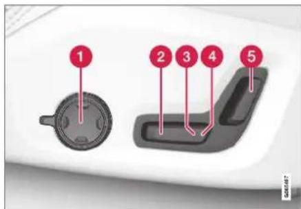
The illustration shows the controls in a vehicle with four-way lumbar support*. Vehicles with two-way lumbar support* do not have the rotary multifunction control.
In vehicles with four-way lumbar support*, turn the multifunction control ^1 up/down to set the convenience functions. In vehicles with two-way lumbar support*, use the round button to adjust the lumbar support forward/rearward.
2 Raise/lower the front edge of the seat cushion by moving the control up/down.
SEATS AND STEERING WHEEL
◀◀
3 Raise/lower the seat by moving the control up/down.
4 Move the seat forward/rearward by moving the control forward/rearward.
⑤ Change the backrest tilt by moving the control forward/backward.
Only one movement (forward/rearward/up/down) can be performed at a time.
The front seat backrests cannot be folded down completely.
Related information
• Manual front seats (p. 184)
• Power* front seats (p. 185)
- Storing positions for seats, mirrors and head-up display* (p. 186)
- Using stored positions for seats, mirrors and head-up display* (p. 187)
- Adjusting front seat massage settings* (p. 189)
- Adjusting* front seat cushion length (p. 189)
• Front seat massage* settings (p. 188)
- Adjusting front seat side bolster settings* (p. 190)
• Adjusting front seat lumbar support* (p. 191)
- Adjusting the passenger seat from the driver's seat* (p. 192)
Storing positions for seats, mirrors and head-up display\*
Adjustment settings for the power* seat, door mirrors and head-up display* can be stored in the memory buttons.
Three different positions for the power* seat, door mirrors and head-up display* can be stored using the memory buttons. The buttons are located on the inside of either one or both* front doors.

1 Memory button
2 Memory button
③ Memory button
4 Button M for storing a setting
Storing positions
- Adjust the seat, door mirrors and head-up display to the desired position.
- Press and hold the M button. The indicator light in the button will illuminate.
- Within three seconds, press and hold the 1, 2 or 3 button.
When the position has been stored in the memory button, an audio signal will sound and the indicator light in the M button will go out.
If none of the memory buttons are pressed within three seconds, the M button will go out and no position will be stored.
The seats, door mirrors or head-up display must be readjusted before a new memory position can be set.
Related information
• Manual front seats (p. 184)
• Power* front seats (p. 185)
- Adjusting the power* front seats (p. 185)
- Using stored positions for seats, mirrors and head-up display* (p. 187)
- Adjusting front seat massage settings* (p. 189)
- Adjusting* front seat cushion length (p. 189)
• Front seat massage* settings (p. 188)
- Adjusting front seat side bolster settings* (p. 190)
• Adjusting front seat lumbar support* (p. 191)
- Adjusting the passenger seat from the driver's seat* (p. 192)
• Adjusting the door mirrors (p. 171)
• Head-up display settings* (p. 144)
Using stored positions for seats, mirrors and head-up display\*
If the positions for the power* seat, door mirrors and head-up display* have been stored, they can be easily activated using the memory buttons.
Using a stored position
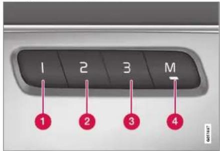
A stored position can be used with the front door open or closed:
Front door open
- Briefly press one of the memory buttons (1-3). The power seats, door mirrors and head-up display will move and stop at the positions stored in that button.
Front door closed
- Press and hold one of the memory buttons (1-3) until the seat, door mirrors and head-up display stop in the positions stored in that memory button.
If the memory button is released, the seat, door mirrors and head-up display will stop moving.

WARNING
- This list point needs to be translated exactly to: "Because the driver's seat can be adjusted with the ignition off, children should never be left unattended in the vehicle.
- Movement of the seat can be STOPPED at any time by pressing any button on the power seat control panel.
- Do not adjust the seat while driving.
- The seat should be adjusted so that the brake pedal can be depressed fully. In addition, position the seat as far rearward as comfort and control allow.
- The seat rails on the floor must not be obstructed in any way when the seat is in motion.
Related information
• Manual front seats (p. 184)
• Power* front seats (p. 185)
- Adjusting the power* front seats (p. 185)
- Storing positions for seats, mirrors and head-up display* (p. 186)
- Adjusting front seat massage settings* (p. 189)
▶▶
SEATS AND STEERING WHEEL
- Adjusting* front seat cushion length (p. 189)
• Front seat massage* settings (p. 188) - Adjusting front seat side bolster settings* (p. 190)
• Adjusting front seat lumbar support* (p. 191) - Adjusting the passenger seat from the driver's seat* (p. 192)
• Adjusting the door mirrors (p. 171)
• Head-up display settings* (p. 144)
Front seat massage\* settings
The settings for the multifunctional seats can be adjusted using either the multifunction control on the seat or the center display. The adjustment settings are shown in the center display.
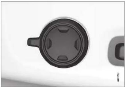
natural_image
Close-up of a black circular mechanical component with a handle, no visible text or symbolsMultifunction control, located on the side of the seat cushion.
Massage settings
The following massage settings are available:
- On/Off: Select On/Off to turn on/off the massage function.
- Programs 1-5: There are 5 preset massage programs. Select Swell, Tread, Advanced, Lumbar or Shoulder.
• Intensity: Select Low, Normal or High.
• Speed: Select Slow, Normal or Fast.
Restarting the massage function
The massage function turns off automatically after 20 minutes. The function is reactivated manually.
- Tap Restart, which is displayed in the center display, to restart the selected massage program.
The massage program will restart. If no selection is made, the message will be stored in Top view.
Related information
• Manual front seats (p. 184)
• Power* front seats (p. 185)
- Adjusting the power* front seats (p. 185)
- Storing positions for seats, mirrors and head-up display* (p. 186)
• Using stored positions for seats, mirrors and head-up display* (p. 187)
- Adjusting front seat massage settings* (p. 189)
- Adjusting* front seat cushion length (p. 189)
- Adjusting front seat side bolster settings* (p. 190)
• Adjusting front seat lumbar support* (p. 191)
- Adjusting the passenger seat from the driver's seat* (p. 192)
Adjusting front seat massage settings\*
The settings for the multifunctional seats can be adjusted using either the multifunction control on the seat or the center display. The adjustment settings are shown in the center display.
Adjusting front seat massage settings
The front seat backrests have a massage function. Air-filled cushions provide the massaging action and a number of settings are available.
The massage function can only be activated when the engine is running.
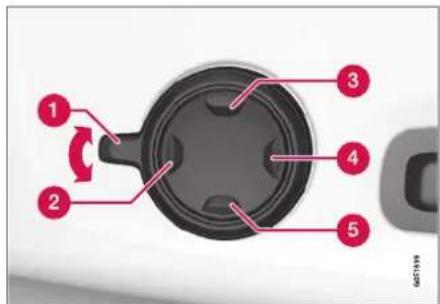
-
Activate the multifunction control by turning the control upward/downward. The seat settings view will appear in the center display.
-
Select Massage in the seat settings view.
-
Select massage settings by tapping the center display or by moving the cursor up/down using the multifunction control's upper ③/ lower ⑤ buttons. Change a setting in the selected function by tapping the arrows on the center display or by using the multifunction control's front ②/rear ④ buttons.
Related information
• Manual front seats (p. 184)
• Power* front seats (p. 185)
• Adjusting the power* front seats (p. 185)
- Storing positions for seats, mirrors and head-up display* (p. 186)
- Using stored positions for seats, mirrors and head-up display* (p. 187)
• Adjusting* front seat cushion length (p. 189)
• Front seat massage* settings (p. 188)
- Adjusting front seat side bolster settings* (p. 190)
• Adjusting front seat lumbar support* (p. 191)
- Adjusting the passenger seat from the driver's seat* (p. 192)
Adjusting\* front seat cushion length
Depending on the selected equipment level, the length of the seat cushion can either be adjusted using the multifunction control* on the side of the seat cushion, or manually adjusted using the control on the front of the seat cushion.
Adjusting seat cushion length using the multifunction control

The multifunction control, located on the side of the seat cushion.
1. Activate the multifunction control by turning the control ① upward/downward. The seat settings view will appear in the center display.
SEATS AND STEERING WHEEL
-
Select Cushion extension in the seat settings view.
-
Push in the front part of the four-way button ② to extend the seat cushion.
- Press the rear part of the four-way button ③ to shorten the seat cushion.
Manually adjusting seat cushion length

natural_image
Close-up of a car seatbelt with a finger pointing to the seatbelt (no visible text or symbols)Control for adjusting seat cushion.
- Grasp the handle on the front of the seat and pull upward.
- Adjust the length of the seat cushion.
- Release the handle and make sure the seat cushion locks into position.
Related information
• Manual front seats (p. 184)
• Power* front seats (p. 185)
- Adjusting the power* front seats (p. 185)
- Storing positions for seats, mirrors and head-up display* (p. 186)
- Using stored positions for seats, mirrors and head-up display* (p. 187)
- Adjusting front seat massage settings* (p. 189)
• Front seat massage* settings (p. 188) - Adjusting front seat side bolster settings* (p. 190)
• Adjusting front seat lumbar support* (p. 191) - Adjusting the passenger seat from the driver's seat* (p. 192)
Adjusting front seat side bolster settings\*
Enhance comfort in the front seat by adjusting the sides of the backrest.
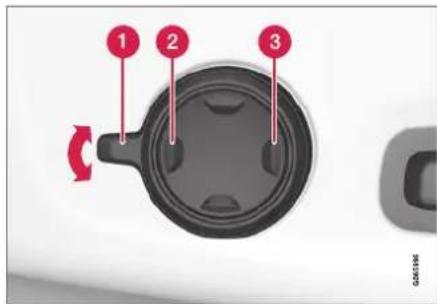
Multifunction control, located on the side of the seat cushion.
The side bolsters in the front seat backrests can be inflated/deflated to adjust the amount of support provided. The settings for the multifunctional seats can be adjusted using either the multifunction control on the seat or the center display. The adjustment settings are shown in the center display.
To adjust the side bolsters:
-
Activate the multifunction control by turning it upward/downward ① the seat settings view will appear in the center display.
-
Select Side bolsters in the seat settings view.
-
Press the front part of the four-way button to increase side bolster support ②.
- Press the rear part of the four-way button to decrease side bolster support ^3 .
Related information
• Manual front seats (p. 184)
• Power* front seats (p. 185)
- Adjusting the power* front seats (p. 185)
- Storing positions for seats, mirrors and head-up display* (p. 186)
- Using stored positions for seats, mirrors and head-up display* (p. 187)
- Adjusting front seat massage settings* (p. 189)
- Adjusting* front seat cushion length (p. 189)
• Front seat massage* settings (p. 188)
• Adjusting front seat lumbar support* (p. 191)
- Adjusting the passenger seat from the driver's seat* (p. 192)
Adjusting front seat lumbar support\*
Use the control on the side of the seat cushion to adjust the lumbar support.

natural_image
Close-up of a black circular mechanical component with a handle, no visible text or symbolsMultifunction control, in vehicles with four-way lumbar support*.

natural_image
Close-up of a circular mechanical component with two side slots, possibly a knob or dial (no text or symbols visible)Control in vehicles with two-way lumbar support*.
Lumbar support is adjusted using the multifunction control in vehicles with four-way lumbar support*, or the round button in vehicles with two-way lumbar support*. The control is located on the side of the seat cushion. Depending on the selected equipment level, the lumbar support can be adjusted forward/rearward and up/down (four-way lumbar support) or forward/backward (two-way lumbar support).
Adjusting lumbar support in vehicles with four-way lumbar support

- Activate the multifunction control by turning the control ① upward/downward. The seat settings view will appear in the center display.
▶▶
SEATS AND STEERING WHEEL
-
Select Lumbar in the seat settings view.
-
Press the round button up ③/down ⑤ to move the lumbar support upward/ downward.
- Press the front part ② of the button to increase lumbar support.
- Press the rear part 4 of the button to decrease lumbar support.
Adjusting lumbar support in vehicles with two-way lumbar support

natural_image
Close-up of a circular mechanical component with two red-labeled points (1 and 2), no visible text or symbols.- Press the front part of the round button to increase lumbar support.
- Press the rear part ② of the round button to decrease lumbar support.
Related information
• Manual front seats (p. 184)
• Power* front seats (p. 185)
• Adjusting the power* front seats (p. 185)
- Storing positions for seats, mirrors and head-up display* (p. 186)
- Using stored positions for seats, mirrors and head-up display* (p. 187)
- Adjusting front seat massage settings* (p. 189)
• Adjusting* front seat cushion length (p. 189)
• Front seat massage* settings (p. 188)
- Adjusting front seat side bolster settings* (p. 190)
- Adjusting the passenger seat from the driver's seat* (p. 192)
Adjusting the passenger seat from the driver's seat\*
The front passenger seat can be adjusted from the driver's seat.
Activating the function
The function is activated via the function view in the center display:

Tap the Adjust Passenger Seat button to activate.
Adjust passenger seat
The driver must adjust the passenger seat within 10 seconds of activating the function. If no adjustment is made within this time, the function will be deactivated.
The driver adjusts the passenger seat using the controls on the driver's seat:

1 Move the passenger seat forward/rearward by moving the control forward/rearward.
② Change the backrest tilt of the passenger seat by moving the control forward/backward.
Related information
• Manual front seats (p. 184)
• Power* front seats (p. 185)
• Adjusting the power* front seats (p. 185)
- Storing positions for seats, mirrors and head-up display* (p. 186)
- Using stored positions for seats, mirrors and head-up display* (p. 187)
- Adjusting front seat massage settings* (p. 189)
- Adjusting* front seat cushion length (p. 189)
• Front seat massage* settings (p. 188)
- Adjusting front seat side bolster settings* (p. 190)
• Adjusting front seat lumbar support* (p. 191)
Folding the second row backrests
The second row of seats has three individual seating positions. The backrests can be folded down separately.
WARNING
- Adjust the seat and ensure it locks into position before driving. Use caution when adjusting the seat. Uncontrolled or careless adjustments could lead to injury.
- Long objects must always be securely tied down to help prevent injury or damage in the event of sudden braking.
- Always turn off the engine and apply the parking brake when loading or unloading the vehicle.
- Put the gear selector in P to help prevent the gear selector from being inadvertently moved.
CAUTION
When the backrest is folded down, make sure there are no objects in the rear seat, and the seat belts are not buckled. Otherwise there is a risk of damage to the upholstery.
▶▶
SEATS AND STEERING WHEEL
◀◀

CAUTION
The seat cushion of the integrated child restraint* must be in the slowed position before the center seat backrest can be folded down.
The armrest* in the center seat must be raised before the seat backrest is folded down.

NOTE
The front seats may need to be pushed forward and/or the backrest adjusted so that the rear seat backrests can be fully lowered.
The rear seats may also need to be moved rearward.
The seats in the second row must be in the upright position before they can be folded down completely. They should not be folded down when they are tilted forward to access the third row of seats.
Center seat

natural_image
Interior view of a car seatbelt with red arrows indicating downward pressure points (no text or symbols)To fold down the backrest:
- Fold down the head restraint manually.
- Pull the strap on the right side of the center seat.
- Fold the backrest down until it locks into position. The seat cushion will move downward/forward when the backrest is folded down and create a flat surface.
To return the backrest to the upright position:
- Pull the strap.
- Fold up the backrest and release the strap. Push the backrest until it locks into position.
- Adjust the head restraint if necessary.
Outboard seats

natural_image
Interior view of a car showing the rear seat, seatbelt, and side panel with red arrows indicating direction (no text or symbols)To fold down the backrest:

NOTE
When folding down a second row seat back-rest, always start from the seat's normal upright position. Do not use the handle for folding down the seat when the seat is in the position for accessing the third row.
-
Pull up and hold the handle on the side of the seat while the backrest is being folded down.
-
Make sure that backrest and head restraint do not come in contact with the seat in front while the backrest is being folded down. Fold the backrest down until it locks into position.
The seat cushion will move downward/forward when the backrest is folded down and create a flat surface. The head restraint folds down automatically when the backrest is lowered.

WARNING
Make sure the backrest is securely locked into position after it is folded down.
To return the backrest to the upright position:
- Pull up and hold the handle on the side of the seat while the backrest is being folded up.
- Make sure that backrest and head restraint do not come in contact with the seat in front while the backrest is being folded up. Fold up the backrest and release the handle.
- Press the backrest until it locks into position.
- Fold up the head restraint manually.

WARNING
Make sure that the rear seat backrest and head restraint are locked securely in place after the seat is folded up.
The head restraints at the outer seats must always be raised when there is a passenger in one of these spots of the rear seat.

WARNING
The head restraints on the outboard second-row seats must always be folded up when there are passengers in the third row of seats*.
Related information
- Adjusting the second row head restraints (p. 195)
- Moving the second row seats forward/rearward* (p. 197)
- Adjusting the second row backrest tilt (p. 197)
- Getting into and out of the third row of seats* (p. 198)
• Folding the third row backrests* (p. 199)
Adjusting the second row head restraints
Adjust the center head restraint in the rear seat to the seat occupant's height. Fold down the outboard head restraints* to improve rear visibility.
Adjusting the center head restraint
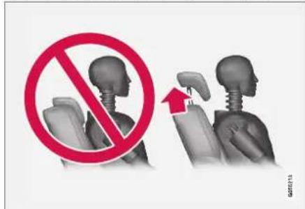
The center head restraint should be adjusted to suit the passenger's height. The entire back of the head should be covered if possible. Manually move the restraint up or down as needed.
▶▶
SEATS AND STEERING WHEEL
◀◀
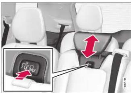
natural_image
Interior view of a car seatbelt with a highlighted inset showing a seatbelt buckle (no text or symbols visible)To lower the restraint, press and hold the button (located between the backrest and the head restraint, see illustration) while carefully lowering the head restraint.

WARNING
The center seat head restraint must be in its lowest position when the seat is not occupied. When the center seat is occupied, the head restraint must be correctly adjusted to the passenger's height, covering the entire back of the head if possible.
Electrically folding down the rear seat's outboard head restraints\*

natural_image
Interior view of a car showing white seat, gray backrest, and a red downward arrow on the backrest (no text or symbols visible)The outer head restraints can be folded via the center display's function view. The head restraint can be folded down when the vehicle is in ignition mode 0.

Tap the Headrest Fold button to activate/deactivate folding.
Manually push the head restraint until it clicks into position.

WARNING
Do not lower the head restraint if there are passengers in any of the rear seats.

WARNING
The head restraint must be locked in the upright position after it has been folded up.

WARNING
The head restraints on the outboard second-row seats must always be folded up when there are passengers in the third row of seats*.
Related information
• Folding the second row backrests (p. 193)
- Moving the second row seats forward/rearward* (p. 197)
- Adjusting the second row backrest tilt (p. 197)
- Getting into and out of the third row of seats* (p. 198)
• Folding the third row backrests* (p. 199)
Moving the second row seats forward/rearward\*
In vehicles with 7 seats*, the seats in the second row can be moved forward or rearward individually to help optimize legroom for passengers in the second and third rows. The second row seats cannot be moved forward or backward in 5-seat models.

natural_image
Interior view of a white car seat with red directional arrows indicating movement or orientation (no text or symbols present)
Lift the handle under the seat.

Move the seat forward or backward to the desired position.
- Release the handle and press the seat until it locks into position.
Check to make sure the seat is securely locked into place after its position has been changed.

WARNING
- Adjust the seat and ensure it locks into position before driving. Use caution when adjusting the seat. Uncontrolled or careless adjustments could lead to injury.
- Long objects must always be securely tied down to help prevent injury or damage in the event of sudden braking.
- Always turn off the engine and apply the parking brake when loading or unloading the vehicle.
- Put the gear selector in P to help prevent the gear selector from being inadvertently moved.
Related information
• Folding the second row backrests (p. 193)
- Adjusting the second row head restraints (p. 195)
• Adjusting the second row backrest tilt (p. 197)
- Getting into and out of the third row of seats* (p. 198)
• Folding the third row backrests* (p. 199)
Adjusting the second row backrest tilt
Backrest tilt can be adjusted separately for each seat in the second row.
Center seat

natural_image
Interior view of a car seat with red directional arrows indicating movement or force (no text or symbols)- Pull the strap on the right side of the center seat.
- Adjust backrest tilt forward/backward by decreasing/increasing pressure on the back-rest.
- Release the strap to lock the backrest in its new position and press on the backrest until the lock engages.
Check to make sure the seat is securely locked into place after its position has been changed.
▶▶
SEATS AND STEERING WHEEL
Outboard seats

natural_image
Interior view of a car showing the rear seat, white leather seats, and a red arrow indicating a specific side panel (no text or symbols present)- Pull the handle on the side of the seat upward.
- Adjust backrest tilt forward/backward by decreasing/increasing pressure on the back-rest.
- Release the handle to lock the backrest in its new position and press on the backrest until the lock engages.
Check to make sure the seat is securely locked into place after its position has been changed.
WARNING
- Adjust the seat and ensure it locks into position before driving. Use caution when adjusting the seat. Uncontrolled or careless adjustments could lead to injury.
- Long objects must always be securely tied down to help prevent injury or damage in the event of sudden braking.
- Always turn off the engine and apply the parking brake when loading or unloading the vehicle.
- Put the gear selector in P to help prevent the gear selector from being inadvertently moved.
Related information
• Folding the second row backrests (p. 193)
- Adjusting the second row head restraints (p. 195)
- Moving the second row seats forward/rearward* (p. 197)
- Getting into and out of the third row of seats* (p. 198)
• Folding the third row backrests* (p. 199)
Getting into and out of the third row of seats\*
The second row of seats can be adjusted for easier access to the third row of seats*.

natural_image
Interior view of a car showing white rear seats with red arrows indicating seat positions (no text or symbols)To fold down the backrest:
- Pull the handle on the upper side of the right or left outboard second row seat upward/forward.
- Fold the backrest down and move the entire seat forward.
To return the seat to the upright position: - Push the seat rearward to its end position. The backrest should then easily return to the correct position.

NOTE
If a backrest in the second row of seats does not lock back into the upright position after being folded down (e.g. for getting in or out of the third row of seats), it may need to be pushed forward again and then pushed back with more force.

WARNING
Make sure that the rear seat backrest and head restraint are locked securely in place after the seat is folded up.
The head restraints at the outer seats must always be raised when there is a passenger in one of these spots of the rear seat.
Related information
• Folding the second row backrests (p. 193)
- Adjusting the second row head restraints (p. 195)
- Moving the second row seals forward/rearward* (p. 197)
- Adjusting the second row backrest tilt (p. 197)
• Folding the third row backrests* (p. 199)
Folding the third row backrests\*
The third row has two individual seats. These can be folded down separately.
CAUTION
To fold down the third-row seat backrests, it may be necessary to change the position/lilt the seats in the second row.
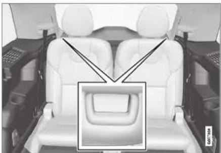
natural_image
Interior view of a car showing the backrest seat, driver seat, and dashboard (no text or symbols visible)-
Pull the handle on the upper side of the backrest upward/forward.
-
Make sure that backrest and head restraint do not come in contact with the seat in front while the backrest is being folded down. Fold the backrest down.
The seat cushion will move downward/forward when the backrest is folded down and create a flat surface. The head restraint folds down automatically when the backrest is lowered.
To return the seat to the upright position, fold the backrest up manually until it locks into position. Fold up the head restraint manually.
WARNING
Make sure that the rear seat backrest and head restraint are locked securely in place after the seat is folded up.
The head restraints at the outer seats must always be raised when there is a passenger in one of these spots of the rear seat.
Related information
• Folding the second row backrests (p. 193)
- Adjusting the second row head restraints (p. 195)
- Moving the second row seats forward/rearward* (p. 197)
SEATS AND STEERING WHEEL
- Adjusting the second row backrest tilt (p. 197)
- Getting into and out of the third row of seats* (p. 198)
Steering wheel controls and horn
The steering wheel has a horn and controls for e.g. driver support systems and voice control.

Steering wheel keypads and paddles*.
1 Driver support system controls ^5 .
② Paddle* for manually shifting gears (automatic transmission).
3 Controls for voice commands, adjusting the head-up display, accessing menus and messages, and handling phone calls.
Horn

natural_image
Interior view of a car dashboard with Volvo logo and air conditioners (no visible text or symbols)The horn is located in the center of the steering wheel.
Related information
• Adjusting the steering wheel (p. 201)
Adjusting the steering wheel
The steering wheel can be adjusted to various positions.

natural_image
Two hands holding a cylindrical object with red arrows indicating movement or force direction (no text or symbols)The steering wheel's reach and height can be adjusted.

WARNING
Adjust the steering wheel and ensure it locks into position before driving. Never adjust the steering wheel while driving.
Steering wheel force can be adjusted with speed-dependent power steering. Steering wheel force is adjusted according to the vehicle's speed to give the driver an enhanced sense of control and stability.

natural_image
Close-up of a white mechanical component with a small rectangular device embedded in its side (no visible text or symbols)Steering wheel adjuster lever.
- Move the lever forward to release the steering wheel.
- Adjust the steering wheel to the desired position.
- Pull the lever back to lock the steering wheel into place. If the lever is difficult to move, press the steering wheel lightly while pulling the lever.
Related information
• Steering wheel controls and horn (p. 200)
- Adjusting the power* front seats (p. 185)

bar
| Category | Value | |---|---| | Category 1 | 100 | | Category 2 | 100 | | Category 3 | 100 | | Category 4 | 100 | | Category 5 | 100 | | Category 6 | 100 | | Category 7 | 100 | | Category 8 | 100 | | Category 9 | 100 | | Category 10 | 100 | | Category 11 | 100 | | Category 12 | 100 | | Category 13 | 100 | | Category 14 | 100 | | Category 15 | 100 | | Category 16 | 100 | | Category 17 | 100 | | Category 18 | 100 | | Category 19 | 100 | | Category 20 | 100 | | Category 21 | 100 | | Category 22 | 100 | | Category 23 | 100 | | Category 24 | 100 | | Category 25 | 100 | | Category 26 | 100 | | Category 27 | 100 | | Category 28 | 100 | | Category 29 | 100 | | Category 30 | 100 | | Category 31 | 100 | | Category 32 | 100 | | Category 33 | 100 | | Category 34 | 100 | | Category 35 | 100 | | Category 36 | 100 | | Category 37 | 100 | | Category 38 | 100 | | Category 39 | 100 | | Category 40 | 100 | | Category 41 | 100 | | Category 42 | 100 | | Category 43 | 100 | | Category 44 | 100 | | Category 45 | 100 | | Category 46 | 100 | | Category 47 | 100 | | Category 48 | 100 | | Category 49 | 100 | | Category 50 | 100 | | Category 51 | 100 | | Category 52 | 100 | | Category 53 | 100 | | Category 54 | 100 | | Category 55 | 100 | | Category 56 | 100 | | Category 57 | 100 | | Category 58 | 100 | | Category 59 | 100 | | Category 60 | 100 | | Category 61 | 100 | | Category 62 | 100 | | Category 63 | 100 | | Category 64 | 100 | | Category 65 | 100 | | Category 66 | 100 | | Category 67 | 100 | | Category 68 | 100 | | Category 69 | 100 | | Category 70 | 100 | | Category 71 | 100 | | Category 72 | 100 | | Category 73 | 100 | | Category 74 | 100 | | Category 75 | 100 | | Category 76 | 100 | | Category 77 | 100 | | Category 78 | 100 | | Category 79 | 100 | | Category 80 | 100 | | Category 81 | 100 | | Category 82 | 100 | | Category 83 | 100 | | Category 84 | 100 | | Category 85 | 100 | | Category 86 | 100 | | Category 87 | 100 | | Category 88 | 100 | | Category 89 | 100 | | Category 90 | 100 | | Category 91 | 100 | | Category 92 | 100 | | Category 93 | 100 | | Category 94 | 100 | | Category 95 | 100 | | Category 96 | 100 | | Category 97 | 100 | | Category 98 | 100 | | Category 99 | 100 | | Total (Total) = [sum of the values] / [sum of the values] * [sum of the values] * [sum of the values] * [sum of the values] * [sum of the values] * [sum of the values] * [sum of the values] * [sum of the values] * [sum of the values] * [sum of the values] * [sum of the values] * [sum of the values] * [sum of the values] * [sum of the values] * [sum of the values] * [total] * [sum of the values] * [sum of the values] * [sum of the values] * [sum of the values] * [sum of the values]CLIMATE CONTROL
CLIMATE CONTROL
Climate
The vehicle is equipped with electronic climate control. The climate system cools, heats and dehumidifies the air in the passenger compartment.
All of the climate system functions are controlled from the center display and the buttons on the center console.
Certain rear seat functions can also be controlled from the climate controls* on the rear of the tunnel console.
Related information
• Climate zones (p. 204)
• Climate control sensors (p. 204)
• Perceived temperature (p. 205)
• Climate control system voice commands (p. 205)
- Parking climate (p. 231)
• Air quality (p. 206)
• Air distribution (p. 209)
• Climate system controls (p. 215)
Climate zones
The vehicle is divided into climate zones to make it possible to set different temperatures for different parts of the passenger compartment.
4-zone climate system

natural_image
Interior view of a vehicle showing four different compartments with white seats and a steering wheel (no text or symbols visible)Climate zones with 4-zone climate system.
In 4-zone climate systems, the passenger compartment temperature can be set separately for the left and right sides of the vehicle, and for the front and rear seats.
Related information
• Climate (p. 204)
Climate control sensors
The climate system has a number of sensors to help regulate the climate settings in the vehicle.
Location of the sensors

① Humidity sensor - in the rearview mirror console.
② Ambient temperature sensor - in the right-side door mirror.
3 Passenger compartment temperature sensor - near the buttons in the center console.
4 Sunlight sensors - on the upper side of the dashboard.
NOTE
Do not cover or block the sensors with clothing or other objects.
On vehicles equipped with the Interior Air Quality System*, there is also an air quality sensor in the climate system's air intake.
Related information
• Climate (p. 204)
• Interior Air Quality System* (p. 208)
Perceived temperature
The climate control system regulates the climate in the passenger compartment based on perceived temperature, not actual temperature.
The selected passenger compartment temperature is based on the physical perception of the current ambient temperature, airflow speed, humidity, sunlight in the passenger compartment, etc.
The system has a sunlight sensor that detects which side of the vehicle the sunlight is shining on and adjusts the temperature accordingly. This means that the temperature of the air coming out of the vents may be different for the left and right sides, even if the temperature setting is the same for both sides.
Related information
• Climate (p. 204)
Climate control system voice commands ^1
Voice commands can be used for the climate control system to e.g. change temperature, activate seat heating* or change blower speed.
Tap and say one of the following commands:
- "Climate" - starts a command dialog for climate controls and provides examples of commands that can be used.
- "Set temperature to X degrees" - sets desired temperature.
- "Raise temperature"/"Lower temperature" - raises/lowers the set temperature.
- "Sync temperature" - synchronizes the temperature for all climate zones in the vehicle with the temperature set for the driver's side.
- "Air on feet"/"Air on body" - opens the desired air vent.
- "Air on feet off"/"Air on body off" - closes the desired air vent.
- "Set fan to max"/"Turn off fan" - changes blower speed to Max/Off.
- "Raise fan speed"/"Lower fan speed" - raises/lowers the set blower speed.
CLIMATE CONTROL
"Turn on auto" - activates automatic climate control.
- "Air condition on"/"Air condition off" - activates/deactivates air conditioning.
- "Recirculation on"/"Recirculation off" - activates/deactivates air recirculation.
- "Turn on defroster "/"Turn off defroster" - activates/deactivates window and door mirror defrosting.
- "Turn on max defroster"/"Turn off max defroster" - activates/deactivates max defroster.
- "Turn on electric defroster"/"Turn off electric defroster" - activates/deactivates heated windshield*.
- "Turn on rear defroster"/"Turn off rear defroster" - Activates/deactivates heated rear window and door mirrors.
- "Turn steering wheel heat on"/"Turn steering wheel heat off" - activates/deactivates heated steering wheel*.
- "Raise steering wheel heat"/"Lower steering wheel heat" - raises/lowers the level of steering wheel heating*.
- "Turn on seat heat"/"Turn off seat heat"
- activates/deactivates seat heating*.
- "Raise seat heat"/"Lower seat heat" - raises/lowers the level of seat heating*.
- "Turn on seat ventilation"/"Turn off seat ventilation" - activates/deactivates seat ventilation*.
- "Raise seat ventilation"/"Lower seat ventilation" - raises/lowers the level of seat ventilation*.
Related information
• Climate (p. 204)
• Voice control (p. 145)
• Using voice commands (p. 146)
• Voice control settings (p. 148)
Air quality
The materials used in the passenger compartment and air filtering system have been selected to ensure a high level of air quality in the passenger compartment.
Materials used in the passenger compartment
The materials in the passenger compartment are designed to be pleasant and comfortable, even for people with asthma or allergies.
The materials have been developed and tested to minimize dust in the passenger compartment and make it easier to keep clean.
The mals in both the passenger compartment and cargo compartment can be easily removed for cleaning.
Use Volvo-recommended cleaning agents and car care products to clean the interior.
Air filtering systems
In addition to the passenger compartment filter, the Clean Zone Interior Package* and Interior Air Quality System* also help maintain high air quality in the passenger compartment.
Related information
• Climate (p. 204)
• Clean Zone* (p. 207)
• Clean Zone Interior Package* (p. 208)
• Interior Air Quality System* (p. 208)
• Passenger compartment air filter (p. 209)
Clean Zone\*
The Clean Zone function monitors the conditions affecting good air quality in the passenger compartment and indicates whether they are fulfilled or not.

A The indicator is shown in the center display's Climate view.
B The indicator is shown in the climate bar when Climate view is not open.
If the conditions are not met, the text Clean Zone will be shown in white. When all the conditions are met, the text will change to blue.
Clean Zone monitors whether:
• All doors and tailgate are closed.
- All side windows and panoramic roof* are closed.
• The Interior Air Quality System* is activated.
• The blower is activated.
• Air recirculation is deactivated.
NOTE
Clean Zone does not indicate that the air quality is good, but only that the conditions for good air quality have been met.
Related information
• Air quality (p. 206)
• Clean Zone Interior Package* (p. 208)
• Interior Air Quality System* (p. 208)
• Passenger compartment air filter (p. 209)
CLIMATE CONTROL
Clean Zone Interior Package\*
Clean Zone Interior Package (CZIP) is a series of modifications that filters even more allergy and asthma-inducing substances from the passenger compartment.
CZIP includes the following:
- An enhanced function that starts the blower when the vehicle is unlocked using the remote key. The blower will then fill the passenger compartment with fresh air. The function starts when required and switches off automatically after a period of time or when one of the passenger compartment doors is opened. The amount of time the blower runs gradually decreases due to reduced need up until the vehicle is 4 years old.
- The fully automatic Interior Air Quality System (IAQS).
Related information
• Air quality (p. 206)
- Clean Zone* (p. 207)
• Interior Air Quality System* (p. 208)
• Passenger compartment air filter (p. 209)
Interior Air Quality System\*
Interior Air Quality System (IAQS) is a fully automatic air quality system that removes gases and particles to reduce odors and contaminants in the passenger compartment.
IAQS is part of the Clean Zone Interior Package (CZIP) and removes air contaminants such as particles, hydrocarbons, nitric oxides and ground-level ozone.
If the system's air quality sensors detect contaminants in the outside air, the air intake closes and air recirculation is activated.
NOTE
To ensure optimal air quality in the passenger compartment, the air quality sensor should always be engaged.
Recirculation is limited in cold weather to prevent fogging.
In the event of fogging, use the defroster functions for the windshield, side windows and rear window.
Related information
- Activating and deactivating the air quality sensor* (p. 209)
• Air quality (p. 206) - Clean Zone* (p. 207)
• Clean Zone Interior Package* (p. 208)
• Passenger compartment air filter (p. 209)
Activating and deactivating the air quality sensor\*
The air quality sensor is part of the fully automated Interior Air Quality System (IAQS).
The air quality sensor can be switched on or off.
- Tap Settings in the Top view in the center display.
- Tap Climate.
- Select Air Quality Sensor to activate/deactivate the air quality sensor.
Related information
• Interior Air Quality System* (p. 208)
Passenger compartment air filter
All air entering the passenger compartment through the climate control system intake is filtered.
Replacing the passenger compartment filter
To maintain the high performance of the climate control system, the filter must be replaced regularly. Follow Volvo's service schedule for recommended replacement intervals. When driving in areas with a lot of smog, dust, etc., the filter may need to be changed more frequently.
i NOTE
There are two types of passenger compartment filters. Make sure that the correct filter is installed.
Related information
• Air quality (p. 206)
- Clean Zone* (p. 207)
• Clean Zone Interior Package* (p. 208)
• Interior Air Quality System* (p. 208)
Air distribution
The climate system distributes incoming air through a number of vents in the passenger compartment.
Automatic and manual air distribution
When the auto-climate feature is on, air distribution is regulated automatically. Air distribution can also be controlled manually.
Adjustable air vents
Certain air vents in the vehicle are adjustable, which means they can be opened/closed and the direction of the air flow from the vent can be adjusted.

Location of adjustable air vents in the passenger compartment.
① Five seats - four vents on the dashboard, two on the rear side of the tunnel console and
▶▶
CLIMATE CONTROL
◀◀
one on each side of the pillars between the front and rear doors.
② Seven seats - one additional vent on each of the pillars behind the rear doors.
Related information
• Climate (p. 204)
• Adjusting air distribution (p. 210)
- Opening, closing and directing air vents (p. 211)
• Air distribution options (p. 212)
Adjusting air distribution
Air distribution can be adjusted manually if needed.
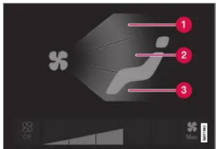
Air distribution buttons in Climate view.
1 Air distribution - windshield defrost vents
2 Air distribution - dashboard and center console air vents
③ Air distribution - floor air vents
- Open Climate view in the center display.
- Tap one or more air distribution buttons to open/close the airflow for that vent.
The air distribution changes and the buttons will light up or go out.
Related information
• Air distribution (p. 209)
- Opening, closing and directing air vents (p. 211)
• Air distribution options (p. 212)
CLIMATE CONTROL
Opening, closing and directing air vents
Some of the air vents in the passenger compartment can be individually opened, closed and directed.
Misting can be eliminated by directing the outer air vents towards the door windows.
Direct the outer air vents into the passenger compartment to maintain a comfortable temperature in warm weather.
Opening and closing the air vents

natural_image
Close-up of a car air vent grille with red arrows pointing to the vent and side panel (no text or symbols visible)Air vent thumb wheel ^2 .
- Turn the thumb wheel to open/close the airflow from the vent.
The more white lines that are visible, the stronger the airflow.
Directing air flow
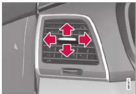
natural_image
Top-down view of a car's rear vent with red directional arrows indicating airflow or movement (no text or symbols)Airflow control ^2 .
- Move the control from side to side or up and down to direct airflow from the vent.
Related information
• Air distribution (p. 209)
• Adjusting air distribution (p. 210)
• Air distribution options (p. 212)
CLIMATE CONTROL
Air distribution options
Air distribution can be adjusted manually if needed. The following options are available.
| Air distribution Purpose | ||
 | If all air distribution buttons are deselected in manual mode, the climate control system will revert to automatic mode. | |
 | Main airflow from defroster vents. Some airflow from other vents. | Helps remove ice and condensation in cold and humid weather (blower speed should not be set too low). |
 | Main airflow from dashboard vents. Some airflow from other vents. Provides effective cooling in warm weather. | |
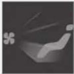 | Main airflow from floor vents. Some airflow from other vents. Provides heating or cooling in footwell areas. | |
CLIMATE CONTROL
| Air distribution Purpose | ||
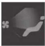 | Main airflow from defroster and dashboard vents. Some airflow from other vents. | Provides a comfortable climate in warm and dry weather. |
 | Main airflow from defroster and floor vents. Some airflow from other vents. | Provides a comfortable climate and effective defogging in cold and humid weather. |
 | Main airflow from dashboard and floor vents. Some airflow from other vents. | Provides a comfortable climate in sunny, cool weather. |
 | Main airflow from defroster, dashboard and floor vents. Provides balanced comfort in the passenger compartment. | |
▶▶
CLIMATE CONTROL
Related information
• Air distribution (p. 209)
- Opening, closing and directing air vents (p. 211)
• Adjusting air distribution (p. 210)
Climate system controls
The climate system functions are controlled from physical buttons on the center console, the center display, and the climate panel on the rear side of the tunnel console.
Physical buttons in the center console

1 Button for heated windshield* and max defroster.
② Button for healed rear window and door mirrors.
Climate bar in the center display
The most common climate system functions can be controlled from the climate bar.
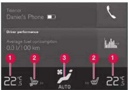
1 Temperature control for the driver and passenger sides.
2 Control for heated* and ventilated* driver and passenger seats, and heated steering wheel*.
3 Button for opening Climate view. The graphic in the button shows activated climate system settings.
Climate view in the center display
Tap the center button on the climate bar to open Climate view.
Depending on equipment level, Climate view may be divided into several tabs. Toggle between the tabs by swiping the screen to the left/right or by tapping the desired heading.
Main climate
In addition to the functions in the climate bar, other main climate system functions can be controlled from the Main climate lab.
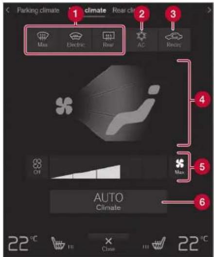
1 Max, Electric, Rear - Controls for defrosting windows and door mirrors.
② AC - Air conditioning controls.
③ Recirc - Air recirculation controls.
4 Air distribution controls.
CLIMATE CONTROL
◀◀
⑤ Blower control for front seats.
6 AUTO - Automatic climate control.
Rear climate control
All climate system functions for the rear seat can be controlled from the Rear climate tab.
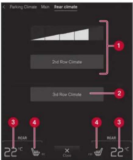
flowchart
graph TD
    A["Parking Climate"] --> B["Main Climate"]
    B --> C["1"]
    B --> D["2nd Row Climate"]
    D --> E["2"]
    D --> F["3rd Row Climate"]
    F --> G["3"]
    F --> H["4"]
    H --> I["REAR 22°C"]
    H --> J["REAR 22°C"]
    H --> K["X Close"]
    K --> L["REAR 22°C"]
1 2nd row climate - Climate functions for the second row of seats. Blower control for the second row of seats.
② 3rd row climate - Climate functions for the third row of seats*.
③ Rear seat temperature control.
4 Rear seat heating control*.
Parking climate
Parking climate functions can be controlled from the Parking climate tab.
Climate controls on the rear side of the tunnel console

1 Rear seat heating control*.
② Blower control for rear seats.
③ Rear seat temperature control.
4 Button for locking/unlocking climate panel.
The climate panel has a screen lock to help prevent inadvertently changing blower speed and temperature. When the screen is locked, only the controls for seat adjustment* and the unlock button will be displayed.
After unlocking, blower speed and temperature can also be changed from the climate panel and all selected climate settings will be displayed. The screen locks automatically after a period of inactivity.
Related information
• Climate (p. 204)
- Activating and deactivating power front seats* (p. 217)
- Activating and deactivating the heated rear seats* (p. 218)
- Activating and deactivating front seat ventilation* (p. 219)
- Activating and deactivating the heated steering wheel* (p. 219)
• Activating auto climate control (p. 220)
- Activating and deactivating recirculation (p. 221)
- Activating and deactivating max defroster (p. 222)
- Activating and deactivating the heated windshield* (p. 223)
- Activating and deactivating the heated rear window and door mirrors (p. 225)
- Setting the blower speed for the front seats (p. 226)
- Setting the blower speed for the rear seats (p. 226)
• Synchronize temperature (p. 229)
- Activating and deactivating air conditioning (p. 230)
- Activating and deactivating climate control for the third-row seats* (p. 231)
Activating and deactivating power front seats\*
The seats can be heated for added comfort for the driver and passengers in cold weather.

Steering wheel and seat buttons in the climate row.
- Tap the left- or right-side steering wheel and seat button in the center display's climate bar to open the controls for steering wheel and seat heating.
If the vehicle is not equipped with ventilated seats or heated steering wheel, the button for seat heating is directly accessible in the climate bar. - Tap the seat heating button repeatedly to select one of the four levels: Off, High, Medium or Low.
The level is changed and the set level is displayed in the button.
Related information
• Climate system controls (p. 215)
- Activating and deactivating the heated front seat* (p. 218)
CLIMATE CONTROL
Activating and deactivating the heated front seat\*
The seats can be heated for added comfort for the driver and passengers in cold weather.
Seat heating can be set to automatically activate when the engine is started. When set to automatically activate, heating will be turned on at low ambient temperatures.
- Tap Settings in the Top view in the center display.
- Tap Climate.
- Select Auto Driver Seat Heating Level and Auto Passenger Seat Heating Level to activate/deactivate automatic start of heated driver's and passenger seat.
- Select Low, Medium or High to select level after the function has been activated.
Related information
• Climate system controls (p. 215)
- Activating and deactivating power front seats* (p. 217)
Activating and deactivating the heated rear seats\*
The seats can be heated for added comfort for the driver and passengers in cold weather.
Activating and deactivating the heated rear seats from the front seats

Seat heating buttons in the Rear climate group in Climate view.
- Open Climate view in the center display and select the Rear climate tab.
- Tap the seat heating button repeatedly to select one of the four levels: Off, High, Medium or Low.
The level is changed and the set level is displayed in the button.
Activating and deactivating the heated rear seats from the rear seat

Seat heating controls and indicator lights on the rear side of the tunnel console.
- Press repeatedly on the left or right seat heating buttons in the climate panel on the tunnel console to select one of four levels: Off, High, Medium or Low.
The level will be changed and the climate panel screen will show the new level.
Related information
• Climate system controls (p. 215)
Activating and deactivating front seat ventilation\*
The seats can be ventilated to provide increased comfort in warm weather.
The ventilation system consists of fans in the seats and backrest that draw air through the seat upholstery. The cooler the passenger compartment is, the greater the cooling effect of the ventilation. The system can be activated when the engine is running.

Steering wheel and seat buttons in the climate row.
- Tap the left- or right-side steering wheel and seat button in the center display's climate bar to open the controls for steering wheel and seat heating.
If the vehicle is not equipped with heated seats or heated steering wheel, the button for seat ventilation is directly accessible in the climate bar.
- Tap the seat ventilation button repeatedly to select one of the four levels: Off, High, Medium or Low.
The level is changed and the set level is displayed in the button.
Related information
• Climate system controls (p. 215)
Activating and deactivating the heated steering wheel\*
The steering wheel can be heated for added comfort in cold weather.

Steering wheel and seat buttons in the climate row.
- Tap the driver's side steering wheel and seat button in the climate bar in the center display to open the controls for steering wheel and seat heating.
If the vehicle is not equipped with heated or ventilated seats, the button for steering wheel healing is directly accessible in the climate bar.
- Tap the steering wheel heating button repeatedly to select one of the four levels: Off, High, Medium or Low.
The level is changed and the set level is displayed in the button.
▶▶
CLIMATE CONTROL
Related information
• Climate system controls (p. 215)
- Activating and deactivating automatic steering wheel heating* (p. 220)
Activating and deactivating automatic steering wheel heating\*
The steering wheel can be heated for added comfort in cold weather.
Steering wheel heating can be set to automatically activate when the engine is started. When set to automatically activate, heating will be turned on at low ambient temperatures.
- Tap Settings in the Top view in the center display.
- Tap Climate.
- Select Auto Steering Wheel Heating Level to activate/deactivate automatic start of heated steering wheel.
- Select Low, Medium or High to select level after the function has been activated.
Related information
- Activating and deactivating the heated steering wheel* (p. 219)
Activating auto climate control
If auto climate control is activated, several climate system functions are controlled automatically.
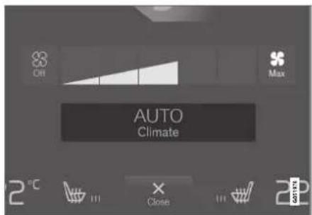
Auto climate button in Climate view.
1. Open Climate view in the center display.
-
Tap or press and hold AUTO.
-
Tap - air recirculation, air conditioning and air distribution are controlled automatically.
- Press and hold - air recirculation, air conditioning and air distribution are controlled automatically. Temperature and blower speed are changed to standard settings: 22 °C (72 °F) and speed 3 (speed 2 in the rear seat).
Auto climate mode is activated and the button lights up.
NOTE
It is possible to change the temperature and blower speed without deactivating automatic climate control. Automatic climate control is deactivated when the air distribution is changed manually or when the max defroster is activated.
Related information
• Climate system controls (p. 215)
Activating and deactivating recirculation
The climate system's recirculation function helps shut out smog, smoke, exhaust fumes, etc. by reusing the air in the passenger compartment.

Air recirculation button in Climate view.
-
Open Climate view in the center display.
-
Tap Recirc.
Air recirculation is activated/deactivated and the button lights up/goes out.
CAUTION
If the air in the vehicle is recirculated too long, there is a risk of fogging on the inside of the windows.
NOTE
Recirculation cannot be activated when the max defroster is on.
Related information
• Climate system controls (p. 215)
- Activating and deactivating the recirculation timer setting (p. 222)
CLIMATE CONTROL
Activating and deactivating the recirculation timer setting
The climate system's recirculation function helps shut out smog, smoke, exhaust fumes, etc. by reusing the air in the passenger compartment.
When the recirculation timer is activated, air recirculation will switch off automatically after 20 minutes.
- Tap Settings in the Top view in the center display.
- Tap Climate.
- Tap Recirculation Timer to activate/deactivate the recirculation timer.
Related information
- Activating and deactivating recirculation (p. 221)
Activating and deactivating max defroster
Max defroster is used to quickly remove condensation and ice from windows.
Activating and deactivating max defroster from the center console
A button in the center console offers quick access to the max defroster.
On vehicles with heated windshields*, the max defroster can only be activated separately from Climate view in the center display.

natural_image
Close-up of a handheld electronic device with four function buttons (no visible text or symbols)Button in center console.
Vehicles without a heated windshield:
- Tap the button.
The max defroster is activated/deactivated and the button lights up/goes out.
Vehicles with a heated windshield:
- Press the button repeatedly to switch between the three levels:
- Activated windshield heating
- Activated windshield heating and max defroster
- Deactivated.
The heated windshield and max defroster are activated/deactivated and the button lights up/goes out.
NOTE
The max defroster starts after a slight delay to avoid a brief increase in blower speed if the heated windshield function has been deactivated by pressing the button twice in quick succession.
Activating and deactivating max defroster from the center display
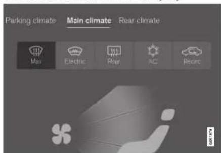
Max defroster in Climate view.
- Open Climate view in the center display.
- Tap Max.
The max defroster is activated/deactivated and the button lights up/goes out.
Max defroster deactivates automatic climate control and air recirculation, activates the air conditioning, and changes blower speed to 5 and temperature to HI.
When max defroster is deactivated, the climate system reverts to the previous settings.

NOTE
The volume increases when the blower speed is changed to 5.
Related information
• Climate system controls (p. 215)
Activating and deactivating the heated windshield\*
Windshield heating is used to quickly remove condensation and ice from the windshield.
Activating and deactivating windshield heating from the center console
A button in the center console is used to quickly access windshield heating.
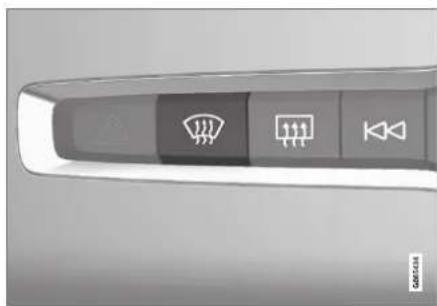
natural_image
Top-down view of a car dashboard with four function buttons (no text or symbols visible)Button in center console.
- Press the button repeatedly to switch between the three levels:
- Activated windshield heating
- Activated windshield heating and max defroster
- Deactivated.
The heated windshield and max defroster are activated/deactivated and the button lights up/goes out.
CLIMATE CONTROL
Activating and deactivating windshield heating from the center display

Windshield heating button in Climate view.
- Open Climate view in the center display.
- Tap Electric.
Windshield heating is activated/deactivated and the button lights up/goes out.

NOTE
Triangular areas at the far sides of the wind-shield are not heated and will take slightly longer to defrost/de-ice.

NOTE
The heated windshield may affect the performance of transponders and other communication equipment.
Related information
• Climate system controls (p. 215)
- Activating and deactivating automatic windshield heating* (p. 224)
Activating and deactivating automatic windshield heating\*
Windshield heating is used to quickly remove condensation and ice from the windshield.
Windshield heating can be set to automatically activate when the engine is started. With automatic start activated, heating will be activated when there is a risk of ice or condensation on the windows or mirrors. Heating is automatically switched off when the window or door mirror is sufficiently warm and the condensation or ice is gone.
- Tap Settings in the Top view in the center display.
- Tap Climate.
- Select Auto Front Defroster to activate/deactivate automatic windshield heating.
Related information
- Activating and deactivating the heated windshield* (p. 223)
Activating and deactivating the heated rear window and door mirrors
The heated rear window and door mirrors are used to quickly remove condensation and ice from the glass.
Activating and deactivating the heated rear window and door mirrors from the center console
A button in the center console offers quick access to the heated rear window and door mirrors functions.

natural_image
Top-down view of a car dashboard with control buttons and warning symbols (no readable text or labels)Button in center console.
- Tap the button.
Heated windows and door mirrors are activated and the button lights up/goes out.
Activating and deactivating the heated rear window and door mirrors from the center display
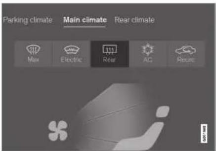
Rear window/door mirror heating button in Climate view.
-
Open Climate view in the center display.
-
Tap Rear.
Healed windows and door mirrors are activated and the button lights up/goes out.
Related information
• Climate system controls (p. 215)
- Automatically activating and deactivating the heated rear window and door mirrors (p. 225)
Automatically activating and deactivating the heated rear window and door mirrors
The heated rear window and door mirrors are used to quickly remove condensation and ice from the glass.
It is possible to select whether rear window and door mirror heating should be automatically activated or deactivated when the engine is started. With automatic start activated, heating will be activated when there is a risk of ice or condensation on the windows or mirrors. Healing is automatically switched off when the window or door mirror is sufficiently warm and the condensation or ice is gone.
- Tap Settings in the Top view in the center display.
- Tap Climate.
- Select Auto Rear Defroster to activate/deactivate automatic rear window and door heating.
Related information
- Activating and deactivating the heated rear window and door mirrors (p. 225)
CLIMATE CONTROL
Setting the blower speed for the front seats
The blower can be set to several different automatically controlled speeds for the front seat.
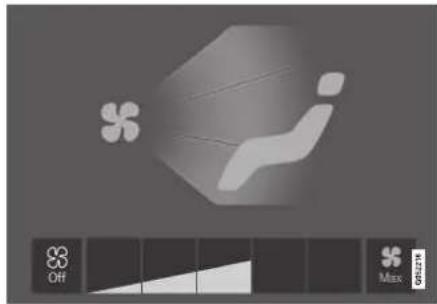
natural_image
Abstract geometric design with floral and gear-like shapes on a gray background (no text or symbols)Blower control buttons in Climate view.
- Open Climate view in the center display.
- Tap the desired blower speed: Off, 1-5 or Max.
The blower speed will be changed and the buttons for the set speed will light up.

CAUTION
The air conditioning will not engage if the blower is turned off completely, which may cause fogging on the inside of the windows.

NOTE
The climate system automatically adapts airflow as needed within the set blower speed, which means that airflow speed may vary slightly within the same blower speed.
Related information
• Climate system controls (p. 215)
Setting the blower speed for the rear seats
The blower can be set to several different automatically controlled speeds for the rear seat.
Setting blower speed for the rear seats from the front seats

Blower control buttons in the Rear climate tab in Climate view.
-
Open Climate view in the center display and select the Rear climate tab.
-
Tap the desired blower speed, 1-5.
The blower speed for the second and third rows of seats* can be switched off by tapping 2nd row climate.
The blower speed for the third row of seats is linked to the setting for the second row, but can be switched off separately by pressing 3rd row climate.
The blower speed will be changed and the buttons for the set speed will light up.
Setting blower speed for the rear seats from the rear seats
- Tap the unlock button on the tunnel console's climate panel to access the controls.

Blower controls on the rear climate panel of the tunnel console.
- Tap the desired blower speed, 1-5.
The blower speed will be changed and the buttons for the set speed will light up.
NOTE
The blower speed for the rear seat cannot be set if the blower speed for the front seat is Off.
The rear seat blower speed can only be turned off from the climate view in the center display.
NOTE
The climate system automatically adapts airflow as needed within the set blower speed, which means that airflow speed may vary slightly within the same blower speed.
Related information
• Climate system controls (p. 215)
CLIMATE CONTROL
Setting the temperature for the front seats
The temperature can be set to the desired number of degrees for the front seat climate zones.

Temperature buttons in the climate bar.
- Tap the left- or right-side temperature buttons in the center display's climate bar to open the control.

Temperature control.
-
Set the temperature by doing one of the following:
-
dragging the control to the desired temperature, or
- tapping+ to raise/lower the temperature.
The temperature will be set and the button will display the new temperature.
i NOTE
Heating/cooling cannot be accelerated by choosing a higher/lower temperature than the desired temperature.
Related information
• Climate system controls (p. 215)
Setting the temperature for the rear seats
The temperature can be set to the desired number of degrees for the rear seat climate zones.
Setting the temperature for the rear seats from the front seats

Temperature buttons in the Rear climate tab in Climate view.
- Open Climate view in the center display and select the Rear climate tab.
- Tap the left- or right-side temperature button to open the control.

Temperature control.
-
Set the temperature by:
-
dragging the control to the desired temperature
- tapping + to raise/lower the temperature.
The temperature will be set and the button will display the new temperature.
Setting the temperature for the rear seats from the rear seats
- Tap the unlock button on the tunnel console's climate panel to access the controls.

Temperature controls on the rear climate panel of the tunnel console.
- Tap the left or right side's ◇ buttons to lower/raise the temperature.
The temperature will be changed and the climate panel screen will show the new temperature.
i NOTE
Heating/cooling cannot be accelerated by choosing a higher/lower temperature than the desired temperature.
Related information
• Climate system controls (p. 215)
Synchronize temperature
The temperature in the different climate zones of the vehicle can be synchronized with the temperature set for the driver's side.

Synchronization button on the driver's side temperature control.
- Tap the driver's side temperature button in the center display's climate bar to open the control.
- Tap Synchronize temperature.
The temperature for all of the vehicle's climate zones will be synchronized with the one set for the driver's side and the synchronization symbol will be displayed next to the temperature button.
Synchronization is stopped with another press on Synchronize temperature or by changing the temperature setting for a climate zone other than the driver's.
▶▶
CLIMATE CONTROL
Related information
• Climate system controls (p. 215)
Activating and deactivating air conditioning
The air conditioning cools and dehumidifies incoming air as needed.

Air conditioning button in Climate view.
-
Open Climate view in the center display.
-
Tap AC.
The air conditioning is activated/deactivated and the button lights up/goes out. When the air conditioning is activated, it will be switched on and off automatically by the climate system as needed.
NOTE
For optimum function of the air conditioning, close all side windows and the panoramic roof*.
i NOTE
The air conditioning cannot be activated when the fan speed is set to Off.
Related information
• Climate system controls (p. 215)
Activating and deactivating climate control for the third-row seats\*
The air conditioning cools and dehumidifies incoming air as needed.
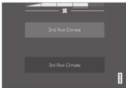
Air conditioning button in the Rear climate tab in Climate view.
- Open Climate view in the center display and select the Rear climate tab.
- Tap 3rd row climate.
The air conditioning is activated/deactivated and the button lights up/goes out.
i NOTE
The air conditioning for the third row of seats is automatically activated if any of the third row seat belts are buckled.
It is not possible to manually activate air conditioning for the third row of seats if the main air conditioning system is deactivated or the climate system for the second row of seats is deactivated.
Related information
• Climate system controls (p. 215)
Parking climate
Parking climate is an umbrella term for various functions that improve the passenger compartment climate when the vehicle is parked, e.g. preconditioning.

Parking climate functions are controlled from the Parking climate tab in the center display's Climate view.
Related information
• Climate (p. 204)
• Preconditioning (p. 232)
▶▶
CLIMATE CONTROL
• Climate comfort retaining function (p. 237)
- Parking climate symbols and messages (p. 238)
Preconditioning
Preconditioning the vehicle before driving can help reduce wear and reduce energy consumption during a trip.
Preconditioning can be started immediately or started at a preset time using a timer.
The function utilizes several of the vehicle's systems:
- In cold weather, the parking heater heats the passenger compartment to a comfortable temperature.
- In warm weather, air conditioning cools the passenger compartment to a comfortable temperature.
- The electrically heated steering wheel* and seats* can be activated.
- Heating for the windshield, rear window and door mirrors are automatically activated as needed.
During preconditioning in a hot climate, condensation from the air conditions may drip under the vehicle. This is normal.
NOTE
Preconditioning is only available when the car is connected to an electrical outlet. A charging post that is not always active, for example because of a timer, can cause loss of function for preconditioning.
If the car is not connected to an electrical socket it is still possible in a warm climate to achieve brief cooling of the passenger compartment by direct starting preconditioning.
NOTE
During preconditioning of the passenger compartment, the vehicle works to reach a comfortable temperature and not the temperature set in the climate system.
Related information
- Parking climate (p. 231)
- Starting and stopping preconditioning (p. 233)
• Preconditioning timer (p. 234)
Starting and stopping preconditioning
Preconditioning heats or cools the passenger compartment before driving. Preconditioning can be started in the center display or from a cellular phone.
Starting and stopping from the vehicle

Preconditioning button in the Parking climate tab in Climate view.
- Open Climate view in the center display.
- Select the Parking climate tab.

Window for seat/steering wheel heating in the Parking climate lab in Climate view.
- Tap the boxes to select if seal/sleering wheel heating should be activated along with preconditioning.
- Tap Preconditioning.
Preconditioning starts/stops and the button lights up/goes out.
NOTE
Preconditioning is only available when the car is connected to an electrical outlet. A charging post that is not always active, for example because of a timer, can cause loss of function for preconditioning.
If the car is not connected to an electrical socket it is still possible in a warm climate to achieve brief cooling of the passenger compartment by direct starting preconditioning.
NOTE
The vehicle doors and windows should be closed during preconditioning of the passenger compartment.
Starting from app\*
A device with the Volvo On Call* app can be used to start preconditioning or check settings. Pre-conditioning heals or cools the passenger compartment (using the vehicle's air conditioning) to a comfortable temperature.
The passenger compartment can also be preconditioned using the Engine Remote Start (ERS) ^3 function using the Volvo On Call ^* app.
CLIMATE CONTROL
Related information
• Parking climate (p. 231)
• Preconditioning (p. 232)
• Preconditioning timer (p. 234)
Preconditioning timer
The timer can be set to finish preconditioning at a predetermined time.
The timer can store up to 8 preset times for:
• A time on a particular date
- A time on one or more days of the week, with or without the repeat function.
NOTE
Preconditioning is only available when the car is connected to an electrical outlet. A charging post that is not always active, for example because of a timer, can cause loss of function for preconditioning.
If the car is not connected to an electrical socket it is still possible in a warm climate to achieve brief cooling of the passenger compartment by direct starting preconditioning.
Related information
• Preconditioning (p. 232)
- Adding and editing timer settings for preconditioning (p. 234)
- Activating and deactivating preconditioning timer (p. 235)
- Deleting preconditioning timer settings (p. 236)
Adding and editing timer settings for preconditioning
The preconditioning timer can store up to 8 pre-set timer settings.
Adding a timer setting

Button for adding a timer setting in the Parking climate tab in Climate view.
- Open Climate view in the center display.
- Select the Parking climate tab.
- Tap Add timer.
A pop-up window will appear.
NOTE
It is not possible to add a time setting if there are already 8 settings for the timer. Delete a time setting to be able to add a new one.
- Tap Date to set a time for a specific date.
Tap Days to set a time for one or more days of the week.
With Days: Activate/deactivate the repeat function by selecting/deselecting the Repeat weekly checkbox. - With Date: Select a date for preconditioning by scrolling in the date list using the arrows.
With Days: Select days of the week for preconditioning by tapping the buttons for the days. - Set the time at which preconditioning should be completed by scrolling using the arrows in the clock.
- Tap Confirm to add a timer setting.
The timer setting will be added to the list and activated.
Editing a timer setting
- Open Climate view in the center display.
- Select the Parking climate tab.
- Tap the timer setting you would like to change.
A pop-up window will appear.
- To edit a timer setting, follow the procedures described under the heading "Adding a timer setting" above.
Related information
• Preconditioning (p. 232)
• Preconditioning timer (p. 234)
- Activating and deactivating preconditioning timer (p. 235)
- Deleting preconditioning timer settings (p. 236)
Activating and deactivating preconditioning timer
Timer settings in the preconditioning timer can be activated or deactivated as needed.

Timer buttons in the Parking climate tab in Climate view.
- Open Climate view in the center display.
- Select the Parking climate tab.
- Activate/deactivate a timer setting by tapping the timer button to the right of the setting.
The timer setting is activated/deactivated and the button lights up/goes out.
Related information
• Preconditioning (p. 232)
• Preconditioning timer (p. 234)
CLIMATE CONTROL
- Adding and editing timer settings for preconditioning (p. 234)
- Deleting preconditioning timer settings (p. 236)
Deleting preconditioning timer settings
A preconditioning timer setting that is no longer needed can be deleted.
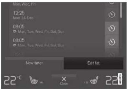
The button for editing a list/deleting a timer setting in the Parking climate tab in Climate view.
- Open Climate view in the center display.
- Select the Parking climate tab.
- Tap Edit list.
- Tap the editing icon to the right in the list.
The icon will change to the text Delete.
- Tap Delete to confirm.
The timer setting will be deleted from the list.
Related information
• Preconditioning (p. 232)
• Preconditioning timer (p. 234)
- Adding and editing timer settings for preconditioning (p. 234)
- Activating and deactivating preconditioning timer (p. 235)
Climate comfort retaining function
The climate in the passenger compartment can be maintained when the vehicle is parked, e.g. if the engine is turned off but the driver or passengers remain in the vehicle.
This function can only be direct-started.
The function utilizes several of the vehicle's systems:
- Residual heat from the engine is used to help heat the passenger compartment to a comfortable temperature.
- In warm weather, the ventilation system cools the passenger compartment by blowing air in from outside.

NOTE
Climate comfort maintenance will be deactivated if the vehicle is locked from the outside in order to avoid using residual engine heat unnecessarily. This function is intended to be used to maintain climate comfort when the driver or a passenger remains in the vehicle after the engine is turned off.
Related information
- Parking climate (p. 231)
- Starting and switching off the climate retaining function when parking (p. 237)
Starting and switching off the climate retaining function when parking
The climate retaining function maintains the climate settings in the vehicle after the engine has been switched off. The function can be activated in the center display.
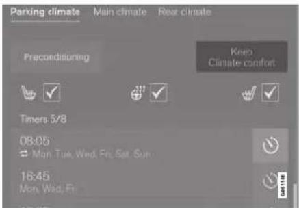
Button for retaining climate comfort in the Parking climate tab in Climate view.
- Open Climate view in the center display.
- Select the Parking climate tab.
- Tap Keep climate comfort.
The climate comfort retaining function will be activated/deactivated and the button light will go on/off.

NOTE
Maintained climate comfort is not possible when there is not sufficient residual engine heat to maintain the climate settings in the passenger compartment, or if the outside temperature is above approximately 20 °C (68 °F).

NOTE
Climate comfort maintenance will be deactivated if the vehicle is locked from the outside in order to avoid using residual engine heat unnecessarily. This function is intended to be used to maintain climate comfort when the driver or a passenger remains in the vehicle after the engine is turned off.
Related information
• Climate comfort retaining function (p. 237)
CLIMATE CONTROL
Parking climate symbols and messages
A number of symbols and messages related to parking climate may be displayed in the instrument panel.
Messages related to parking climate can also be displayed in a device that has the Volvo On Call* app.
| Symbol | Message Meaning | |
 | Parking climateService required | Parking climate is not functioning properly. Contact a workshop ^A to have the system checked as soon as possible. |
 | Parking climateTemporarily unavailable | Parking climate is temporarily not functioning properly. If the problem persists, contact a work-shop ^A to have the system checked. |
 | Parking climateUnavailable Charge level too low | The parking climate cannot be activated because the hybrid battery's charge level is too low to start the parking healer. Start the vehicle. |
 | Parking climateUnavailable, not connected to power supply | The parking climate cannot be activated if the charging cable is not connected. Connect the charging cable. |
 | Parking climateLimited Charge level too low | Parking climate will only run for a limited time when the hybrid battery's charge level is too low. Start the vehicle. |
A An authorized Volvo workshop is recommended.
Related information
- Parking climate (p. 231)
Heater
The heater helps the engine and passenger compartment reach the correct temperature before and while driving.
The heater has two sub-functions:
- Parking heater - heats the passenger compartment as needed when the parking climate's preconditioning is activated.
- Auxiliary heater - heats the passenger compartment and engine while driving.
The heater is a high-voltage coolant heater and is mounted in the front right-side wheel housing.
Battery and charging
The heater is powered by the vehicle's hybrid battery. If the charge level in the hybrid battery is too low, the heater will switch off automatically and a message will be displayed in the instrument panel.

NOTE
Make sure that the battery has sufficient charge if the heater must be used.
Related information
• Climate (p. 204)
Parking heater
The parking heater heats the passenger compartment as needed before driving if preconditioning is activated.
The parking heater is one of two sub-functions of the vehicle's heater. The heater is mounted in the front right-side wheel housing.
The parking heater starts automatically if the parking climate's preconditioning is activated and the passenger compartment needs to be heated.
It switches off automatically when a set timer time or the heater's maximum run time expires, or if the car is restarted.
The heater's maximum running time is 40 minutes.
Additional heater
The auxiliary heater helps heat the passenger compartment and engine while driving.
The auxiliary heater is one of two sub-functions of the vehicle's heater. The heater is mounted in the front right-side wheel housing.
The auxiliary heater is started and controlled automatically when extra heat is required while the vehicle is being driven.
It switches off automatically when the ignition is switched off.
CLIMATE CONTROL
Activating and deactivating the auxiliary heater
The auxiliary heater helps heat the passenger compartment and engine while driving.
It is possible to set whether automatic start for the auxiliary heater should be activated or deactivated.
- Tap Settings in the Top view in the center display.
- Tap Climate.
- Select Additional Heater to activate/deactivate automatic start for the auxiliary heater.

NOTE
If automatic start of the auxiliary heater is deactivated, this may impair comfort in the passenger compartment since the climate system then does not have a heat source during electrical operation.
KEY, LOCKS AND ALARM
KEY, LOCKS AND ALARM
Lock indication
When the vehicle is locked or unlocked, the turn signals will flash to indicate that the vehicle has been locked or unlocked correctly.
Exterior confirmation
Locking
- The turn signals will flash once and the door mirrors will fold in ^1 to confirm the vehicle is locked.
Unlocking
- The turn signals will flash twice and the door mirrors will fold out ^1 to confirm the vehicle is unlocked.
All doors, tailgate and hood must be closed for confirmation to be given. If only the driver's door is closed when the vehicle is locked ^2 , the vehicle will be locked but the turn signals will only flash to indicate locking when all doors and the hood and tailgate have been closed.
Lock and alarm indicator

natural_image
Interior view of a car dashboard with a highlighted touchscreen device (no visible text or symbols)The locks and alarm indicator on the dashboard will display the status of the locking system.
A long flash indicates that the vehicle is locked. When the vehicle is locked, this will be indicated by short, pulsing flashes.
Other indicators
The home safe lighting and approach lighting functions also indicate when the vehicle is locked or unlocked.
Lock button indicators
Front door
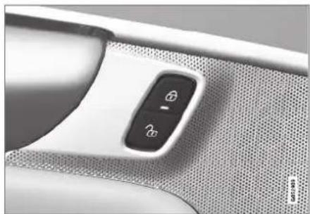
natural_image
Close-up of a car interior panel showing a rotary key and display screen (no text or symbols visible)Lock buttons with indicator lights in front door.
Illuminated indicator lights in both front door lock buttons indicate that all doors are locked. If any door is opened, the lights in both doors will go out.
In rear door*
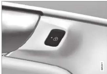
natural_image
Close-up of a white car door handle with a black button and logo (no visible text or symbols)Lock button with indicator light in rear door.
Illuminated indicator lights in each door indicate that that particular door is locked. If any door is unlocked and opened, the indicator light in that door will go out. The lights in the other doors will remain illuminated.
Related information
- Lock confirmation settings (p. 243)
- Welcome Light (p. 161)
• Using home safe lighting (p. 161)
Lock confirmation settings
Settings for how the vehicle confirms locking and unlocking can be adjusted in the center display's Settings menu.
Locking response:
- Tap Settings in the center display's Top view.
- Tap My Car ▶cking.
- Tap Visible Locking Feedback to deactivate the function or to select when the vehicle should provide a visible response: during Lock, Unlock or Both.
- Select to receive an audible response when locking the vehicle by marking Audible Locking Feedback.
Folding door mirrors* confirmation:
- Tap Settings in the center display's Top view.
- Tap My Car Mirrors and Convenience.
- Select Fold Mirror When Locked to activate or deactivate the function.
Related information
- Lock indication (p. 242)
Remote key
The remote key is used to lock and unlock doors and the tailgate. The remote key must be in the vehicle in order to start the engine.

natural_image
Two black rectangular electronic devices with visible ports and a circular logo on the left (no text or symbols on the device itself)Remote control key ^3 , on left, and button-less key ((Key Tag)*), on right.
The remote key is not physically used to start the ignition because the vehicle is standard-equipped with keyless start (Passive Start).
To start the vehicle, the key must be in the front section of the passenger compartment, e.g. in the driver's pocket or in a cup holder in the tunnel console.
KEY, LOCKS AND ALARM
The keyless system for locking/unlocking the doors and tailgate (Passive Entry*) is available as an option. This system has a range in a semicircle with a radius of approximately 1.5 meter (5 feet) out from the driver's door and approx. 1 meter (3 feet) out from the tailgate.
With keyless start in combination with keyless locking and unlocking, the remote key can be located anywhere in the passenger compartment or cargo compartment in order to start the engine.
Each remote key supplied with the vehicle can be linked to a driver profile with unique settings for the vehicle. When a key with a specific profile is used, the vehicle settings are adjusted according to that profile.
Buttonless key, Key Tag
For vehicles equipped with keyless locking and unlocking*, a smaller, lighter and button-less key (Key Tag ^4 ) is also provided. It works the same way as the regular remote key as regard keyless start and keyless locking and unlocking. The key is waterproof up to a depth of approx. 10 meters (30 feet) for up to 60 minutes. It does not have a detachable key blade and its battery cannot be replaced.
Remote key buttons
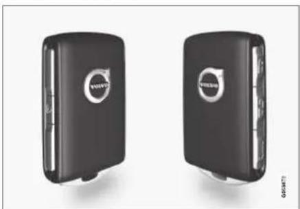
natural_image
Two black Volvo 3.0s hard drives with visible branding (no text or symbols on the drives themselves)The remote key has four buttons, one on the left side and three on the right ^3 .
Locking - Press once to lock the doors, tailgate and fuel filler door and arm the alarm.
Press and hold to close all windows.
Unlocking - Press once to unlock the doors and tailgate and disarm the alarm.
Press and hold to open all windows at the same time. This total airing function can be used to e.g. quickly air out the vehicle in hot weather.
Tailgate - Unlock and disarm the tailgate only. On vehicles equipped with the power tailgate*, press and hold to automatically open the tailgate. Press and hold to close an
open tailgate (an audible warning signal will be given).
△ Panic alarm - Used to attract attention in emergency situations. Press and hold the button for at least 3 seconds or press twice within 3 seconds to activate the turn signals and horn. To deactivate, wait at least 5 seconds and press the button again. If no action is taken, the panic alarm will deactivate automatically after 3 minutes.
WARNING
If anyone is left in the vehicle, make sure that power to the power windows and panoramic roof* is cut off by always taking the remote key with you when you leave the vehicle.

NOTE
Be aware of the risk of locking the remote key in the vehicle.
- If the remote key or Key Tag is left in the vehicle, it will be deactivated when the vehicle is locked and the alarm set using another valid key. The deactivated key will be reactivated when the vehicle is unlocked.
- If the remote key or Red Key is left in the vehicle, it will be deactivated even if the vehicle is locked using Volvo On Call, and will be reactivated when the vehicle is unlocked using Volvo On Call or by pressing the unlock button on the key.
Interference
Electromagnetic fields or obstructing objects may interfere with the remote key's functions for keyless start and keyless locking and unlocking*.

NOTE
Avoid storing the remote control key near metal objects or electronic devices, e.g. cell phones, tablets, laptops or chargers – preferably no closer than 10-15 cm (4-6 in.).
If you experience interference, use the remote key's detachable blade to unlock the vehicle and
place the remote key in the backup key reader in the tunnel console cup holder to disarm the alarm.

NOTE
When the remote control key is placed in the cup holder, make sure that no other vehicle keys, metal objects or electronic devices (e.g. cell phones, tablets, laptops or chargers) are found in the cup holder. Multiple vehicle keys close to each other in the cup holder can disrupt their functionality.

WARNING
California Proposition 65
Operating, servicing and maintaining a passenger vehicle can expose you to chemicals including engine exhaust, carbon monoxide, phthalates, and lead, which are known to the State of California to cause cancer and birth defects or other reproductive harm. To minimize exposure, avoid breathing exhaust, do not idle the engine except as necessary, service your vehicle in a well ventilated area and wear gloves or wash your hands frequently when servicing your vehicle. For more information go to www.P65Warnings.ca.gov/passenger-vehicle.
Related information
- Locking and unlocking using the remote key (p. 246)
• Remote key range (p. 248)
• Replacing the remote key's battery (p. 249)
• Detachable key blade (p. 254)
• Electronic immobilizer (p. 257) - Linking a remote key to a driver profile (p. 138)
KEY, LOCKS AND ALARM
Locking and unlocking using the remote key
All doors and tailgate can be locked and unlocked simultaneously using the buttons on the remote key.
Locking with remote key

natural_image
Two black Volvo SEV50 phone modules with visible branding (no text or symbols on the devices themselves)Remote key ^5 .
- Press the button on the remote key to lock.
To activate the locking sequence, the driver's door must be closed ^6 . If any of the other doors or the tailgate are open, they will be locked and the alarm will be armed once they are closed.
NOTE
Be aware of the risk of locking the remote key in the vehicle.
- If the remote key or Key Tag is left in the vehicle, it will be deactivated when the vehicle is locked and the alarm set using another valid key. The deactivated key will be reactivated when the vehicle is unlocked.
- If the remote key or Red Key is left in the vehicle, it will be deactivated even if the vehicle is locked using Volvo On Call, and will be reactivated when the vehicle is unlocked using Volvo On Call or by pressing the unlock button on the key.
Locking when the tailgate is open
i NOTE
If the vehicle is locked and the tailgate is still open, make sure that the remote key is not left in the cargo compartment when the tailgate is closed and the entire vehicle is locked ^7 .
Unlocking with remote key
- Press the Button on the remote key to unlock.
Automatic relocking
If none of the doors or tailgate are opened within two minutes after being unlocked, they will automatically relock. This function reduces the risk of inadvertently leaving the vehicle unlocked.
Remote key not working
i NOTE
Move closer to the vehicle and try to unlock it again.
If the remote key is not working to lock or unlock the vehicle, its battery may be discharged. Use the detachable key blade to lock/unlock the driver's door instead.
Related information
- Settings for remote and inside door unlock (p. 247)
- Unlocking the tailgate using the remote key (p. 247)
- Remote key (p. 243)
• Replacing the remote key's battery (p. 249)
- Locking and unlocking with detachable key blade (p. 255)
Settings for remote and inside door unlock
Several different sequences are available for remote unlocking.
- Tap Settings in the center display's Top view.
- Tap My Car Locking Remote and Interior Unlock.
-
Select alternative:
-
All Doors
- unlocks all doors at the same time.
- Single Door
- unlocks the driver's door. Press the remote key unlock button twice to unlock all doors.
The settings made here also affect central locking using the inside door handle.
Related information
- Locking and unlocking using the remote key (p. 246)
- Locking and unlocking from inside the vehicle (p. 262)
Unlocking the tailgate using the remote key
The remote key can be used to unlock the tail-gate while keeping the rest of the vehicle locked.
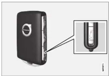
natural_image
Close-up of a black electronic device with a close-up inset showing internal components (no visible text or symbols)Use the button on the remote key to disarm and unlock the tailgate.
KEY, LOCKS AND ALARM
◀◀
- Press the 🎨 button on the remote key.
The lock and alarm indicator on the dashboard will go out to indicate that the vehicle is no longer fully armed.
The tailgate will be unlocked but remain closed. However, the side doors will remain locked and armed.
Press lightly on the rubberized pressure plate under the tailgate handle to open the tailgate.
If the tailgate is not opened within 2 minutes, it will be relocked and the alarm armed.
- With the optional power tailgate* -
Hold and press (about 1.5 seconds) the button on the remote key
The tailgate will unlock and open. However, the side doors will remain locked and armed.
Related information
- Locking and unlocking using the remote key (p. 246)
- Opening and closing the power tailgate* (p. 266)
Remote key range
In order to function correctly, the remote key must be within a certain distance from the vehicle.
Manual use
The remote key's functions for e.g. locking and unlocking, which are activated by pressing 🔒 or 🔒, have a range of approx. 20 meters (65 feet) from the vehicle.
If the vehicle's locks do not react, move closer and try again.
Keyless use ^8

natural_image
Top-down view of a white car with two pink circular shapes on the side (no text or symbols)The shaded areas around the vehicle illustrate the range of the system's antennas.
For keyless use, a remote key or the Key Tag must be within the shaded areas shown in the illustration, i.e. a semicircle with a radius of approx. 1.5 meter (5 feet) along the sides of the vehicle or approx. 1 meter (3 feet) from the tailgate.

NOTE
The functions of the remote control key can be disrupted by ambient radio waves, buildings, topographical conditions, etc. The vehicle can always be locked/unlocked using the key blade.
If the remote key is removed from the vehicle

If the remote key is removed from the vehicle while the engine is running, the warning message Vehicle key not found Removed from vehicle will be
displayed in the instrument panel and an audible signal will sound when the last door is closed.
The message will disappear when the key is returned to the vehicle and the O button on the right-side steering wheel keypad is pressed or when the last door is closed again.
Related information
- Remote key (p. 243)
- Antenna locations for the start and lock system (p. 262)
• Keyless and touch-sensitive surfaces* (p. 258)
Replacing the remote key's battery
The battery in the remote key must be replaced when it is discharged.
i NOTE
All batteries have a limited service life and must eventually be replaced (does not apply for Key Tag). The battery's service life varies depending on how often the vehicle/key is used.
The remote key battery should be replaced if:

the information symbol illuminates and the message Vehicle key bat. low See Owner's manual is displayed in the instrument panel
and/or
- the locks do not react after several attempts to lock or unlock the vehicle using the remote key within approx. 20 meter (65 feet) from the vehicle.
i NOTE
Move closer to the vehicle and try to unlock it again.
The battery in the smaller key without buttons ^9 (the Key Tag) cannot be replaced. A new key can be ordered from an authorized Volvo workshop.
CAUTION
An end-of-life Key Tag must be turned in to an authorized Volvo workshop. The key must be deleted from the vehicle because it can still be used to start the vehicle via backup start.
KEY, LOCKS AND ALARM
Opening the key and replacing the battery

1 Hold the remote key with the front side (with the Volvo logo) facing up and move the button on the key ring section to the right. Slide the front cover slightly upward.
2 The cover will loosen and can be removed from the key.

2 Turn the key over, move the button to the side and slide the rear cover slightly upward.
2 The cover will loosen and can be removed from the key.
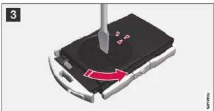
natural_image
Close-up of a smartphone with a screwdriver inserted, showing a red curved arrow indicating motion (no text or symbols)3 Use a screwdriver or similar object to turn the battery cover counterclockwise so the markers point to OPEN.
Remove the cover carefully by pressing e.g. a fingernail into the indentation.
Pry the cover up.
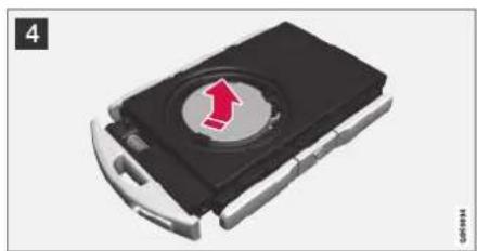
natural_image
3D rendering of a black flip-flop with a red upward arrow on its surface (no text or symbols)4 The battery's positive side (+) faces upward. Carefully pry out the battery as shown in the illustration.
CAUTION
Avoid touching new batteries and their contact surfaces with your fingers as this will impair their function.
5

natural_image
Close-up of a black electronic device with a circular button and red directional arrows indicating motion (no text or symbols)[Unreadable]
5 Insert a new battery with the positive side (+) facing upward. Do not touch the contact surfaces of the remote key battery.
Place the edge of the battery downward into the holder. Slide the battery forward until it locks into place under the two plastic catches.
2 Press the battery downward until it locks into place under the upper black plastic catch.
i
NOTE
Use batteries with the designation CR2032, 3 V.
NOTE
Volvo recommends that batteries used in the remote control key satisfy UN Manual of Test and Criteria, Part III, sub-section 38.3. The factory installed batteries and batteries replaced by an authorized Volvo workshop satisfy the above criterion.
6

natural_image
Close-up of a mechanical component with a red arrow indicating rotation or movement (no visible text or symbols)注意:
6 Replace the battery cover and turn it clockwise until it points to CLOSE.
7

natural_image
Black flip phone case with red directional arrows indicating left and right sides (no text or symbols)[Unreadable]
7 Put the rear cover back into position and press it down until it clicks into place.
2 Slide the cover back.
A second click indicates that the cover is correctly positioned and locked into place.
8
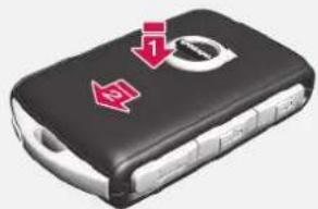
natural_image
Black handheld car with red directional arrows indicating movement or change (no text or symbols)YOGA
8 1 Turn the remote key over and press the front cover down until it clicks into place.
2 Slide the cover back.
An additional click indicates that the cover is correctly in place.
▶▶
KEY, LOCKS AND ALARM
◀◀

CAUTION
Be sure to dispose of end-of-life batteries in a way that protects the environment.

WARNING
California Proposition 65
Operating, servicing and maintaining a passenger vehicle can expose you to chemicals including engine exhaust, carbon monoxide, phthalates, and lead, which are known to the State of California to cause cancer and birth defects or other reproductive harm. To minimize exposure, avoid breathing exhaust, do not idle the engine except as necessary, service your vehicle in a well ventilated area and wear gloves or wash your hands frequently when servicing your vehicle. For more information go to www.P65Warnings.ca.gov/passenger-vehicle.
Related information
- Remote key (p. 243)
Ordering additional remote keys
Two remote keys are provided with the vehicle. One Key Tag is also included if the vehicle is equipped with keyless locking/unlocking*. Additional keys can be ordered.
A total of 12 keys can be programmed and used for the same vehicle. An additional driver profile will be added for each new remote key. This also applies to the key tag.
Loss of a remote key
If you lose your remote key, you can order a replacement from a workshop - an authorized Volvo workshop is recommended. Bring the other remaining remote keys to the workshop. As an anti-theft measure, the code of the lost remote key must be erased from the system.
The current number of keys registered for the vehicle can be checked via driver profiles in the center display's Top view. Select Settings →
System Driver Profiles.

NOTE
Volvo recommends that you order a new or duplicate remote control key from an authorized Volvo workshop.
You can also obtain additional or duplicate remote control keys from certain independent repair facilities and locksmiths that are qualified to make remote control keys. Each key must be programmed to work with your vehicle.
A list of independent repair facilities and/or locksmiths known to Volvo that can cut and code replacement keys can be found:
• on Volvo's website www.volvocars.com/us
• by calling Volvo Customer Care 1-800-458-1552.
Related information
- Remote key (p. 243)
Red Key - restricted remote key\*
A Red Key makes it possible for the vehicle owner to set limitations for certain vehicle properties. The limitations are intended to promote safe use of the vehicle, e.g. when it is loaned out.

natural_image
Two red Volvo SUVs displayed side by side, no visible text or symbols on the devices themselves.For a Red Key, it is possible to define the vehicle's maximum speed, set speed reminders and limit the audio system's volume. Several of the driver support systems will also always be active. Otherwise, the Red Key functions in the same way as a standard remote key.
One or more Red Key can be ordered from a Volvo retailer. A total of twelve keys can be programmed and used for the same vehicle. Up to ten may be restricted keys, but at least two must be standard remote keys.
These restrictions are intended to help reduce the risk of accidents and help the driver feel more
secure when handing over the vehicle to e.g. a young driver, parking attendant or workshop. The settings for a Red Key cannot be changed by its user; a regular remote key is needed to change settings.
Related information
• Red Key* settings (p. 253)
- Remote key (p. 243)
Red Key\* settings
The holder of a regular remote key can adjust settings for a Red Key. Certain driver support functions are always active.
- Tap Settings in the center display's Top view.
- Tap System Driver Profiles RedKey.
The following settings can be made:
- Set Time Gap For Adaptive Cruise Control
- Reduced Maximum Volume
- Max Speed Limit
- Speed Limit Warning
Adaptive Cruise Control\*:
- Default setting: Longest interval
Reduced maximum volume (On/Off):
- Default setting: On
Speed Limiter (On/Off):
• Setting interval: 50-250 km/h (30-160 mph)
• The default setting is 120 km/h (75 mph)
• Increments: 1 km/h (1 mph)

The following symbol and message will be shown in the instrument panel
Red key Speed limitation cannot be exceeded.
▶▶
KEY, LOCKS AND ALARM
◀ Speed reminder (On/Off):
- Setting interval: 0-250 km/h (0-160 mph)
- Default setting: 50, 70 and 90 km/h (30, 45 and 55 mph)
• Increments: 1 km/h (1 mph)
• Maximum number of simultaneous reminders: 6
Driver support functions
The following driver support functions will always be active for a Red Key user:
• Blind Spot Information (BLIS)*
• Lane Keeping Aid (LKA)*
- Distance Alert*
City Safety
• Driver Alert Control (DAC)*
• Road Sign Information*
Related information
• Red Key - restricted remote key* (p. 253)
Detachable key blade
The remote key contains a detachable metal key blade that can be used to activate a number of functions and preform certain actions.
A Volvo workshop can provide you with the key blade's unique code, which is recommended in case you need to order a new key blade.
Using the detachable key blade
The detachable key blade can be used to:
- manually open the left-side front door if central locking cannot be activated with the remote key.
• emergency lock all doors. - activate/deactivate the rear door mechanical child safety locks.
The button-less Key Tag ^10 does not have a detachable key blade. If needed, use the standard remote key's detachable key blade.
Detaching the key blade
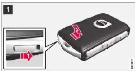
1 Hold the remote key with the front side (with the Volvo logo) facing up and move the button on the key ring section to the right. Slide the front cover slightly upward.
2 The cover will loosen and can be removed from the key.

natural_image
3D illustration of a battery pack with a red upward arrow on its side (no text or symbols)2 Remove the key blade by pulling it up.

natural_image
Black handheld car with white buttons and a red warning arrow on the side (no text or symbols)3 Put the key blade back into its designated spot in the remote key after use.
Replace the cover by pressing it down until it clicks into place.
2> Slide the cover back.
An additional click indicates that the cover is correctly in place.
Related information
- Locking and unlocking with detachable key blade (p. 255)
- Remote key (p. 243)
Locking and unlocking with detachable key blade
The detachable key blade can be used to unlock the vehicle from the outside, e.g. if the battery in the remote key is discharged.
Unlocking

Pull the front left-hand door handle to its end position to access the lock cylinder.
2 Put the key in the lock cylinder.
Turn the key clockwise 45 degrees so that the key blade is pointing straight rearward.
Turn the key blade back 45 degrees to its original position. Remove the key from the lock cylinder and release the handle so that it returns to its original position against the vehicle.
- Pull the door handle.
The door will open.
Lock the door in the same way, but turn the key 45 degrees counterclockwise in step (3).
Turning off the alarm
NOTE
When the door is unlocked using the detachable key blade and then opened, the alarm will be triggered.

Location of the backup key reader in the cup holder.
Turn off the alarm by:
-
Place the remote control key on the key symbol in the backup reader in the bottom of the cup holder in the tunnel console.
-
Turn the start knob clockwise and release it.
The start knob will automatically return to its original position - the alarm signal will stop and the alarm will be turned off.
KEY, LOCKS AND ALARM
Locking
The vehicle can also be locked using the remote key's detachable key blade, e.g. if either the vehicle's or remote key's batteries are discharged.
The left-hand front door can be locked by inserting the detachable key into the door's lock cylinder.
This is the only door with a lock cylinder. The other doors have lock mechanisms in the side of the door that must be pushed in using the key blade. The door will then be locked mechanically and cannot be opened from the outside.
The doors can still be opened from inside.

natural_image
Close-up of mechanical components with labeled parts A and B, showing alignment and mounting features (no readable text or symbols)Manual door lock. This is not the child lock.
- Remove the detachable key blade from the remote key. Insert the key blade into the opening for the lock mechanism and push the key in as far as possible, about 12 mm (0.5 in).
A The door can be opened from both the outside and the inside.
B The door cannot be opened from the outside. To return to position A, open the door using the inside door handle.
The doors can also be unlocked by pressing the unlock button on the remote key or the central lock button in the driver's door.
i NOTE
- The door's lock controls only lock that specific door, not all doors simultaneously.
- A manually locked rear door with an activated manual or electric child safety lock cannot be opened from either the outside or inside of the vehicle. A rear door locked in this way can only be unlocked using the remote key or the central unlocking button.
Related information
• Detachable key blade (p. 254)
• Arming and disarming the alarm (p. 274)
• Replacing the remote key's battery (p. 249)
- Remote key (p. 243)
Electronic immobilizer
The electronic immobilizer is a start inhibitor that helps prevent the vehicle from being started by an unauthorized person.
The vehicle can only be started with the right remote key.
The following instrument panel error messages are related to the electronic immobilizer:
Symbol Message Meaning
| Vehicle key not foundSee Owner's manual | Remote key not recognized during start. Place the remote key on the key symbol in the cup holder and try to start the vehicle again. |
Remote immobilizer with tracking system ^11
The vehicle is equipped with a system that makes it possible to track and locate the vehicle and to remotely activate the immobilizer to prevent the vehicle from being started. Contact your nearest Volvo retailer for more information and assistance activating the system.
The following instrument panel error messages are related to the remote immobilizer with tracking system:
| Symbol | Message Meaning | |
| Remotely immobilised Vehicle not possible to start | The remote immobilizer with tracking system is activated. The vehicle cannot be started. Contact Volvo On Call Service Center. |
Related information
- Remote key (p. 243)
• Ordering additional remote keys (p. 252)
Start and lock system type designations
The following information contains type designations for the start and lock system.
Alarm system
USA FCC ID: MAYDA 5823(3)
This device complies with part 15 of the FCC rules. Operation is subject to the following conditions: (1) This device may not cause harmful interference, and (2) this device must accept any interference received, including interference that may cause undesired operation.
Canada IC: 4405A-DA 5823(3)
This device is subject to the following conditions: (1) this device may not cause interference, and (2) this device must accept any interference, including interference that may cause undesired operation of the device.
Remote keys (Passive entry/Passive start\*) USA
Volvo Standard Key FCC ID: YGOHUF8423
Volvo Tag ID FCC ID: YGOHUF8432
This device complies with part 15 of the FCC rules. Operation is subject to the following two conditions:
KEY, LOCKS AND ALARM
(1) This device may not cause harmful interference, and
(2) this device must accept any interference received, including interference that may cause undesired operation.
Any changes or modification not expressly approved by the party responsible for compliance could void the user's authority to operate this equipment.
Canada
Volvo Standard Key IC: 4008C-HUF8423
Volvo Tag ID IC: 4008C-HUF8432
This device complies with Industry Canada license-exempt RSS standards. Operation is subject to the following two conditions:
(1) This device may not cause harmful interference, and (2) this device must accept any interference received, including interference that may cause undesired operation.
Immobilizer and Passive entry/Passive start\* systems
USA-FCC ID: LTQVO3134
This device complies with part 15 of the FCC rules. Operation is subject to the following two conditions:
(1) This device may not cause harmful interference, and
(2) this device must accept any interference received, including interference that may cause undesired operation.
Any changes or modification not expressly approved by the party responsible for compliance could void the user's authority to operate this equipment.
Canada-IC:3659A-VO3134
This device complies with Industry Canada license-exempt RSS standards. Operation is subject to the following two conditions:
(1) This device may not cause harmful interference, and (2) this device must accept any interference received, including interference that may cause undesired operation.
Related information
- Remote key (p. 243)
Keyless and touch-sensitive surfaces\*
If the vehicle is equipped with keyless locking and unlocking, it is only necessary to have the remote key within range, e.g. in a pocket or bag, which makes it easier to open the vehicle if your hands are full.
Pressure-sensitive surfaces
Door handle
There are indentations on the outside of the outer door handles for locking, and pressure-sensitive surfaces on the inside of the handles for unlocking.

1 Pressure-sensitive indentation for locking
② Pressure-sensitive surface for unlocking
i NOTE
It is important that only one pressure-sensitive surface is activated at a time. If the handle is grasped at the same time as the lock area is pressed, there is a risk that double commands may be sent. This may cause the requested action (locking/unlocking) to be delayed or not performed at all.
Tailgate
The tailgate handle has a rubberized pressure plate that can only be used for unlocking.

natural_image
Exterior view of a white car backrest with a close-up inset showing the rear portion of the window (no visible text or symbols)NOTE
Please be aware that the system could be activated in a car wash if the remote key is within range.
Related information
• Keyless locking and unlocking* (p. 259)
• Keyless tailgate unlock* (p. 261)
Keyless locking and unlocking\*
The vehicle can be locked or unlocked from outside using the door or tailgate handles if the vehicle is equipped with keyless locking/unlocking (Passive Entry) ^* .
NOTE
One of the vehicle's remote keys must be within range for locking and unlocking to be possible.

1 Pressure-sensitive indentation for locking
② Pressure-sensitive surface for unlocking
KEY, LOCKS AND ALARM
◀◀
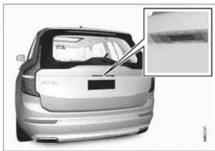
natural_image
Exterior view of a white car backrest with a close-up inset showing the rear window detail (no text or symbols visible)Rubberized pressure plate on the tailgate used only for unlocking.

NOTE
Please be aware that the system could be activated in a car wash if the remote key is within range.
Keyless locking
All of the doors have to be closed before the vehicle can be locked. However, the tailgate can be open when a door handle is used for locking.
- To lock, touch the marked area on the outside of one of the door handles after the door is closed or press the button on the lower edge of the tailgate ^12 before it is closed.
The lock indicator light in the windshield will flash to confirm that the vehicle is locked.
To close all door windows at the same time - place your finger on the pressure-sensitive indentation on the outside of the door handle and hold it there until the side windows have closed.
Locking when the tailgate is open
i NOTE
If the vehicle is locked and the tailgate is still open, make sure that the remote key is not left in the cargo compartment when the tailgate is closed and the entire vehicle is locked. If the key is detected in the vehicle, the tailgate will not lock when it is closed.
Keyless unlocking
- To unlock, grasp a door handle or press the rubberized pressure plate on the underside of the tailgate handle.
The lock indicator light in the windshield will go out to confirm that the vehicle is unlocked. Open the doors or tailgate as usual.
Automatic relocking
If none of the doors or tailgate are opened within two minutes after being unlocked, they will automatically relock. This function reduces the risk of inadvertently leaving the vehicle unlocked.
Related information
• Keyless unlock settings* (p. 261)
• Keyless tailgate unlock* (p. 261)
• Keyless and touch-sensitive surfaces* (p. 258)
Keyless unlock settings\*
Several different sequences are available for keyless unlocking.
- Tap Settings in the center display's Top view.
- Tap My Car Locking Keyless Unlock
-
Select alternative:
-
All Doors
- unlocks all doors at the same time.
- Single Door
- unlocks the selected door.
Related information
• Keyless locking and unlocking* (p. 259)
• Keyless and touch-sensitive surfaces* (p. 258)
Keyless tailgate unlock\*
The tailgate can be opened using the remote key. The key only needs to be within range, e.g. in a pocket or bag.
The tailgate is held closed by an electronic locking mechanism.
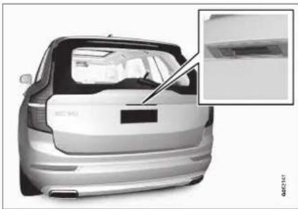
natural_image
Exterior view of a white car backrest with a close-up inset showing the rear window detail (no visible text or symbols)To open the tailgate:
- Lightly press the rubberized pressure plate on the underside of the tailgate handle.
The lock will disengage.
i NOTE
One of the vehicle's remote keys must be within range behind the vehicle for unlocking to be possible.
- Lift the outer handle to fully open the tail-gate.
CAUTION
- Only light pressure on the rubberized pressure plate is necessary to release the tail-gate's locking mechanism.
- Use the handle to lift the tailgate and do not apply force to the rubberized pressure plate. Too much force can damage the pressure plate's electrical connections.
Hands-free unlocking of the tailgate is also possible using a foot movement under the rear bumper; see the separate section.
WARNING
Do not drive with the tailgate open. Toxic exhaust fumes can be sucked into the vehicle through the cargo compartment.
Related information
• Keyless locking and unlocking* (p. 259)
• Keyless and touch-sensitive surfaces* (p. 258)
• Remote key range (p. 248)
- Foot movement tailgate operation* (p. 270)
KEY, LOCKS AND ALARM
Antenna locations for the start and lock system
The vehicle is equipped with a keyless start and lock system ^13 that uses a number of integrated antennas positioned throughout the vehicle.

Location of the antennas.
1 Under the cup holder in the front section of the tunnel console
② In the upper front section of the left-side rear door ^14
3 In the upper front section of the right-side rear door ^14
4 In the center of the rear seat backrest ^14
WARNING
Individuals with an implanted pacemaker should not allow the pacemaker to come closer than 22 cm (9 in.) to the Keyless system antennas. The aim of this is to prevent disturbances between the pacemaker and the Keyless system.
Related information
• Keyless and touch-sensitive surfaces* (p. 258)
• Remote key range (p. 248)
Locking and unlocking from inside the vehicle
The doors and tailgate can be locked and unlocked from inside the vehicle using the central lock buttons in the front doors. The lock buttons in the rear doors* can be used to lock/unlock that particular door.
Central locking

natural_image
Close-up of a car interior panel showing a black lock button with circular icons, no visible text or symbols.Button with indicator light for locking and unlocking in front door.
Unlocking using the front door buttons
- Press the button to unlock all side doors and the tailgate.
Alternative unlocking method

natural_image
Close-up of a car's front and side door panel showing the handle and control buttons (no text or symbols visible)Alternative unlocking method using side door opening handle ^15 .
- Pull either of the side door inside opening handles and release.
Depending on the remote key settings, either all doors will be unlocked or just the selected door will be unlocked and opened.
To change this setting, tap Settings →
My Car Locking Remote and Interior Unlock in the Top view of the center display.
Locking using the front door buttons
- Press the Ⓑutton (both front doors must be closed).
All doors and the tailgate will lock.
Locking using the rear door button*

natural_image
Close-up of a white car interior panel with a black circular button labeled '6' (no text or symbols beyond the button)Button with indicator light for locking/unlocking in rear door.
The lock buttons in the rear doors only lock/unlock that particular door.
Unlocking the rear door
-
Pull the opening handle to unlock the rear door.
-
Pull the opening handle again to open the rear door ^16 .
Related information
- Settings for remote and inside door unlock (p. 247)
- Unlocking the tailgate from inside the vehicle (p. 264)
- Activating and deactivating child safety locks (p. 264)
KEY, LOCKS AND ALARM
Unlocking the tailgate from inside the vehicle
The tailgate can be locked from the inside using a button on the dashboard.
1.

natural_image
Close-up of a car dashboard control panel with indicator lights and function buttons (no readable text or symbols)Press the button on the dashboard.
The tailgate will unlock and can be opened from the outside by pressing the rubberized pressure plate on the handle.
- With the optional power tailgate* -
Press and hold the 📧 button on the dashboard.
The tailgate will open.
Related information
- Locking and unlocking from inside the vehicle (p. 262)
- Opening and closing the power tailgate* (p. 266)
Activating and deactivating child safety locks
Child safety locks help prevent children from opening the rear doors from inside the vehicle. There is an electric safety lock* and a manual safety lock.
Activating and deactivating electric child safety locks\*
The electric child safety lock can be activated and deactivated in any ignition mode higher than 0. The lock can be activated and deactivated up to 2 minutes after the ignition is turned off if no door has been opened.
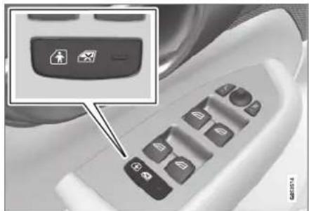
natural_image
Close-up of a car air conditioner control panel with a highlighted function button (no text or symbols visible)Button for electric activation and deactivation.
-
Turn on the ignition and select any ignition mode higher than 0.
-
Press the button on the driver's door control panel.
The message Rear child lock Activated will be shown in the instrument panel and the indicator light will illuminate to show that the child safely locks are activated.
When the electric child safety locks are activated:
- the rear windows can only be opened using the driver's door control panel
- the rear doors cannot be opened from the inside.
To deactivate the child safety locks:
- Press the button on the driver's door control panel.
The message Rear child lock Deactivated will be shown in the instrument panel and the indicator light will go out to show that the child safety locks are deactivated.
When the ignition is switched off, the current setting will be saved. If the child safety locks were activated when the ignition was switched off, they will remain activated the next time the ignition is started.
| Symbol | Message Meaning | |
| Rear child lock Activated | The child safety locks are activated. | |
| Rear child lock Deactivated | The child safety locks are deactivated. |
Activating and deactivating manual child safety locks
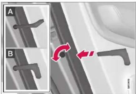
natural_image
Mechanical component diagram showing two views (A and B) of a bracket with curved slots, one highlighted with red arrows indicating rotation or movement (no text or symbols present)Manual child safety lock (this is not the manual door lock).
- Use the detachable key blade in the remote key to turn the control.
A The door cannot be opened from the inside.
B The door can be opened from both the outside and the inside.
NOTE
- The door's knob control only locks that specific door, not both rear doors simultaneously.
- There are no manual child safety locks on models equipped with electronic child safety locks.
Related information
- Locking and unlocking from inside the vehicle (p. 262)
• Detachable key blade (p. 254)
KEY, LOCKS AND ALARM
Automatic locking when driving
The doors and tailgate will automatically lock when the vehicle begins to move.
Related information
- Locking and unlocking from inside the vehicle (p. 262)
Opening and closing the power tailgate\*
The tailgate can be opened and closed automatically with the optional power tailgate.
Opening
To open the power tailgate, do one of the following:
- Press and hold the button on the remote key until the tailgate begins to open.

natural_image
Close-up of a black electronic device with a close-up inset showing internal components (no visible text or symbols)- Press and hold the button on the dashboard until the tailgate begins to open.

natural_image
Close-up of a car dashboard control panel with icons for fuel, parking, and battery (no text or symbols visible)- Press lightly on the tailgate's outside handle.

natural_image
Exterior view of a white car backrest with a close-up inset showing the rear portion of the window (no visible text or symbols)- Move your foot in a kicking motion* under the rear bumper.

natural_image
Illustration of a person's legs and foot wearing a car, with red motion arrows indicating sound waves (no text or symbols)Closing
To close ^17 the power tailgate, do one of the following:
- Press the button on the lower edge of the tailgate to close.

natural_image
Top-down view of a car rearview panel with a control switch and two car icons (no text or symbols visible)The tailgate will close automatically – the tailgate will remain unlocked.
i NOTE
- The button remains active 24 hours after the tailgate was opened. After this time, the tailgate must be closed manually.
- If the tailgate has been open for more than 30 minutes, it will automatically close slowly.
- Press and hold the button on the remote key.
The tailgate closes automatically and an audible signal sounds – the tailgate will remain unlocked.
- Press and hold the button on the dashboard.
The tailgate closes automatically and an audible signal sounds – the tailgate will remain unlocked.
- Move your foot in a kicking motion* under the rear bumper.
The tailgate closes automatically and an audible signal sounds – the tailgate will remain unlocked.
KEY, LOCKS AND ALARM
Closing and locking ^17
- Press the button on the lower edge of the tailgate to close and simultaneously lock both the tailgate and doors (all doors must be closed in order to lock).
The tailgate closes automatically – the tailgate and doors lock, and the alarm* is armed.
NOTE
- One of the vehicle's remote keys must be within range for locking and unlocking to be possible.
- When the keyless locking or closing* functions are used, three audible signals will sound if the key is not detected close enough to the tailgate.
CAUTION
When operating the tailgate manually, open and close it slowly. If you encounter resistance, do not use force. This could lead to damage and loss of function.
Interrupting opening or closing
Interrupt opening or closing by doing one of the following:
- Press the button on the dashboard.
- Press the button on the remote key.
- Press the close button on the underside of the tailgate.
- Press the rubberized pressure plate on the underside of the tailgate's outer handle.
• Using a foot movement*.
Tailgate movement is interrupted and stops. The tailgate can then be opened or closed manually.
If the tailgate stops near the closed position, it will open the next time it is activated.
Pinch protection
If anything obstructs the tailgate with enough force to prevent it from opening or closing, pinch protection will be activated.
- When opening - the tailgate will stop moving and an audible signal will sound.
- When closing - the tailgate will stop, a long audible signal will sound and the tailgate will return to the programmed maximum opening position.
WARNING
Be aware of the risk of serious injury when operating the tailgate. Before opening/closing, make sure that no one is in the path of the tailgate who could be injured by its movement.
Always operate the tailgate with caution.
Preloaded springs
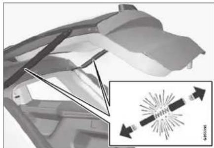
natural_image
Diagram of a car interior with directional arrows and a magnified inset showing a vehicle (no text or symbols)Preloaded springs for the power tailgate.
WARNING
Do not attempt to open or access the preloaded springs in the power tailgate struts. They are preloaded with high pressure and can cause injury if opened.
Related information
- Setting a maximum height for the power tail-gate* (p. 269)
• Foot movement tailgate operation* (p. 270)
• Remote key range (p. 248)
Setting a maximum height for the power tailgate\*
The tailgate can be set to stop opening at a certain height, for example if the tailgate needs to be opened in a garage with a low ceiling.
Setting maximum opening height:
- Open the tailgate to the desired opening height.
i NOTE
It is not possible to program an opening position lower than half-open tailgate.
- Press the button on the lower edge of the tailgate and hold for at least 3 seconds. > Two brief audio signals will sound to indicate that the position has been stored.
Resetting to maximum opening position:
- Move the tailgate manually to its highest possible position and press the 📋 button on the tailgate for at least 3 seconds.
Two audio signals will sound to indicate that the stored position has been erased. The tailgate can then be opened to its maximum position.
NOTE
- If the system has been working continuously for a prolonged period of time, it will be switched off to avoid overload. It can be used again after approximately 2 minutes.
Related information
- Opening and closing the power tailgate* (p. 266)
KEY, LOCKS AND ALARM
Foot movement tailgate operation\*
To make it easier to operate the tailgate when your hands are full, it can be opened and closed by moving your foot in a forward kicking motion under the rear bumper.

natural_image
Diagram of a car's rear suspension system with red sensor waves (no text or symbols)The sensor is located to the left of center under the rear bumper ^18 .
One of the vehicle's remote keys must be within range behind the vehicle (approx. 1 meter (3 feet)) for opening and closing to be possible. This applies even if the vehicle is unlocked in order to prevent the trunk lid from inadvertently opening e.g. at a car wash.
Foot movement operation

natural_image
Illustration of a person's foot stepping on a car tire with red sound waves indicating motion (no text or symbols)Kicking motion within the sensor's activation area.
- Make one slow forward kicking motion with your foot under the left section of the rear bumper. Take a step back. Do not touch the bumper.
A brief audible signal will be heard when opening or closing is activated - the tailgate will open/close.
If the tailgate is open, it will close ^19 when the foot motion sensor is activated.
If several opening attempts have been made without the remote key in range behind the vehicle, foot movement operation will not be available for a short period of time.
Do not keep your foot under the vehicle in a kicking motion. This may prevent activation.
Interrupting opening or closing with a foot movement
- Make one slow forward kicking motion while the tailgate is opening or closing to stop its movement.
The remote key does not need to be within range of the vehicle to interrupt opening or closing.
If the tailgate stops near the closed position, it will open the next time it is activated.
NOTE
There is a risk of reduced or lost function if there are large amounts of snow, ice, dirt, etc. on the rear bumper. Make sure to keep the bumper clean.
NOTE
Please note that the system could be inadvertently activated in a car wash or similar if the remote key is within range.
Vehicle with skid plate accessory\*
If the vehicle is equipped with skid plate, the sensor is located towards the left corner of the bumper.
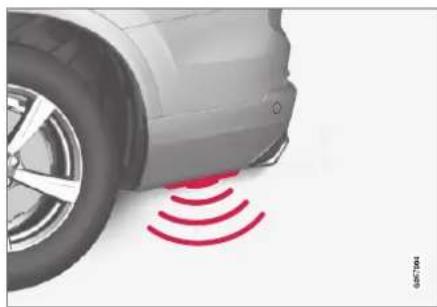
natural_image
Illustration of a car wheel with red sensor waves indicating sound or vibration (no text or symbols)To activate opening and closing using a foot movement on a vehicle with skid plate, make a kicking motion from the side of the vehicle. One of the vehicle's remote keys must be within range (approx. 1 meter (3 feet)) for opening and closing to be possible.

natural_image
Illustration of a person's lower body and foot with red motion arrows indicating sound waves or vibration, next to a car (no text or symbols)Kicking motion within the sensor's activation area.
Related information
• Keyless and touch-sensitive surfaces* (p. 258)
- Opening and closing the power tailgate* (p. 266)
- Remote key range (p. 248)
Private Locking
The tailgate and the glove compartment can be locked using the private locking function to prevent them from being opened, e.g. when the vehicle is left at a workshop or with a valet.

The function button for private locking is located in the center display's Function view. Depending on the current status of the lock, Private Locking Unlocked or Private Locking Locked will be dis-
played.
Related information
- Activating and deactivating private locking (p. 272)
KEY, LOCKS AND ALARM
Activating and deactivating private locking
Private locking is activated using the function button in the center display and a PIN code.

NOTE
For the valet lock function to be activated the car must be in at least ignition mode I.
Entering security code before initial use
The first time the function is used, a security code must be selected. This code can then be used to deactivate private locking if the selected PIN code has been lost or forgotten. The security code functions as a PUK (security) code for all PIN codes used for private locking.
Save the security code in a safe place.
To create a security code:
- Tap the button for private locking in Function view.

A pop-up window will appear.
- Enter your security code.
The security code is saved. The private locking function is now ready for activation.
If the system has been reset, the above procedure will need to be repeated.
Activating private locking
- Tap the button for private locking in Function view.
A pop-up window will appear.
- Enter the code you would like to use to unlock the glove compartment and the tailgate and tap Confirm.
The glove compartment and tailgate will lock. A green indicator light will illuminate next to the button in Function view to confirm locked status.
Deactivating private locking
- Tap the button for private locking in Function view.
A pop-up window will appear.
- Enter the code used for locking and tap Confirm.
The glove compartment and tailgate will unlock. The green indicator light next to the button in Function view will go out to confirm unlocked status.

NOTE
If you have forgotten or lost your PIN code or if the PIN code has been entered incorrectly more than three times, the security code can be used to deactivate private locking.

NOTE
If private locking is activated and the vehicle is unlocked using Volvo On Call* or the Volvo On Call* app, private locking will be deactivated automatically.
Related information
- Private Locking (p. 271)
Alarm
The alarm emits sound and light signals if anyone without a valid remote key attempts to break into the vehicle or interferes with the start battery or alarm siren.
When armed, the alarm will be triggered if:
• the hood, tailgate or any door is opened.
• a battery cable is disconnected.
• the alarm siren is disconnected.
Alarm signals
The following occurs if the alarm is triggered:
- A siren will sound for 30 seconds or until the alarm is turned off.
- All turn signals will flash for 5 minutes or until the alarm is turned off.
If the reason the alarm was triggered is not rectified, the alarm cycle will repeat up to 10 times ^20 .
Alarm indicator

natural_image
Interior view of a car dashboard with a highlighted touchscreen device (no visible text or symbols)A red indicator light on the dashboard shows the status of the alarm:
- Indicator off - the alarm is disarmed.
- Indicator flashes once every two seconds - the alarm is armed.
- The indicator flashes quickly after the alarm has been disabled for up to 30 seconds or until the ignition is put in I mode – the alarm has been triggered.
KEY, LOCKS AND ALARM
In the event of alarm system failure

If a problem is detected in the alarm system, a symbol and the message Alarm system failure Service required will appear in the instrument panel. Contact a workshop - an authorized Volvo workshop is recommended.

NOTE
Do not attempt to repair or alter any of the components in the alarm system yourself. Any such attempt could affect the terms and conditions of your insurance policy.
Related information
• Arming and disarming the alarm (p. 274)
Arming and disarming the alarm
The alarm is armed when the vehicle is locked.
Arming the alarm
Lock and arm the vehicle by:
- pressing the lock button on the remote key
- touch the marked surface on the outside of the door handle or the rubberized pressure plate on the tailgate ^21 .
If the vehicle is equipped with both keyless locking/unlocking* and power tailgate*, the button
on the lower edge of the tailgate can also be used to lock and arm the vehicle.

natural_image
Interior view of a car dashboard with a highlighted touchscreen device (no visible text or symbols)A red LED light on the dashboard will flash every other second when the vehicle is locked and the alarm is armed.
Disarming the alarm
Unlock and disarm the vehicle alarm by:
- pressing the unlock button on the remote key 🔒.
- grip a door handle or press the tailgate's rubberized pressure plate ^21 .
Disarming the alarm without a functioning remote key
The vehicle can be unlocked and disarmed even if the remote key is not functioning, e.g. if the battery is discharged.
- Open the driver's door using the detachable key blade.
This will trigger the alarm.
Location of the backup key reader in the cup holder.
- Place the remote key on the key symbol in the backup reader in the tunnel console's cup holder.
- Turn the start knob clockwise and release.
The alarm will be disarmed.
Turning off a triggered alarm
- Press the unlock button on the remote key or put the ignition into mode I by turning the start knob clockwise and then releasing it.
NOTE
- Remember that the alarm is armed when the vehicle is locked.
- The alarm will be triggered if any of the doors is opened from the inside.
Automatically arming and disarming the alarm
Automatically arming the alarm helps prevent inadvertently leaving the vehicle without alarm protection.
If the vehicle is unlocked using the remote key (and the alarm is disarmed) but none of the doors or tailgate are opened within two minutes, the alarm will be automatically rearmed. The vehicle will also re-lock.
On some markets, the alarm will be automatically armed following a slight delay after the driver's door has been opened and closed without being locked.
To change this setting:
- Tap Settings in the center display's Top view.
- Tap My Car Locking.
- Select Passive Arming Deactivation to temporarily deactivate the function.
Related information
- Alarm (p. 273)

bar
| Category | Value | |---|---| | Category 1 | 100 | | Category 2 | 100 | | Category 3 | 100 | | Category 4 | 100 | | Category 5 | 100 | | Category 6 | 100 | | Category 7 | 100 | | Category 8 | 100 | | Category 9 | 100 | | Category 10 | 100 | | Category 11 | 100 | | Category 12 | 100 | | Category 13 | 100 | | Category 14 | 100 | | Category 15 | 100 | | Category 16 | 100 | | Category 17 | 100 | | Category 18 | 100 | | Category 19 | 100 | | Category 20 | 100 | | Category 21 | 100 | | Category 22 | 100 | | Category 23 | 100 | | Category 24 | 100 | | Category 25 | 100 | | Category 26 | 100 | | Category 27 | 100 | | Category 28 | 100 | | Category 29 | 100 | | Category 30 | 100 | | Category 31 | 100 | | Category 32 | 100 | | Category 33 | 100 | | Category 34 | 100 | | Category 35 | 100 | | Category 36 | 100 | | Category 37 | 100 | | Category 38 | 100 | | Category 39 | 100 | | Category 40 | 100 | | Category 41 | 100 | | Category 42 | 100 | | Category 43 | 100 | | Category 44 | 100 | | Category 45 | 100 | | Category 46 | 100 | | Category 47 | 100 | | Category 48 | 100 | | Category 49 | 100 | | Category 50 | 100 | | Category 51 | 100 | | Category 52 | 100 | | Category 53 | 100 | | Category 54 | 100 | | Category 55 | 100 | | Category 56 | 100 | | Category 57 | 100 | | Category 58 | 100 | | Category 59 | 100 | | Category 60 | 100 | | Category 61 | 100 | | Category 62 | 100 | | Category 63 | 100 | | Category 64 | 100 | | Category 65 | 100 | | Category 66 | 100 | | Category 67 | 100 | | Category 68 | 100 | | Category 69 | 100 | | Category 70 | 100 | | Category 71 | 100 | | Category 72 | 100 | | Category 73 | 100 | | Category 74 | 100 | | Category 75 | 100 | | Category 76 | 100 | | Category 77 | 100 | | Category 78 | 100 | | Category 79 | 100 | | Category 80 | 100 | | Category 81 | 100 | | Category 82 | 100 | | Category 83 | 100 | | Category 84 | 100 | | Category 85 | 100 | | Category 86 | 100 | | Category 87 | 100 | | Category 88 | 100 | | Category 89 | 100 | | Category 90 | 100 | | Category 91 | 100 | | Category 92 | 100 | | Category 93 | 100 | | Category 94 | 100 | | Category 95 | 100 | | Category 96 | 100 | | Category 97 | 100 | | Category 98 | 100 | | Category 99 | 100 | | Total (Total) = [sum of the values] / [sum of the values] * [sum of the values] * [sum of the values] * [sum of the values] * [sum of the values] * [sum of the values] * [sum of the values] * [sum of the values] * [sum of the values] * [sum of the values] * [sum of the values] * [sum of the values] * [sum of the values] * [sum of the values] * [sum of the values] * [total] * [sum of the values] * [sum of the values] * [sum of the values] * [sum of the values] * [sum of the values]DRIVER SUPPORT
DRIVER SUPPORT
Driver support systems
The vehicle is equipped with a number of driver support systems that can provide the driver with active or passive assistance in various situations.
The systems can, for example, help the driver:
- maintain a set speed
- maintain a set time interval to the vehicle ahead
- help prevent a collision by warning the driver and applying the brakes
- park the vehicle.
Some of the systems are standard and others are options. This also varies from market to market.
Related information
• Speed-dependent steering wheel resistance (p. 278)
• Electronic Stability Control (p. 279)
• Stability system Roll Stability Control (p. 279)
• Speed limiter (p. 283)
• Automatic Speed Limiter (p. 287)
• Cruise control (p. 291)
• Distance Alert* (p. 296)
• Adaptive Cruise Control* (p. 300)
- Pilot Assist (p. 316)
- Radar sensor (p. 332)
- Camera (p. 337)
• City Safety™ (p. 341)
• Rear Collision Warning (p. 354)
BLIS* (p. 355)
• Cross Traffic Alert* (p. 360)
• Road Sign Information* (p. 364)
• Driver Alert Control (p. 370)
• Lane Keeping Aid (p. 372)
• Steering assistance at risk of collision (p. 380)
• Park Assist* (p. 390)
• Park Assist Camera* (p. 396)
• Park Assist Pilot* (p. 406)
Speed-dependent steering wheel resistance
Speed-dependent power steering increases the steering wheel resistance in pace with the vehicle's speed to give the driver an enhanced feeling of control and stability.
Steering may feel stiffer on highways. When parking and at low speeds, it will be easier to move the steering wheel.
i NOTE
In some situations, the power steering may become too hot and require temporary cooling – during such time the power steering will work at reduced output and the steering wheel may feel more difficult to move.
In parallel with the temporarily reduced steering assistance, the driver display shows a message as well as a STEERING WHEEL symbol.
WARNING
While the power steering is working at reduced power, the driver support functions and systems with steering assistance are not available.
In such a situation, the driver display shows the Power steering failure message, combined with a STEERING WHEEL symbol.
Changing the level of steering wheel resistance\*
To change the level of steering wheel resistance, see the description of the INDIVIDUAL option under "Available drive modes" in the "Drive modes" section.
On models not equipped with drive mode controls and the INDIVIDUAL option, steering wheel resistance can instead be set in the center display's Top view under:
Settings My Car Drive Modes Steering Force

Steering wheel resistance settings cannot be accessed when turning at speeds above 10 km/h (6 mph).
Related information
- Drive modes (p. 454)
- Pilot Assist (p. 316)
• Lane Keeping Aid (p. 372)
• Steering assistance at risk of collision (p. 380)
• Park Assist Pilot* (p. 406)
Stability system Roll Stability Control
The Roll Stability Control (RSC ^1 ) system helps minimize the risk of a rollover in the event of e.g. a sudden evasive maneuver or if the vehicle begins to skid.
The RSC system monitors the lateral angle at which the vehicle is leaning and registers any changes. Using this information, the system calculates the likelihood of a rollover. If there is an imminent risk of a rollover, Electronic Stability Control is activated, engine torque is reduced and brakes are applied to one or more of the wheels until the vehicle has regained stability.
WARNING
The vehicle's stability systems, including RSC do not replace the driver's responsibility for operating the vehicle in a safe manner. Speed and driving style should always be adapted to the current road, traffic and weather conditions. Posted speed limits should always be respected.
Related information
• Driver support systems (p. 278)
Electronic Stability Control
The Electronic Stability Control (ESC ^2 ) function helps the driver avoid skidding and improves the vehicle's directional stability.
This symbol will be displayed in the instrument panel when the ESC system is intervening.
When the ESC has intervened to apply the brakes, a pulsing sound may be heard and the
vehicle may accelerate more slowly than expected when the accelerator pedal is depressed.
The ESC system consists of the following subfunctions:
- Stability control ^3
• Spin control and active yaw control - Engine drag control
- Trailer Stability Assist

DRIVER SUPPORT
◀◀

WARNING
- The Electronic Stability Control system ESC is supplementary driver support intended to facilitate driving and make it safer – it cannot handle all situations in all traffic, weather and road conditions.
- ESC is not a substitute for the driver's attention and judgment. The driver is always responsible for ensuring the vehicle is driven in a safe manner, at the appropriate speed, with an appropriate distance to other vehicles, and in accordance with current traffic rules and regulations.
Stability control ^3
This function helps control the driving and braking force of each individual wheel in an attempt to stabilize the vehicle.
Spin control and active yaw control
This function is active at low speeds and brakes the wheels that are spinning to transfer additional power from wheels that are not spinning.
This function also helps prevent the wheels from spinning while the vehicle is accelerating.
Engine drag control
Engine drag control (EDC ^4 ) helps prevent inadvertent wheel lock, e.g. after downshifting or using engine braking when driving at low speeds on a slippery surface.
Inadvertent wheel lock while driving could impair the driver's ability to steer the vehicle.
Trailer Stability Assist ^4
Trailer Stability Assist (TSA ^6 ) is designed to help stabilize a vehicle that is towing a trailer if the vehicle and trailer have begun to sway. For more information, see "Trailer Stability Assist".

NOTE
The TSA function is deactivated if ESC Sport Mode is activated.
Related information
• Electronic Stability Control Sport mode (p. 281)
- Activating/deactivating Sport mode in Electronic Stability Control (p. 281)
• Electronic Stability Control Sport mode limitations (p. 281)
• Electronic Stability Control symbols and messages (p. 282)
• Trailer Stability Assist* (p. 485)
Electronic Stability Control Sport mode
The ESC ^7 system is always activated and cannot be switched off. However, the driver can select ESC Sport Mode, which offers more active driving characteristics.
With the ESC Sport Mode sub-function selected, intervention from ESC is reduced and more lateral movement is permitted, giving the driver more control of the vehicle than usual.
When ESC Sport Mode is selected, ESC may seem to be disabled even though the function continues to assist the driver.

NOTE
When the ESC Sport Mode function is selected, the trailer stabilizer (TSA ^5 ) is switched off.
ESC Sport Mode also helps provide maximum traction if the vehicle gets stuck or is driving on a loose surface such as deep snow or loose sand.
Related information
• Electronic Stability Control (p. 279)
Activating/deactivating Sport mode in Electronic Stability Control
The ESC ^9 system is always activated and cannot be switched off. However, the driver can select Sport mode, which offers more active driving characteristics.

Sport mode can be activated/deactivated in the center display's Function view.
- Tap the ESC Sport Mode button in Function view.
Sport mode is activated when the indicator light is green, and deactivated when the indicator light is gray.

When ESC Sport Mode is activated, this symbol will illuminate with a steady glow in the instrument panel. It will remain on until the driver deactivates
the function or until the engine is turned off. The ESC system will return to normal mode the next time the engine is started.
Related information
• Electronic Stability Control (p. 279)
Electronic Stability Control Sport mode limitations
There are certain limitations associated with the ESC ^10 system's subfunction ESC Sport Mode being activated.
The ESC Sport Mode function cannot be selected when any of the following functions are activated:
- Speed limiter
- Cruise control
• Adaptive Cruise Control - Pilot Assist.
Related information
• Electronic Stability Control (p. 279)
DRIVER SUPPORT
Electronic Stability Control symbols and messages
A number of symbols and messages related to Electronic Stability Control (ESC) may be displayed in the instrument panel.
Some examples of symbols and messages are shown in the table below.
| Symbol | Message Meaning | |
 | Steady glow for approx. 2 seconds. | System check when the engine is started. |
 | Flashing light. The ESC is actively operating. | |
 | Steady glow. Sport mode is activated.Note: The ESC system is not deactivated in this mode, but has partially reduced functionality. | |
 | ESCTemporarily off | The ESC system's functionality has been temporarily reduced due to high brake system temperatures. The function will be automatically reactivated when the brakes have cooled.See the message in the instrument panel. |
| [KSZY] | ESCService required | The ESC system is not functioning properly.Stop the vehicle in a safe place, turn off the engine and then restart it.Consult a workshop if the message persists – an authorized Volvo workshop is recommended. |
A text message can be erased by briefly pressing the button in the center of the right-side steering wheel keypad.
If the message persists: Contact a workshop – an authorized Volvo workshop is recommended.
Related information
• Electronic Stability Control (p. 279)
Speed limiter
A Speed Limiter (SL ^11 ) could be described as a reverse cruise control. The driver regulates the vehicle's speed using the accelerator pedal, but is prevented by the Speed Limiter from inadvertently exceeding a preset maximum speed.

Function buttons and symbols ^12 .
1 : Activates the Speed Limiter from standby mode and resumes the set maximum speed.
1 +: Increases the set maximum speed
② : From standby mode - activates the Speed Limiter and sets the current speed
2: From active mode - deactivates/puts the Speed Limiter in standby mode
3 —: Reduces the set maximum speed
4 Marker for set maximum speed
5 The vehicle's current speed
6 The set maximum speed
WARNING
- The Speed Limiter function is supplementary driver support intended to facilitate driving and help make it safer – it cannot handle all situations in all traffic, weather and road conditions.
- The driver must always pay attention to traffic conditions and take action if the Speed Limiter is not maintaining a suitable speed.
- The Speed Limiter is not a substitute for the driver's attention and judgment. The driver is always responsible for ensuring the vehicle is driven in a safe manner, at the appropriate speed, with an appropriate distance to other vehicles, and in accordance with current traffic rules and regulations.
Related information
• Cruise Control limitations (p. 287)
- Activating and starting Speed Limiter (p. 284)
• Managing Speed Limiter speed (p. 284)
• Deactivating and putting Speed Limiter in standby mode (p. 285)
- Reactivating Speed Limiter from standby mode (p. 286)
• Turning off Cruise Control (p. 286)
• Automatic Speed Limiter (p. 287)
• Automatic Speed Limiter limitations (p. 291)
- Activating/deactivating Automatic Speed Limiter (p. 289)
- Changing Automatic Speed Limiter tolerance (p. 290)
DRIVER SUPPORT
Activating and starting Speed Limiter
The Speed Limiter (SL ^13 ) function must be selected and activated in order to regulate speed.
Putting Speed Limiter in standby mode

Note: This illustration is general and details may vary depending on model.
- Press ◀ (1) or ▶ (3) and scroll to the Speed
Limiter function (4).
The symbol (4) will appear, indicating that the Speed Limiter is in standby mode.
Starting the Speed Limiter
The Speed Limiter can only be activated while the engine is running. The lowest maximum speed that can be set is 30 km/h (20 mph).
- With the Speed Limiter in standby mode and
the symbol displayed, press the button (2) on the steering wheel keypad.
The Speed Limiter will be started and the vehicle's current speed will be set as the maximum speed.
Related information
• Speed limiter (p. 283)
Managing Speed Limiter speed
The Speed Limiter (SL ^14 ) can be set to various speeds.
Setting/changing set speed

Note: This illustration is general and details may vary depending on model.
- Change a set speed by pressing the (+) or — (3) buttons briefly or by pressing and holding them:
- Press briefly: Press briefly: each press changes the speed in +/- 5 mph (+/- 5 km/h) increments.
- Press and hold: Release the button when the set speed indicator (4) has moved to the desired speed.
• The most recently set speed will be stored.
Related information
• Speed limiter (p. 283)
Deactivating and putting Speed Limiter in standby mode
The Speed Limiter (SL ^15 ) can be temporarily deactivated and put in standby mode.
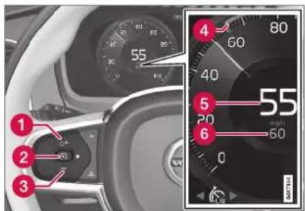
Note: This illustration is general and details may vary depending on model.
To deactivate the Speed Limiter and put it in standby mode:
- Press the Button on the steering wheel (2).
The speed limit markings and symbols in the instrument panel will change from WHITE to GRAY. This indicates that the Speed Limiter is temporarily deactivated and the driver can exceed the set maximum speed.
Temporarily deactivating using the accelerator pedal
The set maximum speed can be temporarily deactivated and exceeded using the accelerator pedal without first putting the Speed Limiter in standby mode, e.g. when quick acceleration is required.
To do so:
- Depress the accelerator as far as possible and then release it when the desired speed has been reached.
The Speed Limiter will remain activated and the symbol in the instrument panel will be WHITE.
- Release the accelerator pedal fully when the temporary acceleration is completed.
The vehicle will use engine braking to automatically slow down to a speed below the most recently set maximum speed.
Related information
• Speed limiter (p. 283)
DRIVER SUPPORT
Reactivating Speed Limiter from standby mode
Speed Limiter (SL ^16 ) can be reactivated after having been temporarily deactivated and put in standby mode.
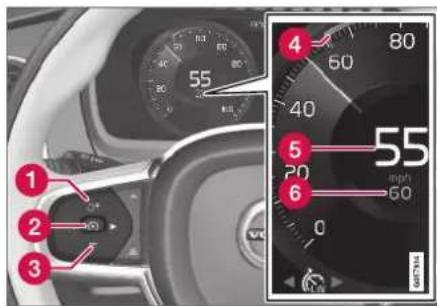
Note: This illustration is general and details may vary depending on model.
To reactivate the Speed Limiter from standby mode:
- Press the button on the steering wheel (1).
The speed limit markings in the instrument panel will change from GRAY to WHITE. The vehicle's speed will once again be limited to the most recently set speed.
or
- Press the Button on the steering wheel (2).
The speed limit markings and symbols in the instrument panel will change from GRAY to WHITE and the vehicle's current speed will be set as the maximum speed.
Related information
• Speed limiter (p. 283)
Turning off Cruise Control
The Speed Limiter (SL ^17 ) can be turned off.
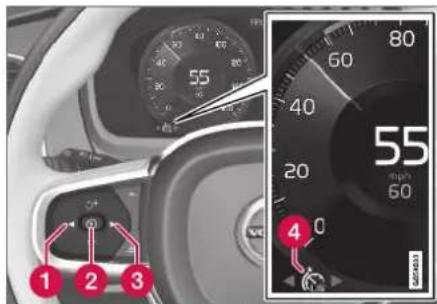
Note: This illustration is general and details may vary depending on model.
To turn off Cruise Control:
- Press the Ⓧ button on the steering wheel (2).
The Speed Limiter will go into standby mode.
-
Press the ▶ (1) or ▶ (3) buttons on the steering wheel to select another function.
The Speed Limiter symbol and marking (4) in the instrument panel will go out and the set maximum speed will be erased.
-
Press the Ⓜ button on the steering wheel keypad again.
Another function will be activated.
Related information
• Speed limiter (p. 283)
Cruise Control limitations
On steep downgrades, the Speed limiter's braking capacity may not be sufficient and the set maximum speed may be exceeded. If this happens, Speed limit exceeded will be displayed in the instrument panel to alert the driver.
i NOTE
A text message on exceeded max. speed is activated if the speed is exceeded by at least 3 km/h (ca 2 mph).
Related information
• Speed limiter (p. 283)
Automatic Speed Limiter
The Automatic Speed Limiter (ASL) function helps the driver adapt the vehicle's maximum speed to the posted speed limits.
The Speed Limiter (SL ^18 ) function can be switched to Automatic Speed Limiter (ASL).
The Automatic Speed Limiter function uses speed information from the Road Sign Information function (RSI) to automatically adapt the vehicle's maximum speed.
DRIVER SUPPORT
◀◀

WARNING
- The ASL function is supplementary driver support intended to facilitate driving and help make it safer – it cannot handle all situations in all traffic, weather and road conditions.
- Even if the driver can clearly see the speed limit sign, the speed information from the Road Sign Information (RSI) function to ASL may be incorrect. In such cases, the driver must intervene and accelerate or brake to an appropriate speed.
- ASL is not a substitute for the driver's attention and judgment. The driver is always responsible for ensuring the vehicle is driven in a safe manner, at the appropriate speed, with an appropriate distance to other vehicles, and in accordance with current traffic rules and regulations.
- See also the heading "Road Sign Information limitations".
Is SL or ASL active?
The symbols in the instrument panel indicate which Speed Limiter function is active:
| Symbol SL ASL | ||
| A | √ | √ |
| Road sign symbol ^3 after "70" = ASL is activated. | √ |
A WHITE symbol: The function is active. GRAY symbol: Standby mode.
B See "ASL symbol" below for an explanation of the symbol's different colors.
ASL symbol

The road sign symbol (next to the stored speed ("70" here) in the center of the speedometer) can be displayed in three different colors, which are
explained in the following table:
| Road sign symbol's color | Explanation |
| Greenish-yellow | ASL is active |
| Gray ASL is | in standby mode |
| Amber/orange A | SL is temporarily in standby mode, e.g. because a speed limit sign could not be read. |
Related information
• Speed limiter (p. 283)
- Activating/deactivating Automatic Speed Limiter (p. 289)
- Changing Automatic Speed Limiter tolerance (p. 290)
• Automatic Speed Limiter limitations (p. 291)
Activating/deactivating Automatic Speed Limiter
The Automatic Speed Limiter (ASL) is a supplement to the Speed Limiter (SL) and can be activated/deactivated.
Activating ASL

The Speed Sign Assist button is located in the center display's Function view.
To activate the Automatic Speed Limiter:
- Tap the Speed Sign Assist button.
ASL will go into standby mode and a green indicator light will illuminate. A road sign symbol will be displayed in the center of the speedometer in the instrument panel.
- Pressing the Ⓧ button on the steering wheel keypad.
ASL will be activated and set to the vehicle's current speed.
NOTE
- If the Automatic Speed Limiter function is activated, road sign information is shown in the driver display even if RSI ^19 is not activated.
- To remove road sign information from the driver display, you must deactivate both Automatic Speed Limiter and RSI.
- When the Automatic Speed Limiter function is activated but RSI is deactivated, no warnings are given from RSI. RSI must also be activated for warnings to be possible.
Deactivating ASL
To deactivate the Automatic Speed Limiter:
- Tap the Speed Sign Assist button in Function view.
ASL will be deactivated, the indicator light in the button will be GRAY and SL will be activated instead.
WARNING
The vehicle will no longer follow the posted maximum speed after switching from ASL to SL - it then only follows the maximum speed stored in the memory.
Related information
• Speed limiter (p. 283)
• Automatic Speed Limiter (p. 287)
- Activating/deactivating Road Sign Information (p. 365)
DRIVER SUPPORT
Changing Automatic Speed Limiter tolerance
The Automatic Speed Limiter (ASL) can be set to different tolerance levels.
It is also possible to allow the vehicle to drive above or below the posted speed limit. For example, if the vehicle is following a current posted speed limit of 70 km/h (43 mph), the driver can instead allow the vehicle to maintain a speed of 75 km/h (47 mph).

Function buttons and symbols ^20 .
- Tap the ⏻ button on the steering wheel keypad until 70 km/h (43 mph) has been changed to 75 km/h (47 mph) in the center of the speedometer (4).
The vehicle will then use the selected tolerance of 5 km/h (4 mph) as long as the posted speed limit the vehicle passes is 70 km/h (43 mph).
This tolerance level will be followed until the vehicle passes a sign with a lower or higher speed. The vehicle will then adjust to the new speed limit and the set tolerance will be deleted from the system's memory.
If Road Sign Information ^*21 is activated, the posted speed limit will also be indicated by a RED marking on the speedometer.
The set tolerance can be adjusted in the same way as for the Speed Limiter's speed.
i NOTE
The highest possible selectable tolerance is +/- 10 km/h (5 mph).
Related information
• Speed limiter (p. 283)
• Automatic Speed Limiter (p. 287)
- Activating/deactivating Road Sign Information (p. 365)
Automatic Speed Limiter limitations
Automatic Speed Limiter (ASL) utilizes the speed limit information provided by the RSI ^22 function, not from the speed limit signs that the vehicle passes.
If RSI ^22 is unable to interpret and provide ASL with speed information, ASL will go into standby mode and switch over to SL. The driver will then have to actively brake to bring the vehicle down to the appropriate speed.
ASL will be reactivated when RSI ^22 is once again able to interpret and provide speed information to ASL.
See "Road Sign Information limitations" for more information.
Related information
• Speed limiter (p. 283)
• Automatic Speed Limiter (p. 287)
• Automatic Speed Limiter limitations (p. 291)
- Activating/deactivating Road Sign Information (p. 365)
Cruise control
Cruise Control (CC) helps the driver maintain an even speed to provide a more relaxing driving experience on highways and long, straight roads with even traffic flows.
Overview

Function buttons and symbols ^23 .
1 : Activates Cruise Control from standby mode and resumes the set speed
1 + : Increases the set speed
2 : From standby mode - activates Cruise Control and sets the current speed
2 : From active mode - deactivates/puts Cruise Control in standby mode
3 —: Reduces the set speed
4 Marker for set speed
⑤ The vehicle's current speed
6 Set speed
NOTE
In vehicles equipped with Adaptive Cruise Control*, it is possible to switch between cruise control and Adaptive Cruise Control – see the heading "Switching between CC and ACC".
DRIVER SUPPORT
◀◀

WARNING
- The cruise control function is supplementary driver support intended to facilitate driving and help make it safer – it cannot handle all situations in all traffic, weather and road conditions.
- The driver is advised to read all sections in the Owner's Manual about this function to learn of its limitations, which the driver must be aware of before using the function (see the link list at the end of this article).
- Cruise control is not a substitute for the driver's attention and judgment. The driver is always responsible for ensuring the vehicle is driven in a safe manner, at the appropriate speed, with an appropriate distance to other vehicles, and in accordance with current traffic rules and regulations.
Related information
- Activating and starting Cruise Control (p. 292)
• Managing Cruise Control speed (p. 293) - Deactivating and putting Cruise Control in standby mode (p. 294)
- Reactivating Cruise Control from standby mode (p. 295)
• Switching off Cruise Control (p. 296)
- Switching between Cruise Control and Adaptive Cruise Control (p. 313)
Activating and starting Cruise Control
The Cruise Control (CC ^24 ) function must be selected and activated in order to regulate speed.

Note: This illustration is general and details may vary depending on model.
Putting Cruise Control in standby mode
To put Cruise Control in standby mode:
-
Tap ▶ (1) or ▶ (3) and scroll to the (4) function.

A symbol will appear and Cruise Control can then be activated.
Activating/starting Cruise Control
In order to start Cruise Control from standby mode, the vehicle's current speed must be
30 km/h (20 mph) or higher. The lowest speed that can be set is 30 km/h (20 mph).
To start Cruise Control:

With the n displayed, press
(2) on the steering wheel keypad.
Cruise Control will be started and the vehicle's current speed will be set.

NOTE
Cruise control can then not be connected at speeds below 30 km/h (20 mph).
Related information
• Cruise control (p. 291)
Managing Cruise Control speed
Cruise Control (CC ^25 ) can be set to various speeds.
Setting/changing set speed

Note: This illustration is general and details may vary depending on model and market.
For vehicles with only CC
- Change a set speed by pressing the ⏻) or — (3) buttons briefly or by pressing and holding them:
- Press briefly: Press briefly: each press changes the speed in +/- 1 mph (+/- 1 km/h) increments.
- Press and hold: release the button when the set speed indicator (4) has moved to the desired speed.
- The most recently set speed will be stored. If speed is increased by depressing the accelerator pedal while pressing the + (1) button on the steering wheel, the vehicle's speed when the button is pressed will be stored as the set speed.
Temporarily increasing speed using the accelerator pedal, e.g. when passing another vehicle, will not affect the setting. The vehicle will return to the set speed when the accelerator pedal is released.
DRIVER SUPPORT
For vehicles with both CC and ACC
- Change a set speed by pressing the (+) or — (3) buttons briefly or by pressing and holding them:
- Press briefly: Press briefly: each press changes the speed in +/- 5 mph (+/- 5 km/h) increments.
- Press and hold: release the button when the set speed indicator (4) has moved to the desired speed.
- The most recently set speed will be stored. If speed is increased by depressing the accelerator pedal while pressing the + (1) button on the steering wheel, the vehicle's speed when the button is pressed will be stored as the set speed. Temporarily increasing speed using the accelerator pedal, e.g. when passing another vehicle, will not affect the setting. The vehicle will return to the set speed when the accelerator pedal is released.
Using engine braking instead of applying the brakes
Cruise Control regulates speed by lightly applying the brakes. On downgrades, it can sometimes be desirable to roll a bit faster and let speed be reduced instead by engine braking alone. The driver can temporarily disengage the Cruise Control braking function.
To disengage CC:
- Press the accelerator pedal about halfway down and then release it.
Cruise Control will automatically disengage the automatic brake function and speed will only be reduced using the engine braking function.
How drive mode affects cruise control
The way the cruise control maintains the vehicle's speed can vary depending on the selected drive mode ^26 .
Cruise Control Eco Cruise with ECO drive mode
In the ECO drive mode, cruise control's acceleration and deceleration will be smoother than in other drive modes to help provide optimal fuel efficiency and reduced environmental impact. Because of this, the vehicle's actual speed may be slightly above or below the set speed.
Cruise Control Dynamic Cruise
With the Dynamic drive mode, cruise control's acceleration and deceleration will be faster and more immediate than in other drive modes.
Related information
• Cruise control (p. 291)
- Drive modes (p. 454)
Deactivating and putting Cruise Control in standby mode
Cruise Control (CC ^27 ) can be temporarily put into standby mode and then reactivated.
Deactivating and putting Cruise Control in standby mode

Note: This illustration is general and details may vary depending on model.
To put Cruise Control in standby mode:
- Press the button on the steering wheel (2).
The Cruise Control markings and symbols will change from WHITE to GRAY, indicating that Cruise Control is temporarily deactivated and the driver needs to control the vehicle's speed.
Standby mode due to action by the driver
Cruise Control will be temporarily deactivated and put in standby mode if:
• the brakes are applied
• the gear selector is moved to N
- the vehicle is driven faster than the set speed for more than 1 minute
The driver must then control the vehicle's speed.
Temporarily increasing speed using the accelerator pedal, e.g. when passing another vehicle, will not affect the setting. The vehicle will return to the set speed when the accelerator pedal is released.
Automatic standby mode
Cruise Control will be temporarily deactivated and put in standby mode if:
• the wheels lose traction
• the engine speed (rpm) is too low/high
- the temperature in the brake system becomes too high
- the vehicle's speed goes below 30 km/h (20 mph).
The driver must then control the vehicle's speed.
Related information
• Cruise control (p. 291)
Reactivating Cruise Control from standby mode
Cruise Control (CC ^28 ) can be temporarily put into standby mode and then reactivated.
Reactivating Cruise Control from standby mode
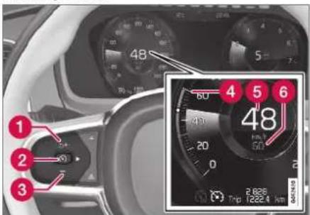
Note: This illustration is general and details may vary depending on model.
To start Cruise Control from standby mode:
- Press the button on the steering wheel (1).
The Cruise Control marking in the instrument panel will change from GRAY to WHITE and the vehicle will then return to the most recently set speed.
or
To start Cruise Control from standby mode:
- Press the Button on the steering wheel (2).
The Cruise Control markings and symbols in the instrument panel will change from GRAY to WHITE and the vehicle's current speed will be set.

WARNING
A noticeable increase in speed may follow when the speed is resumed with the steering wheel button.
Related information
• Cruise control (p. 291)
DRIVER SUPPORT
Switching off Cruise Control
Cruise control (Cruise Control - CC) can be turned off.

Function buttons and symbols ^29 .
To turn off Cruise Control:
- Press the Ⓧ button on the steering wheel (2).
Cruise Control will go into standby mode.
- Press the ◀ (1) or ▶ (3) buttons on the steering wheel to select another function.
The Cruise Control symbol (4) in the instrument panel will go out and the set speed will be erased.
- Press the Ⓞ button on the steering wheel keypad again.
Another function will be activated.
NOTE
In vehicles equipped with Adaptive Cruise Control*, it is possible to switch between cruise control and Adaptive Cruise Control – see the heading "Switching between CC and ACC".
Related information
• Cruise control (p. 291)
- Switching between Cruise Control and Adaptive Cruise Control (p. 313)
Distance Alert\*30
The Distance Alert ^31 function can help the driver become aware if the time interval to the vehicle in front is too short.
However, the vehicle must be equipped with a head-up display in order to display the Distance Alert, which will then be indicated by a symbol on the windshield as long as the time interval to the vehicle ahead is shorter than the set time interval.
Distance Alert is active at speeds above 30 km/h (20 mph) and only reacts for vehicles ahead moving in the same direction as your vehicle. No distance information is provided for oncoming, slow-moving or stationary vehicles.

Distance Alert warning light on the windshield ^32 .
A warning light will appear on the windshield and glow steadily if the time interval to the vehicle ahead is shorter than the set time interval.

NOTE
Visual warnings on the windshield may be difficult to notice in cases of strong sunlight, reflections, extreme light contrasts, or if the driver is wearing sunglasses or is not looking straight ahead.
NOTE
- Distance Alert is only available in vehicles that can display information on the wind-shield with a head-up display.
- Distance Alert is deactivated while Adaptive Cruise Control or Pilot Assist is active.
WARNING
Distance Alert only reacts of the time interval to the vehicle ahead is shorter than the preset value - vehicle speed is not affected.
Related information
• Head-up display for Distance Alert (p. 297)
- Activating/deactivating Distance Alert (p. 298)
- Setting a time interval for Distance Alert (p. 298)
• Distance Alert limitations (p. 299)
Head-up display for Distance Alert ^33
In vehicles equipped with a head-up display*, a symbol will be displayed on the windshield as long as the time interval to the vehicle ahead is shorter than the set time interval.
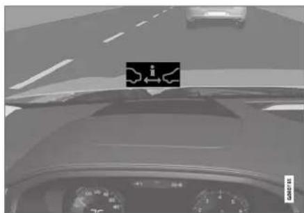
Distance Alert warning symbol on the windshield ^34 .
For this to be possible, however, the Show Driver Support function must be activated under Settings in the center display's menus (see "Head-up display" for instructions).
▶▶
DRIVER SUPPORT
◀◀

NOTE
Visual warnings on the windshield may be difficult to notice in cases of strong sunlight, reflections, extreme light contrasts, or if the driver is wearing sunglasses or is not looking straight ahead.
Related information
• Distance Alert* (p. 296)
• Head-up display* (p. 142)
Activating/deactivating Distance Alert ^35
Distance Alert can be turned off.
On/Off

Press the Distance Alert button in the center display's Function view.
- GREEN button indicator light - Distance Alert is on.
- GRAY button indicator light - Distance Alert is off.
Distance Alert is automatically activated each time the engine is started.
Related information
• Distance Alert* (p. 296)
Setting a time interval for Distance Alert ^36
The Distance Alert function can be set to different time intervals.

Different time intervals to the vehicle ahead can be selected and are shown in the instrument panel as 1–5 horizontal bars. The more bars, the longer the time interval. One bar represents an interval of
approx. 1 second to the vehicle ahead. 5 bars represents approx. 3 seconds.
The same symbol appears when the Adaptive Cruise Control function is activated.

Controls for setting a time interval.
1 Reduce the time interval
2 Increase the time interval
3 Distance indicator
- Press the (1) or (2) button to decrease or increase the time interval.
The distance indicator (3) shows the current time interval.
NOTE
- The greater the vehicles' speed, the greater the distance between them for a set time interval.
- Only use the time intervals permitted by local traffic regulations.
- The set time interval is also used by the Adaptive Cruise Control and Pilot Assist functions.
WARNING
- Only use a time interval suitable for the current traffic conditions.
- The driver should be aware that short time intervals give them limited time to react and act to any unforeseen traffic situation.
Related information
• Distance Alert* (p. 296)
Distance Alert limitations ^37
Distance Alert functionality may be reduced in certain situations.

WARNING
- The radar sensor has a limited field of vision. In some situations, it may detect a vehicle later than expected or not detect other vehicles at all.
- The radar sensor cannot cover all driving situations and traffic, weather and road conditions.
- The driver is responsible for maintaining a safe distance and speed and must intervene if the various driver support systems do not maintain a suitable speed or suitable distance to the vehicle ahead.
- Maintenance of radar sensor components may only be performed by a trained and qualified Volvo technician.
- Strong sunlight, reflections from the road surface, strong lighting contrasts or using sunglasses may make the warning light in the windshield difficult to see. Poor weather or winding roads can affect the radar sensor's capacity to detect vehicles ahead.
- A vehicle's size (e.g., a motorcycle) can also affect the radar sensor's capacity to detect another vehicle. This may result in the warning light illuminating at a shorter distance than the one that has been set or not illuminating at all.
- High speeds may also result in the warning light illuminating at a shorter distance than the one that has been set due to limitations in the radar sensor's range.
i NOTE
The function uses the vehicle's radar unit, which has some general limitations – see the section "Radar unit limitations".
Related information
• Distance Alert* (p. 296)
• Radar sensor limitations (p. 333)
Adaptive Cruise Control\*
Adaptive Cruise Control (ACC ^38 ) helps the driver maintain a constant speed with a set time interval to the vehicle ahead.
Adaptive Cruise Control helps provide a more relaxed driving experience on long trips on highways or long, straight roads with even traffic flows.

natural_image
Top-down view of a car with sensor waves and an inset close-up of the roof panel (no text or symbols)The camera/radar sensor measures the distance to the vehicle ahead ^39 .
The driver sets a speed and a time interval to the vehicle ahead. If the camera/radar sensor detects a slower-moving vehicle ahead, your vehicle's speed will be automatically adapted according to the set time interval to that vehicle. When there are no longer slower-moving vehicles ahead, the vehicle will return to the set speed.

WARNING
- The Adaptive Cruise Control function is supplementary driver support intended to facilitate driving and help make it safer – it cannot handle all situations in all traffic, weather and road conditions.
- The driver is advised to read all sections in the Owner's Manual about this function to learn of its limitations, which the driver must be aware of before using the function (see the link list at the end of this article).
- Adaptive Cruise Control is not a substitute for the driver's attention and judgment. The driver is always responsible for ensuring the vehicle is driven in a safe manner, at the appropriate speed, with an appropriate distance to other vehicles, and in accordance with current traffic rules and regulations.

NOTE
Depending on market, this function may be either Standard or Optional.
Adaptive Cruise Control regulates speed by accelerating and braking. It is normal for the
brakes to emit a slight sound when they are being used to adjust speed.
Adaptive Cruise Control always attempts to regulate speed smoothly. The driver must apply the brakes in situations requiring immediate braking. For example, when there are great differences in speed between vehicles or if the vehicle ahead brakes suddenly. Due to limitations in the radar sensor, braking may occur unexpectedly or not at all.
Adaptive Cruise Control is designed to follow a vehicle ahead in the same lane and maintain a time interval to that vehicle set by the driver. If the radar sensor does not detect a vehicle ahead, it will instead maintain the speed set by the driver. This will also happen if the speed of the vehicle ahead exceeds the set speed for your vehicle.
- Adaptive Cruise Control can follow another vehicle at speeds from a standstill up to 200 km/h (125 mph).

WARNING
- Adaptive Cruise Control is not a collision avoidance system. The driver is always responsible and must intervene if the system fails to detect a vehicle ahead.
- Adaptive Cruise Control does not brake for people or animals and does not brake for small vehicles, such as bikes and motorcycles. Similarly, it does not brake for low trailers, oncoming, slow-moving or stationary vehicles and objects.
- Do not use Adaptive Cruise Control in demanding situations, such as in city traffic, at intersections, on slippery surfaces, with a lot of water or slush on the road, in heavy rain/snow, in poor visibility, on winding roads, or on on/off ramps.

CAUTION
Maintenance of Adaptive Cruise Control components may only be performed by a workshop – an authorized Volvo workshop is recommended.
DRIVER SUPPORT
Overview
Controls

Function buttons and symbols ^39 .
1 : Activates Adaptive Cruise Control from standby mode and resumes the set speed
① +: Increases the set speed
2: From standby mode - activates the Adaptive Cruise Control and stores the current speed
2 (S): From active mode - deactivates/ switches the Adaptive Cruise Control to standby mode
3 —: Reduces the set speed
4 Increases the time interval to the vehicle ahead
5 Reduces the time interval to the vehicle ahead
6 Target vehicle indicator: ACC has detected and is following a target vehicle using the set time interval
7 Symbol for time interval to the vehicle ahead
i NOTE
In vehicles equipped with Adaptive Cruise Control*, it is possible to switch between cruise control and Adaptive Cruise Control – see the heading "Switching between CC and ACC".
Instrument panel

gauge
| Segment | Value | |---|---| | 1 | 230 | | 2 | 70 | | 3 | 200 | | 4 | 60 | | 5 | 80 | | 6 | 100 | | 7 | 120 | | 8 | 140 | | 9 | 160 | | 10 | 180 | | 11 | 200 | | 12 | 220 | | 13 | 240 | | 14 | 260 | | 15 | 280 | | 16 | 300 | | 17 | 320 | | 18 | 340 | | 19 | 360 | | 20 | 380 | | 21 | 400 | | 22 | 420 | | 23 | 440 | | 24 | 460 | | 25 | 480 | | 26 | 500 | The gauge displays a scale of approximately 50 km/h. The red labels (1, 2, 3) are positioned above the gauge, indicating specific measurements or thresholds for the measured values.Speed indicators ^39 .
1 Set speed
② Speed of the vehicle ahead.
③ The current speed of your vehicle.
See "Adaptive Cruise Control symbols and messages" for examples of different combinations of symbols depending on the traffic situation.
Related information
• Adaptive Cruise Control and collision warning (p. 303)
- Head-up display for Adaptive Cruise Control with collision warning (p. 304)
- Activating and starting Adaptive Cruise Control (p. 304)
• Managing Adaptive Cruise Control speed (p. 305)
- Setting Adaptive Cruise Control time intervals (p. 306)
- Deactivating/reactivating Adaptive Cruise Control (p. 307)
• Passing assistance with Adaptive Cruise Control (p. 309)
- Starting passing assistance with Adaptive Cruise Control (p. 310)
- Limitations of passing assistance with Adaptive Cruise Control (p. 310)
- Switching target vehicles with Adaptive Cruise Control (p. 310)
• Automatic braking with Adaptive Cruise Control (p. 311)
• Adaptive Cruise Control limitations (p. 312)
- Switching between Cruise Control and Adaptive Cruise Control (p. 313)
- Symbols and messages for Adaptive Cruise Control (p. 314)
Adaptive Cruise Control and collision warning
Adaptive Cruise Control can alert the driver if the distance to the vehicle ahead suddenly decreases to an unsafe distance.

Collision warning light on the windshield ^40 ,
1 Audio-visual collision warning
② Camera/radar sensor distance monitoring
Adaptive Cruise Control utilizes approx. 40% of the vehicle's braking capacity. If a situation requires more braking force than the Adaptive Cruise Control can provide, and if the driver does not apply the brakes, a warning light and audible warning signal will be activated to alert the driver that immediate action is required.
NOTE
Visual warnings on the windshield may be difficult to notice in cases of strong sunlight, reflections, extreme light contrasts, or if the driver is wearing sunglasses or is not looking straight ahead.
WARNING
Adaptive Cruise Control only issues a warning for vehicles detected by its radar unit – thus, a warning may come after a delay or not at all.
- Never wait for a warning. Apply the brakes when necessary.
Related information
• Adaptive Cruise Control* (p. 300)
DRIVER SUPPORT
Head-up display for Adaptive Cruise Control with collision warning
In vehicles equipped with a head-up display*, a flashing warning symbol will be displayed on the windshield.

natural_image
Close-up of a car's dashboard with steering wheel and speedometer (no visible text or symbols)Collision warning symbol on the windshield ^41 .

NOTE
Visual warnings on the windshield may be difficult to notice in cases of strong sunlight, reflections, extreme light contrasts, or if the driver is wearing sunglasses or is not looking straight ahead.
Related information
• Adaptive Cruise Control* (p. 300)
• Head-up display* (p. 142)
Activating and starting Adaptive Cruise Control
Adaptive Cruise Control (ACC ^42 ) must first be activated and then started before it can regulate speed and distance.
Putting Adaptive Cruise Control in standby mode

Note: This illustration is general and details may vary depending on model.
Adaptive Cruise Control is in standby mode each time the engine is started. To put ACC in standby mode from active mode:
- Press ◀ (2) or ▶ (3) on the steering wheel keypad and scroll to the ⚪ (4) function.
The symbol will appear and Adaptive Cruise Control will go into standby mode.
Starting/activating Adaptive Cruise Control
To start ACC:
- The driver's seat belt must be buckled and the driver's door must be closed.
- There must be a vehicle ahead (target vehicle) within a reasonable distance or your vehicle's current speed must be at least 15 km/h (9 mph).

Note: This illustration is general and details may vary depending on model.
- With the function displayed, press (1) on the steering wheel keypad.
Adaptive Cruise Control will start and the current speed will be stored, which will be shown by numbers in the center of the speedometer.
ACC will only regulate the time interval to the vehicle ahead when the distance symbol shows two vehicles.

A speed interval will be marked at the same time.
The higher speed is the set speed for your vehicle and the lower speed is the speed of the vehicle ahead (target vehicle).
Related information
• Adaptive Cruise Control* (p. 300)
Managing Adaptive Cruise Control speed
Adaptive Cruise Control (ACC ^43 ) can be set to various speeds.
Setting/changing set speed

Note: This illustration is general and details may vary depending on model and market.
1 + : Increases the set speed.
2 —: Reduces the set speed.
3 Set speed.
- Change a set speed by pressing the (+) or — (2) buttons briefly or by pressing and holding them:
- Press briefly: Press briefly: each press changes the speed in +/- 5 mph (+/- 5 km/h) increments.
- Press and hold: release the button when the set speed indicator (3) has moved to the desired speed.
- The most recently set speed will be stored. If speed is increased by depressing the accelerator pedal while pressing the + (1) button on the steering wheel, the vehicle's speed when the button is pressed will be stored as the set speed.
Temporarily increasing speed using the accelerator pedal, e.g. when passing another vehicle, will not affect the setting. The vehicle will return to the set speed when the accelerator pedal is released.
DRIVER SUPPORT
Automatic transmission
Adaptive Cruise Control can follow another vehicle at speeds from a standstill up to 200 km/h (125 mph).
The lowest speed that can be set for Adaptive Cruise Control is 30 km/h (20 mph). When following another vehicle, ACC can monitor that vehicle's speed and slow your own vehicle down to a standstill, but it is not possible to set speeds lower than 30 km/h (20 mph).
The highest possible speed that can be set is 200 km/h (125 mph).
Related information
• Adaptive Cruise Control* (p. 300)
Setting Adaptive Cruise Control time intervals
Adaptive Cruise Control (ACC ^44 ) can be set to various time intervals to the vehicle ahead.
Different time intervals to the vehicle ahead can be selected and are shown in the instrument panel as 1-5 horizontal bars. The more bars, the longer the time interval. One bar represents an interval of
approx. 1 second to the vehicle ahead. 5 bars represents approx. 3 seconds.
The same symbol appears when the Distance Alert function is activated.
NOTE
When the symbol in the instrument panel shows two vehicles, ACC is following the vehicle ahead at a preset time interval.
When only one vehicle is shown, there is no vehicle ahead within a reasonable distance.

Controls for setting a time interval ^45 .
1 Reduce the time interval
② Increase the time interval
3 Distance indicator
- Press the (1) or (2) button to decrease or increase the time interval.
The distance indicator (3) shows the current time interval.
In order to help your vehicle follow the vehicle ahead as smoothly and comfortably as possible, Adaptive Cruise Control allows the time interval to vary noticeably in certain situations. At low speeds, when the distance to the vehicle ahead is short, Adaptive Cruise Control increases the time interval slightly.

NOTE
- The greater the vehicles' speed, the greater the distance between them for a set time interval.
- Only use the time intervals permitted by local traffic regulations.
- If the Adaptive Cruise Control does not seem to respond with a speed increase when activated, it may be because the time interval to the vehicle ahead is shorter than the set time interval.

WARNING
- Only use a time interval suitable for the current traffic conditions.
- The driver should be aware that short time intervals give them limited time to react and act to any unforeseen traffic situation.
Setting how ACC should maintain distance\* to the vehicle ahead
A number of different settings can be made for how Adaptive Cruise Control should maintain a time interval to the vehicle ahead. Settings are made using the DRIVE MODE controls.
Select one of the following:
- Eco - ACC will focus on providing optimal fuel economy, which will increase the time interval to the vehicle ahead.
- Comfort - ACC will focus on following the set time interval to the vehicle ahead as smoothly as possible.
- Dynamic - ACC will focus on following the set time interval to the vehicle ahead more exactly, which could mean faster acceleration and heavier braking.
For more information, see "Drive modes".
Related information
• Adaptive Cruise Control* (p. 300)
- Drive modes (p. 454)
• Managing Cruise Control speed (p. 293)
Deactivating/reactivating Adaptive Cruise Control
Adaptive Cruise Control (ACC ^46 ) can be temporarily put into standby mode and then reactivated.
Deactivating and putting Adaptive Cruise Control in standby mode

Note: This illustration is general and details may vary depending on model.
DRIVER SUPPORT
To temporarily deactivate Adaptive Cruise Control and put it in standby mode:
- Press the button on the steering wheel (2).
The ⚙ symbol in the instrument panel changes color from WHITE to GRAY and the set speed in the center of the speedometer will change from BEIGE to GRAY.

WARNING
- If Adaptive Cruise Control is in standby mode, the driver must intervene and regulate both speed and distance to the vehicle ahead.
- If the vehicle comes too close to a vehicle ahead when Adaptive Cruise Control is in standby mode, the driver is instead warned of the short distance by the Distance Alert function.
Standby mode due to action by the driver
Adaptive Cruise Control will be temporarily deactivated and put in standby mode if:
• the brakes are applied
• the gear selector is moved to N
- the vehicle is driven faster than the set speed for more than 1 minute
Temporarily increasing speed using the accelerator pedal, e.g. when passing another vehicle, will not affect the setting. The vehicle will return to the set speed when the accelerator pedal is released.
Automatic standby mode
Adaptive Cruise Control is dependent on other systems, such as Electronic Stability Control (ESC ^47 ). If any of these other systems stops working, Adaptive Cruise Control will automatically switch off.

WARNING
With automatic standby mode, the driver is warned by an acoustic signal and a message on the instrument panel.
- The driver must then regulate vehicle speed, apply the brakes if necessary, and maintain a safe distance to other vehicles.
Adaptive Cruise Control may go into standby mode if:
- your vehicle's speed goes below 5 km/h (3 mph) and ACC cannot determine if the vehicle ahead is stationary or if it is another object, e.g. a speed bump.
- your vehicle's speed goes under 5 km/h (3 mph) and the vehicle ahead turns so that ACC no longer has a vehicle to follow.
• the driver opens the door.
• the driver unbuckles the seat belt.
• the engine speed (rpm) is too low/high.
• one or more of the wheels lose traction.
• the brake temperature is high.
• the parking brake is applied.
- the camera/radar sensor is covered by snow or heavy rain (the camera lens/radar waves are blocked)
Reactivating Adaptive Cruise Control from standby mode

Note: This illustration is general and details may vary depending on model.
To reactivate ACC from standby mode:
- Press the button on the steering wheel (1).
Speed will be set to the most recently stored speed.

WARNING
A noticeable increase in speed may follow when the speed is resumed with the steering wheel button.
Related information
• Adaptive Cruise Control* (p. 300)
Passing assistance with Adaptive Cruise Control
Adaptive Cruise Control (ACC ^48 ) can assist the driver when passing other vehicles.
How passing assistance works
When ACC is following another vehicle and you indicate that you intend to pass that vehicle by using the turn signal ^49 , Adaptive Cruise Control will begin accelerating toward the vehicle ahead before your vehicle has moved into the passing lane.
The function will then delay a speed reduction to avoid early braking as your vehicle approaches a slower-moving vehicle.
The function remains active until your vehicle has passed the other vehicle.

WARNING
Please note that this function can be activated in more situations than just passing another vehicle, such as when a direction indicator is used to indicate a lane change or before exiting to another road – the vehicle will then briefly accelerate.
Related information
• Adaptive Cruise Control* (p. 300)
- Starting passing assistance with Adaptive Cruise Control (p. 310)
- Limitations of passing assistance with Adaptive Cruise Control (p. 310)
DRIVER SUPPORT
Starting passing assistance with Adaptive Cruise Control
Several conditions must be met for passing assistance to be possible.
Requirements for passing assistance
In order to activate passing assistance:
- your vehicle must be following a vehicle ahead (target vehicle)
- your vehicle's current speed must be at least 70 km/h (43 mph)
• the set speed for ACC must be high enough to safely pass another vehicle.
Starting parking assistance
To start passing assistance:
- Turn on the left turn signal.
Passing assistance will start.
Related information
• Adaptive Cruise Control* (p. 300)
• Passing assistance with Adaptive Cruise Control (p. 309)
Limitations of passing assistance with Adaptive Cruise Control
Passing assistance functionality may be reduced in certain situations.

WARNING
The driver should be aware that if conditions suddenly change when using Parking Assistance, the function may implement an undesired acceleration in certain conditions.
Some situations should be avoided, e.g. if:
- the vehicle is approaching an exit in the same direction as passing would normally occur
- the vehicle ahead slows before your vehicle has had time to switch to the passing lane
- traffic in the passing lane slows down
- a vehicle for right-hand traffic is driven in a country with left-hand traffic (or vice versa).
Situations of this type can be avoided by temporarily putting ACC ^50 in standby mode.
Related information
• Adaptive Cruise Control* (p. 300)
• Passing assistance with Adaptive Cruise Control (p. 309)
Switching target vehicles with Adaptive Cruise Control
At certain speeds, models with automatic transmissions and Adaptive Cruise Control (ACC ^51 ) can switch target vehicles.
Switching target vehicles

natural_image
Diagram showing three cars on a road with a red triangular object highlighting one car (no text or symbols)If the target vehicle ahead turns suddenly, there may be stationary traffic ahead.
When Adaptive Cruise Control is actively following another vehicle at speeds under 30 km/h (20 mph) and switches targets from a moving vehicle to a stationary vehicle, Adaptive Cruise Control will brake for the stationary vehicle.

WARNING
When Adaptive Cruise Control follows another vehicle at speeds over approx. 30 km/h (20 mph) and changes target vehicle – from a moving vehicle to a stationary one – Adaptive Cruise Control will ignore the stationary vehicle and instead accelerate to the stored speed.
- The driver must then intervene and apply the brakes.
Automatic standby mode when switching targets
Adaptive Cruise Control will be disabled and go into standby mode:
- if your vehicle's speed goes below 5 km/h (3 mph) and Adaptive Cruise Control cannot determine if the target object is a stationary vehicle or another object, e.g. a speed bump.
- if your vehicle's speed goes under 5 km/h (3 mph) and the vehicle ahead turns so that Adaptive Cruise Control no longer has a vehicle to follow.
Related information
• Adaptive Cruise Control* (p. 300)
Automatic braking with Adaptive Cruise Control
The Adaptive cruise control (ACC ^52 ) has a special brake function in slow traffic and while stationary.
Braking function in slow traffic and at a standstill
In slow-moving, stop-and-go traffic or when stopped at a traffic light, driving will resume automatically if the vehicle is stopped for less than approx. 3 seconds. If it takes more than 3 seconds for the vehicle ahead to begin moving again, Adaptive Cruise Control will go into standby mode and the Auto-hold brake function will activate.
- Adaptive Cruise Control can be reactivated in one of the following ways:
- Pressing the ⚙ button on the steering wheel keypad.
- Pressing the accelerator pedal.
Adaptive Cruise Control will resume following the vehicle ahead if it begins to move within approx. 6 seconds.

NOTE
ACC can keep the vehicle stationary for no more than 5 minutes – after that time the parking brake is applied and Adaptive Cruise Control is deactivated.
The parking brake must be released before Adaptive Cruise Control can be reactivated.
Deactivation of the Auto-hold brake function
In certain situations, Auto-hold will be deactivated when the vehicle is at a standstill and Adaptive Cruise Control will go into standby mode. This means that the brakes will be released and the vehicle could begin to roll. The driver must actively apply the brakes to keep the vehicle stationary.
This can occur if:
• the driver depresses the brake pedal
• the parking brake is applied
- the gear selector is moved to the P, N or R positions
- the driver puts Adaptive Cruise Control in standby mode.
Auto Activate Parking Brake
In certain situations, the parking brake will be applied to keep the vehicle at a standstill.
DRIVER SUPPORT
This occurs if Adaptive Cruise Control is keeping the vehicle stationary using the brakes and:
- the driver opens the door or unbuckles his/her seat belt
- ACC has kept the vehicle at a standstill for more than approx. 5 minutes
• the brakes overheat
• the driver switches off the engine manually.
Related information
• Adaptive Cruise Control* (p. 300)
Adaptive Cruise Control limitations
Adaptive Cruise Control (ACC ^53 ) may have limited functionality in certain situations.
Steep roads and/or heavy loads
Adaptive Cruise Control is primarily intended to be driven on flat roads. The function may not be able to maintain the correct time interval to the vehicle ahead when driving down steep hills. The driver should be extra attentive and prepared to apply the brakes.
- Do not use Adaptive Cruise Control if the vehicle is carrying a heavy load or towing a trailer.
Other limitations
- The Off Road drive mode cannot be selected if Adaptive Cruise Control is activated.
NOTE
The function uses the vehicle's combined camera and radar unit, which has certain general limitations; see sections "Camera limitations" and "Radar sensor limitations".
Related information
• Adaptive Cruise Control* (p. 300)
• Camera limitations (p. 338)
• Radar sensor limitations (p. 333)
Switching between Cruise Control and Adaptive Cruise Control
In vehicles equipped with Adaptive Cruise Control (ACC), the driver can switch between Cruise Control (CC) and ACC.
A symbol in the instrument panel indicates which cruise control system is active
| CC ACC | |
| Cruise control Adaptive Cruise Control | |
A WHITE symbol: The function is active. GRAY symbol: Standby mode
Switching from ACC to CC
To do so:
-
Press the 📍 button on the steering wheel keypad to put Adaptive Cruise Control in standby mode.
-
Tap the Cruise Control button in the center display's Function view. The button's indicator will change from GRAY to GREEN.
The symbol in the instrument panel will
change from ACC to CC, indicating that Adaptive Cruise Control is off and Cruise Control is in standby mode.
- Pressing the Ⓧ button on the steering wheel keypad.
Cruise Control will start and the vehicle's current speed will be set.
WARNING
Switching from ACC to CC means that the vehicle:
- will no longer maintain a preset time interval to the vehicle ahead.
- will only follow the stored speed and the driver must therefore apply the brakes when necessary.
If CC is active when the engine is turned off, ACC will be automatically activated the next time the engine is started.
Switching from CC to ACC
To do so:
-
Press the Ⓧ button on the steering wheel keypad to put Cruise Control in standby mode.
-
Tap the Cruise Control button in Function view. The button's indicator will change from GREEN to GRAY.
The symbols in the instrument panel will
switch from CC to to indicate that Adaptive Cruise Control is in standby mode.
- Pressing the Ⓧ button on the steering wheel keypad.
Adaptive Cruise Control will go into active mode and set the vehicle's current speed and the selected time interval to the vehicle ahead.
Related information
• Adaptive Cruise Control* (p. 300)
• Cruise control (p. 291)
DRIVER SUPPORT
Symbols and messages for Adaptive Cruise Control
A number of symbols and messages relating to Adaptive Cruise Control (ACC ^54 ) may be displayed in the instrument panel and/or the head-up display*.
Several examples ^55 are provided below.
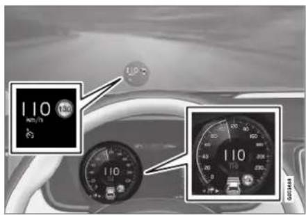
The previous illustration ^56 shows that Adaptive Cruise Control is set to maintain a speed of 110 km/h (68 mph) and that there is no target vehicle ahead to follow.

The previous illustration ^56 shows that Adaptive Cruise Control is set to maintain a speed of 110 km/h (68 mph) and is following a target vehicle ahead, which is traveling at the same speed.
| Symbol | Message Meaning | |
 | The symbol is WHITE. The vehicle is maintaining the set speed. | |
 | Adaptive Cruise Contr.UnavailableThe symbol is GRAY. | Adaptive Cruise Control is in standby mode. |
 | Adaptive Cruise Contr.Service requiredThe symbol is GRAY. | The system is not functioning as intended. Contact a workshop – an authorized Volvo workshop is recommended. |
 | Windscreen sensorSensor blocked, see Owner's manual | Clean the windshield in front of the camera and radar sensors. |
A text message can be erased by briefly pressing the ○ button in the center of the right-side steering wheel keypad.
If the message persists: Contact a workshop – an authorized Volvo workshop is recommended.
Related information
• Adaptive Cruise Control* (p. 300)
DRIVER SUPPORT
Pilot Assist
Pilot Assist helps the driver keep the vehicle in the current traffic lane by providing steering assistance and maintaining an even speed and a set time interval to the vehicle ahead.
How Pilot Assist works
The Pilot Assist function is primarily intended for use on highways and other major roads where it can help provide a more comfortable and relaxing driving experience.

The camera/radar sensor monitors the distance to the vehicle ahead and detects lane markings ^57 .
1 Camera and radar sensor
② Distance monitor
3 Lane marker line monitors
The driver sets the desired speed and distance to the vehicle ahead. Pilot Assist monitors the distance to the vehicle ahead and the traffic lane's side markers using the camera and radar sensor. The system maintains the set time interval to the vehicle ahead by automatically adjusting your vehicle's speed and keeps your vehicle in its lane by providing steering assistance.
Pilot Assist's steering assistance is based on monitoring the direction of the vehicle ahead and the traffic lane's side marker lines. The driver can override Pilot Assist's steering recommendations at any time and steer in another direction, e.g. to change lanes or avoid obstacles on the road.
If the camera/radar sensor cannot detect the lane's side marker lines or if Pilot Assist is unable for some other reason to clearly interpret the lane, Pilot Assist will temporarily deactivate steering assistance until it can once again interpret the lane markings. However, the speed and distance warnings will remain active.
WARNING
Pilot Assist is deactivated automatically and resumes working without prior notice.

The color of the steering wheel symbol indicates the current status of steering assistance:
- GREEN indicates that steering assistance is active
• GRAY (as shown in illustra-
tion) indicates that steering assistance is deactivated.

WARNING
- The Pilot Assist function is supplementary driver support intended to facilitate driving and help make it safer – it cannot handle all situations in all traffic, weather and road conditions.
- The driver is advised to read all sections in the Owner's Manual about this function to learn of its limitations, which the driver must be aware of before using the function (see the link list at the end of this article).
- Pilot Assist should only be used if there are clear lane lines painted on each side of the lane. All other use will increase the risk of contact with nearby obstacles that cannot be detected by the functions.
- Pilot Assist is not a substitute for the driver's attention and judgment. The driver is always responsible for ensuring the vehicle is driven in a safe manner, at the proper position within the lane, at the appropriate speed, with an appropriate distance to other vehicles, and in accordance with current traffic rules and regulations.

NOTE
Depending on market, this function may be either Standard or Optional.
Pilot Assist regulates speed by accelerating and braking. It is normal for the brakes to emit a slight sound when they are being used to adjust speed.
Pilot Assist attempts to smoothly regulate speed. The driver must apply the brakes in situations requiring immediate braking. For example, when there are great differences in speed between vehicles or if the vehicle ahead brakes suddenly. Due to limitations in the camera and radar sensor, braking may occur unexpectedly or not at all.
Pilot Assist is designed to follow a vehicle ahead in the same lane and maintain a time interval to that vehicle set by the driver. If the radar sensor does not detect a vehicle ahead, it will instead maintain the speed set by the driver. This will also happen if the speed of the vehicle ahead exceeds the set speed for your vehicle.
- Pilot Assist can follow another vehicle at speeds from a standstill up to 200 km/h (125 mph).
- Pilot Assist can provide steering assistance from near-stationary speeds up to 140 km/h (87 mph).

WARNING
- Pilot Assist is not a collision avoidance system. The driver must intervene if the system fails to detect a vehicle ahead.
- Pilot Assist does not brake for people, animals, objects, small vehicles (e.g. cycles and motorcycles), low trailers as well as oncoming, slow or stationary vehicles.
- Do not use Pilot Assist in demanding situations, such as in city traffic, at intersections, on slippery surfaces, with a lot of water or slush on the road, in heavy rain/snow, in poor visibility, on winding roads, on highway on- or off-ramps, or with a trailer connected to the vehicle.

CAUTION
Maintenance of the integrated components in Pilot Assist may only be performed by a workshop – an authorized Volvo workshop is recommended.
In curves and forks in the road
Pilot Assist is designed to interact with the driver. The driver should never wait for steering assistance from Pilot Assist, but instead should always be ready to increase his or her own steering efforts, particularly in curves.
▶▶
DRIVER SUPPORT
- When the vehicle is approaching an off-ramp or a fork in the road, the driver should steer toward the desired lane to indicate to Pilot Assist the desired direction of travel.
Pilot Assist strives to keep the vehicle in the center of the lane
When Pilot Assist provides steering assistance, it strives to position the vehicle in the center of the lane between the lane markings. For the smoothest driving experience possible, the driver should permit the vehicle to find the optimal positioning. The driver should check that the vehicle is positioned safely in the lane and can always adjust the vehicle's position by applying more force to the steering wheel.
- If Pilot Assist does not position the vehicle appropriately in the lane, the driver should turn off Pilot Assist or switch to Adaptive Cruise Control.
Overview
Controls

Function buttons and symbols ^57 .
1: Activates Pilot Assist from standby mode and resumes the set speed and time interval
① + : Increases the set speed
2: From standby mode - activates Pilot Assist and sets the current speed
2 : From active mode - deactivates/puts
Pilot Assist in standby mode
3: Switches from Pilot Assist to Adaptive Cruise Control
4 —: Reduces the set speed
5 Increases the time interval to the vehicle ahead
6: Switches from Adaptive Cruise Control to Pilot Assist
⑦ Reduces the time interval to the vehicle ahead
8 Function symbol
9 Symbols for target vehicle and distance to the vehicle ahead
10 Symbol for activated/deactivated steering assistance
Instrument panel

gauge
| Point | Value | |---|---| | 1 | 80 | | 2 | 100 | | 3 | 120 | | 4 | 70 | | 5 | 260 |Speed indicators ^57 .
1 Set speed
② Speed of the vehicle ahead
③ The current speed of your vehicle
See "Pilot Assist symbols and messages" for examples of different combinations of symbols depending on the traffic situation.
Related information
• Pilot Assist and collision warning (p. 319)
- Head-up display for Pilot Assist during collision risks (p. 320)
• Activating and starting Pilot Assist (p. 320)
• Managing Pilot Assist speed (p. 322)
- Setting a time interval for Pilot Assist (p. 323)
• Deactivating/reactivating Pilot Assist (p. 324)
• Passing assistance with Pilot Assist (p. 326) - Starting passing assistance with Pilot Assist (p. 327)
- Passing assistance with Pilot Assist limitations (p. 327)
- Switching target vehicles with Pilot Assist (p. 327)
• Auto-hold braking with Pilot Assist (p. 328)
• Pilot Assist limitations (p. 329) - Pilot Assist* symbols and messages (p. 330)
Pilot Assist and collision warning
Pilot Assist can alert the driver if the distance to the vehicle ahead suddenly decreases to an unsafe distance.
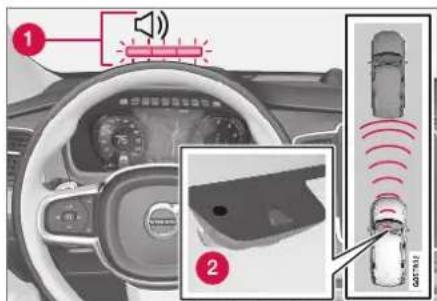
Collision warning light on the windshield ^58 .
1 Audio-visual collision warning
② Camera/radar sensor distance monitoring
Pilot Assist uses approx. 40% of the vehicle's braking capacity. If a situation requires more braking force than Pilot Assist can provide, and if the driver does not apply the brakes, a warning light and audible warning signal will be activated to alert the driver that immediate action is required.
DRIVER SUPPORT
◀◀

NOTE
Visual warnings on the windshield may be difficult to notice in cases of strong sunlight, reflections, extreme light contrasts, or if the driver is wearing sunglasses or is not looking straight ahead.

WARNING
Pilot Assist only issues a warning for vehicles detected by its camera and radar unit – thus, a warning may come after a delay or not at all.
- Never wait for a warning. Apply the brakes when necessary!
Related information
- Pilot Assist (p. 316)
Head-up display for Pilot Assist during collision risks
In vehicles equipped with a head-up display*, a flashing warning symbol will be displayed on the windshield.
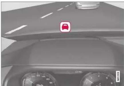
natural_image
Interior view of a car dashboard with steering wheel and speedometer (no visible text or symbols)Collision warning symbol on the windshield ^59 .
i NOTE
Visual warnings on the windshield may be difficult to notice in cases of strong sunlight, reflections, extreme light contrasts, or if the driver is wearing sunglasses or is not looking straight ahead.
Related information
- Pilot Assist (p. 316)
• Head-up display* (p. 142)
Activating and starting Pilot Assist
Pilot Assist must first be activated and then started before it can help regulate speed and distance and provide steering assistance.

Note: This illustration is general and details may vary depending on model.
To start Pilot Assist:
- The driver's seat belt must be buckled and the driver's door must be closed.
- There must be a vehicle ahead (target vehicle) within a reasonable distance or your vehicle's current speed must be at least 15 km/h (9 mph).
With Adaptive Cruise Control in standby mode:
- Press the ▶ button on the steering wheel (6).
The ⚙ symbol will change to Pilot Assist in standby mode (8).
- Press the Ⓧ button on the steering wheel (2).
Pilot Assist will start and the current speed will be stored, which will be shown by numbers in the center of the speedometer.
...OR...
With Adaptive Cruise Control started:
- Press the ▶ button on the steering wheel (6).
Pilot Assist will start.
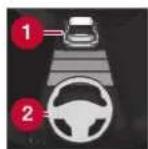
Pilot Assist's steering assistance is only active when the steering wheel symbol (2) changes from GRAY to GREEN.
Pilot Assist will only regulate
the time interval to the vehicle ahead when the distance symbol shows a vehicle (1) over the steering wheel symbol.

A speed interval will be marked at the same time.
The higher speed is the set speed for your vehicle and the lower speed is the speed of the vehicle ahead (target vehicle).
Hands on the steering wheel
Pilot Assist only functions if the driver's hands are on the steering wheel.

If Pilot Assist detects that the driver's hands are not on the steering wheel, a symbol and text message will appear to instruct the driver to actively steer the vehicle.
If the driver's hands are still detected on the steering wheel after a few seconds have passed, the instructions to actively steer the vehicle will be repeated, accompanied by an audible signal.
If Pilot Assist still does not detect the driver's hands on the steering wheel after a few more seconds have passed, the audible signal will become intense and the steering function will switch off. Pilot Assist must then be reactivated
by pressing the Ⓧ button on the steering wheel.
NOTE
Note that the Pilot Assist function only works when the driver's hands are on the steering wheel.
Related information
- Pilot Assist (p. 316)
DRIVER SUPPORT
Managing Pilot Assist speed
Pilot Assist can be set to various speeds.
Setting/changing set speed

Note: This illustration is general and details may vary depending on model and market.
1 +: Increases the set speed
② —: Reduces the set speed
3 Sel speed
- Change a set speed by pressing the ⏻) or — (2) buttons briefly or by pressing and holding them:
- Press briefly: Press briefly: each press changes the speed in +/- 5 mph (+/- 5 km/h) increments.
- Press and hold: release the button when the set speed indicator (3) has moved to the desired speed.
• The most recently set speed will be stored.
If speed is increased by depressing the accelerator pedal while pressing the + (1) button on the steering wheel, the vehicle's speed when the button is pressed will be stored as the set speed.
Temporarily increasing speed using the accelerator pedal, e.g. when passing another vehicle, will not affect the setting. The vehicle will return to the set speed when the accelerator pedal is released.
Automatic transmission
Pilot Assist can follow another vehicle at speeds from a standstill up to 200 km/h (125 mph).
The lowest speed that can be set for Pilot Assist is 30 km/h (20 mph). When following another vehicle, ACC can monitor that vehicle's speed and slow your own vehicle down to a standstill, but it is not possible to set speeds lower than 30 km/h (20 mph).
The highest possible speed that can be set is 200 km/h (125 mph).
Related information
- Pilot Assist (p. 316)
Setting a time interval for Pilot Assist
Pilot Assist can be set to different time intervals.

Different time intervals to the vehicle ahead can be selected and are shown in the instrument panel as 1–5 horizontal bars. The more bars, the longer the time interval. One bar represents an interval of
approx. 1 second to the vehicle ahead. 5 bars represents approx. 3 seconds.

NOTE
When the symbol in the instrument panel shows a vehicle and a steering wheel, Pilot Assist follows a vehicle ahead at a preset time interval.
When only a steering wheel is shown, there is no vehicle ahead within a reasonable distance.
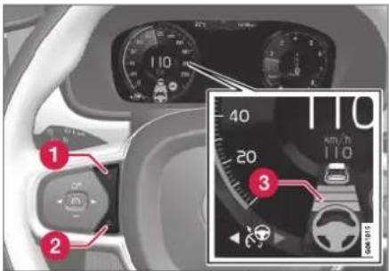
Controls for setting a time interval ^60 ,
1 Reduce the time interval
② Increase the time interval
3 Distance indicator
- Press the (1) or (2) button to decrease or increase the time interval.
The distance indicator (3) shows the current time interval.
In order to follow the vehicle ahead as smoothly as possible, Pilot Assist allows the time interval to vary considerably in certain situations. For example, at low speeds and short distances to the vehicle ahead, Pilot Assist increases the time interval slightly.
NOTE
- The greater the vehicles' speed, the greater the distance between them for a set time interval.
- Only use the time intervals permitted by local traffic regulations.
- If Pilot Assist does not seem to respond with a speed increase when activated, it may be because the time interval to the vehicle ahead is shorter than the set time interval.
WARNING
- Only use a time interval suitable for the current traffic conditions.
- The driver should be aware that short time intervals give them limited time to react and act to any unforeseen traffic situation.
Setting how Pilot Assist should maintain distance\* to the vehicle ahead
The driver can choose different drive modes to determine how Pilot Assist should maintain a time interval to the vehicle ahead. Settings are made using the DRIVE MODE controls.
DRIVER SUPPORT
Select one of the following:
- Eco - Pilot Assist will focus on providing optimal fuel economy, which will increase the time interval to the vehicle ahead.
- Comfort - Pilot Assist will focus on following the set time interval to the vehicle ahead as smoothly as possible.
- Dynamic - Pilot Assist will focus on following the set time interval to the vehicle ahead more exactly, which could mean faster acceleration and heavier braking.
For more information, see "Drive modes".
Related information
- Pilot Assist (p. 316)
- Drive modes (p. 454)
• Managing Cruise Control speed (p. 293)
Deactivating/reactivating Pilot Assist
Pilot Assist can be temporarily put into standby mode and then reactivated.
Deactivating and putting Pilot Assist in standby mode

Note: This illustration is general and details may vary depending on model.
To temporarily deactivate Pilot Assist and put it in standby mode:
-
Press the 🔊 button on the steering wheel (2).
Pilot Assist goes into standby mode - the symbol (8) in the instrument panel changes color from WHITE to GRAY and the set speed in the center of the speedometer will change from BEIGE to GRAY.
...Or... -
Press the ◀ button on the steering wheel (3).
Pilot Assist is turned off and Adaptive Cruise Control will go into active mode.

WARNING
- With Pilot Assist in standby mode, the driver must intervene and steer and regulate both speed and distance to the vehicle ahead.
- If the vehicle comes too close to a vehicle ahead when Pilot Assist is in standby mode, the driver is instead warned of the short distance by the Distance Alert function.
Standby mode due to action by the driver
Pilot Assist will be temporarily deactivated and put in standby mode if:
• the brakes are applied.
• the gear selector is moved to N
• a turn signal is used for more than 1 minute.
- the vehicle is driven faster than the set speed for more than 1 minute
Temporarily increasing speed using the accelerator pedal, e.g. when passing another vehicle, will not affect the setting. The vehicle will return to the set speed when the accelerator pedal is released.
When the turn signals are used, Pilot Assist's steering assistance will be temporarily deactivated. When the turn signal is switched off, steering assistance will be automatically reactivated if the traffic lane's side markings can still be detected.
Automatic standby mode
Pilot Assist is dependent on other systems, such as Electronic Stability Control (ESC ^51 ). If any of these other systems stops working, Pilot Assist will automatically switch off.
WARNING
With automatic standby mode, the driver is warned by an acoustic signal and a message on the instrument panel.
- The driver must then regulate vehicle speed, apply the brakes if necessary, and maintain a safe distance to other vehicles.
Adaptive Cruise Control may go into standby mode if, e.g.:
• the driver opens the door.
• the brake temperature is high.
- the driver's hands are not on the steering wheel.
• the parking brake is applied.
• the engine speed (rpm) is too low/high.
• the driver unbuckles the seat belt.
• one or more of the wheels lose traction.
- the camera/radar sensor is covered by snow or heavy rain (the camera lens/radar waves are blocked)
- your vehicle's speed goes below 5 km/h (3 mph) and Pilot Assist cannot determine if the vehicle ahead is stationary or if it is another object, e.g. a speed bump.
- your vehicle's speed goes under 5 km/h (3 mph) and the vehicle ahead turns so that Pilot Assist no longer has a vehicle to follow.
Reactivating Pilot Assist from standby mode

Note: This illustration is general and details may vary depending on model.
To reactivate Pilot Assist:
- Press the button on the steering wheel (1).
Speed will be set to the most recently stored speed.
DRIVER SUPPORT
◀◀

WARNING
A noticeable increase in speed may follow when the speed is resumed with the steering wheel button.
Related information
- Pilot Assist (p. 316)
Passing assistance with Pilot Assist
Pilot Assist can assist the driver when passing other vehicles.
How passing assistance works
When Pilot Assist is following another vehicle and you indicate that you intend to pass that vehicle by using the turn signal ^62 , Pilot Assist will begin accelerating toward the vehicle ahead before your vehicle has moved into the passing lane.
The function will then delay a speed reduction to avoid early braking as your vehicle approaches a slower-moving vehicle.
The function remains active until your vehicle has passed the other vehicle.

WARNING
Please note that this function can be activated in more situations than just passing another vehicle, such as when a direction indicator is used to indicate a lane change or before exiting to another road – the vehicle will then briefly accelerate.
Related information
- Pilot Assist (p. 316)
- Starting passing assistance with Pilot Assist (p. 327)
- Passing assistance with Pilot Assist limitations (p. 327)
Starting passing assistance with Pilot Assist
Several conditions must be met for passing assistance to be possible.
In order to activate passing assistance:
- your vehicle must be following a vehicle ahead (target vehicle)
- your vehicle's current speed must be at least 70 km/h (43 mph)
- the set speed for Pilot Assist must be high enough to safely pass another vehicle.
Starting parking assistance
To start passing assistance:
- Turn on the left turn signal.
Passing assistance will start.
Related information
- Pilot Assist (p. 316)
• Passing assistance with Pilot Assist (p. 326)
Passing assistance with Pilot Assist limitations
Passing assistance functionality may be reduced in certain situations.
WARNING
The driver should be aware that if conditions suddenly change when using Parking Assistance, the function may implement an undesired acceleration in certain conditions.
Some situations should be avoided, e.g. if:
- the vehicle is approaching an exit in the same direction as passing would normally occur
- the vehicle ahead slows before your vehicle has had time to switch to the passing lane
- traffic in the passing lane slows down
- a vehicle for right-hand traffic is driven in a country with left-hand traffic (or vice versa).
Situations of this type can be avoided by temporarily putting Pilot Assist in standby mode.
Related information
- Pilot Assist (p. 316)
• Passing assistance with Pilot Assist (p. 326)
Switching target vehicles with Pilot Assist
At certain speeds, models with automatic transmissions and Pilot Assist can switch target vehicles.
Switching target vehicles
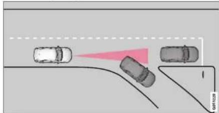
If the target vehicle ahead turns suddenly, there may be stationary traffic ahead.
When Pilot Assist is actively following another vehicle at speeds under 30 km/h (20 mph) and switches targets from a moving vehicle to a stationary vehicle, Pilot Assist will brake for the stationary vehicle.

WARNING
When Pilot Assist follows another vehicle at speeds over approx. 30 km/h (20 mph) and changes target vehicle – from a moving vehicle to a stationary one – Pilot Assist will ignore the stationary vehicle and instead accelerate to the stored speed.
- The driver must then intervene and apply the brakes.
Automatic standby mode when switching targets
Pilot Assist disengages and goes into standby mode if:
- your vehicle's speed goes below 5 km/h (3 mph) and Pilot Assist cannot determine if the target object is a stationary vehicle or another object, e.g. a speed bump.
- your vehicle's speed goes under 5 km/h (3 mph) and the vehicle ahead turns so that Pilot Assist no longer has a vehicle to follow.
Related information
- Pilot Assist (p. 316)
Auto-hold braking with Pilot Assist
Pilot Assist has a special braking function in slow traffic and at a standstill.
Braking function in slow traffic and at a standstill
In slow-moving, stop-and-go traffic or when stopped at a traffic light, driving will resume automatically if the vehicle is stopped for less than approx. 3 seconds. If it takes more than 3 seconds for the vehicle ahead to begin moving again, Pilot Assist will go into standby mode and the Auto-hold brake function will activate.
- Pilot Assist can be reactivated by:
- Pressing the ⚙ button on the steering wheel keypad.
- Pressing the accelerator pedal.
Pilot Assist will resume following the vehicle ahead if it begins to move within approx. 6 seconds.
i NOTE
Pilot Assist can keep the vehicle stationary for no more than 5 minutes – after that time the parking brake is applied and the function is deactivated.
The parking brake must be released before Pilot Assist can be reactivated.
Deactivation of the Auto-hold brake function In certain situations, Auto-hold will be deactivated when the vehicle is at a standstill and Pilot Assist will go into standby mode. This means that the brakes will be released and the vehicle could begin to roll. The driver must actively apply the brakes to keep the vehicle stationary.
This can occur if:
• the driver depresses the brake pedal
• the parking brake is applied
- the gear selector is moved to the P, N or R positions
• the driver puts Pilot Assist in standby mode.
Auto Activate Parking Brake
In certain situations, the parking brake will be applied to keep the vehicle at a standstill.
This occurs if Pilot Assist is keeping the vehicle stationary using the brakes and:
- the driver opens the door or unbuckles his/her seat belt
- Pilot Assist has kept the vehicle at a standstill for more than approx. 5 minutes
• the brakes overheat
• the driver switches off the engine manually.
Related information
- Pilot Assist (p. 316)
Pilot Assist limitations
Pilot Assist functionality may be reduced in certain situations.
Pilot Assist is a driver support function designed to simplify driving and assist the driver in many situations. However, the driver is always responsible for maintaining a suitable distance to vehicles or objects around it and ensuring that the vehicle is correctly positioned in the traffic lane.
WARNING
In some situations, Pilot Assist may have trouble helping the driver properly or may be deactivated automatically – we advise against using Pilot Assist in such cases. Examples of such situations include:
- the lane markings are worn, missing or cross each other.
- lane division is unclear, for example, when the lanes divide or merge or at exits or when there are multiple sets of markings.
- edges or other lines than lane markings are present on or near the road, e.g. curbs, joints or repairs to the road surface, edges of barriers, roadside edges or strong shadows.
• the lane is narrow or winding.
• the lane contains ridges or holes. - weather conditions are poor, e.g. rain, snow or fog or slush or reduced visibility with poor light conditions, backlighting, wet road surface, etc.
The driver should also note that Pilot Assist has the following limitations:
- High curbs, roadside barriers, temporary obstacles (traffic cones, safety barriers, etc.) are not detected. Alternatively, they may be detected incorrectly as lane markings, with a subsequent risk of contact between the vehicle and such obstacles.
The driver is responsible for ensuring that the vehicle maintains a suitable distance from such obstacles.
- The camera and radar sensors do not have the capacity to detect all oncoming objects and obstacles in traffic environments, e.g. potholes, stationary obstacles or objects that completely or partially block the route.
- Pilot Assist does not "see" pedestrians, animals, etc.
- The recommended steering input is limited in force, which means that it cannot always help the driver to steer and keep the vehicle within the lane.
- In vehicles equipped with Sensus Navigation*, the function is able to use information from map data, which could cause variations in performance.
- Pilot Assist is switched off if the power steering is working with reduced power - e.g. during cooling due to overheating (see section "Speed-dependent steering force").
The driver can always correct or adjust steering assistance provided by Pilot Assist by turning the steering wheel to the desired position.
▶▶
DRIVER SUPPORT
Steep roads and/or heavy loads
Pilot Assist is primarily intended to be driven on flat roads. The function may not be able to maintain the correct time interval to the vehicle ahead when driving down steep hills. The driver should be extra attentive and prepared to apply the brakes.
- Do not use Pilot Assist if the vehicle is carrying a heavy load or towing a trailer.

NOTE
Pilot Assist cannot be activated if a trailer, bike carrier or similar is connected to the vehicle electrical system.
Other limitations
- The Off Road drive mode cannot be selected when Pilot Assist is activated.

NOTE
The function uses the vehicle's combined camera and radar unit, which has certain general limitations; see sections "Camera limitations" and "Radar sensor limitations".
Related information
- Pilot Assist (p. 316)
• Speed-dependent steering wheel resistance (p. 278)
• Camera limitations (p. 338)
• Radar sensor limitations (p. 333)
Pilot Assist\* symbols and messages
A number of symbols and messages relating to Pilot Assist may be displayed in the instrument panel and/or the head-up display*.
DRIVER SUPPORT
Several examples ^63 are provided below.

The previous illustration ^64 shows that Pilot Assist is set to maintain a speed of 110 km/h (68 mph) and that there is no target vehicle ahead to follow.
Pilot Assist will not provide any steering assistance because it cannot detect the lane's side marking lines.
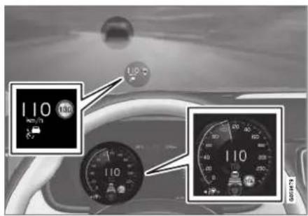
The previous illustration ^64 shows that Pilot Assist is set to maintain a speed of 110 km/h (68 mph) and is following a target vehicle ahead that is traveling at the same speed.
Pilot Assist will not provide any steering assistance because it cannot detect the lane's side marking lines.

The previous illustration ^64 shows that Pilot Assist is set to maintain a speed of 110 km/h (68 mph) and is following a target vehicle ahead that is traveling at the same speed.
In this example, Pilot Assist will also provide steering assistance because it can detect the lane's side marking lines.
DRIVER SUPPORT
◀◀

The previous illustration ^64 shows that Pilot Assist is set to maintain a speed of 110 km/h (68 mph) and that there is no target vehicle ahead to follow.
Pilot Assist will provide steering assistance because it can detect the lane's side marking lines.
Related information
- Pilot Assist (p. 316)
Radar sensor
The radar sensor is used by several driver support systems to detect other vehicles.
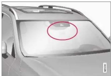
natural_image
Side view of a car's front bumper with a red circle highlighting the area (no text or symbols)Note: This illustration is general and details may vary depending on model.
The radar sensor is used by the following functions:
- Distance Alert*
• Adaptive Cruise Control* - Lane Keeping Aid
- Pilot Assist*
- City Safety
Any modifications to the radar sensor may make its use illegal.
Related information
• Radar sensor limitations (p. 333)
- Recommended maintenance for the radar sensor (p. 336)
• Radar sensor type approval (p. 336)
Radar sensor limitations
The radar sensor used by several of the driver support functions has certain limitations, which also affect the functions using the radar sensor.
Obstructed camera

natural_image
Side view of a car's front window with a red circle highlighting the center area (no text or symbols visible)The area marked in the illustration must be kept free of decals, objects, solar film, etc. ^65
The radar sensor is located on the upper interior section of the windshield along with the camera.
CAUTION
Do not place, affix or mount anything on the inside or outside of the windshield, or in front of or around the camera and radar unit - this could disrupt camera and radar-based functions.
It could cause functions to be reduced, deactivated completely or produce an incorrect function response.

If this symbol and the message "Windscreen sensor Sensor blocked, see Owner's manual" is displayed in the instrument panel, it
means that the camera and radar sensor are unable to detect other vehicles, cyclists, pedestrians and large animals in front of the vehicle and that the vehicle's camera and radar-based functions may be obstructed, reduced, completely disabled or providing inaccurate responses.
The following table shows some of the situations that can cause the message to be displayed, and suggested actions:
| Cause Action | |
| The area of the windshield in front of the camera/radar sensor is dirty or covered by ice or snow. | Clean the windshield in front of the camera/radar sensor and remove dirt, ice and snow. |
| Thick fog, heavy rain or snow is blocking the radar signals or the camera's range of visibility. | No action. Heavy precipitation may sometimes prevent the camera/radar sensor from functioning. |
DRIVER SUPPORT
◀◀
| Cause Action | |
| Water or snow is spraying/swirling up and blocking the radar signals or the camera's range of visibility. | No action. Very wet or snow-covered roads may sometimes prevent the cam-era/radar sensor from functioning. |
| There is dirt between the inside of the windshield and the camera/radar sensor. | Consult a workshop to have the area of the windshield on the inside of the cam-era's casing cleaned. An authorized Volvo workshop is recommended. |

NOTE
Keep the windshield in front of the camera and radar unit clean.
Vehicle speed
The radar sensor's ability to detect a vehicle ahead is significantly reduced if:
- the speed of the vehicle ahead differs greatly from your vehicle's speed
Limited field of vision
The radar sensor has a limited field of vision. In some situations, it may detect a vehicle later than expected or not at all.
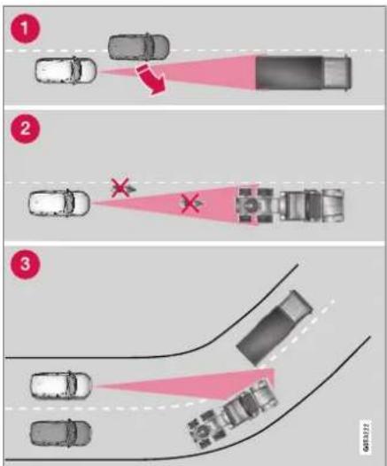
The radar sensor's field of vision.
The radar sensor's detection of vehicles very close to your vehicle may be delayed in certain situations, e.g. if a vehicle pulls in
between your vehicle and the vehicle directly ahead.
2 Small vehicles, such as motorcycles, or vehicles that are not driving in the center of the lane may remain undelected.
3 In curves, the radar may detect the wrong vehicle or lose sight of a target vehicle.
Low trailers
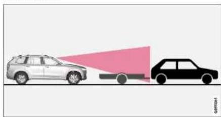
natural_image
Diagram showing two vehicles with a red light beam projecting onto the front, no text or symbols presentLow trailer in the radar shadow.
Low trailers may also be difficult or even impossible for the radar to detect. The driver should be extra alert when driving behind vehicles towing low trailers when Adaptive Cruise Control or Pilot Assist is activated.
High temperatures
If the temperature in the passenger compartment is very high, the camera/radar sensor will switch off temporarily for approx. 15 minutes after the engine is started to protect its electronic components. When the temperature has cooled sufficiently, the camera/radar sensor will automatically restart.
Damaged windshield
CAUTION
If there are cracks, scratches or stone chips on the windshield in front of any of the camera and radar unit "windows" and this covers an area of about 0.5 × 3.0 mm
(0.02 × 0.12 in.) or more, contact a workshop to have the windshield replaced – an authorized Volvo workshop is recommended.
Failure to take action could result in reduced performance for the driver support systems that use the camera and radar unit.
It could cause functions to be reduced, deactivated completely or produce an incorrect function response.
To avoid the risk of loss of function, malfunction or reduced function of the driver support systems that use the radar unit, the following also apply:
- Volvo advises against repairing cracks, scratches or stone chips in the area in front of the camera and radar unit – the entire windshield should instead be replaced.
- Before replacing the windshield, contact an authorized Volvo workshop to verify that the right windshield has been ordered and installed.
- The same type of windshield wipers or wipers approved by Volvo should be used for replacement.
CAUTION
If the windshield is replaced, the camera and radar unit must be recalibrated by a workshop to help ensure proper functioning of all of the vehicle's camera and radar-based systems – an authorized Volvo workshop is recommended.
Related information
• Radar sensor (p. 332)
DRIVER SUPPORT
Recommended maintenance for the radar sensor
In order for the camera/radar sensor to function properly, the area of the windshield in front of the unit must be kept free of dirt, ice, snow, etc. and should be washed regularly with water and car washing detergent.

NOTE
Dirt, ice and snow covering the camera and radar unit reduce their function and can make measurement impossible.
It could cause functions to be reduced, deactivated completely or produce an incorrect function response.
Related information
• Radar sensor (p. 332)
Radar sensor type approval
The type approval for the vehicle radar sensor in the ACC ^66 , PA ^67 and BLIS ^68 functions can be read here.
ACC, PA and BLIS USA & Canada:
FCC ID: L2C0054TR IC: 3432A-0054TR
FCC ID: L2C0055TR IC: 3432A-0055TR
This device complies with Part 15 of the FCC Rules and with Industry Canada license-exempt RSS standard(s).
Operation is subject to the following two conditions:
(1) This device may not cause harmful interference, and
(2) This device must accept any interference received, including interference that may cause undesired operation.
Note: Changes or modifications not expressively approved by the party responsible for compliance could void the user's authority to operate the equipment. The term "IC:" before the radio certification number only signifies that Industry Canada technical specifications were met.
Note: This equipment complies with radiation exposure limits set forth for an uncontrolled environment. This equipment should be installed and operated with minimum distance of 20 cm between the radiator and your body.
Related information
• Radar sensor (p. 332)
DRIVER SUPPORT
Camera
The camera is used by several driver support systems to e.g. detect lane marker lines or road signs.
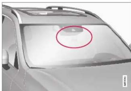
natural_image
Side view of a car's front bumper with a red circle highlighting the area (no text or symbols)Note: This illustration is general and details may vary depending on model.
The camera is used by the following functions:
• Adaptive Cruise Control*
- Pilot Assist*
- Lane Keeping Aid*
• Steering assistance at risk of collision
City Safety
- Driver Alert Control*
• Road Sign Information*
• Active high beams*
Related information
• Camera limitations (p. 338)
- Recommended maintenance for the camera/radar sensor (p. 341)
DRIVER SUPPORT
Camera limitations
The camera used by several of the driver support functions has certain limitations, which also affect the functions using the camera.
Reduced visibility
The camera has the same limitations as the human eye. In other words, its "vision" is impaired by adverse weather conditions such as heavy snowfall/rain, dense fog, swirling dust/snow, etc. These conditions may reduce the function of systems that depend on the camera or cause these systems to temporarily stop functioning.
Strong sunlight, reflections from the road surface, ice or snow covering the road, a dirty road surface, or unclear lane marker lines may drastically reduce the camera's ability to detect the side of a lane, a pedestrian, a cyclist, a large animal or another vehicle.
Obstructed camera

natural_image
Side view of a car's front window with a red circle highlighting the lid area (no text or symbols visible)The area marked in the illustration must be kept free of decals, objects, solar film, etc. ^60
The camera is located on the upper interior section of the windshield along with the radar sensor.
! CAUTION
Do not place, affix or mount anything on the inside or outside of the windshield, or in front of or around the camera and radar unit – this could disrupt camera and radar-based functions.
It could cause functions to be reduced, deactivated completely or produce an incorrect function response.

If this symbol and the message "Windscreen sensor Sensor blocked, see Owner's manual" is displayed in the instrument panel, it
means that the camera and radar sensor are unable to detect other vehicles, cyclists, pedestrians and large animals in front of the vehicle and that the vehicle's camera and radar-based functions may be obstructed, reduced, completely disabled or providing inaccurate responses.
The following table shows some of the situations that can cause the message to be displayed, and suggested actions:
| Cause Action | |
| The area of the windshield in front of the camera/radar sensor is dirty or covered by ice or snow. | Clean the windshield in front of the camera/radar sensor and remove dirt, ice and snow. |
| Thick fog, heavy rain or snow is blocking the radar signals or the camera's range of visibility. | No action. Heavy precipitation may sometimes prevent the camera/radar sensor from functioning. |
| Water or snow is spraying/swirling up and blocking the radar signals or the camera's range of visibility. | No action. Very wet or snow-covered roads may sometimes prevent the camera/radar sensor from functioning. |
| There is dirt between the inside of the windshield and the camera/radar sensor. | Consult a workshop to have the area of the windshield on the inside of the camera's casing cleaned. An authorized Volvo workshop is recommended. |
| Bright sunlight. No action. The camera/radar sensor will reset automatically when lighting conditions improve. | |

NOTE
Keep the windshield in front of the camera and radar unit clean.
High temperatures
If the temperature in the passenger compartment is very high, the camera/radar sensor will switch off temporarily for approx. 15 minutes after the engine is started to protect its electronic components. When the temperature has cooled sufficiently, the camera/radar sensor will automatically restart.
Damaged windshield
CAUTION
If there are cracks, scratches or stone chips on the windshield in front of any of the camera and radar unit "windows" and this covers an area of about 0.5 × 3.0 ~mm (0.02 × 0.12 in.) or more, contact a workshop to have the windshield replaced - an authorized Volvo workshop is recommended.
Failure to take action could result in reduced performance for the driver support systems that use the camera and radar unit.
It could cause functions to be reduced, deactivated completely or produce an incorrect function response.
To avoid the risk of loss of function, malfunction or reduced function of the driver support systems that use the radar unit, the following also apply:
- Volvo advises against repairing cracks, scratches or stone chips in the area in front of the camera and radar unit – the entire windshield should instead be replaced.
• Before replacing the windshield, contact an authorized Volvo workshop to verify
DRIVER SUPPORT
◀◀
that the right windshield has been ordered and installed.
- The same type of windshield wipers or wipers approved by Volvo should be used for replacement.

CAUTION
If the windshield is replaced, the camera and radar unit must be recalibrated by a workshop to help ensure proper functioning of all of the vehicle's camera and radar-based systems – an authorized Volvo workshop is recommended.
Related information
- Camera (p. 337)
Recommended maintenance for the camera/radar sensor
In order for the camera/radar sensor to function properly, the area of the windshield in front of the unit must be kept free of dirt, ice, snow, etc. and should be washed regularly with water and car washing detergent.

NOTE
Dirl, ice and snow covering the camera and radar unit reduce their function and can make measurement impossible.
It could cause functions to be reduced, deactivated completely or produce an incorrect function response.
Related information
- Camera (p. 337)
City Safety™
City Safety can alert the driver with light, sound and pulsations in the brake pedal to help the driver detect pedestrians, cyclists, large animals and vehicles that appear suddenly – the vehicle will then attempt to automatically brake if the driver does not act within a reasonable amount of time.

natural_image
Top-down view of a car with sensor waves and a close-up inset showing the roof panel (no text or symbols)Location of the camera and radar sensor ^70 .
City Safety can help prevent a collision or lower the vehicle's speed at the point of impact.
City Safely is an aid intended to assist the driver if a collision with a pedestrian, large animal, cyclist or vehicle is imminent.
City Safety can help the driver avoid a collision when e.g. driving in stop-and-go traffic, when
changes in the traffic ahead and driver distraction could lead to an incident.
The function assists the driver by automatically applying the brakes if there is an imminent risk of a collision and the driver does not react in time by braking and/or steering away.
City Safety activates a brief, forceful braking in an attempt to stop your vehicle immediately behind the vehicle or object ahead.
City Safety is activated in situations in which the driver should have applied the brakes much earlier, which means that the system will not be able to assist the driver in all situations.
City Safety is designed to be activated as late as possible to help avoid unnecessary intervention.
Normally, the occupants of the vehicle will not be aware of City Safety except when the system intervenes when a collision is imminent.

WARNING
- The City Safety function is supplementary driver support intended to help improve driving safety – it cannot handle all situations in all traffic, weather and road conditions.
- The City Safety auto-brake function can prevent a collision or reduce collision speed, but to ensure full brake performance the driver should always depress the brake pedal – even when the car auto-brakes.
- The warning and steering assistance are only activated if there is a high risk of collision – you must therefore never wait for the collision warning or City Safety to intervene.
- Warnings and brake interventions for pedestrians and cyclists are disengaged at vehicle speeds over 80 km/h (50 mph).
- City Safety does not activate auto-braking intervention during heavy acceleration.
- City Safety is not a substitute for the driver's attention and judgment. The driver is always responsible for ensuring the vehicle is driven in a safe manner, at the appropriate speed, with an appropriate distance to other vehicles, and in accordance with current traffic rules and regulations.
- The driver is advised to read all sections in the Owner's Manual that relate to City Safety to learn about factors such as its limitations and what the driver should be aware of before using the system (see the list of links for all subsections).
Related information
• City Safety parameters and sub-functions (p. 342)
- Setting a warning distance for City Safety (p. 344)
• Detecting obstacles with City Safety (p. 345)
• City Safety in crossing traffic (p. 347)
- Limitations of City Safety in crossing traffic (p. 348)
- City Safety and delayed evasive maneuvers (p. 349)
- City Safety braking for oncoming vehicles (p. 350)
• City Safety limitations (p. 351)
• City Safety messages (p. 353)
City Safety parameters and sub-functions
City Safety can help avoid a collision with a vehicle, cyclist or large animal ahead by reducing the vehicle's speed using its automatic braking function.
If the difference in speed is greater than the speeds specified below, the City Safety auto-brake function cannot prevent a collision, but it can help mitigate its effects.
Vehicles
City Safety can help prevent a collision with a vehicle ahead by reducing your vehicle's speed by up to 60 km/h (37 mph).
Cyclists
City Safety can help prevent a collision with a cyclist ahead by reducing your vehicle's speed by up to 50 km/h (30 mph).
Pedestrians
City Safety can help prevent a collision with a pedestrian ahead by reducing your vehicle's speed by up to 45 km/h (28 mph).
Large animals
If there is a risk of colliding with a large animal, City Safely can help reduce your vehicle's speed by up to 15 km/h (9 mph).
The braking function for large animals is primarily intended to mitigate the force of a collision at higher speeds. Braking is most effective at speeds above 70 km/h (43 mph) and less effective at lower speeds.
City Safety sub-functions
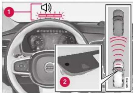
Function overview ^71 .
1 Audio-visual collision warning
② Camera/radar sensor distance monitoring
City Safety carries out three steps in the following order:
-
Collision warning
-
Brake assistance
-
Auto-brake
Descriptions of what happens in these three steps are provided below.
1 - Collision warning
The driver is first alerted to the risk of an imminent collision.
In vehicles equipped with a head-up display*, a flashing warning symbol will be displayed on the windshield.

natural_image
Interior view of a car dashboard with steering wheel and speedometer (no visible text or symbols)Collision warning symbol on the windshield ^72 .
NOTE
Visual warnings on the windshield may be difficult to notice in cases of strong sunlight, reflections, extreme light contrasts, or if the driver is wearing sunglasses or is not looking straight ahead.
City Safety can detect pedestrians, cyclists or vehicles that are stationary, are moving in the same direction as your vehicle and are ahead of your vehicle. City Safety can also detect pedestrians, cyclists or large animals that are crossing the road in front of your vehicle.
If there is a risk of a collision with a pedestrian, large animal, cyclist or another vehicle, or with a vehicle described in the section "City Safety in crossing traffic", the driver will be alerted with light, sound and pulsations in the brake pedal. At lower speeds, during hard braking or if the accelerator pedal is pressed, the brake pedal pulsation warning will not be given. The intensity of the brake pedal pulsations varies according to the vehicle's speed.
DRIVER SUPPORT
2 - Brake assistance
If the risk of a collision increases after the collision warning, brake support will be activated.
If the system determines that the pressure the driver is exerting on the brake pedal is insufficient to prevent the collision, brake support will increase pressure.
3 - Auto-brake
The automatic braking function is activated at the last moment.
If the driver has not taken evasive action by this stage and a collision is imminent, the automatic braking function will be triggered. This occurs whether or not the driver is pressing the brake pedal. Full braking force will be applied to reduce the speed at impact or reduced braking effect will be applied if this is sufficient to avoid the collision.
The seat belt tensioners may be activated along with the automatic braking function. See "Seat belt tensioners" for more information.
In certain situations, auto-braking may begin with a limited braking force before applying full braking force.
If City Safety has prevented a collision, the vehicle will be kept at a standstill until the driver takes action. If the vehicle has slowed to avoid colliding with a slower-moving vehicle ahead, your speed will be reduced to that vehicle's speed.
Auto-braking can always be cancelled if the driver presses hard on the accelerator pedal.
i NOTE
When City Safety activates the brakes, the brake lights come on.
When City Safety applies the brakes, a text message will appear in the instrument panel to notify the driver that the function is/was activated.
WARNING
City Safety may not be used to change how the driver operates the vehicle. The driver must not only rely on City Safety to brake the vehicle.
Related information
• City Safety™ (p. 341)
Setting a warning distance for City Safety
City Safety is always active, but the function's warning distance can be adjusted.
NOTE
The City Safety function cannot be deactivated. It is activated automatically each time the engine/electric motor is started.
The alert distance determines the sensitivity of the system and regulates the distance at which the light, sound and brake pulsations will be activated.
To select warning distance:
-
Select Settings My Car IntelliSafe in the center display's Top view.
-
Under City Safety Warning, tap Late, Normal or Early to set the desired warning distance.
If the driver feels that the Early setting is giving too many warnings or finds them irritating, the Normal or Late warning distance settings can be selected instead.
If the driver feels that the warnings are too frequent and distracting, the warning distance can be reduced. This will reduce the total number of warnings, but it will also result in City Safety providing warnings at a later stage.
The Late warning distance setting should therefore only be used in exceptional cases, such as when a more dynamic driving style is preferred.

WARNING
- No automatic system can guarantee 100% correct function in all situations. You should therefore never test use of City Safety in the direction of people, animals or vehicles – this could lead to severe damage, serious personal injury or even death.
- City Safety warns the driver if there is a risk of collision, but the function cannot reduce the driver's reaction time.
- Even if the warning distance has been set to Early, warnings may be perceived as late in certain situations – e.g. when there are large speed differences or if the vehicle ahead suddenly brakes heavily.
- With the warning distance set to Early, warnings come further in advance. This may cause the warnings to come more frequently than with warning distance Normal, but is recommended since it can make City Safety more effective.

NOTE
The warning with direction indicators for Rear Collision Warning is deactivated if the collision warning distance in the City Safety function is set to the lowest level "Late".
The seat belt tensioning and braking functions remain active.
Related information
• City Safety™ (p. 341)
Detecting obstacles with City Safety
City Safety can help detect vehicles, cyclists, large animals and pedestrians.
Vehicles
City Safety detects most types of vehicles that are either stationary, moving in the same direction as your vehicle or those described in "City Safety in crossing traffic" and City Safety braking for oncoming vehicles".
For City Safety to be able to detect a vehicle in the dark, its headlights and taillights must be on and clearly visible.
Cyclists
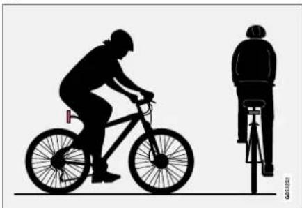
natural_image
Silhouette illustration of a person riding a bicycle with a cyclist nearby (no text or symbols)Optimal examples of what City Safety would interpret to be a cyclist: clear body and bicycle shapes.
For optimal performance, the system's function for cyclist detection needs the clearest possible information about the contours of the bicycle and
▶▶
DRIVER SUPPORT
of the cyclist's head, arm, shoulders, legs, torso and lower body in combination with normal human movements.
If large portions of the cyclist's body or the bicycle itself are not visible to the function's camera, it will not be able to detect a cyclist.
The system can only detect adult cyclists riding on bicycles intended for adults.

WARNING
City Safety is supplementary driver support, but it cannot detect all cyclists in all situations and, for example, cannot see:
• partially obscured cyclists.
- cyclists if the background contrast of the cyclist is poor - warning and brake interventions may then be late or not occur at all.
• cyclists in clothing that hides their body contour.
• bikes loaded with large objects.
The driver is always responsible for ensuring that the vehicle is driven correctly and with a safety distance suitable for the speed.
Pedestrians
natural_image
Silhouettes of two human figures in walking and walking poses (no text or symbols)Optimal examples of what the system considers to be a pedestrian: clear body contours.
For optimal performance, the system's function for pedestrian detection needs the clearest possible information about body and bicycle contours. This entails being able to detect the contours of the pedestrian's head, arm, shoulders, legs, torso and lower body in combination with normal human movements.
In order to detect a pedestrian, there must be a contrast to the background, which could depend on clothing, weather conditions, etc. If there is little contrast, the person may be detected late or not at all, which may result in a delayed reaction from the system or no reaction at all.
City Safety can detect pedestrians even in dark conditions if they are illuminated by the vehicle's headlights.

WARNING
City Safety is supplementary driver support, but it cannot detect all pedestrians in all situations and, for example, cannot see:
- partially obscured pedestrians, people in clothing that hides their body contour or pedestrians shorter than 80 cm (32 in.).
- pedestrians if the background contrast of the pedestrians is poor - warning and brake interventions may then be late or not occur at all.
• pedestrians who are carrying large objects.
The driver is always responsible for ensuring that the vehicle is driven correctly and with a safety distance suitable for the speed.
Large animals

natural_image
Silhouette of two horses, one running and the other running, against a plain background (no text or symbols)Optimal examples of what City Safety would interpret as a large animal; stationary or moving slowly and with clear body contours.
For optimal performance, the system's function for detecting large animals (e.g. moose, horses, etc.) needs the clearest possible information about body contours. This entails being able to detect the animal straight from the side in combination with normal movements for that animal.
If parts of the animal's body are not visible to the function's camera, the system will not be able to detect the animal.
City Safety can detect large animals even in dark conditions if they are illuminated by the vehicle's headlights.
WARNING
City Safety is supplementary driver support, but it cannot detect all large animals in all situations and, for example, cannot see:
• partially obscured larger animals.
- larger animals seen from the front or from behind.
• running or fast moving larger animals.
- larger animals if the contrast of the animal's background is poor - warning and brake interventions may then occur late or not at all.
- smaller animals such as cats and dogs. The driver is always responsible for ensuring that the vehicle is driven correctly and with a safety distance suitable for the speed.
Related information
• City Safety™ (p. 341)
• City Safety in crossing traffic (p. 347)
- City Safety braking for oncoming vehicles (p. 350)
City Safety in crossing traffic
City Safety can assist the driver when turning in the path of an oncoming vehicle in an intersection.

① Sector in which City Safety can detect an oncoming vehicle in crossing traffic.
In order for City Safety to detect an oncoming vehicle in situations where there is a risk of a collision, that vehicle must be within the sector in which City Safety can analyze the situation.
The following criteria must also be met:
- your vehicle's speed must be at least 4 km/h (3 mph)
- your vehicle must be making a left turn
• the oncoming vehicle's headlights must be on
DRIVER SUPPORT
◀◀

WARNING
- The "City Safety in crossing traffic" function is supplementary driver support intended to improve driving safety – it cannot handle all situations in all traffic, weather and road conditions.
- Warnings and brake interventions due to a collision risk with an oncoming vehicle often come very late.
- Never wait for a collision warning or for City Safety to intervene.
- City Safety is not a substitute for the driver's attention and judgment. The driver is always responsible for ensuring the vehicle is driven in a safe manner, at the appropriate speed, with an appropriate distance to other vehicles, and in accordance with current traffic rules and regulations.
Related information
• City Safety™ (p. 341)
Limitations of City Safety in crossing traffic
In certain situations, it may be difficult for City Safety to help the driver avoid a collision with crossing traffic.

For example:
• on slippery roads when Electronic Stability Control (ESC) is actively operating
- if an approaching vehicle is detected at a late stage
- if the oncoming vehicle is partially obstructed by another vehicle or object
• if the oncoming vehicle's headlights are off
- if the oncoming vehicle is moving erratically and e.g. suddenly changes lanes at a late stage.

NOTE
The function uses the vehicle's combined camera and radar unit, which has certain general limitations; see sections "Camera limitations" and "Radar sensor limitations".
Related information
• City Safety™ (p. 341)
• City Safety limitations (p. 351)
• City Safety in crossing traffic (p. 347)
• Camera limitations (p. 338)
• Radar sensor limitations (p. 333)
City Safety and delayed evasive maneuvers
City Safety can assist the driver by automatically braking the vehicle when it is not possible to avoid a collision by steering alone.
City Safety assists the driver by periodically attempting to predict possible "escape routes" to the sides of the vehicle in the event a slow-moving or stationary vehicle were to be detected at a late stage.

flowchart
graph TD
    A["Step 1: Top-down"] --> B["Step 2: Left-side horizontal path"]
    B --> C["Step 3: Right-side horizontal path"]
    C --> D["Step 4: Horizontal dashed line"]
    D --> E["Step 5: Right-side horizontal path"]
    E --> F["Step 6: Horizontal dashed line"]
    F --> G["Step 7: Right-side horizontal path"]
    G --> H["Step 8: Horizontal dashed line"]
    H --> I["Step 9: Right-side horizontal path"]
    I --> J["Step 10: Horizontal dashed line"]
Your vehicle (1) cannot detect any potential escape routes for veering away from the vehicle ahead (2) and may therefore apply the brakes at an earlier stage.
1 Own vehicle
2 Slow-moving/stationary vehicles
City Safety will not intervene to automatically apply the brakes if it is possible for the driver to avoid a collision by steering the vehicle.
However, if City Safety determines that an evasive maneuver would not be possible due to traffic in the adjacent lane(s), the function can assist the driver by automatically starting to apply the brakes at an earlier stage.
WARNING
- The possibility of City Safety predicting a certain situation is supplementary driver support intended to improve driving safety – it cannot handle all situations in all traffic, weather and road conditions.
- City Safety is not a substitute for the driver's attention and judgment. The driver is always responsible for ensuring the vehicle is driven in a safe manner, at the appropriate speed, with an appropriate distance to other vehicles, and in accordance with current traffic rules and regulations.
Limitations of City Safety during evasive maneuvers
NOTE
The function uses the vehicle's combined camera and radar unit, which has certain general limitations; see sections "Camera limitations" and "Radar sensor limitations".
Related information
• City Safety™ (p. 341)
• Camera limitations (p. 338)
• Radar sensor limitations (p. 333)
DRIVER SUPPORT
City Safety braking for oncoming vehicles
City Safety can help you apply the brakes for an oncoming vehicle in your lane.
If an oncoming vehicle veers into your lane and a collision is unavoidable, City Safety can help reduce your vehicle's speed to attempt to mitigate the force of the collision.

1 Own vehicle
② Oncoming vehicles
The following criteria must be met for the function to work:
- your vehicle's speed must be above 4 km/h (3 mph)
• the road must be straight
- your lane must have clear side lane markings
- your vehicle must be positioned straight in your lane
• the oncoming vehicle must be positioned within your vehicle's lane markings
- the oncoming vehicle's headlights must be on
- the function can only handle "front-to-front" collisions
- the function can only detect vehicles with four wheels
- the function requires functioning Electric Seat Belt Tensioners (see section "Seat belt tensioners").
NOTE
The function uses the vehicle's combined camera and radar unit, which has certain general limitations; see sections "Camera limitations" and "Radar sensor limitations".
WARNING
- The "City Safety braking for oncoming vehicles" function is supplementary driver support intended to help improve driving safety – it cannot handle all situations in all traffic, weather and road conditions.
- Warnings and brake interventions due to an imminent collision with an oncoming vehicle always come very late.
- Never wait for a collision warning or for City Safety to intervene. If you notice any hazard or other potentially dangerous situation, always fully apply the brakes.
- City Safety is not a substitute for the driver's attention and judgment. The driver is always responsible for ensuring the vehicle is driven in a safe manner, at the appropriate speed, with an appropriate distance to other vehicles, and in accordance with current traffic rules and regulations.
Related information
• City Safety™ (p. 341)
• City Safety limitations (p. 351)
• Camera limitations (p. 338)
• Radar sensor limitations (p. 333)
- Seat belt tensioners (p. 50)
City Safety limitations
City Safety functionality may be reduced in certain situations.
Surroundings
Low objects
Hanging objects, such as flags for overhanging loads or accessories such as auxiliary lights or front protective grids that extend beyond the height of the hood, may limit City Safety functionality.
Slippery road conditions
The extended braking distance on slippery roads may reduce City Safety's capacity to help avoid a collision. In these types of situations, the Anti-lock Braking System and Electronic Stability Control (ESC ^73 ) will help provide optimal braking power with maintained stability.
Backlighting
The visual warning signal in the windshield may be difficult to detect in bright sunlight, if there are reflections, or if the driver is wearing sunglasses or not looking straight ahead.
Heat
If the temperature in the passenger compartment is high due to e.g. bright sunlight, the visual warning signal in the windshield may be temporarily disabled.
Camera and radar sensor's field of vision
The camera's field of vision is limited and in certain situations, it may be unable to detect pedestrians, large animals, cyclists or vehicles, or it may detect them later than expected.
Vehicles that are dirty may be detected later than clean vehicles, and in dark conditions, motorcycles may be detected late or not at all.
If a text message displayed in the instrument panel indicates that the camera/radar sensor is obstructed, it may be difficult for City Safety to detect pedestrians, large animals, cyclists, vehicles or lane markings in front of the vehicle. City Safety functionality may therefore be reduced.
Text messages may not be displayed for all situations in which the windshield sensors are blocked. The driver must therefore always keep the windshield in front of the camera/radar sensor clean.
CAUTION
Maintenance and replacement of City Safety components may only be performed by a workshop – an authorized Volvo workshop is recommended.
Driver intervention
Backing up
City Safety is temporarily deactivated when the vehicle is backing up.
Low speed
City Safety is not activated at very low speeds under 4 km/h (3 mph). The system will therefore not intervene in situations in which your vehicle is approaching another vehicle very slowly, such as when parking.
Active driver
Action by the driver always has priority. City Safety will therefore not react or will react at a later stage with a warning or intervention in situations in which the driver is clearly steering and operating the accelerator pedal, even if a collision is unavoidable.
An active and aware driving style may therefore delay collision warnings and intervention in order to minimize unnecessary warnings.
DRIVER SUPPORT
Other limitations

WARNING
- Warnings and brake interventions can be triggered late or not at all if the traffic situation or external influences prevent the camera and radar unit from properly detecting pedestrians, cyclists, large animals or vehicles ahead of the vehicle.
- To be able to detect vehicles at night, its front and rear lights must work and illuminate clearly.
- The camera and radar unit have a limited range for pedestrians and cyclists – the system can provide effective warnings and brake interventions if the relative speed is lower than 50 km/h (30 mph). For stationary or slow-moving vehicles, warnings and brake interventions are effective at vehicle speeds of up to 70 km/h (43 mph). Speed reduction for large animals is less than 15 km/h (9 mph) and can be achieved at vehicle speeds over 70 km/h (43 mph). At lower speeds, the warning and brake intervention for large animals is less effective.
-
Warnings for stationary or slow-moving vehicles and large animals can be disengaged due to darkness or poor visibility.
-
Warnings and brake interventions for pedestrians and cyclists are disengaged at vehicle speeds over 80 km/h (50 mph).
- Do not place, affix or mount anything on the inside or outside of the windshield, or in front of or around the camera and radar unit – this could disrupt camera-based functions.
- Objects, snow, ice or dirt in the area of the camera sensor can reduce the function, disengage it completely or give an improper function response.
i NOTE
The function uses the vehicle's combined camera and radar unit, which has certain general limitations; see sections "Camera limitations" and "Radar sensor limitations".
Market limitations
City Safety is not available in all countries. If City Safety is not shown in the center display's Settings menu, your vehicle is not equipped with this function.
In the center display's Top view, tap:
- Settings My Car IntelliSafe
Related information
• City Safety™ (p. 341)
• Camera limitations (p. 338)
• Radar sensor limitations (p. 333)
City Safety messages
A number of messages related to City Safety
may be displayed in the instrument panel.
Some examples of symbols and messages are shown in the table below.
| Message Meaning | |
| City SafetyAutomatic intervention | When City Safety is braking or has activated the automatic braking function, one or more symbols may illuminate in the instrument panel and a text message may be displayed. |
| City SafetyReduced functionality Service required | The system is not functioning as intended. Contact a workshop – an authorized Volvo workshop is recommended. |
A text message can be erased by briefly pressing
the ○ button in the center of the right-side
steering wheel keypad.
If the message persists: Contact a workshop – an authorized Volvo workshop is recommended.
Related information
• City Safety™ (p. 341)
DRIVER SUPPORT
Rear Collision Warning
The Rear Collision Warning (RCW) function can help the driver avoid rear-end collisions from vehicles approaching from behind.
RCW is automatically activated each time the engine is started.
RCW can warn the driver of a potential collision with vehicles approaching from behind by rapidly flashing the turn signals.
If, at a speed below 30 km/h (20 mph), the RCW function detects that the car is in danger of being hit from behind, the seatbelt tensioners may tension the front seatbelts and activate the Whiplash Protection System safety system.
Immediately before a collision from behind, RCW may also activate the foot brake in order to reduce the forward acceleration of the car during the collision. However, the brakes will only be applied if your vehicle is stationary. The brakes will be immediately released if the accelerator pedal is depressed.
Related information
• Rear Collision Warning limitations (p. 354)
• Whiplash Protection System (p. 46)
Rear Collision Warning limitations
In some situations, it may be difficult for RCW to warn the driver of a collision risk.
This may be the case if:
- the vehicle approaching from the rear is detected at a late stage
- the vehicle approaching from the rear changes lanes at a late stage
- the vehicle approaching from the rear is moving at a speed above 80 km/h (50 mph)
- a trailer, bicycle holder or similar is connected to the vehicle's electrical system - the RCW function will then be automatically deactivated.
NOTE
In certain markets RCW does not warn with the direction indicators due to local traffic regulations – in such cases, that part of the function is deactivated.
NOTE
The warning with direction indicators for Rear Collision Warning is deactivated if the collision warning distance in the City Safety function is set to the lowest level "Late".
The seat belt tensioning and braking functions remain active.
Related information
• Rear Collision Warning (p. 354)
BLIS\*
The BLIS ^74 function is designed to help provide assistance in heavy traffic with several lanes moving in the same direction by helping the driver to detect the presence of vehicles in the "blind spot" area behind and to the side of the vehicle.
BLIS is a driver support system designed to alert the driver of:
• vehicles in your "blind spot"
- vehicles approaching rapidly in adjacent lanes.

Location of BLIS indicator light. ^75
1 Indicator light
2 The BLIS button in the center display's Function view is used to activate/deactivate the function.
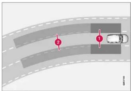
BLIS overview
1 Blind spot zone
② Rapidly approaching vehicle zone.
The BLIS function is active at speeds above 10 km/h (6 mph).
The system is designed to react to:
• vehicles passing your vehicle
- vehicles that are rapidly approaching your vehicle from behind.
When BLIS detects a vehicle in zone 1 or a rapidly approaching vehicle in zone 2, an indicator light will illuminate in the relevant rearview mirror and glow steadily. If the driver then uses the turn signal on the side in which the warning has been
DRIVER SUPPORT
given, the indicator light will become brighter and begin flashing.

NOTE
The light illuminates on the side of the vehicle where the system has detected the vehicle. If the vehicle is passed on both sides simultaneously, both lights come on.

WARNING
- The BLIS function is supplementary driver support intended to facilitate driving and help make it safer – it cannot handle all situations in all traffic, weather and road conditions.
- The responsibility for changing lanes safely and using good judgment always rests with the driver.
- BLIS is not a substitute for the driver's attention and judgment. The driver is always responsible for ensuring the vehicle is driven in a safe manner, at the appropriate speed, with an appropriate distance to other vehicles, and in accordance with current traffic rules and regulations.
Related information
• Activating/deactivating BLIS (p. 356)
• BLIS limitations (p. 357)
• Recommended maintenance for BLIS (p. 358)
• BLIS messages (p. 359)
Activating/deactivating BLIS
The BLIS ^76 function can be activated/deactivated.

Location of BLIS indicator light. ^77
1 Indicator light
② The BLIS button in the center display's Function view is used to activate/deactivate the function.
- Tap the BLIS button in Function view.
The BLIS indicator light shows the status of the function: GREEN (on) or GRAY (off).
If BLIS is activated when the engine is started, the indicator lights in the rearview mirrors will flash once.
If BLIS is deactivated when the engine is turned off, it will remain off the next time the engine is started and the indicator lights will not illuminate.
Related information
- BLIS* (p. 355)
BLIS limitations
BLIS ^78 functionality may be reduced in certain situations.
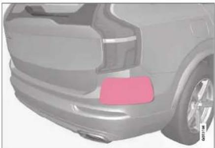
natural_image
Side view of a silver SUV rear bumper with a pink accent area (no visible text or symbols)Keep the marked area clean (on both the left and right sides of the vehicle) ^79 .
Examples of limitations:
- Dirt, ice and snow covering the sensors may reduce functionality and prevent the system from providing warnings.
- The BLIS function is automatically deactivated if a trailer, bicycle holder or similar is connected to the vehicle's electrical system.
- For BLIS to function optimally, bicycle holders, luggage racks or similar should not be mounted on the vehicle's towbar.
WARNING
• BLIS does not work in sharp curves.
- BLIS does not work when the vehicle is being reversed.
Related information
- BLIS* (p. 355)
DRIVER SUPPORT
Recommended maintenance for BLIS
- For optimal performance, it is important to keep the areas in front of the sensors clean.
- Do not attach any objects, tape or decals to the surface of the sensors.

natural_image
Side view of a car's rear bumper area with a pink accent stripe (no text or symbols visible)Keep the marked area clean (on both the left and right sides of the vehicle) ^80 .
The BLIS sensors are located on the inside of each of the rear fenders/bumpers and are also used by the Cross Traffic Alert (CTA) and Rear Collision Warning functions.
CAUTION
Repair of BLIS and CTA components or repainting of the bumper may only be performed by a workshop – an authorized Volvo workshop is recommended.
Related information
BLIS* (p. 355)
• Cross Traffic Alert* (p. 360)
- Activating/deactivating Cross Traffic Alert (p. 361)
• Cross Traffic Alert limitations (p. 361)
• Recommended maintenance for Cross Traffic Alert (p. 362)
• Cross Traffic Alert messages (p. 363)
• Rear Collision Warning (p. 354)
BLIS messages
A number of messages related to BLIS ^81 may
be displayed in the instrument panel.
Some examples of symbols and messages are shown in the table below.
| Message Meaning | |
| Blind spot sensor Service required | The system is not functioning as intended. Contact a workshop – an authorized Volvo workshop is recommended. |
| Blind spot system off Trailer attached | BLIS and CTA have been deactivated because a trailer has been connected to the vehicle's electrical system. |
A text message can be erased by briefly pressing
the ○ button in the center of the right-side
steering wheel keypad.
If the message persists: Contact a workshop — an authorized Volvo workshop is recommended.
Related information
BLIS* (p. 355)
DRIVER SUPPORT
Cross Traffic Alert\*
CTA ^82 is a supplementary driver support system to BLIS ^83 that is intended to help the driver detect vehicles crossing behind the vehicle while backing up.

CTA overview.
CTA supplements BLIS by detecting traffic crossing from the side, e.g. when backing out of a parking space.
CTA is primarily designed to detect vehicles, but in certain cases can also detect pedestrians or smaller objects such as bicycles.
CTA is only active when the vehicle is moving backward or if reverse gear is engaged.
If CTA detects that something is approaching your vehicle from the side:
- an audible signal will sound from either the left or right speaker, depending on which side of your vehicle the object is approaching from.
- an icon will illuminate in the PAS ^84 graphic on the screen.
- an icon will appear in the Park Assist Camera's Top view.

natural_image
Top-down view of a white car viewed from the side, showing no text or symbols on the car itself.Illuminated CTA icon in the PAS graphic ^85 on the screen.
82 Cross Traffic Alert
83 Blind Spot Information
84 Park Assist System: Parking assistance with reversing sensors
85 Note: This illustration is general and details may vary depending on model.
WARNING
- The Cross Traffic Alert function is supplementary driver support intended to facilitate driving and make it safer – it cannot handle all situations in all traffic, weather and road conditions.
- The responsibility for reversing the vehicle safely and using good judgment always rests with the driver.
- Cross Traffic Alert is not a substitute for the driver's attention and judgment. The driver is always responsible for ensuring the vehicle is driven in a safe manner, at the appropriate speed, with an appropriate distance to other vehicles, and in accordance with current traffic rules and regulations.
Related information
- Activating/deactivating Cross Traffic Alert (p. 361)
• Cross Traffic Alert limitations (p. 361) - Recommended maintenance for Cross Traffic Alert (p. 362)
• Cross Traffic Alert messages (p. 363)
Activating/deactivating Cross Traffic Alert
The driver can choose to deactivate the CTA ^86 function as follows:

Press the Cross Traffic Alert button in the center display's Function view.
- GRAY button indicator light - CTA is deactivated.
- GREEN button indicator light - CTA is activated.
CTA is automatically activated each time the engine is started.
Related information
• Cross Traffic Alert* (p. 360)
Cross Traffic Alert limitations
CTA ^87 functionality may be reduced in certain situations.
CTA does not function optimally in all situations and has certain limitations. The CTA sensors, for example, cannot "see" through other parked vehicles or objects blocking the vehicle.
Below are a few examples of situations in which CTA's field of vision may be initially limited and approaching vehicles may therefore not be detected until they are very close to your vehicle:
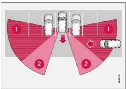
The vehicle is parked very far into a parking space.

In a diagonal parking space, CTA may be completely "blind" on one side of your vehicle.
① CTA's blind zone.
② CTA's field of vision.
However, as you back your vehicle slowly out of a parking space, CTA's field of vision changes in relation to the obstructing vehicle/object and its blind zone is reduced.
▶▶
DRIVER SUPPORT
Examples of further limitations
- Dirt, ice and snow covering the sensors may reduce functionality and prevent the system from providing warnings. For additional information, see the section "Recommended maintenance for Cross Traffic Alert".
- CTA is automatically deactivated if a trailer, bicycle holder or similar is connected to the vehicle's electrical system.
- For CTA to function optimally, bicycle holders, luggage racks or similar should not be mounted on the vehicle's towbar.
Related information
• Cross Traffic Alert* (p. 360)
- Recommended maintenance for Cross Traffic Alert (p. 362)
Recommended maintenance for Cross Traffic Alert
- For optimal performance, it is important to keep the areas in front of the sensors clean.
- Do not attach any objects, tape or decals to the surface of the sensors.

natural_image
Side view of a car's rear bumper area with pink highlight (no text or symbols visible)Keep the marked area clean (on both the left and right sides of the vehicle) ^88 .
The CTA sensors are located on the inside of each of the rear fenders/bumpers and are also used by the BLIS ^89 and Rear Collision Warning functions.
CAUTION
Repair of BLIS and CTA components or repainting of the bumper may only be performed by a workshop – an authorized Volvo workshop is recommended.
Related information
• Cross Traffic Alert* (p. 360)
BLIS* (p. 355)
• Rear Collision Warning (p. 354)
Cross Traffic Alert messages
A number of messages related to CTA ^90 may be
displayed in the instrument panel.
Some examples of symbols and messages are shown in the table below.
| Message Meaning | |
| Blind spot sensorService required | The system is not functioning as intended. Contact a workshop – an authorized Volvo workshop is recommended. |
| Blind spot system offTrailer attached | BLIS and CTA have been deactivated because a trailer has been connected to the vehicle's electrical system. |
A text message can be erased by briefly pressing
the ○ button in the center of the right-side
steering wheel keypad.
If the message persists: Contact a workshop – an authorized Volvo workshop is recommended.
Related information
• Cross Traffic Alert* (p. 360)
DRIVER SUPPORT
Road Sign Information\*
The Road Sign Information (RSI ^91 ) function can help the driver observe speed-related road signs.

Examples of signs that can be detected ^92
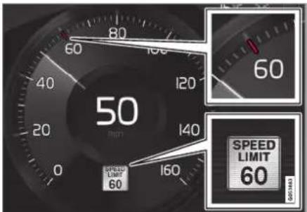
Example ^52 of registered speed information.
If the vehicle passes a speed limit sign, it will be displayed in the instrument panel and the head-up display*.
i NOTE
In certain markets, the Road Sign Information function (RSI) is only available in combination with Sensus Navigation*.
WARNING
- The Road Sign Information function is supplementary driver support intended to facilitate driving and help make it safer – it cannot handle all situations in all traffic, weather and road conditions.
- Road Sign Information is not a substitute for the driver's attention and judgment. The driver is always responsible for ensuring the vehicle is driven in a safe manner, at the appropriate speed, with an appropriate distance to other vehicles, and in accordance with current traffic rules and regulations.
Related information
- Activating/deactivating Road Sign Information (p. 365)
- Road Sign Information and sign displays (p. 366)
• Road Sign Information and Sensus Navigation (p. 366) - Road Sign Information with Speed Warning and Settings (p. 367)
- Activating/deactivating Speed Warning in Road Sign Information (p. 368)
• Road Sign Information with speed camera information (p. 368)
• Road Sign Information limitations (p. 369)
Activating/deactivating Road Sign Information
The Road Sign Information function can be switched On or Off.

Press the Road Sign Information button in the center display's Function view.
- GREEN button indicator light - RSI is activated.
- GRAY button indicator light - RSI is deactivated.
NOTE
- If the Automatic Speed Limiter function is activated, road sign information is shown in the driver display even if RSI ^83 is not activated.
- To remove road sign information from the driver display, you must deactivate both Automatic Speed Limiter and RSI.
- When the Automatic Speed Limiter function is activated but RSI is deactivated, no warnings are given from RSI. RSI must also be activated for warnings to be possible.
Related information
• Road Sign Information* (p. 364)
DRIVER SUPPORT
Road Sign Information and sign displays
Road Sign Information (RSI ^94 ) displays road signs in different ways depending on the sign and situation.

Example ^95 of registered speed information.
When RSI has registered a speed limit sign, the sign will be displayed as a symbol in the instrument panel and a colored marking will be shown in the speedometer's speed scale.
If the vehicle is equipped with Sensus Navigation*, speed-related information will also be retrieved from map data, which means that the instrument panel can display or change information about speed limits even if the vehicle has not passed a speed-related sign.
Signs for "School" and "Children playing"

If the warning sign ^95 "School" or "Children playing" is included in the satellite navigator's map data ^96 , a symbol of this type will be displayed in the instrument panel.
Related information
• Road Sign Information* (p. 364)
- Activating/deactivating Road Sign Information (p. 365)
• Road Sign Information with Speed Warning and Settings (p. 367)
Road Sign Information and Sensus Navigation
If the vehicle is equipped with Sensus Navigation, speed-related information will be provided in the following situations:
- In cases where the speed limit is given indirectly, e.g. signs for highways or other major roads.
- If a previously detected speed sign is deemed to be no longer valid and no new sign has been passed.
NOTE
In certain markets, the Road Sign Information function (RSI) is only available in combination with Sensus Navigation*.
NOTE
If a downloaded third-party app is used for navigation, there is no support for speed-related information.
Related information
• Road Sign Information* (p. 364)
Road Sign Information with Speed Warning and Settings
The Speed Limit Warning sub-function for RSI ^97 can be switched On or Off.
Speed Limit Warning warns the driver if the vehicle's speed has exceeded the applicable speed limit or the preset Speed Limiter speed. The warning will be repeated once after about 1 minute in that speed limit area if the driver does not slow down.
A new warning and message indicating that the speed limit has been exceeded will be provided only when the vehicle has entered a new/different speed limit area.

When Speed Warning is activated, the symbol for the current speed limit in the instrument panel ^98 will flash temporarily if that speed is exceeded.

The driver can be alerted if the vehicle is exceeding a detected speed limit and is approaching a speed camera.
Settings
Adjusting the Speed Warning limit
The driver can adjust the settings to be alerted at a higher speed than the posted speed limit.
To adjust the Speed Warning limit:
- Select Settings My Car InteliSafe
→ Road Sign Information in the center display's Top view.
- Mark Speed Limit Warning.
The function is activated and a speed limit selector is displayed.
- Tap the up/down arrows on the screen to adjust the speed at which the Speed Warning will be given.

Please note that the set warning limit will not be used when a speed camera symbol is displayed in the instrument panel.
Audible alert On/Off
An audible alert can also be given along with the Speed Warning.
To adjust the audible alert settings:
- Select Settings My Car IntelliSafe
→Road Sign Information in the center display's Top view.
- Select/deselect Road Sign Audio Warning to activate/deactivate the audible alert.
When Road Sign Audio Warning is activated, the driver will also be alerted if the vehicle is approaching a one-way/"no-entry" road or entrance.
Speed camera warning On/Off

If the vehicle is equipped with Sensus Navigation* and map data contains information on speed cameras, the driver can choose to receive an audible alert if the vehicle is approaching a speed camera.
To adjust the audible alert settings:
- Select Settings My Car Inte Safe
→Road Sign Information in the center display's Top view.
- Select/deselect Speed Camera Audio Warning to activate/deactivate the speed camera audible alert.
DRIVER SUPPORT
Related information
• Road Sign Information* (p. 364)
- Road Sign Information with speed camera information (p. 368)
Activating/deactivating Speed Warning in Road Sign Information
To activate the Speed Limit Warning sub-function:
-
Select Settings Any Car InteliSafe
→ Road Sign Information in the center display's Top view. -
Mark Speed Limit Warning.
The function is activated and a speed limit selector is displayed.
(See description for "Adjusting the Speed Warning limit" in section "Road Sign Information with Speed Warning and Settings.")
Related information
• Road Sign Information* (p. 364)
• Road Sign Information with Speed Warning and Settings (p. 367)
Road Sign Information with speed camera information
Vehicles equipped with RSI ^99 and Sensus Navigation* can provide information on upcoming speed cameras in the instrument panel.

Speed camera information in the instrument panel ^100 .

If the vehicle exceeds a detected speed limit with the Speed Limit Warning function activated, the driver is given a speed warning when the vehicle is approaching a speed camera if the navigation
map for the vehicle's current location contains information on speed cameras.
For more information on Speed Warnings in conjunction with speed cameras, also see "Road Sign Information with Speed Warning and Settings" and "Road Sign Information limitations".
i
NOTE
- For an audible alert to be provided if the speed is exceeded, the Speed Limit Warning function must be activated and the Road Sign Audio Warning sub-function must be On. Audible alerts are provided if the vehicle's speed exceeds the speed displayed by RSI in the instrument panel.
- It is possible to receive an audible alert for speed cameras regardless of the vehicle's speed, whether or not the speed limit is exceeded, and even if the Road Sign Audio Warning function is deactivated: See heading "Speed camera warning On/Off" in section "Road Sign Information with Speed Warning and settings" and select Speed Camera Audio Warning there.
- Information about speed cameras on the navigation map is not available for all markets/areas.
Related information
• Road Sign Information* (p. 364)
- Road Sign Information with Speed Warning and Settings (p. 367)
• Road Sign Information limitations (p. 369)
Road Sign Information limitations
Road Sign Information (RSI ^101 ) functionality may be reduced in certain situations.
RSI could have reduced functionality due to e.g.:
- faded road signs
• signs located in a curve in the road
• twisted or damaged signs
• signs positioned high above the road - fully/partially obstructed or poorly positioned signs
- signs partially or fully covered by frost, snow and/or dirt
- digital road maps ^102 that are outdated, incorrect or do not contain speed information ^103 .
i
NOTE
Certain types of bike carriers that are connected to the trailer socket may be interpreted as a connected trailer by the RSI function. In such cases, the instrument panel may indicate incorrect speed information.
DRIVER SUPPORT
◀◀

NOTE
The function uses the vehicle's camera unit, which has some general limitations – see the section "Camera unit limitations".
Related information
• Road Sign Information* (p. 364)
• Camera limitations (p. 338)
Driver Alert Control
The Driver Alert Control (DAC) function is designed to help capture the driver become aware of erratic behavior, e.g. if the driver is distracted or showing signs of fatigue.
The objective of DAC is to detect slowly deteriorating driving behavior and is primarily intended to be used on major roads. The function is not intended for use in city traffic.
DAC is activated when the vehicle's speed exceeds 65 km/h (40 mph) and remains active as long as speeds are above 60 km/h (37 mph).

natural_image
Top-down view of a car with light rays projecting onto the road (no text or symbols visible)DAC detects the vehicle's position in the traffic lane.
A camera monitors the traffic lane's marker lines and compares the direction of the road with the driver's movements of the steering wheel.

natural_image
Top-down view of a car driving on a curved road with a red winding line (no text or symbols)The vehicle is moving erratically in the lane.

If driving behavior becomes considerably erratic, the driver will be alerted by this symbol in the instrument panel, an audible signal and the message Time for a break.
If the vehicle is equipped with Sensus Navigation* and the Rest Stop Guidance function is activated, a suitable place to take a break will also be suggested (see section "Selecting guidance to a rest stop if a Driver Alert Control warning has been given").
The warning will be repeated after a short time if driving behavior does not improve.

WARNING
- The Driver Alert Control function is supplementary driver support intended to facilitate driving and help make it safer – it cannot handle all situations in all traffic, weather and road conditions.
- Driver Alert Control must not be used to extend a period of driving. The driver should plan in breaks at regular intervals and make sure they are well rested.
- Driver Alert Control is not a substitute for the driver's attention and judgment. The driver is always responsible for ensuring the vehicle is driven in a safe manner, at the appropriate speed, with an appropriate distance to other vehicles, and in accordance with current traffic rules and regulations.

WARNING
An alarm from Driver Alert Control should be taken very seriously since a sleepy driver is often not aware of their own condition.
If the alarm sounds or you feel fatigued:
- Stop the vehicle safely as soon as possible and rest.
Studies have shown that it is just as dangerous to drive while tired as it is to drive under the influence of alcohol or other stimulants.
Related information
- Activating/deactivating Driver Alert Control (p. 371)
- Selecting guidance to a rest area if the Driver Alert Control warning has been given (p. 372)
• Driver Alert Control limitations (p. 372)
Activating/deactivating Driver Alert Control
The Driver Alert Control (DAC) function can be activated/deactivated.
On/Off
To change DAC settings:
- Tap Settings in the center display's Top view.
- Select My Car IntelliSafe Driver Alert Control.
- Select/deselect Alertness Warning to activate/deactivate DAC.
Related information
• Driver Alert Control (p. 370)
DRIVER SUPPORT
Selecting guidance to a rest area if the Driver Alert Control warning has been given
The Rest Stop Guidance function can be switched on or off.
In vehicles equipped with Sensus Navigation*, the driver can activate a guide that can automatically suggest a suitable rest stop if the DAC warning is given.
To select Rest Stop Guidance:
- Tap Settings in the center display's Top view.
- Select My Car IntelliSafe Driver Alert Control
- Select/deselect Rest Stop Guidance to activate/deactivate the function.
Related information
• Driver Alert Control (p. 370)
Driver Alert Control limitations
Driver Alert Control (DAC) functionality may be reduced in certain situations.
In certain situations, the system may provide a warning even if it has not detected a change in driving behavior, e.g.:
• in strong crosswinds
• on grooved road surfaces.
WARNING
In certain cases, driving behavior might not be affected despite the driver's fatigue – when using the Pilot Assist function – resulting in the driver not getting a warning from DAC.
It is therefore very important to always stop and take a break at the slightest sign of fatigue, regardless of whether the DAC function has issued a warning or not.
NOTE
The function uses the vehicle's camera unit, which has some general limitations – see the section "Camera unit limitations".
Related information
• Driver Alert Control (p. 370)
• Camera limitations (p. 338)
Lane Keeping Aid
Lane Keeping Aid (LKA ^104 ) is designed to actively steer the vehicle on freeways, highways and other major roads to help the driver reduce the risk of the vehicle unintentionally veering out of the lane.
Lake Keeping Assistance steers the vehicle back into the lane and/or alerts the driver using vibrations in the steering wheel.
Lane Keeping Aid is active at speeds between 65-200 km/h (40-125 mph) on roads with clearly visible traffic lane marker lines.
On narrow roads, the function may be unavailable and go into standby mode. The function will become available again when the road becomes sufficiently wide.

natural_image
Top-down view of a car with two highlighted lanes, no text or symbols presentA camera monitors the road/traffic lane's marker lines.
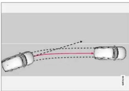
natural_image
Diagram showing two cars with dashed trajectory lines and a red arrow indicating direction (no text or symbols)Lane Keeping Aid steers the vehicle back into its lane.

Lane Keeping Aid alerts the driver using vibrations in the steering wheel ^105 .
Depending on the settings used, Lane Keeping Aid functions in different ways:
- With Assist ^106 activated: When the vehicle approaches a lane marker line, LKA will actively steer the vehicle back into the lane using light pressure on the steering wheel.
- With Warning ^106 activated: If the vehicle is about to move over a lane marker line, the driver will be alerted by vibrations in the steering wheel.
i NOTE
When the direction indicator is activated, the Lane Keeping Aid does not provide any warning or intervene with steering.
WARNING
- The Lane Keeping Aid function is supplementary driver support intended to help improve driving safety – it cannot handle all situations in all traffic, weather and road conditions.
- The function is not a substitute for the driver's attention and judgment. The driver is always responsible for ensuring the vehicle is driven in a safe manner, at the appropriate speed, with an appropriate distance to other vehicles, and in accordance with current traffic rules and regulations.
DRIVER SUPPORT
Lane Keeping Aid does not intervene
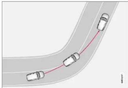
natural_image
Diagram of four cars driving on a curved road with a red trajectory line (no text or symbols)Lane Keeping Aid does not intervene in sharp inside curves.
In certain cases, such as when a turn signal is used or when "straightening out" an inside curve, Lane Keeping Aid will not provide steering assistance or alerts.
Related information
• Steering assistance with Lane Keeping Aid (p. 374)
• Lane Keeping Aid limitations (p. 376)
- Activating/deactivating Lane Keeping Aid (p. 375)
- Selecting type of assistance for Lane Keeping Aid (p. 375)
- Lane Keeping Aid symbols and messages (p. 377)
- Lane Keeping Aid symbols in the instrument panel (p. 379)
Steering assistance with Lane Keeping Aid
Lane Keeping Aid (LKA ^107 ) only functions if the driver's hands are on the steering wheel.
This symbol on the instrument panel indicates that LKA is activated and continuously monitoring that the driver's hands are on the steering wheel.
- If the driver's hands are not on the steering wheel, an audible signal will be given and a message will instruct the driver to actively steer the vehicle;
Lane Keeping Aid - Apply steering
- If LKA detects that the driver is not actively steering the vehicle, the message will be repeated along with a longer audible signal.
- If the driver still does not begin actively steering the vehicle, a short audible signal will be given in a different tone, LKA will be deacti-
vated, another symbol will illuminate and the following message will be displayed:

- Lane Keeping Aid - Apply
steering
LKA will then be deactivated until the driver begins actively steering the vehicle again.
The audible signal will stop and the information symbol and message will disappear when LKA detects that the driver is actively steering the vehicle again.
Related information
• Lane Keeping Aid (p. 372)
Activating/deactivating Lane Keeping Aid
The Lane Keeping Aid (LKA ^108 ) function can be switched On or Off.
On/Off

Press the Lane Keeping Aid button in the center display's Function view.
- GREEN button indicator light - LKA is activated.
- GRAY button indicator light - LKA is deactivated.
Related information
• Lane Keeping Aid (p. 372)
Selecting type of assistance for Lane Keeping Aid
The driver can determine what types of assistance LKA ^109 should provide if the vehicle veers from its lane.
- Select Settings MyCar IntelliSafe in the center display's Top view.
- Under Lane Keeping Aid Mode, select what assistance LKA should provide:
- Assist the driver will receive steering assistance but no warning.
- Both - the driver will receive both steering assistance and a warning.
- Warning - the driver will only receive a warning.
Related information
• Lane Keeping Aid (p. 372)
DRIVER SUPPORT
Lane Keeping Aid limitations
In certain demanding driving conditions, Lane Keeping Aid may not be able to properly assist the driver. In these situations, it is recommended that the function be deactivated.
• Camera limitations (p. 338)
Examples of such situations include:
road work
• winter driving conditions
• poor road surfaces
• a very sporty driving style
• bad weather with reduced visibility
• roads with indistinct or no lane markings
- sharp edges or lines other than the lane's side markings
- when the power steering works at reduced power, e.g. during cooling due to overheating (see section "Speed-dependent steering force").

NOTE
The function uses the vehicle's camera unit, which has some general limitations – see the section "Camera unit limitations".
Related information
• Lane Keeping Aid (p. 372)
- Speed-dependent steering wheel resistance (p. 278)
Lane Keeping Aid symbols and messages
A number of symbols and messages related to
Lane Keeping Aid LKA ^110 may be displayed in
the instrument panel.
Some examples of symbols and messages are shown in the table below.
| Symbol Message Meaning | ||
 | Driver support systemReduced functionality Service required | The system is not functioning as intended. Contact a workshop – an authorized Volvo work-shop is recommended. |
 | Windscreen sensorSensor blocked, see Owner's manual | The camera's ability to detect the lane in front of the vehicle is reduced. |
 | Lane Keeping AidApply steering | LKA's steering assistance is disabled when the driver's hands are not on the wheel. Follow the instructions and steer the vehicle. |
 | Lane Keeping AidApply steering | LKA will go into standby mode until the driver begins steering the vehicle again. |
DRIVER SUPPORT
A text message can be erased by briefly pressing the ○ button in the center of the right-side steering wheel keypad.
If the message persists: Contact a workshop – an authorized Volvo workshop is recommended.
Related information
• Lane Keeping Aid (p. 372)
Lane Keeping Aid symbols in the instrument panel
Lane Keeping Aid (LKA ^111 ) uses symbols in the instrument panel for various situations.

Some examples of symbols and descriptions of the situations in which they might appear are provided below.
Available

Available – the marker lines in the symbol are WHITE.
Lane Keeping Aid is able to detect one or both of the traffic lane's side marker lines.
Unavailable

Unavailable – the marker lines in the symbol are GRAY.
Lane Keeping Aid is unable to detect the lane marker lines, the vehicle's speed is too low or the road is too narrow.
Steering/warning indicator
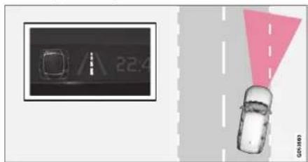
Steering/warning – the marker lines in the symbol are COLORED.
Indicates that the Lane Keeping Aid system is alerting the driver and/or attempting to steer the vehicle back into the lane.
Related information
• Lane Keeping Aid (p. 372)
DRIVER SUPPORT
Steering assistance at risk of collision
The Collision avoidance assistance function is intended to help the driver reduce the risk of the vehicle inadvertently veering from the traffic lane and/or colliding with another vehicle or obstacle by actively steering the vehicle back into the lane and/or swerving out of the way.
Collision avoidance assistance consists of three sub-functions:
• Run-Off Mitigation with steering assistance
• Steering assistance during collision risks from oncoming traffic
• Steering assistance during collision risks from behind*
After the system has automatically intervened, this text message will appear in the instrument panel:
- Collision avoidance assistance – Automatic intervention

NOTE
It is always the driver who must decide how much the vehicle should be in control – the vehicle can never take command.
Related information
- Activating/deactivating steering assistance during collision risks (p. 380)
- Symbols and messages for steering assistance during collision risks (p. 389)
• Run-Off Mitigation with steering assistance (p. 381) - Run-Off Mitigation with steering assistance levels (p. 381)
- Activating/deactivating Run-Off Mitigation with steering assistance (p. 382)
- Limitations of Run-Off Mitigation with steering assistance (p. 383)
• Steering assistance during collision risks from oncoming traffic (p. 383) - Activating/deactivating Steering assistance during collision risks with oncoming vehicles (p. 384)
- Limitations of steering assistance during collision risks from oncoming traffic (p. 385)
• Steering assistance during collision risks from behind* (p. 386) - Activating/deactivating Steering assistance during collision risks from behind* (p. 387)
- Limitations of steering assistance during collision risks from behind (p. 387)
Activating/deactivating steering assistance during collision risks
The driver can choose to have this function On or Off.

Use this button in the center display's Function view to turn the function On and Off.
i NOTE
When the Collision avoidance assistance function is deactivated, all subfunctions of the following are deactivated:
• Steering assistance at risk of run-off
• Steering assistance at risk of head-on collision
- Steering assistance during collision risks from behind*
Although it is possible to deactivate the function, the driver is advised to keep it activated since it can help improve driving safety in most cases.
Related information
• Steering assistance at risk of collision (p. 380)
Run-Off Mitigation with steering assistance
This sub-function is intended to help reduce the risk of the vehicle inadvertently running off the road by actively steering the vehicle back onto the road.
The function is active at speeds between 65-140 km/h (40-87 mph) on roads with clearly visible traffic lane markings/lines.
The system uses a camera to monitor the edges of the road and the painted side marker lines. If the vehicle is about to cross the edge of the road, the function will attempt to steer the vehicle back onto the road. If this is not sufficient to keep the vehicle on the road, the brakes will also be applied.
However, the function will not provide either steering assistance or braking if the turn signal is used. The function will also not be activated if it detects that the driver is actively operating the vehicle.
After the system has automatically intervened, this text message will appear in the instrument panel:
- Collision avoidance assistance – Automatic intervention
WARNING
- The "Steering assistance at risk of run-off" subfunction is supplementary driver support intended to help improve driving safety – it cannot handle all situations in all traffic, weather and road conditions.
- The function cannot detect barriers, rails or similar obstacles at the side of the road.
- "Steering assistance at risk of run-off" is not a substitute for the driver's attention and judgment. The driver is always responsible for ensuring the vehicle is driven in a safe manner, at the appropriate speed, with an appropriate distance to other vehicles, and in accordance with current traffic rules and regulations.
Related information
• Steering assistance at risk of collision (p. 380)
Run-Off Mitigation with steering assistance levels
This function has two activation levels for intervention:
• Steering assistance only
• Steering assistance with braking
Steering assistance only
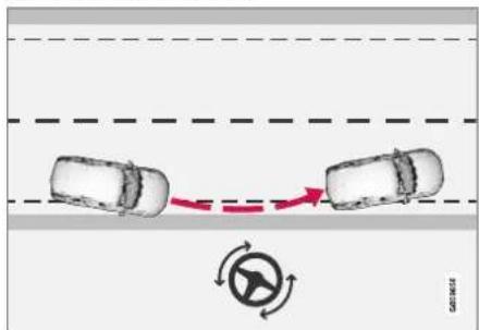
Intervention with steering assistance.
DRIVER SUPPORT
Steering assistance with braking

Intervention with steering assistance and braking.
Braking intervention assists in situations where steering assistance alone is not sufficient. Braking force is automatically adapted according to the situation at the moment the vehicle begins to run off the road.
Related information
• Steering assistance at risk of collision (p. 380)
Activating/deactivating Run-Off Mitigation with steering assistance
The driver can choose to have this function On or Off.

Use this button in the center display's Function view to turn the function On and Off.
i NOTE
When the Collision avoidance assistance function is deactivated, all subfunctions of the following are deactivated:
• Steering assistance at risk of run-off
• Steering assistance at risk of head-on collision
- Steering assistance during collision risks from behind*
Although it is possible to deactivate the function, the driver is advised to keep it activated since it can help improve driving safety in most cases.
Related information
• Steering assistance at risk of collision (p. 380)
- Run-Off Mitigation with steering assistance (p. 381)
Limitations of Run-Off Mitigation with steering assistance
In certain demanding driving conditions, the function may not be able to properly assist the driver. In these situations, it is recommended that it is turned off.
Examples of such situations include:
road work
• winter driving conditions
- narrow roads
• poor road surfaces
• a very sporty driving style
• bad weather with reduced visibility
• roads with indistinct or no lane markings
- sharp edges or lines other than the lane's side markings
- when the power steering works at reduced power, e.g. during cooling due to overheating (see section "Speed-dependent steering force").

NOTE
The function uses the vehicle's combined camera and radar unit, which has certain general limitations; see sections "Camera limitations" and "Radar sensor limitations".
Related information
• Steering assistance at risk of collision (p. 380)
• Speed-dependent steering wheel resistance (p. 278)
• Camera limitations (p. 338)
• Radar sensor limitations (p. 333)
Steering assistance during collision risks from oncoming traffic
This sub-function can help assist a distracted driver who has not noticed that the vehicle is veering into oncoming traffic.

flowchart
graph TD
    A["Car 1"] -->|Rightward Arrow| B["Car 2"]
    C["Car 2"] -->|Leftward Arrow| A
    style A fill:#f9f,stroke:#333
    style B fill:#ccf,stroke:#333
    style C fill:#cfc,stroke:#333
The function provides assistance by swerving your vehicle back into your own lane.

Oncoming vehicles

Own vehicle
The function is active at speeds between 60-140 km/h (37-87 mph) on roads with clearly visible traffic lane markings/lines.
If your vehicle is starting to veer from your own lane and a vehicle is approaching from the opposite direction, this function can help the driver steer the vehicle back into its own lane.
▶▶
DRIVER SUPPORT
However, the function will not provide steering assistance if the turn signal is used. The function will also not be activated if it detects that the driver is actively operating the vehicle.
After the system has automatically intervened, this text message will appear in the instrument panel:
- Collision avoidance assistance – Automatic intervention

WARNING
- The "Steering assistance at risk of head-on collision" subfunction is supplementary driver support intended to improve driving safety – it cannot handle all situations in all traffic, weather and road conditions.
- Pilot Assist is only activated if there is a high risk of collision – you must therefore never wait for the function to intervene.
- The function is not a substitute for the driver's attention and judgment. The driver is always responsible for ensuring the vehicle is driven in a safe manner, at the appropriate speed, with an appropriate distance to other vehicles, and in accordance with current traffic rules and regulations.
Related information
• Steering assistance at risk of collision (p. 380)
- Activating/deactivating Steering assistance during collision risks with oncoming vehicles (p. 384)
- Limitations of steering assistance during collision risks from oncoming traffic (p. 385)
Activating/deactivating Steering assistance during collision risks with oncoming vehicles
The driver can choose to have this function On or Off.

Use this button in the center display's Function view to turn the function On and Off.

NOTE
When the Collision avoidance assistance function is deactivated, all subfunctions of the following are deactivated:
• Steering assistance at risk of run-off
• Steering assistance at risk of head-on collision
- Steering assistance during collision risks from behind*
Although it is possible to deactivate the function, the driver is advised to keep it activated since it can help improve driving safety in most cases.
Related information
• Steering assistance at risk of collision (p. 380)
• Steering assistance during collision risks from oncoming traffic (p. 383)
Limitations of steering assistance during collision risks from oncoming traffic
The function may have limited functionality in certain situations and not intervene, e.g.:
• for smaller vehicles such as motorcycles
- on roads that do not have clear lane markings
- if more than half of your vehicle has moved into the adjacent lane
• outside the speed range 60-140 km/h (37-87 mph)
- when the power steering works at reduced power - e.g. during cooling due to overheating (see section "Speed-dependent steering force").
Functionality may also be reduced in other situations, such as:
road work
• winter driving conditions
- narrow roads
- poor road surfaces
• a very sporty driving style
• bad weather with reduced visibility.
In these demanding driving conditions, the function may not be able to properly assist the driver.
In these situations, it is recommended that it is turned off.
NOTE
The function uses the vehicle's combined camera and radar unit, which has certain general limitations; see sections "Camera limitations" and "Radar sensor limitations".
Related information
• Steering assistance at risk of collision (p. 380)
• Steering assistance during collision risks from oncoming traffic (p. 383)
- Speed-dependent steering wheel resistance (p. 278)
• Camera limitations (p. 338)
• Radar sensor limitations (p. 333)
DRIVER SUPPORT
Steering assistance during collision risks from behind\*
If you become distracted and do not notice your vehicle starting to veer out of the lane while another vehicle is approaching from behind or is in your vehicle's blind spot, this sub-function can help provide assistance.

flowchart
graph TD
    A["1"] --> B["Car Position 1"]
    C["2"] --> D["Car Position 2"]
    style A fill:#f9f,stroke:#333
    style C fill:#f9f,stroke:#333
    style B fill:#ccf,stroke:#333
    style D fill:#ccf,stroke:#333
The function provides assistance by steering your vehicle back into your own lane.
1 Another vehicle in blind spot zone
2 Own vehicle
If your vehicle is beginning to veer out of your lane while another vehicle is in your blind spot or another vehicle is rapidly approaching in the next lane, this function can help the driver steer the vehicle back into its own lane.
Even if the driver intentionally changes lanes using a turn signal without noticing another vehi-
cle approaching, the function can provide assistance.
The function is active at speeds between 60-140 km/h (37-87 mph) on roads with clearly visible traffic lane markings/lines.
After the system has automatically intervened, this text message will appear in the instrument panel:
- Collision avoidance assistance – Automatic intervention
WARNING
- The "Steering assistance at risk of rear-end collision" subfunction is supplementary driver support intended to improve driving safety – it cannot handle all situations in all traffic, weather and road conditions.
- Pilot Assist is only activated if there is a high risk of collision – you must therefore never wait for the function to intervene.
- The function is not a substitute for the driver's attention and judgment. The driver is always responsible for ensuring the vehicle is driven in a safe manner, at the appropriate speed, with an appropriate distance to other vehicles, and in accordance with current traffic rules and regulations.
Related information
• Steering assistance at risk of collision (p. 380)
- Activating/deactivating Steering assistance during collision risks from behind* (p. 387)
- Limitations of steering assistance during collision risks from behind (p. 387)
Activating/deactivating Steering assistance during collision risks from behind\*
The driver can choose to have this function On or Off.

Use this button in the center display's Function view to turn the function On and Off.

NOTE
When the Collision avoidance assistance function is deactivated, all subfunctions of the following are deactivated:
• Steering assistance at risk of run-off
• Steering assistance at risk of head-on collision
- Steering assistance during collision risks from behind*
Although it is possible to deactivate the function, the driver is advised to keep it activated since it can help improve driving safety in most cases.
Related information
• Steering assistance at risk of collision (p. 380)
• Steering assistance during collision risks from behind* (p. 386)
Limitations of steering assistance during collision risks from behind
The function may have limited functionality in certain situations and not intervene, e.g.:
• for smaller vehicles such as motorcycles
- if more than half of your vehicle has moved into the adjacent lane
- on roads/lanes with indistinct or no side lane markings
• outside the speed range 60-140 km/h (37-87 mph)
- when the power steering works at reduced power - e.g. during cooling due to overheating (see section "Speed-dependent steering force").
Functionality may also be reduced in other situations, such as:
road work
• winter driving conditions
- narrow roads
- poor road surfaces
• a very sporty driving style
• bad weather with reduced visibility.
In these demanding driving conditions, the function may not be able to properly assist the driver. In these situations, it is recommended that it is turned off.
▶▶
DRIVER SUPPORT
◀◀

NOTE
The function uses the vehicle's combined camera and radar unit, which has certain general limitations; see sections "Camera limitations" and "Radar sensor limitations".
In addition to the camera and radar sensor, the function also uses the vehicle's rearward-facing radar, which has certain general limitations the driver should be aware of. See additional information in the section "BLIS limitations".
Related information
• Steering assistance at risk of collision (p. 380)
• Steering assistance during collision risks from behind* (p. 386)
- Speed-dependent steering wheel resistance (p. 278)
• Camera limitations (p. 338)
• Radar sensor limitations (p. 333)
• BLIS limitations (p. 357)
Symbols and messages for steering assistance during collision risks
A number of symbols and messages related to the function may be displayed in the instrument panel.
Some examples of symbols and messages are shown in the table below.
| Symbol Message Meaning | |||
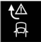 | Collision avoidance assistanceAutomatic intervention | When the function is activated, a message will appear to alert the driver. | |
 | Windscreen sensorSensor blocked, see Owner's manual | The camera's ability to detect the lane in front of the vehicle is reduced. | |
A text message can be erased by briefly pressing the ○ button in the center of the right-side steering wheel keypad.
If the message persists: Contact a workshop – an authorized Volvo workshop is recommended.
Related information
• Steering assistance at risk of collision (p. 380)
DRIVER SUPPORT
Park Assist\*
The Park Assist function can help the driver when maneuvering in tight spaces by indicating distances to obstacles using audible signals and graphics in the center display.

natural_image
Top-down view of a car inside a cylindrical container (no text or symbols visible)Display view showing obstacle zones and sensor sectors.
The center display shows an overview of the vehicle in relation to objects that have been detected.
The marked sector indicates where the obstacle is located. The closer the vehicle symbol is to a marked sector forward/rearward, the closer the detected obstacle is to your vehicle.
The side sectors change color as the distance between the vehicle and an object decreases.
The audible signals will also speed up the closer the obstacle is to the vehicle. The volume of the audio system will be automatically lowered.
Audible signals for obstacles in front and to the sides of the vehicle are active when the vehicle is moving but will cease after the vehicle has been stationary for approx. 2 seconds. Audible signals for obstacles behind the vehicle will remain active even when the vehicle is stationary.
If a detected obstacle is within approx. 30 cm (1 fl) from the front or rear of the vehicle, the tone will become constant and the active sensor's field closest to the vehicle symbol will be filled in.
At distances within approx. 25 cm (0.8 fl) from an obstacle to the sides of the vehicle, an rapid pulsing signal will be given and the active sector fields will change color from ORANGE to RED.
The volume of the Park Assist audible signals can be adjusted while the signal is being given using the >II knob or in the center display's Top view under Settings.
i NOTE
- Besides in the sector closest to the vehicle symbol, audible warnings are only provided for objects located directly in the vehicle's path.
WARNING
- The Parking Assist function is supplementary driver support intended to facilitate driving and help make it safer – it cannot handle all situations in all traffic, weather and road conditions.
- The parking sensors have dead/blind spots where objects cannot be detected.
- Pay particular attention to people and animals near the vehicle.
- Parking Assist is not a substitute for the driver's attention and judgment. The driver is always responsible for ensuring the vehicle is driven in a safe manner, at the appropriate speed, with an appropriate distance to other vehicles, and in accordance with current traffic rules and regulations.
Related information
• Park Assist front, rear and sides (p. 391)
• Activating/deactivating Park Assist (p. 392)
• Park Assist limitations (p. 393)
- Recommended maintenance for Park Assist (p. 394)
• Park Assist symbols and messages (p. 395)
Park Assist front, rear and sides
Park Assist has different parameters depending on which part of the vehicle is approaching an obstacle.
Front camera

Continuous tone warning signal when the obstacle is less than approx. 30 cm (1 ft) from the vehicle ^112 .
Park Assist's front sensors are automatically activated when the engine is started. They are active at speeds below 10 km/h (6 mph).
The distance monitored extends approx. 80 cm (2.5 ft) in front of the vehicle.
NOTE
The Parking Assist system is deactivated when the parking brake is applied or when P is selected on vehicles with automatic transmission.
! CAUTION
When installing auxiliary lights: Make sure these do not obscure the sensors – the auxiliary lights could be perceived as an obstacle.
Back
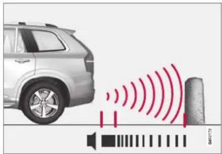
Continuous tone warning signal when the obstacle is less than approx. 30 cm (1 ft) from the vehicle ^112
The rear sensors will be activated if the vehicle begins rolling backward or if reverse gear is engaged.
The distance monitored extends approx. 1.5 meters (5 ft) behind the vehicle.
The Parking Assist system's rear sensors will be automatically deactivated if the vehicle is backing up with a trailer connected to the vehicle's electrical system.
i NOTE
When reversing with e.g. a trailer or bike carrier on the trailer hitch - without Volvo original trailer cables - the Parking Assist system may have to be turned off manually to prevent the sensors from reacting to these.
DRIVER SUPPORT
Side sensors

natural_image
Top-down view of a car with concentric red wave patterns around its roof, no text or symbols present.Rapid pulsing warning signal when the obstacle is less than approx. 25 cm (0.8 ft) from the vehicle ^112 .
Park Assist's side sensors are automatically activated when the engine is started. They are active at speeds below 10 km/h (6 mph).
The distance monitored is approx. 25 cm (0.8 ft) out from the sides.
The detection area increases significantly when the steering angle of the front wheels increases and depending on the steering wheel position, obstacles up to approx. 90 cm (3 ft) directly behind or in front of the vehicle can be detected (also see "Side sensor fields" in the section "Sensor field from Park Assist for Park Assist Camera").
Related information
• Park Assist* (p. 390)
- Sensor field from Park Assist for Park Assist Camera (p. 401)
Activating/deactivating Park Assist
The Park Assist Pilot function can be activated/deactivated.
On/Off
Park Assist's front and side sensors are automatically activated when the engine is started. The rear sensors are activated if the vehicle is moving backward or reverse gear is engaged.

The function can be activated/deactivated in the center display's Function view.
- Tap the Park Assist button in Function view.
The Park Assist Pilot indicator light shows the status of the function: GREEN (on) or GRAY (off).
In vehicles equipped with Park Assist Camera, Park Assist can also be activated/deactivated from the relevant camera view.
Related information
• Park Assist* (p. 390)
Park Assist limitations
Park Assist may not be able to detect all conditions in all situations and functionality may therefore be limited in certain cases.
The driver should be aware of the following limitations for Park Assist:

WARNING

Be extra cautious when reversing if this symbol is shown when a trailer, bike carrier or similar is attached and electrically connected to the vehicle.
The symbol indicates that
the rear parking assist sensors are deactivated and will not warn of any obstacles.
CAUTION
Objects such as chains, thin and glossy poles or low obstacles may end up in the "signal shadow" and then go temporarily undetected by the sensors – the pulsating tone may then unexpectedly stop instead of becoming a constant tone as expected.
The sensors cannot detect high objects, such as protruding ramps.
- In such situations, pay extra attention and maneuver/drive the vehicle very slowly or stop the current parking maneuver – there may be a high risk of damage to the vehicle or other objects since information from the sensors is not always reliable in such situations.
CAUTION
In some circumstances, the Park Assist System may produce false warnings due to external sound sources with the same ultrasonic frequencies as those the system works with.
Examples of such sources are horns, wet tires on asphalt, pneumatic brakes, exhaust noise from motorcycles, etc.
NOTE
When a trailer hitch is configured with the vehicle electrical system, the trailer hitch protrusion is included when the function measures the distance to objects behind the vehicle.
Related information
• Park Assist* (p. 390)
DRIVER SUPPORT
Recommended maintenance for Park Assist
For Park Assist to function optimally, its sensors must be cleaned regularly with water and car washing detergent.
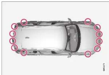
natural_image
Top-down view of a car with red circles highlighting the front and side edges (no text or symbols)Location of the Park Assist sensors ^113 ,

NOTE
Dirt, ice and snow covering the sensors could cause false warnings, reduced function, or no function.
Related information
• Park Assist* (p. 390)
Park Assist symbols and messages
Symbols and messages for the Park Assist may be displayed in the instrument panel and/or the center display.
Some examples of symbols and messages are shown in the table below.
| Symbol Message Meaning | |
| The rear Park Assist sensors are turned off and no acoustic warnings for obstacles/objects will be provided. | |
| One or more of the sensors are blocked. Check and clean/remove the obstacle as soon as possible. | |
| The system is not functioning as intended. Contact a workshop – an authorized Volvo workshop is recommended. |
A text message can be erased by briefly pressing the ○ button in the center of the right-side steering wheel keypad.
If the message persists: Contact a workshop – an authorized Volvo workshop is recommended.
Related information
• Park Assist* (p. 390)
DRIVER SUPPORT
Park Assist Camera\*
The Park Assist Camera can help provide the driver when maneuvering in tight spaces by alert-ing the driver to obstacles using the camera screen and graphics in the center display.
The Park Assist Camera is a support function that is automatically activated when reverse gear is engaged. It can also be started manually from the center display.

Example camera view ^114 ,
1 Zoom ^115 - zoom in/out
② 360° view* - activate/deactivate all cameras
3 PAS* - activate/deactivate Parking Assist
4 Lines - activate/deactivate trajectory lines
5 Towbar ^* - activate/deactivate trajectory lines for towbar ^116
6 CTA* - activate/deactivate Cross Traffic Alert
WARNING
- The Parking Camera function is supplementary driver support intended to facilitate driving and help make it safer – it cannot handle all situations in all traffic, weather and road conditions.
- The parking cameras have dead/blind spots where objects cannot be detected.
- Pay particular attention to people and animals near the vehicle.
- Objects/obstacles may be closer to the vehicle than they appear on the screen.
- The parking cameras are not a substitute for the driver's attention and judgment. The driver is always responsible for ensuring the vehicle is driven in a safe manner, at the appropriate speed, with an appropriate distance to other vehicles, and in accordance with current traffic rules and regulations.
Related information
• Park Assist Camera views (p. 397)
• Park Assist Camera trajectory lines (p. 399)
- Sensor field from Park Assist for Park Assist Camera (p. 401)
• Starting the Park Assist Camera (p. 402)
• Park Assist Camera limitations (p. 403)
- Recommended maintenance of the Park Assist Camera (p. 404)
- Park Assist Camera symbols and messages (p. 405)
• Activating/deactivating Park Assist (p. 392)
• Cross Traffic Alert* (p. 360)
Park Assist Camera views
PAC can display a 360° panoramic view as well as separate views for each of the other cameras: rear, front, left and right.
360° view*

natural_image
Top-down view of a car parked in a parking lot with diagonal structural beams (no visible text or symbols)The location of the cameras and their approximate fields of vision.
The 360° view function activates all Park Assist Cameras and all four sides of the vehicle are shown in the center display at once to help the driver see what is around the vehicle while maneuvering at low speeds.
From the 360° view, each camera view can be activated separately:
- Tap the screen to select the camera's field of vision, e.g. in the area in front/above the front camera.

The active cameras will be indicated by a camera symbol on the vehicle symbol in the center display.
If the vehicle is equipped with Park Assist System*, the dis-
tance to detected obstacles will be illustrated by fields in different colors.
The cameras can be activated automatically or manually. See "Starting the Park Assist Camera" for more information.
▶▶
DRIVER SUPPORT
Back
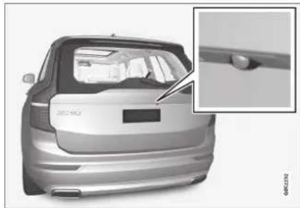
natural_image
Exterior view of a silver car backseat with a close-up inset showing the side panel detail (no visible text or symbols)The rear camera ^117 is located above the license plate.
The rear camera shows a wide area behind the vehicle. On certain models, part of the bumper and the towbar (if installed) may be visible.
Objects on the center display may appear to be leaning slightly. This is normal.
Front camera

natural_image
Exterior view of a Volvo car (no visible text or symbols on the car itself)The front Park Assist Camera ^118 is located in the grille.
The front camera can be useful when pulling out from areas with limited visibility, such as a driveway surrounded by a hedge. The front camera is active at speeds up to 25 km/h (16 mph) and is automatically turned off when the vehicle exceeds this speed.
If the vehicle does not reach a speed of 50 km/h (30 mph) and speed falls below 22 km/h (14 mph) within 1 minute after the front camera turns off, the camera will be reactivated.
Side cameras

natural_image
Close-up of a car's side mirror and rearview mirror on a vehicle (no text or symbols visible)The side cameras ^118 are located in the rearview mirrors.
The side cameras can show views along each side of the vehicle.
Related information
• Park Assist Camera* (p. 396)
• Starting the Park Assist Camera (p. 402)
Park Assist Camera trajectory lines
The Park Assist Camera uses trajectory lines and fields on the screen to indicate the vehicle's position in relation to its immediate surroundings.

Example ^119 of trajectory lines.
The trajectory lines show the anticipated trajectory for the vehicle's outermost dimensions based on the current position of the steering wheel to
help simplify parallel parking, backing into tight spaces or attaching a trailer.
The lines on the screen are projected as if they were painted lines on the ground behind the vehicle and are directly affected by the way in which the steering wheel is turned. This enables the driver to see path the vehicle will take, even if he/she turns the steering wheel.
These lines also indicate the outermost limits that any object (towbar, rearview mirrors, corners of the body, etc.) extends out from the vehicle.
i NOTE
- When reversing with a trailer that is not electrically connected to the vehicle, the screen guide lines show the path the vehicle will take – not the trailer.
- The screen does not show guide lines when a trailer is electrically connected to the vehicle's electrical system.
- Guide lines are not shown when zooming in.
CAUTION
- Bear in mind that when the rearward camera view is selected, the screen only shows the area behind the vehicle – pay attention to the sides and front of the vehicle when steering while reversing.
- The same applies to the reverse – pay attention to what is happening with the rear parts of the vehicle when the front camera view is selected.
- Note that the guide lines show the shortest path - pay extra attention to ensure that the vehicle sides do not come in contact with/travel over anything when steering while driving forward or that the vehicle front moves toward/over anything when steering while reversing.
DRIVER SUPPORT
Trajectory lines in 360° view\*

natural_image
Top-down view of a white car driving on a road with red curved arrows indicating motion or navigation (no text or symbols)360° view with trajectory lines ^119 .
In the 360° view, trajectory lines are shown behind, in front of, or to the sides of the vehicle, depending on the direction of travel.
- When driving forward: Front lines
- When backing up: Side lines and rear lines.
When the front or rear camera is selected, the trajectory lines will be shown regardless of the vehicle's direction of travel.
With a side camera selected, the trajectory lines will only be shown if the vehicle is backing up.
Trajectory lines for a towbar\*

Towbar with trajectory line ^119 .
1 Towbar - activate trajectory lines for towbar.
2 Zoom - zoom in/out.
The camera can help make hitching a trailer easier by showing an anticipated trajectory line for the towbar's path toward the trailer.
- Tap Towbar (1).
The trajectory line for the towbar's anticipated path toward the vehicle will appear and the vehicle's trajectory lines will disappear.
Trajectory lines cannot be displayed for both the vehicle and the towbar at the same time.
- Tap Zoom (2) for a close-up view for more precise maneuvering.
The camera will zoom in.
Related information
• Park Assist Camera* (p. 396)
Sensor field from Park Assist for Park Assist Camera
If the vehicle is equipped with Park Assist, distances will be shown in the 360° view with colored fields for each sensor that has detected an obstacle.
Front and rear sensors

The screen can display colored sensor fields on the vehicle symbol ^120 .
The front and rear fields change colors (from YELLOW to ORANGE to RED) as the vehicle moves closer to an obstacle.
| Field color rear- ward | Distance in meters (feet) |
| Yellow 0.6-1.5 | (2.0-4.9) |
| Orange 0,3-0,6 | (1,0-2,0) |
| Red 0-0.3 | (0-1.0) |
| Field color forward | Distance in meters (feet) |
| Yellow 0,6-0,8 | (2,0-2,6) |
| Orange 0,3-0,6 | (1,0-2,0) |
| Red 0-0.3 | (0-1.0) |
When the sensor field color is red, the audible pulsing sounds will change to a continuous tone.
Side sensor fields
Warning signals vary depending on the vehicle's intended direction of travel. Depending on the steering wheel position, warnings may be given for obstacles diagonally in front of or behind the vehicle, not only directly behind the vehicle.
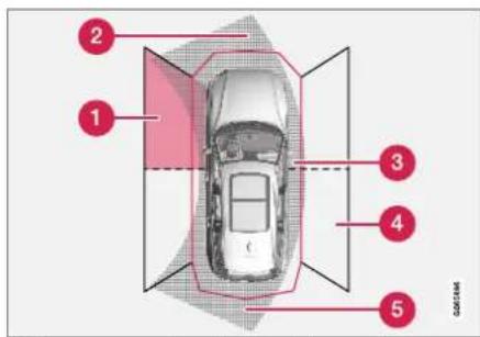
Parking sensor sectors where obstacles can be detected ^120 .
1 Left-side front sensor field
② Obstacle sector in the vehicle's intended direction of travel forward – varies according to steering wheel position
3 Sector with RED field color and rapidly pulsing tone
4 Right-side rear sensor field
⑤ Obstacle sector in the vehicle's intended direction of travel rearward - varies according to steering wheel position.
DRIVER SUPPORT
The color of the side field changes as the vehicle moves closer to the object – from YELLOW to RED.
| Side field color | Distance in meters (feet) |
| Yellow 0,25 | 0,9 (0,8-3,0) |
| Red 0-0,25 | (0-0,8) |
When the sensor field is RED, the audible pulsing signal will become more rapid.
Related information
• Park Assist Camera* (p. 396)
Starting the Park Assist Camera
The Park Assist Camera starts automatically when reverse gear is engaged or can be started manually using one of the center display's function buttons.
Camera view when backing up
When reverse gear is engaged, the screen shows the rear view ^121 .
Camera view when manually starting the camera

Start the Park Assist Camera using this button in the center display's Function view.
The screen will first show the most recently used camera view. However, each time the
engine is started, the previous side view will be replaced by the 360° view and a previously displayed zoomed-in rear view will be replaced by the regular rear view.
Automatically deactivating the camera
Front view switches off when the vehicle's speed reaches 25 km/h (16 mph) to help avoid distracting the driver. It will be automatically reactivated if the vehicle's speed falls below 22 km/h (14 mph) within 1 minute as long as the vehicle's speed has not exceeded 50 km/h (31 mph).
Other camera views switch off at 15 km/h (9 mph) and are not reactivated.
Related information
• Park Assist Camera* (p. 396)
Park Assist Camera limitations
The Park Assist Camera may not be able to detect all conditions in all situations and functionality may therefore be limited.
The driver should be aware of the following limitations for the Park Assist Camera:

WARNING

Be extra cautious when reversing if this symbol is shown when a trailer, bike carrier or similar is attached and electrically connected to the vehicle.
The symbol indicates that
the rear parking assist sensors are deactivated and will not warn of any obstacles.

NOTE
A bike carrier and other accessories mounted on the rear of the vehicle can obscure the camera's view.
Blind sectors

natural_image
Top-down view of a car parked in a parking lot with diagonal roof lines (no visible text or symbols)There are "blind" sectors between the cameras' fields of vision.
With 360° view selected, objects/obstacles may not be detected if they are located in the "joints" where the edges of the individual camera views meet.

WARNING
Even if it seems as though only a fairly small section of the screen image is obstructed, this may mean that a relatively large sector is hidden and obstacles there may not be detected until they are very near the vehicle.
Defective camera

If a camera sector is dark and contains this symbol, this indicates that the camera is not functioning properly.
See the following illustration for an example.

natural_image
Top-down view of a white car parked in an open lot with a road sign visible (no text or symbols on the car itself)The vehicle's left-side camera is malfunctioning.
Dark camera sector
A dark camera sector may also be displayed in the following situations, but without the defective camera symbol:
- a door is open
• the tailgate is open
• a rearview mirror is folded in
Lighting conditions
The camera image is automatically adjusted according to the current lighting conditions. This
DRIVER SUPPORT
means that the brightness and quality of the image may vary slightly. Poor lighting conditions may result in reduced image quality.
Related information
• Park Assist Camera* (p. 396)
Recommended maintenance of the Park Assist Camera
Each of the Park Assist Cameras, located above the license plate, the grille and in both door mirrors, require a certain degree of maintenance.
Clean the camera lenses regularly using lukewarm water and car washing detergent. Wash gently to avoid scratching the lens.
NOTE
Keep the camera lens free of dirt, snow and ice to help ensure the best functionality. This is particularly important in poor light conditions.
Related information
• Park Assist Camera* (p. 396)
Park Assist Camera symbols and messages
Symbols and messages for the Park Assist
Camera may be displayed in the instrument
panel and/or the center display.
Some examples of symbols and messages are shown in the table below.
| Symbol Message Meaning | |
 | |
 | |
| Park Assist SystemSensors blocked, cleaning needed | |
| Park Assist SystemUnavailable Service required |
A text message can be erased by briefly pressing the ○ button in the center of the right-side steering wheel keypad.
If the message persists: Contact a workshop – an authorized Volvo workshop is recommended.
Related information
• Park Assist Camera* (p. 396)
DRIVER SUPPORT
Park Assist Pilot\*
Park Assist Pilot (PAP ^122 ) helps the driver pull into and out of parking spaces.

PAP first checks whether there is sufficient space and then steers the car into the space.
The center display uses symbols, graphics and messages to inform the driver of what steps
need to be taken and when.

WARNING
- The PAP function is supplementary driver support intended to facilitate driving and help make it safer – it cannot handle all situations in all traffic, weather and road conditions.
- Pay particular attention to people and animals near the vehicle.
- PAP is not a substitute for the driver's attention and judgment. The driver is always responsible for ensuring the vehicle is driven in a safe manner, at the appropriate speed, with an appropriate distance to other vehicles, and in accordance with current traffic rules and regulations.
NOTE
The PAP function measures the space and steers the vehicle - the driver's role is to:
- keep close watch of the area around the vehicle
- follow the instructions on the center display
- change gears (reverse/forward) – a "ping" sound indicates when the driver should change gears
• regulate and maintain a safe speed
• apply the brakes and stop.
Related information
- Types of parking with Park Assist Pilot (p. 406)
• Parking with Park Assist Pilot (p. 408)
• Leaving a parking space with Park Assist Pilot (p. 410)
• Park Assist Pilot* limitations (p. 411) - Recommended maintenance for Park Assist Pilot (p. 413)
• Park Assist Pilot* messages (p. 414)
Types of parking with Park Assist Pilot
Park Assist Pilot (PAP ^123 ) can be used for the following types of parking.
Parallel parking

flowchart
graph TD
    A["1"] --> B["2"]
    B --> C["3"]
    style A fill:#f9f,stroke:#333
    style B fill:#ccf,stroke:#333
    style C fill:#cfc,stroke:#333
Overview of parallel parking.
The PAP function helps park the vehicle using the following steps:
- The system searches for and measures potential parking spaces.
- The vehicle is steered while it is backing into the parking space.
- The vehicle's position in the space is adjusted by driving forward/backward.
The Park Out function can be used to receive assistance from PAP while pulling out of a parking space. See the section "Leaving a parking space with Park Assist Pilot".
Perpendicular parking

Perpendicular parking overview.
The PAP function helps the vehicle using the following steps:
- The system searches for and measures potential parking spaces.
- The vehicle is steered while it is backing into the space and its position is adjusted by driving forward/backward.
i NOTE
The PAP function Park Out cannot help the vehicle leave a perpendicular parking space - the function should only be used for parallel parking.
Related information
• Park Assist Pilot* (p. 406)
• Leaving a parking space with Park Assist Pilot (p. 410)
DRIVER SUPPORT
Parking with Park Assist Pilot
Park Assist Pilot (PAP ^124 ) helps the driver park using three different steps. The function can also help the driver pull out of a parking space.

NOTE
The PAP function measures the space and steers the vehicle – the driver's role is to:
- keep close watch of the area around the vehicle
- follow the instructions on the center display
- change gears (reverse/forward) – a "ping" sound indicates when the driver should change gears
• regulate and maintain a safe speed
• apply the brakes and stop.
Information about the actions required by the driver are provided in the center display using symbols, graphics and/or text.
PAP can be activated if the following criteria have been met after the engine is started:
• No trailer is hitched to the vehicle
- Your vehicle's speed is lower than 30 km/h (20 mph).

NOTE
The distance between the vehicle and parking spots should be 0.5-1.5 meters (1.6-5.0 ft) when PAP is looking for parking.
Parking
PAP parks the vehicle using the following steps:
- The system searches for and measures potential parking spaces.
- The vehicle is steered while it is backing into the parking space.
- The vehicle is positioned in the parking space (the driver may be prompted to shift gears).
Searching for and measuring potential parking spots

The function can be activated in the center display's Function view.
It can also be accessed from the camera views.

Parallel parking overview.

Perpendicular parking overview,
To do so:
- The vehicle's speed may not exceed 30 km/h (20 mph) when parallel parking or 20 km/h (12 mph) when perpendicular parking.
- Tap Park In in Function view or in Camera view.
PAP will search for a potential parking space and measure it to determine if it is big enough.
- Be prepared to stop the vehicle when a graphic and message in the center display indicate that a suitable parking space has been found.
A pop-up window will appear.
- Select Parallel parking or Perpendicular parking and engage reverse gear.

NOTE
PAP searches for space for parking, shows instructions and guides the vehicle on its passenger side. But, if so desired the vehicle can be parked on the driver's side of the street:
- Activate the turn signals on the driver's side – the system will then search for space to park on that side of the vehicle instead.
Backing into a parking space
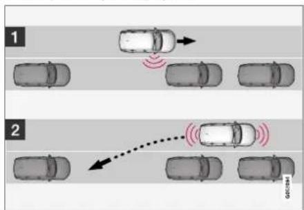
flowchart
graph TD
    A["Top Panel 1"] --> B["Top Panel 2"]
    B --> C["Top Panel 3"]
    C --> D["Top Panel 4"]
    D --> E["Top Panel 5"]
    style A fill:#f9f,stroke:#333
    style B fill:#ccf,stroke:#333
    style C fill:#cfc,stroke:#333
    style D fill:#fcc,stroke:#333
    style E fill:#ffc,stroke:#333
Parallel.
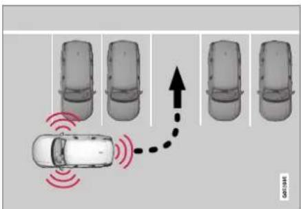
Perpendicular.
To back into a parking space:
-
Make sure the path behind your vehicle is clear and engage reverse gear.
-
Back up slowly and carefully without touching the steering wheel and do not exceed a speed of 7 km/h (4 mph).
- Be prepared to stop the vehicle when instructed to do so by a graphic and message in the center display.
NOTE
- Keep your hands away from the steering wheel when the PAP function is activated.
• Make sure that the steering wheel is not hindered in any way and can rotate freely. - To achieve the best results – wait until the steering wheel is finished turning before beginning to drive forward/in reverse.
DRIVER SUPPORT
Positioning the vehicle in the parking space
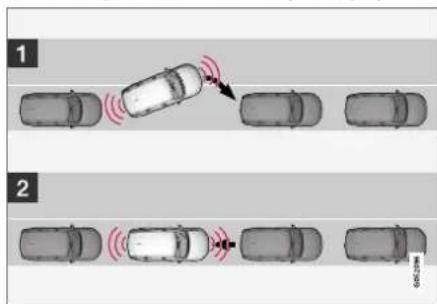
Parallel.

natural_image
Top-down view of a car with five vehicles and red signal waves indicating sensor or sensor coverage (no text or symbols)Perpendicular.
To do so:
-
Move the gear selector to D, wait until the steering wheel turns and then drive slowly forward.
-
Be prepared to stop the vehicle when instructed to do so by a graphic and message in the center display.
- Engage reverse gear and back up slowly.
- Be prepared to stop the vehicle when instructed to do so by a graphic and message in the center display.
The function will switch off automatically and a graphic and message will appear to indicate that parking has been completed. Adjustments can always be made be the driver afterward. Only the driver can determine when the vehicle is correctly parked.
! CAUTION
The warning distance is shorter when the sensors are used by PAP compared to when they are used by the Parking Assist system.
Related information
• Park Assist Pilot* (p. 406)
Leaving a parking space with Park Assist Pilot
The function Park Out can also help the driver to leave a parking space.
NOTE
Leaving a parking space with the Park Out function should only be used in connection with parallel parking – it does not work for perpendicular parking.
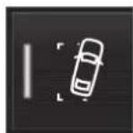
The Park Out function is activated in the center display's Function view or in Camera view.
To do so:
- Tap Park Out in Function view or in Camera view.
- Move the gear selector to the suitable position (e.g. D or R) for the direction in which you will be pulling out of the parking space.
- Be prepared to stop the vehicle when instructed to do so by a graphic and message in the center display. Follow the instructions in the same way as for the parking procedure.
Note that the steering wheel can "spring" back when the procedure is completed and the driver may need to turn the steering wheel back to the maximum position in order to pull out of the parking space.
If PAP determines that the driver can pull out of the parking space without any extra maneuvers, the function will be deactivated, even if it seems as though the vehicle is not completely out of the parking space.
Related information
• Park Assist Pilot* (p. 406)
Park Assist Pilot\* limitations
Park Assist Pilot PAP ^125 may not be able to detect all conditions in all situations and functionality may therefore be limited.
WARNING
- The PAP function is supplementary driver support intended to facilitate driving and help make it safer – it cannot handle all situations in all traffic, weather and road conditions.
- Pay particular attention to people and animals near the vehicle.
- Bear in mind that the front end of the vehicle may swing out towards oncoming traffic during the parking maneuver.
- Objects situated higher than the detection area of the sensors are not included when the parking maneuver is calculated, which could cause PAP to swing into the parking space too early. Such parking spaces should be avoided for this reason.
- PAP is not a substitute for the driver's attention and judgment. The driver is always responsible for ensuring the vehicle is driven in a safe manner, at the appropriate speed, with an appropriate distance to other vehicles, and in accordance with current traffic rules and regulations.
The driver should be aware of the following limitations for Park Assist Pilot:
DRIVER SUPPORT
The parking sequence is cancelled
A parking sequence will be cancelled if:
• the driver moves the steering wheel
• the vehicle's speed exceeds 7 km/h (4 mph)
• the driver taps Cancel in the center display
- when the anti-lock brakes or the Electronic stability control are engaged - e.g. when a wheel loses grip on a slippery road
- when the power steering works at reduced power - e.g. during cooling due to overheating (see section "Speed-dependent steering force").
A message in the center display will explain why the parking sequence was cancelled.
CAUTION
Under certain circumstances, PAP may not be able to find parking spaces – one reason may be that the sensors are disrupted by external sound sources that emit the same ultrasonic frequencies that the system works with.
Examples of such sources include horns, wet tires on asphalt, pneumatic brakes, exhaust noise from motorcycles, etc.
i NOTE
Dirt, ice and snow covering the sensors reduce their function and can make measurement impossible.
Driver responsibility
The driver should keep in mind that PAP is a parking aid – not an infallible fully automatic system. The driver must always be prepared to take control and cancel a parking sequence if necessary.
There are a number of things to keep in mind when parking, including:
- The driver is always responsible for determining if the space suggested by PAP is suitable for parking.
- Do not use PAP when using snow chains or a temporary spare tire.
- Do not use PAP if there are any objects protruding from the vehicle.
- Heavy rain or snowfall may inhibit PAP's ability to accurately measure a parking space.
- While searching and measuring the parking space, PAP may be unable to detect objects located far into the space.
-
PAP may not suggest parking spaces on narrow streets if it does not detect sufficient space for maneuvering the vehicle.
-
Use approved tires ^126 inflated to the correct tire pressure because this affects PAP's ability to provide parking assistance.
- PAP's function is based on the way the vehicles are parked behind and in front of your parking space. If they are, for example, parked too close to the curb, there is a risk that your vehicle's tires or wheel rims could be damaged by the curb during the parking procedure.
- Perpendicular parking spaces may not be detected or may be suggested unnecessarily if a parked vehicle is sticking out more than other parked vehicles.
- PAP is intended to provide parking assistance on straight streets, not sections of street with sharp curves or bends. Always make sure that your vehicle is parallel to relevant parking spaces when PAP is measuring the parking space.
CAUTION
Switching to another approved wheel and/or tire dimension could change the tire circumference, which would then require the PAP system to be updated. Consult a workshop – an authorized Volvo workshop is recommended.
DRIVER SUPPORT
Related information
• Park Assist Pilot* (p. 406)
• Parking with Park Assist Pilot (p. 408)
• Speed-dependent steering wheel resistance (p. 278)
Recommended maintenance for Park Assist Pilot
For Park Assist Pilot (PAP ^127 ) to function optimally, its sensors must be cleaned regularly with water and car washing detergent.

natural_image
Top-down view of a car with red circles highlighting the front and side edges (no text or symbols)Location of the Park Assist sensors ^128 .
NOTE
Dirt, ice and snow covering the sensors could cause false warnings, reduced function, or no function.
Related information
• Park Assist Pilot* (p. 406)
DRIVER SUPPORT
Park Assist Pilot\* messages
Messages for Park Assist Pilot PAP ^129 may be
displayed in the instrument panel and/or the
center display.
Some examples of symbols and messages are shown in the table below.
| Message Meaning | |
| Park Assist SystemSensors blocked, cleaning needed | One or more of the sensors are blocked. Check and clean/remove the obstacle as soon as possible. |
| Park Assist SystemUnavailable Service required | The system is not functioning as intended. Contact a workshop – an authorized Volvo workshop is recommended. |
A text message can be erased by briefly pressing
the ○ button in the center of the right-side
steering wheel keypad.
If the message persists: Contact a workshop – an
authorized Volvo workshop is recommended.
Related information
• Park Assist Pilot* (p. 406)
HYBRID INFORMATION
HYBRID INFORMATION
General information about Twin Engine
Twin Engine vehicles are driven just like any other vehicle, but certain functions differ from a vehicle powered exclusively by gasoline. The electric motor powers the vehicle primarily at low speeds; the gasoline engine is used at higher speeds or during more active driving.
The instrument panel displays Twin Engine-specific information - charging information, selected drive mode, distance to discharged battery and hybrid battery charge level.
Different drive modes can be selected while driving, e.g. electric power only or, if more power is needed, a combination of electric and gasoline power. The vehicle calculates the optimal combination of driveability, driving experience, environmental impact and fuel economy for the selected drive mode.
In order to function optimally, the hybrid battery (and its electrical drive systems) and the gasoline engine (and its drive systems) must be at the correct operating temperature. Battery capacity can be considerably reduced if the battery is too cold or too hot. Preconditioning prepares the vehicle's drive systems and passenger compartment before driving to help reduce both wear and energy consumption. It also helps increase the hybrid battery's range.
The hybrid battery which powers the electric motor is recharged using the charging cable. It
can also be recharged during light braking and through engine braking in gear position B. The combustion engine can also help recharge the hybrid battery.
Important
No electrical current
Keep in mind that if there is no electrical current to the vehicle, i.e. the ignition is switched off or the start battery is discharged, certain functions such as brakes, power steering, etc. will not work.
WARNING
If the vehicle does not have electrical current and both the electric motor and the gasoline engine are switched off, the brakes cannot be used to stop the vehicle.
Towing not permitted
Never tow a Twin Engine vehicle behind another vehicle, as this could damage the electric motor.
Exterior engine noise
WARNING
Please be aware that there is no sound from the engine when the vehicle is being powered by the electric motor and it may be difficult to detect by children, pedestrians, cyclists and animals. This is especially true at low speeds.
High-voltage electrical current

WARNING
A number of electrical components in Twin Engine Plug-in Hybrid vehicles use high-voltage current and can be extremely dangerous if handled incorrectly. These components and any orange wiring in the vehicle may only be handled by trained and qualified Volvo service technicians.
Do not touch anything that is not clearly described in this Owner's Manual.
Related information
• Charging the hybrid battery (p. 417)
• Hybrid gauge (p. 87)
- Drive modes (p. 454)
• Starting and stopping preconditioning (p. 233)
• Hybrid battery (p. 631)
• Factors affecting electric motor range (p. 469)
• Gear selector positions for automatic transmissions (p. 449)
• Towing using a towline (p. 487)
Charging the hybrid battery
In addition to the conventional fuel tank, your vehicle is also equipped with a rechargeable lithium-ion hybrid battery.

WARNING
California Proposition 65
Operating, servicing and maintaining a passenger vehicle can expose you to chemicals including engine exhaust, carbon monoxide, phthalates, and lead, which are known to the State of California to cause cancer and birth defects or other reproductive harm. To minimize exposure, avoid breathing exhaust, do not idle the engine except as necessary, service your vehicle in a well ventilated area and wear gloves or wash your hands frequently when servicing your vehicle. For more information go to www.P65Warnings.ca.gov/passenger-vehicle.
The hybrid battery can be recharged using the charging cable stored in a storage space in the cargo compartment.

WARNING
The hybrid electrical system in your vehicle uses high voltage electrical current. Any damage to this system or to the hybrid battery may result in the danger of overheating, fire, or serious injury. If the vehicle is involved in a collision or subjected to flooding, fire, etc., have it inspected by a trained and qualified Volvo service technician. Prior to this inspection, the vehicle should be parked outdoors at a safe distance from any building or potentially flammable materials.
The hybrid battery's charging time depends on the charging current used.

NOTE
The capacity of the hybrid battery diminishes somewhat with age and use, which could result in increased use of the gasoline engine and consequently, slightly higher fuel consumption.

WARNING
If the hybrid battery needs to be replaced, this may only be done by a Volvo retailer or authorized Volvo workshop.
▶▶
HYBRID INFORMATION
◀◀

natural_image
Side view of an electric vehicle with a plug inserted into the charging station, showing the charger's cable (no text or symbols visible)Charging cable handle and charging socket.
Charging status is indicated in three ways:
- The indicator lights in the charging module (the unit connected to the wall outlet).
- Indicator light in the vehicle's charging socket.
• Images and text in the instrument panel.
The start battery is charged while the hybrid battery is charging and stops charging when the hybrid battery is fully charged.
If the hybrid battery's temperature is below -10 °C (14 °F) or above 40 °C (104 °F), some of the vehicle's functions may be reduced or not available at all.
The electric motor cannot be used if the battery's temperature is too low or too high. If the PURE drive mode is selected, the gasoline engine will start.
Charging using the gasoline engine

The vehicle generates electrical current to charge the battery, e.g. when the driver lightly presses the brake pedal or when engine braking is used on downgrades.
The vehicle can also generate current to the hybrid battery to charge it.
- The hybrid battery can also be recharged by lightly depressing the brake pedal, i.e. during light braking. This converts the vehicle's kinetic energy to electrical energy, which is used to charge the hybrid battery.
- In gear position B, the electric motor brakes the vehicle when the accelerator pedal is released and the hybrid battery is recharged at the same time.
- The combustion engine can also help recharge the hybrid battery.
Related information
- Charge cable (p. 419)
• Charging current (p. 419) - Opening and closing the charging socket cover (p. 422)
• Initiating hybrid battery charging (p. 423)
• Stopping hybrid battery charging (p. 429) - Charging status in the charging cable's charging module (p. 425)
- Charging status in the vehicle's charging socket (p. 425)
- Charging status in the instrument panel (p. 427)
- Twin Engine symbols and messages in the instrument panel (p. 430)
- Gear selector positions for automatic transmissions (p. 449)
• Changing drive mode (p. 459) - Long-term storage of vehicles with hybrid batteries (p. 432)
Charging current
Charging current is used to charge the hybrid battery and precondition the vehicle. Charging is performed by connecting a charging cable between the vehicle's charging socket and a 120/240 V electrical socket (alternating current).
When the charging cable is activated, a message will be displayed in the instrument panel and an indicator light in the vehicle's charging socket will illuminate. Charging current is primarily used for battery charging, but is also used for preconditioning. The vehicle's start battery is charged along with the hybrid battery.

CAUTION
Never detach the charging cable from the 120/240 V outlet (AC, alternating current) while charging is in progress – the 120/240 V outlet could be damaged in such circumstances. Always interrupt charging first and then disconnect the charging cable – first from the vehicle's charging socket and then from the 120/240 V outlet.

NOTE
- In extremely cold or hot weather, part of the charging current is used to heat/cool the hybrid battery and the passenger compartment, resulting in a longer charging time.
- The charging time is longer if preconditioning has been selected. The time required depends primarily on the ambient temperature.
Fuse
There are normally several 120/240 V power consumers in one fuse circuit, which means that more than one power consumer (e.g. lighting, vacuum cleaner, electric drill, etc.) may use the same fuse.
Related information
- Charge cable (p. 419)
- Charging status in the instrument panel (p. 427)
- Charging status in the vehicle's charging socket (p. 425)
• Starting and stopping preconditioning (p. 233)
• Stopping hybrid battery charging (p. 429)
Charge cable
The charging cable is used to recharge your vehicle's hybrid battery.

natural_image
Top-down view of an electric vehicle charging plug inside a car cab, with no visible text or symbols.The charging cable is stored in a storage compartment under the cargo compartment floor.

WARNING
Only use the charging cable provided with your vehicle or a replacement cable purchased from a Volvo retailer.
| Specifications, charging cable | |
| Compliance SAE J17 | 72 |
| Ambient temperature | -32 °C to 50 °C (-25 °F till 122 °F) |

WARNING
- The charging cable must be grounded when in use. It is equipped with a cord with a grounding conductor and a grounding plug. The plug must be inserted into an appropriate outlet that is properly installed and grounded in accordance with all local codes and ordinances and is not damaged in any way.
• Children should be supervised when in the vicinity of the charging cable when it is plugged in. - High voltage is present in your electric meter housing and power distribution service panel. Contact with high voltage can cause death or serious personal injury.
- Do not use the charging cable if it is damaged in any way. A damaged or malfunctioning charging cable may only be repaired by a workshop – an authorized Volvo workshop is recommended.
- Always position the charging cable so that it will not be driven over, stepped on, tripped over or otherwise damaged, or cause personal injury.
- Disconnect the charger from the wall outlet before cleaning it.
- Never connect the charging cable to an extension cord or a multiple plug socket. Also, refer to the manufacturer's instructions for using the charging cable and its components.
CAUTION
Power strips, extension cords, surge protectors or similar devices must not be used together with the charging cable since this may involve a risk of fire, electric shocks, etc.
An adapter may not be used between the 120/240 V outlet (AC, alternating current) and the charging cable.
! CAUTION
Never detach the charging cable from the 120/240 V outlet (AC, alternating current) while charging is in progress – the 120/240 V outlet could be damaged in such circumstances. Always interrupt charging first and then disconnect the charging cable – first from the vehicle's charging socket and then from the 120/240 V outlet.
CAUTION
Wipe the charging cable with a clean cloth lightly moistened with water or a mild detergent. Do not use chemicals or solvents.
The charging cable and its components must not be rinsed or immersed in water.
CAUTION
Avoid exposing the charging module and its plug to direct sunlight. In such cases, the overheating protection in the plug could reduce or cut off charging of the hybrid battery.
Charging cable components


Charge module
240 V adapter clip
3 240 V adapter
4 Charge coupler
5 Release button
Related information
- Charging cable residual current device (p. 421)
- Charging cable temperature monitoring (p. 422)
• Charging the hybrid battery (p. 417) - Charging status in the charging cable's charging module (p. 425)
Charging cable residual current device
The charging cable has a circuit breaker that helps protect against current overloads and thermal overheating.
WARNING
Charging the hybrid battery may only be done from approved, grounded 120/240 V outlets (AC, alternating current). If the electrical circuit or electrical socket's capacity is not known, let a licensed electrician inspect the electrical circuit's capacity. Using a charge level that exceeds the electrical circuit's or electrical outlet's capacity may start a fire or damage the electrical circuit.
WARNING
- The charging cable's residual current breaker helps protect the vehicle's charging system but cannot ensure that an current overload will never occur.
- Never use visibly worn or damaged electrical sockets. Doing so could lead to fires or serious injury.
- Never connect the charging cable to an extension cord.
- Maintenance or replacement of the hybrid battery may only be performed by a trained and qualified Volvo service technician.
If the charging cable's residual current device is triggered, the blue indicator light in the charging module will not illuminate when the charging cable is plugged into an electrical outlet (or the red warning light will glow steadily). Have the outlet checked by a licensed electrician or try using another wall outlet.
Related information
- Charge cable (p. 419)
- Charging status in the charging cable's charging module (p. 425)
HYBRID INFORMATION
Charging cable temperature monitoring
To help ensure the vehicle's hybrid battery is reliably charged each time it is connected, charging is stopped if the temperature in the charging cable becomes too high and reaches a critical limit.

CAUTION
If charging is often inadvertently interrupted, have the charging cable and the vehicle's charging system inspected by a trained and qualified Volvo service technician.
Related information
- Charge cable (p. 419)
Opening and closing the charging socket cover
The cover for the hybrid battery's charging socket opens manually.
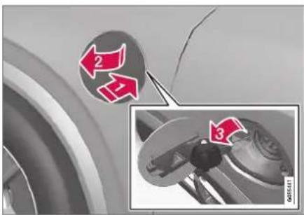
Unlock the vehicle using the remote key.

Press in the rear edge of the charger door and release.

Open the door.

Remove the charging socket's protective cover and secure it in the holder on the inside of the charger door. Make sure the cover's rubber stopper is bent downward to prevent the cover from falling out of the holder.

CAUTION
Make sure the charging socket's protective cover is positioned so it does not damage the paint (in e.g., windy conditions).
Perform the following steps in reverse to close the charger door.

NOTE
Since the hatch is locked during driving, the vehicle must be unlocked again to be able to open the hatch.
Related information
• Initiating hybrid battery charging (p. 423)
• Stopping hybrid battery charging (p. 429)
• Charging the hybrid battery (p. 417)
Initiating hybrid battery charging
The hybrid battery is charged by connecting a charging cable between the vehicle and a 120/240 V outlet (alternating current).
Only use the charging cable supplied with the car or a replacement cable recommended by Volvo.

CAUTION
Never connect the charging cable if there is a risk of a thunderstorm or there is lightning.

WARNING
- The charging cable must be grounded when in use. It is equipped with a cord with a grounding conductor and a grounding plug. The plug must be inserted into an appropriate outlet that is properly installed and grounded in accordance with all local codes and ordinances and is not damaged in any way.
- Children should be supervised when in the vicinity of the charging cable when it is plugged in.
- High voltage is present in your electric meter housing and power distribution service panel. Contact with high voltage can cause death or serious personal injury.
- Do not use the charging cable if it is damaged in any way. A damaged or malfunctioning charging cable may only be repaired by a workshop – an authorized Volvo workshop is recommended.
- Always position the charging cable so that it will not be driven over, stepped on, tripped over or otherwise damaged, or cause personal injury.
- Disconnect the charger from the wall outlet before cleaning it.
- Never connect the charging cable to an extension cord or a multiple plug socket. Also, refer to the manufacturer's instructions for using the charging cable and its components.

CAUTION
Make sure that the 120/240 V outlet (AC, alternating current) has a power capacity sufficient for charging electric vehicles. If you are uncertain of the capacity, have the outlet checked by a licensed electrician.
Take out the charging cable from the storage compartment under the cargo area. Note that the ignition must be switched off completely before charging.


Plug the charging cable into a 120/240 V outlet. Never use an extension cord.
HYBRID INFORMATION
◀◀

natural_image
Close-up of a car's electrical plug with a red arrow pointing to the wheel (no text or symbols visible)2 Open the charger door and remove the charging socket's protective cover. Push the charging handle all the way into the vehicle's socket.
- The charging cable handle will lock into place and charging will begin within 5 seconds. When charging starts, the green LED light in the charging socket will begin to flash. The approximate remaining charging time or the charging status will be displayed in the instrument panel.
Charging may be temporarily interrupted if the vehicle is unlocked:
- and a door is open – charging will restart within a few minutes.
- if no door is opened – the vehicle will automatically relock. Charging will resume after 1 minute.
! CAUTION
Never detach the charging cable from the 120/240 V outlet (AC, alternating current) while charging is in progress – the 120/240 V outlet could be damaged in such circumstances. Always interrupt charging first and then disconnect the charging cable – first from the vehicle's charging socket and then from the 120/240 V outlet.
During charging, condensation from the air conditioning may form under the vehicle. This is normal and is caused by the hybrid battery cooling.
Related information
• Charging the hybrid battery (p. 417)
- Opening and closing the charging socket cover (p. 422)
- Charging status in the vehicle's charging socket (p. 425)
- Charging status in the instrument panel (p. 427)
- Charging status in the charging cable's charging module (p. 425)
• Stopping hybrid battery charging (p. 429)
Charging status in the vehicle's charging socket
The charging status is indicated by an LED light in the charging socket.

natural_image
Mechanical component diagram showing a rotating fan and housing with a red arrow indicating a specific part (no text or symbols present)Location of the LED indicator light in the vehicle's charging socket.
The LED indicator light shows the current charge status during charging. If the LED indicator light is not illuminated, check to make sure the cable is securely connected in the wall outlet and in the outlet in the vehicle. A white, red or yellow light illuminates when the passenger compartment lighting is activated and will remain illuminated for a short time after the passenger compartment lighting has gone out.
| LED indicator light's color | Meaning |
| White Courtesy light. | |
| Yellow | Wait modeA - waiting for charging to start. |
| Flashing green | Charging is in progressB. |
| Green | Charging completedC. |
| Red Malfunction. | |
A E.g. after a door has been opened or if the charging cable handle is not locked in place.
B The more slowly the light flashes, the closer the battery is to being fully charged.
C The light will go out after a short time.
Related information
• Charging the hybrid battery (p. 417)
- Charging status in the instrument panel (p. 427)
- Charging status in the charging cable's charging module (p. 425)
• Stopping hybrid battery charging (p. 429)
Charging status in the charging cable's charging module
The red and blue lights in the charging module indicate the status of ongoing and completed charging.

Charge module: 1. Red warning light, 2. Blue status indicator
When the charge module is initially plugged into a wall outlet, the red warning light will flash once to indicate that a startup safety check has been performed. When the safety check has been completed, the blue status indicator will glow steadily and the red warning light will be off. The charger is now ready to be used. If the red warning light continues to flash or glows steadily, a fault has been detected and the charger will not deliver power to the vehicle. Contact a Volvo retailer or a certified Volvo service technician.
HYBRID INFORMATION
When the charging cable is connected to the vehicle's charging socket, the blue light will flash once.
Charging cable connected to the vehicle's charging socket:
| Indicator light's color | Meaning |
| Flashing blue | Charging is in progress. The light flashes about once every other second |
| Solid blue Charging | Completed. This will also be indicated in the instrument panel |
Related information
• Charging the hybrid battery (p. 417)
- Charging status in the vehicle's charging socket (p. 425)
- Charging status in the instrument panel (p. 427)
• Stopping hybrid battery charging (p. 429)
Charging status in the instrument panel
information is displayed as long as the instrument panel is active.
Charging status is indicated in the instrument panel using both graphics and messages. This
| Graphic Message | Meaning | |
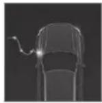 | Fully charged at: [Time] displayed along with an animated blue pulsing light through the charging cable. | Charging is in progress and the approximate time at which the battery will be fully charged is displayed. |
 | Charging complete is displayed. An image will be superimposed over the graphic of the vehicle with a green LED indicator light in the socket. | The battery is fully charged. |
 | Charging error will be displayed. The LED indicator light in the charging socket will be red. | Malfunction. Make sure the charging cable is correctly connected to the vehicle's charging socket and to the 120/240 V outlet (alternating current). |
HYBRID INFORMATION

NOTE
If the instrument panel is not used, it will go dark after a period of time. To reactivate the display:
• depress the brake pedal,
• open one of the doors, or
- put the ignition in mode I by turning the START knob clockwise and then releasing.
Related information
• Charging the hybrid battery (p. 417)
- Twin Engine symbols and messages in the instrument panel (p. 430)
- Charging status in the vehicle's charging socket (p. 425)
- Charging status in the charging cable's charging module (p. 425)
• Stopping hybrid battery charging (p. 429)
Stopping hybrid battery charging
To stop charging of the hybrid battery, unlock the vehicle, unplug the charging cable from the vehicle's charging socket and then unplug the cable from the 120/240 V outlet (alternating current).

CAUTION
Before the charging cable is removed from the vehicle's charging socket, the vehicle must be unlocked using the unlock button on the remote key. This must be done even if the vehicle's doors are already unlocked. If the vehicle is not unlocked using the unlock button, the charging cable or system may be damaged.

NOTE
Always unlock the vehicle so that charging is cut off before the connection to the 120/240 V outlet (AC, alternating current) is disconnected. Note that the charging cable must be disconnected from the vehicle's charging socket before it is disconnected from the 120/240 V outlet, partly to prevent damage to the system and party to prevent unintentional interruption of charging.


Unlock the vehicle with the remote key. Charging will stop.
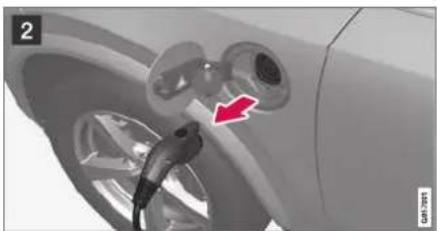
natural_image
Close-up of a car's electrical plug with a red arrow pointing to the plug (no text or symbols visible)
Press the lock button on the charging cable's handle. The handle will be released/unlocked. Remove the cable from the vehicle's charging socket, put the socket's cover back in place and close the charger door.


Unplug the cable from the 120/240 V outlet. Stow the charging cable in the storage compartment under the cargo area floor.
Charging cable automatically locks
If the charging cable cannot be removed from the charging socket, it will automatically lock into place again after unlocking to maximize charging and range and to enable preconditioning before driving. The charging cable can be removed again if the vehicle is unlocked using the remote key. For vehicles with Passive Entry*, the handle can be used to lock and unlock.
Related information
- Opening and closing the charging socket cover (p. 422)
- Charge cable (p. 419)
• Charging the hybrid battery (p. 417)
• Initiating hybrid battery charging (p. 423)
HYBRID INFORMATION
Twin Engine symbols and messages in the instrument panel
A number of symbols and messages relating to the Twin Engine may be displayed in the instru-
ment panel. They may also appear in combination with general indicator and warning symbols and disappear when the necessary action has been taken.
| Symbol | Message Meaning | |
 | 12 V BatteryCharging fault, service urgent. Drive to workshop | Battery fault. Contact a workshop ^ to have the battery checked as soon as possible. |
 | 12 V BatteryCharging fault Stop safely | Battery fault. Stop the vehicle as soon as possible and contact a workshop ^ to have the battery checked. |
 | 12 V BatteryFuse failure Service required | Battery fault. Contact a workshop ^ to have the system checked as soon as possible. |
 | Hybrid batteryOverheated, stop safely | The hybrid battery's temperature seems to be rising at an abnormal rate. Stop the vehicle and turn off the engine. Wait at least 5 minutes before driving. Call a workshop ^ or inspect the vehicle to make sure everything seems normal before continuing to drive. |
 | Reduced performanceMax vehicle speed limited | The hybrid battery's charge level is too low for driving at high speeds. Charge the battery as soon as possible. |
 | Hybrid systemHarsh behavior at low speed, vehicle ok to use | The hybrid system is not functioning properly. Contact a workshop ^ to have the system checked as soon as possible. |
 | Hybrid system failureService required | The hybrid system is not functioning. Contact a workshop ^A to have the system checked as soon as possible. |
 | Charge cableRemove before start | Displayed when the driver attempts to start the vehicle with the charging cable still connected.Remove the charging cable and close the charger cover. |
 | Charge cableRemoved? Turn and hold start knob 7s | Displayed when the driver again attempts to start the vehicle with the charging cable connected.Disconnect the charging cable or verify that the cable is completely disconnected and the charger cover is closed. |
A An authorized Volvo workshop is recommended.
Related information
- Initiating hybrid battery charging (p. 423)
• Stopping hybrid battery charging (p. 429)
• Charging the hybrid battery (p. 417) - Warning symbols in the instrument panel (p. 97)
- Indicator symbols in the instrument panel (p. 94)
• Hybrid gauge (p. 87)
• Hybrid gauge (p. 88)
HYBRID INFORMATION
Long-term storage of vehicles with hybrid batteries
To help minimize degradation of the hybrid battery if the vehicle is not driven for a prolonged period (longer than 1 month) the hybrid battery charge level should be kept at approx. 25% according to the gauge in the instrument panel.
Do as follows:

-
If the hybrid battery charge level is high, drive the vehicle until the charge level is approximately 25%. If the charge level is low, charge the battery until the level reaches approximately 25%.
-
If the vehicle is not driven for more than 6 months or the hybrid battery's charge level is noticeably below the 25% mark, charge the battery to about 25% to help compensate for the natural battery discharge that occurs in long-term storage. Regularly check the charge level using the gauge in the instrument display.
NOTE
Store the vehicle in as cool a location as possible to minimize battery aging during long-term storage. In the summer, park the vehicle indoors or in a shady location, whichever is cooler.
Related information
• Initiating hybrid battery charging (p. 423)
• Hybrid gauge (p. 88)
• Charging the hybrid battery (p. 417)
STARTING AND DRIVING
STARTING AND DRIVING
Starting the vehicle
The vehicle can be started using the start knob in the tunnel console when the remote key is in the passenger compartment.

natural_image
Close-up of a car dashboard with control buttons and a digital display (no visible text or symbols)Start knob in the tunnel console.

WARNING
Before starting:
- Buckle your seat belt.
- Adjust the seat, steering wheel and mirrors.
- Make sure you can fully depress the brake pedal.
The remote key is not physically used to start the ignition because the vehicle is equipped with the keyless Passive Start system.
To start the vehicle:
- The remote key must be inside the vehicle. For vehicles with Passive Start, the key must be in the front section of the passenger compartment. With the optional keyless locking/unlocking function*, the key can be anywhere in the vehicle.
- Press and hold down the brake pedal ^1 as far as possible.
- Turn the start knob clockwise and release. The control will automatically return to the original position.

WARNING
- Never use more than one inlay mat at a time on the driver's floor. If any other type of floor mat is used, remove the original mat from the driver's seat floor before driving. All types of mats must be securely anchored in the attachment points in the floor. Make sure the floor mat does not impede the movement of the brake pedal or accelerator pedal in any way, as this could be a serious safety hazard.
- Volvo's floor mats are specially manufactured for your vehicle. They must be properly secured in the attachment points in the floor to help ensure they cannot slide and become trapped under the pedals.
The starter motor will crank until the engine starts or until overheating protection is triggered.
During normal start conditions, the vehicle's electric motor will be prioritized and the gasoline engine will remain off. This means that once the start knob is turned clockwise, the electric motor has been "started" and the vehicle is ready to be driven. The warning and information symbols in the instrument panel will go out and the selected theme will be displayed to indicate that the electric motor is activated.
In some situations, such as in cold weather or if the hybrid battery's charge level is too low, the gasoline engine will start instead.
The vehicle should not be started with the charging cable connected. However, if the cable cannot be pulled out or if the vehicle incorrectly detects a cable that is not connected, the vehicle can be started using an override procedure:
- Press the brake pedal and turn the start knob clockwise.
- Charge cable Remove before start will appear in the instrument panel.
- Turn the start knob clockwise again.
- Removed? Turn and hold start knob 7s will appear. Turn the knob clockwise and hold it for 7 seconds to start the vehicle.

Location of the backup reader in the tunnel console,
If the Vehicle key not found message is shown in the instrument panel at start, place the remote key at the backup reader and then make a new start attempt.
NOTE
When the remote key is placed in the backup reader, make sure that no other vehicle keys, metal objects or electronic devices (e.g. cellular phones, tablets, laptops or chargers) are in the backup reader. Multiple vehicle keys close to each other in the backup reader can disrupt their functionality.
If Vehicle start System check, wait is displayed in the instrument panel while attempting to start the vehicle, wait until the message disappears and try again to start the vehicle.
! CAUTION
If the engine has not responded after 3 attempts – wait for 3 minutes before starting a new attempt. Starting capability increases if the starter battery is given time to recover.
NOTE
The vehicle cannot be started if the hybrid battery is discharged.
WARNING
Never remove the remote control key from the vehicle while driving.
WARNING
- Always remove the remote key from the passenger compartment when you leave the vehicle and make sure the ignition is in mode 0.
- Always put the gear selector in P and apply the parking brake before leaving the vehicle. Never leave the vehicle unsupervised while the engine is running.
- Always open the garage door fully and make sure that ventilation is very good before starting the engine in a garage. The exhaust fumes produced by the vehicle contain carbon monoxide, which is invisible and odorless but very toxic.
NOTE
With a cold start, idling speed may be considerably higher than normal for certain engine types. This is done to get the emissions system up to normal operating temperature as quickly as possible, which minimizes exhaust emissions and protects the environment.
! CAUTION
- When starting in cold weather, the automatic transmission may shift up at slightly higher engine speeds than normal until the automatic transmission fluid reaches normal operating temperature.
- Do not race a cold engine immediately after starting. This could prevent fluids from properly lubricating vital components in the engine before it has reached the proper operating temperature.
- The engine should be idling when the gear selector is moved. Never accelerate until the gear is fully engaged. Accelerating rapidly before a gear is properly engaged could lead to harder wear of components.
- To help prevent the transmission oil from overheating, select P or N when idling at a standstill for prolonged periods of time.
Related information
• Switching off the vehicle (p. 436)
- Ignition modes (p. 437)
• Adjusting the steering wheel (p. 201)
- Jump starting using another battery (p. 481)
- Selecting ignition mode (p. 438)
Switching off the vehicle
The vehicle can be switched off using the start knob in the tunnel console.
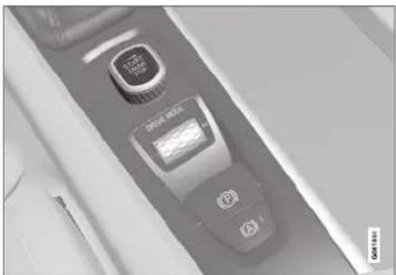
natural_image
Close-up of a car interior panel with two digital displays and control buttons (no visible text or symbols)Start knob in the tunnel console.
To switch off the vehicle:
- Turn the start knob clockwise and release to switch off the vehicle. The control will automatically return to the original position.
If the vehicle rolls:
- Turn clockwise and hold the knob until the vehicle switches off.
Related information
• Starting the vehicle (p. 434)
- Ignition modes (p. 437)
• Adjusting the steering wheel (p. 201)
• Jump starting using another battery (p. 481)
• Selecting ignition mode (p. 438)
Ignition modes
The vehicle's ignition can be put in various modes (levels) to make different functions available.
To enable the use of a limited number of functions when the engine is not running, the ignition can be put in one of three different levels: 0, I and II. These levels are referred to as "ignition modes" in the Owner's Manual.
The following table shows which functions are available in each ignition mode:
| Mode | Functions |
| 0 | The odometer, clock and temperature gauge are illuminatedA.The power* seals can be adjusted.The power windows can be used.The center display is activated and can be usedA.The infotainment system can be usedA.In this mode, the functions are available for a limited time and then switch off automatically. |
| 1 | The panoramic roof, power windows, 12-volt electrical socket in the passenger compartment, Bluetooth, navigation, phone, blower and windshield wipers can be used.The power seals can be adjusted.The 12-volt electrical socket* in the cargo compartment can be used.Electrical current will be taken from the battery in this ignition mode. |
| Mode Functions | |
| II | The headlights illuminate.Warning/indicator lights illuminate for 5 seconds.A number of other systems are activated. However, seat and rear window heating can only be activated when the engine is running.This ignition mode uses a lot of current from the battery and should be avoided whenever possible! |
A Also activated when the door is opened.
Related information
• Starting the vehicle (p. 434)
• Adjusting the steering wheel (p. 201)
- Jump starting using another battery (p. 481)
• Selecting ignition mode (p. 438)
STARTING AND DRIVING
Selecting ignition mode
The vehicle's ignition can be put in various modes (levels) to make different functions available.
Selecting an ignition mode

natural_image
Close-up of a digital camera control panel with buttons and display (no readable text or symbols)Start knob in the tunnel console,
- Ignition mode 0 - Unlock the vehicle and keep the remote key in the passenger compartment.
NOTE
To set level I or II without engine start - do not depress the brake pedal (or clutch pedal for vehicles with manual transmission) when selecting this ignition mode.
- Ignition mode I - Turn the start knob clockwise and release it. The control will automatically return to the original position.
- Ignition mode II - Turn the start knob clockwise and hold it there for approx. 5 seconds. Release the knob, which will automatically return to its original position.
- Back to ignition mode 0 - To return to ignition mode 0 from mode I and II, turn the start knob clockwise and release it. The control will automatically return to the original position.
Related information
• Starting the vehicle (p. 434)
• Switching off the vehicle (p. 436)
- Ignition modes (p. 437)
• Adjusting the steering wheel (p. 201)
- Jump starting using another battery (p. 481)
Brake functions
The vehicle's brakes are used to reduce speed or prevent the vehicle from rolling.
In addition to the wheel brakes and parking brakes, the vehicle is also equipped with a number of automatic brake assist functions. These systems help the driver by e.g. keeping the vehicle stationary when the brake pedal is not depressed (e.g. at a traffic light or intersection), when starting up a hill or when driving down a hill.
Depending on how the vehicle is equipped, the following brake assist functions may be included:
• Auto-hold brakes (Auto Hold)
• Hill Start Assist (Hill Start Assist)
• Braking assist after a collision
- City Safety
• Hill Descent Control (Hill Descent Control)
Related information
- Brakes (p. 439)
- Parking brake (p. 442)
• Auto-hold brakes (p. 446)
• Braking assist after a collision (p. 447)
• Hill Start Assist (p. 447)
• City Safety™ (p. 341)
• Hill Descent Control (p. 466)
Brakes
The brake pedal is used to apply the vehicle's regular brakes, which are part of the brake system.
The vehicle is equipped with two brake circuits. If one brake circuit is damaged, the brake pedal will go down further when depressed. More pressure will then be required from the driver for normal braking effect.

WARNING
The power brakes only work when the electric motor or combustion engine is running.
If the brake pedal is used when the engine is switched off, greater pressure must be applied to brake the vehicle.
In very hilly areas or when driving with a heavy load, gear position B can be used to augment the brakes with engine braking.
Use the Off Road drive mode to increase the engine braking effect when driving on steep downgrades at low speeds.
Anti-lock brakes
The vehicle is equipped with an Anti-lock Braking System (ABS), which helps prevent the wheels from locking and helps maintain steering control when braking. Vibrations may be felt from the
brake pedal when ABS is operating, which is normal.
After the vehicle is started, a brief test of the ABS system is automatically performed when the driver releases the brake pedal. An additional automatic test of the system may be performed when the vehicle is traveling at a low speed. During the test, the brake pedal may feel as though it is pulsating.
Light braking charges the hybrid battery
When the brakes are applied lightly, the electric motor braking function is used. This converts the vehicle's kinetic energy into electrical energy, which is used to charge the hybrid battery. When the battery is being charged with the electric motor braking function, this will be indicated in the instrument panel.
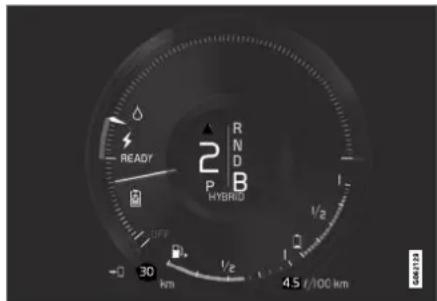
When the battery is being charged with the electric motor braking function, this will be indicated in the instrument panel.
This function is active at speeds in the range of 150-5 km/h (93-3 mph). When braking at speeds outside of this range, or during harder braking, the hydraulic braking system is used to augment braking. This is indicated in the instrument panel with the pointer down in the red area.
Symbols in the instrument panel
| Symbol Meaning | |
 | Check the brake fluid level. If the level is low, fill brake fluid and check to determine the reason for the loss of brake fluid. |
| A | |
| BRAKE | |
| B | |
| Fault in pedal sensor. | |
| A | |
| BRAKE | |
| B | |


A In Canada.
B In the US.
WARNING
If the warning symbols for both brake fault and ABS fault are lit simultaneously, there may be a fault in the brake system.
- If the brake fluid reservoir level is normal when this occurs, drive carefully to the nearest workshop to have the brake system checked - an authorized Volvo workshop is recommended.
- If the brake fluid has fallen below the MIN level in the brake fluid reservoir, the vehicle should not be driven until the brake fluid has been filled. The reason for the brake fluid loss must be checked.
Related information
- Brake Assist System (p. 441)
• Auto-hold brakes (p. 446)
• Hill Start Assist (p. 447)
• Braking on wet roads (p. 441)
• Braking on salted roads (p. 441)
• Maintenance of the brake system (p. 442) - Brake lights (p. 160)
Brake Assist System
The brake enhancing system, Brake Assist System (BAS), helps increase braking force and thereby reduce braking distance.
The system monitors the driver's braking habits and increases braking force when necessary. Braking force can be increased up to the point at which the ABS intervenes. The function is deactivated when pressure on the brake pedal is decreased.
Related information
- Brakes (p. 439)
Braking on wet roads
Prolonged driving in heavy rain without braking may cause braking effect to be slightly delayed the first time the brakes are applied.
This may also occur after washing the vehicle. It will then be necessary to apply greater pressure to the brake pedal. You should therefore maintain a greater distance to the vehicle ahead.
Firmly apply the brakes after washing the vehicle or driving on wet roads. This helps warm up the brake discs, enabling them to dry more quickly and protecting them against corrosion. Consider the current traffic situation when braking.
Related information
- Brakes (p. 439)
• Braking on salted roads (p. 441)
Braking on salted roads
When driving on salted roads, a layer of salt may form on the brake discs and brake pads.
This could increase stopping distance. Maintain an extra large safety distance to the vehicle ahead. Make sure to also:
- Apply the brakes from time to time to help remove salt. Make sure braking does not pose a risk to any other road users.
- Gently apply the brakes when you have finished driving and before driving again.
Related information
- Brakes (p. 439)
• Braking on wet roads (p. 441)
STARTING AND DRIVING
Maintenance of the brake system
Regularly check the brake system components for wear.
To keep the vehicle as safe and reliable as possible, follow the Volvo service schedule specified in the Warranty and Maintenance Records Information booklet. New and replaced brake pads and brake discs do not provide optimal braking effect until they are "broken in" by driving a few hundred kilometers (miles). Compensate for the reduced braking effect by applying greater pressure to the brake pedal. Volvo recommends only using brake pads approved for your Volvo.

CAUTION
The brake system's components should be regularly checked for wear.
Contact a workshop for advice on how to do this or let a workshop perform the inspection - an authorized Volvo workshop is recommended.
Related information
- Brakes (p. 439)
Parking brake
The parking brake helps keep the vehicle stationary by mechanically locking two wheels.

natural_image
Close-up of a car control panel with buttons and a central display (no visible text or symbols)The parking brake controls are located in the tunnel console between the seats.
When the electric parking brake is being applied, a faint sound can be heard from the brake's electric motor. This sound can also be heard during the automatic function check of the parking brake.
If the vehicle is stationary when the parking brake is applied, it will only be applied to the rear wheels. If it is applied while the vehicle is moving, the normal brakes will be used on all four wheels. Braking will be transferred to only the rear wheels when the vehicle is almost stopped.
Related information
- Activating and deactivating the parking brake (p. 443)
- Parking on a hill (p. 444)
• Parking brake malfunction (p. 445)
• Auto-hold brakes (p. 446)
Activating and deactivating the parking brake
Use the parking brake to help keep the vehicle stationary when it is parked.
Activating the parking brake

- Pull up the control.
The symbol in the instrument panel will illuminate when the parking brake is activated.
- Make sure the vehicle is stationary.
Symbol in the instrument panel
Symbol Meaning

A
The symbol will be illuminated when the parking brake is activated.

日
A flashing symbol indicates that a fault has been detected. Read the message in the instrument panel.
A In Canada. B In the US.
Automatic activation
The parking brake is applied automatically:
- when the ignition is switched off and the setting for automatically activating the parking brake is activated in the center display.
- if the Auto-hold function (automatic brake application when the vehicle is stationary) is activated and the vehicle has been stationary for a prolonged period of time (5-10 minutes).
- when the gear selector is moved to P on a steep hill.
Emergency braking
In an emergency, the parking brake can be activated when the vehicle is moving by pulling and
holding up the control. The braking process is canceled when the control is released or if the accelerator pedal is depressed.
NOTE
In case of emergency braking at high speeds, a signal sounds during the brake procedure.
Deactivating the parking brake

Deactivating manually
- Depress the brake pedal firmly.
- Press the control.
The parking brake will release and the symbol in the instrument panel will go out.
▶▶
STARTING AND DRIVING
Deactivating automatically
- Fasten your seat belt.
- Depress the brake pedal firmly.
- Start the vehicle.
- Move the gear selector to D or R and press the accelerator pedal.
The parking brake will release and the symbol in the instrument panel will go out.

NOTE
When the vehicle is initially started, the parking brake could disengage automatically even if the driver's seat belt is not buckled.
Related information
- Settings for automatically activating the parking brake (p. 444)
• Parking brake malfunction (p. 445) - Parking brake (p. 442)
- Parking on a hill (p. 444)
Settings for automatically activating the parking brake
Choose whether the parking brake should be activated automatically when the vehicle is switched off.
This selection is made in the Settings menu in the center display.
- Tap Settings in the Top view.
- Tap My Car Parking Brake and Suspension and select or deselect the Auto Activate Parking Brake function.
Related information
- Activating and deactivating the parking brake (p. 443)
- Parking brake (p. 442)
Parking on a hill
Always use the parking brake when parking on a hill.

WARNING
Always apply the parking brake when parking on an incline. Selecting a gear or putting the automatic transmission in P may not be sufficient to keep the vehicle stationary in all situations.
If the vehicle is pointing uphill:
- Turn the front wheels so they are pointing away from the curb.
If the vehicle is pointing downhill: - Turn the front wheels so they are pointing toward the curb.
Heavy load uphill
Heavy loads, such as a trailer, could cause the vehicle to roll backward when the parking brake is released automatically on steep uphill gradients. To help avoid this, pull the control upward while you are driving away. Release the control when the vehicle gains traction.
Related information
- Activating and deactivating the parking brake (p. 443)
Parking brake malfunction
If you are unable to deactivate or activate the parking brake after several attempts, contact an authorized Volvo workshop.
A audible warning signal will sound if the parking brake is applied while the vehicle is being driven. If the vehicle must be parked before the problem is rectified, turn the wheels as when parking on an incline and put the gear selector in P.
Low battery charge level
If the battery charge level is too low, it will not be possible to apply or release the parking brake. Connect an auxiliary battery to the vehicle if the battery is discharged.
Replacing brake pads
Due to the design of the electric parking brake, the rear brake pads must be replaced by a workshop. An authorized Volvo workshop is recommended.
Symbols in the instrument panel
| Symbol | Meaning |
 | A flashing symbol indicates that a fault has been detected. See the message in the instrument panel. |
| A | |
 | |
| B | |
 | Fault in the brake system. See the message in the instrument panel. |
| A | |
 | |
| B | |
 | Information message in the instrument panel. |
A In Canada. B In the US.
Related information
- Activating and deactivating the parking brake (p. 443)
- Start battery (p. 627)
• Volvo's service program (p. 610)
STARTING AND DRIVING
Auto-hold brakes
With the Auto-hold brake function, the driver can release the brake pedal and the brakes will remain applied, for example, when the vehicle has stopped at a traffic light or intersection.
When the vehicle stops, the brakes are activated automatically. The function can use either the normal brakes or the parking brakes to keep the vehicle stationary and works on flat surfaces or hills. When driving off, the brakes will be automatically released if the driver's seat belt is buckled.

NOTE
When braking to a stop on an uphill or downhill gradient, depress the brake pedal with slightly more force than usual before releasing to ensure that the vehicle cannot move at all.
The parking brake is activated if:
• the vehicle is switched off
• the driver's door is opened
• the driver's seat belt is removed
• the vehicle has been stationary for a prolonged period of time (5-10 minutes)
Symbols in the instrument panel
Symbol Meaning

This symbol illuminates when the function is using the normal brakes to keep the vehicle stationary.

This symbol illuminates when the function is using the parking brake to keep the vehicle stationary.

A Canadian models. B US models.
Related information
- Activating and deactivating Auto-hold at a standstill (p. 446)
- Brakes (p. 439)
- Parking brake (p. 442)
• Hill Start Assist (p. 447)
Activating and deactivating Auto- hold at a standstill
The Auto-hold brake function at a standstill is activated with the button in the tunnel console.

natural_image
Close-up of a car's side panel with a 'DRIVE LOAD' button and control buttons (no readable text beyond basic labels)- Press the button in the tunnel console to activate or deactivate the function.
The indicator light in the button will illuminate when the function is activated. The function will remain active the next time the vehicle is started.
When shutting off

If the function is active and holding the vehicle stationary using the normal brakes (A symbol lit), the brake pedal must be depressed while pressing the
button in order to deactivate Auto-hold.
- The function will remain off until it is reactivated.
- When Auto-hold is switched off, Hill Start Assist (HSA) will remain active to help prevent the vehicle from rolling backward when starting up a hill.
Related information
• Auto-hold brakes (p. 446)
Hill Start Assist
The function for assisting when starting the vehicle on inclines, Hill Start Assist (HSA), helps prevent the vehicle from rolling backward when starting on an uphill gradient. When backing up a hill, HSA helps prevent the vehicle from rolling forward.
The function retains pressure from the brake pedal in the brake system for several seconds after the brake pedal has been released.
This temporary braking effect is released after a few seconds or when the driver begins driving.
Hill Start Assist is available even if the Auto-hold brake function is switched off.
Related information
• Auto-hold brakes (p. 446)
- Brakes (p. 439)
Braking assist after a collision
In a collision in which the activation level is reached for the pyrotechnic seat belt tensioners or airbags, or if a collision with a large animal is detected, the vehicle's brakes will be automatically activated. This function is intended to help prevent or reduce the effects of any subsequent collision.
After a serious collision, it may no longer be possible to control and steer the vehicle. In order to avoid or mitigate a possible further collision with a vehicle or an object in the vehicle's path, the brake assist system is activated automatically to help stop the vehicle safely.
The brake lights and hazard warning flashers are activated during braking. When the vehicle has stopped, the hazard warning flashers will continue to flash and the parking brake will be applied.
If braking is not appropriate, e.g. if there is a risk of being hit by passing traffic, the driver can override the system by depressing the accelerator pedal.
This function assumes that the brake system is intact after a collision.
Brake assist is part of the Rear Collision Warning and Blind Spot Information safety systems.
STARTING AND DRIVING
Related information
• Rear Collision Warning (p. 354)
BLIS* (p. 355)
- Brake functions (p. 438)
Transmission
The transmission is part of the vehicle's driveline (power transmission) between the engine and the drive wheels. The function of the transmission is to change gears depending on speed and power needs.
The vehicle has an 8-speed automatic transmission and an electric motor for rear-wheel drive. The number of gears allows the engine's torque and power band to be effectively utilized. Two of the gears are overdrive gears that save fuel when driving at a constant engine speed. The steering wheel paddles* can be used to shift up or down manually. The instrument panel shows the gear currently in use.
CAUTION
Check the operating temperature of the transmission to help avoid damage to any of the drive system components. If there is a risk of overheating, a warning symbol will appear in the instrument panel and a text message will be displayed. Follow the recommendations given.
Symbols in the instrument panel
If a problem should occur with the transmission, a symbol and a message will appear in the instrument panel.
Symbol Meaning

Information and messages related to the transmission. Follow the recommendations provided.

Hot or overheated transmission. Follow the recommendations provided.

Reduced performance/Acceleration performance reduced
In the event of a temporary fault in the driveline, the vehicle may go into a "limp home" mode with reduced power output to help avoid damage to the driveline.
Related information
- Gear selector positions for automatic transmissions (p. 449)
Gear selector positions for automatic transmissions
In vehicles with an automatic transmission, the system selects the optimal gear for the current driving conditions. The transmission also has a manual mode.
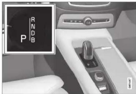
The instrument panel shows which gear is currently in use:
P, R, N, D or B.
For manual shifting, the gear indicator in the instrument panel displays the gear currently being used (1-8).
Selecting gears
The gear selector is a shift-by-wire selector, where shifting is done electronically instead of mechanically. This makes shifting easier and the gear positions more distinct.
Select gears by moving the spring-loaded, non-locking gear selector forward or backward.
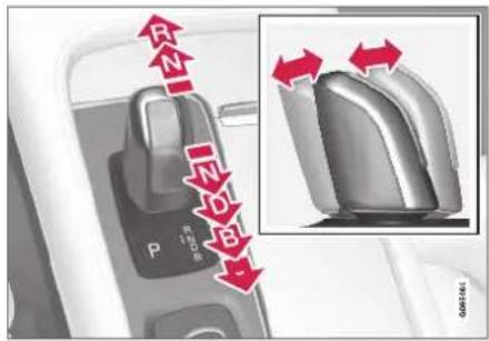
Gear selector positions
Park - P
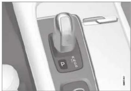
natural_image
Close-up of a white electronic device's control panel with a rotary knob (no visible text or symbols)Park is activated using the P button located next to the gear selector.
Select P when the vehicle is parked or when starting the engine. The vehicle must be stationary when Park is selected.
To move to another gear from Park, the brake pedal must be depressed and the ignition in mode II.
When parking – apply the parking brake before shifting to Park.
WARNING
Always apply the parking brake when parking on an incline. Selecting a gear or putting the automatic transmission in P may not be sufficient to keep the vehicle stationary in all situations.
NOTE
The gear selector must be in the P position before the vehicle can be locked and the alarm set.
STARTING AND DRIVING
Help functions
The system will automatically shift to P:
- if the ignition is switched off while D or R is selected.
- if the driver unbuckles the seat bell and opens the driver's door while the vehicle is running with the gear selector in a gear other than P.
To park a vehicle with an unbuckled seat belt and open door - end P mode by shifting to R or D again.
The system will not automatically shift to P if the ignition is switched off while the gear selector is in the neutral position (N). This is to make it possible to wash the vehicle in an automatic car wash in which the vehicle is pulled forward on rolling wheels.
Reverse - R
Select R when backing up. The vehicle must be stationary when Reverse is selected.
Neutral - N
No gear is selected and the engine can be started. Apply the parking brake if the vehicle is stationary with the gear selector in N.
To move the gear selector from Neutral to another gear, the brake pedal must be depressed and the ignition in mode II.
D drive mode
D is the normal driving gear position. The transmission shifts up or down automatically depending on acceleration and speed. The vehicle must be stationary when the gear selector is moved from R to D.
Brake - B
B can be selected at any time during a drive. In B mode, the engine braking function is activated when the accelerator pedal is released, which helps charge the hybrid battery. This offers additional opportunities to recharge the hybrid battery, since the battery is charged even when the brake pedal is not depressed.
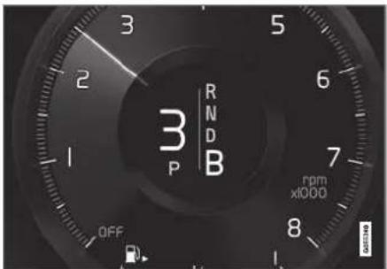
B mode in the instrument panel.
From B mode, it is possible to manually shift to lower gears. The currently selected gear (1-8) will be displayed in the instrument panel.
- Pull the gear selector backward once to shift down one gear.
- Pull the gear selector backward again to shift down to lower gears.
To shift manually to a higher gear, the vehicle must be equipped with steering wheel paddles*.
- Push the gear selector forward to return to D mode.
For smooth shifting and engine performance, the transmission will shift down automatically if the vehicle's speed becomes too low for the selected gear.
Related information
- Shiftlock (p. 452)
- Using the steering wheel paddles* to shift (p. 451)
• The kickdown function (p. 452)
Using the steering wheel paddles\* to shift
The steering wheel paddles are a supplement to the gear selector and make it possible to shift manually without removing your hands from the steering wheel.
Activating the steering wheel paddles
In order to shift gears using the paddles, they must first be activated:
- Pull one of the paddles toward the steering wheel.
A number in the instrument panel indicates the current gear being used.
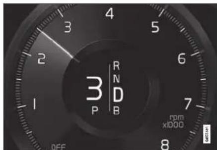
Instrument panel when the paddles are activated for shifting.
Change
To shift one gear:
- Pull one of the paddles toward the steering wheel and then release.

①"-": Shift down one gear.
② "+": Shift up one gear.
As long as the engine speed (rpm) is within the permissible range for the selected gear, a gear shift will take place each time a paddle is pulled.
After each gear shift, a number indicating the current gear will be displayed in the instrument panel.
Turning off Start/Stop
Manual deactivation in gear D and B
- Deactivate the paddles by pulling the right paddle (+) toward the steering wheel and holding it until the number of the current gear is no longer displayed in the instrument panel.
The transmission will revert to gear D or B depending on which gear was selected before the paddles were activated.
Automatic deactivation
In gear position D, the steering wheel paddles are deactivated after a short period of time if they are not used. The number of the current gear will no longer be displayed in the instrument panel.
In gear position B, the paddles will not activate automatically.
Related information
- Gear selector positions for automatic transmissions (p. 449)
STARTING AND DRIVING
Shiftlock
The automatic transmission's shiftlock function helps prevent inadvertently moving the gear selector between different positions.
Automatic shiftlock
The automatic shiftlock has a separate safety system.
From Park - P
To move to another gear from P (Park), the brake pedal must be depressed and the ignition in mode II.
From Neutral - N
If the gear selector is in N and the vehicle has been stationary for at least 3 seconds (with or without the engine running), the gear selector will be locked in that position.
To move the gear selector from N to another gear, the brake pedal must be depressed and the ignition in mode II.
Messages in the instrument panel
If the gear selector is locked in position, a message will appear in the instrument panel, e.g.
Gear lever Press brake pedal to activate gear lever.
There is no mechanical shiftlock function.
Related information
• Gear selector positions for automatic transmissions (p. 449)
The kickdown function
Kickdown is used when maximum acceleration is needed, e.g. when passing.
When the accelerator pedal is depressed all the way to the floor (past the normal full accelerator position), the transmission will automatically engage kickdown, i.e. immediately shift down to a lower gear.
If the accelerator pedal is released from the kickdown position, the transmission will automatically shift up again.
Safety function
The transmission control module is equipped with a downshift protection feature to help prevent the engine from overheating.
In some conditions, the transmission will prevent downshifting/kickdown if this would lead to such high engine speed (rpm) that the engine could be damaged. If the driver still attempts downshifting or kickdown at a high rpm, nothing will happen and the original gear will remain selected.
With kickdown, the vehicle can downshift one or more steps at a time depending on the engine speed. The vehicle upshifts when the engine reaches its maximum rpm to prevent engine damage.
Related information
- Gear selector positions for automatic transmissions (p. 449)
All Wheel Drive (AWD)
All-wheel drive, All Wheel Drive (AWD), also called four-wheel drive, means that power is distributed to all four wheels, which improves traction.
The electric motor that powers the rear wheels enables electronic all-wheel drive functionality. All-wheel drive reacts differently depending on which drive mode is selected.
Related information
- Drive modes (p. 454)
• Low Speed Control (p. 464)
• Transmission (p. 448)
Drive systems
Volvo Twin Engine combines a combustion engine for the front wheels and an electric motor for the rear wheels.
Two drive systems
Depending on the selected drive mode and power available in the electric motor, the drive systems can either be used separately or in tandem.
The electric motor gets its energy from a hybrid battery located under the tunnel console. The hybrid can be charged from a wall outlet or in a special charging station. The combustion engine can also charge the hybrid battery using a special high-voltage generator.
Both the combustion engine and the electric motor can generate power directly to the wheels. An advanced control system coordinates both the drive systems to help optimize driving economy.

Hybrid battery - The hybrid battery's function is to store electrical current. This energy is provided by plugging the charging cable into an electrical outlet, through regenerative braking or from the high-voltage generator. This provides current to power the electric motor and to temporarily power the electrical air conditioning to precondition the passenger compartment.
2 Combustion engine - The combustion engine starts when the charge level in the hybrid battery is too low to provide the power output requested by the driver.
3 High-voltage generator ^2 - Charges the hybrid battery. Starter for the combustion engine.
Can provide the combustion engine with extra electrical current.
4 Electric motor - Powers the vehicle using electricity. Can provide extra torque and power during acceleration. Provides electrical all-wheel drive functionality. Regenerates braking energy into electrical current.
Related information
- General information about Twin Engine (p. 416)
- Starting and stopping the combustion engine in Twin Engine vehicles (p. 454)
- Drive modes (p. 454)
• Transmission (p. 448) - Factors affecting electric motor range (p. 469)
STARTING AND DRIVING
Starting and stopping the combustion engine in Twin Engine vehicles
An advanced control system determines the distance that the vehicle can be driven on the combustion engine, electric motor, or both at the same time. When driving on only the electric motor, the vehicle may automatically start the combustion engine due to outside circumstances, e.g. low ambient temperatures. This is completely normal. The combustion engine will also always start when the hybrid battery is nearly fully discharged.
Climate settings at low temperatures
At low ambient temperatures, the combustion engine will sometimes start automatically to help achieve the desired passenger compartment temperature and air quality. The amount of time the combustion engine is running can be affected by:
• lowering the temperature
• reducing blower speed
• activating Pure drive mode.
Using the electric motor in hot or cold weather
At very low or high ambient temperatures, the electric motor's driving range and power may be reduced and affect how often the combustion engine automatically starts.
Emission control system
To help ensure that the emission control system functions optimally, the combustion engine will run for several minutes after it is started. The amount of time the combustion engine needs to be used varies depending on the temperature of the three-way catalytic converter.

WARNING
California Proposition 65
Operating, servicing and maintaining a passenger vehicle can expose you to chemicals including engine exhaust, carbon monoxide, phthalates, and lead, which are known to the State of California to cause cancer and birth defects or other reproductive harm. To minimize exposure, avoid breathing exhaust, do not idle the engine except as necessary, service your vehicle in a well ventilated area and wear gloves or wash your hands frequently when servicing your vehicle. For more information go to www.P65Warnings.ca.gov/passenger-vehicle.
Related information
• Drive systems (p. 453)
• Economical driving (p. 467)
• Using the electric motor only (p. 469)
- Drive modes (p. 454)
Drive modes
Drive modes affect the vehicle's driving characteristics in different ways to enhance and simplify the driving experience in certain types of situations.
Drive modes enable easy access to the vehicle's many functions and settings in different driving situations. The following systems are adapted to help optimize driving characteristics in each drive mode:
- Steering
• Engine/transmission/all-wheel drive - Brakes
- Pneumatic suspension* and shock absorbers
- Instrument panel
• Climate control settings
Select the drive mode that is best suited to the current driving conditions. Keep in mind that not all drive modes are available in all situations.
Available drive modes

WARNING
Keep in mind that the vehicle does not emit any engine noise when using the electric motor and may therefore be difficult to detect for children, pedestrians, cyclists or animals. This is particularly true at low speeds, e.g. in parking lots.

WARNING
Do not leave the vehicle in an unventilated area with a drive mode activated and the combustion engine switched off. The engine will start automatically if the charge level in the hybrid battery is low and the resulting exhaust gases can be very harmful to people and animals.
HYBRID
- This is the default mode in which the electric motor and combustion engine work together. The vehicle starts in Hybrid mode. The control system uses both the electric motor and the gasoline engine - separately or in tandem - and calculates optimal utilization with regard to performance, fuel consumption and comfort. At high speeds, ground clearance is automatically lowered ^8 to reduce air resistance. Driving capacity on the electric motor alone is determined by factors
such as the hybrid battery's charge level, the need for heat/cooling in the passenger compartment, etc.
If there is sufficient charge in the battery, it is possible to drive solely on electric power. When the accelerator pedal is pressed, only the electric motor will be activated until the battery reaches a certain charge level. Above this level, the current in the battery cannot supply the power requested by the accelerator pedal and the combustion engine will start.
When the hybrid battery's charge level is low, the combustion engine will start more frequently to save the remaining current in the battery. Charge the hybrid battery from a 120-240 volt outlet using a charging cable, or activate Charge in Function view to reset the option of only using the electric motor.
This drive mode is designed for low energy consumption with an optimized mix between the electric motor and gasoline engine, without compromising on climate comfort or driving experience. When faster acceleration is requested by the driver, the electric driveline will be utilized to help provide maximum additional power. The vehicle also monitors the driving conditions and automatically engages all-wheel drive if necessary. All-wheel drive and extra electric power are always available regardless of the battery's charging status.
Information in the instrument panel
When driving in Hybrid mode, a hybrid gauge will be displayed in the instrument panel. The gauge will indicate the amount of electrical current required when the driver depresses the accelerator pedal. The marker between the lightning and the drop shows how much current is available.

The instrument panel gauge when both the electric motor and the combustion engine are being used.

The instrument panel also shows how much current is being restored to the battery (regenerated) during light braking.
STARTING AND DRIVING
PURE
- Uses the electric motor only, with the lowest possible energy consumption and carbon dioxide emissions.
This drive mode maximizes the use of the hybrid battery. Ground clearance is lowered ^3 to reduce air resistance and certain climate system functions are reduced to provide the longest possible driving distance using only electricity.
Pure mode is available when the hybrid battery is sufficiently charged. Even in Pure mode, the combustion engine will start if the charge level in the battery gets too low. The combustion engine will also start
- if the vehicle's speed goes above 125 km/h (78 mph)
- if the driver requests more power than the electric motor can provide
- if factors such as cold weather affect the system or components.
This drive mode is optimized for maximum driving distance with electric propulsion and is primarily intended for use in city driving. Pure helps provide the lowest possible consumption even when the hybrid battery is fully discharged. ECO climate is activated to control the climate in the passenger compartment, and in slippery road conditions slightly more wheel spin may be permitted before all-wheel drive is automatically activated.
ECO Climate
In Pure mode, ECO climate is automatically activated in the passenger compartment to help reduce energy consumption.
NOTE
When the Pure drive mode is activated, settings for certain climate system and electricity consuming functions are reduced. Some of these settings can be reset manually, but full functionality will only be restored by leaving Pure mode or adapting the Individual drive mode to full climate system functionality.
If condensation forms on the windows, tap the max defroster button, which will function normally.
OFF ROAD
- Maximizes the vehicle's ability to traverse difficult terrain or poor roads.
In this mode, ground clearance ^3 is high, steering is light, and all-wheel drive and Hill Descent Control are activated.
This drive mode is only available at low speeds, up to 40 km/h (25 mph). If this speed is exceeded, Off road mode will be cancelled and AWD mode will be activated instead.
All-wheel drive requires both the combustion and electric motor to be in continuous operation, which results in higher fuel consumption.
In Off road mode, a compass will be displayed between the speedometer and the tachometer in the instrument panel. The permissible speed range will be shown in the speedometer.
This drive mode is optimized for maximum control when driving at low speeds on very poor roads or difficult terrain. It raises the chassis ^3 , reduces driveline throttle response, and locks the vehicle in all-wheel drive. The Hill Descent Control function facilitates controlled driving on steep downgrades.

NOTE
This drive mode is not designed to be used for normal street driving.

NOTE
Due to the increased ground clearance, if the OFF ROAD mode was selected when the engine was switched off, the suspension will lower when the engine is restarted.

CAUTION
Do not use the OFF ROAD drive mode when towing a trailer without an electrical connection. This could result in damage to the pneumatic suspension system's bellows.
AWD
- Improves the vehicle's traction and handling by increasing all-wheel drive.
This drive mode locks the vehicle in all-wheel drive. An optimal distribution between front and rear axle torque helps provide the best possible control, stability and traction, e.g. on slippery roads or when towing a heavy trailer or another vehicle. The AWD drive mode is always available regardless of the hybrid battery's charge status.
Both the combustion engine and the electric motor are engaged to enable all-wheel drive, which results in higher fuel consumption.
In the other drive modes, the vehicle automatically adapts the need for all-wheel drive according to the road surface, and can activate the electric motor or start the combustion engine as needed.
POWER
- Power mode is designed to provide sportier driving characteristics and a faster acceleration response.
This drive mode maximizes the combined power from the combustion engine and the electric motor by providing power to both the front and rear wheels. Gear shifting will be faster and more distinct and the transmission will prioritize gears with a higher traction force. Steering response is faster, suspension is stiffer and ground clearance is lower ^3 to help reduce body roll when cornering.
Both the combustion engine and the electric motor are engaged to enable all-wheel drive, which results in higher fuel consumption.
This drive mode is optimized for maximum performance and throttle response. It changes the throttle response, gear shifting program and turbo boost system. Chassis settings and steering and brake response are also optimized. The Power drive mode is always available regardless of the hybrid battery's charge status.
STARTING AND DRIVING
INDIVIDUAL
- Customizes drive mode to personal preferences.
Select one of the drive modes as a basis and adjust the settings to achieve your preferred driving characteristics. These settings will be stored in your driver profile.
Individual drive mode is only available if it has been activated in the center display.

Settings view ^1 for Individual drive mode.
- Tap Settings in the Top view.
-
Tap My Car Individual Drive Mode and select Individual Drive Mode.
-
Under Presets, select one of the following drive modes as a basis: Pure, Hybrid or Power.
The following settings can be modified:
- Driver Display
- Steering Force
• Powertrain Characteristics - Brake Characteristics
- Suspension Control
• ECO Climate.
Using the electric or combustion engine
An advanced control system determines the distance that the vehicle can be driven on the combustion engine, electric motor, or both at the same time.
Its primary function is to use the motor/engine and the current available in the hybrid battery as efficiently as possible based on the characteristics of the various drive modes and the power output requested by the driver by pressing the accelerator pedal.
In certain cases, temporary limitations in the system or mandatory functions to help maintain a low overall emissions level may result in greater use of the combustion engine.
Related information
• Changing drive mode (p. 459)
• Economical driving (p. 467)
- Energy distribution in hybrid mode using map data* (p. 460)
• Hybrid gauge (p. 87)
- General information about Twin Engine (p. 416)
Changing drive mode
Select the drive mode that is best suited to the current driving conditions.
The drive mode is changed using the control in the tunnel console.
Keep in mind that not all drive modes are available in all situations.
To change drive mode:

natural_image
Close-up of a car's side button with a 'DRIVE MASK' and control buttons (no readable text or symbols)- Press the DRIVE MODE control.
A pop-up menu will appear in the center display.
-
Roll the wheel upward or downward to the desired drive mode.
-
Press the drive mode control or tap its button in the center display to confirm the selection.
The selected drive mode is shown in the instrument panel.
If a drive mode is grayed out in the pop-up menu, it cannot be selected.
Related information
- Drive modes (p. 454)
- Activating and deactivating Low Speed Control using the function button (p. 465)
- Activating and deactivating Hill Descent Control using the function button (p. 467)
STARTING AND DRIVING
Energy distribution in hybrid mode using map data\*
The Hybrid drive mode is the vehicle's default drive mode in which the electric motor and the combustion engine work separately or together in hybrid mode. If a destination has been selected in the navigation system*, the Predictive Efficiency ^5 function can use map data to effectively distribute the electric power throughout the trip.
This can lower fuel consumption in comparison with normal hybrid mode, in which the vehicle first runs on electricity and then switches to the combustion engine when the hybrid battery is discharged.
If the distance to the destination is greater than the calculated range on the electric motor, the function will distribute electric power optimally for the entire trip. This makes it possible to avoid situations in which normal hybrid mode would otherwise use a large portion of the electric power to e.g. use the electric motor at high speeds on a highway and then use the combustion engine at lower speeds during city driving.
The greatest fuel savings are attained when the trip begins on a highway, is between 50 and 100 km (30 and 60 miles) long, and the hybrid battery is fully charged at the start of the trip.
Requirements for the function
Certain conditions must be met for the function to be possible:
- A destination must be set in the navigation system and the distance to the destination must be longer than the possible range using only the electric motor.
• Hybrid drive mode must be selected. - The Hold and Charge functions must be disabled.
• The hybrid battery must be charged.
Usage tips
If you commute and it is not possible to charge the vehicle at work, enter your workplace as a waypoint and your home as the destination. Discharging of the hybrid battery will then be distributed over the entire commute to and from work.
Add similar commutes, i.e. the route between two charges, as Favorites in the navigation system to facilitate access.
Related information
- Drive modes (p. 454)
• Economical driving (p. 467)
Leveling control\* and suspension
The vehicle's leveling control system adjusts the suspension and shock absorbers automatically to help provide good comfort and control while driving. Leveling can also be controlled manually to facilitate loading or getting in and out of the vehicle.
Pneumatic suspension and shock absorbers
The system is adapted to the selected drive mode and vehicle speed. The pneumatic suspension reduces the vehicle's ground clearance at higher speeds to reduce air resistance and increase stability. The shock absorbers are normally set to provide the best possible comfort and are adjusted continuously according to the road surface and the vehicle's acceleration, braking and cornering.

The instrument panel indicates when the suspension level is being adjusted.
The following apply if a door or the tailgate is opened:
- If a door is opened, the level can only be adjusted upwards.
- If the tailgate is open, the level can only be adjusted downwards.
Parking
When parking, make sure that there is adequate space above and below the vehicle since ground clearance may vary depending on e.g. ambient
temperature, how the vehicle is loaded, if loading mode is used, which drive mode is selected after the engine is started, etc.
The level may also be adjusted a period after the vehicle is parked. This is to compensate for any height changes that may occur due to temperature changes in the air springs when the vehicle cools.
Transporting
When transporting the vehicle on a ferry, train or truck, only secure (lash) the vehicle around the tires, not using any other parts of the chassis. Changes in the pneumatic suspension may occur during transport, which could adversely affect the lashing and result in damage.
STARTING AND DRIVING
Symbols and messages in driver display
| Symbol Message Meaning | ||
 | SuspensionDeactivated by user | Active chassis has been switched off manually by the user. |
 | SuspensionTemporarily reduced performance | Active chassis performance has been temporarily reduced due to extensive system use. If this message appears frequently (e.g. several times in one week) contact a workshop^. |
 | SuspensionService required | A fault has occurred. Visit a workshop^ as soon as possible. |
 | Suspension failureStop safely | A critical fault has occurred. Stop safely, and have the car transported (raised with all wheels on the flatbed) to a workshop^. |
 | SuspensionSlow down Vehicle too high | A fault has occurred. If the message appears while driving, contact a workshop ^A . |
 | SuspensionAuto adjusting vehicle level | Level control to target height is in progress. |
^ An authorized Volvo workshop is recommended.
Related information
• Leveling control settings* (p. 464)
- Drive modes (p. 454)
STARTING AND DRIVING
Leveling control settings\*
Turn off leveling control before lifting the vehicle with a jack to help avoid problems with the pneumatic suspension.
The vehicle can be lowered or raised to make it easier to load or for passengers to get in and out.
Adjusting loading mode
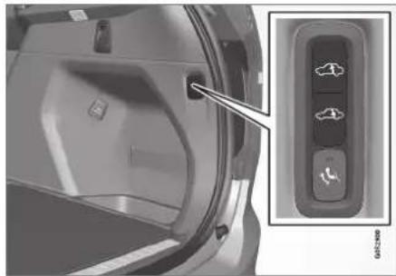
natural_image
Interior view of a car door with a control panel and directional arrows (no text or symbols visible)Use the buttons in the cargo compartment to raise or lower the rear section of the vehicle to facilitate loading or unloading the vehicle or connecting or disconnecting a trailer.
Center display settings
Easy Entry and Exit Suspension Control
The vehicle can be lowered to make it easier to get in and out.
Activating easy entry in the center display:
-
Tap Settings in the Top view.
-
Tap My Car Mirors and Convenience.
-
Select Easy Entry and Exit Suspension Control.
When the vehicle is parked and the engine is turned off, the level is lowered. (Level adjustment will stop if a side door is opened and will resume after a slight delay when the door has been closed.) When the engine is started and the vehicle begins to move, the level will be raised to the height set by the selected drive mode.
Disable Leveling Control
In certain situations, this function must be turned off, e.g. before the vehicle is raised using a jack*. The level difference caused by raising the vehicle with a jack could cause problems with the pneumatic suspension.
Turning off the function in the center display:
- Tap Settings in the Top view.
-
Tap My Car Parking Brake and Suspension.
-
Select Disable Leveling Control.
Related information
• Leveling control* and suspension (p. 461)
- Loading recommendations (p. 598)
Low Speed Control
The low-speed function, Low Speed Control (LSC), facilitates and improves control and traction on rough roads and slippery surfaces, e.g. when towing a trailer on grass or up boat ramps.
The function is included in the Off Road drive mode.
Low Speed Control is designed for driving on rough roads and when towing trailers at low speeds, up to approximately 40 km/h (25 mph).
When driving at low speeds, LSC prioritizes low gears and all-wheel drive to help avoid wheel spin and improve traction on all wheels. The accelerator pedal will be less responsive to improve traction and speed control at low speeds.
The function is activated together with Hill Descent Control (HDC), which makes it possible to control speed going down steep hills using the accelerator pedal and reduces the need to use the brake pedal. The system makes it possible to maintain a low and uniform speed when driving down steep hills.

NOTE
When LSC with HDC is activated in the OFF ROAD drive mode, the feel of the accelerator pedal and engine response will change.

NOTE
This drive mode is not designed to be used for normal street driving.

NOTE
The function is deactivated when driving at high speeds and must be reactivated at lower speeds if so desired.
Related information
- Activating and deactivating Low Speed Control using the function button (p. 465)
• Changing drive mode (p. 459)
• Hill Descent Control (p. 466)
• All Wheel Drive (AWD) (p. 452)
Activating and deactivating Low Speed Control using the function button
There is a function button for driving at low speeds with Hill Descent Control in the center display's Function view if the vehicle is not equipped with a drive mode control in the tunnel console.
Selecting Low Speed Control in the center display's Function view
- Tap the Hill Descent Control button to activate or deactivate the function.

An indicator light in the button will illuminate when the function is activated.
When the engine is switched off, the function will be automatically deactivated.

NOTE
The function is deactivated when driving at high speeds and must be reactivated at lower speeds if so desired.
Related information
• Low Speed Control (p. 464)
• Changing drive mode (p. 459)
STARTING AND DRIVING
Hill Descent Control
The function for assisting when driving downhill, Hill Descent Control (HDC), is a low-speed function with increased engine braking. The function makes it possible to increase or decrease the vehicle's speed on steep downhill gradients by only using the accelerator pedal, without applying the brakes.
The function is included in the Off Road drive mode.
HDC is designed for driving on rough roads at low speeds and downhill gradients with slippery or otherwise difficult road surfaces. The driver does not need to use the brake pedal but can instead focus on steering.

WARNING
HDC is only intended to be a supplementary braking aid and it does not function in all situations.
The driver is always ultimately responsible for operating the vehicle in a safe manner.
Function
Hill Descent Control allows the vehicle to move forward or backward at very low speeds assisted by the brake system. The driver can increase the speed by pressing the accelerator pedal. When the accelerator pedal is released, the vehicle will return to very low speed regardless of how steep
the hill is and without the brakes needing to be applied. The brake lights will illuminate when the function is activated.
The driver can brake to stop or slow the vehicle at any time by depressing the brake pedal.
HDC is activated along with Low Speed Control (LSC), which facilitates and improves traction and control on rough and slippery surfaces. The system is intended to be used at low speeds, up to approximately 40 km/h (25 mph).
To keep in mind when using HDC
- If the function is switched off while driving on a steep downhill gradient, braking effect will be gradually reduced.
- HDC can be used in gear positions D and R, and in manual gears 1 or 2.
- It is not possible to manually shift to third gear or higher when HDC is active.
i NOTE
When LSC with HDC is activated in the OFF ROAD drive mode, the feel of the accelerator pedal and engine response will change.
NOTE
This drive mode is not designed to be used for normal street driving.
NOTE
The function is deactivated when driving at high speeds and must be reactivated at lower speeds if so desired.
Related information
- Activating and deactivating Hill Descent Control using the function button (p. 467)
• Changing drive mode (p. 459)
• Low Speed Control (p. 464)
• All Wheel Drive (AWD) (p. 452)
Activating and deactivating Hill Descent Control using the function button
There is a function button for assistance on steep gradients with Hill Descent Control in the center display's Function view if the vehicle is not equipped with a drive mode control in the tunnel console.
Selecting Hill Descent Control in the center display's Function view
HDC only works at low speeds.
- Tap the Hill Descent Control button to activate or deactivate the function.

An indicator light in the button will illuminate when the function is activated.
When the engine is switched off, the function will be automatically deactivated.

NOTE
The function is deactivated when driving at high speeds and must be reactivated at lower speeds if so desired.
Related information
• Hill Descent Control (p. 466)
• Changing drive mode (p. 459)
Economical driving
Drive economically and more environmentally conscious by thinking ahead, avoiding rapid starts and stops and adapting driving style and speed to the current traffic conditions.
To help achieve the greatest distance with the lowest fuel consumption with Twin Engine, observe the following:
Charge
- Charge the vehicle regularly by plugging it into an electrical outlet. Make it a habit to always begin trips with the hybrid battery fully charged.
- Locate charging stations along your route.
- If possible, choose parking spots with charging stations.

NOTE
Charge the vehicle from the electricity grid as often as possible!
STARTING AND DRIVING
Preconditioning
- Whenever possible, precondition the vehicle before driving by connecting the charging cable to an electrical outlet.
- Avoid parking the vehicle somewhere where the interior will become too hot or too cold while the vehicle is parked. If possible, park the vehicle in a climate-controlled garage.
- During a short drive after passenger compartment preconditioning, turn off the passenger compartment fan or the air conditioning in a hot climate.
- If preconditioning is not possible when it is cold outside, use seat and steering wheel heating first. Avoid heating the entire passenger compartment to reduce the amount of current being taken from the hybrid battery.
Driving
- Choose the Pure drive mode to help minimize electric power consumption.
- Maintain a steady speed and a generous following distance to traffic ahead to minimize braking. This drive mode has the lowest power consumption.
- Balance energy requirements using the accelerator pedal. Use the indicator on the instrument panel to see available electric power and avoid starting the combustion engine unnecessarily. The electric motor is
more effective than the combustion engine, especially at low speeds.
- When braking is necessary, brake gently using the brake pedal. This will help recharge the hybrid battery. A regenerative function is integrated in the brake pedal and can be augmented by the electric motor's braking capacity when the gear selector is in mode B.
- Higher speeds increase energy consumption - air resistance increases with speed.
- Activate the Hold function in the Function view at high speeds when traveling farther than is possible using the hybrid battery's capacity.
- Whenever possible, avoid using the Charge function to charge the hybrid battery. Charging the battery using the combustion engine increases fuel consumption and carbon dioxide emissions.
- In a cold climate, reduce heating of the wind-shield/rear window, mirrors, seats and the steering wheel.
- Maintain the correct pressure in the tires and check pressure regularly.
- The type of tires used could affect energy consumption - consult a retailer for advice on suitable tires.
- Remove unnecessary items from the vehicle - the heavier the load, the higher the fuel consumption.
- Roof loads increase air resistance and increase fuel consumption. Remove roof boxes, ski racks, etc. that are not in use.
- Avoid driving with the windows open.
- Do not keep the vehicle still on an upward gradient by using the accelerator pedal. Use the brakes instead.
Related information
- Drive-E – purer driving pleasure (p. 27)
- Energy distribution in hybrid mode using map data* (p. 460)
- Factors affecting electric motor range (p. 469)
• Using the electric motor only (p. 469)
• Hybrid gauge (p. 87) - Checking tire pressure (p. 567)
Using the electric motor only
When using the electric motor, Volvo Twin Engine provides a combination of good fuel economy, low emissions and high performance.
For energy-efficient driving:
- Select the Pure drive mode to help maximize driving range using only the electric motor.
- Balance energy requirements using the accelerator pedal. Use the indicator on the instrument panel's hybrid gauge to see available electric power and avoid starting the combustion engine unnecessarily.
- When braking is necessary, brake gently using the brake pedal. This will recharge the hybrid battery.
- Activate the Hold function in the Function view at high speeds when traveling farther than is possible using the hybrid battery's capacity.
- Reduce current consumption in the passenger compartment by reducing e.g. fan speed, electric heating, or air conditioning use.
Also follow the general economical driving advice regarding speed, tires and load to maximize range.
Related information
- General information about Twin Engine (p. 416)
• Economical driving (p. 467)
• Hybrid gauge (p. 87)
- Factors affecting electric motor range (p. 469)
• Starting and stopping the combustion engine in Twin Engine vehicles (p. 454)
• "Hold" and "Charge" functions (p. 471)
Factors affecting electric motor range
A number of factors affect the electric motor's driving range. The ability to achieve a long driving range varies according to the outside conditions and to how the vehicle is driven.
The certified value for the distance that can be driven using the electric motor should not be considered an expected driving range. The actual range is dependent on a number of factors.
Factors affecting driving range
The driver can influence some factors affecting driving range, but not all.
The longest range is achieved under very favorable conditions when all factors positively influence range.
STARTING AND DRIVING
Factors the driver cannot control
There are several outside conditions that affect range to varying degrees:
• the current traffic situation
- driving short distances
• topography
• ambient temperature and headwinds
• road conditions and road surface.
The following table shows the approximate relationship between ambient temperature and driving range with normal climate settings and with climate settings turned off.
Up to a certain limit, warmer ambient temperatures increase the electric motor's driving range.
| Ambient temperature | Climate settings turned off | Normal climate settings |
| 30 °C (86 °F) | 95 % 80 % | |
| 20 °C (68 °F) | 100 % 90% | |
| 10 °C (50 °F) | 90 % 80 % | |
| 0 °C (32 °F) | 80 % 60 % | |
| -10 °C (14 °F) | 70 % 40 % |
Factors the driver can control
The driver should be aware that the following factors help conserve energy and improve driving range:
• charging the battery regularly
- preconditioning
- Pure drive mode
• climate control settings
• speed and acceleration
• the Hold function
• tires and tire pressure.
The following table shows the approximate relationship between constant speed and driving range. Driving at a lower constant speed helps increase the electric motor's driving range.
| Constant speed | |
| 100 km/h (62 mph) 50 % | |
| 80 km/h (50 mph) 70 % | |
| 60 km/h (37 mph) 90 % | |
| 50 km/h (31 mph) 100 % | |
NOTE
- The figures shown in the tables pertain to a new vehicle.
- None of the figures are absolute and are affected by e.g. driving style, environment and other conditions.
Related information
• Using the electric motor only (p. 469)
• Economical driving (p. 467)
• "Hold" and "Charge" functions (p. 471)
- Drive modes (p. 454)
"Hold" and "Charge" functions
In certain situations, it can be useful to control the hybrid battery's charge level while driving. This is possible with the Hold and Charge functions.
Hold and Charge are available in all drive modes. The functions will switch off if Pure drive mode is activated.
Function buttons for Hold and Charge
The functions can be activated in the center display's Function view.
Hold

Battery level sustained for later use.
This function retains the charge in the hybrid battery for the electric motor and saves available electrical current for use at
a later time, such as when driving in an urban area or residential neighborhood.
The vehicle will function as in normal hybrid driving with a discharged battery - in addition to reusing energy from e.g. regenerative braking, the combustion engine will be used more frequently to maintain the charge in the battery.
Charge

Engine charges hybrid battery.
This function charges the hybrid battery with the help of the combustion engine for increased use of the electric
motor at a later time.
Symbols in the instrument panel

The symbol is displayed in the hybrid battery gauge when Hold is activated.

natural_image
Diagram showing a battery and lightning bolt on a curved path against a black background (no text or symbols)The symbol is displayed in the hybrid battery gauge when Charge is activated.
Related information
• Using the electric motor only (p. 469)
• Economical driving (p. 467)
• Hybrid gauge (p. 87)
STARTING AND DRIVING
Preparing for a long trip
It is important to have the vehicle's systems and equipment checked carefully before driving long distances.
Check that:
- the engine is running properly and that fuel consumption is normal
• there are no leaks (fuel, oil or other fluid)
• the brake pedal is functioning optimally - all lights are working – adjust the headlight height if the vehicle is carrying a heavy load
- tire tread depth and air pressure are at correct levels. Change to snow tires when driving in areas where there is a risk of snowy or icy roads
• the start battery is sufficiently charged
• the wiper blades are in good condition
Related information
- Checking tire pressure (p. 567)
• Filling washer fluid (p. 662)
• Winter driving (p. 472)
• Economical driving (p. 467)
• Vehicle modem settings (p. 545) - Loading recommendations (p. 598)
• Driving with a trailer (p. 483) - Pilot Assist (p. 316)
• Speed limiter (p. 283)
• Tire sealing system (p. 582)
Winter driving
It is important to check the vehicle before driving in cold/snowy conditions to make sure it can be driven safely.
Before the cold season arrives:
- Make sure the engine coolant contains 50% antifreeze. This mixture helps protect the engine from frost erosion down to approx. -35 °C (-31 °F). Do not mix different types of antifreeze as this could pose a health risk.
- Keep the fuel tank well filled to prevent condensation from forming.
- Check the viscosity of the engine oil. Oil with low viscosity (thinner oil) improves cold-weather starting and reduces fuel consumption when driving with a cold engine.
CAUTION
Low-viscosity oil should not be used with hard driving or in hot weather.
- Check the condition and charge level of the start battery. Cold weather places greater demands on the start battery and reduces its capacity.
- Use washer fluid containing antifreeze to help prevent ice from forming in the washer fluid reservoir.
Slippery driving conditions
For optimal traction and roadholding, Volvo recommends using snow tires on all wheels whenever there is a risk of snow or ice on the road.

NOTE
Certain countries require use of winter tires by law. Not all countries permit the use of studded tires.
Practice driving on slippery surfaces under controlled conditions to learn how the vehicle reacts.
Related information
- Snow tires (p. 581)
- Snow chains (p. 581)
• Braking on salted roads (p. 441)
• Braking on wet roads (p. 441)
• Filling washer fluid (p. 662) - Start battery (p. 627)
• Replacing windshield wiper blades (p. 660)
• Changing rear window wipers (p. 659)
• Refilling coolant (p. 625)
Driving through standing water
Driving the vehicle through a deep pool of standing water on a water-covered roadway is called fording. This must be done with great caution.
To prevent damage to the vehicle when driving through water (e.g. on flooded roads):
- Do not drive in water higher than the floor of the vehicle. If possible, check the depth of the water at its deepest point before driving through it. Be particularly careful when driving through flowing water.
- Always select the Off Road drive mode before driving in water to ensure the gasoline engine is running.
- Do not drive faster than walking speed.
- Do not stop the vehicle in the water. Drive carefully forward or back the vehicle out of the water.
- Remember that waves created by passing vehicles could cause the water level to rise above the vehicle's floor level.
- Avoid driving through salt water to help avoid the risk of corrosion.
CAUTION
Parts of the vehicle (e.g. engine, transmission, driveline, electrical components, etc.) can be damaged if the vehicle is driven through water higher than its floor level. Damage to any components caused by flooding, vapor lock or insufficient oil is not covered under warranty.
If the engine stalls while the vehicle is in water, do not attempt to restart it. Have the vehicle towed on the bed of a tow truck to a workshop - an authorized Volvo workshop is recommended.
CAUTION
Because it can be difficult to determine the water depth, avoid driving through standing or running water.
When you have passed the water, press lightly on the brake pedal and check that the brakes are functioning properly. Water, mud, slush, etc. can make the brake linings slippery, resulting in delayed braking effect.
If the vehicle is equipped with a trailer coupling contact, clean the contact after driving in water or mud.
Related information
• Recovery (p. 489)
• Low Speed Control (p. 464)
STARTING AND DRIVING
Opening/closing the fuel filler door
A button on the instrument panel is used to unlock the fuel filler door.

An arrow next to the fuel pump symbol in the instrument panel indicates the side of the vehicle on which the fuel filler door is located.

natural_image
Interior view of a car air conditioner control panel with mode, battery, and fan (no text or symbols visible)- Press the button on the dashboard.
Pressure equalization in the fuel tank causes a slight delay before the fuel filler door opens. Fuel tank Fuel lid is opening will be displayed in the instrument panel, followed by Fuel tank Ready for refueling.
NOTE
Refueling must be done within approximately seven minutes of opening the fuel filler door. After this time, the valve opened by pushing the button for opening the fuel filler door will close and it will no longer be possible to refuel without the pump's nozzle switching off. If the valve is closed before refueling is complete - press the button again and wait until the driver display shows the message Fuel tank Ready for refueling.
- After refueling, press the fuel filler door lightly to close it.
Related information
• Refueling (p. 475)
Refueling
The fuel tank is equipped with a fuel filling system without a cover.
Refueling the vehicle at a service station

natural_image
Diagram showing a car interior with a hand inserting a component into a vehicle's internal gear (no text or symbols present)Refueling is done as follows.
- Turn off the engine and open the fuel filler door.
i NOTE
Refueling must be done within approximately seven minutes of opening the fuel filler door. After this time, the valve opened by pushing the button for opening the fuel filler door will close and it will no longer be possible to refuel without the pump's nozzle switching off.
If the valve is closed before refueling is complete - press the button again and wait until the driver display shows the message Fuel tank Ready for refueling.
-
Select a fuel approved for use in the vehicle. For more information on approved fuels, see the section on "Fuel".
-
Insert the pump's nozzle into the fuel filler pipe's opening. There are two flaps just inside the fuel filler pipe and the pump's nozzle must push both of these flaps open before fuel can be added.
-
Avoid overfilling the tank. Do not press the handle on the filler nozzle again after it has initially stopped pumping.
The fuel tank is now filled.
NOTE
An over-full tank may overflow in hot weather.
CAUTION
Avoid spilling gasoline during refueling. In addition to causing damage to the environment, gasolines containing alcohol can cause damage to painted surfaces, which may not be covered under the New Vehicle Limited Warranty.
Refueling from a fuel container
When filling from a fuel container, use the funnel provided in a foam block under the floor hatch in the cargo compartment.
-
Open the fuel filler door.
-
Insert the funnel into the fuel filler pipe's opening. There are two flaps just inside the fuel filler pipe and the tube section of the funnel must push both of these flaps open before fuel can be added.
▶▶

WARNING
California Proposition 65
Operating, servicing and maintaining a passenger vehicle can expose you to chemicals including engine exhaust, carbon monoxide, phthalates, and lead, which are known to the State of California to cause cancer and birth defects or other reproductive harm. To minimize exposure, avoid breathing exhaust, do not idle the engine except as necessary, service your vehicle in a well ventilated area and wear gloves or wash your hands frequently when servicing your vehicle. For more information go to www.P65Warnings.ca.gov/passenger-vehicle.
Related information
- Opening/closing the fuel filler door (p. 474)
- Fuel (p. 476)
Fuel
Volvo recommends the use of detergent gaso- line to control engine deposits.
Deposit control gasoline (gasoline with detergent additives)
Detergent gasoline is effective in keeping injectors and intake valves clean. Consistent use of deposit control gasolines will help ensure good driveability and fuel economy. If you are not sure whether the gasoline contains deposit control additives, check with the service station operator.
NOTE
Volvo recommends not using external fuel injector cleaning systems, e.g. do not add detergent additives to gasoline before or after refueling.
Unleaded fuel
All Volvo vehicles have a three-way catalytic converter and must only use unleaded gasoline. US and Canadian regulations require that pumps delivering unleaded gasoline are labeled "UNLEADED". Only the nozzles of these pumps will fit in your vehicle's fuel filler inlet. It is unlawful to dispense leaded fuel into a vehicle labeled "unleaded gasoline only". Leaded gasoline damages the three-way catalytic converter and the heated oxygen sensor system. Repeated use of leaded gasoline will lessen the effectiveness of
the emission control system and could result in loss of emission warranty coverage. State and local vehicle inspection programs will make detection of misfueling easier, possibly resulting in emission test failure for misfueled vehicles.

NOTE
Some U.S. and Canadian gasolines contain an octane enhancing additive called methylcyclopentadienyl manganese tricarbonyl (MMT). If such fuels are used, your Emission Control System performance may be affected, and the Check Engine Light (malfunction indicator light) located on your instrument panel may light. If this occurs, please return your vehicle to a trained and qualified Volvo service technician for service.
Gasoline containing alcohol and ethers, "Oxygenated fuels"
Some fuel suppliers sell gasoline containing "oxygenates" which are usually alcohols or ethers. In some areas, state or local laws require that the service pump be marked indicating use of alcohols or ethers. However, there are areas in which the pumps are unmarked. If you are not sure whether there is alcohol or ethers in the gasoline you buy, check with the service station operator. To meet seasonal air quality standards, some areas require the use of "oxygenated" fuel.
Volvo permits the use of the following "oxygenated" fuels. However, the specified octane ratings must still be met.
Alcohol - Ethanol
Fuels containing up to 10% ethanol by volume may be used. Ethanol may also be referred to as Ethyl alcohol, or "Gasohol".
Ethers - MTBE/ETBE: Fuels containing up to 22% MTBE/ETBE by volume may be used.
Methanol
Do not use gasolines containing methanol (methyl alcohol, wood alcohol). This practice can result in vehicle performance deterioration and can damage critical parts in the fuel system. Such damage may not be covered under the New Vehicle Limited Warranty.
Related information
- Octane rating (p. 477)
- Opening/closing the fuel filler door (p. 474)
• Refueling (p. 475)
• Emission controls (p. 479)
Octane rating
Volvo requires premium fuel (91 octane ^6 or higher) for all T5, T6 and T8 engines, and recommends AKI 93 for optimal performance and fuel economy. See decal examples in illustrations 1 and 2.
Minimum octane
Decals
MINIMUM OCTANE RATING
(R + M)/2 METHOD
91
GATELE
Illustration 1: Sample fuel pump octane label ^6 .

Illustration 2: Decal on the inside of the fuel filler flap on vehicles that require premium fuel ^7 .
TOP TIER Detergent Gasoline
Volvo endorses the use of "TOP TIER Detergent Gasoline" where available to help maintain engine performance and reliability. TOP TIER Detergent Gasoline meets a new standard jointly established by leading automotive manufactures to meet the needs of today's advanced engines. Qualifying gasoline retailers (stations) will, in most cases, identify their gasoline as having met the "TOP TIER Detergent Gasoline" standards.

NOTE
Information about TOP TIER Detergent Gasoline is available at www.toptiergas.com.
STARTING AND DRIVING

NOTE
When switching to higher octane fuel or changing gasoline brands, it may be necessary to fill the tank more than once before a difference in engine operation is noticeable.
Fuel Formulations
Do not use gasoline that contains lead or manganese as a knock inhibitor, and do not use lead additives. Besides damaging the exhaust emission control systems on your vehicle, lead has been strongly linked to certain forms of cancer.
Many fuels contain benzene as a solvent.
Unburned benzene has been strongly linked to certain forms of cancer. If you live in an area where you must fill your own gas tank, take precautions. These may include:
- standing upwind away from the filler nozzle while refueling
- refueling only at gas stations with vapor recovery systems that fully seal the mouth of the filler neck during refueling
- wearing neoprene gloves while handling a fuel filler nozzle.
Use of Additives
With the exception of gas line antifreeze during winter months, do not add solvents, thickeners, or other store-bought additives to your vehicle's fuel, cooling, or lubricating systems. Overuse may damage your engine, and some of these additives contain organically volatile chemicals. Do not needlessly expose yourself to these chemicals.

WARNING
Never carry a cell phone that is switched on while refueling your vehicle. If the phone rings, this may cause a spark that could ignite gasoline fumes, resulting in fire and injury.

WARNING
Carbon monoxide is a poisonous, colorless, and odorless gas. It is present in all exhaust gases. If you ever smell exhaust fumes inside the vehicle, make sure the passenger compartment is ventilated, and immediately return the vehicle to a trained and qualified Volvo service technician for correction.
Demanding driving
In demanding driving conditions, such as when towing a trailer or driving in hot weather or for prolonged periods at high altitudes, it may be a good idea to switch to a higher-octane fuel (AKI ^6 91 or higher) or to switch to another brand of gasoline in order to fully utilize the vehicle's engine capacity and optimize traction.
Related information
- Fuel (p. 476)
• Emission controls (p. 479)
Emission controls
Three-way catalytic converter
- Keep your engine properly tuned. Certain engine malfunctions, particularly involving the electrical, fuel or distributor ignition systems, may cause unusually high three-way catalytic converter temperatures. Do not continue to operate your vehicle if you detect engine misfire, noticeable loss of power or other unusual operating conditions, such as engine overheating or backfiring. A properly tuned engine will help avoid malfunctions that could damage the three-way catalytic converter.
- Do not park your vehicle over combustible materials, such as grass or leaves, which can come into contact with the hot exhaust system and cause such materials to ignite under certain wind and weather conditions.
- Excessive starter cranking (in excess of one minute), or an intermittently firing or flooded engine can cause three-way catalytic converter or exhaust system overheating.
- Remember that tampering or unauthorized modifications to the engine, the Engine Control Module, or the vehicle may be illegal and can cause three-way catalytic converter or exhaust system overheating. This includes: altering fuel injection settings or components, altering emission system components
or location or removing components, and/or repeated use of leaded fuel.
NOTE
Unleaded fuel is required for vehicles with three-way catalytic converters.
Heated oxygen sensors
The heated oxygen sensors monitor the oxygen content of the exhaust gases. Readings are fed into a control module that continuously monitors engine functions and controls fuel injection. The ratio of fuel to air into the engine is continuously adjusted for efficient combustion to help reduce harmful emissions.
Related information
• Octane rating (p. 477)
- Fuel (p. 476)
Overheating of engine and transmission
In demanding driving conditions, such as driving in mountainous areas or hot weather, there is a risk of the engine or transmission overheating, especially when carrying heavy loads.
• Engine power may be temporarily limited.
- Remove any auxiliary lights mounted in front of the grille when driving in hot weather.
- If the temperature in the engine's cooling system becomes too high, a warning symbol will appear in the instrument panel along with the message Engine temperature High temperature Stop safely. Pull over to a safe location and let the engine idle for a few minutes to cool down.
- If the message Engine temperature High temperature Turn off engine or Engine coolant Level low, turn off engine is displayed, stop the vehicle and turn off the engine.
- If the transmission begins to overheat, an alternative gear shifting program will be selected. An integrated protective function will also be activated, the warning symbol will illuminate and the message Transmission warm Reduce speed to lower temperature or Transmission hot Stop safely, wait for cooling will be displayed in the instrument panel. Follow the recommendations given by reducing speed or stopping
STARTING AND DRIVING
◀◀
the vehicle safely and letting the engine idle for a few minutes to let the transmission cool.
- If the vehicle begins to overheat, the air conditioning may be temporarily switched off.
- After a prolonged period of driving in demanding conditions, do not turn off the engine immediately after stopping.

NOTE
It is normal for the engine's cooling fan to operate for a short time after the engine is switched off.
Symbols in the instrument panel
| Symbol Meaning | |
 | High engine temperature. Follow the recommendations provided. |
 | Low coolant level. Follow the recommendations provided. |
 | Transmission hot/overheated/cooling. Follow the recommendations provided. |
Related information
• Refilling coolant (p. 625)
• Driving with a trailer (p. 483)
• Preparing for a long trip (p. 472)
Battery drain
The electrical functions in the vehicle drain the battery to varying degrees. Avoid using ignition mode II when the engine is switched off. Use ignition mode I instead, as this uses less electrical current.
Note that certain accessories may also drain power from the electrical system. Do not use functions that use a lot of electrical current when the engine is turned off. Examples of such functions are:
blower
- headlights
- windshield wipers
• audio system (especially at high volume).
If the starter battery voltage is low, a message is shown in the driver display. The vehicle's energy-saving function will then turn off or reduce certain functions, such as the blower and/or the audio system.
- Charge the battery by starting the engine and let it run for at least 15 minutes (driving charges the battery faster than letting the engine idle).
Related information
- Start battery (p. 627)
- Ignition modes (p. 437)
Jump starting using another battery
If the start battery is discharged, current from another battery can be used to start the vehicle.

Jumper cable connecting points.

CAUTION
The charging point of the vehicle is only intended for jump starting the vehicle in question. The charging point is not intended for jump-starting another vehicle. Using the charging point to start another vehicle could cause a fuse to blow, which would cause the charging point to stop working.
If a fuse has blown, 12 V Battery Fuse failure Service required will be displayed in the instrument panel. Volvo recommends contacting an authorized Volvo workshop.
To avoid short circuits or other damage, the following steps are recommended when jump starting the battery:
- Put the ignition in mode 0.
- Make sure the auxiliary battery (the battery used to jump start the discharged battery) has a voltage of 12 volts.
- If the auxiliary battery is in another vehicle, turn off that vehicle's engine and make sure that the vehicles are not touching each other.
- Clamp the red jumper cable onto the auxiliary battery's positive (+) terminal (1).
! CAUTION
Connect the jump cable carefully to prevent short circuits with other components in the engine compartment.
- Fold back the cover over your vehicle's positive (+) jump start terminal (2).
- Clamp the other end of the red jumper cable to your vehicle's positive (+) jump start terminal (2).
- Clamp the black jumper cable onto the auxiliary battery's negative (-) terminal (3).
-
Clamp the other end of the black jumper cable to your vehicle's negative (-) ground point (4).
-
Make sure the jumper cables are securely attached to help prevent sparks while jump starting.
- Start the engine of the assisting vehicle and let it run for a few minutes at a higher idling speed than normal, about 1500 rpm.
- Start your vehicle's engine. If the engine does not start, allow an additional 10 minutes of charging time and then try to start the engine again.

NOTE
When the engine is started under normal conditions, the vehicle's electrical drive motor is prioritized – the gasoline engine remains off. This means that the electric motor has "starled" and the vehicle is ready to be driven once the start knob has been turned clockwise. Start of the electric motor is indicated by the indicator lights on the instrument panel going out and its preselected theme illuminating.

CAUTION
Do not touch the connections between the cable and the vehicle during the start attempt. Risk of sparking.
STARTING AND DRIVING
- Remove the jumper cables in the reverse order – first the black cables and then the red cables.
Make sure that none of the clamps of the black jumper cables come into contact with either vehicle's positive (+) jump start terminals or either of the red jumper cable's connected clamps.

WARNING
PROPOSITION 65 WARNING! Battery posts, terminals, and related accessories contain lead and lead compounds, chemicals known to the state of California to cause cancer and reproductive harm. Wash hands after handling.

WARNING
- Batteries generate hydrogen gas, which is flammable and explosive.
- Do not connect the jumper cable to any part of the fuel system or to any moving parts. Avoid touching hot manifolds.
- Battery fluid contains sulfuric acid. Do not allow battery fluid to contact eyes, skin, fabrics or painted surfaces.
- If contact occurs, flush the affected area immediately with water. Obtain medical help immediately if eyes are affected.
- Never expose the battery to open flame or electric spark. Do not smoke near the battery. Failure to follow the instructions for jump starting can lead to injury.

NOTE
The vehicle cannot be started if the hybrid battery is discharged.
Related information
• Starting the vehicle (p. 434)
- Ignition modes (p. 437)
• Adjusting the steering wheel (p. 201)
• Selecting ignition mode (p. 438)
Detachable towbar\*
Volvo recommends the use of Volvo towbars that are specially designed for the vehicle.

NOTE
The optional detachable trailer hitch may not be available in all markets or on all models. Consult your Volvo retailer.
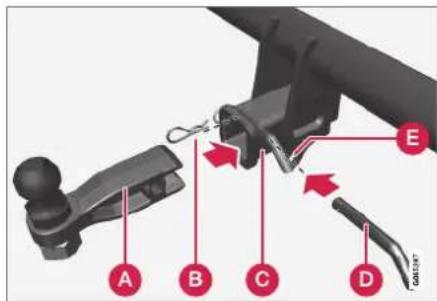
A Ball holder
B Cotter pin
© Towbar assembly
Locking bolt
E Safely wire attachment bracket
Installing the ball holder
- If necessary, remove the cotter pin from the locking bolt and slide the locking bolt out of the towbar assembly.
- Slide the ball holder into the towbar assembly.
- Align the hole in the ball holder with the one in the towbar assembly.
- Slide the locking bolt through the towbar assembly/ball holder.
- Insert the cotter pin in the hole at the end of the locking bolt.

WARNING
- Be sure the towbar is securely locked in position before attaching anything to it.
• Always attach the trailer's safety wire securely to the towbar's safety wire attachment bracket.
Removing the ball holder
- Remove the cotter pin from the locking bolt and slide the locking bolt out of the ball holder/towbar assembly.
- Pull the ball holder out of the towbar assembly.
Stowing the ball holder
WARNING
When not in use, the detachable ball holder should always be properly stowed in the designated location under the floor of the cargo compartment.
Related information
• Driving with a trailer (p. 483)
• Towing capacity and tongue weight (p. 670)
Driving with a trailer
There are a number of things to consider when towing a trailer, such as the towbar, the trailer and how the load is distributed in the trailer.
Load-carrying capacity is determined by the vehicle's curb weight. The total weight of all passengers and any installed accessories, e.g. towbar, reduces the vehicle's load-carrying capacity by the corresponding amount.
- Towbars used on the vehicle must be approved for the applicable use.
- Distribute the load on the trailer so that the weight on the towbar complies with the specified maximum towball weight. The tongue weight is calculated as part of the vehicle's payload.
- Increase the tire pressure to the recommended pressure for a full load.
- The engine is subjected to more load than usual when towing a trailer.
- Towing a trailer affects the vehicle's handling, durability and driving economy.
- Do not drive with a heavy trailer when the vehicle is very new. Wait until the mileage has reached at least 1000 km (620 miles).
- On long and steep downgrades, the vehicle's brakes are subjected to much more load than usual. When manually shifting, downshift and adapt speed accordingly.
▶▶
STARTING AND DRIVING
- Follow applicable regulations regarding permitted speed and weight.
- Drive slowly when towing a trailer up a long and steep incline.
- The maximum trailer weights given only apply to altitudes up to 1000 meters (3280 feet) above sea level. At higher altitudes, engine power (and thus the vehicle's climbing ability) is decreased due to the reduced air density, and the maximum trailer weight must therefore be reduced. The weight of the vehicle and trailer must be decreased by 10% for each additional 1000 m (3280 feet) or part thereof.
- Avoid driving with a trailer on inclines of more than 12%.
- Avoid overloading and other incorrect use.
- The trailer's brakes must be balanced with the vehicle's brakes to help ensure safe stops (follow applicable local regulations).
NOTE
To facilitate towing a trailer in a vehicle equipped with pneumatic suspension*, select: the Suspension Control Dynamic setting in Individual drive mode.
! CAUTION
- Bumper-attached trailer hitches must not be used on Volvos, nor should safety chains be attached to the bumper.
- Trailer hitches attaching to the vehicle rear axle must not be used.
- Never connect a trailer's hydraulic brake system directly to the vehicle brake system, nor a trailer's lighting system directly to the vehicle lighting system. Consult your nearest authorized Volvo retailer for correct installation.
- When towing a trailer, the trailer's safety chains or wire must be correctly fastened to the attachment points provided in the trailer hitch on the vehicle. The safety chain or wire must never be fastened to or wound around the towing ball.
NOTE
The optional detachable trailer hitch may not be available in all markets or on all models. Consult your Volvo retailer.
i NOTE
Extreme weather conditions, towing a trailer, driving at high altitudes and fuel quality are factors that significantly increase a vehicle's fuel consumption.
Trailer weights
WARNING
Please adhere to the recommendations provided for trailer weight. If the recommendations are not followed, the vehicle and trailer may be difficult to control during evasive maneuvers and braking.
i NOTE
The specified maximum trailer weights are those permitted by Volvo. National vehicle regulations may set additional restrictions on trailer weight and speed. The trailer hitches may be certified for higher towing weights than the vehicle is permitted to tow.
Self-leveling suspension\*
The vehicle's self-leveling system attempts to keep the vehicle at a constant level, regardless of load (up to the maximum permitted weight). When the vehicle is stationary, the rear end of the vehicle will be slightly lowered, which is normal.
Driving in hilly terrain or hot weather
In certain conditions, there is a risk of overheating when driving with a trailer. If overheating of the engine and drive system is detected, a warning symbol will illuminate in the instrument panel along with a message.
The automatic transmission selects the optimal gear for the current load and engine speed.
Steep inclines
Do not lock the automatic transmission into a higher gear than what the engine can handle - it is not always preferable to drive in high gears at low rpm.
Parking on a hill
-
Depress the brake pedal.
-
Apply the parking brake.
-
Put the gear selector in P.
-
Release the brake pedal.
Put chocks behind the wheels when the vehicle is parked on a hill with a trailer attached.
Starting on a hill
- Depress the brake pedal.
- Put the gear selector in D.
- Release the parking brake.
- Release the brake pedal and start driving.
Related information
• Trailer Stability Assist* (p. 485)
• Checking trailer lights (p. 486)
• Towing capacity and tongue weight (p. 670)
• Overheating of engine and transmission (p. 479)
Trailer Stability Assist\*
Trailer Stability Assist (TSA ^8 ) is a function designed to help stabilize a vehicle that is towing a trailer when the vehicle and trailer have begun to sway. The function is part of the Electronic Stability Control system ESC ^9 .
Reasons for swaying
A vehicle towing a trailer may begin to sway for various reasons. Normally this only occurs at high speeds. However, if the trailer is overloaded or unevenly distributed, e.g. too far back, there is a risk of swaying even at low speeds.
Swaying may be caused by factors such as:
- The vehicle and trailer are hit by a sudden, strong crosswind.
- The vehicle and trailer are traveling on an uneven road or over a bump.
• Sudden movements of the steering wheel.
Once swaying has begun, it can be difficult or impossible to stop it. This makes the vehicle and trailer difficult to control and there is a risk of swerving into oncoming traffic or driving off the road.
Trailer Stability Assist function
Trailer Stability Assist continuously monitors the vehicle's movements, particularly lateral move-
ments. If swaying is detected, the brakes are applied individually on the front wheels, which has a stabilizing effect on the vehicle and trailer. This is often enough to enable the driver to regain control of the vehicle.
If the Trailer Stability Assist function's first attempt is not adequate to stop the swaying motion, the brakes are applied on all wheels and engine power is temporarily reduced. As the swaying motion begins to decrease and the vehicle and trailer have once again become stable, TSA stops regulating the brakes/engine power and the driver regains control of the vehicle.

NOTE
Trailer Stability Assist is deactivated if the driver selects the sport mode by deactivating ESC in the center display's menu system.
Trailer Stability Assist may not intervene if the driver tries to compensate for the swaying motion by moving the steering wheel rapidly, because the system will then not be able to determine if it is the trailer or the driver causing the swaying.
STARTING AND DRIVING

When Trailer Stability Assist is activated, the ESC symbol is displayed in the instrument panel.
Related information
- Driving with a trailer (p. 483)
• Electronic Stability Control (p. 279)
Checking trailer lights
When connecting a trailer, make sure that all of the lights on the trailer are functioning before starting to drive.
Trailer turn signals and brake lights
If one or more of the turn signals or brake lights on the trailer is not working, a symbol and message will be displayed in the instrument panel. The other lights on the trailer must be checked manually by the driver before the vehicle is driven.
Symbol Message

- Trailer turn indicator Right turn indicator malfunction
• Trailer turn indicator Left turn indicator malfunction - Trailer brake light Malfunction

If any of the trailer's turn signal lights is not working, the turn signal symbol in the instrument panel will also flash more quickly than normal.
Trailer rear fog light
When a trailer is connected, the vehicle's rear fog light may not illuminate and rear fog light functionality is instead transferred to the trailer. If this is the case, check to see if the trailer is equipped with a rear fog light before activating the vehicle's
fog lights when driving with a trailer to help ensure safe operation.
Checking trailer lights\*
Automatic check
When the trailer has been connected to the vehicle's electrical system, its lights can be checked by automatically activating them. This function helps the driver check that the trailer's lights are functioning correctly before starting to drive.
In order to perform this check, the engine must be turned off.
- When a trailer is connected to the towbar, the message Automatic Trailer Lamp Check will appear in the instrument panel.
- Acknowledge the message by pressing the O button on the right-side steering wheel keypad.
The light check will begin.
- Get out of the vehicle to perform the check.
All of the lights on the trailer will begin flashing, and then illuminate separately one at a time.
- Visually check that all of the trailer's lights are functioning correctly.
- After a short time, all of the trailer's lights will start flashing again.
The light check is completed.
Disabling the automatic check
The automatic light check can be disabled in the center display.
- Tap Settings in the Top view.
- Tap My Car Lights and Lighting.
- Deselect Automatic Trailer Lamp Check.
Manual check
If the automatic check has been disabled, the check can be started manually.
- Tap Settings in the Top view.
- Tap My Car Lights and Lighting.
- Select Manual Trailer Lamp Check.
The light check will begin. Get out of the vehicle to perform the check.
Related information
• Driving with a trailer (p. 483)
Towing using a towline
This section refers to one vehicle being towed behind another using a towline.
Twin Engine vehicles may not be towed behind another vehicle due to the risk of damage to the electric motor. The vehicle must be lifted onto a tow truck and transported with all four wheels on the bed or lifting platform of the truck (no wheels may touch the road).
Towing another vehicle
Towing another vehicle requires a lot of power - use the AWD drive mode. This helps charge the hybrid battery and improve the vehicle's driving and roadholding characteristics.
Before towing another vehicle, check applicable speed limit regulations.
Jump starting
Do not tow the vehicle to start the engine. Use an auxiliary battery if the start battery's charge level is so low that the engine cannot be started.
CAUTION
Attempts to tow-start the vehicle could cause damage to the electrical drive motor and three-way catalytic converter.
Related information
- Attaching and removing the towing eyelet (p. 488)
• Hazard warning flashers (p. 161) - Recovery (p. 489)
• Jump starting using another battery (p. 481)
• Selecting ignition mode (p. 438)
STARTING AND DRIVING
Attaching and removing the towing eyelet
Use the towing eyelet to tow another vehicle. Screw the towing eyelet securely into place in the threaded outlet behind the cover on the right-hand side of the rear bumper.

NOTE
If the vehicle is equipped with a towbar, there is no rear attachment for the towing eye.
Attaching the towing eyelet

natural_image
Exterior view of a car dashboard with a close-up inset showing a mechanical component (no text or symbols visible)
Take out the towing eyelet, which is stored in a foam block under the floor in the cargo compartment.

2 Remove the cover - press the marker with your finger while prying open the opposite side/corner open with a coin or similar.
The cover turns along its center line and can then be removed.
- Screw in the towing eyelet until it reaches its stop.

Fasten the eyelet securing by, for example, inserting a lug wrench* through it and using this as a lever.

CAUTION
It is important that the towing eye is screwed in securely as far as possible.
Removing the towing eyelet
- Unscrew the towing eyelet after use and return it to its storage location in the foam block.
Replace the cover on the bumper.
Related information
• Towing using a towline (p. 487)
• Recovery (p. 489)
- Tool kit (p. 574)
Recovery
This section refers to transporting the vehicle with a tow truck or similar vehicle.
Call a professional towing service for assistance.
In certain conditions, the towing eyelet can be used to pull the vehicle onto a flatbed tow truck.

CAUTION
Note that vehicles with Twin Engine must always be towed raised with all wheels on the tow truck.
For vehicles equipped with leveling control\*:
If the vehicle is equipped with pneumatic suspension, this feature must be turned off before the vehicle is lifted onto a tow truck. Turning off the function in the center display.
-
Tap Settings in the Top view.
-
Tap My Car Parking Brake and Suspension.
-
Select Disable Leveling Control.
The vehicle's location and ground clearance determine if it can be lifted onto a tow truck. If the incline of the tow truck is too sleep or if the ground clearance under the vehicle is insufficient, attempting to pull it up may result in damage. In this case, the vehicle should only be lifted with the tow truck's lifting equipment.

WARNING
No person or object should be behind the tow truck when the vehicle is lifted onto the bed of the truck.
Related information
- Attaching and removing the towing eyelet (p. 488)
HomeLink®\*10
HomeLink ^®11 is a programmable remote control, integrated in the vehicle electrical system, that can control up to three different devices (e.g. garage door opener, alarm system, outdoor and indoor lighting) and thereby replace the remote controls for these.
General
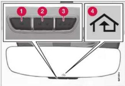
The illustration is generic - the design may vary.
1 Button 1
② Button 2
3 Button 3
4 Indicator light
HomeLink ^® is delivered integrated in the rearview mirror. The HomeLink ^® panel consists of three
▶▶
STARTING AND DRIVING
programmable buttons and an indicator light in the mirror.
For more information about HomeLink®, please visit www.HomeLink.com, www.youtube.com/HomeLinkGentex or call 1-800-355-3515.
Save the original remote controls for future programming (e.g. for use in another vehicle). It is also advisable to delete the button programming if the vehicle is sold.
Related information
• Using HomeLink ^®* (p. 491)
• Programming HomeLink®* (p. 490)
• Type approval for HomeLink®* (p. 492)
Programming HomeLink®\*12
Follow these instructions to program HomeLink ^® , reset all programming, or program individual buttons.
NOTE
In some vehicles, the ignition must be on or in the "accessory position" before HomeLink® can be programmed or used. It can be a good idea to put new batteries in the remote control being replaced by HomeLink® for faster programming and better radio signal transmission. The HomeLink® buttons should be reset before programming.
WARNING
While HomeLink® is being programmed, the garage door or gate being programmed may be activated. Make sure that no one is near the door or gate during programming. When programming a garage door opener, it is advised to park outside of the garage.
- Point the remote control at the HomeLink® button to be programmed and hold it about 2-8 cm (1-3 inches) from the button. Do not obstruct the HomeLink® indicator light.
Note: Some remote controls are more effective at programming HomeLink® from a distance of about 15-20 cm (6-12 inches). Try moving the remote control closer or further away if you are experiencing any difficulties programming.
-
Press and hold both the remote control button and the HomeLink® button to be programmed.
-
Do not release the buttons until the indicator light has stopped flashing slowly (about once a second) and either flashes quickly (about 10 times a second) or glows steadily.
Steady glow: Indication that programming is complete. Press the programmed button twice to activate.
Flashing quickly: The device being programmed with HomeLink® may have a security function that requires an extra step. Try pressing the programmed button twice to see whether the programming works. Otherwise, continue with the following steps.

- Locate the "training" button ^13 on the receiver for the e.g. garage door opener. It is usually located near the antenna bracket on the receiver.
- Press and release the "training" button once. Programming must be completed within 30 seconds after pressing the button.
- Press and release the HomeLink® button to be programmed. Repeat the press/hold/release sequence a second time. For some receivers, the sequence may need to be repealed a third time.
Programming is now completed and the garage door, gate, etc. should now be activated when the programmed button is pressed.
If you experience any difficulties programming, please contact HomeLink® at: www.HomeLink.com, www.youtube.com/HomeLinkGentex or call 1-800-355-3515.
Programming individual buttons
To program an individual HomeLink® button:
- Press and hold the desired button for about 20 seconds.
- When the indicator light on HomeLink® starts flashing slowly, it is possible to program as usual.
Note: If the button you are reprogramming does not program with a new device, it will return to the previously saved programming.
Resetting the HomeLink® buttons
It is only possible to reset all HomeLink® buttons at once. It is not possible to reset individual buttons. Individual buttons can only be reprogrammed.
- Press and hold the outer buttons (1 and 3) on HomeLink® for about 10 seconds.
When the indicator light goes from a steady glow to flashing, the buttons have been reset and are ready for reprogramming.
Related information
• Using HomeLink ^® (p. 491)
- HomeLink®* (p. 489)
• Type approval for HomeLink®* (p. 492)
Using HomeLink®\*14
Once HomeLink ^® is programmed, it can be used instead of the separate remote controls.
Press and hold the programming button. The garage door, gate, alarm system, etc. will be activated (this may take several seconds). If the button is held down for more than 20 seconds, reprogramming will begin. The indicator light will glow steadily or flash when the button has been pressed. The original remote controls may be used concurrently with HomeLink® if desired.

NOTE
If the ignition is off, HomeLink® works for 30 minutes after the driver's door has been opened.

WARNING
- If you use HomeLink® to open a garage door or gate, be sure no one is near the gate or door while it is in motion.
- Do not use HomeLink® with any garage door opener that lacks safety stop and reverse features as required by US federal safety standards (this includes any garage door opener model manufactured before April 1, 1982). A garage door that cannot detect an object - signaling the door to stop and reverse - does not meet current U.S. federal safety standards. For more information, contact HomeLink at: www.homelink.com.
Related information
- HomeLink®* (p. 489)
- Programming HomeLink®* (p. 490)
• Type approval for HomeLink®* (p. 492)
Type approval for HomeLink ^® \*15
FCC (USA) and IC (Canada)
This device complies with FCC rules part 15 and Industry Canada RSS-210. Operation is subject to the following two conditions: (1) This device may not cause harmful interference, and (2) This device must accept any interference that may be received including interference that may cause undesired operation.

WARNING
The transmitter has been tested and complies with FCC and IC rules. Changes or modifications not expressly approved by the party responsible for compliance could void the user's authority to operate the device. ^16
Type approval for EU
Gentex Corporation hereby declares that HomeLink® Model UAHL5 complies with the Radio equipment directive 2014/53/EU.
Wavelengths within which the radio equipment operates:
• 869.40MHz-869.65MHz <25mW E.R.P.
• 869.70MHz-870.00MHz <25mW E.R.P.
Certificate holder address: Gentex Corporation, 600 North Centennial Street, Zeeland MI 49464, USA
For more information, see support.volvocars.com.
Related information
HomeLink®* (p. 489)
14 Certain markets only.
15 Certain markets only.
16 The term "IC:" before the certification/registration number only signifies that Industry Canada technical specifications were met.
Compass\*
An integrated compass in the upper right corner of the rearview mirror shows the direction the vehicle is traveling.

Rearview mirror with compass.
Eight different compass directions are shown with the abbreviations: N (north), NE (northeast), E (east), SE (southeast), S (south), SW (south-west), W (west) and NW (northwest).
Related information
- Activating and deactivating the compass* (p. 493)
• Calibrating the compass* (p. 493)
Activating and deactivating the compass\*
An integrated compass in the upper right corner of the rearview mirror shows the direction the vehicle is traveling.
Activating and deactivating the compass
The compass is automatically activated when the vehicle is started.
To deactivate/activate the compass manually:
- Use a paper clip or similar object to press the button on the bottom of the mirror.
Related information
- Compass* (p. 493)
• Calibrating the compass* (p. 493)
Calibrating the compass\*
The globe is divided into 15 magnetic zones. The compass should be calibrated if the vehicle is driven from one zone to another.
To calibrate the compass:
- Stop the vehicle in a large, open area away from steel constructions and high-voltage power lines.
- Start the engine and switch off all electrical equipment (climate system, wipers, etc.) and make sure all doors are closed.
NOTE
Calibration may fail or not even be initiated if electrical equipment is not turned off.
- Hold the button on the bottom of the rear-view mirror pressed for about 3 seconds (using e.g. a paper clip). The number of the current magnetic zone is shown.
STARTING AND DRIVING
◀◀
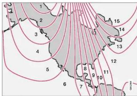
Magnetic zones.
- Press the button on the underside of the mirror repeatedly until the desired magnetic zone (1-15) appears (see the map of magnetic zones).
- Wait until the display again shows C, or press and hold the button on the underside of the rearview mirror for approx. 6 seconds until C is displayed.
- Drive slowly in a circle at a speed of no more than 10 km/h (6 mph) until a compass direction is shown in the display. This indicates that calibration is complete. Drive in a circle two more times to fine-tune the calibration.
- Vehicles with heated windshields*: If C is shown in the display when the windshield heating function is activated, perform step 6 above with the heating function on.
- Repeat the above procedure as needed.
Related information
- Compass* (p. 493)
- Activating and deactivating the compass* (p. 493)
AUDIO, MEDIA AND INTERNET
AUDIO, MEDIA AND INTERNET
Audio, media and Internet
The audio and media system consists of a media player and a radio. A cellular phone can also be connected through Bluetooth to use hands-free functions or play music in the vehicle. When the vehicle is connected to the Internet, it is also possible to use apps to play media.

natural_image
Interior view of a car dashboard and steering wheel, showing steering wheel, dashboard, and steering wheel (no visible text or symbols)Audio and media overview
The functions can be controlled using voice commands, the steering wheel keypad or the center display. The number of speakers and amplifiers varies depending on the audio system installed in the vehicle.
System updates
The audio and media system is continuously improved. When the vehicle has an Internet connection, system updates can be downloaded for optimal functionality; see support.volvocars.com.
Related information
• Media player (p. 518)
- Radio (p. 501)
- Phone (p. 532)
• Internet-connected vehicle* (p. 541)
- Apps (p. 498)
• Voice control (p. 145)
- Ignition modes (p. 437)
• Driver distraction (p. 39)
- Handling system updates via Download Center (p. 613)
- License agreement for audio and media (p. 549)
Sound settings
The sound system is precalibrated for optimal sound reproduction, but these settings can be personalized.
The system's volume is normally adjusted using the volume control below the center display or the right-side steering wheel keypad. This applies, for example, when playing music or the radio or during phone calls and active traffic messages.
Optimal sound reproduction
The audio system is precalibrated for optimal sound reproduction using digital signal processing. This calibration takes into account speakers, amplifiers, passenger compartment acoustics, listener position, etc. for each combination of vehicle model and audio system. There is also a dynamic calibration that takes into account the volume control setting and the vehicle's speed.
Personal settings
Different settings are available in Top view under
Settings Sound depending on the vehicle's sound system.
Premium Sound\* (Bowers & Wilkins)
- Tone - setting for e.g. bass, treble, equalizer, etc.
• Balance - balance between right/left and front/rear speakers. - System Volumes – adjusts volume in the various systems of the car, e.g. Voice Control, Park Assist and Phone Ringtone.
High Performance Pro\* (Harman Kardon)
• Equalizer - setting of equalizer.
• Balance - balance between right/left and front/rear speakers.
- System Volumes – adjusts volume in the various systems of the car, e.g. Voice Control, Park Assist and Phone Ringtone.
High Performance
- Tone - setting for e.g. bass, treble, equalizer, etc.
• Balance - balance between right/left and front/rear speakers. - System Volumes – adjusts volume in the various systems of the car, e.g. Voice Control, Park Assist and Phone Ringtone.
Related information
• Sound experience* (p. 497)
• Media player (p. 518)
• Voice control settings (p. 148)
• Phone settings (p. 540)
• Audio, media and Internet (p. 496)
• Internet-connected vehicle* (p. 541)
Sound experience\*
Sound experience is an app that provides access to additional sound settings.
Open Sound Experience from the center display's App view. Depending on the sound system installed in the vehicle, the following settings are possible:
Premium Sound\* (Bowers & Wilkins)
- Studio - the sound can be optimized for Driver, All and Rear.
- Individual stage - surround sound mode with settings for intensity and enclosure.
• Concert hall - reproduces the acoustics of Gothenburg's Concert Hall

Recreate the acoustics from the Gothenburg Concert Hall.
▶▶
AUDIO, MEDIA AND INTERNET
High Performance Pro\* (Harman Kardon)
- Seat Optimization - the sound can be optimized for Driver, All and Rear.
- Surround - surround sound mode with level settings.
- Tone - setting for e.g. bass, treble, equalizer, etc.
Related information
• Sound settings (p. 496)
• Navigating in the center display's views (p. 115)
Apps
The App view contains applications (apps) that provide access to certain vehicle services.
Swipe the center display screen from right to left ^1 to access the App view from the Home view. This view displays downloaded apps (third-party apps) as well as apps for integrated functions, such as FM radio.

App view. (generic illustration; basic apps vary depending on market and model)
Several basic apps are always available. More apps such as web radio and music services can be downloaded when the car is connected to the Internet.
Some apps can only be used when the vehicle is connected to the Internet.
Start an app by pressing the app in the center display's app view.
Related information
• Download apps (p. 499)
- Updating apps (p. 500)
- Deleting apps (p. 500)
• Apple® CarPlay®* (p. 527)
- Android Auto* (p. 530)
- Internet-connected vehicle* (p. 541)
• Hard disk storage space (p. 548)
• Terms of use and data sharing (p. 548)
Download apps
New apps can be downloaded when the vehicle is connected to the Internet.
NOTE
Data downloading can affect other services such as transfer data, e.g. web radio. If the affect on other services is experienced as problematic, the download can be interrupted. Alternatively, it may be appropriate to switch off or cancel other services.
NOTE
When downloading using a phone, pay extra attention to the data traffic costs.
- Open the Download Center app in App view.

-
Select New apps to open a list of apps that are available but are not installed in the vehicle.
-
Tap on the row for an app in order to expand in the list and get more information about the app.
- Select Install to start the download and installation of the app.
The current status of the download and installation will be shown.
If a download cannot be started immediately, a message will be displayed. The app will remain in the list and it will be possible to reattempt downloading.
Canceling a download
- Tap Abort to cancel a download in progress.
Note that only a download can be cancelled. An installation cannot be cancelled once it has begun.
Related information
- Apps (p. 498)
- Updating apps (p. 500)
- Deleting apps (p. 500)
- Internet-connected vehicle* (p. 541)
- Handling system updates via Download Center (p. 613)
• Hard disk storage space (p. 548)
Updating apps
Apps can be updated when the vehicle is connected to the Internet.

NOTE
Data downloading can affect other services such as transfer data, e.g. web radio. If the affect on other services is experienced as problematic, the download can be interrupted. Alternatively, it may be appropriate to switch off or cancel other services.

NOTE
When downloading using a phone, pay extra attention to the data traffic costs.
If an app is being used while an update is in progress, it will be restarted to complete the update.
Update all
- Open the Download Center app in App view.

- Select Install all.
The update will begin.
Update certain apps
- Open the Download Center app in App view.
- Select Application updates to open a list of all available updates.
- Find the desired app and select Install. >The update will begin.
Related information
- Apps (p. 498)
• Download apps (p. 499) - Deleting apps (p. 500)
- Handling system updates via Download Center (p. 613)
• Internet-connected vehicle* (p. 541)
Deleting apps
When the vehicle is connected to the Internet, it is possible to uninstall apps.
If the app is being used, it must be closed before it can be uninstalled.
- Open the Download Center app in App view.
- Select Application updates to open a list of all installed apps.
- Find the desired app and select Uninstall to begin uninstalling the app.
When the app has been uninstalled, it will be removed from the list.
Related information
- Apps (p. 498)
- Download apps (p. 499)
- Updating apps (p. 500)
- Handling system updates via Download Center (p. 613)
- Internet-connected vehicle* (p. 541)
Radio
The radio can receive broadcasting from the FM waveband with HD Radio™ Technology and SiriusXM® Satellite radio *. When the vehicle has an Internet connection, it is also possible to listen to web radio.


The radio can be controlled using voice commands, the right-side steering wheel keypad or the center display.
Related information
• Starting the radio (p. 501)
- Changing waveband and radio station (p. 502)
• Storing radio favorites (p. 503)
• Radio settings (p. 504)
• RBDS (p. 505)
• HD Radio™ (p. 505)
SiriusXM® Satellite radio* (p. 508)
- Internet-connected vehicle* (p. 541)
• Voice control for radio and media (p. 148)
• Media player (p. 518)
Starting the radio
The radio is started from the center display's App view.
- Open the desired waveband (e.g. FM) from App view.

- Select a radio station.
Related information
- Radio (p. 501)
• Searching for a radio station (p. 503)
▶▶
AUDIO, MEDIA AND INTERNET
- Changing waveband and radio station (p. 502)
• Storing radio favorites (p. 503)
• Radio settings (p. 504)
• Voice control for radio and media (p. 148)
Changing waveband and radio station
Instructions for changing wavebands, waveband lists and radio stations in the selected list are provided here.
Changing wavebands
Swipe from App view on the center display and select the desired waveband (e.g. FM) or open the App menu in the instrument panel with the right-side steering wheel keypad and make your selection there.
Changing a list in a waveband

- Tap Library.
- Select playback from Stations, Favorites or Genres.
- Tap the desired station in the list.
Favorites – only plays selected favorite channels.
Genres - only plays channels broadcasting the selected genre or program type, e.g. pop, classical, etc.
Changing radio stations in a selected list
- Press ◀️ und the center display or on the right-side steering wheel keypad.
Move step-by-step through the selected list.
It is also possible to change radio station in the selected list via the center display.
Related information
- Radio (p. 501)
• Searching for a radio station (p. 503)
• Voice control for radio and media (p. 148)
• Storing radio favorites (p. 503)
• Radio settings (p. 504)
• App menu in instrument panel (p. 103)
Searching for a radio station
The radio automatically compiles a list of the radio stations that are sending out the strongest signals in the vehicle's current location.
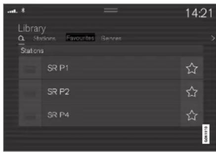
Searching is performed in different ways depending on the waveband selected:
• FM, stations, genres and frequency.
-
Tap Library.
-
Tap
Search view will displayed and the keyboard will open.
- Enter a search word/phrase.
The search will start and change as characters are entered. Search results will be displayed by category.
Searching for a station manually
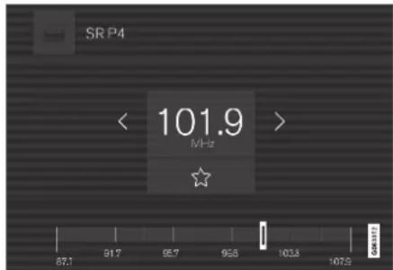
Searching manually makes it possible to find and tune to stations that are not on the automatically compiled list of the strongest stations in the area.
- Tap Manual tuning, drag the control or tap K or B less and hold to skip to the next available station in the frequency band. You can also use the right-side steering wheel keypad.
Related information
- Radio (p. 501)
• Starting the radio (p. 501) - Changing waveband and radio station (p. 502)
• Voice control for radio and media (p. 148)
• Radio settings (p. 504)
Storing radio favorites
It is possible to add a radio a radio station in the Radio favorites app and in the list of favorites for the waveband (e.g. FM). Instructions for adding and removing favorites are provided below.
Radio favorites

Radio favorites shows saved favorites from all wavebands.
- Open the Radio favorites app from App view.
- Tap the desired station in the list to listen.
Adding and deleting radio favorites
- Tap add/remove a radio channel from the waveband's list of favorites or Radio favorites.
If a favorite station is deleted here, it will also be deleted from that waveband's list of favorites.
Related information
- Radio (p. 501)
• Starting the radio (p. 501)
• Searching for a radio station (p. 503) - Changing waveband and radio station (p. 502)
AUDIO, MEDIA AND INTERNET
• Voice control for radio and media (p. 148)
• Radio settings (p. 504)
• App menu in instrument panel (p. 103)
Radio settings
There are a number of different radio functions that can be activated and deactivated.
Canceling a traffic message
A current broadcast (e.g. a traffic message) can be temporarily interrupted by pressing ○ in the right-side steering wheel keypad or tapping Cancel in the center display.
Activating and deactivating radio functions
Pull down Top view and select Settings → Media and the desired waveband to see available functions.
FM Radio
- HD Radio FM: HD Radio™ Technology: makes it possible to achieve a sound quality comparable with a CD.
• Show Broadcast Information: shows information on program content, artists, etc. - Freeze Program Name: select to stop the program service name from scrolling continuously. Instead it freezes after 20 seconds.
SiriusXM® Satellite radio\*
Pull down Top view and select Settings →
Media SiriusXM to show a list of available options.
Related information
- Radio (p. 501)
- Settings for SiriusXM® Satellite radio* (p. 511)
- Symbols in the center display status bar (p. 124)
RBDS
RBDS radio
RBDS (Radio Broadcast Data System) enables certain functionality ^2 , such as:
- Searches for program types or new broadcasts
- Text information about currently broadcast programs
Related information
- Radio (p. 501)
• Radio settings (p. 504)
HD Radio™
HD Radio is a brand name registered by the DTS, Inc. ^3 . They are the developer of a broadcasting technology called IBOC or In Band On Channel, which refers to the method of transmitting a digital radio broadcast signal centered on the same frequency as the FM station's present frequency.
Introduction

Display when the radio is receiving an HD Radio broadcast (generic illustration)

NOTE
HD Radio volume may fade in and out at times due to coverage limitations.
The IBOC system is referred to as a "hybrid" since it is both analog and digital. During hybrid operation, receivers still continue to receive the analog (non-digital) signal. HD Radio receivers incorporate both modes of reception, where the receiver will automatically switch to the analog signal if the digital signal cannot be decoded or is lost by the receiver.
When you have tuned to an HD Radio station, the
HD symbol will appear in the infotainment system display. The symbol will be displayed in different colors:
- Grayed-out symbol: No HD Radio broadcast reception
- White symbol: the radio is actively receiving an HD broadcast
- Orange symbol: the radio is receiving an HD broadcast with digital sound
More information about HD Radio and IBOC can be found on DTS, Inc.'s website, www.dts.com.
Artist Experience™
A radio station's logo and album art can be displayed. If a station opts to provide this information, it is broadcast once every 12 minutes, which means that there may be a delay before the logo/album art appear on the screen. The radio can store 100 station logos so the next time the radio is tuned to the same station, the logo will
AUDIO, MEDIA AND INTERNET
be displayed immediately. Album art is synched with the artist that you are currently listening to.
Ball game mode
This feature means that a main FM station (HD1) will broadcast live events, where the content of the programming is more important than sound quality, in analog mode only to help prevent the delay between analog and digital broadcasting. The HD Radio symbol will be white during live broadcasts and "Live" will be displayed next to the symbol.
Benefits of digital broadcasting
• Better sound (FM sounds near CD quality).
- Some FM frequencies offer a greater number of listening choices through "multicasting" (consisting of a frequency's main channel and any sub-channels that may also be available on that particular frequency.)
- When receiving a digital signal there is no multipath disturbance or hisses/pops/crackling due to outside influences.
How HD Radio ^TM Technology broadcasting works
HD Radio works similarly to conventional radio and broadcasts of this type are available in many areas of the United States. However, there are a few key differences:
- Instead of transmitting one analog signal, stations send out a bundled signal - both analog and digital.
- An HD Radio receiver can receive both digital and analog broadcasts. Depending on the terrain and location of the vehicle (which will influence the signal strength), the receiver will determine which signal to receive.
Related information
- Radio (p. 501)
- Activating and deactivating the HD Radio™ (p. 506)
• HD Radio™ sub-channels (p. 507)
• HD Radio™ limitations (p. 508) - Changing waveband and radio station (p. 502)
• Searching for a radio station (p. 503)
Activating and deactivating the HD Radio™
HD Radio is deactivated when the car leaves the factory.
When listening to an HD Radio station and driving through areas with weak HD signals (fringe areas), you may experience that the radio repeatedly switches between analog/digital and digital/analog reception. If this happens, it may be desirable to switch HD off.
Carry out the following to activate or deactivate HD Radio:
- Drag down the top view and tap on Settings.
- Press Media and FM Radio.
- Press HD Radio FM to activate/deactivate the function.
If HD radio is deactivated, the radio will be unable to receive digital broadcasts but it will continue to function as a conventional radio (analog FM receiver). Please note that when HD is switched off, it will not be possible to tune in to sub-channels.
Note that if you activate or deactivate HD Radio only the selected wavelength band is affected.
Related information
• HD Radio™ (p. 505)
• HD Radio™ sub-channels (p. 507)
• HD Radio™ limitations (p. 508)
- Opening contextual setting in the center display (p. 133)
HD Radio™ sub-channels
In many cases, a main HD Radio station (FM wavebands only) will also have sub-channels offering additional types of programming or music.
Sub-channels

Example of an HD Radio station with sub-channels
If any sub-channels are available, they will listed below the main channel on the screen. In this example, WILD-FM HD2 is a sub-channel.
Selecting sub-channels
To listen to a station's sub-channel(s), tap the station on the screen or press the forward/back arrow keys on the right-side steering wheel keypad or below the screen.
Sub-channels can also be saved as radio favorites.
If you tap a sub-channel favorite, it may take up to 6 seconds before the channel becomes audible. If you tap a station while you are out of digital range of the transmitter, No reception will be displayed.
Related information
• HD Radio™ (p. 505)
- Activating and deactivating the HD Radio™ (p. 506)
- Changing waveband and radio station (p. 502)
• Searching for a radio station (p. 503)
• HD Radio™ limitations (p. 508)
HD Radio™ limitations
Limitations
- Main channel vs. sub-channels (FM only): The main channel is the only channel that can receive in hybrid mode (both digital and analog). If a frequency has sub-channels, they are broadcast in digital mode only. The main FM channel will be displayed as, for example, "WRIF-FM HD1". The sub-FM channels will be displayed as "WRIF-FM HD2", "WRIF-FM HD3", etc.
- Reception coverage area: Due to current IBOC transmitter power limitations, the reception coverage area in digital mode is somewhat more limited than the station's analog coverage area. Be aware that, like all radio transmission technology, terrain, time of day, vegetation and buildings can have a positive or negative effect on radio reception.
- Analog to digital/digital to analog blending: Analog to digital blending will occur as the signal strength reaches a preset threshold in the receiver. This will be noticeable in fringe areas (areas with weak reception) and is normal.
NOTE
There may be a noticeable difference in sound quality when a change from analogue to digital or digital to analogue occurs, such as:
• Volume increase or decrease
- Equalizer settings, i.e., Bass/ Midrange/ Treble cut or boost
- Time alignment (Digital program material in extreme cases can be as much as 8 seconds behind the analogue). This will noticeable as a "stuttering" effect.
The above items are dependant on the broadcaster's equipment settings and do not indicate a fault in the vehicle's radio receiver or antenna systems.
Related information
• HD Radio™ (p. 505)
- Activating and deactivating the HD Radio™ (p. 506)
• HD Radio™ sub-channels (p. 507)
SiriusXM® Satellite radio\*
The SiriusXM ^® Satellite system broadcasts from of a number of high elevation satellites in geosynchronous orbit.
Listening to satellite radio
The digital signals from the satellites are line-of-sight, which means that physical obstructions such as bridges, tunnels, etc, may temporarily interfere with signal reception.
Avoid any obstructions, such as metallic objects transported on roof racks or in a ski box, or other antennas that may impede signals from the SiriusXM ^® satellites.
Selecting SiriusXM ^® Satellite radio mode
- From the center display's Home view, swipe from right to left to come to App view.

2. Tap the SiriusXM® Satellite radio icon.

Home view with SiriusXM® Satellite radio activated
If there is no subscription activated, tap channel 1, where you will be prompted on the screen to phone SiriusXM®.
If a cell phone is paired and connected to the vehicle, you can also subscribe by:
-
From Home view, pull down the Settings menu.
-
Open the settings menu for SiriusXM® Satellite radio.
- Tap Unsubscribed Services
- To call SiriusXM ^® , enter the phone number. They will activate the subscription of your choice. This may take several minutes.
When the subscription has been activated, lap the SiriusXM® Satellite radio icon to start the function and display the channel list included in your subscription.
Related information
Radio (p. 501)
• Using SiriusXM® Satellite radio* (p. 509)
- Settings for SiriusXM® Satellite radio* (p. 511)
SiriusXM Travel Link®* (p. 512)
Using SiriusXM® Satellite radio\*
SiriusXM ^® Satellite radio offers several features for finding and listening to music, news, sporting events, etc. being broadcast on satellite radio stations.
SiriusXM® Satellite radio functions

With SiriusXM® Satellite radio activated, tap Library to display a screen offering the following functions:
• Search (the magnifying glass icon)
- Channels
- Favorites
- Categories
If you have used this view previously, you will be returned to the most recently used one.
▶▶
AUDIO, MEDIA AND INTERNET
◀ Search
Tap the magnifying glass to display a screen where you can enter text using the center display's keyboard or by writing in the free-text field to search for e.g., a station number, an artist, song title, etc.
Channels
Tap to display a complete list of the channels included in your subscription. Tap a channel name to listen. If a subscription to a channel has expired, its name will be grayed-out on the screen.
For quick access to a channel that you often listen to, tap the star to the right of the channel's name. It will then be added to your list of favorites.
Favorites
Tap to display the channels that you have added to this list. Tap a channel name to listen.
Categories/Genres
Tap to display the categories available. Tap a category or genre name to display the channels that it contains and then tap a channel to listen.
If you have activated alerts (see the "Alerts" section below) and an alert is activated for an artist, song or team, temporary virtual categories will also be created and displayed. The channels currently broadcasting the song, artist or broadcasting a program with the selected team will be listed in a virtual category.
EPG (Electronic Program Guide)
On the center display's Home view, tap EPG for information about e.g., when a program is being broadcast and its name, description, artist, etc. If no information is currently available, No information will be displayed.
Alerts
If this feature has been selected under SiriusXM Settings, the Alerts button will be displayed on the Home view.
To add e.g. an artist's name, song title or a sports team to the list of alerts:
- Tune to a channel that is broadcasting a song, game, etc., of your choice.
- Tap the Alerts button.
- A pop-up window will be displayed showing a list of alerts (nothing will be displayed if the selected channel does not support the alert function).
- Select one of the alternatives in list (only one can be selected at a time).
- The song/artist/team will now be added to the list of alerts. Favorite sports teams can also be added to the list using "Game Alert" in the SiriusXM satellite radio settings.
When your choice is being broadcast on a channel, you will be informed by a pop-up.
iTunes tagging
From the center display's Top view, tap SiriusXM Settings. Tap the iTunes Tagging menu. Tap the iTunes Tagging box to activate/deactivate this function and tap Close to return to Home view. Tap Tags List to display a list of all tagged songs.
If the function is activated, the iTunes tag button will be displayed in Home view. If a song is played that you would like to buy in the iTunes store, tap this button while the song is playing to tag it. If a song with iTunes Tagging information is available, the button will be selectable. Tap the button to tag the song. If you would like to buy a tagged song via iTunes, Tap the iTunes tag button.
To buy a song in iTunes, begin by connecting an iPhone/iPod/iPad to the USB port in the tunnel console. The iTunes tagging list will automatically be transferred to the device and removed from the list in the vehicle. If the device is connected when a song is tagged, the data will automatically be saved in the device. To purchase the song, consult the iTunes support page.
Related information
SiriusXM® Satellite radio* (p. 508)
- Entering characters, letters and words by hand in the center display (p. 129)
- Settings for SiriusXM® Satellite radio* (p. 511)
- Settings for SiriusXM® Satellite radio* (p. 511)
- Connecting a device via the USB port (p. 525)
Settings for SiriusXM® Satellite radio\*
There are numerous settings that can be made to enhance your SiriusXM® Satellite radio listening experience.
Settings
Drag down the top view and tap on Settings → Media SiriusXM. The following alternatives will be displayed:

Traffic Jump
Tap to display a list of cities from which you can choose to get traffic/weather information (or Traffic jump off to deactivate the feature). Tap to select a city (JUMP will be displayed on the Home screen next to Library). Tap Back to return to the list of settings or Close to return to the Home screen.
From the Home screen, tap JUMP to activate the function. When traffic/weather information is available from the selected city, the radio will automatically tune to the channel providing the information. When the information/announcement is finished, the radio will automatically return to the channel that you were previously listening to.
During an announcement, tap JUMP to interrupt the message and return to the station that you were currently listening to.
Alert Notifications
Tap the box to activate/deactivate. When activated, you will be notified if a song, artist, etc. that you have selected is playing. You will be asked if you want to listen.
Alert Notifications Sound
Opt to receive an audible alert when one of your selected choices is being played.
Sort Channels
Select how to sort your channels list.
iTunes Tagging
Tap to display a menu with the options: iTunes Tagging and Tags List. With this feature activated, songs can be tagged for later purchase from the iTunes store.
▶▶
AUDIO, MEDIA AND INTERNET
Game Alerts
Tap to display a list of sports.
Tap a sport to display a list of teams and tap a box on the right side of the screen to select a team as a favorite. An alert will then be provided when information about the team is being broadcast.
Tap Confirm below the list to return to the list of sports.
Tap Back to return to the list of settings or Close to return to the main screen.
Unsubscribed Services
If you have a SiriusXM ^® Satellite radio subscription, any channels not included in the subscription will be listed here. Call SiriusXM ^™ to subscribe. The phone number will be shown on the screen. If a cell phone is paired and connected to the vehicle, tap the phone number to make the call.
Skipped Stations
Tap to display a list of channels that you would like to skip (hide). Hide channels from the channel list by tapping the boxes to the right of the screen. Skipped (hidden) channels will not be shown in the channel list. However, a channel previously selected as a favorite will still be displayed in the list of favorites, even it has been added to the skip list.
Skipped Categories
Tap to display a list of categories. Tap a category to skip (hide) it. It will not be displayed in the list of categories.
Related information
SiriusXM® Satellite radio* (p. 508)
• Using SiriusXM® Satellite radio* (p. 509)
SiriusXM Travel Link®\*
SiriusXM Travel Link is a feature offered by SiriusXM® Satellite radio* that can provide information about e.g., weather forecasts, weather alerts, service stations, sports, etc. in the vicinity of the vehicle.
Starting SiriusXM Travel Link
NOTE
SiriusXM Travel Link services are only available in vehicles equipped with the Sensus Navigation system.
From the center display's App view, tap Travel Link to activate the feature. A disclaimer text will be displayed. Tap OK to display a list of SiriusXM Travel Link services:
- Alerts
Fuel - Sports
- Weather
- Favorites
In order to use one or more of these services, the user has to subscribe to the ones desired.
To subscribe to a SiriusXM Travel Link service:
-
Open the center display's Top view.
-
Tap Settings.
-
Press SiriusXM Travel Link and Subscription Status.
To subscribe, call the phone number listed on the screen.
Any services not subscribed will be grayed out and contain the text Service not subscribed.
When the services have been activated (subscribed), tap the one of your choice to start it.
The following applies for all of the SiriusXM Travel Link services:
- Pressing the Back button will take you back to the previous screen
- Pressing the Close button will take you to the SiriusXM Travel Link home screen.
NOTE
If the Close button is used to return to the SiriusXM Travel Link home screen, the following applies (the Weather service is used here as an example):
- If you have already used the Weather function, tapping Weather again in the SiriusXM Travel Link home screen before using any other SiriusXM Travel Link service will return you to the point where you left the Weather service.
- If another SiriusXM Travel Link service is used (e.g., Fuel, Sports, etc.) before you return to the Weather service, you will be returned to the default Weather view (in this case, Local).
The same principle applies to all of the SiriusXM Travel Link services.
Favorites
Many SiriusXM Travel Link selections can be saved for easy access as favorites by tapping the "star" icon next to the selection where applicable.
To display a list of your favorites, tap the Favorites application in the SiriusXM Travel Link home screen.
Related information
SiriusXM® Satellite radio* (p. 508)
SiriusXM Travel Link®* - Fuel (p. 516)
SiriusXM Travel Link®* - Sports (p. 517)
SiriusXM Travel Link®* - Weather (p. 514)
SiriusXM Travel Link®* - Notifications (p. 515)
AUDIO, MEDIA AND INTERNET
SiriusXM Travel Link®\* - Weather
This SiriusXM Travel Link service provides weather-related information near the vehicle, at a local ski resort, etc.
From the SiriusXM Travel Link home screen, to display weather-related information:
- Tap the Weather button to display this screen.
At the top of the screen, the following categories will be displayed:
• Search (the magnifying glass icon)
- Local
- Ski condition
Areas
- Favorites
Tap the category of your choice.
Search
Tap the magnifying glass icon. If the function is supported in the current context, a keyboard will appear on the screen. Enter the text of your choice and tap Search for detailed information from the SiriusXM Travel Link database.
Local ^4
Information from the closest weather station will be displayed and the following alternatives are available:
- Map view
- Today
- 5 days
Map view
Tap the map to display it in full-screen mode. Tap Back to return to the original map view.
Tap Map options to display the following alternatives.
- Weather radar
- Storm attributes
- Surface features
• Tropical storm tracks - Winds
Tap the relevant box to the right of the option to select/deselect it. Tap Done to confirm and return to the previous screen or Cancel.
Today
Tap to see the current temperature, or the temperature in 3/6 hours.
Tap Back to return to the Local screen or Close to return to the SiriusXM Travel Link home screen.
5 days
Tap to see weather information for the coming 5 days.
Tap Back to return to the Local screen or Close to return to the SiriusXM Travel Link home screen.
Ski condition
Tap to display a list of ski areas in the vicinity of the vehicle. Tap a name in the list for information such as if the ski area is open/closed, temperature, wind conditions, snow conditions, the number of lifts that are in operation, etc.
- Weather locations
- Ski location
Tap Map view to display a map and a weather legend.
Tap Map options to display the following alternatives.
- Weather radar
- Storm attributes
- Surface features
• Tropical storm tracks - Winds
Tap the relevant box to the right of the option to select/deselect it. Tap Done to confirm and return to the previous screen or Cancel.
Areas
Tap Areas to display a list of areas/locations in states from the SiriusXM Travel Link database.
Scroll to a state and tap to display:
- Weather locations: tap arrow to the right to display a list of towns. Scroll to desired town and tap for detailed weather information. You can choose Map view, today, 5 days or Favorites (star)
- Ski locations: tap arrow at right to display local ski areas. Tap an area for detailed info.
For information about storing a location, state, town, etc. as a favorite, see the heading "Favorites" in the article "SiriusXM Travel Link."
Related information
SiriusXM Travel Link®* (p. 512)
SiriusXM Travel Link® - Fuel (p. 516)
SiriusXM Travel Link®* - Sports (p. 517)
SiriusXM Travel Link®* - Notifications (p. 515)
SiriusXM Travel Link®\* - Notifications
This SiriusXM Travel Link service provides notifications of potential weather problems or other emergency situations in the vicinity of the vehicle.
From the SiriusXM Travel Link home screen, to show notifications:
- Tap the Alerts button to display this screen.
- If any notifications are currently available, a message will appear at the top of the screen. They can also be listed from the Settings menu in the center display's Top view.
- If no notifications are available, No active alerts will be displayed.
Types of notifications
To select the types of notifications to be displayed:
- From the Alerts screen, tap the Select alerts button at the bottom of the screen.
- This displays the types of notifications that can be displayed. Tap the box to the right of each type of notification to select/deselect it.
- Tap Done when you have made your selections. You will return to the Alerts screen.
Information about a notification
If any notifications have been displayed on the screen, tap one for more detailed information (i.e.,
the location of the weather problem on a map and a description of the situation).
If a phone number is available in a notification, a Call button will be displayed. Tap this button for additional information.
Related information
SiriusXM Travel Link®* (p. 512)
SiriusXM Travel Link®* - Fuel (p. 516)
SiriusXM Travel Link®* - Sports (p. 517)
SiriusXM Travel Link®* - Weather (p. 514)
AUDIO, MEDIA AND INTERNET
SiriusXM Travel Link®\* - Fuel ^5
This SiriusXM Travel Link service provides information and guidance to service stations near the vehicle providing the type of fuel that you prefer/require for your vehicle.
From the SiriusXM Travel Link home screen, to show fuel information:
- Tap the Fuel button to display the main fuel screen.
The following categories are shown:
• Search (the magnifying glass icon)
- Nearby
- Recommended
- Favorites
- Brands
Tap one of the alternatives to display its screen.
NOTE
In each of the categories listed, tapping the Select fuel type button near the bottom of the screen opens a sub-view where you can specify the type of fuel preferred/required (Regular, Midrange, Premium, Diesel, Electric 120V, etc.) Tap Done to return to the previous screen.
Search
Tap the magnifying glass icon. If the function is supported in the current context, a keyboard will appear on the screen. Enter the text of your choice and tap Search for detailed information if available.
Nearby
Tap for a list of service stations in the vicinity of the vehicle, with the nearest station at the top of the list.
The following information will be provided where available:
- For vehicles using gasoline, the price information for regular gasoline (unless another grade/type of fuel has been selected in Select fuel type)
- For electric vehicles/hybrids, information about charging stations, showing the total number of charging ports and the number of ports currently not in use
• the distance to the station - a star icon to set the service station as a favorite
Tap the name of a service station to display more detailed information.
For guidance to the service station, tap the Start navigation or Add as waypoint buttons. See
the Sensus Navigation* supplement for additional information about using the navigation system.
Recommended
Tap for a list of service stations near the vehicle, displayed according to the price of regular gasoline (unless another grade/type of fuel has been selected in Select fuel type) or of stations offering the greatest number of available charging ports for electric vehicles/hybrids. The station offering the lowest price/most available charging ports will be displayed at the top of the list. Tap the name of a service station to display more detailed information.
Favorites
Tap for a list of service stations that have been stored as favorites. Tap the name of a service station to display more detailed information.
In addition to the Select fuel type button at the bottom of the screen, tap the Edit button to delete individual stations from the list or tap Delete to clear the list. Tap Done to return to the previous screen.
Brands
-
Tap Brands to display a list of service station brands in the area.
-
Tap a brand to display a list of service stations affiliated with that brand (BP, Exxon, etc.).
- Tap the name of a service station to display more detailed information.
In addition to the Select fuel type button at the bottom of the screen, tap the Sort button to arrange the list according to Nearest or Cheapest/Recommended. Tap Done to return to the previous screen.
Related information
SiriusXM Travel Link®* (p. 512)
SiriusXM Travel Link®* - Notifications (p. 515)
SiriusXM Travel Link®* - Sports (p. 517)
SiriusXM Travel Link®* - Weather (p. 514)
SiriusXM Travel Link®\* - Sports
This SiriusXM Travel Link service provides information about sporting events, tournaments, teams, leagues, etc.
From the SiriusXM Travel Link home screen, to display sports information:
- Tap the Sports button to display the main sports screen.
A number of sports categories will be listed (Football, Baseball, Basketball, etc.)
Tap a sport to select a league in that sport (NFL, MLB, etc.) or a sport organization (PGA, LPGA, etc.).
The following is an example of the result of tapping Baseball:
- MLB (Major League Baseball) will be displayed.
- Tap MLB to display the two leagues in Major League Baseball (American League or National League).
-
Tap one of the league names to display the divisions in the league.
-
Tap one of the divisions to display:
-
In progress: play-by-play information about a match/game/tournament currently in progress. Continue tapping to display. In the detailed view, you can also select a radio station that is currently broadcasting an ongoing sporting event
- Headlines for MLB: Tap to display brief headline information
- Scheduled: schedules for coming matches, games, etc.
- Scores: match/game results
The same principle applies to all sports.
Related information
SiriusXM Travel Link®* (p. 512)
SiriusXM Travel Link®* - Notifications (p. 515)
SiriusXM Travel Link®* - Fuel (p. 516)
SiriusXM Travel Link®* - Weather (p. 514)
AUDIO, MEDIA AND INTERNET
Media player
The media player can play audio from the CD player* and from external audio sources connected via USB port or Bluetooth. It can also play video format via the USB port.
When the vehicle is connected to the Internet, it is also possible to listen to web radio, audio books and to access music services via apps.


The media player is controlled from the center display. Several functions can also be controlled using voice commands or the right-side steering wheel keypad.
The radio, which is also handled by the media player, is described in a separate section.
Related information
- Playing media (p. 518)
• Controlling and changing media (p. 520)
• Media searches (p. 521) - Apps (p. 498)
- Radio (p. 501)
• CD player* (p. 522) - Video (p. 522)
• Streaming media via Bluetooth® (p. 524) - Playing media via the USB port (p. 524)
• Internet-connected vehicle* (p. 541)
Playing media
The media player is controlled from the center display. Several other functions can also be controlled using the right-side steering wheel keypad or by using voice commands.
The radio can also be controlled in the media player. See the section describing the radio.
Starting a media source

App view. (Generic illustration; basic apps vary depending on market and model).
CD\*
- Insert a CD.
- Open the CD app from App view.
- Select the track you would like to play.
Playback will begin.
USB flash drive
- Inset a USB flash drive.
- Open the USB app from App view.
- Select the track you would like to play.
Playback will begin.
MP3 player and iPod®

NOTE
To start playback from an iPod, the iPod app must be used (not USB).
When an iPod is used as source, the car's audio and media system has a menu structure similar to the iPod player's own menu structure.
- Connect a media source.
- Start playback in the connected media source.
- Open the app (iPod, USB) from App view.
Playback will begin.
Bluetooth-connected device
- Activate Bluetooth in the media source.
- Connect a media source.
- Start playback in the connected media source.
- Open the Bluetooth app from App view.
Playback will begin.
Media with Internet connection
Medial playback from apps with Internet connection:
-
Connect the vehicle to the Internet.
-
Open the app from the App view.
Playback will begin.
Read the separate section on how to download apps.
Video
- Connect a media source.
- Open the USB app from App view.
- Tap the title you would like to play.
Playback will begin.
Apple CarPlay
CarPlay is described in a separate section.
Android Auto
Android Auto is described in a separate section.
Related information
- Handling the App menu in the instrument panel (p. 104)
- Radio (p. 501)
• Controlling and changing media (p. 520) - Connecting a device via the USB port (p. 525)
- Connecting a device via Bluetooth® (p. 524)
- Download apps (p. 499)
• Internet-connected vehicle* (p. 541) - Video (p. 522)
• Apple® CarPlay®* (p. 527)
• Android Auto* (p. 530)
• Voice control for radio and media (p. 148)
• Compatible file formats for media (p. 526)
AUDIO, MEDIA AND INTERNET
Controlling and changing media
Media playback can be controlled using voice commands, the steering wheel keypad or the center display.

The media player can be controlled using voice commands, the right-side steering wheel keypad or the center display.

Volume - turn the knob under the center display or tap ▲▼ on the right-side steering wheel keypad to raise or lower the volume.
Play/pause - tap the image for the track you would like to play, or press the button below the center display or ○ on the right-side steering wheel keypad.
Changing track/song - tap the desired track in the center display, or press ◀◀ or ▶◀.ow the center display or on the right-side steering wheel keypad.
Rewinding/fast-forwarding - tap the time axis in the center display and drag it sideways, or press and hold K or ▶ below the center display or on the right-side steering wheel keypad.
Changing media source - select from among previous sources in the app, tap the desired app in App view or use the right-side steering wheel keypad to select the app in the app menu.

Library - tap the button to play from the library.

Shuffle - tap the button to play tracks in a random order.

Similar - tap the button to use Gracenote to search for similar music on the USB device and create a playlist from the music found. The playlist can contain up to 50 tracks.
Change device - tap the button to toggle between USB devices when more than one is connected.
Related information
• Media player (p. 518)
• Media searches (p. 521)
• Sound settings (p. 496)
- Apps (p. 498)
- Gracenote® (p. 521)
• Voice control for radio and media (p. 148)
Media searches
Searches can be performed to locate a specific artist, composer, song title, album, video, audio book or playlist. If the vehicle is connected to the Internet, it is also possible to search for podcasts (online digital media).

- Tap .Q
Search view will displayed and the keyboard will open.
-
Enter a search word/phrase.
-
Tap Search.
A search will be performed on connected devices and the results will be displayed by category.
Swipe the screen horizontally to display each category separately.
Related information
• Media player (p. 518)
- Internet-connected vehicle* (p. 541)
- Playing media (p. 518)
- Entering characters, letters and words by hand in the center display (p. 129)
Gracenote®
Gracenote identifies artists, albums, tracks and any associated images that can be displayed during playback.
Gracenote MusicID ^® is a standard for music recognition.
- Tap Settings in the Top view.
- Tap Media Gracenote®.
-
Choose settings for Gracenote data:
-
Gracenote® Online Search - search Gracenote's online database for currently playing media.
- Gracenote® Multiple Results - select how Gracenote data should be displayed if there are multiple search results.
1 - the file's original data will be used.
2 - Gracenote data will be used.
3 - Gracenote or original data can be selected.
• None - no result will be displayed.
Updating Gracenote
The contents of the Gracenote database are continuously updated. For optimal functionality, update to the latest version. See support.volvocars.com for information and downloads.
▶▶
AUDIO, MEDIA AND INTERNET
Related information
- Playing media (p. 518)
• License agreement for audio and media (p. 549)
CD player\*
The media player can play CDs with compatible audio files.

natural_image
Interior view of a car dashboard with a close-up inset showing a device labeled '1' and '2' (no readable text or symbols beyond labels)1 Disc slot.
② Eject button.
Related information
- Playing media (p. 518)
• Voice control for radio and media (p. 148)
• Compatible file formats for media (p. 526)
Video
The media player can play videos from USB-connected devices.
Video is not available when the vehicle is moving; only audio will be played. Video will resume when the vehicle is stationary.
Information on compatible media formats is provided in a separate section.
Related information
- Playing video (p. 523)
- Playing DivX® (p. 523)
• Video settings (p. 523)
• Compatible file formats for media (p. 526)
Playing video
The USB app in App view is used to play videos.
- Connecting media source (USB device).
- Open the USB app from App view.
- Tap the title you would like to play.
Playback will begin.
Related information
- Video (p. 522)
- Playing DivX® (p. 523)
• Video settings (p. 523)
• Compatible file formats for media (p. 526)
Playing DivX®
The DivX Certified ^® device must be registered to play purchased DivX video-on-demand (VOD) movies.
- Tap Settings in the Top view.
- Tap Video BivX® VOD to get a registration code.
- Go to vod.divx.com for more information and to complete the registration process.
Related information
- Video (p. 522)
- Playing video (p. 523)
• Video settings (p. 523)
• Compatible file formats for media (p. 526)
Video settings
Some video playback settings can be adjusted, e.g. language.
The following can be adjusted by opening Top view and tapping Settings Video or with the video player in full-screen mode: Audio Language, Off and Subtitle Language.
Related information
• Video (p. 522)
Streaming media via Bluetooth®
The vehicle's media player is equipped with Bluetooth and can play audio files from Bluetooth-enabled external devices such as cellular phones and tablets.
In order for the media player to be able to wirelessly play audio files from an external device, the device must be connected to the vehicle via Bluetooth.
Related information
- Connecting a device via Bluetooth® (p. 524)
- Connecting a phone to the car via Bluetooth for the first time (p. 533)
- Playing media (p. 518)
• Compatible file formats for media (p. 526)
Connecting a device via Bluetooth®
Connect a Bluetooth ^® device to the vehicle to wirelessly play media and give the vehicle an Internet connection if it is available.
Many cellular phones on the market currently offer wireless Bluetooth® technology, but not all phones are fully compatible with the vehicle. For additional information on compatibility, see support.volvocars.com.
The procedure for connecting a media device is the same as for connecting a cellular phone to the vehicle via Bluetooth ^® .
Related information
• Streaming media via Bluetooth® (p. 524)
- Connecting a phone to the car via Bluetooth for the first time (p. 533)
- Playing media (p. 518)
Playing media via the USB port
External audio sources, such as an iPod® or MP3 player, can be connected to the audio system via the vehicle's USB port.
Devices with rechargeable batteries can be charged when they are connected via the USB port and the ignition is in mode I, II or the engine is running.
The content on the external source can be read faster if it only contains data of a compatible format. Video files can also be played via the USB port.
Some MP3 players have their own file system that the vehicle has support for.
Related information
- Connecting a device via the USB port (p. 525)
- Playing media (p. 518)
- Video (p. 522)
- Ignition modes (p. 437)
• Technical specifications for USB devices (p. 525)
• Apple® CarPlay®* (p. 527)
• Android Auto* (p. 530)
Connecting a device via the USB port
External audio sources, such as an iPod ^ or MP3 player, can be connected to the audio system via any of the vehicle's USB ports.
If the vehicle has two USB ports, the phone must be connected to the port with the white frame to use Apple CarPlay* or Android Auto*.
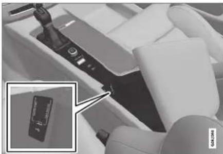
natural_image
Close-up of a white mechanical device with a hand operating the control panel, showing a close-up inset of its internal components (no visible text or symbols)USB ports (type A) in the tunnel console. Route the cable forward to help avoid pinching when the cover is closed.
Related information
- Playing media (p. 518)
- Playing media via the USB port (p. 524)
• Media player (p. 518) - Technical specifications for USB devices (p. 525)
• Technical specifications for USB devices (p. 525)
- Apple® CarPlay® (p. 527)
• Android Auto* (p. 530)
Technical specifications for USB devices
For the contents of USB devices to be read, the following specifications must be met.
Any folder structures will not be shown in the center display during playback.
| Max. number | |
| Files 15 000 | |
| Folders 1 000 | |
| Folder levels 8 | |
| Playlists 100 | |
| Tracks in a playlist 1 000 | |
| Subfolders No limit |
Technical specifications for the USB-A connector
- Type A port
- Version 2.0
- Voltage 5 V
• Max. current 2.1 A
Related information
- Playing media via the USB port (p. 524)
AUDIO, MEDIA AND INTERNET
Compatible file formats for media
In order to play media, the following file formats must be used.
Audio files
| Format | File extension Codec |
| MP3 .mp3 MPEG1 Layer III, MPEG2 Layer III, MP3 Pro (mp3 compatible), MP3 HD (mp3 compatible) | |
| AAC .m4a, .m4b, .aac AAC | LC (MPEG-4 part III Audio), HE-AAC (aacPlus v1/v2) |
| WMA .wma WMA8/9, | WMA9/10 Pro |
| WAV .wav LPCM | |
| FLAC .flac FLAC | |
Video files
| Format File extension | |
| MP4 .mp4, .m4v | |
| MPEG-PS .mpg, .mp2, .mpeg, .m1v | |
| Format File extension | |
| AVI .avi | |
| AVI (DivX) .avi, divx | |
| ASF .asf, .wmv | |
| MKV .mkv | |
Subtitles
| Format | File extension |
| SubViewer .sub | |
| SubRip | .srt |
| SSA | .ssa |
DivX®
DivX-certified devices have been tested for high-quality DivX (.divx, .avi) video playback. When you see the DivX logo, you have the freedom to play your favorite DivX videos.
| Profile | DivX Home Theater |
| Video codec | DivX, MPEG-4 |
| Resolution | 720x576 |
| Audio speed(bit rate) | 4.8Mbps |
| Frame rate | 30 fps |
| File extension | .divx, .avi |
| Max. file size | 4 GB |
| Audio codec | MP3, AC3 |
| Subtitles | XSUB |
| Special functions | Multiple subtitles, multiple audio, resume play |
| Reference | Meets all requirements of the DivX Home Theater profile. Visit divx.com for more information and software tools to convert your files into DivX Home Theater video. |
Related information
• Media player (p. 518)
• Video (p. 522)
- Playing DivX® (p. 523)
Apple® CarPlay®\*
With CarPlay, you can listen to music, make phone calls, get driving instructions, send/receive messages and use Siri, all while remaining focused on driving.

CarPlay works with select Apple devices. If the car does not already support CarPlay, this can be retrofitted. Contact a Volvo retailer to install CarPlay.
Information about supported apps and compatible phones is available on the Apple website: www.apple.com/ios/carplay/. Using apps that are not compatible with CarPlay could cause the connection between iPhone and the vehicle to be lost. Please note that Volvo is not responsible for the content of CarPlay.
When using map navigation via CarPlay, guidance will only be shown on the center display and not in the instrument panel or head-up display.
CarPlay apps can be controlled from the center display, a phone or with the right-side steering wheel keypad (for certain functions). The apps can also be voice-controlled using Siri. Press and hold the button on the steering wheel to start voice control with Siri. Press briefly to activate the vehicle's own voice control system. If Siri
cuts off too soon, press and hold the ⓄE ^6 button on the steering wheel.
By using Apple CarPlay you acknowledge the following: Apple CarPlay is a service provided by Apple Inc. under its terms and conditions. Volvo Cars is thus not responsible for Apple CarPlay or its features/applications. When using Apple CarPlay, certain information from your car (including its position) is transferred to your iPhone. In relation to Volvo Cars, you are fully responsible for your and any others person's use of Apple CarPlay.
Related information
• Using Apple® CarPlay®* (p. 527)
- Settings for Apple® CarPlay®* (p. 528)
• Voice control (p. 145)
- Resetting center display settings (p. 134)
Using Apple ^® CarPlay ^®*
To use CarPlay, the Siri voice control must be activated in your phone. The phone must also have an Internet connection via Wi-Fi or a mobile network.
Connecting an iPhone and starting CarPlay
NOTE
CarPlay can only be used if Bluetooth is disabled. A cell phone or media player connected to the vehicle via Bluetooth will therefore not be available when CarPlay is active. An alternative source must be used to provide an Internet connection for the vehicle's apps. Use Wi-Fi or the vehicle's integrated modem.
- Connect an iPhone to the USB port. If there are two USB ports, use the one with the white frame.
- Read the information in the pop-up window and then tap OK.
- Tap Apple CarPlay in App view.
- Read the terms and conditions and then tap Accept to connect.
The CarPlay tile will open and compatible apps will be displayed.
AUDIO, MEDIA AND INTERNET
- Tap the desired app.
The app will start up.
Starting CarPlay
CarPlay can be started as follows after an iPhone is connected.
- Connect an iPhone to the USB port. If there are two USB ports, use the one with the white frame.
If the auto start setting is selected - the name of the phone will be displayed.
-
Tap the name of the phone - the CarPlay tile will open and compatible apps will be displayed.
-
If the CarPlay tile does not open, tap Apple CarPlay in App view.
The CarPlay tile will open and compatible apps will be displayed.
- Tap the desired app.
The app will start up.
CarPlay will run in the background if another app is started in the same tile. To display CarPlay in the tile, tap the CarPlay icon in App view.
Switching connection between CarPlay and iPod
CarPlay to iPod
-
Tap Settings in the Top view.
-
Proceed to CarPlay. Communication Apple
- Uncheck the box for the Apple device that should no longer start CarPlay automatically when the USB cable is connected.
- Remove and then reinsert the Apple device into the USB port.
- Open the iPod app from App view.
iPod to CarPlay
- Tap Apple CarPlay in App view.
- Read the information in the pop-up window and then tap OK.
- Remove and then reinsert the Apple device into the USB port.
The Apple CarPlay tile will open and compatible apps will be displayed ^7 .
Related information
- Connecting a device via the USB port (p. 525)
• Apple® CarPlay®* (p. 527) - Settings for Apple® CarPlay®* (p. 528)
- Connecting the vehicle to the Internet via a phone (Wi-Fi) (p. 543)
- Connecting the vehicle to the Internet via vehicle modem (SIM card) (p. 544)
• Voice control (p. 145)
Settings for Apple ^® CarPlay ^®*
Settings for an Apple device connected through CarPlay ^® .
Automatic start
- Tap Settings in the Top view.
-
Tap Communication Apple CarPlay and select the desired setting:
-
Check the box - CarPlay will start automatically when the USB cable is connected.
- Uncheck the box - CarPlay will not start automatically when the USB cable is connected.
A maximum of 20 Apple devices can be stored in the list. When the list is full and a new device is connected, the oldest one will be deleted.
To delete the list, the settings must be rest in the center display (factory reset).
System Volumes
- Tap Settings in the Top view.
-
Tap Sound System Volumes to change the settings for the following:
-
Voice Control
• Navi Voice Guidance - Phone Ringtone
Related information
• Apple® CarPlay®* (p. 527)
• Using Apple® CarPlay®* (p. 527)
- Resetting center display settings (p. 134)
Tips for using Apple ^® CarPlay ^®*
Here are some useful tips for when you use CarPlay ^® .
- Update your iPhone with the latest version of iOS operating system and ensure that the apps have been updated.
- In the event of a problem with CarPlay, disconnect the phone from the USB port and reconnect. Otherwise, try to close the app on the phone that is not working and then restart the app, or try closing all apps and restart your phone.
- If the apps do not appear when CarPlay starts (black screen), try minimizing and expanding the tile for CarPlay.
- Using apps that are not compatible with CarPlay may sometimes mean that the connection between the phone and the car is broken. Information about supported apps and compatible phone models can be found on Apple's website. You can also search for CarPlay in the App Store to find information about apps that are compatible with CarPlay in your market.
• CarPlay only works with iPhone ^9 .
NOTE
Availability and functionality can vary depending on market.
Related information
• Apple® CarPlay®* (p. 527)
AUDIO, MEDIA AND INTERNET
Android Auto\*
Android Auto lets you listen to music, make calls, get driving directions and use apps customized for your vehicle from an Android device.
Android Auto can be used with selected Android devices.

For information on supported apps and compatible devices, please go to www.android.com/auto/. For third-party apps, see Google Play. Please note that Volvo is not responsible for the content of Android Auto.
Android Auto is started from App view. After Android Auto has been initially started, the app will start automatically the next time the device is connected. The automatic start setting can be deactivated in Settings.
NOTE
When a phone is connected to Android Auto, it is possible to steam to another media player via Bluetooth. Bluetooth is active while Android Auto is in use.
When using navigation guidance provided by Android Auto, navigation will only be shown on the center display and not in the instrument panel or head-up display.
Android Auto can be controlled from the center display, with the right-side steering wheel keypad or by using voice commands. Press and hold the button to activate voice control and tap the same button to deactivate.
By using Android Auto, you acknowledge the following: Android Auto is a service provided by Google Inc. under its terms and conditions. Volvo Cars is not responsible for Android Auto or its features or applications. When you use Android Auto, your car transfers certain information (including its location) to your connected Android phone. You are fully responsible for your and any other person's use of Android Auto.
Related information
• Using Android Auto* (p. 530)
- Settings for Android Auto* (p. 531)
Using Android Auto\*
To use the Android Auto app, the app must be installed on the phone and the phone must be connected to the vehicle's USB port.
Connecting an Android device for the first time
- Connect the Android phone to the USB port with the white frame.
- Read the information in the pop-up window and then tap OK.
- Tap Android Auto in App view.
- Read the terms and conditions and then tap Accept to connect.
The Android Auto tile will open and compatible apps will be displayed.
- Tap the desired app.
The app will start up.
From a previously connected Android device
- Connect the device to the USB port.
If the auto start setting is selected - the name of the phone will be displayed.
-
Tap the name of the phone - the Android Auto tile will open and compatible apps will be displayed.
-
If the automatic start setting is not activated - open the Android Auto app from App view.
The Android Auto tile will open and compatible apps will be displayed.
- Tap the desired app.
The app will start up.
Android Auto will run in the background if another app is started in the same tile. To display Android Auto in the tile, tap the Android Auto icon in App view.
Related information
• Android Auto* (p. 530)
- Settings for Android Auto* (p. 531)
- Connecting a device via the USB port (p. 525)
• Voice control (p. 145)
Settings for Android Auto\*
Settings for phones initially connected with Android Auto.
Automatic start
- Tap Settings in the Top view.
-
Tap Communication Android Auto and select setting:
-
Check the box - Android Auto will start automatically when the USB cable is connected.
- Uncheck the box - Android Auto will not start automatically when the USB cable is connected.
A maximum of 20 Android devices can be stored in the list. When the list is full and a new device is connected, the oldest one will be deleted.
A factory reset must be performed to delete the list.
System Volumes
- Tap Settings in the Top view.
-
Tap Sound System Volumes to change the settings for the following:
-
Voice Control
- Navi Voice Guidance
- Phone Ringtone
Related information
• Android Auto* (p. 530)
• Using Android Auto* (p. 530)
- Resetting center display settings (p. 134)
AUDIO, MEDIA AND INTERNET
Tips for using Android Auto\*
Here are some useful tips for when you use Android Auto.
- Ensure that your apps are updated.
- When starting the car, wait until the center display has started, connect the phone and then open Android Auto from the app view.
- In the event of problems with Android Auto, disconnect your Android phone from the USB port and then reconnect via USB. Otherwise, try closing the app on the phone and then restarting the app.
- When a phone is connected to Android Auto it is still possible to playback media via Bluetooth to another media player. The Bluetooth function is on when Android Auto is used.
Related information
• Android Auto* (p. 530)
Phone
A phone equipped with Bluetooth can be wirelessly connected to the vehicle's integrated hands-free system.
The audio and media system offers hands-free functionality for remotely controlling a number of the phone's features. The phone's integrated controls can also be used, even when it is connected to the vehicle.
When the phone has been paired and connected to the vehicle, it can be used as an Internet connection or to make or receive calls, send or receive text messages or wirelessly play music.
The phone is controlled from the center display, and the App menu (accessed using the right-side steering wheel keypad) and voice commands can also be used to control certain functions.
Overview
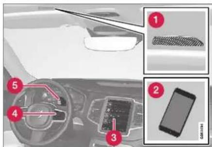
1 Microphone.
2 Phone.
3 Phone handling in the center display.
4 Keypad for controlling phone functions shown in the center display and voice commands.
5 Instrument panel.
Related information
• Handling phone calls (p. 537)
• Managing the phone book (p. 539)
• Handling text messages (p. 538)
- Connecting a phone to the car via Bluetooth for the first time (p. 533)
- Connecting a phone to the car via Bluetooth automatically (p. 535)
- Connecting a phone to the car via Bluetooth manually (p. 535)
- Disconnecting a Bluetooth-connected phone (p. 536)
- Switch between phones connected via Bluetooth (p. 536)
- Disconnecting Bluetooth-connected devices (p. 536)
• Phone settings (p. 540)
• Voice control (p. 145) - Handling the App menu in the instrument panel (p. 104)
• Sound settings (p. 496) - Connecting the vehicle to the Internet via a Bluetooth-connected phone (p. 543)
Connecting a phone to the car via Bluetooth for the first time
Pair a Bluetooth-enabled phone to the vehicle to make calls, send/receive text messages and wirelessly play media from the vehicle, or connect the vehicle to the Internet.
Two Bluetooth devices can be connected at the same time, but in that case, only one will be used for wireless playback. The most recently paired phone will be automatically connected to make calls, send/receive text messages, play media or use as an Internet connection. It is possible to change what the phone is used for under Bluetooth Devices via the settings menu in the center display's Top view.
After the device has been connected/registered for the first time via Bluetooth, the device no longer needs to be visible/searchable. It just needs to have Bluetooth activated. A maximum of 20 paired Bluetooth devices can be stored in the vehicle.
There are two ways to pair a phone to the vehicle. Searching for the phone from the vehicle or searching for the vehicle from the phone.
Option 1 - searching for the phone from the vehicle
-
Make the phone discoverable/visible using its Bluetooth function.
-
Open the phone tile in the center display.
- If no phone has been paired to the vehicle, tap Add phone.
- If a phone has been paired to the vehicle, tap Change . Tap Add phone in the pop-up window.
A list of available Bluetooth devices will be displayed. The list will be updated as new devices are discovered.
- Tap the name of the phone you would like to connect.
- Make sure that the code displayed in the vehicle matches the one in the phone. If it does, confirm the code in both places.
- In the phone, accept or cancel the options for selecting the phone's contacts and text messages.

NOTE
- The message function must be activated in certain phones.
- Not all cell phones are fully compatible and may not be able to display contacts and messages in the vehicle.
AUDIO, MEDIA AND INTERNET
Option 2 - searching for the vehicle from the phone
-
Open the phone tile in the center display.
-
If no phone has been paired to the vehicle, tap Add phone Make vehicle discoverable.
-
If a phone has been paired to the vehicle, tap Change Tap Add phone → Make vehicle discoverable in the pop-up window.
-
Activate Bluetooth in the phone.
- Search in the phone for Bluetooth devices.
A list of available Bluetooth devices will be displayed.
- Select the vehicle's name from the list of devices in the phone.
- A pop-up window for the connection is shown in the car. Confirm the connection.
- Make sure that the code displayed in the vehicle matches the one shown in the external device. If it does, confirm the code in both places.
- In the phone, accept or cancel the options for selecting the phone's contacts and text messages.
i NOTE
- The message function must be activated in certain phones.
- Not all cell phones are fully compatible and may not be able to display contacts and messages in the vehicle.
NOTE
If the phone's operating system is being updated, it is possible that the connection will be interrupted. Delete the phone from the car and reconnect.
Compatible phones
Many cellular phones on the market currently offer wireless Bluetooth technology, but not all phones are fully compatible with the vehicle. For additional information on compatibility, see support.volvocars.com.
Related information
- Phone (p. 532)
- Connecting a phone to the car via Bluetooth automatically (p. 535)
-
Connecting a phone to the car via Bluetooth manually (p. 535)
• Disconnecting a Bluetooth-connected phone (p. 536) -
Switch between phones connected via Bluetooth (p. 536)
- Disconnecting Bluetooth-connected devices (p. 536)
• Settings for Bluetooth devices (p. 541)
• Internet-connected vehicle* (p. 541) - Connecting the vehicle to the Internet via a Bluetooth-connected phone (p. 543)
Connecting a phone to the car via Bluetooth automatically
A phone can be automatically connected to the vehicle via Bluetooth. The phone must have first been paired with the vehicle.
Only the two most recently connected phones can be connected automatically.
- Activate Bluetooth in the phone before turning the vehicle's ignition to mode I.
- Turn the ignition to I or higher.
The phone will be connected.
Related information
- Phone (p. 532)
- Connecting a phone to the car via Bluetooth for the first time (p. 533)
- Connecting a phone to the car via Bluetooth manually (p. 535)
- Disconnecting a Bluetooth-connected phone (p. 536)
- Switch between phones connected via Bluetooth (p. 536)
- Disconnecting Bluetooth-connected devices (p. 536)
- Settings for Bluetooth devices (p. 541)
• Internet-connected vehicle* (p. 541) - Connecting the vehicle to the Internet via a Bluetooth-connected phone (p. 543)
- Ignition modes (p. 437)
Connecting a phone to the car via Bluetooth manually
A phone can be manually connected to the vehicle via Bluetooth. The phone must have first been paired with the vehicle.
- Activate Bluetooth in the phone.
- Open the phone tile.
A list of available phones will be displayed.
- Tap the name of the phone you would like to connect.
The phone will be connected.
Related information
• Phone (p. 532)
- Connecting a phone to the car via Bluetooth for the first time (p. 533)
- Connecting a phone to the car via Bluetooth automatically (p. 535)
- Disconnecting a Bluetooth-connected phone (p. 536)
- Switch between phones connected via Bluetooth (p. 536)
- Disconnecting Bluetooth-connected devices (p. 536)
- Settings for Bluetooth devices (p. 541)
• Internet-connected vehicle* (p. 541)
- Connecting the vehicle to the Internet via a Bluetooth-connected phone (p. 543)
Disconnecting a Bluetooth-connected phone
Disconnect a Bluetooth-connected phone from the vehicle by deactivating Bluetooth in the phone.
When the phone is out of range of the vehicle, it will be automatically disconnected. If a call is in progress when the phone is disconnected from the vehicle, the call will be transferred from the vehicle's speakers and microphone to the cellular phone.
Related information
- Phone (p. 532)
• Phone settings (p. 540) - Switch between phones connected via Bluetooth (p. 536)
- Disconnecting Bluetooth-connected devices (p. 536)
- Settings for Bluetooth devices (p. 541)
Switch between phones connected via Bluetooth
It is possible to switch between Bluetooth-connected phones.
- Open the phone tile.
- Tap Change or pull down Top view and tap Settings Communication → Bluetooth Devices Add device.
A list of available Bluetooth devices will be displayed.
- Tap the name of the phone you would like to connect.
Related information
- Phone (p. 532)
- Connecting a phone to the car via Bluetooth for the first time (p. 533)
• Settings for Bluetooth devices (p. 541) - Disconnecting a Bluetooth-connected phone (p. 536)
- Disconnecting Bluetooth-connected devices (p. 536)
Disconnecting Bluetooth-connected devices
Phones or other devices in the list of registered Bluetooth devices can be removed.
- Tap Settings in the Top view.
- Tap Communication Bluetooth Devices.
A list of registered Bluetooth devices is displayed.
- Tap the name of the device you would like to remove.
- Tap Remove device and confirm.
The device is no longer registered in the vehicle.
Related information
- Phone (p. 532)
- Connecting a phone to the car via Bluetooth for the first time (p. 533)
- Disconnecting a Bluetooth-connected phone (p. 536)
- Switch between phones connected via Bluetooth (p. 536)
• Settings for Bluetooth devices (p. 541)
Handling phone calls
Handling phone calls in the vehicle for a Bluetooth-connected cellular phone.

Generic illustration.
Making calls
- Open the phone tile.
- Initiate a call by selecting the phone number from the recent calls list, entering the number on the keypad or selecting a number from the phone book (list of contacts). You can search or scroll to find a contact in the phone book. Tap ☆ in the phone book to add a contact to Favorites.
- Tap to make a call.
- Tap to end the call.
Calls can also be made from the list of recent calls using the app menu, which can be opened using the button on the right-side steering wheel keypad.
Making multiple calls
While the call is in progress:
- Tap Add call.
- Select from the list of recent calls, favorites or contacts.
-
Tap an item/row in the list of recent calls or for the contact in the phone book.
-
Tap Swap call to switch between calls.
-
Tap to end the current call.
Group (conference) calls
While multiple calls are in progress:
- Tap Join calls to merge ongoing calls.
- Tap to end the call.
Incoming calls
Incoming phone calls will be shown on the instrument panel and in the center display. Manage the calls using the right-side steering wheel keypad or the center display.
- Tap Answer/Reject
- Tap to end the call.
Incoming calls while another call is in progress
- Tap Answer/Reject.
- Tap to end the call.
Privacy
- While a call is in progress, tap Privacy and select setting:
- Switch to mobile phone - the hands-free function will be disabled and the call will proceed on the cellular phone.
- Driver focused - the microphone in the ceiling liner on the passenger side will be muted and the call will proceed using the vehicle's hands-free function.
Related information
- Phone (p. 532)
- Connecting a phone to the car via Bluetooth for the first time (p. 533)
• Voice control for cellular phones (p. 147) - Handling the App menu in the instrument panel (p. 104)
- Entering characters, letters and words by hand in the center display (p. 129)
• Managing the phone book (p. 539)
• Handling text messages (p. 538)
• Sound settings (p. 496)
AUDIO, MEDIA AND INTERNET
Handling text messages ^10
A Bluetooth-connected cellular phone's text messages can be handled in the vehicle.
Text message functionality needs to be activated in certain phones. Not all phones are fully compatible and therefore cannot display contacts and messages in the vehicle. For additional information on compatibility, see supportvolvocars.com.
Handling text messages in the center display
Text messages are only shown in the center display if the relevant setting is made.

Tap Messages in App view to handle text messages in the center display.
NOTE
When the vehicle is moving:
- Only one row of the message will be displayed. Tap Read out to have the entire message read aloud.
- The center display's keyboard cannot be used.
Reading text messages in the center display aloud

Tap the icon to have the message read aloud.
Sending text messages in the center display ^11
-
It is possible to reply to text messages or create a new message.
-
To reply to a text message - tap the name of the contact who sent the message and then tap Answer.
-
To create a new message - tap Create new. Select a contact or enter a phone number.
-
Write the message.
-
Tap Send.
Handling test messages in the instrument panel
Text messages are only shown in the instrument panel if the relevant setting is made.
Reading new text messages in the instrument panel aloud
- To have the message read aloud, select
Read out using the steering wheel keypad.
Dictating replies in the instrument panel
After the test message has been read aloud, it is possible to answer briefly with dictation if the vehicle has an Internet connection.
- Tap Answer using the steering wheel keypad. A dictation dialog will start.
Message alert
Alerts can be activated and deactivated in the text message settings.
Related information
• Phone (p. 532)
• Text message settings (p. 539)
• Phone settings (p. 540)
- Internet-connected vehicle* (p. 541)
• Voice control for cellular phones (p. 147)
- Entering characters, letters and words by hand in the center display (p. 129)
- Connecting a phone to the car via Bluetooth for the first time (p. 533)
• Terms of use and data sharing (p. 548)
Text message settings
Settings for handling text messages received through a connected phone can be personalized.
-
Tap Settings in the Top view.
-
Tap Communication Text Messages and select settings:
-
Notification in center display - display text message notifications in the center display's status bar.
- Notification in driver display - displays notifications in the driver's display and incoming messages can be managed using the steering wheel's right-hand keypad.
- Text message tone - select tone for incoming text messages.
Related information
- Phone (p. 532)
- Connecting a phone to the car via Bluetooth for the first time (p. 533)
• Handling text messages (p. 538)
• Phone settings (p. 540)
Managing the phone book
When a phone is connected with Bluetooth to the vehicle, contacts can be managed directly in the center display.
Up to 3,000 contacts can be displayed from the phone selected in the center display.
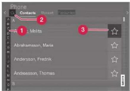
1 Scroll by letter or # find contacts. Only letters matching existing contacts in the phone book will be shown.
② Search contacts - tap to search by phone number or name in the phone book.
3 Favorites - tap add/remove a contact from the list of favorites.
AUDIO, MEDIA AND INTERNET
Sorting
The phone book is sorted in alphabetical order and special characters and numbers are sorted under #. The list can be sorted by either first name or last name. This is adjusted in your cellular phone settings.
Related information
- Phone (p. 532)
• Phone settings (p. 540)
• Voice control for cellular phones (p. 147) - Entering characters, letters and words by hand in the center display (p. 129)
- Connecting a phone to the car via Bluetooth for the first time (p. 533)
Phone settings
When the phone is connected to the car, the following settings can be made:
- Tap Settings in the Top view.
- Tap Communication Phone and select settings:
- Ringtones - select a ring tone. Ring tones from the cellular phone or the vehicle can be used. Some phones are not fully compatible and it may not be possible to use the phone's ring tones in the vehicle. For additional information on compatibility, see support.volvocars.com.
- Sort Order - select sort order in the contact list.
Call notifications in head up display\*
- Tap Settings in the center display's Top view.
- Tap My Car Displays Head-Up Display Options.
- Select Show Phone.
Related information
- Phone (p. 532)
• Text message settings (p. 539) -
Settings for Bluetooth devices (p. 541)
-
Connecting a phone to the car via Bluetooth for the first time (p. 533)
• Head-up display* (p. 142)
• Sound settings (p. 496)
Settings for Bluetooth devices
Settings for Bluetooth-connected devices.
- Tap Settings in the Top view.
-
Tap Communication Bluetooth Devices and select settings:
-
Add device - start the procedure for pairing a new device.
- Previously paired devices - lists registered/paired devices.
- Remove device - remove a connected device.
- Allowed services for this device - select what the device will be used for: making calls, sending/receiving messages, streaming media, Internet connection.
- Internet connection connect the vehicle to the Internet using the device's Bluetooth connection.
Bluetooth® declaration of conformity USA
FCC CAUTION
Changes or modifications not expressly approved by the party responsible for compliance could void the user's authority to operate the equipment. This transmitter must not be co-located or operated in conjunction with any other antenna or transmitter.
Canada
This device complies with Industry Canada license-exempt RSS standard(s). Operation is subject to the following two conditions:
(1) this device may not cause interference, and (2) this device must accept any interference, including interference that may cause undesired operation of the device.
Related information
- Phone (p. 532)
• Phone settings (p. 540)
• Internet-connected vehicle* (p. 541) - Connecting a phone to the car via Bluetooth for the first time (p. 533)
Internet-connected vehicle\*
When the vehicle is connected to the Internet, it is possible to use web radio and music services via apps, download software and contact retailers from the vehicle.
The vehicle can be connected to the Internet using Bluetooth, Wi-Fi or the vehicle's integrated modem (SIM card).
When the vehicle is connected to the Internet, it is possible to share the vehicle's Internet connec-
AUDIO, MEDIA AND INTERNET
tion (Wi-Fi hotspot) so that other devices, e.g. tablets, can access the Internet ^12 .
The Internet status is shown by a symbol in the center display's status bar.


NOTE
Data (data traffic) is transferred when using the internet, which can incur additional costs.
Activating data roaming can cause additional charges.
Contact your network operator about data traffic costs.
i NOTE
When using Apple CarPlay, it is only possible to connect the vehicle to the Internet using Wi-Fi or the vehicle's modem.
i NOTE
When using Android Auto, it is possible to connect the vehicle to the Internet using Wi-Fi, Bluetooth or the vehicle's modem.
Read Terms and Conditions for Services and Customer Privacy Policy at
support.volvocars.com before connecting the car to the Internet.
Related information
- Symbols in the center display status bar (p. 124)
- Connecting the vehicle to the Internet via a Bluetooth-connected phone (p. 543)
- Connecting the vehicle to the Internet via a phone (Wi-Fi) (p. 543)
- Connecting the vehicle to the Internet via vehicle modem (SIM card) (p. 544)
- Apps (p. 498)
• No or poor Internet connection (p. 546)
• Sharing Internet from the vehicle via Wi-Fi hotspot (tethering) (p. 545)
• Deleting Wi-Fi networks (p. 547)
• Wi-Fi technology and security (p. 547)
- Volvo ID (p. 26)
• Terms of use and data sharing (p. 548)
Connecting the vehicle to the Internet via a Bluetooth-connected phone
Establish an Internet connection using Bluetooth and tethering from a phone and get access to multiple connected services in your vehicle.
-
To connect the vehicle to the Internet via a Bluetooth-connected phone, the phone must first be paired with the vehicle via Bluetooth.
-
Make sure that the phone supports Internet sharing (tethering) and that the function is activated. The function is called "personal hotspot" on iPhones and "Wi-Fi hotspot" on Android phones. For iPhones, the "Personal Hotspot" menu page must remain open until the Internet connection is established.
-
If the phone has been connected via Bluetooth previously, tap Settings in the center display's Top view.
-
Tap Communication Bluetooth Devices.
-
Mark the window for Bluetooth Internet connection under the heading Internet connection.
-
If a different connection is being used, confirm the connection change.
Your vehicle is now connected to the Internet via your Bluetooth-connected phone.
NOTE
The cellular phone and network operator must support tethering (sharing of Internet connection) and the subscription must include data traffic.
NOTE
When using Apple CarPlay, it is only possible to connect the vehicle to the Internet using Wi-Fi or the vehicle's modem.
Related information
• Internet-connected vehicle* (p. 541)
- Connecting the vehicle to the Internet via vehicle modem (SIM card) (p. 544)
- Connecting a phone to the car via Bluetooth for the first time (p. 533)
- Connecting the vehicle to the Internet via a phone (Wi-Fi) (p. 543)
• Apple® CarPlay®* (p. 527)
• No or poor Internet connection (p. 546)
- Settings for Bluetooth devices (p. 541)
Connecting the vehicle to the Internet via a phone (Wi-Fi)
Establish an Internet connection using Wi-Fi through Internet sharing (tethering) from a phone and get access to the connected services in your vehicle.
-
Make sure that the phone supports Internet sharing (tethering) and that the function is activated. The function is called "personal hotspot" on iPhones and "Wi-Fi hotspot" on Android phones. For iPhones, the "Personal Hotspot" menu page must remain open until the Internet connection is established.
-
Tap Settings in the Top view.
-
Proceed to Communication Wi-Fi.
-
Activate/deactivate by tapping to check/uncheck the Wi-Fi box.
-
If a different connection is being used, confirm the connection change.
-
Tap the name of the network you would like to connect.
-
Enter the network password.
The vehicle will connect to the network.
Please note that certain cellular phones will disable Internet sharing (tethering) when the connection to the vehicle has been broken, e.g. when the phone has been removed from the vehicle. The phone's tethering function will then need to be
▶▶
AUDIO, MEDIA AND INTERNET
reactivated the next time the phone's hotspot is used to connect to the Internet.
When a phone is connected to the vehicle, it will be saved for future use. To display a list of saved networks or to manually delete saved networks,
tap Settings Communication Wi-Fi → Saved networks.

NOTE
The cellular phone and network operator must support tethering (sharing of Internet connection) and the subscription must include data traffic.

Technical and security requirements for Wi-Fi connection are described in a separate section.
Related information
- Internet-connected vehicle* (p. 541)
• Deleting Wi-Fi networks (p. 547)
• No or poor Internet connection (p. 546)
• Wi-Fi technology and security (p. 547)
Connecting the vehicle to the Internet via vehicle modem (SIM card)
For vehicles equipped with Volvo On Call, it is possible to establish an Internet connection via the vehicle modem and a personal SIM card (P-SIM).
When the vehicle is connected using the integrated modem, the Volvo On Call services will use this connection.
1.

natural_image
Close-up of a mechanical component with a magnified inset showing internal detail (no visible text or symbols)Insert a personal SIM card in the holder.
- Tap Settings in the Top view.
- Tap Communication Vehicle Modem Internet
-
Activate/deactivate by tapping to check/uncheck the Vehicle modem Internet box.
-
If a different connection is being used, confirm the connection change.
-
Enter the SIM card's PIN code.
The vehicle will connect to the network.
Related information
• Internet-connected vehicle* (p. 541)
• No or poor Internet connection (p. 546)
• Vehicle modem settings (p. 545)
Vehicle modem settings
Your vehicle is equipped with a modem that can be used to connect the vehicle to the Internet. It is also possible to share this Internet connection over Wi-Fi.
- Tap Settings in the Top view.
-
Tap Communication Vehicle Modem Internet and select settings:
-
Vehicle modem Internet - select this to use the vehicle's modem to connect to the Internet.
- Data usage - tap Reset to reset the counter for the amount of data received and sent.
Network
Select carrier - select a service provider manually or automatically.
Data roaming - if the box is checked, the vehicle modem will attempt to connect to the Internet when the vehicle is outside its home network (e.g. if you are in another country). Please note that this could entail additional charges. Consult with your service provider for data roaming terms under your contract.
- SIM card PIN
Change PIN - a maximum of 4 digits can be entered.
Disable PIN - select whether a PIN code will be required to access the SIM card.
- Send request code - used to e.g. download or check the balance remaining on a prepaid phone card. This function is specific to your service provider.
Related information
- Connecting the vehicle to the Internet via vehicle modem (SIM card) (p. 544)
• No or poor Internet connection (p. 546)
Sharing Internet from the vehicle via Wi-Fi hotspot (tethering)
When the vehicle is connected to the Internet, other devices may share the vehicle's Internet connection ^13 .

The network service provider (SIM card) must support Internet sharing (tethering).
- Tap Settings in the Top view.
AUDIO, MEDIA AND INTERNET
- Tap Communication Vehicle Wi-Fi Hotspot.
- Tap Network name to assign a name to the hotspot.
- Tap Password and create a password. This password can then be used to connect other devices to this hotspot.
- Tap Frequency band and select a frequency for the hotspot to use to transmit data. Please note that selecting a frequency is not possible on all markets.
- Activate/deactivate by tapping to check/ uncheck the Vehicle Wi-Fi Hotspot box.
- If Wi-Fi is being used to connect to the Internet, confirm the change of connections.
It is now possible for external devices to connect to the vehicle's Wi-Fi hotspot.
NOTE
Activation of Wi-Fi hotspot can cause additional charges from your network operator. Contact your network operator about data traffic costs.
The connection status is shown by a symbol in the center display's status bar.
Tap Connected devices to see a list of currently connected devices.
Related information
- Symbols in the center display status bar (p. 124)
• Internet-connected vehicle* (p. 541)
• No or poor Internet connection (p. 546)
No or poor Internet connection
Factors affecting the Internet connection.
The amount of data transmitted depends on the services or apps currently in use in the vehicle. Streaming music, for example, involves the transmission of a large amount of data, and this requires a good connection and a strong signal.
Phone to vehicle
Internet connection speed may vary depending on the location of the cellular phone in the vehicle. Move the phone closer to the center display to increase signal strength. Make sure that nothing is between the phone and center display that could be blocking the signal.
Phone to network operator
The speed of the mobile network varies depending on the coverage in the vehicle's current location. Coverage may be poorer in e.g. tunnels, mountainous areas, deep valleys or indoors. Connection speed is also dependent on the subscription you have with your service provider.
NOTE
If you experience any problems with data traffic, contact your network service provider.
Restarting the phone
If you experience any Internet connection problems, it may help to restart your phone.
Related information
• Internet-connected vehicle* (p. 541)
• Wi-Fi technology and security (p. 547)
Deleting Wi-Fi networks
Networks that are not needed can be deleted.
- Tap Settings in the Top view.
- Proceed to Communication Wi-Fi Saved networks.
- Tap Forget to delete the network.
- Confirm the selection.
The vehicle will no longer connect to the deleted network.

Deleting all networks
All networks can be deleted at once by performing a factory reset. Please note that all user data and system settings will be restored to original default factory settings.
Related information
- Internet-connected vehicle* (p. 541)
• No or poor Internet connection (p. 546) - Resetting center display settings (p. 134)
- Connecting the vehicle to the Internet via a phone (Wi-Fi) (p. 543)
Wi-Fi technology and security
Networks must meet certain criteria in order for the vehicle to connect.
It is possible to connect to the following types of networks:
• Frequency - 2.4 or 5 GHz ^14 .
• Standards - 802.11 a/b/g/n.
• Security type - WPA2-AES-CCMP.
The vehicle's Wi-Fi system is designed to handle Wi-Fi devices inside the vehicle.
Performance may be impaired if multiple devices are using a frequency at the same time.
Related information
- Internet-connected vehicle* (p. 541)
AUDIO, MEDIA AND INTERNET
Terms of use and data sharing
The first time certain services and apps are started, a pop-up window with the heading Terms and conditions and Data sharing may open.
The aim is to inform the user about Volvo's terms of use and data sharing policy. By accepting data sharing, the user accepts that certain information will be sent from the vehicle. This is required for certain services and apps to work with full functionality.
Data sharing can be set from the center display's Settings menu.
Related information
- Activating and deactivating data sharing (p. 548)
Activating and deactivating data sharing
Data sharing for relevant services and apps can be set via the Settings menu in the center display.
- Tap Settings in the Top view in the center display.
- Tap System Privacy and data.
- Select to activate or deactivate data sharing for individual services and all apps.
NOTE
After visiting a Volvo workshop, you may need to reactivate data sharing so that services and apps will work again.
Related information
• Terms of use and data sharing (p. 548)
Hard disk storage space
It is possible to view how much space is remaining on the vehicle's hard disk.
Storage information for the vehicle's hard disk can be shown, including total capacity, available capacity and how much space is used for installed apps. The information is found under
Settings System System Information Storage.
Related information
- Apps (p. 498)
License agreement for audio and media
A license is an agreement on the right to conduct a certain activity or the right to use someone else's right according to terms and conditions specified in the agreement. The following texts are Volvo's agreements with manufacturers/developers.
Bowers & Wilkins

Bowers & Wilkins and B&W are trademarks of the B&W Group Ltd. Nautilus is a trademark of B&W Group Ltd. Kevlar is a registered trademark of DuPont.
Dirac Unison®

Dirac Unison co-optimizes the loudspeakers in frequency, lime and space for the best possible bass integration and clarity. It enables a faithful reproduction of the acoustic characteristics of specific performance venues. Using advanced algorithms, Dirac Unison controls all loudspeakers digitally based on acoustic high-precision measurements. Like a conductor of an orchestra, it guarantees that the loudspeakers perform in perfect unison.
DivX®

DivX ^® , DivX Certified ^® and associated logos are trademarks of DivX, LLC and are used under license.
This DivX Certified® device can play DivX® Home Theater Home Theater video files up to 576p (including .avi, divx). Download free software at www.divx.com to create, play and stream digital video.
ABOUT DIVX VIDEO-ON-DEMAND: This DivX Certified® device must be registered in order to play purchased DivX Video-on-Demand (VOD) movies. To obtain your registration code, locate the DivX VOD section in your device setup menu. Go to vod.divx.com for more information on completing the registration process.
Patent number
Covered by one or more of the following patents in the US: 7,295,673; 7,460,668; 7,515,710; 8,656,183; 8,731,369; RE45,052.
Gracenote ^x

AUDIO, MEDIA AND INTERNET
Portions of the content are copyright © of Gracenote or its providers.
Gracenote, the Gracenote logo and logotype, "Powered by Gracenote" and Gracenote MusicID are either registered trademarks of Gracenote, Inc. in the United States and/or other countries.
Gracenote® End User License Agreement
This application or device contains software from Gracenote, Inc. in Emeryville, California, United States ("Gracenote"). The software from Gracenote (the "Gracenote Software") enables this application to perform disc and/or file identification and obtain music-related information, including name, artist, track, and title information ("Gracenote Data") from online servers or embedded databases (collectively "Gracenote Servers") and to perform other functions. You may use Gracenote Data only by means of the intended End-User functions of this application or device.
You agree that you will use Gracenote Data, the Gracenote Software, and Gracenote Servers for your own personal non-commercial use only. You agree not to assign, copy, transfer or transmit the Gracenote Software or any Gracenote Data to any third party. YOU AGREE NOT TO USE OR EXPLOIT GRACENOTE DATA, THE GRACENOTE SOFTWARE, OR GRACENOTE SERVERS, EXCEPT AS EXPRESSLY PERMITTED HEREIN.
You agree that your non-exclusive license to use the Gracenote Data, the Gracenote Software, and Gracenote Servers will terminate if you violate
these restrictions. If your license terminates, you agree to cease any and all use of the Gracenote Data, the Gracenote Software, and Gracenote Servers. Gracenote reserves all rights in all Gracenote Data, all Gracenote Software, and all Gracenote Servers, including all ownership rights. Under no circumstances will Gracenote become liable for any payment to you for any information that you provide. You agree that Gracenote, Inc. may enforce its rights under this Agreement against you directly in its own name.
The Gracenote service uses a unique identifier to track queries for statistical purposes. The purpose of a randomly assigned numeric identifier is to allow the Gracenote service to count queries without knowing anything about who you are. For more information, see the web page for the Gracenote Privacy Policy for the Gracenote service.
The Gracenote Software and each item of Gracenote Data are licensed to you "AS IS." Gracenote makes no representations or warranties, express or implied, regarding the accuracy of any Gracenote Data from in the Gracenote Servers. Gracenote reserves the right to delete data from the Gracenote Servers or to change data categories for any cause that Gracenote deems sufficient. No warranty is made that the Gracenote Software or Gracenote Servers are error-free or that functioning of Gracenote Software or Gracenote Servers will be uninterrupted. Gracenote is not obligated to provide you with new enhanced or
additional data types or categories that Grace-note may provide in the future and is free to discontinue its services at any time.
GRACENOTE DISCLAIMS ALL WARRANTIES EXPRESS OR IMPLIED, INCLUDING, BUT NOT LIMITED TO, IMPLIED WARRANTIES OF MERCHANTABILITY, FITNESS FOR A PARTICULAR PURPOSE, TITLE, AND NON-INFRINGEMENT. GRACENOTE DOES NOT WARRANT THE RESULTS THAT WILL BE OBTAINED BY YOUR USE OF THE GRACENOTE SOFTWARE OR ANY GRACENOTE SERVER. IN NO CASE WILL GRACENOTE BE LIABLE FOR ANY CONSEQUENTIAL OR INCIDENTAL DAMAGES OR FOR ANY LOST PROFITS OR LOST REVENUES.
© Gracenote, Inc. 2009
Sensus software
This software uses parts of sources from clib2 and Prex Embedded Real-time OS - Source (Copyright (c) 1982, 1986, 1991, 1993, 1994), and Quercus Robusta (Copyright (c) 1990, 1993), The Regents of the University of California. All or some portions are derived from material licensed to the University of California by American Telephone and Telegraph Co. or Unix System Laboratories, Inc. and are reproduced herein with the permission of UNIX System Laboratories, Inc. Redistribution and use in source and binary forms, with or without modification, are permitted provided that the following conditions are met: Redistributions of
source code must retain the above copyright notice, this list of conditions and the following disclaimer. Redistributions in binary form must reproduce the above copyright notice, this list of conditions and the following disclaimer in the documentation and/or other materials provided with the distribution. Neither the name of the
This software is based in part on the work of the Independent JPEG Group.
This software uses parts of sources from "libtess". The Original Code is: OpenGL Sample Implementation, Version 1.2.1, released January 26, 2000, developed by Silicon Graphics, Inc. The Original Code is Copyright (c) 1991-2000 Silicon Graphics, Inc. Copyright in any portions created by third parties is as indicated elsewhere herein. All Rights Reserved. Copyright (C) [1991-2000] Silicon Graphics, Inc. All Rights Reserved. Permission is hereby granted, free of charge, to any person obtaining a copy of this software and associated documentation files (the "Software"), to deal in the Software without restriction, including without limitation the rights to use, copy, modify, merge, publish, distribute, sublicense, and/or sell copies of the Software, and to permit persons to whom the Software is furnished to do so, subject to the following conditions: The above copyright notice including the dates of first publication and either this permission notice or a reference to http://oss.sgi.com/projects/FreeB/ shall be included in all copies or substantial portions of the Software. THE SOFTWARE IS PROVIDED "AS IS", WITHOUT WARRANTY OF ANY KIND, EXPRESS OR IMPLIED, INCLUDING BUT NOT LIMITED TO THE WARRANTIES OF MERCHANTABILITY, FITNESS FOR A PARTICULAR PURPOSE AND NONINFRINGEMENT. IN NO EVENT SHALL
SILICON GRAPHICS, INC. BE LIABLE FOR ANY CLAIM, DAMAGES OR OTHER LIABILITY, WHETHER IN AN ACTION OF CONTRACT, TORT OR OTHERWISE, ARISING FROM, OUT OF OR IN CONNECTION WITH THE SOFTWARE OR THE USE OR OTHER DEALINGS IN THE SOFTWARE. Except as contained in this notice, the name of Silicon Graphics, Inc. shall not be used in advertising or otherwise to promote the sale, use or other dealings in this Software without prior written authorization from Silicon Graphics, Inc.
This software is based in parts on the work of the FreeType Team.
This software uses parts of SSLeay Library: Copyright (C) 1995-1998 Eric Young (eay@cryptsoft.com). All rights reserved
Linux software
This product contains software licensed under GNU General Public License (GPL) or GNU Lesser General Public License (LGPL), etc.
You have the right of acquisition, modification, and distribution of the source code of the GPL/LGPL software.
You may download Source Code from the following website at no charge: http://www.embedded-carmultimedia.jp/linux/oss/download/TVM_8351_013
AUDIO, MEDIA AND INTERNET
The website provides the Source Code "As Is" and without warranty of any kind.
By downloading Source Code, you expressly assume all risk and liability associated with downloading and using the Source Code and complying with the user agreements that accompany each Source Code.
Please note that we cannot respond to any inquiries regarding the source code.
camellia:1.2.0
Copyright (c) 2006, 2007
NTT (Nippon Telegraph and Telephone Corporation). All rights reserved.
Redistribution and use in source and binary forms, with or without modification, are permitted provided that the following conditions are met:
-
Redistributions of source code must retain the above copyright notice, this list of conditions and the following disclaimer as the first lines of this file unmodified.
-
Redistributions in binary form must reproduce the above copyright notice, this list of conditions and the following disclaimer in the documentation and/or other materials provided with the distribution.
THIS SOFTWARE IS PROVIDED BY NTT "AS IS" AND ANY EXPRESS OR IMPLIED WARRANTIES, INCLUDING, BUT NOT LIMITED TO, THE IMPLIED WARRANTIES OF MERCHANTABILITY AND FITNESS FOR A
PARTICULAR PURPOSE ARE DISCLAIMED. IN NO EVENT SHALL NTT BE LIABLE FOR ANY DIRECT, INDIRECT, INCIDENTAL, SPECIAL, EXEMPLARY, OR CONSEQUENTIAL DAMAGES (INCLUDING, BUT NOT LIMITED TO, PROCUREMENT OF SUBSTITUTE GOODS OR SERVICES; LOSS OF USE, DATA, OR PROFITS; OR BUSINESS INTERRUPTION) HOWEVER CAUSED AND ON ANY THEORY OF LIABILITY, WHETHER IN CONTRACT, STRICT LIABILITY, OR TORT (INCLUDING NEGLIGENCE OR OTHERWISE) ARISING IN ANY WAY OUT OF THE USE OF THIS SOFTWARE, EVEN IF ADVISED OF THE POSSIBILITY OF SUCH DAMAGE.
Unicode: 5.1.0
COPYRIGHT AND PERMISSION NOTICE
Copyright c 1991-2013 Unicode, Inc. All rights reserved. Distributed under the Terms of Use in http://www.unicode.org/copyright.html.
Permission is hereby granted, free of charge, to any person obtaining a copy of the Unicode data files and any associated documentation (the "Data Files") or Unicode software and any associated documentation (the "Software") to deal in the Data Files or Software without restriction, including without limitation the rights to use, copy, modify, merge, publish, distribute, and/or sell copies of the Data Files or Software, and to permit persons to whom the Data Files or Software are furnished to do so, provided that (a)
the above copyright notice(s) and this permission notice appear with all copies of the Data Files or Software, (b) both the above copyright notice(s) and this permission notice appear in associated documentation, and (c) there is clear notice in each modified Data File or in the Software as well as in the documentation associated with the Data File(s) or Software that the data or software has been modified.
THE DATA FILES AND SOFTWARE ARE PROVIDED "AS IS", WITHOUT WARRANTY OF ANY KIND, EXPRESS OR IMPLIED, INCLUDING BUT NOT LIMITED TO THE WARRANTIES OF MERCHANTABILITY, FITNESS FOR A PARTICULAR PURPOSE AND NONINFRINGEMENT OF THIRD PARTY RIGHTS. IN NO EVENT SHALL THE COPYRIGHT HOLDER OR HOLDERS INCLUDED IN THIS NOTICE BE LIABLE FOR ANY CLAIM, OR ANY SPECIAL INDIRECT OR CONSEQUENTIAL DAMAGES, OR ANY DAMAGES WHATSOEVER RESULTING FROM LOSS OF USE, DATA OR PROFITS, WHETHER IN AN ACTION OF CONTRACT, NEGLIGENCE OR OTHER TORTIOUS ACTION, ARISING OUT OF OR IN CONNECTION WITH THE USE OR PERFORMANCE OF THE DATA FILES OR SOFTWARE.
Except as contained in this notice, the name of a copyright holder shall not be used in advertising or otherwise to promote the sale, use or other
dealings in these Data Files or Software without prior written authorization of the copyright holder.
Declaration of Conformity

USA
FCC CAUTION
Changes or modifications not expressly approved by the party responsible for compliance could void the user's authority to operate the equipment. This transmitter must not be co-located or operated in conjunction with any other antenna or transmitter.
Canada
This device complies with Industry Canada license-exempt RSS standards. Operation is subject to the following two conditions: (1) this device may not cause interference, and (2) this device must accept any interference, including interference that may cause undesired operation of the device.
AUDIO, MEDIA AND INTERNET
◀◀
• Audio, media and Internet (p. 496)
• Internet-connected vehicle* (p. 541)
• Media player (p. 518)
- Gracenote® (p. 521)
- Sensus - connection and entertainment (p. 30)
WHEELS AND TIRES
WHEELS AND TIRES
Tires
The function of the tires is to carry loads, provide traction on road surfaces, reduce vibrations and protect the wheels from wear.
The tires significantly influence the vehicle's driving characteristics. The type, dimensions, tire pressure and speed rating have a considerable impact on how the vehicle performs.
Your vehicle is equipped with tires according to the vehicle's tire information placard on the B-pillar (the structural member at the side of the vehicle, at the rear of the driver's door opening).

WARNING
A damaged tire could cause the driver to lose control of the vehicle.
! CAUTION
Some Volvo models are equipped with an Ultra High Performance tire and wheel combination designed to provide maximum dry pavement performance with consideration for hydroplaning resistance. They may be more susceptible to road hazard damage and, depending on driving conditions, may achieve a tread life of less than 30,000 km (20,000 miles). Even if this vehicle is equipped with Volvo's advanced AWD or stability system, these tires are not designed for winter driving, and should be replaced with winter tires when weather conditions dictate.
The tires have good road holding characteristics and offer good handling on dry and wet surfaces. It should be noted however that the tires have been developed to give these features on snow/ice-free surfaces.
Most models are equipped with "all-season" tires, which provide a somewhat higher degree of road-holding on slippery road surfaces than tires without the "all-season" rating. However, for optimal roadholding on icy or snow-covered roads, Volvo recommends snow tires on all four wheels.
When replacing tires, be sure that the new tires are the same size designation, type (radial) and preferably from the same manufacturer, on all
four wheels. Otherwise there is a risk of altering the vehicle's roadholding and handling characteristics.
Recommended tires
On delivery, the car is equipped with Volvo original tires that have the VOL ^1 marking on the side of the tires. These tires have been designed specifically for your vehicle. It is therefore important when replacing tires that the new tires have this same marking to help maintain the vehicle's driving characteristics, comfort and fuel consumption.
New tires

natural_image
Top-down view of a car wheel rim with a black label pointing to the number 0717 (no other text or symbols)Tires are perishable goods. After a few years, they will begin to harden and their friction properties will gradually deteriorate. Always replace tires with the freshest tires possible. This is particularly important for snow tires. A series of numbers is
imprinted on the sidewall of the tire. The last four digits in the series is the Department of Transportation (DOT) stamp and indicates the week and year the tire was manufactured. The tire in the illustration has 0717 as the last four digits, which means it was manufactured week 7 of 2017.
Tire age
Tires degrade over time, even when they are not being used. It is recommended that tires generally be replaced after 6 years of normal service. Heat caused by hot climates, frequent high loading conditions or Ultra Violet (U.V.) exposure can accelerate the aging process. The temporary spare ^2 should also be replaced at 6-year intervals, even if it has never been used. A tire with e.g., visible cracks or discoloration should be replaced immediately.
Tire economy
- Maintain correct tire pressure.
- Avoid fast starts, hard braking and tire screeching.
- Tire wear increases with speed.
- Correct front wheel alignment is very important.
-
Unbalanced wheels impair tire economy and driving comfort.
-
Tires must maintain the same direction of rotation throughout their lifetime.
- When replacing tires, the tires with the most tread should be mounted on the rear wheels to reduce the chance of oversteer during hard braking.
- Hitting curbs or potholes can damage the tires and/or wheels permanently.
Tire rotation
Your vehicle has no required tire rotation. Driving style, tire pressure, climate and road conditions affect how quickly the tires age and exhibit signs of wear. Maintaining the correct tire pressure helps keep tread wear evenly distributed.
To help prevent differences in tread depth and wear patterns forming on the tires, the front and rear wheels should be rotated, i.e. the front tires moved to the rear and the rear tires moved to the front. Ideally, tire rotation should be done the first time after approximately 5000 km (ca 3100 miles) and thereafter at 10,000 km (approx. 6200 miles) intervals.
If you have any questions regarding tread depth, Volvo recommends consulting an authorized Volvo workshop. If significant differences in wear (> 1 mm difference in tread depth) between the tires have already occurred, the least worn tires should always be mounted on the rear wheels. A front-wheel skid (understeer) is usually easier to
control than a rear-wheel skid (oversteer). If the front wheels skid, the vehicle will continue in a straight line instead of the rear wheels skidding to the side, which could cause you to completely lose control of the vehicle. It is therefore important that the rear wheels never lose grip before the front wheels.
Storing wheels and tires
When storing complete wheels (tires mounted on rims), they should be suspended off the floor or placed on their sides on the floor.
Tires not mounted on rims should be stored on their sides or standing upright, but should not be suspended.
CAUTION
Tires should preferably be stored in a cool, dry, dark place, and should never be stored in close proximity to solvents, gasoline, oils, etc.
WHEELS AND TIRES
◀◀

WARNING
- The wheel and tire sizes for your Volvo are specified to meet stringent stability and handling requirements. Unapproved wheel/tire size combinations can negatively affect your vehicle's stability and handling.
- Any damage caused by installation of unapproved wheel/tire size combinations will not be covered by your new vehicle warranty. Volvo assumes no responsibility for death, injury, or expenses that may result from such installations.
Related information
- Checking tire pressure (p. 567)
• Tire direction of rotation (p. 562)
• Tread wear indicator (p. 563)
• Tire pressure monitoring system* (p. 569) - Tire sealing system (p. 582)
• Uniform Tire Quality Grading (p. 566)
• Tire terminology (p. 563)
• Tire sidewall designations (p. 564) - Loading recommendations (p. 598)
Tire direction of rotation
Tires with tread designed to roll in only one direction are marked with an arrow on the sidewall.
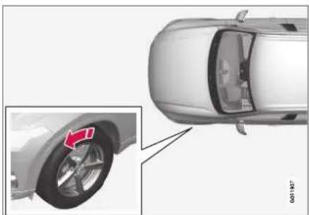
natural_image
Top-down view of a car showing the wheel rim and side panel, with an inset close-up highlighting the wheel (no text or symbols)The arrow shows the tire's direction of rotation.
- The tire should maintain the same direction of rotation throughout its service life.
- Tires should only be moved between the front and back, never from right to left or vice versa.
- Incorrectly mounted tires impair the vehicle's braking properties and ability to force aside rain, snow and slush.
- The tires with the most tread should always be mounted on the rear wheels to help reduce the risk of skidding.

NOTE
Use tires of the same type, dimensions and make (manufacturer) on each axle.
Related information
• Tires (p. 560)
Tread wear indicator
The tread wear indicator shows the status of the tire's tread.
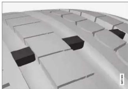
natural_image
3D rendering of a curved architectural or mechanical structure with multiple rectangular blocks and two black blocks on the floor (no text or symbols visible)The tread wear indicator is a narrow elevated strip running across the tire's longitudinal tread grooves. The letters TWI (Tread Wear Indicator) are visible on the side of the lire. When approximately 1.6 mm (1/16 inch) is left on the tread, the tread will be at the same height as the tread wear indicator. Replace the tire as soon as possible. Tires with low tread offer very poor traction in rain or snow.
Related information
• Tires (p. 560)
Tire terminology
The following is a glossary of tire-related terms.
The tire suppliers may have additional markings, notes or warnings such as standard load, radial tubeless, etc.
- Tire information placard: A placard showing the OE (Original Equipment) tire sizes, recommended inflation pressure, and the maximum weight the vehicle can carry.
- Tire Identification Number (TIN): A number on the sidewall of each tire providing information about the tire brand and manufacturing plant, tire size and date of manufacture.
- Inflation pressure: A measure of the amount of air in a tire.
- Standard load: A class of P-metric or Metric tires designed to carry a maximum load at 35 psi [37 psi (2.5 bar) for Metric tires]. Increasing the inflation pressure beyond this pressure will not increase the tires load carrying capability.
- Extra load: A class of P-metric or Metric tires designed to carry a heavier maximum load at 41 psi [43 psi (2.9 bar) for Metric tires]. Increasing the inflation pressure beyond this pressure will not increase the tire's load carrying capability.
• kPa: Kilopascal, a metric unit of air pressure. -
PSI: Pounds per square inch, a standard unit of air pressure.
-
B-pillar: The structural member at the side of the vehicle behind the front door.
- Bead area of the tire: Area of the tire next to the rim.
- Sidewall of the tire: Area between the bead area and the tread.
- Tread area of the tire: Area of the perimeter of the tire that contacts the road when mounted on the vehicle.
- Rim: The metal support (wheel) for a tire or a tire and tube assembly upon which the tire beads are seated.
- Maximum load rating: a figure indicating the maximum load in pounds and kilograms that can be carried by the tire. This rating is established by the tire manufacturer.
- Maximum permissible inflation pressure: the greatest amount of air pressure that should ever be put in the tire. This limit is set by the tire manufacturer.
- Recommended tire inflation pressure: inflation pressure, established by Volvo, which is based on the type of tires that are mounted on a vehicle at the factory. This information can be found on the tire inflation placard(s) located on the driver's side B-pillar and in the tire inflation table in this chapter.
- Cold tires: The tires are considered to be cold when they have the same temperature as the surrounding (ambient) air. This tem-
WHEELS AND TIRES
◀◀
perature is normally reached after the vehicle has been parked for at least 3 hours.
Related information
• Tires (p. 560)
Tire sidewall designations
The following information can be found on a tire's sidewall.
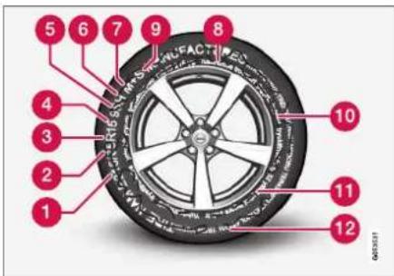
Federal law mandates that tire manufacturers place standardized information on the sidewall of all tires (see the illustration).
The vehicle has been certified with certain combinations of wheels and tires.
The following information is listed on the tire sidewall:
The tire designation:
i
NOTE
Please be aware that the following tire designation is an example only and that this particular tire may not be available on your vehicle.
- 215: the width of the tire (in millimeters) from sidewall edge to sidewall edge. The larger the number, the wider the tire.
- 65: The ratio of the tire's height to its width in percent.
- R: Radial tire (the designation RF and the symbol indicate that the vehicle is equipped with optional self-supporting run flat tires ^4 ).
- 15: The diameter of the wheel rim (in inches).
- 95: The tire's load index. In this example, a load index of 95 equals a maximum load of 1521 lbs (690 kg).
- H: The tire's speed rating, or the maximum speed at which the tire is designed to be driven for extended periods of time, carrying a permissible load for the vehicle, and with correct inflation pressure. For example, H indicates a speed rating of 210 km/h (130 mph).

NOTE
The tire's load index and speed rating may not appear on the sidewall because they are not required by law.
- M+S or M/S = Mud and Snow, AT = All Terrain, AS = All Season
- U.S. DOT Tire Identification Number (TIN): This begins with the letters "DOT" and indicates that the tire meets all federal standards. The next two numbers are the factory code where the tire was manufactured, the next two are the tire size code and the last four numbers represent the week and year the tire was made. For example, 0717 means that the tire was manufactured during week 7 of 2017. The numbers in between are marketing codes used at the manufacturer's discretion. This information helps a tire manufacturer identify a tire for safety recall purposes.
- Tire Ply Composition and Material Used: Indicates the number of plies indicates or the number of layers of rubber-coated fabric in the tire tread and sidewall. Tire manufacturers also must indicate the ply materials in the tire and the sidewall, which include steel, nylon, polyester, and others.
- Maximum Load: Indicates the maximum load in pounds and kilograms that can be carried by the tire. Refer to the vehicle's tire
information placard located on the B-Pillar for the correct tire pressure for your vehicle.
- Treadwear, Traction, and Temperature grades.
- Maximum permissible inflation pressure: the greatest amount of air pressure that should ever be put in the tire. This limit is set by the tire manufacturer.
Speed Symbol
A tire's Speed Symbol (SS) indicates the maximum speed for which the tire has been certified and should be at least equivalent to the vehicle's top speed.
Winter tires, with or without studs, are exceptions and may use a lower SS. When winter tires are installed, the vehicle may not be driven faster than the tires' SS.
The vehicle's speed should always be determined by the posted speed limit and traffic and road conditions, not the tire's SS.
The following table indicates the maximum permissible speed for each SS.
| M 130 | km/h (81 mph) |
| Q 160 | km/h (100 mph) |
| T 190 | km/h (118 mph) |
| H 210 | km/h (130 mph) |
| V 240 | km/h (149 mph) |
| W 270 | km/h (168 mph) |
| Y 300 | km/h (186 mph) |

WARNING
- The wheel and tire sizes for your Volvo are specified to meet stringent stability and handling requirements. Unapproved wheel/tire size combinations can negatively affect your vehicle's stability and handling.
- Any damage caused by installation of unapproved wheel/tire size combinations will not be covered by your new vehicle warranty. Volvo assumes no responsibility for death, injury, or expenses that may result from such installations.
Related information
• Tires (p. 560)
WHEELS AND TIRES
Uniform Tire Quality Grading ALL PASSENGER VEHICLE TIRES MUST CONFORM TO FEDERAL SAFETY REQUIRE- MENTS IN ADDITION TO THESE GRADES.
Quality grades can be found, where applicable, on the tire sidewall between the tread shoulder and maximum section width. For example:
Treadwear 200 Traction AA Temperature A
TREADWEAR
The treadwear grade is a comparative rating based on the wear rate of the tire when tested under controlled conditions on a specified government test course. For example, a tire graded 150 would wear one and one half (1½) times as well on the government course as a tire graded 100. The relative performance of tires depends upon the actual conditions of their use, however, and many depart significantly from the norm due to variation in driving habits, maintenance practices and differences in road characteristics and climate.
TRACTION
The traction grades, from highest to lowest, are AA, A, B, and C, as measured under controlled conditions on specified government test surfaces of asphalt and concrete. A tire marked C may have poor traction performance.
WARNING
The traction grade assigned to this tire is based on braking (straight-ahead) traction tests and is not a measure of cornering (turning) traction.
TEMPERATURE
The temperature grades are A (the highest), B, and C, representing the tire's resistance to the generation of heat and its ability to dissipate heat when tested under controlled conditions on a specified indoor laboratory test wheel. Sustained high temperature can cause the material of the tire to degenerate and reduce tire life, and excessive temperature can lead to sudden tire failure. The grade C corresponds to a minimum level of performance that all passenger vehicle tires must meet under the Federal Motor Safety Standard No. 109. Grades B and A represent higher levels of performance on the laboratory test wheel than the minimum required by law.
WARNING
The temperature grade for this tire is established for a tire that is properly inflated and not overloaded. Excessive speed, under-inflation, or excessive loading, either separately or in combination, can cause heat buildup and tire failure.
Related information
• Tires (p. 560)
• Tire sidewall designations (p. 564)
Checking tire pressure
Correct inflation pressure helps improve driving stability, save fuel and increase the service life of the tires.
Tire pressure decreases over time, which is normal. Tire pressure also varies depending on the ambient temperature. Driving on under-inflated tires could cause the vehicle to overheat and lead to damage. Tire pressure affects traveling comfort, road noise and driving characteristics.
Check the pressure in the tires every month. Use the recommended inflation pressure for cold tires for optimal tire performance and wear. Under-inflated or over-inflated tires could cause uneven tread wear.
Use an air pressure gauge and check the inflation pressure on all the tires, including the spare tire ^4 , at least once a month and before long trips. Volvo strongly recommends buying a reliable air pressure gauge, as the automatic gauges provided at service stations may be inaccurate.
WARNING
- Under-inflation is the most common cause of tire failure and may result in severe tire cracking, tread separation, or "blow-out," with unexpected loss of vehicle control and increased risk of injury.
- Under-inflated tires reduce the load carrying capacity of your vehicle.
Cold tires
Inflation pressure should be checked when the tires are cold.
The tires are considered to be cold when they have the same temperature as the surrounding (ambient) air.
This temperature is normally reached after the vehicle has been parked for at least 3 hours.
After driving for approximately 1.6 km (1 mile), the tires are considered to be warm. If you need to drive longer than that to inflate the tires, check and record the inflation pressure of the tires first and inflate accordingly when you arrive at the pump.
When the ambient temperature changes, so does the inflation pressure. A 10-degree temperature drop causes a corresponding drop in inflation pressure of 1 psi (7 kPa). Check the inflation pressure of the tires regularly and adjust to the
correct pressure, which can be found on the vehicle's tire information placard or certification label. If you check inflation pressure when the tires are warm, you should never release air. The tires become warm after driving and it is normal for warm tires to have an inflation pressure above the recommended pressure for cold tires. A warm tire with an inflation pressure equal to or under the recommended pressure for cold tires could be significantly under-inflated.
Related information
• Adjusting tire pressure (p. 568)
• Recommended tire pressure (p. 569)
• Tire pressure monitoring system* (p. 569)
• Tires (p. 560)
WHEELS AND TIRES
Adjusting tire pressure
Tire pressure decreases over time, which is normal. The tire pressure must therefore be adjusted to maintain the recommended tire pressure.
Use the recommended inflation pressure for cold tires for optimal tire performance and wear.

NOTE
To help prevent incorrect inflation pressure, pressure should be checked when the tires are cold. The tires are considered to be cold when they have reached the same temperature as the ambient temperature (about 3 hours after the vehicle was last driven). After driving for a few kilometers, the tires will warm up and the pressure will increase.
- Remove the valve cap from the tire and press the air pressure gauge firmly onto the valve.
-
Inflate the tire to the correct inflation pressure; see the tire pressure placard on the driver's side B pillar for recommended pressures for factory-mounted tires.
-
Screw the valve cap back on.
i NOTE
- After inflating a tire, always replace the valve cap to help prevent valve damage caused by gravel, dirt, etc.
-
Use plastic valve caps only. Metal caps could corrode and become difficult to remove.
-
Visually inspect the tire to make sure there are no nails or other embedded objects that could puncture the tire and cause air leakage.
- Check the sidewalls to make sure there are no gouges, cuts, bulges or other irregularities.
- Repeat this procedure for each tire, including the spare tire ^4 .
NOTE
If you have overfilled the tire, release air by pushing on the metal stem in the center of the valve. Then recheck the pressure with your tire gauge.
Some spare tires require higher inflation pressure than the other tires. Consult the tire inflation pressure table or the inflation pressure placard.
Related information
• Recommended tire pressure (p. 569)
- Checking tire pressure (p. 567)
- Inflate tires with the compressor included in the tire sealing system (p. 587)
• Approved tire pressure (p. 675)
Recommended tire pressure
The tire pressure placard on the driver's side B pillar (between the front and the rear door) indicates tire pressure for different loads and speed conditions.

natural_image
Interior view of a car with white seats and a digital display panel (no readable text or symbols)The decal specifies the designation for the factory-mounted tires on the vehicle, as well as load limits and inflation pressures.
Related information
- Checking tire pressure (p. 567)
• Approved tire pressure (p. 675)
Tire pressure monitoring system\*
The tire pressure monitoring system ^6 provides a warning symbol in the instrument panel if pressure is too low in one or more tires.
Symbol Explanation

This symbol illuminates to indicate low inflation pressure.
If there is a system malfunction, the inflation pressure warning symbol will flash for approximately one minute and then glow steadily.
System description
The tire pressure monitoring system measures differences in rotational speed between the wheels through the ABS system to determine if the tires are properly inflated. If inflation pressure in a tire is too low, its diameter (and consequently its rotational speed) changes. By comparing the tires with each other, the system can determine if the pressure in one or more tires is too low.
General information about the tire pressure monitoring system
In the following description, the tire monitoring system is generally referred to as TPMS.
Each tire, including the spare (if provided) ^7 should be checked monthly when cold and infla-
ted to the inflation pressure recommended by the vehicle manufacturer on the vehicle placard or tire inflation pressure label. (If your vehicle has tires of a different size than the size indicated on the vehicle placard or tire inflation pressure label, you should determine the proper tire inflation pressure for those tires.)
As an added safety feature, your vehicle has been equipped with a tire pressure monitoring system (TPMS) that illuminates a low tire pressure telltale when one or more of your tires is significantly under-inflated. Accordingly, when the low tire pressure telltale illuminates, you should stop and check your tires as soon as possible, and inflate them to the proper pressure.
Driving on a significantly under-inflated tire causes the tire to overheat and can lead to tire failure. Under-inflation also reduces fuel efficiency and tire tread life, and may affect the vehicle's handling and stopping ability. Please note that the TPMS is not a substitute for proper tire maintenance, and it is the driver's responsibility to maintain correct tire pressure, even if under-inflation has not reached the level to trigger illumination of the TPMS low tire pressure telltale.
Your vehicle has also been equipped with a TPMS malfunction indicator to indicate when the system is not operating properly. The TPMS malfunction indicator is combined with the low tire
WHEELS AND TIRES
pressure telltale. When the system detects a malfunction, the telltale will flash for approximately one minute and then remain continuously illuminated. This sequence will continue upon subsequent vehicle start-ups as long as the malfunction exists. When the malfunction indicator is illuminated, the system may not be able to detect or signal low tire pressure as intended.
TPMS malfunctions may occur for a variety of reasons, including the installation of replacement or alternate tires or wheels on the vehicle that prevent the TPMS from functioning properly.
Always check the TPMS malfunction telltale after replacing one or more tires or wheels on your vehicle to ensure that the replacement or alternate tires and wheels allow the TPMS to continue to function properly.
Messages in the instrument panel
If tire pressure is too low, the low tire pressure warning symbol is shown in the instrument panel along with a message.
- Tire pressure low Check tires, calibrate after fill
- Tire pressure system Temporarily unavailable
- Tire pressure system Service required
To keep in mind
- Always calibrate the system after changing wheels or adjusting lire pressure. See the lire pressure placard on the driver's side B pillar for Volvo-recommended tire pressures.
- If you switch to a tire of another size than the factory-mounted tires, the system must be calibrated for these tires to avoid false warnings.
- If a spare wheel ^8 is used, it is possible that the tire pressure monitoring system will not work correctly due to the differences between the wheels.
- The system does not replace the need for regular lire inspection and maintenance.
- It is not possible to deactivate the tire pressure monitoring system.

WARNING
- Incorrect inflation pressure could lead to tire failure, which could cause the driver to lose control of the vehicle.
- The system cannot predict sudden tire damage.
Related information
• Recommended tire pressure (p. 569)
- Viewing tire pressure status in the center display* (p. 572)
• Action when warned of low tire pressure (p. 573)
- Calibrating the tire pressure monitoring system* (p. 571)
Calibrating the tire pressure monitoring system\*
In order for the tire pressure monitoring system ^9 to function correctly, tire pressure reference values must be set correctly. This must be done each time the tires are changed or the tire pressure is adjusted.
For example, when driving with a heavy load or at high speeds (over 160 km/h (100 mph)), tire pressure should be adjusted to the Volvo-recommended tire pressure values. The system should then be recalibrated.
- Switch off the ignition.
- Inflate the tire to the correct inflation pressure; see the tire pressure placard on the driver's side B pillar for recommended pressures for factory-mounted tires.
- Start the vehicle.
- Open the Car Status app in App view.
- Tap TPMS.

NOTE
The car must be stationary when calibration is started.
- Tap Calibrate.
-
Tap OK to confirm that the tire pressure in all four tires has been checked and adjusted.
-
Run the car until calibration is complete.
Calibration is done when the vehicle is driving at a speed above 35 km/h (22 mph).
If the car's ignition is switched off before calibration is complete, the tires in the center display change color from gray to green upon next start-up, even if calibration is not complete. Perform the calibration again and allow it to complete within the same operating cycle to ensure that the calibration is carried out correctly.
When enough data has been collected for the system to detect low tire pressure, the color of the tire symbols in the center display will change from gray to green. The system will not provide any other confirmation that calibration has been completed.
If start-up of calibration fails, the following message appears: Calibration unsuccessful. Try again..
WHEELS AND TIRES
◀◀

NOTE
Always remember to calibrate the Tire Pressure Monitoring System when the wheels have been changed or the tire inflation pressure has been corrected according to the tire pressure decal or tire inflation pressure table.
If correct reference values have not been set, the system cannot issue low tire pressure alerts correctly.
The vehicle must be stationary with the engine running to access the calibration button and to start the calibration process.

WARNING
The exhaust gases contain carbon monoxide, which is invisible and odorless but very poisonous. For this reason, always perform the calibration procedure outdoors or in a workshop with exhaust gas evacuation equipment.
Related information
• Recommended tire pressure (p. 569)
• Adjusting tire pressure (p. 568)
- Viewing tire pressure status in the center display* (p. 572)
• Action when warned of low tire pressure (p. 573)
• Tire pressure monitoring system* (p. 569)
Viewing tire pressure status in the center display\*
With the system for tire pressure monitoring ^10 , tire pressure status can be viewed in the center display.
Checking status
- Open the Car Status app in App view.

- Tap TPMS to display the status of the tires.
Status indicator light
The graphic in the center display shows the status of each tire ^1 .

Green tire:
- Inflation pressure is above the warning threshold.
Yellow tire:
- The tire's inflation pressure is too low. Stop and check/inflate the tire as soon as possible. Recalibrate the system after adjusting the tire pressure.
All tires yellow:
- The inflation pressure is too low in one or more tires. Stop and check/inflate the tires as soon as possible. Recalibrate the system after adjusting tire pressure.
All tires gray:
• Calibration in progress.
- Status unknown.
The vehicle may need to be driven for a few minutes at a speed above 35 km/h (22 mph) to activate the system.
All tires gray and a message:
- Tire pressure system Temporarily unavailable. The indicator symbol will flash for about 1 minute and then glow steadily. The system is temporarily unavailable and will be activated momentarily.
- Tire pressure system Service required. The indicator symbol will flash for about 1 minute and then glow steadily. If the system is not working properly, contact a workshop ^12 .
Related information
- Calibrating the tire pressure monitoring system* (p. 571)
• Action when warned of low tire pressure (p. 573)
• Tire pressure monitoring system* (p. 569)
• Vehicle status (p. 614)
Action when warned of low tire pressure
When the system for monitoring inflation pressure ^13 detects low inflation pressure in a tire, immediate action is required.

If the system's indicator symbol illuminates and the message Tire pressure low is displayed, check the tire pressure and inflate if necessary.
- Switch off the ignition.
- Check the inflation pressure on all four tires using a tire pressure gauge.
- Inflate the tire to the correct inflation pressure; see the tire pressure placard on the driver's side B pillar for recommended pressures for factory-mounted tires.
- Through calibration of the system via the center display after the tire pressure has been adjusted.
Please be aware that the indicator symbol will not go out until the low tire pressure has been corrected and the system has been recalibrated.
NOTE
To help prevent incorrect inflation pressure, pressure should be checked when the tires are cold. The tires are considered to be cold when they have reached the same temperature as the ambient temperature (about 3 hours after the vehicle was last driven). After driving for a few kilometers, the tires will warm up and the pressure will increase.
NOTE
- After inflating a tire, always replace the valve cap to help prevent valve damage caused by gravel, dirt, etc.
- Use plastic valve caps only. Metal caps could corrode and become difficult to remove.
WARNING
- Incorrect inflation pressure could lead to tire failure, which could cause the driver to lose control of the vehicle.
- The system cannot predict sudden tire damage.
WHEELS AND TIRES
Related information
• Recommended tire pressure (p. 569)
• Adjusting tire pressure (p. 568)
- Calibrating the tire pressure monitoring system* (p. 571)
- Viewing tire pressure status in the center display* (p. 572)
• Tire pressure monitoring system* (p. 569)
- Inflate tires with the compressor included in the tire sealing system (p. 587)
When changing wheels
The wheels can be changed, e.g. to switch to snow tires or spare tires. Follow the applicable instructions for removing and installing the wheel.
Changing to tires of another dimension
Make sure that the tire dimension is approved for use on the vehicle.
If you change to tires of another dimension, contact an authorized Volvo workshop to update the vehicle's software. A software update may be necessary when changing to tires of larger/ smaller dimensions or when changing to or from snow tires.
Related information
- Removing a wheel (p. 576)
• Installing a wheel (p. 578) - Tool kit (p. 574)
- Snow tires (p. 581)
- Spare wheel (p. 579)
- Wheel bolts (p. 575)
Tool kit
Tools for e.g. towing or changing wheels are provided in the vehicle's cargo compartment.

natural_image
Top-down technical illustration of a vehicle interior showing internal components like engine, battery, and valve (no text or labels)The foam block under the cargo compartment floor contains the towing eyelet, the tire sealing system, the tool for removing plastic wheel bolt covers and the tool for removing the locking wheel bolts.
If the vehicle is equipped with a spare wheel ^14 , a jack, lug wrench, and a package with disposable gloves and a bag for the damaged wheel are also provided.
Related information
- When changing wheels (p. 574)
- Jack* (p. 575)
Jack\*
The jack can be used to lift the vehicle to e.g. change a wheel.

natural_image
Mechanical linkage component with articulated arms and a central rod (no text or symbols visible)The illustration is generic – the design may vary.
! CAUTION
- When not in use, the jack* should be kept in its storage compartment under the cargo compartment floor.
- The jack provided with your vehicle is intended to be used only in temporary situations such as changing wheels in the event of a flat tire. Only the jack that came with your particular model should be used to lift the vehicle. If the vehicle needs to be lifted more frequently or for a prolonged period, using a garage jack or hoist is recommended. Always follow this device's instructions for use.
The jack needs to be cranked together to the correct position in order to fit.
Models with leveling control\*
If the vehicle is equipped with the optional pneumatic suspension, it must be turned off before the vehicle is lifted on a jack.
Related information
- Tool kit (p. 574)
Wheel bolts
The wheel bolts hold the wheel in place on the wheel hub.
CAUTION
The wheel bolts should be tightened to 140 Nm (103 ft. lbs.). Over-tightening or under-tightening could damage the threaded joints.
Only use rims that have been tested and approved by Volvo and are included in Volvo's original product range.
Use a torque wrench to check that the wheel bolts are tightened correctly.
Do not grease the wheel bolt threads.
WARNING
The wheel bolts may need to be tightened again several days after a wheel change. Temperature fluctuations and vibrations can cause them to loosen slightly.
Locking wheel bolts\*
A tool for removing the locking wheel bolts is located in the foam block under the cargo compartment floor.
▶▶
WHEELS AND TIRES
Related information
- Removing a wheel (p. 576)
• Installing a wheel (p. 578)
Removing a wheel
Instructions for removing a wheel when changing wheels. Wheel changes must always be carried out correctly.
! CAUTION
- When not in use, the jack* should be kept in its storage compartment under the cargo compartment floor.
- The jack provided with your vehicle is intended to be used only in temporary situations such as changing wheels in the event of a flat tire. Only the jack that came with your particular model should be used to lift the vehicle. If the vehicle needs to be lifted more frequently or for a prolonged period, using a garage jack or hoist is recommended. Always follow this device's instructions for use.
WARNING
- Apply the parking brake and put the gear selector in the Park (P) position.
- Block the wheels standing on the ground, use rigid wooden blocks or large stones.
- Check that the jack is not damaged, the threads are properly lubricated and it is free from dirt.
- Be sure the jack is on a firm, level, non-slippery surface and that it is upright and not leaning.
- The jack must correctly engage in the jack attachment.
- No objects should be placed between the base of the jack and the ground, or between the jack and the attachment bar on the vehicle.
- Never let anyone remain in the vehicle when it is raised on a jack.
- If a lire must be changed near passing traffic, make sure all passengers move to a safe location.
- Use a jack intended for the vehicle when changing a tire. For any other job, use stands to support the vehicle.
- Never crawl under or allow any part of your body to be extended under a vehicle supported by a jack.
WHEELS AND TIRES
- Turn on the vehicle's hazard warning flashers if a wheel change must be performed in an area with traffic.
- Apply the parking brake and put the gear selector in P.
For vehicles with Leveling Control*: If the vehicle is equipped with pneumatic suspension, this must be switched off before the vehicle is lifted with the jack*.
- Take out the jack*, lug wrench* and tool for removing the plastic covers, which are stowed in the foam block.

natural_image
Three black plastic mechanical components with hexagonal bases and a U-shaped clip, shown against a white background (no text or symbols)Tool for removing the plastic covers on the wheel bolts.
-
Place chocks in front of and behind the wheels that are still on the ground. For example, use heavy wooden blocks or large stones.
-
Using the lug wrench*, screw the towing eye into place as far as possible according to the instructions.

natural_image
Two mechanical tools or tools, one black and one metallic, shown against a plain background (no text or symbols visible)CAUTION
The towing eyelet must be screwed into the lug wrench* as far as possible.
- Remove the plastic covers from the wheel bolts using the designated tool.
-
With the vehicle still on the ground, use the lug wrench/towing eye to loosen the wheel bolts 12 -1 turn by pressing downward (counterclockwise).
-
When hoisting the vehicle, it is important that the jack* or garage lift arms are positioned on the designated points under the vehicle. The triangle markings on the plastic cover indicate where the jack attachment points/ lifting points are located. There are two jack attachment points on each side of the vehicle. There is a groove for the jack at each attachment point.

natural_image
Diagram showing a car with suspension bridge and side view of seatbelt (no text or symbols)- Position the jack under the attachment point being used, ensuring that the surface is firm, flat and not slippery.
WHEELS AND TIRES
- Crank it up until it is properly aligned and it is in contact with the vehicle's jack attachment point. Make sure the top of the jack (or the garage lift arms) is correctly positioned in the attachment point, with the bump on the top of the jack in the recess in the attachment point and the base positioned vertically under the attachment point.
- Turn the jack so that the crank is as far as possible from the side of the vehicle, which will position the jack's arms perpendicular to the vehicle's direction of movement.
- Raise the vehicle until the wheel to be changed can move freely. Unscrew the wheel bolts and lift off the wheel.
Related information
• Leveling control settings* (p. 464)
- When changing wheels (p. 574)
• Hoisting the vehicle (p. 618)
- Jack* (p. 575)
- Tool kit (p. 574)
• Installing a wheel (p. 578)
Installing a wheel
Instructions for installing a wheel during a wheel change.
i NOTE
The jack provided with your vehicle is intended to be used only in temporary situations such as changing wheels in the event of a flat tire. Only the jack that came with your particular model should be used to lift the vehicle. If the vehicle needs to be lifted more frequently or for a prolonged period, using a garage jack or hoist is recommended. Always follow this device's instructions for use.
WARNING
- Apply the parking brake and put the gear selector in the Park (P) position.
- Block the wheels standing on the ground, use rigid wooden blocks or large stones.
- Check that the jack is not damaged, the threads are properly lubricated and it is free from dirt.
- Be sure the jack is on a firm, level, non-slippery surface and that it is upright and not leaning.
- The jack must correctly engage in the jack attachment.
- No objects should be placed between the base of the jack and the ground, or between the jack and the attachment bar on the vehicle.
- Never let anyone remain in the vehicle when it is raised on a jack.
- If a tire must be changed near passing traffic, make sure all passengers move to a safe location.
- Use a jack intended for the vehicle when changing a tire. For any other job, use stands to support the vehicle.
-
Never crawl under or allow any part of your body to be extended under a vehicle supported by a jack.
-
Clean the contact surfaces between the wheel and the wheel hub.
- Lift the wheel into place. Tighten the wheel bolts securely.
Do not grease the wheel bolt threads. - Lower the vehicle so that the wheel cannot rotate.
- Tighten the wheel bolts in a crisscross pattern (as shown in illustration). It is important that the wheel bolts are securely tightened. Tighten to a torque of 140 Nm (103 ft.lbs.). Use a torque wrench to check torque.

natural_image
Close-up of a car wheel rim with numbered red-labeled components (no text or symbols visible)- Press the plastic covers onto the wheel bolts.
WARNING
The wheel bolts may need to be tightened again several days after a wheel change. Temperature fluctuations and vibrations can cause them to loosen slightly.
NOTE
• After inflating a tire, always replace the valve cap to help prevent valve damage caused by gravel, dirt, etc.
- Use plastic valve caps only. Metal caps could corrode and become difficult to remove.
Related information
• Leveling control settings* (p. 464)
- When changing wheels (p. 574)
• Hoisting the vehicle (p. 618)
- Jack* (p. 575)
- Tool kit (p. 574)
- Removing a wheel (p. 576)
Spare wheel ^15
The spare wheel is a Temporary Spare and can be used to temporarily replace a punctured tire on one of the vehicle's regular wheels.
The spare tire is only intended for temporary use. Replace it with a normal wheel as soon as possible.
The driving characteristics of the vehicle change and ground clearance reduces when the spare wheel is used. Do not wash the vehicle in an automatic car wash while using the Temporary Spare.
The recommended tire pressure must be maintained regardless of at which position the temporary spare wheel is used on the vehicle.
If the spare wheel is damaged, a new one can be purchased from a Volvo retailer.
WARNING
Current legislation prohibits the use of the "Temporary Spare" tire other than as a temporary replacement for a punctured tire. It must be replaced as soon as possible by a standard tire. Road holding and handling may be affected with the "Temporary Spare" in use. Do not drive faster than 80 km/h (50 mph).
WHEELS AND TIRES
◀◀

WARNING
- The vehicle must never be driven with more than one "Temporary Spare" tire mounted.
- Driving with a spare wheel may alter the driving characteristics of the vehicle. Replace the spare wheel with a normal wheel as soon as possible.
- The spare wheel is smaller than the normal wheel, which affects the vehicle's ground clearance. Watch for high curbs and do not wash the vehicle in an automatic car wash when a spare wheel is mounted.
- Follow the manufacturer's recommended tire inflation pressure for the spare wheel.
- On all-wheel drive vehicles, the drive on the rear axle can be disconnected.
- If the spare wheel is mounted on the front axle, snow chains must not be used.
• The spare wheel must not be repaired.

CAUTION
The vehicle must not be driven with wheels of different dimensions or with a spare tire other than the one that came with the vehicle. The use of different size wheels can seriously damage your vehicle's transmission.
Related information
- When changing wheels (p. 574)
• Recommended tire pressure (p. 569)
Accessing the spare wheel
Follow these instructions regarding handling the spare wheel.
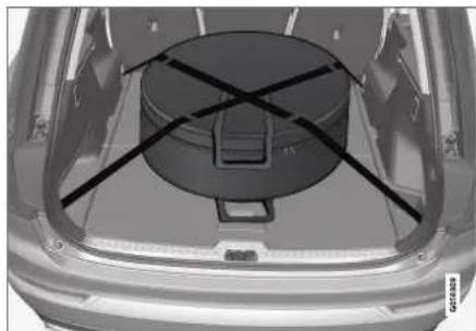
natural_image
Top-down view of a car trunk with a circular component and diagonal black lines indicating alignment or support (no text or symbols)The spare wheel is stored in a bag and should be secured with two straps onto the floor of the trunk/cargo compartment when the vehicle is being driven ^16 . The straps should be strapped down crosswise over the wheel, attached to the load anchoring eyelets and pulled taut.
Wheel changing tools are located under the cargo compartment floor.
Related information
- Spare wheel (p. 579)
Snow tires
Snow tires are designed for winter driving.
Volvo recommends snow tires with specific dimensions. The tire dimensions vary depending on engine type. When driving with snow tires, the correct type of tires must be mounted on all four wheels.

NOTE
Contact a Volvo dealer for advice on the best choice of rims and tires.
Tips for changing snow tires
When switching between regular tires and snow tires, mark the tires according to which side they were mounted on, e.g. L for left and R for right.
Studded tires
Sludded tires should be broken in by driving 500-1000 km (300-600 miles) slowly and gently to help the studs settle properly in the tires. This gives the tire, and especially the studs, a longer service life.

NOTE
Regulations regarding the use of studded tires vary from country to country.
Tread depth
Road conditions with ice, slush and low temperatures place considerably higher demands on tires than summer conditions. Volvo therefore recommends not driving on snow tires that have a tread depth of less than 4 mm (0.15 inch).
Related information
- When changing wheels (p. 574)
• Winter driving (p. 472)
• Tread wear indicator (p. 563)
Snow chains
Using snow chains and/or snow tires can help improve traction in winter driving conditions.

WARNING
Use Volvo genuine snow chains or equivalent snow chains that are suitable for the vehicle model and the tire and wheel sizes. Only one-sided snow chains are permitted.
If uncertain about snow chains, Volvo recommends contacting an authorized Volvo workshop. Use of the wrong snow chains could cause serious damage to the vehicle and result in an accident.
! CAUTION
Snow chains can be used on the vehicle, with the following restrictions:
- Volvo recommends not using snow chains on wheel dimensions larger than 19 inches.
- Always follow the manufacturer's installation instructions carefully. Install chains as tightly as possible and retighten periodically.
- Only put snow chains on the front wheels (also applies to all-wheel drive vehicles).
- If accessory, aftermarket or "custom" tires and wheels with different dimensions than the original tires and wheels are used, snow chains in some cases may NOT be used. Sufficient distance between the chains and brakes, suspension and body components must be maintained.
- Check local regulations regarding the use of snow chains before installing.
- Never exceed the snow chain manufacturer's specified maximum speed limit. Under no circumstances should you exceed 50 km/h (30 mph).
-
Avoid bumps, holes or sharp turns when driving with snow chains.
-
Avoid driving on surfaces without snow as this wears out both the snow chains and the tires.
- The handling of the vehicle can be adversely affected when driving with chains. Avoid fast or sharp turns as well as locked wheel braking.
- Some types of strap-on chains affect brake components and therefore must NOT be used.
Consult a Volvo retailer for more information about snow chains.
Related information
• Winter driving (p. 472)
Tire sealing system ^17
The temporary tire sealing system can be used to seal a puncture in a tire or to check and adjust the pressure in the tire.
Models equipped with a spare wheel ^18 do not have the tire sealing system.
WARNING
California Proposition 65
Operating, servicing and maintaining a passenger vehicle can expose you to chemicals including engine exhaust, carbon monoxide, phthalates, and lead, which are known to the State of California to cause cancer and birth defects or other reproductive harm. To minimize exposure, avoid breathing exhaust, do not idle the engine except as necessary, service your vehicle in a well ventilated area and wear gloves or wash your hands frequently when servicing your vehicle. For more information go to www.P65Warnings.ca.gov/passenger-vehicle.
The tire sealing system consists of a compressor and a bottle containing sealing compound. The sealing functions as a temporary repair.

NOTE
The sealing compound effectively seals tires with punctures in the tread but may not be able to fully seal tires with punctures in the sidewall. Do not use the tire sealing system on tires with large tears, cracks or similar damage.

NOTE
The compressor is intended for temporary tire sealing and is approved by Volvo.
Location
The tire sealing system is located in a foam block under the floor of the cargo compartment.

natural_image
Interior view of a car trunk with an inset close-up showing a battery component (no text or symbols visible)Sealing compound expiration date
The sealing compound bottle must be replaced if its expiration date has passed (see the decal on the bottle). Handle the old bottle as hazardous waste.
Related information
• Using the tire sealing system (p. 583)
- Inflate tires with the compressor included in the tire sealing system (p. 587)
• Tires (p. 560)
Using the tire sealing system
Sealing a tire using the tire sealing system, the Temporary Mobility Kit (TMK).
Overview

1 Electrical cable
② Hose
3 Air release valve
4 Protective hose cover
5 Speed limit sticker
6 Bottle holder (orange cover)
7 Air pressure gauge
WHEELS AND TIRES
◀◀
8 Sealing compound bottle
9 Switch
Connecting
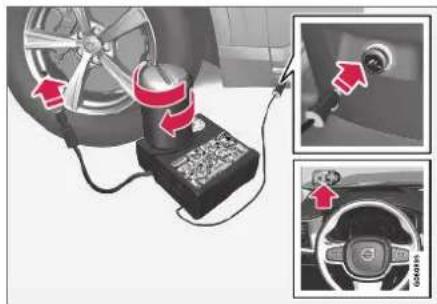

NOTE
Do not break the seal of the bottle before use. The seal is broken automatically when the bottle is screwed into place.

WARNING
Please keep the following points in mind when using the tire sealing system:
- The sealing compound bottle (no. 8 in the illustration) contains 1) rubber latex, natural and 2) ethanediol. These substances are harmful if swallowed.
- The contents of this bottle may cause allergic skin reactions or otherwise be potentially harmful to the respiratory tract, the skin, the central nervous system, and the eyes.
Precautions:
- Keep out of reach of children.
• Do not ingest the contents. - Avoid prolonged or repealed contact with the skin. Remove any clothing that has come into contact with sealant.
- Wash thoroughly after handling.
First aid:
- Skin: Wash affected areas of the skin with soap and water. Get medical attention if symptoms occur.
-
Eyes: Flush with plenty of water for least 15 minutes, occasionally lifting the upper and lower eyelids. Get medical attention if symptoms occur.
-
Inhalation: Move the exposed person to fresh air. If irritation persists, get medical attention.
- Ingestion: Do NOT induce vomiting unless directed to do so by medical personnel. Get medical attention.
- Disposal: Dispose of this material and its container at a hazardous or special waste collection point.

WARNING
- Do not remove the bottle while the tire sealing system is being used.
-
Do not remove the hose while the tire sealing system is being used.
-
Turn on the vehicle's hazard warning flashers if the tire sealing system is to be used in an area with traffic.
If the puncture was caused by a nail or similar object, do not remove it. It will help seal the hole.
-
Peel off the speed limit sticker from the side of the compressor. Affix the decal to a clearly visible location on the windshield to remind the driver not to exceed this speed limit. Do not drive faster than 80 km/h (50 mph) while using a tire that has been temporarily repaired with the tire sealing system.
-
Make sure the switch is in the 0 (Off) position and take out the electric cable and the hose.
- Unscrew the orange cover on the compressor and unscrew the cap on the sealing compound bottle.
- Screw the bottle onto the bottle holder as far as possible.
The bottle and the bottle holder are equipped with catches to help prevent the sealing compound from leaking. Once the bottle is screwed into place into the bottle holder, it cannot be unscrewed. The bottle can only be removed by a workshop. Volvo recommends an authorized Volvo workshop.

WARNING
Do not unscrew the bottle. It is equipped with a catch to prevent leakage.
- Unscrew the tire's valve cap and screw the hose's valve connector as far as possible onto the valve.
Be sure the air release valve on the compressor's hose is completely closed.
- Connect the electrical cable to the nearest 12 V outlet and start the vehicle.

NOTE
Make sure that none of the vehicle's other 12 V sockets are used while the compressor is running.

WARNING
Never leave children unattended in the vehicle while the engine is running.

WARNING
Inhaling exhaust fumes could lead to serious injury. Never leave the engine running in an enclosed space or a space without sufficient ventilation.
- Start the compressor by moving the switch to the I (On) position.

WARNING
Never stand next to a tire being inflated with the compressor. If cracks, bulges, etc. form on the tire, switch off the compressor immediately. The vehicle should not be driven. Call roadside assistance to have the vehicle towed to a workshop for inspection/replacement of the tire. Volvo recommends an authorized workshop.

NOTE
When the compressor first starts, air pressure may temporarily increase up to 6 bar (88 psi) but should decrease again after approximately 30 seconds.
- Inflate the tire for 7 minutes.

CAUTION
To help avoid overheating, the compressor should never be used for more than 10 minutes at a time.
WHEELS AND TIRES
- Switch off the compressor and check the inflation pressure using the air pressure gauge. The inflation pressure should be between 1.8 bar (22 psi) and 3.5 bar (51 psi). If the inflation pressure is too high, use the air release valve to release air.

WARNING
If pressure falls below 1.8 bar (22 psi), the hole in the tire may be too large. The vehicle should not be driven. Call roadside assistance to have the vehicle towed to a workshop for inspection/replacement of the tire. Volvo recommends an authorized workshop.
- Switch off the compressor and remove the electrical cable.
- Unscrew the hose from the tire's valve and screw the valve cap back on.

NOTE
- After inflating a tire, always replace the valve cap to help prevent valve damage caused by gravel, dirt, etc.
-
Use plastic valve caps only. Metal caps could corrode and become difficult to remove.
-
Put the protective hose cover onto the hose to help prevent leakage of any residual sealing compound. Return the equipment to the cargo compartment.
- Immediately drive the vehicle at least 3 km (2 miles) at a maximum speed of 80 km/h (50 mph) to allow the sealing compound to seal the tire, and then recheck the inflation pressure.

NOTE
During the tire's first revolution, some sealing compound may spray out of the puncture hole.

WARNING
Before driving away, make sure that no one is near the vehicle who could be sprayed with sealing compound. Make sure no one is within 2 meters(7 feet) of the vehicle.
15. Rechecking the inflation pressure
Connect the hose to the tire's valve and screw the hose connector onto the valve as far as possible. The compressor must be switched off.
-
Check the inflation pressure on the air pressure gauge.
-
If the pressure is under 1.3 bar (19 psi), the tire is not sufficiently sealed. The vehicle should not be driven. Call roadside assistance to have the vehicle towed.
- If the inflation pressure is higher than 1.3 bar (19 psi), the tire must be inflated to the inflation pressure specified on the tire pressure decal on the driver's side door pillar (1 bar = 100 kPa = 14.5 psi). If the inflation pressure is too high, use the air release valve to release air.

NOTE
Replace the sealing compound bottle and hose after use. Volvo recommends having these replaced by an authorized Volvo workshop.

WARNING
Check inflation pressure regularly.
Volvo recommends driving to the nearest authorized Volvo workshop to have the tire replaced/ repaired. Inform the workshop that the tire contains sealing compound.
The sealing compound bottle must be replaced after use. Volvo recommends contacting an authorized Volvo workshop for replacement.

WARNING
After using the tire sealing system, the vehicle should not be driven farther than approximately 200 km (120 miles).

NOTE
The compressor is an electric device. Follow local regulations for disposal.
Related information
• Recommended tire pressure (p. 569)
• Tire sealing system (p. 582)
- Inflate tires with the compressor included in the tire sealing system (p. 587)
Inflate tires with the compressor included in the tire sealing system
The vehicle's original tires can be inflated using the compressor in the tire sealing system.
- The compressor must be switched off. Make sure that the switch is in the 0 (Off) position and take out the electrical cable and the hose.
- Unscrew the tire's valve cap and screw the hose's valve connector as far as possible onto the valve.
Be sure the air release valve on the compressor's hose is completely closed. - Connect the electrical cable to the nearest 12 V outlet and start the vehicle.

WARNING
Inhaling exhaust fumes could lead to serious injury. Never leave the engine running in an enclosed space or a space without sufficient ventilation.

WARNING
Never leave children unattended in the vehicle while the engine is running.
- Start the compressor by moving the switch to the I (On) position.

CAUTION
Risk of overheating. The compressor should not be running for longer than 10 minutes at a time.
-
Inflate the tire to the pressure specified on the tire pressure decal on the driver's side door pillar. If the inflation pressure is too high, use the air release valve to release air.
-
Switch off the compressor. Remove the hose and the electrical cable.
-
Screw the valve cap back onto the tire.

NOTE
- After inflating a tire, always replace the valve cap to help prevent valve damage caused by gravel, dirt, etc.
- Use plastic valve caps only. Metal caps could corrode and become difficult to remove.

NOTE
The compressor is an electric device. Follow local regulations for disposal.
WHEELS AND TIRES
Related information
• Recommended tire pressure (p. 569)
• Using the tire sealing system (p. 583)
• Tire sealing system (p. 582)
Determining the vehicle's permitted weight
Properly loading your vehicle will provide maximum return of vehicle design performance.
Weight designations
Before loading your vehicle, familiarize yourself with the following terms for determining your vehicle's weight ratings, with or without a trailer, from the vehicle's Federal/Canadian Motor Vehicle Safety Standards (FMVSS/CMVSS) label, and the vehicle's tire information placard:
Curb weight
The weight of the vehicle including a full tank of fuel and all standard equipment. It does not include passengers, cargo, or optional equipment.
Capacity weight
All weight added to the curb weight, including cargo and optional equipment. When towing, tow-bar weight is also part of cargo weight.
Permissible axle weight
The maximum allowable weight that can be carried by a single axle (front or rear). These numbers are shown on the Federal/Canadian Motor Vehicle Safety Standards (FMVSS/CMVSS) label. The total load on each axle must never exceed its maximum permissible weight.
Gross vehicle weight (GVW)
The vehicle's curb weight + cargo + passengers.
Steps for Determining Correct Load Limit
- Locate the statement "the combined weight of occupants and cargo should never exceed XXX kg or XXX lbs." on your vehicle's placard.
- Determine the combined weight of the driver and passengers that will be riding in your vehicle.
- Subtract the combined weight of the driver and passengers from XXX kg or XXX lbs.
- The resulting figure equals the available amount of cargo and luggage load capacity. For example, if the "XXX" amount equals 1400 lbs. and there will be five 150 lb. passengers in your vehicle, the amount of available cargo and luggage load capacity is 650 lbs. (1400 - 750 (5 × 150) = 650 lbs.)
- Determine the combined weight of luggage and cargo being loaded on the vehicle. That weight may not safely exceed the available cargo and luggage load capacity calculated in Step 4.
- If your vehicle will be towing a trailer, load from your trailer will be transferred to your vehicle. Consult this manual to determine how this reduces the available cargo and luggage load capacity of your vehicle.
WHEELS AND TIRES

WARNING
- Exceeding the permissible axle weight, gross vehicle weight, or any other weight rating limits can cause tire overheating resulting in permanent deformation or catastrophic failure.
- Do not use replacement tires with lower load carrying capacities than the tires that were original equipment on the vehicle because this will lower the vehicle's GVW rating. Use only tires with the correct load carrying capacity. Consult your Volvo retailer for information.
Related information
- Loading recommendations (p. 598)

bar
| Category | Value | |---|---| | Category 1 | 100 | | Category 2 | 100 | | Category 3 | 100 | | Category 4 | 100 | | Category 5 | 100 | | Category 6 | 100 | | Category 7 | 100 | | Category 8 | 100 | | Category 9 | 100 | | Category 10 | 100 | | Category 11 | 100 | | Category 12 | 100 | | Category 13 | 100 | | Category 14 | 100 | | Category 15 | 100 | | Category 16 | 100 | | Category 17 | 100 | | Category 18 | 100 | | Category 19 | 100 | | Category 20 | 100 | | Category 21 | 100 | | Category 22 | 100 | | Category 23 | 100 | | Category 24 | 100 | | Category 25 | 100 | | Category 26 | 100 | | Category 27 | 100 | | Category 28 | 100 | | Category 29 | 100 | | Category 30 | 100 | | Category 31 | 100 | | Category 32 | 100 | | Category 33 | 100 | | Category 34 | 100 | | Category 35 | 100 | | Category 36 | 100 | | Category 37 | 100 | | Category 38 | 100 | | Category 39 | 100 | | Category 40 | 100 | | Category 41 | 100 | | Category 42 | 100 | | Category 43 | 100 | | Category 44 | 100 | | Category 45 | 100 | | Category 46 | 100 | | Category 47 | 100 | | Category 48 | 100 | | Category 49 | 100 | | Category 50 | 100 | | Category 51 | 100 | | Category 52 | 100 | | Category 53 | 100 | | Category 54 | 100 | | Category 55 | 100 | | Category 56 | 100 | | Category 57 | 100 | | Category 58 | 100 | | Category 59 | 100 | | Category 60 | 100 | | Category 61 | 100 | | Category 62 | 100 | | Category 63 | 100 | | Category 64 | 100 | | Category 65 | 100 | | Category 66 | 100 | | Category 67 | 100 | | Category 68 | 100 | | Category 69 | 100 | | Category 70 | 100 | | Category 71 | 100 | | Category 72 | 100 | | Category 73 | 100 | | Category 74 | 100 | | Category 75 | 100 | | Category 76 | 100 | | Category 77 | 100 | | Category 78 | 100 | | Category 79 | 100 | | Category 80 | 100 | | Category 81 | 100 | | Category 82 | 100 | | Category 83 | 100 | | Category 84 | 100 | | Category 85 | 100 | | Category 86 | 100 | | Category 87 | 100 | | Category 88 | 100 | | Category 89 | 100 | | Category 90 | 100 | | Category 91 | 100 | | Category 92 | 100 | | Category 93 | 100 | | Category 94 | 100 | | Category 95 | 100 | | Category 96 | 100 | | Category 97 | 100 | | Category 98 | 100 | | Category 99 | 100 | | Total (Total) |LOADING, STORAGE AND PASSENGER
COMPARTMENT
LOADING, STORAGE AND PASSENGER COMPARTMENT
Passenger compartment interior
Overview of the passenger compartment interior and storage spaces.
Front seats

natural_image
Interior view of a car dashboard and steering wheel (no visible text or symbols)Storage compartment in the door panel and near the steering wheel, glove compartment and sun visors.

natural_image
Interior view of a car dashboard with red arrows pointing to key components (no text or symbols visible)Storage compartments with cup holders, net pocket ^* , electrical outlets and USB ports in the tunnel console.
Rear seat
Second row of seats
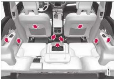
natural_image
Interior view of a car showing three seats with red arrows pointing to the backrest seat (no text or symbols visible)Storage compartment in the door panel, cup holders* in the center seat's backrest, storage pocket* in the front seat's backrest and electrical outlets in the tunnel console.
Third row of seats*

natural_image
Interior view of a car seatbelt with red arrows pointing to the seat (no text or symbols visible)Storage compartment and cup holders in the side panel and storage compartment between the seats.

WARNING
Store loose objects, such as cell phone, camera, remote control for extra equipment, etc., in the glove compartment or another compartment. Otherwise, these could injure people in the vehicle in the event of hard braking or a collision.

CAUTION
Keep in mind that glossy surfaces can be easily scratched by e.g. metal objects. Do not place keys, phones or similar items on sensitive surfaces.
Related information
• Electrical outlets (p. 594)
• Using the glove compartment (p. 597)
• Sun visors (p. 598)
• Tunnel console (p. 593)
- Connecting a device via the USB port (p. 525)
Tunnel console
The tunnel console is located between the front seats.

1 Storage compartment with cover*. The cover can be opened/closed by pressing the handle.
② Storage compartment with cup holder and 12 V socket.
3 Storage compartment and USB port under the armrest.
4 Climate control panel for the rear seats* or storage compartment.
WARNING
Store loose objects, such as cell phone, camera, remote control for extra equipment, etc., in the glove compartment or another compartment. Otherwise, these could injure people in the vehicle in the event of hard braking or a collision.
NOTE
One of the sensors for the alarm* is located under the cup holder in the center console. Avoid placing coins, keys and other metal objects in the cup holder as this could trigger the alarm.
CAUTION
Keep in mind that glossy surfaces can be easily scratched by e.g. metal objects. Do not place keys, phones or similar items on sensitive surfaces.
Related information
• Passenger compartment interior (p. 592)
• Electrical outlets (p. 594)
• Climate system controls (p. 215)
LOADING, STORAGE AND PASSENGER COMPARTMENT
Electrical outlets
There are two 12 V electrical outlets and one 120 V electrical outlet* in the tunnel console, and one 12 V electrical outlet* in the trunk/cargo compartment.
If a problem occurs with an electrical socket, contact a workshop - an authorized Volvo workshop is recommended.
12 V outlets

12 V outlet in the tunnel console, front seat.
The 12 V outlets can be used for devices intended for this such as MP3 players, coolers and cellular phones.

12 V outlet in the tunnel console, second row of seats.

12 V outlet in the cargo compartment*.
Electrical outlets in the tunnel console - rear seat*
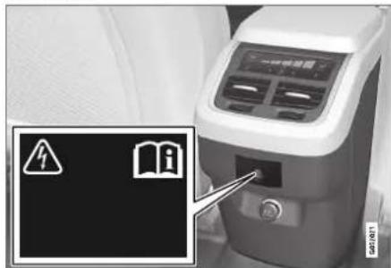
Electrical outlet in the tunnel console, second row of seats.
The high-voltage outlet* can be used for devices intended for this, such as chargers, laptops, etc.
High-voltage outlet status indicator light
An LED ^1 light on the outlet indicates its status:
LOADING, STORAGE AND PASSENGER COMPARTMENT
| Status indicator light Cause Action | ||
| Steady green light The | outlet is providing electrical current to a connected device. None. | |
| Flashing orange light The | the outlet's voltage converter is too hot (e.g. if the device draws too much current or if the temperature in the passenger compartment is very high). | Unplug the device, let the voltage converter cool down and plug in the device again. |
| The connected device is drawing too much current (at the moment or constantly) or is not functioning properly. | None. The device cannot be used in the outlet. | |
| Indicator light off | The outlet has not detected a device plugged into the outlet. | Make sure the device is correctly plugged into the outlet. |
| The outlet is not active. Make sure the vehicle's ignition is in at least | mode I. | |
| The outlet has been active but has been deactivated. Start the engine and/or charge the start battery. | ||
Related information
• Passenger compartment interior (p. 592)
• Using the electrical outlets (p. 596)
LOADING, STORAGE AND PASSENGER COMPARTMENT
Using the electrical outlets
The 12 V outlet can be used for devices intended for this such as MP3 players, coolers and cellular phones.
The high-voltage outlet* can be used for devices intended for this, such as chargers, laptops, etc.
The ignition must be in at least mode I for the outlets to supply current. The outlets will then be active as long as there is sufficient charge in the start battery.
If the engine is turned off and the vehicle is locked, the outlets will be deactivated. If the engine is turned off and the vehicle remains unlocked, the sockets will remain active for up to 7 minutes.

NOTE
Bear in mind that using the electrical outlets when the engine is off could cause the starter battery to have too low of a charge level, which could limit other functionality.
Accessories connected to the electrical outlets can be activated even when the vehicle electrical system is off or if preconditioning is used. For this reason, disconnect plugs when they are not in use to prevent the starter battery from becoming discharged.

WARNING
- Do not use accessories with large or heavy plugs – they could damage the outlet or come loose while you are driving.
- Do not use accessories that could cause disruptions to e.g. the vehicle's radio receiver or electrical system.
- Position the accessory so that there is no risk of it injuring the driver or passengers in the event of heavy braking or a collision.
- Pay attention to connected accessories as they can generate heat that could burn passengers or the interior.
Using 12 V outlets
- Remove the stopper (tunnel console) or fold down the cover (trunk/cargo compartment) over the socket and plug in the device.
- Unplug the device and put the stopper back in (tunnel console) or fold up the cover (trunk/cargo compartment) when the socket is not in use or left unattended.

CAUTION
The maximum power is 120 W (10 A) per outlet.
Using high-voltage outlets
The ignition must be in at least mode I for outlets to supply current. The outlets will then be active as long as there is sufficient charge in the start battery.
- Slide down the cover over the outlet and plug in the device.
The LED ^2 light on the outlet will indicate its status.
- The outlet is supplying electrical current when the light is glowing steadily green.
- Disconnect the device by pulling out the plug (do not pull on the cord).
Pull up the cover when the outlet is not in use or is left unattended.

CAUTION
The maximum power is 150 W.

WARNING
Do not attempt to alter or repair the high-voltage outlet on your own. Volvo recommends contacting an authorized Volvo workshop.

WARNING
- Only use accessories that are not damaged or malfunctioning. The accessories must be designed for 120 V and 60 Hz, with plugs intended for the outlet. The accessories must be CE marked, UL marked or have an equivalent safety marking.
- New let outlets, plugs or accessories come into contact with water or another fluid. Do not touch or use the outlet if it appears damaged or has been in contact with water or another fluid.
- Do not connect power strips, adapters or extension cords to the outlet has this could cause the outlet's safety functions to malfunction.
- The outlet is equipped with a pet guard. Make sure that no one picks at or damages the outlet in such a way that the guard is disabled. Children should not be left unsupervised in the vehicle when the outlet is active.
Failure to follow the above could lead to severe or fatal electrical shocks.
Related information
• Electrical outlets (p. 594)
• Passenger compartment interior (p. 592)
Using the glove compartment
The glove compartment is located on the passenger side. The glove compartment can be used to store the Owner's Manual, maps, etc. There is also room for a pen and a card holder.

natural_image
Medical imaging device showing internal components and a highlighted medical device (no visible text or symbols)Glove compartment and opening button on the center console.
The glove compartment is opened by pressing the opening button in the center console.
Locking and unlocking the glove box
The glove compartment can be locked ("private locking") when the vehicle is left at a workshop, hotel, etc. When private locking is activated, the tailgate is also locked.
Using the glove box as a cooled area
The glove compartment can be used to cool e.g. drinks or food. Cooling is possible when the cli-
mate system is active (i.e. when the ignition is in mode II or when the engine is running).

natural_image
Interior view of a car showing a vehicle's dashboard and internal compartments with a highlighted section (no visible text or symbols)The illustration is generic – the design may vary.

Activate cooling

Deactivate cooling
- Activate or deactivate cooling by moving the control as far as possible toward the passenger compartment/glove compartment.
Related information
• Passenger compartment interior (p. 592)
• Private Locking (p. 271)
LOADING, STORAGE AND PASSENGER COMPARTMENT
Sun visors
In the ceiling in front of the driver and front passenger, there are sun visors that can be lowered and angled to the side as necessary.

natural_image
Interior view of a car showing the rearview mirror and side panel (no text or symbols visible)The illustration is generic - the design may vary.
The mirror lighting* comes on automatically when the cover is lifted up.
The mirror frame has a holder for e.g. cards or tickets.
Related information
• Passenger compartment interior (p. 592)
Cargo compartment
The vehicle has a flexible cargo compartment that makes it possible to carry and secure large objects.
The cargo compartment capacity can be considerably increased by folding down the backrests in the second and third rows* of seats. To make loading and unloading easier, the rear section of the vehicle can be raised and lowered using the level control function*. Use the load anchoring eyelets or grocery bag holders to help secure objects in place, and the retractable cargo compartment cover* to help conceal objects in the cargo compartment.
If the vehicle is equipped with a temporary spare tire, this is secured to the cargo compartment floor under the cover. The towing eyelet and lire sealing system are located under the cargo compartment floor.
Related information
- Loading recommendations (p. 598)
• Grocery bag holders (p. 600) - Load anchoring eyelets (p. 601)
- Installing and removing the cargo compartment cover* (p. 601)
Loading recommendations
There are a number of things to consider when carrying loads in or on the vehicle.
Load-carrying capacity is determined by the vehicle's curb weight. The total weight of all passengers and any installed accessories reduces the vehicle's load-carrying capacity by the corresponding amount.

WARNING
The vehicle's driving characteristics change depending on the weight and position of the load.
Loading the cargo compartment/trunk
- Position objects so they are pressing against the rear seat backrests.
• Distribute the load evenly. - Heavy objects should be positioned as low as possible. Avoid placing heavy objects on folded-down seat backrests.
- Cover sharp corners with a soft cloth or similar to help prevent damage to the upholstery.
- Use the load anchoring eyelets and tensioning straps or similar to secure all objects.

WARNING
In a head-on collision at a speed of 50 km/h (30 mph), an unsecured object weighing 20 kg (44 pounds) can reach a projectile weight equivalent to 1000 kg (2200 pounds).

WARNING
If objects are loaded higher than the upper edge of the side windows, leave a 10 cm (4 in.) space between the objects and the window. Objects placed closer to this could impede the function of the inflatable curtain concealed inside the headlining.

WARNING
Always secure the load. Otherwise, it may shift during heavy braking and injure people in the vehicle.
Cover sharp edges and sharp corners with something soft.
Turn off the engine and apply the parking brake when loading/unloading long objects. Otherwise, it is possible for the load to reach the gear lever or gear selector and move it to a drive position – which could cause the vehicle to begin rolling.
Extra cargo space
The rear seat backrests can be folded down to increase cargo compartment space and simplify loading. If the rear seat backrests are folded
down, make sure that no objects loaded into the vehicle prevent the WHIPS system for the front seats from functioning correctly.
Raising/ lowering the rear end of the vehicle\*
The rear end of the vehicle can be lowered or raised for easier loading or to facilitate attaching a trailer*.
The controls for raising/lowering are located at the rear edge of the cargo compartment's right side panel.
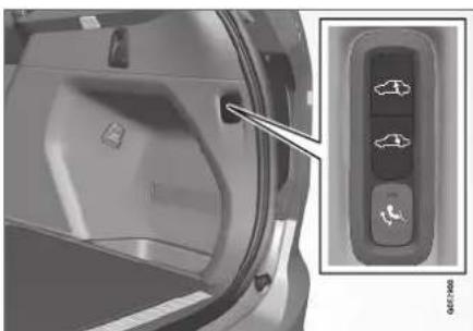
natural_image
Close-up of a car air conditioner panel with a close-up inset showing the control panel (no text or symbols visible)Controls for raising/lowering the rear end of the vehicle.
The controls consist of two buttons - one button for lowering and one button for raising the rear end. Press and hold the relevant button until the desired height is reached.
The rear end of the vehicle cannot be raised higher than its normal height.
The rear end will return to the normal height when the vehicle begins driving.

NOTE
It is not possible to adjust the height of the vehicle's rear when one or more of the doors or the hood is open. This does not apply to the tailgate.

WARNING
Make sure that no people, animals or objects are found under the vehicle when it is lowered. This could endanger life and cause damage to the vehicle or objects.
Related information
- Load anchoring eyelets (p. 601)
• Folding the second row backrests (p. 193)
• Roof loads and load carriers (p. 600)
• Leveling control* and suspension (p. 461) - Weights (p. 669)
LOADING, STORAGE AND PASSENGER COMPARTMENT
Roof loads and load carriers
Volvo-developed load carriers are recommended for carrying loads on the roof of the vehicle.
Volvo load carriers are specially designed to help prevent damage to your vehicle and help ensure maximum safety while driving. Volvo load carriers are available from authorized Volvo retailers.
Carefully follow the installation instructions provided with the load carriers.
- Distribute the load evenly throughout the load carriers. Place heavier cargo at the bottom of the load.
- Check periodically to ensure that the load carriers and load are properly secured. Secure the load firmly using tie straps or similar.
- If the load is longer than the vehicle, such as a canoe or kayak, attach the towing eyelet in its front outlet and secure the tie straps in it.
- The vehicle's wind resistance and fuel consumption increase with the size of the load.
- Drive smoothly. Avoid rapid acceleration, hard braking and fast cornering.

WARNING
The vehicle's center of gravity and driving characteristics are altered by roof loads. Follow the vehicle's specifications regarding weights and maximum permitted load.
Related information
- Loading recommendations (p. 598)
- Weights (p. 669)
Grocery bag holders
Grocery bag holders (hooks) help keep shopping bags in place and prevent them from falling over and spilling their contents in the cargo compartment.
On the sides of the cargo compartment

natural_image
Interior view of a car door with a close-up inset showing a red arrow pointing to a seatbelt (no text or symbols visible)There are two fold-out holders in the side panels, one on each side of the cargo compartment.

CAUTION
The grocery bag holders are only intended to hold weights up to 5 kg (11 lbs).
Related information
-
Loading recommendations (p. 598)
• Installing and removing the cargo net* (p. 606) -
Installing and removing the cargo compartment cover* (p. 601)
• Installing and removing the steel cargo grid* (p. 604)
Load anchoring eyelets
The load anchoring eyelets in the cargo compartment can be used to secure objects with straps, a net, etc.

natural_image
Top-down view of a car trunk with a highlighted internal component (no text or symbols visible)
WARNING
Hard, sharp and/or heavy objects in or protruding from the vehicle can cause injury in the event of hard braking.
Always secure large and heavy objects with a seat belt or cargo retaining straps.
Related information
- Loading recommendations (p. 598)
- Weights (p. 669)
Installing and removing the cargo compartment cover\*
The cover can be rolled out to conceal objects in the cargo compartment.
Installing the cargo compartment cover ^3

natural_image
Close-up of a car rear bumper with red arrows pointing to specific parts (no text or symbols visible)
Press the end piece on one side of the cover into the retaining bracket in the side panel of the cargo compartment.

Then put the other end piece in the recess in the side panel on the opposite side.
LOADING, STORAGE AND PASSENGER COMPARTMENT
◀◀
Push the end piece down on both sides, one at a time.
When a click is heard and the red marks on each end piece are no longer visible, the cover is in place. Check that it is secure.
Removing the cargo compartment cover
In retracted position:
- Press the button on one of the cover's ends and lift out that end.
For 7-seat models - remove the third row seat belt latches from the hooks above the side panels.
- Carefully lift the cover up and out.
The other end will release automatically and the cover can then be lifted out of the cargo compartment.
Related information
- Operating the cargo compartment cover* (p. 602)
- Loading recommendations (p. 598)
Operating the cargo compartment cover\*
The cover can be used in two positions: fully open to completely cover the cargo compartment or partially retracted to make it easier to reach further into the cargo compartment.
Fully open
7-seat models
1.
natural_image
Interior view of a car showing a black belt buckle and ventilation grille (no text or symbols visible)Hang the third-row seat belt latches in the hooks provided in the side panels.

natural_image
Two grayscale images showing a vehicle's side profile with red arrows pointing to specific areas (no text or symbols visible)Grasp the handle and pull the cover out and above the side panels in the cargo compartment. Pull the cover to its end position.
With the cover completely open (covering the cargo compartment), press the attaching pins at the end of the cover into the grooves on the side panels and release the cover slightly while pressing the handle lightly downward to hook the pins into the grooves. >The cover will be secured in the fully open position.
5-seat models

natural_image
Two grayscale images showing a vehicle interior with red warning signs (no readable text or symbols)Grasp the handle and pull the cover out and above the side panels in the cargo compartment. Pull the cover to its end position.
With the cover completely open (covering the cargo compartment), press the attaching pins at the end of the cover into the grooves on the side panels and release the cover slightly while pressing the handle lightly downward to hook the pins into the grooves. >The cover will be secured in the fully open position.

CAUTION
Do not place objects on top of the cargo compartment cover.

WARNING
In 7-seat models - never have a cargo compartment cover mounted when there are passengers in the rear seats. This could lead to serious injury in the event of a collision.
Loading mode

natural_image
Two-panel grayscale image showing a vehicle's interior and side view, with no visible text or symbols.From the fully retracted position - grasp the handle and pull the cover up and over the side panels in the cargo compartment. Pull to the end position and press the attaching pins at the end of the cover into the grooves in the side panels of the vehicle. (If the cover is already fully open, see next section.)
From the fully open position - grasp the handle and press the cover's attaching pins down into the grooves in the side panels and then release.
Retract the cover until it stops in the partially retracted position.
If your hands are full:

natural_image
Two grayscale images showing a vehicle's interior and exterior views, with a magnified inset highlighting the left side of the main image (no text or symbols present)In the fully open position, push the cover's handle slightly upward with e.g. your elbow.
The cover will retract until it stops in the partially retracted position.
To fully open the cover from the partially retracted position:
- Grasp the handle and pull the cover out as far as possible.
- Let the cover retract slightly and press the handle slightly downward.
The cover will be secured in the fully open position.
LOADING, STORAGE AND PASSENGER COMPARTMENT
Retracting the cover
- From the fully opened position:
Lift the cover's handle and pull it rearward to release the cover's attaching pins from the grooves. Let the cover retract.
From the partially retracted position:
Grasp the handle and pull the cover out of the groves to the fully open position. Lift the handle and pull it rearward to release the cover's attaching pins from the grooves. Let the cover retract.
- Let the cover retract with its attaching pins above the side panels until it stops in the fully retracted position.
Related information
- Installing and removing the cargo compartment cover* (p. 601)
Installing and removing the steel cargo grid\*
The steel cargo grid helps prevent loads or pets in the cargo compartment from being thrown forward into the passenger compartment.

natural_image
Interior view of a vehicle showing a transparent cage structure with seat compartments and rear seats (no text or symbols visible)For safety reasons, the steel grid must always be installed and secured correctly.
WARNING
Under no circumstances may a person be in the cargo compartment when the vehicle is moving. Heavy braking or a collision could lead to serious injury.
The steel grid consists of the grid itself and two separate mounting brackets. Each of the mount-
ing brackets has a screw cover and two plastic sleeves for the grid.
WARNING
The steel cargo grid may only be used in the rear position described here. The ceiling attachment points behind the front seats are not intended to anchor the steel grid.
WARNING
For safety reasons, the third-row seats ^4 must be folded down when the steel cargo grid is mounted in the vehicle.
CAUTION
The steel cargo grid and the cargo compartment cover cannot be mounted at the same time.
Installation
-
Fold down the rear seats and lift in the steel grid through one of the rear doors or the tailgate. The curved (convex) side of the grid should face toward the cargo compartment and the hooks on each side of the grid should face upward. The mounting brackets and plastic sleeves are not needed in this step.
-

Press one of the grid's hooks into the larger hole in the ceiling attachment point (1).
Grasp the grid near the hook and pull/push it into the smaller hole (2).
The hook is now secured in the attachment point.
- Repeat step 2 above to secure the other hook in the attachment point on the opposite side.

WARNING
Make sure the cargo grid's hooks are securely attached in the ceiling attachment points to help ensure the grid does not come loose.
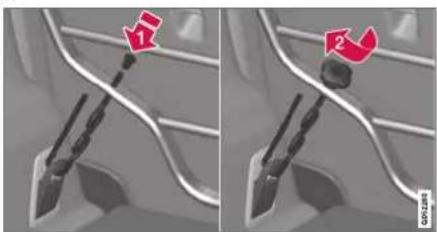
natural_image
Two-panel image showing a car interior with a highlighted component and directional arrows (no text or symbols)Attach the mounting bracket's hook through the cargo anchoring eyelet near the floor of the cargo compartment and insert the threaded section of the bracket through the grid's lower attachment hole (1).
Slide the plastic sleeve onto the threaded section of the mounting bracket with the sleeve's flange turned upward and press it down through the hole. Screw the screw cover into place until its underside is approximately 5 mm from the grid (2).
- Repeat step 4 for the opposite side.
- Center the grid and then tighten both mounting brackets, moving back and forth between them until the grid is securely in place.
Removing the cover
Remove the steel grid by performing the above steps in reverse order.
It can be a good idea to remove the mounting brackets before removing the plastic sleeves from the holes in the grid.
Related information
- Loading recommendations (p. 598)
- Load anchoring eyelets (p. 601)
LOADING, STORAGE AND PASSENGER COMPARTMENT
Installing and removing the cargo net\*
The cargo net helps prevent objects in the cargo compartment from entering the passenger compartment in the event of a sudden stop or hard braking.
The cargo net is attached at four points.

natural_image
Top-down view of a car showing rear seats and seatbelt structure (no text or symbols visible)For safety reasons, the cargo net must always be mounted and secured according to the following description.
The net is made of strong nylon weave and can be attached in two different locations in the vehicle:
- Rear mounting - behind the second row of seats.
• Front mounting - behind the front seats.
WARNING
Objects in the cargo compartment must always be securely anchored, even with a correctly installed cargo net.
Installing the cargo net
WARNING
All of the cargo net's upper consoles, hooks and straps must be securely mounted and attached before the net is used. Never use the net if it is damaged.
NOTE
With front mounting, the cargo net is most easily installed via a rear door.
- Fold out the cargo net and make sure that the upper rod folds out and locks into position.
-
Insert one of the net's hooks into the front or rear ceiling mounting point with the strap lock facing you.
-
Insert the net's other upper hook into the ceiling mounting point on the opposite side.
The telescopic spring-loaded hooks make mounting easier.
Make sure that the net's hooks are pushed forward as far as possible into their respective mounting points.
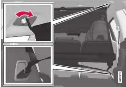
natural_image
Interior view of a car showing a red arrow pointing to the steering wheel (no text or symbols visible)Rear mounting.
For rear mounting:
With the cargo net hooked into the rear ceiling mounting points, attach the net's straps into the front floor eyelets in the cargo compartment.

natural_image
Interior view of a car showing seatbelt and steering wheel (no text or symbols visible)Front mounting.
For front mounting:
With the cargo net mounted in the front ceiling mounting points, hook the straps into the outer eyelets on the front seal rails behind the seats. Attaching the net is easier if the seat backrests are upright and the seats are moved slightly forward.
Move the seal or backrest only until it touches the net. Moving it with too much force or applying too much pressure to the net could lead to damage.

CAUTION
If a seat or backrest is pressed with too much force back against the cargo net, the net and its ceiling brackets could be damaged.
- Pull the straps until the cargo net is taut.
Removing the cargo net
The cargo net can be easily removed and folded up.
- Loosen the cargo net by pressing the button on the strap locks on each side and pulling to allow some slack.
- Press in the catches and release both of the strap hooks.
- Unhook the upper hooks and remove the net from the ceiling mounting points.
- Press the red button on the rod so that it can be folded. Fold and roll up the net. Store the net in its case.
Related information
- Loading recommendations (p. 598)
- Load anchoring eyelets (p. 601)

bar
| Category | Value | |---|---| | Category 1 | 100 | | Category 2 | 100 | | Category 3 | 100 | | Category 4 | 100 | | Category 5 | 100 | | Category 6 | 100 | | Category 7 | 100 | | Category 8 | 100 | | Category 9 | 100 | | Category 10 | 100 | | Category 11 | 100 | | Category 12 | 100 | | Category 13 | 100 | | Category 14 | 100 | | Category 15 | 100 | | Category 16 | 100 | | Category 17 | 100 | | Category 18 | 100 | | Category 19 | 100 | | Category 20 | 100 | | Category 21 | 100 | | Category 22 | 100 | | Category 23 | 100 | | Category 24 | 100 | | Category 25 | 100 | | Category 26 | 100 | | Category 27 | 100 | | Category 28 | 100 | | Category 29 | 100 | | Category 30 | 100 | | Category 31 | 100 | | Category 32 | 100 | | Category 33 | 100 | | Category 34 | 100 | | Category 35 | 100 | | Category 36 | 100 | | Category 37 | 100 | | Category 38 | 100 | | Category 39 | 100 | | Category 40 | 100 | | Category 41 | 100 | | Category 42 | 100 | | Category 43 | 100 | | Category 44 | 100 | | Category 45 | 100 | | Category 46 | 100 | | Category 47 | 100 | | Category 48 | 100 | | Category 49 | 100 | | Category 50 | 100 | | Category 51 | 100 | | Category 52 | 100 | | Category 53 | 100 | | Category 54 | 100 | | Category 55 | 100 | | Category 56 | 100 | | Category 57 | 100 | | Category 58 | 100 | | Category 59 | 100 | | Category 60 | 100 | | Category 61 | 100 | | Category 62 | 100 | | Category 63 | 100 | | Category 64 | 100 | | Category 65 | 100 | | Category 66 | 100 | | Category 67 | 100 | | Category 68 | 100 | | Category 69 | 100 | | Category 70 | 100 | | Category 71 | 100 | | Category 72 | 100 | | Category 73 | 100 | | Category 74 | 100 | | Category 75 | 100 | | Category 76 | 100 | | Category 77 | 100 | | Category 78 | 100 | | Category 79 | 100 | | Category 80 | 100 | | Category 81 | 100 | | Category 82 | 100 | | Category 83 | 100 | | Category 84 | 100 | | Category 85 | 100 | | Category 86 | 100 | | Category 87 | 100 | | Category 88 | 100 | | Category 89 | 100 | | Category 90 | 100 | | Category 91 | 100 | | Category 92 | 100 | | Category 93 | 100 | | Category 94 | 100 | | Category 95 | 100 | | Category 96 | 100 | | Category 97 | 100 | | Category 98 | 100 | | Category 99 | 100 | | Total (Total) |MAINTENANCE AND SERVICE
MAINTENANCE AND SERVICE
Volvo's service program
To keep the vehicle as safe and reliable as possible, follow the Volvo service schedule specified in the Warranty and Maintenance Records Information booklet.

WARNING
California Proposition 65
Operating, servicing and maintaining a passenger vehicle can expose you to chemicals including engine exhaust, carbon monoxide, phthalates, and lead, which are known to the State of California to cause cancer and birth defects or other reproductive harm. To minimize exposure, avoid breathing exhaust, do not idle the engine except as necessary, service your vehicle in a well ventilated area and wear gloves or wash your hands frequently when servicing your vehicle. For more information go to www.P65Warnings.ca.gov/passenger-vehicle.
Volvo recommends having an authorized Volvo workshop perform service and maintenance. Volvo workshops have the staff, service literature and special tools to guarantee the highest quality of service.

CAUTION
To ensure the Volvo warranty is not invalidated, check and follow the Service and Warranty Booklet.
Service and repairs
Service the vehicle regularly. Follow Volvo's recommended service intervals.
Detailed inspection and repairs may only be performed by an authorized workshop.

WARNING
Do not make any repairs on this vehicle yourself. Electrical cables and/or components that have come loose may only be corrected by an authorized workshop – an authorized Volvo workshop is recommended.
Introduction
The maintenance services contain several checks that require special instruments and tools and therefore must be performed by a qualified technician. To keep your Volvo in top condition, specify time-tested and proven Genuine Volvo Parts and Accessories.
The Federal Clean Air Act - U.S.
The Federal Clean Air Act requires vehicle manufacturers to furnish written instructions to the ultimate purchaser to assure the proper servicing and function of the components that control emissions. These services, which are listed in the "Warranty and Service Records Information" booklet, are not covered by the warranty. You will be required to pay for labor and material used.
Maintenance
Your Volvo passed several major inspections before it was delivered to you, in accordance with Volvo specifications. The maintenance procedures outlined in the Warranty and Service Records Information booklet, many of which will positively affect your vehicle's emissions, should be performed as indicated. It is recommended that receipts for vehicle emission maintenance be retained in case questions arise concerning maintenance. Inspection and maintenance should also be performed anytime a malfunction is observed or suspected.
Applicable warranties - U.S./Canada
In accordance with applicable U.S. and Canadian regulations, the following list of warranties is provided.
• New Vehicle Limited Warranty
• Parts and Accessories Limited Warranty
• Corrosion Protection Limited Warranty
- Seal Bell and Supplemental Restraint Systems Limited Warranty
• Emission Design and Defect Warranty
• Emission Performance Warranty
These are federal warranties; other warranties are provided as required by state/provincial law. Refer to your separate Warranty and Service Records Information booklet for detailed information concerning each of the warranties.
Periodic maintenance helps minimize emissions

NOTE
- Refer to your Service and Warranty Booklet for a comprehensive service and maintenance schedule up to 240,000 km (150,000 miles). This program contains inspections and services necessary for the proper function of your vehicle and includes components that affect vehicle emissions.
- The Warranty and Service Records Information booklet also contains detailed information concerning the warranties that apply to your vehicle.
On-board Diagnostic System
OBD II is part of your vehicle's computerized engine management system. It stores diagnostic information about your vehicle's emission controls. It can light the Check Engine light (MIL) if it detects an emission control "fault." A "fault" is a component or system that is not performing within an expected range. A fault may be permanent or temporary. OBD II will store a message about any fault.
Emission inspection readiness
How do states use OBD II for emission inspections?
Many states connect a computer directly to a vehicle's OBD II system. The inspector can then read "faults." In some states, this type of inspection has replaced the tailpipe emission test.
How can my vehicle fail OBD II emission inspection?
Your vehicle can fail OBD II emission inspection for any of the following reasons:
- If your Check Engine (MIL) light is lit, your vehicle may fail inspection.
- If your vehicle's Check Engine light was lit, but went out without any action on your part, OBD II will still have a recorded fault. Your vehicle may pass or fail, depending on the inspection practices in your area.
- If you had recent service that required disconnecting the battery, OBD II diagnostic information may be incomplete and "not ready" for inspection. A vehicle that is not ready may fail inspection.
How can I prepare for my next OBD II emission inspection?
- If your Check Engine (MIL) light is lit or was lit but went out without service, have your
vehicle diagnosed and, if necessary, serviced by a qualified Volvo technician.
- If you recently had service for a lit Check Engine light, or if you had service that required disconnecting the battery, a period of driving is necessary to bring the OBD II system to "ready" for inspection. Two half-hour trips of mixed stop-and-go/highway driving are typically needed to allow OBD II to reach readiness. Your Volvo retailer can provide you with more information on planning a trip.
- Maintain your vehicle in accordance with your vehicle's maintenance schedule.
Owner maintenance
Periodic maintenance requirements and intervals are described in your vehicle's Warranty and Service Records Information booklet.
The following points can be carried out between the normally scheduled maintenance services.
Each time the car is refueled:
- Check the engine oil level.
- Clean the windshield, windshield wipers, headlights, and taillights.
MAINTENANCE AND SERVICE
Monthly:
- Check cold tire pressure in all tires. Inspect the tires for wear.
- Check that engine coolant and other fluid levels are between the indicated "min" and "max" markings.
- Clean interior glass surfaces with a glass cleaner and soft paper towels.
- Wipe driver information displays with a soft cloth.
- Visually inspect battery terminals for corrosion. Corrosion may indicate a loose terminal connector, or a battery near the end of its useful service life. Consult your Volvo retailer for additional information.
As needed:
Wash the car, including the undercarriage, to reduce wear that can be caused by a buildup of dirt, and corrosion that can be caused by salt residues.
Clean leaves and twigs from air intake vents at the base of the windshield, and from other places where they may collect.

NOTE
Complete service information for qualified technicians is available online for purchase or subscription at www.volvotechinfo.com.
Related information
• Vehicle status (p. 614)
• Scheduling service and repairs (p. 615)
- Connecting equipment to the vehicle's data link connector (p. 37)
• Technician certification (p. 38)
• Climate control system service (p. 621)
• Maintenance of the brake system (p. 442)
• Engine compartment overview (p. 622)
Data transfer between vehicle and workshop over Wi-Fi
Volvo workshops have a designated Wi-Fi network for secure data transfer between your vehicle and the workshop. Your visit to the workshop will be easier and more effective when diagnostics information and software can be transferred over the workshop's network.
When you arrive at the workshop, your service technician can connect your vehicle to the workshop's Wi-Fi network to perform troubleshooting and download software. For this type of communication, the vehicle only connects to a workshop's network. It is not possible to connect the vehicle to another Wi-Fi network (e.g. your home network) in the same way as to a workshop's network.
Connecting with remote key
Connection is usually managed by the service technician, who will use the remote key buttons. It is therefore important to bring a key with buttons with you when you visit the workshop. Pressing the lock button on the remote key three times will connect the vehicle to the workshop's Wi-Fi network.
When the car is connected to a Wi-Fi network, the symbol appears in the center display.

WARNING
The vehicle may not be driven when it is connected to the workshop's networks and systems.
Related information
- Handling system updates via Download Center (p. 613)
• Scheduling service and repairs (p. 615)
Download Center
With the vehicle connected to the Internet ^1 , updates for a number of the vehicle's systems can be downloaded from the center display.

The Download Center app is started from the center display and makes it possible to:
• search for and update system software
- update Sensus Navigation* map data
• download, update and delete apps.
Related information
- Handling system updates via Download Center (p. 613)
• Download apps (p. 499) - Updating apps (p. 500)
- Deleting apps (p. 500)
• Internet-connected vehicle* (p. 541) - Navigating in the center display's views (p. 115)
Handling system updates via Download Center
System updates for Internet-connected vehicles and infotainment can be updated via Download Center. Updates can be done one at a time or all at the same time.
Searching for update

If an update is available, the message New software updates available will be displayed in the center display's status field.
In order for system updates to be possible, the vehicle must have an Internet connection ^2 .
- Go to Download Center in the center display's App view.
If no search has been performed since the last time the infotainment system was started, a search will be initiated. No search will begin if a software download is in progress.
A number in System updates shows how many updates are available. Tap to display a list of updates that can be installed in the vehicle.
MAINTENANCE AND SERVICE

NOTE
Data downloading can affect other services such as transfer data, e.g. web radio. If the affect on other services is experienced as problematic, the download can be interrupted. Alternatively, it may be appropriate to switch off or cancel other services.

NOTE
An update can be interrupted when the ignition is switched off and the vehicle is left. However, the update does not have to be completed before the vehicle is left as the update is resumed the next time the vehicle is used.
Updating all system software
- Select Install all at the bottom of the list.
To avoid displaying a list, select Install all via System updates.
Updating individual system software
- Select Install to choose the software you would like to download.
Canceling software download
- Tap the checkbox in the activity indicator that replaced Install when the download began.
Note that only a download can be cancelled. An installation cannot be cancelled once it has begun.
Deactivating the background search for software update
Automatic background searching for software updates is activated as the default factory setting, but the function can be deactivated.
- Tap Settings in the center display's Top view.
- Tap System Download Center.
- Tap to deselect Auto Software Update.
Related information
• Download Center (p. 613)
- Internet-connected vehicle* (p. 541)
- Navigating in the center display's views (p. 115)
Vehicle status
The vehicle's general status can be displayed in the center display along with the option to schedule service ^4 .
The Car Status app is started from the center display's App view and has four tabs:
- Messages - status messages
- Status – checking engine oil level and AdBlue level ^4
• TPMS - tire inflation pressure check - Appointments - appointment information and vehicle information ^3 .
Related information
- Handling messages saved from the instrument panel (p. 107)
- Checking and filling engine oil (p. 624)
• Tire pressure monitoring system* (p. 569)
• Scheduling service and repairs (p. 615) - Sending vehicle information to the workshop (p. 616)
- Navigating in the center display's views (p. 115)
Scheduling service and repairs ^5
This service offers a convenient way to schedule service and workshop appoints directly from the vehicle.
When it is time for service, and in certain cases if the vehicle requires repairs, a message will be displayed in the instrument panel and at the top of the center display. The time for service is determined by how much time has elapsed, the number of hours the engine has run, or the distance driven since the last service.
To use the service
- Create a Volvo ID and register it to the vehicle.
- To select a Volvo retailer you would like to contact, go to www.volvocars.com and log in.
- To send and receive appointment information, the vehicle must be connected to the Internet ^6 .
Book service
Book a service request when desired or when a message is displayed indicating that service or repairs are needed.

- Open the Car Status app from App view in the center display.
- Tap Appointments.
- Tap Request appointment.
- Check that your Volvo ID is correct.
- Make sure your preferred Workshop is correct.
- In the Tap to write information to the workshop field, you can provide details on what you would like performed during the visit or other important information to your workshop.
▶▶
MAINTENANCE AND SERVICE
7. Tap Send appointment request.
You will receive an appointment suggestion by email within a couple of days ^7 .
You will also receive the same message via email and when you log in to www.volvocars.com.
On some markets, the message in the instrument panel indicating that the vehicle requires service will go out once the appointment request has been sent.
8. Tap Cancel request if you would like to cancel your request.
The appointment request contains information about your vehicle that helps the workshop plan for your visit.
The retailer will send you a digital appointment suggestion. Information about your retailer is also available in the vehicle so that you can contact your workshop at any time.
Accepting an appointment suggestion
When the vehicle has received an appointment suggestion, a message will be displayed at the top of the center display.
-
Tap the message.
-
To accept the suggested appointment, tap Accept. Otherwise, tap Send new proposal or Decline.
For some markets, the system reminds you when an appointment time is approaching and the navigation system ^8 can also guide you to the workshop at the appointed time.
Related information
• Vehicle status (p. 614)
- Sending vehicle information to the workshop (p. 616)
- Navigating in the center display's views (p. 115)
- Volvo ID (p. 26)
• Internet-connected vehicle* (p. 541)
Sending vehicle information to the workshop ^9
Vehicle-related information can be sent at any time from the vehicle, e.g. if you schedule a visit to a workshop and would like to assist your workshop by providing additional basic information. Sending vehicle information is not the same as scheduling service.
- Open the Car Status app from App view in the center display.
- Tap Appointments.
- Tap Send vehicle data.
A message confirming that vehicle-related information has been sent will appear at the top of the center display. You can cancel data transmission by tapping the checkbox in the activity indicator.
Information is sent via the vehicle's Internet connection ^10 .
Vehicle information can be accessed by any retailer if they are provided with your vehicle identification number (VIN ^11 ).
Vehicle information contents
The most recently saved vehicle-related information will be sent (the last time the vehicle was turned on). This includes information regarding:
• service requirements
• time since last service was performed
- function status
- fluid levels
- mileage (odometer reading)
• Vehicle Identification Number (VIN ^1 )
- software version
• diagnostic information.
Related information
• Scheduling service and repairs (p. 615)
• Vehicle status (p. 614)
- Navigating in the center display's views (p. 115)
• Internet-connected vehicle* (p. 541)
MAINTENANCE AND SERVICE
Hoisting the vehicle
When hoisting the vehicle, it is important to ensure the jack/vehicle hoist is correctly engaged in the designated attachment points under the vehicle.
For vehicles with self-leveling*, pneumatic suspension (if installed) must be turned off before the vehicle is lifted. Turning off the function in the center display.

WARNING
If the vehicle is lifted on a garage jack, the jack must be placed under one of the four lifting points. Make sure that the vehicle is correctly positioned on the jack and that it cannot slide off. Make sure the jack plate has a rubber pad to help keep the vehicle stable and prevent damage. Always use axle stands or similar.

NOTE
Volvo recommends only using the jack intended for your specific vehicle model. If a jack other than that recommended by Volvo is used, follow the instructions included with the equipment.
The vehicle's ordinary jack is only intended to be used in temporary situations for short periods of time, such as when changing wheels in the event of a flat tire. If the vehicle needs to be lifted more frequently, or for a longer period of time than for a wheel change, a garage jack or hoist is recommended. Always follow the instructions for use provided with the equipment.

natural_image
Technical illustration of a car's front and side views showing internal components and engine assembly (no text or labels)The triangles in the plastic covering indicate where the jack attachment points/lifting points (red areas) are located.
Related information
- Removing a wheel (p. 576)
- Jack* (p. 575)
• Leveling control settings* (p. 464)
MAINTENANCE AND SERVICE
Opening and closing the hood
To open the hood, pull the lever in the passenger compartment and then turn the handle under the hood.
Opening the hood
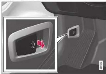

Pull the lever near the pedals to release the hood from its fully closed position.

natural_image
Front view of a car with a hand turning a gear switch (no visible text or symbols)
Turn the handle under the front edge of the hood counterclockwise to release the catch and lift the hood.
Warning - hood not closed

When the hood is released, a warning symbol and graphic will be displayed in the instrument panel and an audible signal will sound. If the vehicle begins
to roll, the audible signal will be repeated several times.

NOTE
If the warning symbol is illuminated or an audible warning signal sounds even though the hood is securely closed, consult a workshop - an authorized Volvo workshop is recommended.
Closing the hood
- Press down the hood until it begins to close under its own weighl.
- When the hood reaches the catch at the handle in the front edge of the vehicle, press down on the hood to close it completely.

WARNING
Risk of injury! When closing, make sure that the hood is completely unobstructed and that no one can be injured.

WARNING
Make sure the hood locks securely after closing. It must audibly lock on both sides.

natural_image
Front view of a modern sedan with a red 'X' mark on the roof (no text or symbols on the car itself)Hood not completely closed. The illustration is generic - details may vary according to vehicle model.

natural_image
Front view of a silver sedan (no visible text or symbols)Hood completely closed. The illustration is generic - details may vary according to vehicle model.

WARNING
Never drive with the hood open!
If there are any indications while driving that the hood is not completely closed, stop immediately and close it securely.
Related information
• Engine compartment overview (p. 622)
• Door and seat belt reminders (p. 51)
Climate control system service
Service and repairs on the air conditioning system should only be done by an authorized workshop.
Troubleshooting and repairs
The air conditioning system contains a fluorescent tracer substance. Ultraviolet light is used to search for leaks in the system.
Volvo recommends contacting an authorized Volvo workshop.
Vehicles with R134a refrigerant

WARNING
The air conditioning system contains the refrigerant R134a under pressure. Service and repairs to the system should only be done by an authorized workshop.
Related information
• Volvo's service program (p. 610)
Replacing a windshield with head-up display\*
Vehicles with a head-up display have a special type of windshield that meets the requirements for displaying projected information.
Volvo recommends contacting an authorized Volvo workshop for assistance replacing the windshield. The correct type of replacement windshield must be used in order for the head-up display to function properly.
Related information
• Head-up display* (p. 142)
• Cleaning the head-up display* (p. 646)
MAINTENANCE AND SERVICE
Engine compartment overview
This overview shows some service-related components.
Some of the components included in the vehicle's electric drive system are located in the engine compartment. Exercise caution when accessing the engine compartment and only touch what is required for normal maintenance.

WARNING
Orange wiring may only be handled by qualified personnel.

WARNING
Several components in the vehicle work with high voltage that can be hazardous in case of an incorrect procedure.
- Do not touch anything that is not clearly described in this Owner's Manual.
- Be careful when checking/filling fluids in the engine compartment.
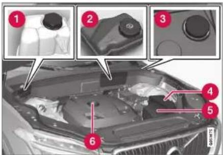
The layout of the engine compartment may vary depending on model and engine variant.
1 Coolant expansion tank
② Brake fluid reservoir (located on the driver's side)
③ Washer fluid filler pipe ^12
4 Fusebox
5 Air filter
6 Engine oil filler pipe

WARNING
Bear in mind that the cooling fan (located at the front of the engine compartment behind the radiator) may start or continue running automatically up to about 6 minutes after the engine is turned off.
Always entrust engine washing to a workshop – an authorized Volvo workshop is recommended. If the engine is hot, there is a risk of fire.

WARNING
The ignition system works with extremely high and dangerous voltages. The vehicle electrical system should always be in ignition mode 0 when work in being performed in the engine compartment.
Do not touch any spark plugs or ignition coils when the vehicle electrical system is in ignition mode II or when the engine is warm.
Related information
- Opening and closing the hood (p. 620)
• Filling washer fluid (p. 662)
• Refilling coolant (p. 625)
• Fuses in the engine compartment (p. 634) - Checking and filling engine oil (p. 624)
- Ignition modes (p. 437)
Engine oil
For the recommended service intervals and warranties to be applied, an approved engine oil must be used.

Volvo recommends:

If the engine oil is not checked regularly and the level becomes low, this could cause serious engine damage.
CAUTION
To satisfy the requirements for the engine's service intervals, all engines are factory-filled with a specially adapted synthetic engine oil. Great care has been put into the choice of oil, with consideration given to service life, startability, fuel consumption and environmental impact.
For the recommended service intervals to apply, an approved engine oil must be used. Only use the prescribed oil grade to top off or change the oil. Otherwise, there is a risk of the vehicle's service life, startability, fuel consumption and environmental impact being affected.
Failure to use engine oil of the prescribed grade and viscosity could cause damage to engine-related components. Volvo Car Corporation disclaims warranty liability for such type of damage.
Volvo recommends entrusting oil changes to an authorized Volvo workshop.
Volvo uses different systems to warn if the oil level is too low/high or the oil pressure is low. On engine variants with an oil pressure sensor, a
warning symbol is displayed in the instrument panel when oil pressure is low. On engine variants with an oil level sensor, the warning symbol in the instrument panel and display messages are used to alert the driver. Some engine variants have both systems. Contact a Volvo retailer for more information.
Change the engine oil and oil filter according to the schedule specified in the Warranty and Maintenance Records Information booklet. Oils of a higher grade than that specified may be used. If the vehicle is driven in adverse conditions, Volvo recommends using an oil with a higher grade than that specified.
Related information
- Checking and filling engine oil (p. 624)
• Engine oil specifications (p. 672)
MAINTENANCE AND SERVICE
Checking and filling engine oil
The engine oil level is monitored by an electronic oil level sensor.

natural_image
Front view of a Volvo car showing engine compartment and dashboard (no visible text or symbols)Filler pipe ^13 .
It may be necessary to top up engine oil between regularly scheduled services.
No action is necessary with regard to engine oil level until a message appears in the instrument panel.

WARNING

If this symbol is shown together with the message Engine oil level Service required, visit a workshop – an authorized Volvo workshop is
recommended. The oil level may be too high.

CAUTION

If this symbol is shown together with a message about low oil level, for example Engine oil level low Refill 1 liter, fill only with the indiume, e.g. 1 liter (1 quart).

WARNING
Do not spill oil on the hot exhaust pipes as this could cause a fire.
Viewing oil level in the center display
The oil level can be viewed using the electronic oil level gauge in the center display once the vehicle has been started. The oil level should be checked regularly.

- Open the Car Status app from App view in the center display.
- Tap Status to display the oil level.
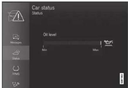
Oil level graphic in the center display.

NOTE
The system cannot directly detect changes when the oil is filled or drained. The vehicle must have been driven approximately 30 km (20 miles) and have been stationary 5 minutes on a level surface and with the engine off before the correct oil level will be displayed.

NOTE
If the conditions for measuring oil level are not properly fulfilled (time after engine shutdown, vehicle inclination, ambient temperature, etc.) the message No value available will be shown in the center display. This does not mean that anything is wrong in the vehicle systems.
Related information
• Engine oil (p. 623)
• Engine oil specifications (p. 672)
- Ignition modes (p. 437)
• Vehicle status (p. 614)
Refilling coolant
Coolant helps keep the combustion engine at the right operating temperature. The heat transferred from the engine to the coolant can be used to warm the passenger compartment.
When refilling coolant, follow the instructions on the package. Never fill the cooling system with only water. The risk of freezing is increased with too low or too high amounts of coolant.
If there is coolant under the vehicle, smoke from the cooling system, or if more than 2 liters (about 2 quarts) of coolant has been added to the system, there could be something wrong with the cooling system and starting the vehicle could damage the engine. Call a tow truck and do not attempt to start the engine.

WARNING
The coolant may be very hot. Never unscrew the cap when the coolant is hot. If coolant must be filled, unscrew the expansion tank cap slowly to relieve overpressure.
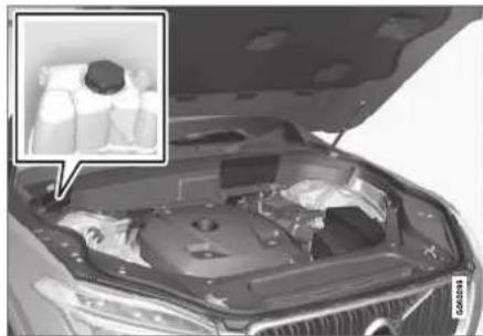
natural_image
Interior view of a car hood with open lid and internal components, showing a close-up inset of a person's torso (no text or symbols visible)Coolant expansion tank.
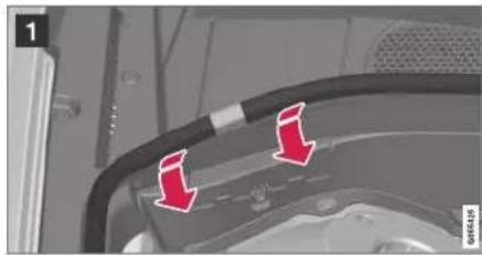
natural_image
Close-up of a mechanical component with red arrows pointing to two circular features (no text or symbols visible)
natural_image
Interior view of a vehicle showing a mounted monitor with a red arrow pointing to it, no visible text or symbols.▶▶
MAINTENANCE AND SERVICE
◀◀
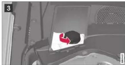
natural_image
Interior view of a vehicle showing a car with a red arrow pointing to a black circular object on a white sheet (no text or symbols visible)1 Lift the rubber strip by pressing it inward into the engine compartment.
2 Remove the plastic cover by folding out the catch and lifting the cover upward.
3 Unscrew the expansion tank cap and fill coolant as needed. The level should be between the MIN and MAX marks on the expansion tank.
! CAUTION
- Do not ingest the contents. May cause damage to organs (kidneys).
- Use premixed coolant according to Volvo's recommendations. If concentrated coolant is used, make sure that the coolant mixture is 50% coolant and 50% water of acceptable quality.
- Do not mix different types of coolant.
- To help ensure sufficient corrosion protection in the system, only use new coolant when replacing larger components in the cooling system.
- Never run the engine unless the cooling system is properly filled. An improperly filled cooling system could lead to high temperatures and cracks in the cylinder heads.
- High levels of chlorine, chlorides and other salts may cause corrosion in the cooling system.
Related information
• Engine compartment overview (p. 622)
• Coolant specifications (p. 673)
Replacing bulbs
Halogen headlights are not available on all models and markets. Contact a Volvo retailer for more information.
LED ^14 bulbs must be replaced by a workshop. An authorized Volvo workshop is recommended.
NOTE
For information on lights not mentioned in this article, contact a Volvo dealer or a certified Volvo service technician.
NOTE
Exterior lighting such as headlights and tail-lights may develop temporary condensation on the inside of the lens. This is normal. All exterior lighting is designed to resist this. Condensation is normally vented out of the lamp housing once the light has been lit for some period of time.
NOTE
Bulbs for active curve lighting* contain traces of mercury and should therefore always be submitted to a certified Volvo service technician.
Start battery
The vehicle has a single-pole electrical system that uses the chassis and engine mount as conductors.
The start battery is used to start the electrical system and power electrical equipment in the vehicle. The hybrid battery is used to start the combustion engine.
The start battery should only be replaced by a workshop ^15 .
The start battery is a 12 V AGM (Absorbed Glass Mat) battery, dimensioned for regenerative charging and to support the function of the vehicle's various systems.
The service life and performance of the start battery are affected by factors such as driving style, driving conditions, climate, battery discharges, number of starts, etc.
- Never disconnect the start battery while the engine is running.
- Make sure the cables to the start battery are correctly connected and the clamps are securely tightened.
WARNING
- Batteries generate hydrogen gas, which is flammable and explosive.
- Do not connect the jumper cable to any part of the fuel system or to any moving parts. Avoid touching hot manifolds.
- Battery fluid contains sulfuric acid. Do not allow battery fluid to contact eyes, skin, fabrics or painted surfaces.
- If contact occurs, flush the affected area immediately with water. Obtain medical help immediately if eyes are affected.
- Never expose the battery to open flame or electric spark. Do not smoke near the battery. Failure to follow the instructions for jump starting can lead to injury.
Connection points
WARNING
PROPOSITION 65 WARNING
Battery posts, terminals, and related accessories contain lead and lead compounds, chemicals known to the state of California to cause cancer and reproductive harm. Wash hands after handling.
Use the vehicle's connection points in the engine compartment to connect an external start battery or battery charger.
The battery terminals on the car's start battery in the luggage/cargo area must not be used.
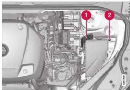
1 Positive connection point
② Negative connection point
CAUTION
It is not possible to charge another vehicle's battery by means of current through the charging points. Using the charging points to charge another vehicle's battery could cause a fuse to blow, which would cause the charging points to stop working.

CAUTION
Only a modern battery charger with controlled charge voltage should be used to charge the starter battery. The rapid charging function should not be used as this could damage the battery.

NOTE
If both the starter battery and the hybrid battery are discharged, both batteries must be charged. In such cases, it is not possible to charge only the hybrid battery first.
The starter battery must have a certain level of charge for it to be possible to charge the hybrid battery.

CAUTION
Failure to observe the following could cause the infotainment energy save mode to temporarily stop working and/or a message in the driver's display regarding the state of charge of the starter battery may be temporarily incorrect after an external starter battery or battery charger has been connected:
- The negative battery terminal of the vehicle's starter battery must never be used to connect an external starter battery or battery charger – only the vehicle's negative charging point should be used as a grounding point.

NOTE
If the starter battery becomes discharged too many times, it will shorten its service life.
The service life of the starter battery is affected by several factors, such as driving conditions and climate. The starting capacity of the battery reduces gradually over time. The battery must therefore be recharged if the vehicle is not used or a long period of time or if it is only driven short distances. Severe cold further limits the starting capacity.
To keep the starter battery in a good condition, the vehicle should be driven at least 15 minutes per week or the battery should be connected to a battery charger with automatic trickle charging.
A starter battery that is always kept fully charged has the maximum service life.
Location

natural_image
Interior view of a medical imaging scanner or scanner device (no visible text or symbols)The start battery is located in the cargo compartment.
WARNING
If the starter battery is disconnected, the function for automatic opening and closing must be reset to function correctly. A reset is required in order for the pinch protection to work.
CAUTION
On certain models, the battery is secured with a tensioning strap. Make sure that the tensioning strap is always securely tightened.
Specifications for start battery
| Battery type H8 AGM | |
| Voltage (V) 12 | |
| Cold start capacityA - CCA ^B (A) | 850 |
| Dimensions, L×W×H 353×175×190 mm (13.9×6.9×7.5 inches) | |
| Capacity (Ah) 95 |
^A According to EN standard.
^8 Cold Cranking Amperes.
Volvo recommends that batteries are replaced by an authorized Volvo workshop.
▶▶
MAINTENANCE AND SERVICE
◀◀
CAUTION
If replacing the battery, make sure you replace it with a battery of the same size, cold start capacity and type as the original battery (see the decal on the battery).
Related information
• Battery symbols (p. 632)
• Hybrid battery (p. 631)
- Jump starting using another battery (p. 481)
Hybrid battery
The vehicle's electric motor is powered by a rechargeable, maintenance-free, lithium-ion hybrid battery.

NOTE
The vehicle cannot be started if the hybrid battery is discharged.

NOTE
If both the starter battery and the hybrid battery are discharged, both batteries must be charged. In such cases, it is not possible to charge only the hybrid battery first.
The starter battery must have a certain level of charge for it to be possible to charge the hybrid battery.

WARNING
Hybrid battery replacement may only be performed by a workshop – an authorized Volvo workshop is recommended.
Coolant
The hybrid battery's cooling system has its own expansion tank.

natural_image
Close-up of a car engine bay with a close-up inset showing a dental implant component (no visible text or symbols)
CAUTION
Filling the hybrid battery coolant should only be performed by a workshop – an authorized Volvo workshop is recommended.
Specifications for hybrid battery
Type: Lithium-ion
Power reserve: 10.4 kWh.

NOTE
The capacity of the hybrid battery decreases with age and use, which could result in increased use of the combustion engine, leading to higher fuel consumption and reduced electric motor range.
Related information
• Battery symbols (p. 632)
• Start battery (p. 627)
• Charging the hybrid battery (p. 417)
MAINTENANCE AND SERVICE
Battery symbols
There are warning symbols and information on the batteries.
 | Wear protective goggles. |
| See the Owner's Manual for additional information. | |
| Keep batteries away from children. | |
| Batteries contain corrosive acid. |


i NOTE
A used start battery contains lead and must be recycled in an environmentally responsible manner.
Related information
- Start battery (p. 627)
• Hybrid battery (p. 631)
Fuses and fuseboxes
All electrical functions and components are protected by a number of fuses in order to protect the vehicle's electrical system from damage by short circuiting or overloading.
WARNING
Never use a foreign object or a fuse with a higher amperage than that specified to replace a fuse. This could cause significant damage to the electrical system and possibly lead to a fire.
WARNING
Orange wiring may only be handled by qualified personnel.
WARNING
Several components in the vehicle work with high voltage that can be hazardous in case of an incorrect procedure.
Do not touch anything that is not clearly described in this Owner's Manual.
If any electrical component or function is not responding, the component may have blown a fuse due to temporary overload. If the same fuse blows repeatedly, there may be a problem with the component. Volvo recommends contacting an authorized Volvo workshop to have the component checked.
Location of fuseboxes

The illustration is generic - appearance may vary according to vehicle model.
1 Engine compartment
2 Under the glove compartment
3 Trunk/cargo compartment
Related information
• Replacing fuses (p. 633)
• Fuses in the cargo compartment (p. 641)
• Fuses in the engine compartment (p. 634)
• Fuses under the glove compartment (p. 638)
Replacing fuses
All electrical functions and components are protected by a number of fuses in order to protect the vehicle's electrical system from damage by short circuiting or overloading.
- Refer to the fuse diagram to locate the fuse.
- Pull out the fuse and examine it from the side to determine if the curved metal wire in the fuse is intact.
- If the wire is broken, replace the fuse with a new fuse of the same color and amperage.
WARNING
Never use a foreign object or a fuse with a higher amperage than that specified to replace a fuse. This could cause significant damage to the electrical system and possibly lead to a fire.
WARNING
Contact an authorized Volvo workshop for assistance replacing fuses not listed in the Owner's Manual. If performed incorrectly, significant damage can be caused to the electrical system.
Related information
• Fuses and fuseboxes (p. 632)
• Fuses in the cargo compartment (p. 641)
• Fuses in the engine compartment (p. 634)
• Fuses under the glove compartment (p. 638)
MAINTENANCE AND SERVICE
Fuses in the engine compartment
The fuses in the engine compartment help protect electrical components such as engine and brake functions.
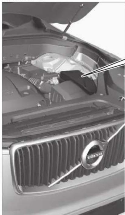
natural_image
Close-up of a Volvo car engine bay with visible grille and dashboard (no text or symbols)
Fuse pliers are provided on the inside of the fuse box cover to assist in removing and inserting fuses.
There are also spaces for several extra fuses in the fusebox.
Positions
There is a decal with a diagram of the locations of the fuses on the inside of the cover.
- Fuses 1–13, 18–30, 35–37 and 46–70 are "Micro" fuses.
- Fuses 14–17, 31–34, 38–45 and 71–78 are "MCase" fuses and should only be replaced by a workshop ^16 .
| Function Ampere | ||
| 1 | - | - |
| 2 | - | - |
| 3 | - | - |
| 4 | Control module for actuator for engaging/changing gears, automatic transmission | 5 |
| 5 | High-voltage coolant heater control module | 5 |
| Function Ampere | ||
| 6 | Control module for A/C; heat exchanger cut-off valve; cut-off valve for coolant through the climate system | 5 |
| 7 | Hybrid battery control module; high-voltage converter for combined high-voltage generator/starter motor with 500 V-12 V voltage converter | 5 |
| 8 | - | - |
| 9 | Converter for controlling feed to rear axle electric motor | 10 |
| 10 | Hybrid battery control module; high-voltage converter for combined high-voltage generator/starter motor with 500 V-12 V voltage converter | 10 |
| 11 | Charge module 5 | |
| 12 | Cut-off valve for hybrid battery coolant; coolant pump 1 for hybrid battery | 10 |
| 13 | Coolant pump for electric drive system | 10 |
| Function Ampere | ||
| 14 | Hybrid component cooling fan 25 | |
| 15 | - | - |
| 16 | - | - |
| 17 | - | - |
| 18 | - | - |
| 19 | - | - |
| 20 | - | - |
| 21 | - | - |
| 22 | - | - |
| 23 | - | - |
| 24 | 12 V outlet in tunnel console, front | 15 |
| 25 | 12 V outlet in tunnel console between second-row seatsA12 V outlet in tunnel console, between rear seatsB; USB ports in tunnel console between rear seatsB | 15 |
MAINTENANCE AND SERVICE
◀◀
| Function Ampere | ||
| 26 | 12 V outlet in trunk/cargo compartment*USB ports for iPad holdersB | 15 |
| 27 | - | - |
| 28 | - | - |
| 29 | - | - |
| 30 | - | - |
| 31 | Heated windshield*, left side | Shunt |
| 32 | Heated windshield*, left side | 40 |
| 33 | Headlight washers* | 25 |
| 34 | Windshield washer 25 | |
| 35 | - | - |
| 36 | Horn 20 | |
| 37 | Alarm siren* | 5 |
| 38 | Brake system control module (valves, parking brake) | 40 |
| 39 | Wipers 30 | |
| 40 | Rear window washer 25 |
| Function Ampere | ||
| 41 | Heated windshield*, right side | 40 |
| 42 | Parking heater* | 20 |
| 43 | Brake system control module (ABS pump) | 40 |
| 44 | - | - |
| 45 | Heated windshield*, right side | Shunt |
| 46 | Fed when ignition is on: Engine control module; transmission components, electrical power steering, central electrical module | 5 |
| 47 | Exterior vehicle sound (certain markets) | 5 |
| 48 | Right-side headlight 7.5 | |
| Right-side headlight, some models with LED ^C | 15 | |
| 49 | - | - |
| 50 | - | - |
| 51 | - | - |
| 52 | Airbags 5 |
| Function Ampere | ||
| 53 | Left-side headlight 7.5 | |
| Left-side headlight, some models with LED^C | 15 | |
| 54 | Accelerator pedal sensor 5 | |
| 55 | Transmission control module; gear selector control module | 15 |
| 56 | Engine control module 5 | |
| 57 | - | - |
| 58 | - | - |
| 59 | - | - |
| 60 | - | - |
| 61 | Engine control module; actuator; throttle unit; turbo-charger valve | 20 |
| 62 | Solenoids; valve; engine cooling system thermostat | 10 |
| 63 | Vacuum regulators; valve 7.5 | |
| 64 | Spoiler shutter control module; radiator shutter control module | 5 |
| 65 | - | - |
| 66 | Heated oxygen sensor, front; heated oxygen sensor, rear | 15 |
| 67 | Oil pump solenoid; A/C magnetic coupling; heated oxygen sensor (center) | 15 |
| 68 | - | - |
| 69 | Engine control module 20 | |
| 70 | Ignition coils; spark plugs 15 | |
| 71 | - | - |
| 72 | - | - |
| 73 | Transmission oil pump control module | 30 |
| 74 | Vacuum pump control module 40 | |
| 75 | Transmission actuator 25 | |
| 76 | - | - |
| 77 | - | - |
| 78 | - | - |
A Not Excellence
B Excellence
C LED (Light Emitting Diode)
Related information
• Fuses and fuseboxes (p. 632)
• Replacing fuses (p. 633)
MAINTENANCE AND SERVICE
Fuses under the glove compartment
Fuses under the glove compartment provide protection for e.g. electrical outlets, displays and door modules.

Fuse pliers are provided on the inside of the fuse box cover to assist in removing and inserting fuses.
There are also spaces for several extra fuses in the distribution box in the engine compartment.
Positions
- Fuses 1, 3-21, 23-36, 39-53 and 55-59 are "Micro" fuses.
- Fuses 2-22, 37-38 and 54 are "MCase" fuses and should only be replaced by a workshop ^17 .
| Function Ampere | ||
| 1 | - | - |
| 2 | - | - |
| 3 | - | - |
| 4 | Movement sensor* | 5 |
| 5 | Media player 5 | |
| 6 | Instrument panel 5 | |
| 7 | Center console buttons 5 | |
| 8 | Sun sensor 5 |
| Function Ampere | ||
| 9 | Sensus control module 20 | |
| 10 | - | - |
| 11 | Steering wheel module 5 | |
| 12 | Module for start knob and parking brake controls | 5 |
| 13 | Heated steering wheel* module | 15 |
| 14 | - | - |
| 15 | - | - |
| 16 | - | - |
| 17 | - | - |
| 18 | Climate system control module | 10 |
| 19 | - | - |
| 20 | Data link connector OBD-II 10 | |
| 21 | Center display 5 | |
| 22 | Climate system blower module (front) | 40 |
| Function Ampere | ||
| 23 | USB HUB 5 | |
| 24 | Instrument lighting; Interior lighting; Rearview mirror auto-dim function*; Rain and light sensors*; Rear tunnel console keypad, second row of seats*A; Power front seats*; Rear door control panels; Climate system blower module left/rightPower rear seatsB; Display for rear seat convenience functionsB; Rear seat massage functionB | 7.5 |
| 25 | Control module for driver support functions | 5 |
| 26 | Panoramic roof with sun cur-tain* | 20 |
| 27 | Head-up display* | 5 |
| 28 | Passenger compartment light-ing | 5 |
| 29 | - | - |
MAINTENANCE AND SERVICE
◀◀
| Function Ampere | ||
| 30 | Ceiling console display (seat belt reminder/front passenger side airbag indicator) | 5 |
| 31 | - | - |
| 32 | Humidity sensor 5 | |
| 33 | Door module in right-side rear doorPower right rear seat ^C | 20 |
| 34 | Fuses in the trunk/cargo compartment | 10 |
| 35 | Control module for Internet-connected vehicle; Control module for Volvo On Call | 5 |
| 36 | Door module in left-side rear doorPower left rear seat ^D | 20 |
| 37 | Audio control module (amplifier) (certain models only) | 40 |
| 38 | Climate system blower module (rear)* | 40 |
| 39 | Multi-band antenna module 5 | |
| 40 | Front seat massage function* | 5 |
| Function Ampere | ||
| 41 | - | - |
| 42 | Rear window wiper 15 | |
| 43 | Fuel pump control module 15 | |
| 44 | Relay windings for distribution box in engine compartment; Relay windings for transmission oil pump | 5 |
| 45 | - | - |
| 46 | Driver's seat heating 15 | |
| 47 | Front passenger's seat heating | 15 |
| 48 | Coolant pump 10 | |
| 49 | - | - |
| 50 | Power driver's seat* | 20 |
| 51 | Active chassis control module* | 20 |
| 52 | - | - |
| 53 | Sensus control module 10 | |
| 54 | - | - |
| 55 | - | - |
| Function Ampere | ||
| 56 | Power front passenger seat* | 20 |
| 57 | Display for rear seat convenience functions ^c ; On-board diagnostics (OBD II) in tunnel console between rear seats ^c ; Extra movement sensor ^c | 5^c |
| 58 | TV* (certain markets only) | 5 |
| 59 | Primary fuse for fuses 9, 53 and 58 | 15 |
A Not Excellence
B Excellence
C Excellence
D Excellence
Related information
• Fuses and fuseboxes (p. 632)
• Replacing fuses (p. 633)
MAINTENANCE AND SERVICE
Fuses in the cargo compartment
The fuses in the cargo compartment help protect electrical components such as the power seats*, airbags and seat belt tensioners.
▶▶
MAINTENANCE AND SERVICE
◀◀

natural_image
Close-up of a car rear bumper with plastic trim and mounting bracket (no visible text or symbols)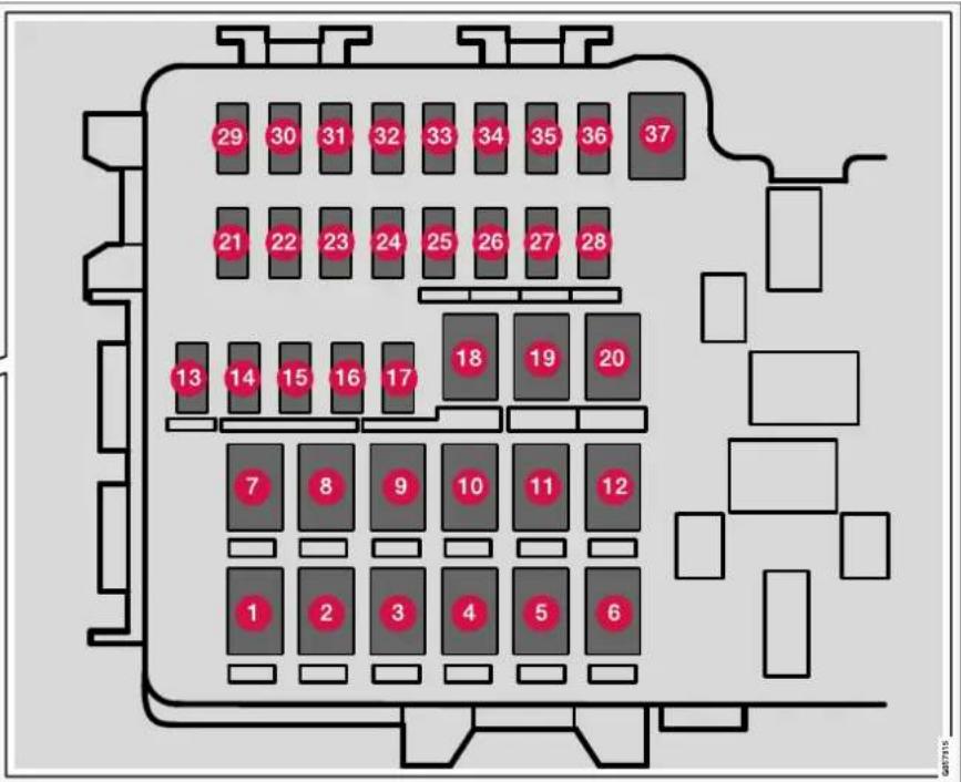
The fuse box is located under the storage compartment on the right-hand side.
Fuse pliers are provided on the inside of the fuse box cover to assist in removing and inserting fuses.
There are also spaces for several extra fuses in the distribution box in the engine compartment.
Positions
• Fuses 13-17 and 21-36 are "Micro" fuses.
- Fuses 1-12, 18-20 and 37 are "MCase" fuses and should only be replaced by a workshop ^18 .
| Function Ampere | ||
| 1 | Heated rear window 30 | |
| 2 | Central electrical module 40 | |
| 3 | Pneumatic suspension* compressor | 40 |
| 4 | Rear electric heater (right-hand side) | 30 |
| 5 | Electrical outlets in the tunnel console between the rear seatsA | -30A |
| 6 | Rear electric heater (left-hand side) | 1530 |
| 7 | Door module right side, rear 20 | |
| 8 | Control module for reduction of nitrous oxides (diesel) | 30 |
| 9 | Power tailgate* | 25 |
| 10 | Door module right side, front 20 |
| Function Ampere | ||
| 11 | Towbar* control module | 40 |
| 12 | Seat belt tensioner module(right side) | 40 |
| 13 | Internal relay windings 5 | |
| 14 | Door module left side, rear 20 | |
| 15 | Foot movement detectionmodule for opening the power tailgate* | 5 |
| 16 | USB hub/accessory port - | |
| 17 | Module for electrically folding third-row seats* | 20 |
| 18 | Towbar* control module | 25 |
| Accessory module 40 | ||
| 19 | Door module left side, front 20 | |
| 20 | Seat belt tensioner module(left side) | 40 |
| 21 | Park Assist Camera* | 5 |
| 22 | - | - |
| 23 | - | - |
| Function Ampere | ||
| 24 | - | - |
| 25 | Feed when ignition is on 10 | |
| 26 | Control module for airbags and seat belt tensioners | 5 |
| 27 | CoolerA; Heated/cooled cup holder (rear)A | 10^A 5 |
| Accessory module | ||
| 28 | Heated rear seat (left side)* | 15 |
| 29 | - | - |
| 30 | Blind Spot Information (BLIS)*; Exterior reverse signal control module | 5 |
| 31 | - | - |
| 32 | Modules for seat belt tension- ers | 5 |
| 33 | Emissions system actualor (gasoline, certain engine vari-ants) | 5 |
| 34 | - | - |
| 35 | - | - |
MAINTENANCE AND SERVICE
◀◀
| Function Ampere | ||
| 36 | Healed rear seat (right side)* | 15 |
| 37 | - | - |
^ Excellence
Related information
• Fuses and fuseboxes (p. 632)
• Replacing fuses (p. 633)
Cleaning the interior
Only use cleaning agents and car care products recommended by Volvo. Clean regularly and treat stains immediately for best results. It is important to vacuum before using a cleaning agent.

CAUTION
- Some colored clothing (for example, dark jeans and suede garments) may slain the upholstery. If this occurs, it is important to clean and treat these parts of the upholstery as soon as possible.
- Never use strong solvents such as washer fluid, gasoline, mineral spirit or concentrated alcohol to clean the interior as this can damage the upholstery as well as other interior materials.
- Never spray cleaning agent directly onto components that have electrical buttons and controls. Wipe instead with a damp cloth with cleaning agent.
- Sharp objects and Velcro can damage the car's textile upholstery.
Related information
• Cleaning the center display (p. 645)
• Cleaning fabric upholstery and ceiling liner (p. 647)
• Cleaning the seat belt (p. 647)
• Cleaning floor mats and inlay mats (p. 647)
• Cleaning leather upholstery (p. 648)
- Cleaning the leather steering wheel (p. 649)
- Cleaning interior plastic, metal and wood surfaces (p. 650)
Cleaning the center display
Marks, stains, finger smudges etc. on the center display may affect its performance and readability. Clean the screen regularly with a microfiber cloth.
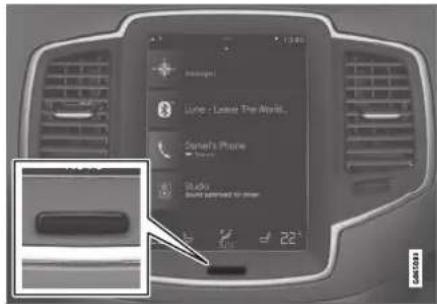
To clean the center display:
- Turn off the center display by pressing and holding the Home button.
- Wipe the screen clean with the microfiber cloth provided or use another microfiber cloth of similar quality. Wipe the screen with a clean, dry microfiber cloth using small, circular motions. If necessary, moisten the cloth slightly.
- Reactivate the display by pressing the Home button briefly.
▶▶
MAINTENANCE AND SERVICE
◀◀
! CAUTION
The microfiber cloth must be free of sand and dirt when cleaning the center display.
CAUTION
When cleaning the center display, apply only light pressure to the screen. Pressing too hard could damage the screen.
CAUTION
Do not spray liquid or corrosive chemicals directly onto the center display. Do not use window cleaners, cleaning agents, aerosol sprays, solvents, alcohol, ammonia or detergents that contain abrasives.
Never use abrasive cloths, paper towels or tissue paper, as these may scratch the center display.
Related information
• Cleaning the interior (p. 645)
• Cleaning fabric upholstery and ceiling liner (p. 647)
• Cleaning the seat belt (p. 647)
• Cleaning floor mats and inlay mats (p. 647)
• Cleaning leather upholstery (p. 648)
• Cleaning the leather steering wheel (p. 649)
• Cleaning interior plastic, metal and wood surfaces (p. 650)
Cleaning the head-up display\*
Carefully wipe the glass covering the head-up display unit with a clean and dry microfiber cloth. If necessary, the cloth may be slightly moistened.
Never use strong stain removers. For difficult cleaning conditions, a special cleaning agent can be purchased at a Volvo retailer.
Related information
- Activating and deactivating the head-up display* (p. 143)
• Head-up display* (p. 142)
Cleaning fabric upholstery and ceiling liner
Only use cleaning agents and car care products recommended by Volvo. Clean regularly and treat stains immediately for best results. It is important to vacuum before using a cleaning agent.
Fabric upholstery and ceiling liner
Never scrape or rub a stain, as this could damage the upholstery. Never use strong stain removers, as this could change the color of the upholstery.
Use soapy water or a similar detergent. For more difficult stains caused by oil, ice cream, shoe polish, etc., use a stain remover. Consult with your Volvo retailer.
Related information
• Cleaning the interior (p. 645)
• Cleaning the center display (p. 645)
• Cleaning the seat belt (p. 647)
• Cleaning floor mats and inlay mats (p. 647)
• Cleaning leather upholstery (p. 648)
- Cleaning the leather steering wheel (p. 649)
- Cleaning interior plastic, metal and wood surfaces (p. 650)
Cleaning the seat belt
Only use cleaning agents and car care products recommended by Volvo. Clean regularly and treat stains immediately for best results. It is important to vacuum before using a cleaning agent.
Seat belts
Use water and a synthetic soap solution. Specially designed textile cleaning agents are available for purchase at Volvo retailers. Make sure the belt is dry before it is retracted.
Related information
• Cleaning the interior (p. 645)
• Cleaning the center display (p. 645)
- Cleaning fabric upholstery and ceiling liner (p. 647)
• Cleaning floor mats and inlay mats (p. 647)
• Cleaning leather upholstery (p. 648)
• Cleaning the leather steering wheel (p. 649)
- Cleaning interior plastic, metal and wood surfaces (p. 650)
Cleaning floor mats and inlay mats
Only use cleaning agents and car care products recommended by Volvo. Clean regularly and treat stains immediately for best results. It is important to vacuum before using a cleaning agent.
Inlay mats and floor mats
Remove the inlay mats to clean the floor mats and inlay mats separately. Use a vacuum to remove dust and dirt. Each inlay mat is secured into place with pins.
Remove the inlay mat by grasping the inlay mat at each pin and lifting the mat straight up.
Put the inlay mat back into place by pressing it in at each pin.

WARNING
- Never use more than one inlay mat at a time on the driver's floor. If any other type of floor mat is used, remove the original mat from the driver's seat floor before driving. All types of mats must be securely anchored in the attachment points in the floor. Make sure the floor mat does not impede the movement of the brake pedal or accelerator pedal in any way, as this could be a serious safety hazard.
- Volvo's floor mats are specially manufactured for your vehicle. They must be properly secured in the attachment points in the floor to help ensure they cannot slide and become trapped under the pedals.
After vacuuming, a specially designed textile cleaning agent should be used to remove stains on floor mats. Floor mats should be cleaned with products recommended by Volvo retailers.
Related information
• Cleaning the interior (p. 645)
• Cleaning the center display (p. 645)
- Cleaning fabric upholstery and ceiling liner (p. 647)
• Cleaning the seat belt (p. 647)
• Cleaning leather upholstery (p. 648)
• Cleaning the leather steering wheel (p. 649)
- Cleaning interior plastic, metal and wood surfaces (p. 650)
Cleaning leather upholstery
Only use cleaning agents and car care products recommended by Volvo. Clean regularly and treat stains immediately for best results. It is important to vacuum before using a cleaning agent.
Leather upholstery\*
Volvo's leather upholstery is treated to protect its original appearance. Over time, sunlight, grease, dirt, etc. could break down the protective layer. This could result in scratches and cracking.
Leather upholstery is a natural product that changes and acquires a beautiful patina over time. Regular cleaning and treatments are required to preserve the qualities and color of the leather. Volvo offers a comprehensive product, Volvo Leather Care Kit/Wipes, for cleaning and treating leather upholstery that, when used as directed, preserves the leather's protective coating.
For best results, Volvo recommends cleaning and applying protective cream one to four times a year (or more as needed). Volvo Leather Care Kit 951 0251 and Volvo Leather Softener 943 7429 are available for purchase at Volvo retailers.
Cleaning the leather upholstery
- Apply the leather cleaner to a damp sponge and squeeze it until the cleaner foams.
- Move the sponge in circular motions to apply the foam to the stain.
- Dampen the stain thoroughly with the sponge. Let the sponge absorb the stain and do not rub.
- Dry the stain using a soft towel and let the leather dry completely.
Protecting the leather upholstery
- Apply a small amount of leather protector to a cloth and then apply the protector to the leather using light circular movements.
- Let it dry for approximately 20 minutes.
Protecting the leather upholstery makes it better able to withstand sunlight's harmful UV rays.
Related information
• Cleaning the interior (p. 645)
• Cleaning the center display (p. 645)
• Cleaning fabric upholstery and ceiling liner (p. 647)
• Cleaning the seat belt (p. 647)
• Cleaning floor mats and inlay mats (p. 647)
- Cleaning the leather steering wheel (p. 649)
- Cleaning interior plastic, metal and wood surfaces (p. 650)
Cleaning the leather steering wheel
Only use cleaning agents and car care products recommended by Volvo. Clean regularly and treat stains immediately for best results. It is important to vacuum before using a cleaning agent.
Leather steering wheel
Leather needs to breathe. Never cover the leather steering wheel with a plastic protector. Volvo Leather Care Kit 951 0251 and Leather Softener 943 7429 are recommended for cleaning the leather steering wheel. First, remove dirt, dust, etc. with a damp sponge or cloth.
CAUTION
Sharp objects such as rings could damage the leather on the steering wheel.
If there are stains on the steering wheel:
Type 1(ink, wine, coffee, milk, sweat or blood)
- Use a soft cloth or sponge. Wipe the steering wheel using a solution of 5% ammonia. For blood stains, mix approximately 2 dl(1 cup) of water with 25 g (one ounce) of salt and wipe the stain.
Type 2(grease, oil, sauces or chocolate)
- Same procedure as for Type 1 stains.
- Finish by wiping the wheel with an absorbent paper or towel.
Type 3(dry dirt or dust)
- Remove the dirt/dust using a soft brush.
- Same procedure as for Type 1 stains.
Related information
• Cleaning the interior (p. 645)
• Cleaning the center display (p. 645)
- Cleaning fabric upholstery and ceiling liner (p. 647)
• Cleaning the seat belt (p. 647)
• Cleaning floor mats and inlay mats (p. 647)
• Cleaning leather upholstery (p. 648)
- Cleaning interior plastic, metal and wood surfaces (p. 650)
MAINTENANCE AND SERVICE
Cleaning interior plastic, metal and wood surfaces
Only use cleaning agents and car care products recommended by Volvo. Clean regularly and treat stains immediately for best results.
Interior plastic, metal and wood surfaces
A lightly dampened microfiber cloth is recommended for cleaning interior details and surfaces. These cloths are available for purchase at Volvo retailers.
Never scrape or rub a stain. Never use strong stain removers.

CAUTION
Do not use solvent containing alcohol to clean the instrument panel glass.

CAUTION
Keep in mind that glossy surfaces can be easily scratched. Wipe these surfaces with a clean and dry microfiber cloth using small, circular motions. If necessary, moisten the cloth lightly with clean water.
Related information
• Cleaning the interior (p. 645)
• Cleaning the center display (p. 645)
• Cleaning fabric upholstery and ceiling liner (p. 647)
• Cleaning the seat belt (p. 647)
• Cleaning floor mats and inlay mats (p. 647)
• Cleaning leather upholstery (p. 648)
• Cleaning the leather steering wheel (p. 649)
Cleaning the exterior
The vehicle should be washed as soon as it becomes dirty. This makes the vehicle easier to clean because dirt does not attach as strongly. It also reduces the risk of scratches and keeps the vehicle looking new. Wash the vehicle in a car wash or garage with an oil separator and use car washing detergent.
Related information
• Cleaning the exterior (p. 650)
• Polishing and waxing (p. 651)
- Hand washing (p. 651)
• Automatic car washes (p. 653)
• High-pressure washing (p. 654)
• Cleaning the wiper blades (p. 654)
- Cleaning exterior plastic, rubber and trim components (p. 655)
- Cleaning rims (p. 656)
• Corrosion protection (p. 656)
Polishing and waxing
Polish and wax the vehicle when the paint is matte or to provide extra protection. The vehicle does not need to be polished until it is at least a year old. However, it can be waxed during the first year. Do not polish or wax the vehicle in direct sunlight. The surface of the vehicle should not be warmer than 45 °C (113 °F).
- Wash and dry the vehicle very carefully before polishing or waxing. Remove asphalt and tar stains with asphalt remover or paint thinner. More stubborn stains can be removed with a grinding paste designed for vehicle paint.
- Use polish first and then liquid or paste wax. Follow the instructions on the package carefully. Many products contain both polish and wax.
- A wide range of polymer-based waxes can be purchased today. These waxes are easy to use and produce a long-lasting, high-gloss finish that protects the bodywork against oxidation, road dirt and fading.
CAUTION
Avoid waxing and polishing plastic and rubber. If using degreaser on plastic and rubber, only rub (if necessary) with slight pressure. Use a soft sponge.
Polishing glossy trim moldings can wear away or damage the glossy surface layer.
Polish containing abrasives must not be used.
CAUTION
Only use paintwork treatments recommended by Volvo. Other treatments, such as preservation, sealing, protection, luster sealing or similar, could damage the paintwork. Paintwork damage caused by such treatments are not covered by Volvo's warranty.
Related information
• Cleaning the exterior (p. 650)
• Hand washing (p. 651)
• Automatic car washes (p. 653)
• High-pressure washing (p. 654)
• Cleaning the wiper blades (p. 654)
- Cleaning exterior plastic, rubber and trim components (p. 655)
- Cleaning rims (p. 656)
• Corrosion protection (p. 656)
Hand washing
The vehicle should be washed as soon as it becomes dirty. This makes the vehicle easier to clean because dirt does not attach as strongly. It also reduces the risk of scratches and keeps the vehicle looking new. Wash the vehicle in a car wash or garage with an oil separator and use car washing detergent.
Hand washing
Keep the following points in mind when washing the vehicle:
- Avoid washing the vehicle in direct sunlight. This could cause the detergent or wax to dry out and become abrasive.
- Remove bird droppings from paintwork as soon as possible. It contains chemicals that affect and discolor paintwork very quickly. Use e.g. soft paper or a sponge soaked in lots of water. Consult an authorized Volvo workshop for assistance removing discoloration.
- Hose down the underbody, including the wheel housings and bumper.
- Hose down the entire vehicle and remove any loose dirt, droppings etc. to reduce the risk of scratches from washing. Do not spray directly onto locks.
- If necessary, use cold degreaser on heavily soiled surfaces. Note that in such cases the surfaces must not be hot from the sun.
MAINTENANCE AND SERVICE
- Wash using a sponge, car washing detergent and plenty of lukewarm water.
- Clean the wiper blades with lukewarm soap solution or car washing detergent.
- Dry the vehicle using a clean, soft chamois or a squeegee. Try not to let drops of water dry in strong sunlight. This could cause water drying stains that may need to be polished out.
- In areas with heavy industrial emissions, more frequent washing of the vehicle's exterior is recommended.
- Tar spots from asphalt may remain even after washing. Use a tar remover to remove these spots after washing the vehicle.

WARNING
Always entrust engine washing to a workshop. If the engine is hot, there is a risk of fire.

CAUTION
Dirty headlights do not work as well. Clean them regularly, e.g. when refueling. Do not use corrosive cleaners. Use water and a non-abrasive sponge.
NOTE
Exterior lighting such as headlights and taillights may develop temporary condensation on the inside of the lens. This is normal. All exterior lighting is designed to resist this. Condensation is normally vented out of the lamp housing once the light has been lit for some period of time.
CAUTION
- Make sure that the panoramic roof* and sun shade are closed before washing the vehicle.
- Never use abrasive polishing agents on the panoramic roof.
- Never use wax on the rubber seals around the panoramic roof.
! CAUTION
Remember to remove dirt from the drain holes in the doors and sills after washing the vehicle.
Related information
• Cleaning the exterior (p. 650)
• Polishing and waxing (p. 651)
• Automatic car washes (p. 653)
• High-pressure washing (p. 654)
• Cleaning the wiper blades (p. 654)
- Cleaning exterior plastic, rubber and trim components (p. 655)
- Cleaning rims (p. 656)
• Corrosion protection (p. 656)
- Settings for automatically activating the parking brake (p. 444)
Automatic car washes
The vehicle should be washed as soon as it becomes dirty. This makes the vehicle easier to clean because dirt does not attach as strongly. It also reduces the risk of scratches and keeps the vehicle looking new.
An automatic car wash is a fast and easy way to keep your vehicle clean, but it does not reach all areas of the vehicle. For best results, Volvo recommends hand washing your vehicle or supplementing automatic car washes with a hand wash.

NOTE
Volvo recommends not washing the vehicle in an automatic car wash during the first few months; the paintwork on new vehicles takes some time to fully harden.

CAUTION
Before driving the vehicle into a car wash, deactivate the Automatic Braking when Stationary and Automatic Parking Brake Application functions. If the functions are not deactivated, the brake system will seize when the vehicle is stationary and the vehicle will not be able to roll.

CAUTION
For automatic car washes in which the vehicle is pulled forward on rolling wheels:
- Before washing the vehicle, make sure that the automatic rain sensor is deactivated. If it is not deactivated and inadvertently starts, the wiper arms could be damaged.
- To help prevent damage from the automatic car wash machinery, make sure that the door mirrors are folded in, antennas retracted or removed, and any auxiliary lights secured.
- Drive into the automatic car wash.
- Turn off the "Automatic Braking when Stationary" function using the A button in the tunnel console.
- Turn off the "Automatic Parking Brake Application" function in the center display's Top view.
- Turn off the engine by turning the start knob in the tunnel console clockwise. Hold the knob in position for at least 2 seconds.
The vehicle is now ready for the automatic car wash.

CAUTION
The system will automatically change to P mode if the above steps are not followed. In P mode, the wheels are locked, which they should not be when the vehicle is being washed in a car wash.
Related information
• Cleaning the exterior (p. 650)
• Polishing and waxing (p. 651)
• Hand washing (p. 651)
• High-pressure washing (p. 654)
• Cleaning the wiper blades (p. 654)
- Cleaning exterior plastic, rubber and trim components (p. 655)
- Cleaning rims (p. 656)
• Corrosion protection (p. 656)
MAINTENANCE AND SERVICE
High-pressure washing
The vehicle should be washed as soon as it becomes dirty. This makes the vehicle easier to clean because dirt does not attach as strongly. It also reduces the risk of scratches and keeps the vehicle looking new. Wash the vehicle in a car wash or garage with an oil separator. Use a car washing detergent.
High-pressure washing
If washing the vehicle with a high-pressure wash, use sweeping movements and keep the nozzle at least 30 cm (13 in.) from the vehicle. Do not spray directly onto locks.
Related information
• Cleaning the exterior (p. 650)
• Polishing and waxing (p. 651)
• Hand washing (p. 651)
• Automatic car washes (p. 653)
• Cleaning the wiper blades (p. 654)
- Cleaning exterior plastic, rubber and trim components (p. 655)
- Cleaning rims (p. 656)
• Corrosion protection (p. 656)
Cleaning the wiper blades
The vehicle should be washed as soon as it becomes dirty. This makes the vehicle easier to clean because dirt does not attach as strongly. It also reduces the risk of scratches and keeps the vehicle looking new. Wash the vehicle in a car wash or garage with an oil separator. Use a car washing detergent.
Wiper blades
Asphalt, dust and salt residue on wiper blades, as well as insects, ice etc. on the windshield, shorten the service life of wiper blades.
When cleaning, put the wiper blades in the service position.
NOTE
Wash the wiper blades and windshield regularly with a lukewarm soap solution or vehicle shampoo. Do not use strong solvents.
Related information
• Cleaning the exterior (p. 650)
• Polishing and waxing (p. 651)
• Hand washing (p. 651)
• Automatic car washes (p. 653)
• High-pressure washing (p. 654)
- Cleaning exterior plastic, rubber and trim components (p. 655)
- Cleaning rims (p. 656)
• Corrosion protection (p. 656)
Cleaning exterior plastic, rubber and trim components
The vehicle should be washed as soon as it becomes dirty. This makes the vehicle easier to clean because dirt does not attach as strongly. It also reduces the risk of scratches and keeps the vehicle looking new. Wash the vehicle in a car wash or garage with an oil separator and use car washing detergent.
Exterior plastic, rubber and trim components
A special cleaning agent available from Volvo retailers is recommended for the cleaning and care of colored plastic parts, rubber and trim components, e.g. glossy trim. Follow the usage instructions for the cleaning agent carefully.
Avoid using car washing detergents with a pH value lower than 3.5 or higher than 11.5. Doing so could result in the discoloring of anodized aluminum surfaces* (as shown in the illustrations below). Abrasive polishing agents are not recommended for these areas (as shown in the illustrations below).

natural_image
Side view illustration of a modern SUV (no text or symbols visible)Components that should be washed with a cleaning product with a pH value between 3.5 and 11.5.
CAUTION
Avoid waxing and polishing plastic and rubber. If using degreaser on plastic and rubber, only rub (if necessary) with slight pressure. Use a soft sponge.
Polishing glossy trim moldings can wear away or damage the glossy surface layer.
Polish containing abrasives must not be used.
CAUTION
Avoid washing the vehicle with cleaner with a pH value below 3.5 or above 11.5. This could cause discoloration of anodized aluminum components like the roof rail and around the side windows.
Never use metal polishing agent on anodized aluminum components. This could cause discoloration and destroy the surface treatment.
Related information
• Cleaning the exterior (p. 650)
• Polishing and waxing (p. 651)
• Hand washing (p. 651)
• Automatic car washes (p. 653)
• High-pressure washing (p. 654)
• Cleaning the wiper blades (p. 654)
- Cleaning rims (p. 656)
• Corrosion protection (p. 656)
MAINTENANCE AND SERVICE
Cleaning rims
The vehicle should be washed as soon as it becomes dirty. This makes the vehicle easier to clean because dirt does not attach as strongly. It also reduces the risk of scratches and keeps the vehicle looking new. Wash the vehicle in a car wash or garage with an oil separator and use car washing detergent.
Rims
Only use rim cleaning products recommended by Volvo.
Strong rim cleaning agents could damage the surface and stain the chromed aluminum rims.
Related information
• Cleaning the exterior (p. 650)
• Polishing and waxing (p. 651)
• Hand washing (p. 651)
• Automatic car washes (p. 653)
• High-pressure washing (p. 654)
• Cleaning exterior plastic, rubber and trim components (p. 655)
- Cleaning rims (p. 656)
• Corrosion protection (p. 656)
Corrosion protection
Your vehicle is constructed with effective protection against corrosion.
Corrosion protection for the body consists of modern metallic protective coatings on the sheet metal, a high-quality painting process, corrosion-protected and minimized metal overlap, and shielding plastic components, abrasion protection and supplemental rust inhibitor in exposed areas. In the chassis, exposed components of the wheel suspension are made of corrosion-resistant cast aluminum.
Inspection and maintenance
The corrosion protection does not normally require maintenance but keeping the vehicle clean is always a good way to further reduce the risk of corrosion. The use of strong alkaline or acidic cleaning fluids should always be avoided on shiny body components. Any stone chips in the paint should be touched up as soon as they are discovered.
Related information
• Cleaning the exterior (p. 650)
• Polishing and waxing (p. 651)
• Hand washing (p. 651)
• Automatic car washes (p. 653)
• High-pressure washing (p. 654)
• Cleaning the wiper blades (p. 654)
• Cleaning exterior plastic, rubber and trim components (p. 655)
- Cleaning rims (p. 656)
Paintwork
The paintwork consists of multiple layers. It is an important part of the vehicle's corrosion protection and therefore needs to be checked regularly.
The most common types of paint damage are minor stone chips, scratches and damage to e.g. the edges of fenders, doors and bumpers. To help prevent corrosion, paint damage should be rectified immediately.
Related information
- Touching up minor paint damage (p. 657)
• Color codes (p. 658)
Touching up minor paint damage
The paintwork is an important part of the vehicle's corrosion protection and therefore needs to be checked regularly. The most common types of paint damage are minor stone chips, scratches and damage to e.g. the edges of fenders, doors and bumpers.
Touching up paint damage
To help prevent corrosion, paint damage should be rectified immediately.
i NOTE
Make sure the surface is clean and dry before performing any touch-ups to the paint. The surface temperature should be at least 15 °C (59 °F).
Materials that might be needed
- Primer ^19 — special adhesive primer is available in a spray can for e.g. plastic-covered bumpers.
- Base coat and clear coat – available in spray cans or as a touch-up pen/stick ^20 .
- Masking tape.
- Fine-grain sandpaper ^19 .
If the damage has not reached all the way down to the metal, then touch-up paint can be applied immediately after the surface has been cleaned.
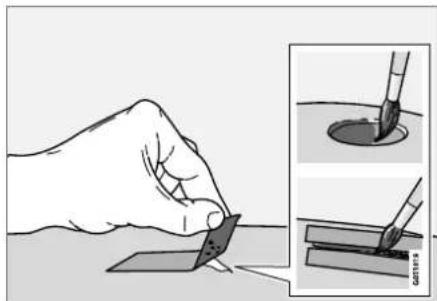
natural_image
Illustration of a hand holding a small object with a brush, alongside two close-up insets showing the same brush tip (no text or symbols present)-
Place a strip of masking tape over the damaged surface. Pull the tape off so that any loose flakes of paint adhere to it.
If the damage goes down to the bare metal, you may need to use primer first. If the paint damage is on a plastic surface, an adhesive primer should be used for better results.
Spray the primer into the lid of the spray can and brush on thinly. -
Light sanding with a very fine-grained sand-paper or similar may be required before painting (e.g. if there are uneven edges).
Clean the area carefully and let it dry.
MAINTENANCE AND SERVICE
- Thoroughly mix the primer and apply it with a small brush, toothpick or similar. When the primer is dry, apply one or more coats of paint and then a clear coat, letting the paint dry between each application.
If there is a longer scratch, follow the same procedure as above, but first mask off the surrounding area to protect the undamaged paint.
Touch-up pens and spray paints are available at Volvo retailers.

NOTE
If the stone chip has not gone down to the bare metal and an undamaged coat of paint remains, apply base coat and clear coat immediately after cleaning the surface.
Related information
- Paintwork (p. 657)
• Color codes (p. 658)
Color codes
Color code
The color code label is located on the left door pillar and is visible when the left front door is opened.

Sample color code (1): US models.
1 Vehicle paint code
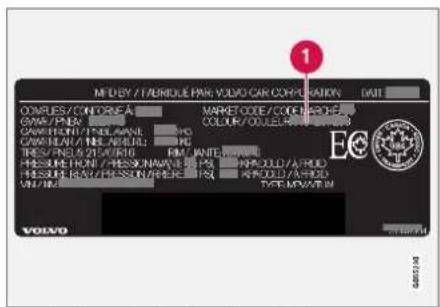
Sample color code (1): Canadian models.
1 Vehicle paint code
It is important to use the right color.
Related information
- Paintwork (p. 657)
• Touching up minor paint damage (p. 657)
Changing rear window wipers
The wiper blades help remove water from the windshield and rear window. Along with the washer fluid, they clean the glass and help improve visibility while driving. The windshield and rear window wiper blades can be replaced.
Changing rear window wipers

natural_image
Top-down view of a car's front wheel and dashboard with red arrows indicating components (no text or symbols)Lift the wiper arm from the window and pull the lower section of the blade to the right.

Grasp the center of the wiper blade and lift it from the window to the stop position.

NOTE
When the wiper arm is halfway folded out, it will stop in a locking position that helps prevent the arm from falling back onto the rear window. The wiper arm must be pulled past the locking position stop in order to change the wiper blade.

Grip the lower part of the blade and pull to the right until the blade loosens from the arm.
- Press the new wiper blade until it clicks into place. Check to make sure the blade is securely in place.
- Fold the wiper arm back toward the window.

CAUTION
Check the blades regularly. Neglected maintenance shortens the life of the blades.
Related information
• Using the rain sensor (p. 177)
- Using the windshield and headlight washers (p. 179)
- Using automatic rear window wiping when backing up (p. 181)
• Using the rain sensor's memory function (p. 178)
• Using the rear window wiper/washer (p. 180)
• Filling washer fluid (p. 662)
- Windshield wipers in the service position (p. 661)
• Replacing windshield wiper blades (p. 660)
• Using the windshield wipers (p. 176)
• Wiper blades and washer fluid (p. 176)
MAINTENANCE AND SERVICE
Replacing windshield wiper blades
The wiper blades help remove water from the windshield and rear window. Along with the washer fluid, they clean the glass and help improve visibility while driving. The windshield and rear window wiper blades can be replaced.
Replacing wiper blades
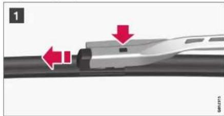
natural_image
Diagram of a high-speed train track with red arrows indicating motion direction (no text or symbols)
natural_image
Close-up of a black cable with a red arrow pointing to a section, no visible text or symbols1 Raise the wiper arms to the service position. Service position is activated/deactivated via the function view in the center display when the car is stationary and the windshield wipers are not on. Press the button on the wiper blade attachment and pull the wiper blade straight out, parallel with the wiper arm.
2 Slide in a new wiper blade until it clicks into place.
3. Check to make sure the blade is securely in place.
4. Press the wiper blade back against the wind-shield.
Wiper blades come in varying lengths

natural_image
Diagram of a car's frontview showing two curved engine blades mounted on the windshield, with no visible text or symbols.NOTE
When changing wiper blades, make sure that the blades are of different lengths. The blade on the driver's side is longer than the one on the passenger side.
Related information
• Using the rain sensor (p. 177)
- Using the windshield and headlight washers (p. 179)
- Using automatic rear window wiping when backing up (p. 181)
• Using the rain sensor's memory function (p. 178)
• Using the rear window wiper/washer (p. 180)
• Filling washer fluid (p. 662)
- Windshield wipers in the service position (p. 661)
• Changing rear window wipers (p. 659)
• Using the windshield wipers (p. 176)
• Wiper blades and washer fluid (p. 176)
Windshield wipers in the service position
The windshield wiper blades must be in the service (vertical) position for certain operations, e.g. replacing the blades.

natural_image
Side view of a car's front window with visible lane markings (no text or symbols)Windshield wipers in the service position.
The windshield wipers must be in the service position when replacing, washing or lifting the blades (e.g. to scrape ice or snow from the windshield).

CAUTION
Before placing the wipers in service position, ensure that they have not frozen to the windshield.
Activating/deactivating service position
The service position can be activated/deactivated when the vehicle is stationary and the windshield wipers are switched off. Service position is activated/deactivated via Function view in the center display:

Tap the Wiper Service Position button. The indicator light in the button will illuminate when service position is activated. The windshield wipers will move to the vertical position when service position is
activated. To deactivate the service position, tap Wiper Service Position once. The indicator light in the button will go out when service position is deactivated.
The wiper blades will also move out of service position if:
• The windshield wipers are turned on.
• The windshield washers are turned on.
• The rain sensor is activated.
• The vehicle begins moving.

CAUTION
If the wiper arms in service position are raised from the windshield, they must be folded back against the windscreen before activating wiping, washing or rain sensor as well as before departure. This is to prevent scratching the paint on the hood.
Related information
• Using the rain sensor (p. 177)
• Using the windshield and headlight washers (p. 179)
• Using automatic rear window wiping when backing up (p. 181)
• Using the rain sensor's memory function (p. 178)
• Using the rear window wiper/washer (p. 180)
• Filling washer fluid (p. 662)
• Replacing windshield wiper blades (p. 660)
• Changing rear window wipers (p. 659)
• Using the windshield wipers (p. 176)
• Wiper blades and washer fluid (p. 176)
MAINTENANCE AND SERVICE
Filling washer fluid
Washer fluid is used to keep the headlights, windshield and rear window clean. Washer fluid containing anti-freeze should be used in very cold weather (below-freezing temperatures).

natural_image
Close-up of a car engine hood with a red arrow pointing to a component detail (no text or symbols visible)Fill washer fluid into the reservoir with the blue cover. The reservoir is used for the windshield washer, tailgate window washer and headlight washer*
NOTE
When there is approximately 1 liter (1 qt) of washer fluid remaining, the message Washer fluid Level low, refill and the symbol will be displayed in the instrument panel.
Recommended grade: Washer fluid recommended by Volvo, with frost protection during cold weather and temperatures below the freezing point.
! CAUTION
Use Volvo's original washer fluid or an equivalent fluid with the recommended pH value between 6 and 8, diluted as recommended, e.g. in a 1:1 solution with pH-neutral water.
! CAUTION
Use washer fluid with anti-freeze when temperatures are below the freezing point to help keep the pump, reservoir and hoses from freezing.
Volume:
• Vehicles with headlight washing: 5.5 liters (5.8 qts).
- Vehicles without headlight washing: 3.5 liters (3.7 qts).
Related information
• Using the rain sensor (p. 177)
• Using the windshield and headlight washers (p. 179)
• Using automatic rear window wiping when backing up (p. 181)
• Using the rain sensor's memory function (p. 178)
• Using the rear window wiper/washer (p. 180)
- Windshield wipers in the service position (p. 661)
• Replacing windshield wiper blades (p. 660)
• Changing rear window wipers (p. 659)
• Using the windshield wipers (p. 176)
• Wiper blades and washer fluid (p. 176)
SPECIFICATIONS
SPECIFICATIONS
Type designations
The decals in the vehicle contain information such as chassis number, type designation, color code, etc.
Location of decals

The illustration is general and details may vary depending on market and model.
SPECIFICATIONS

1a Vehicle Emission Control Information. US models. Your Volvo is designed to meet all applicable emission standards, as evidenced by the certification label on the underside of the hood. For further information regarding these regulations, please consult your Volvo retailer.

1b Vehicle Emission Control Information. Canadian models. Your Volvo is designed to meet all applicable emission standards, as evidenced by the certification label on the underside of the hood. For further information regarding these regulations, please consult your Volvo retailer.

2 Vehicle Identification Number (VIN). The VIN plate is located on the top left surface of the dashboard. The Vehicle Identification Number (VIN) should always be quoted in all correspondence concerning your vehicle with the retailer and when ordering parts.

③ Tire inflation pressures. This label indicates the correct inflation pressures for the tires that were on the vehicle when it left the factory.
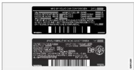
4 Federal Motor Vehicle Safety Standards (FMVSS) specifications (USA) and Ministry of Transport (CMVSS) standards (Canada). Your Volvo is designed to meet all applicable safety standards, as evidenced by the certification label on the driver's side B-pillar (the structural member at the side of the vehicle, at the rear of the driver's door opening). This label also includes codes for paint color, etc. For further information regarding these regulations, please consult your Volvo retailer. U.S. models have the upper decal; Canadian models have the lower one.
SPECIFICATIONS
◀◀

⑤ Engine oil. This label contains the recommended engine oil specifications.
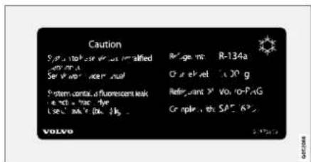
6 Decal A/C. Refrigerant R134a.

NOTE
The decals shown in the Owner's Manual do not claim to be exact reproductions of those found in the vehicle. The purpose is to show approximately how they look and about where they are located on the vehicle. The information that applies for your vehicle in particular is found on the decal on the vehicle.
Related information
• Air conditioning specifications (p. 674)
Dimensions
The vehicle's length, height, etc. are shown in the table.
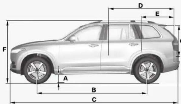

| Dimensions mm | inches | ||
| A Ground clearance ^A | 227 8.9 | ||
| B Wheelbase 2984 | 117.5 | ||
| C Length 4950 1949 | 9 | ||
| D Load length,floor, folded backrest ^B | 2040 1260^c | 80.3 49.6^c | |
| Dimensions mm | inches | ||
| E | Load length, floor | 761/898^D | 30.0/35.4^D |
| 1220^E | 48.0^E | ||
| 554^F | 21.8^F | ||
| F | HeightG | 1776 69.9 | |
| G | Load height 816 | 32.1 |
| Dimensions mm | inches | ||
| H | Wheel track,front ^H | 1665 ^I | 65.6 ^I |
| 1673 ^J | 65.9 ^J | ||
| Wheel track,front ^K | 1668 ^I | 65.7 ^I | |
| 1676 ^J | 66.0 ^J |
▶▶
SPECIFICATIONS
◀◀
| Dimensions mm | inches | ||
| I Wheel track, rear ^1 | 1667 ^1 | 65.6 ^1 | |
| 1675 ^J | 65.9 ^J | ||
| Wheel track, rear ^K | 1671 ^1 | ||
| 1679 ^J | |||
| J Load width, floor | 1192 46.9 | ||
| K Width | 1923 ^L | 75.7 ^L | |
| 1931 ^M | 76.0 ^M | ||
| 1958 ^N | 77.1 ^N | ||
| Dimensions mm | inches | ||
| L | Width incl. rearview mirrors | 2140 84.3 | |
| M | Width incl. folded rearview mirrors | 2008 79.1 |
A At curb weight + 2 people. (Varies slightly depending on tire
dimensions, chassis, etc.)
^1 Does not apply to vehicles with 3 or 4 seats.
C From the second row of seats in 7-seat models*.
D Vehicles with 3 or 4 seats.
E Vehicles with 5 seats.
F Vehicles with 7 seats.
^6 Including roof antenna, at curb weight.
11 Vehicles without pneumatic suspension
1 Vehicles with 19-inch wheels.
- Vehicles with 20, 21 and 22-inch wheels.
K Vehicles with pneumatic suspension.
L Chassis width.
M Width for vehicles with 19-inch wheels.
N Width for vehicles with 20, 21 and 22-inch wheels.
Related information
- Weights (p. 669)
Weights
The following table lists important weight data for your vehicle.
| Category USA | (lbs) | Canada(kg) | |
| Gross vehicle weight | 7-seat 6635 3010 | ||
| 4-seat 6140 2785 | |||
| Capacity weight | 7-seat 1210 550 | ||
| 4-seat 1000 450 | |||
| Permissible axle weights, front | 7-seat 3130 1420 | ||
| 4-seat 2975 1350 | |||
| Permissible axle weights, rear | 7-seat 3590 1630 | ||
| 4-seat 3305 1500 | |||
| Curb weight | 7-seat 4370-5200 2040-2370 | ||
| 4-seat 5230-5240 2370-2380 | |||
| Max. roof load | 220 100 | ||

CAUTION
- When loading the vehicle, the maximum gross vehicle weight and permissible axle weights may not be exceeded.
Related information
• Type designations (p. 664)
• Towing capacity and tongue weight (p. 670)
SPECIFICATIONS
Towing capacity and tongue weight
Towing capacity and tongue weight are shown in the tables below.
| Category USA | (lbs) | Canada(kg) | |
| Max. trailer weights | Without brakes: 1650 750 | ||
| With brakes (AWD): 5000 2250 | |||
| Max. tongue weight | AWD: 500 225 | ||
CAUTION
- The maximum trailer weights listed are only applicable for altitudes up to 3280 ft (1,000 m) above sea level. With increasing altitude the engine power and therefore the car's climbing ability are impaired because of the reduced air density, so the maximum trailer weight has to be reduced accordingly. The weight of the car and trailer must be reduced by 10% for every further 3280 ft (1,000 m) (or part thereof).
Related information
• Type designations (p. 664)
- Weights (p. 669)
- Driving with a trailer (p. 483)
• Trailer Stability Assist* (p. 485)
Engine specifications
Engine specifications (output, etc.) for each engine variant are shown in the table below. The specifications for Special Edition vehicles may vary.
Twin Engine vehicles are powered by both a gasoline engine and an electric motor (ERAD - Electric Rear Axle Drive).

NOTE
Not all engines are available on all markets.
| Engine | Engine code^A | Output(kW/rps) | Output(hp/rpm) | Torque(Nm/rps) | Torque(ft. lbs./rpm) | Number of cylinders |
| T8 Twin Engine B4204 | T28 233/100 313/6 | 000 400/37-90 | 295/2200-5400 | 4 |
A The engine code, component and manufacturer serial numbers can be found on the engine.
Electric motor
Max. output: 65 kW (87 hp).
Torque: 240 Nm.
Related information
• Type designations (p. 664)
• Engine oil specifications (p. 672)
• Coolant specifications (p. 673)
SPECIFICATIONS
Engine oil specifications
Fully synthetic engine oil of at least ACEA A5/B5 must be used. Lower oil grades may not offer the same fuel economy, engine performance or engine protection.
Volvo recommends:

General
See the Service and warranty booklet for information about oil change intervals.
| NOTE |
| This vehicle is delivered from the factory with synthetic oil. |
Do not use oil additives.
Oil viscosity
The wrong oil viscosity can shorten engine service life during normal use. SAE 5W-30 provides good fuel economy and engine protection. See the viscosity chart.

Viscosity chart
Extreme driving conditions
Volvo's VCC RBS0-2AE/SAE 0W20 oil is recommended for extreme conditions.
Oil volume
| The oil volume for the engine is: | |
| Liter (approx) 5.6 | |
| US qts (approx) 5.9 | |
Related information
• Type designations (p. 664)
• Checking and filling engine oil (p. 624)
• Engine oil (p. 623)
Coolant specifications
Recommended grade: Volvo-approved pre-mixed coolant. If concentrated coolant is used, mix with 50% water. Consult a Volvo retailer if you have any questions.
To avoid deterioration of the cooling system, engine trouble, etc., only approved Volvo coolant should be used.

WARNING
Do not ingest. May cause damage to organs (kidneys). The product contains ethylene glycol, inhibitor, emetic, water, etc.
Related information
• Refilling coolant (p. 625)
Transmission fluid specifications
Under normal driving conditions, the transmission fluid will not need to be changed during its service life. However, it may need to be changed if the vehicle is driven frequently in adverse driving conditions.
Automatic transmission
| Prescribed transmission fluid: | AW1 |
Related information
• Type designations (p. 664)
Brake fluid specifications
The medium in the hydraulic brake system is called brake fluid and is used to transfer braking force from e.g. pressure on the brake pedal via a master brake cylinder to one or more slave cylinders, which in turn act on a mechanical brake.
Recommended grade: Volvo Original or similar fluid that meets a combination of Dot 4, 5.1 and ISO 4925 class 6.

NOTE
Changing or filling brake fluid should be entrusted to an authorized Volvo workshop.
Related information
• Engine compartment overview (p. 622)
SPECIFICATIONS
Fuel tank volume
The fuel tank's refillable volume is shown in the table below.
| All models | |
| Liter (approx) 70 | |
| US gallons (approx) 18,5 |
Related information
• Refueling (p. 475)
- Octane rating (p. 477)
Air conditioning specifications
The climate system in the vehicle uses a freon-free R134a refrigerant. For information regarding the refrigerant, refer to the decal located on the inside of the hood.
The prescribed grades and volumes for fluids and lubricants in the air conditioning system are shown in the tables below.
A/C Decal
Decal for R134a
Refrigerant
Vehicles with R134a refrigerant
Weight Prescribed grade
1050 g (2.31 lbs) R134a

WARNING
The air conditioning system contains the refrigerant R134a under pressure. Service and repairs to the system should only be done by an authorized workshop.
Compressor oil
| Volume Prescribed grade | |
| 120 ml (4.06 fl. oz.) PAG | SP-A2 |
Evaporator

CAUTION
The A/C system evaporator must never be repaired or replaced with a previously used evaporator. The new evaporator must be certified and labeled in accordance with SAE J2842.
Related information
• Climate control system service (p. 621)
SPECIFICATIONS
Approved tire pressure
The following tire pressures are recommended by Volvo for your vehicle. Refer to the tire infla-
tion placard for information specific to the tires installed on your vehicle at the factory.
| Tire dimensions Cold tire pressure | for up to seven people (depending on number of seats) | |
| Frontpsi (kPa) | Rearpsi (kPa) | |
| 235/55 R19 | 42 (290) 42 (290) | |
| 275/45 R20 | ||
| 275/40 R21 | ||
| 275/35 R22 | ||
| Temporary spare tire N/A N/A | ||
Related information
• Type designations (p. 664)
- Checking tire pressure (p. 567)
• Recommended tire pressure (p. 569)

bar
| Category | Value | |---|---| | Category 1 | 100 | | Category 2 | 100 | | Category 3 | 100 | | Category 4 | 100 | | Category 5 | 100 | | Category 6 | 100 | | Category 7 | 100 | | Category 8 | 100 | | Category 9 | 100 | | Category 10 | 100 | | Category 11 | 100 | | Category 12 | 100 | | Category 13 | 100 | | Category 14 | 100 | | Category 15 | 100 | | Category 16 | 100 | | Category 17 | 100 | | Category 18 | 100 | | Category 19 | 100 | | Category 20 | 100 | | Category 21 | 100 | | Category 22 | 100 | | Category 23 | 100 | | Category 24 | 100 | | Category 25 | 100 | | Category 26 | 100 | | Category 27 | 100 | | Category 28 | 100 | | Category 29 | 100 | | Category 30 | 100 | | Category 31 | 100 | | Category 32 | 100 | | Category 33 | 100 | | Category 34 | 100 | | Category 35 | 100 | | Category 36 | 100 | | Category 37 | 100 | | Category 38 | 100 | | Category 39 | 100 | | Category 40 | 100 | | Category 41 | 100 | | Category 42 | 100 | | Category 43 | 100 | | Category 44 | 100 | | Category 45 | 100 | | Category 46 | 100 | | Category 47 | 100 | | Category 48 | 100 | | Category 49 | 100 | | Category 50 | 100 | | Category 51 | 100 | | Category 52 | 100 | | Category 53 | 100 | | Category 54 | 100 | | Category 55 | 100 | | Category 56 | 100 | | Category 57 | 100 | | Category 58 | 100 | | Category 59 | 100 | | Category 60 | 100 | | Category 61 | 100 | | Category 62 | 100 | | Category 63 | 100 | | Category 64 | 100 | | Category 65 | 100 | | Category 66 | 100 | | Category 67 | 100 | | Category 68 | 100 | | Category 69 | 100 | | Category 70 | 100 | | Category 71 | 100 | | Category 72 | 100 | | Category 73 | 100 | | Category 74 | 100 | | Category 75 | 100 | | Category 76 | 100 | | Category 77 | 100 | | Category 78 | 100 | | Category 79 | 100 | | Category 80 | 100 | | Category 81 | 100 | | Category 82 | 100 | | Category 83 | 100 | | Category 84 | 100 | | Category 85 | 100 | | Category 86 | 100 | | Category 87 | 100 | | Category 88 | 100 | | Category 89 | 100 | | Category 90 | 100 | | Category 91 | 100 | | Category 92 | 100 | | Category 93 | 100 | | Category 94 | 100 | | Category 95 | 100 | | Category 96 | 100 | | Category 97 | 100 | | Category 98 | 100 | | Category 99 | 100 | | Total (Total) |INDEX
INDEX
1,2,3...
4WD 452
A
ABS
anti-lock brakes 439
AC (Air conditioning) 230
ACC - Adaptive Cruise Control 300, 303,
304, 305, 306, 307, 309, 310, 311, 312, 313, 314
Accessories and extra equipment 35 installation 36
Accessory installation warning 36, 37
Active Bending Lights 159
Adapting driving characteristics 278, 454
Adaptive Cruise Control 300, 303, 304, 305, 306, 307, 309, 310, 311, 312, 313, 314 change cruise control functionality 313 function 300
manage speed 304, 305
pass 309, 310
radar sensor 332
set time interval 306, 307
troubleshooting 312
Adjusting the steering wheel 201
| Airbag 52 | |
| activation/deactivation 56 | |
| driver's side | 53 |
| passenger side | 53, 56 |
| Air bag, see Airbag | 52 |
| Air conditioning | 230 |
| Air conditioning, fluid volume and grade | 674 |
| Air distribution | 209 |
| air vents changing 210 | 209, 211 |
| defrosting | 222 |
| recirculation | 221 |
| table showing options | 212 |
| Air quality | 206, 208 |
| allergy and asthma | 208 |
| passenger compartment filter | 209 |
| Air recirculation | 221 |
| Alarm | 273 |
| deactivating | 274 |
| Allergy and asthma-inducing substances | 208 |
| All Wheel Drive, AWD | 452 |
| All Wheel Drive (AWD) | 452 |
| All Wheel Drive (four-wheel drive) | 452 |
| Android Auto | 530, 532 |
| Antenna location | 262 |
Apple CarPlay 527, 529
Approach lighting 161
Apps 498
Assistance at risk of collision 380, 381, 382, 383, 384, 385, 386, 387, 389
Audio and media 496
Audio system HD digital radio 508 SiriusXM® Satellite radio 508, 509, 511
Auto-climate 220
Auto hold 446
Auto-hold brakes 446 activate and deactivate 446 after collision 447
Automatic car wash 653
Automatic high beam 157
Automatic locking 266
Automatic relocking 246, 259
Automatic Speed Limiter 287, 289, 290, 291
Automatic transmission 449
kickdown 452
oil 673
Trailer 483
Auxiliary heater 239
INDEX
B
Backrest
front seat, adjusting 184, 185, 188, 189, 190, 191
rear seat, adjusting 197, 198 rear seat, folding 193, 198, 199
Battery
Hybrid 631
jump-start 481
Maintenance 627
start 627
symbols on the battery 632 warning symbols 632
BLIS 355, 356, 357, 358
Blower
adjusting 226
air distribution 210
air vents 211
Bluetooth
connect 524
connecting vehicle to Internet 543
phone 532
settings 541
Book service and repair 615
Booster cushions 71
Brake assist
after collision 447
Brake fluid grade 673
Brake functions 438
Brake light 160
Brake position 449
Brakes 439
anti-lock brakes, ABS 439
automatic when stationary 446
Brake Assist System, BAS 441
brake lights 160
brake system 438
emergency brake lights 160
handbrake 442
Maintenance 442 on salted roads 441
on wet roads 441
brake system fluid 673
C
Camera sensor 351
Camera unit 337,341
Capacity weight 588,669
Cargo compartment 598 attachment points 601
cargo net 606
electrical outlet 594, 596
Lighting 163
Cargo compartment cover 601,602
cargo net 606
Cargo net 606
Car wash 650, 651, 653, 654, 655, 656
Catalytic converter 479 recovery 487
CD player 522
Cell phone, see Phone 533
Center console 593
Center display change appearance 131
cleaning 645
climate controls 215
Function view 122
keyboard 126 messages 140, 141
operation 112, 115, 119, 124
overview 109
settings 132, 133
switch off and change volume 131
symbols in status bar 124
views 115
Central locking 262
Change of owner 134
Changing a wheel 574
INDEX
Charge
vehicle function 471
Charge level
vehicle function 471
Charging
hybrid battery 417
opening and closing the charging
door 422
start charging 423
Status 425, 427
stop charging 429
Charging cable 419
Charging current 419
Checking engine oil level 624
Child restraints 63, 65
booster cushions 71
convertible seats 69
infant seats 67
integrated booster cushion 76
ISOFIX/LATCH anchors 74
lower attachment points 74
recalls and registration 65
top tether anchors 72
Child safety
63
Child safety locks 264
Circuit breaker
421
City Safety
341, 342, 344, 345, 351, 353
City Safety braking for oncoming vehicles 350
City Safety in crossing traffic 347, 348
City Safety when evasive maneuver prevented 349
Cleaning 647, 649, 650
automatic car wash 653
car wash 650, 651, 653, 654, 655, 656
center display 645
Seat belts 647
textile upholstery 645, 647, 648
upholstery 645, 647, 648, 649, 650
wheels 656
Cleaning wheels 656
Cleaning wiper blades 654
Clean Zone 207
Clean Zone Interior Package 208
Climate 204
auto-regulation 220
blower control 226
parking 231
perceived temperature 205
Sensors 204
temperature control 228, 229
voice control 205
zones 204
Climate controls 215
center display 215
rear seat 215
Climate system 204, 215
Refrigerant 674
repairs 621
Clock, setting 93
Collision 42, 47, 52, 61
Collision warner
detection of pedestrians 345
radar sensor 332
Collision warning 341,354
Color code, paintwork 658
Color codes 658
Compass 493
calibration 493
Condensation in headlights 651, 653,
654, 655
Connecting vehicle to Internet
No connection or poor connection 546
via a mobile device (WiFi) 543
via cellular phone (Bluetooth) 543
via vehicle's modem 544
Connect phone 533
Contact information 26
Convertible seats 69
coolant 673
Coolant, filling 625
INDEX
| Cooling systemoverheating 479 |
| Corner Traction Control 279 |
| Corrosion protection 656 |
| Coveringcargo compartment 602 |
| Crash, see Collision 42 |
| Crash event data 33 |
| Cross Traffic Alert - CTA 360, 361, 362, 363 |
| Cruise control 291, 292manage speed 292, 293temporary deactivation 294, 295turn off 296 |
| CTA - Cross Traffic Alert 360, 361, 362, 363 |
| Curb weight 669 |
| Customer Privacy Policy 35 |
| CZIP (Clean Zone Interior Package) 208 |
D
| Data | |
| recording 33 | |
| transferring between vehicle and work- shop 612 | |
| Data sharing | 548 |
| Daytime running lights | 154 |
| Decals | |
| location | 664 |
| Defrosting | 222 |
| Detection of cyclist | 345 |
| Dimensions | 667 |
| Dipstick, electronic | 624 |
| Direction of rotation | 562 |
| Display | |
| driver information | 84 |
| Display lighting | 164 |
| Distance Alert | 296, 297, 298 |
| limitations | 299 |
| DivX® | 523 |
| Door mirrors | 169, 171 |
| compass | 493 |
| dimming | 170 |
| outer | 169, 171 |
| power folding | 171 |
| resetting | 171 |
| store position | 186, 187 |
| Driveline | |
| transmission | 448 |
| Drive mode | 454 |
| changing | 459 |
| Driver Alert Control 370 | |
| operation | 371, 372 |
| Driver Alert Control limitations | 372 |
| Driver performance | 92, 93 |
| Driver profile | 136 |
| edit | 137, 138, 139 |
| select | 137 |
| Driver support system | 278 |
| Drive systems | 453 |
| Driving | |
| cooling system | 479 |
| with a trailer | 483 |
| Driving economy | 467 |
| Driving through standing water | 473 |
| driving with a trailer | |
| lowball load | 670 |
| towing capacity | 670 |
E
| Economical driving | 467 |
| Electrical outlet | 594 |
| use | 596 |
| Electrical system | 627 |
| Electric drive motor specifications | 671 |
| electric motor | 453 |
| Driving | 469 |
| Range | 469 |
INDEX
Electric parking brake 442
Electronic immobilizer 257
emergency brake lights 160
Emission inspection readiness 610
Energy distribution using map data 460
Engine
automatic start and stop of combustion
engine 454
overheating 479
start 434
turn off 436
Engine braking 439, 449, 466
Engine compartment
coolant 625
engine oil 623
overview 622
Engine drag control 279
Engine oil 623
filling 624
filter 623
grade and volume 672
Engine shutdown 436
Engine specifications 671
Engine temperature
high 479
Environment 27
| Error messages | |
| Adaptive Cruise Control | 314 |
| see Messages and symbols | 314, 330 |
| Error messages in BLIS | 359 |
| Ethanol content | |
| max. 10% by volume | 476 |
| Exterior dimensions 667 | |
| Extra heater (Auxiliary heater) | 239 |
F
| Federal Clean Air Act 610 | |
| Ferry transport | 461 |
| Flat tire | 582 |
| Flooded road 473 | |
| Fluids, volumes | 662, 674 |
| Fluids and oils 673, 674 | |
| Fog lights | |
| rear | 159 |
| Four-C | 461 |
| Front seat | |
| blower | 226 |
| climate | 215 |
| heating | 217, 218 |
| temperature | 228 |
| ventilation | 219 |
| Front seat manual | 184 |
| Front seats, power | 185 |
| adjusting passenger seat from driver's seat | 192 |
| adjusting seat | 185 |
| Lumbar support | 191 |
| massage | 188, 189 |
| multifunction control | 188, 189, 190, 191 |
| Side bolsters | 190 |
| store position | 186, 187 |
| FSC, environmental labeling | 24 |
| Fuel | 476 |
| Travel Link service | 516 |
Fuel filling 475
Fuel gauge 87
| Fuel requirements | 476, 477 |
| Fuel tank volume | 674 |
| Fuse box | 633 |
| Fuses | |
| below the glove compartment | 638 |
| general | 632 |
| in engine compartment | 634 |
| in the cargo compartment | 641 |
| replacing | 633 |
INDEX
G
Gasoline grade 476
Gauge fuel gauge 87
Gear selector positions automatic transmission 449
Glass laminated/reinforced 166
Glove compartment 597
Gracenote® 521
Grocery bag holders 600
Gross vehicle weight 669
Guide lines for Park Assist Camera 399
H
Handbrake 442, 443
Hand wash 651
Hard disk space 548
Hazard warning flashers 161
HDC 466
HD radio 505
Head restraint 195
| Head-up display 142 | |
| activate and deactivate | 143 |
| cleaning | 646 |
| replacing windshield | 621 |
| settings | 144 |
| store position | 144, 186, 187 |
| Heated washer nozzles | 176 |
| Heater | 239 |
| auxiliary heater | 239 |
| parking heater | 239 |
| Heating | |
| Seats | 217, 218 |
| steering wheel | 219, 220 |
| windows | 223, 225 |
| Height adjustment | 461, 464 |
| high beams | 156, 157 |
| High engine temperature | 479 |
| Hill Descent Control | 465, 466, 467 |
| activate with function button | 467 |
| Hill Start Assist | 447 |
| Hill Start Assist (HSA) | 447 |
| Hoisting the vehicle | 618 |
| Hold | |
| vehicle function | 471 |
| HomeLink® | 489 |
| programming | 490 |
| use | 491 |
| HomeLink® remote control programmable | 489 |
| Home safe lighting | 161 |
| Honk | 200 |
| Hood, opening | 620 |
| Horn 200 | |
| Hybrid battery | 631 |
| Charging | 417 |
| Hybrid battery gauge 88 | |
| Hybrid gauge | 87 |
| Hybrid mode | 454, 460 |
|
| IAQS (Interior Air Quality System) | 208 |
| IC (Inflatable Curtain) | 60 |
| ID, Volvo | 26 |
| Identification number | 38 |
| Ignition mode | 437, 438 |
| Immobilizer 257 | |
| Electronic immobilizer | 257 |
| Indicator symbols | 94 |
| Individual drive mode 454 | |
| Infant seats | 67 |
| Inflatable curtain 60 |
INDEX
Inflatable Curtain 60
Inflating tires 587
Inflation pressure
adjusting 568
Checking 567
decal 569
recommended 569
Inflation pressure monitoring 569
action 573
Status 572
Inflation pressure table 675
Information display 84, 86
Infotainment (Audio and media) 496
Instrument cluster 84
settings 86
Instrument illumination 164
Instrument lighting 164
Instrument panel 84
App menu 103,104
hybrid-related symbols and messages 430
messages 105
settings 86
Instruments and controls 82
Instruments overview left-hand drive vehicle 82
Integrated booster cushion 76
folding down 78
folding up 77
IntelliSafe
driver support 28
Interior Air Quality System 208
Intermittent wiping 176
Internet, see Internet-connected vehicle 541
Internet-connected vehicle 541
book service and repair 615
No connection or poor connection 546
send car data 616
system updates 613
iPod®, connecting 524
ISOFIX/LATCH anchors 74
J
Jack 575
Jump-start 481
K
Key 243
Keyboard 126, 129
change language 129
Keyless
locking/unlocking 259
settings 261
touch-sensitive surfaces 258
Key tag 243
L
Labels
location 664
Laminated glass 166
Lamps
changing 626
Trailer 486
Lane Keeping Aid
operation 375
Lane Keeping Aid (LKA) 372, 374, 375,
376, 377, 379
Language 132
Leather upholstery, cleaning instructions 648
Leveling control 461
settings 464
License agreement 98,549
Lifting tools 575
Light control 152, 164
INDEX
Lighting
Active Bending Lights 159
approach lighting 161
automatic high beam 157
automatic lighting controls, passenger
compartment 162
brake lights 160
controls 152, 162, 164
daytime running lights 154
display lighting 164
emergency brake lights 160
Hazard warning flashers 161
high beams 156, 157
home safe lighting 161
in passenger compartment 162, 164
instrument illumination 164
instrument lighting 164
low beams 155
position lights 154
rear fog light 159
settings 153
Turn signals 158
Lighting, replacing bulbs 626
Limp home 448
Load anchoring eyelets cargo compartment 601
Load anchoring hooks 600
Load carriers 600
Load index 564
Loading
general 598
load anchoring eyelets 601
long load 599
Lock indication
setting 243
Locking/unlocking
Tailgate 247, 261
Locking wheel bolts 575
Locks
Locking 246
unlocking 246
Long-term storage 432
Low battery charge level
start battery 480
Low beams 155
Lower the rear end 599
Low oil level 624
Low-speed driving 464
activate with function button 465
M
Maintained climate comfort 237
start/stop 237
Maintenance 610
corrosion protection 656
Max. axle weight 669
Max. roof load 669
Media player 518,520
compatible file formats 525, 526
voice control 148
Messages and symbols
Adaptive Cruise Control 314
Collision warner with auto-brake 353
Messages in BLIS 359
Messages in display 105, 140
handling 106, 140 saved 107, 141
Mileage 89
electric motor 469
Misting
condensation in headlights 650, 653
Mood lighting 163, 164
N
Net
cargo compartment 606
0
Occupant safety 43
Occupant weight sensor 56
Octane rating 477
Oil, see also Engine oil 672
On-board diagnostics 610
On-board Diagnostic socket 37
Option/accessory 21
Outside temperature gauge 94
Overheating 479, 483
Owner's information 16
OWNER'S MANUAL 21
environmental labeling 24
in cellular phone 20
in the center display 17, 18
P
Paddle at steering wheel 200
Paint
color code 658
paint damage and touch-up 657,658
Panoramic roof
opening and closing 173
pinch protection 166
sun shade 172, 175
ventilation position 174
PAP - Park Assist Pilot 406, 408, 410,
411, 413, 414
Park Assist Camera 396, 397, 399, 401,
403, 404, 405
settings 402
Park Assist Camera limitations 403
Park Assist Pilot 406, 408, 410, 411,
413, 414
function 406, 408, 411, 413, 414
limitations 411
operation 408,410
Symbols and messages 414
Park Assist Pilot - PAP 406, 408, 410,
411, 413, 414
parking
on hills 444
Parking Assist 390, 391, 392, 393, 394, 395
function 390, 391, 392
Parking brake 442
activate and deactivate 443
automatic activation 444
Low battery charge level 445
Parking climate 231
Symbols and messages 238
Parking heater 239
Passenger compartment filter 209
Passenger compartment heater (Parking
heater) 239
Passenger compartment interior 592
center console 593
electrical outlet 594
glove compartment 597
sun visor 598
Passenger compartment lighting 162, 164
auto switch 162
Passing assistance 309, 310, 326, 327
personal information (Customer Privacy
Policy) 35
Phone 532
changing to another 536
connect 533
connect automatically 535
connect manually 535
delete 536
INDEX
| disconnect 536 | |
| phone call 537, 539 | |
| text message 538 | |
| voice control 147 | |
| Pilot Assist 316, 319, 320, 322, 323, 324, 326, 327, 328, 329, 330 | |
| pass 326, 327 | |
| pinch protection 166 | |
| resetting 167 | |
| PIN code 545 | |
| Polishing 651 | |
| Position lights 154 | |
| Power 671 | |
| electric motor 671 | |
| Power folding door mirrors 171 | |
| Power panoramic roof 172 | |
| Power save mode 480 | |
| Power seats | 185 |
| Power tailgate 266 | |
| Power windows | 167, 168 |
| pinch protection | 166 |
| Preconditioning | 232 |
| start/stop 233 | |
| timer | 234 |
| Pressure wash | 654 |
| Privacy Policy (Customer Privacy Policy) | 35 |
| Private locking | 271 |
| activation/deactivation | 272 |
| PROPOSITION 65 WARNING | 481 |
R
| Radar sensor | 303, 332 |
| limitations | 333 |
| Radar unit | 332 |
| Radio | 501 |
| changing radio waveband and radio station | 502 |
| HD radio | 505 |
| RBDS | 505 |
| search radio station | 503 |
| settings | 504 |
| SiriusXM® Satellite radio | 508, 509, 511 |
| start | 501 |
| voice control 148 |
| Radio favorites | 503 |
| Rain sensor 177, 178 | |
| Rain sensor's memory function | 178 |
| Raise the rear end | 599 |
| Rear camera | 396, 397, 399, 401, 402, 403, 404, 405 |
| Rear doorsun shade | 169 |
| Rear seat | |
| adjusting backrest tilt | 197 |
| blower | 226 |
| climate | 215 |
| folding backrest | 193, 199 |
| getting in/getting out | 198 |
| head restraint | 195 |
| healing | 218 |
| moving forward/rearward | 197 |
| temperature | 228 |
Rear sensors 390, 391, 392, 393, 394, 395
| Rearview/door mirrors | |
| dimming | 170 |
| heating | 225 |
| interior | 169 |
| Rearview mirror | 169 |
| dimming | 170 |
| Rear window | |
| heating | 225 |
| washers | 180, 181 |
| wipers | 180, 181 |
| Recalls | 45 |
| Recommendations when driving | 472 |
| Recommendations when loading | 598 |
| Recovery 489 | |
| Red Key | 253 |
| settings | 253 |
INDEX
Refrigerant 621
climate system 674
Refueling
filling 475
fuel filler door, fuel flap 474
Remote immobilizer 257
Remote key 243
battery replacement 249
connecting to driver profile 138
detachable key blade 254
loss 252
Range 248
Remote updates 613
Reporting safety defects 44
Resetting door mirrors 171
Resetting settings 134
change of owner 134
Driver profile 139
Resetting trip odometer 92
Road Sign Information 364, 365, 366
limitations 369
operation 366, 367, 368
Road trip 472
Roll Stability Control 279
Roof load, max. weight 669
RSC (Roll Stability Control) 279
Run-off Mitigation 381, 382, 383
S
Safety 42
pregnancy 43
Safety belt, see Seat belt 47
Safety defects, reporting 44
Safety mode 61
starting/moving 62
Sealing compound 582
Seat, see Seats 184
Seat belt reminder 51
Seat belts 47
Automatic locking retractor/Emergency
locking retractor 65
buckling/unbuckling 48
pregnancy 43
seat belt reminder 51
seat belt tensioner 50
securing child restraint systems 67, 69, 71
Seat belt tensioner 50
resetting 51
Seats
heating 217, 218
manual front seat 184
power front seats 185
store position 186, 187
ventilation 219
whiplash protection 46
Sensors
air quality 209
climate 204
Sensus
connection and entertainment 30
Sensus Navigation 366
Service position 661
Service program 610
Set time interval 298
settings
Categories 135
contextual 133
resetting 134
Shiftlock 452
Side airbag 60
Side Impact Protection System 60
SIM card 545
SIPS (Side Impact Protection System) 60
Sirius Satellite radio
Travel link 512
SiriusXM® Satellite radio
traffic information 508, 509, 511
Slippery conditions 472, 473
Slippery road conditions 473
Software updates 33
Sound experience 497
INDEX
Sound settings 496, 539
phone 540
playing media 518, 520
text message 539
Spare tire 579, 580
Speed camera 368
Speed Limiter 283, 286, 287, 291
getting started 284
shut down 286
temporary deactivation 285
Speed symbols, tires 564
Spin control 279
Stability and traction control system 279, 282 operation 281
Stability system 279
Stains 645, 647, 648, 649, 650
Start and lock system type designations 257
Start battery 481,627 overload 480
Start engine 434
Starting the engine after a collision 62
Start the vehicle 434
Steel cargo grid 604
Steering assistance at risk of collision 380, 381, 382, 383, 384, 385, 386, 387, 389
Steering assistance at risk of rear-end collision 386, 387
Steering power level, see Steering wheel resistance 278
Steering resistance at risk of head-on collision 383, 384, 385
Steering wheel 200, 201 heating 219, 220
keypad 200
paddle 200
steering wheel adjustment 201
Steering wheel keypad 200
Steering wheel paddles 451
Steering wheel resistance, speed-dependent 278
Stone chips and scratches 657, 658
Storage compartments 592 center console 593
glove compartment 597 sun visor 598
Sunroof pinch protection 166
Sun shade panoramic roof 172, 175 pinch protection 166 rear door 169
Sun visor 598
mirror lighting 163
Symbols indicator symbols 94 warning symbols 97
Symbols and messages Adaptive Cruise Control 314 center display's status bar 124 Collision warner with auto-brake 353 hybrid-related 430 parking climate 238
Symbols and messages for Assistance at risk of collision 389 system updates 613
T
Tailgate locking/unlocking 247, 261 open/close with foot movement 270 power 266 unlocking from inside 264
Technician certification 38
INDEX
| Temperatureadjusting 228, 229perceived 205 | |
| Temperature monitoring 422 | |
| Temporary sparespare tire 579 | |
| Temporary tire sealing systemexecution, checking 583Inflating tires 587location 582overview 582sealing compound 582 | |
| Terms and conditionsservices 35users 548 | |
| Tire dimensions 564, 574 | |
| Tire pressure monitoringcalibrating 571 | |
| Tires 560direction of rotation 562glossary of terms 563inflation pressure tablemounting 578pressureremoval 576rotationspecificationsstoragetire pressure monitoring | 675675561564, 675560569 |
| tire sealing | 582 |
| Tread depth | 581 |
| tread wear indicator | 563 |
| winter tires | 581 |
| Tire sealing system | 583 |
| Tire tread | 563 |
| Tools | 574 |
| Top tether anchors (child restraint systems) | 72 |
| Top view | 132 |
| Total airing function | 243 |
| Towbar | 482 |
| removable, attaching, installing, mounting | 482 |
| removable, removing, detaching | 482 |
| Towing | 487 |
| Towing capacity and towball load | 670 |
| Towing eyelet | 488 |
| TPMS - Tire Pressure Monitoring System | 569 |
| Traction control | 279 |
| Traffic information | 504 |
| Trailer | 485 |
| driving with a trailer | 483 |
| Lamps 486 | |
| swaying | 485 |
| Trailer Stability Assist | 485 |
| trailer | 485 |
| Trailer stabilizer | 280 |
| Trailer towing | |
| trailer hitch | 482 |
| Transmission | 448 |
| automatic | 449 |
| Transmission fluid | |
| grade | 673 |
| Travel Link | 512 |
| Fuel | 516 |
| Notifications | 515 |
| Sports | 517 |
| weather | 514 |
| Tread depth | 563, 581 |
| Tread wear indicator | 563 |
| Trip computer 89, 91 | |
| Trip odometer | 89 |
| Trip odometer resetting | 92 |
| Trip statistics | 92 |
| Troubleshooting | |
| Adaptive Cruise Control | 312 |
| Troubleshooting the camera sensor | 338, 341 |
| TSA - Trailer Stability Assist | 280, 485 |
| Tunnel detection | 155 |
| Turn off engine | 436 |
INDEX
Turn signals 158
Twin Engine
general 416
Type approval
radar system 336
U
Uniform Tire Quality Grading 566
Units 132
Unlocking
settings 247
with key blade 255
USB
socket for connecting media 525
V
Vehicle care 650, 651, 653, 654, 655, 656
leather upholstery 648
Vehicle Event Data 33
Vehicle functions
in the center display 122
Vehicle key bat. low 249
Vehicle modem
connecting vehicle to Internet 544
settings 545
Vehicle recovery 489
Vehicle status 614
inflation pressure 572
Vehicle upholstery 645, 647, 648, 649, 650
Vehicle weight 669
Ventilation 209, 210, 211
Seats 219
Video 522, 524
settings 523
Voice control 145
climate 205
phone 147
radio and media 148
settings 148
VOL mark 560
Volvo ID 26
create and register 26
W
Warning light
Adaptive Cruise Control 303
stability and traction control system 279
Warning lights
airbags SRS 97
alternator does not charge 97
brake system error 97
low oil pressure 97
parking brake applied 97
seat belt reminder 97
starter battery not charging 97
WARNING 97
Warning sound
parking brake 445
warning symbols 97
Warning symbols
safety 42
Warranties 610
Washer
Headlights 179
rear window 180, 181
washer fluid, filling 662
Windshield 179
Washer fluid 176,662
Washer nozzles, heated 176
Waxing 651
INDEX
| Weights |
| Curb weight 669 |
| Wheel bolts 575 |
| locking 575 |
| Wheels |
| cleaning 656 |
| mounting 578 |
| removal 576 |
| Snow chains 581 |
| Wheels and tires |
| Load index and speed symbol 564 |
| Whiplash protection 46 |
| Whiplash Protection System 46 |
| WHIPS (Whiplash Protection System) 46 |
| Wi-Fi |
| connecting vehicle to Internet 543 |
| delete network 547 |
| sharing Internet connection, tethering, holspot 545 |
| technology and security 547 |
| Window |
| sun shade 169 |
| Windows and glass 166 |
| Windshield |
| healing 223 |
| projected image 142, 144 |
| Windshield washing 179 |
| Windshield wipers | 176 |
| rain sensor | 177, 178 |
| Winter driving 472 | |
| Winter tires | 581 |
| Winter wheels | 581 |
| Wiper blade | 176 |
| replacing | 659, 660 |
| service position | 661 |
| Wiper blade and washing fluid | 176 |
INDEX

WARNING
California Proposition 65
Operating, servicing and maintaining a passenger vehicle can expose you to chemicals including engine exhaust, carbon monoxide, phthalates, and lead, which are known to the State of California to cause cancer and birth defects or other reproductive harm. To minimize exposure, avoid breathing exhaust, do not idle the engine except as necessary, service your vehicle in a well ventilated area and wear gloves or wash your hands frequently when servicing your vehicle. For more information go to www.P65Warnings.ca.gov/passenger-vehicle.
VOLVO
TP 25890 (English - USA & Canada), AT 1817, MY19, Copyright © 2000-2018 Volvo Car Corporation
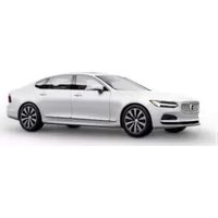


- VÄLKOMMEN!
- TABLE OF CONTENTS
- OWNER'S INFORMATION
- YOUR VOLVO
- SAFETY
- DISPLAYS AND VOICE CONTROL
- LIGHTING
- WINDOWS, GLASS AND MIRRORS
- SEATS AND STEERING WHEEL
- CLIMATE CONTROL
- KEY, LOCKS AND ALARM
- HYBRID INFORMATION
- STARTING AND DRIVING
- SPECIFICATIONS
- INDEX
- Vehicle's center display 1
- Mobile app
- Volvo Cars support site
- Printed information
- CAUTION
- NOTE
- Related information
- Owner's Manual in the center display
- Contextual Owner's Manual
- Navigate in the Owner's Manual in the center display
- Opening the menu in the Top menu
- Saving or deleting favorite articles
- Information
- Using the search function in the Top menu
- Owner's manual in mobile devices
- Online support
- Downloadable information
- Maps
- Mobile apps
- Owner's manuals in PDF format
- Contact
- Using the Owner's Manual
- Option/accessory
- Footnotes
- Messages
- Decals
- Procedures
- Position lists
- Bullet lists
- Illustrations, images and video clips
- Continues on next page
- Continuation from previous page
- The Owner's Manual and the environment
- Contacting Volvo
- In the USA:
- In Canada:
- Volvo ID
- Creating and registering a Volvo ID
- Creating a Volvo ID with the Volvo ID app
- Creating a Volvo ID using the Volvo On Call app 1
- Registering your Volvo ID to the vehicle
- Drive-E – purer driving pleasure
- Twin Engine vehicles
- IntelliSafe - driver support
- Support
- Prevention
- Protection
- Sensus - connection and entertainment
- This is Sensus
- SENSUS
- Information when it's needed, where it's needed
- Software Updates
- Data recording
- US market only:
- EDR
- ASDR
- Canadian market only:
- Terms & Conditions for Services
- Customer Privacy Policy
- Important information on accessories and extra equipment
- WARNING
- CALIFORNIA proposition 65
- Accessory installation
- Connecting equipment to the vehicle's data link connector
- Type approval
- USA
- Canada
- Technician certification
- Viewing the Vehicle Identification Number (VIN)
- Volvo Structural Parts Statement
- Driver distraction
- Warning symbol in the instrument panel
- Safety during pregnancy
- Seating position
- Occupant safety
- Volvo's concern for safety
- Occupant safety reminders
- Reporting safety defects
- Reporting safety defects in the U.S.
- Reporting safety defects in Canada
- Transport Canada can be contacted at: 1-800-333-0510
- Recall information
- Volvo customers in Canada
- Whiplash Protection System
- Seat belts
- Seat belt maintenance
- Buckling and unbuckling seat belts
- Buckling seat belts
- Unbuckling seat belts
- Seat belt tensioners
- Standard seat belt tensioners
- Electric seat belt tensioners
- Resetting the electric seat belt tensioners
- Door and seat belt reminders
- Seat belt reminder
- Front seats
- Rear seat
- Door/hood/tailgate and fuel filler door reminder
- Airbags
- Deployed airbags
- Driver/passenger-side airbags
- The front airbag system
- Front airbag deployment
- In the United States
- In Canada
- Airbag decals
- Occupant weight sensor
- Disabling the passenger's side front airbag
- Modifications
- Side airbags
- Inflatable curtain
- Safety mode
- Starting and moving the vehicle when it is in safety mode
- Starting the vehicle when it is in safety mode
- Moving the vehicle when it is in safety mode
- Child safety
- General information
- Volvo's recommendations
- Volvo has some very specific recommendations
- Child restraints
- Automatic Locking Retractor/ Emergency Locking Retractor (ALR/ ELR)
- When attaching the seat belt to a child seat:
- Child restraint registration and recalls
- Infant seats
- ◀◀
- 3.
- Convertible seats
- Securing a convertible seat with a seat belt
- Booster cushions
- Top tether anchors
- Securing a child seat
- Lower child seat attachment points
- ISOFIX/LATCH lower anchors
- To access the anchors
- Integrated booster cushion\*1
- DEATH or SERIOUS INJURY can occur
- Folding up the integrated booster cushion\*
- Folding down the integrated booster cushion\*
- Instruments and controls in left-hand drive vehicles
- Instrument panel
- Dynamic symbol
- Instrument panel settings
- Settings via instrument panel's app menu
- Settings via center display
- Selecting type of information
- Select theme
- Select language
- Fuel gauge
- Hybrid gauge
- Symbols in the hybrid gauge
- Driver-requested power
- Trip computer
- Trip odometer
- Odometer
- Current fuel consumption
- Distance to empty tank
- Distance to discharged battery
- Starting values for fully charged hybrid battery
- Mileage when using electric motor
- Tourist - alternative speedometer
- Displaying trip data in the instrument panel
- Resetting the trip odometer
- Displaying trip statistics in the center display
- Trip statistics settings
- Date and time
- Time and date settings
- Automatic time for vehicles with GPS
- Daylight savings time
- Ambient temperature sensor
- Indicator symbols in the instrument panel
- Symbol Meaning
- Fault in ABS system
- Auto-brake on
- Tire pressure system
- Emission control system
- Left/right turn signals
- Parking lights
- Fault in headlight system
- Active high beams on
- Active high beams off
- High beams on
- Warning symbols in the instrument panel
- Fault in brake system
- Parking brake on
- Low oil pressure
- Generator not charging
- Collision risk
- Instrument panel licenses
- Boost Software License 1.0
- BSD 4-clause "Original" or "Old" License
- BSD 3-clause "New" or "Revised" License
- BSD 2-clause "Simplified" license
- FreeType Project License
- Libpng License
- COPYRIGHT NOTICE, DISCLAIMER, and LICENSE:
- Simon-Pierre Cadieux
- MIT License
- zlib License
- SGI Free Software B License Version 2.0.
- App menu in instrument panel
- App menu functions
- Handling the App menu in the instrument panel
- Opening and closing the app menu
- Navigating and making selections in the App menu
- Messages in the instrument panel
- Service messages
- Handling messages in the instrument panel
- Handling new messages
- Handling messages saved from the instrument panel
- Reading saved messages
- Handling saved messages
- Center display overview
- Handling the center display
- Using the center display's touchscreen
- Returning to Home view from another view
- Scrolling in lists, articles or views
- Activating and deactivating the center display
- Navigating in the center display's views
- Home view
- i NOTE
- When the vehicle is moving:
- Status bar
- Climate view
- Handling tiles in the center display
- Opening or closing a tile in full-screen mode
- Function view in the center display
- Different types of buttons
- Moving apps and buttons in the center display
- Symbols in the center display status bar
- Using the center display keyboard
- Changing keyboard language in the center display
- Adding or deleting languages in Settings
- Toggling between keyboard languages
- Entering characters, letters and words by hand in the center display
- Handwriting characters/letters/words
- ! CAUTION
- Erasing/changing handwritten characters/letters
- Changing the appearance of the center display
- Turning off and adjusting the volume of the center display system sounds
- Changing system units of measurement
- Changing system language
- Changing settings in the center display's Top view
- Opening contextual setting in the center display
- Tap Navigation Settings.
- Third-party apps
- Resetting user data when the vehicle changes owners
- Resetting center display settings
- Two types of reset
- Resetting settings
- Table of settings in the center display
- Climate
- Driver profiles
- Which settings are saved in driver profiles?
- Global settings
- Personal settings
- Selecting a driver profile
- Changing a driver profile's name
- Protecting a driver profile
- Linking a remote key to a driver profile
- Linking a remote key to a specific driver profile
- Resetting driver profile settings
- Messages in the center display
- Pop-up messages
- Handling messages in the center display
- Handling messages saved from the center display
- Head-up display\*
- City Safety in head-up-display
- Activating and deactivating the head-up display\*
- Head-up display settings\*
- Selecting display options
- Adjusting brightness and height position
- Calibrating the horizontal position
- Voice control 15
- System updates
- Using voice commands 16
- Voice command examples
- Commands/phrases
- Numbers
- Voice control for cellular phones 17
- Voice control for radio and media 19
- Voice control settings 20
- Sound settings
- Language settings
- Lighting panel and controls
- Adjusting light functions via the center display
- Daytime running lights
- Low beams
- Tunnel detection
- Using high beam
- High beam flash
- High beams
- Active high beam
- Vehicles with LED 3 headlights\*
- Limitations for active high beams
- Using turn signals
- Triple flash indicator
- Continuous flashing sequence
- Active Bending Lights\*
- Deactivating/activating the function
- Rear fog light
- Brake lights
- Emergency brake lights
- Hazard warning flashers
- Using home safe lighting
- Welcome Light
- Interior Lighting
- Reading lights
- Passenger compartment lighting
- Courtesy lighting auto switch
- Rear roof lighting
- Glove compartment lighting
- Vanity mirror lighting\*
- Ground lighting\*
- Doorsill lighting
- Cargo compartment lighting
- Ambient Lighting
- Mood lighting\*
- Lighting in the door storage compartments
- Lighting in the tunnel console's front cup holder
- Adjusting interior lighting
- Adjust ambient decor lighting
- Adjusting mood lighting\*
- Changing the brightness
- Changing the color of the light
- Laminated glass
- Pinch protection for windows and sun curtains
- Reset procedure for pinch protection
- Resetting a power window
- Power windows
- Operating the power windows
- Using sun curtains\*
- Rearview/door mirrors
- Rearview mirror
- Door mirrors
- Adjusting the rearview mirror dimming function
- Auto-dim
- Adjusting the door mirrors
- Automatically folding door mirrors\*
- Resetting the mirrors' position
- Tilting when parking 3
- Automatically tilting when parking 3
- Automatic folding when the vehicle is locked\*
- Panoramic roof\*
- Operating the panoramic roof\*
- Opening and closing ventilation position
- Fully opening and closing the panoramic roof with the control in the ceiling
- Manual operation
- Auto operation
- Automatic operation - rapid opening or closing
- Auto closing the panoramic roof\* sun curtain
- Wiper blades and washer fluid
- Using the windshield wipers
- Single sweep
- Wipers off
- Interval wipers
- Continuous wipers
- Using the rain sensor
- Activating the rain sensor
- Deactivate the rain sensor
- Using the rain sensor's memory function
- Activating/deactivating memory function
- Using the windshield and headlight washers
- Headlight washer\*
- Reduced washing
- Using the rear window wiper/washer
- Activating the rear window wiper/washer
- Using automatic rear window wiping when backing up
- Manual front seats
- Power\* front seats
- Adjusting the power\* front seats
- Storing positions for seats, mirrors and head-up display\*
- Storing positions
- Using stored positions for seats, mirrors and head-up display\*
- Front door open
- Front door closed
- Front seat massage\* settings
- Massage settings
- Restarting the massage function
- Adjusting front seat massage settings\*
- Adjusting front seat massage settings
- Adjusting\* front seat cushion length
- Adjusting front seat side bolster settings\*
- Adjusting front seat lumbar support\*
- Adjusting lumbar support in vehicles with four-way lumbar support
- Adjusting the passenger seat from the driver's seat\*
- Activating the function
- Adjust passenger seat
- Folding the second row backrests
- Adjusting the second row head restraints
- Electrically folding down the rear seat's outboard head restraints\*
- Moving the second row seats forward/rearward\*
- Adjusting the second row backrest tilt
- Outboard seats
- Getting into and out of the third row of seats\*
- Folding the third row backrests\*
- Steering wheel controls and horn
- Adjusting the steering wheel
- Climate zones
- Climate control sensors
- Perceived temperature
- Climate control system voice commands 1
- Air quality
- Materials used in the passenger compartment
- Air filtering systems
- Clean Zone\*
- Clean Zone Interior Package\*
- Interior Air Quality System\*
- Activating and deactivating the air quality sensor\*
- Passenger compartment air filter
- Replacing the passenger compartment filter
- Air distribution
- Automatic and manual air distribution
- Adjustable air vents
- Adjusting air distribution
- Opening, closing and directing air vents
- Air distribution options
- Climate system controls
- Climate bar in the center display
- Climate view in the center display
- Main climate
- Rear climate control
- Parking climate
- Climate controls on the rear side of the tunnel console
- Activating and deactivating power front seats\*
- Activating and deactivating the heated front seat\*
- Activating and deactivating the heated rear seats\*
- Activating and deactivating the heated rear seats from the front seats
- Activating and deactivating the heated rear seats from the rear seat
- Activating and deactivating front seat ventilation\*
- Activating and deactivating the heated steering wheel\*
- Activating and deactivating automatic steering wheel heating\*
- Activating auto climate control
- Activating and deactivating recirculation
- Activating and deactivating the recirculation timer setting
- Activating and deactivating max defroster
- Activating and deactivating max defroster from the center console
- Activating and deactivating the heated windshield\*
- Activating and deactivating windshield heating from the center console
- Activating and deactivating windshield heating from the center display
- Activating and deactivating automatic windshield heating\*
- Activating and deactivating the heated rear window and door mirrors
- Activating and deactivating the heated rear window and door mirrors from the center console
- Activating and deactivating the heated rear window and door mirrors from the center display
- Automatically activating and deactivating the heated rear window and door mirrors
- Setting the blower speed for the front seats
- Setting the blower speed for the rear seats
- Setting blower speed for the rear seats from the front seats
- Setting blower speed for the rear seats from the rear seats
- Setting the temperature for the front seats
- Setting the temperature for the rear seats
- Setting the temperature for the rear seats from the front seats
- Setting the temperature for the rear seats from the rear seats
- Synchronize temperature
- Activating and deactivating air conditioning
- Activating and deactivating climate control for the third-row seats\*
- Preconditioning
- Starting and stopping preconditioning
- Starting from app\*
- Preconditioning timer
- Adding and editing timer settings for preconditioning
- Editing a timer setting
- Activating and deactivating preconditioning timer
- Deleting preconditioning timer settings
- Climate comfort retaining function
- Starting and switching off the climate retaining function when parking
- Parking climate symbols and messages
- Heater
- Battery and charging
- Parking heater
- Additional heater
- Activating and deactivating the auxiliary heater
- Lock indication
- Exterior confirmation
- Other indicators
- Lock button indicators
- Lock confirmation settings
- Remote key
- Buttonless key, Key Tag
- Interference
- Locking and unlocking using the remote key
- Locking when the tailgate is open
- Unlocking with remote key
- Automatic relocking
- Remote key not working
- Settings for remote and inside door unlock
- Unlocking the tailgate using the remote key
- Remote key range
- Manual use
- If the remote key is removed from the vehicle
- Replacing the remote key's battery
- Opening the key and replacing the battery
- Ordering additional remote keys
- Loss of a remote key
- Red Key - restricted remote key\*
- Red Key\* settings
- Adaptive Cruise Control\*:
- Reduced maximum volume (On/Off):
- Speed Limiter (On/Off):
- ◀ Speed reminder (On/Off):
- Driver support functions
- Detachable key blade
- Using the detachable key blade
- Locking and unlocking with detachable key blade
- Turning off the alarm
- Locking
- Electronic immobilizer
- Remote immobilizer with tracking system 11
- Start and lock system type designations
- Alarm system
- Remote keys (Passive entry/Passive start\*) USA
- Immobilizer and Passive entry/Passive start\* systems
- Keyless and touch-sensitive surfaces\*
- Pressure-sensitive surfaces
- Door handle
- Tailgate
- Keyless locking and unlocking\*
- Keyless locking
- Keyless unlocking
- Keyless unlock settings\*
- Keyless tailgate unlock\*
- Antenna locations for the start and lock system
- Locking and unlocking from inside the vehicle
- Unlocking using the front door buttons
- Locking using the front door buttons
- Unlocking the rear door
- Unlocking the tailgate from inside the vehicle
- Activating and deactivating child safety locks
- Activating and deactivating electric child safety locks\*
- Activating and deactivating manual child safety locks
- Automatic locking when driving
- Opening and closing the power tailgate\*
- Opening
- Closing
- Closing and locking 17
- Interrupting opening or closing
- Pinch protection
- Setting a maximum height for the power tailgate\*
- Foot movement tailgate operation\*
- Interrupting opening or closing with a foot movement
- Vehicle with skid plate accessory\*
- Private Locking
- Activating and deactivating private locking
- Entering security code before initial use
- Activating private locking
- Deactivating private locking
- Alarm
- Alarm signals
- In the event of alarm system failure
- Arming and disarming the alarm
- Arming the alarm
- Disarming the alarm
- Disarming the alarm without a functioning remote key
- Turning off a triggered alarm
- Automatically arming and disarming the alarm
- DRIVER SUPPORT
- Driver support systems
- Speed-dependent steering wheel resistance
- Changing the level of steering wheel resistance\*
- Settings My Car Drive Modes Steering Force
- Stability system Roll Stability Control
- Electronic Stability Control
- Stability control 3
- Spin control and active yaw control
- Engine drag control
- Trailer Stability Assist 4
- Electronic Stability Control Sport mode
- Activating/deactivating Sport mode in Electronic Stability Control
- Electronic Stability Control Sport mode limitations
- Electronic Stability Control symbols and messages
- Speed limiter
- Activating and starting Speed Limiter
- Starting the Speed Limiter
- Managing Speed Limiter speed
- Deactivating and putting Speed Limiter in standby mode
- Temporarily deactivating using the accelerator pedal
- Reactivating Speed Limiter from standby mode
- Turning off Cruise Control
- Cruise Control limitations
- Automatic Speed Limiter
- Is SL or ASL active?
- ASL symbol
- Activating/deactivating Automatic Speed Limiter
- Activating ASL
- Deactivating ASL
- Changing Automatic Speed Limiter tolerance
- Automatic Speed Limiter limitations
- Cruise control
- Activating and starting Cruise Control
- Putting Cruise Control in standby mode
- Activating/starting Cruise Control
- Managing Cruise Control speed
- Setting/changing set speed
- For vehicles with only CC
- For vehicles with both CC and ACC
- Using engine braking instead of applying the brakes
- How drive mode affects cruise control
- Cruise Control Eco Cruise with ECO drive mode
- Cruise Control Dynamic Cruise
- Deactivating and putting Cruise Control in standby mode
- Standby mode due to action by the driver
- Automatic standby mode
- Reactivating Cruise Control from standby mode
- Switching off Cruise Control
- Distance Alert\*30
- Head-up display for Distance Alert 33
- Activating/deactivating Distance Alert 35
- Setting a time interval for Distance Alert 36
- Distance Alert limitations 37
- Adaptive Cruise Control\*
- Overview
- Adaptive Cruise Control and collision warning
- Head-up display for Adaptive Cruise Control with collision warning
- Activating and starting Adaptive Cruise Control
- Starting/activating Adaptive Cruise Control
- Managing Adaptive Cruise Control speed
- Automatic transmission
- Setting Adaptive Cruise Control time intervals
- Setting how ACC should maintain distance\* to the vehicle ahead
- Deactivating/reactivating Adaptive Cruise Control
- Passing assistance with Adaptive Cruise Control
- How passing assistance works
- Starting passing assistance with Adaptive Cruise Control
- Requirements for passing assistance
- Starting parking assistance
- Limitations of passing assistance with Adaptive Cruise Control
- Switching target vehicles with Adaptive Cruise Control
- Automatic standby mode when switching targets
- Automatic braking with Adaptive Cruise Control
- Braking function in slow traffic and at a standstill
- Deactivation of the Auto-hold brake function
- Auto Activate Parking Brake
- Adaptive Cruise Control limitations
- Steep roads and/or heavy loads
- Other limitations
- Switching between Cruise Control and Adaptive Cruise Control
- Switching from ACC to CC
- Switching from CC to ACC
- Symbols and messages for Adaptive Cruise Control
- Pilot Assist
- How Pilot Assist works
- In curves and forks in the road
- Pilot Assist strives to keep the vehicle in the center of the lane
- Pilot Assist and collision warning
- Head-up display for Pilot Assist during collision risks
- Activating and starting Pilot Assist
- Hands on the steering wheel
- Managing Pilot Assist speed
- Setting a time interval for Pilot Assist
- Setting how Pilot Assist should maintain distance\* to the vehicle ahead
- Deactivating/reactivating Pilot Assist
- Deactivating and putting Pilot Assist in standby mode
- Reactivating Pilot Assist from standby mode
- Passing assistance with Pilot Assist
- Starting passing assistance with Pilot Assist
- Passing assistance with Pilot Assist limitations
- Switching target vehicles with Pilot Assist
- Auto-hold braking with Pilot Assist
- Pilot Assist limitations
- Pilot Assist\* symbols and messages
- Radar sensor
- Radar sensor limitations
- Vehicle speed
- Limited field of vision
- High temperatures
- Damaged windshield
- Recommended maintenance for the radar sensor
- Radar sensor type approval
- ACC, PA and BLIS USA & Canada:
- Camera
- Camera limitations
- Reduced visibility
- Recommended maintenance for the camera/radar sensor
- City Safety™
- City Safety parameters and sub-functions
- Vehicles
- Cyclists
- Pedestrians
- Large animals
- - Collision warning
- - Brake assistance
- - Auto-brake
- Setting a warning distance for City Safety
- Detecting obstacles with City Safety
- City Safety in crossing traffic
- Limitations of City Safety in crossing traffic
- City Safety and delayed evasive maneuvers
- Limitations of City Safety during evasive maneuvers
- City Safety braking for oncoming vehicles
- City Safety limitations
- Surroundings
- Low objects
- Slippery road conditions
- Backlighting
- Heat
- Camera and radar sensor's field of vision
- Driver intervention
- Backing up
- Low speed
- Active driver
- Market limitations
- City Safety messages
- Rear Collision Warning
- Rear Collision Warning limitations
- BLIS\*
- Activating/deactivating BLIS
- BLIS limitations
- Recommended maintenance for BLIS
- BLIS messages
- Cross Traffic Alert\*
- Activating/deactivating Cross Traffic Alert
- Cross Traffic Alert limitations
- Examples of further limitations
- Recommended maintenance for Cross Traffic Alert
- Cross Traffic Alert messages
- Road Sign Information\*
- Activating/deactivating Road Sign Information
- Road Sign Information and sign displays
- Signs for "School" and "Children playing"
- Road Sign Information and Sensus Navigation
- Road Sign Information with Speed Warning and Settings
- Settings
- Adjusting the Speed Warning limit
- Audible alert On/Off
- Speed camera warning On/Off
- Activating/deactivating Speed Warning in Road Sign Information
- Road Sign Information with speed camera information
- i
- Road Sign Information limitations
- Driver Alert Control
- Activating/deactivating Driver Alert Control
- On/Off
- Selecting guidance to a rest area if the Driver Alert Control warning has been given
- Driver Alert Control limitations
- Lane Keeping Aid
- Steering assistance with Lane Keeping Aid
- Lane Keeping Aid - Apply steering
- steering
- Activating/deactivating Lane Keeping Aid
- Selecting type of assistance for Lane Keeping Aid
- Lane Keeping Aid limitations
- Lane Keeping Aid symbols and messages
- Lane Keeping Aid symbols in the instrument panel
- Steering assistance at risk of collision
- Activating/deactivating steering assistance during collision risks
- Run-Off Mitigation with steering assistance
- Run-Off Mitigation with steering assistance levels
- Activating/deactivating Run-Off Mitigation with steering assistance
- Limitations of Run-Off Mitigation with steering assistance
- Steering assistance during collision risks from oncoming traffic
- Activating/deactivating Steering assistance during collision risks with oncoming vehicles
- Limitations of steering assistance during collision risks from oncoming traffic
- Steering assistance during collision risks from behind\*
- Activating/deactivating Steering assistance during collision risks from behind\*
- Limitations of steering assistance during collision risks from behind
- Symbols and messages for steering assistance during collision risks
- Park Assist\*
- Park Assist front, rear and sides
- Activating/deactivating Park Assist
- Park Assist limitations
- Recommended maintenance for Park Assist
- Park Assist symbols and messages
- Park Assist Camera\*
- Park Assist Camera views
- Park Assist Camera trajectory lines
- Trajectory lines in 360° view\*
- Trajectory lines for a towbar\*
- Sensor field from Park Assist for Park Assist Camera
- Side sensor fields
- Starting the Park Assist Camera
- Camera view when backing up
- Camera view when manually starting the camera
- Automatically deactivating the camera
- Park Assist Camera limitations
- Dark camera sector
- Lighting conditions
- Recommended maintenance of the Park Assist Camera
- Park Assist Camera symbols and messages
- Park Assist Pilot\*
- Types of parking with Park Assist Pilot
- Parallel parking
- Perpendicular parking
- Parking with Park Assist Pilot
- Parking
- Searching for and measuring potential parking spots
- Positioning the vehicle in the parking space
- To do so:
- Leaving a parking space with Park Assist Pilot
- Park Assist Pilot\* limitations
- The parking sequence is cancelled
- Driver responsibility
- Recommended maintenance for Park Assist Pilot
- Park Assist Pilot\* messages
- General information about Twin Engine
- Important
- No electrical current
- Towing not permitted
- Exterior engine noise
- High-voltage electrical current
- Charging the hybrid battery
- Charging current
- Fuse
- Charge cable
- Charging cable residual current device
- Charging cable temperature monitoring
- Opening and closing the charging socket cover
- Initiating hybrid battery charging
- Charging status in the vehicle's charging socket
- Charging status in the charging cable's charging module
- Charging status in the instrument panel
- Stopping hybrid battery charging
- Charging cable automatically locks
- Twin Engine symbols and messages in the instrument panel
- Long-term storage of vehicles with hybrid batteries
- Starting the vehicle
- Switching off the vehicle
- Ignition modes
- Selecting ignition mode
- Brake functions
- Brakes
- Anti-lock brakes
- Light braking charges the hybrid battery
- Brake Assist System
- Braking on wet roads
- Braking on salted roads
- Maintenance of the brake system
- Parking brake
- Activating and deactivating the parking brake
- Symbol in the instrument panel
- Automatic activation
- Emergency braking
- Deactivating manually
- Deactivating automatically
- Settings for automatically activating the parking brake
- Parking on a hill
- Heavy load uphill
- Parking brake malfunction
- Low battery charge level
- Replacing brake pads
- Auto-hold brakes
- Symbols in the instrument panel
- Activating and deactivating Auto- hold at a standstill
- When shutting off
- Hill Start Assist
- Braking assist after a collision
- Transmission
- Gear selector positions for automatic transmissions
- Selecting gears
- Gear selector positions
- Help functions
- Reverse - R
- Neutral - N
- D drive mode
- Brake - B
- Using the steering wheel paddles\* to shift
- Activating the steering wheel paddles
- Change
- Turning off Start/Stop
- Manual deactivation in gear D and B
- Automatic deactivation
- Shiftlock
- Automatic shiftlock
- From Park - P
- From Neutral - N
- The kickdown function
- Safety function
- All Wheel Drive (AWD)
- Drive systems
- Two drive systems
- Starting and stopping the combustion engine in Twin Engine vehicles
- Climate settings at low temperatures
- Using the electric motor in hot or cold weather
- Drive modes
- Available drive modes
- HYBRID
- Information in the instrument panel
- PURE
- ECO Climate
- OFF ROAD
- AWD
- POWER
- INDIVIDUAL
- Using the electric or combustion engine
- Changing drive mode
- Energy distribution in hybrid mode using map data\*
- Requirements for the function
- Usage tips
- Leveling control\* and suspension
- Pneumatic suspension and shock absorbers
- Transporting
- Leveling control settings\*
- Center display settings
- Easy Entry and Exit Suspension Control
- Disable Leveling Control
- Low Speed Control
- Activating and deactivating Low Speed Control using the function button
- Selecting Low Speed Control in the center display's Function view
- Hill Descent Control
- Function
- To keep in mind when using HDC
- Activating and deactivating Hill Descent Control using the function button
- Selecting Hill Descent Control in the center display's Function view
- Economical driving
- Charge
- Driving
- Using the electric motor only
- Factors affecting electric motor range
- Factors affecting driving range
- Factors the driver cannot control
- Factors the driver can control
- "Hold" and "Charge" functions
- Function buttons for Hold and Charge
- Battery level sustained for later use.
- Preparing for a long trip
- Check that:
- Winter driving
- Before the cold season arrives:
- Slippery driving conditions
- Driving through standing water
- Opening/closing the fuel filler door
- Refueling
- Refueling from a fuel container
- Fuel
- Deposit control gasoline (gasoline with detergent additives)
- Unleaded fuel
- Gasoline containing alcohol and ethers, "Oxygenated fuels"
- Alcohol - Ethanol
- Methanol
- Octane rating
- Minimum octane
- MINIMUM OCTANE RATING
- TOP TIER Detergent Gasoline
- Fuel Formulations
- Use of Additives
- Demanding driving
- Emission controls
- Three-way catalytic converter
- Heated oxygen sensors
- Overheating of engine and transmission
- Battery drain
- Detachable towbar\*
- Installing the ball holder
- Removing the ball holder
- Stowing the ball holder
- Driving with a trailer
- Trailer weights
- Self-leveling suspension\*
- Driving in hilly terrain or hot weather
- Steep inclines
- Starting on a hill
- Trailer Stability Assist\*
- Reasons for swaying
- Trailer Stability Assist function
- Checking trailer lights
- Trailer turn signals and brake lights
- Symbol Message
- Trailer rear fog light
- Checking trailer lights\*
- Automatic check
- Disabling the automatic check
- Manual check
- Towing using a towline
- Towing another vehicle
- Jump starting
- Attaching and removing the towing eyelet
- Removing the towing eyelet
- Recovery
- For vehicles equipped with leveling control\*:
- HomeLink®\*10
- Programming HomeLink®\*12
- Programming individual buttons
- Resetting the HomeLink® buttons
- Using HomeLink®\*14
- Type approval for HomeLink ® \*15
- FCC (USA) and IC (Canada)
- Type approval for EU
- Compass\*
- Activating and deactivating the compass\*
- Activating and deactivating the compass
- Calibrating the compass\*
- Audio, media and Internet
- Optimal sound reproduction
- Premium Sound\* (Bowers & Wilkins)
- High Performance Pro\* (Harman Kardon)
- High Performance
- Sound experience\*
- Apps
- Download apps
- Canceling a download
- Updating apps
- Update all
- Update certain apps
- Deleting apps
- Radio
- Starting the radio
- Changing waveband and radio station
- Changing wavebands
- Changing radio stations in a selected list
- Searching for a radio station
- Storing radio favorites
- Adding and deleting radio favorites
- Radio settings
- Canceling a traffic message
- Activating and deactivating radio functions
- FM Radio
- SiriusXM® Satellite radio\*
- RBDS
- RBDS radio
- HD Radio™
- Artist Experience™
- Ball game mode
- Benefits of digital broadcasting
- How HD Radio TM Technology broadcasting works
- Activating and deactivating the HD Radio™
- HD Radio™ sub-channels
- Selecting sub-channels
- HD Radio™ limitations
- Limitations
- The above items are dependant on the broadcaster's equipment settings and do not indicate a fault in the vehicle's radio receiver or antenna systems.
- Listening to satellite radio
- Selecting SiriusXM ® Satellite radio mode
- Using SiriusXM® Satellite radio\*
- ◀ Search
- Channels
- Favorites
- Categories/Genres
- EPG (Electronic Program Guide)
- Alerts
- iTunes tagging
- Settings for SiriusXM® Satellite radio\*
- Traffic Jump
- Alert Notifications
- Alert Notifications Sound
- Sort Channels
- Game Alerts
- Unsubscribed Services
- Skipped Stations
- Skipped Categories
- SiriusXM Travel Link®\*
- Starting SiriusXM Travel Link
- The following applies for all of the SiriusXM Travel Link services:
- SiriusXM Travel Link®\* - Weather
- Search
- Local 4
- Map view
- Today
- days
- Ski condition
- Areas
- SiriusXM Travel Link®\* - Notifications
- Types of notifications
- Information about a notification
- SiriusXM Travel Link®\* - Fuel 5
- Nearby
- Recommended
- Brands
- SiriusXM Travel Link®\* - Sports
- The following is an example of the result of tapping Baseball:
- Media player
- Playing media
- CD\*
- USB flash drive
- MP3 player and iPod®
- Bluetooth-connected device
- Media with Internet connection
- Video
- Apple CarPlay
- Android Auto
- Controlling and changing media
- Media searches
- Gracenote®
- Updating Gracenote
- CD player\*
- Playing video
- Playing DivX®
- Video settings
- Streaming media via Bluetooth®
- Connecting a device via Bluetooth®
- Playing media via the USB port
- Connecting a device via the USB port
- Technical specifications for USB devices
- Technical specifications for the USB-A connector
- Compatible file formats for media
- DivX®
- Apple® CarPlay®\*
- Using Apple ® CarPlay ®*
- Connecting an iPhone and starting CarPlay
- Starting CarPlay
- Switching connection between CarPlay and iPod
- CarPlay to iPod
- iPod to CarPlay
- Settings for Apple ® CarPlay ®*
- Automatic start
- System Volumes
- Tips for using Apple ® CarPlay ®*
- Android Auto\*
- Using Android Auto\*
- Connecting an Android device for the first time
- From a previously connected Android device
- Settings for Android Auto\*
- Tips for using Android Auto\*
- Phone
- Connecting a phone to the car via Bluetooth for the first time
- Option 1 - searching for the phone from the vehicle
- Option 2 - searching for the vehicle from the phone
- Compatible phones
- Connecting a phone to the car via Bluetooth automatically
- Connecting a phone to the car via Bluetooth manually
- Disconnecting a Bluetooth-connected phone
- Switch between phones connected via Bluetooth
- Disconnecting Bluetooth-connected devices
- Handling phone calls
- Making calls
- Making multiple calls
- Group (conference) calls
- Incoming calls
- Incoming calls while another call is in progress
- Privacy
- Handling text messages 10
- Handling text messages in the center display
- Reading text messages in the center display aloud
- Sending text messages in the center display 11
- Handling test messages in the instrument panel
- Reading new text messages in the instrument panel aloud
- Dictating replies in the instrument panel
- Message alert
- Text message settings
- Managing the phone book
- Sorting
- Phone settings
- Call notifications in head up display\*
- Settings for Bluetooth devices
- Bluetooth® declaration of conformity USA
- Internet-connected vehicle\*
- Read Terms and Conditions for Services and Customer Privacy Policy at
- Connecting the vehicle to the Internet via a Bluetooth-connected phone
- Connecting the vehicle to the Internet via a phone (Wi-Fi)
- Connecting the vehicle to the Internet via vehicle modem (SIM card)
- Vehicle modem settings
- Sharing Internet from the vehicle via Wi-Fi hotspot (tethering)
- No or poor Internet connection
- Phone to vehicle
- Phone to network operator
- Restarting the phone
- Deleting Wi-Fi networks
- Deleting all networks
- Wi-Fi technology and security
- Terms of use and data sharing
- Activating and deactivating data sharing
- Hard disk storage space
- License agreement for audio and media
- Patent number
- Gracenote® End User License Agreement
- Sensus software
- Linux software
- camellia:1.2.0
- Unicode: 5.1.0
- FCC CAUTION
- Tires
- Recommended tires
- Tire age
- Tire economy
- Tire rotation
- Storing wheels and tires
- Tire direction of rotation
- Tread wear indicator
- Tire terminology
- WHEELS AND TIRES
- Tire sidewall designations
- Speed Symbol
- Uniform Tire Quality Grading ALL PASSENGER VEHICLE TIRES MUST CONFORM TO FEDERAL SAFETY REQUIRE- MENTS IN ADDITION TO THESE GRADES.
- TREADWEAR
- TRACTION
- TEMPERATURE
- Checking tire pressure
- Cold tires
- Adjusting tire pressure
- Recommended tire pressure
- Tire pressure monitoring system\*
- Symbol Explanation
- System description
- General information about the tire pressure monitoring system
- To keep in mind
- Calibrating the tire pressure monitoring system\*
- Viewing tire pressure status in the center display\*
- Checking status
- Status indicator light
- Green tire:
- Yellow tire:
- All tires yellow:
- All tires gray:
- All tires gray and a message:
- Action when warned of low tire pressure
- When changing wheels
- Changing to tires of another dimension
- Tool kit
- Jack\*
- Models with leveling control\*
- Wheel bolts
- Locking wheel bolts\*
- Removing a wheel
- Installing a wheel
- Spare wheel 15
- Accessing the spare wheel
- Snow tires
- Tips for changing snow tires
- Studded tires
- Tread depth
- Snow chains
- Tire sealing system 17
- Location
- Sealing compound expiration date
- Using the tire sealing system
- Rechecking the inflation pressure
- Inflate tires with the compressor included in the tire sealing system
- Determining the vehicle's permitted weight
- Weight designations
- Curb weight
- Capacity weight
- Permissible axle weight
- Gross vehicle weight (GVW)
- Steps for Determining Correct Load Limit
- Passenger compartment interior
- Tunnel console
- Electrical outlets
- High-voltage outlet status indicator light
- Using the electrical outlets
- Using 12 V outlets
- Using high-voltage outlets
- Using the glove compartment
- Locking and unlocking the glove box
- Using the glove box as a cooled area
- Sun visors
- Cargo compartment
- Loading recommendations
- Loading the cargo compartment/trunk
- Extra cargo space
- Raising/ lowering the rear end of the vehicle\*
- Roof loads and load carriers
- Grocery bag holders
- Load anchoring eyelets
- Installing and removing the cargo compartment cover\*
- LOADING, STORAGE AND PASSENGER COMPARTMENT
- Removing the cargo compartment cover
- Operating the cargo compartment cover\*
- Fully open
- Retracting the cover
- Installing and removing the steel cargo grid\*
- Installation
- Removing the cover
- Installing and removing the cargo net\*
- Installing the cargo net
- For rear mounting:
- For front mounting:
- Removing the cargo net
- Volvo's service program
- Service and repairs
- Introduction
- The Federal Clean Air Act - U.S.
- Maintenance
- Applicable warranties - U.S./Canada
- Periodic maintenance helps minimize emissions
- On-board Diagnostic System
- Emission inspection readiness
- How do states use OBD II for emission inspections?
- How can my vehicle fail OBD II emission inspection?
- How can I prepare for my next OBD II emission inspection?
- Owner maintenance
- Each time the car is refueled:
- MAINTENANCE AND SERVICE
- Monthly:
- As needed:
- Data transfer between vehicle and workshop over Wi-Fi
- Connecting with remote key
- Download Center
- Handling system updates via Download Center
- Searching for update
- Updating all system software
- Updating individual system software
- Canceling software download
- Deactivating the background search for software update
- Vehicle status
- Scheduling service and repairs 5
- To use the service
- Book service
- Tap Send appointment request.
- Tap Cancel request if you would like to cancel your request.
- Accepting an appointment suggestion
- Sending vehicle information to the workshop 9
- Vehicle information contents
- Hoisting the vehicle
- Opening and closing the hood
- Warning - hood not closed
- Closing the hood
- Climate control system service
- Troubleshooting and repairs
- Vehicles with R134a refrigerant
- Replacing a windshield with head-up display\*
- Engine compartment overview
- Engine oil
- Checking and filling engine oil
- Viewing oil level in the center display
- Refilling coolant
- Replacing bulbs
- Start battery
- Connection points
- PROPOSITION 65 WARNING
- Hybrid battery
- Coolant
- Specifications for hybrid battery
- Battery symbols
- Fuses and fuseboxes
- Replacing fuses
- Fuses in the engine compartment
- Positions
- Fuses under the glove compartment
- Fuses in the cargo compartment
- Cleaning the interior
- Cleaning the center display
- Cleaning the head-up display\*
- Cleaning fabric upholstery and ceiling liner
- Fabric upholstery and ceiling liner
- Cleaning the seat belt
- Cleaning floor mats and inlay mats
- Inlay mats and floor mats
- Cleaning leather upholstery
- Leather upholstery\*
- Cleaning the leather upholstery
- Protecting the leather upholstery
- Cleaning the leather steering wheel
- Leather steering wheel
- If there are stains on the steering wheel:
- Type 2(grease, oil, sauces or chocolate)
- Type 3(dry dirt or dust)
- Cleaning interior plastic, metal and wood surfaces
- Interior plastic, metal and wood surfaces
- Cleaning the exterior
- Polishing and waxing
- Hand washing
- Automatic car washes
- High-pressure washing
- Cleaning the wiper blades
- Wiper blades
- Cleaning exterior plastic, rubber and trim components
- Exterior plastic, rubber and trim components
- Cleaning rims
- Rims
- Corrosion protection
- Inspection and maintenance
- Paintwork
- Touching up minor paint damage
- Touching up paint damage
- Materials that might be needed
- Color codes
- Color code
- Vehicle paint code
- Changing rear window wipers
- Replacing windshield wiper blades
- Windshield wipers in the service position
- Activating/deactivating service position
- Filling washer fluid
- Volume:
- Type designations
- Dimensions
- Weights
- Engine specifications
- Electric motor
- Engine oil specifications
- General
- Oil viscosity
- Extreme driving conditions
- Coolant specifications
- Transmission fluid specifications
- Brake fluid specifications
- Fuel tank volume
- Air conditioning specifications
- A/C Decal
- Refrigerant
- Evaporator
- Approved tire pressure
- 1,2,3...
- A
- B
- C
- D
- E
- F
- G
- H
- |
- J
- K
- L
- Lighting, replacing bulbs 626
- Loading
- Locking/unlocking
- Locks
- M
- Messages and symbols
- Messages in BLIS 359
- Misting
- N
- 0
- P
- S
- T
- U
- V
- W
- VOLVO
Brand : VOLVO
Model : XC90 T8 (2019)
Category : Automobile