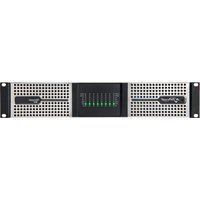
Ottocanali 8K4 DSP+D - Professional audiovisual equipment Powersoft - Free user manual and instructions
Find the device manual for free Ottocanali 8K4 DSP+D Powersoft in PDF.


| Product type | 8-channel professional audio amplifier |
| Brand | Powersoft |
| Model | Ottocanali 8K4 DSP+D |
| Power supply | Dual redundant universal switching power supply 100-240 VAC ±10%, IEC C20 inlet, 16 A max, recommended circuit breaker curve C/D 10 kA |
| Output power | 8000 W (total) depending on configuration |
| Number of channels | 8 |
| Load impedance | Lo-Z and Hi-Z (70 V / 100 V) |
| Audio inputs | 4 Phoenix connectors (12-pin) for LINE, 4 for AUX, 2 Gigabit Ethernet ports for Dante™ |
| Audio outputs | 2 Phoenix connectors (8-pin) for speaker outputs |
| Network connectivity | Gigabit Ethernet (802.3u/ab), DHCP/AutoIP, redundant Dante support (primary/secondary) |
| Control | Via ArmoníaPlus software, front panel potentiometers, DIP switches |
| DSP functions | Digital processing, input selection with backup strategy, pilot signal detection, impedance monitoring, HPF filters (35/70 Hz) |
| Cooling | Variable speed DC fans, removable air filter |
| Auxiliary power supply | 24 VDC (0.2 A max) via PWS OUT connector |
| Safety | Protection against overheating, short circuit, DC presence, mains failure; automatic shutdown in case of overheating |
| Maintenance | Cleaning of chassis with a dry cloth; cleaning of air filter with compressed air or water (allow to dry completely before reassembly) |
| Repairability | No user-serviceable parts; warranty repairs by Powersoft authorized center |
| Warranty | Limited warranty (see powersoft.com/warranty) |
| Compliance | CE, RoHS, WEEE, class A (EMC) |
Frequently Asked Questions - Ottocanali 8K4 DSP+D Powersoft
User questions about Ottocanali 8K4 DSP+D Powersoft
0 question about this device. Answer the ones you know or ask your own.
Ask a new question about this device
Download the instructions for your Professional audiovisual equipment in PDF format for free! Find your manual Ottocanali 8K4 DSP+D - Powersoft and take your electronic device back in hand. On this page are published all the documents necessary for the use of your device. Ottocanali 8K4 DSP+D by Powersoft.
USER MANUAL Ottocanali 8K4 DSP+D Powersoft
Important Safety Instructions
Common symbols and meanings

THE TRIANGLE WITH THE LIGHTNING BOLT IS USED TO ALERT THE USER TO THE RISK OF ELECTRIC SHOCK.
THE TRIANGLE WITH THE EXCLAMATION POINT IS USED TO ALERT THE USER TO IMPORTANT OPERATING OR MAINTENANCE INSTRUCTIONS.
THE CE-MARK INDICATES THE COMPLIANCE OF THE PRODUCT TO ALL THE APPLICABLE EUROPEAN DIRECTIVES
SYMBOL FOR EARTH/GROUND CONNECTION.
SYMBOL INDICATING THAT THE EQUIPMENT IS FOR INDOOR USE ONLY.
SYMBOL FOR CONFORMITY WITH DIRECTIVE 2012/19/EC OF THE EUROPEAN PARLIAMENT ON WASTE ELECTRICAL AND ELECTRONIC EQUIPMENT (WEEE).
Safety Warnings
OPERATING TEMPERATURE RANGE: 0°C TO +35°C (DERATING ABOVE 35°C)
STORAGE RELATIVE HUMIDITY RANGE: 10% TO 85% HUMIDITY (NON CONDENSING).
DO NOT USE THE UNIT AT ALTITUDES ABOVE 2000 M.
DO NOT USE THE UNIT IN TROPICAL ENVIRONMENT.
TO REDUCE THE RISK OF ELECTRIC SHOCK, DO NOT ATTEMPT TO OPEN ANY PART OF THE UNIT. NO USER-SERVICEABLE PARTS INSIDE. REFER SERVICING TO QUALIFIED SERVICE PERSONNEL.
CONNECTION TO THE MAINS SHALL BE DONE ONLY BY A ELECTROTECHNICAL SKILLED PERSON ACCORDING THE NATIONAL REQUIREMENTS OF THE COUNTRIES WHERE THE UNIT IS SOLD.
DO NOT USE THIS AMPLIFIER IF THE ELECTRICAL POWER CORD IS FRAYED OR BROKEN.
TO AVOID ELECTRICAL SHOCK, DO NOT TOUCH ANY EXPOSED SPEAKER WIRING WHILE THE AMPLIFIER IS OPERATING.
DO NOT SPILL WATER OR OTHER LIQUIDS INTO OR ON THE AMPLIFIER.
THIS DEVICE MUST BE POWERED EXCLUSIVELY BY EARTH CONNECTED MAINS SOCKETS IN ELECTRICAL NETWORKS COMPLIANT TO THE IEC 364 OR SIMILAR RULES
DISCONNECT THE AC MAINS SOURCE BEFORE ATTEMPTING TO CLEAN ANY PART OF THE AMPLIFIER
POWERSOFT SUGGESTS TO PLUG THE OTTOCANALI SERIES TO A 32 A RATING, C OR D CURVE, 10 KA SECTIONING BREAKER.
OUTPUT TERMINALS ARE HAZARDOUS: WIRING CONNECTION TO THESE TERMINALS REQUIRES INSTALLATION BY AN INSTRUCTED PERSON AND THE USE OF READY MADE LEADS.
PROPERLY FIT THE AC MAINS PLUG TO THE AMPLIFIER INLET. BEFORE POWERING THIS AMPLIFIER, VERIFY THAT THE CORRECT VOLTAGE RATING IS BEING USED.
TAKE CARE TO LOCK THE OUTPUT TERMINAL BEFORE SWITCHING THE DEVICE ON.
VERIFY THAT YOUR MAINS CONNECTION IS CAPABLE OF SATISFYING THE POWER RATINGS OF THE DEVICE.
NO NAKED FLAME SOURCES SUCH AS LIGHTED CANDLES SHOULD BE PLACED ON THE AMPLIFIER.
IT IS HIGHLY RECOMMENDED TO UNPLUG THE OUTPUT CONNECTORS BEFORE PROCEEDING WITH THE SELF CHECK PROCEDURE
THE TESTING SIGNALS MIGHT CAUSE LOUDSPEAKER IMPAIRMENTS.
TO PREVENT INJURY, THIS APPARATUS MUST BE SECURELY RACK MOUNTED IN ACCORDANCE WITH THE INSTALLATION INSTRUCTIONS.
THIS EQUIPMENT SHALL BE MOUNTED AT A MAXIMUM HEIGHT OF 2 M
THE MANUFACTURER CANNOT BE HELD RESPONSIBLE FOR DAMAGES CAUSED TO PERSONS, THINGS OR DATA DUE TO AN IMPROPER OR MISSING GROUND CONNECTION.
IT IS ABSOLUTELY NECESSARY TO VERIFY THESE FUNDAMENTAL REQUIREMENTS OF SAFETY AND, IN CASE OF DOUBT, REQUIRE AN ACCURATE CHECK BY QUALIFIED PERSONNEL.

Please read and keep all safety and use instructions.
This product is intended for installation by professional installers only! This document is intended to provide professional installers with basic installation and safety guidelines for this product in typical fixed-installation systems. Please read this document and all safety warnings before attempting installation.
- Read these instructions.
- Keep these instructions.
- Heed all warnings.
- Follow all instructions.
- Do not use this equipment near water.
-
Clean only with a dry cloth.
-
Do not block any ventilation openings. Install in accordance with the manufacturer's instructions.
-
Do not install near any heat sources such as radiators, heat registers, stoves, or other apparatus that produce heat.
-
Do not defeat the safety purpose of the polarized or grounding-type plug. A polarized plug has two blades with one wider than the other. A grounding-type plug has two blades and a third grounding prong. The wide blade or the third prong are provided for your safety. If the provided plug does not fit into your outlet, consult an electrician for replacement of the obsolete outlet.
-
Protect the power cord from being walked on or pinched particularly at plugs, convenience receptacles, and the point where they exit from the apparatus.
-
Only use attachments/accessories specified by the manufacturer.
-
Use only with the cart, stand, tripod, bracket, or table specified by the manufacturer, or sold with the apparatus. When a cart is used, use caution when moving the cart/apparatus combination to avoid injury from tip-over.
-
Unplug this apparatus during lightning storms or when unused for long periods of time.
-
Refer all servicing to qualified service personnel. Servicing is required when the apparatus has been damaged in any way, such as power-supply cord or plug is damaged, liquid has been spilled or objects have fallen into the apparatus, the apparatus has been exposed to rain or moisture, does not operate normally, or has been dropped.

Warranty and Technical Service
This product is covered by a limited warranty.

This Powersoft product contains no user-serviceable parts. All warranty repairs must be carried by a certified technician operating in a Powersoft Authorized Service Centre.
Contact The Authorized Service Center For Ordinary And Extraordinary Maintenance. To learn more about warranty terms and conditions, visit powersoft.com/warranty For any service related enquiry, please visit powersoft.com/en/product-repair/
Regulatory Compliance Statements
Europe
If the time arises to dispose of your product, please recycle all possible component. This symbol indicates that when the end-user wishes to discard this product, it must be sent to separate collection facilities for recovery and recycling. By separating this product from other household-type waste, the volume of waste sent to incinerators or land-fills will be reduced and natural resources will thus be conserved.
The Waste Electrical and Electronic Equipment Directive (WEEE Directive) aims to minimise the impact of electrical and electronic goods on the environment. Powersoft S.p.A. comply with the Directive 2012/19/EU of the European Parliament on waste electrical finance the cost of treatment and recovery of electronic equipment (WEEE) in order to reduce the amount of WEEE that is being disposed of in land-fill site. All of our products are marked with the WEEE symbol; this indicates that this product must NOT be disposed of with other waste. Instead it is the user's responsibility to dispose of their waste electrical and electronic equipment by handing it over to an approved reprocessor, or by returning it to Powersoft S.p.A. for reprocessing. For more information about where you can send your waste equipment for recycling, please contact Powersoft S.p.A. or one of your local distributors.
USA
FCC Supplier's Declaration of Conformity
Responsible Party:
Powersoft S.p.A.
Via Enrico Conti, 5
50018 Scandicci (FI) – Italy
Phone: +39 055 735 0230
Fax: +39 055 735 6235
FCC Compliance Statement
This device complies with part 15 of the FCC rules. Operation is subject to the following two conditions:
1) This device may not cause harmful interference, and
2) this device must accept any interference received, including interference that may cause undesired operation.
CAUTION: Changes or modifications not expressly approved by the party responsible for compliance could void the user's authority to operate the equipment. NOTE: This equipment has been tested and found to comply with the limits for a Class A digital device, pursuant to part 15 of the FCC Rules. This equipment generates, uses, and can radiate radio frequency energy and, if not installed and used in accordance with the instruction manual, may cause harmful interference to radio communications. However, there is no guarantee that interference will not occur in a particular installation. If this equipment does cause harmful interference to radio or television reception, which can be determined by turning the equipment off and on, the user is encouraged to try to correct the interference by one or more of the following measures:
- Reorient or relocate the receiving antenna.
- Increase the separation between the equipment and receiver.
- Connect the equipment into an outlet on a circuit
- Different from that to which the receiver is connected.
WARNING: This is a class A product. In a domestic environment this product may cause radio interference in which case the user may be required to take adequate measures
Canada
Canadian Caution
This device contains licence-exempt transmitter(s)/receiver(s) that comply with Innovation, Science and Economic Development Canada's licence-exempt RSS(s). Operation is subject to the following two conditions:
1) This device may not cause interference.
2) This device must accept any interference, including interference that may cause undesired operation of the device.
WARNING: This is a class A product. In a domestic environment this product may cause radio interference in which case the user may be required to take adequate measures
ICES-003 Class A Notice
This Class A digital apparatus complies with Canadian ICES-003.
Radiation Exposure Statement
This equipment complies with RSS-102 radiation exposure limits set forth for an uncontrolled environment. This equipment should be installed and operated with minimum distance 20cm between the radiator & your body.
EC Declaration Of Conformity
Manufacturer:
Powersoft S.p.A.
via E. Conti 5
50018 Scandicci (Fi)
Italy

We declare that under our sole responsibility the products:
Model Name: Ottocanali 4k4,
Ottocanali 4k4 DSP+ETH,
Ottocanali 4k4 DSP+D,
Ottocanali 8k4,
Ottocanali 8k4 DSP+ETH,
Ottocanali 8k4 DSP+D,
Ottocanali 12k4,
Ottocanali 12k4 DSP+ETH,
Ottocanali 12k4 DSP+D,
Ottocanali 1204,
Ottocanali 1204 DSP+ETH,
Ottocanali 1204 DSP.
Intended use: Professional Audio Amplifier
Are in conformity with the provisions of the following EC Directives, including all amendments, and with national legislation implementing these directives:
2014/35/EU Low Voltage Directive
2014/30/EU Electromagnetic Compatibility Directive
2011/65/EU RoHs Directive
The following harmonized standards are applied:
EN 55032:2015,
EN 55032:2015/A11:2020
EN 55035:2017,
EN 55035:2017/A11:2020
EN 61000-3-2:2014
EN 61000-3-3:2013
EN 61000-3-11:2000
EN 62368-1:2014
EN 62368-1:2014/AC:2015
Scandicci,
January 2022
Marco Cati
Quality & After Sales Manager

For compliance questions only: compliance@powersoft.it
Preliminary operations
Package list
The box contains the following:
1x Ottocanali Series amplifier.
2x Phoenix MC 1,5/4-ST-3,81 - 1803594 plug
6x Phoenix MC 1,5/12-ST-3,81 - 1803675 plug
2x Phoenix PC 5/8-STF1-7,62 - 1777891 plug
1x IEC power cord
1x user guide
Location
Install your Ottocanali Amplifier in well ventilated rack cabinets.
Secure both front and rear brackets to the rack.
Connect the AC Mains connector to a circuit breaker.
Install the amplifier far from EMF emitting devices.
Avoid placing the amplifier close to heat generating sources.
Cooling
The ventilation openings must not be impeded by any item, keep a distance of at least 50 cm from the front and rear ventilation openings of the amplifier.
Ottocanali implements a forced-air cooling system to maintain constant operating temperatures. Air enters from the front panel, exiting at the back of the amplifier.
The cooling system features variable-speed DC fans controlled by the heat sink mounted sensors. This ensures that fan noise and internal dust accumulation are kept to a minimum.
In the rare event of overheating, sensing circuits shut down all channels until the amplifier cools down to a safe operating temperature. Normal operation is resumed automatically without the need for user intervention.
Ottocanali amplifiers can be stacked one on top of the other, leave one rack unit empty every four to guarantee adequate air flow.
Cleaning
Use a dry cloth for cleaning the chassis and the front panel. Air filter cleaning should be scheduled in accordance with the dust levels in the amplifier's operating environment.
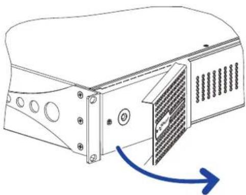
In order to clean the vent filters remove the front cover by firmly gripping the outermost silver panels and pull them outwards.
Use compressed air to remove the dust from filters, or wash it with clean water (let the filter dry thoroughly before reinstalling them).
AC Mains Supply
Ottocanali Series amplifiers implement two universal redundant switching mode power supplies operating in the range from 100 VAC up to 240 VAC ±10%.
AC mains connection is in the rear panel through the IEC C20 inlet, the approved power cord is provided.
Energy Save
Energy save capabilities can be activated for each channel pair. Four DIP switches are located on the left hand side of the front panel: in order to activate the Energy save mode for channel pair set the switches in the bottom position.
When the Energy save mode is activate on a channel pair, the Ottocanali enters a low power consumption idle state when no signal activity is detected for more than 4 seconds. Normal operation is resumed in a matter of milliseconds when an incoming signal is detected on the channel pair.
In case a pilot tone is used for checking system integrity and line faults, the Ottocanali amplifier would continuously detect a stationary signal that prevents the idle mode. In this condition the Energy save will never activate.
Remote On/Off (standby mode)
Remote ON/OFF is available through the proper terminals in the rear panel: in non-DSP Ottocanali by switching 24 VDC ±10% voltage (10 mA max) applied to the REM OFF connector, the amplifier can be remotely toggle between standard operating and the standby modes.
- When a 24 VDC voltage is applied to REM OFF, the amplifier switches to standby mode.
- When the 24 VDC voltage is removed from REM OFF, the amplifier switches back on as per normal boot up operation.
In order to remotely toggle between standard operating and the standby modes, the AC mains power must be active and the mains button switched on.
Connections
Signal Grounding
There is no ground switch or terminal on the Ottocanali Series amplifiers. The unit's signal grounding system is automatic. In order to limit hum and/or interference entering the signal path, use balanced input connections.
In the interests of safety, the unit MUST always operate with electrical safety earth connected to the chassis via the dedicated Protective Earth wire.
Analog Audio Input connections
Ottocanali Series amplifiers implements two analog input connections per channel: LINE and AUX input. Input selection is made via software or through the AUX SEL. IN switch.
Analog input is provided by means of four Phoenix MC 1,5/12-ST-3,811803675 connectors, two for LINE input (channels 1-to-4 and 5-to-8) and two dedicated to the AUX input (channels 1-to-4 and 5-to-8).
AUX SEL. IN: Analog input selection
Ottocanali Series amplifiers can switch from analog LINE inputs to AUX inputs when a constant voltage in the 12 VDC to 30 VDC range is applied to the AUX SEL. IN connector.
When this voltage is removed from the AUX SEL. IN, the unit switches back from AUX inputs to LINE inputs.
natural_image
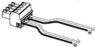
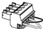
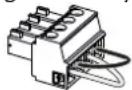
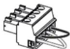
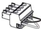
Pure electrical connector diagram without any text, numbers, or symbolsAUX SEL. IN and PWS OUT connector and wirings
PWS OUT: Built-in auxiliary power supply
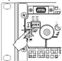
The PWS OUT connector provides a 24VDC - symmetrical with respect to ground (0.2 A max) - when enabled by the toggle switch on the front panel.
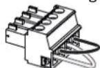
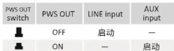
By wiring the PWS OUT connector to the AUX SEL. IN as shown below, the front panel PWS OUT switch is enabled to toggle between analog LINE inputs and AUX inputs: this provides an additional manual procedure to switch from analog LINE to AUX and vice versa.
| PWS OUT switch | PWS OUT | LINE Input | AUX input |
| OFF | ACTIVE | — | |
| ON | — | ACTIVE |
Manual procedure to switch from LINE to AUX.
Digital Audio Input connections
Digital input is supported via Dante™ standard protocols in Dante equipped devices.
In Ottocanali DSP+D amplifiers, Dante connectivity is supported via two Ethernet ports located on the rightmost side of the rear panels. Fast Ethernet (IEEE 802.3u, 100 Mbit/s) and Gigabit Ethernet (IEEE 802.3ab, 1 Gbit/s) network protocols are supported; Cat5e or Cat6 standard UTP twisted pair cables shall be used for connections up to 100 meters (328 ft).
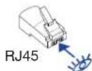
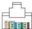
Ethernet cabling must comply to TIA/EIA-568-B and adopt the T568B scheme pinout1.
- Input selection and Backup policy
In Ottocanali DSP+D amplifiers it is possible to select among three input signal sources per channel: analog (either LINE or AUX) and two Dante streams (streams 1-to-8 and 9-to-16).
ArmoníaPlus provides an interface to select the proper input source and manage input gain and delay of analog and digital sources, in order to compensate transmission latency and levels.
Furthermore Ottocanali DSP+D amplifiers implement a backup policy aimed to improve reliability against signal fault. By assigning a bus priority to the three different input sources – analog and two Dante streams – per channel, the system is able to automatically switch to a reliable input connection in case of signal drop or pilot tone mismatch.
Ethernet connection
Ottocanali DSP+D amplifiers can be remotely controlled via an Ethernet connection through a personal computer and ArmoníaPlus. Powersoft recommend the use of Ethernet Cat5 straight through – patch – cables with pin/pair assignments TIA/EIA-568-B, i.e. T568B..
Output connections
Output connectors are Phoenix PC 5/8-STF1-7,62 1777891.
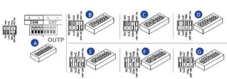
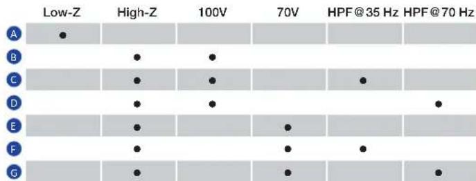
Bridge-tied connection of Lo-Z loudspeaker is supported on adjacent channel pairs 1-2, 3-4, 5-6 and 7-8; inputs must be physically paralleled. Any mixed configuration of low and high impedance output loads can be realized: in order to set the load configuration, each channel is provided by four DIP switches. Ottocanali Series is configured to drive Lo-Z loads by factory default.
Hi-Z 70V/100V operations
Any channel of an Ottocanali Series amplifier can drive 70V/100V (Hi-Z) distributed line of louspeakers. In order to connect any channel's output to a 70V/100V line, the rear panel DIP switch corresponding to the channel must be correctly set.
Powersoft recommends to use the built-in HPF (High Pass Filter) when the amplifier is set to drive a distributed line to prevent loudspeaker transformer saturation which can considerably degrade sound performance. The HPF can be activated by means of the DIP switch corresponding to the channel: two cutting frequency are available 35 Hz and 70 Hz.
GPO - Alarms
The Ottocanali's GPO – general purpose output – system implements triggering signals to broadcast alarms.
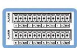
Ottocanali Series provides a pair of paralleled general purpose output connections per channel: one Normally Open ⒺNO and one Normally Closed ⒺNC.
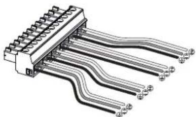
The connections are available on the back panel via two 12-pin Phoenix MC 1.5/12-ST-3.81 1803675 connectors for channels 1-to-4 and 5-to-8.
These contacts are used to report potentially dangerous faults or generally unsafe operation conditions by toggling alarm switches relative to the following events:
- No AC mains (i.e. system shutdown);
- Thermal stress: the system temperature reaches 70°C, thermal protections are going to be engaged;
- Short circuit in output wiring: either the loudspeaker or the line is in short;
- DC presence at the output: a continuously stationary signal is present at output terminals.
Ottocanali DSP feature further monitoring on pilot tone and output load through the GPO monitoring interface in ArmoníaPlus.
Pilot tone monitoring
Thanks to the built-in DSP, the Ottocanali DSP+D amplifiers implement pilot tone detection and alert. Detecting and alerting features are available for both input and output pilot tones on each channel.
The detection of a mismatch in the input pilot tone parameters (frequency and voltage level) can be used to trigger the backup policy and activate an alert through the general purpose output switch. The output pilot tone detection relies on an external signal passing through the amplifier or the internal post DSP pilot tone generator; in both cases any mismatch between the detected signal and the set thresholds triggers the general purpose output switches.
Output load monitoring
Through ArmoníaPlus it is possible to set the thresholds on the load impedance, at given frequency, that trigger the general purpose output of any channel of the amplifiers with DSP.
Attenuators
The row of potentiometers in the front panel behave differently on non-DSP amplifiers and Ottocanali DSP+D amplifiers:
- In non-DSP Ottocanali amplifiers, the potentiometers act as trimmers on the input level: the input signal is muted when the trimmer is completely turned counterclockwise; on the other hand, no attenuation is applied when the trimmer is completely turned clockwise.
- In Ottocanali DSP+D the potentiometers attenuate the speakers gain: they modify the overall gain applied to the group of ways belonging to the selected speaker. The amount of gain attenuation (External gain) is shown in ArmoníaPlus.
Firmware update
Firmware updates for Ottocanali DSP+D can be loaded via the front USB port. Updated releases of the Ottocanali DSP firmware are available at https://www.powersoft.com/en/download/firmware/ The package contains the firmware update file whose name is in the form: update-version#-model.bin (e.g. update-1.10.0.68-8ch.bin): store the firmware update file into a USB storage device and follow these instructions:
- Switch the amplifier on and wait for the completion of the boot sequence.
- Plug the USB storage device with the firmware update file to the USB port in the front panel of the amplifier.
- Press and hold the FW UPDATE pushbutton until the front LED bars start blinking.
- The update process lasts in 3-5 minutes. At the end the system reboots and it is possible to extract the USB storage device.
Networking
Ottocanali DSP+D amplifiers support linear daisy-chain, star and loop network topologies.
Be aware that daisy-chaining does not guarantee reliability in production environment, since any fault may yield to network sectioning and lost of system control.
IP addressing
Factory default network settings are DHCP/AutoIP.
Fixed IP policy can also be adopted and configured through ArmoníaPlus.
If a DHCP server is not active within the network, the amplifier platform initiates a stateless address auto-configuration (i.e. Zero-configuration networking methodology – Zeroconf): it self assigns a local numeric network address (of the type 169.254.x.y – 172.31.*.* for the secondary network if present – with a subnet mask 255.255.0.0) and automatically distributes and resolves the hostnames of networked devices.
Both ArmoníaPlus and the Ottocanali DSP+D must belong to the same subnet. If a DHCP server is present on the network and a Ottocanali DSP+D amplifier is in AUTO IP, networking may become unstable.
As a rule of thumb, turn the DHCP server on before connecting the amplifiers.
IP addressing of an Ottocanali DSP+D amplifier is established during the bootstrap: when the Ottocanali DSP amplifier discovers a DHCP server on the network during the startup, it negotiates the networking parameters. If the Ottocanali DSP does not reveal a DHCP server on the network during the startup it set itself in AUTO IP mode.
Dante™ networking
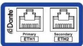
Ottocanali DSP+D amplifiers support Dante redundant networking via the two Rj45 ports on the rear panel:
• Primary/ETH1 is the Primary network port;
• Secondary/ETH2 is the Secondary network port.
Dante connectivity is always supported on the Primary/ETH1 Gigabit Ethernet port; the Secondary/ETH2 Gigabit Ethernet port offers continuity of operation when a parallel redundant network is established.
In order to implement a Dante network, a computer running Dante Controller has to be used. Ottocanali DSP+D amplifiers are automatically discovered and displayed in Dante Controller with the default identifier MODELNAME-SERIAL (e.g. 8K4-71520).
Dante networks will almost always require at least one network switch. Redundant infrastructures may require multiple switches. For maximum reliability, network switch shall:
• be Rated for Gigabit Ethernet;
- be Non-blocking;
• have Quality of Service (QoS) with at least four queues;
• have Diffserv (DSCP) QoS with strict priority;
• have EEE (Energy efficient ethernet) switched off.
Redundant network configuration
Dante Redundancy can be set up and used between any supporting Dante-enabled audio equipment: it works by using two completely independent and separate networks, the Primary Network and the Secondary Network.
To setup and use Dante Redundancy, connect the Ottocanali DSP+D amplifier and other redundant Dante-enabled audio equipment using duplicate Gigabit switches and Ethernet cables. Connect your computer running Dante Virtual Soundcard and Dante Controller, and other non-redundant Dante-enabled audio equipment to the Primary Network.
The primary and secondary networks MUST NOT be inter-connected at any point. Make sure any computer is set to automatically configure its IP address.
Quality & After Sales Manager


| PWS OUT switch | PWS OUT | LINE input | AUX input |
| OFF | ATTIVO | — | |
| ON | — | ATTIVO |
Quality & After Sales Manager


Quality & After Sales Manager

Pour les questions de conformité uniquement: compliance@powersoft.it
MARCHE/ARRÊT à distance (mode veille
Quality & After Sales Manager

| PWS OUT switch | PWS OUT LINE input | AUX input | |
| OFF | ACTIVO | — | |
| ON | — | ACTIVO | |
Quality & After Sales Manager


| PWS OUT switch | PWS OUT | LINE input | AUX input |
| OFF | ATIVO | — | |
| ON | — | ATIVO |
Quality & After Sales Manager

仅限法规遵从性问题:compliance@powersoft.it
初步操作
包装清单
箱内包括如下物品:
从线路切换至辅助的人工操作程序。
数字音频输入连接
natural_image
Illustration of a server rack with temperature sensors and ventilation ducts, no text or symbols presentExposing the control panel
natural_image
Technical line drawing of a computer or server unit with mounting holes and a ventilation grille (no text or symbols)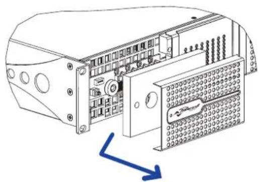
natural_image
Technical line drawing of an electronic device with internal components and a blue arrow indicating direction (no text or symbols)Dimensions
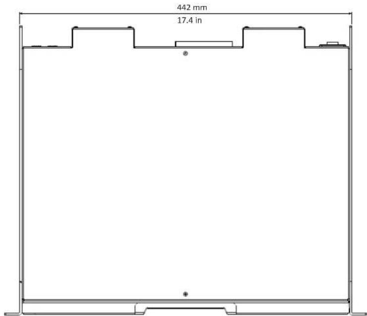
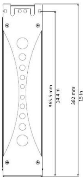
Input Section
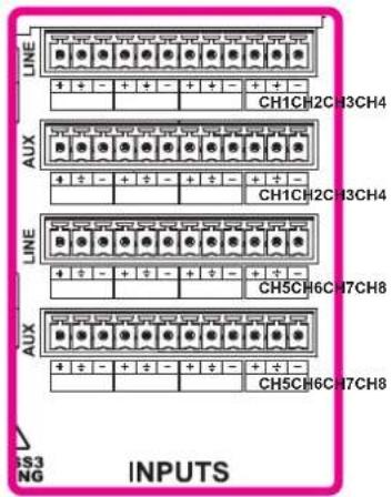
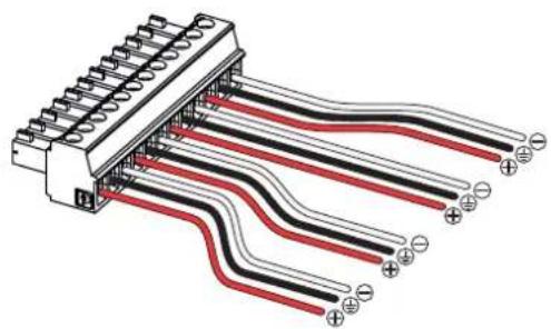
natural_image
Pure electrical connector diagram showing black and red wires with terminal connectors (no text or symbols)Linked channel pairs
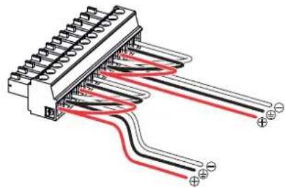
natural_image
Pure electrical connector diagram showing wiring connections without any text or symbolsPhoenix MC 1,5/12-ST-3,81 1803675 Phoenix MC 1,5/12-ST-3,81 1803675
Output Section
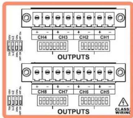
Single Ended
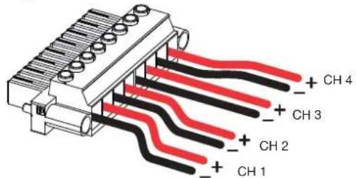
Phoenix PC 5/8-STF1-7,62 1777891
Bridged
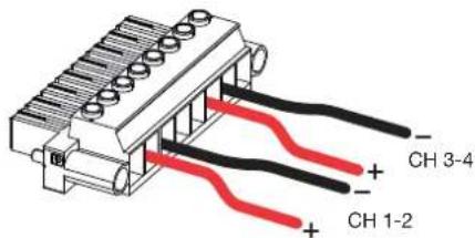
Phoenix PC 5/8-STF1-7,62 1777891
other
| Category | Low-Z | High-Z | 100V | 70V | HPF@35 Hz | HPF@70 Hz | |---|---|---|---|---|---|---| | A | ● | | | | | | | B | | ● | ● | | | | | C | | ● | ● | | ● | | | D | | ● | ● | | | ● | | E | | ● | | ● | | | | F | | ● | | ● | ● | | | G | | ● | | ● | | ● |GPO
natural_image
Diagram of a multi-pin connector with multiple leads and terminal connectors (no text or symbols)Phoenix MC 1,5/12-ST-3,81 1803675
Networking
AC Mains Connector
IEC C20

natural_image
Technical line drawing showing two views of a device with fan and cable connections (no text or symbols)| Color code (TIA/EIA-568-B) Pin | |
| ORANGE / WHITE 1 | |
| ORANGE 2 | |
| GREEN / WHITE 3 | |
| BLUE 4 | |
| BLUE / WHITE 5 | |
| GREEN 6 | |
| BROWN / WHITE 7 | |
| BROWN 8 | |
Front Panel

USB Port - Ottocanali DSP+D series only
Multifunction LEDs (channels 1 to 8)
Control Panel - Ottocanali Series
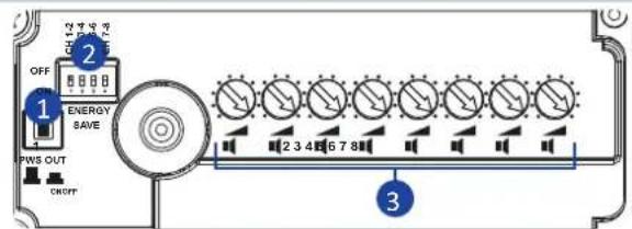
1 24 VDC PWS OUT switch
2 Energy save DIP switches
3 Input attenuators (channels 1 to 8)
Control Panel - Ottocanali DSP+ D Series
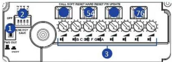
24 VDC PWS OUT switch
2 Energy save DIP switches
3 Output attenuators (speakers A to H)
4 ArmoníaPlus Callback pushbutton
5 Soft reset pushbutton
6 Hard reset pushbutton
7 Firmware update pushbutton
Rear Panel

1 On/off power switch and AC mains IEC C20 inlet
2 Audio outputs (channels 1-4)
3 Audio outputs (channels 5-8)
4 Audio inputs: LINE (ch. 1-8)
5 Audio inputs: AUX (ch. 1-8)
6 GPO - Alarms channels 1-4
7 GPO - Alarms channels 5-8
8 Remote off switch
9 Remote on switch (Ottocanali DSP+D Only)
10 24 VDC PWS OUT
11 AUX SEL. IN input selector
12 Multi function DIP switch ch. 1-2 (impedance, voltage, filter)
13 Multi function DIP switch ch. 5-6 (impedance, voltage, filter)
14 Multi function DIP switch ch. 7-8 (impedance, voltage, filter)
15 Multi function DIP switch ch. 3-4 (impedance, voltage, filter)
16 Ethernet port / Dante™ primary (Ottocanali DSP+D Only)
17 Ethernet port / Dante™ secondary (Ottocanali DSP+D Only)
LED Charts
| Color | Signal metering | Lighting | Warnings Description |
| RED | Clipping SOLID ON | System temperature above 80°C (all channels muted) | |
| YELLOW | -6dB | SOLID ON | System temperature above 70°C2 (thermal warning) |
| GREEN | -12dB | — | — |
| GREEN | -24dB | — | — |
| GREEN | signal presence (-60dBV) | — | — |
| GREEN | — | SOLID ON | Channel ready |
| — | BLINKING | Channel muted (DSP+D only) | |
| GREEN | — | BLINKING | AUX inputs are selected |
^1 Even if only one channel causes thermal overload, all channels are muted and all red LEDs are on: normal operating is restored when the temperature falls under the thermal warning threshold. ^2 Even if only one channel causes thermal warning, all yellow LEDs are on: thermal protections are engaged.

DRIVING HUMAN AUDIO EXPERIENCE
POWERSOFT S.P.A.
Via E. Conti, 5 - Scandicci (FI) 50018 - Italy
support@powersoft.com
+39 055 73 50 230
+39 055 73 56 235
- Important Safety Instructions
- Common symbols and meanings
- Safety Warnings
- Warranty and Technical Service
- Regulatory Compliance Statements
- Europe
- USA
- FCC Supplier's Declaration of Conformity
- FCC Compliance Statement
- Canada
- Canadian Caution
- ICES-003 Class A Notice
- Radiation Exposure Statement
- EC Declaration Of Conformity
- Preliminary operations
- Package list
- Location
- Cooling
- Cleaning
- AC Mains Supply
- Energy Save
- Remote On/Off (standby mode)
- Connections
- Signal Grounding
- Analog Audio Input connections
- AUX SEL. IN: Analog input selection
- PWS OUT: Built-in auxiliary power supply
- Digital Audio Input connections
- - Input selection and Backup policy
- Ethernet connection
- Output connections
- Hi-Z 70V/100V operations
- GPO - Alarms
- Pilot tone monitoring
- Output load monitoring
- Attenuators
- Firmware update
- Networking
- IP addressing
- As a rule of thumb, turn the DHCP server on before connecting the amplifiers.
- Dante™ networking
- Redundant network configuration
- MARCHE/ARRÊT à distance (mode veille
- 初步操作
- 包装清单
- 数字音频输入连接
Brand : Powersoft
Model : Ottocanali 8K4 DSP+D
Category : Professional audiovisual equipment