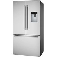
B36FD54SNS - Fridge BOSCH - Free user manual and instructions
Find the device manual for free B36FD54SNS BOSCH in PDF.

User questions about B36FD54SNS BOSCH
0 question about this device. Answer the ones you know or ask your own.
Ask a new question about this device
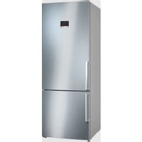
Download the instructions for your Fridge in PDF format for free! Find your manual B36FD54SNS - BOSCH and take your electronic device back in hand. On this page are published all the documents necessary for the use of your device. B36FD54SNS by BOSCH.
USER MANUAL B36FD54SNS BOSCH
natural_image
Blue circular icon with a white human figure reading a document (no text or symbols)
en-us Installation Instructions
en-us Available from our Customer Service
fr-ca disponible via le service après-vente
text_image
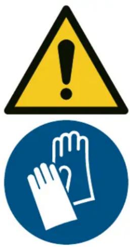
Warning sign with yellow triangle and hand symbol, indicating caution or hazard
IMPORTANT SAFETY INSTRUCTIONS
READ AND SAVE THESE INSTRUCTIONS
Observe the following safety instructions.
WARNING
The heavy weight of the appliance may result in injury when lifted.
▶ Do not lift the appliance on your own.
WARNING
Incorrect installation is dangerous.
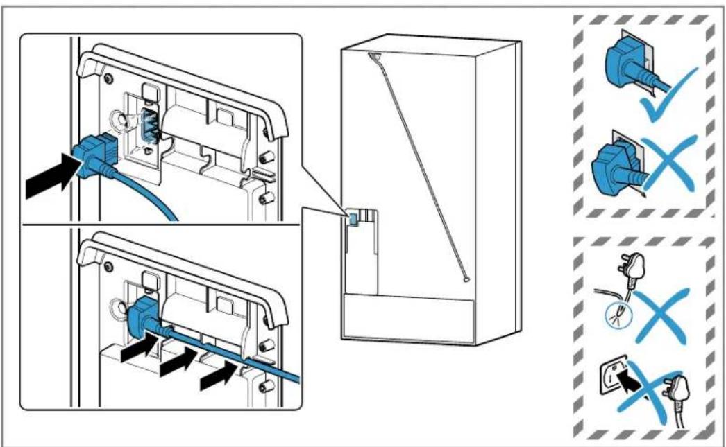
- Connect and operate the appliance only in accordance with the specifications on the rating plate.
- Connect the appliance to a power supply with alternating current only via a correctly installed socket outlet with grounding.
▶ The protective conductor system of the domestic electrical installation must be properly installed.
▶ Never equip the appliance with an external switching device, e.g. a timer or remote control. - When the appliance is installed, the mains plug of the power cord must be freely accessible. If free access is not possible, an isolating switch must be integrated into the permanent electrical installation according to the installation regulations.
- When installing the appliance, check that the power cord is not trapped or damaged.
If the insulation of the power cord is damaged, that can be dangerous.
▶ Never let the power cord come into contact with heat sources.
text_image
Warning sign with yellow triangle and hand symbol, indicating caution or hazard
IMPORTANT SAFETY INSTRUCTIONS
READ AND SAVE THESE INSTRUCTIONS
WARNING
If the appliance's ventilation openings are closed off, a leak in the refrigeration circuit may result in a flammable mixture of gas and air.
- Keep ventilation openings in the appliance casing or in the integrated casing clear of obstruction.
WARNING
It is dangerous to use an extended power cord and non-approved adapters.
▶ Do not use extension cords or multiple socket strips.
▶ Only use adapters and power cords approved by the manufacturer.
▶ If the power cord is too short and a longer one is not available, please contact an electrician to have the domestic installation adapted.
Portable multiple socket strips or portable power supply units may overheat and cause a fire.
- Do not place portable multiple socket strips or power supply units on the back of the appliance.
Preventing material damage
NOTICE:
The high weight of the appliance or, if not rolled in a straight line, the appliance's castors may damage the floor when the appliance is moved.
▶ Transport the appliance using a hand-cart.
▶ Use floor protection when moving the appliance, and do not move it in a zigzag fashion.
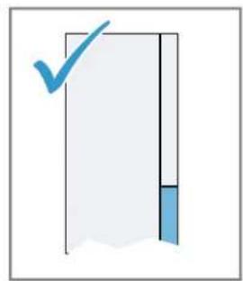
When the appliance door is closed, the mullion rail should be closed (flush with the door edge) or damage may occur.
▶ Never open the mullion rail manually.
▶ If the mullion rail has been opened, rotate it closed (flush with the door edge) before closing the appliance door.
Using the appliance, base, runners or doors as a seat or climbing surface may damage the appliance.
- Do not stand or lean on the appliance, base, runners or doors.
To avoid damage to the appliance or property damage, observe the following.
- Do not connect the appliance to the water line during construction or if the water appears cloudy or contains visible particles. Failure to follow these instructions may result in foreign materials entering the appliance, which could impair its performance, or cause water leakage.
If the water pressure is too high or too low, this may impair functioning of the appliance.
▶ Make sure that the water pressure in the water supply system is at least 29 psi (200 kPa) and max. 116 psi (800 kPa).
If the water pressure exceeds the maximum value specified, a pressure-reducing valve must be installed between the drinking water connection and the hose set of the appliance.
Modified or damaged water hoses may result in material damage and damage to the appliance.
▶ Never kink, crush, modify or cut through water hoses.
▶ Never re-use water hoses that have been used before.
▶ Never pull on the water hose on the rear panel of the appliance.

text_image
Warning sign with yellow triangle and hand symbol, indicating caution or hazard
IMPORTANTES CONSIGNES DE SÉCURITÉ
LIRE ET CONSERVER CES INSTRUCTIONS
text_image
Warning sign with yellow triangle and hand symbol, indicating caution or hazard
IMPORTANTES CONSIGNES DE SÉCURITÉ
LIRE ET CONSERVER CES INSTRUCTIONS
AVERTISSEMENT
text_image
Warning sign with yellow triangle and hand symbol, indicating caution or hazard
text_image
Warning sign with yellow triangle and hand symbol, indicating caution or hazard
natural_image
Illustration of scissors cutting into a bag with tools and a black arrow indicating direction (no text or symbols)
natural_image
Simple line drawing of a wrench and a curved arrow (no text or symbols)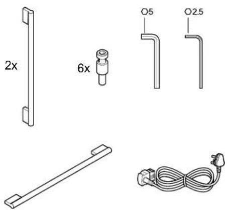
text_image
2x 6x O5 O2.5
natural_image
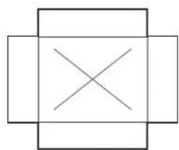
Pure geometric diagram with intersecting lines inside a square (no text or symbols)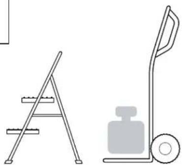
natural_image
Two line drawings: a ladder leaning against the left and a push truck with a weight beside it (no text or symbols)
text_image
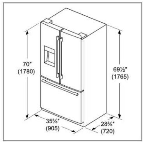
70" (1780) 69½" (1765) 35½" (905) 28¾" (720)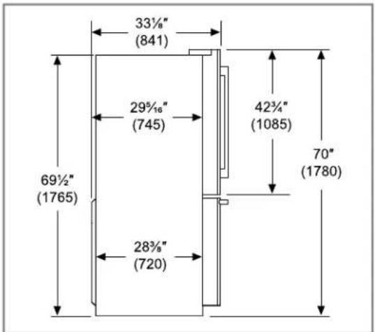
text_image
33½" (841) 29½" (745) 42¾" (1085) 69½" (1765) 28¾" (720) 70" (1780)
text_image
! ≥1¼" (30)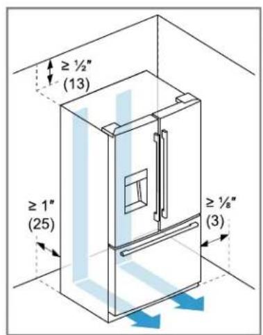
text_image
≥ ½" (13) ≥ 1" (25) ≥ ½" (3)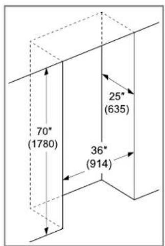
text_image
70" (1780) 25" (635) 36" (914)
text_image
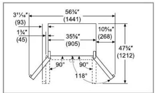
3½" (93) 1¾" (45) 56¾" (1441) 35¾" (905) 10½" (268) 47¾" (1212) 90° 90° 118°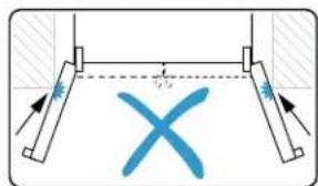
text_image
Diagram showing a mechanical setup with labeled components and directional arrows, featuring a blue X-shaped symbol inside a dashed line.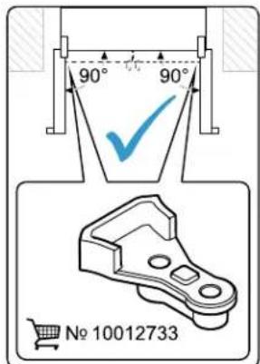
text_image
90° 90° No 10012733
natural_image
Pure diagram of a rectangular block with an upward arrow, no text or symbols present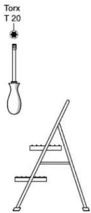
text_image
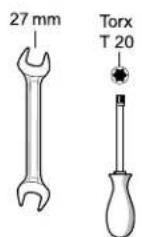
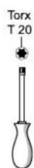
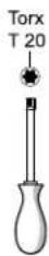
Torx T 20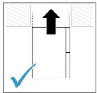
text_image
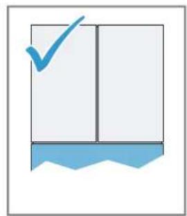
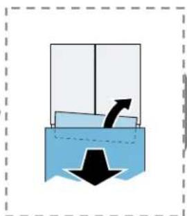
Diagram showing a black upward arrow above a white rectangle with a blue checkmark below, indicating a confirmation or approval step.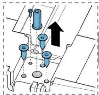
natural_image
Technical diagram showing mechanical components with arrows indicating movement or assembly (no text or symbols present)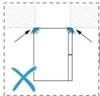
text_image
Diagram showing a rectangular shape with arrows and a blue X mark, possibly indicating a geometric or directional relationship.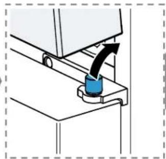
natural_image
Diagram of a mechanical assembly with a blue component being inserted, showing motion direction (no text or symbols)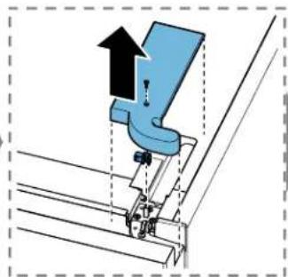
natural_image
Diagram of a mechanical assembly with an upward arrow and component alignment (no text or symbols)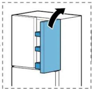
natural_image
Diagram of a mechanical or electrical component with a blue internal structure and an arrow indicating direction (no text or symbols)
natural_image
Simple diagram showing a black upward arrow inside a rectangular box, with hatched regions outside (no text or symbols)
text_image
Torx T 20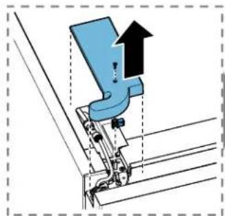
natural_image
Mechanical assembly diagram showing a blue bracket with an upward arrow indicating motion (no text or symbols present)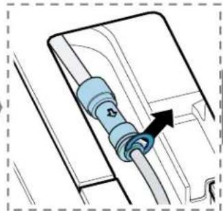
natural_image
Diagram of a mechanical component with a blue cylindrical connector and an arrow indicating direction (no text or symbols)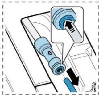
text_image
Diagram showing a device with a blue sensor or connector inserted into a panel, with an arrow indicating the insertion point.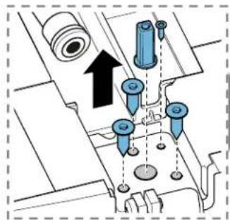
text_image
Technical diagram showing mechanical assembly with arrows and component labels, likely illustrating a process or assembly step.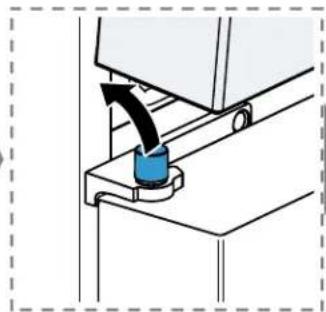
natural_image
Diagram of a mechanical device with a blue component being inserted, showing motion direction (no text or symbols)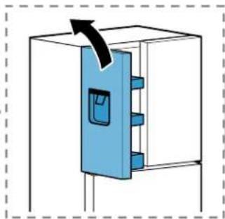
natural_image
Diagram of a blue door lock mechanism inside a white cabinet, with an arrow indicating direction (no text or symbols)
natural_image
Pure diagram of a rectangular block with an upward arrow, no text or symbols present
natural_image
Diagram of a blue sofa with an arrow indicating upward motion, no text or symbols present
natural_image
Diagram of a blue plastic container with an arrow indicating direction, no text or symbols present
text_image
Diagram illustrating mechanical locking mechanism with labeled components and directional arrows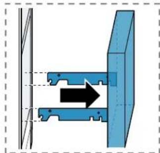
natural_image
Diagram of a mechanical assembly with a blue bracket and directional arrow indicating motion (no text or symbols)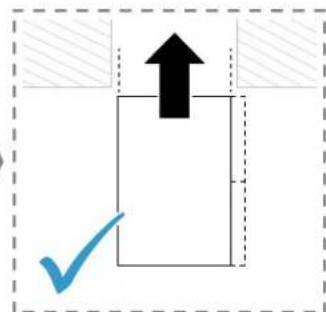
text_image
Diagram showing a black upward arrow above a white rectangle with a blue checkmark below, enclosed in a dashed border.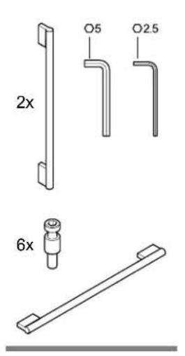
text_image
2x 6x O5 O2.5
text_image
Technical diagram showing two mechanical assembly steps with labeled components and directional arrows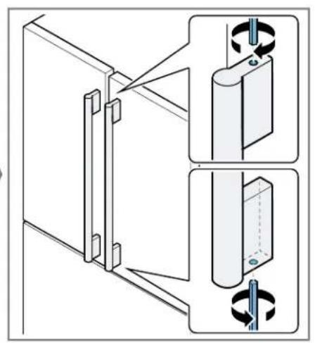
natural_image
Technical diagram showing two mechanical assembly steps with rotating components (no text or symbols)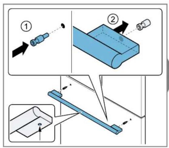
text_image
Technical diagram illustrating mechanical assembly steps with numbered instructions and component illustrations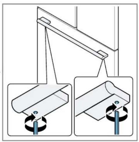
natural_image
Technical diagram showing two mechanical assembly steps with rotating components (no text or symbols)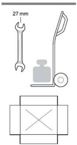
text_image
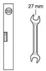
27 mm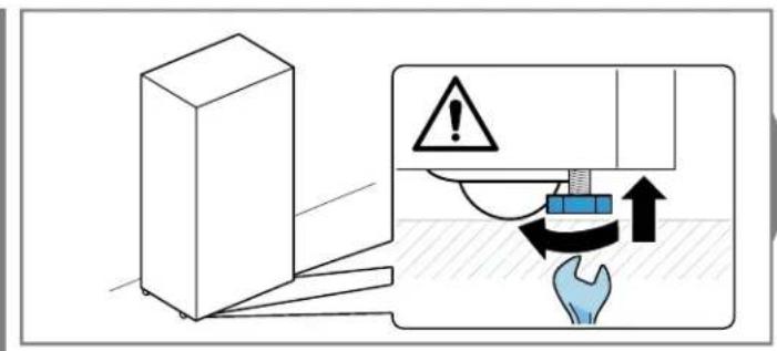
text_image
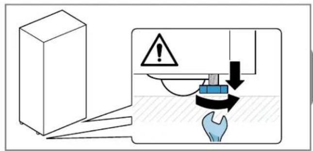
Diagram illustrating a safety hazard with warning symbol, hand gesture, and directional arrows indicating process flow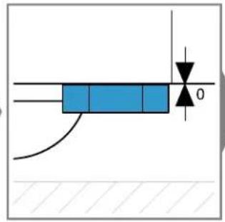
text_image
Technical diagram showing a blue rectangular component with a downward arrow and dimension label '0' indicating a measurement or direction.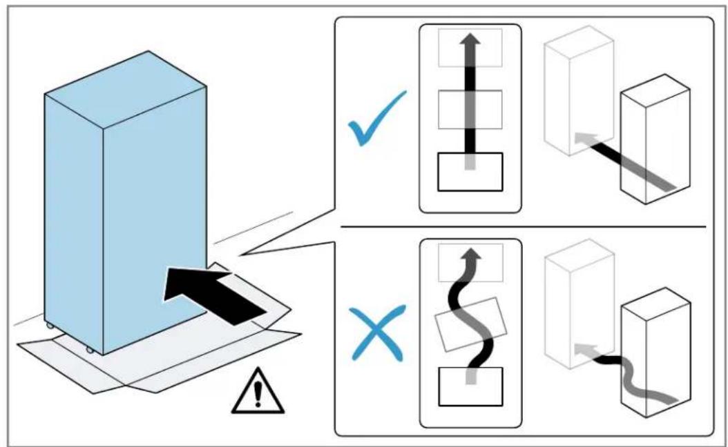
flowchart
graph TD
    A["3D Block"] --> B{Directional Arrow}
    B -->|✓| C["1 Box"]
    B -->|×| D["2 Box with S-shaped Arrow"]
    C --> E["3D Cube"]
    D --> F["3D Cube with Curve"]
text_image
Diagram illustrating a mechanical or electrical hazard warning with an explosion symbol and hand gesture, showing a 3D block and ground contact.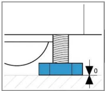
natural_image
Pure mechanical diagram showing a shaft and base assembly without any text, numbers, or symbols
text_image
Diagram illustrating a mechanical assembly process with labeled components and directional arrows indicating motion or force.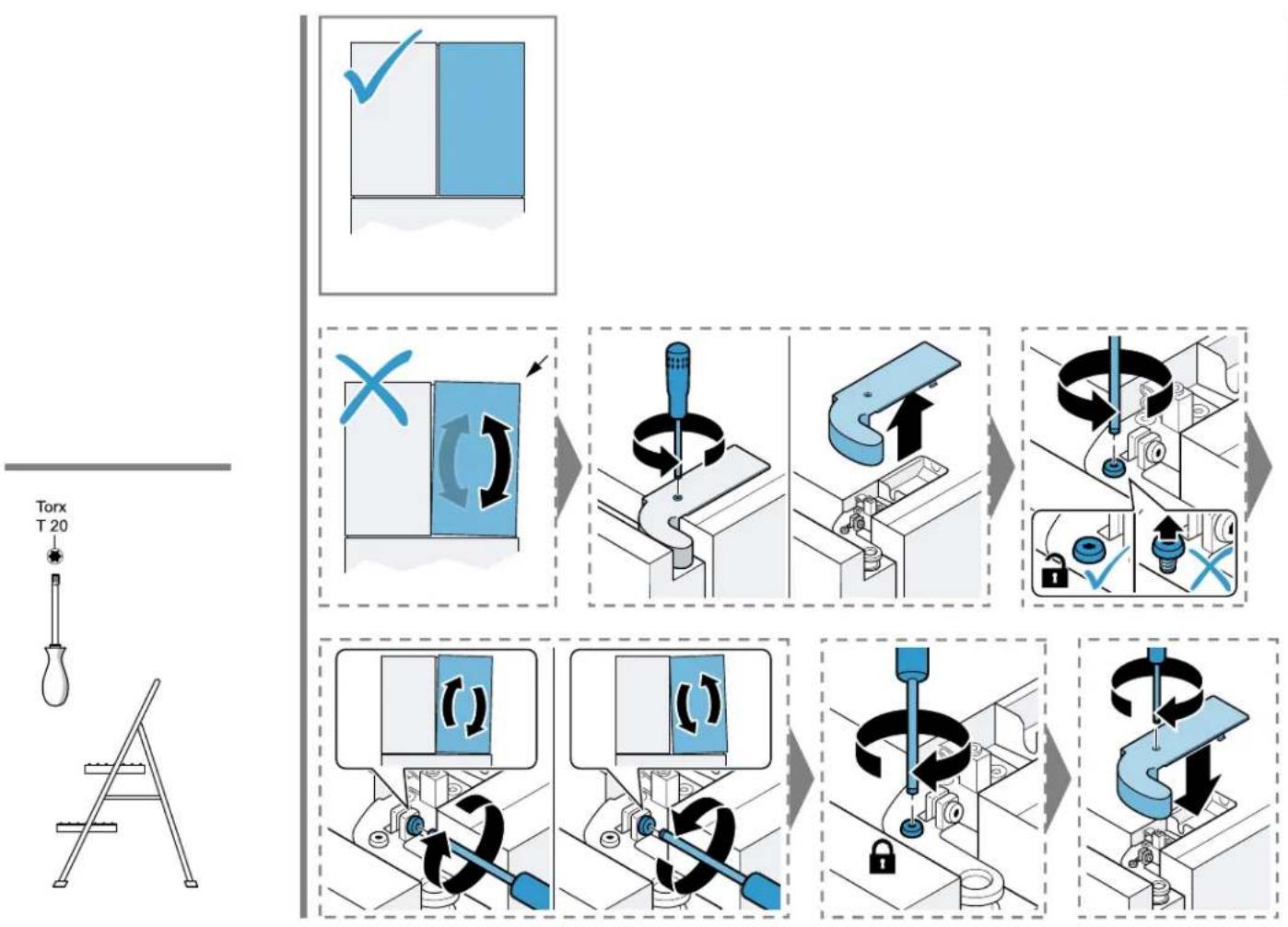

natural_image
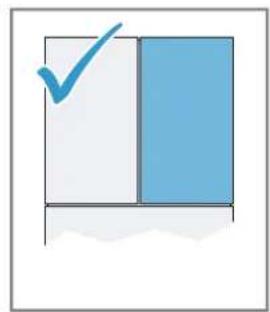
Simple diagram with a checkmark inside a divided rectangle (no text or symbols)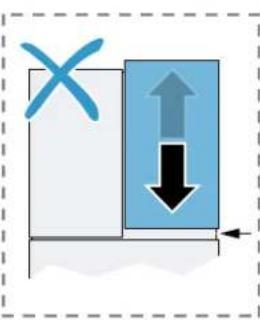
text_image
Diagram showing a blue X mark and a blue arrow with an upward arrow, indicating direction or movement in a process or system.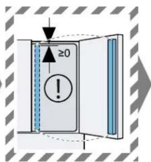
text_image
≥0
text_image
Diagram illustrating mechanical assembly with directional arrows and component labels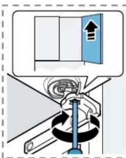
text_image
Diagram illustrating a mechanical or electrical system with directional arrows and a blue door, likely indicating movement or operation.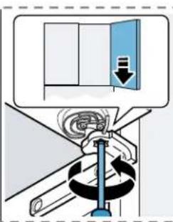
text_image
Diagram illustrating a mechanical or electrical operation with labeled components and directional arrows indicating motion or flow.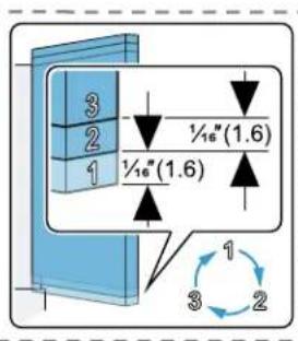
text_image
3 2 1 ½″(1.6) ½″(1.6) 1 3 2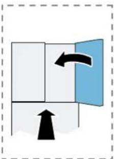
flowchart
graph TD
    A["Start"] --> B{Condition}
    B -->|Yes| C["Process"]
    B -->|No| D["End"]
natural_image
Simple line drawing of a book with a checkmark and wavy base (no text or symbols)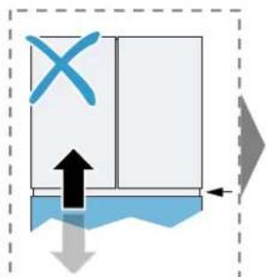
flowchart
graph TD
    A["Start"] --> B{Decision}
    B -->|Yes| C["Process Step 1"]
    B -->|No| D["Process Step 2"]
    C --> E["End"]
    D --> E
natural_image
Simple diagram showing a container with liquid and an arrow indicating flow or movement (no text or symbols)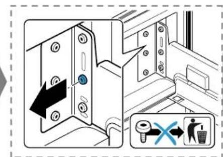
text_image
Diagram showing a door lock mechanism with a blue circular component and a magnified view of a trash bin with a 'X' symbol.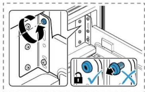
text_image
Diagram illustrating door lock mechanism with clockwise rotation and lock lock operation, showing key points and lock status indicators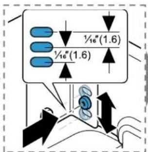
text_image
½″(1.6) ½″(1.6)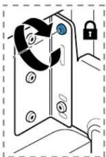
natural_image
Diagram of a door lock mechanism with no text or symbols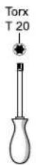
natural_image
Simple line drawing of a document with a blue checkmark and a small blue block (no text or symbols)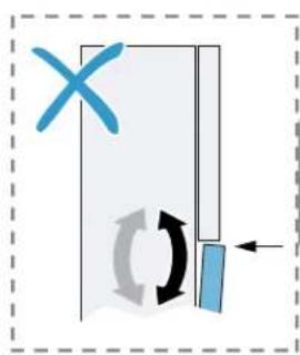
natural_image
Diagram showing a door mechanism with a blue X mark and circular motion arrows (no text or symbols)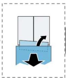
natural_image
Simple diagram showing a container with a downward arrow and an upward arrow inside, no text or symbols present.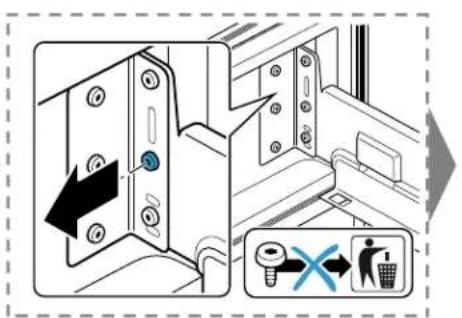
text_image
Diagram showing a door lock mechanism with a blue key inserted, accompanied by a warning sign and a crossed-out 'No' symbol.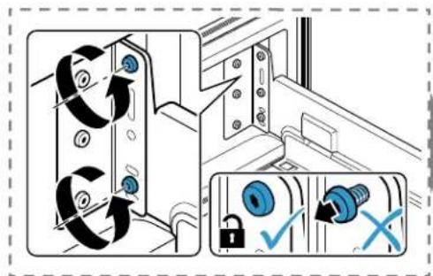
text_image
Diagram illustrating mechanical assembly steps with labeled arrows and checkmark indicators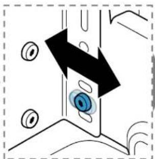
natural_image
Diagram showing a mechanical component with a blue eye and black arrow indicating direction (no text or symbols)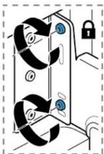
natural_image
Diagram of a door lock mechanism with no text or symbols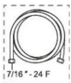
text_image
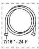
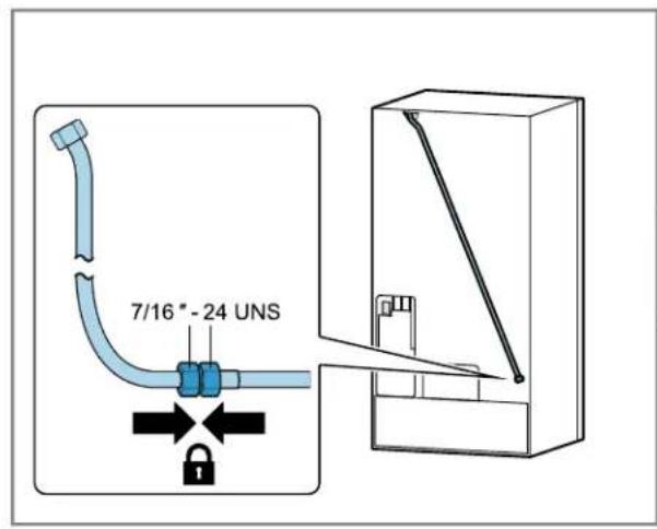
7/16" - 24 UNS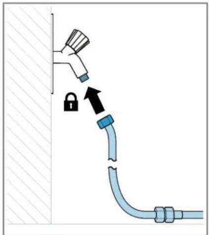
text_image
Diagram showing a pipe installation with a lock and lock icon, indicating safety or clearance mechanism.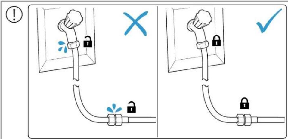
text_image
! × ✓
text_image
Diagram illustrating electrical switch installation steps with labeled components and checkmarks for inspection
26

27

28